Transcripts
1. Geometry Nodes for Beginners Course Intro: Lo welcome everyone to Blender for Geometry
Notes for Beginners. In this course, we are excited
to teach you to create your very own customizable
stair generator using blender. This course is designed to
be intuitive and accessible, featuring step by step
visualizations with helpful annotations and
tools in a three D view, whether you are just
starting out or are an experienced blender user. This course is tailored
for you covering a wide range of
nodes in a way that is engaging yet
not overwhelming. And we've included on
screen keys to ensure you can easily follow along
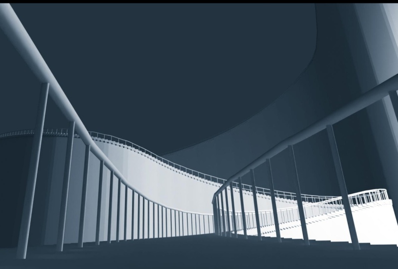
every step of the way. Our journey begins with
creating a simple grid mesh, the density of which
will be dependent on the length of your
own drawn curve. This ensures that no matter the length of the created curve, the consistency and spacing of your stairs remain uniform. Next, we'll dive into transforming this grid
into a staircase, shaping it to fit
a curve form while maintaining a consistent
height for each step. This part of the
course focuses on delicate balance between form and function in pre D design. And we'll take or
created and deform plane and skillfully turn it
into a free D mesh plane. This process is crucial to ensure that there are
no geometry issues, especially as the mesh is
centered on your drawn curve. Once we have the basic
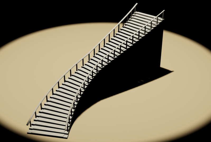
shape of the staircase, we'll enhance its design. We'll start with creating
stepping stones at each corner designed to be scaled in a user friendly way to control
their width and depth. During this process,
we'll introduce you to custom parameters
categorized for ease of use, allowing you to adjust
the width and the number of steps
along the staircase. After perfecting the
stepping stones, our focus shifts
to the creation of hand rails along the
edges of our staircase. This involves two
main components, the hand rails that
follow along the edges and supporting poles that
extend from these hand rails. We will ensure that these
elements are scaled appropriately according to the custom height setting
for the hand rails, You'll learn how to extract curvature information and adjust the hand rails height to align
with the staircase steps. Additionally, this
section includes creating a custom geometry node
for elliptical measures, which we will use to customize the design of the
set hand rails. We will introduce the controls for the hand rails and poles. Use it in the custom node group to create a variety of shapes. You'll discover how to offset the height of the railing and relay this information to the support to
maintain their shape. Finally, we'll guide
you in creating a selection for the control
placement of supports, achieving a uniform
and aesthetically pleasing variation
for the placements. Join us in blender for
geometry, nodes for beginners. And embark on this
journey to unlock your creative potential in
Fredy design and blender.
2. Blender Project Setup for Geometry Node Stair Creation: Hello and welcome I
Brown to Blender Four. Geometry notes for beginners. And we're going to start off
by introducing ourselves with the program I'm
using, Blender four. You can see it at the
bottom right hand corner saying blender four. It really doesn't matter which version you're using
as long as it's above version 3.2 I believe as it gave a couple of extra
updates to geometry. But in general, what you
want to do is as long as you have above that and
preferably above Blender, 44.2 is the new one. At the moment, I believe you
should be fine following a long this course
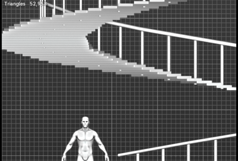
and you shouldn't get any issues along the way. As you might have noticed,
we have a bit of a couple of extra information at the
bottom right hand corner. I simply just have
it enabled in case I have geometry and I want
to see the density. Although throughout
the geometry creation we don't necessarily see that. But it's still quite
useful to have for us to actually
see this information. All I do is just go onto
the top left hand corner, edit, go to Preferences, and then within it we
can go on within it, we can go on to Interface, which will give you
this type of menu. And then just make
sure you go to Status Bar. Just
enable all of them. The main one that
you want to see, if you want to know
which version you have, Blender is going to
be Blender version, so make sure you
have this enabled. Also, I recommend you having a video memory for
sure because that will allow you to
see how much of a performance you're
going to make use out of. Although with geometer nodes, with coding in general, it's quite performance
light unless you're doing very heavy
computational tasks. But for beginner type of set up, it definitely is very light on your computer
in comparison to something like rendering
or animation FX creation, something of that sort. It isn't something you
need to be worried about. And even saving out the file is going to be quite
light on your memory. And actually that might be the best thing to
start off with. If we go onto file, we can click ourselves save. You can see that
it's also set up as control S by default
to save it out. And I'll just recommend you to save out the project
before we start. Just so you could click
control to save it out throughout the entire
of the Gemetr node. And it just will make sure that you don't have any issues, for example, the blender crashing or something
of the sort. You'll still have a way
to get your project back. Anyways, what I'd
like to do is you can either just go
through the set up, you can just find
it through here. But I tend to, a little neat
trick I tend to have is just to have a folder opened up where I work on my projects. Copy the location,
hitting control C, then hitting control
V to paste it in. And that works
really nice for me. But if you're using
something like Mac, you might have a
different set up. It really is up to
you for this case. I'm just going to go ahead
and call this geometry node. It's misspelled it
some going to use py arrows to change it like so. Yeah, that's pretty much it. Let's go ahead and
click Save Now. The next time we're going to use control and to save it out, we are going to be
able to basically save out this project I think that we should do for a brand
new version of blender is make sure that we enable an add on called Node Wrangler. With edit we can go
on to Preferences, go onto Add Ons, and just search for
a Node Wrangler. Just make sure that
this is enabled. We need to make sure
that this is enabled primarily speeding
up our workflows. Most of the options that are
really handy are actually hidden away within this add on. Just make sure you
have this enabled. That is my recommendation. The geometry notes themselves is quite a complex
subject, to be honest. Every note, there's a bunch of different notes to
make use out of. For a beginner, it
really is overwhelming. This type, of course, is going
to primarily focus on just making sure it takes you
through the entire set up. No, it is tempting to learn
every single nook and cranny, every single type
of node just to get all the information to
be able to make use out of. But I really recommend
you to start off with just a simple set up and just
go along for the course. Learn the intricacies of
functionality of how it works, basically with the
combinations of the nodes. And then afterwards, just learn and build up that
knowledge bit by bit. You don't need to
overwhelm yourself with that set up when
learning this a topic. Another thing I want to say is all the keyboard
shortcuts are going to be on the bottom
left hand corner over here. You'll see that I'll. All of the shortcuts shown like so it'll be super easy
for you to follow along. You will notice every once in
a while, me clicking eight. This will just be an indicator that I'm pausing the video. You don't need to worry
about that shortcut. But every other
shortcut is going to be basically showing you what I'm doing throughout the video. And hopefully that will
help you to follow along, since I will be using
shortcuts to speed up the workflow overall when
creating geometry nodes. Now the layout itself, by default, if you look
at the top section, we have a bunch of tabs
called layout modeling, sculpting, and et cetera. The one we're looking
for is going to be called geometry nodes. If you go onto it
by clicking on it, you'll get this a view. It is very useful to have this, especially when we're
working with geometry notes. It's made for that.
Since we have geometry node window
at the bottom, we also have a free D view on
the top right hand corner. And on the top left hand corner, we have all the
positioning coordinates and whatnot which
are also helpful for us to indicate which indexes we're
picking up and whatnot, which we're going to learn along the way route the course. For now though, just make sure you go onto geometry notes. Like if you're not seeing this, you can also make this yourself. You can click on a plus
symbol on a corner over here. And just select the one
that you're looking for. Within general, this should
be called a geometry node. Just click on it
and you should get this identical set
up. There you go. Since this is a duplicate, I'm
just going to right click. I'm going to click delete. And I'm going to go back to
this geometry node like so. Actually, we're
going to start off by simply clicking and holding. And then drag it across the
scene to select everything. If you're not seeing everything, just use your mouse wheel
to zoom out a little bit. Just drag it across like so. And delete three of those
objects just like that. Now we can click
control to save it out, and we're going to have
ourselves an empty scene to work with
throughout the course. At any moment your
project crashes, don't worry, you
can still recover. If you haven't saved
out your project, you can still make use out of file and there is an
option called recover. You should be able to recover it with just clicking last session. Alternatively, you can go
ahead and click Auto Save. And that should put you
in the area where all of the files that are
automatically saved are set up. Which if you want
to get access to, you can simply go on the top, select this control C and
then go on to Windows. For example, control V to
put it into your search bar. Click Enter, you should get
yourself with this window. Alternatively, you can just manually locate it
and then you'll find yourself with the blend file
someplace in this area. That's how you access your basically recovered
files in case you crash. The other way to do it is
when you're saving it out, you should find yourselves with another blend
file over here. You should be able to
recover it from this file. Well, that was pretty much it. This was just a
short video to just go over the overall set up, getting ourselves
to geometry nodes, making sure that we have
ourselves an empty scene, and making sure that
we save everything out so we could start
working along it, and in case it crashes, we can just recover
ourselves a file that. Are we ready? We are going
to go on and move ourselves with the start with the
beginning of our actual course. Thank you very much for watching and I'll see in the next one.
3. Introduction to Geometry Nodes and Group Inputs in Blender 4: Welcome back everyone to
Blender for Geometry, Notes for Beginners. In a last lesson, we got
ourselves with a set up for a brand new project
with an empty slate. We're going to now go
ahead and make use out of this geometry set
up to just simply go ahead and I suppose
we should start with a curve so we could actually visualize the stairs later down the line, how
we're creating it. Let's go ahead and do that.
On the left hand side, we'll see this window. If you're not seeing
additional options, just make sure you
scroll down and you should be able to
see more of them. Now though, we're going
to simply just click shift A and make
sure that you have the window selected shift
A and then go to curve and just select bezier like so this should give you
this type of a line. If you're not seeing
it on your screen, just make sure you
click at this, will just focus in on
your object like so. And make sure that
selection is in view. And now we can simply
make use out of this, or better yet we can
create our own line. So I think that would be
better for us to do as a starting point to just
visualize the staircase. So what we're going to do
is we're going to hit Tab, which will go from object mode to edit mode within
our free D view. Then I'm just going to
drag across like so to select this entire
line that hit Delete, Delete vertices and
now we have empty. But on the right hand
side you can see that we're still within
the Bezier curve. This means that we have
the options to use the curvature still whilst having an empty slate basically. And that's exactly what
we want because, sorry, on the left hand side or more like in the
middle of the screen. At this point, we can
go ahead and just scroll down until we find ourselves
something called draw. Using draw, we'll
be able to draw within the set up within
the actual world. If we were to draw it right away within this three D view, it's actually just going to
give us distorted a line. I do recommend you go onto
the top down view first. You can do so by clicking
seven on your numpad, or alternatively you can
click on the right hand side, you can see the gizmo. You can click on the
Z, which will put you down on the top
down view as well. By simply using this draw, we can just simply create a line like didn't actually
quite like this shape. I think what I'm going to do, I'm going to select it all
and delete it double way. Other than just having
a box selection. You can click a, you can have
this entire selection done. So it doesn't seem to work. I need to go back
onto the selection. Click as a selected click, delete vertices like so. And then we can go back
onto the draw mode, and I'm going to click seven
to go to the top down view. I'm going to start off
from the left hand side, bottom left hand side, and just drag it across like, so this will make it more
easier for us a little bit. And I think, yeah, we'll have a nicer curve
overall to work with. Now we can go on
to the move tool. I'm just scrolling down while hovering over the
tool bar, by the way, and just selecting move, then we're going to just change our perspective
a little bit. Using middle mouse button, we can now select
our vertices and just simply move them
in any way we want. In regards to the Z, I think that's going to
be all right for us. We can keep it as is, it's going to be quite okay. Either way, the
curvature does not have to be perfect
as long as we have a way for it to go diagonally a little bit and we have some
height to work with, we can now go ahead
have it selected. I'm going to hit Tab,
Go with in object mode, make sure that this is selected. Then we're going to go
onto the modifiers. Let's go ahead and
click on this button over here on the
right hand corner. Going to go ahead
and add modifier. And we're going to
select a geometry node. If you're not seeing
it, just make sure within a search
bar you type in geometry and you should be able to find yourself geometry node. So let's go ahead and
click Add, and click New. So as you can see
A right away we get ourselves a
nice geometry node, basic set up for
us to work with. This window is a very
nice type of set up. We can make use out
of the panning mode, just like we have used
in the free D view. But instead of rotating, it's going to just
simply panel around. Since it is a two
D type of view, we can zoom in and out, we can panel around. Think the first
thing that we should do is talk a little
bit in regards to how we should be
doing the staircase. How we can, one of
the ways of doing it, at the very least, how we can actually achieve
that type of result. Before doing that on the
top left hand corner, this window is
useless at a point. Let's go ahead and
make it smaller. We can use this
bar in the middle to just simply click it hold and then drag it across like so. To make it smaller. Now we have a free D view that's much
larger for us to work with. And we also have the same size for the geometry nodes. That's
pretty good for us. What we're going to
do is essentially, let me just go ahead
and select Annotate. This is a very nice
tool when you want to make some quick drawings, quick comments on
your freebie scene. Let me just go ahead
and select this. And it's very nice and simple
to use for partical case, it doesn't really
matter because I'm simply going to be using
it for explanations sake. You don't really need to learn this annotate tool and I'm just going to be using
it for out the lessons. I'm going to go ahead and click one to go onto the side view. I'm going to now just
simply draw a box. And what we want is basically we want a staircase
that goes like this. The easiest way for us
to do that is if we get a grid that spawns
us with a mesh. Imagine this grid has a bunch of different points
for us to work with. We'll want to basically make sure that we make use
out of this grid, whilst at the same time we're telling how big the
grid is based on the, let me just go ahead
and leave it a little bit to the side based on the length of the curvature. There is a point A over here for the starting point
and point at the end. So we'll want to
tell the program to make use out of it in
order to scale this grid. And not only scale, we'll
want to make sure that the steps that it produces
is the same amount. The density of this grid
is going to be the same. Then for the actual grid itself, we'll want to basically be
able to cut it in half. The way we're going to do is we're basically
going to tell that half of this grid is going
to be removed diagonally. So we're going to learn how
to do that in a short bit. But that's essentially
how we're going to start off by creating
ourselves our staircase. Without further ado, let me just go ahead
and delete this. I'm just simply using
annotate eraser over here. It has a shortcut for
shift space bar and eight. Honestly, I should
probably change up the shortcut if I'm
using it so often, but I'm just going
to leave it as is. I am going to make the radius a little bit bigger
just to make sure. Go ahead and delete all of this annotation just like that, since we're not needing it. The grid that I
was talking about, the way we can add it
is simply we can go on to the geometry node section. Make sure you have
over your mouse, The location of
your mouse depends on what kind of actions
it's going to perform. Actually, I'm going to
go ahead and change the anotate back to annotate so we can go ahead and
explain it as we go along. Now within this
geometry node set up, we can simply go ahead
and click Shift in A. We can search for grid, we can just get ourselves
mesh primitive grid. We don't really need to go onto the search tab
when selecting it. And you can see I
just simply placed it in here within the line. It automatically
connects it for me. What I mean by
search, by the way, is simply at the
top, you can see the search part when
we click shift a. But we can also just
simply search for grid anywhere and we are
going to get that result. Anyways, once we get
ourselves to grid, we're going to see ourselves
this sort of a look, it looks like a simple plane, but don't be deceived When
we go onto the wire frame, it's actually not going
to be visible for us. I wonder why that is the case. Actually, it is visible for us. But because it's three by three, it's actually just going
across the grid like so. We're going to increase
within the grid. We have a couple of
options, size and vertices. We're going to go
back to the size of the vertices overall, how we can make use out of them. But now though, let's
go ahead and change the vertices to ten by ten. And you can see that when we are within the
wireframe mode, base pon ourselves with a simple grid and we got
ourselves a base to work with. Simply adding vertices
will give you more of the meshed density within this plane that we
got ourselves a grid. We'll also need to make
use out of it in order to make use out of the density
as we talked previously. And basically based
on the length, we'll need to remove
the grid where we wanted and change up the length
of the overall curvature. Change up the grid size
as well as the density based on the size
of the curvature. Again, right now
we're not actually seeing the curvature itself. The reason being is that we're making use out of this grid. Now though, I'm just
going to go ahead and simply drag and drop
this onto geometry, group input, dragging
it to group output like we're going to get ourselves the default result that
we had previously. When working with nodes, you'll need to
know that whenever something is on the left side, all of these dots over here
and these dots over here, they are inputs when they are on the right hand
side for the geometry. And this upper dot over here, as well as these ones over here, they are actually outputs. It's what the node produces. For example, grid, we'll
produce mesh and UV map. It doesn't mean that we need to make use out of all of them. All the time, but it gives us the control or additional
information to work with, for example,
whenever we want to. But for now, we're
not using the grid at the moment
because we actually need to set ourselves up. We need to determine
how many steps, for example, we want
within the staircase. The way we're going to do it
is actually going to be by making use out of
the input system. We'll need to determine additional information
for geometry nodes, so we could control it from the geometry nodes themselves. For us to do that,
we're going to click N N within this section. We're going to click N right
on the bottom side here. It says how metre nodes. And from here we're
now going to be able to get ourselves
a nicer set up. Within here we have a
couple of controls. We have group, we have node tool and a view
node wrangular. The only one that we
need for now is going to be within the group stab. What we have is we have
the inputs over here. We have options on
the right hand side, plus for adding a new item, minus for taking it away. We're just going to go ahead
and click on a new item. Click on Input like so. And that's going to give
us a new float value. We know it's a float
value because we can see it's a type default is going
to give you a float value. On the right hand side, we can see that within geometry, now that we created
with the modifier stab, we see that we have a new value. It's also going to be appearing within the group
inputs over here. As you can see, we have
not only geometry, now we have the socket,
something called socket. To change the name itself, we can simply double
click on this socket. On the name itself, we can
call it length for example. You can see that within the naming it also
changes over here. Now though, let's go ahead
and change this value to one. We're also going to be changing the value in the
default over here, so let's go ahead and do that. Changing it to default over here doesn't mean that it'll
change automatically within geometr node
over here when working. But if we do delete it
and then click Enter, you'll see that it goes
back to the default values. For example, if I were
to change this to ten, select this and delete it, and that's going to
reset itself to a ten. That's something worth knowing that whenever you're working, make sure to update the
values only geometr node. Modify your tab as well. Actually, let's set this value 2.5 It'll be easier for us to work with during
the course I think. Yeah, let's go
ahead and leave it as is for now. We're
running out of time. In the next lesson,
we're actually going to make use out of the length and we're going to determine the size
of our curvature. Actually, before
we finish it off, I realized that we're not
seeing the curvature itself. The reason being is
that now the length is primarily primary option and we can change up the
way of the hierarchy simply by clicking and holding
and then dragging it out. So you can see that it
has two geometries, one with the dot on
the right meaning that it is an output, and one on the left
meaning that is an input. Within this context, the output, whatever gets output
into the final socket. Basically, the
input is basically whatever being input within
the values themselves. I know that previously I mentioned that on
the left hand side, everything goes in and
I call it as inputs. On the right hand side, it's the output for this
particular case, that's the naming
that's being set out. Group input at the
starting point, giving out values, group output, It's taken in the
geometry basically, and putting everything out
within the modifier tab. One final thing, if
you ever link it in the wrong way and you add
it onto the wrong section, for example, you can always
go ahead and hold control and then love Mass button to the select it and
drag it outside. Remove that link from the node. So yeah, in the next
lesson we're going to go ahead and work on
the link itself. So thank you so much for watching and I'll be
seeing in the bin.
4. Creating Grid Mesh with Curve Length Density in Blender: Hello and welcome back. Apron to Plentiful Geometry
Nodes for Beginners. In the last lesson, we got ourselves quick talk
about the grid. We also created ourselves a length value that
we're going to be able to control from
the modifier itself. Now we're going to go ahead and actually creates a value
that we'll be able to make use out of in order to get this grid to actually
be the right size. What I mean by that is simply
if we have the length, we can go ahead and just
simply determine from point A, from point A to point B, we can determine how
long this grid is, how long, sorry,
the curvature is. Right now, we need to tell
that it's not only from point A to B in
regards to both x, y, and z values in the three dimensional
space, which we can do. So actually right away will
show you how to do that. We can simply click
on the jumetre nodes, click Shift in A, and then we can search
for curve length. So we're going to get
ourselves a curve length read. Then we can just
attach it over here. It's going to attach it like
giving us the length value. I'm going to actually
attach this back to geometry like now. This will tell us
the curve length. The thing though is
that it's just, again, going to tell us in a
three dimensional space for us to make use out of it
in regards to its length. We want to actually
just be able to tell it in regards to the y, which is going to be this way, y and x values. We want to make sure that we're
able to tell these apart. So no, that value, the way we're going to do it, is actually going to
be quite simple. We're just going to
basically make sure that the value is set this year, we're going to squish it
down in regards to the value that's going to help us to start working with
the overall set up. I'm going to now go
ahead and click hold and drag it across this to
make a box of selection. Then click and hold again on the nodes to just
drag it down one. Now we're going to be able to actually get this curvature
length properly set up. Yeah, the way we're going to do it is by clicking Shift and A and finding ourselves
transform geometry, this one over here. Let's
go ahead and add it. We're just going to add it
before curvature length. If we want to see what
we're going to be doing, we can simply add this transform geometry
to Geometry Group output. By default it's not
going to do anything. The reason being is
that the default values are being kept the same. We're only going to
be using the scale. So we can just simply change up the add value over here to zero. And you'll notice that it
turns it into a flat curve, which is exactly what we want because it's
going to be able to tell the proper values apart
now that we have it like so. We can actually just move
this group input back to job entry so we can get the usual curvature
that we had before. We're going to actually make use out of the length that
we previously created. This will give us more
control over the length or more control over the
steps that we're going to set it up within or line. What I mean by that is we're
going to basically divide the curvature length by the length that we have
has a custom option. Let's go ahead and
do that right away. Actually, we're going
to hit shift and A and we're going
to search for math. It's going to be
simple math utilities. Let's go ahead and add it. It's giving us this
type of a node, which if we click on
this bar over here, we get a bunch of
different functions. It's just simple
mathematical functions. And we want to actually find ourselves divide
this one over here. A quick by the way, if we want to go
fast through this, we can have it selected. We can click on the
spot over here. And then without looking, we
can just click M or multiply d four divide a four
ad for substract. Basically those basic
functions you see over here. They're very easy and
useful to go through. I'm going to go ahead
and select on the spot. Going to hit D to divide. Then we're going to
go ahead and set up the value from the
curvature length L of A. We're going to set it up for the first value and then we're going to divide it by the length
that we set ourselves up. Now we're going to get
ourselves a nice value, be able to actually make
use of this number, should be basically, this divide should be
outputting the number of our stairs that we're going
to be able to make use out of route and that we also
have the control over. The other thing that
we need to do is we actually need to set it up. Just round up the values. This is because it's basically any type of lot value we need to
make sure that it's Round it up. And the way we do it is simply dragging it out, we got to sell us
the math value, we look for floor. We can just, simply, instead of writing in
searching for math, we can type in floor and that's going to
give us math value. Floor, again, it's pretty
much the same node actually. Within the same node we just
talked about. Within divide. So it's floor over here
that rounds up our integer, which is going to give us
a nice value to work with. Now to actually
make use out of it, we can simply attach it to the grid value that
we have over here. We had the grid already set up. If you didn't have it,
just make sure you click Shift a search for grid or actually alternatively
a faster way to search. You can click, we're pretty much make use out of
the grid for the floor. We're going to set up the
density to be for vertices X. Why that's going to give
us the right amount of vertices based on
our specification and based on the length
of the curvature, which is exactly what we want. It's looking very nice. But for the sake
of organization, for the sake of making it clean, this type of a set up
is not quite looking as nice to actually make
use of Nbangular. What we're going to do is we're going to hold shift and we're going to use our right most
button to drag it across. Once we start dragging,
you can see this a line dot line coming
up whilst holding shift. It is by simply clicking and holding Shift plus right button, you can drag it across our two lines and it'll
automatically combine into this type of a dot
unticked by accident. Once you have this selected, you can click and you can just move it around to
your desired area. If you don't like it, you can
just select click, Delete. And that'll basically
bring it out, bring it, remove it completely. Basically, again, I'm just going to go ahead and attach it. You get both of these values within the one line,
just like that. Now we can go ahead
and check if it actually works in regards to it being adjusted
to the value. We're going to attach this
grid to the geometry like so. It's going to give us this if we decide to move the curve, which we're not able
to see right now, but actually I'm going to click
Control Z to see it back. To make it easier for myself, I'm going to click
to move Edit Mode. By hitting Tab, we can
select one of those dots. We can just move it all
the way to the side. Now if we attach
this to geometry, should give us more dense
here type of a grid. I'm going to click control
Z a couple of times. Just undo the length so it
would be in the same position. It doesn't really
matter for the sake, but I just prefer to be smaller for the sake of
creating the staircase. Once we have this set up, we can also test out
the length of A here. Actually, let's go ahead and
test the length if it works. Once we start changing the length on the right hand
side within the modifiers, this grid is actually going to be changing the density as well. That's exactly what we
want with our set up. Before we move on
to the next part, we need to talk a little
bit in regards to how we're going to do what
we are trying to do. Already mentioned that we're
going to basically grab the type of a triangle
within this grid. We're going to make
use out of it and set ourselves up with a staircase. You can already see it
has like a nice pattern, which we can basically turn it around to
the side and it'll give us a very nice staircase going all the way to the top. The only difference right
now is that we need to determine how we can delete
this section over here. We don't need it,
we only need to make use out of
the bottom piece. And the selection
method works quite interestingly
because we're going to be making use out of
something called index. Index will allow us
to make selection of each individual type
of pass one by one, but we'll need to determine how we actually can make use of this functionality
to basically delete only this diagonally
section over here. Actually, since we're
running out of time, we're going to continue on
with this in the next lesson. So thank you so
much for watching and I'll be seeing you a bit.
5. Calculating Y Value for Selective Staircase Formation: Welcome back. Ever
on to Blender for geometry notes, for beginners. In the last lesson, we got
ourselves a density of the grid to be based on
the length of a curvature, as well as our own unique value. Now we actually need to
figure out how to grab this grid and make this sort of a jagged line so we can make use out of it
as a staircase. If we look at what we want, we basically want
a diagonal line and having everything
at the bottom to work. If we start thinking of
this form as a graph, we can think of it as a simple
x and y type of a graph. This being y value, this being x value. So the usual maps, type of graphs that we see
in schools and whatnot, we can think of this
type of jagged edge as a sort of a diagonal line
going from 00 value. This would be 00
for example. Like. So as we go further
in this line, it would be 10.420 where two is being the x value and zero
is being the y value. This it way would go
in the opposite way. This would be 01, then
02, and so forth. We basically can make
use out of it and grab ourselves a line and make a selection out of this entire spring
by making use out of a simple type of
a formula that's going to be x greater than y. If we just write it down, x greater than y, we're going to get ourselves a selection that's allowing
us to select this. And we're going to be able
to delete this other side. We need to figure out
how to get the x value, how to get the y value
within the graph itself. How do we do it?
Well, first of all, we're going to make use of S of our single node that
deletes the parts. We're going to click Shift in A. We're going to search
for delete geometry, We're going to add
it onto the grid. If we add it right away, we can see that it basically
deletes its entire grid. That's not what we want. We can also see that this node, we have something
called selection. It is going to be used on
what I was basically talking about to make a selection and only delete a specific part. To delete the specific part
we're going to be using. If we click shift A, again,
something called index. Index will allow us to, if we just put it
directly into selection, actually nothing
will happen because we need to grab another node. Actually, sorry about that. We need to click shift A, We need to search for equal, this doesn't seem
to work, right? The node itself is
called compare. We need to make use
out of a compare node. We're just going
to put it in here. And we're not going
to get anything because we need to set
it up as an integer. Let's change this to an integer. Like now we're
getting this result. Actually we need to put
this index over into a. We're going to set the
value to be equal. Now once we set it as equal, we can see that our
selection actually will go out of the edit mode and onto the object mode to see
it a little bit better. Make a better judgment
on what we're doing. You can see because
it's equal to zero, which is the first starting
point of an index, it's going to remove this square once we
start going upwards. You can see that these are actually going to
start removing, it's actually doing two at once. And the reason being
is because we're not removing the
index of a phase, we're removing the
index of a point. If were to grab my
rotation real quick, we are removing basically a point of a year at the moment, which deles both of
these phases in turn, causing two phases
to be removed. We don't want this, we only
want the phase to be removed. Instead, within
the L deligometry, we're going to change
this to a phase which we'll just remove one
phase completely. Now if we were to go through
this from the very start, see zero starts over
here and it goes to 12 and so on and so on. It goes basically all the way throughout this line,
throughout this row. Then once it goes
to another row, it starts going
upwards again like so this way we can tell that basically each base has its own index that will
go through individually. And now we need to actually
make use out of this index to calculate the x
and the y coordinate. Again, x, we're going to be saying that it's going
this way in a row. Y is going to be going
upwards in a column. How do we do that? Well,
we need to tell where exactly a column ends
and where it begins. Basically, that always
changes based on the length. As you remember previously, based on the density
of our grid, which is affected by
the length of curve and the length of our decided
factory or decided value. I just realized that this what we did over here to
get the grid density, this is the number of bass, the number of stairs
that we're going to set up is actually
number of vertices. Let's say this is
a value of ten. It will give us ten different
points over here. Like so. In turn, these phases
over here will be set as 9910
vertices, nine phases. Basically, to fix that, what we're going to do and to make it easier for
ourselves for that matter, we're going to change this
to be an actual face amount. We're going to go ahead
and click Shift and a, or actually even better, I'm just going to click
escape and do that. We're going to select the floor, we're going to hit Shift D and we're going to duplicate it. Then we're going to
put this in like, so. We're going to click on this
box over here, click A, And then we're going to
change this value to one, and this will add plus one. Basically that is actually going to make our
life so much easier because we'll be able to better determine which step
starts at which row. Or more like, it'll be more accurate to the value of
what we're trying to do. For us to do that, let's say
that this is ten by ten. I think it's a little bit
more than that actually. In this particular
part, we need to figure out where it
starts and where it ends. If it is ten by ten, this is going to be like zero. And this is going to
be going to be nine, which is going to be ten. Because basically
the first phase is going to be zero over here. That's what we determine
with this index over here. Then afterwards is
going to be 19, so forth and so forth. We need to determine
how we can divide it and determine where it
ends, where it starts. All we need to do
is simply divide the index by the amount
of floors that we have, or in this case the
floor, the basis. In this case we
need to divide it by the vertices themselves. Let's go ahead and
do that. All we need to do is grab
ourselves a math notes. I'm just going to
grab Add over here, chip D to put it off to
the bottom over here, like change this to divide,
hitting on the box. Clicking, putting
off to the side. We're going to divide it by
the vertices, basically like. So it's not giving us the, the right type of a line. We're going to learn
how to do the lines, how to make it a little bit more organized in a bit though. Now we're going to finish
this off real quick. We divide it and we should get ourselves the x
coordinate, basically. Again, x in this
direction, y in this. Let's go ahead and check
that out real quick. And once we divide it, we need to make sure that it's
set as the rounded value. So let's go ahead and
go drag this out, search for floor over here, and just add it in
just like that. We're going to add this
to an at like that. Now we have ourselves
a tile pass. The amount of pass there
are within the grid, we can make use out
of this after it's being added to the
floor over here. And we can just simply divide the value. Let's go
ahead and do that. We're going to select
this over here. We're going to shift, click shift to make date
out of the map value. We're going to change
this to divide, and we're going to divide the index by the
floor value, Believe. Let's go ahead and check it out. There we go, we
go to ourselves a nice way of finding where y is. This is going to
give us the columns. We can just scroll through it and see that it just divides everything off the index
value for this column. Now we need to find out
what the x value is. We found out what
this direction is, which is going to be our y. Now we need to find
out what this is. We're running out
of time, so we're going to continue
on the next lesson. Thank you so much for watching and I'll be seeing in a bit.
6. Shaping Grid into Staircase Form using Geometry Nodes: Hello and welcome back
everyone to Blender for join. Two notes for beginners. In the last lesson, we found
ourselves the y value, which is going to be in the
vertical type of columns. So we can see that
actually gives us all of this vertical set up. Now we're going to go ahead and find ourselves the x values. For us to do that, it's
actually quite simple as well. We're going to first of all
just make a duplicate out of divide shift D and just
put it at the bottom. We're going to use the
index instead of divide. What we're going to do
is we're going to make use out of something
called floored modulo. And this is a very good type of a node which basically
once you divide a value, the remainder is
going to be set as modulo and that's going to be the value that
we're going to get. Again, we're just
going to go ahead and set it up like so. Actually, I'm just
thinking, yeah, let's go ahead and just make
it easier for ourselves. We're going to go ahead and simply hold shift
right mass button and just combine
these two control z. To do it we're going
to make sure that we slightly clean
up the process. Then we're also going to
use it from the floor, from the divided floor
without the added one. That is, we could
get the actual edge. We're going to make
use out of this. Again, we're going to
hold shift, right click. Just get ourselves a simple
float value out of here. Instead, we would be able to divide out
of floored modulo. If by the way, you don't
have floored modulo, if you have a simple modulo, you would have to then
simply get yourself floor. This value over here,
you need to get this. In the newer version, it seems
like there is a new node. Instead of just modulo there's something called floor modulo. I'm going to make
use out of that. Now if we set this
value up with a divide, we can see that actually just puts it up in
the right value, we get ourselves a
0123, so on and so on. I'm going to change the
length real quick to something like eight.
Let's see if this works. Or 0.8 Then we're going to
get ourselves again at zero. It delete the first one, it should be delete the second, and so on and so on. I'm going to keep the
length as 0.5 Yes, this seems to be quite
all right of a set up. So we got ourselves to y value and we got
ourselves to x value. Now we're going to go ahead and actually make
use out of them. And make use out of this formula we talked
about previously, x greater than y. I'm just
going to go ahead and find this a greater than going to go ahead and x greater x is
going to be the bottom one, which was a y is going
to be over here. There we go. We got
ourselves a nice set up of what we talked
about previously. This over here,
we're just selecting it and deleting everything
else out of the way. Let's go ahead and have a
quick look through the set up. This seems to be
quite all right. I'm just going to move it
out of the way a little bit. We're going to talk a little
bit in regards to clean up more in later lessons. Now I'm just going to
go ahead and simply collapse the nodes that
we are not exactly using. For example, transform geometry. It's way too large, we
don't really need to. We can click on an arrow
over here to minimize it. Basically, we could do it
for these ones as well. We'll go ahead and just do it. Or for the math values,
I keep them on. Usually something for a grid de le geometry,
not really needed. We can make them smaller, it just compacts the
overall geometry node. The next thing
that we need to do is going to be basically grabbing this entire grid and placing it
alongside the curve. If we look at the curve
that we have over here, I'm just going to go
ahead and drag it. As a reminder, we have this
type of a curve from A to B. It starts over here, over here. If we look at the geometry
that we have right now, it doesn't, this type of grid doesn't exactly
align to these points. What we're going to do
is we're going to grab ourselves a bounding box
that will allow us to, if I were to just delete these
real quick out of the way, we're going to grab ourselves a bounding box that
will be at the start of the curvature starting point
and final point over here. And over here, we're going
to grab those two points, we're going to
determine it and we're going to basically
stretch the grid across these two points
using the bounding box. There's a very nice and
effective method for getting those points out will actually
show you what it does. Let's go ahead and
just drag it from group input and search
for bounding box. Let's go ahead and click Enter, and we can just
directly attach it to the geometry output like so. And you can see that this
is what we're getting. If we were to grab the points, which we should be able
to see it within edit, monde, goo, we're
still able to see it. I'll go back on to Remove tool. There is still points from
the curvature basically, once we start
moving these along, you can see that
the bounding box is changing based on
where they are placed, which is exactly what
we need for this case, we'll just actually turn
off the x ray mode. Let's go back to the solid
mesh. You can see the box. So to get the starting
point and the last point what
we're going to do is we're just going to make use
out of the bounding box. Minimum maximum over here. I'm going to hold
control for starters. I'm going to go ahead and
delete this line over here. The way we can do it is
actually quite simple. Holding control and dragging your right mouse button creates that same line we had before whilst holding shift
and right mouse button. In this case, whilst holding control and dragging it across, it'll actually remove
the lines you cross. Basically, that's pretty
useful, you know, we're going to make
use out of minimum and maximum by making use
out of separate Y, z. Let's go ahead and
drag this out, search for separate X,
Y, Z. There you go. Going to select this shift D to duplicate it and put
this to maximum. Well, we got to sell basically the coordinates for the minimum and maximum,
just like that. Now we're going to go ahead and move this actually downwards. I'm going to go ahead
and move it to the side hold shift right most button to drag it to grab
myself a reroute. Move it to the side, that is quite all right. It's going to
slightly reposition it so it would make more sense. We're now going to be working
on this part of the year. This bounding box is
primarily going to be used for the values
for the height. Basically to tell us how high we want the position grid to be, since we already have the
length in regards to X and Y coordinates from this
section over here, the floor basically where we've divided the length
and whatnot of overall curvature to get just the Z as a zero
value over here. We're now going to
go ahead and grab the actual value. Let's
go ahead and do that. We're simply going to actually make use out of set position
values for us to do that. After we delete
the geometry that we want going to actually
bring this back, we want this to be
basically positioned differently because
it's positioned on the not the right way. Basically, we're going to make use out of shift in a position. This is a very useful node to
make use out of in order to switch the positions
basically off your geometry. For this position, we will want the Z values to
be rotated around. Right now, this is the height, which is actually, if we look at the top
right hand corner, we can see that this
is Y over here. Instead, we want
this to be rotated, so it would go this way
in direction over here. Since we are only working
with the Z value, first of all, we're
going to need to get ourselves a node that
will allow us to do that. Let's go ahead and grab
ourselves a position node. We're going to hit shift A and then search position geometry, position node, this
one over here. Then since we're only
working with the value, we're going to go ahead
and just drag it across. Search for separate x, Y. We only make use
out of the z value. Actually, it's not
going to be value, it's going to be y value. The reason being is
if it click seven, we can see that
this is the bottom. Basically this is the top and it's only
across the y value. We need to change that up. We're going to go
ahead and do that by making note called. If I actually move this
down a little bit, dragging it across from y, we're going to search
for map arrange, we're going to make sure that Y is being plugged
into the value, then we're going
to grab ourselves to the minimum and
maximum values. Let's go ahead and do
that. We're going to grab our minimum values
from over here. Values are from the curvature, these points over here. Since we're transforming
this into the value, basically we're going to go
ahead and do that value. Minimum and to maximum. Just going to make
sure that these are minimum and maximum. So if you remember correctly, when we did it at
the very start, we made ourselves the
transform geometry, which was between X and Y. If I were actually to click control and shift and just
use your left mouse button, you can actually
get a nice preview. This will show you that it
was just X and Y value. We already got
ourselves the value for the curvature using
the bounding box. Now we're going to
just simply attach this from the
transformation of X and Y. To do that, to get
this information, what we need to do is just
we need to drag this out. We need to search
for sample curve. This will give us all the
information that we need. At the bottom, we
have some controls. Factor zero will basically be the siding point
of the curvature and one will be the end point. By using this, we're able to
tell where each basically point should be in regards to the grid that we
set ourselves up with to make use out of it. What I'm going to do is I'm just going to drag downwards like so. I'm going to hold shift
right mouse button. Just drag it across to
get a point over here. Then drag it all the way to the very end where our value is. So this is the z
value over here. Now we need to make use out
of it and combine it all together for the x as you can
see on the right hand side, we have value,
position, tangent, and normal from the curvature. For us to do that, we'll need to actually make use out
of a map range again. But actually before doing that, I'll just show you real quick how to make this a
little bit nicer. Let's say you have a way of
getting it out over here. We don't really need
this view mode. We can select it and hit Delete. And this should give us what we're seeing it with
the group output. Yeah, as a quick clean up tip, I'd recommend you just holding
shift right mouse button, making a second point over here. If you don't want this
curvature to be messy, like if you want straight lines, you can now select
both of these. Like hit for scaling, which will allow you to scale. Then hit X to lock it down in X acts like so as you can
see me moving around. And if you hit hit zero, it will give you perfectly
straight lines. That's very nice when
you want more of a formal type of set up instead of those
curvatures like for example, maybe over here you'd
want that as well. I'm not going to touch it
too much in regards to that. I'm going to click G, Y to make sure it goes only in upwards. But I will just make
use out of it to get myself a nicer set up over here. Then the next lesson, we're
going to continue on with setting this up for the
right values for the grid. Thank you so much for watching and I'll be seeing you in a bit.
7. Deforming Grid Mesh to Curve Line Shape in Blender: Lo welcome back. Everno Blender for geometry, notes
for beginners. In the last lesson, we got
ourselves down to the area where we actually got our sells a nice grid set up
for a staircase. It's being affected by the overall density based on
the length of the curvature. And we're able to also make it, so we have some controls whilst at the same time it
is a nice set up, we still don't have it
in a way that it would be placed in regards to it, well, first of all, properly
rotated and secondly, following along the curve. Let's go ahead and continue
on with the set up. We already got ourselves a
nice extracted data from Y, that is the y area over here being the top and the
bottom of the staircase. We need to transition this,
translate it into a value of which we already got
through the map range. We also got ourselves
the X and Y, in regards to it being basically the sideways
of the curvature. We'll be able to control that. And now we're going to continue
on basically with the set up to be placed
alongside the curvature. For us to do that, we'll
use the sample curve. And the sample curve already
has the X and Y coordinates, but we need to determine
where in regards to the grid, it's going to be affecting
the grid itself. Actually, it's going to be quite simple for us to do that. We need to simply extract
from the position, extract basically the map range. We're going to go ahead
and duplicate it. Hit ship, duplicate it. I'm going to go and I'm going to put it
down over on here. Just going to move it
down a little bit. Now for us to make
use out of it, we're going to get
x and z values. X and z values. I mean, x is going to be basically the starting point of our grid, the end point as well. Let's go ahead and
make use out of that. We're going to basically
grab the x value, put it into the value
itself over here. We now have ourselves minimum
and maximum to work with. Now we can simply put this into the sample curve over here, into the factor which, which we basically
converted to be the first 0.0 And the last
point over here, we're basically
translating the grid to be using the original
points of the curvature. That should give
us the right value for the starting point and the last point of the x value, that's X value over here. If we straightaway
p this position in actually it might be easier to see what the sample
curvature does. We're going to just
go ahead and just p this in pudiometry, we're going to turn
on the, my frame. It's not in here. I need to make sure
we use the geometry. And I'm going to plug in
the sample curve from position and I'm just going to plug it into the set
position over here, we can see that we're
getting this a curve, it follows alongside the
curvature over here. Looking at this, I realize that we're not
getting the same result. May just have a look at
why that is the case. We can see that
it's not actually reaching this point
over here at the end. And I'm just wondering, I think I know the
reason why if we look at the grid,
the original grid. So I'm going to go ahead and find where the
grid is over here. Look at the grid. It's
actually in a scale of one. And it's set, because
it's set in the middle, the original scale is
the original position of this grid is set to -0.5 all the way
to 0.5 over here. We need to do that accordingly. We need to basically go back to the map range and change these. So it wouldn't just be using just half of this
cube over here, it would be using this
entire grid like so. Yet for us to do that,
we're just going to go ahead and use
this from minimum, this one is going to
be -0.5 all the way to 0.5 Now if you plug
this into the set up, if we delete the viewer node, we should get a Cellusgo. It goes all the way
to the very end, from Sony point
to the end point. That's exactly what we want. We can click seven
to see to make sure that it goes through
all of the points. We got a proper values for
the positioning of it. We now need to make sure that it actually is being affected
by the value as well, so it reaches the
highest point of this. To do that, we're
going to basically, first of all, grab only
the x and y values, which in this case, from
now on it's going to be x and y from
the top down view, basically this line over here. Let's go ahead and do that. We're going to
grab it from here. Separate x, y, and z, We got x and y As for we're going to grab
this value over here, which is a map range
from the bounding box. Let's go ahead and actually, I think this is just
a default value of just the value that we need. All we going to do is basically
combine these into x, y, and z. Let's go
ahead and do that. I'm going to hit Shift and
search for a combined x, y, z. This is going to be x and y. Then we're going to
move it to the side. This is going to be
value just like that. We can go ahead
and combine this, I'm not sure if you're
able to see it properly. I'm going to make this with just a little bit bigger like now. We're going to go
ahead and combine this into the position like this should give
us the right result. Which again, is not giving us. And I think I know
the reason why the range again needs
to be from -0.5 0.5 So grabs the entire range
of our, what's it called? The grid. There we go. We got a cell
staircase that's going all the way to the very end. We are getting a very nice
shape or the staircase is. Now the thing that we
should be doing at this point is probably test out if it actually
works out properly. I'm going to grab within mode, I'm going to grab the point and I'm going to
just move it along. And you can see changing across. Like we can also move
it in other directions. All in all, it seems to
be working quite well. That's prey, good. All right, we got ourselves an adaptive
shape off the staircase. Everything seems to
be working x, y, z. And it transforms the
grid to the way we want. The thing that we do need to do, we need to make sure
we extrude the mesh. We need to make sure that
it's not just a plane. Okay, so that's going to
be it for this lesson. It was relatively short
to finish off the overall to be attached
to the staircase. But now in the next lesson
we're actually going to get some depth out
of the staircase. We're going to make
sure it is perfectly positioned within
our grid and yeah, we're going to learn
how to do that, turning basically two day plane into three dimensional object. We're going to learn how to
do that in the next lesson. Thank you so much watching
and I'll be seeing in a bit.
8. Transforming 2D Geometry Node Plane into 3D Stairs: Hello everyone and
welcome to Blender. For omit you notes
for beginners. In the last lesson,
we got ourselves a grid that's actually now curving to the shape of the
curvature that we have. Now we've got to make
sure that we make it into an actual fred object because if we look at
it from the front, we can see that it's
just simply a plane. It's actually quite
easy for us to do. As a starting point, all we need is a
simple extrude mesh. If we were to go at the very end for where
the group output is, we can click and
hold shift A and then just simply search
for extrude mesh. There you go. We're
going to get added to the very end and we're going to get ourselves this
sort of a look. Yeah, as you can see,
it looks very bizarre. It has an interesting set up. The reason being is that it's extruding every single
phase individually. What we need to do
is actually we need to tick this box over here, and that's going to give
us a nicer shape overall, but it's still not
quite finished with. In regards to the set up, the reason being is
that other side is empty and also when
we're extruding, something is actually
extruding to one end. And it's just going
to give us offset. In regards to click seven, we can see that it's actually basically because we had
a grid at the front, in the middle of the curvature. Using exactly the
same coordinates, we're going to get everything offset to the side basically because
of the extrusion. What I want to, ideally, in order to close
off this gap and to get a simple piece
in the middle, I want to grab this essentially this entire mesh
and just cut it in a half. Then put it on the other side. The way we're going to do
it is we have an option for cars to cut the
tire depth in half. We're going to make use
out of the offset scale. We're going to set
this 2.5 and it's going to basically
give us half of that. Of course, we want to control this from our
geometry node itself. We're going to go
ahead and do that. We're going to click on the plus symbol to
add a new item. We're going to grab
our selves input, like double click on it. We're going to call this
whip now the default value. Let's go ahead and change
this to one, just like that. Let's make sure that we also change the default value
over here as well. I'm just going to
delete the value. Click Enter, that's
going to reset it. Now we're going to
make use out of this. Instead of just grabbing this from group input over here
all the way at the back, we want it to be kept clean. The overall set up, what we're going to do
is we're going to simply add it onto next to
extrude mesh basically. Let's go ahead and click Shift a group input. We're
going to paste it in. We're going to select
this and we're going to control basically
the offset scale, which is this one over a year. As I said previously,
we want it to be kept as 0.5 If we were to just use a width as it's not
going to be cut in a half, which won't allow us to
basically make this at the very, in the middle, the curvature. That is what I'm
going to do as well. I'm just going to get
ourselves a math node. We're going to click
shift a search for math, and we're going to just
add it in in between. Like we can either multiply or divide it would give us the same result
depending on the value. So I'm just going to
multiply it by value of 0.5 be the same as dividing
it by two basically. Now this with is one, but it's basically extruding
it by half on one side. Now we basically have to mirror this to be going
onto the other side. The way we're going to
do it is quite simple, but before actual extrusion, instead of just doing
it to a negative value, if I were to quickly hold
control and drag this out, which will remove this value, we can see that by going
into a negative side, it's going to give us
extrusion to our side. We can't really do it like this. The reason being is if we
were to do it like this, it will create our issues basically down the line when we're using it for
modeling and whatnot. Firstly, because if we look at, I'm going to click on
Viewpoint Overlays. I'm going to click on
the face orientation. This will show us
basically which way the faces are being shown, which way the normals are
being shown, basically. And if we're using
real time render or using a shaded
that's one sided, the red side basically
is not going to be visible when we're combining
the mesh together. Also, if one side is red and another one, I'm
just going to show it. Once we start flipping into the outside to a negative value, everything is going
to be red on this. Do we want to make
sure that everything is blue and everything
is nicely connected? If we are doing
modifications afterwards onto the staircase and
there are red faces, it's going to give
us a lot of issues. Whether you want to
inflate the mesh, whether you want to
do some additional, adding additional
modifiers onto it, even just beveling the mesh, It's going to create
additional issues. So we don't want this to happen. We want to make sure that
everything is properly set up with the
right mesh set up, so everything is
basically facing the right way in regards to
each and every single phase. Oh, for us to do that, we're
going to grab ourselves the original phase which
was this one, over a year. We're going to go
ahead and grab that. We're going to flip
it around basically. We're going to drag it out
from set position lip pass. So now we're going to get
ourselves basically the same set up from the flip pass. We're now going to basically do exactly the same function of extrude pass but
basically flipped around. We can even make use
out of the same nodes. Let's go ahead and
do that. Just going to attach this to offset scale. It's going to give us the
same result because now we're basically extruding it. It always extrudes
the positive value where the blue side
is towards that end. Now when we're
extruding it like so we can see that it actually is extruding it even though
we're using the same values, is extruding the upper way. When we combine both
of them together, it'll give us the right result. Actually, before
doing that, I'd like to clean up this
mess a little bit. Going to hold
shift, just drag at my right mask button to
grab this into one set up. Just put it off to
the side like so. And it's just going
to look much nicer. The neatness of the
geometry node is really important when you want to make further adjustments and whatnot. It really helps if you want
to reuse parts and again, make superther
adjustments within the geometry node itself. Just make sure to every once in a while have
a look at that. Not to make it too messy. Too much of a neutral
like things all over the place might need to set
up over here for example. Could for example,
turn this around. It's going to be
the same but it's not going to be twisted in here. This, for example,
could be a bit of, for example, could just
put it out like this. Yeah, that's all right. We can keep it as is now. It's going to be
quite all right. Again, we're going to come
back to this, clean it up, make it all look nice and
understandable. Which is what? Because when the geometry no, that you set up, you spend a couple of weeks out of it and you don't really
know how to use it. Coming back to it can
be quite challenging if you don't have
it properly set up. Yeah, coming back to this, in order to basically
combine these two together, you can do it in a simple
way by using shift, clicking shift in
searching joint geometry. It's very nice and simple. You can see this
power over here. It's not a.it is more
of a alligator one. That means that you can
add multiple values into this and it would
be quite all right. You can even add a
third one, for example. I have a third one.
Sorry about that. Seems to I messed
it up a little bit. I'm actually just
going to remove this. If I have a third one, I can do that. You
can see over here. I don't need to, but it's
nice to know that you can have multiple geometries
joined here together. Now, once we combine these two extrusions,
one to one side, one to the other side, we're
going to get ourselves a nice staircase going
all the way to the top. That's already
looking pretty nice. The alternative actually
I will show you this, the alternative way
for joining me. Try instead of
doing it like this, you can also use that same option that
we had used previously, holding shift and dragging
right button to create a line. It's very useful, not only for making those lines combined, but it's also useful for
joining certain nodes. It's not just shift, it's also shift control.
And there you go. You can see that it
creates it again. Shift control and right button and just drag it across
these two nodes. You can see that it gives
us this green line. That means it's combined. You can combine it together
nicely with certain ones. If you try doing it, actually created it, mess it up here. Let me just go ahead
and not do that. I'm going to go ahead
and just simply clean it up since I made a mistake. But anyways, the point is not all of the nodes can
be combined like that. But when it does work, it's actually really nice and
easy and you can speed up your workflow and
it just gives you the right nodes to combine
the meshes like that. Simple, easy, nice set up. Now we can try moving
this along and we can see how it behaves
with the curvature. You can see that
it doesn't always look like it's affecting
the curvature properly. The reason being is
next to the points, you can see a couple
of extra dots as well. Those dots actually affect how
well, how should I put it, how well the points are being interpolated in between the
vertices of the curvature. For example, if I start
moving this like this, you can see it creates an
interesting shape as it tries to interpolate between
those two points. This one is just trying to
now go this way over here. Keep in mind that
not only the points matter but also
the interpolation, I tend to just have it nicely. If you prefer to
have the points, how should I put it a little
bit easier to manage? You can always go ahead and just delete once in the middle. For example, click delete. Now we have just two points
you can select the first one. The last one you can
click click subdivide, and then you're going to have a third point in the middle, so it might be a bit easier to handle
basically to manage. Yeah, that's pretty much it for creating a
nice staircase. We now need to have
a bit of an extra. We're going to be adding some decorative
steps on the topco. We just leave it like
this as a geometry. We're going to add
some railings as well. And we also control, we definitely need
to control the scale of the width of how
it's being affected. All of that is going to
come in the next lesson. Thanks so much for watching
and I'll be seeing in a bit.
9. Implementing Width Controls Based on Curve Radius: Hello and welcome
back everyone to Blender for Geometry
notes for beginners. In the last lesson,
we got ourselves a nice set up for a pre
diversion of the staircase. And we're still not quite
done with in regards to that because if we look at the
top left hand corner, we have some information. We can just drag this out a little bit to see even
the positions of them, although we don't
really need that. But what we can see here is the information for the
density of the mesh overall. We can see that even though
it's a simple staircase, we're using 500 vertices. Although this doesn't
look quite a lot. The reason it's actually quite dense is because these
two parts that we created, trades on one end, the trades on the other end
are actually not connected. The part in the
middle would always have a separated mesh. What I mean by that is I
can actually show you. Let me just go ahead and delete the dots real quick
from the rotation. I'm going to go ahead and select this Duplicated by clicking Hit, and then Y to offset
it off to the side. I can then real quick
to test out this mesh, go onto object mode, go to convert and
change this to mesh. This will be just a mesh
without geometry node, how it's going to be
converted completely. I'm going to hit Tab then, and I can just select
a part in the middle. Hit G, and we can see that these vertices are
basically not connected. Yeah, that's actually
an easy fix. There's also these
vertices over here, but I usually tend
to leave them off if I want to do some
information or whatnot. But the vertices in the middle, you don't really
want to touch them. You want to leave them as
basically connected ones. Let's go ahead and fix that. Yeah, the easiest way
for us to do that is going to be after
joining geometry. We can just drag this out and search for
merge by distance. It's a very nice and simple
node to make use out of. I'm just going to just drag this out onto the
geometry itself. Default value should be small is 0.001 It will give
us the right result. How do we know that we've
got the right result? Well, on the top level corner, we see that the vertex
amount is much smaller. Now, another tip for
you guys is if you want to see the vertex
amount before and after, what you can do is you
can hover over over your mouse after
joining the geometry. We can see that mesh
has 512 vertices. But if we hover over
merging the vertices, we can see that it
has 444 vertices. That's how we know that
it actually merged off the right vertices
and it gave us a nicer mesh to work with. All right, now that
we got it sorted, the one more thing that
we need to do is going to be the width of the staircase. We already have controls
for the width overall, so that's working pretty nicely. But we don't have
an actual control over the individual with. What I mean by that
is if you go and hit Tab onto Edit mode and
use these vertices, these vertices can be set up
so we'll be able to control the length over the individual
vertices of the curve. Very start for
example. We could have a wider staircase
and then could, could become narrow
basically by the end of it. Yeah, let's go ahead and sort it out so we have more control, even more freedom to work
with this staircase. For us to do that each and every point has a radius,
individual radius. If we click while we
are within the D view, we see the transformation tab. We can change this
radius by clicking Alt. And then you can see the
radius increasing it like now. If we go to another vertice, it'll still stay as a
default value which is one. But if we go back
to this, we can see that the radius has changed. You can also do it
through here obviously, but I prefer honestly
to do it through old S after selection with in
edit mode of the curvature. So we can change it up and down, that would give us good results. Let's go ahead and actually
make use out of that. We're simply going to go to the bottom where we
had the sample curve, where we were picking
ourselves the ten y value. Basically here we're just going to add into the value radius, which will allow us to
basically get information off this sample curve and then
put off the value from here. Let's go ahead and
do that. I'll show you what it does right away. We're going to hit
Shift and a search for radius, it should give us this. We're going to input it
into the value like so. For the input output
of this value. Where it should go is we need to now find where
we had the Whip, find group input for the whip. And we're going to go ahead
and just make use out of this area over here. Multiplication, it doesn't
necessarily need to be set as 0.5 If it was set us 0.1
which is the default value, I think it's still okay. We're just going to make
sure that to keep it simple, we're going to use the
multiply value over here and set it up
with this value. We don't have multiple
nodes for no reason. I'm just going to go ahead and drag this from the sample curve, from the one that
we just created onto the multiply over here. As you can see it right away, we're going to get this result. The reason it's so
extreme is because I set the value a
little bit too high. Let me just go ahead and
change back the radius to one. Then let's go ahead
and test it out, alton S, it seems
to be behaving. Interestingly,
let's go ahead and see that actually
works properly. Yeah, it seems like
the point that's in the middle doesn't seem to
be doing the right job. We need to go ahead
and fix that. Before doing that, let's
make sure that this line doesn't just cross
all geometry nodes. It's not going to look
super nice if we have it like holding shift and just dragging across
the right mouse button. Go, we'll give us
the reroute node. I'm just going to lightly
fix this up, both x zero. There you go. I think
that's all right. Okay. So now to fix this, what is happening
basically is Yeah, because originally when we
were setting up the extrusion, we were using the
position over here. And then as you remember, we set the minimum and
maximum values from a negative 0.5 negative 0.52 0.5 and that basically offset the values overall which
later gets input over here. And we basically just need to reuse the values that
we are already using. Basically need to
capture attribute before this value
is being input. So let's go ahead
and do that right after we delete the
geometry and we set the position of the Rid. Basically we need to make sure we get information
beforehand. To do that, we're
going to make use out of something called
capture attribute. Let's go ahead and hold shift
tab, a capture attribute, then input it into
Delete geometry, a deli geometry, this will allow us to get all the
information beforehand. Then we're going to go ahead and simply input this
value over here. I'm actually just going to move it off the side a little bit. I'm just going to
grab it from here. I'm just going to hold shift, drag it across like so. And just input the
value just like that. Afterwards, I'm
just going to input this value into the multiplier. Hold shift, drag it across, reposition it a
little bit like that. We can delete this
re route over here. And we should get
something like this. All right, now let's go
ahead and test it out. Hold S go. It moves in the right area as exactly as we want it to be. As a quick test, let's go ahead and make sure that
everything is working properly with in regards
to the curvature. I'm actually, yeah, I'm going to go ahead and
create a new node. Just make it a little
bit longer out of this. Instead, going to go ahead and select all with in edit mode, deleted all the vertices and just going to
go ahead and select draw seven to go onto the top down view and
just make a new one. I'm going to go ahead and go back onto the move
within the edit mode. Now we can just go
ahead and drag it out and we should get
ourselves a nice set up. Let's go ahead and test
it out real quick. This works nicely. Everything is
working, all right. Multiple vertices over
here does not matter. Actually seems like overall we're getting the
desired result. Yeah, final thing real quick. Going to hit shift x, G, Y. Just put it off to the side as a duplicate to the
selected object. Convert mesh. Let's see if it's all
working properly. We don't have any issues
with, in regards to that, the grid might be a
little bit too dense, but I think honestly it
should be the way it is. The reason being is
if we want to use deformation afterwards
or something of the sort for the bottom, it's always nicer to
have these proper grids instead of things like engons
or something of the sort. And I'm just going
to go ahead and delete this normal math. Going back to jot node, we're pretty much done
with the base staircase. Thank you so much for watching and I'll be seeing in the Bd.
10. Organizing Geometry Nodes in Blender for Stair Creation: No, and welcome back in front to Blender for Geometr
nodes for beginners. In the last lesson we set ourselves up with
the base staircase. And now we're going
to be moving on to the set up to get more
additional detail. But before actually getting
into that type of stuff, let's go ahead and spend
some time to clean up this whole mess
within the geometry. For us to do that,
it's actually going to be quite simple,
quite easy task. It does make our lives
a whole lot easier, especially in the future
when we decide to come back to geometry
nodes, the specific one. And we want to make use out of specific parts for example. Or we want to just simply edit or adjust
certain parameters. We can easily do
so with the right set up. Let's go
ahead and do that. First things first, let's go to the left hand corner where
we started the whole set up. We're going to get ourselves
to this area over here. This is the place where
we had the grid set up. Let's hit control shift and left most button to tap
it. Let's see what it does. This one is just
basically giving us a simple grid system and we want to basically
make use out of that. What we're going to do is
we're just going to just select all of these grid assets. I'm actually going to make sure not to select the
transformed geometry, just move it off to the side. I'm going to select
all of these parts that create a grid all the way up to delete
geometry over here. And I'm going to just
simply click control J. Control J gives us this
type of a comment box and allows us to group
things together if we want to also make sure that
we have this entire group properly named up with
the group selected, we can click two and allow
us to label the node. In this particular case,
we can just simply call it grid mesh. There we go, we got ourselves a first group set up
which will help us identify the area of what
this geometry node does. For example, if we do have a section like
this one over here that's going to be part of this group because we
basically grouped it up. You can see when we're
moving it outside of the side is going
to move along with it. We don't, we want this to be outside when these
things happen. What you can do is
you can click Alt to basically unparent
the selection. That way you get yourself
this re route node outside. You can do the same thing
with the nodes themselves. Just keep ten in
mind, that's that. Okay, we got ourselves
to grid mesh set up. Let's go ahead and see what
else we need to group up. Basically the other
thing that you can do with in regards to
making more optimizations, for example, when you have
longer rear out nodes. Let's say this bounding
box over here. It might be a little
bit closer over here and you're just
having it overlapping. Like. You can see
that it's actually going from group
input over here. From the geometry node, we don't need this type of a mess. What we can do is we can just simply grab another group input. We can put this
into the geometry. That's pretty much going to
do the exact same thing. The thing is, if we want to hide the unused parts of the node, we can select it, we can
click Control and H, and this will hide everything
that's not been used. If we want to get
those parts back, we can click control H again, and that will bring the
length and the whip. But for example over
here we don't need it. We can just simply set
it up like we can delete this reroute node over
here. Just like that. Really make this a little
bit clean over here, x zero. We'll just get you if both of these reroute nodes selected just like we did previously. We'll get you basically them to be straight
which are quite like. I'm just going to set it up. All right, so this is
looking much better already. Whilst I'm doing this
reorganization work, I tend to start off with
simply getting the groups done first and then
making sure that everything is re routed
wherever it's needed. So let's go ahead
and do that first. The next one would be, let's go ahead and
select all of them. Just move it up to
the side like so. I'm going to go ahead and
delete this viewer node, which I've done by just holding shift and control shift and just tapping it to get
the viewer node. Let's go ahead and
delete it. Should bring us back to the default viewer. I'm going to move
everything up to the. Side. So let me just go ahead
and quickly fix these up. We're going to basically
grab everything. Actually, I'm going to move it a little bit more off to the side. Going to grab the capture node. Put it over here.
Actually, grab these ones. Move it upwards, not too
worried about the rerouted, although this one is
looking quite like a mess, let me just go and delete. I'm instead simply reroute it holding control
and there we go, that's going to
look much better. Going to selected click, move off to the side,
and there you go. This one is responsible
for aligning geometry to the curves ahead and
is properly sorted. We're going to go ahead
and select them all. We're going to hit control
J to join them up. And then we can straightway
click at two and call this grid curve. It's already looking much nicer overall in
regards to the set up. This part I'm not quite
liking how going from here, what I'm going to do is I'm just going to select the geometry, capture attributes, bring
it outwards a little bit. Select the delete geometry, bring it up upwards,
and there we go. It's going to be
much better for us. Again, as I said, the
overall reroutes. I can fix them a
little bit later. Now though, let's
make sure that we have everything
grouped up properly. Let me just go ahead and check all the nodes are
set up properly. After we're done with
a light in the curve, we basically create
ourselves the setup. I just realized that
the set position is not inside of the group. Be able to, there you go, we should be able to put
it in right away like so. It should give us the right set up because set position is
basically the main one. Or when we want it
to be aligning it, the curve, we got to make sure it's that that's part of it. Let's go ahead and
select all the rest ones except for the group output. We're going to click control J picking two and we can
call this one base mesh. I will show you afterwards. Just going to pan
through it real quick to show you how it looks. But for now though,
let me just go ahead and make it look a
little bit nice. For example, this part from set position goes to two areas. We can hold shift, drag the right mast button and get this reroute node over here. And the areal over here. We can just put it off to
the side, just like that. We can lower this
down a little bit. Actually, over here we can
select the group input. We can click Control and
H to hide it dragged out. Now we can start working with
the re routes a little bit, making sure I'll
all nicely set up. Actually, this one is
already looking pretty nice. This one over here, we can
actually just select it, so this one actually
is. All right. We can be a little bit better. Actually, I'm going to
hold shift and right drag a get across these both x zero. Just going to scale
it since it's already scaled as X zero. Click and just scale
and get better results. Going to click Y,
just move upwards. That's going to look
much better over here. Might move this upwards. Just going to basically
looking where the nodes are overlapping
in section like this. You can't really help it
unless we change them around. Honestly, it's not needed. Let's go ahead and bring this
back to help us clarify, since the sample curve
is at the bottom, going to be okay to overlap it some parts where
it's overlapping. Okay? Other areas like
this one over here, for example, maybe it's
not needed overlap. Let me just go ahead and
put index over here. That should be a
little bit better, something like that,
the pide actually. Now it actually will be better if you just move
it up to the side. So I'll just move it like this. It'll be easier to see where the curve length
is not over here. In regards to this set up, this doesn't need to be high up, so it can just move it upwards. So that will be still
quite all right. And I'm just looking at the parts that we
can simplify it. For example, group input over
here we can control and H, there we go all. As a quick recap, let's
just pan it through. Group input, transform
geometry outside. Then inside is going to
be with the grid mesh, group length divide floor A floor modulo divide
index and all of these. I'm just going to
slowly pan through it. We can see over here from transform geometry
it goes all the way to sample curve and all of these parts
are nicely together. We'll just move that, this
downwards a little bit. Just this is looking quite
all right. One over here. Yeah, pretty much. That's how you basically organize
everything together. You get all of these
parts to group them up in regards to the
functionality of them. And you make your life much, much easier in the future. Yeah, that's going to
be it from this video. Thank you so much for watching and I'll be seeing
you in the bit.
11. Generating Step Placement Points with Geometry Nodes: And welcome back
everyone to Blender for geometry notes,
for beginners. In the last lesson, we organize ourselves with
the geometry note, and now we're going to make
use out of it in order to get additional detail
for the staircase. The next thing that we're
going to do is basically we're going to create stepping areas. The steps on top of these
staircases themselves could have even more control over the stylized aspect
of the staircase. Basically what we're going
to do is essentially, if I go back on to
the annotation, we're going to create points that go alongside every step. We're going to spawn
on every step a cube, that we are able to have additional controls
over the staircase. The one thing that
I should mention is going to use the
side over here, is that we need to
basically create a stepping stone like so for
each and every single area. Just like that. But we also want to make sure that we have
control over the scaling, not only in regards
to the width itself, not only in regards to
the section over here. That we want to have additional control to make
sure that we, for example, wanted a bit more elegated or we want it to be like ending
over here, for example. We also want to make sure we are able to control how
much it overhangs itself, the section over here,
we want to control that. For us to do that,
we need to make sure that the origin point, basically the overall
stepping stone is always starting from
this section over here, because this is what will control how the
scaling is being done. It scaling itself is set
up from the origin point, and if we set it up from
one section in the corner, it will always allow us to scale it upwards
from that corner. And it will never
scale backwards. It will never go into
the staircase itself. That's exactly what we want. I will show you what I mean
in a bit and how we do that. But for now though,
let's go ahead and actually make use
out of the staircase and actually spawn something
on top of the staircases. Let me just go ahead and delete all of the
annotations over here. What we're going to do now
is we're going to find ourselves the grid
mesh over here. The floor is the amount of
steps we have over here. Right now we have 38 steps. If we make the length
example even smaller, we should have 81 steps. That is that we're going
to keep it as 0.5 length. And we should have the 38
steps like we had previously. Okay, from here we're going
to basically start off by visualizing each and every point and we could understand
how they're set up. We're on top of this
above the grid mesh. We're going to click Shift
and A and search for points, allow us to spawn the
points within the mesh. I'm going to go back onto
the move tool real quick. Then we're going to attach the floors to the
count of the points. So it's going to spawn
the exact amount of points as we have stairs. That's exactly what we want. Now to make sure that
these points are actually spawning in
the curvature itself, we click and hold to control shift and
just tap on the points. We can see that everything is
spawning in this one area. We don't want this, we want the X and Y to be
properly sorted first. What we're going to do
is we're just going to go on to the
transform geometry. So this area is where it
gives us only the X, Y, since we squish the
entire curvature itself, we can make
use out of it. I'm going to go ahead and going to grab from the
transform geometry. Just grab it upwards and
search for sample curve. You're going to put it upwards like going to hold shift
right most button. Drag it across. Just click, put it off to the side so
it wouldn't get in a way. Now for us to actually make
use out of it properly, instead of just setting it up basically we need to
figure out what factor we're using for the sample
curve 0-1 in regards to the amount basically
up right away. It's not going to give us
the right result because we need to consider in
the steps themselves, what we're going
to do is, first of all we need to grab ourselves, the index said shift
in a search for index we're going to grab
from index map range. But this will allow
us to basically tell the maximum steps where it's
being placed for the points. The minimum is going
to be set as zero and the maximum for the factor is going to be the
amount of stairs. Let's go ahead and do
that. I'm just going to move it a little
bit off to the side. The factor to the maximum. It is going to be, there you
go, this amount of stairs. Now we can plug this into
the factor over here, and that should give
us the right results or x and y values. Just move it off to the side. Now when we plug in the
sample position of the curve to the position of
the points and we can clear control shift
and just step on it, we can see that they're
properly aligned, we can change the length
and it will give us the section to be in the
same area as the stairs. Basically. That is pretty good. Now, we can even join
into geometry with the staircase itself to visualize basically
how it looks like. We're just going to add it
over here, going to geometry. Then we can just add in this as well as
this one over here. The points going to
move it all the way. The section over
here, I'm going to just slightly make sure
that it's properly set up. Shift click, there you go. Going to move it
off to the side. We can now add this in
to our group output. See where the points are which
are not quite as visible. They're underneath, you
don't have the position yet. We can make them invisible
using the wire frame, we can see those points. Or better yet, let
me just go ahead and go back to the normal
material view view port. On the top right hand corner, we can click the basically
partially invisible geometry. Old Z is pretty useful when it comes to
that side of stuff. We're able to visualize it
how it looks like like. So now we basically, well, first of all, we need to check if it aligns properly. So clicking seven on the numpad will allow us to see where they're
being positioned. And you can see that
they're being positioned quite nicely along the path. I'm just worried that
maybe we need to add another one over
here to the very end. But it doesn't seem
to be the case because they're being placed at the start of each of the
staircase. All right? Yeah. Looking at from
the top down view, we get a point on every
starting basically point. And we also want a point over here
basically we'd be able to grab a point over here where it's just have a visual,
better visual over here. We're going to
basically make sure that if we go to notation, we're going to grab each one
of those points over here. We're going to make sure
that it's properly set up, but we also need a point
at the very top over here. Make sure that
we're able to spawn our geometry on this ledge. Starting from this
ledge over here, what we're going to
do is actually we're going to add in another point, which is actually quite
simple thing to do. We just need to add another point over here where we're using the
count from the section, we can just grab it
upwards like so. We're going to hold shift, right click, and just
reposition it a little bit. And then we're going to
add a math node over here, shift in a search for math. Go ahead and add it in. It's
already adding an additive. Basically we're going
to add a value of one. And that will now give
us this point over here. If we set it to zero, it's
not going to give us, but it will basically
if we add it in, that's exactly what we want. Now we have all the
points that we want, but we have an additional
point at the very bottom. This point, we don't really
want this point because it starts at the
start, the very front. We want to offset basically
everything by one. We want the first
point to be over here, which we can do so by basically offsetting
the index itself. For us to do that, we're
going to hit shift A. Actually we can just copy this
node over here, Control C, control B, putting it into it. So there we go. This point now disappears because everything
is being offset by one. But that's pretty good for us. Which is actually
a better solution? It will actually
work out better. Yeah, instead of just
adding a point to the end over here and then
offsetting everything here, this will create two
points at the very end, we don't want this to happen. What we're going to
do instead is we are simply going to delete this
added value over here. Add in the count,
the usual count. And then make sure that
the index is set to one. But is this additive? Basically what we're doing is we're offsetting everything by one and it puts every single
point in the right area. We basically have ourselves
this point at the top, and we remove this point at the bottom by offsetting
everything by one. That's exactly what we want. Let's go ahead and now move
on from this small hiccup. All right, since we're
running out of time, we're going to continue on
with this in the next lesson. Thank you so much for watching and I'll be seeing in a bit.
12. Instance Placement of Cubes on Stair Steps using Nodes: Hello and welcome back. Every
going to Blender for Jo, my Notes for Beginners. In the last lesson, we created the sales points to be
used for the steps. Now we're going to continue on and make sure that this case is actually going to go in
regards to the values itself. So it actually will
be placed on top of these steps first to do that. Well, first of all I'm
going to click old Z within the free D view so we wouldn't actually see all of these parts. Basically transparency, we
are turning that off now. We're going to actually make use of this section over here. If an aligned grid to curve, we got this section. It's a nice set up for us to
make us out in regards to just getting ourselves
the values for the value basically
or the height. Let's actually go ahead and
create a separate group. We're going to click
old P, two on, Group's going to click I'm
just going to move it upwards, like going to click control J to make a new
group for two and we can call this one min max cords, minimum and maximum
coordinates of the curvature. Basically that is
what do we want. And I'm just going to check real quick if that's all right. Yeah, it seems to be. All right. Now we're going to go ahead
and select the ones that we made previously for
the entire set up. I'm going to go upwards
like so a little bit. I'm going to probably
join these two together. That goes from the floor that will be making our
lives a little bit easier. So let's go ahead and
do that. I'm going to hold the shift right click, and just drag it across. Now I'm going to just move this up to make our lives
a little bit easier. I'm focused on the overall
organization at the moment, but we are just
making our lives a little bit easier, actually. In regards to organization, what I tend to do,
whenever for example, I'm using values that
are a bit further away, I'd like to move everything to that same area so we can actually make use out
of them properly. I'm going to go ahead
and do that real quick. I'm just moving
them all like this, just making sure that
they're all nicely set up. That should be all right.
Okay. The next thing that we need to do is grab the range. Another map range that we need to make sure we set it
up with that value. Let's go ahead and copy this map Range
control C, control B, putting it off to
the side like so, we're going to need to use
the same value over here. Let's go ahead and put in
the value from the index. The minimum and maximum values are already set up over here. All we need to do is we need
to set them up as well. All we're doing is going to be just dragon minimum
and to maximum like we also need to have the remapping the
overall index of the curvature. Again from the maximum value of the steps which is
going to be over here. Just go ahead and move this a
little bit off to the side, not to worry about overall
organization at the moment, just making it a little
bit easier while working. I'm just going to
actually drag this across from the maximum, from the re route to the
maximum point over here. We should get
something like this. Now we just need to input this value within our
points over here. Actually we can bypass
this entire sample curve because we're using the
bounding box for this one. We just need to basically get the position value
over here and separate x, y, z from this point. And then from the other point, we'll need to grab it. From this point, we'll need to grab it and we'll
need to combine X, Y, we get x, Y points connected
basically as for the z, we're going to put
it up from here. And as you can see, we're
going to get all of these points to be placed in
the right type of Z values. Now at this point, we should probably fix up
a little bit of this mess. Let's go ahead and
actually do that. I'm going to start from the end, going to just grab
these points over here. Lightly reposition
everything that's needed. Position. This point over here is going to be the
stair count, I believe. Which it is. We'll go
ahead and fix that up. Actually holding shift. Right click is going
to move it across. Going to select the Y zero, make sure that they're straight. We're going to actually
make another one over here, so the X zero, and now they're
perfectly straight, which is very nice for us. We're going to check real quick. Yeah, let's go ahead
and actually I'll show you another way of
organizing real quick. So we can select this
point and we can click 22 and call this stair count. This way we will know that
this is what it's giving us, this exact information or the re routes which is actually going to
be much better for us to work with like so we can actually go ahead and actually
grab all of them. Like we'll actually move
them a little bit further up to grab this point.
Move it upwards. Going to be like
this. That's going to work much better for us. All right, we're
going to grab all of these points, all
of these notes. We're going to go
ahead and click control J to join them up. Click to actually move them
up a little bit to the side. The count can be a
little bit to the side, X going to move it to the side, actually, just like that, this value can be placed at the bottom map range can be
actually more to the side. We'll go ahead and do that. Actually we're going
to leave it as, that's pretty much it in regards to the set up for the points. Now we've got to make sure we understand how
we're going to do. We're going to basically
put it off to the side so we should see the
points on the side. Although this is a bit
more curved the area. What I'm going to
do is real quick, I'm going to actually delete
some of these points so we'd have more ways of working
with this properly. Going to clean clip one and
as you can see we have them on the side although again it's not going to
be exactly on the side. Need two. Straighten
it up a little bit. For the sake of
this, I'm going to make use out of it to be
straighten up like this. Now we can click one and see how it looks
like from the side. This is just purely for
the presentations sake. I'm going to click all Z and
now I'm going to go ahead and start talking about how we're going to
spawn the object. We're going to need
to basically spawn an object which
is going to spawn in these points over here. But we'll need to offset
this object to be off a little bit to the left. This point would be
the pivotal point. So whenever we're spawning
basically a cube instance, we're going to have the corner
in exactly the right area. When we're scaling it up, it's actually just going to be scaling from this position. It's never going to
be going this way or downwards like that. We should be able
to get ourselves a nice set up for us to do that. It's actually going
to be quite simple. We're going to go
back to the points, we're going to just
drag it across. Actually, instead of
dragging it across, it'll be easier if we just
click shift A and search for instance points,
instance on points. We're going to just
attach it directly. We get ourselves, well, we don't have anything
because we need to add ourselves to cube the
instance that we want to use. We're going to
click shift and A, we're going to search for
cube mesh primitive like so we're going to just
attach it to the instance. And this is what
we're going to get. As you can see over
here, it's pawning. As I said, in the
center of the point, we need to offset
it a little bit, which I think it'll be
much easier for us to see. If we make these cubes
a little bit smaller, I'm going to set
the x to 0.1 and actually everything to 0.1 So let's see if this will
work better then. I think it's y. Yes it is. I'm going to set this
2.5 We'll actually see which way it's facing
in regards to the cubes. Now we see we have it
off an edge over here. We're going to fix up the
size overall for the cube. But for now, that's actually
going to be all right for us in regards to visualizing
which way it's facing. Y is going to be our width, basically for the cube, that's exactly what we want. The other issue that we'll
need to fix is going to be, if we go and check
this real quick, I'm just going to move it off to the side thing like this. You'll notice that these cubes don't actually align
to what we want. They're actually always just
facing the right rotation. And we need to make sure that we offset them or rotate them locally based on an
angle of our curvature. So we need to work on that, but I think we are actually
running out of time. So we're going to continue on with this in the next lesson. Thank you so much watching
and I'll be seeing in a bit.
13. Creating Scalable Controls for Stair Steps in Geometry Nodes: On. Welcome back. Vn to Blender for geometry, notes
for beginners. In the last lesson, we
created some cubes to be placed basically on the
top of the staircases. Now we're going to continue on and actually make
sure we fix it. We need to make
sure we're placing it and they're rotating as well as aligning nicely to the staircase itself,
to the curvature. There is a very nice
and simple node to make use out of hold. If I were to drag
this off to the side, basically instance points, we need to change the
rotation over here. Each individual will be
changing the rotation. We're going to
move this a little bit off to the side as well. To do that, we're going
to hit shift and A, we're going to search
for a line vector, line Euler to vector.
There you go. We're going to just
simply attach this. We're going for the information, we're going to find
ourselves, the sample curve. I'm just thinking which
way would be better? We basically need
to get ourselves the vector from the curvature. I think yes, it'll be best
to just grab it from here, from the sample curve. It already is giving us
the information that we require for the x and y,
basically coordinates. Let's go ahead and do
that. We're going to move this downwards a little bit so the tangent is more visible. We're going to
attach this, maybe move up the line would be
more straight forwards. And now hopefully, there we go. We got the cells fixed. It's basically
aligning to the X. If we try to align it to the Y, for example, it will
rotate our cubes. So that's why first things
first that we had to do is make sure that the Y coordinates
are slightly upscale. We would know which way it's
being rotated, set it to X. And what it's doing basically
is grabs the line itself, checks where the rotation is, what kind of rotation per
individual point it has. In regards to that,
it just places the rotation of or
instances in the right way. Basically, it's a very
simple type of a node, but yet it's so useful
when working with curves to just align everything
in the right of way. Now in regards to the scale, what we need to do is
basically we need to make sure that the cube
itself is set to 111. In regards to the size, then we're only going to be using instance on
points to scale it. The reason being is that we want the default scale for the cube. If I were to set this to 111, we can change the
scale over here. This one was 0.5 0.1 The reason we're doing
this is basically because we want the same transformation to be set when we're
offsetting the cube itself. What I mean by that is there are two ways of
transforming the object. Actually, as an example,
I'll just create a simple primitive shape within the three D view itself to
explain a little bit better, we have a simple primitive cube, which basically what it forms on each and every single step. Then what we have is on the right hand side
we have transformations. By default, it's going
to give us the scale of the cube to the same scale. We can upscale
this, for example, and these transforms
are going to give us a larger
scale and whatnot. We can even reset the scale
by clicking alten S, like so. And it'll give us
a default scale. What's interesting about
this is if we go on to edit mode and we start scaling
this outwards like so, then we can go back
on to object mode. It's going to give us the same type of scale because we're not actually scaling the
transformation tool, we're not scaling the After basically set up off
the cube itself, what we're doing is we're
simply grabbing ourselves the cube and making sure that it's set with both perimeters, then we can make
some adjustments. For example, if I were
with an edit mode, again, we were to now offset
this off to the side. It will still see that the
origin point of this cube is going to be on
like right hand side. If I now try to scale it
basically using the S, I can basically scale it from this point.
It's very useful. Or when we want to scale it off, basically off onto the object, we're trying to make some adjustments to
the cube, like so. Basically it will have that
origin point at the bottom. It will consider that as central piece basically,
of the object. When you're scaling, it
will always be scaling from this point over here and now it's not actually
scaling like so because, yeah, we're using
the median point, so that's a little bit
different for our. It. If we go to object mode, we're going to be
scaling off from here because the median point is considered to be
the origin point actually within object mode. That's why we want
to make sure that this original cube is set
to the default value, which right now is
actually not 2 meters, which was the cube
that we spawn. It's actually set 1
meter by 1 meter, which is actually great
because we just need to offset this by 0.5 meters. Before we get into it,
let's go ahead and actually create ourselves additional
parameters to work with. The reason being is that
right now it's going to be a separate section
for the interface. Basically we want the staircase to have another parameter, basically another
section for that. Yeah, we're going to get
the cubes in a little bit. Now though, let's go ahead
and add ourselves to control for those cubes.
Let's go ahead and do that. We're going to click on
a plus symbol over here. We're going to select
the input for this, we're just going to change to float to be a string instead. Let's go ahead and
change it to a string. We're keep the name as empty. This is not control for us. And you can see it is going
to give us like that. Then we're going to change
the default to so we're going to go ahead and
delete it and it should give us right way. So everything after this point will be underneath
the stair section. It's a nice way to break up the overall geometry node in
certain sections basically. Let's go ahead and grab
ourselves a couple of inputs, a couple of floats. I'm going to go ahead
and grab three of them. Actually, we need one. It might be best just
to rename it over here. There you go. And another one for height, and another one for that,
X, Y, and z that scales. We'll be able to have
some control over that. We'll have full
control over our says. Then we'll want to have all of them minimum
value set to zero. We don't want it to
be going backwards and causing issues
overall for the user. The minimum value set to zero, we're going to grab the
same values over here. X is going to be the that we can change this
value to be something like, I think it's okay to use
a small value for now. Actually we're going
to keep it is yeah, 0.1 0.5 We can keep
those values as is. Let's go ahead and change the, the width is going
to be the y value. That's going to be 0.5
the y value 0.5 y. We need to make sure we
change it over here. I'm going to go ahead and
delete the 00 values. It's going to replace it
with default value is going to be value
over here and that's going to be 0.1 Depth
is going to be again, 0.1 Let's go ahead and
keep it as 0.1 Actually, let's not forget to change
it in the default values. We here just like that wave 0.5 height and depth can be 0.1 We can change
them later down the line. A quick test. We're
going to go ahead and actually we're going to grab our selves
to group input. Shift a group input. We're going to get ourselves to the height and the depth
by combining x, y instead. Let's go ahead and
combine x, y, z. Height is going to be the
value is going to be, when I was saying the
depth is going to be the, the x value, that is going to be the x and the whip is going to
be the final one. Just now we can
connect it to scale. Hopefully it should work in
the same way. There we go. All right, so we got ourselves the values properly attached, but now we need
to make sure that actually it behaves in
the same way that it would be also affected with
the curvature together. Remember the curvature
that we did for the scale? When we selected, we
can click Alt and S. We make the stairs
larger and smaller. We need to make sure
that this is also affecting our overall cubes. But before doing that, I
completely forgot actually, to come back to the offset. Clicking one, we can
see that we have the cube right in the
centerpiece of those stairs. We don't want this to happen, We want it to be
offset slightly. Let's go ahead and do
that. The original cube. As I mentioned previously, it's set to 1 meter by
1 meter by 1 meter. This entire section
is just 1 meter. Like so we want it
to be moving it up, moving to the side
a little bit by 0.5 We could get half
of it out on the side. Then we wanted to
move upwards as well. And that can be done by simple geometry node
of transform geometry. Let's go ahead and add that in. Let's search for
transform geometry. We're going to add it to
the cube just like that. We're going to translate this
by value of check there, that's why P 0.5 and
is to be 0.5 as well. I'm just wondering if
that's the right set up or if it's not there. It seems like like
it might not be. That seems to be the wrong
it's not y, sorry about that. It's x. There you go. X has to be 0.5 Reason being, I couldn't see it is because it's not completely
on the side view. The curvature is
slightly sideways. I thought it was
moving but it wasn't. Anyways, going back to this, we need to make sure it's
actually going the other way. This way it has to be negative
0.5 Now if we look at it, it should be perfectly aligned. Now when we're actually
scaling it off over here, the entire, what's it called, the origin point has
to be now on the side. Hopefully since we transform
the cube off onto the side. When we're moving the
depth, there we go, we're basically scaling it
off into the I think y value. And the same goes for
the height as well. We're not basically clipping
into the staircase itself. That is very good for us. We can change the
values a little bit. We have to make sure
that this is being combined in regards to the
width of the stairs as well. First of all, whenever
we're making the larger, they should also be
becoming larger as well. Let's go ahead and do
that. I'm going to go ahead and actually grab
this from the whip, from this with, at the top. And I'm just going to
set it up with math. I'm going to multiply this. We can select this,
hit M or a shortcut, and multiply this with the whip. The whip y. Let's go ahead
and attach this to y. And there we go. We got
ourselves a nice whip. When we're changing the
width of the staircase, this will also be changing. So that's a good
starting point for us, but we still don't
have the change in regards to the
curvature based radius. But since we are
running out of time, I'll go ahead and stop
this lesson here. And then the next lesson
we're just going to add in the curvature based
radius for the scaling, so it would actually look
much better than this. Yeah, thank you so
much for watching and I'll be seeing in a bit.
14. Ensuring Stair Width Uniformity with Geometry Nodes in Blender: Hello, welcome back
and run to Blender for geometer notes,
for beginners. In the last lesson,
we created the cells, the top section of the
set up for the stairs. Basically, we created
the stepping stones and now we're going to go ahead
and actually adjust them, tweak them out a little bit, and make sure for starters, we're going to make sure that
the radius of those stairs, if we go on to edit mode for the curvature and
make them smaller, the radius is actually affecting it as well for these stairs. Let's go ahead and
do that first. We can do it in the
same way that we did for the overall
base of the stairs. We can grab the information
from the sample curve, but we need to input the
radius for it first, for the value. Let's
go ahead and do that. We're going to just click shift a radius or geometry read. Put it into the value
now it's going to output sample curve value. We can combine this
with this value. Actually, yeah, there
you go, with the whip, because it'll only be affecting the overall
width of the stairs. When we're changing,
this will also be affected by the radius overall. Let's go
ahead and do that. We're going to
click shift and A, we're going to search for map actually we can
just go ahead and copy this control and we
can place this in in here. I'm going to put it into the lower value just
to make it cleaner. Holding control, we can just detach it and
attach it over here. Then for this value, we're going to paste it in. And we need to clean
up a little bit. Holding shift,
right click, stop, setting this a little bit,
that looks all right. Go ahead and keep it as is now. It should give us the
right results today. Rehab it, okay. The next thing is we
should probably get ourselves to the
right whip and height and sorted before
we're doing anything else so we could have the
default values properly set up. Let's go ahead and do
that. For the whip, we want to be over
stairs a little bit. Maybe value of two
actually is going to give us a nice result for
the value of height. We don't want it to be too high. We can keep it at 0.1 probably. I think that's going
to be quite all right. Actually 0.05 0.05
would have been better. But the depth we wanted
to be a slight overhang, something like this is going
to be quite all right. That looks quite okay. A bit
of a mess for this staircase because to be checking just multiplier
values a little bit, making sure that
they're not too messy overall there quite all right, so if we set it up so
we should be quite okay once we start getting
the width being okay as well. All right, this staircase is a little bit
messy to be honest. So let me just go ahead and
fix it up a little bit. This value we go all right, we had width, height
and depth is also okay. Value of 0.5 going
to be a right. These values are going to be
nice for the default values. Let's go ahead and
change it up real quick. The whip, I'm going to change it over here for the belt value, the height, I'm going to
change it up as well. Finally, I'm going to change
the depth value as well. There we go. Now we can clean it up a little bit.
Let's go ahead and do that. I'm going to move
it off to the side, like we should probably just slightly adjust
these a little bit. Transform geometry, we can
just basically merge it up. These ones I'm
going to keep open, reckon mainly so I could see
the over here for example, we want to change the vertices. Maybe we want to do that
to add some density. I'm going to leave
it as is for now. I'm going to go ahead and
just lightly readjust it and the rest seems
to be quite Okay. Quite all right. Okay. We're now going to go ahead select
the click control. J, click two and
call it stair match. This part can be a
little bit higher up. Actually, I'm going to create a new one over here.
Select them both. X0y. I can just
slightly offset it, just like that. And
there we have it. Okay. Now, as a quick check, I wanted to see
if it actually is working along different
conditions and whatnot. I did found a bit of an issue. The issue I'm talking about is going to be primarily
with the whip. For example, once I start making the staircase something
like 0.6 for example, I start making this
part over here. Let me just plug in the
values back in this value for the radius to
be much smaller. For example, you can
see there will be. Much more of a
difference, variation in regards to the
corners over here. For example, this
corner is much wider in comparison to the corners that
are much bigger over here. That might cause
us certain issues. The easy way of
fixing it might be to either just grab it instead of multiplying the whip
by the whip and just grabbing this to
the upper section, so it would have
independent controls of the overall with
or the staircase. Now we can basically make
this larger and smaller, it's only going
to be affected by the radius of the curvature. So that's one method of fixing
that issue that we had. We have more uniform
and basically controls that might
work out quite nicely. Now if you make this, for
example, much smaller, you can see that
it still follows alongside the base of
the edge of the line. Basically, that might
be quite all right, I might make smaller
to emphasize it. For example, this one
over here is similar in regards to the size as
these parts on edge. That's one way of doing it. Another way would be if we
want to keep the control over the whip overall while it's
being shaped like that. Instead of just
changing it like. So what we can do, we can change the multiply
to be, instead of multiply, simply add by having have more of a uniform
towards the overall set up. Now when we make this smaller, we can see the overall result
is pretty much the same. This mesh, this side
is going to be here, while it goes bigger should be kept more
or less the same. Although in rotation areas
where it starts rotating, it will give us a little bit
more of a different set up. I think all in all
this might give us another great set up. We can either basically have
the width to be controlled, the stairs and the stepping
stones basically overall, or we can just completely
remove this part all in all and just have the
control to be independent. It really depends on what set
up you want as an artist. Personally though, I think in certain cases,
when I'm creating, for example, larger playable spaces or something for free models that
requires lots of stairs. You can't afford to just have multiple control
controls of variables. You might want to consider
having the previous method. For this case
though, I reckon I'm going to keep it with
just a simple multiply. I think that's
going to be better as having independent
width control with just the basic control
of the curvature radius. I think that's going to
be much better overall. I'm going to go ahead
and go with that, although both
options are viable. But for this case, again,
I will just go with that. I will change the default width because now it's too small, it's not being
multiplied by the other. With, I'm going to go ahead
and see what works best. Maybe slightly outwards,
something like 20 for example might be
quite All right, let's go ahead and
keep it with 20. All right, Going to
copy this value, go into the whip over here. Default value, change it to 20. I think that's going to
give us the right results. I hope these ones are a little
bit too arch foot edges. I'm going to change the
radius to be one everywhere. Actually, I'm going to
remove the entire staircase altogether and grab
myself a new one. I just changed the
values, so the length of the width of the stairs
will be set to one, the width will be set to two, and that will be giving
us a nice results. I just had the overall
width of the staircase a little bit too wide. That was giving me some
odd results overall. But now that I look at it, it seems to be well working. Okay, so in the next
lesson, we're going to continue on with
the staircase. So thank you so
much for watching and I'll be seeing
you in the Ben.
15. Constructing 3D Railing Curve Line Base in Blender: Lo and welcome back.
Abron to Blender for geometry notes
for beginners. In the last lesson, we got ourselves a nice set
up for the staircase, for the stair stepping
stones basically. Now we're going to
continue on moving to get ourselves some railings. For us to do that, we'll
need to, first of all, determine what kind of
railing we're going for in regards to making it
used out of a curvature mode, basically out of the set up. Then afterwards we're going to work on building the supports. We place like right on the edge and we get the entire railing to
be supported basically. Let's go ahead and actually start with the railing itself. We're going to go off to
the side over here before minimum and maximum
coordinates because we need to grab ourselves a
different curvature line. Let's go ahead and do that. We're going to hit Shift in A. We're going to search
for curvature line line where we get this
node over here. Then we'll need to
make use out of the resolution to actually
tell what kind of resolution we need to
get out of this line. For that, we're going to
set it up with the stairs. Where's the stair counter is. Let's go ahead and actually
do that to make it easier. I'm thinking on whether or
not we should put it off a little bit to the side now. We're going to keep
it is to actually get ourselves the resolution we need to drag it out from the curve, we're going to search for
re sample curve like here. We have a count which we can make use out of the stair count. We should have a re route node over here actually as well. So I'm just going to
make use out of that. Or actually I'm going to
hit escape to cancel that. I'm going to hold shift,
drag it across over here to grab myself another over here. I'll make it a little
bit easier to work with. Then we just need
to basically set position so we'll
be able to work on offsetting it and whatnot to set position of the geometry. If click and hold control shift
the left mass button tap. Should find ourselves
with nothing at the moment because we haven't actually set
it up properly yet. We need to tell what curvature coordinates
it needs to use. We're going to grab the sample curve for that
to get the desired result. I'm going to move
this, actually I'm going to move this a
little bit to the side, move this a little bit upwards. And then neath it, I'm going
to hit shift a sample curve. So we're going to get ourselves, the geometry group in. Go ahead and find
ourselves group input. We're going to put
it in geometry so we're getting ourselves
station curvature itself. But we're going to work
on X and Y values. Reason being is because
it's not going to work properly wise.
I'll show you why. Going to click Control and H to minimize this group
input level one needs to be Apple parameter over here, going to put it off
to the side and use factor as a factor information
for spline parameter. Actually I'm not going to minimize this going to keep this is we need to this position
out, this position. And there we go. We got
to sell this nice set up. The difference here
now is that it's making use out of
the curvature set of values exactly as
the curvature said. What I mean by that
is it's not going to go alongside the staircase. If I were to lett, you can
see the staircase is actually having gradual increase
using the bounding box. But when we are just setting it up with the normal curvature, it's not going to
work like that. We need to make
sure we set it up alongside the staircase itself. We're going to do the same
method as we did previously, minimum and maximum coordinates. We already have the set of
values set up over here. Let's go ahead and
make use out of that. We're going to start
off by actually getting ourselves only x and y
coordinates from this. The easiest way
for us to do that, we can either use the
geometry transform, the same option as we
had over here where we scaled to a value of zero. Or alternatively, because it's just a position that
we're looking for, we can just click
shift and a grab ourselves a simple math
node, put it in here. Not a simple map node. What we need is actually
something called vector map. Let's go ahead and search
for that vector map. This one will allow
us to basically do the mathematical functions
in the same way, but in this case, it will allow us to
just simply control x, y, and z values all at once. If I were to be using
the normal value, I wouldn't be able to have control over the functionality. I wouldn't be able to control the individual functionality. I'd be able to simply
do all of them at once. We don't want this to happen. We want is in this case
we can just select all of them by clicking left
mouse and dragging across, writing a value one. And that will
change all of them. Now we're going to
multiply everything. This one is x, y, and z. We need to set the
value of z to zero. Now if we were to
change the position, and we're going to click control shift up on the set position, we can see that we pretty much get the same result as we had in the past with this
set up over here. Now we can make use out of
the mine max coordinate. That's great reason why we split them up like that
because we can actually make use out of them in the same way and just reuse the functionality
multiple times, just like we did previously. We're going to,
again, use map range. We're pretty much
going to recreate it outside this set up. Let's go ahead and do that. We're going to click shift and a map range we're going
to grab ourselves, is it blind parameter
factor for the value, minimum and maximum values? Again, we're going to redo the same step to
minimum and to maximum. Let's go ahead and grab it. I think I might
actually just move these a little bit off
to the side like so. There you go. Now
I'm grabbing this, this is going to be minimum, minimum, and two maximum. There we go. Actually I will show you another method for
combining vectors. It's simple. As simple as we had
basically separate xy z and then combine xyz. Instead of doing that,
what we can do is we can simply add it using
the vector ad. This is a very useful tool
when it comes to that stuff. I'm going to move this
a little bit off to the side now I'm going to
go ahead and it control C, control B vector
map node is here. We're going to basically
grab one over here. We're going to
change this to add, it's clicking A as a shortcut. I'm basically going to add in the value as an
after map equation. Basically, we already have
these values properly. The z value over here is
going to be set as zero. But over here, if we were
to just simply add it, it's not going to
be just the value, it's going to be x and y. We want to change
that up real quick. It's quite simple to do. We're going to search
for combined xyz. There you go. We're
going to leave. That's not giving us
the right result. We need to hold control and just drag it off to the z value. These ones are going to be 00. Now we can go ahead and add it. Basically, it will add the x and y values from here
and the value from here, and the rest in between
should be zero. Now once we get
this to opposition, we're going to get
ourselves a nice gradual slope exactly
as the staircase. If we delete this, we can see this is the shape
of the staircase. If we look at it with the viewer by clicking and
holding control shift, we can see that it's
the same exact set up. That's actually what
we want. We want to make sure that it
follows along the curve. It's a quick test. I'm
going to check how this looks like by actually
combining these two. So let's go ahead and do that. I'm going to actually just join into the
geometry over here. That should be quite all right. We're going to go
ahead and just simply drag this set position
to join geometry. We're going to hold
shift, right click. Make a reroute node over here. Number reroute node over here. Select them both, x zero and I can just select
this Y drag downwards. And there we go. We got
to sell us a nice set up. Let's see how this looks like. All right, we're not
within the Y frame mode. We're going to click Old Said. We see how it looks like.
We're going to click one just to see if it
works in the same way. We do have an issue in
regards to the curvature. It starts at a value of zero where the staircase
doesn't even start. We wanted to start
where the stair is. We might have an
issue over here. Let's have a look at
this issue together. I'm just going to make a bit of an additional extrusion over here is to see how
this looks like. Going to go ahead and rotate it. It was the issue of just
looking at diagonally. I'm going to the staircase.
Looks quite all right. I think I'm going to keep it as there is a better
one issue over here. For example, maybe let me just go ahead and
actually this real quick, let's see what it does. And then you go to remove
this line over here. My biggest concern is
when we get close, we can see that
it's not actually lining completely the staircase, but that might be a bit
of an issue for us. We want to see how it looks
like on this end as well. This one starts properly. One way of fixing it would
be to just simply re, use that same transform
geometry node and just grab it from here and attach it to this section
over here instead, let's go ahead and
give it a quick test, although I don't
think it's necessary before to bring this over here and see it
changing it a little bit. I'm wondering why
that is the case. Then after, if I add
it in to give us this, I'm going to click one just to check what it looks
like on this end. This end is still being in
this position over here. It might be because
it's slightly rotated. That probably is the
reason why that's okay. Why I think it's
okay to make use out of the usual group input. If we were to be re, using
that same transformation. Basically from here we could
delete this section of the multiply because basically we already have the overall set up with the scale of zero. We wouldn't need
this, but to make the code a little bit simpler
and easier to follow, we are going to make use out of the group input for
geometry like so. Now we need to worry about offsetting the entire
set up the curvature, but we're going to worry
about that in the next video. I reckon that's going
to be it from this one. Thank you so much for watching and I'll be seeing in the bit.
16. Building Rail Bases on 3D Stair Generator Sides: Hello, welcome back
around to Blender for geometry notes,
for beginners. In the last lesson, we set ourselves up with a nice curve, and now we're going to
offset it a little bit. Before doing that, we
should probably talk about, in regards to the set up itself, I'm going to click old Z, so we could see a little bit, in regards to that, I might
get a little bit closer. Going to select it
with an object mode. Hit the dot so I could actually position my entire focus point. I'm going to check real
quick how this looks like. What we didn't do basically at this point is it's
going to go underneath because we didn't compensate for the value for the
staircase itself. We need to slightly offset that. What I mean by that is over here we have the value
for minimum and maximum. We went ahead and
made use out of it. Once we start
changing the amount of stairs, the with for example, not the whip, I'm going to
change back to one length. That is, once I
start changing that, you can see that it doesn't
actually align it as well. So we need to put some
calculations basically in regards to
offsetting it a little bit and getting better results. Otherwise, we don't want this to be underneath the staircase when it's at a set
value of zero. We want it to be
slightly offset in regards to the amount
of stairs there are. We're going to go ahead
and work on that first. We're going to
basically, first of all, make use of minimum and maximum coordinates from
the bounding box. We're going to set it
up actually a little bit more to the back and we're going to take away
minimum from the maximum value. Let's go ahead and do
that maximum value, let's drag it off over here. We're going to use math node, so we're going to take away the minimum from
here with subtract, just clicking as a shortcut. Then we're going
to make use out of this value which gives us
the height of the stairs. And we're going to divide
it by the amount of, or is it the amount of stairs, the floor value over here. I'm thinking, what's the
best way of doing it for? I think I'm just going to select this reroute value over here. Just going to rename
this Stair count. I'm just going to put
this to be divided. I think that's going
to be the best set up or alternatively, I can just create ourselves, I can just put it from here. Actually, that will
be much easier for us to the control set to
remove the naming. Just going to put it
over here instead. Then I'm going to go ahead
and duplicate the math node. Going to start dividing
this by the stair count, divide, that should give
us the right result. Now we just need to
implement it over here by simply adding it in.
Let's go ahead and do that. Dividing it by the stair
count while subtracting the maximum minimum
from the maximum, dividing it by the stair count. And then we can add it into
the map range over here. I'm just going to
get a map node over here and just add in
the value like that. Maybe I'll just write this
a little bit more back and reposition this a little bit. That should be
quite all right. Okay, should be better. Let's go ahead and
see beforehand then you can see the middle point is sitting
right in the middle, which is exactly what we want. Once we're changing the length, it should still be
the center piece. I'm not sure if it's
visible as well. I'm going to make these as
a zero for the height real quick just to see if it's
actually behaving as intended. The length, once we
start increasing, it actually is slightly
offsetting it itself, But all in all, I think
it's working nicely. Anyway, it's just going to
go ahead and refresh this. So the fold staircase. Now let's go and it
seems to be all right. Let's go ahead and
just grab the divide and subtract values over here. It should be properly
organize, reckon. Let's go ahead and
just grab this up. I'm going to go ahead and
just click control J. Join it up two and
you can follow. Right white. I'm worried that it might
be a little bit too messy. I'm just looking at this set up. Yeah, let's go ahead and
clean it up real quick. Holding shift and drag in
the right mass button, be able to clean up some
of the mass at least. Yeah, definitely should be. I'm going to clean up
this part over here. This is being like this part over here can also
be slightly cleaned up. This I'm not sure if
we should be doing anything in regards to
that. We might need to. Okay. It's going to
be quite simple, fix and all right, this will be much better. Okay, The next step
is going to be to offset this entire
line off to the side. The way we're going to
do it is we're going to make use out of
the normal set up. Normals right now are maybe a
little bit off to the side. We need to reset them to be basically facing
upwards in the A value. What I mean by that is
if right now we were to, to upscale this line by normals, let's go
ahead and do that. Actually, I will show
you what I mean. I'm going to search for scale, I'm going to search for normal first geometry reads normals. We're going to get ourselves the information off the
normals and we're going to scale vector like finally, we're going to basically
offset this onto the side. You can see it's not working
exactly as intended. Once we start scaling it
upwards, it moves off. And it doesn't give us
information per basis. We need to make
sure we fix that. Basically, we need
to reset the value of the curvature in
regards to its normals. We want to be able
to make use out of it and it's just not
giving us the right value. Overall, we're set position,
we're going to drag it, we're going to set normal, we're going to grab ourselves
a new set position. We're able to now offset it after it's getting
a set curve normal. Let's go ahead and
do that. Going to put it into the
offset over here. That is not going to give
us the right result. Reason is because
I've totally forgot. We need to reset this too from minimum twist to be set up. Also, I'm going to remove
the offset over here. This time we should get
ourselves right set up. We're just looking at the curve. Chin doesn't seem
to want to move. I'm just wondering why. Let me just go ahead and click
control shift and up on the viewer, it seems to work. That seems to be working. If I were to delete
this, it work. It doesn't seem to work well. We need to make some
adjustments regardless. Let's go ahead and keep it
as is. Oh, I just realized. The reason being is that this
is not connected properly. Let me just go ahead and
fix that up real quick. I'm actually just
going to go from the re route over here and just connect it onto
so, and there we go. We got ourselves now the
controls to offset this line. That's why it wasn't working. Just make sure to have
it connected properly. Basically, it will give
you the right result. It's not giving us completely the right result because we're not offsetting it off to
the side and entirely, once we get ourselves
more of a max value, you can see the value is being offset a
little bit as well, but that's not what we want. As long as actually we're
not going to go over the scale factor of one,
we should be All right. Let's go ahead and see
where the line is there. At the very corner
is exactly what we want in regards to the
whip of the staircase. We're going to be
fixing that in a bit. Now though we have
a line on one edge, we need to grab ourselves a
line on other side as well. That's actually going
to be super easy to do. We're simply going to grab
ourselves another scale, that control C, control, grab another scale over here, drag it off, basically, multiply this by negative
one and grab yourselves. Yeah, a new line. What we can do is just grab ourselves
the set position of this. I'm just going to do it that position that ourselves the same set up except this time it's scaling up with
the negative one. Now, as you remember
in the past lessons, you can click and
hold control and shift right click and drag
it across both of them. And this will give us
joining the notes. Now we should be able
to see one line on one side and another
one on another side. It's going to be a good
basis for the railing. We're going to continue on
with this in the next lesson. Thank you so much
for watching and I'll be seeing you in a bit.
17. Conforming 3D Handrail to Modified Stair Curvature: Hello and welcome Bck.
You're going to blend the four Geomegre
nodes for beginners. In the last lesson we set ourselves up with
two curvature lines. So click and control
shift, we can tap on it, that we have two curvature lines on both ends of the staircase. Now the only thing now is
that we need to make sure we control them properly with regards to how they're behaving. If we were to start
changing the scaling for, one going to go
inwards and outwards, and other one is going to go inwards
and outwards as well. So we can technically control the placement of those railings, of the curvature itself. But to make it easier
for ourselves, what we're going to
do is actually we're going to change up. We're going to add this
through the scale over here. We wouldn't need two
values to be used. Actually, we're going to
get ourselves to control of the W itself
through the staircase. Whip. Let's go ahead and
grab ourselves just that. We're going to shift a, we're going to search
for group input, and then we're going
to basically multiply the values over here to
get the right result. Yeah, but instead of
we're just going to go ahead and change the scale over here by adding it like
we should see ourselves. The line to be on the very
edge, exactly what we want. Now, whenever we change
the whip line over here, the line should be going together with the width
of the staircase. That's really nice. We had the steps themselves be affected by the before we
change that around, so we have a different control. Now, I think overall, that will work better for the creative purposes because
we can have these not only as just steps that are
affected by the staircase, but they will still conform to the overall scale
of the curvature. For these railings themselves, I think it's better
to keep it close to the edge of the main
base of the railing. That's why we're going to be
using the whip over here. The way we can have another
change on the other side. For example, right now
we're changing it, The width changes over here. But this other side, if
we were to change it, it would go to the
same position. We need to make sure that it
keeps that negative value. But one way of doing
it would be to just grab ourselves
a multiplier, put it as a negative one, and that would change it up. Or alternatively, what we
can do is because this is simply changing the
value to minus one, we can grab this and we can just make use out of it
through the upper one as well. We're just going to put
it up like this this way. We're basically turning
the same value that we have over here to
a negative value. That way we have a perfect
control on where the edge is. That's pretty good for us. Now we need to get ourselves the controls for the
hand rails themselves. We're going to do similar
to what we did for the stair part and
we need to just make sure we get ourselves
a nice control as a separate section
within the interface. Let's go ahead and
add a new string, new input, that's
going to be a string. We remove the name using
these arrows over here. Actually, we can just drag and drop it to go right
underneath it. We can change the default to be called rails rail. So sorry that seems to have
changed a wrong set up, we just go ahead and
delete it over here. Go ahead and change
it. Hand rail, change over here as well. Don't seem to want
to reset for me. I'm not sure why
that is case anyway. So I'm just going
to go ahead and copy this based over here. Should be all right for now. We're going to create ourselves a new input for the height. We can call this one height for the railing, the hand rail. That is, we're going
to set the minimum to zero and default
value as one. The height itself
can be controlled. I'm going to go ahead and
reset this height to one. The height itself can be controlled through
this section over here where we are combining the map range of the
minimum and maximum values. We can just add it in here, and that should give
us the right result. Let's go ahead and
duplicate this over here. We're going to grab our
selves group input, just like we did previously. And we're going to
grab our selves, the height, there you go. Making it smaller, Not making
it smaller, not like that. We're going to click control H to hide the rest
used out of the way. We're going to do the
same thing over here. Control. And he basically, this is getting added up to the height value and it's
already up like this. Once we start going up and down, we can see that it basically controls the
height of the hand rails, which is exactly what we want. That is great for
us, a great start. One thing that we
didn't encounter, the one thing that we
didn't do just yet, is the scaling of the
radius for the curvage. Selecting this old scales up and the railing is
being kept the same, We need to make sure
that it follows along the path over here. We're going to do pretty much the same thing as
we did previously. We're going to go over here, finds sample curve that we used within the setting to
drag it up a little bit. Then we're going
to find ourselves a radius, mature radius. Put it into value through
the sample curve. Going to give us
the right results. The one where we
need to put it in is going to be over
here real quick. I'm just going to go
ahead and test it out. Putting the sample curve
through the scale, it will, will work perfectly,
but we want to, of course, control it
with the whip itself. That's going to be a
little bit better for us. We're just going to go ahead and grab this group
input back into it. Before that, actually, before
we place the group input, we're going to duplicate the shift scale.
Place it in here. And then for the
scale over here, we're going to put
it up the scale like so that I'm going to click seven just to make
sure it works nicely. Give us the right results, which it doesn't actually, might be because of the whip
itself or the hand rails. Let me just go ahead and check. That seems to be all right. One seems to be doing all
right. Upper one does not. I'm just wondering
why that is the case, picking seven just to see how
it looks like this one is. All right. Now it
seems to be fixed. I'm not sure why
that was the case. Now it seems to be
fixed, worst case. We could always
just mix these up. Basically grab this put in
here and switch these around. That sometimes fixes the issue. I'm not sure why does that, but there you go. Now it seems to be
perfectly aligned. Just going to test
it real quick, getting it a little bit off onto the sides. The with itself. With that, that still keeps up the setting quite nicely there. Is that? Yeah, that
looks all right. Okay. We got it sorted now. Let's go ahead and just clean
it up a little bit. Arts, We're just going
to move this out. Getting ourselves now read out, just like that. Be all right. We now need to get ourselves free version of this.
How do we do it? Well, at the very end, let's go ahead and just
simply grab ourselves, curve to mesh, option
shift to mesh. Then afterwards,
we're going to click shift A to turn this mesh, which are the vertices into
circle, circle over here. And we get ourselves
this sort of a set up and make this
a little bit smaller. We can set the
default value to be 0.1 And we're getting ourselves
a nice set up already, worried about this a little
bit, this section over here. But it might be my curve
was a little bit of, there you go, that's better. Again, something like this
with the railing as well. It might also be because of the lack of resolution
or something of the sort Let's go ahead
and try to rotate it. I think there is a bit
of an issue with that. There you go. Let's see, There you go, that fixes it. It's because of the curve, basically that there were some issues with
the hand railing. Now it seems to have been fixed. We're going to leave
it in for this lesson. In the next one,
we're going to get some less controls
over the height and the width of this
railing and we're going to set ourselves up
with its own unique group. Yeah, that's going to
be it for this lesson. Thank you so much for watching and I will be seeing
you in a bit.
18. Mastering Geometry Node Group Creation in Blender: Hello and welcome back an to blender port geometry
notes for beginners. In the last lesson we set ourselves up with some
nice end railing, but we still don't have
full control to op of them. We need to make sure we
have some custom controls, custom parameters so we
could actually control there with their de,
resolution and whatnot. Yeah, let's go ahead
and do that right away. Actually, we're going to start
off by getting ourselves, just going to move this a
little bit to the side. We're going to get
ourselves transform geometry first to put it before the two mesh so we could actually get
ourselves some nice controls, the transformed
geometry basically. Let's go ahead and
put it up now. We should be able to control the scale for the X and the Y. That's pretty good
in regards to that. To actually make use out of this and to control it properly, we're going to go ahead
and use combined x, y, z. Let's go ahead and
combine x, y, z. So we're going to put it up so we have the same
controls over here, which we can control
individually through the
parameters that we're going to set up over here. In the second we get into
more controls for this, we're going to actually get
ourselves nicer set up. Actually, let's go ahead and
select all of these first. And we're going to about that. There you go.
Select all of them. Change it to one so we
could have the full value. Now I'll show you another way for organizing geometry nodes. Another way for us to keep
the neatness within them. And what you can do
is you can actually create a, a geometry node. Group its own individual
geometry node within the geometry node. For us to do that, we
can just basically group them up in that regard. We can select all those three geometry node parts
over here, the nodes. We can click control G, That will give us the set
up over here to go out of it and see what it did within the geometry node
of our creation. We can hit the control tab, which will go out of it like so. And we can see that we
basically created ourselves a custom node to be
used to go into it. We can hit just tab on its
own with that selected. And that will open up the geometry node,
the group itself. Basically, that's pretty
handy when we want to add extra detail for the set up. Again, tab and control. Tab controls, the way you can
enter and exit basically. Okay, with that out of the way, let's go ahead and make
some controls for these. We can just actually preview this for you can
hold control shift, tap on here to get the viewer and you
should see yourself a. It should be right over here. There you go. Circle
right over here. Let's go ahead and lower
down resolution so we could actually learn how to rotate it. For status, we get
some nitro shape. Every once in a
while you'd want to have some controls
for the rotation. Let's go ahead and
do that. Going to get ourselves combined Xyz as well for the
rotation ship ship D, and then just add it
into the rotation and we can change up the value. This will rotate
the point like so actually I think by default
should be all set to zero go. And this will control
the rotation of the z value, which
is what we want. Another cool thing
to do is to speed up your workflow in order
to create group input. What you can do is you
can directly drag and drop from group input
onto resolution. That will create a
basically a new interface. We created one for resolution,
again from the empty. We're going to create one for the z value to
rotate this around. And we're going to create an X and Y, so we could control, basically squish it and we
can extend it and whatnot. So we're going to go
ahead and do that. X, y, the name. We can go ahead and actually change it
afterwards as well, but it's already
set it up for us. In regards to the values, it's actually pretty
easy for us to do. Within this, we should find
ourselves the value of y. Sorry about that.
It seems like I moved it from a wrong dot. I held control. Done that, we're going to go ahead and
create a new one, x and y. Let's go ahead and call this one double
clicking radius x and double click on this one. Again, radius y x. Another neat thing about this, about setting it up like
that from the group input, is that they should inherit
the default values. But in case you
want to change it, we can go ahead and do. For example, default value
for resolution can be set by default to something like ten
to create starting point. We're not going to be
seeing them over here. Yeah, let's go ahead and just go through the rest of
the default values. Value also should
be set as zero. Actually x and y
should be set as one. Yeah, that seems
to be all right. After we're done with
that, we can actually exit the group
click control tab. We go out of it and
you can see over here, the ones that we
created are actually previewed underneath
this group node. We can even rename this
group node, for example, we can click on it and
call it something like a circle or eclipse,
I'll just call it. And rail circle. That is rail circle,
That's all right. Now from within it,
we can control it. We're going to make
sure that the viewer is deleted since I don't
like that being there. Going to go back into this we can control to
go back onto the group. Now we can go ahead and actually set it up
with the group inputs. We just have a look first. If they work properly, resolution would
increase the value that allow us to rotate it, basically x and y, O, there is the issue. There is a bit of one issue, but honestly it looks all right. The main thing I'm worried
about at the moment is the fact that we're joining
the geometry beforehand, which might cause an issue
of setting the curve to mesh as we ideally set
this up beforehand. For each one of those curves. Yeah, that would also help
us to control the rotations. For example, right now
when we're rotating them, we can see that both of them
are rotating at one angle. We ideally want them to be mirrored when one is
rotating diagonally, the other one would
go inwards as well. Yeah, for that reason we're
definitely fixing it up. Let's go ahead and do that. Actually, we're going
to go ahead and grab this curve to mesh. We're going to delete join over here and we're going to
make two separate ones. Basically, make it like this control shift
indeed that is. And make two separate ones. All right, so now
that we have it, so we're going to
join them both in. Let's go ahead and hit
shift, shift, right click, Drag it across
like there you go. Now when we're controlling
the set of value for one of one is not
going to be changed. So that's good for us because now we can make some
nice adjustments. First things first,
we need to go ahead and create ourselves
group inputs. Let's go ahead and do
that shift a group input, so we're going to
drag it in from the empty space resolution
radius x radius y. So everything is going to be the same except for
the value over here. That's going to be easier if we just go ahead and
select this group. Click control H to hide
it out a little bit. Now we can go ahead
and hold shift cross, go across and then we can
just ahead and add them up like that Seems to be all right, will
need to be multiplied. So let's go ahead and add map and multiply this
by negative one. That's going to invert
the value like that. We can connect this
to a value of said, that's going to be all
right for us and x y. There you go. I'm probably going to wondering which way would be easier to
set this up with. It wouldn't a day ago I
might just drag it upwards. It'll be easier to
read basically. Now we can go ahead and
check these real quick. We'll want to create ourselves
a brand new group for the rail or actually it
might be. All right. Now the only thing that's left actually tested out real quick, the set value over here, it's being nicely
inverted and flipped. That's good for us going to grab the default values and change them up
actually a little bit. The default value
should be set to zero. Go ahead and change zero
resolution, set to 1010. X and y should be set to one. I'm not sure why they're
not think because I messed around with the values
beforehand. There you go. What should be the
default values of these? Yeah. Okay. Another
thing that we need to do is shade smooth. That's another good
option to have. Let's go ahead and
do that shift in a after joining both
of these geometries. Let's go ahead and
s shade smooth like add it in here and take it off will basically give us the railings where the
topology is being shown. We can see it over here, especially by taking the
son, it's everything out. It's a nice option to for
sure whenever it's needed. So let's go ahead
and get this on. Especially when the
resolution, for example, if the resolution is very low, it's nice to have those
low topology look. It might be much nicer
in regards to that. All right, let's go
ahead and set that up. We're just going to
go ahead and add a, let's go ahead and click
Input and add a new socket. The socket is going to
be bullying instead, the bulling is
basically a switch either on or off.
That's what we want. We can set it up to be
above the height value, double click on it and
only shade smooth. Then we can just drag
it. Sorry about that. We can just simply shift in
group in search for that, find it within this whole
set up over like so, and then hide it away. We control H and that'll give us a nice little tick box over here that allows
us to control that. That is pretty much it
with the hand railing. Now we've got to work
on the supports, which we're going to start
doing that on the next lesson. Thank you so much
for watching and I will be seeing in a bit.
19. Designing the Base for Rail Supports with Geometry Nodes: Hello and welcome back
in front to Blender for geometry notes
for beginners. In the last lesson,
we set ourselves up with some nice controls
for the hand rails. Now within the right hand side, the bottom right hand side, just by using a single group which we can go into it and see how it looks like using tab or just going
out using Tab again, we can go ahead and make use out of these controls to
just switch up how it looks like and change
up the radius and whatnot off these rails
look pretty nice. One thing I did forget though is the gaps basically
at the very front. We need to make sure that
within a curve mesh, we fill in these gaps
over here on both ends, they are going to
have solid chunks at the front,
basically afterwards. Let's go ahead before
moving on and actually set this all up to be looking
a little bit nicer. Starters, shades,
moves over here. I'm going to go ahead and select this click control
H control as well. This control H make it smaller to make
everything a bit neat, a bit better looking, and tighter, and just
overall nicer set up. Then we can go ahead
and select Reselect. Move it up a little bit,
perhaps should be good enough. Let's go ahead and click
control and J join up. Yeah, I'm going to move
it up a little bit. Going to put this in here
and put this over here. Or actually be better if
this looks quite all right. I think that's good enough. Let's go ahead and yeah, it is good for the
sake of this Oreal, making sure that everything
is needed basically, we can always come back and
get some additional settings. For example, make use of certain parameters
and whatnot, okay. For the support, we need
to make sure that they're not just looking
like they're just going to be floating like that. We need to make
sure that we have some actual support
within these. What we're going to
do is we're going to create ourselves a new set up from the this point onwards
from set curve normal. This is a good point
to start because from here we created two
different curvatures. And this one will give
us the exact area, or the side edges
basically for us to work, one for us to start the
working process of the ports. Let's go ahead and start
off with the points. Let's go ahead and drag it
upwards like instance points. For the sake of the preview, we're going to grab our selves, a cube shift in a
search for cube. Put it up onto the instance
just so we can visualize it. We need to join this up over here as well. Let's
go ahead and do that. I'm going to, actually, I'm
going to go ahead all the way downwards to join geometry. And I'm going to go
ahead and fix this line. Going across like
holding shift click, moving to the side. I think this should
be all right. All right, now we
have a bunch of cubes going route
this curvature, which I should probably make it smaller for the sake
of visualization. Let's go ahead and
select the size set, the 0.1 Now we can see much better and you can see that
it goes along with the rails. Instead of actually
using the lines, instead of using the cubes
as we have over here, we're going to make use
out of the curve lines. Let's go ahead and do that
search for curve line. So we're going to start it off on 000,
should be all right. It should give us in the same
spot as we have over here. And we're going to basically get ourselves
the same height. Yeah. We should definitely get ourselves to the same
height as we have it in regards to how high
up the hand railings are. For that, we're going
to hit shift A, combine x, y, z. We're going to control the value from the group input of
the hand rail height. Yeah, that sounds right. Let's
go ahead and get ourselves a group input in ourselves
to the right height. Let's make sure that we're using the right height and
put this into value. Now to test it out, let's
go on to curve and change it up to the instance and we're going to get
ourselves this value. Reason being is that
it goes upwards. That point onwards, we need
to be going downwards. So we're going to go ahead and multiply this by negative one. Let's go ahead and just quickly get ourselves
a math node. Add this in, change this by clicking M and setting
this to minus one. There you go. It goes
perfectly downwards. I'm going to hit old
Z to see that it actually is going downwards
where the step ends, which it is that
is great for us. There might be an issue when
we're making this too thick, that the point over here is going to be a
little bit too much. For example, if it's too
thick for the set up, it might start going onwards off to the
side a little bit. And we might see the edges
for these hand railings, but we're not going to
be worrying about that. We're going to get to this point and see if the actual
edges are visible. It really depends
on the thickness of these hand railings though. Afterwards we just
need to make these into the set up that we have. Yeah. Let's go ahead
and make ourselves an actual three D mesh
for the railings. We're going to realize these in two instances.
Realized instance. There we go. We then, let me just go ahead and I'll actually plug
it in a bit later. Let's put this
into curve to mesh similarly to what we did
with the hand railings and actually exactly what we
did with the hand railings. I'm going to go ahead and
combine this now onto the mesh. All right. Now for the profile, what we can do is actually
pretty neat because we can reuse the same
geometry set up from here, from the group or the set up
over here for the profile. So let's go ahead and do
that hand rail circle. Let's go ahead and get ourselves that we're going
to hit shift in A. And then if we were to
search for hand rail, rail doesn't seem
to want to find it. Just wondering why that is. If I'm rail, no, I think it needs to
be yes, sensitive. Rail circle doesn't
seem to want to work. I'm not sure why should allow
us to simply search for this in a hand rail in
the search bar and rail, unless I spelled it way. Let's go ahead and
select this shift D, make a duplicate Now, I'm just going to actually move it off to the side over here, old to unparent now. And move it out so we can now set it up to
profile, just like that. Going to hit old z so
we can see what it looks like, the radius. Let's go ahead and
make the set to one, so it's going to
be a good start. We can even set this
resolution to be set four. I am going to need to make sure grab the shapes move
as well in a bit. Before doing that though, we might have another issue if I were to make this
wider, much wider. Seven, make sure to
fill in the gaps. Seven, actually quite
visible in here. I'm going to go to
the wire frame. We can see that these are not actually facing the right way. That is going to
be quite a bit of one issue we need to go ahead
and fix that right away. In order to fix it is actually we'll need to switch
some values around. The reason being is
if we were to use something like
here to rotate it, you can see that
nothing happens. It doesn't rotate because when we turn the
curvature into mesh, that's when we need
to start rotating it. We actually, yeah, we need to go ahead and switch
it around a little bit. We need to move the curve
to mesh and hand rail. We need to move it a
little bit to the back. That should fix it for us. Let's go ahead and do that. Yeah, I'm going to go ahead
and simply move it over here. Holding control, Going
to set it up like so should give us
a mesh basically. And with this mesh we can
now set it to instance. Then afterwards we
just right away, since it's already set to mesh, we just realize instances to geometry and that should
give us the right result. I'm just going to make sure I combine this to the very end. Let's go ahead and
test this out. Is that a value? There we go. It now works perfectly for us. Let's go ahead and
actually make use out of the value we already had. Set it up for the
stairs themselves. All we've got to
do just re use it. We're going to
simply align it to a vector that will give
us the right results. Let's go ahead and a yeah, from here let's
go ahead and find sample curve with actually
I have not renamed it, I just totally
forgot about this. Sorry about that. Let me just
go ahead and select this. Hit two and write
down hand rail. Then afterwards a sample curve. And then we're going to get
ourselves aligned to vector. I'm just going to make a aligned vector
vector. There you go. Then grab tangent from the
curve vector. There you go. Might need to move the
upwards a little bit. That going to set a new reroute. Simply put this
rotation into rotation. Now we've got to decide which of these are going to
be rotated right way. While some in this view, whichever gives me the
right perspective, I want to see which
one is actually giving me the right rotation, x, Y, that does not give
us the right rotation. For sure it's either x or y. Let me just have a look. This seems to be going
sideways a little bit, not sure why, but y seems to be giving
me the right set up. That's probably what I want. I will go off to the
side a little bit, just extend the radius. Let's see how this works. But that doesn't seem
to be the right value. I'm not sure. I'm going
to go out of this view. See how this behaves. It seems to be, yeah, I was worried a little bit about these going diagonally
a little bit, but after looking into it, it seems like it's just
just a weight angle from my end in regards to the set up to go
ahead and delete it. And that seems to fix
the issue anyways. Yeah, just using the Y aligning to Y angle seems to
do it quite well. We will need to set the real supports to
be going to both ends, basically which we're going to go ahead and start doing
that in the next lesson. Thank you so much for watching
and I'll see in a bit.
20. Offsetting Handrail Supports Along Staircase Edges: Hello and welcome
back. A bronto blender for geometry notes
for beginners. In the last lesson,
we set ourselves up with some nice bullets
going along the staircase. Of course, we need to
make sure we set them up to be going
across the railings. And let's go ahead and
get right into that. Before doing
anything, I'd like to actually take off the
realized instances. This can be done at the
very end if needed. Basically, once we
join all the geometry, we can just realize
instances in one area. And that would basically give us geometry that we can then
convert the mesh if we want to. We can then basically have more control over the
entire geometry node. Once we're finished
doing it all, let's go ahead and quickly get this holding control and
adding it onto the instances. We can just simply
remove this out of the way was all right, Now we're going to go and basically get them going
alongside the railings. One way of doing it would be to do it in the same way we did the railings
themselves to support we can do them in a similar way, but there is an alternative
way of doing it. I'm just checking real quick. The set up over here, I think it was over here, just scaling it by normal, basically, we're
offsetting it over here. But yeah, the alternative
way of doing it is basically to
translate instances. There's a very nice
note for that, we can click Shift and A since we have basically
instance on points, each individual instance is going to have its unique
information alongside. We're going to make use out
of that clicking shift and a searching for
translate instances. Here we go, I'm going to just
put it, this one over here. This will allow us to
basically translate each individual instances if we have the stick to on
based on its local space. Once we start moving this, you can see that
each one of them are moving in regards
to its rotation. Because all of them
are being rotated by the curvature to basically
follow along the curvature. We can make use out of
this translation to offset it onto the side
exactly as we want it to be. Of course, we need
to make sure we set it up with radius
and whatnot to make sure it follows
underneath the rating railing, but that's essentially it. In regards to
translate instances, we're going to set
the stairs zero, since we only want to move
the X and not Y or Z, we're going to basically get ourselves from translation
the combined X, Y, Z, what'll be here. We basically want to go
follow it alongside railings. The railings are
actually the same with, as the same with, as the stairs. We can just simply make use out of the whip of the
stairs themselves. The easiest way for us to
do that would simply be to get ourselves to group input. Group input. And get ourselves to
whip onto the x axis, so car control and H to
hide it out of the way. And there we go, we
got ourselves a nice, a nice pattern basically
going alongside of it. We just simply need to now make use out of it and
make sure that it, let me check the radius. Yeah, we need to make sure that it's also set up
with the radius. We can grab the radius from
this position over here. Just look at where it is.
Sample curve over here, We can grab it from the
value of the sample curve. I'm just going to make use out of this read out node over here. And I'm going to set it
up with a multiply node. Think that's going to
be giving us the best, the easiest solution
to this problem of the radius of the curvature. Let's go ahead and add
a map node over here. Half node it is to multiply
grab the sample curve radius. From this point we can go ahead and just
make use out of it. So I'm going to clean
it up right away. Actually, holding
shift, right click. Just putting it off to the
side. Maybe another one. I'm just going to straighten
it up a little bit. S Y zero. There you go. Just in case I might
need to use it again. I think I'm going to
go ahead and rename this curve radius
going to rename it on the re routed in case
we need to reuse it again. And by just simply multiplying, we should get ourselves a nicer. I'm seeing that these areas over here are not quite
working as intended. I'm just trying to figure
out why that is the case. After a quick check, I
realized the reason for it. The reason it's not being
affected the railings, by the curvature
itself like that is simply because we're not working with the
curvature at the moment. We're working with the instance
points that's going to give us different
results basically on each individual instance. Yeah, in that case it's
actually offsetting it. For that reason what
we need to do is basically we need to
capture the point of the curvature information beforehand and then make
use out of it over here. But that's exactly
what I'm going to do. We're going to go
ahead and click Shift a surf capture and put it into the capture points right
before the instance points. This way we'll be able to
grab the curve radius, put it into the value. We're essentially
saving the value before it's being applied onto
the instance points. Then hopefully after we grab
it over here, there we go. We get ourselves fixed value. Very good for us and we can
test it out and see if it works now seems to be
moving alongside with it. I'm just worried a little bit, in regards to here, I might
have just the wrong curve. It gives us a bit of one offset. I'm going to go ahead and again, redo the curve real
quick just to make sure we have a nice
working curve, something like this,
to go ahead and move, he said, doesn't seem to want to work in
regards to this set up. I'm just wondering
why that is the case. After just playing around
with the settings, basically what each value does, I came to conclusion that it was actually
quite an easy fix. Align, learn to vector, I totally forgot to just
change the pivot if we change from auto to sometimes it doesn't want to
work with automatic. So if you were to
change this value, you're going to get
the right results, which just bear that
in mind if you're having the same issue now, we can go ahead and
test it out real quick. So I'm just going
to go ahead and maybe like change the
radius and whatnot. If it still works and
is attached properly, that seems to be the case. That's really good. Now,
we need to basically do the railings or the supports for them on the
other side as well. Have a look to change the way back to one to see if they're looking right. The other issue that we
might have is that they're not actually touching the base
of the individual stairs. So we need to go ahead and
fix that actually as well. Let's go ahead and
do that in one area. We should have ourselves
the stair height, we basically are going
to be adding that in. Let's go ahead and do that. I'm going to just slightly move this actually we will
leave it as is now. Yeah. Okay. The height can be added at
the very start over here. Let's go ahead and do
that. We're going to simply get ourselves a
math, go ahead and do that. We're going to add it in. We are going to
add in the height. Let's see where we left
it over here, The height. Let's go ahead and add that in. Let's see what it does now. I think, I'm not sure
if it's actually, if I said this is zero, not doing anything now we're
going to be adding that in. Actually, I just
realized there is a re write node from the height over here might
just make us out of that, like add add node. I think it's going upwards. Yeah, the reason it might
be is because it needs to be multiplied by
a negative value. Let's go ahead and do
that. There we go. But in this case, it basically, it doesn't need to be
going to a negative one, it needs to be going
to a negative 0.5. There we go, touching
the base nicely. And it should give us
the better result. Look in regards to if we
were to change, for example, like height going to be changing that in being kept
in the same area. So that's what I like.
Okay, That looks good. We still have the
railing support going on the other side and we also need to control the
placement of them. But we're going to continue on with that stuff in
the next lesson. Thank you so much for watching
and I'll see in a bit.
21. Resolving Handrail and Curve Issues in Blender Nodes: Welcome back everyone
to Blender for geometry, notes for beginners. In the last lesson, we
set ourselves up with the hand railing support that goes alongside the staircase. Now we're going to continue
on moving with this. Before actually doing anything, I'd like to create some
parameters to make use out of so we could have control
from within the geometry. So let's go ahead and do that. While we're going to create
ourselves a separate group, I'm going to go ahead and
select this blue empty section. I'm going to make a
duplicate item out of it. Then I'm just going to drag it down all the way to
the very bottom. I'm going to change the
naming of it to be. Yeah, let's go ahead and
change the name of holes. That's all right. Rename it over here as well.
The next thing. Yeah, let's go ahead and grab the same parameters
as we had previously. We can simply grab
ourselves the resolution, that radius and Y and
make use out of that. I'm just going to make
duplicates out of them and drag it underneath, make our lives a
little bit easier. We don't need to rename
it or anything of the sort because it's going
to be in a separate group. And the final one radius, Why, there we go. We should make them into
a reasonable value. Let's go ahead and do that. Mutation can be default
of zero resolution, can be ten radius
x and radius y. It can be set as 0.1 value. Give us like some pin ones. I'm just going to go ahead
and reset this over here. Then we're just
going to go ahead and basically put in
the input over here. Going to delete this cube, since we're not
using it anymore, I'm going to copy this group
input over here to the side. Then we're just going to, so let's go ahead and make
them over to the end. Basically connect the dots
to the right ones like that. Actually, value 0.1 might
be a little bit too small. Let's go ahead and
keep it as a value of one default value. I'll go ahead and
change it back to one. I'm going to select this, Click control H,
And there we go. We got ourselves a
much smaller group. We're going to click control
H over here as well. Yeah. Okay. There is a bit of an issue that I didn't want
to address until this point, and that is if we look
at the starting point, it starts off on the edge of the stairs and we'll
need to fix that. We also have an issue where
as we go down the staircase, you can see that these parts
are actually offsetting, being offset a little bit off to the side in order
for us to fix it. Originally I experimented with basically the count system of the staircase and was basically using a
different map for that. If we go all the way
down to original point, we had the staircase
count over here, that's basically
staircase count. This gave us the number that rounds the value down
to the nearest integer. What we need to do is
we actually need to round the value up to
the nearest integer. If a value is, that's something like
0.3 in this case, it would round it down
to a value of zero. But if a value is
0.3 and we set this to something called al,
this one over here, it will round it out up to the
nearest integer basically. Let's go ahead and
change this up and we should get ourselves a bit
more control over this. I think it's because
it's also coin sideways. But as you can see,
at the very end, we should get ourselves
the right result. Basically, that should
give us a better result. The other issue that we had is that it's not
properly offset. So if we look at it, yeah, we can look at it
from top down view. And Z to go into. That doesn't actually give us the right perspective
that I want to day ago. They give us a
better perspective. We have an issue where if
I were to go actually at the very start
basically resample, we get each point in the center over here and then we move
the poles onto the sides. But what we need to do
is basically we need to make sure that these supports are actually set in the center over here and then it
moves off to the side. What we can do, we, instead of just
having those points, we can also grab the points
in between them like so, and just make use
out of them instead. And that's exactly
what we're going to do actually this way we get basically the supports right in the middle of
where we want them to be. That's going to be a much better solution
for the railings, for us to get this
kind a result. The best way would
simply be to, again, get double the size
of the railings and then basically offset it by one and we should get
this right in the middle. So what we're going to do
is we're going to find ourselves the seal that
we just changed it up. We're going to go ahead and find it to where
the stair count is. And that's being used
within the hand rail. The reason being
is because we use the hand rail resolution
or if we were to go down, we basically get the set
curve normal from it, capture the
attribute, offset it. Afterwards, we are going to go ahead and yeah, simply we're just
going to go ahead and go to the stair count over here where we had it right before the resample curve
or the hand rail. We're just going to go
ahead and add a map node. The map node is going to
be said to multiply, add, and we're going to multiply
it by two and add one. Basically this way because it adds on every point on
resolution of the curve, We're basically
getting ourselves this additional apart that
multiplies the hand rail and we should get ourselves with to go to the very end as well to check to turn off the
wire frame. There we go. We got ourselves hand rail. Every second one is going in
the middle of the staircase. That's exactly what we want. Okay, Now we need to
just basically remove every other one that we're going to make out of
the instance point selection. Yeah, let's go ahead and
make use out of index index. We're going to make
use of modular modulo. A simple modulo like so that's actually
vector free of one. Make sure we grab Lord modulo.
Actually, there you go. Value is going to be two. It's going to be
dividing it by two. Getting ourselves,
basically we're getting odds and evens. If we're getting
ourselves an odd, we're going to make a
selection or even that is, let's go ahead and
grab our selves equal. We're actually going
to just test it out. We're going to change
this to an integer. It's going to be equal to zero. Let's see if this is
the right choice. That actually removes the
ones that we don't want. If it's going to be
equal to zero to one, once we divide it, basically
if it's an odd number, if it's dividing it by
two, something like three, we divide it by two, it gives us 1.5
It rounds it out, it grabs that 0.5 out
of 1.5 because it just grab the decimal points
after decimal point point, it grabs all of those values. It's going to be equal to one. Once. It's rounded
up after modulo, it's going to
basically be selected, every odd number should be
selected At this point, that should give us
the right results. Here we go. All right, that is looking pretty nice, making sure that they
just might look a little bit off because
of the curvature, but that mainly depends
on the curvature itself. There's nothing we can do
about that. Offset it? No, it's pretty good actually. I'm quite happy with the result. We still have the of putting
it onto the other side. It is actually going
to be super simple. We just need to multiply
it by negative value. To do that, we're going
to go all the way to the very end
translate instances. If we were to click ship D, it's just going to duplicate
the node on its own. But if we were to click after
the selected control ship, it's going to duplicate it with all the inputs
already set up. That's actually quite useful
for us when we want to have the nodes already
connected with the duplicates. We just need to multiply
this by minus one, since it is a vector,
a connection purple. So let's go ahead and
use a scalar scale. We're going to
drag it from here. There we go. Going
to set this up. We have a minus one. Now we can go ahead
and add this in onto the point of dragging it all the way down over here
onto geometry. There we go. It just
flips it around. Nice and simple, super easy. Now let's go ahead and just
slightly clean this up a little bit, a little bit better. Going to go ahead and just see what can be minimized
group inputs. Make sure you click control
on every single one of them. All right, that's
going to be it from this lesson and next
one we still have some ways to go for in regards to the
placement of the railing, so we're going to continue on
with that in the next one. Thank you so much
for watching and I will be seeing you in a bit.
22. Implementing Nth Placement Technique in Geometry Nodes: Welcome back. You
run to Blender for geometry notes, for beginners. In the last lesson, we
set ourselves up with a nice layout for
the hand rails. And we got it down
to the section where each and every single hand rail is placed alongside the step. Now we're going to go ahead and actually make use out
of the controls for the selection to get the hand railings to actually be placed. Every other one, for example, or every third one, if we desire to do so. Before doing that,
we're going to basically make use of, again, within a top section with a rai links section,
the poll section. That is, we're going to make
use out of the selection. But the thing is the selection itself already is being used up over here by this
index over here. What we can do instead, instead of just adding
on top of this, we can make use out of this index to simulate
to the selection. We can make use out of it and
make use out of it in a way that would cause it to
delete the points instead. And this would help
us in a way that will allow us just to
free up the selection so we could have a
separate point for controlling the placement
of the points of the poles. That is mean by that is we
can simply use shift and A, we can delete geometry instead
of having a selection. And we can just
put it over here. Now we can just put the
selection over from this index. We can just put it onto the
selection holding control. I'm going to take it off
from this selection. We're going to get
ourselves this point. Now you might realize that it looks a
little bit different. The reason being is
actually instead of making a selection
where in selection we actually selected
all the points that were that value and then
we were placing them. This selection is actually, we're using this selection
to remove all the points, and that's just causing every selection of this
index to be removed. Instead, what we
need to do is just simply instead of one
to just set it to zero. And that will basically do
the opposite of operation where even instead of all the odd numbers
will be deleted. We're going to get this result. Now the selection is going
to be free for us to use. Let's get some control
parameters for that. We're going to create a
couple of parameters, more or less, basically,
for the polls. Let's go ahead and
just add inputs, these ones as integers. Let's go ahead and set them up like we're going to actually just simply
duplicate this one. We have two green sockets, both of them are set as integer. One is going to be needed to be basically every
point of placement. Every first one is going to
be placed on a selection. Or if it's every second
it's going to be placed basically every second one. So this not sure why the ademptation button
wasn't working anyway. If every second is selected, it's going to be
every second one. Basically every third the selected is going to be like 12. So the first one
and then it goes to skip and every third one
is going to be like. So we got to make sure
we do that again. Socket, Let's go ahead
and hold this one. Every X, it's every
different mount. The second integer that we need is going to be the
offset of this, for example, if we want to have every second one
just like this one. But we want it to slightly
offset it off to the side, so it would be
these ones instead. So I would make it
basically the offset value. Let's go ahead and get
ourselves offset as well. Over here we're going to set every X to be
default set as one. Minimum set as one as well. Because we don't want
the value of zero, we always want it to be placed. We cannot get a value
higher or lower than one. Get the placement
for the offset. We're also going to
keep this default zero, but the minimum should
be set as zero. If we take ourselves index, we can just simply make a
duplicate out of this index. And we can make use out
of the modular modulo. We have a nice control, we can connect to the modulo how many we want, all the points. That's going to be every x. Let's go ahead and grab
ourselves to group input, input, connect every x. We're going to move it up
every x to the second value. We're going to click Control
And he it out of the way. And there we go. Now
it's nice and neat. This value needs to be
equal using equal node. We can set this to be with an integer, we need
to reconnect it. It really is bothering
me every once in a while that it changes up the connections and we
got to reconnect them. But it is what it is now. Whenever it's being basically
divided by every amount, specified amount, we're going to get the right
result, I believe. Let's go ahead and test it out. That's going to be, let's connect to the selection and
nothing is going to happen. The reason being is now that we have control over over here, we should be able
to every second, every one is not
going to do anything. Zero is not going to
do anything either. There is that once
we do every second, every third, it's going
to work properly. Now we just simply need
to get ourselves offset. We're just simply going to
get ourselves at math node to the index right before using modulo actually over here. Let's go ahead and
grab ourselves the math node for the offset. Add it over here. We
will need to expand, actually the group input. Click control H to
unhide, get the offset. Put this into the add value. Let's go ahead and click
control H. Instead of just using the
arrow over here, it should give us this result. Let's go ahead and test it out. There you go. It's going to hopefully jump in
the right amounts. Let me think for a second. It's actually going
in the wrong way. What I mean by that, if we
set this to a value of one, you can see that
this is over a year. It's actually going to be, yeah, it's easier to see it
with every third one. If we set this to
a value of two, this is now jumping to the left hand side and it feels like it's going backwards. And I don't really
like the way it is. Although it's working properly, I would ideally like
this offset to be going up the stairs because this is considered
the starting point. And where the stairs end considers to be the end
point, rather the offset. When we add offset
go towards the end. We can simply change
the ad to be subtract. Instead, it'll be
taken away every once in every time we
change the value. And it should give us
the right results. For example, right now
the pole is over here. We're going to add it and
it's going to move right. I think that is going to be much more convenient and
easier to understand. I think that is
much better way for the set up to be more
intuitive, basically. Now we're almost done
with the entire set up. We still have a couple
of things left to do. The main ones are
going to be just slightly adjusting the holes. For example, if I were
to set this up, yeah, let's set this up
in the Y direction and then rotate it
around a little bit. We can see that
they're both rotating. We want them to be
mirrored actually the same way as we did
with the railings. We're going to go
ahead and actually work on that in the next lesson. And then finally
cleaning up this a little bit and we're going
to be pretty much done. Thank you so much for watching and I will be seeing it a bit.
23. Handrail Offset and Geometry Node Optimization: Welcome back everyone
to Blender for geometry notes, for beginners. In the last lesson, we created ourselves the placement
for the poles. We got ourselves the
offset for them as well, so it's easy to
control real quick. The naming, I realize
we wrote every x, which might be a
little bit confusing when we have radius x as well. In the area, naming is
usually just bluff. But when we're creating some adjustments or parameters to make it easier for the use, be able to control the
overall geomet node in an easier way. It's best to have
a better naming. Do you realize that
it might be not the best naming
for this example? In this case, we can
change every x to be every that would be usually represents the count and would sometimes
be a better naming. But honestly really is up to you in regards to the naming, how you want it to name it. For example, we can call it
for example or rotation. That could also be viable
naming set up, Eva. It is up to you in regards to that whichever way
you prefer it. But before we continue
on with yeah, other than that we
still have a bit of a way to go controls
for these rotations. We need to go ahead and fix
that after we set it up with the instance on points and then translating
instances to be offset. This one is the negative one. We also need to scale
it out in regards to inverting the value
for the geometry. This rotation, I'm not sure
if it's visible quite enough. The rotations, both
are going the same way as you see railings
going inwards. So we want to just
flip it around. The easiest way would probably
be to use scale instances. Let's go ahead and do
that instance scale. Oh no, that's not it. Let's go ahead and
find scale instances. There you go. That's the
one we're looking for. We're just going
to add it in like so let's make sure that the
local space is selected. Now let's see which one
we're needing to scale. This one is just
going to mess it up. Why should be giving
us the right? Yeah, I think it'll give
us the right set up. There you go. If we set this to a minus one, it'll give us just
the right value. I'm just making sure
that throughout the staircase is going
in the right way. I'm going to check
out looking like if we start rotating it, let's
go ahead and do that. There we go, It looks very nice. Level control that would
be nice is going to be Shadmoesf are able to, for example, set them
a squares and whatnot. It would be nice
to control them, similarly to the railing
itself, the polls. Let's go ahead and find
ourselves the pink shade smooth. Let's go ahead and make
a duplicate out of it. Practice all the way until we get to the blue dot
right underneath it. So we get this
little button here. We're going to create it. Right where we set
the curve to mesh. Which is going to
be, there you go. It's a little guy
we're looking for. We'll actually make this space a little bit more packed up. We still need to
clean up a little bit the space but it's not
too much. It will way. Let's go ahead and set shade
smooth. We have control. We can probably,
I'm just wondering rather have a separate
group input actually. So I'm just going to go
ahead and duplicate this. Click control and get
shades moved from the lowest point
and click control, and there we go. All right, set up,
very simple to do, especially useful
when we want to have four or three type
of resolution. Basically, we would have
a set up over here. Always nice to play around
with that, just like that. All right, the final thing
that I'd like to do is ideally I'd like
us to be able to control the whip
off the hand rails. So for example, if
we want to move them slightly inwards or have
them basically closer, move them outwards as
well could be also an option since we're
using the curvature, the same curvature over here, to be able to get
ourselves nice control. And actually, if I do
remember correctly, we had a multiplier node
over here in the past, or maybe not in a previous, in my template set up, I had a multiplier
node over here, just to put them in a half
value the width of this. When it's one it
would also be one. Because right now if you look
at it from top down view, you'll realize that in
regards to the units, if you look at the
grid, we have basically two squares over here and
it's actually two units. The stairs, when it sets length
of the width that is one, it's going to actually
be two units instead, which is totally okay. If we want to be length of one, we can just set this
to 0.5 That would give us a unit of one basically. There you go. Yeah. We can see that it's actually
set to one over here. All right. To control the
offset of the railings. It's going to be quite simple. We got the hand rail over here and we're going
to just offset it. And it should also give us the right position offset
as well over on the side. Let's go ahead and try it out. We're going to go ahead and
let ourselves say math node. Add it in here to multiply, set this value to zero
for status or to one. Then if we start moving it, we're going to get ourselves
to control for the width. That's exactly what we want. Now it might be good, it might actually
be a better idea to set this instead of
multiply to subtract. The reason being is when we have ourselves that the value, for example for the whip,
we start increasing. And you can see the
distance between these two gaps are actually
getting much, much larger. You have a nicer
control over this. We're going to change
this to subtract instead. And this should give you see, it's being constant with
the value from the end. I think that's actually
better for us overall in regards to the
control of the offset. To create ourselves
the offset value, all we've got to do just get
ourselves simple number. Let's go ahead and
create an input. Let's make sure
that this socket is placed in the
handrail over here. I'm going to double click
on it and call it offset. I'm going to put it yeah,
right underneath the height. I think that's a
good area to put it. The default value can be
set as minimum, maximum. We can leave it infinite. That's okay. I think
that's all right. Actually, let's go ahead and
change it to zero offset. Sorry, I didn't
actually connect them. We are going to go ahead and
click control H. Open it up, find ourselves the offset
value and put it in. Just make sure it's
the right value it is. We can see controlling it on
the bottom right hand side. We're going to go ahead
and click Control and H to minimize this. Now we have our
nice subtract value to make use out of the offset. The only issue now is
that the hand railing is not going to the point
to be underneath. So we can pretty much use the
same value all the way at the top where we are right
before combining it, x, Y, we can just
put it over in here. I'm just going to get it shift D duplicated to subtract
and get myself the value from this
group input were to find it offset from
the middle point. We have a couple of
offsets at this point, so make sure to
use the right one. Go ahead and set the
suplex. There we have it. We got to sells a
nice offset for the hand rails control and H
to hide is out of the way. Let's go ahead and have a look. This point seems to be
just hovering over. I'm going to go
ahead and delete it. I'm not sure why it was a point that I think I
replaced it beforehand. Have a look, let's test it out, let's see if everything
is working fine. We're just going to
go and delete it. Before doing that, Drab
picks up this entire mess. Look a little bit nicer overall. It wouldn't be, you see that
this point for example, it's coing through the back
end which we don't want. Let's see if we can fix it. I'm going to control, let this point move it across like having this point
separated from here. The number of point separated
over here. There we go. Like both points x zero
to be it up a little bit. Let's see if it's not too messy. This point is a
little bit messy. I'm going to go ahead and
just let me move it out on the side. This is okay. And I just realized that this
is now being part of it. Slide hiccup on my end. I think it's somehow
just overlaid itself. I don't want this to happen. I'm just going to move
it out to the side. I'm not sure why it happened. Actually, I'm going to hit
control z a couple of times. See what happened.
Some reason just ago. The selection that I
had over here just decided to be part of it. I'm going to go ahead and
just undo it until that step, going to select these first
and move it up a little bit. Click control J, select
two, name this polls. Now let's go ahead and
fix what we just had. This one over here,
this one over here. I'm just simply
making it pretty. Basically, it really is up to you which way you
decide to do it. This one, for example, over
here, select both of them, X zero, Y, move it
downwards a little bit. X contection, move these
a little bit to the side. Just having a look, making
sure that all the nodes are just not in one bumble, I think everything is all right
in regards to the set up. I'm quite happy with
the overall result. Yeah, that's going to
be it for this video. Thank you so much for watching and we'll be seeing in a bit.
24. Final Overview and Parameter Adjustment in Stair Generator: Hello and welcome back everyone to Blenderful Geometry Notes. For Beginners. In the last lesson, we
pretty much finished up the last parameters to be used
within the geometry note. Now we're going to
give it a quick test and see if everything
works properly. We have some parameters. We're also going to go
through the set up entirely. For those of you who want
to check and preview the final results and
just compare it overall, we can go ahead and do that. I actually just realized
I'm going to go ahead and I saw this group hidden. I'm going to click
control H. We fix it up real quick to see if
everything is all right. Some of the groups opened up. It's going to click
control H a couple of times to make sure
it's closed up. Not sure why that was the case. Now it seems everything fixed. Okay, quick test. We're going to go ahead and
see if the length works. For the entire set up, we just went into
negative and it almost crashed up
the Geomegy node. Probably for the length
we might not want to have it set as
a negative value. We will go actually back
to the length itself. When it actually gets
close to a value of zero, it almost goes to an infinity. I'd rather take this value
to a value of 0.1 This way it's not going to just make a bunch of density
within the mesh. Also might be an issue
when we're making super high density with the curvature, with
the resolution. But I think it's also
to do with the way the curvature is being
treated over here as in the average out section
might not be quite as nice. For example, right now
we're fixing it over here. And that seems to be
fixing the issue. I think in regards
to the resolution, it might be a little
bit too much, but we wouldn't be using
it like that e way. I think that's totally okay. And with a normal resolution,
that is totally fine. If we want to have
longer staircase, we can always just make it
like electing the last point, clicking and then then extruding it to whichever
way we want it to be. We're testing the length, the way for the stairs
seem to be okay. We're just going to
give it a quick test in regards to the set ups, the radius of the curvature. I'm going to check
it on other areas. For example, in this
main part over here. Make it smaller, need
to be All right. We're playing around with scale. It seems to be all right.
Again, in this particular case, it might be something to do with the way this is
being played out. And I might need to just
retweak the overall curvature. There's that as well now. It seems to be like more fixed. I think there is not much
of an issue in that regard. Yeah, that seems to be fine. The staircase we've
got wh at the bottom. Well, everything seems to be working quite nicely,
the depth as well. And set it up like
so it would give us a nice o chunky staircase. All right. I'm quite
happy with the result. The hand railing, we've
got the shades move, working, we have
the height working. That seems to be
quite all right. Let's test out extreme values. Not sure why we want to
use that in this way, but it's nice to be
able to know that we can use that like
offset as well. When it comes to
the extreme values, it might be a little
bit of overall, It might also have
something to do with these values over here. I'm just testing. That might be a bit of an issue
when we're taking the values to extreme,
for example over here. It can cause some certain issues we have to capture attribute
place for the poles. I'm not sure why
that is happening. The easiest way for
it to be fixed, to be honest, is if we'd have
another group over here. For example, if we create
another maps known over onto the side that will
allow us to control a separate parameter
offset for the poles. That would give us more fine tuning and even would
allow us to, for example, offset this pole to be a
little bit off to the side, for example, if
we wanted to way. I think that's okay for what we're trying to
achieve for basic staircase. If we wanted to go with more extreme staircases and whatnot, we could definitely head in. The next up is going to be
the poles, the poles itself. Quite all right. We
should also test out the resolution actually
for the hand rails. If we wanted to lower this down an extreme value,
we could totally do so. It looks quite all right
now that I'm seeing it, it actually is okay with
the set up resolution. Just increase it? Yeah,
totally. Okay. All right. The next one is going
to be a radius. Let's see if the
radius works out, so we can have thicker
chunk here once. That looks fine. Polls, let's go ahead and test
it out real quick. Polls, values
resolution radius x, also work quite nicely
out the staircase. Going to check it out
the last bits as well. If we want to placement, we can go ahead and control
as well. That's pretty nice. Okay, we're pretty
much that with the testing and whatnot,
with the parameters. Let's go ahead and go
through the whole set up. I'm going to go ahead and
make this much larger lick. Hopefully it'll
be easier to see. We started off with
a simple transform geometry node to
the curve length. We created a grid mesh
using these nodes, selecting index and
getting ourselves the vertices basically
vertex density based on the length
of the curvature. We deleted basically
the top left section, so we get triangulated
grid section from which we align this entire
section to the curve. Over here we align
it to the curve, then we basically extruded
the entire section to create an actual mesh that's visible basically
in three D view, a nice solid piece
of a staircase base. We added it onto the
group output using the joint geometry things that
we joined is going to be, if we move over here, this is actually a
little bit too high up. You need to low this
down stair mesh. This one is part
of the Per group. I'm going to go ahead
and click Altenmove. It doesn't seem
to want to do it. There you go. All right. So this was part of
making the stair steps. Basically this
section over here, we got ourselves the number
of stairs to count for it. Using the sale calculation, we moved on and
rated ourselves up, or basically the
base of the cube. We offset the origin points, so we'd be able to
scale it from the edge, from the angle it wouldn't go
into the staircase itself. And we basically got ourselves nice controls for
the width, height, and depth Afterwards, again, we just combined it, connected it into
the geometry node. After we got
ourselves that count, we multiply added to the
curve for better resolution. We doubled it
basically so we could place the points twice, then those points move
this out of the way. Then those points,
we got it two. Get it for the hand rail or the poles which we're going
to come back in a minute. Yeah, we doubled the resolution. We added that to the
resolution of the curve. We created ourselves the
hand rails out of it. I'm going to make this smaller. We created the hand
rails out of it. We placed it at the center, at the very start based
on the curvature. Then we offset it
off to the side. We made sure that
we're scaling it only in we're not scaling it, that's going to
be for the poles. We made sure that we
have controls of this. We created ourselves
a geometric group, we can hit the tab and
we created ourselves a nice shape creation part of
circle that we can control. Afterwards, we went ahead and
create the curve out of it. We flipped it around by
making two versions of it, we got ourselves on both ends. We basically scaled it to the other side by
using scale minus one. That's how we created
two versions of it. That's how we got the railings that we see over
here on both ends, this 11 and this one. That's how we got it. We
added control for shades, move, and added everything
onto joint geometry. Afterwards, we finalized with
the placement of the poles. These ones were the
placement over here. Each and every single
pole, we first of all, got ourselves the
multiplier by two, that's why we got multiply a. We added it to
reseample the curve, but it was mainly for the sake of getting the curve
normal capturing the attribute and
just basically adding it alongside the
instance points. Each one of the
resolution pieces. Again, we simply got ourselves the height that we can control. This is being offset by the
position of the hand rail. It would always be
scaled downwards. Yeah, that's pretty much it. We got ourselves again, the same handrail circle that we use for the group on here. We use it as a
mesh and we create ourselves new controls
for the group input it. It's going to make these smaller so it'll be easier to see. We created simple
selection would delete the doubled vertices that we multiply it by two for the
resolution of the curvature. We then create sim controls for a election of how we
want them to be placed. Finally, we got
ourselves the scaling. The scaling, we
basically offset it onto both ends, onto both sides. Finalized it by adding
it onto your geometry. Now if we want to create a simple geometry out of
it, we can actually do so. I'm just going to go
ahead and duplicate it. Once we're done
with the staircase, we can just simply
click object convert to mesh and we got
ourselves the set up. Although the railings, I totally forgot one more thing to add the railings
in here as well. Let me just go ahead
and do that mesh to instances is where we needed to add these points so we can actually
do it over here. That should be easy enough.
Let's go ahead and do that. We're going to move this
a little bit off to the side mesh to instances in realize instances,
that is instances. I'm just going to put it
in a group a duplicate, Put it over here as well. Now when we make a duplicate,
put it off to the side, convert this to a mesh, we have an actual mesh. We can see that we basically got ourselves a mesh that
now we can model. For example, we
can sculpt it out, we can do some
further adjustments outside of the
geometrcurvaturesyeah. It's a simple note
to make use of but realize instances is
basically doing that, converting the geometry, the geometric node
into an actual mesh. So when you are actually done with the oral
geometry node creation, you can set it up as a
free D asset, a prop, or something within like a game scene or something
of the sort to be used. That concludes our
journey in creating our very own staircase generator using blends geometry node, while it may have seemed
complex at first, I assure you that
with this tool in, hand crafted staircases will now be an effortless and
straightforward task. You now have the
capacity to rapidly design staircases of any shape, adapting the seamlessly to
various custom environments. This intuitive approach
to modeling will undoubtedly enhance
your free D projects. Sincerely hope you
found this course both enjoyable and informative. Your feedback is
invaluable to us. If you have any thoughts or suggestions for the improvement, please consider
leaving the review. Your input not only helps us grow but also fuels us passion. To create more
content like this, thoroughly enjoy delving into each aspect of the staircase
geometry node with you. And I look forward to exploring more generators in
future courses. Don't forget to
leave our rating as well if you found this
course cellful as it would be greatly appreciated of you looking to broaden
your blender skills. We offer a wide range of courses covering
topics like Fred, environment modeling,
realistic interior setups, and prop design. Encourage you to
explore these to further your abilities
in Fred Art. If you're also interested
in video game creation, do check out our
Unreal Engine courses. These are designed to
equip you with the skills needed to excel as Fred
Environment Artists end. Yeah, thank you once again for joining me in this
learning adventure. It has been a pleasure
teaching you, and I eagerly look
forward to seeing you in our other courses
until next time.
 3D Tudor, Bestselling Blender Author & 3D Educator