Transcripts
1. 01 Introduction: Hi, I'm Ja Haru. I'm a Fusion 360 certified user and Auto Dec certified
professional. I have over ten years
of industrial exposure, especially in design field. I will be your instructor
in this course. I will be teaching you about making component
assembly in fusion 360. In this course we will start
with some basic assembly, then we will make some
intermediate assembly, and finally we will learn
some advanced ones. Now if you are a complete
beginner to fusion 360, this course might
not be for you. You need to have some
fundamental knowledge of two sketching and
three D modeling.
2. 02 How to download Fusion 360 for FREE: Now the very first step would
be to download Fusion 360. Now for that, we are
having two options. Either we can download Personal Use license or we can download
educational license. It depends if you are a hobbyist then you must download
the personal use license. Or if you are a student or educator associated with
the education institution, you can download educational
license for both of them. I will be showing you a walk through now for downloading
personal users license. This particular link is there. You can utilize this link. It is also available in the resources for
educational license. This particular link is
there now for both of them. For both the license, you need to sign in or you must create
a auto Dex account. If you already have
a Autodex account, you can just select
next over here. Or you can create a account by clicking here and
providing your details. I already have account, so I will be just
moving forward now. As soon as I have signed in, I can download Fusion 360
for personal or hobby use. Just have to click
here and get started, then fill on all the details and your download link
will be available. Now for the second version, the second variant
educational license here also you have
to sign in first, then you have to
click on Get Started. You can also watch
this video of how this educational license
works for the sake of better understanding,
let's just click here. Then it will again
ask you to sign in. Then you will be
asked to confirm your eligibility for
educational access to this Autodex product, not only Fusion 360. You can download all
this Autode product if you are a student
or educator. This is the main
difference between a personal license and
educational license. With a personal license, I'm only able to
download Fusion 360, but with a educational license, you have a library of
softwares of Autodex. Here you have to
click on Get Started. Then you have to provide identity proof of your
educational institution. These three documents
regarding your legal name, the name of your
education institution, a date within the
current school term. This does not falls
in my category because it's been a decade since I have passed
my engineering. This will not be
applicable to me. I will be using personal license only as soon as you have
downloaded the software. For personal uses, it is
you will get this message, personal, not for
commercial use.
3. 03 A brief revision of commands: I assume you must
have downloaded the software by watching the previous lecture
or you must be already having Fusion 360
installed in your system. Now, as explained in the
course description itself, this is not a beginners course, it's a intermediate course. You must have some
fundamental knowledge of two D sketching and three
D modeling in fusion 360. But in case, if you
just want to learn the component assembly of fusion 360, there is a way for that. In this particular lecture, what I'm going to
do is to revise certain commands that are going to be used quite
frequently in the course. In that way, even if you are a complete beginner
to Fusion 360, you can still create
the assemblies that I'm going to show in the court just following my instructions. But my recommendation
would be to get some insights of two D sketching and three D modeling
of Fusion 360. Let's begin now. The very first thing in creating a three D model and
creating an assembly, and creating anything
in Fusion 360 is to start with
creating a sketch. Whenever we click on
Create a Sketch over here, you'll be asked to select
any one of the plane. Let's select this
vertical plane. Then you can see we have a bunch of commands inside
this create tool bar, and then in modify, and then in constraints. Let's discuss them one by one. And I'm not going
to explain each and every commands because that
will take a lot of time. I will be explaining
the commands that is being used in this
course quite frequently. In this regard, the very
first command is line. The shortcut for the same
is L in the keyboard. As soon as we invoke that, you can freely create line
anywhere in the sketch plane. Next we have rectangle. The shortcut for invoking rectangle command is
R in the keyboard. As soon as we invoke
the rectangle command, you can see in the
sketch pellet. You can have feature
options here. You can select two
point rectangle, three point rectangle,
or a center techtangle. This center rectangle
will be used quite frequently in the course.
Let's go with this one. You can create a center
oriented rectangle. Next, we have circle command. The shortcut for the
same is in the keyboard. As soon as we invoke the circle, we have five types of circles. In the catch ballet, we will be using this centered dimeter circle quite frequently. For this, you have to just
specify a center point, and you can just drag the mouse outwards and you
can specify the dimensions. Your circle will be
created at any point. If you want to cancel the command or get
out of the command, you have to just press
Exit in the keyboard. If you want to repeat
the same command, you have to right click and you will have
this mark up menu, this radial one appearing. From here, you can repeat the previously used
command. Just press exit. Now, next arc three point will be used quite
frequently in the course. Let's understand this. For this, you need to select first point, that is the start point, then you have to provide
the end point. The third point, this
is a three point. The third point will be the deciding point
for its curvature. Next slot, we'll be using this one center to
center slot quite frequently. For this, you have to
provide first point, then the center point,
second centerpoint. And you can directly
create a slot. It will automatically
maintain tangency. This sign, this omega like sin, is for tangency constraint. Next we have this
mirror command. For this, we need a mirror
line and the objects. Let's say I'm
selecting this circle, and for the mirror line, I'm selecting this
particular line. It will create a identical
one in the other side. It's like creating
a mirror image. Then we have this
circular pattern. This basically duplicates the sketch entities
in a circular way. For this, let's say I'm
selecting this arc itself, and for the center point, I'm selecting the center
of the circle. It will create multiple number of sketch entities depending
upon your requirement. Let it be three. Only. As soon as you're finished
with the sketch, you can just click
Finish Sketch. You can left click, drag the mouse and select all
the things you don't want, and you can just simply press
delete in the keyboard. If you want to edit any feature, you can edit it from this
particular time line. Let's edit this sketch from
where we have deleted. Now here self, let's
create a line. Now if you want this line to
be tangent to the circle, you can use this tangent
constraint line, the circle and the tangency will be maintained
automatically. Now let's say I have another
line somewhere over here. You want this line to
be equal to this line, so you can utilize the equal constraint like this and it will be
equal like this. There are many constraints
that you can play around with. Often this tangent
constraint is used. I have explained that one yes. One more thing was remaining, that was trim command, The shortcut for the
same is in the keyboard, you can just invoke the
command and you can trim any unwanted
portions of the sketch. One more thing was
there, let's say these two lines are there and you want to create
a fillet in between, you can simply invoke
the fillet command from the modified toolbar,
provide a fillet. In the same regard, we
have offset command, the shortcut for the
same is in the keyboard. Or you can invoke it from the
modified toolbar over here, and you can create
offset of anything. As soon as our
sketch is completed, we can create a three
D model out of it. For that, you have to
just select a Sion, right click, press pull, and you can provide the distance
up to which you want to T. This can be one side, this can be two side, or this can be
symmetric as well. All the sketch creation, three D model generation, all of these things are happening in design
work space only. This course is completely revolving around design
work space only. Now here, when talking
about three D modeling, we have different set of things. We have lots of, lots
of commands over here, out of which we must know about revolve and up
to a certain extent, these pre made entities
like box cylinders, sphere. And now, before explaining
this three D modeling, let's step back a bit and understand the canvas selection. Now this pan movement is being done by pressing and holding
center mouse button. Zooming and zoom out is
being done by scrolling, scrolling the center
mouse button. This orbit is done
by pressing Shift plus holding the center
mouse button at any time, if you're losing
focus of your sketch, you can always click on this home button
in the View cube. This is the view cube
where you have top, front, right view,
and isometric view. Also, if you want
your sketch to fit, always click over here or you
can zoom window like this. Now coming back to
the three D modeling, we understood about
the trot feature, the press pool feature. Now is the time to
understand about revolve, which is also used
in the course. For that, we have to create a
sketch in any of the plane. Let's invoke the line
command and just create something like this
and finish the sketch. From this profile, we
are going to create a revolved component
or revolved object. Go to Create Toolbar.
Click on Revolve. This profile is already
selected for the axis. Select this one and see this
is Water Revolve Commanders. Now here we will understand some modification
tools like Fillet. The shortcut for the
same is in the keyboard. You have to select the
edges and you can drag this handle to provide
the fillet. Click on. Okay, now on this
particular model, you can select this face and let's create a
rectangle anywhere. The shortcut for
creating rectangle was what are in the keyboard. Finish the sketch and
select all the profile. Right click, press pool, just like a new body operation. You can also have a cutting
operation using press pool. Let's create a circular pattern. Now here we have four types, faces, bodies, features
and components. This cut that we have
created right now, it's a feature select feature. Let's select it from the
timeline for the axis. We need axis on this
particular body. For this, we have this
construct tool bar from which we can create axis through cylinder,
cone, and Taurus. Let's select this one. Okay? And the axis
will be created. This construct tool bar will be also used quite frequently. We will be coming
to this one also. Now, since this axis is created, we can create the pattern. Let's go to circular
pattern from the create tool bar
for the object. Let's select feature. Which one? This one from the time line. This cut that we have
created for the axis. Let's select this axis. Let the quantity be three
only, and click on Ok. This is how circular pattern
in three modeling works. Now coming back to this
construct tool bar, we will be using this
tangent plane and this plane at angle and this mid plane quite often for
the tangent plane, as the name suggests,
you can create a plane tangent to any conical
phase, just like this. Over this, you can
create a sketch. This comes very handy when
you want to create a hole, a thorough hole, through
a curved surface. Let's create a
sketch on this one. Let's finish the sketch. And you can see that
it has been created on a curved surface and you can
create a clean cut hole. The next command in the line in the construct tool
bar is the mid plane, and it creates a plane
between two surfaces. Lastly, we have this
inspect tool bar from which we can measure
certain distances. Here you have to select
one of the objects. It can be a face, it can be
a edge, it can be a body. You have to select another one, and you can see its distance
as you can see here. With this, I assume that you got a brief revision of
commands in fusion 360. Even if you are a
beginner still, you can go forward
in the course.
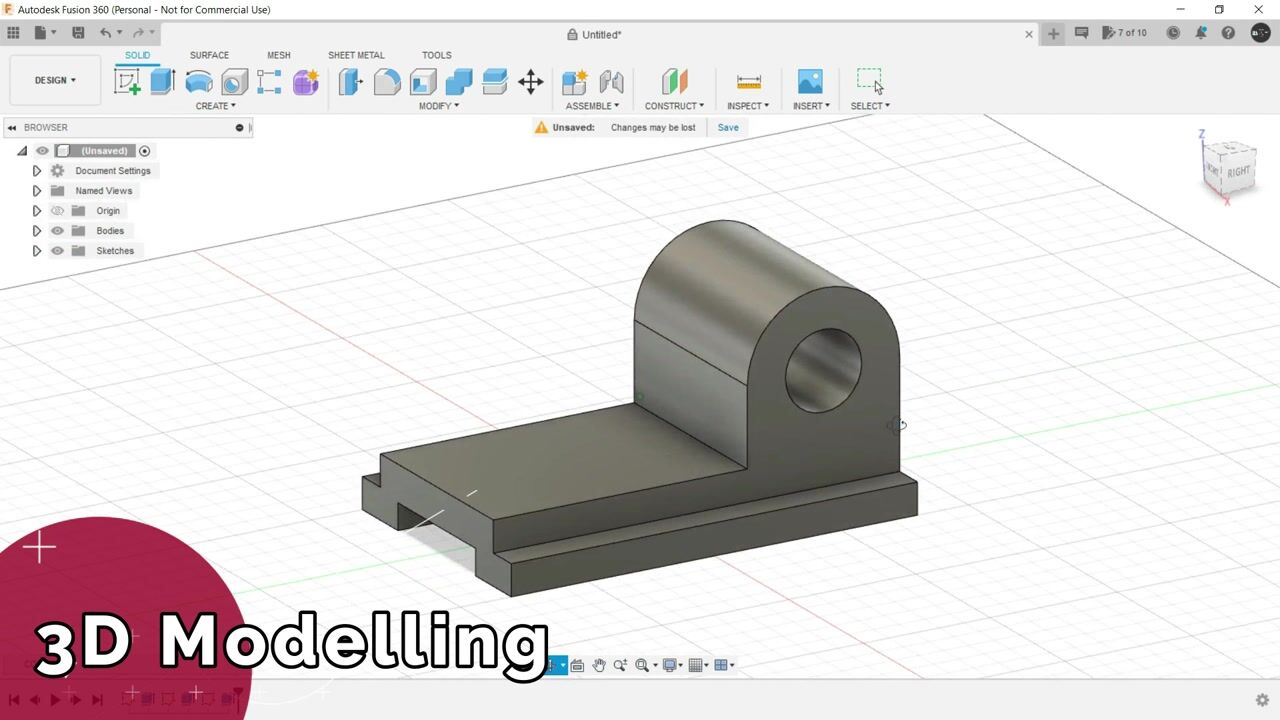
4. 04 Top down design concept: To better understand the assembly making
process in Fusion 360, you should first understand the two common types of
assembly structures, That is bottom up assembly and top down
assembly structure. Let's first take a look
at bottom up assemblies. This is the most traditional
assembly modeling technique. If you are a user of Autodex
inventor, solid works, or any other Cat program, then you must be already
familiar with this one. The essence of the bottom up
assembly technique is that each part or component is
created as an individual file, which we generally
call as part files. And then all of these part
files are inserted into one assembly file where the parts or components are
constrained to each other. With this method,
most programs do not create a direct link
between these parts. If the parts are required
to fit together, then you will have to make
sure that you design them to the appropriate size before inserting them into
the assembly file. If you make a small
change in the part, other part will be affected and you have to make
sure that you go back and update those affected parts accordingly and then reinsert them into actual assembly file. On the other hand, we
have top down assemblies. The top down technique
means you start with an assembly file and build all your parts or components within the context
of the assembly. Parts can be built in place
and can reference each other, making these parts capable of automatically adapting when
you change size or location. Fusion 360 falls into this
top down assembly category. Now to better understand
this top down approach, let's take an example here. As you can see, there are two components which
constitutes assembly. And they are joined
together with a rigid joint over here. Now, these two components, these two parts, they have not been imported
from anywhere. They are made here itself. In this assembly file, there is just one
file, a singular file. This assembly file in which this component and this
component is located. That is the first
thing that makes a top down assembly a new
choice for designers. Now, for the second thing,
we have adaptability. If I change anything in
this particular assembly, in any of the component, the other component will follow. Let's say we are
changing this sketch. We are making the
circle a bit shorter, as you can see the other
component followed and adapted. This adaptability is the
second most important thing in top down assembly structure, which makes fusion 360 a choice for the new
age designers. With this lecture,
you got the idea of the top down design approach of Fusion 360 from the
previous lecture. You got to know about the
frequently used commands in this particular course from
the very next lecture, we're going to start with the assembly making
process of fusion 360, starting with the difference between bodies and components.
5. 05 Bodies Vs Components: Now here in this assembly, there are four basic entities. This Cam, the pin that is
attached with the follower, and the pin that is
attached with the Cam. These four entities are what we call components in feet and 360. These components are what
that makes a assembly. Now to create a component, you have to go to here assemble and you have to create
a new component. Inside every component, we have separate body and
a separate sketch. Each and every component
is independent of each other unless and until
they are a sub assembly. That means if you're
creating assembly by clicking over here and
making a new component, it will make a sub
assembly over here. You have to pay attention that whenever you're creating
an individual component, you need to switch this one on. This is your main head assembly. From there, you can
create a new component. Now, what's the difference
between a body and a component that has
to be understood? For that, let's
start a new design. Let's create a simple
body, a simple box. As soon as I do that, a body is appearing in
the browser itself. We can copy it and
we can paste it. It's like two bodies over here. Next, let's click here in
the head assembly and create a new component This
time also let's create a box in the same plane. Let's select this and copy. Then in order to copy also, you have to select this
one, press copy, paste. These two bodies are actual bodies and these two
entities are components. Now what's the basic difference? These bodies can be a component, but a component cannot
be a part of a body. Basically, what happens when
we are making assembly, we cannot utilize these bodies. When I click on joint, which is the most basic
thing for assembly, the bodies get hidden, but the components are there. You can provide joints
between two components. They can be joined, but the same thing is not
possible with bodies. That's the basic difference. One more thing
from these bodies, you can write, Click, and you can create them
as components as well. But it is highly
recommended that you always create
a component from this assembly or this
assembled tool bar by clicking over here
in the head assembly. In the next lecture, we will start with a very
simple assembly. We will understand
how to create joints, how to create components. Then we will propagate
to something complex like this
Geneva mechanism.
6. 06 How to create joints: Now that we know what are
bodies, what are components, and what is the top down
design approach of fusion 360. Now is the time to understand
how to create joints. The assembly making
process of fusion 360 will be explained very comprehensively in
the coming lectures. But the very first
thing that you need to learn is
to create joints. Now for that, we are having these four
components over here. Now the very first step in any assembly making
process is to ground any one of
these components. To ground any component, you have to just right click, you have to ground it. The reason behind the same is with this grounded component, we can have a
relative positioning for all the joint
making process. Now, there are two
types of joints in Fusion 361 is a simpler joint. The shortcut for the same
is J in the keyboard, and another one
is as Bill joint. The shortcut for the
same is Shift plus J. Let's understand the
simpler joint first. For this, we can go
to this joint over here if it is there in your
case, in your software. Or you can simply go to
assemble and go to Join, or just use the
keyboard shortcut. As soon as we click here, you will see the
grounded component is having a wire
frame like structure, and all the other
components are highlighted. As soon as I howard the mouse
over any of the component, you will see a icon
is being made. This particular icon is what
we call a joint origin. This joint origin specifies that this particular part of the component will go
to another component. Let's select this
particular point, this face of this
particular component. You can also select
this edge and it will automatically
trace to the center. Let's select this. Now,
with logical reasoning, you can tell that this
will go inside of this. If I'm selecting this edge, it's not the inside, it's actually the
outside of the hole. We have to be very vigilant for providing the joint origin. This is the second
joint origin we are going to use for one
particular joint. For this, let's select
this and you will see that the first component will automatically track to here. As soon as the
position is defined, you can provide the motion now. Now in this we are
having lots of options, lots of joints, basically. First is the rigid one. You can animate or you can preview the joint
motion from here. Second is revolute. Here, you can rotate
the joint in any axis. Let's say it's X or Y or jet. You can make it custom and you can select any
of the surface. Let's deselect and
select another one. The joint will behave as per the selection
of the surface, let it be gadexisly. Then we have slider, cylindrical pin, slot,
planar and ball. For this particular joint, we are good with revolute only, let it be now here the rest revolute and slider joints will be explained in basic
assembly section. Cylindrical pin slot and planar joints will be explained in intermediate
assembly section. And lastly, the ball joint will be
explaining advance assembly. We are going to have different
practice exercises or multiple practice exercises for each and every joints
in the coming lectures. Now as soon as you
are satisfied with the position and
motion of the joint, you can click on Okay. Then you can see this icon is
being made over the joint. We will have different
type of icons for different kind of joints
that you will get to know gradually as you
move on or progress in the course for revolute this flag like icon
is being made. When we double
click on this icon, we can change the orientation. Let's say I'm just rotating
it by 180 degrees. Click on, Then if you want it to revert back to
the original position, you can always click
on Revert position. Or here it will be reverted back to the
original position. But if you rotation
that we have provided, let's provide a 90 degree
rotation this time. Now if you want the rotation
that you have provided or the new orientation
that you have provided to be the default
orientation moving forward. Then click on Enter and you can click on
Capture Position. Now let's say I'm again
making any changes, I'm reverting the position. It will revert back to
the new capture position. This is the beauty
of Vision 360. Moving forward, we need this particular pin to
go inside this hole. Now for this, we
can again invoke the joint command and we can
provide the joint origin as the center of this pin for providing joint origin to this base component
which is a grounded one. We are not finding any
prominent point to snap or basically
a prominent point to provide the second joint
origin for the joint. For what we can
do, we can select this inside area of the hole. You can see the center of this particular component is highlighted where
we can fit the pin. But we cannot go over there
just by howering the mouse. What we can do, we can
select the inner portion, just by howering the
mouse over there. And you can press and hold control or command in
case of Mac users. And then you can just howard the mouse to that
point and left click, let the motion be rigid
only and click on. Okay, this was all about
the simpler joint. Now is the time to
create a As built joint. Now for as build joint, you need to have one component made over another component and it is already
fixated at a point. That means position
is already defined. You have to provide motion only. In these two cases, position was not defined, this sin was outside
this component, this number one component
was also outside. And then we have
provided the position. But in case of aspljoint, position has to be
defined earlier. That means, let's say we have created this
second component over this first
component for Aspljoint. Go to Assemble,
click on Apljoint, or you can use the keyboard
shortcut ship plus J. Then you have to simply select
the component anywhere. Let's select this component and then select this component. Then you have to
provide the joint type. It can be site revolute
cylindrical slider, all the joint types
will be available, just like the simpler joint. And then you have to snap
to one particular point. Let's snap to this point inside. It will also have
the same effect or the same outcome
as the simpler joint. But in my opinion, using this joint
simpler joint is more effective because with as Bill joint we are not
providing any position. We are just providing motion. It takes away the essence
of assembly making process. That's why I have used
lesser build joints. In this course itself, I have used the simpler
joint only because this is more down to earth and practical approach
of assembly making. But you don't have to worry. I have covered a
lecture dedicated to build joint with a men
follower mechanism. You can also replicate all the assemblies
that I'm making with build joint if you're comfortable with it.
Thank you so much.
7. 07 A very simple assembly: Now let's understand
how assembly works in Fusion 360 by making this
very simple assembly. As you can see here, it's a
circular plate having a pin attached in the center and a pin attached
here with the handle. The objective here is to rotate this circular plate when
we drag this handle, whenever we are
making any assembly, you need to define
the objective, how the assembly should work. This should be your
primary focus. Prior to making
the assembly here, we have to rotate the circular plate by
dragging this handle. This is the primary focus here. What we will do,
we will recreate this assembly when we
are recreating this. When we are creating anything
in this assembly section, we are not using
proper dimensions. It's not two dimensions. Let's create a new design. Now here we have
three components. One is the circular
plate with a pin over here somewhere and a
circular hole in between. To make it more comprehensible, let's hide the other
two components. This is component number one. Let's make it first go to
Assemble New component. Click, Okay. As you can see, a new component
is added to the browser. Create a sketch. Select a
vertical plane, circle command. Make any dimension because
it's not two dimension. Make a circular hole over here and drag this area for pin. Finish the sketch. Let's
press, pull it backwards. Let's make it minus five. Switch on the sketch. This, we forgot to press, pull this one. Okay, let's make it two side so that we can
press from here as well. For providing the handle, our first component is ready.
Let's hide the sketch. Double click here and write
it as a circular plate. Now for the next component,
let's push them on. For the next component, we need to have a pin over here in the center of
the circular plate. What we will do, we will again
invoke the head assembly. We are not invoking it. If we are having this component activate and we are creating a new component, then it will become a
subcomponent of this component, which is not desirable. For now, let's activate this one and create a new
component this time. Select this phase, this
is very much visible. Create a sketch, make a
circle from this end, select it, Press pool, let it be two sides. So that we can cross over
here to somewhat like this. The most important part is
this operation would be obviously a new body and a new component
has been created. Switch on the head
assembly and you can see, let's name it Pin. Now for the last part, we need to create this
handle over there. This would be the last
component for that. Again, just check if
this is activate or not. Go to assemble tool bar, create, new component. Create. Okay, select this face of the pin that we have extruded
from the circular plate. Create a sketch. Let's
create a circle. The fit point is fine. Invoke the line command. We're almost done. Just stream the unwanted areas
just for consistency. Make them and finish the sketch. Now select this reason that
we have created right now, press pull it backwards. I think this much
would be sufficient. Operation is obviously
new body click. Okay, Now this is a handle. You need to provide specific names for each
and every component because what will happen
if you're having like ten to 20 components
in your assembly? You will not be able to understand which
component is which one. That's you have to make a habit of providing Nomcalsa,
providing name to them. Now, everything
has been prepared. All the three components, they are individual
and when we drag them, they can be go out like this. Now, if you
accidentally did this, you want to revert it to
the original position, Just click here In the revert, it will be reverted back. Now comes the fun part. Now we are going to
provide joints to them. Now, joints are that lets components to have relative motion
between each other. For that, we can go to
assemble and joint, or you can use the shortcut
key Jin, the keyboard. Just click here, this one again, and make the motion
revolute. Click. Okay. Now as you can see, the motion has been provided. But these two components
are attached together, but they are moving
here and there. What we need in such kind of situation is that we have
to ground something. Let's ground this one. Now we can have a
relative motion between the circular plate and the
pin that is in the center. But as you can see, this grip, this handle, is not
attached to this one. This spin, we have to do that. Let's revert the position again. Click J, start the joint, select this one,
select this one, and make the motion as rigid. Click Okay. Now as you can see, we have the desired rotation or basically our primary
focus has been attained with this very simple
demonstrative assembly. I hope you got the
idea of the steps involved in the assembly
making process of future 360. By considering this
lecture as a milestone, we can propagate
further to create basic assemblies like
Universal Joint Garden, Joint knuckle joint and
Geneva will mechanism. Then we will propagate further to create some
intermediate assemblies with some intermediate
joints like cylindrical planner
and pin slot. Finally, in the
advanced assembly, we will understand about some advanced techniques in the assembly making
process of fusion 360.
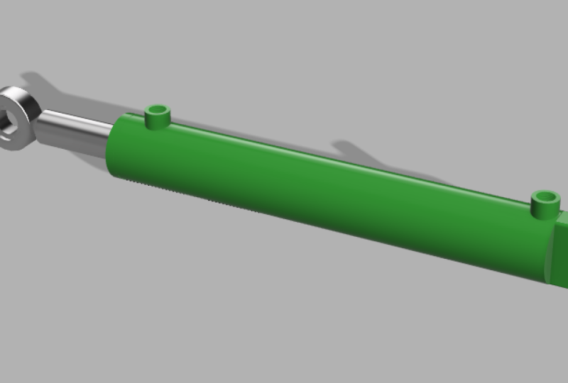
8. 08 Universal Joint: Now, the very first assembly
that we are going to create is of universal joint. A universal joint is a joint, or coupling
connecting rigid rods whose axes are inclined
to each other. And is commonly used in shafts that transmit
rotary motion. It consists of pair of
hinges that we call. They are oriented at
90 degrees to each other and they're connected by a cross shaft that we are
calling center block. Here, I have made this assembly beforehand
for reference in order to have a better
understanding of how each and every components
are connected to each other. Now let's start
with the assembly. Just click on New Design. Let's save it Control. Let's name it Universal
Joint Exercise. As you can see in
the browser itself, the untitled status is changed to the name
of the file itself. We are calling us
a head assembly. This one is the head assembly. Now the first component
that we are going to create is this. F. I have hidden all the other
components because we are going to create each and
every component one by one. First we're going to create this particular
component, the folk. For this, go to
assemble Toolbar. Always go to Assemble
Toolbar when you're trying to create
a new component. Let's name it Folk, invoke rectangle command. The keyboard shortcut is R and select any of the vertical
plane. Let's select this one. As you can see, as soon as we have invoked the
rectangle command, we're having a sketch palette
over here in which we are having option to change the type of rectangle
we are going to make. Let's select center
rectangle from here, then provide any dimension because all the assemblies
that we are going to create in this course are not
two dimension because my aim is to make
you familiarize with the assembly making
process in Fusion 360. You can incorporate
dimensions as per as your requirement or as per as
your client's requirements. I will let you know wever
some crucial dimensions are required as per move
forward in the course. Let's select any dimension. For now, click on
Finish the sketch, select the cason, press pull, then select this
particular phase. Invoke the circle
command by pressing C in the keyboard and create
a concentric circle. Again, let it be
of any dimension. Press pull this one
outwards and click on. Okay, we're done with this particular section of
this particular component. Now we will be
creating this profile. For this, we will select
this particular phase, invoke the circle command, trace the origin,
make a bigger circle, then inside a smaller circle whose dimension we are
going to remember. Let it be like 15, better make it 18. Invoke the line command by
pressing L in the keyboard. Select this particular
point and select a point in which
tangency constrant is being made, as
you can see here. Similarly here, if by mistake you have lost
the tangency constraint, you can always get it from here. Select the line.
Select the circ, let's trim some unwanted areas. Finish the sketch.
Select the reason, press pull it downwards. Now as you can see, we need this particular profile
in the bottom as well. What we will do, we will
invoke the mirror command, select the feature,
select a mirror plane, and click on this. Here creates our first
component, that is folk. Now we have to create another component, focus number two, which is like 90 degrees
inclined with folk number one. Now for this, in order to
propagate to second component, we're going to make a
slight adjustment here. We are going to use the inspect toolbar and
component color cycling toggle the shortcut for the same ship plus N. When we click on here, the color of your
component is changed. As soon as we create
new components, its color will be also changed. Same thing is happening
here as well, because it happens in all
the files in Fusion 360. Now invoke the or, basically activate
the head assembly. Left click and select this
particular component. Control C, control V. Just drag it outwards, rotate it by 180 degrees and
again rotated by 90 degrees. Our second folk is also created. Notice it is having the same
color as the first component because it's a carbon copy
of the first component. As soon as we create
a new component, its color will be changed. That is the beauty
of this particular tool component color cycling to now. Next what we need a
center block for this. Again, just see if the head
assembly is activated or not. And then go to assemble
toolbar new component. Let's name it center block. Select this particular phase and invoke the circle command. The outer circle should touch the outer circle
of the profile. The inner circle is obviously 18 millimeter that
we have chosen. Select this profile,
press pull it and make the extent
type two object. And select this, obviously the operation would
be new body for a new component. Click on Okay. As you can see,
this new component is having a different
coloration. This comes very handy when you're creating a
very huge assembly and you need to maintain order
with separate components. Now, activate this
center block only here. We will create certain sketches. Create a sketch on
this particular plane. Create a circle somewhere
over here of any dimension. But the inside circle should
be of eight millimeter. This we are doing because
we are going to fit a pin in between this at the sketch. Let's hide these two
folks as of now. Now just measure the
distance of this one. This is 60 millimeter. What we will do, we'll
select this profile. Right click, press pull. Let the direction be symmetric, the distance should
be 60 divide by two. Operation should be joined. This created our center block. Or let's activate the
head assembly again. Now what we are going to do, we are going to create
this particular pin. Now for this, again, go to Assemble toolbar,
new component. Let's name it Folk one pin. Click on, okay, select
this particular surface. Invoke the circle command. Select the profile, and again make the extent
type as to object. And select this particular
surface. Click on. Okay, select this, Press pull, let it be like five MM up. And the same thing in
the bottom as well. Five millimeter. Now here, let's create a circle, a bit larger diameter. Select this profile,
right click, press pull again to object. An object would be this one. An operation is joined because it's part of this component, only the folk pin. Now next we are going to
create this particular caller. For that what we will do, we'll again activate
the main component. Main assembly, Head assembly.
Go to new component. Let's name it. Caller, select
this particular surface. Invoke the circle command, let it be of any dimension. Finish the sketch,
press pull it, Trent type again to object operation would be obviously new body and click on. Okay. Now activate the
head assembly again. This time select this
particular phase and create a tangent plane. Now this plane, let's
create a circular hole. Now in order to do that, we need a point to
snap somewhere. What we will do, we will project this
particular area clock. Just create a line from the midpoint of this to
midpoint of this one. Let's convert it into
a construction line. Now from the midpoint of this construction line,
let's create a circle. And let's remember its
dimension as well. It's three millimeter. Finish the sketch,
select this right click, press pull and cut through All notice that we are cutting through
one component and it is cutting through the
second component as well. Because the head
assembly is activated. Now almost all the
components are made. Now the only thing
that is remaining is to create
identical components. This color and this pin. These two components, this color and this folk
pin will go here as well. We have to create a
copy of these two. Just control and
select both of them. Control C control and
just drag it outwards. It has created two
new components. Now the last component
would be a lock, that is, that has to
go between these. For this, we will again go to assemble toolbar, new component. Let's name it Lock. Let's create a sketch
on this plane, only somewhere. Let's say here. As you can remember,
the dimension of lock should be
three millimeter. Now we have to press, pull it outwards to create
a three D model. Now how much to press pull that we have to
inspect from here. That would be dimension
of this color. It is like 26.8 double
three millimeter, we will be excluding it. 26.8 double three.
Click on. Okay. Now we need one more lock. We will again activate
the head assembly. Left click on lock control C, control V, and one
more lock is created. Now we are officially done
with all the components. Let's drag them outwards. And see we have 22 colors, one center block,
two pins for folk, and two lock pins. Now it's time to
create the assembly. All the components are here. Now we have to provide joints. Now, in order to do that first, let's revert the position
by clicking here. Now, in every assembly, we need to ground one particular component on the basis of which
all the other joints, all the other components
will be clubbed together. Here, we will be grounding
the center block. That means all the
other components are free to move as of now, but this center
block will not move. Let's track all the components
out and let's start providing joints for joint. Again, we have to go here or we can use the
kibo shortcut J. Select this particular phase and select this
particular phase. This joint should have
motion of revolute. For the next one, again, click J on the keyboard, Select this particular phase and select this
particular phase. You have to be very vigilant when you are
creating the joints. You need to understand which particular phase or which particular portion of
the component should go. Where. Here also the motion
is revolute and click on. Okay, next is
providing these pins. Just select this
particular phase. And this particular phase, it should not be a revolute, it should be a rigid one. Click on. Okay, let's
see if this is rotating. Yeah, it's rotating. Now, attach a color to this pin. Click on joint, select
this particular edge, basically this particular edge, similarly here also. And then just attach
these lock pins, select this particular edge and select this particular edge. Similarly here, also select this and select this. Now our assembly
is fully complete, but as you can see, when we are rotating, it is overlapping
with other component. Same thing is happening
here as well. What we need is limits. We can provide limits to
all these joints by going to browser and selecting
the respective joints. Let's select this
particular joint. Right click and
addit joint limits. Let's select the right phase so that we can clearly
see what is happening. Or better select the top phase. Now for universal joints, the ideal limit is between
-32 to 30 degrees. We will be using that initially. Provide the rest position, that is at zero
degree as of now. Then provide the minimum
S -32 maximum 30. Just animate it and see Perfect. Click on Okay. Same thing we have to provide with
this particular joint. Let's go to the right view. Rest is at zero, minimum -32 maximum 30 degrees, and click on, Okay,
Hide the joint. And our assembly is
officially complete. The color that you're
seeing here is because of this component
colored cycling togger. You can switch it off as
soon as your assembly is completed and you will see this gray coloration
in all the components. Then you can go to the render
work space and provide the rendering of your
choice, just like here.
9. 09 Knuckle Joint: The next assembly
that we are going to create is of a knuckle joint. A knuckle joint is a form
of pin joint that's used to transmit tension loads while allowing rotation in
one of the plane. There are many applications
of this particular joint, like link of roller chain, bicycle chain chain
types of watches, connecting rods between
locomotive wheels. All mechanism of a
reciprocating engine, Windchill wipers of a car, and the list goes on and on. In this assembly, we are
having four major components, the Eye and Ok and
knuckle pin and color. One minor component
that is taper pin. Here also, we will follow the same procedure of concentrating on one
component at a time. First, we are going to
make this component, let's hide all the other ones. Now in this component, we are having one
particular profile perpendicular to another. Let's create this one by
creating a new design. Go to assemble toolbar and
create a new component. Let's name it. I end now. Create a sketch in any
of the vertical planes. Let's create a circle by
invoking the circle command. The shortcut for the same
is seen in the keyboard. Let it be of any dimension. Let's press pull it outwards. Now here as you can see, this particular profile is perpendicular to this
particular profile, and it is joined by a
rectangular extrusion. So what we will do, we
will create a sketch, a face sketch in this
particular plane, which is perpendicular to
this particular sketch, or basically this
particular profile. Let's create a
concentric circle. Let's trace the origin. Let's place it somewhere here. Now for the inner circle, you have to remember
the dimension. Let it be like 25 men. Finish the sketch, select the
profile that is generated. Press pull, Direction
should be symmetric. Let's extrude it outwards. I think this much is
sufficient and click on. Okay, now we are having this rectangular extrusion from this particular profile to
this particular profile. What we will do, we will select this and create a
sketch over this one. But as you can see,
this second body is hindering our sketch. What we will do will go to the end component and we
will hide the second body. This is the first body. This is the second body. We are going to hide this one. Now we can create a
sketch over this. Let's create a rectangle. A center rectangle,
to be precise. Let's create a square
like structure. Finish the sketch and
show second body as well. Now select this vision,
right click, press, pull, make the extent type to object and select
this surface. And click on Okay, the Outline
of Folk and is completed. Just one detail is required, that is this particular
section of the model. For this, we will select
this particular phase. Invoke the line command
by pressing all in the keyboard. Select this end. Select any point over here. Select any point,
a vertical one. Then press and hold left mouse button so
that we can create arc and just close the region. Now finish the sketch. Select this region and invoke the revolve command
for the axis. Select this and click on this. Particular profile
has been generated, but this is required in all the four corners of
the rectangular extrusion. What we will do well. Creator circular pattern. Then select the feature. Here we are having
types of faces, bodies, features and components. Here we will be
selecting feature because this is a feature
that we have generated here. Then for the axis, we have to select the green axis over here, which is not visible as of. Now what we will do,
we will zoom out. It will be visible. It, yeah, it's good to go. Click on. Okay, our first component, the eye end has been created. Now let's move on to the
second component, the fend. This foc end is like
dependent on the ion itself. We'll be using this
as the reference. But to create any component, you have to activate
the head assembly. Then you have to go to Assemble, Cuba and new component. This time Writers
and click on. Okay. Now select this
particular surface and create center rectangle. Let it be of any dimension, but you have to make
sure that it is larger than the outer circle diameter. Let's finish the sketch. Select this profile. Let's select this one also, right click, press pull, Make the extend
types two object. And select this
surface. Click on okay. Then select this, let's say
let's extend it by ten MM. Here, let's extend this
one also by ten M. Now what we require is this fork looking
structure we have created up to this much only except for the hole that
we will be creating next. For this, what we will do, we'll simply select
this particular phase. Let's start creating
a sketch now. We don't know where
this component is inside of this
particular extrill. Will go to project and select this particular
body completely. Click on okay, the body has been projected to
the sketch itself. Now we are having a clear idea from where to make the cut. Now invoke rectangle
command again. This time two point rectangle. And select this point by tracing from the
projected sketch. Finish the sketch. Select
all these profiles by pressing control, right click, press
pull all the way down. But as you can see, this is also cutting our
previous end component, which is not desirable. What we will do in
this extrude pet, we are having
objects to cut here. De select the end and click on. Okay. Now again, select this phase, Invoke the line command, Select this particular end, hold this left mouse button, and select other end. Similarly from here, hold the left mouse button
and select this hand. Notice the region is not closed, so we have to close
the region as well and then finish the sketch. Now select this profile, press pull again,
extend type two object, and select this
particular phase. Then is almost created except for a hole over here and
this particular profile. Now we will create a hole
in this particular phase. Again, project this body. Clickon, Okay, invoke
the circle command and create a circle of 25 MM. Select this, press pull,
let's create a hole. Now for this particular profile, we need to create
a plane over here. Let's create a tangent plane. Let's start sketching
on this one. Now here we need to find the center point of this
particular profile. For this, we will again use
the project include command. This time in the
selection features, select a specified entity, all these four edges. Now invoke line command, find the center of this one
and center of this one. The midpoint is denoted
by this triangular icon. Now let's create this
as a construction line because this is not a part
of this particular assembly. Then create a circle in the midpoint of this
construction line. Let it be again of any
dimension. Finish the sketch. Select this circular profile,
press pull outwards. And select this phase, create one more circle, a bit smaller, one. Finish the sketch, select this
one, press pull outwards. Now, in this particular phase, let's create a rectangle. Let's trace the origin. Select the whole region of the rectangle that
has been created. And press pull it like this. Now we need like four
of the insertions. What we will do, we will
invoke the circular pattern, Select the feature, this one. And select the axis. Now again, the axis would be this green one number of object would be obviously
four and click on. Okay, and is also created. Next, we need a pin in
between a knuckle pin. For this, we will again
activate the head assembly. Go to Assemble Toolbar,
New Component. Let's name it, knuckle, Spin, and select this phase. Invoke the circle command
and create a 25 MM circle. Select this, press ext type
two object, and select this. Click on, okay,
select this phase, press pull, let it be
like ten MM outwards. And same thing in
the other side. Next we will create a color. The next component for this, select the extruded
pin over here, and invoke the cycle command. You select this region again
to object and select this, and click on, okay, obviously the operation
would be new body. Now activate the head assembly, and this time select the color component and
construct a tangent plane. Now on this plane, let's create a circle of let's say four MM. Finish the sketch, select
the profile press, pull it, and let's create a hole
through both the components, that is the pin and the color. As you can see. Now the last thing that is
required is a paper for this. We know this one.
This particular hole is of four MM of diameter. Now we have to see what is
the diameter of the color. It's like 37.5 do
seven millimeter. You can always
check anything from this inspect tool bar,
the measure tool. Basically the shortcut for
the same is in the keyboard. Now create a new component. Let's name it taper. Create the sketch on this plane. Let's say invoke
the circle command. Yeah, it was four. Mm, finish the sketch,
select this one, pull it like 37 somewhat, but provide it a bit of taper. Let it be like minus
three degrees, it would be very less, let it be two, or
let it be one only. Now, all the components of knuckle joint
has been created. The end, we have the fork, we have a knuckle pin
color and a taper pin. You can always revert to the original position
by clicking here, But as of now, let's move
them out here and there. Now in assembly,
as I told earlier, we need to ground at least one
component in order to have a relative motion or relative movement between
other components. We are going to ground the and
click on Capture position. Now the first joint that
we are going to create is between the I and the foc end. Just click here or go to
Assemble and click here. Or you can use the shortcut
key J in the keyboard. Select this particular end and select this particular end. The motion would be
obviously a revolute one click on. Okay. Next we have a pin that has to be inserted between
the hole over here. For this click on joint ended, the motion would be Sid. But here we have to get this
particular pin outwards, like ten MM outwards because this much that we
have extruded earlier. Now next we have
to provide color. Go to joint, select this face, and select this phase,
and click on, Okay. Lastly we have to attach
this taper pin for this. Again, go to joint, select this end, select this end. As you can see, it is
protruding outwards, which is not desirable. So what we can do, we can flip this component over
the joint origin. This is flipping over the
joint origin and click. Okay. Now our knuckle
joint is complete, but as you can see, when
we rotate this joint, it's rotating like 360 degrees. It is overlapping with the fo can component which
is not desirable. What we will do, we
will go to joints, select the revolute
that we have provided, right click and
added joint limits. In this case, let's make
zero degree as the rest. For minimum we'll provide -32
or basically -30 degrees. For maximum, let's
provide 30 degrees. Just animate it and see. Yeah, it looks good.
And click on Ok. Finally, our knuckle joint
is officially completed.
10. 10 Carden Joint: Now next we are going to
create this Cardon joint, which is like a modification
of universal joint. Now for this we have
certain components. We will be starting
with this yoke one. Let's hide all the
other components. Let's focus on this
yoke component. Let's create a new
component named yoke. Now we need to create this
sketch profile for this, Let's start with a rectangle. A center rectangle,
to be precise. Start from the origin, let
it be of any dimension. Then click on the keyboard
to invoke the upset command. Select this rectangle, upset
it inwards. Click Enter. Invoke the line command. Select this point, select
the outer rectangle, same thing here, and presenter. Now let's trim these two lines. Let's get rid of these
construction lines as well, and finish the sketch. Now, select this
region, press Pull, let it be asymmetric, Let it be five MM only. Again, dimensions
are not the concern. You can provide any
dimension of your liking. Or if you are having any
specific dimensions, you can provide it here. Now, we need this
particular profile for the select this phase, Create a concentric circle, basically a pair
of circles we are creating and finish the sketch. Select this region in between, right click, press
pull, and creator cut. Now as you can see,
the sketch is gone. So we can again show it by
clicking in the browser, in the corresponding component, and in the sketch, this
is sketch number two. Select it. Now select all the
outer regions. Right click, press pull. Then select any of the surface, and let the operation be
joined. Click on, okay. Now hide the sketch. As of now, this particular profile
has been created. Now we need this profile in the top as well as
bottom of the yoke. For this, we are not going
to create any sketch. We are going to invoke the
primate entity, a cylinder. Just select the surface, you can see the origin
is visible over here. Just trace it, unless you're
getting a midpoint symbol, as you can see here in
this particular edge. Then create a cylinder
on this time. Select this surface and
make the operation Us Join. Click on okay again, right click Repeat Cylinder. Select this face and
find the center point of the previously
created cylinder and create another cylinder. Now we need this profile
in the bottom as well. What we will do, we will invoke the mirror command for the
type we are selecting feature. For this, you can simply
left click in the time line. This one also select the mirror
plane and it is created. Our first component is ready If we switch on
the complete assembly, the pre made assembly over here, you can see this component
has a identical twin. What we will do, we will
invoke the head assembly. Let's save it so that the head
assembly can have a name. Let's name it card. Now here as you can see, the head assembly is activated. We can left click
on the component, Just control C and control. And if we can paste
another component, identical twin, let's drag it outwards just to a
sufficient distance. Now both of our are created. Now we need the center blocks. Let's hide other components and just see how the
center block is looking. Create a new component. Let's name it
center block again. Invoke cylinder command, Just hower the mouse
by selecting surface. Just hower the mouse and
find the center point. And create the cylinder up
to this particular distance. And click on. Okay. Now in the center block, we need this cut by
creating a sketch. We can do it easily, but there is another way
as well what we can do. We can invoke the head assembly. Click on combined from
the modified toolbar, Select this component,
select this component, and let the operation be cut. And do not forget
to keep the tools. Now when we drag this outward, you can see this
profile is generated, just revert the position. Now as you can see this
complete assembly, you will notice that
the center block also has a identical twin. What we will do, we will again left click in
the center block. Just copy paste, Let's drag it outwards to
a sufficient distance. Now in the center block, we are having a hole
for fitting this spin. What we can do, we can select the surface and
construct a tangent plane. Click on okay, select
the plane great circle. As you can notice that we
cannot find a center point anywhere we can
project this body. Now from the midpoint
of the top edge and the midpoint of this
bottom match of the projected sketch,
let's create a line. Let's make it construction. Now, from the midpoint of this newly constructed
construction line, we can create a hole, let it be a 15 MM. This dimension may
differ in your case, because it depends upon how much larger you are making your. Or you can have a
specific dimensions depending upon your necessity. Let's finish the
sketch like this. But the idea over here is to remember this
dimension whatsoever, dimension you're taking
to create this hole. You need to remember that
dimension because we are going to create a pin
based on that dimension, as I told earlier in the very
beginning of the course. Also that you have to take
care of certain dimensions, those are interrelated with
certain other components. These dimensions are
provided by you only. It's not like there is some sketch on the basis of which we are
making the assembly. There is no such sketches, there is no such drawings. We are just making the
assemblies out of the air. If you are having dimensions, you can make it easily. But the idea behind
this course is to make you familiarize with
the assembly making process. In my opinion, you should not be dependent upon
dimensions earlier. Because if you get the
flow of making assemblies, you will easily make any assembly without the
need of any dimensions. But in standardized point of view, dimensions are necessary. They are very much required. But before adding
dimensions to the assembly, you must know how to assemble. You must get the feel
of making assemblies. That's the basic idea
behind the course. Getting back to this one, we have created the center
block, both of them. Now we need a pin for that. Let's create a new component. Let's name it pin. Let's create a circle on this
particular plane anywhere. But here, dimension would be 15. It can be different
in your case. Finish the sketch,
select this region, press pool, make it symmetric, and just drag it outwards. And click okay. Now on this face, create a
circle of any dimension. Select this, press pull
inwards, and click on, Okay. Now create a mirror, select this feature, select
the mirror plane as this one. And click on Ok. Now, as you can see in
this premade assembly, we need this particular profile somewhere over here as well. They both are like joining, it's a single component, but having multiple bodies. What we can do, We can go
to this pin component, we can go to the body and we can control and
paste another body. Let's have a sufficient
distance. Click on Okay. Now on this body as create
a two point rectangle. As you can see, the center
of this one is highlighted, but center of this one
is not what we can do. Again, project, press
in the keyboard. Let's select this Sketch
Entity and click on Ok. Now, when we invoke the
rectangle command, you can see, or even in fact
any command you can see. The circle, center
of the circle here. From this center to this center. Let's create a two point rectangular and
finish the sketch. Now, from this profile, this sion, just press, pull it up to this
particular surface. Obviously the operation would
be joined only click on. Okay, Now we need the same
thing in the other side. Just select this feature, select the mirror plane as
this one, and click on. Okay. Now as you can notice, this is a single component. That's why we have copied and pisted this particular
body over here. Now almost all the
components are ready. Just these two shafts
are required for this. What we can do, we can go to assemble again new component. Let's name it shaft. Create a cylinder
from this surface. This is the center, just
extrude it outwards. I think this much is
sufficient. Click on, okay. Now invoke the head
assembly, Select this shaft. Just paste it and move it to sufficient
distance. And click on, okay. Now all the components
are created. Now the only thing
that is left is to create the assembly for this. Let's ground something. Let's ground the shaft. Let's drag all the
components here and there. Let's start providing joints. The first joint that we
are going to provide is between yoke number
one and the shaft. The motion is obviously
revolute about jet axis. You can change the revolution
just to see how it does, but initially the revolution, the axis of rotation is perfect. Click on. Okay. Now for the next joint, select the center block. This is small detail
that we have created. The small cut, this
part of the yoke. Again, the motion would be
revolut only about dex. Next right click,
repeat the joint. You can also use short
cut J in the keyboard. Select this particular point, you need to select
this middle point over the center block. For that you have to press on control and just drag
the mouse over there. The joint is created. Now we need to attach a
center block here as well. For this, again, joint control. And select the center
of this one and center of this one perfect. Now as for this yoke
and this center block, let's select this bottom
one and select here. Okay, just double click on the joint that
we have created. The revolute one and just
revolve it by 180 degrees. Perfect and capture
the position. By capturing the position,
what we are doing, we are basically telling the software that we
want this configuration. As of now we can. Let's say I'm rotating
this shaft here and there, and I'm capturing
the position again. I'm moving the shaft anywhere, or moving anything anywhere. When I am clicking
on Revert position, it will be reverted to
the captured position. This is the beauty
of Fusion 360. Now the last joint would be between this shaft
and this yoke. This would be also revolute. Now, before finalizing
this assembly, we need a slight modification. Just press M in the
keyboard to move this pin. Let's move it by 22.5 degrees. This is the standard
for a cardon joint. Again, use move command
select the yoke, this. Ok? Let's move it, okay, this one and move
it also by 22.5 degrees. This is the standard orientation
for any cardon joint. That's why we have done this. Finally, let's
ground shaft number two as well and
capture the portion. Let's hide the joints. Just animate the model
by selecting any of the joints perfect. So our carbon joint
is also complete.
11. 12 Geneva Wheel Mechanism: Now as promised, let's create this Geneva Mechanism
from scratch. Now, what is this
Geneva Mechanism? Geneva Mechanism is the most
commonly used mechanism for producing intermittent
rotary motion. It is characterized by
alternate period of motion and rest with no
reversal in direction. It is also used for indexing, like rotating a shaft
through a prescribed angle. Other applications
of Geneva Drive includes automatic
sampling devices, banknote counting machines,
indexable equipments like tool changers in CNC
machines, and many more. Let's create this
particular assembly. Now here, as you can see
in the browser itself, we are having four
different components. First is the follower, which is a driven component. Then we have a Cam, which is driving
the whole assembly. It's a driving component, a pin, which is attached
to the follower and which is
attached to the can. Basically, we can say we have two basic components,
follower and Can. We will start with the follower. For that, let's
create a new design. As I told earlier,
always start with a new component from
the assemble toolbar. Let's give the name Follower. Now here let's hide all
the other components. The follower be visible
as you can see here, this component is clearly having circle as the measure sketch
entity out of the circle. All the shapes have been
carved out and the component, the follower is made. What we will do will create a sketch on
the horizontal plane. Invoke the circle command. This assembly is not
two dimensional. You don't have to worry about providing dimensions
here and there. Just go with the flow.
Let's create a line. Let's pray the origin from here. Let's make it coincide
with the origin itself. Let's make another
line over here. Let's say at angle
of 54 degrees. Invoke the mirror command. Select this line. Select the mirror line. Click. Okay, let's convert these
to us construction line. Let's get another
circle somewhere over here and make it tangent
to this and this one. Let's convert this to
construction as well. Now again, make a circle
from the center point of the construction
circle that we have created and give any dimension. Now create a slot center to center slot on this line
till this in section point, let it be of any width. Now what we are
planning to do here, we are trying to recreate this particular section of
the component, this one. That's why a slot
has been created. Now create a circular pattern. Double click on the slot to select all the four
objects of the slot. Select the center point, give quantities of five, y five, because we are having
five symmetrical, or basically similar
sections in this component. Now what we will
do, we will try to recreate this particular
section of the component. Now for that, let's trim, let's remove this one, also better create it as a
construction line only. Again, invoke the
circular pattern. This time, select
this particular arc, select the centerpoint, and provide five
first the quantity. Now all that is left to create this component is to
trim the unwanted areas. We are going to fast forward
this particular section. Since everything is trimmed, finish the sketch and
take the reference from this premed assembly of how
much we have to extrude. We have to extrude
to five millimeter. We're taking reference of how much press pull command
we have to use, up to how much we have to extrude a two D sketch
to a three D model. That's the only reference we are taking with this premed model. Let's select this one, Press pull five
millimeter upwards. Our first component, the
follower is completed. Now for the next one that is the can activate the head
assembly, new component. Let's name it Can. Now for this, what we will do, we will make the sketch of the previous
component visible. Let's create a sketch
on this plane itself, from the previous component. If you can see the circle, the construction circle,
we can project it. This we have discussed earlier
in one of the sketches. This one, click on, okay. It's been projected to the sketch that we are
creating right now. Now, again, create
a circle from here. Try to make it
coincide with the arc. Or here, make one more circle and a small circle over here. Right now what we
are trying to do, let's hide the follower for now. We're trying to recreate this particular
component, the Cam one. For that we are
creating this profile. Let's create one more
circle over here, just trace the origin. This circle corresponds to this particular pin which
is made on the Cam itself. And what this pin
is going to do, as you can see, this is having contact with the
follower and it is rotating it. This is important
in this assembly. It should not be
more than this gap. Let's check the gap once
between these two points. It's 6.221 We cannot make
it more than this one. Invoke the circle command. Just stress the origin. Let's make it five, only now we have to create this particular
section of the cam. For that, what we can do, we can create a line anywhere
from, let's say here, trace the origin, this one. Let's make it tangent
to the circle. This one also. Then let's
make it original vertical. Click on modify,
provide, fill it. I think this much
will be sufficient. Present we are almost
set for the cam, but here we have to generate this particular
profile for that. What we need is a
three point arc. Let's say somewhere
over here to here. Just stream the unwanted areas. We're almost good to go. Just finish the sketch.
Select all this, I just switch out the
follower for now. Right click and we are
to extrude it downwards. By how much? Let's
check it from here. Three millimeter. Remember, you have to provide a space for the pin of the can, that's why this is
blank. Right click. Pull it down by minus three. As you can see, sketch is gone. Let's make it visible again. Now, again, select this one. Select this one. Also, extrude it upwards. Okay. We have to take
the dimension here. Right now, what we're creating, we're creating this profile, this theory profile and this. Let's, let's measure it. It's like ten millimeter above. Let's select this right click, press, pull ten millimeter. Let's hide the sketch. And
switch on the follower. Go to head assembly, and you can see two
components are made. Let's hide the sketches for now. These two components are independent of each
other as of now. But we will provide joints and we will provide
attachment to them. Now, in any case, even if you are dragging
the component here and there and they are in
very different positions, you can always revert them back. Now the only thing that is remaining is the pin for the follower and
the pin for Cam itself. For the follower, we need to
create a hole over this one, let it be of any dimension. Right click, press
pull downwards. Now we will create
a fresh component to give a pin to the follower. Let's name it pin for follower. Select this face circle,
select this one. Press pull it downwards to
let's say 25 millimeter. Obviously the operation would
be a new body. Click on. Okay, again, activate
the head assembly. We are having now
three components. Now the only thing that is remaining is the
pin for the can. For that, again, let's
create a new component, Rename it Pin can, click on Ok. Select this phase
circle command. Press pull downwards and up to where let's make the
extent type two object. And select this one. The pain of the follower, it will be extruded to
that particular distance. Switch on the head assembly. Now we are having all
the components in place. Now comes the time for
visualization to understand how each and every component is interacting in the assembly. For that, let's go to this one, this premed assembly,
as you can see. This is driving the follower. But these two pins are
fixed. They are not moving. This follower is rotating
on the pin of the follower. This cam is rotating
on the pin of the cam. We are having a relative motion between them as I told earlier. Also, we need to
ground certain things. When you try to understand
this particular mechanism, you will come to know
that these two pins, they are both grounded. They are both fixed.
What we will do, we will right click on
the pin of the follower. We will ground it, right
click on the pin of the cam. We grounded. Now these
two are grounded. That means I can
freely move these two. The follower in the cam, but I cannot move these two. Let's reverse the position now. The follower and the
pin of the follower, they are having a
revolute motion. Similarly, the Cam at
the pin of the cam, they are also having
a revolute motion. Altogether, the assembly is having a relative
revolute motion. What we will do, we
will go to joint. The short cut of the
same is J, the keyboard. Select this face and select
this point for the pin, and give the motion as revolute. Similarly for the Cam, again, motion is revolute only. Now, as you can see, the pin that is
supposed to revolve, the follower is like protruding
out of the follower. This is not desirable,
so what we will do, we will adjust it somehow so
that it's not touching it. Let's check if any overlapping is there apart from this pin. I think there is none. Just adjust the pin
in between over here. Now you have to
capture the position. That means if I am
rotating it anywhere, when we revert it back, it will revert to the
captured position that we have did right now. I think we are good to go.
Now provide context to all the surfaces and our
assembly is complete. Now let's animate the
model in order to see if any mistake is
there in the assembly. Just go to joints,
select any of the joint, and animate the model. As you can see, there
might be chances that some overlapping of
surfaces is taking place. What we will do,
we will press pull this just a little bit,
just like over here. And now animate the model. And our assembly is
officially completed. Let's hide the joints. Let's provide rendering to it. And our Geneva mechanism is fully complete.
Thank you so much.
12. 13 4 Bar Linkage Mechanism: Next we are going to create this four bar linkage assembly. It is the simplest movable
closed chain linkage. It consists of four bodies
that are called bar or links, connected in loop
by four joints. It is used in many
different devices like locking players, bicycles, oil well pumps, loaders, internal combustion engines, compressors and pentographsow. Here these bar or links have separate names
as well designated names. This small linkage that
you're seeing here, it is called the Input link. The bigger link
that you are seeing here or the bar that
you're seeing here, this one is called Output link. The one which is grounded or
fixed is the fixed frame. The one which is joining the input and output
link is called coupler. Rest Four components are
simply pins that are provided in order to create revolution in order to
create the assembly. Let's create this one. Let's create a new
design, a new component. Let's name it Fixed Frame. Now here we are going to apply a different approach
because the bar and links are dimensionally
dependent upon each other. We are going to
use dimensions in this particular assembly for
this fixed frame component. Let's create a sketch on any of the vertical plane and just
create center to center slot. Let the distance, the
length of this slot be 100 MM and the thickness ten MM. Click Enter now
finish the sketch. Press pull it, let it be
this side only minus two. We are assuming anything. You can make it more
thicker if you want. Now let's provide name
for this assembly. Let's name it two bar only so that we can have our
head assembly, a name. Now invoke the head assembly
and create a new component. Let's name it Input Link. Now for this, select this particular phase of the previously
created component, the fixed frame, and
create a sketch. Again, invoke the
center to center slot. Select this, select a distance, a length which is
half of this one. We are going to write 50 here, center and for thickness, we are making it uniform. Tanamm need the sketch. Select the profile control. Press control. And
select this profile. Also, right click,
press pull this side. We are making thickness
constant as well, so two MM can click on. Okay. Again, invoke the head assembly. This time also select
the fixed frame. The surface of fixed frame
on create a component, let's name it Output link here also escalator
slot center center one. Again, the distance here, this is the longest link in the assembly Distance here
should be more than this one. Let's make it a 20, let it be 110, only
thickness is ten. Finish the sketch. Select
the profile control, and select this profile as well. Press pool again, two MM. Again, activate
the head assembly. The only thing that is left
is a coupler which is joining the input link and the output link create a new component. Let's name it coupler. You can select this
face of input link, or you can select this space
of output link and create a sketch center center slot from the center of this one
to the center of this one. Notice this is not snapping exactly to the
center of what we need. Our favorite project. Command prep in the keyboard. Select the select. This we're selecting the sketch
entities, not the body here. And click on, okay, we can
find the center point. Now again, go to slot
center, center, slot. Select the center point of the output link and the
center point of input link. Again, width of the slot is
ten. There is the sketch. This try to select
multiple profiles, right click, press,
pull again, two MM. Now our basic components
have been created. Now the only thing that
is remaining is to create these pin like
components, four of them. Basically, because there
are four links for that, we have to manually create holes in all the intersection of
the links. Let's create here. First, let it be five MM. Finish the sketch, select this, just press pull and cut through. Now I'm going to fast forward in order to create all
the other holes. Since all the holes are created, let's create corresponding pins for providing
appropriate joints. Now we need four pins to put in these holes and
then we can provide joints, just like over here. For this, just check
if the main assembly, or the head assembly
is activated or not, Then create a new component. Let's name it Pin. Now from this phase
of the input link, let's create a circle
of diameter five MM, because this is the diameter of the hole that
we have created. Select this region, press
pull up to the fixed frame. Basically, we are covering
the hole completely. Now this particular component is similar to all
the other holes. This pin, what we will do, we will activate
the head assembly. Left click on the pin
control C control, and just drag it outwards. Like this press. Okay, this will automatically snap to this particular hole, but the same would not be the
case for these two holes. For this it can be. If we copy this one, the spin one only and paste it, we can actually move
it to this point. Yes, it's almost snapping. When we are providing
the joints, it will snap perfectly. Now let's select pin number two, control C, control V.
Let's pull it upwards. Basically all the components are created just like this one. This is small details
as you can see here that will be
added afterwards. The assembly is fully complete,
don't worry about that. We will add them also.
Now we need to ground something as the name suggests for this
particular component, fixed frame, we can ground this. Now let's remove the
pins. Just the pins. Let's start the
assembly for this. Click on joint select this
particular phase of the pin. And this phase of the short link motion would
be obviously revolute click. Okay, now here you might
wonder that providing just one revolute joint to
the pin and the linkage, we'll complete the assembly. But that's not the case
because this joint is provided with respect to the shot or basically
the input link. But for the fixed frame there is no corresponding links for
this, what we will do, we will again invoke
the joint command, select the other end of the pin, and we will select
the fixed frame. Again, the motion
is revolved only. Let's repeat the same process
for all the other links. Now, since all the joints, corresponding
joints are created, our assembly is complete, announced the time to
provide these details. For this, what we will do, we will first hide the joints and we will make the
head assembly activated. Now select the larger
or the output link. Let's create a two
point rectangle. Let's chum in and select
some prominent point. Just drag it downwards. Select this press,
pull, this one is done. Now on the coupler here, just start the sketch. Just create a line between this edge and
this edge of the coupler. It should be perpendicular. As you can see, the
perpendicular constraint is shown there. Just convert this line to a construction one because this is not the part of the assembly. Anytime while making
the assembly, if you are losing
focus of your sketch, you can always find
it in the time line. Just right click here
and addit sketch. Now from here, let's create a slot from the center point of the construction line
that we have created. Let's say up to a distance of the center point of this
particular coupler. Let the thickness be three
and finish the sketch. Select this profile.
Right click, press pull, just cut through. These two profiles
have been generated. Now we need to cut this
input link in this fashion. For this, we will
select the input link. We will invoke the sketch. Now we are going to
use a three point arc. Select a point in this edge, then select any prominent
point that you want, and create a arc center. We need the same
sketch over here. We need a mirror
command for this, we need a mirror line For that, let's create a line
from the center. Let's convert this
to construction. Invoke the mirror command. Select this arc and for the mirror line, this
construction line. And click on. Okay, I finish the sketch, select these two profiles by pressing control
in the keyboard. Just shift and middle bows
button to rotate or orbit. Basically, just press this one. Our assembly is
officially completed. Thank you so much.
13. 14 Slider Crank Mechanism: Now the next assembly
that we are going to create is quite a popular one. If you are from mechanical
engineering background, you will definitely
pinpoint its name. It's slider crank mechanism. Now, a slider crank
mechanism is designed in such a way that it converts straight line
motion to rotary motion. Rotary motion to
straight line motion. There are many applications
of this mechanism, like reciprocating
Perms, rotary engines, piston cylinder regiment,
and the list goes on and on. Let's create this
particular assembly. Now for this we are going to
have a different approach. We will create a component
from the assemble tool bar. Let's name it Base. Then just create a box. We have box cylinder, sphere, Taurus coil and pile. These are the pre mat
**** in Fusion 360. You can directly create them. Let's create a box on any
of the horizontal plane, let it be of any dimension. Because all the assemblies
that we're creating in the course, not
two dimension. Now next we have to create
this slider over this base, activate the head assembly, create new component, a slider. Then again select box, select this phase and just create a rectangular
box. Click on. Okay, now again activate
the head assembly. Let's save the file so that our head assembly
can have a name. Let's name it a slider crank. As you can see, the name of
the head assembly is changed. This is done to just
avoid any confusions. Now, as you can see, the head assembly is activated, so both of the
components are visible. You can move them around. Just revert the position, to revert it back to
the original position. Now whenever I'm making any changes on any
of the components, the other component
might also get affected if it is getting
in the way of the sketch. Notice whenever
I'm going to make any changes in one
of the component, the other component will
also get affected only if the sketch and
tities that we are creating overlaps with
the other component. Let's say we are making a
circular hole over this one. Let's select the midpoint of
this edge and just create circular hole of let's say a MM diameter.
Finish the sketch. Let's select the reason cut it through so that we
can put a pin in this one. Notice the changes that we are making in
this component is not making any changes
on this component because the sketch entity is
very far away from this one. But if this sketch entity was somewhere between
this junction, then both of the component could have got this through cut. This we have seen in
previous assemblies as well. Just press on. Okay, now let's switch to the
next component. This is our stroke, but prior to that, let's
create this particular pin. Go to Assemble toolbar,
New component. Let's name it base pin. Select this phase, Invoke
the circle command, let it be a MM. Only finish the sketch. Left click, right click, then select, press pull. Let's extrude it up to object. That means extend type two
object and click on, Okay. Now from this particular phase, right click, press pull, let it be like ten MM
only, and press okay. Now again, activate
the head assembly and see if we have three
components as of now. Now here let's create
this particular stroke. As the name suggests, this component that we are
going to create will define up to how much extent this
slider will slide. Let's create a new component. Let's name it stroke. Now, from this particular phase of the pin that we have created, the base pin, basically, let's create a circular
sketch entity, let it be of any dimension. Then trace this center point up to which you want the stroke. This defines the stroke length. You can change it
to your choice, depending upon the length, to basically the extent up to which you want this
particular slider to slide. Create one more circle. Let's make it a bit smaller as compared to the larger
circle over there. Then join the outer
circles with line command. Just keep in mind that
tangency has to be maintained. Whenever tangency
is not maintained, you can always look into
this tangency constraint. Select the line,
select the circle. Again, here also the
line, select the circle. Now let's stream
some unwanted areas. We are good to go finish the
sketch like this profile, right click, press, pull that. It'd be like five MM in
this side and click, Okay. Our stroke is also created. Next, we need a
small modification on this slider component. What we will do, we will create a pin over this one inbuilt pin. Basically, we're not creating
a separate component, We're creating something that
is inside of the component, which is a part
of the component. Just create it here. Just select this face and invoke the circle command first. Here, what we will
do will create a center line from the center of this edge to
the center of this edge. Let's convert it to center
line from the sketch palette. Now from the center of this one, let's create a circle
of let's say five Fm. Finish the sketch. Now here you have to make a certain
geometrical adjustment. As we know we're having this particular pin
protruding out by ten MM. We will create the pin over here which is
not a component, which is the part of the slide itself more than this ten
millimeter over here. Let's make it like 15
millimeter and click on. Okay. Again, the changes
done in this component doesn't affect any other
component because this was the sketch and
Tity that we have created is not overlapping
with any other component. Now the only thing that
is remaining is to create a connection between this
particular stroke and this pin. Let's create a connector. Select this phase, invoke
the circle command. Let's create a circle, and then create outer circle
that can have any dimension. But for the sake
of proportionity, let's make it similar
to the stroke one. Now here we have to make
a certain adjustment. As we can see, we cannot
pinpoint the center point. The center point is highlighted
with a circular notation, which is visible here. This crosses are there, but it is not 100% show that this will be
the centerpoint. What we will do, we'll go
to create and project. This time we will project this
particular sketch entity. In the selection filter you can see you can project bodies that we have done earlier
in the earlier assemblies, and you can also project
sketch entities of the previous component or the components that is
hiding behind the shadows. Just click on okay here, because we need a sketch entity only, it will be highlighted. Now let's create a circle
bigger than this one. And invoke the line command. And let's join these two. Do not forget to
maintain tendency. You can see this
tendency constraint. Let's click left click, that the tendency is
maintained from here also. Now here the tendency
is not maintained. Just click on
tangent constraint. Select the line,
select the circle, select the line,
select the circle. Now trim some unwanted areas. Let's trim this and this and
this, we are good to go. Just finish the sketch. Select this, select control,
and select this one. Also, right click, press pull. We know it is like five MM more than this
particular point. We can write five here. Our connector is also ready. Now the only thing
that is remaining is to create a pin over here. For this, let's create
a new component. Let's name it common pin. Select this phase, invoke
the circle command. As you can see, the center point is visible with this
circular notation. Let's finish the sketch. Right click press pool, and then extend type two objects like this particle
surface and click on. Okay, finally, all the
components are ready. The only thing that
is remaining is to create joints and
complete the assembly. As of now, we don't have anything rounded so we can
move all the components. There is no joints,
they are free to move. You can revert back to the original position
by clicking this one. Or if you want certain different orientation
of the assembly. Let's say you want all
this over here, and here, and here, and here that you
can see all the components. You can also click on capture
image that if you make any changes and it will be reverted to the captured
image that you have done. But we don't require
that, just controls that. Now let's create the
assembly for this. Let's ground this base. First you have to ground
at least one component. Now click on joint, select this base pin
and select the base. And let the motion be rigid. Again, create joint. You can press J, the keyboard as well. Between this and this pin
itself, the motion revolute. Next, a joint between this
common pin and stroke. Next joint between the common
pin and the connector. Again, motion is revolute. Then between the slider
and this connector. Again, revolute only. Finally, the most
important joint slider. One, the slider select the edge. And notice that here the icon for placing the joint origin
is quite fluctuating. You have to be very
vigilant here. You have to see the orientation. The edge is perpendicular
to the joint origin. That means you are good to go. But if it is not, your
joint will be messed up. Always make it perpendicular
like this, like this. Again, for the base, we have to do the same drill. As you can see, the slider
joint is created gon, okay. Now let's try to rotate this. Yeah, I think we are good to go, but we need a
slight modification because this is going
out of the base. What we will do, we will
just press pull it out. Now our assembly
is fully complete. Just select any of
the joint right click and limit the
model to see the result.
14. 15 C Clamp: So far we have created some six to seven basic
assemblies which involved rigid, revolute and slider joints. The Meserte of the assembly, all the basic assemblies
that we have learned so far revolved around
these three joints. Only now is the
time to understand some intermediate
assemblies that will involve cylindrical pin
slot and planar joints. For this first we are going to cover cylindrical joint using this clamp assembly here. In this particular lecture
we are also going to cover some additional concepts like motion link and contact set. These two concepts, the
motion link and contact set will be covered comprehensively
in advanced assembly. But just for the sake of
understanding cylindrical joint, we are going to use
it here as well. Let's begin. Just start a new design and
create a component. Let's name it Frame. As you can see in the
prevent assembly, we're having a frame. Then we have axle
which is having a cylindrical joint
and which will be rotating on the
basis of the frame. Then we have a stopper, which is stopping
it right over here. For this, for the
frame component, let's start creating a
sketch in a vertical plane. Let's make a center
rectangle of any dimension. Then again, a two
point rectangle. From here to, let's say
somewhere over here. We are basically creating
a frame like structure. Just finish this sketch, select this profile,
right click, press pull, make it
symmetric, this is too much, Let's make it five
F. This is also, let it be ten only, and create the component, this is a frame component. Here, we need a hole
to put the Xl in. Just create a circle
trace the midpoint from over here from this edge
to anywhere over here. Let's have its dimension as a whole number.
Let's make it ten. Finish the sketch and
just cut through it. Now we are going to provide
thread to this one. Notice we are having this
modeled option over here. When we are clicking on
this modeled option, it is actually
generating thread. That means if we are
not switching this on this thread like
structure is being made, but it's not actually a thread, it's just having a
visualization of thread. When we click on Modeled, it creates actual threat. We are taking the
thread profile as ISO metric profile StanMM, and designation as Ampton into 1.5 If you're aware with
the thread nomclature, you will understand
it pretty well. You can change it
from here as well. Let's click on okay, our
first component is ready. Okay, let's give the name
to the head assembly. For that, we have
to save the file. Now, activate the head assembly and create a new component. Let's name it X. From this phase, start
creating a circle. We know the dimension
was like teneM, but if we are seeing over here, it is not snapping anywhere to ten because we have
already created thread. Means the dimension or the dimetrical position of the circle that we have created
earlier has been changed. We will simply provide
ten here. Click on. Okay, finish the sketch. Now you will understand
what I'm saying. This, this blue coloration that is highlighting
this whole circle. That is what we have
created right now. But when we are
selecting the region, this portion is being left out. This is because we have
created thread beforehand. It's not the issue.
Just press on control. This profile, this profile also. Red click, press pool, let it be up to this one. Let's make it two sides. And let's drag this
portion just a little bit. Let's not put it over here because we have
to provide stopper as well. Click on okay, basically we need this stopper in the end of the Excel and this
handle at the other end. That's why we are not extruding
it up to the surface. Now on this particular surface, let's create a
rectangle, a center one. Then simply create a two
point rectangle from here. Finish the sketch. All these profiles. Right click press pool
just a little bit. Then let's provide fillets. Let's say here. All right, let's provide fill it here also. We are good to go. This created our second
component, Excel. But we need to provide
thread on this one also because thread is
inside the hole as well. This thread that we are
going to provide should have the same properties as the thread that we have
provided in the hole. We'll go to thread. Yeah,
this is almost same. You can also click on here to remember the
size if you want. Let's make it modeled
as well so that we can create actual thread perfect. Now, activate the head assembly and create a new
component. Let's name it. Stop this we are going to
create from this phase. Let's make a circle just a bit bigger than
the diameter of the. Select this profile.
Select the inside profile. Right click, press, pull. Now select this surface. Let's provide a taper of
let's say seven degrees. This taper is not here
in the pre assembly, but just for the sake of
proportionity I have made, It looks good also. Now invoke the head assembly. All of our components are ready. How do we need to
ground one component? Let's ground this frame
one, capture the position. Now let's start
providing joints. The first joint that we are
going to use is between this and the center of the other side of
the center of the hole. For this we have to select
this plus sign over there. But for that, when we
are dragging the mouse, it is not snapping to it. What we will do, we
will press control in the keyboard and it
will snap to it. But the motion here we are
going to provide cylindrical. This is our first
cylendrical joint. Let's flip the position, Everything looks good again. Let's adjust the
position just for now. Let it. With this much, I
think this is sufficient. And click on Okay. Now for the next joint, we are using the
stopper and the Excel. Let's select this phase of the stopper and this
face of the Excel, and let's make it rigid.
And click on Okay. Now the assembly
is fully complete, but some discrepancies
are there. Like when we are moving this, it is not moving properly. It's having a very
strange movement. Also we are having
overlapping situation. Just revert the position. Let's make some adjustments. Here comes the concept
of motion link. A motion link defines rotational and translational
relationship between. Degree of freedom of joints. In simple words, a motion link defines motion of
one particular joint with respect to another. In case of cylindrical joint, you can see there
are two movements. One is a translation, that is the slider joint, one is rotational, that
is the revolved joint. What is a cylindrical joint? Basically, cylindrical
joint is a mixture of revolve as well
as slider joint. What we will do, we will go to assemble and create motion link. For this, we will select
the cylindrical joint icon, or here, since there is only
one joint we are selecting, we will select this
link with same joint. Now here you can
see the distance is 100 MM and angle
is 360 degree. This is saying that for the sliding joint or the sliding motion of this
particular component, for every hundred millimeter
360 degree rotation, is there what we will do, We will just reduce it. This can be different.
In your case, you had to have a
trialon error method here. Let it be 50. This looks better.
Let's click on, okay, let's rotate it. This is much better
than earlier. Now let's address the
second problem that is overlapping, reverse
the position. One more new concept
that is contact set. Just click on enable
contact sets. You can see under
the named views, you will see contact sets right click and new context set. And we will select this
component and this component, that means they will
not overlap anymore, they will have a contact. This is the beauty
of contact sets. Click on, okay, Now we
can move left words, but we cannot move right words. As soon as this contact happens. See, the same thing is here, also in the left hand, we cannot move it any further. Let's revert the position. That's it for our
intermediate assembly, the first front
cylindrical joint. In the next lecture, we will learn about pin slot
joint. Thank you so much.
15. 16 Pin slot joint: Now let's create a pin slot
joint as you can see here. For this, let's start a new design and create
a new component. Let's name it Frame. Now, create a sketch on any of the vertical plane and create
a center to center slot. It can have any length and any. Let's invoke the offset
command by clicking in the keyboard and just
offset it sufficiently. Click on, okay,
finish the sketch. Now, select this region, press pull, and click on. Okay. Now create
another component, Let's name it Slaughter. For this one, select this particular phase,
create a circle. Let's snap to this,
finish the sketch. Just extrude it outwards. Click on Okay, then
select this surface. Create another sketch again, a center to center slot. Select this, it can
have any distance. Finish the sketch.
Select this region. Select this region
also by pressing control and press
for it outwards. We are all set to
create the joint. Just invoke the or activate the head assembly
and go to joint. Now select this
particular phase, this particular joint origin for slaughter and for the frame. Just hover the mouse anywhere and select
the center by pressing control and just
flip the position. The motion type is pin
slot and click on. Okay, let's animate the model. You will see some
overlappings there. What we can do, we
can simply edit the joint limits for
rotation, there is no issue. We need to edit for slide, let the rest position be
zero MM only for maximum. Let's say 20, Better make it 25 or even 30, minimum. Let's make it -30
We are all set. Click on okay, and
animate the model. This is how a pin slot joint
is created in Fusion 360. Now you might ask, what is the difference between a cylindrical joint
and a pin slot joint? For this, we are having
a assembly that we have made earlier here, what we had when we are
rotating this handle, we are also having
a sliding movement. But as you can notice, this rotation and
this sliding motion, that means the rotational
and translational motion is in one axis only. Let's show the joint. Let's
see the cylindrical joint. Just click on added joint
and you can see the motion. The motion is in axis only. But in case of the
pin slot joint, when we click on added joint, you can see in the motion for rotation we are
having Jad axis, but for sliding we
are having X axis. That means rotation is in one axis and the translational
motion is on another axis. That's the basic
difference between a pen slot joint and
a cylindrical joint.
16. 17 Creating a curved slot: So far we have understood about rigid joint revolute
joint and slider joint while we were creating
some basic assemblies. And then we understood about cylindrical and pin slot joints while we were creating some
intermediate assembly. In the same regard, we
are going to understand the planar joint
and the ball joint. This ball joint will be
covered in the next section. We are going to deal with
some advanced assemblies and some advanced concept of
assembly in Fusion 316. Let's begin with this one. As you can see, we are having a curved slot in which
a pin is attached, which move in the slot only
it cannot go outwards. Of this, we are going to use the concept of context,
set again here. Now, in this particular lecture, we're not only going to understand about
the planar joint, we're also going to understand
about one new concept, that is how to create a
joint origin. Let's begin. Let's create a new design
and a new component. I always start with a new component from
the assembled toolbar. I can also do it by
creating a body, then creating that
body as a component. But this is more convenient, this is more prominent, and this is more efficient. That's why I use this. Most of the designers
use this method only. They create components,
a fresh component, from the assembled tool bar. Let's create one,
let's name it slot. Now we are going to create
this card slot first for this, create a sketch in any
of the vertical plane, then create a circle
of any dimension, a bigger one, and then
followed by a smaller one. Then invoke the line command. Tress the origin up to the intersection point
that we are getting here with respect to
the outer circle. And then just close the region. Let's trim the bottom
area. This one. Also invoke the offset command by clicking in the keyboard. Just offset this profile
that we have generated outside and click on Oki. Finish the sketch, select
both of these regions, press pull it outwards, let it be of any dimension. Then as you can see, the sketch is gone. What we will do, we will show the sketch from here,
from the browser. Now select this outer region, press pull this time here operation would
be obviously joined. Now just hide the sketch. Our slot is ready. Now we need to create a
Pin over here for this. Again, invoke or basically
activate the head assembly, create a new component, Let's name it Pin. Select this particular
surface, create a circle. Let's first create a line from this midpoint of the
curvature and this midpoint, let's convert this
into construction, one from the center of this one. Let's create a circle. As you can see,
it is snapping to the point with the outer
Dia of the Cod slot. But this is not desirable. We need to make it s the reason behind the
same is we need to have a play in between them. Otherwise it will be stuck. It is like 37.36 millimeter. We can make it like 36 so that we can have play in
the upper portion as well as in the
bottom portion. Clkana and fringe, the sketch, this profile press pool. I think this much would be sufficient then from this face create another
circle, a bigger one. Finish the sketch, select
both of this profile, right click, press pull. We are done. Now
in this assembly, both the components are ready. Now we need to ground
any one of them. Obviously, this slot is
going to be grounded. Let's capture the position.
This is grounded. That means we cannot
move this one, but we can move this one. Now, apply joint. Which one? Planner? Let's go to position snap to this
particular origin. Joint origin. Then you need to find a point to
snap it on the slot. But as you can see, there is no prominent point
where we can snap. Let's say we are
snapping it here. We are trying to adjust it, but it is not going to
be adjusted properly. Now what we need here is we need a joint origin
where we can create a joint between the components for this go to joint origin. Basically, the description
in fusion itself is telling you that a
joint origin positions a joint origin on a component which defines the geometry used to relate a
joints component. That means when we define, when we create a joint origin, it will create a new origin
where joints can be applied. When we invoke the
joint origin Scpture, the position we
have mode simple, between two phases and between
two edge intersection. When we try with the simple one, we cannot snap it to
any prominent position. We have to try something else. The second mode is
between two phases. When we click here, we can
select two phases only, but we want our joint
origin somewhere over here. For this, we need to
make some adjustments. Just cancel for now, and create a tangent plane on
this particular curvature. Similarly, create
a tangent plane on this particular curvature. Cliconoka. Now we can
invoke the joint origin. Just select the mode
as between two phases, Select this phase and
select this phase. And we can provide joint origin in between these two phases. But as you can see, it is not oriented properly. It should be lying parallel
to this particular surface. For this, we can
click on Reorient. Then for the Jad axis, we can select this
particular surface and it will be oriented properly. Click on, okay, Just
hide the constructions. Now we can provide the
planar joint properly. Just go to Join For Motion. It's we have selected
it earlier now for the position to
Snap would be this one and the new joint origin
that we have created. Now as you can see, this is
how a planar joint works. Let's click on Animate. What a planar joint
does is that it moves the component along with the plane in which
the joint origin is. It is moving it around the plane in which the
joint origin was made. Joint origin was made in
this particular plane. It is moving in that plane only. Let's revert the position. But what is desirable
here that it should move under this
slot only for this, we will again use context sets. Just enable the context sets. Right click here and
create new context set. Select both the components
and click on, okay, now when you move the pin, it will not go
outside of this slot.
17. 18 The Ball Joint: Now we're going to start with some advanced assemblies in which we will understand
about ball joint. First, let's make this
assembly to understand this. This is like a joystick. If you have used or
played games in your PC, you must have seen
this moment there. Even in your consoles of 4.5 this movement
can be noticed. Let's make this assembly. We will begin with
a new component. It can have any name,
there's no issue with that. Create a sphere on this
particular horizontal plane, just involve the origin. Let's make it like
60 M and click on. Okay. Now create a sketch
on let's say this plane, a two point rectangle. Then just press pull this one symmetrically and
the operation would be cut. Now invoke the shell command
from the modified toolbar. Select this particular surface. Let's prod shell
of any thickness. Let it be one on it can be
different in your case. Now our first
component is ready. Let's activate the head assembly and create another component. This time also let's create a share on the general plane
and select this origin. The larger sphere was 60 MM. Let's make it a bit
less than that. Let's make it like 57 MM, and click on Okay. Again, this dimension can
be different in your case. Now, create a sketch
on the original plane. Let's create a circle from the
origin. Finish the sketch. Let's hide first component, let's hide the body of this
one, the second component. Now select this
particular profile sketch profile that
we have created. Show the body of component two. And show the body
of component one. Right click, press pull. Let it be outwards. Let's make the operations join. Click on, okay, let's create a sphere on this
particular surface. Let it be 15 MM, and operation should be join. Click on. Okay. Now let's
provide fillets on this and this face perfect. Now activate the head assembly and both of our
components are ready. What we will do, let's capture the position first
what we will do, we will ground this one. This is sphere in which
we have created a shell. This is acting as
a outer sphere. Let's ground this one then
go to Join in the motion. Select ball joint. For position, you have to just select
the surface of the sphere. Anywhere you can click
for the second component. For this one you can click
anywhere in this share, but you must not click on
this particular surface. Otherwise the joint
will be created here. I'll just click it
and press Okay. Now you can see the movement that we desire has
been achieved, but there is overlapping
between the components. For this, we all know
what we can use. We have been using
it for some time now that is contact sets. Just enable contact sets. Right click here.
Create a new contact set between these
two components. And press okay. Now you will
see that it will overlap. The components will not overlap and our ball joint is complete.
18. 19 As Built Joint: Now in this particular
lecture we're going to create a assembly using as built joint which basically positions components
relative to one another. And then it creates a
relative motion between them. To demonstrate the same, we're having this cam and
follower assembly over here. Let's animate the model. We are going to create this particular assembly
purely using as built joint. Let's begin with a new design. Now, here in the premed
assembly itself, you can see we are having
four basic components, this follow shaft
and this base frame. We will be using
the same procedure, creating components one by
one relating to each other. First we're going to create, let's save the file so that we can have a name for
the head assembly. Let's name, it can follow. Now, to create this
particular component, we need to create a sketch in
one of the vertical plane. Then we need to create a
circle of any dimension, followed by another circle
which is inside this one, and then a smaller circle. Basically what we are creating, we are creating this
particular profile. Now let's create another circle by tracing the origin
somewhere over here. And its diameter should be equal to or a bit
less than this one. Let's make it tangent
to the outer circle. Now invoke the line command. Select anywhere on
the outer circle and then maintain the tangency
till this newly built circle. Same thing here as well. Now, invoke the
tangent constant. Select this line,
select this circle. Again, select this line,
select this circle. After that, invoke the
rectangle command. Center rectangle, select this center point and create a
rectangle like this. Just delete these
construction lines of the center rectangle. Invoke the trim command. All the unwanted areas,
we are good to go. Now here, select this profile. This one, This
one, and this one. Let's press pull
it symmetrically, let it be five mm. It can be any
dimension operation would be new body and click on. Okay. Now as you can see,
the sketch is gone. So we can always
show the sketch from the browser inside the
component, that is the cam. Just click on here, or you can just select this and
press V in the keyboard, the sketch will be shown. Now select this profile, right click, press pull again, symmetric, and this time we are going to extradit
outwards like this. Let be seven MM, I want to extradit
two MM outwards on click on operation was
join our first component. This cam is created, just hide the sketch, activate the head assembly
and create a new component. Let's name it follower. Now for this one, we have
to select the origin. Again, just to show the origin. This is very light
in coloration. You have to be very
vigilant here. Select this particular
plane on which we have created the earlier component
and then create a sketch. Now we need to project this one. Press in the keyboard
selection filter as sketch entity
and click on, Okay. Then invoke the circle command, trace the origin and find a prominent point
somewhere over here. Let it touch the
projected circle and the tangency is made. Now here again make
a small circle. Invoke the rectangle command. Two point rectangle this time. Trace the center point
of the circles that we have created till
the inside circle. And start the rectangle, let it be sufficiently long, then use the
coincident constraint. Select this point in the
rectangle and then this circle. Now the length of this follower depends upon the stroke length. That means this distance, this particular point to
this one. Let's measure it. It is like 60, 1
millimeter in this case. Let's measure our follower. It is just almost double the
dimension that we have seen. Basically double
the stroke lend. This is the most prominent way of making a man
follower of this type. Because as you can see in this particular pre assembly when we're animating the model, the follower is jumping upwards
up to the stroke length. The stroke length between this point to this
curvature over here, the follower has to be
made sufficiently longer. Now just edit the sketch again and let's trim
the unwanted areas. Now we have to extrude this particular profile
and this one as well. Let it be symmetric. Only select this surface, let's make it a little
bit less. And click on. Okay, now show the
sketch this time. Select this profile,
hide the body, and select this profile. Show the body, right click, press pull again, symmetric
up to this surface. Let the operation be
new body. Click on. Okay, now our follower
is also ready. Hide the sketch and
activate the head assembly. Next, we need to create this particular shaft
followed by this frame. For this, create
a new component. Let's name it Shaft. Now for this one, we need to extrude this
particular profile. What we will do
from this surface, we will create a sketch. Then we are going to project
this complete region. Press in the keyboard,
select this reason, press anywhere in between here, then click on Ok. Now
finish the sketch. Select this profile,
right click, press pull up to this surface. Click on, now create a cylinder
on this extruded surface. It will snap to the centerpoint and then it will snap
to the outer point. Let's give it some proper
dimensions. It can be anything. In your case, let the operation
be joined and click on. Okay. This here created
our shaft as well. Now the only thing
that is remaining is to create this particular base, which is joining the
shaft to the follower. For this, let's again
create a new component. Let's name it Base. Now for this particular
base component, we need this plane. Create a sketch on
this plane project. This particular body, that
is the body of the shaft. Then anywhere here, you can
create a two point rectangle. Invoke the line command. Now, from the centerpoint
of this created rectangle, let's start drawing
a vertical line. Let it be sufficiently long, then a original line, we should be close enough to this particular surface
of the follower. It should not be touching it. Create a fill it over here. Finish the sketch. Select this rectangular
profile over here, and create a revolve
for the axis. You can select this
projected Diskatchlkonok. The sketch is hidden, so we
can show it from the browser. Now for this profile
that we have created, we are going to create a
pipe for the path fell. Select this. Section
is circular, but section size is very large. Let's reduce it to like ten men. You can also make it
hollow if you want, but better make it solid only. Then click on Oka. We have created this part
and this part of the base. Now we need to create this
particular part for this, just construct a plane at angle and then
select this line o, this is the line which we
have used to create the pipe, but this can be used for creating a angular
plane as well. But we don't want any
particular angle, we just want a plane over there which is cutting
the pipe in between. We will provide the angle as geodegree only and
click on. Okay. Now on this surface, start creating a sketch
just for convenience basis. Hide the cam component and the shaft component so that we can only have the follower
component visible. Obviously the base component. Now project the body of
the follower component, this has been projected
to the sketch, and also project the body
of your base component. Now create a rectangle. A rectangle, Select the midpoint of the followers
projected diskatch. We can find its
midpoint centerpoint. Then place it so that it is touching the projected
diskatch of your base. This much is sufficient. This looks good.
Select this profile, right click, press pool,
make it symmetric. Just give it a glance if it's
covering the pipe or not. Let's extra somewhat
more operation is join now let's if an
extra bodies are there, we can see that we
have two bodies. What we can do, we can
use the combine command, Select this one,
select this one, let the operation be joined. And do not check Keep
Tools option here. Otherwise it will create
a duplicate body. Click on okay, and now we have a single body inside
the base component. Now the only thing is remaining
to create the assembly, but for this we need to ground
at least one component. Let's ground the base so that all the other
components are free to move. Let's revert the position now. To create the build joint, you have to go to
assemble tool bar. You can click on as
Build joint or you can use the keyboard
shortcut shift plus J. Let's invoke this one. Then select two components. Let's select the shaft
and then the base, the joint type
would be revolute. Then you have to
snap to one point. You can either snap to this particular point of the shaft, or you can snap to this point. That means either of the
ends. Let's snap here. We have created a relative
motion between two components. Just animate it and see
this is the desired motion. Just click on. Okay. Next we need to provide a relative motion between
the Cam and the shaft. So that the shaft and the cam accordingly
revolves altogether. That means when we are
rotating the shaft, the cam should also
rotate or vice versa. For this, again, we will invoke the spill joint press shift
plus J in the keyboard, select the Cam, and
then select the shaft. Let's provide the
motion as reside. As you can see, the cam and shaft are rotating
along with each other. Let's see what the
position then we need a relative motion between
the follower and the base. Let's see the moment in
the premed assembly so that you can have a clear
idea what we are doing, why we are creating
these joints. Just animate this one and see
this is the desired result. Here we need a slider joint between the follower
and the base. Again, go to S build joint, select the follower
followed by the base. Let's provide the
joint type as slider, then select the snap point or
snap surface or snap edge. As this one we can have a slider motion between
the base and the follower. Now when we rotate the cam, this follower is
supposed to go up, which is not happening as of now because it is overlapping. Revert the position and
use the same command. Use the same procedure
that we have been using for quite some time. That is, contact sets
just right click, provide new context set between
the can and the follower. Let's select the bottom body because we are having two
bodies in the follower. Click on. Okay, now
let's animate the model. All right, as you can see, the follower moved
along with the cam, but it got stuck in
the top portion. What we need is to provide
joint limits to the slider. Just click on the rest option to zero MM and click on Okay. Now animate the model. We have achieved
the desired result. This complete assembly was
made with as built joint. We have not used the
simple joint anywhere.
19. 20 Motion Links: Now they are just a couple of things that are
remaining in assembly. Motion link, tangent
relationship, and motion study. In this lecture, we are going to understand about motion link. Now for this, we are having this warm gear assembly
where when we rotate, the warm, the gear
rotates accordingly. We are going to
create this assembly, but we are not going
to make anything. We are going to use Mac
Master Card component. From where we can import these components directly
into Fusion 360. Just click on inside toolbar. Go to Macmaster Car component, then you can find a
list of varieties of components available which you can directly import
into Fusion 360. And you can start working
on them directly, but for this particular lecture, we need to find
gear inside gear, we need warm gear. Let's select this. Metal
worms and warm gears. Now here we will first import
a warm width Kat bore. Let's select a 12 pitch or just click here and
select three D step. Just reson download. There you go. You have your
component ready component. Basically you don't have
to create anything. You can directly import it
from Mcmaster Car component. Now next we require a gear corresponding
to the worm only. We will go to gear, metal
worms and warm gears. Then we will select a gear. We have selected
a 12 pitch worm. We will again select
here a 12 pitch gear. Let's select this one and download it and just
make sure this is step. Our gear is also imported
into Fusion 360. Just rename them,
This one is warm, this one is gear. Now we have to make some
slight adjustments. As you can see, they
are overlapping. Just click on the warm.
Invoke the move command by pressing M in the keyboard. Just drag it upwards to some distance and rotate
it by 90 degrees. Now we have to adjust
it so that the teeth of the worm gets in between
the ***** of the gear. For this, again invoke
the move command. In move object, you have
to select component. Because this is a component,
this is not a body. Select any point anywhere, then drag it downwards
a little bit, right? I guess even with precise hands, cannot be sure that there is some interference between
the two components. For the what we will do, we will go to inspect, selecto interference,
capture the position, select this, select this. And let's compute. As you can see, there are
some interference over here. We have to adjust them. This is like a trial
and error method. You have to adjust it using
the move command, obviously. And then you have to again, recheck it until
and unless you're getting the
interference as a zero, you cannot move forward. Just click on. Okay. For now, let's move it by, let's 0.2 Let's again check it. Like both the
components and compute. You can see steel
interference is there. We are going to repeat the process until we are
getting Jio interference. We are going to fast forward
this particular section. As soon as you get
this no interference detected notification, you are good to go. Just click on okay
and cancel this one. That means there is no
interference between these two. Now we're going to
learn a new concept. Let's create a new component. Let's name it Axis Cliconoka. Now for this new component, we're not going to
create any three model. We're just going to create from the construct tool bar A axis through cylinder, Cono, Taurus. Then we will select
this particular profile of M, then Clonoka. This particular component
will only have this axis. This component can
be regarded as a pseudo component because it
is not having any geometry, any sketches, any theory model. But it is still a component. We can use this component,
this axis basically, which is converted into
component for providing joints. Now let's provide joint
between these two. We are going to use again the as bill joint just
like we have used in the previous
assembly press shift plus J in the keyboard. Select this component and select this pseudo component
which is just a axis. The joint type would be
revolute and snapped. To this point you can see
a rotation of arm is seen. Let's click on, Okay, let's do the same thing for this one. Also just create
a new component. Let's name it Gear Axis. Then again create axis through cylinder otaurus
and select this profile. Click on Ok. This is yet again a pseudo component,
a false component. Again, invoke the head assembly. Invoke the as well joint. Select the gear and select
this pseudo component, this axis and snap. Let's say this point, this one is also revolute. Click on. Okay. Now what we need, we need a relative
motion between these two joints that
when we rotate, okay? This is moving freely. We need to ground
something again. We can use these
pseudocponents to ground them. Let's ground this.
This can move, this can only rotate. Is this one moving? Yes,
this one is also moving. Revert the position and
ground this pseudo component. Also both the pseudo components
that we have created, the axis that we have created
as components are grounded. Now what we need as
soon as we rotate the form this gear below should
also rotate accordingly. We need to provide some relationship between
this revolute joint and this revolute joint. That relationship is what
we call motion link. Just click on motion link here, select this joint and
select this joint. As you can see, we can
have a relative motion. Just click on, Okay, this
was your motion links. Now coming back to these
pseudo components, we can hide them. They are like they
were never here. But they did the work. They did the job of
providing the motion link.
20. 21 Tangent Relationship: Now the next thing
we're going to learn is tangent relationship. Now as the name suggests, it creates and maintains
a positional relationship between a phase of one component to a phase of another component. This positional
relationship between the phases is
tangential in nature. Now to understand
this particular tool, we are again going to use this
Cam and follower assembly. This premade assembly
we have made this assembly to demonstrate
how to use as bill joint. If you can recall in this one, what was our main motto? Our main motto was to create this particular movement
of the assembly. That means the follower is eventually revolving
around the can. To create this
particular motion, we needed a contact set. Then we had to, if
you can recall, adjust this slider joint
by providing joint limits. It took like two to three steps to create this
particular motion, but with the help of
tangent relationship, we can simply select phases of respective components
to create this motion. Now to understand this one, let's delete the context
set by clicking here. Then in the context sets, you have to disable
contact for the slider. Let's uncheck the rest option. This is like a normal
assembly with no contexts. That means when we
animate the model, the cam will be overlapping
with the follower. Now we are going to use
tangent relationship for this. Just click here in the
assemble tool bar. Then you have to
select phase of one of the component and then
phase of another component. Let's select this one
and click on, Okay. Now let's animate the model and see this is also
generating the same result, but with lesser steps.
21. 22 Rigid Group: Now the next concept in
assembly making is rigid group. This rigid group locks the relative position of
the selected component, and then those
selected components acts as a singular component. In order to demonstrate
this particular concept, we have these four
components over here. This base component,
this one is grounded already these three
other components. Just for the sake
of demonstration, we are going to make this
assembly the position. Now here, what is desired is that when we rotate this
particular component, which is in the middle, these two components should revolve around this
circular slot. Now to achieve this assembly, we can always provide
individual joints to all these components relative
to this grounded component. Then we can provide motion
link in between them. But that procedure will take like four to five or even
six to seven steps to do so. Here comes the role of rigid
group in these situations. We can use side groups to make
these three components as a singular component and provide respective joints in
the respective motion. Let's do this and understand
the concept of Sid group. Just click on Assemble tool
bar followed by Sid Group. Then you have to
select the components. Select this middle
one, this one, and this one, And
click on, Okay. Now, as you can see, when I'm dragging out
any of the component, all the three components
are moving all together. Let's reverse the
position when we provide a revolute joint between this middle component and
this grounded component. These two other components
that are a part of a rigid group will also have a revolve motion around
this circular slot. Let's do this, provide the joint shortcut for the
same is jam the keyboard. Select this one for the
grounded component. This one click on. Okay. You could have also used
as Bill joint if you want. Now when we rotate this, the other two components are perfectly revolving
around the circular slot. That's the beauty
of rigid groups. This can be utilized
in many scenarios. It's very useful in assembly making
process in Fusion 360.
22. 23 Motion study: Now the only thing
that is remaining in the assembly making process
is the motion study, which performs kinematic motion
analysis based on joints. Now to understand this,
we're having this Cam and follower assembly in which
when we animate the model, you can see the cam is rotating and the follower
is moving up and down. Now if I want to demonstrate
a complete rotation of the Cam followed by
a reverse rotation, this would not be possible
just with animating the model, because when we're
animating the model, it is only rotating in
a clockwise fashion. Here we can utilize
motion study. As soon as we click it from
the assembled tool bar, a new pallet opens. Just adjust your model accordingly so that you
can see this pallet, and you can also see
your assembly here. As you can see, there
is a straight line. This line is eventually
axis of time. If we consider this
axis as X axis, then in the Y axis, we can consider positional
antities like degrees, millimeters, or
basically distance. Now on the right hand side, you can see this
joint revolute joint is already selected. You can always deselect it and
select any joint you want. But for the sake of this
particular lecture, let's go with the revolute only. Now here as we drag the mouse, you can see the
numbers are changing. These numbers are
what we call steps. Now let's select any step. Let's say we're selecting
this step number ten. As soon as we selected that
by left clicking on it, you can provide angle. Initially what I told you, that I want a complete
revolution of the Cam followed by a reverse or
anticlockwise revolution. Initially, I want a complete
clockwise revolution and then anticlockwise
revolution. Here I can write 360 degrees. Just press anywhere. Let's say at step number 50, I am reverting it
back to zero degrees. Click anywhere again, just
click on Play over here. This was very fast, but when we play on
Loop by clicking here, you can see the desired
result is obtained. A complete revolution
followed by a complete anticlockwise
revolution. You can also delete any of
the points that you are created in the graph by clicking this minus
sign over here. You can also create a smooth operation by providing
larger number of steps. Let's say we're providing, instead of 50 steps, let's say we're
providing 90 steps, let it be zero degree. When we click on Play
over here you can see rather smooth operation
in the reverse direction, or the anticlockwise
rotation is seen with this, we're going to
conclude this course. I hope you understood the in and out of assembly making
process in fusion 316. I hope you will apply
the knowledge you have gained and you will create
your own assembly in no time. Thank you so much,
all the very best.
 Fusion Vibes, 3D Artist