Transcripts
1. 01 Introduction: Hi, I'm Jay Shaw, I'm a Fusion 360 certified user Auto Dec certified professional. I have over ten years of
industrial experience, especially in design field. I will be your instructor
in this course. I will be teaching you about
sketching in Fusion 360. How to create three D
models from the sketches. The rendering work space for creating realistic images and creating assemblies from
components in the due process. We will also create some
interesting designs as well. By the end of the course, you will also get to know
how to showcase your skills and the way to become a
Fusion 360 certified user.
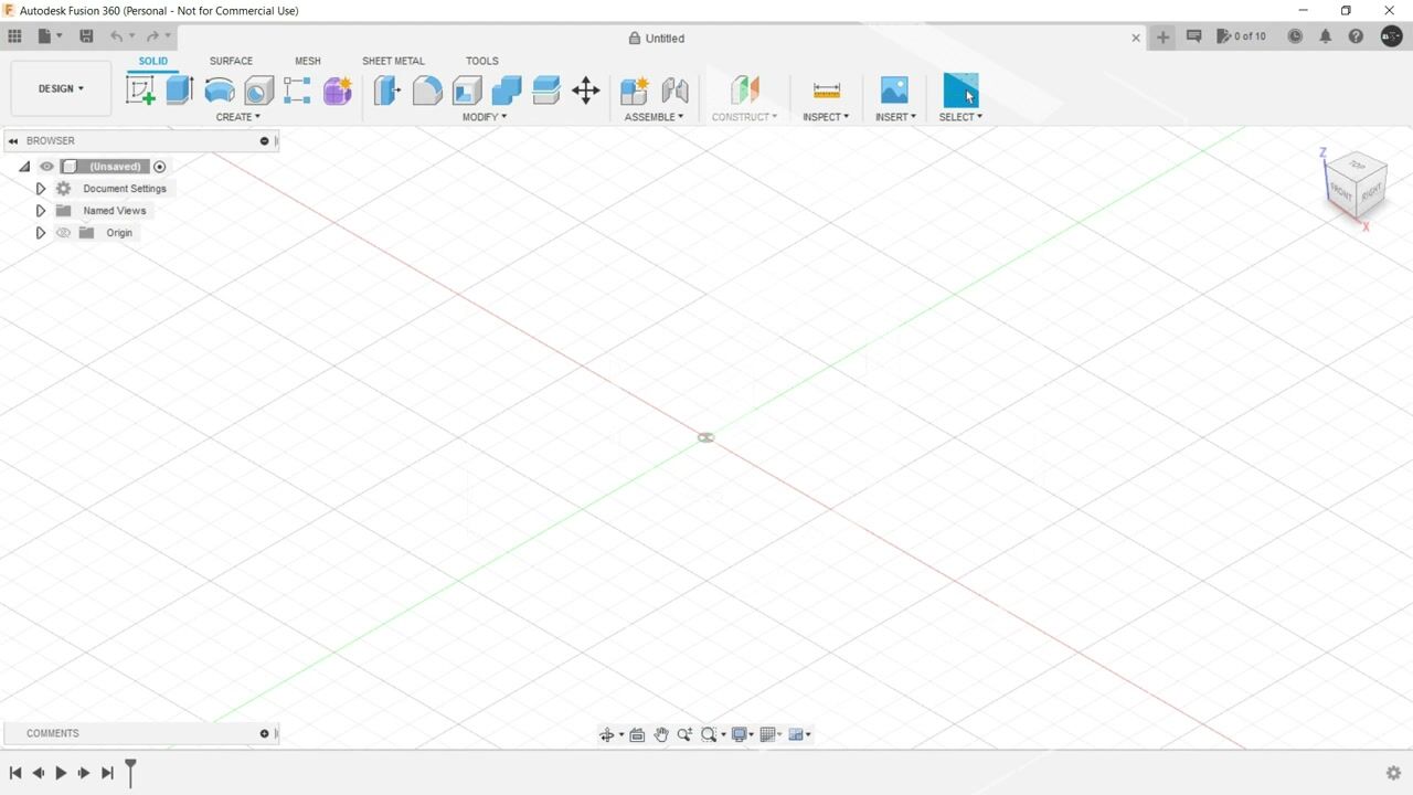
2. 02 GUI Of Fusion 360: I assume that you have
downloaded the software. Now is the time to understand the graphical user interface which is divided
into nine parts. The first part being
the application bar over here in the
leftmost corner. Top corner is which
houses data panel, file menu, the option to save
your file, redo and undo. Inside the file menu, you can create a new design. You can open a design, You can upload a file that you
have saved in your system. You can save it
from here as well. You can export your
files, you can share it, you can capture your
image and many more. The second part is the data panel in which you
can create new projects. You can see the designs
that you have created. Also, you can add pupil or
basically you can invite people to moderate or just to participate in the
projects that you're making. The third part is this
profile and help section over here where you can see the notifications
from Vision 360. From the notification center, you can see the job status. If we are talking about
assembly rendering and simulation, you can take help. You can see your Autodex
account profile preferences or you can just
sign out from here. Fourthly, we have the
main toolbar over here. This is where the
actual action begins. This tool bar has an option to change the
workspace initially. By default it is design. You can change it to render
animation, manufacture, drawing in some cases generate
to design and simulation. Also, it depends upon the
license that you are using. Inside this main tool bar, we have these taps which
contains different set of tools. We will gradually come to understand when we are
propagating through the course. Now, the fifth part over
here is the browser. This browser houses all the
things that you are creating. It's like a project tree. Here you have all the
sketches of your project, the two diskatches,
all the bodies that are made from
these diskatches. You can see the origin
over here and you can change the unit from this
one from document settings. And when we are
dealing with assembly, we will have different set
of attachments over here. That is called components that will be
highlighted over here. Then we have this view cube. This view cube is what shows the orientation
of your three D model. This is basically the
camera perspective here. As you can see, a
home icon is made. If you are making any
changes, you click on home. You'll go to the home position. Next comes this canvas. This grid like
structure that you are seeing in which the three
D model is sitting. This is called Canvas, as the name suggests. This is the place
in which you draw, in which you extrude, in which you create
your three D models, your assemblies, your
rendering, and many more. Then we have navigation
bar over here. Here you can change the views, You can make it a multiple view. You can adjust grid settings, you can hide this
background grid. You can change the environment. By default it is photo booth. You can change it to
these five options. Let's say it's dark sky. Let's change it again to, let's say Tranquility Blue. It depends upon your convenience in which environment you're
comfortable to work with. Choose that
environment only then. Over here we have some
navigation tools. Let's say we are
zooming too much out by scrawling
the mouse to Joom. In and out you have
to scrawl the mouse. If you're Jooming too much in, we want to see our
model clearly. We will click on
this fit option. If you don't want to
scrawl the mouse, you want to just using
the mouse clicks, you can click on zoom more here. And using left mouse button, you can drag it in and out. Now to get out of any command, get out of any navigation tools, you have to just press on exit. Then we have Pan. When
we switch on this one, we can click and drag
our model anywhere. This can be also
done by pressing the middle mouse button and
dragging it here and there. Then we have the most important navigation
tool that is orbit. You can click on
Orbit over here in the navigation bar and you
can orbit here Thready Model. The shortcut for the same
is pressing shipped in the keyboard and pressing
the middle mouse button. This is the most convenient way. My recommendation in
this regard would be to use as much as
keyboard shortcuts as you can to save the time and make yourself more
proficient with the software. Finally, we have the
timeline over here. This timeline is what tells you what is happening
in your project. Whatsoever has happened
in your project. When we press on play, this will show all
the steps that you have followed to create
this particular model. That's it for the
graphical user interface. In the next very lecture, we will directly start
with today, sketching.
3. 03 Basic Sketching Tools: Since we are thorough with the graphical user
interface of vision 360, let's start creating sketches. To create a sketch, you have to click here. Create a sketch. As soon as you do that, the
origin will be visible, and if it is not, you
can toggle it from here. Now you have to select
a plane for that. Let's rotate it once. Let's select this plane. Now let's start with the
most common command line. For that, you can
invoke that command, the line command from here, or you can simply type
L in your keyboard. The very first thing
that this command is demanding is to place
the first point. It's highly recommend that you always start with the origin itself in order to make your
sketch more comprehensible. As soon as I click here
and I drag the mouse, the line will start to be made. Let's place it in
the horizontal axis. In the x axis, let's provide
dimension as 100 millimeter. As soon as I have
provided the dimension, two new things have appeared. First is the dimension
that we have provided, and second is this small icon. This is what we
call a constraint. A constraint is nothing
but an entity which relates to sketch entities
inside the software itself. This constraint here
is telling that this line is a horizontal
line, as you can see here. For horizontal,
this icon is there. For vertical, this
particular icon is there. We will understand all these
constraints that are visible to you later on in the course. Now let's make another line. Click L in the keyboard. Or you can select from here, or you can select from here. Let's make it vertical, let's make it 50 millimeter and drag
the dimension outside. Now let's say you want to make arc from this particular point. For that what we will do, we will invoke the
line command again. But this time we
are going to hold the left mouse button while dragging the
mouse left words. As you can see, R can be made. Now you have to pay
attention here. I have made the arc, but I have not clicked on
the right button here, or I have not pressed escape button to close
the line command. What is happening here? Since I have not done both of them, the line command
is still active. We can create a sketch. Moving forward, we can, let's say, close this region. As soon as I've done that, you can see a difference
in this sketch. These three lines, this one, this one, and this one. They're having black coloration. Where this arc and
this particular line, they're having blue coloration. The reason behind
the same is that these three lines are
defined in the sketch. That means they're having a dimension and they're
having a position and location where this,
this line is not. For that we have to provide
dimension to this arc itself. First, for that, you can select
the dimension from here. Sketch dimension, or from here. Or you can simply press
D in the keyboard. Let's provide a dimension, let it be 50 itself. As you can see, the lines, those were not defined
are now defined. Now let's say I have to make a line which
is a inclined one. I will again invoke
the line command. Let's say, let's
start from here. All right, these two
lines are being made, These are inclined lines, but they are not defined for
defining these two lines. What we will do first, we will try to give it a dimension, let it be 50 itself. But again, it is not
getting defined. Let's provide angular dimension. For that, we will
select the line, and we'll select this line, that will create a angle. Let's say it's 60 degrees. Again, it is not
getting defined. What would be the
reason behind the same? That means dimensions are there, but location is not defined. For that, let's give it a dimension from
the origin itself. Let's say it's 25 millimeter. As soon as I have
provided the position, as soon as I have
provided the location, the line is getting defined. Now let's say I want to make a circle from this
particular line. For that, I will invoke the circle command
center, diameter circle. That means you have to provide a diameter to create the circle, or you can simply press
C in the keyboard. Let's draw the
circle of diameter. Let's say 50 millimeter. The circle is already defined because it's
having a position, it's having a dimension. There is no issue with
the circle itself. But this line is not
getting defined. What we will do, we will
make these two lines equal. For that, we are going to use constraint, this
equal constraint. For that, we will
select this line first and secondly, this line. As soon as we have done that, everything is defined
in the sketch. Now as you can see,
there are certain parts, there are certain portion in the sketch that
are not desirable. Let's remove them by using
the trim modify command. We will understand about all the commands in
the coming lectures, but for the basic command, trim has to be there. For that, you can
click here or you can just use the keyboard.
By clicking. As you can see, the color of the area that can be
trimmed is changing. We can trim it. As you can see, after the trimming operation
is done, lots of area, this whole circle and
this particular line, they are not defined. What we have to do, we have
to define them for that, let's first start with
the circle itself. To define this circle,
what we will do, we will use the horizontal
and vertical constraint. Here. What we will do, we will make this point which is corresponding to the arc
that we have made earlier. And this point of the circle
itself in the same line. That's what the horizontal
and vertical constraint does. The rest, what remains
is this particular line. For that, we have to again use the equal command, equal
constrant command. The reason behind the same is as soon as we have
trimmed the portions, the undesirable
unwanted portions, the constraints
are also trimmed. The constraints are removed. We have to, again,
provide the constraint, but still it is not
getting defined. That means location is missing. Let's provide location
for this one as well. This was just a
formality because it was already located
in a perfect position. But position was not defined. That means we have to
define the position. We have defined the position, and this particular
line got defined. Now let's say you need to make
a line which is inclined, but you want to provide the
angle right away for that. First you have to
provide the dimensions, and then you have to press Tab. Then you can provide the
degree, the angular dimension. And your line is ready again. If you're providing a angular dimension
in the other side, it will create the dimension. But this dialogue box
will be there that will say adding this dimension will
overconstrain this sketch. We will just simply click Okay. But this is not recommended that you over
constrain the sketch. That means you don't have to crowd this sketch with
lots of dimensions. As you can see here, this particular angular
dimension is in bracket. This dimension is called
a driven dimension. That means the changes
in the dimensions. Let's say, let's make it 65. We'll change this dimension. This is a driving dimension, and this is a driven dimension. Let's change it again, then you will see that
this is also getting changed if you want to swap the position
of these dimensions. You can also do
that. You have to just right click
here and toggle. You can make it
driven and then you can make it driving itself. If you want to delete
certain section in this catch just left click, drag the mouse and delete
the selected portions. Now let's say you want
this whole sketch, this whole sketch to be exactly replicated
below this axis. For that, we have
mirror command, but there is a requirement, you need a center line for that. Let's create a line in between. Let's convert this line as a center line from
the sketch palette. Now just select the
mirror command. It will ask the objects
to be selected. Select the whole object. As you can see, a exact
replica is created here. But this replica, as you
can see, is not defined. It is in blue coloration.
We have to define it. But as you see, the
sketch itself is looking cl's not looking very neat because of lots of
constraints being added, lots of dimensions being added. For that, you can
remove them from the sketch pet by toggling show dimensions and
show constraints. We will have a neat
sketch if you want, you can remove the
origin as well by toggling here in the browser. Then we can have a
proper neat sketch, as you can see here, in order to make this particular sketch the replica that we have created using the
mirror command, in order to make this
one as the defined one. For that we have to
provide portion, we have to provide a location to this center line
because as of now, the center line is not fixed. For that we will use
coincident constrant. We'll click here.
Click on the line, and then we will
coincide, coincide. We are coinciding
this particular line to the origin itself. As you can see, the
sketch is fully defined. As soon as the
sketch is completed, you can click on Finish
sketch, or you can click here. Your sketch will be ready. As you can see,
it is highlighted under Sketches in the browser. If you want to make any edits, right click here and just
click on Edit Sketch.
4. 04 Intermediate Sketching Tools: Next, let's start with some
intermediate commands. In Fusion 360, we will begin with creating a
sketch, just like earlier. We will select a plane. The first command here
is the rectangle. A two point rectangle,
to be precise. To invoke this particular tool, to invoke this
particular command, you can directly press R
in your keyboard as well. Let's click it here. Specify the first corner. We are beginning with
the origin itself. As we are clicking and
dragging the mouse, you can see the rectangle
is getting formed. Let's provide the width
as 100, Press tab, provide the height as 50, and your rectangle is ready. Next is a three point rectangle. As the name suggests, you need three points to
create the rectangle. Let's say this is the first point, this
is the first corner. Let's say at 100 MM
is the second corner. And as soon as we click there and drag the mouse
in the other side, you can see the formation
of the rectangle. Let's say the height is 50
and new rectangle is created. Finally, we have a
center rectangle. As the name suggests, it's a
center oriented rectangle. That means you need to
provide a center point first, let's say this is
the center point. As soon as we left click and
drag the mouse outwards, the formation of rectangle can be seen with reference
to the center point. Let's provide the 100 tab height as 50 and your
rectangle is ready. Do not worry if the
sketch is not defined. We are not making a
proper sketch here. This blue coloration
line will be there. We are just understanding
these tools. Then we'll propagate to circle the center diameter circle using shortcut key C, we've
already discussed. Let's propagate to two
point circle here. We need to provide two points. Let's say we need
to create a circle between the midpoints of these two lines of
this rectangle. How to find the midpoint? Whenever we howard the
mouse over this line, a triangle icon is being made. This is nothing but
the midpoint of this particular line
in this rectangle. Select this one,
select similar in the other line with the
triangular notification, triangular icon, and
your circle is made. Next circle is a
three point circle. As the name suggests, you need three points
to create the circle. Let's say the
midpoint of this one, the midpoint of this one, and the midpoint of this one. Your circle is created. Next one is a two
tangent circle. Here you need two tangents, that means two lines are
required to create the circle. Let's say this is the first line and this is the second line. As soon as we click
both the lines, you can see the
formation of the circle. Next is a three tangent circle. That means you need to provide three lines that
tangent to the circle. Let's say this is
the first line, this is the second, and
this is the third line. A circle is created. Let's get rid of the dimensions because we don't require it, because we are only
understanding the tools and get rid of the constraints as
well from this sketch pallet. Next is arc. First we will
understand a three point. That means we need to provide three points
to create the arc. This is the first point, this
one is the second point. For the third point, you
can see the formation of the arc itself. It
can be anywhere. Next is a centerpoint arc. That means you need to
provide a center point. Let's say this point
is the center point, this is the radius of the, let's say it's 50
millimeter again. As soon as I release it and drag the mouse leftwards
or rightwards, you can see the
formation of the arc. This dragging is angular, you have to provide degrees. Let's say it's 115 degrees. The arc created next is a polygon in which first
is a circumscribed polygon, That means a circle is
inside of a polygon. For that we'll
click just provide the center point the diameter of the circle.
Let's say it's 50. Choose the number of sites
you want in the polygon. Let's say it's
octagon, it's eight. And center here polygon
is it's octagon. The next polygon is inscribed
polygon, that means When we provide a centerpoint
and drag outwards, you can see the polygon
is inside of the circle. Let's say it's 50 again, and it's again octagon. You can see there's certain
differences in these two. Next it's ellipse. For creating an ellipse, you need to first
provide a centerpoint, then the radius of
the major axis. Let's say it's 100. Then when we click
here and drag outside, we have to provide the
diameter of the minor axis. Let's say it's 50
click in your Alps. Ready, Next is a slot. Slot is a very
important equipment in many industries
and the design and the sketch of the same is
also equally important. First, center to center slot. That means you have to create
slot between two centers. Let's say this one and this one. Just provide the width
and slot is ready. The next slot is oral slot. It's just like
center center slot, but it will, it is
created more efficiently. Next is a center point slot. That means you have to
provide just a center point. Say, let's check somewhere here. Just provide the center
point radius of the slot. You can see the slot is getting formed with reference
to the center point. Just provide the
width. Let's say it's 15 and your slot is ready. Then we have a three
point arc slot. That means you have to
provide three points. Let's say this one. This one. For the third point,
you are getting a arc. Let's say this is the arc, and when we drag
the mouse outwards, you can create the slot. Finally, we have a
centerpoint slot. That means you have
to provide a center, you have to provide
the diameter, create the arc, and
then create the slot. That's it for slots. Then we have a important, a very crucial and amazing
tool called this Pline. This we will be studying in very detail in
the coming lectures. This is like a aditable line. Just click, left
click, anywhere, multiple number of
times your polyline. In certain software this
is called a poly line, but it's a pline here. The points, these points
are called control points. When you're dragging
these points, you can change the
shape of pine. When we double click
here the handles, they can change the
orientations of different different areas where the control points are made. Then we have conic curve is somewhat like
a three point but it's a bit different context that it is very
much editable here. Also, you have to provide
three points first, second, and for the third point, you can see the
formation is conical. Also, as soon as we release the mouse click on the
left mouse button, you can see this
handle is occurring. Using this handle, you
can change the shape, and even you can bring it
down to a line as well. Then we have, if you need any reference
point in any sketch, you can directly create
a point in that sketch. Let's say I want a circle, somewhat like let's say here, let's sprite dimension
between these two us 20. I want to create a circle here using this reference point. Then this point
command comes handy. Lastly, we have text. In text, we can just
create a text box. We can write here,
let's say Fusion 360. You can fit this text
on Curve as well, on any path as well. Let's select the path, and you can see this is occurring here, or you can simply have
it as a text box. You can change the font. You can change the height. You can make it bold.
You can make it tallic. You can flip it horizontally. You can flip it vertically. You can align it as center, or right, or left,
whatever you want. You can align them
in the middle, in the bottom,
whatsoever you like.
5. 05 Advance Sketching Tools: Now let's understand certain
advanced sketching commands. We will be utilizing this
modify toolbar here, corresponding to
to the sketching. Here we have fill
it. Chamfer, trim, extend, break, sketch,
scale, and offset. In order to understand this, let's create a rectangle. First, select Modify toolbar. Click on Fill It. This fillet actually creates
Arc in a corner point. For that, we have to select first line and then
a second line. Then as you can see,
this handle appears. You can utilize this handle or you can provide the
diameter here itself. Second in the line is chamfer. It's quite similar to fill it, but it looks quite different. Again, you have to
select one line and then the second line and your
chamfer is created. Next is trim that
we have already discussed and then
we have extend. In order to understand extend, let's create certain lines
side this sketch itself. Now what does the extend
commanders is that it extends the existing line to the next line or next sketch. And tight when I'm howing
my mouse over this line. This red coloration
that you can see here is extending to the
next very surface, to the next very sketch. It just left click again. Left click, it will be extended. Same thing goes here and here. Now next is break. When we invoke the
break command, it actually breaks the line or breaks the sketch tit
at the intersection. If I'm howing the
mouse over this line, nothing is happening
because it's not having any
intersection in between. It's semi intersection
in the beginning or in the very end when I'm hoving
the mouse over this line, this cross symbols in between
when I left click here. This is getting break
into two parts. This line is getting
break into two parts. Same thing goes to
goes for here as well. Then we have sketch scale, which basically scales up and
down the sketch entities. Let's select this one.
Select all the entities and select a reference point. I'm selecting origin here. As soon as I do that, you will get a
scale factor here, you can provide the factors.
Then what will happen? All the sketch entities
that have been selected will become
twice the size. If I provide 0.50 0.5 here, all the sketch entities
will be hauled, let it be 1.5 Next,
we have offset. When we click on offset and select the outline
of the sketch, it will create offsets
in either direction. You can use this handle or you can provide plus, minus here. But if you don't want the
whole outline to be offset, you can just untick
this selection, cross this one, and just
select any particular line, you can offset it. Mirror command we have
already discussed, but just for the sake of
a better understanding, let's use it. For that. We have to provide
a center line. Let's convert this line to a construction
line. You can do that. Invoke the mirror command, select all the objects, then select the mirror line. As you can see,
mirror is created. Let's hide the dimensions
and constraints. Last but not the least, we
have this move command. Actually moves the sketch
antitis asperus your comfort. You can translate
or you can rotate. But as you can see, even if I'm making changes
in the actual object, the mirrored image, the mirrored replica of the
same is not getting changed.
6. 06 Pattern Making in a 2D Sketch: Now let's understand how to make patterns in a two D sketch. For that, we will create a diameter circle using
origin as the center. It can have any diameter. There's no need to have a
specific diameter here. Let's convert this circle
to a construction line. Let's create another
circle somewhere here. Let's say now we want this small circle to revolve around this bigger
circle in a pattern, but for this center point
should coincide with this line, with this circle itself. For that, we will use
coincident constraint. Select this, select
this, it's coincided. Now, invoke the
circular pattern. As soon as we do that, we have to select the object, which is obviously this circle. Then select the center point. As you can see, as soon as I have clicked
on the center point, by default three
circles are made. Angular spacing here is full
if I provide angle to it, If I provide 180 degree angle, that means 180 degree, that means half of the circle
will be having the pattern. Let's make it again full. Here you can change the
number of quantities, that means the objects
that we have selected. The same thing you can
do by using this handle. By dragging right side, you are decreasing the number of objects that will revolve
around the circular pattern. By dragging it left
words, you can increase. Next is a rectangular pattern. For that, let's create
a small rectangle here. Click on rectangular
pattern, Select the objects. You have to select the
whole rectangle here. Then you can drag
this one right words, also by default having
three increments. Now you can have it
in one direction, or when we click on symmetric will have a symmetric increment. You can increase the number of quantities by dragging this. You can increase the number of objects by dragging this one. By dragging left,
you're increasing. By right you're decreasing. Same thing goes here as well. Up is decreasing. Down is increasing.
7. 07 2D Sketching Practice Set 1: Since we have completed the basic intermediate
and advanced tools of Fision 360 sketching, let's directly jump into
creating an actual sketch. For that, we are going to
use this particular sketch. My recommendation here
would be to start from the bottom and make your way to the top
and close the region, and then add additional sketch entities
like these circles. This is my way of sketching in Fision 360 and any
other software. This is my style. You can
develop your own style. But in order to do that, you need to grasp the
ideal way of designing. Then you can develop your
own style of sketching. Here I will be taking this particular point as
the origin and I will be creating this section for that, let's invoke the
line command first. The first line is
of a followed by a vertical line of 50 followed by a
horizontal line of 80. It's 100 followed by
50 click followed by 80 click And then trace this particular point up to the point when you're getting this perpendicular
constant icon. Then click this 150
millimeter line. Now we are all set to
create the whole sketch. The foundation has been laid, just adjust the dimensions. Now there's two
ways of doing this. Either you can just provide dimensions and then
start creating this sketch. But for that, for certain
regions you have to calculate. My recommendation here would
be to give a rough patch, to create a rough sketch of this whole outline,
this whole region. Afterwards, you can
give the dimensions. Let's do that from here. I'm not making 100, I'm just clicking anywhere. Just make it up to the mark. A rough outline of
the sketch is ready. Now we will be providing
dimensions one by one. This is 100 and this is 150. Let's provide the dimensions. This is 100, this one is
150, it's already 150. Then this side it's 250. Let's make it 250.
This one is 50. We are almost set. Now we have to provide certain constants to
define the sketch. We will be using this
colinear constraint. The two lines are colinear,
as per the sketch. This two and this two are, and this two are, Let's
make everything colinear. Lastly, this one. Now the
sketch is fully defined. That means everything
is in black coloration. Why I'm using the word fully
defined always the reason behind the same is
whenever you're making any future
changes to the sketches, you need to have a
fully defined sketch. Otherwise, what will happen? Any manute changes you're making that will
trouble the sketch. That's why we need to have
a fully defined sketch. That means dimension
and location. Now the outline has
been completed. Only two things are remaining, this circle and this circle. Let's start with this one. This one is 60 diameter circle. We will click. Let's play. Sit anywhere here, provide 60. It's in blue coloration
because not defined. Because it's a dimensions there, but it's a location
is not defined. We have to define the location. It's 75 from this line
and 75 from this line. Let's give the dimensions, press D, select this one. Let's provide 75.
Select this line. Select the circle.
Again, provide 75. Now it's defined the next
circle is of radius 40. It's R 40 written, that means it's a
circle of 80 diameter. Let's create a circle of
80 diameter, it's 115. From this particular point, we can take this line
as the reference. Let's select this
line, this circle. It's 115. From this line, it's 80. Now our sketch is complete, and it's fully defined. For future uses, we can
click on Finish Sketch. Now your sketch is finished, but your file is not saved. We have to save the file. And here comes the
role of data panel. When we click on the data panel, you can see all your projects here, libraries and samples. These samples you can
go through by yourself. Now, to save this one, you have to create a project. Let's say I'm creating
Project Fusion 360 Sketching. I will be saving all the
sketching files here. As soon as this project
has been created, you can pin it in the top. Then when I click on Save, let's say this one was
practice exercise zero. Then you can select here, this is the new project
that we have created. Vision 360 Sketching. Here you can create a new
folder under the folder name, we can say let's
say section eight. I suppose it's lecture
inside here you can see now how to
access this file. Again, just double
click the project, You can see lecture it. Even if it's not there, you can move it from
here to lecture it. It's inside here.
You can edit it. This editable sign is there. You can make it read
only so that only people can read there. Is that. Then we
can close this one. Now, the next sketch
is this one here. As you can see,
this dotted line, this dotted line is there. This is called a center line. We have to create a center
line wherever possible. First, let's create the sketch. Select the plane line command from here. Here. Then you can see
this area is 225. This is 300 and its orientation, Angular orientation
is 150 degrees. Let's provide
dimensions, this is 225, this one is 300. Angular dimension is 150. Now, since it's a center line, let's convert it into a center line by clicking
on the sketch pallet here. Now in this end, we are having two circles, one of 45 diameter and
another one of 90 diameter. Just click, see this one is 45. Left click again. This one is 90. Left click here, we have 1218120, followed by 180. Finally, here we have
30.60 it's 30, then 60. Now as the outline of
the sketch is concerned, we have to create tangent
lines everywhere. Invoke the line command, select from here, and
click on this circle. As soon as you can see
this tangency icon, this tangency constraint,
same thing goes here as well. But as you can notice, this tangency is maintained at the end point
of the line only. We have to provide tangency
in the start point as well. For that, we will invoke the constraint
tangent constraint. Select the circle, select the line tendency is maintained. Select the circle, select the
line here, also, and here. Now a rough patch of the design of the
sketch has been made. We have to remove
some unwanted areas. Click on the keyboard, or you can click here, or you can click here and remove the unwanted sketch entities. Notice you will
get a warning here because the sketch
entities we're removing, we're up to certain point linked with certain constraints. That's why that warning.
Was there nothing to worry in every sketch? There is one issue, there are some minute
details, all is missing. As you can jom here, you will see these two
lines are not trimmed. We can trim it from here. Now the sketch is
fully complete. You can remove the constraints,
remote dimensions, and as you can see, it's almost similar just
for a minute detail. This particular
arc, let's convert this one as a reference arc. Let's say this one again. Were in 360 sketching project that we have started,
lecture number eight. Let's say this one
practice exercise too. As you can see in the
data panel inside F 360 project lecture eight
folder, this is present.
8. 08 2D Sketching Practice Set 2: Now for this exercise, we are going to use this
particular sketch here. As you can see. First we have to create a
octagon of side 20 millimeter. For that, we will be using edge polygon just to
specify the first point, let's start from
the origin itself, 20, then provide the
number of sides. It's octagon eight. Enter just adjust
the dimensions. Then there is a other polygon, it's a pentagon of side 25. First what we will do, we will again use the
edge polygon command. But we are not going here. We'll be using
right mouse button. You can repeat the
previous command select from anywhere from here. This does not give
the dimensions yet. As you can see, the
polygon is made. Now let's provide the
dimensions specification. This one is 25, Let's provide this 25. The distance between these two, the octagon and the pentagon is six millimeter provide
the dimension of six. It's already six, I suppose. Now next we will create a construction line
between the midpoints. Let's convert it
into construction. Now since this whole line, the edge of the
pentagon is of 25, then obviously the half of it
would be 12.5 Let's provide the dimension between this construction
line and this point. It should be 12.5 This will
define the pentagon inside. Next is a hexagon in between in the center
of the hole sketch itself. What we will do, we will
again create one more line passing through the midpoint
of these two sides. Let's convert it into
a construction line. Then we can create a
circumscribed polygon. A circumscribed hexagon here. For that, click here again,
circumscribed polygon. Select the point intersection, just zooming to make it conform. Then it's 26 millimeter from
this point to this point, or you can say from
this side to this side. Let's provide the dimensions. It is 26, It is
still not defined. We can provide some constraint. Let's make it horizontal,
it's been defined. Then we have the final
thing in the sketch, this rectangular look
sketch entity here. But we cannot create
a rectangle here. If we create a rectangle,
what will happen? This particular
line here will be overlap with the line of the rectangle with one
side of the rectangle. We cannot use that. We will
be using line command. Instead, it's 14. Here, let's provide the
dimensions, It's 14. Again, use the line command, track this particular
point and close it. Hence, our sketch is fully
defined and complete. Now let's save this one
in the same project, but with a new folder,
Lecture eight. Okay, it would be lecture nine. Lecture eight, we have used, let's name it practice
exercise three. Let's click Cons, and
then you can look into the Data panel Fusion 360
Sketching lecture nine, and is there now for the next exercise,
let's solve this one. Let's make the sketch of this
one as you can see here. First we have to create
these center lines. Let's just create two horizontal and two
vertical lines. Let's make this one bit longer. One more genal line, then let's select everything. Convert dimenso construction. Now as I have told earlier, we have to use
origin at any cost. Let's coincide this line to the origin using the
coincident constant. Let's provide the dimensions. This is 45 and this one is 90. This one is 45, and
this one is 90. As you can see, this horizontal
line is getting away. Let's click this one. Control
click this one coincide. Now we are all set
to sketch here. As you can see in the origin, we have these two circles as well as one more
bigger circle, 28 dime 38 diameter. And this is 40 80 dimeter. Let's make three circles. This one is 28, again, origin 38, then 80. Now at this intersection, we have circle of diameter 20 and another
circle of diameter 40. Just in this is 2040. Same thing here as well, 2040. Now let's trim the areas
that is not required. Click in the keyboard
on this one. Then we are having 126 radius
circle, somewhere here. Which is tangent to the
80 diameter circle. Tangent to this one,
tangent to this one. Let's create a circle, let's it's 26 radius. What we can do here, we can provide the mathematical
formula here itself. And we can convert it into
diameter 26 into two. We can write here present this one is tangent to this one. Use the tangent
constraint or you can control and select these
two circles and tangent. Same thing, select both tangent, this area is created. Then we have 198 radius circle. A bigger one which is
touching the radius circle, as well as this 40
radius circle here. Let's create that
one also circle. Let's start somewhere here. It was 98 radius, so we can write 98 into two. It was supposed to be tangent
to this radius circle. Here, just select control, both tangent, select
this two tangent. It's going other ways sideways. What we will do, we will invert this position position
of this circle itself. Let's remove this one. Let's create circle
somewhere else. This thing happens. It's 98.22 If this thing happens and your sketch is like flipping horizontally
or vertically, try in another way, what we will do, We will first
make tangent to this one. Control tangent. Now control tangent. Now we are good to go. Now let's remove the
unwanted areas used. The Rim command. This is removed. This
is not required. This is not required. What else? This area
is also not required. We are almost done
with the sketch. Just some minute
details like there is one fillet here of radius nine. We can provide
file, select this, select this, provide 9.1 very
minute detail over here. Here you can see it's
a straight line. Let's create a straight
line from here to here. Press on trim, the
unwanted areas. Then we are having one tangency between these 240 diameter
circles. Let's create a line. This one is tangent, Let's
make these two tangent. The sketch is almost defined
only for this one line. So we can make this as a
horizontal vertical constraint. And the sketch gets
fully defined. Just remove the dimensions, remove the constraints,
and our sketch is ready. Let's say it again in
lecture nine itself. Let's make it
practice exercise 04.
9. 09 2D Sketching Practice Set 3: Now for the last practice
set of sketching, we're going to create
these two sketches. Let's create this one First, click on Sketch Selected plan. Now. First we have a
circle of radius 23, then a circle of radius 31, and a circle of radius 40. Let's create it first is 23. 23 into two, because we're
creating a diameter circle. Then we have 31 into 262, Then we have 1422,
that means 80. Now as you can see, this 131 radius circle
is a construction. One let's create
as a construction. Now let's create some
horizontal and vertical lines passing through the origin. Keeping the mind in the
top and at the bottom. And in the lab site, we had to create lines, center lines, or you can
make it construction lines. There is no major difference. Track the origin,
create one line here, Track the origin, one line here. Let's first create
the pattern of these six holes of ten
millimeter diameter. Let's start from here. Just make sure that you're selecting
the right point. Now let's create a
circular pattern. Select the object,
select the centerpoint. Use this handle. Six
objects have been created. Now let's define these objects. Just click on this line, coincide it with the
origin, and it's defined. Since this is defined, you can convert it into
construction line. Next we have at this
intersection which is 46 millimeter away from the line vertical line that is passing
through the origin, two circles of 8.15 radius. Let's first create
the intersection. This one is 4062 circles. Are there 8.15 eight in 2.30 that means 15 into two. Remove the unwanted areas. Trim this one. Trim
this one, this one. This one. This
one, and this one. Then we have a fillet of radius eight here and also
in the bottom. Let's create a fillet, Right click, Repeat fill.
This is also eight. Now let's coincide this
horizontal line to the origin and these circles convert them into construction. Both of them. Then we are having
these similar patterns, the similar sketch antities
in the top and the bottom. Let's create them. For that, we have to create a
horigontal line which is 60 millimeter above the x axis. This one is 60 above. Since the dimensions
have been given, you can convert it into construction two
circles are there. One of 22 millimeter diameter
and another is of 18 into 23622 here, 36. After that we are having a arc of radius eight
here, which is joining, or basically which is tangent to this 80 diameter circle and
this 36 diameter circle. For that we will create a circle of radius
eight into two. Control select both of them. Tangent, exit control
select these two, make them tangent, and
remove the unwanted area. Now, the same sketch entity, including this arc, is exactly similar
here in the bottom. As you can see what we
will use mirror command, select the objects,
select this line. Also select the mirror
line. Press Ok. Now, for the last
thing to be done in this sketch is this
100 radius circle, which is tangent
to this 36 radius, 36 diameter circle
in both the ends. Let's create a circle of 200 diimeter
because radius is 100. Control select these two, make them tangent tangency is maintained in
the bottom as well, and trim the unwanted areas. The only thing that is
remaining in the sketch is this sketch entity
here is not defined. Let's try to define it. It's already given 46 here. Let's try to define it by
giving some dimensions. Let's say we're removing the 46 and giving the dimensions. By selecting these two circles, the sketch is defined. Sometimes you have to do certain adjustments in order
to define the sketch. Okay? These two things are not
required to trim them. As I was saying,
sometimes you have to make certain adjustments
in the dimensions. It's not like the sketch
that you are getting. You have to include
the same dimensions. You have to improvise in
order to define the sketch itself as the sketch is
complete finish sketch. Now let's save it there
in fitting 360 sketching. This is lecture number ten
inside this lecture ten, that's right. Practice
exercise five. Moving on for the next sketch, we have to start
with a circle of radius 20 and a
circle of radius 31. Create sketch circle 20, that means 40 diameter, and 31, that means 62 diameter. Let's adjust the dimensions. Now we have to create this
pattern over this 62 diameter, or 31 radius circle. For that, let's create some horizontal
and vertical lines passing through the zine. And keeping in the mind that in the bottom we have
two intersections, the vertical line
would be a longer, one controls that
for unwanted things, an original line
could be shorter. Let's create this pattern. For this, we are having two circles of radius
four and radius eight. Let's create it on
this phase four. That means 8.8 that means 16 trim the unwanted areas. We are not trimming these
four sketch entities here because it's part of
the 62 diameter circle. If we remove them, pattern will not be
able to be made none. Let's create circular pattern. Select these two sketch
entities objects. Select the center point. Drag this 12 plus how
many we require six. Trim the unwanted areas. Okay, we are almost set. Let's define this pattern
that we have made. For that, let's coincide this original line
to the origin. Let's not doing the magic
select the vertical line, coincide with the
original still, it's not getting defined. We have to give some
extra dimensions. Let's say from this
circle to this circle. This is 62 and it is defined. As you can see, this dimension
that I have provided is not visible in the actual
sketch or the reference sketch. But it's not the concern. The concern is the sketch
has to be defined. If you have to give
extra dimension, that you have to give
extra dimensions. Moving on, let's convert these two lines
into construction. Then for the bottom portion, we are having two intersections which are 110 millimeter apart. That means 55 from this side, 55 from this side. This line is 65 millimeter below the horizontal line
passing through the origin. Let's create that first
make original line. Let's make it bit larger. You can always click
on the start or the endpoint of the
line and you can drag it to make it larger. Now this is 65 millimeter from this one, let's make it 65. Then these two vertical lines, they are 55.55 millimeters
apart from this line. Let's make it, this is like 55 MM. On the second thought, you
can see that this particular sketch and the
concentric circles, this this line, they are quite similar replica of
what is in the other side. We can use mirror command here. Let's here here two circles. Are there one of radius ten
and another one of radius 15? Circle of time it 20.30 Let's convert this
one to construction. Convert this one
to construction. Now from here, one
straight line is there. Create a straight line. Just zoom in and make sure that it is touching
this arc in the circle. Then this arc here is
of radius 18 or 36. Diameter circle
we can make here, let's say here 36. Select this one, select this
line, make them tangent. Then select this one, Select this circle, make them tangent. Remove the unwanted areas. Now let's invoke
the mirror command. Select the objects,
this arc of radius 18, this line, these two circles. And select this
construction line as well. Select the mirror line. It has been replicated. Now, as you can see in
the bottom of the sketch, this arc, the dimension
of the arc, is not given. It's not available in
the reference sketch, but it's 100 millimeter. It should have been given,
but it's not there. Let's take it 100. That means we have to create a circle of radius 200. Select this circle,
select this one tangent. Here also, I suppose
tangency is maintained. Trim the unwanted areas. The only thing that
is remaining is these concentrive circles
which are equal to these two. For that, we will select
these two circles. Control C, control
drag the pisted one. If it's not snapping
on this one, just inside, snap it, take it down, press. Okay. But as you can
see, it is tangent. You have to join
and see it is not tangent to the 200
diameter circle. Let's create tangency constant. Here we are almost
set with the sketch. The sketch is almost complete, just 1 minute detail. That is, these two circles,
they are not defined. They are having dimensions, but they're not having location. Let's provide location to them. Click the sketch is fully defined,
remote dimensions. Remove the constant and try to make a composition as we
are made a similar sketch. Now let's see it in Fusion 360 Sketching, lecture ten. This exercise I suppose
sixth one we are all set. Click on Finish this sketch.
10. 10 Using the canvas tool: Now, there is a very interesting and amazing tool in Fusion 360 which involves the
aspects of two D sketching, three D modeling and rendering. But we are including it here because the aspects of
sketching is predominant. This is the tool called canvas. Here what we can do, we
can import image and we can draw over it and we
can create a three D design. Let's understand
it with example. As soon as I click there, I can insert the image
from my computer. We will be using
this Tesla logo. As soon as I have
uploaded the image, we have to select the face. Let's say this is the face. Just click on front
to make it face you. Then you can select
the opacity of the image that you
have imported. My recommendation here
would be to make it as transparent as you
can work with. I generally work with
30% transparency. If you can work
with 100% opacity, it's a prium, let's make
it 30 and click okay. The next step is to
calibrate this one from the browser I got into the
image that we have uploaded. Right click calibrate, make it as close as possible
and place the first point, next point it's 0.58 millimeter. Let's make it one. And as you can see, the
logo has been scaled. Now let's try to find out if the calibration
is done right or not. For that, let's create
a sketch over this one. Click on line, select this
point, select this point. And you can see it's exactly 1 millimeter
calibration is done, correct? See it's one. Let's delete this one. Now we can start making a
sketch over this one. As you can see, this logo
is quite symmetrical. What we can do, we
can create half of the catch and we can mirror
it in the other side. For that, let's create a line, a vertical one, and convert
it into construction line. Now to trace this logo, we are having a very
beautiful command spline. Let's start tracing it. Let's make it as
close as possible. Sometimes when you press Exit, while using Spline,
it goes away. You have to do the work again. Do not forget to press Enter
as soon as your spine is. Now let's use these
control points to make it to the logo. So that we can make the pressing perfectly. Click on the spline. Use the control points,
Use these handles, these green handles and
the control points. All right, now for this section, let's create a line. Let's again use spline for
this particular section. This line is called Poly Line in many other softwares and does the same work center. If you don't want this
construction line to go anywhere, let's coincide it
with the origin. Now for this section,
again, spline. I think we are good to go here at just the control points. Always use these handles to maintain the tangency
wherever you want. All right, now for
this section, again, a line up to this very point. Again, we have to use this line from this point to this one. Right click, repeat,
fit, point, spline. Let's trace it even more. Use the control points. Use these handles to
maintain tangency. Now we can use a
line command here. Let's go all the
way to over here. All right, now we are good to create a mirror about this
particular axis, Mirror. Click on mirror, select
all these objects. Accept this line, because that
is the mirror line itself. And click on, okay, our sketch is almost ready. Remote Dimensions,
Remote the Constraints. Now here comes the fun part. Now we're going to create a
three D image out of this. Select these two regions. What I'm about to tell right
now is going to be covered comprehensively in
the coming lectures. You don't have to worry. Just for the sake
of this lecture, I'm involving the
three D modeling and the rendering aspect here. Both the reasons
have been selected. Right click, press, pull, let's make it
symmetric is provided. Two millimeter and press. Okay, now the canvas role of the canvas tool
has been completed. We have created the logo. We can hide this.
As you can see, the logo of Tesla
has been created. We can go to work
space surrender. This logo has red coloration. We'll apply red color here. This will be discussed
in the coming lectures. Don't fore, let's
make it metallic. Click here. Aluminium
select this one. Yeah, this looks good. Here it is. From a simple
image to a three D model, to a randed image of Tesla logo.
11. 11 Basic Modelling Tools: Since we are finished with
the sketching portion, let's jump directly
into three modeling. For that, let's create a sketch. Select this plane, let's
make a simple rectangle. We're not going to
define every sketch now onwards because that was required in the
sketching module. But for three D geometry, it is very much
recommended that you must define each and every
sketches as you go on. But just for the sake
of understanding, we are not defining
anything here. Now since this
rectangle is created, we can convert this two D
object into a three D one. Just click on the closed region, it will be highlighted and right click you will get
press pull option. You can also use
this trot tool here, but it's more convenient.
Let's just click here. Now as you can see,
this trot pet is open. Now we are going to
utilize this pet. Just drag this handle upwards, or you can provide the
dimensions by yourself. Here, let's make
it ten millimeter. Now as you can see, the
distance ten millimeter is taken and taper
angle is zero. If I'm making some
changes in this one, if I'm making it ten
degrees, what is happening? It's tapering outwards. Now let's make it minus ten. It will taper inward. Now I don't want any taper. Let it be zero
itself and click on. Okay, This is your
first radio object. Just shift center, mouse
button and you can rotate it. Now let's suppose I want a
hole on this particular Boyd. You can say what I will do. I will select this face and I will start
creating a sketch here. Let's make a circle
somewhere here. Click on finish this sketch. Go to home in the view cube. Select this circle,
press pull and cut it by dragging it downwards. If you're dragging it upwards, it will extrude upwards. If we are dragging it downwards, it is cutting through it here. Also you can cut through
taper, let's say ten. It is cutting in a
taper formation. Or let's say I'm
giving minus ten. It will cut in a conversing
taper formation. Let it be zero
itself. Select Okay. Now let's suppose I want to add certain more details
on this one. I will again select
this, create a sketch. Let's create a rectangle. See here we are not
defining any sketches, but it is recommended that you must define for
future references. Here, let's select this. Press pool shaped and
middle mouse to orbit and extrude it. Click Okay. Now let's suppose I want some additional
details on this phase. Then I can select this phase, I can create a sketch. Let's create a rectangle here. Now let's create a
rectangular pattern. This whole rectangle.
Let's increase the numbers, mine. Okay, finish the sketch. Select all the sketches. Select all the sketch entities. Right click, press pull, and drag it here. The joining operation is there. That means we are
adding material. We can use any other options, any other operations as well. This will be
discussed afterwards. Let's click on, Okay. Now, as you notice
here in this time, line one sketch is there. The initial sketch,
then we are extruded. Then another sketch for circle, then we cut through that, another sketch for
the small rectangle. Then we have extruded
that another sketch. Then again, extrude
command is there. This timeline is showing the step by step
progression of your design. When I click on Play, all the steps will be there. Now the beauty of timeline is that if I drag it backwards. It will come to the point where that particular
tool has been used. Here, we have cut it down.
We are down to there. Now let's drag it to
the very beginning. At that time, there
was only one sketch. What we can do, we can add
this sketch by the bulk. Clicking here, let's say
we add a circle over here. Trim the unwanted portions. You will notice the
changes that this will do. Finish the sketch. Go
back, go to home position. See the semicircle portion
with press pull command added. Now let's make sketch 13 design. Now this time I want
a vertical one. I will select a vertical plane. Let's say this one.
Let's get something close, the region and
finish the sketch. Now when we click on press Pull, there was this direction
option available to us. When I click here and
I make it symmetric, the extrusion will be symmetric. Let's make it 15 MM. As you can see, both the side, it's having same
increment of 15. You can also provide
taper if you want. Both the side taper
will be added. Let's make it understand.
Let's see what happens. Let's see. Let's make it now. Let's say I want to create a
circle on top of this one. Finish the sketch, select
the sketch in tight, right click, press pull, and I can cut
through all of them. You can either do that, or there is one option
that is extend. You can click to two object, then the object that
you have selected, it will be extruded to there. Or if you want to cut through all, let's say it's not here, you want to cut through
all, just select extent, type us all, it will
give you a clear cut. That's all for the basic tool. In the next lecture,
we will understand some intermediate tool
of pre de modeling.
12. 12 Intermediate Modelling Tools: Now the next command
is the fillet. You can invoke this
command or tool from modified tool bar or you can simply press
in the keyboard. Then you have to
select any edge, face, or feature from the time
line. Let's select Edge. As soon as I do that, you have to provide
the radius for the fillet or you
can use this handle. Let's say it's a
ten radius fillet. Let's invoke the command again. But this type we are going to provide radius type
a squad length, then select the edge. Notice when we are
selecting the edge, all the three edges, that means the corner, this edge and this, all the
three are getting selected. But if you don't
want to do that, then you have to simply uncheck this tangent chain check box. Then when you select, you'll
be selecting a single edge. Let's check it again. Then you will have a chain selection. Let's select this one. Let's provide some radius
to it and make it length. Now notice when I
use this handle, the shape of the
fillet is changing. Let's change the
perspective so that we can weave it more clearly. See this is a card length
radius type of fillet. Then we have variable length in which what happens
at both the ends. We can have variable
radius of the fillet. As you can see, this red
color dot is appearing, is getting green
at the midpoint. This is the point
of variability. If I select it anywhere
and use this handle, I can change the
shape of the fillet. Let's cancel it for now. Now for the next type of fillet, that is the rule fillet, we're going to create a
sketch over this one. Let's say let's create
a rectangle over here of any size. Press pull. For press pull, we are having
a shortcut command as well, that is Q in the keyboard. Click. Okay, then let's invoke
the fillet by pressing. This time we are
using rule fillet. In rule fillet, you
can either select a phase or a feature.
What is a feature? Everything. Every step
that is occurring in the timeline is a feature like the skitch that we have created, then the extruded portion, then the fillet we have created. It's all getting highlighted.
These are the features. Let's select this feature, that is the small box that
we have created right now. Just provide the
radius, Let's say one. You will see the
formation of fillet here. As you can notice,
the corner type is written rolling ball. All the corners are having
rolling ball like formation. Basically, it's a
ball like formation, but it does not blend properly
with the adjacent faces. For that what we will do, we can have a setback
type of corner type. It blends pretty well. Let's click Okay. As
soon as I have clicked, okay, and the fillet
has been generated. Rule filet, to be precise. This new feature has been
added to the timeline. When we click on the play, every step will be visible. If we want to
delete any feature, we can simply press it. Simply select the feature from the timeline, and click delete. Now let's say we want to create the exact replica
of this feature, this extruded portion,
somewhere over here. For that, we can simply
use the mirror command. But in order to use
the mirror command, we need to have some
reference point, some reference plane to be precise in this
three D modeling. For that, we will use
construct toolbar midplane. We will be discussing
about construct toolbar very comprehensively
in the coming lectures. But for the sake
of understanding this particular concept, the intermediate tools
of three modeling, we are going to use
this midplane only. As soon as we have invoked
the const midplane command, we have to first select two planes in between
which we want to create. You can see as soon as we
are selected two planes, a mid plane is created. Let's select, okay, now we can easily use
the mirror command. Now here we have to
select the objects. If I'm selecting just a
phase, that will not do. We have to select a
complete feature. Let's select it from
the time line itself. Provide the mirror plane. As you can see,
mirror is created. This feature from the
time line is added here. Next we have a very
similar command to fillet, that is Chamfer here. Also you have to select edge. Okay, let's remove
the construction. As you can see in the browser, one construction
option is also added. That is the plane that we are adding. Let's switch it off. Now. Here we have
selected the edge. Now we can provide chamfer
by moving this handle. This is equal distance chamfer. If we change the type
to two distance, we can provide two distances. If we change the type
to distance and angle, we can provide a distance and a corresponding angle to it. That's it for
intermediate tools. In the next lecture,
we will understand some advanced tools
like shell draft scale. We will also come to
know about some pre made objects that can be used in 360.
13. 13 Advance Modelling Tools: Now let's learn some advanced
three D modeling tools. First in the line is the Rip. In order to understand this, let's create a sketch
like this plane. Create a center rectangle
from this point, from the origin itself. Let's press pull it outwards. Then again, let's create
a sketch on this face. Again, a rectangle from
the origin itself. Then press pull this one also. Now what we need for a rib
is a line from this edge, midpoint of this edge, to midpoint of this edge. Or it can be any point, but we're selecting midpoints
of these two edges. In order to do that, let's create a sketch on
this particular plane. Create a line. But as you can see, this line, this line command
is not snapping to the extruded portion
that we have created. What we will do, we will switch on Snap in the sketch pallet. Now it will snap.
Finish the sketch. Now we are all set
to create a rib. Just go to create tool
bar followed by rib, then select the profile. Then you have to provide the
thickness that's says ten, It's in opposite direction,
so you can flip it. Now the extent type is two. Next what we can do, we can give it a distance. In that way, we can provide the distance up to which the repeat is
required for us. You can change the direction to one direction as you can see. Or equal direction or symmetry. The next tool is a shell. For that what we will do, we will again on second thought. Let's delete certain
things in the timeline. Let's use the old
three model only. Right click, press, pull. Let's provide some fillets
in the bottom edges. We select everything
in the bottom. Yeah, I think
everything is selected. Let's give the radius
five. Click on. Okay. Now we're going to create a shell from this
particular surface. As soon as I click here, we have to provide a thickness. Let's say it's two millimeter
and the shell is created. Now here you can
change the direction. You can make the shell from the inside or you can
make it symmetric. And you can use these handles to change the thickness as well. Let's make the inside
thickness as three. Let it be inside. Only, press Okay. Now the next command is Web. Now to create a web, we need to create a
sketch on this surface. Let's create a sketch.
Let's create certain lines. As soon as the
sketch is complete, we can invoke the web command. We can select the profile. Let's say I'm
selecting this one, the extent type I'm
selecting to next. Notice what is happening. It is extending to the
next sketch entity. If we don't want that, we
can make it to distance. Let's provide thickness
and the extent, and the web will be created. Let it be to, let the extent to which
it can go is ten. You can also flip the direction, you can make it one
sided or symmetric. Now let's say we want all the sketch entities
to be created as a web. We have to select
it, press control, select them both,
make it to next. And see, the web is
created everywhere. If you don't want to be
extended to the next surface, you can make it
again to distance, provide the distances
the web will be created. Moving on, let's delete some
features from the timeline. The next command is draft. In order to create
a draft first, we have to create a mid plane
between these two surfaces, the top and the bottom. For that, we will
go to construct tool bar again, mid plane. Select this one.
Select this one. Okay, let's click on draft
from modified toolbar. Select the pull direction. Pull direction would be always the plane that
we have created. And select the phases that
select a phase normal to it. And then you can provide angular direction at any point. If you want to change
something in the feature, you can always go
to the timeline, right click, and added feature. Now here we can also
flip the pull direction. We can make the draft two sided, and then we will have two
angular inclinations. Let's hide the construction. Next we have combine. Now for combine, let's create
a sketch over this one. Let's create a circle. Press pull it. Let's
say by mistake the operation was a new
body. Let's click this. Now let's check in the browser, we are having two bodies. This bottom one with the draft and the top one that
we have created right now, these situations,
what we need is a combined tool to select it, Select a target body and select
a tool body and use join. Click on. Okay. As you can see, these two
bodies are now a singular body. Let's remove these two, Even the sketch also. Now, the last advanced
tool is scale. It is quite similar to what we have learned in
the sketching itself. Just invoke this one,
select the antities, and then provide the scale, that's 6.5 We're
selecting this point. Let's select some other
point. Let's say this one. It will be scale in the reference of
that particular point. Let's provide it
to, it will double, let it be 1.5 That's it for some
advance editing tools of three D modeling. In the next lecture,
we will learn some miscellaneous tools
that are not covered in the basic intermediate
and advanced tools because they doesn't
fit anywhere.
14. 15 Pattern Making in 3D Modelling: Now let's understand how to make patterns in
three D modeling. For this, we have
already created a three D object
box to be precise, with a small hole
at this very end. Now, in order to
create a pattern, just go to create tool bar, go to pattern, Let's first
create a rectangular pattern. It's quite similar to what we have learned in the
two D sketching, but here we are
implementing the same in Thrid modeling here. First we have to
select the phase, or you can select the body, or you can select the feature. We can easily select a phase
here because just a hole. Or we can just select
it from the time line. Then we have to provide the
direction for the same, let's say this edge
is the direction. As soon as the
direction is selected, these two handles
appears as we drag them. The pattern will start
to be created initially, it's in extent type. You can convert it to
spacing if you want. Then you can provide
the spacings, let it be extent only. Now here by dragging
this handle rightwards, you can decrease the
number of patterns, decrease the number of
objects to be made. And by dragging it
leftward, you can increase. Same thing goes
here, also right to decrease, left to increase. Now here one more
option is there, that is called suppress. When we click on this
checkbox here you will see this small check box
are appearing everywhere. When we click on any checkbox, that particular pattern
object will be removed. Let's create, okay, the pattern is created as far as
your requirement. Next is a circular pattern. For that, let's
create a cylinder. Let's click anywhere here. Let's make it bigger as well. Now on top of this one, let's create another circle
of smaller diameter. Let's say 25. Just
press pull it. Now for invoking the
circular pattern, let's go to Create tool
bar followed by pattern. Circular pattern here. You have to select
the object again, let's select the feature that is the extruded
cylinder here. Then you have to
select the axis. As you see, there is one
axis that is available here. If we select this, a bigger
circle is getting formed. It is creating pattern
around this axis, but this is not desirable. We don't require this axis. We need axis in this
particular cylinder. What we will do, we
will construct one, go to construct tool bar and axis through
cylinder cone or trust Select the face on
new axis is made here. Again, invoke the pattern
command, circular pattern, select the feature, this one, then select the axis. It is very much similar
to what we have learned in the two
sketching here. Also, by dragging this
handle left word, you can increase the
number of objects. Right words you can decrease. Let's edit this feature again. Here you can provide
angular spacing, just like two sketching. If we are providing angle of, let's say total
angle of 180 degree, then only half of the circle
will have the pattern. Just like two sketching here. Also you can suppress, click on, suppress suppress any objects that you don't want in the pattern and it
will be suppressed. Finally, we have pattern
on path for that. Let's create a sketch. Let's switch on the origin. Select this vertical face, let's say this one. Then let's create a
sketch over this. Let's use a fit point. Let's create a line
to close the reason. Finish the sketch. Just
press, pull it outwards. Now here I want to make a cylinder on this
particle surface directly. You cannot do so
far that we need to create a offset plane. Go to Construct Tool bar again, click on offset plane. Select this face, offset
it to a distance, to a higher distance. Click Okay. Select this one. Invoke the circle command. Let's start from here. Let it be 20 itself. Finish the sketch. Select
the sketch profile. Right click, press pull, Then select extent
type two object. Select the object and
it will be extrudate. Or press pull to that one. Just click on,
Okay, our objects. Ready? Now we can invoke the
pattern on path command. Click here, select the feature, this one in the timeline. Then select the path,
let's say this edge. As soon as we drag this handle, the pattern will
start to be made. You can change the
quantity from here. Let's say nine, let it be seven. Just click on. Okay, here we go. We understood about
rectangular pattern, circular pattern, and pattern on path in three D modeling.
15. 16 The construct toolbar: Now let's have a
official introduction to the tool bar that we have used multiple number of times
in the previous lectures. That is the construct
tool bar here. First we are having
a offset plane. Now to understand the
construct tool bar, we have made some three
D models and a sketch. This will guide,
this will act as all these three
entities will act as a reference for
understanding this tool bar. First, we are having
the offset plane here. Just click here. And then you have to select a
plane or surface. Then you can create
a offset plane. You can start sketching on that. Next is a plane at angle. It creates a angular plane. Just select a edge
and rotate it, and it will create
a angular plane. Next we have tangent plane. As the name suggests, we need a curvature. For the same, it will create a tangent plane anywhere
in the curvature. Next is mid plane that we have used multiple
number of times. For this, select one phase, select another phase, and it will create a mid
plane in between. Then we have plane
through two edges. As the name suggests, we need to select two edges, it will create a plane
through these edges. It's not like it
will be creating a plane between these two edges. It's creating plane
through these two edges. Then we have plane
through three points, as the name suggests. Let's select three points, it will create a
plane accordingly. The plane along path here, we have to provide a path. And it will create a
plane normal to the path. As you can see, this
drag handle is there. You can drag it along the path, and you can place the plane
of location of your choice. Next Drums Axis. This we have also
used I think once or twice here we can create axis through a
cylinder, cone or Taurus. We are having cylinder here. You have to just select a phase and the axis can be created. Then we have axis perpendicular
at point, select it. As soon as we have selected
it, axis is created. Let's uncheck it once again. Let's select in some
other location. If you have noticed, wherever we are clicking
in the surface, the axis can be created. It doesn't matter
where you're clicking. The axis will be created. This is the axis
perpendicular at point. That means at any point. Next, we have axis
through two planes. Let's select this
one, select this one. And the axis between these
two planes will be created. Next is axis through two points. Let's say this one and this one. And the axis will be
created axis through edge. You can convert a edge to axis. Then we have points. This is the only thing that
is very much important, that is point along path. You can create a point in
a path anywhere you want. That's it for
construct tool bar. This will come very handy
when we are solving practice exercises which will
be in the coming lectures.
16. 17 3D Modelling Practice Set 1: Now let's cover some
practice exercises for this. We are going to create this particular
three D model first. Whatsoever we have learned in two D sketching,
everything changes. Now, whatsoever we have
adapted whatever style, whatever approach we
adapted for two D sketching becomes completely
different when you're creating a three D model. My recommendation in creating
a three D model would be to start creating
your three D model from a horizontal plane. Here what we have, we are having a 32
diameter circle, then a 56 diameter circle, followed by a key hole over
here of six millimeter. Let's start with
this. As I told, we have to start with
the horizontal plane. Make two concentric circles, always start from origin or involve origin somewhere
in your sketch. Because this makes your sketch, this makes your model
more comprehensible. We have 32.56, 32. Then we have 56.
Finish the sketch. Just extrude it up to 56. Again, provide the
dimensions here. Okay, Now what we're having here is a six
millimeter of key cut. Just select this phase, create a sketch somewhere here. We have to create that cut. For that, let's take
center rectangle, Just trace this
point, the origin. You can adjust it. You can place the
center point anywhere. It's not the concern right now, the concern only is
the width of six. Let's pity six. Let it weigh. Anything else? Finish
the sketch. Go to home. Just select this
area, press pull, then make the
extent, type us all. What will happen? We
will have a clean cut. Okay, one portion of
the sketch is ready. What we have done, let's switch on the origin. We have selected a
original plane and we have extruded one portion
of the three de model. Now it's very much easy to look how to create
the other portion. Now what we will do, we will create a sketch on
this original plane. Again, for creating this particular portion
of the three model. Let's select this original
plane, create a sketch. Now let's tangle again. Center tangle trace the origin
point, provide the center. Let's see how much it is. Its width is 48, Let's make it 48 tab. Then its distance from
the center is 90. Okay, let's make it 90 center. Now this is very much far
away from the origin. What we will do, we
will control and select these to the origin in this line and we will use the
construct coincident. Now if I finish the sketch and try to press pull this particular
area, what will happen? The area that is inside
will also be included. And if I'm press pulling
upwards, it will cut. Or even if we use
the join operation, this will not give
the desired result. What we will do, we
will again right click in the timeline
in the sketch feature, and we will edit the sketch. This time what we will do, we will project this particular
circle to the sketch. Now, finish the sketch. As you can see, we can press pull the area that is required. How much it is we have to press
pull up to 24 millimeter. Let's provide it. 24. 24, right? Yeah, 24% Let's the origin. Now we are almost done just for one more detail that is of this particular feature. For this we are having a 32 diameter circle
and a semicircle cut. Is required for 40 millimeter. Let's create a circle in the
midpoint of 32 diameter. Finish the sketch, right? Click here, press pull up to 40. It's in the negative direction. Negative axis, it's
-40 Then click okay. Hence our sketch is complete. And our three model also. Let's save this one. This
time we are saving it in. Let's create a new project itself because we
are into modeling. Now let's create a new project, Fusion 360 Modeling. Save it to that
particular project. Create a new folder. I think this is
lecture number 18. Let's name it lecture
18 inside here. Let's save it as
practice exercise seven. Let's pin this one also. Now double click, See
lecture 18 and this is here. Let's close it for now. Now for the second
three D model, we're having this
particular entity here. Also we will be selecting
a horizontal plane. And we will be providing
certain sketch dimensions, certain sketch entities, in order to create a
base or a foundation. Here, as you can see, there
is a base plate of 160 by 100 and which is having a thickness of 24.
Let's create it. First, select original plan. Let's select again,
center rectangle, only because we have
to involve the origin. Anyhow, it's 100 by 160, it's 100. Tab 160. And finish the sketch. Right click, press pull
how much it is, 24. Now as you can see here, there is three features. One is of 52 with 52 millimeter width
and ten millimeter height. There is a thorough cut cut. Then we have these two
cuts of 12 by 24 -12 12, that means square cut
is there in both ends. Let's make the
corresponding sketches in this phase Here also, we will use a center
rectangle only. This is 52 tab. Let it be 20 because we need height of ten and
it's a center rectangle, half of 20 would be ten. That's why we are providing
20 here and it is repo. Okay, Then we have two
squares here of 12 MM. Let's select two
point rectangle. Select this, 0.12 tab 12. Just click inside anywhere in this square that
we have created. Then your command
will be retained. Then again here, 12, tab 12. I think we're good to
go finish the sketch. Select this one control, select this one control
select this one, right click, press, give the direction
and this time extent, type us all click. Okay, now our base
plate is ready. Now the next thing is to create
this particular section. If you see closely here we are having a 30 diameter
circle hole. Okay? Here zero is
not written minus t, it's a 30 radius circle outside. All right, basically
it's a 30 radius circle. That means 60 diameter,
complete area. This complete dimension
would be 60 itself. And Extrusion is 42 millimeter. Let's start sketching from this phase of the sketch
of the three D model. That means this
particular phase, it would be like 60
by 42 rectangle. Let's select two point rectangle from this particular point. Let's rotate it ten
from this point. It's beginning, right? It's 60, tab 42. This is done. Then
we have a circle inside of 30 in the
midpoint itself. C four circle 30
for another circle. We don't even have
to provide diameter. We can simply select
the end points. Now let's stream
the unwanted areas. This is not required.
This is not required. This is not required. These
two are not required. Finish the sketch. Go to home, select this area, right
click, press pool. This time we have to extend up to this particular surface. What we will use extend type
to object and select this. We're almost done except for
this particular rib here. To create the rib,
if you can recall, we have to create a
sketch in between because the rib is exactly at the center of this
particular base plate. For that, what we'll do first
we have to get the origin. It's exactly in the center. Let's select this particular
plane and start sketching. Create a line. It will not snap properly. I suppose what we will do, we will simply make a line. Click Enter Now coincide
this and this point first, and then this and
this circle second. Also, if you look closely
in this three model, it looks like tangency
is getting maintained. What we'll do, we'll provide tangency constraint
between these two. Finish the sketch, go to
home in the viewcube, Hide the origin, then we can create a rib like
the sketch profile. The rib is of 12. I think we're good to go. Click on. Okay, your
three model is complete. Let's see this one also in Lecture 18 itself,
Vision 360 Modeling. Let's name it practice
exercise eight.
17. 18 3D Modelling Practice Set 2: Now for the next
practice exercise, we are going to create this
particular three model. Now as I told you earlier, we need to utilize horizontal
plane whenever possible. See in this particular
three model, which portion of
the three D model can be created on the
horizontal plane? Obviously, this particular
plate of 15 thickness and 80, the length of this
particular plate would be 80 plus 20 plus 20. That means 120. That
means 120 by 80, and the thickness is
15. Let's create this. First, select the sketch. Select the plane. Here we will
create a center rectangle. Because we need to
involve the origin, it is 120 by 80. Let this site be 120, tab 80, finish the sketch. Now as you can see,
let's suppose we are creating this outer
profile of this rectangle. Then we have to
extrude downwards. Just select press pool, let it be -15 Our
foundation has been laid. Now on the basis of this, we can create the
whole three model. Now what we will do, we will create this particular
area of the Thready model. First, here we are having
a 80 diameter circle, which is extruded up to 20 M. Let's select this surface, Click for circle, make it 80. Finish the sketch,
then extrude it to 20. Now here again we are having
a circle of 60 dimeter, which is extruded
downwards 15 millimeter. Select this one. Circle is of 60 diameter. Finish the sketch. Extrude the inner
portion or press pull the inner portion down
to 15 millimeter. Finally, we are having
a 30 diameter circle inside which is cutting through the whole remaining
area of the sketch. Let's select this surface. Click four, circle, this
is 30 diameter finish. Select this one, Press pull, then you can drag the handle downwards and
you can make a clear cut. Or you can use all types. All the operation is
obviously cut. Let's select. Okay. Just check if
the cut is made. Yeah, it's made perfectly. Whenever you're losing
the orientation of the sketch and you're
getting any confusion, you can always click
on this home button. Now this portion
has been completed. Only thing that determining is these two identical
area of the model. Here we are having
this particular flinch like structure for
this, what we will do, we will create a rectangle, two point rectangle of 80 by 50. Let's do that from this
surface. Create the rectangle. And notice we are taking this particular point because the rectangle should
start from here, because the dimension is
like that, it's like 80. This one is 50. Then here we are having a
32 dimeter circle as well, a bigger circle
which is tangent to these two lines of
the rectangle itself. What we will do, we'll
create a circle from the midpoint and let
it touch this point. Then again, circle of 32
diameter. Finish the sketch. Or on the second thought,
let's trim the unwanted areas. This is not required. This is not required and this
is not required. Let's trim this, also
the finish the sketch. Now select this. It
is having thickness, this fleving thickness
of 20 millimeter. Right click, press pool. Let's write -20 This
particular area is created. This is identical in
this side as well. What will we will use mirror, we will select the
type as feature. And let's select the
feature from the timeline. Then select the mirror plane. As you can see this is
getting created there. Our three D model is complete.
18. 20 Sweep Vs Loft: Now the only thing
that is remaining three modeling are revolve, sweep, loft, and boss. In this lecture we will be discussing about sweep and loft. These tools have not
been included in basic, intermediate advance or even in miscellaneous
because they are very special tools and they need a dedicated lecture,
a dedicated tutorial. Let's begin here. We have certain sketch
entities for sweep and loft. Let's begin with sweep. Basically for creating a sweep, you need a cross sectional area, a sketch, obviously, and you
need a path for the same. Let's create swip. You have to first
select the profile and then you have
to select the path. As you can see, a
swip is created. And this creates
a three D object with this particular
cross section area, area or the profile
that you have initially created
it to outwards. Basically, it don't
only do that, it does so much more that we will be discussing.
Let's create this one. As soon as I created that, a new body has been created. This one we can rename it. You can also double
click here to rename it. Let's rename it Body
here also. Next is Loft. For Loft, we need two profiles. One is the profile from
which the loft will be created and the
end profile also. Let's create a lot.
Select the first profile, select the second profile, and the loft is created between
these two cross section. Initially it was a rectangle
and finally it was a circle. Now, what's the difference
between a sweep and loft? The basic difference is that
sweep need a cross section, single profile and a path, whereas loft needs
basically two profiles. Now in sweep, when let's
say addit this feature, we can adjust the
extent to which sweep command is
going to be acted. But the same thing is
not possible with loft. One more thing is
there, in sweep, we can provide twisting
effect from this twist angle. Let's say let's make it 90, then it will be
twisted like this, let's make it 180. But the same thing is
not possible with loft. Let's control that. Now let's have a sectional analysis from inspectoral bar in order to understand what is happening
in sweep and loft. Now this will be discussed
in the coming lectures, but for the sake of this
particular concept, we are using section
analysis of inspectoral bar. Let's select any phase, let's start dragging
it all the way. As you can see in sweep, the cross sectional
area is uniform. But in loft, what is happening? Initially, it's a rectangle, and gradually it is very
smoothly turning to a circle, but sweep is constant. These are the major difference
between sweep and loft. In the next lecture, we
will understand about revolve and emboss.
Thank you so much.
19. 21 Revolve & Emboss: The next command is revolve. This revolve command
actually revolves a sketch around a axis and
creates a three model. Let's understand this
with the help of example, invoke the revolve command, select the premed profile
that we are having here, It's just a rectangle. Now when we click on the axis, you will see what this rectangle
is going to change into. As you can see, a rectangle
is getting changed into a solid cylinder. What
is happening here? The revolve command is
utilizing this profile of a rectangle and revolving it
around a particular axis, which is for now, as of now, passing through the sin and
creating a three D model. Let's understand the working of this particular tool step by
step by using this handle. As soon as I drag it leftwards, you can see the tool in action. We can also provide
angular orientation to it. We can leave it here.
We can leave it here. We can leave it
anywhere. This is what a revolve commanders. Now let's say in
the sketch itself, I'm making a small change. Let's say I'm just adding
a rectangle over here. Just trim this portion
and finish the sketch. What is happening in
the solid cylinder? We're getting a cut. We are adding something stream the inside portion.
Finish the sketch. You can see a protruding flinch like surface has been created. This is the working
of a revolve command. The next command in
the line is emb. For this, let's just create a small box somewhere over here. Now this emboss requires a sketch profile on a Three D modern or basically on the
surface of a threat model. For that, we will
just insert a logo of Fusion 360 on this surface. Let's rotate it. Click on Okay. Now we are going
to create a sketch over this profile
using the canvas. Select this, create a sketch. Now, first to create this, this particular portion of
the logo of Fusion 360, we are going to use Fit Point. Now I'm going to fast
forward everything because we have already
discussed the canvas tool. This particular portion of
the logo has been finished. Now for writing this, we can simply add a text. Let's select this one first, just write autodesk, all bold. As you can see, it's
going outwards. Just adjust the height. Let's give it 4.57
Let it be eight only. Okay, this looks good. Right click, repeat text
this time from here. Here we have Fusion 360,
increase the height. Let's make it we are not
making anything identical, just for the sake
of understanding, we are just writing
the text here. Now, finish the sketch
and go to home. Invoke the emboss command. Select this one. Select
this te, select this one. Then you have to select the face on which embossing
has to be done. Let's say one click on okay and hide the canvas. This is what emboss
command does. Now you will ask, the
same thing can be done by making a simple sketch
and extruding it outwards. But here, there are
certain advantages. Added the feature and see, you can give rotation
to this one, or you can use this
handle to rotate, which is not possible
with a sketch.
20. 22 The Inspect Toolbar: Now let's learn about
inspect tool bar, which we have used quite
few times earlier. Let's officially understand it. The first tool in the inspect
tool bar is the meser. In order to invoke
this, you can use the shortcut key as
I in the keyboard. Now for this, in order to demonstrate how Mes of
inspect tool bar works, we are taking this
particular example of three D model that we
have created earlier. The corresponding
sketch is this one. This meser tool of the inspect tool bar handy comes into play
when the sketch or the three model has
been already completed because we are going to cross check the dimensions
that we have created. This tool is very much
powerful in finding errors in your three
model or even in sketch. Let's check this. Let's say we need to check if the distance or the length of this base plate is 98 or not. For that we will
select this point. And select this point, this is 98, we are good. Then let's say this fillet
is of five MM radius or not. For that we will just
select the fillet edge, and as you can see,
it's five millimeter. Now let's see, let's check for this 14
dimension here over here. Let's select this one. This one. Okay? This
edge was selected, that's why it's tracing
it all the way over here. Just press exit, press I again. This point and this
point it is 40. This is how measure tool of
the inspectral bar works. Next, interference. It basically reports
the interference between selected solid
bodies or components. About components we'll be discussing in the very
next section itself. But initially let's understand about bodies now.
What is the body? Any they model that
we are creating comes in browser as a body.
This is a body. One body. Now, for one body, there would be no
interference obviously. Let's say we're creating
something over here. Let's say a big circle, the sketch press pull downwards. But this time what we are doing, we are making the
operation as a new body. Click. Okay. Basically
there are two bodies. This is the body
that originally is, this is another body that
we have created right now. Now when we click on
Interference and we'll select all these include
the coincident phases. And compute you will
get this message and it will tell how many areas are having interference, this
red coloration. Let's delete this one
next section analysis. This we have seen while we were discussing about
sweep and loft. Just invoke this.
Select any phase, and then you can have a sectional
analysis of your model. You can provide any
inclination as well, if you want, in any
way, in any direction. Last, but not the least, center of mass for this, we will create something new. Let's create a box initially. All right. Now, what is this
center of mass? It is a point in a body
or system of bodies at which the whole mass may be
considered as concentrated. This is the point to which
a force may be applied, which may cause a
linear acceleration. Without a angular acceleration, this comes very much handy when you're
designing something, the norms of kinetics and
kinematics of machine. For this, just select
center of mass and then select the body. Click, Okay. And you will see this
small icon over here, which is representing the
center of mass of the body. Now let's say I'm creating
a circle over here. Fish the sketch, press pull outwards operation is joined. Now as soon as I click on okay, you will see a shift in the center of mass
which is obvious. This center of mass tool of inspect tool bar is
very much interactive. It changes accordingly,
the changes made in the three model
which is obvious as well. And it is very much useful.
21. 23 Rendering Workspace: Since we have completed the two sketching and three D modeling, the only thing that
is remaining in this particular
propagation is Render. For propagating to
render work space, just click on Change work
space and go to Render. In order to understand the
render work space we are using this particular model that
we have created earlier. Just click here, go to Render. Here you can see the interface
is changed completely. Your three D model is here and the background is completely changed and you're
having a different set of tools over here. Here we have appearance, scene settings, decal,
here we render. We will understand
them one by one. First is the appearance
here in the set up. When we click physical
material is also coming. But this has been covered. This is also available
in design work space. Generally, people provide
physical material in the design work space itself
and then they render it. Sometimes, if you're forgetting about providing the
physical material, you can provide it from here also in the render workspace. Now the appearance can be invoked by using
short cut A as well. This is also available in
the design work space. Let me show it to you once this is available in this
modified toolbar itself, fiscal material we
have discussed, appearance is also
available here. Without going to
rendering work space, you can change the appearance of your three model here itself. But it is highly recommended that you
change the appearance in the rendered workspace because
in that way you will have more control over how the
rendered image will look. Now when we click
on this appearance, this appearance palette opens. And here you have the
application prospects of appearance. You can either apply to the whole body or you can
apply to a particular phase. Here in the library, you have different
kinds of materials. This checkbox is there. If we click here, it will show the available downloadable
materials like, let's say, I think I have
not downloaded this. Yes, you can download
by clicking here, whichever appearance you want. Now here, let's provide some
metallic texture to it. Let it be aluminum itself. When I'm left clicking this one and dragging the mouse
over to the body, it will be applied to the
whole body or the component, because the application prospect
is bodies or components. When I click on this face
and I try to apply it, it will be applied
but only to the face. Let's apply in the face itself. By using this library, you can change the appearance
of your three model. The next thing here
is the scene setting. The scene is nothing but this gray coloration that you
can see in the background. This is the scene, this
is your three model. The background is the scene. When we click here, this scene settings
palette opens Here, you can change
variety of things. You can provide reflection to your model as you can see here, ground reflection, You can change the background
color as well. Let's make it a bit yellowish or even you can provide the background
essay environment. You can also change
the focal length of the camera that we are using. You can change the
exposure of lighting here. You can change the aspect
ratio, lots of things. You can change from this pellet. At any point you are
feeling that you have changed so many things and
you want the original, you can always restore
to the defaults. Now here are very
important things there. You can change the environment from this environment library. Let's say we are providing
this cross roads. You just double click
and you can see. The whole background
has been changed. This comes very handy when
you're working with projects like belonging to like
automobile sector. This environment will
be very much handy. Let's say this one, a snow field here. Also, you have
downloadable options. You can download
them if you want. There are many options over here to change
the environment, change how your
render will look. Let's change it back
to solid color itself. The next thing is decal. You can actually put images
on your three D model. Let's put the logo of
the company I work with that is the Learning Hub. Select this one. You can use these handles to move
around or you can scale them. Also the image that
you have uploaded over here and you can change the
opacity also from here. Let's adds one more
image over here, Fusion 360, you can render the image. Now just click here. You can change the aspects, you can change the image size, you can change the file format, You can make it PNG JPG or
TIWF whatsoever you want, and then you can
render it from here. As soon as render
has been started, rendering has been started. The file will appear here and the status is seen with
this green color line. As soon as it will finish, we will have our render ready. Now once the rendering
has been completed, you can see the image
by clicking here. This is your rendered image. You can download it or you can directly share it
to the Fusion 360 gallery. We will come to later
on in the course, how to share and how to showcase your scales
in Fusion 360. This we will discuss later on, but this option is
there in random.
22. 24 Bodies Vs Components: Now let's start a new concept in Fusion 360, that is assembly. Now for that, we are having a pre made assembly over here. If you are from a mechanical
engineering background or any technical background, you will pinpoint it right away that it's a Geneva mechanism. Now, here in this assembly, there are four basic entities. This Cam, the pin that is
attached with the follower, and the pin that is
attached with the Cam. These four entities are what we call components in fan 360. These components are what
that makes a assembly. Now to create a component, you have to go to here assemble and you have to create
a new component. Inside every component, we have separate body and
a separate sketch. Each and every component
is independent of each other unless and until
they are a sub assembly. That means if you're
creating assembly by clicking over here and
making a new component, it will make a sub
assembly over here. You have to pay attention that whenever you're creating
an individual component, you need to switch this one on, This is your main head assembly. From there, you can
create a new component. Now, what's the difference
between a body and a component that has
to be understood? For that, let's
start a new design. Let's create a simple
body, a simple box. As soon as I do that, a body is appearing in
the browser itself. We can copy it and
we can paste it. It's like two bodies over here. Next, let's click
here in the head assembly and create
a new component. This time also let's create
a box in the same plane. Let's select this and copy. Then in order to copy also, you have to select this
one, press copy, paste. These two bodies are actual bodies and these two
entities are components. Now what's the basic difference? These bodies can be a component, but a component cannot
be a part of a body. Basically, what happens when
we are making assembly, we cannot utilize these bodies. When I click on joint, which is the most basic
thing for assembly, the bodies get hidden, but the components are there. You can provide joints
between two components. They can be joined, but the same thing is not
possible with bodies. That's the basic difference. One more thing
from these bodies, you can write Click, and you can create them
as components as well. But it is highly
recommended that you always create
a component from this assembly or this
assembled tool bar by clicking over here
in the head assembly. In the next lecture, we will start with a very
simple assembly. We will understand
how to create joints, how to create components. Then we will propagate
to something complex like this
Geneva mechanism. We are going to make
this whole assembly by the end of this section.
23. 25 A very simple assembly: Now let's understand
how assembly works in Fusion 360 by making this
very simple assembly. As you can see here, it's a
circular plate having a pin attached in the center and a pin attached
here with the handle. The objective here is to rotate this circular plate when
we drag this handle, whenever we are
making any assembly, you need to define
the objective, how the assembly should work. This should be your
primary focus. Prior to making
the assembly here, we have to rotate the circular plate by
dragging this handle. This is the primary focus here. What we will do,
we will recreate this assembly when we
are recreating this. When we are creating anything
in this assembly section, we are not using
proper dimensions. It's not two dimensions. Let's create a new design. Now here we have
three components. One is the circular
plate with a pin over here somewhere and a
circular hole in between. To make it more comprehensible, let's hide the other
two components. This is component number one. Let's make it first go to
Assemble New component. Click, Okay. As you can see, a new component
is added to the browser. Create a sketch. Select a
vertical plane, circle command. Make any dimension because
it's not two dimension. Make a circular hole over here and drag this area for pin. Finish the sketch. Let's
press, pull it backwards. Let's make it minus five. Switch on the sketch. This, we forgot to press, pull this one. Okay, let's make it two side so that we can
press from here as well. For providing the handle, our first component is ready.
Let's hide the sketch. Double click here and write
it as a circular plate. Now for the next component,
let's push them on. For the next component, we need to have a pin over here in the center of
the circular plate. What we will do, we will again
invoke the head assembly. We are not invoking it. If we are having this component activate and we are
creating a new component, then it will become a
subcomponent of this component, which is not desirable. For now, let's activate this one and create a new
component this time. Select this phase, this
is very much visible. Create a sketch, make a
circle from this end, select it, Press pool, let it be two sides. So that we can cross over
here to somewhat like this. The most important part is
this operation would be obviously a new body and a new component
has been created. Switch on the head
assembly and you can see, let's name it Pin. Now for the last part, we need to create this
handle over there. This would be the last
component for that. Again, just check if
this is activate or not. Go to assemble tool bar, create, new component. Create. Okay, select this face of the pin that we have extruded
from the circular plate. Create a sketch. Let's
create a circle. The fit point is fine. Invoke the line command. We're almost done. Just stream the unwanted areas
just for consistency. Make them and finish the sketch. Now select this reason that
we have created right now, press pull it backwards. I think this much
would be sufficient. Operation is obviously
new body click. Okay, Now this is a handle. You need to provide specific names for each
and every component because what will happen
if you're having like ten to 20 components
in your assembly? You will not be able to understand which
component is which one. That's you have to make a habit of providing Nomcalsa,
providing name to them. Now, everything
has been prepared. All the three components, they are individual
and when we drag them, they can be go out like this. Now, if you
accidentally did this, you want to revert it to
the original position, Just click here In the revert, it will be reverted back. Now comes the fun part. Now we are going to
provide joints to them. Now, joints are that lets components to have relative motion
between each other. For that, we can go to
assemble and joint, or you can use the shortcut
key Jin, the keyboard. Just click here, this one again, and make the motion
revolute. Click. Okay. Now as you can see, the
motion has been provided. But these two components
are attached together, but they are moving
here and there. What we need in such kind of situation is that we have
to ground something. Let's ground this one. Now we can have a
relative motion between the circular plate and the
pin that is in the center. But as you can see, this grip, this handle, is not
attached to this one. This spin, we have to do that. Let's revert the position again. Click J, start the
joint, select this one, select this one,
and make the motion as rigid. Click Okay. Now as you can see, we have the desired rotation, or basically our primary
focus has been attained.
24. 26 Geneva Wheel Mechanism: Now as promised, let's create this Geneva Mechanism
from scratch. Now, what is this
Geneva Mechanism? Geneva Mechanism is the most
commonly used mechanism for producing intermittent
rotary motion. It is characterized by
alternate period of motion and rest with no
reversal in direction. It is also used for indexing, like rotating a shaft
through a prescribed angle. Other applications
of Geneva Drive includes automatic
sampling devices, banknote counting machines,
indexable equipments like tool changers in CNC
machines, and many more. Let's create this
particular assembly. Now here, as you can see
in the browser itself, we are having four
different components. First is the follower, which is a driven component. Then we have a Cam, which is driving
the whole assembly. It's a driving component, a pin, which is attached
to the follower and which is
attached to the can. Basically, we can say we have two basic components,
follower and Can. We will start with the follower. For that, let's
create a new design. As I told earlier,
always start with a new component from
the assemble toolbar. Let's give the name Follower. Now here let's hide all
the other components. The follower be visible
as you can see here, this component is clearly having circle as the measure sketch
entity out of the circle. All the shapes have been
carved out and the component, the follower is made. What we will do will create a sketch on
the horizontal plane. Invoke the circle command. This assembly is not
two dimensional. You don't have to worry about providing dimensions
here and there. Just go with the flow.
Let's create a line. Let's pray the origin from here. Let's make it coincide
with the origin itself. Let's make another
line over here. Let's say at angle
of 54 degrees. Invoke the mirror command. Select this line. Select the mirror line. Click. Okay, let's convert
these to us construction line. Let's get another
circle somewhere over here and make it tangent
to this and this one. Let's convert this to
construction as well. Now again, make a circle
from the center point of the construction
circle that we have created and give any dimension. Now create a slot center to center slot on this line
till this in section point, let it be of any width. Now what we are
planning to do here, we are trying to recreate this particular section of
the component, this one. That's why a slot
has been created. Now create a circular pattern. Double click on the slot to select all the four
objects of the slot. Select the center point, give quantities of five, y five, because we are having
five symmetrical, or basically similar
sections in this component. Now what we will
do, we will try to recreate this particular
section of the component. Now for that, let's trim, let's remove this one, also better create it as a
construction line only. Again, invoke the
circular pattern. This time, select
this particular arc, select the centerpoint, and provide five
first the quantity. Now all that is left to create this component is to
trim the unwanted areas. We are going to fast forward
this particular section. Since everything is trimmed, finish the sketch and
take the reference from this premed assembly of how
much we have to extrude. We have to extrude
to five millimeter. We're taking reference of how much press pull
command we have to use, up to how much we have to extrude a two D sketch
to a three D model. That's the only
difference we are taking with this premed model. Let's select this one, Press pull five
millimeter upwards. Our first component, the
follower is completed. Now for the next one that is the can activate the head
assembly, new component. Let's name it Can. Now for this, what we will do, we will make the sketch of the previous
component visible. Let's create a sketch
on this plane itself, from the previous component. If you can see the circle, the construction circle,
we can project it. This we have discussed earlier
in one of the sketches. This one, click on, okay. It's been projected to the sketch that we are
creating right now. Now, again, create
a circle from here. Try to make it
coincide with the arc. Or here, make one more circle and a small circle over here. Right now what we
are trying to do, let's hide the follower for now. We're trying to recreate this particular
component, the Cam one. For that we are
creating this profile. Let's create one more
circle over here, just trace the origin. This circle corresponds to this particular pin which
is made on the Cam itself. And what this pin
is going to do, as you can see, this is having contact with the
follower and it is rotating it. This is important
in this assembly. It should not be
more than this gap. Let's check the gap once
between these two points. It's 6.221 We cannot make
it more than this one. Invoke the circle command. Just stress the origin. Let's make it five, only now we have to create this particular
section of the can. For that, what we can do, we can create a
line anywhere from, let's say here trace the origin, this one. Let's make it tangent
to the circle. This one also. Then let's
make it original vertical. Click on modify,
provide, fill it. I think this much
will be sufficient. Present we are almost
set for the cam, but here we have to generate this particular
profile for that. What we need is a
three point arc. Let's say somewhere
over here to here. Just stream the unwanted areas. We're almost good to go. Just finish the sketch.
Select all this, I just switch out the
follower for now. Right click and we are
to extrude it downwards. By how much? Let's
check it from here. Three millimeter. Remember, you have to provide a space for the pin of the can, that's why this is
blank. Right click. Pull it down by minus three. As you can see, sketch is gone. Let's make it visible again. Now, again, select this one. Select this one. Also, extrude it upwards. Okay. We have to take the
dimension here. Right now, what we're creating, we're creating this profile, this theory profile and this. Let's, let's measure it. It's like ten millimeter above. Let's select this right click, press, pull ten millimeter. Let's hide the sketch. And
switch on the follower. Go to head assembly, and you can see two
components are made. Let's hide the sketches for now. These two components are independent of each
other as of now. But we will provide joints and we will provide
attachment to them. Now, in any case, even if you are dragging
the component here and there and they are in
very different positions, you can always revert them back. Now the only thing that is remaining is the pin for the follower and
the pin for Cam itself. For the follower, we need to
create a hole over this one, let it be of any dimension. Right click, press
pull downwards. Now we will create
a fresh component to give a pin to the follower. Let's name it pin for follower. Select this face circle,
select this one. Press pull it downwards to
let's say 25 millimeter. Obviously the operation would
be a new body. Click on. Okay, again, activate
the head assembly. We are having now
three components. Now the only thing that is remaining is the
pin for the can. For that, again, let's
create a new component, rename it Pin can click on Ok. Select this phase
circle command. Press pulte downwards
and up to where, let's make the extent
type two object. And select this one, the pain of the follower, it will be extruded to
that particular distance. Switch on the head assembly. Now we are having all
the components in place. Now comes the time for
visualization to understand how each and every component is interacting in the assembly. For that, let's go to this one, this premed assembly,
as you can see. This is driving the follower. But these two pins are
fixed. They are not moving. This follower is rotating
on the pin of the follower. This cam is rotating
on the pin of the cam. We are having a relative motion between them as I told earlier. Also, we need to
ground certain things. When you try to understand
this particular mechanism, you will come to know
that these two pins, they are both grounded. They are both fixed.
What we will do, we will right click on
the pin of the follower. We will ground it, right
click on the pin of the cam. We grounded. Now these
two are grounded. That means I can
freely move these two. The follower in the cam, but I cannot move these two. Let's reverse the position now. The follower and the
pin of the follower, they are having a
revolute motion. Similarly, the Cam at
the pin of the cam, they are also having
a revolute motion. Altogether, the assembly is having a relative
revolute motion. What we will do, we
will go to joint. The short cut of the
same is J, the keyboard. Select this face and select
this point for the pin, and give the motion as revolute. Similarly for the Cam, again, motion is revolute only. Now, as you can see, the pin that is
supposed to revolve, the follower is like protruding
out of the follower. This is not desirable,
so what we will do, we will adjust it somehow so
that it's not touching it. Let's check if any overlapping is there apart from this pin. I think there is none. Just adjust the pin
in between over here. Now you have to
capture the position. That means if I am
rotating it anywhere, when we revert it back, it will revert to the
captured position that we have did right now. I think we are good to go.
Now provide context to all the surfaces and our
assembly is complete. Now let's animate the
model in order to see if any mistake is
there in the assembly. Just go to joints,
select any of the joint, and animate the model. As you can see, there
might be chances that some overlapping of
surfaces is taking place. What we will do,
we will press pull this just a little bit,
just like over here. And now animate the model. And our assembly is
officially completed. Let's hide the joints. Let's provide rendering to it. Our Geneva mechanism is fully complete.
Thank you so much.
25. 27 Animation workspace: As of now, you know how
to make three D models, how to render them, how to create assemblies
from various components, but you don't know how to
showcase what you have made. For that, we have
animation work space. This animation work space
creates animation of how the design should be operated or assembled
in case of assembly. This animation
work space creates a animated video of your three model or assembly
in order to showcase it. Let's understand
this. As you can see, there is a different
set of tools in the top and a new time line that is called animation
timeline made here. This is the slider which
can be adjusted and with this slider we can provide
animation to our three model. Let's say I'm dragging this slider and making
a small change. Then you can see a small
icon is appearing here. This is called a action. Now let's slide it even further
and make another change. You can see another action
is added to the timeline. This action is what
we are calling camera view action because we are playing with the
camera over here. You can also drag these actions and make
them shorter in durations. Then you can play on
the playback over here. Let's make some other
change this time. Let's rotate it and
met in and out. Let's drag them and make
them shorter in duration. Let's click on Play and see this is a animated
video of your three model. Now let's see the
same for assembly. Let's provide a
rotation to this one. First, in assemblies, we are
having different components. We can expo these components to show how the assembly
actually got assembled. For that, we have
different options in this transform tool bar. Here we have transformed
components out, explode all levels,
and manual explodes. Understand them one by one. First is transform components. The shortcut for the same
is M. It's quite similar to the move command
in the design work is Place. Let's click here. And then we have to select any one component.
Let's select this one. You can provide the orientation in which you want to explode it. Let's say we're exploding it upwards when we click on Okay, one more action is added here. This is move action
or transform action. This is along with
the camera action when we click on Play, The rotation of the
camera as well as the transformation
of the component is taking place simultaneously. Let's say we want the
camera view action first and then the
transformation. What we can do, let's
adjust this first. We can drag this one outwards and you can
see this dotted line is showing it is overlapping with the end of the
camera view action. Let's make this short as
well and click on Play. The camera view is
coming first and then the transformation
is happening. The next thing that we have
is auto explode all levels. I don't recommend because this generally explodes the assembly in a very erratic fashion. Better go for manual explode. When we select manual explode
or use the shortcut key E, we can select the components and explode them
in any direction. Let's say this
direction. And then you can provide the explosion scale. Let's hit on playback. Let's transform even more. Select this one,
transform it outwards. Click, okay, drag this. This is the action, and this is the complete playback
of your animation. Now the only thing
that is remaining is how to convert this
into a video format. For that, you have to
click on Publish Video. Then you can provide
the video resolution, let it be 16, issue nine.
Then click on Okay. You can save the
project in the cloud. You can change the type if
it's available over here, or you can save it to
your computer as well. This is got saved here when
we double click over here. Your whole animation video will be played in
high definition. That is how animation
work space works.
26. 30 Ball Bearing: The next design is of
this ball bearing, which is a very common
and widely used part in many instruments and machines in order to minimize
friction and power losses. This is a bit
complex to be made, but if you follow
the steps dead, I'm telling you can make it in like four
to 5 minutes max. Let's start. Go to New Design. Create a sketch in
this vertical plane. Invoke center rectangle. Double click and select this. Copy and paste,
Drag it downwards. Yeah, this much
would be sufficient. Let's make a line in between them and create a circle
in this midpoint, up to the midpoint or the
center of the center rectangle. Now why we are
making this sketch, We are trying to create this outer and inner rays
of the ball bearing. These two are called
outer and inner rays. Now finish the sketch. Let's use re wall again control and select
both the profiles over here. We could have trimmed
this particular line but let it be there is
no issue for the As. Select this one. In just
a matter of seconds, the inner and outer
s is complete. Next is to create
these spherical balls. For that, let's hide the body. First, select control,
and select all these. Then again, invoke
the revolve command. Show the body and select this
axis, the spheres created. Now we need several of them. What we can do, we can
create a circular pattern. Let's hide the sketch.
Don't require it. Now let's create
circular pattern. Select the feature which was the second revolve
to create the sphere. And select this
axis. Let's see, 20. Yeah, let's make it
2020 spheres are made. And when we look at the bodies, we will have the
corresponding bodies. Let's rename it. This
is the outer race. This one is in a race. All of these are
the balls inside. Now the only thing that
is remaining is the encasing that is surrounding
these Spericer balls. For that, let's show the origin
on this particular plane. Let's create a sketch. Must
make a concentric circle. Finish the sketch and
select this region. Right click, press pull, Choose the extent type
as two object and select the surface
of the inner race. An operation should
be a new body joined, not cut new body. Click on. Okay, now when we see
in the bodies we will have this new body which
would act as the casing. Now let's hide this
outer and inner race. Just select the control, select this one, right
click, and hide it. You can also use
shortcut V to show or hide the bodies or anything
that is in the browser. Let's hide the sketches for now. Now we are going to learn a new thing that
was not covered in the course that is using combined in a
more proficient way. Select, let the target body be the encasing
that we are having. For the tool bodies. Let's select all these bodies. Just select first
one, Create on shift. Select the last one, it
will cut the target body. These tool bodies are
cutting in the target body. Do not forget to tick on this
checkbox to keep the tools. Otherwise all these
spherical balls will be gone. Click on okay. Now again select
this body shift. Select this last body, right click, and hide them. Now to create the
engssing properly, we need to provide
shell to this. Select this face,
select this one. Select this and let's make
the inside thickness as 0.1 We are almost good to go now, show the origin. Use mirror and
select the bodies. This is one body only
of the encasing itself. Select the mirror plane. The operation should be join. Because it is joining to the encasing body
only click on, Okay. Then we want all the bodies
to be shown to be visible. Click on the bodies in
the browser and click on Show all the Origin. Our bearing is complete,
almost complete. Let's provide filet to this surfaces control
and select all these. Let it be one m on. Our bearing is fully complete.
27. 31 Lampshade: Knowledge creates something
a bit complex like this. Lambshed over here. Just create a sketch on
any of the vertical plane. Invoke the line command. Make one vertical line, then one horizontal and one larger horizontal
line over here. Invoke the fit point
line. Select this point. Select another point which is above the midpoint of the
vertical line over here, just a little bit above
and close the reason. Press Enter. Now use the control handles to give the
shape of the lampshed. Finish the sketch. Now let's invoke the
revolve command. Select this profile, select
this axis, and click Okay. The outline of this
lampshade has been created. Now as you can
see, we are having these empty ****** in
the top and the bottom. Intricate pattern is created in between when we
rotate the design, we can see the formation of
the top portion like this. To create this, we are going to use a new command that
was not covered till now, that is split body. In order to use this one, we need to create a Pset plane from this particular surface. Now invoke the
split body command. The splitting tool would be the Pset plane
we have created. Notice we are initially
having just one body, and when we use this tool, we will have two bodies. The body to split would be obviously this one.
And click on, Okay. Now you can see two
bodies are created. Now let's do the same thing
in the bottom as well. Again, invoke the
split body command. This is the body to be splitted. It is excluding the
top body because it's been removed
from the main body. Splitting tool would be the new obst plane we have created. Okay, now we have three bodies. Let's name them for the sake
of better understanding, let's say this is top, this one is center,
this one is bottom. Let's hide the construction. Let's hide the center
and the bottom one. Now here, in order to create this particular
intricate detail, just make a hole over this one. Now let's switch on the
center body and hide the top. Let's create a shell. Let's say one MM. We need the same thing
in the top as well. Let's addit this feature. Let's control and select both. Now let's switch off
this one and switch on the bottom here. Also, let's create a shell, one MM on both sides. Now let's switch on all
we have a basic model. Now the only thing
that is remaining is this intricate
pattern in between. For that what we will do, let's switch off the
top and the bottom. Switch on the origin, just zoom out to select
this particular plane. Let's start sketching
on this one. Now, the first
thing we require is the outline of this body. What we will do, we
will project it. This will be projected to our sketch. Let's hide the body. And this is projected to this sketch corresponding
to this particular plane. Now let's make a line somewhat
like this. One more line. Let's use peer constraint to
make them parallel to each other and finish the sketch. Switch on the bodies. Select the reason, right click, press, let the direction
beat symmetric. But we don't require
this cutting operation. What we require for this
particular design is Intersect press. Okay. We just require these two bodies are basically these
intersections. Let's name it as
original center part. This one new center part. This is just for convenience, we need to rename bodies, or even when we were
dealing with assemblies, we need to rename the
components because this makes a bit easy to operate
in order to create. Now, select pattern, circular
pattern, and select bodies. Let's select the
new center part. And select this axis, let it be 20 only
quantity. Click on, okay. Now as you can see, lots of
bodies have been created. That's why we have renamed
them because right now we are going to create a
circular pattern with the original
center part over here. Again, go to Create
pattern circular pattern. The object is already selected, which was the original
center part for the axis. Select this one, let it be
20 only, and click on Okay. Now here, switch on the top
and the bottom as well. Let's hide the origin, and our lamb shed is
complete. Let's go to render. The top and the
bottom portions are obviously having
wooden like texture. The center portion in
which pattern is made, they look like fabric. What we will do, we'll
go to appearance. Let's search for wood. Let's put Mahogany
over here, the bottom. Let's try something different. Let it be pine in the center. We need to provide fabric. When we are providing it, you can see lots and lots
of bodies are there. If you are providing appearance, single one of them, one by one, it will be very time consuming. What we will do,
we'll go to bodies. We control and select all the better shipped and select and control and
release these two. Select this also
the shipped end. Click. I think all of
them are selected. And let's provide fabric white. And it will be applied to all
the bodies in the center.
28. 32 How to become a Fusion 360 certified: Now that you know the in
and out of Fusion 360, now is the time to
understand how to utilize this
knowledge and become a Fusion 360 certified user and earn this
certification and this badge, which can add a tremendous
value to your carrier. Now the very first step is
to understand certiport. Certiport is a portal
which conducts many international
certification examinations including Autodex Certified User Examination for Fijion 316. For that, you have to
just go to buy or here, and then individual purchaser. Then you have to head to
the Certiport USA shop. Here you can show for
certification products. We are interested
in Autodex only. We will go to Autodex vouchers. The very first step is to
buy a examination voucher. As you can see, the most
basic voucher is of $90 which may be
costly to some of you. There is alternative
for the same, that is to locate a Autodex authorized
training center or a Autodex training partner. The respective link for the same is attached
to the resources. From here, you can type the
country you're living in, the state and the city. And when you click on search, all the authorized
training centers will be visible to you. You can contact the centers to purchase the
examination vouchers, which is very much less in cost, almost like one third of the cost that we are
seeing over here. The second step is to register yourself in
this certiport portal. If you are a new user, you can click on
Register over here. Then you have to fill certain details like the
country of your origin, your preferred language, and you have to set
up your account. After that, you can
login from here. You will be welcomed
as a test candidate. You see if you are having any
assigned vouchers to you, if you have bought a voucher or if you are planning to buy a voucher or from a authorized authorized center, you have bought a voucher. Everything will come here and here you will see
the exam results. As you can see, I'm having
two of these examinations. One is of Auto Certified
Professional Exam and another one is of
F 360 Examination. And you can see
the score as well. The Certified
Professional Examination has a score out of 100 and the user examination has a score 1,000 As you can see in the Auto Cat
Certified Professional Exam, I have failed once with
a score of 77 out of 100 because the
passing percentage or the passing marks
at that time was 80. When I retake the
examination in 2016, I passed with the flying colors, whereas for user examination, the passing score should be 700. I have scored 767
and I have passed. Now you might be
wondering what kind of questions can be asked
in such examinations. For that, I have prepared
two sample questions for the same as you can see here. The question goes like,
open the file name model, rip from Fusion exam
folder and find the distance between point
A and B as shown above. Obviously, I cannot
share with you the actual exam interface
because it's very confidential. But I can share what kind of questions comes
with this question. You're having a file that is appearing in
Fusion exam folder. This exam folder is located
in your computer through a console eight or any similar software which is
conducting the examination. This folder will be available to you and this file will
be available to you. You have to just
double click over there and your file
will be opened. Now here, what is being asked? The distance between
these two points. We have made this similar
three model earlier. We will open that. Let's again see the question distance
between these two points. For that, we will use
obviously the Mesa command. This point, select this point, you can see it is
162.234 millimeter. You had to write the
answer over here. Let's see, one more
question here. You had to open a file
name caster wheel from Fusion exam folder. You had to write the name of the grounded component
of this assembly. For that, we're having
this assembly made over here with various components. As you can see, this small pin is made with this component. This is showing that
this is grounded. One more ways there to know
if a component is grounded not is to just right
click over here and you will see
unground option. That means this
one was grounded. We will write Rear
wheel N as the answer. As soon as the exam
is over and you have scored more than
the eligible limit of obtaining the certification, you will become a Fusion
360 certified user. Then you can propagate
to your certiport ID. You can see how well
you have performed, in which area, you can see in which
area you are proficient, and in which area
you are lacking. As soon as this is done, your certification
will be available to your registered e mail ID. You can also go to my transcript and order official certificate, which might cost you like $10 It will be sent to
your address itself. In the transcript tab itself, you can also see
your score report. You can download it for
your future references. With successful completion
of all these steps, your certification
will be available to you, obviously this badge.
29. 33 How to showcase your skills: We have learned many
things in this course. Two, D, sketching, three
D, modeling, rendering, creating assemblies, animation, and how to become a Fusion
360 certified user. Now is the time to understand
the ways by which you can showcase your
skills for that. We have two inbuilt options
in Fusion 360 itself. One is Artodex Gallery, and another one is Grabcad. Let's understand about this
Autodex Gallery first. The Autodex Gallery has many designs by many big
designers in the field. Also, recruiters
and decision makers from many big design companies are already there in
this online gallery. If your project, if
your model is up to the mark and you have
uploaded it to this gallery, there are chances
that recruiters, or the decision makers of
many big design companies, they might hire you to upload anything over
this particular gallery. You need to go to File menu of Application Bar and
then go to Share. Provided that you have
your model ready, just like we are
having here a logo of Fusion 363 logo. We
will click here. Go to Share Autodex Gallery. Here you can choose between a new project
or existing project. Initially, it will have the screen capture
as the thumbnail, but if you have rendered images, that will also come
here in the option. Now let's give the project
title Fusion logo. You had to write a very
lucrative project description in order to add value
to your project, but for the sake of saving time, let's just write here
created in Fusion 360. Then you have to
provide the industries, there are many
options over here. If it is not fitting over
any of these options, you can write other industries. Then you can provide categories. Then you have to
provide certain tags. You can consider this tags
as the tax that we use in Youtube in order to
refine the search engine. In order to put our model or put our project file up in
the search hierarchy, you have to be very
careful in providing tags. This is a logo. You
can write logo here, present to finalize your tag. You can also write
Fusion 360 logo. You can add generalized
tag like three D model. You can provide certain
texts that are very popular, like three D, D in this case. Then you can allow the
users to download the file or you can disallow
it. Let's publish it. It will be published right
away to the gallery. Let's take a look here. Go to your profile, then my public profile. Here you will see your project will have pending approval. As soon as it gets approved, it will be available in
the gallery right away. The next thing is Grab. This is also quite similar
like Ottodex Galt, but in Grab Cat there is
even more exposure here. Also, you need to create an
account in Grabcad community. The respect to link is
provided in the resources. But when we're talking about
the Autodex online gallery, you don't need to
create a account because we have already created Autodex account earlier in the course when we were
downloading the software. These credentials are the same with which you're logging
in in the Fijion 360. You don't have to
create anything else for Autodex online gallery, but for Grabcad community you have to create a
separate account. Now here also for
uploading a file, you have to just go
to share Grabcad. Then you have to select
community or work bench. It's recommended that you
must select community first. You will understand about
work bench once you get hang of Grabcad and
then new library model. Just type the model name, write any description
and create model. You have to just click
on Published here. It's been published in
your Grabcad community. Don't need approval
for this one, just go to my models. You will see that it's
published right away. You can see if any likes, or downloads or comments
are there right here. Apart from these
two inbuilt options to showcase your skills, my personal favorite
is Sketchfab. Here you can upload your models, you can earn from it as well. When I'm clicking on this by three D models and I'm
selecting anything over here, let's say, let's click this one. It's like $5 in cost. That means if you're uploading your models to
this particular site, you might even earn
some side income. That site that wraps our course. I hope you enjoyed the
various aspects of Fusion 360 and we'll
apply it in real time. Thank you so much,
all the very best.
 Fusion Vibes, 3D Artist