Transcripts
1. 01 Intro E: Okay, welcome to this Autodesk
Fusion free 60 course. And now this course is aimed
at complete beginners. So we are going to start
from the very basics. I appreciate most people
will have probably, if you have installed
the software already, had a bit of a play around with, but you might have
some experience in other freedom 3D
modeling software. You might have been able to kinda work your way
around and learn some basics in order that
everyone is on the same level. I am going to start
from a very beginning. If you've already worked
out some of these basics, I suggest you still
follow through from a beginning because
there may be some, some components
that you've perhaps missed and you might
come unstuck later on. So just in order that we
all start on the same page, Let's all start with beginning. If you need to listen
something you already know, I appreciate that
can be a bit boring, but you might just pick up
something you didn't know, especially if you
self-taught because ANOVA, sometimes you can miss out. Particularly cad
Management kind of things that you wouldn't
no, you needed. So we are going to start
from the beginning. We're going, I'm going to
share how to get Fusion. And then just model some basic things I'm
throughout the cost, gradually bringing more commands and we're gonna get more complex
designs going. That way. I like to teach. I
don't just like to go round each and every command. You'll see some causes
and some books. Literally go through
every command until you what it does. And you're thinking, well, okay, but why do I need why
do I need to do that? They either books
or 500 pages are files and pages and
the cost is at 24 h. Okay, but do that because it
makes a product look big, but really people just
get bought and give up. The way I like to teach. We get modelling
as soon as we can. So I'll show you the basics, how to get round the
interface and things. And then we're going to
start modelling things and gradually bringing new commands. So you know why you
would use that command, not just how to use it. Okay, So let me tell you
a bit about the software. For those who are
totally new to it. A new twist, Cadwell, a company called Autodesk, who is probably
the market leader in computer aided
design software. For years and years. They had some very popular
software called AutoCad. I still have, it is
still very popular. I use it nearly every day. It's used in
multiple industries. Does do 3D, but it's
primarily now a 2D package. There's lots of freely
built-in and people will say, no, no, you can do 3D. We've also cad. Yes, you can put those. Usually, every
industry will have their own specific
3D modeling package that kind of texts
it one step further. So most people tend to
use AutoCad just for 2D, then take it to something
else to do the 3D. In Mechanical Engineering, that was something called
Autodesk Inventor, which is a very good, very complex 3D design package for Mechanical
Engineering. Now, it's very, as well
as being very complex. It is pretty expensive. So it was used in industry, but as you kind of in the
last couple of decades, there's been this growth in
what's known as a makers. And it's people,
basically people who liked to build things
at home or as a hobby, or in a small workshop, maybe even a small business. And these people,
I've embraced 3D Cat, an Autodesk identified
that market. They want to be able to
use 3D design tools. But don't want to be
paying a huge fees for the professional
software that has a lot of functionality
but don't need. So Autodesk identified
a gap in the market. They brought out Fusion 360, which is aimed more at
the small business in hobbyist than the
large organization. Saying that it is a
great piece of software. It has some great functionality. And for those was
they remember pain extortionate prices
for cad software. And some of us still do things like AutoCad,
an inventor, fusion. The price of it is great. And what's even better is there's a completely
free version. Because Autodesk realize
hobbyists and start-up businesses can afford to pay
large fees for software. Actually let you
have it for free as a hobbyist or
a small business. So you can go to the site and we'll
look at that and you can get a free version. Now one thing I will say
about that I'm using the paid version because
I use it for my business. And this course will be
recorded on the paid version. There's not really any
difference in how it looks. And what I do. There are some differences in terms
of the file Management. How many files you can
have up kind of thing. And these differences
change over time. Because Fusion is more of a kind of online-based
tool, if you will, rather than just
something you would get, traditionally you
would get it on a CD now will probably on a stick or a large download with Fusion updates
much more irregular. So the differences between the free version and
the paid version that change so often it's hard for me to go
through what they are, but you will be able to
follow along with cost. The main layout of
Fusion doesn't change. It's just kind of things
like the main of a file. So for instance, when
we look at projects, will be working
on one project at a time during the examples. At the moment, as of today, I believe you can only
have ten projects saved with the free version,
but shouldn't be a problem. It's not gonna be a
problem for this course. You can still archive them
and things like that. So anyway, you'll be
able to follow along. But just note that if there's any slight subtle
differences in will look, it's because I'm using
my paid version. If you use them a free version. If you do get the paid version, Autodesk does some
great offers on it. You might want to
check out their page, but let's just have a
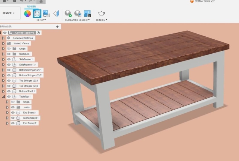
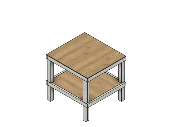
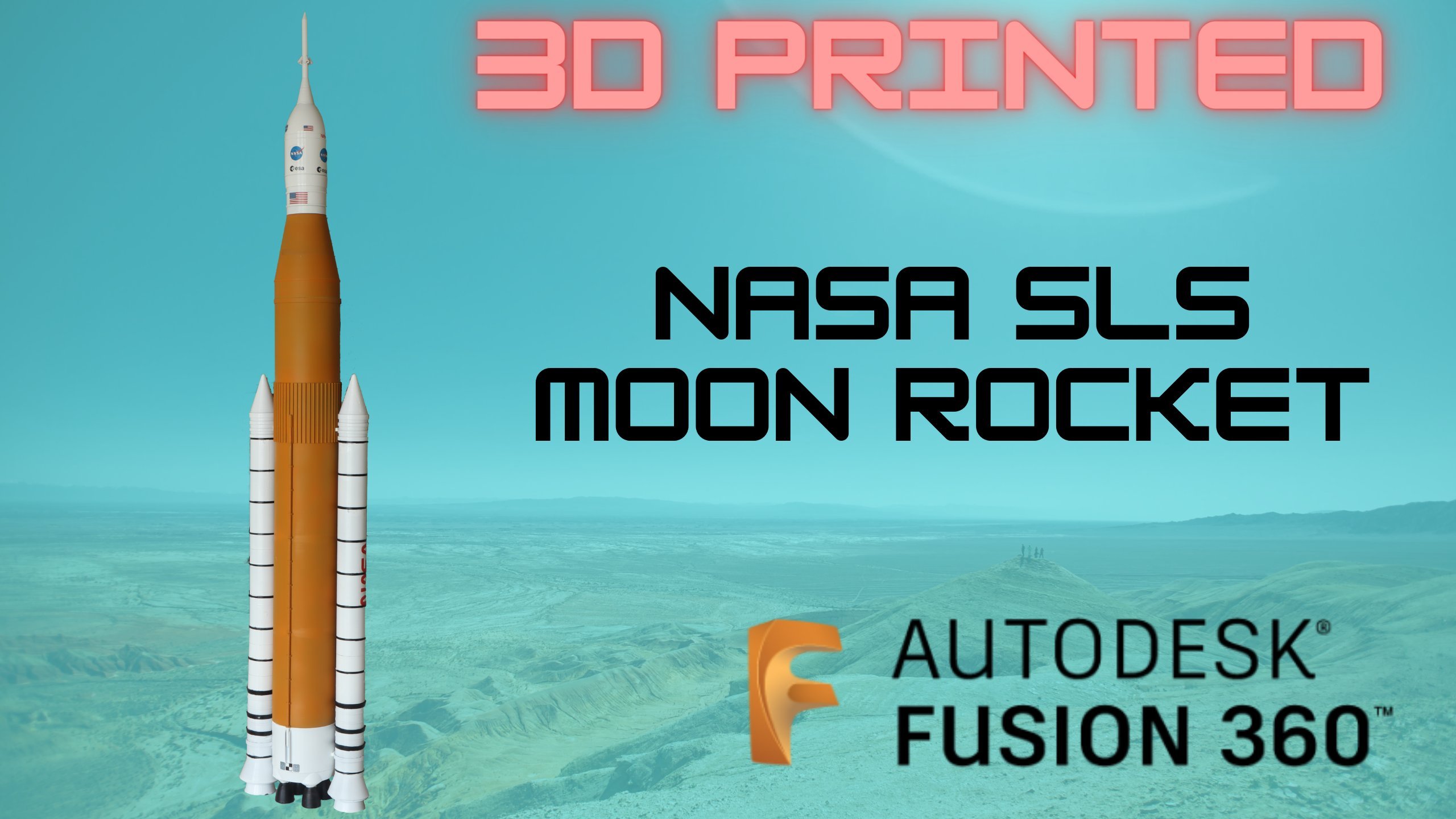
look at this software. So that's kinda where Fusion developed and
where it came from. And you can see it's used. This is a kind of a replica
of a rocket engine. Something about a 3D printed
for some rockets designs. I'll do just kinda best
model type things. This is done in Fusion.
It looks like a beginner. I imagined. It looks like it
might be a bit complicated, very, very simple process
to do is kinda stuff. You'll be doing this easily, even halfway through its cost. So we're gonna go for
all sorts of things. And in the next chapter, I'm just gonna give
you an overview of where you can get Fusion from and how to get
it on your system.
2. 02 Where to get Fusion E: Okay, So I'm only
Autodesk website now. Autodesk.com. This is US site. Now you might have a, I believe as a European
site amaze Asian sides. But what I generally do is
start on the US sites.on.com. And I believe if
it wants you to go to a local one, it
will take you there. And if you go, if you
look at products here, now altered us as the suites which are combinations
of products. So that would be something
that included fusion, but it also includes lots of, these are gonna be expensive. If you go to view all products. And again, this website will
probably change tomorrow. Again, this website may change
tomorrow for all I know. So it might look a bit different when you're
doing this cost, but the layout
should be the same. So basically you're looking
for this kind of Fusion 360. And you can see there's a
special offer on at the moment. Actually, very good offer
because it's usually 495. If you buy a full one. At the moment it's only 447,
which is very, very good. When you when you look at
what some of these are, AutoCad revit
suites, collections. So you can see it's
a very good price. I mean, inventor is a lot more, so very good price, but you don't need to buy it. As I said, Let's just
click on Fusion 360. You can see we've all
Autodesk courses. What you can do is
you can download a free trial and you'll
get 30-day free. So it might be just to make sure we're all
on the same sheet. You download a free trial and you use that 30 day free
trial to follow on him. He's costs and we
will be exactly the same and our software will
look exactly the same. The free hobbyists version. Now it's not gonna be
completely obvious, like software
companies tend to do. But if you get a 30 day trial, then you can look at getting
my hobbyist version. And you can just put
that code in after your trial ends and it will
allow you to continue. I'm going to try and
find it for you. Okay, so you see this
web address here, products Fusion 360 personal. As of today. This is how you would
get the free version. So it's coming up now you see it's taking me
to my local site in the UK. It's telling me the
price for the UK. And here we have this fusion
free for personal use. It's free. Get started, okay? And it tells you some of
the things you don't get. A lot of it is this
kind of thing. So if you're doing CNC
and serious CNC stuff, you don't have as many axes for milling, that kind of thing. I would say if you can afford
this kind of machinery, you can probably afford to
pay the 300 pounds a year. But there we go, you can see the differences
that you get. Okay. You're not really going to
notice it much for this. You're not going to notice
that for this course. But I still recommend
just get a free trial. Do the free trial for 30 days. And then when it comes to having to put a coordinate,
the end of the third, today's just asked for his free version and you'll
get a code for that. So again, this might look different when
you're doing this course. They'll probably go and
change it tomorrow. But it's generally
the same loud. Okay. So click on free trial, download the software, install the software as you would
any other software and menu. Open it up and you will
have a new copy of fusion. Again, if you've
already done that, you're already playing around. Just go, move ahead. Okay, So let's start looking now at how
we use the software.
3. 03 Interface01 E: Okay, so you've got Fusion, you've installed it and
you've opened it up. You should have a screen,
something like this. Okay. I'm just going
to, again, like I said, I don't want to go through every command and
share what it does, but do need to show
you the basics of getting around
that kind of thing. So you may or may
not have this kind of panel on the
left-hand side of it will look different to mine. But you might have it, you might not. If you don't have it. If you screen looks like this, you just click on
these squares here. And it shows it's
called the Data panel. And basically this shows your
projects, your creations. It's like a file
storage for yourself. So you might just have
something that says Fusion mastery on my Fusion,
something like that. But these are all kinda
projects I've worked on, so you won't have those. Eventually your own projects
will be shown there. And then you've got things
like libraries, samples. Generally use this to
get your projects, but if it gets them
away, we just close it. Mrs. your main Fusion workspace. Now, what I will
say is I'm using a, a three button mouse, which is essential for
doing this kind of cut fan. You want left button, right button, and a wheel. And when I'm talking and
going through the course, I will be saying things like
right-click, left-click. We'll no scrolling
wheel out, scroll out. Okay. So you need to
make sure that setup. You can do that on
the preferences. So if you click on
and you can do that. Now we've Autodesk as you've
probably already found out, if you've got the software, you had to create
an account because it kind of partially
runs on line. You create an account with
Autodesk and you will have your whatever photo you've used if you've used when appear, but this is your account. And up there, if
you click on that, you can see you got
your Autodesk account and you've got preferences. This will give you all kinda
main software preferences. There is some preferences for the drawings and this
is your main one. So this will do things like the default, default
units. Okay? So you want your design
minor in millimeters. This course is gonna
be in millimeters. If you want to use inches, you can just works exactly the same when I type
in something in millimeters. So files to type in 25 mm, you would type in one
ain't shot kind of thing. Might be easy to just follow
along in millimeters and then use it in inches
if you want to. Just works exactly the same way. It just depends how
you've got it set. You can work in centimeters, you can work in meters, you can, you work in faith if you want. But for the course we're
gonna do this in millimeters. And that's under
default units design. There's also with a mouse
user preference thing. Some people like
myself like to zoom in when you scroll forwards with we'll and then when you scroll
backwards you zoom out. But just to me, that
just makes sense. But some people like
it. We have a way. So it's kind of merit
and general here. You can do that reverse
Zoom direction. Okay? So I like to
reverse it. Apply. Now. I can, now I can zoom
in and out with a wheel, but we'll see that when
we start modelling. So that's all I'm going
to change for now. In terms of settings
we want to keep pit. I want everyone to be on the
same page so I don't want to personalize it or
anything like that. We're going to look
at this interface. So along the top we
have these tools. Here. We've got create Tools, Modify Tools, assemble,
construct, inspect, insert. So these are your main building
blocks for your 3D model. And you can see you got
boxes, cylinders, spheres, tolerances, and
you've got a sketch. Most of what you do in
Fusion is Sketching and extrude in that kind
of thing. You can modify. So you've got your
Modify Tools here, will look at all those. This is your drawing
space. Okay? I'm this here. There's not a divided
between them, but this is gonna be a list
of files and it will get larger as you create
more geometry. And this is where you can think of it like a file
system for your project. I don't wanna go
too much in detail. What does, because it's when
we've got enough in there, it won't make sense as we
work ahead in this course. This will start using
this and it will become, you'll just realize what it is far because there'll
be items in here. Now, on the left, you can see
we've got a square design. This whole toolbar here
is for Design toolbar. We have other options. We've
got generative design. Okay, That's quite a
complex, way too complex. This course we'll do another
course all about that. We've got render, a photo-realistic images
and that kind of thing. Animation, obviously to produce Animations of your designs, simulations of your designs. We've got the manufacturer. We've got manufacturer. This is where you
can go direct to your expensive CNC
machinery if you've got it. If you work in a
fabrication shop and you learn in this
course for that, and this will make sense to you. I don't want to go
into detail about that because a lot of
people using it for 3D printing or just
general modeling for funded outside the
scope of this course. But that's a manufacturer tab. You've got drawing from
design or animation. Okay, so now the one
we're going to use mainly what start is
for Design button. This will give you our
main Design toolbar. This is where we basically
create our models. So that is the toolbar. And we know about
this, this will, again, this will make more
sense as we've progressed
4. 04 Interface02 E: So if you're not familiar, if you've already used
some cuts off for, you probably know all about coordinates and the
coordinate system. If not, I'll just go through
a brief explanation. Now. We feel going
to create a model, something say you, it was
going to create a rectangle. You would obviously have a lower left corner and a top-right corner
of a rectangle. Just gonna go. Don't worry about following me along
at the moment. Okay. I just wanted to get something on screen
so I can show you that you would have a lower left corner
and the top right corner. I'm not going to be a rectangle. Now. You rectangle
is fall points. The way those points are
identified is with a coordinate. The x coordinate
is along this way, and the y-coordinate
is that way. So just bear with me. If you're not quite grasp on it, it will all make sense. You have something called the
origin point, which is 00. And when we talk
about coordinates, numbers were just talking units. Whether you say a unit
is a millimeter and a foot meat doesn't matter
to cat, It's just a unit. So if we start at this corner, at the origin, that would be 00. This point. If this, Let's just say this rectangle
was 50 units by 50 units. Again, doesn't
matter whether you say it's millimeters or inches, we're just talking units. Now, if this was 50 units, by 50 units, this rectangle, then that point will be 00. That point would be 50 comma zero because it
would be 50 units in the x and zero in the y. We always do x first, then y. This point would be zero comma 50 because it's zero in the
x-direction, 15 and y. And this point would be 50, 50, 50 x 50 that way, and 50 that way to
get this point. So each point has
its own coordinate, which is based on
the direction in x this way, and y that way. If ever you don't know
whether you use an x and y, you can look at this square, and this is in a 2D sketch mode. You can see the red
X is going along there and the greenway
is going there. So you coordinates in
this direction and all x coordinate SAP direction
and y and x is always. If you're going to
write down coordinates, you always do x first and
then y. I remember years ago when I was in drafting school many years ago we still use the drawing board. My instructor said it was something like
walk along the London. I'm going up the stairs,
which never made sense, but that's the way
you look at it. It's x first and
then y coordinates. Again, I don't if
it's a bit vague, just it will all become clear
as you use it. Believe me. Now that's 2D x and y. But what about in 3D? So what I'm going to demo it. Don't worry about following along because you won't
know what I'm doing yet. Probably I'm just
going to create some geometry just
so I can show you. So that was what we had in 2D. We had X, we have Y,
and we had a rectangle. When we're in free day. If we look at it as a cube, you can see we've got,
we've got our x here. We've got our y, which
is about measurement. But now we've got this
height of the cube, if you like, which has come up from the
rectangle, I might exempt. So you've got x, y, z, and that's how you'd
write them down. Isn't but let's just
say this was fit. Okay, let's say
this is 25 units. So our coordinate would be, if you were to write down
the size of this cube, you could say it's
50 by 50 by 25. I'm not sure x why is that? 50 by 50 by 25. And that's basically how
this view cube works. It's going to delete that. If I click the front
of this view cube of view wherein is
looking directly down, we've got x up that
way and y that way. If I wanted to see it in 3D
mode, I can see it here. And this gives you control of what side of the object
you're looking at. Front would be with x and
y in those orientations. But if I wanted to look
at the side of an object, I could have x coming
towards me in that way. It will become more intuitive. You will just start
using this and we'll just click in your brain as
you, as you create them. But that's basically how
his view queue works. You can click on this
cube and it will allow you to view whichever
side or whichever corner. If you want a 3D view, you want to look up and you can just rotate it and
move it like that. There is some options on here. We'll use some of
those as we go. But that's basically
clever view cube. Okay? So that's all I
wanted to do in terms of explaining the interface. Now, there's more to know. We've got this
timeline down here. But we'll show you those as we use them or it won't make sense. So in the next chapter, we're going to create some
basic models and other cubed, things like that, just so you can get used to the interface
5. 05 Basic Modelling 01: Okay, so now we're
gonna get our, get some actual hands-on
Modelling done. We're going to basically
reproduce what I did in my example of
in a jar I basic cube. And we're just gonna go
through how we would do that. And just a general
way for new commits, a Fusion to get modelling. So the one thing to
understand about Fusion is 3D models in a large
part based on 2D sketches. Okay, So let me show
you how that works. If I wanted to create
a box, I can click. I can go create
and pull down with create menu and I
can click box there. Now what Fusion will do is going to show me these three planes. And the way you
can imagine these, if you imagine join
on a flat piece of paper and then
creating your shape. These could, these are like
your flat piece of paper. These are called Work planes. So in the previous chapter
went through V coordinates. You've got X here in red, we've got why ingredient
and we've got zed here. So if I wanted to draw the shape in the
x-y plane on that face, I would select that
workplace if I wanted to draw it
as a top-down view, I would select that plane. And if wanted to draw
it from the side, I could select that plane. So again, just bear with me. For this one, I'm going to draw it in the x-y orientation, and that's how I'm going
to create a sketch. Now once I've clicked
on that, you can see this symbol here
at the origin point. So that's 00. So if I
was to left-click there, now you'll see it lets me draw this rectangle and it's
giving me these dimensions. Again, minor millimeters,
just think them as units. If I wanted it to be 50, 50, 50 by 50. You could try and do it by eye. But when it's
highlighted in blue, you see one of the
boxes highlighted blue. That means you can type it in, so I can just type in 50 there. Now, don't don't presenter, I want to go over
to the civil box. That gives me his high.
So press the Tab key, which is but two opposing arrows on the left-hand side
of your keyboard. But top-k will take you
into the other box. Can type 50 there. Now I can press Enter. You'll see now it's giving me
another box for the height. Let's say I wanted
this to be 25. I can type in 25
and press Enter. And now we've got our Q, which is 50 by 50 by 25. Okay? Um, that's how you create these Basic
Modelling shapes. So let's say we want
to cylinder now. Well this cylinder, again,
we get these Sheets. This time. I'm going, you say I can't select
these shapes because it's selecting this block. So let me explain
what's happening. If you're modelling and
item, let's say this, Let's say this cube had a kind of cylinder protruding out
from that face there. As well as selecting Sheets
to draw on automobile. And you can select faces
of existing objects. So in this case, the cylinder is going
to come off fat phase. And you can see as
I go over the face, highlights, if I click it, it allows me to place a
center point somewhere. So you would generally no whereabout somebody's
face, you wanted it. But the way we're going to model this is I'm just going
to do it by eye. You'll see a can come
up with these snaps. Now what's happening here? If I, if I put my
cursor near corner, it kind of snaps onto that corner and we
get this blue square. So if I was to click there, it would go exactly
on that corner. If we go inside, if
we go to a middle, we get this blue dashed
line that comes up and you'll see there's
a triangle snap. Now that's saying it's going
to put it on that line, which is of a midpoint. So the triangle means midpoint. It's going to
automatically put it on, on the center line, the midpoint of this line, if you like. So it'll be right in the
center, which is good. And we can do it the other side. We can get a sense of air. So if we wanted to actually
in the middle of this plane, all we need to do is go
to that center line. Okay? So we can get, we can put it somewhere
in the middle if reliant, but I'm just going
to put it run. I'm going to have a central here and just put
it about there. When I click once,
left-click once Now it's going to ask me what
diameter cylinder today. I'm gonna make this. I'm going to 12, I'm
going to type in 12. I'm and I'm going
to press Enter. And then it's asking me if a final dimension which
we can type in it, we could get these arrows. You can actually pull these. You can left-click and hold down and you can pull them like this. Okay? So I'm going
to save us 25. I'm going to type it
in and press Enter. Now one thing to bear in mind, this is kinda one object. This object is a
cube of a cylinder. It's not two objects when we're modelling and we're creating an object is just one object. So if we were to, if we
wanted a cylinder separate, we would have to do that as
a different object and we'll go through that in a bit. That's components for now. This is Basic Modelling. So we're creating
warm part here. If we wanted to create, let's say a sphere
for some reason on this corner or on this face. Let's say we wanted it there. Again, a similar
thing so it can go to midpoint and we can
select this sphere here. Now, you'll see it's
come up in red. So red means it's
going to object. What Fusion will do
as you're using it? It will take an educated guess on what it thinks
you want to do. A lot of time, it gets it right as it's quite intelligent. But let's say we want
today an actual sphere, kind of half sphere
sticking out of here. If we were just, just, well, let's give it a
size, let's say 20. Enter. If we were to just okay that it's
done it as a cut. So it's cutout this
circular sphere, which you may or may not want. But we didn't want that. We want to change this. Now. You don't need to draw it again. You can change it. This is where your
timeline comes in. Down here, you'll
see it's a bit like a media player controls
a Mrs. your timeline. So it goes back over
history of your model. Now if you don't have this, it means you're not
capturing that history. Sometimes for whatever reason, you might not want to
capture this history, whether it's to
do with resource, some computer file size,
but kind of thing. But we're capturing the history of this model so we can
see what's happening. If you don't have this, then you need to go to, this is your object here. Right-click and you
get these options. And then at the bottom it
says capture design history. I'll do not. Mind is turned
on. So it seemed do not. Okay. If yours isn't turned on, it will say capture
design history, so you can select that and make sure you've
got this timeline. So with that, what we can do, we can drag this slider. This slider is,
think of it as now, this is where we are in time. We can drag it back to that. And you'll see that sphere
is gone because we've gone in our timeline, we are, we've gone ahead of, well, we've gone to the time
before we create a sphere. We can go to where before
we create a cylinder, right back to the start. What we can also do in
this timeline is we can edit what we've done. So if I select the sphere
here and right-click, I can go to Edit Feature. Now we get the options back
for the size of things. These are the options that
we use to create the object. And you'll see it's
in red because it's cutting it. Up here. You will see in
the dialogue box, we don't have to use these
arrows and text things. We can just put it all in here. Every time you create an object, you'll get a dialog box. So we have some options here. We have 20 mm, which was a diameter or units. And our operation
is cut where we wanted to add a
spherical side to it. So instead of cook
infusion, we call it join. And if we slept, that is now created the object if we okay, you will see it's
created that object. If you want to pan around, if you want to zoom in Fusion, hold down your middle wheel on your mouse,
just hold it down. If you drag around, you will see, you
will pan around. So you can pan around. You're not moving
the object here, you're moving your viewpoint. If you hold down
the Shift key on your keyboard and
hold down the middle, we'll, you can rotate your view and you can get
a good look at your items. Again, you can zoom in and
out with you will light up and hold it down to
pan if you want to. If you suddenly go to View
and you don't know why you, why you can click on the
view cube to get you back in the right position
where you want. Okay? So we've created
this spherical object now, and we've looked
at the timeline. And we've looked at
our dialog boxes, fall creating objects,
and you've got various objects there
so we could do a torus. Okay, It's oris is what we
used to call a doughnut. Again, it's on, I'm
going to put it on Join. You can have all
sorts of options here about the diameter, maybe being a diameter,
want it to be 50. And sour stomach Tools, 50 guys see you
guys. Bulging thing. Maybe like in fact
if we do but at 25, it could be some kind
of handle or pipe. It's a bit rough,
but that's a torus. And we have coils Pi. These are, think of these
ready-made objects in Fusion. So you've got ready-made cubes, cylinders, spheres,
kind of thing. Now, most people I know
who use Fusion don't actually use these
ready-made tools that much. And we tend to model
items based on sketches, which is what I'm gonna
show you the next chapter. But I wanted to show you this is the basics of how
we lay out models. We use coordinates X, Y, and Z. We give, we choose a face or a drawing sheet
called an object plane. I'll stop calling it Sheet now
call it what it really is, which is an object plane. If I was to go box these
yellow squares error is the object planes. Okay, amazing your origin plane. So this is your X, Y Zed kind of planes that
you start with a blank project based around
the zip is 000 point, which is your origin.
So they are playing. Use those to say where
you want to draw and when you use either one of these shapes as a basis or more realistically use a sketch and
you put that on the plane. But we'll look. I just wanted to show you about some basic modelling techniques. And that's a timeline. And hopefully it's
becoming a bit harvest. Have a play about with this
shift and middle button to move around and pan and zoom because you've been doing a lot
of this and it'll become second nature sun, but you just want to get used
to it and have a look at this view cube when
you do it and you'll see it moves around. So it gives you your view. And that's kind of the interface
and the Basic Modelling. So that's going to be very familiar with in
very short time. But that's just an overview. So let's look at
doing some actual, real modelling like
you would. Sketches
6. 06 Basic Modelling 02: Okay, So here we can
delete this now, left-click and drag a window over it and just delete a lot. Okay? So when you go to a
new design Fusion, use these tabs bit
like of the software. So we've opened a new project, and our old project
is still open-air. We can just close
that with the cross. We're not going to save out
it was just an example. So now we're going to look
at sketch-based modeling, which is what most people
use most of the time. If you think of items,
you might muddle. They're not usually based
on cubes and cylinders. And even if they are, a lot of people just prefer
to do it based on a sketch. So how do we do that? Well, under this create command, you've got this option
here, create sketch. And it's actually
because it's used a lot. The buttons at the
top pair tools that I used a lot, Image menu. So this first one here is create sketch. We're going
to click them up. Again. It will ask you which plane do you want to
create a sketch on. So we're gonna go
into X, Y plane. You'll see we get
this point here. Now we've sketches, really
want to be looking top-down. So our x-y plane where we
did the sketch was here. We can, we now have this
sketch palette dialog box. What we want to click on
this here, which is look at. If we click that, you'll see it's flattened us
onto the plane. We're looking down
on to the plane, we creating a sketch
on which makes sense because when your
sketch looks correct. Now what you'll notice, this whole toolbar
here has changed, and this is the sketch toolbar. So whereas before we was in
this solid modelling toolbar, now it's automatically puts
us in this sketch toolbar. And we get these
sketch commands here. So we've got rectangle,
two-point rectangle. If we click that,
we left-click that. We can drag the screen now by holding down
our middle button. We can draw a rectangle if
we want to draw it at 00. If we go near to that point, you'll see it snaps on 00. I'm going to left-click there. I'm gonna drag this corner
out and you'll see we get these dialogue boxes
and we can use with tub command to switch
between the two. So again, I'm gonna do 50, I'm gonna press tab, and I'm gonna do 50, I'm
going to press Return. And now in our sketch, we've got a rectangle. Okay? We've got way more
commands we can use for sketches and we'll be looking at always throughout the course. But for now, I just want you to look at that
rectangle, 50 by 50. And we will go now
finished sketch. This takes us back
into our Modelling, our usual Modelling workspace. We're still looking
down onto the sketch. We still got this view on. Let's say we click. Now we're in a 3D view and we can see, we've got a sketch of
the rectangle down here. We've got our symbol for sketch. If I wanted to make
changes to that, as usual, I can right-click
and go to Edit Sketch. And I could double-click A's and maybe I could
change that to 75. Go finished sketch. So you can, you've got control to be able to go back in and edit them. So now we've got a, well, this one is 50 by 75, and we want that into a
cube like we did before. So the way we do that now, the way we model from a sketch
is by going to extrude. So I'll click on Extrude. Again. Fusion is going to
take a guess on what it thinks I
want to extrude. So the only object in this model was that
rectangle sketch. So quiet Correctly guessed. You see it's
highlighted in blue. If I click on it,
it's de-selected. Fusion has selected it for me because it's taking a guess on the object
I want to extrude. If I left-click it again, I've selected that rectangle. Now. I can drag this to extrude shape or I could
just type in their 25. Okay. Again, I've got our
usual things here. I've got a dialog box
here for Extrude. Now, let's suppose
I wanted that way. Okay, Now this way, now if we go that
way from a sketch, it's gonna, it's gonna
say it as minus. This way is plus units. That way is minus units. And we could go -25 We'll look more extruding later
on and we'll look more at these different
commands later on. But I just want
you to understand the difference between creating objects with these primitives here and what most people do, which is to create a sketch. Now it might seem like they're about to
25 and click Okay, you see we get the
same thing here. We've got a feature
so we can right-click that and we can edit. So maybe you wanted to make
it 35, we can edit it. But it might seem when you watch them as
you might fit well, that seemed a bit
more long-winded than doing the primitive box. Okay, So why would you, what would you do it that way? Why would you do a
sketch when you can just use a box and you'd probably be right in terms
of a cube or a cylinder. But I'm just going
to left-click, I'm going to highlight all
that. I'm gonna delete that. Okay? I'm gonna delete that sketch. So you probably be
right in the case of a cube or cylinder, but usually you'll be creating something a bit more
complex than that. So I'm just going to show
you an example again, I'm going to
left-click on sketch. I'm gonna go to
our x-y workplace. I'm going to look at
it, face down at it. And now instead of using
this two-point rectangle, I'm just going to
click this line here. I'm going to start at zero
as areas it snaps to it. Now, you'll see when
you draw a line, you get to dialog boxes and you can use tubs,
go between the two. So you've got the angle here. So if I type in 90 and
then tap to move on, you'll see it's locked
now at 90 degrees. I mean, you've got
your distance, so I could type in 100 here. It's drawn a line at 100, okay? Now I'm going to carry,
I'm going to click line again and what it will allow you to do it
with light it to snap. So I could snap to a midpoint. I could snap to that end point. I'm gonna go on the end point. And this time, just to show you, I'm just going to draw
something completely random. And I'm going to snap
to that end point. And you'll see when I
snapped to that end point, I get a blue shade. If I right-click, I can go Okay. That blue shade basically
means it's a closed shape. You'll see there's no
open lines. Think of it. If I was to fill this, it couldn't leak out anywhere. The lines are all
closed at the end. Okay. So if I go
finished sketch now, and I'll go into a bit
of a 3D view again. I can click on Extrude. Again, it's slightly
about shape from it. I can extrude that 100. Now I don't know why
you'd want that, but you can see nowhere. Obviously in these primitives is there a shape that
looks like this. So using sketch
will allow you to do well whatever you want
basically in terms of shapes, whereas the primitives are
just cubes and cylinders. So usually we will base all our objects
off a sketch lighter. And you can edit. So if I wanted to
edit the Extrusions, remember this is, this is
made up of two things. A sketch which was
kinda up profile shape, and an extrusion, which
is how it's extruded. So I can right-click, I can go edit feature, which is the extrusion. And this will let me edit
things like the size of it. I can also go back and
I can right-click. I can say Edit Sketch. And maybe I wanted to. If I just left-click
on that line, you say it allows
me to track it. So maybe I could just drag it
there and make it smaller. Now if a finished sketch it
will automatically shape. So in the timeline you
have these two items. Most of the items
you create like this will have two different things. You'll have your extrusion
and you'll have your sketch. So that is Basic Modelling
with Sketching extrusion. Now we're gonna go in a way
more detail about sketches, and we're gonna look at more
detail about Extrusions. But this is just an overview
of modelling process. So if you want to have a play about creating some sketches
and Extrusions, don't worry if you
get any errors or failures or things because it'll become clear as we
look at them in more detail. But that is Basic Modelling. Using sketches, we can
use Bayes if you want, and certainly with pipes,
you might use them, but generally, you
basic objects, we use sketches and Extrusions
7. 07 Basic Modelling 03: Okay, so I'm going to close
that and not save it. And it will automatically start a new project
for his hair. So we're going to look more at this extrusion now because it's a command you're
going to use all the time. And I'm going to show you, let's, let's create
a sketch first. And we're going
to use that plane there. And we're
going to look at it. Now. I'm gonna go to, we use this rectangle before. Again, we'll look
at Sketching in more detail in future chapter. Because quite a, it's a very important and it can
be quite complex area, but we're going to click
on my switches circle. What is he's going to
want? It's just going at the center point of a circle. In this case, we'll
use 00. And then it will want to diameter. I'm gonna go with
a diameter of 200. I'm going to press Enter,
zoom out a bit with my wheel. You could
click this corner. I'm going to hold down shift and middle wheel and just
give myself a viewer one, okay, something like that. I'm going to say Finish Sketch. So we've got our
sketch down here. Now I'm gonna go to extrude. I'm going to drag this out. I'm gonna do it,
let's say to 50. Okay, so we've got
a cylinder of air. But what I want is I want, it's gonna be kind of like a shaft type with
different diameters. So what we can do, we
do a sketch again, but this time instead
of choosing one of the planes to do our sketch on, we're gonna do our
sketch on this face. Here. You'll see it's put a center point automatically
because it's in a circle. The face was a circle, so it gives a center point. So I can go again
to sketch circle, center point, snap to that. And I'm going to bring this out. So that was 200 this time
it's gonna be one-fifth. Now, if I finish that sketch, go to extrude again. It will allow me, you see, I can click inside this circle. And then I can pull this out and I'm going to make this 150. Okay? Remember when we're creating models is
this is one object. We're not, we haven't
got two cylinders here. You can see the face
is a highlighting, but this is one object. I'm gonna do another
sketch on here. And I'm gonna go same
again. We'll look at it. I'm going to create a circle. Snap to the center point. This time let's go with 100. Finished sketch. Hold
down shift and middle. We'll get a 3D view. Extrude. Select that sketch. And let's make this 150. Okay? So you can see you can get these kind of shapes,
something like that. I'm going to want
smart, I'm gonna go sketch onto that face. This time. I don't need to look at it. I know
what we're doing. I'm just going to
create a circle, snap to their I'm going to look at it. I'm going to create
a circle again. This is going to be,
I'm going to make this 50 diameter enter, hold down shift
and middle wheel. And I'm going to
finish that sketch. I'm going to extrude
just as we did before. I'm going to select
this rectangle. Sorry, I'm going to select
the circle and you'll see it. We can do exactly
what we did before. But if I go this way, now it turns red. I'm gonna go into 100. So it's 100, 100. Okay, so what I need to do, you might remember it's plus
minus so -100 will go in. I'm gonna say, okay,
so now we've got this object and it's
got a hole in the end. That could be something like a shaft or a tool or
something like that that will be taken
down on a life. But they gave us basic
objects service. The thing I wanted
to show you in this lesson was V
Sketching extrude. It builds on top of each other. So we've got sketch and
you can see them here. Sketch, Extrude,
Sketch, Extrude, Sketch, Extrude,
Sketch, Extrude. And you can build up quite complex models just
with those commands, the Sketching and we extrude, and it's something
you'll use a lot. The sketch extrude. You'll use all the time And it really is the basics of this whole process
in a lot of ways. So you can have a
play about that. Maybe you wanted to do a, let's do a sketch on this face. And this time I
want a rectangle. Let's look at that.
I want to rectangle. Now if I go to the
two-point rectangle, it wants to two
points obviously. So it would be hard
to centralize it, but there's another option,
this center rectangle. You can click on that and then it will allow you to do a
rectangle in the center. So now I can say, okay, let's go to 50. By top-k to 50. Finish that sketch. And then we can extrude. This time. We've seen it
as two different items, so we'll quit both the items. And let's pull out 200. So now you've got this cube. Again, as I say, this is one
item, this is one model. Now you've got these faces. You could maybe do
something there. Let's do a circle. So
let's look at that face. And I want a circle. I'm just going to do it, but I'm gonna put
it about there. Okay? And it will be 50. I'm going to extrude.
I'm going to go in 100. You'd have to put a minus. Remember, so I can click that right-click Edit Feature and
I'll need to do is -100. That you'll see again. Nothing's happened. Well,
that's because it's on Joints. So if I right-click
Edit Feature, you'll see the
operation was Joints, it's create a solid we're going
assault which is nothing. So I need to uncut further,
you get that happen. It just means you need
to change it to cook. Usually it does
it automatically, but then maybe I'll miss plane. You've got some guy
rectangle down here. Let me go to two-point
rectangle, something like that. And this is going to
extrude out Sketching. And you could say,
I'm completely making this up as they go along. But I just wanted to show
you this process of creating different sketches
and then extruding them minus 150 to create
these kind of shapes. And you can see that might
be something you need. So that's the basics of
Sketching and extruding. Some of these sketches
we've done for these kind of Holes and this rectangle there
were a bit random. Usually what you would do, let's say we wanted
a circle here. You would usually no whereabouts
it, it wanted to be. So if we say look at and
we create a circle here. And it's usually you
would have a dimension from this face and a
dimension from that face. We can do about, we
can lay that out. So once you've drawn your
circle under create, if you post a new will see
we have sketch dimension. If you click sketch
dimension, now, I would dimension is
probably being given to us as the distance from that edge to the
midpoint of a whole. So that's what we're
going to click. We're going to see these
lines now we've slightly dimensionally things
highlight as we go over it. We're going to
left-click that line. And we're going to
left-click center that hole and you'll
get a dimension, just drag it out and click
it and see where it drops. So that's the current distance. Now, let's say we
wanted that to be 75. We can type in 75. And you'll notice
the circle moves. We've tied it to a dimension. So we're gonna do that again,
create a sketch dimension. And we'll go from that
line this time to the center. And
we'll make this 75. Okay, so now that sketch
is tied on that plane. If we finish it, hold down shift and middle
wheel and now extrude, it, will extrude it. 50. Object is tied to those
dimensions and we can, if we want to change it, we can go back in our history. Find the sketch for that object, which was about one
right-click Edit Sketch. And we could change. It may be that wanted to be 100 of
the object was changed. And I said now we want this
to be 100 and not to be 150. We finish it and it updates,
everything updates. So you can go back
in this history and you can change things. We could change
whatever we want. We could find a sketch,
maybe that one. We could put some
dimensions on here. So let's tidy this up. That's 100 by 50, okay? And we want to have a distance
from the edge to be 25. The distance from
that edge to be 50. Okay, finish. And you'll say updates. You can go back in this history and you can change everything. You have full control in
this modelling process. But that's Sketching
and Extrusions. Sketching and extruding
gives you that control. You can. We've just changed
the position of that sketch. But if we want to
change the extrusion, we write, we click on my
feature of extrusion. Right-click Edit Feature
and we can change up, maybe it wants to come out 100. And then we go. So you get this full control
over the history of design. And already, we've got
quite a complex part here. It's just been modeled
with that same process, sketch Extrusions,
Sketching Extrusions. So that already you Modelling
already now to do that, and I would say a large part of most people's Modelling is done with sketches
and Extrusions. Now we're going to
look a bit more at the extrusion itself and the different
options you can get
8. 08 Extrusions 02: Okay, so I'm going
to close out again. You can save it if you wish. Which two? And I'm going to look more up the extrusion options
and dialogue box. So let's just do a sketch
onto this phase here. This should be coming fairly familiar. We're
gonna look at that. We're going to do
a circle is 200. Okay, So finish the sketch. Hold down, shift and middle. We'll give me a
bit of a 3D view. And now I've got
something I can extrude. I've got basic circular
sketch I can extrude. So I'm gonna go to
extrude Fusion selects. It knows what,
what I want to do. Now up until now, we've seen that you
can extrude that way. You can extrude that way by
adding a minus two all units. We can create an
object like that. Even these directions basically. But there's way more you can
do with extrude them that. So let's look at this dialogue box and
let's work through it. First thing it's asking
us is type of extrusion. So if we wanted this
is a normal extrusion. It gives us a solid cylinder. If we click on that one
and just click Okay. Now what it's done
here is it's given us just the outside of a circle. So this is like a pipe. If you go back to
Options Edit feature, you can see, can select
the thickness of walls. So if we wanted it to 0.5 pipe, then that's an easy
way to do that. I'm gonna go back to these
options by Edit Feature. We're just going to stay
on this normal type of extrusion first, which
is this cylinder. And the first option it
asked for is a profile. The profile is
basically the sketch. What do you want to extrude it slightly about automatically, there was only one
profile image files, so it selected, but I'm a
profile was that sketch, but you could select
multiple. So let's go. Let's delete that sketch. And we will put another, let's put another circle
I'm just gonna do is buy I completely random. I'm going to go finished sketch. I'm going to undo that. Go back to our
sketch and I'm going to select another circle. I'm gonna do a rectangle. I'm going to finish that sketch. Now if I go to Extrude
and it's a slip profiles, it doesn't know which
one I want to select. It hasn't slept through
it automatically because there's more
choice basically, before we only had one circle, it was obvious which
profile wanted. Now, I need to actually choose a Profiles
I want to extrude. So that's this option here. Profile, it just means
which object you want. So let me just get
rid of those again. Finish Sketch. Extrude. Profile
is about object. Now start. Where do you want the
extrusion to start from? Most of the time? You would want it to start
from the object you drew. In this case, we drew the circle and we won't be Extrusions
start from there. But we could say we want the
stat to be offset by 50. Mm. Okay? Now what it's going to do, if I okay That our
sketch, how to save it? If you see our
sketches back here, it's offset 50 mm
and then started it. Okay. So that's this offset. You use that when
you sketch it on. If we were to use a plane of an existing
object as a sketch, we can offset it from there. Generally, you'll be using
this profile plane direction. One side, this is
one-sided Extrusions. So that's our sketch. We've extruded outside. We extrude it that
side, that's one-sided. But you can do two sides. So now I could have
Extrusions there. So maybe I wanted it to
extrude a bit out here. Which will be -20.
Sorry, which will be, you don't use a minus here because you already told that you're going out either side. If I were to go 20, it
will it will move it 20. Or if I put a minus on this one because it knows we're
doing it the other side, it would bring it in
if that makes sense. So 20 by 50. So again, to see, but our sketch is basically this line here and it's extruded 20 that way, 50 that way. So it's two-sided and you
can type that in here. So you see when we've got it on direction two sides,
you've got side1. We want a distance of, let's change up to
70 and psi2 we want a distance of 30. We can change. You'll notice there's
some other options here. As well as the distance of
70. We could have a taper. So we could type of 45 degrees. And you'll see it tapers out. Again. Right-click Edit Feature maybe wants to say for
M, So that'll be -45. We can do something like that. Again, you get all this
control to do what looks like fairly complex things just easily with the
extrusion command. Generally, I wouldn't, if I
wanted to create a shape, I wouldn't do it that way. I'll show you, will do
some light around and I'll show you how I would do it. But it's a two-sided extrusion. You've got two different
dimensions for each side and you extrude
on each side of the sketch. Now if you ever want a
symmetric here, you've, you've only got one
distance now you are extraordinaire
both sides again, but because it's symmetric both sides of the same distance. So if you put 15
here, it will go 50. Both sides of the sketch. Hopefully that makes sense. Now, down here,
use the operation. We've got new body,
we've got Joins, we've got cuts, we know of M, we've looked at them but
we've also gotten new body. And most when we've been
creating these objects, It's been putting
it on new body. Bodies and components is
something you need to know, but not quite yet. We'll look at that.
Okay. There you go. So there is a bit
more too extreme. You can extrude from
planes and things like the best way to show that is when we
create in an actual model, it will make more sense. But that is your extrusion
command and your options
9. 09 Revolve: Okay, So I'm gonna, I'm
gonna close that are not saved. I'm going
to start again. And now we're going
to look at some of these other creation techniques
that are available to us, Extrusions we've looked at now. We'll be doing way more
about me examples. But we're going to look
at these ones here. So we've got Revolve,
Sweep and Loft. Okay. And let's have
a look at those first filling going to
do is I'm going to do a sketch on this plane. And I'm going to,
Let's look at that. I'm going to draw a line. So I'll select line. I'll snap to this zero point. I'm gonna go straight
up, straight. I'm going to make sure
it's on 90 degrees, okay. And it'll snap to
the 90 degrees. And I'm gonna go,
Let's go to 50. Press Enter. It gives us 250 millimeter or 250
unit line straight up. Now I'm going to
click on line again, and I'm going to
snap to that point. I'm just gonna, I'm gonna
go straight out there. Let's go 25. And to do a line again from
there, I'm gonna go. Now I'm gonna do the
rest of it's just buy. I don't worry about
exact commands. Now, I want to show you if
you click on this line, you can do as well as straight
lines, CVs or Australians, you can do ox and you do
that when you left-click it, you need to hold it down,
hold down Alt left-click. So if I, instead of just
clicking once on that, I'm going to click
and hold it down. And then I'm going to
drag the mouse out. As you drag the
mouse because I'm still holding down
my left button. So you let go. It will
create this kind of. So I'm going to let go there. I'm gonna do it the same
again, hold it down. I'm going to create
that kind of object. I'm going to same again, hold down left K. I'm going to create
something like that. Just by I, in fact just
by I'm going to put there then I'm going to again holding it down and I'm going to snap
to that end point. I'm gonna, I'm
gonna press Enter. Now go is really weird
kind of sketch shape. If you didn't quite
get those apps, feel free to undo, do it again. Don't try and get
exactly the same shape. I've got. Just any
random shape will do. Okay, So I'm gonna
go finished sketch. Now. If I look at this by holding down Shift key and
my middle wheel, you can see we've got these
very random shape here. But now, if we wanted
to create something, maybe it's some kind of VAR.S. All I don't know, could be a doorknob or
something like that, but we can use this command
here called Revolve. And this is one of those
commands that makes way more sense once you've
seen it being done. So I'm just gonna show
you how it's done here. We click on Revolve. Again. The profile is, we've only got one profile Sketching this file,
so it's selected it. Now the axes is Valine,
it's revolving around. Again, it makes sense
once you see it happened. So I'm gonna say
select the axes. I'm going to select
this line here. There. You'll see what it
does. It's Revolve a shape based on our sketch
profile around this line. Now if I okay, that
you can see we've got this very complex shape
here. I don't know. It could be something on
top of a fence gate like a metal gate could be a top of that are a bad post
or something even. But it's a very, a very
complex shape that you could turn that on a CNC
lathe or something like that. And to model that, if you looked at that, how long is this cost being so far? Maybe an hour, not even that. I've shown you that. And
so you can easily draw this shape within an hour. You might not believed
it, but there you go. This complex circular model is as easy as doing a Revolve
and we can right-click, we can edit feature, we can look at some
of these options. So we select a profile
which was your sketch. We slept at the axes, which is obviously the
centerline we've Revolve around. Now the type was angle. So we had a friend
and 60 degree angle but didn't have to be
maybe it was just a one at maybe it was something
that sticks on a wall. It's an ornamental
thing that it's got a flat face that sticks on
a wall and that comes out. I don't know why
you do. But maybe that's something
you wanted to do. All sorts of things and muddled. And the skill of using
software like Fusion or any kind of freedom
Modelling is knowing which tools to use
to create an object. If you did want something
that looked like that, you could puzzle for a long
time of how you create it. But it's fairly simple with
just this Revolve command. We're gonna go back to free 60. 60. Again, we've got one
side so you could do it. Well, let's say,
let's go back to, let's say 90 degrees. Okay, So this was our sketch. And it's rotated at 90 degrees, but just like within the
with the Extrusions, it could have been symmetrical around the sketch 90 degrees. So it's gotten 90
degrees evil way. And now it will, the sketch will be my center and
nothing will be symmetrical. Or two sides with two
different distances. It's likely extrusion command is where you are taking
that sketch from. I'm gonna go back to
one side and phrase 60. You could carry on
Modelling from, you could, you could put a sketch on there. Could draw circle. If you wanted a
kind of a fitting. You go, now you've got you've
created a V exact name, but it goes on the
end of the gate of a metal gate post and it's kind of an ornamental thing and it's got a hole
that you can fit it on. You can model quite
complex things easily with this
Revolve Command, anything, circular, vases,
that kind of thing. Also, you can use it for shafts. If it's a complex shape, I tend to use
Extrusions and circles, but if you've got
a complex shape, you can use up, no problem. Anything you're going
to turn on a life. Chair, legs, ornamental chair, legs, table legs,
that kind of thing. Perfect for Revolve command
10. 10 Loft: Okay, so again, we'll close
that and not save it. Next one I want to
show you is the Loft. Now we have created
a, if you remember, we have extrusion, we tapered
V angle. Similar thing. So I'm going to
create a sketch on here. I'm going to look at it. And I'm going to create
a circle which is 150. And I'm going to
finish up, okay. I'm gonna show you if I just us taper
show you what I mean. So a shape like this. You can do it with an
extrusion and the taper, but you do need to know the taper angle and
things generally. Usually if you were
to create this, you would know the
damage of this circle, the diameter of that circle, and this distance
between the two. Okay. So trying to work out the taper angle
and that kind of thing, it'll be a bit of a nightmare. But what we can do, we can use this Loft to
create these shapes. So I've got our sketch here. We've got this sketch,
we've gone back into the Modelling Environment. Now I want to draw the circle
at the top of the object. But if I go to Sketch, I've only got in this plane, I've only got this origin
plane here to John. So I could do a sketch
on this previous sketch. I could do a sketch my plan,
but it's in the same plane. I want it to be above that. Okay, so what we need to do, we need to add planes. Just like we have these
free origin planes. We can add our own planes
wherever we want them. And this is a very
important part of modelling that you
were doing a lot. We have this pull-down
menu hair construct. And it allows us to create
planes, axes, and points. And we'll look at axes
and points later. For now we'll
concentrate on planes. Depending on what geometry
you've got to work from. What you want, way you want, you're playing, you will
select one of these options, furrows and the woman people
use most is an offset play. I'm going to select
an offset plane. Now what it's doing is
it's going to allow me to draw one of these yellow
planes I can put a sketch on. But I need to create the plane in the correct place first. So it wants to know which
plane and my offset in from. So we're going to
offset, we could either use this a plane of a sketch, but I'm going to use
this origin plane here. I'm going to offset from there. And suppose the height
of our shape was 100. I'm going to offset
my plane file. Let's go on 50. So I'm going to offset my
plane 150 and press OK. Now, as well as the origin planes, I have this plane here. This is where we can start
looking at this file menu. Now, we've got some
settings here, which is basically our
units. You could change 2. ". We've got some
views, which is just on our main views appear. Don't worry about that for now. I'll origin, origin point, we know is this black point. So we've got the origin in X, Y, Z, and you'll save a blue
line tells you where it is. We've also got origin planes, which is this X, Y, Y zed, zed. Why is it amazing them
planes that come up when I was to do a new sketch,
these planes here. But turned off by default
because they can get him away. Anything in terms of visibility. You see you get a symbol I. If that's on our off, that tells you
whether it's visible. In this case, all
the origin things are turned off. You CVI isn't. If I were to click that, always origin items like these
origin planes will be shown. We've got sketches.
This is the sketch, It's in our model
file and this is our model file that we're
working on this whole thing. So inside this model, we've got these
origins and we've got these sketches. Okay? We've got sketch one. And we've got sketch
to sketch two. Where in the sketch environment
we create a sketch. That's basically what
we're doing now. And then we've got construction. So construction is things
you've added yourself, like planes and axes. We've got one plane
which we've just added. So what it's asking me a moment. I've chosen to create a sketch. And it's asking me, where
do you want me sketch? Now because I've
terminated or I could select one of these origins
like we did before. I could do a sketch on, not on. But we've created this plane for a reason which
you've probably guessed, we're going to do
a sketch on there. So once I've selected
create sketch, I can just select that plane. Let me go back to before Joseph
sketch. We've added this Plane now which we can see
under our construction play. Now when I go create sketch, I can select that plane. I can say look at,
it looks like we're on the same sketches before
when we drew this circle. But if I hold down Shift, you can see our origins here. We're actually on this
other plane we've selected. I'm, that will become
more clear when I create another circle, which is 50 and finished sketch. And now when I hold down shift and middle wheel, I can pan. We've got two sketches. These are both in the same orientation
in terms of X and Y, but on a different plane
in the zed direction. So now we can use
the Loft command. I'm going to select Loft, and it's going to ask
us for the profiles. So we want this profile here. And we want this profile
here be a new body. And then we're going
to select, Okay, and now it's giving us
this same shape. So again, you might
think that's a bit more long-winded than doing
it with the taper, but you generally, you won't
be giving them a taper. You'll be given what
we've used here, which is sketch one, diameter, sketch to diameter, and this distance which you
will use to do your plane. And again, you could
add it up playing, you could, could
change that distance. Maybe it was too 50. They go, it's changed. Now it's much longer. So it gives you
great to control. Whereas if you've
just got up taper and the distance changes, you've got to rework out
the taper angle again is just when you
Modelling in Fusion, you want to always be
thinking, this will change. And a lot of times it
will always be thinking, if this changes, how would, how can I model this item? So at any future changes
can be done easily. And believe me, when
you've got these free, I mentioned that's a lot easier than trying to work
out taper angles. But that's Loft command. And also what we can do, I'm going to close
up so I can show you again where Loft really comes into its own is when
you use in different shapes. So I'm going to create a
sketch on this origin play. We look at that and I'm going to create a midpoint rectangle. I'm gonna make it
200, 200. Finish up. Then I'm going to a
construction plane, offset from their offset by 200. I'm going to do a sketch
on that offset plane. Let's look at that.
This is going to be a circle. Let's go 100. And I'm going to finish that. Now. I want you to imagine if you
as Modelling and trying to work out things
like taper angles, how you would get from
a square to a circle. It would be Modelling nightmare, but you can just go Loft. So let that profile,
this profile, okay? And you will see fusion has
automatically done that, is creative act shake for you. Which is amazing, really. The computing power it takes three fraction of
a second is great. I'm going to show you some
of the options and the Loft, if we right-click
Edit Feature profiles is just slapped him a profile. Okay. In fact, let me, let me, let me do a bit more of that. So I'm going to undo, I'm going to offset
another plane. And this time it's
gonna be offset from, you see we can go offset play. Can select this item. And I'm going to
offset this 100. I'm, and I'm gonna do
offset play from there. And I'm gonna go hundred. So now we've got
multiple planes. And we could do a
sketch on that play, which is another
circle, maybe 200. Finish that sketch. And then we'll do a sketch
on that plane there. Which is another square, which is 300, 300, 300. Put I mentioned on 300. Okay. So now we've got
multiple profiles. But that's fine because we can add as many as you want in here. So we can say, now, important thing is
when you add them, add them in the order of a Loft, don't advanced one, and then
back to that one up there. Create them in the
order of the Loft. And you will see it looks almost like some
kind of goblet or glass. But it's created a
lot from all those. And what it's done,
if you notice, it's, it's kind of done a smooth transition
between the shapes. We've gone from square
to circle to circle. It hasn't just gotten from
here on a straight line, straight to it because it
knows it's coming back out to a wider circle is, is create its own flowing
curves between the shape. There's a lot of
intelligence grown on MS command where it can go from different shaped profiles
and create the curvature. Lots of things. Just be aware. If you get very complex, it can get a bit confused. Its own, it's a very complex
operation is doing here. So generally it's fine, but on very complex things. Sometimes you do
want to split it up. So you could do another Loft. You could, you could create
offset plane from here. Just going to do this by eye. But you could create a circle again by
I, finished sketch. So now you could do a Loft. And you could actually select that shape in though it's not, you haven't done a
separate sketch. If the profile is still
there, you could do that. But it's been done
in because it's been doing two operations. It hasn't done, it hasn't worked out a flowing
curve between them. It's done a tight edge because it's gone directly from there, if that makes sense, it's done as two different operations. So if you did want that
kind of sharp transition, just stop and start
another Loft. But that's the last command. Again, another very
powerful command
11. 11 Sweep: So the other kind of automatic creation
when I want to look at now is this Sweep
commands we have extrude, revolve Loft we've looked at. Let's just have a quick
look at with Sweep command. And I'll show you
how this works. This is, comes in
handy if you're using, if you're drawing something like a maybe it was a handrail around something or a
even a pipe sometimes. Again, it will become
clear as we draw it. So I'm going to create a sketch. And I'm going to look at, and this is gonna be
a line which denotes the center line of
some hand railing. So I'm not going to
put in the dimensions. I just want to show you. Again. I'm going to hold down. I'm just going to
do something like okay, I'm going to, okay, so this is like a center line
of some kind of hundred. We've got, I'm going
to finish that sketch. And then I'm going to draw the actual profile
of the objects. Again, this is
going to make sense when you see what happens. But I'm gonna do is on the, on, I'm gonna do
is sketch on that. And it's going to be a circle. Snap it there and
I'm gonna say 1 mm, finish, withdraw it. We're creating something
very small here, but we basically got
two sketches here. Now, we've got the
sketch which is the center line of a
pipe run or handrail. And we've got this sketch
in that profile which is imagine if you cut
through the handrail, that's the shape
I want it to be. Now if we go if we go to Sweep, it's going to ask us follow
a profile and the path. The profile. Is that the path. Okay? If I select, Okay. I might have done a bit small, but hopefully you can
see what it's done. It's taken that profile and it's swept along the
path of that center line. We've got this kind
of handrail now. I'll pi wherever you
want to look at it. And it allows you to create, to Sweep but object as
it's called Sweet Sweep, the object of profile
along that center line. And we can right-click, we can edit this so we can have, this is a type of Sweep. So we could have a guide
rail which is basically put some more of a guy that I've just stick with
single-part for now. Let's not get it to advance, but a single path distance you can change this
distance was a profile. So I can put this up to five. Change the distance. Distance is the taper
angle so you can taper it, you can twist it,
all sorts of things. But that's basically
the Sweep command, not something you use an awful
lot when you do need it. If you add on a handrail or
pipe, when you do need it, it comes in very handy indeed, is particularly good for doing
something like a beating. If you've got a bead in
round the edge of an object, you could show it by just selecting the edges
and doing a sweet. But it's not something
we use an awful lot. But they have a main kind of automatic Modelling things
extrude, revolve, sweet Loft. We've got things like patterns and things which
will go in later. But that was a Sweep command
12. 12 Sketching 01: Okay, So this is the Sketching
portion of this course, and we're going to take a bit of time to go through
Sketching constraints, that kinda thing and teach some good kind of
work practice here, because your sketches can be thought of as the foundation
of your model, if you like. Whereas when you're
building a house, you need to get good
foundations because it's the basis of
the whole structure. With 3D modeling,
especially in Fusion, you need good sketches that
are fully constrained, unlocked, and you'll know
what that means soon. You need those goods
sketches to provide a solid base for your model. If you've doubled in Fusion
or you've been using it while maybe you will probably come across models which
just tend to, they almost kind of, I'm just destroy themselves when you try and edit
them because they're not you trying to do one
dimension or one face. And my whole thing kind of either crushes and
gives errors or it just changes in a way
you didn't wish it to a mass because that's usually because the sketches
that model is based on haven't
been probably done, haven't been probably properly constrained and dimension
that kinda thing. We're gonna look at
these next few chapters. I'm really getting into
the detail of Sketching. So you can be creating good sketches from a
beginning because there's no point carrying on
with a Modelling until you really know how to
create good sketches. First, I'm going to talk about when we use sketches and
basically use sketches. When you wanted to
create any geometry, really everything is
based on a sketch. And you have 2D sketches.
I'm 3D sketches. We're going to
concentrate on Tuesday Sketching for the time being. So the thing to remember if you're going
to create any object. And we're just
going to talk about a square metal plate to begin
with a very simple object. You want to create that object. You need to know where
you're going to create it. And so you need to use a plain, an existing plane to
create a sketch on. Now, the way you
can think of this, if you're standing
outside somewhere new, want to create this metal plate. You might draw that first as a sketch on a piece of paper where you're going to
put up piece of paper. You're not just going to
hold it in the air at any angle and sketch
on that paper. You going to draw it
where it needs to be. Okay, so let's think is a
plate gonna be on the ground, okay, then we'll
use a ground plane or construction plane. Is it gonna be gonna be
fixed to the side of a wall? Okay, Then we'll sketch on the wall and then
you can extrude that out from that place
if that makes sense, but you need a flat plane. If that might sound confusing
like all of these things, it's going to be second nature when you see you see an action. So here's my Fusion. I've just got a blank
brand new drawing open. I'm just going to close it. If you've got this open, you can close it isn't open
on yours, Don't worry. Okay. So this is a
completely blank project. Now, just as good practice, first thing I'm going to do, which is first thing I
always do is go up here, right-click and go
to new component. And I'm just going to okay that. So now we're working
on an actual component rather than in our main project. So we never want to be working
in this kind of default. Muddle up here. You want to be working with
individual components, but that's covered in
a different chapter. So in order to create a sketch, we have this combined effect, which is called, believe
it or not, create sketch. And when I click on that, it's going to ask
us now for a plane, and this can be, you'll
see it brings up our default construction
planes here. So these are on our
different planes. We've got the
coordinates X, Y, Z. So that will be X, Y plane, that will be XY plane, and that will be
planning if ever you get confused which one is
which you can see up here. Usually in cad, you will
work when you in today you will work on the x-y plane and
then Z will be Extrusions. So I'm going to follow that kind of method of working just because anyone who is
coming from all together, that kind of thing I using CNC, that will just be
what they used to, but you don't have to
do that by any means. And when you are creating a
sketch on existing geometry, you, you probably won't do that. So in this case, we're going to create our
sketch onto this plane. Okay? I'm just going to
click it and you'll see My screen automatically
orient itself, so I'm looking down
on that plane. Now. There is a setting
that makes it do that. So yours may not have
automatically done that. Okay. I'm just going to undo. And I'm gonna go
to Create Sketch. Now if I go to my Preferences
under general design, it's also look at sketch. Now Fusion as it does, it changes all the time. So it may or may not
be in the same place, but it will be called
Auto look at Sketching. It probably is under
general Design tab, even if this might
look a bit different. The do have a habit of
changing the way things look the day after
I record a cost, but that's progress, I suppose. So. There you go. It's called Auto look at Sketch. And if you select that
and you select a plane, it will automatically look down. Now there is a chance, again that even with
that option selected, it doesn't automatically look. And that would be if you
have this 3D sketch enabled. So if I was to come up playing, and you'll see now it hasn't
done that because I have 3D sketch enabled free. If you were Sketching in 3D, you probably won't want
to look straight down. You'd want to remain in
a 3D view like this. So Fusion gives you that choice. You can always automatically look straight down on your
sketch by clicking miss here, look at, okay, if
you click that, it will orientate itself. But for now, turn off 3D sketch. And then when you
create the sketch, select X, Y, and you'll be
looking straight down on it. And we've taught
about these planes, visa, what the Calvi
origin planes. Okay. So when you start a
blank project in Fusion, all you will have is your
origin and your origin. You can turn it on and off here. So this eyeball, so you can
see now this is your origin. So in space you've got X, Y, Z coordinates, this point here, that 000, so zero and
X and Y, zero and Z. And these are planes your X, Y. And when I highlight
them, if you look here, you'll see what happens. So X, Y, Y, zed, zed value or planes, and these lines are actually see your y-axis, x-axis, that axes. Okay? Just to recap of all that, because you kinda need to
really grasp up for Sketching. So let's just say, and you don't need to
follow along here, but let's just say we
had existing geometry, so I'm just going to
create a box anywhere. Extrude it like that. Again, you don't follow what? I just want you to understand this principle of
Sketching on planes. So now when I create a sketch, I can still use
these origin planes, but I also, I can use a
plane on existing geometry. I might want to
sketch on that plane. Now I'm sketching
on that face. Okay? So when I say you need a plane, it doesn't have to be one of these origin
construction planes. It can be any flat surface
on existing geometry, on a origin plane or
on a plane you create. And we'll look at
creating planes laser, but it just has to be on, just think of it asked
to be on a flat surface. Okay. So let's hopefully
that makes sense. It will become second
nature just when you do it. I'm sorry if I've labored for point there if you
already knew that, but I just want
everyone to be on the same page when
it comes to this. So what we're gonna do now
we're going to create sketch, and I'm gonna do it
on this XY plane. And now you can see we're
looking straight down and we have our x-axis
and our y-axis, and we forget about the z-axis now because we're
doing a 2D sketch, so we're only working
in these two, X and Y. And you'll see we have
some figures here. We've got this grid. This grid has separated
itself into units for us. So 25 units, 50 units. So each of these squares
would be five units. If you zoom in, you can see it separates itself
even more on. The more you zoom
in up to a point, the more it separates
itself down. But one thing to be aware
of with these coordinates, this is your 00 point. Whereas that would be 50. If you go this way, it's -50. That would be 50
this way it's -50. So if you were joined down here, that point there would be -50 by -50 point there
would be 50 by 50. Okay. If that makes sense. So this point here will
be -50 annex and 15. Why? This point here would
be 50 and X and -15. Why so anywhere left or below of the odorant is minus and above until the
right is a positive. So now The most important thing, as we've already discussed, is to a fully constrained
unlock sketches. So we're going to
look at that now and we're going to show you what these constraints
mean because people get a bit confused with them. And a lot of people
just don't use them because I don't
like using them. The thing is Fusion will use them whether
you want to or not. So you need to understand them. And as I said, you're models
can just become very, very unmanageable if you
don't use lots of sketches. So I'm going to
draw a rectangle, and this is going to be
the basis of our plate. Now another thing we want
to think of in Sketching is symmetry and Mrs
in Fusion as a whole, in Modelling everything,
you always want to be working symmetrically
around the origin, if you can, with individual
components and parts. So what do I mean by that? Well, if I was to draw we're going to draw a
plate that's 250 by 250. So I could, I could call pair and we have all
our sketch commands. We have rectangle, center, rectangle, line, circle
will go for all of these. But for now if I just click
on two-point rectangle, it's going to ask for the bottom corner or one corner and then
the other corner, and that's going
to be howard your now we said to 50 by 250. So let me undo that. I'm
going to, and you'll see, when I tried to draw, my cursor will be as a snap-on. So if I go near this origin, it goes boom, it snaps to it. Now I'm not snapping to
these individual squares, but we can do that down here. You have grid and snaps, and you can have some
options for your grid. These gray lines have a grid so I could turn on Snap to Grid. Now you'll see it snaps onto these five
millimeter squares. And again, the more you
zoom in and memoriae you narrow down the squares
and loyal snap to them. So it might be something
you'd like to turn on. For me. I usually have
it off because you're going to put a
dimension in any way, but you will snap to
this origin point. So we've got this
two-point rectangle. Now, I'm going to
click there for the first corner and
you'll see it asks us now for he's got two-dimensions when an X wondering why and
the one in X down here, I can't point to it because
the whole thing moves. If I'll try and move my cursor, but down at the bottom
where it says 42.9, 920, you see it's
highlighted in blue. So if I was to type into 50, it will go into that one
that's highlighted in blue. And now I've typed in, you'll
see it's got a lock symbol. So I can only move
in this direction. To swap between the two boxes. We press the Tab key
on the keyboard. Two opposing arrows usually
on the left-hand side. And now I can type
into 50 there. And now it's locked because
I've typed that in. And I press Return. And there we have r-squared. And as we spoke about, if we wanted to go misdirection it, then it would be
minus 250-25-0250. And we've got this plate now, I'm not as our sketches
simple rectangle. But as I mentioned, we want to draw
symmetrically why we can. It just makes our life easier if we want to mirror
objects and things. I, it's just good practice. It's one of those things. It's just it's just
good practice. So I'm going to undo that. I'm going to, instead of slipped them is two-point rectangle. I'm going to select
this center rectangle. What this will do,
it will ask us for a center point of a rectangle so I can snap onto this origin. Now you'll see it's
creating a rectangle that's symmetrical
around the origin. So if I typed in to 50
and then top to 50. Now we have a rectangle
with a center point here, which is good practice.
And what we want
13. 13 Sketching 02: So as I said, we've got other sketch
tools available to us. We've looked at these
two rectangles. We've got a line which
will just draw line. And if you left, keep left-click and it will keep
drawing a line, okay? And when you get to the end, it will snap to Point
and close itself. We've got a circle, centerpoint circle, which
works like the rectangle. There's only one dimension here. If we were to put in 300 with setting the diameter
of a circle, okay? And we have these splines. We're going to look at these, all these different options. Afterwards. I just
want to get this idea of symmetry and things
and constraints first. So Let's have a look at this rectangle that it's
drawn for us because it's, it's added these four lines, but you would expect
in a rectangle. But we've also got some
other things here. We've got these
little symbols on our lines when we've got
these dashed lines here. So what do they mean? Well first, the dashed lines
when you're modelling. And again, if you come in
from other cuts off where you'll know you'll
know about this. But we have things called
construction lines. Now, construction
lines are lines that are there to help you, but don't necessarily appear
as part of your model. So these lines
around the outside, this is the outside
of our rectangle. But these lines here, these are just showing
from diagonal, diagonal to show us
that it is a rectangle. But not going to be
part of a geometry. We're not gonna be able to
do anything with those. It's just there as a guide. I'm one of the
places you might use construction lines,
for instance. And again, you don't need
to follow along here, but if I files to create a line, I can click this. Okay. I can right-click it and you'll see it's either
normal or construction. So I can swap between the two. Now I've made that a
construction line. I might want to mirror this
plate around that line. So I will select the
rectangle, the mirror line. I would use a construction line. Okay, now I have two rectangles. This line I don't
want to parent, I don't want to mobile it. I don't want it to
appear anywhere. I wanted to use that so
I could put a dimension on it and get the accurate
place to mirror the line. Okay. So it was used to construct the sketch,
if that makes sense. But it's not actual geometry
I'm going to use anyway. So that is what
construction lines mean. Mechanical guidelines. You're not gonna be able
to extrude it or anything. I wouldn't be able to extrude this triangle because it would only see these
as a guideline. Anyway, that's
construction lines. So now we've got our rectangle and
it's symmetrical around these origin points. So that's good practice. But what we've looked
at construction lines, now, what do these symbols mean? Will these symbols
are constraints? What constraints
do they set your, they lock your sketch in place. So if I was too, if I was to look
at this rectangle, you can see the
lines are in black. I'm in black is what you want. You want your sketch
lines to be black. That means it's fully
locked, fully constrained. Good job. If I just click
on this line here and I just draw a rectangle by I. I'm not even going to
attempt to be accurate here. I'm going to be very inaccurate. Um, that is my very
bad attempt at drawing a rectangle by a new will
see that it is blue, whereas this one is black. That's because this is
what it's terrible. It's not constrained to all. We've got one. I'm
going to delete that. This isn't constrained at
all. So I want to lock this. If I tried modelling
with this rectangle, it would be an
absolute nightmare. Things would move all over place because we haven't told
Fusion anything about it. Now here the only
thing we told Fusion, you might be thinking is
that it was to 50 by 250, but we actually told
it a lot more when we selected the rectangle command. Rectangle by nature tells
Fusion a few things. It tells it, okay, this line, this line are parallel. This line, this
line of parallel. You see on my very
rough attempt, these lines aren't parallel. If you look here,
we have this symbol And if you notice up here
and the constraints, we have the same symbol. And if you hover over it, you'll see it comes up and
tells you what it means. It means parallel. This symbol here, when I highlight it, this
parallel symbol, you might notice,
if you watch this, when I go over it, this one highlights as well. And that's telling me
these lines are set, so this line is set to be
parallel with that one. So I'm going to choose
with parallel constraint, and I'm going to select
both these lines. And you'll see now
they changed so that the lines are parallel. Okay? We have parallel
on here as well. So I'm also going to select, with parallel still selected, I'm going to select
these two lines and now they're parallel. If I escape out of that, we'll see Outline is two lines are still
blow that far from fully locked yet
there's lots of things, lots of different shapes. It could be if I grab this line, we haven't told it the
length for anything. So it doesn't really know, whereas here you can move it about because it's fully locked. So we're going to have
to give it a length. And we can do that. We can go under create. If you go down here, you've got dimension, sketch dimension. And you can select
the line here. And I could say to 50, okay? Now that line is
locked in length. And I can do the same here. 50. You'll see it's still blue, it's still not constrained. And if I select
this corner here, I can jacket about what
this basically means, what this is called
when it can move is this is degrees of freedom. And we'll, you'll get
used to working with degrees of freedom and find
knowing what the mean. But basically it means this
object can still be moved, Insert in certain ways because it's still
information missing. And that inflammation. We can see up here
if we zoom in, you might not be able to see it. There's a tiny little
constraint symbol there. And if we hover
over, it will get this. These come up here. And what that means, it's
an angle constraint. Whereas here, when we move it, you can see these
angles changing. On this one we angles are set. So we can do that a few ways
we can do is we could say coincident or we
can say T-shape. We could say it's perpendicular. So if we use perpendicular, we'll save that line is
perpendicular to that one. Okay? If I escape that now, you'll see that if I move
this corner, it stays. These lines stay
at right angles. But this one, it can
still move around. So it's still got
degrees of freedom. And I know that I don't need to be doing is
clicking and grubbing. I know because it's blue. So there's another
constraint here. It looks a bit like
this parallel, but it's horizontal and that gives you a clue
as to what it means. You'll see your peer, you
have horizontal and vertical, not horizontal symbol
is this one here. So we want to say this line is horizontal. And
I'll escape out of that. Now. We can change the shape of this object anymore.
It's locked. It knows it's, these two
lines are perpendicular. Parallel, sorry, visa parallel. This is a right angle
and this is horizontal. So we've set that orientation. It knows that they are 25250,
so we've set the size. The only thing we haven't
set is a position. Because we did this from, use the origin as its position. This is locked in space. If we now were to grab this
and snap onto the origin, you'll see it turns black.
So it's fully locked. Now, we've told her
everything it needs to know. Alternatively, we could
have put a dimension from what we could have
done it from here to there. And you'll see now
that would have locked these lines in space. Then we could have
put another dimension from here to there. And that would have
loved the whole thing. So we've sketches, It's all about locking it in place
and locking this shape. And the reason it's so important is if you don't have a look, sketch a new change, one item, it can, it can just throw out
your whole model. And again, you might
have seen this happen and not knowing
what was going on, but that is why it's so
important to lock your sketches. I'm gonna delete this and
go back to our plot here.
14. 14 Sketching 03: Now I want to look a bit sketch which is a bit
more complex than that. So let's say we wanted, again, it's gonna be, gonna be a metal object of
a certain shape. And I'm gonna do is a
completely random shape. And we're going to
tidy up with sketches. So I'm going to start, I'm just going to
start down here. I know I spoke about being
symmetrical around the origin, but not all shapes
are symmetrical. This is going to
be a random shape. So I'm going to stop this one. I'm just going to start
down here in space. I'm going to start drawing. Now, Fusion will kind of, you say if I, it will snap to a horizontal
constraint it will want, because it's
intelligent software. It will try and work out
what you're trying to do. You see it tries to snap
that to a right angle. It snaps it to horizontal. So I'm actually going
to purposely try not to the vertical. You'll see you, but I'm going
to purposely try not to do that just by drawing
it very, very badly. These automatic things where there to help you and
they are very helpful. You see, if I wanted
to come out with my sketch level
with that corner, it puts some of this construction
line to say snap there. In this case, because
I'm showing you as an example, I
don't want that, but I'm going to create a
very bad attempt at sketch. And you'll see when I click
on the start 0.8 now, shades it blow vats to tell
me it's a closed object. This line is closed.
There's no gaps in it. Basically. A very, very bad attempt at
drawing something which I want to be
nice and square. And these lines to all be
right angles and parallel. Where some people go wrong
with Fusion Sketching is very tried to do
everything with dimensions. And if you were to put
on your dimensions, you might say, okay, well, I want to set that angle
actually that you'd probably do. You'd say, Okay, I want
that angle to be 90. I want that angle
to be 90. Okay? And that's how you
set a is parallel. And then you might say, I want this angle to be 90-degree
amalgam around like that. And you'll see people
doing sketches like this. And it's not really good
practice because its dimensions. That's why you have constraints. You don't need to be doing this. But sometimes you'll see people sketches and they'll
be full of dimensions. And then one thing will change and it will
throw over for now. And you've got to hunt round, working out which dimension
you need to change. It's just, it's a very
good way of working. But the best way to
work is to go through your object and use
constraints to set it all up and then just put
all my dimensions uni. So let's look at that now. Firstly, I'm going to do is set a baseline that we can use
to constrain things from. So I'm gonna go with
this Latin here, and I know this wants
to be vertical. So if I select that horizontal, vertical and click on it, it sets it as a
vertical constraint. Now, it's the same button whether you're on horizontal
or vertical Fusion, basically it will
take its best guess. So it will know that it
will set to horizontal, for instance, that one it
would set to vertical. Okay? So I've selected about one and we've made
this line vertical now. Now I could do that,
but I did that. So I could, I could select that horizontal.
We've constraints. There's usually more than
one way of achieving the result is not a big deal. Which one you use in general, in 3D modelling,
you trying to do things with the least amount
of commands as possible. So sometimes you might
go one way or the other, but as long as it's constrained, how you do these various ways, it doesn't really matter. I'm what I like to do. It's a setup, one
baseline like this, and then work around that. So I'm going to use
actually perpendicular. Perpendicular means right angle and I'm going to change
that to perpendicular. Okay? Now I'm going to
choose parallels. So I'm going to select this
line and select that one. Okay? So these two
lines are parallel. Now, again, I could have done, I could have made these
two perpendicular. And it would have achieved
exactly the same thing. I'm also going to set this
line now as let's do, I'm gonna go parallel. I'm going to make
that one parallel. And this line, I want
to be horizontal, but I want it to be
in line with that. I want this edge to be the same. So what I can do here is
I can select co-linear. Now what colinear means, and if you want to know
what any of these mean, just highlight
over it and you'll get a description constraints, two or more objects of
a share a common line. So that's what we want. So
I can select that line, that line, and you'll see
it brings it in line. So these are now co-linear I'm gonna go parallel this one. We've got one. I'm going
to make these colinear. I'm going to make this
parallel. We've got one. Now, you'll see what's happened when I've
tried to do that, it saved, I get
this error message. Sketch geometry is
over-constrained. Now in Fusion, this message about things being
over-constrained, you're going to get that a lot. And it basically means you've given me too
much information. It's Futures way of saying
you've already told me about. You don't need to tell me again, Fusion doesn't like being told the same thing more than once. So we've got this constraint
that came in automatically. This was done when I sketched
it out with my lines. It took a guess at this
and it got it right. It was saying, okay, well, I think these lines
are going to be a perpendicular to each other and put a perpendicular
constraint on. Then when I set
this as parallel, this is in line with that line which is
perpendicular to this one. Already knew this information. We knew that these
lines are parallel because of the wave and
other constraints dump. So we can leave that not an
issue. It's a constraint. How again, how you do that. There's no right or
wrong way really about how you tell it
as long as you tell it. So let's now make these line. You'll see this line here. It already had parallel
constraint on it. So again, if you're not sure
which lines it's set to, you can see by hovering over it. So we've just added this
parallel constraint to make this line parallel
with this one. But it's already got another
constraint on which is set, this line is parallel
to that one. Well, I don't actually want my, I'm going to delete that. The other parallel constraint
is these, which is correct. So I'm going to leave it on. I'm going to make
this perpendicular. So now we're set all
these right angles by using perpendiculars
and parallels. I'm going to make this line and misalign
co-linear. So very in line. I want a perpendicular
constraint here. I want a parallel
constraint here. And I want, we could
even do parallel. We've Outline or
perpendicular here, I'm just gonna go perpendicular. Okay? So now via Skype, our object in terms of right
angles and lines is set. If I can move up, we've got this co-linear, so both of these lines
are going to move. We've got our right angle setup and it's constrained nicely. It's still blow and it
can still be moved about. But in terms of the object, basic shape, parallel
lines, etcetera. That is constraint. I'm just going to put
an, a co-linear here. We want these lines in line. So now what I'm move them
both move same here. So what we need to do
now, we need to think. It knows the basic shape, but it needs to know the size and that's why the
lines are still blow. That's why it's
not locked you up. Now we need to look
at dimensioning. And again, go round and fully constrain it before
you do your dimensions. We've saved so many dimensions in terms of all the different
right angles and things. By setting these constraints, we just need to sell it
a few overall sizes now. So I'm gonna go to
create dimension. I'm gonna give it an
overall size here. Let's say 750. In here. It's gonna be 750. Okay? And now we will
need to say, okay, we can either say when
you dimension in, you could say I
want the dimension from there to there to be 200. Or instead of saying
from there today, you can just say select that line and we'll
make up for 50. Okay? Now, we've told it
this overall length is 750. We've told it this shape, this line here is 200. This line here is for 50. So if I now try and
dimension this gap, you'll say, you'll say it comes up with
this message again. We'll over-constrained
the sketch, the same phrase over constraint. Basically it doesn't
need to know this. I've already told it
because it knows that this dimension here is
750 minus 450 -200. It knows that already
because I've told it. So this is what this
over-constrained means. I do still need to give
it some sizes though. It needs to know. This line is one. Let's make this to 50. And this line, Let's
make it free 50. Okay? Again, I don't need to
give it this gap because it knows it doesn't
know this dimension. So that will be 200. It doesn't know that dimension, which again will be 200. And now it needs to
know this shape here. So again, I'm going
to click this line. Let's make up free 50. And this line. Okay, again, it's going to
overconstrained my sketch. So looking at, as you
might wonder, why, because we haven't given it this dimension, this dimension. So why will that
overconstrained my sketch? Well, you might have guessed
this is because we have this colinear,
colinear constraint. We've told it this line is
in line with that line. So really we have
given this dimension, it's 200 because these
two lines are in line. So we don't need to
give it anymore. In this, this distance here, it knows it's 750 minus three. -200 will give us this. If ever you so now it's still
blow it still not locked. If ever you're unsure.
You can you can click things and see what will move, okay, So you know that this
line isn't gonna move. This line here is the one
we still need to set. So I'm going to
sketch dimension in. Again, you can either
click on that line, I'll click on those two
and I'm going to say 200. Go. This shape now is
pretty much locked. We've the constraints
and the dimensions, knows where it needs to be. The only thing it doesn't
know is where it is in space because we just
created this shape randomly, not from an origin point. So we could put a dimension
from the origin if we want, because it's not symmetrical. I'm just going to take
the bottom-left corner and I'm going to put
that onto the origin. And now it's gone black shape, now it's fully constrained. That will be considered
a good sketch. And that will, in terms of working practice, this is what you want to see. You want these lines to go
black and you want it to be light blue shade
to show it's closed. And again, that
is a good sketch.
15. 15 Sketching 04: But we've only used a
few constraints here. We've got all these
constraints available to us. So let's look at some others
that we could have used. Okay, So coincident. If I, I might draw another line here. And I'll put it. I'm gonna, I'm gonna let it do some automatic constraints for surveys right angles, because
we've been through them. I'm going to
right-click and select. Okay, so I've drawn this shape. I want this to be a cutout, like this one to
be a cutout here. But these lines, the reason
it hasn't really seen it, it's because these
lines don't extend. Now, we could use with our
sketch tools under here, under Modify, we have extend. So how extend works? We're just, if you
hover over line, it will guess where
you want to extend it. You see at this bit in red, that's kind of a preview
of where it will extend it to and from there. But in terms of constraints, this coincident, and again, if you hover over it, it
will tell you what it means. It constraints the
position of two points, a point and align
our curve together. So if I was to select that now, and I was to quit this point, I could say I want that point to touch Outline and you'll
see it's actually moved. It, It's not extended,
it's moved it. I might now say, use the same again
and say I want this point to touch this
line. It's extended it. So now they touch. I could just use this trim
command and Motrin works. It's like extend. If I hover over the line,
I want to trim out. You say it highlights it in red and it will trim out there. And I get told some
constraints were removed because I've
edited of a model, some constraints will
no longer relevant. And you'll see we
have this blue object here which isn't locked. Whereas the rest is in black, is because it needs a
dimension, so to 50. And again, one knows
this hole is false 50, so it needs it needs
something else. We'll need to be 100. I'm not to be to 50. Now it is locked again. So this coincident constraint, it basically means
a line is touching. Now, I want to show you
that again because if I, if I just draw this line here, if I was to go coincident
and unselect the line, this is what a lot of
people do have a say. My coincident constraint
isn't working. I've told it, I want that
line to touch that line, it's not working well.
You need to tell it. You want the point
to touch a line. So it works on a point over the end point of a
line touches Outline. I'm not saying
coincident constraint. Let me just delete
that. We've looked at horizontal and vertical. We've looked at coincident. Now we're going to look
at tangent constraint, and this is a very
important constraint whenever you're using curves. How do we draw our curve? First, we have this line command which we've already looked at. And we can go around,
we can create lines. If you want a
curve, what you do, you go back to our
initial point. So this is where we've got. We now want to create
a curve around here. So you go back to the point
you will just on you. You press the left button
but you hold it down, you don't, it's not a click. You just hold down
that left button and menu drag and you'll see
you get to draw a curve. I'm, you'll see you do get these construction lines
where it's guessing as usual, I'm just going to put it there. If you let go and you carry on, it goes back to
your line command. I'm going to make that
horizontal line, okay? And then right-click
okay to stop. So I've got this curve
and you'll see it's already put this on. So it's guests that we need
a tangential constraint. I'm just going to delete
that for now so I can show you how it works. You might have
already guessed, but basically you see this curve
is coming off this line. It's at an angle,
it's a sharp angle there to sharp corner. We wanted to this line to smoothly transition
into a curve, which would mean
it was tangential. So we can say, Okay, I want this curve to be a tangent constraint
with Outline. And now it will create this
nice smooth curve here. I'm again, we can
do the same here. And we get this
nice smooth curve. And we can do this
with multiple curves. So if I click Align, I'm going to go about
their hold down my left button, correct? Curve. Hold down, left button. Hold down the left button. Create another curve. I'm going to do a few curves Like this. And you'll see it's automatically put these
gentle constraints on. So when I try and add
it Basic will always keep your lines at a
tangent to each other. If I was to delete that
and maybe that one. Now, it will give you the sharp, strange corners. I'm
going to look strange. Usually you wouldn't
want that with curves. So you can fix that by putting this
tangent constraint on. You'll see it works on an
inside tangent as well. So the way to avoid that is by putting these tangent constraints
on in the first place. Then we go, so you've got
this nice progressive curves. So anytime you using curves, you should really
use, I'd say 99%. You want those
tangent constraints. Equal. Constraints, similar
objects sizes are identical. Again, with this one,
we could have used equal if we to that
dimension off. So we could say, I want these lines
to be in line, like we've done before with
this co-linear constraint. But we could have also said, I want these two
lines to be equal. So now they're going
to be equal length. This one is set to 50. So that is gonna
be equal length. And that one can come in handy
when you've got multiple. You might have all these
different lines here. Will also have vertical,
but you can now say, okay, I want equal constraints on them all uneven
move and not in line. They're not lined up which
they are of equal length. So if you want
multiple items to be equal length, that's
where you can do it. We've looked at parallel, we've looked at perpendicular, we've looked at fixed unfixed. So when we move this object and we did wrapped by in order
to set it in space. We moved it onto the origin. Let me just, I'm just going to put any
dimension on there. I just want it to be
locked in terms of size. So when we move it
onto the origin, what we could have done, we could have just clicked
up point and fixed it. And you see it turns
black because we've fixed that point in space. We haven't dimensions it from
anything. We've just said. That point belongs here. And that was enough
to lock that object. I'm going to draw that line. I'm just going to again,
purposely draw it quite bad. So if we were to just say
these two are perpendicular, that was set them
at right angles. If we were to say these two, this point is coincident
with this line. That would put that
point on the line. And do midpoint will put up point on the
middle of Outline. Okay, So show you again, you'll see, whereas coincident, we'll just touch it. It will move on to the
line in same position. Mid point will always put it on the midpoint of a line
and that can come in handy when you want
something to be halved. You still need to tell it, but it's you still need to tell it but
it's perpendicular. Right angle, but it's on my
midpoint where concentric, concentric is when
you drawing circles. So maybe you have a circle, maybe you want to hold him a
middle here and you could, you could easily do
that when you draw a circle by snapping
onto the center. But you'll see it puts this
same concentric constraint. So every time you snap,
what snaps doing, it's basically automatically
using these constraints. Now if you already had your hole there and you said actually
I want that to be my middle. Instead of dragging,
you could just tell it to constrain this
circle with this one. And you'll see you get that
it's exactly the same thing. Whereas this would automatically
drop you constraint in. If you do it this way. You tell him about
what, this is, exactly the same thing,
but you're doing it manually if you like. Now the thing is, you might
have noticed when I did it this way by saying
that's concentric, the large circle moved onto
the small one and done, it depends which one you select first if I select the large one, and then this one,
the small will move. So whichever one you slept first is a woman stays in position. But that's concentric
constraint, co-linear, we've looked at that's put
in lines, in line symmetry. Let's say we've got, we've got this shape here. This might be way use
a construction line. So I'm going to right-click, I'm gonna go construction line. You might now say,
okay, I want symmetry. I want these two lines
to be symmetrical. So you could select those two and then
select the center line. And you'll see now
you've got symmetry. If I was to move up the
medieval and changes. But notice this isn't
length, this is only angle. The angles are symmetrical. The lengths are not. You might decide to say, okay, these are co-linear. So it's the angles that's
symmetrical around that line. And that is another way you
would use construction lines. You don't want this to
actually be geometry, but you want it to use it
for this symmetry constraint
16. 16 Sketching 05: So that's constraints and
you can see there's lots of different ways of achieving the same result
with constraints. It is purely down to personal preference
and lots of time. The main thing is used them. So create your shape, constrain it together,
and then dimension it. And when you've got
your lines black, then you've got a fully locked,
fully constrained sketch. You commend go to
finished sketch. And you can use that
then as an Extrusions. So you can click on Extrude and create your solid objects. And you know that this
is not going to be moved about or mess about
with because it was done on a fully
locked sketch. You can go back now and you can right-click Edit Sketch and
you can change any of these. It will change in the right way. If this wasn't constrained
and I edited that dimension, it might have been actually
put this line up here somewhere because this wasn't It didn't know if this
was a right angle. It wasn't locked as
parallel to this line, so it would have
worked out well, he wants me to make
this line longer. I'll do it in 45 degrees
or something like that. But because it's locked, it knew exactly where
it needed to change. If I go Finish Sketch, you'll see the object updates,
the extrusion updates. And anytime I want, I can go back in this
model, right-click, Edit, Sketch and change it, knowing it's not
going to mess up these right angles and parallel lines and
things like that. Okay? So that is the
main thing we've Sketching constraints
and getting a lot. But let's go back now
and let's look at some more of these commands
that we're going to use. We've looked the rectangle, we've looked at lines and arcs, we've looked at circle. Just give it one
dimension, a spline. So if you wanted a curved line, what a spline will do, it will allow you to keep clicking until you
right-click okay, and create these curved lines and you'll see when
you click Okay, you get these green editing, editing points on every
point you clicked on, you'll get these and you'll
see this one either side. And what this allows you to do, it allows you to quickly
change the shape, the shape of this curve here. Whoops. If I were to click
on this point, for instance, I can rotate this to show what angle the line
comes off of that point. And that will affect
the shape of my my Arc. I can pull it out for a more blunt one or pull it right in. If I want to sharpen that up, I can pull it in and blend it back out again and
then change the angle of it. Of course with a spline,
It's one object. So as I move this, you'll see the other
lines are moving to keep it as a nice smooth curve. You can kind of get into
trouble a bit with this until you get your head in what, what's actually changing. It's one of those
things as you use it, you get used to using
these control points. But yeah, with a spline, it does allow you to create
accurate, curved lines. So that's a spline mirror. Just allows you to Mirror. Mirror. So we've looked at
this before when we did the mirror symmetry constraint. But you can use merits a
mirror sketch objects. And our mirror line
will be about, it might be we just, as we were Sketching
this rectangle, we just decided to mirror
this line, these lines. And user side as a mirror
line. That's giving us this. Again, all it's done is put these symmetrical
constraints on. So it's doing the same thing. These kind of quick tools are just a quick
way of doing what, what you can do by hand
using, using constraints. So it's put this
symmetrical constraints on foreigners and it's
done it automatically. The sketch tools are using
constraints automatically. So way to think
about it. And view of as a fairly self-explanatory. You've got polygons,
hexagon, things like that. And it will ask you
how many sides you want and the diameter, shape. But best way to get used to
using these sketch things. I don't really need to go through every one and
show you what it is, you know what a circle and click on them and see what it does. Like an ellipse, it
will be an oval, so give it a length
there. And you'll see What dimension it's asking for. And it'll create this
elliptical shape. Slot. Slots come in
handy slots you'll use. But don't you solve
them in Fusion? You draw kind of a show you
one. We'll give it a length. Let's just say I'm going
to type into me 200, actually 2 m. Now it
will ask me the width. So let's say 300. And it gives you this
slot with rounded ends. We use to draw these by hand. So you draw a circle and
a circle with a dimension between the center and
then just general with lines and trim them
out, not kind of thing. And you'll see
again, all it's done is create these circles with a tangential constraint. Horizontal line, It's at
these lines parallel. So it is just an
automatic way of creating these different
geometry and constraints. And all you need to do is
you have the ability to just change the different dimensions. So that as a slot
does come in handy. If you need that kind of shaped, like it says, it's used for
creating slots in things. So you could put that on the side of an object
and then extrude into slot splines
we've looked at. Again, we've splines, you
get the option, this one, a pair was what's called
a fit control spline. The spline, the curves will
be on the points I click. Whereas the other
type of spline, It's kind of a best-fit. So you'll see it bounces up between the points
as best it can. It creates a smooth
curve between them, like best-fit kind of thing. Conic curve, okay? That's a cone,
basically like that. So you've got this
control point, is end point, end point. A man, how far up
you want it to go. And then you can adjust it. Not something to use that much. But it's there if you need it. And points, points, I
just single points. So I can click. Maybe I wanted a point there. And in future this was going to be, it's gonna be a whole. We're going to create
hole on that point. We wanted to mark a point. Think of this like getting your center punch
and hitting it to create a point on
an object where later on you might want to
drill a hole or something. But what this will allow you
to do is it will allow you to dimension that point. That point is going
to be 100 hundred. Now about point isn't
going to come out on when you extrude
it or anything, but it will be there
in the sketch. So later on you could reference that points
to put hallway. Okay. So point's texts,
texts is self-explanatory. I want to put some
texts on here. You're in the sketch, so the text isn't
gonna be something that is part of your object, although you can
extrude sketch text. If I type in hair. Form 3D. Okay. You'll see we get a normal text options which
are probably familiar to you. I'm gonna say it's 100. You can now be alignment
middle, right? So that's how it's
aligned in yellow box. Again, I don't want I don't
most of you will know exactly what we say is because
it's just text editing, bold, italics, that
kind of thing. Spacing. And you'll have that. Now.
If I finished sketch. If I go to extrude, say, you can actually
extrude that texts, you could 3D printing
out whatever you might it might be that
you were to put felt. Let me go back. What I could do is I could do a new sketch, so you can say Create Sketch. And I could do it on
this front face here. And I will say create text. Put in my company name, make, let's say 40. Okay, bold. Now if I finished sketch, we've got our texts
sketched on the front here. If I go to Extrude
and select the text, it slightly this face, so I'll deselect the face. So we've only got one
selected, which is this text. I'm going, I could bring it in, maybe, let's just say ten. It will be minus ten
because I'm going inwards, which will cut. You'll see it. It's put a text me, it's cut the text into
objects. So that's good. If you want to do your
logo on something. It all depends how goods. If your 3D printing CNC, then it depends on your machine. It's as to the size of
texts and things like that, but that's pretty
self-explanatory. So that's text
17. 17 Sketching 06: Let's go back to sketching. I'll go back here and edit,
sketch that customer. Some of these are
mall, you won't really use mirror we've
looked at up here. And the other thing to
look at now is patterns. Okay, so let me finish this. And I want, I'm going
to create a pattern. I'm gonna go edit,
create sketch. And I'm going to put
a sketch on this face here and you'll see
automatically goes to it. And then I'm going to put a, now if I hover over
this line here, you'll see it gives me it snaps to a midpoint so I
can bring it down. And you might see we get
this blue dashed line. So if I now draw a circle, I'm going to make this diameter. I know that that is in line
with the center point there. But what I'm gonna
do is I'm going to put a lot of constraint
just on this center point. So that's locked,
it, it's gone black, it's locked in place. Now I'm going to put a point in the same sketch in line
with that fat on it, on this midpoint here. So you can just
snapped up midpoint. You got to make sure of
is blue line continues. And at some point
you'll get a blue line. You see I've got this midpoint here and I've got the blue line, but I'm also going to get a
blue line from that circle. So I know I'm in line. So if I put my point there, I know this point
is in the middle here and it's in line
with that circle. So now I'm gonna go
to circular pattern. And what I want to
do, it's saying, when you get your
dialog boxes here, when you select one of these
commands, but one in blue, if you ever want to know
what it's asking you for, just look at which
boxes in blue you'll see objects is highlighted. So it's asking us which objects you want to
create a pattern off. I want to do it without object. You can select multiple.
I've already selected it. Now I want the center point, so I'm gonna go to Select, and that is my center point. And you'll see it puts these three circles what it's doing, it's doing a circular pattern
around the center point. And we've only got
three of them. Well, I wanted ten of them. Now it's equally spacing
them around 360 degrees. Okay, I get the circles
equally spaced. If you want to edit it, you just find that
circular pattern and double-click it and
you can edit the details. So I didn't want them full 360. I want to round that
angle of way too. Okay, so now it's just
done turn around there. So this circular
pattern, it's great. Or anything like this.
I'm going to undo that. But if I wanted to
finish that sketch, and I want these to be holes, I can now select
those on the sketch. Now you might do
this a different way when it comes to
modelling it rather than doing it in a sketch. But it shows you what you would
do with circular pattern. Because now anytime you
want you can go back, edit this sketch, edit
the circular pattern. Maybe you want 20. Okay. Finish Sketch. And you'll see now it's
only I would need to select the other objects in the sketch that you
can see how it works. So what I've done is
I've right-clicked Edit Feature and it's allowed
us to edit this extrusion. I did. But that's circular pattern That's
wanted to show you. And I do another sketch. Let's just say on this end here. And I'm going to create
the other pattern is a rectangular pattern
which works the same way. But rather than being an
angle around the circle. -50 by 50. In fact, let's, let's move
circular again. In fact, let's make it a
circle again, the circle. And I'm going to
lock that point. Now, a rectangular
pattern, slightly objects. And now it's going to
ask for the direction. So this is kind of rows and
columns we're looking at now. So you can say you want to in that direction and
that direction. And again, I want
it over 500. Okay? And you'll see we
have this symbol here if you want to edit it. And what it's done,
it's using those, what it's done using
these parameters here. So quantity free
in that direction, Let's change up to 63066. Too much. Let's go five. Okay. Again, double-click that. And in this direction
I wanted ten. Okay? Now it allows you to
easily lay things out and this is
something you'll use a lot if you're doing a lot of, if you were to do holds in a peg board or
something like that, you could use this a lot. If you imagine drawing all these circles individually and putting dimensions onto space amout it would take forever and it would
just be a lot of information that you're
given fusion that you don't you don't need to do that way. You have
other options. Maybe this was symmetrical. So rather than just in one direction from
the base point you wanted to either side, you can change it
to symmetrical. Same with this one here. So it's symmetrical around that. The distance type. So it might be you didn't
know the overall distance. You just knew you
wanted these holes to be a certain distance apart. You can do it that way by
choosing spacing instead of stops you having
to do arithmetic, trying to divide it and
work on that kind of thing. But that's your patterning. In the sketch. You create a circular
pattern for objects around at an angle and the rectangular will give you
rows and columns. Okay? Now the only other
thing I want to show which you will use a lot, which I mentioned is this
project and include. But we're gonna be doing
some examples and it's easier for me to show you how that works
when we create an, a proper example because it
will just make so much sense. But basically for now, the aim of these chapters, and I know it's been a bit long-winded talking
about sketches, but it's such an important thing to grasp is having these
fully constrained, fully dimension locked sketches. If you remember.
Constraint first, and then just add
them to set the size. Make sure all your sketches
are black and fully locked, unlocked in space. Then you won't go far wrong. If you try and take shortcuts and not fully constrained your sketches,
that kind of thing. You will run into
errors, believe me, and those areas
are going to take up time trying to
put them right. As your models,
which very habit, habit of doing
become more complex, you're going to wish you'd done it correctly from the start because it's going to,
machine is going to crash. It's going to slow
it down. When fusion doesn't know how things are set, it uses so much computing power, trying to work out. Um, what's changed. And a lot of people
complain that fusion is always crushing those people. A lot of the time I use these sketches
aren't constrained. So it may say to
fusion, this line here, I want it to be 100
mm instead of 200. Fusion has all of these different angles it
needs to work out. It doesn't know how it wants your shaped change because you haven't constrained
a locked anything. That dimension could change
in 100 different ways with different angles and
things I'm fusion's going through and you
compute this journey. And it's trying to
work all that out and people are complaining,
fusion keeps crashing. Well, it's crushing
for a reason. You've given all
this information, all these options, it doesn't
know what to work with. If it's fully
constrained and locked, it will do it easily
and it runs very well. So that's the main thing
I wanted to take away. We've looked at sketching
and sketching commands. Don't worry, if you don't really grasp what all these different
sketching commands are, patterns and things like
that though, because you'll, you'll use them in the examples and it will become
second nature. Again, the object
of these chapters was just to reinforce
that point. Get your sketches
fully constrained, fully dimension,
I'm fully locked. So that sketching done. For now, we're going to be sketching over and over
again as we do examples, but the theoretical part of it, that's, that's enough for now. Okay, so what we're
gonna do next, we're going to, now
we've covered sketching. We're gonna look at
some modelling commands in the next chapters and just go through a few of
these basic commands. And then we'll get on to doing some examples and we'll
put it all into place. So as I say, if it hasn't all
completely sunk in yet and the things are vague and
you don't quite get it, Just don't worry. Just follow along
with our examples as we put these into practice, it's going to make
so much sense. Okay, so bear with us. In the next chapter, we'll start looking at some
modelling techniques
18. 18 Fillets Chamfers 01: Okay, so we've looked at basic modelling using
extrude and shapes. And when we've
looked at sketching, so we know how to create
a good solid sketch and how to extrude that
to make our basic shape. Now I want to show you
some of the shape editing techniques that you can use once you've made that basic shape. Okay? So to do that, I'm going to create
just a random. I'll think of this as kind of a part you might
have on the side of a machine or something
like that is a bit random, but it will show you the techniques that
you need to know. So I'm going to
create a new sketch, and I'm going to use
this x, y plane here. I'm gonna do a center
rectangle from the origin. And I'm gonna make this, let's make it 100 in that direction by 50.
In that direction. I'm going to select, Okay, and you'll see it's fully constrained because
we've done it. We've set it in this space by
the center point rectangle. So it's done over
constraints itself. And we've given our
two dimensions. So I'll finish with that. Now. I'm going to go to extrude and I'm going to extrude
it a make this 50. Mm. Okay. So it's a, a box, if you like. Now I'm going to
do another sketch. And this sketch I'm
going to do on the top. I'm going to make
sure so x and y, so I'm going to do, I'll miss face, which
will be the top. I'm gonna do another
center rectangle, again using this
base point here. And this time I'm
going to make it, Let's go with 75 and misdirection by L. Let's go
further in that direction. Okay, I'm going to finish that sketch and I'm going to
extrude this shape upwards. I'm gonna go with this process, put it into a sketch, onto a shape extruding,
doing it again, extrude, and that's how you
build up these levels of different, different objects. Okay, now I'm gonna do a
sketch onto this face. And I'm going to select
a circle this time. Now I'm gonna, I'm
gonna move my mouse without clicking so I
get the center point and then I'm going
to drag it along, make sure I get the
blue dashed line. And what you can
do, do them both. You'll see we've got two
blue dashed lines there, which means we're
right in the middle. Can take a bit of
practice doing that. You need to find that
midpoint, go along, find that midpoint go up, and you'll see
eventually you get the two blue lines and that'll
say you're in the center. And I'm going to make this. Let's go with 20 diameter. Okay? Now it's not in
black because it's an, even though we use
that to set it out, it hasn't actually constrained it automatically like that. So I'm gonna, I'm just gonna
put some dimensions on. Just to set it in the middle. You'll see it's black now
it's fully constrained. Finish that sketch and I'm
going to extrude that out by. Okay. And then I'm
gonna do a sketch on this side. Similar thing. Let's go from midpoint. I miss will be fatty. We do need to add
for dimensions. Because we drew it right place. We can just press Enter music
values that will come up. Go finish that. I miss one. I'm
going to extrude. But I'm going to say
I want to extrude to object on the
opposite face here. Okay? So it looks a bit like a very
basic tank or something, but apart from a,
some kind of machine, doesn't look much at the moment, but this is our basic
model, model shape. So we've used these all. We've used his
sketch and extrude and we've come up
with this, okay? Now we're going to
use some of them modify options to make
it look a bit better. And the first one I want
to show you is fill it. Fill it will do it
will make a kind of a rounded edge rather than
a sharp right angled edges, make it look like a toy. It will create a
nice rounded edge. So if you select an edge there, I'll show you how it works. It will want a radius of edge. So if I go with ten, Let's go with 3.5. Okay? Okay, that you'll
see now we've got a nice Curved like machine corner on that which is a lot
more, a lot nicer. Looks a lot nicer and
a lot, a lot better. But we don't just need
to do one at a time. We can do multiple. So if I, again, I'm going to click that line, but I'm going to click
all of these lines. I'm gonna go with 3.5. If I go out, you'll
see it's done. It's done. Marvelous. Want it. So I'm going to hug. This time. I'm going
to click this line. These, all four of
these lines here. So at 3.5 and you'll see it's going to round
them all off. So it makes up top look better. Now you can do inside
affiliates as well. So you can use these lines here. And using the same radius, it will automatically
know that it's an inside. Fill it. So it makes
that detail there. And it will put
those fillets on. Okay, now, as with everything, you can go to your fill it
in your design history. And you can say if
we go to this one, you can right-click
Edit Feature. Some, maybe you want it
to change its radius. You could change that to 55. And everything is
that it's a ball. Remember? You can change that. Let's edit that again. You can also use this
arrow to set the radius. Usually you would want
an exact figure on here. But you can see you can go
from everything from zero, which is a sharp corner, right down to 15. So you can use fillets to create around the top
because this width was 30. So if you use a 15 radius, it will create a curve. So here's a bit of a
funny way of doing it. There's better ways of
achieving that result, but it is possible
to use it that way. Most of the time,
what you will do, you will be typing in, you would know the radius
and you would type it in. So let's go about with 3.5. Now, very similar options there. You can have a called
length radius, which is it's getting
a bit complex. This rarely. These are fusion, these cables, some engineer, quite complicated
engineering things. I don't want to
confuse you too much. Most what you will do 99%
of the time we fill it in and chamfers is just
use it in this way. Okay, So I'm going to
stick with the constant. And I'm not going to mess about with these weights and things like that in this course. There is different
types on the corners. You can have a Corner's work in a different way
if you want it. It's something feel free to
click on experiment with, again with these
beginner's classes. Instead of telling
you every command, the aim for me is to get
confident enough to show you what the basic
commands do them and you go and you can
click Amazing, work it out and
see what they do. But generally for this Phillip
command, most of the time, this is what you'll
be doing, either kind of outside Philips light that are inside ones
like this. Okay?
19. 19 Fillets Chamfers 02: Now we also have chamfer. Chamfer is similar to fill it, but it's it's kinda
whereas this is curved. Curved Khanate will put
a straight corner on. Okay, So if you
click on chamfer, maybe on here. On this one. We wanted if we use 3.5 again, we want to something like that. It was a 45-degree
edge on there. I'm what you can also
deal with chamfer. Maybe just on this one. We don't need to go all around. We could just do one edge. You see it says the type of
a Chamfers equal distance. So we've done 45 degrees, but maybe you want it
to different distances. You wanted five in one direction
and telling the other. Okay? So what this has done is it's not set it back
in equal distance, set it back 5 mm that
way. And ten that way. Again, this part would be designed probably with a sketch or something like that
on pen and paper. And you'd be working
this out as you go in these corners Chamfers
to fit somewhere else. It might be on the machine
where this was going. There was a bolt here or
something sticking out. So this Chamfer Edge
was enough to clear that this is wherever
design process comes in. And then maybe, let's go
with these other three. Will be equal distance
of ten, okay? So these are equal, That's 45 degrees I'm and
this one is different. So if whatever reason
you needed to do that, what you could also, you
can use them together. So now we've created
this chamfer here. We've still got kind of sharp edges to
create our Chamfers. So you can go back and you
can you can fill it. These. Maybe we put a small film
on there just of 1 mm. Let's go with 2 mm. So now we've got Fillets on Chamfers just to smooth
out these edges. Again, I'll do that here. You'll see this circle
has touched the edge, so it's separated into two. And you'll see this is actually a complicated things
here with this circle. So what I'm going to do just
to make our life easier, there isn't going to
edit that sketch. And I'm going to change
that diameter to 25. We go, It's nice. Chamfers,
edge and Fillets addEdge. Already about part is looking much more machine
than realistic. We might do the same on these. Here. You'll see it's
selected as one edge, even though it goes
over these Chamfers, you can still chamfer
on top of Chamfers and we'll generally
work out one thing. There's a lot of
computational power going on here and you compute
it to create these Chamfers on Chamfers. So sometimes you might
ask too much of Fusion. It might well, it
might not like it, but generally, It's fairly good. So already this part is
looking much better. Um, we might have
this hole here, for instance, a lot over time, you would see Chamfers just to help guide if
there's a pin going through. Just to help guide on the edge, it will be reassessed like that, maybe on the other side two. Okay. And here I'm gonna
put a Fillets on this one, so we'll have an inside
Phillip there to fight. Let's just tidy it up detail. Let's make it 1.5. And then on the top we're
going to have 0.52, 0.5. So it's nice round
edge on the top. It's about Chamfers. I'm Fillets and it's
one of those things, again, just mess
about with them. Use them. It's fairly
self-explanatory what to do, but they're really
do make it easy to create these kind
of machine the edges. Now one thing I will say
about Fillets and Chamfers. You can, if we go right back to the start
to our initial sketch, you will notice you are Fillets and Chamfers in your sketch. So it would've been possible
for us to put affiliate on this corner, 3.5. Okay. We could
affiliated our sketch. Now it's not going
to like it because we've already added features, since that's what
we get me zeros, but you could have done
it that way and extruded your cube with these
Fillets already in place. My preference, and I think most people's preference is to other Fillets and Chamfers. As we did previously. This way, you would extrude a basic square,
basic rectangle, an amphiphilic sunlight's
because it makes it so easier to go back
in your drawer, in your model and just
right-click Edit Feature and change these. I'm radiuses like that without
affecting other things. If you've done it in your
sketch and then extruded it, it can have knock-on
effects with other items. So really, a lot of time
Fusion is about thinking, well, what, what might I want
to change in the future? If I want to change these items, I just want them to separate
items that can go back to and change again when
you're thinking about. Okay, I could have selected every single line around this rectangle and given
them all a radius. But in the future
you might want to change this radius
and not that one. So again, you thinking, separate these into
different edges. So this phase here, you probably won't
want to change this radius without
changing all four of them. So I did those together. But you might want to change
this one, not change that. So I didn't do them all
together if that makes sense. So you constantly thinking, what might you change them? A future in which
objects are going to always be tied
together and the same. And that's as part of
the skill of fusion. It's something that
will come with time as you do designs, it will, you'll get there. But this is general overview, overview of how to use
Fillets and Chamfers. And hopefully that makes sense. So in the next chapter
we're going to look at creating
holes in objects
20. 20 Holes: Okay, so we've created this part here and this
bit down the middle to me, it's probably gonna have
some kind of pin that goes for fixes
this to a machine. Maybe a bolt or something. I want to have a hole here. We've afraid it's going to
have a bolt into it as well. Now Creative miss
the way we did. We put a sketch up and we
extruded it and that's okay. You would you do that for something
like a void like this? But this whole we're going to
have in the end is a whole, it's a whole, it's
gonna be threaded. It's going to have
all sorts of options. So when you're doing that, for preference is
not to do a circle and extrude it's Fusion actually as a command to create
Holes, which is here. And you'll see the difference
in doing it this way. It just gives you
a lot more kind of intelligence behind the comma. The first thing Fusion is
going to need to know. It's going to need to know
where you want this hole. So what we'll do, we'll
do a sketch on here. I'm going to do a point. You'll see it snaps
to the center. I'm going to finish
that. So we've got all my sketches is a point in
the center of that circle. But now when I select
hole, you will say, I get the dialog box
comes up and it's asking me the first option
is placement. And then face and sketch points. Now, with this selected, it's going to automatically
look for sketches and points. We've just created
one so we can, if we go over it, it'll
highlight with sketch. But if we go over point itself, it's going to select
the point in my sketch. And then that will set the
position of our whole. Now what it's doing now, It's basically the whole
is bigger than the object. We need to make some changes. So the first thing is down here, it gives you a clue of what it needs is we're going
to set its diameter. So I want this whole to be 10 mm diameter. So now
it's looking better. Now the whole is 10 mm in the center of this
round part of the object. You can see in red how deep it's going and the depth is set here. You could also use this slider. But we're going to
type in wiggle, want my whole to be 20. Okay? And then down here, you can see it's asking for
an angle of this point. So if this was drilled out, it would be drilled out with a point on the end, but
you can change that. We have options here,
so drill point, we could have a flat bottom
hole or an angled whole. We have whole types. So a simple hole, counterbore hole, or a
counter sink column. This, this comes in now to where I said we've got
intelligence behind this command rather than
just extruding a circle. Well, what if we wanted
a counterbore hole? Now, you'll see when we
change the countable, we get more options here. We can set the counter bar. So we've got ten
millimeter diameter hole. Well, maybe it's a 14
diameter counter bar which is five-mile date. If I okay. That just to let you sit, you'll see it's put
in our whole it's got a the angle at the bottom
which can just see. But then it's got this
counter ball here. I'm going to click that
right-click Edit Feature. We're going to look at
some other options. So instead of counterbore, we've got a counter sink. And again, we'll get some options here for
our counter sink. So if you want to screw to go and have it
would sit flush, then you'll have
this counter sink. In my whole I'm just going to create a
simple hole for this one. But next option is
whole tap type. Simple. Clarence tapped, tape it up. So if you wanted it threaded, for instance, now you can
look at putting Fred zone. You'll see we've got a
whole load of options now. We can use metric profiles. You could say, okay, 12, whole, which
would be like an M2. M2 by pitch, an M2 bolt. You can have a direction of
the thread right hand Fred, left on Fred for class. Again, this goes into pictures
of friends and things like you even know
about that or you don't depending on your
engineering background. It's something where as an option in Fusion if you want to use it most of the time, it just be a normal
right-handed thread on an M2, ma what kind of thing? But you can get this
threaded hole in there. Okay, objects could, it's
cutting through that body. You can say how, how deep you want this hole. So this is distance. You could have
added two objects, so you want it all the
way down to there. Generally we're gonna
go with distance. So this one will go with
a simple tapped hole with a full Fred flat
bottom and it's empty. I'm going to select, Okay. I'm Fusion now has modeled
that hole with the fret. So some a bolt, something with scrim add bolt or a rod or
something would screw in their creative
at Whole Foods, is the difference
between a whole and just doing this circle. And extraordinary, you
get all this information anytime you can go back
and you can edit that, you can change that if
it's left on Fred V-type, all that kinda stuff. So that's why Holes they
used in preference. So just doing it this way. Now if you have
done it this way, you wanted a thread on
now you could add a fret, so you could just
say create, fred. Lastly, it will be looking
for a cylindrical object. So you can just click that and it will guess it basically, it knows this isn't
a 25 diameter hole, so it's saying, okay, I think gets at M25 fret. So you can Fred a whole
you could Friday. A whole that way, even though it's not technically a hole in Fusion,
it's just a vote. But Holes are the best
way of doing it if it is, this is kind of thing. And also what we can do. We can go for a sketch on here. So what I'm gonna do,
I'm going to create a, I'm gonna put a point.
I'm just gonna put it. And then I'm going to
dimension that point from the middle 38. Okay? And then I'm going
to mirror this point. And then I'm going to do a rectangular pattern
of this point. I'm going to say it's 30. So we want the extent to
be 60 in that direction. And we want in that direction
to be -16, which is double. And we want, Let's
go with for format. Let's go free. So we've done a pattern on a sketch
which we looked at previously, and we've got nine
points laid out. We can now finish that sketch and we can go to
our whole command. And sometimes when you click it, you don't see dialog
boxes, it's hidden. You say you can pull it out. And we can do the same thing. So this time we're gonna go,
instead of single point, we're gonna go to
this multiple holes. We're going to, when
we select this, we're going to
select these points. And you'll see it allows us
to select multiple points. And again, this is where hole is better than using the extra, but we haven't had to draw
these circles in or anything. We've just selected center
points and that's all we need. But rest is driven by
our whole dialogue box. So these are going
to be counter bar. And let's go with tapped hole, going to be five mill. In fact. These are going to
be simple holes are going to be
tapped full angle. I'm not going to be
m5 and 20 mille day. So there we go. Now, we've created
multiple fixing Holes. Not very good design. I mean, these go straight through
to this central one. You wouldn't need nine
to fix that in place. You'll probably have
forward in each corner, but you get the idea is just
to show you the idea by using the whole command and just the points it
allows you much, it's just a much
finer to edit this. If I wanted to edit the amount, I can just go to the sketch. And all I'm changing
is these points here. So I can change the dimension and it's just the center points. If I want to change
the Holes themselves, I can right-click Edit Feature
and change these features. But it's better than
having to change diameters of circles and just
use a mixture. So anytime you doing a whole, rather than avoid,
use a whole command. Now that does ask the question, what is the difference between
a whole and avoid them? And that's kind of
self-explanatory. This is the way I look at
a whole to me would be something that's gonna
be probably tapped. It's going to have
a rod or a screw grown into it or something,
didn't have to be tapped. Maybe it's like a dowel. Or if you're doing would
work, you might have a whole wherever some
dao fitting them, there are Joints that'll be a whole avoid would be
a circular opening. That is just an opening. It maybe it's a whole
lightening hole, for instance, you might drill out just to make the object
lights if it's not needed and it doesn't need to be tapped or
anything like that. That's the way I look at
differences between the two. Men hold gives you all this intelligence of
creating threads and things. If it was just a
circular cook for, you wouldn't need
this intelligence that sitting in my background. So you might just
use a quick extrude, but yeah, but it's a whole
command and how you use them.
21. 21 Pattern 01: Okay, so now we're
going to look at two more creation methods. And these will be familiar
from the Sketching lessons. These are patterns. So just like in Sketching, we have a rectangular pattern
and a circular pattern. We also have Pattern on a
path for God's look at those now and explain why
you would use these. Although they're very similar
to the Sketching ones, you would use these in
different circumstances and we're going to have a
bit of a talk about that, but I'll just show
you them first. I'm going to create a
sketch on this plane. I'm just going to create
using a center rectangle. I'm gonna do a metal plate
which is 500 by 500. Okay? What I'm gonna do,
I'm going to finish that sketch and I'm going
to extrude this plate. And it's just gonna be at
ten millimeter flight. They will have a 500, 500 square millimeter
thick metal plate. And now I'm going to
create a sketch on here. I'm going to put a
point in this corner. I'm, and I'm going to
dimension that point. And it's going to be, let's say two to five. Let's make it 200. And then I'm going to dimension
it 200 misdirection. I'm going to finish that sketch. So what we're trying to
achieve here is I want to put lots of holes in this play. Now we've seen the pots and command and Ms Sketching
tutorial and we've looked at Holes and we know
we can create a whole from his point now by using
this whole command. So I come single Hall, the face. This whole will be, it's
just a simple Hall untapped. And the diameter will be 20 mm. And for the distance and for distance. So instead of doing the
distance of a whole as 175, but we don't need that. This is 1 mm plate, I'm
going to change that. So we say we can have two here. And I can select that face. So it will just put the
whole to the other side, or I can say to all, which will put a
hole for everything. Now, they're both going to do
the same in this instance, so it doesn't really matter, but sometimes when you slept all if you were taught
some of the geometry, it will go through that as well. So I prefer to use the two option and
just select the back face. And now, if I okay, that you can see we've got
a hole through this play. So now I can go to
the create method. And I can either use the
rectangular pattern up here. I can come down in this menu and select rectangular pattern. Now it's going to say, okay, what type of
buttons you want. We're going to use
a feature because a whole is a features feature we've added onto this plate, is going to ask for directions. So it wants to know because it's a rectangular
pattern, lightly sketch. It wants to know which
directions you want basically. So you could, if you
want to select that, you could slip this direction and you'll see you get
your arrows there. You can choose that direction. So now it knows where
rectangular pattern is based on this square and
parallel to this line. Now you can start changing
your settings. Okay? So if a distance I want to
cover is, I want extent. This was 200 mm from the center. So we want to be symmetrical
and go to 200 mm. So our extent will be 400 mm. Five, putting 400 there in that direction and fall
hundred and map direction. Now it's going to be equally spaced or it's going to have
an equal margin if you like, around the outside Holes. We've got it slipped, did
it for our modeling three, I'm going to turn this up. I want quite a lot. So I'm gonna go eight and I'll put eight in
the other direction. You'll see we got a
bit of a menu there, That's this compute option. Now, you can, can make different types
of copies in Fusion, but it does use a lot
of computing power. Most of the time the
reason you using this pattern command is
do an identical object, identical feature, and
replicate it in a pattern. So identical is the one you want to use and that will
be a lot simpler. So we've got our directions, we've got at distances. Just like with the Sketching command pattern in the sketch. You could select spacing
instead and have a space in-between the
parts, the features. If you didn't know the overall,
you've got your options, you've got your quantities, distance and direction in
both aspects, so X and Y. So this way, I'm this way, you can just move the
arrows and modal of boxes. It's very similar to during a pattern in the
sketch, okay, but if I, if I select Okay, now you
will see we get our holes. Now. I know you're probably thinking, why would I do it this way
when I could have just done a pattern on the sketch. So there's three main ways you could have achieved
the same result. You could have done
what we've done here, which is for your sketch to
just be the square plate. Create a whole and use
a pattern in this menu. In the solid editing menu,
like we've just done two, Pattern out your whole
as we've just done, okay, that's option number one. Option number two would have
been to draw your plate, extrude it as we did. Then do another sketch. A circle on there. Do a pattern in the
sketch of that circle, and then extrude that
a1 is all those times, but you would have
to select a few. Imagine doing that in your, when you select your extrude
to cut out your whole, you would have to let every single circle and you'll sketch. Because you've used a pattern in my sketch to set
out those circles. But when it comes to
extrude him the holes in, you would then have
to select everyone. The third option, what
you could have done is the original sketch. When you design this plate, you could have put the holes in men and then when you
extrude the plate, you would have just slept
it outside of the hole somewhere and it would
have extruded replace, minus all these openings. You could have done that again. You making you
original sketch, you, to complicate, you're
putting too much info in my original sketch. Now, as we spoke about
before, in Fusion, the mindset you want to have is if these changes in future, how easy will it be to edit? And by splitting things up. This way, it makes
it much easier. I know looking at this timeline, this hair is my average, is just a rectangle,
is my original plight. This is my original single hole. This here is my Holes patterned. And you see if I had
to go in and say, Okay, where did I
do these holes? Which schedules N, Okay, now go in and you're also giving Fusion a lot
more to do trying to extrude a surface around these holes and things that
just giving it more to do, more reasons for it to crash, larger file sizes,
all that kinda stuff. So he's good to
separate features like holes into their own
kind of command, a member Pattern as
a command as well. I'm, what I can do now is
because I've done it this way. I can go to my whole
edit that feature. And I might say, okay, these are actually, they all need to be 25
and select decay and all that pattern has changed because I
changed this one hole, I could go to my
Pattern Edit Feature and there's only six. Now, instead of a, I don't need to go into
its original sketch and change out because i've, I've separated these commands, the whole, the pattern, the sketch into their
individual elements. I hope that makes sense. It's, you would achieve
the same result. But it's a way of
thinking of breaking down these major commands into the, into their types,
the original sketch, you want to be as
basic as possible. And this goes back to when we spoke about Fillets
and Chamfers, not putting them in the sketch. Just do a basic sketch
at the beginning, which in this case was
a rectangular plate. Agile whole, which
is easily editable, and then replicate that
hole in a pattern. There are times
when you would want to do a pattern in a sketch. And there are times
when you would want to pattern of a whole. And even though HE
for same result, it's something that you will, will come with US basically. But that is the rectangular
pattern command and diverse, solid edited Toolbar works very similar in terms of
setting out as a sketch one just used in
different circumstances. So next we're going to look
at the the other pattern, which is a circular pattern
22. 22 Pattern 02: Okay, so this is going to
be fairly self-explanatory. Here. I'm going to go, I've deleted this pattern so
we have a single hole now. So I'm going to do is I'm going to delete the whole and
I'm going to delete that. I'm just going to
delete that sketch. I'm going to create new sketch. And this time I'm going
to put the point, be honest midpoint
so you could say a follow up from there. Again, this is why we draw symmetrically around the origin. And I'm going to put
the point there. Now. Give it a dimension here of 200. I'm going to make sure it's got this midpoint dimension there. So now it's black,
it's fixed in place. I'm going to finish that sketch. And we'll do a whole
again slept up point. And we'll use simple hole. It will go to this back
face and it's 20 mm. Okay, so now we
have a hole there. Now I'm gonna go back
down to Pattern, this time, a circular pattern. So again, much like
the circular pattern before and on the sketch, we need to select feature first. Now, because we want to, for hole is a feature. So it's the whole we want
to make a pattern off. So I've selected
our object axes. Well, because again, we're working symmetrically
around the origin. I can use this set
origin point there. If you weren't on this origin, you would need
some kind of axes. And we're going to look at axes and added axes and
construction plane. So, but for now we're working
around the origin point, so we can use this Omega. So now it's false
based on our angle. So maybe we only wanted it half. I'm gonna go full spacing
and the quantity, I'm going to say ten. Okay? And again, this compute option, I'm just going to
make them identical. So phi, okay, that now this would be something
that you might do. It might be a base
plate for a column. So the circular column
will sit on miss them. A bolts will go through
into this pattern. That's a perfect example of why you'd use
something like this. But again, we've separated
it into different commands. So now if we wanted, we could go into here, maybe wasn't full, maybe
it was only 180 degrees. Okay. So now those
tennis spaced one at, and we have this control again because we've
separated it. And we can change our whole by right-clicking edit feature. We have all this open to us. And we can change the
original plate if we want to, just by going into this
sketch, changing the sign. So they're all split into
individual components again, but that's a circular pattern. Now, I'm going to
delete this again. And there is another
pattern available to us. So maybe that maybe the
column wasn't circular, maybe it was a certain shape or maybe you work creating
a line of something. So I'm just going
to delete this. I'm going to edit this
sketch and I'm going to make it 5 m long by 100. Okay? So now we've
got this long blaze. Imagine it's the
top of a beam or something, but
it's a long plate. And I'm going to create
a sketch on top. This time, I'm going
to draw a circle. I'm going to just
roughly gap midpoint. Draw 20 mm circle. And I'm just going to
put a few diamond, couple of dimensions
on just position it. Let's make it 30. So that's locked in place. I'm going to finish our sketch. And then I'm gonna do
another sketch on here. This time I'm going
to create a line. Now the problem I've got this, it's not going to
see this point, this geometry because the
point was in this sketch. I'm now working in this sketch, a separate sketch
so I can snap to that point because it's
not in this sketch. So what I need to do
is I need to project this point into my
sketch where I am now To do that, under create, we have this project or include project will allow you to select geometry that's
not in your sketch. Switches that point there. And it will now bring that point into your
current sketch. You can project things behind, and this is good if you
want to line something up, you can project an object
that's behind you. Sketch doesn't even need
to be on the same plane, and it will allow you to easily dimension off things
and position things. Now I can create a line and
I can select this point. I'm just going to put this line. In fact, what I'm going
to do is I'm going to I'm just going
to this line there. Just by eye. It's only an example. So it doesn't really
matter in this case. What I want to show you is
this of a pattern commands. So Pattern on a path. Then I'm going to extrude
our circle sketch. We did make sure it's on Joints, so it's created a new part. Let's make our 50. So this is like a peg if you
like, coming off this beam. Now, what I can do with Pattern is choose
pattern on a path. I want a feature. In this case, it's this pin. It will now ask me for a path
which the separate sketch, I'll use this line. And I can then Pattern along that line
and you'll see it doesn't need to be selective Outline, this is just the path. It doesn't need to
be the full extent. You can use this. I could go four-and-a-half
meters along that line. And objects, I want 100. Again, I get an error.
I want it on identical. And now I have 100 pegs
along that center line. So Pattern on a path
is just as it sounds, it's doing it on this path
and I can edit Up feature. So it's still above in
the whole distance. I want spacing and I want
these pegs every 50 mm. And then we go. So that's easily set out. Now you imagine Sketching all those circles and
extruding, picking all those. It's not something
you want to be, you don't want to work that way. You always want to work
the easiest way possible. Now, I'm going to show you, I'm just gonna delete that. And I'm gonna go and edit this sketch and delete
this line. Okay? Because where Pattern on a
path really comes in useful is when you've got
an irregular shape. If I finish our sketch. And now we'll do pattern on a path feature will select that
object for the path. We're going to select this line. And we can do distance. Let's go with 2.5 m, 50 objects. You'll see now damask
pattern along that path. If you imagine
doing a sketch and chance to lay these
out individually, there'll be so much
information and dimension, the thing that you
give him fusion. But this has been
so easy to just buy a line in it along our
supply now on the end here, because we finished
our spline early, It's just continued it
because the distance we gave it under this command was longer than the
actual line we use. So that's just one
thing to bear in mind. But in general, you
would be Pattern in, along a line that was complete. Where this does come in
handy is things like fences, fence posts, things
like that, railings. But it's one of those commands. You don't use it a lot, but when you need it, you really need it. So that's Pattern
along the path. And those are the free Pattern. Solid editing commands.
Very powerful, very useful, and they
save a lot of work. So we've looked at some ways. We've looked at these
main ones with velocity. We know about our basic shapes. So when does things like that? Hopefully you've had
a play with those. We put up the mirror
map patterns. We still need to learn about constructing planes,
things like that. But the best way to learn
now is to actually create some objects and learn on the fly rather than just going through
individual commands. So in the next few chapters, we're going to create something. We're going to actually
model something. And we're going to bring in
techniques as we need them.
23. 23 Brake Disknew: Okay, so I'm going to close
that. I'm going to save it. I'm going to a new project here. We can actually create something
now and we're going to create something fairly simple, but we'll use a few
of the techniques we've learned so far, hopefully make them
a bit clearer. We're going to create
a Brake desk light. You'd have a car. So now first thing
we want to do, if we just go and we start
modelling now as it comes, it's all gonna be saved under this main kind of
top level here. So when you start a project, you want to split
it into components. And we're going to
look at bodies and components and the
differences soon. But for now, I just want
you to bear in mind, but the first thing you
do is you right-click up here and you go
to new component. You can give it a name. Desk. Okay? So now you have a component
here on the project. When I go to save this, we have our main project
name will appear, which encompasses
everything inside. And then we have, if we start sketching now we're Sketching
in our MS component. It's just a good way of working. Again, it will make sense
as we do more things. So for now, we'll
go to Edit, Sketch, Create Sketch, and we'll go to this XY plane and
we'll select that. And what we're going to
do, we're going to choose a circle from the origin point, and I'm gonna make
it 300 mm diameter. That's it. Then we'll
finish that sketch. So we have a 300
diameter circle. Now I'm going to go to extrude, and I'm going to extrude it 20. So 20 millimeter thick for
hundred diameter metal plate. Now I want the kind of the
hub that protrudes on here. So I'm going to create a sketch. And this time instead of
choosing an origin plane, I'm going to create my sketch on this face. I'm
gonna select that. And because we've been working symmetrically around the origin, I can just select
another circle. And I can use this same
point as a center point. And I'm gonna make this, let's say 150. Okay? I'm going to finish
our sketch and now we can extrude again. We can bring this out
to 50. They'll go. So this same workflow with
use of Sketch Extrude, Sketch Extrude on
top of each other. This is how we can create
this kind of geometry here. It's still a bit basic. What we need now is for this hub to be hollowed
out from this side. Okay, so as you
probably guessed, we're going to extrude
from this face in. So we can hollow how
hollow out here. But we want it to be we
want this to remain, let's say 5 mm thick. But the steel of here, okay, So how do we extrude
inside here? We can't go from
this face because we want this to remain close. So we need to go from this face. So I'm gonna put a sketch
on this back plate. And now I want to
extrude inwards, but we don't know
where this of a, we need to see this
on this sketch. I'm going to look up
directly what this is where our project command comes in because we can
select project. And by holding down
Shift and John middle, we'll even in sketch mode
you can all bits around. And when we've project geometry, we can select this circle here. Now you'll see it's projected that circle onto our sketch. If I OK this and I go
back to it directly, we have this circle. Now this circle is just a
projection of this shape. If we extrude now, we're going to lose
all up because it is the same diameter. So what I want to do, if I go back, I'm going
to go to Offset command. I'm going to select that
project. It's cool. And it's gonna be 5 mm. Now that, that will
project it the wrong side. Because I needed to do -5. Mm. There we go. Now we have the pink line is our
projected circle from here, and we've come in 5 mm. So what we can do now
we can get to extrude, slipped this inner circle. Push it that way so
it will be a cut. But again, if we come all
the way here to this face, it's going to go all the way
through. We don't want that Now we could workout. This is 20 mm, this was 50 mm. So therefore it needs
to be 70 minus five. So we could put an
a distance of -75, which would give us sorry, -65, which will give us
the correct distance. But there's an easier
way you don't want to be anytime you
doing mass like that, as you've just seen with me and my terrible arithmetic,
you bring in errors. You don't really
want to do that. What, what we will do is we will say our extent is going
to be to an object. And it's going to be
to that object with an offset of minus five. So what we're telling it
now is we've extruded, cut to this face -5 mm. And now when we okay, we will have exactly
what we want. Silva is the basis of our plate. And if you want, you could
maybe put a chamfer on. Now we might need
to make it go 2.5. Okay. Will kill a bit of the Chamfers that just
to dress it up a bit. Maybe also have a chamfer amaze to do stuff 2 mm or something. Maybe we'd also
have one on here. Just kind of a machine Dutch. You can see it's already
looking more realistic. So that is our main
hub desk play. That is how it's made.
But this isn't going, anyone knows anything about cows knows you're not going
to be able to use this. We need some fixing
Holes in there. So I'm going to save that. And let's put some Holes. I'm just gonna do a
sketch on this face. I'm going to put our center hole where I have bolt will be. Let's make that 50. Okay. And then I'm
going to finish that. And I'm going to extrude
to object this interface, and it's automatically cut. So there we go. So that
will be the hub area. Now we need our we'll bolt, we'll the bolts and nuts will go that will
protrude through here. Again, don't worry
if you don't know anything about cars and
you don't know what I'm talking about in terms of hubs and things just follow along. It's only a Modelling lesson. And now I'm going
to create a point. The point is going to
be on this line here. And the dimension. Let's go with 50 from there. Okay, I'm gonna
finish that sketch. Now. I'm going to create a
whole using that point that, which will be, let's say 15. This is just gonna be simple. It's going to go
through to this face. Okay? And that is
our Wilmette whole. So now all I need to do
is a circular pattern. The feature will be
about whole the axes. Because we do it symmetrically. We can use this axis. You could, if you've
got a circle like this, you can just select that
circle and it will, it will automatically know
the axes in the center. So if you've got
anything circular can just use that as an axes. Now, let's say how
many five bolts. And it will equally spaced them. Okay? So now that as space those out and
that's what we want. So here we have a brake disc, which we've done in
a matter of minutes. Maps shows us a few of these techniques we've
been using Service. First technique of
Sketch Extrude. Sketch, Extrude to
build up these shapes. That is something you will do probably more
than anything in Fusion with this
type of modelling. Then we used projects
in order to get geometry from one
sketch to another so we could use it as an offset. And then we did some holes
and some circular arrays. So that was a good
demonstration of the different techniques
we've learned and now we've created
this breakfast. So feel free to save that. Feel free to 3D print
it if you want. Do not 3D prints it and
put it on your car. Please don't email me
and say you've crushed your car because you have
to 3D printed brake discs. In fact, forgot I
even suggested it. But there you go. That is
a bright disc and simple. Hopefully you're
already getting a bit more confident with Fusion. And this method we've done here. So powerful, you can,
if you look around, you can probably already seen multiple things around
you and your office or your house that you
could muddle just using this extrude offset, Sketch, Extrude, sketch,
extrude that kind of thing. So feel free to have a play, do some other things now, breakaway from a cost
if you want and just do some modelling. You
get stuck somewhere. That's good because
it means you've identified something
else you need to learn, which will probably cover in the next few chapters if
you're happy with that. And yeah, follow along next and we'll learn a few
more techniques.
24. 24 PressPull: Okay, so we've created a
basic model now and we can look at some more advanced
editing techniques now, just now we've got
something to work with. So the first thing
I want to show you is something
called push poll. Now, this command, it is, it's quite powerful command what it's actually
doing in terms of computing power of your
model is quite powerful, but it can, It's one of those commands
that can really help you. But it's easy to get
reliance on this instead of editing your geometry and I'll show you
what I mean by that. But first I'm going to show you the basics of what it does. So what PressPull does is you select the face and you see it's only
asking for one selection, so it's just looking for any
kind of face on your model. If I select that face there, then you'll see you
get this error, which you should be used
to buy now and you also get a distance you can type in. What I can do now is
I can drag this face. If I wanted to edit this,
if I wanted to make it, let's say 100 mm large, or this distance here I
wanted to increase by 100 mm. So it comes out more by
at 100 mm on his face. But I can just do that. Which is a great command and it's a nice thing
to be able to do. But the problem sometimes, because it's so easy to do, It's so easy to edit
your Modelling this way. You can end up down
here with lots of these kind of PressPull
commands going on. And you really, it can quickly become confusing how
your model has changed. But maybe I also wanted to
during this phase out here. And you can say I could
also increase by 100 go. So it's a very
powerful commander. It's a good command to have the problem with it, as
you might have seen, but it doesn't really give
you any editable information. So once you've done
this PressPull, it's hard to change it. The only real way because
it's not down here. So the way you tend to change it back is to do
another PressPull the same and then put it
back and then you end up with more things going on. Kind of hidden commands
in your drawing, if that makes sense that
you can't go back and edit. So really, if I undo this, I want it to increase that. Then the best way to do it is to find the
original extrusion, edit that feature, and
increase it by 100. Okay, that is the best way. And then I can always
go back and I can find where I inputted
information is listed again. So PressPull, it's
a great command. But be careful with it. If you end up with
lots and lots of PressPull, you'll quickly find, but you can't go back and use the history as you might
have done to change things. But same that, let's
look up some things. It is powerful for IR is useful for it doesn't have
to be a flat face, it can be a circular face. So you could select this, for instance, and you
can increase fat. Now, you might notice it
actually put an angle on it. I'm a reason for that
is because we add this. If I undo that, we
have a chamfer here. So it's going to delete the Chamfers is going to
keep that Chamfers corner. And when I move that out,
it will continue that. If that makes sense, you
could also actually use up, you could use that Chamfers. But all sorts of strange things will start happening
as you go through the reason we get MS.
Gap peers because we're actually going through a
thickness of a material. Sometimes you can use
it may be internally. So if you have this whole here, you could decrease
the size of that. But again, you really
want to go back to the main sketch and it just keeps design
information intact. So that's PressPull. It's a fairly simple command. It will just drag faces about. It can be a powerful
command, it can be useful. It can get you out of something. If you using someone
else's model and maybe they haven't even had
design history on. We haven't got one good info, so it can be used in that way and please don't discount it, use it if you need it, but
just be very wary of that. You won't, you. You can quickly make all of us, for good work you've done
in keeping a design history can make it irrelevant by
having too many principles. But yeah, it's another
tool for uracil, It's another tool
for your tool belt. And keep in mind, use it if you need
it. Just be wary. So that's the PressPull command
25. 25 Shell: Okay, so next we're
going to look at this. We're going to carry on
looking at some of these more advanced Modify Tools. And the next one on to show
you is a shell command. This is a very useful
command when you need it. There's no other way of
doing what this does with so easily, basically. So I'm just going to start, I'm just going to
create a quick sketch to show you the basics
of this command. Now, I'm going to create a career center rectangle
and let's make it 200. 200. Okay. Finished that now, now I'm
going to extrude that. And let's go to hundred or
so. We've got a cube bear. And what I want, I want this to be kind of
like a have an opening in it. So an open box with a thickness. So what Shell command will
do it will allow you to imagine you digging out
the inside of an object. Again, the easiest way to demonstrate is
just to show you. So I'm going to select Shell. I'm a first thing it
wants to know is a face. So if you was to dig out
the center of this object, which face would you start from? If I'm going to select that one. Now it wants to know
an inside thickness. So this is the thickness
of your wall in this box. In this case, I'm
gonna make it 5 mm. I'm going to go
out and you'll see quickly what it's done. It's hollowed-out the inside of this object with a
five millimeter wall. If you are creating a box, It's a very, very
simple way of doing it. It's a great way of doing it. Shell command comes
in very handy. What I could also done. If I start again,
when I select faces, I can select more than one. So I might slip the
opposing faces here and give it a five-mile
thickness and now it would have followed
all the way through. So again, if you're
making a strange shape, maybe pipe our box section
is one way of doing it. So the shell command
hellos things out with a thickness
for the wall. Now, where this command
really comes into its own. You probably think of various other ways you
could have done this. You could have just
drawn a sketch. I'm just extrude the walls or maybe circuitously use a
pipe command or something. But the where the shell command
really does come into its own is I'll just delete that. I'm going to start again. I'm going to create
a new sketch. And I'm just going to
create a line, okay, So I'm gonna go from that, I'm gonna go, let's
go up to hundred. Man. Let's go out 50. Okay. I'm going I'm going to carry
on this. I'm going to cry. I'm, what I'm trying
to do is to create a kind of bottle shape. I'm going to finish the sketch. So we've seen this before. I'm going to use our
Revolve command. I'm a profile is selected. The axes is going to do that. And it's gonna be a fringe
and 60 degree profile. So we've made this kind of
bottle of our shape here. So what we can do now we can use the shell command on
this by using that face. I'm going to get and
we'll go with 5 mm. And if you can see, it's actually hollowed out
the inside of that virus and it's followed this
kind of contour. So we've got five millimeter
wall all the way. We've got this hollow object. So when hollowing out objects, especially for things like maybe 3D printing where you
want the inside hollow. Shell command is the fastest
and best way to do that. Again, you get very
powerful command. What it's doing here in terms of software
is very powerful, is all the inside of object halloween it out with a five millimeter thick
wall of way around. You can choose all those,
all those components. So you can go back in the
timeline as we've a features, you can change that thickness, maybe wanted it to 10 mm. Okay. So you've got that power there in the design history to
go back and change it. And that's the shell command. This is doing things like this. This is where it
comes into its own with no other way really. You could, you could
have done it as part of your Revolve sketch. You could have
created those faces, but it would have been a
long-winded way of doing that. Shell command is by
far the best way. So use whatever commands. You don't use it all the time. But when you need it, it's
very good to have it. So keep in mind, that is a shell command
26. 26 More Modify Tools 01: Okay, so let's look at
some other tools now. And I can, I'm just going
to create a cube here. I know there is a cube command. I just, it's just habit because I just prefer to use it this way to use a
sketch and extrude. But feel free to
use a cube command. If you following along. So they'll go at this cube. Now I want to show you
this draft option. This is another Modify tool. It can seem a bit
complicated and unintuitive, but I'm just gonna
go through it. As with all these things, It's best way to demonstrate
is just to show you. So I'm going to select draft and I'm going to
select one phase where now that same
pole direction, the first selection,
but next selection, it's asking you for a face. So if I just show
you how it works, it will all make sense. If I select that face
where you'll see you get this rotation symbol. You could put in an angle here. Or you can just use this. If I just do it, I can
show you what it does. So if I wanted to
make that 45 degrees, 45 degrees, so that's draft. Again, it's not a command
I use that often. There's better ways
of doing this. Now, you will see it does, does go into your design
history so you can edit it but even serve as is usually better ways of
achieving that shape. But when you do need it, It's bear another tool for you. It does sometimes come in handy, especially as with the
PressPull command, if you, if you're editing someone
else's model and we haven't used a design
history or things like that, then you don't have any choice. You can't go back and
change these options. Maybe we have this history turned off for whatever reason. Then. These other
tools you will need, your press poles,
you drafts fats when these come into Vera and when you haven't got
any other choice. But hopefully in your models, you will have design history on. You will have a nicely structured model
and you'll just be able to go back and do
change this in a better way. So let's look at
the other commands just done on this list.
Now we've got scale. Now scale. If you use in any of
the cad software, you probably
familiar with scale. Even if you notice, it's
kinda self-explanatory, but what it will do, it
will ask for an entity. In this case, we can use this as an example, and it's
going to ask for a point. Another point is the base point. So if you are going to scale it, you need a point that
it's scaling around. For the point I'm
going to select. If I select this point here, for instance, scale uniform. So usually you'd want
things to scale uniformly, which means it's scaling in
every direction the same. It's not changing the shape
of it. And scale factor. Now, you can use this arrow and you can
scale it down like that. Generally, you would know how much you wanted
to scale it by. So if it was point 5.5
size things, obviously. Again, you've got Design
History down here. So you could change
that. Maybe you actually wanted it to scale up by ten. You'll see the reason
for choosing me. His point is that is the center
that it's scaling around. So if I change that back to one, you'll see scaled it based all around that
point as your base point. Again, that comes in handy
scaling objects uniformly. Again, it's very handy when it's someone else's model or
something you've imported, you just want to scale
the whole object. Scale is certainly
useful command. Now, we'll look at these
Boolean in a minute, but I want to share this offset face because
this offset face, when you first see it, it can look, if I divide, it kinda look like PressPull is basically doing what
PressPull dead. It's allowing you to drag that, but it's a bit more powerful than PressPull
and I'll show you what I mean if I were to
do a sketch on this face. And now I know we had a whole lesson on
Sketching where I told you, constrain your sketches
of things like this is just a quick example of
how to use this tool. You don't you don't want to, you don't need seem to go around and kind of constraining things. Okay, so very rough sketch. I'm going to just tidy up. I'm going to finish that sketch. And what I'm going to do is
I'm going to extrude what's shaping just by time. Okay, So this is
something we have. Again, just an example. Just to show you how
this tool works. Now if I was to go
to PressPull and select this face, I
can bring that in. Now. If I wanted to change this, maybe I just wanted to move
this whole side in or out. And I'll show you
what mean by that. But if I was to
select PressPull, PressPull generally it's
looking for one face. So I can move up in that
direction perpendicular. It won't let me
select more phases. If I was to slip that
one and move it. You'll see this extends
it just jogging one face. It's not quite
doing what I want. But we have this other
option, offset face. What I can do here is I can
select all these faces. Now. I can drag the whole thing. You'll see I can change
this and it edits this kind of shape to sue. And it will allow me to
change this object here. So offset faces as wet, lot more power behind it than
just the PressPull command. If you hover over it,
you'll see it gives you an example so you can
use it on curved shapes, such as this example shown here. Again, it's something
that if you need, it comes in very handy. Hopefully. If you work in on your models and you've created
them Correctly, there's better ways
of doing that. But again, other
people's models, you'd need to use of a command. So if you don't have Designing Austria and you
need to offset faces, various PressPull isn't doing quite what you want it to do. Then use offset faces. You'll probably find you get a lot better
results with that. Now if I let these again, just to show you that, you'll also see we have
in our design history, so we can edit this feature. We can go back and change it. And if I select these first
and then select this one, you'll see the last
face you select is the direction it's
going to let you pull. In this case, it's kinda doing
the same frame because it achieves the same result by moving this face
in that direction. But the last face you select that you're
gonna be dragging it perpendicular to
that offset face. To be honest, I use offset face, model and PressPull just
because I liked the fact that it puts it down here and it
gives you that extra power
27. 27 More Modify Tools 02: So we'll look at
a few models that don't worry, chapters of Rome. It's quite simple to show you. The next one we'll look at
is this Replace Face here. So this is actually
another command, but you might not first realized how powerful is and what
it's actually doing. But if I just create a
sketch on here and just, let's just do a
rectangle just by eye. It's just as an example. I'm going to extrude
those faces. I'm going to just pull it out. Now you'll see because
I'm going through an existing object,
Fusion is assumed. I want to cut through that,
but you don't have to. You can change that. I'm gonna
select the new body here. So now we've put this object which is intersecting this one. Let's suppose I
wanted this shape, this phase to be on
this level here. Well, I can use
this Replace Face. And now it's going to
ask for your SaaS face, which is this one on
your target phase, which is based one I'm
going to select, Okay? And what it's done is put
up face, which was up here. It's put it down
onto this level. But if you can see
it's left this one, they only did the actual face. It's not moved the
whole, if I undo, It's not move this
whole geometry of Indent here in the insects not move that whole thing down. It's just this one phase. It's kind of shifted
it down to that level. If you think about that,
how it's moved it without moving miss us quite a powerful command that's going on there. So again, not one
use all the time, but there is
situations where this is the way of doing what
you want to achieve. So it's worth
remembering, it's very, it's easy to forget about
some of these commands, but it's worth
remembering mass of air. It can get you out of
a tricky situation where you would have a lot
of other geometry to do. It just makes it so. So another one up here is this split phase. So what split face will do it, as the name suggests, it will split a face
into two components. So maybe wanted to change this, but one that this top bit here. At the moment it seemed
Mrs. one complete face. So you can go split face and
face to split is about one. Splits into, well, you
could use but phase where now it doesn't look
like it's done anything. But now we can see we've got a face there and
we've got a face there. So if we wanted to use
any kind of offset faces, we can now select these
independently of each other. Whereas before it
was just a face. So it gives you an extra pass. You can separate faces down, makes it more easy to do these other commands
if you need to. Split face. So that's
fairly self-explanatory. So again, here we
have split body. So split body works
the same way though. Body to split will select
this one splitting tool. Now, it's, if you imagine
it's going to split this along a surface like as if your knife blade
has just gone through it. So it's looking for
something like a face. So we could select that face to their extent to which just means it's going to extend all the way through your model. Okay? So we can select OK there. And now when you click these, you have to Bodies. Again if ever you
click these and you want to slit the
whole body lice, it's only selecting their face. But you can change that up here. So under Select, you've
got selection priority. You felt was selected to face. When I tried to click this, it would only
highlight the face. You can change that to body. And now it will select a body. It can change it to component. So it will select
the whole component, which in this case
is for whole thing. But if I have somebody,
you'll see that split body has split this product
into along the face, which shows that some of these
Modify commands on here. Again, tend to be used for editing someone else's models when you don't have
the design history, always if you've
got design history, original sketches and Extrusions
and things like that. Always go back to
those if you can, to edit it just
you imagine if you were to pull these faces around and offset these
phases and things, you will end up with loads. Most things in your
design history, file is all increasing file size and memory usage and all that. If you could just go back to your original sketches
and change them, It's always best
to do it that way. Okay, So there you go. That's a room for the most, the most widely used commands. On the Modify tool
28. 28 Move Copy: Okay, so now we're
going to look at the Move Copy command. And I'm going to,
I'm gonna do again, I'm just gonna do a
very basic cube here, 100, 100, Finish
Sketch, and 100. Okay? So we have R cubed. Now I have a paves Move Copy. And we can select, as now we can select a body, the full object,
I'll just phases. Okay, let's start
looking at Bodies first. This free move here, it's an all-in-one manipulator. This might be familiar with you if you come in from
other software, but generally you've got move, scale, and rotate
all in one control. If you get used to
work with this, if you're doing a
lot of moving about scale and it can be, it can be useful if you don't a lot of different
things in one go. Generally, I like to keep it separate. Whatever I'm doing. I tend to use V equals
V is also gives you a copy Copy option. So let's just have a look. We've got Bodies selection. We've selected one body.
We want to move in it, it calls it translate. Okay, that's just a term a lot software
uses, so translate. And then you can use these
arrows to set the direction. If you get lost a bit
and what's X distance, Y distance, that distance. Easiest thing to do is select the arrow in the
direction you want to move it. And then just see which
one of these changes that will give you your clue
as to why you want, you can type you distance if
you want it to move it 100. And let me turn off. So at the moment we're
moving this object around using these arrows in the three
different directions. If you want it to copy it, then you just select this box. And now when you move it, it's going to leave the
original white walls. And it's going to create a copy. Rotate works in pretty
much the same way. Let me, let me start
again without one, so we'll select Bodies. Rotate. This one here. He's going to ask for
an axis, these axes to know where you
rotate it around. So let's say this one will get this option to rotate it and we can type
it in angle here, and you can create a copy to leave the original where it was. Okay. Now, we also
have point-to-point. So if you know, if you want to do
it from a point, you can just say, okay, well the origin point of there, I want to now be there
and it will move up. I'll copy it to that point. So let's just look
at the face command. We can select the face and
we can move those faces. Now, this is a lot like other
commands we've seen such as press pole and even doing
Extrusions and things. And it is just doing
the same thing. It's just an easier way
if you'd like that. But I won't do anything
because you've got his face is an easier
way if you like, of of manipulating a face. Again, I tend to use PressPull. If I'm doing this, it's just
a bit easier to work with. So that's this Move
Copy Components and manipulation tool. And it just does what it does
once you get used to use. These are generally use it for copying things more
than moving things. Align. So let's just
spin this around. Let's say we wanted this
blocked be in line with that. We want that face to be
in line with that face. Instead of trying to
measure it on move it, we could just say, okay, move this whole body. This one. I want that face
to be aligned with that. Thanks, and there you
go. It doesn't fire. Easy. Move and align delete.
Delete is obvious
29. 29 Boolean Operations: Okay, So the next thing
we're going to look at under this Modify section is what are known as in Fusion
comes into this combine. Now, the old fashioned
term for these. And one you might have
heard if you come in from other cad software is
a Boolean operation. So it's just a historical
way of modelling in 3D. Before we had the, those powerful software with
all these other commands, you did things called Boolean. Now there's still do
come in handy today. And I'll show you
what they do now, but it's the basic set of
3D modeling operations. So I've got my standard 200, 200 but 200 cube here. You don't need follow along.
You can just watch this. Or if you want to follow along, it's up to you, just
create this cube. But what I'm gonna do,
I'm going to create another queue and I'm gonna
do about on an offset plane. So I'm going to,
under constraint, I'm going to choose this
offset plane here and I'm revenues V's origin planes. I'm going to create a new plane, which is going to be offset
from that face by 100. Okay? Now we have a new
plane we can work with here. And I'm going to create
a sketch on this plane. I'm going to put
another rectangle here. And again, I'm going
to make this 200 by 200, 200, top 200. Okay. I'm going to finish
that sketch and then I'm going to extrude that. And I'm gonna go 500. So that should be -500 because it's in the
other direction. Now again, fusion
is taking a guess, but we actually
want to use this as a cutting tool on here. I'm gonna go with a new
body and I'm going to OK, So now we have these
two objects here. Suppose we wanted them to
actually be one object. This is a bit of a weird shape, but it could be any shape. These are just two bodies
that could be any things. But suppose we wanted to join those together
as one object. We can go here to this combined and it's
going to say, Okay, target body to body join. You can either choose to
make it a new component or just modify these
ones if I click Okay. Now you can see when
we do select it, It's one object is
seen as one object. I'm going to undo that. I'm gonna go combine again. You'll notice one of our options here was Operation Joints. So this is a Boolean operation
I was talking about. And also notice we have
target but in Tooele Bodies, well, it didn't really
make much sense. What was the difference
where only joining them? Why is one retarget
one needs at all? It will make sense
when we look at the other options we have here. So as well as join, we can have cooked. So I might want to cook
this object out of there. So in this sense of a
target, I'm at all, it does make sense for target would be the object
you're cutting from. The tool would be the
object using to cook. And you'll see now
I can select that. And I can use that
to cut this out. So wherever this does
come in very handy is if we do that again and we've
got a quickselect up there. If we go to the cut and
we slept target body. So body. And we have the option
here to keep the tool. If I click Okay, now we've
still got these components. But we do. This one is actually
varies a cutout here. So if you want to two objects
that would fit together, then this is how
you would do it. You would select that as a
tool to cut out a shape their, you know, it's going
to slot in exactly. Now this is just a cube. But if this was a
complicated shape, It's an easy way of selecting
an object that will fit in. If I turn this off, then we can see you can see
that cuts out that it's made. And if you were doing something
like 3D printing, now, because it's as if the
exact cutting tool, this fit might be a bit tight, but then you could maybe
going to offset faces. And you could say -0.25. And you could go around and
you could put in a tolerance, for instance, by offsetting the faces -0.25. And that's where these tools
begin to come in handy. Now, if I turn that back on, hopefully, if I zoom in, you will see there is
actually how to see, but there is actually
a very small gap between these objects. So you've got a bit of
tolerance where now, and that's how you would make
two components that would nicely fit into each other. Now let me just go back and
look at these other commands. So if you ever
option under here, we've looked at drawing
with what was intersect. Now what intersect will do? If I select both
fees? I select, Okay. It only keeps the part of the two objects that
we're intersecting, so the two parts overlapped. It's only going to keep that. It's something I can't remember when I'll ask
needed to do that. But if you did need to do
that for whatever reason, then it is a very easy in
handy way of doing it. But most of the time when
I use this combined, it is to combine two objects
into one object or to use cooked to cut
out a certain shape. And then again, I might use that with the offset to create
a bit of tolerance. But yeah, these, these
kind of basic operations, V intersects a combines, cuts vaso what are known
as Boolean Operations. If you hear that term, Boolean operation, and you'll
see named by the software, this is what it means
is this kind of simple 3D modelling or
editing of the shapes
30. 30 Materials: Right? So we've almost done
with part modelling now. But before we move
on to assemblies, I want to show you the
Materials section. Okay, So this is something
people like to use because it makes your objects
look a lot more realistic. But there is a difference
between making them look realistic and making
them act realistically. That's what we're
going to talk about. Now. If we just
click our object, it should ALL select. Again, if it doesn't go to selection broke
priorities, body priority. You can see which one you're on because there's
little tick there. Right-click. And you will see that you
have these two options here, physical material
and appearance. Okay? So let's click on
physical material. If you don't see
anything happen. It may be the menu can
open, it's hidden here. You can just click
on it. It will come out and you'll see
you have a library. You can go to the Fusion 360 material library and underwear. We have all these options of different types of
materials for each folder. So ceramics, fabrics, glasses,
metals would, etcetera. If we go toward scroll down, you'll see you get
different types of woods. Some just shows this,
don't worry about it. But maybe the object
you doing, you know, which type of wood is
maybe is a walnut. Or it could be something else. For this demonstration, we're
going to select walnut. If you just click it, you'll see you get,
I'll go over it. You get this hand
object is hand icon. If you left-click
and hold it down, you can then drag it over your objects and you'll see
your object highlights. And if you then just let go
and drop it on the object. The object takes
on that material. Service now is a walnut cube. We could have used something
else if we wanted, we could have maybe used metal. Maybe it was maybe it was gold. Now, this gold here, how this looks, it
looks quite good. Once you drop it on, it's very, very disappointed
in it just becomes this Goldie yellow color. But don't, don't worry
about that for now. It's giving you a
representation in this, this is our design space, so we don't want it slowed down by It's photo-realistic
looking stuff. We want to know from a representation that this is gold just by this color. But if it was to actually be
shown photo-realistic gold, we would never get
anything done because the software would run so slow. So don't expect photo realism
in this modelling section. We can look at that later on when it comes to
Rendering out things. Materials. You can choose a material to put
your object dump. But if you remember, we had
physical materials and we had another option for just cancel out. We had
another option. Appearance. If we select the parents, you'll see is pretty
much the same. It gives you the same options. Basically. You could put a transparent glass that
probably wasn't good. Let's make it would again. So
let's make it walnut again. So you can see it does
exactly the same appearance and physical materials. But the difference
is if I go to again, you don't need do is
I'm just showing you if I go to manage
materials which you can do under the tools and utility. If we go down to his word, walnuts and double-click it. So you get some
information about it. You get the appearance. The appearance is
how does it look? And it will tell
you how it looks. And you can change a
lot of these things. You could change your parents
or you could change how reflective is the translucency, all that kind of stuff? I would say leave it
as it is. For these Saved Materials just
leave them as air. But you also get this
tub hair physical. Now, you've got advanced
and you've got basic. Let's just look at the
basic properties. We have. All this information is so named description that's
fairly self-explanatory. But then we have basic
thermal specific heat, thermal expansion coefficient,
thermal conductivity. You'll see they're
all given settings, mechanical properties,
the density of a damping coefficient,
Young's modulus. If you don't have a clue
what I'm talking about, what any of these are.
Don't worry about it. This isn't an
engineering course. It's the software costs. You don't need to change. V is on novae. You can just leave
them as they are. But for reason this
information is in if you were to make
an object out of walnut. And this isn't just a
Fusion for Mrs. for all. These guy is kinda software
inventors SolidWorks. I'll asked if the software can do inspections and
it can tell you will. This has got a weak spot. This is going to break
first at this point. How can it know that? Well, because it knows all this Mechanical detail
of the specific material. So this comes with the software. This is all being put
in standard materials. If something is glass, it
knows where, how strong it is. It knows all this kind
of elasticity and how far it can bend before breaking all that stuff is
built-in to the material. If you're doing simulations and not just how it will break, it can do things for thermal. It can say how how much heat it can retain, that
kind of thing. It's very advanced
stuff all that, it's not really part
of this course. This is a uses, a software uses gotten not
Mechanical Engineering course. If you give them this
info, you can put it in. If you are Mechanical Engineer, you can go away and learn
more about less than about the simulations
and things. Most people use this software, especially for things
that 3D printing, you don't need to know it. But what I am trying
to show you is the difference between appearance and
physical appearance. If if this was made
to appear walnut, it would just look like walnut, but it would still just
be it wouldn't have any of this physical stuff
that would come into it. If it's been given a
physical material, it's got all this and it can
be used for simulations. So when you go slightly
object physical material, so that's given it an
actual material you can use with all
that information, parents as just making
it look like something. Why wouldn't you just
use physical material? Well, it might be something to have a physical
materials of walnut, but look red because it's walnut that's been painted
red or coated in something red, if
that makes sense. So that's why you have to
two different options. You want to do simulations on something because it's
made out of glass, but that glass has been painted. So that's why you have a
two different options. You can set the
physical material and you can set the appearance. There is things like
the texture map. Again, that's not really
part of this course. This is just a get you up and running with fusion.
So you can vein. Once you know how to use Fusion, you can then go and learn all this advanced
stuff yourself, okay, but that is a difference between physical materials and parents
31. 31 Components Bodies: Okay, So it's time now
to move on to more than just simple parts and
we're going to look at creating actual assemblies. Now, before we leave out
some things we just need to understand about the
filing system in Fusion. So I just want to show
you this is again, this is something
just to sit back and watch rather than
trying to follow along. Quite important, you
understand how the system works in terms of how it saves and shares with files
that will make an assembly. Okay? So some of you will be coming from something like
Inventor or solid works. And if you're not,
if you totally new, stepping up from Tinkercad
or something like that, just, just bear with me here. But in something like
Inventor or solid works, you will have different files saved on your computer
for each part. When you create an assembly, will then pull in all
those files as parts. And together we'll go
into an assembly file. Which assembly file? All it's basically
doing is pulling him a different part files from wherever they saved
on your computer. Now what that means is if you
give someone an assembly, for instance, you need
to make sure that all those separate
files together. Because if they don't
have the part file, a particular part file
that's not going to load up. That's where you can get so much problems because if he if you work in
my environment, you get used to
work in like that. But That's where
something like Fusion, which is based on line, it wouldn't really work as well. So what Fusion does Mrs.
of how I know what I I I moved to Fusion from Inventor and this is something
I found strange at first. It saves everything
into the same file. Okay? Whereas with Inventor, you will start designing
the various parts, saving them as files may call your different
parts of men. Create an assembler. I'm bringing those
in with Fusion. You think of it as working, move away around you
creating your assembly from the beginning and creating all your part file
within that same file. Okay, so it's all looked after here in this
browser on my left-hand side. And at the very top, you will have your main project. This is your overall
project that you'll design. An undervalue laugh. Any sub-assemblies
and part files in this kind of hierarchy here. Now what I'm gonna do, I'm
gonna show you a fusions, inbuilt kind of sample files that uses you can
get to, at anytime. You can go to this
show data panel. And you should get
something like this. And this will show all
your projects as demos. But there's also
samples that come with the software libraries
and all sorts of things. Now if you go down to this one, design samples,
double-click that. And was wondering here
called bike frame. If you just click
on that and let that load up on your machine, okay. You can close about them. Now. This is the name would suggest a bicycle frame and It's
been modeled in Fusion, service gives you an idea of
a kind of things you can do. If you see this suspension here. You can actually hold
down my left foot, grab something and
move it like that. So you can see how this
assemblies made to move in real-life kinda gives you an idea for the kind of
thing Fusion is capable of. And this is a typical use of
Fusion, something like this. Okay. But what I want to show you is on the left-hand side, you'll see now at
the top we have bike frame V1,
probably version one. That is the overall
project miscible hair. This is your main assembly. Because everything. Now under here, we
have these CVs, cube symbols, surveys
are components. Which means this
bike frame is made up of all these
different components. So that's fairly simple. The difference between
assemblies and components, It's like assembly in parts
and some flunk inventors The assemblies for whole
complete projects, if you like, of
the top assembly. And then under here we
have the components. And together those components
make up the main assembly. But you can also
have subassemblies. So it might have been
met this spring. Here is piston and the spring very could
have been saved as an assembly
called suspension. In this case, they're all just put in as individual parts, but you could have a
subassembly secret of parts. Maybe maybe five parts could have been saved
in an assembly. I'm not assembly. Could have been saved inside this assembly. So you could actually
have a hierarchy. You can have a whole load of
assemblies when assemblies, when assemblies, and in those
assemblies were components. Okay. So that's fairly simple. The difference between
assemblies and components, it's fairly
self-explanatory. The area where people
struggle is the difference between bodies and components. Okay? So we've looked at Bodies, we've been using Bodies as would be Modelling are parts
or components. The difference is a body would be thought of as an item, if you like, that
makes up a component. Okay, So let's look at this. Let's look at this
component here. We've got a swing arm weldment. So that's this part of
the frame here, the arm. And that is a component in
itself called swimming ham. So that might have been
manufacturer of this bike frame. Might have these arms
supplied to him from another part of a factory
or maybe a different company and they're welded together so they
come as one piece. In terms of his part file. If he makes a list of
parts or it gives out maybe some graphical
instructions or something like
this is one part. The customer is
never going to get this in pieces because it
has to be welded together. So this is one part. But in terms of how this
was made originally, before it's welded together, it's made up of
different Bodies. Okay. So if we click on these, if we miss it, I can see by the way, you can drill down. Use a misfold this arrow here. Under the component, you can see how it's
broken down into sketches and Bodies
and also under Bodies. We can say if we just hover
over, it will highlight. You'll see this highlights here. We have dropout, the earlier. We have dropout break. And then we've got body 27. So all these other
separate bodies that are modeled individually, which together make
up this component. Okay? But you want to keep things as individual component because
that's how they will be. That's although
if you like that, this idea is a good way of getting your head,
you know, it works. You'll never you'll
never be supplied as a customer with these
individual parts because they're welded together, so they make up one component. But how this component was made both in real life and in Fusion, it was made with
different Bodies. Okay. And you might want to keep those as separate
bodies so you can, if you'd like, bring
those out and do a design file to give
to a manufacturer is making this component
of the individual Bodies. That is where a lot
of people struggled. Again, assemblies
and components, fairly self-explanatory,
but Components, Bodies. Yeah, you just need
to think of it as the component is an actual part. You might give someone. Whereas Bodies is more about
how that part is made. It's made, you've got
a cylindrical tube, block marrow Bodies, which
together make that component. Okay. So I just wanted to
show you that. Again. If you don't quite get it
with a lot of these things, you will just by using it, it will become self-explanatory. And it's, It's probably sounds more complicated
to explain it, but it is just
getting used to it. So let's look at another
safeguard, our surface here. This is a component,
this is frame. This is a mainframe. We can see just
by looking at it, but it's not one body that
you've got this yellow outside Chu but has these
silver kind of inserts. And again, they
would probably cut if you were to go out and buy this, they would come with it. You can tell just
by looking at it, but they're not made of the same out of the same
piece of metal, if you like. So frame and we'll go Bodies, let's say, right, well we've got we've got the mount here. Okay? So we've got a space
in the middle, we've got a pivot
bracket, bottom bracket. Okay. Yeah. So you can see it's
different color. It comes with the frame, so it's part of a
frame component, but it's a separate individual
piece, if you like. So we've got this mount here. So each tube, you've
got a carbon lay up, which will be the
yellow on the outside. Those Bodies together make up
the component called frame. I'm a component
called frame is in the assembly called bike frame. Okay. So that's components,
assemblies, and Bodies. Again, you can even watch this back if you don't
quite get it all just the idea is half
form the new brain, just go with it and it will become clearer
as you use them. Okay? So now we're going
to start looking at creates an assemblies
and putting them together
32. 32 Starting Correctly: Okay, So one thing we need to be aware of before we start, this is just something, it's good practice really. And you'll see a lot of
people actually do this. Now. Just so you understand why
we do it, I'm going to, let's just create a
quick, quick object here. Again when just a rectangle and I'll
just extrude that out. You don't have to
follow along here. This is just to show you
principle what I'm doing. Now you'll see I've
created this body, which I wanted to
be a component, appear in our browser. We have this one component
here called unsaved. This is how Fusion starts off. But this whole idea
of top-down assembly, where we start an assembly from a beginning and then
put individual components. And it's not really doing that because there's
only one component. It's just showing it as a
component at the moment. Why actually want to show
a pair is an assembly, the whole project to be
in assembly and for this to be a component inside. Okay? Because we've already
got one. This is just the way Fusion does it. But it does mean
that if you then let me go assemble if I
create a new component, okay. I'll call this. Well, I'm going to cause
component two. Okay. And in here, Chris sketch. And it's going to be a cylinder. Okay. I'll do to get out, we're just going to move
it is Move command. Okay? So what we have now we
have this component, which is component to the dot means it's activated so
we can see it effect. Then we have what I want
to be component one. So the blocks should
be component one, the cylinder component to, but what is actually done
because of way fusion stars, it's made this our
whole assembly. And this cube here is actually just a body within
this assembly. Now we can fix that. We could right-click the body. We could go to create
components from body. Okay, and now you
can see we have, all I need to do is rename
that to component one. And you can see we have
component to component one. And they ask is how I want it. And if you notice this icon has also changed to an assembly. And I can now, well, when I save this As
test assembly 01, you can see it changes the name. So this is the kind of
layout that I want. File layout what I want, we've got our assemblies
and our assembly now, we've got components, we've got completed one and any
components I add. Now we'll will go on to here
inside this test assembly, and that's correct, but how
it started was a bit strange. If I go and undo,
we add this body. This cube was actually a, a body, not a component. Okay. And that's just a Fusion thing. There is reason behind it, but for most part, you don't is a bit of a
funny way of going about getting your components
under N assembly. So if I just create a star, again, I'll start a new file. For that reason, what I always
do before I do anything else is I go to new component. You can just leave it
component when you can always rename these
straight away. Now, that has given us our
layout is more useful tools. We have our assembly. So when we save this, Let's just say it's as two. So we have our assembly
of the correct name, and even though
everything is blank, we haven't drawn anything yet. We're here now ready to
start our first component. Rather funny layout, Edwards, the body not being quite
a component of integer, it just good practice really to start off light as it
makes your life easier. So I recommend that again, if you forget or
you don't do that, it's not a big issue. It can it's just a strange
way of going about getting to the same
place and this just makes it a bit easier
to follow along. So we'll be doing
this from now on. That's for reason behind it.
33. 33 Workbench01: Okay, so we're going to look at a project now we're going
to design a work bench. It's actually something
of a built in real-world or maybe
four or five of these. But it's a nice
little project just to get things together. Look at assemblies, look at how we use components and Bodies differently and paste
and things like that and also will Joints so nicely. Project and let's get started. I'm going to create, I'm just
in my folder I want to use, I'm going to create
a a new project. So I've opened a
blank project hair and all need to
do is click Save. And I'm going to call this work. Okay, so now we've
got our project here and we're ready to go. We already know. The first one. I'm going to do that. I'm gonna make some
components first. So I'm gonna click the main root directory and I'm going to say new component. I'm going to call this
first component side frame. Okay? So we have a
new component here. Then I'm also on the side frame. I'm going to create
another new component. And I'm gonna call this like. So. We have a bit
of a hierarchy. We have our main
project Workbench01. We have a sub-components
side frame and a map. We have another
subcomponent like will become clear why we
do that as we go along. Okay, Now on the risk component, I'm going to create
another new component. So we've got this hierarchy
drilling down here. I missed one. I'm going to call like lung recurrence work you,
Ms. Lake long first. So make sure that the
dot is selecting this. So our current component is this like long because
we've got dot there. We don't even where
these are immiscible. Now can start our first
piece of geometry and we're going to be using
a piece of wood I, you built this out to 470, 5 mm by 35-millimeter section. So that's what we're
going to use here, will do a sketch. I'm just going to
select this plane. I'm going to create a
rectangle and it's going to be 35 Tab key. So that's our kind
of section size. I'm going to finish that.
I'm going to extrude it. 900. There we go. That's our first piece here. It's a big split gray. We're gonna give
this a material. So under Modify, you have
this physical material. Fusion has been a bit.
So if this doesn't, if you think nothing's
happened, Nathans popped up because it's hidden. It's kinda hit
itself. You can click this arrow and it will come out and it will dock in place. So you'll get all these
materials here and Underwood, I'm going to scroll down. I'm going to find pine camera, hold down Moleskine, drag
that onto the component. Now we have our like in
Pine, I'm gonna hide that. Okay, so that's our
first component. It's cold leg long and
it has a single body. She's up. Now. We're going to be added a few different sizes
of this same material. And it's the same size section, it's cut from the
same pieces of wood. We could just redraw them
every time doing the sketch. Extraordinary material,
a bit tedious. And in Fusion, you're always looking for fast
ways to do things. So we're just going to copy, paste these and then
can change the length. And it will say was work. But there's kinda
two different types of paste in Fusion that you need to be aware of some
good demonstrate that now by doing both types. So I want to right-click
escape out of any command to right-click our
component and select Copy. And I want you need to do you go to the component above it. So the component, this
is in you right-click. Now you'll see we have
paste and we'll paste new. So I'm going to
slip place first. You can see it's in
the same assembly. It's pulling this leg. So now we have two
legs of assemblies. In this assemblies, it looks
like there's only one, but you get this transform, gizmo, these arrows and things, just pasted it over to in
the same place, if you like. So we can just move it to
a side anywhere for now, let's move it to the side. I'll select. Okay. The reason it's
not highlighted is because we still only
in this component. So if we go to the
main component of both and we'll
see both of them Now that was placed
not paste knew. If I now wanted to change the size of this,
I know it's 900. The easiest ways to use this
PressPull command face. And you see it saying it's 900. Well, I want it to be 300. What's happened is it's
changed me original as well. I'm originally is because
when you select Paste, It's creating what it calls difference between
a copy of them instance. This is how a 3D
CAD world works. If you create, if
you just paste, when you paste in multiple
instances of the same object, if you edit any of those
very will all change because it's the same object, just new instances
if that makes sense. And there's times where
you want to do that, we're going to do that soon. But in this case,
I wanted to use this as a base to
create a new object. So I want it to be able
to change this one without this change
if I just undo, go right back. Okay. I'm going to still, right. So now we just have
a single piece. I'm going to copy
again. I'm going to go to the assembly above. I'm going to right-click
this time. Paste new. Looks like it's working the same way. I'm just
going to drag it off. I'm going to go to the main assembly above I'm and I'm going
to go PressPull. I'm going to talk
to free hundred. And there we go. So when you do paste you, it's a completely different
item that's just, you just use this
as a basis for it, which is what we
want in this case. So that's the main difference between paste and paste new. Also, what some people
do is I might go, okay, I'm gonna go Copy and
I'm going to go pace. I haven't got paste, knew a lot of people struggled
to find the spectrum. You have to, you
will only get paced new if you paste it in the assembly
above in the hierarchy. Captures a lot of people are. So we have this new component
here you can see its paces, a new component and
this sub-assembly, I'm going to rename
that leg lower. I'm going I'm going to right-click
and do the same again. So I'm gonna go to
the assembly above. I'm going to go paste new. We got another one.
Move it there for now. I'm gonna do
PressPull. This one. I want to be for 50. Okay. I'm going to rename leg. There we go. So now our leg assembly contains free
subassemblies like long, like lower and middle. And that's what I want. So now we're going to look at
joining these together
34. 34 Workbench02: It seems a bit
confusing. Don't worry, because it will all
start coming together. To join these together, we go to assemble and you
have this joint command. Make sure we work in the leg
assembly, not one of those. I'm going to select Join. Now we get this dialog box here. We'll look at Joints in
more depth later on. But for this case, we
could do simple Joints. The way Joints work in Fusion. If you're coming from
something like Inventor, you used to using constraints. You might have to two or three
different commands to get something in the
correct orientation. Fusion is much more
clever than it will. Guess what you want to do and it allow you to do just
want a single command. If you've not used anything
like Inventor before, if this is all
Complete, you just don't worry about it,
just follow along. But if you are used to use
in those kind of software, you'll see that this
is much a lot easier, skips a lot of steps. So I want this piece to be this face of this piece
to stick onto that face. And I want the
bottom to be flush. The way we do is you can see if we
hover over it now we get a face highlighted, but we also get
points highlighted. The first thing you
do is you slept the face and you'll see, depending which face I go to it. We're not pressing
only thing here will just hovering over it. So hover over that. And I've got his
face highlighted. Now, move to a point on that
face and I'm going to use up midpoint of that and
you'll see it snaps onto it. This is what I want. I'm going to select Up. That's our first selection. Now where do I want to
stick this on a map phase? And those points to
be snapped together. I'm not so second selection. Now, Fusion guesses as usual. Sometimes it gets it right, sometimes it gets it wrong. In this case, it's
the faces are flush, the points are together, but there's going to two orientations that
could have been at. There is this flip command
which sometimes solve it, solves it, but in
this case it's not. It's going to flip the faces. What we need to do is use this, rotate, rotate back round. It, snaps on the night. It'll stop at 90 and it'll
snap, put one, a two. So if not, you can tap them, but it's a minus 182 and
that is where we want. We can select, Okay. Now I stuck together. This one, I'm going to assemble. Joints. Actually likes it if you go all
orientate it the same. So if I select this
face and that point, because the face is
facing each other, it will probably
guess this better. You go. I'm not start that, but I don't
want it in that position. I want this I want Ms.
pleased to be 75 mm down. So we can use these arrows. Even though we've used that
as a point to snap to, we can give it an
offset from that point. In this case I want -75. I'm going to select. Okay. So that's stuck together now. And that is our leg assembly. So I like assemblies now
complete. We can close up. We have it. So we can end up
with four of these. But again, in Fusion, you're
always trying to make, you don't want to repeat. Anytime you find
yourself repeating the same kind of group of commands are
redesigning their packs. May be thinking, alarm
bells should be going off, saying there's a
quicker way to do this. So this is why we have it
in a site frame components. So I would like he's done
we're going to go up on to our side frame components. I'm going to do a copy. I'm going on here. I don't
want to not gonna change this. I also wanted to replace, so it's exactly the same. Just ignore this
when it comes up. I'm going to jump back out. In this case, if
this was to change, if our leg was to change, I
would want them all to join. You're not going have a table, a change one-legged,
not be able to. So I use paste not pasting you. And they will all update
if one update. Okay. I've just dragged her
out there for now. I've just put it anywhere. It's just off to the side. Doesn't matter. Okay, so now let's create a piece that's
going to run in here. Again, we're just
going to steal or copy one of my leg pieces. So if I go to like
lung, Copy that Underside frame. I'm gonna go face mu. We have this place here. Okay, but I'm going
to right-click, I'm going to rename
it longer on. Okay. So most of the
work you've done, it's already to
the right section. It's already got this
correct material. I just wanted to change
the length of it. So if I highlight longer
and I go PressPull, 900 is you won't
miss to be 1,200. Mozart piece done. Simple. So now I will go to, I'm going to Copy. I'm going to go to side frame. And I'm going to paste
not pasting you. I want this to be
the same piece. If one of them changes
on both to change. Thing about capture position
that keeps coming up. Because we're going
to use Joints, we're going to make things
about don't worry about it. Okay? So now we have these long
runs or inside frame, we're going to assemble a joint. And I won't go in here. But if you say you can, you would think
you can kinda say, Okay, I'm going to not place. But it's not, it's not
gonna give you a point. But because there's
no physical point on this piece of wood, even here where it meets this, it's not going to see a point on this face that because if you just think of this
piece of what There's, nothing exists that
I know there's no corner or midpoint
or anything. So we're going to use, we're going to have to use this face. So if I cancel that selection, what I can do is I can
select that midpoint. I'm going to put
it. There we go. I'm going to do with same again. Point on that. Why not? Now? I can hear now from the preview at only move the piece I
actually selected. But don't worry, it will move because they're
joined together. It will resolve that
as it when you click OK on the only needs to do one joint here because
it's because obviously joint it's going to see
about one automatically. So that is our side frame. Complete. These down here, now, collapse as we have fought point assembly,
sorry, it's done. So as you can probably guess, we're going to just
mirror it about. We're just going
to create a copy. That's gonna be merit.
Way. We'll do that. As you've probably
guessed, is to go Copy, go into our main assembly
and select Paste. We want this again to update
if the original updates. But you can see
what's happened here. That was just fusion of in
some kind of funny to an, as soon as I selected something
in, it resolved itself. So we want to set these up now, but both facing the same way. I want. I want
them to be married if we'd have just selected. So we could have said mirror. Let's go to Components. Side frame, mirror plane. From now through
selected that I said, Okay, and that would look
like that's been okay. But problem is with
American Mound, you lose all your joints. It would have all come apart. Mirror isn't ideal for that. Because we paste it, paste it in new Copy. It keeps it together. And all we need to do now is do a join, join, join, midpoint. So about mid point. Now you can see we've got those
together, but we don't. Obviously we want a table
a bit wider than this. So if I go back to the joint we've just done and I right-click,
I go edit joint. We can pull this apart, but in this case, I don't want my table
to be 900 wide. So if we do, we've got 35. 35 here, 70 side, some two times
214900 minus 14276. So I'm just going to put in 760. Okay. Let Fusion resolve at all. I'm gonna, I'm gonna do a
check here just to check my arithmetic, which
is often wrong. We've got 900
35. 35 Workbench03: Okay, so there's our legs out. Now what I'm going to do
I'm just going to take one of these like you to one
side friendly, right. But I'm just going to ground it. But the moment everything
can move about in space, which is not really good, you want to stick
something down. Trying to build a table
in space at the moment, if things floats and Abrahms is select one of these iframes. I'm gonna go ground position. Now it's all stuck down. Okay? I'm not too worried about where this
is in terms of the origin because we've got enough
geometry now orients I, everything's about, so
that's our side firms. What I want to do now
is write some kind of stringers that will
fix these together. So let's go into one of A's. What's going to leg. Let's just copy one of these like long
medoid is permanent. One of these longer Romans. So Copy. I'm gonna go
into the main Workbench. I'm gonna go paste new because
will be changing this. And I'm going to do a PressPull. Unless wants to be 900s. I'm going to rename
this stringer. I'm going to right-click Copy. I'm going in our main
Workbench, I'm gonna go, we want these to all change if the original dose. So I'm gonna paste four of them. Move it around. Now we're just assemble it. Okay. So we go joint. I would just do the same
for the other side. I don't want to mirror these because I want to
keep the Joints. Have to redo the Joints anyway. So the last one okay. I'm not as our table so that
it's a frame for our table. Now, you can see under our main Workbench we've got two sub-assemblies
and Australia's. Now what I wanted to do
is I want to put some, I want to put a
table top and also a piece which water flows
like a shelf in the middle. We can do about just using
our geometry hit rarely. So let's do a sketch. And I'm just going to
select it on here. Again, we're working
on main Workbench. All right, So girls sketch. Now I want to go to an EQ. I want to draw Sheets of what. It's going to follow
this corner here. But I haven't gotten any
geometry in this Sketching. And it's one to
project the points. But we can see. So I'm
gonna go to project and I'm going to project each
corner to subpoint. And also this corner here. It was enough. Okay? So I'm gonna do a two-point
rectangle from that point. And I'm going to do another
rectangle and I'm gonna go, alright, so do smaller
rectangles from these points. Now I can go to Trim and
I can start trimming out these lines because
you've got two rectangles. You're gonna have to turn
out two lines, each one. Just make sure by highlighting, you can see what it's trimmed. Trim, trim. Trim And trim that out. Now we've finished sketch. Know to say extrude. For some reason.
See this time it's gone right way along
its center line, hasn't slept through it, so I
just need to sweat as well. And before I if I
just do this now, it's going to start
doing crazy things. And it's just Fusion
is because it's on the join would return to join it to these
existing components. But we want here is
a new component. Okay. Now you see it works. And I want not to
be 12 mm Sheets, maybe 12 mm fit. Okay. For our tabletop. Rename, that will be Shell. I'm and I'm going
to create sketch. I'll tell we'll
talk will be easier because it's just a rectangle. Say that no. So we're going to project not point. Not point. Okay. The rectangle, let me sketch. Extrude. Again. Doesn't matter. New component, 12 mm. If you wanted, you could
have offset those lines. If you wanted a bit of overhang. Sometimes you might want
a bit of overhang on the top to put clumps advisors,
I'm like kind of thing. You could have done an offset, my rectangle and
use but instead. But why not? Let's show up. Let's go to
our Sketch. Edit Sketch. Offset. Put a 20 mille. Okay. Let me just sketch and you
just need to reselect that. Would you extrude? Now we have a bit of an
officer split that are actually you have these
nice that cuts out. The only thing I want to do
is go back to our scenarios. Bring her out. Mahogany. And I will rename this straight. Other reframe, rename that. And that's it. That's our workbench Complete. So fairly simple design there. Like say is good design
until a few of A's. But we've looked at a few
things that we've looked at. Assemblies were
flipped up the pastes, the difference between
paste and paste new. Why would use each
different one? And we've looked
at Joints and seen a few issues that crop up
and how to get around them. One thing, if you think
it looks a bit strange, we've got a perspective
view on which is why these kind of
handles look funny. So we can change that, which is also on prospective will
make it look a bit more realistic if
that's what you want. Again, it's a bit of a
personal preference thing. Sometimes it's beauty, it's working. So I hope you enjoy it. But let's move on to
the next chapter.
36. 36 Joints 01: Okay, so now it's time to create another model and put
some of this stuff together. I want to teach you
about some more Joints. We really need to good
model to do this with. And we can use that to just put together some of the constraints
we've learned. Just solidify it in our mind. Okay, So first thing, we started a new project. I'm going to go new component. I'm going to call this
component device body. We're going to create a small device like a machinists would use
as something that again, it will be but very basic. But I'm not here to do 30 our courses and make things complicated
just so I can put it out. That's no good tweet
anyone, you just get pods. So it's gonna be a
fairly simple virus, but it will do the job of
teaching us some more Joints. So this component would
be called vice body. And that's active. Now I'm going to create
a sketch on here. And I'm going to use
a center rectangle, which I will make 50 by
175, okay, into that. And now I want to put some lines on
Ultimaker cutout on here. So I'm going to do a
to point rectangle. I'm just going to
snap onto this line anywhere and just randomly
puts it in there. For now. I'm gonna go trim and I'm going to trim
both those lines out. Now I can get rid of its
diagonal construction lines because we don't have a rectangle anymore so
they're not needed. And let's have a
look at what we've got in terms of constraints. We can see we've got these
parallel constraints here. Parallel there with
everything seems to be set. Right? Angles are parallel, co-linear. It still blow. We need to put some
dimensions on this side. This will need to
be, let's call this. Let's 35, okay? And this side will be
small, this will be 20. Okay? Now this cuts
out here will be 40. Go. It's still blue. And you might be thinking, well, it's all constraint now. But the one thing it doesn't know is where it sits in
space in terms of the origin. So we need to set it in terms of the origin
with some dimensions, okay? And I want it, I want to keep it as symmetrical
as possible. Again, always try and where
it symmetric with this line, this point here to
be in the center, which means this line here
I can put dimension on, which will be half of 175. Okay? Now, I could
get a calculator out and I could work out what is half of
175 and type atom. But we Fusion, you can just
type 175 slash to divide two. So that's 175/2.
And press Return. Easy. Ok, and you'll see
the vertical lines have gone black because
now constraints, so we just need to give
it this dimension here. Amigo, it's all black now
and it's all constraint. And we've got our
first component sketch where we can finish the sketch
and we can extrude it now. And let's make it 120. Okay? So this is our Vice body here. Now, I just want to set it. I'm going to make
this the front. Okay. So you pull down menu and you'll have
set current viewers for now. You might not see
that because it's often on another monitor. But when you click this button, you'll get the option to
set the current views from now as our front. So I'm going to create
a new component. I'm going to call
this slide. Okay? This will be the piece at slides in and out as you twist advice. So let's create a sketch
on this plane here. And let's project. I'm going to project that
point. I'm not lying. I mean, I can do a
two-point rectangle from a point. The line. And all I need to
do now is give it this dimension which I
will make, will make 25. Okay, that's black,
that's constraint. And I can extrude this now. And I'm going to go same height to bring it
up to that level, but 40. Okay? So now if I make
everything active, you can see the whole thing. And I'm going to save this now. Has vice model. And you'll see it changes
the name, their vice model. So we've got vice model,
we've got our Vice body, and we've got our Vice slide. So we need to make our turning mechanism that
we will turn to push, vice forward and backwards. The moment is just
sitting anywhere. Now this is a good time to
talk about the position. We've seen this error
message come up about the position, current position. And I can show you
this now I'm just going to click undo that. So you can see we've got
our two components here. If I go to component view, you can see we've
got the virus body and we've got the vice slide. Now the advice slide has gone
underneath the vice body. We don't actually want that. We want the thighs slides so I can left-click and drag it. I'm going to put it
onto the main model. So that brings it out
from being underneath this body now with two
separate components here. But they're going to remain
where they were drawn. We drew this slide by
doing a sketch off here. It's actually in the
correct position. So we've drawn it in
the correct position. We could have drawn out here
if we knew the dimensions. But it's in the
correct position. And what Fusion
will do is it will capture that position
and it will remember it. So even though this isn't
joined to the vice body, if I was to drag this out, a new command will come up here. This position. Now, I
have two options here. Maybe I drag that into
the correct place, in which case I can capture the position
and what that will do, it will take us a
snapshot and say, Okay, from now on,
this part lives here. This is a new position. Or maybe I just dragged it out
like we did to show, but it's not joined, it's not part of it. And really I want to put it back now so I can go to revert reverting to their and I can do is however many times I want,
I can move it all over it. It's not undoing. It's not, it's not moving it back
to a previous position. It's reverts it back to
the captured position. If I was to move it there and then select
capture position. Whenever I click revert,
it will move back here. Okay? So just be aware,
don't you don't. Sometimes earlier on we will
capture him a position just to be able to proceed because we haven't
learned this yet, but a lot of time you will
just let it revert to the original place,
which we'll do now. So what's I want to do now? I want to create a hole right in the middle
of this phase here. This is hole is going
to be in the vice body. So I want to make sure active, I'm just sat part
that component. So I want to put on the
middle of this face, I want to put a point which is just like getting a center
punch and creating a Mac. So I'm going to get both of these blue lines up by
hovering over midpoints. And we know now we're
in the center of this phase and we
can put that matter. But when you get
these blue lines is just a guide of
where to put it. We haven't constrained
it properly. So we do need to constrain
that by putting on dimensions. Okay? It will be
my correct place because we use those blue lines
so we can just okay them. But we do need to specify it. If it hasn't got dimensions
or anything when it's not, it's not, it's not
fully constrained. So we've got our
center punch map where we can finish that sketch. Okay, so now I'm
going to select hole. I'm going to select that
placement is at point a single whole face is where my point is where it's gonna be this
on a threaded hole. And the distance will be
to that face. There we go. Okay. Now the size, I'm going to make it 20 mm, 25, 25. Actually know 2025. I'll be very big. It
doesn't really matter. It's just example.
I'm going to start it 20 and I'm going to click Okay. And what we're burnout
is a threaded hole. So it sounds of his vice
body. I'm happy with that now
37. 37 Joints 02: Okay, so let's make, let's edit this slide. Let's make this slide active. And I'm going to do a sketch
on here on this face. Now I want this circle to
be the same diameter here. So I'm just going to project it. I want it be in same
place, same diameter. So we can just project this. I'm to face which we get there. Now for this one, I'm going to finish the sketch and I'm just
going to extrude this in. And I'm gonna go
minus minus ten. That will do it. Okay? So we just have a little hole for
our metal rod through here. It's going to screw for this and it's just going to sit in there. Okay. So let's go and let's make our whole
model active again. You can see these holes line
up because I used it for the projected
vector, do a sketch. So now we need a new component. So we make sure we're on
our main model first. And when you go to New
Component and I'll call this, let's call it. Just call it robs. Simple. And this will be just a simple. I can do it on this face and
I can project the circle. Okay, finish the sketch. Now all I need to do is good. So that circle, and I'm going
to make this we know our, so it wants to be, let's make it a bit along. Let's make it one at okay. I'm gonna make it 182. So now we have this new
component there called Rock. We come over this in and
out, even though we made it, we use this to sketch
it is still movable. Okay, let me just revert back. Now I'm going to put a
thread on this and I want it is ten millivolt. So for the idea is the end of this rod will sit
them up Tamil hall. There'll be some kind of bearing thing in reality
that would let it turn, but we're just going
to let it sit in there and it's gonna be threaded so it will screw on here. So we need to put a thread on this rod, but
not all the way. Okay, so let's revert it back to this position and
let's create Fred. It's asking for a face. We just select that face. And it's asking for a profile. Won't miss isometric profile. Select it and when
you select the face, it automatically chooses
the best one. Okay. Now I don't want it to
full length because I want I want a blank
section here for this to slot into an I also want a blank section on the N
for some kind of handle. So offset, Let's go with ten will
be the handle side. So actually let's go with 25. So we'll give it a 25 offset. Now the length of ten mill here, well, we do that by
specifying the length. So if the length
was all the way to the end than the
Frederick Goetzmann. So we want to bring it back. Let's say. Yeah. Okay. So we have a thread on this rod, which is 150 mm long
and it starts 25 mm in. And if we're okay, there we go. So now we can make, our model is almost there, but I want to put some
kind of handle on this. So how can we do about well, I want I want to put a
hole through this rod. What I can do is put this. If I go to construct, we can put a plane on. We've got all these planes here. We've got axes, which
is basically a line, and we've got points. Okay? So I can put
a tangent plane on this that we can specify an angle. I'm going to keep it at zero. I'm going to okay, that,
and that lets us put this, this plane here. For one side. We commend sketch on here and create a circle. I'm going to make this. I'm going to make it 5 mm. Okay, finished sketch. So we have that kind
of float in midair. We can now use I'm just
going to drag that out. We could give it a
distance if we wanted -20. Okay. It's gonna cut a hole
fruher that we wanted. And that's all
threaded rod finished. So it can go back to
the main assembly. And we can see now we are
kind of getting somewhere. It's beginning to lack of bias. We just need some kind of pen to go through here so
we can turn it. So let's do a new component. We'll call this pen. Okay? And I'm going
to draw this. It doesn't really matter
where we draw it. I'm going to draw
this on my origin playing just so we can see. This will be a circle of
5 mm diameter, not 50. Need to change that. Five. Okay, Finish Sketch and I'm going to
extrude this out. This will probably be quite
long, so you can turn, Let's make it, Let's
make it 100 mm. And okay, that will go. So I'm going to activate
the whole thing. You can see. Most of this
was modeled in place. This pin wasn't. We
purposely did it there. So there's demonstration
if I go to revert, now it will go back to where it was modeled, which is wrong. Now, we can pull
all these apart. And sometimes it's easy to see where things are supposed to go when
you do it that way
38. 38 Joints 03: But I'm going to do
some assembly now. I'm going to do some joints. Okay? We're gonna look
at this. So this is where we want it to be. To do this demonstration. We can, we can pretty much see how it needs to go together. So let's assemble it. Let's go. We're gonna do a new joint. And it's going to tell us
about this so we can continue, we can revert back, we
can capture position. So if I just go Continue, it will revert back,
which is okay. We can do that. If
I have clicked on. Again, if I click on capture position than it would have set out this
new position for us. Okay. I'm just gonna go continue. I want to show you also let
me revert back under joints. We have joint and we have as-built joint. What's
the difference? Well, the joint
will just let you drag one component
from anywhere, another component from
anywhere and join them together and that will
be joined him away. You're specifying as-built joint when you want you can use that when you want to put items together already in
the correct place. So let's say this rod and this face are already
in their correct place. We could say as-built
joint and it will it will know that they're
staying where they are. Okay, but we want to, we want to do a bit more
of an intelligent junk, so we want to add
a movement here. I actually sometimes
like to just drag them away and then capture
that position. And I know now, but these
pups need assembling. If I was to start putting them together and then go through the reverts and back to here. Okay. I know that these need building. It's a bit like
assembly, not having your components on a tabletop
ready to be assembled. So let's join them together. I'm going to create a joint. It's going to be that circle. And let me want to look in here. And I want that circle. And it's going to
put those together, but that is a rigid
joint at the moment. So we want this to be able to turn and we want to imagine
there's some kind of bearing and mass of this rod can turn independently
of that block. So we need to add some motion. We're going to use this revolute and you'll see it,
animate it now. It's exactly what we wanted. We wanted back turning there. So we can okay that. And now there is
some animation here. It won't do anything when
we try and drag it because we haven't grounded
any elements yet. What I'm gonna do
while we're here is ground this vice block. Okay, So the next chunk we want, we want to put this, we want this to slide
inside this hole here. Okay. So let's have a look.
Let's go to joint. I'm just going to
click on Continue here because we've
gotten to this now. It's tall, it's
gone. Only partially visible saying it
can't be moved. Okay. So I'm going to select the
face and the center point. And I'm going to
select this here, which is putting it in. And it's animated moment, we've got it still
sit on a revolute. So I'm going to change this
to a slider and you'll see now it's animating how it
thinks we want to do this. If you need to, again, you could just click this
Play button here. So that's actually correct. That's exactly what we wanted. We want it to slide
through that hole. And if I click Okay, now, you'll see because it's
joined to that block, this will move up as well. Okay? So that is in there like that. Now. But the moment this is
set to outside, okay? We've told it that there is a rotation joint between
this piece and this piece. And it doesn't really know, doesn't know what item it says. It's taking the best
guess, it's doing well, but it isn't perfect. It doesn't know what advice is. So we want the other way around. We want this to stay still
and we want to rotate. Well, what we need to do is
join this and this together. So let's go assemble and
we'll just continue for now. I'm going to select, I'm going to select this face. Might corner with that
face and that corner. Now it's tried to put them that way. I don't
want them that way. I want it flipped. So it puts some scholars, if you can see what it's doing, it's either join a
gentleman face-to-face, or joining them side-by-side. We want it side-by-side, but we want some
motion here as well. We want to be able to slide. If we animate that
it's the wrong axes, we don't want it to
slide in there so we can change this x-axis. That's correct. If we have split, the y-axis
would have been incorrect. So we want the x axis, we want this sliding here.
And don't worry about it. Moving through the object will
settle that loads as well. Okay, so now it's doing
what it did before, but it's not going to
let us rotate this. Okay. So we're getting there. And let's put our opinion now. So remind ourselves
a full length. We'll measure from
that face to face. It's pretty sure it
was 100, 100 mm. Okay. I'm going to assemble, and I'm going to assemble. I'm going to click on
continue on this face inside. You'll see we've still
got a motion on, we still got a slide
emotion on because this pin will be free
to slide through. But again, we're going to
select the different axes. And that's what we want. Okay? And here I'm going
to do an offset in the z axes of -45, which will just bring
it in the middle there. Okay, so now we're
getting somewhere. We have our pen here. We have advice, but something's
not quite right here. This should turn this spice
39. 39 Joints 04: So I just need to do
some adjustments here. One thing I'm going to
do is edit this joint. I don't. Whilst it can slide. For our purposes here we
don't want it to slot, we want it to twist
rather than slide. So I'm going to right-click
in the history, the last joint, I'm going
to make this rigid. Okay. I'm not will actually make
it rigid at that point. But we still can't turn it and
there's a reason for that. So we put a rotation joint
between these two pieces. But we haven't got rotation job. We need to be able
to rotate inside the body at the moment
it slides in the body, but we haven't taught it
can rotate him, his body. So Fusion won't let it do something unless
we've told it to. This joint here
needs to be amended. And it's this slide joint here. Okay. So let's edit this joint and
let's see what we can do. A slide in joint which is fine, which is what we wanted. But what we need to do
is slide and rotate. Okay? So here we have some over Joints with cylindrical and if you highlight
it will tell it, it will tell you what it can do. It can rotate and move
along a single axis. Okay? So cylindrical, and
if we click it, you can see now it's doing
exactly what we want. If I play that again, is rotating and it's sliding. So I'm going to okay that and now let's see what
we can do or we can rotate and we can slide. Okay, so now it's, it's kinda get him there. We do have a bit of a problem. In that moment. It seems to be made of thin air. This is going through
the other object. So we need we need
to tell Fusion. This, this object here cannot actually pass through
another solid object. We can do that with
these contact sets. So we'll click on
Enable contact sets. Let new contact set. So it's asking for
Bodies over Components. So that's fairly simple. Just click on these
two and we click Okay. And now you'll see like
a teacher and stop. If you were to get your
mouse and false it. This isn't a simulation, this is just a modeling
tool at the moment so you can false it with your mouth. And it will punch
it through inside. But just if you
just do it gently, you can see whether contexts, contact sets are okay. So this is looking nicer now, but we've also got
something else, say this turning, which
is what it needs. But there's no connection. In real life, you will
be turning this and this will be moving
forwards and you turn it the other
way and it move on. But the moment is
just two different. Joint is rotating and sliding. Well, we can also set up, we can do that with
this motion link. Okay? So what I'm gonna do now is I'm going to
capture this position. I kinda like that
half open, half shut. So I'm going to capture
that same motion link. It's asking us to
select the joints that we want to tie together. So we want to tie
together this slide in joint with this rotating joint here, okay? Um, what we're going to
say is the cylinder joint, sorry, this, this cylinder
will rotate freely and 60 degrees for every
10 mm of slide. Okay, well, what might
be okay, Let's try that. That's OK. And now we can see, but as we, as we move
this rotation here, I think looking at it, it's rotating the wrong way. Okay. So let's see if we can edit up. We just click on reverse. We could have said
it rotates free. 60 for every 20. Mm is not going to
lose preview it. But if we okay, we move this. I'm not looks,
that looks better. So you can see now the alveolus is actually
working as it should. We turn the handle and the
thing slides for omega, That's the power of
Joints in Fusion. And if we want, we can make
this look a bit better. By making it. Let's just make it
a different color. See if we've got
something here that's make it as blue here. I'm in. Let's go with a kind of still proned. We just make it
look a bit better, so we'll get rid of that.
So that's our Vice. Now, you can see how easy is, how easy Fusion makes it
to make not just models, but actually simulate
things and see if I were. And you would not only do
this to see if it worked, but if you wanted to
show somewhere who came up with this design for a new type of bias and
you want it to send it, you can actually let someone
say how it will work. And technical drawing is something I started
years ago and it's a good skill to have. And we'll look later in
this course about how you can create a technical drawing
to send someone to model, but you cannot be able
to just show someone. This is always going to
work. It's something that Fusion is grateful. So they go, that's Joints
40. 40 Insert 01: Okay, so now we go into look at insertions are missing
insertion menu here and see what
we've got under here because there's
some good stuff. So derive, this lets you insert kind of
components and sketches. Let's say something
we're designed yesterday wants to bring in as
part of this assembly, we can insert a new partner, a saved part, sorry. So that's fairly
self-explanatory decal. Now this is great. This will let you put an
image onto something so it could be like a logo if some physical to be made with a logo, if you wanted to actually
3D print a logo, something you can do about here. So it will ask you where it is. Again, it's looking in
your online directory. So if you want something
that's on your computer, you can click on Insert
from my computer, I have the era form 3D Logo. I'm just going to use fat
and it's asking for a face. So I'm going to put
it on this face here. Now you're gonna get all of these options you can fill in. But again, it's easy
to just use the kind of smart editing tool because it's fairly explanatory them what you're
trying to do, okay. You can scale it,
you can rotate it, and you'll see all
of these changes. I'll do it. And you
can move server. That's gonna be okay. You
can make it opaque here. So maybe it was
just a slight logo. I'm going to click.
Okay, and there we have. So that's you decal, that will let you put logos
and things like that. Okay, So canvas, so
what canvases, if you, let's say we wanted to supposing I wanted to
create a new component here. Actually let me
start a new drawing. So this is generally something you'd use for
my organic modelling or maybe we're trying to create a model of an airplane
and real-life airplane, or a car or something like that. You can insert these canvases. Again, Insert from
your computer. Let's go. So maybe you
wanted an airplane. You might choose about
face and scale it up. Okay. I'm going, you might
have another canvas, the front of the airplane on that face and scale up and you would
have to make sure you've got these scales correct. But you could then
start sketching. And you can use this as a kind of template just to roughly, I'm not going to
try and do this. But it would allow you to
then model with the kind of template sitting
in my background, but you could sketch over
and get a correct size. Again, I'm not gonna
go through that. It's just to show
what it is coming from a background from
something like 3D Studio. I'll, one of them are graphical packages like Maya
or something like that. This is that you
would have done this. You'll know exactly what
this is trying to do is giving you something to model. And this is used in
things like film, special effects when you, when they modelling
something from Star Wars as a spaceship
or something like that, what they would do it
with go to an artist who would draw it with
an actual pen, proper AP, Drawing, and he would do what they
call a free view. So into a side view, front view, top view. And then if it came
to an Modeller, who that kind of thing probably wouldn't
be done in Fusion. But if it was maybe wanted to do it in Fusion
for whatever reason, many would take those
Drawing side view, front view, Insert
them as canvases and many would sit anyone
who model around that. Okay. So that's what cameras
does and it's not part of your it's not been an output to anything,
you're not good. This is a bit like
construction lines. This is just something
in my background, but it's allowed you to draw. So it's not actually physically
new drawing become this. Okay. Insert mesh. So let's go with new here. If you're into 3D printing, you'll know about STL
files and you can download STL files
from various places. Some might give you a one
to print, to 3D print. Maybe you want to make
some alterations to that. You haven't got
the actual model, you've just got the output file, which is STL, which is
just a 3D print file. And you can download these from websites such as Thingiverse. You could import that mesh
in, into your drawing. Okay. So have I
got any STL files? I should have Asian hornet
chat. That was one. So we can import that. And you can see what it
looks like this was a K just was actually add some home. It's fine outside my office. So I downloaded an Asian hornet, Chuck cage, and this
is how it will look. This is how it
comes in. So that's been downloaded from by someone who has made it
available to 3D print. And you can bring
that into your model. The 3D print guides
will light up. Let's go file new. So Insert SVG. Svg is kind of a basic image. Maybe you want, maybe you add Outline of something
you wanted to bring in. You can bring my any news
is a sketch so you could over Outline of your car
might be Sketching, maybe. Maybe it extrude that in, Printing out as a cue in and
I don't know, or mouse mat. Dxf, same thing. This is what AutoCad guys
will know what this is DXF. You can insert something
joining autocad 2D. You can bring that
into your sketch. And when you could extrude,
again, these aren't rarely. We don't really need to show, you'll know what these
are if you use them. It will make sense. If you don't, you probably
don't need to know
41. 41 Insert 02: Okay, So one of the, one of the best Insert Options in
Fusion is this one down here, which is Insert
McMaster-Carr component. Okay. So some of you may
know who McMaster-Carr are. Some of you may not it, but basically a large supplier of all sorts of hardware and components
and that kind of thing. That primarily us. But I'm pretty sure
you order from them, but probably do a website
in every country. I've never actually ordered
anything from them myself, but I've user components alone. Okay, So let's have a look. If we go down,
now, this is going to look a bit different
when we click on it, okay? If we go down, if I click on it, it comes up with this
catalog of parts. If you just installed Fusion, they haven't used
this option before. When you click on it,
it's going to cope with something a bit different. It's going to basically
before you can use this, you need to create an
account with McMaster-Carr. Okay? Now I've got
an account name, it's all linked, so it
will come up like this. All I can say is you
just follow the prompts. It's asking for to
set up an account. You may need to register
C. I need to login him. I've got an account,
which I'll do. But you probably need
to go and create a whole account and
go through the thing with confirming your
email and I'll let you, I'll let you do about so
you might want to pause this chapter and do that
and then come back to it. Okay, so hopefully
you're locked in. Unlike mine does it should
say your name there, whatever username
you've created. And you should now have
this catalog here. If you have any problems with creates an account
with McMaster-Carr. Unfortunately,
there's not much I can do in terms of that. So please don't contact me with an issue with McMaster-Carr because there's really
nothing I can do. I'd love to help, but
I won't be able to. You'll need to go through
McMaster-Carr Fusion, help to get any issues
with that resolved. But hopefully, you've all got
to this stage eventually. And now, once you've set
it at once, That's it. If you've ticked
the box to keep you logged in, you won't
need to do any of that. You'll just be able to go down to Insert McMaster-Carr component
and it will log you in. There you go. So I'm gonna move on and I'm going to say we're all at this stage. So what exactly is this? Well, it's a catalog of all
these all these parts here. So you got I mean, you've got everything. Tools. If you want to show Tools, is electrical parts,
fabrication parts. These are the things I'll probably use most,
which is a fastest. So things like screws,
bolts, I bolts. Um, it depends what kind
of thing you doing, what industry you're in, but you can have valves, you can even have furniture. Is hardware here. These would be good to
put on the bottom of a Workbench01 made so
you could level it. Maybe wanted to user. You've got all sorts foods like hinges. So these are used quite
a lot of what we've got, all these heating
stuff lubricated, some things, some things that difficult too much
and how you would actually put them
into a drawing. But you might want to
show that just for whatever reason you got your pipe fittings here.
Power transmission. Again, it really depends
what industry you're in. You also have raw materials, so things like your metals, you could have still round tube, low-carb around children. So if I go back the main site, I'll show you how Let's put
in if we wanted to bolt, so we just wanted to I'm just
gonna go with any for now. Let's just go with
that. I'll show you how to insert something. You choose the size you want. And you get all these options. So there's all sorts here. You will probably find what
you're looking for on this, I would imagine because it's
such an extensive catalog. And let's say this is okay, this is a bolt we want, this
is one we want to use. Okay? It's a bit clumsy
how you get them in. But what you have to do
is when you've selected, you can see it saying add to
what it can actually order your parts for it if you've got it setup
with your payment. Once you don't need
design, you can already a part you need. But let, let's say we've
selected our part now, we want this and we
want it in our drawing. What you actually have to do is click on this
product detail here. Again, it is a bit
clumsy this part, but you'll see you get
all the details of it and you can see all as
if it's what you want, okay? Yes, it's what I want. Let's say it's what you want.
You scroll down the bottom, you get this
pull-down menu here. And it's asking for all these different types
of C can bring it as a PDF. If you using Auto Cut, you can bring them by the way, this isn't, if you look at it, this thinking, wow, this will
be great for my auto color. There are some flight.
You can just go to website and you can get
a lot of this stuff. So this is just a
Fusion plugin on now, you can bring it in as
a DWG and get it off. Get it for AutoCad. Okay, but what Fusion for bringing it all, it's use a 3D step, okay? So select 3D step. I'm going to select Save. Again depending on your
computer and everything. But there you go.
So lots of bolt, which is, it's asking us it's
got this normal transform. Thank basically
asking this way you want it okay, Well Move Copy. So if you're just okay,
it, it brings it in omega and that's a bolt. So if you were
making connections, you don't actually have to
model any kind of bolts off fasteners or anything you
can get on McMaster-Carr, you can just bring
it in which makes which really speed,
speeds things up. It might be one to put nuts
on Matsui and bringing him. I just randomly chose
the size of bolt so I can't remember what size it was, but we could bring in you
bought that and once it's in, once you've got this
part and it comes in as a component,
as you'll see. You can do all the things
like copying that. You could if you add
a bolted connection. So that might be a washer
or two washers and a bolt. So once you've created that
connection, you can then, just like you do
have any component, you can select those for
those three components. You bolt, you wash it, and you know, create that
into a little sub-assembly. And then you can
duplicate those. Some if you had ten holes with the same bolted connection, you could just duplicate, copy that bolted assembly. Offer our L drawing. So it makes life
so, so much easier
42. 42 Insert 03: As I said, there's
raw materials. So let's say we wanted
some steel tube. We can have all our shapes
here because slipped round Chu we get always. So maybe we want it this which
is a chrome molly stuff. So maybe we want this
1 " diameter tube. Okay, we can go product detail. When we go to the bottom. Sorry, we need to
select the length. So let's go the scope
of a 1 ft length. Now we get the step file. It's not coming up with this. So Insert then it's
probably needing more information to narrow
down the actual part. In this case, it needs to
belong. So that's a clue. If it's not giving
you that option, it probably needs more
information from you. When you've got just select Save America and it brings it in. May, you've got a 1 ft length. Now we're working
in millimeters. So generally if I did this, how I like to work is too. You can use PressPull amiss. If we select that face, we can change it to whatever
length we want. We're gonna be in millimeters. I mean, it's going to
ask us for new distance. Well, because this is fate that we import it
as a one-foot them. What I tend to do is
make one workout. The millimeters I need to add to round that up
into same liter section. So I've just changed
it, but you can, all you need to do is go inspect measure from face-to-face. Okay. And it will tell you
the length is free. Oh, 4.8. So I'm just going to do a
quick 1,000 -304.86, 95.2. Okay. So if I now was to go PressPull a mess and go 695.2. We should. So we've got one-meter
length of this now. And what I would generally
do if I'm working with this, you can see this is our pipe
previous, our component. So I would rename that for one to one diameter,
something like this. Again, this is up to you,
but I'd call this 1 m. Okay? I'm not going to use
that as my default. So I know that's
all made section I wouldn't actually
use in my model. What I would do is I would
copy of that, paste it. Okay. I mean, you could imagine your first component
was a four meter length. You can just rename this. Just rename this
whatever you want. So pipe one. And you know, this is a meter. So if you wanted to
for me to length, it would simply be
a case of PressPull in free files and millimeters. Okay. I'm that would give
you your for me to length. So what I would do is copy that. Go to your main assembly, paste new, and then rename that, for instance, Bipolar one. Now this will be all component you could actually
do something with. So I'd always keep the
base of a material. This is just how
I tend to do it. If you, if you're using if
you're going to use lots of these types of pipe. And then putting 3,000. If you're going to use
lots of these types of pipe to make some kind of frame out of the same
same specification. Yeah. I've one as your base. Which news a meter long and
you could keep copying that. And then make sure you go to your moon and pasting
new versions. And each time you
would then be free. Move it off to create
different sizes. Okay. But you'd always have
this base here which you knew was 1 m, which
will make it easier. So you could just
copy that and add or minus whatever size you want. Hope that makes it. I've gone off on a
bit of a tangent. I know I'm supposed to be
showing you as McMaster-Carr, but for the raw materials, that's how I tend to do it. Just bringing and a
lot of them will have, it depends what you click on, but not all just in inches. There are some
metric dimensions. Okay? So some things, I'm going to a bit random which ones are
and which ones aren't. I might struggle
to just find one. But a lot of things do
come in metric sizes, so you don't need to
go for about process
43. 43 Insert 04: So again, my main page, we have all these things,
hinges where it was a hinges. They was and why. Okay. So you could bring in a hinge. You could choose one, and then you'll be able to
bring that into drawing. And if you look very detailed, but they'll
give you what you need. So you could then,
if you were to use these exact component and maybe older it from
McMaster-Carr. Let's say you were making a
box Symphony wants to hinge. You can bring this in and it's actually go
your whole space. So you could set out your whole splicing based on the actual pi it
was going to build. Okay, so just, if we're
starting new design, just to show you how this
would work. In action. I'm just going to create
any guy at random. But of plate just to show you, we're going to put in a hinge. Okay, So we'll go to Insert McMaster-Carr,
some hardware hinges. And I'm not going
to be very, again, I'm just going to select random hinge here. So far. So you can see we've
got this hinge and then we could join that. So put a joint and select this face and corner onto the
face and corner. That will do. Okay,
So there you go. So that's how you
put your hinge on. Now, let's good
as this is a bit, it doesn't really come with all the joint some
revolutions and things that would be a bit
too much to ask for. Mcmaster kept stop
doing that for all the various different
types of software. You have to imagine all these
different freely suffer, work with different
in terms of Joints. So it would be a massive
task for them to do that. But you can do about yourself. You've got the Bodies here. So Joints, remember, Joints only work with
components and this at the moment is one
component. Okay. This him. So you would have to, you'd have to find it in the browser. And then look at the
body service hinges made up of free bodies. So you've got that side, you've got that side,
and you've got the pin. So what you could do is you
could create components from the Bodies and make
three separate components, and then apply your Joints and then save that
as a sub-assembly. Okay, we've done all that so I don't need to go for
it, but that's yeah, That's why don't expect these hinges to work perfectly
when you download them. But there you could
do things like show them and maybe you wanted to put a recess here for
the hinge to sit on. This would give you that size. So that's kinda thing
you use them for. If you want to do any kind of Animations or
things like that, you need to do a better word,
but that's McMaster-Carr. I hope you appreciate
how much work that would save you in terms of
modelling all this stuff. But yeah, it's great. Okay?
44. 44 Drawing Sheets 01: Okay, welcome back. So now we're going to
look at how we can output our designs, okay? And there is, I would say, four main ways you will
output your design. You've, you've come up
with something like this. Now you want to share
it with the world. So you might be sending it
to someone to fabricate, send it to a manufacturer. Maybe it's someone
in the same company. Maybe there's a machine
shop downstairs. You've come up with your design. How do you get it to them if you were to just send a mess? Even though there might
be able to move it back. We're not going
to be very happy. It's not going to give them much to go on in terms
of manufacturer, you would need to create a
traditional technical drawing. Okay, so we'll look at that
in this first section. The way you can check, firstly, you need do is
change your environment. So you'll see it says design, and that's what we've
been doing so far. We've been using
these commands to design something in the
design environment. But now we want to go into
the drawing environment. So we can come down here
and we can say jarring. And this is from design. So we want to create a
drawing from our design. So we'll click that. You'll get this box here. And it's asking you what designers do you
want to do it from? So we want our full
assembly design here. We could just select an
individual component. If we wanted to join of an individual,
individual component. We will be doing that
as part of its design, but we want the whole thing. We need to give the fabricates of a whole thing
so he can make it. So the drawing, we're going to create a new drawing template. So if you were to
go into a company that probably have their
own templates setup here and that would
be in terms of the company logo on my sheet
and that kind of thing. If you find yourself
doing a lot, you would save yourself, save your standard
sheet or as a template. But this is, I'm doing
this as you are with a freshly installed
version of in Fusion. So we're going to
go from scratch. Standard service, ISO as, ASME. Generally that's the
American and the ISO we use here in Europe. But again, this isn't really a drafted
and engineering costs. This is a Fusion costs. You leave it on ISO is me. If you don't know what the mean, you probably don't need
to know what it means. So as a unit, so do you like to work in
inches or millimeters? Again, it's a preference usually between the guys in
America who use inches, European measurement units, which is generally millimeters. So I'm gonna leave this in
millimeters because we did our Designing millimeters,
size of a sheet. Now years ago, when
I started drafting, 24 years ago, we all did
everything on lab sheets. So a 1.0 and these were big, cumbersome Sheets that you
ought to fold up all roll up. And I'm not quite sure why. I think it was a throwback from a drafting days where you'll be on the drawing board. So I'm we'd be something
drawing board with pens not on there was nothing
like this around him. Mda is you'll be using pens and if you might have mistake, that's when you've always
remember the benefits of cad when you've got an undo button because it may old days if
you made a mistake with pen, you have to get a blade out
and scratch it all out. So we use, to use a zero and A1 generally as a throwback from when we was on
a drawing board, the big shape nowadays it
tends to be A3 and A4. Why? By a large scale plotter, when you can just use a
normal, a free prints. I think that's what's
driving most of it. So we're just going to
slit diaphragm here. And I'm going to okay, that you'll see
everything changes. So fusion has taken us into a whole
different environment. Now the drawing environment and all our commands are different. We have a sheet here
that it's put on, which is a Fusion default. It's almost like we're
in a different piece of software. Everything
is different. Well, that's because fusion has these different
environments. It's the same really, it's just different commands
that you might need. You don't need one
of the old commands now because we're not Modelling, we need a whole new
set of commands. So first thing it's going to ask as and if you
see it highlighted here, it's asking for the base view. This means, okay, well You want to do a drawing
of your assembly, but which view D1
as your main view? Again, we've got
some options here. So it's given us a preview
of what it would look like. You can see straightaway, this is gonna be too
small to conduct to convey any
information to anyone. That's because our scale
is set to one to five. Now, I'll model on a free sheet. It's not about
begging real-life, we didn't is only
a little advice, so on and I appreciate it
doesn't need to be one-to-five. I'm going to see
what actual size looks like, which is one-to-one. Well, this view is quite good, but we're gonna get
a few views on here, so it's probably too much. So let's go to wanted to, and that's probably about right. Okay. I'm gonna put this view. I'm going to put it in
the top-left and I'm just going to left-click. It'll be further ado. I'll show you the
other options here. So if you remember, when we designed this, we
set one phase to the front. Well, we could choose
any face we want here. And it will show us a
preview we could have. So we could have kind of
a is symmetric faces. It's not very good
one, but we'll get a 3D view like that. But generally you all first, this, this is the option
for your base view. Your base view wants to be
something like top or from. As the base view. I'm
going to use this one. I'm going to the style. We have the style here, visible edges,
hidden edges shared. It is best if I just put this in and I'll
show you those after. So I'm going to okay, that you'll see it puts
it in and it puts it in just a simple line drawing
and matters of style. If I right-click that, I could go to edit view. I can change your style
now so I can select the hidden edges and
you'll see what that does. It put some the edges
that are actually hidden, but it shows when this dashed. Just so you can see
the representation. We have the shaded view
which colors are in. So we have our blue metal
on our Chrome handle, so it's made up colored. And then we have both so
shaded and hidden edges. So that conveys the most detail. The shaded view can be a bit. What I'll show you what I
like to do for these views. I like to leave them as
the hidden edge views. So just with non-shared review. Now, why is our base view? So that is our first view. We want to view it from
a few different angles. So what we do now is we go to the next one along which
is projected view. And if we click that, it's asking us to which view
we want to project. So we just click our base view. Now without holding
any button down, you can see if we
move to this side, it projects where
view of that side. But if we move to the other
side, it will project. And if we move up, we will
be looking from below. And if we move down, we'll
be looking from above. And also we can go diagonally and get these 3D view so we
can jump to these views out. So what I'd like to
do is maybe take that view and then a
top view and a 3D view. And I'm going to right-click,
I'm going to click Okay. So now we have our
four main views to create this assembly. Okay? And what I like
to do with the shading, I like to just have the 3D view as the shaded
without the header notes. So this is kinda
like a real service will convey the information you need in terms of
dimensions and things. But then this will
be like a snapshot of how that will look,
which is always good. Okay, so that's how you
set up your main views. Now, one thing about
this, we don't, if we just sent this to the fabricator who
will say, Well, okay, this this drawing shows me how to put
the pieces together, but you've got 1234 pieces here. I need details of how these
pieces are made individually. Okay, I'm not sure if
this menu would come in.
45. 45 Drawing Sheets 02: So at the moment, all four of our
components are ticked. But if we, let's say this was just our drawing of how to
fabricate this vice body. So we'll untick everything
except the vice body. Now you can see this is
what this is more of a fabrication drawings
for that actual piece. And that's exactly what we want. Okay. So now we need to start labeling it still
only a picture if you like. So first thing I like to do
is put on the dimensions. You can see here we
have this dimension. If you pull this
down, you can have different types of dimensions. So angular dimension,
linear dimension angles. But then we have one button
which is just dimension. Well, this is kind of a, it does all of them rarely, but it tries to guess sometimes. There might be times you need to specify if it's not
giving you what you want. But generally this
is quite good. You can just click
on that dimension. And let's use our way. Let's
zoom in on this view here. So the dimensions we'd
need to make this. We can highlight line,
you'll see it comes up and if you left-click
on my line, and it gives you the dimension. And now you can just
left-click again to drop it. Left click, Align,
Left click to drop. What I'm gonna do here is
I'm going to click Align. And instead of dropping out, I'm gonna click another line. And it allows us to do a
dimension between two lines. Now, maybe some people saying you do not dimension
to a dotted line. Again, this isn't an
engineering costs, it's a Fusion course. So there you go. A circle. If you just
click the circle, you're gonna get this
diameter rollout there. Okay? And I think that would be enough
dimensions on there. You can then move to
another and we can go here. We can go. You wouldn't need this because you've got the overall and you've
got these two. So you don't want to put on more dimensions
when you actually need actually we need to put it, we do need more on here. We need to put in where this
hole is in terms of phase. So we'll put those two on. Now, if you want to move dimension after you've
put it on and I like to jog my diamond just outside
of the actual component. You can just left-click you dimension and you'll
get these grips so you can you can move
things about that. Okay. And again, please don't email me saying you call
yourself an engineer. You haven't done me
tolerances and things that this isn't an
engineering costs. So let's put it on
I'm dimensions just roughly so you might need, so you can learn how to
do with dimensioning ago. And now you might
need some labels. So you can have text and
you have lead a text. Okay, So later texts
would be something like you might put it out. Okay? It will ask
you for an edge, so we'll use our edge. Now it will ask you
for a bot attack. So we might put here, I'm just going, I can't
remember what Fred, we use. You but you would
actually specify the Engineering Fred and
the pitch, all that stuff. But I'm just going to write
for it or you can write what you want. It gives you the idea. So that's how you
do lead a text. But each of these would want
a title so you could just quit normal text, just text. You can just get to come
up with a normal textbox. So you might right side
view here and underline it. Okay? So again, some texts there. Front view. And
you get the idea. Symbols. Well, a few
different symbols. You might want surface
texture, that kind of thing. Again, a lot of these commands, if you know what they are, if you're coming
from my background and very obvious
what they would do. If you don't know what they are. You probably don't need to know. Geometry. So these
are things like accent lines and center marks. So generally a circle like that, the whole, you
would put some kind of center mark and you can just click it and it does that. You might want a center line
in the plum view of a whole. So you can click two lines
and it'll put a line in the center. Again here. Okay? So Move, Rotate, delete this, talk
about actual view so you could split up, you can move it around on
the sheet if you wanted. Detail View. So
maybe we were just looking at actually
this whole we need to put a lot of
information here. We haven't really got
room. We could do a detail and you'll see
these on drawings. It's like a zoomed in section. Okay, so let's do
a detail of this. So we slept apparent
view, which is this one. We got this box here. So I will detail, Let's just draw a circle
around our detail. And it's going to put this here. Now. I'm just going
to okay, this. Sometimes you need to move this around to get
a correct view after. You'll see, as I move
this detail view, what is in this view changes. I want the circle. So
now we get the circle. We can edit this view
and we can say, okay, it's shaded or it's
hidden edges, whatever. But now it's going to, you see it's put an a there. So this is saying
this is detail a. And it's put on this title. And you can change the scale. Some of this was wonderful. You could do it. So
that was actual scale. So that's a detail
of this whole okay, I'm just going to delete that. And if you don't eat that
because even the detail goes as well. So you have sections. Again, if you know what, these are, pretty
self-explanatory what the due. You could create
a sketch on here. So you could just create, if you wanted to create
a little sketch just to convey something
when you could do that. I mentioned you've got
things like if you were to, if you wanted an
angular dimension, you could just click two lines and it will give you the angle. Okay? So for this, this would be our Vice body
46. 46 Drawing Sheets 03: And you would probably have a lot of text
on here somewhere, which will be on notes, which were kind of convey all sorts of
information is going to miss would say
all sorts of things about what it's made of and tolerances and things like that. You love seeing those
if you work with joins. So here is your title block. Double-click that, and
you can edit this. So you could say vice,
all the details. You could you could
say who drew it, what date, who approved it. You're drawing numbers in again, this is if you're in a company, this we'll probably all
be standard yet have standard join numbering systems
and all sorts of things. I'm not as alpha, I spot it. So now you need to do it
for the other components. And you can create
another sheet down here with this plus, okay. Okay, So then you'd have to do another base view and
the representation. And this one would
be one to two. Okay? I'm, this
might be your slide. So this is just a slide here. So you could project that
for something like this, you'd probably have, now
you'd be thinking, Well, I can fit everything else on here so you could have
another base view. And you'll see you get a
new menu for each view. So this might be the
rod, for instance. Okay? I mean you would
be afraid of you. Okay. And then you select
the live a base view. Yeah. I may be admitted. Exhibit its actual size. And this will be the pin. Now the pen, because it's set on my model to be at an angle. It looks a bit strange
when you can modify it. So you can rotate this project. And you would do all the same
kind of dimensions on here. You might do you-all view
because it's got a thread. You would probably
do this as shaded. So you can put dimension on the actual Fred UW length from things and
ended up drawing, look like this and
follow the same kind of standard Amen for an
assembly drawing. Again, similar. Let's do a similar setup
here as our first one. I'm going to make this shaded. I'm not going to put
our text dimensions on the dimension you have on this one naturally would be
anything for the assembly. So wherever they sit
together in this case, you probably wouldn't need I can't think of any you'd meet. But yeah, maybe if you want
it to show how far in MS. Within that whole you could pull up distance,
that kind of thing. But what's it won't
be important here is which part was which. So here you could put a table. And I'm going to run
out of space here. So what I'm gonna
do is I'm going to, I'm actually just
going to delete that view just so you can see. You'll see I input the table and it
automatically filled it in. And it's put these
balloons on there. If you don't like
where it's put them, if it's interfering
with something else, you click it and
everything is editable. Okay? Everything is editable. Maybe you won't ever
blown on this view. You can click here balloon. And if you click an object, so it's automatically give
them that number one. Well, that's because
I clicked on my body. If I was to click on this rod here, it will give
it number three, which is where it's
so intelligent, it actually knows what
you're clicking on. Ok. And you can do
that in any view. This table here, it's filled
in for part number is give it the file name, the material. Remember we actually
assigned physical materials. So it's done that for us. It's filled out in
furrows description. So if you double-click this and make sure it's
highlighted and double-click. You can select which
columns are included, so you can give it a name. Maybe you didn't want a number, you just wanted to pop
name so you could do that. Okay. Mass. Well,
because we gave it physical material rather than just an appearance material, it's actually knows the mass of that object because it knows the dimensions of it and it knows
what it's made of. So here we get into the
kind of power of fusion. Midst of all this
is all pulled in from the kind of information
stored in a file. So the name is the file name
and description would be the description
that's saved within that in the properties
of that model. I'm not sure ****. And
again, you would fill in all the things like
your joint number. We don't need to
go into all that. I'm not trying to purposely
put up this course. I'm trying to make it as concise as possible.
And there you go. That's giving you the tools
here so you know how to do me certain image as well. So I could insert a logo and then I can just adjust it normal. That will
be your drawing. So you can output, you can output
this now as a PDF. You could output it to DVG so
you can send it to AutoCad, which the cat guys will like. Dxf, which was a CAD system.
You could output to CSV. Now CSV would be a table. So if we went back to this view, it would ask us for this table. Okay, and we could output
that and send it to an Excel or Google Sheets. Someone could use that in Excel, so someone could employ
it straight into there. So again, very
powerful in terms of working with other
people to just print it, output to a PDF and
send it to a principle. That's your drawing sheets. That's how you do
all this stuff, and that's how you can
communicate your design. As a technical drawing.
47. 47 Image Rendering 01: Okay, so let's look at our
other methods of output here. And I'm going to save
this output here. Okay? So, okay, so let's look at our other
methods of output here. So we're now Drawing
Sheets environment and where we're under this
kind of untitled. You see we've got,
it's opened up a new tab here for this. So this is our model appear under this tab.
It's still there. And this is our drawing sheet. So we can save this
vice model drawing. And you'll see it changed
it to Vice model Joints. So we have Vice model,
which is a model, and now we have Vice modal
joint and that saves, this sheet is saved. So if we go back to our model, let's look at the
other output options. Generative design is
something advanced. It's not really going to
be part of this course. It's something I'll probably
do it and maybe not cause me it's some kind of shot
add-on for it later on it. But what is it allows you
to create designs that fit. So let's suppose we have this bias model and
we didn't have this. It would have
allowed us to create this based on our
existing model. I appreciate that sounds
really complicated. Basically, if you have some components and
you need to design a frame around those components, it will help you do that. So if you give it
the requirements it needs to fix to these pieces, it needs to do this,
it needs to do that. Then Fusion can actually
come up with parts fire. Again, that's getting
put advanced. So the next output we're going
to look at is a rendered. So let's click on Render. Now this is where you've done your model and you want to show someone how
it's going to look. You want to put it on
a Facebook page or you want to send it out and
putting new glossy brochure. You haven't actually made
it yet, but you know, it's going to look so you
can do a render of it. We've already given
it the materials. We just need to
set up our scene. So let's look at the
options we've got here. We've got a parent's. So we're going to apply
this to Bodies components. Yes. Now we've already
assigned materials, so we don't need to
sign up for materials. But if you have them, if
there were some parts that hadn't yet been
assigned materials, this is where you could do it in your you don't need
to go back to model. You could do it here and
you can see we've got all our same material
folders here with our materials and we
don't need that with this already assigned
materials to this and those
properties are in there. So let's set up our scene. Okay, so what do we want? We've got our environment, so how bright you want
the environment so they can be completely
washed out like that. It can be lights off like that. So how it was I think it was somewhere around
there. But background. What do we want him
a background you can see at the moment, we've got this gray here. We can choose an environment. Okay? Now we've chosen environment. It looks like not
much has happened. But we've got, we can go
to this top there and we can select an environment, okay, from Fusion 360. So cool white environment. Maybe. Give us this here. Let's try that ground plane. So the ground plane is, you can see the shadows
being cast onto the floor. So this part is setting a flaw. If we turn ground plane off, there is no flow of this
part is hovering EMEA. And because we put
our environment on, you can see there's some
stuff in the background, but this part is
hovering emitter. Let's turn ground plane buck on just so we get
those nice shadows. Floods and ground floor
anyway, do reflections. When I turn that on,
hopefully you could see the floor became shiny and you can save
as a reflection MELAS. We can change these
settings here, roughness. So how can a hazy or sharp
reflection to be camera? So you get an into kind of real image settings here
that people who are into photography and
things would need exposure and focal length. What kind of thing
that fulfilled? For that you need ray tracing, ray trace, and if
you don't know, it's a type of
Rendering aspect ratio, so you can have it
widescreen Mrs. for your actual how you're
going to save it out. I'm not will depend on I suppose what you were
outputting it to. So these are yellow
Render Settings. I'm going to close that decal. We've already put decal on it. Okay? So we've got that texture map. Texture map controls
sweat, our objects. So this is if any of you are
coming from a 3D Max or anything like by
going, you'll know what. It will appear quite simple to infusion for texture mapping
is an advanced really. But for what it is,
it's quite good. It's basically saying it's a way of imagining if you
add a texture on here. So if it was made of brick, you would have a bricks
and mortar in-between. If it was made out of
a textured surface, something like wood, but
you might have a wood grain and it might affect bumpiness
on it that it was showing. And this is how
that's projected. Okay, So this is
quite advanced stuff. And again, it's not really, we don't want to get
an hours and hours into this because most of you won't need to change it.
A lot of this stuff. You just make it
look good basically, if you're using when
materials are inbuilt in it, in Fusion. A lot, but it's taken care of. Let's go to this
income plus render. Let's click that. And
what that's basically doing is showing us a preview in our Canvas. So in our editing area now
my computer is fairly good, but it's still going
to take awhile. If you've clicked
this and you compute, it seems to have died, or it's making all sorts
of strange noises, then I don't know what to say. It's down to the speed
of your computer really
48. 48 Image Rendering 02: So okay, so income is, I'm
not going to press it. Well, this will do is it
will render this out now. And it will, my computer will stop making all sorts of noises. It's quite power
hungry Rendering. You can render out as an image where it saves it as a file. Or you can render
here where it is, which kinda does it in the
design and the current view. Okay, so let's look at
our settings first. We've got advanced
settings. We've got fast. Okay, so fast is materials and lighting are simplified and we have advanced. So let's go too fast. So if we click on
Canvas rendered now, it's going to render
this in the Canvas, which means in this
Design View it's not going to output it
to a separate file. Before we do. Let
me just show it. You've still got all the
main folder options. You can still turn things
on an off if you want. At the moment we've
got the whole model, but we could, maybe we just want to render
the actual body. So we could just activate that. Okay. Um, that would render
out, but just the body. Now it's showing it
hasn't disappeared because we're not Rendering. So Rendering is a separate
process which we'll do now. And if, if we click
in canvas render, it will render it in this view. So let me click it
and see what happens. You can see starts
processing the image on. It's making a photo-realistic
image of our object. Perhaps. We perhaps should
have put this environment on. You can see this. What this is, is our environment reflected in that reflective surface we made. Okay. Let me stop. So if
I stop that now, if I go back here, Let's
go back to my environment. I'll set up, I'm going to just gonna go solid color instead
of environment and the background
I'm going to make. Let me just gonna,
I'm gonna actually do a white background brightness. Okay? We've got
our ground plane. I've got reflections. Okay? So let's try and
do is render now. Okay. So let's go to
a nice view here. And let's do this render now. You can see it's just surrender and he's just makes it look
a bit more photo real. It is very resource
hungry on your computer. So this is going, what happened when you
press that button is going to depend on the
speed of your computer. If you're, if it
came up straight away a lot quicker than mine, then congratulations, you've got a better
computer and I have, if you compute to start
making strange noises, then maybe it's not as
good. It went bang. Don't blame me. But that's Rendering. And it's still going. I'm
going to pause this. I'm gonna, I'm gonna go click on Render and bring
up the render settings. Because what rendered
are usually does is rendered out as a separate
file, a separate image. Now Fusion lets you render, remember nothing is
saved on your machine. So this is, this is in Macleod. This is an Autodesk service. You can choose to render on
your machine all Rendering, the Cloud render on McLeod. Okay, let's just look at this. It's going to tell you how
many credits you need. So Autodesk kinda comes with so many credits and
it allows you to use those credits or bimodal credits if you use the
kind of Rendering. So let's put it
on local for now, so it doesn't cost us anything. And again, I'm just gonna go. You can have video if you make an animation. So
we'll look at that. If you can have video renders, you can print mobile web. Okay. So let's see what
happens when we press printer. Okay, So it's finished this. So let's click it
and have a look. Mary's, so as renders
go, it's not very, it could be a lot better and it wouldn't be a lot
better if we change the settings and spent a lot of time messing with the settings. And I'll model as well.
We'd probably have kind of fill it nice affiliated rounded
edges on hair and things, but yeah, it would also
be a 50 our costs, so we don't want nobody
got lost rendered. So render is used to create these photo-realistic
images that you would show off your
lightest design with
49. 49 Animations: So the next output is animation. And you would use base if you want it to create a nice video to show someone a
bit like the render. If you want it to put
it onto Facebook, you wanted to send it to one. Maybe you just want to show
someone how it would move. Just a quick representation of maybe this is a
solution to problem. You can send them a little video and show how your
design actually works. Or it doesn't even need to be a movable designed to
do is you could just, maybe you wanted to show
it from different views. So you could have a single part, rotate the camera around it, and then send someone is
quite handy thing to do. So we're gonna look at all here. So this is your
storyboard down here, and it's a very
basic video editor. So if you've done
any video editing, it will look familiar if not, don't worry, it's
very, very simple. So the thing to remember about this is animation environment. Anything you change here is
not changing your design. If you move things about, all you're doing is changing how it's going to
move on a video. You're not changing your design in any way, so don't
worry about that. But how it, how it starts will
be driven by your design. Okay? So in this case, our, this is kind of half-open. How shall I want it to
be fully retracted? So I'm gonna go back to Design. I'm gonna grab my virus and
I'm going to put it there. Okay, So when I go back to animation now we've got
a nice starting point. And our animation wants to
show this vice closing. And obviously as it
closes, this moves. Now you're Joints that
you're doing your design. We've already set up a joint so that when this piece moves, this rotates, but the
animation, it doesn't. You need to drive that kind
of separate image animation. But it's very simple
and we'll do that now. So this here is a playhead, so this is at a certain time
and you can see where we've already actually
recorded something. When a zoomed-in have
recorded me zoom in and we'll go back to zero. And I'm going to right-click
and delete that. Okay? Okay, so to animate this, we need to add actions
to the timeline. One thing you need to
remember is this will move independently to how you set up your joints
in your design. So when our design,
when we move this, the rod turns, it's all joined
to do that in our design, but in our animation it's,
it's kinda separate. Those things don't
happen at the same time. You need to set it all,
everything you want to happen, you need to specify again, okay. So I'm areas and fat is because you're not
actually changing your design, the animation of design, you need to think that was
totally separate things. What you do here when you move things here, it's not happening. It's not affecting
your design or so. We're going to set
up, we're going to go to Transform Components. And first I'm going
to click on this, just this slider here. Okay? I'm gonna, I'm gonna
fast-forward to five. Let's go 5 s. Okay. I'm just roughly, just roughly. And I'm going to push this to that end and I'm
going to press Okay. And you'll see it puts on
this component here, okay? Now, one thing that can happen, I'll just do if this view, sometimes it's set to online, that means it's
recording your view. So if you were to
zoom in and out, you'll see it adds a
view to your timeline. So hello, I'm Pause and if
you've got any view here, just right-click and delete it. Okay? So what we've done, we've got this slider here. This is our animation
and we've told it, we've taught it
that this component here over these 5 s or so, it will move forward to the N. Okay? These two will do
separately because I am going to rotate
as well as move. So let's go to the
start and then we'll do another transform. Slept with pen shifts, let the rod, okay. Now of the same period of time, this is going to move
forward as well. Okay? So the way I like to do
it's not to try and put an accurate distances and
dimensions and times of things. I just get something in
my timeline and then you can edit it and make
it all fit afterwards. Okay, So we know at roughly
moves in that direction. And we've got rotation
here as well. So I'm gonna go split transforms because we've got a
separate thing going on. We're going to put a rotation and I'm just going to, again, I'm just going to
put a rotation of a certain random degree, but just so we can change it, okay, and I'm going
to press Okay. Right now you'll see
what's happened. We've got the move for the pen and Marad and
we've got this rotation. It's not going to look right at the moment because the
rotation is happening after. Okay? So that's correct. They're all moving
together the same amount. But when it's rotated. So this is what made about just getting your actions
onto the timeline. Because now all you need to do, if you just move this slider, if you go to the end of here, you can click and drag. Over. Rotation will happen
at the same time, okay? If you want to edit as you
can right-click Edit action. We can see that this slider
here will set to move -19, the X distance, so that's slope. Now you'll see if
we go to the start. Okay? So this animation now, it will all move together. We've got the rotation and
we've got the movement. Okay? So playlists and we can test it. Okay, so that's the animation. I mean, it's not, It's not perfect in
terms of animation, but I'd say definitely that if I should turn way more than it is for that amount
of movement and revise. It will be spinning
around a lot faster, but you can change
our Vitamix settings. You just change a
number of degrees. It's turning per action, which we've shown
you do so anyway, that'll do for the purpose
of this demonstration. So now what we do
is we publish it. You can, you can publish which storyboard we've only got one storyboard axis down
here, it saved down here. And we'll just going to, let's just say save
settings as they are. I'm going to OK. It's going to ask us
where we want to save it. If it's my computer, I'm going to click Save and
we'll see how this comes out. So if any, it will
go through and it will publish your video. Okay. Now I'll show a video playing. Okay, I'm not so
animation or video file, so you can send that
to someone now. Some of them, you know, design. But on Facebook, whatever you want to do, but
that's animation
50. 50 3D Printing: So what I'm going to
do now is I'm going to good to go to a data panel
where we can see our items. If you don't see this, if
you should click on Home, you'll get all these way. You can import the
standard samples and things should be one. Fusion mastery mask is basically where your Fusion name
things automatically. I don't know where
it gets an angel, but suppose that you
all for your items. So these are the
items we've done. And let's, if we go to our
Vice Modelling, we did. And minds copy me animation pane so you can
just go back to design. Here we have our Vice. Okay, so I'm going to go down, I'm going to select now, I'm going to select
manufacturer. So fusion is made for people
to manufacturer parts in things like C and C. A milling machine or to
make a milling machine, The 3D printed map
kind of thing. And this manufacturer,
this is where you get all those options. So milling, turning, and this is where you
can set all your profiles. This course really doubt many of you are going to CNC
milling machines at home. So I'm not going to go
too much into that, but this is where you
would get it from. If you're in my industry, then you'll know what this
is about really familiar. Okay, how you can slip these. Again, it's a bit
advanced for this course, but what I'm going to
look at is 3D printing, which comes on the
best additive. Okay? So a 3D printing is known because you're out in
material basically, so it comes into additive. So let's look as if we
wanted to 3D print miss now. So we'll just need to,
Let's look at the setup. First time. We're
just going to set up some of our options here. So machine, well, this is
basically a 3D printer. You can save your 3D
printing machine in here. I use a free Pro, which is very common
machinery machines. So select that. And you'll see It's already started to add
some actual settings here. And you can edit all
these princesses. Again, this isn't a 3D printing
costs and showing you how to get your models
out as an STL or LA. And then you probably, if you into 3D printing,
you'll know how to take that STL into
your slice and software. So that's a setup. Okay, so you slept
the model, MS, I'm just gonna, I'm
gonna 3D print a base. Remember this is made of
different components. I'm going to choose a base. I'm going to okay that. And you'll see what
it will do is it will show our item on the base. Okay? Now we can turn off the others just to
make it a bit clearer. Now we can slip position
so we have place parts on platform,
built on move. So this you would
want to print it. We have Y around for instance,
so you can rotate it. Again. All this is
available in your slicer. A lot of people
would choose to do this kind of thing unless
licensed software. So you don't have to
position it here. You can put it on
your BED like that. So now it's sitting on the bird. Select your print settings. Now, again, how most people will be taken out of here into
their slice and software. So how, how many ever print settings
you want to change in here and how many you want to
leave for you slices up to you things like your
influencer pause. Yeah. I don't print direct
from Fusion to my printer. I go through my
slides and software. So for me, it's
all about getting my STL file of my designs. So here will go actions. Export for EMF. This. Now what's, what's
happening? This is kind of work and as
you're slicing software, most people like to just get them model out
as an STL file and then use slicing software
to do a lot of this stuff. And so This additive is section here under
additive is if you want to set it up to send
straight TO machine, and this is where you would be, this is where you
would do all that. For me. I prefer to
do it a simpler way. So I would, in my design file, I would go to Tools and make. And you'll see
you've got 3D print. That was a tick box here,
center 3D print utility that's kind of sending
it to for instance. So you untick that,
select the component. And I like to put it on high. You have got a few
options that you click OK and you'll see straight
away you get STL. So you can now saying that out, save that as an STL file and you can open my aim QRA or
whatever slicer you use. Again with 3D
printing, 3D printing, you'll know where to
take that from there. But that's the easy way
to second to 3D print. Again, the other one
be manufacturer. This is if you're going
to workplace them, they send me stuff
down to the workshop, to their CNC machines or
industrial 3D printers. You might use this generally for home hobby use when you've got a 3D printer, you've got slicing software which you've fully affair
with and you know how to use to just stick with
the easy way which is make 3D print. Amigo. There's even
a second here. You could get
quotes from people. These are companies who will
3D print things for you. You where we set. The easiest thing is to just
get yourself an STL file and then find someone to print out if you can't
print it yourself. Okay. So that's 3D Printing. Under this Tools menu. There is some things that
will do the analysis. Remember when we gave
material physical properties, this is where you would do,
again, not very advanced. I will do separate sections on this kind of stuff for
this beginner's cost. That's it. Rarely. You
don't need to know about
51. 51 F360Parametric01: So we're going to now look
at parametric modelling. And initially I'm going to run through the theory
behind parametric modelling and then we're going to
gradually get more into it using some simple examples onto
something a bit more complex. Okay? So first of all, what is parametric modeling? So basically, parametric
modelling means you are creating your design based
on a series of parameters, rather than just doing individual dimensions
and building something the way we might
have done previously. Other way you might be
doing up until now, you can actually input parameters which will
affect other parts of your model and allow that model to change
automatically. Now I appreciate if you
haven't used this before, you may have no idea
what that was all about. It's one of those
things it does sound more complex than
it actually is. The best way to see
it is to just get used to using it and
look at some examples. So we'll look at that now. Feel free to follow along, but you can just sit back and
watch these first few bits. I'm just trying to get
over farrier K. If, if you learn better by doing, then feel free to follow along, but you don't have
to by all means, just sit back and watch. So I'm just going to create
a simple sketch here. And it's going to be, let's do a center rectangle. And you can see as normal, I get The, the option to
put it in the dimension. So I'm just going to make
this 100 top over 100. Okay, So we've done a
100, 100 rectangle. Simple. I can finish
that sketch and I might extrude that
by, let's say ten. Okay, so we've got
a very simple body which anyone can do. And this isn't
parametric at all. This is just a design. So let's look at how
we can turn this into more of a parametric model, how these parameters work. I'm going to go up here
now to this Modify tab. And you can see you get this
option, a change parameters. And if I click that and
we get this new box. And we have three main titles. Here. We have favorites which we can ignore for now, okay? User parameters and
model parameters. The first thing we
need to understand is what the differences
between user parameters, model parameters, and we'll
go through those now. So model parameters, these are automatically
created as you are modelling. So all you, all things
you've done in Fusion, even though you may not have
opened with parameters box, these would have been filled in as you work a lot like
your history here. So it says unsaved, it's just because I haven't
saved this drawing. I'm going to click this here. And you can see we have these commands. These are
the things we've done. We create a sketch
which was our cube, our square, sorry,
then we extruded it. So if we expand this again, we can see when we
create our sketch, it consisted of two-dimensions, which it calls D1 dimension
one, d2 dimension two. They will both 100 mm. And then we extruded it
along the distance D free to millimeters with a
taper angle before of zero. When you extrude in Fusion, it always gives you an
option for a taper. Most of the time
we don't use it, but it's saved it anyway. A zero. So we can see it's automatically
assigned these D1, D2, D3, D4, and it's done. Let me order that we created it. So the first
dimension was 102nd, 100's of this was our square. We create a sketch,
we've been extruded it along to 10 mm. Assignment D3, the taper angle, even though we
didn't do it, it's assigned, saved it before. So we have the option to add that later if you
want by changing here. If we were to go along
and do more modelling, it would automatically
assign that D5, D6 and so on. So every dimension you
do on you include it, automatically assigns that
this D value dimension, one dimension to our
model parameters here we can actually, if I click in here and
change that to 50, you'll see it's extruded 50 mm. It's changed that
dimension free to 50 mm. As well as the history. You also have all
this going on in here, these model parameters. And it's perfectly possible that you can just go
in here and start changing things when
you want to change. But what you've probably
already seen is it's hard to know what is the
one, what is data? In this case, it's a
very simple model. We knew that this extrude along distance that we
changed the 50 mm. We know it's referring
to this thickness here. With our sketch. We
don't quite know, although we can take
a good guess because of the order it does X and Y. But we wouldn't, wasn't
100% sure that 150 would be Y axes until we did it
and sell how it changed. We weren't 100% shot at D1 and D2 corresponding
to this X and Y. Again, we could have taken a
good guess just because of the order is always X
first and then why? But you imagine if this was
a more complex design now, and you open this and everything
was just called D1, D2. You could kind of
follow the history and guess what might have been the correct extrusion or
sketch you're looking for. But without things being named, knowledge is very difficult
to know and you want, you're not expected to know. It's just this
model parameters is fusions way of saving everything
so you can reference it. What you would do
is you would go to user parameters and
you can see next to use the parameters we
have this plus sign. This allows us to add
a user parameter. So what is a user parameter? Well, it's just something
we've specified to make it easier for us to see
exactly what things are
52. 52 F360Parametric02: So we've used the parameters
you can make it easier to identify exactly what you're referring to rather
than just have it a D, whatever it is, we're gonna look at adding
some user parameters. Now, I'm going to add one. I'm going to call this, I'll just call it width. You can have different
units for use of prompts. I'm going to leave it to make it simpler when leave
it on the same unit, I recommend you leave
it on the same. And for expression,
I'm going to put in the same dimension,
okay, so 100. Now comment if you want it
to be a bit more descriptive about exactly what
this refers to in a more complex
model without Chet, without getting along nine, you can put a comment in
here like a description. I'm just gonna leave that blank. It's not needed. And I'm going to add another
user perimeter. And this one you might guess is called length in millimeters. And I'm going to give this
150. I'm going to click Okay. So we've added to
use a parameters, one for web form, for length. We have given them
an expression, but not actually doing anything. We're not driving anything
or being driven by anything because we haven't connected
it to this dimension. The dimension here is always D1 and this
one is always d2. These ones we've created
aren't connected, so we need to connect
these together. And the way we do
that, if we find D1, which we want to use for our
width, we click in here. Now instead of typing in
the value of 100 here, I'm going to type in the
name of our user parameters. So if I just start typing, you'll see even the first letter I type it will come
up with, I guess, of what it thinks we want
it too big because it all, it knows that we're going
to reference V is here, so it's guest width. I'll do my hair just by
pressing L is guest length. If yours is a more
complex design, you might have to
put in a couple of letters, beautiful
guesses it, or it might go a big list of
options, but it could be, but it does look up here to see what you
could be referring to. Okay, so now I've connected this user perimeter of width
to two dimension D one. So wherever I put in here now, will automatically
update this model. Okay? So now it's easy to
see what these referred to. We have the width of our model. We have the length of our model. We can just open up
this box of parameters. Once you've connected them up, you could even close that down. So you just work with
views of parameters. And now we know that we
just have width and length, but I'm going to add
another one here, which is going to be
thickness in millimeters. Actually, I'll need
to open that backup. So another one, thickness in millimeters and the expression I'm
going to put in ten. Then it'll be this
extrude of D3. Here instead of ten, I'm going to type two. You see already brings up
our list which has grown as we add them all, so
thickness, okay. Now this change parameters box, it doesn't float around, it doesn't lock into a colony. Do have to keep you do as I did where accidentally
close it all, need to close it to do something
and then reopen again. But we can see now we've
connected thickness here to D3. If I change the
thickness to 100, it changes our model. So here we now have
free parameter, user parameters which
are easily identifiable, which we can just
change in this box. And it automatically updates
our dimension of D1, D2, D3. So that is the very
basic principle behind these parameters
that you're creating. Easily identifiable terms that make it easy to
change your model. And you might wonder
why you need that. Well, you might, you've probably seen if you've
gone to a furniture shop, look for a furniture catalog
or something like that. You get items such as desks, cases kind of thing, and they come in various sizes. So you might get a desk. It's the same design
desk. It looks the same. It's made the same way, but you get an option
of different lengths and different widths
and different heights. Server might have a bookcase
which is the same design. It's got a name of a bookcase. And that bookcase design comes
in many different sizes. If you were designing my, you could do that with parameters. So you could, you could have the same design but easily
go in and say Right, I just want that design
in a different width or a different height, different
thickness, whatever. You could do that through
these parameters. So it makes it easier
to change things. If you imagine just
having a Design You've just done
with sketches and things and you'd have to,
you wanted to change it, you could do it just changing
sketches and Extrusions, but you'd have to work your
way through the history and can work out what's changed. Parameters is an easy
way of doing that. But it doesn't just stop there. It's not just an
identifiable thing. You can actually use mathematical
expressions on these. So maybe I wanted height
of S over length, as we've called it, to
be two times the width. I can use the expression here. So I can actually
type in if I type in W, you'll see again, like we did down, it
comes up with width, goes from guesses
what you might use. And I could say width and then
do a times to press Enter. And you'll see this changes now. So we've set this
user parameter up. So whatever the width is, the length is always
the width times two. So now we only have two things. We need to change the width and the thickness because the length is kinda taking care of itself. Whatever we change the width, it's just time to maybe
the thickness was the width divided by two. Width divided by two. So it's half the width. Again. So now we've only got
one parameter we need to input because our design
is all tied together. And this, again,
this might be how a bookcase or desk
is designed so that it's always like
us and now it only comes in different
options of width. Let's change this to a files and let's change this
to 50. The same. It's keeping its same shape. It's just changing kind of
scale based on the width. The only option we
need to change to make lots of an infinite number
of different items. Is this and everything
else is tied together. So your design now is
based on parameters. It's using the parameter of width to get the length
from the thickness. And now we're getting more
into this parametric model. And you can see the
power of it, okay? Now these expressions, you
can do expressions down here. I could actually say
that this D1 and I could put this in here like
that. I don't recommend that. The way to look at this is to these model parameters are just you telling
it what D1 equals, D2 equals that kinda thing. I wouldn't put inputs in here. Certainly, you might
see people doing it. My preference is to put your
inputs so your expressions in the user parameter and leave a model parameters once
you've linked them together, just kinda leave them. And let the user parameters
do either work for you. Otherwise, if you start
doing them in both places, it's going to get very
confusing very quickly. But that's kind of overview of parametric modelling
and it's very basic case. We're going to look at some mile kind of complex examples as we go and where we
might use those. But hopefully that's
giving you a good overview of just the basic
theory behind it. And you're getting quite excited about possibilities and seeing a whole new power
in this software Fusion and what it can do. And if you're a carpenter
or an engineer, you might already be thinking
of a stuff you usually do. Maybe the time that
you could have saved on previous designs or future ideas how this
can be implemented. It's a very good
thing to start using the very powerful and
saves a lot of time. So next we're going to look
at a very simple example, real-world example where
this might be used
53. 53 F360Parametric03: Okay, So start a
new blank project. I've saved it off, just
call it pipe stop again. Either follow along
or just watch or save it as what you want.
What we're gonna do. Now, let's say we've got some, we work with metal tube in, maybe it's electrical
conduit, maybe it's Plumbing. Whatever. We have a lot of this stuff without to
maximum end-customer. We 3D printed some handcuffs. This is something I've actually
done just because I have these sharp metal tubes laying around the white
to make some cuts. Firms are 3D printed
some different end caps, but the tube comes
in different sizes. So this is a perfect and very simple case
for parametric modelling. First thing I'm gonna
do is create one. So I'm just going
to sketch on there. I'm going to create a circle, center diameter, and I'm
going to make this 2,525.5. I'm and I'm going
to offset that. And it's going to be 2 mm. Okay. I'm going to
finish our sketch. Now. I'm going to do an extrude, and I'm going to extrude
both of them by 2 mm. So we have this kind of
disk and then I'm gonna do another sketch
onto this face here. I'm going to want to see
the previous sketch. So Icon Project, which at
that line, okay, Finish. I'm going to extrude. I'm going to pull this out. 25. We go. This is let me go to
that sketch service now, it's an end stop that
you would have on a pie. And I'm just going to
make it look realistic. I'm gonna go select component and then let's give
it a material. I'm going to make it. Let's
just make it for this. Let's just make
it a plastic gay. So use a one plastic. I'm going under Options. Appearance. I'm just gonna make it red plastic
and apply that. And apply that. So we have
this red plus it now, and I'm going to put it on
to that red plastic endcap. This is gonna go over the
end of a 25 millimeter pipe. And our dimension, if we bring
up our parameters, Okay, you'll see that we created
our initial diameter, 25.5, so it's half a millimeter
bigger than the pipe, so it will slide on and off. You might, depending
on your Friday, if you were to make this
depend on a 3D printer, you might already have this, might be 0.25 depends how
tuned in you print it, but for this example,
will leave it. Now. Let's create some
user parameters here. First one I'm going to
use is pipe diameter. So this is a pipe diameter. This is basically going
to drive the whole thing. And it's gonna be a
pipe diameter of 25. Okay. Then I'm gonna do I'm
going to do another one. Goal is length. I'll put 20. We made with 25 long. Okay? I'm just going to
put 25 minus allow. Let's connect some up. So our initial sketch
with this 25.5, I'm going to call
this pipe diameter. Ok. And you'll see
what's happened now. It's made it smaller because this 0.5 we added,
we did down here. Now we've got pipe diameter. Well, our pipe diameter is 25. So I mean, we could say to ourselves every time I need to do a
different pipe diameter. If I want to do one
for 30 mille pipe, I need to add on
0.5 and met this 25.5 and always do is you
don't want to be doing that. You just want to type in
what the damage of the pipe is and let these parameters, That's the whole point. Do that themselves. Okay? So we're going to
add in an expression, we're going to add it
down here because it's not something that's
going to change. It's always going to be
adding this little tolerance. If it was something
that will change a lot. And you want it to
be able to change that 0.5 tolerance to let, allow it to slide on Loft
pipe. You could put it up here We're user could change it, but this is something that
it's always going to stay. So we can just say pipe
diameter plus 0.5. Now whatever we put in here, we're going to get that. If I OK this and I do a measure
of diameter, It's 25.5. Our parameter is set up
and working correct. Okay, So now we can just
say where I want to do one for a 30 millimeter
pipe and it's done. This will be 30.5. So now you can see all these
weeks it can save this file. We can come in and just easily by typing in here
what our pipe diameter is. We can easily get an
end cap for that pipe. And the length,
maybe we want one. Let's see if we start
getting up to larger pipes. Hundred mille. Maybe we
won't want a bit longer. So then we could change
that to 35 mill. Now nothing's
happened because we haven't connected the next one. So we need to connect
our extrusion. And it was a second
extrusion is 25 here. So we'll, we'll put
in their length. You can see that changes now. So we can easily
change in length. We don't have to
do anything rarely here in terms of an expression. Just driving it
from the length is driving this extrusion here. Maybe we want it to
fit them this up. So maybe we wanted to be able
to change the thickness. Let's add form for thickness. Okay? And I'll just
put that in for now. So the thickness will actually
be this dimension here. Now by changing the thickness, we can change the
thickness of that. But we did actually want, we've got two thicknesses, say we've got the
thickness of the outside kind of extrusion, but also this first bit would address the end
piece if you like. We want that to be to change. So if we make this
thickness greater, we met the thickness
of SNPs greater. Well, that's down here. So it
was our initial extrusion. We could put it in there, so you can put these parameters
in as many as you want. Now, that's changed. So if we go to change from us, if we change his
fitness again to ten, it will change the thickness
of SNPs and thickness here. So we have these free parameters
we can easily change and everything else. Kind of works. These ones are fairly simple. We just put it in a kind of dimension which is
carried down here. But this one, it's adding that tolerance far
as it's adding that 0.5. So wherever we put in here, so wherever we put in
here will add fat. And that's where again, you start to see
the power of these. You can add these expressions
and make things work. Now, if we save this
file into our library, anytime I need a pipe stopper, I need one for a 45 mill pi. I'll just come in here and
I just change that to 45. I can leave unless
it's a big change. I leave these as they are. I'll go ahead and a 3D printer. So that's pipes up and that is basic but useful
real-world case. So hopefully now
you're starting to see where parameters come in. And yes, you could
go down here and you could change your
Extrusions easy enough. But why? When you've got this and if this was a much more
complicated design, you'd see by linking
them together, which will do in
another example. It makes your life a lot easier. So if you've just been sat, watching and following
along, hopefully you get that now, might want to, at this point, either
Copy what I've done here or look around you
and think what's an item? I, you, I print a lot of different sizes or I
could do maybe you've got the drill bits and you want over
different Holes for different size of jail. But as you can use parameters a, you could all sorts of things. So if you can't
think of anything, don't worry, we'll
do more examples, but you might want to
stop now and follow it along the best way to
learn anything to do it, you might run into problems. You might get confused about what put in
a user parameter, what you put in a
model parameter. Generally, as I've said, things that aren't going
to change over time. This was always gonna
be the same tolerance and put that down here. User parameters put in here. But what you could have done, actually, you could have made
this even more intelligent. You could have added
a new user parameter, which was called tolerance, which would have
been nought 0.5 mm. Then in here, instead of
putting nought 0.5 in, this is probably
better way to do it. You could have just said, this will be pipe
diameter plus tolerance. And now you've got
the tolerance. So if ever you want to print
this onto another printer where it's a bit more refined and maybe this was a
bit low summer pipe. And you want it to go
down to 0.25 tolerance, just put it in there
and it works out. Okay, so that's work that out. If we measure this, we'll see now it's 45.25. Okay? So that's probably a
better way of doing that. Again, things down here aren't going to change, but
things are pair. Must best way to remember it. So there you go. And now we'll look at some more
complex examples.
54. 54 F360Parametric04: So I'm going to run through another example now of
parametric modelling. And again, it's
going to be based on a real-world project. We're going to
design a bookcase. And I'm thinking of a
case where you might, let's say you created
furniture for living, you designed and
built furniture. And we've all seen
these big stores that sell all different kinds of household furniture may
have different designs. So you might have a bookcase and a range
of different bookcases. And each one, each design of
bookcase might have a name, let's say Sven or
something like that. Okay. And within that
design of bookcase, you also have different sizes. So you might have a
bookcase called spin, which is 2 m high. That's quite big
bookcase or you might have a bookcase and
again it's called Sven, and it looks exactly the same and it's got
the same design, but it's 1,500 mm I, and maybe have wanted a meter. So you can have a choose your style and then
you choose your size. But the items in
the same style up, constructed the same way. So it would be a lot
of work to redesign the whole project for each
size that is the same style. And we know now using
parametric modelling, we don't need to do that. We can just create
our original bookcase in that design and incorporate the parametric items server, each different size of bookcase, which is the same design, can easily be generated. So we're going to
look at that now. We're going to follow along
and create this bookcase, which can then be changed
using parametric design. So first off, the
way I like to work, I think first off is
just trying create. Choose a design which is gonna
be all kind of base model. And then create your
bookcase, a man, edema, parametric
stuff as you go. But after you've created
via items and you'll follow along with me and you'll see you once you get into, as you create your
own way of working, which may be the
similar or maybe not. But for me it's just easier to see what you're working with. A man, look at it and adding the parametric items
later as you go. So first thing I'm gonna do, I'm going to create this
bookcase and I'm going to create the It's going to be 1,500
high millimeters that is, and a meter wide. Okay. Just like to use rounded dimensions
for the base model just makes it a bit easier. So when you're looking at this, the way I like to do it, it's
think of something which determines the actual size. If you were doing a
desk, for instance, desks are usually measured
in the width and length. And then the height is usually
the same across all sizes. Put its width and height
of the top of the desk. So I would draw the
top of a desk as a base part of a model
with a bookcase. It's usually width and height. So I would try and get
something to start with, which is close to the width
and height as possible. And that will usually be like the backboard of a bookcase. That's what I'm gonna do. I'm going to create that first. So first off, I've got
a new project here. I'm going to save this. I have a folder hair
just called parametric. I'm going to call
this bookcase 01. To spell bookcase. There a one. I'm gonna save that. Then to start it off properly. I'm gonna go here and I'm
gonna say new component. And this component
will be backboard. Again. How you name it, you naming styles, you naming conventions, totally up to you. Copy me, I'll do it
the way you want. It. Really is up to you. Again, you don't even need
to use the same dimensions. May, might be in inches, you might be doing
it's something bigger. But if you want to follow along, feel free to change
as much as you wish, just please don't get yourself into a bit of a pickle because you've
changed too much. Okay, so I'm going to
call that backboard. I'm going to select, Okay, now I can do a
sketch phase there. I'm gonna do a center rectangle. I'm going to make
this 1,000 by 1,500. Okay, so that's our
sketch of our Blackboard. We can finish that sketch. Extrude. This would probably usually
be a very thin piece of almost card type would. And I'm going to use
distance of let's actually Good how wave? 2.5, okay, so it's just a thin piece on
the bat, if you like. New body. Okay. So there we go. There's our Blackboard.
I'm going to give it a, let's just make sure we're selecting component.
I'm gonna give it. The material I'm going
to do is while we go. So physical material, it's gonna be word
for this Blackboard. Let's go with something, just see what I forgot. I'm not gonna be doing any
kind of analysis on it. So it is just a kind
of how it looks. I'm just gonna go with mahogany. I'm gonna do our
bookcase and mahogany might end up being a bit dark. Hopefully it won't make
it more difficult. See dimensionally, if it
does, I'll change it. So how about for now? But as I backboard, amount is the actual size of the bookcase, as in this bookcase is a meter wide by 1,500 high
of about Bodies or so. Right? Now, I'm going to put in the
outside frame if you like. So why this is
going to be design? I'm going to have side pieces
which start at the bottom. And I remember don't
go quite to the top. The top piece is
gonna be overwhelmed. I'm a width, but the
bottom piece is gonna be inside the side pieces that make sense. Just follow along. But I'm going to start
with a top piece. And what I want to decide is a thickness of the pieces of wood that
make up this water. I'm just gonna go
with ten millimeter. It keeps things easy, keeps the calculations
easy to follow. Okay. Again, if you were
doing this yourself, you would know if you'll build a miss, you
would know what size, what do you want it to use
and what was available, but we're going to use ten
mill thickness for this. I'm going to create
another component now, which will be top. Let's just call it top piece is the best name, but I'm
going to call it that. Okay, now I'm going to do a
sketch on this surface here, and this one is going
to be full length. I'm going to tab over to
the length which was 1 m. The size of a shelf. I'm gonna I'm gonna
make it free hundred. Okay. Finish Sketch. And I'm going to extrude it. And it's going to be 10 mm. And this component is
also bring this out. It's going to be mahogany also. So if I go back here and turn
it all, turn everything on. You can see why that
top shelf here, and we just need to join it. So let's assemble this. And we'll do a joint. And I'm going to go
for the surface. And that midpoint is
going to go on here. So it's gonna be this
surface and this midpoint. It's not at an angle.
That's our top pizza. So now one outside pieces, outside pieces are gonna
go from a bottom of it, of this base down to the floor. We can work it out for now. We know that the whole
height of this is 1,500. If we want to check out, we can go under the
Blackboard, under our sketch. We can just turn it on. We can just look in their 1,500. Okay. So we know it's 1,500 high. So to get a base which goes from a bottom of
hair down to the ground. It's gonna be 1,500 minus a ten millimeter
thickness of this. I'm going to go new component. I'm gonna call this side panel. Caps Lock is on side panel. Okay, I'm gonna go Sketch, Sketch here and we're
going to make this. It's gonna be 1,500 minus
ten mille, which is 14, 90 by 300, which is the
depth of our bookcase. Finished sketch. I'm
going to extrude it. Tamil, make sure
it's on new body and bring them all
material again. Unmake it Mahogany. Okay. Minimize that. And then we can go back,
turn everything on. Let's go to assemble joint. It's gonna be easy to use
a top piece for this. So we're gonna go new joint, we're gonna use this plane. Not my point is going to go against this plane
and that midpoint. And they would go, I'm
gonna, I'm gonna do a copy. Make sure it says Create Copy. I'm going to drag it out
there and click Okay, I'm going to assemble. And then I'm going
to just join that. So assemble joint and we
just do the same thing. So we use this plane and that midpoint
against this plane. So starting to look
like a bookcase now
55. 55 F360Parametric05: I just want to go through
something and you might be already
thinking about this. Now when we took our
height of this panel, we already can start thinking about parametric design here. And if I go to the change
parameters box, Okay? I look at our model parameters. We look our side panel where
we did this height of 14 90. We can already start and
cooperating parameters here. We could just say it
equals the height. We could say equals 1,500
minus the thickness. The thickness being
our Extrusions. I'm Mel I'm that would
automatically work out, but it would be a clumsy way. How you want to
think of parameters, you always want to think of
going back to a single item. Here we have extrusion ten
mill on the top piece, we have Extrusions ten
mill on the back bar. That's different about
two-and-a-half meal, but we have the ten mill we've
already put it in twice. You don't want to do about
parametric design is all about having one input. Okay, So the way
I would be doing this already is I'll be
adding a user parameter. I'm not user parameter. I would be calling
thickness. Okay? We've got to fitnesses because we've got the
blackboard as well. So let's just call
it main thickness. Again, it's up to you
what you want to call it. And I'm going to
turn him the guy. And if you want to, you can write in missiles the thickness of the
main components, something like that,
but that's ten. Okay, so we've got a user parameter which is
main thickness, and now we have our
top piece extrusion. We can call our main thickness. And with our side
panel, that extrusion, we can go out main fitness and nothing's changed obviously. But we started to drill
down into these parameters now because it all we have
combat to a single parameter, which is S. If we
change this to 15, you would see those
fitnesses changed. Now when we go to our
side panel. Okay. We could say this was actually 1,500 minus main thickness. Ok, and you'll see
if we inspire, I forgot to measure. The length is 14, 90 still. Okay? And that's driven
by our dimension here. But again, we've got, we still put it in
dimensions twice. And this is a
mentality need to get my mindset where
we've got 1,500 here and we've got 1,500 on
the backboard sketch. Okay, so remember says that initially you want
your main item first, so you ever, it's your
desktop on the back of your bookcase and
everything is driven by that. This is our size. So I would add another user parameter here called width. We're going to make that 1,000. And then let's have
another one called bookcase height, which is 1,500. Um, this will be on main
way of driving everything. So when it comes to doing
a different design, if you want to do
design which is 2 m, all you do is change this
user perimeter here and everything in your model
parameter is going to change. That's how we're going
to set this out. So we want to look at where
we've typed in this 1,500, where we've typed in either
of these, to be honest. And so this will
be, if we do Bay, it will be bookcase, height minus nine thickness. Nothing's changed. Sometimes it looks
like it's changed is because that was highlighted.
Isn't highlighted. It can confuse you a bit, but nothing changed there.
And what have we got here? We've got fringe of
millimeters is our debt. So let's add another debt. So bookcase that
and we'll say 300. And that might be
something you want to change in different
models as well. So if I press B, I can just slept bookcase depth. So that is our side panel. Now, our top piece can
also incorporate those. So here I want bookcase, width and press be
bookcase that you can see. It tells us what it
is. So really don't, you don't want actual numerical values in here
if you can help it, sometimes you will if
it's just a one-off, but generally I like to keep the numerical values up here and have the
description down here. Blackboard. So that can be width. Alright, I'll main, main
kind of project name. So we've got our Blackboard, which is now the
backboard thickness. That's probably not
going to change because it's the same material gonna be used as a case where
you might just keep a numerical
value down here. Feel free to, I'd, I'd
want to pay if you want, but that probably
wouldn't change. That will be the same across all styles. So I'm
going to keep that. So that is our Blackboard,
our top piece. So that looks okay
and our side panel. So already we've incorporated parametric design into this. And already if we wanted
to change things, we can just go to our
user parameters and say, okay, let's make a
two meter bookcase. If we click Okay,
you'll see that it changes and it keeps
the same style. So let's just go back to 1,500. Now, I'm going to
incorporate some. Obviously it's not going to
hold up many books like this, so we're going to
cooperate our shelves
56. 56 F360Parametric06: So I'm gonna go new
component and I'm going to call this shelf. Do a sketch. And let's just do it here. And just for now, I'm gonna do 300. In fact, now we can do our, let's say because this needs
to be slightly different. Because we can't just call it. But if we just did
for hundred depth, it's not going to incorporate
the bat bought it. This needs to be the depth
minus a backboard, okay? So you can do it straight here. You can do your parameters
in y-dimension here. And I'm going to do
bookcase depth minus here. Now we've realized, now we do, We should use a parameter for our backboard fitness because we're gonna be due
to the duct in it. So Let's just go
in depth for now. And this one can be bookcase
width minus main thickness. We need to change this. So I'm going to finish this sketch and I'm
going to extrude. Again, this is kind of deduce it and working out the
parameters needed as you go along is just a normal,
the normal workflow. So I'm just going
to create this. I'm just gonna
finish it by giving it with physical material. And then I'm gonna go
and edit this parameter. So I'm going to use a
parameter called thickness, which is 2.5 in our Blackboard. I'm going to set up there. Then for our shelf sketch, it's going to be
bookcase depth minus. Okay. So that ties it all
in now and I'm going to, I want to put this, Let's say I want
this at the bottom. So I'm going to assemble, it will do a joint. I'm going to use this face. I'm not midpoint. I want
to put it into this face. Let's zoom in this face
and that midpoint, okay. I'm going to flip it. So it's sitting in
that gap there. Again, I've seen, I've seen an era we've made
which we need to fix. But what I'm going to do, I'm going to say I
want to offset it on it appear with bit of a plinth. So just so I know which dimension I need to
change, obviously Z February, if ever you're unsure which you want to change as move it in the direction you want
it to move and see which of these changes. I'm going to do it -50.
I'm going to set up. You can see what we've done. This piece here. Actually comes, it goes through this side panel and some of
you might have guessed why. Some of you might have been
ahead of me all the time. The reason is we are when we create it the size
of this shelf, we said we wanted it
the full width of our bookcase minus
this thickness, whereas it should be minus two fitnesses because
there's one either side. Okay, so let's go
to our parameters. Let's go to shelf. And let's say it's width minus
main thickness times two. Let's view all. There we go. So just, just using these kind of
mathematical type expert, very simple mathematical
type expressions, you can incorporate these
parametric design items. So that's the main
outside of our bookcase. What I also want to do, even though it's plinth
is probably going to be the same across all designs. Just to tidy up, I'm gonna do a new one
called Plymouth height. I'm going to set that 50. Then for the So it won't be in here. We go back to this
assembly, edit that giant, and here I'm gonna do minus. Because you can use these parameters in all
sorts of places, not just for the actual
dimensions of a physical item, you can use them when setting
out things like this. So now we have -0.5. Now I'm going to create bit of a plinth just to go in here, which is going to be set back. So Let's do a new component. I'll call this Plymouth. I'll just create it
on this panel here. It's going to be the height
is going to be blunt type, and the width will be bookcase. Width minus main
thickness times. To decide we did with the shelf. I'm going to finish sketch. I'm going to extrude that. Again. Now, when we're
doing these Extrusions, we can just say main fitness. Okay. I'm going to assemble by puts in
face and that midpoint, that face amount midpoint. Okay, let's flip that. And then again, use an arrow
to see where we want to be. I'm going to set this
bumps because set this back minus nine fitness. Okay. So we've got
a bit of a recess. They're just both
design and we just need to give it all
physical material. So acumen along now, I just wanted to check
these parameters. Again, just looking
for numerical values, which might trip us up later on. It's easy to miss, especially when you're doing
thicknesses and things. I think we've got on there, so we've the shelf and we
do have a thickness. We actually give it a 10 mm. We could just use main thickness, Plymouth
Extrude Sketch. So these are all tied
in with parameters. Now, I'm going to look at
cave. I'm going to save
57. 57 F360Parametric07: A map. We have the main kind
of outside of our bookcase, but we want to add
more shelves in here. And we want to make
sure that when we change the sizing
of our bookshelf, our shelves, kind of
distributed equally. Okay, so we're going to look at now the way I'm going to do it. I'm going to do an array. So this is a shelf
here on the bottom, obviously that needs to stay in the same place on
top of his Plymouth. And then we others are
going to be arrayed off of that an equal distance. Now, in order to know
where, how we arrived them, I'm going to create a
user parameter which is the size of this voids of avoid being the
empty space inside. So I'm gonna go two parameters
and I'm going to create a new parameter which
is void height. Let's capitalize up properly. So height. And this expression
is going to be, it's gonna be the
bookcase height minus main thickness times two. Put in brackets. Minus plinth fight. Matt should equal 14, 30. So I'm going to okay. That you could do on if you
wanted to do over shelves, you could do another
one for width. I'll just do that just to show you will need it
in this example, but void width would be, this will be a bit easier. This would be the bookcase width minus nine thickness times two. So if you're not following
along what I'm doing here, I'm going to describe it now. This void height and void width, I'm trying to get the open area inside wherever shelves will go. Void height or
created a parameter. And it was basically
the height of a bookcase minus main
thickness times two, which is this top piece. And the shelf and plinth height, which worked out at 14:50. And you can check
that by just doing a measurement here, 14, 30. Now, why it's 1430005? I do not know. Let
me try that again. From that face. Face. 14, 30. There we go. So it was just I think it
was going from aligns. It's doing something
bizarre, but it's 14, 30. Okay, So that worked out great. So we've got, we've now got a parameter which
is our void height. So what we can do
now is we can say, I want to create a pattern, a rectangular pattern on it. It wants to be, in fact, let me say component, which is this shelf direction. So I'm going to click Outline, I'm going to, it
gives me this arrow. I can then pull it out. The distance types. So it's gonna be we can have extent
or space in do we want the spaces in-between
our Doyle and extent? We want extent in this case
because we're going to use the whole thing and the distance will
be void height. So now what this
is doing is it's copying the shelf over the distance of vita
and it's divided in it. So we've got three items. But you might see you might
notice something is doing is it's actually including
MRSA first item, but then it's putting
one at the top because it's splitting
this Void hi, into and give him three atoms. It will do one at the
start, one at the end. We actually get
this extra shelf. And here, now, looking at this, free isn't enough for, let's go with five. Now we don't want
this one at the top here that this is
causing a problem. We've done everything we want. It's divided this by
using void height, but it gives us this extra
shelf and you wouldn't have What you can do
when that happens, you can click this box
suppress here and this will let you actually
delete individual ones. You see these tick boxes. So if I untick that, then it's taking that one out. Now. It does mean it hasn't
shuffled them all up. It doesn't mean we've
got an extra space here. Okay. That's okay.
What we can do. If I okay, that
we can go back to our parameters and we
can look at void height. And instead of in main
fitness times two, we can just have it times one. Now that, that will sort
that out because it has taken the main void to
beat from the top, okay? If I inspect and measure that height
there, we get free 50. If I measure that height there, we also get free 50. So that's solver on.
But there we have it. So now we have a bookcase. If I close this, which is created using parameters
and our shelves are spaced using this void is
this idea of creating a it's kinda like
a phantom element, a phantom component
that you created. It's a component that
doesn't actually exist. Void height and void width is talking about this vote
doesn't actually exist. It's not physical item rarely. But you give yourself
you give yourself fees, parameters that can then
be used for other things. So we to lay the shelves out, we did a rectangular
pattern using void height to divide it by the number of shells and
that's equally spaced one. If you wanted
something width wise, maybe you wanted some dividers. You can do the same again. But now we have this bookcase
and using parameters. Let me just make this
a bit easier to see. This box is quite annoying the way it doesn't
nest somewhere. Because if you can
nest it down the side, but let's Fusion
care of everything. But what we can do now we
can just change these. If you want a different style, bookcase and bookcase height, you can change that if we go
for a two-meter bookcase. When it's changed
and our shelves, if we measure those, they were free 50 now 475, but we've got the same
number of shelves. Divide it up. You can say false 75 over
all space for same. You can now sell this bookcase
in a variety of styles. And your design files will all
come off this one drawing. And you might want to 1 m high and maybe it's
only 800 wide. But it's all change
and it's all tied in, makes it a lot easier, okay?
58. 58 F360Parametric08: So what I'm gonna do
next, I'm going to do actual drawing files face. We're going to carry
on with this project. We're going to carry
on using it as this example is if we were in a workshop and we made this, and we're going to do, but we can't just give
this to the workshop guys. We need to make some
proper drawings. So we're going to
create some proper Joints who's now and
then we're going to see how the
parameters affect those. So let me save this. And then we'll
look at that next. Okay, so we've
created a bookcase. Now, as we said previously, we need to give
something to the guys and we'll workshop to
actually manufacturer. So we're going to create
some manufacturing drawings. You probably know
how to do that. The beginners course,
if you've done that, we did go through that. If you come in at this as an experienced user,
you probably know that. So we're not going to go
into too much detail how we create the manufacturing jobs. We're just going to see how the parametric
design effects Vose. So let's begin.
We'll go to Drawing, and we'll go drawing
from design contents, full assembly, a new
joint ISO units. Okay, It's unplug
from a free level. Do we go so it's
already populated. It's got my name. Michael. My mother calls me Michael. So that's in here somewhere taken from my Autodesk account. No doubt. Let's see. We're going to so I'll leave that you know how
to populate that. We can do that later if
we need to put for now, I'm just going to
create our main view. So our base view will be our bookcase and wanted
to 20 is a bit small. Let's go on to turn. Now that looks okay. So this is gonna be all
kinds of assembly drawing. First. Let's plot that I like that. I'll let the elbows views after. Let's do a projected
view to the side. And then one, a top view. Let's have a 3D view, kind of like that one there. So I'm aware I like to do it. Let's have fees. Show the hidden lines. So let's show those
hidden lines. Okay. And so these ones, I'll have kind of why a space? Well then this one I'll
have just a shaded. So this would be like and
realistic view if you liked, and these will be
for manufacturing. We will give it some titles from front view. No, I'm not. Don't want to get too in depth
about how to create these because we have no or we've
covered it in our cost. Okay. So we've got some titles there. How are you doing? What you call them? Again, you when you
normal workflow. I just wanted to show
how we do is now actually I want to project it
just because of I like it. And for my OCD, I want to
project the left side. I want the Blackboard
on the right. I just think it looks better. I know Fusion projects
it the other way, but I just, I like
it the opposite way. So I'm going to delete that. I'm going to pull out him there. Again. This is my preference, so it's entirely up to you. I just prefer it that way. So now we can start
adding some dimensions. We want our overall dimension. And I'm gonna do another
overall dimension. So it's gonna go from that
corner down to there. And then I'm gonna do
the individual shelves So again, in a real
manufacturing environment, you might have done these
dimensions to the center. So rather than actually
dimensioning of a void between the shells to make it easier
for the guy making it. You might have done it
from the center point, the middle of via, to the middle of that and
just laid out a sentence. Hydro is up to you. I just want to demonstrate how the kind of parametric stuff affects these dimensions so
that we have it. And let's solve one
for the Plymouth. Okay. I'm going to put one just to show kind
of internal width. I'm going to have an
overall one for the depth. You'll see our depth is the
fall. It's adding this. Okay. Now we could have used are permitted to deduct the back, the back thickness from
everything to get a depth. We could do that, in fact, probably would make sense because if
we bought a bookcase, which was a debt-free
hundred and it ended up for you to we
might not be happy, but I'm going to we can
go and change that. Okay. Something seems to be
happening with our shelves. They are not quite
reaching the Blackboard. I'm not quite reaching my front, so we'll investigate that. But I just wanted
to put a dimension. The internal then a
setback of a Plymouth. Okay. So we have a few things that aren't tighten up and we're gonna go
and fix those now. We're gonna go back
into our bookcase. The first one was this depth. Let's go to our parameters. So bookcase depth of 300. Now that should mean
that all our items, so our top piece, when it comes to the sketch, it it shouldn't be
that it should be of a bookcase depth
minus back thickness. I will okay. That. And then
side panel should be bookcase depth minus thickness on our shelf should be kept. That is bookcase
depth back fitness. Okay, so now if we measure this, it's 297.5, which is correct. Our shelves which
weren't quite fitting. Hopefully, this would have solved the issues
we were seeing. So let's save that. Go back here. Now you'll see image a little noise
don't have you heard about, but we get this warning is
going to tell us things have changed. Which is
click this here. And it updates it.
And you'll see, if you saw a change to 300, you'll see now, things
are looking okay. So this is correct. I'm going to put a new
dimension on here. Again, you don't want these
to all be numerically. You don't actually want these to say main fitness of his life. They don't mean anything to
anyone apart from yourself. But hopefully you saw
what happened there. The way we change
something and it outdated this joint and that's what we're
going to look at it, that's how it's
all going to work. So I'm thinking now what dimensions would for guys
making this need to know? And it's better to have
a bit of overkill here. The not have enough
59. 59 F360Parametric09: Okay, So we have
a assembly join. It tells them the
overall dimensions and how they lay
out with shells. The only other thing
they'll probably need is a kind of the materials. So let's do a parts list. Okay. For now. Might need to know smaller cells, a bit more room. Okay, let's tidy this up. So a lot of blown
onto this piece. And we'll add, see what
the wide array works. It sees it as one item. So I do like to add
them on each one. Again, we've probably doing more than we need to
miss abouts costs. This might be familiar, but it's, it's all
good practice. So one is backboard. Item two is the top
piece free side panel. We've got two of those four is a shelf forgot followers
and then Plymouth. Okay. I'm going to edit this. Actually. I'm going to
actually edit this. I don't want description. It makes it a bit better for us. I'll do. This would
be assembler. Let's try it out by moving it. So that shows us how
to put this together. Now we're going to, now we're going to create
another sheet. And this one is gonna
be a component design. So and for this when we
only want the backboard. So this is going to be the manufacturing
joint of a buck box, let's say ten. Okay. I'm just going to just so
they can have the thickness. I'm going to do that. Now I can put dimensions on. Let me go and create
another view. Let's do this from a top. Again, wants to turn. And for this one, I'm just gonna have a top piece. For the thickness. Again, this is fairly self-explanatory
what I'm doing here, so you can just sit
and watch this. You don't have to follow along. Just want to show
you what's gonna happen if you haven't
guessed already. So that is our top piece. And let's create another
one for our shelf. So top view to turn And then we'll do one for the so just be careful when you do if you've got more than one item, like we've got two
side panels here. Don't select them all
because when you do, y'all, I'll show you what will happen when you go to
do your projection. You don't want it's
going to do both. Both of them where they asked
you to sweat one of them. Now and then I think
we just need one fall. When again, it's tidyr on if you're
doing natural drawing, feel free to rearrange it,
make it a little better, change your heights and
that kind of thing. It's just, it's just
to show an example. So now I'm just going to go
ahead and create some titles. Side panel. Okay, that's enough. So you get with just you
know, what's happening here. We've got surveys are
our component sizes. This is what will be
given to the workshop. And they will be able
to cut these out. And then we have our
assembly drawing, which also comes with this kind of bill of
materials is parts list, so it tells you the
quantities needed. So with that now, obviously you will
give him a load more information about the type of wood and things like you probably have notation
in here saying what kind of what it is and how the edges are cut,
all sorts of thing. But we don't need
to go through that. This is a tutorial
and parameters, so we've done this now, and this is bookcase R1, which is 1 m by 1,500. So you've got your design file, so you go ahead and you
could export these now, export them out to PDF. And then let's say we change
this title here to be bookcase, 1,500 by hundred. Okay, Let's just finish that. Now you go to Export, export that as a PDF. I'll save that as
1,500 by 1,300. Okay, I'm gonna save that. Now Fusion, we'll go ahead
and export those out. If I open the PDF, you'll see I'll get to Sheets
and it's all those sizes. Okay, so now we go
about to Fusion. We go into our model. Okay, So if we go to Change parameters
and now we're going to 800 wide by 1 m high. So we get same style, but
different dimensions. When we save this, now, we've got our update button. You go, so now
Fusion is updated, but you are going to need to do a bit of just
rearrange and your texts and things in terms of where it's positioned just because
obviously it's made things smaller but
important thing is all these dimensions have
changed automatically Now 800 with seven at your your parameters and
all these individual items, the sizes of the shelves
or size of always, it's all done automatically. It's all changed itself. So that is a power of
parametric design. It can save you so much time. You can then export this Sheets
and you would call this, obviously you would
export it at all. So files and hundred. And then you go and you
create yourself another set. So you can, from that one model, you can now churn out drawings, manufacturing Joints
for a host of all different sizes that
you save in this one file. Now you might save this
when you change it, you might save a model
and the Joints as individual sizes just
because if you're shuffling a lot of
things around it Can you don't want to be doing that every
time you change, so you can go ahead and
save as it's up to you. But that's just an overview of how parametric
modelling ties into your design files
and hope you can understand how powerful
this is and how, how much time it can save. Going back to when we use to do this kind of thing in auto
CAD in the early days or so much work involved in creating all of a new models and all the new
sheets and all that, and not just time, but each of these stages, you can get errors creep in, so you might forget to
change these dimensions. I'll one damage sheet, that's where air is coming in and areas go to the manufacturing
facility of a workshop. And that's when money is
wasted because things haven't. Just because one-dimension is, you forgot to update
one dimension. That takes all those areas out by using parametric design. It's not just a time-saver, it's a money saver and it's just it takes out elements
of error that can creep in. So I think that's enough
of parametric design. Hopefully, you can,
you're already thinking of all different
ways that whatever it is you do with Fusion or
you want to do probably thinking of all
different ways you can incorporate parametric design. I would say go away and just
do as much as possible. Look at something you've already created if you've
already used it, if you've done with beginners
cost and you've created lots of things to
look at those again, revisit them and think, how can I incorporate
parametric design into this or come up with a new
design for something. Maybe a desk or table
will be perfect. I'm trying to model it
using parametric design. Remember, the aim of the
game with parametric design is for your model parameters to have as few actual numerical
values as possible. Okay, That's the way
I like to look at it. Some people might
disagree and say if something is never going to
change, you don't need to. You can just leave it as
a numerical value here. Yes, she can. But it just, you don't know
if that will change them. If future you might
want to reference it, you might just want to deduct
it from another dimension. So I do like to have my user parameters here and
non-numerical values here, but each design has its own kind of rules
and that's up to you. So, yep, I hope you enjoyed it. Next, we're going to look at a different element of fusion. But that is parametric design
60. 60 SheetMetal01: So in this section we're
going to look at sheet metal. And in Fusion we have this
tub hair, sheet metal. This will allow us to model sheet metal items
in basically in a way that manufactured
so you can construct the finished
item if you like, with all the folds and abandoned
when you can unfold it. So you can see how that would
be cutout of a flat sheet. So let's have a look
at how this works. And they workflow involved. I'm just going to create
a simple box here. And I'm imagining
this is something like you would have on
an instrument panel. So it wouldn't be a case
to hold some kind of maybe electrical panel
and then that will have Holes to screw or
river into the front, but it'll become clear
when you see it. So let's get started. First off, the way this works. Up until now when you're doing solid model and
you'll draw a sketch, you will extrude it to
a thickness you want, and you'll add for
thicknesses as you go. With sheet metal. Obviously, items,
single items and parts will be made out of
the same thickness because it's made out of one
piece of sheet metal. That's just the way
Fusion handles that is, we tell it the type of material
that's being made from. Then it automatically applies those properties
across the models. And I'll show you
what I mean now, the first thing you
want to do under the sheet metal
tub under Modify, we have a sheet metal rules. And Mrs. way, you can tell it
what material you're using. And you should have a library, Fusion library with some
presets of different materials. And if you've added some
like averted one here, this is like an
aircraft aluminum. You can add your own and you
build up your own library. If he was working
in a factory that use a certain type of material, those have very unlikely there, but for now we're going to
use these default ones. We're going to use
this aluminum in millimeters for this example. If you just expand that, you'll say you've got a
thickness of 2 mm K factor. So, well, what is K factor? We're not gonna go into
too much of the kind of engineering around this. But basically, if
you were to bend a piece of sheet
metal 90 degrees, the internal side would
be under compression and the external side will be under tension where it's bent. I'm a K factor is a ratio of wherever midpoint
between the toes. But don't worry about
that, Don't worry, I'll just leave that
as the default. In fact, we're going to leave
all this as default here. So you can have a look
at some of these. The way it's going to work for bend radius usually
uses a thickness, as we're saying that there's
a kind of bend radius and then the lover leaf shapes. And don't worry if you
don't know what this is. We're just going to show
how to use the sheet metal. So just leave it all as default. So we're going to use aluminum,
aluminum millimeters. So to start our new
sheet metal project, we're in a new
untitled project here. And we're going to
right-click that. We're going to go new component. And under this new component, you want to make sure
premium standard, you change it to sheet metal. And then you can select one of those presets, Slightly
aluminum millimeters. I'm going to call this I'm
just going to call it box. And you've got parents that will show me that it's under this
project here. Will okay. That I'm going,
I'm going to save, and I'm going to call this box. Okay, so now we've got our
main projects saved as box. And in there we've got
a sheet metal part. You can see SheetMetal01 because it's got the sheet metal icon. And that's called box one. We've got the rule there. You could change
out if you wanted. And then you've
got your origin as normal. You can turn
that on if you want. Make sure we're in this box
and we'll start working. The first thing
we're going to do, as usual, we're going
to create a sketch. I'm going to create
it on this plane. Now I'm going to do
a center rectangle. And I'm going to make
this 50 by 100%. Okay, I'm gonna, I'm
gonna Finish Sketch. Up to now. This is usual workflow
for doing solid modeling. But whereas we would now do an extrude office and
give it a thickness, we're going to use this flange
Command K on the crate. You've got flange and
it should behave. Quick. Select. So you've got a couple
of options, just going to leave it on this edge fungi and where it's asking
to select the profile, we're just going to
select that main profile. And you could choose
a side if you want, depending what side
just sketch was, or you can choose the center I'm just going to
live on sidewall. It's gonna be new body. Okay. I'm just going to click Okay. So you'll notice we never actually gave it
a thickness dimension. It's taking that thickness
from the sheet metal rule, which is two
millimeter thickness. This is like this is the bass part of our
box, if you will. Now we're gonna go
to flange again. This time we're not going
to select the profile. We're going to select an edge. You see it's also
asking for edges. So I'm gonna select that edge where you can select
more than one edge. Okay? So I'm going to select
all four edges. Now I'm gonna drag this up
and you'll see what happens. We start getting an ad. It's as if this
piece here has been bent up 90 degrees. It's moving. So instead of Extrude and
it's actually creating these flanges Office
main base piece. I'm going to make those 50
mm. And I'm going to okay. So if we hold down shift and
we do a bit of an orbit, we can see what's
happening here. It's actually bent
this as you would, and it's got some of
these notches here. Okay. So this is how it handles the bend when it cuts out the shape and you
might not want that. I don't want that in this case, I want to change this
so you can go to modify sheet metal rules. You've got in this design,
you want to use this one. You see the pencil
you can go to Edit. If we look at our
bend conditions here, we've got the different shapes. So if we've got a corner condition on a
free band intersection, we could change
that to foreground. I'm going to change
that to round one. We can save that
because now you'll see it's got a circular shape
rather than those jagged edges. And that's the
kind of thing that is part of the continent of design rarely rather
than using fusion, but it would make that less
of a stressful kind of bend. But you can change that
so it's all changeable. But what I wanted to show us, these changes take effect
throughout the drawing. You change the rule
and it takes effect on all your kind of
bends and your features. And that's how the sheet
metal tends to work. So we've got this box now. I'm going to do another flange. I'm going to select
these edges here. I'm going to come out, and let's come out
20 mm, 15. Okay?
61. 61 SheetMetal02: So you can imagine that
this could be made out of a flat piece and then
it would be used. So I'm thinking this will
go on to a main sheet with a cutout and you'd have Holes here where you'll be
able to bolt it on them. We can add those now, so we could do those in
just the normal way. We can use normal kind
of workflows as well. So photo a sketch. I'm going to select
this and let's go project these two lines. These two lines. Okay? I'll create a line. Let it snap to midpoint. Midpoint. And another line,
midpoint. The midpoint. And I'm going to make both of those lines construction lines. Because I just want to drop
a point onto the mid point. Now we can do a
rectangular pattern. So slope that point. We're go misdirection
and let's go. Symmetrical, will do the spacing change if
it's an extension, just a space in-between. So let's put some Holes. Do what five Alex about, right? We'll go with 30, 35. Okay? Will do same again here. Rectangular button, symmetrical. 522 looks about right? Well, okay, then we can
just mirror of A's now. Mirror those points. I'll use the origin. Like if your origin isn't turned on, you can
turn it on there. So I'll use the origin
is a mirror line. Will do it again
on these points. Okay, so now we
can finish sketch. As we've done before. We'll use those points
to create Holes. We'll select those points. Now, what it's gonna, it's gonna default
to the last use. So as you click in these bonds, you might be getting huge. Holes are tiny ones. I just select them
first if you can. And then you can edit
the size of them. So I'm going to go 2 mm since
it's two millimeter thick. And let's do 0.5 mm diameter. Just simple Holes straightaway
through malonyl-CoA. So now I've got a sheet
metal part, simple as that. You could keep adding
to this if you want. So imagine this would hold something like
a display screen. Something like I imagined it
would be vertical because she probably display
screen with wires coming out of vaccine
problem, we need something. Let's do a sketch
on this back face. We'd probably need a whole for wires and
things to come out. Let's make our 45.
Finish. This type of modelling now is just the same as we've been doing. So he just extrude
up to that face cut. Okay. So now you've
got a hole there. Maybe wanted something
on my bottom. Let's just do I'm just
going to do this roughly. Random 20 mm finished. And we'll extrude as well. To this face. I'm that sheet metal. That's how you design it.
You can keep growing. You could do more flanges
office if you wanted. Hopefully you can see
how this would be. But the good thing
about sheet metal, save that you would
want to send this to your cutting department
or company would make this way and they
would be good to miss out a flat sheet and
then bend in it. Well, we want to see
how that would look. So once you've finished
doing your model, Like this will go to Create. And you can see here
create flat pattern. So I'm going to click
that and it's going to ask for the stationary phase. Now this basically means if you imagine you're going
to fall to his flock, which is a piece of it's already flat, if that makes sense. So I'm going to use
this face there. I'm going to click Okay. Now what is done
is it's unfolded it and it is used the rules
from a sheet metal rules to work out the radius is this
line is way it would bend it and this is where it would start and end either
side, if that makes sense. We've got our cutouts here. And remember when we
changed the corner, how it goes, jacket corners. Hopefully you can see this
relief that we changed. Now we'll change it to round. And this is what it means.
It's just a circle. You would basically look
where these two lines meet. And it will drill a
hole at this diameter. And that allows it to bend in both these directions given that relate to not
creating any stress. And that's how it will
look as a flat pattern. Now, up here, we
have this toggle. So you can create
the flat pattern. It's not going to come into
your let me finish that. Okay. It's not going to
show down in your timeline. It's not something
that comes down here. When you create a flat pattern. It's in your options
is something you can turn on and off. Like a different display type rather than an actual operation. Just want to show some
of these options here. If we go back when we went, when we did these
flanges, for instance, let me, you see we have these edges that meet each of them has quite a
nice detail like that. When we look at
our flat pattern, it cuts them out at an angle
to allow it to do that. You may imagine it might be
something you don't need. If we go back to when we created these flanges
and edit feature. These are the four edges and Mrs. the type of flange it did. So we can have some
options in here. Full edges, what we've
got at the moment, which will just
extend that edge out. And it's done this
kind of angled detail. If you play about ways
you can see symmetric, okay, So what does it? It just creates the default. It will do full length,
but it comes straight out. But you see you get an arrow, you can actually, you could do some kind
of tabs like that. Maybe it's just told it in place you didn't need
the full length. You just want it to
small little tab. You can see you've got dimension that you've
put it in here. So 20 mm. You can change it
to a tab like that. Two sides, this is a bit, these options
symmetric two sides of this is like we've been using all along when
we're doing it. Extrusions and things. You might want these
lengths to be different. You might want it
to be down here, in which case you would
use two sides. Symmetric will do
it symmetrical. Both sides, we'll do the
same length or two offsets. So instead of giving it the
distance of the tab itself, you can give it a
distance from the edge. You can see it works out. It's kinda band and
how it's going to work with ALL according
to the rules of putting. If we just go back to full edge, see these maters here.
Maybe you didn't want that. You can just have them as
normal, straight out flanges. We okay, that will
give leave these you could change depending
on how you want to show. What these will do is
zeros will show the data. If we go to a side view, you see how these bend works, that you can change
it to be the size. When we said this was 50
mm here at 90 degrees, whereas that measured from K. And that's all well then you can see
it changing there. And you can also change
the way it's bent. So does it bend Outside risk dimension adjacent
to it, tangential to it. Okay, So play about those. You can also flip it so it
will bend inwards if you want. Let's OK. And now I'll
hold it too near the edge. So we'd probably want to adjust. Pots are no sketch
that I do that. So let's edit the sketch. And you see to change a
button, you find the icon. Right-click Edit
rectangular pattern. I'm just going to change
this distance to 25. This 117.5. Okay? So now we've changed
those flattened j's and any changes you can do, You don't need to
do Pattern again, you've already got it here. You can see it's got
a yellow hazard. I come up being
something has changed. It needs to redo it. And you'll see when you click
it, it redoes it and it's taken those angled might is off
62. 62 SheetMetal03: Now, what you might want
to do if we save that, go to a drawing from design. And you'll see we want a
new drawing from scratch. Sheet size or family okay, that let Fusion do its
thing and load up. And it's bringing him a title
block fusions a bit slow today. Good Hold Fusion. Okay, so it tries to put
this kind of bags view in here and one-to-one will fit. That will just get the normal options. You've done all this
in the drawing module. We'll begin his course. But there you can see it
puts this flat plan and you can add things like dimensions. Now because it's working out radiuses and
things that we're gonna get kind of
funny dimensions here. And do it from that center
circle also, we want, probably want dimension
between those. So it's gonna, it's not gonna be rounded
off because it's, it's taken into account radiuses,
things from this curve. Then you won't want to do out. But this is the general gist of how you do it and
you can make this, you might want to radius here. Shows them how to Drove up. You probably have radius. Let's put a dimension
that this cuts out. And under Text,
you can just bend. Note, if you select
one of the bend lines, it will say bend up 90 degrees,
two millimeter radius. And it will add
those automatically. You can have your whole
and threatened notes. So sweat one of you Holes, 22.5 diameter times
two millimeter deep. And again, you'd want
more dimensions on here, but I'm just showing
you you can use the same technique used
to create your drawings for other parts, but you
can use that for you. Sheetmetal01, this will be handed to send to a company who could cut out this,
bend it for you. That's a great
thing about Fusion. You can design quite
complex things on Fusion, send them out to a competent, there would be able
to work if you put all the other dimensions
needed on this. Now, told them what materials to make this phi
and send it up to you. Can say that they have it. So that's the drawing. You can go back to your box. Finished pattern. Maybe in our drawing we want
to do another base view, which isn't a flat button. Let's do the review like that, like a 3D view is to show it. Okay. I'm not sheet metal. So the best sheet
metals, fairly simple. It's just remembering that all of these options
are in the real. Sometimes it can be hunting around on how you change
something halide. It's just in these sheet
metal rules. Okay. Don't one thing to watch out
for is if you want to change a sheet metal rule,
you can do it here. If you want to change the
actual rule you're using. So let's say we didn't want to be alum and you
want it to be still. You can change it
and it will update the whole design and everything. Everything's updated to still. You'll need to regenerate the flat pattern just
by selecting it. But go back to aluminium, okay? If you wanted to
actually change any of these details in
the room itself, the thing to watch out
for is when you go to modify sheet metal rules. If you were to go down here and find aluminum and change it. You change in the library, you changing with default on safety Fusion library you
don't want to do about, you just want to
change the instance of that rule in this drawing. So you want to do it under
here in this design aluminum. Okay, I'm that way you're
not going to change it for use forever. If you did want to change
it in your library, that's how you do
it, but most of the time you'd only want
to change it in that time. Most of these other tools are pretty self-explanatory frets
and it's the same thing. Chamfers Fillets. It's
the same thing as you get in solid modelling,
what kind of thing? So you can do Joints. You can have more than
one sheet metal part and you can join it together. You can create whole complex
SheetMetal01 assemblies. But it just works the way
normal, solid modelling dose. The thing I wanted
to show you in this section was of a sheet
metal specific tools. Okay. The way uses these flanges on the sheet metal rules
to create these paths. So hope you enjoy that. Again. Best way is just
have a play about with it. It's very handy if
you using sheet metal
63. 63 Summing Up: Okay, so I'm gonna call
into this beginners cost. Now, We've learned
so much on here, but still things we'd
haven't learned. Once you have put in practice the things we've
learned in this course, you can create most objects. You, then it's only
when you come up against things where
you find it difficult. You might want to branch
out into other areas, service, things like
this, far modeling. If you do a lot of organic
shapes and curves, surfaces, you're going to want
to get into form modeling. I'll do some separate
tutorials on that because it's not something
everyone needs to know. There's also things
like sheet metal. Sheet metal tools. If you're working with sheet
metal fusion is very good. It makes it so easy. You don't need to be doing the extrusions that we've done. If you-all go into, if you've got a machine
that's going to create some fun out of
a folded single sheet. It will actually create
that and unfolded again. I'm gonna do a
separate section on that separate course on
mini-course surface modelling. Similar thing if you're
doing organic surfaces, curved surfaces, vehicles, that kind of thing you might
use surface modelling. So all those are going to come in separate kind
of mini courses. But for now, you've
learned the basics. The basics of fusion.
You've learnt most things. We've gone right into
creating animations, which is a lot of
crosses wouldn't teach. Um, you have the
ability now to take most objects you can
see and create a model. I'm fruit, maybe
free to print Matt, I'll send it out to
be manufactured. You can, if you have an
idea in your head of an invention is
something you can put that down and you
can make it move. And in animation you can send
it out and make a video. This course has covered a lot, and like all these software, when you first
start learning it, the limitation really comes
from your imagination. It takes awhile to build up that modelling mind freely model in mind if you're coming from other software you
might already have. And you just wanted to
know how to use fusion. So now you've got what you need. You'll have enough
confidence now to be able to even things
we haven't gone through, right-click and see what it does because you know how
the browser works. I'm a history and
that kind of thing. But if you're new
to 3D modeling, my advice now would be to look
around you in your home or in your office and just look at random objects and
start thinking, how can I make that free day? You'll quickly find,
but most things can be broken down into cylinders in cubes and just fill it to
the edges, rounded edges. And you can actually
come up with quite complex looking
objects, fairly easy. But for everyone, I
teach 3D modeling tool. I always say, Look
around you and start modeling objects
and don't pick easy ones. Don't just pick
something because it's basically a cube or a cylinder. Push yourself as you go. I'm looking now,
my doll, humble. It's a cylinder and a cube and maybe a sweep for
the actual handle. And you could model
that fairly easily. My 3D printers are all made
up of frames and parts I could get from McMaster-Carr
and cylinders and cubes. I could model that,
for instance, visited a farm, which is, which will be a challenging
thing for the actual blades. But it's all doable because it's just a revolve and pattern. So start doing that. Start looking
around a modelling. The worst thing you
can do when you own any cuts software is to
learn it and then not use it for a while because you need to embed and solidify the
techniques into your mind. So yeah, just for
the next few days, weeks I will just create when
you get some spare time, just look at random objects around you on your
desk or in your home, or things you actually need modelling and just
start modelling them. And if you run into any
trouble getting in touch, we're going to have
our own website and community which we're
building fairly fast now. It's all in the process
of being constructed. And we hope to have a big community at some
point with their farm 3D, where people can help each
other out as well as I'll be on there as much as I can
and helping others out. Like I said, I'm going to
be releasing mini courses. Skill-building course
is going more into detail with specific aspects. They'll all be available on our website when it's
up and running. And it'd be great
to see you there. And it'd be great to see you
involved in the community. So I hope you
enjoyed the course. If you did, please
leave us a review. L helps get the word
out there about us. And if you want to do any of our other
courses, have a look. What we have available, whether it's AutoCad, inventor, invented it would be the
next step up from fusion. If you are going to
get more serious, it works more or
less the same way. There's just a few
fundamental changes, but it isn't free. This is your industry software. If you get good at fusion, you feel like you want
to do is for career, it might be worth doing the inventor cost just
to see the differences. And you could probably
good at fusion, you would easily be
able to transfer to Inventor once you learn those
fundamental differences. And you'd be able to put
up, stop looking for work. Because if you're
good on fusion, theories are going to be able
to do an inventive jump. So there we go. I hope you enjoyed the course. Please leave a review and
I hope to see you again
 Michael Freeman