Transcripts
1. 1 ) Introduction To The Course: Hey everyone, and
welcome to this class. My name is Yash and
in this course I'm going to teach you the
basics of geometry notes. When people think of
geometry notes in blender, they think of it as something
that's too complex, but that's really not the case. In fact, geometry notes are extremely simple
and effective and can help you accomplish a wide variety of
tasks in minutes, which would otherwise
take hours to accomplish. So in this course, we'll go over the very basics of
geometry notes, which would help you get
started with geometry notes. And introduce you to the basic concepts that
you can later mix and match or combine with
the advanced concepts to create some truly
amazing things. So just sit back and relax
and try to follow along. And by the end of this course, you should be having
a basic understanding of geometry notes.
See you in the class.
2. 2 ) Your First Introduction To Geometry Nodes: Hey everyone. My name is Yes. This is the first lecture
of our geometry note score. In this video, I wanted to clarify some of your doubts
with geometry notes and also give you a basic
introduction through geometry notes so we can start diving into complex topics. When people think
of geometry notes, they usually think of it as
something that's too complex. Like they have seen some
complex notes set ups. And they feel like they will never be able to do
that themselves. But that's really
not the case because geometry notes are
actually very simple. You know why I'm saying that? Because jometal notes are basically what you're
already doing. But instead of doing that thing by hand, like
if you're modeling, instead of modeling
the model by hand, you're essentially telling
blender what to do. So let's say I wanted
to extrude this cube. I could go to Edit Word, I could press 34 faces. I could press Alt and slip
extrude individual faces. And then I could
extrude them like this. But if I were to do the same
thing in geometry notes, what I could do is
open up a new panel. This is very simple, so slick geometry
editor and clip on new. Now once you come over here to the cube and you go
to the modifiers, you'll see that a geometry notes modifier has been
added to the cube. I can first close
this panel using N and then maximize this panel. Like right here, you can
see we have two nodes, the group input node and
a group output node. What these nodes are
doing is essentially the group input is what we are
feeding into the geometry. Note what we actually applied the geometry node modifier on this cube is what
the group input is. Group output is what we
are seeing on the screen. If I went ahead and disconnected
the two nodes like that, you'll see that the
cube disappears because we are not outputting
anything to the screen. And everything else is going to come in between
these two nodes. So what I want to do is
first of all press Shift. Like to add anything in Blender, you'll use Shift and then
search for extrude mesh. And then come over here, you'll see these
notes turn white. And then you can click and this extrude mesh will
just pop into place. And as you can see, our
mesh has been extruded. I can of course, adjust the
offset scale and we did basically the same
thing that we did in edit more. This
is no different. Now, another node I could add here is the subdivide mesh node. Again, the chip and such
for subdivide mesh, place it before the
extrude mesh node. Now, nothing different happens, but if I come over to the
wireframe mode like such, you can see that the geometry
has changed earlier. When I add no extrusions, the geometry looks like this. Now it looks like
this. And of course, I can decide how many times
I want to extrude this mesh. Now, what if I wanted to extrude all of
these spaces randomly, like I wanted to have some
kind of sci fi structure. Well, that's really simple. I could just take this
offset scale right here, pull out this node and
release it if you have already done shader or then you'll probably be
comfortable in this, otherwise you will get
comfortable with a little bit of practice and now
search random value, select that and there we go. All of these spaces have
been extruded randomly. Of course, I can change
the min and max values to decide how much minimum and maximum the faces
need to be extruded. I can, of course,
change the subdivision. So now you can see that
we are starting to get some sci fi structure
right here. These are the basics
of geometry nodes. To recap, I first
took a group input, which is a cube, and then I subdivided it and
then extruded it. I extruded the faces randomly. I use this random extrusion node and then I outputed
it to the screen. Now instead of the group input like I can cut this away using control and right
click, put this away. And I can also add
something right here. Let's say take a UV
sphere primitive shape. This is also a node. I can take this mesh and plug
it into a subdivide mesh. There we go, we have an
extrusion on a UV sphere. Basically, we are
taking some geometry. We are plugging the mesh into
the subdivide mesh load. As you can see, it
takes in a mesh. It's very simple to remember. Then we can plug
in this mesh right here and we can pass in a random value to the
extrude mesh and we get this. It's very simple. If I
wanted to do this normally, then it would take
a lot of time. It didn't take me a
lot of time this way. So I hope you guys understood and I hope it was
easy for you guys. So let's see you in the
next lecture where we'll learn how to duplicate
things around the curve anyway. Goodbye.
3. 3 ) Duplicating A Cube Along A Curve: All right, so moving on from where we left off
in this lecture, I want to teach you guys how to duplicate things
along with curves. If I'm using the regular method
which we use in blender, let's say I take a
cube in here and I get a circle, a curve circle. I can scale it up. And what
I can do right here is I can add an array
modifier like such. I can increase the count, and I can add a
curve modifier here. And I can plug in
this curve like such, and I got my cube distributed
along this curve. But of course, there
is no way I can decide to distribute this
absolutely randomly, like I want absolute equal
gaps between the cubes. And also notice that this is actually deforming
the cube structure. The interior side is
getting flattened, squished, and this side is
getting expanded, right? We can actually avoid this
problem using geometry notes, And I think the set up is
really simple as well. So what we need to do here
is come over to this cube, and again click on to Add
Geometry Notes Modifier. And now we need this
curve in our set up. So that is really simple. Just drag this Bezier circle from the Outliner
over to the set up, and now we have this
Gove in our set up. Make sure to turn on relative because otherwise it's going to take in the original
geometry of the curve, like the default geometry
which we get when we create the Gove,
which we don't want. So make sure you turn on
relative and now drag out this geometry and search
for curve two points. Then take these poits and plug
it into the group output. As you can see, we generated
some points on the sphere. These are not, these are just a visual representation of the points that
are being generated. And of course I can decide how many points I
want to generate. I'll just go with ten foot. Now I want to instance the cube on these points.
Remember this language? I want to instance the
cubes on these points, for instances on
oils right here. Drop it L. Now as you can see, I am taking my curve, converting into points, Plugging the points of this node
to the point node here. And then I'm going to pass the instances over
to the geometry. Now I need some
instance to plug in here so we can plug in our tube. There we go. We have a cube
on the curve right now, but you notice that still the cubes are not
aligned to the curve. They are just facing
the same way, they are not aligned
to the curve. To fix that, what we
can do is we can drag out this rotation or search for. Align oiler to vector. I don't know. Pronounce that
oil. Euler. Don't know. And take this vector Ode and search for
position. There we go. So what we're doing is basically we are taking the positions of the tangents and we are aligning these instances
to those tangents, right? And I can obviously increase
and decrease the counter. Cool thing that you can
do is come over to edit, slip the curve first, and then come to edit. Now I can take the pencil and start drawing
and it's going to a T. Let's say I can go H E, L L, and now I can come over to the zone set up and
increase the power. So I now have this really
cool looking hello. So that is what this video
I hope you guys enjoyed. See you in the next let ure
4. 4 ) Replicating The Wireframe Modifier With Geometry Nodes: All right, so in this video
I wanted to teach you guys how to replicate the
wire frame modifier using geometry notes. If I come over here
and search for monkey, make this mesh a bit bigger. And I can add a wire
frame modifier and I have the edges being thickened
in this monkeys mesh. And I can also keep the
original mesh like so. So basically I'm getting an
outline of all the edges. It's converting the edges
into a mesh, so to speak. So how do I replicate this? Using geometry notes,
it's very simple to do. First of all, again, add geometry notes
to this monkey. First of all, we want all
the edges in this monkey. So search for mesh
to verb plug it in. As you can see now it converted
the mesh into a curve. Now obviously a curve cannot hold the
information of the faces, so we are left with
only the edges. But we cannot work on curve. So we actually need
a mesh for this, we need to convert this
curve back into a mesh. Now such for curve
to mesh, plug it in. As you can see previously, if I plug the group input in, the group output, we
had this monkey mesh. But now when we convert it into a curve and then converted
it back into mesh, then we are now left
with only the edges. But now I want the edges to
have some kind of thickness. That's really simple
to do as well. You can see this profile curve. It's asking, let's say I have a curve right
here to explain this. Let's say I have
a circle, sorry. If I come over to the curve
properties and geometry, you can see that I
can actually extrude this curve and have
a profile like so. As you can see, this is what
you call a profile curve. It's a mesh that's
wrapping around a curve and it actually
exists in three D space. It's not just a curve, it's a ish that's wrapping
around the curve. When we convert this
curve to a mesh, we can take this profile
curve right here and search for curved circle ops. To fix that, we can just
decrease the radius to about 0.01 There we have a wire frame. It's very smooth right now and I don't need this Must geometry. So I'm just going to decrease the resolution to three now. It's just a monkey
made of triangles. The Wi frame is
made of triangles. Now what if I wanted my
original mesh as well? Because this is just
showing me the wire frame. In the wireframe modify. I have an option to keep my
original mesh right here. I don't to fix that, we can use a joint geometry. So I'm just going to move
this Do to keep myself organized and such
for joint geometry, plug it in and then plug
in the group input. That's what we basically
did was took up group input and this
wire frame nodes, we joined it together and then
we are out putting it out. We now have our
wire frame modifier replicating it in
geometry nodes. I really hope you enjoyed. That's it for this
course. Thanks watching.
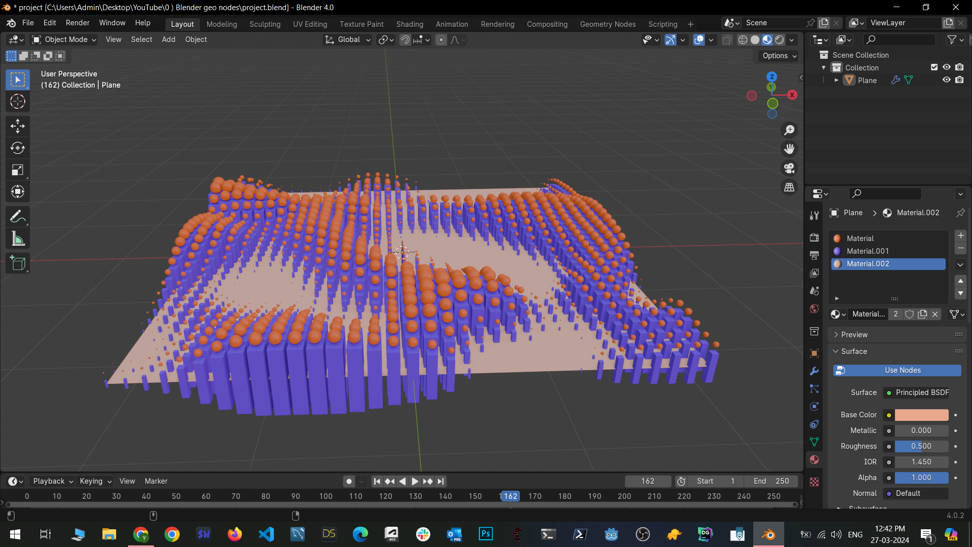
5. 5 ) Making Our Project: All right, so this is the
last lecture of the course. In this lecture, I wanted to show you guys a cool project. Now this video is going to be a bit faster pace
than the other videos, because I think you already know the basics of
geometry notes. So I'm going to quickly
set up everything. First of all, what I want you
to do is get a plan object. There we go, scale it up a bit. Now I'm going to come over here. Geometry, note data,
add a new note. Put this panel away. Let's go. First thing I want you to
do is subdivide the mesh. That's very important. And I think I'm going to go with
five subdivisions right here. Scale it above it more, put these nodes away. This thing is I want you to
convert this mesh to points. What we do is we search
for mesh to points. Now, earlier we learned
about curve to points. Right here, it's mesh to points, It's very simple,
it's pretty related. Put this in right
here. As you can see, our entire mesh has been
converted to points. Now in here we get a few options like where we want to
generate the mesh on. I want to generate the
points on vertices. Of course, you can decrease
the radius of these points. Let's say I go with 0.05 or actually I'm
going to make it smaller. There you go. So it's a
bit more understandable. Now, I'm going to grab a cube. Instance, search for
instances or points. Plug this in right here, we have a cube at just
the scale of these cubes. Or actually I'm going to use a scale instances node for this because we get
a bit more options. Go with scale instances, Plug this in, I'm actually going to pull out the scale
and search for noise texture. What this does if you
remember from the shade or if you've ever used the
shade or by Cha, you haven't. I'm going to show it right here. Let's say I had a plane. What this noise texture does is I'm going to create
a new material for it. Go over to the shade or pull out this base color and
search for noise texture. And go over here. You can
see that we have a bunch of noise in here and I
want the texture to be 40, so a time value so I
can change the noise like wait a minute, Yeah, there we go. Another load I will be using is called the
color ramp load. If I use a color
ramp in a shade tor, if I plug this in right here, I can pull these
controls like such. And it's going to clamp those
black and white values in the noise texture
to be closer to the actual black and
white colors, right? So the black values are
going to get blacker, and the light values
are going to get lighter until they are
closer to black and white. Anyway, let me put this away. Go over to a plane, that's the same thing that's
happening right here. So go back to jot, search for color ramp, plug this into the
lowish texture. Now I can change the scale like so the next thing I want to
add is a vector math, Lord. What this does is now I can take these black and white values
to scale the instrances, but I only want to scale
them on the z axis. On the other axis, I
want to scale them much less than I would scaling
them on the z axis. I can add a math operation
to all of those vectors. Let's say I add a
multiplier operation. Everything disappears
because notice that the vectors right here
with which we are multiplying the values
are set to zero. It's taking the x, y, z scales, and it's multiplying
them by zero, which means we see nothing. Let's say I modify
it to be 0.1point 1.1 Now as you can see, we got this nice
variation in scale. Of course, I can
change these values, I get a better variation. Such go back here. Now I can put out this value right here
and search for value. Now I can enter a derivative
like hashtag frame by 600. It's taking the frame number, dividing it by 600, and that's how we get a
small animation such. Now let's say we wanted
spears on top of these cubes. What I can do here is I take
the scale instances node. First of all, I want
to join geometry because I want both the
plane and these instances. I come over here, pull
this geometry down, take it in here, join geometry, so I get my plane. Now what I do is I search
for mesh to points. Again, put this here. Now our cubes have been
converted to these points. I also want our cubes. So I'm going to take
this original instances mesh and plug it in here. As you can see,
we've got points, all of the cubes. First of all, I want to change the points to be
generated on faces. We have got a problem here, because it's generating
points on all of the faces, but I only want the points on the top faces. How
do we do that? First of all, I'm going to pull this mesh points node up here. You see the selection node. What this does is
you can use this to tell Blender where to
generate the points on. Let's say I pull out
the selection node, I search for normal. What this is going to do is it's going to tell
blender that I want the points to be generated based on the normals
of these cubes. Now I want to put in a much
more better selection logic. First of all, I'm going
to use a separate X, Y Z node and a
combined X, Y, Z node. What this does is it's separating the
normals into x, y, z. And then combining them back, just like we did
with the Y frame. And now I only
want the z values. I'm going to cut
this x value away. As you can see now we
only have points on the top face and
the bottom face. But that's still
not what evolved. We only want the
top face so that there's another load which
is called the math load. Put this in here and change
the operation to seal. What it's going to do is it's going to ignore
the bottom vertex, it's going to
ignore the negative normal and it's only
going to take into account the positive normal when we sealed it and
then we turned on clam. You can see that the points on the bottom vertices disappeared and we only have
the top vertices. Now right now, I can use these points to generate
an instance instances. All points take the
instance as co sphere. We've got a problem
right here because the spheres are elongated. Which is because if you
come over right here, you can see that in
the scale instances we multiply the z
value with one. It's elongating the
spheres as well. To fix that, we can simply come over here in
the scale value. We can decrease the z axis
by ten times. There we go. Then we can set position
of these instances, them to forward right above the cube 0.05 I think
is going to be fine. Let me also increase
the subdivisions. That looks good. Now if I
play this animation back, you can see we've got this
really cool animation. Let me add another scales note. After the set position, I'm going to set the
scale to 0.5 everywhere. It's going to multiply
the original scale with 0.5 because the spheres
getting too big. Actually, let me put this
set position right here. Yeah, this is good. We've got this really cool
animation going right here. The last thing I want to do is set a small
material for this. Come over here, I'm
going to use for this, I'm going to turn on
ambient occlusion and blue. This just makes it
look a bit better. Now in the spheres I
can use a node called Set Material as
the name suggests, it's used to specify a material, come over to the
material editor, a new material, set the
color to, I think, orange. Let's say. I want
to come over to the plane and I want to
get rid of this material. And I only want the material
on the spheres. There we go. You can see that the spheres
are now orange color. Of course, I can create
materials for the cubes as well. Let's say I want the
cubes to be purplish. I can come over here, set material, and set this material right here so
the cubes are published. And of course, you can set it to any material you
want. That's up to you. If you know a bit of Sheedor, then you can also use
ambient occlusion, so the cubes change color when they get too close to each
other or something like that. You can also set it to a glass material,
whatever you want. That's going to be the
project for this class. What I want to do is to create this note
set up right here. They'll implement your
version of this note set up so you can make it a little more beautiful
if you want to. You can add some other kind
of animation if you want to. That's what I want you to do. And that's going to be the
project for this class. So I really hope you enjoyed, thanks for watching last and
see you in the next one.
 Yash Kejriwal