Transcripts
1. Introduction: Hello and welcome to the
Fusion 360 masterclass. My name is Steven and I'm
the course instructor and I'm very excited to
have you in this course. So this course is very
comprehensive and you'll get as much out of the course as you're
able to put into it. So there's a lot of really
small lessons where I go through all of the different
features in fusion. 360 will almost all
of the features. And yeah, so I recommend going through all
of those lessons first and then approaching the
projects that way you have a very solid foundation. Yeah. So once again, I'm very happy that you signed up and I'm
glad you're here. And this is a very good
skill set to have in life. It's very applicable
for a lot of things. If you want, if you
want to make anything yourself, or create products, or just fun things than having
the ability to 3D model and 3D print something is
definitely necessary for that. Once again, my name is Steven, and I'm glad you're here. And I know that
you'll learn a lot.
2. 101 What is Fusion 360: In this video,
I'll be giving you a brief overview of Fusion 360. Fusion 360 is a very
powerful and easy to use CAD or 3D modelling
software that allows you to essentially
design almost anything. So here is a marble
machine that I designed. I could rotate around it. I could change a bunch
of the features of it. And you can see here from
a list of my projects, I've designed numerous
different things. You could really
pretty much design anything in Fusion 360. The only constraint is if you have a very complicated design, a could start to lag if your computer is not
powerful enough. But I love using Fusion 360. It's a really great program. Very powerful, very easy to use. So I'm looking forward to
teaching you all about it. And I hope you're excited
to learn because this is really a great program and
I highly recommend it.
3. 102 How to Install Fusion 360: In this video, I'll show
you how to download the free version of Fusion
360 for personal use. Go to the Fusion 360
page at Autodesk.com. Go to download free trial. And here you'll see
the option for Fusion 360 for personal or hobby use. Click Get Started. And it'll
probably ask you to sign in. I've already signed in, but you'll need to sign
in or create an account. And then you'll
probably have to kit, click, get started again. And this will lead you
to the download page. Sometimes it changes a
little bit depending on how you get to the page or
where you're coming from. But that's the basic way to download the free
version of Fusion 360.
4. 103 Project and Saving Files: In this video, I'll
show you how to save your project in Fusion 360. So when you first open up
Fusion 360 for the first time, you'll have an untitled design. To save the design. Click the Save button
on the top left. Fusion 360 saves all of the
designs inside of the cloud. You can name the project. Actually, I'll call it design because technically
it's a design. And you can choose the
location of that design. Click the drop-down arrow here, and you can choose a project
to save your design it. I think by default, it should have just
the admin project. To add a new project, just click New Project and you can name it
whatever you want. And inside of the project, you could add new folders and save your design into a
new folder just like that. So I have my Fusion
360 lesson's project, and I have my folders
inside of there. So I'll save this in my
getting started folder. And I'll just call
it design 0, 1. And then just click Save. That's how you save
designs in Fusion 360.
5. 104 User Interface: In this video,
I'll be giving you a very quick overview of
Fusion 360 user interface. So the main portion of the
screen is the viewport. And this is where your
design is located. On the top, we have all
the different tools and different tabs for
other tools as well. We have a browser with
a different workspaces. We have a timeline
on the bottom, and different navigation tools. I'll be going over everything in detail later on in this course. But that's a brief overview
of Fusion 360 user interface.
6. 105 Document Settings : Units: In this video, I'll
show you how to change your document settings and
the units for your project. In Fusion 360. The document settings are
found in the browser, and you can click
the drop-down arrow to open up the units. Click Change active units. And here you can switch
between different unit types. Centimeter, millimeter,
meter, inch, or foot. And that's how you change
the units in Fusion 360.
7. 201 Example Workflow (Brief Overview): In this video, I'll give you a very quick example workflow. It's going to be a
brief overview of how I typically
approach a project. In Fusion 360, There's a
thing called sketches. And I'll be going over
these things a lot more in detail later in the course. But that'll be a good
idea to show you just a very quick overview of the basic process in
how Fusion 360 is used. So I'll click sketch. I'll click one of these planes. And I'll draw a quick sketch. Show you what everything is
doing later on in the course. But there's my basic 2D sketch. I'll click Finish Sketch. And I'll extrude that sketch. And that'll give
me a solid body. If I want to move
one of the faces, I just right-click on the face and go to this quick shortcut
here it says move and copy. And I can move the face like so. I could also create a
box on this top face. And if I pull this down, it'll cut this box shape
out of the solid object. So this here is
considered a body. It is found underneath
this body drop-down. And I could rename it shape. I can round off the corners. And with just that there, you could already make
a lot of cool things. But I'm gonna go into all
the different settings. That way you'll have all
the tools you need to make whatever you want and know how to use Fusion 360 to the best, fullest
extent possible.
8. 202 Timeline : Parametric Modeling: In this video,
I'll introduce you to the timeline functionality of Fusion 360 as well as
parametric modelling. These are two of the
best features and to the coolest features
in Fusion 360. So starting off
with the timeline, here on the bottom
is my timeline. I could go back anywhere in history and see where I was at that current
stage of the project. You could skip forward as well. Let's go all the way back
to the very beginning. And you give it a click Play. You can see the entire process of how the shape was created. Now, the cool thing about parametric modeling
means that say, I want to make a small
design or small change to the design in the future
because something has changed. I have a different consideration
or something like that. And let's say instead of having
this cut into the shape, maybe I want this, this
rectangular shape to stick out. So I could double-click
on this extrude. And I can actually change the distance r. Actually I
clicked the wrong one. It's actually, it was
this box shape here. Instead of having it go down, I could just let's see, if I do type five. And I don't want
it to cut anymore, I could click Join. Now, the rectangular
shape is sticking up. And you can see now I've added
that rounded curve there. So I could change
anything in the past, like even go back and
change the sketch. Let's say I want this corner to be in a
little bit like that. I've now changed the sketch,
click Finish Sketch. And it'll go all the way back to the current spot
in the timeline. With that correction. You just want to
be careful if I, let's say I made a
change like this, the rectangles
here, so it'll mess up that rectangle
shape that I added. I'll show you. Well, actually it was pretty smart and it didn't
really mess it up. Sometimes you'll get an error, but other times the
program is smart. So that's really cool thing
about the Timeline feature. I'll correct that really quick. I just go back and correct it. And the whole model is correct. It just like that. Like even change
the fill it size. Let's say I didn't want
it to be as rounded, like just change it to two
and have a smaller Philip. So that's parametric
modelling and the Timeline feature
in Fusion 360.
9. 300 Data Panel: In this video, I'll give you a quick overview of the
data panel in Fusion 360. To access the data panel, click Show Data panel by clicking the button on the
top left of the screen. Here you'll see all
of your projects. I think when you first
start Fusion 360, you will only have
default in admin. But I don't quite remember. If you want to add
a new project, just click New Project. And you can name your
project wherever you want inside of a project. So let's go to my
Fusion 360 lessons. You can create folders. And inside of the folders, you could access
your saved files. So as a quick overview of the
data panel in Fusion 360.
10. 300b EditableDocuments: In this video, I'll be showing
you one update that fusion 360 has made to its data panel. And this is new for the
end of 2020 and 2021. So now you can only have
10 editable documents. You can still access all
of your old designs, but you can have only 10
active files open at one time. Well, you could actually
open more than 10 files, but after 10, they
are only read only. And if you run out of space in your editable documents folder, all you have to do is
click on this button here, and he could switch over
that design to be read-only. It'll give you
this warning here. At anytime you
could actually make the file editable again. So it's not very much of a big
deal to make it read-only. So now I have seven
active designs and I could easily
switch between these and continue
working on them without having to make them
editable again. So that's a new feature
that fusion 360 has added for 2021 now. And it's not too
much of a big deal. You just have to switch
between editable and read only depending on which
product you're working on. And you can access
that folder here in the all projects section
of the data panel. And you just click on the
My editable documents here and here's all of your
recent editable documents. If you're out of
space, once again, just click read only. And if it's a read-only project, let's say I go back into here. This one is read-only, are actually, here's
this one here. I can switch it
back to editable. And it's really easy and
it's not a big deal at all. So that's a new
change to Fusion 360, editable and read
only documents.
11. 301 Navigation: In this video, I'll
show you how to navigate around the
viewport and Fusion 360. It's important to
have a mouse with the middle mouse button because
you'll be using it a lot. It's not necessary, but
it really helps to have the middle mouse button
to pan side-to-side. Click and hold the
middle mouse button to rotate around your object. Hold Shift, and hold down
the middle mouse button. There are two different
types of orbits. In Fusion 360. You could orbit with
constrained orbit, which is set as default. Or we could use free orbit. Free orbit does not
feel as controlled, and I prefer to use
constrained orbit. If you don't have a mouse, you could pan by clicking the
pan button on the bottom. You can zoom in and out
with the mouse wheel. If you don't have
the mouse wheel, you can zoom in and out with the zoom button on the
bottom of the screen. You could also click Fit to fit the object in the viewport.
12. 302 View Cube: In this video, I'll be
going over the view cube. In Fusion 360. The view cube is a
helpful tool that lets you rotate the camera two
different orientations. So right now, if I orbit
around in my scene, you can see the view
cube will also orbit. If I want to look at my
object from the front view, all I have to do is click
front on the view cube. I could go and look at
any side of my object. I can move the camera
to look at the back, the left, Front, the right. And it helps you just look
directly in that direction. So this is directly looking at the front view of the object. You could also click and drag
on the view cube to orbit. And he could also look at you can switch the view
to an angled view. So here's the angle
between front and right. You could also look at your object from a
corner perspective. This helps you quickly
change your view precisely.
13. 303 Orbit: In this video, I'll
show you how to orbit around the viewport
and Fusion 360. Like I mentioned in the navigation and
view cube tutorials, you could orbit by holding Shift and the
center mouse button. There are two different types
of orbit and Fusion 360. There's constraint orbit, which orbits in a more
controlled manner. And there's free orbit, which allows you to orbit around in a little bit less
controlled manner. I prefer to use
constrained orbit. If you don't have a mouse
at the center button, with the middle mouse button. Just click on the
orbit button on the bottom to orbit
and press Escape. To exit that command. You could also orbit by clicking and holding the view cube.
14. 304 Look At: In this video, I'll
show you how to use the lookup function
in Fusion 360. Let's say I have a fairly
complicated model and I want to look at one of the faces
directly into the face. All I have to do is click, look at and select the face that I want to
look directly towards. This is helpful if you
have an object that has many different angles. And you can't really use
the view cube because maybe this face here doesn't align with any of these
sides of the view cube. Just click at the lookout button and have the face selected
and I'll look at it. So you can see there's
two ways of doing it. Either you select the face, then click look at, or you could click look at
it then select the face. That's a quick overview of the lookout command
and Fusion 360.
15. 305 Display Settings: In this video,
I'll be going over the display settings
in Fusion 360. First, there's the visual style. You can look at your
object in a shaded view. Shading with hidden edges or
shaded with visible edges, or different variations
of wireframe. I prefer to use shaded
with visible edges only. However, sometimes I like to use shaded with hidden edges. This allows you to see
through the object and it has a dashed line for all the edges that are
behind these faces. Another interesting visual
style is wireframe, as well as wireframe
with visible edges only. Sometimes I use this
if I want to get a quick line drawing
of my object, I'll just take a screenshot of the current viewport like that to get a line
drawing of my object. Next, there's mesh display. I rarely use this setting. Another setting
that I like to use is the environment setting. Let me switch back to shaded
with visible edges only. Environment you have dark
sky gray room photo booth, tranquility, blue
in infinity pool. Most of the time I used
the default photo booth setting. I'll show
you some of them. There's the dark sky. It's kind of a moody, dark version, sometimes a
little difficult to see. There's also gray room,
tranquility blue. I'm not sure why you
would use this one. And infinity pool,
which is not bad, also, kinda has a
nice look to it. And it has a nice
reflection on the floor. However, most of the time
I just use photo booth. There's also the
different effects. Right now I have all
the effects turned on. If you're worried
about performance and it starts lagging
a little bit, you could turn some of
these effects settings off, like anti-aliasing or
ambient occlusion objects shadow in ground, reflection. These will speed up
the program a lot. Because sometimes Fusion 360, if you have a complicated model, it does start to lag down a lot. So a quick fix to that is
just go to your effects here and start turning off
different settings there. Next we have object visibility. You could turn off different
object, things like that. And another one that's pretty
important is the camera. You can switch to
perspective or orthographic. When I'm doing design, I usually
stick with orthographic. It means there's no perspective. And objects that
are far away are the exact same size as
objects that are close up. See how the object looks
skewed in this picture, it's more accurate to real life, but when you're designing
and you need to see the dimensions of
different parts of your model. And it's hard to
tell what sizes are, what and how to compare the sizes to each other when
you're in perspective mode. So typically, I'll do all my modelling in
orthographic mode. There's also ground
plane offset. I very rarely use
that setting as well. The three that are used
the most are visual style. And use that a ton, environment. And use Effects little bit. If I'm worried about performance
and the camera setting. Orthographic and perspective.
16. 306 Grid Settings: In this video,
I'll be going over the grid settings in Fusion 360. Click the grid and snaps button on the bottom of the screen. You can turn on the grid by
checking the layout grid box. You can snap to grid, as well as use in current
incremental move. I'll show you how
this works now. Incremental move allows
you when you move a face, to move that face in increments. So you can see it's
snapping to the grid. In those increments. If I want to change
the grid settings, click Grid settings. Change it from
adaptive to fixed. And I could change my
minor sub-divisions. I'll set it to 50. You can see it working here. This is a nice feature
and allows you to easily change the shape your
model very accurately.
17. 307 Solid: In this video, I'll be
giving you a brief overview of the solid tap
tools in Fusion 360. Now in Fusion 360, you'll mostly be
using solid bodies. There are also surfaces and
forms, sheet metal tools. But most of the time
you'll be using solids. So with a solid,
you could create different solids like boxes,
cylinders, spheres, Taurus. You could also do
other functions that I'll get to later
on in the course. You can modify those objects and you could assemble
them two moving parts. So you can make mechanisms
inside a Fusion 360 that'll work just like
mechanisms in real life. You can make
construction planes, which I'll also get into
later on in the course. As well as insert photos
and other things, reference materials like that. So the solid tab, you'll be in the solid
tab most of the time when you're designing your
object in Fusion 360.
18. 308 Surface: In this video,
I'll be giving you a quick overview of
the surface tools. In Fusion 360. I actually rarely use the surface tools,
if ever actually. And basically I'll give
you a quick example of a use case for
the surface tool. Now my kid extrude
these edges here. Just like this. And you can see a surface is
actually not a solid body. So it's just a, essentially
a two-dimensional surface. And one thing you could do
with this is I could actually, let's see where it is here. I could create a, I get thicken it like this. And I'll select the surfaces
that I want to thicken. So it's actually, I'll select
all of the surfaces here. And I could type
in negative two. And now I have a solid
body from those surfaces. That's a quick use
case for surfaces. And I won't be going too much
into detail for surfaces. And it shares a lot of the
same functionality as a solid. But I find the solid tools
to be much more useful. So that's a quick overview of the surface tools
in Fusion 360.
19. 309 Sheet Metal: Fusion 360 also has some pretty cool features
for sheet metal design. However, in this course, I won't be going into
those features at all because this course is
geared towards 3D printing.
20. 310 Tools: In this video,
I'll be giving you a brief overview of the
tools tab and Fusion 360. So there's a lot of cool
features in the Tools tab. But in this course we'll
be looking at the add-ins, measure and section analysis. Those are the most
applicable for 3D printing. Add-ins. That's where we'll
be making gears and different mechanical things. Measure obviously means
measuring between two points. So you can measure
between Two faces or even between edges. And then section analysis
is a good feature. It allows you to cut
into the shape along this plane and you can look
at a section of your object. So that's a brief overview of the tools tab in Fusion 360.
21. 311 Create: In this video,
I'll be going over the Create tab inside
of the solid section. The Create tab is a very, very important tab
in Fusion 360. You'll spend a lot
of time in it. And it has a lot of
really powerful features such as extrude, which we'll use that a lot. As well as the basic
fundamental shapes, as well as patterns. Where he could
create an array of a body as well as mere thick
in a lot of great things. So I'll be going
into each one of those later on in this course. That's a quick overview of
the Create tab in Fusion 360.
22. 312 Modify: In this video,
I'll be going over the Modify tab in Fusion 360. So after you create
your base shape, a lot of times you'll
need to modify it. And what that means is you could add like an
affiliate to it, or you can add a chamfer or a good cut out the
center of it or combine or subtract
different objects. So the Modify section tab is also a very important
tab because after you create
your base shapes, typically what you'll do
is you'll modify them. And that's where you'll combine different fundamental shapes
or chamfers, fillets. You can even do press pull, which is where I could like
pull it out like this. A lot of good
features and modify. Not quite as
important as create, but definitely a very
important section. And we'll also be using it a
lot in the future lessons. So stay tuned. And that's a quick overview of the Modified tab in Fusion 360.
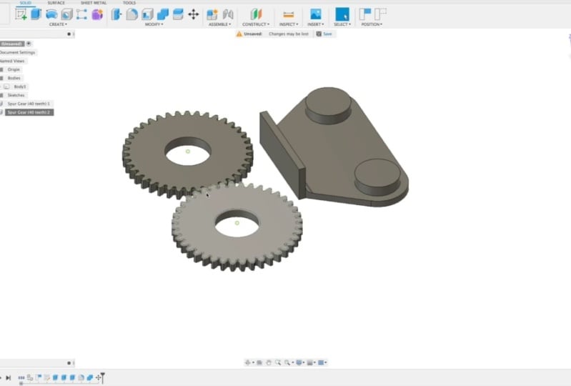
23. 313 Assemble: In this video,
I'll be giving you a brief overview of the
assembled tab in Fusion 360. Now the assembled tab is
not the easiest tab to use, but it's very powerful. This is where you get assemble different components and
actually make the move. And you can make all
different types of really cool mechanical things and
test it out in the computer, which is really great for prototyping and
things like that. So for example, I can create
a joint for this gear here. So I could select this
and also select that. Set the motion to Revolve. Click Okay, and I'll be
going into all of this into detail in later lessons. So you can learn how to do it, but really powerful
and you can see how quickly I was able
to make a gear that spins and I can make
this gear spin and other gear, move a lever. All different types of things. Extremely powerful and also really cool once you
know how to use it. So I'm looking forward to
teaching those lessons. So stay tuned. And that's a quick overview
of the assembled tab. Basically, it's where
you assemble components to make all different types of mechanical contraptions
and things like that.
24. 314 Construct: In this video, I'll introduce
you to construction planes. So in Fusion 360, one of the main things
that you do to create a new body is you use
what's called a sketch. So a sketch can be
created on any plane. So I could choose a plane
from the object here, or it could choose
one of the planes from the world origin. But what if I don't want to
use any of those planes? And let me just do an example of a sketch to a body really quick. So I clicked on the plane on top of this rectangular prism. And let's say I just want
to make a random shape, maybe something like that, kind of a trapezoid shape. So I created a sketch on
the plane and then I can extrude that sketch
just like this. All right, so now I have another body on top of that buddy. But let's say I don't
want to create the sketch on that plane or on any of
the world origin planes. What you can do is we create
a construction plane. And so I'll do an example
of an offset plane first. So I could click on a face and I can offset a plane
just like this. And now I could do a
sketch on that plane. So let's do suit different. Let's just make a circle. And I'll finish the sketch. Now I have a circle sketch
floating in mid air. And you can see here, here's the construction
drop-down, and there's the plane there. I could turn it off
so you can't see it. And then I could
take this sketch here and I can extrude
a cylinder out of it. And that's how you could create an object offset
anywhere from any plane. And there's a whole
bunch of really cool, really powerful, different construction
planes that you could do. And I'll be getting into those in future lessons
in this course. So stay tuned. And that's a general overview
of construction planes.
25. 315 Inspect: In this video, I'll give you a quick overview of
the Inspect Dropdown. So the only two
things we'll look at in the Inspect Dropdown, our measure and
section analysis. So it measures pretty
self-explanatory. You can measure different
points on a object like that. However, I'm not sure why you would want to
do that really, because if you look down here on the bottom right corner,
I'm actually will, well, if I hold Shift, it will actually tell
me two vertices. Min distance is that. And I can also do faces. So if I select one face, rotate around and
select another face, it'll actually tell me the
distance between those faces. The other cool thing in
Inspect is section analysis. I did mention that in the
other lesson as well. But I'll show you it again. So basically a section
analysis allows you to take a view the inside of an object. So if I click this face here
and I pull it in like this, you could take a
section of the object. And here you can see I actually hid some text
inside of my shape. So that's actually as a whole, like it's hidden the words
inside of the shape basically. And I can see it when I'm
doing the section analysis. So that's a cool way. I like to add a watermark
to some of my designs. I'll actually embed my
logo inside of the print. So that way, if anyone
prints it when printing, you can see it's from
3D printer academy. Just a cool Easter egg
type of thing like that. So that's a section
analysis allows you to see the inside of your object. And that's a quick overview
of the Inspect Dropdown.
26. 316 Insert: In this video, I'll give you a quick overview of
the Insert drop-down. The two most important things
in the Insert drop-down, RD CAL and Canvas. In this course, we'll
probably only look at Canvas. And I'll give an example
of what insert Canvas is. Basically, you could insert
a picture into your drawing. So if you click canvas here, I can insert a photo from my computer and I'll just
pick a random photo here. This is just a screenshot
from my Instagram. And you could add
that image anywhere in your scene here,
in the viewport. But you have to pick a plane. So usually you'll
probably pick one in the world origin planes like that and you
can move it around. So let's just put it here and
I'll scale it up like this. And the reason you'd want to
do this is let's say I want to trace this shape here
for that marble machine. I could actually create a
sketch on the same plane. And then basically
what you could do is trace out that object. Like so obviously much
better than that, but this is just a general
idea of how it works. And then after you
trace your object, you can extrude it. And then you have
the object traced. And you could turn
off the canvas, turn off the reference. And that's the cool
thing about canvases. And other interesting thing
is you could actually put the canvas on to one of your objects. So let's
just do it again. I'll just use the
old thumbnail from a Kickstarter project and I'll
add it to the face there. I can rotate it
around like that. And okay. And there I have a photo on that shape
just like that. And I mean, you could do that for a lot of different reasons. Most of the time would
be for reference. But I guess you could technically make it like
a texture or something, but it's made basically to be, to add reference drawings
in to Fusion 360. So that's a, that's
a quick introduction to the Insert drop-down
in Fusion 360.
27. 317 Right Click Short Cuts: In this video,
I'll introduce you to the right-click shortcuts. The right-click shortcuts
are very convenient. Basically, all you have to do is you right-click and
it opens up this, I guess, dialog box here. And it has a lot of your
recent things that you've done as well as some things
that you often want to do. So, for instance,
one of the things I do a lot is I would
move and copy. I probably use the
right-click shortcut for that the most. And the second thing
I would use it for is setting the orbit center. And that basically is the point that camera orbits around. And I think I'll go
into that later. I'm not sure, but
it just sets the, I'll just show you an example. I can set the center of
the orbit to say here. And now when I rotate around, it rotates around that point. So kind of a nice
thing to know about. But as far as moving copy, a lot of the time, you'll use this a lot. So I'll do a quick
example of this as well. Let's say I want to
move this face here. Actually, I need
to select the face first and I'll right-click
move and copy. And now I can move this face and you can even rotate
the face like that. I can rotate it. Well, I can't rotate that way because it just doesn't make
sense to twist it like that. But I can move it
in this direction, and I could also do in this
direction or whatever. But that's a very
common thing to do is to move or rotate something, as well as move the entire body. So I slept the whole body and
I can move the entire body. A very normal thing that you'd
be doing all of the time, as well as the copy feature. So I select the body,
right-click and copy. You just click, Create a
Copy, select that box. And now when you move it, have a copy of the box. So the right-click shortcut is a very important
thing in Fusion 360. I use it all the time. It's very convenient
because wherever I am, wherever the mouse
is in the viewport, I just right-click. And here's a lot of very
convenient quick things. I think he even just
right-click and drag like this. So see that I just right
clicked and dragged and it will it like
highlights that easy, like that pie
shaped thing there. And so it makes it very
quick to do things. So that's the right-click
shortcuts in Fusion 360.
28. 401 Sketches Overview: In this video,
I'll introduce you to sketches in Fusion 360. Sketches are extremely important in Fusion 360 and it's one of the main tools
that you'll use to create whatever object that
you're trying to create. So the way a sketch works
is you have a lot of different options for shapes
or lines that you can draw. And basically a sketch
is a 2D drawing. And you can make a 3D object
out of that 2D drawing. So for instance, let's say, I don't know, I'll create, I'll just do an example of something that you would create. Maybe it's like a slot
type of thing like this. So I could create two circles and a couple of lines like this. And there's my sketch. And now that I've
finished my sketch, I can select these faces
here and extrude that. And I have my Custom, my custom shaped
3D solid object. Now you may have noticed when I was drawing
this sketch here, that the lines are blue. And one thing that's
really cool about fusion 360 is it has a
thing called constraints. So if I go back into my, I can right-click on the
timeline down here and edit that action that I did. So I could go to Edit Sketch. So here I'm back into my sketch again and you can see
the lines are blue. What that means is those
lines are not constrained. So I could actually
grab one and move it around and see how it's
adjusting the sketch. And it's kind of
unpredictable right now. And that's because I
didn't put any planning into how I drew it at all. So you can see this thing here, that little circle, that's
a tangent constraint. And what that means is this
line here will always be tangent with this
circle's edge here. So you can see it's
never going to be a different angle from
this line like this. See how this one
has an angle here. There's the circle and angles, there's a sharp corner here. This will never
have a sharp corner except for this side here. So it's always going to be
in line with the circle. So it automatically
adds some constraints. But all of the other things
are not constraints. So let me delete everything. Now I'll give you an example. Fully constrained sketch. So for instance, if I draw a line starting from the origin, it will constrain that
first to the origin. I get control the
length and the angle. So see how it's a
dark black line now. Same with here,
actually not that one. Let me do it again. I'll start from
beginning and you actually want to
type the dimension. So I'll actually type
10 millimeters and 90. And for this one here
I'll type in 1090. See now it has these
dimensions here. Those are the constraints. So that means this line here
has to be 10 millimeters. And I could go into this
constraint and change it. And that'll adjust my drawing. So it's a very powerful feature. So like here I have
a triangle shape. Maybe I want it to be this
side here to be smaller. I could just change
it like that. And when all the
lines are black, that means your sketch
is fully constrained. And you can see all the
constraints up here. I'll be going into each one of them in detail so
you can learn all about these tools
here and how to create really cool sketches
that will save you. It's a little bit
more work up front to make your sketch
fully constrained. But it'll save you a lot
of time down the road. Let's say when
you're prototyping something and you
need to change it, instead of redrawing everything, all you have to
do is just change one-dimension and
your entire object will modify itself to update itself to that new
dimension there like that. So in the next
couple of lessons, actually I have quite a few
lessons coming up here. I'll be going into each
part of a sketch in detail. So you could get all
of the tools you need to make whatever
you want to make. Sketches are very important. That's where I'll be
spending a lot of time. I think I've probably,
I don't know, 10 or 20, 10 or 20
videos coming up here, 15 videos, I think. Now know a lot of videos
coming up where I'll be going into all the different things
you could do with sketches. Very important and very
cool feature of Fusion 360. So that's a quick overview
of sketches in Fusion 360.
29. 402 Lines: One of the most important
things in a sketch is a line. And it sounds very simple. But there's some things that
you could do with a line that aren't the most intuitive. So select the Line Tool. You can also press
L on the keyboard. And we want to have some sort of anchor
point for our sketch. So I'll just use
the world origin. I'll give it a dimension so
that way it's constrained. And now you can see I have a basic line and it
has a dimension. And I could change that
dimension like that. I could also. So I'll draw another line. This time. I'll specify an
angle for this line. So to access the angle textbox, you want to press
tab on the keyboard. And now you can type
in any custom angle, so I'll just type in 40 degrees. And if I move my mouse around, you can see that it's 40
degrees from different origins. So I can move it over here
down anywhere like that, still 40 degrees,
but it's basing the origin off of
a different point. And you can also see that I
can still adjust the length. So if I press tab again, I can add a dimension there. And now it stays solidified as that length
of a line at that angle. And if I click the mouse button, it'll confirm that line. It'll have me draw
another line if I want, but I'll just press Escape. And it'll clear that. And so you can now
you see I have a fully constrained
line path here. And the last thing
you do with a line, notice there's a curve here. You can actually make
curves with your line. To do that. Not the most intuitive
thing in the world, but what you do is you click and hold from an existing
endpoint of a line. So if I click and hold
and drag the mouse, it creates a curve like this. Now, the weird thing
is you can't really constrain it at this point. So if I let go the mouse, it'll be click this arrow here. Or I could press Escape
to confirm that our arch. So the weird thing
is not constrained. And that's because I can
still move this point here. So if I had a way to tell Fusion 360 what
this dimension is here, then it will constrain
this line and it'll be black and not this
light blue color. Because best practices are fully constraining
your sketches. Unless you're doing
something really quick, but usually long-term, it's best to constrain
your sketches. So to add a dimension
constraint. I'll click this dimension
button here, sketch dimension. And I'll click this point. And I guess it's already, they've already had
that point selected, but I could set this
dimension here, and let's just set it to three. Now you can see the sketch
is fully constrained. So everything is
locked in place. The only thing that can
move is this dot here. I could change the length
of that arch like that. So that's the basic line tool and that's what
you could do with it. You could also
close your sketch. Let's say when I
close this here, you can see that
line is also not, it's not black because it doesn't have a constraint on it. So I could add a constraint there by clicking on the line at the dimension tool and
just clicking Enter. So now it's fully constrained, like a change, this like that. And you can see it's going
to keep this arch here. So that's why if I
change this value, it moves it in that
direction unless they added a different
constraints somewhere else. But That's the
basic functionality of the line tool for sketches. You get to create
either a straight line or we can make arches. And it's important to remember
to always fully constrain your sketches because you will, you'll regret it in the
future if you don't, when you wanna go back and make a little change and
everything gets messed up. Because you can't simply
just go in and just type in 4.5 and have it
automatically adjust. All nice like that. So that's the basic line
tool in Fusion 360.
30. 403 Rectangles: The next tool we have
in sketches and fusion 360 is the rectangle tool. This is the basic
rectangle tool here. But if we click Create, we can see more options for different types of
rectangles that we could create. So by default, fusion 360 has a two-point rectangle
where you can select basically the origin point
and the opposite corner. And if you type in your
dimensions five, I'll hit tab. And that will go to the other, the length of the rectangle. And I get a maybe seven there. If I click the mouse button, I have a fully constrained
rectangle. Just like that. I could easily go in and
change the dimensions. Super easy. So that's a two-point rectangle
in Fusion 360. Fusion 360 also has
this one's very useful. And then skip the three-point
for now and go to the center rectangle because
this one is way more useful. It basically creates the origin of the rectangle at
the center. Like that. That's very useful. It makes it much quicker to center a rectangle inside
of a different object. And you can also just type in the dimension for that side. Press tab and press it
dimension for the other side. And if you press Enter, you have your basic
rectangle shape there. And you can easily change
the lengths of the sides. And notice on the
center rectangle, if I change the
length of a side, it's mirrored along
the center point. So very, very convenient
for a lot of things. And now the last rectangle tool we have is the
three-point rectangle. Basically, what you do is you essentially just create three points and
let me do that again. So go to the rectangle, I'll click this point here. Click this point here. And I could pull it
out. And basically, I guess the point of
this is you could change the direction or the
angle of the rectangle. But I, I don't think I've ever used the three-point
rectangle tool. I definitely have a
lot more use cases where I use the
two-point rectangle and the center rectangle. And most of the time it's
just the two-point rectangle. So that's the rectangle
tool in Fusion 360.
31. 404 Circles: So the next tool we have in Fusion 360 for sketches
is the circle tool. The default circle
tool is very basic. You basically just determine what diameter you
want for the circle. And you can easily change it
after the fact if you want. And that's the basic
circle function. But there is also a
two-point circle. And this would be useful
for a situation like this. Let's say I want a circle centered between
these two lines here. I can just click
there and there. And now I have a circle that is perfectly centered
between those two lines. So there's also a, let's go to the next one,
the three-point circle. And that's very similar. I can click here,
here, and here. And now I have a
circle right there. Kind of pushed up against this
edge here just like that. Now they're useful
circle and having these extra circle tools
or functions, I guess. Just make it easier for certain situations like having it pushed up against
this edge here, the three-point circle made that very easy and very quick. So knowing about the special
circle functions really kid, improve the speed of
your design process. Okay, We also have the
two tangent circle. Let's say we want a circle here. I can just click on this
line and this line. And it'll create a circle
just like that with the edges connected to
those two lines like that. Another very convenient
circle creation tool. And the last one is the
three tangent circle. Or I can click on three lines. And it'll create a circle
perfectly in the middle. And you can see that one's fully constrained because each one of these points is connected
to those lines like that. Whereas this circle here, I guess, still change
the size of it. So if I gave it a diameter like that, Let's
just give it five. You can see that's also a fully constrained now, just like that. So that's the circle tool
in sketches in Fusion 360.
32. 405 Arcs: So now we're getting
into more of the specialized tools for
sketches and Fusion 360. And this tool is the arc tool. And there are three
different options here. You could do a simple
three-point arc, and I'll show you
an example of that. Say Do this center point
to this center point, to this center point. And here we have a arc based
off of those points there. And I can make maybe a shape
like that if I wanted to. Such a use case for that arc. Another one that we have is
the the center point arc. So basically you select the center point
and then you select two other points like that. And it creates an arc around the center
point just like that. And the last one is
the tangent arc. Basically what that one does
is it creates a line that's tangent or creates an arc that's tangent to the line
that you start from. So just like that you can see
it's, no matter where I go, it's still tangent with the
origin line just like that. And I guess actually
with that one, you could do some pretty
interesting curves like that very easily. And it's all tangent to itself. So those are arcs. It's a, another good
tool in Fusion 360. And you could create
a lot more variations with your sketches like that. And they all have a
constant radius sets. That's what an arc
is in Fusion 360. You could also do splines, but a spline has a
continually changing radius. So this is basically just
a segment of a circle. So that's how you make
arcs in Fusion 360.
33. 406 Polygon: Next I'll show you how to use the polygon tool for
sketches in Fusion 360. For this example,
I'll be creating my sketch on the top
face of the cylinder. So I'll select the
top of the face. I'll click Create Sketch. And now what I'm going
do is I'll build a, I'll create a smaller circle, an eight millimeter
circle, just like that. And now I'm going to go
to the polygon tool. And you can see
there's three options. For this example. I'm gonna do the
inscribed polygon. So I'll select
inscribed polygon. I'll click the center point and then drag out to the edge. And you get determined
the radius, as well as the number of
edges that the polygon has. So right now I have
a six-sided polygon and I could change that
with the Tab button. Well, I can't have a
two sided polygon, like a triangle, square and just like
that all the way up. So for this example, I thought would be
interesting to do a hexagon. Because you could like make
an indent into a shape for, let's say, nuts and bolts to
hold the head of the bolt. So I'll create the inscribed
polygon just like that. Now finish the sketch. I'll select the
hexagon like that. And I'll extrude it
down negative 10, or just go negative
four just like that. So now I have this polygon
cut out of this cylinder. So I know I haven't really
gotten into extrude yet. But it's a little sneak
peek into that future. And with the tools
you know already, you should be able
to do a lot already. But I recommend continuing to go through all of these lessons here because it'll give you a really strong foundation and it will really help
your design skills. So I highly recommend
going through each one of these lessons
because I'll be going through every single tool. And you will have a lot more
skills if you're able to, to know each tool and
what exactly it does, and it'll just make you
a much better designer. So that's the polygon tool away. I didn't go through the other. Let me show you
the other versions of the polygon tool as well. They're fairly similar. So let's quickly
go through these. We have edge polygon
and circumscribed. So that's essentially
the same thing. However, it goes on the outside
of the circle like that. And then the other one
is the edge polygon. So I could select
two points here. And it'll create a polygon based on that edge
just like that. So that's the polygon
tool in Fusion 360.
34. 407 Ellipse: Next I'll show you how to use the Ellipse tool for
sketches and Fusion 360. The Ellipse tool is fairly simple and there's
only one option. You basically pick
the center point and the first dimension, and then the second dimension. And that's essentially all
it is for the ellipse tool. So that's the Ellipse
tool in Fusion 360.
35. 408 Slots: In this video, I'll
show you how to use slots in sketches in Fusion 360. Go to Create, down to slot. And you have a few
different options here. We have center to center slot. So I can select this point
here and this point here. And those two points will be
the center of the circles on the ends of the slot. So you can see just like that. And there we have
our slot there and we can extrude it up or
down if you wanted to. But I'm going to keep
going and show you the other versions of
the slot functions. Slot function. We have an overall slot. So I could do something like
this from this point here, this point here and there. So there's my slot inside
of that rectangle. You could also do a
three-point arc slot. This one's pretty
interesting as well. Let's say I wanted to
go from this point to this point. Actually,
I don't wanna do that. Let's do one more time. I wanna do this
point, this point. And that point, I could
create an arc like that. So that's a pretty
interesting one. And the last one is my favorite slot function
here, or slot tool. It's the center point, our slot. And basically all you
need to do is select the center point and then select the starting point of the arc and the
ending point of the arc. Let's go to there. And then you just pull
out the width like that. And then for example, if I finish the sketch
like a selected this area, and I can extrude
it in like this. And now I have this
very nice cutout slot inside of my shape
just like that. So very convenient feature. That is the slot
tool in Fusion 360.
36. 409 Spline: The next tool in
sketches for fusion 360 is the spline tool. Now when you first start
a Fusion 360 Project, you usually happen up a
blank screen like this. And usually what
I do is I create a sketch and I just pick one
of the planes on the origin. So I've skipped that step on all the other sketches, videos. So I thought I should show that just to show you where
I was getting started. So the spline tool is
very nice because it lets you make very customized curves. I'm basically any
curve that you want. So to use the spline tool, you basically could
just select area. You create points
just like this. And then to end, you want to click on this check
mark here just like that. So the spline has a bunch
of nodes that you could, you could click on
and you can move those kind of handles
just like that. And you could change the
shape of your spline. So it's a very convenient
tool for making very customized curved
shapes just like this. I can offset the spline, connected the edges
and then extruded. And there's my custom shape that are designed
with the spline sets. I use blinds in Fusion 360.
37. 410 Conic Curves: So this tool is a little
bit obscure and I'm not exactly sure what
use cases it has, but I'll still show it anyways. It's the conic curve. And there's a lot of, I guess, theory behind it I'm
not too familiar with, but it has to do something with a second order linear partial, partial differential
equations or something. But it's been a long time since I've taken differential
equations, so I don't remember any of that. But basically, you can
create different parabolic, hyperbolic or elliptic
lines just like that. I'm not sure exactly what
the use case is for this, but you can make these
shapes if you want to. So that's the conic curve
tool in Fusion 360.
38. 411 Point: The next tool I haven't
used that much either, so I'm gonna go pretty
quickly through it. It's the point tool. And essentially you
could create points and you can connect
the points with lines. And I'm not exactly sure
what the use cases for this because I could just take a line and do the
exact same thing. But that's the point
tool in Fusion 360.
39. 412 Text: In this video, I'll
show you how to use the text tool for
sketches in Fusion 360. The Text Tool is a very nice
tool and it's very useful. And it's also a very
fun tool because you can personalize all your
work with this tool. So I'll create a sketch
on this face here. And I don't know why it
rotated it around like that, but I'll just rotate
it back to normal. And I'll just click
Create and text. So there's two options here. You can click text on path, which means maybe I could
put it on this path here. It even looks like it goes through the object I
can line it up with. And that line on the back of the object that
I want to do text anywhere on my plane here. So I'll do just the
basic text tool. And I'll select the bounding
box here for my text. And click OK. And you can see the
text is very large. So what I'll do is I'll
change the height of the text. I'll make it 2.5. Let's go for Nope, do three. So three works like that. I'll center space it and center it in the
middle. Like that. I'll type in 3D printer academy. Just like that, but
with the three, and I'll make it bold. And what you could
also do is you could also change the font. So I like to use Avenir. Next. Just like that, I'll probably
make it just a little bit smaller to 0.7, maybe 2.5. There we go. So that's how you create text and then what you
could do with the text. And also has a character
spacing tool, which is nice. So I can space it
out a little bit. Let's do 10, okay? And then I can click
Okay and Finish Sketch. So with this, what I could do is select the text and
now I can extrude it. And let's say I wanted
to make a stamp. You can very easily make your
own custom stamps this way. Or if I wanted to make just a custom little label
thing here with my name on it. I could cut inside of
the shape like that. And now I have a little block with 3D printer
Academy written on it. And I could 3D print
that and put it on my desk or anything like that. So the Text tool is very useful. You can customize all of your 3D prints or
all of your designs. You can put your name or your
logo, anything like that. So that's the text
tool in Fusion 360.
40. 413 Mirror: So this next tool is very useful and I use
it all the time. It's the mirror tool. So to use the mirror tool, Let's say I have my
own line drawing here. Just something random like this. And so let's say I want to
mirror this onto that side. So Fusion 360 makes
it very easy. What I could do is I could
create a construction line, so I'll create a normal line. Just like this. I'll
select this line. And I'll change the line
type to construction. Just like that. So now
it's a dashed line. So it's actually not a line, it's just a, basically
a reference line. And now to mere this, all I need do is click
the mirror button here. And I'll select my lines
that I want to mirror. Just like this. So I have my 10
lines here selected, and I'll click the mirror line, I'll select that, and I'll do this construction line here. And now you can see my
custom line drawing has been mirrored to the side. And that's very convenient. I use the mirror function a ton. So that's how you do mirrors for your
sketches in Fusion 360.
41. 414 Circular Pattern: In this video, I'll
show you how to use the circular pattern tool
for sketches in Fusion 360. The circular pattern tool is very powerful and very useful. And I use it a lot
in my designs. So go to Create. And so actually before we do
the circular pattern, we'll need something to
rotate in a circular pattern. So what I'll do is I'll create a circle on the
end of this line, maybe just a five millimeter
circle, just like that. And I want this to repeat in a circular pattern
around like this. So I'll select my circle and
I'll go to circular pattern. You'll need to select
the center point. And then you can choose
how many times you want it to be repeated. So I'll just increase this
till I get a good amount. And so it's evenly
spaced, just like that. And click, Okay, I'll
click Finish Sketch. So now what I could
do is I could select all of these areas here. And what I could do is
extrude it maybe five. And now I have these
evenly spaced cylinders and the perfect
circular pattern. So that's the circular
pattern tool in Fusion 360.
42. 415 Rectangular Pattern: Next I'll show you how to use the rectangular pattern
tool in Fusion 360. So I have this circle
shape here that I want to repeat in
rows and columns. To do this, I'll use the
rectangular pattern tool. Now there's two different
types of distance types here. There's extent and spacing. So first I need to
select my object. I'll change my distance
to, let's say 30. And I could increase
the quantity. Let's do just do six of them. And then I could do
that also for the rows. So I'll do six and I'll
change the distance to 30. And I could change
the direction. Let's see if I could
do negative 30. Yes, I get a negative 30
to get it to go down. And now I have my circle repeating in a
rectangular pattern. I could also make it go in
both directions like that. Or I could use spacing. So for the spacing, it automatically converted
it to six millimeters. But now let's say
what if I do 0, it stacked on top
of each other, 15. So if I do five because
that's the diameter. So it's from center point, the center point it looks like. And I did get UPS quantity 26
and distance negative five. And they should all be
touching and just like that in a rectangular pattern. So that's how you use the
rectangular pattern tool in Fusion 360.
43. 416 Fillet: In this video, I'll
show you how to use the affiliate tool
in Fusion 360. The fill tool is
really important because in the real-world, corners are not
infinitely sharp, like they are in the computer. It's very difficult to get
a perfectly sharp corner. And actually you never really want a perfectly sharp
corner in your design because it'll either
be very uncomfortable to hold or it won't
look that great. Even objects in the real world
that look like they have sharp corners are actually slightly rounded and have
a slight fill it on them. Just because That's how it works in reality versus
on the computer. So to use to use the fill tool, just click the Philip button
and you can either select two lines or you can select the corner
point, just like this. And if you select
multiple corners, you could change the
radius of all of them. Just like that. It's a very convenient tool. And I highly recommend
using fillets in your design because it'll
make the designs look. Whoops, what did I do there? It'll make the designs
look much more professional and
much more polished. So that's the Philip
tool in Fusion 360. It's a very nice tool. And it really improves, improves the quality of
your designs and really makes it look extra good. So I highly recommend
the fill tool. It's very convenient. I use it all the time in
almost all of my designs. You can even do it on a solid body and ran
off the top like that. So it's a very nice
tool in Fusion 360. That's the filler
tool in Fusion 360.
44. 417 Trim: In this video, I'll show you
how to use the trim tool in Fusion 360 for modifying
your sketches. The trim tool is this
scissors icon here. You can also access it by
pressing T on the keyboard. And basically what the trim
tool does is it will trim a line or a curve to any
line that intersects it. So I can trim off this
portion of the circle like that or a kid trim
align just like this. And it's pretty
self-explanatory. Most of the time it will
remove your constraints. So if I trim this line here, you see it'll break a
lot of constraints. And that's what this warning
is down here in the bottom. So you'll have to read
constrain your sketch. But that's how the trim
tool works in Fusion 360.
45. 418 Extend: In this video, I'll
show you how to use the extend tool in Fusion 360. You could access the
extend tool by going to the modified drop-down
and clicking on extend. And actually basically
before I do that, let me trim off this line here. Ok, and now I'll extend that
line back to the slide. So all extend does
is it basically, if you hover over
an existing line, it'll predict the length it needs to go until it
reaches the next line. And if there is no line, like you can see in
this situation here, I'm not sure what
defines that distance, but it doesn't know
exactly where to go. So in this case it I think it kind of gets
a little bit confused, but if there's a clear line in the same direction
as the line, then it will extend a
line just like that. It also, if you remember, we trimmed the circle here. It'll actually
basically untrimmed, or I guess extend that arc of the circle back to how we had it before we trend
it, trimmed it. So that's a, that's how they extend tool works in Fusion 360.
46. 419 Break: In this video,
I'll show you what the break tool does
in Fusion 360. To access the break tool, go to modify and click break. So what break does is
actually before I click that, I'll hover over this
line here you can see this line goes across this
entire distance here. So if I select this
line and click Delete, then it deletes
that entire line. So what break does? I could get that
line to come back. There it is. So what break does is it'll essentially break a line where any other
line intersects it. And if you hover over the line, you see gives you a preview of where it'll break that line. So let's say break
justice line here. You can see now that line
has been split into two. And this line here still
hasn't been split into twos. Phi break that line. Now, each of these lines
here are split into two, just like that sets the
break tool in Fusion 360.
47. 420 Sketch Scale: You could easily
change the scale of your sketch by using
the sketch scale tool. It's found underneath
the modified drop-down. So basically you'll
have to select any of the entities that
you want to scale. So I'll actually
select all of it and I'll pick a point from
where I want it to scale from. So I'll have it scale from
my origin point here. And now I can type in a
number for the scale factor. So let's say we want to
make it twice as big. I'll just type in two. And I can see my sketch is now scaled twice as large
as it was before. It's a pretty neat feature,
it's pretty useful. So that's the sketch
scale tool in Fusion 360.
48. 421 Offset: In this video, I
will introduce you to the offset tool
in Fusion 360. The offset tool is very useful
and I use it quite often. To access the offset tool. Click this button here in the Modify section
of this top toolbar. Select the line that
you'd like to offset. And you see that
it will actually select tangent or it'll have a chain of selection is
what they call it here. So if I have this
checkbox selected here, chain selection, it
will select all of the lines that are
chained together. If I uncheck this box here, it will only select just the line that
I am hovering over. So for this example, I'll
turn on chain selection. I'll click on this line here. And I'll select a
dimension for the offset. So that's how I use the
offset tool in Fusion 360.
49. 422 Move : Copy: In this video, I will show
you how to use the move and copy tool in Fusion
360 for sketches. There are a couple
of different ways to access the move and copy
tool in Fusion 360, the most convenient way is to right-click and drag your
mouse down to the bottom left. The other way you
could access it is in the Modify section
of the toolbar. You can also press
M on the keyboard. For this example, I will right-click and go
to move and copy. Next, you will need to select the objects that you'd
like to move or copy. So the first example I'll show you will just be a basic move. I can select all the objects
that I want to move. And it automatically
sets a pivot point here with some arrows that
I can click and hold. So actually that didn't work. Let me try to set
the pivot here. So I'll click set pivot. And let's click this point
here and be sure to click the check mark either
here or over here. And now I should
be able to move. Okay, So the reason
we can't move this object is because it's
constrained to the origin. So if I hover my
mouse over here, you can see these
three constraints. So I haven't really gotten
into constraints that much, but this will be a
little bit of a preview. And it's a good time
to show you actually. So if I hover my mouse
over this point here, you can see three constraints. I could actually select
each one of them. And if I hold the
Shift key down, I can select all
three constraints. If I press Delete, it will delete
those constraints. And now my sketch
has turned to blue, which means it's no longer constrained to the origin point. And now I should be
free to move it. So if I somehow press
M on my keyboard. So now by pressing
M on the keyboard, I've opened up the move
and copy panel here. Out drag and select
the entire sketch. And now when I pull
on this arrow here, it'll move the sketch. You can also determine where you want the pivot to be located. By clicking Set pivot. And let's move the pivot
to this point here. Be sure to click done. And now you can move your
sketch from that pivot. And that's useful if you want to rotate your sketch
just like that. So the other thing
you could do is you could create a copy and move the copy to do that or you have to do is click Create copy. Just click on this
check box here. And now when you move, you're actually moving
a copy of the sketch. So let's say I wanted
to rotate this 180. Just like that. I now have a copy of
this sketch rotated 180 and press Okay. To confirm. So that's how you
use the move and copy tool in Fusion 360.
50. 423 Sketch Pallette: In this video, I will show you the different settings
in the sketch palette. For Fusion 360. The sketch palette is located on the right side
of the viewport. When you're in sketch mode. You can see there's
different options here. And you can select
different checkboxes to change at different
options for the sketch. We've used this before for
the construction line type. So I can click on a line, let's say this line here. And if I press on
it, construction, It'll make that line
a construction line. So it's no longer a solid line, it's just basically
a reference line. Another good feature
is the look at option. So let's say I'm not looking directly perpendicular
to the sketch. Let's say I'm at an
angle like this. If I want to get back to the original view perpendicular to the plane of the sketch. All you have to do is
click this button here, look at and it'll
point you backup. Looking directly at the sketch. You could also turn
it off and on, on and off the sketch grid. Snapping. I actually am not quite sure what the
slice option is here. You could show the profile. So that's the highlighted
profile there. It'll show you the areas, as well as points, dimensions, constraints,
and projected geometries. So what projected
geometries is, is it's, let's say had a
cube behind this. So I could probably do
that really quickly. Actually. Let's just put a cube. I'll put a box and I'll put it underneath the sketch here. I'll just make it random
dimensions and I'll just move it down like this. And let's say I move this here
and pull it in like that. And if I want to create a
sketch on this plane here, if I create a line, it'll let me snap to
the lines on the, on that shape that
I just created. But it's actually projecting
that line through the shape. So if I rotate here, you can see there's actually, there's no line to snap to here, but it wants to
snap to this line here because it's
projecting this bottom line here up through the body or the object to this
top surface here. So I'll click look at
and go to the top of it. And if I click on this
spot here, and here, you can see now it's showing
this purple line here, which means it has snapped
to a projected geometry. And you could turn that on
and off just like that. So it's nice if you have a
certain shape just like this. And I wanted to
make this line go. This point here be directly
on top of this line. It will automatically snap
to that projected geometry. And the last thing in the
sketch palette is 3D sketch. So if I select this, I can now sketch in
three dimensions, which is a pretty neat feature. So it's also a little
tricky to use. But now you can see I have
the three directions here. So if I click this origin
point here and I drag up, you can see it snaps
to the z axis here. Or you can snap to the x
or the y just like that. So if I wanted to make a
line going out of the plane, I could click just like this. And now you can
see I have a line. So now my sketch is actually
in three-dimensions. So that is the sketch
palette in Fusion 360. And that helps a
lot with, maybe, if I click look at it again, actually, I'll go back into
the original sketch here. So if your sketches getting a
little bit messy like this, it's really nice
to be able to turn off dimensions every
once in a while. Or if you don't
really want to see the constraints at the moment, you can make your sketch very
clear and easy to look at. And what you want to turn
those options back on. It's very easy just to click of the button just like that. So that is the sketch
palette in Fusion 360.
51. 501 Sketch Constraints Overview: In this video, I will give
you a quick overview of sketch constraints
and why they're so important and why
they're so powerful. So let's say I have
a basic objects like this and it has some holes
in it just like that. Now let's say I've just finished designing
this part here. And it actually turns out it's not quite
the right dimensions. And maybe these
two holes here are too close together
and maybe I want to make this whole
shape a lot longer. Now without constraints and
without parametric modelling, I'd have to recreate
this entire object. And that would be a big hassle and I
will take a long time. But what the power
of constraints and the power of
parametric modelling, it's very easy to change your design at any
stage of the process. So I'll go down
here to my sketch, I'll right-click it
and go to Edit Sketch. And here you see I have a sketch here that's
fully constrained. So like I was saying, maybe I want to make the
shape a lot longer and less, less of a square shape. So all I have to do is go
to this constraint here. And let's make it 25 set of 15. And notice what happens. This whole automatically
moves were exposed to. These lines. All move when
they're supposed to. And everything just does exactly what it's supposed
to all automatically. Now if I click Finish Sketch, you can see I have a
finished part that has been stretched to how I
want it to be now. And let's say maybe these
holes are also too big. I can go back into my sketch. And I have all of the holes, all of the circles here are
constrained and they're all. And dimension to
this dimension here, two millimeters in diameter. So instead of having to go
through all three of them, I could just change this
here to, let's go to 1.5. And you can see all three
holes change to automatically. It's not the biggest deal when
you just have three holes. But let's say you had
nine holes or 12 holes. And it'd be a lot of work to go through
each one and change it. But this way you can
quickly change anything. And maybe these corners here. I wanted it to match the same dimensions as
this. Maybe I don't know. Let's make it 1.5. And you can see everything has
automatically adjusted and the circles are
even connected to the center point
of this arc here. So if I may make this four, you can see the circles
move just like that. And I could change this
dimension here to maybe four. I don't know. But it makes it very easy to quickly change the
design of your part. Same at this circle here, the circle is in a
more random spot compared to these two which
are just on the corners. Let's say I want this circle to be a little bit closer here. Just change the dimension. And you can see
how easy it is to change any part of your sketch. And by changing your sketch, you actually change
the entire part. And you could do any
modification in the past, and it will apply
all the changes to the future items
on the timeline. It's very, very nice feature, one of the best
features in Fusion 360. So I highly recommend using constraints and fully
dimensioning your sketches. So that way, if you want to
make a change in the future, it's very easy and everything
updates automatically. Very nice feature. That is a quick overview of sketch constraints
in Fusion 360.
52. 502 Horizontal : Vertical: In this video, I will show
you how the horizontal and vertical constraint works
in sketches for Fusion 360. This is the horizontal, vertical constraint button here. And what it does is
let's say a draw, two lines here and there, slightly crooked,
just like that. To make them perfectly
perpendicular or actually just vertical
and horizontal. It doesn't have to be
perpendicular to this line here. All you need to do is click on the horizontal,
vertical constraint. And you can see it automatically adjusts the lines here to always remain vertical
or horizontal. And because they're still blue, I can still move
them just like that. So you actually see I can move
it in both directions like it pulled up and
out, just like that. But no matter where I move in, even if I drag the line, it's still remains
horizontal and vertical. So that's the horizontal
and vertical constraint for sketches and Fusion 360.
53. 503 Coincident: In this video, I will
show you how to use the coincident constraint
in Fusion 360. The coincident
constraints very useful. Let's say I have a
line just like this. And you can actually see here
jumping back little bit to the last lesson on horizontal
and vertical constraints. It automatically has added the vertical constraint if I'm close to vertical
or close to horizontal. So let's add a line here. And now let's say I
want this point here to connect to this line here. All you have to do is click
the coincident constraint. Click on the point, and then click on the line. And now you can see
that this line is always connected to this
point here, just like that. And there is the
constraint here. If you want to delete it, you can just click
it and press Delete. And now it's no longer
stuck to that line. I can re-add it back
just like this. And now no matter how
I move this line, that point will always stay connected to this
line just like that. And that is the coincident
constraint in Fusion 360.
54. 504 Tangent: In this video, I will
show you how to use the tangent constraint
in Fusion 360. Let's say I want to draw a line here that connects
these two circles. Let's say we want
to create a slot. So what I could do,
I'll zoom in here and go towards
these circles here. To make my slot, I could click on, actually, let's use the coincident
constraint as well. So I'll just create
an arbitrary line here that has no
constraints at all. It's just floating on the plane. Just like that. I'll create two of these lines with no
constraints at all. I'll use the coincident
constraint here and I'll connect this point to the circle and this other point
to this circle. And I'll do the same for the two points on
the other line. Okay? So now to use the
tangent constraint, this tangent constraint
will basically align these lines here to be
tangent with the circle. And if I make it tangent
with both circles, I'll get a perfect custom slot. So let's click on tangent here. All I have to do is
select the line, click the circle,
select the line again, and I'll click the other circle. Now you can see it's
actually fully constrained. And I'll do the same thing with the second line,
just like that. So now we have perfect slot by using the tangent function
or the tangent tool. And let's see, actually I'm
curious if I adjust this. If it'll adjust the
slot perfectly, Let's say I want to
move it really far. Yep. So that's the
beauty of constraints. It adjusted all of
my lines perfectly. No need to go back into it
and do anything manually. Like even stretched
out even further. Or let's say I wanted
it really close to the wall back where
it was before. That is how that
works basically. So that is the tangent tool
in Fusion 360 sketches.
55. 505 Equal: In this video, I'll
show you how to use the equal constraint
in Fusion 360. So let's say I wanted to create a circle on this point here. And I want this circle to be the same size as all
the other circles. So I'll just click an
arbitrary diameter here. And you can see it's
not constrained yet because there's no set diameter. I could change it to any
diameter that I want, but it's not an exact value. So to make it be the same
as the other circles, all I have to use is
the equal constraint. So just click on the
equal button here. And I'll select on already
selected on the circle. And I'll select the circle
I want it to be equal to, just like that. So now if I change this circle, it'll change all of my circles, including the one I just added, to be the same diameter
as this circle here. So that's how you use the
equal tool in Fusion 360. It also works for lines as well. So let's say I have a line
center point and it's for, and I create another line
on this center point. I don't give it a length. I can also see right now I
could still move it here. It's showing as being
fully constrained, but I'm not sure how it is if
I can move this like this, but let's say I
wanted to be the same length as this one here. All I have to do is click equal. This line here, it in the line
I want it to be equal to. So now if I change
this line to a three, it'll automatically
adjust that line. So that's the equal
constraint in Fusion 360.
56. 506Parallel: In this video, I'll
show you how to use the parallel constraint
in Fusion 360. So let's say I have two
lines that are going across my part just like this. And I want these lines to always be parallel
with each other. All I have to do is use the parallel constraint
button here. Select the first
line that I want, the other line to
be parallel with. The second line.
And now you can see my two lines are
automatically parallel. And if I move this
line like this, you can see the other line
will always remain parallel. And it actually works for
move the other line as well. So you can see both my
lines are always parallel. So that's the parallel
constraint in Fusion 360.
57. 507 Perpendicular: In this video, I will
show you how to use the perpendicular constraint
in Fusion 360 sketches. So the first thing I
wanted to do before I used the perpendicular constraint is constrained in these
two lines here. And I can set the angle here by selecting these two
lines just like this. And I can click this sketch
dimension tool here. And that'll let me set the angle between these two
lines so I'll pick 120. The next thing I'll do is
determine the distance between these two
parallel lines. And I'll do it just like this. And maybe there are
1.5, just like that. Now to make a line
perpendicular to these lines, I'll just create a line here. And I could use the
perpendicular constraint. I'll click the starting line
first and the second line. And now I have this line perpendicular to my parallel
lines here, just like that. I think it will also automatically
make it perpendicular. Yeah. So if you see that square
at the corner there, that means it's 90 degrees and perpendicular to that line. So it's two ways of doing it. And if you do the automatic way, or he could force it to be perpendicular by
creating a line, an arbitrary angle, and then clicking the
perpendicular button. And it will make that
line perpendicular. So that's how you use the perpendicular constraint
in Fusion 360 sketches.
58. 508 Fix : Unfix: In this video, I'll
introduce you to the fixed unfixed constraint
in Fusion 360 sketches. The fixed unfixed constraint essentially will lock
the item of your sketch. So let's say I want to keep these two parallel
lines here locked. All need to do is click this lock button and
select the two lines. And now if I try to change this dimension here and let's
say I wanna make it three. It won't let me, because these two lines are fixed
in that position there, so there are essentially locked. So that is the fixed unfixed
constraint in Fusion 360.
59. 509 Midpoint: In this video, I'll
show you how to use the midpoint constraint
in Fusion 360. This triangle up here
represents midpoint. And you'll see that when you
create a line or any shape, if you go to the
midpoint of a line, you see that triangle pop-up. That means that is the
midpoint of a line. So let's say I create a line here and I'll make it
just a non-constraint, just a random line
sitting just like this. Let's say we want to
make it parallel to this line and have it be
connected to the midpoint. So what I'll do is actually
I think I said parallel by meant perpendicular and make it perpendicular by using the
perpendicular constraint. And now I want to set
it to the midpoint. So I'll click on
the triangle and midpoint button up here. Select that point of the line, and then select the line that I want it to connect
to the midpoint of. And it will automatically
snap the line to the midpoint of
the other line. And I'll do it again here. Let's create another line. Let's just put it
here just like this. Let's see if it'll
work, even if it's not connected to this point here. And I'll click the
line that I wanted to snap to the midpoint. And you can see it
automatically moves to the midpoint of that line. So that's the midpoint
constraint in Fusion 360.
60. 510 Concentric: In this video, I'll
show you how to use the concentric constraint
in the Fusion 360 sketches. Let's say I have a circle. And it is a five millimeter. Actually, I'll do
a four millimeter. I'll do a three millimeter
diameter circle. And let's say I
want this circle, the midpoint of this circle, to be directly on top of the midpoint
of this circle here. To do that, I'll use the
concentric constraint. And I'll select the
midpoint of this. Actually, I'll select
the circle that I want to line up with
the other circle. And then I'll select
the other circle. And that will move my three
millimeter diameter circle directly to the same position
as the destination circle. And I'll do that one more time. If I want to move this circle here to the same point here, I just use concentric. I'll click the big circle
and then the small circle. And now I have my two circles
with the same origin point. So that's the concentric
constraint in Fusion 360.
61. 511 Colinear: In this video, I will
show you how to use the code linear constraint
in the Fusion 360. Let's say I have
a rectangle here. And I want this side
of the rectangle to be directly on
top of this line. To do that, I could use
the co-linear constraint. I'll select the starting line, and then I will select
the destination line. And it will automatically
move that rectangle to share this same line
here, just like that. And it still contains that line. But that line is overlapping, this longer line underneath. So that is the co-linear
constraint in Fusion 360.
62. 512 Symmetry: In this video, I will
show you how to use the symmetry constraint
in the Fusion 360. So let's say I have
these two lines here and I want them
to be symmetrical. I can click the symmetry
constraint, select two objects. So for this instance, I'll select these
two lines here. And I'll select the cemetery
line just like this. And now you can see if
I move this line here, it'll make them
both symmetrical. So I can move the
other point as well. And they always essentially
mirror each other. But it essentially just
makes it symmetrical. So anything I do this
point here and this line, it will essentially
mirrored to that line. So that is the symmetry
constraint in Fusion 360.
63. 513 Curvature: In this video, I'll
show you how to use the curvature constraint
in Fusion 360. Let's say I have two splines. I'll create one
spline like this, and the other spline will have a sharp angle
just like this. So if I want to have a
force it to always have a smooth transition
between these two lines, I could use the
curvature constraint. So I'll select the first spline
and then the second line. And you can see it automatically
smooths out that corner. And because of the
positions of my splines, it didn't really do the
most intuitive thing because they're a
little bit too close. Let me do another
situation here. Or the second spline is more
in this direction like that. So now to smooth
this corner here, I'll use the
curvature constraint. Select both splines. And I can see it has
smooth that out. If I wanted to be a
little bit more like the original shape here, I can just move these
lines a little bit. Actually this is locked here, so I'll have to actually zoom in and move the lines like this. So actually I could
grab either handle. So if I, if I click on this
point here and actually selecting both points
for both splines. And if I move this handle here, it'll move the other
handle as well to maintain this smooth transition
between the two splines. So that is the curvature
constraint in Fusion 360.
64. 601 Construct Overview: In this video,
I'll be giving you a quick overview of construction
planes in Fusion 360. Construction planes are very important because
fusion 360 heavily, heavily focuses on sketches for creating objects and bodies. So when I create a sketch, I have to click on a plane
to draw the sketch on. So I could use one of
the origin planes here. Or I can select a
plane on a body. However, what if
I want to create a sketch not on an
existing plane? Well, I'll need a construction. I'll need to build myself
a construction plane. So I can go up to here. And the main construction
plane is the offset plane. So this allows me to
select a face and offset a construction
plane from that face. And this will allow me
to do things like this. Let's say I create a circle
sketch just like this. Now the circle sketches
offset from this plane here. And for instance, I could do
a sweep command or a loft. I mean a loft command
between these two sketches. That's one practical application
of using a offset plane. Now there's many
other different types of construction planes. Some of them you
will rarely use, but some of them
are very useful. The top three out say, are the offset plane, a mid-plane, and
plane along a path. And I'll be going through
each one of these in the next couple
of lessons here. So that's construction
planes and Fusion 360.
65. 602 Plane at Angle: The next construction plane we have is the plane at an angle. Now I've actually
rarely had a time. I don't know if
I've ever actually used this construction plane, but there may be a certain instance
when you will need it. So the tool is there
and it basically allows you to create a
construction plane at a specific angle along
any edge of your bodies. So that is the plane at angle construction plane
option in Fusion 360.
66. 603 Tangent Plane: Next we have the tangent
construction plane. This one is useful for making
tangential planes along the face of a round or
cylindrical object. I could specify where I want
the plane that to be placed, but it will always be
tangential to the cylinder. So that's the tangent construction
plane and Fusion 360.
67. 604 Midplane: In this lesson,
I'll be going over the mid plane,
construction plane option. The mid plane is very commonly used construction plane tool. It'll basically allows you to build a construction plane at the midpoint between two faces as shown here. Just like this. This one's very common
and I do use this one. Probably maybe the most out of all of the different
construction plane options. Maybe besides plane along path, I do use plain along path a lot. I'll be getting into that one
in a couple lessons here. But this is the mid
plane construction tool. It's very useful and
allows you to build a construction plane
anywhere between two planes.
68. 605 Plane Through Two Edges: Next we have the construction
plane through two edges. I have rarely, if ever, but it is there if you need it. Once again, it allows you to create a plane
between two edges. So if I select these two edges
on this rectangular prism, you can see I have a new
construction plane that is inline with those two edges. I could also click on this go
to plane through two edges. If the two edges are
already on the same plane, it essentially just picks the
face between the two edges. So that is the construction
plane through two edges.
69. 606 Plane Through Three Points: Next we have the construction
plane through three points. And I have used this
one a couple of times, so it's not completely uncommon, but basically it allows you
to select three points. And it'll create a plane
between those three points. And it's actually very
useful sometimes, especially when you're
creating a more complex shape. Side is the construction plane through three points
in Fusion 360.
70. 607 Plane Tangnet To Face At Point: In this video,
we'll be going over plane tangent to face at point. And now I can see some
interesting use cases for this construction plane. A tool such as the following. Let's say I have a cylinder here and I want to
create a plane that is tangent to basically
this edge here. So I'll select this face, and I'll select this point here. And now I have a
construction plane that's tangent to
this edge here. So I could actually, unless
do a sketch on this plane. And I will create just a simple
rectangle just like this. And click Finish Sketch. So now what I could
actually do is I can extrude this rectangle
here that I created. I'll go negative two. I will join it. Okay, so now you can see that
I have this rectangle and it's perfectly tangential to this face here on the cylinder. So that's a pretty cool use case for this construction
plane tool. It's the plane
tangent to face at point construction plane
tool and Fusion 360.
71. 608 Plane Along A Path: Now we're moving on to one of my favorite construction
plane options. And this is the
plane along a path. And I've used this one a lot
and I think it's very useful for a lot of different
circumstances. Let's just say I create myself a basic spline
here like this. And I want to create
an object that essentially sweeps
along that path. So I'll show you
what I mean here and I'll finish the sketch. And I'll go to construction
plane and plane along a path. And all you have to do is select the path that you want
the plane to go along. And legacy this plane
here follows this path. And it's always
orthogonal to the path. So what I could do is I
actually set the distance to 0 and it'll place at the very end point
here, just like this. I can go into that plane now. I'll create my sketch. It could be any
shape that I want. Essentially. As
long as that shape won't intersect itself going along the path. And I'll
show you what I mean here. So now I have this
sketch here and it's perfectly
perpendicular to the, to the, to the spline. And I could sweep. I use the sweep command and I'll sweep it
along that path. Okay, so here I have the air that I was talking
about earlier. The body would intersect itself. That essentially means that
maybe this corner here is too sharp and dull
actually intersect itself. So what I'll do is I'll hop
back into this sketch here. And I'll modify it just to
make it a little bit smaller. I could also modify
the spline as well. That'll be another option
to solving this issue. And let's see if this
will fix that issue. Select the path,
and there you go. So there's my special shape that I have swept
along the path. Very useful tool in Fusion 360. And here you can see
this is the corner where it was getting
pinched on the still a little tight but it's
not overlapping itself so it doesn't throw an error at us. So that is the construction
plane along a path. I really like this tool in Fusion 360 and I
do use it a lot.
72. 609 Axis: Fusion 360 allows you
to construct an axis. And I'll show you
what this means here. Basically, I can
create an axis through a cylinder perpendicular
to a point, through two points or through
two planes and through two points through an edge and perpendicular
to face at point. And I'll just quickly
go through these here. I'm, here's a use case for an axis through the center
of the cylinder here. So click on the face
here, the cylinder. Okay? And now I have the axis
here, just like that. So let's say I wanted
to repeat this thing, this shape here
around the cylinder. I'll go to my circular pattern. And now I can select, select the axis that
I just created. Just like that. And
now you can see I have it repeated along that
axis just like that. I could also do it for
other things as well. So let's say I wanted
to create an axis here along this edge. Now the only thing I don't
quite understand about creating an axis is
let's, let's go back. Actually. If I wanted to do
the same thing here, I can remove the axis and I can actually go into that
circular pattern again. And fusion 360 is smart enough. I'll go to bodies,
I'll select this body. It is smart enough to know to
create an axis on its own. So you can see I can just select the cylinder on its
own just like that. And it'll automatically create
the axis for to go around. And this is why I'm not sure exactly why they
have this feature, which is why I only have a one lesson covering
all of them. But there may be some
circumstances where this could be useful and that's
why I decided to cover it. So that's creating an
axis in Fusion 360.
73. 610 Vertex : Point: And now even more unusual than the axis is we
have the points. And now I've never
actually used a point in Fusion 360 to not exactly
sure why you would want to, because most of the time a
point is already created or you'd create the point while
you're creating a sketch. So it is there if
you want to use it. However, I've never actually used it before and never
found it to be useful. Because I can create
a point like this. But I'm not exactly
sure why I'd want to. Well, actually I just
thought of one use case. I could do the tangent
to phase out point. So maybe I've selected that
point for a certain reason. And now I have selected
this face and that point. So now I have this plane here, and that's tangential to this face and it
intersects that point. So that is a use case. So a could be useful actually for that
reason right there. And, but I have very
rarely used it. So that is creating
a point or vertex. In Fusion 360.
74. 701 Solid Bodies Overview: In the next few lessons, I'll be showing you all of
the different ways you can create a solid body
in Fusion 360. Now, most of the
time in Fusion 360, you'll be using bodies. And if you're not using
a body would be using a component which
consists of bodies. So basically use sketches to initiate the shape of the
bi that you want to create. And it can do other
functions from that sketch. So you could extrude,
revolve, sweep, loft. And then there's a
couple other ones here, rib weapon and boss, which are less common, but extruded probably
the most common. Second up to sweep and loft, as well as the basic shapes
that you can create here, the box cylinder, sphere, taurus coil and the pipe. Then you can manipulate
those bodies with a pattern or a mirror. So I'll be going through
each one of these in the next few lessons, showing you what you could
do with each one of them, such that you create solid
bodies in Fusion 360.
75. 702 Extrude: So probably the most
common solid body tool that you can use to create a solid body is the
extrude function. And you can get to it
by either clicking the shortcut up here
or by pressing E, or by clicking on it
here in the drop-down. So basically let's say
I wanted to create a simple bolt and I want to
create the head for the bolt. So what I'll do is
I have this sketch here of this hexagon
and the circle. And I can extrude
these down here, so I'll select both of them by clicking on the faces
when they're highlighted. And I can hold Shift to
select both of them. I could press E to extrude. Let's extrude it negative 5 actually, let's
do negative 10. Negative 20 millimeters here. Just like that. And you can
see when I finish using the extrude function,
the sketch disappears. However, I don't really want
to sketch this appear yet, so I'll go into my
sketches dropped down and I'll turn it back on. And now extrude the
threaded part of the bolt. I can just select
the circle alone, press E to extrude. And let's say I wanted
to go up to a 100 millimeters, just like this. Okay, and now I could select
a different operation here. I could join a cut, intersect, or create a new body. In what I wanna do,
I wanna correct. I'm going to click
on it join because I want this cylinder to
be connected to this, the head of the bolt
there, just like that. So I'll click, Okay. And Agassi, from
that one sketch, I now have this
basic bolt shape. I could turn off the sketch now because I don't need
to be looking at that. And then what I
could do with that. And so I could actually
create a thread on this bolts here just by clicking thread and going to the face
here just like this. And if you want the thread
to be actually modeled, you just select the modeled
button here like this. And I'm going to go
to a basic metric. I'll do the isometric
profile like I have here. Select the diameter
and the pitch. And this one would be the
best thread for 3D printing. And I'll get into, most
likely I'll get into some better designs for some
threads for 3D printing. Just because this one is a very small thread which would be difficult to 3D
print inhabit work very well, but I can just click, Okay. And now you can see I have
a basic bolt designed. And since I'm this far
along in this lesson, I might as well
finish up the ball here and make it look a lot better and a lot more realistic. So let's select all
the faces here. And i'll, I'll give you a little sneak preview of some
of the other things. We'll learn. The fill command here for faces. And I'll do a five millimeter
film, which is like this. In Agassi. My bolt doesn't have
such sharp edges and it's a lot more realistic to
a real bolt and real-life. And actually since,
since we're on, since we're doing this, I might as well show you
how you can create a, a hole for a hex wrench. So let's create a sketch
from this face here. And what I could do
is since I already have this hexagon shape, I could just create
a offset here. And I'll offset this line
and do negative five, negative 15, maybe even negative 20 depending on the
size of your hex wrench. 17 like this. And I'll do an extrude again. And I can do negative five, Nobel be more negative 15. There we go. Now we have a spot
for a hex wrench. So we have our accustom
bolts in Fusion 360. And I mainly used the extrude function
to create this bolt. So you'll be using the extrude function
a lot in Fusion 360, It's one of the
most common tools and one of the most powerful
tools in Fusion 360.
76. 703 Revolve: So next we have the Revolve
tool in Fusion 360. So let's create a sketch first, and I'll create my sketch
on this plane here. And let's say we
wanted to create a, I don't know, some sort
of container, sawdust. I'll make it maybe
kinda like a vase. I'll do this. And it'll be pretty basic. C, I want this here, and I want these two
lines to be parallel. So I'll select both of them and I'll select on the
parallel options. So now they're parallel,
just like that. And maybe I wanted to
have a bottom like this. You can see what I did there. I dried my pointer to that
dot and if you pull it down, it will give you this guideline. It just like this. Okay? And I'll create one
more line going up here. And this will be my
construction line. So when I revolve
this profile here, it'll revolve around
this axis here. So let's finish that
sketch and I'll show you how the Revolve tool works. So I could select this
profile actually. Okay, So actually what
I'll need to do is because I made this
a construction line. It's not a closed profile, so I'll go back into it by right-clicking on the timeline. And I'll actually, I'll do
is I'll delete this line and I won't use a construction line. Let's
make it a normal line. That's fine. Okay. And it's now selected
the profile. And we'll click the
Revolve button. And basically without,
it'll revolve that face along an axis. So I'll select this axis here. Now you can see I have
this basic shape. Still pretty neat
tool in Fusion 360. I do use it a lot as
well and you probably will too in some
of your designs, It's very easy to use and
you can make a lot of really nice custom shapes, such the Revolve
tool in Fusion 360.
77. 704 Sweep: Next I'll show you how to
use the sweep function to create a body along a path. So I'll finish this sketch is just a basic spline
that I just created. I'll go to construct and
I'll do plane along a path. I'll select on this line here. Now, drag the plane all the
way down to the bottom. Or I could select on, or I could type in 0
here for the distance. Click OK. I'll go into that plane. And let's say I want to create, let's make it a, I do a center rectangle on the
origin point of the line. And I'll create maybe a long
skinny rectangle like that. Okay, So I'm a little
mixed up here, my orientation, so
let me rotate around. Okay, so now I have this sketch here on the
bottom of that line. And I can sweep that
rectangle up the line. And you see there's
different types. You're not be going into the
different types of sweeps. And in a lot of things you
could do with a sweep. So I'll select on the path. And here you can
see that rectangle is now sweep along the path. So right away there's a couple
of things you could do. You can select the
distance of the sweep. And that is the unit distance. So it's, let's say about
49 percent along the path. And one would be a 100
percent of the path, and so on and so forth. You could also choose
a taper angle. So let's say I wanted
to have it taper, I can select one degree. It will basically mean
that that rectangle will get larger as it
goes along the path. Or I can make it smaller. Negative two actually makes
it disappear along the path. Negative one, Let's
see what that does. It's still disappears
along the path because eventually it gets to 0. You could also apply
a twist angle. Let's do 90 degrees. So now you can see
I have my rectangle along the path and it goes along and it twists and tapers. So you can really make a lot
of custom shapes this way. You can also decide
if you wanted to be perpendicular or parallel. So you can see parallel
is not quite working. I'm assuming because it overlaps itself here along this turn. Most of the time I
use perpendicular. Anyways, I'm I guess See, I could definitely see a lot of situations where you would use the parallel version
for the orientation. So already with those
few things there, There's a lot of things
you could do with a sweep, but it gets even more complicated and even
more powerful as well. Because you can see here we have a guide rail and
a guide service, and I'm only going to go
into the guide rail here. So let me cancel
this sweep here. I'm going to go back into
my sketch for the spline. And I'll create what's
called a guide rail. And this will allow
me to basically customize the taper
of that shape. So let's say I make
it go wide there in that portion and narrow and the other portions, I'll
finish the sketch. So now if I go into my sweep, I'll select this profile. I'll click sweep. And now, well, I may
have made a mistake. We'll see if this works. I'll do a guide rail. I'll select my path and
I'll select the guide rail. Okay. So it worked just fine. And I guess it looks
like a stomach. So I guess if you're trying
to model the stomach, then that's a very good
way of modeling a stomach. I was not going for that look, but that's kind of what
it looks like anyways. But you can see here, it makes my profile as wide or narrow. It can basically I could control the taper of the profile
with my guide rail. So here you can see
really guide rail goes further apart from my line. The profile gets much larger. And I think I could do a
couple of other things. Yeah, I could I could scale
or I could stretch it. So here, if I just do stretch, it only stretches along
that portion there. But if I do scale, then adjust the scale as well. Another cool feature. You can also see, let me go into my sketch here. Actually, I think I can edit it without going into the sketch. If I create a three-dimensional
thing now, sketch. I'll move these out here. Okay? And now when it
follows the guide rail, it will actually twist
as well as taper. So let me select this profile. I'll go into sweep,
select my path. I need the guide rail, select
the path and my profile. Let me de-select. It sounds like to me
getting my profiles here. My path is here, and my guide rail is here. Okay, So now you see
it looks really funky. Probably because it's
scaling too much. Let's see if I could
change that profile. I'll just do stretch for now. So I'll make it look
a little bit better. But because it goes so far out, it looks kind of strange. I'll select that and what I'll do is I'll actually go back into my sketch after the fact. And I'll actually
move these to make them a little bit
smaller since I don't want to be so extreme. And you can see it will
adjust itself automatically, which is a really cool feature
of Fusion 360 as well. And it is kind of a very
ugly shape right now. But there is a lot of things
that you could do with it really allows you to
make a lot of cool custom. I guess I don't know,
I'll call this, but a lot of custom,
interesting custom shapes. So it's a little
bit longer lesson. But there was a lot
of things to go over. And it is a very powerful tool. And I do think it's a very
neat tool in Fusion 360. So that's the sweep
tool in Fusion 360.
78. 705 Loft: A loft and fusion 360 will
essentially allow you to interpolate between two
different profiles. And I'll show you
what I mean by that. So let's say I have this basic very short cylinder,
maybe a disk. I create my offset plane. And let's go pretty high. Maybe 150 is fine. And let's say I want
to interpolate between a circle and a square shape. So I'll create a new
sketch on my offset plane. And maybe I'll do a, I'll do a still a center
rectangle like this. Okay? And now with the loft tool, I can interpolate
between this circle and this rectangle is
go to Create loft. And there you can see the
loft has been created. It's good for transitioning
between different shapes. So that's the loft
tool in Fusion 360.
79. 706 Ribs (Advanced): In this lesson, I'll be going
over ribs in Fusion 360. Now, this is a fairly advanced
lesson for this course. And I do go into a little bit of injection molding design. So I mean, because that's
mainly what ribbing is for, is for adding strength, two parts for injection molding. So let's say here, I have
a section of my mold. So this gray object here is the the tool or the mold
for the injection mold. And I'm holding this
orange part here. So let me pull this
part out of the mold. So you can see I've already
added some what they call draft angles here to the sides In that helps the
piece not bind to the mold. So you can see as it's
releasing from the mold, it has some extra
space here so it could easily pop
out of the mold. And this is used for high volume manufacturing for
injection molded parts. So let's say I remove the
part here from my mold. Okay, and let's turn off
this section analysis, which I haven't gone over yet. But there is a tool called a section analysis
where you can go to Inspect section analysis and you could essentially
click on a face. And he could to cut
into your body. The body is like this
and see the cutaway. Basically. I'll turn
off the analysis. And you can see I have
basically I'll turn off the, the mold as well. So basically I have this orange box I want to create here. But let's say that these
edges are a little bit too flimsy for what we're
trying to make this part four. So what we could do is we
could actually add what's called a, a rib. And a rib will add
some strength to these long sides here of
this box part that we have. Okay, so I'll need
to create a curve. So to do that, Let's say we want the rib right
and middle here. I'll do a mid-plane, saw construct a mid-plane. I'll select these two. Now I have my plane
in the middle. Actually, I want to select
these to construct mid plane. So now I have my construction
plane right in the middle. And I'll need to draw essentially
the shape of the rib. So I'll go into my sketch. And for this I'll actually
turn on shaded with hidden edges because
I do want to see that inside shape there. And let's draw the
line for our rib. I don't want them to
go all the way up. So I'll start the
line from here. And I go to maybe
here enable us to a 45 degree angle like this. And the last thing I'll do is a constraint for the sketch. And I'll make it connect to this line here
just like that. Okay, so there's
our basic ribbed shaped actually. Let's see. Can I move that up? Yes, I can. So there's our basic rib shape. I'll click Finish Sketch. I'll rotate around here. Okay, and the purple means that. So in my sketch here, when it's purple, that
means it's showing. Let's go back into the
sketch and I'll show you exactly what that means. The purple is a
projected geometry. So it projected the geometry that I snapped to essentially. So it's snapped to this line, which is a projected geometry. See this line here is the
projection of this line there. Okay? And so that's create the
rib. I'll go into rib. I'll select on this
curve and what it does. It basically fills in
the area underneath that curve like this, and it will give you a
symmetrical distance just like that. Okay, I'll select
two millimeters, which that's good for this
part. And I'll click. Okay. And now we have a rib here that's holding up
this wall and it still allows the part to be
thin and injection moldable. So that's the purpose of the rib because with
injection molding, you need to have
the wall thickness as uniform as possible. Otherwise you'll get
uneven shrinkage of the part and lt cause a lot of issues with your part design. So I know this a little
bit of an advanced lesson. I do go into a lot of the basics of injection
molding design, but that is what
ribbing is four. So that is ribbing
in Fusion 360.
80. 707 Webbing (Advanced): In this video, I'll
show you how to add a web to your parts
in Fusion 360, a web essentially allows
your part to become much stronger without adding the need for much more plastic
in the design. And this is good because we want to have even
wall thicknesses, especially if you're designing
for injection molding. And I know that is out of
the scope for this course. However, I will be
touching it a little bit. Just because fusion
360 has a lot of tools that are geared towards
injection molding and design. And a lot of the same
principles that apply to injection molding also
apply to 3D printing. So let's designate the basic
shape for the web here. I'll go to the top
view and I'll add, I'll kind of eyeball
it to where I think the part will need
additional strength. So I'll create two
lines here like that. Okay, That's going to
further this example. And what I'll do is I'll
select both of these lines. I go to create web
and Agassi, it, it creates this internal web here at a specified thickness. And I'll click, Okay. So now the part, it
will be much stronger. And it basically is, can be injection
molded very easily and it has an even
part thickness. Now the last thing I'll
do if I was designing for injection molding is out at a draft to each
one of these sides here. So to do that, I'll
go to Modify, Draft. Select the pole angle, sets the the pole direction that the part will be released
from the injection mold. And I'll click on
the faces here. That will have the draft. And it looks like I can only
click on those for now. So I'll do an angle
of one degree, which is not very much. It's kinda pushing it for
injection molding design. I'll select that again, select this face
one degree case. Now this section here is good. I'll add a draft to
this section as well. See how many faces allows me. I can only select that one face, so I have to do it a couple
more times here. And okay. Just that one again, I'm not sure why it limits me. But you just have to do it to each of these
vertical faces here. Same with this one. Again, the draft
allows the part to be released from
the mold because if the sides were completely
perpendicular, if they could get stuck in the mold and it won't
release very easily. And that's exactly
what you don't want in injection molding. Because injection molding
you're trying to produce parts really high volume. And you really want
to get the cycle time down for each part. So that's why you need to add a draft to all of the sides. A little, little bit of work. But I mean, the draft tool
makes it very, very easy. It would be a lot more work if the draft tool was not
built into the program. See what I did here. Draft, select the face. And one more. Okay, and now if I do a section analysis
of this part here, I'll just click this face here. You can see now I have
a slight draft angle here that'll allow the part
to be released from the mold. And actually let's why not just let's just finish this
part here just for fun. I'll do a part that could
actually be injection molded. So I'll turn off the analysis. And let's just create the mold. So I'll create a box here
on this bottom face here. And this won't be completely
accurate, but I mean, you'll have an idea of how
injection molds are designed. Okay. So that is one part of the mold is going
to be a new body. Okay. And now the second
part of the body, Let's see, I want to extrude
up to above this here. So select this here. And let's add five millimeters. It's not completely accurate
to traditional design, but it, it'll give you an idea. Okay, So now if we do
our section analysis along this plane here, we can now see, turn that on. And let me do the analysis
section a little bit more at, at that and I can just
slide it down like this. Let's go to here
so we can see it. You're doing the web. Okay? And now take off this
lower this plate here. That's fine. And I'll show you the part. I'm actually I do need to cut
that part out of the mold. Let's go. This body in our cut, this part out here. I'll keep the tool. Okay? And now you can see change this just to visible edges only. I'll pull the part out
of the injection mold. So that's how the part would
be released like that. So that's how you add
a web to your part. In Fusion 360, it adds strength to your part
without needing to add a lot more plastic. It wasn't advanced lesson. So hopefully you learned a
couple of interesting things. If you do want to get into
high volume production, this is how you will have
to design your parts. Yep. Sets, webbing
in Fusion 360.
81. 708 Emboss: In this video, I'll
show you how to use the emboss tool in Fusion 360. So let's say I have a disc or a cylinder here
just like this. And I want to end boss some text into this
curved surface here. So I could do is I go to
construct and I'll do a plane, tangent xy plane, which
one is tangent plane here? And I'll select this face
and 0 degrees is fine. So now what I'll do is I'll type out my text here with a sketch. So I'm going to sketch, I'll
create a text object. Here. There we go. And I'll just write 3D printer academy,
just like that. And maybe I'll make
it just a little bit smaller so it's on one line. Okay. I'll move the text right
here to the center. I'll click Finish Sketch. And now I can emboss this text here onto this curved surface. So just go to create emboss. And I'll select, I need to select the
sketch profiles first. So I'll select my
sketch here, the text, and now select the face of the object I want
it to emboss on. And now we could
choose the depth. So I'm going to do
negative one millimeter. I'll click. Okay. And now you can see I have my text recessed into this
curved face, just like that. Really neat feature
in Fusion 360. That is how you emboss a curved face with some
text in Fusion 360.
82. 709 Holes: In this lesson, I'll
show you how to make a customer hole in Fusion 360. So I have to do is go to
Create and go to hole. And you want to select the face where you want to
create the whole. Ok. And now it has a
predetermined hole size here. And you could choose a couple
of the parameters here. So let's do that depth first, I'll do a 10 millimeter depth. 118 is fine, and I want the diameter to be
10 millimeters also. And you can also
change the whole type. So I can have a
counterbore hole. I could have a
counter sunk hole. And you could also have
different whole tap types. And this is not very
applicable for 3D printing. It's more for
machining your parts. So I won't go too much into detail about these
settings here. Probably. And usually I don't
even use the whole function that
usually what I'll do is just create a cylinder if
I want to create a whole. But this does give you some extra parameters that
you could choose from. And it is a kind
of nice feature, mostly for CNC work and
not for 3D printing. But if you are planning on
doing some CNC work with some standard machine screws
and things like that, then this would be a
very convenient feature because you could choose
the thread types, the thread size and direction, and a lot of extra parameters. So that's how you create a
custom hole in Fusion 360.
83. 710 Threads: In this video, I'll
show you how to make a custom thread in Fusion 360. So here we have, let's just consider this to be the head of a bolt
that I'm making. So I'm making a custom embossed
3D printer Academy bolts. So what I'll do is I'll
create a cylinder first. And this is going to
be a very large bolt. That's okay. I do 95. And then all your to do
to create a thread is you go to this thread tool here and you select the surface where we want the
thread go onto. And they wanna make sure
that you click on modeled. If you're planning
on 3D printing this. If you're not planning on
3D printing it and you just wanted to be a reference and you don't need to click modeled. And it'll save you a lot
of processing power. Because I'll just
show you basically a representation of
the thread versus the actual modeled thread with all the calculated shadows
and everything like that. So you could choose
the thread type. There's a whole bunch of
predetermined thread types here. For lunch of different purposes. You choose the size and
different parameters and each thread type has
its own perimeter. So you could do standard, um, I guess M 40 by three, the thread there if you want to, and you could choose the
direction of the thread. So that's essentially
how you add a thread to the
outside of a cylinder. And what you could also do
now is you could create, let's say we wanted to
create something that it, it threads into. So I'll create a
circle or a cylinder. Actually, let's create a, a box. Actually will create
the cylinder. And let's say it's
a 100 millimeters. Okay, so here's a glitch that I keep having with Fusion 360. If you have the Mac version, you might run into
this glitch and I'm not sure why it does that. But it does get a little
frustrating sometimes, but it's not too bad. You just have to keep trying. So there we go. Now it worked. So sometimes it just creates a circle and not the cylinder. And what I found is if you
don't specify a diameter. So I just chose a
random diameter first, then I decide the diameter then most of the time it works. Yes, let's make this
40 millimeters tall. It'll be a new body. Okay? And now what I'll do is I'll
create another cylinder. So I need to cut out a
hole in the middle of it, and it'll be the same
size as my thread. Now when I extrude this down, or I could do is I could
actually select on this face here and it'll snap
it to that face. So for the whole depth
of this part, okay? And now we can make
an internal thread. Click on thread,
and I can click on the internal face here. I'll make sure I click
on modeled again. And the size. It should remember the size from the last time that
you created a thread. Even if you don't click
on remember size, it's still seems to remember the last setting that
you had for your thread. Okay? And so now I have two parts and they can
interface with each other. So I have this threaded part here and the bolt there that
could be threaded into it. Now if your 3D
printing these threads are a little bit
tighten a little small. So there is a chance
that these won't print out precise enough to
actually function. So I do want to make another
video on how to make your own custom thread that has a higher chance of
success for 3D printing. But this is how the default
standard thread function works in Fusion 360.
84. 711 Box Cylinder Sphere: In this lesson, I'll
show you how to create the most basic shapes
in Fusion 360. And this will be very quick because it's fairly
straightforward. But a lot of times you'll
want to create a box, cylinder or sphere it
with these three shapes, you can really create a lot of interesting and cool objects, just really with
these shapes alone. So to create a box, you'll click on the
box and select which face you want to create
the profile of the box. So I'll select here, you
can choose your dimensions. I'll do 65 by 65, and then you'll choose
your height, maybe 10. And you could also
choose who wanted to join an existing body, cut into an existing body, or intersect a body. So here I'll just do new body because the only
body in my scene right now. And let's say I want to
cut a cylinder out of it. And you create a cylinder
in the middle here. And when I'm creating
the cylinder, I could pull down. It'll automatically switched
the operation to cut and it will cut a hole in that box that I created earlier. I could also join it, intersect. What it does is it takes the, the intersection
of the two bodies and creates a new
body from that. But for here I'll do a cut. And the last one is a sphere. Also fairly straight forward. You basically select which
plan you want the center point of the sphere to go to. And you could determine
what you want for the diameter of your sphere. And for this, I'll just
do 50 millimeters. So those are the three most fundamental shapes
and Fusion 360. And with those three
alone, by combining them, cutting and joining
them in different ways, you could actually
create a lot of really cool and
interesting things. You can also
manipulate the shape. So let's say I wanted
to go into here, I could actually right-click
and click Move Copy. And I actually, I can skew
the cut-out here like this, or I can even move it like that. So you could actually
modify a lot of things after the fact. Same with the sides
of the box here. I can right-click it and I
can move it and I can angle this in like this and move
it down here like that. And now I have a pretty
unique custom shape just from a box and
just from a cylinder. So they're actually
really powerful even though they're
fairly straightforward. And you can really make a lot of interesting unique
shapes from just a box, a cylinder, and a sphere.
85. 714 Torus: In this video, I'll
show you how to make a torus and Fusion 360. A torus is essentially
a doughnut shape. So I can select tours here, choose the plane where I wanted
to create the origin on. And now you'll, you'll, you'll choose the initial
diameter for the torus. So I'll do a 100 millimeters. And then now you choose the, the diameter of the
cross-section profile. So I can make it a thin ring or I can make it more
of a doughnut shape. Just like that. You could also choose
to go on to one side or on-center or outside of
that initial line there. So if I do on the center, and you can see the profile is centered around that
initial circle. Inside goes inside
and outside basis the profile onto
the outside edge of that circle just like that. So for this I'll do
on-center and I'll click. Okay, so that's how you create
a torus and Fusion 360.
86. 715 Coil: In this video, I'll
show you how to make a coil in Fusion 360. So I'll go to Create and coil. And the first dimension
you'll choose is the diameter of the
actual coil itself, and this will be the
center of the profile. So here it has some
predetermined dimensions that it comes with. And there's a couple of
interesting parameters that you could change. So you could change the
amount of times that actually revolved around itself. So five is actually too many and started
overlapping itself. So I could do up to four with this current profile diameter. I could change the
height of the coil. So if I add a few more
millimeters to the height here, I could actually maybe double. I can't quite double the
number of revolutions. And you can also change
the angle of the coil. So what this does is it
basically stretches or skews the top or bottom of the coil
depending on if it's positive or negative. So you can see I can make an interesting spiral
shape just like this. You could change
the section here. So right now it's a circle. I could also make it a
square or a triangle. And you can already see here
if I do a triangle external and I change the angle to
negative or just angled to 0. Now I have kind of a
thread type of look here. So actually what you could
do is you could create your own custom
threads this way. And I can change the
size of the section, so maybe 25 is too big. I can make it 10, and I could change the
number of revolutions to, I could double it. I could even probably I
could even get to 20 here. So now, that is a way you can make your own custom thread. And by doing that, it'll actually allow you to create your own custom
threads for 3D printing. So this overhang here is a little much the
little sharp here. So you can actually
click on this line. And I can add a fill it to it. And let's do, let's try two millimeters first
and see how that looks. Okay, so that's looking good. So I have my custom
larger thread shape here. And obviously what I
wanna do is I want to fill in the inside as well. So I'll create a cylinder. And I'll also base it on
the origin point here. And I forget what
I did for I do 45, I feel exactly what I did
for the diameter of that, the coil, but I think
I got it right. And I'll join it. Okay? And so that looks correct here. Another thing I wanna
do is I want to not have this piece
overhanging here. So I'll create another cylinder. And this cylinder will chop off this excess thread piece here. So I'll extend it
past and I'll pull it down just like this, okay? And now you can see the thread ends correctly how it should. If I wanted to, I could
even take this little piece here and angle it this way. Just so that it's
easier to thread in to whatever you're
trying to turn it into. So that's a way you can make
your own custom thread in Fusion 360 using a coil. It's not the only use
case for the coil. Of course. There's a lot of other things
you can do with the coil. I've used it to make lifting mechanisms for
my Marvel machines. But there's really a lot of
things you can make springs, coils a pretty powerful
tool and it is very useful. So that's how you
make a coil and a semi custom thread
in Fusion 360.
87. 716 Pipe: In this video, I'll
show you how to use the pipe command
in Fusion 360. First, we'll need to
create a line or a curve. And for this I'll just
create a simple spline. And it'll do, I don't know, some random shape here. I don't know why not like this, S shape like this. Okay? And I'll click Finish Sketch. And now if we want to make this a actual body would I could use, I could use the pipe function. And so I already had
the line selected. And you can see it's
created a very small pipe, but I could increase the section
size not to a 100 to 10. There we go. So now I have this
curved pipe here, and I can also change
the section to a circle, square or triangle. And I could choose a distance. I want it to go on as well. And once again, this
is a percentage of the total length,
the unit length. And I could also make
it hollow as well. So that's an
interesting feature. So it's actually a hollow
pipe just like that. And it's very similar
to the sweep function, but it's a little
bit more automatic. You don't have to go
through the stage of actually creating the section. If you just want a circular, square or triangular section, It's very easy and automatic. You don't have to
create an extra construction plane
and then a profile. You just go directly
to the pipe stage. So that's how you use the
pipe function in Fusion 360.
88. 717 Rectangular Pattern: In this video, I'll
show you how to use the rectangular
pattern in Fusion 360. So let's say I have a
box here just like this. And I want to cut in a bunch of, I guess, slots here
for some square pegs. So I'll show you
what I mean by that. I can create a box
here on this corner, and I'll create a five-by-five
blocks and it'll go down, let's say just do negative
five and it'll be a new body. Okay, so I want to
repeat this pattern across the entire box, kinda of like a checkerboard. So I could do is I go on
to rectangular pattern. I can click on this box. You have different
types here. I could do face bodies, features
or components. I want to click on bodies. Now select the object. Okay? And now I want to
select the directions. So what I'll do is
I'll just select this edge here on this box. So actually I want
the directions to be the opposite way here. So let's, let's see. There we go, Just like that. Now we have this direction
and that direction. Okay? And so now there's two
different distance types. You could separate them by spacing or extent,
somebody who's extent. And I'll make the distance since my base here is one hundred and twenty
one hundred minus five. Okay, there we go. And for the second direction, I'll do a distance of
100 minus 5 as well. And I can see it's
already repeating. But I want to increase
the quantities. Let's do 10. And I'll do 10 here as well. And I guess I have all
of the boxes there in perfectly even pattern
across the base, I'll click. Okay. And so now what I'll do
is I'll actually subtract all those boxes from the base. So I'll select my base, go all the way down
to the bottom. There's quite a lot of boxes. I'll hold Shift and
click the last one, and I'll do a combined function. And I'll actually use
the cut operation. And I won't keep the tools
because I don't want to have all those extra
bodies in my design. Click Okay. And now you see I have a lot of holes cut into
this piece here. So if I was making some sort of modular mounting board on this could be a cool
way of doing that, where I have some standard size pegs I could just fit into here. So that's a fairly
simple use case for the rectangular pattern
tool in Fusion 360.
89. 718 Circular Pattern: In this video, I'll
introduce you to the circular pattern
tool in Fusion 360. So let's say I wanted to
create a classic pinwheel, kinda like something
you'd see in a Leonardo da Vinci invention. So I have my base disk here. And let's say I create a cylinder here on
the edge of my pins. So I have a five millimeter pin. And let's make it exactly five. And let's say it goes
to a height of 10. So there's my pin. I'll join it. Actually, no, I'll create
a new body. Click. Okay. And now I could use circular
pattern to repeat that along the entire surface
of the disk here. So I've got a pattern
and circular pattern. Okay, the type is selected
two bodies perfect. I have my body selected. I select the axis, which I'll just use
the outside ring here. And now I can change
the quantity. So let's say I want 30
pins, maybe 25 pins. I'll click. Okay. And now you see I have
a classic old school, Leonardo da Vinci pinwheel. In the last step, I'll
just join everything together just like this. So that's a use case for the circular pattern
in, in Fusion 360.
90. 719 Pattern On Path: In this video, I'll show
you how to use the pattern along a path function
in Fusion 360. So let's say I have a box here. And I create my box
just like this. The full extent of the object
and I create a new body. Okay, now I want to have
this repeat along this path. So I could do is I
could select that body, go to create pattern
and pattern on path. I'll select the path here. So now I want to do
the entire distance. So what I could do is it doesn't
look like it has extent. Okay, I'll do a distance of 100. Let's see if I get the distance
of the entire path first. Yeah, so I get the
length here, 201.849. Select my body and the path. And the distance of 201.849. That's the entire length. And actually I think a little
bit smaller because I don't want it to overhang
here on the end. So I'll just do a 195, 187. Let's just get it
close to the end here. 199 imperfect. And I'll increase the quantity. Let's do a lots, do 20, okay? And I can make the orientation, I can have it be
parallel to the original or I guess haven't followed
the path direction. Just like that. And because mine is
already at an angle here, each one of them is still at that same angle along the path. But for this, I just
want to keep it identical and have
it be vertical. I can click, Okay. And I can see a
couple of issues here because it's not actually
going down into the, into the object here. So all I have to do
is I can go back on my timeline here
before I did that. And I can actually
adjust this body here. So what I'll do is I'll just
drag this part of the body down and look a little bit
further just to be safe. Okay, and now if I go
turn that back on and go to the move my timeline
here to the end. You can see now all of them
are intersecting correctly. And the last step is, I'll just join everything
together just like this. So that's a use case for
the path function or the pattern along a path
function in Fusion 360.
91. 720 Mirror: Let's say I want to
mirror this object. I want it to be symmetrical
along this plane here. Instead of trying to recreate
it exactly how I did it, there's a very
convenient mirror tool. So I just go to mirror. And you want to select the
type so it set it to face, which I don't really want. I want to be selected
onto bodies. I'll click this body here and I'll select
the mirror plane. Now you can see my
custom part here is now mirrored and it's symmetrical and like either
join it or create a new body. And for this I'll just
do join, just like that. So the mirror functions
very convenient. I use it a lot in Fusion 360. And I'm sure you will too in
some of your own designs. So that's basically just,
it's pretty self-explanatory, but that's how you use the
mirror function in Fusion 360.
92. 721 Thicken: In this video, I'll
show you how to use the thickened function
in Fusion 360. So for this one, I've moved
over to the surface tab here. And I'm just going to create a basic surface from a spline. So create my spline shape here and I'll connect
it to itself. And then what I'll do is
I'll click Finish Sketch. And I'll actually take this
line and do an extrude. But this time I'm only
extruding the line and so it's just going to
be creating a surface. So you see that that's
actually not a body that is just a infinitely thin surface. So I could do is I
could actually go to solid and you create
a hero to thicken. And I actually thicken this
surface just like this. So you create your flat surface
initially and then choose which thickness that
you would like to have the shape actually be. And he could choose to
have it one-sided or symmetric, just like that. And I'm going to create a
new body and click Okay, so that's a good take
a flat surface and you could thicken it to make it
a three-dimensional body.
93. 722 Forms: In Fusion 360, you have the
ability to also create forms. And what a form is, it
allows you to create a more organic shape, kind of like if you imagine
a body panel on a car. So you go to create, and I can create a form here. And it's similar to
how you would create a body in create a solid body. So what I'll do is I'll create
the form just like this. And you can see already, it's a lot different. So what you do with the
form is you actually, it's a lot more
organic of a tool. So I'm not actually
creating surfaces, I'm creating a form
where everything and is automatically rounded. And you'll see
here if I move it, I want to move just a failure. So do modify. And I could edit the form. So I could do is I click on this panel here and move it up. And you can see it
modifies the entire form. So if we're looking at making more organic shapes
or some smoother, rounded objects,
this is a way to go. And so you can see here, if I go to my body, It's
not an actual body, but it's a form. And I do believe I
could convert it. So let's see, I could convert
T Splines to be rep, okay? And so now I've converted
my form into a body. And at this stage, it'll be fairly difficult to actually manipulate the body. Let's see what happens here. Yeah, so it's an unable to manipulate the faces
on the form now. But what I can do is I can combine it with
other objects now. So let's say I have a box
here and I don't know, I just wanted this box
for some reason to be connected here or maybe
I wanted to cut it out. Make more sense. I want to cut out this box here from the form. It's now we could actually cut
it out since it is a body. And there's really a lot
you could do with forms, but I'm not gonna go too
deep into form because that's a little out of the
scope for this lesson. So that's an intro I would
recommend if you want to explore some of the other
features that you could do with forms on a lot
of similar things, but a lot more, a lot more organic and rounded. So that's forms in Fusion 360.
94. 801 Introduction: In this next section, I'll be going over all the
different ways that you can modify a solid body
in Fusion 360, There's a lot of
neat features here and a lot of very useful ones that you'll be using a lot
in your design process. So I highly suggest
watching each one of these videos because of a
really add to your skills. And it will give you a lot of useful tools to use in
your design process. So these next few lessons
will be a quick overview of how to modify solid
bodies in Fusion 360.
95. 802 Press Pull: So the first tool we have
in the modify solid bodies drop-down list here is
the press pull function, and I'll show you what
this is useful for. So basically, what it'll do is it will kinda
what the name says. It'll press or pull a face. And this is useful when you have a circular cutout or cylindrical
cut out just like this. So I could select
this face here. And you can see this has
a 10 millimeter radius. And let's say I want to add, I'm a little bit
of extra space to add some tolerances for 3D
printing so that I could do is I could just type in negative 0.4 because I want to do a 0.4 millimeter extra space for the tolerances
for 3D printing. And basically just will keep it on automatic offset
and select OK. And now you can see
I have a radius of 10 and 0.4 millimeters. So now if I had a,
another cylinder, maybe this was a sleeve or
a washer type of thing. Now there's that
extra space there. So let's say I have
my 20 millimeter diameter piece like this. Now. Now I'm able to have
that small gap here. Just so it's loose in a
slide or rotate freely. You can also press and
pull a flat side or face. Actually let me get out of that selection there and
click on this face here. If I go to press pull, you could also press and
pull a face like so. However, there's no
need to really do that with a normal flat face. I could just
right-click and select, move and copy and essentially
do the same exact function. So it's really mostly
useful when you have shapes like this. I can even make this wider here. So I could press and pull and let's say I just want
to visually do it. You can see out
literally just it's, it's smart and it knows how
to expand that feature. Whereas if I did
a move and copy, it would not know
what to do with it. It would actually just
slide it like this, such Say, a quick overview of the press and pull
function in Fusion 360.
96. 803 Fillet: So this next function is very useful and I use
it all the time. And so this is the Philip tool and basically a fill it and
Chamfer are fairly similar. However, different people
have different opinions about which one is better for
certain circumstances. A fill it may not be
very practical for real-life manufacturing
in some cases. And same with the chamfer. It just depends on
the application and if the part is going to be
3D printed, C-H and C-D. So there's a lot of different
variables that would determine whether you choose
a fill it or a chamfer. So let's look at fill it first. So a fill it will basically
round off the edge like so. And you can either select
an edge, how I did here, or you can select the
entire face like this. And it'll automatically add a fill it to all of the edges. And you can see how it
actually doesn't round off the corners because I didn't have that edge or face selected. So if I wanted the whole thing to be slightly rounded out, how to select on every single
face of this cube here. Click fill it. And I'll say we
want to add a two millimeter fill it just to give it around slightly smoother. Look. A lot of objects just appear and feel a lot more finished when you add a fill
it to the edges. So if you want to make,
you're going to add that extra polish
to your models. I highly recommend adding
a fill it to them. I could also do it for
curved edges like this. No issue at all. And I can even add it to the
inside edge here as well. Another thing you could
do is you can select multiple edges at the same time. So maybe I want to add a
two millimeter fill it too. Most of the edges on the model. So I just select
each edge and hold Shift to select multiple edges, go to fill it and press two
for two millimeter fill it. And if you ever want to
change your the amount, the value of the fill it, you go down to the
timeline here. And let's say I wanted to make
this square a little bit, have a little bit sharper edges. So let's do a one
millimeter fill it. You just go down to the
timeline and you can edit that feature and click Okay. And it'll automatically go
back in time and add that, fill it there just like that. So this is the affiliate
tool in Fusion 360.
97. 804 Chamfer: Next we have the chamfer tool. And like I was saying
in the Philip video, chamfers very similar and it's used for many of
the same purposes. It basically just breaks
that sharp corner. So let's go on to chamfer
and we'll see how it looks, that difference between the
chamfer and the fillets. So let's say I want
to add a chamfer to all of the edges
of this cube here. And let's add a two millimeter
chamfer, just like this. So there's some practical
applications for Philips and chamfers are actually many
practical applications really. And one of them is breaking
this bottom edge here. So specifically, if you're making something
for 3D printing, let's say that this is
the build plate here. I'll just make a quick
flat surface here. So let's say that
is the build plate. By adding this chamfer
to the bottom here. First off, you're
allowing the piece to not adhere to
the build plate too much and also give you a space to actually the piece
off of the build plate. Because if I didn't
have that chamfer, so let me go down
to the timeline and delete this chamfer. You can see it's going to do 90 degree connection to the build plate for
your 3D printer here. And sometimes it can
make it difficult to peel the part off
of the build plate. I'm also a lot of times
this bottom edge here, the first few layers
we'll kind of have a thing that's
called elephant's foot. And that basically means that the first few layers are kind of squished and it actually increases the dimension
of that part. So I don't know. Let's
see if I get it to a quick explanation of
how that would look here. If I could add a, I'll do a side view sketch in and try to show you what the
elephant's foot would look like. It would do a thing
kind of like this, where it actually like makes this squashed piece
on the bottom here. So this is just showing you what like the
elephant's foot is. So sometimes you
can have this piece on the bottom here when
you are 3D printing, where that first layer
is just slightly wider. And a way to avoid that is if you add that chamfer
to the bottom edge. So there's this chamfer
here on the bottom edge will keep you from
having that issue. So that's a practical
application for 3D printing. And it also just breaks
the corners and makes the object a lot more realistic. And it'll make it
look a lot better. And I'll accent these edges instead of just being a sharp, very sharpened,
uncomfortable feeling. And it almost looks like if you don't add a
chamfer or fill it, it looks like he
didn't really spend as much time
designing your part. So that's a quick
overview as well as some practical applications for the chamfer tool in Fusion 360.
98. 805 Shell: The next tool look at
is the shell tool. This is a very useful tool
and it'll save you a lot of time for certain circumstances. So basically the shell
tool will hollow out a solid body and give you a
consistent wall thickness. So let's say I wanted to save on some plastic here and
I didn't want this to be and you wanted to print
solid for whatever reason. So I could add a shell and basically I can click on
this top surface here and tell the program
what thickness I want it to be hauled out to or
what wall thickness I want. And let's say I want a 1.5
millimeter wall thickness, which is good for 3D printing. I just type in 1.5 and I could see if I select the bottom
surface and the bottom here, it's 1.5, and the
walls are also 1.5. I could also do that for
this cylinder shape here. So I need to do is click
on the shell tool, select this top surface and tell the program what
thickness I want. In there we have it and it is hollowed out just like
that and very easy to use. It's a lot easier than creating a new square and extruding it to the right depth. It's very quick, very practical. So that's the shell
tool in Fusion 360.
99. 806 Combine: The next tool that
we'll be looking at is the combined tool. And this tool, the name
of it is a little bit misleading because not only
can you combine objects, you could also cut objects, and you could also find
the intersect of objects. So basically, let's
say I wanted to add, I don't know, l small shelf
or foot to this object here. I can click here. What I'll do is I'll
just create a separate shape just like this. And so now it's a separate body. So we have this body
and this body here. So let's move the most recent body and I'll
have it so it's just touching this shape here. And the way I could do that is I could actually change
the pivot point. So over here on this panel here, I can select set pivot, and I could choose
this face here. And I'll click this
green checkmark for w1. And I can drag it. If I just start
dragging it here, it will now highlight
this blue arrow. And I could select
this face here, so it'll automatically move it to that face just like that. Very convenience now it's
exactly in line with that face. Now I could use
the combined tool and select this
body and this body. And I'll choose joined for now. So now these two
bodies here are joint. So let's say I change
the color of it too. I don't know. And abs white, you can see it
is one body just like that. And so, like I was saying,
it's called combine. However, it's really
a Boolean modifier. So Boolean basically
means you can add or subtract something. So let's do this
subtract function here. So let's create a cylinder. And I don't want him to join, because when you create
a cylinder on a face, it'll automatically
want to join it. I'll do a new body. Okay, and I'll move
that body down. So let's say I'm trying to cut a hole out of this foot here. Now, another way I
could do it is I could pre-select first the body
that I want to cut from. And then I'll select
on the tool body. In the tool bodies the one
word that's actually the tool. So imagine like the
tools like a drill bit, it'll cut out from the body, the original target body. So you have first you select on your object you want to cut, then you select the cutter. So I'll go to combine. And I'll go to cut. And I could see it turns red
here and it shows the cut, a preview of the cut. And what you could do is
you could choose to either keep the tool or
not keep the tool. And let's say for some reason
I wanted to keep the tool. I'll click on this check
box here and click Okay. So now you can see I have the
object cutting through it. And maybe I want to add
that tolerance here. So I'll go back to the
present pool function and maybe give a little bit
of space like this snag, you see it indeed was cut. And the last thing you do
is the intersect tool. This one is a
little less common. And I'll show you
kind of how it works. Let's say I have two boxes. Box here and maybe not
even a box maybe let's do, I don't know, they
will do a cylinder. I'll create a
cylinder kind of on the corner here like this. And I'll make it a new body. Okay. I'll just bring this up here just for demonstration purposes. And I'll also quickly just
change the color of it to this white plastic
so you can see they are two separate objects. So the last thing you could
do is they intersect. So I can select
both of them here, go to the combined tool, and go to intersect. That will actually
find the intersection of those two pieces. And I'm not going to
keep the tool this time. You click Okay, and there is the intersection of
those two parts. A quick overview of
the Combine tool in Fusion 360, extremely useful. I use it all the time. And they, they basically tried
to have the most useful, most used tools up here
in the easy access area. And then there's
more of a specialty items in the drop-down. But these tools up here are
used a lot, very common tool. So that's why they
are, they have the, the quick access buttons
available just like that. So that's a quick overview of the combined tool in Fusion 360.
100. 807 Split Body: In this video,
I'll be going over the split body tool
in Fusion 360, the Split Body
tools very useful. So in the previous
lessons here I, I combine these
two objects here. So I'll turn it off and on. So that's the object I'm
talking about there. And let's say I wanted to
detach this foot here. Well, Fusion 360 makes
it very easy to do. And I can get with
the split body tool. Essentially, I'll just select on the body I want to split. Then I'll select
the splitting tool. So I could select a
face as the tool, and it'll automatically
extend that base as well. So if I select on this
face here you can see now it has extended it. So basically slice
these two pieces and cut them apart
from each other. I'll click. Okay. And it did give me an error
and I'm not sure why. So let me try it again here. Do the split tool, select on this tool there, and I'll click on, Okay. Okay, third time's the charm. Let's select on this face. There we go. I'm not sure why the other
face wasn't working. But when I selected this
face, it eventually worked. Now I'm sometimes Fusion 360
does glitch a little bit. I'm not sure if that
was a glitch or if that was something that I missed. But I'll leave it in there. So you guys can
see that sometimes fusion 360 is not perfect. It does some weird things, but now you can see that the
two bodies are now split. So besides the slight hiccup
Fusion 360 makes it very easy to split a body along
a face just like that. As a quick overview of the
split body tool in Fusion 360.
101. 808 Move Copy: In this lesson, I'll
be going over the move and copy tool in Fusion 360. So I've already done, I've already used this tool
a lot in previous lessons, but in this one I'll officially introduce you to the
move and copy tool. There's a few different
ways that you could access this tool. How I like to do
it, I like to use the right-click button here, and it gives us
this little panel here that's very
quick to access. So he go, just move down and to the left to go to move and copy. So that's one way to
get to move and copy. Another way is you can click
on this button up here. Or another way I like to do
it is just right-click on the body and select Move
and coffee to move a body. So in Fusion 360, you can move bodies,
you can move faces, you can move edges. You can essentially
move any feature. And you can not only move them, they can also rotate
them as well. So let's say I wanted to change the shape of
this container here. I can right-click on this
face and go to move and copy. And so here you can see
there's different objects. You can live, components, bodies, faces, sketch objects. And for this one,
I'll click on face, since I want to move this face. And it automatically
selects the pivot point to where you clicked on the object. So if I rotate this piece, it rotates it along
that point there. Okay, and if I wanted to change the pivot position and I
could go to set pivot. And let's say I wanted to
set it on this corner here. I could do that just like this. And now when I rotate it, or first you have to confirm it. So click on the green arrow
here or here to confirm, to confirm the new pivot. And now I can move
and rotate it. So here I'll rotate
it 15 degrees, and I'll also move it as well. Let's move it five millimeters. So you may have
also noticed that there's a couple other
things you could do as well. So let's go to this body
here and click Move Copy. There's a couple different
types that you could do. Usually I'll do the free move. There's also translate, which will only allow you to
translate the object. Basically move it in space. There's the rotate option. And here's an interesting one
here it's point to point. So let's say I wanted to align this corner with this corner. I could select on the
point-to-point move, select the origin point, and then select the
destination point. And that's a really easy way to align objects in your scene. So another thing
you could do is you could also create copies. So the move tool is also
the copy tool as well. So let's say I wanted to
create a copy of this, this object here, the hole on it I could select
on this object, click move and copy. Click on the Copy button. And maybe I want to go
back to the Free move. Maybe I want it to
be right next to this one, lined up with it. I'll select the pivot
position to this side here. I'll click on Create a
copy and I can drag it. Oh, first you have to confirm. Don't forget to click on
the green arrow first. Confirm that new pivot point
and create copy is selected. And now I could drag it and just select on this face and it'll automatically align
it just like that. I'll click, Okay. And it actually has
created a new object. And maybe I want
them to be combined. I can just click, Combine and
go to join. And I'll click. Okay. So that's a quick overview of the move and copy
tool in Fusion 360. Again, he could access
it with a right-click, which I like to do the most. Or we can access it by clicking, right-clicking on
one of the objects here, one of your bodies. And you can click,
move and copy. Or he could click it
up here to access it. That way. It's a very useful tool. You'll probably use it. You might use it the most out
of any tool in Fusion 360. So that's a quick
overview of the move and copy tool of Infusion 360.
102. 809 Draft: In this lesson,
I'll be going over the draft tool in Fusion 360. Now the draft tool is not the most useful tool
for 3D printing now, and it's mainly
in Fusion 360 for designing for injection
molded parts. So basically what a draft does is instead of
having your walls, the internal walls
be 90 degrees, like so completely vertical. And I'll actually, I'll
explain why you do this. So let's say I have a this is going to be a
pin if that makes sense. So I have a pin like this. And let's say if I'm injection
molding this part here, I need this part to be able to pop off of this pin easily. Like this. It's going
to be pushed out like this and I'll have that
hole in it like that. So basically an easy way for the piece to
be able to release from this pin here is to add a slight angle to the walls
and that's what the draft is. So I click on draft, you select on the face that the object will be pulled
from the pole direction. So my part will be pulled down essentially like
I was showing earlier. And I could click on the faces that I want
to add the draft to. Just like so. And I could choose the
angle for the draft. And I'll do a really, really
small angle, maybe 1%. So you can see here, and now it has angled
all of these faces out a little bit that way
it's not completely perpendicular to
the pole direction. This allowed the piece
to be released from the mold or the tooling
a little bit easier. So this is kind of an
advanced lesson that not really geared
towards 3D printing, but I thought I would
include any ways for educational purposes. Hips, that is the draft
tool in Fusion 360. You will not use it
for 3D printing. If you do happen to get into more advanced design
for Fusion 360, it will be a very useful tool.
103. 810 Scale: In this video, I'll
be introducing you to this scale function
in a Fusion 360. Now the scale function is
fairly straightforward. It allows you to scale an
object proportionally. And you could also
do non-proportional scaling as well as well. So let's say one of the
scale is part here. I can click on this
entity and I could just scale it down
like so. Very simple. However, what if I wanted
to not do a uniform scale? I can go to the scale type
here and go to non uniform. And this allows me to select a scale amount for each
direction in space. So I get squish it or scale
it in this direction. Any of the three
directions essentially. So that is the scale
tool in Fusion 360.
104. 811 Offset Face: In this video,
I'll be going over the offset face
tool in Fusion 360. Now the offset based
tool is very similar to the press pull function and very similar to
the move function. So I'll do some examples here. I could offset this face and maybe you want to
go five millimeters, or I could offset
this face here. So it almost does the exact same function as
the press and pull feature. However, it is a little simpler, I suppose, not really
too much though. It does simplify the move tool. So instead of moving this thing here and
we're maybe you could accidentally move it in the
wrong direction or something. You could just simply offset
that face by going to the offset face tool and choose the exact number that you
want to offset that face.
105. 812 Replace Face: In this video, I'll be
showing you an example of the Replace Face
Tool in Fusion 360. Now it's, it's kind of a
interesting tool in Fusion 360. I could actually replace a face, let's say this face here
with my own custom face. So for this, I'll go
actually to surface. I'll create a sketch
on this face here. And I'll just make a
simple wave shape like so. And I'll click Finish Sketch. And I'll extrude this
line to create a face. And I'll select on
this back face here. Click, Okay. So now I can replace this top
face with this face here. So I'll go back to
solid to modify, and I'll go to Replace Face. I'll select on the source phase. And I'll click on
tangent faces here. Or target faces, not tangent. And there we go. So now you can see that top
face has been replaced by this new custom wave shaped
face, just like that. And all I need to do is
either turn this off or simply remove that
object from the scene. And then you can see
I have my custom wavy days here for my object. Pretty cool function. I can see some use cases for it. Satisfies the Replace
Face Tool in Fusion 360.
106. 813 Split Face: In this video, I'll
show you an example of the split face tool
in Fusion 360. So let's say I have this object
here and this wavy plane. And I want to extrude just the bottom portion
underneath this line here. So what I could do is I could
use the Split Face Tool. Go to Modify Split Face. Click on the face that I
want to split this one here. I'll select on my
splitting tool. I'll click, Okay. I can hide the
splitting tool and now you can see
there's a line here. So this face here has been split or divide it into two parts. And I could click on this face here and extrude it like so. So that's an example of the split face tool
in Fusion 360.
107. 814 Silhouette Split: In this video, I'll
be showing you how the silhouette split
works and Fusion 360. Now basically the
silhouette split allows you to split an object in half. So I go to modify and
silhouettes split here. You see it's asking for
the view direction. And basically, let's
say I want to split it in this direction here. Along the y-axis, I
would select actually this line here that's in the same direction
as the x-axis, so it'll split in half on
either side of this line. So I'll show you by
the example here. If I select the target
body here, and click, Split solid body,
and click, Okay, you can see it's split in the
middle of that line there. So now I actually
have two bodies. And it has been split
perfectly in half. So that's how you
use the silhouette split into Fusion 360.
108. 815 Align: In this video, I'll
show you how to use the Align feature in Fusion 360. So very nice tool in Fusion 360. Say if these two parts here, and obviously they aren't
aligned in any way right now. Well, except for the
bottom plane here. So let's say I wanted to
align them in this direction. I can go to Modify,
click a line. And I can select this edge here. And I want to align this
edge with this edge here. If I just click on. Okay, so first I need to
make sure yet bodies, okay, I want to go to
this line there. Boom. So now these two
lines are aligned. Okay, For the second example, I'll align two points. So I go to modify a line. I'll select on this point here. And I want this
point to be aligned exactly with this point. It will essentially
just move the body and it's not much different from the point-to-point
move tool. So I'll click on the 1.2nd. Analogies. Two objects are aligned. These two points
here are aligned to the exact same
position in space. So that is the aligned
tool in Fusion 360.
109. 901 Appearance Overview: In this video, I'll be
showing you how to change the appearance of the solid
bodies in Fusion 360. And this is really
cool because it's not just the appearance on the screen while you
are designing the part, but it's also the appearance of the finished render
of your object. So fusion 360 has a really
great built-in renderer for getting photorealistic
renderings of your designs. So if you go to your bodies, you can select on
whatever body you want to change the appearance, just right-click it
and go to appearance. And in appearance. So
you can see there's all different options here. Let me move this up here
and expand it down. Actually, I'm not sure if
I can expand that down. And he sees all of these
built-in materials essentially. And so if I go to plastic, they, it's very convenient because
they've already dialed in the exact look of
all of these materials. So if I want my part
to be an ABS plastic, I could just choose the ABS plastic material
and move it here. And now inside of the
design workspace, it just kind of looks like the material is basically a sample of how the
material will look. And this will be
more apparent when, let's say go to a metal
and let's say you go to a bronze with the patina. So inside of the
design renderer, it won't really look like
the material that much. However, if I go into my renderer workspace
and I go to sample, so I could do that
in canvas render. And this will render the
material in the candidates. So this is actually how it
will look after it renders. And it'll be pretty slow depending on how fast
your computer is. So you see if I move it, it will slowly increase
the number of samples as I keep the viewport
in the same spot. And you can see here it's actually continuing
to render it. And so now it's done 26 samples. And I guess they consider around 32 samples to be
an excellent quality, which I can say see even higher
sampling would be better because fusion 360
does not have a built-in de-noise are so you can still see a
little bit noise. 31 samples that I
could actually, let's see if I get increases. Yes, I could increase this
to the final quality. And it will continue
to render the image and increase the number of samples until it gets
to the final quality. And you can make
your objects look really nice for
your final renders. And they have a bunch of
really cool built-in material. So let's go back into the
appearance settings here. So there's the different
metals, different plastics. And you could also change
the color of each material. So if I double-click on
this ABS plastic material, Let's say I want a I don't know, a bright orange plastic. I guess it's more of a muted
well, it's pretty bright. Now I have this bright
orange ABS plastic. If I go back into the
render workspace. And I do in canvas render, you can see now it is rendering this plastic
and you can see all the different colors because the light is refracting off
a bunch of different things. So it even has like a translucent look subsurface
scattering, I'm assuming. But they do really make
it easy to get a very, very close to photorealistic
render inside of Fusion 360, which is really a great tool. And you can see thirty-seconds
in him about 40 samples. And my computer's not
the fastest computer, but isn't a core. Has a core processor
and a decent GPU. I'd say, well, fairly
decent GPU for a laptop. So I'm at 50 seconds and you can see what the
quality and looks like. A final render. If you go into the final
Render Settings up here, could take anywhere from like two minutes up
to 15, even an hour, depending on how high of a quality you want to
render your objects, you see it actually does. It really looks
like ABS plastic, like very, very close
look to ABS plastic. So that is the
appearance tools I think I touched on
pretty much everything. Feel free to explore all
of these fun materials. So some of them actually,
let's see if I can find one. Let's go to would some of
them actually have a texture? So if I go into
let's go to Pine, all right, drag it
onto my body here. So it actually has
an image texture. And I go to Advanced. And so here's the image texture that it has for the material. So there's the image
would pine color JPEG. I'm not sure how they
wrap the material. So it's actually, let's
try this pine color. Cancel. Okay, so it's pine right now. Okay, and I'll go into
the renderer and let's just see how it, how it looks. And I'll go to in canvas render. It should look okay, but
I'm not sure what the scale of the image texture
will be on my model. So depending on how big
or how small it is, it may look more
or less realistic just because it's an
image texture and it's not a procedural texture. So you may have to tweak
the image textures to make them look
a little bit more realistic depending
on the scale of your design and other factors. But it's really great. I mean, there's a few of them
aren't pre-downloaded, so you may have to
download those textures. Show yes, it has
a spot here says Show downloadable materials and has a lot of great
built-in materials. I usually designed
things in plastic, so I'll usually use a abs white. The abs y has a little bit of a weird blue translucence to it. So sometimes I'll switch it over to the acetal resin material. If I'm looking at
rendering a white object. But a lot of really
great things. So when you're designing, you could actually
get the final look. And you could render out a final high-quality
image of your design, right in Fusion 360.
110. 1001 Introduction: In this next section, I'll be going over
rendering and Fusion 360. I touched on rendering
a little bit in the last section, the
appearance section. So if you want to get to
the render workspace, click this button up
here and go to Render. And here you can render
your objects to make them look close to
photorealistic. So right now this is
just the preview. If I go to in canvas render, I'll get the actual
final renders a look. And you can see it's
loading down here. And I went over a lot of
that in the last Lesson. Bobby going into more
detail on how to render, how to change the settings, how to output and save your
renders to your computer, how to add decals, and had to modify the texture
map of your 3D model. So it's pretty cool section, and you can really make some
really good-looking renders of these objects. So this is going to be the
render section for Fusion 360.
111. 1002 Scene Settings: In this video,
I'll be going over this scene settings
for Fusion 360. So you could access this
scene settings by clicking the Settings button
in the top toolbar. And here we have a
lot of things that we can control with the scene. So right away, you can see
that there is the environment, the ground, and the camera. And we're actually
getting to a couple of fundamental and camera topics as well, or photography topics. You can see here, I haven't switched
to orthographic. I'll go back to
perspective view. And there it is,
it's updating now. I also have my
Canvas Renderer on. So you can see
it's automatically rendering my object here. Now if I move this over, you can see how many iterations it's gone through
how many samples. So right now, it's only
at like ten samples, but once it gets up to
about 30 to 60 samples, you get a pretty
high-quality image. Okay, so let's go through
some of the settings here. You can change the
background color with this button here. And this is just a
solid background color. There's also some
different locks you the background color will remain the background
color and I don't think the lighting is too much. I'm not I don't have
this confirmed, but I don't think that
background has that much control over reflective lighting
onto the object. Maybe a little bit,
but I know that you can go into your
environment lighting here and choose some
different HDR images. So this will affect
the color and the light refract reflecting
off of your object. So if I go into plaza here, I've already downloaded
the plaza background. So if I double-click that
and I move my picture here, you can see now that
because the plaza has certain colors in the scene, those colors will be
reflected onto my object. And it's pretty subtle. But maybe if I go
to download field, you'll be able to tell
that there should be some green light reflected
onto our object. So click into the
green, the field HDR. Yeah, and you can see already there's that green
light that has been scattered and reflected off of the scene
onto the object. So that's what's
called an HDR image. It basically renders the image as if this object
was in this scene. So my background is still gray. However, the green from the
plants and the brown from the road are being
reflected onto my object and that just gives
it a realistic lighting. So if you want your
object to look like, to look even more real, I suggest using a HDR
image for your lighting. Or you can use more of a studio
lighting like these here. And if I go into one of those, you'll see that
it won't actually reflect too much color
onto the object. So it's just essentially, it's similar to the
HDR image, I guess. However, it's more of a a setup scene with
some lights in. Yeah, some sunlight's
essentially. So you can choose warm, soft, sharp highlights, different
images for your environment. And ELA basically just changed the lighting of the
object in the scene. Such the environment,
Environment Library, the HDR is are very nice. That's a cool feature. And let's go back
into the settings here and tweak some
more of the setting so you can choose to have reflections turned on and
the ground plane turned on. And you can see my object is being reflected here
just a little bit. You could adjust the roughness. So if the floor is more rough, has more roughness, then
it will reflect less. If I go down to no
roughness at all, you can see it's
really reflecting a lot of my object
onto the floor. Okay, now let's
go to the camera. With the camera, you
can change between perspective and
orthographic mode. So perspective is essentially
what we see in real life. So when object is far away, that object, it looks smaller. Even though it's not smaller, it's just far away. And objects that are
close are bigger. If I switch to orthographic, you can see now my shape, the back of my shape is the
same size as the front. Or things further in the distance don't
actually get smaller. They stay the same size. And they kind of give a
little bit of a cartoony tilted look or maybe like
a isometric video game. So this line here, even though it's closer to us, is the same length in the
image as this line here. If I go back to
perspective mode, you can see this line
here will be a little bit longer than that line, because this line is further
back in the distance. Let me go back to
orthographic just because I think it's kind of a fun look. I'll go maybe like this. And another thing we
have is the exposure. I'm not going to touch watch. I can't touch the exposure. I'll just go to if I go
to 12, it gets dark. If I go to or yeah, So 0, actually not sure what
number this is right now. That might be 0, since there's nothing typed
into that field. If I go to four. And you can see it
is still bright because I guess
for is close to 0. And it looks like the ranges
from 25 to negative 15. So I go to 25, it's
completely dark. If I go to negative 15
is very, very bright. So let me go back to the automatic exposure
which was 9.5. And now we have depth of field. And basically that will make a certain plane of
the image in focus, in anything in front of
that plane or behind that plane will be out-of-focus. So I could select on the
point of my model that I want to be in focus. So let's select here. Actually you click
on this button and I can move it to here. So now this plane here should be in-focus and you can see it more if I
increase the blur, which it would be
like increasing the f-stop on your camera. So let me do that. I'll move it so it
refreshes itself. And it should, it should add a blur unless it only does this
on perspective mode. So let me go back
to perspective. Yeah, So it looks like
it only adds depth of field if you're in
perspective mode. And right now I
have a ton of blur. So if I decrease
the depth of field, well, I can make the depth
of field smaller or larger. And that's basically
kind of what the blur is doing
to some degree. So let's get a good
amount of blur here. So you can see this point
here should be in-focus. It's little hard because
it's loading so much. Because see this corner here
because in line is in focus. And everything else. Things closer and things
further away are out-of-focus. And let's see if I could. Actually, I'll move it
to this angle here and I'll move the center of focus
right to this point here. So now that point
should be in-focus and everything else behind
it will be out-of-focus. Or I can move the point
to the back of my model. And you can see now
that the back of my model is in focus and
the front is out-of-focus. Okay, you could also
change the aspect ratio. So right now it's
using the viewport. You could change it
to anything 16 by 9, four by 31 by one. For this render, I'm going
to turn off depth of field. And let's just do an
orthographic render. Okay? And now if you want to actually have a
new perspective, but what I'm gonna do, actually
something that I think that I skipped on was
the focal length. So you could change your lens essentially or the focal length. Length. So I could go right now I'm
using a 16 millimeter lens. It's kind of a wide
angle, not actually. It's kind of a standard lens. If I go down to like
an 18 millimeter, 14 millimeters UCI beginning
a really a fisheye look. So like a GoPro camera will have a really small focal length and it's a really
wide angle lens. So it's really good for like
really large landscapes. But for an object will
probably want to have maybe a 50 millimeter lens
that's fairly standard. Or maybe in this case, I go down to a 24
millimeter lens just so we get a little bit
more of that perspective. Look. Ok, now, I'm going to switch my aspect ratio to a
one-by-one square. And you can see it, it changes there so I can see
where it actually is. I'll move this tool panel over. I'll place my object right
in the middle of the scene. Okay? And in this
teapot image here, that's the Render button. So I click Render. Okay, so it says I need
to save my design. So I'll just save
it really quick. And I'll just do tutorial. I'll do render tutorial. Render tutorial, click Save. Okay, my editable Fusion 360 document limit has been reached. Okay, I'll go to Render. And now we have some of
the Render Settings. So I have my aspect
ratio exposure. Basically I set up
all of those things. Now, what I'll do actually, actually I'll leave the width
and height are the same. And I'll do a final
quality render. So I'll click Render. And now that will actually take quite a
while probably to render. So I won't I won't keep the
video going that entire time. But you can see from
the sample render here, it should look really
nice and it should look just like this, but
higher-quality. So that's the
scenes settings and how to render in Fusion 360.
112. 1003 Decals: In this video, I'll
show you how to add a decal to your rendered object. So basically you just have to go to the Dekalb button
on the top toolbar. And you want to select an image. Typically I would
select a PNG image. So I'll go to my 3D
printer Academy folder. And I have my website files. And I have this,
my logo mark here. So I use my logo mark
and I'll select. Okay, So I have my
object split right now. They're, so I'll do is I'll use this face to put the decals on. Okay? And I'll rotate the object
90 degrees and click. Okay. Now the only issue here is my, it looks like the image does not have a transparent background, which I would like my image to have a transparent
background. So let's go back into
DKL from my computer. In it now remembers
my spot here. It looks like this image here has a transparent
background. So I'll use that one. And it's the logo
with my name on it. 3d printer academy. Okay. I'll select this face here. Once again, I'll rotate it. Since I went that direction, I'll have to rotate it to 70. And I'll actually
scaled up a little bit. I'll scale it to, and it's going a little bit
slow right now just because I have the in Canvas Renderer on. So it's trying to render as I am moving my object
around the scene. Some of it five, I'm
going to get 3.5. Click OK. And now I'll let it load for a little bit and increase the number of samples
for the preview. And you can see how
you could easily add your own logo or your own
decals to your 3D renders. So that's a quick overview
of decals and Fusion 360.
113. 1004 Texture Map Controls: In this video, I'll
show you how to modify your image textures
in Fusion 360. So you can see here I could add many different
appearances and different actually change the material
of my object in Fusion 360. So a plastic color is very simple because it's a
procedurally generated texture, which means is computed
by the computer, the shaders computed by
the computer essentially. So if I want to use
a walnut texture, it's actually going to
take an image of a piece of someone took a
picture of walnut and will actually be wrapping our shape with this walnut
image kinda of like how you would wrap a car with
like a I don't know. Like the wraps that
people do for their cars, for maybe their advertisements
and things like that. So if I go into my
advanced settings here, you can see that this image here has been wrapped
around this shape. And it's doing it
all automatically. However, because my
image is so small, the wood grain is
very, very large. So that I could do is
I could actually go into here and I could change
the scale of the image. So Ci could drop it down. And now it's actually
starting to look like a wooden material. So the thing with
using an image texture is there's no way of actually
wrapping and a 2D image over a 3D object without
either having to have cuts in the image or without warping or scaling the
image in weird ways. So right now if fusion
360 is doing its best to automatically wrap
that image around. But you can see here if I
zoom in this face here, the wood grain is
actually going in a different direction
than this face here. And so I'll show you how to
adjust that to try to hide any seams or any stretching
of the image texture. So I go into render, move my object this way. Okay, I get it
lined up like that. And if I go to texture
map controls here, I could select on this image here and I could change
the projection type. So right now it's
set to automatic. And you can see how the grain is going in
different directions. And we could just try out a
couple of different ones. Maybe box might work. So boxes, okay. Maybe our box literally
has wood seems. And you just kinda have to go through each one
and try to find one that looks the best
for your object. And for me, I think I might
actually go with box. We'll see how that
looks. I'll render it and I'll do the same
for the other one. So it's basically wrapping
it as if it was a box. So it's literally taking this three-dimensional object
and every single phase. It's unwrapping that
three-dimensional object into a 2D image and placing the
wood texture on top of that. It's kind of a advanced topic. So hopefully that
kind of makes sense, but basically
literally unwrapping each face of this
three-dimensional object into two-dimensions and placing the wood image on top of that. That's a little bit of
the theory behind it. Okay. And I'm gonna do the
in canvas render just so it renders a
little bit quicker and we can see how it looks. It looks, okay. The only thing I don't like
about it is it does look like it's like a veneer
on top of an object, like we put a sticker of
that wood material on it. So I actually might
go back into it and change it back to
automatic and just kind of deal with
the the fillets having a different orientation. And it's a little difficult
to get a perfect UV unwrap of your or a texture
wrap of a 3D model, especially with the
fill it like this. And Fusion 360 doesn't
really give you HE control doesn't give you
that much control of UV unwrapping your object. So you kinda have to do
the best that you can. In Fusion 360, other programs
like Blender or 3ds Max, allow you complete freedom, which does greatly increased the complexity of adding
a texture to your image. So Fusion 360 really
makes it very, very easy to add realistic textures to your
object, just like this.
114. 1005 In Canvas Render: In this video, I'll
be showing you the in Canvas renderer, and I'll be going through
some of the render settings. So here I have a brass
cube object here, and I can sample how, how the render will look. And I did touch on this in
the previous lessons as well. So I'll just make this
very, very quick. This button here is the in canvas render
button and allows you to see a preview of
how your object will look. And here I have my
object and it's fully rendered now
at 42 samples. So it looks pretty
clean and that's essentially how the
final render will look. The final render we'll add
a couple of other things. I think subsurface scattering, I think Fusion 360 does that. And maybe I'll change the
environment to field. Okay, so here's a
good example of how the HDR is work actually. So you can see my background
is still this gray color, but the object is actually
reflecting the field. Look. So that's a little bit awkward having the background
but like that. And I think so I can't
actually change, I could change the background to the environment background. I'll turn off the reflections. So now actually this kind
of looks kind of cool. If you want to sell a random NFT because that's
really popular right now. I'll just render this in a circle and saw that as an NFT and that'll
probably do really well. I'm not sure how long enough
TAs will be popular or, or what That's kind
of a side topic. But this made me
think of that because it's very surreal looking. So you could definitely
see with a shiny object, the HDR image is directly
reflecting off of your object. And I can go into
my studio lights. And the studio. Let's see. Yep. You can actually
see studio lights. So it's actually
a built-in scene. You can, even there you can see the soft light reflection. So it actually has a very
powerful built-in renderer, which is really nice. So this is more, more of the in Canvas
Renderer in Fusion 360.
115. 1006 In Canvas Render Settings: In this video,
I'll be going over the in Canvas Renderer settings. In Fusion 360. They are very, very minimal, but you can choose between a fast and advanced
performance options. So you can limit the
resolution as well as go to a faster render, which let's see how fast us
compare the difference here. So if I rotate
around here, okay? It kind of has a finished
look around five seconds. If I go to this one here, it's still, you can see
there's a lot more noise. Yan'an will take probably. I'm already at ten seconds noun. And it still has a lot of noise. So probably actually take over
20 seconds to kind of get the same to reduce the
noise on the image. But it does look a
lot more realistic. Sets the canvas render
settings in Fusion 360.
116. 1007 Capture Image: In this video, I'll
show you how to capture an image of your
in canvas render. So all you have to do is essentially wait until whatever
quality you would like. So right now, I'm
at a 160 samples. So it's a very, very high-quality, almost,
almost that final. So all you have to do is
you go to this button here and I can click
Capture Image, and it'll capture this
current document window size. Click, Okay, I'd
like to save it to my computer and I'll just
save it to my desktop. I'll click Okay. And
click Save. Okay. So now if I go into
my desktop files here and you'll sort
by date modified. You can see there is the outputted render
and it looks decent. It's not super high
res, but from this, from this scale here, it looks very decent and it's actually a very,
very quick render. So that's how you, that's
an easy way to export your renders a lot quicker than using the actual renderer. And that will be
the next lesson.
117. 1008 Render: In this video, I'll
show you how to render your object officially
in Fusion 360. So to render your objects, I did touch on this
already before, but I'll go through it
again officially here. Click on the teapot button. And he could change all the
different settings here. You can change the width and
height, the file format. You can even make it have
a transparent background, which is very nice feature. And you can choose between
a standard quality and a final render quality. And then basically all you
have to do is click Render. And now this renderable
take quite a long time. It could take anywhere from
two minutes to 20 minutes, maybe even up to an hour, depending on how fast
your computer is. So that's how you
render in Fusion 360. If you didn't watch my other
videos in this section, I highly recommend going
back to those because I, I do touch a lot more
on how to render. You can really make your
objects look really nice, almost photo-realistic,
if not photorealistic. I've showed people some
of my renders and they have thought that
they were actually real 3D printed objects. And they thought, well, look how smooth you're able
to 3D print this. But nope, they're actually just really
high-quality renders. That Fusion 360 makes
it very, very easy. So that's rendering
and Fusion 360.
118. 1101 Section Analysis: In this video, I'll
show you how to take a section analysis
of your object. And this is a very neat feature. It allows you basically to
slice and look at an object, essentially from that slice. So if I go to Inspect, you can go down to
Section Analysis, select on a face. And that'll bell determine
the direction of the plane. And now if I move the plane, you can see it's actually, we're actually looking
inside of the part now. We're looking at a
section view of the part, which is very nice
if you're designing some complex shapes, you could easily break
open the part like this. Maybe I only care about what's happening on this
side of the object. If you click Okay, you can see that this analysis
folder has showed up. And we could turn on
and off the section. And maybe we wanted to modify this part of the shape one
and move it up maybe five. And now if I turn off
the section analysis, that has been mood and
it was a little bit easier to see in a little
bit easier to access. So that's the section
analysis tool in Fusion 360.
119. 1102 Measure: In this video, I'll show you
the different ways you can measure your object
in Fusion 360. So I'll actually turn
off my section analysis. And let's say I wanted
to measure the distance between these two parts here. Well, the easiest way
and the way I like to do it as you just
click on this face, hold shift and
click on this face. And you can see down here, we can see the minimum
distance is 8.975. Or another way you could do it. And you can go to inspect and measure or click on
the measure tool here. And then you could
actually click on either two lines or two
points or two faces. For this, I'll do
the same two faces. This face and that face. And you can see now
it actually gives you a little bit
more information, which might be a little
bit more helpful. It tells you the distance, the angle, area,
the loop length. I'm a lot more detail
and we can see actually two different
sections here are selections. One should have a
bigger area because I raised the floor
up little bit. And the other one
has a smaller area. So a lot of detail with
the measure tool sets the measure tool in Fusion 360 and two different ways
you could access it. Very useful tool
and very helpful. And it's one thing that
makes designing envision 360 a lot easier than
other CAD programs.
120. 1201 Decal: In this video, I'll
show you how to add a decal to your model. And we actually did go over
this in the rendering videos, but there's another way
you could access it. You could go to the Insert drop-down here and go to detail. And I'll go back to Insert
from my computer and I'll go to my chart to find
the transparent one. Not sure why that
one is upside down, but a logo flipped. I'll do this logo here. And I'll select on this face, rotate it 90 degrees. I'll move it over. Maybe this one I
want to be actually like in the bottom right corner. Just like that. I'll click. Okay, now
you can see I've added a custom decal to my object. Let's say you add a decal to
your object in Fusion 360.
121. 1202 Canvas: In this video, I'll show
you how to add a canvas to your scene in Fusion 360. So basically what a canvas is, it's basically an image. And actually if you
hover over Canvas here, in the Insert drop-down, you can see a good portrayal of what you could
do with a canvas. You can basically plays an image and the
background and you can model your object in
front of that image. So the way to do that is you
just click insert Canvas. I go to Insert from my computer. And maybe I'll just do my logo. And I'll select this face here. And now you can see that the
canvas is now placed there. I could scale it up
and click, Okay. Now I have my canvas. And if I go to, if I click, look at, look at this face here. Now if I was designing, I don't know, maybe I
wanted to trace this. I could actually just
go into it like this. And you get trace. This object. Obviously you'd not want to
use straight lines like this, but that is how you
can insert basically a reference image or a canvas into your model or your
scene in Fusion 360. And you can see here it
adds a Canvas folder. Here's my canvas is located. If I right-click it
and go to Edit Canvas, you can change the opacity. And you can also move your image around and scale it as well. So that's how you add
a reference image or a canvas to your, your viewport or your
scene in a Fusion 360.
122. 1301 3D Printing Process Complete Overview: So if you're completely
new to 3D printing, I thought would be a
good idea to give you a big picture view of the
entire process of how it works. So basically, you have your 3D models and they're
in your design program. And this course, of
course, is Fusion 360. So you have your 3D models. But how did we get
the 3D models to actually print on
your 3D printer? Well, to do that, we'll have to use a
program called a slicer. And I like to use Cura. Cure is the slicing program. And what that means
is it actually, it actually slices your
model into layers. So that way the 3D printer can print each layer one by one. So I go into the preview here. We can see every
single layer and every single path that the 3D
printer will actually take. And I could actually go into the individual layer and see
the actual path as well. So this is an actual
complete simulation of what the 3D printer will
do to print the model. So basically, if we
have our CAD program, Fusion 360 and we
have our models, are our 3D models. We have to export
these models to what's called an STL file. And an STL file is what
the slicers able to read. And the slicer slices
that STL file. And it'll save that file into a, into what's called G-code. And G-code is basically
the language of a 3D printer or CNC machines
and other things like that. And the G code will tell the stepper motors
what to do essentially. So it'll tell, it will tell
the extruder where to move. As shown here. You can see the extruder moving. And that's because the slicer
converts the STL file. So that's our 3D model. These pieces here. It converts them into
a sliced version. And every single one
of these lines here, Let's go into an individual
Linus go to, Yeah, You can see right here, the
G code essentially tells the nozzle to go from this point to this point
at a certain speed. And slicers are
really great programs because it does all of
the hard work for us. Stat way. I've already
actually slice to this file. So that way, it's very easy
and pretty straightforward. So here's the model
before I sliced it. If I go, just choose one of the default Print Settings
and go to standard quality, you'll just click on the
Slice button and it'll load. And that's basically
converting it to the G-code. And we can click preview, and that's how I got to
the individual layers. So what you'll do now is you can either connect your 3D printer to your computer
with a USB cable, or would I like
to do is just use the micro SD cards just because if your computer
happens to turn off, it won't freeze your
print mid sprint. So what you do now is use save the G code file to your SD card. So I don't have an
SD card plugged in, so I'll just save it
to my desktop for now. Just to show you what the
code actually looks like. So I'll go into my files here. I'm actually going to open up the G-code with a text editor. So this is actually
what the 3D printer is going to be reading. And this is the G code. And you can see it's
essentially just coordinates. So it tells it. So g one is a Move command. It'll move to this
coordinate x, y. Actually only x and y because it doesn't
need to change the z, the height at all. And then E is the extruder. So it calculates all of this for us and it's very
nice that it does that because having a type that by hand would be
absolutely horrible. So that's why slicers are such a great program and really makes 3D
printing possible. And you can see it's actually
slowing down my computer. If we go back up to the
top of the G-code file, you can see some
some information. We have the G-code
flavor Marlin, the time, the filament,
the layer height. And anytime it has
this semicolon, it means it's actually
not going to, it's actually not
part of the G-code. These are just notes
for the human. So this is actually where the inner three custom start
G code will actually start. And you can see here they
have a semicolon here. And it kinda tells you
what it's actually doing. So this here resets
the extruder. This here, we'll home
all the axes and then so on and so forth all the way down until
your model is printed. So you don't really have to know what G-code is or how it works. But I thought it'd be
interesting to actually dig in deep to what the 3D
printers actually doing. So you have a little bit of
some theoretical background. So this file you
never actually have to never have to go into unless you actually
want to manually adjust it, which you can, because
it's literally just a text file with the
dot g Code extension. But I'm not going to mess
with that because you can potentially damage
your 3D printer. If you tell it to
go to a coordinate, maybe that's not
possible for it. So it actually, it'll try
to get to that position, but it won't be
able to because of the dimensions of
your 3D printer. So that's a big picture overview of the entire 3D
printing process. So basically you build your
model in a CAD program. And in this case we're
using Fusion 360. You export the model
to an STL format. You drag the STL file into
your slicing program. Where that slicing program will convert the
three-dimensional object into individual layers that the 3D printer can
actually print. So that is how 3D printing
works in a nutshell.
123. 1400 Introduction to First Project: All right, so we've made it
to our first sample project. And in this project
we'll be learning how to make this simple
gear assembly. And we'll also learn
how to simulate the motion of the
gears in Fusion 360. So if you haven't
gone through all of the previous lessons, I highly recommend
going through those. Just because it'll give you
a really solid foundation of all of the concepts
of Fusion 360. If you, if you did skip
those, that's okay. We'll be going over a
lot of the things that I've touched on in previous
lessons in this video. And this is basically
the application of all the tools have we
learned in the past? I don't know, 10
or more sections. So, yeah, I'm really excited. I hope you're excited to, for this sample project
will be going from the complete idea
stage all the way up to preparing it for 3D printing, slicing it, and finally, actually printing the object in testing out in
the real-world. So this design is actually
optimized for 3D printing. And there are certain
design considerations that I made to make it easy
to 3D print with no supports. Since I, I'm a big proponent of designing things that way. You don't need to support them because peeling off
supports from a 3D print is just a really big hassle and it's not really any, any fun. It's really nice just to pop the piece right
off the build plate of your 3D printer and put the pieces together and
have it work perfectly. First try. So that's the goal for these
next few lessons in this sample gear project.
It's pretty fun. It's pretty simple, but
you'll learn a lot. We'll go over pretty much
all the other things that we learned coming up, going up to this stage here. And once again, if you didn't go through all of the
previous videos, I highly recommend
doing that because I'll just give you that
really solid foundation. And you could even make any of your own tweaks or adjustments to the sample project and really make it
your own if you want. So yeah, let's jump right in
to the first sample project.
124. 1401 Spur Gears: In this video, I'll
show you how to make a gear in Fusion 360. Now Fusion 360 makes this
very easy, easy. Actually. Head over to Tools up on the top toolbar
and go to Add-ins. Now you'll see a whole list of different add-ons
that fusion 360 has. And we're actually going
to go down to spur gear. So that's the type of gear
will be creating a spur gear. Click on spur gear
and click Run. And here's all of the
parameters for your spur gear. So the most important
thing is the module. Now the module is basically the size of the
teeth of your gear. And so if you're designing a system that has a bunch
of different gears in it, basically you want to keep
the module value the same. That's basically the
tooth size of your gear. And what I found with 3D printing that
A-module between 12 is a good tooth size for your gears if your
3D printing them, I actually prefer 1.5. So some other important
aspects of a gear. There's the pitch diameter. That's essentially the
diameter of the gear. And you can see it is basically in the
middle of the tooth. So when you line up two
different gears with each other, you'd line up both gears with the pitch diameters
of each of those gears. So for this example, I'm going to keep the
pressure angle at 20 degrees. I'll set the module to 1.5, since I've found that to be a good tooth size
for 3D printing, any, any larger and
the tooth becomes very big and your gear would
have to be very large. And for example, let's say
that a module of 140 teeth, the pitch diameter will
actually be 40 millimeters. That's because module is the pitch diameter divided
by the number of teeth. So that would equal
40 millimeters. If I switched the module to, to, the tooth size would be bigger
and the pitch diameter, the diameter of the gear
will be twice as large. So you see we have 40 teeth, a module of two. So two times 40 is 80. And for this I'll do 1.5. So 1.5 times 40 is 60. And a 1.5 module works
out very nicely. You'll have to change the
route, Philip radius. I've already changed mine to 0.5 millimeters and
that works out great. And for the thickness
of my gear, I've found that a 55
millimeter gear is a a good thickness for the gear. I wouldn't suggest
going any thinner than probably about
three millimeters. And I have this designed for a standard skateboard bearing
or a standard bearing. And the diameter of the
bearing is 22 millimeters. And I'll probably build in a little bit of a
tolerance in here. So I found that 0.4 millimeters is just a little extra
dimension that you could add to your parts
for 3D printing that way everything fits
together nicely because often there'll be, if you, if you make a hole
in your object, many times, that hole will be slightly smaller than when you actually tell it to be because
of 3D printing. So I like to do
is I just add 0.4 millimeters to any
holes or any parts. That way it fits better. So if I click Okay, it'll load for a little bit
and it'll create that gear. And it actually creates
a new component. And if I open up the component, you can see there is the
sketches and the bodies. So if I open up bodies, there's the gear
body right here. Okay, if I go to the top view, so you can see this
dashed green line, that's the pitch diameter. So let's say I wanted
to create a mechanism. I get actually duplicate
this spur gear. So I have my 40 tooth spur gear. I'll just collapse it. And I'll right-click it
and go to Move Copy. I'm going to create a copy. Okay. And I'll move it. So remember, this gear has a pitch diameter
of 60 millimeters. So I actually can move it over. Move this out of the way here. If I move it over negative 60, you can see that these
two green dashed lines, circles perfectly line up. And that's good. But oftentimes, once
again, for 3D printing, the tolerances
aren't that precise. So i'll, I'll build in a little
bit of an extra distance. So I'll probably subtract another half a millimeter
just to be safe. And I can also rotate this. I'm just going to
eyeball it for now. I'll do negative 4.5. And I'll click. Okay. So now you can see
these two gears can interface with each other. So that is how you
make a spur gear. In Fusion 360. In the upcoming sections, we'll be making some assemblies with some gears and
so will actually be rotating them and
seeing how that works. So this is how you make a
spur gear in Fusion 360.
125. 1402 Design Thinking : Process1: All right, so now
we're starting, starting to get into some of the advanced features
here in Fusion 360. So we'll be making
our first assembly. So this is pretty exciting. So right now we have
the two spur gears from the last lesson. And we'll actually do is I'll
probably just rotate these, these gears 90 degrees. Student negative 90. Okay, so there we have our
gears rotated 90 degrees. So let's build something
for them to spin on. Let's build a stand
for these gears. So we have to think
about how we want to approach this issue. And that's kind of when
you start getting into more creating original designs, you'll have to think
how do you want to approach your design process? So remember we have
sketches and we could make those sketches into
three-dimensional objects. Or we could start with combining
different solid bodies. So for this design here, I think a good approach would
be to start with a sketch. So I'll select a
surface to build our sketch onto or a plane. So there's our
plane that will put the sketch onto, got a solid. And let's create a sketch. Okay, so you see this
dialog box pops up here and it says some
components have been moved. So basically when we copied
the geared, moved it over, we moved the gear to a new location and the
program doesn't know if we're just testing out
the assembly or if that's where we actually want
the gear to be positioned. So we actually want that
gear to be in that position. So we'll say capture position. Okay, so now we're creating
a sketch on this plane. So we want to build a
stand for these gears, so we'll need the center axle. So let's create a circle at the center point of
the gears whole. And so you can see 22.4 is the value when we
snapped to the circle. Let's go to 22. Okay, so I'm going to
pause the video here for a second because
after I printed it and I realized that
gears are a little bit too tight on the axle, so it's a little bit
hard to spend them. It does work. So typically,
for 3D printing, 0.4 millimeters is
a good amount of space to add to your parts
to make them fit correctly. If you want them to be
a little bit looser, you can go to half a
millimeter or even 0.6 millimeters to get just a
little bit of a looser fit, so things will spin
a little bit easier. So maybe a good middle
ground would be 0.5 millimeters for that extra
space for loose fitting parts. So for this example, I in the video did
22 millimeters, but you might want to
do 21.9 millimeters or even 21.8 millimeters would also work and just be
a little bit looser. All right, so let's
just jump right back into where we left
off in this lesson. That way we have a
little bit of a space between the axle and the gear. Okay, so there we have
our 22 millimeter circle. We'll do the same
thing over here. Create a 22 millimeter circle. Okay, so that's good. Now we need the
actual stand as well. So let's see. We can make actually
another circle a little bit bigger as kind
of a backing for the gears. So let's do a 30
millimeter circle and a 30 millimeter
circle as well. Okay, so I'm going to turn
off the visibility of the two gear components by
clicking the eyeball icons. Okay. Let me do that again. There we go. Okay, So I need to find the center point between
these two gears. So what I'll do is I'll
create a line from the center point to the
center point of the circles. And I'll zoom in and I'll
create a another line. And snap to the
midpoint of the line. And you see this triangle. That little blue triangle means it's the center
point of the line. So I'll drag this line down. And we just needed some
clearance for the teeth. So this is going to be like a vertical orientation gear stand. And we want it to snap to 90. So you can see a little
blue square on the corner means it's snap to
90, right there. So let's do 35 millimeters
and click Enter. Okay, so there's the
height of our stand. And now we need to
create the width. So let's do a kinda
wanted to taper up. So I'll do a I'll
do 24 millimeters. And under the same
for the other side. 24 millimeters. Okay, there we go. It's starting to take shape. And the next thing we should
do is create a line from the bottom of the base
up to this circle. And I want it to be tangential. Tangential, sorry,
kinetic. Some reason I, I struggle with
pronouncing that word, but we want it to be
tangent with this circle. And you can see when
this icon shows up, that means it's tangent. And now we'll keep it
fully constrained. We always like our sketches
to be fully constraint. Okay? And now we need
one more line for the thickness of the base. In actually, I
think what I'll do, yes, what I'll do,
I'll offset this line. Hope we have the
sometimes Fusion 360 decides to freak out a hand, do the spinning wheel of death. Okay, so there we go. Actually, I'm not
going to offset it. I'll create a new line
in the center point. And let's do a thickness
of 3.5 for the base. Okay? And this line will also
be 24 millimeters. We'll connect it up to there. So this is the
thickness of the base. Okay? So there we have our, Actually there's one more
line we need to draw. And this is the top line here. So what I'll do for
this one is I'll just click anywhere
on this circle and anywhere on this circle. And then we'll use the
tangent constraint to constrain that line. So it's tangent with
the two circles. So I'll do it to one side. And then we could do
it to the other side. Now you can see all
my lines are black, which means the sketches
fully constrained. We actually don't need
these lines to be lines. We could change these
to construction lines, which basically just means they are reference, reference lines. Same with this line here. Okay, So now we have our sketch. Now we can extrude the sketch
and create our gear stand. Okay, click Finish. Sketch will turn on the gears
again so we can see them. Okay, so now you can
see we have our sketch. It's all lined up
with the gears. And Alice, first thing we
do is create the axles. So select on these two surfaces
and we'll extrude them. And our gear thickness, I believe, is five millimeters. So let's go negative six. X goes to negative 5.5. Okay? And now you can see our sketch turned off when you turn
the sketch back on. And now let's extrude to
the thickness of the stand. Now the only issue
with choosing the gear as the surface to build
the sketch on is it does. Remember that the
line for the teeth. And so you'll have to select the surface and multiple
spots to actually select that entire surface for the backing of the gearbox
or the gear stand. Okay? We'll select this one as well. This circle and this circle. And there's this smaller ring that we should also click on. And we'll do the
same for this side. Okay? And I believe that
should be good. So we'll decide on what we want for the
thickness for the stand. And I think 3.5 will
be good as well. And let's do a new body for now. We'll combine all the
bodies together at the end. So now you can see our
gear stand is starting to take shape. Okay? But obviously we're
going to need a foot. Otherwise it'll easily tip over. So let's click on
this rectangle here, and we'll extrude
it to negative 10, maybe even negative 15, just to make it a
little bit more stable. Okay, there we go. That's looking nice. So at this point, we could turn off the sketch. All right, yeah,
that's looking good. So another thing we
could do is we could add a fill it to this line here. And that'll just increase
the strength of this corner. Many times. You'll want to add a fill it to strengthen corners because if it's a sharp corner like this, it will actually cause what's called a stress concentration. And which basically
means that part is more likely to break along
this point here. So it's always a good idea to add a fill it for that reason. And will probably
only be able to do a three or four
millimeter fill in. But that'll be good. Okay. So let's open up our bodies. Click on the little arrow, and for some reason, it's struggling to
click on that arrow. Let me try again. There we go. Okay. So our standard
right now is broken up, it looks like into
three different bodies. Let's select all three of them. Go to the Combine tool
and we'll combine them or join them
into one piece. There we have it. Perfect. And so another thing
it's important to think about when designing a part for 3D printing is how
are we actually going to be printing these components? And it's good to, or at least you don't have to. But I really like to avoid printing anything
that has overhangs. Because anytime you
have an overhang, that means you'll have to
support that overhang. And peeling off supports is always a pain for,
for 3D printing. So you'll see here,
I'll show you. Um, I was also thinking
about how it's going to print as I was designing
this assembly. So if you take our gear stand and so we know it works
in this orientation here, I will just arrange the parts, how they would be if I
was 3D printing them. So I'll actually move this. And I designed it so
that way it can be printed flat like this. So yeah, there's no
overhangs anywhere. So that means it
could easily print this without any supports. And same with the years. They're already flat so
it makes it a lot easier. So I'll rotate them. It'll load for a little bit. And I'll actually set the pivot point to
the bottom face here. That way I can align
it with this base. Okay, move it down and then
click on the back there. Now they're on the same plane. Then we can move
them down to here. The other thing I'd
probably want to do if Alice 3D printing these is I would want to separate the gears
just a little bit. So there we have it. There's our assembly and that's how we would lay it onto the
3D printers build plate. And you can see that
there are no overhangs. So it'd be a very easy assembly to 3D print and to
slice and 3D print. So that's our first
really simple assembly for, for 3D printing. In the next video, we'll be going over how to
create a joint so you could test the assembly
inside of Fusion 360.
126. 1403 Joints (As Built Joint): In this video, I'll be
showing you how to test your assembly inside
of Fusion 360. So we have our parts laid
out for 3D printing. But let's actually go back on our timeline to before
we move to the parts. And what we can actually
delete this here, x, we won't be
needing that feature. So just right-click on the Move and click on Delete all
features after history marker. There we go. Okay, so now if we want to test these gears here and
see how they work inside of Fusion
360 will need to create what's what's
called a joint. So what you could do is you could create different
types of joints, whether their rotational joints, sliders, and things like that. You can make those between
different components. If your body is not a component. So let's say we have
the stand Here. We should make that
a component as well. So I'll call this stand
and we can right-click on it and select create
components from bodies. Now you see our stand
is now a component. And you could open it up. And you can see there's
the origin and the bodies, and it's just has
one body, the stand. Okay, so now let's
create a joint between this gear and the stand. And actually before
that, I'll make the standard different color
just so it stands out. No pun intended. So I'll just create a
white ABS colors that way. There's some contrast between
the stand and the gear. And maybe I'll make
the other gear a different color as well. I can do. Let's just
do a nylon material. I'll do this gear. Okay. So you can see actually
there's something that I didn't go over yet. And that's the fact that these gears are
actually connected because when I clicked
Copy the gear, it linked the two
gears together. So anytime you copy a
component or a gear, it actually links them. So if I change this here, it will actually
change the other gear. So like when I added the
appearance options to the gear, the other gear changed
automatically. So if I move this phase, you'll see it'll move the
face of the other component. And so the way to create an
a complete separate gear. Oops, I don't know why
that is doing that. When you, if you want to create
a complete separate gear, you'll actually want to
right-click it and click on Copy. And then you'll right-click on your document and
you'll do paste. Knew if I just did a normal
paste, then it would, then it will create a linked copy the
component that I want to paste a new component. Okay, So there it is. And I'll leave it. I think it actually
have to move it over. We'll move it 60.5. Okay, another thing
is, before we move it, Let's make sure our
pivot is accurate. So I'll click on select Pivot. Okay. Let me go back to here. So let's go to move. We'll select the
pivot we wanted to go along this axis here. Click Done. And let's move that 60.5. Okay? And we'll also have
to rotate it again. So let's select the
center point by clicking on the circle. And we can rotate it. Or first click on Done. Then we can rotate it
negative 4.5 degrees, like we did in the last video. In the only reason
I'm doing this is to show you how you
could actually create two separate gears that
aren't connected in any way. So that way, when
you change one gear, it doesn't change
the other gear. Okay. So now I get turn up, I can actually remove this gate. We don't need this anymore. Keep the new gear
that is not linked. So now, if I go into appearance, we can select a
different material. Let's do abs will remove the existing appearance and let's change the color. I'll know to perhaps
this color here. And you can see the standards
changing colors because the stand was already
that abs white color. Let's do another. We'll add that will add the
abs white back to the skier. Okay, so now you can see we have four different appearances
in this design. And let's change
this color here, maybe to a yellowish color. So now each one of our components has a
different color and each one of the components is completely
separate from the others. Okay, so now back to the joint. We wanted to make a joint between this gear and the stand. So what we'll do is we want
this not to be selected. Okay, let's go to assemble on the top toolbar and we'll
create an as-built joint. And the reason we want
to do an as-built joint versus a normal joint
is an as-built joint. We'll keep that components
of current position. So actually before I do that, you'll see up here
there's two icons. There's capture,
position and revert. So when I moved to
the second gear, we never captured its position. So if we click on
this button here, it'll actually
capture its position. And now they disappear. So everything is in its spot. So let's click on
as-built joint. And once again, the
reason for as-built joint is we don't have
to align anything. It just it'll
automatically be in the current position
where it is. And this will make sense
as we go through it. Okay, so first let's select on the spur gear and then second, we'll click on the stand. Okay. And now a joint
has been created, but we need to make sure that
the joint type is correct. Now, automatically,
it assumed we wanted a rigid rigid joint. That's not correct. We
want to do a revolute. So basically it'll revolve around the center
point or the axis. Okay? All right. And now we want to click on the point
for a to revolve around. So you can see here
it's trying to figure out where we want it to
actually revolve around. And since we're doing
the yellow gear, we wanted it to be on this center point here,
just like that. And you can see it gives us
a 360 preview of the joint. Okay. And now we'll click, Okay. And now if you actually
click on the gear, okay, So here's one more
thing that I forgot to do. I'll do revert to go back
to its original position. We need to ground
the stamps that way. Because when I move it here, see how the stand moves with it. We don't want that. So let's go to stand and right-click it and
click on ground. This will make it so the stand, it's essentially grounded and stuck in its position so
it can't move at all. So click on ground. And now we can rotate our gear. So it's actually pretty easy. There's a lot of extra
steps that we had an error just because
I was showing you some other things like
how components are linked unless you
do a paste new. So that's when I
right-clicked up here and it paste New to
create a new gear. Otherwise, if you just copy
and paste a component there, they're kind of linked. So now you can see that this
is rotating around the axis, so that's cool, but it's
not moving the other year. And that's because fusion 360, he doesn't really
know what to do yet, to pretty much tell it to do. It's not really smart. It's just a tool essentially, we have to tell it what
to do, it doesn't know. So in the next video, I'll show you how to
link these two gears. So that way when
we spin this gear, the other gear will spin.
127. 1404 Motion Link: In this lesson, we'll be making these two gears interface
with each other. So first we'll have to create
another as-built joint for the bluish green gear. So let's go to assemble. And we'll go to as-built joint. We'll select on the gear
and then the stand. Okay. And now we'll
select the center point. And you can see it's doing the sample rotation
and that looks good. So we'll click, Okay. All right, so now we
have two gears that could spin independently
from each other. We'll need to do is
we'll need to create a a motion link between
the two of them. So let's go back to revert, to revert the two gears to
their original positions. Now is the revert button up
here in case you missed it. I went a little bit quick. Okay, so now let's go
to assemble again. And we'll go to motion
link here. Okay? We can select on a select on the first joint and
then the second joint. Okay, now it's giving us a sample motion and we can
see that it's not working. How two gears should work? Both gear should be spinning
in opposite directions. So what we could do here, we can't really click Reverse wax should
we can't actually, that's, that's the
correct way to do it. I actually, I guess I thought was going to
reverse both gears, but no, it makes it so both of them are spinning
opposite directions. The other way could
do it is to put a minus sign on the angle. That's how you do it manually. You can either do a
negative 360 degrees or they have this nice
built-in feature, reverse, and just click
on that checkbox. And now the two gears will
rotate how gears should. So let's click on, Okay. And now if we rotate the gears, you can see that they rotate exactly how they
would in real life. It's pretty cool.
128. 1405 Enable Contact Sets: So there's also another
way that you can make the two gears spin how
they would in real life, or to simulate the
motion of the gears. So let's go back in our
timeline and let's remove the motion links now they're both spinning
independently. Once again. I'll click reverts.
They go back to their original
positions or rotations. And let's go to assemble and click on Enable contact sets. And that essentially
will turn on the physics for this assembly. And this will be very processor intensive because
it will actually be calculating the physics for
these fairly complex shapes. This is why using a motion
link is much more efficient because it knows exactly what to do by enabling contact sets. It'll actually only, it only, it actually uses real
physics essentially. So now if I rotate this gear, okay, let me try that again. Let's revert it. Let's go back to
enable all contact. Okay? All right, so now it's working. And you can see how slow it is. Neither a fairly fast computer, not the, not the
quickest computer. But it's okay and it
really slows down. And you can see actually that these are actually
touching each other. And that's what tells
the gears to spin. So if I zoom out again and
I'll try to rotate it again, but it's really
going to lag a lot. You see that? So it's
not ideal to enable the contact sets just because it's very processor heavy
and it'll really slow down. And it's just not
an efficient way to to simulate motion
in Fusion 360. So what I'll do is
I'll actually turn off the contact sets
because you can see even now my computer is really struggling with
the computations. So let's go to assemble and
let's see how I do this. I think I would go down to here. There should be a button
that says disable. Yeah, here we go.
Disable a contact. Now. It's back to how it was. They are not linked and
they rotate freely. So let's go back
to our timeline. Actually, before I do that, let's revert the
rotations of the gears. And let's turn on the motion
link again just by moving this timeline bar to
the furthest point. And so now that motion link
is once again enabled. And now we can rotate the gears. And they rotate very quickly. And there's practically Laci, there's essentially
no lag at all. And this is great for
when your assembly, you start to get a little
bit more complicated. So that the two
different ways that you can simulate motion
in Fusion 360, you can use emotion link or
you can enable contact sets. And I highly recommend
using a motion link. It's a little bit
more work to set up, but it works a lot better.
129. 1406 Export to STL Method 1: Okay, So we've finished
our design and we've tested out and we've simulated
it inside a Fusion 360. So we know most likely
it should work. It's time to now export
the files for 3D printing. And we'll want to
export the files to a STL file because
that is the file type that slicing programs use to convert the 3D models and to G-code for the 3D
printers to print. So if fusion 360 has
two ways to export a 3D model to an STL file. And both the, both the ways
have different pros and cons. I'll show you that the first
way is the official way. I'm pretty sure it's
the official way. And the main way of exporting
a file to an STL format. However, actually like to
use a different version, which I'll show you
in the next lesson. Just because it's
much quicker. Okay? So first we'll actually
have to break the joints. So I'll just move the timeline back to before we had
any of the joints. I'll select on
both of the gears, right-click and go to Move Copy. And now what we wanna do
is select the pivot point. And I'll just click on here. Just because I know that this plane is in the
correct orientations. So that way we're not
twisted or rotated. How we don't want it to be. Okay, so let's just first
you always have to click on the green arrow here or up here to confirm
that pivot point. Okay, so let's move these
back here 90 degrees. That way they're laying flat. Click, Okay. And I'll also want to move this gear and separate
it from the other gear. Let's just move it to here. That's fine. Okay. Now we need to rotate the stand sideways
laying on its back, because that's the optimal
orientation for 3D printing. Once again, I'll move
the pivot point to a, either a corner or
a face that I know is in the same way that the axis to be the same
as the origin essentially. Okay, So let's rotate this
thing back 90 degrees. Okay? That looks good. And I'll move it into a position where it's not
colliding with anything else. We can even rotate it a little
bit, perhaps, like this. Now the only thing is that
they are still out of plane. So let's set the pivot point to the back of this component. Confirm. And then we'll move it up. And we could select on
this face that way it aligns with that base click. Okay, so now the parts
are arranged how they should be for 3D printing,
there's no overhangs. So that's optimal. That's the optimal
orientation for 3D printing. So now to export
it, go up to file. This will be cut out here, but there's a file button. And we'll go to Export. Okay? And what we want to do is
select on STL format. Okay? And it's giving me
a warning because I haven't saved my document, so I'll have to save
the document first. And I'll just call it
sample gear lesson. Okay. Now that it's saved, we could export it. And it's always a good
idea to save throughout your design process because
it does autosave sometimes, but not all the time. So by not saving it, you are risking all of the work that
you've done just being lost if the program
crashes and it's not unusual for Fusion 360 to crash. Okay, so let's go to
STL because that's the format that we'll want
to save the file into. And for this, I'll just
save it to my desktop. Okay, so now here's the
downfall of using this method. It uses Fusion 360 cloud service or Autodesk flout Cloud service, which is extremely slow. And I kind of don't like that. That's how it works
for this method. And this is the reason I
don't use this method. And the reason I would use
this method is because the other method only
allows you to export one component at a time. So if you want to prearranged everything inside a Fusion 360, then this is the method to use
because you get export the entire It's not
assembled anymore, but essentially the
entire all the components in the orientation
that you set them too. So if I yeah. So if I want to have
everything preset to his position and that way when I put it into my slicer, everything's already
in one file, then this is the way to do it. Otherwise, you get
export each component. So the two, the two gears
in the stand separately. And that method is much quicker. So I'll cut the video here just because it's gonna
take a while to load. And in the next lesson, we'll be importing the
STL file into our slicer.
130. 1407 Importing Models into Cura Part 1: So now that we have our files, export it to an STL format. We can now upload or import the files into ultimaker Cura. And I like to use
Cura as my slicer. There are other many there are many other good
slicers available as well. Like simplify 3D is
another good option. But I prefer Cura. It has worked out
really well for me. So that's why I
recommend using it. I recommend other
people use it as well. Okay, So we'll take our STL file and to
import it into Cura, all you have to do
is just drag it in and drop it on top
of the build plate. And if you're not familiar with slicing or if you're new to 3D printing and you want to learn more about what
slicing actually is, then I recommend I'm
heading over to the preparing your files
for 3D printing or the slicing section
of this course, where I'll go over all the
details of what a slicer is, how it works, how to
choose the best settings, and everything in regard
regarding slicing your files and preparing
them for 3D printing. And you can see when I
imported the STL file, it is exactly in the arrangement that we had
it inside a Fusion 360. And so for this one, I have my slicer set up to work with my ender
three 3D printer. And I'll just be using
the default settings. So I'll just click on slice. And now it'll load. So it says like four hours. And if I go into
my settings here, you can see I have it set to the default low quality profile. Actually, I did have
a couple of changes, but I'll just discard the
changes and slice it again. And you'll see it
should take, okay, now it only takes 3.5 hours. And if you click on Preview, you can actually preview
all the different layers. And we can see that it'll, it looks like it'll
have no issues 3D printing this model. In the next lesson, I'll go over the other way of exporting your 3D models to an STL format for slicing them and preparing
them for 3D printing.
131. 1408 Export to STL Method 2: In this video, I'll show
you the second way. And this is actually the
way that I prefer to export my 3D models
to an STL format. So you could slice them and then send the files to
your 3D printer. So like I said, this is a method that I
prefer just because it's much quicker and it gives you a little bit more
flexibility later on. So this way works by actually
going into the body. So I can select on
an individual body, right-click it, and
click on save as STL. And it will give you a
couple of options here. I just use a medium refinement. And I'll just click on, Okay. And now we can save it as, I'll just save it as a body to body one is what
I'll save it as. And then it'll go to my desktop. And you'll see
that this actually practically instantaneously
saves it as an STL. The previous version,
or the other example I showed you for saving your
3D models as an STL format, takes a very long
time to load it. I'm not actually sure why. This version is much, much quicker and this is
the way I prefer to do it. Okay, so we've done
the first body. Now let's do the second body. You do have to go through
each one individually though. But I'll show you why
that's beneficial in the next video. Click Okay. And I'll just save this to
be body to it in the stand. Save as STL click, Okay, and we'll call that stand. Okay, So the next video we'll be importing the files
into the slicer. And if you're brand
new to 3D printing, I'll have a overview
video for you. Notice give you a bigger picture of the entire process
from start to finish, all in one video. So if you're brand new, I recommend checking
out that video. It'll be just the design for 3D printing
complete process video.
132. 1409 Importing Models intoCura Part 2: Now with the second method
for exporting the STL files, the method that I prefer, you'll have to import each one the STL files into
Cura separately. So I'll just click and
drag each one of the files into Cura one at
a time, like so. Right now I'm on the
preview mode of Cura. That's why everything has
the ghosted look. For this. We want to go to the
prepare tab, okay, and you can see now it has arranged the objects
automatically on the build plate. And we could print
it out like this if we wanted to see where there are the red sides of
the model, the red portions. That means there's an overhang. And essentially we want to minimize the number
of overhangs. So what we'll do is we'll rearrange the parts
like we did in fusion 360 will rotate this
90 degrees back. And now one of the benefits of exporting each one
of the 3D models individually is now you
can have the freedom to rearrange them on the
build plate however you like. So for this, I'll
just place them in the center so they're not
overlapping each other. Just like so. And you can see there are no
red portions of the model, which means there
are no overhangs. And not to say that you
can't print an overhang. You could print an overhang
too us to a certain amount. So let's say for instance, I rotated this object like so. Technically, actually let's
slice it so I can show you exactly what the slicer or
the 3D printer will be doing. So it's definitely
not an optimal, optimal orientation at all. So if we go down to the bottom, the first layers, and
you can see these, we'll print out fine. You know, it's just
a, just a rectangle. That's no problem. But if we start going up, there's overhangs and
that's fine as well. I'm a 3D printer could handle about 60 to even like
70 percent overhang it. Without really too many issues. The problem will occur when we get to these overhangs here. So see this layer. The
printer will actually, and I'll go through
this exact layer here. You can see right here, it'll actually start printing
this line in mid air. And it can't really do
that because there's nothing for that
filament to stick to. So basically it will just be
squirting that filament out. And it won't. It'll just squirt down and it'll be all
stringy and messy. And it won't actually print
how we want it to be. You can see over
here, same thing. It's printing out in mid air, which is not possible unless it had something to
connect to on the other end. That's called Bridging. And that'll be in
a different video. But Bridging is cool. It
allows you to actually do overhangs to print
straight across. But if there's nothing
for it to connect to, it's just floating in mid-air. Let's go up a
little bit further. So once it gets to
this stage, it's fine. Because now it's printing
on top of itself. But underneath here
it'll be really messy and it won't be how
we want it to be at all. And same with this top
cantilever overhang. It will do fine printing. These are fine here. It could do that
overhang, no problem. Because it's still just offsetting a little
bit each time. But when we get to this
major offset here, that's, that'll be a
major issue because let's go into this layer. Will see this entire
portion here. You can see that this green line is just being printed in midair, so I'll just fall down. And if you did try
to print like this, that are probably all fall down and eventually might
correct itself. But once again, it'll
just be it'll be a big mess and it won't
it won't be good at all. So that's why if we're, if we think about these things, while we're designing the parts, we get plan for these things. So like this one here. We planned it to be
printed on its back. And by printing on his back, if we slice it, we can see that. We can actually see that
there's no overhangs. If we preview it. I'll, each layer will
be built on top of itself, which is perfect. And that'll work out just fine. And I'll be going
into a bunch of, I'll have a bunch of
lessons where I go over how to design apart for 3D printing and how
the orientation matters. How to even do a, what's called a printIn place mechanism where you don't
have to arrange it at all. It essentially is a, a whole assembly that just prints in its
pre-assembled state. So when you pop it off
of the build plate, the joints will already
be attached to each other and it's really
cool that you can do a lot of interesting things. You may have seen. There is some very popular. They're called articulated
print in place. 3d models like there's
the octopus or there's the hand
where you just print it and you peeled off the
build plate in the fingers, have the joints
already built in. So really cool feature of
3D printing and that will be in the future
lessons of this course.
133. 1501 Introduction: Okay, So we have finished
our first sample project. And that is the two gears
with the basic stand. And like I mentioned earlier, there are some
improvements we can make to this design
for 3D printing. We already did some of the things that I'll
be talking about in these next lessons like designing your part so that
it doesn't need any supports. But I'm going to go into
more detail in that regard. I'm also going to go into
other best practices for designing for 3D printing. We're going to see what factors will help increase print time. We'll look at how to make
your parts stronger. And we'll even go into how to design a printIn
place mechanism, which is really cool. So I'm really excited
about this section. It's going to go into
a lot of detail about all the different design
considerations that you could think about when
you're designing your parts for 3D printing.
134. 1502 Overhang Angles: When you're designing
something for 3D printing, it's important to remember
that a 3D printer can only print at a certain
overhang angle. And what I mean by that is if
your design has overhangs, it can't be too steep. So the closer you get to
parallel with the build plate, the more the 3D printer will struggle to print that overhang. So typically you want
to keep an overhang about 60 degrees or less. So here I have a
model and it goes from a 20 degree overhang to 40, 60, and then finally, a very extreme 80
degree overhang. So I'm going to throw this
on the printer and we'll see how it comes out. All right, so here's the finished example for
the overhanging angles. And you can see that
up to 60 degrees, it actually did really great. But once it past 60 degrees and once we got to 80 degrees, it really looks sloppy and it doesn't really
look good at all. So best practices for designing
for 3D printing is to keep your overhang angles
60 degrees or lower.
135. 1503 Print Time Considerations: In this lesson, we'll
look at what factors actually affect the print
time of your objects. So let's, let's make
some guesses here. I have four different objects. All right, so I have
this solid cube here, and I have the whole
hollowed out cube as well. So which cube Do you think
we'll print quicker? The hollowed-out cube
or the solid cube. So let's find out. I'll
save as an STL file. And this will be the solid. Okay, Let's drop
that in our slicer. Okay, so let's see
how long will a 40 millimeter by 40 millimeter by 40 millimeter
cubed take to print. And for this, I'll change my nozzle size to the standard nozzle
size, 0.4 millimeters. Okay, So it takes two hours to print this cube and let's
look at the inside of it. Okay, and that's what
the pretty high in fill. Let's just go to the
standard low quality so I'll discard
everything and just do the default profile
for my CR ten. Okay, so one hour and 41
minutes for the solid cube. Okay, Now let's switch it
with the hollowed-out cube. So what do you think? Do you think it'll be take
longer or will it be faster? It is hollowed out. So let's see. I'm just going to override the
solid one actually. So this one is one hour and 41. S1 is one hour and 19. So you do save a little bit of time with hollowing it out. However, I did optimize
the wall thickness. So let's do one
more change here. So when I hollowed
out this shape here, I made it so there's
no infill anywhere. Let's say instead of 1.5, I do three millimeters. And let's export that. I'll just override it once again and we'll see
what that does. Okay. So check this out. Now. It'll take one hour
and 51 minutes. So it's kind of interesting. The hollowed out
cube actually takes longer to print then
the solid cube. And the reason for this
is it's doubling up on the number of shell passes. It has to do. So
if you look here, it has to print the outside
shell and the insight shell. You would think by
hollowing it out, you would save time. But sometimes it'll actually
take longer to print that object as a
hollowed out object. So in this case,
it actually takes ten minutes longer
to print this. And if you hover your
mouse over this I, you can see what percentage
of the amount of time it takes for certain tasks
for the 3D print. So you can just analyze those. You can see the inner walls take 25 percent of the print time and the outer walls take 26
percent of the print time. So printing the walls takes
up a lot of the print time. So minimizing the number
of outside walls or inside walls will greatly
impact your print time. And you can see here
that in this case, if you make your
walls too thick, It actually will add a lot of
print time to your object. So sometimes hollowing
out an object actually won't
save you any time. Okay, So let us check out
these two flat panels. That's kind of the
same situation here. We'll a hollowed-out piece
actually save you time. And so let's find out. So let's save this as
an STL and I'll just call this nano are called base. Okay, Let's drop that into here. So this one's going to have some different
considerations. Okay? So it's 29 minutes to
print this base panel. Okay, so 29, and
now let's switch it out with the
hollowed-out version. So what do you think
is the hollow one going to be quicker or take longer like
the holdout cube did. All right, In this
case it's 19 minutes. So it's actually faster. And the reasoning for this
is because printing out the long flat surfaces
takes a lot of print time. So if you have a part here that has really
big flat surfaces, if you want to save
on print time, you can hollow out the big long flat panels to
save a lot of print time. But you can see that it does have diminishing
returns depending on the ratio of walls to flat panel surface
if that makes sense. So in this case here, hollowing out saves
you a lot of time. But in this case up
here with the cubes hollowing it out actually
takes longer to print. So it's kind of an
interesting thing with 3D printing and you'll get, you'll get more used to what changes you can make
to your designs to get them to print faster. So yeah, that's a quick example, showcasing different ways of thinking and different ways
of designing your objects. So that way you could print them faster and save some time.
136. 1504 Bridging: In 3D printing, There's a
cool thing called Bridging. And basically it allows
you to print in mid air. So instead of having
to use supports, two supported beam, you could actually print
the beam without supports. And I'll show you what I mean. So let's say we have
a simple box here. Let's do a ten millimeter
by ten millimeter box. And let's make it 25
millimeters tall. Okay, and we'll copy, move and copy this. And let's go 60 millimeters. And so what we could do is we could actually
design our parts to allow the 3D printer to bridge across
these two columns. So let's say that's
eight millimeters tall. So it could actually
bridge across here. The only thing to
make sure of is this has to be perfectly horizontal. So let's export the STL file. And I'll just call it bridge. Okay, and let's go into the
slicer and look at the file. So if we slice it, there you go. If we go to the preview, you can see on this layer here, the 3D printer will
bridge across like so. And if I go into this, you can see first it does the outside lines and
then fills in the middle. Now the one thing you
have to make sure of, once again, is it has to
be perfectly horizontal. So let's say we take this line here and just
rotate it slightly. Even less, even go negative
1 degrees like this. I'll save as STL again. I'll just override
the other one. And that way our program
could just reload it. Now in this case, it
won't work because now we have this cantilever
here, see this? So there's a very
high chance out. I could almost say a 100 percent
chance of this will fail because it'll be printing
these lines here in mid air. So when you're bridging, all you have to do
is make sure that it is perfectly horizontal
to the build plate. So any angle at all, we'll make a bridge not work. And you can actually have a slight chamfer on this
corner if you want. That is possible. But once again,
let's say we needed a fairly large chamfer that will work as long as this overhang
angle isn't too steep. So let's export that and see
how it looks in the slicer. Okay, reload slice. So now you can see it'll print the overhangs for a small
section or for a few layers. And then I'll do the bridge. And that's completely fine. And that works well. The only thing you
have to work out, look out for in this case is sometimes these
corners tend to peel up and it increases
the odds of the extruder nozzle hitting and
crashing into the column. So that is the one thing you
have to look out to when you're printing a
shape like this. Especially if it's moving across mid air to
the other side. These corners here
sometimes peel up and that increases the
odds of it colliding with it. So as far as how far
you could bridge, usually about under 60 millimeters
will work really well. And basically, the shorter
you go from there, the higher chance of
success that you will have. I suggest trying out on your 3D printer and see
how far you could bridge. I do have a bridging file on my website that I've
already made where he could just download that file and test out how far you could bridge. But bridging so cool feature, it allows you to print over midair without
having any supports. So oftentimes you would think, Well maybe I need to add
support just like this. But it's actually
not necessary at all to use those supports. You will probably get a
little bit of sagging though. So if you're worried about the aesthetic qualities
of your print, you may want to have
supports, but if you, if you're not too concerned about the aesthetic qualities, you could do some very
interesting designs by utilizing bridging.
137. 1505 Part Strength: In this lesson,
we'll learn how to increase the strength of
your 3D printed parts. Okay, so let's look at a
simple beam shape like this. Okay, so if we print it
in this orientation, this will actually
be the strongest orientation to print it. And I'll show you why. This here. The layers are going horizontal, the same direction as
the length of the beam. That means you
don't have to worry about the layers separating and compromising
the strength apart. However, let's say we printed it in a
vertical orientation. You can see now the
layer lines are perpendicular to the
length of the beam, or in this case the column. So in 3D printing, your prints are considerably weaker along the layer lines. And there's different
ways to improve that. You can increase the
temperature of your prints or you can slow your prints
down that way you get better layer adhesion. But just by nature, fusing together
plastic is weaker than the long extruded
strands of plastic. So when you're choosing which orientation to
print your objects, consider how strong you
need the piece to be. And if you could
orientate the object in a certain way to have the long pieces print the same direction
as the layer lines. And because that'll greatly increase the strength
of your parts. Another thing to consider
is stress concentrations. So let's say we had a
bracket piece kind of like this here. It seems. Okay. However, Let's put this into the slicer and
I'll show you why. There may be room for
improvement in this design. So if we slice the model and we scroll down through the
layers and look at it. You can see at this point here, there isn't much
connection between this part of the beam
and the vertical column. There's only these two lines here and the rest of the
shell and some of the infile. Which means that this
corner here is very likely to break under
any sort of stress. So we could do
there to strengthen this corner and to remove
this stress concentration, this sharp angle here
is you could either add a chamfer or you could add
a fill it. A 3D printing. Fillets are very easy to add. Just click the Fill button, and let's do a 10
millimeter fill it. Okay. We'll save the STL file. And it's called beam again. That way it overrides it. Okay, so let's reload this and slice it and look
at the difference. So now you can see we
have these pieces, these I guess, layers of filament that will greatly increase the
strength of this joint here. So now actually the
weakest point of this joint is most likely right here. So if you were to
test this piece and try to snap off
this vertical piece, most likely it would break
along this line here. Because all of these
lines have this extra, all these layers have
these extra added strength of this connection there. Another way to increase
the strength of this part with p would be to increase the number of shell walls or the
wall line count. So here we could change the wall line count
from maybe 22. Let's go, let's make it
really, really strong. We can go to five
and we'll slice it. And now you can see we have
a lot more surface area for the plastic to fuse two. Now of course, the best way to improve the strength
of the joint will actually be to rotate it 90
degrees in this orientation. And if it's just a simple piece like this, that's no problem. But if it's part of
a larger component or a larger design, then sometimes you can't
rotate this piece. So let's slice it again. And now this would be the strongest out of all
of them because now we have the joint going in the same direction
as the layer lines. So that'll be very,
very strong joint. So this is the best orientation
to print apart like this, to have this corner
be very, very strong. So when you're
designing your parts, it's good to think about at what points will it be stress
and strain on the parts. And how can you either orientate the part in your slicer or how can you design
the part in Fusion 360? So that way you could
have a very strong piece. If you need a strong piece.
138. 1506 Print In Place: In this video, I'll
introduce you to the idea of a printIn
place mechanism. So a printing place mechanism is basically multiple parts
that are assembled. However, you don't actually
have to assemble them. They print in there
assembled positions. And actually most of the time, if you want to take apart a
print and place mechanism, you'll actually have
to break the part. So for this one will make a very simple prints in place mechanism together from scratch. And it basically will be
a print in place hinge. So let's start by
creating a cube shape. And let's select on
the ground plane. And let's make our
rectangular prism 10 by, let's do ten by 40,
should be fine. Actually, we don't
have to really do 10, 10s little wireless
just do five, so that way it prints quicker. Just because this is
a example project. Okay, and let's make it 10 tall. Okay? So now when you cut
a hole into this, so let's select this face. And we'll, let's do a sketch that way we can
make it more precise. Okay, we'll create a
line at the center point here so we could
choose the distance. Let's do six millimeters. And we'll do our circle. And let's do seven millimeters
and click Finish Sketch. So basically it will be
cutting a hole here. To do that, we'll click
Extrude and extrude the whole. Okay, so now we have the
first part of our hinge here, now we need the
other half of it. Okay? So actually let's see if we
get be creative with this and not have to do everything twice. I think we can, I
think what we could do is click moving copy. Select the pivot point
to be this circle. Just by clicking on the circle. Click on Create a copy. And we can literally
loops first. Before you do that,
don't forget to hit the green arrow to
confirm that pivot point. Now rotate the part a 180 degrees and will also
move it that way. It's aligned with
this side here. Okay? Now we'll take
the new body that we just created and we'll
duplicate it again. And this time I'll move
it to the other side. Just like that. Okay? So now you can start to see what our hinge will actually do. Okay, so now let's create our actual axon that goes in the middle of
the hinge, the pivoting. I don't know what to call it, but the point where it hinges around the rod that
goes between the two. All right, So
actually we won't be needing these circles there. Okay, we'll click on this face here and create a new sketch. And actually let's turn on
shaded with hidden edges. That way we can see the
circle inside of it. Okay, so we'll
create a new circle. And this one will be
a little bit smaller. So this will be a
six millimeter. It's actually, yeah, it's a circle because we're
doing the sketch. Okay. And it's six millimeters
just to give us some space so it
can freely move. All right, Let's
click Finish Sketch. So now all we have
to do is extrude this circle through the entire
assembly or the mechanism. So let's take that and
let's just snap it to the other side here,
just like this. And then click for
the operation, go to we could do to join. And that'll actually join these two sides together.
Let's see what that does. It might join all three, but joins all three
will redo it. Nope, So it worked. So now we have this
part of the mechanism. And you can see there's
that pivot rod or point. And the other part
of the mechanism. Now the only thing
we have to do now is give a little bit of space between these two parts
because right now they're completely touching and
we don't want that. So let's move this 1.5
a millimeter this way. So right-click and go to
move and do negative 0.5. And we'll do the same for
this one, negative 0.5. Okay? So now we have two parts and we have the connection
point between them. So that way this piece
here can swivel. So now we get actually save. Before we do that, let's
make it a little bit nicer. And let's connect these
two pieces together by building a cube between them. And I'm actually not
going to measure it. So I'll just eyeball it there and snap to this corner here. And then go to join
for the operation. Okay? And maybe we'll make it
look a little bit cleaner and add a fill it to
these two corners. Let's just do a four millimeter. Let's do a three
millimeter fill it. Okay? So here is a very simple
printing place mechanism. And basically this piece
here and will swivel. And you can actually
print just like this. So what we'll do is we'll save each one of them as an STL. And I'll just call it part one. And the second one
will be Part 2. And now it'll be saving 20 STL files that are
separate from each other. But we import them
into the slicer. It should keep them in their
same relative position. And that's really important. Okay, so let's go
into our slicer and make sure it's clear. And let's load those two
parts into the slicer and hopefully they
remain aligned. Okay, so the two parts actually
did not remain aligned. So it's not too big of a
deal. Will delete those. So we'll actually
have to go and use the other method of saving
the model as an STL. We'll go to Export. And we'll export it as an STL. Okay, and this uses
the Cloud Translation. So first we'll have
to save the document. I like to use the other export
exporting method for STLs. But if you're doing
a print in place mechanism and you want the position to be
relative to each other, you'll probably have
to use this method. So I'll just call this print in place example and save it
in 3D printer academy. Okay, so now that that is saved, we can export it as an STL file. And we'll have to wait for
the, the cloud processing. And so I'll see
you in the slicer.
139. 1507 Print In Place Mechanisms: All right, so the file has
export it and you can see both pieces are in the correct position
relative to each other. And now let's slice
the file and I'll show you how the printing place
mechanism actually works. So if you go to Preview, if we go down
through the layers, let me actually increase the infill so a little
bit easier to see. Let's go to a house, go to a 40 percent infill. Okay. And the reason it's
still so why does because my nozzle diameter is
0.8 millimeters. Okay. So this is how the
prints and place and mechanism actually works. So you can see the
two pieces are completely separate
here at the start. And as we go up, you can now see that
this piece here. Okay, So we're seeing this. That's why I was pulling
that one up as well. Okay. So you can see we have our two pieces and as we
go up at this point here, this second piece will
actually bridge across. Let's look at this in detail. So at this point here, it'll actually bridge
across just like that. And it won't actually
be touching this piece. So that will allow us to build this axle between
the two pieces. So as we go up
through the layers, we can see the two pieces
are always separate. They actually never touch. And then it closes around it. And now we have two pieces
that will just print in place. And it'll work as a solid mechanism even though
it is two separate pieces. So that's pretty cool. So I'll put this on the printer and I'll show you
how it comes out. Okay, so here is the
final 3D printed, very simple prints
in place mechanism. And you can see that the hinge works and it can't be separated. And it has just enough
space for it to rotate. Now here are some very, very well-designed printing
place mechanism, the octopus. And this gear actually
prints in this orientation. And you peel off
the bed plate-like. So in the gears spin separately. So those are some examples
of prints in place. Mechanisms, very, very fun and very challenging to design, but very cool thing that you can do when you're designing
for 3D printing.
140. 1508 Smooth Surfaces: So another important thing to consider when you're
designing or preparing your files for 3D printing is the surface finish
or the quality of the surface of your
3D printed parts. So here we have two
identical parts. And what I'll do is
I'll actually rotate this piece 90 degrees. Okay? And if we slice it and
we look at the layers, Let's go to Preview. You'll notice here
that this part, because it's in
this orientation, has all of the layer lines and it's not a perfectly
smooth finish. However, just by rotating
that same piece 90 degrees, the slicer will slice the file and zoom in
here so we can see it'll actually print along
the outside of the part. And that way you'll get a
perfectly smooth surface. So that's an important
thing to consider when you're both designing
and slicing the files. If you go in this orientation, you will definitely
see the layer lines. And you can improve that by going into maybe a super quality or very small layer height. So let's slice that. And then we'll preview it
and you can see the layer. The layer lines won't
be as pronounced, but they're still there. So a really easy way to keep your print time down and
also be able to have that perfectly smooth
surface is just by rotating your
piece 90 degrees. So that way the nozzle or the extruder nozzle follows
the shell of the part. Just like so.
141. 1509 Tolerances1: Another important thing to
consider when designing for 3D printing are the
tolerances of your parts. This model has five holes of different diameters and the peg is six millimeters in diameter. We're gonna see how
the size of the hole affects the fit of the
peg into the hole. Sometimes you want the part
to fit in as a press fit. And other times you
want the part to build a freely rotate. Depending on your 3D printer,
your slicer settings. These results may differ. Here are the results on
my 3D printer setup. The six millimeter pay fits very loosely and the seven
millimeter hole, it's still fairly loose in
the 6.5 millimeter hole. For my setup, an extra 0.4 millimeters is perfect
for loose fit. An extra 0.2 millimeters is perfect for a slight press fit. And a six millimeter hole with a six millimeter peg
doesn't quite work. I suggest trying this on
your own so you can see what type of fit works
best for your setup.
142. 1601sm Nuts and Bolts: Okay, so in this lesson we
have a kind of a mini-project. And we're going to be
fastening together two parts with a
nut and the bolt. So let's create a box here. And we'll just do a 20
millimeter by 20 millimeter box, and it'll be 17
millimeters tall. Okay. And we'll use the
silhouette split tool to cut this box and a half. Okay? You select your
view direction and the target body and
splits solid body. Okay, so now we have
our two halves that we're going to be
fastening together. So cool thing we could
do actually is we could make a sketch that is
the same size as the net. So that way it kind of
acts like a wrench and it holds them in place as you're
screwing in the machine, a bolt or the Machine Screw. Okay, so let's create a
sketch on the bottom surface. And it will be a polygon. And for this, we're
going to want to use a circumscribed polygon. So hover over the midpoint and the other midpoint and
we can drag in that way, it snaps to the center. All right, so now
we need to measure our NAT and see what the sizes. So for me I'm using a
eight millimeter nut. So what I'll do is I'll
do 8.2 millimeters. Okay? And that's the distance from
a point to is the radius. So we'll do a 4.1
millimeter nut. Okay? And it doesn't
really matter what the orientation is. Okay. So I did the point
extra point too, because in our last lesson, that tolerance lesson, we
found that an additional 0.2 millimeters will give
you a nice snug fit. Okay, So let's finish the sketch and we
get to extrude that. Let me measure the nut here. Let's extrude it
four millimeters. So let's do 4.2
millimeters. Negative 4.2. And this will depend on
your specific hardware. Okay, so now that we have
the cut-out for the nut, Let's counter sink the top. So I'm using a bolts that has a round head and it's
actually for an Allen wrench. And that is about
8.5 millimeters. So I'll do a nine millimeter counter sunk
cylinder in the top. So I'll create a cylinder. And once again snap it to the two midpoints
and drag it to the center. And I'll do nine. And maybe just to be safe,
I'll do 9.2 millimeters. And then the height
of the head of this machine screw is
roughly five millimeters. So I'll do, Let's just do six
millimeters, negative six. Okay? And the last thing we
have to do is cut out the center hole for the actual
threaded part of the bolt. And for me, that is
five millimeters. And I'll do 5.5. So it's not actually
threading into the plastic. There
we go. It worked. And we'll just use the cut
operation for the cylinder. Okay, so now we
have our two parts. We have a nice spot
here for the nut and it's counter sunk for
the head of the bolt. Okay, So I went ahead
and I printed the files. And here you can see
the nut fits nicely, fairly snug actually into the hole that we created for it. And we could just thread
in the bolt like so. So this is a nice way to
actually design your parts. So that way the hardware
fits in really nicely. It's counter sunk. You don't have to use a
wrench to hold the nut. And it's just very convenient. And it's one of the great
things that you can utilize when you're designing
your parts for 3D printing.
143. 1602 Bearings: You can fairly easily
design your parts that way. Bearings can be
inserted into them. That will greatly
reduce the amount of friction on the rotating parts. So what I do is I
take the covers off of the bearings and I
actually decrease them because the greases there for higher load applications and most likely for
3D printed parts, we're not going
to have that high of a load on the bearings. So degreasing them
is perfectly fine. Here you can see how
well the bearings actually help to
part continue to rotate even after releasing
from the input force. For lubricating
the plastic gears, you could use silicone oil. You want to avoid any
other lubricants that will actually
degrade the plastic. So that's why silicone
oil is a good choice.
144. 1603 Magnets: Another really cool thing
to do a 3D printing. Now you can't do with any
other manufacturing process is you can embed magnets
into your parts. And what I mean, you could embed that
it means the only way to actually get the magnet out of the part again is
to break open the part. Okay, so here you can see the magnet that is
imbedded into the part. And you could do
this by inserting the magnet while the
part is printing. So while that cavity
is still open, all you have to do is insert
the magnet into the cavity. And then the 3D printer will actually finish
printing the part and cover up the
top of the hole. So here you can see the
printer is still printing. And I'll pause the printer here and insert the magnet
into the part like so. And then click resume
on the printer. And now you just
have to wait for the printer to finish the print. And once it's done, you'll have your magnet fully embedded inside of your part.
145. 1604 Threaded Inserts: In this video, I'll
show you how to use threaded inserts and
your 3D printed parts. For this, you'll need
a soldering iron as well as threaded
inserts for 3D printing. Now there's two different
types of threaded insert. There's, there are
threaded inserts for injection molding, and there are threaded
inserts for 3D printing. Make sure you get the
ones for 3D printing. My threaded inserts were 5.5
millimeters in diameter. I made the holes in my
part five millimeters. Take the soldering
gun and put it into the threaded insert and
lightly press down. It's actually pretty easy. Just make sure to get
the alignment correct. Adding the threaded inserts
really makes the parts look really high-quality
and finished. I have attached
the design process of this enclosure to
the end of the video. If you're curious
how I designed it, feel free to watch
that if you want.
146. 1701 Overview: Okay, so to prepare your
models or your design, or the bodies in Fusion 360, to prepare him for 3D printing. Well, you'll have to
do is you'll have to save the body as an STL. So here I have this
hydrofoil wing here. It's for a hydrofoil wing, so it flies
underwater basically. And so what you do is
first I'll name the body. I'll call it wing. Okay. And then you can
right-click on the body and go to save as STL. Here you could choose
the refinement. I've always found
that medium is fine. Okay? And then just click Okay and save it to
wherever you want. I'm just going to save
it onto my desktop here. Okay? And I'll just click Save. So now as you wanna
do is you want to go into your slicing program. And I like to use
ultimaker Cura. See I'll drag it
down so you can see the name ultimaker Cura. And there what you
do is you just take your I'm file that
you export it. And let's see here. I have it right
here on my desktop. So you take your STL
file and you just drop it right into your
slicing program. Now this wing is very large, so I'm going to switch over to my preset printers and then
switch to my reality CR 10. Because as a bigger build plate. And what you could do
is you could arrange the model by using these
controls over here, you have the movement,
scale and rotate. So I'll need to rotate the wing into a
vertical orientation. And you can see how
it has that. Here. I'll go back to this spot here. How it has this look, I guess the stripes. That means there's
something wrong and it can't print it in that position. So if I move it over to the
center and let's move it up. Okay? And this wing is
very, very large. So in reality, I would
cut it in 1.5th. For this, I could just
actually scale it down 50%. Okay. And it should, I might have
to move the arrow again. It yeah, so it should snap
it to the build plate. All right. And then you
can choose your settings. They have default profiles and Cura that are
actually very good. You don't really
have to stray too far from the default settings. So I could just go to the low quality setting and click Slice. And it will load for a moment. And I could see it'll take
12 hours to print this wing. And if I preview it, you can see that there
are different colors. So you can go to this
color scheme up here and you can have
it show different, I guess, the extruder, the travels the helper subshell. So on this one here you
can see the shell is red and the top and bottom is, the top and bottom are yellow. And the infile is
this orange color. So this is actually the path
that the nozzle will take. So let's drag this up here. And you can see if you
scroll on this line here, you could actually go
through the entire path and preview exactly what
the 3D printer will do. All right, so in these next, I've a lot of videos
actually coming up on all the
different settings. So if you want to
get a detailed view of Hera and everything could do, then I recommend watching
all of these next videos. I'll be going through
everything in detail. Basically, quality shell infill
material, speed, travel, cooling support,
build plate adhesion, and unlocking other settings. Dual extrusion, some special nodes are
some experimental things. There's a whole bunch
of cool stuff and cure. So if you want to
get a really good detailed and really build
up your knowledge of cure. Then I suggest watching
these next few videos.
147. 1702 Downloading: To download a cure, just go to Google
and type into Cura. And you can see automakers
website pops up first. And cure is actually an
open-source slicing application. But Cura, but ultimaker has
their own version of it. And it's very good. So that's the
version that I use. So just go to automakers
website and agree to that. And now all you have to do is just click download for free. And it should, yeah,
you could do it. You can download it for Windows, Mac, or for Linux. So I have a Mac. So all you have
to do is click on your operating system
and click download now. And it's as simple as that.
148. 1703 User Interface: In this video, I'll give
you a quick overview of Ultimaker curious
user interface. Okay, so on the top left here, we have all the different preset printers
that you could add. And I have three
printers as my presets. And on top we have the
prepared tab where you can actually input or
import your 3D models. So here I've put this, I guess some adapter
that I've made. I'm, I could also put this motor mount,
everything like that. And on preview, you'll
notice that it's actually see through until you
click the Slice button. And it'll actually
give you a preview of what the 3D printer will do. And he could drag to
the layers like so. And the Monitor tab
is for when you have your 3D printer
connected via USB. And you actually control
the 3D printer and monitor the print while
sprinting from your computer. Okay, on, if you go
back to prepare, on the left, we have all different tools where you
can move, scale and rotate. So I can move the model. I can scale the model, and I can rotate the model. And if you right-click, There's also some
other things here. So you can multiply. So if I click on a model
and right-click it, you can multiply
the model, like so. And you can also arrange all
the models automatically. Okay, and for the settings, you click on this
button up here. There's different
preset profiles and you can modify them as well. And there are a bunch of
other settings as well. And if you want to get
to the advanced mode, like I have, just click on
these three lines here. And you could have basic
just to keep it simple, or E2 advanced export, or even show all of the different settings
that are available. And there are a lot of settings, but really, I mean basic
or advanced as fine. You don't really
have to change much from the default profile. And when you're
ready to slice it, just go on the bottom right
here and click Slice. Okay, and then you
get to click preview. And now we have a preview of exactly what the 3D
printer will do. So that's a quick overview of ultimaker Cura user interface.
149. 1704 Preset Printers: In this video, I'll
show you how to add your own printer to cure. So go to this button up here. And for you it might be
a little bit different. So I've already had, I already
have 3D printers added. So just go to add printer. And so it'll say add a
printer on the network. And most printers, most inexpensive printers do
not connect to the network. So you want to go to add a non-network, non
networked printer. And you can see here
it automatically goes to Ultimaker since they are promoting their 3D
printers, of course. But to be honest, I think Ultimaker charges too
much for their printers. And you get the
same exact quality with an inner 3 which costs
only a little over $200. They are nice. They have some nice
feature I've used ultimately pictures before, but I actually do
not recommend them. Okay. So let's see, let's
say have a reality. So I go to reality. And you can see all
of these realities. 3d printers already
inputted into Cura. So as long as you have the
updated version of Cura, you have all of these
printers preset. So let's say I have
a, I don't know. If you've got a new
reality CR ten mini. Just select that and
you can even name it. And then you can
add that printer. And then once you click Add, it'll show up on this list here. And that way you
could easily switch between the preset printer. So it's very nice. So that's a quick overview of the preset printers
in ultimaker Cura.
150. 1705 Profiles: In this video, I'll
show you how to set up a custom profile
in ultimaker Cura. So basically a profile is just a preset
for your settings. And you can set up different
presets or profiles. And I'm right here. So you go to manage profiles. And here you can see there
are the default profiles, which are actually very good. And you may not even have
to create a custom profile, but it's kind of nice
to know how to do that. So here you can see I
have a custom profile, 4.8 millimeter fast
printing basically. So to do a, to make a custom profile, where you can do is you can start from an existing profile. So let's say I want to create a high-quality profile for
my 0.8 millimeter nozzle. So what I could do
is I can start with dynamic quality and I can go to my line thickness of
my line width here. And I could change it
to 0.8 millimeters. And now what you could do is go back into manage profiles. And you can actually
don't go there. Go to here. You do create profile from current settings
slash overrides. So just click that button. And so synthetic call it
dynamic quality number two. And I'll do is
dynamic quality 0.8 millimeters for my zero-point
eight millimeter nozzle. And when you click, okay, now it shows up. And if you want to
delete a profile, just make sure you're
not already on the profile over here. So let's say when I delete
the dynamic quality profile, I could just go to a
different profile, maybe the low-quality one, and then go back into
manage profiles. And then you could
easily just click on it and then just click Remove. Just like that. So either modify
existing profiles or you can create your
own profile from scratch. But highly recommend just
modifying an existing profile. If there are certain settings that you happen to use a lot, then this could be
very convenient. So that's a quick overview of
profiles or custom setting. Profiles in ultimaker Cura.
151. 1706 Quality: In this video, I'll
show you how to adjust the quality of your 3D
print and now insecure, basically the quickest
way to adjust the quality is just to change
which profile you're in. And so if you go
to super quality, and basically it just
changes the layer height. So pretty much the
smaller the layer height, the higher-quality the print
will be because you'll see less of the layer lines. And a low quality print like 0.28 millimeter layer height, you'll see those
layer lines more. So if you want a
smoother surface finish and you could do super quality. And just for an example,
Let's see here. If we did super quality
and we slice the model, we'll compare that
amount of time. So 19 hours for this a very long time compared to low quality. It's only seven hours. So you can see is
a huge difference between super quality and low quality in regards
to print time, I usually just print on low
quality because most of my prints are functional and
I don't mind the layer line, look for what I do. So that's a quick
overview of how to change the quality of your 3D prints.
152. 1707 Shell: Okay, so now let's start
to get into more of all of the moreover the
specific settings. So if I close down all of
these here just like that, you just click on the
little arrow button and it closes down
in the drop-downs. And so you can click
this button here, the three lines, and you could change how many settings
that you want to see. So as default, I think it
shows just the basic settings, but you can just
change it to advance. Now usually use
advanced because it has a couple other things
that I like to use. Fairly. User settings. A lot really. Okay, So the first
thing you could do is you could adjust the shell. And basically, if I go
to preview and okay, so the shell is going
to be the red color. If we zoom in here, you can see that right now there is one shell and there
is one interval. So that is the wall
line accounts. So we have to basically to outer walls or two
walls, inner and outer. And that is good for
most of the time. However, if you want to
increase the strength of your part and one of
the best things to do is to increase
the wall line count. So let's say we want this to be. Let's do four and
we'll slice it. And we'll compare
the difference. So now you can see there
are three inner walls and there's one outer wall. And yes, that will greatly increase the
strength of your part. So you get both increase the wall count and
the infile if you want to have a much
stronger part. So you can also change the top layers and
the bottom layers. By default it's for
but a lot of time. So let's go down to the
very first layer here. You can see that's quite
a big area for to print, and it has to do
that four times. So I could really slow
down your print time. So what you could do is you
can just decrease these 22. And let's go back to
two for the wall count. And now you can see
that the print time will be much shorter. For this model doesn't make
the biggest difference, but sometimes it's significantly
decreases print time. However, with that, you
risk having not as good of a quality finish on the
top or bottom surfaces. Because usually by the
third or fourth layer, any imperfections will kind of be hidden by the
layers above them. So if you only give it
two layers on the top, then there's a chance that it could still not be
the best quality. But if you're prototyping or just trying to
test your design, then by changing the wall
count and the top layers and bottom layers can greatly
speed up the print time. So that's a quick overview of the shell settings
in ultimaker Cura.
153. 1708 Infill: In this lesson, I'll give
you a quick overview of the different infill
settings in cure. All right, so first off, we
have the infile density. And that's basically
what it sounds like. It's the density of the infill. So typically anywhere
between, let's see, let's say ten to 40%
is pretty normal. On average, I'll probably say
about 20 percent infill is probably most common
for, for most people. If you want to print
faster, you go down to 10 percent and 40 percent. It will be a lot
stronger and more dense. You can even go up to
a 100 percent infill, which basically means you'll
be printing a solid part. And usually you don't wanna
do that for a large thing. You usually do that
for a smaller part that needs to be very strong. And anywhere between
50 and a 100 percent is very unusual. And I don't think it
would make that much of a difference going anywhere between 50 and I don't
know, 50 and 70. At that point, it has
some diminishing returns. So yeah, so basically, a good rule of thumb is about 20 percent infill and you can also change
the infill pattern. So let's go to 20 percent. And by default
right now and Hera, they put it at cubic. However, I'd probably
prefer grid. I'm, I'll show you what
the cubic looks like. The logic behind this
one is that it's strong in every direction
because it's a bunch of essentially triangles
inside and triangles are very strong shapes. The only issue I
have with cubic is, I'll show you here
if we zoom in, the lines cross over each other. So let's go through
here and preview it. So when it, Let's look
at this line right here, go down vertically
on the screen. And you can see when
it gets further along, it'll actually cross
directly over it without moving up or anything that sometimes causes it to hit that line right there. And that for me has
caused some issues. Let's compare that with grid. Okay, so create a
similar, however, I don't have that
same issue as much. If you're looking for
an infill pattern that doesn't cross over itself. You could do lines. And the only downfall with that is it could be a
little bit weaker. So you can see the lines
actually skip every other. So if we go through, you can see that's kinda of
like a lattice structure. I use grid a lot. I do use cubic lot. A lot of, there's a lot
of other different ones. Quarter cubic centric zigzag. The other most common
one to use as gyro ID. In gyro, It's a cool
one because it's strong in pretty much
every direction. And it doesn't ever
crossover itself, which is kind of interesting. So here's an example
of how it looks. And probably for thyroid I would go down to 10 percent infill. And it has this really
interesting wavy pattern. And it's just, I don't know, I've had a lot of
success using Girouard. It's kind of fun to visualize and it works really
well actually. Okay. And usually I don't adjust
any of the other settings. So a good a good infill to use for most parents would
either be cubic or grid. I have a lot of
success with those. And then occasionally
I'll do gyro ID. So that's a quick overview of different infill
settings in Cura.
154. 1709 Materials: Okay, In this video we're
going to be going over the material settings in Cura. So basically for
different materials, you want to print out
different temperatures. And I'll be going over
that more in the types of filament section of this course. But for now, if you're
printing with PLA, Usually once be
between 20210 Celsius. And the reason you
would change it is a higher temperature would
have better layer adhesion. And you're also risking some warping or sagging because it heats up
the plastic more. And also the build
plate temperature, usually between 50 and 60
is a good rule of thumb. For this default settings here. It puts it at 50. However, on my other
printer it puts it at 60. And I think 60
will probably give you more success
more of the time. But once again, if you heat
up the plastic too much, you risk it warping. Okay, So if you print with
on the different filament, I'll say the most
common filament besides PLA would be P, T G. And that one requires a much
higher printing temperature. And once again, I'll
be going over that in more detail in the types of filaments section
of this course. So yeah, this material
section here, these settings here
are mainly for adjusting temperatures
for different materials.
155. 1710 Speed: In this video,
we'll be going over the different speed
settings in Cura. So by default, for my CR 10, the print speed is set to 100, 50 millimeters per second. And that's a very good
speed to print out. Um, I have a lot of
success using that speed. However, I've been
able to print okay, up to a 150 millimeters
per second. I don't really recommend a 150. It's very fast, but if you want to print
something very fast and you don't mind a
lower-quality surface finish, then 150 is good. If you have things well, if you want to decrease the
chance of your print failing, then it go for a lower speed, such as 40 millimeters
per second. And basically, the higher you, the higher speed
that you print out, the higher the chance
of that print failing. And I don't really
suggest touching any of these settings here
for the other speeds because they automatically
adjust with your print speed. And curious built-in
speeds for the infile and wall and travel are all very good and it's proportional
to your print speed. So for everyday printing, 50 millimeters per
second is very good. And you can even do 7080
millimeters per second without really noticing any
difference in print quality. So that's a quick overview of
the speed settings in Cura.
156. 1711 Travel: All right, so now let's look at the travel settings in Cura. Now right away we can see that the first option is
enabled retraction. And basically what that does is when actually we can see it gives us a little
hint of what it does. It says, retract
the filament when the nozzle is moving
over a non printed area. So basically what that means
is whenever the nozzle is not actually printing
part of the part of your, the part that you're printing. Then we'll actually suck back the filament backwards
in the nozzle. That way it doesn't ooze
out causing any stringing. So retraction greatly
reduces any string. And you could change the
retraction distance. So by default set
at 50 millimeters. And this will affect the amount
of stringing essentially. So if you do have a
lot of stringing, one thing you could change
as the retraction distance, and you could increase it. For me, I found that the
default at 50 millimeters works perfectly and my prints don't
have any stringing at all. Another cool thing that you
could adjust is the Z hop. And basically what that does is if you're printing
a tall skinny column, it'll actually lift up the
nozzle when moving around. That way doesn't the nozzle
won't crash into your part. So let's actually
read what it says. Whenever a retraction is done, the build plate is lowered or the nozzle is raised
depending on your printer. It prevents the
nozzle from hitting the print during travel moves, reducing the chance to knock the print from
the build plate. Yeah, it also prevents the print from breaking itself or the
nozzle breaking your print. So if you have a
tall narrow column and a bunch of tall narrow
columns in your print, you may want to turn on Z hop. That way. A lot of times the, if you're printing large
overhangs, it could actually, the plaza could warp
up a little bit and the nozzle could hit
that warped portion, causing that piece of
your print to break. So z hop will actually
lifted up and you get, decide how much you
want to lift up. So right now it's set to a
very small amount of point 2. And I'm not sure how
high you can make it go. It looks like it doesn't matter
how high you can set it, but I would not do
five millimeters. That's very extreme. Probably really
decrease or really increased the amount of the
print time of the parts. So yeah, that's a
quick overview of the travel settings in Cura.
157. 1712 Cooling: So Cure also lets you set how much you want
your part to be cooled. So most 3D printers
have cooling fans. And let's say for
instance, you're doing, your print has a lot of
bridging or other things you can control how
fast the fan is going. And by, by default, print cooling is turned on. And basically the faster
you print the moral needed to cool down the print. And usually I'll just keep
it at the default settings. I've had very good success
with default cooling settings. So I don't recommend
changing these. If you do change them, you'd be basically feel free to change them
and experiment. But I've found that the default
settings work very well. And I haven't hadn't really
a need to change them. So that's a quick overview
of the cooling settings. In ultimaker Cura.
158. 18000 Intro: In the next few videos, I'll be going through a bunch of different filament types. These are really cool. It's a lot of great
options out there. So I'm excited to
show you a bunch of really cool filaments
that you could utilize in your projects.
All right, let's go.
159. 18001 PLA: So the most commonly
used filament for 3D printing is PLA, and this is for FDM
printing of course. So PLA, and you can see here, is usually sold with a 1.75 millimeter diameter if you
get other thicknesses. But by far nowadays, 1.75 millimeters is
the most common. And so it prints at about
200 degrees Celsius. It says 195 to 230. But usually 200 or
up to 210 is good. And you can see here that
this is what they call silk, essentially just
a glossy finish. So he anywhere from Matt to
glossy and they call it silk. So there's also Matt PLA. And just depending
on what you're going for, you can
see this one here. It's not shiny at all. So you can get map PLA all
the way up to shiny PLA. And PLA is a great material because it's very
easy to print with. It's very strong. It is a little bit, it can
be a little bit brittle, but it's really not that bad. It's a great all around print. It cannot handle super
high temperatures. And that's the only thing. So if you're making a part
for your car or anything that's going to be exposed
to high temperatures, you're going to have to find
a material other than PLA. But for most things, PLAs, a great material. It is semi biodegradable. And this varies depending
on who you talk to. But under the correct
conditions it's biodegradable. But those are kind of
specific conditions. You have a fairly
high temperature and it will actually degrade. So it's actually a relatively
decent plastic to use. It's not really compostable, but kind of so that is PLA, It's a great overall
material used. It's the most widely
used filament for 3D printing because of its ease of use and
its versatility.
160. 18002 PETG: Okay, So next we have P T G. So P t g is the second
most commonly used filament and it's a good
alternative to abs. So not long ago people
used abs more than PET g, But now P T G is becoming
more popular because it does not emit any fumes
or maybe as many, as much doesn't have as many toxic fumes
as ABS does. Abs. You'd only really
want to print in a well ventilated area, but P Tg is pretty much
fine as far as I know. And I don't really know the
exact science behind it. But yeah, PDG is a much stronger material
and as much tougher. And yeah, so you can tell here, it prints at a
higher temperature, so at least 230 degrees Celsius, whereas PLA was around two hundred and two
hundred and ten. This is from 230 to 260. And you also have to increase
your bed temperature. I go up to 70 degrees Celsius to have better bed adhesion. And you can see, you
can even tell just by kind of feeling, it
behaves differently. It's a little more bendable and less brittle of the material. So yeah, it basically
stronger than PLA. And it also is a little
more tricky to print with. You could have some more
stringing and it can, it's more prone to
warping compared to PLA. And this is the second
most popular type of plastic to print with P, T g of a lot of great
success with it. Yeah, It is a great
material as well.
161. 18003 TPU: Okay, So next we have TPU
and TPUs are really fun. Filament here, let me
pull out a strand here. It's a flexible filament. So here you can see just
how flexible it is. Like a very rubbery plastic. It is a lot trickier
to print with. It's definitely prone to
stringing and you also have to print it at
very slow speeds. And otherwise what happens is when it's feeding it
into the machine, it will bunch up like this
and kind of jam in on itself. And so it's an
interesting plastic. You can use it to make skateboard wheels on a bunch
of other things, shoes. It's not the easiest
filament to print with. But if you're looking to
print something flexible than TPU is the go-to filament. Let's see here. I'll put it up. I lost the little hole. There it is. So it prints out this one here at least goes from 200 to 220. So not too much
different than PLA. They are definitely trickier and definitely prone to stringing. But a great material
nonetheless.
162. 18004 ABS: So the next material is abs. And I'm holding PET g because I actually don't own any abs. And the reason is because
I print inside of my office and I don't really
have very good ventilation. And ABS does produce toxic fumes or you
don't want to breathe. So that's why I use PET
g instead of ABS. Abs. Abs is a very basic plastic
widely used in toy industry. It's, it's good against higher temperatures
compared to PLA. It is a great material. Actually don't print
with PLA though, with ABS because of the fumes. So a good alternative, like I said before, is P T G.
163. 18005 Marble : Speckled: Okay, Next we have a
cool filament here, and this is a marble PLA. If you're looking to
have your prints look a little more
aesthetically pleasing. Try marble PLA or like a speckled PLA that really
improves the finish, a kind of heightened
imperfections. The only issue with using
filaments like this is it could cause
your nozzle to clog. So if you're using a
0.4 millimeter nozzle, you're almost risking the
nozzle getting clogged. So you might want to bump
up to a 0.5 millimeter or a 0.6 millimeter nozzle to print speckled or
marble filaments.
164. 18006 Metal:Copper Infill: Okay, so now we're getting
into the very fancy filaments. This here is a
copper metal infill. And it's made by pasta. It's, I really, really
liked this filaments, one of my favorite filaments. So it's actually, I don't remember exactly how much
coppers inside of it. I think around 20
percent actual copper. So you could
actually oxidize it. You could sand it and polish it. It's extremely
expensive for PLA. And yeah, so it is PLA
with copper inside of it. So that's how it
works. It's they put copper powder in it. It's a very, very brittle. And let's see if I get
show you how brutal it is. See that. So it's extremely brittle and that's because
of the metal infill. And that makes it very
tricky to print with. But I've actually had
great success with it. It's really fun to oxidize it. You could oxidize it with hydrogen peroxide,
vinegar, and salt. So just mix those three equal
parts and just sand down the copper and you could get
a really nice green patina. So actually I have some
right here I can show you. So this is printed with the copper filament and I I
gave it this green patina. So it's not colored or anything, it's just literally
the oxidation. So I really like this filament. It's very, very expensive, but it's very fun to use. There's other ways,
of course, to get a thick copper look. You could post-process it, but this is fun. I really like it. It's very
cool, exotic, PLA, filament.
165. 18007 Wood Infill: So another PLA, filament
that you can get is a wood infill
filament and so on. And you can see here, but it kinda has some
little strings in it. So it's actually just PLA, with basically wood
saw dust inside of it. And once again, it's a
little bit more brittle. Let's see if I could
show you here. Well, it's actually actually performing pretty
well right here. But you could see how
kind of is changing colors is kind of unique. You can see where it's kind
of tearing apart where the wood filament is
or the wood infile is. And I do actually, I do actually have an example
of what it looks like. So I 3D printed this
violin with wood filament, and it kind of has
a real wood color. It looked better before
I oil that actually the oil made it look a little
bit less like real wood. But you can see here, I definitely had some
issues printing with it and it had some serious
layer adhesion issues. So once again, the
infile filaments are a little trickier
to print with, but you get some cool
finishes with them. Yeah, you can see the layer
adhesion issues there. And I probably could
have mitigated that with a higher
printing temperature, as well as using a printer
that has an enclosure. But I was able to successfully 3D print the
violin with just normal PLA, with no issues at all. So that is the wood infill PLA
166. 18008 Glow In The Dark: So this filaments an
interesting one here. This is a glow in
the dark filament, but it's also a color changing, so it's multi-colored, glow in the dark and you
actually, you're active. It'll tell me Studio
obviously because it's light, but it changes from like a green to a blue to
back to a green again, glow in the dark
color so you can get normal color changing
filament that slowly changes color
throughout the school. But this one is kinda fun. A little gimmicky. Not really much uses for it. But if you want
something glow in the dark and you wanted to slowly change from like a
blue to a greenish color. And this is perfect
for that, of course.
167. 18009 Heat Sensitive: Okay, so here we have a
really interesting one. So this is actually a
color changing filament. And so I've actually
tested this before, but if I add some heat below it, Let's see how long
it actually takes. Yeah, so it's already
changing color. I don't want to melt
it and ruin the spool. So I'm gonna keep the flame
kind of far away from it. But you can see, well,
it's kind of hard to tell, but it is actually
changing color. There we go. So this color changing
filament goes from a dark green to a yellowish color. And I didn't heat
it up that much. But it's so it actually changes from,
you can see it here. It changes from this
bright greenish yellow to orange to a dark green color. So it's heat sensitive and it's actually it doesn't actually have to get too hot for
it to change color. So like obviously i'm I'm
touching it now and it's probably men try to
guess how hot that is. Let me think. I don't even know. Maybe a hundred and fifteen hundred and twenty
degrees Fahrenheit. So it's really not that hot. Let's see. Hopefully I did
attach it a little bit there. I got a little bit too hot. But yeah, so very interesting
has some cool applications. You have to be creative to
find those applications. But I definitely see some interesting use cases for color changing
filament like this. And it's also just PLA. So this actually very
easy to print with. And it'll slowly, as
the temperature goes back to room temperature, it will slowly go back to
this dark green color.
168. P1 1 Introduction: Hello and welcome to the
first project of this course. I'm really excited
about this one. We're going to be
making this gearbox. Now, this gearbox has
been extremely popular on both my Instagram account
and on my YouTube channel. So that's why I decided
to use this as one of the course projects just because
of how popular it is and how many people really
want to make it. So I thought it'd be
cool to show you how I designed it and how you
can design your own. So if you haven't watched all of the other videos, that is fine. So there's two different
approaches you can take when you're learning
how to use Fusion 360. You can either start
with a project like this and kind of
learn while doing. Or you could build up the tools first and then uses tools after. And I think either way is fine. Even starting with the project might be a good idea just so you get the full big
picture right up front. And then he could
fill in any gaps with all of the other lessons that show you all of the
tools in Fusion 360. So yeah, very
excited about this. At the end, you should
have a working gearbox. And this is actually, I don't even know how
many iterations I've gone through on this design, but this design works very well. So that'll be
perfect for you have already fixed all of the issues I've had
with the other designs. So yeah, it does
require metal rods. You could 3D print your
own rod. That's okay. But it also requires
standard bearings. So yeah. With that out of the way, let's jump into the first
part of the project.
169. P1 2 Saving: Okay, so the first thing
you'll want to do is open up a new design file. And we'll save that file. And I'm going to save it in my 3D printer Academy
project folder. And it'll actually
create a new folder inside of that project. And I'll call it gearbox. Okay? And I'll call the
design gearbox as well. Alright, now click Save, and we should be ready to go.
170. P1 3 Gears Part1: Okay, so now that we
have the file saved, the first thing we need to
do is create the first gear. Now to do that, go
up to the top here, go over to Tools and
click on Add-Ins. Alright, now here we have
the scripts and add-ins. Scroll down until
you see spur gear. And we're going to
click the one that has the blue hexagon that
says C plus plus. So select spur gear
and click run. Okay, so now here we have all the settings for the
spur gear and we're going to keep it in metric will keep
the pressure angle the same. And we're going to
change the module. Okay? And I go into detail about what the module is in my gear lesson. So if you want more detail, go ahead and check
on those lessons. Okay, so what we're
gonna do is we're going to create gear that has essentially a big part of the gear and a small
part of the gear. And the big part
is going to have 90 teeth and the smaller gear
is going to have 32 teeth. That way we have a three-to-one
ratio on each gear. So for number of teeth
will start with 90, will change the route,
fill it radius to 0.5. And the gear thickness is
going to be five millimeters. And if you're not
already in millimeters, you could change your units and the document settings up here. Okay? And so now we're
designing these gears to have a bearing
inserted into them. So a standard bearing
is 22 millimeters, but we're going to give a
little bit of extra space. Just because sometimes
if you print a hole, the hole is slightly
smaller than we actually designed
it to be just because of 3D printing and that the tolerances aren't that
tight on the printers. So we'll do 22.2 just
to get that extra 0.2 millimeters so we could press fit the
bearing into the gear. Okay. Now if you click Okay, it'll load for a little bit. And we will have
our first part of the gear than the 90 teeth gear. Okay, so here it is.
That looks good. Okay, so now we want to
create the smaller 32s gear. So go back to Add-ins, scroll down to spur
gear, and click Run. Now it's nice because fusion 360 remembers the last two
settings that we used. So all we have to change is
the number of teeth to 30. Okay? And then we'll click. Everything looks good.
We'll click Okay. So you can see now we
have two components. We have the 90 teeth spur gear and the 32 teeth spur gear. In the next part of the project, we're going to start arranging these gears, how they should be.
171. P1 4 Gears Part2: So as you can see now, the small gear is actually
inside of that big year, so we'll have to move the
small gear component, eventually will combine the two. So go to your spur gear, that 32 tooth spur gear, right-click and go to Move Copy. And now we'll move this up five. And it should line up perfectly. Okay, so that looks good. Now the next step is actually going to
build in a little bit of this small years actually could be a little
bit wider than the big year. We put in to the settings,
five millimeters. However, let's move
this up another four millimeters just to give us
a little bit of extra space. So we'll click on
this face here, right-click it, go to Move Copy. And we'll drag this up. And we'll type in four. Okay, because we want this
to be nine millimeters. Total thickness for the small
part of the gear on right. Now we'll click, Okay. All right, so that's good. Now the next thing
we wanna do is add just a small rim
around this gear. And it's mainly for aesthetics, but it also helps the two gears from rubbing
against each other. So we'll select on this face. On the top here
will go to solid. And we'll create a new sketch. Click on a capture
position, that's fine. Okay, So now we'll create
two circles, like so. And let's do 75 millimeters
for the first circle. And we'll create another circle. You could press C
to create a circle. That's the shortcut.
And this one let's do, let's try 70 first. And 70 looks good. And then click Enter or Return. Okay, and click on Finish. Sketch. Extrude this rim here. Select on that ring and then
click the Extrude button. And we're going to type in 2.5. Okay, and it's going to join
it to that bottom spur gear, the 90 tooth spur gear. And that's okay. All right, now let's just round
this off little bits. Let's select the top face. And we will add a fill it. And let's add let's
see what a one yeah, Let's do a one
millimeter fill it. That looks good. And then select. Okay. All right, so there we go. We could also add a fill it here on these bottom two edges. So let's do that as well. Let's just do a
half a millimeter. And then click, Okay. All right, so there we
have the first gear.
172. P1 5 Bearing Mockup: Okay, so the next thing
we'll do is we'll actually design a mock-up
version of the bearing. So to do that, we'll
just create a cylinder. Will select the floor plane. And we'll make it 22
millimeters in diameter. And if you get this glitch
were just creates the circle, you just have to try again. Fortunately, this glitch
happens a lot for me. I'm not sure if it's the
Mac version or what. But one way to get
around it, well, I found is don't
set dimension yet. Then set the diameter after that way you don't
get the glitch were just creates only the circle
and not the 3D object. Okay. So a bearing is
seven millimeters tall or y depending on
how you look at it. And that looks good. New body. Okay. And now we need to cut out
the center of the bearing. Will create another cylinder. This time I'll select
on the top plane. And this will be
eight millimeters. And we're not going
to be printing this. So I'm not going to worry about any tolerances or
anything like that. And we'll just drag it down subway, it gets a
hole through it. Okay, and now let's
change the color of this so we could
differentiate everything. This is a body and
not a component. So go to your body's folder. And you'll see here we've actually pick a time to name it. So just double-click and
we'll call it bearing one. Right-click on it and
go to appearance. And let's just do a well actually what we could do is instead of
changing the bearings, since it's already
a steel color, It's a satin steel. Let's change the gear
to a plastic gear. Let's go to plastic. And let's just do abs white. And we'll do that for both
of the gears that we have some we could tell
the difference between the individual parts. Okay, so there's our bearing. Let's put it into the position
where we want it to go. So let's right-click on
bearing one, go to Move, Copy, click point-to-point,
and now the origin point. Let's do this top face here. So it's actually the
center point there. You can see a little
blue dot in the middle. Okay? Actually you
will have to click on the edge, like so. And now the target point, we'll click on this circle here. So that's where we will
position our bearing inside of the gear when we assemble the entire
gearbox. Now click, Okay.
173. P1 6 Gears Part3: If we turn the gear around, you'll notice that there's
this extra space here. So we'll actually need to create a smaller part of
this opening here. So that way when we
put the bearing in, it goes to the exact position
where we want it to go. So to do that, first, right now I have show hidden edges on them
and turn that off. And I click on this display
option button here, go to visual style. And I'll do shaded with
visible edges only. There's a lot easier to see now. At this point, we'll need
to combine the two years. So let's open up the
two gear components. And I'll actually open up
the body folders as well. And we will start with
the 90 tooth gear. So select on that body
and then hold Command. And click on the next body. Okay? And now we'll click on combined. And this will join the two
and click OK. Alright, so let's turn that sketch
off like they're like so. And that looks good. So let's create this I guess, stopper piece inside
of this cylinder. So click on this back face here and click on Create Sketch. Okay, So what this to be
a nine millimeter circle. And then we'll make it a I guess we'll make it go all
the way up to the end 20 to actually make sure you zoom in because
we wanted to be 22.2. Okay, Looks good. Now click Finish Sketch. So now what we could do is we
could extrude this. First. Actually, let's check on
what the distance is from this face to the inside
face of that bearing. So let's turn off sketches. Will click on this face
and then the face inside. And if you look on the
bottom right corner, it says the minimum distance
is seven millimeters. Okay, so we wanna create, will want to extrude it seven millimeters that sketch
that we created. So click on this face of the sketch and we'll
click on Extrude. And we'll do negative
seven millimeters. And we'll actually
probably want to do new body first
and click Okay. And then we will click on the gear body and
combine it with that new body we
just created. Okay. So just click on the body of the gear then that
new body that we created and click Combine. And the reason
we're doing that is because we don't want it to
connect to that bearing. So it will join those two
pieces. That looks perfect. So now if we take our bearing and we go back to
the normal free Move type, if we pull it up, you
can see that there's a perfect space for this bearing
to fit in, just like so. And we'll just cancel that
move since we want to keep the bearing inside
of it just like that. And this hole here is, has a radius of 4.5 millimeters. So the diameter is
nine millimeters. So it won't interfere with our eight millimeter steel rod or a carbon-fiber rod depending on what
you choose to use.
174. P1 7 Gears Part4: Okay, so now it's time to
rotate this gear into position. So let's right-click
on the spur gear. Move Copy. And we want to click
on the Move type, wanna do a free move and will set the
pivot to the origin. So if you don't see the origin, go up to here and turn on
the visibility for origin. Okay? I'll go down to the bottom
here and I'll click on this world origin. And my computer
is lagging a lot. Okay? So there we go. All right. Doesn't really matter
how you rotate it since we looked
on the center. But let's just rotate it. Let's rotate along the x-axis. So we'll click on this one here. And we'll rotate it 90, actual rotate around this way. So I just looked at
the view cube and this we're looking at
the back right now. So that way the front of
the gear will be like so. Okay, so that looks good. Rotate it 90 degrees
and click on. Okay. And only issue is that
bearing didn't rotate, so we'll right-click
on the bearing, go to Move Copy. Select the same pivot
point, the world origin. Click on the green arrow to
confirm the pivot point. And we'll rotate it
90 degrees as well. Click Okay. All right, so there is the gear in
the correct orientation. Now let's duplicate this gear. So to do that, all we have
to do is just right-click on that and we'll
go to Move Copy. And if we do a, if
we copy this gear, it'll actually be linked
to the original gear. So any modifications
that you make to the original gear will also
be made on this new copy. If you don't want
that to happen, you'll actually have to copy it. And then right-click up
here and go to paste. New doesn't show up right now, but it would if you
had something copied. But we don't mind,
we want them linked. So that way if we decide to make any changes on this one gear, since they're all going to
be the exact same gear. Having them linked
is actually perfect. So let's right-click on spur
gear 90 teeth, Move, Copy. Click on the Create a copy. Checkbox. Okay, and
we'll make sure that the pivot point is
on the World Origin. Ok, click on the
green check mark. Okay, and we have Create copy there and we're going to move it negative 61 millimeters. Okay. And then I have to
double-check to see how far we move it back. Let's see 8.75 millimeters. Let me confirm that
with a another 1.758. Okay. So then we're also
we're going to take this new gear and move it back 8.75 millimeters. And then click, Okay. So now the two gears should
be perfectly spaced apart. And I was able to figure this out basically through
trial and error. This spacing here. It looks like there's
some extra spacing here, but when you print the pieces, the printer is not
perfectly accurate, so your gears will probably
be a little bit bigger. Then we actually have designed
them to be just barely, just like maybe 0.2
millimeters bigger. And if you run
into troubles with the gears stripping or the
gears being too tight, all you have to do is
adjust the spacing between the two gears so you can just go back instead
of doing negative 61, you could do negative
60 millimeters. And that will make the
gear connection tighter. But what I've found is 61 millimeter spacing
should work perfectly. And that's based off of
this design that works. I can confirm it. So if I click here, I'll go into the sketch and let's measure the distance between these two. So from this center point
to the center point, okay, Actually it's 60.5. Good thing I double-checked. Let me check on
the back as well. Escape out of this
finished sketch. Let's check the spacing
between the gears here. Okay. I see it is 61. Okay, so we did it correct? It should be 61 millimeters. Alright. So that is perfect. And it's 8. So now you can see there's that perfect amount of space here so they don't
touch each other. And these are lined up. Just right, like so. Okay, so now what we'll
need to do is we need to duplicate these two gears. Let me double-check
on the distance. It's going to be 17.5. Okay. So select on both of the gears. Right-click Move Copy. This time we're just going
to bring them straight back. Click Create Copy. And it'll be negative 17.5. And when you do it one more
time for justice one gear. So if you click on it, it'll
do a little underline, a dotted underlined so
you know which one it is. Right-click that
click the Move Copy. And we'll create a
copy and this will be negative 17.5 once again. And that's how easy
it is to actually get them all set up and ready to go. So now the next step will
be designing the base around this
configuration of gears.
175. P1 8 Stand: Okay, so first we need to select the plane that we want to build the sketch
for the base on. So for that, I think we could
just use this bearing here, since it's a fairly simple plane and it's perfectly in line
with the edge of the sphere. So select that face
and click on Create, Sketch and be sure to
click on capture position. Okay, so to start off, we'll create a slot and
it will be a center to center slot will go from the center point to
the other center point. And let's make this 35. Okay, So that looks good. And now let's click on the center point of
this dashed line. Right here. The blue triangle means
that's the central point. And let's drag this line down, making sure it is 90
degrees or vertical. And let's type in 60. Okay, so the line should
have created them and try it again. Type in 60. There we go. Okay, and then let's see
how far this goes here. So this is 96 millimeters. So for the base down here, click on the center point and
we'll do 96 divided by two. And we'll do the same
for the other side. 96 divided by two. And there's a million other ways that you could design this base. So this may or may not be
the most efficient way, but it will work. Okay? We'll create a line from
there to the tangent point. And from here to
the tangent point. The good thing about
designing it this way is we could always change
this dimension here. So we wanted to be
little bit taller. And if we change
this dimension here, if we do, I don't know, maybe it's just an example. We can make it angled like so. But for this I wanted to be vertical, straight up and down. And we'll go back
to 60 millimeters. Okay, So that looks good. And lastly, we'll need to create the holes for the metal rods. So these will also be well, these will be 8.2 millimeters. And I'm going to design them. Well, let's do a 0.48.2. You may have to actually
drill out the holes. A 0.4 will allow it
to be just a little bit looser for the rods. So if you don't mind
drooling it out, then 8.2 is fine. If you wanted to fit
perfectly first try, most likely a 0.4
will be better. Okay? And will do to the other side. Perfect, just like that. And you notice we're not really
designing the crank yet. So we'll actually be coming
back to this side of the base and adding
this top part. And I'll show you here
this top part there. So we'll come back
and add that later. For now this will work. The last thing we need is the thickness of
the base down here. Let's do seven millimeters. That'll be plenty strong. Like so. All right, now just click on Finish Sketch. So now we just need
to extrude this. And let me see how
thick I made this one. So seven millimeters. So we'll extrude this. Select on each part. And make sure, okay,
that looks good. Over then we'll
click on this here. Okay. Yes, that's good. This bearing here is eight millimeters and we added that extra 0.4 sets of that extra
space is there. So let's extrude that
seven millimeters. And then we don't
want to join it. We wanna do new body
and click. Okay. All right, so there's
that side and now we just need to duplicate this
onto the other side. So do move copy
will create a copy. And the pivot points already on this side,
which is perfect. So when we drag it over, we can just click
on this face of that gear and it will
perfectly align it. And then click. Okay. And now let's turn on the sketch again and we'll
extrude that out. So we'll go to sketches, turn on the last sketch we made. Click on these two
rectangles and extrude those all the way
to this side here. This time we'll join it. So now this will
be one solid unit. I'll click Okay. And then we could
turn off the sketch. Alright, so that's the first
part of the base design. Next we'll start refining
it and adjusting some of the tolerances and adding
some fillets and all of that.
176. P1 9 Spacers: So to keep the gears spaced
correctly will actually, will actually have to
design some spacers. And another thing
to remember is that this last gear here will
spin extremely fast, but it'll have very,
very little torque, which means if
anything touches it, it'll be very easy to
stop the rotation. So you see here that it's just directly against this wall. That means if a drugs drugs against this part of the stand, then it could easily stopped
the entire gear mechanism. So what we could do
is we could just add a little bit of
extra space here. Actually, we'll add
an entire spacer. And then we'll, we'll
standardize the spacers sizes as well. So that way there's
only two different spacers sizes to
keep things simple. So if we click on this face and it's kinda hard to
get the angle correct. But if we go into here,
we click on this one. You can see that these are
separated by 3.5 millimeters. So let's click on this
wall and this wall. And we'll move that
by 3.5 millimeters. Negative 3.5. Okay? So now that gives adequate
space for this one to rotate, and even if it's
a little bit off, it's still won't
hit this edge here. Okay, so we know we need a
3.5 millimeter spacer 4 here, as well as for every distance
between the two gears. And also for this here. Okay? And then we'll need
another spacer to go here, which will be an 8.75
millimeter spacer. So let's create the spacers. Obese, very similar to how
we created the bearing. Create a cylinder. And let's find,
let's just create it on this plane, on the bottom. That way It's basically
on the floor. Doesn't really matter
where we put these. Okay? So we'll design this to be actually isn't
even really matter. It probably should be
smaller than the bearing, so it only contacts
with the bearing. So let's make it 20 millimeters. And we'll do negative 3.5. So this would be
the small spacer. Ok, let's create a
hole in the middle. And for this one to be loose. So we'll just do a
nine millimeter hole. Okay. So there's
our first spacer. I guess it could be
considered a, a washer. Alright, now let's move and copy the spacer that we
don't have to read, remake it, but you just
drag it to be taller. Okay. So I'll take this here and we'll move it up so we want the total height to be a 0.75. So a little tricky to
do is just pulled up, click on the bottom
face and now it's at 0. Then we just add 8.758. And then click. Okay, so now let's
double-check it. See if that trick worked. 8.75. Perfect. So now these spacers should work for every part
of the gearbox right here will have to use
both types of spacers because this distance is 12.25, which is 8.75 plus 3.5. So that should be
the correct distance and we could even
double-check that as well. I could do the math or
I could just move it to here and check the distance
between those 12.25. Perfect. So that works. So there is the, there are the two spacers
there for the gearbox. And then now the next step is to design the drive
gear and the handle.
177. P1 10 Drive Gear: Okay, so now it's time to
create the drive gear. So go to Tools, click on Add-ins, will go down to spur gear and click Run. We'll want this to be a 32, 32 teeth in this gear. And the thickness is going
to be 6.5 millimeters. And this time we
actually don't want any hole diameter at all. Okay, that looks
good. And click Okay. So we can't really see
the gear should be. Yeah, it's right in
the middle there. Okay, so let's move
and rotate this gear. So let's just move it out of
the center of the object. Okay, and we're looking
at the front of the gearbox so you
can see Front. All right, and let's
rotate it 90 degrees. Perfect. Now let's set the pivot onto this face, the front face. And we'll move it. So it's right behind this
side of the stand. Okay. Let's go to the front view
and we'll move it like so. Okay, Let's just move
it there for now. And go to your display settings. And we'll turn on shaded
with hidden edges. That way we can see the
other small gear here.
178. P1 11 Drive Gear: The position this drive gear. And I'm going to reference
this design because it works. So the center point of the
drive here to this point here, it's 1330, 36 millimeters
and 41.2 degrees. And I think we'll do 30
millimeters for our design because when I was cranking
on the handle really hard, occasionally a
could still strips. I think 30 millimeters
should be perfect. So I'll do 30 millimeters
and 41.2 degrees. Okay, so let's go to here. So we'll create a sketch on
the front here of our stand. Capture position will
create this line. And the angle is
going to be 42.1. And the distance will
be 30 millimeters. Okay? And I'll double-check
this one more time to make sure
this is correct. Oops, I'll go from the top
gear down to this 141.2. Oh, it's 41.2. There we go. Actually, that
probably doesn't even matter because this distance here is the only decisions
that actually would matter. Okay. Click Finish Sketch. Now we need to put this
gear right onto this point. So let's take our
32-bit gear Move Copy. We'll do the
point-to-point move type. We'll select this origin point and I'll move it to
that point there. Okay? And now if you want to adjust the connection points here of these teeth of the two gears, all you have to do is go
back into the sketch. And you could change
this dimension here. Okay? And I'm going to turn off the visual style for
the hidden edges. It's a lot of lines. And now I just have
to move this gear back to the inside of the stand. This will be a free move. So at the pivot again, just like we did before. On that phase, click
the green arrow, drag it across and
click on this face, and I'll snap right into place. Okay, So that looks
good. I'll click Okay. And now we'll modify
the stand to make it. So we did have the axle for the handle
and the drive gear.
179. P1 12 Drive Gear: Okay, so let's create
a sketch on this face. Capture position. And let's add a circle here. And we'll do a 35
millimeter circle at the center point
of that drive gear. Okay, now we'll
create two lines. From here to there. And from here, make sure it
only snaps to the circle. We don't want it to snap
to anything else because I'll add a unnecessary
constraint. Okay? And now we just want to make it
tangent with these curves. So click on the
tangent constraint. Click on the line
and the circle, the line and the ark. And we'll do the same
for this, the line, the circle, then the
line and the ark. And now you can see the line
is changed to a black color, which means it's perfectly
tangent to these two curves. Now. Okay? And now let's create a 22.2
millimeter circle here. And the reason it's trying
to point to is to allow you to put a bearing in if you
want for the handle axle. Okay. Now that should be good. Click Finish Sketch. Okay, so let's extrude. Okay, so we actually have to
go back into that sketch. So double-click on the
sketch in the timeline. And it looks like
we'll have to connect these two points here. That way it fills
in that that area. Now we can click on these
areas loops like so. And we'll extrude
that negative seven. And we will do, let's
do a new body for now. Okay, we'll have to go
back into the sketch. Actually don't go. We'll have to go back
into the sketch. We have to turn on the
sketch. There we go. And we could turn off
this sketch there. Because we need to
cut this circle. Here. There we go. So select the circle area and
click on the back of this. And it should cut it
negative seven millimeters. Click Okay. So let's turn off the sketch and we need to join
these two pieces. So we'll click on the stand. And actually this
is a good time to rename this body to stand. So we'll click on
the stand first and then this part here. And we will combine
them like so. All right, so that looks good. And now we just want to extend
this portion of the stand. So let's click on this face
will create another sketch. Will go to the center from
the center point up to here. So it should be 35. And
the center point to here, 22.2, that looks perfect. And click Finish Sketch. Now let's extrude this
seven millimeters. That way we could
put two bearings in if we want to click okay. And now you'll see here if we're printing the stand straight up, there's an overhang that the printer wouldn't
be able to print. So to solve that issue, all you have to do is
click on this edge here and add a fairly
large fill it. And now you can see the overhang angle is still pretty steep, so maybe let's do 15. There we go. And click OK. So now this overhang is not too steep and the
printer can easily print it.
180. P1 13 Axle: And with that, there's only
a couple more steps and the drive gear or the
gearbox will be finished. Okay, So let's make the the
axle for this drive gear. And for this we're
going to design to be extra strong because
we want to either attach a drill to the drive gear or we want
to attach our handle to it. Okay, so let's select this
face here of the small gear. And we'll create a sketch, will create a circle. And if this is 22.2, we wanna do to 21.8. That way we have
0.4 millimeters, that extra space
for the rotation. Ok, and click Finish Sketch. And this is assuming that
we're not designing it for bearings to be
inserted into it. And the axle of the drive
gear LV extra strong. Okay, So let's extend
this out to here. So 14 millimeters. And we'll click Okay. And we have to create
the spot for the, either the drill or the
handle to be attached to.
181. P1 14 Final Design: Depending on what drill and
what drool adapter using, this part may vary for you. For me, I'm using a quarter a quarter inch hex
adapter for my drill. So I'll click on this part
of the small spur gear. And we'll create a sketch. And I'll create a polygon. Okay? And we want to do the distance
from the side to the side. So we will do this option here. Click on the center point. And so we are deciding and
the radius of this polygon. So mine will be 6.5 and
we'll divide it by 2. That way we have
the diameter. Okay? And that's because 6.25 is
roughly a quarter of an inch. So 6.5 as a 0.2
millimeter extra space. That way it'll fit
in fairly snug, but not too tight. Not too loose hopefully. Okay. Yeah. So 3.25, so it's 6.5
all the way across. And we'll click Finish Sketch. And for this we'll
click on the polygon. And we'll move it in. And this will depend on
your adapter as well. For mine, it goes in
about 15 millimeters. So I will do negative
15 millimeters. And click Okay. So now we have it
set up for a drill. And if you're only
using a drill, that's really where you can stop that portion
of the design. You actually don't have to
design the handle, of course. For this we'll do
a handle as well. So that way you could
either drive it with a handle or with a drill, will will still refine some
portions of the base also. So we're not quite done
with the base yet. And maybe we'll do that now. So basically what we'll do, we'll be doing is
we'll be strengthening these sides here just
by adding a chamfer. And it'll be a pretty
large chamfer. Let's do Let's just do
six. That looks good. Okay. And we'll also add a
chamfer on this line here. This will just basically
refine the look. So a new 3D printed, it looks really
nice and finished. We'll do the same for this
side here or this edge. And you can see it automatically continues the chamfers
and makes it very easy. You don't have to
select on each segment. Modify chamfer, and we'll
do one millimeter again. Okay, so there we go. That looks perfect. And now let's design the handle. So we'll select on
this face to sketch. And for this we'll do a slot and we'll do a
center to center slot. Okay, we'll drag it
down making sure it's 90 degrees and we'll
do 65 millimeters. We'll extend it out
20 millimeters. And click Okay. Now we'll create
the handle portion, which could be about 10
millimeters, is fine. Okay. We'll also need to
create the same polygon, just slightly smaller pool we could do is we
can just offset it. So click Offset, click here, and we'll do 0.2. Now it's depends on how
tight we should make it. I think we should make it fairly snug because this will
have a lot of force on it. And actually if you are
driving it with a handle, it will probably
be a better idea to make that polygon
much larger. So I'll actually, I'll
do that for the example. Actually, since we're doing
parametric modelling, this is a good time
to showcase of that. So I'll just make it
offset from there. That way it's referencing
that original size. Go to Finish Sketch. And let's extrude this
flat part of the handle. And will want to click
on that entire inside. There. Okay, so let's extrude this seven millimeters
and it'll be a new body. Will have to turn on
that sketch again. And we're going to extrude this little circle
here. And the back. That'll be the actual handle
that you'll hold onto. And this could go probably
30, 30 millimeters. Looks good. And we'll actually
be joining it. And we'll click, Okay. We'll add a fill it here to
add a lot of extra strength. And you could do a
chamfer or fill it. Either one is fine. Some people prefer
one over the other. And we'll also add one here. Like so. That looks good. And now we'll probably want
to turn off the stand. Turn off this small gear. That way we could click on this inside polygon and we'll
move it negative 10. Ok. And you can tell if, if we're gonna put
any force on this, that would easily snap off. So we designed it for the drill, but now let's modify
it for the handle. So to do that, all we
have to do is go back to the sketch where we
created the first polygon. This one here, the
one that was 6.5. And now let's make
it much larger. Let's see if 10 will work. So ten is little bit too big. We'll go to seven. Yes, seven looks a lot better. Okay, We'll finish sketch. And that should actually update everything,
which is really cool. That's one of the coolest things about
parametric modelling. You see that now it's
perfectly modified. And that should
be much stronger. To even increase the strength
just a little bit more. We could add a very slight
fill it on these edges here. Little hard to see. Ok, and we'll add just
maybe a 0.5 millimeter. 0.5. I'm not sure why it it click. Let me try again. We'll click on OIC. I've been selecting that sketch. So turn that sketch off. And now we can select
on these edges. And you'll get a lot faster
and navigating around. Hopefully I'm not going too fast and hopefully I'm not
going too slow as well. But you can always pause it
and go back if you have two. We probably even do a
one millimeter fill it. Okay. And now it's chamfer this edge, so it looks pretty okay. So that Philips
kind of getting in the way the chamfers
so we could do a 0.5 millimeter chamfer there. Okay. And we'll see if the
chamfer works on this one. The Philip might also be getting in the way,
but we'll try it. Okay, that one worked perfectly. That's great. And I could see what the
current design of this handle. We will have to print
it with supports, but it's not that big of a deal since it's
just a flat surface. Okay. So there we have it. That's pretty much
the complete design. Hopefully you learned
a lot of cool things. Hopefully you learned a
lot of good techniques, a lot of a lot of the tools. I mean, if you did go through, this was your first project,
then congratulations. This is a fun project. I really enjoyed
designing this one. I've designed it maybe. I don't know, like I
said, maybe this is my seventh or eighth
time designing this gearbox to try
to make it perfect. And I think we're
getting very close. I do have a YouTube
series on it as well. Yeah. So the next steps will be
slicing it and putting it on to getting it on our 3D printers and we'll
see how it comes out.
182. P1 15 Export Files: Okay, so now it's time to export the files
for 3D printing. So we're going to export
them as an STL file. And there's two
ways of doing this. I'm into it the
quick and easy way. So first, make sure we have
everything named correctly. We have the small
space of large space here and handle them. I've already changed
the names there. Okay? And so let's export everything
except for the bearings. Since we will be using
purchased bearings. Case you just right-click on
the body and click save as STL and medium refinement
and is just fine. And you could do high as well. But there's nothing
wrong with medium. Click. Okay. And I'll just create
a new folder on my desktop called gearbox. Now do lesson as well. Okay. So then we have
standard dot STL. That looks good and click Save. All right, now do
that for each item. And it automatically and
gathers the name of the body. That's nice. Okay. Next the large spacer
and finally the handle. Okay? And we will also have
to do the gears. And since each one of these
gears is exactly the same, we only have to do
it for one of them. So I'll call this large gear
and export that save as STL. Click. Okay. And we have a large gear and we'll
also have the drive year. And I'll rename it first
drive Q save as STL. Click OK. And there we have it to
have 123456 different files for this gearbox. It's
really not too bad.
183. P2 00 ProjectShowcase YoutubeVideo: So for our second
project in this fusion 360 course will be designing
this marble machine. And right now you're looking at my YouTube thumbnail
because I did make a YouTube video just showing the marble
machine in action. It will be a
challenging project, but if you can get through it, I know it'll be
worth it for you. So I thought would be fun just before we get into the project, just to show you that video. So there's YouTube video
was just made to be kind of calm, relaxing,
and entertaining. Right? Let's let the video rule. This is a new marble
machine that I designed. There's just
something satisfying about a classic marble machine. It's the sounds, the
sense of nostalgia. It's something simple enough
to wrap your head around, yet, just complicated enough
to really be intriguing. It all starts with the lifting. We'll now there's something
special about this wheel. And it's the way that the holes are angled inside of the wheel. If you notice, the bottom
hole is angled in that way, the marble stays in
the hole and when the wheel rotates 180 degrees, now that top angled hole
is now angled down, which allows the
marble to fall out. The marbles load in from the
inclined plane in the front. Next, the track is
placed in a way to catch some marbles as they
fall out of the top hole. I designed the track piece in a way that makes it modular. That way I can attach different mechanisms
like this one here. This is the divided
by 2 mechanism. It uses one marble
as a counterweight. That way it takes the weight of two marbles to
trigger the lever. The marble machine is powered
by a six-fold DC motor. So that is for
double a batteries. These small dc motors are
really fun and super simple. I just plug it directly
into the battery pack. I used to love making
marble machines as a kid. But now that we
have 3D printing, it's opened up a whole new
world of possibilities. Never before has
it been easier to create almost
anything imaginable. Thanks for watching
and happy printing.
184. P2 01 Introduction: Hello and welcome back
to 3D printer Academy. This is our second project in the Fusion 360
masterclass course. Okay, So I'm really excited
about this project. We're going to be creating
this marble machine. We're actually going
to be recreating it. And we're going to be
making a few updates to it and improving on the
original design. So this project is a little bit more of an art than a
science, I would say. So a lot of the dimensions
we will be eyeballing and trying to just basically
design something that works. This is a great project if
you'd like to learn by doing. And you'll also learn a lot
of the behind the scenes thinking of the design decisions during this entire project. This is definitely a complicated
and advanced lesson, but this is a Fusion
360 masterclass. And if you've gone through
all of the other lessons, you should be more than
prepared for this project. All right, with that, let's get right into it.
185. P2 02 Gears: Okay, so the first
thing we're going to start with is the gear. And basically we're going
to be building everything around this main gear here. So to create a gear, go to Tools and head
over to Add-ins. You can see they also
have the other gear generator and that's an add-on that you get from the Autodesk
Fusion 360 App Store. But we're going to
use the basic add-in. I'm like we've done
in previous lessons. And we're going to
have a module of 1.5. And for the number of teeth. Let's see here. We'll set it to 60 for
the root Philip radius. So we'll do 0.5 millimeters and the gear thickness
will be 12 millimeters. And we'll come back to
the whole diameter later. But for now, three
millimeters will be fine. So go ahead and click Okay, and fusion 360 will
load for a little bit. And since I'm referencing this model in my current design, it'll create the gear
kind of on top of it. So I'm just going to
move it over and we'll rotate it 90 degrees
so that it's vertical. And here you can see
it's the exact same size as the original gear. So it doesn't really
matter where you put this gear it as long
as it's vertical, because we'll be referencing the gear for all the
other components. Next we'll create the
smaller drive gear. So go back to Add-ins, scroll down to spur
gear, click Run. And this time we'll set
the number of teeth to 10. And all the other settings
will stay the same. So go ahead and click. Okay. And for me once again, the small gear will be
created at the origin point. So I'm just going
to move it over. And let's rotate it
once again and 90 degrees that waits in the
vertical orientation. So next, we'll need to align the gears and arrange them
how we want them to be. So let's move this gear
spur gear component. And for this, like I said, this is where the art form of 3D printing kind
of comes into play. We are going to be
eyeballing this distance, but I will be measuring
it a little bit. And we want the separation of the two diameter sketches
to be about one millimeter. And this will change
depending on your 3D printer, your 3D printer settings, and a lot of other factors. But if you give it
about one millimeter or a little bit more
than one millimeter, that should allow
the gears to have enough space to freely rotate. So once again, the
exact location of the small gear doesn't
matter that much, as long as it looks
about the same as the positioning for my gear. Alright, and now I'm
just going to change the appearance of
the gears just so that they stand out and they are different
from everything else. Okay, And the last
thing we'll do for this gear is we'll create a cylinder and be sure to
click capture position. And we'll create the cylinder on the front face of
the large gear. And we're going
to be cutting out the hole to the
exact dimensions. So let's do 8.4
millimeters and that will give us the extra
0.4 millimeters. That way the gear can have enough space to freely
rotate around the axle. All right, so that concludes the gears for the
marble machine.
186. P2 03 LiftingHoles: Okay, So next we're
going to create the holes in the lifting gear. So let's create a sketch on the front plane of
the large gear. And we'll do a line
going straight down from the center and will constrain this to a
certain dimension. So let's first try, and let's try 30 millimeters and make sure it's
completely vertical. Actually, let's do 35. Okay? And it has a dimension there, so we could always change
it and modify it later. Okay, and for the holes
will do 12 millimeters. That way. There's enough space for the 9.5 millimeter steel ball bearings. Okay. So it looks like it's
a little bit too low. So we're gonna go back
into this dimension here. And we're going to try
a couple of dimensions. 33. Looks pretty good. Okay, and we can make this
line here a construction line. That's the dashed line there. So it's actually
not a real line, it's just a reference line. Okay, so that is looking good. Click on Finish Sketch. Okay, and I have my
sketches turned off. That's why it disappeared. Okay, so let's extrude
this sketch here. And we're going to
go back negative 10, negative 11 millimeters. Okay? And now the way this
lifting mechanism works is that circle there will
actually have an angle to it. So let's create the angle. We'll click on that cylinder face and we'll go to move and copy will set the pivot position so that way it's vertical. So that worked by clicking on the edge of the circle there. And now be sure to click
the green arrow to confirm. And now it's angle it down. Let's do, Let's do negative 12. And I hope I'm not
going too fast here. And if you need to
pause and go back, feel free to do that. And once again, I angled
down that cylinder face from the front edge of the circle so it's angling
down into the gear. Alright, now let's do
a circular pattern. And we'll set the axis to the
center of the large gear. And here you could
actually choose how many cylinders you want. It's completely up to you. It won't change the
outcome of the project. And let's see here, Let's see how eight looks. So eight looks fine. We could definitely fit more. So if we go back into
our timeline and we could actually
change that value. And let's go to 12th. Yeah, I think that
looks a lot better. And it's utilizing more
of the gear space. Okay, so now you can see
that the top hole is angled down in the bottom hole is
angled in. That is perfect. And how we want it to be.
187. P2 04 StandPart1: Okay, So next we'll
create the stand. To do this will actually create an offset construction plane. So you click that
construct button on top and we'll offset it
by half a millimeter. That'll give the stand just
that half a millimeter of space so that the
gear can rotate. Okay, so now go ahead
and click, Okay, and we'll create a sketch on that new construction,
that plane. Okay, So click on the construction plane
and go to New Sketch. And the first thing
we'll create it as a circle based off the
center point of the gear. And we'll make this,
let's see here. 20 millimeters. Looks pretty good. All right, and now
we'll set the height of the stand by creating
a vertical line. And this line will go down
just above that first hole because we want the marble to be able to roll
into that hole, set at 37 millimeters. And we'll set the width to
40, will create a new line. And we'll complete
the triangle on the tangent of the circle. Okay? And now we'll do the
same for the other side. We'll do a 40 millimeter line and you can get to the line
tool quickly by clicking L. Okay, we'll set it
to 40 and then we'll hover over towards tangent and then add that automatic tangent
constraint on that circle. Okay, so that's the
top part of the stand. Now let's add the lower
portion of the standards so we'll create a line
and we'll make it parallel or inline
with the previous line. And you can see that by the
2 blue line constraints. Okay, and that will
be 10 millimeters. Actually, let's change it to 15 so it's a little bit thicker. Alright, now we'll
do a horizontal line all the way across. And actually it'll be easier if we do the diagonal line first. Okay? So let's create a line starting
from that point there. And we'll make it 15 with the double line
constraint to keep it in line with the
other angled line. Okay? And now we've connected the
bottom part of the base. Alright, so now let's offset
these two lines here. And i'll, I'll be going
kind of quick here. So feel free to pause and go
back if you, if you need to. But let's offset
it 10 millimeters, and we'll offset this one
10 millimeters as well. Okay, so that's looking good. You can start to see the kind of triangular shape
of the stand here. Okay, So this is looking good. And let's see what we
needed to do next here. So here is the
triangular portion of the stand that we
will be extruding. Okay, So let's create
another circle. And this time it'll
be a little bit. Let's see here. Let's add another circle. And this time it'll be 8.4. Okay? And we had to do this
because we're actually not touching the gear face. So the program doesn't know
that there's a circle there. So that's why we had
to create a, another 8.4 millimeter circle. Okay, we'll create
these vertical lines here to cut off the corners. And we will clip or trim the extra lines
that we don't need. Okay. So there's the base will trim the will make this line
a construction line. And we'll continue
trimming all of the other unnecessary lines. And now you can see the shape
starting to form even more. And the lines are turning blue, which means we're losing
all of the constraints, which is not really
best practices. But for this project,
I think it's fine. Okay, So there's our stand. Finish the sketch and
let's extrude it. And let's set our thickness
here 25 millimeters. And we'll make sure
it's a new body.
188. Conclusion: Congratulations on
completing this course. I hope you learned a ton and I definitely hope
it was worth 85. Any questions? Feel free to let me know. I really want you to be
satisfied with this course. I put a ton of work and
effort into this course, trying to make it the best Fusion 360 for 3D printing
course available. And I hope that
you're able to see that as a reflection
in the course. And I hope that this skill
set is very valuable for you. And yeah, so once again, thank you for being
in this course and I wish you the best of luck on all of your projects
and endeavors.
 Jeffrey Wolfe