Transcripts
1. Introduction to Shape Keys: In this lesson, we will see
how to use a feature called shape keys that is very useful
for creating facial rigs. Shape Keys can be used to
create custom deformations in a geometry that can be
animated in a controlled way. To demonstrate the
working of shaped keys, I will start by deleting the initial objects
of the scene. I will create a monkey object from the object creation manual. Now with this geometry selected, I will click on the
Object Data tab in the Properties editor. Here we will find this
panel called Shape Keys. When we want to
use this feature, the first thing we
need to do is click on this ad button to
create a new shape key. This first shape key is
already named Basis, and we can keep this name. When we work with shape keys, we generally don't
make any changes to this initial basis shape key. To be able to animate
custom deformations, we needed to create
new shape keys. To this, I will click on the
Add button in the panel. Again, with this, see that a new shape
key has been created. This time, this shape key
has a value next to it. We can rename each shape
keys As we wish to do this, simply double click on the name. I will rename this
shape key as example. Now to be able to
animate a deformation, we will configure
the deformation we want with the
shape key active. To do this, simply make sure it is active in the
shape keys panel. Then we can edit the shape of this shape key in edit mode or scooped mode of the object. In this case, I will
use the edited mode. Now I will change the position of some
verses in the model. I will return it to object mode, since I add the shape
of the geometry in additi mode with a shape key other than the basis one active. When I exit the Aditi mode, the object returns to
its initial shape. This happens because
the values of the created shape keys
are initially zero. But if we click and drag the value field to the right
to increase the value, we will see that the shape of the object will
interpolate proportionally between the initial shape of the object and the Shape
configured in the Shape key. Now I will click on the subtraction button to delete the shape
key that I created. I will create a new
shape key which I will rename as expression One. With this shape key active, I will enter the editing mode. I will select these two
verses from the top of the eyebrows to make a smooth
deformation in the edit. I will enable the
proportional editing button in the upper part
of the tridivial. When this option
is enabled and we start to move a component
of the geometry, we can see that an area around the selected component also undergoes a gradual influence
of the transformation. We can screw the
mouse wheel up or down to increase or
decrease this influence. This feature is very useful for creating smooth shaped keys. After configuring a
reasonable influence radius, I will move these vertes up to create a stylized expression. Now I will return
to object mode. I will create a new shaped key, which I will rename
expression two. We can't create
practically as many shaped keys as we
want in the geometry. Now I will leave the shape key active and
enter editing mode. Now I will click on
one of the edges around the mouth with
the out key pressed. To select the whole loop, I will use the key to
scale the selection. Since I still have the proportional editing
influence active, the transformation also affects the region around the selection. Now I will return
to object mode. If I tweak the
values of the shape keys expression one
and expression two, we can see that each of these parameters can be
changed independently, but their deformations
can also be combined if we use the values of more than one shape
key at a given moment. Now I will reset the
values of both shaped keys to zero to show how to
create a simple animation. For this example,
I will position the playhead of the timeline at the frame it 20 of the scene. I will activate the
shape key example one. I will click on this point
next to the value field. This will generate a key
framing for this parameter. At this frame of the time line, I will repeat the same procedure for the shape key
expression two. Now I will position
the playhead of the time line at frame 80. I will increase the value of expression two to
the maximum value. I will click on the icon next to it to generate a key frame. I will repeat this procedure for the shape key expression one. In this way, the two
expressions have key frames with different values at
frame 20 and frame 80. If I move the play head
back to the beginning of the time line and
press the play button, we will see that these
expressions are already properly animated with that. We conclude this
brief introduction to the concept of Shape keys. Thank you for watching,
and until next time.
2. Drivers: In this lesson, I will show
a powerful feature for creating animation
controls called Drivers. This feature allow us to create automated control systems in a summarized and simplified way. A Driver is a feature that
allows us to configure a valuing blender so that it
is controlled by another. To illustrate, I will delete all the initial
objects in the scene, and I will create a cone and a Suzanne
clicking on monkey. Now, to prevent the
object from overlapping, I will move the head a little to the side to configure a driver. We needed to understand
that in the system there is a controlling value
and a controlled value. The controlling value and the controlled value may belong to the semi
object sometimes. But most of the time the
controlling value belongs to one object and the
controlled value belongs to another object. For this first example, I will set up a
driver that makes the z x position
value of the cone, control the rotation value
of the x x for Suzanne. To create a driver, we will configure the
value that will be controlled as the
controlled value will be a value from Suzanne. I will make sure I have
this object selected, since I want the
controlled value to be the x x rotation value. I will go to the Object tab
in the Properties ejector. Right click on the
rotation axis field in the transform panel. In the menu that appears, I will click on
the driver option. After clicking this option, we will see a floating
panel of driver settings. It is in this panel
that will configure the driver to control this
value the way we want. But if we move the cursor
away from this panel, we will see that it
automatically closes. We can also see that when a certain parameter is
configured with a driver, it is highlighted in
purple in the value field. If the driver configuration
panel has been closed, we can right click on
the value in question at any time and click on the editor driver's
option to reopen the panel. The first thing we will
do in this panel is to define which object
will control this value. To do this, we will click on the object field to choose the object from a
list of seen objects. Or we will click on
this drawer tool and click on the chosen object
directly in the Viewport. Now we will define which
value from this object. Will control the parameter with the driver as I
mentioned earlier. In this case, I want the
z axis position value of the cone to control the x
axis rotation of this object. To define the value that
will act as the controller, I will open the type menu. I will choose the controlling
parameter from this list. In this case, I
can simply choose location with the a simple
control relationship is configured between
these two values. If I move the cone
on the z axis, we will see that Suzanne will be rotated automatically
on the X axis. However, if I select Suzanne and try to rotate
her on the X axis, we will see that this rotation
is not active initially. When a parameter is configured to be
controlled by a driver, it cannot be
controlled manually. Now let's see another
configuration we can make with drivers. For the, I will
right click again on Suzanne's rotation value
to open the editing panel. Now I will briefly show
the expression field. In this field, I can addit mathematical
expressions to change the automation value
of the driver. If I use the expression var, which means variable
multiplied by five, using the asterisk
for multiplication, we will see that when I move
the cone on the z axis, the rotation will happen
five times faster. If I use the expression R divided by three using
slash for division, we will see that the rotation will happen three times lower. This expression field
can be used for us to use this type of mathematical
expressions to make adjustments so that
the driver works with the intensity that
we want to finish, I will talk about
the space field referring to the control value. This configuration is under the type menu in the Driver
Configuration panel. When this parameter is
set to world space, the considered control
value will be the value traveled by the object on
the Z axis of the scene. This means that if
I rotate the cone forward and move it on, what would be the z axis
of the cone itself, We will see that
Suzanne's rotation is not being affected as before. I can even change
the configuration of the transformer orientation menu so we can visualize it better. If I try to move the object
on its Z axis arrow, the driver's effect will
be almost negligible. But if I move the object
up and down in the scene, we will see that the driver
is influenced normally. This happens because
the space parameter of the driver is
set to world space. This means that the value
taking into account to control the driver is the
value traveled by the object on the z
axis of the scene, not the object's own axis. If we want the
considered z axis to be the z axis of
the object itself, we can change this parameter
to the local space option. This way, when remove
the cons position, the value considered to measure the distance traveled
on the z axis will be the value traveled on the object's local
axis, not the scenes. And this is space parameter can also be quite important
for driver configuration. This was a brief
presentation on how we can use drivers for
control automation. In the future, we
will see how to use these drivers to create simplified controls for
facial expressions. Thank you for watching
and until next time.
3. Creating Shape Keys Part 1: In this lesson, we will start creating the
shape keys with a facial expression for our character to keep
the viewpoard cleaner. During the process, I will
disable the display of the rig collection and the display of all
character objects except for the body and teeth. Now I will start creating the shape keys of
the body object. The shape keys I'm going to create for this
character are these, as we have seen before, the basis shape keys is the initial shape key with
the neutral expression. In addition to that, I will create an expression
with the mouth open, an expression with
the mouth more stretched on the
horizontal axis. An expression with the mouth compressed on the
horizontal axis, an expression with a smile
and an expression of sadness. To begin, I will make sure the initial expression
is very neutral. And with the mouth closed, in my models case, the mouth
is still slightly open. I will go into the
objects editing mode. I will activate vertex
interaction mode to manipulate the models vertex. I can go to the modifier stab and disable the visibility
of the subdivision modifier. Additionally, I can activate the shade flat display
mode for the model. However, I actually
need to be in object mode to do
this with the object. In object mode, I can right click activate the
shade flat option, then I can go back
into edited mode. Note that it's not
mandatory to edit the mode with the subdivision
modifier disabled. If you want to edit the mode
with the modifier active, you can enable the
own cage option by clicking this button in
the modifier interface. When this button is active, the editing components
of the geometry appear in the final modified
version of the object, instead of appearing in a separated geometry with
the original shape. This way it's easier to visualize and select
the components. Now I will manipulate
the verses to keep the mouth closed and neutral
for this initial expression. When you are editing
symmetric shape keys, keep the mesh symmetry option
active for the x axis. If the model is symmetric, this option will mirror the transformations made to the components to
the other side. Unlike the mirror modifier, this doesn't mirror
the effects of tools like extrude or loop
cut for example. But any movement that we make will be mirrored
to the other side. With that, I will move the verts to keep the mouth
closed and neutral. I will also keep it with an
not too wide lateral opening. During the process,
I like to disable and enable the subdivision
modifier a few times. This way I try to keep the original structure
very smooth. When I am satisfied with
this initial shape, I will go to the object data
tab in the property Gor. I will create two shape keys. The basic shape key, which will be the initial one, and the second one, which I
will rename it to mouth open. I will configure this shape key with the mouth open vertically. With the mouth open
shape key active, I will go into editing mode. I will make a change
to the geometry shape so that the chin
goes down for the. I can activate phase
selection mode and select these central
phases of the chin. I can move them down to
facilitate the transformation, I can activate the
proportional editing function. However, initially when
this function is active, the virtues around
the selection will be influenced based on the absolute distance
from the selection. This means that the verses above the mouth will also
be influenced. Even if I decrease
the influence radius to make the influence not consider the vertes
above the mouth. I will open the Proportional
Editing settings menu. I will activate the
connected only option. This way the influence
will have to go around the mouth before
affecting the upper part. Now I will move
these faces down. I will also work with
Vert Selections mode active to make a series of
adjustments to the shape. This process is a bit laborious and should be done with
patience and care. Try to keep the
shape very smooth. In the case of this
open mouth shape key, we can also select
the loop around the mouth we can scale
with. With the key. I will disable the teeth
object visibility for now. I will continue
moving the verts to distribute them organically and smoothly around the mouth. For this open mouth shape key, we also need to it the verses
on the inside of the mouth. We can use wire framing mode or x ray mode to visualize
the inner part. We should open these
verses so that the inside opens
along with the lips. When I am satisfied
with the shape key, I can go back to object mode and test the shape key
by editing its value. Now I will enable the
teeth objects visibility, and I will also need to create shaped keys so that the teeth
open along with the mouth. With this geometry selected, I will create two new shaped
keys for this object. I will rename the second
one to teeth open. With this shape key active, I will go into the edited mode. I will position the cursor
over the lower arc. I will press the L key to
select the entire arc. Now I will move
this arc downwards. I will rotate it a bit so that the rotation
fits the mouth. Now I can go back
to object mode. I notice that in this case, the initial shape of the
arches is a bit open. If I want to edit this, I just need to activate
the shape keys basis, go into edit mode and add. In this case, I will leave these initial shaped keys with the archers
touching each other. Now I can go back to object mode and test
the shape keys For now, the teeth and mouth
shape keys of the character need to be
controlled separately. But in a set up we
will do in the future, we will create a controller to control both at the same time. Thank you for watching
and until next time.
4. Creating Shape Keys Part 2: In this lesson, we will continue creating the
character shaped keys. We are going to create the other four shaped
keys that are missing. The mouth open shaped key with the mouth more stretched
on the horizontal axis. The mouth shape key with the mouth compressed on
the horizontal axis. The mouth shape key with a smile and the mouth said shape key with
a said expression. I will create and rename
each of these expressions in the Shape Key
Spaniel, Mouth out, mouth, mouth happy, and mouth set. I will start by activating the mouth out expression
and I will enter edit mode. I will select this
loop of virtues around the mouth by click
on one of the edges. With the out key pressed, I will activate the
proportional editing function. I will scale the
selection on the x axis, adjusting the
influence radius of the proportional editing so that the transformation
is smooth. I also like to check how
each of these shape keys is looking without the influence of the subdivision modifier. I will make some
adjustments to make the shapes smoother
and more organic. When I am satisfied
with the shape, I will re enable the
subdivision modifier. I will test the shape key
in the object data tab. In the case of this
particular shape key, we also need to adjust
the inside of the mouth. This is important because
this shape key can also be combined with the
mouth open shaped key. When the character has an
open and widened mouth, the inside of the
mouth also needs to be widened to be seen
correctly from the outside. I will enter Edit mode. Again, I will
activate x ray mode. I will position the cursor over one of the vertes
of the inner part. I will press the L key to select the entire
inner mouth cavity. Now I will scale the
selection on the x X. I will check how this edit looks without
the x ray mode active. As we can see, this outer part of the cavity is going
through the cheek. I will select this vertex of the tip and move it backward. When I am satisfied with this, I will test how this
shape key looks combined with the
mouth open shape key. If necessary, I can make any corrections to the
other shaped key as well. In this case, I will enter edit mode again for the
open mouth shape key. And I will open the inside
of the mouth a bit more. As we can see, we
can activate each of the shaped keys at any time and make adjustments
in edit mode. In this case, for example, I need to move the
outer vertex of the mouth out shape key
a bit further back. Now I will go back
to object mode, activate the mouth in shape key. I will enter edited mode. Shape key consist of the mouth being
compressed horizontally. I will select this
loop with the out key. I will scale it on the x axis. Then I will disable the
subdivision modifier. I will make some
adjustments to make these verses a bit less jumbled. But note that they don't need
to be perfect as long as the shape key works well with the subdivision modifier active. Later, I will go back to object. I will test the shape key. Let me make an observation
that I forgot to mention. You may have noticed
that I'm working with a wire frame visualization
active on the faces. If you want to visualize the wire frame even
in object mode, just activated the
wire frame option in the Viewport overlays panel. Now I will activate the
mouth hap shape key. I will enter editing mode. I will add the mouth to create an arc like a smile for the. I will work with the
proportional editing to active and I will set a relatively small
influence radius. I will move the outermost
mouth vertex slightly upwards. Note that I will only move the vertex upwards,
not outwards. If I want to use a wider
smile or during animation, I will be able to combine shaped key with the
mouth out shaped key. Additionally, I will
make adjustments to the shape with the
subdivision mopire disabled. If you are unsure
whether to create shape keys more smoothly
or more exaggerated, I recommend creating them
slightly more exaggerated. Because you can
always opt to use smaller values when
you actually use them. But created them exaggerated gives you the option to use
them this way if you want. Now I will go back
to object mode. I will test the expression. Now to finish, I will activate
the mouth set shape key. I will enter edit mode and use more or less the same method to create a downward curve
shape for the mouth. I will make
adjustments both with the subdivision
modifier on and off. Later, I will go
back to object mode. Since I have finished
all the shape keys, I can disable the wire
framing visualization on the overlays panel. I will right click
on the tredviw. I will click on the
Shade Smooth option. Now I can test all
the shape keys. Remember that if you notice any imperfection
in any expression, you can activate
that shape key at any time and edit
it in edit mode. Thank you for watching
and until next time.
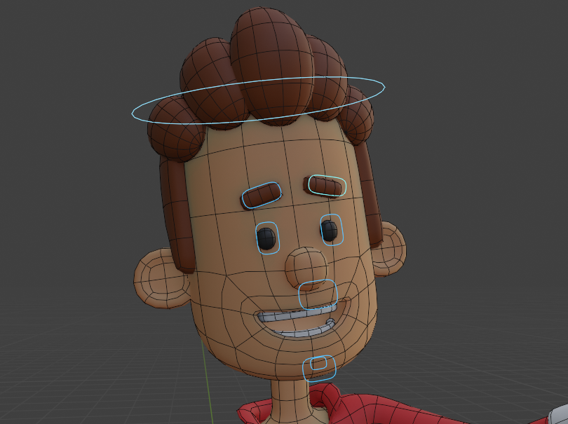
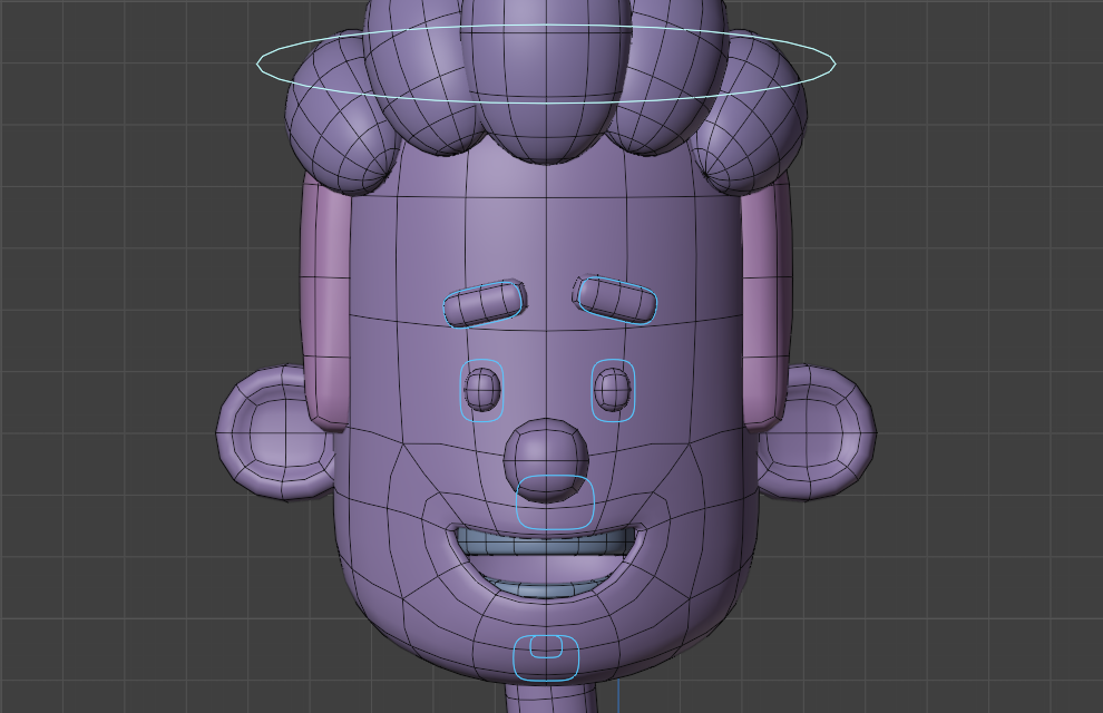
5. Adding Bones to the Facial Rig: In this lesson, we will start creating the control
structure that we will use to manipulate the
shape keys we have created in an easier
and more intuitive way. At the end of the process, we will have a structure
similar to this one. We will have a control for
each eye and each eyebrow. The controls and
eyebrows correspond to effective bones
that will influence this part through
vertex group influence. To control the mouth shape keys, we will have three controls. One control that will
handle the lateral mouth opening both outward and inward. In addition to controlling the smiling and set expressions, all of these will be configured
in a way that activating all these expressions
will be done by adjusting a single control. Furthermore, we will
have a control for the vertical mouth opening and a control for
the vertical opening of the dental arches. If we want, we can select and move these two
controls at once. In this already
configured example, I am manipulating
this expression imposing mode of the rig. But if I enter the edit mode, we will see that these controls
are conventional bones. They are simply configured with some custom shapes to make the interface more
user friendly. But I will show you how to configure them this way
in a future lesson. In this lesson, I will
just show you how to create these bones
in the Rigifirig. To create the bones I
will use to control the expression within
the Rigify rig itself. I will start by activating the visualization of
the rigi collection. But I will keep the meta
rig object disabled. Now I will select the rig object to create a new
bones for an existing rig, we will need to be
in the edit mode of that particular rig. But now I need to make
an observation about the layer or collection in which the new bone
will be created. This procedure is a
bit different if you are using Blender 3.6 or earlier or if you are using
Blender version four or later up to version 3.6
When a new bone is created, it will belong to all
the layers that are visible in the rig layer spanel
at the time of creation. If I leave only the torso
layer active, for example, when I create a new bone, its visibility will be tuggled
along with this layer. I will press Shift
and right click to position the predecursor
somewhere around here. To create a new
boning editing mode, I just use the shift, a shortcut for creation. With this, a new
bone is created. I will enter the pose mode now and alter the
visibility layers. We will see that the
bone I created will be hidden or shown along
with the torso layer, which was the one that was
enabled when I created it. Since I did this just to
demonstrate this functionality, I will go back into editing mode and I will delete this bone. But for this project, this is the layer
where I actually prefer to create
the facial bones. But now I will show how this procedure works
in blender vision. For and later. If you have
created the rigifying, this version, a layer called
face may have been created. But to set in which layer
the bones will be created, you should go to the
object data tab of the property editor and activate the collection where you want the bones
to be created, in the bone collections
panel list. This is how we define
the collection, where a new bone
will be created in an existing rig in
blend of version four. If I create a bone in a particular collection
interpose mode, we will see that when I disable or enable
that collection, the bone I created will
be hidden or shown. After defining the layer or collection where your
bones will be created, let's actually start
creating the bones. For this, remember that the reading question
must be in edit mode. I will start by creating
the mouth bones. Since I want these
bones to be created in the center of
the x axis of the, I will start by pressing the shift C shortcut to center the predcursor
in the grid center. I will use the shift A shortcut
to create the first bone. With this, a new bone is created in the
center of the trevi. Since I want it to stay in the center of the X
axis of the scene, I will activate the
orthographic side view. To move it this way it won't be moved to the side and will
remain the center of the axis. Now I will position it in front
of the character's mouth. I will scale it to
make it much smaller. I will position it so that the lower joint is roughly
aligned with the mouth. This will be the
control we will use to manage most of the
mouth expressions. Now I will cup this bone using
the shifted disshortcut, and when the copied
bone starts to move, I will press the Z key, so that the bone is only
moved along the axis. I want this bone to
be a bit larger. I will move the upper joint
a bit upward in this region. I will need two controls that will be positioned
in the same place. One to control the
mouth opening, and another to control
the teeth opening. I will use the shifted dish shortcut once again
to copy this bone. When the bone starts moving, I will right click to
cancel the movement. Now I will simply click on one of the joints
of the top part. To select only one of them, I will move it a bit downward. This way I can see the
two bones separately. Now I will set the view
part to the front view. I will copy one of
these bones to create the first eye bone if you want. You can also activate the wireframe view in
the overlays menu to help with the alignment
in the front view. I will copy one of these bones using the Shift D shortcut. I will position the lower joint, roughly align it with the
center of one of the eyes. Now I will copy the
bone once more. Align the basis of this new bone with the center
of one of the eyebrows. Now that I have created the bones on this
side of the face, I will copy and mirror
them to the other side. I will select the two bones and copy them using the
shifted shortcut, I will right click to
cancel the movement. Now being careful
not to select them, I will mirror these
copied bones to the other side, to the D. I will do the following. I will once again use the shifty shortcut to make sure the treedcursor is in
the center of the tredviu. I will go to the transformed
pivot point menu. I will set the treedcursor as
the transformation center. Now I will go to the
Armature menu Mirror. I will click on X Global. This way the copied bones are properly mirrored
to the other side. Now to finish, I will
rename each of these bones. For this, I will select each bone and I will go to the bone tab
of the property editor. In this first field of this tab, we can define the name
of the active bone. I will name this mouth
bone, Bone, mouth. I will name this larger
bone in front of the chin bone, Mouth open. I will name this
smaller bone as bone. Teeth open. The left bone will be bone. The left eyebrow
bone will be bone. Eyebrow, the right
bone will be *****. The right eyebrow
bone will be bone. Eyebrow bones can be named in a way that
makes sense to you. The only guideline
that is advisable to follow is that symmetric
bones have the same name, differing only by for
left and for right. This rule allows you to use some uring tools during
the animation process. Now I will parent all these facial bones to
the character's head bone. For this, I will activate x ray. I will select all the
facial bones first. I will add the head
bone to the selection. While holding down
the shift key. I will go to the Arma
Chairman, Parents Make. Then I will click on the
Keep of Set option so that the parent head bones retain their original position. With this, the creation of
the bones is completed. If I want to test the parenting, I can go back to pose mode, return the transformation pivot, point menu configuration to the individual origins
or median point option. And manipulate the
head control to see if the created bones are
following it correctly. Thank you for watching,
and I see you next time.
6. Using Custom Shapes: In this lesson, we are going
to see how to customize the appearance of
the custom bones we created in the last lesson. This customization is not mandatory and the rig can
work perfectly without them. But in general, manipulating
the control bones become more user friendly
with customized objects. This procedure works by
replacing the shape of the bones with the shape of any other objects
existing in the scene. The rigifhise controls
themselves are configured with
specific custom object for each control bone. To create a custom object, I will go back to object mode. I will create a new object. This object could be
anything, even a geometry. But the most common thing is
that the objects chosen to use as controls are objects
from the curve category. I will go to the curve subnu, I will create a circle object
to facilitate editing, I will move this object
a bit to the side. I will activate the top view. Now I will enter edited mode to customize the
shape of this object. Editing objects of
the curve category is a bit difference from editing
conventional geometries. These objects work like curves. In vector software like
Illustrator or Coral Draw. The objects are composed of verses that have
Bezier type handles. These handles can be
moved, rotated, or scaled. For this example, I will
make a very simple edit. For these, I will activate the median point option in the Transforming
Pivot Point menu. I will use the scale to to
bring these two verses closer. Now I will select these
two other verses. To scale their handles, I will need to set the
transformed pivot point back to individual origins. This way, when I
scale the selection, the handles will be scaled. Additionally, I will
scale the handles of the other verses
a bit horizontally. In this way, I have
reached this curve, the rectangular shape,
which is what I wanted. This will be the shape I will use for all the phase controls. I can go back to object mode in the object tab of
the properties editor. I will rename this
object with my name. I remember for this example, I will use the name,
my custom shape. If I want, I can move this
object in the Outliner into the WGTS rig collection where the custom shapes
used by rigifi are located. But this is not mandatory Now to configure the bones
with this custom shape. I will select the rig, I will enter pose mode, and I will select
one of the bones. I will start selecting one of the eyebrow bones with
the bones selected. I will go to the bone tab
of the properties editor. I will open the view
part display panel. I will open the custom
shape sub panel. In the custom object menu, I will start typing the name
of the object I want to use. In my case, I will start
typing my custom shape. With this, we will see the
object appear in the menu. Now I just need to click on it. We can see that the
object in question is now being used as the
shape of the active bone. Additionally, we can use the transformation values
below to change the size, rotation, or position of
the shape in question. In this case, I will adjust the lateral scale
of the shape of bit. I will try to use
a rounded value so that I can use the same value on the bone on the other side. Now I will repeat
the same procedure for all the other bones. I will choose the
shape I made from the menu for the
symmetrical bones, I will use the same
transformation values I used on the first side. Now I will repeat the same
procedure for the eye bone, but in this case I
also want to rotate the shape I will test to see which rotation
axis I need to adjust. I will rotate the figure
90 degrees on this axis. I also think I can scale the figure a bit in
all the three Xs. I will also adjust the
position on the lateral axis. After that, I will repeat the same procedures and values for the bone
on the other side. The difference is that
for the position Xs, the value of the X X that is negative on one side should
be positive on the other. Now I just needed to repeat the same procedure for
the three mouth bones. I will just adjust the size
of the controls so that the teeth opening control is slightly smaller than the
mouth opening control. To finish, I will show
one option configuration. These dash, the lines
that we are seeing show the connections
between parented objects. If you don't want
to see these lines, you can go to the Overlays menu and disable the
relationship lines option. With that, we finish creating the control
object for the facial. Rich. Thank you for watching
and until next time.
7. Using Bone Constraints Part 1: In this lesson, we will
look at another optional, but highly recommended,
configuration for the facial rig. If we select each of these controls in
the rigs pose mode, we can move, rotate, and scale each of them freely. This isn't necessarily
a problem, but if you're not careful, you might end up moving the controls far from
where they should be. To prevent this issue, we can use a feature
called bone constraints. Bone constraints allow us to
set limitations for bones, ensure they can only be
transformed within a range. We determine to set up
a bone constraints, we need to have
the relevant bone active in the rigs pose mode. Then we will click on this tab called Bony Constraints
in the Properties editor. Here we will open this menu to choose which bone
constraints to add. Since I want to restrict
the controls movement, I will add the limit
location constraints. All the constraints we will
configure for this rig should have this owner option
set to local space. This way the Xs taking into account will be the local
axis of each object. Additionally, we will also check the effect transformer option for all the constraints
in this rig. To demonstrate how
the constraints work, I will enable the
restriction for the minimum and maximum
values of all Xs, since the value is
zero for all Xs. If we try to move the control, we will see that the
object doesn't move. But instead of completely
locking the control, if we want to restrict the
movements to a certain value, We can configure each axis with a desired value to test what
values to set for each axis. I can temporarily unlock all axis and enable the local option in the
Transformer Orientation menu. This way, the axis we see in the transformation tools are the local axis of the control, which are what matter
for our configuration. Additionally, we will leave the transformer panel
in the side bar open. As we can see, the local
vertical axis is the Y axis. Now what I'm going to do is move this control on the y axis while paying attention
to the value of this axis in the
transform penul. I will move the control more or less to the point
where I think it should be restricted and look at the value that appears in
the transformed penul. In my case, I think
I can restrict the controls movement
to about 0.1 upwards -0.1 downwards
for the side. I want to be able to move
the control a bit more. I think a displacement of 0.15 on the x x will
be a good value. After finding these values
and rounding them in my head, I will return the control
to the zero position. I will enable the
lock for all Xs. I will configure the
restriction ranges. Note that the minimum values
should always be negative. In the case of the x x, I will set -0.15 in
the minimum x field. For the y x, I will set -0.1
in the minimum y field. For the maximum values, I will use the same
values but positive. That is 0.15 in the
maximum x field, 0.1 in the maximum Y field. Since the z x
corresponds to death, and I don't plan to move the
controls in that direction, these values can remain zero. If I test the movement of the control in the
treaty view now we can see that it will only move within the restricted
space we configured. Now I can select the
bone mouth open control. I will add the limited
location constraints. I will set the
local space option. I will check the effect
transform option. Now I will enable
the lock on all Xs. In the case of this control, I want it to only be
able to move downwards. That is, I will only leave the movement free on the y axis. I think I can use the
same limiting value that I used for
the other control. Since the movement I want
to allow is downward, the value is negative. In the minimum y field, I will set the value minus 01, which is the same value I had already tested for
the other control. This way if I try to use the
control in the view part, we will see that it only moves downward and only
up to this value. Now I will show a quicker way to configure the constraint
for the other control. The teeth control should have exactly the
same restriction as I configure for the bone
dot mouth open control. I can first select
the teeth control, then I can add the mouth control to the selection
with the shift key pressed with the selection
made in this order. I will go to the already
configured constraint. I will open this menu for
the existing constraints. I will click on
Copy to Selected. This will add to the
control I selected first a constraint with
the same settings as the one already configured. This way the position
restriction is already set. Optionally, we could also add rotation and scale
constraints for each control. But when we don't want the
control in question to be rotated or scale on any axis, we can also go to the
transformer panel in the side bar and activate the locks next to all
rotation and scale Xs. We can do this for
each of the controls. This way we finish setting up the restrictions for
the mouth controls. In the next lesson, we
will see how to add constraints to the eye
and eyebrows controls. Thank you for watching,
and I see you next time.
8. Using Bone Constraints Part 2: In this lesson, I will configure the bony constraints for the
eye and eyebrow controls. I will start by
moving the control of one of the eyes to the
approximate point. I want to be the limit
of this movement. I will observe in the
transform panel what the approximate value is that
corresponds to this limit. In this case, I will do this for the y axis and the x axis. In this case, I think
I can use the value of 0.05 as the limit for each axis. I will go to the bone
constraints panel. I will add the limit
location constraints. I will set the option
to local space. I will activate the
effect transform option. Then I will enable the
restriction for all Xs, I will use the value of -0.05 for the minimum x
and minimum y fields, and the values of 0.05 for the maximum x and
maximum y fields. This way, this control will only move this distance
in each direction. Since the constraint
for the control on the other side should be
identical to this one, I can select it first. Add the already
configured control to the selection and use the cup to selected command
in the constraint menu. This way the right control will be configured with
the same constraint. Now I will select the control
for one of the eyebrows. I will measure the
approximate distance that I will use in the
constraint values. I think I will use 0.15
as the positive limit for the y axis -0.05 as the
negative value for the y axis. For the x axis, I will allow the control
to move 0.05 inward, but I won't let the
control move outward. I will add the location
constraint to the control. I will set it to local space and I will activate the
effect transform option. I will enable the
restriction for all Xs. I will set 0.15 as the positive limit for
the maximum y field -0.05 in the minimum y field for the x x. I only want
the control to move inward. I will set -0.05 in
the minimum x field, but I will leave the
positive field zeroed. This way I will be able to move the eyebrow slightly inward to create a forward expression. Now I will select the control
for the other eyebrow. Add the first one
to the selection, and copy the constraint
from one to the other. I will only need to
make one change. In this case, since I want the control to be able to
move inward and not outward, I will reverse the
configuration for the x axis. For this eyebrow. I will leave the minimum x field zeroed. I will set the value of 0.05
for the maximum x field. This way the movement is
configured the correct side. Now to finish, I will add another constraint
for the eyebrows. In the case of these controls, I also want to rotate
this bonus to create more expressions to
limit the rotations, I will add the limit
rotation constraints. I will also set it
to local space. I will activate the
effect transform option. I will also lock all axis. Now I will activate
the rotation to, to see which axis I should configure the
restriction values for. As we can see, the relevant
axis is the z axis. Since the rotation
constraints works in degrees, I think I can restrict the rotation to 30
degrees on each side. This way I will set -30 degrees
in the Z minimum field, 30 degrees in the maximum field. This way the control can be rotated 30 degrees on each side. And to finish, I can copy the constraints to the
control on the other side. And with this, we finish configuring the constraints
for all controls. Thank you for watching,
and I see you next time.
9. Setting Up Drivers for the Facial Rig Part 1: In this lesson, we will see how to use drivers to
make these controls. We created effectively control the Shape keys we set
up on the character. I will start by setting
up a driver to control the mouth opening Shape key
as we have already seen. To set up a driver, we should have the
object to be selected. I'll switch back to object, I will select the
character model. I will go to the
object data tab. In the Shape key spanele, I will activate the
mouth open Shape key. Now I will right click on
the value of the Shape key. I will click at the driver
in the object field. I will choose the rig object
as the control object. But when we choose an
armature type object, besides choosing the object, we need to define which bone will be used
as the controller. I will click on this bone menu and start typing the name of the bone I want to
use as control. In this case, I will start
typing Bone Mouth open. I will click on the
respective bone. In the type option, I will choose the y axis. I will set the space
to local space. To test, I will select the
gino and interpose mode. If I move this
control downwards, we will see that
nothing will happen. This happens because I am
moving the control downwards. In other words, using
a negative value. Since I want the value
of the shape key to increase when the position value of this control decreases, I will have to invert the
mathematical expression. For that, I will switch
back to object mode, select the character, open
the driver editing panel. To invert an expression, simply add the
subtraction sign in front of expression in
the expression field. This way, when the
controller value decreases, the controlled parameter
value will increase. If I select the rig
and interpose mode, we will see that when
I move the control, now the expression
starts to appear. However, the influence
value is still very low. To change the intensity
of this influence, we can use a
multiplication value. I will once again switch back to object mode and open the
Driver Editing panel. Now I will add a Nester risk. After the word var, I will
choose a multiplication value. To find this value, we usually need to go through
a trial and error process. I had already tested some values before
recording this lesson, and I concluded that ten is
a good value for this case. But usually you will need to test a bit to find
the ideal value. If I test the control, now we will see that the automation is
already working properly. Now that this first
driver is set up, I will show an
interesting option. If we want, we can copy an existing driver from
one value to another. In this case, the driver I
will use for the shape key we created for the teeth is
very similar to this one. I can select the
character object, right click on the
value that already has the configured driver and click on the copy driver option. Now I will select
the teeth object. I will right click on the value of the teeth
open shaped key. I will click Paste Driver. This way an identical driver to the first one was
added to this value. But in this case,
I want to change the controlling bone so that this driver's control is
separate from the mouth. I will open the driver
editing panel in the bony field where it's
defined as bone mouth open. I will type bone teeth open, which corresponds to
the other control. I will select it this way. If I enter the posing mode of the rig and test each
of the controls, we will see that each of them is acting on their
respective shape key. In the next lesson, we will continue setting up the drivers for the
shape keys we created. Thank you for watching
and I see you next time.
10. Setting Up Drivers for the Facial Rig Part 2: In this lesson, we will
configure the drivers that will allow us to control the other mouth shape
keys of the character. With the bone dot mouth control. I will start by
selecting the character. I will right click
on the value of the mouth out shape key. Click Driver in
the driver panel, I will set the rig as
the control object, the bone, mouth as
the controlling bone. The controlling value will
effectively be X location. But I will set up the
space as local space. If I put the rig imposing mode
now and move the control, we will see that the
control is already working, but the influence is very small. I will select the character again and add the driver
value with a multiplier. But I will take this
opportunity to show that we don't necessarily need to open
the driver editing panel. If I click on a value that
already has the driver, we can see and add the
expression of that driver. I just needed to input
the multiplier with the asterisk and some
value as we have seen. It's usually necessary to test the values until
we are satisfied. But I had already tested some values and concluded
that for this case, eight is a good value. I just need to set this
expression as asterisk eight. If I test the control, now we will see that the
infants is much better. The driver. I will
use the control. The mouth in shape key will
be very similar to this one. I can copy the driver from the mouth out shape key and paste it into the
mouth in shape key value. However, as I want this
value to be activated, when I move the controller
to the other side, I will invert the expression of this driver as we have seen. To invert the
expression of a driver, simply add the subtraction sign in front of the expression. If I test the control, now we will see that for one side it triggers
one shape key, For the other side it
triggers the other shape key. Now we will do more or
less the same thing with the y axis and the smile
and front shape keys. I will add a new driver for the mouth ha shape key
In the driver panel. I will set the rig as
the control object, the bone, mouth bone as
the controlling bone. In this case, the controlling
value will be de location. As always, the space will
be set as local space. In this case, I will already
set the expression as var asterisk five to multiply the influence
by this value. Now I will test the control. I think the multiplication
is still weak. I will go back to
the driver value, and I will change the
multiplication value to ten. I will test again. Now I think the
influence is good. Now to finish, I will copy
the driver from the mouth happy Shapy key and paste it into the
mouth said Shapy key. However, as I want this
shape key to be triggered, when I move the
control downwards, I will add the subtraction sign in front of the expression. Now if I test this control, we will see that with
a single controller, we can activate four
different expressions. We can still combine these expressions with the ones from the other control we area. Configured. With that, we finish configuring the
controls for the shaped keys. In the next lesson, we will configure
the influence of the eye and eyebrow
bones on the geometry. But in this case, we will
do it using vertex groups. Thank you for watching,
and I see you next time.
11. Weight Painting the Facial Elements: In this lesson, we are going to finish setting up
our characters, facial G. What is left to do is configuring the controls
for the eyes and eyebrows, for these parts of the face. I will set up the virtues of these components so that they are directly influenced by the bones of their
respective controls. This I will select
the character. I will enter the weight
paint mode of the object. Now I will use the
sample group command to check which bone is influencing
the verses of the eyes and eyebrows up until Blender 3.6 We do this by pressing the shift key and right
clicking on the relevant area. From Blender 4.0 onwards. We do this by placing the
cursor over the area in question and using the
control shift X shortcuts. As we can see in this rig, the bone influencing the
verses is Death Spine 006, which is the
character's head bone. At the end of my configuration, I want each eye and eyebrow to be influenced only by its
corresponding control bone. I could do this whole set up
using weight painting tools, but since in this case
I will be changing the influence of entire
and specific volumes, it's easier to do this by directly modifying
the vertex groups. In edited mode, I will switch to the edited
mode of the object. I will make sure the vertex
selection mode is active. I will select each eye
and eyebrow to do this, simply place the
cursor over each of these parts and press the L key. Now I will go to the
object data tab. In the Properties editor, I will open the
vertex groups panel and I will find the
group death spine 006, which corresponds
to the head bone. Since I don't want this bone
to influence the vertes, I will click the remove button. This way this vertes will no longer be influenced
by the head. Now what I need to do is
create a vertex group for each of the control bones I created for the
eyes and eyebrows. To this I will go to
the end of the panel. I will click the head button to create another vertex group. I needed to create a group
for each of the controls. As we have seen, it's
important that each group has exactly the same name as the bone that
will influence it. If you don't remember
the bone names, you can select the rig, go into posey mode, activate the bone tab in
the properties editor, and check the name of each bone in the first
field of the panel. As we can see, the left
eyebone is named bone, the right eyebone is named bone. The left eyebrow bone
is named bone eyebrow. And the right eyebrow bone
is named bone eyebrow. But I see that I made a
typing error in this case, I will correct this error
because it's important that the bony name and the
vertex group name are exactly the same. Now I can return to object mode, select the character, and create the vertex groups with the name of
each of these bones. The first one should
be named Bone. The next one will be Bone It. The next one will
be Bone Eyebrow. Finally, I will create
the group Bone eyebrow. Make sure not to make any typing errors when
creating these names. Now I will enter editing mode. I will select each of the vertex volumes by
placing the cursor over the relevant part and
pressing the Lkey. In this case, since I started
with the left eyebrow, I will activate the
bone eyebrow group and click the assign button. Now I will clear
the selection and select the virtues
with the L key. I will activate the bone
Dol group and click a sign. Next, I will select
the right eyebrow, activate the bone dot eyebrow
R group, and click a sign. Finally, I will select
the virtues of the right. I activate the bone
group and click assign. Now I can return to object mode, select the rig interpose mode. If I select the controls
for the eyes and eyebrows, now we will see that they are already influencing the corresponding virtues
of the character. This way, we can move
each of the controls to create a range of expressions
on this part of the face. Additionally, we can rotate
the eyebrow controls. We can scale the eye controls. If we scale the eye controls
only on the y axis, we will create the impression of closing the character's eyes. And with that, we complete the
creation of our character. Now I can enable the display
of all the models objects. And I can enable the display of the G layers I want to use
to animate the character. That's it for this lesson. Thank you for watching
until next time.
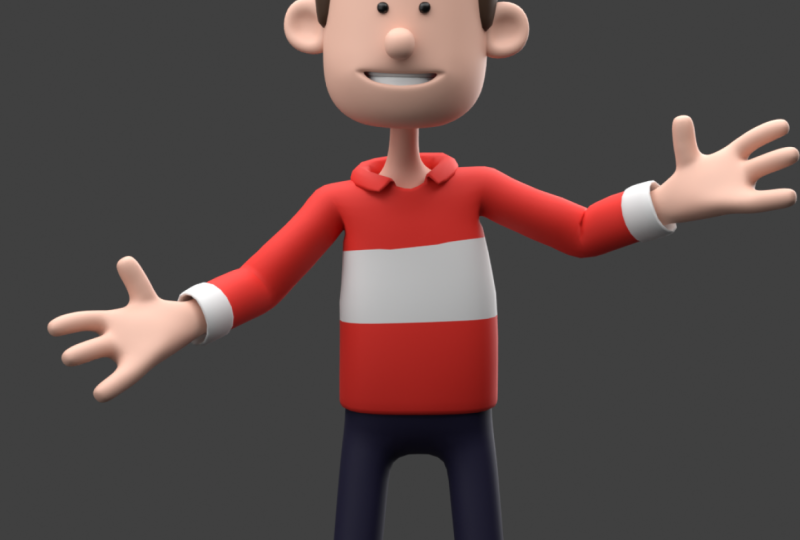
12. Creating a Simple Animation Part 1: In this lesson, we
are going to start creating a final animation
for our character. This is not an animation
focused course. I want cover advanced character
animation techniques. But I thought it would be a good idea to
show how to create a simple animation so we can
see our character in action. The animation we will
create will be this one. As we will see, this
animation can be created with just
four different poses. To begin the animation process, I will make sure I am
imposing mode with the rig. I will activate
only the layers I intended to use in
the rig layer spanel. In my case, I will
enable the torsal layer, the fingers layer,
the FK layers, and the leg K layers. But for the arms and legs. In addition to
activating the layers, we needed to ensure that
the controls are set. For the K and K modes, I will start by selecting a
control from one of the arms. To begin checking, I will open the rig main
property spaniel. Since I am using the
K mode for the arm, I need the IKFKvalue to be one. I also need to select
one of the controls on the other side to
perform the same check. In the case of the legs, each of them needs the IKFK
parameter set to zero, as I want to use the
IK mode for them. I will also check this value for the controls of each leg. Now I will create the first
pose of our animation. I generally like to start
creating poses for the legs and waist to make the character
look more relaxed. I will slightly open his feet to keep the
feet within the grid. I will only move
them to the sides. Next, I will lower the waist a bit to give the
legs slightly bent. I will also rotate this smaller waist control to
create a more natural pose. Now I will select the top trunk control and rotate the bits
to the other side. It's very common that when the waist is rotated
in one direction, the trunk is rotated in
the opposite direction. Now I will rotate the head to the side to make it appear that the character
is more relaxed. I will start working on
the rotation of the arms. To work on the arm rotation. If you are using the
rotation manipulator, it's recommended to use the local mode from the
transformer orientation menu. I will lower the arm a bit and
slightly flex the forearm. Remember that if
you want to change the rotation of the
elbow with the K mode, you should select
the first bone of the arm and rotate
it on the Y axis. In local mode now I will start working
on the hands position. I will rotate each finger controls to make the hand
slightly more closed. I will also close the
Palmer control a bit. Keep in mind that
for the fingers, the rotation of the control
rotates the entire finger. However, if we scale the
control with the key, it will close the second and third phalanges
of the finger. In question, I will take some time to make the
hand look very relaxed. Usually the pinky
finger is the one that closes the most
in a relaxed pose, while the index finger
remains slightly more open. When I am satisfied with the
position of the first arm, I can copy the pose of this
arm to the other side. If I want to do this, I will select all the controls of the arm that has
the pose ready. Then I will go to the Pose menu. Click Copy Posey. Then I will return to the menu and click Paste Pose, Flip it. With this command,
the symmetrical bones of the rigifi are positioned in the same pose as the bones we used
to copy the pose. But after that, if we want, we can make small
changes to make their positions
slightly asymmetric. Now that I am satisfied
with the body pose, I will also manipulate the facial controls to create a simple initial expression. I will give him a simple
smile and relax the eyebrows. Now I will give the
pose a general check. I think I needed
to open the knee a bit more on the leg
that's further out. In the end, when I am
satisfied with the pose, I will select all
the controls with the key and generate a key
framing for all the controls. For the, I can go
to the pose menu, go to the animation sub menu, and click Insert Key frame. Or I can press the shortcut key. We will open for us to choose what type of key frame
you want to create. Since I am using
position, rotation, and scale controls
to create the pose, I will create a location, rotation, and scale key frame. If we look at the timeline now, we will see that a
key frame has been created on the frame,
one of the scene. In the next lesson, we will finish the remaining
poses of this animation. Thank you for watching
and I see you next time.
13. Creating a Simple Animation Part 2: In this lesson, we are going to finish creating the
characters poses. The first thing I will do is position the playhead
at a different frame. In this case, I will give a train frame interval between
the first and second pose. At the end of the process, I can test and
adjust the interval between the poses to achieve the desired animation timing. In this lesson, to make
the process faster, I will use the
transformation shortcuts to manipulate the controls. But if you prefer,
you can create the poses using the
transformation two handles. I will start by moving the character center slightly upwards and towards the center. I will reduce the
waist rotation. If you want you can leave the
auto king button enabled. Then I will make the spine a bit straighter and also rotates the head slides to
the other side. Now I will lift the
character's arm, but I will keep it flexed, anticipating the gesture it
will make with his arms. In this pose, the hand
can be a bit more flexed, as we will have an
open mouth smile. In the next pose, I will
start opening the mouth. For this pose, I can also copy the pose from
one arm to the other. I will select all the
controls of the arm. With the pose ready, I will use the copy pose
command from the pose menu. Then I will use the paste pose flipped command afterwards. If I want, I can make
slightly changes to the other arms pose to make
them slightly different. When I finish the pose, I will once again select all the controls
of the character. I will press the key to open
the key frame creation menu. And I will generate another
key frame of the location, rotation, and scale type. Then I will move
the head forward by 20 frames to start
creating the next pose. Now I will begin
creating the next pose. I will move the waist slightly
downward and to the side. I will open the leg a bit more. I will make the spine
more curved again. I will also rotate
the head a bit more. Now I will give a
character a wide smile. I also want the character to blink between this
pose and the next. In this pose, I
will scale the eye controls on the y
axis to close them. Now I will start opening
the character's arm. I think for this pose, I can also make the hands
slightly more open. Once I am satisfied with
the pose of this arm, I will copy the pose and mirror it to the other side using the paste pose
flipped command. Now I will once again select all the controls and generate a key frame for all of
them of the location, rotation, and scale type. Now I will create the final pose for the animation indispose. I will make the waist a big higher and the spine
a bit straighter. I will also raise the eyebrows slightly and keep the
eyes open. Indispose. Arm should be in the most
expressive configuration. I will open then a bit more. Then I will select
all the controls. I will copy, dispose, and use the paste pose flipped command to mirror it
to the other side. To finish, we should also create another frame
of the location, rotation, and scale
type for dispose. If we activate the
play button on the timeline or
move the playhead, we can already see the movement. Now we can adjust the
animation timing if desired. In my case, for example, I want the character to stay in the initial
pose for a while. To adjust the timing
between the key frames, I need to have all the control selected to have the character
stay in the first pose. For a few frames, I just need to select and move
all the key frames a bit on the time line. If I position the first
key frame on frame 20, the character will remain the
initial pose for 20 frames. I think the timing between the first pose and the
second pose is good, but I want the movement between the second pose and the third
pose to be a bit faster. For that, I just need to
move the key frame for the third pose a bit closer to the key frame
for the second pose. To get the timing just right, it's a matter of
trial and error. Remember that to
move the keyframes in this way on the timeline, you should have all
the characters control selected to finish. I think I will move the
last keyframe closer to the third to make this
interval a bit faster as well. Once again, I will test to
see if the timing looks good. Now that I think the animation
has the right timing, I will reduce the active
frame range of the time line. For this, I will enter a
value in the end field that's just a few frames after the last key
frame of my animation. I will try frame 80. I will play the animation. I think I can extend
it a bit more. I will try frame 90. Now I am satisfied
with my animation. Remember that your animation doesn't have to be
identical to mine. The goal of this exercise is for you to become
familiar with the animation controls and create a presentation
for your character. Feel free to create your
own animation if you want. In the next lesson, we will set up the lighting
for the final video. Thank you for watching, and
I see you next time, P.
14. Rendering the Final Video: In this lesson, we will create the final video
for our animation. But first, I needed to create some lights and a
camera for the scene. To do this, I will start by returning to the object
mode of the rig. Since I won't be creating
any more animations, I can turn off the auto king
button on the timeline. Now I will create the lights and the camera for the scene. Although it's not mandatory, it's a good idea to keep these objects organized
in the Outliner. I will create a new
separate collection to store these objects. You can rename this
collection as you like. I have the habit of naming
the collection where I store the lights in
the camera as a studio. Now with this collection active, I will press the Shift a shortcuts to open
the Creation menu. I will go to the
Lights sub menu. I will create an area light, which I find most suitable
for this type of lighting. I will move these lights
above the character and to be able to visualize the final lighting
in the Viewport. I will enable the rendered mode in the Viewport shading options. I will move the light a bit
further from the character. I will click on the
object data tab of the properties jitter to configure the light in
the size parameter, I will increase the size of
the light significantly. I will also increase
the power value considerably to make the
light considerably stronger. Now I will use the shifted
shortcut to copy this light. I will rotate it so that it comes from one side
of the character, but also a bit from the front. When I am satisfied
with these lights, I will copy the selected light. Once again. I will position the last lights at
the back of the character. I want this light to
come from behind, but on the opposite side
of the front lights. This light is often
called a back light. It helps create a high light
for the character against the scenes background in
the lights property spanel. I will adjust the
value to make it even stronger if you want to see
how your scene is looking. Without the Viewport elements, you can temporarily disable
the Viewport overlays button. Now to wrap up, I will create a scenes camera, The de simply clicking on the camera option in
the creation manual, as I want the camera to be
pointed exactly forward, I will start by zeroing out the vertation values of this
object in the side bar. Now in the side view, I will rotate the
camera to face forward. I will position it at a
reasonable distance from the character to see exactly how the frame
is turning out. I will split the view
porting by right clicking on the divider and choosing
the vertical split option. Now I will click
on the camera icon in one of the view parts. To activate its view, I will use the other viewport to continue it position
in the camera. In addition to
moving the camera, I can also click on the
Object Data tab and change the focal
length parameter to adjust the camera's aperture. If I use a slightly lower value, the lens will be more open. For this case, I will use
a 35 millimeter camera. Then I will make sure the character is well
framed by the camera. Once I am satisfied with
the lighting and camera, I will set up the scene rendering in the
scene rendering tab. I always like to enable the
ambient occlusion option. This option creates shadows in the areas where
the surfaces meet, making the lighting
appear more natural. In this case, this is not making a
significant difference. But I still like to keep
this parameter enabled. Now we can click on the Output tab in the
Properties Editor. Here I will click
on this folder icon to set the location file name. I will save my file on the
desktop of my computer. I will name it my
character animation. Now I will go to the file format menu and choose
Mpeg video format. In the encoding menu, I will select Mpeg four. Now I will go to the render menu and
click Render Animation. This will render your animation. Once the render is complete, you will see the video file in the location
where you saved it. Here is the final
result of our work. With this, we
conclude discourse on creating stylized
characters with blander. I really hope you enjoyed it and that you can
make good use of the tools and
techniques I've shown so that you can create
your own characters. Congratulations on
getting this far. Thank you for watching,
until next time.
 Gustavo Rosa, 3D Artist and Blender Instructor!