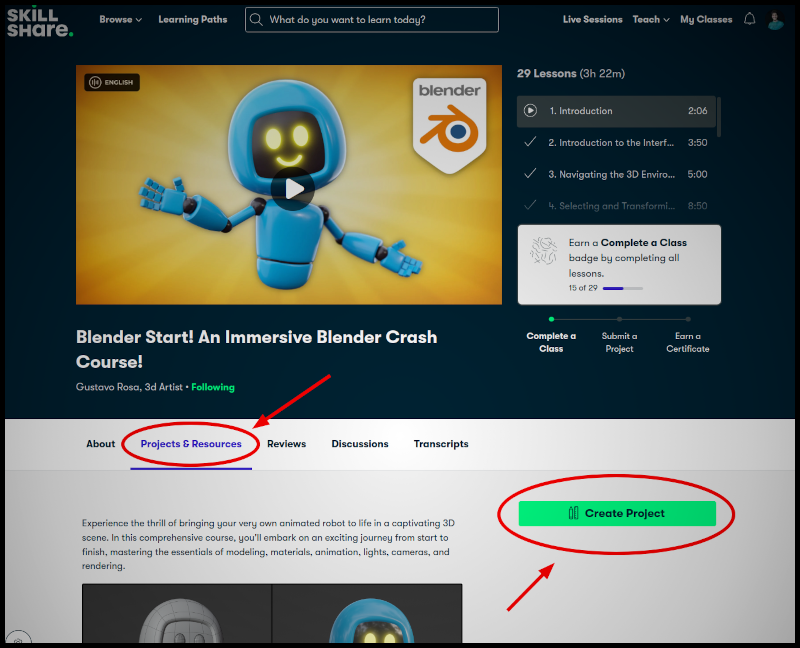
Transcripts
1. Introduction: If you are interested
in learning how to create criticms for animations, games, the special effects
and other purposes, and don't know where to start. This course is for you. Welcome to Blender start an immersive Blender
crash course. This crash course was
developed to give you a first contact with one of the main critic creation
tools of today, Bland After learning the
basics about the interface, object creation
and manipulation, and getting to know some of
the main modeling tools. You will create the scene of the animated robot from scratch. Throughout the project,
you will see how to model set up basic materials, animate adjust lights and cameras and generate a final
video for your animation. You will do all of
this with blender. Blender is an open source and free software that can be
downloaded at no cost on the. My name is Gustavo az. I am a professional
pretty artist with more than 15 years of experience in both teaching and producing professional
sings and PD. I'm tried to be your structure
in this amazing course. Access the website, download the blender and let's embark on this amazing
journey together.
2. Introduction to the Interface: In this lesson, I'm going to
give a brief presentation of the interface so that you can start getting familiar
with Blender. If this is your first
time opening blender, your interface should
look similar to this. Immediately after
opening blender, it shows us more
window-like this. This window is called
the splash screen. And if you are
opening blender for the first time after
the installation, they splash screen will present some initial
configuration options. This version of this splash
screen that appears right after the installation
is called quick setup. These windows offers some
options for shortcuts and themes related to the interface and
usability of Blender. For this crash course, we will leave all
the settings with the default options
and click on Next. When we do that, we will encounter the default
splash screen. This is the window that appears every time we opened Blender. Here, we can choose
to start working with the specific settings
and access some links. But if we simply wants
to start working, we can click on the
General Watson, which starts blender with
the default interface. Or we can click anywhere outside this window to close it and
see the interface info. The blender interface
is completely customizable and can be configured with
numerous components. In this course, we
will focus only on the components of the
default interface that we are seeing here. As we can see, the
interface is divided into several large areas
through these dividers. And the content within each
area is called an editor. The default Blender interface comes with four main editors. The 3D view, where we visualize and interact with
the objects in this scene. The timeline, which
is a timeline, is similar to the progress
bar of any video software. The outliner, which consists of unorganized list of all
the objects in this scene. And the properties editor, which allow us to view and edit various properties
of the elements. In the top-left
top the interface, we find some floating
may lose with a series of functions
divided into categories. These is the default interface that we will use
throughout the course. But although these
interface can be used to perform in most tasks, the blender interface can be customized in many
different ways. N here at the top we
can see a tab system that provides access to different
interface arrangements. These interface arrangements
are called workspaces. Each workspace is focused on a specific stage of
the work process, such as coping or animation. But since it's possible
to perform all stages of the synchronization
process using just the default
interface of Blender. In this crash course, we will only use the Layout tab, which is the initial
workspace up Blender. And with that, we conclude this brief presentation
of the Blender interface. Thank you for watching and
I'll see you next time.
3. Navigating the 3D Environment: In this lesson, we
will learn that the main navigation commands in the blender treat
the environment. The main navigation commands
in the 3D environment, our Zoom, Ben, an orbit. There are many ways to
use these commands, but we will go straight to the two most accessible
and important ones. One way to use navigation
commands is true the navigation icons located here in the top right
corner of the 3D view. And the other way is true, mouse and keyboard shortcuts. Let's start with Zoom. The Zoom command is used to zoom in and out of the SR elements. If we want to use
the navigation icon, simply click on this
magnifying glass icon. Hold the button down
and drag up to zoom in and drag down to zoom out. This shortcut for zoom
is the mouse group. Just screw forward to zoom
in and backward to zoom out. Command is used to
move the screen from side to side, up and down. To use this command
through the icons. Simple click on the Hand icon here in the corner
of the 3D view. Hold the mouse button down and drag in the
desired direction. And to use pen
through a shortcut, just hold the Shift key and
the middle mouse button pressed and drag in
the desired direction. And finally, we have
the Orbit command. This command is used
to rotate the 3D view so that we can see
the 3D environment from different angles. To use orbits, Trudy icons, simple click on these
colored icons and drag. Or simply leave the cursor
over the tradition. Hold the middle mouse button down and dragging the
desired direction. In addition to being able to rotate using these
navigation icon, we can click on each of these
is more colored circles to position their
viewpoint exactly on the specific views of each axis, such as top, front, left side, and so on. And now to conclude, let's take a look at
this burden here. This button is used
to switch the 3D view between Perspective mode
and orthographic mode. The autograph commode
shows the 3D environment without the natural distortion that we see in the real-world, which makes objects appear smaller as they move
away from the observer. How though these viewing
mode is not natural, MAC a bit strange, it can be quite useful in
certain stages of the work. Now that we have started to see the first blender shortcuts, It's important that you pay close attention
to how they work. I'll blender shortcuts. Are editors sensitive? These means that this shortcut
will only work if you have the cursor over the editor where you want to
use the shortcut. For example, we just saw
the navigation shortcuts. We saw that if we have the
cursor over the 3D view, we can rotate the
mouse scroll to zoom in and out of the same. However, if we place the cursor over the timeline and
rotate this group, we will see that
this zone will be applied to the timeline itself, not to the 2D view. And if we place the cursor over the properties editor
and rotate this grow, we will see that nothing happens because there's nothing to
zoom in in this moment. Similarly, if I place
the cursor over the outliner and rotate this
grow, nothing will happen. So whenever you use a shortcut, make sure the cursor is over the editor where you want
the shortcuts to work. In order to work comfortably
in a 3D software, it's essential to know how to navigate comfortably
in the 2D environment. You can use the navigation icons in their interface if you want. But for agility
and productivity, I really recommend
that you memorize the navigation shortcuts
shown in this lesson. Thank you for watching
and until next time
4. Selecting and Transforming Objects: In this lesson, we
will learn how to select and transform objects. To do this, we can use the
default seen in Blender. By now, you may have noticed
that when we opened Blender, the default initial scene are radicals with these
three objects. In the center we see a cube, which is a geometry. In addition, we have this point, which is the light, and this pyramid shaped object, which is a camera. Since the default seen already comes with these three
initial objects, we can use it to learn how to select and transform objects. If we look here on the
left side of the 3D view, we will see these bar
with some buttons. These bar is the
credit view toolbar. Although the icons are quite intuitive and easy to identify, if you want, you can position the cursor over the
right margin of it. When the cursor
assumes this shape, you can click and
drag to the right. When you do this, at first, you will see that the burdens
are organized into columns. And if you drag a little more, you will see that
the buttons start displaying the two names
next to the icons. As I mentioned before, the icons are easy to identify. But when we are learning
to use the software, it can be a good idea
to have the names available to facilitate
their identification. As you can see, the first button is called the select box. If we keep this button pressed, we can see that there are other options for
selection tools. But since the select box will be sufficient for everything we
needed to do in this course, I will keep this option active. When these two is active, we can click on any
object to select it. Additionally, we can
click and drag to create a selection window and
select everything inside it. If we click on an empty
space in the 3D view, we will deselect anything
that is currently selected. If we want to select
more than one object, we just need to
select the first one. And then click on the other
object to wants to add to the selection while
holding down the Shift key. Furthermore, a
quick way to clear the selection is by using
the out a shortcut. A quick way to select everything is simply
by pressing D, a. And finally, another quick
and efficient way to select objects is by clicking on the object's name
here in the outliner. Now, let's take a look at how to transform
objects in the scene. And by transform, I mean move, rotate, and scale the objects. To perform these operations, we will use these tools
here in the toolbar. Let's start with the move to. When we have one of
these tools active, we can also select objects
by clicking on them. And when we select
one or more objects, we will see a colored icon
appear in the credit view. This icon can be called a
transform gizmo or manipulator. The manipulator for
the move to consists of these three arrows
and these three squares. Each of these arrows
corresponds to one of the axis of
the 3D environment. The red arrow corresponds
to the x-axis, the green arrow
corresponds to the y-axis, and the blue arrow
corresponds to the z axis. If we click on any of
these arrows and drag, the object will be moved
only along that axis. So if I click and drag
on the red arrow, I moved the object
only along the x-axis. If I click and drag
on the green arrow, I move the object only
along the y axis. And if I click on
the blue arrow, I move the object only
along the z axis. This is squared that
exist between the arrows allow us to move the
object only on two axes, excluding the axis of
the corresponding color. So if I click on
this red square, the movement excludes
the x-axis and moves the object only
along the y and z axis. If I click on this green square, I move the object along
with the x and z-axis. And if I click on
this blue square, I moved the object
along the x and axis. And if I have the Move Tool
active and click and drag on, this is more white circle. The object will be moved
perpendicular to the screen. Now, let's take a
look at the rotation to when the rotation
tool is active, we can see these four arcs
around the selected object. This is the rotation
manipulator. Each colored art corresponds to an excess of the
treaty environment If we click and drag
on one of them, we rotate the object
only around that axis. In other words, if I click
and drag on the red axis, I rotate the object
only around the x-axis. If I click and drag
on the green axis, I rotate the objects
only around the y-axis. And if I click and
drag on the blue axis, I rotate the object
only around the z-axis. And if I click and drag
on these white arc, the object will be rotated
perpendicular to the screen. And finally, if I
click and drag within this arc without clicking
on any other arcs, I rotate the object freely as if I were clicking
and dragging on a bowl. Now, before using these KO2, I will use the controls
this shortcut to go back a few steps until the box returns to
its initial position. By default, Blender
is configured to say verb to 32 steps
in the history. This means that if
we use Control Z, we can go back up
to 32 commands. Now, let's take a look at the scale to scale manipulation. Icon is very similar to the
movie to manipulation icon. We have this edges to scale the object to
one x is at a time. We have these squares to scale the object to x is at a time. And if we click on the white
circle around the icon, the object will be scaled on all three axes at the same time. And finally, we have
the transform to these two is nothing more than all of the orders
mixed together. When these two is active, we see all the manipulators
at the same time. So we can move, rotate N scale the
object using just 12. This can be a bit confusing
in some situations, but it can also be
quite versatile. And to conclude, I will activate the select
box to once again, to show how we can use
the transformation commands through some
basic shortcuts. These shortcuts can make your
work much more productive. So I recommend that
you memorize them. So even if you don't have any
transformation to active, I can move the
selected objects by pressing the G key for grad. And to finalize the
transformation, simply click on
the mouse button. I can rotate the object
using the R key for rotate. And I can scale the object by
using the S key for scale. And those were the
main selection and transformation commands. Thank you for watching
and until next time
5. Creating and Deleting Objects: In this lesson, we
will see how to delete existing objects in this scene and how to create new objects. To do this, we can start with
the default Blender, same. We can take advantage
of the fact that this scene already comes
with three objects, a cube, a light, and a camera. And start by learning
how to delete objects. Deleting an object
in Blender is as simple as deleting an object
in any other software. Just select it and
press the Delete key. But there is another shortcut that might be interesting
to know as well. If I select another object and press the X key on the keyboard, blender also delete the object. But when we use the x key, instead of deleting
the object directly, it opens a window asking if we really want to
delete the object. If we click Delete or
press the Enter key, the object is deleted normally. Finally, another way to delete objects from this scene
is true the outliner. We can select the
object by clicking its name in the list of
objects in this scene. We can press Delete, even with the cursor
over the outliner. Now, let's take a look at how we can create new
objects in Blender. To create objects, we
will access the admin Lu, which we find here at
the top of the 3D view. In this menu, we will find several sub menus
divided by categories. Within each of these sub menus, we will see all of the objects that are available
for each category. In the light sub menu, we will see how the types of
lights that can be created. In the curves submit loop. We will see how the types of
curves that can be created. In the mesh sub menu, we will see all the types
of geometries that can be created and so on. In addition to access and the creation of menu at
the top of the 3D view, we can also use the
Shift T, a shortcut. Just have the cursor over the 3D view and
press the Shift T, a shortcut to display the object creation memo
in these floating formats. In this lesson, we
will focus on creating geometries and afford that we
will use the mesh sub menu. As we can see, there
are several options for primitive geometries
that can be created. If we click on cube, we will see that a cube will be created in the middle
of the 3D view. Actually, the object is not necessarily created in the
middle of the treaty view. It's created where the creative
cursor of this scene is. The 3D cursor is this icon with three axis and
this dashed circle. When we create a new object, it is created where
this icon is. To reposition the 3D cursor. We just needed to hold the Shift key and right-click
anywhere in the 3D view. And if we want the 3D cursor to return to the
center of this scene, we can use the Shift
to see shortcuts. So if I press Shift and right-click to reposition the
cursor here, for example, open the creation menu
with the shifting a shortcut and
click on Mesh cube. A new cube will be created
in these new position. I'm going to press Shift and right-click to reposition
the 3D cursor. Once more. I'm going to open
the creation menu with the shift th shortcuts. And in the mesh sub-menu, I'm going to click on UV
sphere to create this fear. Now, I'm going to talk about an important aspect
of Blender commands. Several blender commands, heavy properties that can be edited. And some of these
properties can only be edited immediately after we perform the respective commands. When we create an
object, for example, we can add it some initial
properties of that object. And these properties can be found in this panel down here, which we can open it
by clicking on needs. In the case of object creation, right after we create
a specific object, we can add some initial
properties of it in this panel. These properties will vary
from object to object. In the case of this
fear, for example, we can add the number
of segments which corresponds to the vertical
edges of the object. The number of rings, which corresponds to
the horizontal edges, and the radius which
corresponds to the size. But pay attention
to the following. We can only add it to this parameters immediately
after creating the object. If we perform any
other commands, these properties disappear
and the panel starts showing the properties of the last comment
that was performed. So if I activate the rotate to, for example, and
rotate this fear We will see that this
painter will no longer display the initial
properties of this fear. And we'll start
showing the properties of the rotation we just did. In other words, this panel shows the properties of the last
action performed in Blender. So if you want to configure the initial properties
of an object, pay attention to edit these properties immediately
after creating the object, even before performing
any other action. To practice a bit. Now, I recommend that to reposition the critic cursor
in different parts of the 3D view and create each of these initial geometries from the measurement tool. To exemplify, I'm
going to reposition the 3D cursor once again with
the Shift and right-click. And I'm going to
create a cylinder. And I'm going to reposition
the 3D cursor once again. And I'm going to create a cone. But I recommend that
you continue with testing and create each of
the geometries for the menu. Now, let's see another way to create geometries
with Blender. If we look at the
bottom of the toolbar, we will see a geometry
addition button. If we hold down this burden, we will see that it allow us to create different geometries. I'm going to start with
the Add Cube option. That the phrase in
creating geometry is true. This burden is that we can
define the position and dimensions of the object created
at the time of creation. To create an object
with this tool, we click and drag
somewhere on the grid to define the size
of the objects base. We release the mouse button and drag to define the height. And we click once more
to finish the creation. This way, the object is created based on the horizontal
grid of the scene. In addition to being
able to create objects by clicking and
dragging on the grids, we can also click directly on the surface of other objects. This way, the object
is created as if it was resting on the
surface in question. These same procedures
can be used to create all the other geometries available in the
middle of these two. In other words,
with this method, we can create cones, cylinders, UV spheres. N equals spheres, which
are a type of sphere with a different initial
organization of the polygons that
make up the object. And those are the main ways to delete and create
objects in Blender. Thank you for watching
and until next time
6. Modeling Part 1 - Selection: In this lesson, we will begin to see how we can
transform the blenders basic geometries into customize the objects through what we
call polygonal modeling. We have already seen that when we select an
object in Blender, initially, we can move it, rotate it, scale
this object freely. We can interact with the
object in this direct way, because initially it is in an interaction mode
called object mode. If we have a geometry
selected and look here in the top left
corner of the 3D view, we will see this menu here. This is the interaction
mode millieu. In it allow us to choose the
objects interaction mode. The default mode is
the object mode, which allow us to interact
with the object as a whole, selecting and
transforming it freely. If we open this menu, we will see order
interaction modes. If we have a geometry
selected and wants to add it to the object's shape using
polygonal modeling tools, we will enable edit mode here. In this lesson, we will learn about the structural
components of the object and see how to select n manipulated
this components. If we look here next to
the interaction mode menu, we will see three buttons. These buttons allow us to choose which structural components of the geometry we will
be able to select. There are three structural
components of the geometry. Vertices, edges, and faces. If we have the phase components active and the box selection to activity here in the toolbar, we will be able to select
the faces of the object. And initially, the way to select these components is the same
user to select objects. In object mode. We can click on each face
individually to select them. We can click in an empty area of the 3D view to clear
the selection. We can add new components to the selection by holding
down the Shift key. And we can create selection on Windows to select
groups of vertices. Edges are polygons. The next structural
components is the edge, which can be activated
with this button here. When it's active, we can use the same selection commands to select the edges
of the model. In other words, we can click on each edge to make
individual selections. We can create selection Windows
to select group of edges. We can add edges to the selection by holding
down the Shift key. An important aspect of selecting
structural components in Blender is that when we select all the edges that
make up a face, in practice, it is as if the
face itself is selected. This means that some modelling
commands that work on faces can be used with
a selection like this, even if the active selection
component is the Agile mode. And finally, we can activate Vertex Selection Mode API here to select the individual
vertices of the model. Once again, we can select independent versus buy
click on each one of them. We can add more vertices
to a selection. The Shift key pressed. If we have both vertices that
make up an edge selected. In practice, it's also as if we have the edge
itself selected. And if we have all the vertices that make up our
face is selected. The selection also act as if
the face itself is selected. Additionally, we can also use the selection window to
select multiple versus. When using the selection window, we needed to pay attention
to the following. Initially, the selection
window doesn't select the components
that are in the back, which we can see
of the geometries. This means that if I make a
selection window like this, the vertices that are
at the back you have, the model won't be selected. But if we look in the top
right corner of the 3D view, we will find this
button called X-ray. When this button is active, objects have these lights
transparent appearance. Additionally, any select
two when we make, will select the components
at the back of the object. Now I'm going to
deactivate the X-ray mode. And I'm going to
select the vertices corresponding to this
top face of the cube When we have any
structural components or group of structural
components selected, we can use transformation
tools to move, rotate, and scale
that selection. This way, we can start editing the shape of
the initial model. Now, observe an important aspect about the objects editing modes. When we are with an object in edit mode, the selection, move, rotation, and scaling tools will only work for the components
of the selected the object. If we try to select
another object like the light or the camera, we will see that we
simply can't do that. So in order for us to be able to select the other object
in the scene, again, we must exit the edit
mode by going to the interaction modes menu
and clicking on object mode. With these, we will
see that we can now select the other
objects normally. Now, I'm going to select and delete these
initial cube from this scene and create a UV sphere to show a few
more selection commands. To do that, I'm
going to press Shift T. And in the mesh sub menu, I'm going to click on UV sphere. Now I'm going to enter the
edit mode for these objects. But this time I'm going
to use a shortcut for it. And the shortcuts to
enter the editor mode for the selected geometry
is the Tab key. Very well. Now I'm going to show how we
can quickly select entire loops of vertices,
edges, and faces. I'm going to start with
Vertex Selection Mode. To select an entire loop. Simply hold down the Alt
key and click on an edge. This shortcut will work for both horizontal loops
and vertical loops. And the same shortcut will
work for the order components. In other words, I can activate edge selection mode and select loops by holding
down the Alt key. And activate the
Face Selection Mode. And select the loops
with the alt key. In Face Selection Mode, the direction of
the selected loop will depend on where
on the face you click. If you click with the Alt
key held down closer to the vertical edges
like here or here. It will select a
horizontal loop. And if you click closer
to the horizontal edges, like here or here, it will select a vertical loop. Finally, if you want to
select multiple loops, simply combining the
shortcut to select the loops with the shortcuts to add more components
to the selection. In other words, out and shipped. So if I hold down the
Alt and Shift keys, I can click and add a new
loop to the selection. And those are the main
selection commands, blenders, edit mode. Thank you for watching and
I'll see you next time.
7. Modeling Part 2 - Creating and Deleting Components: In this lesson, we
will see how to create and delete edges and
faces on an object. For that, we can use the initial cube from
blenders default scene. So we can select it and
enter the edit mode by going to the
interaction modelling tool and clicking on edit mode. Let's start by learning
how to delete phases. To delete a phase, simply select one or more entire faces. As we have already seen in the lesson about
components selection. We can select a face with
an active selection mode. So if I am in Vertex Selection Mode and select the four vertices
that make up a phase. In practice, the face
itself is selected. Therefore, faces will be selected both in
Vertex Selection Mode, in edge selection mode, and in Face Selection
mode itself. When the face is selected, we will press the Delete key. When we do this, we
will see a menu with several options to delete
the geometry components. Some of these options are more advanced and can be
a bit confusing. Furthermore, to the later phase, we will always choose
the phases option. So after selecting a face, click on delete faces. If we want to create a new
face to close this whole now, we will need to select all the components that
make up this boundary. For that, we can be either in Vertex Selection Mode
or edge selection mode. In this case, I will use
the vertex selection mode. And I will select
all the vertices of the hole's boundary. Once all the vertices of
the whole are selected, we can go to the
vertex menu up here. Here we will find some very
specific tools for versus. If I use the new edge
faces from versus command, it will fill the hole
with a new phase. I will also create another
phase to close the hole I created by deleting the
face on the other side. This time, I will select the entire loop
that corresponds to the boundary of the hole using the shortcut we saw in the
component selection lesson. As we have already seen, to select a loop, just keep the Alt
key pressed and click on one of the edges of
the loop we want to select. Now to effectively
close the hole, I will use the shortcut for the new edges faces
from versus commands. As we can see here in the menu. The shortcut for this
command is the F key. So if I have all the
components of a boundary selected and press the F key, a new phase is created,
closing the hole. Now let's see how to create an remove
edges from the model. When we entered the edits mode, we can observe that the tools displayed in the toolbar here on the left change the toolbar
or is displaced to, corresponded to the current interaction mode of the object. As we have also seen, we can bring the cursor
closer to the right end of the toolbar and
click and drag to the right until we see
the names of the buttons. One of the modelling
tools we will find here is the loop cut tool. If we activate these two, we will see that
when we position the cursor over an
edge of the model, it will display a yellow loop
perpendicular to the edge. And if we click, that loop of edges will be effectively created
on the model. And the if, instead
of simply clicking, we click and drag. We can define the starting
position of that loop. As we have also seen, if we click on this
panel down here, immediately after performing
a certain action, we can configure some
properties of that command. And in the case
of loop cut tool, interesting parameters
are the number of codes and the factor parameter which allow us to determine the initial
position of the loop. But remember that once you
perform any other command, you can no longer edit
this loop good properties. So if I activate the scale tool, for example, and the scale, the selection, the properties of this panel will become the properties of
the scale command. Nots, they look good. Now I will show this shortcut
for the loop cut tool. So I will leave the
select box to active. If I hover the cursor over the blender buttons for awhile, sometimes we can see the corresponding
shortcut for the two. As we can see, the shortcut for the loop cut is the
control our keys. So even if I don't have
the loop good, active, if I position the
cursor over an edge of the model and use the
control our shortcuts. Momentarily, I will be able to insert a loop of
edges in this way. In addition, when we are using this shortcut for the
loop cutting this way with control are immediately
after using the shortcut, we can rotate the
mouse scroll wheel to define the number of edges. Before clicking to
create the new loop, we can screw up or down to increase or decrease
the number of edges. Then we can click and drag to define the loop
position as usual. But note that this option to edit the initial
edges count with the mouse scroll wheel can only be used when we're
using this shortcut. When the two itself is active, this is not possible. Now, let's see how to remove
edges from the model. To remove an edge
from the model, we will select it with
the select box two. Let's click on Delete and
click on this soft edges. Do not click on the simple
edges option in the menu. If you do that, all
the faces around the selected edge
will also be deleted. So if we click on
this solve edges, only the selected
edge will be deleted. A very useful shortcut for this command is control delete. To use the shortcut, it is important that we have the edge selection mode active. If we have the edge loop selected in Vertex
Selection Mode acted, this shortcut will
not work properly. So if we want to delete
an entire loop of edges, just select the loop with
the Alt key pressed. Let's make sure we have the
edge selection mode active. And let's use the
Control Delete shortcut. The shortcut is probably the fastest and easiest way to delete entire loops of edges. So those were the main
commands to create and remove is structural
components from the geometries. Thank you for watching and
I'll see you next time.
8. Modeling Part 3 - Modeling Tools: In this lesson, we
will get to know some of blinders main
polygonal modeling tools. Blender has various
modelling tools that allow you to create
practically any type of shape. Although we won't cover all
of them in this course, you will see that even
with just a few tools, we can create very
interesting projects. To showcase these tools, I'm going to delete the
initial cube for this scene. And I am going to create
a sphere using the shift. The shortcuts go into the mesh sub-menu and
clicking on UV sphere. Now I'm going to
enter edit mode for the object by going to the
interaction mode menu up here. But remember that you
can also enter and exit the editor mode using
the tab shortcuts. Now, in order for us to start exploring the polygonal
modeling tools, let's turn our attention
to the toolbar. As we have seen before. If we click on the corner of the toolbar here
on the right and drag the 2-bar expense so we can see the
names of each button. The two icons have a great
design and once you know them, you can easily identify each two just by looking at the icon. But while we are learning, it may be a good idea
to keep the names visible until we get
used to the icons. In this class, we will focus
on the first trip burdens in the polygonal modeling
tools group in the toolbar extrude,
inset and bevel. So let's start by
activating the Extrude two. Although the extrude tool can be used to extrude
vertices and edges. It is predominantly
used to extrude faces. So I'm going to activate the Face Selection
Mode API here to facilitate the
selection of polygons. Now, if we select a face, have the extrude
region tool active, we will see an additional
icon in front of the face. If we click on this icon
and drag it inward, we create a negative extrusion. In other words, blender pushes the polygon inward,
creating new polygons. Let's connect this
selected polygon to the rest of the geometry. If we select a polygon and click on the addition
icon and drag it outward, we create a positive extrusion. Right after using
the extrude two. We can see that in addition
to the additional icon, we can also see a narrow
in front of the face. If we click and
drag on this arrow, we can reposition the polygon, adjust the size
of the extrusion. And if we click on the
addition icon once again, we create another extrusion
with new polygons. It's also possible to
use the extruder to, with multiple polygons
selected at the same time. So if we select some polygons while
holding the Shift key, we can extrude all
of them at once. Now, let's see
what happens if we try to extrude an
entire loop at once. So I'm going to select an entire loop here on this
sphere by holding down the Alt key and
clicking near one of the vertical edges of
one of these polygons. And now I'm going to click on the extrude addition
icon and drag. As we can see, the result
looks a bit strange because all of the polygons are extruded in the
same direction. So I'm going to undo the command using the
controversy shortcuts. And now I'm going to show
you some variations of these Trudy to there are useful in these
type of extrusion. To access these variations, we are going to click on the
extruder Region button in the toolbar and hold the button until this
man who appears. As we can see, these may lose, show some variations
of texts, true too. For this situation, the
interesting options are extruded along with normals
and extrude individual. I'm going to start by activating the
extruder log normal's. With these two active, we will see that if
we click and drag, each of the phases will be extruded in the direction
of their own normals. And if we switch to individual extrusion
and click and drag, we will see that each polygon will be extruded individually, separate from the
adjacent polygons. Now, let's take a look at the shortcuts to use
the extrude tool. So I'm going to activate
the select box two. And I'm going to select
a few more polygons. This shortcuts to use
the extrude region, which is the default
mode for the Extrude, is the E key. So if we have some
polygon selected, press the Escape key
and move the cursor. The polygons will be extruded Now let's see the shortcut to activate the order optimus
of the extrude tool. For that, I'm going to select
a loop using the Alt key. And I'm going to use
the e shortcuts. These shortcuts
opens the menu with the other options
of the Extrude two. So if I have a group of polygon, select it and choose the extrude faces along
with normals option, the polygons will be extruded
according to this mode. I can also use the
shortcut again and choose the extrude
individual option to extrude each
polygons separately. Now, let's take a look
at the inset faces to which we activate just below the extruded tool
in the toolbar. When these two is active, we can select one
or more polygons and click and drag inward. These will reduce the
original polygons and create a group of polygons connecting
the original polygons to the rest of the geometry. Initially, when groups of
adjacent polygons are selected, they are affected by the
inset to as a single block. But if we want the inset to occur individually
for each polygon, right after using the command, we can open the
properties panel down here and check the
individual option. This will make getting
set to be performed individually for each
selected polygon. Finally, let's take a
look at the Bevel tool, which we activated just below the inset to here
in the toolbar. To use these two, I'm going to activate edge selection
mode up here. And now I'm going to
select one of these edges from one of these corners that we created
with the extrude. And D, If I have the Bevel tool, active and click and drag, we will see that
these two splits, the original edging to creating a chauffeur on
the select the edge. We can now select
an entire set of edges and use the command. Additionally, we can open the
properties panel down here. In configure some parameters, such as the number of segments and the
size of the chamfer. Now, let's see how to use the bevel command
through a shortcut. For that, I'm going to
activate the select box two. I'm going to select
a few more edges. And I'm going to use
the Control B shortcut. This is the shortcut
for the Bevel tool. And that's it. These are basic tools, but they are among the
most important ones in polygonal modeling software. Thanks for watching, and
I'll see you next time.
9. Copying Objects: In this lesson, we are going to learn how to copy objects. For this demonstration,
I'm going to copy the default cube object
from the blenders scene. But before showing you
how we can copy objects, I will present some
new information about objects
transformation tools. We have already
seen that besides using the tools in the
toolbar to transform objects, we can also use this. Some shortcut keys will have
seen that to move an object, for example, we can use the G key for grad to
initiate the movement. To finish the movement, simply click the mouse button. But something interesting that I haven't shown yet is that we can interrupt the transformation while we are performing it. After pressing the shortcut key. If I right-click the mouse before completing
the transformation, the movement is canceled. This shortcut will work
for all transformation. That is, move,
rotate, and scale. The next thing I'm going
to show is how we can transform objects with
shortcuts on specific axis. If I press the G key to
start moving the object. Before finishing
the transformation, I press the X key
on the keyboard. The object will be moved only along the x axis of the same. Similarly, if I start moving the object and press the Y key, the object will be moved only along with the
y-axis of the scene. If I start moving the
object and press the Z key, the object will be moved only along the z axis of this scene. Now, let's see how to effectively copy objects
from this thing. One way to copy the
selected object is by using the traditional
shortcut Control C to copy control V to paste. The problem with this method
is that it's based as the corporate objects exactly on the same place as
the original object. As a result, they are perfectly overlapped
in the credit view. But if we look in this
scene as outliner, we can clearly see that now this scene has two
distinct cubes. To facilitate selection,
we can click on the name of the chosen
object here in the outliner. If we don't want the
objects to be overlapped, we can move one of them
after making the copy. So I will press
the G key to start moving and the X key to move the object
only along the x axis. Another way to cut objects is by using the Shift D shortcuts. When we use these shortcuts, the copied object starts moving immediately as if we had pressed
that the G shortcut key. And if we want the object to
be moved on a specific axis, we can also use this
since access keys. So if after use the
shifted this shortcut, I press the X key. The copied object will move along the x-axis of this scene. I can also use shifted D to
copy the object once again. And press the Y key to move the object only along the
Y axis of this scene. And use the shifted this
shortcut once again and press the Z key to move the object along with the
z axis of this scene. Now you know how to cope
objects from the scene. Thank you for watching and
I'll see you next time.
10. Applying the Scale: In this lesson, I'm going
to talk about the type of problem that can occur during
the modelling process. If we don't pay attention to an important aspect of
blenders operation. For this demonstration,
I will need a two cubes. So I will select the default
cubing, the blenders sin. And that will copy it using
the Shift D shortcuts. That will press
the X key to move it only along the x
axis of this scene. If we look in the Object
tab of the property editor, we will see a panel
called transfer. This panel displays
the transform values of the selected objects. If we activate one of the transformation
tools like the move to, for example, and move the
object along a specific axis. We can see the value of the corresponding x is being
modified here in the panel. In fact, we can even have no
transformation to select it. And we can directly change the transformation of
values to this panel. Just click on the
value of each axis of each transformation and move it sideways to alter the value. In the case of position
and rotation values, there is no problem in
freely changing the values. But when it comes
to scale values, it's important that
the values of the x, y, and z axes are always one. If I activate these KO2 and scale the object
along the z axis, for example, we will
see that the value of the z axis independent is
simultaneously changed. Now, let's see what
happens if I try to use polygonal modeling tools
with the object in this way. For that, I will
enter the edit mode. I will explain the toolbar to
see the names of the tools. Now, I will activate the Bevel tool that we'll use the bevel to
share for this top edge. For that, I will activate
edge selection mode. I will select the
respective edge. And that will use the Bevel
tool to create the server. The default behavior of the Bevel tool is to
create a chauffeur of 45 degrees when
the original angle is 90 degrees, as in this case. But as we can see, the chauffeur was made with
a highly deformed angle. These type of irregular behavior
of the tools is directly related to the fact
that the object is scale is not set to
one on all axes. So what I'm going to do
now is use the controls, these shortcuts to
undo the command. We will exit the edit mode. And with the object
in object mode, I will go to the Object menu. I will go to the
applies, certainly Lou. And click on Scale. Note that when I click
on this command, they scale values
of the object will return it to one of our axes. But this command doesn't
change the object dimensions. So every time you
use the scale tool to change the object's
dimension in object mode, you should make sure to use
this applies scale command. With this scale values
properly applied, we can go back to Edit mode and use the
bevel to normally. Now, we can see that the tube
is functioning properly. The same type of problems can occur with different
modelling tools. And the severity of the
problem will depend on the specific tool and how much
the object was the scaled. But if you apply the scale, as I showed, the problem
will not manifest. Now, I will go back
to object mode. I will select the other cube in this scene that will enter the editor mode
to show one more thing. If I am in the edit
mode of an object, select all the components
using the shortcut key, and use this Q2. We can observe
that this k values of the objects are not outward. They scale values
are only changed if we use the scale
tool in object mode. And since they scale values
are not changing in this way. If I select the top
edge and use the bevel to the deformation will not manifest and the
two will work properly. So if you use the scale
tool in edit mode, you don't need to
worry about anything. And if you use the scale
tool in object mode, just use the applied
scale command to avoid problems doing
the modelling process. Thank you for watching
and until next time
11. Modeling Exercise: In this class, we
are going to do a modeling exercise to see in practice how to use the modeling tools we
have learned so far. In for this exercise, we are going to model
a simple airplane like this one here. Before we start
modelling the airplane, I'm going to delete the
light in the camera in the scene since I won't
need any of those objects. One other thing I like to
do when I'm going to model one object is to move it
slightly above the scenes grid, that the object doesn't
overlap with these grid lines. Now I can start the
modelling process. So I'm going to enter the
edit mode for the object. And the first thing I'm
going to do is this cubed, the cube to make the object have proportions closer to the
airplane we are going to model. An interesting tip is
to try to model objects with their sides facing
the x axis of this thing. In other words, this side
should be directed towards the x is represented by this red line on
the scenes grids. So I'm going to
activate the scale too. And I'm going to scale the
object on the y axis so that it becomes the longitudinal
axis of the airplane. Now, I'm going to create the
front part of the airplane. To this, I'm going to
activate the select box too. I'm going to create a
selection box to select the vertices corresponding to the front face of the object. Will activate the
extrude region two. And I will make an
extrude trying to achieve the proportion I want for
the front of the airplane. Now, to make the front pointy, I'm going to activate
the scale tool. And I'm going to
scale that phase by clicking on the white
circle of the tools icon. This way, base scaling happens on all axes
at the same time. Now, to make the design
more aerodynamic, I'm going to activate
the move tool. And I'm going to move
that polygon down a bit. Now. I'm going to create the
back part of the airplane. So I'm going to activate
the select box two. And I'm going to select the
back face of the airplane. This time, I'm going to use the shortcuts we already know
to perform the commands. So I'm going to extrude that
phase by pressing the E key, which is the shortcut for
the extrude region tool. I'm going to scale that
face by pressing the S key. And I'm going to
move that phase by pressing the G key to
start the movement. And the Z key so
that the face is moved only on the
scene as z axis. Now, I'm going to create
the vertical stabilizer. For that. I'm going to activate the Face Selection Mode
and select that top face. Now, I'm going to
activate the inset two. And I'm going to use the tool
to create a new polygon. When using the inset. Pay attention not to
use a too large value. Otherwise, part of the polygon
made a form like this. So using sets until the polygon looks more
or less like this. Now, I entailed to
extrude this polygon to create the vertical
stabilizer of the airplane. But I want to do a
stabilizer to be thinner and not have
such a large front part. So I'm going to activate
the edge selection mode. I'm going to select
that front edge. I will activate the scale tool. And I'm going to
scale the edge on the x axis to make the front
of the polygon narrower. Now, I can activate the
Face Selection Mode. Select that stop polygon. An extrude it by
pressing the E key, which is the shortcut
for Extrude. Now I can activate the
scale tool once again. Scale the polygon on the y axis to make the shape
more aerodynamic. I can also activate the Move tool and move the
polygon backward at bids. Now, I'm going to create
the wings of the airplane. For that, I'm going to
activate the select box too. I will select one
of the side faces. And while holding the Shift key, I will click on the face on the other side to add
it to the selection. This way, both phases
will be selected. Now I'm going to
use the inset to, but this time I'm going
to use the shortcut, which is the icky. Now, I'm going to
extrude these phases. But since I want to extrude each phase
to a different site, I can't use the extrude region, as we have already seen, to extrude the phases
in a way that each of them is extruded in the
direction of its own normal. We should use the extruder
longer normals command. As we have also seen, we can open them a
little extra options using the out E shortcut keys. I will choose the extrude faces along with normals option. And I will drag it
until the wings are more or less like
the size I want. If the size of the extruder didn't turn out the
way you want it. You can activate the scale
to scale it on the x-axis. If the scale tool
isn't working to move the selected polygons
are we are closer. Go to the transform
and pivot points menu at the top of the Today View. And make sure the median
point option is active. This option is scales the elements from the
center of the selection. Once the wing is the right size, I'm going to scale
the polygons on the z-axis to make the
wing tip and narrower. And I will also scale on the y-axis to make the
wings and narrower. After that, I'm
going to activate the Move tool and move the polygons backward to make
the design more aggressive. And with that, we've finished this exercise of modelling
as simple airplane. Now I can switch back to
object mode and save my file. It is important that you save your file as well because we will use it to cover a few more topics in
the upcoming classes. Thank you for watching
and until next time
12. Subdivision Surface: In this class, we will
see how we can round the three-dimensional
models using a feature called
subdivision surface. For that, I will use the airplane that AI model
in the previous class. So open the firewall off your plane by going
to the File menu. Click on Open, and click on your file in the
folder where you saved it. For this demonstration,
it may be interesting for us to see deconstruction
edges of the object. We have already seen that
the construction edges of a geometry appear when the
object is in edit mode. But if we want to visualize
the edges of the model, even with the object
in object mode. We can go to this menu, which is called viewport, overlays the neighborhood,
their wireframe option. This is not mandatory, but it allow us to
see the edges of the object even when we're
not working yet, It's mode. Now, let's see how to
sub-divide the model. In Blender, we will
subdivide the object using a type of feature
called modifier. Modifiers are functionalities
that can be added or removed it from an object while preserving the
original object. To add a modifier to an object, we will click on
the Modifiers tab in the Properties editor, which is the one with
the blue to white icon. Here we will click on the
add mode, firemen Lou. And we will click on the
subdivision surface option. When we do these, small
interface is added to the Modifier Tab containing the properties of the
mode firing question. When we add the subdivision
surface modifier, it is already edited with a level of subdivision
in the view port. And with that, we can
see that the airplanes becomes slightly more rounded
than the original model. If I click on this arrow, I can add one more
level of subdivision. With that, we can see that the object become
even more rounded. To understand what is happening, we can disable these
optimal display option. This option does not change anything in the practical
functioning of the modifier, only in its visualization. When this function is enabled, we only see the wireframe corresponded to the number of original edges of the model. When this option is disabled, we see the wireframe
corresponding to all of the edges that are
added by the modifier. If I decrease the
subdivision levels to zero, we will see the original model. And as I add new
levels of subdivision, we can see that the
original polygons are subdivided in both directions. And besides
generating new edges, the modifier also
round the object, making it more organic. In most situations, it's not necessary to add more than
three levels of subdivision. Adding too many subdivision
levels can make them all. They're very heavy and start compromising the
software's performance. Below the levels viewport
parameter where we can configure the amount of subdivision levels we
see in the viewport. We find the render parameter. In this parameter, we
define the number of subdivisions that we will appear when we generate a final image. We will talk about
rendering a future class. But if you want, you can leave the same value in both fields. If we pay attention to the top part of the
modifier interface, we will see a button with
the icon of a monitor. If we deactivate this burden, we deactivate the visualization of the modifier in the viewport. And the return on
the button again, we activate the
visualization again. As we can see, when we use subdivision surface
on the object, the model becomes quite rounded. Now, let's see how
we can control the intensity of this routing in specific parts
of the objects. We need to enter the
editor mode of the object. As we can see when
we're in edit mode, we can visualize the
original arrangement of the polymers of the model in the somewhat transparent away. One of the factors
that define the thing, things to you after rounding
off a part of the object, the concentration of edges. So one way to make the
wing tips is less rounded, for example, is to add
more edges in that region. To add more edges in this part, I will enable the loop cuts to. I will click on one of these wing edges to
insert a new loop. And I will drag it's
closer to the tip. As we can see. The closer we'll insert
the new loop to the tip, the more controlled the
rounding becomes in that part If we want, we can also disable the visualization of the
Modifier by clicking on the monitor icon and insert a new loop
with the loop cut tool. In this way, if I add a new loop closer to the
center of the airplane. When I enable the visualization
of the modifier, again, we will see that the rounding in that part is also
more controlled. I will also add another loop
like this with the look good on the top part of the vertical stabilizer
of the airplane. Now, I will show another way to control this
subdivision rounding. For debt. I will disable the
visualization of the modifier. Can I will activate
the select box two. Now, I will select all
the edges of the base of the vertical stabilizer
while holding the Shift key. So we can visualize the effect of what
I am going to show. I will enable the
modifier again. Now, I will open the sidebar of the treaty view by
clicking on this arrow. When we are in yet It's mode
and with edges selected, we can find this parameter
called crease here. If we have more than
one edge selected, we will see this
parameter S mean crease. This parameter ranges 0-1. As we increase this value, this subdivision becomes more tense on the respective V edges. And if we set the
value to the maximum, the edges will be
completely sharp. To demonstrate once again, I will select this loop
around the wing base by click on one of the edges
with the Alt key pressed. I will disable the modifier. So you can see the
selected group that will enable it again. Now, I will increase,
decrease value. With these, this region also
becomes completely sharp. So these are two ways to control the rounding of a region
of a subdivided model. By adding more edges
in curved the areas we control the rounding while
maintaining some curvature. And if he wants to make an
error completely sharp, we can use decrease parameter. The finished this class, I will show how we can make an object symmetrical
in editing mode. Since I made all the changes
in just one of the wings, they choose sides, ended
up adding difference. To make the model symmetrical, I will select all
the components in the editor mode by
pressing the shortcut key. I will go to the Mesh menu
and click on symmetrized. With these, it will take
all the information from one side and a mirror
reach to the other side. But as it cannot guess which
side we want to mirror, it may mirror in the
wrong axis, r direction. If that happens immediately
after using the command, we will open the properties
panel down here. And we will choose the
correct axis and direction. In this case, it's mirrored from the negative side of the
x-axis to the positive side. Since I want the mirroring to be done in the
opposite direction, I will choose the plus x, two minus x option. With this, we can see that
the mirror and becomes correct and the model is
now symmetrical again. Now I can exit edit mode and disable the
wireframe option in the view port
overlays me Lou. And with that, you
have learned how to use the subdivision
surface modifier. Now save your file because
we used to use it once more. Thank you for watching
and see you next time.
13. Smoothing: In this class, I will talk about a feature called shaders move. This feature is used to create the illusion
there are surface composed of adjacent phases is more rounded than
it actually is. To demonstrate, I will start by deleting the initial
cube for the same. I will open the object creation and with the shift
THE shortcuts, I will go to the Mesh serpent NLU and I will
create a UV sphere. Now, I will move
these fears likely to this side using
the Move tool. And I will create another
object using the creation menu. This time, I will
create a cylinder. As we can see, even geometry is representing round our curve. The objects are actually composed of a series
of flat faces. These objects could appear more rounded if they had
more subdivisions. But the more polygons
and an object has, the heavier it becomes. So there is a feature
that allows the object to appear more rounded without
needing as many polygons. To demonstrate, I will
select both objects. And I will right-click
anywhere in the 3D view. The right-click open
as the context menu, which has different options depending on what you
selected in the 3D view. When we have geometry
selected in object mode, we can see these three options
related to faces moving. If I enable the
shade smooth option, we can see that the sphere
appears much smoother. This happens because
this function applies a visual
effect to the phases, making their shady appear more continuous in this way and objects and appear more rounded even without
having many polygons. In the case of these
feared disease affects looks very good. But as we can see, this cylinder looks
a bit strange. This happen because
this is moving, is also being applied between this side polygons
and the end polygons. And in a real cylinder, the edge between these
phases would be sharp. If I right-click again and click on the
shade flat option, the face of visualization
returns to the default mode. And if I right-click and
click on auto smooth, it will apply the effect in another way that makes
the cylinder look better. If I open the properties menu for the last command down here, we will see a parameter
called angle. When we use our toes move, the effect will be applied
according to this angle. How the phases that have
an angle between them up to this value will
have the effect applied. And phases that have an angle greater than the value
defined it here, we will not have
the effect applied. So as I decrease this value, we can see that the
effect gradually disappear even from faces
with a similar angle. And if I increase
the value too much, we will see that the effect is applied even to face
with a large angle. For these objects, the default 30 degrees value
works very well. Now, I will demonstrate
these effects on the airplane file we created
in the previous classes. So I will open the
file. As we can see. Although the airplane has
some levels of subdivision, we can still see
the fasted surface. But if I right-click and
click on Shade Smooth, the model will become
completely smoothed. And if I want the sharp edge
is not to have this effect. I can use the auto
smooth option. With this, the model will have is move appearance
where needed, and sharp edges in areas with
more pronounced the angles. By combining the subdivision
surface modifier and this smooth function, we can create organic
and rounded models in a highly controlled way. Thank you for watching and
I'll see you next time.
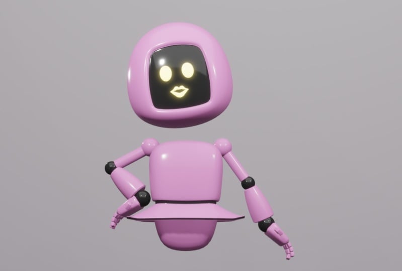
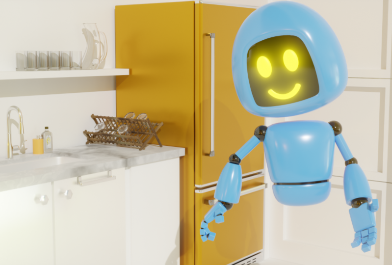
14. Robot 1 - Modeling the Head Part 1: Now that you already know the fundamental concepts
about the interface, navigation and objects
transformation commands, and blenders, modelling tools. We're going to
create a project to put all this knowledge
into practice. In the next lessons, we will create this scene with an animated robot from scratch. To start, we will model all
the parts of the robot. In this lesson, we will
begin by modelling the hat. To begin, we'll go to the
scenes outliner and click on the icons next to the light and the camera
objects in this scene. When we click on this icon, the object is temporarily
hidden in the viewport. Since I won't be using
these objects for now, I will leave them hidden to
keep the 3D view cleaner. To model the head, I will start from the initial
cube in this scene. I mentioned in a previous
lesson that it's good to model objects with their site facing
the x-axis of this scene, represented by this
red line on the grid. So I will model the
robot's head with a front, align it with the y-axis. If we look at the Icahn,
use the two orbits, the report, we will see the representation of
the orthographic axis. Notice that for each axis, the corresponding letter
appears on only one side. Indicates of the y-axis, the green circle on the
side without the letter, corresponds to the
front of the scene. Therefore, I will model
the robot's head, considering that the front of the object should be
facing this direction. I will activate the move tool to move the cube is slightly
above the grid plane. If I click on this green circle, often navigation icon, the view port will activate the frontal view of the scene. So I will move the cube
is slightly upward, just so it's not in the
middle of the Greeks. Now, to make the shape
of the cube and more rounded and closer to the
shape I aiming for the head, I will add the subdivision
surface modifier. For that. I will go to the Modifiers tab in
the Properties editor. Will open the Add
Modifier, me, Lou. And I will choose the
subdivision surface modifier. As we can see, the
object already has some subdivisions and
is a bit more rounded. But I will increase the
effect even more by adding another level of subdivision in the view port levels field. Now, let's see an
interesting way to adjust the shape of an object
with a subdivision surface. For debt, I will
enter edit mode. As we can see, the
vertices that appear for editing in yet
It's a mold or not, The versus generated by
the subdivision surface. The vertices we can add it in edit mode are the original
vertices of the object. In other words, when we added
the geometry editor mode, we operate on the
original components, not altered by the modifier. But if the modifier is active, we can see the original geometry with these more
transparent aspect and the modify the geometry with these more conventional
solid surface. To start manipulating the shape. I will activate these KO2. I will make sure all the
vertices are selected. And I will make the shape
a bit wider on the x-axis, a bit taller on the z-axis, and a bit narrower
on the y-axis. Now, I will select only the
upper vertex of the object. And I, we will slightly reduce this top face to make the top of the head
is slightly smaller. Note that it's not important for your robots to be
identical to mine. You can use the commands, instructions from
these lessons and make modifications to the proportions
and design of a Robert. Just try to follow the basic
structure of what I am doing so that you can follow the project without any issues. Now, I will show you
a new procedure. What I want to do now
is be able to use the edit mode tools
on these segments and averts is generated by
the subdivision surface. To the d's. We'll have to use a
command called apply, which we find in these
both firemen law. However, this command cannot be used if the object
is in editor mode. To use the apply command, we must go back to object mode. And then we can go to the modifier menu
and click on Apply. Notice that when we do this, the modifier disappears from the modifier step of
the properties editor However, the
subdivisions generated by it are still visible
on the objects. In other words, when we
apply them with fire, the modifications
generated by it are incorporated into the
geometry of the object. These means that if I
entered the editor mode, I will be able to use the modelling tools
on these vertices, edges, and faces that were
generated by the modifier. Now, I will make one more
alteration to the shape. For that, I will select only this bottom
vertices of the model. But since I want to select the vertices on the
other side as well, I will activate the X-ray mode. And that will make your
selection window to select all these
bottom vertices. Now, I will use
the scale tool to make this bottom
part a bit flatter. I will activate the X-ray mode again to select
this central loop. And I will move this
loop a bit lower. But remember that this
shape adjustments can be changed according
to your preferences. Now, I will create a screen in front of the head where
the robot's face will be. For dead, I will activate
the Face Selection Mode. And I will select this phase
is called the front part. While holding down
the Shift key. I will make a small
shape adjustments using these KO2 to make the
phases vertically narrower. And now we'll move them a bit downward with the move tool. I will also use
these KO2 to make them slightly narrower
on the y-axis. And I will use the movie to, to move this group
of phases are big backward also on the y-axis. Now, I will activate the
inset tool in the toolbar. Now we'll use the set command to create a border for
this group of polygons. Now, to create the screen sets, I will activate these
through the region two. And then we will extrude these
phases slightly backwards. To make the border more visible. I will activate this Q2. And I will decrease
the entire selection by clicking and dragging on
the white circle of T icon. And that will make these
crania bit flatter by scale the polygons
on the y-axis. I will also activate
the Move tool. And I remove the phases a bit so that the screen is not
so far from the border. With that, I achieved the base shape that I
planted it for the hat. Now I can go back
to object mode. And to create the final
rounding of the object, I will once again go to the Modifiers tab of
the properties editor. And I will add the
subdivision surface modifier. I will set the modifier with
two levels of subdivision. Now, to finish, I will configure the quiz parameter
on the edge of the screen to make the
corners more pronounced. For debt, I will
temporarily disabled the modifiers visibility by
clicking on the monitor icon. I will enter edit
mode of the object. I will activate the
edge selection modes. I will select all the
edges of the border. You may wonder why when we click on one of these edges
with the Alt key pressed, it doesn't select the completely
loop of this green area. The answer is that these loops selection
command is not able to identify where the
selection should continue on these vertices
connected to treat edges. So the loop selection is
interrupted in those regions. But if we keep the Shift
and Alt keys breast, we can add the
remaining selections of the border to the selection. With these edges selected, we can open the sidebar by
clicking on this arrow. And in the Items tab, we can increase the
increase parameter to the value of one. Now, if we enable the
modifiers visibility, we will see that these edges
will be fully pronounced. So I can go back to object mode. And with that, I finished
the modeling of this object. If you want, you can keep your object names
organized in the outliner. This is not a mandatory, but it's a recommended practice. So I can double-click
on the name. You have the cute object, and I can rename
it however I want. I will name this object head. And with that, we finished
this part of the project. Save your file as we will continue using it
in the next lesson. To do that, simply go
to the File menu and click on Save As choose a name. And click on Save. Yes. Thank you for watching
and I'll see you next time.
15. Robot 2 - Modeling the Head Part 2: In this lesson, we are going to create the Roberts
eye and mouth. To create one of the eyes. We can use this fear. So I'm going to
open the creation. We know using the
shift, THE shortcuts. And in the mesh sub menu, I'm going to create a UV sphere. I'm going to activate
the move to. And that will move this fear up to the height of the head. I will also activate these KO2 and that will greatly reduce the
size of the sphere. Now I'm going to activate
the move to once again. And that will move this
fear a bit forward. Now, I'm going to
activate this Q2 to make another adjustment
to the object size. And to visualize the
eyes in the right place, I'm going to move these fear
a bit more to the side. For this Robert,
I'm going to make the eye shape more elliptical. So I'm going to use this KO2 to make it slightly larger
on the vertical axis. And I'm going to make it
very flat on the y-axis. Now, I'm going to make
one more adjustments to this size and move it closer to the
surface of the screen. Now, since I used the
scale to in object mode, I'm going to the Object menu. I will go to the apply submenu. And I will click on Scale to reset the object scale values. The next step will be to
add the mirror modifier, which will mirror the
eye to the other side. Just so that the mirror
modifier mirrors the geometry. It needs a reference point, a central point that will be used to mirror the geometry
to the other side. And the point that is used
as a mirroring point for the mirroring process is
the object's speed vote. In Blender, the objects people can also be called the origin. And the objects origin is, this is more orange point that we usually see
somewhere on the object. When it's selected. I'm going to move the
eye in object mode again to the center of
the scene on the x-axis, which is the rabbits
lateral axis. To do this with total precision
and go into the sidebar. And in the Items tab, I'm going to change the value of the location x field to zero. This will ensure that
the objects before is exactly at the center of
the X axis of the Sing. It is very important that
the head of your robot is also at the center of
the X axis of the scene. So if by chance you have moved
it slightly to the side, select the head object and set the location x value
to zero as well. Now that the object is at
the center of the scene, I'm going to move the
geometry of the eye to this side without altering
the pivot position. To do this, we just need to move the components
in the edits modes. So I'm going to enter edit mode. I will press the a key to make sure all components
are selected. And that will move the
geometry to the side. Note that when we manipulated the components
in editor mode, the objects people remain
in the same place. So we can place
them wherever you want without worrying
about the pupil. Now, I'm going to the Modifiers tab in
the Properties editor. Will open the Add Modifier menu. And I will choose
the mirror modifier. As we can see, the
modifier creates a copy of the object geometry on the
opposite side of the people. With the four mirroring x is of the modifier is the x-axis. But if you wanted, you could change the mirroring
access modifier options. You might be wondering
why I didn't use the symmetrized command that
we saw in a previous lesson. We could perfectly use
symmetric but tear. The advantage of using
the mirror modifier in this case is that if we
select all the components of the eye with
the a key and make any transformation or shape changes to the object
in editing mode. That change is updated in
real time on the other side. So we can make some
final adjustments. And then we can
return to object mode To finish, I'm going to rename this objects
in the outliner. I will name it eyes. Now, let's create
the robot's mouth. For that, I will open
the creation Mendel. And I will create a cylinder. Now, I will click on the x-axis of the
Viewport navigation icon. To activate the side view. I will move this
cylinder up a bit. And they will activate
the rotation tool. With the rotation tool active, I will start rotating
the object forward. I could continue to rotate in the cylinder forward until
it's completely horizontal. But since I want it to
be perfectly horizontal, I needed to rotate it
exactly 90 degrees. One way to do this precisely is true the numerical
values in the sidebar. So I can set the rotation x parameter in the sidebar
to the value of 90. This way this cylinder
is completely flat. Now I'm going to
activate editor mode. We will enable Face
Selection Mode. I will select the front
face of the object, and I will activate
the inset faces too. Now, I will use the inset to, to create a border with the thickness I want
for the robot's mouth. If this size easily
to watch you want, you can press the S key to scale the polygon
and adjust the size. Now, I will select a narc of faces on the bottom of
these created polygons. These arc will be the base
of the robot's mouth. Make sure the selection
is symmetrical. Now, I'm going to delete all the polygons except
the ones I selected. These, I will go to
the Select menu. And I will click on
the word commands. If you want to use this
shortcut for this command, you can use the control keys. This command will
invert the selection. Now, simply press the Delete key and click on faces to
delete the selected phases. Now I will press the a key
to select all the faces. And I will press the E key
to extrude these phases, creating some thickness
for these objects. Now, I will go to
the object mode. And in the Modifiers tab
of the properties editor, I can add this subdivision
surface modifier. I will leave them with fire with two levels of subdivision. Now, I will activate
the Move tool. I will move the mouth closer to the head so that I don't have to use the
apply command later. I can enter editing mode and move em SKU the components
within editor mode. Then everyone, just the
position of the mouth to make it very close to the surface
of the heads screen. When I'm satisfied
with the position, I can go back to object mode. And I can rename this object
as mouth in the outliner. And with that, we finished modeling the elements
of the robot's face. Now, save your file so that we can continue the modeling
in the next lesson. Thank you for watching and
I'll see you next time.
16. Robot 3 - Modeling the Body: In this lesson, I'm going
to model the robot's body. But before that, I want to
emphasize the importance of objects being not align it in the center of the x
axis of this scene. This is a simple
and reliable way to ensure that objects are
aligned with each other. One way to ensure this
is by making sure the 3D cursor is
at the center of the scene before
creating an object. Remember that we can move the critic cursor
by holding down the Shift key and clicking and dragging with the right
mouse button pressed. And if we want the 3D cursor to return to the center
of this scene, we can use the shortcut Shift C. Using this shortcut before creating an object is a way
to ensure that the object will be created in the center of the x-axis of this scene. But if by chance you accidentally move an
object to the side, taking it off the
center of the x axis. Remember that you can open the sidebar on the right side of the 3D view and set the
location x parameter to zero. This way, the object
will return it to the center of the x
axis up the same. Now, I'm actually going to start creating the robot's body. And to begin modeling the
robot's body are we wove in the creation and Lou and
I will create a cubed. Now, I will use the navigation icon to activate the frontal
view of the scene. And I will move the
objects are little higher. Now I'm going to
enter the objects edit mode to start
modeling the body. I will start by pressing the S key to scale
the cube Alito, making it smaller than the head. I can also activate this KO2
and adjust the proportions. I will make it narrower on the y-axis and slightly
taller on the z-axis. And that will move it
down a bit to leave as no space between
the body and the head. Now, I want to taper
this shape a bit, making the bottom part of the
body is slightly smaller. To do this, I will activate the X-ray mode of the viewport. Will select only the bottom
vertices of the model. That we'll use the S key
to scale them a bit. Making this part is slightly
smaller than the top part. Now, I will use the
shortcut for the loop cut tool to create some
more edges on the body. This shortcut is Control R. So I will position the cursor over one of
these horizontal edges. And I will press the
control our keys. After using the shortcut, we can scroll the mouse
wheel to increase or decrease the number of
segments to be created. I will screw just a bit to
create choose segments. When we click, the
edges will be created and we can move them
from side-to-side. If we don't want to move this
edges, we can right-click. This way. The edges are
created in the center of the model without
lateral displacement. To make the shape a
bit more rounded, I will activate the scale tool. And I will scale the
central segments a bit on the z-axis and on the y-axis. Now, I will use the control
our shortcut for loop cut, once again to create a segment
on the side of the model. And I will use this Q2 to make
these edges a bit wider on the x-axis and a bit
taller on the z-axis. We'll also create some
horizontal segments using contra war once again. And that will use this KO2
to scale these segments on the y-axis to make the profile
slightly more rounded. Now sees my goal is to make
the body more rounded. I will temporarily
exit the edit mode. How will go to the
Modifiers tab? And I will add the subdivision surface modifier to the object. And to make it more rounded, I will set it to true levels of subdivision in the view port. To finish, I'm going to create one more small detail
on the robot's body. I'm going to create a
small extruded strip inward just to make the
design more interesting. For that, I will enter the
edit mode. Once again. I will activate the
edge selection mode. And while holding
down the Alt key, I will click on one of the horizontal edges
of this bottom loop. I will click on
the modifiers icon to temporarily disable
its visibility. And CSI wants to
create a nice trip. I will activate the Bevel tool. And I will click on
the tools icon and drag to create a small
strip of polygons. And to make this trip go inward, I will keep the Extrude button. After two pressed. I will activate the
extruder log-normal two. Now I can click on
the tools icon and reggae beat to create a
small inward extrusion. To see how it's looking, I will enable the
visibility of the modifier. Again. We'll go back to object mode. This trip is almost
how I wanted, but I still wants to make this inner part more pronounced. So I will enter edit mode again. I can disable the visibility
chapter modifier to make it easier to see
the original geometry. I will select the two
horizontal loops of the inner edges to the debt. I just need to hold the Alt key and click on one
of the edges of the loop. And then while holding down
the Alt and Shift keys, click on the other edge M. Now, I will set the mean
Chris parameter for these edges to
a value of one. Now, I can go back to object mode and enabled the visibility of the subdivision
surface modifier again. Now, to remove the
faceted appearance of the geometries phases, we can select our objects. Right-click anywhere
in the 3D View and click on the shade
out with smooth option. And with that, we practically finished the modelling
of the robot's body. I would just enter
edit mode once again and make some
small shape adjustments. But remember that
your Robert doesn't need to be exactly
the same as mine. In these is more
designed details can be slightly different. The important thing is to try
to keep them more or less the same structure so that your project as a whole
works like mine. After finishing the adjustments, I will name this object S body. And that will save my file. Don't forget to save yours to. Thank you for watching and
I'll see you next time.
17. Robot 4 - Modeling the Arms: In this lesson, we will model
one of the robot's arms. To begin, I will open
the creation menu, and I will create a UV sphere. Now, I will use the navigation icon to set the viewport
to the front view. And I will position this fear approximately where the
robots showed a Ruby. I can also press the Esc key to decrease
the size of this sphere. This way I can adjust
its position and size. I want this fear to be small and placed at the upper corner
of the robot's body. Now, I will go to the
viewport shading and Lou. And I will enable
the wireframe option to make this fear
edge is more visible. As we can see, blenders, the photosphere has a radial
arrangement of edges. It has two main poles where
the edges flows converge. To model the arm, I need to dispose to be aligned
it laterally. So I will activate
the rotate tool. And that will start rotating
these fear on the y-axis. If we look at the top-left
corner of the credit view, why rotating an object, we can see the rotation value changing simultaneously
in that region. This value is in-degrees. Initially, object
rotation is quite free. But if we hold down
the Control key, why rotating an object, we will see that
rotation is done in increments of five degrees. These make it easier to rotate an object with
a rounded value. Since I want to rotate this
fear exactly 90 degrees, I can hold down the
Control key and keep an eye on this value until
it reaches 90 degrees, either positive or negative. Now, I will set the 3D
view to the frontal view. And CSI scaled this
object in object mode. I will go to the Object menu
and click on apply scale. This way, the modelling tools we work without deformations. Then I can enter Edit mode. I will activate the
Face Selection Mode. I will enable the X-ray mode. And I will select
these three loops of faces from the outer
pole of this fear. Now, I will press the shortcut key to extrude this
polygons and create the main structure of the R. I don't want the
arm to be too large. So I can use the
move tool to adjust the size by moving
these polygons inward. After that, I can switch
back to the object mode. I can go to the outliner and rename the object as arm are. I usually use the letter r to refer to the right
side of the object. But this is not mandatory
for this project. And now to create the 40 arm, I can start with a copy
of the arm itself. So with the cursor over decorative view and
the ARM selected, I will press control
C to copy the object, and Control V to paste
the object copy. Before doing anything,
I will rename the object as 40 arm are. And now making sure that the
Army selected the outliner, I will move it is
likely outward on the x-axis using the movie too. Since I want these joints to be slightly smaller
than the arm joint, I will scale the object of bits. Since I scared the
object in object mode, I will go to the Object
menu and apply the scale. Now, I will enter Edit mode. I will make sure that only the
end polygons are selected. And I will move them
outward a bit so that the forearm is a
slightly longer than the arm. Now, my goal is to make the forearm wider
and more rounded. So I will start by activating
the edge selection mode. I will select only this
outer loop of the end. While holding down the Alt key. I will press the S key
to increase this part. I will also move this loop
all the x axis a bit outward. Now, I will select this
loop in the intersection of the cylindrical part
with the spherical part. I will scale with
using the S key. And that will move it is
likely above the joint. Now, I will make some position and scale adjustments
to these structures. Remember that these
adjustments can be made according to your
preference in your model. Now, I want to make this
structure more rounded. And I will do that as follows. I will activate the loop, cuts to I will create a new loop of edges curtain they
structure vertically. And I will press the S key
to make this look larger. Note that I will significantly increase the size of the loop, making it is slightly larger
than the original structure. Now, I will activate
the Bevel tool. I will use the
bathroom this loop, making the result quite open. And right after using the bevel, I will open the properties panel of the left action down here, and that we will
increase the number of segments for the bevel. If you have performance, the second sub commands and
the shape doesn't look good, the best thing to do is
to undo the commence with Control Z a few
times and try again. It may require some trial and error to achieve a
shape that you like. Now, to finish, I will select this loop on the inner
part of the Fourier arm. And I will use the Bevel
tool to create a chamfer. And then we repeat the
same procedure with this loop on the outer
part of the 40 yard. If you feel that any size
adjustments are necessary, you can simply select the
loops and move them slightly. I will activate the
X-ray moving my file. And I will select
and move some loops just to make the Fourier
arm slightly longer. Now, I can exit the editor mode. And I can disable
the display off wireframe in the
overlays we loop. To finish, I can select
the arm and the forearm. I can right-click. And I can enable this shaded out too smooth option to adjust this move
in-between the faces. And with that, we
finished the modelling. I won't make the other
arm now because I want to mirror the entire arm
when it's completely ready. So now you can save your file so that we can
continue in the next class. Thank you for watching and
I'll see you next time.
18. EN Robot 5 - Modeling the Hands: In this class, we will
model the robots hand. This part of the model will
actually be very simple. We will use a sphere to create the wrist joint and the modified kube to create
the palm of the hand. So I can start by
using the Shift T, a shortcut to open
the creation menu. And I will create a sphere. Now, I will set the 3D
view to the front view. That will move this fear to
where the risks should be. I will also need to press the S key to scale this fear
and make it much smaller. Then I can position it at
the end of the 40 yard. Now, I will open the
creation myth once again. And I will create a cube. I will also move the cube
closer to the red sphere. And now we will scale
with, to ensure the proportions are consistent with the rest of the robot. Note that I will scale with on the z-axis to make it flatter. After adjusting the proportions
of the cube and sphere, I can slightly overlap
them like this. Since I scaled both
objects in object mode, I will select both of them. I will go to the Object menu
and click on Apply Scale. Now I can select the poem
and enter Edit mode. I want the outer part
of the poem to be slightly thinner than
the part near the wrist. So I will activate the
agent selection mode. I will select these two edges on the outer part of the poem. I will make sure the
median point option is active in the transform
IPv4 point menu. And I will scale
the selection on the z axis to make the
tip of the hand thinner. Now, I will press the, a key to select all the
edges of the model. I will activate the Bevel tool that we'll use the bevel to share for the edges of the hand. Immediately after
using the bevel, I will open the properties
panel off the last action. And I will increase the number of bevel segments slightly. If necessary. You can also make some size
adjustments to the bevel. Now, I can return
to object mode. To simplify the project, I will combine these two
geometries into a single object, since they will
always move together. To do this, I needed
to have both objects selected end-user command
that I will show you shortly. When we use the command to join two geometries into
a single object, the command will preserve the transformation
of one of them. But we don't want the ppois
of the hand to be preserved. Since the hand rotation
should not occur from there. We want the hand rotation to
occur from the wrist pivot. To ensure that the command will understand that this will
be the preservative pivot. We will select the poem first. And then with the
Shift key pressed, we will select the wrist sphere. When we select more
than one object, the last object selected will have a slightly lighter
shade of yellow. And that will be the objects
with the preserved pivot. So with this electron
in this way, we go to the Object menu and
click on the join command. This way, the pivot of the murdered object
is at the wrist. And when we animated the rabbit, the hand rotation will
be done from that point. Now, we can right-click and
click on Shade, Smooth. And to finish, I will
rename the objects in the outliner S hand are. And I will save my file to
continue in the next class. Thank you for watching
and see you next time.
19. Robot 6 - Modeling the Fingers: In this class, we are going to model the fingers
of the robots hand. Actually, the
rabbits fingers will consist of phalanges
that will be the same. So we will only model
a single phalanx. And then we will
copy and arrange this phalanges to form
the shape of the fingers. Each phalanx will be made
up of a modified cylinder, which will be the joint, and the modified cube, which will be the main
volume of the phalanx. So I can open the creation menu and create
a cube to start with. Now, I will activate these q2 to make some
changes to the proportions. I will flatten it
more on the z-axis. In a little flatter
on the x-axis. Since I scale the
object in object mode, I will go to the Object
menu and apply this KU. Now I can enter edit mode. My goal is to round the
edges of this volume. For debts, I will make sure that I have the
edge selection mode active and that all the
edges are selected. Then I will activate
the battle to end. Use the command to
bevel all the edges. Right after using the command, I will go to the
Properties panel off the last action and increase the number
of battles segments. With that, we finished the
main volume of the phalanx. Now I can go back
to object mode. Now, we're going to create the cylinder that will
be the finger joint. So I will open the
creation menu. Create a cylinder. Now, I want this
cylinder to be oriented in the same direction as
the volume of the phalanx. So I can activate the
rotates to start rotating this cylinder on the x-axis and hold down the Control key. This way, the object will rotate in five
degree increments. And I can look at the
rotation value and rotate the object
exactly 90 degrees. Now, I will use the scale
and move tool to adjust the position of
this cylinder right next to the main
volume of the phalanx. Hi, We were just the size and
position of the two objects until the cylinder is just slightly smaller than
the fun Links box. Now, I will once again apply
the scale to both objects. At entered the editor
mode of the cylinder. With the edge
selection mode active, I will select the
loops at the ends of the senator by pressing
the Alt and Shift keys. And now we'll use
the bevel commands to bevel these edges. I will go back to object mode. Joining these objects
using the joint command. As we saw with the hand example, the order in which we
select the objects matters. Since I want the
rotation pivot to be the center of the
cylinder and not the box. I will select the box first. And then while holding
down the Shift key, I will select the cylinder. Now, I will go to the Object menu and click
on the join command. Now, I will move this first full length
very close to the hands. I will also need to adjust
the size of the phalanx. We'll use the front and top reviews to do
the positioning. And since I scared the
object in object mode, I will once again
apply the scale. Looking at the links
next to the hands, I think that the box could be a little larger on the z-axis. I will make these adjustments,
added some modes. So I will enter edit mode. And since I have two volumes in the object and I only want
to select one of them. I can't use DH shortcuts. One way we have to select a whole volume in the
editor mode to place the cursor over the volume
and press the L shortcuts. These shortcuts will select
all components of the volume in question without
selecting the order volume. And now I will make this box a little taller on the z-axis. Now, I will go back
to object mode. How we rename this
object as phalanx. And I will start creating the
copies to form the fingers. I will set the
viewport display to top view to do the
positioning more accurately. The cop, the phalanx, I will use the shifted
these shortcuts. These shortcut will copy the
object and start moving it. Immediately after. I can press the X key
on the keyboard to restrict the movement
to this since x axis. So I will position this copy
or little to the side of the first phalanx so that the joint cylinder is in the
middle of the two boxes. Now, I will repeat the procedure using the shifted
this shortcut to copy the forelegs and moving it to the
position of the tip. Links. With that, we've finished
creating one finger. Now I can activate
the selection tool. Select all the phalanges. And using the top view, how you use the
Shift D shortcuts to copy the entire finger. And I will move it and scale the selection a bit to
create the pinky finger. Now, I will copy the finger once again and adjust the position
to the index finger. As you can see, this Robert
will have only four fingers. To create the thumb. We will use only two phalanges. So we can select these two phalanges
from the middle finger, which are slightly larger. Corpus. Then forward. Now I will activate
the rotate tool. And while holding
down the control key, are we rotate this finger 90 degrees and position it
at the base of the hand. Since I used the scale to
several times on these objects, I will select all of them and apply this K
wouldn't the Object menu. With that, we've finished
creating our hands. So we can already saved the file to continue
the project later. Thank you for watching and
I'll see you next time.
20. Robot 7 - Materials - Part 1: In this lesson, we will start setting up the materials
for our robot. Through materials,
we can configure properties like colors
and reflections. To configure an
object's material, we must have it
selected in the treaty V. Then we can click on the material stab
in the properties do, which is the one with
the sphere greedy icon. At the top of the material tab, we will find a
section of slots with the materials that are
assigned to the object. Since we created the robots head from the initial
cube in the scene, it already has a
material applied. This happens because by the foe, the initial cube
in the blender sin comes with a material. If we want, we can
rename the material. For that, we can click on this field and write a new name. I'm going to call this
material main color. Each material has a
series of panels. The most important panel is
probably the surface panel. Here, we find a parameter
called base color, which defines the surface color. If we click on this
rectangle next to the name, we can set a color for the material using the
color wheel that appears. We can click on drag
on the wheel to define the heel and
saturation of the color. However, even though we have set a color
for the material, we can observe that this color is not visible in the viewport. This is because the viewport, display mode is set to solid. If you want to see the material properties in the viewport, we need to activate the
material preview mode. Or the render mode. Keep in mind that
the render mode relies on the sinus lights. If the sinus lighting
is not ready, the visualization in this
mode won't look good. In this case, it's more appropriate to use the
material preval mode, which already has lighting
specifically designed for visualizing materials during the
configuration process. With this mode active, if we try to configure the color of the base
color parameter, we can see the changes happening in real
time in the tridval. For this example, I'm going to set the material to
a shade of blue. And I'm going to adjust
the brightness using this vertical bar next
to the color wheel. But you can configure the color of your robot
however you want. Another interesting
parameter that we find here is the
roughness parameter. This parameter
determines the level of roughness of the material. The higher the value, the rougher the surfaces, and the lower the value, the more reflective
the surface becomes. I'm going to make this material
slightly more reflective. Now that the men surface
of the material is ready, I'm going to create another
material for the screen area, which is the robots face. Since the new material will also be used
on the same object, I will keep the head selected. With the head selected, I will go to the top
of the material step. This top section of
the interface is where we can add
lots for materials. When the object has
only one material, only one slot is needed. But since I want to add a
new material to the object, I need to add a new lot here. To do this, I will click on this button with the plus sign. This creates a new lot for the object where we can
add another material. To add the new material. Make sure we have the empty slot selected and click
on the new button. This will create a new
material in the selected lot. I'm going to rename
this material to black. I'm going to set the
base color parameter to a very dark shade. But as we can see, it's not possible to see the material
on any part of the object. This is because
when the object has more than one
material by the full, only the first material in
this lots list is visible. To add the second material, we need to select the polygons where we want it to appear. And for that, we need to enter the dit mode
of the object. After entering Addit mode, I will activate the
face selection mode, and I will select all the faces that correspond to the
robots face screen. Now, I will make sure that the Black materials lot
is active in the list. And I will click on
this assigned button below the materials name. This will apply the materials to the selected polygons
in edit mode. Now I can go back
to object mode. And if I continue configuring
the material now, I will be able to see the
changes in real time in the tridval I'm going to lower the value of the
roughness parameter to make the material
more reflective. With that, I finish configuring the materials
for the robot's head. Now, I'm going to create the materials for the
robots eyes and mouth. For that, I will start
by selecting the eyes. As we can see, these lots
for these objects are empty. One interesting thing
we can do is to use a material that has already been configured for another
object in the scene. To do this, simply click on this icon next to
the new button. This opens a menu where I can see all the materials
already in the scene. If I click on one of them, the material will be
applied to the object. If I don't want the material
to be applied to the object, I can click on this x next to the materials name to
delete it from the model. And since I actually want to use a different material
for this object, I will click on the new button. I'm going to call
this material leads. For the base color parameter, I'm going to use a
light shade of yellow. Now, I'm going to
scroll the panel interface down a bit to
show another parameter. Here at the bottom, we find the emission parameter where
we can also set a color. I'm going to set this color to roughly the same
shade of yellow. First, I will increase the brightness of the color
using this vertical bar. Then I will choose the
heel on the color wheel. Below this parameter, I
will increase the value of the emission strength
field to around six. This value will
make this material appear luminous in a
configuration we will do later. Now that the material is ready, I can select the
mouth object and load this already configured material in the
sins material list. With that, the mouth will have the same
materials as the eye. And with that, we finish configuring the
materials for the head. Thank you for watching and
I see you next time. Okay.
21. Robot 8 - Materials - Part 2: In this lesson, we will finish applying materials to
the robots objects. All the other objects of
the robot will also receive the blue material and the black material that
I already configured. I will start by applying these materials to
the robots body. So I will select the body. In the material step of
the properties editor, I will go to the
scenes material menu, and I will start by applying the blue material that I
created in the previous lesson. If I wanted only this material to be applied to the object, I wouldn't need to
do anything else. But in this case,
I want to apply the black material to this
strip on the robot's body. To that, I will add another slot by clicking
on the Add button. And with this new slot active, I will open the menu and I will choose
the black material. Now, I need to
select the polygons of this strip where this
material will be applied. So I will enter d to modes, I will activate the
face selection mode, and with the out key pressed, I will click to
select the face loop. Now, I just need to make sure
that the black material we selected and click
the assign button. Then I can go back
to object mode. Now, I will repeat more or less the same
procedures for the army. I will select the army. Choose the blue material
as the first material. I will create a new slot. I will assign the black
material to the second slot, I will enter Ed mode, and I will select the polygons where I want to apply
the black material. In this case, I want to
apply the black material to the joint to select the
polygons of the joint. I will activate the x ray mode. With that, I can make a
selection window and select all these polygons and making sure that the
black material is active, click the Aside button. Now, I can go back
to object mode. Okay. And I can repeat more or less the same
procedures for the 40 arm. I will select the 40 arm. Choose the blue material
as the main material. I will create the
second on the slots. I will choose the
black material. I will enter a mode and I will select the polygons where I want to apply
the black material. In this case, I also want to apply the black
material to the joint. So I will activate
the x ray mode again. But in this case, it is a
bit more difficult to select just the joint because I have the overlapping
polygons here. So I will make a slightly
larger selection, and I will reduce the
selection by going to the select menu and going to select more
or less sub menu. Here, I could increase
the selection by clicking on more and decrease the selection by clicking
on s. Note that I could also use the
shortcut control and the minus key on
the numeric keypad. So I can press control
and the minus key to decrease the selection until
only the joint is selected. Now, I will click on
the assigned button, and go back to object modes. Now, I will show a more dynamic
way to do this procedure. First, I will use
a command to apply these materials
that are already in these objects to
the hand objects. To do that, we will first select all the objects that
will receive this material. In other words, I will
select all the hand objects. Now, with the shift key pressed, I will select the farm last. It is important that the
selection is made in this order so that the 40 arm is the activity
objects in the scene. With the selection
done in this way, I will go to the object menu. I will click on the link
transfer data sub menu, and I will click
on Link materials. This way, the
materials that were in the 40 army have been applied to all the
selected objects. Now, to define the polygons that will have the
black material, we can enter edit mode with
all the hand object selected. With the phase
selection mode active, we can clear the selection, and to select the joints, we can place the
cursor over each one and use the L shortcut key
to select the entire volume. If you select something wrong, just use the control shortcut
and redo the selection. After having all the
joints selected, just activates the
black material in these lots and click
the assigned button. After that, we can
exit editor mode. With that, we finish configuring the
materials of the scene. Remember to save your file. Thank you for watching
and until next time.
22. Robot 9 - Checking the Joints: In this lesson, we will check the position of the objects
transformation pivot. If you have followed along
exactly as I have done so far, it is likely that your robot doesn't have any pivot
positioning issues. But if you do find
any misplaced pivot, I will show you how to
correct the problem. As we have seen before, the pivot is the small
orange point that usually appears somewhere on the object when it is selected. It is also the transformation
point of the object. So if I select the head, and press the R key
to rotate the object. We will see that the object
rotate around that point. Since I don't want the head
to be rotated like that, I will use control Z
to undo the command. Now, I will set the view
port to the front view. For the rotation of the head, I want the pivot points to be in the region between the
head and the body, roughly where the
charged neck would be. There are several ways to edit the p v position
of an object. One of them is to have the object selected
in object mode, go to the options menu in
the top right corner of the treaty and enable the
affect only origins option. When this option is active, the transformation
tools operate only on the objects origin without
affecting the actual geometry. So I can activate the
movie to and move the pv downward on the z axis until it's between
the head and the body. Remember to disable the effect only origins option after
you finish adjusting. After adjusting the pivot, it might be a good idea to
press the R shortcut key to rotate and test if the rotation point is
according to what you want. If we want, we can right click before finishing
the rotation. This way, the
rotation is canceled and the object returns to
its previous position. In the case of the robot torso, the pivot is already
in its center. And for this object, the pivot position
is already suitable. And for all the other objects, we want the pivot position
to be exactly at each joint. As I mentioned before, if you haven't followed
along as I did, it is likely that the
pivot positions of the objects in your scene
are already correct. In the case of the arm
object, for example, the pivot is in the center
of this black sphere, and if I rotate to the arm, we can see that the rotation
occurs as expected. But if I select this
fy arm, for example, we will see that I
intentionally changed the pivot position to a
place outside the object. If I try to rotate this object, we will see that
the rotation origin is in an inappropriate place, we won't do the command with control Z to return the
objects to its place. As we have seen,
one of the ways to adjust the pivot
position is to go to the options menu and enable the effect
only origins option. This way, we could manually reposition the pivot
using the movie to. The problem with this method is that since it's
done manually, we cannot achieve a
precise positioning. I will intentionally leave the p vote out of place
to show another method, and I will disable the effect only origins option
in the options menu. Now, I will show another method
that is a bit more work, but allow us to
position the cursor at a specific point on a
well defined geometry. For that, I will enter
the object editing mode. I will activate the
vertic selection mode, and I will select
a set of verses whose centers correspond to the position I want
for the pivot. Since in this case, I want the pivot to be at the
center of the joint sphere. I will select the
central loop of the sphere while holding
down the out key. Now, I will right click
anywhere in the viewport. Go to the snap versus submenu and click on the
cursor to selected option. This will position
the predecursor exactly in the middle
of the selection. But note that this
command is only available when you have the
vertic selection mode active. After positioning the
Tree Dcursor in this way, I will go back to object mode. I will right click to
open the context menu. Go to the set origin sub menu and click on the origin
to Tree Dcursor option. This command will position the object pivot exactly
where the tree Dcursor is. And this way, we can
correct the pivot position of each object that has
the origin out of place. I recommend that
you test to see if the pivot positions of
your objects are correct. To do that, just
rotate each object and see if the rotation occurs
from the joint as intended. Notice that this phalanx of my character also has
the pivot out of place. So I can enter edit mode, and to ensure that only
the joint is selected, I will clear the selection, position the cursor over
the volume of the joint and press the L shortcut key to select only the
verses of that volume. Now I will right click Snap
versus cursor to selected. Now I will go back
to object mode, Right click to open
the context menu, click Set origin,
origin to predecursor. This way, the pivot will be positioned exactly at the
center of the selected volume. You can use the same
method to correct the origin position of any joint that happens to
have the pivot out of place. Thank you for watching
and until next time.
23. Robot 10 - Parenting Objects: In this lesson, we
will talk about a concept called
object parenting. This concept refers to
a relationship between two or more objects where one object known as the parent
influences the position, rotation, or scale of another
object known as the child. When an object is set as
the child of another, any transformation applied to the parent object will
affect the child object. In the case of our robot, we will use a series of such relationships to
animate it properly. I will start by discussing the relationship between
the head and the body. When I want to rotate
the robot's head, I don't want the body to be affected by the
transformation. But when I select and move
or rotate the robot's body, I want the head to follow
those transformations. So in this case, I want the head to be the child object in the parenting relationship
with the body, which will be the parent object. To create such a relationship, I will start by selecting
the object that I want to be the child
in the relationship. In this case, I will start
by selecting the head. Then with the shift key held on, I will select the object that I want to be the parent
of the relationship. In this case, I will
select the body. Then I will go to
the object menu, click on the parent sub menu and click on the Object option. This will make the
first selected object become the child
of the second one. If we now select only the robot's body
and move or rotated, We will see that the head
will follow the movement. Now, I want the objects
for the eyes and mouth to also follow the head
whenever we transform it. So I will clear the selection. Start by selecting the eye. Hold down the shift key
and click on the mouth. Finally, while holding
down the Shift key, I will click on the head. Since the head was the
last selected object, it will be set as the parent
in this relationship. Then I will go to
the object menu, click on the parent sub
menu and click on object. Now, if I select only
the head and rotate it, we will see that these objects
will follow the movement. I I select only the body, we will see that all objects
will follow the movement as they are directly or
indirectly children of it. Now, we just need to repeat the same procedure for
the remaining objects. For this, we will
need to consider which object will influence
which other object. In this case, the relationship
is straightforward. Each limb object should be
child of the preceding object. Following this logic, the army should be the child of the body. I will select the army Select the body next with
the shift key, go to the object menu. Go to the parent sub menu
and click on object. But as we can see,
the shortcut for the parent menu is
the control P keys. With the selection
properly made, if I use the shortcut Control P, we will see a floating menu with the options from
the parent menu. If I click on the
object option here, the parenting
relationship will be set. We can test this by selecting only the body and performing
some transformation tests. Just remember to right
click before finishing the test transformation or use the Control Z shortcut to
undo the test command. Now, we just need to
repeat this procedure to finish configuring the parenting for the remaining objects. The fyarm will be set as
the child of the arm. So I will select
the for arm first. Select the arm with
the shift key. Open the menu with the Control P shortcut and click on object. The hand will be set as
the child of the 40 arm. And in the case of the fingers, the tip phalanx will be set as the child of each
preceding phalanx. And the first phalanx
of each finger will be set as the child
of the palm of the hand. Now, we just need to repeat the procedure
for all the fingers. Each tip phalanx will be the
child of the middle phalanx. The middle phalanx will
be the child of phalanx, closes to the palm, and the phalanx closes to the palm will be the
child of the palm. And then we just need to repeat this procedure
for all the fingers. At the end of the configuration, we can perform some tests to see if the relationships
are correct. Just remember to cancel these transformations
or undo each one using control Z so that the robot remains in
its initial position. Thank you for watching,
and I see you next time.
24. Robot 11 - Mirroring the Arm: In this lesson, we are going to copy the army that we have already configured and mirror this copy to the other side. So the first thing we
are going to do is select all the objects of the
arm with a selection box. To copy the arm, I will
use the Shift D shortcut. This shortcut, we copy all the objects and
start moving them. Since I don't want
to move the objects, before finishing the movement, I will click the mouse button. This way, the
objects are copied, but the movement is canceled. So the copy the
object will be in the exact same place as
the original object. Now, we are going to mirror this object to the other side, and to do that, we are going
to keep the object selected. Go to the object menu. Go to the mirror sub menu, since we want to mirror the objects on the x
axis of the scene, we will click on the
x global option. But we will see that
when we do this, the object will not be mirrored
to the desired position. This happens because initially, they are mirrored according to the original position of
the objects themselves. If we go to the transform
pivot point menu, we will see that
the active option is the median point option. This option determines
that the transformation of the objects should be done based on the pivot of
the objects themselves. And since the mirroring
operation uses the transformation point
determined by this option, the mirroring occurs based on the position of the objects. So I will use the control z shortcut to undo this operation. And what I'm going to
do is configure blender so that the mirroring occurs based on the tre
decursor of the sin. As we have seen, if we
use the shift C shortcut, the tre decursor is positioned exactly at
the center of the Trev. And if I go to the
transforming pivot point menu, we will see that I can choose an option called tree Dcursor. This will make the
transformation of the objects be done
based on the precursor. Since the mirroring is
done using the setting, the mirroring will also be done using the position
of the predecursor. If I go to the objects menu, mirror and click on x global, we will see that
the army will be mirrored taken into
consideration, the position of the predecursor
as the mirroring center. With this, the mirroring will
be exactly as we want it. After performing the mirroring, it is a good idea to
return in the transforming Pvopointnu setting to
the median point option. With that, we finish the
mirroring of the arm. Thank you for watching
and I see you next time.
25. Robot 12 - Introduction to Animation: In this lesson, I will introduce the base animation tools we will use to create
the robot animation. To create animations, we
will use the time line, which is the editor at the
bottom of the interface. If we want to increase
the editor's area bit, we can place the cursor over the divider and click
and drag it up a little. In the upper central
part of the time line, we can see the
playback controls. Here, we find a button
to play the animation, and when the play is active, the button becomes a pause
button for the animation. This button on the
far right takes the playhead to the
end of the time line. And the first button moves the playhead to the
beginning of the time line. The playhead is the icon with a vertical line that marks in which frame
the animation is in. We can click on the
icon and drag it along the timeline to
reposition it in time. I will position the
play head at frame 50 to show how we can
create key frames. A key frame is a type
of marker that record a specific state of a specific object at a
specific moment in time. To create a key frame, we need to select the object for which we want to
create the key frame. With the cursor
over the viewport, let's press the shortcut key. When we press the key, we can see a melou where we can choose the type of
keyframe to be created. Since for this project, we will only animate the location and rotation
transformations. We will work only with the location and rotation
type of keyframe. When we create a
keyframe for an object, we can see that keyframe on the time line exactly on the keyframe where
the playhead is. If I move the playhead
a little to the side, we can see that the keyframe consists of a small
diamond shape. Now, note that we can only see the keyframe
on the time line. If the object for which we created the key
frame is selected. If I clear the selection
or select another object, we won't see that keyframe. But if I select
the object again, we can see its key
frame on the time line. For an object to
have an animation. It needs to have at least
two different key frames at different moments in time. So to create an example
animation for this object, I will move the
playhead to frame 120. Now, I will move and
rotate the object a bit. When an object already has at least one key frame
on the time line, and we make a change in the property that
has the key frame. It is important to pay
attention to the following. After change the
property in question, we need to create a key
frame before moving the playhead or using
the playback controls. If I move the playhead or use the play back command before
generating a keyframe. Blender it ignores the
transformations made, and the object returns
to its previous state. So I will put the playhead
back on frame 120. I will move and
rotate the object, and I will press the key to open the keyframe creation menu and I will create a location and
rotation type of keyframe. With that, we can see that a new key frame has been
created at frame 120. So if I rewind the play
back to the beginning of the time line and
press the play button, we can see that the object
performs an animation, which consists of
the interpolation between the position it was in at frame 50 and the position
it is in at frame 120. Now, I will position the
playhead at frame 200, and I will turn on
this button here. The name of this button
is automatic key. When this button is turned on, any transformation we make will automatically
generate a key frame. So if I move and
rotate the object, we can see that blender creates a key frame at the frame
where the playhead is, even if I don't manually create a key frame
with the menu. So if I rewind the animation to the beginning and
press the play button, we can see that the animation
is already happening, taking into account
the new keyframe. The speed at which an
animation progresses is directly related to the time
space in between key frames. If I click and drag the key
frames along the time line, we will see that we can
reposition them in time. If I make the space between
them smaller and press play. We will see that the
animation becomes faster. If I spread the key frames, increasing the space between
them on the time line, we will see that the
animation becomes slower. And finally, if we are dissatisfied with a key
frame we have created. We can select it on the Ty line, and making sure that
the mouse cursor is over the ty line and
not over the viewport, we can press the delete key. This way, the keyframe is deleted and the animation
will work without it. This lesson was just to
test the animation tools. You don't need to
save this file, since we will start
creating the animation for the robot project
without any key frames. Thank you for watching
and I see you next time.
26. Robot 13 - Animation 1: In this lesson, we
will effectively start creating a small
animation for our robot. For our first animation, we will create a very simple
sequence of movements. In this sequence, the robot will appear coming
from bottom to top. It will make a small gesture
waving to the camera, and it will return into
a resting position. The entire animation will
consist of only six poses. At the beginning,
the robot will be in a pose where it's
below the frame. In the second pose, the robot will have entered the frame and we'll be
looking at the camera. In the third pose,
the robot will be slightly lower to give the
impression that it's floating. This pose will have
a slightly change in the position of the arms to make the floating more natural. In the fourth pose, the
robot will start waving, moving slightly up in the frame and placing
its hand to one side. In the fifth pose,
the robot descends a bit again and move its
hand to the other side. And in the sixth and final pose, the robot finishes waving and brings its arm back to
the initial position. And when we visualize the motion interpolation
between these key frames, we will see this
final animation. To start working
on the animation, the first thing I will do
is enable the scene camera, which I hit at the
beginning of the project. To do this, simply
go to the outliner and uncheck the icon
next to the camera name. With that, if we look
in the Treaty view, we will find this object, which is the scene camera. If we want the Treaty view
to show the camera view, we can click on this button in the top right corner
of the viewport. With that, we see exactly the framing
captured by the camera. The problem with setting the viewport to show the
camera view is that it becomes difficult
to move and rotate the camera itself in the
three D environment. To solve this, we
can divide the area of the tree D view into
two separate viewports. To do this, position
the cursor over the divider between the
viewport and the time line. Right click and select
vertical splits. Then move the cursor somewhere in the middle
of the current viewport. When you click, a
divider will be created, and the space where
there was previously only one tree view now
has two viewports. If you want, you can click and drag this divider
from side to side. When the tree d view
port is split like this, we can use one of the viewports to navigate the in the
tri the environment and manipulate the camera and the other viewport to check the framing of the
camera's final view. So I'm going to set the display of one of the view
ports to the top view. And I will move and rotate the camera so that it's
pointing at the robot. For this, I can use the
move to or I can open the side bar and enter zero
in the location x field. This way, the camera
will be positioned exactly at the center of
the x axis of the scene. I can also take this opportunity to adjust the
rotation values here. I can set the rotation value
of the z axis to zero. This way, it's perfectly
pointing forward on this axis. Now I can set the tretvi to the side view and move and rotate the camera until it's framing the
robot straight on. Since the robot is taking
too much space in the frame, I can move the camera
further back on the y axis. Finally, I can make a few more small adjustments to the rotation and
position of the camera. Once the camera framing is set, I can hide it again
in the outliner. Hiding it here only hides
its icon in the viewport, but it still works with
the framing i sets. Now, before we start creating the first
pose of our animation, I'm going to show an
optal configuration that I like to do in blender. If I select any object
in the tre D view and orbit the viewport using
the middle mouse button, you will notice that
the viewport rotation occurs from a random point
in the middle of the screen. As a result, when
we orbit the scene, the selected object can move a lot and even go out of frame. To change this, I'm
going to the edit menu, And click Preferences. This will open a setting window. Here, I can click on
the navigation section. And I can enable the orbit
around selection option. Then I can close the window. When this option is enabled
in the preferences, and we orbit the scene with
the middle mouse button, the rotation of the tree view starts from the selected object. This way, the selected object remains framed at all times. Now, I can effectively start creating the first
pose of the animation. Since in the first pose, the robot will still be below
the framing of the scene, I'm going to move
the robot's body down until it exits
the camera frame. Now, I'm going to give
another tip because of a situation that's
happening to me right now. Sometimes when we're
trying to zoom in on an object in the tre
dv by scrolling the mouse, the navigation starts
to behave strangely. It seems like the zoom simply
doesn't progress anymore. This is something
normal that can happen sometimes when we're navigating
the perspective view. When this happens, you can go to the V and click on
frame selected. Or, as we can see, press the period key on
the numericy keypad. This command will not only
frame the selected object, but also reset the
viewport navigation, and with that, the zone should start working
normally again. Now I'm going to start working on the position of
the other objects. I will select the head, and I will rotate it
slightly upwards so that the robot moves up while
looking where it's going. Now I'm going to select
one of the arms, and I will rotate it downwards. When we are working with
more complex rotations, such as the robot limbs, it can be a good idea to go to the transforming rotation menu and activate the local option. When this option is active, the transformation two icons align according to the
selected object itself, instead of aligning
them with the scene, and in general, it's easier to work with the object
rotation in this way. Now, I'm going to
select the 40 arm. In the case of the 40 arm, it's very important to pay
attention to only rotate it along the axis corresponding to the natural
rotation of the arm. In the case of my object, this is the x axis. If I rotate the object
along another axis, the farm animation
won't look natural. We can simply try to
be careful not to rotate the fore arm
along the wrong axis. But if he wants to ensure
that this doesn't happen, we can open the side
bar and click on the padlock icons next to the rotation axis that
we want wants to move. This will lock those axis, and we will only
be able to rotate the fore arm along
the desired axis. Now I'm going to select the other fore arm and
do the same thing. Now, very carefully, I'm going to rotate
object by object to create a natural pose for the arm with its slightly
relaxed downwards. When it comes to
finger animation, there's another setting that we can use to speed up the process. If I select all the phalanges of a finger and try
to rotate them. Initially, they will rotate as a single block from the
pivot of the first phalange. But if I go to the
transforming pivot point and enable the individual
oranges option. When I rotate a group
of selected phalanges, each one of them will rotate
from its own pivot points. And this will allow us to bend the entire finger with a
single rotational command. So now I'm going to select
the phalanges of each finger and slightly flex each finger to give a more natural
look to the pose. When we want to change the direction the
finger is pointing, we should only select the first phalange of
the respective finger. Now I'm going to repeat the same procedures to get the other arm in a
similar position. Take your time and perform
these procedures carefully. Creating poses for
a character is a laborious process that
requires a lot of patience. Once all the objects are
in the position I want, I will select all of
them in the viewport. I will make sure that the
playhead is on framing one I will press the shortcut key with the
cursor over the view port, and I will click on
location and rotation. This will create a key
frame on frame one, saving this position for all
the objects of the robot. Now, save your file so
that in the next lesson, we can create the remaining
poses of the animation. Thank you for watching
and until next time.
27. Robot 14 - Animation 2: In this lesson, we
are going to create the remaining poses for
our robot animation. A procedure we should
use when animating characters is to set a frame
to create a specific pose. This frame doesn't
have to be final since we can move the key
frame later in the process. But while we are
creating the pose, we should move all the parts of the character in that frame. And once the pose is created, we should select
all the characters objects and generate a key
frame for all of them. In the end, if you want, you can move the key
frame along the timeline to make the animation
faster or slower. For this animation,
I will create poses with the intervals
of 25 key frames. So I will position the
playhead on frame 25, and I will start
creating the pose. The first thing I will define is the position of
the robot's body. Since this will be the pose
in which it enters the frame, I will select the body. If you want, you can
leave the auto key button on so that key frames are
created automatically. This prevents us from losing the pose configuration if we accidentally
move the playhead. Now I will move the
object up on the z axis. Now, I will rotate
the head forward so that the robot is
looking at the camera. Now, I will rotate the
arms a bit downward, and I will rotate the
hands a bit upward so that they look slightly different from the
previous pose. Now, I will select all the objects with
the selection window. And I will insert
a new key frame by pressing the eye
shortcut key with the cursor over the tree and clicking on
location and rotation. I know that the objects
we manually manipulated already had key frames due
to the ato king button. But when we create
character animation using this pose method, it's important to
generate key frames, even for objects we didn't
move in this frame. Now, since I want to create all the poses with
intervals of 25 frames, I will move the
playhead on frame 50, and I will start
creating the next pose. The first thing I will do
is move the robot down a bit to give the sensation
that it is floating. To make the robot appear to
have a bit more movement, I will move the head
slightly backward, and I will move the
arm a bit upward, and the hands a bit downward. And I will repeat
the same movements on the arm on the other side. Once again, I will select all
the characters objects and create a location and
rotation key frame with all of them
selected in this frame. To create the next pose, I will move the
playhead to frame 75. Now I will start creating the pose where
the robot is waving. To do that, I will move
the robot's body up a bit. And to add some swing to
this part of the movement. I will also rotate the body a bit and I will rotate
the head a bit as well. Now, I will rotate the arm, the 40 arm and the hand to characterize the position where the robot is waving
at the camera. I can also select all the
phalanges of each finger and rotate them a bit to
open the hand in this pose. Now, I will make some
adjustments to the position of the arm just to make
the post more appealing. And to finalize the pose. I will once again select
all the characters objects and create a location and
rotation key frame for them. To start working
on the next pose, I will move the play
head to frame 100. And for this pose, I
will start by creating a slight variation in the position of the
robot torso and head. I will move the body
a bit downward, and I will rotate it slightly in the opposite direction to create a slight swing
in the movement. I will do the same
thing with the head, rotating it a bit
to the other side. And to characterize the
movement of the waving hands, I will move the arm a bit to the other side in the opposite direction of
the previous position. And for the other arm, I will simply rotate
each part a bit so that it doesn't stay still compared
to the previous position. After making some
more adjustments, I will select all the
characters objects. I will open the
keyframe creation menu, and I will create a location
and rotation key frame. If you want, you can test the animation
throughout the process. To do that, just move the playhead back
to the beginning of the time line and press the play button to see how
the animation is turning out. Now, I will create the last
pose of the animation. So I will position the
playhead on frame 125, and I will start
manipulating the character. This final pose will
be a neutral pose, very similar to the
initial position. So I can rotate the
robots body and head to make their posture
more upright and neutral. And I will also
return the arms to more or less the same position they were at the beginning. And to finish, I will
once again select all the objects and generate a final keyframe
for all of them. Now we can move the playhead
back to the beginning of the time line and press the play button to see how the animation
is turning out. As we can see, the animation is already working as planet. However, the acti area of our ting line is a bit larger than the
animation I created. If I don't want the
final animation to have this extra space, I can adjust the active range of the playback in these fields here at the top right
of the time line. Since the last key frame of my animation was that frame 125, I will set the end
frame of the animation to 125 as well in this field. And if you want to move
the time line sideways, you can press the
middle mouse button and drag it to the sides. Just like you can zoom in and out of the time line
with the mouse screw. Be careful because if you press the middle mouse button and
drag the time line upwards, the keyframes may end up hidden at the top
of the timeingline. And if you want to fit
all the key frames of the time line within the
visible area of the interface, simply over your
mouse cursor over the time line and press the
home key on your keyboard. And with that, we conclude
the animation of the scene. Save your file so that we can finish the production
in the next class. Thank you for watching,
and I see you next time.
28. Robot 15 - Lights and Render: In this class, we will
set up basic lighting for the scene and generate a finalized video through a
process called rendering. I will configure the
scene lighting to make it specially suitable
for the camera framing. To visualize the lighting,
while configuring it, I will place the playhead
of the time line on any frame where the robot is fully visible within
the camera framing. An important note is that whenever we are not actively
animating something, we should deactivate
the ato key button. Otherwise, we may
unintentionally generate key frames and
obtain undesired results. Now, to actively start
configuring the scenes lighting, we can go to the outer liner. And we can enable
the visibility of the light hit at the
beginning of the project. By doing this, we can see a black icon in
the pretty view, which represents
the light object. To visualize the effect of how the light will appear
in the final video. We need to activate the der display mode in the viewport that
has the camera view. To do this, simply click on the last icon in the top
right corner of the viewport. Now, with the light selected, we can begin adjusting
its properties. When a light is selected, we can configure
it by clicking on this tab with the light icon
in the properties editor. In this tab, we can
change the light type. Initially, the light
functions as a point light, a meeting light in
all directions. But for this project, I want to create a slightly more
commercial lighting. To achieve that, I will change the light
type to area mode. This way, the object
emits light from a rectangular or square
area that we define. If we look a bit further down, we will see the values for
the size of this area. If the light is in
rectangular mode, we can adjust the vertical and horizontal size of
the light area. But to simplify things, I will change the area mode to square in this manule here. This way, I only need to adjust one value to
configure the light size. Note that I like to
make this area quite large as if it were a light panel in a
photography studio. Now, I will configure the
position of the lights. I will work with three lights. This light will
come from behind. So I will move and rotate it so that it comes from the back
on the side of the robot, and it should be
pointing at the robot. Notice that I prefer to use the top view for this
type of transformation. Be careful as clicking
on one of the corners of the light square in the viewport
can also edit its size. Now, to create the second light, I will duplicate this already configured light using
the shift D shortcut. This will copy the light and it will immediately
start to move. I will also position this other light at
the back of the robot, but on the opposite side, and I will have it pointing
at the robot as well. If I want to adjust the size, I can click on one of
the corners and drag it. And now to finish, I will copy this object once again using the
shifted dis shortcut. And this time, I will move this new light to the
front of the robot. I will also have it
pointing at the robot, and I will adjust
its position until the light reflection on the
robot looks interesting. If you want, you can also
go to the lights panel in the properties editor and
edit the power parameter, which defines the
light intensity. With that, I think the lighting
is already looking good. But remember that you can
further experiment and configure the lighting of your scene differently
if you want. Now that the scene is fully set, we will save a final video. This process of converting
the treat sin into an image or final video
is called rendering. So now, we will configure some parameters related
to rendering the scene. To do that, we will click on the render tab in the
properties editor, which has a camera icon. Here, we will enable
two properties. Let's start by enabling
the blue option. This option will make materials configured with the emission
parameter and meet a globe. Since we configure the
emission parameter for the material of
the eyes in the mouth, we can see that these objects now have a luminous appearance. If we open the bloom panel
by clicking on this arrow, we can configure
some properties. The properties I like to adjust
are the radius parameter, which defines the size of the glow and the
intensity parameter, which defines how strong
the glow will be. The other parameter we will
enable is the motion blur. This parameter will render moving objects with
a slight blur, enhancing the sense of motion
and realizing the render. Now that we have configured
the rendering effects, let's set up the final file. For that, we will click on the output tab in the
properties editor, which has a printer icon. Here we can define the file dimensions
in the format panel. But for this video, I
will leave the full size, which is full HD to
configure the file, we will go to the output panel. Firstly, we will click on this
button with a folder icon. Here, we will set the location
and naming of the file. I will save my file
on the desktop. And rename it to
Robot animation. Then I will click Accept. Now, to specify that the saved
file will be a video file. We will open the
file format menu. Here, we could choose any of
this image or video formats. Since I want to create a video, I will choose the
FFPE video option. Now to actually
render the video, we will go to the render menu and click on Render Animation. This we will start
a process where all the frames will be rendered to generate
the final video. This may take some time depending on your
computer's configuration. When the process is finished, you can close this window. And if I minimize my
blender window and open the video file that
was created on my desktop, we will see the final
animation of our project. And with that, we conclude our project and this brief introduction
course to blender. I truly hope that
you have enjoyed it, and that this encourages you to further study this amazing
tool that is blender. Thank you for watching
and until next time. Okay. Yeah.
29. Conclusion: Congratulations on
successfully completing the blender Start course. You have shown
incredible discipline by dedicating your time and
effort to improve your skills. Choosing the path of learning instead of succumbing to easily distractions like
watching series are spending hours
on social media. Your determination has
brought you this far. If you have created your
own animated robot, please don't hesitate to share the render off your
work in the gallery. We are eager to see the results, to have achieved
it and celebrate your accomplishments along
with the other students. If you really enjoy the course, consider following my
profile here on Skillshare. That way you will
be formed when I released the exciting new
courses on the platform. And if you can spare a little
extra time leaving review, telling me in the community what you thought
about the experience, your opinion is valuable to us. Once again, I would like to
express my sincere gratitude. It's a pleasure to have you as part of this
learning journey. I hope you to see you
again in a future course.
 Gustavo Rosa, 3D Artist and Blender Instructor!