Transcripts
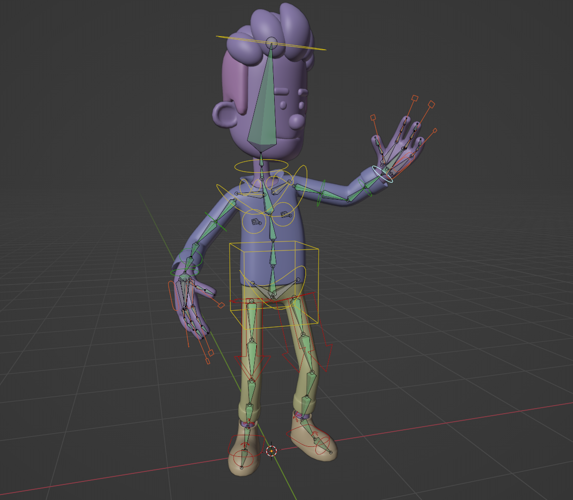
1. What is Rigging: In the next lessons, we will create an animation
skeleton for a character. This animation skeleton,
also known as Rig, is what allows us to move the character in a
controlled manner. The rig for a character
like this is usually created using an object
in the armature category. This object has a series of
components called bones, which influence the
corresponding parts of the character allowing
controlled deformation when positioned in the model. In addition, the character's
armature object is often configured with structures we call animation controls. Animation controls are
the components we select and manipulate to position
the characters as desired. This stage of the
production where a character rig is created
is called rigging. The problem is that this stage is one of the most
complex and time consuming in production and is usually handled by
specialized professionals. Fortunately, there are some
tools that allow us to create animation rigs
using automated solutions. What I will do is the following. To provide you with a basic
understanding of the process. In this section, I will
introduce some tools and fundamental concepts
necessary for creation. After that, I will introduce
an Adn called Rig Phi, which will enable us to create a complex body rig for the
character quickly and easily. Finally, we will see how
to set up the influence the rig bones will have on the character's body through a process called weight paint. Thank you for watching
and I see you next time.
2. Vertex Groups: In this lesson, I'm
going to present a property of geometries
called vertex groups. To demonstrate how
vertex group work, I can use the default cube
from Blender's initial scene. I will enter the edit
mode of the object. I will move the top face of the object upwards
to make it longer. Now I will use the
control shortcuts of the loop cut two
to insert new loops. In this direction of the model, I will rotate the
mouse scroll to insert approximately
15 segments. Now that I have a
reasonable amount of vert, I will activate the
Object Data tab in the Properties editor. Here we will find a panel
called Vertex Groups. If I click on this button
with the plus sign, I can create a new vertex group. If I double click on the
group's name, I can rename it. I will name this
group First Group. Now I will create
a second group. I will rename it
to Second group. If I want, I can create practically as many
groups as I want. If I want to delete a group, I just need to have it
active in this list. And click on this button
with the minus sign. Now let's see how to associate
the virtues of the model. With each group, I will activate the x ray
mode of the viewport. I will select a group of virtues
at the top of the model. Now to associate the
vertes with a group, I just need to have this
group active in the list. And click the assigned button here at the bottom of the panel. If you ever want to exclude a set of
verses from the group, just select them and
click the remove button. If you click the
selected button, it will select all the
verts of the active group. If you click select, it will remove all the vertes of the group from the selection. Now just to finish
the demonstration, I will select another
group of vertes. At the bottom of the model, I will activate the
other vertex group. I will associate the
virtues with this group, but this time before clicking
the assigned button, I will change this
weight parameter. I will type 0.5 when we
click the assigned button, and this value is at maximum. That is with a value of one. The verts are entirely associated
with the active group, but when we use a smaller value, the verts are only partially influenced by
the group in question. In this case, if I click the assigned button with
the weight parameter at 0.5 the verts will be only
50% influenced by this group. Now I will exit the edit
mode and deactivate the x ray mode to show one of the
applications of vertex groups. I will go to the modifier tab
of the properties editor. I will add the simple
deform modifier. This modifier can deform the object using one
of these operations. Twist, bend, paper or stretch. In this case, I will leave
the twist option enabled, but I will change the x of
the operation to the z axis. This way, when I adjust
the angle parameter, the object will be
twisted along this axis. Up to this point, we are not seeing anything
extraordinary. This is just the way a
simple modifier can work. However, some modifiers
can have their effect restricted to a
specific vertex group configured on the model. If we open the
restriction subpanel, we can see a field
called vertex group. If we click on this field, we can see all the groups
you created for the object. If I choose a group
to which I have associated a certain
set of verts, only the verts from that group will be
affected by the modifier. In the case of the first group, we can see that these
verts are being 100% affected by the modifier. If I change the defining the group here to
the second group, we will see that
only these verts are now affected
by the modifier. But here we have another
interesting factor. Since I assigned a weight of 0.5 to the vertes in relation
to this vertex group, we can see that
demodifier is acting at only 50% of the
configured intensity. Vertex groups are just a way for geometry to save a specific
selection of verses. The selections can
have a partial weights associated with the
vertex group if we want. Vertex groups can be used in various functions of blender
with different objectives. For our purposes, we will see that the vertex
groups will be essential for configuring
the influence that the bones of the skeleton
will have on the character. That's it for this lesson. Thank you for watching
and see you next time.
3. Introduction to Armatures: In this lesson, I will give
you a brief demonstration of how the beginning of the
manual creation process of the animation skeleton works. But before creating the
animation skeleton itself, I will create a geometry that will be influenced
by this skeleton. Since I only want to do
a simple demonstration, I will transform this
initial cube from the blender default sin into a small cylindrical
structure like a sausage. After selecting the cube, I will enter edit mode. I will scale the geometry on
the y axis so that it has roughly disproportion
around five times the size of
the original object. Now I will use the control
R shortcut of the loop, cut two to insert five segments in the
longitudinal direction. After that I can go
back to object mode. Now I will go to
the modifier stab in the properties jitter. I will add the subdivision surface modifier to the object. Afterwards, I will click
the applied commands in the modifiers menu
to effectively incorporate the subdivisions
into the model. Now we can create
the armature object. To this, I will use the Shift DA shortcut to
open the Creation menu, I will click on the
Armature object. This will create a skeleton
with one bone in the sing. To visualize the object, I will temporarily disable the visualization
of the geometry we created in the outer liner. This structure we are seeing is a bone which is the smallest part of
an animation skeleton. If we look at the objects
interaction mode menu, we will see that it
has three options. The object mode, which
is the default mode. The edit mode, where the
skeleton shape is configured. The pose mode, which is the interaction mode we use
to animate the skeleton. To start editing the skeleton, we can activate the edit mode. Now I will activate the lateral view of the
tridiviw by clicking on the X, on the navigation icon. I will make sure I am in the orthography mode
of the tridiviw. By clicking this button
with the edit mode active, we can see that it's
possible to select and manipulate the
different parts of a bone. The central part, which
is the actual bone, this is spheres at the ends. One of them is called the head and the other
is called the tail. When we reposition
these spheres, we are automatically adjusting the shape of the actual bone. Now I will activate
the visualization of the geometry created again
in the sensual liner. In this way, we can
start adjusting the skeleton according
to the object. What we will do is position the first bony joints at
the end of the geometry. I will position the other
joints at a distance of approximately one third of
the size of the geometry. In addition to being able to manipulate these three spheres, we can extrude the bone. To do this, just have
one of these spheres selected and press
the shortcut key. When we extrude a joint, we create another bone
for the skeleton. I will position this
joint of this new bone in the middle of the space between the previous joint and
the end of the object. To finish, I will press the key again to
extrude one more bone. I will position this bone
at the end of the geometry. These are the basic procedures for creating an
animation skeleton. After creating the
animation skeleton, we can enter pose mode in the interaction modes menu
to animate the skeleton. Here we could select any of the bones and rotate
with the R shortcut key. The problem is that in the, the geometry isn't
yet configured to follow the movement we
make with the skeleton, I will use the control shortcut to undo the
positioning of the bones. I will go back to object
mode of the skeleton now. Let's save this file. In the next lesson, we will continue with this
sing to see how to configure the geometry to follow the movement we make in
the animation skeleton. Thank you for watching
and I see you next time.
4. Weight Paint Part 1: In this lesson, we will
begin to see how to set up a geometry to follow
an animation skeleton. The way a geometry knows
which vertes should follow each bone is
through vertex groups. We will configure
the vertex groups of the geometry so that each individual vertex group follows a specific
bone of the skeleton. We could do this
configuration manually, we saw in the lesson
on vertex groups. But there are more
practical ways to set up these groups when we want to configure them to be influenced by an
animation skeleton. In this lesson, I
will start to show the method I consider the most
objective for the set up. The first thing we
will do is select the geometry that will be
influenced by the skeleton. Next, while holding
down the Shift key, I will add the skeleton
to the selection. Now I will go to the
Object menu Parent. I will click on the
Armature Deform with empty groups option. Note that in this menu, there is also an
interesting option called Armature Deform with
Automatic weights. This option will indeed do part of the work
automatically. But before I present
this option, I want you to understand how to configure the
weights manually. Let's start by using the
empty groups option. Now I will select only the geometry to see what
this procedure has done. If we look at the modifier step in the properties ejector, we will see that
this procedure added a modifier called
armature to the object. This modifier informs
the object that it should be deformed according to a certain skeleton
in the scene. Since we use the parent
with empty groups command, the modifier has already
been automatically configured to use the armature
object that was selected. Furthermore, if we click on the object data tab of
the properties editor, we will see that the command
has automatically created some vertex groups
with this procedure. These vertex groups are
already created according to the name of each bone that will influence the deformation
of the object. However, the procedure we used create these vertex groups, but does not assign any virtues of the
model to each of them. The process we are
going to learn now is called weight paint. This process is a
practical and visual way for us to assign influence values of
each vertex group to the vertex we
want on the model. The way I consider
the most practical to work with the weight paint
process is as follows. We first will select
the skeleton, then with the shift key pressed, we will add the geometry
to the skeleton. This way, the geometry
is the activity object, but the skeleton is
also in the selection. With the selection, we can go to the interactions mode menu and enable the
weight paint option. The interaction mode
menu can also be opened with the
control tab shortcut. With the shortcut, we
can open the menu in this floating form and choose an interaction
mode for a geometry. The weight paint mode
allows us to select the vertex groups and use painting tools to paint the influence on
the models verts. To activate the vertex group to be painted at a given moment, we could click on the name of the respective vertex group
in the object data tab. However, when we make
the selection the way we did where the armature
is also selected, we can directly select the
bones in the tridivial. In this case, it's good to check if we have the x
ray mode active. To make the selection, we simply hold the out key
and click on the bone. If you are using
Blender version four or later if you are using a
version prior to version four, you should hold the
control key and click on the bone when we select
a bone in this way, the corresponding
vertex group is automatically activated
in the geometry. If we have a vertex group active and use the
weight paint tools, we will assign weight values to the vertes we are painting for the vertex group
that is active. To start, I will leave the first bone of the
skeleton selected. With that, we can see that the first vertex group is
active in the geometry. Now before I show the
weight paint tools, I will show you some
settings that I recommend you do whenever you use
the weight paint mode. First, check if the
painting mask buttons are disabled for both
faces and verts. If any of these
buttons are active, the painting tools
will only work for verts or faces that are
selected in the edited mode. In general, it's good to
leave these buttons disabled. Next, enable the mesh
symmetry button for the x axis whenever your
model is symmetric. This way everything you
set up for one side of the model will be automatically mirrored to the other side. Finally, open the options menu and enable the
autonormalized function. This function will
prevent the sum of the values of
different vertex group on a specific vertex from
exceeding 100% In practice, this will prevent a series of problem during the
painting process. So just trust me and
enable function. With these three settings, we can start setting
up the weight paint, but to keep this video
from getting too long, I will continue in
the next lesson. Thank you for watching
and I see you next time.
5. Weight Paint Part 2: In this lesson, we will
continue to see how to use the weight painting
mode to configure the influence of vertex groups on the virtues of the model. Now that we have configured some basic properties of
the weight painting mode, let's take a look at the
weight painting tool. As you can see, the
weight painting mode has a series of tools
in the tool bar. But to be direct and concise, we will only need the draw
two and the blur two. The draw two is the tool we will use to paint the
weight on the verses. Here in the brush
configuration bar, we can see the weight value which corresponds to the weight that will be assigned to the vertes when we brush
over the geometry. The radius, which
defines the brush size, The strength parameter, which defines the
tensed with which the configured value will be added each time we
brush over the model. Initially, we will leave the weight parameter
with a value of one when we want to add weight from a vertex
group to a region, or zero when we want to
remove a value from a region. We will adjust the intent
with which we will add values to the verts through
the strength parameter. The brush radius can be freely configured according
to the situation. If we have the brush to active and the cursor
over the view port, we can press the shorted key and move the cursor out and in
to adjust the brush size. Now I will rotate the viewport to see
the scene from above. I will make sure
the first bone is selected by clicking on it
with the out key pressed. If you are using a version of blender earlier
than version four, you should click
on the bones with the control key pressed
to make the selection. Now I will brush over one side of the region
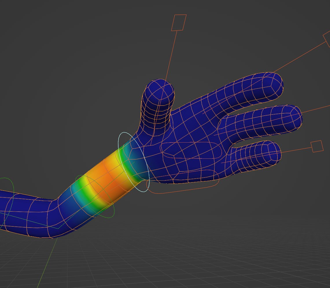
near the first bone. As you can see, as I
brush over the model, this red coloration
appears on the verts. In addition, we can see some other colors
appearing on the model. These colors indicate
how much infants the active vertex group has
on the vertes in question. Red means the vertex is fully influenced by
the vertex group. Dark blue means the vertex in question is not influenced
by the vertex group at all. Green means the vertex
group has an influence of approximately 50% on
the vertex in question, and the other colors indicate intermediate values
according to this chart. Since the mesh symmetry
option is active, we can see that what I paint on one side is automatically
painted on the other side. But if I rotate the viewport
and look under the model, we will see that the painting does not go through
the geometry. If we want the painting to
go through the geometry, we need to go to
the brush panel. We will disable the
front faces only option, but that alone will not be sufficient for
most situations. In addition, we go to
the fall off panel. We will change the
fall off shape setting from sphere
to projected. Now if I brush on one side, the back of the geometry
will also be painted. I will brush over the model to paint all these verses around the first bone of the skeleton when we make the selection. As we did having the skeleton and the
geometry in the selection, besides being able to select the bones to activate
the vertex groups, we can also rotate
the selected bones. If I press the R key, I can rotate the bone and
see it acting on the model. This procedure is good to test
the infants at the moment. After doing a test like this, we can use the control Z shortcut to revert the bone
to its initial rotation. Now I will select the
next bone of the skeleton by clicking on it with the
out or control key pressed. I will use the draw two to paint the vertes
around this bone. To finish, I will
select the last bone. I will paint the
verses around it. With the draw to now, I can select the bones
and rotate using the R key to see how the
weight paint is coming along. If we rotate the bones and see verses staying
in place like this, it means these verses are not influenced by
any vertex group. In this type of situation, we should select the bone
that should be influencing these verses and use the draw to brush over
the verses in question. During this testing process, we should rotate the bones reasonably to see if the
deformations are good. Generally, the regions that are challenging to adjust
are the joints. To better visualize the vertes during the weight
painting process, we can go to the Overlays menu and enable the wire
frame display. Now let's see how we can make the deformation in the joint
region a bit smoother. I usually like to
start smoothing the joint region
using the blurred to just have a bone that affects the joint
in question active. And start brushing with this two over the virtues
of the joints. These will distribute
the weights of the different vertex group more gradually among the
virtues in the region. In this situation,
we can also select the vertex group
on the other side of the joint in question, we can also brush using
the blurred tool. Now I will also use the
blur tool to smooth the transition between the vertex group on the other joint. I will also smooth
the transition with the other
selected vertex group. When we use this procedure, we may conclude that a
particular vertex group ended up with little influence
over a specific origin. If we want to increase
the influence of the vertex group
again on the verts, we can activate the
draw two again. We can paint again
over the region. But if we want to paint in
a more controlled manner, we can increase the intensity of the strength parameter a bit. Leave the weight parameter
at the maximum value, but use a lower value in the strength parameter when you want to add value gradually. Now we can select
each vertex group and brush in the areas
where we think they should have more inference. These are the Bask
procedures we can use to adjust the weight painting
manually on the model. Now to finish, I will present the parent with
automatic weight option. But first I will show you how to undo this weight
paint configuration. With the firstly, we need
to select all bones of the skeleton with the key
and use the out R shortcut. This shortcut resets the
rotation of all selected bones. And now I can go back to the
object mode of the object. Now let's see how to remove the weight
paint configuration we did for this with
the geometry selected, we will open the options menu
of the vertex group panel. By clicking on this arrow, we will delete all
groups option. This will delete all vertex
groups from the model. To finish, we can go to the modifier step of
the properties ejector. We can delete the
armature modifier. With this, we undo all the infants
configuration we had done. Now I will select
the geometry first. Then with the shift key pressed, I will add the skeleton
to the selection. I will go to the
Object menu Parent. I will click on the
Armature Deform with automatic weights option. If we select the geometry and
look in the modifiers tab, we will see that
this procedure also adds the armature
modifier to the object. Additionally, in the
object data tab, the corresponding
vertex groups for each bone are also
created automatically. The difference is that this procedure does a
weight paint configuration automatically
taking into account the proximity of the
verts to each bone. If I select the skeleton first, add the geometry to the selection and enter
weight paint mode. We can select the
bones and rotate to see how this automatic
influence turned out. The weight configuration
made by the parent with automatic weight command works very well in many situations. But it's also common to find some imperfections
in the deformation when testing the joints. In that case, we just
need to use the tools of the weight painting mode that we saw to make the
necessary adjustments, especially in the
joints of the model. This was a brief presentation of the weight configuration
tools for the vertex groups. Thank you for watching
and until next time.
6. Introduction to the Rigify Addon: In this lesson, we will
see how we can create a complete rig for a character in a practically
and automated way. To do this, we will
enable an addon that is already installed in
Blender called Giphy. To do this, we just
need to click on the Edit Preferences and click the sections of
the Preferences window. Now just start typing Rig
in the search section, so the rigid will
appear in the search, just enable it here and it
will be available in Blender. If we open the ado pen or
here the preferences window, we will see some
information about the adom, this
documentation button. If we click on it, the
Rigifhi documentation page will open in your browser. This page has various
information that can be useful if you want to delve a
little deeper into Rigifhi. If we go back to Blender and close the
preferences window, we can start using Rigifhi. I will select and delete the initial objects
in the scene. That we will open
the creation menu with the Shift, a shortcut. When we open the Creation menu, we can see that where there was only the armature
option before. Now a sub menu opens with
the single bony option. Blender creates a single bone just like it did before.
We enable the addon. Now I will reposition the
predcursor with the shift in the right mouse button to create other options
in different places. Opening the Creation
menu once again, I will now create this
human meta option. As we can see with this option, Blender creates a complete
humanoid looking skeleton. This is the skeleton
we will use to create the animation
skeleton for our character. But if you go back to
the Creation menu, we will see that
besides this option, we will still find
a sub menu with various preconfigured
skeleton options for animals like bird,
which creates a bird, skeleton cat, which creates a filing skeleton horse which
creates a horse skeleton. Shark which creates
a shark skeleton. And wolf, which creates a
nine shape of the skeleton. Additionally, we have
another sub menu with some more basic skeleton options for humanoids and quadrupeds, which come without fingers
and facial controls. All these skeletons
can be adjusted in editing mode so that the size matches that of a character
with that structure. This initial rigify skeleton we create at the beginning of the process is not the final skeleton that
will be used for animation. It's just a skeleton
we use to indicate to the final skeleton what the
characters proportions are. If we look in the Outliner, we will see that the name of this initial rigify skeleton
is called Meta rig. After the meta rig is adjusted, we can use the command for
rigify to automatically create all the final animation controls with the
configured proportions. To demonstrate this process, I will delete all these
skeletons that I created. I will press shift C to position the predecursor in
the center of the scene. Later on, we will see
that initially it's quite important for the skeleton to be created in the
center of the scene. Make sure to use the shift C shortcut before
creating the skeleton. Now I will create a human meta G. Now to generate the
animation controls, we must have the
meta rig selected. In object mode, we must enable the Armature
object Data tab in the properties Djitor with this person icon in the
rigifi buttons panel. We will click on this
Generate rig button. This process may take a while. When the process is complete, we will see that several lines have been created
around the skeleton. These lines constitute
the rig with the final controls we
will use for animation. If we look in the outliner now, we will see this new object
which is called Rig. Besides it, we see the meta rig, which is the skeleton we
used previously to scale this skeleton and a collection
that is already disabled. These collections hold some
objects that are used so that the controls
of the final rig have the shapes of this line. As we see this collection and the meta rig can be hidden as from the moment the
final rig is generated. We will only use this object
to animate the character. In the next lessons, we will see how
to use rigiphi to create the animation
skeleton for our projects. Thank you for watching
until next time.
7. Checklist for the Rig Creation: In this lesson, we will
begin preparing the scene to set up the animation
skeleton for our character. Before we start this process, let's check if the scene is on the most appropriate form for everything to
work correctly. If you have done everything exactly the way I have so far, your scene is likely already
in the state it needs to be and you won't need
to make any adjustments. However, if you
have done something different regarding the
topics I will show now, you may need to make some adjustments for
everything to work correctly. For this lesson, I will use a file where I
intentionally left some configuration
issues for us to solve. Let's do the checks. Firstly, check if your character is oriented correctly in
relation to the scene. This means having the models front facing the
front of the scene. This is important because
the direction in which the animation
skeleton is created take into account the
scene orientation. It is possible to adjust the skeleton for characters
with different orientations, but everything works easier if the character is already in the correct orientation
and position. If we pay attention to the
navigation icon of the scene, we can see the three
arcchtagonal axes, x, y, and z. Each axis has two circles, one of them has a letter
corresponding to the axis, and the other circle has
the color of the axis, but does not show the latter unless we hover the
cursor over it. The front of the scene is
the side corresponding to the y axis circle
without the y letter. This means that for an object to face the
front of the scene, it must be pointed
in this direction. If your character is facing
a different direction, it's best to correct this. Now you can do this by
pressing the A key to select all the objects to
ensure the rotation occurs. From the center of the sing, press the shift C shortcuts to position the predecursor exactly in the center of the thing. Go to the Transform
Pval Point menu and choose the
predecursor option. Since the predecursor is
at the center of the sing, this, we will ensure that the rotation is done
from this point. Now press the R key and then the Z key to rotate
the character on the Z axis. Now just start rotating while holding down
the control key pressed so that the rotation is done at precise
intervals of five degrees. Now just rotate the object
to the front of the scene. Observing the rotation value in this part of the interface, probably the value that
will make your model face forward will be a
multiple of 90 degrees, like 9,180 or 270. Afterwards, remember to go
back to the transformer piv of point menu and re enable
the median point option. The next step is to check
if the characters objects are perfectly positioned at the center of the x
axis of the scene. Remember that the red axis is the axis represented in red, which is the axis towards which the sides of the characters
should be pointing. To check if the objects are
at the center of this axis, just select each of
them individually. Open the side bar
in the item tab. Check the x value of the location parameter for the object to be at the
center of the scene. This value should be zero. If it isn't simply
zero, this value. Do this check for each of
the objects in the scene. The positioning of the
objects on the Y axis and the Z X is not as important as the
positioning on the X Xs. But generally, I
like to position the character roughly in the center of the
scene, on the Y axis. I like to have the
character soles on the baseline of the Sens
grid on the Z axis. As I mentioned earlier at
the beginning of the lesson, if you precisely followed my
steps to create your model, it probably didn't have
any of these issues. But if you missed something and your file has any
of these issues, just use these procedures
to make the corrections. With this, your file is now ready to start the
rig creation process. That's it for this lesson. Thank you for watching
and until next time.
8. Creating the Metarig: In this lesson, we will
create the meta rig, which is the skeleton
we used to instruct the rigifile where the characters animation
controls should be created. To do this, you will
open your characters file performing the checks I showed you in the
previous lessons. Now the first thing
we can do is create a separate collection
for the rig so that we can keep the
outliner organized. I had already created a collection just for the
character in a previous lesson. If you haven't done it yet, I recommend you do it. This is not mandatory, but it helps keep the
outliner cleaner. If you have a collection
that you are not using, you can also delete it, just selected, and
press the delete key. Since we are no longer using
the characters references, you can hide or even
delete that collection. Now we can create a collection
exclusively for the rig by right clicking
in the out liner and selecting new collection. After that, we can rename
this collection to Rig. Now we can create a skeleton. Make sure the rig
collection is active, because when we
create an object, it is created in the
active collection. Before creating the skeleton, I will use the shift C shortcut. This will place
the tredcursor in the center of the
treaty view with the. When we create the skeleton, it will be created
exactly at this point. Now we can use the Shift D, a shortcut to open the
Creation menu Armature. We can click on the
Human Meta Ig option. This will create the skeleton
at the center of the scene. The next step is to make an initial adjustment to the size and position
of this skeleton. This adjustment can
be done in two ways, in object mode or edited mode. If we change the
size and position of this initial skeleton
in object mode, we will have to
make an adjustment before generating
the final skeleton. To illustrate, I will make
sure I am in object mode. I will move this
skeleton forward a bit and scale it a bit
by pressing the key. Now let's see what happens if I go to the object data tab in the properties editor and
click the generate rig button. As we can see, the animation
controls were generated ignoring the position
and size adjustments I made in object mode. This happens because
these transformations were not applied
to the skeleton. To demonstrate how
we can fix this, I will press control Z to undo this step of
skeleton creation. And now before generating
the animation skeleton, I will go to the object
menu, apply all transforms. This will incorporate
all the transformations I made in object mode
into the skeleton. If I press the
generator Gi button now we will see that the animation
controls will be created, taking into account
the transformations made in object mode. Now I will press control Z once again to undo the
creation of the controls. I will delete this skeleton
so that I can start fresh. I will create a new human meta
rig in the creation menu. Now I will show
you how I like to make the initial size
adjustments of the skeleton, which is through the add mode. After creating the skeleton, we enter edit mode. We select all the bones with the key we will be able to move and scale the
skeleton in edit mode. The difference is
that when we make these transformations
in edit mode, we don't need to worry
up about supplying the transformations before
generating the controls. We can move and
scale these bones. When we create the controls, they will take into account all the transformations we made. Therefore, I recommend that
after creating the meta rig, you don't make any
changes in object mode, only in It modes to start transforming the skeleton and see how it fits
inside the character. Let's activate the x ray
mode here in the top bar. And to scale the skeleton
from the center of the scene. Let's use the Shift C shortcut to ensure that the predcursor is at the center of the grid. Go to the transformed
pivot points menu and select the
Tredcursor option. With this, when
we press the key, the skeleton will be scaled
from the predcursor. As we can see, there
is no size that makes the skeleton fit
perfectly into the character. I will scale it so
that the height of the skeleton's shoulders roughly matches the height of
the character's arms. To ensure that all the bones have the correct size
and positioning, we will need to adjust
each one manually. The initial positioning
is the same. I won't move the skeleton on the X axis because
the character is already correctly
positioned in the center of the green as is the skeleton. But if I want, I can make a small adjustment to
the skeleton position on the Y axis just to make the manual adjustments
work easier later. Now, before we proceed with the manual adjustments of
each of the skeleton bones, I will hide the
collection that contains the character geometries
here in the outliner. If we look at the skeleton now, we will see that
it has a series of bones that create
a humanoid figure. All these bones
we are seeing can be used for some
types of characters, but in the case
of our character, we are not going to use
these facial bones. This rigififacial rig
is a bit tricky to adjust and I am not so
satisfied with the result. In a future lesson, I will show a different way
to create the facial rig. Additionally, since
our character has only four fingers
on the hands, we can delete the bones
for one of the fingers. It's important to note that most of the bones in the
skeleton cannot be deleted because doing so we'll simply break
the generation of the animation controls. It's crucial that you
only delete the bones. I indicate to delete a
bone from the skeleton, we need to be in edit mode. Then we can select the bones we want to delete and
press the delete key. Let's start by excluding
all the bones of the face, but without excluding the bones of the neck and the head bone. A safe way to do
this is as follows. Ensure that x ray is active. With this, we will see a small
bone inside the head bone. If we activate the
bony property, stab in the property adjitor, we can see the name of
each selected bone. When we select a bone
in the skeleton, we can see its name in
this field, in the panel. If we select the larger bone which corresponds to the head, we will see that its
name is Spine 006. We can't delete this
bone or the neck bones. What we need to do is delete smaller bone inside
the head called face. Additionally, we should delete all the face bones linked to it. A safe way to do this is to
select only the face bone. Make sure there are no
other bones selected. Then go to the Select menu. Similar children, this command will select all the bones linked
to the selected bone. Then we can press the delete key to the delete all of them. To finish, we can select these
four bones correspond to the pinky finger of one
hand and delete them. We can repeat this procedure
on the other side, selecting the four bones
of the pink finger on the other hand and
deleting them. These are the bones
that should be deleted to ensure
everything works correctly. It's important not to delete any other bones from
the initial skeleton. Now that we have only the
relevant bones in the scene, we can unhide the collection with the characters geometries. With that, we can
start adjusting each of the bones manually in
each part of the body. But to keep this video
from getting too long, we will do that in
the next lesson. That's it for this lesson. Thank you for watching,
and I see you next time.
9. Adjusting the Metarig Proportions Part 1: In this lesson, we will begin adjusting the bones
of the meta rig we created in the previous class to fit our characters
proportions. But before we do that, I recommend you check
if you haven't deleted any bones that shouldn't have been deleted in the
previous class. To do this, we can be either object mode or edited mode of the
meta rig skeleton. To test if the bone
structure is correct, we can go to the object data tab of the properties editor. We can click on the
Generate Riggibton within the rig Fi panel. This is the button we
will use to generate the final rig skeleton with
the definitive controls. If you deleted only the bones I mentioned in the
previous class, these animation controls
should be generated correctly. That means the command will also work after
the adjustments we will make in this class in case you don't delete any more bones. The issue is if
you deleted a bone that is necessary for those
controls to be created, you will see a narrower
message at this moment. If that happens, it's better
to go back to object mode, delete the entire skeleton, and start the process again. Since what we have done so
far was a quick process, this won't take much time. Since adjusting the bones to the character can
be a bit laborious. It's better to
start this process only when you are sure
your rig will work. In the end, once this test rig has been
created correctly, you can use the control Z
shortcut to undo the command. Now we can start adjusting the skeleton to the
character's body comfortably. But before we start working on the proportions
of the skeleton, I will make a few more
adjustments to the scene. For that, I will switch the
skeleton back to object mode, since in the previous
class I had set the transform pivot point
option to the tridcerus mode. I would change the setting
to the median point mode, which is the default setting. To adjust this caton to
the character's body, I can leave only
the model's body visible in the viewport. This will simplify
the visualization. During the process, I can go to the outliner and hide all the character
geometries except the body. Now I will make one
more adjustment that is not necessarily mandatory,
but can simplify. Some step of the rig set up, I will join the body
object to the head object. But before doing that, it's important to apply the mirror modifier to
each of these objects. With the head object selected, I will go to the modifier tab. I will click on this
mirror modifier arrow. I will click the applied command to apply the modifier
changes to the object. Only the mirror modifier
needs to be applied, so we can leave the odd
modifiers as they are. Now I will select the body. I will also apply
the mirror modifier. Now I will select the
character's body. Holding down the shift key, I will add the head
to the selection. With this selection,
I will go to the Object menu and click
on the Joint command. Now to effectively start adjusting the meta
skeleton size, I can activate the x ray mode. I can select the
skeleton and enter the edited mode so that we can adjust the bones on only half of the skeleton. We can activate the x, x mirror function by clicking on this button in the
two settings bar. If this bar is not appearing
in your interface, go to the view menu and activate the two settings option
with this button active. Everything we do on one side of the meta rig will be
mirrored to the other side. If you want to act
as a guide on how the meta rig bone should be positioned within a
humanoid character, you can go to the edit menu Preferences in the Add section. You can type rig in
the search field. With this, you will easily find the rig pia
dome in the list. If you expand the interface by clicking on the arrow
next to the add ons name, you will find a
documentation button. If we click on this button, we will be taking to the
rigifying manual online. Here we can click on the
bony positioning guide link. On this page, you will find various information
that can help you position the bones
of the character. This first part is about positioning the
bones of the face, which we won't use. But if you scroll down a bit, we will find the guide on how to position
the dorsal bones. I particularly like to start with the
positioning of the bones. Hearing blender, we can close the preferences window to ensure that the arms don't
interfere with the positioning of
the torsal bones. I will start by selecting them that will press the H key to hide these bones temporarily. Now I can activate the side view and make sure I am in orthography mode
by clicking this button. Now if we consult the
bony positioning guide, we will see that the
spine bone should go more or less through
the center of the model. The top of the head bone
should be at the top. The base should be in the
middle of the top of the neck. The top neck bone should go from the middle of the neck
to the base of the head. The bottom neck bone should go from the base of the
neck to the middle. The trunk bone should be all positioned more or less in
the middle of the torso. Here at the bottom, I need to select the base
of the spine with a selection window so that I can do this without accidentally selecting the leg. Will select the leg bones. I will also press the H key
to hide them temporarily. Now I can create a
selection window to select the tip
of these bones. I can drag it to the middle of the base of the
character's torso. Now I can adjust the distribution of the
bones in the middle of the torso following
the instructions from the Gi Fi bone
positioning guide. Now I can activate
the front view and adjust the position of this outer tip of
the pelvis bone. The inner part of
the clevical bone should be in the center
of the upper chest. The outer part should be near
the top of the shoulders. This other bone assists in the skeleton Z inference
configuration process and can be positioned
more or less like this. With that, we finish the
positioning of the torso bones. It's very important that all these bones are fully centered in the
middle of the model. If by chance you move one of these bony ones out of the
X X center of your sin, you must make sure to correct the disposition to
center the bones. Again, you should open the side bar by
clicking on this arrow. Here you will find
the coordinates of each joint of
the selected bone. The value of the X axis
in the head field, we will adjust the position
of one of the bones joints. The value of the X axis
in the tail field, we will adjust the position of the other joint of the bone. If you accidentally move a
spine bone out of the center, you should zero the value of the X axis in these two fields. However, when we move a
bonus position like this, the bones rotation may
become misaligned. To fix this, we can zero the row parameter of
the respective bone. Just type zero in
this parameter. Three, straighten
the bone again. If you'll notice that
another spine bone is the stumes aligned, You can also select the bone
and zero the row parameter. Now that the torsal bones
are correctly positioned, I will use the out H shortcut to unhide all the bones
I had hidden earlier. Now I can work on positioning
the character's legs. For this, I will create a selection window to select
all the bones of the leg. I will move them
on the X axis so that the bones pass exactly through the
center of the leg. Notice how I am moving
all the bones at once, keeping the structure completely
stretch along this axis. Now I can take this
joint at the top of the leg and move it downward, pressing the G key to start moving and the Z key to restrict the
movement to this axis. Now I can activate
the side view. I can start working on the
positioning in this view. Remember that we
can always consult the positioning guide
of the rigifi itself. As you can see, this joint should align with the
ankle of the model. This joint should be more or less in the
middle of the foot. This joint, at the tip, should be positioned at
the front tip of the foot. This back bone should be positioned at the
heel of the foot. The knee joint should be positioned at the
character's knee height. But it's very important that
it's aligned more forward, not in the middle of the leg. It's extremely important for the rig to function
that there is a small angle between the tight bone and the
calf bone of the leg. This angle will tell the rig in which direction
the leg should bend. When we move the
character's controls, we should leave a small angle in this direction
between these bones, instead of keeping
them completely straight or at an angle
in another direction. In practice, you
should make sure that the knee joint bone is a little forward from
an imaginary line. That should try to
visualize between the top leg joint
and the ankle joint. This way, everything
will work as it should. And with that, we
finish positioning the bones of the head,
torso, and legs. In the next class, we will work on the positioning of
the arms and hands. Thank you for watching,
and I see you in the next class. P
10. Adjusting the Metarig Proportions Part 2: In this class, we are
going to position the arm and hand bond
for the character. I particularly like to start by making an approximate
positioning of the hand bones. I will select all the
bones of one hand. With a selection window. I will set the report to the
orthography, front view. I will make sure I have the transformed pivot point configured with the
median point option. Now I will move these
bones with the key. I will rotate them with the key. I can also use the top view
to make these adjustments. I can use the key to
scale these bones. To position the elbow, I will select the joint
in the middle of the arm. I will move it to the middle
of the character's arm, but to help in this process and also in position
in the finger joints, I will show you what trick
up here in the interface. I will activate
this nap function by clicking on this button
with the padlock icon. I will set this nap
to volume mode. Opening this menu
next to the padlock. This will cause when we move a certain element
onto a geometry, it will be positioned at the center of the volume
of that geometry. But for this setting
to work with each individual selected
joint of the bones, we need to activate the active option down
here in the menu. Now if I move the selected
joints to the arms volume, the vertical and
horizontal position will follow the
movement I am making. But in the Thrid
environment depth, the joint will be positioned in the middle of the
volume I am clicking on this greatly simplifies the positioning of
some skeleton joints. I will position these
three arm joints considering the shoulder, elbow, and wrist positions
according to the rigify guide. Now let's position
the finger bones. As we can see, each
finger has four bones. The first one should be
positioned inside the hand, and the other three correspond to each of the finger phalanges. The first joint of
the hand bone can be positioned near
the wrist like this. Now pay attention to
an important detail. This hand bone and the first phalange bone are not connected in this
rigifhy skeleton. Which means it's
possible to move the joint of each of them
separately in this part. But for rigifhy to
work correctly, you shouldn't separate
these joints. If you accidentally separate
one of these joints, use the control shortcut
to undo this movement. To move this
structure correctly, you should create a selection
window over these joints. This way, you ensure that both joints of the two
bones were selected. Then you can move
them with the key. When positioning
this first joint, leave it a little inside the hand before the start
of the first phalange. And the other two joints can be respectively
at the first, third, and second
third of each finger. And remember, whenever
you move this base joint, you should create a
selection window to select the joints of the
two bones simultaneously. Pay attention to
leave the tip of the last phalange slightly inside the finger
volume as well. This way the volume snap will position it at the center
of the finger volume. Now just repeat these procedures for the other three fingers. Note that the base of each finger should be
close to the wrist. We can also see a hand
bone linked to the wrist. This bone can start at the
wrist and have the joint at the other end position in the central part
of the palm end. In the case of the thumb, we will follow more or
less the same logic. The only difference is that
it has three bones instead of four counting with the bone that should be inside the palm. But to position it, we will use the same method. To finish, we will need to
make sure that the army bones also have a slight angle indicating where the
Army will rotate. It's very important that
these bones are not completely straight or turned
in the wrong direction. We can leave the wrist
joint in the center. The elbow joint
positions towards the back and the shoulder joint also more towards the center. This way we ensure
a slightly angle between the army bone
and the 40 arm bone. It's possible that at some point the volume
snap may hinder your process when you
are no longer using it. Turn it off at the
top of the interface. To verify if the arm bone positions are
as they should be, just imagine an
imaginary straight line between the elbow joint
and the wrist joint. Looking from above,
the elbow joint should be positioned
behind this line. Now you can check to see if everything is in accordance
with the positioning guide. With that, we finish
position in the bones. In the next class, I will
show you one last adjustment we need to make before generating the final
rig for the character. Thank you for watching
and I see you next time.
11. Adjusting the Bone Rolls: In this class, we
are going to make one more adjustment to
the rigifying meta rig. This adjustment will
be necessary for the fingers of the
final rig to rotate in the correct direction
When using the animation controls to
make this adjustment, I will keep the x ray mode active and I will enter the
edit mode of the metallic. The adjustment we
are going to make, easing the rotation of the
longitudinal axis of the bone. If we look at the rigify
bone positioning guide, we will see that
each phalange should rotate on the X axis
of the bone itself. In addition, each
phalanx will rotate towards the Z axis of
that specific phalanx. Now let's see how this applies to the rotation
of the phalanges. In order to adjust
the rotation of the phalanges according to
the bony positioning guide, we needed to visualize
the axis of each bone. To do this, we will click
on the Object Data tab of the Properties Jitter in
the Viewport display panel. We will enable the axis option. This option will allow us to see the axis of each of the
bones in the skeleton. To adjust the rotation of the longitudinal
axis of each bone, we must have the sidebar open by clicking on this
arrow in the interface. Here in the item tab, we find a parameter called roll, which specifically
regulates the rotation of the longituginal
axis of the bone. What we need to do now is select each bone and adjust this
parameter so that the X axis aligns with the
main rotation axis of the bone that the Z axis points to the
bottom of the hand. It's quite possible that most of the bones already
have this rotation, more or less correct. But if we adjust and align the rotation of the
phalanges bones, the final control
will work better. We could adjust the
bone row parameter for each of these bones now. But there is a way to cop
the adjustment from a bone. We have already adjusted
to the other bones. What I need to do is select
the other bones first. I will select the other
phalanges of this finger. Finally, holding the shift key, I will select the bone that already had the row
perimeter adjusted. This makes this the active
bone in the selection. Now I will go to
the Armature menu. I will click on Bone
Row Recalculate row. Here I will click on
the Active bone option. These will make
the selected bones copy the row value
from the active bone. This way they will be perfectly
aligned with each other. In fact, if we want, we can repeat the procedure by selecting all the phalanges
of all the fingers. Just select. Lastly, one
of the bones that already has the row adjusted while
holding down the shift key. Now just go to the
Armature menu Bone. Row Recalculate
Role Active Bone. Then it's worth checking to see if the orientation of
the bones is correct. Remember, the X axis is
in the rotation axis, and the Z axis should point to where the
bone should rotate. If something is wrong, you should adjust the
role parameter manually. This parameter is mirrored
in the active mode. Once you have adjusted this
parameter for one hand, the other hand will
be ready as well. Now we just need one more procedure before
we can create the rig. For this, we need to
enter the pose mode of the skeleton by going to
the interaction modes menu. Although the edited mode
is the interaction mode used to configure the
positioning of the skeleton, Some additional settings of a rig can be done
in posing mode. With the skeleton in pose mode, we select the first phlength of each finger of the skeleton. We click on the bony tab
of the property agitor. We will open the
rig fi type tannal. Here we will change
the configuration of the band rotation axis
parameter to X manual. This parameter will make the
rotation of the finger in the final rig follow the configuration of the bony
role we did in edit mode. Now we will do this for
each of the other fingers. Note that this configuration is not done on the bone
inside of the hand. We will select the first effective plengths
of the finger. We will set the bend
rotation axis to X manual. In the case of the thumb bone, the adjustment is made
on this first bone, which is on the
inside of the hand. Unlike the bone row, this parameter is not
mirrored to the other side. We should repeat
the procedure for the first phalanx of each of the fingers
on the other hand. With that, we finish configuring
the characters meta rig. Now we can go back to the object data tab of
the properties editor. We can turn off the
display of the axis. That's it for this class. Thank you for watching,
and I see you next time.
12. Generating the Final Rig: In this class, we will generate the final rig
for the character. Furthermore, I will provide some additional observations
about this process. After creating and configuring the meta rig with the
characters proportions, the only thing we need
to do effectively is ensure that we
have the meta active. Go to the object data in the properties editor
in the rig panel. We will click on the
Generate rig button. If you have done everything
exactly as I showed, you should see the final
animation controls generated around your character. But before concluding the class, I want to make
some observations. I will use the control Z
shorted to undo this command. The first observation I will make is about the neck joint. Some joints in the
metari skeleton are connections
between two bones. This means that if we select
a single joint and move it, these transformations
affect the two bones connected to the
joint in question. However, the joint between the last dorsal bone and the first neck joint works
a little differently. These two joints
are not connected, which means we can move
each of them separately. However, if we do this, the rig won't work if I leave these two joints
disconnected in this way. And click the
generate rig button, Rig pi will not create the rig correctly and will display
this error message. If we look in the outliner, we will see that the
rig object was created. But as it was created
with an error, I will delete this object. I will select the meta rig again to show how to
fix this problem. For the rig to be
created correctly, I will need to position these two joints
in the same place. For that, I will enter
the addited mode. Now I needed to position these two joints exactly
in the same place. Since it's practically
impossible to do this by moving
these joints freely, I will use a specific
command for this. I will start by select the joint that is in
the wrong position. Then with the shift key, I will add the joint that is in the correct place
to the selection. Now I will right click to
open the Context menu. I will click on
the Snap submenu. I will click on the
Selection to Active Option. This option will move the
joint that was selected first to the position of the joints that
were selected later. Eventually, these
transformations may cause the bone row of one of the
bones to be misaligned. If this happens, we
can select the bone, we can open the side bar and
zero out the row parameter. Now if we select the
generate rig button, we will see that the rig
will be created correctly. But before concluding the class, I will use the control
Z shortcut once again. To make one more observation, what I will do is leave
the meta rig skeleton with some bone positioning error before generating the rig. In editing mode, I can, for example, move the top head joint is
slightly backward. Now I will click the
generate rig button. Since the dish positioning
problem is not structural, the rig is created correctly. The only problem is that the head control is not perfectly aligned
to my character. This particular error
is quite visible. I could use control Z right after generating the rig
to make the correction. However, it's
possible that we make a small error in position in the meta rig skeleton
throughout the process. We only realize this later. If this happens, we can
select the meta rig again, we can enter edited modes. We can correct the position
of the bone that is wrong. In this case, I will move the top head joint to
the correct position. If we look at the
rig fi panel now, we will see that the button has changed to regenerate rig. If I click here,
we will see that the rig that had already been
created will be updated, taking into account
the modification I made to the meta rig. If we look in the outliner now, we will see that the
generate rig button created a new object called Rig and a new
collection called GTS Rig. The object that we
will actually use to animate the character
is the rig object. Initially, we want to need the meta rig or this collection. But instead of deleting these
objects from the scene, I recommend you simply
leave them disabled by unchecking the selection and visibility icons
in the outliner. This way, if you
discover in the future that some rig bone was
positioned incorrectly, you can activate the meta rig, make the necessary correction, and generate the rig
again as I showed. But this is just for you
to have a meta rig backup. If everything is
correct from now on, you should only use
the rig object. That's it for this class. Thank you for watching
until next time.
13. Automatic Weights: In this class, we will start configuring
the influence that the rig deformation
bones will have on the character using the parent with automatic weights command. To use this command, we
can start by selecting the character object Next, while holding down
the shift key. We will add the rig we generated with the
rig to the selection. Now let's go to the object and we will
choose the Armature, the form with automatic
weight option. As we can see, the shortcut for the parent menu is control. If we have the selection in this order and use
the control shortcut, we will see the parent
menu in a floating form. Then I will click on the
automatic weights option. If we select only the character now and go to the object data tab in
the properties editor, we will see that this command has already created a series of vertex groups corresponding to each of the rigs,
deformation bones. If we go to the modifier step, we will see that
this command also automatically adds the armature
modifier to the module. Now I will make an observation about the order of the
characters modifiers, but for that I will
select the models rig. I will enter pose mode using the interaction modes menu
or the control tab shortcut, which switches between
object mode and pose mode. If you have an armature
object selected. Now I will select this
hand control and I will move it a bit to see
the characters deformations. After that I will go
back to object mode. As we can see, the parent with automatic weights
command has already configured a considerably
good weight influence. But one thing we have seen before is that the
order in which the modifiers are added to an object can affect how
they act on the model. In this case, the
object already had the solidify and subdivision
modifiers added. However, in this case, if we click on this
dotted area of the modifier and move it
up on the modifier stack, we will see that the deformation will be a bit smoother this way. Now I will select the rig again. I will enter pose mode. I will press the key to select
all the models controls. To reset these changes I
made to the characters pose, I will go to the pose
menu, Clear transform. I will click on the
all option command. We reset any changes you have made to the position of
the selected controls. Now I can go back
to object mode. It's important to remember
that the paint with automatical weights command does a good initial job of
configuring the weights. But this configuration
is not always perfect. In a future class, we will still make
some adjustments to the models weight paint. Thank you for watching
and until next time.
14. Using the Rigify Controls Parte 1: In this class, we
will see how to use the rigifi controls to
move the character. But first, let me
make an observation. In the previous class, we used the parent with automatic weights command to configure the bone weight
influence on the model. However, as we
have already seen, although the parent with automatic weights command does a good initial job,
it's not perfect. And usually small
manual adjustments with the weight paint tools are necessary after
using this command. But for us to make adjustments in the weight painted mode, we needed to work with
the animation skeleton. We need to have an understanding
of how to manipulate the rigifi controls before making adjustments in
the weight painted mode. Therefore, before making
these adjustments, we will use our model to learn how to manipulate
these controls. But don't be surprised if some parts of the
model still have some strange deformations caused by imperfections in
the weight paint. Let's start by
seeing how to manage the visibility of the
character's rig layers. To view the rig layers, let's enter the posing
mode of the rig. Let's open the sidebar. Here in the item tab
of the side bar, we will find a panel
called rig layers. Through this panel, we will
be able to enable and disable the visibility of the
layers corresponding to the emission controls for
each part of the skeleton. But before we proceed, let's turn on x ray. When we are in the
posing mode of a rig, x ray allow us to see the skeleton elements
inside of the character. With this, we will see the animation controls of the rig in front
of the geometry, even if they are inside
or behind the model. From now on, I will
show you how we can use each of these animation
controls to move our character. To do this, I will hide all
the layers here in the panel. I believe only the
dorsal layer enabled. If I put the rig
back in objects and modes and try to transform
a part of the skeleton, we will see that the controls will not be manipulated
separately. For us to effectively move
the character controls, the rig must be imposed, moved with the, we can
select each of the controls separately and effectively move the character with the
torso layer enabled. We will see the controls
for the head, neck, and torso in general. All controls can be moved,
rotated, or scaled. But usually the controls are used only for one of
these transformations. The head controls,
neck controls, and these curved
lines in the trunk, for example, are often
used for rotation. You can also move
scale these controls, but these create the
formations in the characters that are usually used only
in stylized animations. This layer also has
the shoulder controls, which can be rotated to
position this part of the body. Additionally, this
layer holds this box, which is the central
control of the body. The difference between this
box and the curved control of the waist is that when we
move or rotate the box, all the trunk objects follow
these transformations. But if we move or rotate
the smaller heap control, the rest of the trunk does not move to rotate each
of these controls, we can simply press the R key to rotate the control
perpendicular to the viewport. Or we can press the R key twice. When we press the R key twice, the control rotates as if it
were looking at the cursor, which can also be useful for positioning the character
in some situations. Additionally, we can also use the rotation manipulator
from the tool bar. When using this manipulator
to position the character, it's very useful to enable the local modes in the
transformer orientation menu. This way the rotation icon rotates along with the control. These allow us to have
a lot of control over which axis is being
rotated at any given time. But it's important to
remember to switch back to the global option in the transformer orientation menu when it's more convenient. If you look here
in the panel now, we will see that below
the torsal layer button, there is a button called trick. Additionally, we can see other trick type layers
for the arms and legs. These are adjustment layers and enables separate controls
for these parts of the body. These controls are often used to create stylized
deformations in characters, such as making a body part
more stretched or curved. But these controls are generally used only in very
specific situations. In general, it's
simpler to leave these layers disabled when
working on a character. But before hiding these layers, I will reset the position
of these controls. If after testing how to use the controls you want to return them to their
initial position, you can press the a shortcut
key to select all of them. Go to the pose menu, clear transform, and click
all to reset the position, rotation and scale of
all selected controls. Alternatively, you could use the short cuts out to
reset the position, out to reset the rotation
out to reset the scale. Now I will disable the trick
type layers in the panel. In the next class, I
will continue using this file to show you how to
use the rigo file controls. Thank you for watching,
and I see you next time.
15. Using the Rigify Controls Part 2: In this class, we
will see how to manipulate the arm
controls in di phi. I will continue from where I
left in the previous lesson. Now I will start by
enabling the finger layers. This layer, we will enable
these controls on each finger. If we take one of these
controls and rotate it, we will see that
the entire finger will rotate from the base. If we scale the control
using the shortcut, we will see that
the middle phalanx and the finger tip
phalanx will bend. We can even select all finger controls and press the S key to
scale them all at once. We just need to be
aware of the following. To manipulate more than one animation control
simultaneously. It's ideal to go
to the transform, a pivot point menu, and activate the
individual origins mode. If we have the median
point option active, we will see that
the fingers will scale from a point in the
center of the selection, which will cause
a strange result. Therefore, make sure to leave the individual origins
option active. This way the control for each finger will rotate
from its own origin. In addition to the controls, the fingers layer has this control on the
inside of the hand. This control is used to deform the palm of the
hand through rotation. The fingers detail layer enables some circular
controls on each phalanx. These controls can be used to rotate each phalanx
independently. These controls can
be used to make some fine adjustments after creating the hand pose
with the main controls. If we observe the panel, we will see that each
character's limb has two types of options, IK and FK. I will enable the Arm, K, and ArmfK buttons
for both sides. The Arm buttons refer
to the left side, the RR buttons refer
to the right side. The terms IK and FK refer to two different ways of
controlling articulated limbs. The first thing we needed to understand is that
although we can enable the visualization
of both types of controls simultaneously
in the viewport, only one of them
will work at a time. We can define whether
the K mode or the FK mode is active
separately for each limb. I will start by showing
how to define which of the two modes is active using
the left arm as an example. For this, I can select any
of the controls of this R. Then I will open the
rig main property spaniel. If we have a control of
one of the limbs selected, we will see the KK value here. When this value is zero, the limb in question will be
controlled by the K mode. If the value is one, the limb will be
controlled by the K mode. I will start by setting
the parameter to zero to begin showing
how the IK mode works. Now I will deactivate
the FK mode button for the left arm to leave only the controls of
the K mode active. When the IK mode is active. The positioning of the limb is mainly defined by the
control at the end. In the keys of the arm, we can select the dicontrol
around the palm of the hand. We can move and
rotate this control. With this, we can put the arm in practically
any position. The only thing we
can't define with this control is the
rotation of the elbow. When we are using the
K mode of the rigifhi. The rotation of the elbow is defined by the other control. Simply select it and rotate the control to determine
where the elbow will point. Now let's see how
to use the K mode. For this, I will enable the visualization
of the ArmlKbton. With this, these controls
appear in the viewport, but they are not active yet. If I select one of these
controls and rotate, we will see that nothing
happens to the arm. To switch the control mode
of this army from K to FK, we must have any of
the arm controls active in the rig,
main property spannel. We will set the value of
the IKFK parameter to one. Note that this value is individual for each
arm of the character. Changing the left army from K to FK does not change the
right arm as well. With this change, we can
see that the army will no longer follow the
controls of the IK mode. If we move them, I will even disable the
Ark button in the panel. When the K mode is active. The limb in question is
controlled by controls that active only on the
rotation of the limb parts. Unlike the K mode, where the positioning
of the limbs is predominantly controlled
by the position of the end control. In the case of the arm, the FK mode leaves the
three controls active, one for the arm,
one for the farm, and one for the hand. We just need to be careful
with the fore arm control. Initially, this control
can be rotated freely, but in real life, our fore arm only rotates in one direction. To show how we can prevent the forearm from rotating
on the wrong axis, I will select all
the arm controls. I will use the out R shot
cut to reset the rotation. Now I will select the
fore arm control. I will open the transform
panel in the side bar. As we have seen, we can change the transformation values for each axis through the spaniel. But as we can see, the only axis that
corresponds to the natural rotation of the
four army is the X axis. If we rotated this
control on the Y axis, on the Z axis, the Army will look
like it's broken. One thing I recommend you
do with the FK controls for the four arms is to activate
lock for the Y and Z X. This way this Xs
will be locked and the control will only
rotate on the X Xs. Whenever I create
a rig with rig hi, I do this for the FK controls of both four arms of the model. To finish, I will mention
one more difference between the FK mode
and the IK mode. For this, I will set
the right arm to K modes and the left
side to FK modes. Now if I select the central control of the
trunk and start moving it, we will see that the
arm that is set to FK mode follows the
movement of the trunk, while the arm that is in K mode keeps the hand
in the same place. Each of these control modes has its advantages and
the advantages. In general, animators
tend to use the FK mode whenever they are
animating scenes where the characters
arms are moving freely. Since K mode animation is
donly through rotation, the movement usually appear smoother with this
type of control. But when the character has hands resting or
fixed at some point, the K mode is usually used. In the next class,
we will see how to use the controls for
the leg in the Rigid. Thank you for watching
and see you next time.
16. Using the Rigify Controls Parte 3: In this class, we
will see how to manipulate the Lega
controls in Rigifhi. As we can see in the
Rigifhi layers panel, the legs in Rigifhi also have the IK and FK options we
saw in the previous class. For this demonstration, I
will leave the leg L K layer active and the leg
LK layer inactive. For the right leg, I
will do the opposite. I will leave the leg
RFK layer active. I will deactivate
the leg RK layer. Similarly to the arms. The fact that the controls
are visible in the viewport doesn't mean they are
active by the foe. The active controls
for the legs are the controls of the K modes. If I move the controls
of the left leg, now we will see that
they are working. But the controls that I left enables for the right
leg are not working. To activate them, I will
select any of the controls. I will go to the rig
main property spaniel. Here I will set the value of
the K K parameter to one. This way the rig
of the right leg will be controlled by
the FK mode controls. The difference between the IK and FK Mode in the leg is the same as in the arms
with the FK Mode. Each part of the leg
is positioned by the rotation of the
corresponding control. With the K mode, the leg is positioned
with the movement of this main control located
at the base of the foot. Furthermore, the rotation of the knee is defined
by the rotation of this other control similar to the rotation of the
elbow in the arms, just like in the arms. If we move the central
control of the character, we can see that the
leg configured with the FK mode follows
the character, while the leg with the K mode keeps the foot stationary
in the same place. In the case of the legs, it's considerably
important for the feet to remain stationary
when remove the trunk, since the feet in general
are supported on the ground. This is a dynamic that is
desired almost always. In the case of the legs, it's most common that we always leave these controls in K mode. Now to finish, I
will show you how to manipulate the controls
of the feet in K mode. As we have seen, this
larger main control can be used to move
and rotate the foot. But when the feet are
resting on the ground, we can use other controls to
rotate parts of the foot. I will use the out R shortcut
to reset the rotation, and the out G shortcut to reset the
position of the control. Now I will select this control
on the back of the foot. This control should be
rotated only on the X axis. If you want, you can even
lock the rotation of the other axis of this control so that they are not
accidentally rotated. When we rotate this
control forward, the tip of the foot remains supported and the foot
rotates from the center. We rotate backwards, the
foot rotates from the heel. The other two controls
are less important, but can also be used for obciliary rotation
of the center of the foot and the
tip of the foot. With this, we finish seeing how the controls
of the legs work. To finish, I will activate
the root control. This is the control where all the other controls are
linked directly or indirectly. If we move this control, all the controls
will move with it. In general, we use
this control only to define the initial position of the character
in the animation. And then we
deactivated with this, we finish seeing how to
use the rigo Fi controls. I hope that with this you can already create custom
positions for your character. If you want to reset your
character's position, you can enable the
visualization of all the controls you
have manipulated. Select all the controls
with the a shortcut key. Go to the Pose menu, Click on Clear Transform
and click on All. This way the whole character will return to the
initial pause. That's it for this class. Thank you for watching
and until next time.
17. Weight Paint Adjustments: In this lesson, we will see how to correct any
imperfections in the weight painting
mode of the model left by the parent with
automatic weights command. For this, we will select
the character object. We will enter the
weight painting mode in the interactions mode when
we have a geometry selected. We can also use the
control tab shortcut to open the interactions mode
menu in the circular format. Here I can choose any interaction
mode like object mode. I can use the control tab, shortcut again and enter the weight paint mode
through this path. When you are using
weight paint mode, it might be a good
idea to disable the subdivision modifier
in the modifier tab. This will make the process
lighter in the viewport. Another important
node is to make sure the overlays
button is active. Otherwise you won't be able to see the weight influence
map on the model. If we open the Viewport
Overlays menu, we can also enable the wire framing
visualization over the model. This configuration
is a matter of preference and it's
not mandatory. Another important observation
is to ensure that the face and vertex
selection masks are disabled in these buttons. If any of these two
options are active, the tools in weight paint
mode will only work on vertexes or faces that are
active in the edit mode. In general, it's a good idea to leave these options disabled. Another function we should
enable when working with the weight paint mode is the autonormalized option
found in the options menu. As we have seen, the
weight paint process involves adjusting the influence values that a particular vertex group
has on certain vertices. One way to select these
vertex groups is by going to the object data tab and choosing the desired group in the
vertex groups panel. However, I standard rig
has numerous groups and it's quite difficult and counter intuitive
to select them. Through this list,
I will show you another way to select the vertex groups to work on
the weight paint process. For this method,
I'm going to show I need to go back
to object mode. I will need to select the rig, but in addition to
selecting the rig, I will need to enable the display of the rigs
deformation bones. The deformation bones
are the bones that effectively act on the
characters vertex groups. We can enable the display of
the deformation bones using the rigs layer system in the object data tab
of the property Gor. The layer system is in the
skelet companion of this tab. Here I need to make
an observation. If you are using a
blender version from the 3.6 series or earlier, you will see the old version of the layer management system
with this Dots interface. In this interface, each dot
corresponded to a rig layer. The layer we need to enable is this third one from
back to front. But to enable its display
without disabling the others, I will click on it with
the shift key pressed. If I click on it without
the shift key pressed, I disable the others. I will press control Z and click on it with
the shift key pressed. If I enable x ray mode, now we will be able to see a series of bones
inside the character. These bones are the bones that effectively act on
the vertex groups. If we leave them enabled, we can select them in the weight painting mode
using the methadame. Going to show if you are using version 3.6 or an earlier version
activated this layer. If you are using version
four or a later version, you will see that the layer
management system interface has been replaced by a panel
called Bone Collection. In this new system can enable
and disable the display of each rigs layer or
collection by clicking on this icon next to
the collection name. If you created your rig
in an earlier version of Blender and opened your file
in version four or later, the layer you should
enable to view the deformation
bones is layer 30. If you have already generated the rig file rig in
blender four or later, you will see that
the collections already have a more
organized naming structure. In this case just activates the collection called death
at the bottom of the panel. After enabling the display
of the deformation bones, we will keep the rig selected. We will add the character to the selection with the
shift key pressed. Now we can enter weight paint modes so that we can see the deformation
bones inside the model. I will enable x ray mode when we are in
weight painted mode, but we also have a
rig in the selection, we can select rig objects. The shortcuts to select a bone or a rig
control up to Blender 3.6 control and click If you are using
Blender four or later, the shortcut is out. And click. This way I can select any control or deformation bone
that is visible. If I select an
animation control, I can even move it normally. In the case of this head
control, for example, I can press the R key
to rotate the control. An observation is that
when we have a rig object selected that does not
affect any vertex group, such as animation controls, the models colors turns
pink as you can see. But then using this method, we can select the controls. Even when we are in weight
painting mode of the model, we can test the position to see if the weight
painting is working. If it's not, we can make
the necessary corrections. If we select the
deformation bone with control and
click up to version 3.6 or with out and
click from version four, we can see the weight
painting of the vertex group, of the respective bone. In the case of the
deformation bone of the head for example, we can see that it's not influencing the
nose as it should. In this case, I will
do the following. I will select the head control. I will use the out R shortcut to reset
the bones rotation. I will select the head
deformation bone again, I will use the weight paint
tools to paint this bone. If I start painting normally
with the drop brush, we will see the vertex being painted wherever I
passed the brush. But if I rotate
the thru de Vial, we will see that
the brush is not painting on the other
side of the model. If we want the brush to
paint through the model, we need to do the following. In the brush panel, I will disable the front
face only option. But if I do a test now, we will see that this
alone is not enough. Additionally, I need
to go to the fall off panel and change the fall off shape setting from
sphere to projected. Also, make sure the front
face fall off option is not enabled with these settings. Anything you paint on one side, we'll go through
the geometry and paint on the opposite
side as well. If I test the
rotation of the head, now we will see that the nose is already correctly inferenced
by this vertex group. Now all you need to do
is move the controls of your character to see if you encounter any issues with the
weight paint configuration. As we can see initially, the paint with automatic weights
command does a good job, especially on slim
characters like this one. But if you need to
make any corrections, is a good idea to
activate symmetry for the x axis by
clicking on this button. This way, anything you configure on one side will be
mirrored to the other side. If I select the deformation bone and make a painting adjustment, the deformation bone on the other side will undergo
the equivalent adjustment. Now it's a matter of selecting the controls and testing to see if the
deformations are good. In the case of the leg, I'm seeing a detail that
could have been better. I could have inserted a loop in the model exactly
at the knee joint. This would make the deformation in this region more controlled, but we can take
the opportunity to see that there is no
problem in doing this. Now if we go into editing mode, we can use the loop cut
to with the controller shortcut to insert a new loop
at the height of each knee. If I go back to
eight painted mode, we will see that
these new virtues are automatically configured. Looking at the result
of this deformation, I think I can make the influence in this
area a little smoother. With the shin deformation
bone selected, I will activate the blur tool. I will go over this region. Since symmetry for
the x axis is active, these adjustments
will already be reflected on the
other side as well. Now it's a matter of
continuing to test to see if the deformations are good and making the
necessary adjustments. With the tools of
the weight in mode, remember that you can select all the controls and use the out R shortcut
to reset the rotation, the G shortcut to
reset the position, and the out A shortcut tha set
the scale of the controls. This way you ensure that the character returns to
the original position. At the end of the process, you can return to
object mode and disable the display of the layer or collection of the
formation bones. That's it for this lesson. Thank you for watching
and until next time.
18. Parenting Objects to Bones: In this class, we will
see how we can parent objects that will not
deform to bones of the rig. In the case of our character, the objects that will not
deform but should follow a rig bone are the hair
objects and the dental arches. In this case, all these objects should follow the deformation
bone of the head. To perform this procedure, I will start by enabling the visualization
of these objects in the outliner to parent
**** to a rig bone. We will select the object and the bone to which the
object will be parented. But since I want to parent the objects to one of the
rigs deformation bones, I need to enable the display of the layer or collection
of the deformation bones. Up to version 3.6 this is
done by adding this layer to the active layers by clicking on these little dots with
the shaped key pressed. From version four onwards, we enable the display of the deformation
bone collection by activating the death collection in the bone collection spanel. If we enable the x ray, we will see that the
deformation bones are visible inside the model. Now we should start by selecting the object
we want to parent. I will start by selecting
the hair strands. With the shift key pressed, I will add the rig
to the selection. But for the commander to know which bone I want to
parent the object to, I will enter pose mode. I will click on the
head deformation bone. Now I can go to the Pose menu, Click on Parents
and click on Bone. This way, the selected
object will be parented to the active
bone in the armature. If I select the head control
and rotate with the R key, we can see that the object is already correctly
following the movement. Now I will go back
to object mode. I will select the
base hair object. I will add the rig
to the selection. I will enter pose mode again, select the deformation bone. Go to the pose
menu, Parent bone. In fact, we don't
even need to exit pose mode to switch the object selected in
the object to mode. If we go to the outer liner and click on the teeth object, the teeth object
will be selected. We can now parent it
to the active bone. Now we can go back to object
mode and save the scene. Thank you for watching
until next time.
19. Transfer Weights From Body to Clothes: In this class we will
see how to transfer the weight paint
configuration we did on the character's
body to the clothes. These procedures I'm going to show work whenever
the object wants to transfer the already
painted weight to has shapes very similar
to the original object. If the target object has a more different shape like loser or different
shaped clothes, this technique may not work. To start, I will activate
the visibility of the shirt, pants, and shoes,
objects in the outliner. Since I won't need the rigs deformation layer or collection, I can hide this layer or
collection if I want. Before performing the weight
paint transfer procedure, we needed to select the object for each piece of clothing. We need to apply
the mirror modifier so that it's effectively
incorporated into the object. Additionally, it's
very important that during the procedure we deactivate any
other modifiers that the object may have. I will do this for
all the clothes. I will apply the mirror
modifier for the Pens object. I will deactivate the
subdivision modifier. I will repeat the
procedure for the shoes. Applying the mirror modifier, I will disable the display of the subdivision and
solidify modifiers. Now I will start the weight
paint transfer process. What we need to do is
start by selecting the object that already has
the configured weight paint. In this case, I will start by selecting the character next. While holding down
the shift key, I will add the target
object to the selection. In this case, I can
start with the shirt. With the shirt active, I will activate
Weight Paint mode. I will go to the Weights menu. I will click on the
Transfer Weights command. Immediately after I
click on the command, I will open the Transfer
mesh data panel down here. Here we will configure
three parameters. In the vertex mapping menu, we will select the nearest
phase interpolated option in the ray radius parameter. We will enter the value five. In the source layer
selection menu, we will choose the
binding option. The next step is to add the armature modifier
to the object. In the object field
of the modifier, we will select the rig object, which correspond to
the rig for which we want the weight
paint to be configured. To finish, we will move the armature modifier to the
top of the modifier stack. With that, the process is ready. Now we can re enable the visibility of the
modifiers for this object. If you go to the object mode, select the rig, interpose mode, and make some changes
to the modus pose. We will see that the clothing
is already configured with the weight paint and is the forming along
with the character. Now I will repeat exactly the same procedure for
the other objects. I will start by selecting
the character's body. Add the pen to the selection while holding down
the shift key. A weight paint mode. Go to the Weights menu and
click on Transfer Weights. Since I had already configured
this panel previously, Blender saved the settings. As we can see, the panel is already configured with
the necessary parameters. Then we can add the armature
modifier to the object, and we can choose the rig
object in the object field. Now we just need to
move the modifier up to the modifier stack and enable the display of the
subdivision modifier. Now I will go back
to object mode, select the rig, interpose mode, and test the movement to see
if everything is working. As we can see, the knee spoking through the
Pens object a bit. This may be happening
because I added an additional segment to the character's knee that I didn't add to the Pens object. Furthermore, the
character object does not have the
subdivision modifier active. I can go back to object mode and enable the subdivision
modifier for the character. Now I can select the Pen Object, Enter Edited mode,
and add a segment at the height of each knee using the control or shot cut
for the loop cut two. As we can see, the deformation
is still not perfect. I can go into the
weight paint mode of this object and select the vertex groups to make
a weight paint adjustment. We could enable the
deformation layer or collections as we did before, but I will show another way
to select vertex groups. If you are using blender
version four or later, you can position the cursor
over an area of the model and use the control shift X shortcut to open a menule like this. If you are using a
version prior to four, the shortcut is shift and
the right mouse button. When you position
the cursor over an area and use these shortcuts. Blender shows a menu with all the vertex groups influencing the vertexes
in that region. It may be a little less
intuitive to select this way, but in many cases, a bit of
trier and error can solve it. In this case, I will
select the shin bone. I will activate the blur tool, I will activate the
symmetry button. I will brush over the region. Now I can use again
the shortcut control. Shift X for versions above four, and shift right click for
versions before four. And I will select the
tight deformation bone. I will continue brushing, I will keep trying to adjust until the deformation
looks reasonable. Now I will go back
to object mode, select the rig and test
the pose a bit more. When I think everything is fine, I can go to the pose menu, Clear transform
all, and to finish, I can repeat the procedures
for the shoe object. I will select the character, add the shoes to the selection. Enter weight, painted mode. Use the transfer
weights command. Add the armature
modifier, choose rig. Move the modifier up and
enable the other modifiers. And with that, we finish the weight paint transfer from the body object to
the clothing objects. If you want, you can
enter the exposed mode and do some tests to see if everything is
working correctly. Eventually, some adjustments may be needed in weight
painting mode. But overall, these techniques works very well for
tight fitting clothes. Thank you for watching
and until next time.
 Gustavo Rosa, 3D Artist and Blender Instructor!