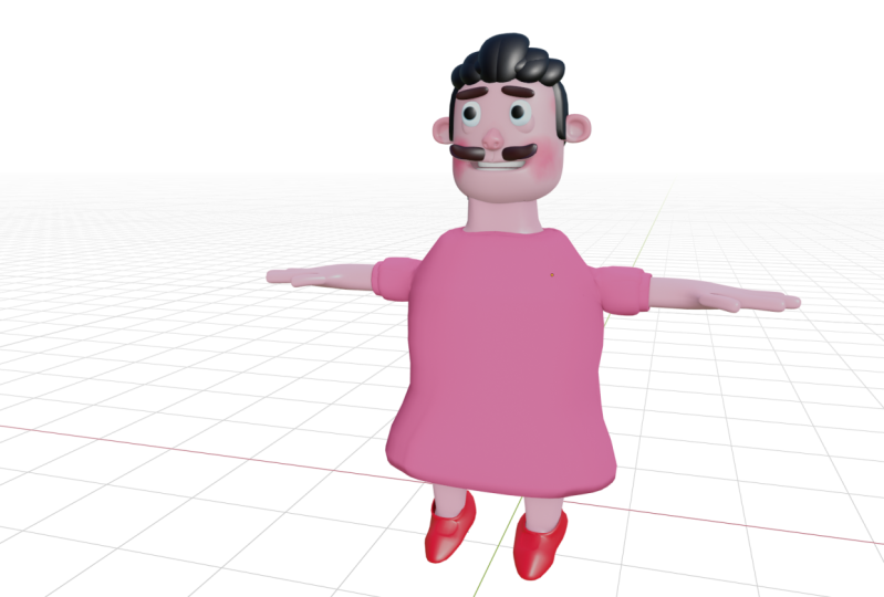
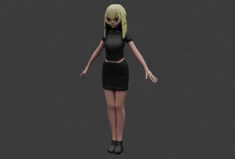
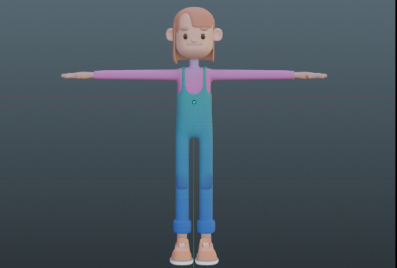
Transcripts
1. Skill Share Trailer: Hello everybody. My name
is Gustavo Oza and I will teach you how to create
treaty charts for animation. For this learning, Johnny, we will use Blender, an amazing free treaty
modeling software. This is an intermediate
level course where I need you to have
the knowledge of the blenders basic features. But if you still don't know anything about
blender, don't worry. In my profile here
on the platform, you can find blender, start an immersive
blender crash course. After completing
this fresh course where I cover the
basics of blender, you will be ready to take this
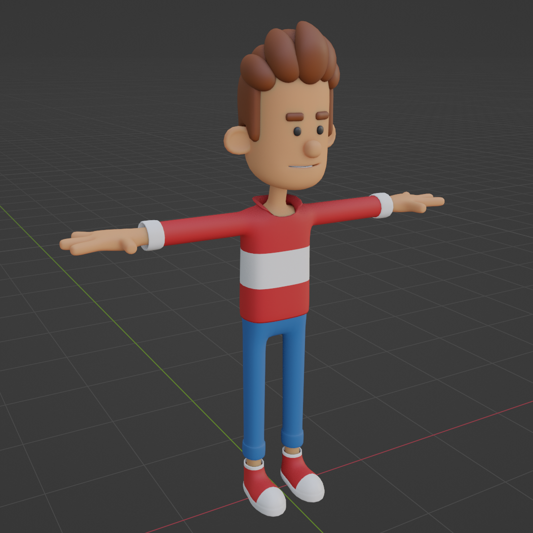
character creation course. The course Creating
Characters a Bit. Blender is a series
of three courses. In this first part
of the course, we will see how to model a complete character using blenders, Coligal
modeling tools. You will learn how to set up your three dimensional scene with references for modeling. And you will see how to use techniques and tools to
model a complete character. Additionally, we will create clothing and materials for
the characters objects. At the end of the project, you will create a rendered image showcasing your
finished project. After completing this
course, you stay tuned. The second part of the course focuses on creating the
character's body rigging. This means creating the
animation skeleton that will allow us to move an
animated the character's body. And the third part
of the course is dedicated to create
a facial rigging. In this part, you
will learn how to create custom controls that will enable you to create personalized facial expressions
for your models face. Finally, you will create
a simple animation demonstrating
everything you have learned in this amazing
series of courses. If you are interested in
creating expressive models, sign up and start creating your own iconicic characters
with blinder right now.
2. Preparing the References: In this lesson, we will
prepare the blender file with the necessary references
to model our character. However, it's important to mention that using
references like this is not mandatory when modeling a character or
any other treaty model. If you prefer, you can follow
this course without using references and create character with different proportions
without any issues. The advantage of using
references while learning is that you can focus a bit less on the characters
proportions. Consequently, more
attention to using the tools and understanding the character creation process. One suggestion is to watch
the lessons and create the character with
the references the first time to become
familiar with the process. Later when you are
more comfortable, you can rewatch the
lessons and try to recreate the character without
the aid of the references. This type of reference
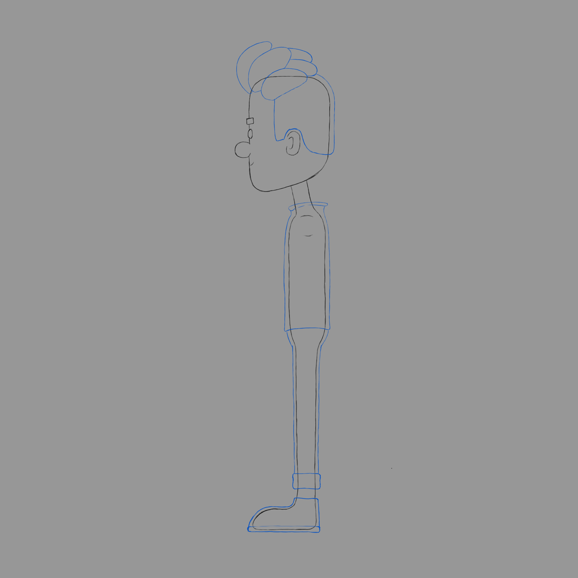
we are going to use is called model sheet. In our field, this
type of image is used to standardize
the appearance and proportions
of the character. For creating
modeling, it's common to use a front and side image of the character in the
professional world, if you are working on
a company or a studio, you will likely receive
these images from another professional
specialized in this type of illustration. But if you don't have
access to a model sheet, you can model the character
using only observation. Now let's effectively begin preparing our blender scene
for character modeling. But before setting up the scene, I will create an organized
folder for the project. You can create the
folder whatever it's most convenient
on our computer. In my case, I will
create a folder on the desktop called
mitridiccharacter. Inside this folder,
I will create another folder
called references. Inside the references folder, I will place these reference
images we will use, you can find this image available for download
with the course. Download the images
and save them in an organized folder structure
like this for your project. After creating the
project folder, I will open Blender. Since I won't need these initial objects
during character modeling, I will select the initial
scene objects and delete them. Now to place a reference image in Blender through the view, all we need to do is open the operating
system folder where the images is located and drag the image
into the Viewport. When we do this, blender creates an image
reference object in the scene using the image
we drag as a reference. At the moment we drag the
image into the scene, this image plane is created perpendicular to the
viewports observer used. This means that if you
drag the image into the viewport while it's
in the perspective mode, the image will be misaligned with the scenes ortogonal axis. We could correct
the orientation of the object by going
to the object tab in the properties editor and manually adjusting the
objects rotation values. But another thing we can do
is deleted this object and prepare the viewport
so that the image is imported into the scene with
the corrected orientation. Since the first image I will import is the front view image, I will set up the viewport with the front
ortographicy view. To do this, I can click on the minus y circle in the
Tredview's navigation icon. This will set the viewport
to the front view, but it's still in perspective. To import the image
and ensure that the reference plane is created
facing exactly forward, it's important that the
viewport is orthographic mode. To do this, I can click on this button in the upper
right corner of the viewport. If we look in the
upper left corner, we will see that the viewport is set to front orthographic. Another way to set
up the viewport with the front view is to
go to the view menu, Open Viewpoint submenu,
click on front. After that, just make sure the viewport is indeed
in orthographicy mode. If it's not, we can switch
it to the front view by clicking the switch
Perspective orthography button. Finally, we could also
set the viewport to the front view using the one shortcut key
on the numeric keypad. And tuggle between front
and orthography views using the five short cuts on the numeric keypad once you made sure the viewport is
set to front orthographic. Open the operating system folder where the reference image are located and drag the reference front
file into the Viewport. When you do this, the
reference plane will be created with the correct
orientation in the scene. Now I can double
click on the name of this object in the Outliner and rename this object with an easily identifiable name
such as reference front. Now let's adjust some
settings for this object. If we have this reference
plane selected and click on the Object Data tab
in the Properties editor, we will find some settings
related to this object. I personally like it to
enable the opacity option. I like to decrease the opacity of the object to around 0.5 Now let's set the position of this reference plane When using a reference
image for modeling, it's ideal that the
drawing in question is perfectly centered in the
image as it is in this case. Furthermore, it's also
ideal for the image to be perfectly positioned in the center of
the blender scene. To precisely
position this object in the center of the scene, you can click on the object
step of the property, Zgtor. You can adjust the
value of the x axis. Since I want the
object to be exactly in the center of the
x axis of the scene, I will type zero
in the axis field. This is the most important axis. It's crucial that the image is centered on the x
axis of the scene. The z axis defines the height
of the object in the scene. You could place the
object at any height on the axis, but personally, I like to set the height of the reference image
so that the solus of the feet aligned with the base of the
scene on the z axis. To this, I will adjust the z axis value
until the soles of the feet of the
drawing are more or less aligned with
this ready grid line. With that, the
reference image for the front view is
perfectly configured. Now let's create the reference
plane for the side view. To import the image with
the correct orientation, I can click on the circle with the x in the navigation icon. Or I could go to the View menu, click on Viewpoint
and select right. Or I could press the three key
on the numerical keyboard. Next, just make sure the view is in
orthographic key mode. When the viewport is set to
right orthograph key mode, you can open the
operating system folder and drag the reference side
file into the viewport. This way the image will be imported with the
correct orientation. Now for us to use both images simultaneously
as references, it's crucial that both are perfectly aligned
in the height. To do this, you can select the front view image which already has the
heights configured. Go to the object tab of
the properties actor. Copy the z axis value from the location parameter using
the control C shortcut. Then select the reference
object for the side image. And paste the value we copied
from the other object into the z axis of the
location parameter using the control V shortcut. Now let me take a quick note. In the case of these references, the image drawing came in
the correct orientation. But if you are using a
difference reference and the drawing has been
imported facing the wrong way, you can invert the
rotation of the object. To do this, simply invert the value of the z axis
rotation of the object. In this case, the original
value is 90 degrees. If I set the value
to -90 degrees, the object will be reversed and the drawing will
face the other way. If your drawing is
faced the wrong way, you can do this since in my case the drawing was
already facing the right way. I will leave the original
value of the object. Now all we need to do is leave a central space for the
actual character modeling. For this, I can move the front reference
backward on the y axis. I can move the side reference
to the on the x axis. Now I will select
the side reference. Go to the object tab of
the properties editor. I will activate the
opacity option. I will set this parameter
through the value 0.5 just like I did
in the front view. I will also rename this object
in the outliner to the. I will double click
on the object's name. I will rename it
to reference site. Another thing I can do is to start organizing the
scene collections. I will rename this
collection where the references are
as references. To finish, I will go to the
Outliners Filters menu. I will enable the
selectable option by clicking on this cursor icon. This will display a column with selection icons in the Outliner. If we disable this cursor icon for the references collection, it won't be possible
to accidentally select these objects during
the modeling process. With that, we conclude
the configuration of the file with the reference
images for the modeling. Now we can save our initial file by
going to the File menu. Choosing the folder we created for the project
as the location, giving a name to the file. You can name your
file as you see fit. I will call my file
micridiccharacter 01. I will click say this. With that, we finish preparing
the file for modeling. That's it for this lesson. Thank you for watching
and until next time.
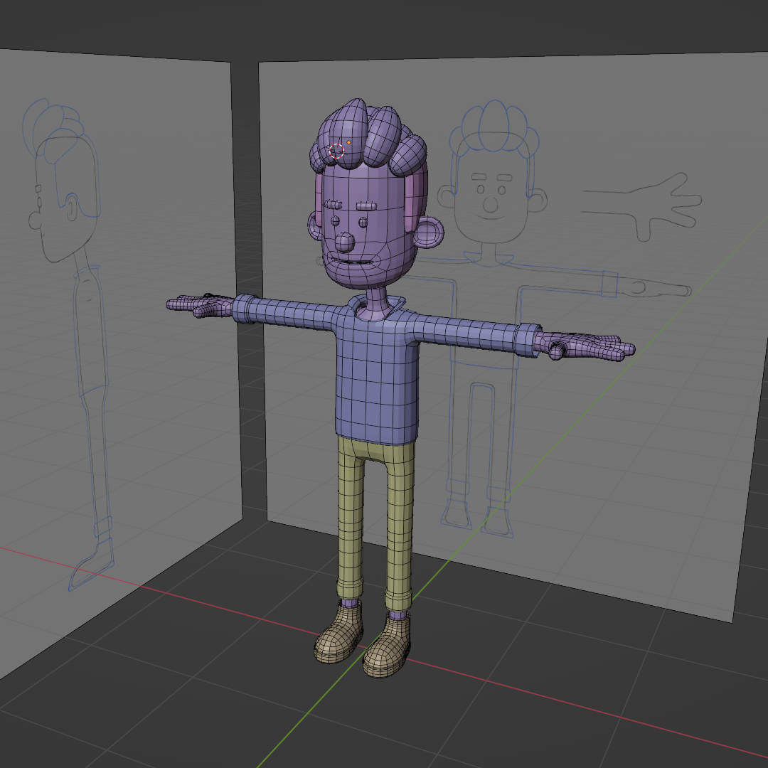
3. Modeling the Head: In this lesson, we will effectively begin
modeling our character. We'll start the modeling
with the character's head. But before creating
the first object will you use to model the head? Let's create a separate
collection for the character. Here in the Outliner, I will make sure I have the
same collection active. I will click on the
new Collection button. This will create
a new collection which I will re character. Now I will use the
Shift C shortcut to ensure that the predcursor is at the center of the scene. I will use the Shift A shortcut to open the object
creation menu. To create the head, I
will start by creating a cylinder immediately after
creating the cylinder. If we don't perform
any other command, we can open the
property spanal for the last action here in
the lower left corner. To simplify the
modeling process, I will reduce the initial
number of cylinder segments. I will set the verses
parameter to 16. This will make the object simpler and easier
to manipulate. After that, I can minimize the property spanul for
the last action again, now I will make a
personal adjustment. I will go to the
Viewport Shading menu in the upper right corner
of the three view. I will set the color
perimeter to random. This way each object
in the scene will have a different color
assigned randomly. The setting is not mandatory, but I personally
prefer objects to have these different colors
rather than being all gray as they are
with the full setting. Now I will set the viewport
to the front view. Put it in orthography mode
by clicking this button. After that, I will
move the cingular to roughly the height of the head according to the
reference drawing. I can also switch the
viewport to the side view and perform the initial alignment of the object according to
the side view drawing. To visualize the reference
drawing through the object, I will activate the
x ray viewing mode by clicking this button. Now I can enter Edit mode and start making
more adjustments. I will select all components in editing mode using
the a shortcut key. And I will scale the
geometry so that it roughly matches the
references initial size. For that I can use the shortcut
for the scale command. I can also select
the bottom verses and align them with the
base of the head using the move to and do the same thing with
the top of the head. I will also adjust the alignment and scale while looking
at the side view. Note that the alignment
between the side view and front view drawings will
hardly ever be perfect. In this case, we need to
make an approximation, aligning the object somewhere in between the two references. Now I will activate
edge selection mode. I will select the top
loop of the cylinder by click on one of the edges while
holding down the out key. While holding out and shift, I will click on one
of the edges in the bottom loop to
edit the selection. Now to round these edges, I will use the bevel command. I can use the control B
shortcut for the bevel command, or I can activate the
bevel two in the two bar, and click and drag on the yellow icon that
appears over the geometry. I will drag it until
the beveled Regan is roughly the size of
the rounded area in the reference drawing. Now I will open the
property spanle. For the last action in
the lower left corner, I will increase the number
of bevel segments to three. Now I can turn off x ray mode. Now I will activate
phase selection mode. I will enable the
selection tool. I will select the top phase and deleted by pressing Delete
and selecting phases. Now I will activate
edge selection mode. I will select this edge loop by click on one of the edges. While holding out, I will go to the phase and click
on the grid command. This command will
fill the open hole with organized four
sided polygons. This structure is more suitable for modeling
in many ways. But this command will
only work if the hole in question has an even number
of edges on the border. If the border has
another number of edges, the command won't work. When you use this command, make sure the central
segment of the grid is crossing the object center
axis on the X axis. If this structure is
rotated differently, you can open the last
action panel and adjust the offset value until the grid central axis is aligned with the
object central axis. Now let's repeat this procedure
for the bottom polygon. We will select and delete it. We will select the edge loop. We will use the grid fill
command if you prefer. Instead of going
to the phase menu, you can use the control shortcut to open this menu in a
floating mode in the viewport. After that, just make sure the grid
orientation is correct. Now I will activate x ray mode. I will enable vertex
selection mode. I will create a selection box to select the verts at the
bottom of the model. I will reduce the height
of this part a bit by pressing to activate
the scale command Z. To restrict the command to
the z axis of the scene, I will reduce the height a bit. Now I will activate the
side view and press R to rotate this part of the structure G to adjust
the position of the verts. I can also select each loop individually using the out key. And adjust the position of these loops according
to the reference. With this, we complete the
main volume of the head. In the next lesson, we will
continue from where we left off here and model the
mouth cavity of this head. Thank you for watching,
and I see you next time.
4. Modeling the Mouth: In this lesson, we will model the oral cavity of
our character's head. I will begin by setting up the geometry to create
the character's mouth. The character's oral
cavity needs to have a structure of polygons
that surround the mouth. To start creating
this structure, I will insert some
new edge loops. To do this, I will begin by
using the loop cut tool, which can be activated
in these two bar button. With the two active, I can click on one of
the vertical edges of the model to create a loop
perpendicular to that edge. Then I can drag the new loop
to the area where I want it. In this case, I want this loop to be roughly
at the base of the nose. Another way to use the loop cut is through the
shortcut for this two. If I don't have the two active, I can position the cursor over the area where I want
to create the loop. I can use the
control R shortcut. This time I will create a
loop at the mouth's level. I will create another loop in the middle of this other region. Now I will activate the front view and I will
deactivate the x ray mode. Now to start creating this elliptical structure
in the shape of the mouth, I will select these eight
polygons in this region. I will then press the key, which will activate the
inset phases command. To actually create
the oral cavity, I will press the delete
key to delete these pass. From now on, we will make some slightly more laborious
manual adjustments to avoid having to make the same adjustments on
both sides of the geometry. I will activate x ray mode. I will select all the polygons
on one side of the object. I will delete these faces. Now I will go to
the modifier stab in the properties Ajitor, I will add the mirror modifier through the Add modifier menu. Now, any adjustment we make on one side will be mirrored
to the other side of the model to prevent the
central verses from separating. When we move them, we can enable the clipping
option in the modifier. Now, I will manually
move these verses around the oral cave to align them
with the reference mouth. But in this case, I won't
worry about creating a mile. When we model a character, we usually create it with
a neutral expression. And other facial expressions are configured in another
stage called reading. Now I will adjust these verses so that
the mouth verses are neither sticking out nor too far inside the expected
volume for the head. This way we avoid surface
irregularities on the model. We can also adjust
the virtues of this outer loop so that they contour the mouth verses
more harmoniously. Try to look at your model from various angles while
making these adjustments. And adjust the position of the verses whenever
they are too far, inside or outside the
desired volume for the head. After these initial vertes
are well positioned, I will use the control
R shortcuts to insert another loop in this region that surrounds the oral cavity. Having another loop in this
region will allow us to have more control when creating facial expressions
in the future. After inserting this loop, I will once again
adjust the position of any virtues that may be outside the intended
volume for the head. I will try to adjust these loops as organically and
smoothly as possible. This way we are avoid
imperfections on the surface. With this, we finish modeling this first
part of the head. I can go back to object mode. I can save the file by
going to the File menu, Clicking on SavS here. If I click on this
plus icon next to the name field blender will automatically create a
file with the same name, but add a number to
the object's name. This way I can save incremental files for each stage of the process if I want to. That's it for this lesson. Thank you for watching
and until next time.
5. Modeling Face Features: In this lesson, we will model the character's nose,
eyes and eyebrows. To do this, we will start with the file saved in
the previous lesson. The first object I will
model will be a nose. As you can see in the reference, the character's nose consists
mainly of a small sphere. I could use a sphere
to create the nose, but to keep the
structure simpler, I will use a subdivided cube. I will start by using
the shift key shortcuts to ensure that the predcursor is at the center of the scene. And I will use the
shortcut shift TA to open the object
creation menu. Here I will create a cube. Since I want this
cube to be rounded, I will go to the modifier tab. In the properties editor, I will add a subdivision
surface modifier. I will leave the
view port levels parameter with only
one subdivision level. With this, the object
will already be slightly rounded as I wanted this to be the basic
structure of the model. I will click on the arrow
in the modifier interface. I will click on
the apply command. This way the modifier
will be applied to the object and this will
become its basic shape. Now I will set the view
port to the side view and I will position the object according to the nose
position in the reference. To facilitate the process, I can activate the x ray mode. Now I will enter
Editing mode and I will scale and position the structure according
to the drawing. If the reference drawing is not perfectly aligned
between the two views, we can position the geometry
midway between them. With that, we completed
the Nod structure. Now I can return
to object mode and turn off the x ray mode to better visualize
how the model looks. If necessary, I can make further adjustments to
the object position. Now to create the
character's eye, I will use the same structure. I can use the shifted shortcuts
to duplicate the object. To adjust the position
and side of the eye, I can activate the x ray
mode and enter edited mode. With this, we can use
the orthography views to move and scale the geometry according to the
reference drawing. I will scale the
object slightly on the y axis to make it
narrower in depth. I can also rotate the
object slightly on the Z axis to align its
rotation with the surface. Once I am satisfied
with the eye object, I can return to object mode. To create the eyebrow, I will use a cube to adjust the geometry in
relation to the reference. I will once again enter
the objects edited mode. I will activate the x ray mode. Now I will simply
adjust the size and position of the cube
according to the reference, both in the front of view
and in the side of view. I will also rotate the cube
to match the head surface. After that, I can return
to the object mode. What I will do now is combining all these geometries into
a single head object. But since the head object is cut in half and has a
mirror mode fire, I will also delete half of the nose object so that the
nose is mirrored as well. I will select the nose
enter edited mode, activate the x ray mode
to select the back faces, I will delete the faces
on one side of the nose. Then I can return to object mode and turn
off the x ray mode. Now I will use the
joint command to combine all these geometries
into a single object. When we use the joint command, the name and pivot that prevail are those of
the active object. When we use the command, the active object is the last object we
added to the selection. I will select the
facial elements with the shift key pressed. I will select the head
object last with the, the active object
is the head object. We can see this because the active object
is highlighted in a lighter yellow tone in both the Viewport
and in the Outliner. When the selection is like this, we can go to the Object menu and click on the Joint command. Now to make the
structure more rounded, we can add a subdivision
surface modifier in the modifier step of
the property ejector. This time I won't apply
the modifier as I want to be able to enable and disable it during the
modeling process. As we can see, the eyebrow became more rounded
than the reference. I will enter the
object added to mode. I will use the control R
shortcut for the loop cut two to add three more loops in the central region
of the eyebrow. This way the object will have a slightly more rectangular
shape after subdivision. Now I can return
to object to mode and save the file so that we can continue in
the next lesson. Thank you for watching.
I see you next time.
6. Modeling the Ear: In this lesson, we are going to model the character's ear. But before creating
the ear object, I will name the head object in the outliner which I forgot to name in
the previous lesson. I will name the object head. Now I'm going to create the object that I will
use to create the. To do this, I will open the creation menu with
the Shifty shortcut. I will create a cube to make it easier to align
the object with the drawing. I will set the viewport
to the front view. I will enable the x
ray mode to facilitate the alignment if you prefer. Instead of using the sort
viewport display mode with the x ray active, you can enable the wire
frame display mode. This mode already
includes x ray with it. We can also view the
edges of the model. Both modes will work for
this type of situation. Feel free to choose
whichever you prefer. Now I will adjust the size of this initial box according to the proportions of the
year in the drawing, both in the front
and side views. Now I will start shaping this object to be more
rounded and organic. To this, I will add
some segments using the loop cuts with the
control R shortcut. I will add one segment vertically and
another horizontally. Now I will rearrange
the verses of the model to make the
structure more rounded. To do this, I can select
the central verts and scale them on the Z Xs
by pressing the key, followed by the Z key. I can also scale the verts
on the horizontal center by pressing the key
followed by the X key. I can also manually
move the verts at the edges to make
the shape more rounded. Now I can switch back
to solid display mode. I will activate face
selection mode. I will select the forefront
faces of the object. I will press the inset shortcut key to activate
the inset command. I will move the mouse until
the new faces generated by the inset have the size
I want for the ear cavity. After that, I will press
the extrude shortcut key to extrude these
faces slightly backward. I will press the scale shortcut key to scale these faces a bit. I also think I will move the inner part of the ear
slightly further into the head. To do this, I will
activate x ray mode. I will activate the
vertex selection mode, and I will select the
innermost virtues of the ear. I will move them
further into the head. The next thing I
will do is select all the virtues of the model
with the A shortcut key. I will rotate this
structure slightly on the z axis to
define the ear tilt. With that, we finish the
modeling of the ear. Now I can return to object mode. And to join the ear object
to the head object, I will make sure the ear
is already selected. Then with the Shift key pressed, I will select the head. I will go to the Object menu. I will click on
the joint command. This way the year will become
part of the head object. Since the head already has the mirror modifier and
subdivision mode fire, you can see that the year is now also subdivided
and mirrored. If you want, you can
still select each part of the model in edit mode and make separate
adjustments if needed. After that, simply save the file so that we can
continue in the next lesson. Thank you for watching
and I see you next time.
7. Modeling the Mouth Interior: In this lesson, we will model the inside of
the character's mouth. Modeling the inside of the
mouth is not necessary if your character is only used to generate an image
with a closed mouth. But if you want to create facial expressions where the
character has an open mouth, you will need to model
the inside of the mouth, which will be visible when the character has this
type of expression. Since the inside of the mouth will be literally
inside of the head, I will disable the mirror
modifiers viewport visibility by clicking on this button in the
modifiers interface. This way, the half of the head generated by the
modifier won't appear. And we can see
inside of the model. Another thing that can
hinder modeling in this case is the reference
images themselves. But since we have organized them into a separate collection
in the Outliner, I can simply deactivate
the collection by clicking on this checking box next to the references
collection. This way the objects within this collection become
temporarily invisible. The inside of the mouth
for characters like this consist of a curved
structure inside the mouth. This structure can be created
so that it is connected to the lips inside the model or
separately from the lips. I personally think that
creating this structure separately makes some steps of the facial rigging
process a bit simpler. I'm going to use this method
to create this structure. I will use the Shift a
menu creation shortcut. I will create a cube to make the cube more
rounded in shape. I will add a subdivision
surface modifier in the Properties
Editors modifier step. And I will apply the modifier so that the object incorporated
this modification. Now I will move this object upward until it's at
the height of the head. I will set the viewport
to a side view. I will activate
either the x ray mode or the wire frame
visualization mode. I will position the center of this object slightly behind
the characters lips. Now I can enter edited mode. I will scale this volume
to fit inside the head. Now I will activate
the front view. I will enable x ray mode. This way I can select one of the models haves and delete
it with the delete key. Now I will activate
the side view. I will select and delete the
front faces of the volume. I will position this
volume is slightly behind the mouth area,
leaving some space. I will select the edges at
the front of this volume, and I will extrude these edges by pressing the E shortcut key. Then I will press the Y key
to only move this part along the y axis of the sin to make the front part of
the mouth more rounded, To match the head shape, I will select the two central
virtues at the front, and I will move
them forward a bit. To do this, I can press the
key to start the movement, and the Y key to restrict
the movement to the axis. You can also make any
adjustments you find necessary. After that, we can return to the object in
mode for the object, we can join this object
with the head object. I can make sure that this object of the inner
mouth part is selected. I will add the head to the selection while holding
down the shift key. I will join the two objects
within the joint command. This way, the inner mouth
part will also be affected by the heads modifier and will be mirrored when the mirror
modifier is active. But before I finish the lesson, I will disable the
mirror modifier to show how we can give the lips
edge a bit of thickness. To this, I will add a
modifier called solidify. What this modifier does is create a thickness
for the entire model. Since in this case the
solidify modifier works placed after the
subdivision modifier. The lips edge is not being smoothed by the
subdivision surface, but by clicking on
this dotted area in the modifier interface and dragging it
throughout the panel, I can change the order
of the modifiers. I will place the solid
defined modifier before the subdivision
surface modifier. With this, the
polygons generated by the solid defined modifier will also be affected by the
subdivision surface. And this part of the leap
will become smoother. If the modifiers are taking too much space in
your interface, you can minimize or expand them by clicking on the
areas next to each one. If you want, you can leave only the solidified
modifier open. The main parameter
of this modifier is the thickness parameter, which defines the thickness
generated by the modifier. I will adjust this
parameter until I am satisfied with the
result in the leap area. Additionally, I will activate
the only ring option. This option makes the modifier only affect the open
edges of the model. It won't add thickness to areas that are not an open edge, which is better for this model. Adjust the modifier until you're satisfied with this
part of the model. Then you can re enable the
mirror modifiers visibility. With that, we conclude
the mouth modeling. Notice how this part
of the mouth becomes more interesting with the solid fined modifier
on the model. After this, we can re
enable the visibility of the reference collection
and save the file. Thank you for watching
and until next time.
8. Modeling the Teeth: In this lesson, we will
model characters teeth. Actually, we will model
objects that will be simplified dental arches for
the upper and lower parts. To do this, I will start
by creating a new object, which in this case will be a cylinder to keep
the scene organized. I will make sure that I have the character
collection enabled in the Outliner and to ensure that the new object is created in the center
of the Tredview. I will use the Shift C shortcut to reset the
pred cursors position. Now I can use the
Shift A shortcut to open the creation menu. In the mesh menu, I will create a cylinder for the
teeth of the character. I will use a cylinder
with few segments. Immediately after
creating the cylinder, I will open the added panel of the last action in the
lower left corner. As I want start modeling the teeth with a relatively
lightweight cylinder, I will set the diverts
parameter to 16. After that I can enter the
edited mode of the object. Now I can press
the A shortcut key to make sure all the
polygons are selected. Then I will press the shortcut key to initiate
the scaling process. I will press the Z key to restrict the scale to
the Z axis of the scene. I will scale the object until it roughly
matches this position. Since I want to create
an arch shaped object, I will delete some polygons leaving only the front
arch of the cylinder. I will start by selecting the top polygon and
the bottom polygon. I will delete these faces. Now I will select all the polygons from the
back of the cylinder. I can click on one polygon while holding down
the control key. I can click on another
polygon further ahead to select all the
polygons in between. If needed, I can select the remaining polygons while
holding down the shift key. I will also delete
these polygons. Now I will make the remaining
arc slightly flatter. For that, I will select all the polygons with
the A shortcut key. I will activate the scale too. And I will scale the object
slightly on the y axis. Now I will create the volume of the dental arch by
extruding the polygons. In this case, I will use the out to open the menu
with extrude options. I will choose the extrude
faces along normal option. This way I can extrude the polygons in the direction
of their own normals. To finish, I will delete all the polygons that will
now be visible in the arch. In this case, I will delete the polygons from the back
and the top of the arch. To finish this arch, I will return to the
object mode of the object. I will add the subdivision
surface modifier by going to the modifier stab
in the properties editor, and adding the subdivision
surface modifier using the Ed modifier menu. With this, the appearance
of the tooth is almost as I wanted to finish, I want to make the bottom part
is slightly less rounded. To do this I will enter the editor mode of
the object again, If I add another
horizontal segment, the smoothing generated by the subdivision surface
will be more restricted. In this area, the teeth will be slightly less rounded
in that direction. I will place the cursor over one of these front vertical
edges of the object. I will use the control R
to activate the loop cut. I will click to create the loop, and I will drag it down a bit. With this, we can see
that the rounded part becomes a bit more concentrated
at the edge of the arch. Now that I am satisfied with the shape of
this dental arch, I will return it to object mode by pressing the
tab shortcut key. The next step will be
to adjust the size of the dental arch and position it inside the character's mouth. For this, I will temporarily disable the visibility
of the collection of references in the outliner
With the head object selected. I will temporarily
disable the visibility of the mirror modifier by clicking on this button
with the monitor icon. With this, we will only see half of the
head in the viewport, which will allow us to position the dental arch inside
the mouth more easily. I can start by moving the dental arch objects up
to the height of the head. Now I can set the tree view to the left side view and activate the orthographic mode to view things more precisely. To adjust the size of the arch, I will press the key for scale. I will scale the arch until it roughly matches
this proportion. I will also move
the object until the bottom is roughly aligned
with the mouth sight. Now, I will activate
the front view. As we can see, the arch is
still too wide for the head. I will scale the object only on the X axis by pressing
the key to start the scale transformation and the X key to restrict the scale to this
transformation axis. I think I can scale
the object in all Xis once more to make the
dental arch even smaller. Once again, I will position
the object so that the bottom of the arch is roughly aligned with
the mouth opening. I will adjust the
scale of the object, x axis a bit more so that it matches the
width of the mouth. I will move the object
a bit backward, leaving a small gap between
the arch and the lips. Now since I scale the
objects in object mode, I will go to the Object menu. I will click on Apply on Scale
to reset the object scale. Now to create the bottom
part of the teeth, I will enter the edited mode. I will select all pass
with the A shortcut key. I will use the Shift D shortcut to copy
the selected pass. Then I will press the Z key to restrict the
movement to the axis. I will place the copy of the arch is slightly
below the original arch. To rotate the arch
to the correct side, I will activate
the transformation to I will start rotating the
selection on the Y axis. I will keep the
control key pressed to rotate the selection in
precise five degree intervals. I will rotate until it
completes 180 degrees. Since the bottom arch is slightly smaller
than the top one, I can scale the selection
slightly with the shortcut key. I can move the
selection up a bit. Now I can it edit mode. Using the tab shortcut key, I can rename the object
in the outliner. I will also select the heads and re enable the visibility of the mirror modifier
in the viewport. I can also enable the visibility of the
collection of the references. To finish now, just save the file so we can
continue in the next lesson. Thank you for watching
and I see you next time.
9. Modeling the Base of the Hair: In this lesson, we will model the lower part of the
character's hair. Since this part of the hair has practically the same
shape as the head, where it is, we can use some existing polygons from
the head to start modeling. With the head selected, I will enter added to mode with the face
selection mode active. I will select the
faces of the head that correspond to the
area where I want hair. In this case, I will select
these polygons here. Now I will create a new object with a
copy of these polygons. To start, I will use the
shifted shortcut to copy these polygons since I don't want the copied polygons
to be moved elsewhere. After using the
shifted shortcut, I will right click this way, I cancel the movement of the
polygons after copying then. Meaning the polygons
are copied but remain in the same place
as the original polygons. Now I want to make
the copied polygons separate from the head object and became another
separate object. To do this, while keeping
the selection as it is, I will go to the Mesh menu. I will click on
the separate menu. I will click on Selection. This will make the selected
polygons no longer part of the head object and
become a separate object. Now I can return to the
object mode of the head. I can select the new
object that was created. I will rename this object as
hair base in the outliner. With this new objects selected, I will enter editing mode. If we look in the modifier
stab of the properties editor, we will see that when create a new object using
the separate command, the new object is created while retaining the modifiers
from the original object. I will temporarily deactivate the solidified modifier and
the subdivision modifier. Now I will make some
changes to the hair shape. First, I will activate
vertex selection mode. I will select all these verses from the bottom of the object. I will make this loop completely
straight horizontally. To do this, I will press the key to activate
the scale command. I will press the key to restrict the transformation
to this axis. I will press the zero key to scale weight to
zero on this axis, making the selection
completely flat. Now I can create another loop by pressing the shortcut to
instru the selection. Immediately after
pressing the key, I can press the Z key to move the selection
only vertically. I will move this loop until it's slightly above
the ear's height. Now I will select
only this group of verts from the
back of the ear. I will once again extrude downward by pressing
the key to start this trout and the Z key to restrict the movement
to the vertical axis. Now I will select only this
edge at the front of the ear. I will also extrude it downward. Now using the move too, I will make some adjustments to the position of the verses. So that the gap between the polygonmes is
exactly where the ear is to finish the hair shape. I can select these
verses at the back and move them slightly downward to make the corner a
bit more rounded. Don't worry if some parts
overlap with the head. Now we will once again enable the visibility of the
solidify modifier, the subdivision modifier
in the modifier. Now I will expand the
solidify modifier panel. I will adjust the
thickness parameter until the hair is
the size I want. You may also need to adjust
the offset parameter. This parameter shifts
the entire volume of the model further in or out, relative to the original
position of the polygons. Once the sickness is defined, you can make adjustments to the vertex position
if necessary. With that, we conclude the modeling of this
part of the hair. Now we can save the file to
continue in the next lesson. Thank you for watching, and
I see you next time, P.
10. Modeling Hair Strands: In this lesson, we are going to model the strands of the hair on the character's upper head
before creating the object. To form this trend,
I will make sure I have the character collection
active in the outliner. I will ensure that the
predcursor is at the center of the scene using
the Shift C shortcut. Now I will use the Shift A shortcut to
open the creation menu, I will create a UV Sphere to make the modeling
process easier. I will reduce the
number of segments on this sphere right after
creating the object, I will open the
property spanele. For the last action, I
will set the number of segments to 12 and the
number of rings to eight. These will make this sphere lighter and easier
to manipulate. Now I will switch the treaty
view to the side view. I will move this object
to the hairs position. I will also use
the scale two with the shortcut key to start adjusting the size
of this first strand. I will scale the object along the y axis to make
this sphere a bit narrower along the Z axis
to make it a bit longer. I can also activate the wire frame
visualization mode in the treaty view to see the
reference through the object. This way I can make position and scale
adjustments to try to match the objects
shape to the drawing. Now that I have roughly measured the size and position of the
object to the reference, I can enter edited mode
to start modeling. But since I used the scale tool with the object in object mode, I will go to the object menu. I will use the applied
scale command. This way the modeling
tools will work correctly. Now I can enter the objects
edit mode with the object. In edit mode, I will try to make the objects shape even
closer to the reference. I can keep the viewport
in wireframe mode whenever I want to look at the
drawing behind the object. Now I will adjust
the position and rotation of the geometry in
relation to the drawing. Now to create this
curving the trends, I will activate the
proportional editing function by clicking this button at
the top of the interface. With this function active, I will select only the top
virtues of the object. With wireframe mode enabled
with this selection made, I will press the G key to
move the selected components. However, you will notice that when this
function is active, the move command will affect the verts that are not selected. When the proportional
edit function is active, unselected components around
the selected elements will also be affected
by the transformation. The farther away the
unselected components are, the less they will
be influenced. After pressing the G key to
start the transformation, I can rotate the mouse scroll to set the influence radius of
the proportional editing. The larger the radius, the more components
will be influenced. The smaller the radius, the fewer unselected
components will be affected. I will adjust the radius with
a relatively small value, and I will move and
rotate the selected part until the tip of the object
roughly matches the drawing. If you don't like this
function, you can leave it, turn it off, and manually adjust the position
of each loop of the object. Simply select each
loop with the out shortcut key and move and rotate the verses
according to the drawing. You can also make a movement rotation or
scale adjustments to each vertex or group of vertex to mature
the objects shape. When the first strand is done, I can set it back to object mode using the
tab shortcut key. Now to create the next strand, we can copy this first strand
using the shift D shortcut. Then we can adjust the
position, rotation, and scale of this copied object according to the reference. If you use the
scaling object mode, remember to use the
applied scale command before entering editing mode. Now, I will enter the
objects editing mode. I will select the
verts at the tip. I will activate the
proportional editing function. I will try to adjust the shape of the strand
according to the drawing. I will also need to scale and
rotate the selection a bit. Now I will switch
back to object mode. I will copy the object once more Using the
shifted shortcuts, I will position the new object in the position of
the next strand, I will enter edit mode. I will adjust the
position, rotation, and scale to match the
objects to the reference. Now, I will repeat
this procedure to create the two final strands. I will copy the object, adjust the initial position
according to the reference. I will repeat the same steps once more for this last strend. Now, so that we don't have to manually create the
strengths on the other side, I will mirror the strends that have already been made
to the other side. But to do that I will combine all this geometry
into a single object. I will select all the strands
with the shift shortcut. I will select the central
front strend last. This way this object will be the active object and it
will remain after the union. Now I will go to the object menu and I will
use the joint command. Since I want to mirror this
object to the other side, I will delete the half of the object that is
crossing the center line. To do that, I will
enter editor mode. I will activate x ray mode
or wire framing mode. I will select the faces that are crossing the
symmetry center line. I will delete those faces. Now I can return to object mode in the modifier
tab of the properties editor. I will add the
mirror modifier to the object to make it look
smoother and more rounded. I will also add the
subdivision surface modifier. I will also rename the object to hair strands in the out liner to keep the scene
well organized. With that, we can
now save the file. That's it for this lesson. Thank you for watching,
and I see you next time.
11. Modeling the Torso: In this lesson, we are going to model the characters dorsal. To do this, I will
create a new object, which will be a cube. To ensure that the cube is created in the
character collection, I will make sure
that this collection is active here in the outliner. Additionally, I will
also make sure that the cursor is in the center of the tree using the
Shift shortcut. Now I will open
the creation menu. With the shift a shortcut, I will create a cube
in the mesh sub menu. Next, I will use the
front view to move the object up and align the cube with the
drawing of the torso. I will also align the object with the drawing
using the side view. To do this, I can use either the x ray mode or the wire framing mode
in the viewport. Once the object center is roughly aligned
with the drawing, I will enter the edited
mode of the object. Now with all verts selected, I can use the scale to adjust the size of
the box to match the drawings proportion
if necessary. I can also move a specific sets of verts to adjust the
objects to the drawing. I will also make the same
adjustments in the front view. I will use scale to adjust the overall
width of the object. I will align the bottom vertes with the bottom of the toursl in the drawing and the top verts
with the top of the tours. Now I will insert new edges into the model so that I can
work on the objects shape. To do this, I will
use the loop cut two, but in this case I will
use the short cut. For the loop cut two
is the control R keys with the cursor over one
of these horizontal edges, I will press the
control R shortcuts. When the command
starts creating edges, I will scroll the mouse wheel up to create three segments. If you accidentally create a different number of segments, remember that immediately
after using the command, you can change the value in the property spanele
of the last action. Now I will place the
cursor over one of these vertical edges and use
the control R shortcuts. This time, I will scroll the mouse wheel until the
command creates five loops. To finalize the
creation of segments, I will place the cursor over
one of these lateral edges. I will use control war
to insert one more loop. This time I will want only one loop in this
part of the model. Now I will select all the
vertical edges at the corners. To do this, I will
click on one of the vertical edges at the first corner with
the out key pressed. Then to add the other
edges to the selection, I will click on the edges of the other corners with the
shift and out key pressed. Now I will activate
the scale two. I will scale the
selection slightly on the x axis and a
bit on the y axis. This way the box begins to have a slightly more
rounded organic shape. Now I will activate the
selection two again. I will set the viewport
to the side view. I will activate framing
mode for viewing. I will adjust the position of the corner verses of the model in relation
to the side view. I will make these adjustments on the top verses and on
the bottom verses. With this, the initial shape of the torso is almost defined. Now I will model the
character's neck, but to prevent the other objects from interfering with the view, I will hide them by disabling the eye icon for each
one in the outliner. Now I will activate the
face selection mode. I will select the top
four faces of the torso. Next, I will press
the shortcut key, which is the shortcut
for the inset two. I will use the inset command until the phases are
roughly this size. Now I want to make
these new phases generated by the inset
command a bit more rounded. To do this, I will activate
vertex selection mode. I will select the four
verts at the end of the polygons and I will use scale to bring these
verts closer together. Note that for the scale
to work this way, the transformed pivot point menu must be set to the
median point option. Now I can select these
four faces again and use this scale on the x axis to make the
faces more narrower. Also use the scale on the Z axis to make
the faces flatter. In this case, I will press
the key to start the scale. Then I will press the Z key to restrict the
scale to this axis. I will press the zero
key to set the scale of the selection to
0% In other words, the selection will be completely
flattened on this axis. Now I can activate the
side view and move and rotate this selection until these polygons are aligned
with the base of the neck. After that I can press the E shortcut key to start the strut. Strut the neck until it extends slightly beyond
the beginning of the head. To give the neck some segments, I can use the controller
shortcut end. Insert three loops in
this part of the neck. Now I will just check if I need to make any
more adjustments, I can move this verses up a bit and do the same with
these verses at the back, just to make the model more in line with the
reference drawing. With this, we finish this
part of the body modeling. We can return to object mode. We can rename this object
as Body in the outliner. We can enable the visibility of the other character objects. Again, now you can save your file so we can
continue in the next lesson. Thank you for watching. Can I
see you in the next lesson?
12. Modeling the Legs: In this lesson, we are going to model the characters legs. In this case, the leg
will be modeled from the torso which we already modeled in
the previous lesson. I will start by selecting the torso and I will activate the edited
mode of the object. Now to work on the torso object without the interference
from the other object, I will hide the other objects in the character collection. In the outliner that I don't
have to model both legs, I will use the Miramode fire. Then I can activate the x ray mode and delete
one half of the object. I will save adding the Miramode fire to
the end of the process. This way it's easier to
visualize the inside of the leg. While we are modeling, I will use these polygons from the bottom of the body to
start modeling the leg. But for now, these two polygons
together have six edges. After experimenting with
different settings, I've come to the
conclusion that modeling limbs with eight sides
is quite practical. And the result is
very satisfactory. In order to extrude the leg with eight sides
from this region, I will insert another
loop in the trunk. To do this, just place the cursor over one
of these edges in this region and use the contro ar shortcut which correspond to
the loop cut command. Now I will put the tree view in the bottom view and I will re, arrange these verses in this
part so that the shape, it becomes more circular. I can select these four
verses and bring them closer together a bit using the
scale two on the y axis. This way, this group
of polygons from which the leg will be extruded
will become more circular. I can also move these
verses a bit further down. Now I will select
these four polygons. I will press the key to
start extruding the leg. To make these polygons
perfectly planar, I will press the shortcut
key to start scaling. I will press the Z key to
restrict the scale to these Xs. I will press the zero key
to zero out the scale, make the selection
completely planar. Now I can use the scale and move tools to adjust the selection
according to the reference. I will also adjust these versus a bit to make the
construction more harmonious. Now I will once again select
the polygon at the base of the leg and extrude them
up to the ankle high. Once again, I will
adjust the selection to the drawing using the
move and scale tools. Now I will use the control R shortcut to insert horizontal
loops along the leg. These loops will be
important to keep the subdivision modifier
under control to ensure that the leg can be
deformed correctly when bent in the case the character
is animated at some point. Now I will once again select all the polygons at
the bottom of the leg. Extrude them until they align
with the base of the foot. After that, I will use
the control R shortcut. Insert three loops
in this region. Now I can activate the wire
framing mode or x ray mode. To make some adjustments, I will move the verses
from the front of this top loop forward to
align them with the drawing. I will also move
the front verses from the bottom
part forward a bit. In fact, I will also align these other verses
here with the drawing. Now I can select these
four front polygons. I can scale them a bit on the X axis to make this
part of the foot wider. I can also widen these
two top versus a bit. Now I will once again
select the front faces. I will extrude with the key. I will align the faces with
the front part of the foot. In the drawing, I will insert two more loops along the foot using the
control R shortcut. Now to adjust these
vertes to the drawing, I will activate the
wireframe mode. I will move the vertes at the top of the foot
according to the drawing. To make the shape more rounded, I will select these verts
on each side of the foot. I will move them down a bit. Now I will select these two loops of vertes
at the base of the foot. I will scale the
selection a bit on the x axis to make the
base of the foot wider. I will also move this
vertex pair separately on the X axis to make the base
of the foot more rounded. We can also use the wider
framing mode and switch the view port to the
top or bottom view to adjust the verses. The idea is to make the
shape of the tip of the foot rounded and a
bit wider than the back. I will continue making positional adjustments until the foot matches
the reference. I will also try to keep the hell part a bit
narrower than the front. Then I can select all the
polygons on the sole of the foot and make them a bit
narrower than the top part. When the adjustments are done, I can go back to object modes and add the mirror modifier in the modifiers step of
the properties editor. And with that, the
legs are ready. Now we can go back to
displaying the other objects of the character in the
outliner and save the file. Thank you for watching
and until next lesson.
13. Modeling the Fingers: In the next lessons, we will model the
character's hands. We will start with
the modeling of the fingers to create
each of the fingers. We will begin by
creating a cylinder. As I'm going to start by
creating a new object, I will make sure I have the
character collection active. Now I will activate the
front view of the viewport. As we can see, I have prepared the front reference
of the character with the hand drawing. We can create the hand aligned with this
part of the drawing. When the hand is finished, we will move it to
the correct position as we are going to
create the hand here. After making sure I have the front portographicy
view active, I will press the shift key and the right mouse button to
position the predecursor here. Now I can open the creation menu with
the Shifty A shortcut. I will create a cylinder, but that the cylinder is easy to work with and fitted to
the hander structure. Later on, I will change the initial
vertex count to eight. Remember that you can
only edit the properties in the spanele immediately
after creating the object. After setting the initial
properties of the object, I can activate the wire framing
mode for visualization. I can enter the editing
mode of the object. Now I can adjust the scale, position and rotation of
this initial cylinder. It matches one of the
fingers in the drawing. I usually start with
the middle finger. After adjusting the
initial proportions, I can select the verts at
the tip of the cylinder. I can move them so that they align with the tip of the
finger in the drawing. Now I will insert some
segments along the length of the cylinder using the
control R shortcut. This way the finger
can be deformed correctly if the character is to be animated in the future. Another thing we can do is
create some connections at the tip of the finger so that all polygons have four sites. These will make the
subdivision smoother when we add the subdivision
modifier to the object. Additionally, these
extra segments will help make the
shape more organic. To create these segments, I will select these two
opposite verses of this phase. I will press the J shortcut key. The J key is the shortcut for the connect
vertex path command, which creates an edge
between the selected verses. Now I will also select
these other two verses. I will press the J key to create another connection
in this direction. Now I can select
the vertex that was created at the intersection
of these segments. I will move it slightly forward to start rounding the
tip of the finger. I can also select
all the virtues of this loop around the
edge of the finger. I can scale them a bit to
around this part of the finger. I will also adjust the scale and position of this other loop to match the shape
of the drawing. When I am satisfied
with the finger shape, I can position the
cursor over some part of the geometry and press
the L shortcut key. When we do this, blender selects all the verts connected to
the part of the model where the cursor is now to
create the other fingers, copy the geometry I
have already created. I can use the shifted shortcut to copy and move the finger. I will rotate and position this other finger to match the index finger in the drawing. Now I can once again select the geometry with
the L shortcut key. I will copy another finger
with the shifted shortcut. This time I will use the copied geometry to
make the pinky finger. But since the pinky
finger is a bit smaller, I will rotate it slightly to make it more or
less horizontally. Align it with the screen. I will use the scale two to make the object is smaller
on the X axis. When I think the geometry matches the size of
the pinky finger, I can position and rotate it
according to the drawing. If the size is not right, it may be necessary to make
the geometry horizontal again and try to adjust the scale once
more on the X axis. Then I will position the finger
according to the drawing. Again, when this finger
is already good, I will copy it with
the shift D shortcut. I will position it according to the thumb in the reference. I will need to
scale this finger a bit since it's a bit
thicker than the others. When I finish
adjusting the thumb, I can return it to
the object mode by pressing the
tabby shortcut key. And I can rename this object
in the outliners fingers. Now we can save the file. Thank you for watching
and until next lesson.
14. Modeling the Hand - Part 1: In this lesson, we will begin to model the palm of the
character's hand. For that, we will create
an object separate from the fingers with the viewport
set to the orthography. From the view, I will press the shift and the
right mouse button to position the precursor roughly in the center of
the palm of the drawing. Next, making sure I have the character collection
active in the outliner, I will create a cube. Now I will activate the wire framing mode
for visualization. I will enter the edited
mode of the object. I will scale the
geometry so that it roughly matches the size
of the hand in the drawing. Now I will select the vertes at each of the corners
of the cube and align the right vertes
with the finger tips and the left vertes with
the wrist of the drawing. Afterwards, I can
switch the viewport to the top view and scale the entire
geometry so that it roughly matches the
width of the fingers. Now we can start giving a bit
more shape to the geometry. For this, I will
use control war. For the loop cut, I will create two segments in
this direction of the object. Each of these segments will align with a gap
between the fingers. I can move these
created verses to the position of these gaps between the fingers
and the drawing. I can also move the
base virtues a bit to start making this
shape a bit more organic. Once these virtues
are positioned, I will use the loop
cut once again to create a loop aligned
with the side of the thumb. Another loop cut to create another segment aligned with
the other side of the thumb. Furthermore, I will use the loop cut with the
control shortcut once again to create a
segment cutting across the entire
side of the object. Now to make the sides of
the hand more rounded, I will select the corner verts, both in the front
and back parts. I will move them inward. I will do the same with
the bottom corners. I will select the vertes at
front corner and back corner. I will move them inward. A bids. Now that the initial volume
of the palm is established, I will create a cylinder to establish the initial
volume of the wrist. In the front view, I can
press the shift key and the right mouse button to position the predcursor
in the wrist region, I can return to the object
mode of the Palm object. I can create a cylinder through the creation menu
with the shift, a shortcut, just
like with the leg. I like to create the
arm with eight sides. Immediately after
creating the cylinder, I will ensure that the
number of verts is set to eight in the property
spanule of the last action. Then I can enter
the added mode of the cylinder and
adjust the size, position, and
rotation according to the reference for rotation. I can hold the control key while rotating to make it rotate
in five degree increments. I will also escape the
geometra beating depth so that the wrist width harmonizes with the
hands proportion. As both sides of the cylinder will connect to the other
parts of the model, I can select the two polygons
at the tips and delete them as I will eventually merge this cylinder
into the hands geometry, I will combine these two
geometries into a single object. To do this, I will return
it to object mode. I will select both objects, the wrist and the hand, With both objects selected. I will go to the objects menu, and I will use the
joint command. Now I will enter the
editor mode again, to merge the bottom part of
the hand with the wrist. I will select these basic
polygons of the hand. I will delete them. Now I will start
adjusting the shape of this hand base hole so that it visually
matches the wrist. I will select these verts. I will move them forward so that they align
with the wrist end. I will do the same thing
with the back verts. Now to make the shape smoother, I will move the central
vertes of the hand a bit. The goal is to create
a smoother transition from the wider part of the
hand to the narrower part. When the adjustments to
the main shape are ready, I will start planning the feet of the palm
with the fingers. In the case of the thumb, I will select these two
polygons near the finger. I will extrude them, then I can move, rotate, and scale them a bit to align this polygon with
the base of the thumb. Now I will repeat the same
procedures for each finger. I will select each two polygons pointing toward each finger. I will extrude them and align them with the base of the finger using the
transformation tools. Additionally, I can delete the polygons at the tip
of the extruded part. I will repeat the
same procedures for the other two fingers. I will also delete
the polygons from the thumb that I had
forgotten to delete earlier. To finish this part
of the modeling, I will simply activate the wire frame
visualization mode in the view part and adjust the verses a bit more according to the
reference drawing. With this, we conclude this first stage of
the hand modeling. Thank you for watching
and until next lesson.
15. Modeling the Hand - Part 2: In this lesson, we will continue modeling the
character's hand. Since s at some point in
the modeling process, we will merge the
hand geometry with the finger geometries
into a single object. We can do that now. I will make sure I
am in object mode. I will select both objects, the hand and the fingers. Now I will go to the
object and click on the joint command with the the two geometries
become a single object. And I can enter edit mode again. As at some point I will need to connect the hands structure
to the finger structure. I need the hands borders
that will fit each finger to have the same number of
sites as each finger border. For that, I needed to create more segments in the
palm of the hand, I will start by
using the control R shortcut to create a
segment in this region. This segment will be connected to the thumbs
central segment. If we want we can activate the wire framing mode
for visualization and adjust the position
of the virtues of this edge so that they are closer to the virtues
of the thumb's edge. Now I will repeat this procedure
for the other fingers. I will use the control
R shortcuts and create a segment aligned with the central segment
of each finger. I will do this for
each of these fingers. The problem is that
when we do this, these segments are
created end to end. Although these segments are necessary to connect the
hand to the fingers, the same segments end up hindering the connection
of the hand to the wrist. This happens because
the hands border ended up with more segments
than the wrists border. What we are going to do is remove some segments that
are reached in the wrist, but we will keep the
segments near the fingers. I will select the six segments on the hands part
closest to the wrist. Notice that I am
selecting the edges of the loops that started at the vertes where
the fingers meet. Now I will press
the delete key and choose the dissolve edges optum from the floating
menu that appears. This optum will
remove the edges and verses but will preserve
the faces around them. With this, we ended up with some pentagons
in this region. This is not recommended for most models that
will be subdivided, but we'll address this
issue at a later time. Now I will repeat
the same procedures. On the other side of the hand, I will use the
control R shortcut to create a loop aligned with
the finger central segment. I will select the six edges from the loops that come out of the verses where the
fingers intersect. I will press the delete key and use the dissolve
edges command. If you have the edge
selection mode active, you can use the control
delete shortcut instead of using the command from the delete
menu if you prefer. This shortcut will also remove the selected edges and verses
while preserving the faces. But for this, it
is important that the edge selection
mode is active. Now we can start
joining these volumes. To begin closing the hands, we can start by merging
some verses with the wrist versus I will first select
the central hand vertex, then add this wrist vertex to the selection while holding
down the shift key. Now I will open the menu with the options for
the merge command, which is used to merge verses. To open this menu, we will press the M shortcut. As we can see, this menu
has several options. But basically these
options determine at which point of the selection the selected verses
will be merged. In this case, I will click
on the at least option. This Optum will
merge the verses at the position of the last
vertex that was selected, which was the rest vertex. Now I will select these
two other verses, selecting the wrist vertex. Last I will use
the same command, pressing the M shortcut key
and clicking on at last. I will once again repeat this procedure for
these other two verses. Now I will repeat
these procedures to merge the corresponding verses
on the back of the model. Now we will use a different command to close the edges on the
sides of the wrist. Each of these edges can be
closed with 24 sided polygons. I will start by selecting these four verses and
press the shortcut key. If I want, I can
move this vertex a bit to make the edge
flow more organic. Then I will do the same
thing with the other verses. I will select these four
bottom verses and press the shortcut and smooth the position of
this vertex a bit. Now I will repeat
the same procedure in this other hole of the model. I will select four verses. Press the key and adjust
the flow One last time, I will select four verts. Press and adjust the
vertex position. Now we can address these
polygons that have five edges. It's not necessarily
a huge problem to leave these polygons
with five sides. But when a polygon of a model
consists of four sides, the subdivision generated by the subdivision surface
modifier tends to be smoother. To make all these polygons in
this area have four sides, we can do the following. We will activate the
knife two on the two bar. The two allows us to create edges with three
clicks on the model. I will click on this
vertex to start the cut. I will click on the
middle of this face. I will click on
this central edge. I will click in the
middle of the other face. I will click on the
other remaining vertex. To finish, I will press the
Enter key on the keyboard. Now for the structure to be composed only of
four sided polygons, I will click on this vertex
in the middle of the polygon, I will connect it to the
vertex on the opposite corner. I will finish by pressing the
Enter key on the keyboard. I will repeat the procedure
on the other side, clicking on this vertex, clicking on the opposite
vertex, and pressing Enter. Now I will repeat exactly
the same procedures on the other side of the hand. Notice that with
the all the polygos in the reder in question
have four sides. This is more suitable
when the model is subdivided and when the model is animated in a future moment. Now you can save your file so that we can continue
in the next lesson. Thank you for watching,
and I see you next time.
16. Modeling the Hand - Part 3: In this lesson, we will
finish modeling the hand. The first thing we are
going to do is connect the finger geometries
to the palm geometry. To do this, I will start by activating face selection mode. I will delete the inner faces of the cylinder of each finger
that I hadn't deleted yet. To make it easier to visualize
and select these faces, you can activate the x
ray mode if you want. Now, I will select
these inner faces of each of these fingers. I will delete them. After that, I can deactivate
the x ray mode now. Before making the connections, I will slightly adjust the position of the
verts of the palm. I will mainly adjust the verts that will
connect to the fingers. Notice that I will
move them to make them more aligned with the virtues
of each of the fingers. These will make the
borders that will fit into each of the fingers more
organic and rounded. I will also start aligning each palm vertex with the equivalent vertex
of each finger. But note that
although I am moving the hands vertices closest
to the finger vertices, I am still living
in a small space between the hand and
each of the fingers. Now to make the connection, we will do the following. I will start by
selecting two verts from the hands border and the two equivalent verts
of the nearest finger, ensuring that only these
verts are selected. I will press the F shortcut key. This will create a new polygon connecting the four
selected verses. Now to create the remaining
polygons of this connection, we can use an interesting trick. If we select these
two vertes from this edge and press the key, it will also close the next segment of the
border with a new phase. If we keep pressing the key, it will create a new polygons until the entire
border is closed. But with this procedure, the model ended up with two segments very
close in this region. What we can do to
simplify this area is to remove one of the edge
loops from this region. To do this, I will select this loop by clicking
on one of the edges. With the out key pressed, I will press the delete key. I will click on the solve edges. As we had seen before, this command removes
the selected edges and verses while preserving
the polygons in the region. Now I will repeat this procedure
for the other fingers. I will select the four
verts from a specific area. I will press the key to create
a new face between them. Then I will select the two verses on one side of
the polygon I just created. I will press the
key several times until the entire border is
filled with new polygons. Then I will select one of the
loops in this region with the out key and delete the loop using the
dissolve edges command. I will repeat the procedure
for the other two fingers. Select the verses, fill with
the key, select the side, versus continual filling once more and delete the Xs loop. Finally, I will repeat the same procedures for
the last finger, create the first polygon, close the rest of the border, and delete the axis loop. With these, all the fingers are properly connected
to the palm of the hand. Now I can make some
adjustments to the position of the verses to match the reference drawing. Additionally, I will also use
the controller shortcuts of the loop cuts to to insert two more loops in this
region of the hand. This way the polygon distribution
becomes more uniform, which will make the hand more suitable for the
formation and animation. Now I will make some
more adjustments to the position of the verts to
align them with the drawing. I will also rotate
the view parts to see if I can find any verts
that can be adjusted. This way I can adjust
the position of any vertices that I think that can be smoother or more organic. With that, we finish the
modeling of the hand. We can save the file now. Thank you for watching
and until next time.
17. Modeling the Arm: In this lesson, we
are going to connect the hand to the model's
body and create the character's arm with the viewport aligned
to the front view. The hand object is still
in the object mode. We can move the hand we created to the height where
the character's hand is in the reference drawing,
in the side of view. We can move the character's hand until it is roughly aligned with the model's body is still
in the side of view. We can rotate the hand so
that it becomes horizontal. To do this, I will use the rotate tool while holding
down the control key. Pressed this way, the rotation will be done
in five degree intervals. Just keep an eye on this
part of the interface until the rotation
value reach 90 degrees. Now that I am comparing my
model to the reference, I can see that the shape of
the hand is a bit concave. To correct the, I will enter
the edit mode of the object. I will select a central
vertex of the hand. I will activate the proportional
editing function by clicking on this button
as we have seen before. When this function is activated, the verses around
the selected vertex are also affected by the
transformation tools. While using a transformation, you can screw the
mouse to increase or decrease the influx
area of this function. I will leave the view port in the front view with a
relatively small influence. In the proportional editing, I will move the top
vertex slightly upward. Then I will select some verses from the
bottom of the hand, and I will move them downward using the proportional
editing influence. Additionally, I can make some more small adjustments
using this function. Now that the hand shape is
closer to the reference, I will activate the wire
framing mode in the viewport. I will select these verses
at the border of the wrist, I will move them closer
to the shoulder region. Now I will join this object with the body object to the that. I will go back to object mode. I will select both objects. Then with the arm selected, I will press the Shift key. I will click on
the body object to make it the active
object in the selection. With both objects selected, I will go to the Object menu and I will click on
the joint command. Now that both geometries are
part of a single object, I will enter the edit
mode once again. Now I intend to connect the arm's body to this
lateral part of the torso, but since the arms border
has eight edge segments, I will need to add one
more loop to the torso so that the connecting part
also has eight sites. I will use the controller
shortcut to activate the loop two and insert another loop at this
part of the model. Now I will activate
phase selection mode. I will select these four phases
that are facing the arm. I will delete them using
the delete phases commands. Now I will activate the
edge selection mode. I will select an edge from the trunks border and the corresponding edge
from the arm's border. With these two edges selected, I will press the shortcut key to create a connecting
phase between them. Now I will select this edge connected to two open
edges from the border. I will press the key with the blender will create
a new phase in this space. I can continue pressing the key to fill these
spaces in this border, since in this case both sides of the borders had the same
number of segments. This procedure closed the
open space perfectly. To adjust the shape of
this part of the model, I will activate the
orthography front view. I will enable the wire framing
mode in the view part. I will adjust the position of the verts according
to the reference. I note that the proportional
editing option was active. I will deactivate it to
avoid unwanted results. I will also adjust the verses in the back part to make
the shape more organic. Now to have a more evenly
distributed number of verts in the arm, I will use the control R shortcut to add segments
along its length. This way the subdivision
will be more controlled when we add
the subdivision modifier. Moreover, the arm will deform correctly if the model
is used in an animation. For this case, I will
use ten segments. What I try to do to determine
this quantity is to keep the ratio between the width and heights of the polygons
roughly the same. With that, we finish
the body modeling. I can go back to object
mode in the modifier stab, I can add the subdivision
surface modifier. Now I can save the file. Thank you for watching
until next time.
18. Modeling the Pants: In the next lessons, we will model the
character's clothing. We could perfectly use the
polygonal modeling tools and techniques we have seen so far to create the
clothes from scratch. But instead, I will show you
a technique that you allow us to create the clothes from the character's own polygons. In this lesson, we will use
this technique to model the pants as we will use
the character's polygons. To start modeling, I will
select the model's body. I will enter the edit
mode for the object. Now I will activate
the front view of the viewport and I will enable the wire
frame display mode. Now I will select
all the polygons that correspond to the piece of clothing I want to create. If your character's
polygons don't exactly match the clothing you
want to create, it's okay. You can create an
approximate selection and make adjustments. After the clothing object is separated with the
selection made, I will activate the solid display mode in the
Viewport again. Now as I want to create a new object by copying
these polygons, I will start by copying the selected polygons
in edit mode. To do this, I will use the
shifted this shortcut. These shortcuts will copy the selected components and start moving them
in the Viewport. Since I want these
copied polygons to stay in the same place, I will write clip to
stop the movement. Now being very careful to
not undo the selection, I will go to the mesh menu. Up here, I will go to the separate sub menu and I will click on
the selection option. This command will separate the selected polygons
into a new object. To access this object, I will go back to object mode
of the character's object. I will identify the object created in the
outliner and selected. I can also rename
this object as Pens. Note that when we use the separate selection command
to create a new object, the created object retains the modifiers of the
original object. Now with the pent
object selected, I will enter the edit mode. As we can see, the
polygons of this object are perfectly overlaid on the
character's leg polygons. But usually we will
want the clothes to have a small distance
from the character's body. We will now use a command to slightly expand the
polygons of this model. To do this, I will press the shortcut to make sure all the models
polygons are selected. I will press the Out shortcut. This is the shortcut for
the shrink fatten command. What this command does is move the selected components in
the direction of the normals. This way if we
move the cursor up after using the shortcut,
the object inflates. If we move the cursor
down, the object shrinks. I will use the outs
shortcut and move the cursors slightly up to make the pens a bit wider
than the model. If necessary, you can adjust the value in the property
spanel after using the command with the the
base of the pens are ready. If you want, you can make
small shape adjustments. Now in my case, I will activate the wire frame display mode
in the viewport, I will select the verses
at the bottom of the pens. I will move this border down so that it aligns with
the reference drawing. I will also lower the
waist verses a bit. Now to create some thickness
for the pants ham, I will activate face
selection mode. I will select the entire
loop with the out shortcut. I will use the out shortcut to open the Extrude
Options menu. I will click on the Extrude
Faces along Normals option. With the I will create
a very small extrusion. To make this part
more pronounced, I will temporarily disable the subdivision modifier by
clicking on the monitor icon. Now I will activate the loop
cut two in the two bar. I will click on this area of the model to create an
additional loop in this part. With this additional loop
we will see that when we re enable the subdivision
modifiers display, this part of the model
will be more pronounced. With that, we finished the
model of the characters pants. I can return to object mode and save the file.
Thank you for watching. I see you next time.
19. Modeling the Shoes: Okay. In this lesson, we are going to model
the character's shoes. And for that, we
are going to use the same technique we used to model the pens in
the previous lesson. So I can start by selecting
the character's body, and I will enter the dit mode. Now, I will temporarily disable the subdivision
modifiers visibility. I will enable the wire framing
mode for the view port, and I will select
the polygons on the character that correspond to the area where
the shoe will be. Now, I can switch back to the
solid de view port modes, and I can duplicate the selected polygons using
the Shift D shortcuts. Since I don't want the copied
polygons to be displaced, after using the shifted d
shortcut, I will right clip. Now I can go to the mesh menu. Click on separate selection. Now that the copied polons have been separated
into a new object, I can go back to object mode. I can identify and select the copied
object in the outliner, and I can rename it to shoes. Now I can enter the dit
mode of the object. Just like we did with the pants, I will press the a shortcut
to select all the faces, and I will use the out shortcut to inflate the
geometry slightly. After that, I will make some adjustments to make the geometry match
with the reference. So I can activate the wire framing mode and I can start moving the vertes of the object to align
them with the drawing. At the bottom, I will
adjust the vertices so that the bottom of the shoe is not thinner than
the central part. I also noticed that the sole virtues are not
completely straight. I can select all of them. Press the S shortcut
key to start scaling. Press the z key to restrict
the scale to this axis, and press zero to flatten the selection completely
on that axis. With this, the selected
polygons are completely flat. Now, I will create a new
loop with the control R shortcut to start creating the lateral thickness
of the sole. Now I can activate
phase selection mode. Select the entire solar
loop with the out key. Use the out shortcut to open the extrude menu and click on the extrude pass
along normal option. I will create a very small exti just enough for this part of the solar to
have a thickness. If necessary, make
adjustments to vertex positions to ensure that the
so shape is appropriate. Now, I can activate the subdivision modifier
to see how it's looking. Looking at it with a modifier, I think that the shot could have a bit more space relative
to the character's foot. So I will once again use the out as shortcut to inflate
the geometry a bit more. Now that the volume
is how I wanted, I will return to object mode. To finish the shoe, I will go to the modifier stab in
the properties editor, and I will add the
solidify modifier. This creates a
consistent thickness across the entire
object surface, and we can adjust
the thickness in the thickness parameter
of the modifier. Additionally, we can configure
the offset parameter. This parameter shifts
the total volume of the object inward or outward
based on the volume. So after finding a value that suits you, you
can save your file. Thank you for watching
and until next time.
20. Modeling the Shirt: In this lesson, we will
model the character's shirt. For that, we will also
use the technique of copying the initial polygons
of the character itself. I will start by selecting
the character's body object. I will enter the edit mode to make it easier to
select the polygons. I will set the viewport to
the front portographicy view. We have already seen that if the characters loops are not perfectly aligned with
the clothing reference, we can make an
approximate selection and change the
clothing shape later. But if we want, we can also
insert extra loops into the character so that the initial selection already
matches the clothing. To illustrate how will
create another loop on the character's wrist using
the control R shortcut. This way my character will
have a loop exactly where I need to finish the selection of polygons that I will
use to make the shirt. Before selecting the polygons I will use to make the shirt, I will hide the pent
object in the outliner. Now I will activate the wire
framing visualization mode. I will select the
character's polygons in the area corresponding
to the shirts design. I will return the
tredviw to solid mode. I will check if the selection
is the way I want it. In this case, I will
remove these verses from the selection by clicking on them while holding
the shift key. Now I will copy the selected polygons using
the shifted shortcut. I will stop the movement
with the right mouse button. Now I will go to the
Mesh menu and I will click on Separate
and then selection. After that I can switch back to object mode
for the object. Now I will select the copt
object in the outliner. I will rename it to shirt. After that I can enter
the edited mode. Press the a shortcut
key to select all the polygons and use the out shortcut to inflate
the selected polygons. When the shirts proportions
are more or less adjusted, I can reactivate the pen
object in the outer liner. Now I will move this
front color vertex a little further inside to
make this part more rounded. I can also move the
entire loop below it. To this, I can click on the first vertex with
the control key pressed. Click on the last
vertex down there. With this, I select all the edges between
these two verts. I can move them a bit further
inside to adjust the shape. I can also make the same shape
adjustments in the back. When the initial color edge
shape is more organic, I will activate the
edge selection mode. I will select these
two side edges and the back edge of the color. With the edges selected, I will press the short cuts to start extruding
the selection. I will extrude a bit upward. After that, I can move
this side edge a bit outward to start giving the
color a more organic shape. Looking at the
back of the model, I see that the
central color vertex has detached from the
vertex on the other side. I will move it back
to the center, but for the central
vertes on each side to be properly attached to the
verts on the opposite side, the mirror modifier needs to have the clipping
option enabled. I will enable this option. Now if I move the
vertes to the center, there will snap to
the mirroring center. Now I will once again select the upper color loop
with the out key. I will extrude it
again using the E key. Then I will adjust
the position of the vertes according
to the reference. Now that the color is ready, I will create the
shirt sleeve fold. To do this, I will select the polygons of this part
of the shirt sleeve with the wire frame
visualization mode active using the out shortcuts. To open the menu with
the extrude options, I will use the extrude
faces along normal command. Additionally, I will
use the controller shortcut to create a loop
in this part of the model. As we have seen before, this extra loop will
make this part more defined when the subdivision
modifier is activated. To finish the model, I will select and delete these polygons at the
end of the shirt sleeve. After that, I can
return to object mode. I can add the
solidified modifier to the object as we
have seen before. We can adjust the thickness of set parameters until
the objects shape look the way we want it to. When we are satisfied
with the thickness, we can re, enable the
subdivision modifier. Note that when the
subdivision modifier is added after the
subdivision modifier, the edge it generates is not smoothed by the subdivision
surface modifier. But if we click on
this dotted region in the modifier interface, we can drag them up and down. This way we can change the order in which they
affect the object. If we leave the
subdivision modifier below the solidify modifier, this edge will also be rounded. You can decide which
configuration you prefer, but in my case, I will
leave it this way. As we can see now, the bottom of the shirt is
overlapping with the palms. To fix this, I will
enter the edit mode. Once again, I will
select the verses. In this region, I will enable the proportional
editing function. I will use the out a shortcut
to inflate the selection. Additionally, I will
scroll the mouse wheel to adjust the influence area for the proportional
editing function. I will scale this region until it's slightly wider
than the pens. I can also inflate the entire shirt with the out
as shortcut if I want to. With that, I finish the
modeling of the shirt. I can return to object
mote and save the file. Thank you for watching
and I see you next time.
21. Fixing Symmetry Problems: In this lesson, we will learn
how to correct problems that may arise in geometry
when using the Mirormud fire. Throughout the modeling process, we have used the Mirormd fire so that we could model
only half of the object. However, when using
this procedure, it can happen that
central virtues of the object become misaligned. If this happens,
the model may end up with some imperfections
in the central part, like this here, if any of your objects have this issue in the central
part of the model, you can use the
procedures I'm going to show you now to
correct the problem. I will start by demonstrating how to correct the
problem on this shirt. If the object in question has other modifiers besides
the mirror modifier, we can start by disabling the visibility of
those modifiers. Afterward, we can enter the
additive mode of the object. As we can see, this
model has some verts that are not aligned with the
models center of symmetry. If the clipping parameter
is active in the modifier, we could move each vertex that is out of place
towards the center. We could do this for both
the vertes that are before the center and those that have crossed over to the
other side of the center. This method works
well when the model has only one or two
vertes out of place. But if the model has many
misaligned central vertes, we can use a more
efficient procedure. I will use control Z to
undo this correction. Now I will show you
how we can correct the alignment of
multiple verses at once. To start, I will select all the vertes in the
central line of the model. To do this, I can
activate the front view, the wire framing mode
of visulization. With this, I can create
a selection window, making sure to select
only the central vertes. If you want to hide the
other objects in the scene, you can go to the View menu, Local View, and click on the
togal local view option. Note that you can also use this slash key on
the numeric keypad. This command isolates the selected object
in the viewport. After making sure that only the central
vertes are active, I can return to the solid
mode of visualization. The next thing I will do is
move the median point of all selected vertex exactly
to the center of the scene. To do this, I will open the
side bar by clicking on this arrow or by pressing the shortcut
key in the item tab, I will adjust the x value
of the median parameter. This value defines
the average position of the x axis of the
selected verses. Since I want the verts
to be exactly at the center of the model where the objects pivot is located, I will type zero in this value
and press the Enter key. Now making sure that the median point option is active in the transform
Pv point menu, I will flatten the selection
of verts along the x axis. To do this I will press the key to start
scaling the selection. I will press the x key to restrict the scaling
to this axis, and I will press the zero key. With this, the scale of
the selection will be zeroed and the verts will be perfectly aligned
along these axis. After that, I can return to the object mode
of the object and activate the visibility
of the other modifiers on the object to display
the other objects. Again, I will go to the
View menu once more, local view and click
on Togo Local View. Now I will repeat these procedures on
the character's head, which also has some
misaligned central verses. So I can isolate the selection. With the Togo local
view command, I will disable the
solidified modifier and the subdivision modifier. I will activate the front view and enable the wire framing
mode of visualization. I will enter the edited mode, select all the central
virtues of the model. I will type zero in the x axis position of the vertices using the numeric
in value in the side bar. I will flatten the selection
by pressing the key, the x key, and the zero key. With that all the central
verts are perfectly aligned. Now I can return to object mode, Enable the visibility of the other modifiers and exit the local view mode
through the view menu. These are the procedures
you can use whenever you notice that the central verts of an object are out of place. Thank you for watching,
and I see you next time.
22. Fixing Modeling Problems: In this lesson, I will talk about some procedures
that we should follow to correct some problems that may arise during
the modeling process. The first issue we may
encounter in geometry is edges and verts that are not
connected to any phases. These components are
called loose geometry, and edges not connected to any phases can arise
in different ways. A common way to
unintentionally create one of these components is simply
by extruding a vertex. If we select a vertex, we can extrude it
by press the E key. We can do this intentionally
for various reasons, but it can happen
unintentionally. And we may end up with a small edge like this
somewhere in the geometry. Another way to create
verts or edges not connected to any phase is by
copying these components. We have seen that we can copy any selected component
using the shifty shortcut. If we select a vertex or an edge and use the
shifty shortcut, we will copy these components. If this happens without
us realizing it, we will end up with these loose forgotten
components in the model. This type of edge can cause different types of problems
during production. If the edge is connected
to the model, it can, for example, change the
way subdivision works. If we add a subdivision
modifier like the subdivision surface and set a few levels of subdivision, we will see that the area around that loose edge undergoes
a slide deformation. Edges and vertices that
are not connected to the model will not
affect subdivision, but they can still negatively affect other production stages. To delete these
loose components, all we have to do is press the key to select all the
virtues of the model. Go to the mesh menu, click on the clean up sub menu, and select the
delete loose option. This option deletes all verses and edges not
connected to any pace. Since this type of component
is generally unwanted, it's always good to use this procedure to
clean up the model. Another type of structure
that we may end up with in the model that is harmful
is overlapping vertes. Overlapping vertes are verts that are literally in
the same position. A common way to end up
with this type of problem is by canceling an extrusion
with the right mouse button. We have seen that we
can select verts, edges and faces, and extrude them using
the E shortcut key. We also see that we can cancel
blender commands that are in progress by right clicking before completing the
command in question. If we start extruding a component right click before
finishing the extrusion, we cancel the extrusion. But what happens is
that the shortcut key executes two
commands in sucsection. The first command creates
the new faces, edges, and virtues of the
extrusion that connect the extruded components to the original structure. The second command is Move, which moves the extruded
component to a new position. We have two distinct commands creating new components
and moving them. When we use the
right mouse button to cancel the ongoing command, we only cancel the
movement of the structure. The components created in
the process still exist. If we try to move these
components with the key, for example, we will see that we still have these overlapping
components in the model. These overlapping
components can also be detrimental to the
model in various ways. What we can do to get rid of all overlapping verts
is the following. We will select all the verts in the model using the
a shortcut key. We will use the merge
by distance command. This command can be
found in the Mesh menu. Clean up Mesh by distance in
the Mesh menu by distance. Or with the M shortcut, which also opens the Merge
menu and click on By Distance. This command will merge
all verses that are in exactly the same place
and solve this problem. Finally, we have one more
type of problem that, although a bit more rare, we may end up with in a
geometry without realizing it. These are the phases that
Blender calls interior phases, but we will see that
this name is not quite appropriate in many
software programs. An edge of a geometry can be connected to a maximum
of two phases. However, in blender, an edge can be connected to
more than two phases. If we select an edge that is connected to two
phases and extrude it, we will see that blender
will create another phase. Another way to
create such a phase would be to select
two internal edges of a model and press the key to have blender create a filling
phase between them. Although this type of phase can be used in some rare situations. Generally, we do not use them in organic models
like characters, since we can eventually create these phases using these
commands without realizing it. Let's see how we can
select and delete them. What we are going to do is clear the selection to make
sure nothing is selected. To do this, simply click
on an empty area of the screen or use
the out a shortcut. Then we will use a
command that will identify and select
all these faces. For this, we will go
to the Select menu, Select All by Trait, and click on Interior Faces. As we can see,
Blender will select all these extra faces that
are connected to these edges, which connected more
than two faces. These phases are not
necessarily internal. This name is not quite suitable, but the command will identify
and select these phases. Then all we have to do is press the delete key and
click on Delete Phases. Although it's possible to finish modeling without any
of these problems, you may have some of them
without realizing it. If you think that
an object that you have modeled has any
of these problems, it's recommended to perform
these three procedures. Select all and go
to the Mesh menu. Clean up the let loose, select all and go to the
merge command. By distance. With the selection cleared,
the select command, select all by trade, interior phases and
deleted the extra phases. With these, your
geometry will likely be perfectly clean and ready for the next stage
of production. Thank you for watching
and until next time.
23. EN Creating Clothing Materials: In this lesson and the next one, we will create the
characters materials. We will start by creating the materials for the characters
clothing in this lesson. But before we begin
creating the materials, I will make an adjustment to the model surface visualization. As you can see,
all the objects in the scene still have this faceted appearance
on the surface. To achieve a more organic
and rounded appearance, I will ensure that I
don't have any object. In added mode, I will select all the objects
using the A shortcut key. I will right click
somewhere in the Viewport. To open the object context menu, I will click on the
Shade Smooth option. This will make the surface of the object appear smoother
and more organic. Now I will start creating the
materials for the object. I can start with any object. In this case, I will
start with the pent. After selecting the
pent in the Viewport, I will click on the Material
Stab in the properties editor to create a new
material for the object. I will click on this new
button if you'd like. You can rename each material you create by clicking
on this field. This makes it easier to identify each material and keeps
the scene organized. You can rename each
material as you like. In this case, I will rename
this material as blue. To define the material color, I will click on the color field in the basic color parameter. Here, you can choose your preferred color
on this color wheel. But as we can see, even if we set a color and apply the
material to the object, we can't see the material
in the viewport. This happens because we have the solid viewing mode
active in the viewport. To view the materials
in the viewport, we can activate the
Material preview mode by clicking on this button. With this, we can now see the materials correctly
applied to the object. Additionally, if we change the material color in
the basic color field, we can see the color change
on the object in real time. In my case, I will choose a slightly lighter
shade of blue. Remember, you can choose any colors you like
for your character. Another property we can adjust is the
roughness parameter. The lower this value, the more reflective
the surface becomes. The higher this value, the more made the
material becomes. In my case, I will
leave the value around 0.7 to give the material a slightly less
reflective appearance. Once I am satisfied
with the Pens material, I will select the shirt object. I will click on
the new button in the Materials tab to
create a new material. I will rename this
material as Red. I will choose a shade
of red that I prefer on this color wheel and in
the brightness slider. Additionally, I will
slightly increase the roughness parameter to make the material appear
a bit more made. After configuring
the first material, I will create a
second material for this object to give the
shirt two different colors. To do that, I will click
on this button with the addition icon next
to the material lots. This will create a second
empty slot in this lot field. To create a new material, this lot just needs
to be active. Then I will click on New. I will rename this
next material White. With this, the object now has two materials
associated with it. But to specify which polygons of the object will
have each material, we will need to enter
the models edited mode. Now I will select
the polygons of the object where I want to
apply the white material. Then I will activate the X ray Viewport display mode and I will select these
polygons on the Fold region. Actually, I want to select
only the polygons on the fold. I can go to the Select Menu. Click on the Select More, Less. Click on Less. Notice that I can also use the control and the minus key on the numeric keypad as a
shortcut with this command, the selection will be reduced. I will use Control minus again, to further reduce the selection. After selecting the polygons where I want to apply
the white material, I will make sure it's active in the Properties Editors lots. I will click on the
assigned button. Note that for this assigned
button to be visible, the object must be in edit mode. Now I also want to
apply this material to a horizontal stripe in
the middle of the shirt. But to ensure that the
stripe is the size I want, I think it's better to create another segment in the
middle of the object. For the I will use the control R shortcut to insert
another segment in this direction of the shirt. And with the move to active, I will select the horizontal
loops by clicking on them. With the out key pressed, I will adjust their position. I see that I have the proportional editing
function active. I will turn it off
at the top here. Now I will adjust the position
of these loops to have a stripe of the size I want
to apply the white material. Now I will activate the X
ray Viewport display mode. I will select all the polygons
of this horizontal stripe. With this polygon selected, I will click the Assigned
button once again. Now that the materials are correctly applied to the object, I will return to object mode. I will select the
characters shoes. For this object, I will use the same materials I
created for the shirt. When you want to use an
existing material on an object, you can click on this menu
next to the new button. Here, I can choose to use one of the materials that already
exist in the scene. If I click on the blue material, for example, the shoe
will have this material. But in this case, I want
these sneakers to be red. I will switch the material
in the main slot to the red material to have two
materials on the object. I will click on the
addition button to create a new material
lot for the object. With this new slot active, I will open the Material
Selection menu. I will choose the
white Material. Now to specify which polygons this material
will be applied to, I will enter the edit
mode for the object. I will activate the X ray
Viewport display mode. I will select the entire sole of the shoe using the
front portography view. I will use the control minus shortcut to
reduce the selection. I will apply the material to the selected polygons by
clicking the assigned button. Actually, I think I prefer
to expand the selection a bit using the control and the plus key on the
numeric keypad. And click the assigned
button again, so that the white material is applied to a slightly
larger area. Now using the X ray
Viewport display mode, I will select all the
polygons on the front part of the object and I will apply the white
material to them as well. To finish, I think I will create a white border on
the top of the shoe. For this, I will insert a new
edge loop in this region. Using the control R shortcut, I will select these polygons. I will apply the material
with the assigned button. With that, we finish creating
the clothing materials. You can return to object
mode and save your file. Thank you for watching and I
see you in the next lesson.
24. Creating Character Materials: In this lesson, we
are going to create the materials that are
missing for our character. Which are the materials for
the skin, eyes, and hair. I can start by selecting
the head object. The first material I am going to create will be the
characters skin Material. With the head selected. I will click on the new button. I will rename this
material as Skin. In the basic color parameter, I will choose a shade between yellow and red with
low saturation. But for this material to have a more natural
skin appearance, I will also define a color for the subsurface color parameter. For this parameter,
I will choose a more saturated
shade of orange. Human skin in real life
is partially translucent, and this causes lights to
enter the skin and spread beneath the surface differently than it does with
other materials. Since different layers of the
skin have different colors, the colors we see
on the surface is a result of a combination
of these different layers. The color we see in each
part of the model will blend the surface color and the subsurface color differently depending on the
lighting at that point. But to make the material
combining the color of the base color parameter with the subsurface
color effectively, we need to increase the value of the
subsurface parameter. The higher this value, the more visible
the effect becomes. But as you can see, there is no need to exaggerate
this value. I will leave it around
0.23 With this, you can see that the
materials appearance has become more organic. Furthermore, I
will also slightly increase the value of the
roughness parameter to around 0.7 With that, I can consider the
skin material. Ready. Now I'm going to create the material for
the characters Ice. I will click on the button with the addition icon to
create a new slot. I will create on the new button, I will rename this material Is But to define the polygons to which I
will apply this material, I will need to enter the
edit mode of the object. To select the polygons, I will place the cursor
over some part of the E. I will press the L shortcut
key for the material. I will simply choose a color
with a very dark gray shade. And to apply the material
to the selected polygons, I will click the
Assigned button. Now I will create
another materials lot. I will create another
material, clicking New. I will rename this
material Hair. To select the eyebrows, I will place the cursor
over one of the verts. I will press L. I will click the assigned
button to apply the active material
to the polygons. For this material, I will choose a very saturated and
dark brown shade. I will also slightly
increase the values of the roughness parameter to make the material
slightly less shiny. With that, I can exit the
objects editing mode. In fact, now that I'm looking
more closely at the head, I see that the inside of the character's mouth cavity is slightly smaller than
the mouth opening. To correct this, I will disable the object modifiers I will enter at the mode. I will select these faces on the side of the mouth cavity. I will move them slightly
outward and a bit backward. After that, I can return to object mode and
enable the modifiers. Now I will select the
character's body object in the Material tab. I will select the
key material I just created with this material
is applied to this object. Now I can select the characters hair base and
choose the hair material. I will do the same thing
for the other hair object. With that, we conclude the creation of the
character's objects. Thank you for watching
and until next time.
25. Final Skillshare Video: Hello and congratulations on reaching the end of the course. If you haven't taken all
the classes in the course, you have probably created your own character
by this point. If that's the case,
it's time to publish it to the gallery to share your creation with
the community. To do so, you will create an image using the steps I'm
going to show you right now. If you have your
scene like this, you can start by hiding your references
collection here in the outliner so that we can see only the
character in the scene. You can use the
material Pre view Viewport shading
option by clicking at this little sphere here in the top right corner
of the preview. Right, so that we can see the
materials of the character. To give a special touch, we can enable the ambient
occlusion option. To do that, we are
going to click on the rendered tab in the
Properties editor up here. We are going to enable the
ambient occlusion option by clicking in this
option right here. Okay, what the ambient
occlusion option does is create these contact shadows in the points where surfaces
touch each other. When we enable this, we can see the more pronounced
shadows in these areas. What you can do also
is open this spanel and increase the distance value. We can exaggerate a bit, so we can see more shadows
in the surface areas. I believe this gives a better
touch to the final image. Okay, now you can choose
an angle that you like. We are not going to create
a final render for now. That's going to be created in the third part of the course. But to create a presentation for this point of the character, we can go to the view of the Treaty view and we can click on Viewport Render Image. Okay, don't confuse that with the render command,
render image. We can't click this because we don't have a camera
in the scene yet. Okay, so that we can
create an image of this pretty view scene
that we have for now. Okay, we go to the View menu and click on Viewport Render Image. If you render your
image and you see that your character is
not fully framed, you can close the window. We adjust the zoom
and try again. We can do that until we are
satisfied with the framing. I think I'm going to move
the character a bit to the left and try again. Okay, now I have a final image of my
character that I can showcase in the
gallery of the course. I can click on Image, the Image Menu up
here, and click Save. And I'm going to save it on the desktop or the Documents
folder or whatever I want. I'm going to give it a name, my final character image. Okay, so when you do this
and you open your image, you will have a final image that you can showcase
in the gallery with us. Okay, so once again, congratulations for
reaching the end of the course and thank you
for being my students. Don't miss the second
part of the course. That will probably be in
my profile in a few days. Okay, bye bye.
 Gustavo Rosa, 3D Artist and Blender Instructor!