Transcripts
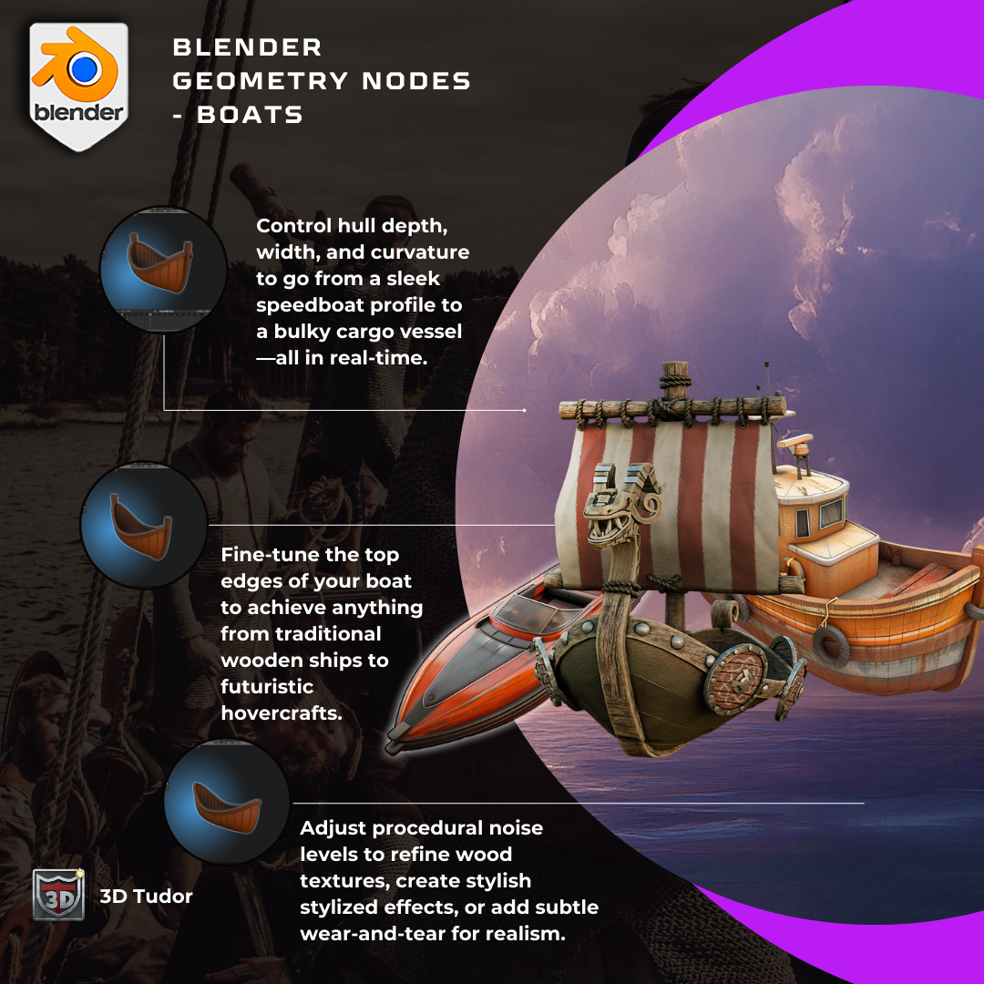
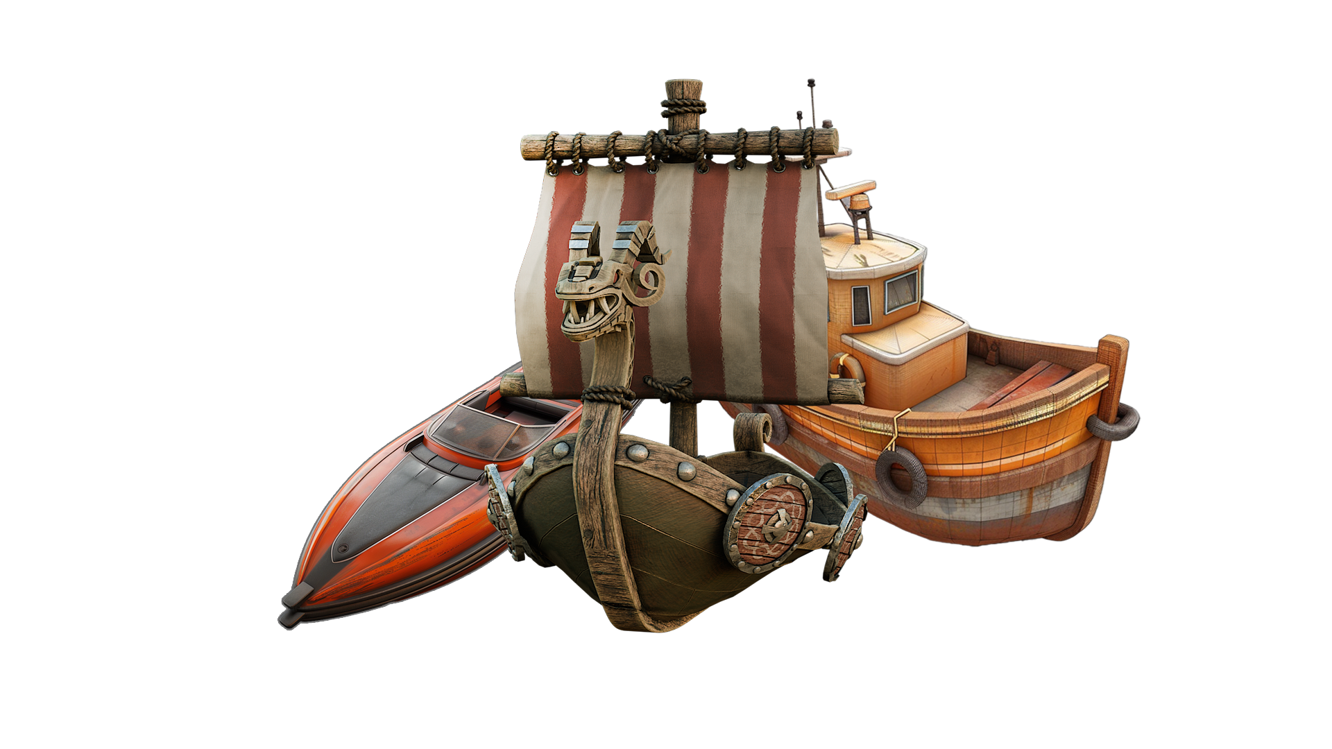
1. Geometry Node Overview: Hi, welcome to Blender
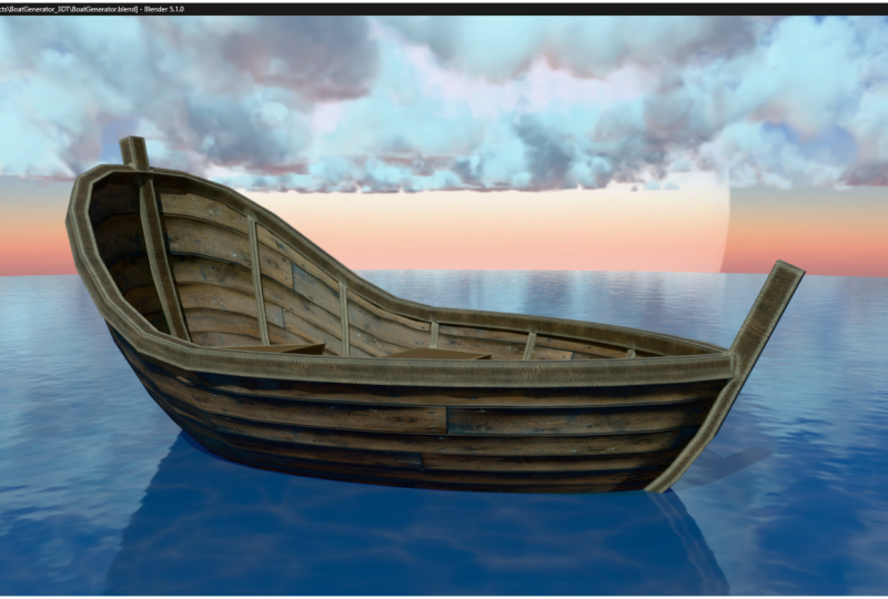
Geometer nodes boats course. In this lesson, I'll go through the final product which we'll
be making in this course. What parameters will it contain, and what are the
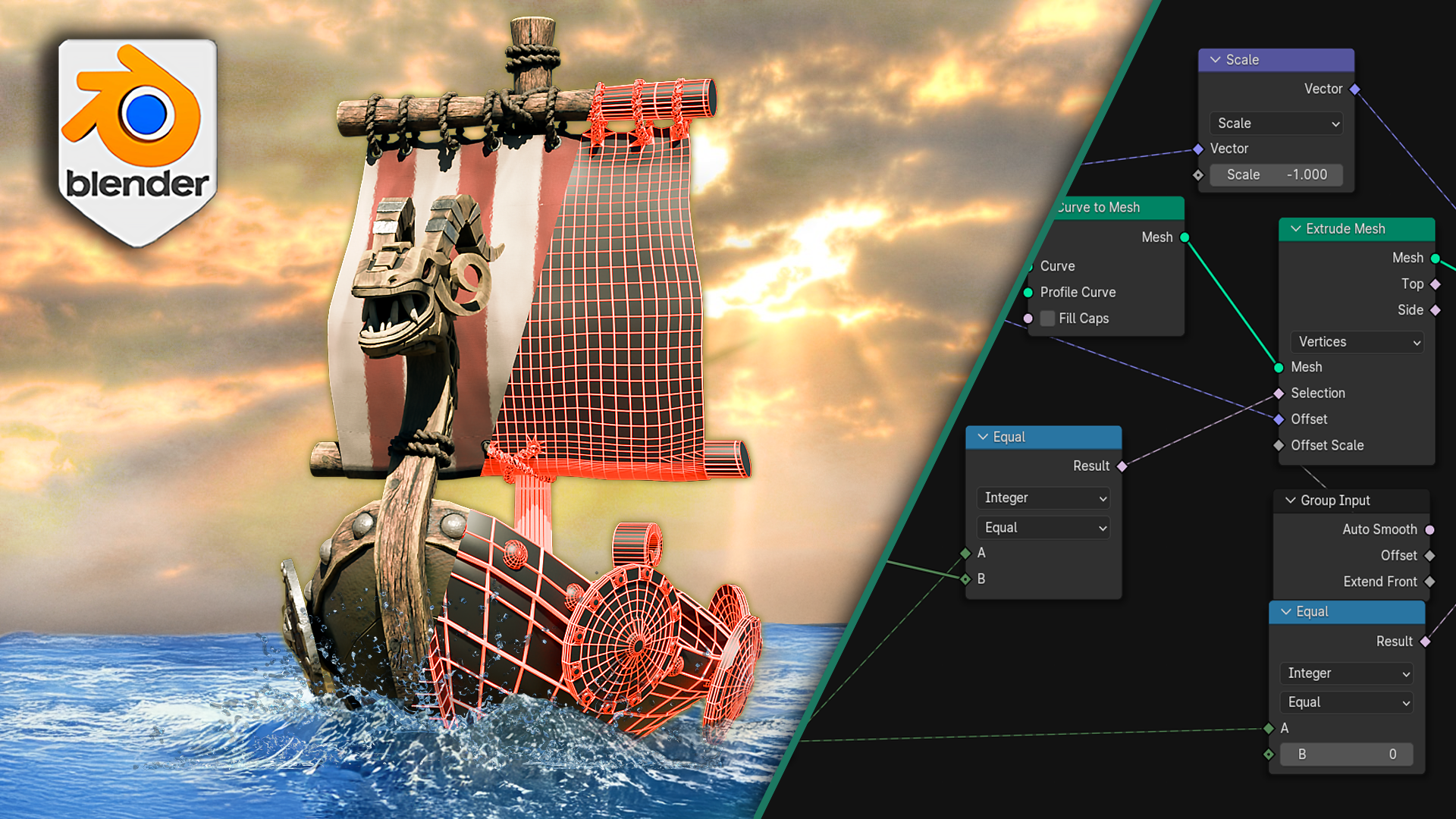
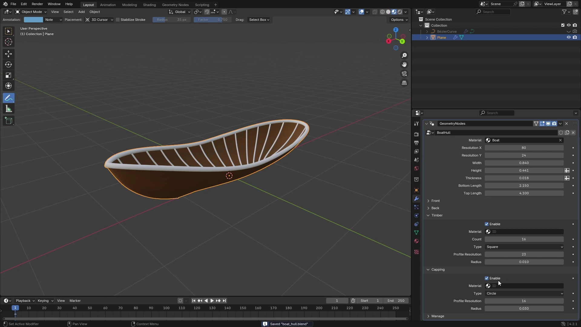
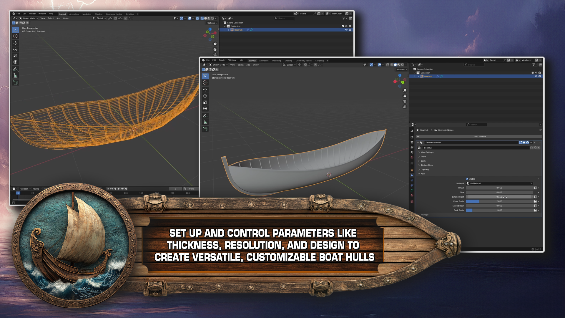
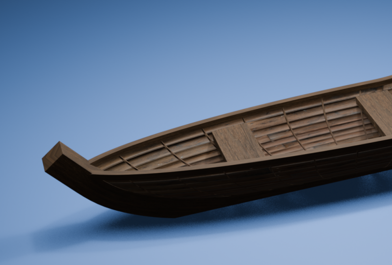
possibilities of this setup. So here I have a simple
example of my boat hull, and as you can see, is just
the one geometrone modifier, which contains all
of the parameters. So if we take a look at them, you can see that first
there is this panel of main settings in which we
can control many things. First, there's resolution. So let's actually switch to wireframe mode so we
can see it better. And if I decrease the
resolution in one axis, you can see that it controls
resolution on X axis, and then there is Y resolution, which controls
basically resolution on Z axis of the boat hull. Then there is material slot
and dimensions of the boat. We can control the height with and also length of the
top and bottom parts. So if we take a
look from the side, if I increase the bottom length, you can see that
we can basically control the shape from the side. And also how long
the overall boat is. Then there is thickness,
which is basically just a thickness of our hull. And now let's go
to the next panel. Here are two panels,
front and back. Each of them has a separate
control for height offset. So if I increase this one, we can see that
here at the front, we can control how high
the front part is. We can also control the type. We can set it to
square or round. And also how pointed
this front part is. Same thing can be controlled
for the back as well. And the last three panels are for three types of supports. First one is the timber, which if I disable, you can see that those are the ribs around along
the whole boat hull. For this, we can
set number of them, how many of them are there, and also their size or
basically the radius. And there's also option
for outside or inside, which controls if they are
also visible from outside. The second one is capping, which is basically the rim around the top part
of the boat hull. And this one only has the size, which is just radius. And the last one is keel which is a center support
between the front and back. So between the endpoints, if I enable and disable it, you can see which
part it actually is. And there's a little
bit more control. We can control the offset, which is basically the
offset from the boat hull. Then the size is the radius. We can extend the front part, as well as the back part, and we can also control their scales. So those are all the parameters
which we'll be able to control at the end of
this course in our setup. And in the next lesson, I'll go through a
little bit of theory about how this setup will
actually work inside.
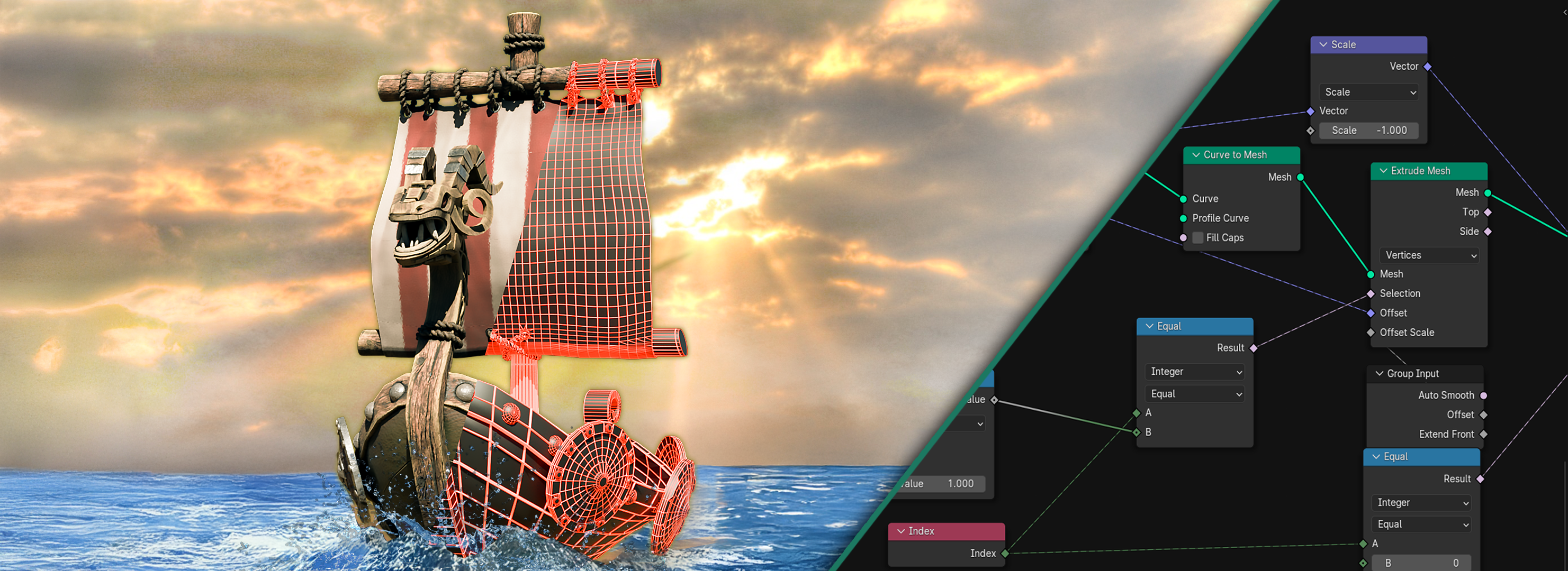
2. What is Lofting: Hello, and welcome back to
Blender Geometrn boots cars. In this lesson, we will
go through a little bit of theory of how the setup will actually work and
how we will achieve this really nice shape
of the boat hull, which looks very organic, and at first, it's not very clear how we can get this shape. So for this shape, we'll be
using a technique which is called loft or
lofting technique. And what it basically means if we take a look here
from the side. So how it works is that we
have a bunch of curves. So I'll draw some curves here. Let's say we have
these free curves, and these curves can
define some kind of shape. Those can be in freedi. Currently, they are just in tui, but let's say they
can be in fried and they also might look
something like this. We can have a one
curve down here. Then one curve here,
here, and here. So we can see that these curves basically define
the shape of this boat. And now when we have
bunch of these curves, we can connect them
together or we can create a plane along these to
create the final shape. So let's say these curves
have resolution of four. So each of them has four points. So I'll just put this in
here, something like this. Those points are evenly distributed. We have
something like this. Now, to create a
shape along these. So basically, we
would want to connect these together, these together. These and these. If you take a look
at this drawing, you can see that it's
actually a distorted grid. So we can say that we
have just a simple grid, which is just two
by three squares. So it looks something like this. And then we can
distort this grid or reposition these points to according points
of these curves. Let's say we can put this
point into this position, his neighbor will be
this one, and so on. This corner will be this one,
that's for the first curve. Then for the second curve, we'll take a second row of these, and this one will be this point, this one, this, and so on. And this bottom line will be distributed along
this bottom curve. And this should give us a final shape which
we are looking for. So if we take a look at
the example of the boat, you can see that these curves will probably have a much higher resolution than just the four. But let's say they have
a resolution of 20, and we have four curves. So what we need is
we need a grid which has 20 points in each row, and it has four of these rows. So we'll just create
four by 20 grid. And then we will align it or distort this grid so it
creates this kind of shape. And how we can actually create these curves if you
look from the top, you can see that first
starts at the center, and their end points are
still in this same line. So they are all on the X axis. But let's say those are
some kind of bezier curves. So their control points will
be somewhere like this, and they will be slowly getting more and more outwards
to make them more curvy. So we will be
creating some curves which will look
probably like this. The first one can be straight, then it can be
something like this, then this. And this. Those will be also
offsetted on the Z axis. So the first one
will be at the zero. The second one will
be slightly higher, the third more, and the
fourth the highest. And then if we connect
these together, this should give us this
nice bowed hull shape, which we are looking for. This technique can be used on many places, and
this is one of them. Also, if you search
for the history of building the
boats in the past, they used a similar technique which was also lofting or loft. So this is very useful
thing to learn, and it's also possible to create some modern shapes with
these, for example, for some buildings or some unusual items. O
3. Curve Generating Base: Hello, and welcome back to Bender Geometry
nodes boots cars. In this lesson, we will
actually start creating basic curves from which we
will later create a geometry, which will create our boat hull. For creating these curves, we'll be using the of technique which I described
in previous lesson, and we'll implement it
inside geometry odes. So first, let's
actually add object on which we will be
testing our setup. So you can just
add, for example, plane. It doesn't really matter. And now we can go
to Modifier Stop, add new modifier, select
Geometri nodes, and hit New. And we can rename this
geometry nodes setup to, for example, mode Hull. Now, if we switch to
geometry nodes stub, we can start working
on the setup. We won't be using the
original geometry so we can delete
this group input. And at first, I would like to add a few
perimeters which we'll be controlling from
the modifiers stub and those will be width, height, length of the top part, length of the bottom part, also resolution of this whole setup, and also front and
back pointiness. So we can hit N to bring
up this site menu. And I'll hit Plus button
to create a new input, which I'll call with, and we can set
default value to one, for example, and
minimum to zero. Then there will be height, which we can also default
to one and minimum to zero, bottom length and top length. I'll set the default value of bottom length two,
for example, three, and stop length will be four, and their minimum
can be also zero. And for now, we will also add
resolution on X and Y axis. So I'll add a new input. This will be actually integer, so we'll select type integer. I'll rename this to resolution X and duplicate this and edit
this to resolution on Y axis. And their default values
can be, for example, 32 for X axis and 16 for YXs. Now if we go back to
the modifier style, we can hower over our inputs and hit backckspace to reset
them to default values. All right. And now we can
start working on our curves. So if we take a
look at our inputs, we can say that from
the resolution, the boat will look, for example, we can use the side view. It will have curves,
something like this. And the resolution on Y is controls how many
of them are there. So if the resolution
would be four, there will be four
curves, and in our case, there will be 16 curves. The X resolution controls how dense or how many points
these curves have. So currently, all of these
curves will have 32 points. We will be generating these
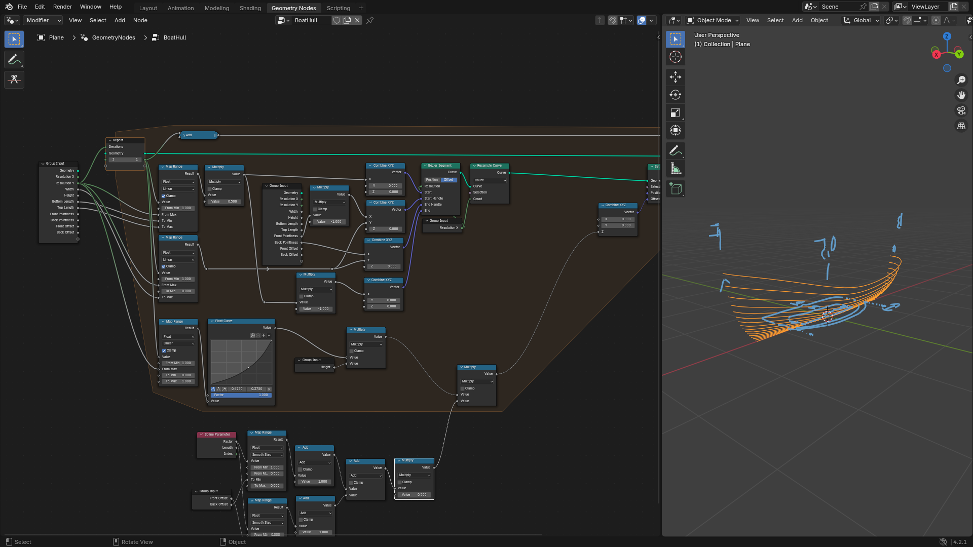
curves inside repeat zone so we can hit Shift A
and type repeat zone. This will bring up
our repeat zone, and we will be creating each curve in one iteration
of this repeat zone. So we can connect output
of our repeat zone to group output and set
up a few things. Number of iterations will be equal to resolution on Y axis, so we can bring up group input and plug
resolution Y to iterations. And how it will work
is that there will be a joint geometry node to which we will in
every iteration, at a new curve which will correspond to the
current iteration. To find out on which iteration
we are currently in, we can add a new variable
to this repeat zone, so we can select this
repeat zone, hit N, and here in the bar, we will select a node. And here in repeat items, we will also add a new input, which we will call,
for example, I, which is like iteration and
set sockets type to integer. And on every iteration, we will increase this I by one. So I'll add a meth node with addition and
add one to this. And we will plug this at soit to output of
this repeat zone, which always sends this I to the start of
this repeat zone, and then it will be
again increased by one. So currently, when our
resolution Y is 16, the I will go 0-15. The curves which we'll be
using will be Bziar curves. So for this, we can add
a new Bezier segment. And as you can see, this
BziR segment has few inputs. There is start end and
positions of handles. How it basically works
is that, for example, if we want draw a
curve like this, we will set endpoints. So start and end will
be those endpoints. And then there are
those handles, which you can imagine
as something like this. And those handles control the overall shape
of this BziR curve. So, for example, if we put this handle upwards,
something like this. And this in the same direction, it will create this kind
of shape of bezier curve. If those handles would
be to the other side, the bezier curve would also
lean to the other side. If we move these points
horizontally like this, we can actually control
the pointiness. So if we would move this
handle to the right, the besiar curve would be a bit more pointe in this side and then same on the right side. And with this, we'll be controlling the
pointiness of our boat. But first, let's
actually figure out the start and end points
of our besiar curves. If we take a look from the top, our curves will always
lay on the X axis. So the first curve will
look something like this. The second curve will
look something like this. Third one will be
like this and so on. So you can see
that the endpoints are always on the X axis, and we will only control the
X value of these positions. So let's add few combined
XYZ nodes so we can actually control individual
parts of these vectors. And when I is zero, the distance from the origin on the X axis will be basically bottom
length divided by two. Because if you take
a look at this, the first curve will have
length of bottom length. So BL, for example, and the top curve will
have length of top length, and the curves between
those two will be calculated depending
on their index between first and last curve. So for this, we can
use a map range. So let's add a map ranch and
we'll be using this I value, and we'll be remapping
it from zero to resolution Y minus one
because as I previously said, the I will go 0-15 or actually, we can just set the
first value of I to one, and now we can rememb this
from one to resolution on Y axis to zero to one. We don't want this zero to one, but we want to actually
control the R length. So let's actually
plug the length to these Min and max values, and this will just tell us how long the curve on
current index should be. So we can just use
this group input. You can hit Control H
to show all inputs, and we will remap
this eye socket or I variable from bottom
length to top length. And now if you would
use this result, this result will give us
length of each curve. So when I is one, that means that this map range will give us bottom length, and when I is 15 or 16, sorry, it will give
us the top length. And every I 1-16 will be remapped with
linear interpolation, and it will give us
the right length. To calculate positions of
these start and end points, you can see that
those are always half of the length
from the origin. So we can multiply this by 0.5 and plug this
value into X axis. The start, we can put the
start, for example, here. So this will be our start
and our end will be here. You can see that start is
on the positive side of Xxs that will be positive
length divided by two, and the end point
is on the negative. So we can just multiply
this value by negative one. And plug it into X axis. Now our start and endpoints should be calculated correctly, and if we plug this curve
into joint geometry, we should get some
kind of curves. You can see that
they are slightly distorted and that's
because there are some default values
for the handles, and if I set start
handle to zero, we will only get
a straight curve. You can see that it looks
like there is only one curve, but actually there are
quite a few curves. If we **** over this output, you'll see that there is 16
splines based on 32 points. That's because
currently each line has two control points, but we can't actually tell
the difference between them because they are all
laying on the x axis. The second thing
which we need to calculate are the
positions of the handles. So I'll create a space
here for the handles.
4. Curve Generating Hull Shape: Hello, and welcome to Blender
Geometry notes both scores. And now there are
two options how we can calculate positions
of these handlers. You can select
position or offset, and we'll be using offset because if you take a
look at the handles, it would be much more work to
calculate overall position of them than just
setting the offset. The offset is calculated from
the corresponding point. So the start handle, if we
input vector to start handle, it's offset from the start point and same for the endhandle. So we'll set this to offset, and now we'll be
calculating those vectors. So we can again at combine
XYZ for both of these inputs. And to calculate them, you can see that for now
we are just moving them on the Y axis depending on how wide the both should
be and current level. If I move this Y value, you can see that the
curves are bending. And what you can
also see that they are not starting at
the same positions, and that's because
we are interpolating their start points from
bottom line to top length. If we set this Y to one
and this also to one, you will see that we have
some kind of this shape, and we want to interplate again this Y value between
zero and width. So we'll again using MP wrench. We can duplicate this
and we'll be mapping I again from one to
resolution on Y axis. And now we just want
to interplay it between zero and
width of the bot. So we'll plug with to the
maximum of this map wrench. And this result value can be now plugged into
Y axis of these vectors. You can see that now we have nicely distributed curves which are all white depending
on their index. And if we play around
with the parameters, you can see that
if I change width, the boat gets fider we can also set bottom
length and top length. So if I decrease
the bottom length, you can see that the curves are getting more to the center, and for top length,
you can see that it's getting longer overall. All right, two more parameters
which we haven't used yet are the height and
the resolution on X xs. The resolution on X ces
will be pretty simple. We will plug this
resolution into this resolution input so we can set resolution of
each Bziar segment. So I'll bring up new group input and plug resolution X
to this resolution. We can also hide
this with Control H. Now we can control the
resolution of these curves. Also, you can control
the resolution Y axis, so you can see that if we
set just resolution to two, there are just two curves,
but as we increase it, the more and more
curves appear here. Now let's actually
use the height value. For this, the one thing we could do is just calculate
the height of current curve and just plug it into all of these Z axis values. But I think we can do it
a bit more elegantly. So let's add set position. And the thing we'll do is
we'll just offset our curves on Zaxs by calculated value. So let's add a combined
XYZ for this offset. Now we need to calculate the
Z position of each curve. For this, we will again use a
map range so you can select one of these map ranches
and hit Control Shift D to duplicate it with
connected inputs. But now we don't want to actually map it to
some kind of range, but we just want to
map it to zero to one, and we will use a float curve to actually control the
shape of our boat. So let's plug this map
ranch to float curve. In this float curve,
we will be able to change the shape of our boat. So for example, like
this, and then we will multiply it by the
height of the boat. So I'll duplicate
this group input and add a multiply node, which we will where we will multiply output of
this float curve with the height of the boat. If we now plug this result
into the Z coordinate, you will see that the
boat changed shape, and you can see from the side that the bottom
curve is at the bottom, and the top curve is at
the height of the boat. We can control this, so you
can set height of this boat. And also, if you change
this float curve, you can see that we are
changing the shape of the boat. And this is really
helpful because you can really control the
shape of overall boat hull. Now the last two
parameters which I talked about are the pointiness of
the front and back parts. So let's actually add
those two parameters. I'll go to group input
and add a new input, which I'll call front pointiness and duplicate this
to back pointiness. And now if we take a
look at our setup, the think we will be changing our positions of
our curve handles. If we look from the
top, you can see that our curves have some kind of control points
which are like this. Currently. They are only
changing position on Y axis. But if we change them on X axis, the shape of the boat at
front and back will change. So in these two
combined XYZ nodes, if we change the X value, you can see that as I'm
changing this X value, the right side is more pointy. And if I increase it to
something larger than zero, it gets a little bit weird. So I think we'll stick
to negative values. And you can see that if I just set it to something
like minus three, and I can also set
minus three sorry, positive three to the front. The boat really changes the shape or you can get many different shapes
with these values. So let's bring up
these two values. I'll add a new group input, and I'll also create
a space for these. It's getting a little crowded, but I think we'll
handle it. All right. The thing we'll be controlling
are those X values. And those inputs
will be just numbers from zero to something
which you'll set here. So we'll set their
minimum values to zero. And we can say that
the front will be where the X x is positive. And here we need to make
the value negative. So we'll multiply the
front pointiness by negative one to make it negative
and plug it into X axis. And the back pointiness can be connected right
into this X axis. If we now change these values, you can see that
we can control how pointed the boat
on each side is. One last thing which we can also add is height offset of
end and start points. So with this, we would achieve some
kind of shape like this. If we increase the start
offset or front offset, we would get shape like this. And if we increase
the back off set, we can get shape like this, which can also be
handy in some cases. So let's add this as well. We'll first add new parameters, front and height offset. So let's add front
offset and back offset. And what these values will
do is they will be changing this height offset
which we are plugging into this set position
by some kind of value. If we take a look from the side, here we have front
and here we have B. And the curve have some kind of factor which here is
zero and here is one. And what we will do is we
will map this factor 0-0 0.5, which is in the middle to back offset to value between
back offset and zero. And with this value, we will be changing
this Y or Z offset. So let's add a spline
perimeter node which will give us
this factor 0-1. And we will map this factor
with map range between 0.5 to back off set to zero. So here at the start, we should get a back offset, and here in the middle,
we will get zero. And now with this value, because you'll be multiplying
this by this value, we don't want to
multiply it by zero, but we want to multiply it by one, so we'll add one to this. So basically, this MP
branch will give us value 1-1 plus back offset. And if we multiply
these two values together and plug it into Z
axis, nothing will change. But if we increase
the back offset, you can see that
we get this result which elevates the back or okay. In our case, it's front, but we'll just swap this so we can just set
it from 0.5 to one. And the reason why it's not
really working correctly is that even though
we set resolution of this Bziar segment
to our X resolution, this curve still has only
two points and one spine. So we'll resample this curve
to this resolution on X. And now you can see that the elevation is
a bit more clear. Now because we are currently it's back offset and
it's contrnk front, we will switch this
to 0.5 to one. Or actually, it should be one to 0.5 because when it's one, we want this to be back
offset and when it's 0.5, in the middle, we
want this to be zero. And the shape of this
elevation is not really nice, so we can switch this linear to something like smooth step, and now it's much
nicer transition. If we now change
the back offset, you can see that we can
change this offset, and we will do the same
thing for the front. So let's hit Control Shiv D, and we'll be mapping
this 0-0 0.5 to front offset to zero,
so something like this. Now if we again add one to this, and we will add this value to
one previously calculated. Let's add again and
plug this here. Now you can see that we are
controlling the front of set and the offset separately. The problem we are currently facing is that if we
set height to one, you can see that it
actually has height of two, and that's because those
values are at minimum one. So we can just fix this by multiplying this sum
of these by 0.5, and now the height should correspond to overall
height of the boat.
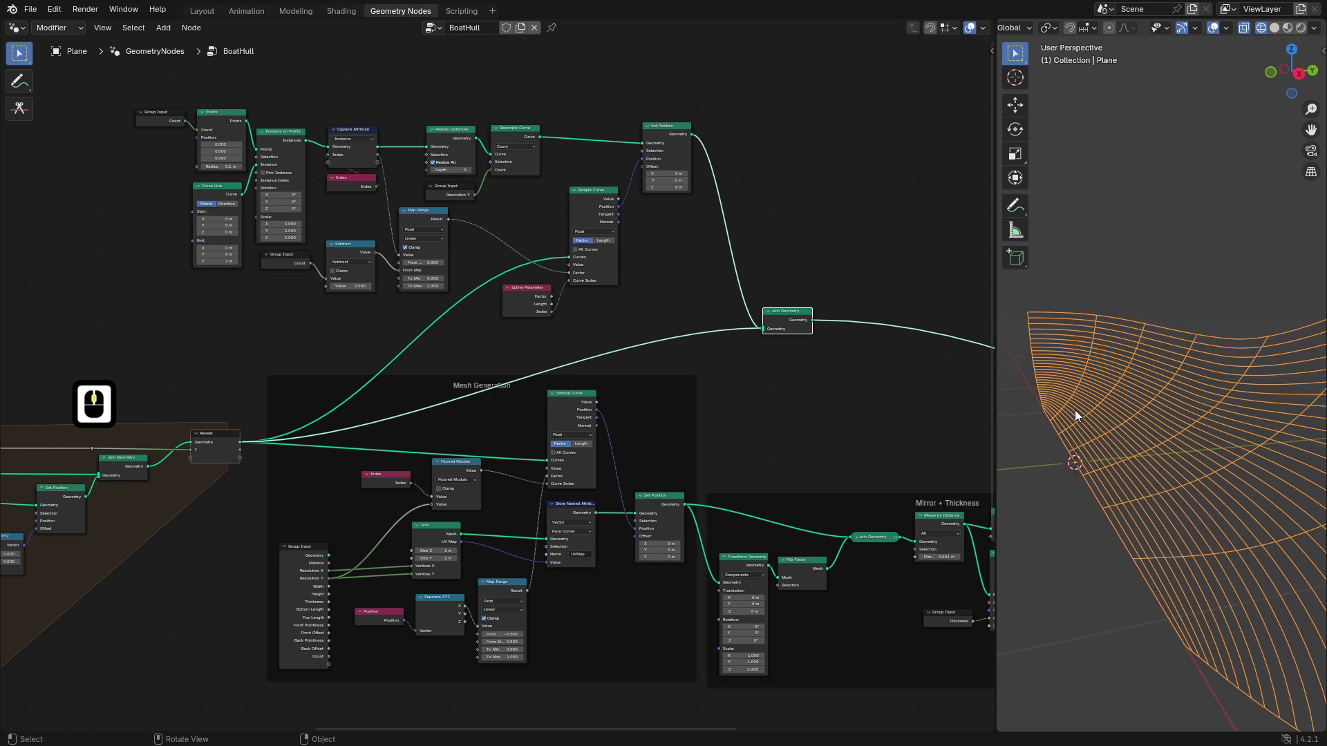
5. Mesh Generating Hull Base: Hi. Welcome back to Blender
Geometro notes boat scores. In this lesson, we'll create an actual geometry from the curves which we made
in previous lesson. We will also add basic
material and some UV and wrapping so we can play around with the overall
look of our boat. As you can see, currently, we have just a bunch of curves, but now we'll create
actual geometry, which we can render out
and play around with. So let's go into Geometro
nodes workspace. And as I mentioned
in previous lessons, we'll use a grid mesh which we will align
to these curves, and this will generate
our final shape. So if we take a
look at our curves, you can see that their count is controlled by this
resolution on Y axis, and their resolution
is controlled by the resolution on X axis. So if I set resolution on X to 32 and resolution on Y to eight, for example, you can see
that we have eight curves and each of them has 32 points. So first, let's actually
add a grid mesh. And this grid has four inputs, size one on X and Y axis and number of vertices
on X and Y axis. For now, we don't care about
the size because we'll be changing the positions of the points with
set position node, but number of vertices is
very important for us. So let's add group input. And the important thing is that number of vertices
must correspond to number of points
generated by these curves. So on X axis, we will use this
resolution on X axis, and for number of
vertices on Y axis, we will use
resolution on Y axis. If we output this grid mesh
and look into wireframe mode, you can see that this has
eight rows and 32 columns. We'll be changing
positions of these points, so let's add set position. And now we can change
positions of them. And for figuring out
positions of these points, we'll be sampling these curves which we made in
previous lesson. So let's add sample curve node. And we'll be inputting some factor and curve
indexes into this node. And this will give
us a position, which we will then plug
into set position, and this will deform our grid
to the shape of the bot. So first, let's actually
figure out how we will get the index of curve
for each point. If I add a index
node and view index, you can see that our grid is indexed basically at here
at the bottom left is zero, and then it's
increasing on Y axis. So here it's seven,
here it's eight to 15, then it's 16 to 23, 24 to 31, and so on. Currently, we have
eight curves here. So what we need to
calculate is that this first row must
have index of zero. The second one will be one, two, all the way to seven, I think, three, four,
five, six, seven, and we need to calculate it somehow from indexes
of the points. You can see that the first
column is all right, but the rest of them are much higher than
we actually need. To get the right index, we can use math node. So let's add a math node, and let's set the
operation to module. So I'll add float modulo, and the number which
we'll be plugging here should be number of
curves which we have. So I think that's on
the y axis, right? So we'll plug resolution
on Y axis to this value. And now if we view this, you can see that the
indexes are right. Why this works is
that modulo gives us the remainder after division. So if we divide eight by eight, which is the resolution,
we get zero. If we divide 11 by eight, the remainder is
three, for example, 49 which is here, divided by eight is six,
and remainder is one. So it always gives us the right index
using the remainder. And now when we have
this calculated, we can plug this value
into the curve index. If I now view the output
of the set position, you can see that now we
have this line here, and if I change the factor, you can see that it's sweeping along the curves which we made. That's because all of these
points have same factor. So if this is set to zero, all of these points are sampled at the start of the curves. And if we increase this to one, you can see that
they are sampled at the end of the curves. Now let's actually
figure out the factor. So for the factor, we'll be using a slightly
different technique. And the way we will do this is if we take a
look at our grid, we can say that, for example, we want this column to has factor zero and this
column has factor one, and the rest of them will be calculated depending on
their position on X axis. So we'll do a linear
interpolation. So for example, this in
the middle will be 0.5. This will be 025, 075, and so on. So to get this, we
can get the position, and we'll be using
position on X axis. So let's add separate XYZ, and we'll be using
this value here. And we'll be basically
remapping this position from negative 0.5 to 0.5, because currently our
grid is 1 meter wide. This is one, and that's why this on the
left has negative 0.5, and this on the right
has positive 0.5, so we'll remap this. So let's add a map range, and we'll be remapping
this X value between negative 0.5
to 0.5 to zero to one. If we view the result of this, you can see that these
on the left are black, so that means it's zero, and these on the right are one, so that means sorry,
they are white. So that means it's one. And now the final thing is just to
plug this into the factor. And if we now view
this set position, you can see that
the grid is nicely aligned to the curves
which we created. You can see that if I increase the resolution and we
can switch to wireframe, the resolution is
changing dynamically, and we can also set this one. And you can see that the
boat has really nice shape. Everything should
work as before, so we can change
the bottom length, the top length, and
also the pointiness and also the offsets. So we can increase
these, for example, and you can see that
the grid is nicely aligning to these curves.
6. Mesh Generating Hull Tweaking: Hello, and welcome to Blender
Geometry notes both cars. As you can see, this still
doesn't look like a boat, and that's because this
is just the half of it. So we will mirror
this on X xs to get the other half because
the boat hull is symmetrical, so we can just use this
one and just flip it. And for that, we can just
use a transform geometry. We'll plug output
of the set position to this transform geometry. And now if we scale
this on Y xs, you can see that it's changing or it's basically mirroring, and if we set it to
negative one on Y axis, we should get the mirrored
version of the hull. And if we join these, you can use Control
shift right click and the drag between
the set position and transform
geometry like this. You can see that this generates
the overall boat hull. One problem which
is here is that if we enable the face orientation, you can see that half
of these are wrongly oriented because those should be blue because they
are pointing outwards, but they are red.
So let's fix that. We can fix this by using flip faces on this
mirrored version, and now the normals
are consistent. And also because we
mirror this part, those points are duplicated because point from one
half and second half, so we need to merge
these through that, we can just add merge
by distance node, which will connect
these points together. We can't see any difference, but if we hover over
this trineometry, you can see there
is 5,280 vertices. And if we hover over
this, there's only 5,136. So that's 150 less vertices, which means they
connected together. All right. Now let's actually
add thickness to our boat. So for this, we'll be
using extrude mesh. To which we'll
plug our geometry. And by default, you can see that all the faces
extrude individually. So we will disable
this individual, and this will look a bit better. I will decrease
the offset because this is still pretty high. And if we set it
to, for example, 0.05 and check this, you can see that the boat now
has some thickness to it, and I will also
disable the normals. And now because we
are extruding this, we are losing the original mesh that's here and it's extruding. So you can see if I said
this to some higher numbers, you can see that there is a hole and those faces aren't
filled anymore. So we need to join this
with the original geometry. So let's join geometry, and now this looks a bit better. I will decrease this
peck. But again, we need to check if
the normals are okay. So I will enable
face orientation, and you can see that the faces inside are wrongly oriented. So I'll again use these flip
faces to fix this problem. And now all of the faces
which you see should be blue, which means they are pointing
the right direction. Now there is probably
the same problem which we faced a
few seconds ago, and it was that we have some
duplicated points here. And in this case, those are
probably somewhere here. Where the original and
the extruded part is. And because we are
draining them, those points will overlap. So to fix that again, we
will add merge by distance. This should connect those
two parts together. To control the thickness, let's actually add a
parameter for this. So hit to bring
up the side menu, and we will add new input
and call it thickness. I'll set default value to
0.05 at minimum to zero, and I'll plug the thickness
into this offset like this. Now our basic hull is
basically ready to use. But one thing you can see
is that we can still see the individual faces here
and it's not really smooth. So let's actually
smooth this out. For this, we'll use
setshade smooth. Now this also changes
those rims here, which we want to stay sharp. So if we use the edge angle, which gives us the
angle of the faces, which one edge connects. So you can see if we view this
and the disable the text, you can see that we
have much higher values here at the rims or
here in the middle, where we want this to be sharp. And here, where we
want this smooth, those values are close to zero. So we'll use this
unsigned angle, and we will only
smooth faces where the angle is less
than some value. So let's plug this
result into selection. And now as we increase this, you can see that nicely smooths only the parts
where it's needed. The best results are usually with something
called 30 degrees. And because this is
input in radiance, we can use a meth node, which also contains
this 2 radians thing, which where you input degrees, so we'll input 30, and this will give us radiance, so we can plug this
into the B socit and this should give us
relatively nice results. You can see that it's
still sharp here, so we'll increase this
until it's smooth. So something around
40 looks fine. Alright, now the last part is
actually creating UV maps. So the nice thing about grid mesh is that it also
gives us the UV map, and we can use this UV
map for later usage. So we will store
it in attribute. So I'll add Sornamed attribute, set this to vector, and we'll store this
for face corner, plug this UV map into the
value and we can call it, for example, UV map. And now here at the end, if we view this attribute, you can see that we
have pretty nice UVs which we can then
use in material. So let's actually create
input for the material. I'll add a new input,
call it material, set type to material,
and here at the end, we will use set
materials to actually assign the value from
the group input. And now, if we create
a very basic material, I'll call it both
and assign it here. We can go to shading workspace. And if I add a
attribute input name, which we used for the UV map
and switch to render to you, you can see that we can view this UV map inside the shader. And this can be used as UI maps, for example, for noise texture, which you can use with combinations of
different textures to get some interesting results. All right. One last thing which
we should be doing inside our geometry tree is grouping those parts where
we do different things. So here at the start, we did the basic deforming of the curves or
generating the mesh. So let's select all
these hit Control J and rename this with F
two to mesh generation. The next part creates the overall or is basically the next part does the
mirroring and extruding. So Let's again, join these together and call this mirror plus extrude
or maybe thickness. And the last part, this part, grades the shade smoothing, so let's call this shade
smooth and we can leave this material with pot
frame because that's pretty self explaining
what it does.
7. Creating Supports: Hi, welcome to Blender
Geomet boat scores. In this lesson, we will start
working on the supports, which means we'll be
working on timber, which are the supports from
the bottom center to top. Then on the capping, which are supports along the
top of the boat hull. And then the keel, which
is a center support going across whole boat
from front to back. All of those supports will have a very similar structure
and similar parameters, which we'll be able to control. So the first thing we'll be
working on is node group, which will generate supports along a curve which we
input to this node group, and we'll be able to control parameters such as
material thickness, shape, and offset with rotation. Then when we finish
this node group, we'll just generate three
different groups of curves. So one of the group will be
timbers going like this, and there will be capping along the top of the boat
and then the keel. So for now, we can
hide our boat. So I'll just hide this object, and I'll add a new
object on which we'll be testing our support node group. So I'll add a new curve. And we can, for example, use
this default Bezier curve. I'll create a new modifier, set it to geometri
nodes, hit new, and I'll call it curve to support because this node group will take a curve and
create support from it, and now we can go to
Geometri workspace and start working
on the node group. So first, let's add
few parameters, which will be controlling
this node group. So you can hit N to bring up
this side bar, and first, I'll add a bullying
input which will control if this support
is enabled or disabled. This is not very helpful for this particular node group
or just using it separately. But later when we'll be
using it in our boat hull, we can just check
these checkboxes if we want to disable or
enable this support. So we can add a bullying
input and call it Enable. Then we will also
want a material. So let's add a new
input for material. The next one will be radius. That will be controlling the
thickness of the support. We can for now set
also default value to something like 0.1
and minimum to zero. And the last input
will be the shape. So for the shape,
we'll be picking between round and square. So for this, I'll
add a menu input, which we will later then
connect to menu switch node. So we can just call this type, and now we can start
working on the setup. So first, we want to convert
this curve to a mesh. So for this, we'll be
using curve to mesh node. And as a profile, we'll be
using circle or square. So let's add both of those. So I'll add a curve
circle and also square. And we will be
picking between these two with menu switch nodes. So let's add Menu switch, and we can connect
the curve circle to this A input and this
square to B input. And output of this will be
going into profile curve. Now you can see
that it's set to A, so that's why it's circle. But if we switch it to B, you can see that it's square. We don't want these
to be called A or B. We want those to be
circle or square, so you can hit N. And
here we pick node. And in this part, we can
rename these inputs, so I'll rename the first one to circle and the second
one to square. Now, if we connect
the type socket into the input of Menu switch, you will see that now if I go to Modifier step here in type, we can select between
circle and square. Currently, those profiles have
their default dimensions, and we want to be
able to control these with this radius input. So for the circle, we can just plug
radios directly into the radius socket
and for the square because radius is basically
half of the size, so we will just
multiply this by two. And plug it into width
and height of the square. Now if we go back to modifier stub and set
radius this default value, you can see that now this is set to square and we can
control the size of it, and we can switch it to circle
and control it as well. As you can see, both of the
profiles are shade smooth. So for the circle, this
looks pretty okay, but for the square, we want
it to have sharp edges, so we'll fix this by
changing the shade smooth so in our boat setup, we used set shade smooth with
combination of edge angle. And depending on the edge angle, we would shade it or not. But instead of this,
we can actually use existing
modifier in blender, which is smooth by angle. So if you search for
smooth by angle, you should get this node. If not, you should be able to use the same technique
as for the boat. But for now, we can try
using this node group, and you can see that we
can just set angle here, and the furti is pretty okay. So we can Use Ferdi you can see that
now if we switch between circle and square, the circle is nicely smooth, but the square has
nice sharp edges. We probably also want
to fill the caps so you can check this check
box at the curve mesh, and now the ends
are filled as well. And now we can move on to next perimeters which
we want to use, and those are the material, and we will also be adding
the offset and rotation. So for the material,
we can just use set material and plug our material from group
input to this socket. But we would also like
to at the UV map. So let's actually
create UV maps, which we can then
use in our material. So when creating UV map
for curve two mesh node, we usually want to
use two coordinates. One will be X and one Y, and the X value can
be basically in this direction around
the center curve, and the Y value can
be along this curve. So to get the X value, we can just use a factor
of this profile curve. So let's move this a little bit. Now if we use the
spine perimeter, we can actually get this factor. So if we take a look at these, and we can see this much, but you can see that the square has zero here
and one is around here. So this should create a nice Us. And if we switch this to circle we should see
this even nicely. You can see that it's going
from zero around to one. So we want to
capture this value, so let's capture attribute, and we'll be
capturing the factor. And for the second, the Y axis, we capture the length
on the original curve. So let's duplicate this
scapture attribute, and we can use this length. You can also use vector, but if you change
length of the curves, it would stretch the textures
which is not real nice, so it's better to use
length because it doesn't change when the curve
gets longer or shorter. So now, when these two
attributes are captured, we can use stor named attribute. We'll be storing vector
because that's a UV map. We'll call it UV map. And now we just need
to create a vector from these two values so
we can add Combine XYZ, and we will plug this factor to X and the second factor to Y and the output vector to UIMA. Now if we view these values, you can see that we have
a pretty nice UV maps which we can later
use in our shader. All right, so those are almost all the perimeters which you want to be able to control, but there are two last things
which you want to add, and those are the offset
and the rotation. So let's hit N and
add two more inputs. One of them will be offset, and the second one
will be rotation. For the rotation, we
can set sub type to angle because this
will be in degrees, usually, and we can
leave offset as it is. The offset input will be
basically controlling the offset of the
generated support in the direction of normals. We'll be using this when
creating the keel because we might want to be the keel inside the boat or
outside the boat. So we'll use this offset to
tweak this in this case, and we might also want this to use when creating the timber or ribs from bottom sender
to top because we also, in some cases, want this to be outside and sometimes inside. So let's add a set position because we will be just
offsetting our curve, and we'll use a normal, which will be then scaled with vector math and we will
scale it by this offset. Now if we plug this
result into offset, we should be able to control
the curve and it's offset. You can see that if I change it, that the normals are like
this in these directions, so it's moving along them. The second input is rotation, so we'll be just
using this to change the tilt of the curve, so you can just add
a set curve tilt and we will plug this
rotation into this tilt. This isn't very helpful
when this is set to circle, but if we set it to square, we can rotate this support to get the result
we are looking for. Ast parameter, which we didn't use is this
enable disable, so this will be pretty simple. Let's just add a switch node
to the end of our setup. And the input for this switch will be the enable parameter. And if the enable is true, we want to output our support, but if it's false, we don't
want to output anything. So this is how the
switch will look like. And now if we enable this, we can see the support, and if we disable it, we
can see anything.
8. Adding Timber Borders: Hello, and welcome back to
Blender Geometrn boots cars. In this lesson, we'll
start working on the first type of the
supports, which is the timber. If we take a look
at our boat hull, so I'll hide the setup
which you made in previous lesson and
unhide the boat hull, the timber are
basically the ribs going from the bottom to top, so it will look
something like this. To start off, we'll be
generating those curves which are going from
the bottom to top, and we'll be able to control
their count and all of the parameters which we added to the setup which we
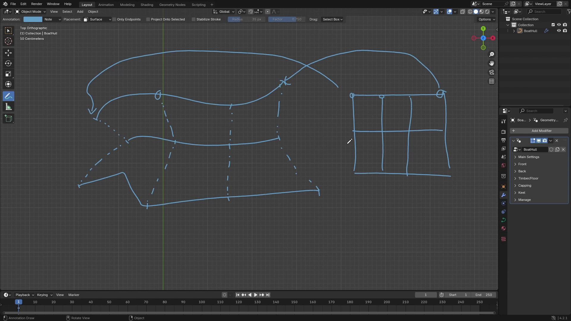
made in previous lesson. So let's go into geometry nodes and to make this setup
a little bit cleaner, we will start using
the panels because we are creating more
and more parameters, and it gets a bit more
complicated if you don't have them grouped
into some panels. So let's add a few panels. First, we can group these parameters for front
pointiness and front of set. And the second group can be back pointeness
and back off set. So I'll add a new panel
and just call it front, and I'll move front pointiness and front of set
into this panel. And I'll add second panel, which will be back and I'll add back pointiness and
back offset into this metal. I'll also move thickness
after the height. And now in modifier stuff, we can just hide and
unhide these groups. For the timber, we will
also create a panel. So let's add a third panel, which we will call timber, and I'll move it to the
end of the circuits. And let's also start
with some perimeters. So I'll add a
perimeter for count, so it will be integer and
we can set it to count. And the default value
can be, for example, eight minimum zero, and we
can leave maximum as it is. I'll also receive this value
here in modifier stop, and now we can start working
on generating the curves. The curves will be
generated using these curves which we
made for the boat hull. And the way we will do it
is, for example, car play, we want to create eight
of these timbers, so we will add eight curves. And each of them will be
assigned to one of the factors. So this first curve will
have factor of zero. The last one will
be factor of one. The second one will be
something like 0.125, I think, something like that. And the way this
will work is that the first curve
which has factor of zero will look at all of these curves and their
positions at the factor zero, and it will align itself
along these points. Now, for example, there would
be one curve which has 0.5. So it would take a look
at all of these curves at the factor 0.5 and also align
itself along these curves. So this is the basic idea
of how this will work. And now let's try to do
this using geometry rods. So first, let's generate bunch of curves which
we'll be using. So for this, I like to create points and then
instance curves on them. So the number of points will
be the number of curves. So I can bring a group input and plug count into this count. Deposition doesn't
really matter, and then we will add
instance on points. And as instance, we
will use a curve line. For the curve line,
it also doesn't really matter what are the start and end points
because we will be resampling these curves and
also repositioning them. So it really doesn't matter. After creating these curves, we want to realize
them because we'll be working with the
points themselves. So let's use realize instances. And now, if we take a
look at this geometry, you can see that this
is just one line. But if we **** over this, you can see that it's eight
splines from 16 points. If we take a look
at these curves, we want each curve to have as many points as
there are these curves. And because number
of these curves is controlled by the
resolution on Y axis, we will resample each curve. So it has resolution on
Y axis number of points. So you can just
plug it like this. And now all of these
curves should have enough points to
create the timber. You can see that there
are eight splines made from 264 points, and that's looking much
better than just 16 points. And now let's actually align these curves to
corresponding factors. So for this, we will be
using a sample curve. So let's add a
sample curve node, and we will be
sampling these curves. So let's plug these
curves into the curves. And we'll be changing
positions of these curves. So let's add a set position, and we'll use this position
as the resulting position. Now we need to pick
the right factor and we curve index to
generate these timbers. And the first thing we
can do is the factor. So for the factor, we
can basically take index of our point or our curve, which is currently 0-7 because there are eight of
them, so it's zero to seven. We can take this index and map
it or map it to range 0-1. So here before realizing
the instances, we'll capture attribute, and we will be capturing
index of instance. So you need to switch
this to instance, and we will be
capturing its index. Now after this, we'll take this captured attribute
and use Map range. And we will remap this from
zero to count minus one. So we'll subtract one from this count and plug
it into maximum. And the range it will
output is the range 0-1. So now this result
should give us the right factor and we can
plug this into the factor. To check if this is
working correctly, we can see or we can
view the points of these curves by using
curve to points node. So let's add curve to
points. Like this. The important thing
is to switch this to evaluate it so it
doesn't change the points. And you can see that if I
change the curve index, that those eight
points are going from the top to the bottom, sorry, from the bottom to
top of these curves, and there are eight of them. And now we need to set the right curve index for
each of these points. To do this, we can just take the index of the point
inside the curve. So for this, we can
use spline perimeter, and this index doesn't give
us the index of the curve, but it gives us index of
the point in the curve. So if we plug this
two curve index, you can see that it
creates the nice timber. How it works is that the
point with index zero, samplus the first
curve, index of one, samplus second curve, and so on, and it creates this nice effect. If we combine these with those
curves just to see this, I'll just add join geometry
and join these two together. Now you can see that
we have nice timbers or nice curves going
from the bottom to top. The nice thing is
that we can also control the spread of these, so you can set their minimum and their
maximum if you like to. But I will leave these
0-1 to make it easier. If we now play around
with the count, you should see that it's
all working nicely. And we can now use
the setup which we made in previous lesson to create the actual supports
from these curves. So let's take our curves, and I'll add curve to supports. Group node, and we'll
plug our curves to this node group and
output this node group. We will enable this and also
set it to circle for now. And now you can see that we have a nice supports generated
from these curves. One thing which is missing here is the resolution
of the circle. So let's quickly hop into
the Snd group and fix this. So with this selected, you can hit tab to go
into the Snd group, and we will add a new input, which I'll call resolution. The type will be integer and
the default value can be, for example, 16 and
minimum to three. And with this resolution, we will be controlling
resolution of the square circle. Now, if we atup,
we can go back to our original load group, and we can control the
resolution of these supports. Can also see that if I
switch it to squares, it's all working nicely. And the only issue is that the offset doesn't really work, so let's fix this. To fix this, we need to set right normals for these curves. So let's add a set curve normal and change
the type to three. With this option, we can set the normal of each point of
the curve as we want. So now if this is set to Z
equals to one and XY zero, that means that all of
normals are pointing upwards, and if we change offset, it's just going up and down. But in our case, if we
take a look at our curves, we want these to be offsetting
in some kind of this way. And to achieve these normals, we can use a double
cross product trick, which I'll try to explain. So currently, we only
have a curve tangent, which is a vector,
which is pointing in the direction of the curve. And if we do cross
product with Z axis, so Zaxs something like this, and cross product
gives us vector which is perpendicular to
both of these vectors. So we will get
something like this. So if we do this cross product
on all of these curves, we will get vectors
pointing like this. And now, if we take these vectors and the
original curve tangents, we should get vectors which are pointing in the direction
which we are looking for. So let's actually try this. We'll get a curve tangent and use a cross product with
001, which is the Z axis. Now it's better to
normalize this vector. So let's add normalize, which will set the length
of this vector to one. And now let's again,
use cross product, so I'll duplicate
this with Shift, and first vector will
be the one calculated, and the second one will
be the original tangent. Now if we plug this
result into this normal and look at the supports, you can see that
now the supports are offsetting much better, and I think this should
be working correctly. So to finish this part, we'll just select
all of these notes, hit Control J, and
rename it to Timber. And we also want to be able to control all of
these parameters. So let's add group input. And to make this a
little bit quicker, we can just take this
unconnected socket and connect it to
all of these inputs. So we'll be using those
first five inputs, and the last two, which is offset
and rotation will be used later if needed. So now if I plug this
last socket into these, you can see that it creates a new input and set
its right name. So that's pretty useful. And now we have these
new five inputs here. And now we just need to move
them to the right panel. So those are these five inputs. So I'll just move them
into timber panel. I'll also rename resolution
to profile resolution. And now we can hide a
new sockets with Control H. And if we go
to Modifier Step, you can see that we can enable
and disable our timber. We can set a material for it, change if we want
it to be square or circle and also
change its radius. Now to combine it with
our original boat hull, we also want to mirror
this and to mirror this we will just take these vectors or take these curves before
setting their normals, and we will just mirror them. So let's add transform geometry, plug this into the
transform geometry, and we will scale these on
the Y axis to negative one. And as you can see, there
will be duplicated curves. Those are this one and this one. And to get rid of them, we can basically just
join these together with join geometry and then
merge by distance. Because we can do merge
by distance on curves, we will first
convert it to mesh. So let's add curve to mesh node. Then merge by distance, and then we will use
again, math to curve. Now, if we take a
look at our curve to support and play around
with the offset, it should still be
working correctly. And to finish this,
let's just add join geometry at the end of
our setup and we will join our timber and our original
mode hull and now you can see that we have those
nice ribs around our bod hull.
9. Capping the Boat Hull: Hi. Welcome back to Blender
Geometry notes Boat Scores. In this lesson, we will continue
working on the supports. And the next supportype on which we'll be working
on is the capping. The capping should be relatively
simple because that's just the supports along
the top of the boat. And if we take a
look at the curves which are generating
shape of our boat. So those curves, you can see
that we will just need to separate the top curve from these curves and then just mirror it and use
it as a support. So to separate it, there are
probably a bunch of ways, but we'll just use the index of the curve and
just pick the last one. So I'll take these
curves and I'll use separate geometry
with which you can just split geometry into
two parts with selection. We'll be splitting splines, so I'll set type to spine. And now to pick one
with the last index, we will just use the
index value and when it's equal to number of
curves minus one, right? This is controlled by the
resolution on Y axis. So there are 24 splines and the bottom one
has index of zero, and the top one is 23. So we will take resolution
on Y axis and subtract one. So this should give us 23, and where the index
is equal to 23, we want to separate this one. Now, if we view the selection, you can see that we only
picked the last curve and the inverted selection are the other curves which
we won't be using. Now, all we need to do
is just to mirror it, so it's on both
sides of the both. And then we will just also
merge these two curves together and use our premade node group
to create the profile. So let's add a
transform geometry, and we will transform this by scaling it on Y
axis two minus one. So this should flip the
curve to the other side. Now we will join
these two curves together with join geometry. And now those endpoints
are duplicated here, so we need to use
merge by distance. And because those arcurves which can't use
merge by distance, we first need to convert
these curves to mesh. So let's add curve to mesh. Then merge by distance, and then we will convert
it back to curves. So match to curve, and this should give
us the final profile. Now we can just use
the same node group as we used for the
previous support, which is the curve
to support node. So let's add curve to support. And the input will
be our curves. So let's take a look at it. We'll enable it. And, we also
need to select a profile. So let's set this
to square for now, and you can see that the curve or the subpart is
working correctly. Yeah, we can also join it with the other parts
of the boat hull. So I'll plug it into
this joint geometry. And just use readout
to put this closer. We can also play around. Let's set this to circle. You can see that it's nicely aligned to the top of the boat, and we can control all
of these perimeters, including material, for example. So now all we need to
do is just to connect these controls to group input, and we should be
finished with this part. So let's bring up
the side menu with N. I'll add a new panel, which I'll call Capping. Now we can use the same technique as
we used for the timber. So we'll bring up group input, and now we will use this empty bottom socket
to create a new input and drag it into all of the sockets which we want
to be able to control. So I'll plug it into
enable material, radius, resolution,
and profile type. So this created those five
sockets here in the menu, and now I'll move them
into the cupping panel. It's great to have these support controls
in the same order. So I'll put them in the same
order as in the timber. So first it's
enabled in material, then there is type, I'll rename resolution
to profile resolution, and we can leave
radius as it is. And now if we go
to Modifier Stop, you can see that we can
now control the capping. We can set this to, for example, square and control the radius and material, and
it's working nicely.
10. Creating the Keel: Hello, and welcome back to Blender Geometry
notes Boats course. In this lesson, we will create a final type of the
supports for the boat, and this will be the keel, which is basically the support, which is going from the
front part of the boat. Through the center and
to the back of the boat. And we will also be able to
control how much it extends. So if I look from the side, the keel support is
going like this, and we will also add controls
to extend these beyond the curves and also setting
the scale of these. So we'll be able to make these
at the end, for example, a little thicker or thinner, as well as control
the extension. So just to make the
setup a little clearer, we can just group all
of the notes from previous lesson and
we'll call it capping. And now we can start
working on the keel. So the keel, if we look at the curves which are generating
the shape of our boat, you can see that we will be basically sampling
these curves again. Let's say here at the side, all of the curves
have factor of zero, and here they have one. So we will basically
create a mesh line with number of points
which will correspond to number of curves
multiplied by two, because the mesh
line will be going from this side all
the way to this side. So first, we will sample
all of the curves at the factor of zero for the
first half of the points. And for the second
half of the points, we will sample all of
the curves at factor one in reverse order, basically. And this will create the
basic curve for our support. Then we will extend
these endpoints, depending on the inputs. So there will be front and back controls
for the extension, and we will also
control the radius of these curves at those
endpoints and in the center, depending on the overall radius. So let's start by creating the mesh line with
enough points. So I'll add mesh line. We don't need to worry about
start location and offset. We just need to control
the count because we'll be deforming this mesh line
depending on the curves. So the count will be basically number of
curves multiplied by two. So number of curves
is resolution on YXs, so we'll multiply this by
two and plug it into count. So this will create this line, which has currently 48 vertices, which corresponds to
24 multiplied by two. Now we'll be changing
position of the vertices. So let's add a set
position node. And we'll be getting the
positions from the curves. So let's also bring
up the curves, and we'll be getting the positions using
sample curve node. So I'll connect it
to sample curve. So first, let's align the
first part of the points. So we will first look at all of the factors zero at the curves. Let's just bring
this resolution on Y axis to something smaller,
something like five. So in this case, our mesh
line will have ten points, and we need to start
at the top curve, which has index four. So the first point
will look at the fourth or the curve with fourth index, and
a factor of zero. The second point will look at
the curve with index three, then one, sorry and zero. And this will create the first
half of the curve support. So we need to somehow
remap index of the point on the mesh line
to corresponding curve line. So here at the top, I'll just write down the original indexes. So the index zero should
be remapped to index four, Index one, two,
three, and so on. So for this, we can, for
example, use a map range. So let's add a map range, and we will be
remapping index, right? That's the top value between zero to maximal
index of the curve. So that should be resolution
on Y axis minus one. Two basically inverse range. So minimum will be the
resolution on Y axis minus one, and maximum will be zero. This should give us the
right index of the curve. So let's plug this result into curve index and the resulting
position into position. And now you can see that this created the first
half of the support. You can see that it's
on the other side. So here the factor is
zero and here is one. And now we need to figure out the second part of the support. So with the five curves, there will be five more points. So something like this, which have index 5-9. And we need to remap
those indices to again, indexes of the curves. So if we look at the curves, you can see that we
have this part now, and we need to continue on the other side but in
the flipped order, so the index five
will be remapped to the curve with index zero, which is this one
here, then one, two, three, and four. So to get the side, I'll duplicate this
simple curve node, and we will do these
calculations separately. We will set factor to
one because we want to sample the other
sides of the curves. And now to calculate
the curve index, we will again use Maprench. So I'll add Map brnch we will
be remapping index, again, and we want this to be 5-9, which is basically from resolution on Y
axis, which is five. And we will add basically
number of curves minus one. So let's again, we can basically add
this value at the top. So something like this. And this should give
us in this case, nine because resolution on
Y axis is five minus one, that's four and five
plus four is nine. So this should give us
this maximal index. And we'll be
remapping this value. Again, 0-4, the four is
resolution on Y axis minus one. So we'll again use this value, and this should give us the
right index of the curve. If we replace the old
position with this new one, this should give us you can see that it created
the other side. So now we just need
to switch between those position depending on
the index of the points. So for the first five points, we need to use
this top position, and for the last five points, we need to use this
bottom position. Through that, we can
add a switch node, which will be switching
between those two vectors. I made a little mistake here at the second map range because
we need to map range 5-9. So this addition
gives us the nine, and the resolution on
Y axis is the five. And this should be
mapped to zero to four, which is now correct, I think. So let's also visualize
the indexes of the points. You can see that now
if this is true, here zero points 529
are correctly remapped. And if this is false, you can see that zero to
four is correctly remapped, and they are also here overlapping with
all of the other points. But now this should give
us the right mapping. And now we just need to Switch this Bolin input
depending on the index. So for the first five points, this should be false. And for the last five points,
this needs to be true. So we can just take
the index and if it's greater or equal
to five, right? So the five is basically
a resolution on Y axis. This should
give us true. And if we plug it into
this switch node, it will correctly remap all of the points of the mesh line. So you can see that first five points are
remapped at this side, and the last five points are
remapped at the other side. If we increase the resolution, it's all working nicely. You can see that all of the vertices are
correctly remapped. So to sum this up, this
drawing up here is, I think, the most important because we
just needed to remap points of the mesh line correctly to
the indexes of the curves. So here the first five points were remapped to factor zero, and those last five points were remapped to
factor where it's one. And you can see that it's
starting at the last top curve, then going down to zero, which is the first curve and
then back to the top curve. So it's basically going in
this direction. All right. Now let's clean
this a little bit. So I'll just reposition
these notes a little. Right, so final setup could
look something like this. I also moved the
resolution on YXs here to the front so there aren't
any long connections, and I think this looks
a little better. So I'll just select all of these nodes and group
them with Control J, and I call this label keel base, for example, because it creates a baseline for our keel support. And now we can continue
working on the next step, which is going to
be the extension. So first, I'll add
two parameters which will control
this extension. So I'll add a new panel, which I'll call keel, and there will be two
new perimeters front extension W you'll have minimum
zero and back extension. Sorry. So I'll just
duplicate this one and rename it
to back extension. And now if we look
at our mesh line, we need to extend those endpoints depending
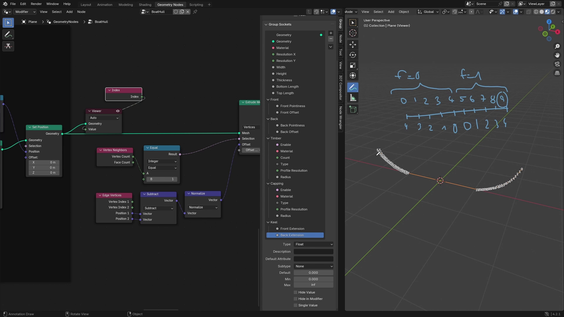
on these values. So to extend points, we will use extrude
mesh, basically. With extrude mesh, you
can extrude faces, but also you can switch
here and extrude vertices. So that's what we'll be doing. We will be extending
our mesh line. So let's plug mesh
line into mesh. And now if I don't do anything, you can see that
it extended all of the points in some
kind of direction, and you can control
it like this. We will need to tweak
this a little bit. First, we only want
to extend endpoints, and we can do this
with selection. So to select only the endpoints, we can, for example, take or we can consider that these points at the
ends have only one neighbor, and points inside have
always two neighbors. So there's something
called vertex neighbors, which gives us how many
neighbors each point has. And if the vertex
count is equal to one, this should give
us the endpoints. So now if we plug the
result into selection, you can see that only the
endpoints are extruded. Now we need to set a
corresponding direction of these extrusions, and that's done with the offset. And to get the direction
of these vertices, we can, for example,
if this was a curve, we could use something
called curve tangent, which gives us a vector in
the direction of the curve. But because this is mesh, we can't use this
curve tangent here. You can see that if I plug
this curve tangent here, this doesn't do anything. But because we are
working with the mesh, we can take these edges
because they are edges, right? Or we can basically
create vector between the points from
which the edge is created, and this should give us
the direction of the edge. Each edge is constructed
from two points like this. And if we subtract these, so let's say those are A and B, and if we do A minus B, we should get a vector which is pointing in the
direction of the edge. So to get points of the edge, we can use edge vertices node, which gives us positions of the points from which
it's constructed. And to get a direction, we
can just subtract these and it's also good to normalize these to make the length
of the vector one. So let's normalize,
and this will give us a direction of these points
or the edges with length one. Now if you plug this
vector into offset, you can see that on one side, it's working nicely,
but on the other side, it's basically in
opposite direction. If I said the offset
to something negative, you can see that it's
extruding in right direction, but in that way, it
messes up the other way. So we need to somehow differentiate between
those two points and invert the direction in
one of these directions. So the way we can
do this is we can just select a point
width index of zero, which should give
us one of them, or we can just visualize these. So let's add index and viewer, and you can see that this
point here has index zero, and this point
here has index 53. So 53 should be basically resolution on Y
X is times two minus one because that's the maximal
index which the mesh curve has because a mesh line has number of curves
times two points, and maximal index is always counted from
zero, so it's minus one. So if we select this end point, and then just use a
inverted direction. This should work correctly. So to select this
endpoint with 53, we can use Index node
where it's equal to 53. And to get the 53, we
can use group input and if we multiply this resolution on Y X is
by two and subtrack one, this should give us the 53. We can do the two operations in one node using
this multiply t, and we will multiply this
by two and at negative one, and this should give us the 53. If we visualize this, you can see that in
all of these points, it's false, and only in
this point, it's true. So that's exactly what
we are looking for. And now we can use
this result in, for example, a switch, which will be again switching
between two vectors. And if it's false, we want
to use the old direction. But if it's true,
we want to flip this direction so we can
scale it by negative one. And now if we plug
output into the offset, you can see that now both points have
the right direction and we can control
their extrusion. Now the last part is to control
the extrusion separately, depending on the inputs
of the group input. And we can basically
use the same technique. We can switch between those
two points with this result. And on one side, we want to use front extension
and on the second one, we will use back extension. So let's add another
switch node, but this time we'll be
switching between two floats. It will be controlled
by this result again, and we will use group input. We'll plug these front
and back extensions here. Like this. And now we can plug this output
into the offset. If we now go to Modifier step, you will see we can
control this side with front extension and this
side with back extension. And let's also check that
it's working correctly. This one should be front. And yeah, those are
working nicely, so it should be matching with
the back and front offset. So for me, it's matching. If it wasn't, you can just
switch those two sockets. So front extension would go to true and back
extension to falls. But for me, it's working nicely, so I don't need to
tweak anything. All right, so now we
have the extension done. And the last part
which we want to control is the radius
in those endpoints. So for this, we will need
to add two more perimeters. I'll add front radios
and back radios. And I'll set the
default to something like 0.1 and minimum to zero. And now we need to somehow control the radius
of these points. First, let's reset these
two default values, and I'll also group these nodes together and call
it kill extension. Now to control the radius
of these parts, first, I'll just bring up the
curve to support node so we can see the results
in real time. And I'll just set some
default values here. And yeah, there's a problem. You can see that there's
unsupported type mesh. So we first need to convert
this mesh to curve. So let's add mesh to curve, and now this should work nicely. So you can see that we can
control the radius here, but we want to control radios on the
endpoints separately. To do this, we can
use set curve radius. Which gives us ability to control radius of each
point in the curve. So for example, if you take
the factor of the curve, which is here zero and here
one and plug it into radius, the curve should be thin at this end and thick
at the other end. So let's add a spine perimeter, for example, and plug
factor into radius. Now you can see that here
is zero and here's one. The way we want to control
this is we want to be able to control radius on each
point on each end point. And to do this, we
can use this factor and remap it between
those two values. So let's add a map range, and we'll be remapping factor from range zero to
one to the range, which is created by back
extension and front extension. So let's add group input, and I'll plug, sorry,
not extension, but the radius. So
something like this. Now the factor here at the
zero should be front radius. And here where the
factor is one, there should be a back radius. So now if we play
around with these, you can see that
it's controlling radius at the
endpoints separately, and we should also
be able to control the profile and
it's radius here. Because we are controlling radius in the back
and front separately, the way this works is basically it takes
radius from this input, and it's multiplied
by the curve radius. So if we want exact values
in front and back radios, we will set this radius to one. And now a those values
in the modifiers tab should correspond
correctly to the radius of the profile because now if we
set these to 0.1, those are real at 0.1. If there was something different in the radius,
for example, 0.5, those values would
be multiplied, and the resulting
radius would be 0.1 times 0.5, which is 0.05. And that's not what we want. We want to control these
with their real radios, so that's why we will
set this radius to one. And we will be controlling
it with this curve radius. All right. I think this
is now working nicely. We can also test it
with the extension, so you can see that
we can control the extension and the radius. And we can also group this
with the rest of the setup. So this is a little thick. I'll just make these thinner. But you can see that it
creates a pretty nice effect. And now all we need
to do is we just need to connect all of these inputs from the curve to support node group to
the modifiers input. So let's again bring
up the group input, and I'll plug this empty
circuit into enable material. We'll skip radios because we
are already controlling it. Resolution and the profile type. We also need to move these
values here to the kill panel, so I'll move enable material,
resolution and type. And now you can see that we can control all of these
values from the modifiers. We can check that all
of the supports are working correctly
with the dimensions. So we can play around
with the bottom line, for example, and you
can see that all of the supports are working nicely. If we also change offsets
of the front and back, all of the supports are
still working really good. And I think this
looks super cool. All right, so to finish this up, we can also group
this part so we can call this set keel radius. And now the keel
support is ready.
11. Generating Seats in the Boat: Hello, and welcome to the
next lesson of boat course. In previous lesson, we finished all types of the supports, and in this one, we will add one more feature
to the setup, and that is going
to be the seats. If we look from the
side to the boat hull, we will be adding seats, which will look something
like this from the side, and we'll be able to
control number of seats. Their dimensions,
so there will be width and thickness.
Gaps between them. And also overall
position of the seats. So you'll be able to control
how high from the floor they are and in what part
of the boats they are. So we'll be able
to control them on Z axis and also on the X axis. So to start off, we will add a bunch of perimeters
to our node setup. So let's go to Geomet
nodes workspace, and I'll add a new panel here, which I'll call seats. And the first parameter
will be count, which will control how
many seats there are. So we'll add a new input, which will be integer,
and I'll collet count. Default value can
be, for example, two, and minimum zero. Next, we want to control
dimensions of these seats, so there will be a width and thickness Next parameter will be how large the gaps
between the seats are so we can add input gaps, and I'll default to something like 0.5 and minimum to zero. And the last two parameters will control overall position
of these seats. So first one will be
height from floor. And the second one
will be position, which will control
position on the X axis. We will set sub type of these
two parameters to factor because we will be basically controlling those two
values in range 0-1. If we take a look from the boat, you can say that on X axis, the minimum will be zero
and maximum will be one, and it will be
controlling the position between the endpoints
of the boat hull. And the height from the
floor will be very similar, but this one will control
the position on Z axis and on the maximal point or maximal position of the
boat, that will be one. So somewhere here and minimal, so that's height of the
floor will be zero. So let's set subtype two factor and set ranch to zero to one, and we can set default to 0.5, for example, and same
values for the position. Now I will reset all of these perimeters
in modifier step. And we can start
working on the seeds. So the way we will
generate the seeds is that we will first
create a mesh line. So in this case, it would be line between the
centers of these seeds. So it would look
something like this. And then we will create a cube with parameters
corresponding to the group inputs. So it will have
dimensions of the seeds, and we will use
instance on points, so we will instance the
cubes on these points. If there are, for example,
three seeds like this, the mesh line will
have three points, and it will generate three sats. So let's add a mesh line. And we'll be using meshline
with this offset option, and the offset will
be basically spacing between those two seats. To start off, the
mesh line needs to have as many points
as we want sets, so we'll plug this count
into number of points. And now we need to calculate the offset between the points. So we will be only controlling
this on the X xis. So we will add Combine XYZ. And the gaps between
the points will be basically this gap
between the seats, so that is the gap input. And then we need to add
also those two dimensions, which if we add together, this should give us
the width of one seat. So if we add width
and gaps together, this should give us the
right offset on the x axis. If we visualize this mesh line, you can see that we
have a mesh line, and if we increase
number of seats, you can see that it's
extending on the X axis, and we can also play
around with the gaps, and you can see that
it's extending as well. So now when our
mesh line is ready, we can start instancing
the cubes on it. So I'll add instance on points, and the object we'll be
instancing will be a cube. So let's add a cube, and I'll plug the cube
into the instance. And if we visualize
this, you can see that now we have
two cubes here, and we can control their
count and also their gaps. Now this cube should have dimensions as the seat.
So let's fix this. We will add a combined XYZ to the size so we can control
all dimensions separately. And on the X axis, that will be the
width of our seat. Let's plug width to the X axis. On the Y axis, we can leave this for now
to, for example, one. And on the Z axis, that is going to
be the thickness, so we'll plug thickness
to the Z axis. Now, if we go back to modifier, you can see that if
we set gaps to zero, the seeds are next
to each other, and as we increase the gaps, the basing between them
increases as well. We can still control the count, and now we can also control the wave and the
thickness of the seeds. So now the basic structure
of the seats is generated, and now we need to position them accordingly to the
inputs of the modifier. So let's add a transform
node with which we will offset these seats to
their corresponding positions, and we will be using
this translation because we only want
to translate them. So let's again,
combine XYZ so we can control it on
each Xs separately. I will also join this together
with original boat hull, so I'll use this join and
visualize everything together. So now we can see everything
including the boat hull. Currently, you can see that
the position is at 0.5, which means that the seats
should be in the middle. But only one seat
is in the middle, and then they are moving
towards the axis. What we basically want is that when the
position is at 0.5, we want the middle seat to be in the middle and then the rest
of the seats around it. So we need to transform this on the X axis by basically half
of the length of mesh line. If we take a look
at the mesh line, it looks something like this. And we need to move
this middle point to the center of the boat. So we will take length of
the mesh divided by two, and then offset the mesh
line by this value. To get the length
of the mesh line, that's basically the number
of gaps between those points multiplied by the offset value which we are using
here in the mesh line. So the number of gaps is
number of seats minus one. So we'll subtract one from the gound and then we can multiply this value by the offset between those points. So I'll at a multiply node and multiply those
two values together. So this value should now give us length
of this mesh line. And if we multiply this by 0.5 and offset the mesh line
on the X axis by this value, This offsets the seats
in the wrong direction. So let's multiply
it by negative 0.5. And now you can see
that the middle seat is in the middle of the boat. When we now increase the count, you can see that they
are still centered, and now we can work on the
rest of the positioning. So when the position
is set to zero, the seats will be at one
end point of the boat, and when it's set to one, the seats will be
on the other side. So we can take the
position and map it between those two endpoints
to achieve this effect. So let's use a position
with a map wrench. I'll also hide these socuit
so it's just one input, and we will be
mapping this position in from range zero to one to values which correspond
to endpoints of the boat. There are two
perimeters which are controlling the
length of the boat, and those are the bottom
length and top length. So to get the overall
length of the boat, we can take maximum
from these two values. So I'll duplicate
this group input and create a maximum
between those two. So this should give us
the length of the boat. Now if we multiply this value, by 0.5, we should
get this value. And if we multiply
it by negative 0.5, we should get this value. So let's at a multiply note, and I'll multiply this
by negative and positive 0.5 and plug these two values to the range to which we
are mapping the position. So something like this. And
now we can add this value, which we calculate to the
offset on the X axis. So I'll just add a add node and add my calculated
value to this offset. Now, if we play around
with the position, you can see that if the
position is set to zero, the offset on the X axis
is length divided by two, so that corresponds
to this point. And when we set position to one, you can see that the seats
are on the other side. So this works nicely, and now let's also do this for the
height from the floor. We will use the same approach, so we first need to get
height of the boat, which is controlled
by the height input, so we can just take
this height input and again use it for mapping
the height from the floor. So I'll at a map range, which will be controlled by
the height from the floor, and it will be mapping
from range zero to one to range between zero
and the height of the boat. So now when the height
from the floor is zero, the output value is still zero, and when it's one,
the output value will be the height of the boat. Now when we plug this value into the Z axis of this combined XYZ, you can see that
the seats are now offset in the
middle of the boat. If we set it to zero,
they are on the bottom, and if we set it to one, they
are on the top of the boat. You can see that they are not exactly on the top of the boat because the height of the
boat is only the main part, and now and then the
front and the back are also offset on the Z axis. So we might also use these front and back offsets to control the maximum
height of the boat. But for now, I'll just
stick to the height of the boat because that
will work as well. So now we can nicely position our seats and their
dimensions and their count. But the only issue
is that they are now overlapping the boat. And if we, for example,
increase the width of the boat, they are not across
the boat at all. So to fix this, we will
be using ray cast. So that means that
if we look from the top, from each point, we will shoot a ray
cast or array in direction pointing
out from the X axis. So it will shoot raise
something like this. And where it hits the boat hull, it will change position
to this collision point. We also don't want to shoot rays from these points
exactly because if the width was less than
width of these cubes, the ray would never hit the boat hull and
this wouldn't work. So we will be shooting
those rays from zero on the Y axis in the
direction of these points. And this should give us the right collision
point to which we will snap these points. So to manipulate with the
geometry of the seats, we first need to realize
those instances because now those are just instances and we can't work with the
points separately. So let's realize instance. And now we can work with
the points themselves. We'll be changing
their position, so let's at a set position node, and we will be using the cast
node, which I mentioned. So let's also at a cast. The target geometry of the ray cast will be the boat hull. So let's find the boat hull. This one, so I'll just plug this socuit into the target
of the ray cast like this. The right direction will need to point in the direction
of the points. So to get this direction, we can just take the position
of the point and then just use its Y coordinate
to get this direction. So to just separate
this Y coordinate, we can multiply
position by a vector, which will be one on Y
axis and zero on X and Z. So now when, for example, this point is vector
minus one, 0.5 and 0.5. If we multiply this
by zero, one, zero, we will only get vector zero, 0.5 and zero, which is the vector which is pointing in this direction on the Y axis. And also, we can normalize this. So we will get 010, which will give us the
normalized direction. So let's also at normalize. And this will be the direction which you want to use so we
can plug it into direction. Now the second
important input is the source position,
which as I said, we don't want to use
the original position, but we want to shoot it from the position where Y is
zero, from the X axis. And we can again achieve this
by vector multiplication, and now we will multiply it on the X axis by zero and on
the rest of the axis by one. So this will basically just move the vector on the
X axis to zero, but the direction will remain. So we can plug this vector
into source position, and now this cast should give us the right data for
snapping to both hull. So let's connect the hit
position to position of the Cs. Sorry, I made a mistake here. This vector which controls
the source position, we want to multiply
this vector on Y axis by zero and not on X axis because we want to remain
the X and Z position. So that is on this
plane from the side, we want to remain
position in this plane, and we only want to
move it to the X axis. So we'll multiply
it by vector 101, and now this should give us
the right source position. Now if we visualize this after
changing their position, you can see that the points of the sets are now
snapped to the boat hull and they are not colliding
with the boat as before. We can also visualize
the source position. So if I use the source
position as the position, you can see that it basically scales the cubes
on Y axis by zero. And from these positions, it's shooting the rays in
corresponding directions. And where it hits the boat hull, it snaps to this
position like this. So that works nicely. So now if we combine
these with the boat hull, you can see that the seats
are nicely snapped to the boat hull and we can
control their thickness, how many of them there
are there width, and, of course, the position. When the sats are at the edges, you can see that it's
glitching a little bit, and that's because the
rays aren't basically colliding with the boat hull because they are
outside the boat hull. So we can fix this or we
can't really fix this, but to make it a little cleaner, we can use a selection. So we will only
displace the points which actually hit
the boat hull. And now you can see
that the points remain in their
original position. And that's a sign
that you should play around with the variables, so it doesn't go outside
of the boat hull. All right. Now the last
part for the sets is to add a material and
UV mapping for this. So because the cubes
already have a UV map, we just need to store
it in attribute. So I'll add store
named attribute. We will be storing a
vector for face corner, and the name will be UV map, which we used in previous parts. And we can just plug this
UV map into this vector. Now we want to
apply the material, so we will add a material
input to the SETS panel. I'll also add a checkbox for enabling or
disabling the seeds. So I'll add a new
input, call it enable, and the type will be Boling
now to use those two inputs, I'll first add set material and plug the corresponding material from group input to the socket. And to use the enable, I'll add a switch node, which will be switching between the seats and empty geometry, and it will be controlled by the enable input
from the panel. So now if we go
to Modifier Step, we can enable and
disable those seeds, and we can also apply material. And you can see that
everything is working nicely. To finish this, we
can also group all of these notes together with
selection Control J, and I'll call this frame sets. And we can also clean this
note tree a little bit. To it can look
something like this.
12. Adding Materials to the Boat: Hello, and welcome to the
last lesson of boat course. In this last lesson, we will apply special material
for our boat, which you will get for
free with this course. So you can download the file which should be available
with this course. And it includes two materials which we will apply to our boat. So to append these
materials to your file, you will go to File append and find your blend file
with materials, then we will double click it. And here we will
select material, and we want to import
those two materials, so I'll select them
both and hit append. Now to simply use them,
you can just select those materials in modifier. So for the boat hull, I would like to use
the wood planks, which look something like this. And for the rest of the parts, I'll be using the wood. So I'll select wood
for these parts, wood for all of the support. And you can see that both
now looks much better. And now the last
part to which we'll apply the material
are the seeds. So I'll select here. And you can see that it
might not be working, and that's because I misspelled
the UV map in lesson. And here where we are
string the UV map, we don't want it to
be UV underscore map, but we want capital UV and map. So if you change
this to this name, it should be now working nicely. Why it wasn't working is
that because if we go to shading and look at
those materials, you can see that they are
using attribute which is called UV map like this. So now we can play around with these materials as we want. So for example, when I
go to wood material, and for example, I want
to make it darker, I can just play around
with the nose here. So, for example, if we
change this color here, we can make the wood arker and we can also play around a little bit with
perimeters of the boat.
 3D Tudor, Bestselling Blender Author & 3D Educator