Transcripts
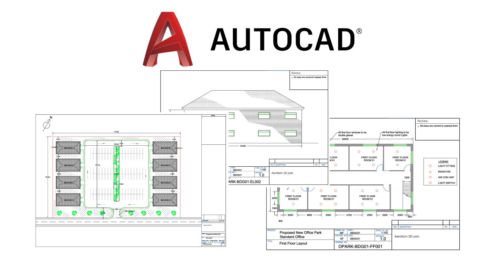
1. Introduction: Hello and welcome to this introduction to the beginners. Also cut costs using the architectural example. So the way this course will work is a cost will be working in two phases. Will be learning core skills, which is your commands. You are modifying tools, just in general, how to use them. We'll be doing a project which will progress as we learn new skills. So we'll be switching between a blank drawing, learning the core skills of creation and modification. And then in the project, chapters will be completed. Miss building layout. Step-by-step, as we learn new skills, will then be put onto a title block, adding text and dimensions and getting it ready so it could print it out and presented to someone as you would in the real world. But we're not just going to learn all the core skills in one go. That tends to become not just a bit boring, but you can easily forget skills you've learned when you're just bombarded with skill after skill. So the way I like to teach is to first teach for core elements that you need to get going. And so you don't get too overloaded and forget what you taught will then switch to doing some of our project and beginning of a project and actually put them into practice. Once we've got the basic elements of a project, we'll move back to learning some more advanced core skills and then switch back to the project and put those into practice. And by doing it this way, learning the core element and then putting it into practice and switching between the two throughout the course. You don't get too overloaded with the knowledge before you've put it into practice in and led to use it. A lot of courses will teach you every command and just go through them all. And you just don't understand why eLearning and why you would do that way by switching to your project and then put them on a scale into US. You will learn not just how to do it, but why you do it and why you would do some for a particular way. And it helps to set that skill in your mind and really learn to use the software properly. So by the end of the course, you will be able to produce standard layout of a floor plan using correct cat techniques, using blocks, layers, and all the type of cup management. And you will know enough to be able to work as a Cat technician in kind of a Julius newly trained role with all the skills you need going forward. We won't just teach you in this course how to use the software, but how to use it in industry. I myself have over 20 years in this industry, in a variety of disciplines, have worked on all sorts of projects. So I can bring real-world knowledge to this course and teach you how it is actually used out there in the real world. There's a big difference between someone who's taught themselves also cut, and someone who used in industry knows how to use it with my eyes down to the cat management tools and the way you, your joins are presented. So after you've done this course, you will, your joins will look professional. So as you work for this course, you can create, just work on a blank drawing just while you follow along and do the core skills modules, as we learned in most techniques. And then you can have another file open, which is your project. And when we get to the end of a project chapters, you can save that. Go back to a blank, joined to learn the fervor techniques. Come back to your project and continue working on it. And by the end you will have a finished model and drawing done to a professional standard. So let's get started. The first thing we need to do is begin just learning the basics. Learn about software and how to use it and get started.
2. CORE SKILLS: First Look At AutoCAD: Okay, so here we are in this first proper lesson with our new installation of AutoCad open. And we're just going to look at some basics here. This is just a very brief overview of the software. Again, I don't want to go into detail. You don't need it for a moment or you won't understand. So we're just going to have a quick look of what we're presented with when we first open a new installation of the software. Now, when if you are using someone else's software, or maybe it might be an installation has been installed on in the workplace or something you've had on your computer for a while and you've kinda be messing about with your screen may look a bit different hair, this is most of the default settings from new installation with just a few jars of Hadoop underneath this list on yours will be completely different is just the recent drawings you've worked on recent documents. So it may have other things you've worked on, things someone else's work don't maybe completely empty if you've just installed the case. Don't worry about that. Other than that, you should see pretty much a similar thing with same screen. And the first thing we're going to do is we're going to start a new drawing. Okay, so that's a pair. Top left. You will see this kind of sheet icon here. We're going to click that and that's just to start a new drawing. Okay, So you'll go and with AutoCad when you start a new document, it comes pre-loaded with different settings depending on what it thinks you're going to do. So rather than just start from the beginning over time you establish with a template and it's just a blank drawing. The already contains some, just some basic settings in the background. And that's why when you say new drawing, it will ask which template you want to use. There's different things depending on what you're doing. And you can save your own template is we're going to have a course on cut management, which we'll go into that, but that's way advanced for now. All you need to do for now is slept woman that just as a cat dot DWT, okay. And open my amiss will present you with a new drawing. Now, you may or may not have this panel on the left-hand side. Okay. We'll go we'll look at later, but you should have now a blank screen. You may not have this also, we're going to look over and how to get your sets of the same as mine. Okay. So let me just close out. Okay. So just in case you didn't have that, I've turned those off and this is a completely blank screen. Okay, I recommend having a mess. The overview thing on, and you can do that on the options. We're going to look at the options in a minute. Okay? But first of all, while we've got this blank screen, I'll just go through the basics here with you. So at the top you've got your standard commands. You have an old various software things like New, Open, Save, Save As Print. And we got some mobile options. I wouldn't worry about the moment. But that's kind of a basic what used to be on the kind of file a and file menu. So it's just you saved your opens up kind of thing. I won't worry about this is you can actually select what comes up here, okay, but you won't as the beginning of that note must result how it loads with the default installation is quite good and I just leave that as is. Okay. And you've got these boxes underneath. Now if you can't see these, you have various options of how they are shown, okay? So if yours looks anything like that, you just need to go through over burden and I recommend having it in this layout follow along the course. And veins are basically your main tool panels. So in also catch, we worked with panels and we worked with file menus. So along the top, you'll have always gonna, it's gonna look very complicated. And maybe a bit intimidating at first is don't worry about just ignore all of them for now. We don't need them. We're going to use these as we go and it's going to be much more intuitive that way. But basically, you've got the main tools under his home menu, which are draw, modify, and rotation blocks, etc. Okay, Again, we're going to look all that as we go. And then you've got your main blank area. This is going to be drawing space. So if you imagine your drawing board, this is where you would actually draw. So this is your news, okay? And what I'm gonna do with those options we talked about. So if you go to this big red a in the top-left and click that, you'll see down here you have a box options. And then under options we have these various tabs here, okay, So I want you to go to user preferences. And there's one right-click customization. And then I want you to check these boxes. So it looks like my screens with tuples repeat last command, middle one, the shortcut menu, but one is enter, Okay? If you, if you slip them that way, you're going to be able to follow along. If not, your mouse isn't going to perform the same way as money. And it's just going to complicate for you not gonna understand what I'm doing when I'm clicking. So if you just for the purpose of this course, if not already slept them like this, I recommend you get used to using it this way. This is how most people in the workplace user miss a really fast way of working. Okay, so apply that. And then we're gonna go on the 3D modelling. And the rest up. And down here you've got displayed tools and viewport. Make sure all these are ticked on that one, okay, and apply that. And that will bring up this view finger. Okay. It might have already been tagged to worry about. I'm not said and that's all we need to know for now really. In the next chapter, we're going to look a bit more about zooming and panning around and using my mouse, etc. But your cut now should look the same as mine and you'll be able to follow along in the course.
3. CORE SKILLS: Navigating the Software : Okay, welcome back. So now we're going to look at just a bit more about how we use our mouse and how we view and things like that. So first thing we want to talk about is the mouse. And most people will have a mouse of some salts. Now I recommend for this course, you have a kind of basic free but some mouse. And by Free button a main or left button, right butt's in the middle, we'll stroke button. So if you can get those, if you don't already have them, it will make following along viscose much, much easier. I think most people have. What tends to happen is people have more advanced mice with buttons everywhere. Later on when you get used to the software, you can program commands to the extra buttons. But there's so much variety in mice out be impossible for me to go through various settings and it be very confusing. So we're just gonna go back to basics this. And we're going to use a left button, right button and a middle button with the middle bots and also being a wheel. Okay, and I'll show you how, how you can use art now in the previous chapter, we set the right-click, if you remember. And that's all about this right clicking, which we're going to do throughout a course. You're gonna see me do that early on in the course. I'm going to point out what I'm doing. Then as we progress. You should know what I'm doing when I'm right-clicking, left clicking. And it's very intuitive way of working so you'll be able to follow along, okay? Right. So in order for me to demonstrate the viewing and the zoom in and things, I need some flung my screen. So I'm going to draw a basic rectangle. Okay? We're going to, in the next couple of chapters, we're gonna go over in more detail, creates an object. So you don't necessarily need to follow on with creating these objects yet, but do need some funnel my screen just to demonstrate the Zoom In and things. So a pair, we have our draw commands and we have one which is rectangle, which is here. So I'm going to left-click that. And I'm just going to select anywhere on the screen, I'm going to left-click. And it's gonna ask me friend of a corner. And I'm going to left-click again, simple zone. Okay, now I've got a rectangle of my screen. So the way I'm doing this, I'm going to move him about this is called panning. And you may notice from the software, so sorry, I'm going back to the beginning just so we're all on the same page. And I'm doing this by holding down my middle wheel on my mouse. So if you press up middle wheel and hold it down, you'll see the cursor turns into a hand. And with it held down, when you move your mouse, you will kind of Panama along. Okay. Not move with my rectangle. What you're doing is you're moving the view. So if you imagine the cameras pointed at the rectangle, you're panning the camera around. So if it goes over objects here, and again, don't worry so much about what I'm doing. It's just a demonstration. So if I was to pan, I'm not moving the individual rectangle. If I was moving it, it will be doing an eval. Say. So what I'm doing is I'm panning the view. Again, don't worry about Bayes, what I'm doing with rectangles, we're going to go into in a minute. I'm just demonstrating view, so I'm polymath view. Now with a middle wheel, you can also roll the wheel and that will allow you to zoom in and out. Okay? So it's that mixture of panning and zooming in and out that we use all the time to move around our drawing. And they used to be able to still isn't a view commands viewing windows and Unix. We do use those not as much as we used to base days with a nice, It's mainly done with the wheel and new. If you see someone doing CAD experience user, you'll see them panning and zooming all day long. Okay. We only have a name. One is if let's say you got something down here and you've been working away down here. Okay. And you pan along an O and now you're bit lost where you are, you panning around whereas majora and new, okay? What you can do if you double-click up middle, we'll quite fast. It zooms out to extends and zoom extents just means I'm going to zoom out to the extent of your model, your drawing. So everything in this file in with on this screen, it will zoom out to encompass all of that, okay? And that's great if ever you do get kinda lost. Sometimes you can end up down here and you're looking for here. You can just double-click and that will zoom. So that's, so you've got Zoom, Pan, an extensive That's all controlled by that same middleware. Okay. One thing you may notice on my screen and you may or may not have it on yours, is you can see these faint kind of grid lines here. This is known as grid for all these reasons. It's auto cuts way of helping you work out what the measurements of units. If you see, the more you zoom in, the more your grid kinda separates down, it's a smaller grids. Some people like it. Some people don't, to be honest, is one of those things that used to be used a lot more than it's used now is quite faint. Sometimes I work with are even register in it. Okay. If it gets a new way or you don't like it, you can turn it on and off with this hair. So that's probably how most people work now with a grid off again because it's so faint. Sometimes I just don't forget it's evil man, don't turn off. So you'll see me working with the audience just because I don't, actually, I don't mind that. I just kinda block it out, but it has no use rarely for me. So he can turn it off. When you start working in paper, then it can get him away because you're working with a white background. When I turned it off because it is much more noticeable. But if you don't know what I mean by working in paper space, just don't worry about that. That's something you do like two new cause. The main thing I would say is if attorney off, I'll just get used to it being manic Narnia master grid. And that's basically it with views at the moment, varies a view cube of pay. We're going to look a bit complicated now. This will get you through 90% of what you need in terms of views, just zooming, pan and zoom extents. Okay, so in the next chapter we'll look more on selecting objects.
4. CORE SKILLS: Basic Selection Tools: Okay, so we're going to carry on looking at the basics now and we're going to look at selection. I've got two rectangles have created in a previous chapter. If you don't have those, it's literally just left-click this rectangle command here. Left-click on the screen once and twice to drop it and just poke apply rectal. Don't worry about size that we about anything. It's just visual. Just a couple of rectangles, okay? And now with our mouse, we're going to look at selecting items. So with the left mouse button, It's as easy as just clicking an object. And you can click as many objects as you want and it will carry on selecting them. Okay? And I'm just gonna go to his copy. I'm going to left-click and I'm going to select both of them. Okay? And then I'm going to right-click. I'm going to go to left-click again for a base point. Don't worry about what this is confusing because we're going to look at, this is kind of modify and we're going to look at in more detail. Just want, again, I just want things on the screen just to work with. Okay. So all I did was copy and then select them. Again just so you've got the same thing. So it's copper. Left-click, left-click, right-click, which is enter. Left-click base point just means when he asks specify base point, it just means where should a grab this from a K? And if you don't have this piece of text domains boxes next to your cursor is F2. Press F2 on the keyboard, and you'll see what it's asking for next him commands. So say in specify base point. It just means where should a graph-based from before a copy? And it could be anywhere. You just click in the space and just left-click, left-click and it'll keep dropping copies of A's go into you right-click to end the command. So again, that's something we'll look more into the chapter would use won't miss on screen. So in terms of selection, we can left-click an object and we can carry on left clicking. And you'll see in your cursor you've got a small square in the middle of the two lines in the middle of a crosshair. That's kinda as a PEC box. So you put some fin, hello box over an object and you can carry on selected if you've selected something. And actually I didn't want these two, you can hold down shift. And you can select things that you want to unselect, maybe that one as well, okay. I might say is let things. And we don't actually have a command active at the moment. So I'm just, I'm just selecting them just to show you. Okay. But like so that's how you select items and what you do with those items when you select them. Well, that will be a command which we'll look at later. But for now it's just how we actually slept these items that is the simplest left clicking. So Shift left-click, as we've seen, unselect some, ok. Now if you do have a lot of objects and in a more advanced drones, when you start using it, you'll have way more objects and mess. It can be a bit tedious. It's a quick things. It could also be, if you've got overlapping objects, it can be hard to select one object and not slept over. So if you're doing multiple selections, you can use a window select. And to do that is left button again, you just click outside. So if we go to the top-left of these objects and just click anywhere in the blank space. And we left-click ones. You'll see now we have across our pink box is gone. And as we move our mouse is dragging a Windows. It looks like when we drew the rectangle. But what it's doing is drawing a window. And if we put this window over these four here and left-click again, they are selected them. So that's a window select. So again, if I press escape to one Dava, just click outside here, maybe is vase ones we wanted. Okay. You can go Window select. Now you might have noticed what happened in Australia. Again, I've drawn a window completely around this object, completely around my object, completely round this object. But these two, this one and this one, I've only half going over and when I left-click, it doesn't select them. Okay, So this is all to do with how I created a window. Again, I click out here, I'm going from the left to the right. And when you draw a window, a selection window from left to right, you have to, it will only select the objects you fully enclosed. So anything you are only partially over, it won't sweat them. Okay. If you then if you do the window in the opposite direction. So we're going to move from right to left. We fully enclosed and we'll just touch on base 2 and it can be just touching a little bit, Okay? You say it selection and it's even slightly best. So left to right, a selection window needs to enclose the whole object. Right to left. It only needs to touch it. And that comes in handy when you've got a very busy drone. And sometimes you do want to just specify which objects, sometimes easier to just touch an object. Sometimes you only want things you're going to go over this different, the different times when you will use a different windows, it will make much more sense later on when you start doing more complex drawings. But for now, just bear in mind is the difference in Windows selection. Okay? You can either and close it fully. I'll just touch it and you'll use them in different times. So that's basically it for selections. At the moment we've got our Windows selects, we know we can left-click and shift select. We'll unselect objects. So that's the main selection Roundup. In the next chapter, we'll start looking at actually creating some of these basic shapes in more detail.
5. CORE SKILLS: Basic Object Creation: Okay, so let's look at creating some more basic shapes. Now. We've got, is still on the screen. You might have some film was screened from a previous chapter. You might not. It's a good time to show you how to delete an object. So we're going to use our windows. So we're gonna go down from the right and remember all we have to do is touch phase because we're going right to left. So that's selected all of them. And then we just press Delete, the delete key on the keyboard. Go. Okay, so let's look at these shapes in more detail. Now. We've already looked at rectangle. We're gonna do it again. I want you to look at the button and you'll see it's got two blue circles on. Now that's kind of a hint of how it's going to, what it's going to ask you for basically. So that rectangle wants to corners receive a blue dot are into corners. And if you just hover over the cave over button for awhile, it will come up with an explanation. They're always commands, you can hover over it, you get a basic explanation and then a more detailed one. Okay, So this rectangle here, if I left-click it, as it kinda shows when blue dots is looking for first one corner than another. And it can be, it can be left to right, top to bottom, any way you want to draw it. It's going to ask for two corners, opposing corners. Okay? So I'm gonna, I'm gonna select that and we're delay and we're going to look at it again. I'm going to left-click this rectangle. Most of the time when you are creating a model file or a drawing, you do actually want to draw to a specific measurement. So in this case, in this course, we're going to be using millimeters, but it's exactly the same if you set up in inches. Usually you want to draw some fun. If it's a building, you want to measure the walls, rooms of ability, you want to join a specific size. It might be a mechanical component, you know the sizes, okay, most of the time you will want to draw to scale. Okay? So we're gonna go to the rectangle tool again. And I want you to notice next to your crosshairs, we have this as a piece of text which says specify first corner point R. And if you can't see this, it's F2 on the keyboard. Remember? And then we have a box where we have two boxes with figuring each box and one of them is highlighted in yellow. Okay? So when you get a piece of text, it's giving you a clue as to what it's looking for basically. So we've clicked only draw a rectangle, and now it's looking for the first, the first corner point of a rectangle. So whereas the rectangle going to begin from, in this case, we're just going to click down here, okay? And now it's saying specify other corner point. So as we've seen, it's looking for the opposite corner. But these boxes with the numbers in these allow you to input an actual dimension. So let's say we wanted to create a rectangle verts. 100 millimeters, which is the meter by 500 millimetres. Okay? So if we want to do 1000 this way, you'll see that the box for that dimension is that volume that's highlighted. If our other bugs have been highlighted, we would have to swap between the two. And we swapped between these two boxes by pressing the Tab key, which is usually on the left of your keyboard above, Caps Lock needs to opposing arrows. By pressing the Tab key, we can change between these two boxes. Okay? So to draw a box which is a 1000 by 500, we would go left-click for the start point. Make sure this box is highlighted and type in 15. Now it's important here not to press Enter if you presenter, you're going to end the command. So just press Alt Tab K and switch to the other box. And you'll see this will now is locked. It's a 1000 and there's a little padlock next to it. So now we'll put in here 500. And now we can press Enter. And we have our box which is 500 by 500. Okay? So that's how you would draw a basic rectangle to set dimensions. Now, withdraw box here. There's all sorts of other objects. So maybe we wanted to draw a circle. We click on the circle and we can see from the blue dot is given us a clue. It's going to ask us for a center point and then radius. So we'll just click anywhere. And similar to the rectangle, we've got a box highlighted. There's only one dimension to the radius, so we've already got one box. I'm gonna make this 500 radius when you press enter amounts of 500 radius circle. Okay? Now you see under similar ways we've got pulled down. So in the circle, you can change how you draw that circle. Maybe you've got diameter and radius. We can choose center, circle with a center diameter. So as before, we just left-click. And then this time it's gonna ask for diameter, so 500 diameter. And you'll say it's half the size because its diameter. We've got polygon, the rectangle we've got polygon. This flask refers to the number of sides. Let's have six sides. Enter. When we drawn a circle, we click the center of the circle. Now it will say inscribed or circumscribed, but just means do you want the corners to be to the outside of a flats? You'll be easiest way is to just show you. So let's say inscribing circle, okay? Now we weren't going to specify a position of one of these joints like a corn is, if you will. Okay. Unclear if we'd have slightly over option and gone circumscribed about circle. You'll see it's asking for the point, not the corner. So to be honest, we don't use very much. You use rectangle a lot. We use circles a lot, and we use lines all the time. So you might notice, hey, we've line, there's two different types of line and as polyline. So we'll look at the difference between those. So line. If we left-click that, you can say it's going to ask you if a two points, start point and an end point. Okay? I mean, it's gonna keep going. And you can keep drawing lines as much as you want until you right-click to end the command. If we have unused the just left-click outline, you'll see it's only highlighted the first par. Okay, a mass because all these are different lines, even though we driven one after the other as part of one command via separate lines. Okay? And I'm going to shift, I'm going to draw window to select them all and press Delete. And I'm going to look at polyline with a left-click on, and I'm going to do the same thing. Start not worrying about units. I'm just drawing a line again, right-click to end. And now when I select it, you'll see the whole thing is selected. And that is the main difference between line and polyline. Line will end up in lots of different lines. A polyline is one continuous line. And there's reasons why you would use one after we ever, to be honest, most of the time are preferred to use a polyline. The polyline you can give things like width. You can do all sorts of various things with it, which we'll go into later. And it's just easier to work with. It's got more intelligence if you like, you can, you can do more with it, whereas a line is just single lines. And if, if you wanted to select the whole thing. So for this, for instance, if this was a fence line, I could click it, the whole thing will be selected. I could get a length, I could change how it looks in Mongo, whereas if it was various different lines, I would have to slip them all individually. But again, he's just an overview misestimate how to create them. And that is the main difference to remember going forward. One is separate lines, the other is a continuous line, okay? And then we have things like ellipse, which is going to ask you for free points. So the center. And then it's going to be like drawn a circle. But it's also going to let you make it into an ellipse. Okay? Again, not used very often. When you do need it, you need it, but it's quite rare thing. So we'll get rid of the main ones are circles, rectangles, lines, and polylines. And we're going to look at them in more detail in the next chapter.
6. CORE SKILLS: Line & Polylines: Okay, So we're getting through it now, getting through these basics, and we're just going to look in more detail at lines now. So I'm going to draw window, window select. Remember left-click, left-click again, press Delete. And let's look at a basic line. So we left-click line. And you'll say it's asking us for to specify the first. Again, if you don't have this, these boxes mistakes, It's F2, turn on and off. So you can see it's asking for a point. And we're gonna look at coordinates bit later. For now, just left-click anywhere in the screen. And the options here, we confronted with these boxes again and you'll see it's asking you for two things. Okay? So the highlighted box in this case is the length. Let's say we wanted to draw a line which was a 1000 millimeters and it was drawn at 45 degrees, so it was kinda like that. Okay, so we type in a 1000. And then again, not, don't presenter, if we press the Tab key, we've now switched to V of a box, and you can see this is locked now, we've told the line is 1000 millimeters long, so it's not going to let us change. Would it doesn't need to know is the angle. Okay? We've got MATLAB being 0. So we can type in here 45 and then press return. And it's created our line, 1000 millimeters long at 45 degrees, and it's continuing the command. It will continue the line command until we say different. So if our next line wants to be 500, we type our N tab. And maybe this is 0 degrees, okay, press Enter, and there we go. And we can carry on doing that until we've finished. Maybe we just want to draw a line by eye. You can't just do that. You don't need to type anything in. Okay. Maybe we need a length. The length of this line was going to be a 1000 compressed up, but we don't know younger look for any angle we want. And it will tell you what the angle is, but you don't have to type N. So maybe we just want to do it by either. Okay. And you can carry on going like that until you finished. Or you can go back to this Dart and do right-click. Now, one thing you may notice here, if I go back to the start, when I get near the end of this line here, I get this little kind of green box and it'll come up with a piece of taxane end point. Okay? And that's called a NOS1AP. We're going to look at that in a, in a chapter coming up. So don't worry about that for now. I'm just going to end it there by right-clicking. And now we have aligned. But as I said before, if we slept any points on this line now, they're going to be individual. So I'm going to left-click and draw window over L naught and delete it. And we're going to do the same with polyline. So left-click polyline. Again, exactly the same. We're just going to start anywhere. And it's exactly the same. You can say it's asking us for length and an angle and we could type him those if we want. This will maybe a thousand tab 45 and OK. And you'll see. Before when I type in 45 and 50, let me show you this again. If I type in a 1000 for the length, I'm gonna do tab, okay. As well as actually type Lemmy angle you can, you can, you can tell AutoCad which side you want to go. So obviously we would 45 degrees. We could be 45 degrees of hair or it could be 45 degrees here. Okay, now what I can do, I can move my mouse and I could kind of do it by ILO. Are you can see it's telling me about 45. I could left-click there. Okay. If I go 1000 tub, OK, do it down here, I can do anywhere. So I could do 45 down here. Okay. But you'll see 45. 45 is basically seen as the same. So you can do that as a kind of a mixture of your, of buying a dirty by I and type in N, let's say a new and it was 47 degrees. I didn't want to kind of try and be exact libraries. I'm going to type in 47, okay. With my mouse appear, it's locked it to that. And you can say if I press Tab it, locked it. Now, if I delete that. Okay, and if I do it again, type in wound 1000, and then Tab, if I move my mouse down this way, as long as it's in the, on the correct side and type in 45, tab is gone, 45 or so. It depends which side you mouses. You can just move your mouse, okay? And that goes with length as well as. So if I wanted to malign, say, free 1000 millimeters in misdirection, I just move the mouse over here. Again. I'm not trying to I'm not trying to get it to freak out and just moving it. Misdirection, letting go of the mouse, leaving it there, typing Free 1000 tab. And it knows that you want free thousand month direction because it's moving it towards your mouse cursor. Okay. Now, if I wanted it for kind of 45 degrees of there, I'd have to put in a 135 because it's still tackling it from the same zero-point. Okay? So you have 45 degrees that way. 4500 Weber overhead would be the kind of 145 either direction because there is 0. So you would put, you would move your mouse appear generally direction typing 145 omega and and you can carry them out again. You can just do it by eye Wanted. And I'm going to right-click to finish. And now when I click that, actually did it in two different stages. So we've ended up with two polylines, okay? Now the thing with polylines, but don't need to be straight lines at all. So if I left-click polyline again, and I'm just going to click anywhere. You will see this bit of text next to my cursor actually says specifying next 0. And then it's got a pull down arrow. And what I've seen is where our options, you don't have to just specify that point. And the other options are down here. So we can do an arc half width, length. And the width. Now, the main thing you do here's the arc, okay, So if you wanted a curved line, you can select OK. And when you get these options down here, you might notice one letter is usually the first letter, but not always. But one of them is in blue and it's a higher case that's given you a clue to the shortcut, keyboard shortcut. So if you want to do, it's a return. If you wanted to do length is L return. Okay? So I'm gonna do, I'm gonna quit polyline. I'm going to left-click anywhere. And this time I'm going to click with the left button. And now we get the option to draw a curved line. And it will carry on doing this until we tell it. Either to end a command or we can go about down here. And click Line, and go back to straight lines. And you can carry on swapping between the two as much as possible. Now if arcs, polylines, arcs when you draw them, generally, draw the endpoint of VR. You'll see it puts its own kind of curving based on the previous one. Just click to the end point and then right-click to finish. And what you can do, you can edit these lights, but that's grips. We're going to look at grips in another chapter. Basically for now, I wanted to show you again when we click on my slacks for whole thing, we can delete that. So polylines come with this align. You cannot just say line varies, no other options with polyline, you get these options for arcs and things like that, okay? And we can click, left-click that, or you can just type in a return and that will do the same thing. It depends whether you prefer clicking or keyboard shortcuts. In this course, we're not going to use keyboard shortcuts much just because it's harder for me to show them to you. Sometimes you do a course and people using shortcuts and you don't understand how we've done a command because he missed the shock. All you see is a command change because you can't see the mouse can sometimes confuse people, so, okay, so we're not going to use keyboard shortcuts in this cost just for that reason, you wouldn't see what I'm doing. Okay? So we've polylines. You can do polyline at its more advanced things. We'll look at those lights. So that's a basic overview of the lines, the line on the polyline. We also have this line here which is arc. So whereas with a polyline, we have the option to do lines and apps within the same line if you were doing it separately. So let's just say draw a random line like that. And you wanted a curve without being a polyline for whatever reason. You can't do an arc. An arc, as it gets to here, it's going to ask you for free point. So start a middle and an end. And that's the best way to get used to vase. We've just learned is to just click them, play about them. Just start creating some basic shapes with or without dimensions and just get used to using them. Again because we set up our mouse with the left-click and right-click. To finish the command is right-click, okay? But what you can also do if we now wanted to draw a line again. So let me show you if we select a polyline, okay, and we left-click, left-click, left-click, right-click to end. And now I want another polyline. We can right-click and it will repeat the last command. So anytime, wherever command we use over it's moved copy anyways, rectangle. If you then want to do it again or you need to do is right-click miles. And it will repeat the last command. That's one of the races. We set it up that way and it really just speed things up. But you'll see me doing that in this course. And so I'll do a command and then I'll do it again. And you might think, Well, mine's not repeating, needs me to click a PE, warm the colander is right-click him a mouse to repeat the last command K. So if you see me doing my mouse Y, okay, in the next chapter we're going to look at O snaps and objects. Snaps.
7. CORE SKILLS: OSnap & Ortho: Okay, so I'm back to a blank screen now and I'm going to select the polyline. And you might have noticed, and we did mention it in the last chapter. As we're drawing, you can see when we move our cursor, we sometimes get these kind of green highlighted objects on your cursor and you may not see them. You may see them. We're going to look at those and setting them up. Now. We're going to see what they are and how you set those are, okay. But what they're doing, they allow you to snap your cursor onto a specific 0 or part of an object. So when we close out, let's say I wanted to draw a just this kind of shape hair and it was closed. Okay. So it was the end valine. Started valine. Now, if I didn't have snap-on, I would be doing it by eye and I'll be like, Okay, that's about on that. But the more you zoom in, the further away you are. And if you don't get those points exactly aligned, it's not going to work out in terms of measuring angles and filling it with a color and that kind of thing. You need End to be exactly on the stack, okay? And the way you do that is by using things called o stamps. So if I just fix it up, you're oh, snap settings. Down here. There's a rec rectangle, the small square in the corner, okay? And next to that, you've got a pull down arrow. If you click on, these are all the options you get. So this is basically where you're lying can snap to. I'm just going to turn mine off. You can turn them on and off by clicking them and you'll see you get a tick next to the ones that are turned on. So if I just want to be endpoints, I'm just going to select that. And I'm going to click away now, It's not, it's not on your all often is select the points I want to snap to when the command is turned on and what will happen you'll term is command on and off as you go. So to turn it on and off, you can click up and you'll see it goes blue to be turned on. I'm going declares when it's turned off, most people use, but do use the shortcut key for this one just because it's used so often in the key for this one is F on your keyboard. And you say if I press F3, it turns on and off. Okay? So I'm going to turn that on. And again, all we've got selected is endpoint at the moment. So if I go to draw another line, when I hover over this line, you'll see it comes up with these green squares. Depending which endpoint I'm nearest. So all I need to do is hover over an object and it will go to its endpoint. Okay? And if I was to now just hover about there, when this green square comes up, if I left-click to start a line, you say actually started on my end point, exactly on the endpoint. I don't need to zoom in. And if I want to finish it on the end of this line, all I need to do is go nearby Tova. Square comes up and left-click. And it's exactly on my end point. Okay? There's no guessing. It's exactly on there. So that is basically 0 stamps do. And you could put on all these different options. So as looking at some of the others, we have midpoint, okay? So as you've probably guessed, relevance and up into the end, we'll also get one now at the middle. And it's a triangle, and it says midpoint. So sometimes you want to have a line exactly at the middle of something, exactly at the middle of another line. We want a Lyapunov exactly the middle of this line. We can just have that snap to end point. And now we need to get nearby and it will automatically do it. Okay. So silvers center, if you're working with circles, maybe you have a couple of circles. You want to draw a line from the center of that one to that one. Okay? So we'll select the line and UPA on the circle. And now all we need to do is go in a circle and you get Center. Okay? So again, if we just never circle, as long as we get the grain sentence symbol and click. Snap right to the center of that circle. Okay? No guesswork involved. Forget our own node. The nodes, nodes based on points, we'll cover those later quadrant. So maybe we wanted the line to be at the top of this circle. Okay, so these are your quadrants, top, right, bottom left. And it's exactly a kind of 12 o'clock position, 3 o'clock, 6 o'clock, nine o'clock. And you know that they are exactly those positions because you snap to them. Intersection. So maybe we add a line crossing where we want to draw a line from intersection of these two lines. Okay? So when we get nearby, you'll say, it's hard to say this one is basically put in a green cross. And, but it will come up with a word intersection as well. So you get nearby. And it was done. Now you might notice it's becoming less and less easy to snap to a must because we've got more things on. So when you get here, it is easy to go to the midpoint intersection, okay? You do end up sometimes in busy joins, it's hard to actually see what you've got. So in that case, you might want to turn things on and off. So maybe let's turn midpoint of hair. And now we can snap easier to read intersection. And we know that that line starts where those two lines cross. Will. I'm just gonna go through the main ones. Use mommy will hardly ever used perpendicular. So we'll turn that on. Let's say we wanted to draw a line and it was from Vienna, but it had to meet this line. Exactly a right angle that's perpendicular. So now when I go nearby, you'll see we get a perpendicular sign, which is a right angle. I like snap there. I know this line has that line at 90 degrees, okay? And tangent. So for a drug, if we've got a circle and we want to align to come up here. And we don't want it to go to a quadruped. We wanted kind of tangent. We can have tangent selected. I'll turn off quadrant is to make it easier. And now it will get tangent command. So it meets that circle, tangent, okay? Again, you don't need a lot, but when you do, when you need it, you really do need it. So now it's tangent and narrowest. So maybe you want aligned to come off this line, but no specific point, not the midpoint. No specific point, but it did need to be on this line somewhere. It didn't need to meet a line. You can have Near East. And as long as you're near that line, wherever you click will actually be on the line itself. Okay? It might not, it won't be the midpoint, won't be any specific part of outline, but it will be on that line. And apparent intersection small for when you've got things in free day. So intersection was two lines crossing. So that will be the intersection when you work in 3D, it might be the lines across it in your current view, but they don't actually cross. That. One might be higher advanced to get into the moment. That's basically what it is. So bad the main ones, what I tend to have is I have my set upper endpoint, midpoint intersection. Okay? Nearest can be quite dangerous if you want, if you have narrowest on when it's hard to get to endpoints, midpoints because you've got nearest turned on. So you, you're always going to have the option to just be to just be at the nearest point, okay? So attend to only Avant if unaided. So endpoint, midpoint, intersection and perpendicular usually goes on. Okay. And there the settings kind of a default settings I'll have which allow you to snap two end points. But you can turn those on and off all the time would be afraid k. So that's how I tend to work. And most people tend to work, you'll have those on and it'll just be a case of turning the whole setting off and on with afraid while having the having etc, this way. Okay, That will do if I'd say a good 80% of the time. Now we have a thing we need to look at is something called ortho. If we're drawing a line we've already seen, we can give it an angle of 0, okay? And it will just be plain. And maybe the next line, we can give it an angle of 90. And it will just be in that plane. But a lot of the time you do want to work in Kelvin 90 degrees. So you do want to work exactly horizontal or exactly vertical. And you don't want to go to vassal of Putnam is angle over time we have the option, we have something called Ortho, which is down here. And if we turn that on by clicking it and you'll see it highlights. Now when we do a line, it will only let us go in these 90-degree planes, either vertical or horizontal. So that comes in really handy when you want to get exactly straight lines that 90 degrees because we've got on you. You can just draw freehand line up or you can just put in lengths and press Return and not worry about it being exactly 90 degrees because if you've got this off or turned on, okay. So a bit like oh snap, this is a setting you will turn on and off over time. And that's why we also use this as a key shortcut, which is F8. Okay? So you see it turn on and off with FAA. And when you're drawing, you will be turning on and off, snap and ortho quite a lot. So FRA and FAA, you'll be turning on and off quite a lot. Okay. And but something to get used to. So I want you now to just using your line. If a lineup polyline doesn't matter in this case, practice those auto settings that were right angles and we oh, snap settings are moving from midpoints and intersections and points and that kind of thing. And get used to using them and also turning on and off. Remember it's afraid to turn off, snap on and off, and FAD. Okay, so that's something to practice. Just do that with some lines. And when you've got used to it, I'll see you in the next chapter.
8. CORE SKILLS: Units 01: So one thing that's important to know about and also to setup in your software at the start, before you even start drawing anything is important. New sets of units and you know the units you want to work with. So most people will know what type of units we want to work with. But you do need to set up a star of y as it can really mess things up. So the main two things and differences between the metric system and the imperial system in the US, still use the imperial system in feet and inches. Most of the places use metric system-based days. But even then you need to kind of narrow down how you're going to work with inverse systems. So let's just have a look and see exactly what domain. So you may be working in metric system, but if you were to create a small a component, say, and you probably going to be working in millimeters. Same if, even if you do building layouts all of these days, people will work in millimeters. In the UK, it tends to all be in millimeters. And so you get to the really big distances. I've seen people use centimeters a lot in Europe. But on the big layoffs, if you were doing some fun like a site layout with lots of buildings and it was maybe a few miles wide. You probably wouldn't use millimeters. In that case, you'd use meters. Okay. But you need to be aware of what you're using. You don't want to be putting dimensions on and measurements and not knowing what you get any face. If you're getting a measurement of 500, you need to know what r is, because obviously 500 millimeters, big difference and 50 millimeters. And likewise ME, us. If you're using feet and inches for a larger, say a building layout may just be inches using for small components probability would be. So you might then you might be down to fractions of an inch. So whereas the building layout would be maybe ten feet, six inches for a small component, you might be working in thirty-seconds syringe. So you might have a measurement that's 21030 seconds and then you infractions, or sometimes it's in decimals of an image. So instead of saying a half an inch, it is 0.5. So even with inches, you could have different ways of expressing it, decimal or fractional. And it's important to know what it is you want to use and to set that up right from the beginning. Now, generally you will know in terms of work, the metric or imperial, it probably is down to where you're based. Although sometimes it could be based in Europe. I'm working on a project in America or vice versa. Menu might be using a type of units which is a bit more on familiar, but generally you'll know via the start. So first thing you want to do is set those units and we'll have a look at doing that now. In AutoCad, the basic measurement is just a unit, okay? So this is something to kind of get your head around at the start. Autocad works in units. If you create some of those 10 units long, to Auto Cut is 10 units long. Now, you could call that what you want. You could call it millimeters, you could call it inches, whatever, but it is a still a unit you just saying towards target. Okay. In this jar, in every unit represents one millimeter or every unit represents an inch. Okay, so let's have a look at janie moves. So in AutoCad, you can just type in units, press Enter, and you'll get the drawing unit setting box. So this box here, the first saturates architectural. And you'll say this is inches. And it says inches here for the insertion scarcer contaminants inserted image or ion will be in inches. And you can set your precision. So a working down to precision of half-inch, quarter-inch, maybe 256 of an inch, which I'd say is very precise for an architectural drawing. You've also got decimal. So do you prefer to work in degrees, minutes and seconds, and or just decimal degrees, 45 degrees, etc. And again, how precise do you want to be without? Now? You can go decimal. So even in inches, you can be decimal. Okay? So if i okay, so if we were let's say we were 10.5 inches. Okay. If I just click on the line here and left-click, then I can drag this out and I can type in our length. So if I would say 10.5 and right-click to enter. If I click this now, and if you haven't got this box, you can right-click and go to Properties. Ok. And you'll see it says 11. So I derive is at 10.5, but it says it's 11. Well, let's have a look. We've got our precision set to 0. If I did it to one decimal point. And now could connect. You can see it says 10.5. So by setting your default units, you can set how many of these decimal places going to go to. And sometimes you open a drawing because a lot of people don't change that precision setting by the way, I don't know why, but sometimes you will open a drawing and you put the dimension on and it comes out, and it will come out at 10.5000. That's just because I haven't changed the units scale. Okay. So if you, if you say that it's easy to stop that happening every time just by changing the precision in the units box. Okay, so I'm going to leave other, but we're on decimal and we're going to inches. So that's how we would express inches. We can also go engineering, so it's set to engineering. If we click this line again, you'll see now it's 10.5. And as we inches symbol. We've got our area in square inches. Okay, everything is actually denoted as being in inches rather than just a decimal. It's actually saying inches. We can go units again, and we can go, we can go to fractional. So on the fractional base will be 10.5 and actually says that the fraction half. So sometimes when you're drawing and you have an old join, it might say so many sixteenths of an inch. And you have to, if you're in decimal, you go on your calculator and you work that out, or you have a convergence of what law is as a decimal. But you can, if you want, just have a unit set to this and you can, you can draw out. So if it was going to say this is 1 and five-sixteenths of an inch. So how you would write that is one I'm going to do with dash. So it's one complete Ange, and then next is five. And then do your slash 16 k, So that is one and five-sixteenths of an inch. And now when you press Enter, if we click on that, okay. So what's happened now? It says 1.5. Why is that? It's supposed to be one and five-sixteenths. Well remember we've got our precision set. So also cut will always, it will always kind of round things up because we've got our precision set to half an inch. That's how it's going to be. We, we wrote five-sixteenths, so we need to be on a precision of sixteenths. Ok? And now we will say this is what I'm 56 aims and make sure your precision is set to what you want to pay. Usually inner join you will have a mixture, but if each set it's your highest. Okay, So if you were, if you have one dimension that's in thirty-seconds to set it to that. But if we look now if we look at this blue box, you'll see still saying the distance in inches even though we're going into feet because we're over 12, It's still call it 51 inches. And that's where V is of a certain commands. So for instance, let's type in units. If I change it to architectural, architecturally, you using bigger distances. If you think of architectural, think of working in FAPE because you talked about building layers. Now if I was to draw a line in the blue box, you'll see it says free feet. And the way it's shown it is free. And then the sign dash, free space, half inch. So that is free fate and free and a half inches. Ok. And you can see we've got a precision, precision cell and 16 by the look of it, because it is showing, if we move it along, It's gone into sixteenths, fractions. And I can right? Now if you wanted to buy a new could put. So let's say I wanted to be six feet. So we do our six feet sign and then we do five dash. And I'm gonna go seven slash 16. So that's how you would write that dimension. And that will be six feet, 57 sixteenths of an inch. Okay. You don't need your sign because it knows what you work in. But if we look down here, that's how that's what we've got. So let's go back to unit. So that's the difference really between the architectural and the fractional. Here to it'll keep in inches. So it will say your total inches. Theta is architecture, we'll say of a decimal as we've seen, will do. So 10 point font, Let's do more or less do 24.5. Okay? So that's 24.5 inches. And engineering is going to split it. So two phi nought, 0.5 inches. So you've got the whole option now you've got total inches with no fate. You've got feet and inches as a fraction. You got free 10 inches as a decimal and you've got total inches as a decimal. So that should cover you in terms of imperial for whatever you want to do.
9. CORE SKILLS: Units 02 : So if we go back now and I'm gonna go decimal if, if you're, if you're working metric, okay, let's, is going to be a much simpler because you don't have all the fractions and things you don't use your fractions in decimal is just a case of am I working in meters, millimeters, centimeters all up. So precision, Let's go with two points, okay, and I'm gonna change this to millimeters. So let me delete this. So now we work in millimeters, okay? So I can say 100 millimeters. And that will give us a, so that's a meter, 1000 millimeters. And if I go two units again, I'm going to change to architectural. Say if we tried to OK, it will say for use with actor geoengineering linear units, insert unit should be set to inches because it's, it's just irrelevant. So it makes it a lot easier if people who are metric, really, you only have to set its insertion scale. And that's important because someone else might want to insert something in your drawing. So it's a lot simpler for those guys, were pretty much it. And really all you need to worry about is kinda of a precision you want set which is easy to change and you can change on your dimensions. We'll do that later, will purposely do it in one of these largest setting silicon show how you change the dimensions to show up an angle. Most people tend to use decimal degrees. I would say. Most places I've worked on, I'm struggling to remember anywhere where I've used anything other than that, if I was to do. So, you got us what you want as a dimension. You'd want it to measure in degrees lab 27 degrees degrees, minutes and seconds radians over. I honestly can't remember if we use Nipah, if if you need this is where you would change up and always can be changed by. But what's important to remember is taught to cut. They're all just units. It's just a way of how it presents the information to you when you change it in a box. Autocad really is just a unit. So that is a brief overview of units and how to change them. Now one thing I will say, if you do a course and it's in millimeters, but you're used to work in feet and inches or maybe do one of these causes and it's in feet and inches and you used to work in millimeters. Just go along with it. It's, it's good practice to learn to use different measurements systems. But also if you really want to do it in inches, these easy enough to convert as well. So if someone asks for 5000 millimetres, just do a conversion, has low, just Google inches to millimeters conversion or millimeters to inches. And you can always follow along these courses in your chosen system of measurement. Certainly my cost is everything's open. Everything I do is an example. You can always draw things a bit different. And I encourage people actually to mess around with the examples and come up with your own building layouts. You don't have to put walls or winds are anything I draw where I put it. You can now experiment. You can change the units to wherever you feel comfortable, whether it's feet and inches, millimeters, miles, yards, chains or any of these obscure things, just feel free. Working mat, we're not building anything here. Nothing's gonna go out to say, no one's going to care if you accidentally do you build in an is 600 yards long instead of being only six meters, no one cares, nothing is getting built as long as you learn in the software and you know how this stuff works, That's the main thing. Okay, So whatever you feel comfortable with, just work your mat and at least now you know how to change between the two, between the many systems should say. So that's units. Hopefully that made sense. Again, it's one of those things in AutoCad where it might not make sense when you just learn it. By the time you get to the end because it will eat you just become, because you put it into practice, that's the best way of learning. And once you start putting it into practice, it will make a lot more sense if you earn 80 percent there. Don't worry, continue with the cause. If it's completely bewildered to watch video game, feel free to send me a message if you need more clarification. But if it is, kind of add, just move on with the course and it all makes sense as you start using it.
10. CORE SKILLS: Coordinates: Right, So I want to talk a bit now about units and coordinates. And this is quite an important thing to kind of get your head round and understand. Like a lot of things in cut. It can seem confusing to people that start, but once you kind of get your head around, especially the coordinates, you've always got a moving from caste system. The caste system is going to work the same and you just gonna know instinctively what's happening, okay, and how it's working. So I'm gonna presume everyone is starting with no experience whatsoever. Some of you, it may be obvious, the first part of this, just bear with us. I want everyone to be at the same level, okay, so we're going to start with we're going to pretend you've never seen, you've never worked with any coordinates before. X and y means nothing. And we're going to start from. So let's have a look at what we've got. Looking at our blank screen here. And the easiest way to explain this, if you look down in the bottom left, you'll see there's this kind of right-angle shape and it says x and y, okay? And also could use is the x, y coordinate system, x, y, z. That actually, but let's not forget the zed for now. So it uses the x and y coordinate system for 2D drawing, which is what we're interested in in the moment. And what that means is any, if we draw a line, any kind of distance in this direction or this direction along this kind of axes here is measured in x and o pair. And a pair is measured in y. Ok, now, people might fit y, x, y. No, Why not millimeters inches? Well, the truth is nobody knows what you're going to use. You might be drawn in inches, you might be joined in millimeters, you might be drawn in anything. So it needs a kind of universal way of describing it. And it uses vase x, y coordinates. So x is this direction and y direction. So if we were to draw a, let me delete this. So if we were to draw a line, and I'm gonna make this 1 thousand. Okay? And their degrees. And we have outlined lab this line is actually is a thousand long. It's actually a thousand in the x-direction. Okay. So from this point we've moved wouldn't files and units in the X direction and 0 units up. So if you were to write this down as a coordinate, you would write 100 comma 0, okay? I'm a comma, splits up the x and y. So, so just, just drawn on this, just to demonstrate. If you imagine, we have an extra line running this way and our wireline running that way. Okay. And let me just don't again, don't you don't need to be following long-haired Ravi just watched and actually grasp the what's happening. Okay, So going this way is x and my y is y. And as you move, you would go up in value. So if I must be a 0, okay? And, and this is known as 000 is this symbol we had here down in the bottom left of your icon is where that starts. That is your 00 of your drawing. It's called the origin point and it's going to be origin of your, your whole model, the zero-zero point. So if we were to create a rectangle from 000 and I'm just going to snap to that. So this is now from 000. I miss. Rectangle. Was, let's say it's 500 by 400. Okay? Then this point here, if I was to mark this point, and we write it as a coordinate. And that coordinate will pay 500 comma 400. Okay. So five hundred, four hundred. And if you've ever worked with grid references, mapping face exactly the same principle. We have x, which is along this way, and y and everything, every point is specified as an X and Y from 000. Okay? Now what about if we were to do the same thing? 500 by 400 down here. Okay? Well this is 0000 as we move up in this direction. And this direction is positive numbers, but as we move, either this way of outweigh its minus, okay? So this coordinate down here, this would be known, well, it's minus 500 and minus 400. Okay? So that's how coordinate would be expressed. So this way you get into negative numbers and you might get mixtures of the two. So if we were to go free 100, 200, and draw. And you might have guessed, this one would be to be a negative number misdirection. The minus for a 100. But in this direction we're going up, so that would be a positive 200. Okay? So from 000 x-direction, y-direction. X always expressed first. So you know which way that was, you always know which way that rectangle's going to be, because it's always x first minus is down into the left and positive numbers are open to the right. I must say that's a coordinate system. Okay? Now, if you don't quite get it, you might watch that again. But what I will say, the best way to learn a lot of these subjects is by using them. So if you kind of follow along as we creating things and put it in figures, you'll get it. And once you get it, you never forget this stuff. It's like riding a bike, okay? And if you move on to other CAD systems, this is going to come in handy. Now the only thing to bear in mind is we don't actually you've heard me talking in units and say Mrs. 500 units is we're going to be drawing in either millimeters or inches in most cases. Okay. But you do need to tell auto cover. Obviously your drawing is going to look very different. Your building, your component is going to be very different depending whether it's in inches or millimeters. Okay. So you need to tell AutoCad, unless you do, autocad will just work in what it calls units. Okay? So you can change that by typing in units symbols are, and it will come up with this box. And this is where you can set, need to do this when you start a new drawing, make sure you work in the correct units. At the moment it's set to inches. So when I have been offsets amaze 500 by 500 and 1000 by 0 is all inches. Okay? So if it was millimeters, it would be millimeters. Okay. Now, I'm going because I was from an earlier example is actually the correct size. But if I was to draw them again, and I'm going to do is five hundred, four hundred. Okay. So you may have seen this box that keeps popular pair and thinking, well I haven't got that, or maybe it's appeared on your drawing. You don't know where from it it will come up and it will go all the time and it's your properties box. You do use a lot in our circuit. And you can bring that up by clicking any object, right-clicking and going to Properties. And it gives you a whole load of information, most of which you won't understand yet. But it gives you, it does give you the coordinates, okay. For you, something like a rectangular as multiple points. So what I like to do is just create a simple circle, snaps to the point you want to measure. And if you click that circle, you can have a center coordinates. So you can see the center of this is 500 by 400, which makes sense because US, and if we snap, if we put one here, the coordinate, so this is minus 500 by minus 400. Okay? And if we type in units were set to millimeters, service box is 500 by 500 millimetres. So when you are creating things, everything will have its own set of coordinates. And it depends how your modelling and higher cranium, whether you really need to know them. Sometimes you'll work with them a lot. So if you're doing something like surveying, where a surveyor is, it's giving you points, maybe are creating an architecture layer or landscaping plan. You'll be getting survey points in from a surveyor may be saying this is where lampposts, RL fences with bean out on we've surveyed ways and means of the coordinates. And in that case, it's really important and you can just take those coordinates and you can type them in and you can plot things where they actually are. In other times, things like mechanical components and map coordinates you will use more in terms of when you are actually create an object a bit like we do when we draw our rectangle. So when we create the size and it's 500 by 3000. Plus the kind of way you will use coordinates in that situation. The main thing to remember is x always is reference first, which is that way. And the y-coordinate is that way. If you forget that it's closest properties books were actually on Etsy, can't say, but this little icon here will always be that the zeros are origin. Okay, so the main thing to remember is x is in that direction. Why is it there? Which you can check by looking at this and let your origin is 0, 0. And that's why it finance all you need to know to follow along. Later on if you get into 3D, you'll be introduced to a liver coordinate which is zed and not rarely is high value. So if you imagine looking down on this, if you draw a line from the end of your nose to this blue square, that will be the zed axis. Okay, But really I wouldn't worry is now till you get well used to work with these coordinates here. So yeah. So you know about coordinates now basically, you know about units. You notice the units will be working in inches or millimeters. And in over x is always referenced first in AutoCad.
11. CORE SKILLS: Modify 01 : Right, So we're going to occur modify now is modified panel. We've already learned about creating, about drawing basic objects and creating basic items so we know how to create, okay, and I'm just going to put some rectangular and we understand some basic concepts. But what about modifying? A lot of what you do involves modifying existing geometry, whether that's changing an existing model or drawing, or creating a new one. The way we tend to work in auto CAD is if you're working in a similar industry will always be a drawer in a lot of time will be a drawing similar to when you go into Create. So rather than starting from a blank Canvas, lots of Italians easy to grab an existing object. Another modifier to your needs, and modifying is one of the main skills to know in Auto Cut, in any cuts software. So we're going to look at the basic modify tool here. And I miss begin is cause we're gonna go over onesie you can use. More often is lots of tools in AutoCad and in all COT software, which are very good tools to do a very specific job that you might use a small fraction of the time. Okay, Now, when you don't need them, that come in very handy, but most of the time we'll just sit there. And whenever used. And when you look at cuts off a look all these menus and all these buttons, and it's easy to be overwhelmed and think, how am I ever going to learn a lot. But, but most Fumito use the very core commands that use all the time. Other ones here and most of the 20 percent of the command you use 80 percent of the time. So they're the ones you're gonna learn most and wherever ones he gets now that we have as you just bring them in as and when, it's easy, rather than trying to learn so many commands and getting overwhelmed, just learn the basic ones, learn recall ones, which will allow you to do most of what innate probably. And then just gradually bringing more advanced or fascinated as the best way to learn. So say mat, we're going to learn these basic modify commands here, which are like the building blocks of cat. So these basic tools here, if these basic shapes of the building blocks of cat, these are the basic tools, canvasses you basic toolbox. So the first one is move. Pretty obvious what it does. It grabs an object and it moves it. So again, as with any command, if unsure, hover over it, it tells you what it does, Lever hovered over it, but it gives you a bit of an example, but I'll show you now, you click on Move, we left-click. And it's going to ask us to select an object. So we left-click an object, and with our mouse up away it is, all we need to do is right-click for Enter. And now it will say specify base point. And remember the base point, what it's asking far as where should I grab this from? Okay? So I want to move this rectangle where you want me to grab it from. If you just move in it as we're going to, it doesn't really matter. I've got 0 snap-on. So it's going to snap to this corner, which is fine by me. I'm going to left-click. And now it's going to say, Okay, where do you want me to move it to? And I'm gonna say here, left-click. And that's the commandment of move the rectangle. That is the basic principle mode. If I undo that most of the time, you want to be a bit more specific than that. Okay? So let's say we have a circle here. Okay? Now I want a circle in this corner as well. We use the Move command. We slept a circle. We right-click Enter. It's asking for a base point. So I want to I want the center of the circle, which is currently on my corner to bill not crossover base point is obviously the center of the circle. Okay? That's why it's important when asked what you want to grab it by. If I was to move the circle and just grab it by a random point up here. How would I then be able to align it in the same place? By using the same but as a base point. Then for the second to move it to, I can just say center point, and now I've moved it. So if you want to move it from one corner to another, you can use that corner as a base point and then drop a mass with ozone upon. So, Oh, snap is used throughout AutoCad and all the different commands whenever you are creating an object with the unmodified object wherever, Oh, snap comes in handy all across the board. And if you were to be moving it and you wanted to move it, say snap to that. Since point and you didn't want to, omegas wanted anyway, you can turn it off of a free unknowns known. But most of the time you'd be moving it somewhere or maybe I wanted to in the midpoint of a midpoint there. Okay? These are, so by using base points with move, you can do that. We have. But we can also use the coordinate system and the angles and things like we did before as well. So I can say move, right-click. I can select the midpoint is base point. And now we see we've got these highlighted boxes again, so I could type in 10 and then the distance Tab. And now it's just asking for an angle. Okay, so something like move, this is what's called a polar input. It's asking for a distance and an angle. So that's termed polar. Okay. If it was asking for a distance that we're in a distant site where that would be a rectangular input system information, you don't need to remember that, but that's, you can see what it's going to ask for. Asking now for an angle. So maybe 45. Okay. And I will put it they're not often have done that occur. Remember it's I whenever actually ever really needed to do that. Most of the time when you move in objects, you will have 0 snap-on. I knew will be moving in from a base point to a base point. Okay. And that's the move command. Now copper, believe it or not, it works exactly the same as move, except it's copying rather than moving. So now that sounded very simple. Glass what it does. So let's look copy. We're going to select that. I'm going to right-click for until we're gonna grab that as a base point. And I will want in every corner we've copied because it's copying, it will carry on doing it. You don't need to put them in a midpoint. You don't need to keep doing that each time. It will just keep copying instances until you right-click and finish the command. And now you've got all them copied. Okay? Now they are all separate objects. So if you were to vent J, change the size of s1, the word old mode, an alternate reality, individual, independent objects we've copied. So I'm going to I'm going to undo them. And by-the-way to delay, what we usually do is select the object and press Delete. But there is a delete button. Sometimes you might want to click on arrays and click an object. Okay? Why would you do it that way? Some people just prefer it, especially when you've got multiple objects and you select multiple objects. It's just preference real. And let's suppose this box actually, I don't want it that way. I want to orientate it. If as landscape, I want it kinda portray around Mach corner, rotate. So the rotate command works much the same way we left-click and object. Right-click when we've slept because you can do it with more than one object. So you will select your objects. And if it was multiple objects, she slipped them, all of them. Right-click. On the right-click is enter meaning of made my selection. And now it's continue the command. So base point is, in this case in rotate, the base point is the point you want to turn around. Again, it'll make more sense when you see it done. So left-click up corner and now you can turn it and we've rotate. You can type in an angle, so I could type in 90. Okay. And, and it will rotate it. In this case, it's rotated that way because when the muscles, but most of the time or a lot of the time we rotate, what we tend to do is if you want to do, we just turn off all. And remember ortho is this restricting two right angles in horizontal, vertical? Well, if you turn it on, it will only let you go right angles. So if you're rotating, it will only give you the option. Okay. But you can type in 45 and it's gone around that way. If you want it to go the other way. You could type in minus 45, an inverter in that way. So you can type in the angle or you can use your cursor much rotate. Okay? Offset. Offset is a command we use a lot, especially when you are creating things, are architectural plans. Withdraw. I'm going to pretend them join the building. Okay. So let's say we were well zoomed in on it. So this is small-scale, let's just say this is 50, okay, so under no 150 and then 100. Okay. So we've got our line is going 55 way 120. Again, it doesn't matter what working in at this point, doesn't matter. Units is just eight is just unit is just a general example. This line has been 55 away, 100. But what I want is a double lines, 10 on it like a wall with an inside and outside. Okay, so rather than trying to draw a line that follows it and it's the correct dimensions. Or you need to do is go to this command here, which is offset. So you left-click up and it's going to ask you first specify a distance. So I want to offset this, say five units. So I'm going to type in five enter. And now I have, it's asking me to select the object I want to slit is polyline. And because it's a polyline, It's like the whole thing. And then it just needs to know the side. And I can select that by moving my cursor. So I'm going to select five away. And that's it. So it offsets the object. And it isn't again, like copper is a new object of itself is just a way of creating an offset. Use a lot is one of the main commands.
12. CORE SKILLS: Modify 02 : We have a mirror command, so we'll use this as an example. I'm going to say we want to mirror this and we want to down here as well. Okay? So we click mirror and it's asking to select the objects. I'm going to select these two and right-click. And now it's going to ask for first of the mirror line. So the mirror line, the way to think of this is distinct. If you were to place a married down, kind of It's end, where would that be? And the first part is our mirror line will be here, and the second would be there. Okay? And that will create this mirror image. And if you right-click to finish it, it will create a mirror image. And you could do that again, so we can split these two now. Right-click. We'll select our first of our Marilyn there by left clicking. Okay, I will second is on missing left-click. And what you're doing get you get this option, erase source objects. So sometimes you want to change something by mirror in it. In which case you would erase the object. Click Yes, and now it's changed. But other times you want to mirror some thing and add it. Okay. So you would select No, and then you would get the original would stay and when new part I'm nuts, mirror. The mirror is just create a mirror image. And then we have scale. So with scale, you just change the size of an object. So I'm going to select this whole thing. I'm going to right-click for new selection. The base point is a point you want to scale up from. I'm gonna go with bottom-left corner. And now if you drag your cursor, you can see you actually, it looks like the Zuni. You're actually scaling the object inside. I'd say most of the time you type in a reference for this. Okay. So the way it would work if let's put a line, okay? Let's say I have this rectangle, these rectangles here. That needs to be bigger. How big do we need to be? Well, this line needs to go from where it is now, but instead of ending here, it needs to end at this point. So we'll go scale. We'll select them. All right-click. That will be our base point. And now instead of just putting something down here, you get this option reference. If we click that, it's saying specify reference length flow, we will reference length is the length now the existing length. So the length now is VAT. And now it's a specify new link for the length we want it from there. So the Omega, so if you didn't quite get, I might need watch it again. But that's basically how, that's how I mainly use scale, is the other reference the scale something up to fit a certain size. Sometimes you can type in scale to, which will be to double in size five or eight times five. Because you can type in a digital era. If you go to scale, uses base point, you'll say it's asking you for a scale factor. You can type 2 and it's just doubled in size, so you can do it that way, but mainly an amusing and reference. Now one of the simplest ways to quick edits on an object is to use what are known as grips. So if I just left-click this rectangle here, you'll see we get these blue squares in the corners. And there's also very hard to say, is a blue square in the midpoint of each line. We can actually left-click days and just drag them around. And you'll see we get input boxes to input dimension if you wanted. But you can edit objects by, by grabbing maze blocks, okay? And you can grab the middle ones to move a whole line, or you can move the corners. And how this is usually used is just to drag it. If you wanted to drag this corner, for instance, onto the corner of another object, you just did. And don't worry about how I selected back corner. It's something called oh snap. You look at that laser beam because if you haven't already, but I just want to show that you can use these kind of points to move objects about and to change the geometry. Okay? So we use those a lot. Grips, and it's not just rectangles. All objects have them in some form. A circle, for instance, will have a center point so you can move where it is. I mean, you can change the diameter with these, okay? And same with arcs. When you create an arc, you can use grips to move up and change the radius. So all things kinda have grips. And you'll get used to using those. It's a very fast way of changing objects when you get into actually creating some funny because you'll see us using those in more detail. But that is another modify method. Now the last modify method we use a lot is copy and paste. And you might be thinking, well, we've already learned about copy miss, miss chapter, but there are actually two different versions of copy in AutoCad. And I'll show you the differences now I'm just going to draw a, again, don't worry about how the revenues going to create a rectangle. And we've looked at this copy here, So we've done our job. And if I want multiple instances of this rectangle, I can do a copy like that. But what if I wanted to, if I didn't have a drawing here and I wanted this rectangle in another jar and okay, and this is something we actually do all the time in AutoCad. It's rare when you work in industry that you will start each drawing with a blank screen every time. What tends to happen is you find the jar and that is something like what you're about to create. Save as a new copy of menu Edit. Revenue wherever you want the new design to be, if that makes sense. So you don't always go back and start with new Join and set it all up from scratch. Most of the time, we created him where the tin exists in, joins in. And you might want to pulling things you've already drawn zeta after Java. And again, if you were creating an object that you draw many times, you wouldn't draw it again from scratch, you just go to that John, you'd copy any bringing in is we have a form of copy, so we've looked at this copy here. Copying within a jarring, but we've also got under his clipboard tab, we've got our copy, which will be familiar for many of the type of software. Rarely it just does the same thing. Copy and we can copy the object and right-click. So it looks like nothing's happened there, but now it's on our clipboard. We can paste it into revenue join, Okay, and it will bring in any kind of layer, if it's on a layer to bring my nm, insert the image on it or bringing line types that will bring in color. So it's actually a good way of bringing in things as well. If we haven't looked at yet, you don't know what I mean by layers. Line types are kind of in don't worry, it will make sense lights around. And if we look at this pace, we have a few options as, as always, also cardiovert options. We can paste, we can paste as a block hyperlink to original coordinates by special, Don't worry about them yet. They will make sense later on. We might start using them depending on what costs you doing and it will make more sense. But I just want to show you is how to get something from one joint whenever you can copy cut. If you actually want to remove it from my jar and put it in. Don't use that very often. Copy and paste between drawings I use all the time. So that's just one thing to bear in mind. There is two ways of copying. But this should be pretty self-explanatory because it's the same kind of process you go through in anything. Wherever the word processing software has a copy and cut and paste from a masala is in this case. So this is taking things from one drawing to another in separate files. And you can see there's other tools in the modify panel, but they have a basic ones to remember now for this lesson, that is your basic toolbox if you can, if you imagine you were a builder simple and you had a whole cabinet full of tools. Okay. Most of them you wouldn't use day in, day out, but you'd have a tool bell with a hammer, a screwdriver assault, which he took everywhere and you used all the time. Thus, what these commands I've just shown you is your tool belt that you carry with you. Most ways of is a tools are going to sit in your cupboard and the shiny and possibly never even get used. So we've learned the main tools in our tool belt and now we can go forward and learn of humor. And now we can start putting them into practice, um, and gradually bringing a few more as we needed. But as with anything, the best way to get to know surveys and get to 11 is just create enough to create objects. You now know how to modify them. Just the rat is doing some objects, modify them, copy of a movement, rotate them. Miriam, just aware, and then it will become easier. You'll become an enol. That kind of left-click, right-click. We'll get second nature as well because, because that really speeds things up. We only have a main. So I want to show you now is a trim and extend, but that's gonna be a challenge of itself.
13. CORE SKILLS: Fillets & Chamfers: So we've had a look at trimming and extending. The next thing ready to move on to is the fillets and the chamfers, which can be found on the modify panel. And if you pull down this arrow, you get fill it, chamfer and blend curves. So let's just have a quick run through those and see what they actually do. And we'll start with fill it. So you can kinda say and get an idea based on just the icons here. Affiliate will take two lines and put a curved radius curve between them. A chamfer will put a 45-degree line. It doesn't have to be 45 degrees, but it will put a line, straight line between them, light up. And blend curve will take two curved lines and create a nice smooth curve between them. Okay, so let's look at them all in action. We'll start with a Fill it command. So first I'm just going to draw a couple of lines on my a is less than 250. Okay. I'll put one there. And I'll put one. So let's say you've drawn less, okay? And you've got two lines like that and you decide you want ways to be a curved corner on here, okay? Now, we've drawn this line is 250 long, so probably it might want to 50 radius. So again, we work in units. Now we kinda of these basic lessons, we don't necessarily need to be in millimeters or inches. We're not creating anything real. So I'm just gonna I'm just gonna say units. I'm not covered everything. Okay? So if that's 250 units long, endless, try a 50 unit radius curve on and see what it looks like. So the way we would do that, we would go up to fill it. Ok. And it's going to ask you for two objects. Okay? If I was to just select 12, you'll see what it's actually done is it's created a right-angle corner. And we said we wanted to 50 radius. Okay, well, you need to actually tell it the radius. But if you don't, it defaults to 0 or actually defaults to the last radius use. So if it's something you've command you've done before and not drawing. It would just use the previous radius. If it's a new drawing, such as this one, it will default to 0. But sometimes you actually want not if it's a good way to join two lines. If you want to base to be a corner. Rather than kind of trying to trim, extend, trim, extend. You can just go fill it. Okay. And then set the radius to 0. And the way you change the radius, you can see down here as usual, we've got some options and we have radius or you can leave a left-click radius, or you can see it's got the highlighted are the start. You could type in return, okay, But easiest family says just to click and you'll see it says specify, fill it radius. And this is the default that is setup now. So if we leave, so if we left it at 0, okay, we can press return or right-click because I'm LC setup. Now we just need to select two lines. And we can select our two lines and it will do that radius far as a guy. Now, supposing we've done that and we decide we want as 50 unit radius. We can select radius, and now we'll type in 50, Okay? And either enter or right-click. And now when we put the lines again, it doesn't matter which two lines you pick, which way round. But you'll see it gives us this nice smooth radius. And because we use polylines, is also turned it into one polyline. Okay? So that's a good way of doing curved corners. Now, supposing you wanted to kind of a straight line, chamfer will have a look and we'll go to chamfer and you get some options again here. Okay? So you need a few more, I need more than just the radius on this one. You're going to have a straight line between these two. Create a macron above that line. So you'll need to know what angle that line is. Is it 45 degrees or is it going to be stopped by can be quite cut, kind of a shallow angle, semi overlay. So you need to tell it basically free things. It wants to know the angle. But even if it knows the Android don't know where to start at 45 degree angle could be here, it could be here, or it could be back here. So you also need to tell it the distance back from the corner. If it was a right-angled corner, the distance backwards. We'll look at those options. So let's look at those and let's see what it asks for. So we have a few options. We can say distance, angle, trim. Most of the time you'll be working with an angle. You'll know the angle. Okay? So if we click on angle, it's going to say, okay, what's the length on the first line was shown for length. And that basically means the length biophysics for first line, the distance back from, if it were a right-angle corner will be. So we'll say, let's go with 100. Okay? And now it'll say what's the angle from the first line? And we're going to put it in 45. Okay? Now as I select first-line, select second line. And that's given us a 45 degree angle. And this distance here will be a 100, and that will be a 100. And I'm going to do that again. And this time I'm going to say distance a 100 again, but now the chamfer angle from a first-line, I'm going to say it's 25 degrees. Okay? So this dummy, now it does matter which line would pick first, because if I, if I outline first, you'll see we get to a greater angle here. So when I said 25 degrees, it was from this first line, if that makes sense. If I was to do exactly the same good to angle distance 100, angle 25 degrees. But this time I pick, this is the first line. You get the angle in the opposite sense because it's IS take him a 125 on this line. Okay, so hopefully that makes sense. We're going to use these in practice of a will become, will make more sense. But us chamfer, again, have a play about it. Have a play with some of the ways you can, you can sell it just by distance, okay? But the main way you would use is by angle. And then it will ask you a distance of a first line. So have a play about with that and get used to using it. The next one, I'm going to do a polyline and I'm going to do an arc like pressing a. This is turned off and on. I'm going to do when a drug that okay. And I'm going to copy it and rotate it. So if you're following along, you don't need to be doing exactly the same. We just put two arcs, which would be kind of difficult to just if you want to join my interval. And it's not a simple case of just extending or anything or trimming. It needs quite a complex curve to do that. So we're going to use that as the example for this blend curves. Okay, we're gonna click that. And now it's literally just swept the first curve, the next one. And you'll say it works out some kind of curve. If we undo that and have a look at our options, we get continuity. Okay? So do you want to tangential or smooth? That was tangential or as a default as GI smooth one. Pretty much the same thing, okay? Now if you click A's, you get some options. So you can, you can set it to fit, which will be a kind of an automated smooth fit. Or you can have various control vertices. Now control vertices will let you pick these vertices and Jacqueline about. So it allows you to edit the way developed back curve, okay? And it gives you a bit of control. So is the blend curves command, again is one of those hardly ever use. But then when you do need it is very useful. The filler in chamfers, I use a lot, especially fill it. Do you use Philip Marvin chamfer? But it would depend on what you're doing. But Phil, It's definitely used a lot for doing rounded corners. Yeah, Phyllis. So I'll say fill is chamfers and blending curves, and if you have a play about them, maybe re-watch it if you didn't quite grasp of the options. Once you get used to use to using these, it's just second nature. The main thing you do is just fill it slightly radius and go have the rounded corner. Okay. So let's fill it and chamfers.
14. CORE SKILLS: Trim & Extend: So we're going to look at this trim and extend command. Now. Autocad sometimes makes improvements to commands and you haven't, but not always improvement straight away. Sometimes you need a better word. In the latest version. They did change the trim command a bit. Personally, I like the way it was. And the new command works is it works how you, how you'd want it to basic drawing. But when you get into advanced joins, it can be quite resource hungry or phone. And because I don't know what computers you working on, for example, it's easier if we just set it to how it was, which is how you'll find that if you ever, you're working on old machine. Okay? So what I want you to do is type in trim mode. Okay? So t i m, m ODE. And yours might be set to 0 wherever it set. So we want to set it to 1. So just type in one enter, okay? Omega. And now all our trim modes will be the same service less than will make much more sense. And we'll look at trimming extent is basically how it sounds. So let's say we've got a line, we've drawn a polyline, and we've got another line. And someone's draw map. Even if it didn't snap, turned on or it was just real for maybe you just edited it down. Okay. You want these lines to be a right angle. You want to you want to trim these loose ends off. So we go to trim. And it's going to ask us trim objects, okay, so we want to select that object and then we right-click. And now I will say slightly object to trim. So we want to trim that. I'm right click. Okay. And that in essence is the basics of other commands. So you select the first object is the object you want to use as kind of a trimming edge where you want to trim to you right-click and then you select the object you want to trim, but you slightly massaged, you want to disappear. Okay? So whichever scientists LET is a side that will disappear, light up, and it's not just used on corners. Let's say we had something like this. And we'd aligned clue through. We'll select trim and we want to trim objects. So we're going to select multiple objects by doing a window about why. Remember if we do it that way, we don't need to touch him. If we did it that way, we'd have to go over whole line. So we go that way. And it's going to slip these four lines and we right-click. And now we can trim in between those lines. We might call it live up and you go. Okay. So that's the trim command. Next to the trim command, we have the extend command, which you've probably guessed what it does is similar, just does the opposite. So we want to extend an object. Where do we want to extend it to? So if I select this line and right-click are convinced lattes. And it will extend it. Okay? And again, you can select multiple, so good, Extend Not one in both directions. I'm not just left-click in. I'll go through that again. So extend. So we left-click the command, we left-click the lines we want to extend to. Right-click to say we've finished the selection and then we left-click the ends. It's important. It's going to want you to quickly, towards the end of a line you want to move. Okay? And it is quite intuitive. It will know it automatically. I meant to finish up command we right-click. So that's the trim and extend command. Again, you'll use those a lot.
15. First Look at the Project : So now we can begin to actually look at the project that we're going to create in this course. And this is an architectural or to cut costs. So we are going to be creating a building layout. And in your resources folder, you should have something called building survey. Now, we have got aversion in millimeters and a version in feet. So you can choose which you'd prefer. If you're unsure of how the differences in how to do that. We did go over the unit's chapter. So you might want to watch for again if you're still unsure, but if you're pretty much out of it, 80 percent, The rest will just come naturally by following along with this course. Okay, so most of my demonstration, we'll be using this millimeters. One. I don't want to be to keep swapping over and say in everyday, mentioned in two different things, or it's just going to get confusing and long-winded and barring. So I'm going to go ahead and start creating this building newsmen millimeters shown here. But if you are using feet and inches and your mockups would feed some inches, just do exactly the same as I do. But set you join up as we did with the units chapter in feet and inches and just use these dimensions. So for instance, whereas I'll be drawing a line at 6 thousand millimeters, you would just type in 19 feet and inches. Okay, So apart from the actual unit itself, everything else is going to be exactly the same. So it's up to you, which would use the both included in the resource folder. And there we go. So What is this? Well, we're going to pretend that a surveyor has gone out to cite, measured up is building, brought back the dimensions and we're going to draw our IT guy. And so this is a typical thing you would do. If he was in an architectural company may be used. Refurbish should miss build in interior design, maybe it leads to a layout for it, decorations. Real estate agents may be measuring up to rent out the office. Whatever the situation we're going to pretend we've got this marked up drawing with all dimensions on, both come from side. And we're going to draw, It's a bin cat. Now, looking at this, I can tell you one thing. This is a cat technicians dream to get a market like this. For one thing, it's obviously already cat, but we'll forget up for a minute. Usually things like this would come to what, a bit of screwed up paper. The dimensions would be scribbled on. You won't be able to read them. The coffee stains on it. The survey is denoted be on it also. So yeah, you probably won't be given some fingers good as us. But for the purpose of this course, we're going to follow along with these mockups and these dimensions. So what have we got? Okay, well, all the dimensions obviously are these numbers with the arrows. The building layout is 20 meters by 10 meters, or 66 feet by 33 feet. And these thick gray walls of external walls here, okay. Inside we've got a number of rooms separated by race internal walls. We've got doors. We've got our main entrance with double-dot here. We've got windows around the building and we've got some blocks in the form of lights. These are streetlights in mobility. So we're going to show up, I still going to mock up and you're going to create, recreate this in AutoCad. And you, after this course, you'll be able to do this over and over. So you'll be able to get some measurements we're building, even measure itself or get them from someone else. And you'll be able to turn out is kinda flouts. No problem. Later on we're going to put it on a title block. Use viewport to view from paper space to model space. Our own dimensions on maybe some notes and get it to a point where you could print it out and give it to someone as a completed floor level. Okay, so this course is going to joyfully, you need to know to do that, which will, the same principle will go for any 2D layer is this is a fairly simple building as buildings go, but it be exactly the same process if there was numerous rooms and new newest during numerous flaws, maybe five floors oversight, but the same process, just more of it. Okay. So let's get started. In the next chapter, we're going to look at settled out those external walls and gets no drawing going.
16. Creating the Building Outline: All right, so let's get started with our drawing. And if you're on this blank screen, that comes up when you first start out. So I've got, just go up here to new and select this you can slightly so when I cut DWT, okay, and click Open. And now we've got our blank drawing here. Dry, make sure your autoclave is setup the way we set to open the basic modules. So your trim mode should be set to one. And in your options you've got your right-click mouse setup, that kind of thing. So we're all working the same way. And let's begin drawing our building. So the first thing we're going to do is just create this external thick wall here, kind of the outline of our building. So it is just a rectangle which is 20 meters by 10 meters. Again, if you work in feet, you can go by these dimensions. If you go out and again, make sure your units are sets up the way you want to work. I'm going to check this. Actually this is inches, so I'm going to set this up in millimeters and decimal, okay? And I'm going to go up here and I'm going to click the rectangle. So we'll just go into the basic light would do them a basic objects chapter. We're just going to create a rectangle and it's going to corner rectangle. Now I'm going to start, I'm going to start down and this is our zeros or origin. Okay? So I'm just going to go somewhere nearby. You don't have to start. There is no reason why you need to start. I really I'm just gonna go down here somewhere close and I'm going to left-click. And now I'm going to pull out a rectangle and I'm going to type in our dimension when millipede millimeters, so it's 20000. And then the top k to switch to vivid dimension. And you can see already we were way out in terms of where we zoom sums. Good type in the 10 thousand. Press Enter, and now I can double-click my middle wheel to zoom extents and zoom out a little bit with a wheel. And now we have it. So this is our building outline and it's pretty much at 000. Not that it matters, but I'm just because this X and Y symbol can sometimes getting my eye, I'm just going to drag it out so about there, okay, just by using the Move, left-click, right-click, and then drag. And that's a nice position for our building layout to start in. The external walls are 300 millimeters thick, okay. Amongst all the way around. So the easiest way to do that, to get aligned free 100 millimeters inside this one would be to use our offset command. So I'm just going to left-click offset. And now it's asking as a distance, so 300 and then slightly objects and click inside. Simple. So now we have our external wall, which is 20 meters by 10 meters. Again, if you were doing that in feet and inches, it would be exactly the same way, but you would use the one foot thickness here. Okay. So depending whether you work in all inches or feet and inches, 12 inches, or one foot, but you just type out dimensioning, say I'm an offset the same way. Again, adult want to show every single measurement is fate and millimeters, or it's going to get a bit long-winded, but it is exactly the same. Whether you typed in 300 or 14, you would have got similar results. And as long as you stick to the same thing, don't do one thing in millimeters and then start adding Fe O, start joining fate 19 millimeters is just whichever using, use up throughout and you'll be able to follow along fine. So from now on I'm just going to work in millimeters. But it should be obvious that if you invade Egypt following along with these measurements. So that's our external law. We've got 20 meters by 10 meters and fringe of millimeters thick. And in the next chapter, we're going to look at putting some internal walls in here. But first, we want to save this drawing, okay, so if you click on Save and then give it a name, save it somewhere on your computer that way if also got crushes or something, you're not going to lose. You were, so Save. I'm going to give it a name. This case building layout is QuickSight. Okay. So I'll see you in the next chapter.
17. Creating the Internal Walls: Right, So now we can start adding amazing tunnel walls and wooden your creating things in our circuit, it's always good to be thinking, see self, What's the easiest way to do this? When you get more experienced as you're actually modelling or drawing a line, your brain will be getting one step ahead and obey already be thinking how you go into Create the next object. You are. If we think about the object, you're actually drawing it up point. But that's further down the line when you get more advanced for now, let's just have a look at this and think what would be the easiest way to create it. So we can see these lines. We have a main corridor here, which is basically two lines if we ignore the doors for a minute. And then we'll look at these rooms. These lines divided my room, rooms are actually the same length either side of a corridor. So I'm already thinking, I don't want to draw things twice. I could just put these walls in right away across. And then I can add the two walls of a corridor. And with some trimming and fill eating and things, I can do all those out. So apps, bus way, I'd like to go months away. We'll look at doing it in this course. So first thing I'm going to do is set out these walls. The early enough to sell from his club. I'm the first one is going to be 4,100 millimeters of 4.1 meters across in our millimeters. In Example, 13, 56 millimeters, 4,100. So I'm going to set that out first. And also the thickness of these walls, Vera, they are a 100 millimeters, a case of always internal walls are a 100 millimeters or four inches for the imperial guys. So let's look at that. We want to line first-line first internal one line is going to run down here is going to be 4.1 meters or 4,100 milliliters of this line. And it's going to ruin all the way down and then be a 100 millimeters Fick. So how can we do that? We could offset line here, but this is a polyline. So it would end up offsetting the whole rectangle. If I clicked on offset in charge of satellite would offset the whole rectangle there. Now, I could draw a line. I'm going, I could offset that. And it would just offset line. But then we're adding geometry and it can get messy later on if we forget to delete it. As an easy way to start your line. To start is line at a point that is 4 will meet us from. So what we do, we turn on this, don't ever stop in reference line. Okay? We turn now on a Mac will let us select a start point. Without creating a extra geometry and I'll show you what to main. Now I'm going to go to polyline and I'm going to hover over this corner, make sure you've got your O snaps on. As we do remember snaps chapter, you've got at least, I would say for this one was put on endpoint, midpoint, perpendicular, and intersection. So hover over this corner, don't click anything, and you'll see when we first hover over it, we get our normal dimensions, grab it, it kind of changes. And it will say endpoint, okay? So Javier cursor over it until it changes. And it says endpoint, when you get this, move your mouse along the wall that you want to measure along, okay? So you go end point. Make sure when you do it you get this kind of green dashed. If you can see that the green dashed horizontal line following my wall where what's happening is, is it's allowing me to start point. A lot like when we put type in a length, when we create in geometry, we can also now doing this, we can just put in a distance for our start point. So I'm going to type in 4 100. And I'm going to press Enter. And you'll see now it's moved for start point of that line. Okay. And if I turn off on with FAA, is moved it to this point here which is 4,100 millimeters long. And I'm just going to go down and because we've got perpendicular on, it will allow us to snap perpendicular. And I can left-click and right-click to finish. Okay? And if I do a distance measurement from here to here, you can say is 4,100. So I'm just going to show you that again because it can be a bit difficult to follow, make sure you've got your oh, snap on, at least end point and perpendicular. And make sure you've got this highlighted here. Click on new polyline. Don't quit but hover over the corner until it changes to just say end point. Move it along the line you wish to measure along. Make sure you've got the green dashed line. You don't have to move it in a, just move it to the correct kind of direction you want to go. You don't have to try and get the dimension correct before 1100, just in general direction you want to measure along. You could move it right out here if you want. As long as you've got this green dashed line and puts him a dimension, you want to move along 4,100 presenter. And now it's moved the start point to that position. Then using the perpendicular step, you can left-click, right-click to finish the command. And there you go. And now we can use the offset command. And I'm going to type in 100, which is the thickness of our internal wall. And I'm going to offset and make sure you offset to the right side. There we go. So far as our first wall, and that is the wall here, Ruden to avoid down. The next one is going to be exactly the same process, but six meters. So let's do that again. Polyline hover over this corner. Wait for it to change. Move along, make sure you get green dashed line, type in six zeros 0000 and then snap perpendicular. Now right? Offset, but it's already set to 100. So you can just right-click because it remembers the last offset you did. And we've gotten to the wall. And again, now next one is another 6. Now we've moved, we've offset this 16 meters, and now we want to offset this one is six meters. So we can do it the same way. All we can just go copy. I'm going to Window select both those lines, right-click. And for the base point, I'm going to click here and drop it to that point. And because I basically copied this wall using my base point, I know that this is 6000 as well as 65 MCO. It's the same dimension. If you doing the same dimension, you can just do it that way. Or you could have done it the same way we did because it's completely up to you. So now we've got these free walls, routineness way. We're going to put two walls running horizontal and this is going to be 3,600 down. So same process, polyline hover over, wait for it to change. Moving down, we've got our green line typed in free 600. And I'm going to go right away across perpendicular snap, right-click, go, sorry, left-click to place it in. Right-clicked on offset 100, saved right-click. And we go. And now I'm going to just offset this to 1000 here. So I'll go offset typed in 2 thousand of 71. Right-click to finish command, right-click to repeat command. This time is 100, end and offset. And just as a check, I'm going to make sure that this distance here is free 600, which it is. So we've got our internal walls now. We just need to tidy up. Okay, if you look on our drawing where our walls cross, we've got these crossing lines. We don't want any walls across the corridor. We don't want all here. Most of that can be done on all of it can be done with just trim extend, maybe some fillets. So let's look at trim him first. I'm going to select trim, left-click trim, and I'm going to click on these kind of in the corridor walls, but on the room side, I'm going to right-click to complete the selection. And now it's going to ask is what we want to trim. So I'm going to just left-click in space here and draw a window right away down McCarthy doll, left-click, right-click to finish command. I must taken all of those out. I don't want these little pieces here because these walls are kind of just won't be internal walls to be one complete kind of flow in section. So we have to, it will fill them all in. We can do the same command. I'm going to select trim, going to left-click, you miss space. I'm going to select all these lines with a window going this way. Remember, for what we have, I would have to complete block would have to cover the whole line this way which is touch them. So I want to trim, I'm going to right-click, and now I'm going to just left-click and select these objects here to trim them out. And then we'll go same again down here. Okay. I'm going to now, this one is a bit different here. We wanted this corner. We don't want a wall and we want these corners. These are open reception area. So what I'll do here, I'll click on fill it. I'm going to click r for radius type. And it's already set to 0 by light. So just make sure we haven't got a curved radius on there. Sometimes you can have a very, very small curved radius and you don't know about it. So I've set that to 0, and now I can select these two lines and give it a radius. And all I need to do is delete that one. And we're done. I'm not is our internal walls easy? So already we've got our main building Lao and our room separations done just using those few commands. So you've probably seen now already what I spoke about in the basic module section. Although also carriage really powerful and it's got lots of commands for different things. The main kind of tool belt, the EU's is just a very small selection of commands that allow you to do quite a lot of things. So in the next chapter, we're going to look at putting a dollar in so you can actually get into these rooms.
18. CORE SKILLS: Groups & Blocks: In this chapter we are going to occur groups and blocks. And the difference between the two. Some people get a bit confused between a table. Each one has a specific use case and we'll look at those now and compare them. So for this chapter, if you want to follow along, we're going to be some a building O1 model. Let's include it in my resources. We've used this before and as I said before, if you open it and it looks something like this, if you haven't gone over Lao, some very positive things yet, Don't worry about it. Just click on down here where it says model. You want it to be a buck, a black background and look like this. Okay, so once you've got this open, you can follow along if you wish. These basic modules again, as we said before, you can just sit back and watch him about teaching the concepts, not necessarily creating something. So feel free to sit back and watch vase. And in your actual modelling lesson, you'll put into practice. Okay, so let's look at groups first. Now, supposing I wanted to change phase Lights, visa lights by way of these orange components in this building now, so in each room you've got a set of lights. Now maybe I wanted to do something with them. And every time I wanted to change them and to sled every light. Okay. Now we've looked at selection tos is quick ways of doing it. It might be you can just right-click it, select similar buzz word in this case. So each time we wanted to do it, we could do that. Select similar, but that doesn't always work and sometimes it's more complex than that or sometimes you might not want every single light. So it might be another building with lights and it's let those as well. So how can we get around my if every time we want to do a command on all of these lights, we have to select them all. Well, we can create what's known as groups. Okay, So if I just do slept similar ones, to slap them. So once I've selected all the objects I want, if I know I'm going to select those again multiple times to do different commands on. But now probably best creating a group out of them. And I can do that by right-clicking and going down, you'll see group. And it is just a group command. Okay, so I can select that. And now it will say down here 22 found an, an unnamed group has been created. Okay? And now when I click just one of them, it select them all. And I can do I can change things, I can do various things on hair, and I can put them on different layers. I can change the cause and effects all those objects in one go because of made from the group. And I can lay them lightly. I can live with the drone is a group if a number its use over and over, I could just leave out and if I right-click now and go to Group, I can get other options. I can ungroup them, which will put them back to individual items. I can click on Add to Group. Maybe I wanted to adapt to the group for some reason. I don't know. I can add objects to it. Okay. Or I can remove it. I wanted to remove waste to say, remove them from the group. And you end up with this group that stays in my drawer in and every time I want to select those same objects, I can do it. Maybe I wanted to do with the doors, so I'll choose select similar. Okay. And I'll advertise to a group. Okay, and now it sounds like the doors, I can just click one and it's a group. But it's not a permanent thing, but it's not an item that remains, they all remain individual items is just a selection, a way of selecting multiple objects and you'll see your pair. If I was to click on the doors, We're all are certainly selected these arcs, but where it's not selected, some of that slack days. Okay, but it's St. Mary's nine arcs in this group. And if I wanted to do things like change the color of them occurred, I could change and alter yellow ocher among different line types, all sorts of things. So that's group. It's just a way of quickly selecting multiple objects over and over again without slept swim, and they remain individual objects. That's the important thing to remember. Very main individual objects themselves. And it's just a group really is a temporary thing you do. And you can ungroup them at anytime. So that's groups. Is there just to help you select multiple objects. So what when our blocks, okay. We've got some blocks. Him is join these lights here, visa blocks. If we look at a light and I'm just going to copy one out so we can play about with it. If I was to click this object, if you look at it first you can say is for lines, we've got two short lines on the end and then the two longer lines. But if I click on one of these lines, it selects the whole thing. Okay? That's because it is a block. Now is it looks like it's doing the same as what a group that maybe we've just grouped these four lines, but a block is different. A block is an actual Osborne object. If I click this, it doesn't say four lines with it would if we group them, it says block reference. It's turned into one object. And you do this if there is an item that you want, multiple instances of in your drawing, okay? Then you create a block. And the beauty of a block is you can double-click that block. Okay? And it'll ask you to editor. So you, this is list of all the blocks in the drawing. You can select a light. And what I'm going to do now is I'm just going to draw our circle. I'm just going to circle it up, okay? Wherever raise and I'm gonna circle that. And I'm going to close out. And it will ask me di, want to save it. So I'm going to save it to the block, okay? And now when we click it again, is just slept in all the objects is a blot. We've edited that block and we've already brought circle. But if we look at all these now, okay, it's done the same and you can see where we've married. A block is where it's put it on the other side. So you can see a block is a, is one object. The EU's multiple times. And by, and if you want to change it, you can just change one instance of it and it will change all the other blocks. So vast a power of blocks. And we tend to use blocks for things like this. It's symbols. If you add some tables or chairs, very would be a block, for instance, and you'd have multiple instances of that block. So the group to recap is a collection of objects, is just an ease of selection thing really. It's just allows you to select the same groups of objects over and over, just by government together, or grouping them together. Sheila say, whereas a block is a, an I, an actual physical item, one item that you've created and saved as a whole. So you've put all those lines in this service together as one object and is just one object. And if you were to select for, say you've slept with four blocks, it wouldn't say you selected 18 lines, for instance. So the eyes are different. And there's all sorts of things you can do with blocks. But the purpose of this is just to outline what they are and the difference between blocks and groups. And again, the best way you're going to learn messages by using them you will do in the courses. So this is an overview and then you'll see a use case for it as you're doing the modelling. But for this lesson is just an overview of what a block is and what a group is. And hopefully you now know the difference. If not, you might need to watch again, but hopefully that was clear enough.
19. CORE SKILLS: Properties : So let's look now at properties and properties in general. Now every object in autocad has properties and its properties, or it can be the way it looks, the way it acts. It can be various things, but even a basic line, just, even a polyline, just a basic line will have set of properties, okay? And you can bring those up by right-clicking and going to properties. And we have looked at this in various other chapters, but let's just look at this in more detail now. You might notice a lot of the time I have this box, this panel permanently on this side. Okay. You do use it a lot or I use it a lot the way I work. And sometimes it is easier to just leave it open. If you, if you're using a smallest screen, if you're on a laptop, something you might want to close it just to give you more room to get it back up, you just select any object, Right-click and properties. Okay? So what does it tell us? Well, if I select the object, we've got things like a color, which is fairly obvious. So the color of an object it can map, can be changed under its properties. Now we also have these properties box here and you'll see when I change things here. It also changes of the properties panel. It has that basically the most used properties, okay. So things like color, line type, but kind of thing. But I tend to use unless I'm just doing quick changes for layer, I'll color attend to use this panel here and we'll, we'll construct a map on this panel. I miss lesson. So we can change the color of an object easily. We can change the layer it's on. So if you not sure what layers are, if you look at the basic chapter layers that will explain that so you can change your layer. We only have one lamb is join, so it's an equilibrium layer 0. We can change the line type. Again, we haven't loaded any image drawing. But if I quickly load them and don't worry if you don't know what I'm doing here. If you haven't yet done the chapter on line types by explains how to load vase M. I'm just bringing some fan-in as an example. Okay, so I can select the line type. Okay, I can change the line type scale. Again, that's discussed in the line type chapter. Plot style. Don't worry about that. Okay? Line weight, line weight is basically the thickness of the line. So by default, line weights are set to bi-layer. If you don't know someone concept of bi-layer, go watch basic layer chapter. But bi-layer just means it's set in the Layer Properties panel. But line weight is how thick outline looks. So you can have thick lines and you can have thin lines. And you might notice when I click this. Line weight. If I put it on a really thick line, like nothing's actually changes, it's still just looks the same mass because we've got an option down here. We can display line weights or not. And you can turn on and off here. So we've got turned on. If I change this line right option, you will say, I can change the thickness and displays. Now some people don't like using line weights. Some people do. Even if you use them, it might be that you don't want to show them because it can, it can get him away, it can overlap things. So sometimes you'd want to turn them off and have everything shown. Default, which is just a thin line, but it's up to us, down to personal preference. And what you working on this chapter really, I'm just show him a properties but how we can change the line, right? Okay. So you can set the line weight, transparency. Maybe we had, let me just say again, don't worry about what I'm doing here. If you want to learn about hatching, do the chapter on hatch in if you're an hour a day. But maybe I wanted this line here. Okay. I wanted to be able to see it. I can click on this hatching and I can set the transparency. So it's 50 percent transparent, Okay, and now you can see the line running through it. It's got transparency. So you can see we can set that in the Properties panel. And anything can have transparency. So line anything. Okay. Okay. We've got hyperlink. Don't worry about thickness. The thickness is, is a free day thing. So just basic costs. Don't worry about anything for it. It generally goes. So a lot of stuff done and you don't need to know this is a coordinate. So we've talked about the coordinate system. This will tell us very coordinates of our line. So we have a start and an end of the line. This is a coordinate in x and y, the start. And this is a coordinate here of the end. So we have these, you do have this ad which will be 0 because it's not for a day. But generally about say, coordinate of status or coordinate vendors. Don't worry about any of this EVA. Okay? That's more in depth. Polylines. If we do a polyline instead of a line, we get the same options basically. But there is a few things with geometry and this is another reason why polylines and more powerful. Because now our polyline properties include things like width. So if we do want to use line weights, okay, we can give the polyline a width. So I could set up, wait for us to either width of one and we have a wide line. Okay? Now why would you do about instead of line weight? Line weight, it's a more of a visual thing. Really. You can control them. Displaying various property. Now why would you want to revise the language? I prefer if I want to thickness do prefer to use a polyline and give it a width. Okay, that's my personal preference. Some people choose line weights. To me, line weights is more something you would use indicative Lee. So if you wanted to select, let's say you wanted the line to look fake and fame for. So you want to differentiate between one line and universal. Maybe the external walls, you want it to be thick, line. Internal walls thinner. You could use line weights. And it goes back to the old days where we used to joke with pens and you would, you have different width of the pen nib. See the thick lines and you'd have thin lines and the thin lines to show little details. And then the main objects like external walls be nice, big thick lines and not be lying waves with a polyline width is actually it's in units. So if you wanted up, if you are drawing a pipe and that pipe was 50 millimeters wide or maybe six inches wide or something. You can actually select that. So if this if this was a Let's say it was a pipe and it was five units wide. Okay. Whether that's millimeters inches wherever it's 55 millimeters or five inches wide, you can actually give it a width of five. So you're working with units, so it's actually to scale. The width is to scale was with aligned way tends to be more of just a display, a visual thing. This is actually five units wide. Also what you can do with a polyline wet, you can have different start and end with. So if it was something like a pipe gradually getting larger, forever reason. You could start at one and finish at five and you can do just like that, but it's all correct. Co-op, correct dimensions. That's the thing with these five units and that's one unit. So it's accurate. It's not just a visual thing or another, I just, for that reason, I prefer to use polylines with widths whenever I'm giving it away. Okay? And you can also wear properties. Also comes at a 100 few of a rectangle. If that was, let's say that was a room. Okay. So so small to be room to a bigger one. So it's it's just but size. Okay, so, so if you click on it, you can get an area, okay? You can also get a length of a whole, so the perimeter just by clicking on it. So it gives you the information you might need. If someone came along and says, tell me the area of that room, you can just if it's not already draw a polyline all around the outside and click on it and it'll tell you the area. Okay. Just remember it's in your units. So if this room was drawn in millimeters, when you go in the area, it's millimeters squared. Okay, So indeed converge remap decimal point if you wanted to emit this graduate after bringing out. But yeah, you can get my information in the properties. Different objects will have different properties. So a circle, it will have radius and diameter and circumference area. And you can change it, you can put in, you want it to change the radius, you can type it in and it will added so you can edit it in this properties panel. Okay. You are the center, the coordinates of the center point, as well as the usual things like layers, close fitness, that kind of thing. So that's properties is one of those things. E is kinda go to panel for Information Interchange things quickly. Sometimes you'll say open up my drone with, as we go through lessons. Sometimes it won't be because I use it a lot. Sometimes I tend to even forget it's open and I use a fairly big screen as well. So I've got plenty of room in the joint spaces. So sometimes I'm working away and I forget it's even open. So it might be that even when I'm not using it, because I'm using a big screen. But if your show on screen space, disclose it, you can always bring it back code with right-click Properties. Okay? So what would you do if you had one objects and you wanted to have another object with the same properties, it can get tedious and long winded to kind of select an object and put it on the door. Maybe this maybe I had a, just a rectangle here and I wanted to have the same, all the same properties as wisdoms is door here. So I could put a middle layer. But maybe it was already set to a different line type. You see it's not set to bi-layers. I've got the changed by this he got to go through and you got to change all these settings. But where is this button here which I use all the time, it's called match properties. And what that will do, it will just say, okay, I want you to take the properties of this object and apply them to our object is just a simple audit. Again, C can left-click, left-click. And now this one will take on all the same properties of the object. You select it first. And it's great if you've got a lot of objects you want to change. Something like say is all the time. In terms of making your joins onto a standard. It makes things so easy because you can just select multiple objects and match them to the properties of another. So you'll see me using this in the example where we can, for example, chapters and the cost chapters. And you'll see me use Mesilla us much properties.
20. CORE SKILLS: Linetypes : So next up we're going to look at line types. And line types is a fairly simple concept, is just your, the way you align looks if you like. So I'm just gonna draw straight line by line. And this is a solid continuous line. And this line type that we're seeing now, when you first draw a line, the solid continuous one is called continuous. Okay? So it is just a normal line with no breaks or anything. It's called continuous, but as the name of the line type. But suppose we wanted this to be a dashed line. We need to change that. And the line types can be found here. This pull-down menu is third one down. And you've gotten our side. And you'll see all the line types that are currently loaded in your drawing. Now with AutoCad, it contains in the software many line types that can represent different things. But you don't necessarily anything right? Line types and things aren't takes up memory in your journey. It makes your drawing file size larger because all those like Zipes have to be stored within my drawing. So you don't want your default drawings when you first create a new drawing, you don't want them to contain all the line types because there's probably most of them you'll never use in my drawing. So they're going to sit there in the background of your dried credit, taking up space, making your drawing files larger, which affects been able to email and things like that. So the way Auto Cut works with things like that, light line types, the objects variable aboveground in the software, but they're not loaded in the drawing until you bring them in. So what you do is if you want any bringing the lines habit isn't here. You go to the bottom and Mrs. your line type manager. So this is where you can manage the line types that are contained in this drawing. And we can click on load. And now we've clicked on load. We will see the list of line types available to us. And there's all sorts of things. So you've got your u dots, you've got your dashes. Here. There's also one under the dashed one called hidden, which is similar to dashed. It's just different way of doing it. Okay. You've got things like fence lines, which is a dashes that with a circle or a square. You've got gas, which is obviously a gas line. So there's all sorts of things. Here's exacts, hot water. And it might be the inner project. Or wherever you go to work. They are very thin line types that are created as well. But generally for basic Georgia can find what you need in the standard article ones just by going to load and look in here. So we're going to change this to a dashed one. I'm actually going to use. It's just personal preference. I prefer these hidden wounds. Okay? I'm going to select hidden. And I'm going to click, Okay? And what that will do about, well, these lines have IJ and now slightly about butt's loaded it into our drawing. So if I ok dot bots now loaded into the Jordan, and if I select this line and this pull-down, I now have this hidden line type and I can put my line, I'm a hidden line type, okay? But where is it? It's still showing as continuous. Well, what's happened is we, whenever you have a pattern. So these line types here, you also have a line type scale. And what does that mean? Well, you imagine a dashed line. You have. Let's look at this dashed line here we've brought me. So this hidden line, for instance, you have a series of small lines with spaces in between. Now, those can be different sizes. Need to autocad listed oversize. How long do you want these individual lines and how long the gap. And that's controlled by the scale. So a small-scale line type would have v small lines, very small and the gaps, tiny gaps, and they'd be very close together. This is quite a small scale as it's shown. The small lines are small gaps, but you can go way, way, way smaller to a point where you can't even see the gaps and the line, okay, which might be what's happened here. This is just the dashes and gaps are so smallest blended into one continuous line. The other way you can go is with a scale so large that one of these lines is bigger than the length of that line here. In which case it would also just shows one line because we haven't actually reached any gaps yet on this scale. So by changing the scale, you can make the line look however you want it to. Okay, and how do we do that? Well, let's click the line and we've got our properties panel. If it's not open, you can go right-click Properties and you'll see we have line type and underneath we have line type scale, which will usually be set to one by default. If I was to change the scale, make it 10. You can see we now can see our line. So one was to smaller scale. If I change up to 100, we now have larger lines and larger gaps. If I change it to 1 thousand, we lose our gaps because we've got such a bigger scale. We haven't reached any gaps yet. We still covered by line and we can demonstrate that by just knock it down a bit. So 75th day we get one gap, two lines and a gap. Okay. A 100. Same. Okay. So a 100 bigger gap, amen. Now if we go 900, that's when we lose it. So that means our scale is too large. And if we were to put it back to the scale of one. We can zoom in and see what happened. It was so smallest scale okay, for the size of our line. So because lines have a different length, if you would obviously want, depending on the scale of your join you, you might want to show your lines a different scale. Two of us. Okay. It's not one size fits all. You can't just slept a dashed line because you also need to tell the computer this scale so it knows how to represent them. So that's line type scale and it's something that a lot of the time. You might just need to do a bit of trial and error if you click Alignment and just play about, and so you get a scale which looks correct. It also means you could have two objects in the same drawing, both using the head command, but you can have them, make them look different. So you could set this at 250. So you can see this line could easily represent something completely different to that line. Even though they're both the same line type. When you've got lots of objects that you want to represent in different line styles. You can do it not just with the style, but with the scale as well. So let's look at some different line types here. Let's load in. Let's go with dash dot, okay? And let's go with this guess. Okay? So only dashed dot line. And this gives you, as you can say, as it's named, it's a dash and a dot. Again, you can control that with the line type scale. This would be a gas line. And again, with the scale, you can make it look different. So yeah, you can use a bit of trial and error to get a scale you want. But if you, the palm thing to remember is if you bringing out a line type and you've changed your pair and it's still showing continuous is 99 percent of the time, it's down to your scale, okay? And all these things can be set. So if we just go back to the bi-layer, all these things on the line way, Sorry, the line type. So you can set a line type on the layer, okay? But the line type scale is set individually, which will allow you to have different, different lines on the same layer with different scale line side. Maybe this was a one type of gas line was another. Okay. Now you might have them on different layers, but the line type scale, it will be controlled individually. But that's basically the lifetime. So that's all you need to know is it's a fairly simple concept. The important thing, the most tricky thing is a scale once get used to use them at scale. And dystonia is fairly simple, but it can trip people up when it doesn't look like a line type has actually changed. It just leads you to go in and adjust scale to suit.
21. Adding the Doors: So our buildings looking good or at it. But it would be a bit difficult to get into these walls is no Dawes is no one knows nothing. So we're going to put adores him first. And let's have a quick look at these. I'm going to save a surveyor has said where 900 wide and a 100 millimeters from his well, he hasn't mapped them all generally, that would mean they're all the same. So that's how we're going to draw it. We're going to draw all these 900 wide internal doors. Forget about this one for now. And we're gonna make them a 100 millimeters of hair. Okay, So the way I'm gonna do is I'm going to, because we've got objects. Whenever you've got objects like these doors for lights, for Windows, I'm, are all the same. You want to be thinking blocks. We've looked at block Sigma basic in the core modules. So we're going to use it, we're going to actually put into use here and see how it can help us. So anytime you see objects that will say when you've got many of them, just always be thinking this could be a block away. I'm going to draw, this is quite simple. It's just a line. So it'll be 900 line, and then it will be an arc which can do with a circle and trimming out. And then we'll have two lines to just close off the wall. So let's create our first one and we'll create it here. So I'll click on polyline. I'll hover over this point. Move out, make sure you get the green line and I'm going to type in 100 setters, 105 wall. And then with a perpendicular snap, I can click, left-click and right-click to end the command. Now I can offset, use a value of 900. And now we have our opening. I'll now draw a line from this point, a pair and I'll type in 900 to make it 900 long and finish up command. A command do a center point circle from here to the end. And then only need to do is trim using this line. And I'll draw a line, right-click and trim out. You go. The final thing to do is to trim. And I will select these two lines here. Right-click. Trim out all. And there we have it. But as our first door now it's fairly simple. Some places and pull it would be a bit more detail. Maybe this would have a thickness. You might have some details of the frame here, but again, that's just detail that would extend the cost too long. Make it bar denotes draw lines. You know how to turn this into whatever data you want to add, you know, after doing this course. So we're just going to show it. Indicative Lee, which a lot of the times you do just by this line and this arc. So that's showing how the door swings and how it opens, which is the important thing to know. If you were installing this door, it needs to know how to hang it, where the hinges are and which side opens. And this symbol, which is kind of a universal symbol for dog, tells you that the hinges are part of a frame and it opens that way. And usually, when you do in design law is how you would do it. You, you don't want a doll Opening the other way because you want to be able to see my room when you open the door on people in the room to see who's walking through when you open the door. So generally, it would open this way against the wall. Now, the only time of the main time isn't a case is in a bathroom when for privacy reasons, the dog does tend to open, we have away. So if you walk into their own bathroom, you don't just get a full glimpse into a room. You get a bit of warning and serve as everyone else. So yeah, most cases, that's how you would do a DOM. That's how we'll go ahead. So we've created that now. We want to put in all the other places on our layout. So we could copy all those objects and we can copy it there. And we could copy it there. Now, this one is bit different because it's it's the other side of the corridor is hopefully move away. This one is a bit different because it's swinging, move away. But it's the same object is just, you can use the mirror command to create those. But we don't want to be selecting every object. We've got the door there, the line, the line. We don't want to be slept in all that every time. So we're gonna make a block out of this. And to do that, you can go to this under the Insert. It says, Hey, create block, or you can just type in block. And you get this block definition. And it's asking us how we make, how do you want to make a block, okay, So we'll give it a name and I'm going to believe it or not, I'm going to call this door. And now just work through the options and these free columns. So it wants to have a base point. You imagine if you create a block every time you bring that in and do a repeat of the object, you want to base point, where do we drop it? Okay, So for the base point, I'm going to click Pick point. And I'm going to use for the base point. This here, which is kinda where the wall opens on the door side. Objects. I'm going to click on Select Objects. And I'm going to click select these four objects here and right-click. And we can allot, we can forget all of us, okay? We don't need by using these two buttons are basically done everything we need with. I'm not going to give it a description. I think it's fairly obvious by the name or what is. Okay. In a more complex John, you might want to, I'm just going to click Okay. And now we click on this object. You can see just clicking it once everything is selected. If I was to right-click and go to Properties, it will now say it's a block. And its name is though. Okay, so all I need to do now, I'm going to look up which does we have the same orientation. So this one is the same. This one is the same. And there are a 100 off the wall. Okay. So I'm just going to do a straight copy of this one to here and to here. So I can go back to Home, copy and right-click for the base point. Now, I can use this corner and that will allow me to drop it. I'm going to right-click. And now I'm going to go to trim. And I'm going to select that now even though this is a block and if I was to just slept it, it selects the whole thing. When you're doing a trim, you can select the individual pieces and right-click and then trim. And so again, right-click to redo trim or click on trim. So at least two wall points and are blocked, right-click and then left-click to trim them out. So now we're free blocks in our join for the others. Well, we won't list dot here. Now, you can see it's just a mirror copy of life. We just mirror this. It will be in the right place. We just need to make sure it's a 100 millimeters off. So an easy way to do this would be to create some kind of temporary geometry, just a temporary line. If we create a temporary line joining those two corners. Okay. We make sure we've got our midpoint. Oh, snap on. What we can do now is select mirror, select our block, right-click, and then click on the midpoint of that line we've just created and just pull down and it will allow you to mirror. Do you want to raise the source objects? No, we want to keep this one. They go and now we can delete that line. It was just a temporary lines help us. And we know that this is a 100 millimeters off because it's been married from the midpoint, if that makes sense. If it doesn't watch it again, but hopefully it did. And now we can just again use those clips, trim out and we have our doors. We're gonna do some similar. So you can see these two and this one are just mirrored across the corridor L. Okay. So that is a mirror image of that? That's a mirror image of that. That's a mirror image of that. And the mirror line would be right down the middle. Simple. So you're always looking for the easy way is to duplicate and create geometry that save you a bit of time and don't worry if it's hard to visualize that a is in the style you don't, then you're more concerned about what you're actually drawing it that time. But as you get more advanced, more used to the software, things like join lines will become second nature and you will be gained the thinking ahead of it and the best way to do do the job you need to do next. So I'm gonna go to mirror again. I'm going to select our free blocks. I'm going to right-click and I'm going to snap to the midpoint of that line, left-click, and then I'm going to drag that way. Erase source objects. Now, right-click, and now we've got our dolls in the correct place. And I'm going to click Trim. Okay? And I'm going to select these points now. I'm just gonna do it as 1 command, 1 trim command. So I'm going to select all those. And right-click and I'm going to trim out. And there we go. We've got our dolls in place. So the only other thing we want to add is a way of getting into the actual building itself. I'm not cis double doll here. So we know it's him a center. Okay. And it's because it's for one hundred and four hundred Heaviside and it's 8800 wide. So the way I'm going to draw this, I'm going to do a line and I'm going to snap to the midpoint, just check it out. And I'm going to offset 900 IV aside to give us our DAW. I'm then going to create a circle from middle line to the center. Line to the center. And then just use a trim. Trim those out. I'm going to use a trim again. But this time they will be looking at tonnage. And I'm going to trim out all down. I'm then going to trim a gain. We use fish line. And I'm going to trim out. All right, we've got a moment. Our DAW extends all the way. I want these to be two different lines just for reasons that will become clear later on. So I'm just going to use the grips, going to click that line and we're going to drag that back. And then I'm going to create a separate line to close up walls. So we have one line to the wall, on one line for the DAW. Same again here. Use the grips, drag that back for its new line. And I can get rid of this now. And I'm actually going to make this a block. We've already got one of them. I don't really need to be a blot. Okay. So there we go, our doors and we can now get in our building and intervene individual rooms. But it's gonna be big. It's going to be a nice place to work. There's no windows. So in the next chapter, we're going to look at creating a Windows, which will be a very similar process. We're going to create a block of a window and just copy it along. So it is in the next chapter.
22. Adding the Windows: All right, so let's look at amaze Windows now. Quick look at our survey. So all the windows of the same size, they are all two meters long. Okay. And how has shown again, this is kind of a standard. You could add more detail if you had more detail, I miss cases. We just want to show window, so it's going to be a rectangle. And then we'll have just these free, narrow lines in the middle, kind of representing a pane of glass. The main thing is the width is two meters and the thickness of the wall. So we can easily do that with a block. And we'll create the first one in the correct place, which is 900 office corner. So I'm going to first film where there is draw a rectangle. I'm just going to draw out here just to make it easier for us. And I'm going to do is to 1000. Tab three hundred. Three hundred was the thickness of our wall. Okay. I can then move this right-click slept but as a base point and put it in my comma. And then I'm going to go move again, select the object, Right-click with Ortho on, so it only moves, which is FA, remember, we don't want it moving down here. We can have also all we can just drag it somewhere out in misdirection and type in 900. And now that is in the correct place. And just want to add that extra bit of detail, which was just a line from the middle. Okay? And then for the next one, I'm just going to offset it unless offset if 50 of it will look okay. 50 either side. And there we go, and that is our window. Now we're not worried about colors and things yet. We'll do that later on. The main thing is we want to visit block, okay, So again, we'll go insert and we will say Create block. And what are we going to call this? Well, probably guessed window, pick point. We'll use of it. We'll use that as our base point. Either these columns would do. We're going to go with that one. Select objects, I can just Windows select all those and right-click, click. Okay, and now we've got a window block. So let's look at setting these out. The next one is going to be 3,600, okay? So there's a few ways you can set these out. Probabilities is one is do some construction lines. So what I'm going to do is we're going to draw a line from there and we will just extend out again. Don't worry about like for is just construction lines are temporary lines just to help you lay things out. Okay. And I'm going to do so I'm going to offset sorry, I'm going to move on. So I'm going to create a construction line, just office. And here, now construction lines are temporary lines just to help you set things out. So don't worry about leg, just a random line up in that direction. And then if we check this distance, the next one is 3,600 away. So I'm going to offset phrase 600. Okay? And I'm going to offset that side. Now you can copy this block. Right-click use as a base point and put it there. And there you go. You've placed your window, you could you could do that again further down. The next one is 4,100. Another way you could do that is you could copy it and typing the damage, but bear in mind when you copy in, you need to remember to. So let's say we were going to copy this and we're going to use this as a base point. We can't just type in 45 swollen joint because if we use it misses a base point, it will jump up. Base point nano window will be in this position. So if we use this is a base point. We would have to copy it for files 12 plus two files and so it ended. Okay. So it would be 6,100. And I'll demonstrate now. So we can say Copy, select the object, Right-click, use this as our base point. Move our cursor misdirection and type in 6100. And that would give us, if we measure that, that will give us our 4,100. Hopefully that made sense. Re-watch up. But if it didn't sometimes to be honest, just drawing lines that are offset in them and deleting them Cambyses way. There's no right or wrong. We've cut. There's lots of different ways to achieve the same result. So it's entirely up to you whether you do have a copy or you just offset the gap. Alright? And use up Geometry, use those construction lines and then get rid of them. I'll do that a lot. Sometimes when you're off in a world of your own career and lots of things you don't want to be doing calculations and bringing in areas. You just want to be listening to music and joined away that kind of thing. So to do that, use the lines and then delete them. And we can see down here our windows, the dimensions between our windows. Most buildings are creating symmetrical of why is it don't look right. So our windows are spaced exactly the same distances. Service block we can just mirror, okay, so we can select all four blocks. Go to mirror, I O snaps on, we can go to a midpoint, which is mirror point where and when right-click and we've got our Windows in. I'm not say it. So now we've added all our windows. And they are all set as blocks, simple to already where we really get MNO. This doll looks a bit strange. I wouldn't like to be walking out of his office if someone came in the main engines. But that's why answer is we're just going to leave it whereby it's just an example. It was actually designing a building. Our output will change up. In this case, let's not worry. So we have our building, we can get a1, we can get in each room and we can see up a window. And remember, at the end of each phase, click Save because autocad can crash, is not immune to crushing. So save your work. And I'll see you in the next chapter.
23. Creating and Editing Blocks: So the next thing we're going to do again to advise lights and let's just say the surveyor pick them up. These, when you add in things like lies generally be in the form of a symbol rather than trying to draw something that looks exactly like that. Things like light sockets, light switches, lights themselves, all those kind of things tend to be shown with symbols rather than too much detail. And the only thing in this case that would be correct would be the length of it. So you might have different flights. Let's say you had a light that was a meter long and a home that was 1.2 meters, maybe one that was only 600 millimeters, and you'd have those saved as blocks, which you just use. The caret symbol would look the same. It would just change in length. Okay. So in our case, the surveyors picked up that there's light, this number of lights of foreign matter to him, not room for in my room. Let's just say it's broke down. I'm going to read all 1200 length lights. So for imperial guys, say fall foot-long, kind of straight lines. And we're going to draw phases is block like shown here, which is kind of a standard light block. We're going to draw them 1200 long. So let's start by just creating one and our click on a polyline. And I'm just going to do the line 1200, okay. I'm going, I'm going to offset that. And let's say, let's offset 50. See how it looks. I'm going to offset it 100. So we just create an assemble hair really, there's only about 1200 length which was of any importance. So I'm just going to create a line from those endpoints. Now I'm going to scale just to create a tibet this line longer. So I'm going to clip the scale command. Select line, right-click, select the midpoint, and I'm going to scale it by two. And now it gives us a double length lines as just a simple way to do that, we can now mirror it. Okay, use the midpoint as your base point. And there we go. That's our, our liked. I'm going to turn that into a block. Polarity. Guess what I'm going to call it. I'm going to select for the base point. I'm going to set the midpoint here. It doesn't really matter in this case. And for objects, I'll select all of them. I'm going to, okay, so now we have this light block here. We can start adding in the rooms. So in this room we've got two down the center. So first we want to do is find a center line. Again, I'm just going to, I'm going to create because we haven't really got line who can't use a midpoint of this? We can use a midpoint is I'm going to create a new line. Here. And then I can find my midpoint. I'm going, I'm going to delete that line. You don't want to leave these kind of things Lomax, you forget the ML might cause problems later on. And now I can move the block. I can use the midpoint and put it there. Okay. I'm going to use grips to move visits. And now our line is for width of the room. I could do him a mirror on there and use our midpoint is a base point. And that looks okay. So now we've got two lights in our room. I'm now going to use Vose and I'm going to copy them. And I'm going to do this by, I am going to put it there, okay? And then I'm going to draw another construction line. I'm going to go from that midpoint, midpoint. And I'm going to use that to mirror them. So now we've got the four. And now this room is the same size as this one. So in this case, I can select all fall copy from that base point to the k. And for this one, we want to lights, I'm just going to say is in the middle. So I'm going to do a line from there and then take a midpoint down. Remember to delete our own. And now I can copy that midpoint and perpendicular lines. You can see how these objects snaps really help you lay things out. And then let's just delete these construction lines. And there we go. We have our room, our lights laid out. Now. Is that accurate? No. If you add electrical guy or you'd actually taking measurements of phase, they would tell you exactly where. In this case, it's not important, but very indicative. Okay. If this was an electrical light for electrical technician, you would generally use something like a ceiling grid so that beer, a ceiling gradient newsroom and you show which squares it was gone into, argued. If it wasn't a ceiling grid, you'd dimensional off the walls for electrical contractor. We know how to do about it. We don't we don't need to go into all that detail is just indicative in this case. And a lot of the time when you create things in CAD, you will be working. Indicative Lee light, yes. Okay. And what you can do now, we can just copy it, used that as a base point. Now, I would say probably some lights Dharma car at all, but we haven't gotten them on our survey. Maybe they use freestanding lumps or something like that. These two on an area. So we're just following a survey. So that's how we get our lines. And again, don't worry about a cause for now. We'll do the under layers that you can see. We've got our blocks, our light blocks, blocks, we've got our window blocks, we've got our wall. So already we've got this floor layout done is it's basically draw now it's just a case of tidy, nope. And applying some standards before we go into it. Title block, I might say so creates the most Blocks, allows you to do same geometry very quickly. And just these which still use pretty much basic Auto Cut commands. And we've already got our building layout. So, yeah, fairly simple. You could go or you could do that. It could already can measure up a building and joy. And in the next few chapters, we're just going to look at tiding and applying some standards.
24. CORE SKILLS: Layers 01 : So now we're going to look at some layers. And layers is something is fundamental in autocad rarely. And some people, you should use them. It makes your life easier. It would also, if you was in the workplace that would expect you to use them. Some people don't, especially self-taught people can maybe not use them because we're not used to them. Also cut like a lot of CAD software. It's one of those things you could start using it. You could find your way through it. You could learn to draw rectangles and things and is quite self-explanatory. And maybe some new self-taught could end up being able to draw the object I wanted to draw. And they think, Well I notice Auto Cut. But there's all sorts of things in there such as that kinda cut standards and just professional ways of using this software. But if you're not showing you wouldn't even know you were supposed to do. And that's one of the, one of the ways in the workplace you can tell someone who's kinda just picked up a software and let's use it against someone who's been properly trained is a waiver. You do certain things with layers is definitely one of those things. So it's important to know about layers and also how they can make life so much easier, especially when you start getting a more complex drawing. So we'll look at the basic principles in this chapter and in other chapters. In the actual cost is you, you put them into practice. But we'll go over now looking at just the principles behind the layer system. And to do that, we're going to use an example drawing in the resources, which is building 0, 1, okay? And if you open that, now if you open it up and it looks like this, okay, you're in the layouts up. If you don't understand what that is, don't worry, you just haven't got var1 you cost yet. But you want to, if it doesn't look like this with a white background, you want to click down here where it says Model. Okay. And you, you be covering all that Lightroom, whatever cost you doing if you haven't already. But for now, just click on Model so you'll get a black background and it will look similar to my screen. Unlike us, look at what layers are all about. So let's imagine we've got this building layout here, and we've got our external walls. We've got our Windows. So this is a building layout is fairly simple, but a large building will just be the same on the largest scale. So is this a good example? And we were looking down on the building plan. If you're not used to looking at building plans, we're looking down on kind of a fruit of a building. Okay? So these gray thick walls have easily external walls of the building. And the green objects of a Windows. So it's going to cook for you if you imagine curtain a line halfway up the wall of a building and it goes through the windows and the doors. This is what we're looking at here. These thinner lines of internal walls. So they would be like a partition wall, the blue objects doors. So these are shown a DAW and it's showing how it swings. If you just showed a doll hair is a line in the wall. It wouldn't tell you how that door opens. So you need to know which way it would actually swing, which would tell the person building a layout out. A hungry dog gets hung in Han is swinging this way. Okay, so it's important to know that again here you've got a double doll. And that's kind of a standard, standard. You might have more detail of a frame on some blocks. But for the simple ala, as far as the standard block or standard way of creating a doll. So these orange objects, these are strict lights on the ceiling. So this would probably be a lighting layout, for instance, for the electrical contractor. And that's basically us. Again, a simple output is going to, it's all created properly using the caret layers. So what are layers? Well, a layer is a way of separating objects into similar groups, if you like. So the layers can be found. We have a layer tab here, which will give you commands to work with layers. But if you want to actually see the layers, the founding of the properties box here. And if we click on layer properties, which is this button, it will come up with this Properties Manager here, which allows you to manage all the layers in a drawing. And now we'll look at this and it will give you an idea of what layers actually do. If we look at our list here, and I'm just going to move it. So you can see the join as well. We have Layer 0. Layer 0 is standard when you create a jarring. If I was to go and creates new drawing just by clicking on top, we get new drawing and I will lay a manager now in this joint it says Layer 0. Okay? So when you start new journey as Wooden layer, which is layer 0. And if you want to create anymore, you need to add them. And we'll look at in a minute. But back to this one. We have layers apart from layer 0. We've got Def points. Def points is kind of an automatically generated layer. Just ignore that for now. Don't worry about it. But these layers are layers of being created in this drawing. And we've got layers for each item or each type of item. So we've got doors, which is obviously the dollars. We've got the external walls, which is these thick walls. We've got internal walls. We've got lighting. Okay. Title block to worry about Windows. Windows is these green objects. Okay. And then we've got one called hatch. Hatch is basically the hatch inside the walls. Sometimes you might want to show up, sometimes you might not. So why do we separate them out? Well, perhaps is a good example. Let's say for this join, the electrical contractor says Actually, I don't want to show the hatched in this building. Okay. Maybe we act at those electrical contractor doesn't for whatever reason. Because this is on hatch layer all we can do a select this light bulb here, okay. It's lightbulb is a visibility icon. It's kind of standard again, around Autodesk range of software. If light bulb is on, it's visible. If the light bulb is off, which can do by clicking it. It's not visible. And you'll say our hatches all disappeared now, but it's not deleted. All we've done is turn all hatches off. Okay. Like look him up. And maybe this drawing goes someone else, Not the electrical contractor and they don't want the light showing. We can go to lighten and we can switch that off. Okay. And we can switch those off. We can switch the internal walls off. We can tell a Windows out. Okay. So now we've just got our walls with the openings for the windows but not the actual Windows. Sorry, external. And if we wanted to bring any vacuum, we can just turn them on and off again. So Vi is really the principle of layers. You enables you to turn items off a MATLAB not visible and do of a change properties which will only affect that group. So let's say the internal walls. So we turned to hatch off, okay, the internal walls. I want all those to be dashed lines. So you can select the line and you could go dashed. Okay? So that's additional and you could select all the lines for the internal walls and you could do the same. But what you'll notice is that most objects by default when the created, the line type style is bi-layer. Okay? I'm not goes for, if I click on the color wheel, that can be set to bi-layer, okay, the line thickness can be set to bi-layer. So what does bi-layer mean? Well, it means those properties, whether it be color, line type, whatever have been set in the layer manager.
25. CORE SKILLS: Layers 02 : So we can slip up in the layer command by going into line type dashed. Okay? And you'll see all our internal walls are now dashed. So what we've done, we've selected the particular property which is line type. We've selected it in Malaya manager, which means every line on that layer ok, will change as long as, as long as the object itself is set to bi-layer, which means it takes a line type by the life if you can go on here. So maybe forever rays and this line, for instance, These two lines, you didn't want these dashed, you want to them continuous. You can select those individually to be something else. Okay. So you do have option of not having it bi-layer, but generally the way you want to work is just having it bi-layer, okay? And then controlling things in the layer command. And we could pull out that's continuous. And we can do that so easily because we can show it by layers. Everything becomes easier. Maybe the color. Okay, Well, actually internal walls, I don't want them. Why? A woman red. Okay. I want all the internal walls to be shown in red. Well, we can just click on our layer manager. We can go to color red. Okay? And now we'll change. This one hasn't changed because its color is set under this properties panel. If we change it to be bi-layer, so it takes its color from the layer manager and it will change. And that gives you a lot of control over your drawing because it allows you to quickly change objects and turn objects on and off, okay? And this is why in the workplace, when you create your work with large layouts with lots of things on, it becomes more important because you really would want to be able to differentiate between objects that are similar and turn objects on and off. Later on your lookup layer controlling viewports, it's too complex look at now, but by his way, layouts will come into their own. It allows you to do so much with your drawing. So do get used to using layers. Do good, even if it's just general, you can name them. When you drawing for yourself, you can name them what you want. And the easy way is to name them what they asked her, dolls, external walls, etc. In the workplace, you tend to find projects have our own layering system, so that can be codes. There's a lot of different ways of doing it. Generally, it will be code numbers for different items that reference about two documents. It there's a few eyes but you would give a map in the workplace, you'd be given a kind of lay a table and it will say walls go Miss layer does go misfire. Okay, so that's how you would set. So let's look now at creating a layer. And I'm going to do rounded, just draw a table, okay? And it's going to be a very basic table. It's just going to be a rectangle. So that's the table and maybe that's a chair. Okay. I know, but just pretend. So we want to credit a couple of layers 14, we could create one for furniture and put them both on. Oh, it could create separate ones for tables and chairs. The way you would do that, it depends on what you're going to be doing going forward. Some people will detail layers down to individualize. I've seen joins before where a tree, it add a layer for a branches under layer for the leaves. Why you would need up or do not know, maybe an automated want to turn off who knows? But it all depends on what you see yourself doing without Germany in the future. If you don't think there's any reason you would need to show tables and chairs or any reason you would want to show chairs and tables and just create a furniture layout. Okay. If the tables have been done by one contractor, matures by another supplier, maybe would want to differentiate them. In that case, you would have a different layout, a layer four tables and chairs. It doesn't really matter. End of the day. It's up to you. And really it depends on whether you would want different colors, all different line types of V ability to turn one off and not the other. So we're going to do it as an example. We're going to create two layers. And you, we can create a new layer in this layer properties box. We click this here, which is new layer, okay? And that gives us a new line on our Layer table. And it's asking you to type something in, but default is layer 1. The next default would be layer two and so on. So what I'm going to call this jazz press Enter. We now have a layer called chairs. But if I turn it on and off, nothing's going to happen because we haven't actually put anything on it yet. I'm going to create another layer. And I'm going to call up tables. Again, nothing's happened yet. So we're now actually so we now have to put the objects on the correct layer. And to do that simple, you just click it. So when you click an object on the layers, it will say the layer objects on the layer amendment is under the title block layer. Why is under the title block layer? Well, you always need to have one layer selected as the current layer. If I draw a line that has to be on one layer. And you'll see under the layer manager, we have a green tick can start subplot. So that means that's telling us title block is for current layer. We can also see it's recurrent layer because it's selected here. Okay? So if I was to select, if I wanted 0 is a current layer. I could double-click it in line manager. Or I could change a headphone to chess to be the current layer. I could select jazz. So now with this selected, if I draw a rectangle now, but it's on the jazz layer, I can select the object and it's on the chairs layer. Okay. What about changing it? Well, all I need to do is select the object. And I can use this pull-down menu. And I can say, okay, how much is on a layer now called chairs? And I'll do the same with this one, is going to go on the tables layer. Okay? So we have chairs and we have tables. And if I was to now turn tables off, that will disappear. Same with chairs. And now we get a message. And this message is saying, it's basically asks you, do you want to turn the current layer off? Be very careful with turning off the layer that is set to current. And I'll demonstrate why. If we turn this current layer off. So chez is current and it's turned off. And I now start drawing a line. Nothing happens. I'm going to do again. Nothing up. Autocad is a broken. Everything I'm drawing is not there. We've probably guess what's happened. And if I turn chairs on now you will see all these lines are Joe pair. So but as a danger you have in your current layer turned off, really shouldn't ever have a current layer turned off. Best thing to do, certainly we're beginning is leave 0 as your current layer menu. Now anything you draw, anything new that you create is on layer 0, okay? And that tells you that anything that hasn't been given a layer is on layer 0. So supposing I drew bookcase or ANOVA table. Okay? So let's suppose a journal of a table, but I forgot to put that on a layer. If I was to turn all these off, which we can do, you can select the top one. And just like in other software you can use, just like any other software you can use Control to select individual ones, or you can use Shift select to select the whole list. So if I select all those and turn them off, everything's gone except this line. And because layer Zara is we only thing turned on, I know that this hasn't been assigned, so it's kind of a quick way of making sure of and you've got is assigned I can pull out on tables and it disappears. Okay. And it would just give me a warning, but it's been moved to a frozen layer. If I now turn those on, everything reappears. So we've created a new layer. So we've created our two new layers. We've got tables and we've got chairs. But I want those to be certain color so I can set that in the layer manager by clicking the color here. Let's make jazz purple. Okay? And let's make tables. Let's make this kind of pink. Now you'll see non-evasive actually changed in both change layer. This is on tape, a table layer. Okay. I'm a table. I set the color 11, but it's not general reason is not set to, its color is set to buy block. Forget about what by blot names because we haven't got the blocks. But we want it to be set by layer, which basically tells it the color is controlled by the layer. You could give it a color of its own, but you lose control of being able to change it. All. Change all your tables in one go. So where possible. Things really should be set to bi-layer. Okay? And now you've gotten and you can turn the tables off, and you can turn it off.
26. CORE SKILLS: Layers 03 : So we've looked at setting current layers, and we've looked at layer names. Let us look at a few more of these options that we've got in here now. So we've seen how we can turn things on and off. And we added some furniture and we turn those on and off. And we know we could, for instance, turn our internal walls of by selecting this, okay, maybe we want to turn our hutch enough. Okay? But we also have this comb hair, which is, it's actually called phrase. And the opposite is four. So this is one of those things a lot people don't understand the difference between turning on and off and freezing it and foreign it. Okay. So first look, if I was to freeze the hatch layer, it disappears. Okay. So it looks like it's done exactly the same as turning it off. But there is two fundamental differences here. And I'll show you those now varies. A selection tool that is not used very much in Arts Academy is just to type in all. And it basically means everything. If I was to say if I was to select Delete, okay, and I type in a double L, all that's going to select everything. And if I right-click that is deleted everything. So let me quickly. So that's delete all basically. And you can use that. You can move all, okay? And you can move it, but if you type in all that will select everything. Now if I turn off the sketch layer and I go delete all and delete it. It's gone. If I've entered on a hatch layer, nothing comes on because even though that was turned off, when I chose to delete, all, still selected it. If I freeze VAT layer, okay, and I go deletes all. Okay. And it's gone. And then I far it comes about so far is the main difference. When you turn things off, it is just a display thing. You just turn off the visibility of them if you like. Bastille that. And they will still be selected by a lot of commands. When you freeze them. It removes them from the drawing that can still be reloaded just by unfreezing it or foreign it, whichever you want to say. But they really, they removed from a Jordan. They won't be selected by any future commands until they are on frozen. Also, a process of removing them. It means they're not using resources. So if you have something that's quite detailed, lots of detail and is really slowing your drawing down and mechanism how to load. You can freeze our objects and the layers or objects on, Okay? And it will, it will, it won't load it in. You'll see your drawing suddenly becomes a lot faster because it's freezing out. So it can be used to temporarily just stop loading some info while you do some work on new drawing, a menu can load it back in again. It's like removing the object from a join with an option to bring it back in. So if you don't want, if you relevant delete something that you might need later, you can consider just creating a layer. Sometimes I create a layer in a drawing and I call it temp delete or something like that and I just fired and anything, I won't read off the amount, wouldn't they need again upper layer and it just helps you out. So you know, you have a high deleting things and you might end up the same way. You never really want to delete something in case you need to again, maybe it's a bit of a harder, I don't know, but just freeze and it makes up kind of more user-friendly if you lie, the next column is lock. So anything, if I let go with the doors, if I lock that layer and I select objects, okay. If I was to delete now, you'll save a doors were deleted. I can't do anything with because it's an unlocked layer. So it won't let me do anything without layer while it's locked. But it's good when you've got busy drawing and you keep selecting things by accident, maybe move in an odd Lima Maxon, you can lock layers and it stops. You slept in them. Color, pretty self-explanatory. As long as things are set to be, to have a color but set by layer than whatever color is in here. That's the color variable type comma k. And you have all these different ways of choosing colors depending on how you want to go about it. Line type. So in the lesson about line types, you'll learn all about them. You can't set them by the layer system, okay, In this layer manager, Same with the line weights, transparency, how transplant you're always can be set by the layer so you don't have to do on lines individually. You can set all your doors to be fairly transparent. This hatching for instance. So you could say be 30 percent transparent, so it's a bit more faded and you can see objects in cyber wall. This column here print, maybe they want certain things to print. You can put notes on your drawing. For instance, this wall set to be demolished at these lights, not work in that kind of thing, would come up in your drawer in but it wouldn't print. You might not want it to print for whatever reason. If you didn't want some vintage print, you can just select this layer. And now when you print Withdrawal match, in this case wouldn't print. Okay. Now, viewport freeze is I'm going to I'm not going to look us. This layer chapter is going to be quite early on because it's such a fundamental thing to know about layers. But if I start telling you about things like viewport phrases, you really not going to know what I'm talking about because you won't have done the chapters on paper space in model space here, we will be doing a lot of view port freezing in the actual example chapters when we get onto them. So just ignore that for now, but these are the main settings you will do. You can have things not print transparent, the main action, or there is phrasing and turning things on and off in this layer manager. Okay? So that's a basic overview of what layers are, how to create them, and how to generally work with them in terms of color and line type and turning them on and off. You'll get to use them in the individual courses. And you'll get to use it. Things like, you get to look at things like layer control with viewports, lights are on book. But it's a basic overview. That can sound a bit complicated. I appreciate that, especially when you not use to actually use them in practice. But believe me, when someone gives you a complex join and asks you to edit just one particular item. Having the ability to just turn all the other items off and just work with that. So maybe you needed to edit all the windows. You can just turn it off for an authentic allies much easier. You're not slept in lots of different things by accident, especially in a busy Jorn. That's when you'll appreciate layers. Okay, so that's an overview of a layer system in AutoCad.
27. Creating and Assigning Layers: So in the call chapters in the core skills module, we did look at layers and the importance of layers, how they allow you to turn things on and off set closed line types, that kind of thing. And it's important the ears, those just to make life easier. But also if you go into a company, they will expect things to be on a certain level layer in terms of ACOTE standards. So we're going to look at now we're going to add some layers into this jar and put individual objects on the correct layer. The first thing We're gonna do unto his home and you're gonna go to Layer Properties. And we're going to bring up the layer box and we're going to create our layers in here. So to create a new layer is this symbol on the left. I'm going to click that and I'm going to call this first layer external walls. Now when you type in a name in layers, don't try not to use spaces and things that I'm not even sure it will let you. The way most people do it is to capitalization. So capital letter, start of each new word with our space. So capital a, capital W, external walls. Okay? I'm going to press Return. I'm going to press Return again, which will add a new layer. Internal walls and windows and doors, and and lighting. Okay. And I'm going to add another one. I'm going to call it hatch because we'll be adding some hatch and move on will be taxed. And never one dimensions. Okay. I'm not although for now. So we've added all those. We can close this down. And we can look at putting these onto a layer. So we're gonna go round and we're going to select objects. Are we going to put them on two layers until everything is accounted for? We don't want anything on layer 0. Layer 0 is woman comes in when you 0 Mileva exists in a new drawing. Really, we don't want anything on that. We want everything to other layer associated with it. Now, a good way I do, I use of making sure you've selected everything is to shift, select all your layers apart from Layer 0 and turn them off, okay? And close out. So now all only things on layer 0 will show. And we can see, we can see all our drawing because it's own layer 0, but as we, as we assign its layers, it should disappear. So let's try that out. If I click on a light, for instance, and what I can do, I can right-click select similar, and it will select all those same blocks because we're all the same block. I'm going to pull this down and I'm gonna put them on the lighting layer. And it will say, we'll get one in one or more objects has been moved, is just giving you a warning if you didn't if I layered just been turned off by someone else, you didn't turn off yourself. You'd think, oh, I've accidentally deleted my objects. Just done a ton of layer. I'm gonna do the same for Windows. I'm going to go Select Similar and put those on. Windows. Does similar. And we're gonna make sure I select this one as well, which isn't a block. So I'm going to select both objects and I'm going to put onto the top layer. And now I can just select all those total walls. It was a bit. Keep your image command is warning. And then external walls, everything's gone. So now everything is assigned to a layer. I can go back to layer properties, shifts, let them turn it on its back. Now, I want to set some colors to these objects when they do that through the layers. So first we need to do is select all and make sure that the color for all of your objects is set to bi-layer. If you don't know what that means, you may need to re-watch the properties and malaise modules in a comatose. But you should pick you up just by watching this example. Because V is a set to bi-layer, that means the color of each object is set by the layer color. So if we go to the layer manager, for instance, doors, I'm going to make the door layer blue. Okay, So the dog layer is set to blow. Now all our doors of Cumplo, because we're all set to color by the layer by layer. Same again, we can do that in Windows. I'm going to make these green, doesn't matter which shared agreement. It doesn't even have to be gray and you can choose whatever color you want to lighten. I'm going to make orange. Okay. I'll do for now. So we've got that color now jar and it's easy to say, it's a lot easier to differentiate between the objects. Now one thing I will say, if we just copy one of these lights are, you can see this block is taken is color, okay? It is applied across the whole block. Now if I double-click a blog, if you double-click block, it will come up with this edit block definition. And you can select you block. And it kind of takes you into this edit block space. So it's like a mini joint space just for editing block and it will allow you to make changes to your block. So let's say I put this the individual lines inside of a block. We're on the let's say they were on the windows layer. Okay. I'm going to close and it will ask us to save. If we save these changes, go now. Because any change you make to one-block will affect all the objects. So all these lights and now green because the lines inside would put on a Windows layer. And that's overriding the block layer. So the objects inside or override Min we can solve are easy enough. We can go in and we can put these objects onto the correct layer. Okay? Okay. We'll close out, save, and now it saves all those blocks. So I just wanted to share that if ever you were using a block and you change its color just by clicking it. And it's not Dayton is because the symphony inside the block is overriding. Okay, and that goes for line types as well. Any, any kind of properties like that. So now we've got our objects on the caret layers. In the next chapter we'll look at just fill in a maze walls would have hatched to make it look better.
28. CORE SKILLS: Hatching 01 : So next up, we're going to look at hatching. Hatching can be, well, it can look complex, but there's some basic principles to stick to and colors all Hopkin really. So we're going to create a basic rectangle guy. And I'm just gonna do it by, I say, some Finland lab. Okay? And to create a hatch, we have this icon here under the draw command, okay? And we have some, some different options underneath. For now, we're just going to go straight on heart. She says when you use most is this Hatch command. And it can also be done by just type in H return. So you kind of shock for That's the icon there, Hatch. Okay? And now you get a new toolbar with a whole load of options. But the pretty basic first of all, there's these two options to choose, a hatched area. And you'll use, depending on what your object looks like and how crowded your journeys you might use one or the other. But we'll look at those later. For now, I'm going to select, I'm just going to choose a select command. Okay? So here we have a boundary, so it's a clear boundary is a rectangle, which means it's closed, okay? There's no openings in it. It's a closed line. So we can automatically fill a vase. If you imagine, it's a bit like the paint bucket tool. If you've ever used any of things like Photoshop and things, you want to fill this with a pattern or a color or both. Okay. If there's any gaps him is line. The fill is going to leak out and you're gonna get some if it's going to fail or you're gonna get some kind of crazy behavior. So you want to be always using these closed lines with a hatch. And we'll look again, we'll look a bit more about that later. But for now, let's just create a basic cash. So we've got our select command, which means select an object to hatch. And then we can choose our pattern. So you can click this little button here to bring out a bit more, give you a better view. Autocad comes with Always kinda standard hatches which go back to some of them, the old hands-on days where different things would represent different types of brick work and blood work and not kind of thing. So it includes all those basic catches and generally these are good enough to get you free. Most things. You can have concrete, you can break all that kind of thing. So if I wanted to make this into just some diagonal lines, we'll choose that one, okay? And we're already, I'll select so now I slept objects and you'll see, if we zoom in, we get all these diagonal lines. Okay? The thing is, I know looking at this is just going to look like a kind of Solid hatch because the lines are too close together, so it's no good at the moment. And that's where our properties panel comes in, which is the next kind of box. And here we have different things. We've got potassium which will change between this kind of pattern. So where it says pattern, it means we use it in actual design libraries to diagonal lines. We could change it to a solid hatch, which is just a full solid color, which is this is also the pattern, but you can change it here. Or a gradient which is basically a, it will change from blend gradually from one color to the river. And you've got different types of gradients. You can have it going back to the same coin. So you've got these different gradients, a, you could have circular ones. Okay? But we're going to stick with Putnam a moment. And this pull-down rarely, That's the three main types of heart. So you've got solid hatches which you just saw. You got the gradients and the patterns. And they're all, you can't just choose them all in here. Okay, so if we wanted to saw it, we could have just slightly solid instead of a diagonal lines. If we want to gradients we could have selected. To be honest, this is the way I usually choose my department. I wanna just slightly in this bottom box. Okay, and we left. So we'll go, we'll go back to these diagonal lines. And we've got this pattern here. And now the next line is a color. So Colonial this hatch. And you've got always kind of index Cause we can click on markers and you get even more. You can click on True Colors. If you know the actual code, you could type R n, okay? You've got all different ways of selecting colors. Generally, I use this index, is usually an affair first, okay? Is usually in the field to choose from. So let's make this red. Okay? And this option here Is a background color. So by default, background color is just empty. It's kind of transparent. It's whatever is in the background. But we could change that. So it's a blue curve solid with red lines. Again, we can, it's hard to see and as we zoom in because I was our lines are too close together. Don't use that much To be honest, I usually have no background. And the main thing to change for us here is this, the distance between the lines. And that can be done using this hatch pattern scale. Okay, so it set to one. And that's too close together. Let's change that to 10. And now you can see we get a nicer kind of pattern, which will actually print as a pattern. It's not, we're not too close to go. It just merge into one mass. So you can see these diagonal lines. But supposing we wanted them to run the other way. Thus, this option here angle, if we change that to 90, we can now have them running meaningful way. If you wanted to invert. We could change it to 45. Okay. On 35 will be horizontal. So maybe you wanted to represent some thin lines, wooden kind of in. You could have a combination of scales and angles. You can make it look however you want. So these are the main two properties are changed, the Angular Misko and the angle is only rarely only diagonal lines. You wouldn't change the angle rarely on Brit work usually or anything like that. Scale. Certainly every harsh, if it's a pattern, it will require a certain scale. And then we've got transparency. So let's say we had a solid hatch and we add some fun underneath it. We wanted to fill in a room maybe just to show just to specify that any room highlights the med needs a carpet, for instance. Okay. But we still want to see the things in my room, which was furniture my room texted my room. This solid Hatch would overpower. You won't be able to say we can set a transparency, okay? And that allows you to actually see through the hatch. So you can use it as more of a kind of indicative reference kind of thing, but it does come in handy. When do you use up? It can also we saw it touches that can be a bit overpowering when you print them. By putting transparency, it just kinda blow them out the maximum, less overpowering. So that's the main options in terms of properties. Okay, So we will ignore this for a moment. These more advanced commands.
29. CORE SKILLS: Hatching 02 : So I'm gonna go back to our Home menu and I'm going to, I'm going to select the polyline, okay? Now, let's just draw by I roughly, I'm going to draw a region. Okay. So if we were to try and hatch vest, this is open, this doesn't the ends don't meet. So we've got an open area here. So let's look at hatching again and we'll slip. This is diagonal line. Okay? Now I'm gonna go select, I'm going to select object and you can see what it does. It kind of this is all okay, but where it's got an opening, it just kind of ignore that line. It will just go from here to there. And what is done basically create a diagonal line between these two points and just fill in my area, which probably never going to want to do. So. If I don't do that, you always want. I'll do this with a simple fill it. You always want to make sure your areas are closed off. And now when we select to hatch, and you can see we get this nice trimmed out Canada. So try to always close the boundary line, okay, now, let me delete that. If this was on the UNAR, show you a solid hatch. So a solid hatch, which we've seen before. If I was to select this line here and right-click, it just wouldn't do it. Okay? Whereas with a pattern it can kind of bridge with a solid hatches just going to it's just going to leak for if you're trying to fill this with paint, him. A reward is you're going to pour out, think of it that way, That's an easy way to think of it. So if ever you do a solid hatch and it just won't work, such as rat back and it's a clue that you've probably got an opening in your line somewhere and to look around and just make sure it's all closed out. Okay. So if a closer again by fillets in it and there was this other option on the hatch, so as well as slept an object to hatch it. Okay. We can have pick points. So what Pig points allows you to do is just say in fill this area. So rather than slightly object, I can just click inside an area and it will hatch it. Okay? Now, the thing to remember with this method, it requires, this is very simple. This is very simple joys of a simple object. If you've got a complex jar and maybe enacted to allow or a mechanical layout. Lots of things going on. You've got texts, you've got lines. Autocad has to actually analyze that and say, where will we want less, what does he want? Fill on it. And it's actually more complicated with anything over you might know this is just a room outline. To also cut, It's just a line. So it has to go for an analyzable. If you've got a complex joint vis can be quite resource hungry and it can use quite a bit of memory. It can even cause crashes if it's a large jar. I just don't really like using this anymore. I prefer to actually draw a boundary if is not one already I can use and use with select command, okay? But pick points, That's how it works. You basically just so if I was let me demonstrate some circles. Right. That okay. And I was to hatch, if I was to select that circle, it's going to hatch all of the circle. Okay? And this is where I pick points will come in handy if it may be didn't want this middle part. If you slept, pick points, it's going to select the enclosed area and it will count outline as part of enclosure. Okay. So maybe you just want it to hutch where these overlaps. So that's where you would use Pig points overslept. But usually you would want to hatch and enclosed area in which case attend to use a select option. Now one thing you can do with hatch, which does come in very handy, is you can trim, you can use the trim command on a hatch. So if I was to do a solid hatch, actually let's do a line harsh and select this object. Actually, I didn't want this portion hatched. Ok. I wanted I wanted just this one actually use pick points. But maybe I didn't know, maybe it was a combos joining pick points would have messed up AutoCad. It might have to resource on grip. There's lots got a majority forever raising attainment News pick points. But now I want to get rid of this hatched area. You can just use the trim command. And like you do with a line, we'll select the object to trim, right-click or Enter, and then select the hatch, and it will trim that hatch out. So you can use trim on how GKE is extend on it as asking a bit too much, that would be that would be a nightmare. It's certainly if it did work is crushed most drawings. But you can use trim. And yeah, that's that's pretty much the basics of hatch. The rest you will. There's not much else to learn, but the rest you'll learn just by using it. But we have other things to know about hatch is we have this associative hatch option. So what does that mean? Well, if I was to if I was to change, if I've hatched this object here and now the object changes, it stands to reason the hatch, usually it won't change with it. So if I click this rectangle and I use the grips, I just left-click and I drag it. Maybe that's where you'll save a hatch moves with it as well. I'm raising my hatches moved with it is because it's associative. Okay. So if I was to create another hatch and I term is associative command off. Now I'm going to move this rectangle. You'll save a hatch doesn't move with it. But what you do get with a non-associative hatch is you can click the hat and you get grips for the actual hatch itself. So you can always edit separately. And you can also do more with that. And it's just under grit you get if it was with a rectangle, say you don't get those grips with an associative hatch because it's tied to the grips of the object. So really depends what you do in most cases that say you want to associative. But sometimes you might want your hatch to be different. If you've done an associative and you want to change it, you can just select hatch, go ahead and click that and it will turn associativity off. And you'll see now we've got grips for our hatch. Okay. You can then turn it back on because once you've once you've kind of untie advice, it's gone. You can't switch it. Also, you could right-click go to Properties and a lot of that stuff you can change under the normal properties box including the associative. So associative, yes, you can just change that to know. Okay. There you go. So that's how much, that's the basics. Again, have a play about with it, get used to those commands, but just put it into practice into the chapters you will soon become second nature.
30. Creating Hatches: Okay, so hatching, hatching is fairly self-explanatory. You should have gone over him a call module, and that would have given you most of what you need to know. This example, we're just going to hatch our walls. Will do that because these are individual lines. We don't have a clear boundary. So the best way of doing this would be with pick points. And that will mean we can select a side hatch. Okay. Now I don't for me is my preference not to pick too many things in terms of color map before you set it, you can always change those. I just generally like to get the hatch in the in the correct place. So I'm going to click Pick points, okay? And I'm going to leave it. I'm not white color. Remember, everything can be changed. And then I'm going to right-click once for hatches in. But I'm going to click hatch itself. And I'm going to pull out onto a color and I'm going to pull out onto I'm going to use one of these graves down here. Okay? And I'll do that general edges because sometimes you can click the wrong thing in half. You have to read it a hatch. And if you've set up all your options and then you need to redo it, you got there. But every time it's easier to just get the hatch in and then mess about with the options later. So this one is going to be these internal walls, again with pick points. So you can see that I made a mistake. Now what you can do, you don't have to do it all again, you can just type E, Z undo down here. You can either type you until I can just click that and it'll undo your last selection. Okay, So you see, it keeps doing that. This is a clue to me that something is wrong here. I've got hatched leaking out. There we go. So in our circuit thing. So what also cut wants to see is it wants to be able to make this boundary like that. But if your if you pan off the screen, also cut confinement difficult in this case, it did. It is one of those things. Sometimes it's trial and error, but when we tried to appear because that line was off the screen, it was leaking out and filling the whole room. So if you get up funny behavior, just zoom out. So you've got the actual whole pick point area in your screen. If you zoom out too much, you'll find it hard to pick points, Okay? I will. And then right-click and that's done. And you can see now if I click this, it selects all the, even though these could be different classes, separate kind of boundaries, it selected all of them as one object. So if I change the color and I make this into a lighter gray, everything changes. But we've got kind of a subtle difference in color between the internal walls on the external walls. And this would actually be classed. There's two objects, so we've got two hatches, but there's many, there's actually many different boundaries here. This is a boundary. To me, external walls, this is one boundary. The boundary. The boundary. There is an option. If I delete this hatch. When we go to hatch, we can say is under options, create separate hatches. Okay? And with that selected, we're actually going to become separate objects. Now. It all depends. So if I click out, you'll say it doesn't slip. The other half is it just slipped. And all of these now are separate objects. It all depends what you think you might be doing with them in the future. I would say with this external, you would usually want to change the whole thing. If you change the color of it, something that you'd want to be able to select the whole thing in one go. So I'm going to redo that and I'm going to go I'm not going to have create separate hatches. Okay? I'm going to do it all as one. So now when I click one of them, selects a whole lot. So I can change. I put it on. Now you can use grips on hatches. So say if this will move to but I could drag this hatch, move it about its put on different wall point and snap. So you do still have the ability to edit them individually with the grips, but things like colors and properties you can change all in one go. So the next thing I'm gonna do, I'm gonna put this and I'm going to put it on the hatch layer. And I actually signed ways two different colors. So these are not bi-layer, These are assigned individual colors, which you can see up here. So that's hatch. Fairly simple, fairly self-explanatory. There's not much Multiservo. Australia is one of those things you play about with it. You get the hatch you want. Please don't think you need to do a solid hatch, an internal wall. It could be that kind of pattern. So you don't have to follow this course exactly. Let's say let's go millimeters. So maybe you want to show it was some kind of brute work or maybe this one was. So he could show it like that if you prefer. Is entirely up to you. Again, viscosity, I encourage you to just play about do things your own way. I'm just showing you how to do them, but get it look however you want. You don't even have to use the same dimensions. But yeah, that's how much.
31. CORE SKILLS: Advanced Selection Tools: In this lesson, we're going to look at a more advanced way of selecting. We looked at selecting very early on. It's one of the basic skills, which is basically clicking. But there are other ways of selecting multiple objects. I left it will literally because, because you do need to know about things like layers and close to appreciate how to use this. But once you, once you do know that the selection tools is quite powerful, relay, so there should be a joining your resources folder under basic modules called selection. Okay? And if you open that up, you'll see we have these circles and squares, just random sizes, but they are different colors and they are under layers. So we have layered blue circles, blues, grass, et cetera, et cetera. Okay? And you could use this to practice your layer control and turn layers on and off, putting things on, credit layers, that kind of thing. But in this lesson we're going to look at the Quick Select tools. So let's suppose we wanted to select all the red circles and nothing else. Well, we could go wrong. What could click the red circles individually, but supposing there was lots and lots of them. One of the easiest ways is to click the red circle, just one of them, anyone. And then if we right-click, you say we have this option, select similar. If you swap out, you'll now see all our red circles are selected. So what also cut is doing? It's saying we basically tied also can go and select anything else that's similar to this object. Okay, Let's try it out on the green squares. Select similar green squares. So it's a great command and it can come in handy, but it does have its limitations. The whole concept of slept in similar, it needs to be based on a certain property, so close layers kind of thing. And if I was to take this and we have a circle here, and I'm going to put it on the green squares layer. And I'm going to select this red circle and go to Select Similar. You'll see now it hasn't selected that. So also cut isn't selecting all the red circles. What it's actually doing. It's got some kind of priority built in. It's looking for things on layers. Layers is a main priority. Look for objects on the same layer. And if he's not in the same way it worked, selected. Okay, So select somehow it's one of those commands. You try it and you hope that it does what you want. But if it doesn't, you need to do something else. So it's always worth trying, somewhat similar. And if you've got, if you use one to select all the text or something like that, or all the internal walls on the internal walls layer some tonight will work for you. But if you've, if you've got bit more complex of enjoyment, it might not. So it's worth trying. And when it works, it is a great command, believe me. But what do we do if we want to? Refine it further. Okay, well, let's I'm going to bring up our Properties panel. And we have here quickselect is put some hair guy. I'm going to click that. And you'll see now we, this is, it brings up some options. And here we can specify what we want to select in terms of a multiple selection, okay, So the first option is applied to entire drawing. That's basically means as it says, everything image or an object type multiple. I'm just going to click on Multiple. And now what do we want? So we want, if we want this, let all the red objects for instance, we can say, okay, well, the sludge for our entire drawing, I want multiple objects where the hover color of red, okay? And how to apply, including a new selection set. So we want a new selection set, and I'm going to say, okay, now nothing's happened. And that's because our red, we need to differentiate between the different codes. So on the colors, we have red, which is this one. But then we also have ways reds. Okay? And what you'll find is veins are actually under this red 200, 520 to 39. Okay. So let's try that again. And let's say this time entire jar in multiple objects where the color equals. So 532, 39, including a new swatches that OK, and now it's selected all those red objects. Okay? Maybe we want it to do. So. Multiple objects where the layer is equal to green squares include a new set. Now it selects everything on the greatest squared layer. You can see it's let see this is actually on the green squares and circles, so it's selected. So you can use this to create a new selection. Sometimes you've already selected everything. So let's say we've got all those selected. We can go to Quick Select. And this time instead of entire drawing, we get this option here, current selection. So maybe you only want to work on his first half here. So you can select those objects. We don't want to deal with anything any matter what a is. We just want this. We go to Quick Select and we can, instead of entire drawing which will slightly as well, we just go current selection, so it's only going to deal with a collection of objects here. This would be useful if you were just looking at objects. You want room, for instance, instead of a whole layout. And now we want objects whose color equals green we used include a new selection set. Okay? So now it's led to these objects with Jerome agree. So you can use quickselect on a selection. You could also say, okay, I want to slit the whole thing. So a current selection, multiple objects. I don't want any. I don't own anything on the blue squares layer. So you can say layer equals blue squares. And instead of including new selections that I want to exclude that from the selection set. Okay, so now that it's deselected those blue squares. So you can see you have all these different options. You can select things by layer, by color, by line type. So maybe you have lots of squares that were dashed. You didn't want to slit them. You can do it by line type, scale plus bi line weight trans always, okay. You can either even have things like these functions. So, so in my current selection, and the color is not equal to read, including new selection set. So now we're going to select everything that isn't red. Okay? So that's quite powerful. Again, in a small jar, in a kind of small objects we have here. It seems like it might be easy, just click them individually. But when you've got a big plan, just made this list of, this is a great way of selecting things. And you can add it to the selection set, you can include it. You can have. So, so just a quick way of selecting objects. And I wanted to leave it until later on, before I told you buy it because you needed to know what layers were about closing line types, fix, appreciate how you can differentiate, but that's the quick select tool. I use it when it's inevitable that I don't use all the time, but every now and then, it's a massive time-saver. So it's good to know about it. Um, I select similar. I always Java. If, if, if an, a multiple objects, I always give it a go because this is just a right-click and then click. So it's so simple and when it does work, yeah, it's great. So that's the advanced selection tools.
32. CORE SKILLS: Arrays : So, uh, never modify command we have available to us is the array tool and the eraser tool. It is good for when you want to create multiple copies of something in a particular pattern. So I'm going to just draw out something here. This is going to be a floor plan and it's going to be 50 millimeters. Let's just make it 50 millimeters by 50 meters, psi by 50 meters, just to keep things easy. And up here, I'm gonna go and we're gonna draw column, okay? And again, to make it easy as 500 millimetres by 500 millimetres. So that's a column in the corner. Now I want to space these columns are columns in a kind of a grid pattern overlay over this building. So you could Copper and, and let's say there are five meters apart. I could copy and kinda go five meters and do it that way in. And now this is a long-winded way of doing end. Azoles always have AAS covers, usually easy ways of doing things. So the easy way in this case is the array command. So if we click on map, we now get asked to select the objects. And I'm going to slip up on and right-click. And now it comes up with all these options and a new toolbar and a kind of visual display of what's going on here. So already it's done. Four columns and three rows, okay? So rows are going to outweigh columns are this way. And you can see the upper four columns and three rows. And if I was to change this to six columns into it, updates here to six. The spacing service space between them is 750. Now bear in mind maps from the same, similar points is not when it's a space between. It doesn't mean this space. It would mean the space from but top-left corner of the square to that top-left corner of the square. And you can say it's 500, which we know plus 250. So it's the distance between two similar points. And then it's got the total distance, which would be the distance from here over oil along. Now we can also drag it out here with the arrows. We could do it that way. Maybe we knew the distance between was five meters. And same that way. Now it's going. Now we can just use these arrows. Okay, and it's not going to quite region because this 50 divides by 5. So we could move this maybe I'm just gonna do it by eye. Maybe it was something like that. Okay, and that's our columns. And we can set distances, maybe it is changed. So there were actually four meters. Separation means we've got an extra couple of rows, extra couple of columns and rows. So it's so easy to create multiple instances of the same object. And you can edit arrays. Once you've done that array, if you click Connect, you get options to add eight to replace items and all that kind of thing. So arrays can be really powerful. It can save you loads of time if you're doing some thin lines, anytime you doing things uniformly spaced, like you want to be thinking of arrays. But maybe, maybe I add a circle. And some Finland. And I wanted to put these around this circle here. It's the same thing is still an array. So we have arrays as free types, as rectangular and polar array. And the next one we'll look at is polar array. Okay, so we've looked at rectangular array. So if you pull that down and go to polar array, now this is when you want things in degrees rather than rows and columns. And again it will say select objects, so I want that one right-click, and now it needs a center point. So where is the rotation around? And it's going to be the center of that circle. And now again, you'll see it's already done. A visual kind of display is given a guess, can change that. So we have number of items, which in this case it's given a six items with 60, this is in-degrees now, so 60 degrees between each item and it's filling the whole 360 degrees. Or maybe I wanted, maybe I want to like a clock face, so I want to 12 items. Okay. Now it's going to die is going to change the angle between, because obviously 360 divided by 12 is 30. So now we've got, alright sums that we don't have to go over free, fall, free 60, we could go just 180. But some things always got to change. One of these as always got to change if you go down to 18 and you keep 12 items, it's going to now be 16 degrees between the two. Or you could keep a six items and now we'll go back and they will ECE can fiddle around with these. And you can change what you want. You can also have rows here. So maybe you wanted six rows going out. You can do that kind of thing is pull up about 46 day. And so you can do these kind of patterns here. You could have levels. You can change things that you can replace items and reset again, it's one to just play around with and you work out what exactly how you can use it. But that's the basic method behind it. And you can use these arrows to change settings as well. So you can actually snap to points on existing drawings, for instance. So that's a polar array. And this is a rectangular array, which is small. Now we have a type of array. I'm going to a polyline. And imagine this was a fence. Maybe it goes up and it's got, let's say and then a line. Maybe you've got for some reason you've got a line like that and you want to put some finger along it. So this is a offence, is a weird looking fence police offense and misses a fence posts, and I won't fence posts all the way along this line. Then we use this path array. So we click that. And again we slightly objects, right-click, and now we select the path and we click out. And same thing comes up here. It gives us a guess about what we want. And usually I'd say Miss case, you would have some fun like a distance between. So maybe you've got ten meters between. And so you can sell A's friends posts along this line. And you could change that. Say maybe you just need the total number of items or the total number. Again, you can have rows. So you can do that kind of thing. Levels which is more afraid a finger and a pin high. And associativity can change based upon textures, directions, measurement, you can align them. So in this case it was a circle. If I undo that, suppose in our drawn a rectangle and I'll do whatever. You have drawn a rectangle. And I'm just gonna go supposing I've drawn a rectangle along here at UVA array again are slightly Object Path. Make, see what happens is a rectangle rotates and it follows a curve and the angle of the line. And that's because it has this align items on. If I was turned off now you'll see the rectangle remains in its same position all the way around. So there's different options you can use. Again, play about with it. There's times when this comes in very handy. Is the number of those commands that you don't use all the time. It depends where you doing that either is it all the time, but every time and when I use it, a really do need it. You can see it's a massive time-saver. And thus arrays. So yeah, Have a play about with them. And fairly self-explanatory. We old versions of auto card doesn't have as much of this kind of previewing and dragging with grips. So it was harder to see what was going on. Now with these new versions away, it gives you that preview straightaway unless you drag things around, it makes it so much easier to visualize. But that's arrays.
33. CORE SKILLS: Working with PDF Files: So in this chapter I want to talk about PDFs and how we use them. We've also cut I've got a drone open-air, which is from our architectural example, cause it doesn't matter what John is. We're just going to use this as an example to show you a few things we can do with PDF sonata cut. Now the simplest thing is to output to a PDF. And a lot of the times people will see PDFs of your drawings. If you start sending people the auto CAD file, the DWG file, unless they've got Auto CAD awesome kind of cut view of a not going to be able to open it. Also in industry, a lot of time you don't want to be settled in drawing files out because you'll just lose track of the current of whether A's people could alter it. Pib can move things that are not joined, gets passed around to someone else. And things have been moved. And ultimately they'll look at you and say, why did you draw it out? But it could have been the person that sent it to someone else has moved things that edited things jar and has become basically corrupted because it's been edited. So if you send a PDF, it's fixed. It is just a PDF and people can't change it. And the way we do that, There's a couple of ways in art. So catch, the traditional way is to print to PDF. So when you set up just like you are printing to a printer, but you could choose one of the PDFs. So autocad comes with surveys, PDF settings, and if you've got Adobe installed, you probably have an Adobe version as well. So if I say, and you've got, depending, if you've got images of free day things, you might want to go high-quality. General documentation for joy and lightness is usually okay. If I leave everything else the default. And that will ask me where to save it. And you just click Save it and it's done a minute. We'll open it up. If I've got Adobe Acrobat Pro installed on my machine, it does depend on your database if you've got a free version or whatever, but I want to show you when you create a PDF, it isn't just taking a photograph, an image with PDF a actually. It keeps a lot of the intelligence of the drawing. And if I go to the side here and I click CMS, we've got layers. You can see, you can actually, you could actually have some layer control in majora in, and I can turn my layers, my internal. So even though I'm in PDF, OK, naturally turn my layers on and off. And the reason it can do that is because it has less intelligent stored in the PDF file. It knows what lines and circles and it knows what layers. I'm not just a photograph. Okay. Now. If someone wants to print this out on a piece of paper and then scan my n as a PDF. Obviously you would lose all that intelligence because a photocopiers scanners just taken a photograph of it. And that might have sounded obvious, but it's something to remember later on. When we go into what else you can do with PDFs. Base is two different types of PDFs from a CAD file. There is this tie which, which keeps the intelligence. And there's a type which is just a flat PDF image, which it doesn't know the difference between a line or a circle or tax, or just whitespace is just different goals on the image. Okay. And in certain times it PDFs can be emailed around a lot that can be printed and scan them emailed again. So the further along the chain you go over more chance you've got Office intelligence being lost. And it's better to be working with the original PDF. But in most cases you'll just want to send the hour and people will just look at prints it, and that's all they'll do. So I did mention those two ways to create a PDF. We've looked at print into PDF via the way is simply really is just export. So you can go, if you click that big a, go down to Export, export to PDF omega, and you can choose what it includes and options for your PDF creation. It's doing exactly the same as a print and you'll see, it's asking, you can still choose between these same kind of autocad PDF Presets. And you can choose what it is exported and all that kind of thing. But that's the other way. Click Save. And it's basically doing the same thing. All the versions of wild-caught might not have vest, so depends what version you're using. But that's the other way. Both to exactly the same thing. Just up to you which one you use. Now this other type of PDF is, I've just created one from the same file. Hopefully you can see just in a way it looks. We've got the blurriness and things. So this is the type of PDF it would have been maybe scan then awesome thing. And it can be followed like a photograph. There is no lines or any intelligence in here. If I pull this out. If I go to layers varies nothing because it's as if he's taken a photograph and it's just colors rarely. So even though it's the same dry mass, two very different types of PDF. Now I'm going to look at how we can use those in AutoCad by bringing them in. So let's just go to a new, new drawing here. And suppose when we wanted to have pdf n is some kind of reference in our drawing, we wanted to use it, but we only had V image file. Okay, well to bringing the PDF, we go to the Insert tab where, and this is where we can insert all sorts of things. And we click on this PDF import here. I'm going to bring in the image drawing. Ok. And you'll see we get this when we import PDF, forget some options here. And it's asking us, most of these are to do with this intelligence and how we want to bring it into auto car. Because VC's V image file, we need to make sure we've got raster images checked. Okay, if we don't have that chat is just going to give us an error that say no objects are important because it can't find any kind of intelligence we talk about. So when you have a PDF awesome with just an image, you need to make sure you select raster images. And now it will bring that in. And you can say we can use normal commands on it so we can rotate it, we can move it, we could copy it, we could scale it. Okay. And you have a drawing. You could put it into a, you could go into layout and you could have a new viewport for instance. And it looks like it should be part of a join. So if you were to move your viewport around and kind of try and take out the title, but you could almost get away with pretended it was something you drawn, but you don't actually have a gist of a PDF. The problem is when you do that, inevitably someone's going to come on say OK, knee, just edit vessel there and you have to say, Well account because I only have the basic in each file. Now they used to be some software around that was actually capable when you had a PDF, they still contain V, the intelligence. We have a type of PDF. There was some software that was the fuel is used to use and it would actually recreate that in AutoCad and a couple of versions of auto CAD ago. Auto could actually a muscle up company. I'm a Incorporated interests into water cup, which is really good because now if you have a PDF or you know, someone else has created from AutoCad, it's a file that retains our intelligence. You can bring up backends. So if you go to Import, and this time we'll go to this PDF here that we know contains all the information. We don't need. The raster image is going to leave it alone because it will, it will default to importantly information when it's cold air pumps could turn it off. And you have some options there, but how it wants to convert solid fills to hatches will do that. You can employ as a block. There's a few different things to play about with. I'm just going to click, Okay. And you can see it goes through some calculations. If it's a big file, I will say contact while because it is doing some impressive stuff there. But now it's brought up pdfs. And if I click on something, you'll say, I can click on lines. I can select this DAW, OK. Now, it doesn't retain things like blocks, various options you can play about with options and you might be obligates do it, but things like this dimension, it will see it as separate things. It's not that clever. It will damage now is exploded into kind of the arrow head. We are a line extension, that kind of thing. So it's not gonna be as good as the original, but It's a lot better memory drawing. Now sometimes you have to play about with scales. The thing I would say to do is use scale reference. If I was to measure the distance of this line. It's actually done quite well here. This is brought into the cell. It's fairly easy miss case because this file is literally just come from my computer and being PDF if visited, been email passed around, depending how they've done it in paper space. And if you had different views on different scales, you might have to do some scaling, but you can do that just with the scale command. Find the dimension. Okay? Use this, use VAT and make sure you go down to reference. So use a dimension which is on the drawing as a reference. And then type in what I mentioned, say's. And it will scale it to the correct size. Once you've done that, you've got your drone. If someone says I want you to change it, you can change it. So that is such a good command. I cannot tell you the amount of times I've had to recreate PDFs in the past, even when we didn't have the software available. If you go back a few years, you would actually get work to recreate PDFs in order to occur. So, yeah, one thing I will just say, oh, there's a reason people like to give you a PDF rather than a drawing. And there could be some copyright issues is a bit of a gray area doing this. Not all complete one, it's a half a cup file, but that's something I'll leave up to you. In this case. I just want to demonstrate how PDFs can be used and the main waste output to PDF to send it to someone or bring a PDF n to uses either an image or geometry in your drawing. So that's PDFs.
34. CORE SKILLS: Working with a UCS: So now we're going to have a look at the UCS and what exactly the UCS is. This can be another topic that people struggle with is fairly simple principle. And it's basically altering your coordinates. So we're going to just go is of course building Lao Harris is just an example drawing in the architectural cost. Don't worry, you don't need this. Is Mall. Something to follow on with. If you want to. Just draw a rectangle, can do assign film of a rectangle. But let's say this. I'm creating my actual model here and I'm drawing a Mrs. Nice and easy to use because it's at a right angle. Gaviscon hair is at a right-angle. So if I was to draw a line in this room, and I turned off on by pressing F5, I'm joining a same kind of angle. So as easy. But let's suppose this was actually created in its correct coordinates in terms of its position on a phone, it was actually align some fit my lab. Okay. So maybe you are the road running here on the site. And this was a building. Now I wanted to address. So you can see as I'm drawing, if I am creating lines joined to joy, mystery we fight. So an ortho on offer works that way, is right angles our relative to the screen. So it's difficult for me to do things because I want to work in these axes. It would be good if I could temporarily change this x and y so much the corner lot building it would make my life a lot easier on my eyes. Basically, what you can do with the UCS. So this is a UCS, this is a coordinate system. Okay. The correct way to set up those visuals, ACS, this was a coordinate system and the main one in AutoCad when you open a joy and how it set its x and y. Okay. Is world coordinate system, it's, if you like, it's a default. Think of world coordinate system is the default, and that's done with WCS World coordinate system. So I have brought this drawing in a world coordinate system and it happens to be at an angle. Okay? So I want to create a coordinate system just based on this building, which will make it easier. And that will be known as a user coordinate system is being signed by me, the user to use temporarily to make my life easier. So UCS is, can be found on the desktop. And we have WCS, which is a world coordinate system. So anytime you want to go back to this, to this default, you can swipe WCS and you can't change up. There will always be this coordinate system, world coordinate system. But I can create a new UCS or use a coordinate system. I'm going to click that. And you get some options about how you want to create it depending on what you've got to go with. Okay? So the easiest way is to just click. And now it's going to ask you to select the part of the x-axis. Remember the x-axis is kind of alone. The bottom if you like. So we wanted the x-axis who want to be this wall here. So I'm just going to select any point on this. And now I can right-click it. And what you can say, our cursor has altered now. And the crosshairs are actually in line with our building. So now if I draw a line and I turn Ortho on, the ortho is in line with upbuilding and it makes it much easier to draw. Okay? Now my view is still, the null view is still tied to the world coordinate system. But you can see our view cube here is aligned to our new UCS we made. So if I click Top and I use these commands, I can now actually be viewing in our User Coordinate System. And you'll see it's changed. Doesn't say UCS, it says unnamed. Okay. So I can work happily now with this model and I can be in the same kind of orientation, but haven't affected It's point in space and its orientation. I haven't destroyed the main file. You could always go back to that. And if I was to type UCS, okay, I'll go back to these commands where we created our uses. I can click essay named and I can save. And maybe this was, I wanted to call this building one. I can save that UCS and you'll see it's changed. It now says building one. So I can work. You miss anytime I want. Now it's saved image join. I can switch to the world coordinate system. And I can go back to the main view. So that is, well, this is a kind of default or world coordinate system looking off. Okay? But if I wanted to work on this building again, all I need to do is change this now to build a new CS. And I've got in line. And if I want to, I can change my view to match depending on what orientation or just using these commands. But it's all saved and it makes life a lot easier. You can imagine how awkward it is to try and work on some phenomenon angle. So if you find yourself doing that, do yourself a favor, create a temporary a UCS. And save it and then work on a menu can always switch between the two and it will make your life so much easier. It also stops errors creep in NMAC kind of thing. Also, another thing to remember is the actual coordinates themselves and the origin point. So it might be in the world coordinate system. This was in a city, maybe London, New York, whatever. And it's created two cities. All cities in all places in the world have different coordinate systems are used for different projects. If you're working on a large project, maybe a project which gives a large part of the city. The project might have its own coordinate system with a base 0 somewhere. It might be using a national coordinate system of the country. Wherever you use in this drawing might be placed by a surveyor NMAC correct. Location. So you can get kind of latitude and longitude of a point, your x and y. We'll refer to maybe latitude or longitude or a local coordinate system for the side. When you create a UCS sorry, when you go to your building use, yes. But when you place the original point, that is where your 000 is. So it's just one thing to remember. Don't, don't give a surveyor anyone, any coordinates from your user UCS. If you use the mat, you will want to even, even this, the jump would have given you a new UCST use based on that system, or you just, you working in W CS world coordinate system. The user UCS should be for others, just something based around that building. So in this case, a building coordinate 00 of a building UCS is where. But the world coordinate system. Well, it's only heavy consider example, but it could be anywhere and you could be working to actual coordinates. Okay, So if that sounded a bit confusing, you might not need to know it. If you're just doing work for yourself, you create an objects for you or are you just doing layouts maybe for real estate, that kind of thing you probably won't need to do is just if you're working on big projects where there's a large site layout or civil engineering mechanics. And when you might be working to reaction coordinate system, and when you bring some frame, it goes to the coordinate axes up in real life in terms of latitude and longitude. But that might be the case or in terms of a's things. Now things are a local site coordinate system. Most of the time a big project will have its own coordinate system. If you work on something like an airport. Aftermarket, Heathrow airport in London, and Nazca, its own coordinate system. So you will be, everyone would be work into that. And when you insert something, you just say Insert and it's currently in its actual location, it comes in right place because we're all using the same site Coordinate System. Refugees wanted to work on a terminal building. An angle like this in my airport. Terminal building would have its own UCS, which you could then work on. Oops, easily. And every amass, everyone's able to use Ortho and everyone's work at right angles up, but kinda fun. But then when you put it back on psi, it will all be done to a WCS, which is the airport coordinate system. Again, if you if it's confusing, you probably don't need to know it. If you're not used to working with coordinates already. Don't worry about it. But that is just an overview of UCS is what they are and how they work.
35. CORE SKILLS: Working with XRefs: So a method we use a lot in our circuit is we use things called external references. And we tend to short-term not Robinson external references over time that they're known as X refs. Okay? And the whole kind of principle around X refs, well, there's a few reasons for doing it. One is file size, another is just ease of change and join Control. And I'll go through what they are now. So we've got this. Again, this is from the architectural cost that we do a misses a building layout. And if I go to model space, you can see we have this building here. Now let's suppose I was very architect and I designed this building. All I'm concerned with is the building itself. Somebody else, a civil engineer or a landscape, or someone's, created an office park somewhere. And they put in lots of different offices. And this is just one of them. Okay. So I'm as they acted, I'm not concerned with all of your external things. All my job involves is creating this building layout and then give it to somebody else to the client. Also aren't of a company involved. And they will take my file and they will put it in the kind of landscape of where it's going to go. For instance. Now that our drawing is concerned with things like cowpox and traffic and roads and all that stuff. So they just want to be able to bring my building filing. If I then decide to move this wall, for instance, bit to the side, I don't need, I don't want to be phoning around all these different people who've brought my drawing and instead I changed it. So you need to move you all 508 millimeters. Same as item. Obviously that wouldn't work. So the way things work, and this is something you can use in your drawings, even if you just work in for yourself, you can use vest to good effect. We have these things called external references. So I'm going to have this new drawing. Ok, and let's say I'm going to make this 100 meters by 50 meters. So this is just indicative. And let say this is kind of enough is the area where the offices are going. I could get a CAD file of the actor or whoever, and I could go, okay, I want to copy this. I'm going to paste the unoccupied as a block, so, so it's a block, okay. And I could have a few of them. Maybe they had fray light up and maybe yeah. So the three offices with but then if something changes, I need to get that drawing again and I need to insert it again. I need to make sure I've done that. Which means if something changes after level on this, it just becomes a nightmare in terms of file management. It also means this drawing. Now, I might have a lot of detail in this drawing in terms of landscaping and roads and that kind of thing. The drawing could get fairly large in terms of file size. Well, it's going to get even larger. We're not bringing all these offices because they also contain information on lights and windows, things I don't need. So when you go down, I might then take, send my file to someone who puts it into an even bigger site layout. And you can end up with huge file size is because you've got all this information in. So the best way to do it is to use what's known as X refs and it's under the insert command. And as usual, the best way to explain this is just to show it in use. So we have these references here. And I'm going to go to attach. And when you go to touch, you get a dialog box is asking you for file, but you can attach all sorts of things. The default here is an image files, but I can attach all different cut files. And what I'm looking for here is a DWG, which is a auto CAD file. Okay? So now I can select for building join that the architects have me. In this case, it's our office layout. So I'm going to open up and I get some options here. First thing it's asking me scale now, if a join you've been sent is an actual drawing to scale, you shouldn't have to change this, okay, you should leave it just as one insertion point. Again, if we architects is created, we officer in actual coordinate space in the coordinates in the world in terms of where it needs to be even you wouldn't need to. You just want it to come in where it, where it comes in. But most of the time you'll be specified on screen. Rotation. Again, I would say specify that on screen. Okay? And let's click OK. And now it's just like when we click on paste, we get the option to bring in our office and to rotate it. I can turn off or on the islands it there. Okay. And I'm going to right-click. And I can copy that. And there we go. And you might notice it's kind of grayed out. Now. That shows advice and x ref and what an X ref has done. It has an inserted any of this information in our actual drawing. What it's done is it's set to auto CAD when you open this drawing. Go and open raise over joins in the background. So the separate files that load and end and displaying in the background, but would be information result starting miss join. It still remains the original. Okay. So. Hopefully that makes sense. I'm going to show you that if I type in x ref, when you can bring up this box which is the x ref manager. And this is where you can manage all the X refs in your drawing and some joins, big joins can have many X refs. So we've got this hair building one. This is extra 50 is pulled in and when you click on it, it highlights just to show you which one it is and it saves a path where it was found. This is just a powerful my computer. Yours, if you're doing similar, will be different. But basically you can see it's loading in a different drawing. Okay. When we load restaurants, so when you go to open it or to cut opens this file drawing for a minute goes as extra CE, and it loads in movies and displays when in the background. And it's important to note that it's just displaying it. Okay, now I can open this x ref by right-clicking and it opens it. And you can see that it is a different drawing. So let's say me architect and I decide forever rays and there's going to be a big circle there. I don't know what it is. It doesn't matter. Ira. So I changed that. I'm going to email it out to everyone involved. All the architect needs to do. Now I open my drawing and when I open up, AutoCad, realizes it's out of date. So it says an ex ref was modified. And it will pick up because I would have got the drawing from your acceptance saved over. Okay. So if you miss a message where we can say down here, you get this tub manage X refs, okay? Which is your extra if managers same as typing X ref. And I get a little comment, said it needs reloading. Because I saved over, it's realized that this woman displayed here, it's not the latest file. All I need to do is right-click and go to reload. And it will save the references changed. You can even compare the differences. Okay. If I was to quit, yes. Say it's kind of cloud around it is detected what these new and it's showing me what is new. Okay? And I'm going to select, Okay. I'm now, by the way, is brilliant. In older versions. This is some fair Cayman in fairly recent versions. And it's a great way of seeing what's changed. So now all my extra efforts have updated our stoke not got any of this information, so don't miss actual joint. It's loaded. Emma, background. Now you do need to make sure I would've had to save overview phyla juices vector for the latest file, for all that to happen with some file management going on. It depends how you want to do that. If you wanted to keep it different, you might have up to reinsert, really kind of define the file, but this is just an overview of how extra work. I'm not as a general principle for bringing in over drawings that are other models, sorry, but remain external to your model v. But don't. Bringing intelligence and information into your file that don't increase your file size. It just says to this drawing when you open load vessel of a drawing in the background and puts it here. And this, it might seem complicated. I get it. If you're just doing some food for yourself in your own office, it might seem unnecessary, but it's a good way of managing things that change a lot. Because you don't have to keep remembering where whichever joins you inserted it in and then maybe forgot one in your plant. Let's say that's the wrong, say our date version. All you need to do if you've got a drawing, but even certainly lots of other drawings. For instance, URI chain, if you've done as extra Fs, you only change that one dry months and it will automatically update when you open your joints or at least it will tell you about it. Okay. So that's actress. Again, it can be one of those things some people struggle to get their head around is it's fairly simple principle. When you break it down, The best way is get used to using them if you go into industry, will definitely use them, I would say these days, but just get used to using them myself and it will become clear. Okay. So that's extra.
36. CORE SKILLS: Paper Space & Model Space 01 : Okay, so now we're going to look at model space and paper space. This is one of those things in our circuit for a lot of people can struggle with. I still work with companies and people now who don't use it properly, who seemed to have given up even trying because of the way in bizarre ways to get around it. It's a very simple concept. Unlike most of these things. Once you grasp it, you'll never forget it. And once you start using it properly, you realize why we need to do them. A lot of people don't see the point in having a different space in model space and paper space. But that's because they're kind of the way they get round. It makes a drawing worse. And maxilla, people's life more difficult. You'll see why and I'm going to explain it hopefully in an easy way to grasp. Okay? But first what we're going to do, we're going to open in the resource file for building our one drawing, which is our building layout. I'll close the properties for now. So in auto CAD, as you've seen, we always draw actual size. Wherever it's something, a small mechanical pace or which is actually going to chose One-to-one actual size on the paper. Or it's a layer of a large building or even a sum for like a retail part which is huge. Maybe it could be something that could be a city, it could be miles, miles wide, doesn't matter. We draw that actual size in terms of units, okay, Now, units might be set to miles or meters or millimeters, but it's still going to be drawn at Joel size service building for instance. I'm going to go, we have a tool, a pair if we haven't looked ready depending on costs you doing, what was measured tool. Okay. And I would say this isn't one of those things where autocad tried to improve it. It's not necessarily in a bit as a tool for measuring. And if you click this arrow, you can measure the distance, the radius, the angle, the area, volume. But then he's got a standard books and just measure a mat. We'll also coupled try and guess what you are measuring. The problem is, it can be a bit resource hungry if you've got a busy drawing. Sometimes it doesn't help. So I tend to use the distance. If you pull this down, you got distance measuring tool and it's just a ruler. Ok, so now you can click on two points. And you can measure distance. And our distance is 20 thousand millimeters, okay? So 20 meters, in other words, this building is 20 meters wide. Now, if you were to print my actual size, you would need a very big printer to print some Victorian teammates as y. So you would put on a sheet of paper, whether it's a, an A4 sheet, a free whatever size paper you're going to print on. You would have to show it to scale. And we'll look at scales. But the concept is you would show it smaller than actual size. However, it's drawn to actual size. You don't want to start drawing things to resize it you're going to print if he was going to miss out on a piece of paper, surveys, it was only 10 centimeters wide on the sheets of paper. You don't want to be having to do that calculation. Oh, okay, I'm gonna draw this. It's actually going to be 10 centimeters wide f of this room, isn't it needs to be you've got if you see what I mean, you'd have a calculation through every time you created a new object, how that would scale down. You don't need to do, I know it's cut. You shouldn't divide out or cut. It defeats the whole object of using auto cut, you may as well be using some fun light paint or PowerPoint, okay? Auto CAD is a precision drafting tool and you draw everything actual size. So we draw this but 20 meters wide the way it wants to be. And then what we do, we have everything here drawn to actual size. And this is known as our model space. So this is our model, our model of our building created to actual size. In model space, we've got the black background here. And if you look at these tabs, this one says model. So we are in the model space where everything is created actual size as perfect real-world. We also have these layout tabs. Now, acknowledged that there's two of them. Okay, we're only going to work with one. If you click this layout tab here, you'll see the screen, the background has gone white. And this is known as paper space. When you're in these layout tabs, this is paper space. What we see now is how it will print out. It's kind of like a print preview, but you can work in this space. So if I do have a measure again, and I measure this distance, this black line here, and these blocks with attacks, this is called the title block. So this is what you will print out, which will tell you what your journeys tell us. It's a building plan with day, the initials, maybe drawing number, blah, blah, blah. So if I measure the distance here is 261 millimeters. So that's probably what's going to fit on a piece of paper for my printer. 26 centimeters. Okay. So again, this sheet is designed to fit an A4 piece of paper at 26 centimeters, and it measures 26 centimeters. So ignore the building, pretend that wasn't there. Okay. If I was to copy this, move out. This is a drawing shaped for an A4 piece of paper and it's drawn actual size. Again, everything in our circuit is drawn actual size. So our paper frame is actual size in paper space. Our model is actual size. In model space. This is 20 thousand millimeters. This is 260 millimeters, okay, So above John actual size in the relative space. So how then do we show our model? In this piece of paper? For this, we use something called View polymerase is where people get, people get a bit confused about what's happening. I want you to imagine you look out your window. So if you start narrow window, look out that window now. And I'm presuming somewhere outside of that window you can see a building. And that building is probably many meters tall. Okay. But your window frame might only be one meter tall. Yet you can see, maybe you can see the whole outline of that building. So you might be able to see a 20 meter high building and see the whole outline of that for a window frame. But it's only will meet at all. How does that work? Well, the building's fire away, so you're you've zoomed out, if you like, the building is set way back. So frugal will meet a square window. You can see a 20 meter building. If you remember that. That's all you need to know is how a view port works. Okay? So what I'm going to do in this frame, I'm going to insert a view port on a viewport is a window, is a window from paper space to model space. Okay? And the way we add that window, because we're in the Layout tab, we will have this available towards her layout. Okay. And under that, we have layout viewports. There are different ones. Just go for rectangular now just click on where it says rectangular K. And one is going to do now is just like drawing the rectangle. One corner, another corner. And you should now see your building layout. Okay? This rectum we've tangled with just drawn. We can move up, we can do things with it. Maybe we'll put over here. We can use grips, we can change the size of it, but this is a window, this is a window looking through from paper space to model space. And if we double-click it, we can go into the windows. And now we look, now we kind of controlling the view in this window if you use your normal view tool, so your middleware, you can zoom in and out. You can pan. Okay. You'll see that changes in size. Now, we're not, now it's important to remember we're not changing the size of this model. We're not affecting this modelling anyway. All we're doing is just an overview. So the example we used of looking through your window and seeing a building, if that building was writes up to you, you probably save up. Okay. If that building was a mile away, it might look like that. And that's all we're doing here. So we set it to how we want say if we, if we just wanted to make sure we saw the whole thing, we can use a double-click zoom extents. Okay, and we've got the building in our window. So now we can see the whole building. And if we double-click out of here, what we could do, we could kind of use the Move command with a base point. We can move up in here now and we've got building loud. So we have a paper space drawing frame, which is John to actual size. We have a building which is still actual size. We have an alternative at all. And we have a window from one to the other where we've set the view server, we can see it. Okay. And Well, what's important to remember if you were to print this out and you were to try and use it, nobody would kind of know what scale this is. We tend to use scales. So different drawings. If we just zoom extents in this window and you add all sorts of different joints that none of them would look the same, but orbits of different sizes. So you tend to use standard scales. And I don't wanna get too much into engineer, but scales would be some fill light one to 100. So one to 100, for instance, would mean that a 100 meters in model space would equal. We'll meet her in paper space. That's how the scale works. So when you say wouldn't want a 100, it just a ratio. And we can do that easily and cut so we can double-click in our window. And instead of using the Zoom command, if we look down here, we have the standard scales kind of setup. So if we wanted to show is actual size, that will be one-to-one. And if I just upon it a bit so we can actually let me do it on something. So if a cell is it one-to-one, but its actual size, so we only get a bit about wall because a 100 millimeter wall, that's how it's going to look at actual size on pay on a piece of A4 paper. But we can try that, maybe one, let's say one to ten. That's still way too big. Okay. So it's going to be something more like 12 one hundred one hundred one hundred outside is perfect. So if i is to an official actual scale of one to 100, okay? And we can use that.
37. CORE SKILLS: Paper Space & Model Space 02: And maybe another drawing we had. We went through the same process, but it was only constraint on this room. Will then we might have, say, 10 to 50 or 12 to 40. Okay? And what we can do with a sideways view, pauses window, it doesn't have to go to fill this whole frame. We can use grips on it and we can bring it in like this. And what you get a view of just that room on this drawing. But what's important to remember, we're not changing anything about, we've still only got one model in model space. If I was to insert circle, we've got a table in that room and go back to paper space. You can see the table in a room. You can see it in this view. However many views we had, we could have a 100 types of blocks and different scales and everything, but we haven't were any viewing intermodal space to see what's in model space. And in model space. There's only one drawing. So that's how they use. And you could have, you could have as many as you want. You could maybe have visit one to 100, Something like that. Okay. Let's move on into the middle. And you can have lots of A's. So a jarring is fairly unusual to see a drawing with multiple viewports. But remember you've only got one model. You've just got lots of different layouts. And that will then allow you to print this model or a portion of it or whatever you want. Any view you want on a normal piece of paper to scale without having to change the model. Okay? So I appreciate it can be a complicated for a lot of people struggle with a lot of people have been using CAD for many years, still struggle with this by the way. So if you haven't grasped, if it seems a bit complicated, we'll do it perfectly understandable is probably the one thing in auto CAD. That's hard is to teach. And that's why I use this window example. People can kinda see that life, he might need to watch this again. You might need to create some youself a mess about with it. That's why I've included this reference drawing. But once you grasp, it just becomes second nature. Now, what else do you see people doing? If I take this drawing frame or title block, which is a proper name, and I use a clipboard so I do a copy. Okay. And in model space, I paste it. This is how I say a lot of people get around it. Now remember everything's drawn actual size. So one of broadly saying this is, this is the actual size a piece of A4 paper would be to the sides about building. So people then go, Okay, well, I'm going to scale up and I'm going to pull it. But I'm not so people get around it, but you can see you've messed up nothing. You build an actual size, but now your title block is whatever size it needed to be. And that's always going to be. If you were doing another join of this build is room, you would make it smaller and you text me differently. That's how people get around it, but it's not a good way of doing it. The other way people get around it, which is even worse, is to take a copy of a building. Okay. So then I would copy of a building and scale the building down. Now you can say that is asking for trouble because now your building is no longer actual size and you can't measure anything now, you've basically lost all that information. If someone comes along and says right, how long is that all? Oh, I'll need to have out because of changes side is just a nightmare. And also cut has this facility for a reason. The main thing to remember, everything is drawn actual size and kept actual size. And the way of doing that is by having a model space, which is your model of a building, the creation of a engineering component, whatever. But remodel and paper space, which is your paper. Okay. So yeah, trying had Rama again in May projects, we're going to use these. There's lots of powerful things you can do with Viewport controls, turn layers on and off and think, we're going to look at those later in your different causes. This is carbon overall concept. So if isn't quite a 100 percent in your mind, don't worry just by using it and seeing a use case for it will it will kind of become concrete. If it's really going above. You had just re-watch this video and try, and try and remember the window analogy of looking for a window and that everything is actual size, okay? Now, in paper space, you can do all the same things it can do in model space. So I'm in paper space now. Okay? I can create objects, rectangles, circles, wherever I can create text, I can create dimensions. Okay? So I can put dimensions somewhere. Thing to remember is your units are different because of the on a different scale. So, whereas in here, if I was to put some multi-line text is going to be tiny. Hypha is probably going to be 250, 250 units. Okay. In paper space. Height is only 2.5 because you've got a scaled-down happening is a lot smaller. And what I tend to do, and what I prefer is to have all my text and dimensions in paper space. The way to look at is paper space with his fingers. You want to print out on the paper model spaces, anything related to the model dimensions as something you want to print out on the paper. Because you're going to use this same model. So in this example, for instance, you will overall dimensions here of a building. In this example, you probably want dimensions. Let me put linear dimensions of the room. Okay? Maybe we'll want a window. Size of the window because this list view you've created here is relative to just this room. This view is relative to the whole building. If we were to start putting dimensions in the model. If we were to damage in the room here. And I'm not going to worry about the scale and have a look. If we were to put dimensions here, I'm in dimensions on the outside. Okay? When you will see them in every view. So you can see we've got this dimension is in the modal space or can't get rid of a and x is in the model space, okay? So they're shown in every view. Whereas things like dimensions and texts tend to view specific. You want to win some views, some not. So. By doing them in paper space, you can choose what you have and also the scale of them. If you have room numbers in your plan. If you all zoomed in here, that real number is gonna be a lot bigger because you've zoomed in. If this was, let's say we had a full view in this plan and this was going to be one to 40 of room. Okay? You can say if, if very motu symbol was bad in model space, it would be huge in this view. But by keeping them in, in paper space, you can keep them the same size relative to the rest of your drawing sheets. So it meant it makes sense to put it in paper space to me now you're going to get different opinion on this because it is, is an argument that is ongoing and some people think it should all be in model space. Again, I don't, but that's just my opinion. If you use AutoCad yourself, do whatever you feel comfortable with, I will say is easier to control different views when you've done it in paper space. If you go into a company, you just going to have to do it, how they do it. Okay. They'll go in and say I did an online course and someone told me I should realize you probably not gonna win any friends. So. Just do what they're doing. Make life easy. But I prefer to do all texts and dimensions like that in paper space. Now we have a thing is on your drawing frame. Okay. You've got tags that you can change in here. And it is just normal text. Chinese DoubleClick is exactly the same base drawing frames are drawn, say it's a block. Also good works exactly the same in pipes, dresses. It doesn't model space is just two different kind of zones, if you like. Now, a title blocks VR in your resources folder for this course, and you'll see ones in inches, ones in millimeters. If I just open. And you'll see now, we've got quite a few tabs in this drawing. You can have as many papers spaces you want in any drawing file, you can have one model space because in theory that should be where your model is. But you might want many, many types of blockchain, many different things and you can separate that in layouts, but like you do further things are the types of software. And what we've got in this title block drawing, we've got the largest such block is 800, which is the large sheets of paper. And then we've got different sizes of paper until you get down to a fall, which is a type you would have in a normal home printer. For this one, you could have horizontal or vertical space or a landscape or portrait depending on what you are wanting to show. And you can you can change what's in the jar in-frame just by double-clicking attacks and doing the tax edit on it, okay, you can select the whole thing. So if you wanted to use this in a future project, you can select the whole thing, go to your clipboard copy. And if we go to building 001 and just quit paste, you can see we can bring it in here. Okay. And now we can go back to our layout, a rectangular viewport. Create that. And then we can give it a scale. And it's exactly the same principle. You have a drawing on a drawing frame to scale, okay? And this is something we'll do in the project causes, in the project part of your course. Again, this is just an overview, overview of a farrier and how that works. So hopefully if grass or if you do grass, but you know, more than a lot of people in the industry and people have been doing for many, many years never grasp this. Mainly because I don't sit down and try and get your head into it. So if you have well done, if you haven't, please watch it again, if it's only kind of 75, 80 percent there, you just need to put it into practice, which you'll do in the project part of the course, provides an overview of paper space and model space. The differences between the two and why we need two different types of spaces. Server, everything can be drawn one to one.
38. Adding a Titleblock: All right, So we've, we've already created our building layout. Now we've got our model. And we've put it on the credit layers. So we've got some cuts standards going on. And not say it rarely. In terms of this beginners course. And create in your architectural model, you should have all the necessary skills to create a building layout, to scale to the correct size I'm using whatever dimensions are, various imperial or metric. How to create blocks, you know how to hatch you now to then put those objects on a layer, create a layer, specify a color, that kind of thing. So what we have now here is a good card modal or Mrs. Beth and I say from people who have been using kept for a long time. People don't use layers. People put everything on layer 0. Don't have all the different colors without using bi-layer as much as some joins are a complete mess. And if you can just follow these simple rules, even if you are creating a building many times this size, just follow simple rules and you'll be creating good cut files. So we're going to move forward now N terminus from a model, we're going to create a drawing from it. So what we have here in model space, we actually build in old John actual size. This is what would be known as a model. Okay, and that's kind of a different differentiation to the model in a drawing. The drawing is what you print out and give to someone, is to scale as the text, the dimensions, that kind of thing. This is a model. This is your building to actual size and you could do various things with this. And you'll see when we get onto the kind of different viewports of how powerful this convey and why you would use paper space and model space. So Let's go into the layout tab. Also cut defaults with two laptops. Don't worry about tissues, l1, Okay. You'll see our background has turned into the white background, showing that we're in paper space. And we have a wind, a viewport window here. You can click on, and it's just a generic one that you get when you start auto cut. Okay, So we're gonna, we're gonna bring in a title block and we're going to change is the first thing I want to do is turn our grid off. Now we've been working away quite happily with is grayed out Gridium about great, doesn't really get him away. It's of no use, rarely tools, but it doesn't really get him away. But it does tend to get him away when you got your white background in paper space. So I'm going to turn off, I need to turn it off in model space. But I can do that via paper space. And ANOVA sounded really complicated. But let me show you what I mean. I can double-click inside the viewport. And I can now select parts of a model. Okay, I could delete things or can edit this model. I haven't gotten paid in model space. I'm still in my layout tab. I'm in paper space, but I'm actually working on my model. And that's because we're in some fun here called tiled model space. And all that means is. We're looking through the viewport window into model space while still being in paper space. Okay. Is it permitted so complicated? Don't worry about it. Just remember there's paper space, which is west where you, you can't select them because we're in paper space with modal space where everything's actual size and you can't even see you paper, but there is this tiled model space which allows you to go between the two. Okay? And it will become obvious why you need that later on when we start doing different drawings. But for now, what I want to do is just double-click into it and turn off the grid by selecting that and then double-click to get out of it. Just double-clicked off to the side. Okay? Because it is annoying that grid is an ion when you're in paper space. So we're going to bring in a title block. And what I want you to do is go to Open. And in your resources folder, you should have this Terraform Friday, which is kind of a standard title block, is one in inches or millimeters the case. So I'm working with the same wherever you've been working. I'm working in millimeters on this drawing. I'm going to open the millimeters title block. And this is kind of a standard title block, just a generic one. As an example. See, this is why you can have multiple tabs because we have an 800 wana means with different sizes. We have A1, A2, A3, and A4, vertical and horizontal. And these are all in their own tabs. So what I'm going to do is go to this A4 horizontal, okay. And I'm gonna draw a window around everything. Slept at all. And I'm gonna go to the copy, but not this Copy to Clipboard, Copy to copy it to my clipboard. I'm then going to go to our building layout and make sure I'm in model space. I'm going to pull this down as a paste to original coordinates. Okay? And it looks like nothing's happened, but if I double-click my middle wheel to zoom extents, there we go. We have a title block in our paper space. Now this kind of generic viewport that is on the auto CAD default, we can use the grips. Now. I'm just going to click OK corner and I'm going to put it in that corner. And this corner, I'm going to put into the air. So I've added it to our viewport, but often they are because we haven't, we haven't actually moved to the Giardia. So by double-clicking inside it, okay, I'm going to get our join back in the center of the screen. But chemosensory for window, I'm going to double-click my middle wheel, which will zoom extents. And now I can specify an actual scale. So let's try one to 100, and that looks perfect. So I'm just going to use the middle. We'll pan to get that centered. And I'm going to click, double-click out here. To go, it's put back into paper space. So you can see this is the reason we have this extra tailed model space. Here. We have our model. Here, we have paper space. But without the Talmud spaces, no way of seeing how they look together. If that makes sense, we can edit our title block here. We can move our title block. Okay, we can move out where we want. But we don't want to be moving things in model space to try and get them into the right place in pipes burst, all we need to do is double-click inside and we can use this kind of viewing method tailed model space to get things looking at. So that's why you have. Now one thing people think, when they say this, my white paper is grown, something's gone wrong here and nothing's wrong. As we've said in the module, all that's happened is until you print for the first time. Also kept doesn't know what size this needs to be. So I'm gonna go to print and I'm going to select a PDF. Any of the PDFs will deal. You might not have the same as may depend on what Adobe software you've got. You should have an auto cup PDF, okay. It doesn't really matter paper size. Well, I used an A4 Landscape title block. So I'm going to select A4 size. What to plot? I want to plot. Well, in this case, we only have one thing on the drawing, on the sheet. We have our title block, so I'm gonna go extents which will print the extents. I'm just going to scale it to fit. Just you can say it's pretty much one-to-one. In fact, I'm gonna go extends. I'm going to center the plot. And I'm going to want to print him One-to-one actual size, okay? And this gives you a little preview of it just to share what it's going to fit. We want it landscape, everything else will leave as it is. And if I press Okay, it's going to print. I don't want to print, I just want to apply those settings or click Apply to layout. And now what will happen if I cancel out? You can say it's lined up nicely now in our whitespace and on our paper. And that's looking good. So now we have a title block in here and we have our join and we could move is about to get it to the right position. And once you get it right, we can left-click out here. And now when we pan, we put Omaha fail. Okay? So all we need to do now is double-click on this. Call it whatever you want, okay? If you need more space, you can drag along is just M Tech. So you kinetically saw you want you can put your initials in the day revision. You can give it a juror number of units, but that's how you would do your title block. In the next chapter, we're going to look at adding some actual text to show what this is a marker.
39. CORE SKILLS: Text 01: Okay, so in this lesson we're going to look at texts. Texts as an important part of most drawings. It's no good having lines of things if you can't say what they are. So let's look at the different types of text and how it's used. I'm just going to click on this top hat star, a star blank drawing, okay? And this is just going to load it with the defaults. So there's a big, I can say in text. So you've probably guessed that is how you create tags. And it's under Annotation tab, which has a few things, some advanced for this course, but love look at dimensions in a different lesson, but deserves less than all of its own. We are going to concentrate on this tab here and there is an arrow, see like a lot of frequency probably find it in also got various options and different ways of achieving things. So let's look at the most basic first, which is single line text. And I've selected that, I get my crosshairs. And it's asking for the start point of text. Remember if you don't get these options amazed boxes, It's F2, turn on and off. So it's just asking where do you want to put your tax and I'm just going to left-click anywhere, is now asking me to specify the height. And again, this is going to be in unit. So if you're if you're drawing things in millimeters off, it doesn't matter. You should you should be able to see what size you want your text relative to the object. So if you've got, if you're joining, say, internal walls and you know, there are a 100 millimeters fake or you know, say five inches thick. Looking at your drawing, you should be able to work out how many of those units you want ETags hype to pay, for instance. But I'm just gonna put in 2.5 in here. We haven't got any other geometry in is just to show you the text. So I'm going to put 2.5 and press enter. And now it allows for the rotation. I'm not asking for an angle. So sometimes you might want your texts, we're going to vertically alongside something. Generally want it to be the angle of 0, okay? You do have the ability to use the cursor to specify it. For instance, if you are putting in along the line, you can also turn on off with FAA to get you 90 degrees, but it's just the default is 0. So I'm going to just press enter to accept the default. And then I will start typing. Okay? And so a finished of type little sentence. And I'm going to press Enter and type in number line, okay? And I can keep typing lines until I just click out of the usual way is just click out of it all. Press Escape to end the command. Okay, so I've done that now. And I, I typed out two lines of text. If I now click on it, you'll see is two individual lines. So even though I was typing mess and oppressed return like you would in Finland, Word and create a paragraph. It has, each line is a separate object. Okay, and if I go pay, you can see we've got text. We've got our normal properties, things like layer, color kind of thing. We've got a few texts, specific properties, the content, so we could change what it says here, or you can double-click it and actually type in. Okay, we've got a style, so textile, an active or standard. Now annotative is a bit advanced for this course, so we'll just stick to standard for now. Okay? You can, you can split up the justification lefts of us is based on the point you click to select where you want your texts to start, which was this point. And just like in Word processing, you can have up to fit, that point is the center. You can have it. So it's a left, which is what you usually do. And you've got to love you. So you've got a few justification points there. If you are connecting mapped to an object, for instance, you might want it to always be moving around the object. Justification. Okay. Hi, So you could change the height here if you wanted to know what line bigger, let's say rotation. Again, you can change the rotation here. With factor. A. Factor is kind of how wide that text isn't. This is one of those things is it's probably easier to show you if I put that up to five. Okay. You'll say it just goes a lot wider basically. Don't can't actually remember a time where I've needed to change up. The main reason is I don't tend to use line textbook and we'll see why. So oblique and that's basically tell it can do. And when you've got your coordinate information, and that's line text. So it's not that powerful in terms of editing. Years ago, when we were concerned about file sizes and things like that. A lot of these also cut options. Go back to them days where you might use line text because it takes up less space. Now, we don't really need to bother about moments where these things are still in there. Most people I know prefer to use M text. And I'll show you the M text next.
40. CORE SKILLS: Text 02: Though under tax we add single line text. Single line text is, as it says, Remember when we type S and we press Enter and it didn't have a line. That's because it's creating single lines each time. We hover option is multi-line text. Now if I do multi-line text, instead of just left-click in estab point is grassroots to draw kind of a window and this is where I want to type my paragraph. Okay? So if I now type the same and then I press Enter, you can probably guess what's going to happen. Okay, back and keep precedent as much, so on. So again, I'll just click out of it or Skype. And now if I click CMS is going to slap a whole thing because it's highlighted the whole thing because multi-line text, as the name would suggest, it's creating a multi-line, is creating a kind of paragraph. And the options here. So we've got kinda the same sort of options. We've got style, we've got annotative and style in single line and multi-line text, you do have sex dots. What is this textile? It basically means font. So you can load in fonts, okay, just like Econ in other word processing software, if you want to change fonts, but they call them styles in our circuit. And you'll notice we only have standard here. A bit like the line types. Also cut doesn't when you open a new joint, it doesn't come preloaded with all the styles them above-ground because of space and things, most of them you'd never need. So it will allow you to load vermin. And we'll look at in a minute. Okay. But annotative, again us, It's an advanced topic. Justification, just the same as before, except now what it's doing, it's kind of doing it within that window you made rather than around the point direction. Okay, so you can change it. Now, what we're doing here is where changing things, you get more control because it's multi-line things like line spacing. But what we're doing here, we're changing things in my properties. Most people don't tend to do that with em tags because if you double-click it, you'll see it brings up your text window and it brings up this whole toolbar here, which is most of it's going to be familiar to anyone who's used any kind of word processing application. Okay, you've got your normal justification tools. Here. Bullets and Numbering, okay? You've got bold. You've got italics. You can change the height. Okay? You can put in symbols. So if you wanted to do like a squared sine, r cubed sine, you can just go to where you want to and you can have texts squared. Don't ask for our mains, but you can have text quit and things like Find and Replace. Find and replace is great because they allow you to. If I wanted to list. So I've got the word text, I can go find them replies I want to replace with text with. M text because this is diameter and you can match a case, you can, or you can just replace all going to replaced. So now it's replaced each instance of word tax event X. And if you've got a large paragraph, some, some joins are just text. If it's part of a series, you might have withdrawn, which is all the notes and it's just a whole load of text. Vi is a great option. Survey is a general word processing tools in terms of the style of font. You can see now we've got a nice window. We can see what's available tools. So we can go down and look at these various forms. And if whatever is highlighted, you'll say China is very much like a word processing file. Don't want go too much in depth because I'm going to guess that anyone learning colors already used a basic word process, a miss. Things like bullets is just going to be simple. This is gonna be, it's just going to be self-explanatory. So the main point of this lesson was to show you the difference between single line text and M. Text. Me personally, I prefer M text. One thing I'll do like about if you were to just click it once, you'll see you get grips. Okay. So if this was, Let's say we had a column in the title block isn't for new police text. You wanted to invite, okay. But it's outside the boundary. All you need to do is grab that grip. And you can set these to your boundaries. And it will ultimately kind of word wrap and justify the text to fit in. And if you put it as well, it'll make another column mass and now it's split into two columns. So it gives you a lot of power in terms of new tax then. And that's why I like it. Sometimes you do open a join him. It's got single line text and you might wish it was M Tech. So you had that same kind of control. What you can do versus an option. You'll see we have on the base bars here, there's one called Express tools. Now expressed tools, these kind of tools that don't necessarily fit into the main toolbar. This little quick commands may be things that have been added in light of the underexpressed sources wouldn't call convert to em tags. And if you click on that, and that will convert your texts em tags. And now you get these kind of grips that you can move around. So that's the difference between tax and M text and how to add text to your drawings. A lot of the time you, when you add tags, you want an hour on. Ok. And you can do that with these leaders. An arrow in AutoCad is called a leader. Okay. So if you see one of these eruptions, just pull down menu and so it says leader. And when you select leader, you can click and also is turned on at the moment. So you can press F8 to turn off. And I'm going to draw an object actually. So let's say this is an object. It's a table. We want the base attacks coming up with an arrow that says table. Okay, so we've got to leader. And we can have arrows Nepantla, this is the narrowest and it is going to click on i, o might just click anywhere inside. We drag it out like this. Ok. And now it's going to ask us to put in some text. So I'm going to write table. Okay? Now that looks absolutely terrible because there's a few things wrong with it. The arrowhead is tiny, but text is tiny. So the leader is actually, it comes on the dimension and it's set by our dimension style, which we're going to look at every dimension chapter. So in terms of changing this, I'll leave up for that. I mentioned shot of advice. How you do it by is how you do later. So that's how you do text with an arrow. Okay? And again, we will, in the next, next dimension chapter, we'll look up tables that you can import. You can create tables with columns and things. Again, mass one, that's all pretty self-explanatory. It's just wanted to have a play around with. The main thing with this is creating text and the difference between multi lines and single line text. That's the main point of this lesson. And as you can see, tax is quite easy. Anyone who's used to use in any of the software can pick out values. My recommendation is to just stick with multi-line text and just use it using these commands like a word processor. Okay, so let's look at dimensions in the next chapter.
41. CORE SKILLS: Dimensions 01 : So I'm going to start a new drawing again tab. And we're going to look at dimensions. I'm going to leave this property boxer, because we'll be using that if it's not on your Don't worry. Okay. So I'll share it, scale it by the dimensions we have here. There's two main ways of creating a dimension. We have a button called dimension, which you would think is how you, how you should do that. And we have this pull-down menu here, which gives you the different styles of dimension. Now, auto card is quite intelligent. It can work out what type of dimension you need. In most cases, if you're clicking on a circle, is going to know the E1 diameter or radius guy if you're quicker, angle two lines that are angles to each other, He's gonna guess you want to measure the angle. So just using this dimension button also carries going to try and guess what you want. But if, if you want to actually specify it, you can just click on the type of dimension you want. And that's why there's two main ways of doing it. You can just use this one bottom, which is kind of, here's what you need or specify the type of dimension you want. And we'll have a look at doing that now. So I'm going to create a line. I'm going to turn off home with aphasia and I'm gonna make it 100 units long. Ok, Right-click twin command, and here we go. So if I am just going to use this pull down command for now, and the simplest dimension of all is just a straight dimension, linear dimension. And this is going to ask you to pick the two points. So I want to pick the beginning and I've got snap-on. I'm going to turn nearest of us because it's going to interfere. And I get both end points. And now you can say is we, as we move our cursor, is dimension attached. So what's it will snow is where do you want to put, sir? Okay. And we need to left-click again to show where we want to. Do. I want it there. And that's created our dimension. It doesn't look very good with a few things wrong with is the text is too small. We arrows to small image up-to-date on leaders and text. It's basically how that came out. A few issues, okay? And I can see what's happening. The scales are all grown a bit light with very minimal lines or you need to give it a scale. So as with anything else, I'm going to click on it, right-click Properties to bring up our properties box. Ok. And now we can say we've got all our standard kind of layer color, kind of fame, but we've got a whole load of options here. And we've got quite a few options on the dimension. We've got all these boxes you can, you can pull down, okay, now. There's a lot of options. Most of them you'll never change, but there is a few you need to know about. So with the dimension it's, it's kinda separate into two policies, valines and we are OZ, which is vase. And it's the text. Okay, you don't want them all Berets. The dimension style and the dimensions scale, okay, like an overall style, but sometimes you want to control the text and marrows different. You might want small arrows in larger text or big arrows and tiny texts for everything. You do want separate control on both those items. So first off, let's look at lines and arrows. And if we pull this down, we get all these options here. The main one, the main options of A's top fray. And that is what type of arrow? D1? Arrow one. So when I mentioned you've got two arrows, one on each end. You can have different styles. So we're going to stick with close field, which is what this is. And I'm going to scale, and I'm going to set the scale at 2.5. See what that looks like. Okay, so that looks a bit better. So now we've got decent size arrow. We can say when we change this, we could have closed blanks and now it's still an arrow, it's just not filled in. We could have adopt. And if you're depending what you do in a more industry from supervisor use. Marvelous, okay. Willingness US law is oblique, so you just have a line like decline between them. But you could have an airline. And again, a lot of it is personal preference. Rather than industry. You can have none. You can turn off, a mess can come in handy when you just want an arrow on end because you've got an option for each side. Okay. So you could have an arrow on my end anonymous line. Most of the time I'd say 99.9% of the time, a woman both. And I will use either close filled or oblique. And a lot of what you're doing cat, you're not creating new joins over time. You're editing drawings, you opening somewhere else is drawn from a manufacturer. Some fun and new editing it. So you might just change out I mentioned to match up. Okay. And was easy ways which we'll look at, but that's how you change the arrow. So we put an arrow type and the arrow scale. The other things are just standard author cut properties or line weights. Colors, line tight, lot, kinda fun. You can change all of those. Now this is a dimension line. And these lines that go down from the arrow to your object, they extension lines. You can see you want them to have a bit of a break so it doesn't look like you don't want this fill our case. Align with those that you want. The dimensions of a bit of a break and you can set are generally, you want all these number values. Wherever you've chosen is a correct size for your arrow. You want to use the same for everything else, which is, has a number value. So we'll change that to 2.5 and we'll change that to 2.5. And you can see now it's much more of a, you can tell it's a dimension and not parts of the object. Okay? So that's the line as lines and arrows options. Next is a text option, and here, standard text of so we've got a text color. We're gonna go with a 2.5 for height. The offset is kind of where the lines are. So if we, if we change up to 55 as well, you'll say it just gives you this opening. These are the position coordinates, Standards, RACI font. If you've loaded fonts and you can match them position. So maybe you want to above the line centered in the line. You want to outside, which is the same, you want it below the line. You can change all that. Position horizontally. Might want to. First extension line or second extension line over the first extension line. So you have all these options to change your dimension. Whereas on the text
42. CORE SKILLS: Dimensions 02 : Now you can see we've got 100, but it's shown as 100 and it's four decimal places. Sometimes you might want to be that exact. Most of them you wouldn't survive is controlled under primary units. Okay. But we've gotten over 1.5 fit, so let's look at them in order. So under effect, it can have an overall scale of your dimensions. So you could scale the whole thing up uniformly, okay? If you wanted, you can have your dim lines inside. Now. Okay, now most of these options, as I said, you know, you're not really going to alter that much. Best thing you can do is service chapter isn't an hour long. Click them and silver DO. But the ones you will use most is this 100? If you want to move out and you want more control. We've already looked here where you could put it, say above or below. But even, even many, if not got that much control, few could come up. The whole thing moves as one object. So what I like to do under this one option I do like to change here you see you've got text movement. Keep dim line with text. So I like to MOOC, put on move text. Now what I will do if you click on Move text, no leader. You get a grip on your text. You can now move up, okay, and we'll turn off off. You can now have much more control about where you put up without aligned movement as well. And that's good when you've got a CO2 drawing, maybe there's a wall above viral symbol use when movie texts recited, but it gives you much more control. V over option was to add a leader. Now, this one, when you do move it, it's going to put an arrow on, but can get very cluttered. Attend to use Wes, no leader and just adjusted Myself and mass. Is if you get close to valine it or break it for you. That's generally all use on this one. Now let's look at his primary units. Precision. This is where we've got our four decimal places. We can knock that down to no decimal places. Or if you want a bit of precision, one decimal place. So let's save this line was, I'm going to add another line here. Okay? And it's going to be nine units. And I'm gonna put dimension onto Enter. So now we've got it says it's a 109. We don't want it to say a 109. If someone's manufacturing mess, they're not going to make it a 109. Maybe it's not precise if you're talking precision. Yes. But if it's just something you couldn't out of wood will just laugh with a 109 millimeters. So we want a 110. You don't need to change all the lines to be exact lengths. You can just say, let me collapse some of these. Under this primary units. You can just say we'll round it off, round off to the nearest five, okay? And it will automatically kind of Rama of the veneers and you can be as exact as you want. You could run off to the nearest 500 and 600, but probably asking a bit too much. So round-off can come in handy just to need to know those dimensions, especially when you start getting decimal places. So if it's, if it's that said 10, 9.975 or something. And you wanted to keep the decimal place, but you want it to be 0.9. You can just round it up to the nearest one and it will automatically do, okay. So that's primary units. You can put a prefix and a suffix. So you could type in millimeters and it will automatically put millimeter lens. You don't need to tie line. Or you could put inches. Okay. Or you could just put in the inches, man, sorry, eight inches. So you can deliver ML automatic way address onto all your text. And again, you can do that as a prefix as well. So maybe you wanted to say length. We can put that as a prefix it and it will add my ultimate 2. And now, if this dimension changes, it's going to change the value, but it's still going to leave a length of three inches. So prefixes and suffixes, okay? Then units, we've got different notation, different ways of, so if you've got your engine a mass given you a foot, four inches, sometimes you want to as a decimal, even in inches, an hour sometimes use decimals, sometimes you want to inflate, an engineer can change other. And this is, again, have a play about see what it does with your precision. Alternate units. Can't say ever use up tolerances. Yeah, you can add things that you can as symbols and tolerant. Again, mass that's very advanced as more of an engineering costs needs. This is just an out-of-pocket costs. So that's the basics. One thing I will say is if you want to invest to actually say something completely different, sometimes it's just indicative, okay? So it might met this line might measure 100 units, but you want it to say six miles, for instance, I don't know. So you can just double-click it and it comes up, it's just em tags. So you could write six miles long and then delete what was everyday. And you'll get, and you just like your dimension tags. But now, and if you go in the text, you will say it's actually got a text override, which is here. So you can change it there. But it tends to just double-click it. And that's dimension.
43. CORE SKILLS: Dimensions 03: So we looked at later before in the texts lesson, if we have this table now and we did lead now to the north of off, okay, and we wrote table. And it looks terrible r is basically the same as our dimension, so it can click it and we get the same kind of options. But we have instead of line which we had on the hair, we had lines and arrows. We've got later, but other than that, we've got the arrows type. We've got the arrow size, we can change. Okay? We are a type we can change. We've got the text height, we can change. Okay? We've got grips. We can move about. We can move this arrow, change the angle, change wherever is. You say. So. You can always functionality on the Alisa Woods, you understand how to change it. But E, a leader is a dimension. That's the main thing. That can trip people, cannot occur is a dimension. Okay? Now, when you've changed his service dimension is how I want my dimensions to look. And I will probably do one the same in one drawing. All your leaders and tax, you probably all want to look like this. If you do another one on over objects, you're gonna, you're gonna get the same thing if this was a chair pointing to a chair. Okay. Now you've got to go and you've got to change all that. For an auto CAD has on the properties which is part of a properties which I use all the time is the match properties. You can click on as much Properties button. Select an object you lie, you're happy with. And now any object is lead will change, Same as long as there is the same object. Or you can, if you've got another dimension, you can do match properties. I mentioned, match the properties of up to that one. Okay. And exits even because we had suffix and the inches, we have a length as a prefix means is a suffix is added. All of them options. But even that can be a bit tedious if you've got a lot of dimensions in your drawing. So the best thing to do is say, Okay, now I've, I'm happy with how my first dimension looks. Any dimension I create in this drawing, I want to automatically take on those properties. And that's done on DR. styles. So so if we go pair, we got to this annotate pull-down menu. You'll see we get options for the annotation. And you've got things like your leaders, okay? This is the same tools is you'll get in before you home menu is kind of a quick tools and the actual annotate toolbar is more in-depth tools, but it's the same things. We will change it in my property. But the one thing is you can set a style to be the default style. So we've changed this dimension. We've got it How we want, we want this to be the default style in this drawing. First thing we need to do is make this into a style itself. And we can do that. We can select it, right-click and we go, It's the dimensions that we want. Dimension style, OK, save as new style. And I'm going to call this, I'm just going to call it stumps, style 100. Okay, you can name it, anything you want. You can name it, so we call that style 100. But now what you need to do is we've given this a style. And if we go to our properties box, you can save a DEM style is style 100. We could change it back to standard, which was a day file and go back to how it was. But now we can select star 100 bad, and it will automatically change. And what we can now do wherever you've got sat on the hair. So it's under annotate dimension. This is your current dimension. Style is a default dimension style. It works like the Layer Style by changing mess. And we will see now we have style 100. So we can forget about now Kamala. But now if we set that as the establish settler as a default styling, withdrawing. So if we create a dimension now, all our dimensions from now on, we'll have the same style automatically be applied. So by changing your first one to be how you want, you can then all your others can be said, as long as that's the default style or your others will come out. Okay.
44. CORE SKILLS: Dimensions 04 : So vats, dimension styles. Now we've got our dimensions looking, okay, we can now look at different types of dementia. So linear, linear is straight line. So like I said, it was dimension along this straight line, okay? If our line up in a diagonal line and we select linear map point to the endpoint. What it's gonna do is, it's going to ask us and we can control it with my mouse D1 to measure that length. Or did you want to measure that length? Okay, now it's linear, so it has to be stray asked to be either horizontal or vertical. But we wanted to dimension along angled normal line. So the next one is aligned. And if we click Aligned, it will give us that dimension there. Okay. So let's look at some of the others we have angular. I'm going to draw a line. Okay? So we've got these two lines. Angular will ask for two lines. And it's gonna give you a distance, the angle between them. If you go outside it, it will give you this angle here of angle K, C. Again, you can control it with your mouse where it said, it's always going to keep that same default style. Maybe we've gone OK. Part of an archway or something. How long is that? We don't want a straight line distance. Want to know the length of the actual arc length, okay? It gives us, and it shows it's an arc length without symbol. So we're all quite self-explanatory of a circle. We could have a radius. Okay. Again, it's Linphone. Maybe I didn't want to show that length anymore. Okay. Maybe I can do. I can delete it from the prefix. And now it's taken out about one-dimension. See that instance of the dimension no longer shows up prefix before to change it on the style ones. Get rid of this and all of them. I can go back here to the annotate tab. I can go manage Dimension Style. Go to our style here I can go modify. And you see we've got all these options. So there isn't the primary units is the same options. We've got an R Properties. I can delete that prefix. Okay, close. It's going to follow them now because of updating the style not but individual dimension. Diameter. Well, it's going to be simultaneously just gives you the diameter polygon up and ordinate now ultimately is going to give you a coordinate. We've looked at coordinates, we understand coordinates, but if you want to show the ordinate of a point, okay, You can click the object, and depending which way you put it, it will show those dimensions from your zeros. There can come in handy when you're doing things like from a, from a surveyor and you want to you want to show a coordinate. So this vacant cetera out and jogged. Jogged is just it just gives you if you're very sure of space and coming home, they don't often use, okay, we did mentioned we've got this dimension button here. It's kind of also God's way of guessing what it thinks u1 to use. So you say variant, thanks, I'm doing aligned dimension, but if I click hint of a line, it knows I'm doing an angle. Okay? If I click a circle, it's going to go with diameter. If it's an arc, is going to give me a radius. So if I do, it doesn't break. So it's kinda techniques best guess. If you're doing a lot of dimensions, the only time it really comes in handy when you've got a lot of dimensions to do of various types, you can just keep doing the right-click and repeat command and without having to select which type of dimensioning is all the time. But generally I'll add a control of choosing it myself. I must dimension. So, yeah, we've looked at texts and dimensions now, hopefully will later. Thing makes sense. It's kind of staggered both lessons because it is something you use in the form of text, but it's clustered as I mentioned, but hopefully it makes sense if not rewatch it. And as with anything, the best way is just doing some of a play with that have a play with the settings. Generally what tends to happen is either on a new journey of the dimension style or if you are doing an existing, you change it in existing join with already a diamond you may like, you just do a match properties of existing dimension onto yours. That's how most people generally go about it. If you go into a company or you work on a project, I probably will have a whole lot of cut standards. And this will match exactly how they like to see their dimensions. What kind of error over like the size, the textile, all that kind of thing. It will all be set my even be set as a default image, honorary doctorate or anything. If you're working on your own from home you just learning cat, just have a play about with different things like a dimension styles, okay? Hopefully that made sense styles are just kind of overall ways of changing the properties in a joint. So you can have a stylist. It's like fonts basically for dimensions. So yeah, that should do it with dimensions.
45. Adding Text to Our Drawing: Okay, So let's start adding some text here. Just so things like, for instance, for one-to-one 100. But I'm going to add some actual room names. But I'm going to add some room names in hand, just some market text. So up here we have text and we also have leader. First room where there is room name. And I'm going to do those. You could do them with single line text, but I prefer multi-line text. It just gives you a bit more control. And I'm going to call this room 001. Okay? Now, you need to specify height. Remember our units are in millimeters, so the moment is going to be set to nought 0.2 millimeters. Well, that's obviously going to be too small. I'm going to go with free 0.5 millimeters and see how that looks. In the preview. It looks massive, but when we click Close Text Editor, you can say a normal size. So I'm going to put that there. And it actually, it might be a bit too big. Well, you can change the size. You can either just select it. And then if you don't have your Properties, right-click Properties and your height is here. So maybe we'll go down to 2.5, okay? All you could double-click it and you have your text editor here. Same thing, doesn't really matter which way you do it. Some people prefer one way to uncover. What I'm gonna do then is I'm going to copy it and we're turned off or one, so we keep them all in a line. And I'm just going to copy ways along y bar and double-click. And we can change them. For a UFO. And now I will select all four. And again we've Ortho on so the line dot colon down and then just set it is a miss method of copying and editing is what most people use for things like I said, you don't necessarily want to be creating new geometry or text all the time if there's already text image drawing and it's to the right height and the right layer and the correct style, just copy a piece of tax a man edited to sue us. Far easier, even communicate with new text every time. So that would be all. Have tags, your room names. Suppose I wanted to know in here saying, I don't know, reception to be fitted out as desired. Let's just say, ok. So with a note like that, you want to narrow on it, which would be leader? A leader. Okay, remember arrows are called liters. So we can click leader. And I'm going to turn off, off to get a nice angled line. And I'm going to write the text. Let me pull up the lowercase actually reception to be fitted out as desired. And I'm going to click, well, you can see it's too small, so we need to change some properties here. And if you remember from the chapter on dimensions, lead as a class as a dimension. Okay, so I'm going to set this to a is arrowhead on clothes filled, I'm going to set it to 2.5. Same as attacks generally, you want to these figures to be the same as a text height to look good, okay? And you can see we don't actually have whereas with em tags you can drag this box and kind of do word wrap and things. We don't have that here. So under Hey, you have width and the easiest thing to do is type in something. So 25, that's just roughly correct. And it will it will then allow you to get the grips and drag it around. And once you get that, you can drag this no. And drag out our arrow and you can make it look how you wish, okay. As a general note. And then again, if you had a bunch of notes on this join, the easiest thing to do is just copy it. Once you've set to 0, just copy it. And you could put in all sorts of notes. This other no decoration notes also. Just create one and then copy it. So there we go. That's our notation on our drawing. And if you wanted to know it's a PE, you could put in some C, put in some text, draw another window lighter. And now you could type in all sorts of, suppose you want a general note like that. And again, the height. When you can do that as M text. Okay? So that's text. So go ahead and put one on there. If you're doing a different layouts, may add whatever it's actually, but that's generally how you do it. And again, the text is in paper, space is not in model space is not entailed model space, its impact space. So next we'll look at in some dimensions.
46. Adding & Formatting Dimensions: All right, so now we're going to add some dimensions on this drawing. We can see we've got the dimensions on our mock. I'm not going to always, I'm just going to out on this one. I'm just going to add the two main dimensions. In fact, I'm going to have a main dimensions is some, a few dimensions Remy outside and you'll see why later. But let's go over that again. We've done him a core module was put it into practice. So the dimensions I want here are just straight dimensions, linear dimensions, okay? Now I'm going to add one. I'm going to put it on Laila and you can see we can't see it because if the texts we can't see VR as we need to edit our style. So I'm going to do this the same height as the text we did down here. The arrow size with 2.5. Okay, I want undisclosed filled arrows 2.5 and extensional. And when it changes to 2.5, the texts height of 2.52.5, guy. I'm going to change. I'm going to be able to move the text with no leader and precision. I'm just going to have it set to 0. So this is going to give us a dimension in millimeters. I'm going to select the dimension. Right-click, go to dimension style, save as new style. And I'm just going to call this building style. I'm going to, okay. Now open annotation under the dimensions in the pull down styles menu, we have our building style. So by selecting here we set it as the current style. But I want you to notice something else, something that's happened. When we speak about model space and paper space. We know the immortal space versus actual size. So this is 20000 long as drawn actual size in paper space. Title block is drawn actual size. So if I was to measure distance here is 285. But when we put a dimension or if even though we had that dimension in pipe space, because we, we click in these points is called as of ability to alter. Cat is intelligent enough to know that we want the damage on the building. And what also cut does. It will look at the scale of our viewport and where we've clicked. And it will do the calculation to work that out. Okay? Now, I want to show you something that happens a lot and people don't really understand why it's happening sometimes. And I'm going to draw a rectangle here. Okay? So that's any size. We don't know what size it is in model space because it did the entire model space. If I put dimensional, I'm not going, I don't have to change the Khyber can say and the text is 71797 long. Okay, so you don't have to follow this. This is just some Fanon to show you. If I go back to pose specified per dimension on here. Now, It's actually dimension, they're way too big. It is 17, 9, 7, 5, 9. Also cut is, is it's adding a scale factor on here and it's not coming up with the correct dimensions. And you can see is people find this happening and also a cut because every dimensional correctly, what you need to do to get around that if you see that happening, if you go to the current dimension style, okay? And then Modify. And you want a primary units tab. This is a scale factor, okay? So this is, It's like how scaling, okay? Now, well say applied to layout dimensions aren't me, just set that to one. Okay? And if you offer a scale factor to one, then that will solve your problems. If you find might have perimeter is coming out with weird figures. That's the issue. And you'll see now is coming out with the correct dimension. So if you put dimension on, and I would say when you create a new dimension style, I would always change that scale factor to one because if you're doing your dimensions in paper space, That's how you want Excel. And now when we add various dimensions as well, they all come out in the correct, in the correct way. And we'll put some on site a couple for ways. Windows. Okay. I'm gonna, I'm gonna put. So that's how you dimensional drawing is another thing. It can seem a bit complicated, especially about scale factor. But I would say you don't need to a 100 percent understand what's going on. Just that change the scale factor towards okay. I'm not will if you get in any weird behavior. Like I said, also cut does the calculation with the scales and the units, and sometimes it gets confused what it's doing. And again, you can use property paints Romney. So if this Let's say you had a dimension. This standard, the default I mentioned have been changed and you created one. And it doesn't look right. You can't just do a much properties from dimension two, dimension. I must dimensions.
47. Working with Layouts 01: So now I want to look at some layout work. And in this chapter is going to become a lot things we've gone through which may be a bit hazy. I don't quite understand why we're doing it. This chapter, we'll probably solidify all of those things and you'll realize why we do it that way, especially things like viewports and paper space and model space, the dimension cells, that kind of thing. So we've got our building layout. If this was a, rather than just one drawing, this is going to be a kind of a package of drawings. We're going to have a main layout, which we've done here. And then we're going to have a drawing for each room. And remember when I say drawing a dot, we model a main as in a drawing sheet and texts and dimensions. Okay. But what we don't want rarely is lots of different models. And Mrs. when people aren't using paper space in model space correctly, this is where they come unstuck because if you're in model space, a new just scaled up your title block and puts it down here. If you want to show a drawing that just shows his room, you got to do an award. You got to do a new model for every drawing. And if something changes, you have to change up in every mobile or drawing that you do. Whereas this way, the correct way, paper space and model space, you don't need to do. And I'll show you what I mean by that now. So we have these layout tabs. We have to which the default of this drawing was tough two tabs, okay, to make things easier, I'm going to select this top TO, I'm going to right-click and I'm going to go Delete. And it will say it will be permanently deleted. Yes. So you can right-click and you can get a few different options for these. But we're going to go to rename and we're going to call this full plan. And gay. Now I'm going to right-click it and I'm gonna go to this move or copy. So rather than create another tab, insert a title block, fill it in with maybe the day I may address analog and we don't need to already to do is click on Create a Copy. Moved to the end. Click. Okay. And what it's done, it's done an exact copy of that tub, but it's new. Document texts are all knew. So if we if we were to change this title, for instance, to room 001 layout and let me pull it out. Maybe delete that, okay. Then this one hasn't changed. So we could have this says full building layout. Okay. So we've got building a one, full building layout. And then here, and let me rename this right-click, Rename room 001. Here we've got a tab which is building one, room 001 loud. But it's still show him a whole building. I'm going to delete these dimensions now. And this piece of text. I'm gonna delay and I'm going to delete these renames and this dimension. I'm going to take this, I'm just going to move it out to the side just for now. Okay. So we click into a tiled model space. And now upon Service room, one-to-one is kind of in the center and miss this whole Lau was a scale of one to 100. So one meter on the drawing equals a 100 meters in real life, basically don't relate finger by allies, just one to 100. Scale that down here I'm going to try it changes to one to 50. Let's see if we get anything better. One to 41 to four is a great skill for a 12 to 20. Okay, I'm gonna go with this one to fall to just because it kind of fits nicer. And I'm going to click outside. So we've zoomed in to the room. It does look a bit odd that we've got, we've also got most of this room and there. So another thing I'm going to do, I'm going to select the viewport. Now. The viewport was a rectangle. If you remember, we put a rectangle here following this line. When I tried to click that viewport, if I bring up our properties, it will tell us what we click in. I'm actually clicking the polyline of the title block is viewport window we pawn and we know it's there, okay? But I can't click. It. Denotes a cut. If you imagine a lot of the time you end up with lines on top of each other. And when you just click the Auto CAD doesn't know which line you want to click it. If the lines are actually on top of h of a wooden line will be clusters As on top in order to cuts view. And when you select it, that's the line that will be selected. Now it might not be the line that you want to be on top, but you can change that. And the way you do that, you click on the object, right-click. And you can go to this, draw out a guy. So I've clicked a little polyline which is part of the title block. I can send it to the back. So let's say you had five objects on top of each other. I could just some miss right to the back or I could send it underneath and over object. So if there were lines cross, so each server can select another object and bring one and reflow. In this case, I'm just going to send it to about sees this way. And now when I click again, you will say select the viewport because now the viewport is sitting above that line. So if ever you, for the clicking Align and it's selecting something else instead. And you want the object beneath it. You can use vat. Draw order here. And you can bring objects and to the baton. So now we've got our viewport selected. I'm going to use grips. I'm going to drag them in. And what I want to do is just have the room that we're concerned with, some Finland drawing. So now I've got a drum which is room 001. I don't actually want me square shown. So I'm going to go to Layer Properties. And you can say these are our layers we created earlier. These ones, these are just part of the tablets of these came in when when you bring in something, it brings him a layers as well. But I'm just going to create a new layer. And I'm going to call it V pub for viewport. Ok. And I'm going to turn it off. And then I'm going to select this. And I'm going to put it on the viewport layer. And it will save a current layer will be turned off. We don't want it as a current layer. So I'm going to select this. And I'm going to put it on a viewport layer V Paula, and it will save it. It's been moved to a frozen ledge is to let you know that's fine. But they could see what we have here is r1 and I'm going to move this back-in. Okay? So we now have a drawing for Room 1. And we have a drawing for a full plan and we can put dimensions on here now. The refer just to a room. Now I change the change the damages done to demonstrate something. So let's go back to fill in style, okay? And so now we'll put dimensions on that. Just relate to this room. Maybe something like that. And this is a written one layout. And we can save that.
48. Working with Layouts 02: And now we want to do that. We have room to, we can just go right-click go to, move to the end and creates a copy. It creates a new tab. Let's rename Map Room 0, 2. Even though our view port is turned off, you can still double-click where it is and drag it along. In this case is. I'm going to turn it on because we need to adjust it. So we'll turn back home. I'll use the grips to drag this viewpoint. You can see our dimensions go into bit haywire because I actually linked to the object below. I am just going to delete those because it's easy enough to do them again. So we'll change this to room two. And you can save this using afraid to turn on snaps on an often things like really comes in handy and I'm not going to worry about too many dimensions. Turn off vapour again. Many girls get rid of A's and change up to room. And you could do that for each room. So you can see now we've got in our tabs, we've got a full plan, a room one and room two. And this is where the benefit of working with paper space and you viewports really comes in because we've still only got one model. If I was to art. Let's same room one. Those are another lie. There may be room to those interval I. If I go to a full plan, you can see this MOOC with text that they've been added. But with also, if I go to room 1, it's also been noted. If I go to room two, no, you have to do is just any kind of texts and dimensions that are inhibit in terms of editing model, you only have a wooden model which is drawn to actual size in the correct place. So anytime we architect came along, if this was a building design, anytime we act, came along and says We will move in this wall, maybe with this, Darwin's be on that side. You only ever have to change that ones. But in terms of your documentation, your drawings, all this will update. If you would just done Java title block in model space around her, you would have had to have another join with a Zoom or a different size tablet just around this room with all the rest trimmed away. And none of it will be linked, none of it will be Intelligent. Nothing would update automatically. The way we sell here is intelligent. It has this automatic. Date. And you could have as many of these tabs as you want. I've done joins with 50 or more tabs in them for different views. You might, you might have allow, which is just one window, typical window. Maybe there was some kind of detail, ms. Connie, you I'd love a layer of justice detail here, for instance, but it could all be drawn in the model in the correct place. You just have different views, zooming in, in different layouts. And as you would want, each of those labs can have its own title. Set the scale, often used for TV for remember rightly. So you can add a kinetic and you can Control L and you can reference it all. We've nodes. Maybe you want it. For instance, room to, you may have a general room layout and electrical layout which shows a wiring and the lighting and mechanical out which may be showed some radiators and things and 18 and pipe work and interior design lab we showed with a 100 nodes towards the decoration and blood. So you might have multiple drawings for each room, but still you would only need one model. And all these notes and dimensions would be in paper space referring to different things on different layers. So hopefully now it's becoming more clear why we do it that way and why that is the preferred way. You will definitely if you do card and you start going into companies are working with other people, you will definitely see people not using this the correct way. Put in my title block in model space or scaling everything done in paper space. And it just, you lose all this functionality and ability is another way where you can see someone who's, who's been taught properly and somebody who's taught themselves. If you just jump onto auto CAD, you could probably figure out how to draw rectangles and circles inquiry a short time and you might have done already. But this is a kind of thing you'll never figure out if someone doesn't show you. Because it's not, it's not just intuitively, you wouldn't know that this existed, but when you get used to use so powerful, it allows you, it saves so much time. If you can imagine having a different model for every lout electrical and mechanical interior design. They all had a different model. And then something changes. You have to go and change it in every single different one. And that's when areas come in and it just becomes a bit of a nightmare. So this is by far the best way to work. And if you've got this far, which I hope you have already learned, Marvin, many, many people are working without their day in, day out. People don't use the correct layers that don't use paper space models faster, don't understand it. So you're already far ahead of a lot of people on this. Just what we've learned so far will stand you in good stead to go out there and create some good models. Moving forward, we're going to learn a few more little tricks and just general items that you can have just to improve your drawings.
49. Creating a Legend : So one of the things that can, well, people can think it's an issue. It's not an issue, but it's when you copy in between model space and paper space. So we have some lights in here. Let's just say we've got a couple of other objects and we want to make a bit of a legend down here, so we want to show what these symbols mean. Well, we already obviously as a block in our drawing. So we can go now insert and we can click this and we can see all the blocks in our drawer. And if we wanted to insert anymore and we slept light and we bring that in. And you can see because everything is drawn actual size and this was created in model space. It will come in actual size and your drawing, and that's way too big. So then you need to do scale and you need to work out here. Well, what do I scale it down by my boss, go down by two, maybe I'll scale it down by 0 and who knows? But I'll see people doing it by eye and trying to get it right. And then okay. You don't need to do any of that. If you want to move something between spaces and you want it to remained in the size, whether that's a line type size, an object size, whatever. There is a command that not many people know actually. And it's called CH space, and I'll show you right now. So double-click to go into your tile model space. And then you can select the light and just copy it just somewhere to the side like that. And then right-click. Okay. And then type in C H space to slide up and press Return. And now it's going to ask this is not an object. So let the object right-click, okay? And it looks like nothing's happened. But what we've done, we've moved out of tiled models, but I can't select occurrence, let things in paper space now can't select these lights, cancel out walls or can select the text and the dimensions because I'm in paper space, That's how normally pipes plays. If I click this, I can select Outline. You say, it's all cancel out this one. Just going into so I can't select this one. Cancel out these lights. Can select this one because CH space command, it will, it will move something from one space to another, but keep it looking exactly how it looks. A brilliant command and not many people know it exists. And it's great for doing legends because now you know, if I was to let say, oops. Because now, you know, let's say I was to create a legend here. And you can go as my on the line. I'm going to do I'm going to say light fitting. And maybe what some other things maybe you add radiator, air-con unit. Could be anything at all, maybe light switch. And it goes on, you get a big long list of items. All you need to do is to use our CH space. Two gentlemen from the model space. And I'm just gonna, I'm just gonna use this symbol for everything. This is just an example. And you create a nice legend like that. I mean, you could copy that legend and paste it into each drawing. Okay, Now here for instance, let me delete that. This is a good example. So this is a different size here, so that legend wouldn't look right. So we can do it can double-click, just copy one type CH space. So the object right-click and you can see because the viewport disappeared, we know we've gone to paper space. And now that will look okay. Forget about whatever symbol they are. You can do the same. And now we've got new legend for different scale drawing, which we can copy. Maybe place to go. So change space is a great command. Not many people know exists, especially for doing legends is brilliant.
50. CORE SKILLS: Printing Your Drawings: So now we've looked at the difference between model space and paper space. We can look at actually printing now and sending it to a printer. You might have noticed in our paper space labs we get this white area here. Okay? I'm not AES is better to represent the size of our sheet and how our model will learn, how our drawing, so it will look on the paper that is specified. Okay, so bear with me suddenly like a bit of a long winded statement that you'll see what I mean if I was to print now, this is what we would print on a piece of paper. Vista of our him a gray area wouldn't be included because think of it like a print preview, this background, okay? And the way we change that is in my setting itself. So if I go up here to print, okay, as we've already filled in AutoCad, we're confronted with lots of options, but it's fairly self-explanatory and we'll go through them. So Page Setup and you can, you can save page sets up some things as a bit advanced ves, just ignore that layout phenomenon. Here we want to choose our printer, so yours is going to be different to mine to promote prints, you've got what we've even got to a printer. You can set this just so we're all using the same thing. Let's set it to one of a PDF on. So yours might not say Adobe PDF depending what you've got installed on your machine. But you should have AutoCad PDF. Okay, maybe or something PDF. So just change it to a PDF settings. And what that's going to do is going to output it as a PDF file. So in also cut away you or whatever ways that traditional way you output to a PDF file is by printing to a PDF. Okay. So that's what this will do it on the properties next, right? You've got your general PDF properties. So that's self-explanatory. You do of PDF options which are things like the quality. Okay? Um, there's gonna be a chapter on working with PDF. So this is just a print shop, so we're not gonna go too much into detail about that. You have your paper size. Now if you are printing one-to-one when you want your paper size to be the same as your frame size, your title block size. When we use an A4, you can see one of A's is landscape, and one of them is portrait or landscape, which we get now preview, okay. Now what do we want it to plot? Well, I could choose to plot the extents. Extents is going to include all of this. Okay? I just want to print this one frame here. So I can choose is to print the window. I can click on the window box and I'm just going to draw a window. I'm just going to draw it a bit outside my frames. Make sure it includes the lines themselves, okay? And that will now print my window. I wanted to center of a plot in the screen. Otherwise be document top-left corner or anything like that. And now we get to scale. Remember everything is one-to-one. So I want to print one-to-one. Now we could say Fit to paper, but I want to One-to-one. Okay. If you were just printing something, maybe it's a quick image, a quick part of the joint just to show some more Europe. So you might say just Premiere window and fate of the paper. But in this case we wouldn't want too much means one millimeter equals one unit. Okay. Forget about these options. I would say if you've got transparency, we've looked at transparency in the properties. You need to tell your printer to print out. So if you've got transparency, you joy, you want to, and it doesn't show maybe you set some things as transparent, but when you print them and not transparent, you've probably haven't selected this. We've looked at line weights. You can, or you cannot print a whole range of line weights. If you don't, all lines will come out as normal side, normal width lines. Okay? So depending on whether you've used line weights, you would select that over options. Just leave them. Plot styles. Lever, if you work in a company very my hovering plot styles. A plot style will say things like anything that's red will come out fake. Anything that's green will come out transparent. Anything that's yellow and blah, blah, blah. That will be something set by a company and the vast standards by the CAD manager if we use it. If you don't, if you're just working on ways to just ignore it for now. And then you could choose portrait or landscape. So this is obviously landscape. Okay? So if I do a preview of that, It's going to show me that's how it will print on a piece of paper. Now, if I exit the preview, if I press Okay, this is going to come out on a printer, or in this case it's going to ask me where to save the PDF that the action of person okay, and printed. What that does is it saves all the settings. So next time it will come up with the same setting. Okay, So if I was to okay, that I get this box and it will say Where do you want to save your PDF E5 and say that all these options will kind of lock in to default on this drawing. Sometimes you want to lock those in so that it's easier next time. Peter actually want it to come out on a piece of paper or you don't want it to save as PDF. In that case, you can click Apply to Layout, okay? And then when you cancel it, saves those options for you. In this case, we didn't change anything if I if I go so now what I'll do to save me setting all those again, I can say just previous plot, so that will say same options as the previous plot of the last plate it. But this time for our window, I want to use this sheet here. Okay. If I now go flights layout. And I also can't do its thing. So that you'll save out whitespace has moved on here because it's locked in our last print setting. So this is now our kind of print preview, but the show a mess on a piece of paper. The reason I want to show you that it's sometimes what can happen if you start a new drawing. And I'm going to do that, I'm gonna go to this, this is a new drawing. Let's pretend we've got a modelling where we go to paper space. Okay. I'm going to open up. Okay, I'm gonna go to our ties of what? I'm going to get a big a o title block, the largest title block we've got. I'm going to copy that. I'm going to bring it in. I'm going to paste that. I'm going to paste it, okay? And this is what can happen. People look at this and we say something's gone wrong. My paper, my size, my white background is only very small compared to the sheets. Okay? Sometimes the opposite, opposite can happen. You can have a big Y area and a tiny little drawing frame. And people think something's going on, some fees not working, don't worry about is perfectly normal behavior for the first time you print. Because if you haven't printed yet, you haven't saved those print settings. So all you need to do is go to print. Okay, change it. So I'll change it as a PDF. It's this one is a large A0 sheet. Okay. One-to-one landscape. And what you want to plot, let's plot the window. Okay? And now if I preview that, you'll say, I didn't quite draw around and do it again. Okay. If I go, if I just do it, scales face just slightly too big for the PDF to pay for him a PDF setting, don't worry about. So if I do fit because a is 1 is basically one-to-one Anyway. So I have m preview that. Now that fits on the sheet. If I have an IV, a printed by slipping, Okay, I'll just go apply to Layout. Okay, and then cancel it. Now, our whitespace fits perfectly on the paper. So if you open a drawer in a new start working, are you doing Ms. Cause? And you go to Print and it doesn't you bringing you a blocking, it doesn't fit on the y print preview. That's perfectly normal. It's just because you haven't yet set up your printer settings. And once you set up your printer settings that saved now I'm not will always look okay. So going back to this, if I now want you to print out, it's a simple case of just saying, okay, and it's saving a PDF if I wanted to print it to my printer. Okay, I could just sweat. It's my printer which I think is that one. And now if I click Okay, that will come out my printer now. Input. So the main thing is using the same scale, getting these print settings correct. Hopefully they all made sense to ignore most of this, ignore that, ignore that. Ignore that unless very reason, very well. Time I used this really is if I go Previous plot wanted to have a previous settings. So a printer, so a pipe size. What do you want to print? Maybe wanted to print everything in you join in which case you could grow extense is going to print everything. Okay? Yeah, center window. Generally you want to on a window, you want to select an object. All right, Law Center. And that's what you want to print. So that's true. Okay. Again, if you didn't quite get all, if you integrate all, please re-watch. If you were 89 percent edges, carry on with the course when you pull it into this in the example that you don't, depending on what cause you doing, you'll see this in more detail and it'll actually be specific to something you've created. Okay? So that's pretty.
51. Wrapping Up: Okay, so that brings us to the end of this architectural beginners are to cut costs. I hope you've enjoyed it if you've made it this far, Well-done, you've now learned all the skills you need to create good joins to a very good cub standard. And probably no more than a lot of people of worked with who are out there making a good living, not using things like layers and extras, and not understanding things like model space and paper space. So you're already way ahead of them. And if you just doing this for your own interest, maybe doing some work on your own home and you wanted to be able to draw up those plans. Or maybe you've got a small business in real estate or something, or construction business. And you're going to use this software to create plans for business and it's called should've sent you in good stead for you. You'll be way ahead of others when it comes to producing good quality layouts and drawings. We do. We will be having lots of other courses for beginners, also kept series. We aim to produce in many different flavors. So this course was the architectural cost. There's also going to be a aircraft design costs where we'll be learning all circuit while creates in an aircraft design, design of a home-built aircraft biplane. A landscaping course for those landscape designers out there who want to learn how to allow gardens or maybe you work as a landscape designers will be using that as an example. There'll be a joiner he calls will be creating things like work benches for those of you enjoy doing. Wanted to produce your own designs and also occur. And they'll follow the same format. They'll have the same core skills chapters that you learn in this course, but the project will follow a different project in a different discipline, whether it's the aircraft design, the landscape imaginary. So if you'd like to get more experience and please, wherever you found this cost look for out of a beginner's courses. There's also an advanced dots are cut costs which we'll go take these building we've created here and move it into 3D. Actually put materials on it, put it in a real location on the earth, whichever giveaway, and do a photorealistic render an artist's impression. So if I as a great cost to do, to follow on from this one, if you'd like more 2D practice and look out for our other courses, imaginary design, the aircraft design map kind of thing. We're going to be issuing many of those. And while the core skills will be the same, It's good to go over those again, but under project will be a different project. So it's always good to get more practice and to use also cut in a different way, created a different subject, whether that's a join R3 project or a mechanical engineering projects such as via craft, it's all good practice. So I look forward to teach new again. Also look for are other causes in different types of cuts software such as fusion inventor, that kind of thing. And I really hope you enjoyed the course. Please leave a review wherever you found this course and get in touch if you have any questions. And again, I'd like to thank you for taking my course.
52. BA01 Building Amendments Intro: Okay, So in this
section we're going to look at some doing some changes
to this building layout. This layout will look familiar
if you've done an article, beginners cost, but it is
in the resources folder, so it doesn't matter if you
haven't, even if you have, I would use volume
and resource folder because because I did make some add some notes
and things like that. So it is a bit different, but is the same layout, so
you will recognize it. Anyway. We're going to pretend that the client has come back and actually he wants to do
two-story building now. So he's going to
create an office part. And that's what project
we're going to look at, is gonna have a number of
these offices all identical. And he wants them
to be two stories. So the first thing
we're going to do is we're going to take
our ground floor plan, which is this plan in
your resources folder, and we're going to
create a copy of it and then do some amendments to
create our first floor plan. And the type of things we'll
be doing is editing text. Editing lines will
be using grips, we'll be using hatches,
a few different things. And really it's to simulate
the type of job you'd be given in the
work environment. The things we're going to
edit. Things you will do every day if you are working
as a cat guy in industry. Also, its basic skills that you need to know
to do your own layouts, to do your own drawings
wherever you're doing, whether you're going to apply for jobs as a cut technician, are you going to use it
in your own business or just for fun or
in your workshop. The skills we're going
to use here will be beneficial and
it's kinda fun. You use day-in, day-out. So this is going to
be a good example of changing texts and just doing some basic amendments
with grips. A PDF in the resources folder. And it's building zero-one, first floor markup or ff markup. Now, in the real world, this would likely be
a screwed up piece of paper covered in
dirt and footprints, maybe a coffee stain on it. All this red stuff would
be scribbled on in pen. You probably won't
be able to read it, but we don't need
to be realistic. So I've just done it in PDF. And you can see what's going to happen is
the ground floor is going to reuse a plan and we'll edit it and save it as
a first floor layout. So a few things here. Obviously there's a staircase
up to the first floor. Now, this would be added
onto the ground floor plan, but I don't need to
shave things twice, so let's just do the
first floor here. What it's saying is adverse staircase receptionist gonna be kinda moved over
into this area here. So we're gonna put
staircase on the door. The external diet
obviously don't want to step out into space
on the first floor. So we're gonna block caught up. We're going to add windows here and here and
the dimensions, It's 1 m and two meter window. So it's the same
as these windows and we're just going to
put them on each end. And these can be considered
the same dimensioning. Now everywhere it
says ground floor, it's going to say first floor. And here we've got the note
similar rooms or in capitals, which need changes
first and the notes for general notes with the
arrows are in lowercase. I'm going to show you some
tricks for changing multiple, multiple pieces of
texts all everywhere. It says ground, it needs, say firstly, you can
do that automatically. I'll show you that.
And we can reason. I've done two
different cases so you can share how you distinguish between
lowercase and uppercase. The lights are all
going to be changed from strip lights to
a circular light. So that will mean
update them a block. And that's by religious. This wall here and the
door is going to be moved, will meet it to the
side and the lights to match us just on
the first floor. But other than
that, it's going to be the same layout on the first floor just
with these amendments. So it's a good example to use an everyday kind of job you get just doing
some amendments. And if you are going
to go into industry, this is a kind of thing you can expect to be given
these basic amendments. I remember doing stacks and stacks of this kind
of stuff years ago. Go into a job. You work a few weeks and your job is to work through
a stack of amendments, just like this kind of thing. So we'll look at this in the next chapter.
We'll get started
53. BA02 Building Amendments Plan 01: Okay, so let's open up AutoCad. I'm using Article 2022, which is just come out as
I'm recording this video, is basically the
same as our target 2021 and basically the same
as Article 2020 at least. So don't worry if you're
using any of those. It's the same thing. Just
close the properties. So what I've done, I've opened
up building zero-one Gf. Gf is ground floor because
this is going to be used. We don't want to draw
everything from scratch. I'm generally you don't. It's very rare. I will start a drawing from
scratch in the workplace. Usually there'll be
something similar. There'll be maybe
end of a plant if I was to create an
electrical plumbing, for instance, with all
the electrics or I'd open this floor plan
and I'll just save us. And generally I tend to do that and people tend
to do that in industry, you will always have
something similar to start on which you set
up the way you want. It's got peptides are
blocking that kind of thing. So we're going to
use this granuloma. First thing we're going to
do, I'm going to go save us. I'm going to save it as
buildings, everyone. F, f, So first floor. I know ground floor,
first of all, not everyone uses
that terminology. I think usually in America
the first floor will be on the ground and the second floor
would be the next one up. But it doesn't matter for the
purpose of this tutorial. We're going to call it ground
floor and first floor. So we've got this saved
now as first floor so we can edit it and not do any changes to the
ground floor plan. So let's take a look
at our PDF again. If you are following
along with this, I would recommend either
printing this out and having it alongside you
are on a separate screen. You may have my costs
on a separate screen. I appreciate that. Maybe
print it out for me. I'll keep switching
between the two just so you can see what
I'm doing if I was to have it on a different screen but
I wasn't recording, you wouldn't see what
I was referring to. So I am going to keep
flicking between the two, but it's a bit of a awkward
way of working for yourself, so you might want
to print it out. So let's have a look what
we're gonna do first. We're going to do the
main changes first. And I think I'm going to put
it I'm going to block up this door and I'm going
to put in these windows. So that'll be my first thing. And the windows
are just the same block we've gotten the drawing, which wouldn't meet it in. Okay. So let's go
ahead and do that. Let's switch into
our model space. And I'm going to
lock up this door. So I'm going to delete
the door first, select it and press Delete. Now, we can look at
deleting these ends. Okay? I'm the rest of it. I'm actually going to just deal with grips. So I'm going to select all that. I'm going to do a window
and just touch all that. So it's selected and you'll
see I've got the blue grips. Now to select multiple
grips to hold down Shift. I'm going to select
these three groups here. And then without Shift held, I'm going to select one of them. I'm going to drag it out. You don't actually need to have snaps on because
you've slept to grips, all your groups are highlighted. It will automatically
snap to grid. I can just choose
that grip there. And because I'm still
working kind of grip mode, I can snap onto that
grip and then press Escape Omega. So that's septum. Now I'm going to
put in a window. So I'm going to copy
one of these blocks. I'm going to rotate it. So left. Again. If you've
done my beginner's class, you'll know about this
clicking them doing. If not, it is simply slightly command,
select your object. And because I've got the
right-click setup where I can just do
right-click to enter. Now specify my base point, snap-on, which is up.
And then I can turn it. So I'm using a right-click to be enter and repeat command. If I click it again,
it will repeat the command. I can do it again. So by having your
right-click set up that way, it makes it so much simpler. If I was to move
this, for instance, I left-click move,
left-click the object, right-click, left-click
for base point. Put it where I want. If I want to do, but again, it's just right-click
to repeat the command. I'm going to select the object. Right-click. Don't really need it by Spark and
click anywhere here. Okay, and I'm just
going to type in 101000 for 1,000 mm or 1 m.
I'm going to press Enter, and that's now in
the right place. So all of this setup
is right-click button, really just speed things up I'm going to copy that now. I'm going to put it there. I'm gonna, I'm gonna move it up. Just using the same process
without right-click button. Now could have merit that, but I would have
had two older view. This will not this one
because we've brought that and it's not in the middle, so I just moved it. You could do it
as there's always multiple ways of achieving
the same result. So wherever you feel
comfortable with, now, I'm just going to mirror that on my midpoint of that line. Erase source objects? No. Okay. So all we did was mirror about using the midpoint
of this line is kinda view mirror
line which would put it on the wall on this side. There we go. But we do want
to trim out the hatch now. And luckily we can do that. Autocad allows you to trim
hatch so we can select trim. Click on it most block it will select just the
outer rectangle, right-click friends or just, we're just going to
click in that hatch. And then right-click
to finish and it's trimmed out and we'll
do that on the other. So click it, right-click, left-click to select all the bits are hatch, making
sure you're not, you don't click on the line, you click on the hatch
in between, it's done. We'll right-click to
repeat the command. Left-click on the outer
rectangle of a window, right-click to enter,
and then left-click to select each piece of Hatch. Right-click to finish. And then again, last time, right-click Repeat command, slightly out a
rectangle, right-click. And there you go. So set to right-click as we did in
the beginning of course, and as we've done in
the introduction, sets it up part of this course, it really just speed things up. And now we've added our windows. What else do we need to do? Let's move this wall and
door 1 m to the side. So I'm going to let's have a look what we've got.
Well, it's a hatch. So the first thing I'm gonna do, I'm just going to move for line. And all the actual geometry. I'm going to leave
a hatch as it is. So I'll left-click both of these lines and often a
window select on the door. I'm gonna go to move, just going to click
anywhere. It doesn't matter. Make sure Ortho is
on by pressing F8. You don't want to be
moving it like that. So make sure you press
F8 and you've got this restriction to 90 degrees. Just move your mouse in
that general direction. Type in 1,400 mm,
which is a meter. Your geometry has moved. And now it's just a case
of tighten up your hatch, which I like to do with grips. So if you left-click, you'll see you get all
the grips available tier. And now I'm going to
hold down Shift and I'm going to choose multiple grips. Now, you could do
it all in one go. The problem is if
you do it actually, sometimes when you
try and do too much, if you miss click on, it just ends up being
more time-consuming. Having to do it again. It is to do it in smaller bits, but I'm just going
to select all of those soft shifts like
did all of those grips. I'm just going to select
one which will be this one is a base point. And put it there. Okay?
And our whole hatch now has been edited just
using those groups. Then we've got these lines here, which are just extending too far so we can use
our trim command. Left-click, right-click, enter, left-click,
right-click finished command. There we go. So that's our wall. Moved will meet easily. Now, we want to
move these lights. We wanted to get them in
the center of the room. Quickest way is to
find center points. So if I do a line from the midpoint here down
to the midpoint here, midpoint of this line is pretty much the centroid
of those lights. If I just do the same
from corner to corner. But now I can just slip the
midpoint there and put it on the midpoint there.
Unless central. Just the way I like to
do things if you put in construction lines and use
midpoints, makes it easier. This one's for even simpler. We'll just do a
line between them. I'll do align corner to corner. Select all of them. Midpoint, midpoint, delete our construction
lines. And there you go.
54. BA03 Building Amendments Plan 02: Okay, so let's look
at the steps now. And if we go back here, so the stack S itself is 2.6 m or 2,600 mm by
1.2 m, 1,200 mm. And the individual steps
to save the 200 steps. Okay, so let's have a
look on our first floor. First thing I'm going to do
is just draw that rectangle. So it's going to be 1,200. And we press the Tab
key to switch between x and y to 600. Okay? I'm gonna, I'm
gonna draw a line. I'm going, I'm going
to draw a line on top of that line there, which I'm then going
to offset through 200. I'm going to delete them.
So that will be our step. Okay? So we want steps all the way along.
We can just offset. It's just, it's quite
quick to do that, but I'm going to show
you an array again just because we can. So I'm going to choose, we don't, we've got
different arrays here. I'm going to choose
rectangular array. I'm going to select that
line and right-click. And he's asking
rows and columns. So I'm going to say
columns we want one. And then rows we want. So distance between 200. And I'm going to
say we want ten. I'm going to click that
arrow and I'm going to drag it up, and
it ends up being 12. Okay, so that's
our, us an array. Again, it was such
a simple thing. It would have
probably been just as quick to offset it a few times, but I wanted to show you that. So we've done a
rectangular array there. And I'm going to move
it into position which is 1,200 from this wall. So I'm going to select
the whole thing. Right-click, use up base point. I'm going to put it there.
I'm going to say move. I'm just going to type P and
tougher previous selection. Right-click. Now
I'm just going to select anywhere as a base point. Push it way up
further and it needs to be just misdirection. I want to go and type in 1,200. That's our staircase
on the first floor. Now, normally what you would do, you would do something
like I'll draw a line. And I'm just going to
draw this squiggle by using all fall
off and off on. And just by, I'm just going
to draw something like that. Okay. I'm gonna, I'm gonna trim. I won't be able to trim
because it's a array. So what I can do is I can go
to this explode button here. And that's exploited as
technicalities objects out of the array so that
individual objects. Now, now I can use trim, select that line, right-click,
and select those. And you can delete those. What you would
actually end up with. You probably have, hey, I imagine a London
like that staircase. It'll be about like
that kind of thing. Okay. So you don't need to show because we're on
the first floor plan. We're not interested in the bottom stairs because
they're on the ground floor, that'll be on the
ground floor plan. What we're interested in is how it's going to
look on the first floor. And in our case,
we're just gonna have this handrail London here
with the steps coming up. So this will be a London, this will be a void and the
steps will be coming up and we only show the top path.
That's usually how it's done. You just show the top
half because that's all that's associated with
the first floor plan. Right? So what else is there? The last thing to do
in terms of editing geometry is we'll
change these lights. So all lights to be free, hundred diameter round lights. So sort of a strip lights, we're going to use round lights. Now the easiest way to do this
week, we've got two ways. We could edit the block, which would change them all. Or we could create a new block. Now, it all depends if we were to add this block,
and I'll show you that now. If I select one of these blocks, I can double-click this. You see it says
light. Can edit it. I can just draw a circle
on that mid point. I'll type D for diameter
and type in 300. Okay, now I'm going to
move using map-based point Midpoints and now
it's in the center. I'm going to match properties. I'm going to delete
the original geometry. If I close up block editor, save changes to light that
all updated automatically. Okay. We're presumably may ask staying in the
same positions. Now. That's fine. And it's a quick
way of doing it. And you'll see it's even
updated in our paper space, a whole join is updated, but what might have
been named strip light. So what we've done here, we've changed the block
strip light to around light, which isn't totally correct. And also if there were other strip lights and
the drama wanted to stay, now they would all change. So it's not it's a
quick way of doing it. And depending on
your circumstances, you might choose to do
that in the workplace, but probably wouldn't appreciate their strip light blocks all
being changed around one. So another way you can do
is to replace the block. I'm gonna show you in a
better way of doing it. I'm going to credit
the light first. Now one thing that's important to know is wherever
base point of a blockers. If you click on a
block, you'll see this blue square that's Tanya,
wherever base point is. In other words, it's the
insertion point of the block. So I'm going to
create this light. I'm just going to draw a circle. I'm going to type
D for diameter. I'm going to call it 300. And I'm going to put a
circle on that midpoint, so it's only insertion point. Okay, So we've got a free
hundred diameter light and it's on this line here. So the center point of a line, which is what I'm going to
use this base point is on the originally surgeon
point of origin. And you'll see, you'll
see what I'm doing. So I'm going to replace
this block with this one. And I won't be insertion points
to be in the same place. First, I'm going to make sure
it's on the light layer. And now I'm gonna
go to this block. I'm gonna go Create block. I'm going to call it 300
for diameter, light. Base point. I'm going
to say pick point. I'm going to choose
the center objects, select objects on right-click. I'm going, I'm going
to click Okay. Now on the block, If I go Insert block, we Office 300 damaged to light, and we
have our strip line. I'm actually going
to delete that. And I'm going to go up in this menu bar here we
have expressed tools. And express tools
are little add-ons, just little commands that don't necessarily fit
in anywhere else. Sometimes things have been added just before the
software is released. When that happens, I tend to leave them underexpressed tools, even the next future version, just because
everyone knows where they are, where to find them. But there's another Blocks tab here and it's different to
you in main block or miss. This can be sort of
the basic commands for block expressed
towards these little, little helpers,
little extra tools. So under blocks we've
got this replaced block. It says select the
block to be replaced. So we're going to replace light. Let the block to replace
light free 100th time. It's like, Okay. I'll say Do you want to purge unreferenced items
when finished? What that means is you, now if you will
load up a drawing, if you start a drawing, it's just got basic
items in there. All your blocks can be loaded in as you need
them, but they don't. Every block you're
ever going to use obviously isn't loaded
into join when you start to every line type you're going to use
isn't loaded into John, but the file size
will be too big. So what this is
basically asking is when I have replaced
the strip lights, do you want me to delete
it from the drawing? So it's not taking
up file space. In this case is the
file size will be so minuscule Doesn't
really matter, but I'm going to say yes anyway. You'll see it is
replaced those lines and it looks like it's
done the same as we did earlier when we
edited the block, but it's not because
of a block has remained for free
and diameter lie. You're not replaced for blocking drawing, but
you haven't edited it. So it's a much better
way of doing that. Now we've got our
circular lights and you can see they
are in paper space. Okay, so that was blocks. Now in the next lesson we're
going to look at doing some text amendments on
the paper space drawing
55. BA03b Text Amendments 01: Okay, so let's switch to our
paper space tab down here. And we'll start editing
these notes now. So we've got some, this is a note to us. This isn't a note
to add to the Join. Sometimes when people are
concentrated in the workplace, you'll see you'll get
these kind of things I'd like to draw
and you might be checking the join
someone else has done. And it will say something
like delete this line and it will be an actual note on
the drawing with an arrow. And that's when, you
know, someone hasn't been really concentrating, privilege listening to their
iPod, wet music, whatever. So yeah, that isn't a note. So up to the joint,
that's a note for us to change these lines. The main thing that's
going to change is changing ground to first. So wherever it says first, sorry, wherever it says ground, we now want to say first, you can do that automatically. So the way of doing
that is to type in, find, AutoCad us at
all, Find and Replace. It can find and replace
text exactly as it sounds. So if we type find f i n d, Enter, and you'll get
this dialogue box here. And there is some more options. If I just say, let
me just close that. If I just say find, let's go ground and
replaced with first. Now say find where
you can choose to search and change
the entire drawing. Or you could just
say in this layout, so maybe you didn't want
to do it and if you had other layouts, you
didn't want to change it. It may just wanted
in this layout. Or you can have select
objects and maybe it was just a small selection
that you've selected. You just want to
change the text. This case, this is becoming
a first of all layer. I'm going to say entire drawing. I'm gonna go Replace All. And now it's going to say it's finished doing it and
it's replaced 11 matches, it's replaced 11 objects. So it's changed
11 bits of texts. That's a ground with
text that says first. And if i okay, that you can see all these
ground floor notes. Now first Filipinos, which
is great, but up here, it's changed it, but because
I typed it in capitals, it's done it in capitals. So let me undo that.
I'm typing find again. It does remember your selections or if you've used it
previously, you what? You can pull down
this menu and have a previous items
you've, you've done. Now I'm going to highlight
the options here. I'm going to say match case. So if I do match
case and replace all now it's only saying it's found seven and change seven. And you'll see it's
changed the ones that are in capitals because
I wrote it in capitals, it looked for all newborns in capitals and these ones have
remained where they are. So I can just now
type in lowercase. Replace all and it finds another free, which
are these ones. Now I've changed all those
notes automatically. Sometimes you'll get drawings
which have lots and lots of these notes here you might
have whole paragraphs of text. Sometimes the first joint, one joint in a
series can just be paragraphs and
paragraphs of text. Find and replace is a
great tool for that. I use it a lot. I say a
lot of people not using it and clicking things
individually and change them all
and missing ones. And why, why? When you've got Find and
Replace it so much easier. So looking at our mock-up, all these have now been done. Okay, we're gonna put some
dimensions on our window here. So let's add a dimension. I'm going to add
linear dimensions. Left-click and I'm just doing the same thing as Mr.
right-click again. So I'm going to left-click
selecting where I want. It puts them in there. Right-click to repeat command. And I'm just going to left click this one and
use the grips. Just drag it out to tidy up. I'm not gonna put
him on his side. It's up to you. You
can if you want. For me, it's fairly obvious. I'm going to move this up
so I'm gonna get rid of our perception because we're
on the first floor now. I'm gonna get rid of that. Nope. So let's see. We
should be there, I think dimensions for stairs. I'm just going to put them a
width should be eliminated. It's up to you. If
you want to practice, you want to add any more notes. Feel free. Do what you want. You don't need to
change it the same way. If you could change it,
you can start moving all these walls about
if you want move dolls, It's all good practice,
so it's up to you. But in terms of this, we pretty much assume that we just need to change now our drawing
title block notes. And you'll see it didn't change the refinery place for
reason is we've got a bit, we've got better both here. So I know it's only one piece of text and it would be easier to click it and
texts and change it. And I'm just going
to demonstrate Replace All it would have found it because it was
matching the text. So it's only changing things
that have the same kind of upper and lowercase Lao. And I presume a joy
numbers can be changed. It's going to become ff001. The GF was ground
floor zeros zero. Then we go scales
the same revision, one still up to you. If you want to change the date, change your initials,
put your initials in. Again, if you've moved anything
about move to Windows, you might want to
change the dimensions, play about that as much as you want microsite, it's
all good practice, but that is a
general overview of just the type of amendments
you'll be asked to do day in, day out as a cut
guy on a job and how to edit your own drawings and fight off just
seeing something else. Say it says the lights. Strip, lights. Could do a find
and replace a map, but sometimes it's easier
just to double-click it. It's only one bit of text. Why it was a capital
S but around lights. And then we've got a much should be drawn change and that's an overview
of basic amendments. So make sure you've
saved, but as first floor, save it again. And you should now
the ground floor plan and the first floor layout. In the next chapter is
going to look at creating some elevations of a building
56. BA04 Building Elevations 01: Okay, so now we've got
our two flow levels. We're going to look at
doing an elevation now. And elevations. It's one of those things you you'll probably be asked to do. You never really get any info on it other than a few heights. And generally the
best way I find, at least to get something to start with is just to use for plans and just using
lines off plans, you can usually come up
with something fairly, at least good enough
to give back to an architect and say malice
or things like that. All you need really
is a sill heights of a Windows, eight
floor height. So we're going to use some will just use some generic levels. And it's just a guide of
how you can use the plans and site down from the plugins
to create your elevation. So we'll have a
look at that now. First thing I've
done, as I said, I don't like starting
with blank drawings. Generally about is
not how people work. You offer join like this. Okay, we're gonna be using
the same title block. We're probably going to be using the same dimension styles, that kind of thing. So why start from scratch
enough to load it all. It just opened a drawing similar to what you're
going to create and save as so I've saved this as building 01 elevation O1, and this was actually
the first floor plug. Okay. So if you do that, then you should have a
drawing ready to go. Cold elevation one. What I'm going to do now is
I'm gonna go to model space. And you can see we have
our first floor plan here. Now I'm going to
open and I'm going to select the ground floor
plan, an output map. I'm gonna go to model space
and I'm going to select this whole ground floor plan and then use copy
this copy here. Remember we use them
a clipboard copy. I'm going to copy that. Go back to our elevation join. I'm going to click
paste this block. Is block will do it is brought in and it's
created a block. Now we're not bothered about the name or anything like that. The only benefit
really doing much for us and it is a benefit
is that it's one object now. So if we want to select
this and move it around, we don't need to
make sure we select everything and maybe
we wouldn't miss a wall and it would mess the whole thing up
because it's places the block is one object is
really easy to deal with. You can say this one is
still separate items. I do this a lot
when I'm drawing. If I just want an object
to easily be movable, you can group them and
group will do that, but I find it easier to just go. Okay, if I want to do
this, I'm gonna go cut. I'm going to cut
that though it's gone and I'm gonna paste
it back in as a block. And now it's just one object. Again. It's pretty much
what group will do. I'd just like to do it this way because it means
I can go in and I can change it if I want
by double-click on it and it'll still be a
group of blocks away. Okay. But again, my
personal preference, just my workflow from
working on stuff for years. So what I'm gonna
do, it's gonna draw a line with turn-off on. I'm just getting them lined up. Like now over. The walls are in the same plane, so these are in line with each
of the ground floor plan. What I'm gonna do, I'm
gonna move it there. Okay? So it doesn't matter where about some work
in terms of the origin. We're not using
coordinates or anything. I'm just going to create
some kind of elevation here. And I'm going to draw one line, and this line is going
to be the ground. So that's a ground plane. So that's just
gonna be a big line like that to
represent the ground. Now what you can do, you can create some
lines like this. I'm going to go copy. So I've drawn a
straight line off Wall edge where the polyline, I'm gonna go Copy. Right-click. Use that
as a base point. I'm gonna get my of a wall. We're going to put it on
either side of a window. And you'll see because
the windows in my first floor match as well, those lines will line up. Now, the architects told us that each floor is
two-and-a-half meters. Let's go free meters. Okay? So I'm going to offset
selected offset here. I'm going to type
in 3,000, 3,000 mm Which is 3 m. So that will be our ground floor, first floor. Now I'm going to
do some trimming. So I'm going to select trim. I'm just going to draw a window.
Remember if you draw it. If you draw a window, that way, it will
only select objects you fully enclosing, not
fully enclosing them. If you draw it this way, it's anything you touch. Okay? So I'm gonna select
all that right-click. And then I'm going to Window slept outside of that
to give me my bill. And so this is already the basic layout of a
face of our building. Now these windows, we need
to know the sill heights. So it's free meter, let's say it's 1,200
from the ground. The window is 1 m. Okay. And what I can do
now, I can copy those because we measured it
from this base point. I can copy those two lines using a lot of ground line
as a base point and put it onto this separation. This line is kind of
a separation between the first and ground floor. So we'll end up with the
same measurement there. If we measure the
distance that it's 1,200, we can do the same
there as 1,200 because we copied it using
the same base point. If that's, if that's confusing, you can just offset again
the same dimensions, 1,201 meter from this midline. But now we can do the
same we did before. We can trim big window around. They're not the
outside this time. And we can start just creating these big window selections
along the lines we want to trim out what we'll end up with. Sweat lows, windows. Okay. Now we can actually
get rid of that line. We don't need that line anymore. I'm gonna get rid of. So we've already got face
of our building. They're pretty quickly
needs a bit more detail. Let's try and come up with
some kind of roof design now. So I'm going to draw a line. I'm gonna go straight, straight along just like that. And I'm going to go rotate. Slit that line of that as a base point and
let's try 30 degree. Yeah, so first-degree
pitch on that roof. And it will have some kind
of overhand, maybe 500. Again, this is not an
architectural costs. That's as detailed as
we're going to go really, well, maybe put some
kind of software on. But if there's any
kind of architects, all roofers laughing at
this at the moment it is a cut costs on
architecture costs. So now I'm going to mirror that. From the mid point here. I'm a building isn't
symmetrical because a Windows will position the
midpoints of these rooms. We've got a bigger gap, P7 here, so don't use a Windows
to get midpoint. I'm going, I'm going
to offset another 3 m. Let's see what this
looks like. Yeah. I'm going to trim that out. Again. You'll be given all
this stuff from the architect. And let's offset,
Let's go with for 100, some kind of Suffolk detail. Let's just do that
and then put a, fill it on the radius rho and trim that out. It just gives us a
more realistic detail. So fill it. Trim
57. BA05 Building Elevations 02: Now, these windows, we can have them all
dates on here obviously. So what I'm gonna do is I'm
going to draw a rectangle. I'm going to move out. And we're just going to create a window and we'll create a block like we
did on the plant, and we'll, we'll add it in. So first let's offset our frame. Let's go with a 50
millimeter frame. I'm going to put a
line on the middle and offset that 50 m again. But I'm going to move up. And this is gonna be by i I'm
just going to put it there. Okay. I'm not saying that's basically that's
going to be our window. So because we saved as I'll draw and we've
got all our layers. We can just pull out
my window layer, these layers of the same as on the plumbed
because we did a save as I'm gonna, I'm gonna go Create block. Now. You could do a quick way. We could do what
we've already done. Just go cooked and then paste this block. And
then you've got your blog. You could do it that way. A
lot of people do that now. Rather than go, go Create block. This way it is
easier to name it. We could call that
window LA for elevation. Pick our point,
select our objects. So you could do it that way. The only difference
really is when you do, when you do it the
other way by just cutting and pasting his blot, it assigns a name, and that name will be
a random collection of numbers and letters. Okay? So it's up to you. If we go here. It's
probably about one. No. It's that one. So that is the name
assigned to it. When we did v cut
and paste as block. You can rename it. If you type in Rename. Rename is going to give you all the objects you draw it
and you can rename them all. So you could do that. It could go two blocks. You could choose that
block and you could say Rename to Window live. I'll just put TO because
I've already put one. You could do that. Okay. Now, if you go Insert block, you'll see we have,
we've renamed it. So your options basically, you can cut the
object and go paste as block and leave unnamed just what it assigns
if it's not important here. In terms of cost management,
if you move up place, it probably won't
go down very well. In which case you want to create a block using this method
and give it a name. You could use a cut
and paste method. I'm going to just
type in Rename and rename it that way your options, I'll leave it up to you
what you want to do. But that's your
options with blocks. And we've got our window now. I'm just going to our
Individually items in my blocker on my Windows lay
up if you click on our blog, now that's one object, it's its own layer, Zara, so I'm going to put that on
the Windows layer as well. So now our items inside the
block or I'm a Windows layer, but also our block is
on my Windows layer. I'm gonna, I'm gonna
move out one using that corner there into place. I'm going I'm gonna go copy
using the same corner. I'm just going to put
it on. There we go. So we've got our windows in there now. And you
can see this one. The reason this has got the white rectangle
triangle round it is because I want
to do with jar order. If you select all your Windows, right-click and then say
Send to Back on the door. I'll just say Send to Back. They all go behind the kind
of the white elevation lines. Now we could add some details. Feel free to use
polyline things. You might add some Good-Turing, maybe a down pipe, anything you want.
It's up to you. Feel free to add that.
You know how to do that. It's just polylines of things. What I'm gonna do, I'm
gonna hatch this just so it looks a bit more detailed. Now, we could say, if I just get this
positioned so it fills up the screen in front
of me. Get rid of that. Get rid of this window.
If I go to hatch here And I'm gonna go to, I'm going to be clicking inside. So I'm going to pick
points and the pattern. Let's pull that down
so we can have a look. I'm going to use
this brick here, one of these Brit works. But again, you can choose
which one you want. I'm going to choose that one. And I'm going to click
in here like that. And you can see it's
given us a solid hatch. Now that's because of our scale. I'm going to change the scale. Let's go with thousands. Or looks like That's
why today I'm going to change the scale to 15. Let's go with 150, 25. Okay. You can see
the scale of 25. You could just check. That's probably about right,
is very overpowering. Now we can click that
and we can change it to a kind of a grayed-out color. One of these grades
here I like to use, I'm going to push it to about
makes it look a bit better, but it's still
quite overpowering. And my thing is
you don't need to show that it's all Brett. You only need to give
a kind of indication. But it's going to be brick work. So what I like to do is
to get some polylines. Okay? Now this is gonna
be fairly random. But I liked, I'm going to
turn snapping off off. I do this kind of thing. Again, probably really random. But now I'm gonna go hatch.
I'm going to click here. And here. I'm going to make them gray. I'm going to delete these lines. Now you just kind of get an indication without it being too overpowering,
but it's Brit work. I'm gonna do the
same on the roof. Go hatch. And I'm
going to choose this kind of tile. Delete those. And I'm going to make this gray omega naught,
sorry, elevation. Now again, you could put
some ridge tiles on. Hey, you could maybe offset
this outer line in to get you bridge
because you'd have a different tiles on
the edges of marriage. That's deeds that you
know how to do that. Same principle. Don't want this cost to be
too long that it gets boring. And all I'm gonna do
now is trim that off. There we go. You've
got an elevation
58. BA06 Building Elevations 03: So I'm going to save
that. Now we're going to create
another elevation. Now, straight away I can see that this what
elevation looking on this wall is going to be
exactly the same as that one. So I'm gonna copy that. Slide, a copy over here. How about so although
elevation done already. Now, I'm going to take
this and I'm going to rotate it there. Gonna do the same with that one. Let me just turn on Snap, going to put that
corner on there. And then I'm going to move it
down just so it's in line. And I'm going to make sure
we use the same ground line. And I'm going to do exactly
the same as we did before. So let's get out the door. We'll do that. And then I'm going to put a
line for our window. Windows. So just on
the first floor. That's how we act at
wanted it apparently. So again, we offset the 3 m, so the separation
between floors. And then we know it's a
free me to pitch roof. So let's do some trimming. A window, select all up, trim all around the
edges. The door. I know it doesn't extend
further on the ground, obviously, windows that
just on the first floor. Let's see what our third
degree pitch does here. So I'm going to rotate it. I'm going to mirror
you know what? It's so close. I'm just gonna do this. I'm just going to
fudge it a bit. But again, it will be
designed by the actor. You'd be given all
the information. We've also got the overhand. So if we just put that
up to 3 m and then do our five-hundred overhang. That'll give us our roof. And if it seems like I'm
making this up as I go along because I am. But it's not important
because this is a cut costs, not an architectural costs. But you'd be giving my info. So you wouldn't be
expected to work it out. We could just come off here
for our window and door. I'm going to set out to 100. I'm going to trim out
this is a double door. So you can see how fast you work when you've got
this right-click cell. And you might, I don't know
if you've not been able to follow them up to pause
the video slowed down. It's this right-click. If I'm gonna I'm gonna
show you that again. So for trim, It's
left-click to select trim. Left-click window to
select all your objects. Right-click Enter, and then
you can just left-click, trim them all out. Right-click finished command. So when you see me
clicking away fast, it's just it's just my workflow. Omega fats. No, we'll do that as a block. So now I'm going to
trim all this out. I'm going, I'm going to
copy one of these blocks. We've got our Windows. Let's just give us some of
the rectangle to work with here and move it out. Now I'm going to create
a, a door block. So again, offset
50 for the frame I'm going to explode because we don't
want a bottom piece. Those lines will extend
right to the bottom. And then we're going
to put a door down, a line down the middle
to represent two doors. And I think these doors, I'm going to offset say 200. And it's just gonna be a
glass panel like that. Okay. Um, let's copy that. Again. Feel free to do
whatever style you want. Some kind of metal
opened in, play on it. And then I'm going to
select all of that and we have our doors. So now i'm, I'm going
to use this method. I'm going to cut, I'm going
to paste this block. Okay? No need to know what is actually called 65. E5. We go now it's called
external door. I'm going to move
that into place. Get rid of this line. I'm gonna, what I'm gonna do, I'm going to copy
these two lines here. I'm going to steal this, so I'm just going to select it. Use this copy of
fact-based point. What I'm going to
take a line from that midpoint. I'm
going to trim. I'm not trim this line again using my right-click
workflow. Trim again. I'll say it does look a bit odd, which probably should have put some windows on
the ground floor, but that's what the
actor wanted apparently. And we only need to show
something once in his costs. I keep saying it, but it's not an architectural design
course, it's a cut costs. So let's do the hatching again. And if fact, before I do
that, I'm going to select it. I'm going to copy it. And let's pull these lines. We don't need them that long. Let's put them just by eye. So we have our two elevations. One of them doesn't have a door. You go. So now we'll do the same. Just get some random lines and make it look
a bit different. Okay, now I'm going
to do hatch again. And what I'm gonna do now, I'm just going to
pick the points. Okay? I'm going to right-click and I'm just
gonna go match properties. And that's easiest way
rather than having to do the same pattern and scale
and things like that. If you've got a
hatchery already, like you can just put any hatch in there and
then match the properties. And I'm going to do that again. I'm a reason I'm
doing it like this. I didn't want to select all four shapes even though they're the same hatch properties because then it would
see it as one object. If that makes sense. If I select this hatch, you can see it
selects both of them. All the hatches I chose at the same time, it's
selecting them. If I'd have done all
four at the same time, they would all be
in the same place. And if I wanted to move this for hatches were
to stay the same. There is an option to do
it as separate arches, but it's easier
sometimes just do it as two separate
Hatch command. So if you didn't
understand, don't worry. It's just I'm just explaining
some of our workflows, but it all comes second nature after you've
been using it for awhile. So let's do hatch,
going to go there. I'm gonna, I'm gonna do
it again. Right-click to repeat command, slept there. Now I can match properties. With those. You can see I work very fast with this
right-click command. And you might, I appreciate
you've got to rewind it, pause it, play it on half speed. But do get complaints that I
go a bit too slow sometimes, so I try to please
everyone and you can always slow it down
or repeats it. But I also want to demonstrate how quickly is to work with
this right-click workflow. So I want to show you how you can do it at those
right and left clicks. But let's say that we
have our four elevations. And that was done
pretty quickly. Yes, they are basic elevations, but you would use
the same process of siting down from your plan. No matter how complex this was, just a different maybe
there was more windows, more doors, different
pitch roof, but it's the same process and that's what I wanted
to demonstrate.
59. BA07 Building Elevations 04: So now we can go to this plan here and
Mrs. from the floor, the first floor layout. So we've got all our dimensions,
the text still here, but the join has gone off
with just deleted it. So what I'm gonna
do, I'm gonna select all that stuff in paper space. I'm just going to move it
for now out to the side. Okay? I'm gonna delete a
few. I just want at least one dimension and
some bits of texts which I can copy and rather than creating
it from scratch them. And I know we use them as saying kinda step text fonts, heights, dementia starts because
we're just going to use the same copy and then
match properties. If you double-click him out, we've got our viewport still. Okay. And it's locked. So it can unlock it. And now it can look at doing
our one of our elevations. Let's go with this one first. Just get it roughly
the right scale. And let's see what,
what looks right. So let's try one to 100. Actually, one-to-one
hundred is pretty much perfect because that's the
same as our floor plan. So we know it would fit because our floor
plan was one to 100. So we'll move right
into the center. We'll click here to go
back into paper space. Again, if this, if this
whole model space, paper space isn't
comfortable fire. When you might want
to do for beginners cost where we explain
all this stuff. If you've joined this course without them are
beginners course. It's hard for me to know what you know and
what you don't. So if anything, is
if you're thinking, well, he hasn't shown
us how to do that. It's because I've shown
in the beginners costs. So now we can just choose
to put some dimensions on. We'll choose linear
dimensions first. And what would we want to say? Well, let's go with a
height, the soffit, and let's go over the move this out. Okay? Texting. And we'll put a dimension here. Now. You could argue this elevation, you
might not have damaged. Like that's more of
a detailed drawing. But again, I just want
to show you some things. In an elevation like this. It's really up to you what kind of notes you've put on it. A lot of the time
it would just be for the planning process to
see what it's going to light. So I'm not going to
fill it full of notes. You already know how to do that. But if you wanted to
put any notes on, we've got them copied
here so you can get the same font and things. And all I'm going to do is say, now it's going to be
multiple of these offices. So a lot of time you will see an elevation level
of north elevation, east elevation depending on
how you're looking at it, maybe North East elevation. This building is going
to be as multiple times it's gonna be rotated. So I'm just going
to say I'm going to call them elevation 123.4. And that will do, and
let's say change that to. So again, we're making this numbering system
up as we go along. Don't worry, I'm going to
leave the date and everything. I'm just going to leave
up elevation one. Okay. I'm going to delete
these detail layouts. I'm going to rename
that elevation one. And we're not gonna put any
more texts and dimensions on. We're going to
leave it like that. I'm going to save that file. And then all we need
to do now is copy. So right-click on the tab. Copy, move to the end. But make sure you
create a copy of it. Because it's the same command
to move as it is to copy. I'll show you in a minute, but we're going to
rename motivation to. So now what I want to do,
create a copy of that. This is gonna be at elevation to I just want to show one of the other elevations
which are in model space along this plane. Okay, So I know if I just slide that to the left or right, I'm gonna get one
of the other views So for double-clicking,
click inside it, make sure you click
inside the viewport. And that will give us
this tailed model space. And now you can do a pan. But if you pan, it's not going to do it by, you're
probably not gonna get it. Horizontal. Also won't
work in this case. But what you can do is
you can hold down shift, but makes sure I'll do
that to get it back in. Make sure you don't hold down Shift first because
that will take me too crazy for AD will make sure you hold down your middle button and then hold down Shift. And you'll see it will only
let you pan that 90 degrees. I'm trying to line up
with the dimensions because just won't
just get it close. Click outside, and then re-attach dimensions
to the walls. If you try to actually
line up by, you wouldn't. And also the items with dimensions won't actually
be attached to anything. So this way it fixes
them to the points, you re fixing them to
the point that you want to dimension basically go. So that's elevation to however you want
to number them OK, or wherever you want to call them, It's completely up to you. Folks who joins are
basically the same. Now, if I were exactly the same, you might have got
away with ST elevation one and 2.1 drawing, but it's probably gonna be
some minor differences, I would imagine maybe in terms of considering
or something. So that's two elevations. Now I'm gonna go
Move or Copy again. I'm going to say
move to the end. If I didn't click Create a Copy, it would just move
this one to the n. So by creating a copy of it does actually
give you a new one. I'm going to rename
that elevation free. Okay. Now, same again, double-click in
there, hold down, middle button, hold down,
Shift, slide along. Let's bring in fats. We might get away with putting both phase on the same drawing. Yeah, let's do that. So go to model space. I'm going to move
these closer together, make sure Ortho is on. Okay. I'm gonna do, I'm gonna
slip mode if I'm going to let this break line here just to make sure we have a cut line in-between them. Go back to our
elevation and you can say to actually fit
it on one drawing. So now I'm going to
reattach these dimensions. This one, not touch. Let's move it to the
side of the door. And I'm just going to put
new dimensions on this one. Doesn't really matter
where we put new ones on all movie old ones, as long as you reattach them. Okay? Um, so this one,
I'm going to call this elevation f3 and f4. And I'm going to borrow up text. And I'm going to say label
which ones they are. So capitals, elevation of free. I'm going to slip up
texts and a pair we've got underlined and bold. Then we can copy it and make sure all phones on so
it's nice and aligned. Change that to four. This will be joined free, safer, and just need
to change that number. There we are. We've now got
a draw, elevation drawing. We've all building
elevations in and again, add whatever details
you want to add, make it look as detailed
as you need to do. But that is the principle behind it and
creating elevations. So now we've got a building let flow layout for
the ground floor, the first floor, and we've
got four elevations. So next we're going to
create a quick roof plan because we're going to use the roof plan in our site
layout. I'm gonna save that
60. BA08 Building Roof Plan: Okay, so what we're going
to do now we're going to do a very basic roof plan. And we'll use that
in our site layouts. In general, it would
be a roof plan anyway. So this series of drawings. So I'm just going to
be quite simple one, but we're going to
use the same method. We just did use the elevations, but we're going to
do it in reverse. So I'll save it as an owl, say building R1, roof blood. Save that. I'll go
into model space. And I'm just going to move this elevation thoughtless move. Let's rotate this
elevation like that. Now all we need to do
is like we did before, take some lines up,
some lines across. And that will give us our
kind of outside roof area. Now. Slot, slot detail and find out where kind of pitch
down to the corner. So it's gonna go
something like this. Again, I'm not a I'm not a
roof designer or an actor. So I'm demonstrating how
you had to do is incurred. So roof layer I'm now will need just a representation of
where the walls are formed. We put it on a plan. I'm going to do this
with a rectangle using the lines of just offset. And I'm going to
delete those lines. And I want to make
this a dashed line. So if I look into the line
types, we've got dashed. If you don't have dashed. If I don't want to use
a hidden line type Robin dashed, I like
the hidden one, so we'll go, I'll
show you that again. We'll go line type of a load. I'm going to go down to
this one I hidden to that. Okay, Now that's loaded
it into the drawing. So it's under here.
So we can select our object, go to Hidden to. Now you'll see it's
still showing a solid. I'm gonna change this to 2,500. Okay. I'm gonna make it gray. That's just changed the scale. The scale is really small now in paper space, it
might be different. We'll have a look at that
when we get to paper space. But that's our layout there. So let's do some
hatching. On this plan. I am going to put
a bit more detail. I'm going to offset these
and I'm gonna go 100. Because I do want bit realistic. I'm going to put some detail on. And I will go to
extend with a window, select that center rectangle. Okay, extend all
these lines to there. Okay. Now I'm going to trim, trim out these overhangs. You could have done this
just on one column and used some mirrors to live that way, but sometimes it's easier just to do the trimming individually. Okay, so now I'm gonna go hatch. I'm going to select,
Make sure you slip This overhung as well. I'm going to hatch
those two first. I'm going to
right-click to repeat command. I'm going to hatch. Now I can match properties, them, but these tiles are
running the wrong way. So I'm going to select
them and under angle, I'm going to sweat 90
determined 90 degrees. And then we'll go on
now I just wanted to choose these lines. I'm going to get A's, one of these gray, so
maybe that one there. Okay. So that is our low actually let me make this white so
it stands out now. So that's our roof layout. I'm not, although this is
gonna be kinda flat area, but I'll leave that just
on hatched roof layout. So now I'm just going
to move them off. Double-click in there, bring
that down once 100s, fine. I just want room
first dimension. So maybe we'll have dimension and then probably won't for the overhand. So we'll choose perpendicular. So I'm just going to call it up. You could add in things like
some notes for the pitch. I'm that kind of thing
you can really put on whatever you want just
for the purpose of this. That's it you know
how to do No, it's not to do dimensions. And that's how I would
lay out a roof plan. So let's say let's just
call this through 01. I remember his advice. I know you probably
haven't learned much new in this course. I just wanted to show you
the process of, again, this lining off that
we do to line up elevations and plans
from other elevations. We can delete those now. And also we're going to use
this when we do our good to a site layout with
multiple office buildings. You wouldn't really want
to show the ground, the first floor
details on there. You would just probably
share of a roof plan and how that looks on the site. So we'll use this join again
as an extra F for that. But for now that will do. I'm just gonna get
rid of this stuff. I can get rid of ease of a layout and I'll save it as roof plan. Okay, so that's our series of join our set of drawings
for the office block. Next, we're going
to start looking at the site layout and laying
out our office park. Okay?
61. Promo: Autocad practice course. We'll be looking at doing
some basic amendments to a building layout. Text amendments. By those you'd be expected
to do in the real-world. Using Find and Replace
and quick commands. Will then look at creating
some elevation drawings from our basic building plan. Before beginning on
our site layout, we will be creating a setting out drawing
for the surveyors. I didn't cite details
such as walkways. Will then start on our
landscaping layouts. Adding blocks for trees, shrubs and bushes
will then begin creating our drawing package I didn't note and dimensions. So enroll now and
become even more proficient in auto CAD software.
62. Setting Up AutoCAD: Welcome to this AutoCad
example course. This course is there just
to give you more practice on using AutoCad
in the workplace will show you some workflows. The stuff you're usually
going to be doing in the workplace on a new job. First, I want to make sure
we're all working from the same point because I don't know whether you've come
from a beginner's course. So you've come from another beginners
course or you've just used quite a bit and you need more practice. I don't know. So in order three
of this course, we all need to be starting
from the same point. So this is my screen. This is what it's gonna
look like in terms of how it sets out
throughout the course. This course is recorded on a
Windows version of AutoCad. If you're using a Mac version, there will be some differences. I personally have
never owned a Mac. Don't think I've
ever used a Mac. It's not something that's used really an auto cuts in
the Arctic of world. So I'll try and help you as best as I
can if you get stuck. Finally question. But generally when it comes to Mac
stuff, I just Google it. So it might be
quicker to Google it. We're going to
change some options. These options are gonna
be changed to the way most people work
in my workplace. You'll see this kind of right-clicking going on
throughout the course. And if you can get
used to doing that, which I highly recommend you do, it's going to speed
things up so much, okay? So in order to set that up
and change any options, it also cut in the
Windows version, we come up here to this red. We click this arrow and you'll
have the options box here. Now I do know in Mac, to get the same options,
you just type in options. Your, this is a dialogue
box with our options. In the Mac version, it
will look a bit different, but generally all under
the same headings or something that's
sounds are saying why they change it
so much for Mac, I do not know, but that's
one of those things. So first thing we're
going to change. We're gonna go to User
Preferences here. And you'll see there's the right-click customization
button. If you click that. In order to solve
it the same as me. You want this default mode
to be repeat last command, edit mode to be Shortcut menu, and command mode to be enter. Okay, So if you
change it like that, then you'll be able to do the
quick right-click working. Because you right-click
button will be enter and then repeat last component just
when you get used to that, believe me, it really
speeds things up. If you've done my
beginner's costs, you might be set up
like this already. Okay, now, this view cube
thing here that we use, it may or may not be
displayed on your screen. My advice, have it on,
get used to using it. That can be found on
the 3D modelling. Even though we're gonna
be working in 2D, we are going to be just in
our UCS in this course. So the 3D modeling, you can click these boxes and turn things on and
off and you'll see if you don't have gaba view cube and
also this UCS WCS toggle. This is where you
turn it on and off. So that's some of the 3D
modelling. Apply that. And your screen should
look like this. If you're creating a
line or some geometry. And you want to
have the textbox on service box next to my cursor
where you can type in. Let's us use usually
type in numbers. So that's something we use in order to typing now dimensions. You can tap between the
boxes with the Tab key. So if you wanted something
5,500, you could do that. If you don't have that box. To get on-off, it's F2. Just press the F2 key. And then the other things are all photos which you can
turn on and off with F8. And your 0 snaps which
you can set down here and turn on
and off with F3. Also trim, AutoCad,
brought in a new way. Trim works. A lot of people don't like it. If you want to change that
and have Trim working. Well, I would say is
a traditional way and the way you'll
see me doing it, you can type in trim mode all one word and
set that to one. So just type 1.2, not all, then trim will work properly. Sometimes you've gotta
bring in new ideas, but don't always work the best. So once you've done that, your screen should
look the same as mine and you're ready
to start the course. Now in order to follow
along with this course, you'll need the resource files. So wherever you
find these costs, wherever resources are usually stalled whatsoever should be and all the resources will be in then zip file that you'll
need for this course.
63. SL01 Site Layout Intro E: So now we're going to look at our site design for
the office park. We've concentrated on getting our building layouts correct. We have to flow layouts
and the roof layout. But there's going to be more
than one of these offices. We're going to be developing a whole office park site here. So now we're going to concentrate on the
actual site layout. We have some mockups in
the resource folder. So this first one,
this is just a, a general kind of site
location drawing. So imagine there's a Greenfield
site, a field somewhere. All varies at the moment is a road running through
this Greenfield and we've been given a section of that to
build our office part. So we probably be working with a surveyor here and will be given something like a coordinate
and some dimensions of where our site is so we
can start our design. And then what we will
do, we will flush out the basic site layout, put some more
coordinates on that, which we can then
give to a surveyor. They will go to site
and stake out the site, and that becomes our
site to work on. We'll then look at
creating national design, a villa in terms of a car
park and things like that, where the offices are going. And then we'll bring in
our offices and we'll use, will use an X ref for that
and external reference. We'll bring in the
offices and put them in. And this process is going to let us look at quite
a few techniques. So we're gonna be as an
extra S for the officers. We're gonna be using coordinates
for plotting things out. We're gonna be
using some arrays. We've probably
going to use some, we're going to use some
blocks for the landscaping. And it's gonna, it's gonna be a good exercise for
them kinda skills. One thing I will say, up until now we've
been working in millimeters and that's normal, at least in the
UK, that's normal. I know in Europe, some places are prefers centimeters in the US
is feet and inches. It's the same process. You obviously familiar with whatever units you
use in your country, but it is the same process
we've been through that if you've done
that beginners cost. But in this example where we've used millimeters
for the building layout, for the site layout, you
would usually be in meters. So this gives us a
good opportunity. You, you probably
will come across this difference in scale. So we're gonna be running
into that in this example. And it gives us a good
opportunity to show you how to work with different
things like that. So this is our site location
plan and it's in meters, and this is in your
resource folder. And if we zoom in,
we've been given here is one coordinate. Now if rounded up in
this case, in real life, this would generally be all
sorts of jumbled numbers. It's not going to be exact. Let's make it easy. I've made it 100,000 by 50,000 will go for
what that means in the first chapter
and we'll lay that out this site location. But we are going
to have this issue of meters and millimeters. So we're going to show
how to work with that. And we're going to go through the process
from start to finish. So we're going to pretend
we've got a team of surveyors. We're gonna give them a
survey joined to stake out. Then we're going to
create our site layout. Then we're going to bring you
now a different floor plans as external references. And we'll create landscaping capac and
all that kind of stuff. So it gives us a very good range of topics to practice with. And it is the kind of a
thing you would be doing in the real-world in kind of a small developer are
construction company. So first off, we'll look at actually the
information we're going to receive in terms of a base plan and this coordinate and how we can get a drawing with more coordinates to give to the surveyor on
site to stake out
64. SL02 Site Setting Out 01 E: Okay. So if you
open up the file, office park GIF, which stands for
Greenfield site location. So this is something
we would have been given by the client. Okay. Or maybe it was the landowner were
to be given this. So in AutoCad, we have a drawing which is
office park, G, F sites. So if we open that in AutoCad, and if you zoom extents, you can see all it is is
it's a road basically, we've got the
pavement either side. We've got a midline, which is just for
reference, and that's it. But one thing to make a note of, if you zoom right out, you'll see that our z, remember this is the
00 origin point way up this icon here. I've drawn it quite a long way. From this zero-zero. A mat is for a site
location plan. That's normal, zero-zero. It depends what coordinate
system you're using. So if you work in a big
city, London, New York, something like they would
have their own city coordinate system where everything's kind of any, any design that is done, is done on that coordinate system. So that way you can import background street maps,
things like that. May be working on a
big sites such as an airport that would likely have its own
coordinate system. And that way everything can be configured in relation to each other and everything
comes in in the same point. Or maybe working on just
some generic system for it could be a large kind of remote location like a farm
or something like that. If you just work it
on your own, a house, chances are it's just the
bottom left of your land, which is used as
zeros. That's fine. It's the same process. It's just, it's good to
know how to work with these coordinate systems
where you're not on 00. Okay? So we're
gonna look at that. We're going to see how
to work with that, with that coordinate
system in this example. Now, you would probably have more than just
a road on here. You would be something like a town map or
something like that. But for the purpose of this
example, we don't need that. And also it just takes up
room when you're drawing. If you did have valued, usually cook out anyway
if you don't need it. So we're just going to pretend this is a road running
through a kind of Greenfield, quite remote location and
this is our spot here. So if we go back to a PDF, then we can see we've been allocated this
parcel of land here, which is 110 m by 70 m. On the bottom left corner
is that this coordinate? First thing we need to do is get this red area
on our drawing. So let's take this
Greenfield site and let's Save As I've
already got things. So, but save as G,
F, site survey. Because this initial drawing, we're going to produce
a set of coordinates. Round robin will
probably have this one. Love each corner and we'll have midpoints and then the surveys can go out there,
can set that out, and they'll go to the actual site and they'll
put stakes in the ground, which we'll get to delineate our site layout and a bit
of site we're working on basically then the ground
guys can come in and start bulldozer and stripping the
top soil, things like that. And then know the perimeter of our site and the
boundary if you like. So that's our first project. Get a join with coordinates of our site boundary
to give to the surveyor. And we'll do that
now in this lesson. So first things first, let's look at B. We've been given this
by the client or the landowner to show us where
we can set out our site, but parcel site we've
actually bought or whatever. Okay. So it's easting
is 100,000 m, northing is 50,000 m. Now this is basically X and Y
when you're doing coordinate. So x will be 100,000 and then northing or
y will be 50,000. So let's lay that out now. And what I'm gonna do,
I'm going to create a UN, It's called a node or
a point in AutoCad. So we can click, we can have multiple points And these are good for creating things like survey points. I'm going to click multipoint. Now it's going to ask us
to specify this point. So we just need to type in these coordinates,
100,000 by 50,000. So I'm going to type in 100,000. Then I'm going to
press Tab to go to why 50,000 and press Enter. Now it doesn't look like
anything's happened. But we've actually
got that point. If we were to draw a
circle around there, now, we would see
we've got that point. If you highlight it. Now, it's just a dot, but it can be hard to say adult. So what I'm going to do now to change how
this point looks, we can type in p type. And that will give us
this dialogue box with different points styles
available to us. You can choose whichever
one you like. The look of. This will be normal for a
survey type these points here. And if we select
Okay, you can see it changes how it's viewed. It's not, it hasn't
moved for point. You really can't
make a point bigger because it's just
a single point. It's just changed how
it's represented. And if we press enter or right-click to
bring up dialog backup. We also have the option to
change the units of the size. This point size is how big
the point is at the moment, remember, we're working
in meters services effectively a meter. If we change that to 5 m, all the points are
gonna get bigger. Okay? Now, you do also have an option
here to set the size relative to the screen
or in absolute units. So absolute units means, okay, if we say this is one unit, then the point is
going to be a meter. Size of this icon is
going to be a meter. Whenever we zoom in and out,
It's an absolute units, It's absolutely 1 m, so it's not going to
change just by zooming. If we set it relative to screen and you'll
see where we're at. Absolutely. It says it's one unit relative to
screen is a percent. So how much per cent of the
screen does it take up? So if we say ten per
cent of the screen, then you'll need to region. And it will go some sense
if you zoom right out. You can say It's changing its size relative to the screen. And if it doesn't update,
you can just type in region for regenerate
and it will update. It changes its size. So when you zoom in and out, you can, you can say it. Generally if you just using one scale on a
drawing like we will, it's easier to keep it
absolute units and let's just go with 5 m for now. Let's see how that
looks. Okay, but that is our set an out point. So I'm going to create a
layer in this drawing. And you can see we've
got all these lies in because we've been reusing things we're using
with title blocks from the building layout,
that kind of thing. We already have
all these layers. That's fine. But I'm going
to create a new layer. I'm going to create a new layer. And I'm going to call
it survey points. I'm gonna make this red. If you want to delete all these layers out of
your drawing them, things like blocks that you
don't use. You can do that. We've purge, but I'm
going to call it, I'm going to make a survey point and I'm gonna make it in red. I'm going to put this on
the survey point layer. Now if I was to type
in purge PUR GE, I can choose all the
items in the drawing, but I want to delete. Now. You can delete layers from a jar and as long as
there's nothing on that layer. But if you've got some
times you open to join him, there's hundreds and
hundreds of layers. It's a very long process to try and delete them
and work out what has got things on. It wasn't purged, will just purge if it will just
get rid of them, it will get rid of
anything you've ticked here. But isn't used. If you have a drawing file and sometimes you
try and e-mail it and maybe over 10
mb in file size. It might be, it's got
all this information, all these blocks in line types and layers
in the background. They're not used in
withdrawn so you don't need them but there have
been loaded in. Purge would get rid of those out of the back of a
joint account is if I was to take all the items
and just say purge all, they will say, Do you
want to perch per Joel, check the items and then close. If we go back to
this layer manager, you can see all the layers
that weren't used have gone. Now. We just have our survey point. Okay. I'm just going to undo app because I want I want
this joint to be saved, but that's something you can do it if you find yourself with
lots of layers and adjoin, then purge will
get rid of those. Do that. Okay?
65. SL03 Site Setting Out 02 E: So back to our drawing. This is our point here
for our setting out. Now. What we have there is 110 m by 70 m. And this is a kind
of bottom-left corner. So let's allow our site. There's a few ways
we could do is we could draw a
rectangle which is 110 m by 7 m. And then we could rotate
it around this point. All we could just create
lines and draw that geometry, which is the way
I'm gonna do it. So I'm going to
create a polyline. I'm going to create it
from this line here. Now, what I want to do, I want it to be perpendicular to this road is going
to come straight out. I'm just going to be
at a right angle. I can do this by finding out
the angles and working out. The easiest way I find
sometimes to do things like this is to use the USA
geometry is already on there, so I'm gonna go, I've got
under my house snaps. In fact, I'm good. Turn
off some of these. I like to have endpoint, midpoint, intersection
and perpendicular. They have ones I
like to have on. So now I can draw a line
from that point and make it perpendicular to the
other side of the road. And then I'm going
to scale this line. I'm going to click Scale. I'm going to use that
as a base point. And I'm just going
to scale it by 100 just to make
it nice and large. So now we'll go
under and 10 m here. All I need to do is
an offset of 110. Remember we're
working in meters and I'm going to offset that side. So now I can connect
those two lines here. And I can use that to
trim out these points. And then all I need to do
now is offset this 70 m. And then by Truman again, we now have our line. So I'm going to create
another layer which I'm gonna call site boundary. I'm going to also make this
red fat the survey points, Let's make them different colors below the site
boundary can be red. Okay? So I'm going to put these lines now onto the
site boundary layer. Now we have it. So we
have our survey point which was given to us. Then we have our site boundary. Now, this all we've done is create information
we'd already been given. So there's no this isn't an actual drawing yet
to give to anybody. We want to give some surveys,
a vacant set it out. Well, the need you don't want to send someone
to site without point on a tape measure
because the chances of you getting these at
right angles and things, what a surveyor would
look for is a set of survey points you
can just put in his machine and
it can stake out. So we're going to
create more points. We're gonna go to this
multi-point here. Make sure you've
got your 0 snaps on with mid point and end point. And we're going to
select the midpoint. Then midpoint, endpoint,
orange section, its own thing. And we don't really
have it because it's, because it's a payment
will put it anyway. Or right-click. I'm just
going to match properties, this survey point just so we get them all on my right layer. But now the privilege bit big. So we can type in p-type again. Let's try miss it too, and you'll see they all
changed now because we've got control over the way our
points are displayed. But that is going to
be our site layout. In terms of points.
This isn't any good. So Alice via because he needs actual coordinates
putting these machines. So we're going to go to our
paper space layout here. And we're going to bring
in our title block. So in your resources folder, you will have one title block. I'm just going to open
that. I'm going to copy it. Go back to our drawing, and I'm going to go paste
to original coordinates. I'm not going to go
to the Layout tab Okay, And I'm gonna
go rectangular to do a rectangular viewport. I'm just going to go
from that corner down to the and then we have
our viewport coming. To scale this. I'm
going to double-click inside first and I'm going to
do is get rid of the grid. Then I will go Z for zoom. Now, when working
in millimeters, we would want to
vis, wants to do 50. We would say one slash
two-fifths. X pay. You might be doing it that way, or you might be used to going down here and
say in a one to, one to one to 100 kind of thing, That's not going to
work with us now because we're in meters. So what one-to-one means is one on the paper space is same
as 100 on the model space. Now because we're in meters, we need to work in, in
thousand millimeters. So if I was to type fast goes Z for zoom and just typing one. So if I was to change
this to one-to-one, okay. That would be one to 1,000. So when you work in meters, you need to divide it
by 1,000 if you like. So in order to get
something that wants to 50, the way to work out is just divide one files and
by what you're after, if you want to do it at
one-to-one thousand, divide one files and buy
1,000, which gives you one, which will be a scale of one
to one if you wanted it, one to 500, divide 1,000 by
500, which gives you two. So it's not one to two to one. Okay. I appreciate is
gonna be very confusing. It's just one of those
things when you work in, in meters that
you're going to use, It's called a scale reference. Two to one is one to 504
to one is one to 250. You just take that
first figure and divide it from 1,000 map gives
you what you need. I appreciate that
can be confusing. You don't really need to know the math behind
it or anything. You just generally remember one-to-one when you work in in meters is 12000 because it's a father
milliliters. That's all. If you can remember that, then you can you can remember there S
that means two to one is 541 is to 55 to one will be one to 210
to one will be one to 100. Okay? If you need to write
that down for future, do it. But usually remember that one-to-one is 1,000
and that will do, okay, so anyway, this
is now wants to 50. So I can click on
the outside here. And these are our survey points we're going
to give to the surveyors, but we need to obviously
tell them what they are. So if we go to a
line dimension now, we know we can put this
dimension on here, which would be our 110 m. It's not going to be much
use to a surveyor though. He wants coordinates. So if
we pull down this option here where we have our
different dimension options, we have one which is ordinates. If I click on that. And I'll go down to this
one, which we know. I click on the
center of a point. Okay? Now we have two options. Once we've clicked on it, we
can either drag it out this way or we can drag
it out that way. And one of them is
your E stings or x, I'm one of them is
your novels or your y, depending on which
way you put it. Okay, so you need to
do this action twice. You can actually choose the
options down here as well. You could choose a text
and things like that. The settings are
down here as normal. I'm just going to go, I'm
going to click it once. I'm going to put up
there, I'm going to right-click to
repeat the command. And I'm gonna put it there. Now one thing I will say we've put our points on the
mid point and the endpoint, so we, we kinda can't go wrong, but when you're doing this, I would turn off everything on your OS naps and turn
on node to node. It means point, it's
the same thing. So for all intents and
purposes, it's the same thing. Just click on your note and now you will only snap
to these points. Then we go and I'm going to do that on all
are others now. So you see it will only
snap to that point. Now. This is where
we'll start getting some random numbers just because of the angular
measurement and things. So we can lay out these surveys. Sometimes it can just mean positioning
them out of the way. As long as it's clear
which ones are, which. Survey would type these into a machine and it would go out on site, and it would
live them out. Now, usually a
survey point would be to three decimal points. And I'm going to
create a new layer. We've got survey point there, which is a color of one-fifth. I'm going to create survey href, which is survey reference, and it's the same color, okay? Because I always highlight it. I'm not all want to click New. It's going to carry
the properties over, but it's a color of one-fifth. I'm going to close out. I'm going to click
on this dimension. I'm just gonna go
right-click select similar. And it's going to
select all those DZ. I'm gonna I'm gonna put them
on the survey ref layer. I'm also why I've got
them all selected. I'm going to change them. Make sure they are all
on three decimal places. We go. So that is
our site survey dry. So now we can fill
out our title block. Will say the project was just check our proposed the office park. This is gonna be
cite setting out. Actually let's this is the
title will be site layout. Sort of project
will be proposing the office part
and the title will be cite setting details. You can fill this in
with what you want. So you know, it's
just double-click it. In the scale, things like that. Your name when it was checked. Give it a join number, revision, all that kinda stuff. Okay. You know how to do that. So there we go. This joint can now be
printed out and given to the surveyor who will go on-site and you'll state that
out to these coordinates. And now we can get on with
actually flushing out this site layout,
which will start now. Save you join. I'll see
you in the next chapter.
66. SL04 UCS E: Okay, so we've created
our survey layout. A survey has gone out
and staked out the site. Now we need to start actually creating our proposed
site layout design. And in your resources folder,
you'll have a markup. So pretend this is
come from the octet. Again, it is encountered here. We're going to pretend
this is a sketch with some dimensions on. This is the kind of
thing the client or the designer might have given you as the circuit designer
to flush out in AutoCad. So you can see we've got
these eight rectangles here. These are our building layout. So these are the same dimension as a building we've
already created. I'm just going to
be eight offices. Obviously the main doors will
face towards the car part. We're going to have
a turnoff from a road which will be created. And there's gonna be
a main car park area. And you'll notice it's kind
of just cut off the pavement, will do that in a landscape enjoying will
actually come up with our own pathways and landscape design.
We'll do that later. But the first thing
is just to put in these building rectangles just to represent where our
buildings are going to go. And we'll add this car park area with this island in the middle. So let's get started with that. And I'm going to begin, I'm going to begin up here. We know our building dimensions. We can check those. They weren't, that
was 10 m by 20 m. 20 m by 10 m. So we'll draw
one of those first. And then we'll do some
copying to space them out. And they are 5 m apart. And it is. So so the first one will be 4.7 m from the back
fence and 3.3 m in. I'm yeah, they are symmetrical. So if you imagine a center
line down the middle of here than it is going
to be symmetrical. So we're going to add
these eight buildings here and we know the size. We can get that from
our building layout. The problem we've got. And what I'm gonna do, I'm gonna go to our site survey. I'm going to go to
our site survey. Now this is a drawing. It's two other coordinates for the surveys. We're
going to save this. This is our survey drawing and we want to keep it just
like that, just how it is. And if ever anyone comes
along and future wants to get anymore coordinates
anyway, I'll plot someone. We can use this dry and
we can add info later on, but this is okay for
now, just as it is. So we're going to create a new drawing for
our site layout. And by doing that, we don't have to insert new
title block and everything. Again, it's easier just
to do to take this join and go Save As I'm gonna go, I'm gonna call it
G, F site layout. Again, feel free to call
it whatever you want. But now this is saved us. It's a site layout. And I'm going to turn off the survey references
and survey points. So we just have our outline here and let's go into model space. So we know we're going to put eight office blocks
for either side. The problem we've got, if we
start creating rectangles, I'll just do this. Let me do. And remember we're
emitters in this drawing, this site layout
drawing is going to be meters, rather millimeters, so it will be 20 sub k. So that is the size
of a building layout. But you can see in
terms of orientation, it's not aligned with the site. And we obviously want our buildings to be
aligned with the site. So yes, all we need
to do is rotate it. We could maybe put that
corner user as a base point. Let me turn on endpoint, midpoint intersection
can turn off node now. So I'll use these endpoint, midpoint, intersection
and perpendicular. So I could move this
to that corner. I could rotate it using that base point and then type or click down
here for reference. And I could say, okay, well, that line to be rotated there. That's one way of doing it.
It's a bit long-winded. And also now, every time we do something
we need to rotate it. Also the main problem
with drawing like this, if we want to add any
lines or geometry, we turn on auto by pressing F8. It's not on the right Angle. So it's gonna be very
awkward to draw like this. And this is where
our UCS comes in. If you've done, we'll
begin this course. You've learned about the UCS. We're going to get chats,
put it into practice. Now. If you do it there, we'll begin this
course and you have some experience with UCS
is gonna be good practice. If you don't really
understand the UCS. Hopefully this will
make it clearer. All the beginners cost will
give you more information. But basically at a moment, when we put our coordinates in, we're using this default
coordinate system. Okay? So where I'm world
coordinate system here, which is kind of a
AutoCad default. The zero-zero point is down here and where our coordinates that we used
on the survey drawing. But that's going to
make it very awkward. North in the real-world is
going to be straight up. So let me put an arrow on. So that will be off
in the real-world. And that's why our road is at an angle because it's
running Northeast. But we don't want to
draw it like out. So we're going to create
a UCS based on this, these lines, this geometry here. And to do that, to do that, make sure you escape out of
any commands that you're in. And you'll see where
it says use WCS. So here, there's a
little arrow next to it. If we click that,
we can say new UCS. So that's a new use
a coordinate system. We're going to click
that and you'll see down here we've got all
sorts of options. And these are asking is
basically how do you want to create this coordinate system or what geometry do we want to use? We could select
object and we can click on one of these objects. We can click a face of
something. You can click a view. So if you, if you've rotated
your view and you like that angle, we could use that. So I'm going to click
this object here. And it'll say, Okay, slept
an object to align the UCSD. We have rotated this. I could use this. I could have
also used that line there. You'll see as you move along it, your x and y. You'll origins symbol will show you where this
axis is running. So if I just click that line, that is exactly what I want. But if I was to click one
evasive, as you'll see, the origin isn't quite, although it'd be aligned
correctly and also would work. X will be running down this way. While we'll be running that way, it makes sense to
me looking at this, that we have this line here
is our x, this line as our Y. So if I click on
something like this, for instance, there. Now it's moved our X and our Y. Now you can see
just by our cursor, that we're all
aligned correctly. And if we draw a line
and turn on our phone, or phone now is in
line with our site. So this is going to make
it much easier to draw. There may be a requirement
to keep switching backwards between eve of a
world coordinate system, the default with
WA, CSM, the user, you don't want to be setting it up all the time like this. You don't want to be
changing it all the time. You can see we have
under here now as well as with two options we have before world coordinate and new. We have this unnamed. That's the coordinate
system we've just set up, but it's unnamed, so
it's not really saved. Now if I type UCS, we get our same options
here we go to named. What I can do now is
I can click on Save. And it's saying, okay, enter name to save the current UCS. So I'm going to
call this site 01, doesn't matter what you call it, want to name, but
you can save it. And now here we have
WCS site 01, new UCS. So if we switch back to W UCS, we're not default here. Also, it works for normal way. We can easily go
back to cite 01, where the origin
is the bottom left of our site and
we're all in line. That's made it much
easier not only to draw in this kind
of orientation, but to switch between the two. The only other thing now is our, we are looking at it at an angle which isn't the
most comfortable thing. So what would be good
is if we could switch our view to also be
at this alignment. Well, we can, if
you look up here, your view cube, where we have
our top view, it's changed. So it's orientated to the UCS. This square that
shows you a view, orientation is
orientated to the UCS. If I go back to World, you'll see it's level
or in line aligned. But if I go back
to cite, it goes, it changes like
our UCS obviously, if all I need to do is click top and the view has changed. So now I can comfortably
work in this orientation. It's just much easier, much nicer to work in. And you can do that with
any orientation you want. The chances of you having
a site when you come to do site layouts that's
actually aligned nicely. East-west and north-south
is fairly slim, but with this, it
doesn't matter. So I'm going to save that, to save those settings. Now we have something we can use
67. SL05 Adding Site Design 01 E: And let's see, I've got my
layers still loaded in. Because I've saved Asimov, I've used the same drawing, but I'm going to create a, I'm going to create a new
layer and I'm going to call this building outline. I'm going to make
up Lou, I think. Okay, it doesn't matter. Choose
whatever color you want, call it whatever you want. I'm going to close up and I'll put this onto the
building outline layer. So going back to our layout, we can see this
building is 3.3 m from this boundary line and
fall 0.7 from there. So I'm going to go move, click on the object,
Right-click base point. Doesn't matter. Click anywhere and make sure you've
got all for one. And I'm going to type
remember meters. So it's 4.7. Right-click
to repeat the command. Same process, doesn't matter
what the base point is. I'm going to click Free. 0.3 is now in the
right position. We want four of these 5 m apart. I must say easy enough to do. We're not really worth doing
an array for something. Just far of a setting out. What I would do is copy one. I'm going to go to move struck
that down, typing five. Now you've got a gap
between these two, correct? You can go copy. Select that one. Right-click. Use fat as a base point, and
put it on there. And we'll do that
again. And there we go. That's our building.
We know because we checked before that symmetrical. So this distance is
the same either side. So our next job, we can just use mirror. Select all those. So what the midpoint? Let's pull down for
our mirror line. And there we have it. We have our buildings laid out. So now we're going to lay out this car park area
in the middle. And we'll go back to our markup. We can see the size
is 57.7 m by 55 m. And central dome the site. So the first one I'm
going to do is create that rectangle, 55 by 57.7. And I've got to rectangle. I'm just going to click anywhere and I'm just
going to type it in. So 55 and then top 57.7.
That's our rectangle. And I can start by just
moving it midpoint, midpoint, just to
get it central. And I'll mock-up, It's free
0.5 m from that back wall. So we'll just move it and click anywhere and
make sure our foes on. We can just type in 3.5, 0.5, and they'll go. So that's our rectangle there. But you can see because
it's a car park, it's got nice curved
kinda curbs here. Some of this detail, we're not going to be told all of it. Here. We're just going to create it ourselves, if you will, given it, obviously you'd use these whatever radius
is you are given. But the landscaping kind of
thing on the curb lines, we're going to come up
with a design ourselves. This is generally
what would happen. You'll be given the main
kind of constraint details, the size of a building,
the size of copper, and then you'd be expected
to fill in details yourself. So we're just going to do that. Use a bit of license,
come up with a design. If it changes, it's
easier for someone to change a dimension
on your print. Constantly having to fill in things that you'd miss just
because you didn't know. So sometimes it's
better to just take a guess and if it
changes, so be it. And that's what we're
gonna do here. We're going to call this design. So I'm just going to fill it. And I'm going to, I'm going
to have a guess at a radius. So we've clicked on fill it, we need to now give it a radius. I'm going to go with 2.5 m. And that's gonna give us a nice rounded
corner to this car park. There we go. I'm going
to I'm going to start to get this road in there. Okay, so I've gone
from a midpoint of this line down so
it's perpendicular. Now, we can see
this road wants to be 5 m. It's, it's all curved. Okay? So if we look at this, if this width is 5 m, and here we've got 10 m
back. This is a 10-meter. The radius must be 5
m because it's going to be a full curve.
If that makes sense. The damage, if this
was a circle of a dam which would be 10 m, silver, radius must be five. So let's see. Hopefully that works. And we will first offset 2.5. So we can get
either side of that We'll then use those
lines just just to trim, just to separate the lines out. Okay. Now we'll go to fill it will radius and
we'll type in five. Now I'm going to radius those.
So that works out well. So we've got our five meter line and we'll do the same there. Remember that's the center line. So use the lines you've offset. Mat now is going to give
us our outside curb line. And all I'm gonna do
with this inside line, I'm just going to trim it off. Okay, so we've got two lines, so we've got a curved
line in white. We've got the site
boundary in red. That's fine. I'm gonna get rid of this site boundary
because it's just going to become confusing. So
I'll delete that. Front boundary we don't need obviously the road
is a boundary. And that's enough to
give us our outline. We just need to add
this island now, which is 5 m by 47.5 and
it's 5 m off the back wall. So let's see, we're
going to draw a rectangle just quick anyway, we're gonna go five, top 47.5, which is
that we're going to move it using the midpoint
here, midpoint there. And then as you've
probably already done, we're going to probably
well ahead of me. We're going to move it up five. If you if you think
I'm going too slow, All I can say is for everyone
who says I go too slow, I get people saying I go
too fast and vice versa. So I try to aim for
somewhere in the middle. You can always speed it up. I know what I've done
training before. People watch it on
one-and-a-half speed or two times the speed. Definitely speeds it up. I do sound like I've been
breathing helium, but it does speed up. If I'm going too fast,
you can always pause, stop, rewind, replay,
that kind of thing. So I aim to be somewhere
in the middle, but I appreciate everyone's different and everyone has
different experience already. So I'm going to offset
that 5 m. Five. I'm not seeing the
correct place. And now I'm going to
put some smaller radius always I'm gonna
go with a meter. So we'll go fill it radius one. And let's just put
these small radiuses. I imagine this is going to
be the purpose of it is just to allow the traffic to have a one-way system
around the kappa. This way, depending
where you live. And here it would be full of probably shrubs and bushes
and that kind of thing. But for the purposes
of this lesson, we just want to get this
outlining. There we go. So we've got our UCS, so now we can use, and we've got our buildings laid out and we've got our car part. Let's just create a
layer for our car park. So let's just call
this kappa point out. And I'm going to make that, go ahead and make it
orange. Orange we'll do. Sometimes orange can print exactly like red depending
on your printer. Mainly for you. Again, you can call it
color it however you want. I'm going to create this
orange and it's going to be those lines. Okay, I'm gonna, I'm
gonna click Save. And this is the
beginning of our layout.
68. SL06 Adding Site Design 02 E: And let's see, I've got my
layers still loaded in. Because I've saved Asimov, I've used the same drawing, but I'm going to create a, I'm going to create a new
layer and I'm going to call this building outline. I'm going to make
up Lou, I think. Okay, it doesn't matter. Choose
whatever color you want, call it whatever you want. I'm going to close up and I'll put this onto the
building outline layer. So going back to our layout, we can see this
building is 3.3 m from this boundary line and
fall 0.7 from there. So I'm going to go move, click on the object,
Right-click base point. Doesn't matter. Click anywhere and make sure you've
got all for one. And I'm going to type
remember meters. So it's 4.7. Right-click
to repeat the command. Same process, doesn't matter
what the base point is. I'm going to click Free. 0.3 is now in the
right position. We want four of these 5 m apart. I must say easy enough to do. We're not really worth doing
an array for something. Just far of a setting out. What I would do is copy one. I'm going to go to move struck
that down, typing five. Now you've got a gap
between these two, correct? You can go copy. Select that one. Right-click. Use fat as a base point, and
put it on there. And we'll do that
again. And there we go. That's our building.
We know because we checked before that symmetrical. So this distance is
the same either side. So our next job, we can just use mirror. Select all those. So what the midpoint? Let's pull down for
our mirror line. And there we have it. We have our buildings laid out. So now we're going to lay out this car park area
in the middle. And we'll go back to our markup. We can see the size
is 57.7 m by 55 m. And central dome the site. So the first one I'm
going to do is create that rectangle, 55 by 57.7. And I've got to rectangle. I'm just going to click anywhere and I'm just
going to type it in. So 55 and then top 57.7.
That's our rectangle. And I can start by just
moving it midpoint, midpoint, just to
get it central. And I'll mock-up, It's free
0.5 m from that back wall. So we'll just move it and click anywhere and
make sure our foes on. We can just type in 3.5, 0.5, and they'll go. So that's our rectangle there. But you can see because
it's a car park, it's got nice curved
kinda curbs here. Some of this detail, we're not going to be told all of it. Here. We're just going to create it ourselves, if you will, given it, obviously you'd use these whatever radius
is you are given. But the landscaping kind of
thing on the curb lines, we're going to come up
with a design ourselves. This is generally
what would happen. You'll be given the main
kind of constraint details, the size of a building,
the size of copper, and then you'd be expected
to fill in details yourself. So we're just going to do that. Use a bit of license,
come up with a design. If it changes, it's
easier for someone to change a dimension
on your print. Constantly having to fill in things that you'd miss just
because you didn't know. So sometimes it's
better to just take a guess and if it
changes, so be it. And that's what we're
gonna do here. We're going to call this design. So I'm just going to fill it. And I'm going to, I'm going
to have a guess at a radius. So we've clicked on fill it, we need to now give it a radius. I'm going to go with 2.5 m. And that's gonna give us a nice rounded
corner to this car park. There we go. I'm going
to I'm going to start to get this road in there. Okay, so I've gone
from a midpoint of this line down so
it's perpendicular. Now, we can see
this road wants to be 5 m. It's, it's all curved. Okay? So if we look at this, if this width is 5 m, and here we've got 10 m
back. This is a 10-meter. The radius must be 5
m because it's going to be a full curve.
If that makes sense. The damage, if this
was a circle of a dam which would be 10 m, silver, radius must be five. So let's see. Hopefully that works. And we will first offset 2.5. So we can get
either side of that We'll then use those
lines just just to trim, just to separate the lines out. Okay. Now we'll go to fill it will radius and
we'll type in five. Now I'm going to radius those.
So that works out well. So we've got our five meter line and we'll do the same there. Remember that's the center line. So use the lines you've offset. Mat now is going to give
us our outside curb line. And all I'm gonna do
with this inside line, I'm just going to trim it off. Okay, so we've got two lines, so we've got a curved
line in white. We've got the site
boundary in red. That's fine. I'm gonna get rid of this site boundary
because it's just going to become confusing. So
I'll delete that. Front boundary we don't need obviously the road
is a boundary. And that's enough to
give us our outline. We just need to add
this island now, which is 5 m by 47.5 and
it's 5 m off the back wall. So let's see, we're
going to draw a rectangle just quick anyway, we're gonna go five, top 47.5, which is
that we're going to move it using the midpoint
here, midpoint there. And then as you've
probably already done, we're going to probably
well ahead of me. We're going to move it up five. If you if you think
I'm going too slow, All I can say is for everyone
who says I go too slow, I get people saying I go
too fast and vice versa. So I try to aim for
somewhere in the middle. You can always speed it up. I know what I've done
training before. People watch it on
one-and-a-half speed or two times the speed. Definitely speeds it up. I do sound like I've been
breathing helium, but it does speed up. If I'm going too fast,
you can always pause, stop, rewind, replay,
that kind of thing. So I aim to be somewhere
in the middle, but I appreciate everyone's different and everyone has
different experience already. So I'm going to offset
that 5 m. Five. I'm not seeing the
correct place. And now I'm going to
put some smaller radius always I'm gonna
go with a meter. So we'll go fill it radius one. And let's just put
these small radiuses. I imagine this is going to
be the purpose of it is just to allow the traffic to have a one-way system
around the kappa. This way, depending
where you live. And here it would be full of probably shrubs and bushes
and that kind of thing. But for the purposes
of this lesson, we just want to get this
outlining. There we go. So we've got our UCS, so now we can use, and we've got our buildings laid out and we've got our car part. Let's just create a
layer for our car park. So let's just call
this kappa point out. And I'm going to make that, go ahead and make it
orange. Orange we'll do. Sometimes orange can print exactly like red depending
on your printer. Mainly for you. Again, you can call it
color it however you want. I'm going to create this
orange and it's going to be those lines. Okay, I'm gonna, I'm
gonna click Save. And this is the
beginning of our layout.
69. SL07 Adding Site Design 03 E: So the next thing
we're going to do, we're going to add some
K-Pop Bayes into this kappa. Obviously everyone would
just park wherever, wherever they want it as it is. So we're going to add some marked bays and
we're going to let, this will be a bit
of an exercise, see what we can fit in. Now. It depends where about
some world you live. I know in American,
cows tend to be huge and a lot bigger than
somewhere like the UK, but I'm going to use the
standard size of each bay. I'm gonna go with 5 m long by
two-and-a-half meters wide. Let's have a look how
that looks on our part. First, Let's draw one
with a rectangle. So it's going to be 2.5, Tab five, and that will be
one space and a form cast. So we're going to lay these
out and what we're gonna do, we're gonna come
off with some iambs here and then
spaces either side. But leaving enough to get out and maneuver
around the car park. So I'm gonna go off, I'm
going to draw a line. I'm gonna go off
this midpoint here. And I'm just going to
come out just by eye. I'll get rid of
that now I've seen, I wanted to draw it just to see roughly the scale and
where I could put them. And I'm going to draw
a line from here. I'm there and it's gonna,
it's gonna be 5 m long. And then I'm going
to offset that 2.5. And that will be
our a CapEx base. So you, you drive in that way. Now, I can offset some more, just leaving it on
the same setting. So 2.5 and odd thing, 12345. So that's probably the
limit I would imagine. Don't forget, you need to
be able to drive in here. In fact, you could probably
add another couple. Let's see. I'm going to go with
five meter is a space that we require driveway. So yeah, we'll get
another warning. So let's offset. Okay. So 12345678. We go now. All I need to do its mirror those points and put them there. And I'll get rid
of these because the lines are just on the curb. So that's our CapEx basis. I'm gonna put that on a layer. I'm going to call
it parking space. I'm going to make this kind
of a light gray color. I'll select all those and
put them on that layer. Now I'm going to copy. In
fact what I'm going to do. I'm going to cut that now. I'm going to paste
it as a block. And then I'm going
to put it, Let's just put it back
on that midpoint. I type rename. I'll rename two parking spaces. Okay. So this now is a block
called parking spaces. I'm going to copy that. Let's
put the endpoint on there. So looking at that now I
know we'll probably only get free to these kind
of branches on here. I'm gonna move that
will probably need it. Let's try 10 m. But now I know that's gonna
be way too tight up here, will probably got more
space than we need here. So I'm gonna move it
back down to 0.5. I'm that looks more like it. Now all we need to
do is mirror once. And then there are all those. There we go. We have our car park laid out. So just using some
offsets mirror, we can lay out all of
these car parking space. I'm not going to count
how many spaces. We've got plenty of
spaces, eh, but it was, we only do a few lines and then it was just
a case of copying a mirror in and using face
points or mirror lines. You can, you can set
this out fairly easily. So it's looking like pretty
much our site is laid out. Now we're just going to
dress this up a bit. We're going to put in
our paths and curbs. And then we're going to add just some shrubbery as some
blocks, just indicative Lee
70. SL08 Adding Walkways E: So now we're going to
look at laying out our walkways and paths
around our site. And it's going to be a
simple process just using polylines and we
have, oh, snap on. So we're gonna be
using endpoint, midpoint in sections,
offsetting, that kind of thing. And you can see these tools, these offsetting and
copying and moving. That is the basics of autocad. Rarely. I like to
think of AutoCad. I mean, we have all these tools available and that's what makes the software a bit
intimidating too many because you have just so many
tools available to use. When people first
look at the software, first load it up a thing, how am I ever going
to learn all that? But truth is you don't
need to at first. I think I've also kept a bit
like a mechanic would have a big chest of all these tools he's going to use to
fix a car or something, or maybe a carpenter
has all these tools to make something out of wood. He'll walk around
with a tool belt on with all these basic tools, whether that's a
hammer, screwdriver, maybe a wrench,
that kind of thing. And he's going to have on a tool belt because he
uses it all the time. So these tools up here
that we use all the time, That's kind of like
your tool belt. But then they'll also
have a cupboard full of tools for specialist things that he will use
every now and then, and that's all
these other things. So the main tools tend to
be used 90% of the time. You can see that just working
through these examples. So I've drawn a line
from a midpoint there, which is where the door will be. I'm going to offset, I want
this path to be 3 m wide. So I'm going to offset 1.5. Remember we were in
meters on this blend, so that will give us our path. I also want a
walkway all the way round that will connect
into these walkways here. So I'm going to offset 1.2, 0.2 m, just offset this way. And then I'm going to use
this brake line command, which will let you break a
line at a certain point. So if I just click
on this line here, I want to break it there. And then same with this line. I want to break it there. Now you can see these
are two different lines, so I can just delete
these orange parts here. And then I'll use
trim trim off these. Actually, I'll use
grips on that one. Drag it back. There we go. So these now we'll kind of
combine into this here. And I'm going to, for now, I'll leave that for now. Okay, so this is our curve. I'm going to trim
here. Trim this out. Okay. Now I'll copy. This path is three
meter wide path and I'll put it in
front of every office. And then I'm gonna do a mirror. I'm going to select all these. And I can just mirror down the center point and we
have them on this side. I'll trim window, select all
those, and try them out. I'm gonna I'm gonna do
it again. I'm here. Okay, and then all I want
to do now is offset. This is just gonna
be 0.1 is just to show kind of a middle. In the middle is going
to be landscaped inside. Okay, Let's offset same curb. And just so we've got
this curve showing, okay? And that is our Walt way. So we have now of
a walkway all the way round and we
have paths going in. I'm going to create a layer. So I'm going to call this layer, I'll call it walkway. Why not? I'm going to make this
green, dark green. Now, I'm going to select
all those, all those. I'm actually going to put
this on the walkway layer, just maybe should have called it curve or
something like that, but it will do him a
walkway layer for now. Again, you can call these
layers and color them however you wish.
It's up to you. I'm just just for good measure. I'm actually going to
break these lines just so we just wherever
become part of a site. So Let's just want to be able to
differentiate what is our kind of construction
and what was already there. So I'll put these lines
back on the original line. Okay. So this is everything in green is our
new walkway and pavements. Now, all we're going to
do next is add a bit of some blocks and some
hatching just to show the landscaping that's required and create a bit of a
landscaping drawing
71. SL09 Landscaping 01 E: Okay, So next we're
going to dress up a bit, do a bit of a landscaping
drawing here. In your resources folder, you should have a drawing file
called landscaping blocks. If you open it, it's got some of these fairly basic blocks indicating trees and
that kind of thing. And you can make these
different sizes to show different things
that a tree could become a bush or a
shrimp, for instance. Now, if you need to find any blocks wherever
it's landscaping, maybe you want to
put some cars in, some people walk now. You can just Google
AutoCad blocks, landscape, or AutoCad
blocks people. There's lots and lots of sites online where you can
download these things. So it's up to you
whether you use visa that are included
or you go and get your own and you add any
other kind of things. It's just feel free. Dress it up as much as you want. It's great to just people
changing it about. But for the purposes
of this tutorial, we're going to use these
landscaping blocks included in the cost. I have it open. What I
like to do is just select some a few different ones that
you think are appropriate. So this site I'm imagining, for instance, in the UK, I probably won't
have palm trees. Are definitely wouldn't
have palm trees because they're not
going to last long. If you're imagining
Messiah somewhere else, feel free to add palm tree is feel free to do
whatever you want. I'm going to choose this. I'm just going to create a
selection of some of them are fairly basic and won't
really look like this. It looks more like a snowflake overs a mark, just indicative. But they can be used.
You can use them. Depends what you want to
share, whether you want to show a big tree or a bush. I'm not going to use
firearms for mine, but again, feel free. Okay. Well, I'm just going
to take those ones. I'm going to copy
from a clipboard. I'm gonna go to the site layout. I'm going to go to, I'm just going to go to
paste and bring them in. And you'll see the massive, these are probably created millimeters and we're
working in meters, so that's perfectly normal and all you need to
do is select them. Go to scale and select them. Right-click. When you've
selected all the objects, click somewhere
around your drawing and to go from
millimeters to meters, you type 0.001 because you
scaling down by 1,000. Now the tiny service
is something you get, but probably
centimeters. So let's try scaling
them up by ten. And that's probably the
size they were created, I imagine. So it's
still quite small. But if we, if we go up here, we can go to measure,
measure distance. So it's like one-and-a-half, about one-and-a-half
meters diameter. So it'd be okay for a
shrub, that kind of thing. And I'm going to copy it. I'm just going to copy one. What I'm gonna do, I'm gonna
put it in here like that. And I'm going to dot a few around that random,
something like that. I'll take one of these maybe. Okay. One of these
you can see I'm just, all I'm doing is kind
of showing these random spacing out of shrubs. Don't, don't try and click exactly where I'm clicking
or anything like that. It's totally random. And then all I'm gonna do
then is let's just copy one of h. And I'm going to scale
this one by 21 by two. Go up by two. Move. Move from about that. I'm charged to create this
kind of random Florida scheme. So maybe we'll have one of
those scaled up by 1.5. Let me see. You end
up with this kind of jumble of different sizes. And that's all I'm trying to do. You just very, very
random plummeted. These vegetation and
landscaping blocks us. That's all you can do
really is just indicative, you know, way telling
someone you need to plot this kind of tree here. If you don't want to type
at a scale reference, you can just click it
and drag it out with your mouse until it looks right. Just feel free with
your own scheme. Once you've got
something like that. In fact, what I'm
going to do now, I'm actually going to do it. I'm gonna get rid of these. Now I've got this color jumble here and it looks random enough. I'm just going to
copy the whole lot. Make it a bit easier for myself by doing
something like that. There we go. So that's some kind of shrubbery planted
scheme in the middle, again, is just indicative. I'd also like to have, maybe we're going to
do, maybe they're going to want some trees, new trees planted here. Let's just scale them up. 1.5. Okay, so we're going to have some
trays at the front. Again, very random. Once I've laid them out, I'm going to mirror. So we've got some trees
scattered. Maybe they won't. Look. Good luck to our
landscaping drawing. I'm going to copy this one. And I'm gonna imagine this
one is kind of a pine tree, a conifer type pine tree. Let's put these massive at
the moment to scale it. And I'm just gonna do it by eye. So imagine them as
something like one of it. When you have the conifers
either side of a path? Well off, something
like that and we'll do that on each office so we can just copy, copy. And then mirror. Now I'm going to create
a layer and I'm going to call it trees. Actually I'm going
to call it veggie station because it's
a bit of everything. I'm going to make this, I'm going to make
it green as well, but it's gonna be quite
a light green miss one. In fact, no, it's yeah, it's gonna be one of
these light greens here. I'm going to click this. I'm
going to go select similar. And you'll see all that same, that same block, whatever
size is selected it. So you can just do it
on the other blocks. Right-click it, select similar. And all of them, I'm going to put it on
the vegetation layer. You see the branch has
remained white. That's okay. That's just because it says
by block instead of bi-layer. If you wanted to change that, you could double-click
it to go in and block, select it all inside the block and put it on
the vegetation layer, change it to change
the color to bi-layer. Just save a block
72. SL10 Landscaping 02 E: Okay, so that's our
trees laid out. What I want to do now is I
want to just put an indication of that this area is
going to be grasped. Now, we could go to, if we go to hatch, let's find, let's
pull this down, this pattern so we can see more. We want one to represent grass. So usually for
grass you would use either dots or crosses,
kind of thing. Maybe sand dots can sometimes
not show up at all. So I like to use crosses. And if we were to go pick
points and pick him there, it's going to take awhile. But it's going to
find this boundary. And my computer is
thinking about it now. But problem we've got is trying to find all these
branches on this vegetation. It's trying to see that as some kind of boundary
and you'll see it's selected it but there we get an
indication of the grass. If I change the scale, gets bigger, probably
five might look better. Something like that and
that will show grasp, but it just looks a bit
overpowering To me. When you do. So, I'm
going to substitute. You can do it that
way if you want it. Um, and then you can click it and you can make it a color. That's up to you. I
just find it a bit too much to help the
whole hatch in there. So what I like to do is to just create
some random shapes. So I'm going to turn off off. And again, don't try and
create the same shape, just create these random
shapes with polylines. All you're trying to do is show the areas that are going
to be grasped like this. And it just, it's
not as overpowering. It's just some indication rarely will go between buildings. Maybe a couple of
different shapes, and then we'll just copy them. You just want it to
look a bit random. It's not really going to, doesn't matter on
the actual shape. Is just indicative. As long as you show
each type of area. But it's just trying to tell people that
it's gonna be grassed. Pull up my account. And I'm going to copy. I'm going to use groups
just to put it about, just to make it look
a bit different. So when you've done that, then you can click on hatch. Will have the same
setup. I use crosses. I'm gonna go with,
let's try 3.5. It might have been a
bit big lost time. And now I'm going to
select, go to Select, instead of picking a
point and I'm going to select the shapes. Now I'm gonna, I'm gonna do
is I'm going to show you, I'm going to demonstrate some
funny if I just click all these and we have
in our options, we have one to create
separate hatches. Well, if I just
select these now, I'm going to go
right-click to finish it. Now if I was if I said, okay, I want you to copy
missed one here. I want to copy this
one in if I select it, because I selected all of these
objects at the same time, it's selected them all together. So if I was to copy
that into that gap, we've got all these
hatches here. Okay. So I'm just
going to undo it. I'll just demonstrate.
I'm going to undo it. I'm going to go to hatch again. Same settings for 8.5. And this time my options are gonna go create
separate hatches. And now when I select them, it will create them as separate individual hatches so I could copy them individually. I'll delete them individually,
whatever I wanted, but I'm still
selecting them all in one operation, if
that makes sense. So I'll select these
and I'll right-click. And now I can copy. So I could copy this
one into there. But first I want to
these items, again. I want, I'm gonna
do, I'm gonna select all these boundaries
that we created. I'm going to hit
Delete. Copy this. And you can see it's just not as overpowering as it was before. Now if i, I'm going to
create a new layer, I'm going to call this
grass, believe it or not. I'm going to suppose
that should be green. I'm going to make this
just a bit of a different, a very dark green. In fact, now, I'm going to
make it a gray gray color. I don't want it to
stand out all really. So that's grass. I'm going to right-click,
click on it, right-click, select similar,
and they're all selected. And all I need to do now is
put it on this grass layer. And there we go. That's gone to about and you can
see it doesn't, it's not as overwhelming. It doesn't overpower the drawing like it did before because we've just done
these little areas, but it does tell us that
It's all being grasped without having to draw over n. This is our
landscaping plan now, and this is our site. But what we'll do next, we'll actually bring in
our building plans. This is going to demonstrate
external references. I know external references
people can struggle with. Some people don't quite
understand the concept. We do go over in the
beginning as cost, but people still might
not quite understand why you would use when instead of blocks and
things like that. So next we'll look at those
73. SL11 XRefs 01 E: Okay, So we have a
layout, finished it. Again. Feel free to change it as much or as
little as you want. You probably want to add
some road markings here. Maybe some signage you could draw and create
them as blocks, put them in layers, all
that kind of thing. But you know how to do that. We've been over that. What we're going to
do now is we're going to explore using some extra Fs. Now you may or may not need to be doing this at this stage, you might be happy just
with this indicative kind of rectangle showing
where the offices are. But what we're going to do, we're going to bring
in the layouts for whatever reason you
might want to show the ground floor layouts here so you can see the
external doors. What kind of thing? You might want to show the
roof plan just so you can see how it looks. Regardless. We're going to do it more as an example of how
extra Fs are used. So first thing I want to do, I want to go back to our
world coordinate system. I'm going to click just so
way back in this world. Coordinate view.
Now I'm going to look at first bringing in the ground floor plan
that we created. So I'm gonna go up here to
insert an under reference. I'm gonna go to attach, I'm going to pull this down. You can touch all sorts
of different files. I'm going to touch a drawing. If you navigate to our
project folder and go to your ground floor layout
drawing that we have. It's in the resources section. If you go to that
and click open. But it's going to bring this
in as an external reference. Now, I'm gonna explain
something here. When we created our floor plans, we drew those in millimeters, so one unit equals 1 mm. In our site layout, we draw an ammeter as
one unit equals a meter. So rarely we want our, when we bring in our site plans, we want them to be
scaled down by 1,000. Now, if we were doing that
normally as a block or something would
bring it in and we'd scale it down by 0.001, which will be scaled
down by 1,000. When you attach an extra, if you can actually
have the option it because our units
are set up correctly, it's detected that the
unit is millimeters. You can see it's got this telling us it
will factor that in, it will scale it down by 0.001. So because we sell the units
currently in both joints, it's already autoclave
is intelligent enough to know that. We
don't need to change. We can bring missing
with a scale of one. And we can let it do its thing with this
here set correctly. If if it hadn't been
set up correctly, you would have to say, okay, I'm gonna uniform
scale it by 0.001. But if we do that now
it's going to scale it twice because it's already doing it here. It will do it again. So we'll leave that set
to one insertion point. Now, because it's
a different scale, we didn't draw it to
actual coordinates. If you were inserting
something as an external reference,
let's say another, complete them the landscaping
and sent it to us as a file and it was done
in the correct coordinates. We could just untick that
and just bring it in. And because it was
both both joins, we're doing the correct
coordinates to scale. It would come in in
the right place. And a lot of times you
will do that because everyone's work into the
correct coordinates. And it's a good way
of checking, making sure things coming
at the right place. But in this case, we created that it was
just a floor plan, so it was just too its
own coordinate scale. So we're going to have to insert on screen
where it's going. And then you have rotation. Rather than try and work
out what rotations coming. We're just going to
select onscreen. We're going to have
this as an attachment. I'm not, so I'm
going to click Okay. And you'll see now are
building comes in. So we can see where
our zeros are. A point wasn't my
building, it was just where the crosses here. Now what I'm gonna do, I'm
just going to put it there. I'm gonna have all
four and I'm just going to put it there for now. And then I'm going to move it using this corner of the
actual building onto there. I'll then rotate it. Again using that
as a base point. But now instead of
pressing Return, I'm going to, I'm going to
click on the reference. And the reference will be, I want that corner to, that corner to actually
be on that angle. And now we have this external
reference in our drawing. So if I now go down here, And you'll see this
little, it's like a, it looks like a paperclip
and a piece of paper icon. If I click on this, we get the x ref manager. X ref is just a
shorthand way of saying external references
are both the same fig. We get our x ref manager. The first thing you have
is your actual drawing. You are in office park,
ground floor site loud. It just comes up at the top. That's the majority are open. It's telling you all
the drawing files that are in this file. And the first one
is always itself. Now the second one here, this is an external reference and it's our ground floor site. So we can see now, what is actually happening is if we were to load
this drawing up, if we were to close it down
and then load it up again, it would load up this drawing, office park, Greenfield
site layout. And then it would look for another file which
is a ground floor, and it would load
button my background. So that is the main difference with an extra F and a
block with an extra half. We haven't inserted this flow out into this drawing in
terms of all the geometry. We've just told it. Load
this file and show it, display it on top. So none of that geometry, none of the file size of this is added to the current file. You could have a face
file, office office park, Greenfield site layout was only, let's say it was 1 mb file size and this
office park layout was 10 mb. If you inserted this office
part into your drawing, the whole join will become 11 mb because it
would be ten from the floor plan and 1
mb of site layout. So 11 mb in total
worth of information with an extra F. If you
inserted it as an extra half, this fire would still
only be 1 mb because it's not the inflammation is only been loaded and
displayed on top, not being inserted and it
remains separate files. And that is a key difference
with external references. Now what I can do just
as a demonstration, if I right-click
this and go to Open. Okay, I'm just going to
move this out of the way. I can actually open the file. If not, let me close out
so I can open the file. And this is your
original file here. And if I was to now
for whatever reason someone came along
and says I want a big circle in the middle. And I wanted to delete all the internal oblique internal wall and
all the hatching. Now, don't do this if you follow along because you
might ruin your file, I'm just going to save that. Okay? And if I go back here now, a little message
pops up and it says an ex ref was
modified, reload it. And if I click reload, what's going to happen? Also cut is going to
reload with the changes. And it takes you into
this ex ref compare. This is now if this
doesn't happen on your auto CAD VUS come in in. One of the recent ones, it might have been 2020 or 2021. What it used to do and what it might have done
on yours is it just reloads and it
shows the new layout. And that's it. This
X ref compare, it says because obviously if you haven't been told what had changed, you wouldn't know. We used to have to
hunt through and find out what Jane what it's doing. It's highlighted in red, the wall that was
deleted and it's put this yellow box around the
circle that was added. So it's highlighting
what has changed and you can just accept that. It's just a display. But now you can see
it just reloaded a file and that's updated
to show the latest layout. While I remember, I am
going to undo, undo, undo, and go back here and
I'm going to click Save. And again it will
happen again, reload. And it's the opposite. So
the circle has been deleted, it's in red and the
wall has been added. It's in green. There you go so far. But that demonstrates
the power of X refs. If you imagine that the landscaping was done by an external landscaping company, that would come in as an
extra weird load it in. And then he did some
changes he found as obvious as I'm just about to
email your revision two, we've made some changes. All we need to do is save
over the top of the old file. Next time you open my drawing, or if you've got to open it, it will save reload
and you reload that and it will put
in all their changes because it's an
external reference. So X refs have two benefits,
two main benefits. One is that any change
is done automatically. The second is it reduces
the overall file size. A huge site layouts can be split into many different items
74. SL12 XRefs 02 E: What we can do now, we can copy this
ground flow layout. We can put it there. Now
what we've done up to now, if you've got anything
on this side, we've just married
it to that side. You can mirror this flawless out because it will be a
different flow layout. If you were to mirror that. When you look at the floor plan. If I want to show you if
I was to mirror this, you can mirror it an extra half. The problem is I'm just
going to move that. If I was to do that. Our floor layout drawing
shows this plan. We've reception
down here and the dove and are mirrored
version it would be, everything would be
mirrored, so reception. So you can't just do that. It would end up being
a we would need another one of these drawings
for the mirrored version. I mean, they just wouldn't
do that in the real world. There's no reason for doing it. So what they would do here
is you would just rotate it. I'm going to rotate that by 180. I'm going to move at that, and then I'm going to copy it. There we go. So we have our eight
building layouts. If we come down to X refs now, you can see even
though we copied it, we still only have one X ref because we're only load
him up failing once. We're only loading
information in once. What I'm gonna do, I'm
going to demonstrate again, just delete anything. I'm just going to
add, let's say add a little extension
and save that. Go back here. Let me close
this and I'll click on Reload. It's added it to all of them because the original
designs chain. So that's a power of x refs. A lot of companies now use
excess for everything. So what you might find is you would open the site layout
drawing and there will be no information in the
site layout drawing. You would pull in the
existing layout drawing, which would just be this row. You would pull in the
site boundary drawing, there's an extra F which
will just be this red line. You would add a car park, extra F, which will just pivot and it would go on
and so on and so on. So your actual drawing itself doesn't contain anything
other than X refs. A lot of big projects
have done that way. Now. Let me just I've just deleted
that. I'm going to go back. I'm going to save this reload. If the change is it
didn't ask you to reload. You can also go to
your extra Manager. You can right-click
and just go to reload. And we'll look again
at this in a minute. Now this is a site layout
with the ground floor plan. Maybe we want to show
the first floor plan. I don't know why you would
want to do that, but you can. And what we're going to do is we're gonna go to
extra for manager. I'm going to highlight
the ground floor. I'm going to right-click.
I'm going to go unload. And you can see it's gone. But it's important to remember, unload hasn't removed
it from the drawing. If you wanted to bring it in, you don't reattach it. Because then you
need to specify. You need to add them
all and copy them all and tell it where it
is an orientation. All you need to do
is go reload and it comes back in all the
copies in the right place. It's just you basically
turning it off. So do that and then we'll go, let's go back to extra. And you can also add an
extra fear attached drawing. I'm going to add my
first floor plan. Same as before. For scale, it's detective or
millimeters and the factor. So I'm going to leave
the scale at one. I'm going to specify insertion
point and I'm going to specify rotation and click. Okay. I'm just going to
bring it in like that. I'm going to move this one. I'm going to rotate it
using this as a reference. Okay? Next I'm
going to copy that Again, I don't know. It's not technically
I don't know why you would want the site layout
with just the first floor on. Because really the first floor on what's happening on the ground outside is
two different levels, but just an example of extras. So here we have ground floor
and we have first floor. We've got a little red tag
S and this one is unloaded. I'm going to save this. I'm gonna I'm gonna
went to unload the first floor. So
again, it's gone. And now I'm going to
insert roof plan. All the same millimeters
detected it. I'm just going to put that
there. I'm going to move in. Remember I'm using the wall, not the overhang of the roof, so we go on that corner. And this is a bit more
realistic than the first file. I could see why you
would want to just show the roof if it was a site plan, you just looking from above. And then I will these are symmetrical so you could mirror that and
it would look okay. But it wouldn't
actually be right. So I'm gonna do it properly. I'm going to rotate 180. There we go. There's our site now. And if we wanted
to help this drove wanted to create the first floor layouts
on the site layout, all we need to do is
unlock the roof plan. And if it was a first floor, reload those extra Fs or we can unload VAT and we can
have the ground floor. So whichever join you want, it's anonymous
information is added to the file size because
they're all just X refs. But can be unloaded, reloaded as you wish. And they will all update,
automatically, updated. So that's the
beauty of extra Fs. That's why we use, um, that's basically an outline of how to use them
in your drawing.
75. SL13 RoadMarkings E: Okay, So we're almost done. We're almost ready to start
doing our paper space things. I'm just going to
tidy this up a bit. I'm going to put a
few more things on. I will need some road
markings and I want some arrows going around
his car park. So I'm gonna, I'm
gonna draw a line. And I'm going to go from, let's just go from
here across to there. And this is a
polyline, I'm good. I'm gonna go under Modify.
And it fully lime. Okay, click graph. And I'm going to
change the width. And remember we're in meters,
so I'm going to try to 0.1, 0.2, 0.2 looks better. And then I'm going to
offset, offset 0.5. Okay? I'm going to
move this back a bit. Maybe there. I'm
going to draw a line, I'm going to trim it out first. Just saw get an
accurate midpoint. I'll trim the sides. Then I can go from
this midpoint here and without snap-on
perpendicular to that, which this will allow
me to trim this out. There we go. So this is
gonna be like no entry. Now I'm in the UK, if you're somewhere else while you drive on the other
side of the road, this is going to be
married obviously. And also as with everything, feel free to do
what you want here. I mean, you could have whatever
roadmap things you need. You don't need to copy me. I'm just going to do
something like that. So that will be no entry. That way. An entry that way. I'm not we'll do and then probably it will be broken, something like that. Well, do I know I've got is we've got
these markings here. We've put these on a layer
called parking parking space. I'm going to go lay a manager. I'm going to create a new
layer and I'm going to call this road markings. And because our highlights hippopotamus best
light to create new, it's copied for properties, so we've got the same color,
which is what I wanted. Okay? I'll put these
on what layer? I want to do a leader, okay? Which is an arrow. I just want to do what's
called a quick leaders. It's not going to ask me
for texts and things. I don't want any text,
I just want an arrow. So you can type in queue leader, which is quick leader. I'm just going to draw
this arrow just by eye. It's going to be
something like that. So this will be kind of a
mocking in the car park. And it's just going to tell
people which way round to go. So let's copy that. May be helpful on you can
set this out with midpoints, some things and exact angles. I'm just doing this by eye. So I'm going to rotate this one, move it into the center. I'm going to mirror this
midpoint and rotate it. I'm going to click
point and typing 180. Okay? So we've got those arrows,
but I'm going to mirror. All three. Can use any of
these lines, midpoints. I'm going to rotate. There's just so
many road markings, so it's not critical. Well, you slept
the midpoints and things go on our loops, on our roadmap,
our parking space, okay, Now we won't
meet on road markings, so I'll select all these and
I'll put them on road map. Just tidies, makes it look
a bit more realistic. Again, if you haven't
go around, move away, or different road markings
entirely up to you. You might want to add some
lettering saying Ain't out, whatever it's up to you. But there we go. So that's gives us some
road markings now. So I will save that
76. SL14 PaperSpace01 E: Okay, so now we're going to
start looking at creating our layouts and our
separate drawings. And if you've done any
of my classes before, you know how I like to work. One model. Correct layers, extra
Fs, that kind of thing. We can create all our
drawings from his one model. It's the best way to work. It means anything that changes, you don't have to change once. It reduces so many areas. I've seen so many areas in the workplace when
I've gone into jobs, you find out that every
different drawing, whether it's for a building that landscaping the road
markings were all based on. They all have different models, a model for each thing and
when one thing changes, it's been forgotten
on some drawings. Some things don't line up
when you've copied it, just creates so much work, so much hassle when you
can just do it this way. So much easier. So we'll
go through that now. And what we're gonna do,
we're going to create all our different drawings is layout tabs in
this same model. Okay. So our initial we initially created this when
we did the site boundary. The first thing we did, we used the survey joined
we'd already created. So if I go to the
first Layout tab in paper space, we have outside. So blocking, it still
says setting out details, but that's because we
used a Jordan's base. We didn't start
from a blank file. If for whatever reason
you don't have it, maybe you've deleted it or you started from a different place. In the resources folder, you can just bring in
the a one title block. And then when you've
brought by n, you create a viewport. So under the Layout tab, which is go to rectangular and creates a
rectangular viewport from that corner to that corner. Now, I'll setting out drawing. What's the scale? So slightly, but it was soon XP. Now because we're meters, scale would have been something like one to 250, I think it was. So if we go Z for zoom and
then type in for an XP, which means it's kind of a
code when you're doing scale. So you type in x pay after it. And it means, I'm not sure
what it means to be honest, but it gives it the
scale reference anyway. But now I just wanted to
50 because it's in meters, everything has to be
divided by 1,000. So all you do is you
divide 1,000 fi, what everyone wanted to 50. So we divide 1,000 by
four is one to 250, which means we zoomed by
Zoom and we type in for x. And that will give us this is just because we're
working in meters. So I'll title block here
is scaled in millimeters. On our setting out drawing,
we were working in absolute coordinates because
they will go into site. We needed alcohol
ordinate dimensions to give the correct dimension. If we'd have used
our UCS that we created to make this
aligned when we put those dimension coordinate
and they would have come out based on a zero-zero
point of here. And X and Y being in that orientation. So
it wouldn't have worked. So we kept our setting out
drawing in this orientation. Now, I'm going to change this site layout to be as
we have it in model space. So if we double-click into viewport and you can see you've got the
same pull-down menu. And we saved our UCS so
we can just click that. And now I'm going to
click the top view. And I'm going to scale
it again. So I'm going to type Z for zoom, and I'm going to type for XP. Okay? Now, because it's no
longer on the diagonal, we might get away with one
to 200 is that it wants to 50000/200 is five. So I'm going to type zed for zu. Phi of x p map
looks much better. So one to 200 us what
we're going to go for, and you'll see it
says five down here. I'm going to double-click
outside of that, we're now back in paper space. One thing we need to
make sure we do here. So when looking at this, if you look at a site layout, you need to know nuff. If there's no north arrow should always
anything like this, this should always be enough. Even if an awful straight
to the page site layout, you didn't need it
only office hours because they vary obviously, but a site layout should
always have a north arrow. But we want our Navarro
obviously to point to null. So what can we do about that? Well, we'll save this Okay, I'm going to
double-click back in there and I'm gonna go
back to world coordinates. And now I have, I'm not
going to click on it. I don't want to change my view. But now my cursor is to
the world coordinate. So I can now draw an ortho on. Good draw a line like that. That's all. I'm going to, I'm going
to type CH space. And what this will do, it will
bring it from model space. When I right-click now, it's brought her
into paper space. So I can't select any of us because we were in paper space. I can only select my title
block that I can select this line because of CH space
brings it into paper space. You might think, why can't
you just copy and paste? If I undo? If I go to copy, I'll go back to paper
space and I click Paste. You'll say, what's happened. It's in the wrong
orientation for a start, but also its size, its different sides because it's going to work with the scales is
probably five times, because we've got a
scale of five that's gonna be five times too small. Not a major issue, F5 times it. But if you're working
at larger scales, if this was in millimeters, we worked at once or it
will come in as a tiny, tiny dots or sometimes it
rounds, it comes in huge. So you mess up all your scales. Or Mrs. good, when you're doing a legend or something because you want your
blocks to look the same. If you've got, the whole
point of a legend is to show this item refers to this object and if the
scales are all different, it's not, people might not
realize it's the same. We'll do a bit of that when
we get into the landscaping. But for now, I'm
just going to undo that. I'm going to do it again. I'm going to type in CH
space, select that line, right-click and it keeps it
looking exactly as it did, but brings it into paper space. Now I'm going to put it up here and I'm going to
create a bit of an offer. Or you can, again, as
you deal with blocks, you can go online and
you can download a block of an offer out and
align it to the slide. Is there's nothing
complicated about Navarro. By the time you've
found one online, you could have drawn it. So I'm just going to do that. I'm going to widow basic one. You can get some
nice looking ones. It all depends what you want, but it will be just
something like that. And do off a big gentlemen. Give it a height.
It's one-to-five. Close. It's a bit big. Let's go with 510. I'll move up. And then what I'm gonna do, I'm going to create a layer. I'm just going to call it off. Leave MY just so I have the ability to turn
it on and off if I want. I'm going to put
that on that layer. Okay? And then also I'm going to, I'm not
going to make it a block. I'm just going to group it so
that we have a north arrow. I'm not now he's
pointing to North. Even though we've
aligned our drawing. To be nice on our sheet, we've got a north
arrow aligned to North
77. SL15 PaperSpace02 E: Okay, Now some of you
might have noticed, but actually some items
missing on this view here. If we look in model space, we've got all our
vegetation and our grass. This plan we've been
doing, it's not there. This is the kind of layer
controller talk about. So we're going to show you what I've done and we're going to set up
our drawings now. So I'm going to rename this one. I'm going to call
it site layout. Okay? And then
what I'm gonna do, let me change this. I call this site layout. I'll do. Again, you can fill in all this with
your initials and things. You can give it a join number. Let's just give it a number just so it can I'm
going to call it. Let's just say a three day God calls.
And this will be 001. If you're in the workplace, you'll have a number system
given to you for a project. If it's your own, projects, may make it wherever you want, but we're going
to call it that. And again would
fill in all this. We'd have we've
changed the scale. This is now 200 revision. You'd have a JD to be all
that stuff you don't need. It's Chez how to edit text. So this is our site layout. Now I'm going to save that. I'm going to copy this. I'm going to
right-click this tab. I'm going to go to Move or Copy. I'm going to make
sure I select creates a cockpit and click Move to end. I'm going to say, okay. And then this one, I'm going to right-click it, go to Rename. And I will call this. Let's call a landscaping. Okay. I'm gonna, I'm
gonna do that again. So we've got another example. Make sure you click on Create, copy it, and move to end. It creates a new one. I'm going to right-click
Rename markings. Okay? So now we've got free
joins. You might have more. It depends really how many you need to think,
how you would separate, what you want to show
two different people if you want to draw
and to give to a landscaper that you don't need to know
the road markings, but don't need to know
much about the building. They just want to
know the landscaping. And some of these joints
move it joins you do. You can have a lot
of texts if you need to be telling people all about things,
maybe the paving, you need to describe
the type of paving slabs size and many
different types of Kevin, you're going to end up
with a lot of notes, maybe a lot of dimensions. So by separating your drawings, you can just have those
dimensions to give to the paving contractor. He's not going to say
all the notes about the landscape in a miss things because he's tried
to filter out which notes it needs to refer to
and which don't concern him. You could have a joint,
especially for that person. So each project you divide your joins up depending on the
people that need to go to. The mountain of information on we're just gonna do is e.g. we can have a main site layout which will have everything on. We'll have landscaping,
which will just be sphinx of a landscaper
and love road markings, which will just be for marketing
contractor. Site layout. Now, I'm going to turn, I'm going to leave some
vegetation off a fake because I quite like this for
the site layout. This is going to show
how the buildings are laid out in relation
to the site boundary. The buildings laid out and
maybe a few dimensions for this kind of cop out the curbs in his car park and his island and
that will be it. Okay. So make sure
we're in paper space. And let's go up and let's
do linear dimension. And we're going to set
out this boundary. So go from that corner
to that corner. We can see this dimension here. It's actually not too bad. Sometimes in AutoCad you dimensions will be
all over the place. I can demonstrate that. I'll delete that if I go
to this annotation tab, you've already got a style here, I'm going to just say, so
I've gone to standard. So I'm gonna go to, I'm gonna put our first dimension
on what will happen. We will set up a
damage the style, but first let's just see how
it looks with a standard. Also got dementia So it's just a line. We do have an arrowhead,
it's very small. I'm assuming we have some
texts. It's very small. We've got four decimal places.
It doesn't look very good. So what we'll do, we'll edit this one dimension. And I will go with
a arrow size of. Let's try ten. Okay. I'm, I'm gonna do the
extension line 55, okay? These options here. If you click on the
properties of a dimension, the main two you want to
change our lines and arrows, which obviously refers to
this part of the dimension of a lines of the arrows and text. Again, this is
quite basic stuff. So in this course
you probably know this already, but generally, I find having these set to
the same five for arrow size. And then whatever you choose
is a good arrow size. Choose that same figure for
the extension and may offset. So that extension as well. So you've got those things j. Now we'll have a look at text. So let's, the arrow
size should give you a guide to how your
textured look. If we put five in, you can see your texts
comes up quite well. Now I don't like this text when it's sandwiched in this line, I like to be able
to move the text. Sometimes if I try
and move this, it's going to move a
whole dimension line. Sometimes you just
want to move up the text out of the
way of something. Maybe it's something underneath or a note or
something like that. I like to change this under fit. You see it says keep
dimension line with text. I like to say move text. I don't need an arrow. You just end up with
too many arrows. Move texts, no leader. And now we can just
select the text. And if we move out a line, we can just put a
text like that. And it gives you more control over how that dimension looks. Now this site layout, we don't
need four decimal places, it's 110 m. So under
Primary Units, if you scroll down in your
properties, you can change. I'm gonna go with
zero for site layout. The last thing I want to do with this dimension, I want meters. I want to make sure people
know it's in meters. You could edit the text. You can double-click this. And you could put an M
after every dimension. But if you're going to do it, it's easier to just
click the dimension. And under here you
will find you can have prefix and suffix. So obviously a prefix
will put a symbol before the dimension
text, suffix after. So if we just put me M
in there for meters. Now we're going to get this. In fact, what I'm
gonna do, I'm gonna go just because we
might have some, I can't quite remember if
we would have decimal, I'm gonna go with one
decimal place, at least. If you prefer a comma instead
of a dot as your separator, that was also under where we
just were prefix and suffix. So you can see
decimal separator. We could have what
you want. You could have a question mark
if you want to. I don't know why you
would, but there you go. So it does have a Properties in here which you're
probably aware of. But once you are happy
with this dimension, and you can click
it, right-click. If you see this dimension style, save as new style, lost you for a name. I'm just going to
call this a free day. Call it what you want. Now,
go up to this Annotate tab. This is your dimension. This is your current style. So by pulling down, you will see we have a free day. This is a style which is created
with that selected here. Now, all our dimensions will automatically come
in in this style
78. SL16 PaperSpace03 E: So all I need to do now
is say linear dimension. And if I put a dimension
here in our style, so we don't need to change
those settings again. Now saved in our drawing. So let's go ahead and put in some dimensions we would need. Now what I've just done that
I'm clicking from this roof, if you are going to lay
out this site layout, you wouldn't show
arose because it was the exact reason that's
just happened to me. I've gone off this, which is kind of a gutter line instead
of a building line. So it will be a good
idea to turn these off. So now we can look
at this kind of extra power of the X refs. All I need to do. So there's
two ways I can do this. If I wanted to
turn the ribs off. I can go to x ref
like we've done. And I can say roof
plan. I can unload it. Now. If I wanted, I could reload and how to ground floor shown. Probably wouldn't
want to unload, but for setting
out the building, these rectangles
will be quiet good. However, maybe I'm
just going to say e.g. sake. I wanted to show the roofs in the
landscaping drawing. Will because we're
using the same model with extra Actually, can you turn them on
and off per file? So this is the file which
includes all of our layouts. If we were to turn
this roof extra, if we were to unload it
like we've just done, it's going to unload
and overviews. If I ever wanted to show
it in my landscaping. And I reloaded it, it's going to come
back in the site loud loading and unloading. Extra S isn't a good thing. A good way of using layer
can viewport control. It's not good for turning
things on and off, but it will, it will
happen throughout the drawing and all
your layout tabs. But what we can do if
I go to site layout, this is the reason we're not
seeing the vegetation here. If I make sure you
double-click into your pupil. And by the way, now if double-click then
I could panelists, I could zoom in and it
would throw everything out. So what you need to remember
when you work in like this, once you've created
your viewport and zoomed and got your
view the way you want. Click this puddle up here
and that will lock it. Without that, I could
accidentally pattern. I could accidentally
zoom enough, messed up that view and my dimensions don't no
longer mean anything. So if I undo that, if you click this potluck, I can't pan now, I can't zoom. It's locked. So it's a
good idea to do that. So let's go back to
the loop control. If we click on the
Layer Properties tab, you'll see we have
our layers here, that grass hatch,
blah, blah, blah. But then we have
these other layers and always lasering gray. And they all begin with
building zero-one FF, all buildings L1, g, f, or building 01, roof plan. So what's happening when
you bring the extra fun? It also brings the layers in. But it prefixes for layer name with the
name of extra file. So we have a roof plan and this worth to the roof plan drawing. Now I'm just going
to make sure I'm going to go, I'm
going to close this. I'm going to click
on one of these roof plan external
references, right-click it. I'm going to go open
extra F. I'm going to, I'm going to make sure that
all of this at the moment is when we created this, we didn't put it unless
it's on layer zero, so we need to get this
on a layer first. So in this roof plan drawing, I'm gonna go to
Layer Properties. I'm just going to
create a new layer and I'm going to call this roof. I'm going to select everything and just put it on
that roof layer. Because if it's on layer zero, we won't be able to
do layer control. I'm going to save that.
I'm going to close it. Now. And now site layout, we get this reload, roof been reload, but it's just going to give us a guide of what's changed.
It's only layer controls. It's not really going
to show anything. But now we've changed
that what we can do now, we go back to our
layer properties. We find out all our layers. It say building
their own roof plan, which you can select them all just to make sure you turn
off everything on this extra. If you want it to turn
off that complete extra, you would select them all. Okay. In our case,
we're only on this lab, but we'll select them all
just to as the example. So all the layers at the game, we've buildings
everyone roof plan Now we can turn them off. We can phrase it like that. And that's done the job for us. But again, it's going to do the same as
unloaded me extra. It's going to turn them off
throughout the whole drawing. We just want it in
this layout tab. So if we, if we do, go back to layers, again, select all those
roof plan layers on the phrase them.
Let's get them back on. And what we want to do if
you scroll along here, there's another option
which is VP freeze, and that stands for
viewport freeze. Okay. So rephrase them. And what that will do, the closer it will freeze them. In this viewport,
That's VP freeze. So if I go to this landscaping, we have a ruse in
their drawings. It's only frozen in this particular viewport
on this particular layout. So this gives you the control. And this is where we get the
idea of using one model for multiple drawings which cuts down so many errors
and mistakes, but allows you to control of
exactly what you display. So now let's get back
to our dimensions. And now we're gonna
go off the building itself and the external
wall. Which is correct. We don't need to
put the dimension of a buildings because we will assume make it out from the
actual building layout. We just need to put the layout
dimensions, if you like. We will reference the buildings, will give them a name. And we'll probably do
it alphabetically. So I'm going to create
multiline text. I'm going to write building a. I'm going to make sure
that it's x-height of time. Probably too big list. I think it's 55 will do. I'm going to move up into the, I'm going to create a layer, this joint which I'm
gonna call notes. I'm going to put that
on the layer notes. And you'll see we have
these extra layers. So we need to scroll
down, pass those notes. I'm actually going to
create another one called dimensions. As you've probably guessed, I'm going to put all my
dimensions on it. Don't click all the
dimensions. No, I don't. I'm going to right-click
select similar, selects all my dimensions, and put those on the
dimensions layer. I'm going to copy that note
using this base point. Miss clicked one. I can click that
and delete this. These will be, so
this will go a, b. And you know the alphabet a, B, C, D. And then following. Again, you can references or
name 0s. However you want.
79. SL17 PaperSpace04 E: Okay, so we've got our
buildings and we've got some dimensions layout now. Hopefully. Or maybe. That's a big error that's
happened in our drawing. I wanted to demonstrate
this because it's something that happens
in our target them, you have to be aware of it. See people this happened, people that don't know
what's happened and we're not aware this dimension here, 110 m, okay? If I go into model space
and I measure the distance, It's 110 m, so that's correct. This damaged says 40 m. Well, I know that can't
be right. 7 cm. Same 40 m. This is an ammeter. This is 0.9 of a meter. All these dimensions are
saying the wrong thing. Why is that? Well, if I
click this first dimension, I look under dim scale linear. It will say -0.2. If I click these 0.0 false if a dim scale is out
and this is when we set up our a free day. You have to be careful with the dim scale and make sure that it's creative
and what I'm gonna do, I'm gonna go under a free day. Managed dimension style. Okay, I'm gonna go,
this is how you would change that once you've
created a style. If you want to change it, you can just pull down menu. Click on Manage styles, highlight a free day,
click on modify. So now I want to say primary
units, scale factor. And you can see it's
scaling the drawing. If I click one, close
all our dimensions. And now correct. So
you need to make sure that it's set to one. It is something AutoCad. It's just one of those things
that happens in drawing. And I see people
making mistakes. I wanted to demonstrate it. But now if I go in model space, you can see if I
measure the distance, 5 m, our dimensions, so 5 m and that's fixed, that issue with all
our dimensions. Now we can add more and we know we're getting
the right value. Maybe we'd have on there. Let's set out. Now this dimension, this is the benefit of being
able to move your texts. It's a bit of a crowded area so we can just move
it up like that. And Ireland, this dimension
looks a bit weird. Not enough room for it, so I'm going to move
out but looks better. Okay. Here we go. So we've got some
setting out dimensions. Maybe move this one. Again, feel free to put whatever dimensions
you think it needs. But this would be our main
building layout drawing and we'll call it site layout. Again, filling that
however you need. Maybe we want some
notes on here. So we can go to Leader. I'm going to have a note
here, create an arrow. So I'm gonna point there. I'm going to type in site. Entrance. Looks terrible. So we click on this and we know our text height
needs to be five. Arrows had size five. I like to move this out a bit. You can use the grips, you
can edit all this stuff Sometimes when you overdrawing people don't like to use this. Why would people don't
like to use this kind of arrow and texts? A lot of the time you'll
see it done separately. So what you will
have you will have some multi-line text
that says site entrance. Let's just make
this five amendment will have this same as
we did. A quick leader. So Q leader. And they'll do
something like okay. So it looks exactly the same. The only thing is you've got
two individual components. Some people like it gives
you a bit more control. By keeping it separate. It's completely up to
you how you do it. There's no real preference. I don't think in terms
of Scott standards, some people might be fussy, depends where you work, but really depends
how you want to work. So let me delete that one. We've got now, we've
got some dimensions. We've got, we've got a
nullifier or this is our site layout plan,
so I'm gonna save that. And then we'll look at doing
some more layer control and creates a meal plans. Okay, So we've saved
our site layout, we're going to look at our
landscape and join now. For this. We obviously want our details for our vegetation
and our grass and things. So if I double-click
in paper space, again, I'm going to
make sure it's locked. I'm going to go to layers. And I'm going to in
this actual model, so it's not an extra half, but down here we've
got vegetation. If I scroll along, you can see our VP
freeze. It's frozen. Same with grass
on the VP freeze. Yet as frozen. Now you can
see we have our vegetation. And that's because we we
copied our site layout tab, north arrow scale in our view, it's all the same. So you can create by creating one and having the null phone if incorrectly reorientation
you create, you could create 100 of
these top layout tabs if you had 100 different contractors
with different information. And all we need to do is
I can go back and say, okay, I want a note like that. I want it to look
exactly like that. Maybe I want the title to
look exactly like that. In fact, on all these
building titles. Okay, because they reference
the individual buildings. I'm going to click Copy. I'm going to go to
the landscaping tub. And then I'm gonna go paste. And you can see it
brings them in. I'm just gonna put
these just by eye. I'm going to put them
there. And then you can move site entrance notes. I'm going to have
this outside here. Probably best on
the left-hand side. Okay? And then I can
copy this now and I can maybe refer to these. This might, this is
a landscaping join. So this might say for number,
that's short for number. What kind of a
tree? I don't know. Let's say you trace. Okay, and then I might copy
that and put it that again, whatever instructions
you want to give to your landscaper up to you. And then we might
have a note here, same island to be planted with various robbery. Okay. Let's click that. Now, you save a multi-line
text and it's going too long. If I click on it, I got no kind of grip here. That's
because there's a width. So we want a width for
this multi leader. If I type in ten, my, my recommendation is to put in any kind of figure
roughly around the text size five attendant
and it'll give you a grip and then you can adjust the groups to suit like that. That's the easiest
way I think to do it. I'm going to pull these out and look a
bit cilium or road. And we've got all
this room here. Again, click it
and use the grips. I'm going to put these on. You can be put away you want again, this
is all up to you. You don't have to follow
exactly. Do what you want. I'm going to create
another note here. And this will point.
So the building. And I want another arrow here. So I'm gonna type
in queue leader. I'm gonna go off of here. Let me have 0 snap-on. Let me right-click twice, and I'm gonna draw an arrow. So we've got two arrows
referring to both of these. And this will say many
colonies to be planted. Either side of main entrance. The main entrance for all
buildings, something like that.
80. SL18 PaperSpace05 E: So I'm going to copy this bit of text and I'm going
to put it in here. This is going to say like K. Okay? You can call it a legend, you can call it a k.
It's the same thing. They've got different things. And then I'm going
to put a rectangle. So what we're gonna
do, we're going to put some items in here
just to refer to them. So people know what
you would do this if you are creating
something like, well, any layout, rarely. It's done a lot in
the building services with electrical symbols, that kind of thing
anywhere where you've got multiple items and
you've shown them inductively and you want to kind of describe
what that is. Okay. Mrs, wherever CH space we used earlier comes
in really well. This is main reason I
use it because again, if I was to just copy this, so I want to show these little
conifer trees and McKay. If I was to copy one, go back to Pope space
and paste it in. You see it comes in
a different size, so it doesn't actually, I'm trying to say that this
refers to a conifer tree, but it's a different
size to how it will appear from the viewport. So I would run off to try to
scale it up and match it. And that kind of a far better
to just use a CH space. What I do is I double-click into this type of model space. I click items that
I want to put in my K and make sure
you do as a copy. I do a copy, just
this kind of copy. I just move them
out into an area. So all of the items I
want to put them okay, I've got outcome outside area. I then type in CH space. Select the objects. Right-click. And you'll see now it looks like
nothing's happened, but it has actually
gone to paper space. And these are in
paper space so I can move them over and you'll see they are actually
exactly the same size. So I'm going to put
these into our qi. Actually, what I'm also gonna do, I'm gonna
do that again. I'm going to double-click
now I'm going to copy one of these bits of grass. Again, I'm going to type
C H space. Right-click. And again, it's in paper
space now hatching. It's great for this because if I have pasted this for hatch scale would
have been offered. It definitely wouldn't have
looked right? As it is. It looks exactly the
same as the models, but the ones in model space. Okay, so what I'm gonna do
now I'm going to go to hatch. I'm going to select that. I'm gonna, I'm gonna
match properties. The only thing else done, but it hasn't cared for
is the orientation. Because in here
we've got different orientation with our UCS. Doesn't match that,
but that's easy because all we need
to do is click it. And we look for the rotation, the angle, and you'll
see it's at 03:30. We'll change that to
zero. Then we go. So we've got our Hatch, we've got our small
conifer tree. We've got this huge tree here. And I'm just going
to copy this text. This is just how I like
to do the legend over k. I'm going to say
area to the grass. You did. Okay. We'll take off the underlining. And I'm going to go down, I'm going to say pop too many conifer trees. So now this is how
we do kind of key. I'm not as our landscape plan. If you want, it,
might be you didn't want to show the
road markings here. So maybe you double-click in here and you do a bit
more layer controls. So again, we've got two layers. We can click on road markings. And remember it's not
freezing, it, it's free. Vi Part three is not just
normal freeze parking space. We can turn those off,
which gives us a bit of a clearer display. After all, the guy doing the landscape contractors
doesn't need to know about. Then we just need to
change this to say Landscaping. Maybe this is
Tableau to this one. Save that. And then this one. What we will do here, we will just have some dimensions
to show a single-space. And then I'm just going
to copy some notes. So we'll take one of these days. I will take our building notes. I'm going to copy, paste. I'll change this to say I'm traffic direction arrows. In fact. I'm gonna do this
as a legend again, I'll say let's call this site entrance
road markings. We could just do it. We'll do this as a as
a demonstration again, if that's the H space because
it is a good command. So this case we'll just say traffic shouldn't
arrows to be pain. Painted on surface. Again, we click in here.
I'm going to lock it. I'm going to copy one of
these Type C H space. The object Right-click
space. I'm going to move it. Move out one note. Again, very, very basic key. You would generally
have way more. You'd have more notes
that need to know. Maybe also things like a cooler color of these
markings, that kind of thing. You know how to
do that now shown that as an example
so that we have three drawings,
landscaping markings. Maybe on this one we didn't
want the rules again. We do same layer control. We go and we find our x ref, which refers to the roof plan. We can turn that off
and this V part. So we just have our buildings. So that's how you create multiple drawings to give to different people
from the same model. And the beauty of this is
if for whatever reason someone decided they want a big circle painting
in that kappa, don't ask me why they would
do that, but just did. Okay. We've added
it in model space. It's in each drawing. We don't need to worry, but we haven't updated
all the drawings and that's where all these areas commends things change and you maybe you changed
it at the site layout, forgot to change on the
landscaping drawing. It can cause all
sorts of things. So by having one model, you cut down on that, by having extra S. You also
cut down on that. If the size of these
buildings change, they would automatically update. When you open the join, maybe you're open to
landscape and John, you would say, hold on a minute. It's come up with cloud and red symbols showing
what's changed. And now the building is to our conifers are apparent
in the buildings, so we need to update
the landscape in front. So by having this
kind of extra F and layout control and
just using a single model, it cuts down on so much time and so much error is not just areas, but the time itself. You imagine every time you've
got to send something out, you've got to send
a collection of maybe eight or more files. You've all got to be the same every time
something changes, you've got to change
eight different drawings instead of just one. So much better way of working. And that's our site layout. So we would have, as part of our drawing package, we would have our
ground floor layout, our first flow layout, our roof layout, and
then our site layouts. And you can see now
we've put together a whole drawing package of
this office park project. In reality, there will
be lots more things, lots of details for how the
gutters are going to work. The drainage drawings
you would have you would have all sorts of things,
streetlights and dry. We don't need to go out phi. This is just an example che, it's the same process you use to create as many
joins as you want.
81. Summary: Okay, so that finishes off this course. I
hope you enjoyed it. I hope it gives you a
bit more confidence with the software and
was a fun exercise. You should have now, a whole kind of project set
which you can print off. You could use that
in your portfolio if you go for a job and explain why you did it the way he did this whole method of
working with the extra Fs, having a single model with
the extra F Somalia control. That's how most good
cabs departments tend to work these days. So that's a good thing to show that if someone came to me and I've interviewed
many people, if someone came to me understanding the
extra F management and the layer control, then I would hire them
because that is one of them. One, that is one of the
things you see people not understanding who
are self-taught on AutoCad and the paper
space and model space. If someone came to me with a
set of drawings like this, they will be hired
on the spot because it is showing that kind of knowledge that you just don't
know to teach yourself. If you just jump on auto, Kevin, start learning how
to create a line there. Circle. As many more kind of tabs as you as you
can come up with. So maybe do some drainage runs, whatever business you're
in or you want to be in, do some joins based around that. Just make your drawing
set as looking as attractive and as
comprehensive as possible. I'll do something else,
do a different project, and do it the same way with the single model on the x-axis. And then once you are confident with this method of
working in a 2D AutoCad, you might want to
move on to our 3D costs where we start
taking things more into the 3D realm and there's all sorts of costs is
planned in the future. So please keep an
eye out for those and hope you enjoyed it
wherever you found it. Please leave a review
and I look forward to teaching you some mock-up skills in the future. Thanks again.
 Michael Freeman