Transcripts
1. 1 Introduction skillshare: Hello and welcome to this
new course in which I'm going to teach you how
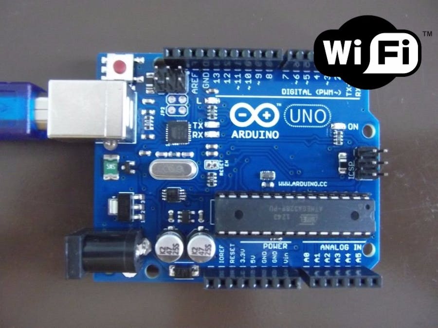
to add Wi-Fi, too. Simple Arduino board. In this course, you will
learn how you can connect your Arduino microcontroller
into a WiFi, would you all? And to make it with enabled, you can turn this symbol
Arduino board into an internet of thing device
with a few simple steps. Now, for this purpose, we will use our module about a cheap module that costs
less than four dollar. And it's called
ESP, Ready to 66. It's basically a Wi-Fi mode. You that can provide Wi-Fi
capabilities to Arduino board. We want fuse the WiFi Shield because it costs so much and
it has limited capabilities. And instead, we're
going to use a smaller, cheaper thing to make
it were enabled. I know that after
this course you will gain a lot of knowledge
that will help you start using any Arduino board as an Internet of Thing
based microcontroller. Adding this module
two, do you know on, on open you more
exciting devices, projects, and ideas
using the old symbol Arduino on a board or any
other board of that matters. Not only thing that you would
need is an Arduino board, and I will do, and we'll talk about that in the next lesson. Thanks for watching this lesson.
2. 2 Hardware and Software Requirements: Hello and welcome
to this new lesson. You are going to talk about what you will need
to make this happen. First, let's talk about
the hardware components. You will need an
Arduino Uno board, which is basically the main microcontroller
in our project. And you'll also need an ESP 266, or it's also called ESP 01. This is a very
small simple module that you can find everywhere. And we will need two resistors
are ten kilo ohm and the one kiloohm resistor plus wires and RID
board for connected. Now, these are the
hardware requirements. Let's go to the
software requirements. You will only need Arduino. Ide is an integrated
development environment, which is basically
a software used to program at fixed resource, like a notepad with
different features, is used for writing code, compiling the code to check
if any errors are there, and uploading the
code to the Arduino. We will use our write our
code and we will do To the right thing to do while writing this code in a
step-by-step manner. As you. Now, these are the hardware and
software requirements you need for this course. And you are going to explain
how to download and install Arduino IDE and
unnecessary files needed to make this work. For watching this lesson.
3. 3 Working Principle: Hello and welcome to this new lesson in which we are going to discuss that process or
the working principle. There are a lot of
ways to use ESP 8266 to communicate with Arduino board and to
have them all together. Some may use it to
send and receive data online or simply upload that. For this course,
we will just show you how we can communicate to Arduino wirelessly
using your smart phone or using any
web-based in browser. This will be done either
offline or online. Offline using mobile
application or online. We observe. Now our ESP eight to six essays will serve as access point. Which means that it will provide access to Wi-Fi and it works for other devices and connects them further to our
wire with what? The process is simple. You need to use your phone
to send any command to agreeing with the
help of ESP a 266. Everything would
work by adolescence. So your Arduino board
commands from ESP A22 66, and ESPN to 66 will receive
commands from new form. This is our phone,
but here we have it. This phone will send
commands to our BSP board, which is the ESP API to 66. Now the SBA to 66 will send command and I'll
read from and 80-66. So this will be
our Arduino board. Now, Arduino will
persist the message, messages that it receives
from the ESP is 66. And we'll execute
commands like turning on, building a button, et cetera. While ESPN 266 will send messages to Arduino and
Arduino read these messages. And the mobile
phone will be used to send string messages via TCP. And we can improve and work on that to make it receive messages from any web browser would be
a really easy thing to do. Simply by turning our Wi-Fi on and connecting Arduino
to our local Wi-Fi network. And we are going to discuss
that as well. That's it. This is the working principle and we are going to
explain how to do it. But first we'll start
coding process. That's watching this lesson.
4. 4 Circuit Connection: Hello and welcome to this
new lesson in which you are going to design our circuit. Now for this purpose, we are going to use Tinkercad, which is basically
a circuit design, 3D design, and simulation
software that is free to use. First thing, go and
look for Tinkercad, then go to the oxide. You can easily create an
account by hitting Join now. And you can say that you
are an educator student. If you have a student or a teacher e-mail or you can
create a personal account. Intrapersonal account
is easy using the sign-in with Google or
with Apple features. I usually use the sign
in with Google feature. If you don't have, you
can click on More sign in options and sign-in with
Microsoft or with face. If you don't have any of these, you can simply sign
up with email. And it will direct
you to this page where you have to
fill your county, you bear, and click Next, add your e-mail,
your password, etc. Now, you won't find the ESP a 266 module on Tinkercad because it's not
supported. But I have it here. I managed to import it
like with shortcut. So the main idea here is to learn how to connect
these components. So I need you to concentrate because failing to
connect it that way, I do well result in having your bold maybe burned out
or not working at all. So the first step now is
to add an Arduino board. Here we have Arduino and
let's place it here. Now this is our module. You can rotate the module using this button top-left corner. Let's place it here. And we also need to resistors. This is the first of the store. This is the second resistor. Now we need another
resistor down here. Let's rotate. It says now who will starts with
connecting the power line? Now, here we have power and
here we have the inept. We need to connect
them together. We need to take a point
and connect it to 3.3 v through a resistor. So let's change the color to red and connect the
other side to this area. That's it, shows the
color for this as well. Now we have the 3.3 v connected through ten kiloohm resistor. This is a thing
kiloohm resistor to fans power and enable
lump on three. Now, we need to
connect the TX and RX. Tx, which is this pin, can be connected directly
to pin number three. Design. And our x can be connected through
these two resistors. Let's change the color
for that first one, okay? Now this is the dx. Now here we have the RX. We need to connect it
to these two resistors. Let's make it green. Now we have connected
between the two resistors. The other side of that resistor would be connected
to pin number two. Bricks that zine. Now the last step is
connecting background. So let's change the
color to black. Connect a wire from this bin, which is the ground Ben. Go down and connect
it to this resistor. Now, drink a ground
pin from here. And let's connect it to
the resistor asthma. Now, this is our
self connection. We need to make sure that
these are one kilo-ohm. And this one is also on kiloohm. Now we have these two
pens connected to 3.3 v. We have this pin connected to t x directly. We have this pen. She's hidden,
connected to choose the first Spinner Tool
resistors and one side, the other side of this resistor
is connected. Number two. The other side of this resistor
is connected to ground. And that is also grounds connection to the first
friend here on the right. So you need to make
sure that this print, this print, these
pens are connected. The only pens that
are not connected data sets that GPIOs
zero and GPIO2. These two pens or
input output pins, if you want to use this as a
standalone microcontroller, you have a course about that. And this rosette pen is used to reset the board and
we don't want those. So here's the connection
to one kiloohm resistor, 110 kilo-ohm resistor, 3.3
v connected to two pens. Power and enable background is connected to ground then
and to the resistor. Now, both of these
resistors are connected together and connected
to that expand. The other side of this resistor is connected to pin number two and the exponent is connected directly
to pin number three. Now, to explain the connection, we can simply see that we are using tenants number 2.3 for the serial
communication. And we are connecting power and down to our PSP ball
from our Arduino board. That's it. This is how symbol? This. Now if you have
any questions about that connection or the circuit schematic,
I'm here to help. Now you can see the schematic
view by clicking here. And you can see here that
we have our green Ono. And because I have
another Bolden, same schematic, but it's not
shown. You can see it here. But this is basically
our schematic abnormal. And here we have a socket. Here we have one
kiloohm resistors, that 3.3 volt, and
the three bins here. Now for one down here, you can see this is the
module has eight pins. We have the tin
kiloohm resistor, we have 3.3 v and
2.3. And the ground. This is it. This is
our circuit schematic. If you only the
list of components, you can see them here. On Wi-Fi, you one kiloohm resistor to bind to
kiloohm, not used. And tinker ohm resistor. These three are not used. That's it. This is our design. Thanks for watching this lesson.
5. 5 Free IoT Platform to Visualize Data from Arduino: Hello and welcome to this
new lesson in which you are going to talk
about the platform that we are going to
use to receive data from our web enabled
Arduino board. Now, the platform is called Ask sensors.com and
it's free to use. That's why we love
this platform. Now, this platform will
help you get sensors, data on the Cloud, and control actuators
easier than ever with the use of web enabled
devices like Arduino. If it is connected to Internet, Raspberry Pi, ESP, our boards. It has a user-friendly
and easy to use internet of thing interface. Now, the first thing you need to do is to click on get
started for free. You will get a list
of pricing options. We only need the free plan, which is zero dollar per month. Simply hit the subscribe now can allow you to
connect up to two devices. We only need to connect
to an Arduino board. And most of the
features are available. Now here you need to write
your data, your username, your password, and
email address. Hey, now you need to
choose a password. And then hit I agree. Click Submit. Okay, you
can use spaces anyway, that was another password. Now click submit. Save your data just to make sure that you
will have it when you need it. They sent you an e-mail, which is a confirmation email. So go and check
your email to make sure that you can confirm your account
before you start using. Now, as you can see, I already received an email. Is click activate your account. And you should be good to go. Now that comes activated, hit the login button. Now once you have your account, you'll need and you need
to take a quick look. On the left here
we have devices. Click on it. And as you
can see, it's asking you, do you want us since all
device or actual device, I will select sensor device. You need to do this and
create a new sensor. Now, enter a name, Let's call it green or we can
write the description ion. Now, you can add modules. And these modules, you
can give them a name, a description, and
you can simply hit the edit button to change the module name and description. You can even define
the essence of location, latitude,
and longitude. And you can enable that show
since our location option. Once you are done, click Save, you'll end up with this page. This is our sensor on
our device up doing ESP. And here you can
see the API key, which is one of the most important things
that you need to consider. Because this thing will be
used on our Arduino code. As you can see here, you can see the modules that
you have assigned. And here we have the API key. So asks and supports communication with all it
workable microcontroller, bridges and material with internet connection
capabilities such as albino, ESPN to success and
other materials. Now, you need to get your API key from your
sensor device page, which is basically this key. And the next thing
that you need to do is to form the URL. Now as you can see here, we have our API URL. And this is where you
should paste your API key. So let's copy it and
go to the notepad. Paste it here. Now we have
our key or API key here. Now, here comes the modules. The modules are basically the values are that
we are sending. I only added one, would you? Because we are only
sending one value, let's say on the value
from our Arduino Uno. But if you have, let's say
568 or even ten sensors, you can simply
keep adding these. What you'll want, equal
value one to two, equal value two, and so on. But since I only
have one module, I will send only one value,
which is this value. Now, keep this link,
we will need it. Now. If you want this
to have the link, you can simply copy it on the
browser and paste it here. And it showed respond
with the numbers. And as you can see here, we have one because we have
only one module. And this is the value that
the April I send to us. So they buy Kias, right? And we can start using
it on our Arduino. Now, the next step is
to draw our dashboard. Now here we have a dashboard. As you can see, we have custom dashboards
and favorite switch. I can go to the
custom dashboards. You can create a new dashboard. Now, this feature is
available for paid accounts so you can go with
their favorite widgets. Now to see the data, we need to visualize it. You need to go back
to the devices and sensors or devices. From there, you can
click on Visualize. And when you reach this point, you can see that since
all tails and modules, now here we have the modules we can easily add I
graphed our module. And here it will ask you
about the graph details. The x-axis, the y-axis, and the minimum and
maximum values. So let's add zero. Let's add date for the x-axis. And the y-axis is add value. Now, we can set the
minimum and maximum value. I will leave it. You can
save the results here. You can see that the
maximum value to, let's say thirsty or 50, depending on what
you are sending. You can change the module
title with, let's say button. And here you can change line, bar gauge or whatever you want. I will leave it to line, then hit the Save button. And here you are. This is our bathroom graph. You can change this word, sensor or whatever you want. And once or albumin
is connected, we can easily see
this graph moving. This will be shown on
the practical as of now, you can even add alert. So you can enable alerts and you can and get email
alerts, your e-mail. If the max threshold
exceeded, let's say 25. And you need to check every
15 min or every one day, one week, depending
on what your needs. And we will make
every 15 min if it's exceeded one. Click save. So now we have a graph, we have an alert,
and we have emoji. Now, you can again change the module name
or anything you want. You can go back to the essential details here we have them. The API key, and you can add
as many modules as you want. As we already mentioned. Can also show the sensor
readings on our graph. I like a gauge, but since we
only have one with you all, Let's add the sensor and
add an imaginary module. Let's call it analog.
Hated the name. Call it analog, and save the changes against
them, the sensor. Now we have two modules, dot one, so we can
add another graph. And from here we can
select, let's say gauge. And we can select they're
gonna to be bar or series. Yes. So that green, yellow, red is after, let's say 40, and green from zero. Yellow from wanting a
minimum value is zero. And green to 1929 yellow,
which is the color. And read 4-200 and around value and an axon
value of zero or 100. Let's call it a sensor. And hit the save button. Here we have it. We have an analog gauge and a
digital graph on the left. This one would be
for the temperature. This one will be for the on-off readings that we
will receive from Arduino. Now, again, you can
even show the sense of location. If you want. You can click Edit sensors
and you can add any location. Let's copy the example
location from here. It is, and enable the
location exception source. Now, Ahmad will show your
sense of location here, and as you can see, we have a graphical interface that
shows us almost everything. We need to see that
the sensor is reading. Since our location, let's say
that location is different. It will show on the map as well. And here you can see the
exact same location. It is. That's it. This is like a quick walk-through
to the asks and so user interface and how you
can create sensor device, how you can create
modules to get different values
from your Arduino or Internet of Things device. If you have any questions
or if you fail to do any of the things
that we did here, you can leave a question
and we are all done happy to help you solve
the issue for him. Next, we will code
our Arduino board to send data to this button graph, which are basically on-off
signals from Arduino pen. But that's it for this
lesson. That's rushing.
6. 6 Coding Part1: Welcome to this new
lesson in which we are going to start the
coding process. Now the first step would be
running your Arduino IDE. Now, create a new sketch, which we will use
to write our code. Now, we are going to use a library called
Software series. So you need to include it. But software serial. Now to configure the serial, we need to define the RX and
TX RX and has defined dx. Now, you need to make sure that you have
the right numbers. So let's go back to
our design. Design. We have this pin, which is the elegant, connected to that green pen, connected to the RX. Now, since this is the t x prime must be connected to our
expand on our Arduino. And this is cell communication that receiver will receive
from a transmitter. And the transmitter
will send or receive. So r is for the receiver, T is for the transplant. So TX pin is connected to pin number three,
which is the RAX. So we can go back to our code is pin number three and the
other pen is number two, which is the t x that's
connected to the RX, as we can see in here. This one is called RX, so it's connected to
two, which is dx. Again, you need to understand
why we are doing this. Because the receiver
needs to be connected to a transmitter and
the transmitter needs to be connected to others. Now, the next thing is to
start the software Syria. So we will pass the
values of TX and RX x dx. Here we are. Now, this is the
server configuration lines. The next step is to challenge
the user configuration. We need to create a string
for the Wi-Fi network. And for the API String SIB. We need another string
for that password. Wi-fi network. We also need
another string for the IPIP. And for our sense of
platform. This is it. These are the three things
that we need the user to add. After that, we need to
add an alt interval, which is basically to enter file that massive pray that I think
operations like constant, unsigned integer,
interval equal 185000. Now, this is in milliseconds, so it's about 25 s. The last thing is to define the host and the
board for our asks Since or interface or
not for string cost. Nick one string port. The port is 80. Host is ABI. Ask sensors com. Now create a new variable, let's call it a t, CMD. Time. Now, AT commands are very common commands
in Sierra Communications. And we are going to talk
about them and few seconds. Now the second thing is Boolean variable CMD,
result equal false. Now, we have that these two variables that we will use with the AT commands. Now, let's move forward
to the setup function. And this function
is solved Assyria. A baud rate, 9,600, which is the usual
thing that we use. What you do and
all of our codes. Now, we will use it
for debugging and to see what's happening
on the background now, right, cereal, brand new line. And let's simply rent
a line of stars. Now we need to
print another line. And let's say that
program started. Let's make it. Then. After that, let's start the AT
command and location, which is the software
serial communication with our USP it to 66. Katy began at about
three to 415,200. Now indicates that we are starting AT command
initialization. Initiate commands. Esp 8266 or width. Okay? Now we will send the first AT command using
the AT command function. So if I send 80 CMD, this function will
take three things. The first thing is a text, which is the API command itself. The second is a number. The third is to say, okay, now we will send
another 80 command. This command will include
an actual command which is 80 plus C W mode equal one. Now at a semicolon. And let's talk a little
bit about these two lines. But after we save our code to make sure that we
have in the right place. Now here we have a
list of AT commands. Let's take a quick look
at this. This list. As you can see, 80 plus
RST. Start the module. 80-plus CW. Cw wounds will basically help you choose the Wi-Fi moons. 80-plus CW. Jab will join an access point. The access point will
list all access points. Q access point will
quit your access point. And we have other commands
like CIP status will get status of the
TCP IP protocol. Cip starts. We'll help you sit up
TCP or UDP protocols. Cip send will help
you send that. Cib close will help
you close TCP or UDP. Ci LFSR will help you get the IP and be MUX will help you
set multiple connections. And we also have CIP server, which will help you sit as
altered your device ourselves. This is a list of
the ethic months, and we already used one of them. So let's say this CW mode, which is basically to
set the Wi-Fi want. Before moving forward. The first command AT will help the device recognize
that who will send ATP? Now, the second thing is
sending the actual command to set the mood for our WiFi. Would you? Now, let's talk about
the function itself. The AT command function. The synthetic month function
will send these 18 months. And this function
is not written yet. So let's go ahead and dry goods. Go and write void,
send, 80, CMD. Now the first thing that we need to know
about this function is the fact that it
doesn't return anything. It will take a string, which is basically
the AT command, will also take an integer, which is the AT
command max time. And it will take an
array of character, which is basically
another string, which is that Aedes. The plane. Now, these are the three things that
this function will take. The first thing that
we'll do when we enter this function is we will print. So print command. And after that, we will print the
actual commands. So this is just debugging. So we are just painting
on the serial monitor. So here we will print cmd, which is the incoming
command that we will use. Now, we need to make sure
that sending or receiving data command does not exceed
a specific amount of time, which is a, T, C and D max time, otherwise we have a problem. So write a while loop to make sure that we do
not exceed this time. Now inside the while loop, you need to write 80 CMD. Time is below 80 CMD max time. Now, the CMD time, you must not exceed the maximum
time entered by the user. Otherwise, there is a problem. Now, once we go
inside this loop, we need to write the
command AT rent. Here we would write
cmd command itself. After that, we will check if now inside this if
statement, what we need to do. Now inside this if statement, you need to know that I knew that AT commands
that we send, if it is executed successfully, it will respond with, okay, so just to look up Spokane, so we need to make sure
that we are receiving this. Okay? So like AT dot find, this find will take
that read reply. Now after that, inside
the if statement, we will write this 80 cmd. The result equal. We initialize this
variable to be false to make sure that when we
are first getting started, it will only return true if we receive the okay After
that, the AT command. If this is the case, then break. Get outside of this. Once you have done, We
need you to increase the AT command type, CMD. Sorry, timeless. Now that interplay here, we reply is basically
reading this, okay? Again, if you received okay, it means that everything
is going just fine. Now, going back
to this function, we are done with the while loop. You need to bran cereal, then that is a result. And we will, for
printing the results, we need to make sure
that is man was sent successfully using this
line AT CMB results. So if the CMD result
equal, equal the room, then in this case, we need to bran cereal brands. And I'm done. That means that everything
is done correctly. So 80 CMD time, we'll be all set to zero
because we are done with this. Let's say liberal on
this sending operation. Now, if it is false, CMD result is false. This is false. We
need to print failed. And we will also set
this cmd time to zero. Now once we are done, and if it is a
successful operation, it is and the result is true, we need to reset
it back to false. So after this if statement and for the end of our function, we need to write 80 CMD. Result equal false. That's it. This is our eighties
and Command, or send 80 command function. Now in the next lesson we'll proceed with writing the code. This is like going
for a very long time. Now, we're all about
16 min of this lesson. So without further notes, if you need any help
with any of these lines, I'll be more than happy
to explain it to you in more details. But that's it. This is the first
part of our code. Next, we will finish
the setup function and we'll go for the blue function. Thanks for watching this lesson.
7. 7 Coding Part2: Hello and welcome
to this new lesson in which we're going to proceed with that coding of our Arduino to make sure that it can communicate with ESP to 66. Now, we are done with
setting the Wi-Fi moods. The next step is
connecting to Wi-Fi. So let's inform the user that
we are connecting Wi-Fi. And let's run the
wildfire name, SSID. And let's send the AT
command to connect to Wi-Fi. And the command goes as
this first unit, right? Kt plus C w j AB, or join access point, which is basically
the lists that we mentioned on the previous
lesson, list of commands. After that we need to write equal backslash and we
need to add another text. So here we need to
add a plus sign. Now, after writing
the plus sign, like SSID, another plus
sign to add backslash. And then another backslash. Double quotation twice,
then last password plus backslash, double patient. Another comma. Another comma. Okay? Which is the takes that if we receive means that we have
connected successful. Now, let's review this line. 80 plus TW join ACS is point equal backslash,
double quotation, twice. Blessed, SSID blas, backslash
between debilitation, a comma, then backslash, double quotations plus
password plus backslash between two double
mutations than either single or
double quotation. Coma 20 comma between
two double quotations. If you have send this, then we are done with the setup function and we need to go to
the loop function. Let's save our code. Now inside the loop, we need to create the URL for the request. Now to create the URL, first, we need to create a string, call it URL, equal
to that reputation. Get the bytes. After that. You need to append the
next string to this. You all right, You are equal. The first thing that
we will append is that API key that we will add. Another plus equal. Now here and a question
mark, number one equal. Now, as you can see, you
can add the numbers. You can add a random
value between, let's say 1,000 last week, what runs on ten? And the hand. So this will be the
format hardware will include the height API
key N, or the old one. And an ambush, which
is basically 012. And we already assigned
the number to be 10-100, which will be a random value. Now once you're done with that, we need to print something, the user to tell him
that we are still here. So cereal, the brand new line. Now, again, serial print, new line. In here. We need to tell the user that we are opening ECB connection. Now we will send commands
to open disconnections. So send three commands. The first one will be 80
command plus CIB MUX equal one. The time is ten and
the return is okay. After that, we will send
another command, CMD. Again. Man is 80 plus c equals zero. And after that, we need to send backslash, TCB and capital. And another backslash
and a semicolon, or a semi or a coma, sorry. Now after that comma, we need to add another backslash and to double quotations, blasts, blasts. Another backslash. After that, add a comma, single quotation
or double quotation. And plus the port number, the time, which is 20, and the reply which
pushes, which is okay. So this will make sure that we are connecting
to the host. This portion and the
host on the board are basically values that we
already created here, which is the asks
and social platform. And it's formed. Now once we are done with that, if we got an okay means that we have
successfully connected. So we need to send
something, send commands. We already have the answer. We need to initiate the send. Cip send equals zero. Now, before the
end, add a comma. Now what we need to do
is to add the string. So string length plus four and add a comma ten, which is the time another Homer. The sign, which is great. Now we will send the printing, are requesting you are to the user to tell him
where we are right now. So serial print LN. Now someone might ask, should I like
memorise all of this, or should I know all of this? No. You can simply copy the whole code and paste
it on your Arduino, upload it to your Arduino and start using the project
or the app greener, but connected to the Internet. But we'd like to
explain every piece of detail because this is what our students
are expecting from us and this is
the right thing to do. You need to know if
the read line of code whites here while
you are writing it. And why you need to write. This is simply user that
we are requesting URL. Now, we will print they are
all on the serial monitor. So Serial.print. You are on. Now 80 the n. We will send the URL to
them as an ethical manner. Now after that,
this other delay, for this to stabilize
2 s delay on top, then we need to close
the connection AT CMD. And in here died AT last. Cip laws equal zero. Then k. Now let's tell the user that we just
close the TCP connection. So phase these two lines here. Tcp, TCP connection closed. Now after doing that, simply, another line of starves
and add a delay, which is basically the
right interval the day. As you can see, the lane right. Now, That's it.
This is our code. And what you need to do at this point is to go
up here to change that API key in with your device from the asks
and soles interface. Landfall. We already
have this here. So I will just copy the API key. And simply get it from here. I can go back here, paste it. Now, you need to write this
as ID and the password. Now someone might ask, where are the values
that I'm sending to our sensors platform? Which is a good question. Now if you scroll down here, you can see that in here these are the values or the random values
that we are sending. These can be seen
as central value. So you can replace this
line with you can commit it and replace it
with you or Alt plus equal temperature sensor. And it will send a
temperature sensor, sensor values to that
platform. It can be a batch. One. Value will send the pattern of value
to the platform and you will be able
to visualize it. But we are sending a
random value each time, 10-100, to see the values
on the graph moving. And here is the graph
that I'm talking about. Let me open it. Here's the graph that
we're talking about. Now we can even change
the subgraph to match that ten to 100 values. So it, it charged to keep it. Let's give it a line between 1,000 and hit the save button. And we will see the values
here once they are coming in. Now, as you can see, between ten and they will keep moving. Now it won't be a baton
value to be at random. So let's change
again random value. But again, you can change
it with any other thing. Simply change this line of code, this slide, remove this and
add whatever you want here. Now if you want to add
another module, you can, you can simply do
that by copying these two lines and
pasting them here. And add module two. And the values here. Then Add
Module three values here. So it will be censored one, since there's two or
three, and so on. And you also need to change
the SSID and password for your WiFi network for uploading the code and make sure that
you have these numbers. And that item. We will
provide the full code. And if you did everything just like what
we do, what we did here. You can easily get your Arduino connected to Wi-Fi and sending
values for the platform. Now, we will save the code, we will add that
SSID and password. In the next lesson,
we will upload the code to our Arduino board. And the final lesson, we will test this out. Thanks for watching this lesson.
 Achraf Mad, Creative Engineer