Transcripts
1. Presentation: Hello everyone. I'm welcome
to this sketch up course. My name is Manuel Perez. I am an architect and
three D designer. And throughout my career
I have worked for different architectural
studios in charge of the realization of three
D models in a sketch. In addition, I've been
teaching sketch up in different creative schools
for several years. And as a result of all
of that experience, I've created this online course in which I've tried
to synthesize all that accumulated
knowledge in the best possible
way in this course. Therefore, maybe you will
start as a beginner, but without exceleration, you will finish it as an expert, of course, As long as you are
able to finish the course, because it is a
long course where we will immerse ourselves
in the program. But I can assure you that it
is a very fun course too. We will study each of the
programs tools through theory and various
practical exercise at different scales. We will combine
academic exercise with professional projects taken from my architectural
activity as a teacher, I've had many students
face to face, and I've seen the
main difficulties you usually encounter
in the program, which are invariably the same. Therefore, the course
is designed to focus on all those complex
aspects of the software. Drawing a sketchup is easy. It is a very intuitive program, but it is just as
easy to draw battery, Do what I used to call Pat work. When the model we want to
draw becomes more complex, that way of drawing
no longer works for. To model correctly in sketcher, you have to understand the
sketcha way of thinking. It is a very special
way of thinking. Understanding it will
take us a bit of work, but once done, it will be like
understanding the matrix. Everything will make sense. We will be able to model
all kinds of architecture, interior design, landscape
or construction projects. The program is very
fun and full of possibilities during the course, in addition to theory and the different practical exercise associated with its model, we will carry out project of high difficulty in
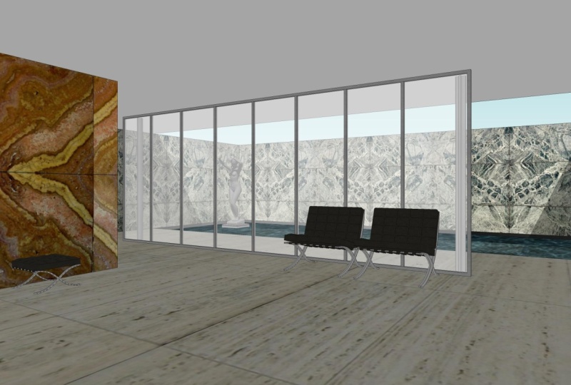
a transversal way. We will model one of the most emblematic buildings
of the 20th century, the Barcelona
Pavilion, designed for the Universal Exhibition
of Barcelona in 1929 by Miss Van der Roy. Finally, to finish the course, we'll learn a new
software layout, connected in real time
with a Sketzap layout will allow us to make
presentations of our projects. Because we have to be
aware of the fact that having a good three
D model is just as important as knowing
how to present it to our teacher,
colleague, or client. All this and much more awaits you in this
sketch up course. So if you are ready,
let's get started. I would like to highlight
that the course will be updated every
year with videos of the new versions
of sketch up and with the most
cutting edge plugins paying special attention
to the development of artificial
intelligence in Sketchup.
2. Intro to Setchup: Hello everybody and welcome
to this SketchUp course. Inward, we will learn everything about this amazing software. My name is Maria Garcia by race, I am an architect
from Madrid, Spain, and I am a specialized in the
development of 3D models. First of all, I would like
to talk a little bit about the history and some
characteristics of SketchUp. A SketchUp was
actually created in 2000 to buy an enterprise
called last software. After four years, Google
decided to buy this enterprise. But finally, in 2012
was Trimble navigation, the one who acquired
finally, SketchUp, as you already know,
we are talking about are three V modelling software. And you will be able to run this software either
in Windows or Mac. The license in order to
use the software can be taken for free in the
official website of SketchUp, although it is limited
for some time, or you can own the license, and depending on your plan, the price will be different. If we talk about the informatics
requirements here you can check the features of their recommended hardware and the minimum hardware in the description of
this video anyways, I will give you more
information related with the specific requirements for a Windows computer
and a Mac computer. But to be honest,
the requirements are very similar in both platforms. And I would like
to point out here, the importance of the
processor gets up is a software which demands
a very good processor. The graphic card is important, but it is not paramount. Nevertheless, if you want to use SketchUp in a
professional way, I strongly recommend you to invest in a very good computer. If we talk about the 3D design abilities
of these software, based on my experience, I have to say that
SketchUp is as super flexible and
polyvalent software. We will be able to model
architectural projects, interior design projects,
landscape projects, town planning, construction,
design of products. And we can even use it in order to develop 3D print projects. And these are not just words. You should know that
I've been working in different creative schools as
a teacher for a long time. And I have had a lot of pupils from different
backgrounds. Some of them were architects, others who are engineers, others were doing
landscape master degree. So maybe this is one of the most important strengths of this program,
the flexibility. Once you have an
overview about SketchUp, I just would like to say, welcome to all of you. I am going to do my
best in order to give you all of my knowledge and
experience with this program, the course has two main pillars. The first one is to be very
professional and give you all the information and knowledge
that SketchUp requires, either with theory or
practical exercise. And the second pillar
is to have fun. During the process,
we will learn to sketch out through
modern buildings, Greek temples,
contemporary editorials, pyramids from the ADPCM times. Time to say goodbye now, and we will start working
in the next class.
3. Installing Sketchup: Hello people and welcome to this first class in where we're going to see the
possibilities that is, SketchUp offers us in order to install the official version. So we should go over
a sketchup.com. And here let's hover
over Plans and Pricing. One-click, compare all features. I change the currency, dollars. And as you can check, we have different
options available from $0 SketchUp free to $699 per year is SketchUp
studio just for Windows. In the middle, we have a
SketchUp go and SketchUp Pro. If we follow these columns, we will see the different
features of its plan, e.g. these free version
will not allow us to work with it in our desktop. We don't have the layout
software included. The 3D warehouse library
is limited, and so on. So I really don't recommend you to work with this free version. Actually, in my opinion, we always should work with
these SketchUp Pro plan, which has all the
important features except the skill to import
and viewpoint clouds, which actually is something that we will not
see in this course. And this photo-realistic and
real time visualization, which is related with virtual reality viewing,
not normal renderings. This is something just
relevant in case that you want to be a specialized
in that field. So my suggestion here is the most popular plan
is SketchUp Pro. Anyways, if we hit this
another option, try SketchUp. You will be able to use these SketchUp Pro plan
for free during 30 days. Anyways, looked at here we have different labels for
personal projects, for professional projects,
for higher education. And this is the
option that I want to point out on the four
primary, secondary school. In case that you are in school, you can get SketchUp for free, but I guess that you
are not in school. You are an individual person and maybe is very likely
that you are a student. Then if we hover over Plans and Pricing for
higher education, you can get SketchUp for
our very reduced price, just $55 per year. And you are getting
this ketchup is to plan the best one with all
these features included. So maybe this is your epsilon. It is available for students, educators, and for universities. So time to say goodbye, and I will see you
in the next class.
4. Templates: Hello people and welcome to this first class of
these SketchUp course. Inward, we will see the first thing that we have to do when we open a scatter. That thing is to
choose our template. This is the welcome page. And here we have different
templates available. If you look carefully, we can read meters,
inches, millimeters. So the most important
thing here is to be hour of the unit
that we are choosing. Furthermore, we have a
thumbnail in where we can see the colors
of that template. So of course, this depends
on your preferences. Anyways, Here, more templates. Let's click it and then again, focus on the units
of its template, the colors, and in some cases, the position of the camera
changes as well as e.g. here in this plan view, where the camera is
placed in a top position. If you want to make one
of them as your favorite, you have just to
click on this heart, one-click and then
this template, when you close this window, will appear here in the
very first position. Anyways, during this course, we will work with this
template, simple meters. But before clicking on it, Let's explore a little bit more. Welcome page. Down here, we find these and other option, goal open fire. If I click on it, we will be able to search
for an SketchUp file already saved in our computer
or in another device. And if I continue
scrolling down, we have this another category
called recent files. So from here, a SketchUp
makes our life easier. We can open files which
have been used recently, and we have even the
possibility to recover some files which we didn't
save when we're close to them. So here we can find automatic recovering
where we can read the date and the time in when SketchUp made
these autosave. Finally, we have here
information about our license. And here, if we click on Learn, will find different tutorials,
the SketchUp forum, the SketchUp campus, and
sketch up videos in order to learn by ourselves
about this so forth, Let's click on Files again. And once we have this general view about
this welcome page, let's click on this
template, simple meters. And once our file
is already opened, we are ready to go
to the next episode.
5. Preferences: Hello guys. And we'll go into this new class where we will see specific to
call preferences. We will find it if we move
over Window Preferences. One click on here, and then this window pops up in where we find different options. As you can see here, we have a list of
different categories. Now, template is marked, but if we start
from the beginning and we select accessibility from this menu will be able to
change the default colors used by a SketchUp in order to represent
different things. The red axis, the green axis, or the blue axis. We are talking about
this general axis, which actually is super
important because it will be our main reference all
the time in Scripture. So we can change the colors
of this general axes. We can change other colors
as the parallel and perpendicular lines or
even the tangent lines. In case that we don't want
to apply those changes, we can reset all the
next three options. Applications, compatibility
and rowing, in my opinion, are not very important because the default
settings are quite good. But taking mine that you can change the default image editor. You can say it e.g. as well, the mouse wheel
style and inverted. You can play with a
clicker style and some different
options as this one called Disabled pick
on push-pull tool. You would understand it when we arrive to this tool, push pull. But as I told you before, the settings are
already quite good. So we can jump to the
next option called files. Here we can read file location. So this menu is quite
good because we can easily know
where it's placed. Everything in a
sketch, the models, the components, the materials, the styles, the texture, images, the watermarked images, the export, the classifications,
and the templates. We can even change that
file location preference, or we can open that a specific folder and then use
that file for any purpose. The next option is
called generalise. This first category is saving is quite important because he's talking about the backups of
our files and the autosave, I recommend you to set the
auto save every 5 min. So in case that you're
a SketchUp crust, you would be able to
recover your file and you just lose 5 min of work. Here, I would like
to make a break. Let's focus now on this
folder in where we can find these two
different files. One is an a SketchUp file, which means that the extension
or the format is S k, p. And the other one has an, a strange extension as it is, S k be this S KB is the backup. As far as in our preferences. We said that we want to make an auto save every five-minutes. These both files are gonna
be saved every 5 min. And as far as we said in our preferences that we
want to create a backup, then we will always have
this strange file with this strange extension as KB as a backup of
our SketchUp file. In case that we lost this file, we can always recover our
information using the backup. We should select
it right button, go to Properties and then change that strange extension
and type in S, k, p, SketchUp, extensive change the name of the file in
order to don't have both files duplicate
it because then we will receive an
error and say accept. This window is asking us if
we are sure, we say yes. And then this backup is now available to be
used in SketchUp. The rest of the options
are not important. So let's go to the
next one, open D L. Here we are talking
about our graphic card. From here, we can adjust
this multi-sample anti-aliasing in order to avoid our image to be pixelated, this value is okay, and we can take the properties
of our graphic card. The next option called
shortcuts is one of the most important things
that we can set from here, we will learn how to do
it in a specific episode, because thanks to it, we will have a much
more better workflow. This template option is talking about the thing that we saw
in the previous episode. Templates. Here we will find the same templates as
in the word compete. But look because if I
select this template, e.g. this plan view and I click, Okay, my file is not
changing at all, just in case that I
go over File New, then the new file is going
to use that template. So again, Window Preferences. Let's go to the last
option workspace. Here we can change the
size of our main toolbar. I'm talking about
this one placed on the left side of our screen. So if I unclick this option called use large two
buttons and I say, Okay, you can check how this toolbar now
is smaller, right? So it is better to don't
unclick this Upsilon. And finally, thanks to
this reset workspace, we will undo all
the changes that we previously had done
in our interface. Imagine e.g. that I decide
to close these Default tray. If I go over Window Preferences, work space, and I
click Reset Workspace, that Default tray appears again, and my interface will be
again as it comes by default, I will lose all the
settings made by myself. So once we have an overview about these preferences panel, is time to say goodbye. And in the next episode, we will see another
important window, as it is, the model info window.
6. Model Info: Hello guys and welcome
to this new class, where we're going to see
another important tool, as it is the model info window. We'd have two ways. In order to open this panel, we can go over window model
info just above preferences, and then this window pops up. And here we have all the different categories
available for us. The other option is to go down here and click
on this cycle. One-click and the model info
window is opened as well. As you can see, we have
different categories, animation classifications,
components, credits, dimensions, file,
geo-location, rendering, statistics, text, and units. We will see all of them
during the course. And in this class we will focus just on the last one, units. We saw how when we
choose a template, we are choosing a unit as well for our SketchUp
document, right? But we can change that unit once our document is
opened and we should do it from here,
model info units. Then if we move over format
and we expand this window, will find different options, architectural, decimal,
engineering, and fractional. This is up to you. I am an European guy, so I am getting used to work
with the decimal format. And besides decimal, we can choose if we want
to work with meters, centimeters, millimeters,
et cetera, et cetera. Normally I work with meters, but we can do it as well with centimeters depending
on the project. If we're doing a big project, maybe make more sense
to work with meters. And if we are designing e.g. I don't know, I kind of vase
or something like that. It's small. We can
choose centimeters. Take in mind that we can
change the units so easily. So don't worry, once
our length is 2M, We have to display
the precision. Decimals are okay. We don't need more. And
then we'd have to do the same with the area
and the volume, not just with a length. So it makes sense that
the area now we choose square meters and I'm
volume meters as well. I strongly recommend
you to have marked this both options enabled length is snapping and
display units format. And then we jump into these
Another Label angle units. Again, we can adjust
precision 0.0 is okay, but let's say 0.00 more precision enable
snapping, always mark. And this 15 degrees
means that when we are drawing an angle
every 15 degrees, the tool is going to
stop in order to mark those 15 degrees and
make our lives easier. We can change it, but 15, in my opinion is okay. So as you can see, this
panel is very intuitive. Once we have chosen all
of our preferences, we can close it. And if I measure something, e.g. this high looked at in
our measurement bar, we can read 8.00 m. So
time to say goodbye. And in the next episode, I will give you a piece of information which I think
that it's very useful. And it is about how to
open different sketch up files and copy
different elements from one file to another. This is something that normally
it should be super easy, but clearness gets up. It is a little bit tricky. So in order that you don't have problems during the course, we will learn how to do it
early when we are just in the beginning of
the course and then we will not find any
travel in the future.
7. Open different skp files at the same time: Hello people and welcome
to this new class. Inward, we're gonna see how to open different SketchUp files at the same time and copy different elements from one file to another in this process, although it is very, very simple, is at the same
time a little bit tricky. So let's see how to
do it correctly. This is a modern house. They can from the
warehouse library. And imagine that we want to include more and
more elements, e.g. let's say a car. This looks like the
entrance and we want them to add here a car. The thing is that that
car is in another file. So the first thing that we
want to do, open that file, then the logic is step, good way to go over file, open, search for our file. Here it is, The name is
car selected and open. But look what is
going to happen. Our car file is already open, but then the previous file, the modern house
file, is closed. If I hold down Alt
key class tabulation, then I can see all of
my windows already opened and a half just
one SketchUp file, open the car one. So this is something which
can make us feel Gracie. And the solution to
have both files open at the same time is to
go over that folder. Here, we need to open the modern house file and then open it from
here, two clicks. The file is already open. And if I hold down
Alt plus tabulation, the car file is opened as well, so I can go over
both files easily. The thing now is that
if I want to copy this car and paste it
in my modern house, I have to select my car, go over edit, copy, then go over the other file, the modern house
file. Go inside. Here, say Edit, Paste. I have to wait a little bit, but here we have the car. So as you can take in
order to copy one element from SketchUp file to
another SketchUp file, we first need to have both
files open at the same time. Then we select that specific
element, Edit Copy. We move over the other
file and edit paste. I hope that this process is
totally clear now for you, because in the next
future during the course, we will have to use it
time to say goodbye now, and I'll see you in
the next episode.
8. Workspace : Hello everybody and welcome
to this new class in where we're going to talk about the workspace in SketchUp. As everything in SketchUp, their workspace is very
intuitive as well. So at the left side, we can find this large set tool which can be moved easily. Just click in here at the
beginning and dragging. Then I could place this
toolbar in another position. But to be honest, the best place in my
opinion is where it was. So I click, I drag
till the left side, and then I released
this large tool set is divided in different
group of buttons. The first one, I like to
call it select some group, even when not all the
buttons are for selection. The next one, I call
it drawing tools. Next one is going to be
transformation tools. If we continue, we will
find the measurement tools, then the navigation
tools, camera tools, and finally these two options, 3D Warehouse and
extension warehouse, which will need to
use the Internet. Furthermore, you can
see that we have more bars with
many more options. If I move the mouse to the top and I click
the right button, then all the toolbars available in the software right
now will be sung. We have just to click or
unclick for using them. I said right now, because we will be able to add much more options when we learn how to use the
extensions or plugins. At this very moment, at the beginning of the course, I would like you to
have on your workspace, the section toolbar,
the saddle toolbar, this one called tax. In older versions it
was called liars, this one called views, and this another
one called styles. Let's say that these ones
basics about this bar, we can find the menu bar, which is very
classical, width file, edit, view, camera,
tools window and help. If I go into any of them, we will find more options. But the one which
is important for me now is here in window, this first one
called Default tray. These Default tray,
it is related with the panels that we can
see at the right side. This is called the fold tray. And now we have here
these different traits related with the ones which
are currently on here. So e.g. if I go to
Entity Info, I close it. It is not here anymore. But if I wanted to restore it, then I will have to go here. We know Default tray and
click over Entity Info. Then it is here again, but this time in
the last position, I will have to click and drag
till my desired position. In this case, the first one. Of course, during the course, we will go deeper into all of these default trace because all of them are very,
very important. But now we just
want to understand, let's say the organization,
the workspace. To finish the class. If we go down, we will see what is
called measurements bar. Here, there is a space
where we will be able to type measurements
using our laptop. And if I go to the left, we can find two different items. The first one is this
person inside a cycle. If I click on it, then this window will be opened. It is called model info window
with different options. If I move even more to the
left and I click on it again, model info window
will be opened, but this time it is
marked the geo-location. This model info
window is important. We will be able to
open it as well if we go over window model
in the same window, once we have understood
the workspace of SketchUp, we are ready for going to the next episode
in where we will start learning how to navigate
in this 3D space Canvas.
9. Navigation: In this episode, we will
talk about the navigation. So first of all, we have to understand these three axes that we
can see on the screen. One is blue, another
one is green, and the last one is red. They are representing
the three-dimensions that we have in this space. The blue one, a
vertical dimension, most of the times represented
by the letter set. And then we have these two ones, the green and the red for representing the
horizontal dimension. The letter for the green
one is the letter Y, and the letter for the
red one is the letter X. So as you can imagine, this axis will be all the time. Our references for don't be lost when we are orbiting e.g. because at the end it is like
if we are astronauts into space and then we have to be patient in order
to be able to, let's say, control our movements or the movement of the
camera as to prefer, in a very accurate way. I would like to add as well that every axis continue
after the region, which is this point I am
marking right now with mouse. So this lines, this axis
continue with a dotted line which represent the negative
part of that dementia. Furthermore, if we look further, we will see the line
of the horizontal. Above that line, we have the sky in a blue
color right now. And below that horizontal, we have this gray color. All of the canvas at the end
is representing a sphere. At this very moment, we don't have color for
the plane of the ground. Right now, that plane is
completely transparent. So we can see that semi sphere below the horizontal in
that gray color are, we can see that
another semi sphere above that horizontal
line in that blue color. In the next episode, we will talk about the templates
and in a very rapid way, I will teach you how to change those colors in case
that you don't want it. But continue with this lesson in where we are focused
on the navigation, we have to pay attention to
this group of buttons we have here where we can find this first option called orbit, which actually I am already
using it without clicking on here because I am clicking on
whole the will of my mouth. Then I click I hall
and I moved for understanding better these
movements of the camera, I will draw a queue. Once we have this
cube as a reference, if I click a whole, the will of my mouse and I
move my mouse to the left. What is happening is
that we are actually looking at the right side from my point of view
of these Q, right? So if I move now the
mouse to the right side, the other side of
this cube is visible. Besides, if I move the
mouse now to the top, as you can imagine, what is visible now is the
ground floor of this cube. So the opposite all the time. And if I move my mouse down, then I am Watson at
the top of the queue. So I recommend you
to draw this cube. It is very easy. You just use a rectangle and use the extrusion,
push and pull, and be very conscious
about how this orbit tool works in a sketch will help you a lot for the next lesson. Apart of this orbit tool, which is very, very important, we have this pan tool, the shortcut for the pen tool is the letter H in your laptop. And then what I'm doing is not rotate the camera as
I was doing before, but moving the camera
vertically or horizontally, but I am keeping more or less
the angle of the camera. Next option is the soon
using the wheel of my mouse, I can scroll in or scroll out. But if I want it to
be more precise, then I could use
these two tools. The first one called
soon, one is clicked. If I use the left
button of my mouth, I click and hold, and I move the mouse, I will get closer, but in a very soft way, softer than if I am using
the scroll of the mouth. So sometimes can be useful. Next option, Zoom window, will allow us to create a
window clicking and holding. And then I will assume that content inside that
window when I released, then I have some
that specific area. I will do it again. With this woman, I create
this window around her. And when I released, then you can see that we have some the woman at her
maximum size in our screen. Next option for a
good navigation is this button
called zoom extents. This is a very useful
bottom in my opinion because it will help us
a lot to recover our, let's say, perspective drawing when we are quite lost, e.g. imagine that we are here
now, maybe too close, and we want that perspective in where we can see everything. So we can click on here. And then the camera, we'll capture the complete
drawing at its maximum size. That is very, very
nice because e.g. if I have another object, let's say a line here
and we were just pointing this woman and I
use again this zoom extents. What the camera is going
to do is to capture all the drawing at its maximum size, as
I told you, right? So you can see here
how our drawing now is not that big
because the camera has to go farther
in order to get that line which was hidden
under these Default tray. But it is there so many times. If you click on the
Zoom extent and you realize that the
camera goes so far, it is saying to you
that something, it is drawn and maybe
you can't see it. Anyways, I will erase this element and let's
jump to the next option, which is called Previous. These previews is kind of undo, but just related with the
movements of the camera. So we will go one step back
in our camera history. I click on it and you can see our previous step was
here pointing this woman. Finally, it is important to point out here in this episode that we have this toolbar
which is called views. I wouldn't put it here. Now, which is going to be super, super helpful for navigation. I mean, we don't have to
all the time try to place the camera manually using these tools that we
have just learned, like orbit or pan
or zoom extents, we have this automatic positions of the camera right
here in this toolbar. And the first one is the
isometric view of the model. Click on here, then we
have this isometric view. As always, we will have to keep in mind the
position of the axis. Then we have this another
option called top in where we will be able to what our
model from the top one-click. And here we are. Then we have front, right, back, and left, e.g. if we start clicking on front, you can see how the camera moves exactly to this position. And again, pay attention
to the axis in order to know where
exactly are you. If I go to right, then the movement of the camera has been towards the right side, then back, we continue moving
to the right and then left. So this is going to be super
helpful as I told you. I'm finally we have this
another option which is just select one face of
the object right button. And then we have this
option called Align View. If I click here, then the camera is going
to be aligned with that phase Following
that orthogonal line. To finish with the navigation, I would like to mention another tools that
we can find if we move over a camera here we
will find these two option, parallel projection and perspective when
we're navigating. It is very, very interesting and useful to switch between
these two options. Normally, we will be
working on perspective. But if I select
parallel projection, you will see that everything
is like if we are working in a dihedral system. So if I use e.g. this top view, all the
measures will be real. I mean that it is like if we're doing a
planned floor here, we don't have
perspective at all. All the lines are parallel
between each other. So this could be very
interesting for generating, as I said, gland floors
or elevations, e.g. if I move to this
front view, etc, etc. If I go again over camera, we will find here a third option called two-point perspective. But this upsilon, Let's say that it's not that important for the navigation and
we will see it in a more advanced
stage of the course. Good, we will finish
the class here. We will talk more
about navigation. This is the beginning. And of course, practice will make you
more and more wetter. And at some point, you will not have
to think is like driving a car and
the movements of your fingers and
your mouth will be super accurate even
without thinking. Time to jump to the next
episode where we're going to learn how to
use the selection tools.
10. Selection tools: In this episode, we will talk
about the selection tools. Well, first of all, I'm going to draw one
rectangle and one Q. So I'm gonna go here to this
drawing tools rectangle. I click on the origin, one-click and second click, e.g. here, I will do exactly the
same now with the first click on the red axis and the second click more or
less around here. We don't have to be
accurate right now. So next step is going to
the transformation panel. Click, pull some pool, then go to this surface,
one-click unreleased. Move your mouse up and just
click again when you're high, when the high of your
cube is okay for you. Here we are. So we have
here now these two guys, the first one is in 2D and
the second one is in 3D. They will allow us to
check how we are going to select things in SketchUp
depending on if we, our entity is 2D
entity or 3D entity. So first thing that we
have to do is going to this first button called
Select and click on here. Then you will see this
black arrow on the mouse, which is going to be our
minds selection tool. Taking mind that
the shortcut for this important selection
tool is the Space bar. If I go again, e.g. to post poll and I want to go to the selection tool using the
shortcut, then Spacebar. And here we are. So let's start with this
rectangle in two d dimensions. First thing that we can
see is that this surface, this gray surface,
is made in dots. This is because it
is already selected. If I want to unselect
this surface, I have to click outside. Then we have now
these clean surface, which actually is in
this grey blue color. Maybe we want this
surface in a white color. Then I just click on it. It is already selected
right button. Here we can find this
option Reverse Faces, one-click, and here we are. We'll talk about why we have these two colors in all
the different phases. It is not the correct
moment right now. So let's focus on
the selection tool. First thing that we have
to have in mind is that SketchUp is all about
surfaces and edges. We have here a surface
and we have edges. I want to select any of them. Yes, one-click on
the correct spot and that entity
will be selected. If I want to add more
entities to my selection, then I have to click
and hold Shift. And again, click, I can
release, scroll out, scrolling, click and hold Shift again and add more entities to
my selection, e.g. these four edges
around this survey, I can select as
well the surface. And once it is already selected, if I click and hold Shift and I click again
on the surface, it will be unselected. So this is one way for
selecting different entities. Furthermore, we can
use the box selection. This book selection
works like that. If I start the box from
the left to the right, one click and then I haul, I move my mouse, e.g. till here, what is
going to happen? As you can see, just this
EDS has been selected. And the reason is because it was the only entity which was
completed inside that box. I click outside for unselect that and I will repeat
the operation one box. You can see, you can take
right now that the only entity completed here is that it just, this one has been
selected again. On the contrary, if my selection goes from the right to the left, we can see that this window, this box is made by a
discontinuous line. Then everything inside that box, even when it is not
completed, will be selected. I release. And here we are. This adds this another ads on
the surface being selected. This time, the same
story when I am working with this 3D cube, if I click and hold and I do this selection box from
the left to the right. And I release here just this line was complete
and then it is selected. On the contrary, if my box goes from the
right to the left, e.g. two here, these three edges
where inside that box and have been
selected and the same story with these two surfaces. Easy. Eventually we have
a third option for selecting entities when we
are working with a 2D entity, if I click once in the surface, we already know that
it has been selected. But if I click twice, then I am selecting the surface plus all
the bounding edges. We can go to this
option as well. If I click on the surface, then right button
select bounding edges. As you can see here, we have more different options. Let's see how this
works with 3D cube. One-click on the surface, then I select the surface, two clicks, then I select the surface plus
the bounding edges, and we have this third option, three clicks on the surface,
click, click, click, and then I select everything
connected at the end, all the cube edges and surfaces one-click
outside from the drawing. Then I unselect everything. As you can see, it is very easy. I recommend you to
practice at home. And in the next episode, we will learn about
the shortcuts, which are very, very
important in order to get a very good
workflow in schizo.
11. Shortcuts : Hello everybody. In this lesson we will talk about the shortcuts in SketchUp. So first of all, what I'm
going to do is to import here the image that is attached
with this episode. Actually there are some of them. Specifically, we
have four images depending on the sketch
our version we are using. So I should go over
File Import here. We'll choose the correct folder. Once there and choose the
option for desktop Windows, then I will choose my first
point here in the region. My second point, time
to erase this woman. And I can choose this
option some extent and say that I want to look
at this image from the top. Here we are. I recommend you strongly that you spend
some time trying to study these different
keyboard shortcuts because as soon as possible you have to use it frequently and then your workflow will
improve dramatically. If you look down here, we can see which letters of our keyboard is already
assigned with different tools. E.g. letter Q is
going to rotate. Letter E is going to erase letter R is for
drawing a rectangle. Letter T will grab the
measurement tools. Let her be very important
for Pusan pool, letter a for drawing an arc, S for the scale, for the offset g, Letter D, which actually in
my laptop is doing nothing. Letter L for choosing
the line tool set for the soon see for the cycle be
for the Paint Bucket tool, which will be used in
order to apply textures. And finally, M for moving. Different entities. Pay attention here
to the arrow case because they are super,
super important, they will allow us to look movement along the
different axis. Left arrow for the green exit, right arrow for the red arrow up for the set access,
an arrow down, it is this pink color for
drawing orthogonal lines, we can use as well, of course, the number of paths in order to enter different dimensions. And if you check here
all the descriptions, you will find more options
which can be very useful, e.g. as this one here
with the pen tool, I told you before that you
can use the letter eight, but you can use as well Sift plus whole
middle mouse button. I click and hold the middle mouse button and then we can pan the screen anyway, during the course,
I will all the time be using all of these shortcuts. So I think that,
yes, Watson, me, doing the exercise
will help you to remember more and more
these different commands. Furthermore, in this episode, I would like to show you how to customize your own shortcuts. If I go to Window Preferences, Here we'll find an obscene
phone call shortcuts in where we will
easily find any tool. Here, we have just to
type the keyword e.g. imagine that we
want to use these two here with this I
called Look around, then we type here, look around, just typing down. Look, we can find
here the function. Once we hit on it, it is already selected and we should just add a shortcut, e.g. the letter oh, but
pay attention here at this assigned window because the letter 0 is
already assigned. In your case, it's
very likely that you don't have this
letter assigned yet. So we can write here 0, then say plus 0 is
currently used by camera. Look around, okay? Once we have that letter
inside the assigned window, we can say, okay, and now if I click letter 0, we can see that we are
using the look around tool. As you can see, it is
a very easy process and a step-by-step. I suggest you to
customize your shortcuts in order to improve
even more our workflow. Time to say goodbye now. And in the next episode, we will do our first
exercise in where we will improve our
navigation skills, practicing with a
simple exercise.
12. Navigation exercise : Hello everyone. In this exercise we are going to practice their navigation tools. I'm doing one
exercise that I have checked with my different
students that is kind of, let's say, useful for you. So first of all, we have to hit the
rectangle tool. If we use a shortcut, it is the letter R. Then one click on the origin. And the key here is
to zoom out a lot because I want that
rectangle to be very, very large, e.g. like that. Then I have to zoom in a lot
using the will of my mouse. Here. For instance, I will draw another rectangle
before Post poll, one-click and release. I move my mouse when I am happy with the high.
Another click. Here, we have this cube. Here. It starts actually the
exercise because now I have to zoom out if I want to
go to the opposite corner. And that is the key
of this exercise. We have to move from one
corner to the opposite corner. And maybe you are
thinking that this is super easy, a piece of cake. But actually, I am 90% sure that you will find some problems
if it is your first time. Why? Because normally if you
want to go to that corner, you will move the mouse
in that direction. And then you will scroll out and then look
what is going on. Actually, we are not getting
closer to that corner. But further, why
is happening this? Well, the thing is
that I will check in, I will scrolling again. The thing is that here, if we want to go to that corner, what we have to do is to put, place our mouse in the
opposite direction. So here, then I scroll out
and what is going on is that, that part of the
screen is opening. And then at some point I can
visualize my desire corner. Once I can see it, then it's very easy because
I have to put again the mouse wherever I want
to go and then scrolling. And here we are. Once I'm here, I can
use this pan tool, which is very useful as
well for good navigation. So I click and hold down Shift plus the
will of the mouse, and then the hand
appears and I can pan easily or the time
holding Shift and the wheel. Once I'm here, I
will draw a cycle. The dimensions now are
not important at all. Here we are. Again, imagine that we want to go to the previous corner again. What we have to do, there
are many ways, of course, we could use the
zoom extent tool. Click and then again, scrolling, pointing
our desire place. But if we want to do it, let's say more manually
then what we have to do, and I will come again
to this corner. Then what do we have to do is, instead of putting the mouse towards the direction
that we have to go, we will place it on the
opposite direction, e.g. here, but always
touching the canvas, not the Default tray of course. Then I zoom out and the opposite corner of
the screen is opening. Once I am able to look
at my desire point, I change the position of
the mouse and I scroll in. This is very important
because many times maybe you have a target and you
are trying to go closer, but you can't
because the position of your mouse is not correct. On the other hand,
sometimes in my experience, not always because e.g. now is working perfectly, but sometimes when you try
to scroll in or throughout, the mouse is placed just on
the space, is not working. So if that happens, what you have to do is just place the mouse
on any surface and then 100% sure that the scrolling on the scroll out
are going to work smoothly. Well, time to say goodbye. I hope that you find
this exercise helpful. In the next episode, we will start talking about the main concepts for drawing
correctly in SketchUp. And not just drawing for understanding how a sketch
up, Let's say things. You are able to understand
how the software things, then you will be able to fix
any problem that you have. You will be much more skillful. At the end, you will enjoy more the experience of drawing
here and modelling here.
13. Lines and surfaces: Hello people, welcome
to this class in where we're going to talk
about the main concepts that we have to
muster in order to understand well how
SketchUp things. And then we will become
experts and we will be able to do any operation,
any transformation. We will be able to
fix any problem. And we will enjoy
much more drawing in. So mainly we have to take
in mind that there are two things super-important in a skin cell, lines and surfaces. Here we have a 2D
drawing on a 3D model. Both of them are based
on lines and surfaces. So let's start with
a more simple one, which is of course
this rectangle in 2D. I have this woman here
for giving you the scale, but we can perfectly delete it, because actually a scale
right now is not important. So as I told you, here, we have lines and surfaces. Actually we have
just one surface. We know how to select them. We want to select the line. We can do it using our mouse and clicking and adding more
and more lines, e.g. that if we click
out of the drawing, then we unselect everything. If we want to select the
surface, here we are. But the thing that we have
to understand is that when we are drawing a
sketch up our scope, our purpose is to generate surfaces in order to
create 3D models from the surfaces is how we are going to use the Post poll tool to extrude those surfaces and being able to achieve 3D models, e.g. here, once we have the surface, I can use the cost pool tool, one-click and then
we have our queue. So imagine that we delayed the surface and we have
just lines. In this case. In SketchUp, we can
barely do nothing. So we should recover the
surface that we have just lost. In order to do that, we better go to line
and then we can draw or redraw over any of the
lines of this rectangle. Then we recover that surface and we can generate
again that 3D model. So the lines are
containing that surface. If this time I erased
one of the lines instead of the surface,
e.g. this one. What is going on? I have lost, of course, the line, but at the same time, I lost the surface because the line are the
concerns of the surface. If I lose any of them, then I will lose
the surface to tell again for selecting
the line tool. And I close again and I
recover the surface again. Let's see how this works. When I am working
with a 3D model. In a 3D model, it is exactly
the same like in a 2D model, but with high, I mean, if I select this surface
and I delete it, you will see that the
queue is completely empty. Inside the queue,
we have just error. It is not a solid figure. So we can think about this Q as different 2D planes pouring
all together, right? And of course, all of
those 2D planes will work exactly the same as
our first 2D drawing. We saw dust before. So here, if we wanted to
recover that surface, we should draw any line
of its concern, right? E.g. this one. And once we have the surface, we can mark it and extrude it and play with it as we want. Furthermore, if I
choose this time, e.g. this line and I delighted
what is going on. We have lost, of course,
the line selected, but at the same time, we lost two surfaces. The surface on the left side, on the surface on the
right side, right? Why? Because that line was holding those two surfaces the same
as here in the 2D drawing. When I select this
line and I delete it, we said that this line was holding the surface
in the 3D model. That line was holding
knot one surface, but two of them
according to this logic, if I select the line and I draw again from this point
to this end point, I will recover both surfaces. Here we are. This is one of the most
interesting and fun things about SketchUp because
if we are able to understand these concepts
in a very deep way, we will be able to enjoy a
lot and draw it in SketchUp because it's not just about the lighting and
recovering surfaces. But e.g. if I select this line and instead
of deleting it, I move it using the Move tool. Look what is going on. That line is holding either the surface on the top and the
surface on the front. So if I move e.g. that line following the set X, both surfaces are
changing this way. And if I go till
the ground floor, I could become
easily my shape into a triangle 3D model, right? We will go deeper
into this, Let's say, reshape and resize figures
when we see these Move tool. But at this very moment, I just want you to
understand how lines, surfaces are connected
to each other. How lines are the concern
of the surfaces here? How surfaces are the key
for creating 3D models. And how those 3D models
are totally empty inside. So we can understand
them as different to d, draw wins joint altogether
creating that shape. So let's finish the class here. In the next class
we will talk about another very important
concept in SketchUp, as it is the groups
and components.
14. Groups and components : Hello everybody. In this class we will talk about another important concept in SketchUp as groups
and components. So first of all, you can see on the screen that we have a
rectangle and a circle. We know that both
of them are based on surfaces and
lines as concerns. So let's just start
choosing e.g. this circle and
moving it following the red X for keeping that
cycle on the ground floor. And eventually I will place
that cycle on the rectangle. Both of them will be
occupying the same plane. Here we are. And what
is going on here? We have an intersection
between both sets. So now we have an
independent surface here, another one in the middle, and the last one here, the three of them
are independent, so we can choose it and create
3D models from each one. The same thing happens
with the lines. All of them have been cut and
now are independent. Okay? This is something that sometimes
will be helpful for us, but other times could be very annoying and we will not
want that to happen. So the question here is, how can avoid these to happen? If I click Control set
for undo this movement, and then I select the cycle and I say right button make group. Then you will see this box around the figure,
which means that, that geometry has been placed inside a kind of
transparent box. We have to think about
groups as boxes, transparent boxes in
where our geometry is protected to blue with the rest of the geometry
in our drawing. So now, once the
circle is selected, I click M for
moving this entity. One-click here, I
move the cycle along the red X tilde the corner exactly the same
as I did before. Another click here. Here we have the cycle placed on the same plane
as the rectangle. But now if I select the
selection tool and I try to select those
surfaces and lines. As you can see, the result now is completely
different because the cycle is protected and then it is not blue
with a rectangle. So I can move that charcoal independently without the fear about create intersections between
the different geometry. Our cycle is independent
inside that box and our rectangle
remains untouched. So this is the main purpose
about creating groups. Furthermore, if we
wanted to apply changes inside our groups, we should go to the
group selected. You will see how our box is
now made by a dotted line, which means that we are already inside the box,
inside the group. So we can touch our
geometry and we can work use while making
the transformation or the changes that we want. E.g. here I stood that cycle in order to create a cylinder. And then the box is adapting
to that new geometry. If I wanted to go out from
this box, from this group, then I would go to the selection tool and I
click out of the group. And here we are. What about components? Components is like a group
with more properties. So our geometry will be
protected by a box as well. But it will have, as I said, more properties. Let's create a polygon, e.g. this hexagon. I will click on the
surface right button river faces because I want this
white side towards me. We will talk about
this in another class, and then I will
place this geometry inside a component or
say it in another way. I will transform this
geometry into a component. For doing this, I will select
my geometry right button. And instead of
saying make group, we can say make components. We have this option
here as well. The main toolbar, which is exactly the same Make Component. Then we have this menu create components in where we
can write a definition, name, description, and we
have more different options. We will see all of them in a specific class
about components. But now I will say just create. Once the component is created, you will see as it happened with the
groups, this box around, which will protect
our geometry from intersections with other
geometries till now, exactly the same as
with the groups. So if I move this
element to this corner, again, the rectangle
will keep untouched. As it happens with our hexagon. But we have here a
component and not a group. And the main property
about components is that if I copy any of
them, Let's do e.g. three copies and I make
any change in any of them. It doesn't have to be that
change in the original one. Let's do a change, e.g. in this second copy, I go in, I select the surface, I click for post and
pull, click unreleased. And I create this 3D model. As you can see already, these changes inside
this component is affecting the
rest of the copies. So now I will click Space key, one-click outside
of the components. Here we are. As you can imagine, the
use of components in SketchUp is going to
be key for drawing, let's say in an intelligent way. Because many times we will find modeller elements
and we will need that our changes will be applied not just
in that geometry, but in all the elements
similar to them. I'm talking about windows, frames or doors or
bathrooms, PLRs, etc, etc. So we will finish
the class here. And in the next episode, we will talk about another
important concept, as it is the outliner
Default tray. We will find that here. And it will help
us to understand better the structure
of our drawing. And I'm talking about these three elements that
we have seen already. The first one would be simple
geometry or free geometry. It is free because it is
not inside any box, e.g. this rectangle we have here. And other elements
would be groups. And the third element
would be components.
15. Outliner : Hello everyone. Welcome to this new class
in where we're going to talk about the Default
tray called outliner. We will continue
with the drawing as we left it in the last episode. So we said that we have here three different
entities or concepts. We have these free geometry because it is not inside a box. It is not inside a
group or a component, which can be
considered as well as real geometry because
we can touch it. The key is that we can
touch, not geometry. We have our group and
we have our component. If we expand, they
outline their tray. We will see here that
geometry represented by different names
and icons, e.g. now, this component is
selected and we can see here how this element
is selected as well. This component has this name, component one, the
icon for a component. And the component, it is like this rectangle in black
divided in four pieces. If we select the next one, we can see inside the drawing that element
has been selected. So we can work in our
tool when directly with the geometry
placed in our Canvas. Or we can go to this outliner tray and
select elements from here, erase elements from
here, because e.g. if I click right button, I will find many more
options as erase, hi, look, explode, make
a unique, as I said, many different options that
we can select from here. Let's say e.g. erase. The
element has been erased, it, now it disappears
from our outliner tray. We have just three components. This one, this
one, and this one. And then we have a group. The group, the default
name is gonna be group. And the icon for
representing groups is this black rectangle not
divided in different pieces. As it happens with components, we can hide and unhide easily those entities
using these eyes. And as you can see, what we find here is
that free geometry, the free geometry we have
to take in mind that is not represented inside
the outliner tray. Here, we will find just
components and groups till here, easy, but our drawings
can be much more complex. Let's do an example. Imagine that I select these three components,
right button. And I say that I want
to create a group, a box to place the three
of them inside this group. Here we are. Now we have that box which includes these three components. Let's check how this is
represented in our outliner. Now we have another group
which is already selected and we have this arrow
already expanded. So inside this group, we have three components. I can collapse the arrow and then we see just
the name of the group. We already know that inside this group there
is something else. Because we have this arrow. I click again here. I'll expand the group and I
see what is going on inside. This is very, very important
because in many cases, you will work with drawings which haven't been drawn by you. Maybe you are downloading a
model from the warehouse. And usually they are very, very complex with many groups inside groups and
components altogether. And thanks to the outliner, we will be able to understand the structure
of throwing in a much more easy way a
part of creating groups. We can destroy those
groups, those boxes, those component boxes, we have
gas to select the element, the group right button explode. Then that group has disappeared
and the elements are now, lets say free, they are
not into another box. To understand this better, I think that it could
be helpful if you imagine this kind of, let's say, organisation as something
that you already use every day when you organize
your stuff in your computer, placing your different files
into different folders. Here I made this
example for you. Currently, I am in windows inside one folder
called group one. Inside this folder, which could be any group in
SketchUp, that box, just the box inside the box, inside the folder,
we have more things. Those things could be
free geometry, e.g. these files or more boxes. Those boxes could be
components or groups. If I want to work
with the geometry, I have to go inside
the box, right? Like it happens here. So I should go to
group number two, e.g. click Select. Go inside, then I will
find the real geometry, in this case, the real files. One PDF, which could
be a rectangle, a palm tree, a house,
a wall, whatever. But it is the real geometry, what I call free geometry. And here we have another
piece of geometry. In this case, another file. Once I am here, if I want to go back, I need to go out from
this group one step back, which means that now I am outside from that
group number two, but I am still inside
this group number one. And then here I will
find another box, in this case a component. And inside this box I will find more
geometry, more files. Again, one step back for
going inside group number one in where I can find as
well real geometry already, because this geometry
wouldn't be inside any box. In this case, files, which we can already
open and work with them. If I go one step back from here, then I would go to the
Desktop. In SketchUp. It could be like our canvas. The plays in where
there is no boxes selected, even one here. So let's represent that
example here in a schizo, we have one group, so I will put everything
together inside one group. Inside that group. Number one, we have in Windows, another group and another component and some
free geometry. So I will go inside this group. We have another group. We have free geometry, which can be touched and we
can transform this geometry. And we had another
component, just one more. Note three. So I will erase this element and
another element. We have just one more component. We go to the outliner, we can see the group, group number one in Windows. Another group called group
number two in Windows, Let's put the same
name, rename Group one. Here, rename Group two, component, rename component one. The fried geometry is not
shown here as I told you, because it is not directly
inside another group. If I go inside any
of these boxes, e.g. let's start with this
group number two. Click, click. We will find the real
geometry which can be transformed because we can touch it in the
Windows example, we had two files to
different files. Here we have just one element, so I could draw
another element here. As you can see, the
box is adapting itself to this new size to cover
all the elements inside. But at the same time
in the outliner that real geometry is not
represented just the boxes. Once we are inside
the group and we want to go one step back, we need to choose
the selection tool, one click outside from that box, and then we are already one step back is still
inside the group. Number one, we can now go inside this another box
called component one. If I click twice, I go in. And then in Windows we
had as well two elements. So I will draw another element. Another element is placed inside that box called component one. Again, is not represented
in the outliner. If I want to go back using just the Outliner, I can do it. I can select group number one or even I can
select on title. And now I am outside any group. Like if we were in the desktop and we haven't selected
any folder yet. So as you can see, using the outliner could
be very, very helpful. Well, time to say goodbye. And in the next episode, we will continue talking
about another concept, the last one before
we start drawing, which is called reverse faces.
16. Reverse faces : Hello everybody and welcome to this new episode in where
we are going to talk about another concept which
is called Reverse Faces. Well, when you are
drawing in SketchUp, you will see many times
that your faces are colored either in white or this
kind of gray or blue color. This is because, as
you already know, SketchUp is facing modeller, not as solid Modeller. So it is treating each
phase individually. And we can say that its
phase has two sides, the front side, the backside, by default, the
front side is white, this one, and the backside is
this kind of gray or blue. If I select any phase and
I go to Entity Info tray, you will see here
those thumbnails representing those two sites. The first one for the front side and the second one
for the backside. Right now, they are both the same because it is selected
this default style. But if I apply any color, I go to materials, select. I go here and I say
colors, and I choose e.g. this pink, I apply this pink
to this backside phase, then as it is still selected, you can see here that
color for the backside and this another default
style for the front side. Here it is represented
those two colors, the white and that blue
color for the backside. So the thing here
is that it's very common that when we are
drawing a sketch up randomly, Our Faces take the
backside color when we actually want that
front color towards us. And then is when we
have to use that to call reverse phases,
Let's do it. E.g. here with the cube. On the left side, we
have this cube with all the phases using
the front color. And on the right side, we have just the opposite
example, my advice here, and you will see
during the course that I will do it every single time is to fix this
situation immediately. So it will become like a habit for you to
reverse the phase. Place the front color
to us, the camera, e.g. here, if I click on this
face and I say right bottom, and I go to reverse faces, then this phase
is already fixed. Then I should do the
same everywhere here. I select all the faces, right bottom reverse phases. Here we are. Maybe you are thinking what is the
reason for doing this? Firstly, is because
it is very good to have your drawing organized, but at the same time, having the backside color to us, you might have bad consequences in terms of performance
when you are exporting your SketchUp file to our rendering software
or our 3D printer. Both of them use that
information for pointing a normal vector towards the
interior or the exterior. So it could end up in an error here in a SketchUp actually
doesn't matter so much. E.g. if we are applying
materials and I will recover those
backside phases. And now I'm going to
materials select. Let's pick up e.g. this brick antique texture. I will select with three clicks, all the entities connected here. Then letter B for the Paint
Bucket Tool, one-click. Here we have this texture
applied to the cube. I can do exactly
the same to this another queue and there
will be no differences. So we can think that it is not needed to do this reverse faces. But as I already told you, the problems will
appear when we export this cube to our rendering
software or a 3D printer. In my experience, not always
those problems will ACU, but it does exist the
possibility of the error. Another tool related with this Reverse Faces is called
orient faces. Here, e.g. in this cube, we can check how this phase is
currently oriented, but the rest are not. Instead of choosing every single wrong
phase and fix them, I can choose the correct one, right bottom orient faces. And then the program
is intelligent enough to recognize
all the phases connected to our
selection and orient them in the same direction
as our reference. Finally, if I go to Styles, I will collapse the entity Info. Here, you will
find, first of all, a thumbnail about the
default style with those color I told you the
white and the blue one. But my tip here is going to Edit and here go
to face settings. Here you will be
able to change and customize that front
and back color, creating your own style or modifying the one you are
using at that moment. So I'll click on this color and I will
change e.g. this red. Or I can go to the
color wheel and say that I want this
red all the time with the purpose of making that backside color much more different than the front color. Furthermore, if I go to style
and I click this option, displays said that
he using all same, which can be found here as well. Then you will be able
to spot Where are you using that back side
color and then fix it. E.g. in this cube, where we applied
that brick texture, three clicks, pattern,
reversed faces, it is already corrected. And then I can go back to this, say that with textures option. Now that brick texture
is applied inside the queue for spotting this
backside color's faces, we will be able to use as well. And let's say automatic tool, which is not native
from SketchUp, it is an extension. It is called solid inspector and then it will be
easier and faster. But we will see that when
we talk about plug-ins. Now, it's time to say goodbye. In the next episode, we will jump to another block of information and we will start drawing in SketchUp using the line tool and freehand tool.
17. Lines and freehand : Hello, nice people
and welcome to this new episode in where
we are going to learn how to draw using these
first tool we have here, as it is the line tool, we will use as well, this free hand tool. But to be honest, the most important one
here is without any doubt, the line tool, the shortcut. We already know that
it is the letter L. And once we hit on it, first thing that we have to
do is just one single click, release and then move
around our mouse, then a second click in
my desired position, and I would have my first line. So first tip here is
when you draw a line, click your left
button and release. Then move your mouse till the second point
and second click. Because another option
could be to click and drag holding down the mouse and then release wherever you want. But the thing here is that you can't draw a continuous line. You have to start again, can drag, holding the
mouse, then released. And as you can see, you are starting a new
line. Instead of this. If I click and release and
then I move around my mouse, when I choose my second point, I can still continue drawing this shape
using the same line, which is very handy and useful. Furthermore, if I use this
way for drawing lines, and I will repeat
the same operation, one click and release. And then I can move my
mouse around the space. I can as well type a precise length on the
lower right corner, e.g. 20 m, Enter. And here we are. If I want to now to
release this line, I should be asked tap either
escape or the Space key. So remember when you
add row in SketchUp, it is a good policy, not just with this tool, but with all the drawing tools. Click and release. Instead of click and drag, I will erase everything here. And let's continue
drawing lines. But this time, I would like to point out one
very important tip, as is the use of the axis when
we are drawing our lines. So e.g. one first click here, and then if I move my mouse
around on one moment, my line will become green, which means, of course, that line now is parallel
with the green axis. Second click, and here
we have our line escape. And I will repeat
this operation, but this time, drawing the
line parallel to the red X. In addition to this, I can lock their access well, using the arrow keys, e.g. one-click here and
then left arrow, and you will see that the
line becomes thicker. So if I move my mouse around, the line is still parallel
with the green axis. And at the same time, I can use the inference that is SketchUp is suggesting mean. Summing up the left
arrow is going to look the green axis, up arrow is going to
look the blue one, and right arrow is going
to look the red one. So this is very useful because
when we're drawing NSAID, we can use The looking access
to and at the same time, SketchUp is going to give
us some inference, e.g. here, if we want
that line the same length as its
parallel one click, then we'll stop that line
exactly at that point. And we can close
our setup easily, as you can see now, if I move
my mouse along any line, the SketchUp is going to snap
some important points as the mid point of the
line or the end point. Furthermore, if I choose the line and I
click right button, I could use this divide
tool, one click, then the line will be divided
into equally spaced length. If I move my mouse, I will change the
number of segments. In addition to this, I could type in the number of segments in the
lower right corner, Let's say e.g. four, Enter. And if I select my line again, you will see how
the line has been divided into four segments,
into four pieces. This is one way for
dividing a line, but I could do it
in another way. I will click letter L. I will use the inference to start my line at this 0.1 single click on second point here for making this line the same
length as its product. Now this line is a
continuous line, but you have to take
in mind that if I draw another line which is in contact with this previous
one, e.g. this one. Then I have a split up
the line into two pieces, 1.2, I will repeat
this operation. One-click here, second click, and then the line is splitted
into two different pieces. So either I can divide a line or heal that line and make
the line continues again. For doing this, I
should just select that it's drawn off
the line and belated, then the line has been healed. The same here. Here we are. Having your line continues. Normally, it's gonna
be good for you. If I select the line and
I go to Entity Info here, I can check the
length of that line. If the line is divided, I will not find here the complete length at the same time when
my line is divided, like in this example, when I use the Post poll tool. Here you will see
how those segments become vertical lines
and divide my surface. So now I should use the erase tool and fix
the surface at the end. More work, Let's jump
now into the next tool, the free hand tool, which I have to say
that it is very simple. In my experience, in
my work experience, I haven't used this so
much in order to use it. Instead of click unreleased. This time we should click
and hold the mouse. Then we move the mouse
creating the shape. And finally, as always, we need to close the line in
order to create our surface. Here we are. Once here. Of course, we can extrude the elements and
create a 3D model. We will finish the class here, and in the next episode, we'll talk about
the rectangle tool, the rotated rectangle, the
circle on the polygon.
18. Tape measure tool: Hello everybody and welcome to this class in where
we are going to see a very important tool which will be used in many different cases. This tool is the
tape measure tool. This will be the first
tool that we're going to learn because actually it will help us a lot in order
to draw correctly in Sketch. Firstly, you must know that
it has four properties. Measure distances,
create guidelines, or guide points on a
scale, the entire model. Let's analyze all of them. The first thing
that we can do and the most obvious one
is to measure things. So if I zoom in here and
I want to measure e.g. this side of this rectangle, I have just to select this
tool by tapping the letter P, that is the shortcut letter T. And then you will be able to
play with the control key, tiny guideline, icon
appear or disappear. You want to measure things. You will have to
make icon disappear. Then just one click and
release on the first point. And you don't even need to
click for the second time. You just need to
hover the mouse over that second point and have a look on the
length measure bar. Here we have 3 m, so there is no secret here. Very easy. So let's jump into
the next property. Create guidelines
or guide points. Let's go with the guidelines. In order to create a guideline, I should tap the Control key. Then that guideline appears
next to the measure tool. Then I will have to
choose a previous ads are lying on my drawing to
create a parallel with it. E.g. I. Choose this edge, then
one-click unreleased. I move the mouse to any
direction I can even type in. Let's say 0.5 m. This lines will be
used as references. We will not use
them for drawing, but as a reference, e.g. now I can choose another
drawing to ask the rectangle. And now I have that reference for creating this
next rectangle, 0.5 m far from the previous one. In addition to this, you should know that when we
are using these guidelines, Let's do it now with
this q and with this. As far as in this case, this auxiliary line
could be parallel with the red axis or the green axis. I could tap as well
the arrow keys to constrain unspecific
axis, left arrow, e.g. and I'm locking this green axis, right arrow, and I am
looking this red axis. I could use as well the
sift key in order to hold the axis in where I'm
moving at that moment. In this case, I have to
hold down shift key. Finally, for using
this tool correctly, I can support myself as
well on the general axis, if I need a vertical
auxiliary line, I could use this blue axis, one click and release, and then I can create
a parallel with it. My advice here is
that once you have finished with your guidelines, delayed immediately, all of them in order to sort
out your drawing. So click on delayed
and click ambulate. Let's go now with the next
property, guide points. This is similar to guide lines, but with some differences. In order to create
a guide point, we should hit the tool. And instead of clicking
on any point of one Eds, we have to go to the end
points of a line, e.g. here, here. Or if we have a line which
has been drawn in two pieces, 1.2, this line has one piece
here, another piece here. So we have 12.3 end
points from any of them, we can create a guide
points letter T, I'll choose my end point. And then as I was doing
with the guideline, I just need to select the
direction and the length, the distance, let's
say 1 m here, e.g. Enter. And this
point will appear, it looks like as a guide line, but it is not. This dotted line is the kind of track for guiding
us to this point. Here the geometry that matters is this element, this cross, this point, this is
the point, the rest, this dot line is nothing
just attract for. I've been asked to
find the point. Once we have the
point, we can use it. E.g. if we want to draw a cycle and we need the
center of this article, we know that it should
be there. Here we are. Let's go now through
the fourth property, a scale, the entire model. We will practice with this tool quite a
lot in the future. So don't worry if you don't understand perfectly
now the tool, but I'll give you
a preview of it. Imagine that we measure this Q, this is the first property
of the measure tool. I don't need that
guideline icon, so I tap Control
key, it disappears. Then I measure, this, adds one single click. I hover over this second point. I don't need to click for
the second time, 3 m. And then I want this q to
be 5 m instead of three. With this tool, I
will be able to resize this ends of the queue. But the thing here is that I will resize the
entire model as well. So the same scale
will be applied to all the geometry
in my drawing, except one thing called
external components. And that is an
important exception. Let's do an example here. I go to the full
tray components. Here I will take e.g. this guy called cris. One click, I move the
mouse into the screen. I place this man
here on the origin. This guy is considered by SketchUp as an
external component. Let's measure how tall is here, 1.74 m at the same time,
Let's measure e.g. these ads of this
rectangle, 1.53. Okay? Now let's re-scale
the size of the queue and we will check how this
affects the rest of the model. So one-click here, first point, second click here
on the end point. Then I have to type
in the length. I want 5 m Enter. And this window will pop up
asking me this question, do you want to resize the model? Note that components within
the model that we're loaded from external files
will not be resides. This node is talking
about this guy. Yes. Everything was resized. Now is bigger except
these external component. We can check it by
measuring things. Control key, first point, I hover over the second 0.5 m. The, it has been resized. But the rest of the
geometry to the rest of the queue and the rest
of the things, e.g. this site was 1.53,
now is bigger. But when we check this
man, how tall is he? It is exactly the same, 1.75. So now that we have this knowledge about
this important tool, we are ready for going ahead
and in the next episode, we will start learning how
to draw using the line tool.
19. Rectangles, circles, polygons: Hello everybody. In this class, we will talk
about this drawing tools, the Rectangle Tool,
this rotated rectangle, which actually is
very, very simple. They're cycle and the polygon, which are very related
between each other. So let's just start with
a rectangle, one-click. And now again you have the possibility of one
single click and release, which is the good one
as you already know. Or click and drag and release
when you want to finish, your rectangle will use the
first 11 click and release. Then, as you can see in the dimensions bar on
the lower right corner, we have their
different dimensions separated by a semicolon. The first dimension talks about the red acts,
as you can see here, 3.29 m now and 1.27
for the green box, the second one is
the green axis. So we can draw this
rectangle rapidly, or we can type in a precise length for
each dimension, e.g. 3 m semicolon. And this is very important
to type in semicolon. Again, three Enter. Here we are our rectangle, which actually is an a squared. This rectangle is based in
four years or four lines. We could have used the
Line tool as well, but with a rectangle, normally is gonna be faster. And in the anterior
we have our surface. What else can we do with
the rectangles letter R? And then let's try
to draw a rectangle, but placed not in
the ground floor, but in another plane. When you are going
to draw a rectangle, you will see our pencil. And near the pencil, this rectangle in a
blue color right? Now, this blue color is because the rectangle
is gonna be drawn in a plane perpendicular to
the blue axis. Here we are. If I orbit, then I place the camera in front
of another plane. Let's say, for instance, displaying based on the
blue axis and the red axis. My rectangle tool is changing the color and now
the color is green, which means that
the rectangle is going to be perpendicular
to the green axis. Exactly the same is going
to happen if I place the camera in front of
this and other plane, the color changes
to the red color. And then my sake is going to be perpendicular to the red axis. This time the rectangle
was placed so far away. Anyway, I will erase everything. I think it is clear
this concept. So let's jump into
the next tool. They're rotated rectangle. This rotated rectangle
needs three points, but firstly, we can see a protractor in our
drawing in a blue color. That means again that
we are growing in a plane perpendicular
to the blue axis. So first click here, second click e.g. here. Then my protractor change
the color now is green. And if I move the mouse, we will see how
this rectangle is making a plane with some
rates, with some angle. If I keep my mouse still, we will find a level
will of the information, the angle, the length,
and the width. Second click, or better
said thirst click. And here we are our rectangle. To be honest, this
tool is not one of the important ones because for doing this
kind of draw wins, we will use the normal
rectangle or even the line. So let's jump into the next
one, this trichome letter. For the shortcut. Once we have chosen the tool, the first thing that we have to check is the measurements bar. This time we will find a level, say insights, and the number 24. This means that our circle
is base font 24 sites. I will draw it for you here. And you will see that this perimeter is
not a perfect curve, is not smooth at all. It's more a polygon, right? So we have here those 24 sites. This is not good at
all because we'll be able to appreciate
this roughness, these sharp P in our drawing or even
later when we print it. So what we have to do is to go back to another
tool, Let's say e.g. the selection tool,
then cycle again. It appears the side
bar with a number 24. Then in this moment, not before, not later, we type in the number of sites that we want
for our cycle. I recommend you 50. 50 is enough for
making a smooth curve. And at the same time,
if we write e.g. 100, we will generate
too many sites, too much geometry at the end, and our file will
become heavier and heavier and difficult to
move for the graphic card. So as a habit are cycles
will be 50 sites, one single click, then
I move the mouse, now is the correct
moment for the radius. I will type the radius in
the bar, let's say e.g. 2 m to enter. Here we are, and
you can check how this time our perimeter
is much more smooth. Of course, any cycle is based in two
different dimensions. Where is the center of the
circle and the perimeter? Once I have my circle, if I use the line tool e.g. I. Can find the center
of the cycle, but sometimes it's
not that easy. E.g. here you can
see how SketchUp is not being able to
snap that center. Then one tip here, you should go to the perimeter, stay there for a
couple of seconds, and then go back to the center. Here we are suddenly pops
up and then we can use it for creating
our next geometry. Finally, let's jump
to the polygon tool, which is very similar
to the cycle. They are more or
less the same tool, but with tiny differences. Once you heat it, you
will see number of sides. By default, we have six sides. This is an hexagon. And if we want to
change this polygon, then we have just
two right here. In this precise moment, the number of sites we
want for our polygon, let's say e.g. eight. Enter. Now, the little drawing
near our tool is changing. We have eight sites, an octagon, one single click release, and second single click. Again, we can use here
the measurements bar for typing in the precise
length of the radius. As you can see, all
of these tools are very easy and intuitive to use. We will finish the class here, and in the next episode, we will see the tools
created for drawing arcs and what is more important for
drawing curves in SketchUp, if we want to draw a curve, we will have to use an arc. At least if we just want
to use the native tools when we become more experts
in the software in SketchUp. Then we will download different plugins in order
to create curves easily, faster, and more precise. But at this very moment, we need to know how to use the native tools and arts
are quite important.
20. Arcs : Hello everyone and welcome
to this new episode in where we're going to
talk about the arcs. We have four tools for the arcs. The most important ones
without any doubt, or the first two, this one and this one. And in my opinion, this second one is
even more important. So I will leave this tool
for the end of the class. Let's start then
with the arc from center and two points.
One-click here. Then it appears that
protractor, in my case, with the blue color due to the position of my camera here, pay attention because if we
normally click and release, we have the protractor
on the screen. It means that we have
the possibility about changing that color by
clicking and dragging. So if I click here and I drag, I am keeping hold down the
left button of my mouse. Then I will be able to change the color of that protractor. And by doing this, I am choosing where I
want to draw that arc. Let's say here in the red one, then I have to release the plane and the center of the
arc is already 2AM. And then SketchUp is asking me the length of that
arc from the center. And of course, I can type in that length in the
measurements bar. And I can choose as
well, the direction. Let's put it on the
ground floor and I will type in 3 m length, enter the second point of the art is already
chosen as well. It Mrs. just the third one. And as long as I'm
moving the mouse, we can see it already
on the screen, right? Let's do a quarter cycle
or we can even type in again the angle measurements
by third click and release. And here we have our arc drawn on the plane
perpendicular to the red axis. And with all of
the specifications we have been deciding together during the
drawing process. If I go closer to the arc, we will see that as it
happened with the right call, this arc is Sharpie made
by different actors. So it doesn't give us
the feeling of a curve. The reason of this is
because when we choose the tool first
option that we can change is the number of sides. By default, we have 12 sites for the arcs and that is at all, we were to change that
number to at least 24. The double I alluded
to before Enter. Then I will repeat
the same operation. Click and drag, read protractor, I released second point, third point, creating
a quarter cycle. Here we are. And now this arc is
much more smooth. If we want more
sites, of course, we can do it depending always on the level of our drawing. Let's jump now into
this next tool, Pi, which is exactly the same
as this previous one, but the tool will
generate a surface. Once we have finished our arc, I will show you, I will
repeat the same arc. Click and hold read. Protractor released on the
green axis, 3 m length. I move my mouse quarter cycle. Third click here we are our arc. But at the same time, this tool generated the surface because we have of course, those two lines for closing the surface and create this way, this kind of quarter. Alright, nice. Let's jump now to this next
option, three-point arc. To be honest, I have barely use this tool in my
work experience, but I have to show you. So thanks to this tool, you will be able to draw an
arc through three points, which all of them are part
of the same circumference. Click and release.
Click and release. We have two. Then the circumference
pops up and we have just to click again
for the third time. In this example, again, we find our arc very sharp P. So we could go back to the tool, check the number of
sites that we are using. Once we have changed
That number of sites, the file will remember, and we will not
have to do it again just in case that
we open a new file. In that case, yes. Let's go finally over these
main Arc tool to point arc. One-click. I will move here till
this side and I will draw my first arcs on the ground
floor, one single click. I will hold myself
on the green axis. Second click, and then
I move my mouse and I can choose to draw
along the red axis. Or if I move the mouse
along the blue one. Besides, I can type in the
lens or do it graphically. Let's do it
graphically this time. So third click, and here
we are easy to draw. But the most important thing
here is that we can keep drawing Arts in a continuous
way and then create a more, let's say, sophisticated curve. Let's do it again. But this time, fixing
the number of sides of our arc space key for going
to the selection tool. Then I go back to these
specific two-point Arc tool. I can check that the
number of sides is 12th. Let's say 24. Enter one first, single click, second single click,
third, single click. Now let's continue the curve. First. Single click on the nth point. And then when I move
my mouse around, you will see that the
color of the arc now is the meaning of this
is that that arc is tangent to the
previous curve, to the previous arc. Tangent here is a very, very important word because if you know a little
bit about the geometry, when we have two curves, tangent between each other means that the curve
is continuous. So we read to have a complex
curve, not a polygon. Now, just 1 s. Click e.g. here, and look what
is going on here. The second click was correct. But then the tool is asking me again for the length
of this high. If I want that arc to be
tangent to the previous one, then I have to look
for that cyan color. Click again. Here we are. Actually I can do it
easily if I click twice. In my second click,
when I am here, I will show you control set
for going one step back, then first click, second click. And if I don't move, either need to be fast. But as soon as I move the mouse, then I lose my color and
I have to find it again. But if I don't move it, second click, click here, we are a perfect curve. To finish this class, we will practice this tool, but this time inside
our rectangle. Because here I will show you another thing to point arc tool. Then my first click here at
any point along the line. And look what is going on. Again, the CRM color, which means that this arc, this curve is tangent to the x. What ads? The ads immediately
behind the arc? This case, this EDS, I am pointing out, the arc is automatically done the end that S. And furthermore, if I move the mouse
still this next Ed's, then I can find this another
color, this magenta color. The meaning of this
curve is that the arc, the curve is tangent
to both edges. The one behind the arc and
the one in front of the arc. Of course, if I move my mouse, I can easily lose that color. So second click here. And again, if I don't move the mouse and I click
for the third time, the arc is already drawn
tangent to both edges and automatically SketchUp
erased that left corner. So let's repeat this same
operation on this corner. First single click. Then we have our arc
tangent to that. Behind us. We choose the second click, always alone, this another EDS. And then we move the
mouse till we find the imagined color once we
are here, second click. If we move the mouse here, we lose the color, but we can find it again with a little
effort. Here we are. Once we have the color
search click on, the arc is already drawn. This time this gets up, didn't erase the left corner. This is something that is
SketchUp does randomly. So don't, don't
take it seriously. And if we want to
erase this corner, we can do it by ourselves. Just hit the selection tool
and we can relate this easy. So time to say bile. We have already feelings all the drawing
tools placed here. And in the next class, we will see this
toolbar called styles. And thanks to it, we will be able to have
more control about the aspect and the
properties of our surfaces.
21. Styles : Hello everyone and welcome
to this new class in where we're going to see a
toolbar called styles. This toolbar is here,
already expanded. If you don't find it, remember you have to go with the mouse still
here, right button. Then you will find styles. This toolbar actually is part of a more important Default
tray called styles as well. We can find it here. I will give you an, a
specific class about this tray because
it is kind of long. But you should know that here
we can find three levels, select it, and mix. If I go over edit, we could change
the font color and the color of our surfaces. We saw this already. And in the lower part we
have this toolbar style. This toolbar is exactly the
same than the one here, the one we're going
to use right now. Let's focus right now on
these styles toolbar. I will place it
here horizontally. It is more comfortable for me. And you will find that at
this very moment, the oxygen, which is heat, is this one with that blue color
around, right? If we hover, the mouse over, this bottom level
will pop up with a very nice explanation
about how this option works. So in this case, it is called say that with
textures in the description, it is said display the
model with textures, faces. As we already know that in SketchUp we have
mainly two entities, lines or edges and surfaces. With this option, we
will be able to display our model with all the textures
applied on the surfaces. And at the same time,
we will be able to watch all the edges. I said, Oh, but if we
look carefully our model, we can notice how the hidden
edges are not visible because the textures from the surfaces are covering
them at the same time. If we are talking
about the textures, we can see here in this first block that we
have a marble texture, while the rest of the
elements are just colors, we can see all of them. Let's jump now to the
one on the right side. It is called monochrome display. The model with only
front and back faces colors, one single click, and then the model is
displayed just using colors assigned by default to the front side of the
surface and the backside, we can find those
colors here in styles, edit, font, color, black color. Now all the surfaces are using the front color
towards the camera. But if I go into this group, I select the surface right
button reverse phases, then we will be able to
appreciate this back color tube. We talked a little
bit about this during the Reverse Faces class. So let's jump now to this third option
called just said it. Display the model with solid
colored faces, one-click. And as you can see, it is very similar to this, say that with textures, but now we can
appreciate lectures from more sophisticated
materials than colors. Remember that here in
this rectangular model, we have marble, but now
using this display mode, marble becomes a gray color just in order to
simplify the graphics, the rest of the colors
remain untouched. Fourth option, hidden line, hit all back edges and faces colors in the
model. One-click. Here, we can find how
we lost our surfaces, the textures, and the colors. All the models take
this background color. It doesn't mean
that the models are transparent and according
with the edges, back, edges are hidden, we can't see them. Next option is called
wireframe and display. Only ATS in the
model, not surfaces, just the edges, which means that the surfaces
are transparent. This time completely
transparent. And finally, separated
by this vertical line, we have two more options. One is called back edges and the other one
is called X-ray. These are the most
useful in my opinion, if we combine them with e.g. the, say that with textures. So I'll go back here, say that with textures, then I can choose any of them, not before when I was
using this wireframe, just because here we
don't have surfaces. So once we are with sided, with textures on and
we can see the marble, we can see the colors, we can't see the hidden edges. Then we have these two options. Back edges, display the
model with back at dusk. One click. And we can
see here how this works. This is very useful
because it allows us to snap any point from
any position, e.g. we are here, we use the line, we want to use. This point, SketchUp
can snap it easily. Then from here we
continue drawing. If we don't have this option on, it's going to be much more difficult to access that point. We should orbit
behind that point. Maybe it's this one and so on. More or less the same. We have this another option
called x-ray, which display the model with
nobody transparent phases. So here we don't have those hidden edits
in a dashed line, but our faces in
global transparency, the purpose is the
same to have access to different points of the model easily and without the need. Using the orbit tool, which means to work more
loose time and don't be so precise as we can
see with those tools. So here you have
to choose between the x-ray and the bad ideas. Which one is your favorite? My tip here is to use
it when you need it. And then when you finish, turn these two off so you can continue working with
a very nice workflow. Furthermore, sometimes
if you have problems with the speed of
your graphic card, because maybe you are working
in a very high poly model, then I would suggest
you to use e.g. this say that option in where you are going to lose the
textures but not the colors. And then the graphic card will work faster in case
that you need it. On the other hand, in case
that you want to take, if you have any reverse
phase in your model, you already know
that you have to use this option monochrome, and then it will be super
easy to spot out any of them. So till now, I can
say that we were talking mainly about
surface styles. It is high time for going
over the edge styles. We don't have any specific
toolbar for this edge styles, but we have two paths
for going there. Once we are in the styles
editor, then by default, we have this face settings heat, and on its left we have the
edge settings, one-click. And from here we can
change or we can define the edges of our
model at the same time, we can go to View
in the menu bar. And here we will find
a style just below, we find phase style. This is exactly the same
that we have just learned. So let's go to style,
and from here, we will be able to
turn on the edges, the edges, the profiles, depth, cue and extension. If you look carefully, you will find that it is the
same as we can find here, with the difference
that from here, from the style stray, we can be more precise,
unchanged these numbers, which will change that
say the thickness, the length, the
aspect of our lines. During this class, we will check these more simple options here and we'll go into the deeper version of
the Xist during this, another class about
the style tray. At this, if I turn off edges, you can see in our model that
we have lost many lines, but not all of them. This is because SketchUp Make
a Difference between lines which are placed inside
the term of the model. And those other lines called
bias ketchup profiles, which we can say that our
liked the term e.g. here. In this element, as
it is inside a group, in a group box, it is treated individually. And then we can see how those lines around the elements
are still there, right? Those the profiles,
these profiles, this number two
is the thickness. The rest of the
lines are the edges. Here we can see them. So if I go back again over view its style and I
say profiles off. Now we have zero edges, not edges, not profile's, not even one line, just the surfaces
again view its style. And then here we can
find as well back edges. You already know what
is the mean of this. And depth cue and extensive the depth cue extension
have to do with how we are going to represent those lines in order to create, let's say more
artistic graphics. What is important for us now
is just to understand edges, back edges, and profiles. Of course, we need to turn on edges in order to play with
the back edges as well. Here we are. This option actually is
the same as if we go to the style toolbar
and we hit say that with textures and
then back edges on. So I could turn off
bad ideas from here or go to View style
back edges off. Now at this very moment,
profiles are off. This is something that I really like because profiles actually, in my opinion, don't
make any sense. I mean, just to have
a big line as I can turn around our
models plus the MDS, It is like something
completely unuseful. So when I work, I always switch off profiles. We will see how to
do it automatically creating our own
style by default. But from today on, I recommend you to
switch off profiles and work just using the edges. Look the difference. I turn on profiles
and then we have those thick black lines around the perimeter of all the models. And when I turn, profiles of lines are thinner
and similar to each other. If you want to check even
better these profiles, we can turn them on and
then increase this value, this number to, let's
say number ten. Enter. Here you can see perfectly where those lines are in our drawing. So better suites of profiles. I'm to say goodbye. In the next class, we will do our first exercise
where we will practice all of the theory that we
have been learning till now.
22. Eraser : Hello people and welcome
to this new class in where we're going to talk
about a very important, useful, handy earn, a
little bit complex tool. It is the eraser, it is here, eraser and you can read erase often or smooth
entities in the model. But actually, it can
do even more things. So it will allow us
not just to erase. Here, we have a list of
things that this tool can do. Erase, select, Hide,
soft and smooth. And a part of this, it is related with a
tray called soft edges. So we will see all
of these things. I will make you think a
little bit so be ready. First of all, we can erase. This is the main thing that we will do with this
tool, of course. So let's practice with this cube letter E for heating the tool
using the shortcut. And then you will see
that the tool has a tiny circle near the rubber. And actually that little circle
is the one which matters. With that little cycle. We will erase things. Here. The mechanism will be click and drag, not click, unreleased. I click drag. And then when I go over any edge and I said
It's not surface, ads will be illuminated
or better said, selected. And then when I release, I have just erased that. And pay attention here
because the only thing that we erased was this EDS. But as we saw in
another chapter when we talked about lines and
surfaces in SketchUp, these EDS, this line is
holding two surfaces, the one on the right side and
the one on the left side. And I point out this
because you have to understand that this
tool is going to delay it. Just lines or edges,
not surfaces. I can click and drag
over this surface, e.g. and nothing happens. But when I move the
mouse over any ads, then all of them
have been selected. And when I released,
they are delighted. And then the surfaces they were holding our delighted
to hear e.g. now I have just these
leftovers which are lines. They are not holding
any surfaces. So if I click and
drag and I really, only that, it will be delighted. Right? Let's jump now into
the next option. Select. This is a very interesting
property of this tool, which just few people know. It can be super, super useful. So if I tap letter T, again, I hit the tool and then I repeat the same
process as before. Click and drag. I move the mouse over
different edges. They are selected. And we know that
if I release now, they will be delighted. But if instead of relief, I tap the space key, then I maintain the selection and they haven't been
the later, right? So I have used the eraser
for selecting these edges. I can assure you that it is a very handy way for
selecting things. Imagine e.g. that I have to do it just by clicking
and clicking, using Shift and
clicking and clicking. I will always have to be super precise because I have
to click on the line, not on the surface. So in my opinion, this way for selecting
things is much more easier, faster, and even relaxing. I repeat, you just have
to click and drag, go over the idea is you want to select and before release, tap the space key, time to jump into
the next property. Hi, with the eraser, we will be able to hide
entities in a SketchUp. Actually hide is a tool that we can use apart
from the eraser, it is, let's say independent. We can find it if we go over
edit, hide, and unhide. First of all, we need to choose what we want to hide, e.g. let's say this entire 3D model. So I make a selection box, edit height if I want
to unhide this element, again, edit, in
this case unhide. And we can choose if
we want to unhide the last entity or all, let's say e.g. last. Doesn't matter. And now let's do it using
the eraser letter E. And then I have to
hold down Shift while I click and drag over the
edges I want to hide. Because again, the
eraser is about edges, is not about surfaces. So e.g. I. Am hiding all of these
ideas I released. And then you can see the 3D model with
those edges hidden, not all, just the
ones I selected. If I go over edit, unhide, all they will appear
again on the 3D model. Furthermore, if I
make R group here, I select all the elements, right button, make group. If I feed the eraser again
and I go over the element, you will see that I am
selecting not just one, but the entire books. So now it is up
to me either if I want to delete the entire books or just hide it by holding shift this time I
decided to hide it. So if I go to Edit
unhide, it will appear. Let's move now to
the next option. So often and smooth. This time for soft
ten and smooth, we will have to hold
down Control key. Remember that you
can check all of this information on the files
attached with a course. In this case, you better go
to the shortcuts episode. You will find there
this J peg here. If you go through the eraser, you will be able to check
all of these shortcuts. Control for soft
and smooth sift, for hiding, Sift plus control
and soften and smooth. What soft and smooth
do in SketchUp? What is the purpose
of this tool? Well, so often is super, super similar or better said, it is exactly the same as high, we will be able to hide
edges of our model. But this time we can
say that it is a kind of property for the Ed's while we were using hide for
hiding different elements, groups, components, even
surfaces if we choose it before, the software tool is just an internal
property of the SDS. So if I select it and
I go over Entity Info, here, I will find
information about this. Ed's the texture, the tag, the length, and two
boxes, soft and smooth. Because soft and smooth
are properties of the LTS. If I select a surface, these properties
will not be here because the surface is
something different. So coming back to the ED, if I click on the soft box, this element will disappear. And it is actually
like it is hidden, but actually it is not. If I go to Edit and hide all, it will not appear
because we are working now with a
property of the Ed's. The meaning is the same. This property is
hiding the edge, yes, but they are both
different categories. So if I want to recover
this Ed's, how can I do it? Because now I can't
select it again and go over Entity Info
and unclick that box. So I should go over
view hidden geometry. If I show the hidden geometry, then that will appear
under this new aspect. Now it is adult line. You can find here different hidden geometry
in which this curve, this arc is based on. Anyway, what matters
to us now is that if we focus on these ads, just on this, now, I can select it again. And once it is selected, I can go over Entity Info
and unclick the soft box. Now it is not so often anymore. So if I go again over
view and I unclick, hidden geometry is
again here with us. I think it is clear. So let's jump into the next
property of the edges. Smooth. I'll go over view
hidden geometry. Then I will select these different vertical lines in which this curve is based on. Because in a SketchUp, you better know that curves, perfect curves don't exist. They are all the time, many different straight lines altogether creating this
way the filling of a curve. And that is the key
for understanding the concept under
this smooth tool. Smooth tool is
created by SketchUp in order to render
the different shapes. In a way in where we
can believe that we are watching a curve
and organic model, not a 3D model, based on different polygons. So if I select this hidden
geometry and I will do it using the eraser as we have
already learned, space key. And then I check
the entity Info. We will see that
these Haydn geometry is soften and smooth. Of course, it is because it is an example of a
curve in a sketchy. But if I unclick a smooth and I unclick hidden
geometry as well. We can appreciate perfectly
the different straight planes even when the edges are hidden
or soft and better set. But the problem now
is that the edges are soft but not a smooth. If I wanted to smooth them, I should go to View
Hidden Geometry. Select again this geometry, and this time I will do it
using the selection tool, clicking and clicking again, then go to entity Info and
say a smooth, here we are. I can unclick hidden
geometry and now I have this curve again rendered
in a very smooth way. Finally, to finish this episode, I would like to just mention this soft and add
yes tray that we can find here on
the Default tray. If you don't have it,
then you should go to Window Default tray. Here you will find soften edges
using these Default tray, we will be able to
soften and smooth all the ideas of any object
in a very rapid way. Imagine e.g. this cylinder. We already know
that the heat and the geometry is soft and smooth. And if we wanted to do the same with the rest of
the entire model, we should select it
and then go into stuffed and edges and
play with this bar. By playing with this bar, it is like if we are clicking on those both boxes so
often and smooth, sometimes we can find some leftovers inward is
not working the tool, and then we better click on
this soft anti-coplanar box. Now my cylinder is
completely soft and smooth. But maybe you are
wondering yourselves why we have still this around. And you should have
the answer as well. Because in the previous class, we saw that in Sketch tab we
have two different lines, AD DS and profiles. This line is like the
term of the element. It is the profile. Here we are playing just
with the head. Yes. We should go to Styles, edit, settings, and switch
off profiles. This is another reason for not working with
the profiles on. If I go now over view
hidden geometry and I select any of the
edges of this 3D model, then I go to Entity Info. You can be surprised if you
don't find here those boxes, those soft and smooth boxes. And the reason is just because
this entity is a cycle, is not an ad. It has actually 24 segments. 24. Yes. Although it is soft and smooth, it doesn't appear here
on its properties. We should explode the curve, right button, explode curve, and then we have here 24 edges with those boxes already marked. Anyways, the result is the same. We have all these
entities, soft and smooth. This is something
that we will use in the future when we work
mainly with the reins. Time to say goodbye now. And in the next episode, we will start doing our
first exercise in where we will practice many of the tools that we have
been learning till now.
23. Exercise 2D: Hello everybody and
welcome to this new class in where we are going to
do our first exercise, which is going to be quite easy, but it will help us to practice some of the tools that we
have been learning till now. We will go to File Import, and here we will hit this
image called polygons. And before we will
have a look here below where it is
right and down. Use Image, Image, Texture, new match for to just
remember this menu, by default, we will
use the Image option. And if we move over this corner and we
expand this window, will find many different formats for the fight that
we want to import. If we are talking about images, then the best option is
all supported image types. One single click on the image
and import here we are. First click on the
origin and released. Then we can adjust the
scale of the image. We have that lady
in order to give us more or less the human scale. Second click. And we have the image already
in our SketchUp up file. If I go to Entity Info as far
as the image is selected, here we can check some
information about it. It is an image, one in
the model, the name, in what torque is placed, the resolution, etc, etc. So in order to work in
a more comfortable way, and as long as we
are going to draw in 2D during this exercise, I'll go over camera
parallel projects and then I move the camera to
the top view of the model. Picking on here top
now is gonna be so easy for me to
draw the shapes. I scroll in towards
this triangle. Then I have to choose the correct tool,
polygon, one-click. And then first of all, I have to type in the number of sides of
this triangle, right? In this case, three sites. So three Enter. We can see how the timely
drawing has changed. One first single click, I adjust the scale of my
triangle more or less. Now my new CEP is
covering the mats. So I could use the
X-ray style view in order to make transparent
my surfaces right, space key for hitting
the selection tool. And now I will make this book selection
from left to right. Move one first point,
scrolling second point. We will go deeper
into these Move tool, but I think that you can
use it in It's more, let's say simple way, even when we haven't
yet gone through it. So let's zoom out, zoom in, and now let's draw this square. We could use the
rectangle of course, but I want you to use
as well the line. So letter L, first point
here, one single click. We move the mouse to the right. This red color pops up, which means that our line is
parallel to the red axis. And then now, before clicking
for the second time, Let's check the length 1.22 m. Second click
and we move down. This time the green
color or pops up. We are parallel to
the green axis. And now, as far as we want
to draw a perfect square, we need this side to be the same length as the
previous one right here, I would type in 1.22 Enter
and we continue drawing. Now, I will use the tools. So I want this line
parallel to the red axis, so I will type the right arrow, the line becomes thicker. So I could go with my mouse to this point in order to get the best of the inference
from sketches. Second click here, and now
the last line is super easy. Here we have our perfect
square pentagon polygon tool. I type in five sites. Enter, I choose the center of the polygon
more or less here, one single click, unreleased. Still hear Space key. Select some box M for
moving an element, one single click, unreleased. And here we are, zoom-out. I move the mouse towards
my desire, destiny, and zooming hexagon, polygon
tool six sites center. Here we are. Again, Selection tool for moving my drawing and I will move it a little
bit to the left. Now, instead of zoom out
and zoom in, I will pan. So I will click and
hold down, shift, and I click and
hold down as well the will of my mouse so I can pan and I move the camera till the next figure in where I
will have to use a new tool, the two-point arc,
one first point, second point, click and
release, click and release. Click. And we have our first arc. Again, one first click, click, click, and for the
first time, one first click. Second click, third
click, mild domain. And we do exactly the
same operation this time in order to draw in a more
precise way this figure, I will use our rectangle here. Pay attention that
when we are drawing a rectangle and that
diagonal pops up, means that the rectangle is actually a squared,
a perfect square. That is exactly what we want. So second click here, and now I could use the auxiliary lines in
order to be 100% precise. So one-click here, unreleased. Let's measure the
depth of this arc. Let's say 0.25 m. In my case, it will depend on the
scale of your image, 0.25. And then I will do the
same in every side. 0.20, 50.20, 5.0, 0.25. Now I will use the
two point arc. I will change the number
of sites instead of 12th, 2041, single click unreleased,
second click unreleased. And now I know exactly the length or
the depth of the arc. First click here we are. Now, it is very easy
and we know that all the arcs are going
to be exactly the same. Once I have finished
all of my arcs, I should erase the leftovers. So I will click on the eraser, and I will click and drag over all the entities
I want to delete. Once I release, all of
them will be erased. This is very relaxing,
at least for me. Here we are. Let's go
with the next shape. Let's span again,
this time using the letter H as a
shortcut scrolling. And now I will draw a pentagon. So five sites. I would try to guess
here the center, more or less here. Second click. And now again, I will use
these two point arc because this first option
is not going to be useful as far as we
have the center. But when we want
to draw the arc, the arc is gonna go
outside of the figure. So control set to point arc. And this time, instead of
using the auxiliary lines, I will be very confused
about the depth of the arc. So let's say e.g. if I take the measurement bar, we have 0.12 in my case. So first click and I
will repeat that depth. First click, second click
0.12, one-click, click 0.12. I have to repeat this
process a few times. And here we are, letter
E for the eraser. And I delayed the left overs. Let's go with this, another one, this is an hexagon. So again, polygon, six sides. If I want to infer the center, I could use lines scape. I've hurt myself
with the inference to choose this 0.1
single click again, I use the inference. And then in the cross, we have the center
of the hexagon. I go to the hexagon, one single click, second click. Now, I will erase these
lines to point arc. First. Second, Let's check the depth, 0.17, and we repeat this
process five times more. Here we're eraser. We have already drawn. Let's go with the last one, which is this
cycle, easy, right? Cycle, sites 24, we
can change to 50. Let's guess where is the center? More or less here, radios. Second Click. Here we are. This is all. Now I can orbit, I can change my camera
to perspective. We could shoot off the X-ray. Once we have finished. We can even erase the image or place the
image in another attack, but we don't know
how to do it yet. So let's erase it. And in order to be
more organized, I will select all
of my shapes and I will create a group, make group. So the exercise is done. In the next class, we will do another
exercise where we will increase a little
bit the difficulty.
24. Exercise: chess pawn : Hello people. Let's go with this
next exercise in where we are going to draw
in two D artists ****. So first of all, we have to import an image. I'll go over File Import here. Again, as in the
previous exercise, one single click on the
image we want to import. Here. We make sure that we are using the image as an image
in this window, all supported image types. Then import, first
click on the origin, and then we can add just the scale of the
image. Here we are. Let's go over camera, parallel projection
and top view. Once we are here, we are ready for
drawing correctly. So let's use some
of the tools that we already learned during
the previous lessons. Firstly, we have to
draw a cycle here. So cycle sites that say 50, guess more or less. Where is the center
of this cycle? One single click and release. Let's go with the radius
still here more or less, our surfaces are
covering the emails, so I will use the X-ray style. We can check now that our
cycle, our circumference. This is still a little
bit Sharpie, right? We've changed the sides. Now we have 50, but it's not still smooth
enough, in my opinion, at least scale in case
that we want to change the number of sites when we
have already drawn the say, We can do it just by
selecting the element. I'm going to Entity Info. Here. It is said
that it is a circle. We already know that the tag, the radius and
segments, segments. So here we can say 100 Enter, and now the figure is
completely smooth. One single click outside
for unselect the element. And let's go with the next. Say. I will pan swimming. And then we can see that all of these elements are
based on symmetry. We haven't learned yet
how to do symmetries. But anyways, we will take
this into consideration. So I will use an
auxiliary line in order to draw that
symmetry axis, assign it a vertical line. I will draw e.g. a. Rectangle here. Then auxiliary line,
one, single click. I move my mouse still
the center of the cycle. Second click, and then I
have my symmetry axis. Once I have it, then I could use the Rectangle tool,
e.g. letter r. From this point till here, I will check my
dimensions because I want the same length for these right rectangle than
for the left rectangle. Here we have 0.53, right? Second click, and I will repeat this rectangle
to us the other side, then it is time for the
cycle letter C, sites 50, we can say 100 if we want, then I sue in mid point
radius still here, and we repeat the same
drawing in this other side. Then letter E for the eraser, click and drag in order
to delete all the edges. I don't want for
deleting these ads. If I use the eraser, I will delete as
well the cilia line. So then the space key
and I will create a selection box from
left to right to select just all the
complete objects. Then my head is selected and I tap delayed
and it is done. Let's go now with this
Another big shape. First of all, be careful with not orbit because in case
that you are worried, you will lose this top view. And then you will need
again to go here. Use letter H, e.g. for panning and adjust the
camera position correctly. Another option if
you orbit is to use this tool previews in where you would undo to the
previous camera view. Now I will use the line tool. First click here, second
click here, length 0.39. I repeat the same length
to the opposite direction, even when I can check that my line here looks
longer than the image, but this is the correct
one, length 0.39. Length 0.39. We have to use the image
only as a reference. So let's go with this left side. Here we have a complicated
curve because it is like one piece of the curve could be this one
till here more or less. And the second piece of
the curve is this one. So we will need to use
the two point arc twice, and both are, of course, we'll have to be tangent between each other
in order to create a continuous curve from this
beginning point till here. So two point arc sides, 24 at this first here, I am assuming t
more or less here. Second point, and then I
adjust the depth of my yard. 0.02 is okay for
me. Here we are. Let's go with the second arc, first point, second point here. And I check the length, 0.70, 1 s. Click, click without
moving the mouse. Perfect. Let's repeat this curve
in the other side. In order to be precise, I will use an
auxiliary line here. Here, then again, two-point arc. First click, second,
click 0.02, right? Okay, second arc, first
point, second point, it was 0.71 without
moving the mouse. Second click on Insert
click here we are. Letter L for the line. We close the figure them
out swimming later, our rectangle from here to here, more or less Dimensions
0.78 in the red box. Second click, I repeat
that rectangle here, then cycle, Let's see. Strike call letter
E for the eraser, I can click and drag
and I am going to delayed just the
SDS, the surfaces. Here, I have to make a selection
box from left to right. Let's repeat this same
operation for the last time. This time I will use
the line tool letter L, length 0.92, assuming I
close my figure, very easy. Length 0.92, I use the inference
and I close my figure, letter c For the cycle. Again, letter E for the eraser. Now for selecting these ads, I will use the
Selection Tool Space key one click on this. Delete, zoom out. We have already finished. I can relate the
auxiliary lines, this element as well. I can orbit. Finally, switch off
the X-ray style. If I wanted to
delay it very much, I could do it easily
just by one click. So before closing the file, Let's go over File
Save As chess poem, because we're going
to use this file in the future in order
to play with it. We will rotate it, we will scale it. And of course, we will
create a 3D model. So time to say goodbye. And in the next class
we will start doing another exercise where we will continue increasing
the difficulty. This time, we will draw
a house plant floor.
25. Exercise: floorplan : Hello people. And we'll go into this new
exercise in where we are going to practice more
our drew in skills. This time we will draw
a house plant floor. So I want you to go
over File Import. We know this already
and this time, let's open this house
plant floor File Import. First click on the
origin and now be careful because our
image has unskilled. Second click wherever you want. And once our image is on the ground floor,
fire scroll in, we will see that we have this
graphic scale, 01.5 m here. We have as well here, the North. But what is really, really important now
is this graphic scale, because I want you
to do this exercise practicing with the real
measurements of this house. So first of all, camera
parallel projection. We know this already top view. We are ready for working nicely. Then I go to this
graphic scale and then we will use this
tool, tape measure tool. Remember that this tool
has four properties. First of all, we
can measure things. Of course, we can create
guide lines or points, and we can scale the
entire model as well. This is what we're
gonna do right now. So one-click here, first
single click on zero. Let's see the length
of this distance, 3.49 and it has
to be 5 m, right? So it is not correct obviously. So second click here. Then I write down
the correct measure, five Enter, it will pop up this window that you want
to resize the model. Note that components within
the model that we're loaded from external files
will not be resized. This is a very, very
important message, will go deeper into these
methods in the next future. Because according
to this message, I want you to
understand perfectly what you can do and
what you cannot do. So we will resize all the model. Yes. And now all the entire
model has been resized, which means that our image has been resized, not this woman. Similarly is her name. Check that the high is the
same because the matter is considered an external component for schizo, again, top view. So let's start drawing
the external walls. We'll do it using guidelines. So letter T, one click
on the edge of the image and then I can drag a guide
line parallel to that. Ed's. Remember that
by clicking control, you will allow this tool, this tape measure tool, to create guidelines now or to use it just for measure things. So tap control, you will have that tiny icon representing the guideline and
then keep drawing, scrolling for being precise. And second click here. Now I will use this guideline in order to create another one. The thickness of this wall, let's say it will be 0.25 m. We will keep this thickness
in all the external walls. Remember that the images
are always references. Scroll out. Let's go with this
wall letter T, click and release swimming. Second click here. I will use this guideline. So one click and release
and 0.25 second click, scroll out scrolling, we can pan will repeat exactly
the same process. The scroll out. We open the screen for
going to this side, to the right side, we compound
letter T and again, 0.25. Here we are scrolled out. And now let's use the line
tool or even the rectangle. This is up to you. If I use a rectangle, is gonna be faster. First click, second click
on the second rectangle. First click, click. And now I will select
this surface and I will delete it in order to see the image through this wall, I will use the X-ray style. So now I can continue drawing. This time the holes
for the windows. Let's check this
measurement, 1.20 L. We close the hole, we can erase this guideline. We remember that the whole
for this window is 1.2. Here we need to do a
whole for adore, so l. And again, I will use the guideline zero-point
that say 0.8. This is the normal distance for other erase, again
the guideline. And now we have just to continue drawing all the
windows and doors. Well, once you have finished
your external walls. We can remove all the guidelines
to clean our drawing. And let's go now with
internal partitions. Again, we will use the guidelines to make
sure that we are drawing precisely letter T first
guideline, e.g. here. Then let's set the thickness of these internal partitions. Zero-point ten could be nice. It will be always the same. Now, again, it's just a matter of repetition here
for this partition, I will set zero point
to time now for using the line or the rectangle first
rectangle tool here. And then one surface
has been generated, but we will not pay attention
to it is not important. At the end, we will
correct all these things. So let's continue
drawing our rectangles. Here. I recommend you to use
the pan by holding Shift and the width of the
mouth because it is very, very handy when we are drawing and we don't lose
the tool that we're using. In this case the rectangle. I can start my rectangle, e.g. here using the pen tool
in the middle, release. And then I still have
the rectangle on. And I can finish it. Once we have finished
the internal partitions, time to erase the guidelines. I will use the eraser this time clicking and holding
my left button. And now I need just
to draw the holes for these kinds of doors
sold letter L. And again, if I
want to be precise, I need to use the guidelines
0.78, let's say 0.7. We close the line. We can erase this guideline at this very moment and we
repeat this same operation. Of course, there are more
ways for drawing this because it is kind of
slowly to do it this way. But we haven't learned
already those tools as e.g. the copy tool,
because here I could select this element
and say Copy, right, the distance 0.7. And here we are. I think it's faster, right? But now we are learning to use the guidelines that the
rectangles and all this stuff. So we have to be patient and do it using the tools
that we have learned. We have to do it this way. I know is a little bit
slow, maybe repetitive. But it's the way once we
have our drawing like that. Now, I would suggest you to
use the eraser in order to just delete all the lines that we don't want
in a very easy way, clicking and dragging e.g. here, I committed a mistake, but it is very easy to now
fix those things for me, using the eraser is
very, very relaxing. So we have almost finished. I will orbit now. Camera, perspective, switch off the x-ray and then we can
see perfectly our surfaces. The space key for
the selection tool, one click here on
this surface and delayed the same here
and the same here. We could delete as
well the surfaces for the entrances eraser again, click and drag, click and
drag, click and drag. We have now our drawing
ready for extrude, but first looked
at our surfaces. All of them have the
buck color towards us. This is not good because when
we extrude those surfaces, the whole 3D model is going to have the back color
towards the camera. So I strongly recommend
you to reverse faces when we're still in
our two, the model. Then I will make a selection box just for
selecting the geometry. Then I will place my
mouse above any surface, right bottom reverse phases. Here we are. Now we could use the
Post poll tool easily, but this is something
that we will do in the next episodes after learning how to use this tool in a professional way.
26. Push/pull: Hello people and welcome
to this new class in where we're going to talk about
a very important tool. It is the pool tool. We will find it here. It is part of the
transformation tools and one of the most important tools without any doubt in SketchUp, as you can imagine, it
will help us to extrude our 2D surfaces in order
to achieve 3D models. So we will need all
the time to work with surfaces, not with lines. Here we have a queue. This cube is based on
different surfaces. So we could double letter P, that is the gut. And then if I hover the mouse
over any of these surfaces, we will see how these
surfaces become full of dots. In that very moment, I can click and release, move my mouse and
extrude my surface. I could type in the length as well in order to be
more precise, e.g. let's say 1 m wave of
the queue was 3 m. And now we have 4 m, that is E3. And we can call this extrusion positive because we
increased the volume, but we have as well
negative extrusions, e.g. if I draw a cycle on this phase, in order to be more precise, I will use the guidelines to find the center
of this surface. One parallel here
across this mid point. The same in the
opposite direction. We have the intersection here, then letter C for the cycle, one-click and the radius, let's say 1 m e.g. now we have this surface inside the cycle and this another
surface outside the cycle. If I use the Post poll tool now, I select first the surface, post pool, one-click
and release. And I move my mouse, we could either extrude
in a positive way, that surface or in
a negative way. Because now we are
subtracting volume. If we wanted to create here a perfect hole
through this Q, we should extrude this cycle
till this other side, right? Till the other side of the cube. So we could choose
as our reference, any point of this side of the
cube, including the edges. So I recommend you when you are here and you
want to create a whole instead of orbit
around the cube, you can choose any point of that side using the address e.g. here, click and you know that
the hole has been created. This is like that because
as you already guessed, the push-pull tool
is working through the orthogonal vector
of any surface, e.g. if I incline this
side of the queue, we will be able to appreciate
this orthogonal extrusion. More clear, let's draw
the perpendicular first with the line tool, one click and release. And then I check where is
that perpendicular here in this pink color perpendicular to face here we have this
orthogonal vector, which is the one that the
Post poll tool is using. Here we can see it. Let's erase the guidelines
and let's talk now about another function that
we can use with this tool. We have positive extrusions. We have negative extrusions, and we have a third option
in where we will be able not to increase the volume, but at another volume letter P, I select the surface,
click and release, and in one moment I have
to tap Control key. Then the plus icon will appear next to our
post poll tool. And then we can say that this
extrusion is independent. Second click here,
and we have generated independent surfaces which
can be extruded as well. Imagine e.g. that we are working with the
room of a house. We have this first volume
and we want now to create a kind of rock
and then play with it. If I extrude this surface
in a positive way, we are increasing the volume and the surfaces in a
continuous way. But if I click Control key, then from that surface
as a reference, we'll start a new and
independent volume, which will be our rod. This time, I will type in
here the length of this rod, Let's say 0.5 m. And then I can select
any of the surfaces of this new volume and
continue extruding it, e.g. for creating here a cantilever. Here we are. Anyways, we will
practice with this tool during all the
course and we will learn more functions about this boost pool tool when we go through the plugins episode. Because I have to say
that there is a very, very well-known plugin
which will allow us to extrude things in a
very creative way, not the AST playing with
these orthogonal vector. Anyways, we have to muster this native
push-pull tool from SketchUp in order to use in the future that
interesting plugin. We finish this class here
and in the next one, we will start learning
about this move tool, which actually, apart
from moving things, is able to copy things. So we can say that
it is the move and copy to in SketchUp.
27. Move tool: Hello people and welcome
to this new class in where we're going to
see a very important tool. It is called move, and we will find it here in
the transformation panel. It is this tool and it is set, move a stretched copy, an array selected entities. In my opinion, this description is a little bit confusing, so don't pay too much
attention to it, and I will try to explain
it more clear way. So this tool has three
main properties. We will be able to move things, we will be able
to rotate groups, just groups, not free geometry, and we will be able
to copy things, any kinds of things. Three-year maturity, groups,
components, everything. So let's start from
the beginning. We have to distinguish
three main things here, surfaces, SDS, and endpoints, because our movements
will be completely different if we start our
movement selecting a surface, selecting Annette, or
selecting an end point. Let's go with this
2D example here. This square, we have a surface, we have edges around, and we have endpoints
in every corner, right? If I select the surface
and I tap letter M, that is the shortcut
for this tool. I'll be asked to select the first point of this
movement, let's say e.g. this first point
outside of the square, and then click unreleased, and then I move my mouse, let's say on the blue
axis, what is going on? I am moving the entire
rectangle on this blue axis, because as we already know, all the edges
around the surface, Let's say that they are
part of the surface. Surface can't live
without the address. So now I should precise the
length of this movement and I could even type in this
lens on the distance bar, Let's say e.g. 2 m distance. Here we're Space key. One-click outside
from the figure. We have finished our movement. Let's go now with the edges. Imagine that I
select an edge, e.g. this one letter M. Now I have to select my first point of the
movement, let's say e.g. this point, this is not the key for understanding this
kind of movement. Then I move the mouse and
look what is going on here, because this is what it
is really important. If I move again along the blue axis as far as
the line was selected, when I am moving it, thanks to the glue concept, perpendicular lines in
contact with it are being inclined and
the parallel line, which is not in contact at
all, remains still, right? So I could create this kind of inclined surface just
by moving that line. I could say that the second point of my
movement is the origin. I have locked the blue axis
by using the up arrow. Click on the region,
and here we are. If I select another line, e.g. this one letter M,
again, first point, let's say any point of the line, including the end points
that is not important here. And then I move the mouse alone, this time the red axis. What we are doing now is light stretching that surface, right? It is the same concept. Perpendicular lines
in contact with my selection are being
affected by these movements. And the parallel line
just in front of my selection remains still
working as an anchor. Now I can type in the length
of this new distance, Let's say 2 m. Enter. Finally, we can move endpoints. When my first selection
is an end point, then the movement is gonna
be completely different. But the thing here is how I select an endpoint, because e.g. this corner could
be an endpoint. But I can select it, right? I just can select surfaces
and lines or edges. So if I want to
select an endpoint, what I have to do is to
select my move tool and go directly to that
endpoint looked at if I hover the mouse
over the surface, all the lines, I
am selecting them. Even when I didn't use
the selection tool, just by hovering the mouse
over these entities. So if I go over the end point
and I click unreleased, we can say that it has been selected when I move
the mouse now you can see how we are moving just that endpoint and then
the lines in touch with that end point are
being affected by this movement and the rest remain still working
as an anchor. Again, I could look the blue
axis again and create e.g. this kind of figure. As far as this new
geometry is more complex and these both two
surfaces are not coplanar, then SketchUp has
created this new EDS. Let's practice these
movements now in a 3D model, I will place this Q
a little bit further because I want you not to be distracted by the
rest of the geometry. So first option, move
the surface, letter M. I hover the mouse over
any of my surfaces, I select the first
point, e.g. here. Then I have to decide the direction in where I
want that surface to move. And we can see here their consequences on the
lines in contact with that surface will be
affected and the ones which are not in contact
will work as an anchor. If my movement is in the perpendicular
direction of that surface, it will be like if I
am doing an extrusion, Let's do it like that. Second point, we have
finished our movement. Let's go now with
this second option, moving a line, I have a
steal my move tool selected. Then I hover over a
line, I select e.g. this line by clicking, I'll release any point of the line except for
the end points. Because if I click
on an endpoint, the movement will be different. So one-click here. Then again, I have to select the direction
of my movement. Lines in contact will be
affected by this movement. So I could create
this inclined plane, or if I move myself, let's say on the green axis, I could stretch that plane and create this
kind of 3D models. Let's select this second point as the end of the movement. And let's jump into
this third option, moving an end point. For this third example, I will draw another cube, and then I will draw two diagonals on the
top of the queue. As far as we have
here, an intersection. This point works as
an endpoint, right? Because we have a split the
lines into different pieces. So if I say letter M, I hover over this
endpoint, one-click, unreleased, and then I move the mouse along the blue axis. What we are doing is to create this kind of neuroma tree
as far as we are moving just the point and the rest of the model remains still
working as an anchor. I hope it is clear. Anyways, we will practice a lot these tools
during the course. So let's jump now into
this second property, which is rotate groups. With the move tool.
We will be able as well to rotate things, but not free geometry. E.g. here we have a queue
which is free geometry. It is not placed
into a box group. So if I select the Move tool, I cannot rotate anything here. On the other hand, if I
go to this another cube, which it is placed
into a group box, I select again the move tool. When I hover over the queue, you will see that it will pop up this kind of
different crosses, depending if my mouse is
in one surface or another. If I hover the mouse over
any of those Croesus, then a protractor appears. So I could initiate
the rotation. One first click here, I move the mouse and I am rotating my group
along that plane, which is selected the
plane of the ground floor, which is perpendicular to that blue color of the
protractor, right? I can type in the angle, let's say 45 degrees. And the rotation is finished. You should know that
we have another, a specific tool
for rotate things, which is this one, rotate. But when we are working
with groups and we want to rotate them
this way could be very, very handy and fast. Finally, with this move tool, we will be able as
well to copy things. As you can imagine,
copy things will be paramount for us when we
are doing a 3D model. So I prefer to do
on a specific class for learning how to
copy them, say goodbye. And in the next class
we will learn how to copy any entity in SketchUp.
28. Copy tool: Hello everybody and welcome
to this new class in where we are going to learn
how to use the Copy tool. This tool is part of the move tool as we saw
in the previous chapter. So let's see how to use it. First of all, we have
to select our geometry. For this example, we
will use this cylinder, which could be inside
a group box or could be as well, just
three-year metric. In this case, it is
not inside a group, so I should select it then
letter m for the shortcut, we have hit the Move tool. And now SketchUp
is asking us for the first point of
that movement, right? So click and release. My first point will be
here outside the cylinder. One-click and then let's move this cylinder along
the red axis. But if I want to make a copy, then I have just to tap the control key when,
whenever I want. So Control key, then
you will see that plus icon next to our Move icon, and we are generating one
copy of the cylinder. Let's type in the land e.g. 3 m Enter. And here we are,
basically one click on the free space and
our copy is done. Let's see now how to do
multiples copies, control set. And I go one step back again. I select my cylinder again, Move Copy again, one-click and released for the first
point of the movement. And then again, Control key for doing a copy instead
of a simple movement. Now, again, I type in
the length 3 m enter. But now if I want multiples
copy instead of just one, what I have to do before I unselect the element which
is now in blue color, then I have to type in arteries and precise the
number of copies that I want. You will see the asterisk
in the distance bar. Now, let's say
instead of one copy, I want three copies,
three enter, and you will see how a SketchUp has generated three copies, 12.3 instead of one. So in total, we have
four cylinders. This is one of the
two ways that we have for copying things. Let's explore the second option. So I will select this cylinder letter M and I will make a copy
using Control key. Let's say here. Now, I will hover the mouse over the cylinder right
bottom and make group. This time, I want to make copies starting from our group box. In addition to this, I will draw a kind
of ground floor, which could be,
let's say, a square. And imagine now that we
want to create a kind of colonnade so we know
where it is placed, this last column here, and the number of
columns in the middle. And of course as well, we know that they have to keep the same distance
between each other. How can we do that?
Well, the thing here is to start measuring and using guidelines to fix the
position of that last column. Here we have 0.82 m. Then I can go to that
other side and create a guideline using that
distance zero point T2. Now, I will select
my column moves. First point of the
movement should be any of these side one-click
unreleased to Mao, I move the column along
the red axis again, Control key for making a copy. And then the second point
should be on that guideline. I can constrain the axis and choose any point
of that guideline. Secondly, I have my copy
well-positioned there, and now we know that
we want not one copy, but three of them keeping the same distance
between each other. So instead of using
the asterisk, I will use the seven bar, that inclined bar above the number seven
in your keyboard. Here we are. You have to use it
always before unselect the first copy when it is
still in this blue color, then we precise the number of
copies that we want three. If you consume too much time, then you will lose that inclined bar and the
tool is not going to work. I have to repeat it. Inclined bar number three, we want three copies. Enter here. We are not one copy, but 312.3 in total. We have, for this time, we have started with the column placed in
the last position. In the previous example, we started with a copy placed
in the first position, and then using our 3s, we create that more copies. Here the process is different. We are started with this copy placed in
the last position. Then we said that we wanted
not just one copy, but 312.3. Now we can erase
these guidelines. The exercise would be over. So this is all about
the Copy tool. We will use it a lot during the course, as you can imagine. And in the next episode, we'll learn about this, another tool from the
transformation panel called rotate. With this Rotate tool, we will be able, of course, to rotate things, but as well, the tool will allow us to
rotate and copy things in a very similar
way that we have just learned in this class.
29. Rotate+copy: Hello people and welcome to this new class in
where we are going to learn how to use the
rotate tool in a sketch. So these Rotate tool, it is here in the
transformation panel. And thanks to this tool, we will be able to rotate in a very precise way and we will even be able to rotate and copy. During this class, we will use this chest bone that we drew
you in a previous exercise. So I'll ask you to open it. Once we have it here, we can check that this
chest bone is what we call free geometry because
we can touch the geometry. It is not inside a group. We could place this geometry
inside the group or not, doesn't matter for using
these Rotate tool. The thing that we
have to do is select the elements that we want to rotate as far as this geometry, not inside the group, I will make a selection box, then Rotate tool and a protractor will pop
up in the screen. The color of that protractor
is the key for the rotation. Now the color is blue, which means that
we are working in the plane perpendicular
to the blue axis. The rotation will
occur in that plane, but we can change
that plane just by clicking and holding down the
left button of our mouth. So let's choose that first point which is paramount
for the rotation. It is paramount because
that first click will be a point that will work as
an anchor of the rotation. So that first point
should be placed on any point of that
baseline, right? Let's say e.g. here
in these midpoints. So click and hold down, and I move around my mouth. As you can see, the colors
of the protractor are changing and then I have
to choose the correct one. This time, I want the red color, which means that
we are working in the plane perpendicular
to the red axis. Once the red color
is on my protractor, I released the left button
of my mouse and that color, that protractor, that
plane is already fixed. Now it gets app is asking
me for that second point. We already fixed first point. And with this second point, what we're gonna do
is to create an axis, an axis for the rotation. So it's not that important
if that point is here or here because we are
creating kind of an axis. Let's say here, second
point, click and release. And I move. Now is the
time for the angle. We can precise that
angle graphically just by moving the mouse and
clicking for the third time, or typing in that angle in the measurements bar e.g. Nike. And here we are basically
on one click outside, the rotation is finished. Let's repeat it again. This time I will make
a group right button. Now the chest bone
is inside the box. Rotate, I select
the first point, the one which is going to
work as an anchor, e.g. here, click and hold down, I select the color
of my protractor. This time it should
be blue. Here we are. I released now, I need to assign the second point for
creating that new axis. Second click, e.g. here, I move my mouse around, time for the angle, let's
say 90 degrees this time, I will do it graphically. Third, click on the
rotation is finished. As you can see, we will
need three clicks. First one, click and hold down, then click and release
for creating an axis. Then thirdly, four, assign the correct angle based
on my experience, if it is the first time that
you are using this tool, it can be a little bit tricky, but I can assure you
that you will get it. Let's go now with another option of these
to rotate and copy. I will move first of all, this geometry to the region. Then I will move it along the
red axis and imagine that now I want to rotate
that just bone around. But in addition to
rotate the figure, I want to make some
copies. How can I do that? Well, first of all, I have to select my geometry one-click
because it is a group. Then again, rotate tool
and the first point, remember that it has to
be like the anchor point. The anchor point this time will be placed on the origin and then time for fixing the planning where the
rotation is going to happen. Blue color is correct. So I released now till here, everything is the
same as before. Now second point for fixing
the new axis of rotation, let's say any point
of the red axis. Then I move the mouse time
for the new angle on here. At this very moment is when
we have to tap Control key. If I tap Control key, you can see that we have created a copy exactly the same way as when we were using the Move tool and we
wanted to create a copy, we fixed that new angle, let's say 45 degrees
enter and we have that copy and that
rotation already done. The copy is still selected. So as we did with
the Move tool, now, we could tap arteries and
say how many copies we want using that
angle of rotation. Let's say e.g. for
Arthur is four. And we will create
four copies instead of 1,123.4 as we did when we were using the Copy tool
here with the rotate tool, we can use the asterisk
for copying thing or that inclined bar above
number seven control set. I select my chest palms, rotate, anchor point, click
and hold down. I select the correct color. I really second point for fixing the new axis
of the rotation. I move the mouse around, I tap Control key
for making a copy, third fleet for fixing the
position of that copy. And this time still when
that copy is selected, inclined bar and number
of copies that I want to have between
the original geometry. First copy, Let's say e.g. six Enter here we
have 123456 copies, seven in total with
the original one. So as you can see, we can be super precise
using the rotate tool. So time to say goodbye now, and in the next class we will
go through the scale tool.
30. Scale and mirror: Hello people and welcome
to this new pass in where we are going
to see this scale. We will find it here in the
transformation panel as well. And if we hover the
mouse over the tool, we can read scale and a
stretch selected entities. Actually, this tool
is able to scale, but Miro as well, we'll be able to create
symmetries using the scale tool. So let's start with
these 2D square. I will make a selection box, then letter S for
the shortcut scale. And the first thing that
you will see is that many different grid points will appear on the perimeter
of my objects. We can hear identify two
different grid points. On one hand, we have the
points plays in the mid point, like this one, this one, this one, and this one. And then we have the
points placed on the corners like this one
or this one, or this one. And this one we hover the mouse
over any of these points. The opposite point is active two will work as an anchor, e.g. here we can read red scared
about opposite point, which means that if I click and release and I move my mouse, the opposite points will work as an anchor completely still. And then it's like if we're stretching our object
along the red axis, escape, and let's do it
now using this grid point. The opposite is
active now and we are stretching the object now
along the green axis. When we are using this function, we can read in the
measurement bar a number, which it is like
the scale factor. I mean, we are multiplying the original distance
by that scale factor. If I say e.g. 0.5, enter that
measure from here to here. Now is 1.5 m when it was 3 m. So it is half of
the original size. If I repeat now, e.g. using this grip scale, one click and release. And then I say to the
scale factor now is two, it will be double
the original size. Now it will be 6 m
instead of three. But pay attention here
because with the scale tool, we're gonna be able
as well to type in a specific distances and
not just scale factors. So e.g. if I hit the
scale tool again, I said grip is scaled 0.1. Click and release. We know that the original
distance was 6 m. And now instead of just
type in that scale factor, zero point something or
two or three, whatever. I have to write down the specific distance I
want for that length. Let's say e.g. 1 m, then I type in one and
the unit m 1 m enter. And as you can see, if I measure that distance
now is going to be 1 m. So that gives us a lot
of possibilities, right? Scale tool again. In
addition to this, Let's work now with the
corner grip points. We have been working till
now with the midpoints. But now, let's go to
the corner points. These are very, very useful
because we will be able to scale our object in an uniform way,
one-click and release. And then you can see
how the scale now is uniform about that
opposite point, which is completely still here. Again, we can type
in that scale factor or the specific length
of that diagonal, e.g. let's type in to enter. I didn't write the unit meters,
centimeters or whatever. So I used scale factor and that diagonal is double
the original sites. Let's practice this now
in a 3D model, e.g. here with this cube, if I select this cube letter S, you can see now
how any surface of this cube has now
these red points. And at the same time
we have another GREP, a scale point in the
middle of any surface. This one, this one, this one, and so on. That specific mid point of the surface is very
important here in a 3D model because it will
allow us to stretch that 3D model along
that direction. E.g. here, read the scale
about opposite point. We can read on each level, the opposite point works as an anchor and then
one-click unreleased. And I am a scaling the
queue along the red axis. Again, here I can type in
the scale factor or an, a specific length,
Let's say e.g. 4.5 m letter M, enter if I measure
that distance, now we have here 4.5 m.
It was 3 m long before, and now it is 4.5. If we wanted to scale
the cube uniformly, we should go here. This corner grip point,
one-click can release, and then the scale of the
cube works in an uniform way. Second click here, e.g. and we are done. One very interesting thing
that we can do when we are working with the scale tool
in a 3D object is e.g. the *** select one
surface scale and then transform just that surface because of the glue concept, the rest of the surfaces
will be affected. So e.g. if I select this gray
scale and I move my mouse, you can see how I am transforming
not just that surface, but the rest of the
3D object, right? Furthermore, if I
click Control key, then the anchor point will
move to the center of the surface and my scale
will keep uniform, but the anchor point
will be placed in that mid point of the surface, not in the opposite corner. I can create these
truncated pyramids. I have to hold down Control key, then second click,
and we are done. This way of working
with the scale tool will be very useful
in the future. You will see, Let's
practice now, e.g. with these components,
if I select this guy letter S and
I hit the scale tool, and then I measure the guy. It is like 1.76 m. And imagine that I
want him to be 1.5. Then scale again, I
select this point because it is with which
I can control its high. And then if I type in 1.5, the scale hasn't been uniform. So the guy, let's say
it's being distorted in a strange way now is fatter
because it's thicker. We can see it more clear
if I make this guy is shorter or if I make
this guy taller, right? The scale is not uniform. If I hold down Shift, then the scale is uniform. But when I want to
type in the length, let's say 1.5, strange symbols
appear on my measurement. By the way, for doing this is to hold down Shift when
I am doing the scale, but I don't type in the length. I can do it graphically
and randomly. Second click, and when the
guy is still selected, then I write down the correct Hi For this
guy, we said 1.51, 0.5 m m enter, or 2.5 m enter or 5 m enter. The scale is uniform and we are controlling the
height of the guy. Let's jump now into
the symmetry tool. Let's use this car, which is a component, it is already selected. And if I hit the scale tool, we'll see our skin rips in
the specific positions, corners, mid points in the middle of the
surfaces like this one. And those points are
the ones which are very important if we want
to Meroe that object, imagine that we select this mid point of the surface,
one-click and release. Then we can stretch the
object in that direction, in this case, along
the red axis. And at this very moment, we are working with a scale
factor in we're number one. Like if we are multiplying
that length just by 10.5 is half of the original. Size. Two is novel. And if we go into the
negative numbers, look what is going on. We are creating a symmetry. Now we have -0.37 minus
zero point, whatever. So here, the correct number for creating that symmetry along the red axis without distorting the object would be minus
one, exactly minus one. If we are doing graphically, we will notice how when
we arrive at minus one, the scale is like
kind of blocked. Then second click and
our symmetry is done. We did it this time
along the red axis, but we can do it as well, e.g. along the set axis, I have to select this scale
grip, one-click and release. Then I move into the negative
numbers till minus one. And we have that
symmetry control set. And let's do it now. Along the green axis, this would be the
correct scale grip when click and release
and then minus one. Now that we are talking
about the symmetry tool, you have to know that
if I select any object, right button, I have
this option, flip along. Then components red components,
rain components blue. With this tool, we
will be able to generate symmetries as well. But you see the axis
of the component, not the general axis. Anyways, we will see this
tool when we go deeper into the components in case that we wanted to use the general axis, we should explode
these components. Let's do it, selected,
then explode. We can see here in the
entity Info that now is not one component,
but 14 components. If I make a selection box and now right button flip alone, I can flip along
the read direction, green direction, blue direction. We are talking here
about the general axis. If I say red direction, then we can see how we made a symmetry along that red
direction as we did before, just by stretching into
the negative numbers, the correct scale grid. So time to say goodbye. And in the next episode, we will see another tool of
the transformation panel, which is called Follow me. This is a very interesting tool. It will allow us to create
surfaces of revolution as e.g. a cone or a sphere, among other many things.
31. Follow me: Hello people and welcome
to this new class. Inward, we're going
to see a very, very powerful tool which
is called Follow me. We will find it here in the transformation panel
under this icon, Follow me. The description says follow a path with asset-backed
that phase, but actually it has much
more functions and features. So let's start here
with this model in where we can see
a path and a face. So basically the
tool is going to extrude our surface
along the path. We have two ways for doing this. The correct one and
the incorrect one. The incorrect one
would be to hit the tool and then go
directly to our surface, one-click and release and move
our mouse along the path. As you can see, we can
do it using this way, but we can find some kind of problems when we want
to turn the corners. And the more complex
the path is, the more difficulties
we will find. The best way is to
select first our path, then hit the tool, one click and release. On our surface, everything
will be done in 1 s. We can see how this tool
makes these 3D model merging everything together
perfectly in the corners. And this is a very huge
time-saver because MIN, if we wanted to do
this by ourselves, we should add and
remove material here. And it could be
very problematic. In addition to this, we have to take
into account that this tool is not
working The asked when our path is in contact
with our surface like before, but we can use it as well when there is
no contact at all. Like in this example, we have this path, we have this surface, and they are not in contact
between each other. So the mechanism
will be the same. We have just to select
the path firstly, then hit the tool and
go to the surface. One-click. As you can see, that surface, that kind of ring
we had before has been extruded along the path, creating this kind of hold, this kind of pipeline, right? But this tool is not working
just with linear paths, but with circular paths as well, or better said, closed
paths like e.g. this one, we have this, we have this Eds, we have this EDS, and we have this Eds. We have a square here and one
profile I drew before here, using this tool, we will be
able to extrude this profile, this shape, along this path. First, we select the path. Then we hit the tool on one click on our
say, here we are. We can create these
complex shape very easy. And as you can see again, on the corners, everything is merged in a very smooth way. However, we can use this
tool as well without using the atheists but
using their surfaces. I mean, control set
when a step back. And then if I want to
select those edges, that path, in order to
do the same function, I could click just on the surface heat the tool SketchUp will know
that we want to select the edges on
the perimeter of that surface and then one
click on the shape again, we have the same result. In addition to these, apart of adding material, we can remove
material using these. Follow Me too. Again. I select the surface, then I hit the tool. One click on this surface,
what is going to happen? The extrusion along the
path is going to remove the material along
these square one hit. And here we have the result. This is very interesting because we can do this kind of stuff. E.g. I. Will use the Arc tool now, one-click, hear, one-click here. Let's say that our sales will
be more or less like that. We have the surface, then we can again select this surface in order to get
the perimeter as a path. Then we hit the tool. One-click here. We have here this another
example in where we will do exactly the same but
working in another plane, I will click the surface. I will hit the tool. One click on my profile. We can create this
kind of relief for, let's say, a window. Imagine that this surface, e.g. is not solid, is glass. So I go to material
less and minerals, translucent glass
tinted, e.g. one-click. And we have then
this window with this kind of
sophisticated frame. In addition to this, we can create that frame
around this perimeter even when our profile is
not in contact with that, as we said before. So one-click on the surface, we hit the tool, one
click on our profile. And here we have that frame, which is keeping that
distance to that perimeter. Finally, another feature of this tool is the possibility to create what is called surfaces of revolution, e.g. a. Cone. Say, imagine that we want
to create a cone shape. We can't do it by using
the extrude tool. Because if I want to do it, I just can create this
kind of triangle in 3D. So we need this. Kind of profile to turn
around this circular path. That is the definition of
a surface of revolution. So again, we select
first the path. It could be this surface. If we want to select
the circumference, then we hit the tool one
click on our profile, and here we have our condensate. Sometimes you will
find that e.g. here, it is not closed the
ground floor of this comb, then maybe we have to
do it by ourselves. I just have to draw
with a line tool one diagonal and then
erase this line. Now I could reverse phases. Here we are. However, when you
are using this tool, you can find some time some
difficulties because e.g. here we have these two cycles. They are not in contact at all. And we will use this cycle on the ground floor
as a path and this cycle above
it as the surface that we want to extrude
along the path. So I select surface, I hit the tool, one click on my sake. And here we have this sphere. This is a very nice way for
creating an atmosphere. On this another example, we have the same both cycles, but the position between
each other is different. If we repeat the same process, we select this cycle as a path. We hit the tool and we click
on this cycle in order to extrude this cycle along the path we don't
have here on a sphere, but we have this kind of
ring along this cycle. This is because of
the relative position between each other on
this another example, the center of the cycles not
aligned along the blue axis, as in the first case
with the sphere. And they are not
aligned neither along the red axis as in
the second example. If I repeat the same process, I select this surface for selecting the
circumference as a path. I hit the tool, one click on my safe, then you can see here this new shape that
we have generated. If you wanted to
understand better how this safe or why does this
say is like that? We can go one step
back and then use the tool directly to our
say, one-click and release. Then we move the
mouse along the path. We can see how this path
is being generated. In this case, it is a little
bit strange, in my opinion. To finish this class,
we will use this follow me tool with this chest bone. Remember that we worked with this just pond in
different episodes before. You can use it now in order
to create the 3D model. Because again, if we
just extrude this poem, the result will not
be good enough. If I use the Post
poll tool here, one click and release, we will create this kind
of orthogonal extrusion, which actually is
not correct, right? So we need to create here again, a surface of revolution. Furthermore, we
have here a group, the chest bone is
inside a group box. But even when our geometry
is placed inside a group, we can use the follow me to the mechanism is more
or less the same. We have to select our path. Secondly, we hit the tool and then if we move the
mouse to our sake, we will find this
forbidden icon because the geometry is placed
inside that group. But then we click
the right button, edit group, we are
already inside the group. Follow me to remember the
path we had selected. So now one-click and
release on the cycle e.g. and we have the sphere. The thing now is that we can't
do it over and over again. We need to go out
from the cycle and start again from the
beginning, select the path, hit the tool right
button, edit group, and one click again
on the next surface. Here we are. And we should repeat this
process three more times. Once we have finished
our chest poem, we can delay to the surface because we don't want
the path anymore. And here we have the result of our chest bone modelled
in a very nice way. As you can see, this
tool is super powerful, much more than many
people used to think. I strongly recommend
you to use it. Practice with it with different geometries because
it is a little bit tricky. And in the next episode, we will see the last tool of
the transformation panel, which is this offset tool. It is much more easier
but useful as well.
32. Offset: Hello people and welcome
to this new class. In where we're going to
see the offset tool. We will find this tool
here under this icon and the description says offset
selected edges in a plane. Let's see how it works. It is a pretty
straightforward tool, but it has some
different features and functions that it is
convenient to know. Let's start with
this square in 2D. And as it happens with a
lot of tools in SketchUp, you can pre-select geometry
or you can actively hover over the geometry
and choose it for offset. Let's start with this
second option, letter F. For the shortcut,
we hit the tool and then if I hover
over the geometry, we can see how this
face lights up. And at the same
time, one red spot appear on the edge of
our surface, right? That red spot is kind of
reference for our offset. So one-click e.g. here, and then you can see how
this tool is going to pull out an outline of the
face I have on here. We can create a
negative offset when we are like pulling that
offset into the phase where we can create a positive offset if we move the mouse outside of the face. Furthermore, like a lot of
other tools in SketchUp, you can type in an exact
measure in the measurement bar, Let's say e.g. 0.5 m Enter. Here we have the result. We have this new perimeter at that exact distance
from the original one. And a SketchUp creates as well
the surface in this area, as it happens with
a boost pool tool. If I hover over this new phase
and I click twice rapidly, we will repeat the same
command at the same distance, and we could do it
over and over again. However, we can work not
just with the surfaces, but with the edges. This time, instead of
hover over our surface, I will pre-select the
geometry one and second ads. Then I go over offset,
one-click here, that red point
will pop up and we can exactly says where we
want that reference to be. Let's say here, one-click, then we move the mouse. You can see how we are creating that offset
of those two lines. That could be very useful. We can again type in the exact measure or doing graphically just
by another click. Take into account that
this tool will not work if we try to
offset just one. Let's check it here in
this another example, I will select this
line letter F, and then the tool
doesn't allow me to continue with the offset. I have to select at least
two SDS, Then letter F. And this time I can use the
tool without any problem. Of course I could use it as well with more than two edges. Let's select everything
here, letter S. Now I have two precise where I want to be that red
point here, e.g. I. Move my mouse and let's
type in how long we want to pull out that new
outline, e.g. 0.5. Let's jump now into a 3D model. As I told you before, this is a 2D tool. You can use it just in
one plane at a time. So in this case, if I
hit the tool letter F and I hover over this
phase, one-click e.g. here, then I move the mouse. I will be able to work just in this surface
as we saw before, this offset can be
negative or positive. This time, I will
pull this offset into the face to create
a kind of frame. And then I could use these postpone tool in
order to create a whole, the combination of
these two tools, they postpone tool and the offset tool is
very, very powerful. Remember that when you
are working in SketchUp, the normal geometry and
the hidden geometry. If I go to View Hidden geometry, we could even use this
offset tool taking that hidden geometry
as a reference, e.g. here, I will hit the tool again. And as you can check
here on the screen, when I hover over these faces, the tool is recognizing
the LTS as the perimeter, even when that edges are
part of hidden geometry, one-click and I move the mouse and I could create this frame, which maybe I could
repeat by clicking twice on every side
of this cylinder. Then using the push-pull tool, I could create unique sex like this one you are
watching right now. Finally, this tool
has another feature. If we focus on these strange
shape and we make an offset, I hit the tool, I hover over
the surface which slides up, then one click and
I move my mouse, you will see how depending on the distance with
the outer line, different saves with
appeared and when they are very close to each
other, in one point, they will merge and a continuous figure will appear right here
we are working, let's say with a normal
mode of the two, but we can toggle
it to another mode, tapping Alt key in your Windows, then a new icon will appear
next to our offset symbol. And now block that
if I move my mouse, these two figures will
lap over each other, creating a unique shape. It is not something super
relevant in my opinion, but I would like you to know
because the tool has this, another possibility,
another click here, and we are done. Maybe now we can put pool these new saves
creating this figure. So this is all about this tool. It is a very straightforward
tool you see useful. And in the next episode, we'll learn about how to work
in SketchUp with solids. We will have to switch on a
new toolbar going up here, right bottom and solid
tools, one-click. These new toolbar will
appear solid tools. And thanks to it, our geometry will work not as different surfaces
connected altogether, but as solid objects, which will open us a
lot of possibilities to draw new kind of geometries, impossible to get without it.
33. Solid tools: Hello people and welcome
to this new class in where we're going to talk
about this solid tools. These tools has its own set bar. You can see it here. If you want to turn it on, you have to go here
to the upper bar, right button and
look for solids. Here we are study tools. One-click and we'll find this
tool set with six bottoms. If we hover over any of them, we could read a very
interesting description about what this function is doing
actually in our model, because actually it
is very accurate. Anyways, what do we
have to understand before what a solid means? So let's go here to
this first model in where I have a
Q and a sphere. Now, during the course, we have been working
with models which are based on surfaces, e.g. a. Queue. We said that it is not a solid, but many different
surfaces placed altogether and creating
this CEP of a cube. If I remove one of their faces, we can see that the interior
is completely empty. And we already know that
all the shapes in SketchUp, all of our models
work like that. When we are talking
about a solid, the meaning is very intuitive. What we are trying to say
is that we want are safe to work as a real solid
or in other words, not empty in the interior. And why we want our models
to work as a solid. What is the benefit of
working with a solid and not with a normal
SketchUp geometries? The answer is easy. We can create unique geometries and I will give you
here an example. This both elements are
working as a solid. So if I say that
I want to say it plays this sphere here in order to allow this
fear to bite the queue, I use this, let's say
subtract function, one-click, second click, click. We have, as I told you, a unique geometry as the
result of this subtraction, imagine to try to
get this geometry by working with the normal tools that we have already
learned in a sketch, it would be completely
impossible. But before jumping into this first example
called outer cell, Let's see how I did in order to make these both geometries
to work as solids. So once the bug control set, one click on the sphere and if I open my entity Info tray, you can read solid group
one in modal solid group, this is fear is placed into
a group and forest gets AB. That means that the element
is already a solid. So when we make groups, we are creating solids
the same with the cube. One. Click on the
queue and we can read solid group one in model because when our geometry is not a group,
so let's explode. This cube e.g. now is
not a group anymore. And if I click on subtract
and I hover over the Q, this forbidden icon will
pop instead of the number, and it is said not a solid. So we can't make that geometry to interact
with another one. Furthermore, if our
geometry is a group, but it has some kind
of error, e.g. I. Go into the group and I
draw a little line here. I go out of the
group, I clicked on, so strap and I hover over
the Q and we can read again, not a solid the element, our geometry is a group, but we have this error. We need, let's say, a
continuous geometry. In order to fix this
kind of errors, you should know that we have a plugin called solid inspector. We will see this plugin in the future and it will
help us to detect kind of mistakes in our geometry
and fix it immediately. So it is a very
useful plugin here. We know where is the error. So we can go into this group, select this line and
related, want to step back. And now, if I click
on subtract again, I hover over the cube, the number pops up. I can select my cube as a solid. Now the tool is asking
me for selecting the second geometry
for the interaction. And when I hover over this fear, everything seems to be okay. So second click, and
here we have the result. The order is very important
because now the cube was the one who bites the
sphere and not the contrary. Now I think that we're ready for jumping into this first example. The first feature that we have available is called outer cell. We have here two cubes
which are in contact. And this feature, what
it's gonna do is just to combine both of them in order to create a
continuous safe. So if we hit the
tool outer cell, this time, the order
is not important. First click here, second
click on the second cube, and then we have
created a new shape. If we select this new shape, we will see on the entity Info. That it is a solid group, so we don't have
two cubes anymore, but one continuous shape. We can check it by using
the x-ray and here we are. Furthermore, the tool says that it will remove all
interior entities. I have to say that this
feature of the tool is a little bit
confusing because that part about removing the interior entities
is not working clearly. So in my opinion, you can forget that part. Let's move on now to
this second example. Intersect. If we read
the description, it says that intersect
all selected solids, but keep only their
intersection in the model. It is very clear. So we hit the tool one
click on this first cube. Secondly, here, the order
is not important because the tool is just keeping
the intersection. In this third example, Union, we will have the same result as outer cell here
the two says that combined all selected
solid into a single solid and
keep interior voids. So we hit the tool one
click here, click here. And as you can see, we have the same result as
with outer cell. In this next example, subtract the description says subtract first
solid from second. Keep only the result
in the model. So here the order is going
to be super important. We hit the tool one click, and here I will click
firstly this orange q. So this orange cube
is going to be the one who bites the second q. And here we have the result
as the description said. Yes, the result keeps on
our model and the orange Q, the little one has been removed. In my working experience, I have to say that this
tool is the most useful, at least for me. Let's go with the next one. Trim, trim, first,
solid against second, and keep both in the model. So it's gonna be super
similar to the previous one, but it will not remove
that orange cube, the one who bites
from our model, we can check it, makes sure that you don't have
anything selected. We'll hit the tool first. Solid will be again
the orange one, seconds solid, the big cube. Then we can see, thanks to the X-ray, how the neurons cube made
a bite on the big Q. But the thing here is that everything
remains on the model. Nothing has been removed. We can check that we have here one group and a second group. We move this orange cube. We have the same
result as before, but this orange cube
was not removed. That is the only difference. The last feature
is called split. We can read intersect all selected solutes and keep
all results in the model. So we hit the tool
one click on here, second click on here. We can say that something
happens in the interior. So let's move the
different models we have here, the urines one, we have here, the big one, and we have here the
intersection of both of them. So it is very similar to
this one to intersect, but this tool is keeping all the different
solids in the model. So time to say goodbye. I hope that you have
clear in your mind how to use these tools bar. Anyways, we will
practice with it during the course and in
the next episode, we will do an exercise
about drawing a swimming pool in
where we will start using all the tools from the transformation panel that we have learned
during this model.
34. Exercise: swimming pool: People. And what goes into this new
class where we're going to do an exercise for practicing
the transformation tools. So first of all, we have
to import an image. Of course this image is
attached with the course, so we'll go over a file import and we'll select this swimming
pool, the back. We have to make
sure that we have this upsilon March
use image as image. Here, we have to select all supported image
types and import. The first step will be to place the image correctly
on the ground floor. So first click on the origin, and then we can choose
a random scale. Then let's go over the top view. Let's go over camera
parallel projection. Now we are ready to change
the scale of our image. Here we have the measure. So we will use the tape
measure tool in order to add these 27 m to
the real scale. So first click here, one-click, unreleased, second click here, second click and release. The length is 7.42 m, not 27 with type in
the correct measure. So 27 m Enter. This window will pop up. You want to resize the model? Yes, we can zoom out or even we can use the zoom extents tool. And now our swimming pool, our plan is in the correct size. Actually, this step is
not needed because we are not going to draw
over this drawing. We are going to use this
image as a reference, but it will be, I think, more handy to have the image in
the correct scale. So now I will move my image. I am using the shortcuts. I will orbit because I don't
want to draw in 2D anymore. So the first thing
that they have to do is to draw this rectangle, which we already know that it is 27 m long and 12th meters width. Then we have an inner
rectangle separated by 2 m, because we have
here 10 m and 2 m, the difference is to meet. So let's start throwing
rectangle tool one click. We know that we are drawing
on the ground floor, and then we can type
in 27 semicolon 12th. Enter. Here we have
our rectangle. Now we need to draw
the inner rectangle. I will use the offset tool, one click over the surface. Once it lights up, one click and release the
distance with the perimeter, we say that it is 1 m because the width is 12 m minus ten. We have 2 m in both sides. So 1 m distance to
the perimeter, 1 m. Enter if we want to be
precise at any moment, we can use the
guidelines in order to place our drawing in
the correct position. This is not needed,
but we can do it. I can erase the guidelines
once I have used it. So we have just finished with the ground floor of
the swimming pool. And now we need to work
with this section plane. We can check here that we have the ground floor of the
swimming pool at 1.5 m. Then we have a kind
of inclined plane. Then this ground floor 4 m deep. So I'll use the
guidelines again. Shortcut letter T. We have here this distance, 8 m, 8 m along the red axis. Now, I will use the
line tool letter L. I will draw this line. Now I have this surface
isolated so I can push, pull, one click and release. And here we have this
round floor or 1.5 m. So I'll type in this measure. Enter. I could repeat this
same command on this, another phase by
clicking twice rapidly. Now I will select this
guideline again, letter M. I copy this guideline
by clicking Control key while I am moving it 7
m along the red axis. So here we have our reference, but actually we need
this reference placed on the ground floor for being
able to draw the line. So I am still with the Move Tool selected
and with a guideline selected one click on this intersection,
click and release. And I placed my guideline
on the ground floor. Then I draw the line here. I can use the X-ray if I want to be able to
select this point, this another intersection point, click I switch off the X-ray. Now I am able to select
this another phase, which we already
know that it is 4 m, 4 m -1.5, it is 2.5, right? So if I push pull here 2.5, I have those 4 m from the bottom of this part of the swimming pool
till the surface. Once I'm here, I just need
to draw this inclined plane. I can do it in many
different ways. One of them could be to select this line M for moving it first, click here, click here
letter E for the eraser. And I delayed the guidelines. Here we have our swimming pool. Now. I could reverse faces. I could select everything
right bottom reverse faces. And now I could even
apply some materials. If I go to Materials title e.g. this one, and I could
apply this style over all the surfaces
around the water. Then I could change
the tile, e.g. this one and apply this
another type here. I could even close this whole
just by drawing one line of the perimeter and then apply here this water
transparent material. This is one of the ways for
drawing the swimming pool, but there are many
different ways in SketchUp, we have always different paths to follow in order to draw. That is one of the funniest
thing about this software. There is not just one
way of doing things. We can be creative and follow our intuition
even when we are wrong. So e.g. here, we draw the swimming pool by starting
with the ground floor. But what happens if we start
using the section plane? Maybe it is better, actually, I think
that it is virtual. So let's do it. Letter L for the line
tool we have here, 1.5 m. I will start
drawing here, and then I have to draw
in the vertical plane. One first click, I can
click the up arrow to be sure that we are drawing
along this blue axis. Then I type in 1.5 Enter. Here we have our first line. Then we'd have to go 8
m along the red axis, eight Enter, then we
have that inclined line. We don't know the angle, so we have to go down
again vertically. The distance you'd be 4 m -1.52, 0.52, 0.5, Enter then 7 m. Then the next line
would be 10 m. Then again vertical line
along the blue axis, 4 m. This time, we can close the section plane
again, letter L. We are ready for drawing
that inclined line. We know that it starts
here and we will find an end point along this line because this line was
drawn into Business. Here it is the end point. And if we want to check
that this dimension, this measure is correct, we can measure it 7 m, which is totally correct, 7 m. Now we'll use the eraser because we need to delayed
these leftovers. So now the section plane is totally correct time for
using the push-pull tool, letter P, one click
on here, unreleased, and the distance here is 10 m. 10 m width here we are. Now I will use the
Offset one click and release 1 m distance
for that outline. And we have already finished. It was easier this way right now we just have to
apply materials. We have the material
as already here. So letter B for
the paint bucket, letter out for the sample paint, one click on the water. One click on my face. Again, add for the sample pain. One click on this tile, on one click on my face. Of course, everything
related with materials will be taught
in a specific episode. In fact, we will have
some episodes for talking about materials because
it is a very important, Let's say, dense
part of the course. But I want you to
start being familiar with these materials to staff
from these very beginning, I am thinking that
I didn't apply the tile in the interior
of the swimming pool. So I will select this face
and this face edit height. Let her be out for
the sample paint, one-click and then I can apply the material on here so easily. Once I have finished, I can go again to edit unhide. All. We are done with
our swimming pool. I encourage you to practice
with this exercise. If you have any lab while
you are doing this exercise, don't hesitate to
leave a comment and I will respond to
you as soon as possible.
35. Exercise: vase: Hello people and welcome
to this new class in where we're going
to do an exercise, in where we are going to
practice tools as the arts, the offset tool and
they follow me tool. Our goal will be to draw a base in three d. We will
support ourselves with an, a specific image which of course is attached
with the course. So first of all, we have
to go over file and import will click on here
on the base J peg image, all supported image
types import, as we already know, first click on the iridium and then we can choose
a random skill. The image is on
the ground floor, and now it's up to you
if you want to work on the ground floor or maybe you
prefer to change the plane. This is up to you in order to change a little bit our habits. This time I will work
on the vertical plane. So once the image is
selected, Rotate, tool, one, click and hold, I choose the correct plane
for that rotation. In this case, the red
plane is okay for me. I released second click, third Click, Here we are. I will erase this lady and
we are ready for drawing. So let's go over camera
parallel projection. And here we'll choose
not top but front. Now the first step
will be to draw a section of this vase in order to use the
following me tool afterwards around
a circular path. This way we will get a 3D model. So line tool, letter L, I will start here in the middle, because we have a symmetry, I will draw just one
half of the base. This element is
completely horizontal, don't trust to match the photo. We know that this surface
is straight, so till here. And now it is high time
for using the arc. This exercise is
thought in order to make you practice this arc tool. Or in other words, to learn how to use or how
to draw curves in SketchUp. So arc will use
the two point arc, first two here, second
click More or less here. But I forgot one
important step to change the number of
sides of this arc. So I will press Escape. I will choose another tool
as the Selection Tool. Again, Arc tool sides 12th, let's say 20 for the double. Now I am ready. Again. One-click, second click
More or less here I move the arc in order to adapt my
curve to the photography. Here could be okay. So third click, unreleased here. Second part of the curve, first click and release. We can see that blue color, which means I remind
you that that curve is going to be tangent
to the previous one. We can adapt here, are curved to the
profile of the base. Second click here. Click here without any movement. Let's keep going. Third curve, one-click that see, the second click could
be more or less here. And third click. Pay attention to that message is not important at all for Claire. One-click and you can
see here that maybe our curve is not
so precise, right? If I want to be tangent to the previous one and follow
the profile of the various, I am not, let's say being
very, very precise. Well, maybe here,
Let's try here. If not, you can go one step back and draw the previous
curve in a different way. I will try with this curve. Here we are. And I
keep going, Not bad. My suggestion here
is to try to draw this vase with the
minimum amount of curves. If you use a lot of curves, the final result will be, let's say not that
continuous us. If you are able to use the hash, let's say four or five, a minimal amount of curves. So here I will try to
go till the end, e.g. here, now line, because
here we can see a curve, but this is because
of the perspective. If we're drawing
our gut playing, we know that here the base is completely a
straight right here. We could block the red axis
by clicking the right arrow. Then I take this reference
and I close my section plane. Now we have this
half of the base. But you have to think that
this vase is not a solid. Actually, it is empty inside. It has some kind of thickness, but the interior of course, has to be empty. It might be that we
want to put inside some flowers or
whatever letter F. And we hit the offset tool. We hover over this phase and it lights up,
one-click and release. And let's choose this
thickness using, let's say our intuition, it is not needed
to be completely precise because we don't
have actually that measure. Now we have to fix a little bit this profile letter
L. And I will fix This bottom of the base
and the upper surface in order to create the
whole E for the eraser. And now I can be
laid the left overs. Here we are. Now we are totally ready for
using the Follow me tool and create a kind of
surface of revolution. But we need our path, right? So we could hide e.g. this image right button height. We hit the cycle tool, we change the number of
sites, let's say 50. Eye orbit a little bit, one click on the
center of that cycle. Second click. Once
we have our path, it is high time for using
their Follow me tool. So first thing that
we have to do is to select the path, then follow me. And then we hit on the surface that we want
to follow that path. Here. Maybe we have to
wait a little bit because SketchUp has to think. So here we are. The base is already done. We have an empty space
in the interior in order to play as
flowers or whatever, we could reverse phases by selecting everything right
bottom reverse spaces. We could make a group here and place it exactly on
the ground floor. Because if I select
the front view, we can see that it is
floating a little bit. We could even scale it, because now if I measure
the height of these ways, it is 4.77 m. It is a lot, right? Let's re-scale the various them using the
tape measure tool. If it pops up the icon of the guideline near our
tape measure tool, then we have to tap control. Second click on the
top of the vase. We introduce them in
the correct measure, let's say 0.4, enter
this window pops up. You want to resize
the model? Yes. And now we have the vase
in the correct size. Now, if you want to set
the file, go over File, Save As this is all, I hope that you like the class. If you have any doubt, don't hesitate to
leave a comment and I will respond
as soon as possible. And in the next episode, we will do another exercise
where we will keep practicing all the tools that
we have learned till here.
36. Exercise: drill: Hello people and welcome to this new exercise in where
we're going to practice our drawing skills by modelling this kind of drill
that we have here. So first of all, let's analyze this image which is
attached with the course. And we can find that we
have on the upper part, our ground floor of this
that say industrial object. Then on the bottom of the image, we have a profile section plane. And here at the right side we can see an axonometric view. We have measures, so we have everything we need
to model it. Here. Of course, it is. You how to draw it. I will do it in one way, but there is a lot of them. Maybe you can find one even
more better or maybe worse. So feel free to follow
your intuition. Maybe you will make some
mistakes and you have to go back and then draw it again. But that is a good process for
getting better and better. So me, I will start by drawing the plant
floor, first of all, but before any step, I will re-scale this image in order to be more comfortable. We know how to do it perfectly. Tape measure tool, letter
T for the shortcut, if we find that icon
of the guideline, we tap Control key. We don't want it right now. We can go over camera,
parallel projection, top view, I will use
this measure 50. It seems that here
it is talking about millimeters because this piece
seems to be kind of small. But I will work during all the exercise in
meters, not millimeters. And at the end, when
it is already done, then I will re-scale. I will resize the object
into millimeters. This is because if we are
working in millimeters, SketchUp can have some kind
of difficulties or errors. So it is better the
way I just told you work in meters and then
re-scale at the end. So first click here,
second click here, we introduce the
correct measure, 50, and you want to
resize the model. Yes, zoom extense, and we have the image now
in the correct size. I will move it. Let's start. I'll
use some guidelines. This is not needed and you can draw your drill
wherever you want. But I think it is a little bit easier for being, let's say, organized to follow with
the guidelines are plants. And now if I check
this floor plan, I can see that I have 50 here. Then we have here
a radius of 15. And here this distance is again 15 because of this radius. So 15 plus 50 plus 15 total API, we have a rectangle, 80 m long, ten plus ten plus
ten, 30 m width. This will be my first
drawing. Rectangle. One-click AT semicolon. Here we're now letter
T for the guidelines. I can check here
that we have ten, then a whole and ten again, this whole is this hole here. So one click on the green axis, I type in 10 m. And again, 10 m. Perfect. Now this hole, it
seems that ends here. And the distance, the depth
of this hole is this radius. Multiply it by two, right? So if we have here 15 m radius, then we need 30, the diameter more
than the radius. One-click here. I type in 30. Perfect. Now we are ready for deleting this piece
of the drawing. I can use the rectangle
again to be faster. One-click, one-click letter
E for heating the eraser. And I delayed this phase. This side of the drill, the right side is already
done in my plant floor. Let's go with the left side. We have here a
cycle, this cycle. This cycle. If we are looking at a
piece from a top view, I will draw here a
guideline for you. In order to understand
better the drawing, we need to be able to mark
the center of the cycle. Because actually we have cycles. We have this little one
and we have this big one. The distance from this margin to the center of the circle
is the radius 15. And it seems that
it is placed just in the middle of the width
of the piece, right? So we have everything
we need guideline, one-click 15 m enter. I didn't draw a guideline, but a point is a point. I don't want a point, so I can select
it and delete it. And let's repeat
this axial letter T, one click and release 15. Here we are. And then here another guideline, one click and release. And I look for this mid point, perfect, here in
this intersection. We have the center
of our cycles. Let's check the drawing again because we have a big cycle, 15 m radius and then
this little one. And we know that the
radius is going to be five because it is
one-half of ten, right? The diameter would be ten, this diameter, but
we need the radius. So the radius is
one half of 105. Okay, let's draw it. Cycle sites 50. Let's start with the little one. One-click unreleased. We said that the little
one is 5 m radius, five enter and the
big one is 15. We can introduce the measure
or we can do it graphically. We know that the
radius is going to be tangent to here
and here and here. So second click Space key, and now is high time for erasing
the left overs letter E. And one click on this. And this is the relaxing
part in where I delayed everything
that I don't need. Pay attention that I
have to delete as well. This phrase, because
here we have a hole and this half of the
cycle as well, letter e. Once I have the floor
plan perfectly drawn, I would say that it is time
for Extrude my drawing. Letter P for Post poll tool, I can orbit one-click
unreleased. And what is the height of this model for
knowing the high, I have to check, not the floor plan, but the profile, right? The section plane. This section plane
is talking about this phase that we can see
in the axonometric view. So if we trust the radius, we know that the height
is going to be 30 m, the diameter, again, know the radius and the height
would be the diameter. So again, pause, pull,
one-click, unreleased. And I type in 30 m, I can erase these guidelines. I don't need them anymore. And now I will rotate
my image because I want to pay attention to the section plane nodes
to the ground floor. I selected Rotate, tool, one click and hold down. I select the correct
plane for the rotation. The red color for the
protractor is okay. I released second click
and I type in 90, 90 degrees than
selection tool move. And I can move this image
in a position in where I feel comfortable for drawing because I need to
check the measures. It could be there.
This is up to you. So we have a cycle
here, kind of hole. This hole is this
hole which goes through all the
width of the piece. And then we have
here a kind of bite, which is gonna be a little
bit more complicated. You will see because
we will have to use here the solid tools. So let's start
with this EC part. We need to draw this cycle. When we draw a cycle, first thing we need is
the center of the cycle. The center is going
to be separated of this margin by 15 m, the radius, and it is placed in the middle of the
height of the piece. So it is easy to draw
guideline, one-click here, 15, another guide line
parallel to this line, we look for the mid point, and here in the intersection, it displays our center. We have here again two cycles, a little one and a big one. The little one, the
diameter is ten, and the big one,
the radius is 15. So let's start with the little one letter c
For the cycle 1-click, the radius is going to be five and the big 11
click on the center. And we can do it
graphically because we know that it should be
tangent to this side. Perfect time for
Post poll tool P, when this face lights up,
one-click and release. And we know that if we move now to this right side,
look what happens. We are creating a
kind of cylinder, but this is not what
we really want. We want to create a hole in this kind of leg and
another hole in this, another leg of the piece, right? So let's do the whole
once at a time. Then my second click
should be e.g. here, in any point
of this phase, and the hole is created now
with a push-pull selected. If I hover over these phases, you can see how this
face lights up. So one-click here and I'll do a negative extrusion because this piece of geometry
is not needed at all. So I can delete it, doing, as I told you, this
negative extrusion. So we are done with
this leg and we need to do exactly
the same here. We could repeat the same process by looking for the center, draw with the cycles and so on. But maybe it's more
intelligent to copy the geometry that we
have already drawn. So I could select this
half of the cycle. I could add to my selection
this cycle as well. So I hold down shift key, one click on this cycle. The selection that I
want to copy them. Letter M for moving, I select e.g. this point. And this is very
important because you will need a point
which is repeated there in this and other
leg in order to place my selection exactly
in the same position. So one-click here, then
look that I am moving my selection and my geometry
is distorting a lot. But when I click Control key, I'm doing a copy
and the copy is not glue with the
previous geometric. So I move this copy to
this another point, these twin point of this, another leg, second
click and release. Here, our geometry drawn
in a faster way. Right? Now we have the US to repeat the negative
extrusions letter P. And look that this surface
is perfectly marked. It is separated, isolated, so we can do that and
negative extrusion. Let's do it. But this inner cycle
is not isolated. I could say that it
is a kind of error of a SketchUp because we
did everything right. This is something that
can happen time to time and we just need
to find solutions. So we need to delete this cycle and we can
try to repeat it again. Letter M, one-click
control for doing a copy. And now it works. If it doesn't work, don't panic because we have many ways for drawing in
SketchUp control set. And I will do it in
another way, e.g. letter T for the guideline, one parallel to this line. Second click here. Then I have here the
intersection point for my center letter
C, one-click here, 5 m. And we have this face drawn in a
completely different way, then letter P, one
click and release. And we know that that hole has
to finish exactly on this, another phase of the piece. So here we have the
whole perfectly done. Let's erase all
the guidelines in order to sort out our drawing. We don't need this half of
the cycle neither, okay? Um, the only thing missing
now is this hole, right? This kind of rectangular hall, which if we check the
axonometric view, is this part. For doing this whole, as I told you before, we will need to use
the solid tools. First question would be why? And the answer is because we have a complex geometry here. We have a kind of
curve we have here. So if we try to do here
and negative extrusion, like we did with this whole, we will find that
is not possible. A SketchUp won't
allow us to do it. But first of all, let's use the guidelines in
order to be precise. We know that this
height is 1,010.10, and here we have 30 m width. Let's move this image down here. Letter t, one parallel
10 m distance, another 10 m. Perfect. And then we have this 30 m, 15 from the center. So from here, 15 front view. And we already looked at here, I committed a mistake because those guidelines are not
touching this phase. This is because when I was
using this front view, my guidelines were taking
from the red axis. I did something like that. So be careful with that. When you are using the
top or the front view, I will erase them. This vertical guideline,
it seems that it's okay. And then I will draw again
this horizontal guidelines, letter T, 10 m, 10 m, perfect. Now, if I use a rectangle, you will see that I can make that extrusion
push-pull tool. And as you can check, It's not possible to do this kind of negative
extrusion here, not even here,
because I will find that hope that
vertical cylinder. So I need to work here
with solid tools. So let's go over this
upper bar, right button. We look for solid tools, one click and release. Here we have its two set. So we need now to
solids to interact between each other and
create this kind of bite. One of those solids will
be this piece and the other solid will be a
kind of 3D rectangle, which I will use in order
to bite this first solid. So first thing is to create
here a group right button. Make group one. Click in any of
these buttons, e.g. here, subtract. And if I hover over this piece, I can find a number, which means that the tool is recognizing this
group as a solid. It doesn't have
any kind of error. Okay, then let's draw
the second solid here. We have perfectly marked with these guidelines the
height of that rectangle. So I will use them letter P. I will create this 3D model when this kind of graphic errors appears in SketchUp normally is because we are using the
parallel projection view. And then the graphic card
has some kind of problems. Sometimes if we go
over perspective, you want find these problems. So that's work now with
the perspective mode. We have that rectangle,
three clicks, right button, make group. Let's check now if
the solid tools recognize this element as
a solid, it does perfect. Now I have to place this rectangle in the
correct position here. Now I have to move it
along the real axis. Here. Perfect. All is ready
for doing the subtraction. I need this rectangle to
bite my drill, right? Then I need that rectangle
to disappear after the bite. So the tool that I
need is subtract, subtract first, saw it from second and keep only the
result in the model. This is exactly what I need. So I hit substract here. The order is very important. The one who bites
is the rectangle. So first solid, the
rectangle, one-click. Second solid, the drill. Here we are. It worked perfectly and
the drill is finished. We just need to erase
these guidelines. And here we have a group with
this drill perfectly drawn. Now, the last step is to place
this drill on the origin. So letter M one-click
here origin and resize, rescale this drill because we were using during all
the exercise meters. So letter T, one-click here, Control key if it pops
up the guideline icon, second click the lens. Of course, it is 80 m
and it has to be 8 mm. So we have to type in a t
and the unit is millimeters. You want to resize the model? Yes, it seems that
the real disappeared, but no, the thing is that
now is very, very small. We can use the zoom extents. And here we have our
drill perfectly resides. We can measure it 0.08 m, which is the same as 80 mm. Our image was resides as well. So this exercise is done. I know that the difficulty
increased quite a lot, but I am totally sure
that you are able to be successful if you have
any doubt or any problem, don't hesitate to leave a comment and I will respond
to you as soon as possible. And we will continue in the next episode with
another exercise.
37. Exercise: greek column : Hello guys and welcome to this
new class in where we are gonna do an exercise about
drawing Greek column. You can see on the screen the image that we
will try to reply. This time, we will not support ourselves with measures
just with the image. And our model will have to be as much proportional
as we can. So we will start
drawing the base, this square base first, then those circular Donald's. Then we have the column itself, which is a little bit
inclined to the interior. Then again we have
the Donald's and another cube on the
top of the column. You will see that the
exercise is quite complete because we will have to use a lot of the tools that
we have already learned. So let's start drawing the base rectangle
tool, one click. And the measures here will be, let's say 1.5 per each side. So 1.5 semicolon, 1.5
enter postpone tool. Here. The high, let's say 0.4 m. We
have in this case the lady, the human being in order to give us the scale the humans kill, this column will
be big and strong. So second step, I will make
a loop with this cube. And let's start
with the Donald's. Pay attention here
because we'll need to use the Follow me tool as far as the SDS of this
cylinder are curved. So let's start drawing here
a cycle letter C, sites. You can choose 50 or 100. I will say 100 is time. I want my circle to
be very, very smooth. Then I need to
find the center of this cube and I can do it
through the iterations. So I'll go to this midpoint. I move myself along
the red axis. I do exactly the same
here, mid point, and I move along the green axis, and I found the center of this cube without
drawing any line. One-click, then I
need the radius. The radius will be 0.55. And here we have our site. Very smooth because it has
100 sites, 100 segments. Now pay attention here because we will need to use
the Follow me tool. This kind of donuts
has its sights curve. So if we just
extrude this phase, we will get a cylinder, which we don't want it, right? So first thing
that we have to do is to draw a section plane of that donuts and then use this cycle as the path
of the Follow Me too. Let's do it. Letter
L for the line tool. Then I'll find the
center of the cycle. One-click, I move along the
green axis this time and I hold down shift key in order
to block that direction. When I find the intersection
with the cycle, second click and I move
along the blue axis. This time, 0.2 will
be this high, 20 cm. Then I move again
along the green axis. I blocked that we axiom and I close easily this section plane. Now, I will use the arc to be more precise, two-point arc, I would say that it
is up to you how much curved you want
your donuts to be. So let's say that e.g. first click could be here. Second click here, and
click on the mid point. I didn't change the number
of sides of this arc, so I find it too much polygonal. One is the back control
set to point arc again, 24 is not enough,
let's say 51st. Click, second click
and click. Good. Now time for using
the Follow me tool. Firstly, I have to
select the path. Then I hit the tool, follow me and I click on
the surface. Here, e.g. here we have our donut. We can erase the left overs. Even this cycle here. We don't need it anymore. And this line can
be erased. It too. I will select the
complete object right bottom reverse faces. And I will make a
group here as well. Let's go with this second
donut letter M. And I will make a copy by
clicking Control key. This second donut, we can check that it is a little bit smaller. So I'll use the scale tool. One click on this corner, I hold down Control
key in order to fix the center in the
middle of this cube. And then pay attention
here because this second click will
be random, e.g. here. Now before selecting
anything else, I will type in the
correct scale, 0.9. Enter this object now is a
little bit smaller and it is perfectly aligned with
the center of the column. Now, I need to place it
just over this first. Known it. So I'll go over camera,
parallel projection, front view, letter M. I will
select this precise point. I will move myself
along the blue axis, and I will select any point on the surface of the doughnut. Here we are. I can orbit and check
that everything is right. Everything seems
okay, except for the fact that this
second object, it is too high, right? So let's change that scale. I will distort the high just by changing the scale
through this rap points. I moving myself along
the blue scale axis. I will type in 0.5. Let's make another copy, letter M, Control key. We repeat the same action
with the scale tool using the Control key for fixing
the center randomized scale. And then 0.9 enter letter M. We go again over the
front view and we repeat exactly the same
process as before. Here we are. We have our
base already modeled. Let's go now with the column. We can check that the column has more or less the same radius, a little bit less. And then the big difficulty
here will be to model this stretch marks alone
all the perimeter. Let's start by
measuring these radius. One click on a
tape measure tool. If we don't find here the
center of this cycle, let's try to go inside this group and then repeat
the same operation. Hover over the circumference. Few seconds, then go to
the center and we can check that we're not recognizing the
center of this cycle. This would be because we have changed the shape with
the Follow me tool. And now Sketchfab
is not recognizing this object as a normal cycle, we have to find a solution. One solution could be
to use this queue. By using the tape measure tool. I will draw some guidelines. I'd click on the x-ray and
then another guideline, vertical one on
this intersection. I will erase this
horizontal ones and I will keep the
US the vertical, which for sure would be very, very useful now
and in the future. Because let's say that it is the central vertical
axis of this column. And besides this, on
this intersection, we will find the center
of any of these donuts. Furthermore, if I even
want to mark that center, I could use a guide point. I select the guide 0.1. It is draw one, and I will place
it exactly here on this intersection
point in order to mark clearly where
is that center? Okay, so we were trying
to measure that radius. One-click 0.4 m,
that is the radius. Let's draw the base
of the column. Cycle tool. One click zero point, let's say 39 because it
is a little bit smaller. Push-pull tool, 3 m high. Now let's go through
those stretch marks. This will be a little
bit difficult. So pay attention here. First thing that I want
you to do is again, to use the guidelines letter T. I will use a guideline in
this green axis direction. And I want that
guideline go over the center of this top
surface of the column. Then again, the same, but in this
orthogonal direction. We have here now
I kind of clock, Let's say that this
is 12th, 36.9. And I am saying this
because we're going to use the rotate tool, but adding a copy and
not just one copy, but 24 copies because we want 24 stretch marks around
this conference. So we'll start placing here
our first stretch mark, and then we will copy that
stretch mark once here. And we will repeat
that copy 23 times for completing all
their circumference. Let's start again to point
out sites 24 is not enough. Let's say 50 will
go to this point. And we'll try to be here
very, very precise. So I will use the guideline, 0.02 on the right side and the same distance
on the left side. Then two point arc. First click here,
second click here, and the third click, let's say 0.02 m. Again. This window pops up, but it is not important. We accept it and
we can keep going. So what I'm gonna do with
this arc here, well, I will use the boost pool
tool in order to do and negative extrusion and
subtract this geometry. This way I will create a
kind of a stretch mark. It's not always about
adding geometry, but sometimes it's easier
to subtract the geometry. Good. Now I can erase
these guidelines. Look that here we have
our graphic card error. This is because we are using the parallel projection camera. So let's say it's
over perspective. And now I will select this
arc here to select it. Hit the rotate tool. Pay attention here
because this is the most difficult
part we need to fix the center of that rotation. The center will be the
center of the circle and the protractor has to be
in this blue color, right? So it is correct. So I can click and release. We fix this first axis by
clicking this second point. And then we move ourselves
to the right side. And we got to fix the
angle of this rotation. But we don't want to
move this stretch smart. We want to make a copy. So I will click Control, and here it is, this first copy. What is the angle that we want? Well, here we have
to do some math. We want 24 stretch marks, and we have 360 degrees
in this circumference. So 360/24 is 15 degrees. I can type in 15 Enter. And here we have our copy
perfectly placed on our object. But we haven't
finished yet before unselect or selecting
anything else. We have to type in arteries and the number
of copies that we want, in this case 23 because the
original is the 24th Enter. Here we have all the stretch
marks already drawn. Next step would be to
make those extrusions, those negative extrusions
over and over again. But for doing any of
these extrusions, first, I need to check that
the area is correct, that this arc is closed, this phase is closed. Here. Look that it is
not closed at all. Here it is, but here it's not. This is because sometimes when we are using the side clouds, the conferences are not perfect. We know that they are
not curves but polygons. And then we can find this kind of errors and we have to fix it. Letter L. And we draw this little line that we need for
closing this phase. Once the face is
close, Post poll, zoom out and I can easily
do my negative extrusion. I repeat this axiom
here by clicking twice rapidly. Again here. Let's hope that we
don't have to fix many more faces once we have
finished our task, this will be the
aspect of our column. Then we'll need two
inclined that column towards the interior, right? How can we do that? Well, first thing is to
raise this guideline. And then I will
select this area, this phase in order to hit the
scale tool and look that I am just scaling this surface
thanks to the glute concept. If I change the scale of these elements are
just in the center, in the middle by holding
down Control key, look that I can incline all the column towards the
interior or the exterior. So again, I will click for
the second time randomly. And now I'll type
the correct scale. Let's say 0.8. Here we can take our column a little bit inclined
towards the interior. We have those lines like leftovers that should
be erased. Of course. Let's make our group and let's place the column on
the correct spot. So I will grab the center. First click here, and the
second click is already marked. So it is super easy. We are close to
finish the exercise. Let's go with this top
part of the column. I'll use this same donuts. I select the first one. I move it along the blue axis, and I make a copy camera. Parallel projection,
top view, scale tool, hold down Control
key, one-click, and let's fix this download
more or less here. Second click. And we move our say, along the blue axis on this
top part of the column. Here it is. Maybe we need this donut
to be a little bit bigger. Scale again, hold down
Control key, let's say 1.1. Here we are. It looks okay. Let's make a copy. One click and release. We constrain the axis
scale tool again, Let's distort this CEP
along the blue scale axis. I type in to that is the
scale factor this time. And finally, that's model that Q I hit the rectangle tool. Once the rectangle
tool is selected, I will tap Control
key in order to draw that rectangle from the
center of the rectangle. Here we find the
intersection point, which is the center. One-click and I move
myself in any direction. One semicolon, 1 m, postpone tool, 0.2 m. Here we are. It is more or less, okay? We can make a group
with this cube as well. And we could say that the colon is already
finished, right? Camera perspective. We can watch it even
better right now. I really hope that you'd
like the exercise. And if you have any doubt, don't hesitate to
leave a comment. And I will respond to
you as soon as possible.
38. Intro Barcelona Pavillion: Hello everybody and welcome to this new class in
where I will give you an introduction about
this new project that we will be doing
during the course, which will be a little bit
more difficult, complex. So we will need different
glasses for finishing it. Here you can see a model of the economy Barcelona Pavilion, designed by me run
the ROI in 1929, where this building is very, very famous because it is very representative
about minimalism. So it means that it is complex about how the space
is worked on it. But at the same time, the year my tree is
simple or three angles, the surface of the
materials are playing. It is used glass and metals
and other novels materials. So what I want to say is that this building is very
good for learning. So at the end of the course, we will be able to design
a model like this. This is our goal, our scope. Here I have different
scenes, e.g. this one of the entrance
here at the swimming pool. Here looking at the interior. So the idea is to
review all the tools that we're learning as
we model the building. I hope you liked it and be ready because on
the next episode, we will start working.
39. Barcelona Pavillion 1. Podium and walls: Hello everyone and welcome
to this new class in where we're going to
start our work project. We will start with the
Barcelona Pavilion. So let's go over a file import. Here, I will pick
up the floor plan. One click on the iridium, and we have to
rescale the image. We have here a graphic scale. So it will be very easy. Tape measure tool, one click
and release, second click. The measure has to be 10 m. Then enter. Do you want to resize the model? Yes. As you can see, I'm working
faster because here, let's say that we are in the third level during
this work project, I tried to not
explain many things. It will be more practical
class where I tried to work more or less like
in my normal workflow. We have the theoretical classes
in where I explain a lot. Then we have the normal exercise in where I go one step forward. There is less theory
and more practice. And this is the third
level, as I told you, in where there is
no theory because the theory is already explained, more practice and more speed. So coming back to our drawing, the image is already resides. We can check that here we have nor the direction
of the north. We will use it in the future. We can take as well that
we have different walls, different furnitures, glasses, the entrance here and here. This is the swimming pool. We have two swimming pools. This one and this one. I recommend you any way to check the different images that I attached with the course to get familiar with this building. But anyways, I will start drawing the
podium of the building. So camera, parallel projection, top view here, maybe
we're more comfortable. We can use the line
tool. That's a start. We have finished our podium. We could orbit, and here we will need the
high of this podium. In order to get this high, we will need to use different peaks that I
attached with the course. And more or less, we have to guess that high, I would say that it is 1.55
m. So P post pool 1.55 m. We have the podium
already drawn. And now if we want
to follow the image, we would need to place again the image on the
surface of that podium. So I will select it and
I will move it from e.g. this point to this one. Now we have the image on
the surface of the podium, and we could use the X-Ray in order to watch
through that phase, I see what is going
on on that surface. Next step here will be to
draw the swimming pools, these two swimming pools, this one and this one, because let's say that
those swimming pools are part of the podium
kinds of holes. So I will use the tape measure tool in
order to draw a guideline. Right-click on here. And this distance is
important because it will be the thickness of the
walls you will see later. So let's say that it
is 0.16 m, 16 cm. Enter. Now I'll use the rectangle
tool one click on here, and second click on this corner. We have a new phase that
we will post later. Let's go with a
second swimming pool. We will use the same process. So letter T, 0.16, that distance will be the thickness of our
wall here as well. Another guideline on this side, 0.16 rectangle tool,
one click here on the corner and another
click on the opposite corner. We can check that we
have created a surface. So now let's switch
off the X-ray. I will hide my image
and I will post this phase in order to create the depth of
the swimming pool. That depth will be 0.3 m. Two clicks here for
repeating that last axiom. Once here, I will select
all my podium and I will create a group time
now for drawing the walls, Control U, that is the data
for unhide, the last object. In this case, the image we can
switch on again the x-ray. And if we don't have a shortcut, maybe is high time
for creating it. So let's go over
Window Preferences. And here we go over shortcuts. The filter would be x ray. We can find the function here, view phase style X-ray, and we should add a
shortcut letter X. In my case. Click on here and okay, so now I hit letter X and
I switch on the X-ray. If we are still not able to recognize the lines
of the walls, then we can change this view is Style and go over wireframe. Now we can appreciate much
more better those lines. I will start drawing
this wall here so we can see that it
starts at this point, all our podium is
inside a group box. So if I draw something here, isn't gonna be glue
with anything else. So top view line tool now, one click on here, 0.16, because I want the
same thickness everywhere. Then I move along the red axis. I can block that red axis
field here, green axis. I can lock it as well till here. And I close this surface
of this first wall, like we are working now
on this wireframe view. We can't see the faces. Let's move over, say
that with textures. And let's check that we have
created that phase that will be extruded with a
caret high it is there. So everything is correct. Postpone tool. The high this time will
be 3.1 m. Here we are. We have our first wall
and now we have just to continue around the perimeter
letter T guideline. Here, 0.16 L, we create this face letter P
and we extrude this wall. Here. We could repeat
this same process. Letter T, 0.16, letter L. We use the guideline
letter P tilde. Here we are with again the same 0.16 letter L P here. Now we can check
the photo again. I switch on the X-ray. I could erase these guidelines if I am a little bit confused. Now we have another wall here. So let's do it. We can use the rectangle there. We'll start here. We'll finish this more or less. Here, the thickness
will be 0.16. I check the dimensions bar
to adjust that thickness. And second click,
we check the face. Postponed tool, 3.1 m. I am all the time working with the parallel camera view on. So if I want to change that, I can go over
camera perspective. This is up to you. Let's go now with this, another wall which starts here and it goes
along this perimeter. It turns left here around the swimming pool and it will
finish more or less here. When it becomes IN of glass. Then we will find
two more walls. This one and this one. We can check the photos
whenever we need. As you can imagine, I know this building as the
palm of my hand, but you will need some time
to get familiar with it. So let's start this wall here. And this time we'll use
another way for drawing. Another tool. This time we'll use
the Follow Me too. Because actually we know
the path starts here. And as we said, it goes
over this perimeter around the swimming pool and finishes more or less here when
it becomes a glass. So we'll draw the path
and withdraw as well. The surface that we want
to follow that path. Let's start with the letter L. It starts here. One quick second
click on this corner. Click on this, another
corner of the swimming pool. Third, click here. At this point, we have the path. Let's go with the
Surface line tool. I draw this first line
along the blue axis. Now when x is 0.16, and then I can close
this phase easily. We have the face and
we have the path. So we choose the path. First click hold down Shift key for adding elements
to my selection. Once we have the path, Follow me and one
click on my face. Here we have our wall perfectly drawn and I think that
it could be more rapid. We are close to finish. We need just those
two walls. More. Rectangle starts here,
and it will finish here. The thickness is 0.16, So I adjust that thickness
and I keep that length. Second click Postpone tool. I can use the height of
any wall as a reference. And let's go with the last one. Rectangle tool starts here
and it will finish here. Again. I take the thickness. Here we are. And finally, the walls are done. We can hide the meds and
erase the left overs. So summing up the most
important things here, first, draw the podium and
make that podium group because we don't want the walls to be glue
with that podium. After modelling the podium, we will start with the
walls step-by-step using the x-ray and sometimes
the wireframe view, we will draw those words using
always the same thickness. In my case, 0.16 m, the height will be 3.1 m. And once we have finished
with all of them, is time again to make groups. So I will make a
group with this wall, another group with
this another wall. Look here, e.g. I. Made a group and the
group box is quite big, much more bigger than
it should be on. For me, this is a signal
that there is an error here, not an Iraq, sorry, but in my selection, Let's say that I had to
grab something else. Then that's something
is inside the group. That is the reason because
this box is so big. So when a step
back and I repeat, my selection, may group. Now we can check that the group box fits
perfectly with the wall. That is the good side. Now, another group with this, another wall right
bottom, make group. Another one with this one. Look that I selected
some lines here. Which item want? So I will repeat the
selection this time. I will click three
times on my wall. Right button, met
group, the same here. Three clicks, 123, everything is perfectly selected,
right bottom. Make group. Now, everything is
perfectly organized. We have one group
for the podium, including the swimming pools and different groups for
the different wolves. Sometimes say goodbye. If you have any doubt, don't hesitate to
leave a comment, and we will continue modeling the Barcelona Pavilion in the
next work project episode.
40. Measure distances and angles: Hello guys and welcome
to this new class in where we're going to see how
to use the measure tools. And when I say measure, I mean measure distances
and measure angles. Because actually we have already learned how to
measure distances. We learned that we have to
use the tape measure tool. And I'll give you
here a reminder, because this tool is one of the most important tools in SketchUp and it
has four features. The first one, we can
measure things, e.g. the basement of
this cone, 1.50 m. The second feature is the
possibility to create guidelines and that
guideline icon will pop up. We'll have to tap Control key to turn it on
or turn it off. The third feature is the possibility to
create guide points. Remember that for
creating a guide point, we have to click and release
on an endpoint like e.g. here, or here or here. The fourth feature,
as you already know, is the possibility to
scale all the model. We have to measure any distance, e.g. this 11.5 s. Click. Then we have to type in
their desire measure. Let's say e.g. 1 m enter, window pops up and
we say yes or no. This time we'll say No. This is all about the
tape measure tool. But we have another tool
for measure angles. It is this one. Here. It is called protractor. And in the description, we can read measure
angles and create guides. Because a part of
measure angles, this tool will create
a guideline to, let's see how it works. It is very easy. Let's hit on the protractor. Then this protractor
will pop up. Depending on the
camera position, it will have one
color or another. We know that that color
means that we are working on the orthogonal plane to
the color of that axis. So let's place the
camera on a top view, and then we will be working on these orthogonal plane
to the blue axis, in other words, in
the ground floor. And don't forget that we
can change that color of the protractor if
we hit the arrow keys, right arrow and we
change to the red color, left arrow and which thanks
to the green color, arrow, blue color and down arrow
and returns two are orthogonal or parallel plane
relative to other element. In this case here the protractor is
parallel to that photo. Once we are clear
about those concepts, we have to click unreleased
on one specific point. For this example, let's do it randomly here,
one-click release, and then we have to choose
another single point in order to create a
kind of rotation axis. Let's choose this second
point on the red axis. And once we have said that axis, then it is the time for
measure the angle that we are looking for that I am moving the mouse and in
the measure tools, it appears a number, which means the angle. So here we can do it graphically or we can type in
that specific number, let's say e.g. 45 degrees. I type in 45 Enter. And here we have that guideline which has
been created in order to allow us to draw normally
aligned using that angle. Now let's use again this tool. In a more practical example. I will erase everything
except my column. I will even this photo, then I will make a copy. This column, e.g. 10 m far away from
the first one. And let's draw this kind
of triangular fronting, typically from these
Greek temples. So firstly, we have to
heat the tool protractor. Then we'll need to choose the correct lane for that angle. And the first specific point
for the rotation axis. I will choose this mid
0.1 click and hold down in order to change the
color of that protractor. We can do it this way as well, or using the arrow keys, as we said before, once the green color is marked, I released the bottom
of my mouse and then that green color is fixed. And the tool is asking
me for choosing that second point of
the rotation axis. This second points should
be along this red axis. So one-click e.g. here, it is already
fixed and then it's high time for
choosing the angle. I can orbit. And let's say that our
angle will be 30 degrees. So I type in theory, enter that guideline keeps
drawn on the screen so I can use the line tool in order
to draw over this reference. But before using the line tool, I will repeat this
previous axiom with this another column. So productive. Again, mid 0.1,
click and hold down, I choose the correct color, the wing 1 s point for
fixing the rotation axis. Then the tool is asking
us for the angle three. Enter. Here we are. Now we can hit the
line tool in order to draw easily this
triangular front term. Actually in the future, we will continue drawing this rig temple in
a more precise way. And we'll use this
protractor in order to draw in a very accurate way
this rig front-end. So I hope that you
liked the class. And in the next episode, we will see this another
tool called text.
41. Text tools: Hello people and welcome
to this new class in where we're going to talk
about the text in SketchUp. Well, we have two tools here. We have this tool called text. The description says
Draw text labels, and then we have
this another one, 3D texts, draw 3D texts. So let's just start with
this one, the normal text. So I'll hit on it. Then. We have different options for writing our
texts in a scepter. Basically, it is
going to depend on where we are going to
click with the tool. The texts will have
different properties. If I click and release on here on an empty space
without human tree, or I click over any geometry. If I click on an empty space, one click and release, this level will pop up. And then I just have
to type in the text. Let's write down e.g. portico. One click outside. Here we have our text. This is called Screen text and its main property be
that it would be, let's say, always
facing the camera I am orbiting and the text is
always facing the camera. If I zoom out and
zoom in, the texts, keep facing the camera and the size doesn't change at all. Furthermore, we have
another kind of text. It is called leader text, will need to click on release
on any geometry, e.g. here. And then the two
will ask us about selecting a second
point. Let's say here. Now the label is
available for us to type in whatever we want. Let's type in here, e.g. sunk, one-click outside. Here we can say that
this kind of texts is made up of two
different elements, the label and a leader line. We will be able to edit
both of those elements. The third kind of texts that this tool offers
us is called area text will need to click
on any area on any face. I will choose e.g. this one
on the top of the column. And we need to click
here twice very rapidly. Click, click, then
the labeled pops up. I'll type in here, capital one click outside. Here we have this
new text I told you is called area text. And the main property
about these texts is that as it happens
with the screen, text is always
facing the camera. But when the area in
this text is placed, this appears because we changed the point of
view of the camera, then the text disappears too. So summing up, we have
three kinds of tests. A string, literal,
text, area text, if we want to edit, any of them, will need to go over
the model info window. I remind you that this
model info window is here. Click on this
little human being. Or we can find it as well. If we go over window model, then here we have a list
of different things. And one of them is texts. We can find here three
different categories. Screen text. This is talking
about this kind of text written in an empty space. Then we have the
leader text, this one, and then we have this third
category called leader lines. We will use this
category in order to edit this leader lines. If you are wondering
where is the area texts? The answer is that the area text is included here inside
the leader tests. So let's start with
the screen text. Here we can read the kind of type font that we are
using and the size. We can change easily
that type font. If we click on here,
Let's say Arial, Let's change the size, 16, okay? We can change the color. We have available
different color modes. And once the changes are done, then we have to click
on this option, select all screen text. One-click on here, our screen
text is selected, this one. And then we have to
click on selected text. The text is still selected, and that is the reason
because it is still blue, one click outside and we can see how those changes
are already applied. Exactly the same with these and other kinds of texts. Liter. Let's go over fonts. Arial, let's change the font. Style is time, the size, okay, and the color,
let's say green. Ok, select all literal text. And you can check
on our Canvas how the area text is
selected as well, and then update selected text. One-click outside. And we can see the changes
applied leader lines, two categories, endpoint
and leader and point. If we expand this window, we have known dot, closed arrow and open arrow, Let's say dot liter. We have pushpin on View base. Let's click on view based. Again, select all liter text and then update,
select the text. One click outside. Here we have the changes. More things about
these texts tool. If I click any of
them, right button, will find here this option text. So I can easily
type in a new text. We are talking about
this literal text. I select it right button. I have the same
option, edit text, but I have as well
this arrow option. So I can change this
specific leader text and not all of them as we were doing before through
the model info window. Finally, it is convenient
for you to know that if we are using
these texts tool, it is very handy to
support ourselves with this entity Info tray one. We have the text
selected through this tray will be able
to change the liar, even edit this specific text, change the color, and so on. So this is all about
these texts tool. Let's move on this 3D text. One hit on it, and then
this window pops up. First thing we have to
do is to write down the text 40 go again. Then here we will be
able to change the font, the alignment, and
the font style. And we'll find these
different options in order to field the phases
of the letters, extrude those faces this way, create a 3D model. This high is talking about
the high in 2D of that text. And this, another
value is the one talking about the high
of the extrusion. Let's check it here. Plays one-click and release. Our 3D text is already placed. And if we use here that
tape measure tool, you will see that the height
is 0.03, as I told you. And this value, 0.25
m is the one which was talking about the
high in 2D of that text. I will hit the tool again. And you can circuit this
high is the high in 2D. This another value
is the high in 3D, the height of the extrusion. If I switch off this field
option and I placed the text, then we find that
the faces are not filled and we don't
have any extrusion. Because the thing here
is that you have to understand that this text is like normal geometry
in SketchUp. This element is
actually a component. We could explode it. And then the geometry can be
manipulated easily through the post poll tool or any different SketchUp
tool, like e.g. the scale tool, the
rotate tool or whatever. Let's create a group. Again, make group. And I'll rotate this
text and I will scale it as well in order to create
a more attractive layouts. So this is all about the
texts, tools in SketchUp. I hope that you
liked this lesson. And in the next episode, we will see this dimension tool.
42. Dimension tools: Hey guys and welcome to this new class in where
we are going to see the dimension tool will
find this tool here. And the description says, draw dimension lines
between any two points. It is very easy and intuitive. So we hit the tool
one click e.g. here, another click on this
end point, click and release. And then when I move the mouse, we can see our dimension, 12.37 m. Third click for
fixing that dimension. Here it is. We could repeat the
same action on this, another facade of this building, or better said,
this plant floor. Furthermore, we have
the possibility to go over the model info window. We already know that we
can open this window if we go over this little person, or we can find it too. If we go over window model info. In the previous class, we saw here this text category, and this time we'll go over
these dimensions category. It works in a very similar way. We have here text,
leader lines dimension. What we're gonna do
from here is to edit our dimensions drawn
in our Canvas. The current font is called tau. This is the size of the
font and this is the color. We can change it easily. Let's pick up Verdana font. It static, 14 Points size. We can change the
color, red color. And if we want to update these
changes in our dimensions, we have to click on
Select all dimensions first and then update
selected dimensions. Here we are. If we are talking
about the leader lines, we can expand this window and we can choose between
all these options. Now we are working
with closed arrow. Let's select dot. Again, select all dimensions, update selected
dimensions, very easy. The last option is
called dimensional, and we have two
possibilities aligned to screen and aligned
two-dimensional line aligned to a screen means that when we are with the text of our dimensions is always facing
the camera so we can read it easily
from any position. On the other hand, if we select aligned two-dimensional
line, again, select all dimensions and
updates selected dimensions. Then when we orbit, we won't be able to
read those dimensions because that text is now
aligned to the dimension line. Furthermore, we can
align that text outside of that line centered. You can see it here or
what is called above. As you can see, we
don't have here a lot of possibilities,
just a few. But to be honest, if you want to prepare layout of your plants or of your drawings and use dimensions
on that layout. Maybe SketchUp is not
the correct software, but another software
called precisely layout. This software is a kind of
brother or sister of SketchUp. When we download SketchUp, actually it comes with it
and it is thought exactly for doing presentations
of our projects. Anyways, in this window, we can find here our last option called experts
dementia and settings. I'll go just through
the first one, room, withdraw a cycle, and we use
the dimension tool on it. We can read a prefix
before our measure. The prefix of diameter, thanks to this option, will be able to
hide that prefix, which is not, let's
say, attractive. Besides this edit options, if we want to change
just one dimension, e.g. these 12.37, I can
select it right button. And here again, we can edit
text and change this measure and pay attention
here because these 12.37 is the true measure. But here, if it is
convenient for us, maybe we can say that
this measure is 12.3. Enter. We are lying, but
sometimes it can be handy for our goals again, right button and we can go
over the x position as well. We can change the position of
that text now is centered. We can say outside start and it moves here to the beginning
of the dimension. Or we can say outside
n and it goes, as you can see, to
the opposite side. Let's place it again, centered. And then the last option
here is go over Entity Info. Thanks to this tray, again, we'll be able to
make changes easily. We could change the color, we could change the font and the font style exactly
as we did before, but just for this
specific dimension. So this is all about
the dimension tool. In the next class, we will see how to change the position of our
general axis in order to draw in a more faster and simple way
when our model demands it.
43. Axis: Hello guys and welcome to this new class in where
we're going to see the axis tool will find this
tool here in this position. It is called axis. And the description says move or reorient the drawing axis. It is talking about
this general axis, the blue one, the green one, and the red one, which, as we already know, are helping us all the time, draw in a more easy
way because we can block parallels,
use inspirations. One, e.g. in this drawing, we have a kind of a square, a square with a building. Let's say that this
Q is a kind of building in case that
we want to draw e.g. let's say a kind
of lethal garden. And its geometry is all
the time orthogonal to the different lines that
we have in our drawing. We won't need change anything. We will draw us. We usually do this little garden or this little swimming pool. It could be whatever
will be drawn easily. But imagine that we don't
want this kind of geometry. But another one more complex
in where we have angles, inclined lines or
something like that. Imagine e.g. that this is
our angle are inclined line. Then we want to draw
another circle or a line to this previous line. Then we can use this
information in this pink color, which is telling us
that we are drawing a perpendicular line
to the previous eds. We can use this information, but we can't use the arrow keys or whatever
to block our axis. We can do it this way, but it's not that easy. If I want to close
this, take e.g. the iterations are
not working and I cannot block anything
using the arrow keys. I should draw this line
longer than escape, and then another line,
then the eraser. And here we have our sake, maybe for just one CEP, we don't need to change the
position of the general axis. But if we are going to draw many different shapes
using these precise angle, then I strongly recommend
you to use this access to. We should hit the tool
one click and release, then the tool is
loaded and asking us for the first
point, let's say e.g. here we click and release, and then we have to choose
the second point and the position of that red
axis and green axis. Let's say here, second click, then I move the mouse again, and it's time for setting these
green axis and blue axis. The blue axis has to
be always pointing up. So third, click here, and the new position
of this general axis has been set successfully. The good thing about this
is that now if we want to draw more shapes with
these precise angle, as I told you before. Now, it's super-easy because we'll be able to draw
again parallels, block the axis using the arrow keys or holding
down the Shift key, as we always used to do
once we're happy with the result and we want to reset the position
of the general axis. We better go over any of
the general axis, e.g. in this case, I will do
it over this blue axis. Right bottom, reset, just here, one good piece of information, and I'll go one step back. Because when you hover
over any of the axis, if you want the reset option to appear when you click the
right button, like now, you will need to click
the right button in a position in where you don't have the geometry behind you. I mean, if e.g. I. Hover over this
position right button, then a sketch up thus and
understand what we want to do. And he thinks that
we are trying to modify that phase
of the square root. So scape and will need
again to go over any of the axis in a
position in where we don't have the geometry
behind that axis, e.g. here, right button reset. As you can see, these
two is easy and simple. We just have to be focused on when is the correct
time for using it. I hope you liked the class. And in the next episode, we'll go through this
section plane tool. This tool, you have to know
that it has its own set bar. It is this one. So it will be a little
bit more complicated.
44. Section tool: Hello people and welcome
to this new class in where we're going to see
the section plane tool. We can find this tool
here in this position. It is part of the
cameras set to, but at the same time, it has its own tool set. These toolset is this one. And if in your
case it is closed, you will have to
click right button in the upper bar and look
for section here where this set bar has four
buttons and normally it comes with the last two
of them already clicked. So take that into account. This one and this one
are already pressed. That's the reason
because they have this blue field cholera around. Anyways, let's start
from the beginning. The first option is
called Section Plane, and the description says
the row section planes to expose interior
details in the model. So let's click it. I feed the tool, and then
when I hover over my model, you will see how different
section planes bought up. And depending in
what plane I am, hover my mouse, I will
take one plane or another. Let's choose e.g. this plane orthogonal to the green
axis, one-click unreleased. And then this window
pops up in where I can write down the
name of that section. Section one is okay. I can change even the symbol
of that section plane. I can even click this
up soon if I want to avoid this window
in the future. And my section plane is already there in this orange color. The symbol is number one. And now it will work exactly the same as all the
geometry in SketchUp. I mean, I can select it
just by clicking on it. Then it becomes blue
and I can move it, move tool, one
click and release. I move myself along the axis. And then that section
plane is cutting my model from a different
position, right? Once I'm happy with the result, second click on my
section plane is already placed in
these new spot. The color is still blue, which means that the section
plane is still selected. If I hit the selection tool
by clicking space key, one click outside, and the section plane is
already selected. As you can check. Now,
the second option has been automatically breast, because if we read
the description, it says title section
planes on and off. Now we have in our drawing
one section plane, and in this very
moment it is on. But if I select it and I
use this second option, I can toggle it on or off, one-click and I toggle
that section playing off another click
and I toggle it on. The third option is talking
about this section cat. It says Toggle section
cuts on an off. Now it is on. And if I say one-click
and it is off. So here we have to distinguish
between the section plane. This is the section plane
and the section cut. When the section cut is off, it means that this section plane is like not working at all. It's doing nothing. It's just a plane. They're like normal geometry. But if the section cut is on, that plane, is
cutting our model. The fourth option is
talking about the section. This section fill is now on. We can see it here. Now is blue because the
section plane is selected. But if we deselect it, then we can check that the
sexiest fill is black. We will be able to
change that color. But thanks to this
fourth option, we can toggle on and off that
section field now is off. The section field now is empty. We have this emptiness typical from any
model in a schizont. Let's toggle it on. I zoom out. And once we have learned everything about this
section toolbar, Let's see more possibilities
that this section toolbar is offering us in SketchUp because this is not
all that we can do. Firstly, we will select the
section plane right button. And here, first of all, we will be able to toggle on and off that section plan as
we were doing before. But we will find here
new options to e.g. this reverse option,
our section plane has some arrows on its corners
pointing in one direction. If we click reverse, we are changing that direction
along the green axis. And then we are cutting our model in the
opposite direction, again, right bottom reverse. Another thing that we
can do is aligned view. We can align the position of the camera as we used to do with normal geometry and even use the parallel projection camera. This is the typical view for
using our section plane. We don't want the
perspective view normally. One is the BCG perspective
right button again. And the next option is called
Create Group from slides. This could be interesting. Let's do it. One-click. It seems
that nothing happened, but you can check that here
we have something selected. I will toggle off
the section cut, and I will toggle off as
well this section plane, look that we have here, this line across all the model. I will select it and I will
move it out from the model. What we have here is a group with that slice of
the model inside. If I open the entity Info tray, it says that this
element is a group. We can go inside this
group by clicking twice. Then we'll be able to
use these slides for our purpose in the way that
we consider the best escape. Let's come back to our model. I will toggle on the section plane and
then look what happened. The section plane now is longer. It comes to the
end of this group, will see what is going
on just in few minutes. But before that, let's select again that section
plane right bottom. And I want to show you this
last option which is very, very powerful slice
model at section, if I hit this upsilon, what I'm doing as that option
set is slice the model. So now the rest of the
model has been delighted. This could be very
powerful, as I said, but of course, it
depends on our purpose. This time, I don't want to
lose the rest of the model. So I'll go one step back. Control set. I will select again
my section plane. I toggle on the section cut right button on the section
plane aligned view. I will zoom in. I will deselect
this section plane. And now I want to
show you how can I change thickness
of the section cat and the color of
the section pill? I will need to use another tray, a new one called styles. We will see these styles
tray in any specific episode because we have here almost
endless possibilities. And one of those possibilities is to play with
the thickness and the field of our sections
will need to go over edit. And then here we have
different possibilities. The last one is called
modelling settings. Once you hit it, then you will find more options. And these last two are
section and section lines. Here we are talking
about the color. I can change it easily, let's say red color, e.g. then the section
field is already red. We can change the color of the section lines as
well and the width. Let's say e.g. instead of three, let's say six, the double Enter. Now you can check in our drawing how the thickness has increased. So finally, let's talk about why this section
plane became longer. I will toggle off the section gut and I
will click on my model. Then look that this model is placed inside a group
or component box. I can check it on the entity
Info. It is a component. If I go now over the outliner, we can check here the
structure of our drawing. We have one component
called Italy pavilion. Then we have a group, which is this new group
that we did before. And we have one section plane. This section, if we focus on this Italy pavilion and
we expand this component, we can find that here we have
another four components. This one, which is this guy, another guy here, another
one and another one. And then we have four groups. The white one, the red one, the green one, and this
white rectangular cube. So the thing is that when we
are using a section plane, that section plane
is going to fit the size of our different
groups or components. And if we don't have
any group or component, that section plane will expand
till the next geometry. I mean, here we have
a component box. If I click on the
section plane and I create a new section plane
pointing the same direction. Click Name section two symbol to this section plane as it is not placed inside the component box, but outside, is taking the
length of all the geometry that he is finding in our drawing till the
beginning of this model, to the end of this, another model, I will erase it. And then let's do
another example. If this time I go inside
these components box, click, click sex and plan again, same direction named Section 33. Okay, now you can check how this section plane is fitting. The size of our component box is not going outside that
box, I click outside. And now we have two section
planes in our drove in, one inside that component box
and the other one outside. Imagine e.g. that I want to just this red part of the model. How should I do it? First of all, I have to go
inside this component box. Click, click, then I will
select this red model. It is a group. Then I have
to go inside this group. Click, click, and once I
am inside section plane, I select the correct position of my section plane,
name and symbol. Okay? Here it is. Now just is a matter of
plays my section plane in the correct spot and play with our different options
as we already learned, the good thing about this
is that we can combine different section planes
in the same drawing. I mean, now we have this vertical section plane inside this group. And then e.g. it could be interesting if I use inside this group
another section plane, but this time in this
and other position, in a horizontal position, click Section five, symbol five. I select this section plane. I move it along the blue axis. Click here, I have
the result. Here. Pay attention because this
is a little bit tricky. This horizontal section
cannot interact with this vertical section because
they are in the same group, but it can interact with this
another vertical section, because this vertical
section is in another group. Let's do it. So I go out from that group, I select this number
three section, I move it. We can see how this section
is cutting our model and now look how it's interacting
with that number phi section. So we can create complex
cuttings in our model. I deselect everything. I could hide the section planes. And here we have the result. If the width of the
section lines is too much, remember, we should go over
styles, modelling settings. Let's say three again. The section fetal, let's say again black because I prefer it. Now, there's one last tip. Imagine that you
want to toggle off just one section plane. Not all of them when you are working with many different
sects and planes, you don't have to do it by
using the section to set, because here we are taking over all the section planes
at the same time. So e.g. if we want to toggle off that
horizontal section plane, we should go inside that group. So one-click, two clicks to go inside
this first component, I select the correct group. I click twice. Once I am inside, I would toggle on
the section planes. I will select the correct
one, right button. And then I have to use this
option and this selected. Here we have the result, just that section plane
has been toggled off. I can go out from
all of the groups. I can toggle off all
this axiom planes. And here we have
the final result. Well, this is all
about sections. I strongly recommend you to
practice because it can be a little bit tricky when we are playing with different sections, at the same time, with different groups, with
different components. But at the same time is very fruitful because we can
really do amazing things. So I say goodbye. Don't hesitate if you have
any gaps to leave a comment. And I see you in the next class.
45. Barcelona Pavillion 2. Pillars: Hello guys and welcome
to the second part of this work projects in
the previous class, we left the restaurant,
a pavilion. In this state, we modeled the
podium and the main walls, and now it's time
for the pillars. So first of all, I will show the
photo, edit unhide. Last, I'll use the
wireframe view. And here we have the pillars
in that red color, right? We don't have so many. Just 12345678, we
have eight pillars placed kind of grid in order to draw those pillars
in a precise way. I will use a photo that it is attached with a
course, of course. So I'll go over File
Import here and choose this photo
import, random scale. And now top view camera, parallel projection, we are
ready for drawing the pillar. As you can see, the photo
has a lot of details. We'll try to simplify a little bit the
pillar because e.g. doesn't make sense to
draw these screws. So let's start line tool, one, click and release. We move along the green
axis now the red axis. Now we'll use the iterations. We have our first leg. Let's say if we are not able
to see the lines correctly, we can change the view of style. Let's go over x-ray, and now let's repeat this
rectangle three times more. I will measure it in order to do it exactly the same size. It is 6.33 long and 3.60. See white line
again, 6.30, 33.66. Now we can use the
iterations and again and again, 6.33, 0.66 rad. And one more time, once we have our
cross already drawn, will use the arcs in order
to do the corners softer. So two-point Arc tool, one click sides, let's say 24. Let's follow the
photo a little bit. One-click here. We need that color, which means that our curve is tangent to the first line and
two the second one as well. Second click, third click. Here we are. Now, if we want to
repeat that same arc, we will need Use the guidelines. One click here on
one-click here, arc again, first click, and we look for
that color. Click click. Now, if I want to be faster, I could use the offset tool in order to draw this inner line, always at the same distance. So now I can use
this another tool, draw arcs from center onto points because I have
the center one-click, another click on
Insert, click eraser. And I delayed the left
overs again, one-click, second click, third click
Eraser, left overs out. Again, we can repeat this
operation, ECB many times. As you can see, this way
is going to be faster than if we are using
the guidelines eraser. Okay, here we are. So let's erase the guidelines. And this inner line. I can even delayed the photo. Now, I will make a group
here with my cross, but then I committed
a mistake because I said to make a group
when actually here, we need a component
y because we will have eight pillars,
exactly the same. So we want that if we make
a change in one of them, that saints will be replicated in the
rest of the pillars. So make a component
name, Peter, create. Now it's time for a scale. This pillar, first scale. I will do it randomly, but smaller than I will move my pillar to the
correct place, e.g. here. And I'll be more
precise with its size. To be totally accurate, I will give you the
size of the pillar. It is 15 cm each side. So let's measure.
Now we have 13. So a scale, one
click on this point, and I type in the
correct measure, 15 and the unit
centimeters. Here we are. And we have to repeat
this same axiom alone, this another axis, 15 and the unit enter
one, tweet out, Let's place the PDR
a little bit better. And now I will make
a copy which will be placed in another
position of the grid. Secondly, select
tool, Shift key. I select both pillars
at the same time. Move tool and I would
make a multiple copy. First copy will be here. And then without this, select that first copy, I can zoom out and I
will type in arteries. And I need how many copies? 1233 arteries, 333. Enter. Here we have all the floor
plans of our pillars. Let's extrude one of them. E.g. this one, click, click, Postpone tool,
one click and release. And I use the height of
the wall as our reference. We are on the rest of
their peers as they are, components have suffered
the changes as well. Basically, I click outside
and we are almost done. I can switch off the X-ray if I want to
have a better view. And I can even hide the
photo control aids. So time to say goodbye. Now, I hope that you like TikTok and I see you in
the next episode.
46. Entity info: Hello guys and welcome to this new class in where
we're going to start a new section where
we will focus on the different traits
that SketchUp offers us. Here we can see
the Default tray. In this Default tray, we have different traits
depending on your own settings. I mean, if I go over
window the full tray here, you can adjust the trace that will appear here in
your Default tray. In this class, we'll start
with the entity Info tray. Actually, we have
been learning about this tray from almost the
beginning of the course. In this class, we will review the different possibilities
that we can find here. So firstly, it will depend on the element that we have
selected before, e.g. here. If I select this element, then in the entity Info tray, I can check everything
about this geometry. First of all, it
is said that it is a component and it
is set as well, that we have just one in model. At the same time,
we can check in what duck is placed
this element, we can enter here a name for
this component definition. And here we have four
different options. First one will allow us
to hide the component. If we wanted to unhide it, we should go over
edit and height last, as we usually do. We can lock this
component as well. Then the color becomes read. This lock option is
the same as if I click the right button,
lock or unlock. And then we have this last
two options which are related with another
tray called saddles. This santos tray, we will learn about the south Australia
in a specific episode. So this is not the
correct moment for talking about
these two options. However, if we select a line
instead of a component, the entity Info
will be different. We can change that here easily, take into account that we have
another tray called docs. There will be another
specific episode about that. Now we have just one
tag called an dark. So here there are
no more options. We have the length of that line, which could be very, very useful and we can soft
or smooth that line we did on a specific class about these options so we
know how to use it. And then in these toggles
option, we can hide, but we can't look, we can't use this third option
about receives settles. We can use the fourth one. This is because of the
nature of this entity. It is aligned. And then we have some
options available, but not all of them. If I move on to the next entity or surface, and I select it. And then we can take here
that we have two colors. These two colors
are talking about the front color and
the color of the face. If those colors are
the default colors, then here we don't
have any difference. But if I apply e.g. this pink here,
you will see that this first thumbnail is
talking about the front color. This second thumbnail is
talking about the back color. Apart of that, it is
remarkable that here we can measure the area
of that surface. This piece of information
could be very, very interesting if we need e.g. to have specific data
about our projects. Again, hearing the
toggles option, we have some features available, but not all of them. We can't e.g. look a surface. Next entity here is a cycle. Looked at. This text is just in the middle of the
screen. I will delete it. It was placed apart, but as it moves
through the camera, it became a little
bit annoying cycle. The good thing
about this is that once the circle is drawn, we can change the
radius, let's say three. And we can change the number of segments of that conference. We can know that it can have
a very polygonal aspect. So usually will need to increase
the number of segments. If we forgot to do it
before, draw the cycle, we can do it
afterwards from here, let's say 100, enter this. Another option is talking about the length of that
side conference. It can be useful as well. And the same story
with the, here, I select this arc and
then we can change the radius segments and we have the length
of that arc here. Let's go with another
entity as a group. If I select a group box, then here we can read
solid group one in model, we have the duck, we can
enter a name for that group. This another option is
not very interesting, but look at this volume. We can measure the
volume of our 3D model. We'll need to make
a group and then just select it and go to entity. Then in toggles option, we have all the
features available. If we explored the group. Here, we'll find a
completely different aspect of this entity Info tray. It is said that we have
18 entity selected. We have lines and surfaces. We can just hide or unhide and change the dark in case
that we want to do it. Finally, we can use as
well the entity Info for editing our dimensions. We can change the color, the dark, the font. And if we expand this, Advanced attributes will
find here more options. We can change the
texts from here and even the alignment if
we have addressed, let's say text, enter
and we select it, go to Entity Info again. Here we'll find
different options in order to edit that text. As you can see, this tray
is super, super handy. I recommend you to use it
in a very regular basis. So don't forget about it when you are drawing
in SketchUp. I hope that you like the class. And in the next episode, we'll go to another different
tre, call materials. It is one of the most
important and dense ones here. So maybe I will have to split
that class into two parts. So we're ready and see
you in the next class.
47. Materials: Hello guys and welcome
to this new class where we will see
the materials tray. It is already open. And the first thing that we
can see is that here we have a thumbnail about the material which is currently selected, then we have the name
of that material. In this case, we are talking
about the default material, which has two colors, the front color and
the back corner. I remind you that we can change those colors through this
style, stray styles. And then we'll go over
edit face settings. And here we have the
possibility to change the font color and the color
of that default material. Coming back to our
material panel, if we keep exploring this
upper part on the right side, we have this little plus icon, and if we hover over it, it says display the
secondary selection panel. I hit it and then this secondary selection
panel appears and it offers us different folders divided into different
categories of materials. These materials category are the same that we can find. Here. We expand this arrow. Here, we have the same
materials categories. So it is up to you. If you want to use
that secondary pile, then we have this icon for
creating a new material. I mean, through this icon, we will create a new
material from zero. And then we have this
third option in order to heat and to paint with the
default material easily, we have always the possibility to hit here in this button, and then choose the
default material. Then we find two different
options. Select. If I hit select, first, I will be able to go
backwards or forwards. I have this little house, which means that the
materials which are appearing here are the ones
which are being used in, right now in the model. This yellow, this
blue, this flag. All of them are being used
in right now in our model. Or better said, they have
been using in the model. And maybe now there
is nothing with those materials
because I delete it. I am talking about symmetric
about that component. That component is here, components in model or similar. One-click, I put Sumer
then on my canvas. And here we have all these
materials or colors. We are talking about the same. So if I delayed, the materials are still there unless I go over these details, arrow and I use the option
called birds and use. Now I cannot use it. It is not available
because Sumatra is still in our
components directory. If I go over my
components library, I select similar, go over
the detail arrow again. Here I say birds and used, which means that I want to delete all the
components that I'm not using in my model
has been the rated. Then I go back to my
select panel details. One click. Now, you can see that pert and used is available. I hit it. And all of these materials which were part of Sumer there. Anyways, if we keep exploring
this part of the panel, I can expand this arrow. And I have all the different
materials categories we have in model
exactly the same. If we hit the house, we have materials the same
as the secondary panel. We have 3D printing, we have asphalt and concrete. Brick played in and sitting. We have carpet,
fabrics, leaders, colors, color name,
glass and mirrors, landscaping, metal patterns, roofing, stone,
synthetic surfaces. We have dy we have
water window coverings, and let's select e.g. this last one would be SketchUp library has
this kind of woods here. I will select e.g. this one, then the texture of this
material, the thumbnail, this place in this upper window
with the name wood floor. And if I hover over my Canvas, the paint bucket
appears loaded and ready for applying that
material on any surface, e.g. on this one,
one-click and here we have our material,
our wood floor, apply it here another
quick and we can apply the material
on any surface. However, if we move over, edit will find this
another menu which will allow us to modify and
edit that texture. In this case, the wood floor. We have two main
different options for modifying that
texture color. The first one and texture, the second one, talking
about the color, we have the picker, I can expand this arrow and select a
different color mode. Now we are working in RGB, so I can modify these different
values of the red color, green color, or blue color. And you can see how our
mood is being modifying. We can even select a
color using this option. Much color of objects
in Model and select one color from our
Canvas as these white. Or we can select another color
using these match color on a screen and then pick
any color of our screen. It can be a color in our
model or outside, e.g. let's say this blue here
on this upper left corner, one-click, and here we are. If I want to recover
my original color, I just have to hit here
and do color changes. If I wanted to change this RGB
mode color, I could do it. And e.g. use this color
wheel or whatever. Second main option for modifying our material is called texture. Here we can see that our
texture is made of J peg image, which is placed in a specific
folder inside SketchUp. And we will be able
to change that image. But then let's say that, that change could be huge. We would be talking
about a new material, so I will not do it here. But what we can do here is to change the size of this texture. Here we have the
width and the height, and we can lock or
unlock its aspect ratio, let's say the proportion
between those two values. Now the value is 1.52 m, Let's say e.g. 10 m. And we can see that
change in our model. On the contrary, if I
type in smaller value, let's say it's 0.5,
enter our wooed. Now, looks like that. Finally, we have the chance to reset the color
from here as well, and to change the
opacity of that texture, we can make that
material transparent. So once we have our general view about these materials tray, let's use it here with this, another cue I'll go over select, then I'll use this
time, these secondary. Let's pick up a stone. One-click and here I'll pick
up this stone vein gray one. The material is loaded
in the main window. We have the name and if
we hover over the canvas, the paint bucket is ready
for applying the material. Let's apply it here. If e.g. I. Want to apply this material over all of the
surfaces of this cube. I could select all
the cube letter B for the paint bucket. This is the third cut
and then one-click. And the material is
applied everywhere, one click outside
and we are done. Again. If we wanted to
edit this material, we should go over here,
make the changes. Remember that if I go over select and then I hit
the house in model. Now I have these two materials
in model in the stone. And they would finally to
finish with this episode, let's see how to edit a material
in a more specific way. I mean, I will apply a texture here on this cube
Secondary panel. One step back, I
have my folder here. I want to style,
I'll select e.g. this marble camera floor tile. One click on this surface, or as we did before, I select the entire queue
letter B and one-click. Then one click outside and
pay attention here because instead of going over edit and make any changes
from this panel, I will select this
surface right button and I'll go over
this option texture. Then we will find here
different possibilities, position, projected,
and edit texture image. The most important one, without any doubt, is
this one position. When I hit it, this four icons
will appear on my texture. We have the blue one, the yellow one, red
one, green one. And they are placed on every corner of the
title of the material. You have to know
that any material in SketchUp is made of tires, or better say, it is
made of one tile, which is repeated
over and over again. The tile of these
marble material is this one. This is squared. And then our icons are
placed on every corner. If I hover over any of them, I can read the description
and we'll understand perfectly what we can
do with all of them. E.g. drag paint to
scale and texture. Make this kind of transformations
with my materials, something that I cannot do
from the general edit panel. This one, the blue one says
wrapping to distort texture. If I click and drag, I can make this kind
of transformations. I am changing the
perspective here, thanks to the red one, we can move the position
of the texture. We click and drag and we
are changing the position. This material, or better said, this texture is seamless. So the position is
not very important. But we will see another
example in this pin, this red beam, and
how we will place the position of the picture is going to be super,
super important. Finally, we have
the green one to a scale and rotate the
texture, click and drag. Then I can scale my
texture proportionality, not like we were doing
with the blue pin. And at the same time, I
can rotate that picture. Let's do it. E.g. bigger,
I released, zoom out. And when we are happy
with the result, we can click outside. The good thing here is that those changes have been applied. On this surface. The rest of the cube remains intact using the setting from
this edit General panel. This is specific changes
in just one surface is something that we
will use a lot in schizo to finish
with this episode, let's do another example here, but this time we'll use an
image from the exterior, so we better go
over File Import. And here we'll select
this logo image. One-click. We'll use image as an input. One click on this corner, I adjust my scale, second click, and here we have our image perfectly placed. But this is an image, this is not a material, right? So if I want to transform
an image into a material, I have just to select the image and say,
right Bhutan, explode. Now if I go over
select in model, you can see that here there is a new material called Logo date. If I select it and I click
on any surface, e.g. here, one-click,
then we can fill that surface with that texture. Let's do the same
with the surface. So as you can see, the image has become
a new surface. With these ideas, I can erase these edges and apply
the material again. Now, if I select this
surface right button, lecture position, it will make a lot of sense to
use this red pin. So I click and drag, and then I will
place this corner on the corner of my q here. And I'll use the
green pin in order to scale and adjust the
width of my tile, the width of my texture, to the width of my cube. Here we are. So they have to say
that the red and the green pin are the most
important, in my opinion. One click outside. Here we have the texture perfectly adjusted to
the width of the cube. And then we can do the
same with the high just by pushing this roof
here, e.g. here. Here we have our result. On the contrary, here, it is not adjusted
perfectly because it has the settings of the
general edit panel. So I could select e.g. this default material
rapidly and just one-click and clean
the surface in 1 s. Furthermore, if we
go over File Import, I pick up any image from
the exterior that say e.g. this orange marble. And instead of using this
option called image, as we were doing till now, I use this another one
called texture imports. Then SketchUp is
not going to allow me to place that
image everywhere. I will be allowed just to place this image which is
being used as a texture, not as an image just on a surface of any
object, let's say e.g. this surface, one-click
here, one here, adjust the scale, second click, and then SketchUp has
created a new material. Immediately. We didn't have to explode that image
as we did before. And if we check
these thumbnails, the neurons marble
material is already here. Anyways, if we want that side of the cube
completely white, again, default material and
one click on this surface. Eventually to finish
with this episode, let's talk about these
two call sample paint. It is here. I will hit it and then it
will allow us to select any material which is placed
in our Canvas graphically. E.g. let's go to
this second queue. One click on this stone, and then that material is
already loaded here on the main window and the paint
bucket is ready to be used. Let's use it here. When
Craig here we are. So when we are
working in a normal, let's say a normal flow, it is very useful because
imagine that we want this side with
another material and then we can steal that
material from the Canvas. Letter B for the paint bucket, this is the circuit and
then Alt key in order to select this sample
paint, I still e.g. this time this marble, 1-click, the marble
is already loaded. Release Alt key, and I apply
the material as useful. So time to say goodbye, we have many things to
learn about materials. So we will continue learning about this
interesting topic. In the next episode, we will learn how to create
a material from zero. And I will show you
different libraries on the Internet where you will find amazing textures
for your materials.
48. Materials 2: Hello guys and welcome to this
new class in where we are going to continue learning
about materials in a sketch. In this episode,
we'll be focused on learning how to
create materials. For doing this, we can
start a material from zero, or we can start a material
from another material, do some modifications
and then save it. Let's see how can I do
this second option. If we work with a model
of the previous episode, we should have here this
different textures, the ones that we
used in our model. Imagine then that I
select e.g. this marble. I go over edit, I can read the name
marble floor tile and I decide to make
some modifications, e.g. in a color, I can use
the color wheel or any different color mode
as the RGB color mode, I change this red color value. And then we can
see how our Marvel now is more pink, right? If we like this
color and we want to save this
material as new one, the most simple way, just going over the title, over the name here, right? Something else, e.g. pink. And that's all
because if I go over, select, I click on my model. We can see how
here our marble is pink and the title comes
with the word pink. At the same time, the original
texture of that marble is here inside the
title Father of sketch. So I could still use this marble because now I
have two different marbles, the original one
and the pink one, with two different names. This is one way for
creating a material. Another way is to use this specific button
called create material. Then you have to be
our First of all about what material is selected
in the main window. Now, the original
marble is selected. So if I hit Create Material, SketchUp understands that we
want to create a material. You've seen the settings
of that marble. Here. We can make our
modifications, our changes. Let's work with a color again. This time, let's do it a
little bit more greenish. We change the name
of the material. Let's call it marble
green and we click, Okay, Margaret green
is already here. And we can use it
easily on any surface. Imagine now that you
don't want to create a material from the settings
of another material, but from zero,
what should we do? First thing that
we have to do is just to click on the
default material. Because the default material
is like a start from zero. Then we hit Create material. And as you can see, this window pops up and we
don't have any settings. We don't have any
texture selected. Our color is white. Then we should type
in here the new name, let's call it e.g. new marble. And secondly, but even
more important is the fact that here we
need a new texture. We need a new image. A J peg emits from the exterior. So we can either
click on this option, use texture image or
we can click on this, another button, Browse from material image file, one-click. Then we need to go over our texture in our
computer here, e.g. I. Will use one of the
textures attached with the course inside the
Barcelona Pavilion folder. And I'll pick up this green
marble, one click Open. And the texture is
already loaded. This width and this
high art related with the aspect ratio of our image, we can click, Okay, then that new texture, that new material is ready to
be used in the model panel. One-click, I hover over our canvas and I click
again over this surface. Then we can take that our
texture is super small. The tile, which is repeated
over and over again. Tiny. This is something very typical when we create
a material from zero because we don't control their dimensions
at the beginning. So then we have to go over, edit and change
these dimensions. I will type in 1 m e.g. and it is getting better. Let's see what is going on. If I type in two, even better or three. Now, it depends on our taste, but the texture now is
working quite good. If we are happy, then we could select on the
cube three clicks, letter B and the
last one another. So we'll finish there. Here. I recommend you strongly to practice all of
this new knowledge. And in the next class, we will see
specifically the three best lecture libraries
on the Internet. In my opinion.
49. Textures libraries: Hello guys, and we'll go
to this new class inward. We're going to see the three
best texture libraries on the Internet, in my opinion. So we will continue working on this model
with these cubes. And the thing is that we have to be aware
of the fact that the SketchUp library of
materials is not very, very, let's say sophisticated. The textures are quite simple. I mean, if I expand this arrow, here, we have e.g. metals and then look at how many methods we
have, not so many. And the textures, the quality
of the textures is not, let's say, the best
possible ever. So if we want to acquire a very, very good ones, then we should have them
from the Internet. The first website I would like
you to go is ROA textures. You can check here the address. Anyways, you will find the
links in the description. And the thing about
this website is that this is a
construction website. I mean, it is not about 3D models or rendering,
is about construction. So the texture
that you will find here is something
super, super real. They give us that
texture in order to have a real view about that
material before buying it. So we should go over
texture browser, one-click, we accept and
continue the cookies and so on. And here we can
filter our searching. We can say e.g. material
we want, let's say good. Then different goods pop up. Let's click this narrow boards. It looks like the price is €4, but we will be able to take
this texture for free. Look that we have a
view of that texture already applied on the
floor, on different walls. Then here we have the size, the real size, the resolution. And if we go down, we will find here
the possibility to download this texture for free. Just one click on Download will get a compressed
file. Inside. We will find always
three the apex files, one with the letter B, another one with the letter D, and another one with the letter S. This is because all
the materials here are, the textures are what is
called PBR materials. A PVR material means
physical based rendering. They are materials based on different maps in
order to describe a photorealistic aspect
of that material physically and in terms of
interaction with the light, which is something very complex. So we have here three
months bump map, letter B, diffuse map, letter D, and specular map, letter S. Bump map is talking about the relief of the texture, the defuses about the color, and the specular is
about the reflection. This is something unrelated
more with renders than with SketchUp in where
we are doing 3D models, we have not rendering. So here we are just interested in using the diffuse
map letter D. But you better know that
if you afterwards want to work in render software
as we re or lumen, thanks to this website, you already have the bump, map and spec requirement. So once that we are
back again in SketchUp, if we want to use that texture, we should go over materials, click on Default material, then click on Create
material from zero. Let's type in the name of
this new material, e.g. new. Good. We use a texture
image. One-click here. We need to go over
the correct folder. And once here, just pick up the image with the letter
D, one click Open. The texture is already loaded. And pay attention
here because normally we don't know the
dimension of the texture. But if we check our material
in the website here, we can find the real
size of this material, 400 cm per 180 cm. Coming back to a SketchUp, we can type in 4 m and then the proportion comes
automatically 1.80 m. And then let's just apply
these new material, e.g. on this first queue. Click here. And here we have. Our excellent texture,
three clicks, letter B. Here we have our cube
with that wood texture. Second website that
I would like to show you is called texture.com. The browser here
is very intuitive. We can write here e.g. a. Stone, enter. And we'll find these
different textures. We need just to click
on one of them. Imagine that we like, let's say this Stonewall, one click, we have a preview. And then again, this will give us three maps of that texture. Map, the high map
and the normal map. Again, we're talking about PBR materials, physical
based rendering. The Albedo map is as
the diffuse map before. It is the same but
with a different name. This is the one
important in SketchUp. In SketchUp, we can just
work with the colormap, the diffuse map or
the Albedo map. All of them are the same. The high map and the
normal map will be useful in case that
after a SketchUp, we want to work in a
rendering software, you better know that
I have a course about lumen in where I talk deeper about how to
use all of these maps. Anyways, here we
have a free texture. I think that we can download three or five textures
free per day. Anyways, if you want to
use this website a lot, you can pay the subscription
is not expensive at all, but in this case, I will just click on here. The lowest resolution is enough. One click. And you can see that
I have this texture, this Albedo texture already in my computer and ready to be
used once in SketchUp again, we should repeat the
same process as before. Default material,
create new material. Let's type in a new name, new stone wall texture image. Then we select our image,
One-click and open. And here we don't have the
correct size of that texture, so the material is already
created, unselected. So I would apply the
material here, three clicks. Letter b. Again, we have the problem that the texture
is very, very small. We go over edit. Let's change the
size more or less. Here is, okay, it's up to you. We are done with this material. Finally, the third website that I would like
to recommend you, and in my opinion, the best one of all of them is called a SketchUp
texture club.com. Here you will find not just
textures, but 3D models. You will be able to read about many news
related with SketchUp, tips, advices, and so on. Anyways, we have to focus
now about the textures. So we should click
on here textures, we will find different
categories, free PVR textures. We know already what PVR means, physically-based
rendering textures. And then we have
architecture materials, nature, elements,
backgrounds, and landscapes. If I expand e.g. architecture, you can see how many different
categories we have here. Let's click on concrete. Then we have two different
more options where I'm plates, plates, and then we find clean, dirty that are handled. Let's click on that arrow. And as you may be already know, is a Japanese architect, very famous, and he lights a
lot to work with concrete. Let's click e.g. on this one. And then we find
here a preview and two options for
downloading this texture. An option for a free user and another option for
a club member user. In case that you are
a club member user, you will find in your
folder more maps, the displacements,
specular, normal, ambient occlusion, and so on. If you are going to use a
lot of SketchUp rendering, where I really recommend you to subscribe
to this website. The price is super tip. If I am not wrong, it is around €12 per year. And then you can download endless amount of super
amazing textures. I am a member, so I will
download this folder. One-click again, we will
get a compressed file and inside we will find a demo and different
maps as the diffusion, the displacement,
the normal specular, and the ambient occlusion
month in SketchUp, remember that we can only
use the diffusion map. It is called as well
a map or colormap. So then again, go
back to sketch out. We reset our material, we click on Create material, we select a new texture. We'll go over the
correct folder and we choose the diffuse image. Click on Open. Here we have the
texture already loaded. We don't know the
measures because if we go back to this website, this information is about the
resolution of the texture. Of course, the
resolution will be better if we are a member. So we say, okay, let's apply this texture
on this surface. I select the entire
cue that are b. And now let's change the
size of the texture. 1 m or even 2 m
could be correct. One click outside,
and here we are. Look the resolution and the details that we find
here in this picture. So time to say goodbye. I hope that you liked the class. Don't hesitate to leave a comment in case that
you have ended up. In the next episode, we'll talk about
unspecific dusk, how to create a landscape in SketchUp through our
projected texture.
50. Projected texture: Hello guys and welcome to
this new class in where we're going to see how to create
a landscape in a sketch. So first of all, I'm going to do a rectangle from your region using
the left arrow key. I will create this rectangle. Then I would create
a new material, as we learned in the last class. So create material, I
will pick up a new image. These new image is
called landscape. One click and open. The scale. Looks like it is too small. I will write down here one, okay, here we have
our new material. So let's apply it on this phase. Let her be one-click.
Here we are. The material is super small, so I will edit it. Let's say ten. Now it looks much more better. I could do it even bigger. So let's say 20, 20th, okay, Now I will
adjust the height. Here can work. We have a kind
of landscape background, which can be useful in our
models or in our renders. Imagine that you want to apply this landscape in a curved face. E.g. I. Will create here a
rectangle up arrow key. Here we are. Letter P, pool. Now I'll use the arc sides 51. Click second click. Create. This surface. Here we are now in letter B
for applying the material, the landscape material
is already selected. One-click. Here we have our landscape. The material now is
perfectly apply it. But sometimes when we are
working on curved surfaces, we can have problems
with the texture. Sometimes the image is kind of broken with strange
lines across. In that case, what we have to do is going to this surface, the plane surface, the plane texture, right bottom texture. And use this option
project that lecture. We mark this obscene. If we come back again, texture, we can see that
projected is marked. And then we apply
that texture on these curved face just using
the sample paint tool. Letter B, I hold down Alt key, one-click for
stealing this texture which is already projected. And then another click
on the curved face. If you are using the last
versions of SketchUp, it is very likely that
you don't need to use this projected tool because the texture is not broken
on your curved surface. Anyways, if you
have that problem, you know already how to fix it. In the future. We will use this kind
of way for creating a landscape when we will be
working in our final project. So time to say goodbye. I hope that you liked the class. And in the next episode, I will start talking about
a new tray call components. It is this one,
very important one. So we're ready. I see you in the next class.
51. Components: Hello guys and welcome
to this new class in where we're going
to see a very, very important
thing in SketchUp. And it is called components. It is a tray, it is
already expanded. It is a deep topic in SketchUp. So we have many
things to learn here, and it will be paramount
to understand. It's super good if you want to save time when you
are modelling. So first of all, we have here this figure. We know that this figure
is a component and this component is appearing
here in this menu. We have the name and
we have a description. If we select it, then as it happened with the materials are
main thumbnail would appear in the upper part of the tray with the name
and the description. At the same time, we have
here this little icon. In order to expand
our secondary panel, I would click and here we
have this secondary panel. I will close it because I don't want too many
things around us here. Let's do it simple. Anyways, if we go down, we have three options. Select, Edit, and statistics. Then just below, we
have the possibility to control different aspects of
the size of the thumbnails, tails list, et
cetera, et cetera. Our little house. We know that this little
house means in model. So if we hit it in
the menu just below will appear just the
components in the model. Right now, we have just
one component called Suma. Then we have this little arrow. If we expand it, will find many
different categories and at the right side
will find a shirt, but in order to download different components
from the Internet. Finally, here we have this little arrow pointing
to the right side, which is called details, where we'll find more
different options. One of them called Purge Unused, which will work exactly the
same as with the materials. So after this resume, Let's draw an object. E.g. I. Will draw a kind of, let's say column 0.3 semicolon, 0.32, 0.5 m high. Control key, whose
pool again, 1 m high. I will select this area, this face scale tool, one click on the
corner Control key. And let's create
this kind of shape, which could be attractive right? Now, if I select this element, three clicks, right button, we have the possibility to
make a component from here, from this window, however, we could use as well. This second bottom in the main toolbar called
Make Component, one-click. And this window will pop up in where we will find
different categories. Some of them are quite
important, not all. Here we have the definition. We can call it e.g. per gallon. I will leave the
description empty. And then we have this
second category, alignment, Bluetooth known any horizontal, vertical slot will see
this option later. But to be honest, in my experience, I
haven't used it a lot. Then we have this another option called set component axis. This one, I would say that it is important because if you
focus on our canvas, we have the general
axis and then we have the component axes here,
much more smaller. It is placed here because we
can't see the component box, but it is there. Its axis is always placed
in one of its corners. So if I hit this epsilon, I can change the position. Let's say that we want
the component axes here. So one-click. Then if I move the mouse, I can change the position
of the different axis, red axis pointing this way. Another click here we are. Next option is called
always face camera. As it happens with smelly
sometimes can be useful. Usually we will not use it. Then finally, we find replace selection with component
always marked. So our geometry will
become a component. We say create. If we turn this option off, the component will go to
the library components and this geometry will
remain as normal geometry. So let's say create unclick, then the component box appears. And at the same
time we find here the component in our
component library. If we open the outliner, you can check how here there are two elements, Sumerian
and parabola. Both of them are components
and they are represented by these little square
divided into four pieces. Take into account
that a component is very similar to our group. In many aspects, I mean, we are collecting the
geometry into a box, as it happens with a group, and it will allow our geometry to be independent
from other geometry. I mean, the geometry
inside a component works were not GLUT-2
other geometry, as it happens with
the groups too. This is one of the
main properties, but it is not the
most important. So the main property of a component is the
following one, Move tool. I will select this
specific corner, e.g. Control key first
copy here, asterisks, let's say ten
copies. Here we are. Then I will select all of them. I'll deselect similar
Move Tool, Control key. First copy here, Arthur is
ten copies. Here we are. Now we have this kind
of structure with many different instances
of the same component. The thing here is
that if we make any change in one
of any instances, that change will be done in all of the instances
at the same time. Let's do it. I will go inside this box. I will select this upper face. Post pool, one click, and then look the change that I am doing in this component. It is happening in all of them. Let's say that this
distance will be 0.2. Here we're Space key
one click outside. This is the main property of the components and as you can
imagine, is super powerful. Imagine that we are
working with Windows, with doors, with p elements, which will be repeated
in our model many times because they are
always the same geometry, we will need just to make one change and
everything will be done in 1 s. This is something that not happening
with the groups. Let's see now how
we can interact with our components
once they are drawn, if I select any of them, any of these instances, and I click right button, I will find here
interesting options. E.g. I. Would like to highlight the possibility to
change the axis, change axis, and
then I can still change the position of
this component axis. Another interesting upsilon is this one called make unique. If I hit it, this component
now is a new one, is not an instance of the
original one anymore. If I go over my
component library, I can check here that there is a new one with a different
name, parabola, one. We find here as well the possibility to
explode this component, to destroy the component box as it happens with
the groups explode, then there is no box anymore,
just fried geometry. But the component remains in our component
library all the time. If we wanted to delete a component from the
component library, then we should first of all, the lake that component
from our canvas. Let's erase Sumatra. Anyways, Sumerian remains here, and then the second
step would be go over details and click
births and used. Then smelly and parabola
one have been delighted, definitely from the
component library. However, if I select my parabola component here
in my component library, instead of selecting any
instance in my Canvas, I will be able to go over, edit and change that blue
upsilon known any horizontal, vertical or a sloped. And we will be able to mark always face camera will
see this both options in the next episode in
where we will create a component of ourselves and we'll play with
these options. Finally, we have a
statistics just to check the maths of the geometry. Another important aspect
that we have to take into account here is that we
have this search bar. I mean, if I write
down here e.g. chair enter will connect with warehouse library
on the Internet. I can pick up e.g. this chair and then
download these component, this term into my drawing. Let's say that this is a kind of shortcut for go into
their warehouse. And we'll learn about
this warehouse in a specific episode because
it is without any doubt, one of the most important
tools in SketchUp. If I expand this arrow, I will find different
categories, e.g. let's say architecture or landscape connected
with that warehouse. So to finish with this episode, I would like to point
out two exceptions about components that I would like you to
know. A strongly I said that if I select
one of my instances and I make any change in its
geometry, let's do it. So two clicks for
going inside the box. I select this face
useful tool, one click, and then let's make higher this upper
part of the parabola. Here we are. Space key. One-click outside. If you are wondering why this, another particular hasn't
suffered and it changed, remember that we
made this component unique first and
secondly, we exploded it. Anyways, let's apply a material here, materials, stone, marble. Once I picked up
my material and I have my paint bucket
ready to be used. Look that if I click on the component books from
the outside, Let's do it. The material, this
marble has been applied on all of the
surfaces of these component, but just in this component, not in all of them, right? Not in all of the instances. This is because I apply it, the material from the
exterior of the box. On the other hand, if I go
inside the component box, two clicks or right button, IT component letter B for
the paint bucket tool. Then I hold down
Control T plus letter a. I select all of the faces
inside this component box. Letter B, I apply this
material in all of the phases of the component
Space key one-click outside. And then these changes are in all of the instances
of the components. So this is the first exception. Materials, it is not the same
to apply the material from the exterior or from the
interior of the bugs component. Second, exception, scale. It happens exactly the same
when we are using tool, I will select again this instance of the
component, the scale tool. Then I modify the scale
of that particular looked at the changes are not happening in all of
the instances, right? Just in this one. The reason is because
I am applying this scale from the outside
of the component box. On the other hand, if I select another instance
of the component, e.g. this 12 clicks for going inside. Then I select all the
geometry with three clicks, scale tool, and I
change the geometry. In this case, all
the instances are being modified by this
scale transformation. Space key one click outside, and we are done. So remember these two exceptions because you can play
with them in your favor. They are, I would say, very, very interesting
and you will use it many times in the future. So it is time for
saying goodbye. I hope that you like
the class very much. And in the next episode, we will play with the
components and we will create a new one using a
picture of ourselves.
52. Creating our own component figure: Hello people and welcome
to this new place in where we're going to
play with the components. So we will create a new one
using photo of ourselves. So first of all, I'll
go over File Import. Here. I use this photo, call
myself all supported image dice because
this photo is tau, p and d format. It is not that date back, import one-click and you're
reading random scale. Here. The picture, I will rotate
the image first of all, one click and hold down. I choose the correct
plane for the rotation. Second click and click. Now, let's go with the scale tape measure tool
from this point to the head, more or less here, let's say 1.8 m enter. You want to resize the model? Yes, we are ready for doing
the components caffeine. Mind that the picture
that you will use of yourselves has to have a
transparent background. You will have to
go to Photoshop, cut your silhouette,
delayed the background, save that image in a PNG format in order to
keep the transparency, then you will be able to use
it here in appropriate way. Anyways, once we have
this photo ready, we can select it. But look that the
option for make a component is not available. So we'll need to explore first, this image right button explode. Once the image is exploded, the image has became
into our material. If I go over materials, I click on the little house. Here we have a new material
called myself as the image, but we don't want a
material right now. What we want is to create
a component and now we have the option Make
Component available. But firstly, I will make some arrangements so
I can move easily these areas in order to adjust my figure and then being able to use this component
in a more proper way. Now, be careful
because we don't want those edges to be visible. So I should select them. I can click on the
surface right button, select bounding edges,
then deselect the area, then go over edit height. Now we are ready
for selecting again our future component and
click Make Component, definition, myself,
description, empty, glue to, let's say non
set component axes. We can check that
the component axes are placed in the correct spot. Always face camera, yes. Shadows face some, let's say No. We'll see why this option
means in the future. And replace selection
with component. Yes, Create. Here we have our new component. It is already in our
components library. And if we are with, we can check how the component is always facing the camera. It seems that we have
finished, but we haven't. First of all, our component
is floating a little bit. Move tool. One click on this corner, next click on the origin. Now it is not floating anymore. But the real problem is
that if I turn on the sun, the saddle of our component
is rectangular, right? It shouldn't be rectangular. And what is the reason? The reason is because although our background from
Photoshop is transparent, when we turn our image
into a material, that transparent background
became something solid. So how can we fix this? First of all, we should
go into this component. I will go over edit and high. Oh, I want those edges visible. Then I will use the
free hand tool in order to draw the
silhouette of myself. Let's do it e.g. like that. Here. I will continue till here. Then I will select this
surface and I will delete it. Look that if I check the shadow, that poll is not
now in the salon, which means that we are
in the correct way. We have to continue below 18, that surface using the free
hand once I have finished. And you must know
that I have used the product projection
camera on the front view, I could click on the
surface right button, select Bounding MDS. I disinfect the area. Edit. The same with the edges
of the perimeter. This time I would use the
eraser and I hold down shift key in order to show you another
way for hiding elements. Here we are. We are ready. We go out of the
box and then we can check how the saddle
now is perfect. I could select this
component from the components library and
use it over and over again. And if I go over edit, you will see that from here, I can still change
the option about shadows faced some,
Let's click it. If I orbit now around
my components, you will see that at some point. So those are not matching with our components
with our fingers. However, if I unclick this
option shadows face sun, then our shadows will match
again with our fingers. So my recommendation here is not used these shadows
face son option. Finally, we have
the possibility to change this another
feature, blue two, we said nine, but we can say any horizontal,
vertical, or sloped. Let's create first one, vertical plane, e.g. this one. Then I will say that I want my component blue
to vertical plane. Once I have changed
this Bluetooth option, and I go over, select, I, take another component
and I move around my Canvas. Look that my component is
glued to this vertical plane. Now it is perfectly place
in that vertical plane. In this case, when we are
talking about a human being, we will not use it. But now you know the
sense of these two. So I will erase this guy. Edit, glue to non is
the correct one here. So I hope that you
liked this class. I encourage you to do it
with an image of yourself. I see you in the next episode.
53. Styles: Hello guys and welcome
to this new class in where we're going to
talk about the styles. The style string
is already open. The interface is similar
to the previous ones. We have our main thumbnail, which is displaying how our current style looks like with a name and description
at the right side, we can expand a secondary panel. Let's do it. Here we have different
folders with different styles that we will be able to
use in the future. Coming back to this upper part, we have the possibility
to create a new style and the possibility to update
their current style. If we make any changes, we have these three levels, select, Edit and mix. If I go over select, then we find two arrows for going backwards
or going forward, we have our little house in
model, Right-click on it. We'll see the styles that
we have used in this file. In this very moment, we have just one. If I hover over this thumbnail, I will be able to
read simple style. This is the name of this style. And if I expand,
this little arrow, will find different
folders in where I will find more and more
predefined styles. We'll see this later. Right side, as usually, we find this arrow pointing to the right side called
details with more options, open or create a collection, safe collection as a
collection to favorites. Remove collection from
favorites birds and used, and the possibility to change the display of the thumbnails. Well, once that we have overview the style
stray, Let's go deeper. Let's move over the
next level called Edit. Here we have 12345
possibilities. We have Ed settings, we have faced settings, we have background settings, we have watermark settings, and finally, we have
Modelling settings. Let's go to the first
one, edge settings. This is quite important because
here, as you can imagine, we are talking about just
the edges of our drawing. First of all, we find
that NTS is on and, but IDS is off, profiles is on with number two, the rest are off except
for the dust is optional. If I switch off edges, then in our drawing, we can see that some edges
are off, completely off, but we have still some of them, the ones that SketchUp
used to call profiles. If I switch off profiles, then we don't have any
ads on in our drawing. I can make these changes if
I go over, view its style. And here I switch on
or switch off edges, back edges, profiles,
depth, cue or extension. It is exactly the same. And I can use both ways for
making these changes later, it will happen the same with
this phase style option. Anyways, if I switch on edges, you will see that I
have edges everywhere. Now, if I switch on back edges, then those back edges
will be visible. This option is at the same time, the same as this one. Here, back ideas. Take in mind that this toolbar, it is directly related
with these styles tray. If I switch off the
back edges here, the mark here in my style
stray is off as well. Then we have the profiles. If I click this profile
option and instead of two, I write down ten. To be more clear,
we can see that the profile is a kind of
an Ed's around our CEP, which is, let's say, kind of perimeter of our sake, I will draw here a queue and you will see it
even more clear. As you can see, the
profile is that ads, which is around the same. The edges placed, let's say in the middle are
not called profiles. So my suggestion
here is to switch off always these profiles off. We don't need them at all. Depth cue is another option
which is not very useful. Let's type in ten
instead of four. And you can see that now
some edges are thicker, but it's a kind of
random process. Extension is talking
about the lens of our ideas when we arrived
to an end point, e.g. here, if I type in ten, this length is longer. If I type in 50, even longer, and then you're drawing maybe can
look like caskets. On the other hand, endpoints
will allow us to represent. Our endpoints with
this kind of cross. If I write down e.g. 50, you can see now how
our drawing looks like. Furthermore, detail, we'll
play with the values of all of our previous
options in a random way. So if I switch on this option now the representation of our
row, it will be like that. But if I switch off, switch on, again deter, then we will
get another kind of effect. Finally, the last option
is called dashes. It comes on automatically
and if we switch off, the dust is option, we cannot appreciate any
change in our model. This is because this does, this option is talking
about a different kind of line that we are not using
right now in our model. So we should go over
another tray call tax. If you have a previous
version of a SketchUp, maybe this tax tray
is called liar. And here we find that
in this model we have just at that core and that all of our models in SketchUp will have this
tag with this name, will be able to create more and of course to delete
them as we want. But the thing here
is that if we are working with this
data right now, if we hit here, fault, one-click, then many
different lines appear and we can choose
not just the default line, but different line with dashes. Let's choose e.g. this one, then there is no
change in our model. Because if we come
back here to Eddie, Ed Dyess does is
now that this is a one-click and then all of our edges now are displayed
with this dashed line. This is something
very interesting, unrelated with this task tray. So anyways, let's switch
again to the default line, and it's time now to jump to the next option called
phase settings. This nu is simple. We have the front color now in white and the black color
in this kind of gray. We already talked about this
in that episode in where we were trying to understand deeper fundamental concepts
around the SketchUp. In this specific case, the concepts related
with the front color and the color is the one that
I called Reverse Faces. The thing is that in
SketchUp, we have always, in every phase, two planes, the plane towards the
camera with a color. This is the front color by
default in white color. And then we have the back color. If I erase that
phase, we can see, but color in all the phases
in which this Q is made off. That back color in this style has this kind of
blue or gray color. So the thing is that here, we can change those
color easily. Imagine that I want my
font color in these bright blue and the black
color in this kind of pink. My suggestion here is don't
change the font color. White is perfectly okay, but the back color, I recommend you to
change to another one, I would say a more bright
color, e.g. this one. Because this way, when you
need to reverse phases, you will distinguish that
back color super easy. E.g. imagine that here. This phase is not placed
towards the camera. So the more bright
your back color is, the more easy for you
to distinguish it. If we come back to this menu, will find here the style bar. This style bar is exactly
the same as this one, but it makes total sense because this toolbar is
actually giving us the chance for playing with different features
in our surfaces. These features most of the times are related
with the transparency. So here we can switch on and switch off that
transparency feature and we can change the value of that transparency faster
means 50 per cent, nicer, means around
65 per cent time to jump to the next option
called Background settings. Here, we'll be able to change the color of the
background now in gray, imagine that we want a
more whitish color, e.g. this one, we find as
well in this menu the possibility to switch
on or switch off the sky, the ground, and of course, the possibility to
change the color of those features as well. Now this guy is off, but we can switch
on that the sky easily and change
the color as well. And the same with the round. Because remember, and I
will switch off the ground again that the white
color is not the ground. The white color is the
color of this fear. But we don't have a plane
right now as a ground. So if I switch on ground, then we have that plane
plays at zero in the set. Axis. And the thing is that now
we have some transparency. If we don't want
that transparency, we can say that the
transparency is zero. And then you can
see now perfectly the ground when I orbit the
camera around my model, if I keep the transparency
at 50 per cent, which could be nice because
when I have some object, e.g. let's say my Italian Pavilion, I move it along this axis and this new
position, as you can see, thanks to this ground option
and the transparency, I can distinguish
how my object is not placed exactly
over the ground, it is below the ground, so it is not a bad idea. If you make an style
using this ground option, I could change the color. Of course, I don't like
this when it could be a kind of gray, e.g. this one. And then you have
this another option called so round from below in order to see that ground when you are looking at your
object from below, if I switch off this upsilon,
the ground disappears. I will keep this option on. I'd like to have an sky, but this is up to you. And once that I am happy
with these changes, you can check how in
our main thumbnail, our current ten years
are already there. So I could click on
this thumbnail in order to refresh, update my style. This style called simple style, I could have used as well this little button called update the style with
changes, it is the same. Let's jump now to this next
option, watermark setting. We have on display watermarks. So let's add one watermark,
one-click over here, we have to find an image that we want to use
as a watermark. We'll use e.g. this logo of
the Tate Gallery in London, one click Open, and then
different windows will pop up. We can change the name
watermark. One is okay. We can choose if we want that watermark to be
in the background or in front of the model as an overlay,
let's say Overlay. Next here will be
able to play with different aspects as the bright, we can create a mask. We can play with the transparency
again, let's say next. And this is interesting because here we'll be able to choose how we want to display that
watermark in our screen, e.g. to fit the screen tile across the screen or positioned
in the screen, I will choose this last option. And I could say that I want my watermark in the
right down corner. The scale of that
watermark can be modified. And then let's click Finish. Now we can't see our watermark because the default
rate is above the mat, but here it is in our menu. At the same time, we have a watermark called
watermark one, a thumbnail with the image, and we have the possibility
to create more watermarks. Or if we want to
delete this one, e.g. we just have to click on here. Delayed watermark. Yes. Finally, we find this last option called
modelling settings. If I hit it, then you
will see this menu called modelling in where basically
we can change the color of, let's say, different
elements that we use when we are modelling
and object, e.g. when we select an object as it is already selected,
the Italian pavilion. Now, that selection, that box
selection is in blue color. We can change that blue and say that we don't
want that blue, but we want this purple. Now, the selection box
is in that column. I prefer to keep the blue one. I wouldn't suggest you
to make changes here, but of course, it's up to you. You can change the color
when an object is locked. The guides, different
aspects of a section, plane, section
feel sexual lines. And this is interesting
because here, there is this option
called section line width. Here Aeneas gets
up, is difficult to change the width of the lines. It is something that I
really miss some time. So for me, this option
is a little gift. Let's use it rapidly. I will hit the section
plane upsilon, one click the name of
the section is okay. I will select it and I will
move it along the green axis. One-click here. I will use the
section toolbar menu. I will deselect everything. And now the section
line is visible. If I change this number
three and I type in. You can see how these sex online now is much more thicker. I could change as well the color of that
sex or line here. So this is interesting anyways then is to match,
let's say five. Then we have more
and more options. We can decide if we want to
watch the hidden geometry, the hidden updates,
color by dark guides, model, axis, etcetera, etcetera. This last part of the menu
called match photo is related with something that
we haven't learned already. Something called photo mats are very powerful tool in SketchUp. Remember when I go over File Import and then I
want to import an image, we can use that image as image texture when we want that image to turn
into a material. And then we have this
last third option called new matched photo. This is something that we
will see in the future. So this modelling menu is done, and now it is high time to
jump into a different level. We have seen everything
about this edit option and now we'll go over mix
that in this menu, we find the same features
we have already seen. So summing up,
thanks to this menu, will be able to mix different features
from different styles. Will be able to take
the head settings from one style and
mix it with e.g. the face settings
of another style. But first off, doing an example, I'll go over select. And here I will expand this little arrow in
where we will find different folders with
many different styles, predefined styles
inside of all of them. The first folder is
called in model. This is the same as
our little house. Then we have this another
folder, call it style. Here we have asserted
styles, color sets, default styles for the
modelling, sketchy ideas, straight lines, style,
bidder, competition winner. If I click on the
first one, e.g. you will find here different
predefined styles, e.g. this one called watercolor
paper with pencil, I will click on it
and then playing with all the features that
we have already seen. The edges, the front color, the color, the sky, the ground, etc. etc. This style has create this
kind of effect in our drawing. I will hide the section plane. Here it is, the result. It is interesting. Let's try e.g. this is another
one called PSO vignette. If I move one step backward, then I can go inside this another folder called
a sketchy edges. This is my favorite because
here I think that you will find the ones
which are more useful, the ones which at the end, maybe you will use it
in your projects, e.g. let's use this third
option, brush strokes. You have this kind of effect, or let's say this one
called watercolor. You can create that filling
in where your drawings are, a kind of sketch. Again, the section plane. Actually, I could
erase this section. We don't need it. I was telling that
maybe this kind of styles are very good
when you are starting your project and imagine
that you want to show your project to your
teacher or to your client. You have the first model is not finished at
all, the project. So you can use this
kind of style in order to express your ideas in a very, let's say, fancy way. So I suggest you to explore
all of these folders. We go back again to mix. If I want to mix
different styles, then I should go over
these secondary panel, select one of the styles
that I want to mix. I will hit this little house
in model and then e.g. let's use this one
called simple style. The first one we use, and I will click and drag over the feature that I
want to use, e.g. background settings, then I have mixed my current style called watercolor with the background
of this simple style. Now, I have this gray
background and I have an, a sky, blue sky, but I keep the edges
the previous style. If I liked it and
I want to save it, I could do two things. I could rephrase the
thumbnail and then update this style
called watercolor. But I would lose the original style called
watercolor as it was. Or I can create a new one with
these different settings. In my opinion, this is
the best option here. So I will change the name makes
and then I can just click on here update style with changes and they have a
new style called mix. If I go over select house, you will find it here. Mix, and I haven't lost
my watercolor style. It is not here, but I can find it if I go over a sketch here, ds,
here, watercolor. We're going to finish
the class here. I strongly recommend you
to practice with it. This is something
that you can do just when you open your file. And in the next episode, we will see how to save our own style in an independent
file in order to use it. Every time we open a
new file in a schizo.
54. Styles 2: Hello guys and welcome
to this new class in where we're going to continue
working with the styles. And in this episode, we will see how to
save our own style. So we'll be able
to use it when we open a new file, because e.g. here in our Canvas, we find this model in where we used our own style in
the previous class. If I go over styles, we'll see if I hit in model that here we have this
style color mix. But the thing here is that
if I open a new file, I go over File New, then this file doesn't
come with those styles, not with that mixed style, the one that we want to use, e.g. in this case. So how should I do for
saving my own style? If I come back
again to this file, then I should go over
the thumbnail call mix, right button, save us. Then a new window will pop
up and I will have to select a route for saving
these style file. But pay attention here
because I will have to create a folder in where I
will save that style file. So the folder will be called
mixed in block myosin, and I will save my style file inside
this folder called mics. I open my folder, my new folder, and
I save my new file. Good. Now if I go over file, new file, we can see that here. We don't have again, that style of ours. But if I go over details, open or create a collection, I search for that route and
I find my folder called Mix. It is the folder what
I have to select here, not the fire, because if I go inside the folder,
there is nothing. So I have to go one
step backward and select the folder and
say Select Folder. So read because here
it is in Spanish, one-click and then my new style
appears here called mics. I hate it and I have, My name is tied ready
for being used. Furthermore, some few
things to point out here. This folder we have just
created called mix with its style file is
placed now here among all the rest of
this tide folders. If we wanted to make that
folder one of our favorites, because we can say
that all the folders here are called in
SketchUp favorites. We should go again over details
and say Add to Favorites. We select again the folder, and we say Select Folder. Then when we open
again a new file, if we go over the styles tray and we expand this little arrow, we'll see that our folder
called mix is there. So we can use the file, the style file easily and we
don't have to say details, open or create a collection
and find our folder. It is already there. The second thing that I
would like to point out is that if I go over
Window Preferences, then here, if I go over files, you will find the file locations of everything here in SketchUp. One of those things is a styles. Here you will find the root in your computer in where
all the styles Placed. You will be able to
modify that route or to just open that folder. So maybe this place
is a good folder in order to place your new styles. Anyways, this is
everything about styles. I hope it is clear for you
now and I'll see you in the next episode in
where we will see another very interesting
tray call, tax. If you have a previous
version of SketchUp, it will be called liars.
55. 50 tags: Hello people and welcome
to this new class in where we're going to see
a new tray called ducks. It is here, I will expand it. This tray was called
before liars, to be honest, I
preferred that name. But anyways, let's see how this works because it
is kind of easy. But at the same time, it has some points that
we have to take into account if we want to use
these tags in the correct way. So let's start with
the easy part. Automatically, we have
one tag called untapped. When we draw in a SketchUp, by default, everything
will go into this stack. But of course, we can create more ducks and we
will be able to delete them as well
in case that we want. So if we want to create a duck, we have just to hit
on here at that, Let's type in a name, e.g. q cubed. Enter. In fact, I will
create few tax more. One called program it. Another call a sphere. And the last one will
be call cylinder. As you can see, our tags are placed now in
alphabetical order. We can reverse that order, just clicking on here. And then symmetrical order will be ascendant
or descendants. Furthermore, we
have these colors. If we hover over details, one-click and we
hit color by tag, then these colors will
appear in our Canvas, colorizing each stack
with its color. Now, all the dots are in
the dark, cold and tucked. Then we have just this red color in our screen to the
right of these colors, we have the word default. This is talking about
the kind of line, the kinds of ads that
we're using on each stack. If I hit on here, e.g. on this stack, then
instead of default, which is a continuous line, we can use a dashed
line, e.g. this one. You can see how our edges
now are made of dust lines. Finally, we have
this little pencil, which is saying us
that this dark, the dark inward the pencil is, is the current duck. If I select my current tag, I hit on the pencil and
immediately hit on another layer, then I will change
my current data. This means that right now, if I draw something, e.g. this rectangle I'm drawing right now inside this sphere tags, you can check it by the
column more to the right. We find these details, we expand it as usually
will find more options. Birds is here again,
and don't forget, color by tag will be able
as well to the Late tag, the tag folder, etc, etc. Anyways, if we hit
on any dark, e.g. this cylinder right button will find here more or
less the same options. Expand or collapse. All select, all, delete, tag the lake doc
folder, color by duck. Again here, this doc
folder is talking about this option at
that folder in order to get a better organisations of our tax in case that
we have a lot of them, we can create easily a folder, Let's call it geometry, Enter. And then we have just
to click on our desire. Duck and drag. Click and drag over
this folder released. And then if I
expand this folder, will find inside this cube duck, if I wanted to take this
tag out from this folder, I just have to do
exactly the same. Select my tag, click and drag and release outside
of that folder, Let's delete the folder because we don't
need it right now. Right button, delayed
doc folder, easy. Let's see now something
very important as it is when we want to
move our entities, our geometry from one
layer to another, e.g. this cube, I will
select it three clicks. Now, it is placed in
the taco untapped. And I want this geometry to
be inside this cube tag. So I have mainly two options. I can use this toolbar
which is here, and it's called ducks if you
don't have it right now, remember, just go on this
upper bar right bottom here. Look for this
toolbar called tax. Then if I expand this arrow, I will find here all
of my ducks ones. First, I select the geometry
that I want to move here. I just have to click
on the new tag, in this case, cubed, one-click. And then all of my selected geometry is now
in these dark call queue. Again, you can check it by
the color green and green. Another way for
doing this process is by using the
entity Info tray. One-click on here. Then remember that we have
an option called duck here. As long as we have this
geometry already selected, the entity Info is telling us where that
geometry is placed, in what duck, but e.g. if I click outside, I don't have any
selection right now, I will do a new one, e.g. this pyramid, then
the entity Info Panel is telling me that I have
selected 14 entities. They are placed
in this tak, tak. I can expand this arrow and say, I want all of this
geometry to be placed in the pyramid stack. One click on here. It is already done. Let's repeat this
process with this fear. I select the sphere, one click on here is
fear with the cylinder. I select the cylinder. One click on here, cylinder. I will erase this
to the rectangle. I will place my taskbar
again on its position. And finally, let's see how to delete attack because one thing is to delayed attack
folder completely empty. And another thing to delayed attack with geometry inside e.g. this pyramid stack, phi
selected right button. And I say the late tack, this window will pop
up with this message. Entities in the model have
been tagged with pyramid. What would you like to
do with those entities? It means that we have
something inside that tag, some
entities, geometry. And then SketchUp is asking us what we want to do
with that geometry. We want to delete the attack
and all the entities inside. Then we have to choose
the second option, or we have to delete the dark, but move that geometry
to another tag. That case, we should
use this first option, assign another tag and assign, as the word says, the new tag, e.g. untag, then I don't
have the dark anymore, but I haven't
deleted my geometry. That pyramid geometry is
placed now in this untapped, that this is all the
basics about the tax tray. I encourage you to
use it and to get familiar with this tray
because it is important. And in the next episode anyway, we will see the complicated part because using correctly
this tax in SketchUp, maybe it's not as logical
as you are imagining. So we will have to be careful about how we are going to do it. And we will understand why e.g. the cylinder has this
dashed line when it's dark, is using this default line, which is continuous line. So I say goodbye here and I
see you in the next episode.
56. Tags 2: Hello people and welcome to this new class in where
we're going to see what is the current workflow
with tax in a sketch, because SketchUp has its own way for doing this and it
is not very logical. I have to say e.g. as I mentioned at the
end of the last episode, here we have a complicated
situation with this cylinder. It has a dashed line. When if we check the kind
of line of this tack, it is at a fault line. It means that it has to
be a continuous line. What is the reason there? Well, the reason is
that this cylinder was drawn beginning in
this untapped tag. So all the geometry was
placed inside that tag. Then we made a
selection like that and we move all the
entities to the cylinder. But we selected all the phases
and all the visible edges. This is a cylinder, so it has a lot of hidden
geometry, hidden edges. If I go over view, hidden geometry will see all
of these hidden geometry, these lines which were
not selected and they remained inside this
untapped layer, which has this dashed line. That is the reason. So this explanation connects with what I'm going
to explain now. What is the best
workflow when we are using the tax in a sketch? So imagine that
my current layer, Let's say that it is this untapped layer as
it comes by default. But when I am drawing and I
have organized these tasks menu using different layers
as cube, cylinder, sphere. Then I decided to draw something
inside this cube duck. Then my logic could be to
change the current layer. So one-click, hear,
one-click here. Now the currently it is cubed and then I
draw something, e.g. this rectangle, then I want
to draw something else. This time. I know
that this geometry, I want to be inside
the cylinder duck, then my logic could
be changed again, my current layer, unselect
the cylinder duck. So one-click, one-click
and I draw another entity. This geometry I know is
placed inside this cylinder. Let's repeat the process
with this sphere. Duck, I change the
current layer. Once the sphere, that
is the current layer, I draw another rectangle. Cool, but this is not the correct way for using
the tax in this case. Look that if I want to hide, let's say this cube duck, one click on the little eye. Something strange happens here. The line seems to
not be complete. If I hide the cylinder dark, it is more clear. We don't have this EDS and something again is
not complete here. If I hide this fear, that one click on here, then this window pops up. You cannot hide
the current duck. Okay, so I will change
the current tag. Let's say the current tag
is the tag tag again, then I hide this sphere dark. And again, this is missing. Two big more clearer. Let's hide this cube dark. This is fear tab. I'll select this
rectangle and I will move it a little bit
along the green axis. Then when I unhide the cube
and this fear that look, what happened, that you imagery was modify it because
of my movement. So everything becomes a mess
and y is happening this, what is the reason? The reason is because
our logic says that if we are using
different ducks, it is like if our
geometry is isolated inside those tags and cannot
be glue with other geometry, that is our logic. It's not the logic of a sketch. For a SketchUp, ducks don't work like that
under the symmetry, can be blue even
when the geometry is placed inside
different ducts. So what is the good workflow
for drawing in a schizo? Don't never change the current. The current tag by default is this untapped, dark and you
don't have to change that. So if I repeat the same
drawing correctly, I would start my drawing with this untapped dark
as the current tag, I will draw my first rectangle. I will make a group. If I want that geometry
to be isolated. I mean, we don't want that geometry to glue
with anything else. I will draw my second rectangle. I will make a groove again. Then if I want this rectangle
to be in another layer, I select the group and I
move it to my desire, duck, I will repeat the same operation with this, another entity. I select it and I move it
to my desired new tag, this time sitting there, Let's do it for the last time. I draw my geometry, I make a group and I change
the tag this time sphere. So now what is happening
is that the group, the box is placed
in my cube duck, but the interior of the
box, the fried geometry, as we use to name it, it is inside this untapped
dark all the time. That is the reason
because we have this does line on the edges. If we wanted to change that, we should go over here. One-click default. So this way I can hide, for instance, this cube tag
and everything goes normal. I can hide this cylinder
tag, everything goes normal. I could hide the
cube and this fear. Select this rectangle, move
it along the green axis. And when I unhide
the previous DAX, my drawing hasn't
changed at all. It has sent became a mess here. And I have all the
control of my entities. So I give you a reminder, don't change the current duck. And when you draw, make groups or components in
order to isolate geometry, if you don't want that geometry to glue with something else. And then afterwards is
the correct moment for moving the entities to another layer in
case that you want. I hope it is clear now, in case that you have any doubt, don't hesitate to ask me. In the next episode, we will see another tray. This time, we'll see the tray
goal since this tray here. So be ready and see you
in the next episode.
57. Scenes: Hello people and welcome
to this new class where we're going to see
a new tray called a. Since this tray is
here, I will expand. It, will find here the
possibility to add icing or to delayed our scene. So let's wait a little bit
till we create our first. Firstly, I would like to
talk about other tools related with this
sin tray, like this. Three tools that we find here at the end of the main toolbar. We have position camera. We have this tool called
Look around with this. And we have these two Cold War, the three of them are
related with the TRE, why? Because the three of them
are going to help us to place the camera in a
very, very good position. Once this is done, we will record that
position of the camera with many more properties
through our essence. Let's do an example. Here. We have a professional project in where I'm working right now. This is a bit house
and I have to do the interior design
of different rooms. One of those rooms
is the living room. The living room is placed here. Then if I go just scrolling in, I can get this position
of the camera. But if I orbit here
as I am placed in a, let's say a small space rapidly I can have
travels, right? So in this case is when you are working in a project like that, my first recommendation
is that you should create what I
call our work is sin. I mean, in this project e.g. as I told you, I am in charge
of the Interior Design, so I will work a
lot in this space, in this living room, the ceiling most of the time
is just something annoying. Okay, So while you are working, we can create attack in where we put everything
we don't need, like e.g. the ceiling, this is something
that it is already done. If I go over tax, you will find here this
tag called serine so I can hide this tag and then I don't have the ceiling
anymore so I can work. I can place my
furnitures easily. I can have a better view of the space all the
time and so on. So e.g. if this
position of the camera, let's say that it is
correct as a reference, then I can go over, uh, scenes and say, add a sin one click and I am recording right
now this position of the camera with many
more properties as all of this that
we can read here, if I scroll down, the name is seeing
one we can call this scene work is seen
better at description. And then this is
interesting because we have here all the properties
safe with the scene. The camera allocation,
which is obvious, top level hidden geometry, hidden objects receive all
ducks, active section planes, style and fog, subtle settings
and access locations. All of these things are
safe with this sin, which means that if I
continue working, e.g. I need the ceiling. Right now. I am here working
on working again. And then I need that
word sin again. I just have to hit
on here two clicks, the tag goes out. If I had a section plane, e.g. it comes if I had
some subtotals, settings, they would
come as well, etc, etc. So this is my first
recommendation. Create a word sin. Anyways, once you have
finished your project, like in this case, all the furnitures are
perfectly placed and then you want to create a final note. Work is seen, then it is the correct moment for
using these tools. The first one is called
position camera. If I hit on here and
I hover over Miocene, SketchUp is asking me where
I want to put this guy, let's say here on the
main floor, one-click. And then the first
thing that we have to check is is the eye. Down in the right corner, we can read 2.42 m. This is the high,
high right now, I could say that it is too much, so I can just type in 1.6. We can adjust these high, high and then automatically
the other tool called Look around, which will allow us to pivot the camera view around
and a stationary point. If I click left
button and I drag, I will pivot around
a stationary point. It is like I am using just my neck if I would
be a human being, but my body is completely still. I can move my neck looking at the upper part of my
room or even my fit. This is super useful in order to select the
best camera view. Imagine that we are happy
with this position. We unhide the ceiling, tack, one-click here and we can
add a new lesson here. We're the third
tool that we have available is this
one called Walk. It will allow us to adjust the camera view because
using this tool, we will not lose the eye height. That is the point of this tool. So once it is selected, once you hit it and you
hover over your scene, if I click on here, e.g. you will see a little gross, which is the reference
for our future movements. The thing about this tool is
that we will keep the high, high all the time. We will not lose it as if we
were using the orbit tool. I click and drag and I have that little cross
as a reference. If I go above the little cross, I will move forward. Below the little cross, I will move backwards. If I move over the left
of the little cross, I will move towards
the left side and the same over the right
side of the cross. Here, our movements
are a little bit complicated because I have
to say that this file, it comes from articulate. So the movement are a
little bit strange. Normally, it is easier
to use this tool. Let's jump now here to this another project in
where everything, the base, not just the furnitures
were made in a sketch, then as you can see,
we have this work is seen called tobacco in Spanish. So I can come to
this meeting point. Let's say easily,
I can work here, I can put my furnitures. And then once that I want
to create a final scene, I use the position camera. One click on here, I check the IHI. 1.6 could be okay. I look around using
the tool call, look around and I
am not changing my eye, my position neither. And in case that I want to move, then I can use the warp tool, one click and drag, and then I move above, behind, left or right accordingly with this little
cross, this time, I can control much more bitter the movements because
as I told you, we don't have the problem
as with the file before, once I am in my
desired position, e.g. let's say here
again, look around, I can check what is the
best camera view, e.g. this one could be nice. I would need to unhide
the ceiling and create another esteem just by
clicking on Add a scene. Take into account that if
I use my work tool and I position my feet far
from the glitter cross, I will move more rapid than if I position the feet close
to the retailer crops. Finally, if I find in
my movement of all, I stop against the
wall and I find this little icon
which says forbidden. Unless I hold down Alt key, then I can go through the walls. Were coming back to
our first project. Let's use the luca
round tool in order to find Another nice
camera position. Imagine that we like e.g. this one, and we say that we
want to add a sin, perfect. The same number three
will come here it is, with all of these
properties, right? But the thing here
is that the lines, the vertical lines are
a little bit inclined. This is because we are using this perspective
camera and it will be better if we use this
two-point perspective. Now, all the vertical lines are completely straight because we have delighted that third
point of the perspective, which is placed the upper part, this will be explained better in another
class where we will see how to export our
sins into IJ back. But now the thing is
that we have made some changes in our sin and we want to save
those changes. So we should go over
sin number three, right bottom update
as soon as SketchUp asks us if we want to save
all of these properties, we say yes, update, then this scene comes with
this two-point perspective. So if I move the camera and I go back again to
a C Number three, we can see two point
perspective here. The same will happen
if we come back to a C number two, let's do it. And we realize that
we haven't used another very useful tool
which is not very well known. It is here if we go over camera field of
view, I will hit it. And then in the measure bar, we can read 75 degrees. This is talking about our
visual field as a human being. The normal field of view for
a human being is 60 degrees, but we can play with
it in order to give more information to our project. That is the reason
because here I have 75 degrees by default, but we could say 45 Enter and
then everything changed it. So I place my guy here again. I look around. I can use the warp tool. If I want to move a little bit backwards without
losing my eye height, look around again, I check
my better camera view. I can use even the hand tool in order to pan a little bit. And then again, look around. I could use the camera
two point perspective. And if I go over
camera field of view, we are using 45
degrees right now. If we don't like
it, we can say 60. And then they fill
of view is wider. Again. I can look around again if I want
to move backwards, I have to use this fit tool. If I don't want to
lose my I high. And once I am here
and I am happy, then if I have my sin
number to select it, I can say right
button update as sin, and all of these
changes will be saved. This update, the sin of
sin is here as well. And these arrows
will allow us to move this thing down or up. Finally, we have
this Upsilon for in order to make modifications
in our thumbnails. And eventually we can hide
details or so details. Those details are talking
about those properties we saw here when we scroll down as
it is useful in SketchUp, we have this arrow in every tray in where
we have more oxygens, which you can easily check, but the most important
ones are already seen. You have to have in mind
that the goal of having seen is that we can come back to
that as sin whenever we want. It will allow us
to finally create a J peg when we export
this as seen as an image. So I encourage you to practice
with your own projects. Create two or three nice scenes, make some modifications on
them and refresh those scenes. Don't forget to use the
two-point perspective, two-point perspective Upsilon,
and the field of view. And in the next episode, we will see another tray
which can be used as well in a scene as it
is, the saddles tray.
58. Shadows: Hello people and welcome
to this new class in where we're going to
see the saddles trip. It is already expanded
and we have as well a toolbar called
Show Hide settles. Here. We have the main options, but if we move to
the tray shadows, as you can see, we'll find
here many more options. So let's start from
the beginning. We have this button,
so hide shadows. It is the same as this one. So if I hit, then I am switching on the sun. In a sketch, we have now these cast shadows on the ground and thanks
to these, sliders, will be able to adjust time and the day
and a specific day, which will change the
position of the sun and then it will make change
as well, the cast shadows. So e.g. if my time is 12:00, I mean, it is known and
we change the month, moving the slider to
our summer months, not a winter month, the cast shadows
will be very short as it happens in
our normal life. On the contrary, if we are
still using the same time, 12:00, but our month
is, let's say e.g. November, the cast shadows will be much more longer, right? We have to control
these settings in order to make the
best of our project. Anyways, we have
here more oxygens. It is the light. Now we're not talking
about the cast shadows. We are talking about the light. So we can make that
light lighter here, e.g. or we can make that
light more bright. The next slider is
talking about this time, years, about the cast shadows. We can make them
lighter or darker. This another option
called use sun for saving makes sense
if this button, the first one, so hide
Santos is turned off. So let's do it. We don't have cached
silos anymore, but we are still using
the SketchUp some because this oxygen is
already marked, right? That means that we
have some faces illuminated while
others are not, right. E.g. this one, the
difference is that we are not using cast shadows, but we are still using the
position of the SketchUp son. If I unclick this
option we have is still an artificial light because
some faces are eliminated, but not all of them with
the same intensity. But right now, as we are
not using this upsilon, that artificial light
has nothing to do with the SketchUp sun and
then with this slider. So this option, in my opinion, it is not very useful
and important. Anyways, we can mark it. Let's turn on so high shadows. Let's check these other
options on faces, on ground from edges. To understand
better this option, I will draw here a cylinder. Then we will see
how we have cast shadows on the faces
of this cylinder. If I turn off on faces, then you can see how our cast shadows is not affecting the phases
of the ceiling. So to be more realistic, I recommend you to use this
option on faces on ground, as you can imagine already, is going to allow us to
cast shadows on the ground. If I turn off this option, we don't have Saddles
anymore on the ground, but pay attention here
because it can seem obvious that we will need to use all the time this
on ground epsilon, but it will depend
on its case, e.g. if I have this kind of situation in where I have a
hole like this one, Let's draw it and
then I turn on, on ground, I will move. Don't read the data slider. And the time, you can
see that here we can find a kind of error, right? Because this cast shadow from the queue on the
ground is turned on, is going through the whole
plane as a horizontal plane, and it is not going
inside the hole, is not working in a
realistic way, right? So how we can resolve
this problem? First of all, we have
to turn off on ground, then we have lost the cast
shadows on the ground. Obviously, in that case, we will need to create
our own ground. So I will select this x and I will make this
phase much more bigger. I will reverse phases. And then if I move the sliders, now, I don't have
that problem, right? My cast shadows are
working in a normal way. We're not creating
that horizontal plane. I will turn on, again on ground as it
happens here, right? So on round is not always an option that we
have to mark here, e.g. it is better to create our own ground and
unclick this option. Finally from this will allow us to make cast shadows
from an egg. Individual ads, e.g. I. Will draw here a vertical. Now this is not
making any shadows, but if I click from edges, you can see that
now we have this x. Let's jump now to
these projects. A Greek temple, and let's
use the subtle Stray here. First of all, we have
to turn on the shadows. Here they are. And now through these sliders, we will control the position
of our cast shadows. E.g. here could be okay. We will use this example for explaining another
important tool. When we are working in
a project like that, maybe we want some
elements to have an specific behavior in terms of cellulose,
e.g. the roof. Sometimes maybe we don't want to cast shadows or to
receive shadows. If we want one element to
behave in a specific manner, we have to select it, go over Entity Info, and then we have
these two options. One is called Dawn
receive shadows, and the other one is
called Don't cast shadows. So e.g. this roof, it is already selected. If I hit, don't receive shadows, it will not change
now because we don't have any cast shadows on it. We have just the
light of the sun. But if we hit, Don't cast shadows, then
it will change a lot. What is happening inside the building because
this element, this roof, is not
casting shadows anymore. We could do the same with this. Another roof don't cast
shadows and then create inside the building
another effect with more and more light. Of course we are, Let's say that we are cheating
a little bit or a lot. But sometimes could
be very useful in order to put some
more light inside our interior and
being able to tell our client or whoever our ideas in a better
way in a sketch. My last advice here is
that you have to be aware that when we are using
the saddles in SketchUp, we're consuming a lot of
resources of our computer. So just turn them on
when you really need it. The rest of the time
when you are working, just modelling, my advice
is to turn those off. So we finished the episode here, and I will see you in the next one in where we will continue modelling our Barcelona
Pavilion using our new skills.
59. Barcelona Pavillion 3. Roofs: Hello people and welcome to
this working project in where we are going to continue
drawing our Barcelona Pavilion. After drawing the podium, the walls, and the Pindar's, it is time for the roofs. But before starting,
I will draw here a little cube which we will use in the future to
explain some concepts. So now Yes, Let's start
with the roofs Control L, top view camera,
parallel projection. And I will activate the X-ray. I will start drawing these
roof placed at this side, which I think is a
little bit easier. So as I used to say, You have many ways in order to draw in a sketch up here, e.g. we can use the rectangle, one click on this corner
and another click on here. Now it is important that you have to be aware
that when we are drawing with a
parallel projection and using the top view means that we're not totally sure about at what high
we are drawing. So now I orbit. We can see that our rectangle is drawn on the
surface of the podium, on the surface of where
it's placed, the image. The reason of this is because our first click was
here, was this one. And the height of this point
is the surface of the image, then the rest of the
rectangle keep that height. So now it is easy to continue. I just need to
select my rectangle, which is not blue
to anything else. Because the rest of the things, our groups, I click em to move. First point, I constrain
my movement to the set X and I choose correct
reference of high e.g. here, I can orbit to check
my row when it is correct. So now pause, pull, one-click and I write down
the thick of this roof. It is 0.3 m. Enter. Here we have, I could
switch off the x-ray. And the last step would be select these roof
with three clicks. Right button, make a group. And now we have this roof
in a protective box. Let's go with the other roof. I go here, top view. Again, X-ray, I can see the lines for the roof
making this rectangle. So now I will use the line tool. First click here. Click here. Next point is aligned with this edge
of the swimming pool. So I will constrain
to the red acts and I will select this
edge as a reference. Then I continue till here. Again, I will
constrain this time to the green acts
with a left arrow, and then this would be
the edge of reference. Now the last line
till the end point. Now I can orbit, I can switch off the X-ray. And if I click on here, we can see that we
have the surface. Because again, as we before
made different groups, these new rectangle hasn't
been glue with anything else. So two clicks M for moving it, I can choose any point inside the rectangle or even outside. I constrain this
movement to the set x, I choose a correct
reference for the high. Now push-pull, one-click
and I write down 0.3 m spacebar for
select three clicks. Right button, make room. Here we have sometimes
when we orbit and we are using the camera in
parallel projection, then we have errors because
of the graphic card, as you can see here
with this cube. This is normal in SketchUp, so it is good to change the camera tool perspective
as soon as possible. So now let's go with a tux. I will create a new tag
called roofs Enter. And then looked at
from this tray, I can't place my geometry
in any of these tax. I have to do it from this tool. It is very, very easy. I have just to
select the geometry, in this case, the roots, then expand these key. It appears all of the texts
that I have in my drawing. Then I just click where I
want to place that geometry. In this case, roofs click. And now this geometry is
already in the roofs stuck. If I want to take it, the best way is just
to click on it. And then if my
geometry disappears, it means that
everything is right. I will unhide it again. I will select the image
Control H to hide it. And now we are almost done. I recommend you strongly
that every time that you draw a roof in your drawing, put it in a different
tack in order to be able to hide and
unhide so easily. This is because
many times you will want to work in the interior. And if you have the
roof in your drawing, it will disturb you quite
a lot because it will be in the middle of the camera many times that it is
happening right now, I am zooming out and then you
have to hello inside again. So bothering, but we have
the roof in a different tag. We just have to
click on the eye. And that's all. It is. Even easier than the to hide and unhide that we
have learned before. Hide and unhide is
more, let's say, for being used when we
have to improvise e.g. we are drawing right now and
then we have this pillar. I don't want it right now here in the middle
of the drawing, then I can say hide, right button, height
or Control H. But when we are working with, let's say a structural
things like a roof, then it is much more
better to place it in a different tack and work like we have just learned
in this episode. So control you for
a high that pillar, I will click here in zoom extents to show
the entire model. Click on the eye
of the roofs liar, and we are ready to
continue in the next class.
60. Barcelona Pavillion 4. Glassmakers: Hello everybody and welcome
to this new episode. Let's continue working with
our Barcelona Pavilion. So in this class, we will focus on drawing
the glass makers. If I click Control L, then I can see my emits
X-ray on top view, I will hide the roofs. Here in blue, we can
see this glass makers, which have an aluminum
frame and are divided in vertical
partitions as well. We can support
ourselves watching some real images of the Barcelona Pavilion
before drawing it. And I am thinking that I will place this image
into another dark. It will be more easy
from this point on to hide and unhide it. So here in tax at that, the name will be emits enter. Once the image is selected, I expand this menu
and click on image, then I will hide it. If I go here and I
unhide my image, I switch on my x-ray, I select the top view and the camera in
parallel projection. We are ready to draw and we
will start with this glass. Once we have
finished this class, the rest of them will
be easier because we will have the mechanism
in order to do it faster. So I will orbit. I am thinking that I will not use the parallel projection. So I'll go to perspective again. We need here the
thick of that glass. I will tell you
it is 5 cm thick. So I will select the line. First point, second point
at 0.05 m, then zoom out. Redox did more or less here. And again 0.05 m, but I have the
automatic reference. So click on now, just end point. As you already know, the
rest of the elements of my drawings or
groups or components. So this rectangle can't
be glue to anything else. I will switch off the X-ray
post-school one-click and I will move my mouse just to
the top of e.g. this wall. As you can see, I have
made a solid wall. Now, I will use a new
tool called offset. It is here, it belongs to
the transformation tools, and once it is selected, I have to choose a surface. In this case, this one, one-click and I move my mouse, then you can see in the measure bar that
we have a distance. This is the distance that we are performing from the
bounding edges. So I write 0.05 m Enter. And now we have the frame
of the glass maker. If I want to create a hole here, St. Paul, one-click and I pose just Tilly other
side here, e.g. we have the level on phase. I can click here and
a hole is created. Now we need the
vertical partitions. We know that we have two here, one around here, and
another one around here. For doing this, I will
use my measure tool. I will create an auxiliary
line here, one click, I move my mouse and I come back, click and I have just
created an auxiliary line. Then I will select
this auxiliary line, move first point
of the movement. But I don't want a movement. I want to create a copy. So I click Control, I choose my final point. It will be here. And I write a split
bar, three Enter. Now as you can see, instead of one copy, I have three copies which are at the same distance
between each other. Now swimming to e.g. this auxiliary line. Here, I can draw these vertical partition
in many different ways. I could do e.g. here,
the plant floor and then post pool or even
better in my opinion, I could use this vertical
line in order to create a vertical surface
and then extrude that surface in the
horizontal dimension. So again, tape measure
tool I will create from here in the red acts
a new auxiliary line at 0.025 and the same in the
opposite direction, 0.025. Then rectangle, first point, zoom out and zoom in. Here we are. So at this point, I just have to select these
essays and be laid them. Go closer again to
hear whose pool. In this case, just pull e.g. to these ads, which can
be used as a reference. Perfect. Now, in order to do it
in a different way, I will use the select tool. I will create a box
from left to right. Once I have selected my
new element movement, enter, I select the correct
point for the movement. If I just move, I am distorting my geometry, but I want a copy. So I click Control and I select the correct spot to place
these new elements. Mouth space bar, I
click out, here we are. Now I could, with
the eraser delayed these auxiliary lines
because I don't want my drawing to be dirty. And as you can see, we have almost finished
with our frame. We just need now the glasses. But first of all, I will make this frame a group. So select three clicks, right button may grow. Once it is a group, I will go in with two
clicks rectangle, I will select this mid point. Somehow. I look here because if I
want to work with select the opposite point for drawing this glass could be
quite hard for me. I can do it, but
because I have a lot of experience with this
navigation tools, but the correct advice here is to use the X-Ray phi switch. On the X-ray, I am able to
see these points which are hidden by the
surfaces and select them in a super easy
way, midpoint click. Now I can switch off
again the x-ray and I have my surface
or read it wrong. Let's repeat the operation here. Midpoint. Somehow, instead
of orbiting x-ray, and I choose super-easy. The opposite midpoint
here, midpoint, midpoint. Switch off the x-ray. And if I go to glass and
mirrors and I choose e.g. this Miro number one. Then it appears
this paint marker. And I have to click
on the surface in where I want that
material to be applied. Here. Maybe these
material doesn't fit with the Barcelona Pavilion. So I will choose
another one, e.g. this translucent
glass blue click, I think it is better. Another click here. And finally here, then a space bar. And I click out of my group. If I go to the outliner
and I select my window, you can see that here
we have our group. And if I go inside, I have the glasses
and I have the frame, just like free geometry. So escape within is here. This is a very important class. I hope that you will be able to update your drawing till here, because in the next episode, we will finish the
rest of the windows and we will continue practicing
with the material tray.
61. Barcelona Pavillion 5. More glassmakers: Hello everybody and
welcome to this new class. Let's continue drawing
our plasma occurs. So I will switch on
my x-ray and we will start this class drawing this
glass maker which is here. So I could start
drawing a line between these two pillars in order
to get the midpoint. And I reference, which I will use for placing correctly
these new glass maker. Here it is, Now rectangle. So first point here, second point around here. We can check now the dimensions
8.14, semicolon 0.18. We know that the
second dimension, 0.18 is not correct. It has to be 0.0, 0.5. So we can write 8.15 more or
less semicolon 0.05 Enter. Now I select this element, I click twice my
left button Move, and now I will check where is the middle point
of this geometry. And I will move it
to my reference. Here we are. Top view. It is more or less correct. So E for the eraser, and I delayed my auxiliary
line once I have done this post pool and we take
our reference for the high, now we can use the
offset to 0.05. I will switch off the X-ray Post poll again
and we will make a whole. So we have to find
this level on phase. Click. Perfect. Now we have the main frame. These mainframe. Let's put it into a group, three clicks, right
bottom may group. And now we have to draw
the vertical partitions. At this point, we can check with some photos how many we have. Ai tells you already
that we have seven. So in order to draw these
seven vertical partitions, we will use components. Why? Because these elements are
exactly the same all the time and they will be repeated not just here in this glass maker, but in the rest of the last
makers in the pavilion. So I can use the line red x, 0.05, again, the red X. And I close my surface post
pool and I pull till here, I select this element. Three clicks, right
button, Make component. Let's call it vertical part. Create. Here it is. Now we need the references. So I will use my auxiliary line. This auxiliary line in order
to be totally accurate, should be placed in the middle of this
surface resistance, then it would be 0.025. Enter here we are. I will make another reference on the opposite place here, 0.025. And now I can select
this auxiliary line, say Move, select e.g. this point I click Control
because I want to make a copy. I place this copy using
my reference here, and then I have to write split bar and the number
of copies that I want. I don't want one but eight in order to have seven in
the interior of the frame. Perfect. Now I can select my component, move midpoint and I
use my reference. Once I have placed
correctly the first one, I have to make copies. So again, I choose this
midpoint move in my way. I click Control and I
make a copy placed here, then I don't want one
copy, but 123456. So asterisk six Enter. Here we are eraser and now I can delete all of
these auxiliary lines. Let's go with the glasses. I can use the rectangle
I looked at here instead of orbit and
try to find that point. Moving the camera, we can
use the X-Ray in order to be able to detect that
point, much more easier. So I select the
correct point and I go to the opposite midpoint. Click switch off x-ray. I select this surface M for
moving first point, e.g. this one control
for make a copy. I placed my copy here and instead of one
copy, I want 1234567. So seven, Enter. Here we are. Now I could select all the
elements of this glass maker. In order to do that, I will make a box. The selection tool
and then using sift, I will say that this
pillar and this pillar are not part of the selection
right button make group, then I can notice that
something went wrong because the box of this
group is too large. It means that something is included in this group
which shouldn't be there. Let's check it
then double-click. Here it is, this line. It is included in my group, but it is not necessary, so I will select it and delete. Now we can notice that
when I click on My group, the box is not that large. Perfect. Now we are done with
this glass maker and we will learn another tool
which is called Rotate. You will find it here in
the transformation panel. But first of all, let's
make a copy of this group. And then let's use
the rotate tool. I click on it, and then
you can see that we have this cycle for measure
angles in a blue color. So we need to work
with the blue color. I can just click e.g. here, one click, and then
my circle is already fixed, then we need a
reference second click. And from that reference, from that line which has been created between
these two points, I will start
measuring the angle. I move the mouse and you can see that the angle is changing. We can even write the angle
by ourselves, 90, enter. Perfect. Again, X-ray on. I will move this element
to its correct place, which is more or less here. And look now that this glass maker is
shorter than the real one, it should be this large here. So first thing that
we can do is e.g. go here, go inside this
group, select this frame. Go inside this group
again till we can select the surface post pool. And I pull my sire point. Here. I should do the same with this, another surface, this one. So Post poll again,
in this case, I will push, but I don't
have the reference. So I need that reference
auxiliary line parallel, e.g. to this 0.05. Now I have the
reference tool again, click on that surface
till my auxiliary line. Here we are. I can switch off the X-ray. You can see that we have
already the main frame. But in this particular case, the distance between
the vertical partitions are different than in the
previous glass maker. So I should erase all of
the, let's say glasses, clicking twice in order to
select not the as the surface, but the surface and
the bounding edges. Here we are. Now I will erase as well these vertical partition,
all except one. And finally, I will need again auxiliary lines in order
to create my references. Here. If we check
with some photos, we will find that we have
nine vertical partitions. So again, we have to
repeat the same operation. Auxiliary line, I take e.g. this 0.0, 0.025. The same operation on
the opposite side, 0.025, zoom-out eraser. First of all, I will delete, which doesn't need to be there. So one-click, I see that
it is part of a group. I have to go inside
and double-click. Then I can select
my auxiliary line and delayed scape
for going backwards. Now I select again
this auxiliary line. Move one point. I don't want to move
my axilla line, but I want to create a copy. We're here at the end. I use my another reference. Click, then I write a
split bar, ten enter. It means that we
have ten copies, nine in the interior
of the main frame. Time for placing the vertical
partitions correctly, I select it moves. And let's start just placing
the first one correctly. And then we have to make copies. Again. Mid point control
for making the copy. First copy here. But we don't want one copy. But 12345678. So asterisk eight, Enter. Here we are eraser. And we delayed all of
these auxiliary lines. Time for the glasses, I will use the X-Ray in order
to detect these mid point. Is here, one first point
and second midpoint here. Nice. Switch off X-ray. Let's make some copies. I select the surface
m for moving, reference point, control
for making a copy. Second point. Here, we don't want one copy. We want 12,345,678.9. So asterisk nine, Enter. Here we are. We are still inside
the group, so escape. If escape is not working, then Spacebar and
we click outside. If we go to the
outliner to understand better the structure
of this glass maker, we can see that we have a group. Inside that group, we have
different components, which are the
vertical partitions. And then another group
which is the main frame. Apart of this, we
have the glasses, but the glasses, I
can select it here. You can see that
they are free, yeah, symmetry and geometry doesn't appear here in the outliner, but actually it is there
inside this first group. So once we have finished
with this element, again, X-ray and we will draw finally, these two elements, which
are exactly the same. So we will draw just one and
then we will make a copy. They think about these elements
is that the structure, the frame is shared with
these previous elastic maker. So we will use these
vertical partition, this one and this one as
a structure elements. So first of all, again,
auxiliary lines, I need something parallel to these new elements,
e.g. this line. And I will place
it just following this vertical line when I am
able to touch the ground, click, now I can repeat
this auxiliary line. The distance would be 0.05. Click and we can check
that everything is right. Draw in another
vertical auxiliary line here, another here. And then these contact points, we'll say if the drawing
is correct or not, switch off the X-ray rectangle. First point, second point. Here. When we touch the wall, click Post poll, we pull and we choose the
correct height offset. Click 0.05 post pool, and we make a hole when
the level on face appears. In this point, I have
just realized that many of my elements don't
have the correct height. That is because when
I draw the pillars, I did a mistake. This is very normal situation
when we draw in SketchUp, it is almost
impossible to do it. Everything perfect
the first time. No problem. For the pillars. It will be super easy to correct it because
they are components. So if I go inside any of them, I can say post pool
this time, Yes, Go e.g. till here and correct the
height of these elements. Click now I have to do the
same with these two elements. So I go inside this group. I will go inside the main frame. I will select this
upper part, move. First point, I can constrain to the set x and then I use a
reference with this wall. Because of the glue concept, surfaces and SDS are
going altogether alone. This movement in the set X, I go out from this group. And then I will do the same with this vertical partitions. They are components. It will be super easy. Post poll. Click, Fill here
with the glasses. I go back and in this case, I can select e.g. this line M for move in. And again, because of
the glute concept, if I stretched this surface
from any point of this alone, the set Ax and Ay constrain
this movement here. Then all of the
surface and all of the edges go together and
the job is already done. I can make this same
operation with the rest of the elements M. I constrain
my movement to the set x, and then I can choose this
point as a reference. Here we are Spacebar
and I click outside. Now I have to do the same
with this glass maker. The vertical partitions are
already corrected because they are components and they changed when I made
the corrections here. So I should go inside the
group of the mainframe. Again, one box just
for the upper part. Move. First point, constrain
the movement and choose the correct height
one step backwards. I mean, we have to go
out from this group. Spacebar, I click
out, I click outside. Now I go inside the main group and I
choose all of these edges. The edges m, any point
constrain the movement, and I choose the correct height. Here we are. I can go outside of this group. Everything is already corrected. So we will draw in this element, we had the mainframe, but here we need to eliminate this part
because we are going to use this vertical partition from this another glass maker. So I can, you just
say Post poll, I go till here. But then we have a surface
left. You can see it. If I hide this element, we have this surface left. So let's go with the eraser. Now we can go to Edit and
height last or Control U. We can make a group of
this frame, three clicks. Let's use an auxiliary
line in order to detect the midpoint
of this element. If we are trying to find it and we're not being successful, it is because we are
not inside the group. So we need to go inside, again, auxiliary
line, one parallel. And here we are. Now we are working with
the real geometry, not with the boxes. And the program can
find the references. Here we are. Spacebar, click outside. Now we need one of our vertical partitions
and place it here, just one in the middle. So if I go e.g. inside this group
and I select e.g. this vertical partition,
you have to be aware of the fact that this is
placed inside a group, and we don't want that. Our copy is placed
inside that group. We want that copy in another
room outside of this one. So in order to do this task, we have to select our elements, edit, copy or control C. Then I go back, I go outside that group. E.g. here I am in
the normal growing. I say Edit, paste or Control V. Then I have my component ready to be placed
wherever I want. Let's say here, then I choose the midpoint and I
use the reference. Here, we're time for the
glasses x-ray rectangle, I choose the correct
midpoint, sum out. Second midpoint. Here we are switched
off the X-ray. I select this surface
and I make a copy. First point, control. Second point. Nice. Let's put all of these elements
together inside a group. I mean these two surfaces, this component and this group. So I select the group for the mainframe, I
select component. And finally I select
these two surfaces, right button, make group. If I click on it and
we go to the outliner, we will see that
we have a group. Inside. There is one vertical partition, one component, and
another group, which is the mainframe. Again, the surface is for the
glasses don't appear here, but they are inside this group. Pay attention because e.g. now, when I select this
group in which there is the mainframe inside this out cilia line is already selected. It means that this
auxiliary line, it is inside that group by one. To delete it, I have to go
inside that group and then I can select just the human tree. So I can select this auxiliary
line and say delayed. I go outside. And then with just one click, I select all of these elements because they are all
inside one group. I say M for moving. But I want a copy. First point, e.g. here, second point exactly here. We have the second glass maker already done time
for erasing e.g. this auxiliary lines,
this one as well. We are almost done. It is one of the most
difficult classes of the course in
terms of drawing. Because here you
have to be able to understand perfectly when
you are inside a group, when you are outside complex groups with
different elements inside, at the same time,
you have to use your drawing skills
and make them better. So don't worry if you find difficulties for
drawing these elements. It is part of the process. And I will see you in the
next episode in where we will start using quite a
lot the material tray.
62. Barcelona Pavillion 6. Textures: Hello people and welcome
to this new class, where we will continue working with the
Barcelona Pavilion. This time, we will
apply materials. In the previous class, we applied a material here in this glass maker so we can hit the letter B or
the paint bucket, then the materials tray
is already expanded. And we can see that we have here this translucent glass blue
select any ways we can Alt key and hold down Alt key while we hit this
material, complete. And then we are totally
sure that this is our material,
translucent glass, blue. If I move over edit, and then let's say that we use this option called match
color on a screen. I click it and
then we can select a color in our screen
that we want to use. Let's say e.g. this gray
here in the upper bar, one click on here, and we keep the same properties
of the previous material, but with this color, Let's change the name. I would call it
new glass easily. So now let's apply our new
glass material on our model. Firstly, I'll go here
to this glass maker, and then I select it. I go to my outliner and
I see the structure. I expand this key and
I can see that we have some components
and another group. I click on it and I see
that it is the main frame. So if I want to apply my glass here on the
quadric surfaces, we have to know that
in case that I am outside of the group
like I am right now, I select my paint bucket
and I click just once. Then all of the
geometry of this group, all of the things
that are inside this box will be modified
with this material. This is another beer, two of the groups, but we have to know when is the correct
time for use in it. Of course not now. So I will undo this
last step control set. I will click Select, I will go inside this
first box and then we have these different
surfaces like free geometry. So I can use the
paint bucket here, creating these different
transparent and glasses. The rest of the things
inside this group, part of their structure and another material will
have to be applied on it. Spacebar, I click outside. Let's go with this. Another classmate,
just the same. I have to go inside the group. Let her beak and apply my new glass on the
correct surfaces. Spacebar click outside. And more of the same just here. Okay, Let's go now to apply another material
for data structure. Then we should go to
the material tray, expand these key
Anglo e.g. to metal. Here we will find
different options. Let's pick this aluminium. One-click. The material
is already loaded, and then let's go e.g. let's start with this first, last Maker, Space bar. One click, I go to the
outliner and we can see that this group is
different than the others. It was the first that
we made and there is no more groups or
components inside. So inside this group, there is just geometry,
fried geometry. So if I click twice and
I go inside letter B, I should go surfaced by surface applying
these new material. This could be a slow process. So another way could
be select all of the geometry using
control and letter a, then apply my aluminium. And once all of the
geometry has this aluminum, we will change just the glasses, which is easier and more rapid. So Spacebar, I click outside, I go to the House bottom. I select my new glass material. One click on this surface, another click here, and
another click here. We can jump to this, another glass maker here, one-click, I go
inside, two clicks. And for this
vertical partitions, we know that they are
inside a component box. So if I apply my aluminum
from the outside, one click, we can see that that
material has been applied to all of
the geometry inside, but not on the other copies. This is something particular
about components. If we apply a material from
the outside of the box, that material will be applied on the
symmetry of that copy, not in all the
copies control set. Because we want to apply the aluminium in all the
copies at the same time, then we should need to go
inside these component box. Okay, We can click again, control a, all of the
geometry is already selected. Then letter B, one-click
and we are already done. Much more rapid. I click outside, and I
go then to this group, the mainframe letter B. And I will apply
my material from the outside space bar
and I go outside. Let's repeat the same
process with this. Another glass maker, of course, all of the vertical partitions are already done because
they are components. So two clicks, we're going inside the main group, letter B. And I apply my aluminium from
the outside of this group, the mainframe,
perfect space bar. And I click outside
the same here. I click twice letter B, one-click from
outside of this room. The same with this last element. And we are done. So let's finish this
class applied in this aluminum as
well to the pillars. We know that the pillars
or components as well. So it will be super
easy and super rapid. I have just to press the letter B that I have my
aluminum loaded. I can do it in any copy. I click twice, I go inside, control a for selecting
all of the geometry. Let her be one-click
spacebar, click outside. Let's just start working with the materials for the walls. This means that we have
to import some textures. But first of all, I just realized that here
it Mrs. an important wall, so I have to draw it. I'll click on X-ray
and then I will use this wall for making a copy. I will put it on
the correct place, let's say more or
less around here. And then I have to
make it a little bit shorter and go into
this group, P. Click, and let's say
it goes still here. Perfect. I go out W camera,
parallel projection. It is. Okay. I can move it a little bit more. Upwards. Camera perspective, x-ray off. And here we are. I go to my dogs, I hide the image and
now materials tray. And let's create a new material. So first of all, I said the material
to paint with two default and create
a new material. Once here I would call it Forums tool and click on
Use texture image. We go to our attach textures
and we choose orange marble. Here we are. The size is the
size of the image. We can say, okay, we have created the
material already. Now. Pay attention because
this is very important. We are outside of our group. So if I click here
from the outside, then this material is applied in all of the surfaces
of the group. This could be very nice, but sometimes it has
some inconvenience, e.g. now with this wall,
we will see why. The first thing that
we can see is that the texture very, very small. So we should go to edit and
make this texture bigger. Let's say 3 m. Now it is more or less, okay? But the problem is
the position of these different
drawings of the marble. So we need to change that
position from this menu. From the Edit menu, we can change the position. We can change just the
size of the texture. And then we change the size. The position is
changing already, but we don't have actually a real control of the position. So for doing this, there is an option in SketchUp. So I will go with the Spacebar, select into this group. And when I select a surface
and I click the right button, we can see here that we have this option make unique texture. There is an option
which is missing. It is called just texture
and it's not here. This is actually the option
that I'm looking for, but why it is not
appearing here? The reason is because we apply the texture from the outside
of the group, you remember? So I'll go backwards. Control set, control, set, control set, I'm here. Then instead of applying the texture from the
outside of the group, I will go in letter B and I will apply this texture
just to this surface. One-click, then
right button and you can see the oxygen I
was talking about. Then if I display this option, we can find position projected
and edit texture image. Position is the option
that we need. One-click. And then if I
assuming we find for, let's say e times on the
corners of our texture. The first one is for a scale
and share the texture. The second one allow us
to distort the texture. And the red and the green one are the most important. For us. With the red, I will be able to change the position
and with the green. We'll be able to rotate my
texture and at the same time, I will be able to scale and
make it bigger or smaller. So zoom out and then I
will scale first of all, my texture, let's
say more or less till here to mouth,
I will move it. I just have to use
the left button and keep it pressed
while I'm moving. I will go to here, then a scale again. Here for scaling, I have to move the mouse just in
the horizontal line. Because if I move upwards, then I will make a rotation. So I will scale it
till the end of the wall in its upper
part, more or less here. Then I can move
that texture again. And at the limit of the texture to the
right edge of the wall. Here we are. And then we would be done with this
side of the wall. Take into account that these changes that we
just made with this wall, with this texture haven't been recorded here in the Edit panel. So if I go to the other
side and I click, we can see that we have
still these measurements. In case that we want to
record these changes, I should go to this
texture right bottom. And then we have to
use this option, make unique texture one-click. And then if I go to Select, we find that we have
two different tools. The first one, this one, and the second one, this one. So now we need this second one. I click on here,
and here we are. The problem is that
the drawings are now facing the other side. They are pointing
to the right side. Then we have to rotate them. No problem. One-click right bottom
texture position. We use the green item, we make a rotation, but without changing the scale. Here we are. And now we can just adjust the position e.g. here. Select and I click out. Now, I go inside the
group again, letter B. And I use the same
second orange marble to complete the entire wall. Here we are. Let's go now
with this second one. This will be much more easier. Why? Because we will not be worried about the exactly
position of the texture. So again, the fault material create new material,
use texture image. Now we select the green marble. Let's name it as green marble. One-click from the
outside of the group. Then on the surfaces has been affected by the material
will go to EBIT. And from here, let's make
that texture bigger for e.g. here we are, nice. Let's do it a little
bit more bigger, six, even better, as
you can see here, we don't have that problem about the drawings of the marble, so we don't need to go
e.g. inside the group. Select this surface right
button and make this surface, this material like
unique texture. And then in that case
we could play with the texture option with the
position and all the stuff. So I go out and we repeat
the same operation here. Default material,
create new material, use texture, image, in this case the green marble to open green marble to as a name. Okay, one-click from the
outside of this group. And we have it. Now again, we go to the Edit
panel and let's say e.g. three here, more or less. Okay? Even bigger. Four-point, too,
little bit more. 4.3, here we are. This could be nice. Again, in this case, we don't need to
do the operations that we did with
the orange wall. So as you can see, our pavilion is now
much more colorful. Let's continue applying our
textures to our pavilion. So first of all, we will apply the
stone to the podium. As we already know, we
have to go to materials, select the default
material first of all, then create new one,
use texture image. Here we will use this 1 st open. We can change the name stone. Then the material is
already created, is here, and we can see the paint bucket charged with that texture, then I would apply
it on my podium. Podium is a group. So if I click
outside the group or their surfaces inside the group will be painted
with this texture. Let's do it, one-click,
and here we are. The problem is that the
texture is very, very small. So I will go to the
Edit panel here. Let's write e.g. 4 m. It's okay. We can take here
with some photos how this texture is
in terms of size. Let's make it bigger, 6.2. And here we are. Now the same process
with this wall. One-click from outside. We can see that here
we have this lines of the texture which doesn't fit exactly with the
height of the wall. So we can go to edit. And right, 6.3 or six, or 6.4, even better. Now one-click to this wall. Here we are. Let's go
with the swimming pools. First thing that we can
take is that the bottom of the swimming pool has these stone texture and
we need to change it. We need to put our
gravel texture, which we already have it. So again, the fault material, create new material,
use texture image. Here we have this
stone pool open. We can call it gravel. And now Spacebar. I go into the group letter B
and I click on this surface, the bottom of the
swimming pool, one-click. And here we are. We go to the Edit panel and
we change the size, e.g. 2 m. Maybe this is too
big, let's say 0.7. Okay? It seems okay. The same process here, one-click because I'm
already inside of the group. And we are finished with this. Let's go the water space
bar and I click out. They think about the
water is that we don't have the surface to
apply that water. We have to draw with first. So in order to be organized, I will draw it again
inside the podium groups. So two clicks, I go inside. And now you can see
that here what we have is a rectangle with a hole. So if I select the Line tool
and draw just one line, e.g. on this edge. I will close this surface. Then now I can go to materials, select water, I look for water. Here we are. We can select this
water pool light, one click on this surface. We are almost done, but just almost
because this water is placed as the same
height as this floor. So in case and we want to
put this surface below, we sorted select the Surface, Go to move and then look, because here we will
find a situation. If I select this first
point of the movement, and then I try, as I told you, to place these surface below because of
the glue concepts, everything is moving
at the same time. And we're distorting our
swimming pool on our model. But we have learned
how to resolve this. It is just doing are
copied five press control. This copy is
completely released, the original and it can be
placed wherever I want. So I zoom in, I can constrain
the set X and write 0.10 m. Here we are now Space
bar and I have to click on the original surface
in order to erase it. Let's repeat the process with this, another
swimming pool. We have a whole line. We close this surface, letter B, I apply this water texture here and then move first point. But I don't want to
move it because then I distort all of the geometry
because of the glue concept. So I click Control
and I make a copy. I constrain the set X
and I write 0.10 m. Now Space bar, and I click
on the original surface, which is at the same
height as the floor, and I just delete it. Here we are. We are almost done. I can click outside the group. And before finishing this class, Let's go to tags. I will unhide the
roofs and let's apply some colors on the top of the roofs, then materials again. Let's go to colors. White. I click outside
the group. Then gray. I go into this group, letter B, and then apply this
gray on the top of this roof outside. Inside. And I repeat exactly
the same here. We're, now I can go again
to tax and hide this layer. Well, let's put the
end of the class here. I hope you have
learned a lot about materials and I see
you in the next class. We will finish draw with these other restaurants
which are placed here. Here we have a bunch and
we will finish as well. The toilets.
63. Wharehouse: Hello people and welcome to this new class in
where we're going to see a new tool call warehouse. This warehouse is a library that we can find if
we hit this button, 3D Warehouse from
the main toolbar, or we can go over
Window 3D Warehouse. Let's do it this way. And this will be
your welcome page. Maybe Trimble will ask you
to log in with your account. This is a very easy process. Anyways, in this welcome page, we'll find some different models and different
brands which can be used in order to get very sophisticated
products and so on. So it is good if you check all the chances that you have around here in
this welcome page. Anyways, normally, when
we use the 3D warehouse, it is because we want to
download a specific model. You have to understand
that this library is huge. Many people from all
over the wall are uploading their projects and
what is even better lately, many enterprises are doing exactly the same width
products from the real world. So let's see what is
the best workflow in order to use these
amazing warehouse. Let's type in here e.g. table, generic table. The result of our
shirt is this one. We have many
different models that we can download easily. But let's analyze this
window because here, there are many options that it is convenient for you to know. If we look at the left side, we find here
different categories. We can filter our shirts by animals, architecture, etc, etc. You might know e.g.
that instead of table, we type in here car, then we have here many cars, but not all of the
models will be cars. So now it is the moment
for using this filter. I can filter and say
transportation and Sub-Category, Let's say automobiles then all the models now
yes, will be cars. Then we have these properties, the file size and
number of polygons. And then if I hit advance, we can say if we want our
models to be live components, dynamic components,
geo-located, and we can filter the title
and the author. If I focus now on this tax, you have to take in mind
that your first search is gonna be filtered by
this tag products. These products means, if we read this information, button, models are real-world
products from verified Companies can be
found here under the products. So as I told you,
under this tag, will find products
from the real-world. But sometimes we don't want
this kind of, let's say, more sophisticated products, but we want a more
generic model. Then we have to hit models and our shirts normally
will be bigger. These models uploaded by
the SketchUp community, people like you and me, then we have collections
and catalogs. These both tags are more or less the same
and they are used mainly by companies or
individual designers. They can be super, super useful. Imagine e.g. that I type in a touchy this brand
about furnitures. Don't forget here to change the category instead of
transportation or categories. And then I could go over
collections or catalogs. Then I could hit even the name of the enterprise
or the designer. Click, I will say that this enterprise has
12th connections, coffee tables, sofa, bed, lamps, beds, 66 a lot so fast. So it could be a very nice
way for having access to a high level models in
SketchUp, if you like e.g. this profile, we can say here like in case that we
want to download e.g. one bed from here, I can go in if I hit
on this window beds, I find here 66 models. And if I hit in
one of them, e.g. this first one,
again, I can like it. I can add it to favorites or
I can add it to a folder. But first, I have to create it. Anyways, these options are important but not
the most important. Looked at here we have
some information, 65 lights for k downloads
and six K views. This piece of information
will be paramount in order to rank this
model in our search. Anyways, the most important
options, in my opinion, are these ones, materials
to polygons, 6,517. File size super-important, 2 mb, and the last date in where
this model was modified, this is not very important. Anyways, the file size
is super important because you have to take into
account that in SketchUp, we don't have endless space
in terms of geometry. So we have to be
cautious when we download something
from this library. My advice here is that it
is nice if you imagine your SketchUp file like a human being in
terms of the weight, if a human being is
more than 100 kilos, that human being is going
to be heavy, right? Too much heavy, the
same in SketchUp, but instead of kilos,
Let's say megabytes. So the maximum, I could
say that it is 100. Of course you can handle 150, but then everything is going to start working slow
like a turtle. So when you download a file, be careful because if your file, your bed or whatever is, let's say 50 mb is
going to be two mass, 2 mb is okay. We can hit download and then
this window will pop up, load these directly into
the rest gets that model, we can say yes and
we can say no here. Another advice, theoretically,
It's better to say no. Why? Because we don't know if that SketchUp file
is gonna be a mess, is going to have an error, is going to come with
many more geometry than the one we are
looking at the thumbnail. This library is amazing, but sometimes the
models are super messy. Sometimes not, but
sometimes, yes. So here I recommend
you to say no. But then after checking
few times offline, I have to say that this
version in SketchUp is making a mistake
because I say no. And it is the same as I say yes. What it has to happen is that SketchUp is
going to ask you, where do you want to save
that file independently? And then you will be able to open that file
whenever you want. Check that everything is right. And in case that you want
just one part of the fight, imagine the bed or
the car or whatever. You can select it and copy
to your original file. Sorry, because I can show
you that process because my SketchUp is not doing
that process correctly. And I say no, but the bed
is coming to my file, so I will place it. And what I can do here, and I recommend you
to do it always is go Over the outliner here, check how this model is made. Look that we can check
here that we have one component with
more things inside. I will expand this arrow. We have many groups, one of them with more things. Another group. We can select each
group from here, from the outliner and check in our Canvas the
selected group. So then we would be able to make modifications much
more easier in case if we want to
modify the material, the color, even the geometry, that is very normal when we download something
from the warehouse, Let's do another example. We'll go over Window
3D Warehouse, and here I will type it in car. Okay, we have these products. Maybe we prefer to
use the top models. And imagine that I
like this model. The file size is 20 mb, but we have not just
one car but three. So download, I will say no, but as I told you, these two is not
working correctly. Anyways, I will say no. But as you can see, the model is coming
into my file. I place it and then I
have these three cars. I have the outliner open one component inside,
three components more. If I open this component,
another component inside, another component inside
another component inside, look, this is what I
wanted to show you. This could be really,
really messy, right? So you have to use the outliner in order to
understand the drawing. Because if not, if
you don't use it, imagine that you are not
using it and you start just clicking and clicking
on the model inside. You will never get the
surfaces in case that you want to modify something like the color or materials
geometry as I told you. So escape. But my point here is to show you another important tool when you download something
from this library. A very good habit is going
over window model info here, go over statistics, will find here all of the
statistics about this model, the one we have just downloaded. And then it's a very
good habit to say birds and used because
sometimes the file could be messy and maybe
there are a lot of components which are not
being used in the model. And they are just
occupy in space. So let's birds and use, Let's fix problems, okay? And then after doing this is the correct moment for taking whatever you want from this file and bring it your original file. Let's say that e.g. here,
the only car that you are really interested in
is the white one, right? So we can explode
this first component. Let's open the outliner. We have the three cars selected,
these three components, but we want just the
white one called adduct. Then I should go
over edit copy and then go over my original file. My original file for this example was this
one with the bed. Once here, just go over edit, paste and then we have
here our white car, and we are occupying the
least space possible. Coming back to our 3D Warehouse, if we look at the
right side now, we see this dark
goal, relevance. If I hit it, then we have
more options like popularity, likes author, title, date,
modified, date, added. These are filters
for our search. To be honest, I think that
relevance is not the best one. I would recommend you
to use popularity. One-click and then our cars, our rank because of
their popularity. What popularity means? Well, if I hit this first model and I see
this piece of information, we see that it has 106 lights
and 856 case downloads. This is the number important
for popularity downloads, the one with more downloads. It is the first in popularity. Of course, one
mother who has been downloaded a lot means
that the model is good. If I go to the second one, we can see that it has 404
k is downloads and 66 legs. The third one, it has 378. K is downloads. 37 likes. You can order as well
your search by lights. And then of course, if I hit the first
one is gonna be the one with more lights here. Eventually, if I
hit on my profile, one-click and then I
have three oxygen, my public page, my content
and 3D Warehouse settings. If I go over my
public page here, you will have the models
that you have uploaded, the collections that
you have uploaded, the ones that you have created. The model is that you like or the collections
that you like. This profile is done
for the course, so I have none. And if I go over now my content, I will find something similar, but with some more options. Finally, 3D Warehouse settings will allow you to introduce some modifications
in your account for this warehouse library
as your display name, something about you,
your social media, and you will be able to modify some preferences from here. So this is all about
the 3D warehouse. I really encourage you to use it and I hope to see you
in the next episode.
64. Terrains. Sandboox tool: Hello people and welcome
to this new class in where we're going to see another
tool called terranes. Actually the real name
SketchUp is sandbox. You should go over this
upper bar, right button. Here, you will find sandbox. So first of all, we
have here two tools. One is called from contours, and it says create a
sandbox from contours, and the other one from scratch, create a sandbox from scratch. With these two tools, we will create the
terrain with the others. We will modify that terrain. Let us start with the
first one from contours. This means that we need to
have some contours already. I will click it and
this window pops up. You must first select
the contours you wish to use to create a sandbox
before using this tool. So we need some contours here. Let's go over File Import. I want you to go to your
attached files once here, pay attention because
we don't want to import an image this time. So here we have to
go over this window, all supported image types. We don't want this now, one-click and let's say
AutoCad files. One-click. Here, it will appear this
file, cat, sandbox, One-click. Let's go over opsins because we will have
to adjust the scale. So I move over here,
this last option, and I will say meters
accept, and finally inputs. Here we have some data about
these Import File Close, and here we have our terms. First of all, let's check how this AutoCad file has
come here in SketchUp. If I click it, we
can see that we have our box or a component. So let's go over the outliner and we can see that we have
a component actually inside. There is nothing. Now, let's go over these
ducks stray one-click. And then we can see
that we have one, that this one will
be a strange name. If I hide it,
everything disappears. So all the geometry is here. And once we have understood the file that we
have just imported, it is high time to work on it, because here what we
have is just edges. If I go inside this
component, click, click, I can select these edges
and they are just, as I told you, SketchUp
edges altogether. The thing here is that they are not all in the same level, they have different elevations. We can appreciate
this better if I go over camera parallel
projection and then I hit e.g. right, you can see that all these edges are
not at the same level. This is important
in case that you want to generate a terrain. Anyways, let's come
back over perspective. And then in order to use this first tool
called from contours, what we need to do
is to go inside this component box and
then select all the edges. I am already inside the box. So Control a and I select
everything inside. Then I hit these first
two from contours. One-click, it takes some time. And finally, SketchUp has
generated are real new phase. This phase, let's say, or these phases are joining the different terms in order to eventually create a terrain. The thing is that now, besides that new terrain, we have still the
alto cut edges. If I hide this stack, then we can see just
the new terrain which is placed in my untapped duck. I could click out from this box, from this component and I
can check this new terrain. The second way for creating rain is the second tool
called from scratch. Here, we don't need
to have some concerns before we start using
this sandbox tool, will need just to hit
the tool from scratch. One-click, then have a look
at the measure bar and we can read grid spacing and we
have this measure 3 m. Then we have this pencil active one-click and I move
along the red axis. We can read now the
length second click, and then I am moving along
the perpendicular axis. Again, we can read the
length because actually we are creating
agreed, another click. Our rate is done. This grid spacing is 3 m, but we can change that if I go back control set just
when I hit the tool, when I can still
read grid spacing, I can say e.g. ten. Enter, click, I move
along the red axis again, but the grid spacing now
is ten instead of three. Second click, then I move
along the orthogonal axis, another click, and I
have my new grid here. I recommend you to don't
become crazy with these rates. I mean, don't make endless
grids super big because then your SketchUp will look because it will be
too much information. Anyways, let's work
with this grid. So once it is already drawn, if I select it, we can see that
actually it is a group. So let's go in to
click, click, click. And then let's use this
first to call smooth, which will allow us to
modify this terrain one-click and then we can
read on the measure or bar, radius 10 m. And if I
hover over the grid, we can see this
cycle in red color. So we can change
that radius easily, just typing in e.g. 50 Enter. Then this cycle is
much more bigger. And when I click
and release and I move my mouse up, down, you can see how this cycle is grabbing all the
vertices from the grid, of course, the vertices
inside that cycle. So we can modify this
sandbox this way and create a kind of mountain
or even a whole, a valley, something like that. Let's create here a mountain. So second click when I am happy, then I can still
change the radius. Let's say ten Enter. I can still modify
this mountain. One-click, I have the ***
to grab one vertice here. So be careful with that. Let's make the radius bigger. 30. Here we are, and that's
all you can say. It is easy to use this tool. So let's move to the next one. The next one is called stamp. In order to explain this tool, I will go first of all out
of the group and I will draw a kind of concrete
slab, 1-click the size. Let's say it will
be ten semicolon, ten, push-pull tool,
one-click 0.3 m. I select my slab. I will make a group perfect, and then I will move this concrete slab
inside my terrain. I can constrain the axis,
one-click, another click. I can change my camera view, let's say parallel
projection, top view. From here, I can place my slab much more easier in the
correct position. Here. It seems that it is placed in the middle of the
whole I don't like it. So let's say more or less here. Okay, let's imagine that it is the place in where we will
construct something else, a house or whatever. Once we have fixed
the correct place, actually we can
elevate this slab. It doesn't have to be in a specific point
along the set axis. Because now what we're gonna do is first of all select the slab, then click own stamp. As you can see, a
red offset line will appear and that distance
right now is 1 m. But we can change that distance. That offset, Let's say e.g. five Enter, nothing changes. But if we select again the
group and we hit again stump, now the offset is 5 m. Once we're happy
with the offset, we select our group. So Spacebar select again stamp. We are happy with the offset and then now we have to heat on the sandbox one-click and
the tool is now working. As you can see, we are creating modifications on the
terrain in order to adjust that offset with our
slab in a very realistic way. Now I am moving my
mouse up and down in order to set where we
want to place that slab, let's say here and we are done. Space key, one-click outside. This slab could be erased, and now we could continue
drawing on this space, our house or whatever. Let's move to the next
tool called drape. We use this tool, we will be able to
modify our terrain, but not in terms
of the geometry, like it happens with
the stamp tool. This tool, let's say
that would allow us to draw on our terrain, e.g. imagine that we want
to draw one path, that path, let's say
that it is natural. It is not like a road. It is not modifying the terrain. We want that path
to be gas going along the terrain in
a very natural way, then we can start
drawing a rectangle. One-click here,
another click here. Select that new rectangle. I select the face letter M, one click, I moved, then that rectangle
along the blue axis. Once here, I can use
the X-ray camera, parallel projection,
and top view. Then I can draw my path from
an orthogonal point of view. In order to draw the path, I will use the Arc tool. So one trick here, sites, let's say 24, the Davao. And then be careful
here because if we are using the x-ray
for a SketchUp, this phase is not there, and when I draw, it will take the references
from below, from the terrain. That is not what I want. So I will turn off x-ray
and I would draw my path. Let's say that one-click, second click, another arc, tangent to the
previous one, click, click, I continue
drawing this curve. Let's do it finally
like that, perfect. Then I will use the offset tool. One click, second
click the offset or distance that say 5 m. Nice eraser. I will delete the left overs
and then I need to close this path in order to get a new area here
just for the path. So before selecting
anything, move tool, and I'll go directly
to this end point, one-click, then I can move it
along the rest of the EDS. And I do the same with
this, another end point. It will not be perfect. If I don't like the result here, I will press Escape and I can
use the line tool is okay. Now I achieved to get this area. This was my goal
from the beginning. I can erase the rest of the things I will orbit,
delayed the leftovers. I will select my
path three clicks, right bottom, make group. Once I have my group, I'm happy with its position. So again, top view, it seems that the
position is good enough. We don't have to be
very accurate here. Then let's use this drape tool. The path is already selected. One click on drape, and then we have to heat the sandbox one-click.
And here we are. That path has been
projected along the orthogonal axis
to my terrain. Now I can delete. The path is not useful anymore, and we have that path drawn on my terrain
camera perspective. And then we can use this path in order to change
e.g. the material. So I told you we haven't
modified the geometry, but maybe we want here to use another material
because this is a road, this is a path, this
is a river, whatever. So let's go over materials. Let's choose e.g. landscaping, fencing and
vegetation, and I hit e.g. these gravel, then I need to
go inside this component. And as you can check here, we have different phases. So letter B, paint bucket
and I'll use my gravel as the material for this path
step-by-step till here, then I'll jump here. So we are done. Time to move now to the
next to add detail, this one and the next one. Let's say that they are
kind of twins, flip heads. And thanks to these both tools, we will be able to make small, tiny modifications
on the terrain to understand better how
these both tools work. I will go over view
Heav'n geometry. Then we will
understand better how a SketchUp is
generating the terrain. Because we can think that we are working all the time
here with rectangles, many rectangles
next to each other, generating these
different elevations of the phases joined altogether to finally get these sandbox where this is not correct because
here in SketchUp, as in many other softwares, and I mean 3D softwares, all the models are created
by using triangles. Rectangles here is
exactly the same. So when we activate
the hidden geometry, we can see those
triangles, right? It happens exactly the
same if I move over this first terrain
created from concerns, as you can see here, everything made of triangles. So if I hit this first
to call add detail, one-click and first, sorry, I have to go inside this component so I
can select any ads. Then I hit the tool, add detail. I hover over my terrain. And then a SketchUp is
asking us for a point. Imagine that I hit this
midpoint, one-click, then another Ed's appears and I can modify derivation
of this new point. The result is that I am making a modification
on the terrain. Actually are little, tiny modification, but
a modification. Let's do it again
here, one point here, then SketchUp creates more
triangles around that point. And I can set the height
of that new point. To be honest, in my
work experience, this tool is difficult to use because it creates this kind of too much sharp or triangular
geometric filling in our terrain. But anyways, it's good that
you know, that it exists. This another tool,
flip heads, one click. It will allow us
to flip the edges, the selected edges, e.g. this diagonal one-click and the diagonal goes the other way. Thanks to this flip, sometimes the geometry
will suffer modifications. Not always, but sometimes, yes, e.g. here or here. As you can see, the
mountain is not the same, but again, it's difficult
to control any ways. Sometimes the
result can be good. So once that you have a complete overview about
these sandbox in SketchUp, we will finish
this episode here. You have to know that there are several plugins in order
to create terrains, a part of this sandbox, they are always not easy to use. I will show you some of them, at least one when we arrived
to these plugins episodes. And in the next
episode, anyways, we will see another native
tool from SketchUp, like it is this geo-location. It is very powerful. It has to do a lot with this sandbox and it
will allow us to import at arranged in a very realistic way
from all over the wall.
65. Geo-location: Hello people and welcome
to this new class in where we're going to see the
tool called geo-location. We can find this tool if we
go over file geo-location, add location, we have another
way for getting this tool. If we move over model info, clicking on here on
this little cycle, one-click model info window. Then we go over geo-location
at location one. Click on here. At location, this window will pop up and then we'll use
this search bar in order to find the part of the wall that we
are interested in. Here we can see
Bali in Indonesia, where I am living right now. But imagine that we
are interested in taking the terrain of
the Acropolis in Athens. So we have just two
right here, Acropolis. Search. Here we are. Then we have to
select the area that we want to import
into our model. So we hit Select radium, and then we have to
move this rectangle accordingly with the area
that we want to import. We have different
options here like the peptides satellite or a street map that is
not very important. Anyways, we can zoom
in or zoom out. And then the radium
that we are going to import is going to be
bigger or smaller. I will select more
or less this region and then we hit Import, will receive this message. This model is accurately, you're located country Greece, location, Athens,
latitude and longitude. And we could clear the location, or even we could
add more imagery, which means to add more
pieces of terrains next to this one that
we have just imported. Anyways, let's
close it because we have our new terrain here. But as you can see, it seems that now we don't
have a terrain, right? It is just a flat image. Let's go over the outliner. You can see that here
we have two groups. Both of them are locked. One is called location snapshot, and the other one is
called location terrain. If I move over tags, we can see this more clear. We have the tag called location, a snapshot and another tag
called location terrain, which it comes hidden. Unhide this tag, then we
can find our terrain. I hide now the
location snapshot, which actually is
just a flat image. Then we have here now just the terrain with
that snapshot image, which comes in another tag
as the current material, apply it on this terrain. So let's see that this tool is giving us the terrain
and the photo, separate it, and that photo
is actually the material, apply it on the terrain. So if I go over materials
and I hit in model, I will find here this location
is snapshot as a material. Once we have understood the things that we
have just imported, we can start modifying
it in case that we want. Let's do a little
exercise in order to practice the skills that we learned in the
previous episode. So now I want you to use an attached file
called Parthenon. This is a Greek
temple very famous, which is placed here on
the top of the Acropolis. So we'll need to open
that file independently. And once that it
is already open, I will select it. I will go over edit copy. I'll go back over my
original file, edit, paste. Here we have our
Greek temple, right? I can check that this Greek
temple is not inside a group. So first of all, I will make a group here. And then I will place
these Greek temple, this Parthenon on here. But we can check that this
string is not completely flat. So we'll need to use
the tool called stamp. But for a better workflow, I will hide the location
terrain and I will unhide the location snapshot because you will see that it
will be easier this way. So first of all, I will model
the concrete slab inward. Later, we will place the
Greek temple, so rectangle, I will create a rectangle
from here to here. Once my rectangle is done, I will select it. It is not glue with my temple because my
temple is a group. So here I have my rectangle push-pull
tool, let's say 0.1. I will select this model
right button, make group. Once I have it, Let's place
it on the correct spot. I will take it from here, from this corner, zoom out. Let's move to this part
of the Acropolis camera, parallel projection,
top view, zoom out. First, click on here. I will rotate this
element first click, second click More or less here. It seems that maybe this
rectangle is two big scale. I would take this corner. I would do it till
here. More or less. Nice. Once I have it, I can orbit. I can move it along
the blue axis. Let's go over ducks. I will hide location,
a snapshot. I will unhide the
location terrain. I will select my location
terrain right button and look that box in the red
color means that we have our group
completely locked. Unlock. Now I can work on it. We selected a stamp tool. We have to set the offset. Now, let's say 5 m enter. We deselect our concrete slab, then we'll repeat the
same process stamp. Now we have those
5 m as an offset. We could say even
more, let's say ten. So we select it again. Stamp ten, Enter,
select outside, and we repeat the same process. Stamp here, 10 m. Then we hit the
Sandbox, one click. We all wait for having a
better view when we are happy with the high
of our platform. Second Click Here we are. We can delay the concrete
slab and now it is time for placing our Greek temple
in the correct spot. So we have to move
it from one corner, let's say deal here, okay, then we need our rotation. Let's place this corner
in a more accurate spot. Here. Rotation, one-click, blue color. Second click on Insert, click here we are. Now we just need to
scale a little bit. This temple, it is too big. So this corner, and let's say tail here,
little bit bigger. Here. We have our temple perfectly
placed on the Acropolis. I encourage you to do this
exercise because it will clarify a lot how to
use these new tools. And I hope to see you
in the next episode.
66. Photomatch: Hello people and welcome
to this new class where we're going to see another
tool called photo mat. This is a very special tool, I have to say mainly
because it is completely different to the
rest of the tools here. And this gets, in
order to use it, we should go over
File Import here. I want you to go to
your attached files. Be sure that here the option selected is all
supported image types, because now we are going
to use an image again, but here we will not click, Use image as image, not as texture, neither, but new matched photo. So we mark this third option. We select this image
called photo mat. We're angry here. Important. Then if I zoom out a little bit, we'll find the photo
in front of us with all of these lines
in different colors. Some axes, kind of
messy interface. So we'll have to sort out all of these things in order to
understand how to use this tool, which actually is kind of
powerful, you will see. So firstly, I want you to
focus on the right side, because here in
our default tray, a new tray is already expanded. This new tray is called
maths photo or photo match. We will have to learn how to use all of these options
at the same time. Here we have a new tab
called photo months. Anyways, if we focused
on our Canvas, you will see that we
have this yellow line. This line is going to
work like the horizontal. You have to think that now
we are going to work with some theoretical aspects
related with the perspective. I mean the clinic perspective in where we have the
horizontal line, this is the line
aligned with our eyes. Then we have two points, then we have two vanishing
point of this perspective. One is this one, and all the red lines are going directly to
this vanishing point. And then we have
this another one, and all the green lines are going to this another
vanishing point. Then we can find
a third element, which is paramount here. This element is the general
axis with the origin here. So we can move this region
and the axis as well altogether and place it in the most convenient
point for us. Now, you don't know what is the most convenient
point, but I know it. So I will zoom in
and I will place this region right here. As you can see, this blue
axis is aligned with this edge of the building and the region is exactly at
the level of the ground. You will understand later why this is a very
good position. Anyways, once I have
placed the axis, I have more elements which
needs to be adjusted. We have this
discontinuous lines in red color and this continuous
lines in green color. The thing here is to take
one of these lines and align the line with one of the
heads of the photographic, but not any Ed's
one, which is going, the projection of that is
going to this vanishing point. So e.g. this one
could be fine, right? So I'm assuming I
can click and drag, place my discontinuous
red line there. This point is correct, but this one is not. So I can take this end point, click and drag and
move it till it is placed in the
correct position. I will do the same with this, another discontinuous red line. E.g. I. Can do it with this
another line of the swimming pool right click
and drag and I released when my red is
continuous line is completely aligned with
the head of the photo. Now I have to repeat
this same process with the discontinuous green
lines, click and drag. I will place this first
point correctly here, zoom out, and then
I will click and drag this end point here. Now, let's repeat the same
with this second green line. I will use again swimming pool, but you can use another line of the photo which goes to that
bunny seen green point. Here we are. Now, everything makes a little bit more sense, right soon, you will understand why we are
doing all of this. What is the purpose
of this tool? Now, it comes the most
tricky part, in my opinion, because our axis and
our vanishing points are correctly placed
accordingly with this photo, but not the scale. Now we have to
focus on the scale. Look that we have point
lines, vertical lines. Vanishing lines, which goes
to the vanishing points. And all of them are making
two different grids. One grid here and
another grid here. Those grids are made
of rectangles, right? So the measure of
those rectangles, the distance between e.g. this dotted red line. And the next one is going to be our references for the scale. That is one of the keys. If I go now over this
much photo tray, you can read grid on or out. Then you have here different
styles for that grid inside when we are using
this tool inside a room, outside, like in this example. Now the name here is
above an outside, which will be used when we are trying to replicate a photo like panorama photo in where
we can see things from a very high point of view. The first two are the ones
that we will normally use. Then we have here
planes, red and green. We have red and blue for displaying green and blue
for this another plane, you're going to have to pay
so much attention here. The most important
part is coming here, spacing 1.52 m, that is
the spacing of the grid. It means that the
distance between the lines of the grid
are always 1.52 m. So these are not
rectangles but squares. If the spacing is 1.52
m means that e.g. from this red line here on
the ground till the next one. This one, we have
1.52 m right now, and this is sensitive. It is too short to be real. We have here a wall of a
building with some doors, the main entrance, and then
even more high ceiling. So 1.52 is not real,
it's not correct. So it means that we have to
change the scale, right? Okay. So here my advice is to find something in the
photo as a reference. Something that, you
know, the real, the real measurement,
e.g. adore. This entrance could be used
as a reference because we know that the height of
this door should be 2.1. This is the normal
high for an entrance. So we can typing
here 2.1 m Enter. Now we can check how
the read is bigger, and then the next step
is hover over any axis. I will use the blue
axis, click and drag, and then I will adjust
that grid to my reference. Here we are. We have this red dotted
line and the next one, I want that line to be exactly on the top of
the entrance here, because I know that this
measure is 2.10 meter, then I can zoom out
and I know that my model is now in
the correct scale. We don't have to touch
anything else at this moment. We can even click here. Don't. All of these
auxiliary lines, because they were,
auxiliary lines have disappeared, right? If I zoom out, I can see the photo
and the axis. But look what happened when I obey, everything
disappears, right? This is normal. So if I want again
to come back to my, let's say photomask view. I just have to click on here
for the mass one-click. And then again, the photo
is in front of me with the axis placed accordingly
to that foot out. I don't orbit because I don't want to lose this point view. And then it is the correct
moment for a starting drawing. Because our goal here is
to model this building, the building of the photo in the correct scale without
having any measure. This is the power of this tool. Just with one photon. We can model that space or
that building using this tool. This is something powerful if you think about it normally, in order to model something, we need to have measures. We need to go to that
place, measure things. This is true using a tape, whatever the height
of the building, this is 3 m, 2 m, 0.5, draw a plant floor,
draw some elevations, and then we can model in 3D
that building with this tool. You can do it just
with one photo, although not all the photos are correct for using this tool, you will see a photo
like that with very two distinguished
vanishing points. If you don't have a
photo like that with this chronic perspective
perfectly marked, then this tool is
not going to work. But anyways, let's
start drawing. So once I have set
all the adjustments is a matter of using my
normal SketchUp tools. I will start using the
rectangle and I will draw this wall because my purpose
here is to draw this q. So one-click here, then I move. If I want to change the plane, because this is not the
plane that I wanted to draw. I can use the arrows
of my laptop. Then I have changed it. And I can move over this
and say more or less here. If I want to do some adjustment, I can select this line and
I can move it as usual. Then I can select this
face push-pull tool, one click and release. And I pose that phase till the end of the queue
accordingly to the photo, one-click here, then
I will orbit and look what I have just drawn
this cube in 3D. So for drawing using this tool, we should go to the
normal mode here. Now SketchUp this one, and then go back to the photo maths mode in
order to continue drawing. This is the process, go and go back, go and go back. Because we will
have to check many times if we are
drawing correctly, mainly at the beginning
when you don't have still the knowledge
about this tool. So once we have drawn this cube, Let's go with this second one. I have here an
intersection point, right? So this could be a very useful reference
for drawing this, another Q line tool. This time, I'll go here to this intersection
point, one-click. Then I draw a line
along the blue axis, still here, zoom out, then I check that I am drawing this line
along the red axis, okay, till this
vertice, another click, then I can go up
till this point. Perfect. And then look
because here I will orbit because sometimes it is better to continue drawing in this sketch abnormal mode in
order to draw this phase. For me, it is easy. If I do it here like
this way, right? Then I have the face. I can even reverse faces. I can go back again
to photomask, zoom out, push-pull tool, one-click where these
ads, if I orbit, I can exactly post that phase till the end of
this, another cube. Again for the mats zoom out. Here we are. Let's draw now these two PRs. In order to do this, I will use an auxiliary guy. One-click here, another
guideline here, another one here on the
ground, I will orbit. Everything seems to be correct. Nothing is floating
or out of its place. Then I go back again
to Format Line Tool. I will select this
point, starting point. I will constrain this
line to the blue axis. I will stop that line here using this reference,
the limit, perfect. Then I can draw this line
and this another line. And I have my new surface. Once here I can hit Post poll tool one
click on this face, and then I adjust to the limit marked on the foot here
once I have one pillar, and this is the result. When I check it in my 3D model, I could repeat this same pillar in this another place, right? I don't have to follow
the photo again because it is a slower process. So I will select it with one box from left to right, letter M. Control key for doing a copy. Here we are. Photo mats. Again, I have my pillars, I have my two cubes. Let's go with e.g. these secondary
entrance line tool. One. Click here and look because when I'm clicking on here
on the floating, Let's say floating in space. I am not totally sure
that I am clicking on the correct spot in order
to be sure it is good. If I support ourselves with the guidelines guideline,
one click here, then I have this guideline here, which I am sure that it
is placed on this plane. Then I can draw
another guideline. Using this. Another line, I move along
the blue axis field here. And then I am totally
assured that if I draw a rectangle from here to here, it is placed correctly. But let's check it. We are weight and
we can check that it is drawn correctly
on this cube. And then I can use
now the postpone to easily what is the depth for this entrance for
tomato postpone tool? One click. Here we have the reference. Perfect. So this is the process
photo mats again, let's draw now the
swimming pool, e.g. again. We'll support myself
with the guidelines. One-click here, I have to
take one parallel here. This one could be, okay, then Line Tool, click here, click here, then along the green axis,
still here, Perfect. Then along the red axis where we don't know
because the photo is cut. So I could use here
a guideline again, another guideline here, and
another guideline here. So now if I orbit, I have just to follow
the guidelines in order to finance
my swimming pool. Here. Here. We finished here. I already have my face, my area, perfectly
drawn photo mats again, because I need the
depth postponed tool, one click and I pose to
where I can't appreciate it. So let's say X-ray till here. Turn off X-ray. We orbit. Nice. We can erase this cover. We have here, the swimming pool. Let's continue with
this building. We have this wood floor. This is gonna be easy to draw. One click here on this corner. Then I can look the green axis by
clicking the left arrow. I take this reference and I
close this line till here, then another line
from here to here. And I have this another
tool in where I will have to apply a material, wood material in the future. If I need to reverse faces, I do it like here. Reverse phase as with the
swimming pool, right? Reverse Faces. Okay. And I will have to
do it with all of these sites of the
swimming pool. So one-click, another
click, another click. I'm using Shift key in
order to add elements to my selection and then right
button, reverse phase. So this is the process,
as I told you. Now it's a matter of
working on working again, putting more and
more detail into our model and then
apply materials. Get your scenes, get your
images or whatever you want. The thing is that you have made a sophisticated model jealous without one measure
and using just 1 ft, I encourage you to finish this model, finish
this entrants. These different windows, make the different
planes for the grass, this little path for
parking the car. As far as you already know
how to use their warehouse, you can download a car, you can download some plants, download some chairs for the swimming pool,
and apply materials, water in the swimming pool, grass for the garden, glasses for the entrance,
for the windows. There is a lot of
work here ahead. So this will be your homework. You are, if you have been
following the course. So time to say goodbye. And in the next episode, we will see another tool in SketchUp called
dynamic components.
67. Dynamic components: Hello people and welcome
to this new class in where we're going to see
the dynamic components. What you are watching
right now on the screen is some dynamic components
which have been taken from here from our
components tray. So if I expand the tray
and I make a search, pay attention because some
of these components have this green stuff at
the right down corner. And that sign now means that
they are dynamic components. Those dynamic components,
their own toolbar. I will take it from here, dynamic components one-click,
it has three buttons. The first one will trigger the interaction behavior
of that dynamic component. One click on here, and then when I hover over
this track, e.g. you will see that
the tool is ready to be trigger one click on here, and then the geometry
is changing. We have different tracks, right? On the other hand, if
I click on the calf, then the color is
changing, right? So depending on the component, their behavior will be
completely different. Let's take this bet
one click on here, and then the size, the geometry is changing. If I click on the sofa, look at this forbidden
icon appears, we can think then that this sofa is not a
dynamic component, but it is not true. The thing is that
in order to use it, we have to use the
scale tool, this time. Scale tool, one click and then look that it is strange because we don't have all the typical graph points
on the corners. On the midpoints, we
have just this one. Let's see. And then look because
when I click and release, the sofa is changing
its geometry, not just the scale, right? This is because the
element is dynamic. So sometimes we should use this trigger option and other times we'll have
to use the scale tool. If I hover over this mailbox, then on this door, on this little door, I can click and then the
door is open or close here. The same thing. If I hover now over this stirs, it happens the same
as with the sofa. If I tried to click
and trigger with, this option is not
working at all. But if I select it, Scale tool and
scale the element, then you can see how these
terrorists is becoming wider, but the railing
remains completely, still, is not changing. On the other hand, if I scale this theorists in this
another dimension, look what is going on. So when you are using
a dynamic component, first thing that we
have to do is to shirts for all the
options available. Let's check now this
another two options. The first one says view and configure the attributes
of dynamic components. So let's select this track. I click on this second option, and then here we
have a panel inward. We can read clearly all the behaviors and options
about this dynamic track. We have a kind of instructions in order
to use it correctly. If we expand, this window, will see the different
colors available. If I click this time on the stairs and I click
on this second option, look that in this case, thanks to this menu, we can type in the measures that we
want for these stairs. We can type in here
the rise and the run, let's say 1 m and 1 m apply. Here we have the result. Finally, we have
this third option. It says create and customize their behaviors and data
of dynamic components. Thanks to this option, will be able to create our own dynamic components or change the behaviors
of any of them. If I select e.g. the
track and I click it, we find two windows, the info panel and
the functions panel. In order to use the basics of this feature we will use
here and a specific file. It is called door
Barcelona Pavilion. It is attached with a course. So you will have to
append selected Edit, Copy, go back to our file because we
will work on this file. And then once here, Edit, Paste. Here we have our door, which actually it is
a dynamic component. Once it is selected, if I use the trigger feature, you can see that the
door has some movements. So we'll learn how to do this using simple geometry
from schizo. First of all, I will
rotate the door because I prefer to work with
the door in this position. Again, trigger, it works. Okay, Then let's see with this
second upsilon, one click. There is nothing here, there is no instructions. The reason is
because once you are creating your dynamic component, you have the option about using this tool and create,
hear those instructions. We will do it as well. If I
go over this third option, then here we can see
the info panel with some behaviors associated
with our door. So it seems we are ready. Let's analyze now the
geometry of the door. I will expand them, the outliner, I will
select my object. It is a component. I can see that there is a component with
two groups inside. One group is the gloves, the other group is the frame. Okay, so first of all, let's replicate this geometry. I mean, let's model a new door using the normal
tools of a sketch. So I will measure the door. One-click, second click 1.17
and the height is 3.10. Easy rectangle, one-click. I will use the arrow key and
the measure was 1.17, 3.10. Trick here we're, then I
will measure the thickness. It is 0.05 m, 5 cm. So then offset to one
click on the surface, and I will type in 0.05. Here we are again,
time to measure. Let's see 0.05 again. So push-pull tool, I
will use the frame 0.05. Here we are. Once here, I will erase this surface and I will create a group with
the frame make group. Now I need another group
for the glass, right? Tango key, x-ray midpoint
here, midpoint here. Let's see. Here we are, we
have the rectangle. Now, two clicks. Make group time
for the materials. Letter B, I hold down. Alt key IS still this aluminium. One-click from
outside on the frame. And the same with the glass. Here, we're good. Once we have our geometry
already modeled, now is the correct moment
for creating a component. Then, once the component
is already done, we will add dynamic
component properties. So first, we select these both groups and we click on the option
to make a component, let's call it door
Barcelona Pavilion. No description. Blue to non set component
axis is very important, but we can change it later. Now. We can see that it is
on the left down corner. So it's okay, more or less replaced them with component
is already marked. So Create. Once we have our component created and it is
already selected, then I'll click on
this third option, create and customize
the behaviors of our dynamic component. One click on here. Then we have to add
some attributes. If I click on info, we can see here the
name of our component, and here we have the
upsilon add attributes. If I click on here, then this window pops up because we have different
attributes available, we can change the
position, the size, the rotation, and we
have some behavior. The one we're looking for is
this one onclick because we want our door to change
when we click on it. So I select on click. And then we have
this bar in order to describe what we want to happen when we
click on the door, It's time for going through this, another window functions. I will click on it and I
will expand this arrow here we have a lot of
different functions. Thanks to these functions, we will create
different behaviors, movements, and amazing
things in our objects. The one we're looking for
this time is called animate. This one animate. We want to create an animation. Then once it is
already selected, we can read it on this bar
and we have to click Insert. Then it is already inserted
here in the previous menu. In the previous window, we have the component door, Barcelona Pavilion,
the behavior onclick, and then this bar
with this function. Inside this function, we
have different options. One is called attribute, and then we have state one, state two, etc, etc. So we have to define this
attribute and this states. If I go this time here
at attribute one click, we can read the names of
the different attributes. The one we're looking for
right now is this one rod set. We want our rotation
on the ground floor, so we have to type in
exactly this world. Oh, the set and our unset
in capital letters. We go back here,
behaviours onclick, we insert again our function
because it was deleted. Then here attribute
with type in, set, our unset in capital
letters, a state one. Now we are talking about that rotation and the
degrees that we want to use. So we can say here zero and
second estate that say 90, we erase the rest of the things. We can close this window, select the trigger Upsilon, and see how our door is working. It is working nicely, but the rotation is working
on the opposite direction. So if we want to change that, we select again our door. We go over their behavior bar. We go inside this bar and
we change here this state, instead of 90 -90 enter,
we close the door, we use the trigger
Upsilon and now is working exactly the
same as our reference. Look that if I select
these components now and I say right
button change axis, then I can change the
position of the axis. This window pops up. When I release position, I accept, I select
my new position. And then when I
trigger the movement, now the rotation takes
as a pivot point, that new position of the axis. Look that here, if I select the reference and I say
right button change axis, we can see that the position, the pie votes of the rotation
is not on the corner. It is more at the right
side here in our new model, right bottom change axis. Now it is more or less
in the same position. Finally, if I select my door and I click
this second option, we will say that it is
empty, completely empty. So if we want to use
this component options, we should go over
this third option. Once here, go over the attributes bar and then will find this arrow called details. If I hit it, then we'll
be able to expand this window and choose
between these options. By default, it is selected. Users cannot see
these attributes. But imagine that we mark
this second option. Users can see this
attribute one-click. Then we can change
the display level, and then in this third
bar, Find the unit. In this case we
have just degrees, we can say Apply. And then if I close
this window and I go over this second option, then we find a new bar. But pay attention because here, if I try to type in a
new measure, I can't. So let's go back over the
component attributes. Once here, let's click
again on details. And instead of just users
can see these attributes. Let's select users can
edit as a text box, apply again, we'll go
over this second option. And then if I try
to type in and you measure this time
45 and I apply, we can see how our door is open now using these 45
degrees rotation, Right-click -90 apply, then I have this new
rotation on my door. Finally, if I click again
over this third option, I click again over details, and this time I select
this last option, users can select from a list. Then I can add options
for that list. I could type in e.g. open enter a value,
let's say -90, I add another option called
close enter value zero. I applied, I close this window, I go over this component
option and then I find here Alice
open and close, open. Remember that it is
associated with -90. And if I select
Close and I apply, the door is closed because that level is linked
with zero degrees. So this is the way for using
these component options. Now, I will close
it and this door will be used in the
future when we will be working in our Barcelona
Pavilion for the main entrance. Well, time to say goodbye. I hope that you
liked the class and I'll see you in
the next episode.
68. Animations: Hello people and welcome to this new class in where we are going to see how to make
animations in SketchUp. We will use this model about the pyramids in Egypt in where actually I am working right now for history channel in YouTube. So you can see the model
is already very elaborate. It, it has a lot of work
and now it is ready for, let's say, make the best of it. If you know nothing
about these pyramids, I will tell you a little bit. This is the main pyramid. It is called the Khufu pyramid. It is the tallest. And then we have a girlfriend pyramid and this
one, man corral pyramids. The three of them are the
tombs of those funds. And the rest of these constructions
mainly are more tombs, smaller, but tombs as well. So this Giza Plateau, actually it is a
super big cemetery. It's pyramid has two temples. This is the Pyramid Temple, and then we have
the valley temple. The both of them are
joined by these corridor. So in the old times, Egyptians used to bring here
the forearm using a boat. They used to prepare the body
for going to the paradise, the deep sand
paradise, of course. And then in a kind of ceremony, they bring the body along this corridor to
this next Temple in where there is no
much information about what they were
supposed to do here, let's imagine another
final ceremony. And finally, the body was
hidden inside the pyramid. Well, this history
not important. We are in a SketchUp class, but I think it could be
interesting as well for you. Because when you want
to do an animation, it is important to have a story to tell with
that animation, and that is exactly
what we're gonna do. So we will do an animation
in where we will pretend to arrive to this
Giza Plateau by boat. We will enter this
valley temple. Then we will put the
camera up in order to have a better view about
all the pyramids. And finally, we'll
move the camera till here more or less to have a general view about the
three pyramids altogether. Once we have our mind clearer about how we want
to tell our story, let's see how to
do it in a sketch. Animations in SketchUp
are based on the scenes, will create some
scenes and we'll make the camera move from one
scene to the next one. And in that path, SketchUp will generate
a kind of video. So let's go to our first spot. Let's say more or less here. Look that I am using the i. Maybe here could be okay. We'll go over a since at a scene here we have a
warning about the style. So let's say that
we want to save as a new style, create a sin. Now let's move to our next spot. Let's say here, just in
front of the main entrance, I will pan a little bit. I can use this tool
called position camera. One click on here. We can move a little bit back, maybe here again, palm. And when we're happy, we click on Add a
sin, the second one. Here we are. Let's use now the
work tool because we don't have to
lose our eye height. So I move the camera
forward and when I arrive to the middle
of this code here, I can use the eye to
have a better look. And again, add sin. Now we said that we wanted
the camera to move upwards. So this time I will orbit, I will zoom out. I would use the eye and I
will look at the pyramids. This could be a very
nice view at a scene. Again, we have forest
since already under final one we are with
again, we use the eye. Here we have this
panoramic view. We can zoom out a
little bit more. We can see the three pyramids. We can see even from here, the famous sphinx here. So at the scene again, once we have, let's say, record all of our sins. And we can say that
they are like row, since maybe we'll have to make
some modifications later. Let's create our
first animation. I move over view animation. Here we can add a scene, update the scene,
the latest thing, mainly the same
things that we can do here from our scene tray. But then we have
two options that we don't have their
play and settings. If I click on play, the animation will
start a scene one, the camera goes to the same two, then stop and we go to
the C Number three. Then a C Number four, stop again and a
sin number five, and then it starts again
to SN1 in an endless loop. So I will stop and I'll go now
again over view animation. But this time I will
click on Settings. Then this window pops up. And actually it is a window
that we already know. It is the model info windows. So we can arrive here
just by clicking on here model info or going over window model info on the first option
is called animation. We have two categories, a scene transitions and delay. Thanks to the first one, we can set the time transition from one scene to the next one. Of course, this option
should be turned on enable a scene transitions
if we want to record that path from one
scene to the next one. And then here we
have that time 2 s. If we want to move
the camera faster, then this time should
be shorter, right? Instead of 21, e.g. and if we want the camera to
move slower than we need to adjust the time here and increase the time
of day transitions. Let's say e.g. 4, s, the double. Then we have this another
category called a delay. When the camera arrives
to the next scene, that delay could be one-second, zero or 5 s. We can adjust that delay here according
to my preferences. I could say that here
the best obscene is zero in order to make the movement of the
camera more fluid. Once we're happy
with these settings, we can close this window. And let's go overview again. And he may seem play as sin one. We can see that the camera
moves now a slower sin2. We don't stop on the
scene to scene three. Then we move again. The camera goes slower. And then the final
sin, sin number five. And we start again. If you find some error
or something that you want to adjust even better, we can do it easily. I will click on
stop first of all, then I will go over
a scene number two here to make the
movement better. I will pan a little bit to
the right side and I will update this update
then a century. You can see that we are
going through the pillars. That is not very realistic. So here again, I will move
the camera to the right side. I will update this scene. Then I'll move to a
scene number two. And from here, I move to
a scene number three. Now is much more better. We are not going
through the pillars and everything seems correct enough. Time for exporting
our animation, we should go over File
Export Animation. Once here, select your route. If I expand this window, you can select the file that
you want to export for. It's okay for a video. And I recommend you to hit
this button called options. Here we'll find
this export options which are very interesting. The resolution which
can be HD, full HD. This is up to you, not less than HD, Let's say full HD. The aspect ratio
comes automatically. Here we find this interesting, obscene about the
line scale multiplier as it happened when
we export a day back. This value is talking about the thickness of our
edges in our model. The thing is that in this model, in this pyramid model,
I am not using. So I will not modify this value. We can see here a preview
of that frame size. One-click and we can
check this aspect ratio. Then we have this frame rate. 24 frames per second is okay. We can change it anyway, but 24 is okay. A value 20-25. Maximum theory is okay. Then always mark this anti-alias
rendering for better. Or let's say a smoother
rendering precisely on the head. Yes, we have this upsilon
loop to a starting same. This means that when
the video finishes, it will start again in
an endless loop or not. So I will not mark this
epsilon item one that flew. This third option, always
prompt for animation. Upsilon is not very interesting. Then we have restored
defaults in case that we want to undo
all of these settings, we don't want to do that. So let's click Okay
and then Export. Once my video has been rendered, I can select it and open it. Maybe we can do some
adjustments in order to try to improve
this animation. E.g. we haven't used the saddles and maybe we can make the
camera to move slower. So if I want to use the saddles, I'll go over a scene number one. Then I would turn on saddles
and I will update my sin. I have to repeat this process
with all the scenes here. So a c number to turn on the saddles and
update the scene. A scene number three, turn on the saddles
and update the SCN. See number four, turn on the saddles and we
update the essay. Finally, we have to repeat the same with this final scene, number five, and we are done. Then I move over view
animation settings. And I will say that I want
my transitions to be longer. Let's say 6 s instead of four. I close this window
and I am ready for going over File Export, Animation, pyramids
plus settles. Let's call it like that. The options will be the same. Okay? Exports. Again, once our animation is
done, Let's open it. Pdms plus Saddam's
is here to plead. I could say that the result
now is much more better. Anyways, as you can see, it is not super, super sophisticated way
of doing our animation. We can still feel those stops, those delays when we
arrived to the next thing. And we don't have, let's say, very accurate
control of the camera. But this is what we
have in SketchUp natively for doing an animation. Anyways, when we
talk about plugins, I will show you and
a special plug-in for doing more
sophisticated animations. Because I think that it is a very interesting
area and that plug-in, in fact is kind of
much more powerful. So I hope that you liked the class and I see you
in the next episode.
69. Plugins 1: Hello people and welcome
to this new class. Inward, we're going to see
a very important tool, like it is the plugins
in a SketchUp. First of all, we would
understand what a plugin is and then where we can
get the resources for, download them first of all, and installed them in
our SketchUp software. Afterwards, we
will go one-by-one learning how to use the
most important ones, in my opinion, as it is
the solid inspector, the solar north, select
an isolate round corner, et cetera, et cetera. So first of all, what is a plugin? Well, a plugin, you have
to understand that it is an extension of a SketchUp in order to have more skills which will allow us to model
in a better way. And where can we download those plugins or
how we can do it? Well, we have
different resources. Firstly, we will see
the native resources. If we move over, window will find here what is
called extension warehouse. And just below we can
read Extension Manager. If I click on
extension warehouse will find here our house, but just of plugins, many of them are free, not all. Here we have a search bar. We can expand this and filter our shirts by
these categories. Then we can read
feature extensions, we can read top extensions, we can read top developers. Anyways, I will recommend you the most important ones here. So first of all, we'll start downloading
these live to. This plugin is made by
this developer, TomTom, and it will allow us mainly to use any plugging made
by these developer. If we don't download
this plugin, we will not be able
to use Plugin of this TomTom author one-click
or Here we go inside, we have here a description and I want you to click on install. This window will pop up and
we have to click on Yes. And then another
window will say that the process has been successful. Accept, and that's all
super easy, right? When a step backwards. And here you can
download as well these clean up plugging. It is interesting because
as the name says, it will clean up our model, erasing edges which bell or materials that
we are not using, or even components that
we are not using either. Another interesting plugin
is this one solid inspector. I have all of them already
installed in my computer. And anyways, I made
a list of all of these important plug-ins
that I want you to download in the comment
of these episodes. So you will have the name of the plugin and literal
description and the link for going directly
to the download page. Once that we have understood
this extension warehouse, I will close it
and go over this. Another option
Extension Manager. This extension
manager will show us all the plugins that we have
installed in our SketchUp will be able to read the
author and we will be able as well to enable that
fluorine or disabled, that. If I go over minutes, I will be able as well
to install the plug-in. But the most important
option here is this one just down here in where we
can read in style extensive. This button will be
used when we want to install a plug-in
from the outside applying which is not placed in that extension warehouse
that we have dust sin. So I will close this and then it is the
correct moment for talking about other resources,
not native resources. The most important one, it is called a sketch location. If we type in a
sketch location on Google will find
here the website. And once we are inside, will find huge community about SketchUp inward will
find a lot of resources. If I hit on community, will find here a big furrow
which is updated every day, will find tutorials, will
find a SOP with textures, model extensions and so on. And mainly the most
important part is this one called
lagging store. You have to understand that
this sketch location is the official biggest
resource about the sketch. Here, many authors,
many developers, upload their plug-ins and we can download them easily
Many times for free. You will have to
register yourself. You can have a free account. There is another option in
where you will have to pay, but I recommend you to
use the free account. Once you have registered
yourself, then. You will have to log in. I did it already here. If you expand this
window resources, you will find this
another option, plugging store, download. You hit on here,
and then we will have to hit on Download. Now, in order to
download what it's gonna be a file with this
extension, our B set. This will be a manager
tool, and thanks to it, we'll be able to download any plug-in from this sketch
location on library, but from our SketchUp file that it happens with the
extension warehouse. So coming back to a SketchUp, we should go over window
Extension Manager again. And then we'll have to hit. This option is styled extension, the one I was talking
about before. One-click, we look for our fire, the sketch location tools. One click Open. Once it is already installed, we can close this window. And then if I hover
over this upper bar, right button, I will find this plug-in called
extension store. One-click. Here it is. Anyways, if I go
over extensions, one-click here, I will find as well a new option
called a sketchbook. If I hit extension store, then this manager
tool will be opened. And from here we'll be able to download all the plugins
from that library, from that sketch
location on library, but just from here from
our SketchUp file. Like if it was a kind
of native extension, we can look for our plugin
using different filters, like recent buy downloads
or authors categories. So once you are here, I want you to look
for one author, one developer, which is very, very interesting because he
has a lot of useful plugins. My name is Fred six. So I will click on Fred R6. Here we have his plugins, but the first thing
that we have to do is go over this one, leap Fred or six. If we don't download and
install this plugin, we will not be able to
use the rest of them. Like it happened with that
developer called TomTom. We can get some info and
then we connect with Google. And we can say Install. Let's choose our root and
choose how to install folder. Once the plugin is
successfully installed, we say Accept, and then we
can download more plug-ins. This author, you have a list, so step-by-step, just
follow that list. But e.g. this could be loved
is important to download it. We'll see it in
the next episode, round corner as well too. So unsure phase or animator
will be seen in the course. So we can close
this window and we can say now that
we are ready for a start downloading
a specific plugins as these ones that we have here, and start learning how
to use all of them.
70. Best plugins 2: Hello guys and welcome
to the second part about the plugins
in a SketchUp in where we will start learning
about specific plugins, will see what I consider the 11 most important
plugins in SketchUp. The first one will be the
one called solid Inspector. Then we'll see solar north, select an isolate round corner, say bender, Bezier, sublime, could be love and
joined Post pool. Further scale as
power bar and sorrow. So let's start from the reading. The first one is called
solid inspector. If you want to download it, you should go over Window
extension warehouse, and here you will
find it easier. If I scroll down here it is, It is free as all
of these plugins. So once you download it, it is here, this is its toolbar. And this plugin mainly
will help us to detect and we solve problems when
we are working with solids. Remember that we had that
toolbar called solids. I will open it. Solid
tools, here it is. And when we were working with
this toolbar with solids, we needed first of all, that this tool recognizes
our model as a solid, e.g. this element now is
just free geometry. But if I select all
the entities together, I make R group. And then I say that I want
to use it as a solid. I select any of
these tools, e.g. Union, and then I
hover over this group. The tool is recognizing
this element as a solid. There is no problem. But e.g. if I go inside this group
and I draw a little line, this time is clear, we can see it perfectly. This is an error. And now I use the same tool, union, I hover over my group. The message says, not as solid. In this case, it is very
easy to recognize the line and just delete it and
we solve the problem. But sometimes I can
assure you that it is not easy when
our model is complex. We have worked a lot on it. Sometimes we make the best
of our cells in order to resolve the problems
and we can't do it. Then we have this tool. Then I select the element, I hit Inspect and repairs
solid groups and component. One-click. And here
we have the problem. Stray head, yes, one, we have to click on fixed
and that's all easy. Let's go now with this second
plugin called solar north, this blurring, you
will find it again over the extension warehouse. The toolbar is this one. We have two options. We have the option for
display the North one-click. Then we can see on this orange line the
direction of the north. And of course, as
you already know, the direction of the North, it is the key for the
position of our shadows. So if I turn on the
son of a SketchUp, the North is here
in that direction, pointing to that direction
from the origin. That means that this side of the cube is the
north part of, let's say, this building. We don't have light here, not direct light at least. But thanks to this plugin, we can change that
position of the North, then change the position
of our shadows. I will click on this second
option, set North, one-click. Then I will use the origin
as the first 0.1 click. Then I can change
that direction. Let's say that the North now goes from the origin
to this direction. Second click, as you can see, shadows changed accordingly
to that direction. And now this side of the
cube is the north side. And here we don't
have direct light. In my opinion, this is one of the most important
and useful plugins when you are working with
architectural projects, always you will have to use it. And that's the
reason because it is here in this specific
list for you. I will turn off the saddles and let's
move to the next one. Select and isolate. Again, this plugin is in
the extension warehouse, very easy to
download. Looked at. This orange line is still there, marking the direction
of the north. So I will click on
here display North. So I was going to
say that select and isolate works in
a different way. We don't have a toolbar. So when we want to use it, we have just to select the
entity then right button. And here we have
isolate and reveal. This plugin goes
directly to this window. I would click on it and then the rest of the model is hidden while our selected entity
remains there in our Canvas, this can make our life much
more easier in SketchUp. Now I can make some
modifications easier in case that they want or whatever
to restore the drawing. Before just write bathroom again and isolate
and reveal again. Super easy plugin,
simple and powerful, in my opinion, the next plugin
is called round corner. It is this one. In this case, you
will have to use the extension store one-click. We'll go over authors
that say Fredo six. Here you will find
the round corner deploying has three options. The first one is
called round corner, the second one, sharp corner, and the third one bevel. The explanation here is easy. The first one, we'll
round the corners in a more organic and soft way. The second one will be a
little bit more geometric, and the third one even more. Let's see how it works. First, we have to
select our element. And in this case, look that this cube is a group. If I hit round corner, is not going to work. So I have to expand or explode my group and then
hit round corner again, this toolbar pops up. We have a lot of options, but the most important one
is this one called offset. If I click it, we can change
the value now is 1 m, let's say 0.1, okay? Here we can check easily
what this offset means. Actually, it is
the distance from the edges of the cube
to this green line. And that offset will be
used for round the corners. Once we're happy
with the offset, we can go generate geometry. One-click and here
we have the result. If I go over view, hidden geometry will understand better the geometry
of our new queue. Let's use the second option of the plugin with
this second queue. Again, we select the
cube, we exploded. Now it is not a group anymore. I will select it. We'll say sharp corner,
one-click again. I have to adjust the offset. Let's say again 0.1,
okay, generate geometry. Here we have our new cube with the new corners,
little bit sharper. And the third option, the two bevel, again, we select, I will explode
it bevel again, the offset. Should we change 0.1? Enter generate geometry. And here we can check perfectly our bevels in our corners. When we are done
with the plugin, will have just to click
on here Exit Tool. Next plugin is called
CLF CEP vendor. It's toolbar is this
one just one bottom. You can download
this plugin from the extension warehouse and it will allow us to bend linear
entities as this window. First of all, we have
to draw our curve path. So I will use an arc
one click on here, second click on here. And let's say that our
path will be this. We'd have to check that
this element is a group. It is a group then Line tool. And let's draw a line from
here to here on the base. Next step will be to click
on our group, say bender. Then we hit that line, one-click and we will be
able to read end and start. I will active the x-ray. Here. You can read a start and end. That will be the measure
which this plugin will transform into
this band curve line. So the last step will be to hit on this curved
line. One-click. And here we have the
transformation enter, and that's all super powerful. I will turn off the X-ray view. Hidden geometry of next plugin
is called Bezier a spline. Again, you can get it from
the extension warehouse. And this time we
don't have a toolbar. In order to use it, we should go over
draw bezier curves. One click on here, the plugin is loaded. And then when I want to draw, one-click, second
click and look, we are able to draw curves and we don't
have to use the arcs, because as you already know, using the arc is the way in
SketchUp for drawing curves. It is not a very
sophisticated way. So thanks to this tool, we will be able to
draw curves in a more, let's say, accurate way. The next plugin is
called, Kirby loved. The author of this
plugin is frayed or six. So again, you will have to
use this getLocation library. It's toolbar is this one. We have three options. The first one is called
loved by spline, second one, loved along path, um, third one is skin contours. Let's start using
this first option. Imagine e.g. that we
have these edges. And to be more clear. I will erase this
one and we want to create a surface through
these two edges. Of course, if we try to close
a face in a normal way, we can't create that phase
because they are not coplanar, they are not making a plane. Then it is when we have to use this gloopy could be loved. We will generate a kind of curved face joining
those two first lines. In order to use it, we select this first line, second line, and
we hit the tool. Once we have our surface already done through
this tool bar, we can change the
number of segments. We can simplify or
increase the geometry. And we can, even if I
hover over my face, I could modify these
edges and then create a new kind
of curved face. Once I'm happy with the result, I have just to click on here, finished and generate geometry. Here we are. If I go over view
hidden geometry, then we will understand
better the face. It's the geometry. With our changes. We can use this
same tool as well. In cases like that, we have a rectangle, this rectangle, and
we have a cycle here. If I select both of them
and I hit this first tool, could we loved them? We have this geometry joined that rectangle
with that cycle. Again, I can make some
modifications when I am happy, finished and generate geometry. Let's jump now to this second feature of
this could be loved, plugin, this one called
loved along path. Here we have an example
where we have a rectangle, we have a path, we have a cycle. As you can imagine, we will
create a surface which will start from this rectangle and
we'll end on this strike. This is similar to this follow
me tool from a SketchUp. But remember that if I
use that follow me tool, I can say that e.g. I want that to go
along this path. But then what I cannot
do is to turn that, let's say curved cylinder into
our rectangle at the end. This is the power
of this new tool. In order to use it, it is easy. We have to select the
three entities at the same time and
just hit the tool. Here we have our new surface. Again. We can make some modifications and we are happy green button. And finally, we have this third option
called a skin contours. We will use this tool
when we want to generate a surface and we have
three or more edges. In the first example, we had just two ideas. Remember, but here
we have 123.4. If I select all of them and
I use this first option, this window pops up, I will say, okay, and it is not working. Sometimes, maybe it would work, but the surface will
have some errors. So anyway, it will not be good for these kind
of situations. However, if I select these four edges and I
hit this third option, then I will generate
the surface perfectly. Again. We can transform the
geometry manually or we can make some modifications through its toolbar
when we are happy, green button,
Phoenix and generate geometric super powerful tool, this could be loved. Next plugin is called
joined Post pool, but as far as this video is
becoming a little bit long, I will finish the
class here and we will continue with this plugin
in the next episode.
71. Best plugins 3: Hello people and welcome to this new class in where
we're going to continue with the plug-ins in the last
episode we finished here, we will going to talk about
this joint postpone plug-in. The author of this
plugin is fructose-6. So you already know how to download a plugin from the
specification and I'm sorry, this is it's toolbar. And first of all, you
have to understand that this joint
cost pool tool is related directly with this
tool from a SketchUp. But here we'll be able to pause and pull in
many different. So it's color represents
a different way for doing this postpone tool
will be able to pause and pull
along a direction, will be able to put some pool, multiple phases individually. We'll be able to compact post
pool on average direction, et cetera, et cetera. But the most useful
unimportant feature here is the blue one. This is the one that
you will use in your normal life in SketchUp, it works like that. If I use this model and I select this face and this another
phase at the same time, if I hit Post pool
from SketchUp, I can't do it because I have to do it individually one by one. Thanks to this tool, I can select as many surfaces as I want and then hit the tool, one-click, It's toolbar appears. And the most important
feature here is the offset. The offset means actually the measure of
that push or pull. One click on it. Let's say 1 m. Here we have the result. We made an extrusion with that distance using
this measure. But look that we joined the space between
those two volumes. I mean, if I undo
this movement and I postpone tool like
normally in SketchUp, one-click here and I say 0.5. Here, I do the same as
far as we are doing an extrusion using the orthogonal direction
of that plane. We have here. This whole, thanks to
this joint cost pool, we can extrude different
areas at the same time. And furthermore, we will
join those empty spaces. So it can be super,
super useful. Control set, control set. Again, I select, this time all the surfaces joined Post
pool and looked at here, we find two more options. If I hover over finishing, the first one says
erase original phase, and the second one says keep original phase and
reverse if necessary. So if I hit the tool, one click and now
I hover my mouse, I am adjusting these
offset manually. Second click, and here
we have the result. We erase the original,
Let's say volume. We don't have that
reference anymore. If I hit this second option,
the second finishing, then that first reference, that first volume remains here. Depending on each case, it will be convenient one
finishing or another. This tool can be
very useful as well. When we have a case like that, we have a curve, a
curve surface actually. And we want to
extrude that surface. That is something
that we cannot do using these push-pull
tool of a sketch. If I hit it and I
tried to do it, this message appears saying cannot post full curved
or smooth surfaces. But if I hit this blue
opsin joined Post pool, one click on my
surface and then look, I can do it perfectly and create this kind of curved wall. Super powerful, super easy. And it makes our 3D
wall much more wider. Let's jump now to
this next plugin. This plugin is
called Fred scale. As you can imagine,
the author is fructose-6 will give us more options when
we scale something, it's toolbar is this one. We have many different options, so we will see just the
most important ones. This second one
called box scaling, in my opinion, is one
of the most powerful. It works laid out
if I select e.g. this cube and I hit the tool, then this graph
points appear like it happens with the normal
scale tool in SketchUp. But look that if I place the
mouse here on this corner, this axis pop up. And when I click and
I hover the mouse while I tap tabulation key, then this window
appears where I can set the measures of the
cube alone every axis. So let's say that I want along the red axis a measure of 3 m, along the green axis, 0.5, and along the
blue axis, 6 m. Okay, here we have our result. Again. I hover over the corner, like if I want to
do a uniform scale, one-click and then I
tap tabulation key. Then I take the position of the axis and I set
my new measures, 11. One. Okay, here we have our
new cube powerful, right? Remember that if
I want to do the same with enormous scale
tool of a SketchUp, I have to select the queue, then hit the scale, then select the
correct graph point. Then here, type in
the new measure, let's say 2 m Enter. Then repeat the same operation
along this blue axis, 2 m, enter the same alone. This another axis, 2 m enter using these
for the scale tool. One, hit another click Tab key, and I write here all the Mercer's just
through this window. The second option
that I want to show you is this one called
box a stretching. This is very interesting
because e.g. if I have a situation like that, a window with one glass
and the frame around, and I want to scale it
something very normal. Then I grab the correct point, and when I stretch my window
along that direction, I am doing my glass wider, but the frame too. So I'm losing the correct
measures of the frame. In order to resolve
this situation, I have this tool called
box stretching, one-click. Then I hit this graph
point, one-click. If I stretch my window
along that direction, you will see that my frame
remains exactly the same. Time to jump now to this next plugin
called DHS power bar. The toolbar of this
plugin is this one, super, super long beak. Many options right here, we will see some of them. The first one is related with the ability to extrude curves. We saw before how to extrude a curved surface here using
this impulse pool tool. And now let's see how to extrude a curve when
the curve is aligned. Remember that if we want to
use the normal postpone tool, we can't do it. If I try to use this join push, pull tools, I can not neither. So here we have this
option, extrude lines. I select my curve,
one-click on here, second click, I select the
direction of my extrusion. I select as well the
height of that extrusion. We can read it in the
measurements panel, let's say 2 m Enter. And here we are. In my opinion, this is
very, very powerful tool. And I have to say that I haven't founded in another plugin, just in this one, in the middle of many,
many, many tools. The next option it has to
do with this situation. We have a rectangle here, but we lost the face, something normal in a scepter. If we want to
recover that phase, we know that we have just to draw one of the sites and
the phase is coming again. But thanks to this
tool phase finder, I can do it easier just by selecting my ideas and
clicking the tool. Imagine that I have
many different phases. Then I select all of them. I hit the tool and I recover
my areas just by one-click. Very interesting, e.g. when I import a floor
plan from AutoCad, we will see it in the future. This another situation has to
do with this tool offset x, and it will allow us to
offset an EDS and individual. Remember that we have these two call offset here in
a SketchUp, a native tool. And if I hit it,
I will be able to use it just through phases. The tool detects a face
and then one-click. And I can make this offset using the edges
around control set, thanks to these new
tool, offset x, I hit it and then the tool
detects individual edges. I click on this one, e.g. and I can offset easily using
this orthogonal direction. I will type in that
offset, e.g. 0.25. Enter second click,
and here we are. We repeat the same operation. One-click, I should type in
the new measure 1 m enter. And secondly, it is simple, but I think that it
can be useful as well. Another interesting tool here in this super huge bar is
this one called Meroe. It will allow us to Meroe
things to make symmetries. Remember that in
SketchUp natively, we don't have an, a specific
tool for doing this. So if I want to do a symmetry taking this volume
as a reference, I should select it first of all, then use the scale tool. Select the correct graph point, going to the other side, a scale minus one,
and click again. But I lost my original volume. So I should have done a copy. Summing up is not easy. Final set. I select my volume again. I click this mirror
tool, one click, and then I have just
to click on one point in order to generate my
plane and new plane, which will be used as the
axis for that symmetry. So I select this another
point on the blue axis. And here we have the symmetry
accordingly to that plane. Is C powerful and super useful. Next tool, this
one called mover. I would select this cylinder. I will hit the tool and then
look because I will use the arrow keys in order
move this element. This is something
that of course, I cannot do without this tool and maybe
sometimes can be useful. The jams that the
object is doing when I fit any arrow key is the
distance written down right? Now in my measurements bar 0.1. I can't change that distance. Let's say 1 m enter. And then when I
tap any arrow key, my object is jumping 1 m. If my distance, let's
say that it is 0.01, Enter, I can do tiny
movements with my entities, which can be useful as well. Finally, I would like to show
you these three options, random scale, random rotate, and random scale and rotate. So imagine that we have
a situation like that. Many different entities. This time they are cubes, but they can be
trees or whatever. We want to change them,
Let's say randomly. So I can select all of them. Click this first
option, random scale, and then I have different variations of
the scale in any cubed. If I hit this, another option call
random rotate, it happens the same
but with a rotation. And if I click
this third option, random is scale and rotate, I change the scale
and the rotation. So as you can see, this bar, this plugin has a
lot of, let's say, tiny plug-ins because most
of them are not super, super powerful, but they
are interesting and useful. So I think that this plugin, actually, it is a good one. Um, don't forget what for me is the most important skill here. The ability to extrude
lines, even curves. Well, finally we,
This Sarah to plugin. This plugin is here. You will find it on the
extension warehouse and it will allow us to cut
objects super easy. Imagine that we
have these stairs, but we need to cut these
stairs using a diagonal. In this case, we will
use the plugin server to look that our element
can be a group or not. Let's do a group here, a group, and then I will support
myself with a guideline in order to do this lies
in a more accurate way. So first protractor here, Let's say that my angle, I want to be more
or less like that. Here we have our guidelines. Then Sarah to one-click, first click on the diagonal, and second click
holding Control key on any point of
the diagonal. Two. Here we are. We have a slice in
all of our groups. And I had two groups, the stairs and these
square as the ground. So if I go inside my group and I select this right
part of the stairs, I can delete it easily. The problem now is that
I lost the surface, but we know how to
recover it. Ecd, right? I can do it this
way or I can do it using these two we just
saw a few minutes ago. If I don't want to slice
this another group, I can erase that line and that's all this tool will be
used in an exercise in the future in where we
will analyze some components at the same time and you will see how powerful this tool is. Anyways, we have arrived to
the end of this episode. I hope that you like it. If you have any comments, don't hesitate to do it. And I hope to see you
in the next episode.
72. The special one. Fredo6 animator: Hello people and welcome
to this new class in where we're going to
see another plugin, the one called
Freedom Six animator. It is this one. The developer, of course, is Fredo six. So you will need to download it from the education on rivalry. And it will allow us
to make animations in a more sophisticated way than the ones that we can
do using the scenes. So let's see how
this plug-in works. I will use this model about
the Egypt's pyramids. This model is attached with
a course so you can try to replicate the animation that
we will do here together. It will be simple because the plugin is a
little bit complex. So it is better to start
with an animation. Not very difficult, but
as you can see here, we have a lot of elements
and the animation could be, let's say, super intricate. But as I told you, will use just the
three pyramids and the rest of the things
will remain still. So first of all, we have to hit this first option animator, and then these
toolbars will appear. We have on the left side a timeline here,
different options. I want you to focus
just on this ones, the blue one and the green one. The blue one is for
insert a new movement. And the second one is
for using a new camera. Then here we have this option, play the clip animation, and here we have the
speed of that animation. With those elements, we
can do amazing things. But before starting
our animation, we have to be aware
of the fact that we have to prepare our model, placing the things
that we are going to move in the correct
starting spot. So I'll go out of the
plugin Exit Tool. And if we are going to move
just the three pyramids, the Khufu pyramid, keyframe,
pyramid, Menkaura pyramid. Then we have to
place the three of them at the starting position. So I will select all of
them and I will move them along the blue
axis distance, let's say 1,000 m. Why so high? Because I don't want
them to appear on the camera view in the
beginning of our animation, I want them to fall down from that app
position to the ground. I should remember
that high 1,000 m. Once this step is done, I can go to the plugin. So one-click and time for using the option for inserting unit
movement in the timeline, I click on these blue
opsin, new movement. Then I have to always look for the element that
I want to move. Let's say this pyramid, one-click on the
pyramid and then I have different
options to select. I can select that component which is inside the main group, or I can select the main group with all
the geometry together. This is the one that
I want to select. So one click, the element
is already selected, and then I have to
select the kind of movement that I want to do. I have different options. I have this first option
called translation. This is the one actually
that we want to use, but we have a screw,
we have rotation, we have spin, we have scaling, we have explosion, we have path, and we have apparition. So as you can see, we can make amazing things here. Let's choose translation,
one click on translation, then we have to select the
direction of that translation. We want to move our
pyramid along the axis. One click on here, then I hover over the canvas and I will click on any point. First point, e.g. here, I select the direction of our movement and I will
type in the correct offset. Then remember 1,000 m. Enter. Here we have our first movement. If I want a preview, I have just to click on here, play animation for the sequence. And I can see my preview. Once I am happy, then let's click on here. This blue bar will appear on my timeline with this
panel on the right side. Thanks to this panel, I will be able to
modify that animation. I can change even the name. Let's call it Khufu, like the name of this pyramid. Okay, I can change the duration. And I have here an interesting
ostium, this easing. Now the ECB mode is linear, but I have different options. I invite you to
explore all of them. For this animation, I
will keep linear easing, but sometimes it
can be, let's say. Good effect to use
different precincts. So time to jump to
the second movement. Then we'll have to go
again over these upsilon, insert a unit movement, one-click and we hit
on new movement. Again, we have to repeat
the same process. We select the element that
we want to move this time, this second pyramid, one-click. Then we have different components
inside the main group, but we want to move on
the group together. So one click on here,
translation, set axis, one click on any point, we choose the correct direction
and we set offset 1,000. Again. Let's preview this
second movement. It seems that
everything is okay. I can change the name
from here as well. One-click and let's
call it different as the name of this
second pyramid. When we're happy, we save
the sequence and exit. That new animation is here
at the end of the first one, we have on the right side, again our resume
of that animation. And if we want to preview the
whole animation together, we can go over here and
one-click first 1, s one. Everything seems to be okay. Let's go with the third one. So new movement. We select this third pyramid, one-click all the
group together. Translation, set axis,
one-click offset 1,000. Name of this animation. Main cut out. Save the sequence and exit. The new animation is here. So let's see the three
of them altogether, but this time from
another point of view. So be careful because
if you zoom in, zoom out, maybe it's not
working like in the normal way. So we have to use an
SketchUp zoom tool. When we are done with the toll, this window pops up and
says temporary exit. To sketch up, the plugin is asking us if we
want to return to the normal SketchUp view or we want to still work
inside the animation. So we don't want to exit
and we have to say, no. Let's have a preview about
the whole animation. First, pyramids, pyramids, pyramids, everything works fine. Just, I would like to let
you know that you can change the position
of any animation. Imagine that you
want the third one and the second one
go down together, then I should move while I am holding down the left button, this animation and place
it next to this one, e.g. here we're be careful because when I select an animation, e.g. this one main corral, when I move it, if I move too much
to the right side, I can read disabled and then
the animation will not work. I have to move closer
to the animation. Then I can read start time. I released left button,
and here we are. So you can play with the
position of any animation once they are already recorded. That is interesting. Anyways, I want Mancur
out to be the last one, as it was said in the beginning. So the first one will be Khufu, the second one
will be Catherine, and the third one
will be main Kara. Hi time. Now to learn about another
tool of this plugin, this second option called insert a camera in the timeline. Look that now I have
in my timeline, this red line exactly
at the fourth. Second, if I hit the tool, insert a camera in the
timeline new camera, then this toolbar will pop up. I have different options
for setting that camera, but I think that the easiest, this one capture
current view camera. This works exactly the
same as the scenes. So I have just two orbits. Use the i2 in order to be
happy with my camera view. Let's say e.g. that the
first one will be this one. Once I'm happy, I
say no because I want to remain
inside the plug-in. Click Capture
current view camera, and I hit Save the
sequence and exit. Then look at this
icon representing the camera view is now here in the fourth second
of my timeline, I have another panel summing up the features of that camera. So now I can select this
camera and place it e.g. in the beginning, let's say
here 0.00 s I released, I have my camera now
in that position. And when I click on play the clip animation
to have a preview, the camera goes to that point. The interesting
thing here is that I can create another camera, new camera, I will orbit
around my pyramids, let's say till here, capture current
view camera save, and then my new camera is positioned here at the
end of the animation. If I hit the Preview, then we can see how
the camera goes from that first camera view
position to the next one, like it happened
with the essence. Nothing new here. If I consider that
everything goes so fast, we can make the animation
goes slower easily. I can say that I want this
first animation called Khufu, and I want the duration of
that animation, let's say 4 s, the same with the second one, 4 s, and the same with
the third one, 4 s. Then I have to sort
out all the blue bars. This first one is good for. The second one will be
keyframe at the end of Khufu. And the third one
will be men carried out at the end of Catherine, looked at the cameras, remains in their position. I will change the position of the camera, the
second camera. So let's play this second camera here at the end
of the animation. And again, let's have a preview. Now, everything looks
much more better. So once we are happy and we
want to export our animation, we should go over this
option, generation of video. Let's name it as pyramid video. And then we have
different export options. By default, the
plugin will export our animation images sequence. So we will need a
video Edition software later in order to
create that video. Anyways, the plugin
give us this option to export the animation
already in a video format. But first, we have to click on here once you
have downloaded and installed that little software that it is needed
in order to have these options you can select
before not move just MP4, the frame rate, 25 frames
per second is okay. Speed factor of 1.0 is okay. The dimensions of our animation, could we change here? These are pixels. So maybe here we can say 1920 and the height is
coming automatically. And finally, generate video. It will take some
time depending on the power of your computer. Once the render of
the video is done. And it took some
time around 20 min. In my case, I have
here the MP4 file. I have to open it. We can check the result. As you can see, thanks
to this plugin, we can do amazing things. This is just a simple example. So I invite you to use it and
don't hesitate if you have any adapt to leave a comment and I will respond to
you as soon as possible. I hope that you liked
the video and I'll see you in the next episode.
73. Barcelona Pavillion 7. Stairs: Hello everybody. Let's go with our pavilion. So now in this episode, what we're going to do
is to go into detail. I mean, we are going
to draw these stairs here and these other
esters from here. A part of that it will be means the band and the details
of these toilets. So let's just start
with this esters. First of all, I will
switch on my image, view and camera in
parallel project. So here I can count how
many steps has this ester. So from this point, I have 1234567 lines and I say lines because I'm
going to use the Copy tool. So if I orbit, I switch off the image again. I will use my auxiliary line in a vertical position, one here. Then I selected move and copy, and I placed my copy here, but I don't want just one copy. I want seven copies, so I will say split
bar seven Enter. And here we have the
width of each step. Now we need the
high for that task. I will use the measure tool, 1.55 m and it should
be divided by a, the result, it is 1930 7 cm, but we are working on meter. So it should be nice if I
go here to this little man, click on it, then we have
this modal informing you. And here we can change
units super easy. We go to length and
instead of meters, we said centimeters, we close. And now we can introduce our measurements
into centimeters. So we said that the height of
each step will be 19.37 cm. We have everything we need. I will go to rectangle
first point, second point, then p. And let's say that
the high is 19.37 cm. Then I will select this
element and I will make a group now move into
the correct position. First movement here,
second movement here at 19.37 cm distance. Then I will make a copy, one copy, but we need more. So asterisk seven, here we are. One of the steps
is our leftover, so I will erase it. Now. I will erase as well
all the auxiliary lines. I will not need them anymore. And my next step
will be to place correctly the stairs
in the correct group. First of all, I will make one room for all
the single steps. Now, all of them are into a box. And now I will place this
box into the podium box. In order to do this, I will go to Edit Cut. Then I will go into
my desire box, in this case the
podium click click. And once I am inside, Edit, Paste in Place. And here we are. We have all perfectly arranged. And at the same time, you can see that ministers have already the texture
of the podium. That is because we applied before that material
from outside. So everything inside the
eggs, that material Escape. Let's go to the,
another ester here. Image on. We have here first
kind of platform. Let's draw it. First point here, second point, more or less. Here, I will switch
off the image again, P. And let's play with
that thick all the time like a constant that 1930, 7 cm. Here we are. Now. I will make this
platform a new group. And I will use a single step from this term in order
to make the new ones. So I go in, I select a group
of any of the steps, e.g. this one, once it is selected, Edit Copy, In this case, I go out and I say Edit, Paste, not paste in place
because now I don't mind. I will place this step here and then I will rotate
it first point, once my desire plane of
rotation is correctly, first point, second point
for adjusting the reference. And now I can choose the angle, let's say 90 degrees. Here we are M for movement, I choose the
midpoint in a group. And again, here I'm
looking for the midpoint. Here we are. Now, I put this step in
the correct position, x-ray and I will need to make a hole in this first platform. So I will use my
auxiliary lines. One reference here,
another reference here, one more here, and
the last one here. Now I have to go into
the platform group line, first point, second point. And I close my area, switch of the x-ray. I can take that. I have already this area, so I can push it to
create this whole. I go out from my group
and here we are. Now. I erase this up cilia lines and we can
continue with the sisters. But before that, I
am just realizing that we should move a
little bit this platform, that step, 19.37 cm. Now, here we are. Okay. Now again the image, let's count how many
steps we have here. 12345, and then the platform. Okay? You see, I select my first step, one point, Second point, we make a copy and
we want four copies, not just 15 steps in total. For the next platform, I will select one step. I will make a copy, but we don't want a
copy, but a platform. So I will pull this step in order to
create that platform. Here, a measure so we can switch on again the
limits top view. Remember that we are working in parallel projection
for important in order to measure things. Measure Tool. And this is more or less
210 cm, more or less. Switch up the image again, I go into inside this
group, I am already, then I can use an auxiliary
point from this corner, I write 210 cm enter. We have this grows as
the reference, then p. And I go till my references. Here we are. Again the same operation. I use. One of the steps, make a copy, place it in the correct place, then another copy here. But we don't want just one. But how many? Let's count 123,
456-789-1011, 11 in total. So we said that we
don't want one, but 11. So 11, we can check
it now again, it seems that there are
two which we don't need, so I will delete it. I counted too much too fast. I hide the image again, and then I select all
of these elements. And I say that I want
to make a group. Once we have this rule, Let's place it into the
podium group again. So edit, cut, we
go into this box, edit paste in place here where the stone texture is already applied in all of
these elements. So we have that
work already done. We'll go out of the
group and we are finished with our stairs. I invite you to
follow me and copy this process in order to
draw both the stairs, because it is a very
useful exercise in order to improve
your drawing skills. But at the same time, to understand better and better those movements between groups, which are very, very important in order to master SketchUp. So keep working. And I see you in
the next episode.
74. Barcelona Pavillion 8. Bench and toilets: Hello everybody and welcome
to this new episode. Let's continue working
with our pavilion. This time. We will go into detail
with the toilets. And at the same time, we
have to build to model this band which is placed here. So let's start with the
band, which is easier. And then we will
jump to the toilets. In order to do this view x-ray, I'll go to my ducks
and I unhide image. As you can see, we can't see perfectly well the image
because of the texture. So we can use here
different style. We are working now with
a sided with textures. But we can use e.g. this wireframe in which we are going to see
yes, the edges. Here we are. Now we can
see perfectly the bunch. So I choose the rectangle. We can see that we have
here 1234567 models. We will draw one
and we will copy it six times more. Let's start. First point. Second point, more
or less around here. Now I will orbit
because as you can see, this rectangle is drawn
not in the correct height. This is because we
don't have surfaces. And then this draw, when went to the bottom of our drawing, I
would choose it. And I will move it
on the blue axis. Here we are. I recover my say
that with textures, and now I will
extrude this element, let's say 10 cm, or maybe a little bit more. Let's say two more. Here we are. Then I will make this element
or group no more x-ray. And now I will
copy it six times. Not one copy, but six. We can check if
everything is correct. We can see that our drawing is not much in perfectly
with the image. Doesn't matter. I will erase this last element and we
will leave it like this. Now, I will select all of these elements and I will
create another group. We'll move it on the floor. And now the high will be 3 cm. Nice. Let's go with the
legs of these bands. I will create a rectangle
with these dimensions, 30 cm, 3 cm. Here we are. 30 cm as well. Here we are. I will create a group
with this group. Now, I will place it in the correct position,
midpoint, midpoint. Here we are. Now. I will move it along
the blue axis, still. Here. Here we are. We have our first leg
correctly placed. Now we have to make
some copies, right? So move one point, be careful because sometimes with the move we
can rotate as well. Control first copy, but
we don't want one copy, but 12345, the risk five. Here we are. Then we have to
arrange this last leg. Moves. First movement here,
second movement, let's say 15 cm. Nice. Let's do the same here. So one copy, redox. So I use the right
arrow of my laptop. First position, second position, 15 cm in that
direction, finished. Now, we have to apply
the textures, right? So I will create a group with all of the
elements of these bands. Make group. Now materials, I click on the house and
here we have this stone. We could go as well
to the paint bucket. And you just take the material
clicking on the stone, then one-click from outside of the group and it is
already applied. Let's go with the toilets. So top view. And we can see that here. We have this glass with one
door here for the entrance. Then we have here kind of wall, another wall here
with different doors. At the same time. We have here one class
and another one here, which are kind of Windows. So let's start with the walls. In order to do this, I will use the wire frame to be able to watch
the image easily. Then auxiliary line. Here we have our reference,
then again textures. And now we have to go
inside this group. In order to make the elements
glue with each other. First element letter T, let's say 10 cm distance
L for the line to here. And now it should be this area. This is the sign that we have
done correctly our work, then push or pull. We create this
wall nights. Nice. Let's go with the other wall. It is around here. So the same process, letter T, auxiliary line. It is more or less here. Okay. Again, textures. Again line. But be careful, go
inside the group. Yes, we are already inside. First line, auxiliary
line, 10 cm l. Here we are. We have
the area whose pool? We have the wall. Nice. We can use the eraser in order to eliminate the different
auxiliary lines. This auxiliary line is
not inside this group, so I can't erase it from here. And let's draw the halls
of the different doors. So T again, here, let's say 80 cm, another 84, the door and
the high will be 2.10 m. So 210 cm. Here we are. Now we can use e.g. that referenced in order to
create this auxiliary line. Here it will be the same
measurements, 80, 80. Here we are, in
this case, again, 210 here, let's
say 10 cm and 80. Everything prepare for
doing the whole rectangle. First point, second point, P. And we pose still will
receive this message on phase. Click perfect rectangle again. First point, second point, p. Same thing. We can go e.g. till this line, which is part of the
plane of the other side. Here we are rectangle again. One point, Second point, P on phase perfect eraser. And we eliminate all
the auxiliary lines we have already used. We can go now outside
of the group. We can erase this
auxiliary line. And let's go then with the
holes for the windows. Take notice that we are working with a
parallel projection. If you don't like it,
we can always change it easily here and
go to perspective. So here t Again, let's say here 2 m, 200 cm high, 50, distance from
the corner 20 and the width of the
window 160 rectangle. First, we have to go inside of the group rectangle, P on phase. Perfect. Now, let's go with
this, another window. So t, We have here
the references. So we can use them in order to create
this auxiliary lines. Here we are
rectangle, one point, Second point P. We can repeat
the same operation here, rectangle, click,
click, push, pull. And we choose e.g. one
point of this EDS. And we create the whole period. We can erase auxiliary lines. Scape, Spacewar, scape, eraser. Perfect. Let's jump
now with these glass. In order to do this task. As you can imagine, there
are many different ways. I will show you just one. But feel free to
draw this glass as you really think that is
the best way for you, okay? So in my case, e.g. I. Will take this glass maker
and I will make a copy. Let's put it here. Now is very, very high. Let's go to the ground. Here we are. Now let's place it in
the correct position. So W and camera, parallel projection, I
will move it more or less. Here is okay. I can see that those
walls are too short, so I have to make them longer. Not very difficult, right? Yes, I have to go
inside this group p, select my shirt phase
and extend this element. Let's say e.g. if I go here, I can see perfectly here, okay? And then I have to
order it. Go again. Same distance here. Spacebar. And I go out from the group. Okay, Now I will work with
the camera in perspective. And remember that this element is a group and in the interior, we find different
elements like this. Vertical partitions,
which are components, or these glasses which
are just free imagery. So first of all, I will erase these glasses,
these free geometry. And be careful here
because you have to click twice in order to select
the surface and the edges. To click twice and then erase. If you don't do that and you
just select the surface. You will see that here you have different edges as leftovers, which can be very annoying in order to
delayed later, right? So it is much better
to do it properly. Yes. When you select here, I will use the side. In order to orbit better. You can see that it could
be very, very annoying. Okay, Here we are. We continue to cliques. Two clicks to click. Perfect. Now I will erase this vertical partitions,
these components. I don't need them,
I just need one. And with this structure, I could use e.g. the scale tool. If I select it and
I say a scale, I go to the midpoint, this 0.1 click, and then
I go to my desire point. Here, we're, well,
it's not here. It was a mistake. It is here. The problem about this
is that I have changed the thickness of these
two vertical elements, this one and this one because it was on
a scale operation. So if my thickness was, remember 5 cm, then I
have to recover it. You have to go
inside this group, T, one auxiliary line, 5 cm. Here we are for
boosting or pool. And we have the reference. The same operation here. P, not from here, but from here, 5 cm P. We go the reference. We can erase these
auxiliary lines. Now I go out from the
group and I will place this element just in
the middle, midpoint. Then midpoint of
the other whoop. I go out and then I would
need to place the glasses. So I go inside the group again. Rectangle, midpoint
here, Sumatra, x-ray and midpoint again
here, midpoint, sum out, assuming perfect, I
switch off the X-ray. I need to apply the
glass material. So Paint Bucket. One-click here, new glass
is already selected. So one-click and one-click
spacebar escape. Well, as you can see, this has been a little bit, maybe difficult
to draw this way. We have used the
other glass maker in order to do it,
not from zero. So we have to fix
the other row in, in order to adjust it here
to these new placement. Let's do now this other one. So again, top view camera, parallel projection,
wireframe. Here it is. We have here a door, so we need some
references of cilia line. I will orbit here we
have one reference, then the next one, let's say 100 cm, perfect. Again, say that with textures. Let's repeat the same process. So I will make a
copy of this glass. I will place it
here on the edge. Then I will go inside the group. I will erase this glass, this glass tube, and these
vertical partition as well. Now a scale. First I have to choose
my group at scale. Then I select the midpoint. Important thing, my reference. Perfect. Now I have to adjust
these elements because as far as we are working in the
horizontal dimension, some measurements have changed. So I go in letter P, 5 cm in the green, x p. I use my reference again, the same operation here, 5 cm letter P, t as my reference. I can erase the references because it should
be super clean. The drawing. Now, rectangle X-ray. We can choose this midpoint. We can go till here. Perfect. Switch off the X-ray, then let there be new
glass is already selected. One click Spacebar, escape. Perfect. I can see that here I have
this element leftover. It should have been
erased it before scape. And last time. Another copy. Let's add this side. Again. I go in, I select the group scale
midpoint till here, escape. Now again, I go in letter t5p. But here we have the
problem that the glass is interrupting is
separating elements. So let's erase the glass. I don't want any problem. P here. And again, p5p here. We can erase auxiliary lines. I go out of that group,
rectangle, x-ray, midpoint, midpoint, x-ray of
letter B, Spacebar escape. Here we are eraser. We eliminate these
auxiliary lines. Camera perspective. Here we are. We can go to tags,
hide the image. You can see our improvement. Remember here that
if you want to make it easier,
much more easier, you can use this plug-in
called fred, a scale, and specifically the tool
called box stretching. Thanks to this tool, we can select directly the
frame, click on stretching. And then when we re-scale this frame in this
horizontal dimension, our frame, the thickness of our frame is not gonna change, is going to remain as still. So if you download this plug-in, your life in SketchUp
will be easier. So type, say goodbye. I hope that you
like the class and I see you in the next episode.
75. Import dwg: Hello people and welcome
to this new class in where we are going to
see how to import a d, w d from AutoCad to sketch it. So first of all, we should go over File
Import once here. Pay attention because
this window down here should be expanded and
then choose AutoCad file, the data do d or d, x f. Once this file is selected, your article is going
to appear not before, then you can select it. In this case, we're going to use this attached file
called floor plan. And then first of all, we should go over oxygens. Here the most important
part is about the units out of that
works in millimeters, but in SketchUp, we're
working in meters. So here we have select
meters, accept, then we can select Import
and we'll have to wait a little bit while all the
entities imported to our file. Finally, this
window will pop up, summing up all the information
about these entities. We can close it and here
we have our new geometry. As you can see, the
scale is correct. Compare to our person, we have a kind of floor plan, a simple billion,
with some walls and furniture placed
in the interior. If I try to select any
of these entities, we can see that all the elements are inside a group
or a component. So first of all, let's open the outliner. Here we have our component. If I expand it, then we can see that we have
a lot of components inside. The second step should be to go over tax loop that we have here. A lot of tax, exactly the same number of
ducks as in our AutoCad file. Once here, we have
different options for working with
our AutoCad file. My advice is first of all, to organize the tax. In this case, our scope
is to model the walls. The walls, because the
furniture's will be taken from the warehouse or
different 3D libraries. We will not model
the furnitures. But thanks to this floor plan, we know where they
should be placed. So what we have to do
first is to select all the tags and then say that we want to erase
them, right bottom, delayed tax, this window
pops up and then we will assign all the entities inside those tags to the tak, tak. This option is correct. We say, Okay, then we have just the default tag with
all the entities inside. Once this is done, let's go to model our world. Here, we have two options. Then I will make a copy in order to explain better
these two options. The first option and the most intuitive one is
to select our components, say that we want to explode it. And once we can access
to our geometry, tried to close the
different surfaces in order to push and
pull all of them. I mean, this is a line, this is a line, but we
don't have surfaces, right? But if I select this
line tool, e.g. I, close this line, here, we have a new phase. We can push, pull this new
phase with the current height. Let's say that the
correct height, 3 m. We can model the walls
using this method, but I don't recommend
you to use this method. Why? Because first of all, it's a kind of dirty method. We have to close the
different areas, sometimes works nicely, but other times I can assure you
that we can find travels. Then we have to push poll, as you can see here, we should reverse faces. Sometimes the geometry is
glued to another geometry, like it happens at this point. And then we have this
line from the bottom to the top of the wall and
then we should erase them. So it's a kind of, as I told you, dirty process, we can commit mistakes. And in this case, it is not the best one. What is the best one? The best one is to
select our floor plan, our components, and then
just look it right bottom. Look, it becomes red. And this is good because
now if I use the line tool, I will use the imported
geometry just as a template. So I will draw new lines from SketchUp in order to
model those walls. So now I have to be a
little bit patient, but in the end it will
be much more better. Let's do it. I can use the hand tool as well. Line again, zoom in and zoom out all the tools that
you already know. This is the most tricky
part because you can see that the lines are a
little bit messy here. So better to zoom in
a lot at this part. Be careful, this is
not a straight line. We have here two lines. And once we finished, our area will be able to postpone this area
that say 3 m high, just with one movement. We have this line here
because as I told you, this is not a straight line. We have two lines, but everything is
much more clean here. Now, I can select
these walls easily, just by three clicks
and make a group, if I want to do the same here, is not gonna be that easy. Because as far as we
have some geometry, which is glue, we will
select more things, not just our walls, but coming back to
our good model, we have the walls perfectly
organized in one group. And now we could just
take some furnitures, the warehouse or
another 3D library and start doing the interior
design using that component, which is already blocked as a guide for placing those
furnitures correctly. Tech in mind anyways, that this process is the best one in this case,
but not always. Actually, at the
end of this model, we will do a more complicated
exercise in where we will play with the imported AutoCad
file in a different way. So I hope that you
liked this class and I will see you
in the next episode.
76. Export jpg: Hello people and welcome
to this new class. Inward, we're gonna see
how to export a day. This is something that
actually we have already seen when we learned about
the seams in sketch. We already know that in
order to export a J peg, we have to go over File, Export, choose the graphic. But in this class,
we will go deeper. So we will work with this model. It is an interior design
project about our living room. If I open the tax tray, will see that we
have three dogs. They're sitting
right now is hidden. I can unhide it easily and we have another
tag for the furniture. But let's go to the point. If we want to export a J peg, the first thing that we have
to do is to create a scene. So let's create
our first lesson. We'll use these options,
the camera options. So I hit the position
camera and I will choose an attractive
point of view, e.g. this one from the South. Once here, I could
make some adjustments. I will change the high, high, let's say 1 m, even a little bit
less, 0.5 or 0.75. This could be nice. Like if we are
lying on the sofa, then I use the I in order
to be more precise, I will unhide the serum. And once we're happy
with our point of view, I will add a scene, save us a new style is
okay, create a sip. The second step will
be to be more and more accurate and
precise with this sin. So what else can we do here? My first recommendation
is to go over a styles. Once here, edit it and check that your
profiles are turned off. Look the difference. If I turn on the profiles, many lines will be thicker
without any sense. So profiles, and we continue. Next thing which is mandatory
is to go over camera and look that here we have three options for the
camera, parallel projection, perspective and
two-point perspective on these estates when we already have our architecture modeled and we want
to export as a PECC, we should select two-point perspective
while click on here, maybe you can't appreciate it, but we have erased that
third vanishing point, which makes our vertical
straight lines to be inclined a little bit in a
normal colonic perspective. So when we are using this
two-point perspective, our vertical lines
are completely straight and this will give
our image more quality. So if we wanted to add this
new change to our sin, we should go over the thumbnail right
button, update a sin. The next thing that we
have to take in mind is their field of view. If I go again over camera, will find here this option
called field of view. I will click on it. And then on the measurement
bar we can read 60 degrees. This is the normal
human field of view. Actually it means 60
degrees. It side. We can play with this value
and make it a little bit wider or more narrow
depending on our project. In this case, 60
degrees is okay. So just make sure that, that value is on your sketch. Once I am sure about
my field of view, I would add just a little
bit the normal point of view because I think that
maybe here is more attractive. Pay attention because now I have lost my two-point perspective. So I should go over camera
two-point perspective again and then update
the lesson again. The last thing I can play
with is the shadows. In this case, as far as I
am in an interior space, I will not turn on them. But if you are working
in an exterior space, I highly recommend you
to active the cellulose. So let's say that we
are ready to export our day Beck File,
Export 2D graphic. Once here, we should select the root and the
name of our file. Let's call it interior
design, living room. If I expand, this window, will find different
formats for our file, PDF, EPS, JPEG, PNG. So let's choose J peg. Then look, because here
we have these options. I will click on it and
then this window pops up. And here we find very
interesting options. The first option is
about the image size. We can use the view size, which has these measurements, this width and this high, the image will be
quiet, panoramic. And then we have this option called
line scale multiplier. By default, this
multiplier is three. We can change it if we click
this option, use View sides. But if I unclick this option, then I can change the line
of scalar multiplier, which is quite interesting
because thanks to this tool, we will be able to play with
the thickness of our edges. So I will make some proofs in order to show you
the difference. The first one will
be this value three. If I keep going, I find this another
level called rendering. We always have to click
anti-alias we are talking here about to improve the
smoothness of our MDS. And then we have this another
option, J Beck compressor. We should go over the maximum quality when
we are happy, Let's click. Okay, so here, in order
to be more organized, I will add the value three. For the line scale multiplier. I will create a new folder in where I will save the
different images. Let's call it living
room JPEG export. If we go over this folder now, and I open this J peg, here, we have our result. As you can see, the thickness of our edges are quiet,
Let's say visible. Let's do another proof
now, changing that value. And instead of three, we will type in one. So again in SketchUp, one-click or minus sin File
export to the graphic. I select the same folder, same name, but this time, instead of 31 options, here, I type in one, the rest of the things are
the same, Okay? Export. And I will do another proof with 0.5 times to check the results. This is our first image. The line is scalar multiplier is three and we can
check the edges. Now, the multiplier
is one and we can perceive a huge difference. And now the multiplier is 0.5. So this is up to you. I like the lines
to be very thin. So maybe the best option
is this 10.5 or this one. We can say that the
image is already done. On the other hand,
once you are here, the logical step is to go to our rendering software and try to get an imperialistic image. Here, I saw you an example
of this living room. This render was done
in Lumiere won, which is my favorite
rendering software. Actually you have aluminum
cores available in my profile. So time to say goodbye. Now, I hope that you like the class and I'll see
you in the next episode.
77. Exercise: modern auditorium: Hello guys and welcome to this new episode
where we're going to build an auditorium based
in some floor plans. They can from AutoCad, this is the final result, so we have some work ahead, but this will be a
very good chance in order to practice many of the skills that we
have learned recently. So once we are in our
new file in SketchUp, let's go over File Import. I want you to go to
the thorium folder. And here we have to
select our AutoCad files. Then these gut auditorium file will pop up. We will select it. Just make sure in options
that the unit is meters. Accept the file in AutoCad
was made in meters. So here we have to select
meters as well, then import. We find here some information about these new geometry.
We can close it. And here we have the floor plans and one elevation
about our building. If we focus on the outliner, we can check that
everything is a component. So the first thing
that we can do is to explode it right bottom explode. If we continue
checking the outliner, we can see that we don't have any more groups or components. So everything here is
just free geometry. Next thing is to
open the tax tray. Here we have some
tags in Spanish, sorry for that, but we will
translate them immediately. So if we start from down to up, we have here interior. Actually, we will not
work on interiors. So we can delete this
stuck right button, delayed dark, and we don't want this first option,
assign another tag. Actually, we want to
delayed these entities. So delayed entities. Okay. And then I will delayed as well all these floor plans
because they are related with the interior
of the building, then we have what is
called in Spanish Harlem. We would call it ceilings. We can say if I hide and
unhide the ceilings, we can see that we are talking
about this floor plans. Then we have this one, what is called the
romantic Spanish. We will change the name. This means enclosures. Then we have these
auxiliary attack. If I hide it, we can check
that it is not very important. We will work mainly
with these floor plans. Anyways, let's
leave it like that. Let's start modelling. The first thing that we
have to do is to create the surfaces that we
want to extrude, right? Because here we have just lines. So we can go one by one
using the SketchUp tools, e.g. the line tool. Then draw this line. We have this surface already done and then go
to this next one. But this will take
us a lot of time. Here. We will use a plugin that we have already learned
for making faces. I remember it was part
of this J H s power bar. You will find it here. Phase finder. There are more plugins
with this skill, like the one called tools
on surveys from fructose-6. Anyways, we will use this one. So we can select all of our floor plans altogether
and say phase finder, just in one movement, we have everything
done once here. Don't forget to delete this face and this face
because we don't need them. They are not part
of the building. Next step is about to
extrude our faces. And here we find the same
situation as before. I mean, we can use the
push-pull tool of a SketchUp. I will type in 3.7. This is the high
for these walls. And I can repeat this same
process over and over again, but we have many, many faces. So we can save time if
we use another plugin, this time, the one called
forensics joined Post poll. And to be more precise, this blue option
called joint postpone. Thanks to this tool, I can select all the faces
together, hit the tool, one-click unreleased,
and I type in the new measure, 3.7 Enter. We have to wait a little bit, but everything is
known perfectly. We exit the tool and I will use it again with the ceilings. So I select all the
geometry joined Post poll, one click and release. And the offset here is 0.3. And once it's done, time to exit the tool, we can check that we have
that extrusion already done. Nice. Now, next step, don't forget that
everything now is pretty geometry and this
is not good at all. So we have to organize our geometry in
groups or components. This time, I will use components because it is easier to
call them with names, and then we will get a
better organization. So e.g. I. Select this first
was of the first floor. I say that I want to
create a component and I type in here name, floor. One f x1 create. If I open the outliner, we can check here the name. Let's repeat the same process
with this second floor. Right button, Make Component
F to create the same here, right button Make Component
f, three, create. And last time, right button
may component F for Create. Now let's do it
with the ceilings. I will select this geometry
red button may component, and this time I will call
it C in capital letters, one, ceiling, one,
create another time. Make Component C to
create one more time. S3, create. And finally, Make
Component C for Create. Once this is done and our geometry cannot glued
to each other easily, then I will join the different elements
in the correct order. So here we have the walls of the first floor and
here it's ceilings. So I will move it
from this point, this specific point to this,
another specific point. Again, the same process
with these walls. I hit letter M, the circuit. First click on here, second click on here. Now the ceiling, I select the ceiling
of the second floor, letter M, first point, zoom out, zoom in, second, click third floor letter M.
I select the correct point, and I move that flow
to my building. Ceiling, letter
m, correct point. Zoom out and zoom in. Here we are. And finally, I select this fourth floor and
I place it here again, the same with the last ceiling. We have already a 3D model with all the walls and
the ceilings altogether. Once on this stage, it is time for the Windows. And in order to do this, windows will use a
dynamic component. The name is window
dynamic component. So I can select it
and drag and release. Here we have our window. And the good thing about
these dynamic component is that we will not lose the
proportions of the frame. We can scale it, but the proportions of the
frame will remain still. So once it is selected, I will choose the correct spot. I will rotate it. One-click, second click, click, time to scale it first in
this horizontal dimension, and then I will scale it
in this vertical diamonds. You can check how our frame remains always with
the same proportions. I will make a copy. I will place it here because this window has a
different size scale. Again, I choose the
correct graph point and I have a new window. Now. I will make another
copy for this, another window with
a different size. We have three different
sizes of Windows. Not more. I select the correct graph
points, and here we are. Now, I will have to
copy and rotate. This window is the same as
here and the same as here. Well, once we have all the windows correctly
placed in our model, now it's time for
checking this elevation. I will click View, and here you can check that
we have one wall inclined. The inclination is six degrees, and here we have a
reference at 1.68 meter. So if I go over my model, again, I go over camera perspective because I changed to
parallel projects. I go over the correct fossa. This is the correct fossa. Then look because here we
don't have some lines. In order to repair this, I can select everything
and go over this tray called soft and reduce here
the angle between normals, let's say six degrees. Now, those lines appear because those planes
are not coplanar. So it is correct. Then I was saying
that we have to cut this wall with that
inclination, right? So first thing that I can do is to go over these elements, select the area, right button, Align, View, then camera,
parallel projection. I can go out from that component and I'll use the guideline
tape measure tool. One click on here, and our reference was
at 1.68 m right center. Then I can select
the protractor. One-click first
click on this point, second point on here
to set the axis. And then I precise the
angle six degrees. Once here, I will
use another plugin, this time the one
called sorrow, too. This one. So I will hit it
one click on here, I hold down Control key, and second click on any
point of this guideline. It seems that nothing happened. But if I orbit, I can see that we
have here a cut. First of all, again,
camera perspective. And now I can go inside
each component and select all the leftovers and
delete them and look here because if I go
over view component, heavy, hide rest of model, when I go into a component, the rest of the model is
hidden and I can work easy. So now I can select this
geometry and delayed them. Look that we lost these phases, but we will repair
that altogether late. So go out from this
component inside this one, and I repeat the same process. The same here. Again, here with the ceiling. I'm finally here. And here. One, we have our cut perfectly done. We have to recover those phases. If I select all the
geometry together and I hit the same tool as in the
beginning phase finder. Everything is fixed
nicely and we can delete our guidelines. Now. Once this is done, it is time for doing the glass
makers of the main facade. Let's start with this one. We could use the line tool, one click on Clear, another click on Clear. Let's go to this corner
and another corner, and we close our rectangle. Here. We have our surface. We can select faces and edges. Right button Make component, let's call it glass one, Create. Now, I will go inside. I will select this line, letter M. I will
make a copy here, placed exactly on
the opposite edge. And then it's split bar six, enter Spacebar,
one-click outside. Let there be for the
paint bucket tool, I hold Alt key and
I steal the glass of the dynamic component
and one-click from outside. If I want to be more accurate, I can go in again. I'll go over view component edit and I will not
use this option. Hi, rest of model. Now I want to unhide
the model because my idea is to select this horizontal line
and make some copies. One here, another one here, and the last one here,
spacebar, one-click outside. It looks nice. I can select it. Maybe I can change the
position of the axis, red button, change axis, one, click on here, and other polygon here. We go here. And
then I will move it a little bit along
this direction. Let's go now with this. Another facet we can this time use the rectangle
tool, make components. Thus to create. Once here, I will go inside the component. I will select this
vertical line, letter M. I make a copy placed
on the opposite. Let's split bar six,
enter Spacebar, one-click outside letter B, add key, and I apply a material. Once this is done, I can
select the component from outside and
make some copies, not one but two. And here we are. Let's
go now with this part of the building for
abductor workflow, I would change the
position of the dinner or axis because here,
as you can check, We are not parallel
with the unit axis, so it is better
to make a change. So one click on Axis tool, I will use this point
as our reference point, second point and click here. Once this is done, I can use the
Rectangle tool easily. I will support myself with
the left arrow key. Good. I will select this edge. We'll make a copy
and a split bar six. I will repeat now the same
process on the other side, line tool, one click, click. I can lock the axis here
and close my surface. I reverse faces. And again, I will select that in order to make a copy
and split bar six. Once this is done, I will select this glass
maker and holding Shift key, this glass maker as well. Right button, Make Component. Class three, Create letter B. One click both pluses half. Now the correct material, once this is done, I
can make some copies. The first one place here, arteries to now we have
these three glasses missing. I can change the axis again. One click on here, one click on here to here, rectangle tool, first, click, second click, Reverse phases. I select this line, letter M. I make a copy and a split bar
this time that say three. Once this is done,
three clicks, right? Pattern, Make Component,
glass for create, clutter, be one-click from
the outside letter M. Let's make a copy
on this upper floor and another copy on
the ground floor. As far as this glass
has to be smaller, I would use the
scale tool x-ray, and I will add my glass
to this space key. One-click outside. I turned off the X-ray right
button on any of the axis. If I take the result, I can see that here I committed a mistake because on
the ground floor, we don't have this glass maker. It is a kind of
corridor like that. And here we can maybe make a movement along
this direction. Let's check the
measure here, 0.60. So I will repeat the
same distance that m, 0.6 and everything looks nice. We can delete this geometry. We don't need them anymore. We can select all the model
and place it on the origin. This is a good habit. We can go over ducks and
erase these three tax. They don't make sense anymore. So 123, right
button, delay that. And this time we want
to assign another tag, the one called untagged. If I open the styles tray, you will see that our edges
have the profiles on so we can turn them off
in order to have a better view about our model. And once all of these
things are done, we can say that we have finished to model
this auditorium. I really encourage you to
try to do it by yourself. It will help you a lot to master SketchUp
because you will be forced to use many of the tools that we have been
learning during the course. I say goodbye here, and I will see you
in the next episode.
78. Avoiding slowness: Hello guys and welcome to this new class in where
we're going to say, what do we have to do if
we want to avoid that, our file becomes slow. I have to say that this is
something then euros in SketchUp because it's
ketchup has one weakness. In my opinion. It is precisely this thing. It is a software which can
not move a lot of polygons. While other softwares like 3D Max or rabbit or
something like that, are able to move a
lot of polygons. Here in SketchUp, we have
a limited amount of them. That means that we
cannot use models over and over again if we are not sure about the weight of them, here we have a project
about an interior design. And my task here was to take furnitures from
different libraries, place them correctly, doing an interior
design project, and then afterwards use our rendering
software in order to get a photo-realistic image. So we can see here a bed, some pictures, some tables. And the thing is
that when I go over my 3D Warehouse and I
search for a bed, e.g. bet, and we filter our
circuits by popularity, it is paramount that you
check the file size. Here we have 24 kb, that is super, super thin file. Remember that I told you
a rule which says that an SketchUp file is
more or less the same as a human being in
terms of the way. So if your file in total
is more or less 80 kilos, kilos is the same as omega
as you are on the limit. If you exceed 100 mw, then the file is going
to become as low. So under this rule, when you download
something like e.g. this bit, be conscious
about these file size, 24 kb is less even
than one Mega. So as I told you, is super thin escape. Let's check the second one. The second one is 6 mb, much more heavier but
still acceptable. The next tip is
about this types. If I open the styles
tray and I go over edit edges, by default, you will find that
your file is used in a style with this option
called Profiles active. As we already know, this means that some
edges will be repeated in our file that will
make our MDS thicker. But in terms of polygons, it will increase dramatically
the number of them. So my suggestion
here is, of course, to turn off profiles
always don't use them. The drawing, the model will
be cleaner and a SketchUp will be able to move our
geometry much more faster. Talking about the styles, I would like to remark
as well that we have always this option
available called styles. By default, we will be using normally this option called
sided with textures. But the tip here is that if you are finding problems
with your file, I mean, it becomes a slow. You are not able to move
your graphics correctly, then you can change to
another style option, e.g. this one, just say that inward, we will lose the textures
of our materials. We will keep the colors
of those materials. But as far as we are
losing textures as e.g. on this picture, we have less information on
our model right now. And we can orbit and move
the geometry again faster. So we can work using
this style mode. Just say that. And just in the last moment
when we are creating our scenes or we want to
export our day back, then, we recover these upsilon, say that with textures, the next step to avoid our five, to become slow is to work
correctly with our tax. This time, I will go over the
tax tray, I will expand it. And here you can take the different decks that
I use here on this file. The dip here is to create a
tag for the heaviest models. Normally, the
heaviest models are the furnitures or the vegetation
in case that we have it. As you can check in this file, I don't have vegetation, but I do have furnitures. So if we are having problems
with our graphic card, we can turn off the
furniture stack, then we can orbit
much more better. Keep working and turn on
the furniture's again, just when I need it. The fourth tip is about to
go over window model info. And then once here, we can find an option
called statistics. If I hit it, we can count here
all the information about our geometry separated in different levels at these faces, components, guides, groups,
et cetera, et cetera. The interesting
thing is down here where we can find two options. First one is called
birds and use. And it will delete
all the materials and the components which currently are not being used in our model. So by doing this,
we will decrease. The size of our
file and we will be able as well to move our
graphics more rapid. The second option
called fixed problems, it is related with
informatics staff. Time to time is
convenient to use this obscene in order to avoid this kind of failures
in where suddenly our SketchUp file stops working, switched off or strange
things like that in mind that this option
called birds and use, as I told you, is about
components and materials. So we can purge
them individually if we move over components. Once here, I hit the little house In model
and then all the components that I have used
on this model from the very beginning till now
are going to appear here. E.g. this boat, I
don't remember now, but probably I
downloaded this boat. I made some tries in
order to place it, but finally, I decided
to not use it. The boat, the
component is still on our library and it is
taking some space. I mean, it is increasing
the size of our file. If I go over details and
I say birds and use, then the bot and all the
different components, which on this library, but not in the model,
will be eliminated. I click on here. It
takes some time. And finally, the boat is
related as many others and the size of our
file has decreased. We can do the same. If I go over materials in model, it happens exactly the same as with the components
we have here. All the materials that we have used from the very
beginning in this file. If we go over the details, we can say birds and use, remember that if we go
over window modelling for, and I use this obscene
birds and use we will birds components and
materials at the same time. The next tip is about
the use of the setups. We have to be aware of
the fact that if we are using the shadows and
I will turn them on, our file, will become
much more slower. It is logic because
as you can imagine, when I orbit the camera, then the computer has to calculate again the
position of those saddles. And then if our file is big, it can consume a lot
of time and resources. So here the advice is to work always with the saddles off and just use them when
you really need it normally when you are
creating your essence. The next tip is
about the scenes. I will open this
thing straight here. You can check that I
have three estates. And my advice here is to don't use a lot of scenes
in your files, just the ones that
you really need. Why? Because always, when
you create Anniston, you are increasing the
size of your file. Take in mind that e.g. this is sin, one taken from a very high point of view in order to have something
like a meeting point. When I am lost orbiting
around the walls. Then I hit C Number one, I am in a very good position again to place my
furniture or whatever. Well, any sin if I scroll down, has normally all of these
properties included. This means that we are
saving just in this scene, the camera location,
the hidden geometry, the hidden objects, they're visible tax dissection planes, the style and ****, the shadow settings
and the axis location. All of these properties
are saved with this sin. So imagine that we have
a lot of sense, 1087, our file is saving again these properties with
different values, of course, then our
file will increase. So the tip here is to use just the scenes that you
really need, not more. The last step is what
is called proxies. In order to explain this better, I will open a toolbar
called VRA objects. We re, you have to
know that it is a rendering software which works as a plugin
here in the scatter, and it will allow us to
make renders of our model. It has different toolbars. One of them, this one
called we re objects, in where we can find
these two options, Export proxy, import, proxy. We will use them
mainly with trees, because trees have a lot of geometry and we
want to reduce them. So if I go over
Window 3D Warehouse, I type in three. I download e.g. this one, 2 mb download. Yes, I placed these three
here in the garden. And if I zoom in, you can check that there are
a lot of polygons, right? Well, it might
mean that we don't have to use just one tree, but a lot of them because we are modelling a park, e.g. I. Can assure you that our scatter file is going to
become a slower and slower. So thanks to this option, once the tree is selected
and I hit Export proxy, first of all, we have to
define the file path. The name will be three 3D, okay, let's say that they want
to save it in my desktop. Save, then I will
click on Export. Then our tree has
changed dramatically because we have reduced a
lot the number of polygons. We can say that this tree
now is much more smaller, so we can make many copies
and our graphic card will not suffer moving these
geometric at the same time, when we render an sin
with this tree inside, the appearance will be perfect, will be as the tree in
its previous state. So I think that this tip
can help us a lot if we want to use VRA
for our renderings. Anyways, in the next episode, We'll talk deeper about what is the best rendering
software in my opinion. And I will compare
we re with Lumia. Furthermore, we have
here another option called import proxy, or we re, imagine now that we are working
in another SketchUp file and we want to import that
tree already as a proxy. Well, take in mind that we saved already a file
in the desktop, so I can import
that file directly, is this one called three 3D. This is the extension. We are a mess. I select it, I click on Open and the tree will
come already as a proxy. So the thing here
is that you can create a proxy library
in your own computer. And this way you will
have a better workflow. With this last tip, we have arrived to the
end of this class. I hope that you liked it a lot and I will see you
in the next episode.
79. Best rendering softwares: Vray vs Lumion: Hello guys and welcome to this new class in where
we're going to compare the two most important
softwares in terms of rendering in market nowadays, in my opinion, one
of them is we re, and the other one
is called Lumia. The first feature
that we're going to compare is the SketchUp
compatibility. If we are talking
about compatibility, in my opinion, be re is a
little bit better than Lumia. The reason is because we re is incorporated into a SketchUp
as a normal plugging. This allow us to use it so easily while we are
working inside SketchUp. On the other hand, lumen
is a program separated from a SketchUp into which
our models can be imported. Furthermore, if we decide
to work in the array, we don't need an excessively
powerful computer for the program to run. Well. On the other hand, Lumia really needs a powerful computer, especially a very
good graphic card. So maybe you even cannot use
it in your current computer. Finally, we re, is
available for Mac and lumen nowadays is still
not available for Mac. If I jump now into SketchUp, you can see here we re toolbar. Once it is already in start, we have three toolbars. Actually, we re for a SketchUp, we re objects and
we re utilities. We want to render
e.g. this cube. We should go over this
third option, render. Then this window pops up, and here we have
our first random. On the other hand, as
I already told you, lumen is an
independent software. So we need to run the software
out from a sketch up. Here we are in the
lumen interface, which is linked with
our SketchUp file. You can see here the same queue. The good thing that
we have here in SketchUp in order to increase the compatibility with Lumia is a plugin called Live sync. It is this one. Lumi on live sync. You can get it for free from
the extension warehouse, Window, extension warehouse, and here you will
find it easily. The good thing about
this plugin is that our SketchUp model will be synchronized with
our aluminum file. So if I click on Start live sync and I make some changes
here on this file, let's apply e.g. a. Material, this brick wall. I will select all the cube. Let her be one-click. Here we are. Then I have to save the file. Save. If I go now over my Lonian file, the changes will appear
here automatically. If I didn't have that plugging in stock
in my sketch file, I should rephrase
the link from here, from Lumia, and then the
changes will appear again, but that process should be
done once here again in Lumia. Anyways, I will live in your attach documents of
discourse, both softwares, we re and aluminum In
order that you can install them easily
and for-free. The next aspect that I
would like to have into consideration is the
quality of the renderings. I will say that we re, is a little bit better
accordingly to this aspect. But just in case that
you really want to get super hyper-realistic
image and you really are required to achieve that
high level in your render, then we re, is your software. But in case that you are
looking for getting very good, render photorealistic as well. But you really don't need to be exactly as it is the real-world, then lumen is perfectly okay. And the good thing is that you can learn it much more easier. Talking about the
learning curve, bloomin wins this much because actually it is one
of its strengths. It is very intuitive. And after working
with it a little bit, after doing a course, after practicing
with some projects, you will have
spectacular results. I would say as well, that the learning is also fun as it happens
we've sketched. On the other hand,
ray has greatly improved the interface as well as the learning
curve even so, it still has a slow
learning curve to have high level results. The next feature is
the rendering time. This is something paramount when you are doing a random here, lumen is incredibly good. They're rendering
time is really short, and it also has a
real time preview of the render that you
are doing while you work. This is something powerful and
it makes your life easier, intuitive, while it gives you a lot of joy while
you are working. On the other hand, this is not happening with we
re the render time. It can be very, very long. It does not have a
previous preview. So the only thing that we can do to achieve that preview is to make low quality renders
before the final one. Here aluminum wins. Clearly, this aspect is actually related
with the next one, call videos or animations. You'd have to keep in mind
that for doing an animation, we need around 25 normal
renders per second. So imagine the time
that we will need in the array for doing
a 1 min animation. We need a lot of time for
doing just one render. Imagine if we need to
render 200 or 300. On the contrary, thanks to that short rendering
time Illumina ion, they VE degeneration is really
attractive and easy to do. Furthermore, Lumia has a large library of
characters, effects, sounds, weather conditions, landscape,
environments, etc, etc. Which will help us a lot to increase the quality
of our animations. We will be able to
introduce fire, waterfalls When
etcetera, etcetera. So here we arrive to
the final question. Which one do I stay with? We re or nomial? If we count all the points taken from the
different features. Sketchup compatibility,
quality of renders, the learning curve, rendering time and be videos
or animations. We re, has 19/25 points and
Lumiere has 23/25 points. So in my opinion, luteum is the best rendering
software currently. Of course, this is my opinion. And as I told you, it depends a lot on what are the requirements of
your future renders. But talking in general, I would say that I prefer Lumia. Actually, it is the program
that I have been using for a long time in order
to render my models. Here you can see
some examples of the most recent projects modelled in SketchUp
and render it in Lumia. I would like to let
you know that I have aluminum course in
where we will learn everything about lumen from beginner to expert with a model, which I'm sure that it
is very familiar to you because it is the
Barcelona Pavilion, the one that we have been modelling during all
these SketchUp course. During the course, we will
learn everything about this software and we will finish it during an
animation like this one. So time to say goodbye now. And I hope to see you in the next episode of
these SketchUp course.
80. Barcelona Pavillion 9. Furnitures: Hello guys and welcome
to this new class, where we're going
to continue working on our Barcelona Pavilion. In the last episode, I remind you that we
worked on this part of the building with the
toilets and with this binds. This time, we will import here
some different furnitures. So first of all, I want
you to open the file of the main entrance call
nor Barcelona Pavilion. Once the file is open, you will have to
take both doors. They are dynamic components. We can check if the
file is ready to be used in our building. I made some adjustments in order to make
your life easier. You copy and paste these
doors in our file. So we select them, Edit Copy. We'll come back to our
file and edit paste. We select the
correct paste point. Here it is, it
matches perfectly. Let's use the dynamic
component bar. First option, trigger. It, opens nicely and nicely. Good. Then let's make a copy in this, another position in
where we have as well, these two doors click
here and better here. We can take that
in this position, the doors are not wide enough, so we need to make some
adjustments. Let's do it. I will move this left
door to this position. Right door exactly here. We have this space. So the best option is to draw a line in order to
mark the mid point. Then I will use a plugin, the one called Frieda scale. I will select this component. Box is stretching
because I don't want to lose the
proportions of the frame. The same thing with the
right door box is stretching till the midpoint
spacebar eraser. And here we are.
We can check that it continues working nicely. If you are wondering why these
doors are not bigger now, as far as they are
copies of this, another doors, they
are all copies. We have two components, the left door and the door. It is because I made this change on the scale from the
outside of the component. I didn't go inside the box, but I changed the scale
from the outside. I explained this when we
talked about the components. We can make changes from
the outside on the scale, on the materials, and they will not modify the other copies. Time to open now the
file called furnitures, then we select these
four objects, edit copy. We come back to our
File, Edit, Paste. Let's place the four of them. Here. I will close the Fredo
scale tool and now it's time to place those
elements on the correct spots. Let's start with this door. I will select it first point, zoom out, zoom in. It matches perfectly.
Trigger tool. We will make a copy. Rotation tool, 90
degrees movement. Here we are. Trigger. Finally, let's make
another copy for that. Another door. Again, we have to
rotate the door. Letter M, I orbit. I placed the door, their trigger tool,
and here we are. Space key. And let's go now
with the static. I select the statue first
point on the basement to Mao. And assuming here in this
position of the swimming pool, more or less here could be okay. But if I want to
be more precise, I can go over camera, parallel projection, top view. And then from here, I can change the coordinates
much more easier, right? I can use the image
now as a template so I expand the tax tray
and unhide the image. Let's move a little bit
our statue to here. Now it seems okay, I hide the image again. And then now I have to be sure that we are in
the current high. So I will select
this specific point. I will move now
along the blue axis, and I will constrain
that blue axis. And I will select e.g. this point at this corner. To be sure, we'll
turn on the X-ray, one-click at this
corner, turn off x-ray. And now it seems, okay. Base came to view again. And let's place now this, this table and these chairs
I could unhide again, the limits turn on x-ray even better if I use this time
the wireframe option. Then with this information, I will select first this table. I will move along the red axis, then green axis, still
here, more or less. I will make a copy. I
will place it here. Another copy. I will delete
this table, this copy, because I want to
select this and make two copies at
the same distance. One here, Arthur is two. Here we're now I will
select the chair. Again. I will move the chair
using the axis. One here. Then I will make a copy
another chair here. I will make another copy. One place here, or maybe a little bit
closer to the table. And another copy on the
other side of the table, more or less here. Space key. These elements are different. They are an, a
specific term that we will have to download
from the warehouse. So again, I will hit say that with textures
as a display mode, I can change the camera
perspective again, turn off x-ray, and here
we have our results. I have to hide aim at Surrey, but everything looks nice. Let's take now that served from the warehouse so we can practice how to search a specific
object from that library. We should go over
Window 3D Warehouse. And here I would type
in church, barcelona. We can filter our
shirts by popularity. It seems that this one, the fourth one, has some
material suppliers. So let's check its properties. The file size is the most important thing
for megabytes is okay. So let's say download directly into our
sketch, our model. Yes, and here we have our chirp. It looks nice. Let's analyze it
on the outliner. It is a component. The component has
one group inside. That group has more different
groups inside exactly four. So if we want to change
the materials, e.g. let's say that we want our new chair with
this same materials. First of all, letter
B, Paint Bucket. I hold down Alt key and
I still this material. Then let's go to our new chair. I will select the correct group, this one, first letter B, one-click from outside,
then space key, I select this and other one
letter b, again, the same. Here. It seems that we have
some elements still in black. I select them letter B,
one-click from outside. Letter B again, We'll still
the material of the legs, the space key again, I select these legs. Look that they are
free geometry. They are not inside any group. So I can say three clicks, letter B and I apply the
new material space key, one-click outside,
one-click outside, one-click outside anterior. Once I am happy with
my new feature, Let's place it correctly. So again, camera, parallel
projection, top view, I will go over tax and I
will unhide the image. Wireframe. Good. My chair is selected. Rotation tool one
click another trick. 90 degrees, letter M. I move my chair
along the red axis, and this time I will
change the position. I prefer to place the chair here next to this glass maker, and I will make a copy. Here we are. Again. I have to change
the display mode, the camera, and
unhide the image. It looks nice. So we can finish the class here. We are very close to the
end of this work project. So I encourage you to
follow my steps and keep practicing and I hope to see you in
the next episode.
81. Barcelona Pavillion 10. Escenes: Hello guys and welcome
to this new class. Inward, we will continue working with our
Barcelona Pavilion. First of all, we'll
polish up some details, and then finally, we will create some sense of our buildings. So here in the toilets
that there are some windows missing
in those holes, right? The easiest thing
that we can do is to take these elements
and make a copy, place it here, and then use the scale tool in order to don't lose the
proportions of the frame. So Fred or scale tool, then we use the box
stretching tool. Let's use it first in
this vertical dimension. Here we are. Space key. Let's use it again. Now, turning on the
x-ray first along these horizontal
dimension to this, Let's turn off x-ray. Everything looks nice. Then I will make a copy. I will use this corner
as a reference. One copy here, it seems that the length of the
hole is not the same. No problem. Box stretching again, here
we are a space key, perfect. Now I will select e.g. this element, I
will make a copy. I will rotate this
element 90 degrees. Here we are, letter M. I will select the mid point, zoom out, zoom in. Here we are. Again, I have to use the
box stretching tool, X-ray, this Space key. Here we are. Now we have the windows and it is missing this door, right? So we can take one
door from here, e.g. this one, I will make a copy, zoom out swimming, and
I will place it here. Remember that this is
a dynamic component. So as far as maybe I have
to make some changes on it. I will make this
component unique. Then I will rotate,
first of all, the component, and I will place it again in the correct spot. If I use the trigger tool, we can check how is doing
the door the rotation, maybe we can make
the best of it. Yes. Move the door here and using
the box is stretching tool at this dimension
to this space key. And here we are trigger. We can leave it like that, although it seems that the
glass is different, right? This more transparent
and these new door. So letter B, Paint Bucket, I steal that material. I go inside my component. I select the glass letter B. Here we are. Let's go
now with the roof. I will unhide the roof. You should know that
we have here a whole, so let's do it. I will hide the rules again, and this time for doing this, I will use the guideline. So in order to be precise, I have to zoom in a lot. Here. I have my first guideline. I want another here and
another one at this corner. And finally here, once I
have these guidelines, I unhide the roofs looked up. Now I have this references. So I can click this roof, go inside this group. This is pretty geometry already rectangle
tool, one click. Secondly, I select the
correct area and I posted, I received the message
on face. Here. I have my whole already
wrong space key Escape. I can relate these guidelines and we can take any
of these windows. I will place it firstly here, then I will rotate it
one click and hold down. I want the product
term to be green. So I click on the
Left Arrow key, I released second click, click. Now I can place it in a more accurate way,
let's say here. And I can scale it as well using the box into first in
this dimension here, and then another dimension
to this space key. Everything looks nice, so we
are done with the details. I can close the
further scale tool, the dynamic component
where I would place it here and look because
I will hide the roofs, because I will add a new
tab called furnitures. Then I will select all the furniture's using the Shift key. I will move all of them to
this new tag called furniture. So if I hide this duck, I don't have furniture. Visible anymore, do more
things that we have to do time now for our final, since phi expand
the scene stray, I have some of them. I will write all of them and
we will do it from zero. So let's start here. At this entrance. I would use the AI
tool that's roofs on. I will orbit a little bit and this image looks quite
attractive, right? I will add the same
and then I will work for make it
better and better. So firstly, camera,
two point perspective, then I will click the look
around tool I high 2.38, let's say 1.8 better here, camera field of
view, 35 degrees. Let's change it. And I will type in 60. Enter again, look
around tool again, Camera two point perspective. Once we're happy with
the result right button on our sin, update sin. Now let's work with the shadows. But first, remember that
if I unhide the limits, we have here the
position of the node. We have a plugin
called solar north. This one, in order to set correctly the position
of the North, if I click this first, awesome, We can see that the node is
aligned with the green axis. By default, the
North in SketchUp is always the same as the
positive green axis. So if we want to change it, Let's click on Set North, and then let's
follow this arrow. Here we are. Now we have this line in orange color pointing
the correct direction. I can hide the image again. I can go again over
my scene number one, I will turn on the
saddles and I will change these values in order
to get an attractive image. Once I am happy again, right button update, it
looks like Around measure, but we can still improve
it a little bit. In my opinion, the sky
is too bright to blue, so we could go over styles, Edit Background settings, and here we can
change the color, either the background
or the sky. I will change a little bit
the background as well. Let's select these different gray and maybe the
sky, Let's change it. Maybe we have to make some
proofs, something like that. E.g. okay, I think
now it is better. I'm not so happy with
a field of view here. So I'll go over camera
field of view again. And I will say 45. I will assume in that say 1.8, I will change the position
of the sun a little bit. Maybe here could be nice. Right button,
update, update here, this window pops up, warning me about that. I didn't save the changes I
did with the newest style. So I will say that
I want to save that changes as animus
style update a sin. I have saved already
a new style. I go over a style,
select the house. This third one, simple as
Title III is the new one, that it is already saved. Let's make another scene. We'll orbital a little bit, look around more or less
here could be nice. Camera, two-point perspective. I can play again with
the position of the sun. And once I am happy
with the result, again, add another one. This time from the interior, I would place myself here, look around, how to be
careful with that pillar. Look around here, could be nice. Camera, two point perspective. Let's change the saddles. Maybe here are the same. And now finally, let's
make some general views. One, e.g. from here we can
say isometric view orbital, it'll wait, camera,
parallel projection. And we can create a scene with the roofs and another
scene without the roof. So I'll go over tax, I will hide the roofs. Maybe here, I can even turn off the saddles and again soon. So I have a C Number one
here at the entrance. Has seen number two here from
this side of the building, and the scene number
three from the interior, looking at the statue. Finally, we made some general
views from the outside. You see in the parallel
projects you're on camera, one with the roofs, with saddles and another one without the roofs
and without saddle. So time to say goodbye now, and in the next class, we will see how to
export our sins in different formats
as date peg or PDF.
82. Barcelona Pavillion 11. Export: Hello guys and welcome to this last class of
this work project in where we will export our
sins in different formats. In the previous episode, we prepared all this seems, so they are already
here and then it is the correct
moment to select e.g. let's start with a thin
number, one double-click. And then we should go over
File export to the graphic. Once here, we should name it. And the most important
option here is to select the correct
format for our file. Look that we have here different images options
as the PECC or TIF, or p and d. Using these formats, we will rasterize the image and just keep in mind
that the apec is a compressed file in where we will not be able to
keep transparencies. And on the other hand, p and d does not
compress the image. So the quality will be a
little bit better and it keeps the alpha channel in order
to save the transparencies. Normally apply it
on our backgrounds. This option tiff is
more of the same, allow us to keep the
transparency as well. So imagine that I select PNG, then I go over options. We know already this window, we can control the image size. And we have this
interesting option call line scale multiplier in order to adjust the
thickness of our lines. And here is where we find the option called
transparent background. However, if I go over Export 2D graphic and I select J peg, the upper part of this
menu is exactly the same, but we will not be able to control the transparency
of the background. We have this another option called David Beck compression, which should be always
at its maximum quality. There isn't a specific class explaining this window now very deep way in where we did different examples using
this line scale multiplier. So this time we will just
say that here we have 0.5, we'll use the view size. Then the line scan
multiplier has changed. I unclick this option and again 0.5 here, okay, and export. If I open this file, we can check the result. The image looks in
general and quite nice. Then we should repeat this
process with every sin once we have finished to export all
of our sins in the apec, this is the result. We can open the first one, go to the next one, and then play with these
images in different softwares. Maybe we want to
make a presentation in PowerPoint or in InDesign, or just send them by email. But here we have all
of them separated into different date back files
coming back to sketch up, if I go over File Export again, and this time when I
go over to the graphy, I select the option PDF file. The name will be again
Barcelona Pavilion. And I go over options. Here we find different options
about the drawing sites. They look a little bit confusing
because then we can mark on or off these other
options like so profiles. Of course we don't want them
in our PDF, extend edges. We don't want to extend
SDS neither, and so on. To be honest, in my opinion, we should not export our SketchUp file into
PDF. And why not? Because we will not be able to achieve what really matters. We will not be able to
create a multi-page PDF. All of our sins together
in the same file, but we will get just one
page for each scene. And then we will have to repeat the process as it
happened with the apex. But this is not the main reason. The main reason is that we would lose the textures of our images. This PDF will vectorize
all the limits, so the lines will
be quiet, Chris, but the textures will
be completely lost. I will show you, I will press. Okay, and if I go
now to my folder, here we have our PDF and
once it is already open, you can check, cow, we have lost all the textures. Now. There are just colors. We have just one bates. The lines are quite sharp. That is okay, but it is
not worthwhile at all. So my suggestion here in case that you want to create a PDF using your different scenes is to export them as they beg, as we already did, and then use Acrobat
Pro in order to create that
multi-page file PDF. This is one solution. The other one is once we are
here in Sketch tab again, is to send our model to lay out. Layout is another software which comes with SketchUp
when we installed it. And it will help us a lot
to create presentations. From there, we will
be able to create a very sophisticated PDF. Anyways, we will learn about
layout in the next episodes. So time to say goodbye now, congratulations because you have finished this work project, but the course is
still not finished. So I will see you in
the next episode.
83. Updates Sketchup 2022: Hello guys and welcome
to this new class. Inward, we're going
to see the new update of the new version of
SketchUp, Version 2022. As it happens normally
with a SketchUp, the changes are not quiet big, but we have few of them
which deserve to be told. So we will focus just on
the most important ones. The first thing is
that here we can find a new tool
called shirt schizo. If I click on it, this new bar will appear. And from here, we can search for any tool or commands, e.g. let's type in move I, type in m over v. Here it
appears the move command, I can click on it and I have
my command already pressed. The same happens
with any extension. Imagine that we
want to search for the plugin called sonar nodes. We type in solar north
and there are no matches. This is because as
this is a new version, I didn't download
already that plugin. Let's do it. Extension, extension
warehouse. Once here, solar north, I installed what plugging
in these new SketchUp. Once the plugin is installed, if I use again this search tool, I type in solar, solar north appears
immediately here. So in my opinion, SketchUp is very intuitive. All the panels on windows
are easy to find, but if you are in trouble, you can always use
this new tool, escape and let's jump
to the next feature. The next interesting feature of this new version is the
tool called Lasso Select. Now, thanks to it, I can make as an axiom
in a very easy way. Imagine that I have a lot
of copies of this guy. One here, one here, another one here, another
one here, and one here. Thanks to these new
selection tool, I can make an organic figure in order to select my
objects easily. Cool, right, unrelated with
this last explanation, there is another feature of an old tool which has
improved dramatically. I'm talking about the Copy tool. You have just seen how
I copied this guy. Few times. I had to select my entity, Move tool, tap, Control key, and then make a copy. But once I have
finished that copy, I have to tap again,
Control key again. First click, second click
for the end position. Now with this version, if I select one entity Move tool and I tap Control key twice, then a new icon
appears on the corner, which means that when
I am making copies, I don't need to stop
and start again. I can do it fluently just by clicking over and over again. So it is much more
easier right now. The new improvement is
related with the tax tray. If I expand this tray, you will find that new
two buttons appear here, the one called tac tool and
the one called color by tuck. This one actually
was hidden inside these details menu now is
available from this main menu, which can be very, very useful. But let's go deeper into this first option
called dark tool. The first thing is that this option is available as
well in the main toolbar. In this position, the
name is tagged and the description says apply attack two entities
in the model. So first of all, let's create some
different tasks. 12345, we have the default
dark color on that as usual. And then we have these
different tags with these names and with these colors
associated with all of them. Currently, all my entities are placed in the
default tag, right? In the previous version, if I want it to move one
entity to another tag, I had to select that entity. E.g. use this
toolbar called tax. This was my favorite method
we could use as well, the entity Info tray. But from here, if I
expand this window, once my entity he selected, I can move it easily to
e.g. tag number four. Nice. Now in this new version, 2022, for doing this task, first of all, I have
to select what is my Active Tag currently
is tag number four. And then just by
clicking this new tool, and then I hover over
a new entity like e.g. this one, just one click. And then this guy now has
been moved to that tag for, if I want to make sure that
this actually happened, then I can use this
tool color by tag one, click on it, and I can see the columns associated
with each star. Red is the color for tag for. So again, I will say that. My active tag now is D2. Then I click these
new tool called dark, and then I just click on the guys that I want to move
to that tattoo on here. We're furthermore, as it
happens with the materials, if I tap Alt key, I can use the sample paint, but this time in order
to steal the attack, or better said, make that
the active tag, e.g. this one, the red
one tag for one. Click on here and then apply that tag two different entities. One-click, one-click,
one click, one-click. Easy, intuitive. It would allow us to have our model much better organized. I think this improvement
is powerful, actually. One reminder here, don't
confuse the pensive, which means the current tag in where I am drawing right now, with the active tag, which is the tag
selected in blue color. Anyways, more things
about the ducks. And in case that we want to be faster than we can
use the sift key. Yes, one click on Shift key, these three red squares
appear next to our tag icon, I select my active tack, Let's say dark one, the green one, and then yes, buy 1-click all the elements of this new entity
which is going to be clicked on it will
change the tag. So one click on here and Aldrin eventually to
finish with this tool, if I place another
component on my model, e.g. let's say I make some copies. So I hit Control twice. One copy here,
another copy here, another copy here,
and another one here. Clearly assuming there
is another component. Now I say that my active
tag is Back Three, the purple one, I
hit the tag tool. If I click on Summary now, just this component will
change the tag, right? But if previously
I tap Control key, this new icon appears. And then when I hit similar, all the copies of these
component will change the tag. So summing up sift key chains, all the entities inside
that tack and Control key, change all the copies of
that component, more things. The next improvement
has to do with the free hand tool
in this new version, when I use the free hand, you will see that the curve
is much more accurate. In the previous version, our curve was almost polygonal. Here has improved quite a lot. And once I have just finished my curve and the
tool is still on, if I hit Alt key, I will increase the number of wrap points of that
curve during the curve, more accurate, more organic. And in the contrary, if I hit Control key, I will make that same
curve more polygonal. To finish with this class, I would like to talk
about the Arc tool. This is a tiny improvement, but actually I like it
because it is related with the tangent arcs
in this new version, when I want to draw
a tangent arc, by default, the arc will
be locked at tangent. So just with one click, my arc will be tangent
to the previous one. And then I can draw organic curves much more
easier if I tap Alt key, I unlocked that tangent mode, and it will be then like we are used to do in
that previous version. Finally, but not least, now, I am in a SketchUp 2021. Remember that when we used the parallel projection camera, camera, parallel projection, we used to have problems
with the visualization because our model was cut in
some points when we orbit, we used to have problems. Here. We can appreciate
how our model is cut and the visualization
is not good. In order to refresh the model, I used to recommend to hit
this command zoom extents. One click on here,
and then our model used to recover
its normal aspect. If we jump now to
this new version, 2022 and we hit the
parallel projection view. We will say that
in this version, finally, a SketchUp has
achieved to fix this problem, congratulation
SketchUp, because now our model using the parallel
projection is not at all. This is something
good and it will make us to be less angry sometimes. So these are all important
changes in these new version. You should know that
I will always update the course with a new class related with the new
versions of a SketchUp. So it means that you will a new video about
the version 2023, the same with a 2024, 2025. And so on. This way, you will always be
updated and you will not need to look for that
information in other places. Time to say goodbye. Now, don't hesitate to leave a comment in case that
you have any question. And I hope to see you
in the next episode.
84. Updates Sketchup 2023: Hello people and welcome
to this new class, or I'm going to tell you the most important updates in the new version
sketch of 2023. I have to say that
they are not so big, they are not important at all. But still we have something. So let's go for it. The first thing that we can
notice is that sketch of 2023 is now able to
import it files. This is a very nice step, mostly if you work with it. But the bad new here is
that this importer is just available in this
sketch up studio version, which is much more expensive than the
normal sketchup pro. We can read it here.
Import bit files into sketch up in a few clicks. In my opinion, this is quite
strange and I think that in the future we will have this importer in
Sketchup Pro as well. In case that you have
this sketch up studio, you just have to
follow these steps. Go to file import and
here you will have this possibility
file and your model. We'll be here ready
to work on it. The next tool which deserves to be mentioned is
the new flip tool. We can play the video and we will see how this tool works. Actually is quite simple. We used to use before a
plugin in order to do this, for example, the Miro plug in. But now if I come
to sketch a 2023, we'll find here in the transformation panel
this new tool called flip. So once I select something, I just click on it and these three different planes in different colors will pop up. I just need to click
on one of them, let's say the green one. And we can check how our figure is flipping
along that direction. If I draw, for example, a cube, let's extrude it. Now, I will draw here another
rectangle, push pull tool. And once we have
this figure which is not symmetric anymore, if I selected flip tool, then I click on
this green plane. One click, and here
we have our symmetry. In addition, if I
click control key, we'll be able to make a copy, one click again on
this green plane, and here we have our copy
and the flip altogether. To be honest, these
both things are the most important updates in this sketch up version 2023, although we have some more. If we look carefully in
this sketch up help page, we'll see that we have a
window common installer. Okay, It says a new
installation experience with more options
including studio features. Well, this is not important. Then we have the bit importer, we saw it already. The flip tool and then this large model saving efficiency. For saving big models with improved efficiency using
multi threading technology. We used to have some problems in the past when our
model was so big, the file was
corrupted sometimes. And then thanks to this new
technology, our models, our files will be saved
safely and in a better way, this is a good improvement. Then we have this another
one called over lies. This is not very important. It's talking about the possibility
to use some plugins at the same time as we are modeling in three
D inside sketch. If I click on it, we can
check that, for example, it is possible to use the solid inspector while we are modeling in three
D. At the same time, then the solid inspector
is going to say to us the problems that we need to
fix while we are modeling. This is not a big deal
one step backwards. And finally, we
have this feature, various modeling updates and improvements including
new select options, freehand tool updates and
improvements to the axis tool. Let's see the most
important ones. If I come back to Sketch of 2023 and I select the freehand, once I draw this new line, if I click Control Plots and I continue
heating plats again, we will see how our line is divided in
different segments. And if I click Control minus, those segments will
be less and less. Thanks to it, we will have
more control on this curve. In order to explain
the next tool, I will draw a cycle. I will select the line right
button, explode curve. Once this is done,
push pull tool, second click control key, and I will make this another
push pull tool. Till here. Well, in the previous versions, if we wanted to select just some specific entities
as the edges or the surfaces, we had to use a plug in
called Selection toys. Now in this version, we have a native tool in order
to do almost the same. For example, if I select this upper part of the cylinder
and I click right button, then I move over Select. And here we have more
options as this option called the Select Edges
or the Select Phases. I will click this one,
the Select Edges. Now I have selected just the area and then I
could erase it easily. This improvement
is not bad at all. Not big, but not bad. The next one has to
do with the eraser. In this version, the eraser
works much more better. It is supposed to be
much more sensitive, and actually it is. For example, if I hold down
the left button off my mouse, and I go through
all these edges, you can see how all of them have been selected and erased easily. In the previous version of
Sketchup in 2022, for example, when we did the same operation, some of them were
still alive sometimes. Now we can do it so fast
and it will work perfectly. 100% accurate. This
is good as well, is improving our workflow. As far as I love
the eraser tool, I appreciate any improvement done on more things. The Axis. Remember that we have
this tool called Axis. In order to change the position of the global axis, right? In the previous versions, this process was a little
bit slow because we had to click many times this axis tool
in order to use it. Now if I, for example,
make a group here, and I click on this axis tool, and I want to change
the position inside. For example, this group,
I will click again. One click on here,
another click on here. This is the previous mode
for doing this stuff. Right click and click rotations, and let's say a slow process. But in this new version, 2023, I can just click twice, click, click, and then my axis
will be placed there. Keeping that is important. Keeping the same position
as they were previously. Again, it's not a big deal, but it is something. And finally, let's
talk about the arc. If I draw, for
example, a rectangle, and then I select this Arc tool, I draw this tangent arc. And once I have still
on this tool tool, thanks to this new version, I can still change the radius. I should write down
the new radius. Let's say five enter and
you can see how this arc, although it was
inside a save this rectangle say can still
change the radius. This is all about the new features if we are
talking about modeling. If we come back to
this sketch page, then we can read that we
have more improvements, but this time related with
layout, not with sketch. The most important one
here is the first one, the possibility to play with the references we are
talking about Autocad files. I will click on it, and here we can find more and more details. The important thing
here that you have to keep in mind is that now if you change your Autocad file and it is linked with
layout as a reference, then that change will appear in layout as it happens
with Sketch up. Again, it's not going to
change our lives, this update, but Sketchup is continue
improving to say goodbye. Now here is the name
of this new figure. I hope that you like the
class and don't hesitate that if there is any good
update about Sketch up, I will make a new video as
soon as possible as possible.
85. Layout. What is Layout?: Hello guys. I'm going to go
into this new class in where we're going to talk about a new software
called layout. When we started SketchUp, it comes with two
more softwares, layout and style builder. In this last module
of the course, we will learn layout and here
we have the world compete. We can create a new document. We have these
templates available. We can open a file from here. We will see here recent files. When we have some of them
already saved in our computer, I can click on More Templates
and then look at here, because we have the
option called paper, the option call a storyboard, the option called title block. Let's open for this first
class A3 landscape once here, as you can check, the interface is very
similar to scatter. Actually, the first
thing that we have to understand is that
both softwares are linked and this will be
a super powerful tool when we want to make a presentation using
our SketchUp file. Because at the end of the day, that is the life meaning
of this software. Layout is a software which
will help us a lot in order to make presentations using
our SketchUp models, the workflow is very similar to other softwares as
PowerPoint or InDesign. We have different pages. I can create more
or eliminate them. I have liars and they work not as it happens
in a SketchUp, but as normal liars in software
such as Photoshop, e.g. I. Mean, the layer above on the top is the one visible and it's covering all
the rest which are placed just below a part of it. Thanks to this program, we will be able to
introduce nodes, dimensions, and call-outs. Very easy way. But first of all, let's connect our
layout document with our SketchUp documented. In order to do that, we have two different ways. The first one is
once you are here in your layout document and you'll have a blank paper already open, then you should go over
fire insert once here. If I expand this window, you will see the
different kind of contents that you can't import
here and SketchUp file, but as well you can
import raster images, text, files, and tables. Let's keep insert
double content. And then I will select
the last version of our work project of the
Barcelona Pavilion. One click on here
and immediately one new viewport pops
up in our paper. And inside we can find our
Barcelona Pavilion model. If I open now the
SketchUp model tray, you will read here
the name of our file. Just below, under viewport
we have the level is seen. If I expand this window, will find here all
the scenes that we already saved in
our SketchUp file. The last saved a
SketchUp view. So e.g. if I click on a
scene number one, we can find here the
sin of the entrance that we already saved the
same with C number two, number three, and so on. This is one of the
ways to connect our layout with SketchUp. But normally, and
now I will delayed this viewport and
then we don't have any connection with
the SketchUp anymore. If I jump into our sketch file, Here we are, I could work
on here with my model. And once I'm ready, I want to connect my
SketchUp file with layout. I can go over file
sent to layout. Then the welcome page pops up. I will select again
A3 landscape. And directly my document
will appear with the viewport connected to our SketchUp file already there. Once we have an
overview about layout, Let's finish the class here. And in the next one, we'll prepare our
SketchUp document specifically for making an interesting
presentation in layout.
86. Layout. Preparing our document : Hello guys. Let's continue preparing
our SketchUp file in order to send it
later to layout. As we already learned, the scenes in SketchUp
are the key in order to do a nice
presentation in layout. Currently, we have five things
in our SketchUp document. One is the entrance, the next one is this view from the swimming pool is C Number three is a view
from the interior. And then we have two different general views using the parallel
projection camera. The first one with
the roofs active, and the second one, the tax roofs disabled. Let's create a scene small. One will be a plant floor and the other one and elevation. Let's then go over top view. We can active the saddles
and say at a scene, we can even change the name. So click on Show
Details and name. Let's say plan floor. Now I will choose this
another view, right? Or maybe better front. Let's turn on the roofs. And maybe in order to make
it even more attractive, we can make a kind of
section elevation. So I will click this upsilon Section
Plane, one-click on here. The name is correct. I select my section plane
and I will move it, Let's say till here
could be interesting. I will make visible
the section toolbar again, front view. Then I will turn off. This first option displays sex and plain I scrolling
a little bit, taking mind that
these Default tray is covering part of our section. And now, depending
on your preferences, we can display the
section fill or not. This is up to you. Furthermore, if we are
working with sections, we can go over a Styles. Eddie, click on
this last option. Just this section line width, maybe three is too
much, let's say two. And we can change as well the section fill in
case that we want. I will close the Default
tray in order to adjust my section playing
to the correct size. And once I am happy, again, window the full tray. So tray, I'll go again
over a since are the same. We made that change
in the style, so I will save it
as a new style. Okay, create a scene name of
the same sexism elevation. It seems that I didn't change the name of
the previous scene, so I will do it again. Floor plan. Now it is already done. We can say that we are ready to export our SketchUp
file to layout. So then, first of all, I have to go over File, Save my SketchUp file. Once this is done, if I jump over
layout again and I recover the file as it was
in the previous class. I need to relink the SketchUp file with
the layout file, right? In order to do that, I have just to select the viewport right button,
update, model reference. We have to wait a little bit. Then we can take that
everything is going fine. If we go over the sim window, I expand it and we
can check that here. Now we have two new scenes as the floor plan and
section elevation. If I click on the floor plan, here we have our sin
from a skit taking mine, that once we select our
viewport right button, we just used the option
update model reference. The reason was because
the connection between us gets up and layout
was already done. We did it in the first class. So we asked, had to
update our presentation in layout with the changes
made before in sketch. This another option just
below relink model reference, if I heat it is asking
me for another fire. We will use this
option in case that we change the name of
the file of schizo. Anyways, once here in layout, let's prepare our document,
our presentation. First of all, I would
suggest you too. Yes. The number of pages
that you want to use, Let's say e.g. three pages. So I add one baits
more, another one. Now, let's go again
over page one. Let's focus now on this
tray called SketchUp model. This is very, very
important because it is the one connected
with our viewports. We can select the scene
from our SketchUp file. Look because here we
have the possibility to change as well the
width of the lines. If I go below, we have
this option in where we can choose between vector
and raster and hybrid. We will see it later
in another episode. We find here another
category called Camera. You can check,
besides our viewport, we brought here all the
information from a sketch. In this case, talking about
this floor plan is sin, the camera view is stopped, but we can change it from here as well if
we are not happy. So this means that our
sins are our references. But here in layout, we can make changes as well. Let's go back again to top. We find that the ortho
camera is active. It means that we are using the parallel projection camera. Here we find one of the most
important options, a scale. If I expand this option, we find many different
scales available. And the one that
we are using right now is called current scale, and it has this value. The first thing that we have to do is to change the scale, let's say 1200, then our model is already
in that scale, 1200. And when I make modifications
in my viewport, e.g. I. Make it longer, the
size of my model, the scale of my model
is not going to change. I am changing now,
just the viewport. So I can even got my model because my model is
not going to change anymore. This is because when I just
selected and human scale, this option called preserve a scale onresize turned
on automatically. If I turn off this option, then when I change the size
of the frame of my viewport, the scale of my model
can change as well. Here you can read
that the scale now is not 1200, now is smaller. So let's select again 1200 pre-service scale and
resize terms on automatically. And let's make the size
of our viewport a little bit bigger in order to allow
our model to be completely. Here we are a part of this. We can rotate our viewport easily just by clicking
and drag layout. I have to say that it's
more click and drag, then click unreleased that
it happens with a SketchUp. We can move as well the
position of our viewport, again by clicking and
drag and release. And in case that we
want to make a copy, we can click and drag and
hold down Control key. Then I released and I
have a new viewport. In these new viewport, which is already selected, I can change the scene, let's say section elevation. And then at the floor plan,
section elevation altogether. In order to do this, I will make this
viewport short-term and look now because I will use this specific point which I can move as a reference, I will place it here. It is detecting the edges
and end points of a sketch. Then I scroll out, I moved my viewport
with that point to the correct
reference, that wall. And once they are aligned, I can just move my viewport
in its vertical line. I can use the shortcut
H to pan my paper. Space key shortcut for
the selection tool. Make a selection box and select both viewports
at the same time and move them in order to adjust next to the central axis. Here we're imagine now that I am not happy
with the style. I don't like that gray of the ground floor or that
blue of the sky is fear. Then again, in this
SketchUp model tray, if I move down over effects, I could change the position of the sun and then the
shadows will be different. And I can as well, to change the style of my model. Select these simple
as type two inward, either the ground
floor and this guy is fear is completely white. One-click outside,
and here we are. Let's make this
viewport shorter. And once it's selected, I can say Edit Copy, then move over the pages tray. Let's go over page two and
say Edit, Paste again. Here, let's change the
scene a scene number one. Now let's go over
page number three. Again, Edit, Paste and we
can select a sin number 234. This is up to you. I will select a
scene number two. So we have our document
already said three pages with their main viewports
assigned time to save our layout file. So I want you to go over File, Save As and type in
here and aim e.g. Barcelona Pavilion, we can
save it in the correct route. And I hope to see you in the next episode in
where we will see a very important tool
called Page Setup.
87. Layout. Setting up our document: Hello guys and welcome to this new class where
we're going to see a very important tool
called Document Setup. We have to go over
file document setup. Once here, this window pops up and we have
different categories, different options in order to change the settings
of our document. This one called outer text, is not very important, but the next one, grid can be useful in case
that we want to support ourselves with our grid in order to place the different
objects ECT, I can control the kind of
grid, lines or points, the spacing 10 mm or more, the color, the subdivisions,
the color again. Anyway, if I close it and I
come back again to my paper, you can see the grid around
our viewport, right? So let's go again,
document set up. I will hide the grid because
I don't like to use it, but this is up to you. Here we find an option
in order to fade the rest of the document
when we select a group, like it happened in SketchUp, we had that option too. Thanks to this bar, we can make it darker or lighter and even hide this
one called paper. One of the most important ones we find here the
size of the paper, and in case that we
want to change it once our document is already
open, we should do it. From here. We can
change the size, we can change the
position of that paper, landscape or portrait,
et cetera, et cetera. Another interesting option is the chance to include a margin, left, right, top
or bottom margin. Again, the color and the possibility to
print those margins. Then here another category
called rendering resolution, display resolution and
output resolution. We can change that resolution. We have three options, low, medium and high
output resolution. I recommend you to use high
resolution references. This is another
interesting option because here will appear all the external references that are linked with our layout. Currently we have one right
there, SketchUp file. We don't have anything else. But as I told you
in another class, we can link as well images, AutoCad files, et
cetera, et cetera. So from here we can
update that reference, relink and link edit and birds. Finally, another important
upsilon is the units. The format right now is
decimal and millimeters, the precision 0.1 mm. So here is up to you. Maybe if you are an
English speaker, decimal would not be
comfortable for you. And maybe it's better fractional and work
with inches, right? As far as I am from Spain, I haven't yet used to
use the decimal format. Here. I will use centimeters
precision. 0.01 is okay for me, so I can say Close. Now, if I use any of
the drawing tools, e.g. this line and I want
to draw a line in my measurements bar appears
the length in centimeters, and with that
precision to decimals, and I could type in
here the length, e.g. 20 cm, I will delete it. So as you can see, this is
a very intuitive panel. It is important that you are aware of the
fact that you can use it once your file
is already open, you can make changes from here. I hope that you like the class. And in the next one, we will start learning about how to add an edit dimensions.
88. Layout. Adding and editing dimension: Welcome to this new class. Inward, we're gonna see how to include dimensions in
our paper document. The first thing that I want
you to do is to collapse these SketchUp
model tray collapse as well, the pages tray. Because in this class we will be working with the lawyers tray, the shape style tray, and the dimension style tray. So the first thing that
we are going to do is to add a new layer. As I told you in another class, liars in layout work in a
different way than in SketchUp. They work like in
a normal software, I mean, as Photoshop, InDesign, et cetera, et cetera. The layer above is going to
cover all the things below, all the layers which
are placed below. Here in layout, this pencil, which is marking
the active layer, is very important because
if we create a new layer, this layer three,
let's change the name. I will call it dimension. We want to draw
dimensions actually. Then we need to place the
pencil on this layer, on this specific layer. Remember that in SketchUp, I recommend it to you to
not change the position of that pencil in order to draw always inside the
untapped layer. Here is different. Once we have created
our dimensions layer, then I want you to go over here, over this bar in where we find this tool
called dimensions. Let's click on it
and then we can already draw in our
paper any dimensions. I will scroll in
and we can check, format the style
of this dimension. One tip here, if you want to use dimensions in your drawing, is much more better to
set the dimension style before you draw all the
dimensions in your papers. So then if I go over
this tray called CEP style and I hover
over a start arrow, I expand this window and I
can change that arrow to e.g. this one in where I
have a kind of item, I will do the same with this
another option and arrow. And then if I go over this
another panel text style, I can change the font family and maybe use one that
I really like. E.g. let's say
Calibri light, e.g. regular ten points could be. Okay. Let's make a proof. Here we are. Once we are happy, we are
ready to add our dimensions. So I will scroll in
and look because layout snaps to our
SketchUp points. So first click on here, second click unreleased here. Then I pull up on third
click unreleased here, and I have my dimension
already there. I could repeat the same
process from here. One click, released,
second click and release, and I pull up till here. If I wanted now to continue adding dimensions
following this line, then layout helps us a lot. Because if I just go to this end point of the next
dimension and I click twice, click, click, then
my dimension go directly at the end
of the previous one. The thing now is that we don't have enough space for the texts. So in a situation like that, the best option is to use the shortcut space key in order to select
the selection tool. Then I can hit this dimension, which actually is a group. Go inside this group
by clicking twice. Then select just the text. And by clicking and dragging, I could change
easily deposition, if I still don't like it, I could hover over
the dimension style. Look that I don't have
anything available. This is because I am selecting
right now, just the texts, not the group of the
dimension of the space key, I click outside, I select
all the dimension group. Then here in the tray, I have the different options available and I could use e.g. these different options above. And then the texts goes directly above to
the line center, below, vertical, horizontal,
aligned, and perpendicular. In my opinion, for
this dimension, the best option is
the first one above, and of course not
perpendicular but aligned. Then finally here
we have the option for displaying the units. If I turn it off, we don't have the
unit visible anymore. And that unit look
because they are meters. We were working with centimeters
in our documents setup. But here in this tray, we have. Our own units, we can
change it easily from here, length, decimal or fractional. Then we can choose
between inches, millimeters, centimeters,
meters, or point. I think meters is okay for
this specific building, we are doing a kind of presentation of an
architectural building. Meters, in my case,
works perfectly. Maybe we don't need
to solve the unit. So in case that
we want to repeat this dimension style
into another dimensions, we have a very good option
going here to the upper bar again and hitting this
eye dropper called style. Click on here. Then let's still this
style of this dimension. One click on here. The paint bucket is active
now and ready to be used. And I will hit them on this another dimension because
I don't want the unit, the meters visible here. So one click on
here and we repeat the style of the original,
again, the same. Here. As you can see,
this is super good in order to be very fast, imagine now that we have
this situation with this thirst and we
decide that we want our dimensions in a
more higher position of the paper because
we don't want them to cross along these terms. So first of all, space key, I will select these
three dimensions and I will unselect
the viewport. Then I will relate
the three of them. I will select these three
dimensions which are good. And then if I hover
over the line, these arrows will appear. Click and drag. I pull up and I
can change easily the position and the
height of these diamonds. Release one click outside. Here we are. Let's finish now, this
side of the building. So again, dimension tool, again, I go to the end point
of that dimension. The double-click
now is not working because I did that
change just before. So I have to repeat this same
process with three clicks. And then now if I scroll out, I go to the next point, double-click, the rapid
method is working perfectly. The next end point
is placed here. Double-click here. The double click is not working. Anyways, when it's not working, we need to do it manually. So one click on here, I scroll out, second click, scroll out, third click,
finally, double-click here. Now is working good. Let's do it in this, another side of the building. One-click here. Second click here, look because we don't find
that green point. So we have to use the red 1
s click, click from here, double-click on from here, double-click when these
DoubleClick is not working, we have to do it manually
is not a big problem. Now it's a matter to
give some style to these new dimensions of
this side of the building. So I will select this one, look because the option is
this one above and aligned. And this time maybe we can
use center and perpendicular. One-click outside.
It looks okay. So again, the eyedropper
one-click and we apply these changes on
this another dimension. Finally, another remarkable
thing about this panel, and I will select again
this dimension group is this option called
extension lines. This extension lines
are these ones from our object to our dementia. Layout offers as two
options, gap and length. Both of them you have to understand that are
working at the same time. If we length, it means that the length of
our extension lines, the maximum length is this one. We can change it and say
that we want 5 mm e.g. and then look this dimension,
this specific dimension. Now the start and the
end is just 5 mm. You are wondering
why this line is still so long is
because of this, another dimension by debated. Then we can find
that the start and the end extension
line is 5 mm long. On the other hand, we
can play with the gap. I will select this time, this another dimension here, the gap is 3.175 mm and
the length is 95.797 mm. So to understand the gap, I will scroll in and we will
see how our extension lines before touching the point of
the building have this gap. I will click out and
we will see it better. We have this gap. It is very likely
that we don't want those extension lines to go across our building
anyways, in this case, in this specific project
and this specific layout, I don't like long
extension lines, so I will use the 5 mm length
for all of the dimensions. First, I will draw this missing dimension,
and then eyedropper. And let's use this style for all of the dimensions placed on the right side
of the building. And then here, for
this, another side, I should not use it because then the text is perpendicular, right? So control set. I will select this
dimension, length 5 mm. Now again, eyedropper and I
can copy the style easily. In all the rest. I could even select
all the dimensions, hover over the line till I get these arrows and
then click and drag. Say that I want my dimensions placed
here, one click outside. And here we are taking
mine that, as I told you, layout is a snapping to
the points of SketchUp. So if we change any object of our SketchUp model when we refresh in layout
our paper document, the dimensions will
have changed as well. Anyways, once we are
happy with the result, we will save our file. File, save time to
say goodbye now. And in the next episode, we will see how
to include levels and call out in our
paper document.
89. Layout. Adding labels: Hello people and welcome
to this new class. Inward, we're gonna
talk about the labels. The labels are very similar to the dimensions in terms
of how they work. We can find the tool
here in the upper bar. Let's hit it. And then first thing
is to check how is the default style
for these labels. So one-click, another click, click, and let's scroll in. Let's type e.g. Barcelona
Pavilion, pavilion escape. In my opinion, these default
style is not very nice. I don't like it too much. So as it happened
with the dimensions, we should arrange
the settings of the label style in the first place before
we start working. So once the tool is selected, we go over the same style tray. Let's change this Start arrow. I will select this one with the cycle in black and an arrow. The first one is just
a straight line. So it's okay for me. Now let's go over the text
style, the family font. It's completely up to you. I will stick with the category
light, regular ten points. Now we are ready. That's labeled the
swimming pool. One-click on the swimming
pool and then look because the second click could be a straight line or
an inclined line. In case that I do
an inclined line, then I have another third click
with these straight line. And finally, time for the texts. Look that the tool is measuring the area of the swimming
pool automatically. This could be useful in
case that you want it. Anyways, I will use the
caps lock in order to type in the text swimming pool, one-click outside,
and here we are. The other possibility to
use this tool is one-click. And then if I want
a straight line, not an inclined line, this second click can
be a double-click, click, click, and we save time. Again. Swimming pool, one
click outside. I prefer to use for this Barcelona Pavilion
architecture, straight lines. I think that they
suites much more better with these minimalism
architecture. So in case that I want to erase anything in
my paper document, I can use the eraser as it happened in SketchUp
shortcut letter e, one click, and it is done
again, labeled tool, one click on the toilets
double-click toy. Now we are going to
use a useful tool in order to support
ourselves when we are using the label tool will
find it on here, a range. But first we should
select our labels, then a rents align
and look here, we find different
alignments to the left, to the right, top and bottom. We can even align the axis of those labels, let's say left. And then you can check how our levels are
aligned to the left. Don't confuse these two
with this another one. Now, let's go over the trace. First, we should select
the labels again, and here on the text style, a part of the family and so on. We can change the color
of that fond of course. And we have these alignments, left, center, and right. But here we are talking
just about the texts, the texts accordingly
to their leader line. Now, this alignment is left and maybe write can be better. Right? One-click outside and then
you can check how the text is just next to the
leader line, right? Let's repeat now this same axioms down here, labeled tool. I will label this table one-click, straight
line, double-click, and look because here it appears automatically the
name of this group. This is because this group
is named in SketchUp. The name is maximized, which means me a stable. Anyways, we have here an arrow, we can expand it, and then
we can check what entity. Actually we want to
label that group with that name or
just the phase, then we can label the
area or the viewport. And this viewport is
talking about layout. Note about our model
in the sketch. Let's select mess Amir's and we can type in here our own text. Double-click table, one click
outside, and we are done. Let's repeat this same
process with this term. Double-click the name of this component and this
time we have a component, not a group, and its name
is Paul Toronto, barcelona. Again, we can
expand this window, but actually we want to just change the text me
as chair this time. And finally, I will label
this wall, green marble wall. Look that on purpose, I didn't align
these three labels. So now I will select the three
of them are rents align, and this time bottom,
it looks okay. Now I can hover
over my selection. I find this icon,
click and drag. And I can be more precise with the position of these elements. One leak outside
and we are done. Scroll out, I just have to
erase this first level. So letter T and One-click, Let's go now over another page. I can use this tool called next. So now I am placed
in page number two. I could have used, well, the pages tray once here, labeled tool, first click, second click and look
because here we have the possibility to change
the position of our texts. Maybe we don't want to type in our texts
at the right side. And then we have
just to tap control. Actually you have to
hold down control. Then you can check how our textbooks is moving
to the left side. Another click on this type
in again, green marble wall. Now we will repeat the same
process with this pillar. So first click and
before the second click, we hold down control
and double-click. Let's name this label, gross pillar looked at
here in the first one, there is another
perpendicular little line. I will erase it and repeat this label before
this second click is when I have to hold down Control and then
double-click green, marble, warm. And finally, again,
hold down Control, double-click orange marble wall. We erase this text, one-click outside time
to arrange these labels. Select tool, selection
box are ranked, align, let's say top. It looks okay, but the
distance with the leader line, in my opinion is too much. So let's select them. Textile align, right? I think here is much more nicer. As you can see in this tool
is not BP cool at all. It just needs some practice. So time to say goodbye. And in the next class
we will see how to add line weight to objects.
90. Layout. Hybrid mode: Hello guys and welcome to this new class in where we
are going to see how to transform our viewports
into hybrids or a vector file in
order may lead to play with the thickness
of the lines. So this is a very, very interesting and
important task in Layout. And we will start with
this page in where we have this view of the
building and pay attention because
when I scroll in, you can check how our lines
are kind of pixelated. So maybe it's okay for you, but if you want to
be more flashy, then lay out, give
us some options. We should go over the trace. And this time, as far as we want to play with
SketchUp model, we want to go over the tray
called a SketchUp model, select our viewport, then
the tray is active already. We have selected the scene one. So all the changes
that we are gonna do, I'm gonna happen
just on this sin, not in all the scenes
in our paper document. That is very, very important. And the first thing
that we can do is to play with a line scale. Actually, this is
the thickness, 0.5, and we can change it, we can make it wider. Let's say one point, you can appreciate
the difference or we can do it thinner. Here we are. But the thing that
we didn't do is to avoid to have our
lines pixelated. For this task, we have
this, another option. I will expand this window and we have three different features, vector, raster and hybrid. By default, we are working in layout with this raster option. Active raster, as
you already know, means that we are
working with pixels. These are kind of grid
or the image made of pixels like when we are
working in Photoshop. On the other hand, we
have the option in order to work with vectors. This is us when we are exporting
from a sketch up a PDF, our lines becomes vectors. So they will be
very good defined, but we will lose the textures of our materials, of our images. Let's click it and then this window pops up
vector rendering While good for line drawings cannot represent complex styles. Okay, then we can check how our lines right now are
perfect, super polished. But as I told you, we lost all the textures
of our materials. So this is not
interesting for us, but don't worry, because Layout give us the solution,
the midpoint, hybrid. With hybrid, we will have
the best of both worlds. Let's click it. Hybrid rendering,
while effective at representing complex styles, can take much longer to render than either a vector or raster. The time is not
important, Let's say, okay, because actually
it's not that long. And here we have the result. The lines are very
sharp and accurate, not pixelated anymore, and we keep our textures
perfectly drawn, right? The problem here,
and this is because this image is a
little bit complex, is that we have lost lines of different elements placed in the interior of this building. If I jump back to raster, you will see that here, e.g. this pillar has some lines as it happens with the rest
of the elements, right? If I go over hybrid, okay, our lines becomes better, but we lost some details. Some lines better said, placed in the interior
of the building. So this is up to you. Anyways, once we have
selected Hybrid, we can still change the line scale and
with vector to 0.10, looks okay for me. So let's keep it like that. Now, let's jump to
this first page because I would like
to show you how this tool works with a different case as
this section elevation. So first of all, we have to select it, make sure that the scene is
called section elevation. The line of scale, by default is 0.5 and we are working
in the raster mode. As you can check, our
lines sometimes are not even completed and the
corners are like broken. This situation happens
in more places, so it is time for
using the hybrid mode. Okay, we have to wait
a little bit and then check how our lines now
look much more better. They are not broken anymore. We keep the textures. Everything looks very,
very much nicer, right? We could even play with the
thickness of those lines. So let's go over line scale. And instead of 0.5, let's say zero
point to this line, scale is affecting all
the drawing together. We will decrease all the lines
in the same person dates. So maybe right now
is even better. Let's check 0.3. I am happy with this. So let's go over the floor plan. One click on here, the viewport is locked, so I have to unlock the
viewport instead of raster. Let's say again, hybrid. Remember that vector is good for the lines but not
good for the textures. You can check here the result. So hybrid will be our
favorite most of the times. Let's click it. Here we are. Let's play now with the line scale instead
of 0.5, let's say 0.2. I think that now is much
more better as far as here, we are not using
a section plane. We're not cutting the building. It is just a floor plan. Maybe even 0.1 can be better. Once we are happy
with the result, we can look again our viewport, this one and this one too. And we can save our document
time to say goodbye now. And in the next episode, we will continue polishing
up our document this time by adding different elements
drawn here in layout.
91. Layout. Adding lineweigh and fill: Hello people and welcome
to this new class. Inward, we are going to continue polishing our paper document. And specifically,
we will focus on the elevation section or section elevation as you
prefer in this class, we will learn another
way to improve the quality of our drawing, this time using
elements from layout. I'm talking about
the drawing tools as the line or the rectangle. But first of all, let's add another layer
called added elements. This one called dimensions, actually includes
the labels to write. So I will change the name. I will name it dimensions and labels enter dimensions and
labels should be above. So click and drag. Let's select this new layer added elements as
the active one. We can focus now on
our section elevation. If we look at our
model carefully, we can check how we have some different graphic problems
as this swimming pool, which is in gray color, or even these interior
of the section plane, which is not, let's
say, very, very clean. It happens the same
with this roof. So let's improve it. This time, we will
use the line tool. Once it is selected, the tool will recognize
the geometry from SketchUp and we will create a site
following the section cut. You will see how this say is followed by a fill
in white collar. And don't worry if
that still doesn't match the shape that
you want to achieve. Because at the end, when we close that new figure, everything will be fine. In order to do this
task correctly. I recommend you
to, first of all, have changed the mode of
your viewport to hybrid. Why? Because we want to be sure about the final thickness
of our lines. And you will
understand soon why. Here we have our
CEP already drawn. As you can check, the field. Finally is perfectly placed. It is in white color and we can control it from here, shape, style, tray, and here we
find two different options. We will use both of them, the fill and the stroke. We could even add a pattern, but this is not
interested in right now. So I can have my field
active or I can turn it off. And the same with
the stroke width, the perimeter of that fill, I can change its color and
its thickness as well. So this is very, very interesting because
in case that we are happy with our lines
after the hybrid mode, we don't need to use the stroke. We can turn it off and
just use the fill. On the other hand, if
we are not happy with our SketchUp lines after
using the hybrid mode, we can use the stroke
as a new line, as a new perimeter for
our section or whatever. For this example, I will use just the field in white
collar, one-click outside. And here we are. Let's do another example this time with this swimming pool, I will hit the rectangle
tool, glue that. I can expand this
tool, this rectangle. And we have different
drawing options. I only use the first
one rectangle. And then if I draw this rectangle in order to
represent the swimming pool, I should select it. And then, first of all, go over this same style tray, fill and change the color. Let's say that we want
to use this blue. And then we can
transform the length and the height of this rectangle just by clicking and dragging. We don't want actually this blue rectangle
above the section line. So we should be
super accurate here, because those lines
are from SketchUp. Here we are. Let's go to this
other side here. It could be fine. If I want to be more precise. I can go over file documents, setup units and work with the
precision instead of 0.01, I can say 0.0 001 close. And then here I will
have a bigger margin. Anyways, if this method
is complicated for you, we can always select this and other CEP and turn
on the stroke. We can increase a little
bit the thickness. And then when we select
this blue shape, if we click right
button or rents, we can send it to
back. This way. We don't have to be
worried about to align both elements perfectly and
maybe is a faster method. Look here, we have this gap. I can go over here
and close the gap. I will make this swimming pool higher till here because
I don't want to. So a section line on the top of the swimming pool
as far as it is water. And once I am happy
with the result, I can go to the sample,
paint. One-click. Still this style. Let's do it again in this
another swimming pool. So one-click and second click. I will select my element. I will make it higher,
clicking and drag. And now we have just
the roof missing. Again, Rectangle
tool, one click, second click. Let's select it. Should be white this time. So I'll click RDB to
55 in all the bars. As far as I used the stroke
in the preview section line, I will use it here again. A stroke, 0.8 was the
stroke that I used before. One click outside.
It looks okay, so now I can check
my new drawing. It looks better. Let's pan a little
bit, scroll out. I think that now is
much more cleaner. Remember that all of those new elements are inside
these added elements layer. So if I hide it, I can see the previous state. And if I unhide the layer, this is the new state, much more cleaner,
right? Previews. Now, maybe we don't need this
stirs and we will learn how to make them disappear by using what is called
a clipping mask. In the next class.
92. Layout. Clipping mask: Hello guys and welcome to this new class in
where we're going to see a new tool
called clipping mask. This tool could be
quite interesting. So let's use it first in order
to mask off this stirrers. Stirrers looks a
little bit weird here. They are the
projection of this and other esters from
the floor plan. They are the same, but they
are behind the building, behind this section elevation. So maybe in my opinion, they shouldn't be there. So here we could do
different things. The first one is to
add another element, like in the previous class. Say rectangle, one
click, second quick, change the color, sample, paint, one-click
paint bucket here. Now the fill is in white collar. I select this element, I move over the correct tray and I turn off the stroke
one click outside, and now I select the
element right button, arrange, send to back,
one-click upside. And now this line is continuous
because it's above this. Another element
which is invisible. This is one option. Another option, I will select
this element and I will delete it is to use
a clipping mask. For doing this, I can
use the rectangle tool. Again. I will just
snap this corner. We'll make a new rectangle
and pay attention here, because this new rectangle, which I am selecting right now, and I'm turning off the fill
and turning on the stroke. This rectangle will
be the new viewport. Everything inside this
rectangle will be visible and everything out of this
rectangle will be visible. So in order to do this, in order to use
these clipping mask, I have to select the rectangle,
the visible rectangle, then select as well, yes, the current viewport, right button, Create,
clipping mask, one click on here, and here we are. Our new viewport is that previous rectangle
which I just draw. And as you can
see, we don't have the stairs anymore because those esters were placed
out of this rectangle. One click outside and I
am finished if I want to recover the previous state of the viewport and
the stairs as well, then I have to click and find the new viewport,
this rectangle, right button, release, clipping
mask. And here we are. Now the rectangle is
just a rectangle. Stairs are again here, and the viewport is
the previous viewport. This is interesting
because we can create, let's say, creative
viewports, e.g. instead of the rectangle, I will use now the
line and I will create a compound path
which will be at the end, my new viewport, right? So let's follow the section
plane to here, e.g. then I will go up, I will follow the roofs. I can turn on the
stroke and turn off the Fill in order
to draw easily. I continue drawing should always finally close my
compound path. Here we are. Then it is the
correct moment for selecting that compound path. We can check it here. And if we want a better check, we can use the Fill. And here we are. This is our compound path, which in the next future
will be our viewport. All the things out of that compound path
will not be visible. So I turn off the fill, the clipping mask is
already selected. Now I need to select the
viewport, the current viewport. So I hold down shift key, one-click both elements
already selected. Right button, Create, Clipping,
Mask, one-click outside. It seems that it
didn't work correctly, but the stars are not
there anymore, right? The thing is that
this element is an added element and it is still there because it was out of the clipping mask from
the beginning, right? So if I want this podium out, I should delete it by myself. And here we have the result
of the clipping mask. This vision of the interior
of our Barcelona Pavilion, I think is quite attractive. If I select that clipping mask, I can turn on the stroke
and maybe now is better. So this is up to you. I think that I prefer to have
these previous version of the section elevation using
the first clipping mask. So I will undo my last axioms. And here we are
without the stairs and with the first
Clipping Mask active, let's save the
changes file, save. And in the next class
we will see how to draw titles and a
scrapbook items.
93. Layout. Drawing titles and scrapbook items: Hello guys and welcome
to this new class, where we're gonna go deeper
into the tool update, model reference and
relink model reference. We have seen this tool already, but during this episode, we'll see the beauty
of this tool. You have to understand
that a SketchUp and layout our link and
what that means. Because we can save a
lot of time if we are able to make the
best of these two. Anyways, if you
are wondering why this title block
looks like that is because I made
some arrangements. I modified some text. And finally, I added as a logo, this official image of the International
Exposition in 1929, celebrate that in Barcelona. Anyways, during this class, we will mainly work
in this second page. And the first thing
that we're going to do is to select our viewport and make it a little bit
shorter because in my opinion, it is too close to our title block once the viewport is
selected, right button. Look because here we
have two options. Update, model reference,
we link reference, and there is a third
one open with a sketch. This option allow us to open our SketchUp file from
here, from layout. Let's do it. Here we are already in
a sketch, ones here. Imagine that we move
over the scenes. Let's click twice
on the first one. This is seen as the one that
we are using in layout. And imagine now that your
client wants another version of the project or your teacher is asking you for
another proposal. And then the fact
is that we need to make some changes here
in the main model, e.g. as far as we are playing with an iconic building
of the architecture, let's do something kind
of radical and we will change dramatically the material on these two different worlds. So I would select
this green marble, Control a in order to
select all the faces, then materials and supplies. Something like super
crazy dial here, maybe this one,
one-click here we are. Edit a little bit bigger. 1 m here is okay. One-click outside. Let's do the same in
this, another war. This time, I will select
this another one. It is okay. And once we are happy
and we can realize already how our building now is, let's say another building, just thanks to those materials. Much more idea. We have to say, then we
should go over File and Save or Save As if
we save our file, our layout document will
change automatically because it is linked
with this file called right now
Barcelona Pavilion ten. On the other hand,
if we want to save this version with another
name, we can do it. Save us and call it e.g. Barcelona Pavilion, new
wolves, we save it. And then once again, in layout, we have our viewport already
selected right button as far as we want to link our
layout with another file, another sketch up a
file with another name. Then instead of update
model reference, we have to say relink
mother reference. We searched the correct file, the Barcelona Pavilion,
new walls open. We will need to
wait a little bit. Here we have our viewport
already updated right? Now, if I go to
page number three, you can be surprised
because here we don't have the view-port, update it, right? We're still have the
previews marble. So again, we should select
the viewport and follow the same steps as before
in order to avoid this. And now I'll go one
step back and I would click Control Set
one step back again. We have now the
previous marble again. So instead of selecting the viewport right button
within model reference, we can go over File
Document Setup references. And once here, we can check all the external references linked with our layout document. So this is the SketchUp file. Once we select this route, we can relink and
select the new one. Barcelona Pavilion knew
was open and close. Now we can see the new
material applied on the walls. And if we move over
the third page, the materials are
already applied as well. So in case that you want to
relink your SketchUp file, I recommend you to use
this, another option, File, Document Setup references
and do it from here. If we move now to
page number one, maybe you will be surprised again when you find
these two warnings. This word means are there because our viewports
are locked, so we have to lock them. Once both of them are unlocked, we should go over File
Document Setup references, then select our SketchUp file. And this time instead of relink, we will say update. I had to wait a little bit, but when I close it, the warnings have disappeared. Let's do now another thing. Let's change the geometry of something, e.g. these stairs. So I will go inside this group and I will post
this element 1 m and a half. I will repeat this same
axiom in the other side. Foosball 1.5, Enter, then File, Save, this time, just safe
and I will move over layout. Once in layout, your viewports will be automatically
updated and you will have to do nothing
as you can check our esters have been modified, but we have kind of error regulate to explain
you what is the reason? All depends on the point cute took when you
did these dimensions. If I select this dimension, we can check how our
point references are. This one here and this one here. And those points
have never changed. On the other hand, this
another dimension is using points from the stairs, actually the points
of the geometry that we have changed
in SketchUp, then the dimension is changing with the SketchUp geometric. So be careful with that. Now, we should do
some changes as e.g. make this dimension longer. We could be late. This one, make this
longer and draw a new one from here to here to avoid
future problems, right? Let's use the sample paint. We still this
dimension style and we apply it here in case that
we change in the future, this platform, the
dimensions will change as well
without any problem. Anyways, we are ready to
export our layout file to PDF, but this is something
that we will do in the next and final episode.
94. Layout. On every page items: Hello guys and welcome to this new class in where
we're going to see on a specific layer which
is called on every page. So you should go over the
lawyers tray, expanded on here. Layout by default creates
this layer on every page, the thumbnail is a
double page instead of just one like the
rest of the layers. And this is a very useful
tool because it will allow us to work
with master items. And what is a master item? Well, a master item is
an object which will appear exactly in the same
position in every page. So we will save a lot of
time if we use it correctly. One example, Let's go
over the scrapbooks tray. I will expand it. I'll use this TB simple folder. And here I have this drawing
which says Progress drawing, click and drag I released
on my paper document. We can check that we have some visual problems because
our element is not complete. Right here, it looks complete. And the reason is
because our layer on every page is placed
in the last position. It is placed under
all the rest, right? So if we don't want to have
programs like this one, we should move up this layer and place it in
the very first position. Then we can set how our drawing
now is perfectly correct. Once we have fixed
this little problem, Let's place this element e.g. here we want to click outside
and let's change the page. As you can see, the element
appears in this pair. It's number two, exactly
in the same position. And in page number three, more of the same one. We have understood the logic under this on every page layer. Let's see how can we add title block in our
paper document. So I will eliminate
this element. And in order to draw
that title block, we have two options. We can do it manually using the drawing tools from layout, or we can use a template. If I go over fire, new layout offers us in this welcome page an
option called title block. Here we have many
different options. I recommend you to open most of these paper documents and check what is your
favorite title block. For this example, I
will use this one inside the rounded
category A3 landscape. One-click here and you
document will be opened. And here we have
our title block. I can select it, go over edit, copy. The shortcut is Control plus C, Then go over my file and press Control V.
A new window pops up and the message
says entities will be pasted to layer on every
page. This is correct. So here we have our title block perfectly
pasted in the same position of the paper document as
in the original loop that if I click outside and I tried to
select it this time, this element is not a group
with different objects, so I recommend you to
do it by yourself. Select all the elements, right button, make group. If we move now to
page number two, you can see how our different texts folders
will remain the same, but the number of this
title block is changing. Here we have number two
and in page number three, the number is three. How can we do that in case
that you wanna do it manually? Well, first of all, I will select my group, two clicks and go
inside the group. I will select the number. We'll delete it,
one-click outside. And now if I move
over page number one, we can take how that text
field is empty, right? So we'd have to do
it by ourselves. First thing that we have to do, and I will scroll
in a little bit, is to go inside the group, press the text tool, one click and create
our text field. Once we have just to
type in our text, then let's go over
this upper bar text, insert our two texts. We have another option called
customize our two texts. But in this example, we'll use insert our two text. So here we have many
different a text options. The one we are looking for
right now is page number one. Click on here and a
strange code will appear immediately
in our text field. But don't worry,
everything is correct. We have just to
click outside and then the correct number
of our Bates pops up. We can select it and
edited text style. Let's increase the
size, 14 points. Let's align the number in
the center of the box. There seems, okay, so one-click outside,
another click outside. Here we are. Now, if we move
over the next page, the number is
changing correctly. The rest of the entities in this title block
are not auto test. So if I go inside and
I change this level, drawn by, let's say here, Caps Lock Manuel,
that is my name, this K. Let's go over
this second option, description and the title
says sit description. Here is a good opportunity
to learn another Autodesk. So I will go inside, I will select a
specifically this box I delayed sit description. And instead of writing
down normal decks, I go over text
again, insert text, and this time I
will use bait name, the code appears, so
one-click outside, and now we can read page three. The reason of this title is because if we move
over the pages, page number three has
this name, page three. So we can change here
the name of the page, swimming pool view, and then the name changes as well
in this title block. So if we move now to page number two and we change here
the name of the page. Let's name it as entrants. View Enter. We have a new description
in our title block as well. And finally, let's do it
again in our page one, let's call it floor
plan section. We could continue
editing and fulfilling all the different levels of this title block,
even this logo. And for doing this, we should go over file insert
and bring here our J Beck, not complicated at all. And then our document could
be ready for the next step. So time to say goodbye. Don't hesitate to leave a
comment in case you need it. And I will see you
in the next episode in where we will go
deeper into the tools, update, model reference and
relink model reference.
95. Layout. Updating and relinking the Sketchup model: Hello guys and welcome
to this new class, where we're gonna go deeper
into the tool update, model reference and
relink model reference. We have seen this tool already, but during this episode, we'll see the beauty
of this tool. You have to understand
that a SketchUp and layout our link and
what that means. Because we can save a
lot of time if we are able to make the
best of these two. Anyways, if you
are wondering why this title block
looks like that is because I made
some arrangements. I modified some text. And finally, I added as a logo, this official image of the International
Exposition in 1929, celebrate that in Barcelona. Anyways, during this class, we will mainly work
in this second page. And the first thing
that we're going to do is to select our viewport and make it a little bit
shorter because in my opinion, it is too close to our title block once the viewport is
selected, right button. Look because here we
have two options. Update, model reference,
we link reference, and there is a third
one open with a sketch. This option allow us to open our SketchUp file from
here, from layout. Let's do it. Here we are already in
a sketch, ones here. Imagine that we move
over the scenes. Let's click twice
on the first one. This is seen as the one that
we are using in layout. And imagine now that your
client wants another version of the project or your teacher is asking you for
another proposal. And then the fact
is that we need to make some changes here
in the main model, e.g. as far as we are playing with an iconic building
of the architecture, let's do something kind
of radical and we will change dramatically the material on these two different worlds. So I would select
this green marble, Control a in order to
select all the faces, then materials and supplies. Something like super
crazy dial here, maybe this one,
one-click here we are. Edit a little bit bigger. 1 m here is okay. One-click outside. Let's do the same in
this, another war. This time, I will select
this another one. It is okay. And once we are happy
and we can realize already how our building now is, let's say another building, just thanks to those materials. Much more idea. We have to say, then we
should go over File and Save or Save As if
we save our file, our layout document will
change automatically because it is linked
with this file called right now
Barcelona Pavilion ten. On the other hand,
if we want to save this version with another
name, we can do it. Save us and call it e.g. Barcelona Pavilion, new
wolves, we save it. And then once again, in layout, we have our viewport already
selected right button as far as we want to link our
layout with another file, another sketch up a
file with another name. Then instead of update
model reference, we have to say relink
mother reference. We searched the correct file, the Barcelona Pavilion,
new walls open. We will need to
wait a little bit. Here we have our viewport
already updated right? Now, if I go to
page number three, you can be surprised
because here we don't have the view-port, update it, right? We're still have the
previews marble. So again, we should select
the viewport and follow the same steps as before
in order to avoid this. And now I'll go one
step back and I would click Control Set
one step back again. We have now the
previous marble again. So instead of selecting the viewport right button
within model reference, we can go over File
Document Setup references. And once here, we can check all the external references linked with our layout document. So this is the SketchUp file. Once we select this route, we can relink and
select the new one. Barcelona Pavilion knew
was open and close. Now we can see the new
material applied on the walls. And if we move over
the third page, the materials are
already applied as well. So in case that you want to
relink your SketchUp file, I recommend you to use
this, another option, File, Document Setup references
and do it from here. If we move now to
page number one, maybe you will be surprised again when you find
these two warnings. This word means are there because our viewports
are locked, so we have to lock them. Once both of them are unlocked, we should go over File
Document Setup references, then select our SketchUp file. And this time instead of relink, we will say update. I had to wait a little bit, but when I close it, the warnings have disappeared. Let's do now another thing. Let's change the geometry of something, e.g. these stairs. So I will go inside this group and I will post
this element 1 m and a half. I will repeat this same
axiom in the other side. Foosball 1.5, Enter, then File, Save, this time, just safe
and I will move over layout. Once in layout, your viewports will be automatically
updated and you will have to do nothing
as you can check our esters have been modified, but we have kind of error regulate to explain
you what is the reason? All depends on the point cute took when you
did these dimensions. If I select this dimension, we can check how our
point references are. This one here and this one here. And those points
have never changed. On the other hand, this
another dimension is using points from the stairs, actually the points
of the geometry that we have changed
in SketchUp, then the dimension is changing with the SketchUp geometric. So be careful with that. Now, we should do
some changes as e.g. make this dimension longer. We could be late. This one, make this
longer and draw a new one from here to here to avoid
future problems, right? Let's use the sample paint. We still this
dimension style and we apply it here in case that
we change in the future, this platform, the
dimensions will change as well
without any problem. Anyways, we are ready to
export our layout file to PDF, but this is something
that we will do in the next and final episode.
96. Layout. Export: Hello people and welcome to this new and last class
of these SketchUp course. In this episode, we
will see how to export our layout document
into different formats. As you can see on the screen, we are working with
the version of the Barcelona Pavilion in
where we made some changes. But to be honest, I think that these
changes are not improving the quality
of the pavilion. So in order to export
our final PDF, I would use the
previous version. So I'll go over file
documents setup. And here I will select
my sketch up link. We'll say relink, and I will select the previous
ketchup file open. Then we will have to wait
a little bit because all the viewports have
to be rendered again. And once it is done, we'll close this window. And we have this previous
model of a SketchUp with the walls and with esters as they are in their reality, I would adjust the
position of the North's. I'll go over page
number three in order to do a little bit shorter
the frame of the layout, I will select this
dimension which is here. I don't know the reason. So once we are ready,
we have polyester, all the details, then we
should go over File Export. And here we have three options, images, PDF and d w, d, the oxygen that most of the times we are
going to use is PDF. So let's start with PDFs. I will save this document
in a specific folder. The name will be
Barcelona Pavilion type of the format PDF. Then let's click on Save. This window pops up. We have different options. We can select the pages
that we want to export. All is correct. The root is already there. Image resolution high
is what I recommend. Image compression that
say maximum quality. As far as our PDF can
have different layers, we can create the same layers as in our layout document
where this is up to you. I prefer to don't have any
layer in my PDF document. And finally, we can
mark this option, show export in PDF viewer. So let's export it. And here we have the result, page number one, number two, and page number three. Remember that our PDF, thanks to the hybrid mode, will have its lines perfectly sharp because they
will work as vectors. So if I sue in, we will see the quality of those lines and
at the same time, we will not lose the textures of the pictures because they
are working as images. Back to Layout. Let's export now our document using the next ops, that option was called images. If I click it and I
expand this window, we have two formats
available, P and Z. And they pick, you have
to know that they peg is compressed type of format. So we will lose a bit of
quality in the image. And p and d is thought
mainly in order to keep the transparency
in the background, this format will
clip alpha channel. Anyways, normally we
will use date back. It is the most universal
format for images in the wall. So one click on here and say, then we have to select the
pages that we want to export, the size, width, and height in pixels,
and the resolution. Taking mine that 96
pixels per inch is a good resolution
in case that you want to send that
image by e-mail, not in case that you
want to print it. If you want to print
it at least 150. And in case that you have
a really high standards, then 250 or 300 pixels per inch. Finally, again, we can mark
so export in image viewer. So let's say Export. And once it's done, I
have my presentation separated into
different J peg images. This can be useful in case
that I want to create a PowerPoint
presentation or I want these images to place them
in my InDesign document, something like that. I close it. You can see now the folder in where I have the PDF document. And then these three images called Barcelona Pavilion one, Barcelona Pavilion to
Barcelona Pavilion three, back in layout. Once again, if we move
over File Export, we have the first option, d w, d, or d, f. This is the outer
cut format, right? I would click on it.
Then we can select these both Formats, DWG, DXF. We will lose the
textures of our images, but we will keep the
lines as vectors. To be honest, I don't
think that this is the purpose of
layout presentation. To send these lines
to our target, anyways, we will save it. Again. We have here more or
less the same options, the pages that we
want to export, the format liars and other possibilities,
export and accept. And here we have that file
ready to be opened in Outlook. To be honest, if we
wanted to use this option to export our layout
presentation in DWT, I would recommend you to do
it from SketchUp, not Layout. Remember that in
SketchUp we have as well that option available. We should go over File
export to the graphic. Here. We should select
AutoCad d w, d phi. Anyways, remember
that your layout file is always linked with
your SketchUp model. And the main purpose of this software is to
help you in order to make presentations in a more
attractive and complete way, always using your 3D models
made before in sketch. At the same time, it will help you to save time in case that you want to make changes
in that 3D model. And this gets up and
it will help you as well to include dimensions, titles, nodes, call-outs, and
so on. Time to say goodbye. Now, I really hope that you
have enjoyed this course. It's been a long time together learning this amazing program, SketchUp layout
with, in my opinion, is a part of SketchUp. I would be super happy if you leave a comment and
I can hear from you. And in case that you
are interested in, keep learning with me, I can recommend you the
aluminum course in where we will learn how to
render our 3D model to get photorealistic
images and in where we will be using as well
this Barcelona Pavilion, which I am sure that you know already, super
good Bye-bye.
97. Plugin Artificial Intelligence Veras: People and welcome to this new glass in where we
are going to talk about a new plugging in set called
as this plugging is about. Ai powered visualization is one of the best
right now Currently. As you already know,
this new technology is under developing. It means that this plugging is in its childhood,
I would say. Anyways, it is incredible and it has a lot of power to
help us in our designs. First of all, I recommend
you to go to the website. You only have to type
in veras in Google, you will find it ECD. Then once you are here, if you want to
download this login, scroll down, and
finally here you will find this Ops
Windows Free Trial. Just click on it, start
the download process. When you open your
Sketsup again, you will find this
plugin already in style. Here we have the icon. If you don't find it, remember
go to this upper bar, right click, and look
for the Veras login. Good. Once we are here, let's see how this plugging
works and what he can do. First of all, keep in mind that you have two main options. You can use this plugging with your three D models
or with images, Jpeg images or whatever. Let's start with
the three D models. Let's use, in this
case, this auditorium. This three D model which
we already learned how to model during the course and it is
attached with the course. You can use it by yourself
and then first of all, place the camera in
a good position. For example. I think
that here could be nice. I will use the hand maybe here. Let's save this scene. Create a scene. Here we are. Then we click on the
Veras flagging one. Click on here. Pay
attention now because the flagging is going to
ask us for our email. In this three trial version, we'll be able to make 30
renders with each email. But we will be able as well, to change the e mail. Eventually, we can use
it endlessly as far as I already used and consumed the renders associated
with my E mail. I will make up a new one. For example, Manuel Three Gmail.com Next one,
random password. Make sure that you
will remember it. That's a safe. Here we are, inside
the plugging, you will see that it works
in a very easy, easy way. You can even read the tips. I will close it, because
during this class, the tips come from me. First of all, we see
up here three levels. Explore, compose, and refine. We have here our canvas, some prompts done by the fault, by the plugging up here. One button just for our renders our images
in a specific fold. If we move to the right, we can play with
the settings and just log out above this bar. Look carefully because
here we can read renders remaining still 30 because
we haven't used any of them. Of course, we can buy the plugging and
have more benefits. Furthermore, in the left side, we have the option for saving the selected image as whatever we can hide the
original renderings. And then compare our new
images with the previous one. And we can even refresh
the preview image. But currently on our canvas, we see that the building
is not complete. If I come back to the
sketch of canvas, I will have to adjust
my camera here. The first step is to
place the building in the middle and give it some
air around, for example. Here I will update the scene, update, come back to the
plug in and then refresh. We can check the improvement but still is not 100% correct. We repeat the process. I will move a little
bit the building to the left, I will update. Then we go to the Veras plugging and we refresh the
preview image. Here we are now is perfect. Let's start using
this first menu on the right side which is associated with
this level Explore. What we find here is nine prompts made by
the fault by the P. What is a prompt? What a prompt means? Well, we can read
here prompt and then modern design
with large windows, timber building during autumn, and some specifications
about the strength 60, the commetry of the right, zero and the material
of the right. The prompts are words
which we create in order. To the AI some information
about what we want. Then the AI will create something accordingly
to those words. The more quality and the more
information the prompts, the better image the AI will do. That is how it works. We can even buy prompts
in other websites. We can find as well
three prompts. We can create our own prompts
based in our experience. We will become better and
better with the prompts. This one, the title is
Timber Autumn Realistic, but if we change
to the next one, the title is Forest
in Realistic. Just explore those prompts. Let's make our first proof as far as this building
is quite modern. Let's go here to this prompt, which is called
Parametric X machine. The prompt says,
articulated facade, rectilinear contrast surfaces
with sharp edges and sharp corners reflected and make my surfaces
class and steel. And so then we have the width
and the high of the image. The free version, we cannot
change these dimensions. Once we are happy we hit Render, we'll have to wait
accordingly with the power our computer. Once it is done, we have here our first imag, not bad, this is when
the game starts for you. You have to compare the
image with the prompts, change the prompts, and
play with the settings. So anyways, we have
here our first Imag, which is going to be saved automatically in
a specific fold. If I go here one click, then by the fault
the plugging is going to save the
images in this folder, call renderings
inside this route. But I recommend you to
go to the Settings, then here we can read
Saved Renderings folder. We can change that path and
make a new one easier for us. For example, I have mine placed in a folder called
Images, Easy to cut. The name of that folder
in my case is Verus. Once this is explained, let's move on to the next level. This level, this opsim
here, call compose, will allow us to customize our, let's say settings to get
a very personal image. Let's understand
then the meaning of these different attributes. First of all, we have
geometry over right. A value, in this case 75,
associated with slide. The less this value is, the more respect the E will
have with our project. With the geometry
of our project, imagine that we
move this slide bar completely to the left geometry
of the right value zero. It means that in theory, the E will not change
at all the geometry. Based on my experience, on the proofs I already made, I have to say that
still with this value, with zero, the geometry
sometimes is changed. On the contrary, if we move the slide bar completely
to the right, will be allowing the I to change dramatically the
geometry 0 project. Let's jump now to
the next attribute, material over right. You can imagine now the
meaning maximum value means that the materials that we are using already
in our project, or the materials that
are already applied in our Emacs will be completely over, will
change dramatically. If we move this slide bar
to the left value zero, then we will not allow the AI to change the
material anyways, as it happened
with the geometry. Materials will be
changed little, but they will be changed. Then we have the width and high and four different levels. They can be on or off. Now we have the
turbon nature level. On this atmospheric level, we can turn off them as you can imagine
because it is very intuitive. If we turn on the
first one interior, the AI will create something
specific about interiors. This one is for aerial
views turbo Nature is in order to allow the AI to create more things
related with nature. Atmospheric is
playing with shadows, sun and mainly with the
F. Then we find here a box where we have
all of our prompts. I can erase all of them and write whatever I
have in my head. This is one of the funny things about this new technology. Talking about prompts,
I have to say that we have to learn a lot.
It's not that easy. As you can imagine. When you start writing
down your own prompts, you will see that
maybe you don't have as many ideas as you wish. That's the reason because
sometimes we will use prompts from different
websites in order to help us. What I want to explain
here is that maybe Be one specific lesson just
talking about prompts. Anyways, for this example,
I will write here, I am sure that you know this amazing architect
and the good thing about sad is that her
architecture is very unique. Then we have this
another slide bar called Prompt Strength. This is talking about again, the tolerance for
following the prompt. Then we find this button called, as I told you before,
it's not possible to use it in this trial version. Summing up means that
we will be able to use one code already used in one
image that we already like. Then we want to use that code in order to generate
another image. Similar. Because the thing here, and this is something new, is that with the same values, AI will generate different
images every time. If we are able to keep that
code of one specific image, then we'll be able
as well to control more the final
result of our image. Let's go with our
first experiment. Geometry override 100
material over right 100. With high we cannot
touch it as an interior, as area view could
be turbonature, atmospheric prompt
strength 100 render. Here we have the result
after 12 seconds, 0.7 in my case. As you can check,
the geometry is quite different
materials because we are working with the modeling skates where we didn't apply materials. We just have glass
and white walls that the prompt is
clearly visible in this. Let's do another render
without touching anything. Here we are a completely
different image, a completely different building
with the same settings. In my opinion, this one
is more attractive. I really like it, to be honest. It could be a building from Venus or Saturn,
something like that. I could imagine aliens
walking around here. Anyways, let's change now the settings geometry of the right zero material
of the right zero. We keep this aerial view on the prompt from the
strength 100% render. As you can check,
the result here is the geometry
didn't change at all. Materials a little bit. If we want to compare this
Imats with the original one, we can go here to this I click, and then we can
compare both models. Final, try Geometry over right. This time let's say 65
material, right, 70. The rest of the attributes
are not touched. Render, here we are. Let's compare the Imats
with the previous model. The geometry is different
materials as well, and we still have something
related with Taji, but to be honest, I don't
like this building. I will make another proof. This one looks a
little bit better, but still I don't like. Man, let's become crazy. Geometry of a right 100,
100 material, right? Let's click on all these
levels all together. On prompt Sahadi, let's
add something else. Reflective glass,
urban, back round, touristic sky, people around. That's from strength. 100 grander look. We lost completely our
treaty model and now we have two glass boxes floating
in the middle of a forest. This is not even close to
what I was looking for. Let's do another
test. Here we are. As you can see, we
have to balance the intensity our slide bars. Otherwise, we lose
control completely. Imagine now that we choose, for example, the image
as our favorite one. Then we want to
refine something. We have this, this third
level called refine. We should now select some specific area that
we want to refine. One click on here,
and then we can start selecting a new area in our
image that we want to refine. We close the area. We can modify the
previous values which are already here that we used
for doing this image. Or we can just click
on Render Selection. Here we have another
version for that facade. Maybe we like it even
more or even less. I don't finish this lesson. I'll explain to you
rapidly how we should use this plagging in case
that we want to use images instead of threat models. First of all, we have
to go to file Import. Then we select our input, we place our imags in our cavas. Then let's rotate this image as we already know
how to do it in. Once it is well placed, we again have to just place the camera in
the correct position. We can again make scene and we go to the
veras plugin and we refresh our cameras exactly
the same as we did before. If you find problems refreshing, then log out and log
in again. Here we are. We correct a little
bit the position, update the scene, we
go back to our plugin, we refresh the image. Once we are happy we start playing with the plugging
as we already know. If I use a default prompt
for the first one render, we can check the result and compare it with our
previous image. Let's use now this
another style. Here we have our living room. Let's compare with the
previous and original one. And the result is quite
interesting, right? If we want to play
with the image, it is the same as we did before. Remember that we
have 30 shots and then you just have
to change the email. Well, time to say goodbye. But firstly, I would
like to remind you that this playing was
just a few weeks, two months maximum ago. It is a baby. Imagine the things that he will do in the future. The power inside is endless. It will transform completely
our way of working. Don't doubt that I
will be updating the course with
important advances, important improvements
related with AI, with this plugging, and with new technologies, which can appear suddenly
in the next years.
 Manuel Pallarés, Architect + Graphic Designer