Transcripts
1. 1. Introduction to the Course: Hello, Welcome to the mastering Solid Works 2021 course. Now if you pull this course, you already know that we are going to be learning how to use Solid Works by modelling of those 12 real-life items. Before we get started with the first one, the circuit board, we're just going to have a very quick introduction to cat, what it is and why it's so useful in the modern world. And then after that, there's another short video telling you how to get the most from this course. This is things like how to use the exercise files and how to get help if you get stuck on an FM. So again, welcome to the course. Congratulations on starting your cat Jenny. And I hope you can use the knowledge that you learn here to build something cool. Let's get started.
2. 2. What is CAD and Why Use Solidworks?: As you probably know, CAD stands for computer aided design. And if we take the widest definition, this just means using a computer system to help with the creation or optimization of a design. And these designs can be anything ranging from a very simple single part all the way up to an extremely complex assembly with thousands or tens of thousands of parts. In the modern world, CAD is used to design nearly every product. One of the reasons that it's so popular and widespread is that it really streamlines and improves the whole design process. If we look at a traditional design process, you'll probably be given some kind of design brief. And then you'll come up with an actual design. And then you test out that design. And then at the testing stage, you'll probably find out that there's something not quite right with your design. So you have to go back to the design stage and make some changes. Then you have to test out that new design and then see if any further changes need making is extremely rare that a product goes through this design process without going back for further changes after testing. Then when you finally have a product that you think is ready, you can then actually manufacturer it and then start using it or selling it. So what Kant does is allows us to reduce the time and cost spent on these design and testing phases. Because we can design directly in the computer. We can find out are things will work properly much quicker and without spending much time or money on making actual real prototypes. It's also actually possible to do a lot of that testing within the CAD program with things like simulation and analysis. Another reason that cat is so popular is that most manufacturing is now fully integrated with cat. So you might have heard the term cab camp, which stands for computer aided design and computer aided manufacturing. And what this means is you can use those CAD designs to interface directly with the machines that are making the physical parts in the real-world. So this means that you can make parts that would probably be almost impossible to make by hand. And you can make them quite quickly and cheaply. And this doesn't even have to be just on an industrial level in things like factories. It's entirely possible now to get things like 3D printers, home laser cutters, even home CNC machines. So you can create these designs and then you can make your own parts in your own home. This course focuses just on Solid Works, which is one of the most popular 3D CAD programs. And that's because it's very powerful, also is fairly easy to pick up and use. But what you'll probably find is that many different CAD programs use the same principles. So if you learn how to 3D modelling solid works, then you'll probably be able to transfer a lot of those skills onto different CAD programs as well. Now a little bit about the course itself. When I first started making this series of courses, I looked online for some decent Solid Works courses. And I found that there's a lot of information, but a lot of the courses are very abstract. So they'll say something like design this bracket and then put five holes here and then make this a little bit sticking out. But because it's not a real-world physical product that you can relate. So it's hard to remember all of these skills because you can't really anchor it to anything in your mind. So in this course is different because it actually uses real-world examples that you're probably already familiar with. And hopefully you'll find these easiest to remember and easy to learn from. I think one of the best ways to learn CAD and something I found really helpful myself when I was starting is just a practice as much as he can. Whenever you pick up an object, whether it's something like your phone or maybe something like a knife when you're making dinner, then just have a look at it and think, how could I model this in solid works? And then you'll start to get into that mindset of modelling things. The examples used in this course range from really pretty simple all the way up to fairly complex models. And we'll use these to learn all the major features of solid works. Before we finish the video just a minute or so of my background, I've been using solid works since 2006, so over 15 years now. And as a professional product designer, use it almost every single working day. I've got a first-class honors degree in product design from the UK. And I've been working as a product designer for almost 10 years. So I've designed all sorts of different things, ranging from kids toys to electronics enclosures to gym equipment, to mechanical products. I've also completed a number of the certified SolidWorks training courses that I was sent on by my employer in England. I created the first version of this course back in 2015. And since then, I've had over 12 thousand students on it. And I've taken all the feedback from all the previous versions of the course and put it all together to make this 2021 version, hopefully the best one yet. Before we actually start making the first model, the circuit board, there's just one more short video about how to get the most out of this course.
3. 3. How to use this Course: Before we start making the first model, the circuit board, we've just got some quick information about how to get the most out of this course. I would recommend that you watch the course in High-Definition HD, just so you can see everything very clearly. The course is quite fast-paced, so feel free to pause the video at any 0. Slow it down if you need to. The course is linear, so we'll start off with the basics and then we'll build upon those foundations in the lessons that follow it. At the end of each video, there is a short recap which just quickly summarizes everything that was covered in that video. And then at the end of each section, there's a separate recap video where we remake the model, but speed it up a bit. Just as a reminder of everything that was in that section. You don't have to watch the recaps. It's totally up to you. So if you're pressed for time, then feel free to skip through any that you feel you don't need. Each section has also got an optional assignment at the end for you to practice the skills learned in that section. These are entirely optional. You don't need to do them. They're not assessed or anything like that, and they're not needed to finish the course. They're just extra practice for you. I do look at the models there if you want to show off something that you made, or if you want to ask a question about something you've modeled. This course is designed to be used with Solid Works 2021. You can use different versions of solid works. They are all very similar. Usually they just have very minor differences in things like how the interface looks and a few little details in the Options. If you learn SolidWorks using this 2021 version, then you'll still be able to use those skills with different versions of solid works and even many different CAD programs use similar modelling techniques. The only issue that you might face if you're not using SolidWorks 2020 one is that solid works isn't backwards compatible. So this means that files from 2021 can't be opened with older versions of solid works. So these Solid Works 2021 files won't open in SOLIDWORKS 2020, 2019 and so on. Most of these files aren't actually needed to complete the course. They're just there as an example, if you get stuck on anything, if you are using an older version of solid works and you having issues opening the files, then please just send me a message because I do still have some older versions of the files from previous courses that are very similar that I can send over. If you get stuck at any point and then feel free to ask me a question using the Q and a section below. I'd recommend that just before you send the question, just have a quick search through the questions and see if anyone else has had it with the questions that I get on other versions of this course, about 90 percent of the questions I've already been asked by previous student and already answered in detail. And on a similar note, if you have a problem when you're modelling and you get an error message, then just try making sure that you actually read the error message and know it sounds really obvious. But I know personally that when I was first starting, it can be very easy to just dismiss those error messages without reading them properly. But actually in solid works, the error messages are pretty good and often they'll tell you exactly what's gone wrong and how you can fix it. So with all that out of the way, let's get started on that first model, the circuit board.
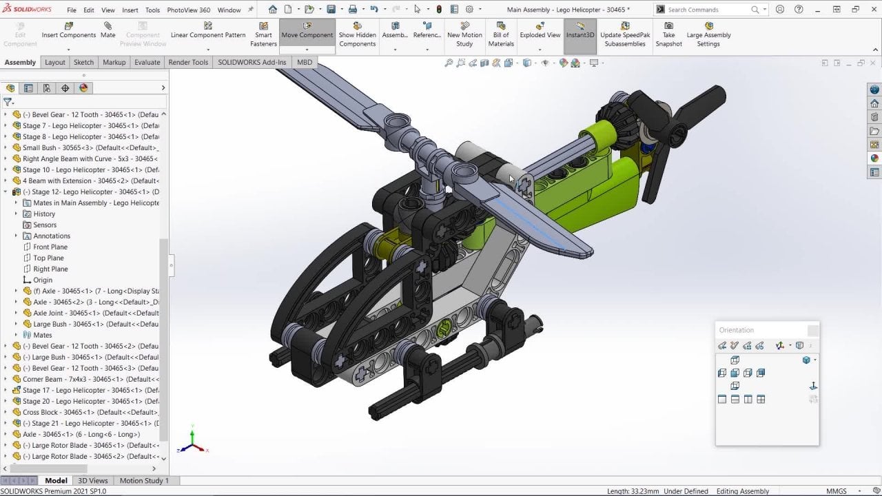
4. 4. Introduction to the Solidworks Interface and View Controls: The first thing that we're going to do is download the files that you need for this course. The course is broken up into 12 different models. And each of these models has a different set of exercise files. The files for each model can be found under the section for that model. And each of these sections has got this Resources tab where you can download the files for that model. So for example, here's model 1, the circuit board. You can click on Resources here and then you can download this zip file that contains all the files you need for model 1. So download those files onto your computer and you don't have to do it all at once. You can do it section by section. So for example, here is model1, and the files will be downloaded as zip files. If you unzip these, there'll be further files within each zip file. So for example, here on model one, we've got these three extra files. So here we've got a PDF drawing of the circuit board that we're going to make. Here we have a JPEG image of a sketch we're going to make for this model. And then here we've got the solid works part file for this model, the circuit board. And you can tell this is a Solid Works file because it's got this SolidWorks icon here. To open Solid Works, you can either double-click on a Solid Works file or you can just double-click on the SolidWorks icon. In my case, I'm going to double-click on the circuit board file. So this will open Solid Works. And depending on the speed of your computer, this might take a few minutes. When the program opens. This is the view that you should say. So this is the circuit board part that will go into make. And you can spin this around and zoom in and so on. Now again, to quickly go through the Solid Works interface, it's quite similar to many other standard Windows programs. Up here at the top we've got the menu bar. And then just below that here, we've got the command manager. And this is where you find most of the features that you'll be using to create your SolidWorks models. A number of different tabs with loads of different options. And we'll go through these as we go throughout the course and we'll learn what most of them do. Down here on the left we have the design tree, sometimes called the feature tree. And this is where you'll find all of the features that make up your Solid Works parts. And then finally here on the right we've got the graphics area. And this is where the part that you are modelling will actually be shown. These names can be a lot to take in initially, but as we go through the course, these will become a lot easier to remember and a lot more intuitive. Now we're going to go over the basic Solid Works view controls that you can use to navigate around your model. So grab your mouse and hold down the middle mouse button and the scroll wheel, and then just move your mouse around. This will rotate your model in any direction. You can also zoom in and out using the scroll wheel. And you'll notice that you actually zoom in at the point where the cursor is. So you can actually use this feature to move around the model. We can also move the model around by holding down the control key, pressing down the middle mouse button, and moving the mouse around. Then finally, we can also zoom in and out by holding down the Shift key and the middle mouse button and moving the mouse up and down. And they sometimes just gives you a little bit better control than just using the scroll wheel to zoom. We can also rotate the model by using the arrow keys on the keyboard. And if you hold down the Shift key and use the arrow keys, then you'll rotate by 90 degree increments. Now on your screen you might have this little orientation view menu. If you can't see this little View menu anywhere, just press the space bar and it should open. And if you click the little pin icon, it will keep them in you open and on top of everything else. This little menu is really useful because it's got a load of preset views and you can just click on the view you want to go to that view. So for example, if I click front here, will go to a front view. And then if I click back will spin around to the back. And then if I click Top will go to a top view. There are also some 3D isometric views here. And if you click on the drop-down, it can get slightly different types of isometric view. So if you find yourself with your model view a little bit messed up and you're looking at it from the wrong view, you can easily just click one of these standard views and it will take you back to something more familiar. Then we also have some more view controls up here in the middle of the graphics area at the top. And we'll go through these in more detail as we go through the course. But for now probably the most useful one to know is this one on the left here. This is Zoom To Fit. So what this does, if you're fully zoomed in on your model, you can just click this and it will zoom out so your entire model fills the graphics area. You can also just press the F key for fit, and this is a really helpful shortcut. The F key that you'll probably use a lot to zoom your model outs. So this was a quick overview of the Solid Works interface. To quickly recap. Up here at the top we've got the menu bar. And then below that we've got the command manager with all of the features that we're going to use. Here on the left we've got the design tree or the feature tree. And then here on the right we've got the graphics area where your model will be sharing. The main way that you'll move your model around is by holding down the middle mouse button, the scroll wheel button, and moving your mouse around o by zooming in and out with the scroll wheel. And that will zoom in and out where your cursor is. However, you can also hold down control and the middle mouse button and move your model around. And you can also hold down Shift and the middle mouse button and move the mouse up and down. And that will zoom in and out. And then you can also use the arrow keys. And if you hold down Shift and use the arrow keys, then you spin around at 90 degree increments. As a quick way to get to any pre-set views, you can use the view orientation menu. That's this little View menu here that can be opened by pressing the space bar. And it's got all these presets that you can click to go to that view. And then finally, you can use the FK or click this icon on the left at the top to zoom out to fit. So your entire model, we'll zoom out to be fitted into the graphics area. So that's an overview of the Solid Works interface. In the next video, we're going to start looking at sketches which are the basis of the vast majority of parts and features in SolidWorks.
5. 5. Sketching Basics: Welcome back to the course. In this video, what we're going to start looking at sketches and these make up most of the features that make up your parts in SolidWorks. Now you might already have the PCB modal open from the previous video. If so, then just close that by clicking here on the top right. So we don't have anything open in solid works. And then we'll start a new part. You can do this by going to File New, or you can just click the new icon here. And the first thing that we'll see is that you can have three different types of documents in solid works. The first one of these is the part, and this is just a representation of a single design component. Next, we've got an assembly, and this is a collection of parts or sub-assemblies. And then finally we've got a drawing, and this is a 2D representation of a part or an assembly. So we'll select the option and then we'll press OK. And this will open a new empty part. In SolidWorks, virtually all parts start off with a sketch. And the sketch is basically a 2D drawing that you can use to create a 3D feature. So the first thing that we need to do is draw that sketch will move over here to the left to the feature tree. And you might remember that this has all of the features that make up your part. Should see here at the top that we've already got some things in the design tree, even though we haven't added any features to the part yet. And up here near the top, we've got these three planes, the front plane, the top plane, and the right plane. These planes are basically a representation of a flat plane in a certain direction. And if we hover over them, we can see in the graphics area we've got the front plane, the top plane, and the right plane. Let's select the front plane by hovering over it and then left clicking. And now we can start a sketch on this plane. We can do this by going up to the top to the command manager, selecting the sketch tab, and then choosing sketch, which is the first icon here. As you select that, you'll see that the plane actually moves. So now we're looking at it straight on. You also see over here in the top right of the graphics area. Now we've got these two little icons, the sketch exit icon and the council icon. And these indicate that we're in a sketch. Sketches are made up of sketch entities. These are things like lines, circles, arcs, and so on. And these can be found up here on the sketch tap. So what we'll do is we'll hover over the line tool here, left-click on it once to select the Line tool and then move down into the graphics area. And just left-click anywhere in the graphics area. And then move your mouse around and left-click again. And you'll see that as we left-click, we're drawing line segments here. So anyway, we left-click will be the start of a line segment. And then when we left-click again, it will be the end of a line segment. And you continue drawing these lines. And so you either double-click which ends the line segment or until you exit or close the tool. And you can do this by pressing the Escape key. So if you want to start sketching again with the line tool, you'd have to go up and then re-select the line tool up here on the sketch tab. And then you can continue placing new lines. If you finish a line segment at an existing point, it will also end the placing of new line segments with the sketch entities. You can use a lot of standard Windows commands like deletes and copy and paste. And I'm going to show you this by first exiting the line tool. So you can either press Escape or we can click here on cancel on the left. So now we're no longer using the line tool, but we're still editing the sketch. So for example, you can left-click to select one of these lines. And if you press Delete, it will delete that line. And then for example, you can press Control Z or Control Z to undo that delete. You can also left-click and drag these end points around. If we wanted to select multiple endpoints, we can left-click and drag a box around them. And a really nifty feature about solid works is that if you hold down the left mouse button and drag from the right to the left, then you get this green selection box. This green box will select any sketch entity that it touches. But if we hold down the left mouse button and drag from left to right, then instead we get this blue box. And this only select things that are fully within the box. So you see if I drag from the left to the right, we get the blue box. And then these two lines here aren't selected because they're not fully enclosed within the box. If I drag from the right to the left, then we get the green box. And now they are selected because they're being touched by the box. We can also use standard commands like Control C to copy and Control V to paste. So for example, we could drag a box around these two lines to select them. And then we could press Control C to copy them. And then just left-click somewhere else and press Control V to paste them. This was quite quick introduction to starting a new Solid Works Part and starting sketches to quickly recap. In solid works, we've got three different types of files. We've got a part assembly and draw it within your part, virtually all of your features. We'll start off with a sketch. And your first sketch has to be made on a plane, such as one of these default planes, the front plane, top plane, or right plane. To start the sketch, just choose the plane and then choose sketched from the sketch menu. And sketches are made up of sketch entities. These are found up here and these are things like lines, circles, arcs, rectangles, and so on. These can be manipulated using standard Windows commands, things like Control C to copy and Control V to paste. You can also use the Delete key to get rid of entities you don't want, or you can use Control Z to undo to bring them back. In the next video, we're going to actually start drawing up that first part of the PCB part. But for now you can just close this part down.
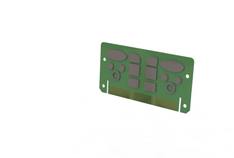
6. 6. Sketching a Rectangle and Adding Dimensions: Welcome back to the Solid Works course. In the previous video, we had a look at how to start a sketch, and we had a quick look at sketch entities. And in this one we're going to actually start drawing the PCB that will go into make. So firstly, let's have a look at what we're trying to create. Let's go back to that PDF drawing. And this is the PCB that we want to model up. We're going to break this up into manageable chunks. And the first thing that we want to draw is this main green rectangular background. Let's go back to Solid Works and start a new part by clicking up here on New and then choosing part and pressing. Okay, so now we have a totally empty part and the first thing we need to do is start a sketch on one of these default planes. To do this, let's select the front plane here on the left, by left clicking on it, and then go to the Sketch tab and choose sketch. So now we're drawing a sketch on the front plane. And you can see we have the icons in the top right corner that indicate where in a sketch. The first thing that we need to do is draw a rectangle that's 300 millimeters long and 150 millimeters high. So let's go to the Sketch tab and choose the Line tool by left clicking on it. And then go into the graphics area. And then just left-click to start placing a line. Then I'm just going to draw a vertical line. So I'm just going to move the mouse vertically down. And as I do, you can see the line appears and you can see we've also got this little yellow square with a vertical line in it. This is called a relation, and this indicates that this line is vertical. Left-click to place the n segment of the line. And then we'll move over to the right. And you should see another line appears. You can see we've also got another one of those yellow relation squares, and this one's got horizontal line in it. So indicates that this line is perfectly horizontal. Then left-click again to end that line segment. And then we'll go back up, do another vertical line up. And as we get to about this point, you can see we get this dotted snap black. And that indicates that we're lined up with that original start point. So we can left-click to end that line segment. And then we can go over to the left. And we can left-click on that original start point. And that will finish placing new line segments. And now we can see we've got this rectangle shape. And it's turned blue because it's a fully enclosed shape with no gaps. The next thing we need to do is add some dimensions to set the size of this rectangle. And to do this, let's go back up to the command manager. Choose the sketch tab if you're not already on it, and then choose Smart Dimension, which is this tool here. Smart dimension is a tool that you'll use all the time. It allows you to set different sizes, angles and things like that. So with Smart Dimension selected, Let's go back into the graphics area and then just left-click on the upper horizontal line, and then move your mouse upwards. And you should see a number now follows your mouse. Left-click again. And then we can write in the length of this line. So let's just type in 300 and press Okay. And now this line is 300 millimeters long. That's assuming we're working in millimeters. Throughout this course, I will be working in millimeters if you want to use inches or another type of units, that's absolutely fine. It's very easy to change the units in SolidWorks. If we look down here on the right, we can see it says M MGS, that indicates we're working in millimeters to change the units, all we have to do is left-click here where it says mgs. And then you can see some common unit types. So we can change to inches, which is IPS, or centimeters, meters, or millimeters. If you click on the Edit Document units at the very bottom, there's also some more obscure ones. So for example, to change the inches, or we'll have to do is click on IPS. And when we change the unit type, you'll automatically exit any sketch you're working in. So when I click IPS, we can now see the sketch is a little bit grayed out and we don't have those icons in the top right corner. We no longer have that exit sketch icon. So that indicates we've already exited the sketch to get back into the sketch to re-edit it. Or we have to do is go over to the feature tree here on the left where it says sketch one. And then just left-click on sketch one. And then from the options, let's choose Edit Sketch. So now we can see this dimension that we previously set as 300 millimeters, now says 11.81. So it's 11.81 inches. Exactly the same length as 300 millimeters is just shown in inches now. So to go back to millimeters again, that's just go down here to the right, click on IPS and then change it back to M MGS. And then we'll have to go back in and edit the sketch again. So left-click on the sketching the design tree and then choose Edit Sketch. And now you can see it's gone back to 300 millimeters. Next, we want to add another dimension to the vertical line to do this to Smart Dimension again from the sketch tab. And then just click on that vertical line. When using Smart Dimension, you can either click on the line or you can click on the two end points and it will give you the same distance. So let's set that line as 150 millimeters and press Okay. And now we've got a rectangle that's 300 wide and 150 high. To edit these dimensions, we can just double-click on them and then we can change them. And the smart dimension is actually pretty smart. So for example, if we realized that this 300 was too small, and we wanted to add say, 12 to it. We can just write plus 12 and then press Okay. And then Solid Works will figure out the total for you. And now this one is quite an easy example just to do in your head. But you might have something a lot more complex like seventy-three point six plus 24.9. And you can just write that n and solid works. We'll figure it out for you. We can also do other operations like divide and multiply. So if I double-click on Map 312 to editor again. So after the 312, we can now put slash to divide by two and then press Okay, and you see that number is now divided by two. If I edit it again, we can also use the asterix for times or multiply. So I can put an asterix to and then press Okay, and then it will be times by 2. Another good thing is that you can use any units even if you're not working in that unit system. So for example, we're working in millimeters, but we could double-click to edit this number and we could write something like six IN four inches. Press Okay, and then that will be converted into millimeters. You could also use combinations of units. So you could write something like six feet, five inches. So if you do prefer to work in inches throughout this course, you can set your units as inches. And then if I give you the millimeter dimensions, you can just write in, say for example, 300 M&M, and that'll be converted into Hs for you. So let's just change this back to 300 millimeters. When you're editing these dimensions, make sure you do a fast Double-click. Sometimes if you do a slow double-click, Solid Works, thinks you've just done a single click. So it just gives you this very simple box and you can only change the number there. If you do a fast Double-click, then you get this full adjustment box here. So there we have our rectangle. It's the correct size, but it's not currently anchored in space. And we'll look at that in the next video. For now, we'll just save this part. And you can do this by pressing Control S. Or you can go up to the top and click on the Save icon. Or we can go to File Save. We will look at saving in a bit more detail in a future video, all the different file types and things like that. But for now, let's just save your part as something like circuit board in progress. And just double-check that it's saved as a solid works part. It should just be there by default and then press Save. So now the part is saved. We've got the filename here at the top, and we'll pick this up in the next video. So to quickly recap, in this video, we started to sketch on the front plane, and we use the line tool to draw these vertical and horizontal lines to make up this rectangle. Then we use the smart dimension tool to set the length of these lines. The smart dimension tool allows you to just write in the length. And it also allows you to do equations like plus or minus and divide and multiply. You can also use any type of units and you can mix and match units. And you can change your units down here on the right. In the next video, we'll take a closer look at fully define your sketches and at sketch relations.
7. 7. Fully Defining Sketches: Welcome back to the Solid Works course. In the previous video, we drew this rectangle made up of lines and we set the size as 300 by 150. But this rectangle isn't actually anchored in space, we can move it around. So in this video, we're gonna talk about fully define your sketches and why this is important. If you click on any of these sketch entities to any of these lines, you should see a small relation icon. So for example, with this one, we've got a small vertical icon. And if we look over here on the left in the property manager, we can see under existing relations, it says vertical. So that indicates this line is vertical. We can also see some other details about the line. So down here we've got the length and we've got the angle as well. And if we click on another line, you can see again we've got different relation this time this one's horizontal. Here at the top on the left it says horizontal. And then down at the bottom we've got 300, which is the length. And then we've got 180, which is the angle. If I grab one of the rectangle corner points by left clicking and dragging and move it around. You can see this rectangle isn't fixed in space, we can just move it around. That's because there's only actually one fixed point in your model called the origin. That's these two red arrows here. If you can't see yours, try pressing F to zoom to fit or maybe zoom in a bit. It might be behind your view menu. We should always try to link our sketches to the origin because otherwise potentially they can move around and this can cause problems to your model later on. So let's try linking that rectangle to the origin using some smart dimensions. So let the smart dimension tool and then left-click on the origin, and then also left-click on the corner of the rectangle. And let's add a dimension there. Let's say 200 millimeters here. And let's also add a vertical one. So I'm going to click on the origin again and then click on the corner again. And I'm gonna make this one a 150 millimeters. You might have noticed that as we added those dimensions, the rectangle lines turned from blue to black. And this indicates that they're fully defined, which means that they can't move around. And then down here, it also says fully defined. So this means everything in this sketch is fully defined. It can't move around anymore. So now if I exit the smart dimension tool by pressing Escape, and now if I try and drag this rectangle around, we can't move anymore. If we delete one of these dimensions. So for example, this one just by selecting it by left clicking and pressing delete. Now we can drag the rectangle around left to right, but we can't drag it up and down because it's fixed by that 150 down here. And you can see the horizontal lines are black because they can't move because of that 150 dimension. But these vertical lines are blue because they can move left or right. They're not fixed in space left to right. We can also see down here at the bottom, it now says that the sketch is undefined. And then if I delete that second dimension, we can now see the entire rectangle is blue, so we can move the entire rectangle around. A bit of an easier way to fully define your sketch is to just grab one of the corners and then drag it all the way down to the origin. So I'm just left clicking and dragging it down and then hovering over the origin. And you can see as I do, we get this new different type of relation symbol. This is a coincidence symbol. So it means that the two points, the corner of the rectangle and the origin, are in the same place. Then if I release the mouse button, those two points will be fixed together. And now we can see the sketch is fully defined. Again, it says fully defined at the bottom and the lines are black. And if we left-click and select that bottom right corner, we can see we've got the coincidence symbol down there. And then here on the left it also says coincident. What we can also do instead of dragging the points together, if I just press Control Z to undo. So the rectangles under defined again, we can also select a point like the origin and then hold down control allows you to select multiple items and then also select the corner of the rectangle. So now we have both points selected the corner and the origin, so it can release control. And then over here on the left, we've got these add relations options. And if we choose coincident than the corner of that rectangle will be moved to the fixed point at the origin and will be fixed there. And again, if we now select that corner, we can see we've got the coincidence symbol, and we can see it's coincidence up here on the left. So this might all seem a bit theoretical at the moment, but it's very important that when we sketch into try to always make sure that our sketches are fully defined unless you've got a good reason not to. Because as I said, if they're not fully defined, then potentially parts of your sketch could move around and do things that you're not expecting and it can cause problems with your model later on. So now that we have a fully defined sketch, we can use this to finally create the first feature, and we'll do that in the next video. But for now we can just exit this sketch. You can do this by clicking exit sketch here in the top right. And I can see in the feature tree, we've got sketch one, or you might have a slightly different number there, just depending on how many sketches you've had in the model. Now you can save your part by pressing Control S. So quickly recap, let's edit the sketch by left clicking on it in the Feature Tree and pressing Edit Sketch. So within your sketch you can click on any entity and you can see the relations is important to try to always fully define your sketch. You can do this by linking the sketch to the origin or just starting the sketch from the origin. And the fully defined entities of your sketch will turn black in color. And when everything in your sketch is fully defined, you'll see down here it says fully defined. In the next video, we'll finally use this rectangle to start making your first feature.
8. 8. Extruding Solids: Welcome back to the course. In this video, we're going to make our first feature. So this should be how we left the previous model. We've just got this single sketch on the front plane. And if we click on the Sketch in the feature tree, we should see that it's 300 wide and 150 millimeters high. We're now going to use this sketch to create our first feature. So make sure you're not editing the sketch. You should see no icons in the top right corner. If you do, just click the Exit sketch icon, then let's go up to the Features tab, which by default is the very first one. Then let's just choose the first feature on their extruded boss base. And now we can see here on the left we've got a little message telling you how to use the feature. And this is a really good thing about SolidWorks. Often it will just tell you exactly what to do. So if you get bit stoke destroy, reading the message on the screen, and it should tell you how to use the feature. And this also goes for error messages. They usually very descriptive and they'll tell you exactly what the problem is. I know it can be tempting just to press okay, without properly reading it, something I do myself. But if you actually just read what it says, then often it will help you out with the problem. So here on the left our message says, we need to select either a plane on which to sketch the feature cross section. All we need to select an existing sketch to use for this feature. So we're going to select that existing sketch that we've already drawn, that rectangle sketch. To do that, let's just left-click anywhere on that sketch in the graphics area, and you should see a yellow preview of the feature. So this is basically an extruded block based on that rectangle that we've sketched. Here on the left, we've got some different options. One of the most important ones here is the thickness or the depth. Let's left-click in the box and change it from 10 millimeters down to two. And then you can just press Enter or tab. And you should see that the preview changes to reflect that fantasize two millimeters. So now all we have to do is left-click on okay, at the top, the green tick. And then we've created our first feature. Here in the feature tree on the left we've got Boss Extrude one. So Boss Extrude and extruded boss, or just two slightly different names for the exact same thing. And here it looks like our sketch has now disappeared. But actually, if you click on this little expand symbol to the left, you can see the sketch is actually underneath the boss extrude feature, the sketches being consumed by the Boss feature. So now we can still click on this sketch and press Edit Sketch. And now we can go into that sketch and adjust the size if we want. So for example, we could change this 300 up to something like 350. And then we can press Exit sketch. And then you should see that the Boss Extrude has updated to reflect that new size. So those sketch changes have now pulled through to that feature. We can also edit the Boss feature itself. If you left-click on the name in the feature tree and then press Edit Feature. Then we can change any of the parameters, such as the depth, like so. So we initially created a blind extrude. This means that we're just extruding blindly in one single direction. And you can tell that from this little arrow here on the preview. If I increase the size a little bit, you can see that a bit more obviously. So we have the sketch here at the back. We've just extruded 32 millimeters away from the sketch in this direction. If we go back over to the left and we click here on the drop-down where it says blind. You can see we actually have different options. We'll go through these as we go through the course. But for now, let's choose this one at the very bottom called mid-plane. So when you select me to plan, you should see that your preview changes. And if we zoom in a bit, you can see what's happening now is we're extruding in two directions equally from the sketch. So we're extruding in 16 millimeters this direction, and 16 millimeters this direction, giving a total of 32 millimeters thickness. And this means that the sketch is at the center or middle for mid-plane of your Extrude. So make sure you have mid plane selected. Let's set the size back down to two millimeters and then press Okay. So now all that we have to do is change the length back down from 350 to 300. And you can do this without actually editing the sketch. Or you have to do is left click once on the feature in the graphics area. And you should see those underlying dimensions of the sketch. We can then double-click on the 350 and change it down to 300 and then just press Enter. And you should see that the extrude updates. If it doesn't update straight away, you might just need to click on rebuild, which is this traffic light icon up here at the top. So there we go. Our first feature, at this point, you can press Control S to save your part. So to recap this video, we started off with just a single sketch and then we created a boss extrude feature, which was on the Features tab. When you create a feature, the sketch underneath it is consumed by that feature. But you can also go back in and edit that sketch just by expanding the feature and then editing the sketch underneath. You can also edit the feature itself by left clicking on the name and pressing Edit Feature. And then you can go back in and change any of the parameters. A blind extrude is the most basic kind of extruded. Just extrude in one single direction blindly. But we've gone for a mid plane. This means you extrude in two directions equally. And we made the rectangle two millimeters thick. In the next video, we'll start adding some surface features to the PCB.
9. 9. The Circle Tool: Welcome back to the PCB section. We're now going to start to look at some slightly more advanced sketch entities. And in this video we're going to look at the circle tool. And we're also going to look at some more sketch relations. This was how we left the previous video. So we've basically got this Boss Extrude rectangle is 300 millimeters long, it's 150 high and it's two millimeters thick. So if we look back at our PDF drawing of the PCB that we're making, we can see we've already drawn this green background. And the next thing we're going to add is all of these gray surface features, the chips. So let's go back to Solid Works. And you might remember from the earlier videos, we said that the first sketch has to start on Warner, these default planes. But actually subsequent sketches can start on any flat surface. Let's select this surface of the Boss Extrude just by left clicking on it. And you should see that this fly out menu pops up. Now we want to choose Start new sketch, which is this icon here. Now be careful that you choose the one at the bottom, which is start a new sketch and not this one just above it, which is edit the existing sketch. So select start a new sketch. Now we're sketching on that blue face. And you can tell that we're in a sketch because we've got this exit sketch icon in the top right corner. When you're sketching, it tends to be much easier if you're looking at a completely flat view. And to get to this, we can select the normal two view. Down here I've got the view orientation menu open. And if you don't have this, you can just press the space bar and it should open. And then we're going to choose Normal 2, which is this icon down here on the right. So if we press normal too, we can see the view moved a little bit. And now we're viewing this flat surface that was sketching on, completely flat on. Now let's just quickly go back to our JPA drawing. And this is what we want to draw all of these features. And we're going to start off with these four circles. So going back to solid works were in the sketch already and we're now going to select the circle tool, which is up here on the sketch tab with the other sketch entities. And there are two different types of circles. We're going to look at this first one, the default one, which is the center point circle. So make sure you have this one selected. And if you look at the little icon, you can see there's two numbers on it were 12. This indicates the clicks that you're going to make to use the tool. So the first collect number one, since the center of the circle, and then the second clip number two, sets the diameter of the circle. Let's move into the graphics area and start drawing circles anywhere on this face. So the first clicks, that's the center point, and then just move your mouse out and click again to set the diameter. And then we can do the same to add three more. So again, the first click sets the sensor and then you move your mouse out and the second click sets the size of the circle. And then we've got a third one roughly here. And then let's just put the fourth one to the side here for now. Now let's exit the circle tool. And you can do this by pressing Escape, or you can just click on this tick up here on the left. Now we're no longer using the circle tool, but we are still editing the sketch. And you can see all of these circles are still blue. And that's because they're undefined. And if we grab them and try and drag them around, we can move them around and we can also drag them to change the size. So let's add some smart dimensions to fully define this sketch. And set the size and position of these circles. The top two circles are 20 millimeters diameter. So let's select the Smart Dimension tool from the sketch tap. And then we can just click on the outside of one of the circles and just move your mouse out and click again. And then let's just write in 20 millimeters and press Okay. And the diameter of this circle is now 20 millimeters. Now the second circle is also 20 millimeters and we could just carry on using the Smart Dimension and click on this circle and write in 20 again. But what we'll do is we'll use a relation. So press Escape to exit the smart dimension tool. And then left-click to select that first circle that we've set as 20 millimeters and then hold down control. And remember this lets you select multiple items. So whilst holding down Control, also select that second circle. And then release control. And from the little menu that pops up, we want to choose this one, make equal. If we click on this, both of the circles will be made and equal diameter, so they're both be 20 millimeters. You can also click add relations equal here on the left is exactly the same thing. And now we can see that both of them are the same size. And if we click on one of the circles to select it, you can see they've both got this equals symbol on them. And now for you just the size of that first circle by double-clicking on the dimension and changing it, you can see the second one also changes. So there are always equal. These first two circles should also be lined up horizontally. So let's select the center point of one of them. Hold down control and also select the center point of the second one and then release control. And then from the pop-up, let's choose make horizontal. This will line up both of those center points horizontally. And if we click on one of the center points, we can see that they're both got this horizontal relation icon. Now we can carry on using Smart Dimension to fix these circles in position. So select the Smart Dimension tool, choose the bottom of the PCB, and then choose the center point of one of the circles. And let's set this distance as 85. And you see that both of the circles move because they're both lined up horizontally. Then still using the Smart Dimension, Let's choose the left-hand edge of the PCB and then choose the center point of that left-hand circle. And let's make this 40 millimeters. And you can see as we add in those dimensions, that left-hand circle turns black because it's now fully defined. Next, there's also a 40 millimeters between the two circles. So let's choose the center of that left-hand one, and then also choose the center of that right-hand one and write in 40 millimeters. Now if we look at the third, fourth circle in the drawing here, you can see that they're actually concentric. This means that they both share the same center point. So going back to Solid Works will add some smart dimensions to the third circle first. Firstly, I'm going to add the diameter. So I'm gonna click on the circle itself and write in 30 millimeters. And then we can set the position. So it's 60 millimetres from the left-hand edge, like so. And it's also 60 millimeters from the bottom. And like the first two circles, you can see this one now turns black because it's fully defined. If you find that your dimensions are getting in the way any point or getting a bit cluttered up. You can just grab them and move them around and space them out a little bit more. Now that we've got the first three circles fully defined, we just want to finish off that final circle. We want it to be concentric with that third circle. So what we can do is press the Escape key to exit the smart dimension tool. And then let's just select that circle, the fourth circle, hold down Control, and then also select the third circle and then release control. And from the menu that pops up, we want to choose make concentric. And that should move that final circle. So it's fully lined up with that third circle. They now both share the same center point, so they are both concentric. And if there are similar diameter, like my video, you might not be able to see them very well. So if we just zoom in a bit, we can drag the size of that fourth one and we can see that they're both lined up concentrically. There is actually a slightly simpler way of doing this as well. If I press Control Z to undo, so that final circle is no longer concentric. What we can do instead is just left-click to select the center point of that final circle. And then just drag it into the center point of that third circle. And you'll see as the two sets of points line up, we get this extra symbol, this yellow concentric symbol. And that shows that they're now concentric. So we can release the mouse button and then there'll be locked together like that. Now the fourth circle is still believe because we've defined the position, but we haven't yet set the size or the diameter of it. If we look back at the drawing, we can see that the final circle is actually five millimeters smaller than the third circle. So let's just grab that final circle and then just drag it inwards so it's a little bit smaller than that third circle. And then let's get the smart dimension tool and we can just click on both circles. And you should be able to drag out the dimension. And let's just write in five millimeters and press Okay. And now we can see that all of our circles are black. And down here at the bottom, it tells us our sketch is fully defined. Now we've added all of the circles that we need for this video. To recap. In this video, we looked at the circle tool. It can be selected up here on the sketch tab. There's two main types. In this video, we looked at the centerpoint circle. So the first click sets the center point, and then the second click sets the diameter or the size. We then sketch these four circles. We set the diameter of the first one, and then we learned how to use an equal relation. You can do this by selecting both of the entities, by holding down Control and clicking on them, and then just selecting make equal. We also added the horizontal relation in the same way. And this means that both of the circles are lined up horizontally. Using relations can be a good way of fully defined new sketch without having to dimension every single item. In the next video, we'll have a look at the ellipse and the rectangle tools.
10. 10. Ellipses and Rectangles: Welcome back to the PCB section. In the last video, we drew these four circles on the Boss Extrude that we've already made. Open up your part and we'll start editing the sketch again. To do this, left-click on the sketch in the design tree and then just choose Edit Sketch from the pop-up menu. So now we're editing the sketch again, and you should be able to see we've got the exit sketch icon here in the top right corner. In this video, we're going to have a look at the ellipse tool and the rectangle tool. And we're going to build up more of those surface features on the PCB. The first one we're going to use is the ellipse tool, and that can be found up here on the sketch tab. Now an ellipse is almost like a squashed circle. Let's select the tool and then let's start drawing an ellipse somewhere roughly about here. So the first click is going to set the center of the ellipse. The second one is going to set the major diameter. And then the third one is going to set the minor diameter. Let's draw out something roughly like this. And then we can use Smart Dimension to set the exact size and position. Let's choose the smart dimension tool. And firstly, let's set the position. So from the left-hand edge here is going to be 60 millimeters to the center of the ellipse. And we could also have used a vertical relation with this middle circle. And then from the bottom here, it's 120 millimeters. Next, we need to set the actual size of the ellipse. So firstly, let's do the major diameter. So let's select this point here on the left and then this one here on the right. And let's move up here and write that in as 70. And then we can do the minor diameter. So select this top point and the bottom point, and we'll set that as 30 millimeters. So now if we exit the smart dimension tool, we can see it looks like we've got all the dimensions we need, but the sketchy still blue and it still says we're undefined. So if you're not sure why you sketch isn't fully defined, a good tip to find one of the entities that's blue. And then just left-click and try and drag it around. And you should see how it can move. And that will tell you what kind of relation or dimension you need to add to fully define your sketch. So in this case we can see we've got the size and the shape of the ellipse effects, but we haven't fixed the orientation. So we need to add some more relations. And what we can do is select this left-hand point and then hold down control and also select this right-hand point. And from the menu that pops up, Let's choose make horizontal. So now these two points, the two major points, are lined up horizontally, so that should fully define your sketch and your lips. She turned black. The next thing we'll be adding are the three rectangles. When we previously drew this initial first big rectangle, we use the line tool, but we can actually draw these in a more efficient way by using the rectangle tool. This can be found up here on the sketch tab. So select the tool and there's a few different options here on the left. We'll cover some more of these later in the course. But generally the little icons and the numbers on them tell you exactly how the tool works. So we want to choose a corner rectangle, which is the first option here. And if you look at the numbers, you can see the first click sets the left-hand lower corner, and then the second click sets the upper right corner. Let's go over here to the empty space on the PCB and start drawing our rectangles. So the first flex, that's the lower left corner, and then the second clicks that's the upper right corner. Then let's draw two more and try to leave plenty of space between them. Just draw them something roughly like this. And then after this, we can add the smart dimensions. To do this, let's select the Smart Dimension Tool. Let's set the size from the bottom of the PCB to the bottom line here as 38. And then the actual height of this rectangle is 25. The next one up is 73 from the bottom. And then the height of this is 32. And then the upper rectangle is 110 from the bottom. And then this very upper line is 13, 5 from the button. So the rectangle lines are all lined up vertically, but they're not lined up horizontally yet. And we can see that they're blue, which means they're still undefined. So let's also add those dimensions. The first one here is 160 from the right-hand edge. And you can see that the rectangle moves around a bit as we add this dimension. Then the next one is 19 five. And now that rectangle is fully black because it's fully defined, all of the vertical lines of these rectangles should be lined up. So what we could do is use more smart dimensions. And we could actually Smart Dimension these upper two rectangles. But instead we can use relations. To do this exit. The smart dimension tool can do this by pressing Escape and then select this lower vertical line, hold down Control to select more items. Then also select this next vertical line, and then keeping the Control key held down. Let's also select this upper vertical line and then release control. And from the menu that pops up, we want to choose co-linear. This means that these lines will be exactly lined up with each other. Let's click deselect that. And I can see these right-hand lines are all lined up and the upper rectangles have changed their shape a little bit because those other vertical lines aren't yet fully defined. But now we can do the same thing with those other lines. So select that bottom vertical line, hold down Control, and then select the other two, and then release control and then choose make co-linear. You can also choose it here on the left where it says Add Relation co-linear. Now all of those lines are lined up and if we select one of them, we can see we've got the co-linear relationship symbol there. So now our sketches looking pretty good. It's almost the same as the JPEG. The only thing we need to add is this angled top corner on this upper rectangle. We'll do that in the next video. To recap this video first, we looked at the Ellipse tool. This can be found with the rest of the sketch entities, and the first click sets the center, the second one sets the major diameter, and then the third one sets the minor diameter. And when you are defining your lips, just make sure that you also define the orientation as well as the size and position. For the rectangles. We use the rectangle tool. There are different options for this tool. We use the first one which is a corner rectangle. So the first collect sets the lower left corner and then the second clicks, that's the upper right corner. We drew the three rectangles out and then we fully define them using a mixture of smart dimensions and also the co linear relation, which lines up those edges of the rectangle exactly. In the next video, we'll finish off those parts with the angled line. And we'll also have a quick look at the difference between driven dimensions and driving dimensions.
11. 11. Angled Lines and Driven Dimensions: Welcome back to the PCB section. In the previous videos, we added these circles and then we also added the ellipses and rectangles. So we've almost finished our sketch and we're almost ready to start making those new features. But all that we need to do is add that angled line to the top corner of this top rectangle. To do this, let's first edit the sketch. So click on the Sketch in the design tree. And then from the menu that pops up, let's choose Edit Sketch. Now that we're in the sketch, we're going to add that angled lines. So the first thing we need to do is select the Line Tool from the sketch tab. Then let's zoom in a little bit and we want to start drawing a line from here. And we want to go up to here. So hover over this right-hand line. And you should see that anywhere we hover over, we get this yellow coincidence symbol. So that means we're exactly on top of that line. We have that coincidence symbol all the way along the line. And so we get to this middle point and then we get a slightly different symbol, the midpoint symbol. This indicates that we're at the very center of that line. So let's start our new line from the midpoint of that right-hand line. And then we'll go up to this horizontal line at the top, and we'll hover over it. So we also get the coincidence symbol. And then we'll click to end that line. So anywhere in this left-hand half. So you should have that coincidence symbol, not the midpoints symbol, so you shouldn't be in the middle. Now we can press escape to close the line tool, and we can start to add some smart dimensions. So we know from our PDF drawing that the bottom of this line should be a 125 millimeters from the bottom of the PCB. If we grab the smart dimension tool from the sketch tab, and then we try to Dimension this line. We can see it's actually coming up as a 122.5 millimeters. And if I left-click to add that dimension, we can see we get this warning pop-up. It says adding this dimension will make the sketch over defined or unable to solve. Do you want to add it as a driven dimension instead? And if we press Okay, you can see the dimension is added there. We can still see it, but it's actually grayed out. And if we double-click on it and try and edit the value, it says the dimension selected as a driven dimension is value cannot be changed. So we're just gonna talk very quickly about what driven dimensions actually are, because these will pop up sometimes when you're modelling. So if we look at that top rectangle, we can see we've already completely defined it with dimensions. So the bottom line is a 110 from the bottom of the PCB, and then the top line is a 135. Then we've set the start point of our new angled line as halfway between those two horizontal lines. So the only possible dimension that this can be is halfway between that 110 and the 135, which gives us 122.5. We can't actually change that because it's driven by these two-dimensions here, the 110 and the 135. To explain this idea in a slightly different way, I'm just going to start a new part. You don't have to follow along with this. And then I'm just going to start a sketch on the front plane. I'm going to quickly grab the line tool and I'm going to draw a triangle. So this triangle, I'm going to set the base as 50 millimeters long. And then I'm going to set the height as 40 millimeters. So because we now set the base of this triangle. And we've also set the height. Then this diagonal line can only be a certain dimension, and it can only be a certain angle because it's driven by the base and the height. So we can actually add a driven dimension which will show us the length of that line. But we can't actually set that line because it's driven by those two other values. So when you're working in solid works, you only need to actually add the minimum number of dimensions to define your sketch. And if you do try to add extra dimensions, then often they'll be added as driven dimensions. It's not a problem if you add these. This is just a quick way of showing what that actually means when you get that error pop-up. So going back to our PCB model, we can now see that the start point of that line is fixed at one to 2.5 because it's at the midpoint of those two are the lines. So if we want it to change that to a 125 like the PDF drawing, what we have to do is firstly delete that driven dimension. So just select it and press Delete. And then we also need to delete the midpoint in relation at the start of that line. To do this, we can zoom in, select the start of the line, and then we can select the little midpoint icon and just press Delete. You can also select it on the left and press Delete. So we no longer have that midpoint relation there. So now we can select the Smart Dimension tool and we can dimension to the start of that line and the bottom of the PCB. And this time we can write in 125. And you see the start of the line actually moved up slightly. That's because it no longer has that midpoint relation with a vertical line. So it's not fixed to the midpoint of that vertical line. The next thing we need to do is set the angle of this line. You can do this using Smart Dimension and all you have to do is click on two lines aren't parallel and then you automatically add the angle in. So let's select this vertical line and then also select the angled line. And then you should be able to add an angle dimension there. You can also move the dimension to the other side of the lines if you want to get the opposite angle. So in this case I'm going to add 120 degrees. And as you add that, you might see that the start of the line actually moves away from that vertical line on the right. And that's because we don't have any relation between the start of that line, the vertical line, we deleted that midpoint relation. So to fix this, all we need to do is exit the smart dimension tool by pressing Escape. And then just grab the end of that line and drag it over to that vertical line. And you should get a coincidence symbol. When you get that, just release the left mouse button and then they should be fixed together. So now that line should be fully defined because we've set the angle, we've set the start point, and then we fixed both ends of the line using those coincident relations. In the next video, we'll trim away this top corner and then we'll be able to start making those chips features on the surface of the PCB. So to recap in this video, we added the angled line at the top of this rectangle. We did this just using the line tool. And initially we started the line at the midpoint of the side of this rectangle. But we found that that gave us a fixed start point. So it gave us a driven dimension. So what we did was delete that midpoint relation and then we could set in the correct height there. Then we can set the correct angle using the Smart Dimension just by clicking on two lines that weren't parallel. And then finally, we just fix the start point of that line by dragging over to the side of the rectangle. So a coincident relation was added. So at this point you can save your file and exit your sketch. And in the next video, we'll have a look at the trim tool and we'll trim away that top corner.
12. 12. Trim Tool: Welcome back to the PCB section. Following on from the previous video, we've got a sketch that is almost complete and the only thing we need to do is trim away this top corner of the rectangle. So what we're gonna do is make sure your parts open and then we're going to edit this sketch. So left-click on it in the feature tree here on the left and press Edit Sketch. And now we're editing the sketch. We can see all of the details and we've got the exit sketch icon in the top-right corner. So trim away that top corner, we're going to use the Trim Entities tool. And this can be found up here on the sketch tab. It's just to the right of all the sketch entities. So select that tool. And then down here on the left, we've got a few different options. Probably the most flexible and the one we're going to focus on on this course, the power trim, which is the first option. So make sure you've got the power trim, the first option selected, and then just move into some empty space in the graphics area and hold down the left mouse button and just move your mouse around. And you should see this Trail follows you mouse. So anywhere that this line cuts through, it will be trimmed away from your sketch. So if we want to trim away that top corner of the rectangle, I'm just going to zoom in a little bit. And I'm going to hold down the left mouse button and just drag through the lines that we want to cut. You can see as we go through the lines, they're removed from the model. And then the same with this one as well. And then when you're done, you can release. So now those lines have been trimmed away from the model. They've gone from the sketch. Sketch is still fully defined because we've got all the other dimensions and relations that we need. So now we can close the trim tool and we can exit the sketch. Now we have our sketch ready to add the next feature. So what we're gonna do is select the sketch in the feature tree. If you pre-select it before you select the feature, then it can save a little bit of time. So select the sketch by left clicking and then go to the Features tab. And let's choose extruded boss base. And now you should see you get that yellow preview because we already have the sketch selected. And we're going to extrude all of the enclosed shapes that we drew in our sketch. Let's keep the end condition here is blind. And let's set the depth as four millimeters. And then we can press Okay, and now we've made those features. We can see here in the design tree, we've now got these two Boss Extrude features. So Boss Extrude one is the big rectangle at the back. And then Boss Extrude. Two are these chips on the surface. And you might have slightly different numbers after your feature. If you do, that's fine. Just depends how many features you made in that model. What we're going to do now is rename these features. Now you don't have to rename features in SolidWorks, but it is good practice and it can really help save time. If you've got a really big model. If you can imagine, if you've got loads of features Go Boss Extrude one boss extrude to, boss extrude 55. It can really save you a lot of time and headaches if you rename them as something useful. Renaming the features can also really help if you're sharing your models with someone else or even if you're picking them up yourself at a later date, you can almost see the thought process of why things were modeled in a certain way. So it can help you picking up someone else's model or even picking up your own later on to rename them, just hover over the feature name and then they'll slow double-click. And this doesn't always work that well first time, so sometimes you have to do it twice. So let's rename that first one as PCB base, and then just press enter oldest, click off the name. Let's do the same for the second one. So if the slow double-click isn't quite working, you can also just left-click on it once and then press F2 and then rename it. And let's call this one PCB chips, and then click off it. And now both of those are renamed. So now we've made half of those chips features. If we look back at the PDF drawing, we can see we've only actually modeled off of them. We need to add the ones on the other side. In the next video, we'll look at using the Mirror entities to add these over to the other side. But for now we'll just do a quick recap of what we covered in this video. So we edited that chip sketch and then we use the trim tool to trim away the top corner of that rectangle. We use the poetry an option. And with this, all you have to do is hold down the left mouse button and then just drag a line through the entities you want to trim away. Then after trimming those lines, I'll sketch it was still fully defined. So we just exited the sketch. And then we use that sketch to create a new boss extrude feature. This was blind and four millimeters high. And then after we made that feature, we renamed those first features. And you can do this by doing a slow double-click. Or you can select the name and press F2. You don't have to rename, but it really can save you a lot of time and a lot of hassle. If you've got a really complex model and you go back to earlier in the design trade to try and troubleshoot items or add new features. In the next video, as we mentioned, will be mirroring these chips over to the other side.
13. 13. Mirroring Sketch Entities: This was how we previously left our PCB model. We'd made half of the chips on one side, but we still need to mirror them over to the other side. If we look back at the PDF drawing, the chips on the other side are the same, but they're just mirror it. So instead of drawing out a whole new set of sketch entities, we can actually just mirror them. To do this first, let's edit our sketch. So let's expand our PCB chips feature. And you can see this is the benefit of naming them. We've only got two here, but if we had loads of features, we can immediately see which one is the one that we want to adjust. So expand the PCB chips and then select the sketch underneath and press Edit Sketch. So now we're editing the sketch and I'm going to go to a normal to view. Remember you can open this view menu if you need to by pressing the space bar. And then I'm going to select Normal 2. So we're looking flat on, on this sketch. What we need to do is select all of these entities and mirror them over to the other side. So the first thing we need to do is add a center line that will mirror them about. To get to a center line, Let's go up to the Line Tool. But instead of actually clicking on the line tool, click on the little drop-down next to it, and then choose center line. You can't also create a central line just by choosing a normal line and then selecting for construction here on the left. So a sends a line and a construction line are the same thing. It's just a slightly different name. So now I've got a central line or construction lines selected. And I'm going to start a line from the midpoint of this top edge of the PCB. So hover over the top edge and just move your mouse until you're roughly in the middle. And you should be able to pick up the midpoint in that. So when you're about in the right position, you should see this little square. And then if we hover over that, we should see the midpoint symbol. It's slightly different to the coincidence symbol. It's only got one single line with a point on it, whereas the coincident has got the extra line coming off in the middle. So let's left-click to start our line at that midpoint. And then we're going to draw vertically down. And we're going to finish the line at the midpoint of this bottom edge. Then you can press Escape to exit the line tool. So we're no longer place in new line segments. And we can see that that center line is fully defined because it's fixed or the midpoint at the top edge, and it's also fixed to the midpoint of the bottom edge. Now a construction line is a line that's ignored by all the other features in SolidWorks. So it's really useful for things like mirroring and for laying out your sketch to actually mirror these entities, what we're gonna do is go to the Sketch tab and then select Mirror entities here. And then here on the left we've got two boxes that we need to fill. The first one is entities to mirror. So make sure you are in this box. Make sure that it's blue. If it's not just left clicking that box. And then we want to select all of the entities on the left. So we can just drag a box around them to select them. And I can see all of those entities have gone into the entities to mirror box. So all of these lines of the different lines from the rectangles, these four arcs here are the circles. And then down at the bottom we've got the ellipse, then we just need to choose the mirror about point. So click in the mirror about box at the bottom, so it goes blue. And then we just need to select that center line that we just drew. And as you do, you should see a yellow preview peers of what we're going to mirror. That looks good press, Okay, and now those features have a mirrored. And if you click on any of them, you should see that we've now got a symmetric relation on each of them. This indicates that this part on the right is symmetric with this part here on the left. And that is mirrored about this center line in the middle. And if you click on any other entity, you can see the same sort of thing. So if we were to change the items on the left than the items on the right would automatically change as well. So now that we've got the full sketch, we can press Exit sketch up here in the top right. And you should see that the PCB chips feature now uses the entire sketch. And we've got the PCB chips on both sides. Just one thing to quickly note, if we go back in and edit that PCB chip sketch, if you find that you've gotten loads of sketch relation items, it might just be that you've got the relations icons turned on. You can get to these by just right-clicking anywhere in space in your graphics area. And then go into sketch entities. And then down at the bottom there's a View sketch relations option. So you might have loads of relations like this and it might be a bit distracting. These can be useful, but sometimes if you've got loads of them, it might be a bit cluttered. So if your view looks like this and you want to turn these off, we have to do is right-click in some empty space, then go to sketch entities, and then de-select few sketch relations. And then they'll all be hidden. They're still in the model. So if you click on any specific entity, then they'll show up. But they just weren't be cluttering up your entire sketch. So now I'm just going to exit the sketch again. To recap in this video, we looked at the Mirror entities. This can be found on the sketch tab. And to use this first we edited the sketch and then we drew a center line. Center line and a construction line are the same thing. It's just a slightly different name. And these are lines that are ignored by features in your model. And they're very useful for things like laying out the sketch and doing things like mirroring. To use the Mirror entities we just selected the feature. And then in the entities to mirror, we selected all of the entities that we've already drawn. And then for the mirror about, we selected the center line. And once you mirror the entities, you can have these symmetric relations and that indicates that the entities are mirrored and they're symmetrical. And then finally we exited the sketch. And now we saw that the feature includes all of the entities in that sketch. In the next video, we'll have a look at actually mirroring features themselves. So we can mirror the chips onto the other side of the board. But for now you can just save your parts.
14. 14. Mirroring Features: Welcome back to the PCB section. This was how we previously left the model. So we've extruded the overall shape of the PCB, and then we've drawn the sketch for the PCB chips on the surface, and then we've mirrored those entities over to the other side and then we've extruded the whole thing. But actually if we look back at our PDF drawing, we can see we've actually got chips on both sides of the PCB. So back in solid works, we want to mirror these chips over to the opposite side of the PCB. And to do this, we can use a mirror feature. So there are two types of mirrors. You can mirror entities within sketches and you can also mirror entire features. To do this, just open your model, make sure you're not editing any sketches. Go to the Feature tab and then choose mirror, which is this option here. Here on the left we've got the options, and this is sort of similar to the Mirror entities. So you've got to choose two things. We've got to choose what we want some mirror and where we want to mirror about. The first thing we need to select is the mirror face or plane. This is where we're going to mirror the features about. We want to actually choose the front plane because that's directly in the middle of our model. But you might see a little problem. We can't actually see where the front plane cuts. This property manager is hiding our feature tree and also we can't see the front plane in the graphics area. But we've actually got a second feature tree that we can use, and that's just here. We can get to this by just expanding this filename here. So click on the little arrow to the left, and then you should see your entire feature tree. So it's exactly the same as the one that's usually on the left is just we can use this when that's hidden by the property manager. Now we can select the front plane here. So make sure you're in that mirror face plain box. It should be blue in color. If not, just left-click in it, and then just select the front plane from the second feature tree. Next, we need to choose the features we actually want to mirror. Clicking this features to mirror box. And then we can either select the PCB chips in the feature tree or we can just directly click on the feature in the graphics area. And as we do you can see we get a yellow preview as usual. So we're going to mirror that chip feature over to the other side. And if we press Okay, now that feature has been created. We've now got chips on both sides and we can see we've got that mirror feature in the feature tree. Now when you're creating this mirror feature, there's a fairly common error that some students might get and we're just going to run through that now, you don't have to follow along with this, but it's just purely for information. So if your mirror feature isn't quite working properly, if you're getting an error, then just watch this following that. So let's imagine you're back at the stage when you're trying to create your mirror. So let's go to the Feature tab select mirror. And then for the mirror phase plane, Let's choose the front plane. And then for the features to mirror, Let's choose the chips. So it looks like we've selected everything, okay? But then when we press OK, we can see that feature isn't shown up in the model. If we look in the design tree, you can see we do have the feature, but it's got this small warning triangle next to it. And if we click on that or hover over it, we can see a bit more information about what's going wrong. So it says some feature instances are disjoint and will not be created. But what does this actually mean? So this means that some of your features aren't connected to the main model and so they can't be created using this type of mirror. And this has probably happened because when you created that first PCB base feature, maybe you accidentally did a blind extrude instead of a mid-plane extrude? If we go to top view, we can see exactly why this is a problem. So if we zoom in a bit and we select the front plane, we can see the front plane isn't actually in the middle of the model because we haven't used a mid-plane extrude that. So if we try to mirror this chips feature over using the front plane, then there's actually going to be a small gap. So the feature will fail. You can't actually mirror features unless they're all connected together. Luckily, this is very easy to fix. Let's exit that mirror feature. Oh, you have to do is edit that PCB base feature, the first feature. So left-click on it in the feature tree and then press Edit Feature. And then just make sure that you've got a mid-plane extrude here and not a blind extrude. So if we zoom in this mid plane means that we're going to be extruding one millimeter up and one millimeter down. If we do a blind extrude, we're just going to be extruding two millimeters down. So then when we tried to mirror that chips feature, we're going to have a gap in the model, so the mirror feature will fail. So just make sure that you've got mid-plane extrude here. Then if you press Okay, and then now we can see the feature has been created correctly. So to recap in this video, we looked at mirroring features. This can be found on the Features tab. Just select the mirror tool and then we need to choose where we're going to mirror it about and what will go into mirror. We selected the front plane. You can also select a flat face. And then we also selected the chips feature. When you are mirroring features like this, they need to all be connected together. So if you get an error saying the features are disjoint, it just means that they're not connected together. So you probably need to go back and edit that PCB base feature and just make sure you've got a mid-plane extrude that. For now, you can save your part. And in the next video we'll start to look at making extruded cuts.
15. 15. Cutting Material: Now we've got a PCB outline with the chips on both sides. And the next thing we're going to do is have a look at cutting in solid works, cutting is pretty similar to extruding. So you need to draw a closed profile, but then instead of adding material, you're cutting away material. So if we look back at our PDF drawing, what we're going to do now is cut away these two small slots, one and each site. Going back to solid works, Let's start a sketch on this large front face. So left-click on it and then choose Start new sketch. Remember that's the icon at the bottom here. And then I'm going to go to a normal to view. Remember you can open this little View menu by pressing space bar if you need to. The first thing we want to do is draw that slot outline. So let's get the line tool from the sketch tab and draw something like this. So vertical line going down to the bottom of the PCB and then a small horizontal line going along the bottom of the PCB, and then another vertical line going up to about the same size as the first one. Then press Escape to exit the line tool. And the top of the slot is actually an arc. So if we go back up to the sketch tab, we've actually got the Arc tool here. So let's left-click to select that. And then here on the left we've got three different options. We'll go with the third one, which is a three-point arc. And as usual, you can look at the little numbers on the icon, and these will tell you how to use the tool. So the first click sets that start, the second ones at the end, and the third one sets the radius. I'm going to zoom in a little bit. And for the first Glick, I'm going to start at the end of this left-hand line. The second click is going to be the end of this other line. And then I'm just going to drag out a little bit and set the third click to set the size. And then you can press Escape to close the Arc tool. If we look at our drawing now, we can see it doesn't actually look much like the PDF drawing. To fix this, we can add some relations and dimensions to fully define the sketch. The first thing we can do is add a horizontal relation between the top of these vertical lines so they're the same length. So select the endpoint of one of them. Hold down Control, and then also select the endpoint at the second one and then release control. And then from the pop-up menu, let's choose make horizontal. Next we're going to fix the arc so it joins the straight line at the correct angle. Select the left-hand vertical line and then hold down control and also select the arc and then release control and select Make tangent. This means that the arc will join the straight line at a tangent angle. And you can see immediately that the sketch looks a lot more like the PDF drawing there. And now it's just a case of using the smart dimension tool to set the size of this slot. So I'm going to get the smart dimension. And then I'm going to set the width here as five millimeters. And then the distance from this idea is going to be 27.5 millimeters. And then finally, we just need to add the height of this law. If we click on the bottom edge of the PCB and then we click on the arc itself. We can add that height. If we zoom in a bit and we look carefully, we can see the high only actually goes up to the center point of that arc. So it's not the full length of the slot that we need for the drawing. To fix this, let's press Escape so we no longer place in that dimension. You might need to press it twice. And then we want a dimension to the outside of an arc. To do this first, let's click on the bottom edge of the PCB and then hold down Shift and then click on the OK. And now you should see that we can actually dimension to the outside of the arc. Let's set that as 40 millimeters and that should fully define the sketch. All of the entities are black. And we can see within this profile it's turned dark blue, which indicates we've got a fully enclosed profile. If yours isn't dark blue, just make sure you've got the shaded sketch contours option to add on, on the sketch tab. And then also make sure you've got this little horizontal line at the bottom can be easy to miss that one. Now if we zoom out the other current on the other side is exactly the same as this one. So we could just draw a center line down the middle. And we could mirror this over using Mirror entities. But instead we're going to have a look at the slot tool, just say can see how it works. To find this tool is up here on the sketch tab, is with all the other sketch entities. It's this one in the bottom left corner. Select that tool. And then we've got four different options. We'll select the first one which is a straight slot. And as usual, you can see the little numbers on the icon indicate how you can use it. So let's go down here to the right, the first clicks, that's the start. So let's start on this bottom edge of the PCB and then go directly upwards and make your second clip, which is the length of the slot. And then just move your mouse out and make your third click, which is the diameter or the thickness of the slots. Then you can press Escape to close the slot tool. And we can use the smart dimension tool to define this slot. The first thing we'll set is the thickness or the radius of the arc. So click on the ark at the top here, and we're going to write in 2.5, you can see the letter R here that indicates radius. So because this is a radius, it means that total width will be five millimeters because radius is only half of the total diameter. This is now the same thickness as the other side. And if we were to add in the thickness, they're using smart dimension, we can see it's five millimeters. We can see, we can add it, but it's a driven dimension. And that's because the thickness is already driven by this are 2.5 here. Next we're going to set the height and we can do this using a relation. Let's press Escape to close the Smart Dimension tool and then select the top point of the slot on the right. Hold down Control. And then also select the top point. So it's the center of that arc here on the left. And then release control. And let's press make horizontal so they're both at the same height. And then finally, we just need to set the left right distance of this arc. So to do this, we're going to add a center line and a symmetric relation. To get to the center line, go up to the sketch tab, click on the drop-down next to the line tool and choose center line. Then let's draw a center line down the middle of our PCP. So hover over the top edge, get that center point, get the midpoint relation, start your line there and then go vertically all the way down to the midpoint at the bottom. And then finish your line and press Escape to close the line tool. So we want to space both of these slots are equally. So let's select this inner vertical line on the right and then hold down Control. Also select the center line. And then keeping control held down, also select this inner line on the left, then release control. And from the menu that pops up, we want to choose make symmetric. And as usual, you can also choose this on the left, those two lines and now symmetrical. And if we click on one of them, we can see we've got that symmetric relation and we've also got it on the center line in the middle. So our sketches now fully defined. Everything has turned black and it says fully defined here at the bottom. So we can use this to make our first cut. You can do this from within the sketch. So when you've created your sketch, you can actually select features without exiting the sketch. Just go to the Features tab and let's select extruded cuts and then the options are very similar to the extruded boss base. We're just cutting away material instead of adding it so that stay on blind. We can set whatever thickness we want, but let's keep it as 10, that default. And if we move the model around a bit, we can see we're going to cut those two profiles out 10 millimeters. You can see that yellow preview there. And if your preview isn't working properly, then just double-check that you've got this small horizontal line here on the left. Press Okay, and now created your first cut feature. We can see those two slots in the model, and we can also see the code extrude one in the feature tree. And at this stage we can rename that. Let's go over to cut extrude one here. Can do a slow double-click on it, or you can left-click on it and press F2. And let's call this slot cats. You can also rename this mirror feature if you haven't done already. So that's select that one and press F2, and then let's call that something like mirror chips. So to recap in this video, we made the first extruded cut feature. To do this. First we drew a sketch on this front face. We drew a closed profile. For the first one, we just use the line tool and the Arc tool. For the AAC tool, there's a few different options. We used a three-point arc. Then we added a tangent relation to make the arctangent with that straight line. And then we added dimensions to fully define this sketch. And remember to add dimension to the outside of an arc. You can hold down Shift. Then for the profile on the other side, we use the slot tool. This has got four different options. We used a straight slot, we drew out and then we used smart dimensions and relations to fully define the sketch and the radius here it will be half the total thickness. We also used a symmetric relation with the center line to make sure the slots are the same distance from each side. Then from within the sketch we selected the feature. So we went to the Features tab and we selected extruded cut. This is pretty similar to extruded boss, but it just takes away material instead of adding it. And then finally we just renamed the features. So at this point you can save your model. In the next video, we'll be taking a look at the Hole Wizard.
16. 16. Hole Wizard: Our PCBs coming along pretty well now, we just made the slot cuts in the previous video and looking back at the PDF drawing, the next thing we want to add are these four small holes. So going back to solid works to make these holes, we could use something similar to this locker. So we could start to sketch on this front plane. We could draw out the circles using the circle tool, fully defined of course. And then we could do an extruded cut to cut these holes. But there's actually a much better way to make these holes in solid works. So I'm going to delete that cut feature and also the sketch underneath it. And instead we're going to have a look at the Hole Wizard. This can be found up here on the Features tab. Here is. And the Hole Wizard is a really good way of inserting holes because there's loads of preset sizes and types, and you can also modify them very easily later on. So let's select that whole was a tool. And then here on the left in the property manager, you can see we've got two tabs, the type and the position tap. Firstly, we need to set the whole type. There's loads of preset sizes and options here. We'll go through these in more detail as we go throughout the course. But you can do things like threaded hole, slots, countable holes, and all sorts of different options. For now we want to choose just a simple hole. So we'll choose this one in the top right, which is just a basic hole. Then we need to set the exact type. So make sure you're on ansi metric for the standard here, you can also use ansi inch and there are some other options there. And then further type, there's a number of different sub options. You can do things like screw clearances. So these are holes that screws will go through. But we'll just stick with dal hall. So this is just basically a normal hole, just the standard whole. Next we can set the size, a load of preset sizes. We can also click this Show custom sizing box, and then you can write in any size you want. But for now we'll just stay with 10 millimeters. Next is the end condition, and this basically sets the depth of your whole. We're going to stay with blind and 10 millimeters. So this just means the hole will be 10 millimeters deep in one direction. And then there's some further sub options that we don't need to cover at this stage. So we've set the type. The next thing we need to do is set the position and number of holes. So go up to the position tap and choose that. The first thing we need to do is choose the face where we want to make the holes. So let's left-click that large face of the PCB. Now we are creating a sketch on that face, and you'll see that we've automatically selected the point tool up here on the sketch entities. So anywhere that we left-click will place a point and anywhere point is there'll be a whole. So I'm just gonna go to a normal to view. And then I'm just going to left-click and place four points for four holes. Just somewhere roughly in the right position, somewhere like this. And then you can just press Okay. You can press it on the left or the right. And then those holes are at it. And you see we've got the whole feature here in the design tree. So now we've got those four holes, but the position of them isn't correct. So let's edit that whole feature and we'll set the position correctly. Left-click on the whole feature in the feature tree and press Edit Feature, and then click on the positions to have again. So now we're back in that sketch and we've got the point tool again. So anyway, we left-click will add more holes. We don't wanna do that at this stage. So you can press Escape to exit the point tool. And now we're basically in a sketch. So we can use smart dimensions and relations to define where these points are. First, let's set the position of these ones on the left. Let's get the smart dimension tool. And this one on the lower left is 20 millimeters from the bottom edge. And then this upper one is 100 millimeters from the bottom, like so. And then they're both 15 millimeters from the left-hand edge. So I'm going to set the distance for this bottom one only. So that point in the lower left corner is now fully defined. I'm going to press Escape to exit the smart dimension tool. And now I'm going to use relations to fix the other ones in place. First, I'm going to select this lower-left point by left clicking on it. And then hold down control and also select this upper left one and then release control unless press make vertical. So they are now lined up vertically. So all of the points on the left-hand side are fully defined. Next, we can line the ones on the write-up horizontally with the ones on the left. Select this one on the left, and then hold down control. And also select this one on the right. And then release control and add make horizontal. And then let's do the same for this one. So I'm going to select this one, hold down Control and then select the corresponding one, release control and press make horizontal. And then finally I'm going to select these two on the right. And then I'm going to press make vertical. So we're almost fully defined now, but these two on the right, their position isn't fixed along the x-axis, so left to right. To fix this, Let's add a symmetric relation. So first, let's add a center line. Select the center line from the drop-down next to the line tool, and then add a center line down the middle of the PCP. So it should be midpoint at the top and then midpoint at the bottom. So you might remember that we said that the center line will be ignored by features. Even though we're in this hole, was it sketch? That center line is going to be ignored when actually creating holes. It's just used to line up where the holes are. When you've got the center line in place, let's select the first hold down Control. Also select the center line. And then keeping control held down, also select the opposite point and then release control. And let's press make symmetric. And now you can see the sketch is fully defined. So we can press Okay to exit. And now those four holes are in the correct place. So the great thing about the whole Was it is, firstly, it's very easy to add new holes is very quick. You don't have to draw a new circle for every one. You can just place those points. But the main thing is, it's very easy to modify those holes. So if we want it to change the size of all of these holes, we could very easily do that just by editing the whole feature. So left-click on it in the Feature Tree and press Edit Feature. And then we can change any of the parameters, for example, the size, like so. And then we can easily go back in and change them back. You can also change the type and all of the other options. So the whole Was, it is a great way to save a lot of time when you're making these holes. To recap in this video, we looked at the Hole Wizard. This can be found on the Features tab, and it's an easy way to add a load of preset sizes of poles and easily modify them later on. Within the Hole Wizard, we've got two tabs, the type and position tap. For the type you can set the type of hole. Obviously, you can set the size and the end condition and things like that. And then you can go to the positions tab, choose the face where you want to place the holes. And then every way you place a point, a hole will be created. Then in the future, if you need to, you can very easily edit the whole feature and then you can change any of the parameters that you want. At this point, save your part. And in the next video we'll be looking at Philips so we can round off the edges of this board.
17. 17. Fillets and Chamfers: Welcome back to the PCB modelling section. In this video, we're going to be looking at adding fillets and chamfers so we can round off an angle off the corners of our PCB model. We're going to start off with Philips and fill it. It's a very common in engineering and product design. And they're basically when a corner, interior or exterior is just rounded off. There's many different reasons why you might wanna do this. Maybe it's just aesthetic. It makes your product look a little bit nicer. They can also give a better user experience by rounding off sharp edges and corners. And also from an engineering point of view, having a rounded edge actually reduces the stress concentration, so it can actually make your part stronger. Now, fillets are known by different names depending on where you live in the world. Sometimes they're called rads or radiuses, radii, or even rounds. But in solid works they're known as fillets and they're very easy to add. Or we have to do is make sure you're not editing the sketch. Go to the Features tab, and then choose villus, which is this option here. Select the tool. And as usual, we've got loads of options here on the left, there's a few different types and we'll look at some more of these later in the course. But for now we're going to use this first one, just a constant size Phillip. Then probably the most important thing is just to set the size down here. So we're gonna keep this as 10 millimeters. We'll keep it as symmetric. So it just means it'll be 10 millimeters in both directions. And then the next thing we need to do is actually choose what we want to fill it. To do this, make sure you have the items to fill it box selected by left clicking in it. And then zoom in in your model. And I'm just going to hover over some edges. And as we do we get this orange selection. So all we need to do is just left-click on the edge, we want to fill it. And the one we want is this very small edge on the corner. And then just left-click to select it. And now we can see the preview of the phillip. It can be quite easy with this tool to accidentally select the wrong edge. So for example, if I select this one and we can see on the preview that's not what we want. De-select, just click on the edge again. You can also right-click on it here on the left and press Delete. When that side looks good, I'm going to zoom out and I'm going to move over to the other side. And I'm going to also select that upper corner on the left-hand side. And when I've got both of those, I'm just going to press Okay to add those. Philips. And we can see we've got the Philip feature here in the design tree. And as usual, we can click on this and press Edit, fill it, and then we can change the parameters or the selection that. Next we're going to look at chamfers and these are very similar to fill it. They're also very common in product design, but instead of a rounded edge, they've got an angled edge. Again, they've got different names depending where you live in the world, you might hear them called an angle or a phase. To add chamfers, we can go to the Features tab again. And the tool is actually under the Philip tool. So click on the drop-down underneath it and then you should see chamfer there, select that tool and it's quite similar process to adding the fillets. We can just zoom in and select the edges we want. I'm just going to stay with the default settings. We'll look at those in just a moment. But I'm going to select this bottom right corner. And then I'm going to zoom out and go over to the other side. And you can also actually select through the model. So we can see there should be a corner here. We can't see it because it's hidden by the model. But if we hover over the area, we can actually see the edge of that. And we can select that. If we look over here on the left in the property manager, we can see the different options that we have. There are four options for the chamfer, but there's two main types, angle distance and distance distance. So for the angle distance, as the name suggests, we can set the distance or the size of it, and then we can also set the angle. If we keep it as 45, it will be symmetrical. For the distance, distance we can actually set to distances instead of the angle. With this symmetric option, obviously both sides will be the same distance. We can also choose asymmetric and then we can set the distance for each side. But for this model, let's stick with angle distance 45 degrees and 10 millimeters, and then press Okay to add those chamfers. Another point to mention is that with Philips and chamfers, you can also add them at the sketch level instead of the feature level. So if I go back to the PCB base feature, the first one, and I click on it and press Edit Sketch. Now I've got that rectangle that we initially started with. We can actually add the fillets in chamfers to this rectangle. Up here on the sketch tab, we've got this sketch fill option. If you look underneath it, we've also got the sketch chamfer option. So if I select the sketch Villette, you don't have to follow this, but it's just for an example, I select the sketch, fill it, and then you can set the size. And then you can either click on the corner itself or you can click on two lines and the Philip will be added in the corner. You can also do a similar thing with chamfers, and we'll discuss this a little bit more later in the course, is really up to you whether you add your chamfers and Phillips at sketch level or feature level. I personally recommend when you're starting out, keep your sketches as simple as possible and then add the fillets and chamfers as separate features later on at the feature level, this just generally gives you a lot more control and it's easier to modify them or delete them later on if you need to. So I'm going to delete those fillets in chamfers from the sketch and then exit the sketch. And then one final thing to note, it's good practice to try and keep your fillets and chamfers towards the end of your model. This isn't a hard and fast rule as times when you might need to break it. But in general, try to add them after you've added all of your other features. So it's a recap. This video fillets and chamfers can be added using the fill it or chamfer tool that can be found on the Features tab. So firstly, select the tool and then set the size and type, and then just choose the edges you want to fill it all chamfer. If you select the wrong edges by mistake, you can just click on them again to de-select, and then you can edit and modify the features later on if you need to. You can also add fillets and chamfers at the sketch level. But unless you've got a good reason for this, I would recommend just keep them as separate features because they're easier to change or delete later on. In the next video, we'll be adding the metal contacts or the bottom of the PCB. And we'll be looking at patterns. So you can pattern all of those along the bottom there.
18. 18. Linear Patterns: Welcome back to our PCB model section. We're now doing pretty well. We've nearly modeled up everything. And the final thing we need to add are the contexts that go along the bottom of the PCB. If we go back to our PDF drawing and we have a look at the detail drawing here. We can see there's 45 of them. The naught 0.2 millimeters high off the board, two millimeters wide, 25 high, their space three millimeters apart, and there's 6.5 from the slot. So if we go back to solid works, we can start drawing a single one of these contacts and then we can use linear patterns to add the rest of them. I'm going to start a sketch on the large front face of the PCP. So left-click on the face. And then from the menu that pops up, Let's choose sketch. I'm going to go to a normal two view, so we're looking flat on. And then I'm just going to draw one of those contacts using the rectangle tool. I'm going to start on the bottom edge of the PCB here and draw out roughly the right shape, something like this. And then I'm going to use the smart dimension tool to set the exact size. So from the drawing we know those 25 millimeters high. It's two millimeters wide. And then it's 6.5 millimeters from the edge of the slot here. So that should fully define our rectangle. Now we can do an extruded boss base. So from within the sketch, we can go up to the Features tab, can choose extruded boss base, and then we know that the contact is nought 0.2 millimeters high off the board. So let's just do a blind extrude, nought 0.2 millimeters and press. Okay. Now our first contact is added there. I'm just going to rename the feature by doing a slow double-click on it in the design tree. And I'm going to call it something like contact. So we've modeled a single contact, but on the drawing is actually 45 of them. We're going to use a linear pattern to add the rest. There's actually two different types of linear pattern, sketch and feature. So firstly, we're looking at sketch. I'm going to go back in and edit that contact sketch again. So click on the contact feature in the design tree and then choose Edit Sketch. I'm just gonna go to a normal two view. So we've got a nice flat view there. So now we're back in the sketch and we're going to use the linear sketch pattern. This is on the sketch tab. Is this tool here. Left-click to select it. And it looks like there's loads of complicated options here on the left, but we'll just go through it bit by bit. There's only really four things that we need to select. The first thing that we need to do is choose the direction of the pattern. And this can be any straight line. I probably see like mine, that direction one is being prefilled with the x-axis it. And that's actually the one we want. If we look at this little triad down here, we can see the x-axis is this red arrow is pointing in the correct direction. If this was the wrong direction, we could just right-click in the box, place elections. And then we can choose any straight line in the direction we want. So for example, we could choose this bottom edge along the bottom of the PCB. Underneath the direction we've got the spacing and the number of instances, and we'll come back to these in just a moment. But firstly, let's choose the entities to pattern. This is what we actually want a pattern. So let's zoom in, let's click in that entities to pattern box. And then in the graphics area, Let's choose those four lines of the rectangle that we drew. So there's this once more one at the top, two long ones on the side, and then one more small one on the bottom. And as you select these, you'll probably see a preview start to appear. When you've got all four of those selected, we can then go and set the spacing that was three millimeters. And then we can set the number of instances. This is how many times you want to pass in the items. So we're going to set 45 before we press Okay, Let's just zoom out and checked everything looks correct. And we can see something isn't right here. We've got a big gap here. So what's actually happened here is we set the spacing is three millimeters, but actually the thickness of the contacts is two millimeters itself. So we need to add that to the spacing. So the total spacing should be five millimeters. And if we change that to five, we can see the spacing looks a lot more correct there. So we can press Okay, it's a pattern, all of those entities. Now we can see we've got 45 of those rectangles patterns, but some of them are still blue. So that means they're undefined. We need to add some kind of relations or dimensions to fully define this sketch. And a good way to see why things aren't fully defined is to grab one of the blue lines and just try and drag it around. So we can't actually move these up and down, but I can move them left, right? That's because when we create the pattern, it actually just sets the spacing, but it doesn't fix the spacing. So now let's use Smart Dimension and let's add in the spacing there. So let's get the smart dimension tool from the sketch tab. And let's just choose any two of the contact. And let's add a three millimeter gap. And as we add that I mentioned, it should apply to the entire pattern. So the inside pattern should now be fully defined. Now if you want it to go back in and edit the pattern parameters, what you have to do is just click on any of the pattern entities, so any of the lines. And then here on the left in the property manager where the pattern relation is, just right-click on that relation and press Edit Pattern. And now we can adjust some of those parameters if we need it. But for now you can just press Okay to exit that. Then you can press Okay to exit the sketch. And now we can see that the contact feature uses all of those pattern rectangles. So we've got 45 of the contacts there. So that was the linear sketch pattern. You can also use a linear feature passing. And personally I'd recommend if you've got a lot of instances like this, if you've got many items you want to pass in, then you should use a feature pattern. It can be just a bit easier to modify later on and also is a little bit easier on your computer to show the linear pass and feature. I'm just going to press Control Z to go back to when we just had one single contact. So now I've just got that one concept. I'm going to exit the sketch and there's just that single contact. Now the linear pattern feature is pretty similar to the sketch pattern feature. But this one can be found on the feature tab. Choose linear pattern, which is this one. And then as before, we've got to choose four main parameters. Firstly, we need to select the direction, so make sure you're in this direction, one box, and then just choose a line or an edge going in the direction that you want. So for example, this bottom edge of the PCB. Next we've got the spacing. Remember let's set that to five millimeters. And then next is the number of instances. So we set this to 45. And then finally, just what we actually wants a pattern. So let's go down here to features and faces. Will click in the features to pass in box, and then just zoom in. Let's choose that contact feature. And as you can see, we get the preview of all 45 of those contacts so we can press Okay to add those. And I'm just going to rename that linear pattern feature as something like contacts pattern. So there we saw two different ways that feature pattern and the sketch pattern to achieve exactly the same end result. So the final model in terms of geometry and size, is exactly the same, whichever method you use. And you'll find this often in solid works. There's many different ways to achieve the same end result. And often there isn't necessarily a right or wrong way to do things. But in terms of patterns in general, I would say try to use feature patterns where you can and keep your sketches as simple as possible. So to recap this video, we can create patterns in two ways. If we use a sketch pass in feature, we go to the Sketch tab which use linear sketch pattern. And then we firstly choose the direction which can be an edge. Then we set the spacing, we set the number of instances, and then we choose the entities such as the lines that we actually want to pass them. You might then also need to add extra dimensions and relations to ensure your sketch is fully defined. We can also add patterns using a linear feature pattern, and this generally gives you a bit more control and it's easier to modify them later on. This is a very similar process to the sketch pattern, but you can find the feature on the Features tab, choose linear pattern. And then similar to the other tool, firstly set the direction, then the spacing, and the number of instances. And then finally choose what you actually want to pass in. So this could be feature faces or even bodies, but we'll cover those later in the course. For now, you can save your part. And in the next video we're going to have a look at the design tree and some of the things you can use this for to help improve your modelling.
19. 19. The Design Tree (Feature Manager): Our first model, the PCB, is now pretty much finished in terms of modelling, so well done for creating that. In this video, we're going to talk a little bit about the design tree and how you can use this to improve your modelling. As we learned earlier, the design tree is here on the left, sometimes called the feature tree or the feature manager. And this contains all of the features that make up your model. We also found out that you can do a slow double-click on these features and sketches to rename them, but you can also reorder them. You might remember that earlier on, we said that the fillets and chamfers should ideally be at the end of your model badly here and RPC Bay, we've got the other features after them, the contact and the contact pattern. So to move these features or to reorder them, we can just hold down the left mouse button and just drag them down to the bottom with the feature tree. So today the same with Philip, just hover over it, left-click, hold down the left mouse button and just drag it down to the bottom and then release. And now our fill it in chamfer features are at the end of the model. Another thing we can do with design tree is what's called suppress features or sketches. Suppressing a feature turns it off temporarily, but it doesn't delete it. To show an example, I'm going to choose the Phillips. I'm going to left-click on it and then choose suppress from the menu here. So if I click Suppress, you can see the feature is removed from the model. So if no longer got those rounded corners at the top, we can see in the design tree that the filler is now grayed out. So Solid Works won't calculate this feature now. It's essentially turned off in the model, but it's not deleted. And if we want to turn it back on, we can just click on the feature again and press unsuppress. This is a really useful feature. For example, if you've got a really big model, you want to turn off some features temporarily. Or maybe you wanna do different versions of a model. So you want to turn off certain items and there may be exploited for 3D printing and then maybe turn the features back on and Export As a different version of the same part. Now if we look at the design trait and we look at the PCB chips feature, we click on this and we click Suppress. So the PCB chips are now turned off. They're taken out of the model. But you'll notice that the mirror chips feature has been suppressed as well, and this is automatic. And if we spin the model around, you can see the mirror chips feature isn't there. And that's because this mirror chips feature is what's called a child feature of the parent feature, which is the PCB chips feature. So it's not possible to have the mirror chips feature if we don't have the PCB chips feature, because there's nothing to mirror. And you'll see if we now unsuppress the marriage hips feature. So if I click on it and click on unsuppress, it automatically and suppresses the PCB chips feature as well. So if you suppress a parent feature, then it automatically suppresses any child features as well. However, we can just suppress the child feature and it won't affect the parent feature. He could just suppress the mirror chips feature. And that won't affect the PCB chips feature. It's also not possible to drag a child feature before apparent feature. You see if we tried to do this, we get this little no entry symbol. These parent-child relationships can be a bit confusing at first. So really good way to understand them is to turn on the visualization tool. And we can do this by right-clicking on the file name at the top of the design tree. And then there's two, I can say one for parent and 14 child. So first I'll turn on this one just by clicking the icon, the parent visualization. And then I'll right-click again, and then I'll turn on this one. The child visualization. What this does is now we can hover over any item in the feature tree. And we'll get some arrows that indicate how it's related to other items in the feature tree. So for example, if I hover over the chamfer feature, can see we've got this blue arrow going up to the PCB base feature. And that means that the PCB base feature is the parent of the chamfer feature because that chamfer is made on the PCB base. So if you don't have the PCB base, then you can't have the chamfer because there's nothing to chamfer. And then for example, if I go up to the contact feature, you can see we've got the PCB base as the parent because we made the contacts on the PCB base. We've also got the slot current as a parent because we set the dimension for the spacing from That's locker. And then you can see we've also got a child feature with this purple arrow. So that's the contact pattern. So the contact pattern is based on the contact feature. So we can't have the pattern without the parent feature. We can also use this for sketches as well as features. So for example, if I expand this PCB chips feature and hover over the sketch, you can see we've got this blue arrow going up. So the PCB base is the parent because that's where we actually started the sketch. And then the PCB chips is the child because the PCB chips is made from this sketch. So don't worry if this doesn't make too much sense at the moment, this will become a lot clearer as you get used to using solid works. But these visualization arrows are a really good way of understanding how you different features relate to each other. And they can be really helpful if you're trying to troubleshoot why a certain feature isn't working properly. Then the final part of the design tree we're going to look at in this video is called the robot bow. And that's this blue bar at the bottom of the design tree. If you move your mouse down and hover over this, you'll see that the points are changes to a little hand. And if you hold down the left mouse button and drag this upwards, you can release it at any point and it will basically take you back to that point in the model. So we haven't actually deleted everything below it. We've just gone back to this point in the model and we can now add new features at this point. Say for example, I could do something like star sketch, maybe do a cut extrude. And now if I drag back down, you can see that that could extrude is at that point in the model. So it's before all of the features that we're after the rollback bar. So this is one of the strongest features of SolidWorks. We can go back to any point in the model and we can edit at that point. We'll be using this robot bar a little bit more further on in the course. So the reasons for using it and the times you might want to use it will become a little bit clearer. But to recap in this video, we talked a bit about the design tree. We talked about how you can rename items and how you can reorder them by dragging them around. We also talks about parent and child features. And we learned about suppressing features and sketches, which is temporarily turning them off. If you suppress apparent feature, it will automatically suppress the child features as well. But you can't suppress a child feature without affecting the parent feature. You also can't reorder child features before parent features to help understand and visualize the parent-child relationships a little bit more easily. You can turn on this visualization tool by right-clicking on the file name at the top of the design trip. And that can really help you figure out how your different features and sketches relate to each other. And then finally, we can use the robot bar just by dragging up to the point we want. And then you can edit at that point in your model. And this is a really good way of going back in time in your model and making changes at an earlier point without having to delete everything later on in your model. In the next video, we'll be having a quick look at design intent.
20. 20. Design Intent: In this video, we're going to talk about how you can simplify a model and whether you actually should. We're also going to discuss design intent. So if we look at the PCB model that we've made so far, we can drag the rollback bar upwards just by left clicking and dragging it up. So we started with the PCB base, which was just this rectangle. Next we added the chips on the surface, then we mirrored those. Then we cut the slots. Then we made the holes using the Hole Wizard. We added the contacts and the pattern those along. And then finally we added the fillets and chamfers. So we built this PCB model up with quite a few smaller features. If we think about it, we could have probably combine some of those features into one single sketch. So we could have simplified our design tree. To show an example of this. I'm just going to start a new part to show how we could have done this. You don't have to follow along with this because it's going to be speeded up a little bit. So I'm going to start new part, start a sketch on the front plane. Draw the initial rectangle and set the correct size, which is 300 by 150. Next, I could add those sketch fillets and sketch chamfers directly to this sketch, so we don't have to add them later on. Then we could also add those holes using circles instead of the whole wizard. And we could mirror those over to the other side. And then finally, we could add those slot cuts. We could maybe use this lot tool to draw something like this. And then we could also mirror that slide over to the other side. And then we could trim away the bottom bit. And then we can just extrude this one single sketch. So we've got the main rectangle, we've added in those four holes and the slots, and we've even added in those rounded corners at the top and the chamfer at corners at the bottom. So here in one single feature we've made, if we go back to our other model, what we actually made in 12345, different features. So you might think that this is a better way of doing it because it's really simplified our design tree. We've only got one single feature that, but actually I would recommend that you try to keep your sketches as simple as possible and then you add different features to build upon that. That's because these features are actually much easier to edit or turn off later on if you need to. So say for example, now we wanted to remove these slots. We could go in and edit that original sketch and we can trim them away. But now we've started to lose some of our relations. We've got a gap here at the bottom. So if we exit, we're gonna get some kind of error. And then if we fill in that gap, we aren't fully defined. And it could just cause you a lot of problems if we get back to the original model. So turn off the slots. All we have to do is find a slot feature and click on it and choose suppress. And you might notice that we've lost the contact pattern and the contact feature that, and that's because it's a child feature of that slot cup. Because we actually set the distance from that slot. But we could modify that so we can keep the contacts that turn off the slots. So I'd recommend trying to keep your sketches as simple as possible and then just adding additional features, even though it might give you more features in your design trait. The final thing that we're going to talk about in this video is design intent. And this is something that's a little bit theoretical and it might not make that much sense at this stage in your modelling. They will definitely become easier as you practice more with Solid Works. So design intent is basically just spending a few minutes at the start of your modelling or as you're modeling, to think about the most efficient way you can build your model and how you can best add dimensions and things like that. We'll have a look at an example using the holes that we added. So let's edit our whole was at feature. So left-click on it in the design tree and press Edit Feature, and then go to the positions tab. And we've set the position of these four holes. If we have a look at the sketch, we can see we've got four holes. The ones on the left here are 15 millimeters from the left-hand edge. And then the ones on the right are symmetrical. So they will be 50 millimeters from the right-hand edge. So if we press Okay to exit that feature, those holes all look okay. And now say if we want to change the length of this board, we can double-click on the main base and then we can see those dimensions. Then we can double-click on the 300 here and say, let's change it to 400 and press okay. And you might find like my modal that it doesn't update straight away. That's because the model needs to be rebuilt. If we look here in the design tree, you can see next to the PCB base, There's a little traffic lights symbol. That's the rebuild symbol. You can also see down here at the bottom of the model, we've got the rebuilt symbol. This means that there's some features, any model that I've changed, but they haven't yet updated in the view to rebuild, you can press Control B or you can click on the rebuild icon as the traffic light here at the top. So now the model updates. So our PCB is now 400 wide. And you can see that those holes are still 15 from the left and 15 from the right. Because of the way we added the dimensions. If we think about different ways we could have dimension those holes. I'm going to go back into the hole, is it feature? And then I'm going to edit the positions again. So instead of having these holes symmetrical, I'm going to choose these ones on the right. I'm going to select that symmetric relation and I'm going to press Delete. So the holes are no longer symmetrical. We can move these right-hand ones around. But now instead of symmetrical, we can maybe add a dimension like this. We can say, let's make these holes 370 millimeters apart. So it's exactly the same distance as we just had. We exit this feature, you can see the holes look exactly the same. They're still in the same place. So it's still that 370 spacing, which is exactly what we had before. But now if we were to edit the size again, so say let's change the PCB from 400, maybe up to 500. So it's even longer and then press OK and rebuild. And now we can see the holes on the right and no longer properly spaced because they're still 37 C from the holes on the left. If we'd kept the relations and dimensions as they were before. So the holes were still symmetrical than they would be in the right place. They would still be 15 from the right-hand edge. So this is quite a simple example. And as you learn SolidWorks, you'll come to appreciate more different examples. But really designing 10 is just thinking about the best way you can dimension and model your features. Really thinking about what you want from your model before you actually start modelling. So now I'm just going to undo those changes and I'm gonna go back to 300 with the correct spacing for the holes. So it's a quickly recap. In this video, we talked about simplifying your model. How you could potentially just use one single sketch to make all of those five features. But actually I would recommend that you try and keep your sketches pretty simple. And then you add extra features using the actual features, just because it's easier to modify these later on to suppress them or delete them if you need to. We also talked quickly about design intent. As we said, this is something that's quite theoretical, but it will become much easier and it will make more sense as you get more solid works experience. And it's basically just thinking about the best way you can lay out your model and what you want from your model before you start modeling. In the next video, we'll be looking at adding appearances to your model and then it making your first ever render.
21. 21. Appearances: Our models now almost finished, but it doesn't quite look right because it's just colored in this gray color. So we can add some appearances to this to make it look a bit more realistic. To do this, go over to the right-hand edge of your screen and just click on this little colored ball with four colors on it. This is the appearances, scenes and decals tap. And it will expand this pain at the side. If you want, you can close your view menu or move out of the way. And then up here, we're going to expand the option that says appearances. So click on the little arrow next to it to expand that. And you can see we've got all these different types of appearances. And you can drag this down a little bit if you need to. So we can see we've got loads of different types of materials here. For the first one, we'll just add an overall green color for the circuit board. So let's expand plastic and let's go to medium gloss plastic. And then you see down here we've got all of the different default colors. We know that the circuit board probably actually isn't made of plastic, but the medium glass plastic looks pretty similar to a circuit board. So we're just going to use it in this case. So we want to add the green color to the model. So what we can do is just go down, find the green and then just double-click on it. And that appearance will be added to the entire model. We can also add appearances to specific features. So firstly, let's just pin open the Appearance scenes and decals tab by clicking this little pin in the top right. This just means that it won't close when we click off it. So to add appearances to specific features, firstly, let's select the chips feature and then hold down control. And that's also select the mirror chips. So we've got the chips on both sides selected. And this time let's add a different color, maybe something like a dark gray plastic. So I'm going to stay in plastic, stay in medium gloss. And I'm gonna go up and I'm going to find a dark gray color. And then we've already got the PCB chips and mirror chips selected. So let's just double-click on dark gray and then that appearance is added to those selected features. So finally, let's just add some appearances to these contacts. Along the bottom. Let's select the contact feature, hold down control, and also select the contact pattern feature. And these are likely to be Gold or maybe copper. So let's minimize the plastic folder, and let's open the metal folder. And let's go down and choose gold. And then we've got three options under that. We've got shiny matte satin finish. You can choose whichever one you want. Just double-click on it or drag it onto the model. Then that should add the appearance to those selected features. So already our model, they's look in a bit more realistic, a bit more like a real product there. So now let's unpin the apparent scenes and Details tab. We don't need it open anymore. So click on that pin and then it will close. And if we want to edit any of these appearances later on, we can do this from the display manager. You can get to this by clicking on the little ball, the little colored ball at the top of the design tree here. So now over here we've got the three different appearances that we've added to the model, and we can now edit these if we need to. So you can right-click on any appearance and you can press Edit appearance, and then there'll be some different options. So say we've decided that these chips are a bit too dark. We can right-click where it says dark gray, medium gloss, plastic, press Edit appearance. So now we've got quite a few options here on the left, you probably start on this basic tab. So under basic you can change the color. And here we can set any color we want. It doesn't have to just be those standard ones that we saw earlier. And you can also choose which features and faces and surfaces are going to have that appearance that selected. You can also click on the Advanced Options, and this gives you loads more different choices. You can do things like change the elimination, how shiny your object is, how reflective it is, and things like that. And these mainly show up when you're doing renderings in photo view. Then once you done, if you want to go back to the design tree, you can just click on the little icon here at the top left. So now that we've added those appearances, the only thing we need to do is make a render. And the rendering is basically just creating an exporting a high-quality image of your model. To do this, or we have to do is go up to the render tools tab, which should be on your command manager. If you don't see the render tools tab here, it might be switched off. So to turn it on, Try right-clicking on any of the other tab names. Then go into tabs and just look for render tools here. Make sure you've got a tick next to render tools. If you still don't see the render tools tab, it might be that you have photo of you turned off. Sometimes it's turned off by default to check whether this is the case. You can go up to Tools, go down to near the bottom, and choose Add-ins. And then from this list we're looking for photo view 360. Photo view is the rendering module of SolidWorks. So make sure you have a tick in the box next to the photo view 360. And if you also check here on the right where it says startup, it means every time you open Solid Works, photo view will open automatically as well. If you don't see photo view 360 in this list, it might be that you just don't have it installed. Some of the packages, especially student licenses, don't come with photo view. So that means you can't do the specific renderings, but there are other ways you can save images out. We'll cover those in the next video. But for now, the rest of this video probably isn't that relevant to you. So you might want to skip forward to the next one. Assuming that you can see for review there, you put a check in the box and you press Okay, and now you can see the render tools tab. All we have to do to make your rendering is go to the render tools tab. And then you just need a quick final render that has many different options along here to do with scenes and lighting and things like that. But the most important one is just this final render button. When you press this, you might get a pop-up that says you can either add a camera or turn on perspective. So this just gives you a little bit more of a realistic view. So let's click Yes to turn on perspective. And then you should get a pop-up with a preview of your render. And then it might take a moment, you're rendering should begin. And depending on the speed of a computer, the size of the model, and the quality of the Render. It could take anything from thirty-seconds up to ours, really, depending on what you're trying to render and how good the quality is. There's loads as that's on the right here. But when the render is complete, you can zoom in and you can save it just by clicking the Save Image box. There's a few different image type options. I find that the PNG format is really useful because it saves with our background is transparent. So you can put it onto any background you want. And you can save your image as something like circuit board. And when you're done, you can disclose your preview and close that render window. Now that we're back in the graphics area, you might notice if you really eagle-eyed, that your model looks slightly different. And that's because we're still in perspective view. So these straight lines are no longer parallel of converging to a single perspective. This can make your renderings that good, but it can be a bit confusing when you're modeling sometimes. So to turn this off, we can just click here on the right hand icon at the top of the graphics area. And then just de-select perspective. Back to the render tools tab. There's a few different buttons. Probably the most important one is options. This allows you to set the size of your rendering, the type, and a lot of the smaller details. And it also allows you to set the render quality. What I found personally is when you are at the maximum setting, it takes quite a bit more time to render, but it doesn't really give you that much better quality than best or better. So probably the best one to use actually is best or better. This video covered appearances and basic renderings. To recap, you can add appearances to model by opening the appearance scenes and decals tab on the right. Then you can choose from loads of different appearances. Can either drag these onto certain features or onto your entire model, or you can double-click to apply them to your entire model. You can also pre-select features like we selected the PCB chips and the mirror chips. And then you can double-click on an appearance and it will be added to that selection. Once you've got the appearances on your model, you can edit them by going to the display manager that's at the top here on the left, then you can right-click on any of the appearances in your model and you can press edit. You can change the color, the illumination, the surface finish, and things like that. And you can go back to the design tree by just clicking on the little part icon in the top left. When you've got all of your appearances added, you can use the render tools to create a final render. So go to the render tools tab and just click final render. If you don't have the render tools tab there, then we'll look at some different options for you in the next video. But assuming that you do, you can play with all the different options for the quality and the size, and then you can make your final rendering. So as mentioned in the next video, we'll just have a quick look at the different options that you can use to save images if you don't have the render tools tab. And this can be useful for creating quick images, even if you do have the render options.
22. 22. Troubleshooting - Missing Render Tool Tab!: Welcome back to the course. In the last video, we looked at adding appearances to this model and we looked at creating a rendering. If you find that you don't have the render tools to have installed, then there are different ways that you can get images of your models out of solid works. Firstly, it might be that your render tools is just not switched on. So we're going to recap what we said in the last video and just double-check that your render tools tab isn't just switched off. So the first thing to do, if you can't see the render tools tab, it's just right-click on the name of any of the other tabs and then go to tabs and then just look for the render tools. And if you can see it there and there's no check, just put a check there and the render tools tab should appear. If you can't see the option there or if you have the render tools tab for everything's grayed out, then it might be that your ad in isn't turned on. So to fix this, we can go to Tools, go down to near the bottom, and click on Add-ins. And then make sure you've got a check next to photo view 360. Photo view 360 is the rendering module for SolidWorks. So put a tick here on the left. If you put one on the right here where it says startup, that means it will open every time you open, solid works. If you still can't see felt review 360 there, it might be that you just don't have it installed. Some packages of solid works, especially student versions, don't come with photo view 360. But there are still other ways that you can save images of your models. So if you want to send a picture to someone, maybe to a client or maybe for a project. If you're working at university or something like that, then the easiest thing to do is just to take a screenshot of your model. You can do this just by pressing the Print Screen key. Then open an image programs something like Photoshop or Microsoft Paint. Start a new document and then just press paste and then you should get an image of your entire screen. You can also use the Windows Snipping Tool. This lets you take a snapshot of anywhere on your screen. And I use this snipping tool probably every day when I'm at work for sending pictures to my clients. However, if you're looking at your image and you think in, this isn't really the same quality is a rendering. It's not quite that good quality that I need for my project. Then there's a few things you can do to try and improve this. Firstly, you can turn on real view graphics. So go up here to the top of the graphics area, click on View settings, which is the icon on the right-hand side. And from the drop-down, choose real view graphics. You can see this does make the image look a little bit better. We've got this nice reflection at the bottom. But this does depend on your graphics card, so you might not have that option available. Another thing you can do is turn off the edges of your model. You can do this by going up to display style, which is in the middle of the graphics area at the top here. And currently we're on shaded with edges. You can try pressing just shaded without edges, which is the second option. And that might improve how you model looks a little bit. If you're finding that you screenshots still isn't high-quality enough. You can also save out an image directly. You can do this just by going to File Save As and then changing the options for the Save As type. Currently we're saving as a solid works part file. But there's also a number of image options that we can use. So for example, you could try to, if you could try PNG or JPEG, I find that the PNG is a good one. It's a good trade-off between high-quality and small file size. When you've selected the type that you want, you can also click on Options here, and it'll give you some more options for the image. Then to increase the resolution of the image, just make sure you're on print capture instead of screen capture. Then you can set the DPI, the image resolution down here. And I find that 300 dpi is a good trade off between a good-quality image and file size that isn't too big. So set whatever options you want and then press Okay, then we can save that image as whatever type you chose. And if we go and look at that image in the folder, we can see it doesn't look too bad. It's quite simple model, so it looks like quite a simple image. If you try this with a more complex model, then you can actually get pretty good results. The final thing that you can do if you're finding that these images don't really cut it, then you can save your model something like a third part, a CAD file, like a step file. And we'll cover this more in the next video. And then you can use that step file with a third party rendering program, something like key shots or Maxwell render. For example. This is a third-party rendering program called key shots. And you can just drag your SolidWorks model directly into that. This is a Coke bottle model that we will make later on in the course. And then you can set all the materials and the lighting and stuff. And you can get really good results with this program. And I'll just flash up a few renders I've got from this program, but using SolidWorks models quite recently. So now I'm just going to turn back on those shaded edges and I'm going to turn off real view. So to recap, if you don't have photo view 360 and you won't be able to make the standalone renderings, but there are other options for saving images out of solid works. The easiest and the simplest thing to do is just to take a screenshot. You can also use the Windows Snipping Tool. And then you can also save an image directly. So you can go to File, Save As, and then choose one of the image types. You can change the options to increase the quality if you need to. If you're finding that the quality is still isn't good enough, then you can use a third party rendering program, something like key shot. And you can get really good results with these. So we're almost at the end of our PCB section in the next video, but just have a look at saving and all of the different file types they can use for different purposes.
23. 23. Saving and File Types: Our PCB model is now pretty much finished. And in this short video, we're just going to talk about saving your files and the different options that you have there. Now as you've been going through, you probably have already just saved your part as a solid works part. So to save a file, or we have to do is click on the Save icon or go to File and then Save, save As or Save All. And underneath save as there are a few little sub options that we're going to have a look at. So when you're saving apart file, the standard file that you'll save as is SLD, PRT, Solid Works part file. And one quite important point is that when you saving your modals, you should try to always use a unique filename if you can. And that's because if you've got an assembly and you've got two different parts that have the same filename. Maybe something common like screw or PCB, then SolidWorks can basically get confused about which part should be which if they've got the same filename. So I tried to always make it unique. And what I usually do is put some kind of day or project number in there, as well as the actual descriptive filename. There's also many different file types that you can save your partners. So if you click here where it says Save As Type, we can see loads of different options. So the first one at the top is a standard SolidWorks part. And then there's a few other common CAD Formats. Two of the most common one to use for engineering are a step file and an IGES file. And these are very common in manufacturing. So if you're trying to make something a factory, for example, then they might ask you for a step file or an IGES file. And this will basically just save your model as a 3D model that can be opened by many different programs instead of just Solid Works. Next, we've got an STL file, and this is very common in 3D printing. So if you've got a printer or if you're sending something to a printer, then they'll probably ask for an STL file. We can also save as an E drawings pot which is here. So E drawings is a separate standalone program. Usually it's installed bundled with Solid Works. Count. Also download a free viewer. So you can use this to send 3D files to people who don't have solid works. They can then open the drawings file using the viewer and then they can spin them all around, make some measurements, zoom in and things like that. And then finally, there's a few other CAD Formats. Dwg, DXF are pretty similar and usually they use for 2D formats. So things like sheet metal or when you're exporting items for laser cutting, for example. Then we've also got PDF, which is a 2D document format that you're probably familiar with already. And then as we mentioned in the previous video, we've got some image formats, things like JPEG and PNG and tiff and so on. There's also some Adobe options, Photoshop and Illustrator up here. Usually when you select a specific file type, you can then click on Options and it will give you some specific options for that file type. So for example, with STL here, we can set the quality we want to explore and some other options. So let's go back to PDF, which is this one here. And before you save this, you can click this box, save as 3D PDF. And this will save your model into a PDF as a 3D version that you can spin around and look at it from different angles. So this is really useful for sending your designs to people who don't have cat. Just one thing to note on these 3D PDFs, they can be a little bit temperamental depending on the exact computer and the version of the PDF reader that they've got, they might not always work properly. And I found that this especially seems to happen on Macs. So they can be great when they do work, but just be prepared that they're not that reliable. And it can be easier sometimes just to send images. So to save the file, obviously we just put in the filename and then press OK. And I've already saved this before, so it's going to prompt me whether I want to save over it. Then finally, there's just a couple of other saving quirks that might be useful. The first thing is if you change anything in your model. So for example, if I edit this chamfer, just change the size a little bit. Now you'll see at the top next to the filename, There's a little asterix. This is common to quite a few windows programs, but this means you've got unsaved changes in your file. So if I now press Save, we can see that asterisk disappears because we've now saved the latest version of that file. And then if I change that chamfer back, so if I make another change, can see the asterix appears again because we've got unsaved changes in the file. So this is a good way at a glance just to see whether the latest version of your file is saved. And solid works does tend to crash sometimes. So try to get into the habit of saving things as often as possible. And then one last thing, when you go to Save, As there's three different options down here, we can use these to save the file as a copy. This is more relevant when you're working in assemblies that we'll cover later on. If you have an assembly open with the parts in it, and then you re-save that part. So you do Save As and change the filename. Then the part in the assembly will be replaced with that new filename that you've just saved. If you don't want to replace it, you can do save as copy. There's two options and these can be a little bit confusing by the names. So if you hover over them, it'll tell you exactly what each one does. And you don't really need to worry about this at this stage is just for information. So it's a very quickly recap when you save your part, there's a number of different file types step and I just are very good for exporting, for manufacturing. Stl is good for 3D printing. There's also some image types. And you can do things like save as a 3D PDF if you want to share your model with someone who doesn't have cat, each of the file types as usually got separate save options that you can use. And when you save it, you can also save items as a copy. And this means that if the parts in an assembly that's open, the file won't be replaced. So we've now reached the end of the PCB. In the next video, we'll just have a recap to go over everything we've learned in this section.
24. 24. PCB Section Recap: We've now completed our first model and you've learned quite a lot about solid works in the process so well, don't forget in this far. To recap this entire section, I'm going to rebuild the PCB from scratch. Some of these might be speeded up a little bit just so the video doesn't take absolutely ages. So the first thing we're gonna do is start a new document. And there's three types of solid works files, those part assembly and drawing. And we started with the parts. Up here. We've got the menu bar, then we've got the command manager, and then we've got the design tree or the feature manager here on the left. And this main area is the graphics area. When you start your part, you'll have some items in the design tree already. You've got these three planes at the top. That default planes, most part start with a sketch and the initial sketches have to start on a plane. So we're going to start on the front plane by left clicking and pressing sketch. The first thing to do is draw the initial rectangle. Can either use the line tool or the corner rectangle. I'm going to use the corner rectangle and I'm going to start from the origin because this allows us to fully define the sketch by anchoring it to that fixed point, which is the origin. We can then use the smart dimension tool to set the size. And we made it 300 by 150 millimeters. And the units can be found down here in the bottom right. We're currently in millimeters because it says m MG. Yes. With the smart dimension tool, you can also use different units to the ones you're working in. And you can also do things like use mathematical operators plus, minus, divide, and so on. Next, we extruded this rectangle using an extruded boss base. It can get to these features while you're in the sketch by going to the Features tab. And we chose extruded boss base. We set the depth as two millimeters here. And then there's different end conditions. We changed it from blind to mid plane. This means we extrude equally in two directions. So we're extruding one millimeter in each direction, and that gives us the overall total of two millimeters. So that first feature is made and I'm going to rename it by doing a slow double-click and calling it PCB base. Next we wanted to add the chips feature. So I'm going to start a sketch on this face. Can start a sketch on any flat face or plane. So we left-click and press sketch. Then we went normal too, and we started drawing the chip items. So the first one, use the circle tool we drew out for circles, and then we used relations and dimensions to fully define them and set the correct size. So you can use relations like equal, which makes the circles the same size, can use horizontal, which line them up horizontally. Then you can also drag the circle to the center point of another one, so line them up concentrically. Next we use the Ellipse Tool. Remember the first collect sets the center. The second one is the major diameter, and the third one is the minor diameter. Then we added some relations and dimensions. Remember, you need to set the orientation to fully define this ellipse. Next, we drew up the rectangles using the rectangle tool. And they were down here, given them plenty of space. And then we use the smart dimension to line them up vertically. We fully define the bottom one and then we selected the multiple vertical lines. Remember if you hold down control, we can select multiple items. And then we added a co-linear relationship, which means those entities sit along the same line. At this point the sketch is fully defined. In the next thing we needed to do was add that angled line on the top. We use the line tool for this. Initially we started the line at the midpoint of that vertical line, but we found that this gave us the wrong height, gave us a driven dimension. So he started it from higher up and we just drew it to the top. And then we fully defined it using an angle. And by adding a dimension. Next we use the trim tool and we run power trim. So we just held down left mouse button and we drag through the lines. We want it to cut away. Next, we wanted to mirror all of these items over to the other side to do this, firstly, we sketched a center line. You can get to this by clicking on the drop-down next align. And then we drew it from the midpoint at the top here. So hover over the middle, select that midpoint, go vertically down, and then finish the line at the midpoint and the bottom. And then a quick tip here. If your sketches only got one single central line in it, we can select the entire sketch by pressing Control a, and then just press Mirror Entities. And everything will be automatically mirrored about that center line because there's only one center line there. This can just save you selecting everything manually. So I'm going to press Control Z to undo, and I'm going to show you the manual way. So with nothing selected, you can press Mirror entities. Then you need to draw a selection box around what you want to mirror. And then you need to choose the mirror about point. So it's pretty similar process. It can just save you a little bit of time if you've just got one single sensor line, if you press Control a to select everything and then just press Mirror Entities. Next, we extruded this sketch using a blind extrude. So from within the sketch you can go to the Features tab, press extruded boss base, and we just did a blind extrude four millimeters. We rename that feature. And next we wanted to mirror those chips over to the other side of the board. To do this, we can also pre-select the items that we want to use in the feature. So select the front plane, hold down Control. Also select the PCB chips and then press mirror from the Features tab. And this will mirror that feature that we selected about the point we selected. So about the front plane. If you find that you have any problems here, then just check that your first feature, the PCB base, uses a mirror plane and not a blind extrude. Renamed that mirror feature. And next we wanted to add this loss. So started to sketch on this front face. And for the first one, we just drew the slot out manually. So we use the line tool, make sure you get this little line at the bottom. We also use the Arc tool and a three-point arc. And then we added some relations, such as the tangent between the art and the line to make sure everything was lined up properly. Next, we added some dimensions, so we set the size of it. And to dimension to the top of an arc, you have to hold down shift. On the other side, we just use the slot tool. And we chose the first option, which is a straight slot. So the first click sets the start, the second clicks it's the end. And the third one sets the width. We said that radius at the top is our 2.5. So that gives the total width of five millimeters because the radius is half of the total diameter. Then we added some more relations and we use the sensor line to make sure that these two slots are both symmetrical. Next, we use these two profiles to make a car extrude. So you need a closed profile and a closed profile should be blue. If they're not glute, make sure you've got the shaded sketch contours option selected. They're still not blue, then you've probably missed a line somewhere. Maybe it's this little small one at the bottom. From within the sketch, we can go to the Features tab and then we can press extruded cut. Then let's do a blind cut and we'll set the depth so it cuts all the way through that PCB, so two millimeters or larger. Then we can rename that feature. Next, we use the Hole Wizard to add the four holes. And the whole visit is a great tool that lets you add all sorts of different holes very easily and then modify them easily later. You can select the tool and then choose the type of hole. So we went with a standard hole, whole 10 millimeters, and we set the depth as 10 millimeters. Then we clicked on the position snap. We chose the face where we wanted to place the holes. So this takes us to a sketch on that face and it opens the point tool. Anywhere that we place a point, a whole will be added. So we added for those, and then we fix them in place using dimensions and relations. We added a center line so that the holes on the right are symmetric to the holes on the left. And this is a little bit of designing 10. It means that no matter how wide the PCB is, the holes will always be spaced correctly from the outside edges. Next, the order is slightly different to the way we made it, but I'm going to make the contacts next. So we started a sketch on this front face. Again, we'll use the rectangle tool to draw one of the contacts. And then we extruded that nought 0.2 millimeters next where we want it to pass in this contact feature along. So there's 45 of them. And you can do this using a sketch pattern within the sketch. But generally, if you've got a lot of instances like this, it can be better to use a feature pattern. This is a bit easier to adjust later on and it can use less computing power. To use this, go to the Features tab, select linear pattern, and then first select the direction so we can select this bottom edge. And then we need to set the spacing, the number of instances, and we need to choose what we want to pass in. So in this case, it was the contacts feature. And then finally we just need to add the fillets and chamfers. So to select the Philips, We just added the tool. We chose a constant size round villa. We said it, it's 10 millimeters, and then we zoomed in and we just chose those small edges. Remember if you choose the wrong age by mistake, you can just click it again to de-select it. The chamfers are very similar. They can be found under the Philip tool on the Features tab. We used an angle distance. We said it's 10 millimeters and 45 degrees, and then we just selected those edges. So now that our model was geometrically complete, we talked a little bit about the design tree. You can reorder things just by dragging them around. Can also use the rollback bar to go back to any point in your model and edit at that point. So to do this, just hold down the left mouse button and drag the robot powerup. We can suppress items which turns them off temporarily. And if you suppress a parent feature such as the PCB chips, it will also automatically suppress the child's feature. If you unsuppress the child, it will automatically unsuppress the parent. But you can't actually suppress the child feature without affecting the parent feature. We talked a little bit about design intent, as we mentioned earlier, about setting those distances for the holes and thinking about the best way you can create your model before you start and whilst you are modelling. And we also talked about simplifying your models. So I recommend keeping your sketches as simple as possible and then adding extra details using additional features, these can be just easier to modify later on and to turn off or delete if you need to. Next, we adjusted the appearances. You can do this by opening the parents scenes and Details tab. And then we can expand the appearances. There's loads of different types of materials. We can add these to the model by double-clicking on them, that will add them to the entire model. And you can also select specific features to change the appearance of those. You can later edit these appearances by going to the display manager up here. And then finally, you can create renders using the render tab. Make sure you've got photo view 360 turned on. Otherwise you won't be able to use those renders. If you don't have photo view in your license type, then we covered a few other ways he can save our images from your models. And then right at the end In the previous video, we talked about the different types of save files. So there's a number of different CAD formats that you can use. Step and I guess are probably the most common in manufacturing. And STL is very useful for 3D printing. Just one other important point when you're saving your files, try to remember to always use a unique filename instead of something just generic, like screw or PCB. So congratulations, you've made your first model and we've learned a lot about solid works in the process. In the next section, we're going to start looking at multi body parts and revolts. And we're going to be making a pencil model to do that.
25. 25. Pencil Introduction and Creating the Lead: Hello, welcome back to the course. Congratulations on finishing our first section, the PCB model. And if you made that PCB, you've already got white takes to finish the rest of the course. Everything from now on is just building on those foundations. In this section, we're going to be making a pencil, something like this. Now you might think this is quite simple object. But actually if you think about it, it is fairly complex. There's four different materials. So you have the light could be made out of graphite in clay. Then you've got the wooden casing that could be something like CDA. Then there's a rubber eraser on the end. And then there's metal feral that holds the eraser onto the pencil. And that could be made out of something like 10. And those materials have probably come from all around the world. In this section, we'll be learning the features by the cut revolve and the revolve. And we'll also be using multi body parts that allow you to create different bodies within one single path for these four different materials. Before we get started in the course downloads, there is a finished version of this model as a PDF drawing that's got all of the dimensions you need. And there's also some images of the sketches will be making. So let's get started. Start a New Solid Works part, and let's start a sketch on the top plane. So left-click on the top plane over here and select Sketch. First, we're going to draw the lead. So get the circle tool and start a circle at the origin. Drag it out. And then let's set the size using the Smart Dimension as 2.5 millimeters. We're then going to extrude this using a blind extrude. So from within the sketch, go to the Features tab, choose extruded boss base. And let's keep it as blind and we'll set the distance as one 85 millimeters and press Okay, so there we've got the lead feature and you can rename that in the design tree. In the introduction, we mentioned that a pencils made are four different sub-parts. But on a bill of material, I would probably just be one single part. So we're going to model this as one part, but with full bodies. Bodies are sections of your solid model that aren't connected to each other. They might touch each other, but they're not connected. And the reasons you might want to use these will become more obvious as we go throughout the course. We're going to model up the wooden casing as a separate body. So I start a sketch on the end face of the lead. Click on it and press Sketch, and then go to a normal to view. And we're going to use the polygon tool. That's this one up here. And it works in quite similar way to the circle tool. But first we have to set a number of sides. Let's keep it as six. And then let's click to set the center point at the origin and then drag it out and then set the size roughly like this. Then we can use Smart Dimension and we'll put the size across these flat lines as seven millimeters. Now we can see that even though we've set the start point and we've set the size, the polygon is still undefined, it's still blue. So to find out why it's undefined, we can close the Smart Dimension tool by pressing Escape, and then just grab one of the blue entities and try and move it around. And we can see that we can still rotate the polygon. So we haven't fixed the orientation. To do this, just select any of those straight lines and then just add either a horizontal or vertical relation. And that fully defines the polygon and it turns it black. Next, we need to add a circle in the middle. Because if you just took the wooden part of the pencil with nothing else, then that actually be a little circular hole down the middle where the lead fits into. Select the circle tool and then draw a circle at the origin, drag it out to roughly about this size. And we could use Smart Dimension and set it as 2.5. But instead, let's close the circle tool. Let's select that circle, hold down control and also select the circle of the LED, and then release control. And from the menu that pops up, Let's choose make CO radial. This means that both circles are the same. They share the same center point and the same diameter. So now we've got a hexagon around the outside and we've got a circular hole in the middle. And we can extrude this profile from within the sketch, go to the Features tab and choose extruded boss base. And we want to set it as a 185 so it's the same length as the lead. And from this view it looks fine. If we move around in 3D, we can see we're actually extruding the word in the wrong direction. We can flip this by clicking on this button here, reverse direction. And now it's going in the correct direction so we can press Okay. That second feature is now being created. If we zoom in and we look at this N face, actually the two features of merged together into a single body. We've just got one face on the end here. So usually when you create new features that are touching, they'll merge together into a single body. But we don't actually want that. We want to keep them as two separate bodies. To do this, Let's edit that second feature. First, let's rename it. I'm going to double-click it and call it wooden casing. And then click on it and press Edit feature to make it into a separate body. Or we have to do is uncheck this merge result bucks. And then press OK. And now we can see if we look at the face, we've got two separate bodies that we've got the lead in the middle and we've got the wood outside. And if we look in the design tree up here, we now have this solid bodies folder and there's a two in brackets next to it. If we expand that, we can see we've got two separate bodies that, so we've got the LED, which is here in the middle, and then we've got the wooden casing on the outside. If you hover over one of these bodies and press the Tab key, you'll temporarily hide it. So for example, if I hover over the word and press tab, we can see we've only got the lead showing them. Then you can press Control zed to show the wood again. I can hover over the lead and I can press tab. And you can see now we've got that hole down the middle of the word where the lead fits in. If you don't have that hole, then just go in and edit your wooden casing sketch and then just make sure you've got that circle in the middle of the hexagon. So reshow antibodies that are hidden, you can just expand this solid bodies folder and then if any of them I slightly grayed out like this. Just click on it and press check. So multibody parts can be a really good way of modelling up some complex shapes. And we'll look at these more later on in the course. To recap this video, we started off by making a new part, and then we sketch the lead on the top face by using a circle and extruding that 185. Next we sketch the wooden casing, also on the top line. That was a hexagon that we made using the polygon tool. We added that in a circle for the lead gap and then we extruded this 185. And we found that if we don't de-select that Merge results box, then all of our features will be merged together. If we uncheck that box, then we can have two separate bodies. In the next video, we'll be looking at the up to surface and condition and we'll be adding in a raise it to the end of the pencil.
26. 26. Up to Surface End Conditon and Making the Eraser: At the moment both of our boss extrudes, use a blind extrude. That the problem is, if we change the size of one of them, then the other one's going to be the wrong site. So for example, the LED is currently 185 lung. If we click on the feature in the design tree, we can see it says 185 there. We can drag out that dimension. If we wanted to change this, we can double-click on that 185. And then we can write in say, 200 millimeters and press okay. You might need to rebuild by pressing Control B or pressing rebuilt. But now we can see that the lead is actually too long for the wooden casing or the wooden casing is too short. To get around this, we can edit that order and feature. So click on it and press Edit Feature. And we can change the end condition so that instead of just being a blind extrude, it will go up to a certain surface. So click on the drop-down and let's choose up to surface. Then you get a few more options under here. Make sure you're in this box, the surface box. And then just spin your model around and zoom in on the end face of the lat and just select that face. And you see we get a preview that looks correct. So this means that the wooden casing will always be extruded up to that surface no matter where it is. And if you press OK, we can see that the wood and the lead and now the same length. Now if we change the lead again, so if we were to edit that feature and change it back to 185 from 200 and then rebuild. You can see that the would also automatically goes to the correct length. So this can be a very useful end condition because it allows your features to update automatically if you edit other features. To finish off this video, let's just add an eraser onto the end of the pencil. So move your model around star sketch on either the end face of the wood or the interface that the lead. And then go to a normal to view. Get the circle tool, draw a circle at the origin, and let's make it seven millimeters diameter. Then you can extrude this a blind extrude 10 millimeters. I'm going to press Okay to create that feature. But now you might have noticed that in our solid bodies folder, we've just got one body now. And if we zoom in and look around, we can see everything is merged together again. So whenever you add new features like the Boss Extrude, they will merge all of the features that they touch together. To fix this, we can edit that new feature. So firstly, I'm just going to rename it. I'm going to double-click and call it a razor. And then I'm going to edit the feature. And then just de-select that Merge Result box. Now when we press Okay, we've got three separate bodies. So we've got the lead here on the inside. We've got the word here on the outside, and then we've got the eraser at the end. So we've got three separate bodies within one single part. To finish off this video, we're just going to add a small fill it to the end of the eraser. So select the fill tool set size of nought 0.5, and then just choose that top edge, just a rounded off a little bit. Then at this point you can save your model. I'm just going to press Control S, and I'm going to save it as something like pencil. To recap in this video, we just did the end condition of the wooden casing and we changed it from blind to up to surface. This means that no matter what length we set the LED, the length of the wooden casing will match it. Then to finish off, we just added the eraser. We extruded a circle to make this. And we found that anything that this extreme touches will be merged together into a single body unless we go back in and uncheck that Merge Result box, then it gives us three separate bodies. And then finally to finish off with just rounded off the top edge with a small Philip. In the next video, we'll be continuing this pencil and we'll be introducing the revolve feature.
27. 27. Sketching the Ferrule Profile: Welcome back to the pencil model. We've already made three of the four materials that we need for the pencil. So we've got the razor, the wooden casing, and the lead. And the final thing that we're going to add is the feral. That's the little metal, but at the end that holds the eraser on. We're going to use a revolve boss base for this. This feature essentially takes a closed profile and revolves it or spins it around an axis. And so this lets you make circular parts. To make this a little bit easier to visualize, we're going to go to a cross-section view. You can get to this by clicking on the icon that's in the middle at the top here of the graphics area. So click on section view and you see our model is cut through like this. Here on the left, there's a lot of different options about how the cross-section view is slice through your model. But probably the most important three are these three icons. These just give you a cross-section view through the default planes of your model. So the front, top and right. So if you click on them, you might have to zoom out a little bit. See now a slicing through the model on the top plane. This one's the right plane or the front plane. So we're not actually cutting anything. We're just looking through a slice of the model. So I'm going to select the front plane and press Okay. So now we've sliced our view through the middle of the pencil. And if we zoom in, we can see we've basically chopped the modelling half. We haven't actually taken anything out with just chop the view in half. So here we've got the outside of the wood. In the middle, we've got the LED, and at the top here we've got the eraser. So I'm going to adjust my view. So we're looking at this straight on. It will probably be the front or the back view on the view menu here. And we want to see a view where we can see the lead down the middle, the wood on the outside and the erase it at the top. We're now going to sketch the profile that we're going to revolve for the revolve feature for the feral. Firstly, we need to start our sketch, but you'll find that if you try to choose this flat face, you can't actually choose it to start a sketch. And that's because there isn't actually a face here. It's just a sliced view on the cross-section view. So we can't select that because there's not actually a face to select. It just looks like the rest because of this cross section. Instead we'll just start a sketch on the appropriate plane. So I'm going to hover over the default plate. And for me, this is the front plane. For you, it might be the right plane just depending on how you section your model. But we want to choose the one that's parallel to the slice of that model. So choose the correct one and then start a sketch on that plane. And then I'm gonna go to a normal to view. And you might have to click the button twice. So we want to see the lead down the middle here. So the revolve feature, as we said, takes a closed profile and it spins it around an axis. So the first thing we're gonna do is draw the axis. We're going to use a center line for this. So select the center line, click on the drop-down next to the line tool and choose a center line. And let's draw one from the top of the eraser in the middle. So make sure you've got that midpoint relation down to the bottom of the eraser in the middle. So that should be a vertical line. Now we're going to sketch the revolve profile for the feral itself. You can find a picture of this in the course downloads and you can just follow along this video. So let's start off with a corner rectangle. Can get this from the sketch tab. We'll draw it in roughly the right place, so overlaps the wood and the eraser. So we'll draw it about here. And then we'll set some dimensions using smart dimension. So it's 10 millimeters high. It's halfway between the word and the eraser. So it's five millimeters from the top of the wood that it's half a millimeter thick. And then the outside of the feral here is 4.1 millimeters from that center line that we just drew. And at this stage your sketch should be fully defined. The next thing we're going to do is add the four small circles that grip onto the pencil and eraser. Firstly, let's select this outside vertical line, and then let's make it into a construction line. You can do this by clicking for construction here on the left, you can see that line now turns dotted. Next, let's get the circle tool and we'll zoom in and we'll draw a small circle somewhere on that vertical construction line near the bottom, like this. We'll set it as one millimeter from the bottom edge. So get the smart dimension tool and add a dimension from this bottom edge. But remember if you want a dimension to the outside of a circle, we have to hold down Shift. So start from the bottom edge, then hold down Shift, and then click on the circle and then add one millimeter space in that. The diameter of the circle is nought 0.4 millimeters. And then there are four of these circles in a row. So we can use a linear pattern for this. Select linear sketch pattern. And then the direction we wanna go straight upwards, we've got this x-direction automatically selected, which is the wrong direction. But instead of choosing a new direction, we can actually just change the angle down here. So let's change it from 0 degrees up to 90 degrees. Next, let's select the entities to pass. And just so we can check that everything looks correct. So clicking the entities to pattern box and then select that small circle. And then we want to choose four instances. And you might notice that we can't really see any preview. If we zoom out, we can see the circles are actually right up here because the spacings up at 10 millimeters that we want to drop that spacing down to nought 0.4. So all of the circles are right next to each other. And then you should be able to see them all lined up before you press OK, we can also now check this box that says dimension x spacing. And this means that the pattern spacing will actually be fixed with the spacing that we wrote into the box. So you don't have to add additional dimensions. So now all four of those circles are fully defined because they're all black and they're all spaced out correctly. But actually we only need the outer half of these circles. So we can get the trim tool. Make sure you're on power trim. And then just left-click and drag through the inside half of all of the circles. And you should trim away those hearts. As you trim them, you might find that your sketch turns yellow. This means it's over defined. So some of the dimensions or Relations clash with each other. This does sometimes happen when you're sketching, especially if you're trimming things away. So to fix this, just click where it says over defined here at the bottom. And this will open the sketch expert. This allows you to fix these problems. Click on diagnosis here on the left, and it might take a moment that should come up with some solutions to the problem. You see here. It says there's 23 different solutions. And what this does is removes different relations or dimensions from your sketch. To get rid of this over definition problem, you can click through these and ideally what we want is a solution wherever thing in the sketch is black. So for me it number 5 seems to work. We've taken out this one relation here that everything else is still blacks, everything is fully defined. So choose one that's completely black and then press OK. And now the sketch looks fine, it's completely, fully defined and we don't have any problems. Next, if we zoom out a little bit, we want to mirror these four small circles up to the top half. So we can do this just using a simple mirror. First, let's draw a center line to mirror it about. So get the center line tool and then draw a center line. Halfway up this vertical line, just go and across to the other vertical line. And if you find that you sketch becomes over defined again, you can click on the over defined warning again and then run the sketch expert again and then choose one of the solutions that removes that problem. Now we're ready to make the mirror. So press Mirror Entities and then choose those four arcs as the entities to mirror. And then for the mirror about, just choose that small horizontal center line that we just drew. Then when you press okay, that was for semi-circles will be mirrored up to the top. Next, we need to close the profile again. You can only revolve a closed profile, but we now have gaps in this profile because we made that long vertical line into a construction line. And construction lines are ignored by features. So this counts as a gap in the profile. To close this, let's just get a normal line, so not a center line. And let's just fill in those gaps. So there's one here at the top, and then there's one from the bottom of these upper circles down to the top of the lowest circles. And then there's a third one at the bottom here. And as we close those gaps you sketch, you'd get shaded in again. If it's not, then just double-check that you've got the shaded sketch contours switched on. And if that switched on and it's still not shaded in, then it means you've got a gap somewhere in your profile so you revolve won't work. So just check there aren't any lines missing in your profile. Make sure you've got a line here, here and here. So we're now almost ready to revolve this profile. The only thing we need to do is copy these small circles over to the inside as well so they can actually grip onto the wood and to the razor. To do this, we're going to mirror them over. But the first thing we're going to do is select this inner vertical line and turn it into a construction line. That's because when we mirror everything on the right, we don't want to have two lines in the same place because this might cause a problem with a revolve. So if we turn this into a construction line, it will basically be ignored, but we won't lose any relations or dimensions or anything. So our sketch will stay fully defined. Make it into a construction line, just click on the line and then choose for construction here on the left. Now we need to mirror everything from the left over to the right. Let's draw a center line to mirror it about. So choose the center line and then draw one from the middle of this small top line to the middle of this small line at the bottom. Now we can actually create the mirror. So let's drag a box around everything on this left-hand side. Make sure you also get this small line at the top and at the bottom. So you might need to hold down control and out those lines on. And then keeping control held down, also select that new center line that we just drew, the vertical one in the middle, and then select Mirror Entities. We should get the Mirror entities property manager here on the left. Solidworks isn't sure where we want to mirror about. So we need to click in the mirror about box and then choose that new vertical center line in the middle that we just drip. And the preview looks good there. So let's press Okay. And then those lines and semi-circles are mirrored over. And you should see that profile is now shaded in because it's fully closed. If it's not shaded in, you've probably got a gap somewhere in it. So check you've got those three small lines. And also make sure that this large vertical line, the one that runs the entire length, make sure that's a construction line. So it should be slightly dotted and if you click on it, it should say for construction here on the left. If you find that it's a solid line, it can be quite hard to see the difference. Then just select it and make it for construction. Now the profiles finished, so we're finally ready to make the revolve. And we'll do that in the next video. To recap, in this quite long video, we sketch the profile that we're going to use to create the federal profile. First, we went to a cross-section view so we can see half of the pencil. And then we started a sketch on one of the planes. You can't actually start on these cut faces because there's not actually a surface there. It just looks like there is because we're in that cross-section view. To draw the sketch profile, we used a few different techniques. So we use lines, circles, trim tool. We used linear patterns and mirroring. We found that if your sketch becomes over defined, you can click on the warning at the bottom and then you can use the sketch expert to fix any problems there. To create the revolve feature, you need a fully closed profile, so no gaps and no overlapping lines. In the next video, we will use this profile to create the Revolve for the firm.
28. 28. Revolved Boss/Base: Now the profiles finish, so we're finally ready to make the revolve. We can do this from within the sketch, go to the Features tab, and choose Revolve Boss Base. And the main thing that we need to do is choose the axis of revolution. This is the line that the profile will be revolved or spun around. So make sure you're in this box at the top. And then choose the very first center line that we drew, the one that goes down the middle of the eraser. And we should get a yellow preview like this. So we're going to spin that closed profile around that center line. Make sure you've got 360 degree selected so it's a full circle. And then press OK. And now that revolve feature has been created. Now if you try to create your evolve OIS space and you end up getting an error, something like this. The sketches open, self-intersecting or intersects the center line. We'll have a look at how we can fix this. This is a fairly common error that some students get. Luckily, it's fairly easy to effects. Firstly, let's have a look at the actual error message itself. So it says there's potentially three things wrong. It says the sketches open or it's self-intersecting or intersects the center line. Look at these in turn, and we'll start with the last one because it's quite unlikely that it will be that problem. So this says the sketch intersects the center line. What this means is that the sketch profile that you're trying to revolve crosses over the center line that you try and to revolve around. So it crosses over that middle center line. When you are creating revolve boss bases, you can actually have profiles on both sides of the center line, but you can't have a profile that crosses the center line. But it's very unlikely That's the problem here because we've just got this profile on the left-hand side. So it's probably one of those first two areas, the sketches open or it's self-intersecting. So the first one, the sketches open. When we create our revolt Boss Base, we need a closed profile to revolve around the center line. This means that we need a path of solid lines all the way round. Can't have any gaps in it. And center lines or construction lines are actually ignored by features, so they count as gaps. If you look at my model here, you can see there is actually a small gap up here because there isn't a solid line that it looks like there's a line there, but it's just a construction line, so that's ignored. So if we fill in that gap with a solid line, then it should work properly. And you'll probably be able to see this. Because when you've got a closed profile, it usually get shaded in to make sure you've got the shaded sketch contour option selected up here. So if yours isn't shaded in, it means you probably got a small gap somewhere. So if I fill in that line, now the profile is shaded in blue. And now if we do a revolve boss base, you see it works correctly. So what happens if you check carefully and you can see there's no gap there anywhere, but you still getting that same error. This means it's probably the second part of the era. The sketch is self-intersecting. In simple terms. It's just means that some of the lines in the sketch overlap each other or they're drawn in the same place. So probably what might have happened is this long vertical line. Maybe it hasn't been made into a construction line. So maybe you've got a solid line all the way down there and then you've got other solid lines on top of that. So if we just turn that line solid and try and do a revolve boss base, we get the same error again. And the problem here is because we've got two lines overlapping each other. We've actually got multiple close profiles that were trying to revolve. So solid work doesn't really know what we want to revolve. So if you think about it because we've got that solid line, we've actually got these four small close profiles, and then we've got this one, larger one as well. So it's not just one single profile. So Solid Works doesn't know exactly what we want to do. So it just throws up this era. So if you've still got an error and you can't see any gaps, then just double check that that large vertical line is for construction. And maybe also the one on the left. If you still can't see any problems, it probably means you've got two lines drawn in the same place, so one on top of another. So you should only have solid lines all the way round in one single unbroken path. So any other lines like these vertical lines need to be construction lines. And now if we try to create the revolve, you should see it works correctly. So assuming your revolve works correctly, it should look something like this. We can only actually see half of it because we're still in that cross-section view. And also if we zoom in, we can see that everything has been merged together into one single body. And if we look in the solid bodies folder on the left, we can see there's just one body that instead of four, we actually want to split this out into four different bodies. So let's edit that revolve feature, click on it and press Edit Feature, and then just de-select this Merge Result box here. Now when you press Okay, you should see that all the bodies are separate. And we've got these four different bodies up here in the solid bodies folder. We can rename that revolve feature as feral. And you can see that the name changes up here in the solid bodies folder as well. So the body takes on the name of the last feature in that body. We can now exit that cross-section view by clicking up here on the cross-section icon. And you can see we've got a feral that goes all the way around and it grips on the pencil and on the eraser. To recap this video, we looked at the Revolve Boss Base. This works by taking a closed profile and spinning it or revolving it around the line or an axis. First we went to a cross-section view so we can see a half of the pencil. And then we started a sketch on one of the planes. To create the revolve feature, you need a fully closed profile, so no gaps and no overlapping lines. We select the Revolve Boss Base feature, and then we just select the axis of revolution, which was this center line. We also uncheck that Merge Result box. So we've got four separate bodies for the four different materials of the pencil. In the next video, we'll continue this model and we'll add some finishing touches to it. And we'll have a look at adding text.
29. 29. Fillets and the Edge Selection Toolbar: Our pencils now looking pretty good. But actually if we zoom in on the edge, we can see that it's not sharp and yet so it's not very useful. We can't actually write with it. We'll do that in a future video. But first we'll add some more smaller finishing touches. If you zoom in on the end of the pencil, you can see it's very angular and sharp on these edges probably wouldn't be very comfortable to hold. So we're going to round these off using Phillips. Go to the Feature tab and select the Philip tool. Make sure you're on a constant size Philip. And let's set it as one millimeter and symmetric. And then we can start to add fillets. Let's choose one of those edges. So for example, this one. And as you add the fill it, you should get this little toolbar pop-up. This allows you to select multiple edges when you fill it in. So it can really save you a lot of time. Depending on the model, you'll have different number of options. So here we've got three different options. And if you hover over them, it'll tell you the number of edges that you are going to select and it will highlight them in this pink color. So for example, the first one, it's got all six of these edges. So it's got five additional edges. And the one that we've already selected. And then the second one is also got the ends. And then the third one is also got the inside of the circle that if you find that you lose the toolbar for any reason, you can just click to deselect the edge and then select it again, or you can just select another similar edge. Let's choose the first one, the one that says connected to the start loop, five edges. When we click that, you can see we've selected all six of those edges all the way around. And then we can just press Okay and add a fill it to all of those edges in one go. So this can potentially save you a lot of time when you're adding fillets. If you find that you don't see that toolbar. I'm just going to clear this selection to show you again. It might be that you don't have the option turned on. So just make sure you've got tick in this box, Show Selection tool bar. So I just put a stake in that box. And then when you choose new edges, you should get that toolbar pop-up. So if we press Okay, those are added and the pencil looks a bit more comfortable. And if we look up here, there's a bit of an overlap between the federal and the edges here, but that's okay because the pharaohs really going to be crimped on and gripping that pencil. So to recap, this was a very short video. All we did was add those fillets around the edges to improve the look and the feel of the pencil. You can use the edge selection toolbar to select multiple edges at once when you fell eating. If you don't see that toolbar, just make sure you've got it turned on with the checkbox here. In the next video, we'll add some more finishing touches and we'll look at adding text to your models.
30. 30. Adding Text: In the previous video, we fill it to the edge of the pencil. And in this one we're going to add some text just to improve the realism of the model a little bit. Now text is added as a sketch entity and it can be found on the sketch tab with the other sketch entities. It's here. Firstly, we need to start our sketch. So let's zoom in, select any of these flat faces, and then just start a sketch. Then I'm gonna go to a normal to view and I'm just going to spin the model around. So I'm going to hold down Shift and press the arrow keys. And so we're in this sort of view like this. We want to write some text along here. I'm going to select the Text tool first. And then here on the left in the property manager is the textbox where we're actually going to write the text that we want. So I'm going to write something like pencil to be. And at the moment we can't actually see any text. If I zoom out, you can see it's over here on the left and it's in the wrong orientation, and it's in the wrong place. So we actually need to select an edge to align the text. I'm going to zoom back in a little bit and then I'm going to click in this curves box at the top. And then I'm going to select a line. And you should see that the text is aligned along that edge that you selected. So now we've got the orientation of the text correct, but the position is still wrong. We kind of want to overhear on the right. Instead, we can actually fix the text in place by using a center line. So firstly, let's exit the sketch tool just by clicking on the tick up here on the left. So we've still got that text there and we're still in the sketch. But now let's select a center line or construction line, and zoom in a little bit and draw a line somewhere along like this. Let's say, let's start at the bottom of the feral will go all the way along like this. And you might notice that we've actually got a vertical relation, even though it looks like we're drawing horizontally. And that's just because we rotated our viewer around when we went into the sketch. Next, let's get the Smart Dimension and let's make it say 30 millimeters long. And let's make it not 0.75 from this bottom edge here. Then we can close the Smart Dimension tool. So now we've got this line and we can use this to line up where we want the text to go. The way to do this is if you zoom out so you can see the text again and then just move your mouse over the text. And sometimes you get this little a symbol, sometimes that doesn't appear. Just move your mouse over the text and then double-click. And this can be a bit fiddly, so you might need to zoom in a little bit, but just hover over the text and then double-click and you should be able to edit it again. Now we can reach us where we want the text to align. So you can right-click in that curves box and press clear selections. And the text is now gone back to that default position. Now we can zoom out and we can select that construction line that we just drew. And you probably see that the text is anchored to that line now, but it's upside down and it's back to front. We can play around with these settings on the left and we can flip it vertically. We can also flip it horizontally. You might also need to change the alignment until you get it in roughly this position here. Now that we've got it in the right place, we can see that actually the text is way too big. To adjust this, we can uncheck this, use document font box. Then hearing the tool, we can change the width and the spacing. If we click on this font box, then we can actually choose any font that you've got it installed on your computer. And you can also adjust the size more accurately. We'll stay with Century Gothic, but let's play around with the size of it. So you can set the height in terms of actual units like millimeters, or we can use points, which is just the unit for fonts. So I'm going to try points. I'm going to try maybe 14. Text doesn't actually update until you press. Okay. And if I press okay, you see that didn't really change the size much, It's still too big. So I'm going to click that box again. And then I'm going to try maybe eight this time. And now when I press Okay, that looks much better. Maybe it's still slightly too high, but I'm gonna keep it as a, I'm going to close the text tool and then I'm just going to adjust this line. So I'm going to double-click on points 75 and just change it to half a millimeter. And now that looks pretty good in terms of the position and the site. We can now use this text to create an extruded cut or an extruded boss. Let's do a very shallow cut. Extrude just a cut that text slightly into the surface. So from within the sketch go to the Features tab, select extruded cut, and then we'll just go blind. And there's gonna go very small, maybe nought, 0.1 millimeters. And if we move around and zoom in and look at the preview, we can see all of those closed profiles of the text. They're all going to be cut. And when we press Okay, that feature is created. And then finally to finish off, I'm just going to rename that feature as text. So that's how you can add text to your models. To recap, text is added within a sketch. The tool can be found with the other sketch entities on the sketch tab. So firstly start sketch and then write in the text that you want. You can then use construction lines or edges to anchor it in the position you want. You can change the orientation. And if you uncheck that use document font box, you can choose any font you want at any size you want. If you're editing the sketch and then you're not in the text tool and you want to re-edit the text or you have to do is hover over it and then double-click. And then finally we did a cut extrude using that text because all of those letters are small closed profiles. In the next video, we'll add some appearances just to bring this pencil to life a bit more. And then after that, we'll sharpen it.
31. 31. Adding Appearances to the Pencil: Over the course of the last few videos, we've been adding finishing touches to our pencil model with the rounded edges and the text here. But it still doesn't look that much like a pencil because it's just this gray color. So we're going to add some appearances to bring it to life a little bit more. We'll do this in a similar way to the PCB model. So expand the parents scenes and decals tap. Remember that's that little ball here on the right. We can pin it open. And then let's choose some appearances to add to the model. Firstly, I'm going to expand plastic and I'm going to go to medium gloss plastic. And similar to the PCB, we know the pencil isn't made of plastic, but plastics quite a similar material to how that paint might actually look. So I'm going to look through these default colors. And yellow looks like it'll be a good choice. So I'm going to double-click on yellow, and then that appearance will be applied to the entire model. Next, we're going to zoom in and we're going to select those rounded edges just as a highlight. So you could zoom in. You could select one of the faces, hold down control and select the rest of them. But actually it's a bit quicker just to select the fill it here on the left. And that gets all six of those faces. And then let's stick with Medium Gloss will go up and we'll make that black. And now if we zoom out, you can see already it looks more like a pencil. It's like one of those ones that you use to get in school. Next up, we can make the texts black. So you could zoom in and you could select all of those little faces. Again, it's easier just to select the text feature. And then we can double-click on black again to make that black. Next we can do the feral, so the pharaohs just one feature. So I'm going to choose it down here. And then I'm going to minimize plastic and I'm going to have a look in metal. So I'm going to go for something like a Chrome. In reality, it's probably something much cheaper. But as we said, you don't always have to use the exact correct appearance as long as it looks right in the middle. Next up we've got the eraser. And this is actually made out of two features. So you can either select both of the features or you could expand the solid bodies folder and then you could just select that one single body. So you can apply appearances to either the entire model, faces to bodies or two features. For this, let's use a rubber material. So let's expand rubber. And we'll have a look at Matt rubber. And in there there's only actually one color. So I'm going to choose this one color. And then I don't think that black really looks quite right here. So I'm actually going to go to the display manager, appear on the left. And then you can right-click on that rubber or parents and press Edit appearance. And then you can choose any color you want. So maybe a pink might be more suited, or maybe something like an orange. Next we want to add an appearance to their lead. So you could just zoom in and select this small end face. But actually if we want to select the entire LED, we can expand the solid bodies folder. Click on light to select it. And let's look for an appearance that might be suitable for this. So as we said before, it doesn't have to be the exact correct material as long as it looks right. So I'm going to expand stone. And in here we've got wet concrete. So double-clicking to add that it looks pretty good. It's even got that little texture in it. And then finally, let's just add a wooden appearance to this end face. I'm going to click on that face to select it. And then if you expand organic, there's loads of different types of wood in there. So have a look through and see one that you like the look of maybe something like OK, that's got a nice grain to it. And then if we zoom out, we can see already that looks a lot more like a pencil. Obviously it's not sharp and yet That's something we'll cover in the next video. But for now we'll do a quick recap. So to add the appearances, all you do is open the Appearance scenes and decals tab. Then you can double-click to add an appearance of the entire model. You can select individual or multiple features, bodies or faces, and then add appearances specifically to those. And you can edit the color of appearances by going to the display manager and pressing Edit appearance for the LED, we selected the entire body and then we added the wet concrete material. So it's not the correct material in real life, but it looks close enough for the render. As mentioned it in the next video, we'll be learning about cut revolves so we can finally sharpen the pencil.
32. 32. Sharpening the Pencil - Revolved Cuts: Our pencils now almost complete. And the only thing that we need to do is sharpen it. So you could actually use it for writing. We're going to recreate what you do in real life. So we're gonna take a triangle profile and revolve that took away material at the bottom. Firstly, we'll go to a section view. So let's choose section view up here. And then remember there's some default options. You can choose either the front plane or the right plane. And that will slice through the middle of the model. I'm gonna go with a front plane. I'm going to press OK. And there we can see down the middle of the model. So we can see the lead all the way down the middle and then the word on each side. And I'm gonna go to the appropriate view. So you can see down the middle of the pencil. For me, this was back for you, might be slightly different one, just depending on how you sections your model. So to make the revolt feature is very similar to revolve boss base. We have a closed sketch profile and we spin that around a center line or an axis. So firstly, we need to start with a sketch. Remember, we can't actually sketch on this face because there's not actually a face that it just looks like the rays because of that cross-section view. So we need to start a sketch on one of the default planes. For me, this will be the front plane because that's where I've cut the section through. But for you it might be the right plane. It just needs to be the one that's parallel to the curt that we're currently luck in and start our sketch on that plane. And then we'll start to set up for our revolved cut. Firstly, we need to draw a center line to revolve around. So select the center line and I'm going to draw vertical center line from the origin directly upwards. So it's through the middle of the pencil. You might notice that even though we haven't defined the end of this line, so we can still move it around. It says that we're fully defined down here. So we'd center lines or construction lines. You don't actually have to define the length as long as you've set the direction and the start point, because the length doesn't really matter in this case. Next up we're going to draw the profile that we're going to use for the cut. So get the normal line tool. And let's start a line somewhere on the lead here at the bottom. It can be anywhere on that bottom edge, as long as it's not at the origin, Not at this outer point. So start somewhere on the edge and then just go out to the left horizontally. Then go up vertically to about here, and then go back to the start point. So we've basically got a closed triangle there. And it should turn shaded in to indicate that it's a closed profile. Now we can define this sketch using smart dimensions. So I'm going to make the triangle 15 millimeters high. I'm going to make this stop point on the right, nought 0.5 from the origin. And then I'm gonna make this endpoint on the left, five millimeters from the origin, and that should fully define your sketch. We could also have done this using angles. Now we're just going to revolve that profile around that center line to make a cut. You could do this from within the sketch, but I'm just going to exit the sketch just to show you how else we could do it. So you could exit the sketch and then just select the sketch in the design tree, go to the Features tab, and then choose revolved cut. And we automatically get that preview. And that's because we've only got that one single sensor line in the sketch. So we're going to automatically revolve around that center line as the axis of revolution. So we've got 360 degrees here. You can actually choose which bodies you want occur, but by default it should select all of them. So I'm just going to press OK. And there we can see we've made that curve and we've sharpened the end of the pencil. If we close the cross-section view by clicking on the icon, can see that looks really good. It looks like a real pencil. Maybe the only thing we can do is just open the apparent scenes and decals tab and just make this face into a wooden appearance. So I'm going to expand organics. I'm going to select a word and then we're just going to drag it onto that face. And as we drag that appearance on, we get some different options. So it could apply to the whole part, to the body, to the entire feature, Just to this face. And I'm just going to choose this face and IRAC in that's looking pretty good. So to finish off, you can just rename that feature something like sharpen occur and then save your part. So to quickly recap, in this video, we sharpen the end of the pencil. We did this using a revolved cut feature. This is very similar to a revolve boss base. So it starts with the sketch. We need a closed profile and we need a central line or an axis to revolve that profile around. In the next video, we'll have a quick look at some common errors that can sometimes happen with revolved cuts and how to avoid those.
33. 33. Revolved Cut Errors: Welcome back to the pencil model. This was how we left. The model is pretty much finished. We just made that revolve cut to sharpen the pencil. In this video, we're going to have a quick look at two common errors when you're making revolves and how to avoid them. So down here we've got the sharpener code that we just made in the last video. We're going to click on that and press Edit Sketch. Now we're editing that underlying sketch. I'm just gonna go normal too, and I'm going to zoom in so we can see it clearly. So firstly, I'm going to delete this five millimeter dimension, and then we're just going to drag in the outside of that profile. So the outside of that triangle. So it's coincident with the outside of the pencil. And as we drag it in, you can see we get this coincident icon. So that means it's lined up with the outside of the pencil model. I'm going to release that profile so the sketch is fully defined. We can still see you've got some kind of preview. So everything looks okay. So I'm going to exit the sketch and now the feature should update with that new updated sketch. We can actually say the feature doesn't appear in the graphics area. And here in the design tree, we've got some kind of error on the feature. If we go over and click on the feature, we should be able to see what the problem is. So it says, unable to create this feature because it would result in a 0 thickness geometry. So let's have a look at what this actually means. 0 thickness geometry is an arrow that sometimes pops up, can be quite hard to understand and to explain, but we'll try to have a go now. So if I now go and edit the sketch that underlies the feature, you can see we do get some kind of yellow preview, so it looks like it should work and we can't really see any obvious problems. But what's happened here is if I put on an extra dimension here. So from the origin to the outside of this triangle is 3.5. So the total diameter is twice that seven millimeters. But actually we set the outside of that polygon as seven millimeters as well. So we're trying to revolve a cut that's exactly seven millimeters in diameter. But actually also all of these six polygon faces are exactly seven millimeters as well. So SolidWorks is trying to cut this at seven, and this is also seven. So it's trying to cut down to a 0 thickness. It's always trying to cut to an infinitely sharp point here. And that just can't be calculated mathematically. Solidworks can't figure it out. So the best way to fix this error is to either meet your current slightly larger or slightly smaller. So whenever you get a 0 thickness era, that kind of hard to pin down the exact problem and they're hard to explain really, but just try to adjust your size of your current vary slightly. So for example, we can remove this dimension and relation, and then we can make this curve either slightly bigger or slightly smaller. So I'm just gonna put out to four and then press OK. And now you see the curve as being created correctly. The second problem you might get with revolves, this could be Revolve Boss Base or revolved cut. I'm going to edit that sketch again. I'm going to remove that 0.5 dimension. Then I'm just going to drag over the corner of this triangle to the other side of the center line. I'm going to add another 0.5, but on the other side and then exit the sketch. And now that should update the feature. But now the feature doesn't work again. But this time we've got a slightly different error. This is the same as the one that we got a few videos ago when we were evolving the feral. So it says the sketches open, self-intersecting, or intersects the center line. So this time if we look at it, we can see that the sketch profile intersects the center line. So it crosses over this center line. When you're making a revolve, a Boss Base Orca, it's not possible to have a profile that crosses the center line because the profile is essentially going to be cutting into itself. You can have two or more separate profiles on different sides of the center line. But you can't have a profile that crosses the center line. So if I just double-click that 0.5 dimension and then instead of deleting it, you can actually just flip it. If you click this button here, it'll just flip that no, 0.5. So now you might be able to see it says minus 0.5 and it's flipped that dimension. And then if we exit this sketch, we can see that the cut features work correctly. So to recap in this video, we looked at a couple of common revolve errors. Firstly, if you get 0 thickness error, then try adjusting the size of your revolve profile slightly. Make sure that it doesn't exactly clash with another part of your model. And then next, when you're making your profile, may show that it doesn't cross over the center line. So as we said, you can have profiles on different sides of the center line, but you can't cross the center line. And also, as we mentioned in the previous viral video, make sure you've got a closed profile. So you've got a single unbroken line around the outside and made sure the sketch isn't self-intersecting. So it doesn't have any lines that overlap each other. In the next video, we'll create a rendering of the pencil. And then after that, we'll do a recap of this entire section.
34. 34. Rendering the Pencil: Over the previous few videos, we'll finish off the pencil by sharpening it. And we looked at some common errors with revolves. In this one, we're going to do a rendering to finish off the pencil. And then in the next one, we're going to recap this entire section. We've already added all of the appearances. So you can just do a render at this point if you want. I've got a quick tip to improve the quality of your renders a little bit. Go to the display manager by clicking up here on the left. And then you can edit some of these appearances, though, for example, right-click on the first one, the yellow plastic, and then press Edit appearance. Then go to Advanced, go to the illumination tab. And he can change all the different settings for the material. How shiny is, how reflexive is things like that. If you go all the way to the bottom, there's this option that says round sharp edges. And if you put a very small number in here, maybe 0.2 millimeters. This will make all the sharp edges where this apparent says a little bit more rounded. Then let's do this for all of the other appearances. It's a little bit of a drawn out and tedious process. So right-click on them. Go to the illumination tab, go down to the bottom, and then just put a small value in that round sharp edges box. So as we mentioned, what this actually does is when you create your render, it rounds off the sharp edges. And this can help your rendering look a little bit more realistic. If you think about it. If you look at any real life item, if you look at it closely enough, there are no sharp edges on it. Even if you took something like a knife, if he zoomed in far enough, you'd see it was slightly rounded. So by setting the sharp edges as slightly rounded in solid works or photo of you, actually makes the light in the render reflects off them in a more realistic way. So it can improve how you renders luck. So you don't have to do this for every rendering, but it can really help, even though it is a bit tedious. When we've done that for all of the materials, we can then position the model how we want it. So I'm going to try on perspective mode. Then we'll go to the render tools tab and we'll have a look at the options. I'm going to set maybe a better quality. So it's a bit faster than maximum, but it's still good quality. I'm going to keep it as a JPEG and then press okay on those options. And then if you're not sure where your model's going to be in the rendering, you can actually click this preview window box. It might take a few seconds to open. But now you can move your model around in solid works and you can see where it will be in the rendering window. And you should also be able to see all the different kinds of lighting and material. So if we look at this now, maybe the LED looks a little bit too light there. So I can keep this preview open. I can go and edit that material that was the lead, which was the wet concrete. And then I can click on color here. And I can darken that up a bit. And you see changes in the preview in there. And then when you're happy, you can press final render and your render will be created. And that looks pretty good. Now I'm just going to close the render tool and to recap. When you create new renders, you can try adjusting the illumination settings so you can edit those appearances, can go all the way to the bottom and you can round off the sharp edges slightly. And this should improve how your model looks in the rendering. In the next video, we're going to recap this entire pencil section, including the revolves and the multibody parts. And then in the next section we'll start looking at assemblies with the pencil sharpener.
35. 35. Pencil Section Recap: Congratulations on finishing the second model of the course, the pencil and learning about revolves and multi body parts. In this video, we're going to recap the entire section similar to the PCB, by rebuilding the part from scratch. At times The video will be speeded up so you can either follow along and pause it or slow it down, or you can just watch it for information. So initially we started a new part. We start to sketch on the top plane and we use the circle tool to draw a circle at the origin for the lead. Then we use the blind extrude and we extruded this a 185 millimeters, and we renamed that first feature as lead. Next up we drew the wooden casing. So he zoomed in. We started a new sketch on the end of the LED. And then we use the polygon tool and a six-sided polygon to draw the outside of the wooden casing. We set the size of the polygon using the smart dimension tool. And remember with this tool, you also have to set the orientation to fully define the sketch. We also added a small circle in the middle to give us a gap for whether letters. So we drew the circle at the origin and then we used a co radio relationship to link it to the lead. So it's the same size and it's the same position. Then we extruded the shape. And initially we did a 185 millimeters blind. You might have to flip the direction by clicking the reverse direction button. And then instead of blind, we actually changed it to up to surface and condition. And then we chose the end of the lead. So this means no matter what length the lead is, the length of this wooden casing feature will automatically match that. Then before we created the feature, we uncheck this Merge Result box. This means that when we make the feature, it will be a separate body from the first lead feature. We created that feature and now we can see we've got two solid bodies in this solid bodies folder in the design tree. And if we rename that second feature, then we can see the name of the body changes to reflect the name of the latest feature in that body. Within your models, bodies are separate solids in the model. So they can overlap and they can touch each other. They are completely separate. And multibody parts can be used, for example, if we want a single-part, but we want multiple materials within it, or they can be used to model some unusual shapes and we'll cover that more later in the course. Next, we drew the eraser by starting a sketch either on the end of the face or on the end of the LED. And we drew a circle. And then we Extremely this 10 millimeters, we uncheck that Merge Result box because otherwise anything that this new extra touches will be merged into a single body. So by unchecking that box, it means we now have three separate bodies. Then to finish off the eraser, we just rounded off the top with a small fillets. Next, we wanted to create the feral feature by using a Revolve Boss Base. So firstly, we went to a section view. This can be found up here at the top of the graphics area. We can choose default section views. I went with the front plane. Then we need to draw our revolve profile. But you can't actually start a sketch on this face because there's not a face there, just looks like the rays because of the cross section view. So I started a new sketch on the front plane and then start drawing the profile for the revolt. With a revolve, you're basically taking a closed profile and you're revolving it or spinning it around a center line. So firstly, we draw a center line down the middle of the pencil. And then we start a drawing that feral shape. It was initially a rectangle. We fully defined that. And then we started to add the details. First, we made the outer line into a construction line just by clicking on it and pressing for construction on the left. Then we started adding the small circles. So we just drew one. And remember you can dimension to a circle or an arc by holding down shift. We added the three extra circles by using a linear sketch pattern. And you can keep the direction as the x-axis and then just change the direction of the pattern by putting a new direction in here. We can also check the box that says dimension x spacing. And this will fix the spacing of the pattern. And then our sketch has got those four circles, they're all fully defined. So we zoomed in, we got the trim tool and we've got the power trim and we trimmed the way the inside of the for small circles. And as you do, your sketch will probably become over defined. This means that some dimensions or Relations clash with each other. And you can easily fix this by clicking on the arrow and the bottom. And this will open the sketch expert. Then here on the left you can choose diagnose, and it will give you a load of different options to fix this problem. What this basically does is remove some relations or dimensions from your model. So you can click through the different options. And ideally, we want to choose one where everything is still black. And then you can press except, and that should fix your sketch. Next, we want to mirror those circles up to the top. So first we drew another small center line. And then I've got the Mirror Entities tool, selected those four arcs, and then selected that new small sensor line as the mirror about point. And if your sketch becomes over defined again, you can use the sketch expert again. Next that we need to close this profile. So when you're revolving, you need to have a fully closed profile with just one line all the way around the outside. And construction lines actually count as gaps. They don't count as solid lines. So we need to add in some more solid lines to close these three small gaps. And as we do, we should see that the profile gets shaded in because it's a fully closed profile. And then finally, we just want to mirror those circles over to the inside of the federal. So I'm going to add a new center line all the way down the middle of vertical one. And I'm going to select all eight of those circles, going to also select those three small vertical lines and also that large center line. And then if I press Mirror Entities, this has been automatically mirrored because we only had one center line selected. But you see now that we've mirrored them, we've become over defined again. And this does happen sometimes with mirroring and patterning. So now we can use the sketch expert again and we can fix that problem. And now our sketch is fully defined and we've just got one closed profile. And we can use this to create the Revolve Boss Base. To do this, go to the Features tab, select Revolve Boss Base. And then the main thing we need to do is choose an axis of revolution. That was that first vertical center line down the middle of the pencil. This is where your profile will be spun around for the revolve and you should get a preview. If yours doesn't work, then make sure you've got one closed profile, so no gaps all the way around the outside. Also make sure you don't have any overlapping lines. So the lines inside of the small circles should be a construction line, not a solid line. Then before we press Okay to make the feature, we're just going to uncheck Merge result. So the feral will be a separate body. Then we can see that new body in the solid bodies folder on the left, we can rename that revolve feature and we can exit the section view. So this is coming along quite nicely. Next, we need to add the fillets, get the affiliate tool. And I'm going to select one of these long edges. And as I do, you should get this edge selection tool bar. You can use this to quickly select multiple edges when you fill it in. And if yours doesn't show up, just make sure you've got a check in this box, Show Selection tool bar. So we added a one millimeter, fill it to those six edges. Next up, we learned how to add text. This is added as a sketch. So we started a new sketch on the face where we want the text. And then we move the model around using the arrow keys. Then we just added a construction line so we can align it the text in the right place. Then we've got the text tool, which is on the sketch tab. We wrote in the text we want pencil to be. And if we zoom out, we can see the text is automatically gone to the origin, but we don't want it there. So let's click in this curves box. And then let's select the construction line that we drew. Then you might need to play around with the options on the left to flip the direction both vertically and horizontally via text. And you can also change the alignment of it. If you find that it's too big or you want a different font, you can uncheck this use document font box, and then you can use any font on your computer and you can set any size. Doesn't update until you press Okay there. So I reduce the size a bit and that looks pretty good. And now we can use this text to create features like extruded boss base or extruded cut. So we did a small cut, just nought 0.1 millimeters into the face of the pencil to add that text. Now at this stage we added some appearances. So we opened a parent scenes and decals tap here on the right. And we added something like a low gloss or medium gloss plastic to make the entire thing yellow. Remember, you don't actually have to select the real life material as long as it looks similar to what you want in the render. Then we added these black stripes. We added some metal for the feral and some rubber for the eraser. For the rubber, there was any one single color available. So we added that. And then we went into the display manager here on the top-left, we edited that rubber material and then we just changed the color. Then next we added that wet concrete material to the LED. And you can select the entire body and that an appearance to that. And then finally we just added a wooden appearance to that end face there. Next up we sharpen the pencil using a revolve cut. And this is very similar in principle to a Revolve Boss Base. So we just have a closed profile in a sketch that spun or revolved around a center line or an axis. First up, it's probably easiest again if we start from a cross-section. So I'm going to open that and then I'm going to start a sketch on the appropriate plane. For me, this was the front plane. First up, draw a center line down the middle of the pencil, and then draw a closed profile, just a triangle using the line tools and fully define that. With these revolve profiles. Remember they have to be a closed profile, so no gaps. They can't crossover or intersect the center line and they can't self-intersect. So this means there can be no overlapping lines. When you draw in this profile, it's probably best if you extend that a little bit beyond the edge of the pencil, just so we avoid any problems with 0 thickness error. So now we've got a center line, we've got a closed profile, and we can create that revolve cut by going to the Features tab and pressing revolve cut and then just choose that center line, 360 degrees and press Okay. Now the cut is made. We can rename that feature and we can also add a wooden appearance to that end cut face. So to finally finish off, we learned a little trick with the rendering. If you go to the Display Manager and edit appearances, then choose the advanced option. Then go to the illumination tab, go all the way to the bottom and just put a small value here where it says round sharp edges. This just means that when your renderings being made, that light will interact with the model in a little bit more of a realistic way. So it should give you a better render. You don't have to do this every time because it can be a bit of a pain to do. But if you want a really good rendering, then this can help. So then finally to finish, we just did a final render. So well-done again for finishing the second model, the pencil and learning about revolves and multibody parts. In the next section, we'll create your first assembly. It is going to be a pencil sharpener made up of three parts. And it can go with this pencil.
36. 36. Pencil Sharpener Introduction: Welcome back to the course and well-done on Vinci in both the PCB and the pencil. We've now learned two of the four major techniques that you'll use in solid works. So we've learned extruded boss base and Revolve Boss Base. Before we go on to those final two features, which are lofts and sweeps, you guys have a look at assemblies. Assemblies are a collection of past. And so to demonstrate this, we're going to create pencil sharpener to go along with our pencil model. It's a very simple assembly, only has three parts to it. There's a screw of light and a body. We gave some model, each of these parts separately, and then we'll put them altogether in an assembly to show how they work. I should also mention that assemblies don't just have to contain parts. They can also contain other assemblies known as subassemblies. So if you imagine something like a car, the entire cow would be the top-level assembly. And then underneath that you'd have sub-assemblies. So you might have something like an engine sub-assembly, a suspension sub-assembly, and so on. And then even within those sub-assemblies, there will be further subassemblies. So for example, the engine might have something like a carburetor sub-assembly all the way down until you get back down to part level. So let's take a closer look at this pencil sharpener. It's made up of three parts. And if I take it apart, you can see there's the body, the blade, and a small script. So I actually measured these parts in real life, and then I made the model based on those measurements. To take those measurements, I used a digital caliper. And depending on what kind of work you do, you might find it useful to get a pair of these. They're not too expensive. You can get cheap pair for probably about 10 US dollars. And then the price can go all the way up depending on the kind of quality you want to buy. Even with quite cheap pair of calipers, you can get very accurate measurements. And you can see when I measured the body of the pencil sharpener, it was exactly 16 millimeters. And I felt this was amazing for something so cheap that pencil sharpeners probably only a few bucks is made so accurately. As usual, there are awesome course files to download. There's a number of files for the different parts of the assembly. And then there's also an assembly file which has all of the parts joined together. And we'll explain this a little bit more as we go through it. There's also a PDF drawing of the entire assembly, and this has a few pages. It probably looks a little bit daunting if you look at some of the views, especially the body, but it's just for reference rarely. And we'll cover everything as we go through this section.
37. 37. Sharpener Body: Before we can make the pencil sharpener Assembly, first, we've got to make the parts that go into the assembly. And we'll start with the body. Start a new part, and start a sketch on the right plane. We're going to draw a side profile is a sharpener. So select the Line tool and start drawing from the origin. Go across to the side horizontally and then go upwards and draw profile, something like this. That be aware that this line going up isn't vertical. So make sure you don't accidentally pick up that automatic vertical relation. So it should be something roughly like this. And then we want one going up to the right and then another one going down to the origin. I'm also isn't vertical. So make sure you haven't got that automatic vertical relation by mistake. Now we can use Smart Dimension to set the size of this. So if I get the smart dimension tool and I tried to dimension this large bottom line, we know from the drawing that this should be 26 millimeters, but actually it's coming out about 83. So the whole sketch is way too big. But if we add that first dimension and we just type in 2006 and press okay, then you can see that the entire sketches now resized based around that 26. This only happens with the first dimension that you add to the sketch, but it can be useful for resizing your sketch. So it can be helpful to draw out the entire profile first and then to add the dimensions afterwards. So your entire sketch will be resized to roughly the correct size. Next up we want to add the angle here. So keeping the Smart Dimension open, Let's click on those two separate lines and then add 84 degrees. Now we want to add the length of this long line. So let's click on the line. You can either click on the two end points or the line itself and move your mouse out to the side, but don't click to add that dimension yet. And you should see that as we drag the dimension now, we can either get this vertical relation or if we move the mouse around a bit, if we move the mouse up a little bit, we can actually get the length of the line. So those two dimensions are going to be slightly different because the line is invertible. So we can either get this vertical 122.02, or if we get the actual length of the line is going to be slightly longer, That's actually obscured by the mouse at the moment, but I'm just going to add in to show you the difference. So this one is 22.14, so it's very slightly longer. So I'm just going to delete that new dimension just to show you again. So we can either get the full line length or we can get the vertical dimension. And you can adjust this just by moving your mouse around. We actually want the full line length. So move your mouse around and you should get this slightly angled dimension and set that as 10 millimeters and press okay. And it's the same thing with this smaller line on the left here. We can select the endpoints or the line itself. We can either get the vertical dimension or we can get the line length. So we want to choose the line length and we want to set it as five millimeters. Now the final thing that we need to do is make sure that the large line on the right and the small one on the left are parallel. So let's press Escape to close the Smart Dimension Tool. Select one of the lines, hold down control, and select the other one. And then from the menu that pops up, Let's choose parallel. You can also choose it on the left. And as you do, you might find that you sketch becomes over defined like this. Some of the icons of turn red or yellow now, and that shows us the problem with those relations. So the reason my sketches over defined is because when I was drawing the lines, I accidentally picked up a perpendicular relation in this top corner here. You might not have picked up that automatic relation. If not, that's no problem, that's fine. That's exactly what you want. And you can just follow along with this video for the explanation. So that perpendicular relation that was added automatically means that this line on the left, the small red one, and this line on the top, the large yellow one, are at right angles to each other. So there are 90 degrees. So based on all the other dimensions and relations in the sketch, the sketch can't solve all of these angles and sizes don't add up mathematically. One of them must be wrong. So it's basically not possible to draw this shape with these angles and with these sizes. So we need to change something. We could either remove this perpendicular relation, we can make it so the lines aren't parallel. Or maybe we could change some of the lens somewhere. In this case, we know exactly what the problem is. We just need to remove that perpendicular relation. So we can just click on it, select it, and press Delete. And that has fixed at the sketch now looks correct. And this angle in the top-left is probably now something more like 95 degrees. Instead of that 90 degrees, I'm just going to press Control Z to undo. So we're back in the previous position. And if you're not sure what the problem is, you can click on the ovary to find warning down here. And that will open the sketch expert. This is similar to what we did when we were drawing the federal sketch in the pencil section. So I can press diagnose and then we've got six results here. And basically all this tool does is either take out relations or adjust sizes. So if we look at the first option here is taken out that power level relation. Then the next one it says we can extend the base. Then the next one says we can take off that 84 degrees. The fourth one says we can change the height on the right. The fifth one says we can change the height on the left. And then finally, the last one says we can remove that perpendicular relation in the top corner. So that's exactly what we just did manually. So all of these different options, the law give you a valid solution, that only one of them is the one we want in this case. So when you're using the sketch expert, just make sure you're getting a solution that you want. It can be easier just to manually delete the relation sometimes. So I'm just going to press except on the solution that removes that perpendicular relation. So now we've got a fully defined sketch. Everything looks correct. So let's make a mid-plane extrude. Go to the Features tab. You can do this from within the sketch. Choose extruded boss base. And we'll set the size as 16 millimeters. And then we'll just change it from blind extrude to mid plane. So we're extruding eight millimeters in each direction. Let's make that feature and then rename it as body. And then let's press Control S and save that part. And you can call it something like sharp and a body. So to recap, we started making the pencil sharpener body. To do this, we start a sketch on the right plane and we use the line tool to draw the profile of the body. We saw that when you add the first dimension to a sketch, it will resize the entire sketch automatically. So sometimes it can be good to draw out your entire profile first before you add any relations or dimensions. Then next we added some smart dimensions. And we found that when you've got lines that aren't vertical or horizontal, you can actually set two different dimensions. So we can either set the vertical dimension here or we can set the actual length of the line. Next, we made those two upright lines parallel. But because we automatically picked up this right angle in the corner, it meant that the sketch was over defined. So we looked at how you can remove or change your sketch to fix these problems. You can do this using the sketch expert. But sometimes it's easier just to manually delete the relations that you don't want. And then finally we did a mid-plane extrude of 16 millimeters, and we renamed that feature and saved the part. In the next video, we'll have a quick look at how you can speed up your work by using keyboard shortcuts and mouse gestures.
38. 38. Mouse Gestures and Keyboard Shortcuts: Welcome back to the pencil sharpener section. In the previous video, we created the body of the pencil sharpener by drawing this sketch and doing a mid-plane extrude. If we look back at the sketch that we used, you can see we set the length of three the lines, and then we used an angle to fix the other line in place. So we didn't actually set the length of that top line is driven by all of those other dimensions in the sketch. So if we wanted to find out the length of this line, we can either measure it in the sketch just by adding a smart dimension to it as a driven dimension. But we can also use the measure tool. Go to the Evaluate tab, and then select Measure tool. And we get this little pop-up box. And then the cursor changes to a little tape measure icon. You can now use this to measure the length of lines, distance between points, angles, and so on. So we can select that line and we can see the length of it is just under 26 millimeters. If I click on two lines, for example, we can see here on the left it tells us the angle, so it's 95 degrees. And it also says a little bit of information about the two items selected. So the two items intersect and we can see the total length of both of the lines. Then for example, if we select these two lines, we can see that they're parallel. We can see the distance directly between them, which is the normal distance. And we can also see the minimum distance and we can see the drop between them. So this can be a really useful little tool if you're trying to find out things about your model. But the thing is it can be a bit of a pain to constantly have to go to the Evaluate tab and then select this tool. So instead we can set up a keyboard shortcut for it. To do this, go to the Tools menu and then scroll all the way down to near the bottom and click on Customize. Solid Works has got absolutely loads of different customization options. So you can set it up exactly how you want it. The one we're going to look at is the keyboard shortcuts. So click on that tab at the top. And here's a list of all your current keyboard shortcuts. We probably use some of these already, things like Control S to save or maybe control B to rebuild. But actually we want to set one up for the measure tool. Click in the search for box and start to type in measure or the name of any tool you want to add as a shortcut. And we'll see the measure tool comes up and there's no shortcut there for it. So let's just double-click in the box where it says shortcuts and then we can add whatever shortcut we want. So I'm just going to press the MK, the measure. And now if we press Okay to exit, anytime I press the Enter key, now it will open the measure tool. So now it's much easier to open that instead of going to the Evaluate tab and clicking on it every time. Now let's go back into the customization. So go back up to Tools, go down to the bottom and click on Customize, and then go back to the keyboard tap. And we'll also set up one for normal two. We're using this normal to view quite a lot. You start to type in normal two from the search for box can see we've got some different options here with normal in the name. So we want this one normal too. We can see there's already a keyboard shortcut for it, Control eight. But I personally don't think this is a very useful shortcut. It's not that easy, just depressed with one hand quickly. So we're gonna change it to N for normal to double-click in the box and then just press the N key. And as you do, you might get a pop-up saying that the end key's already assigned to something else. So it's assigned to others next edge. But this isn't really common tool, to be honest, I don't know if I've ever used it. So we can replace this with normal too. If you want to choose something else more suited to you that you can remember more easily. That's fine. But I'm gonna go with N for normal. And then before we press OK to close this customization box, Let's also go to the mouse gestures, tap. Now the mouse gestures are a way that you can really quickly use your mouse to get to a common commands in solid works to turn them on or taking this box enable Mouse Gestures. And then here underneath you can choose the number of gestures you want. And I'm gonna go with eight gestures here. You should also see this little pop-up guide, and this tells you how to use the mouse gestures. To use the gestures or you have to do is hold down the right mouse button and then just move your mouse in any direction. Depending on which direction you choose, you'll get a different command. These gestures are actually context-specific. So that means they're different in parts of sketches, assemblies and drawings. And this guide here on the right shows you which direction gives you which tool. So for example, if you're in a sketch, you hold down the right mouse button and move to the right. You get the circle tool. If you hold down the right mouse button and swiped left, then you get the line tool. And if you hold it down and swipe up, then you get the smart dimension tool. If you're in a part instead of a sketch, you'll get these different options. So you'll get some different view options here. In assemblies, you also get the views and in a drawing you get some different tools. So let's enable the mouse gestures to add it onto eight gestures, and then press OK. And we'll have a quick look at how you can actually use these. So we're currently in a part and our sketch. So the mouse gestures will adjust the view controls to see what the different commands are. Just hold down the right mouse button and just move your mouse slightly and you get this wheel of different commands. Then all you have to do is basically swipe your mouse in the direction of the one you want. So I'm holding down the right mouse button, I'm going to swipe right. And that takes me to a view of the model from the right-hand side. Now for example, if a hole down the right mouse button and I go up and write, it will take me to this isometric view. And as you get used to these, it's a really fast way to navigate around your model. As we said earlier, these are context-specific, so they're different in different situations. And it's probably in a sketch that they're most useful. So I'm going to edit the sketch. So firstly, I'm going to click on the body sketch and press Edit Sketch. Now we're in the sketch so I can hold down the right mouse button. And for example, I can swipe to the right to get the circle tool down and write to get fill it. Then rectangle, trim tool, line tool, convert entities tool, Smart Dimension Tool, and then exit sketch here in the top right. So if I wanted to get to the circle tool, all I have to do is hold down the right mouse button and then swipe my mouse to the right. And now I'm in the circle tool to get to the Line Tool, hold down the right mouse button and then swipe left. Smart dimension is hold it down and swipe up. So hopefully can see these can be really useful once you get used to where the different commands are. And I'm just going to exit that sketch and we'll have a very quick recap of what we covered in this video. So firstly, we looked at customizing the keyboard shortcuts. We went into tools, customize and onto the keyboard tap and we change it so the measure tool can open by pressing M, the measure token be really useful. You can measure all sorts of different things with it. We also change the shortcut for normal two to the N key. And we turned on the mouse gestures and eight gestures. Now you don't have to use these mouse gestures, but once you get used to them, they're really good way of saving time. In the next video, we'll continue on with a sharpener body part and we'll cut some finger grips into the sides.
39. 39. Cutting the Finger Grips: Welcome back to the pencil sharpener model. We've just got a solid block of the body at the moment. In this video, we're going to add some more features by adding finger grips into the site. Will begin by starting a sketch on this top face. So select that face by left-click in Sketch. And now because we set up that end key for normal to, you should just be able to press N. And now we've gone to a normal two view. We want to cut away two semi-circles, one on each side to make it easier to grip the pencil sharpener with your fingers. They are going to be the same on both sides. So firstly, let's get a center line and draw it down the middle of that top face will start from the midpoint at the top, and we'll just get down to the midpoint at the bottom. Now if we look at the drawing, we wanna make that semicircle cut. So we need to use the Arc tool for this. Select this tool from the sketch entities, and then choose three-point arc, which is this third option here. So you can see the first clicks, It's the start of the arc, the second ones that's the end. And the third one sets the diameter, will make the first one somewhere on this left-hand line, somewhere up here. And we'll make the second one a little bit further down on the line. Then drag it out a little bit and make the third click to set the diameter, something roughly like this. Now we need to close this profile. So let's select the Line tool and then just draw a line from the top of the care to the bottom of the arc here. So we've got a closed semicircular segment now, and it should be shaded in because it's a closed profile. Now we can fully define this sketch using smart dimensions. So get the smart dimension tool. And let's make it 7.5 millimeters from this top left corner to the top of the arc. And then also 7.5 from the bottom to the bottom of the arc. We actually want the bottom corner of this face that was sketching on. So it's not that very bottom edge there is the one slightly above it. Now we need to set the diameter of this arc. And you might remember that if we want a dimension to the outside of a circle, you need to hold down Shift. So let's try that now. Hold down shift. Click on the ark, and then go over and click on the center line. But don't place a dimension just yet, just leave it floating around following the mouse. We're just going to look quickly at another feature of the smart dimension. So you should have a dimension, something roughly like this. Yours might be slightly different. And you can see that diamond gene is on the left-hand side of that center line that we drew, and it's roughly about this size. Mine says 6.4 millimeters. If I move the mouse over to the other side of the center line, we can see that dimension doubles. So now it says 12.79 and it looks like the arrows extended and it kinda looks like it's just floating in space. But actually what it's showing here is the distance from the up to the center line and then the same on the other side of the center line. So it's actually a double dimension. You see something you can do when dimensioning across center lines. If I move the mouse back over to the left, see it goes back down to 6.4. Then all you have to do is move the mouse across the center line and it will double that dimension for you. So this is really useful when you've got symmetrical features like this, or when you try to rotate something, maybe with a revolve boss base, you can actually set a full diameter instead of just the radius. We want to add the doubled size here. So I'm going to move the mouse over. I'm going to left-click and I'm going to add 13 millimeters. And that should fully define the sketch. So if you look at it, it kinda looks like the right-hand side of the arrow here is just floating in space. But actually what it means is if we mirror this arc over to the other side, then the arrow will be pointing to where the mirrored arc is through. Actually, we do want some mirror, the archiver. Because we want cuts on both sides. Let's press Control a that will select everything in the sketch. And then because we've just got one single center line in the sketch, we can just press Mirror entities on the sketch tab. And those entities on the left should automatically be mirrored about that center line now, because we've just got that one center line in the sketch. Now I should have those semicircle profiles on both sides. And now you can see that 13 is the distance between those two arcs. Now we can do a cut feature. I'm going to move them all around. Can just go to the Features tab, press extruded, cut, and we're just going to cut those two profiles. You can do a blind cut. Mine is defaulted to 16, so that cuts all the way through. So that's fine. Or you can do a through all. This will cut through everything in your model. If you find that this doesn't work, if you cut feature isn't created, then just make sure you've also added those straight lines as well as the arcs. So you should have two arcs and two straight lines, one set on each side. And I'm going to rename that coat feature as finger grips. Next up we're going to add some more cuts, small circular cuts just to improve the grip a little bit more. Start sketch on that top face. So it should be the same face that we started that first finger grip sketch on. So select the face and press Sketch. And then we can go to a normal to view again. Remember we can now press the Enter key. Now let's get the circle tool and draw six circles somewhere along this curved line on the left. They don't all have to be the same size and they don't have to be spaced correctly because we will do that in a moment. So just that 123456, somewhere along that line. So something roughly like that. Now I'm going to close the circle tool by pressing Escape. And I'm going to drag a box around those six circles. Then from the menu that pops up, Let's make them equal. You can also choose it on the left as usual. This means that all six of those circles are now the same diameter. So if I grab one and try and drag the diamonds around, it changes all of the others. Now let's grab this might've mentioned tool and we'll make them all one millimeter diameter. So you only have to dimension 1 at them because they're all the same diameter. Then for the spacing there, 1.65 millimeters apart. And the top one is 1.65 from this top corner where the OC status. So let's click on that corner and then click on the center of the circle and write in 1.65, try to ensure that you don't pick up the vertical relation. So as you add these, you might just need to move your mouse around a little bit and try to always get that angle dimension. And just continue to add days. Go from center point, the center point. It's not the end of the world if you do get that vertical spacing, but it's better if you get the actual angle distance between them. So as you add them, you might just need to move the mouse around a little bit to pick up the correct one. So I'm just going to add the final two down here. So it's 1.65 between each one and then the last one there. Now if we zoom out, we can see all of the circles are fixed. They've all got the fixed diameter and a fixed position. We actually want to do the same on the right-hand side. So we can mirror these over. Firstly, let's draw another center line down the middle of the body. So select that, go from the midpoint and the top to the midpoint and the bottom. And then when you've got that press Control a that will select everything in your sketch. And as before, we only got one single center line in the sketch. So we can just directly press Mirror Entities. And that should mirror everything about that center line. And it should look something like this. Should have a fully defined sketch with 12 of those circles in. Now let's do an extruded cut with these circles. So go to Features, extruded cut. And you can do a blind, same as before, all the way through or you can do through all press. Okay. And now those finger grips are added. So they're looking a little bit sharp at the moment, but we'll fix that in one of the future videos. You can rename this feature as finger grip cuts. So we've just been slowly building up this model. First with the profile and then with these two sets of cuts. To recap, firstly, we made the cuts on the sides. We drew a closed profile using an AAC and align. And we found that if you dimension to a center line, you can actually move the dimension to the other side of the center line and get doubled dimension. And this can be really useful when you're adding myriad features. We made a cut extrude using those two closed profiles, and we renamed that feature. And then next we started another sketch on that same top face. We drew six small circles on that new ARCA. We made them all the same size by selecting them and adding an equal relation. And then we space them out with smart dimension. Then we mirrored them to the other side. And we may do an extruded all 12 of those small circles. And there's our sharp nobody so far so you can save your part. In the next video, we'll be creating the pencil hold. You put the pencil in and we'll be having a look at offset entities.
40. 40. Cutting the Pencil Hole: This is how we left our pencil sharpener body. And in this video, we'll get into the hole that the pencil goes into full sharpening. Now if we look at the drawing, we can see the whole doesn't actually go through the center of the body. It's offset, so one side. So we're going to add a new plane for this. Up until now we've only used the default planes, the front plane, top plane, and right plane. But you can easily add new planes to help with making new features. Do this, go to Features, Reference Geometry, and then click on plane. Now to define the plane, we can use up to three references. Often you only need one reference, sometimes you need to, and occasionally you need three. But in this case we're just going to use one single reference. Expand the second feature tree here, and click on the plane that goes down the middle of the sharpener. So for me this was the right plane. So we're in that first reference box. I'm going to select the right plane. And now we can see a new plane has been offset from that right plane. If we look at the reference details here on the left, it says that we've selected the right plane, were parallel to the right plane, and we're offset by 10 millimeters. So if you look at the graphics area, you can see that we've got the right plane, then we've got a new plane ten millimeters away that's parallel. We actually want to change that distance down to two millimeters. So that's right in two millimeters there and press Enter or tab. So now we've got a plane that's offset two millimeters like this. And we want it to the right-hand side of the right plane. So it should look like this. So if you look from this isometric view, the new plane should be to the right. And if you find yours is on the other side, you can just click or unclick this flip offset box. So it should look like this. And if that looks good, then press Okay to add that need plane. And we can see the new plane in the design tree. You might have a different number. They are just depending on how many planes you've added before in the model. Now we're going to draw a revolve profile for the pencil while on this new plane. But this will be easiest from a cross-section view. So let's select that new plane just by left clicking on it, and then press section view. And the model will be sectioned at that selected plane. So we can see here on the left it says plane one. And we can see the models cut through that plane. And if we press Okay, the section views made that we want to draw the revolve cut profile in this position. But there isn't actually a face there that we can start on because it's just a section view similar to when we made the pencil. So we have to select that new plane, plane one and then start our sketch on that plane. And then you can go to a normal to view and we can start drawing that profile. The first thing that we're gonna do is add a center line for the revolt. So get the center line tool from the drop down next to the line tool. And let's draw a center line from the midpoint here on the left. So hover over the line and get the midpoint and then go over to the right-hand side. We also want the midpoint of this long line on the right with this one on the right. Just zoom in a bit and be careful, make sure you do get the midpoint. It can be easy to get this automatic relation that's a little bit too high. And that one is perpendicular with the right-hand edge. So we don't want this perpendicular automatic relation. We do want the midpoint. So hover over the line, make sure you've got the midpoint. So it should be that little midpoint symbol. It's just one line with a dot on it. When you've added that center line, press Escape to close the center line. And then let's get the normal line tool and we'll start drawing the profile that we need. So something like this. I'm going to draw it over the top of that center line. Then I'm going to go up this left-hand edge, go back to the right-hand edge, and then go down the right-hand edge. And then we can use Smart Dimension to add some dimensions. So this small line on the left is 1.7. And make sure you pick up the length of the line and not the vertical length. So you might need to move your mouse around a little bit when you adding the dimension than the one on the right here is four millimeters. And again, that's a line length, the vertical dimension. So it should be a slightly tapered line like this. And then we can close the line tool. Now we can use this profile to try to make a revolve cut for the pencil whole. To do this, go to the Features tab and press revolve cut. And you probably automatically pick up the center line because there's just one sensor line in the model. And you'll probably get a preview, something like this. If we press OK, we get that dreaded error is 0 thickness era. But actually our preview look like it should work. So let's go back to the preview and see if we can see what the problem is. Actually, if we zoom in all the way here on the right, the issue is that this revolve line isn't perpendicular with the edge of the body. So as it revolves, it goes down to 0 somewhere. So it creates this 0 thickness error. To fix this, we can extend the revolve cup beyond the edge of the body a little bit to avoid this error. And to do this we can use Offset Entities. So I'm going to press Control Z to remove those lines that we added for the profile. So I'm going to press Control Z to undo until we've just got that center line in the middle that's going from the midpoint on the left to the midpoint on the right. Now we want to draw that profile again, but we want to extend the sides. And to do this, we can use the offset tool. This tool allows you to take sketch entities or even edges within a sketch and offset them by a certain amount. And we'll have a look at how it works now. So we're in the sketch already. It can be found on the sketch tab. Here is Officer entities select the tool. We've got some options on the left. It would probably default to 10 millimeters. But first up, let's just choose an edge. Let's choose this left-hand small edge. And you should see that we get this yellow preview line. This is the edge that we just selected, offset by 10 millimeters, which is the distance here on the left. We're going to change that distance down from 10 millimeters to one. So we're offsetting that line one millimeter to the left. Let s, if you need to for any reason, you can also flip the direction by pressing reverse it. If you press okay, then that line should be added. So it should look something like this. Then we're gonna do the same on the right-hand side with this tool like many others, you can pre-select the edge. So I'm going to select the edge first and then press officer entities. And now we're going to offset that edge one millimeter to the right. And if you need to, you can reverse the direction by clicking the reverse box. So we should have two lines like this that are both offset slightly outside of the existing body. Now we can close the rest of the profile. So I'm going to get the line tool. I'm going to draw a line from the midpoint of the left-hand line to the midpoint of the right-hand line. And that should line up with that existing center line. We have. The next I'm going to add a line along the top here, just something roughly like this. And then we can add some dimensions in a moment. Then let's get the trim tool and that's just trim away those excess parts of the line. And as you do, will probably find that we lose relations at the top and the bottom. So starting with the bottom line, Let's select that existing center line, hold down Control, select that new long line, and then add a co linear relation. So that lines, these two lines up along the same line, just need to set in the lengths of these lines on the ends. Badly if we think about it because these lines are angled or tapered. If we dimension the end of the line, it'll be the wrong dimension is going to be very slightly different to the dimension here. So let's add a point in that we can use to dimension to select the point tool from the sketch entities. And then zoom in a bit and just hover over the area where those two lines intersect. So where the body and the new line that we drew cross each other. So if we hover over that new line, you can see we've got one coincidence symbol. If we hover over the edge of the body, can see we've got a separate coincidence symbol. And then if we hover over the join, you should see two symbols, one yellow and one white. That means you're at the point where those two lines cross. So you can left-click to add a point there. And you should see here on the left on the existing relations, there are two coincident relations. So the point is coincident with that body edge and also with the sketch line. And if I now press Escape to close the point tool and then grab that point and try and drag it around. I can only move up and down that edge. So let's do the same on the opposite side, gonna zoom in to the other side, get the point tool. And I'll show you what happens if you don't pick up both of those coincident relations? So we're hovering near the joint, but not quite close enough. We've just got one coincidence symbol. So Roni coincident with the sketch line. So now if we try and drag the point around, drag it along the sketch line, but we can also drag it up and down. So we need to fix it to the edge of the body. And you can do this just by dragging over to the edge and releasing it. And now we've got two coincidence symbols here on the left. And you should be able to just drag that point just up and down that body edge. And now finally, we can use the smart dimension to define these points. So this one here on the right is four millimeters. Remember it's the exact line distance is not the horizontal distance. And just to show you an example now if we dimension this end line, you can see it's actually a little bit longer. That's because of that tape at angle. So that's why we added the points in. And then here on the left we've got 1.7, and that should fully define your sketch. Now we can go back and do that revolved cut again. So from the Features tab, choose revolved cut. You should automatically pick up that center line. If not, you can click in the axis of revolution and then choose that long line and then create a full 360 car. And it should look something like this. If we now close the cross-section view, this is really starting to look like a pencil sharpener. And we can now rename that revolved cut feature as something like pencil whole. So to recap this video firstly, we added that new plane. You can add these planes as a way of setting up new features. And you can do this by going to Features Reference Geometry Plane. He then have to choose up to three references. Often you only need one, sometimes you need to, and occasionally you want to use or threat. But we offset parallel from the right-hand plane by two millimeters to the right hand side. And then we start a sketch on that new plane. And we try to do a revolve cut, but we've got that 0 thickness error again. So instead we edited that sketch and we offset the edges were made them one millimeter larger than the existing body. But we found because of the angled line, that the dimensions would then be wrong. So we added in these extra points were made them coincident with the sketch line and also with the edge of the body. And then we added in the new dimensions. And then finally, we did the revolve cut, and this time it works correctly. And then we just rename the feature and save the part. In the next video, we'll be cutting away the cavity where the blade will sit.
41. 41. Cutting the Blade Cavity and Finishing the Sharpener Body: This was where we previously left our pencil sharpener body. So I've drawn the finger grips, we've got the pencil whole. And in this video, we're going to cut the blade cavity where the blade will set. To do this. Start sketch on this top face. So click on it and press Sketch and then go normal too. You can press the Enter key for this. If we look at the profile for this blade cut is basically a rectangle with a rounded top. So I'm gonna get the line tool. I'm going to zoom in a bit. I'm going to start from this very bottom edge. So make sure you're right the bottom there. You're not on this second line that's a little bit above. And I'm going to start off drawing a vertical line upwards. Now a little tip to draw the arc at the top. So currently drawing a vertical line, I'm going to left-click to end the line segment. Then I'm going to move the mouse away from that point and don't click anywhere. And then move the mouse back to that point and still don't click. And now move the mouse away from the point again. And you should've automatically transitioned to an arc. This one's gone a bit wonky, but I'll show you again. So I'm going to press Control zed. So I'm just going to start drawing a straight line, going to draw a line vertically up from that very bottom edge, going to get to the end of the line segments. So left-click to end the line segment and then move the mouse away. Don't click. Move the mouse back to the point. Still don't click. And then move the mouse away again. And you should auto transition into this arc. And then you can just left-click the end of the arc. Make sure it's not coincident with this new plane we added. So somewhere here to the right. So click here somewhere. And then you can carry on drawing a vertical line all the way to the bottom again, you might need to zoom in and make sure you just get that very bottom line and don't accidentally pick up any points of this circle. And then finally, we can just go over to the left horizontal line back to the start point to finish off that profile. And this should be a fully closed profile. So if we zoom out, there should be four elements. There's this little horizontal line on the bottom, two vertical lines, and then there's an arc on the top. If you're arcs looking a bit wonky, that's fine. We can fix that in a moment. So now let's use smart dimensions are fully define this sketch. From the left, it's 2.3 millimeters. And if you find that you get an angle when you tried to add this, it probably means that your line isn't vertical. So make sure those two up bright lines are vertical. Then the actual width of the blade cat is seven millimeters. And then for the top here, firstly, let's just check that arc looks correct for you. So press Escape to exit the smart dimension tool and then just click on the ark. And we should have a tangent relation on both sides. If you don't have tangent relations there, you can just select the arc, hold down Control and then select one of the lines and click Make tangent, and then do the same on the other side as well. So then finally, it should be 1.4 millimeters from the top of the body to the arc. So I'm going to get the smart dimension tool again. Click on that top line and then hold down shift. And this will let you dimension to the outside of the arc. And then add a 1.4 millimeter space in there. And that should fully define your sketch. If it's not fully defined, then just check those tangent relations between the arc and the straight lines. Now that profile is finished so we can do an extremely current using it. So go to the Features tab, choose extruded cut, and we want to do blind 1.2 millimeters downwards. So should look something like this. It should be cutting just into the edge of this circle on the end. Press Okay, and now that cut is added, and that looks perfect really. We're just cutting into the edge of the hole there. So the pencil will just be shaved the way that we can call that feature blade cuts. Now the shop, nobody is looking really good. It's coming along well, but there's a few little finishing touches we need to do. The first thing is a screw hole so we can hold the blade in place. And we're going to use the whole visit to add this. Go to the Features tab and select Hole Wizard. And we want to use a tapped hole. This is a whole with threads that you can put a screw into in the Hole Wizard, the tapped hole is this option. It's called Straight Tap. And then for the standard, Let's go ansi metric, keep the type as bottoming tap toe. And then for the size I M 2.5 by 45, this is the size of the screw that was screwed into the hole. Then for the end condition, this will set the depth of the hole. Let's stay with blind, but I'll put it down to four millimeters. Next, we can go to the positions tab and we can choose where we want this hole. So remember in this tab, first we need to choose the face where we want the whole. Let's select this face inside of the blade cap. And now we've gone to the point tool. So we're essentially in a sketch placing points and anywhere we put a point, a whole will be added. So let's just put a point somewhere roughly in the middle of the blade cavity, something like this. Then we can go normal too, and we can add some smart dimensions to put it in exactly the right place. And now if you want to try out your mouse gestures, can hold down the right mouse button and just swipe up. And that should get you into the smart dimension tool. The screws to 0.8 from the left here. And it's 12 millimeters from the very bottom edge here. So zoom in, make sure you pick up that bottom edge, not the one that's just slightly above it there. Press Okay, and that hole should be added. Now, depending on your settings, you might see a thread here or not. Usually in solid works when you do a threaded or tapped hole, it doesn't actually show the threat. Usually the thread isn't actually modeled in solid works. We just create a whole for what's called the tap drill. This is a hole a little bit smaller than the threat that the thread is then cut into. So if you look at the whole day, small outer circle represents where the thread will actually be. So if you like, you can turn on the threads in your view settings, but often by default it's turned off. So don't worry if you can't see it. Now we're almost done. And the final thing we're gonna do is just round off some of these sharp edges with affiliate tool. Select the tool and let's set one millimeter, just a constant size, fill it symmetrical. And we'll start off by choosing one of these bottom edges. We might be able to pick out the other three using the Edge Selection Tool Bar. So we'll give that a go. Going to hover over some of these options, can see loads of different lines. We just want the four different corners. And as we go over them, that isn't an option there. So you don't always have every selection you want with the toolbar. So in this case, I'm just going to select them manually. Luckily there's only three more to select. And then I'm going to add that, fill it. The next these finger grips are also looking a bit sharp, so we're going to add another Philip, make this one a little bit smaller, half a millimeter. And I'm going to try the Edge Selection tool bar by selecting one of these edges. And hopefully this time it will be useful. So we can see this second option looks pretty good. It seems to have everything we want. If I go to this third option, it looks pretty similar that actually we've got those two extra lines there at the bottom of the blade cavity. So I'm gonna go back and I'm going to choose this second one. And that looks good. Selected all of those lines. And it saved us quite a bit of time by selecting all of those manually. So press Okay to add that, fill it. And now the entire body is looking pretty good. That to recap, in this video, we cut the blade cavity. We did this by starting a sketch on the top face. And we drew that rectangle shape with the rounded top. We found that if you want to auto transition to an arc, you can draw a line, straight line, finished the line segment, move the mouse away, move it back, and then move the mouse away again. And it should have automatically changed to an arc. And this can just speed up your sketching a little bit. We fully define that profile and then we made a cut. So we just left a little gap there between the pencil hole and the blade Cup. Next, I will use the Hole Wizard to add a tapped hole where the blade will screw into. And with the tapped hole, often the thread isn't actually modeled or shown in Solid Works. B can change that deep within the settings. And then finally we added some fillets. Sometimes when you're adding fill, It's the Edge Selection Tool Bar won't give you the selection you need, so you have to select manually. But luckily with that second Cephalus, we were able to select those all automatically and we rounded off the finger grips quite nicely. In the next video, we'll just have a very quick look at materials and how these differ from appearances.
42. 42. Assigning Materials & Mass Properties: Welcome back to the pencil sharpener model. This was how we left the body. So it's pretty much finished and it's looking really good. Before we go on and make the blade, we're going to very quickly look at materials. Nanomaterials are a little bit different to appearances. Appearances are just a visual thing. It's just for rendering and how we model looks. That a material is actually a set of physical characteristics that's applied to your model. So you can use this for working out engineering details to set the material. Or we have to do is go over to the design tree. And here at the top it should say material. And it will say not specified. To set the material, just right-click on it and press Edit material. That will then open this huge list of materials. There's absolutely a hundreds of them are shop, nobody is probably made from aluminum. So let's expand the aluminum alloys. And you can see even within this, there's dozens of different types. We'll just go for something standard like a 1060 Alloy. This is quite a basic standard aluminum. And as we click on that, you can see here on the right, we've got loads of different engineering specs. So these will tell you things like the strength of the material, the density, so you can get the weight and things like that. If you get much more advanced in cat and start doing things like FEA simulation, then you can actually use all this information to work out how strong you parts will be. To add this to our part, let's just click Apply and then close. And now we can see where it did say material. Now it says 1060 Alloy. So you can see at a glance what material you're parties, you don't necessarily have to add a material. It's not really a problem if you don't assign anything. But what we can do now we've got that material assigned is go to the Evaluate tab. We can click on mass properties here. And this will tell us the exact mass of our part. So how heavy it is in real life? So this box tells us if we make this part in aluminium, then it will be 5.34 grams. So it seems very light, but actually it's only a really small piece of metal and aluminum is quite light. There's also loads more useful information here in this box, things like the volume. This can be useful for 3D printing. And also other things like the center of mass can be useful if you're trying to balance apart. And you can close that box just by pressing. Okay, so that's it for materials really to recap, all you have to do is right-click where it says material and then you can choose whichever one you want. There's also a quick list of common ones here, so you can just quickly add them without going into that full list. You can then use this material to work out the actual engineering characteristics of your model. And the most useful one is probably the mass, how heavy your part will be in real life, depending on what material you make it in. You can find this on the Evaluate tab by clicking on mass properties. That's the pencil sharpener body finished. In the next video, we will be making the blade.
43. 43. Making the Sharpener Blade: Welcome back to the pencil sharpener section. In the previous video, we finished off the body. And in this video we're going to make the blade that sits in the body. Start a new part in SolidWorks and then start a sketch on the top plane and go normal two. Now if we look at the drawing, the blade profile is very similar to that blade cut that we made on the body. It's basically a rectangle with a rounded top. Let's get the line tool and start from the origin and start drawing this. So I'm gonna go over to the left horizontally and then up to the top. And again we can use that auto transition feature. So left-click to end your line segment. Move the mouse away, Don't click and then move back and then move the mouse away again. And we should get this arc. You can also just use the Arc tool to draw this. And then go vertically down again back to the origin. Your sketch should look something like this. Make sure that these two lines are vertical. The bottom one's horizontal, and that the arc at the top here is tangent to those two vertical lines. If it's not, you can just select the arc, hold down Control, select one of the lines, and then press Make tangent. Then we can add the dimensions to fully define the sketch. So get the smart dimension tool. I'm going to start with this bottom one. And again, we can see this is completely the wrong size. Is 59 millimeters. Actually it should be seven millimeters. So I'm just going to write in seven. And that will resize the entire sketch. As we mentioned in one of the previous sections, when you add that first dimension to your sketch, it will automatically resize your entire sketch. So let's make that seven millimeters. And then for the high, you can click on the bottom line and then hold down Shift to dimension to the outside of the arc. And that should be 23.5 millimeters. And then that should fully define your sketch. If he's not fully defined there, just make sure you've got those tangent relations between the top of the vertical straight lines and the arc. Now we need to add a further vertical line because the blade isn't actually the full width. So get the line tool again. Start from that bottom line somewhere to the left of the origin, go all the way up vertically and then finish it on the ark at the top. Then use the smart dimension and set this 6.7 millimeters from the left. So now we just want to extrude this left-hand section. So we could select the trim tool. We could trim away these lines on the right that we don't need. But actually you see, if we do that, we start to lose our relations and dimensions. So the sketches now undefined. Instead, I can actually press Control zed. So we've got the full sketch, but we've got two different profiles within the sketch. And we can actually choose which one of these we want to extrude. Let's try this out. So let's go to the Features tab, press extruded boss base. And then let's just try to create the extrude with the sketch that we've got. It's going to be blind. Nought 0.8 millimeters thick. Say, right in nought 0.8, press OK. And you'll probably get an error that says this. So solid work doesn't really know what to do here. It says the sketch has got both open and closed contours. It says pick a sketch entity that define an open or closed console to define a region, peek inside an area bounded by sketch geometry. So in simple terms, this just means that we need to select the area we want to extrude. If you look at our current sketch, we've got those two separate areas. So Solid Works doesn't really know what we want to extrude. Maybe we wanna do this left-hand area or maybe the right or maybe both of them. So it's not sure. So we have to specify to fix this that's close. That warning. Then just click directly in the area that you want to extrude. So for example, we want to extrude this left-hand area. Let's just left-click in it. And we can see we're just going to extrude that area. You could also extrude this right-hand area as well. So we could do both of them basically the entire profile. You can also click on areas again to de-select them. If you're having problems selecting these areas, just firstly click in this selected contours box here on the left at the bottom. And then try selecting the areas again. Sometimes you have to click in that selected contours box first. So make sure you've just got that large area on the left selected. We've got nought 0.8 millimeter sat blind extrude and press Okay to add that feature. So this is basically the blade shape. We can rename this feature as blade. Next up, we've got to make the cutting edge itself. So we could draw a triangular sketch on this end. We could do an extruded cut all the way through. But actually it's a bit easier if we just use a chamfer. So go to the Features tab, click on the drop-down underneath fella, and select the chamfer tool. This time we're going to use a distance distant chamfer. So instead of angle distance, That's choose distance, distance. Then let's change it to asymmetric. And this allows us to put in two different dimensions here. The first one should be just the thickness of the plate, so it's not 0.8. And then the second one will make it a little bit bigger, so make it 1.2. So we've got quite a shallow blade angle there. Then clicking items to chamfer. And let's just select this top edge on the right-hand side. The previous looking pretty good there. So you've got quite shallow curve is gonna go all the way through the blade. So press Okay, and we can add that cut face. Then the final thing that we need to do is adding the hole for the screw so we can actually screw the blade into the body. Let's select the Hole Wizard. And then we just want a normal hole. This hole is actually 2.8 millimeters diameter. This isn't really a standard size, but we can just use a normal hole. We'll keep it on down hole. And if we look in the existing sizes, you can see we don't have to 0.8. We've got 2.5 or three. But instead we can actually just click on Show custom sizing. And then we can write in any hole diameter we want. So I'm going to put in 2.8 here. For the end condition, we can keep that as blind 6.3 because that's going all the way through the blade is only nought 0.8 thick. Then click on the position stack. And firstly, we need to choose the face where we want the holes. I'm going to click on this top face here. And then we can just place a point where we want the whole. So put it roughly in the middle, something like this. And then we can go normal too. We can exit the point tool by pressing Escape. And then you can open the smart dimension tool and we can define the position of this hole. Is 2.7 millimeters from the left. And then from the bottom it's 11.4. And that should fully define it. So you can press Okay to add that whole the blades now almost completely done. The last thing we'll do is just specify the material for this as well. So right-click on material here in the design tree. And instead of pressing Edit will choose one of these common materials here. Let's just go with plain carbon steel. Now we can go to the Evaluate tab. We can click on Mass Properties and we can see the weight there or the mass there is less than one gram. Seems really light, but actually it's only tiny piece of metal, so it's probably about right. And then we can save the part just by pressing Control S, and I'm going to call it blade. So to recap this part, we start a sketch on the top line. We drew the blade profile and we use that auto transition again to go from a straight line into an arc. We also drew another line within the profile. So we had to close profiles within the one sketch. Then when we did the extruded boss base, we can actually select which profile we want to use. We extruded nought 0.8, and we named that feature blade. And then we use the chamfer and we used a distance, distance asymmetric chamfer to cut that angle on the blade edge. Then finally, we use the Hole Wizard to add a non-standard hole. So it was 2.8 millimeters diameter. And you might just notice here in the design tree, even though we changed the diameter in the tool, still says worn millimeter Dao Wo because that's what it was based off. So I'm just going to rename that and call it something like screw hole. We've now got two of the sharpener parts that we need. So in the next video, we'll be starting in assembly and put in these parts in.
44. 44. Basic Assembly: Now that we've completed our pencil sharpener body and blade parts, we can make the first assembly. Make sure you've got both of the parts open in solid works. So here's the body. And you can switch between open documents by going up to window and then just choosing the file name you want. If you hover over it, you can also get a little preview of the file. So there's the blade and we've also got the body. You can also switch between open documents by holding down Control and pressing the Tab key. You can then just use the Tab key to move between them. Or you can just click on the one you want to start a new assembly. We can either click on the new document icon. We can go to File New. And let's select assembly. And this is what you should get. It's just an empty assembly. Here on the left we've got the two open document. So we've got the blade and we've got the sharpener body. If you don't see anything here, it just means you don't have any other documents open in solid works. So you can click Browse and you can just find the files you want wherever they're saved on your computer. The first thing that we're going to do is insert the first part, the main part, which is the shop nobody. So left-click on the shop, nobody here. And then move your mouse into the graphics area, but don't click anywhere yet. And you'll see that that part now follows the mouse around. Now still don't click anywhere, but if we did click somewhere, it would place the part at that point. Instead of that, we can actually move over to the left. And we can click on this green tick in the top left. That will now place this part fixed to the origin of the assembly. So that sharp nobody part is now in the assembly. And here on the left we can see the part name. This is called the parse tree. It's kind of similar to the design tree, but it's just for assemblies. So we've got the part name and then next to it in brackets, we've got a small f. This indicates that this part is fixed. And if we go into the graphics area and try and drag the part around, you see we can't move it. It says the selected component is fixed, it can't be moved. Next we need to add our second component, the blade, go up to the command manager and there should be a new tab, the Assembly tab. Click on Insert Components. And now we're back to that first dialogue. So we've got the open parts here on the left. And now we can select the blade, but instead of pressing the green tick this time, let's move into the graphics area. And as before, the selected part follows the mouse around. This time, we'll just left-click somewhere in space to place that part. We can now see the new part name here on the left in the parse tree. But instead of an F in brackets, we've got a small minus symbol that indicates that this part isn't fixed. So if we go back to the graphics area and try and drag it around, we can actually move it around. It's not fixed anywhere in space, it's just floating around. So somehow we need to link these two parts together so that the blade is fixed as well. In assemblies, we do this using mates. Make secant is similar to relations, but they're just used in assemblies. To add makes, we click on the Make tool in the Assembly tab which is here. And the main tool will open on the left. There's some different tabs for different types of mates will stay with standard for now. And these are the usual options that you'll use when making your parts together. Let's think about how we would actually join these parts. In real life, we'd have a screw going through these two holes. So those two holes would be aligned and then the screw would actually clump the parts together. So the top of the cavity where the blade cut is on the body, would be flushed or coincident with the bottom and the blade. So the first mate that will add is the concentric mate of the two holes. Go over to the mate tool on the left and select concentric mate from the list. And then make sure you're in this mate selection box. Then we need to select the items that we want to make. This can be faces, edges, planes, and so on. So let's zoom in and we'll click on the inside circular face or the hole, then that face is selected and it goes into the selection box here on the left. Then we also need to choose a circular face on the blade. So let's zoom in there and we'll choose the inside face of that hole as well. And you should see that the blade moves. So the hole in the blade is lined up with the hole in the shop. Nobody. If you find that your blade is upside down, you can click on this flip Mate alignment box at the bottom so that flip the blade 180 degrees upside down. It might be hard to see from this angle, but if we move around, we can see it's now upside down. So to flip it back, we can just click the other button. Then when you're happy you can press Okay, and that makes a is added. So now we can drag this part up and down and we can rotate it based fixed along the axis of those two holes. So those two holes are concentric. Next, we can set the height of the blade by adding a coincident mate. We're still in the mate tool, we've still got it open. But this time I'm not going to pre-select any certain type of me. So I'm going to select the top of that body cavity where the blade sets. So you see that selection goes into the box on the left and then spin the model around and also select the bottom of the blade, the underside face. And you should find here on the left that we've automatically chosen a coincident mate. Because Solid Works thinks that's the best one for the selections that we made. We could also change it to some of the other options if we wanted to. You might also notice that some of the options tangent and concentric, they're grayed out, we can't use them. So it's not possible to add a concentric mate with this selection. Obviously, we can't add a concentric mate between two flat faces. It needs to be curved surfaces or maybe edges or axes. So only the mates that are available for the selection you've made will be there. We want to add coincidence, so I'm going to press Okay to add that. So that may is added. And now if we try and drag the part around, we can still rotate it, but we can't move it up and down. And it's still fixed where those two holes are aligned. At this point, let's close the mate tool. And you can see, as we said, we can still rotate the model around. And here on the left we've still got that small minus in brackets next to the part name, because the part isn't fully fixed in space, so it's basically not fully defined. So fully fix this, we can add a third me to stop that rotation. So I'm going to add maybe a parallel mate. So this time I'm not gonna go into the mate tool first. I'm just gonna pre make the selections. So I'm gonna select this edge on the blade. And then I'm going to zoom in, hold down control and also select this corresponding edge on the body and then release control. And you should get a pop-up with some may options on it. And as before, you can see only the ones we can actually use our show. So there's no concentric mate here because we've got two straight lines. Let's add a parallel mate, which is this one here. And as you click that, you should see the blade moves into position. Now here on the left, we've got no minus symbol because that part is now locked in place with those three mates. And if we move the assembly around, we can see that's looking pretty good. We've got a slight overlap of the blade here where that hole is, where the pencil fits in. So you put the pencil in there, rotate it, just shave off a little bit to actually sharpen the pencil. If you now want to edit any of the mates, you can go over here to the left and underneath all of the parts and you parse tree, you should have the mate's folder. You can expand this and it's got all of the mates that you've got in your model. If you hover over them, you can see a preview of what the mates are. You can also click on the mates and press Edit Feature. And then you can go in and change anything, maybe flipped the alignment or change the mate type if you need to. So at this point, let's just press Control S and save this assembly. We'll talk a bit more about this in the following video. But in assembly is usually saved as a solid works assembly file. And I'm going to call mine something like sharpness assembly. So to recap in this video, we used the two parts that we just made and we created an assembly with them. To do this, you can go to new assembly and then you'll open an empty assembler. Any documents that you've got open will show up here on the left, or you can click browse and find them saved on your computer. If you select a file, you can place it floating anywhere. Or you can click on the green set and that part will be placed fixed to the origin. Then if you want to add more parts, you can go to Assembly, insert components apart. There's fixed will have a small f in brackets next to it. And a part that's undefined or have a small minus next to it. Then we can fix the parts in place by using makes. It can either use the mate tool and you can choose any of these standards elections. Or you can just pretty select the parts. And then you can use that pop-up menu. When all of the mates are added, we now see that the minuses disappeared from next to the filename. And we can edit the mates by expanding the mate's folder. In the next video, we'll have a bit of a closer look at assemblies and some other things you can do with them.
45. 45. More Assembly Details: In the previous video, we created our first ever assembly and we put the blade and the sharpener body parts in. In this video, we can have a look at some more assembly options and some important things you should know about them. So firstly, here on the left we've got the parse tree. This is very similar to the feature tree that you have in apart, it's got all of the parts in your model. You can click on these parts and choose suppress. And this will temporarily take them out with a model, but it won't completely delete them. And then to unsuppress them, you can just click on it again and press unsuppress. We can also hide parts by selecting them and pressing height. This is similar to suppressing, but they are actually still calculated by Solid Works. They're just not shown. To reshow it. You can just click it and press share. There's also a bit of a quicker way to hide parts if you just want to maybe look behind selling quickly to see what's going on in your assembly. You can just hover over it and press the Tab key. An easier way to reshow your part is to expand this little pane on the left by clicking this little arrow up here. This then shows you at a glance all of the display states for the different parts in your assembly. So we can see the blade part is hidden because it's kind of grayed out on the icon. It's also grayed out on the left. But now if we want to reshow it, or we have to do is click on this icon here. So to hide, just click on the icon to reshow click on it again. Another quite useful thing that we can do is click on the part and press Change transparency. And this will make it semi-transparent. This is really useful if you're trying to look behind apart. Maybe to see if holes line up or something like that. But you still want to see the first par. And you can see here on the left now we've got this semi-transparent icon. So to make it solid again, you can click that icon to make it semi-transparent. You can just click in that area. If we want to get back to a certain part from within the assembly or to open that part. You can click on it either in the part street or in the graphics area and press open part. And that will take you back to the part file or it will open it if it wasn't open. So you see now we've got all the features here on the left. We're in the part. And as we said before, you can switch between your open windows by holding down Control and pressing the Tab key. So now you see we've got three open documents. We've got the body part, we've got the blade part, and then we've got the assembly. So I'm gonna go back to the assembly. We can also actually edit the parts within the assembly. We're gonna cover this more in future videos. But this can be really useful because you can make changes to pause while you can still see other parts. So you can really see how your whole assembly will work together. To do this, just click on the part and then press Edit part. And we should get this icon in the top right. This is xy editing parts, so it shows that you're editing apart. And every other part in your assembly that you're not editing will go semi-transparent. So you're only actually editing the one that's currently solid. Now we can access all of the usual features. So for example, I could start a sketch on this face. I could draw a circle and then do a quick cut Extrude. And we've edited that part. And if we expand that part in the parse tree, we've now got a new feature down there at the bottom. Now I'm just going to delete that feature and I'm going to exit editing the part by clicking the icon in the top right. And now all of the parts I've turn solid again. Now at this stage we're going to talk a bit about saving your assembly. We've already saved it in the previous video. So I'm going to go to File Save As. When you saving an assembly, it will usually be saved as a solid works assembly file, dot SLD, ASM. There are also different options similar to the part file. So it useful one is the step file because this will save out was one single file, but it will have sub-parts within that file. So you can import it back into solid works and you'll have all of those sub-parts within it. You can also save as other options like a 3D PDF or an E drawings assembly. And this is an example of an assembly file within a Windows folder. It just looks the same in terms of the icon as the part files. But you can see from the thumbnail that it's got those two parts within it. One very important thing to note is that with SolidWorks assemblies, all at the assembly file is doing is basically taking the part files and putting them together in one file and telling them how to interact. So to open the assembly properly, You also need all of the files that make up. If you tried to open an Assembly without the part files, then it won't work properly. To show an example, I'm going to close all of my files in solid works. Then I'm gonna go back to that folder and I'm going to delete the part files and I'm going to try to open the assembly file without the part fails. So as we open it, you'll get a quick preview. So it will look like it's opening correctly. But then you'll get a warning like this. It says unable to locate the file and it will tell you the part files that I'm missing. Now you can browse for these files maybe if they're just being moved or renames, if you don't have them. If somebody's just sent you the assembly file, then there's nothing you can really do. And when your assembly opens, it will look like this. So you can see here in the parse tree the parts that should be there, but they're just automatically suppressed. And we can't unsuppress them because we don't have those files. So if you're sending an assembly to somebody else, makes sure that you send the assembly file and also the part files as well. Otherwise it won't be able to open it properly. But say, for example, now I go back into that folder and they undo that delete. So now we've got those files again. Now I can go back into the assembly and I can actually unsuppress those part files. And now they'll show up correctly. And easy way to get around this problem is to use what's called the pack and go feature. This will package up all of the files that you need for that assembly into one single file. And then you can just send that one file and you don't have to worry about the person not getting all of the correct path to create a pack and go, just go to File, packing out. And then you basically get a list of everything that makes up this assembly. The main option that I usually use is click on this one, save to zip file, and then choose the location where you want to save the file. Then when you press okay, everything in this assembly. So the assembly and the part files will be packaged into one single zip file. If we go back to the folder, here it is. So if I click on that zip file to see what's in it, we've got those two parts, the blade and the body. And we've also got the assembly file. So if you send this zip file to someone that have everything they need to open the assembly correctly. Then finally, we're just going to look at one more thing before we recap. A slightly quicker way to start your assemblies. So instead of going to File new assembly and then inserting everything from directly within the part. You can't actually click File make assembly from part. You'll then be taken to a new empty assembly and you part will be preselected. So you can just click the green tick in the top left. And then you part will be placed fixed to the origin. And then you can start inserting your new parts. So this can just save you a little bit of time when you're modelling. So to recap, I'm gonna get back to that first assembly. In this video, we talked about some more assembly features. On the left you have the parse tree, and within this, you can suppress parts to totally take them out of the model. Or we can hide them just to temporarily and show them. Or you can change the transparency so you can see behind them or through them. When you're sending assemblies to people, it's really important that you send the assembly file and also all of the part files that are within that assembly. To get around this problem, you can use the packing go feature. This package is everything from your assembly up into one zip file, and this can be found in the file packing go. So that was some more assembly details. In the next video, we'll be finishing off by adding a screw from the Solid Works toolbox.
46. 46. Adding the Screw using the Solidworks Toolbox: Our pencil sharpener assemblies now almost finished, but we need to add a screw to act to stop the blade from just falling out. The size of the screw is m 2.5 by five. This means that the diameter of the threat is 2.5 millimeters and the length of the thread is five millimeters. We're going to use the Solid Works toolbox to add this. The toolbox is a library within SolidWorks of loads of different parts that you can actually model and use like normal parts. To get to the toolbox, go over to the right here and click on Design Library. And this pain should come out. You should see toolbox there. And if you expand that, you should see loads of different folders with flags on them. We'll come back to this in just a moment. If you don't see the toolbox there, it might just be turned off in your solid works. So if you don't see it, try going up to Tools. Then go all the way to the bottom and click on Add-ins. And then from this list we're looking for the Solid Works toolbox library. Make sure you've got a tick in the box next to it. And similar to the photo view on, if you put a tick in the box on the right, then the toolbox will load up every time you open SolidWorks. So partaking that box and press Okay, it might take a moment, But then toolbox should appear in the design library on the right there. If you don't see toolbox in this list, it means that you don't have it installed. Sometimes it's not bundled with certain license types. If you don't have it, it's not a huge problem. We can just add the screen manually and we'll look at that in the next video. But if you don't have the toolbox installed, then the rest of this video isn't that relevancy. So you can skip forward to the next one. Assuming that you do have the toolbox installed and that you can see toolbox on the right here in the design library. Let's expand the toolbox. And there's a massive list of different folders with different flags on them. These are different standards from different countries. So ansi inch is mainly used in the US and symmetric is used all around the world. And then down here we've got Australian, British, Canadian, German, and so on. So let's expand one of these folders. I'm going to expand ansi metric. And underneath we've got subfolders of different types of parts. These all contain different part files that you can use in your models. So if I click on bearings, and now down here we can see all the different types of bearings. And you can just drag these directly into the model and use them like normal parts. We actually want a screw, so I'm going to close bearings. I'm going to expand bolts and screws. And then there's some subtypes in there. I'm going to go to the machine screw folder. And the type of screw we want is called the pan slotted had. This just means it's just got that rounded head and it's got that one slot along the top. Or we have to do to use this part is hold down the left mouse button and just drag this part into the graphics area. And you see a screw follows them outset. And when you release the left mouse button, you should see the screw there. We can set the size of it here. So currently is M25, that's what we want. But we could change it to different sizes. Then over here on the left, we can specify more details. So we want the length to be five millimeters. So I'm gonna change that to five and the thread length has changed to five as well. When you've got the size set correctly press Okay. And now that ghosted screw follows the mouse around. So anyway we collect will place a screw. And this is really useful if you place in multiple screws into your model. Then to stop place in newsgroup, just click on the Red Cross. So now we can see in the parse tree we've got these three screw items. We actually only need one. So I'm going to draw a box around to them and delete them. And now we've just got that one single screw left in the assembly. Now if we realize later on that we've got the wrong size, you can just right-click on it and you can press Edit Toolbox components. Then you can change the size or the diameter or anything you want. The next thing we need to do is make the screw into place. So let's zoom in. Let's select the circular face inside the hole on the body. And then hold down control. And also select a circular face of this group. And then from the pop-up, let's choose concentric. Remember if you're facing the wrong way, you can expand the mate's folder. You can right-click on the concentric mate and you can press flip Mate alignment. Then next we can set the height so I'm going to select the top of the blade, move them all around, hold down control, and also select the underside of the screw head. And then I'm going to add a coincident mate. And you see the screen moves down into position. If we grab the screen now and try and move it, we can still actually rotate it. And because of this, we've still got that little minus symbol next to the name in the parse tree. We can actually lock the rotation pretty easily, rotate it to the position you want, and then expand the mate's folder. Right-click on the concentric mate. So make sure it's the one for the screw, the second one. And then just click lock rotation. And now that minus symbol is disappeared and we can no longer rotate the screw. We could also have locked the rotation by maybe using something like a parallel mate on maybe this surface and a corresponding surface on the sharp nobody. So usually there's multiple ways you can use mates to get the same end result. So the screws fixed in place and I'd say we're pretty much done with this assembly. But there's actually a bit of a faster way you can add these screws and we'll have a look at that now. I'm going to delete that screw from the assembly. Just click on the part and press Delete. So we no longer have the screw in the model. I'm going to open the toolbox again. So go to Design Library. We're still in the correct screen folder. I'm going to select the screw we want. And I'm going to drag it into the model, but I'm not going to release it just yet. And I'm just going to drag it over the whole where we want to place it. You see, as we do, we get this small pagan whole icon. This can be quite hard to see, but we can actually meet it directly into a whole, so drag it into the hole. You can also set the depth or the height by moving the mouse out to the surface where you want the bottom of the screw had to be made to two. So to show that again, just drag the screw into the hole that you want. When it locks in the hole. Then just move the mouse out to the face where you want the bottom of the screw head to make, which in this case is the top of the blade. And then just release. And now that screw should be fixed in that. You see here on the left, we've got the wrong length, so I'm going to change that back to five and then press Okay. And we don't need to insert any new screw, so I'm just going to press the red cross here. And you see we've got that news grew in the parse tree. And then in the mate's folder we've got two new makes, the concentric one for the screw in the hole. And then we've also got the coincident one where the bottom of the screw head sits on top of the blade. And if we want it to lock the rotation again, we could just right-click on that concentric mate and press lock rotation. So to recap in this video, we added that screw and we use the design library to do this. This is a massive collection of different parts you can use in your assemblies to save times. And screws and nuts and bolts are particularly useful. And if you scroll down, there's even things from individual manufacturers. So things like standoffs can be really useful if you're making sheet metal parts to use these parts or you have to do is open the design library and then expand toolbox. If he can't see toolbox, try making sure that it's turned on by going to Tools, Add-Ins and put in a check in the box next to the Solid Works toolbox library option. The parts can just be dragged into the graphics area. Then you can set the size and you can place multiple items at once. If you're using things like screws, bolts, and washes can actually make them directly into or aligned with holes by using that auto meet feature. So drag the part over the whole and then just move the mouse until it made it correctly and then release. In the next video, we'll look at how we can add these screws. If you don't have the toolbox, maybe don't have it installed or maybe the exact size you want isn't in the toolbox. There are lots of different parts in there, but it's not a completely exhaustive list. Especially if you're using an unusual part size.
47. 47. Adding the Screw without the Solidworks Toolbox: In the previous video, we used the toolbox to add this group to the shop near assembly. But in some cases you might not have the toolbox installed or you might want to use a nonstandard screw that's not in the toolbox. The toolbox is really great and a real timesaver that personally I've sometimes found that it doesn't have the exact size of thing that I need. So you can just add this group manually instead. For this example, we're going to import a step file. This is a different type of CAD format that can be used by multiple CAD programs. Often if you go on a manufacturer website, they will have their parts, save their step files. So you can download these and import them into solid works and use them. To start off, let's delete that original screen part that we added in the last video, the one from the toolbox. So click on the screw and press Delete, and now we're back with just the blade and the sharp, nobody. So if you go to the course downloads for this section, you should see this file is called M2 0.5 by five millimeter screw dot step. To use this debt file, all we have to do is just drag it into SolidWorks. You can open it from within SolidWorks by going to File Open and then changing the file type to step. But usually it's easier just to drag the file directly into your assembly. Like so. Depending how complex the file as it might take a few minutes to import for this grows pretty simple, so it's gone pretty fast. Now we can see the part in the graphics area, and it looks like a normal part. But if we look here on the left, there's a little green arrow next to it. This basically just indicates that it's not a typical SolidWorks file. And we'll cover this in more detail later on in the course. If you don't see this arrow, then don't worry, your settings are probably just slightly different. If we expand that part, you can see there's another part within it. And then there's just a solid body within that. So it doesn't have all the usual Solid Works features that we can edit. But that doesn't really matter in this case because we're just gonna make it directly into that hole. Because this isn't a toolbox component. We can't automatically fixed in place. So you've got to use manual mates. When you're doing this, particularly with screws, it can be easier if you roughly preposition the parts into roughly the correct orientation. And you can do this by holding down the right mouse button and rotate the model around. This can be a bit unwieldy, but move it to somewhere like this, so it's roughly lined up. And now let's add a concentric mate. So zoom in, select the inside of that circular face of the whole, and then hold down Control. Also select a circular face on the screw, release control. And then let's choose concentric mates. So the part looks correct there for me. Remember if your screen goes upside down, you can expand the mate's folder. I can right-click on the concentric mate and you can press Flip me alignment. Next we can select the top of the blade and the bottom of the screen. And we can add a coincident mate. And then this part can still rotate. So we could right-click on the concentric, can press lock rotation. But instead let's select, say this face. Also select this face on the body. And then we can add maybe an angle mate. So I'm gonna make the angle of 25 degrees and you see the part rotate slightly into position and now is fixed. So this is exactly the same file geometrically as the previous assembly. By that I mean in terms of the physical size of the actual parts, it's exactly the same. So if you don't have the toolbox installed and don't worry too much. You can easily get around it by using things like set files, even modelling up your own screws and using those. The only thing that you can't use is that automatic screen whole mating system. So to recap, we inserted a step file. We did this just by dragging the file into the assembly. Step files are account format that can be used by many different CAD programs. And they're really useful for sharing or downloading different CAD models. We fix this screen model in place by using concentric and coincident mate. And then we locked the rotation by using an angle mates. And at this point you can save your assembly. Now that it's finished. In the next video, we'll have a look at some more advanced assembly features.
48. 48. Assembly Tools: Our pencil sharpener assemblies now finished. But before we finish this section, we're going to look at some handy things you can do within assemblies. And the first one is mass properties. We have already looked at this for individual parts, but we can actually use it to get the mass or the weight of the entire assembly. Before we can get the correct mass, we need to make sure we've got materials assigned to all of the parts in the assembly. We've already applied the aluminium to the body and the steel to the blade. But the fastener, the screw doesn't have a material. So we need to assign one and we can do this from within the assembly. Right-click on the part name and the pottery and then go down to material. And we can edit the material directly here. We can also just use a standard one. So I'm gonna go with plain carbon steel. If you're working with a step file, you should be able to just apply this. If you're working with a toolbox part, it might give you a warning that you're part is read-only. But that's okay because we don't need to save the new material. We're just going to use it to work out the mass. Now that we have material set for every part within the assembly, we can go to the Evaluate tab, click on Mass Properties, and that will tell us the weight for the entire assembly. So it's about six grams. That seems about right. Because you might remember the body was about five grams. The blade was a bit less than one gram, and the screw is also pretty tiny, so that's probably less than one gram as well. Next, we're going to look at interference detection. This is a really useful tool in assemblies, and it lets you see if there are any clashes or overlaps between your different parts. Before we actually use the tool, we're going to expand the mate's folder and we're just going to turn off one of the mates. So click on the parallel mate and choose suppress. So this may is turned off in the assembly, but it's not deleted. And now we can drag the blade around and we can put it in a position like this. So in real life, obviously you won't be able to do this because the blade would be stopped by the body. But in the model we can do it. We can immediately see just by looking at it, that there's obviously a problem there. There's an obvious clash between those two parts. If you had a really big model with low departs or maybe a model with parts inside or something like that. Then sometimes you don't know is if some parts are clashing. So that interference detection can allow you to check every part very easily. To use it, go to the Evaluate tab and click on interference detection. By default, the whole assembly will be selected. So all we have to do is press Calculate. And you'll immediately see some different interferences in the model. We've got three results here on the left. And if you click through them, you can see the interfering areas are highlighted in red. So the first two are really obvious. We can highlight them both at the same time. And you can see it's where the blade clashes with the body. And we already knew that rarely. The third one is a bit harder to see. If we click on that. It looks like the screws too large for the whole. This is because we actually insert a threaded hole. But when we do this in SolidWorks, the whole size that's drilled is called a tap drill hole. So this is the hole that's made before the thread is cut. So it's actually slightly smaller than this group because the thread isn't actually cut into it yet. So it showing an interference. But this is fine because we kind of expected this really. If you scroll down some more options and some of them are pretty useful. One of these is treat sub-assemblies as components. This means that if you've got a sub-assembly within your assembly and you check this box then that sub-assembly, we'll just be treated as one single par and any clashes on that part won't be calculated. So for example, say you're building a case or a box for a circuit board. Somebody sent you a circuit board model. They've sent you a circuit board model that's a sub-assembly, and it's got an actual circuit board in it as apart. And then it's got loads of other smaller parts, things like resistors, LEDs and so on. But let's say the circuit ballparks got nail holes in it. So all of these items that go through the board, they'll all show up as load to small interferences if we do a normal interference detection check. But we know that these on a problem in real life because we're just going to be given a circuit board just as one single part. So we're only interested in whether the circuit board as a whole clashes with the case that we're making. So if you click this one treats sub-assemblies as components, then that circuit board is sub-assembly. We'll just be treated as one part. Another useful option is this create fasteners folder. This makes a separate folder within your results and all of your fasteners. So things like nuts, bolts, washers and so on. We'll all go into that. So as we've seen often a screw will actually crash with a whole. But if we're using toolbox parts, then all of these fastener interferences, we'll go into this separate fastener folder so you can ignore them or you can just check through them really quickly. In this case, the screw hasn't gone into it because we're using a step file. So this only works if you're using toolbox parks. And then finally, you can use this one. And this is a really useful one to ignore hidden bodies and components. If you click this, anything that's hidden will be just ignored by the interference detection. So sometimes you'll have two versions of a similar part that you want to test out. So maybe you want to hide one of them. You want to put the second one into your assembly to see how well it fits. If you do an interference detection, then you'll get some results between the two separate paths, even if one's hid it. If you click this box, ignore hidden components, then the hidden ones will just be totally ignored. You can also do interferences between just specific parts of the model. So if I right-click up here and clear the selection, and then I choose just a blade and the body. And then I press Calculate. Now we've only got two interferences. The screw is in calculated because we didn't choose that component. And so just to demonstrate the tool a little bit more, if I exit the tool and then go back into the mate's folder and I turned back on that parallel make the blade now moves back to the correct position. Now if I go back to evaluate interference detection and a press Calculate, Now we've just got one result. We've just got the fastener that, and we know that one's okay. So all of those results look good. That's interference detection, a very useful tool for checking your design after everything is finished. The final thing we can do now is just bring in our pencil model that we made in the previous section. So I'm going to go to Assembly, insert components. We can't see it there because it isn't open. So can click Browse. We can find the folder where I saved that pencil, and then choose the pencil and insert that. We can move the pencil around by right clicking and dragging it around. And I'm going to try something like going to select a circular face on the pencil, maybe the eraser or the feral. And then I'm going to also select the inside circular face or the pencil sharpener. And we can add a concentric relation. And then we can drag the parts around so they look pretty good like this. And you'll notice that the pencil perfectly fits within the sharpener. That's because all of these items were actually modeled using real-world dimensions. So if you try to use actual dimensions instead of just making them up, then everything should fit together within your Solid Works ecosystem. So maybe the last thing we can do is arrange them something like this. Turn on Perspective mode, and then just do a quick rendering. I'm going to save this assembly now and to quickly recap. Firstly, in this video, we looked at figuring out the entire mass of your assembly. Make sure that you've got materials assigned to everything in your assembly. Otherwise you might come out with the wrong results. We also looked at the interference detection. This can be used to check whether parts in your model clash with each other. You can choose the entire assembly or just selected parts. And there's some useful options down at the bottom. And then finally we inserted the pencil and we saw that it fits correctly in the sharpener because we model them both using actual real-world dimensions. In the next video, the final one before the recap, we'll be having a quick look at exploded views.
49. 49. Exploded Views: The last thing we're going to look at in this section before we do a recap of everything is exploded views. These can be a really good way of showing how your model fits together and maybe explaining it to people who aren't as involved in the design as you to create them, we can go to the Assembly tab, click on exploded view, which is here. And then as usual, we get a lot of different options. On the left. It looks a bit complicated, but essentially the first thing we need to do is just choose one of the parts that we want to explode. So I'm going to zoom in and I'm going to click on the screen. And you see we get this triad of three orange arrows and also these three orange circles. We can now move this part around just for the exploded view by dragging on these arrows. So for example, I can drag the part up like this. And then we've created the first step. You see explodes, that one appears here. When you're done with this step, you can click done down here. Be careful not to click Okay at the top here. Otherwise you'll close the entire exploded view. To make the next step we can choose some more parts. So maybe this time the blade and the script, and then we can drag those out as well. And when you're done with this step, we can also right-click. If you look at the cursor now, there's actually little return icon on the right mouse button. This just indicates that you can press the right mouse button to end this step. If you find that you move something around and you lose that right-click option, it does disappear after a little while. Then you can just click done here on the left. When you're exploiting the parts, you can also rotate them by dragging on the circles or semi-circles. So I could do something like rotate like this and then press down to add that step. If you find that you don't want to step, you can select it here on the left and just press Delete. We can also use this robot bar just by dragging it up to go back to any stage in the exploded view and add a new exploded step there. If you find that you do accidentally close the tool, or if you close it when you're finished, then you might find that you can't see the exploded view anyway. To get to it, we have to go to the Configuration Manager tab, which is this one. Then expand the configuration UN should just be one at this stage, the default one. And then you should see your exploded view under there. You can make multiple exploded views in the same model. To collapse the view, we can just double-click on the name. And then to explode it, we can double-click again. If we expand the view, we can see the different steps and you can drag the items around by just dragging on these orange arrows. Or you can right-click on exploded view and press Edit Feature. And then we've got the entire property manager again. So you can click on these steps and adjust things or add new steps if you need to. Then when we're done, you can press okay at the top. Another pretty cool thing we can do is right-click on the view and press Animate collapse. And then it was Larry show you how everything fits together. So exploded views, pretty simple rarely, but a good way to demonstrate how your model fits together. So to quickly recap, exploded views can be found on the Assembly tab. Just click the button and then choose the part that you want to explode. Drag it into the correct position using the arrows or rotate it using the circles. When you're done with this step, either right-click or press down. You can also select multiple parts. Then when you're finished, you can close it on the top left. You can also click on the steps and then go back and adjust individual steps. And you can use that rollback bar to go back to certain points in your exploded view. When you're done, you'll find your exploded view under the Configuration Manager tab. You can double-click on the name to either explode it or collapse it. So you see now I've got two different exploded views. You can have multiple ones within your part. You can also right-click and press Animate collapse or animate exploit. So that's it. In the next video we'll be looking at recap in this entire pencil sharpener section.
50. 50. Pencil Recap - Part 1: In this set of videos, we learned about assemblies and we built the pencil sharpener model. In this video and the next one, we're going to recap this section by rebuilding everything from scratch, similar to the two previous sections. As before, there are times where it might be speeded up. So you can either follow along and pause it or you can just watch the video for info. And assembly is a collection of parts or sub-assemblies. So first we have to make the parts that go in. At first we made the body. So we started a new part and we started a sketch on the right plane. And we drew the body sketch using the line tool. It was something like this. And we tried to avoid getting those automatic relations for the vertical lines. Fully define this sketch by adding dimensions and relations. And we found that when you add the first dimension, you can resize your entire sketch. So even though this dimension is completely wrong, I can write in 2006 and it will resize everything. Then we added the angle just by clicking on two lines. And then we added the lens of these two upright lines. And we made sure that we were getting the length of the line and not the vertical length. Then finally we made those two upright lines parallel. And you might find if you picked up some automatic relations, then your sketch becomes over defined. You can use the sketch experts to fix this. Or if you know which relations are causing a problem, you can just manually remove those. When the sketch was fully defined, we did an extruded boss base. We made it mid plane, and we made it 16 millimeters. Then we save the part and we call that first feature body. Next that we talked about customizing your SolidWorks to speed up your workflow. You can do this by going to tools customize. And the first thing we looked at was keyboard shortcuts. We setup shortcuts for m for the measure tool and the End key for normal too. We also turned on the mouse gestures. You don't have to use these and they might be a bit confusing at first, but they're a good way to speed up your sketching. Next, up, we added the finger grips. So we start a sketch on this top face. We drew a center line because we knew the sketch was going to be mirrored. And then we use the Arc tool to draw something like this and the line tool to close the profile. Then we use Smart Dimension to define the top and the bottom of the art. And then we added a dimension to the actual curve of the arc itself. And we found that if you dimension to a center line, then you can stay on one side and get the actual dimension. Or you can move the dimension over to the other side of the center line and you'll get a doubled dimension. So we added the doubled 1 and we made it 13 millimeters. Then we selected everything in the sketch by pressing Control a, and we press Mirror Entities, and then this will automatically mirror your entire sketch because you've just got that one center line in the sketch. And now we can see that 13 millimeter actually aligns with the arc on the other side. Then we did an extremely car and we made sure it cut through the entire body and we called that one finger grips. Then next we started another sketch on the same plane, that top plane, we drew six small circles along that curve. On the left. They didn't have to be the same size at this stage, because we can select all of them and add an equal relation. And that makes them all the same diameter. We set that diameters one millimeter. Then we dimension those lines as 1.65 away from each other. So we just added that dimension in from center to center. And we tried to make sure we picked up the actual distance directly between the circles instead of that vertical distance. As we added those dimensions in, the circles turn black as they became fully defined. And when they're all done, we drew a center line down the middle. Then we selected everything by pressing Control a, and then we press Mirror Entities. And again, this mirrors everything over to the other side automatically. Then we could do another extruded cut, make sure it goes through the whole body. And let's call this one finger grip cuts. Next up we insert a new plane. Can do the revolve cut for the pencil whole. To do this, we went to Features Reference Geometry Plane. We only needed to choose one reference in this case. So we expanded the feature tree. We chose the right plane and we offset two millimeters parallel to the right plane and to the right hand side. We made that new plane. Then we selected the plane and we did a cross-section view. So now we're sectioning the model at that plane. Then we started a new sketch on that plane. And we drew the revolve profile for the pencil whole Cut. Firstly, we added a center line all the way down the middle of the body. We went from the midpoint on the left to the midpoint on the right. And we made sure we didn't pick up that perpendicular relation on the right. We actually got the midpoint that then initially we use the line tool to draw the revolve profile. But when we tried to make the revolt, we found that we got a 0 thickness error because the revolve on the right-hand side wasn't quite perpendicular with the edge of the body. So to fix this, we extended the revolve profile beyond the edge of the body. And we did this using the Offset Entities to use this, select the tool from the sketch tab. And then we set the offset which was one millimeter, and then we chose the edge we want to offset. So we offset the left and the right. When we have both of those, we use the line tool again. We close the profile by firstly drawn a sketch from the midpoint on the left to the midpoint on the right. And then we drew another line up here at the top somewhere. Then we use the trim tool to trim away the excess areas. And we found that the sketch loses some of its relations and it becomes undefined. So we selected the long lower line and we made that colinear with the original sensor light. Then we want to fully define these top lines. But because we've now extended the lines and the lines are tapered than the original dimensions won't line up. So we added some points in that we could dimension to using the point tool. We made sure that these points were coincident with both a new line and also with the edge of the body. So you should have two coincident relations there. If you can't pick up both in, you can just add one and then drag the point to the edge and it should automatically pick up the second one. We did the same on the right. And then we use these points to dimension two. So it's four millimeters on the right and 1.7 on the left. And with that sketch fully defined, we can now do a revolve cut. We call that pencil hole. And then if you exit the cross-section view, then the body is looking pretty good. Next up we made the cut in top for the blades. So we start a sketch on this face. We went normal too. And we use the line tool to draw something like this. It was starting from the very bottom line here. We went up. And we found that you can auto transition to an arc by ending the line segment, moving the mouse away, going back to the point and then moving the mouse away again. And then you drawing an arc. And then we close the profile like this, making sure not to pick up any automatic relations with the bottom of the holder. And then we fully define that sketch. So it's 2.3 from the edge seven wide. And at the top here, you can dimension to the outside of the art by holding down Shift. And that was 1.4. And if you're out goes wonky, then just click on the art and make sure that it's tangent with both of those upright lines. So one tangent relation on each side. Then we made an extruded cut 1.2 millimeters deep, blind, and we call that blade cuts. Next, don't we use the Hole Wizard to add the hole where the blade will be held. So we went to the Hole Wizard and this was a tapped hole, which is this option. It was antisymmetric size pm2.5 by 45, and it was four millimeters deep. We went to the position step. We chose the correct face and place the point where we want the hole. Then you can go normal too, and use the smart dimension to actually fully line up the hole. So it's 12 from the bottom and 2.8 from the side. Then to finish off, we just added some fillets. So one millimeter fill it to these four outer edges. And we couldn't use the Edge Selection Tool Bar for those. But for the next one it was a half millimeter film to get all of these other edges. And we could use the Edge Selection Tool Bar to automatically select all of those lines. Now the body part is finished, so you can save that and we can go on to the blade part. So start a new part. We start a sketch on the top face and we drew a simple profile using the line tool. We auto transition to the arc. And then we went vertically down and we added in some dimensions. So seven millimeters wide and 23.5 high. Remember hold down, Shift to dimension to the outside of the arc. If you find that your art goes wonky like this, you can just select the arc, also select the line, and then make sure you have a tangent relation there. And that should fix it. Then we added a second line within the profile, going all the way up vertically. And we made this 6.7 from the left-hand edge. Now we made an extrude, but we just want to extrude the left-hand section of the profile so we can set the size so it's blind, nought 0.8. And then we can click in selected contours and we can choose that left-hand edge. We can make that feature, and we'll call this feature blade. Then we can cut the edge of the blade using the chamfer. So we selected chamfer, it's under the Philip tool. We selected distance, distance and asymmetric and then we can put into distances. The first one was nought 0.8, so the thickness of the blade and the second one was 1 to then just select the edge that we want to chamfer. So you might need to zoom in and select this top edge. Then to finish off the blade, we just needed to add a non-standard whole. So go to the hole, was it it was a standard hold. This one we kept on a dowel whole and we want it to 0.8 diameter, but it wasn't there. We are 2.5 or three. So instead we clicked on Show custom sizing and then we just wrote into 0.8. The end condition was just blind and that's deep enough to go all the way through the part. Then we went to positions, clicked on that top face position to point in roughly the right place. And then we went normal too. And we use Smart Dimension to line up properly. So it's 11.4 from the bottom and 3.5 from the side. Press Okay to add that hole. And now the blade is almost done so we can save it as something like light. Then we could also set the material so you can right-click on material here at the top of the design tree. And let's set it as a plain carbon steel. Then if we wanted to, we could go to evaluate and we could do mass properties. And we can see the weight of this tiny piece of metal is less than one gram. So I'm going to save again, I'm gonna go back to the body in progress. This one, I'm going to right-click on their own, and I'm also going to give that one a material. I'm gonna make it 1060 Alloy, which is a really popular type of aluminium. Both of those parts and are finished. So we'll leave this video here, and in the next one, we'll put those parts into the assembly and finish off.
51. 51. Pencil Recap - Part 2: In the previous recap video, we created the blade and the body parts. And in this one we'll continue where we left off and we'll create the assembly. So we can go to file make assembly from part. This will take us to an empty assembly. We can see the open documents here on the left. We've got some other ones I've been working on. But we're going to choose the one we want body in progress and press the green tick in the top-left. That's elected part is now inserted into this assembly and it's fixed to the origin. Next we can insert the blade part. So we can go to Assembly, insert components, and then find the blade part. Just left-click somewhere in the graphics area and that part will be inserted. So now we've got the body which is fixed because it's got an F next to it. And we've got the blade which can move around and it's got a minus next to it. We can now use mates to fix these parts together. So I'm going to zoom in. I'm going to select the circular edge inside the hole on the body. I'm going to also select the circular edge inside the hole on the blade and then add a concentric mates. Then you can add a coincident mate between the top of the body and the bottom of the blade. And now if I look at the assembly, I've got some kind of issue. I've been rushing through this too fast. So I've made one of the holes in the wrong place. It looks like I'm going to check the blade first. I'm going to double-click on the whole. We can see that 3.5 dimension. Actually, if I look back at the drawing, I've read the drawing wrong. This should be 2.7 millimeters. So I'm going to double-click on it, change it to 2.7, and then I can press Control B to rebuild. And everything should move back to the right place. And now that looks correct. Now a blade is fixed in two directions, but we can still drag it around like this. So I'm going to add a third make. You can do this just by selecting the edges of the faces and using the popup. But you can also go to the meat tool. And then I can select some faces like these ones. And it's saying here on the left, it thinks are parallel me is the best one and that is actually lower than I want. So I'm going to press Okay to add that. And now that blade part is fully defined. So I can close the mate tool and save our assembly. Now we can insert the screw using the toolbox bar. So go to the design library on the right and expand the toolbox. If you don't see the toolbox there, then just make sure it's turned on in your ideas. You can do this by going to Tools, Add-Ins, which is near the bottom. And then making sure you have a tick next to the box that says Solid Works toolbox library. Then assuming you have the toolbox, I'm gonna go to Tools and unsymmetric bolts and screws, machine screws. And then I'm going to drag in a pan slotted head screw. When you're dragging in these toolbox parts with fasteners, you can automatically make them into hold. To do this, just hover over the circular part of the whole and then move out to where you want the bottom of the screw head to mate with. So to show you again, you can hover over the circular part of the whole and then just move out to where you want the screw had to make. So in this case, that's the blade. The sizes being picked up as 2.5 automatically. That's based on the whole that we have in the body. But the length, we need to increase that a little bit. So let's make that five millimeters and then press Okay. We don't need to add more screens at this point. If you wanted to, you could left-click to add those. So we can close this by pressing the Red Cross. Then if we expand this green part in the parse tree, we can see we've got the mate's folder here. We can right-click on the concentric one and we can press lock rotation. So this assembly is now fully defined. If you don't have the toolbox, you could also use this that file to use this, just drag it into the assembly and you won't be able to automate it. So you can add mates like a concentric mates and a coincident mate to fix in place. Then we have some other assembly features. So we can do things like go to evaluate and find out the mass properties. If you do this, make sure you assign materials to all of the parts in your assembly. Otherwise you might come out with the wrong answer. We can also use the interference detection tool. And this will show you any parts in your model that are overlapping. And it will show you any problems. Just open the tool and press Calculate, and it will automatically calculate the entire model. You can also choose different components if you only want to select certain parts. This time when I do it, it looks like we've got no interferences. If I expand that fascinates folder, we can see that fastener interference is within the fastener folder. We expected that fastener interference because when you actually model this whole, it's a little bit smaller than this group because the thread will be cut into it at a later stage with both inmates and the parts in the assembly, we can also suppress them. So for the mates can suppress those and then we can move parts around. When you unsuppress them, the parts should snap back to position. So suppress the parts. We can just choose them and press the press. They are essentially taken out of the model, but they're not deleted. So they won't be calculated when apart suppressed, the mates of it are also suppressed when you unsuppress the part that made should be on suppressed as well. Then if we expand this little View pane here at the top, we can do things like hiding parts or we can change the transparency. And this can be useful for checking how your parts all fit together. So when we hide them, they're still in the model, but they're just not visible. When we suppress them. They're essentially completely taken out of the model. If not deleted. When you save your assembly, it should be saved as an SLD ASM. This is just a solid works assembly. Now the assembly file references all the part files. So if you want to open the assembly file correctly, you need to have the part files as well. So if you're sending someone and assembly, make sure you also send the part files. To get around this, you can use the pack and go feature these packages, everything you need for the assembly, all of the parts and everything into one single file. You can do this by going to file packing go. And a good option to choose is this safe to zip option? Then finally, we looked at exploded views. You can get to these on the Assembly tab. Click on exploded view and then select the parts you want to move. Move the parts to position, and then okay, that step. You can then do the next step. And you can change the axis that you explode along, if you like, by changing the direction here. Then when you made the exploded view, you can get to it by going to the Configuration Manager tab. You can explode the view by double-clicking and you can collapse it by double-clicking again. You can also edit the exploded view feature here. Then to finally finish off, we just inserted the pencil model that we've already made. So we went to assembly, insert components. We browse for the pencil and we found it. And then we mated it in place. We found that the pencil fits perfectly into the sharpener because they were both modeled using real-world dimensions. And we created a very quick render at the end there. So well done for creating the sharpener and learning about assemblies. In the next section, we'll be creating a set of headphones and we'll be learning about sweeps and splines.
52. 52. Headphone Jack: Welcome back to the course. Now you might have noticed so far that everything we've modeled as being quite angular and square and blocky. So in this section, we're going to learn about suites and splines. These allow you to produce shapes are much more free fall and flowing. And to do this, we're going to model up some headphones. So I guess we're going to start off with headphone jack on yet starts in IPA and start a sketch on the right plane. Now firstly, we're going to model the jack that fits into the headphone socket. And we could model this as a series of circular extreme, but probably it's much more efficient to draw it as a single sketch that we can then revolve. So get the line tool and we'll draw something like this. There's also a sketch of this in the course downloads that you can use, or we can follow this video. Start at the origin and draw a vertical line out to the left. Make it nice and long. And then we're gonna go upwards, we're gonna go back into the right. Then there's a small step down here. We're just going to draw this roughly out. And then we're going to add dimensions in a moment. Then we stepped down again. We go along, and then there's a small step. We go back up, go along to the right, a small step again, backup and to the right again. As you're adding these, it doesn't matter if everything isn't exactly lined up, just make it roughly right. And then we angle down something like this. And then we angle back up. Try to make sure you don't get a perpendicular relation by accident in there. It should be roughly like that. And then we're gonna angle down again. We're going to go to the start point and then go vertically down to the start point. And that should close the profile. So it should be something roughly like this. This is a bit of a simplified version of the Jack. And as I said, it doesn't matter if it doesn't look exactly the same because we'll now add the dimensions. So now I'm going to get the smart dimension tool. And firstly, I'm going to set the entire length. So this should be 35 millimeters, but as you can see, it's way bigger than that. But as we said, when you add this first dimension, it will resize the entire sketch. So I'm going to write in 35 and then the entire sketch is shrunk down, but all the proportions are the same. Then the section on the end is four millimeters. And now let's just work from left to right. So this long line on the top should be 20 millimeters. We can see it's actually about half of that. If I write in 20 now it's probably going to mess up all of our other proportions. So actually, I'm going to press controls at gonna take that down to what it was. Going to leave that one for now, and we can update that a bit later on. Then we'll continue to add dimensions. So this is three millimeters. This little step is one millimeter long. When you're adding dimensions to the smaller sections like this, It's not so much of a problem with the lines moving around. Then this one is 1.7. And now at this point I'm just going to close the smart dimension tool and I'm going to add some relations. So this, this, and this line should all be co-linear. They're all lined up. And then this line and this line are also colinear. So thereby find up. Then I'm gonna get Smart Dimension again. So this section is 5.5 and this is messed up the lines a little bit, but I'm just going to drag them out. So they're roughly in the right place. Then these two bands are both naught 0.7. These are the little insulation bands that you have on the jack. This gap in the middle is 2.5. And then these two small indents are both nought 0.1. Because they're both colinear than they should both be pulled into the right place. Then I'm just going to drag the lines out a bit if I need to. So it looks roughly correct. Then this little section here is no point to. The bottom of here is 1.25. And you can always pause there, so I'll slow it down if it's gone a bit too fast or you can look at the drawing in the course downloads. Then this part is nought 0.4 millimeters. Make sure you get the full horizontal dimension that and then go and over here, this point is 1.6. There's one on the end is No.5. Then at this stage it might be good to zoom out and go back and adjust that original dimension that we missed. So let's change this up to 20. And then back at this, and let's just drag this around. So it's kind of in the right place. Then let's add that final angle, 135 degrees. And that should fully define everything and move everything into place. So looking at the sketch, That's all fully defined, if you have any problems, then just go through maybe from left to right and check that all of the dimensions are correct. Check you haven't picked up any automatic relations by mistake. Then the last thing we can do is just get a sketch from the sketch tab. And let's just add a nought 0.2 millimeter, fill it to this end here, just rounds it off a little bit where it gets pushed into the socket. Now that we've got our fully defined sketch, we can use this to make a revolve boss base. So from within the sketch, gonna go to the Features tab and then choose revolt Boss Base. And for the axis of revolution, going to choose that long line along the bottom. That should give you the correct preview like this. So press Okay. And I'm going to call this feature at Jack. And now if we look at that, hopefully you can recognize that as a headphone jack. As we said, this is a slightly simplified version, but it's close enough for this model. Then at this point, let's save our part and let's call it something like headphones. Next up on the end here where the cable will come out. We want to draw a small short, straight length of cable before it starts to go all curvy and goes up to the headphones. Start a sketch on this end face and we're going to draw a circle. So use the circle tool. It should be two millimeters diameter, lined up horizontally with the origin and one millimeter from the origin. And that should fully define your sketch. Now we want another one on the other site. So we could just mirror this, or in this case we can just copy it. So I'm going to press Control a to select everything in the sketch. Press control C to copy, and then Control V to paste. Then I'm just going to drag it around to about the right place and add some relations. So it's horizontal with the origin and it's one millimeter from the origin. Now let's try to extrude this and see what happens. So from within the sketch, I'm going to go to extruded boss base. And you might notice straight away we don't get a preview. So this might be because we've got to close profiles. So let's try clicking in that selected contours box and clicking in both of those profiles, clicking in both the circles. Now we do get a preview and that looks fine. So let's press Okay. And we get that 0 thickness error again. Now the problem is if we zoom in here, we've got two circles that are exactly touching. So they're going down to 0. So this can't be extruded in this state. Personally, I find this era a bit difficult to understand sometimes, but basically those two circular edges are exactly touching at 0. Can't extrude like this. To fix this, Let's try adjusting the sketch and move in the circle's slightly closer together. And actually this probably reflects what happens in real life more accurately anyway. So let's go back and adjust the sketch. Let's change those 21 millimeters down to nought point and 95 millimeters on both sides. Then we can use the trim tool on power trim, we can just trim away where the circles overlap there. And now if we do an extruded boss base, Let's go blind 30 millimeters. That works correctly. So we've added that small length of straight cable. In the next video, we'll continue on with this, but for now let's do a recap. So initially we made the jack and we drew this using a single revolve sketch. So first we just sketched out all the lines, and then we started to add relations and dimensions. Then after making the Jack, we added on those two circles for the straight section of cable, we found that if two circles are exactly touch in, you won't be able to extrude both of them because of the 0 thickness error. So we move them slightly closer. We trimmed away in the middle, and then we could extrude fine. In the next video, we'll have a closer look at how this cable joins onto the jack and whether we want to add some kind of strain relief in that.
53. 53. Modelling the Strain Relief using Multiple Bodies: In the previous video, we modeled up the headphone jack and we added a small straight length of cable. This is something like you might see on a really cheap pair of headphones. If you look at items, maybe like phone charges or these cheap headphones, then you'll often find that they seem to break at this point where the cable goes into the jack. That's because there's a lot of strain here. The cables always being pulled around at this point. And usually especially in cheap products, this area where the cable joins isn't designed very well for strain relief. So in this video, we'll have a look at that and we'll add some strain relief features. Start a sketch on this end face of the Jack and go normal too. And we're going to draw a slot that's centered on the origin. This time it's a centerpoint straight slot. So they starts from the sensor and goes out in both directions, is the second option here on the left. Let's start from the origin, go out to the left and drag out a slot, something like this. Then select the outside of the circle. Also select the curved slab edge, and then add a tangent relation. So that means this curved edge of the slot and the circle are just touching. Then we're gonna make it five millimeters I. And that should fully define your sketch. Now we can use this slot to make an extrude. So go to Features extruded boss base, and we're going to extrude 18 millimeters blind in this direction before we press okay. Firstly, we can add a draft angle. You can do this by clicking this box here. Draft. And a draft is an angle along the length of your extrude. We've started with one degree here. I'm gonna put this up to four. And as I increase that number, It should see the angle is increasing along the length of the extrude. You can also drift outwards by clicking this box. But in this case we're going to draft inwards and say as 40 degrees. Then also before we exit, we're going to uncheck this Merge Result box. This will mean that when we make this extrude, it will be entirely new body from the rest of the Jack. So we'll have two bodies in the model. So uncheck Merge Result, turn on draft and add four degrees and then press Okay. And let's call this feature strain relief body. Now this looks roughly correct. It will be better than nothing, but we want to add some cutouts. So there's a bit of flexibility here, so the cable can still move around a little bit. So let's start sketch on the top plane. Go normal two. And we're gonna make some cutouts along here. So get the corner rectangle tool and draw a rectangle roughly here. Now we can also draw a center line down the middle of that new body that we just added. Then using Smart Dimension, the rectangle should be one millimeter from the center line, two millimeters from the top of that body we just added. And then the height of it should be two millimeters as well. And then for the size, it should completely cover that new body. So I'm going to drag it out and I'm going to set maybe four millimeters there. So we're going to cut all the way through this rectangle and we also want to add more of them. So I'm going to select that entire rectangle. You can draw a box around it, or you can right-click on one of the lines and then press Select chain, and that will select all the other lines connected to it. Then with that entire rectangle selected, I'm gonna do a linear sketch pattern, which is this one. We don't want to go in this x-direction, so we can change it to 90 degrees here. Now we're going upwards. So we can also flip the direction by clicking this box. For the spacing, Let's make it four millimeters, and let's add four instances. So it should look something like this. And remember if we check this box dimension x spacing, it will set the spacing between the passage. So let's click that and then press Okay to make that pattern. And you sketch should be fully defined. If it's not, if some parts are still blue, that you might just need to add a few more smart dimensions in there. Then finally, we want to mirror these rectangles over to the other side. So let's press Control a. And this should automatically mirror when we press the button because we've just got that one center line. So I'm going to try that. I'm going to press it. And for some reason it hasn't worked. But instead we can just choose that mirror about box. So choose the center line and then press okay, and then we should have eight rectangles, four and each site. Now we want to cut these rectangles out of the strain relief, but not out of the cable. So let's spin around to a 3D view, go to Features extruded cut. And for the same condition, Let's try through all both. So this is sort of like a mid plane because in two directions that goes through the entire model depth. Now before we press Okay, Let's go down to the bottom of the options here. And there should be an option called feature scope. Make sure you're in selected bodies there. And then uncheck this auto select box. And then in the body's box, this bottom box, we just want to add that strain relief body. So you can just select that from the graphics area. This means that will only make the cut through the body that we've selected. Now if you don't see this feature scope option, it means you've only got one single body in your sketch. So you need to exit this feature and then edit that previous feature that we made the strain relief body. And just make sure you uncheck that Merge Result box. So you should have two bodies, any model before we make this cut extrude feature. So if you've got more than one body, you'll see the feature scope here. We can go to selected bodies and we'll choose that strain relief body. Then let's press Okay, and now we've just cut through that strain relief body. We haven't cooked through the cables underneath. So this is a good example of how you can use multi body parts to create certain items in your models. We could also have modeled the strain really first and made the cuts and then model the cable afterwards. And often in solid works, There's multiple ways to do the same thing. Now that we made the cart, let's rename it as strain relief cup. And let's merge these two bodies back into one single body. We can do this using the combined feature. You can find this under Insert Features combined. Here on the left, there's a few different options for this tool. Make sure that you're on the Add option. This will merge or add different bodies together. Then in the body that combined, Let's just select those two bodies. So the jack and the strain relief body, then press OK, and now they're merged back into one single body. So for tools that aren't on the command manager, like the combined feature that we just used, there is actually a quick way to find them as well. You can go up to this search bar at the top, click on the dropdown and make sure you're on commands. And then in the box, just start to type in the name of the tool that you want. So for combined, I'm going to type in COM-B. And you see combine that. It's actually grayed out now because we've only got one single body, so there's nothing to combine, so we can't use it at the moment. If I drag the robot bar up above that combined feature we just added. So now we do have two bodies. And then I go up here and search again for combined. And there we see combined. So you can click on it directly here to get the tool. Or we can click on this little icon next to it. And that will actually show you where the tool is in the menus. So I'm going to click on the I, and now I'm not moving the mouse. This is Solid Works doing this. It's showing you in the menu where that tool is. I'll just show you that again. So you're looking for the tool, can click on the eye. And this is SolidWorks moving the mouse, this isn't me. And that little red arrow shows where the two lists. So to recap, in this video, we made that strain relief body to try and improve the area where the cable joins the jack and make it a little bit stronger. Firstly, we extruded a slot shape and we use the draft, which is an angle along the extrude. Then we uncheck that Merge Result box. So we had a new body. We are two separate bodies in the model. Next we made a cut that only went through that new body strain relief body. We did this by choosing the body that we want to occur in the feature scope. And if you don't see the feature scope, it means that you've only got one single body in your model. So you probably have to go back and edit that strain relief body and uncheck that Merge Result box. And then finally we combine those two bodies together. The combined feature, if you're looking for the less common tools that aren't on the command manager, you can use this search box at the top. Just type in what you're looking for and you can directly select the tool up there. Or you can click on the eye symbol and it will show you where it is in the menu. In the next video, we'll introduce the sweep feature and we'll start to draw the wavy section of the cable.
54. 54. Creating the first cable using a Swept Boss/Base: Up until now, we've modeled the headphone jack, a small straight part of the cable and the strain relief. And in this video we're going to model the wavy section of the cable that goes up towards the orbits. So at the back of the cable, two cables leave like this. And then they go up to a small cable joint. And then the cable split apart and go to each of the individual headphones. So the first thing that we're going to add is that cable joint where the cable split apart. And we'll draw this on a new plane. When you adding new planes, you don't have to go to reference geometry to do it. He can just drag them out from existing planes. I'm going to select the right plane, the plane that goes down the middle of the Jack. And to drag out a new plane, or we have to do is hold down Control and then hover over the edge of the plane somewhere. So we get these four arrows, then just left-click and drag out. And you should have a new plane following the mouse. And then if you release, we can type in some dimensions. I'm going to set it to 100 millimeters. So we're adding a plane that's parallel with the right plane and 200 millimeters away. Then start a sketch on that new plane. Go normal too. So we've got a view roughly like this. And then let's use the slot tool to draw a small slot somewhere around here. So it's lined up horizontally with the origin. You should be able to get that construction snap line. And then if we zoom in, we want to make it 300 millimeters away from the origin. So it's all the way out here. They sent the line should be four millimeters long. And if you lose your model, if you can't see ways gets in, you can press F to zoom to fit. And then the radius of this outer curve is R1, 0.6. And that should fully define these law. If not, you might just need to add a horizontal relation between the center of this law and the origin. Then we can extrude this five millimeters. So go to extruded boss base and just the five millimeters blind. And the direction doesn't really matter. So if we zoom in, we see it's just a small extrude like this. And you view controls when you rotate might feel a bit weird just because we've got those two bodies so far away from each other. Then let's call this feature cable joints. So now we have two solid bodies. We've got the headphone jack, which is down here, and the cable joint which is here. And we want to join these with a wavy cable. And we'll do this using a sweeper. If you think about the features we've used so far, usually you're using some kind of profile. So with an extruded boss base, you're taking that profile and you're extruding it in a straight line with the revolt was basically taking that profile and your revolving it. Now sweep is pretty similar really. You're just taking a profile and you're sweeping it along a path. So it's very roughly similar to an extruded boss base. But instead of just going in a straight line, we can set any path that we want. So to create a sweep, we need two sketches. We need a profile sketch and the past sketch. We'll start off with the profile sketch. And if we zoom in, what we want to sweep is basically the outline of these two circles. So let's start sketch on the end here. And we could just draw out these circles manually. If you draw the two circles and trim away the middle, like we did when we model this part of the straight cable. But actually it's much easier to use the convert tool. So make sure you sketching on that face, select the face, and then press convert entities. This is on the sketch tab. So you should see that those two outer lines get converted into new entities in the sketch. So this convert entities is a really useful tool. You'll use it all the time. We can select any lines or edges such as this one and press Convert. And then that edge will be projected onto the plane that you sketching on as a new entity. So for example, we could do this one as well. I'm just going to delete those two extra lines. And now we've got the profile that we need. Just those two semi-circles are joined night that. So we can exit that sketch. And the next thing we wanna do is draw the path sketch that this will be swept along. We want to draw it from the end of the Jack here all the way out to the cable join. And to do this, we're going to use the spline tool. So let's go to the top plane, start a new sketch and go normal too. And you should be looking down something like this. Now the spline tool can be found up here with the rest of the sketch entities. It's sort of very roughly similar to the line tool, but it lets you draw curves instead of just straight lines. So I'm going to select the tool. I'm going to zoom in. And I'm going to start by left clicking on the middle of the cable there. Then I'm going to zoom out and I'm going to add some points and draw the spline out. And you should see that as I add new points, that line curves around to those points. So I'm gonna go all the way down here and finish at the midpoint of the cable join there. And then you can press escape to stop place in new line points. Now if you select the whole line, you should see every point that we added. You've got these flying handles. You can grab these and move them around to adjust the curve. If you don't see those spline handles, they might just be turned off. So you can fix this by going to Tools, go all the way to the bottom, Jews options. And then in the search box, just type in spline. And this is the one that we're looking for. So click on that and just make sure we've got to take in this box enables blind tangency and curvature handles. Sometimes this seems to turn itself off for some reason. So you might just need to go in and make sure we've got a check in that box. So you should be able to click on any of these points and just move them around. If you finally get too wonky, you can also just click on the handle and press reset this handle down here, but we'll cover this in more detail later on in the course. So the spline tool is really powerful and you can create all sorts of different curves with it. I'm just going to delete this one and add a new one. When you're drawing splines, it can be tempting to add loads are points in, but actually it's good practice to use as few points as possible. And actually it's probably easier to adjust your spline if you have fewer points. So in our case, I'm gonna get the spline tool again. I'm going to start from the middle of the cable. They're just going to add one single point. And then I'm going to finish at the middle of the cable joint in there. So now we have both of the sketches that we need and we can exit the sketch. Now if we look at the sketches, we've got the profile sketch, which is that small one with the two semi-circles. And then we've got the past sketch. That's this flying that we just drew. So let's make our sweep. Go to Features. Select swept boss base, which is this one. And we need to make two selections, the profile and the sketch. First is the profile sketch, that's this one. Now if you zoom in in the graphics area and click on the profile sketch, sometimes you don't select the entire sketch. So usually it's better to expand the feature tree and then just click the sketch here, and that will definitely select the entire sketch profile. Next we need to choose the path sketch. Make sure you in that path sketch box. And then just select the spline that we just drew. And you should get a yellow preview. If you don't get a preview, then make sure from the top view that you spline is actually touching the profile sketch at some point. And we'll cover this more in the next video. You can also try clearing the profile sketch here on the left. And make sure you select the profile sketch from the feature tree so that you get the entire sketch and not just some elements of it. Then you can press Okay to make that suite feature. So now the cable has been created. If we zoom in, actually we can see where the sweep joins the rest of the cables. It doesn't really look natural. It's not a very good join there. And if we go to the other end, you see it's even worse on this end. Luckily, this is quite easy to fix and we'll look at that in more detail in the next video. For now, I'm just going to rename this feature as cable. To recap in this video first, we added a new plane. We did this just by holding down control and dragging out from an existing plane. And then we set the distance and the exact references. Then we sketch the cable joint on this new plane. This was just a slot that was extruded and it gave us two different bodies that Jack and the cable joint. Next up we started to look at the sweeps. So for sweeps you need two different elements. You need a profile sketch and the sketch. For the profile sketch, we just wanted the outside lines of that cable section that we've already drawn. We start to sketch on that end fakes and we'll use the convert entities tool. This is a really useful tool, probably one of my favorite tools in sketch it. And you'll probably use it all the time once you get used to it. Then to create the past sketch, we use the spline tool. This is a really powerful way to draw curved lines. We drew a line between the jack section and the cable joint. And we said that when drawing splines, try to use as few points as possible. Then finally, we use those two sketches, the profile sketch and the sketch to create our first sweep. We found that when we zoomed in the transition between the spline and the straight part of the cable wasn't very good, but we'll fix that in the next video and have a look at sweeps in more detail.
55. 55. Improving Sweeps using Tangent Relations: In the previous video, we created our first tweet feature that join the headphone jack to the cable joint. But we found that the sweep doesn't really join the rest of the cable. Good angle here. And also it doesn't look right at this end. So in this video we're going to look at the sweep in a bit more detail and we're going to fix this. We need to adjust how the sweep joins the rest of the cable. So to do this, let's expand the cable feature and edit the past sketch. So that's the spline sketch. Find the right one, it will probably be the second one. And then press Edit Sketch. Now if we go Normal To and zoom in, we can see the problem is this blind doesn't really join the rest of the cable here. A very good angle. So if we click on that spline point and move the handles around, we want it to join sort of more like this, more of a straight angle. But that's still won't be exactly right. So what we can do is get a center line. Let's draw a center line out the middle of the straight section of cable. And then we can select that center line, also select the spline. So hold down control and select both of them and then add a tangent relation. This now means that the spline joins the straight part of the cable, exactly tangent. So we shouldn't have any problems with this planet, this end. We can also go and do the same at the other end. So zooming into the cable joint end. As you zoom in, you might actually lose the spline there sometimes depending on your graphic settings, this can happen at a small sense line. Select the center line and the spline, and add a tangent relationship. Now it looks good at both ends, but if I zoom out, it's gone a bit king there. So I'm just going to move the spine around a bit and make it look a bit more realistic. And then exit that sketch. And now we should see the sweep looks much better. It looks good on this end, and it also looks good on this end. So that looks much better already. So when you're using splines for things like sweeps, tried to make sure that they always join the straight parts at a tangent angle. And you can do this by adding that center line and adding the tangent relation. Another thing you might have noticed, if I go back into that pass sketch. So edit the splines sketch. We didn't actually define the spline, so it's still undefined. That's because a spline, because it's based on all these curves, is really hard to define. But a way that we can cheat a little bit is going to display delete relations here on the sketch tab. Click on the drop-down, and then just press fully defined sketch. Then if you press Calculate should get some dimensions put into your sketch automatically, that should fully define it. You can use this in any sketch. It doesn't always work that well sometimes, but can be a bit of a time-saver. And then if you want to adjust the sketch, you can maybe delete these dimensions and play around with the handles a bit with splines, often I tend to define certain set points that they go through and then leave the rest of it under defined. Now let's have a look at the sweep in a bit more detail. We can see that as we added the sweep feature, emerge together the bodies they touched. So it merged the headphone jack and the cable joint. Now I've just got one single body. If we edit that suite feature, we can see there's quite a few different options if we expand them. So these ones determine how the profile follows the path as it goes along the sweep. So we are currently on follow path. If I zoom in and try keep normal constant, we see it looks all right at this end. But then as we zoom out and we go to the other end, we see it looks completely wrong at this end. So it hasn't maintained the profile we want as we go around the curve. So if we go and edit that feature again, can change that back to follow path. And you can play around with these settings to get the exact shape that you want. You can also adjust the start and end tangency if you want. Next up, I'm just going to delete the cable feature and show you a slightly quicker way to make it in future. So we've got the two sketches in the model, the profile sketch and the sketch. I'm going to select both of those by holding down Control and select them both. And then go to Features swept boss base. And you should see the sketches of automatically being put into the correct boxes. So all we have to do is press. Okay. Another thing that you might notice as we've been doing these videos is if you expand a feature such as this one, you can drag the rollback bar up above the sketches, but below the feature. And this will own absorb the sketches of the feature. So you can then basically separate the sketches from the feature, but without deleting the feature. Do this, you can drag the robot ball up above the sketches, but below the feature. And then it should give you this message. It says you're going to temporarily own absorbed the features. Press OK. And now we can see that feature is split out into the two sketches as well. And we can drag back down below the sketches, but above the feature to keep those separate. When you do this, the sketches will probably be hidden automatically. Can click on them and press show if you need it. This can be useful if you want to add a new sketch to the feature or switch out one of the sketches. But you don't want to delete the feature entirely. And we'll look at this a bit more when we do lofts later in the course. And then when you drag back down below the feature, those sketches will be taken back into the feature. So in this case, I'm just going to select those sketches again and hide them. Now to finish off the video, we're just going to have a look at a common error that occurs when making sweeps. So I'm going to drag the robot bar up above the cable feature, but below the sketches. So now we've just got that profile sketch, but we haven't got the original path sketch. I'm going to start a new sketch on the top plane, and I'm going to draw a new path sketch just to show you this problem. So I'm going to get the spline tool. I'm going to zoom in. I'm going to start somewhere near the profile, but not touching it. And I'm going to draw a path sketch like this. I'm just going to drag the star around so it's a bit of a better angle there. And then if I exit the sketch, we've got two sketches. We've got the profile sketch, that's the original one we used. We've got this new path sketch. So now if we try to create a sweep using these two sketches, let's see what happens. If we pre-select them and press swept boss base. It doesn't work, but we can try and select them manually. So I'm going to select the profile sketch and that seemed to work correctly. Select the past sketch. We've selected that correctly, but no previews come up. Then if I press Okay, we get this error. It says cannot get to a point on the path to start with. For an open path, the path must intersect the section plane. So the problem here is that the path isn't touching the profile. So the profile can't get to the path to start the sweep. So a common problem when making sweeps is that the past sketch doesn't actually touch the profile sketch. To fix this, we just need to edit the past sketch and make it coincident somewhere on the plane where the profiles sketches. So if I now edit the sketch like so, go to the top view and then just drag the start point up so it's touching the profile plane. Then I exit the sketch. And now if I select those two and try and do a swept through our space, It works correctly. And that looks great. So remember when you're doing this week, make sure that the path touches the profile sketch plane. So I'm just going to delete that extra feature and the extra sketch, and then drag all the way back down to the bottom and then just hide that sketch. So to recap in this video, we looked at sweeps in a bit more detail. We looked at how you can add tangent relations to your path sketch with the spline. And that will improve the start and end points of the sweep feature. We also looked at how you can fully define your sketches, especially splines, by using the option under the Display delete relations that says fully defined sketch. The sketch is already fully defined, so the option isn't visible that we looked briefly at some different sweep options. You can play around with these to get the exact shape that you want. And then finally we saw that you can an absorbed sketches that make up features using the rollback bar. And this can be useful, especially in lofts. And we'll look at this more later in the course. In the next video, we'll start actually making the Ebert.
56. 56. Creating the Ear Bud: So far we've modeled the headphone jack, the strain relief, and the length of double cable going down to this cable joint here. In this video, we're going to model up the first air, but the actual headphone that goes in us start our sketch on the top plane. And we'll go normal too. And we'll draw the earbud shape, which is something like this. It starts with a revolve. So we're going to draw a center line first. Sketch up here to the left somewhere. It should be horizontal. And let's make it roughly 300 millimeters to the left of the origin and about 400 millimeters above. But the exact spacing isn't too important as long as it's out of the way of the rest of the model like this. And it's quite a short center line. The total length is 19 millimeters. Then I'm just going to use the line tool to draw out the revolve profile for the year, but it's quite a simple sketch. You can find this in the course downloads, or you can just follow this video. So start from the end point of that center line and just draw something like this. And all of these lines should be the horizontal or vertical. So it should be a fully closed profile. And if you miss any of those automatic horizontal or vertical relations, you can just select the line afterwards and add those manually. So just going from that drawing, this end section is two millimeters from the very enter. This part is seven, and then this length is ten. And then this very end section here should actually line up with the end of the center line. So let's drag it to about the correct place and then select the end of that center line and make it vertically in line with that line at the end. And we've already added that 19 millimeters for the main center line length. Then let's add some of the diameters. So this is a revolved part. So we can click on one of the lines, then click on the center line and move the mouse over it. And we want to add this doubled diameter dimension. So the diameter here should be three. This one is 5. Remember these are all double lens. So if you're just dimensioning to that center line, you can't just have all of these. So this one is six millimeters diameter. And then this big one on the end is 12. And you see my sketch isn't quite fully defined than I would expect it to be at this point. And it's because I've actually missed a coincident relation here. So I'm just going to grab this end of the line and drag it into the correct place. And then that total length, if it's not fully defined, should be 19. So that should fully define the sketch. And now we can use this to make a revolve. So from within the sketch, I'm going to go to Features Revolve Boss Base. And because we've just got that one center line in the sketch, you should automatically pick up the axis of revolution. They can press Okay to make that feature. And that's called EBIT. And if you do have any problems with the Revolve, just make sure you've got no gaps in your profile that makes sure it's a fully closed profile. So at the moment, this is a very basic shape. This is where the sound actually comes out at this end. There's going to be a rubber section on here that fits in there, but there'll be a separate part. To develop this a bit more. We're going to round off the end and then angular. And the way a cable that comes off here and goes down to the cable joint. So let's start to add those new features now. Firstly, a five millimeter fill it on the anti-A, just get the fill IT tool, make it constant size five millimeter fella. He can either select the edge or the face. Next, there's an angle curve on this end. So I'm going to get back to the top plane, start a new sketch, and then go normal too. You might need to zoom in again, going to get the line tool and draw a line from the midpoint of this right-hand edge down to this point on the bottom edge. And both of those ends of the line should be fully defined. Then just go back out to the right and then vertically backup to the start point. So this should be fully defined by itself because we're fixed here and also here. Then this line is horizontal and this one is vertical. If you're not fully define the Canvas stats and more dimensions. To fix that, then I'm going to go to Features extruded cut. And I'm just gonna do extruded cut through old back. So this cuts through everything in your model in both directions. And I can call that feature a bad angle. Then you can save your part. The last feature to add a little stem on the end here where the cable come out. So the cable go all the way down and join on the cable joint to add the stem. Let's zoom in, select that cut face and then get a center line. You might need to spin your model around event. Let's draw a center line from the midpoint on this end down to this end. And that should be fully defined because we've fixed at this end and also this end. Then get the circle tool and just draw a circle at the midpoint of that center line. So halfway along here, I'm going to make it five millimeters diameter. So that should be fully defined because we're fixed at both ends of the line and we've drawn it mid point along the line, and we've set the diameter. Now we can do an extruded boss base. Let's make this eight millimeters blind. And let's also put a draft angle on it of five degrees. So I'm clicking on draft and then just drafting it, something like that. Then we can make that feature. And that's called that earbud cable stem. So now if we press F to zoom out, we've drawn that here, but it's all the way up here. And in the next video, we're going to join it to the rest of the model using a 3D suite. So to recap, if I zoom in, first out, we started the earbud cable sketch. This was just a revolve sketch, is quite a way away from the origin. We drew that center line and then we drew the profile and just revolve that. Then we fill it at the end to round off. We cut away this angle using a through all both extruded cut. And then finally we started a sketch on that cut face. We drew a center line and then we drew a circle halfway along that. And we extruded that. And we added a draft to the Extrude just to add that angle, as we said in the next video, will be joining this Ebert to the rest of the model.
57. 57. Joining the Ear Bud with a 3D Sweep: In the previous video we created the first year, but, and in this one we're going to join it to the rest of the model, to the cable joint down here. We're going to do this using a sweep. So for a sweep, you might remember we need both a profile sketch and a path sketch. Firstly, let's draw the profile sketch. Let's zoom in on the cable joint. And we want to draw a profile on the end of this section. So click on that face and start a new sketch, and then get the circle tool. And let's draw a two millimeter circle for the cable profile. Now before you start sketching, just hover over this existing circular edge here. And you see we get a little cross appears that indicates the center point of this. Ok. We could also do the same on this side. So you hover over the circular part and then you get a little cross appears. That's the center of this arc or circle. So let's hover over this one on the right. And then the center point appears. And then you can just move the mouse in. And let's start the circle from that center point. Then let's make it two millimeters diameter. And you see the sketch is fully defined because we fix the diameter. We've also fixed the center point is the center of that arc that we picked up. If it's not fully defined, if it's still blue, then just try and grab the circle center point and drag it around. Maybe drag it over to that arc line on the right-hand side, but keep the mouse button held down. And then you'll see that center point again. And then drag the circle back to that center point and release it at that center point. So now we have the profile sketch, that's all we need in it, so we can exit that sketch. Next up we need a path sketch. And we need something that's going to go all the way from the cable joint all the way up to the ER. But that we made in the last video. To do this, we're going to use a 3D sketch. Now, 3D sketches are very similar to 2D sketches, except you're not limited to a single plane. To get to these, go to the Sketch tab and then click on the drop-down underneath sketch and choose 3D sketch. Now we can use all of the sketch entities like normal, except we're not limited to a single plane. So let's select spline. And then zoom in here on the right down to where the cable joint is. And start from the center point of that circle that we just drew, the profile circle. So start a spline from that center point. And then let's just zoom out and let's draw a spline up to the a bird. Maybe add a few points along the way. When you get to the abled, let's hover over the circular edge of that cable stem and then pick up the center point of that circle and then finish the spline at that center point. And you can press Escape to close the spline tool. And then when you zoom out, you should have a spline, something like this. Mind's gone really wonky. So I'm going to grab some of these points and move them around, drag it something roughly like this. The thing about sketching in three days, because you're in 3D. Sometimes you accidentally place a point at the wrong position in space and you don't notice until you spin around. So it can be a bit confusing. So I'm going to grab those points and just drag them around. Make it a little bit more, something like this in the video. It doesn't have to be perfect at this stage. We'll just try making a sweet with this and then we can fix it more later in the video. And I'm going to exit that 3D sketch in the normal way by clicking the top right. So now we have a profile sketch, a small circle, and we've got a path sketch, the 3D spline that we just drew. So let's select both of those sketches. Then go to the Features tab and choose swept boss base. And you should get a preview press. Okay, and now that sweep is created. So we've joined the ear bud to the rest of the model. But if we zoom in, we can see similar to our first week. We can see the cable doesn't join the cable join a very good angle. And then if we go to the other end as before, it's even worse. So what we need to do is edit that 3D path sketch and add in some tangent relations similar to what we did with the first sweet video. Select the sweep feature, and let's just delete it. And then we can edit the 3D sketch. So just click on the Sketch and press Edit Sketch in the same way as any other normal 2D sketch. Let's start off with a cable joint end. So I'm going to zoom in. And as you do, you might find that you lose your spline. Sometimes especially in 3D sketching. This is a bit of a graphics glitch that sometimes does happen, but it's not a huge problem. So we want to add a center line that we can use to make the spline join the cable join at a nice tangent angle. So let's get the center line tool. I'm going to zoom in. And if we do lose a spine like this, it's all right because we know where the start point is. We know it starts at the center of that circle. So let's start our central line at the center of that circle. And when you're sketching in 3D, it can be a bit hard to know which direction you actually sketching it. If you look at the cursor, you see it says x, y. And we've actually got a small relation that says we're sketch and along the x-axis. You can also look at the start point of the line and the center of that circle. You see there's two red arrows. This indicates that direction that we're sketching it. And if you actually press the Tab key, you can flip the direction that we're sketching it. So you see those red arrows at the start point changed when I press the Tab key. And now the cursor says y, z. And if we move around in 3D, can see now we're actually sketching in a different direction, but can be sometimes hard to see unless you rotate the model around in 3D. So if I press the Tab key a few more times, we can see those red arrows at the stop point moving around. And that's flipping the direction in which we are drawing the line. So sketching in three days, especially with straight lines, can be a little bit confusing. But in this case, we know the start point of the line is that circle center point. And we can also set the end point, so we don't have to worry about going in the wrong direction. To set the end point, we can hover over this circular edge at the bottom of the cable joint and then pick up the center point of that circular edge. And then we can finish our center line there. So if we know the start and the end point, then we know that the line must be going in the correct direction. Then let's zoom out and now we can see our spline again. So we can select that new center line, select the spline, and add a tangent relationship. And now that should join a much nicer angle. Now let's do the same at the other end. So I'm going to zoom in on the year, but still in the 3D sketch, going to get a sense a line. And I'm going to do a similar thing. So I'm going to start at the center line from the midpoint of that circle. So it's the other end of the spline. And then I'm just going to zoom in. I'm going to hover over the circular edge at the other end of the cable stem. And then finish the center line at the center point of that circular edge on the other end of the stamp. And then we should have a fully defined sketch. Then we can add another tangent relation. In this case, my spline is kind of back to foreign. So if we add a tangent relation, it might actually be the wrong way round. So if your cable kind of looks like this, it can be good to zoom out or bare, get one of the handles of the spline and then just drag your spline to roughly the correct orientation. So something kind of like this. And then select the center line and the spline and then add a tangent relation. And now you see it joins quite nicely. So the start and the end points and are looking good. At this stage, we can zoom out and have a look at the whole sketch. Check the run any areas that are really tightly kinked. And maybe can drag some of these points around and just adjust the line to something that you like the look of. When you've got the points in a position that looks good. You can also just click on one of the handles and then go down here on the left and press reset all handles. And that should smooth out the curve a little bit for you. So now we can see it joins this end nice and smooth and this in nice and smooth. So we can exit that sketch. We can select both of the sketches, the profile sketch and the sketch. We can go to Features, swept boss base and then press OK. Now if we zoom in, we can see the cable that's good at this end. We've got a nice flowing cable and then it looks good at the other end as well. So if you have any problems with your sweep, tried to make sure that 3D spine isn't really tightly kinked anywhere. At the start and end points. Make sure the spline is joining a nice tangent angle like this. Make sure it's not back to front. If it is back to front, you can just select the tangent relation, delete it, and then drag the spline around using the handles and then re-add a new tangent relation. But in this case I think that looks pretty good. So I'm going to rename that feature as a board cable. So to recap in this video, we added the ear but cable, and we did this using a sweep and a 3D sketch. First we drew the profile sketch and we saw that if you hover over a circular edge, you can pick up the center point of that. Ok, the next we drew a 3D sketch for the past sketch. We did this by going to the sketch tab, clicking on 3D sketch. And then this is very similar to a 2D sketch, but you're not limited to a single plane. We use the spline and we started it from the cable joint and we went all the way up to the ER but stem. Then we use that 3D spline along with the profile to create a sweep. But we found like before, the start and the end points weren't very good. So we re-edited that 3D spline. We use some sensor lines and then we added a tangent relation to make sure we had a nice angle on the spline. We found that when you're drawing in 3D, it can be a bit confusing which direction you are actually sketching it. But if we use a known start point and end point, so if we go from the center point here on the left to the center point here on the right. Then we know that we're definitely in the right position in 3D. Then we just move that spine around a bit. We selected one of the handles and we press reset all handles. And that made the curve nice and flowing. And now this is coming along quite nicely. So in the next video will be making the second Ebert.
58. 58. Adding a Second Ear Bud using Move/Copy Bodies: We've now got the jack, the double y going up to the cable joint and then a single wire going up to a single air. But the next thing we're going to do is add the second and final air. But you might think that an easy way to do this is just a mirror, the entire EBIT feature and cable over. So we'll give that a try. The first thing we need to do is make a new plane to mirror about. Let's zoom out a little bit, hover over the front plane, then move out to the edge of the plane. So you get this symbol with a four arrows. Then hold down the Control key and just drag out away from the plane. Now we're adding a new plane that's parallel to that front plane, but don't set the distance yet. Instead, we're going to use a different reference for this. Let's zoom in. Make sure you're in this second reference box on the left. And let's zoom right in on the cable joint and select that midpoint of this line here. You should just be able to hover over and left-click on it. If you can't quite do that, you can try right-clicking on the line and choosing Select Midpoint. So now we're going to add a new plane that's parallel to the front plane. But it's fixed at a distance that we just chose the midpoint on the cable joint. So press Okay to add that plane. Now let's try to use this to create the mirror. I'm going to go to Features mirror for the mirror plane, going to choose that plane that we just made. And then for the features to mirror, going to expand the second feature tree. And I'm going to select all of the features for the EBIT and the cable. So we want the ER but revolve the filler, the angle cut, the cable stamp and also the air boat cable. So let's try that. We've got all of those features in there. I'm going to press Okay. But unfortunately we get an error telling us is not possible to meet this mirror. Sometimes when you are mirroring parts like this, it doesn't always work, especially if you have separate bodies like the earbud that later merged together, like we did with the cable. It says if appropriate, make a passing of bodies instead. So let's try maybe something else. Let's try just mirroring the cable and see if that works. I'm going to remove all of those other features and then just select the cable and press Okay. And you see the cable by itself mirrors, absolutely fine. However, if we zoom in, we can see because it's mirrored, we've got a bit of a clash here. And if we zoom out, we can see we've got exactly the same cable shape on both sides because obviously it's mirrored. So this doesn't really look very natural and realistic. It would never be exactly mirrored like that in real life. So let's try a different approach. I'm going to delete that cable mirror feature, and then I'm going to suppress the cable feature. So now we have two separate bodies. Again, we've got the jack with the cable joint on it, and we've also got the Ebert. Let's try mirroring just the air, but this time go to Features, press mirror for the mirror plane. Let's choose that plane, we add it. And then instead of features to mirror, this time, we need to select bodies to mirror. So you might need to expand the option here and then just select the air but body. And this will mirror the entire body. Press Okay, and you might have to zoom out. And we can see that body is being mirrored correctly. Now at this point, if we unsuppress the air but cable. You see that mirror feature fails because we can't just mirror that body because it's no longer a separate body. It's connected with that cable. So what we can do instead is just drag that a bad cable feature down below the mirror feature. And now you see it works correctly. Because the cable feature is after the mirror feature doesn't have any effect on it. And now at this stage, we could maybe draw a new 3D sketch. We could create a new sweep and join this second air, but using an entirely new cable. But we've still got that problem that the year bots are exactly symmetrical. So it's still a bit unnatural. So there's actually a better way we can do this. Let's suppress that mirror feature. So we've taken out that second Ebert. Then drag the robot bar up above that air boat cable. So now we have two bodies. We've got the a bird and we've got the cable joined with the jack on it. Instead of mirroring, we can actually just copy the entire Ebert body with all of the features and everything on it. To do this, we can go to Insert Features, move slash copy. The first thing we need to do is choose the body we want to move or copy. So let's choose the air but body. And when using the Move slash copy body tool, there's actually two different ways to use it. You can move things using mates, or you can move things just by specifying the amount. If your tool looks like this, if it says mate settings, we don't want to use this option. So if so, go down to the bottom and click on this button that says translate rotates. So your tool should now look like this. And you can switch between those two options by clicking the box at the bottom to it will either say constraints or translate slash copy. We want to be on this one. Then in the graphics arrow, you'll see these arrows and circles around the body that you've selected. And you can use these to move or rotate that selected body. Before we do this, let's go over to the left and put a check here where it says copy. This means that when we move this body, we're going to copy it and leave the existing one in position. So now we can either translate the part which is basically moving at all. We can rotate it, but we can't do both within the same feature. Let's try moving it first. So just drag on some of these arrows and you see the body is moving around. Now if we try and rotate it by moving some of these circles, you see it snaps back to that original start point. So you can either rotate it or you can move air within one feature. Let's move it first. And you can either use the arrows or you can put in an exact amount down here. So I'm going to move it to roughly this position not too far away and press. Okay. And now you see we've got a second air but there. And we've got three bodies in the solid bodies folder To Err birds, and we've got the existing Jack. Now because that second year but is in the exact same orientation, it looks a bit weird. So now we can use a second feature, but the same tool and we can rotate the body around. So you could go to Tools, insert moves, slash, copy, or you can just go to the search bar, make sure you're on commands, and then start to type in move. And then just select the tool from up there. So this time we're just going to rotate the body. So let's zoom in. Select the body. This time I'm going to uncheck copy because we've already copied at once. We don't want to copy it again. Otherwise we'll end up with three air. But now we can use these circles to drag the power around to rotate. It can be a bit hard to see on the preview sometimes. Now I'm going to put something roughly that you can also write in the numbers on the left. You can also choose an edge to rotate around. If you have a straight edge. Let's just make it something a bit different from the first one. And then press Okay. So now at this stage, we can drag back down below that first day board cable. And you see it's added back into the model. It doesn't have any effect on the other body because it's at the end of the feature tree, it doesn't have any effect on anything before it. And in the next video, we can add a second and final cable using similar methods to the first one. So to recap in this video, we looked at a few different ways in which you can make the second debit. Firstly, we tried to just mirror it everything. We found that the mirror feature didn't work. So we tried to mirror just the cable and that work correctly. But it looked really unnatural because it was exactly symmetrical. So instead we tried suppressing that cable and then mirroring just the air bird body. We saw that you can mirror it an entire body. But again, it still looks a bit unnatural because it was exactly symmetrical to the other Ebert. So instead of this, we created an entirely new body by using moves slash copy bodies can be found under Features insert, move slash copy. And you can also search for it using the command search and the top right. To use the tool you just choose the body you want. You can select copy if you want to add a copy of that body. And then we can either move it or rotate it. But we can't do both within the same feature. So first we moved it just using those arrows. You can also write in an exact amount. And then secondly, we added the same tool again, but we use this one to rotate the body. This time we de-selected copy because we didn't want to add a third copy. And then finally we drag the robot bow back down below the cable feature. And then this added it back into the model. So it merged the first day but back to the Jack, but it didn't have any effects on the features before it. So it didn't have any effect on that second air but body. In the next video, we'll join the second day, but to the rest of the headphones.
59. 59. Creating the Second Ear Bud Cable: All that remains to finish your headphone part is to add a second cable going from here down to here to connect the second Ebert. We're going to draw this using a sweep in the same way as we made the first one. So firstly, let's draw our profile sketch. Zoom in on the cable joint, and start a sketch on this end face. And then draw a circle using the circle tool and pick up the center point of that circular edge by hovering over it. And then starting the circle at that center point. And let's make that circle two millimeters. So we've got a fully defined profile sketch now and we can exit that sketch. Next up, let's draw the past sketch using a 3D sketch, honest blind. So I'm gonna go to Sketch, click on the drop-down under sketch and choose 3D sketch. Then choose spline. Start from the center of that circle that we just drew, and then go all the way up. I'm just going to add one single point. And then I'm going to finish the center point of the cable stamp on the second Ebert. Press Escape to close the spline tools. And now we've got the spline there. I'm going to add those center line so we can add the tangent relations. So get the center line tool. And I'm going to start with one from the center point of the end of the cable stem to the center point of the other end. So remember, just hover over that circular edge and you should be able to get that center point. You might need to zoom in a little bit. Then if I zoom out, you can see this spline is kind of backwards to how we want it. So if I selected that center line and the spline and add a tangent relation, you see the tangent relation is kinda back to front. There is opposite of what we want. So we can click on the line, click on the tangent relation, and delete it. Then you zoom out and select the spline. Get one of the handles, and just drag this flying around so it's in roughly the correct orientation, suddenly like this. And then select the spline and the center line and then try adding a tangent relation. And if it's in roughly the right place, it should snap to the correct orientation like this. Then let's do the same at the other end. So let's zoom in, get the sense Ally, start from the center point of that profile sketch. So the center point of the circle and then finish at this center point of the arc at the other end of the cable joint. Then when you've got that, you might have to zoom out a bit so you can see this blind and the center line. Select the center line and the spline and add a tangent relationship. So we should be tangent about the start and the end points. Now we can use that new path sketch to create the new sweep. But before we do, I just want to check the length of the cable. So I'm going to exit this sketch. I'm going to expand the previous cable feature for the first year bird. And then I'm going to edit the 3D sketching that. And we've got the spline in there. We can actually find the length of the spline. If we click on Smart Dimension and you click on the spline itself, not on the ends, just on the actual line itself. And you should be able to see that length of the spline. So there's about 10, 60 millimeters. I'm going to set that down to one hundred, ten hundred millimeters, so one meter, so it's quite long headphone. But I'm just gonna give it a nice round number there and press Okay. And you probably saw the curve changed a little bit just because of the length of the spline is changed. So if you need to, you might just need to drag the curves around to get it exactly how you want it. So now we know that first cable is 1000 millimeters long. So let's exit that sketch. Let's edit the second one, the latest one that we just drew. Let's also get Smart Dimension. Click on this blind and that's make this 11000 as well. You see that one's much longer, it's about 1600. So I'm going to set it down to one hundred, ten, hundred millimeters. And again, you saw the shape of this blind changed a little bit as we change the length. If I look around in 3D, that all looks pretty good. Everything looks correct. We have a nice join at both ends and there's no really tightly kinked areas. So we can exit that sketch. Then we can select the profile sketch, and the sketch should be the two later sketches in the model. Then we can go to Features swept boss base and create that sweep. I'm just going to stick with the default settings and press Okay. And now we've got our new cable there. And all looks good. And I'll rename that as something like Cable 2. Now you should notice in the solid bodies folder, we've just got one single body again. So we've merged everything back together into one single body. In the next video, we're going to put this part into an assembly and just finish it off. For now, Let's add some final finishing touches to the jacket so I'm gonna zoom in. I'm going to get a filler, just going to add a one millimeter, fill it around this edge here, and it should go all the way round. If it doesn't, you might just need to select the edges on both sides. Then we're also going to add a two millimeter, fill it around this circular right here. It just moves off that transition a little bit and then you can save your part. So to recap this short video, we added the second cable to the second Ebert. We did this using a sweep similar to the previous one. So firstly, we draw a profile sketch on the cable joint that was just a circle and it was at the center point of that circular edge of the cable joint. Then we use the 3D sketch and we drew a 3D spline to join the cable joint. And the Ebert. We made sure that the two year but cables were the same length by adding a dimension to the actual 3D spline. And you can do this just by clicking on the spline itself. Then finally, we use those to new sketches to create the sweep. And that all looks great. So in the next video, as we said, we're going to insert this into an assembly and we're going to finish it off with a few extra parts.
60. 60. Adding the Silicone Ear Buds, and Finishing the Assembly: Welcome back. The headphone part is now finished in terms of modelling, but we're going to add some appearances to make it a bit more realistic. Firstly, you can hide those new planes that we had it. So you can just click on them and press hide. Or you can go up to View, Show Hide, and press planes and that will hide all of the planes. So without anything selected, let's open the Appearance scenes and decals tab. Then let's go to appearances. And that's add something like a plastic, maybe a Medium Gloss, dark colored plastic to the entire model just by double-clicking on it. Now we can select some individual features. So I'm gonna zoom in, maybe select those two abled cables, just going to give them a slightly different color just to accentuate them a little bit. Next up I'm going to zoom in and select all of the metal parts of the Jack. So hold down Control and just click on the surfaces you want me to all these ones. And then I'm going to add some metal to those. So I'm going to add a goal to parents. And already that looks good. And then also we can select these two insulation bands. And I'm going to add a plastic appearance. So that's maybe something like a green. So you see straight away that makes it look much more like a headphone jack. Now let's save this part and let's use it in an assembly. So go to File, make assembly from part, and this will take you to a new empty assembly. Here on the left, you should have the headphone part selected. So press Okay, press that green tick in the top and the headphones will be placed fixed to the origin. Now we want to add those little rubber sections on the end that fit into a rare. Usually these are removable and they come in different sizes. So let's start a new part. It's a very simple part is just one revolve. Start sketch on the right plane and draw a center line like this, and then draw out this profile. You can also find this sketch in the course downloads or you can just copy this video. Then when you've got the profile, we can start to add some dimensions. So this part is 4.8 for the diameter. So remember for the diameter first click on the line, then click on a center line, and then just move your dimension over to the other side of the center line. And you should be able to get that doubled diameter distance. So that's 4.8. So this one is 7.8. And then this one is 11. And then this outer one here is 12. Then the total length here is ten. And this small section here is six. And that should fully define your sketch. And if it doesn't, just make sure this right-hand edge is coincident or vertical with the origin. Then to finish off the revolve sketch, we will just get a sketch, fill it from the sketch tab. I'm going to make this 3.5 and then just click on that top left corner, or you can click on the two lines that join it. Then we can exit that sketch. Let's select the sketch in the feature tree and then create a revolved boss base. So it should look like that. And that's all there is to it really. So let's press Save and cool listening like rubber air. But then we can add an appearance to the model with your parents says it's usually best to try and add your parents is at the part level. Because sometimes if you add them at the assembly level, then the hierarchy of the appearances can get a bit confused. Sometimes you can add a parent says to the entire assembly instead of just the parts you want. So I'd recommend tried to always add your appearances within the part. Let's open the Appearance scenes in details tab, and let's just add a rubber parents, something like this. Then I'm going to save the part and go back to the assembly by pressing control and tap. And then from within that assembly, let's go to the Assembly tab. Insert components. And then choose that a boat component. And let's place it in the graphics area, somewhere around the headphones, somewhere about here. So it's already in roughly the right position, but it's not quite in the right orientation. So let's drag it around just by holding down the right mouse button and just dragging me around. Before adding makes it can help to roughly position your product correctly before you add the maze to avoid the mates just snapping into the wrong orientation. So when it looks good, let's select a circular edge on both parts and then add a concentric mate. And then we can also select maybe this face and this face and add a small distance in something like half a millimeter. And that looks good. Next up we want to add another one at the same part down here. So we could go back to Insert, and we could insert a new part. But actually if you just want to copy an existing part, you can hold down Control and just drag from a part that's already in the model. So you can do this from the graphics area or from the pottery. Just hold down Control, left-click and drag from an existing part. And then just release the left mouse button when you are in the correct place. So now we've got a new part in the graphics area and also in the parse tree. So you could have also done this from the pottery. Just hold down control and drag into the graphics area and then release. Just going to delete that second one. And then I'm going to rotate that other one around, so about the right position. And then again, I'm going to add a concentric mate and a half millimeter distance mate. And now if we zoom out, everything looks correct. So I'm going to save the assembly, something like headphones. So now the assemblies looking pretty good. But one thing you can do to really improve the realism of your model is if you just insert apart that the viewer is already familiar with, maybe something like a cell phone, mobile phone or keys, something like that. It just really helps the viewer kind of anchor in their head what they're looking at. In this case, we're going to add a mobile phone. And you can find this model in the course downloads for this section. So we're looking for this file, mobile phone 2021. And you can just drag this directly from your folder on your computer into your open Assembly. Then let's move it to about the right place. Let's zoom in a bit and let's make the headphones into the headphone socket on the phone. Luckily, this one does still have a headphone socket. I previously used to use an iPod for this demonstration, but I don't know if many people actually use iPods for music anymore. So in terms of the maze, let's add a concentric here between the circular edge of the jack and the circular hole of the socket. Let's drag the phone to about the right place. And then maybe I'm just going to add a distance mate between the jack and the phone. When you don't have a flat edge nearby, it can be hard to add mate, but you can just add a distance one here. So that already looks a bit better. We could also open this phone file by clicking on it and press open part. You might get a message that says, do you want to proceed with feature recognition? You can just press now in this case. So now if we wanted to, we could add a lot more appearances to this phone. So maybe we can make the entire thing a dark color. And then we could add something like a high gloss plastic to the button in the screen just to make them a bit shinier. And we can even select all the way around the outside here and maybe add something like rushed aluminium, just to give it a bit more of a premium feel that some mobile phones have. Now, before we get back to the assembly, you might notice in this model that all of the features are just called imported. And we can't actually edit these like a normal feature. That's because this mobile phone model originally comes from a CAD format different to solid works. So we can't actually edit the features that make it up. We can add new features and cut away material and things like that. But we can't actually edit any of these features that originally made up the model. So now I'm going to get back to the assembly by pressing control and tap. And it's looking a lot more like a phone now. So we can maybe do a quick rendering and see how that looks. So it's looking okay, but we could spend a bit more time playing around with the settings and maybe come up with something better like this. In terms of actually finding these parts to insert them. There's loads of great resources online. One that I use a lot personally is called grab cat. And this is a really big library of loads of free models of all different CAD formats and all different types of things. So for example, I could just type in cell phone and there's loads of different types of phones or things related to phones like phone holders and brackets and so on. You can also go more specific, maybe something like iPhone. And you see we still got a lot of iPhone cases and things like that, but we do actually have some phones that you can also search by software type. So sometimes if you search for SolidWorks types, you get more of an editable model. Another good one to use is the step file format. And you can import that into solid works just by dragging the file into solid works. When you find the model that you want, just click on the listing. And then down here there should be a load of different types of files. So ideally we want a Solid Works file, or if not maybe a step file, they're also quite useful. So using collections of existing files like grab cat can be a really good way to make your models look much better without spending that much more time on them. Now if I go back to the assembly, Let's have a quick recap. In this video, we created the ear buds and we insert those into our assembly. We saw that if you want to copy apart within an assembly, you can just hold down control and drag that pot and that will add a copy of it. We also talks about websites like grab cat, and you can use a to insert existing models into your assembly to make it look a bit better. So the headphone assembly is now completely finished, well done for doing this section. In the next video, as usual, we'll be doing a recap of the entire section, and then after that, we'll be creating a Coke bottle.
61. 61. Headphones Recap Part 1: In this video, we're going to recap the entire headphone section by rebuilding the model from scratch. As usual, it might be speeded up at times. So you can just follow along or you can just pause as you go through and try and recreate the model again for your own practice. So we started off with a headphone part, we started a new part and we start a sketch on the front plane. First step, we sketch the profile for the headphone jack. This could be found in the course downloads, and it was a reasonably complicated sketch. Firstly, we sketch out the entire profile. There was a sticker section on the left. Then we stepped down a bit, we added these insulation bands. Then we added the angle detail on the end of the JAK. Then we started adding in the overall dimensions. Remember the first I mentioned you about resizes the entire sketch. So it can be good to draw out the rough profile first and then add the dimensions. We also use some relations, things like co-linear to simplify the sketch. When the sketch was complete, we created a revolve feature using it and we call that Jack. Next, we added a small straight length of cable on the end of the Jack. So we started a sketch. We drew two circles. They were exactly one millimeter away from the origin, and there were two millimeters in diameter, so they are exactly touching. And we found that because of this when we try to extrude them, that 0 thickness error. So instead we move them slightly closer to each other and we trimmed away that gap. And then we extruded that 30 millimeters and that worked correctly. We call that feature cable. And the next step we start to draw a strain relief feature. This is to avoid the cables break in at the point where they go into the jack. So we started another sketch on this face, we use the centerpoint straight slot, and we use relations and dimensions to fully define it. Then we extruded this and we added a draft to the extrude. This is an angle along the length of the extreme. We also uncheck that Merge Result box. This means when we create this feature, it will be an entirely separate body. The existing features. Then we had two separate bodies in the solid bodies folder. And the bodies are named after the last feature in that body. So we renamed that feature as strain with it. Then we start a sketch on the top plane and we drew a rectangle. We're going to use this to cut away from the strain relief. We fully defined that and then we used a linear sketch pattern. You might have to flip the angle. In this case, I didn't have to. And we set it as four millimeter spacing and four instances. And if you click this direction x spacing box, then it should fully define your sketch and you shouldn't have to add in any extra dimensions. We also had a center line in the sketch, and we use this to mirror those rectangles over to the other side. We can then use these eight rectangles to cut away from the strain relief body using an extruded cut. We chose the through all both options. So this will go through everything in your model in both directions. But before we press Okay, we went down to the feature scope down here. If you don't see the feature scope, it means you've only got one single body in your model. If so, it probably means the accidentally didn't unselect that Merge Result box on the strain really feature. So you've only got one body in the model. If so, then edit that strain relief body and just uncheck that merger soapbox. So you should see the feature scope there. Let's unselect this auto select box, clicking selected bodies, and then just select that strain relief body. So this means that this code extrude will only cut through the body that we selected, the string relief bought it. And if we press OK, we can see we've cut through the strain relief, but we haven't cut through the cables underneath. And you can call this strain relief cut. Now we can merge everything back together and we can use the combined feature for this. This can be found in insert features combined. Make sure you're on the Add option. And then choose those two bodies, the strain relief and the Jack and press. Okay, and now they're merged into one single solid body. At this point you can save your model. And the next thing to add is the cable join, where the double cable will split off to go to both of the Ebert. First, let's insert a new plane. So I'm going to drag down from the right plane. I'm going to drag down in this direction. So we're dragging a new plane that's parallel with the right plane. And I'm going to set the distance as 200 millimeters and press okay. Then start sketch on that face and let's draw a slot. And that is, I mentioned it away from the origin. So I made it 250 millimeters away in line with the origin. But you can set any size you want. For the actual size of this law. It was our 1.6 and the straight line along the middle was four millimeters. And then we just did a blind extrude five millimeters. And it can be either direction. Let's call that feature cable joint. And now we want to join this cable joint body to the rest of the jack. And we can do this using the sweep feature. To create a sweep or a swept boss base, we need to sketches a profile sketch and a path sketch. Let's start with a profile sketch. So zoom in star sketch on the end face of that double cable section. And we want the profile to be the exact outside of this cable section. To do this, we can use the convert entities tool. Select that face and then just press convert entities. This will convert the outer edge of that selected face into new entities. And that's all we need for this sketch. So we can exit that sketch and now we have that profile sketch. Next up we need the path sketch. And for this we're going to draw a spline sketch on the top plane, get the spline tool. And let's zoom in and start from the center point of the Jack there. And maybe at 1, and then go down to the center point of the cable joint. When you're adding use blinds, try to use as few points as possible. And now it can be tempting to add loads are points in there, but it's actually easier. If you use fewer. Then we can add some center lines and we can use these to add tangent relations. So I'm going to go straight along here with a center line and then select the center line and this line and add a tangent relation. This just means that the spline will join the rest of the model are really nice angle. And it means that the sweep won't be all kinked when we create that feature using this spline and the profile sketch. Then let's do the same on the other end. So firstly, you might need to drag the spline around to roughly the correct position at a center line that's fully defined. And then select the spline and the center line and add a tangent relationship. And you see that even though we don't have any extra points on this line, we can still adjust the curve by moving the handles. Now we've got both of the sketches that we need so you can exit that spline sketch, select both of those later sketches, the profile and the path, and then go to Features swept boss base. And it should automatically pre-fill those boxes for you. If not, the first one is the Brave, I'll sketch and the second one is the past sketch. You can keep the options as default, so just follow path and no twist. Press. Okay, and that cable sweep should be created. And you can call that something like double cable. You can use names that just make sense to yourself as well. When you're sketching splines, it can be hard to fully define them. So generally, I try to define the start and the end point and any point along this line. You can also use the automatic fully defined, which is under display delete relations next week and make the first year but using the revolve feature. So start sketch on the top plane, guess center line, and draw the ear but revolve, it's something like this. There's also sketch of this in the course downloads. It's quite a simple sketch really. All of the lines are horizontal or vertical. And then we just add the dimensions. Remember when you're adding those diameter dimensions, firstly, you can click on the line itself and then click on the center line and then move the dimension over the center line. And that should give you that doubled diameter distance. Once we've got a fully defined sketch, we can revolve this using Revolve Boss Base and then rename that feature something like air. But then we can add some extra features. So firstly, you can add a fill it on this end, a five millimeter film it. And then I'm going to start another sketch on the top plane and draw a triangle going from the midpoint of the end down to the bottom of this line. And then close the triangle. Then do an extruded cut through all both. And you can call this one something like air but angle. Then finally we'll add a little stem on the end of the Ebert. So start sketch on that cut face. Draw a center line down the middle, and then draw a circle at the middle of that center line. And then extrude that at a draft to the extrude. So it's going to be angled as you go along. Create that feature, and then rename it as something like Ebert or cable stem. So now we have the abled body and we've got the Jacquard, the cable joint, and we can join the two of them together using another sweep. And we'll pick up from that point and continue on from there in the next video.
62. 62. Headphones Recap Part 2: In the previous video, we recap the first half of the headphones model. And we're now at a stage where we've got the jack and the double cable go into a cable joint. And we've got the first year, but we can now join these parts together using a 3D sweep. The first thing we need for the sweep is the profile sketch. So let's start another sketch on the end of the cable joint. And we'll draw a small circle. So get the circle tool. And if you hover over this circular edge of the cable joint, should be able to pick up the center point of that circle and make it a two millimeter diameter circle. And now it should be fully defined. And that's all we need for the profile sketch. So you can exit that one. Then for the past sketch, we used a 3D spline. To do this. You can go to Sketch, click on the drop-down underneath sketch, and choose 3D sketch. The 3D sketches really similar to the 2D sketch, but you're just not sketching on a single plane. We selected the spline tool. And then we started from the center point of that profile sketch. And then we used a few points as possible, So maybe just one here. And we finished at the center point of the stem on the EBIT. And you see now because we're in 3D, if I spin around, I've actually placed that point in probably the wrong place. So sometimes when you sketch it in three days, especially with things like splines, it can be difficult to get things in the right plane. So sometimes it can help to go to one of the default views like the front view or the top view. And then make sure that you correct in that plane. And then go to the next one and make sure you correct from that view as well. Once you've got a spline that looks about right, we can add some center lines to add those tangent relations. So I'm going to zoom in on one end, the ear, but END going to get the center line and start a center line from the end of the spline. Then finish it at the center point of the other end of the cable stamp down here. So because we know both the start and the end point of that line in 3D, we know that it's going in the correct direction. We can then select that line and the 3D spline and add a tangent relation. And then we can do something similar at cable joint end. So zoom in, get a center line, start from the end of the spline, then hover over the circular edge at the other end of the cable. Join and pick up that sense of point and finish the line. Then select the line and the spline and add a tangent relation. Then before we create this week, Let's just zoom out there, get the Smart Dimension. Click on the spline itself, and then we can set the length. So I'm going to set this as 700. Then let's exit that 3D sketch. We can select both of the sketchier, so the profile sketch and the sketch. And then we can go to Features swept boss base, going to keep all the settings as default and press. Okay. And now we've created that cable up to the first air. But when you're making this blind, tried to make sure you don't have any really tight kinks in it. But in this case that looks pretty good. So we can rename that feature. Next. We looked at a few different ways you can make the second Ebert. Firstly, we looked at mirroring. We added a new plane, so we drag the play now from the front plane by holding down control and dragging. And then instead of setting an actual distance, we zoomed in on the cable join. And for the second reference, we selected that midpoint. If you're having trouble picking up that midpoint, you can also right-click on the line and press Select Midpoint. So now we've got a new plane that's parallel to the front plane, but it's added distance of the midpoint of that cable joint. We added that plane and we used it to try and mirror the entire ear bud and cable. But we found that if we try and mirror everything, it doesn't really work. In this case, we tried some different options and we found that we could mirror just the cable on its own. But it doesn't really look at naturalists too symmetrical that. So instead we took a different approach. We deleted that mirror. Then we suppress the abled cable, and we tried to just mirror the air bird body. To do this, you can use the mirror feature again, but you have to choose bodies to mirror instead of features to mirror. We saw that this looks okay, but it still looks a bit too symmetrical. We also found that if we now unsuppress that cable sweep to the airport, it makes the mirror fail because we can't mirror at a separate body because it's not a separate body anymore. It's joined to the cable jack. Instead, we drag that cable suite feature down so the bottom. And because that feature was now at the bottom of the feature tree and it was after the mirror feature. It doesn't have any effect on the mirror feature. So that works correctly. But as we said, this looks a bit too symmetrical. So instead we tried to use a different option, the move slash copy bodies tool. This tool can be found in the Insert Features, move slash copy. To use this feature with the EBIT body, first we have to turn off that cable feature. So let's just drag it above that and then use move slash copy body. First we can select the body. We want a copy. Let's put a ticking the box that says Copy. So this means we'll create a new version of it, but the existing one will be left in the same place. And if your tool looks slightly different to this, you can just click at the bottom where it says translate slash rotate. You should be able to see the orange arrows and circles in the graphics area. Now we can use this tool to either move or to rotate, but not both within the same feature. Firstly, let's try moving, which is called translating. In this tool can do this by dragging these orange arrows, or we can just write it in the exact amount you want to translate. Press. Okay, and now that new body is copied and it's also moved. We can then use the feature again. Instead of going into the menu this time you can use the command search at the top, just going to type in move and then click directly on the tool. This time we can select the new body. We can uncheck copy because we don't want to copy it again. And then this time we can rotate it around just so it's not an exactly the same orientation as the other ear, but you can do this by dragging these orange circles around. Or you can write in an exact number on the left. So now we have two ear buds and the jack. And if you drag back down to the bottom of the feature tree, we should add back in that cable. So now one of the Abrams is connected and we've got a second one. We need to add a new suite for. We're going to use the same process as for the first one. So I'm going to zoom in, draw a profile sketch of a circle on the end of the cable joint here. Then I'm going to exit that sketch. And we're going to create a 3D sketch by going to the drop-down under sketch and choosing 3D sketch. Then I'm going to draw a spline from that cable join to the center point of that new Ebert. Then I'm going to add some center lines and some tangent relations to ensure that the start and end points of the spline are nice and square. We can also set the length of the spine, so it's the same length as the other 1700 millimeters. When you've got both of those, we can exit the sketch, select both of the latest sketches, and then we can do a swept boss base to add that second cable. And if that's looking good, you can rename that feature and save your model. Then some final finishing touches. Let's just zoom in on the jack without a one millimeter fill it around here. And then a two millimeter fill it around here, just to smooth out that transition a little bit. To finish off, we added some appearances. So we added a dark color to the entire model, and then we made the cables a little bit darker still. And then we also added some gold appearance to the jack. And then we added some grain to those insulation bands, but you can add whatever colors and appearances you want. Then finally, we created an assembly using this file. So we went to File, make assembly from pop with those headphones, insert into that new assembly. We then created the rubber air buds that fell on the end. So these were our new part, if just a single revolve. So we started a new sketch. We draw a center line and drew that revolve profile that's in the course downloads. This was all just straight lines. We added some dimensions. And then finally we added that sketch filler and we created the revolve. We added a rubber parents, and then we save this part. We went back to the assembly using control and tap. And then we inserted that neat part into the assembly in roughly the right place like this. Then we use makes to fix imposition with parts like this. It can help if you rotate it to roughly the correct orientation before you add the mate can do this by holding on the right mouse button and just dragging the part around. So we added a concentric mate and also half millimeter distance mate. Then we added a second rubber air but part that was just the same. And you can do this by holding down Control and just dragging from an existing part. You can do this in the graphics area or from the parse tree. Then we made it that one in place as well. Then the next thing we did was just add an existing component to make the assembly look a bit better. In this case, we added a cell phone or mobile phone. And then we made it that in place and we change the appearance on it. With these inserted parts. You can find lows of them online, on websites like grab cat. And this phone originally came from a step file. So we found that when we opened that it didn't have all the original solid work speeches in that it just had these important features. This means that you can't edit the features that make up the model, although you can't add new features and you can build upon this base model. So to go back to the assembly, we are now finished with the headphones. So well done with that. You've now learned three of the four major features that you'll use in solid works. The extrudes, the revolves and the sweeps. In the next section will be modelling a drink bottles, something like a Coke bottle. And we'll be looking at modelling threats using helixes and also hollowing out your parts using the shell feature.
63. 63. Creating the Main Bottle Shape: Welcome back to the mastering Solid Works CAD course. We're now about a third of the way through the course. So hopefully you started to become quite comfortable with the use of solid works. For the fifth model will be modelling a drinks bottle, something like this. This is actually a rendering produced from the model that we're going to be making. So we'll be modeling both the bottle and the camp. And we'll be learning a few new things such as shelling, which is hollowing out parts, and also adding decals, which are these labels to make your renderings that bit more realistic, will also be modelling the threads on the top of the bottle and inside the camp. And we'll be learning how to create these using helixes and also using the thread feature. This is actually the drawing of a thread from a disposable drinks bottle. And I think it's kind of amazing that something that's so disposable, it's probably just single use for most people, they just use it once and chuck it away into landfill. But it's so highly engineered and it's designed to search a precise standard. But you might be happy to hear that we're not making something quite as complicated as yesterday. So let's get started. Open a new part, and let's start our sketch on the front plane. First, we're going to draw a revolve profile of the bottle shape. I'd recommend that you start off with the straight lines. So use the line tool. And a more detailed picture of this revolve profile can be found in the course downloads. So it should look something like this. Doesn't matter if it's not exactly right at this stage because we are going to add the dimensions and relations. So there's a small horizontal section, then a large vertical line up from the origin. And then at the top you've got this little cap section. And then those two lips that stick out like this. These are the parts at the top where the bottle cap is held on. And then there's another vertical straight line about here. Then we can add some dimensions at this point. So there's main upright line is 230 millimetres, and then the bottom of that cap section is 210. And as you add in these dimensions, you might just have to drag your lines around a little bit to keep them in roughly the correct position to each other like this. So next, the main part of the cap where the bottle thread will be is 12 millimeters tall. This little lip underneath it is two millimeters tall. And again, you might need to drag the lines around a little bit. This little LET is one millimeter tool. This large section at the top here is 12.5 radius. Then the smaller lip sticks out 1.5 millimeters. And this larger lipsticks out three millimeters. And then these two upright lines are co-linear. Now if we zoom out this vertical line here has got a radius of 32.5. The bottom end of it is 90 high. And then the other end of it at the top end is 145 high. And then this horizontal section at the bottom is 27.5. Then also just zoom in at that top area and make the end of this line so there's coincident with those two lines above it. So your sketch should be fully defined at this point. But we don't have a closed profile yet. We need to close these gaps with some splines. Firstly, we're going to add some points in using the Point tool that the splines will go through. So select the point tool, just add two points down here, and then we can add some dimensions. So this lower one is 32.5 from the center. So that's the radius. And then it's 30 from the bottom. The next one up is 50 high, so it's a little bit higher, but then it's only 25 wide. Now we're going to use these points as a guide for the rest of the curve. So get the spline tool, start at the bottom here, go through those two points and then finish out a line here. Then at the bottom here, select that horizontal line and the spline and at a tangent relation. And then at the other end, do the same. So select the vertical line and the spline and add a tangent relationship. And that should give you a pretty close curve like that. My design lecture back in university once told me that the curve of a Coke bottle, originally designed to look like the curve of a woman's hips. I'm not sure how true that is, but you can drag your curve around until you're happy with the shape of it. If you find that when you are just in the curves that you mess up the curve a little bit, you can always just click on a handle and choose reset this handle or reset all handles down here. Then finally, let's just close the profile by adding one more spline appear. So from the top of this line up to the end of this other line, it should be tangent at the bottom, so tangent with this vertical line. And then for the other end, you can just drag it around. So it's a nice curve like this. This should then give us a fully closed profile. And if your profile isn't shaded in like this, then just make sure you don't have any small gaps anywhere. Sure. Any of your lines aren't construction lines. To finish this off, I'm just going to zoom in, get the sketch for that tool. We're going to add a one millimeter, fill it to the top of this small lip here. And then we're also going to add a 2.5 millimeter, fill it to the top inside of this larger lip here. So it just rounds off those ridges there. Then we can zoom out. We can go to Features, Revolve Boss Base. And for the axis of revolution, Let's choose that large vertical line all the way up the middle of the bottle. And it should give you a preview, something like this, and press Okay to make that feature. So let's call that something like bottle revolve. And then let's save this part. I'm going to save it as something like coke bottle 2021. So looking back at the model in 3D, it looks all right, but if we look from the side, it looks kind of flattened at the bottom here. So I'm gonna go back in and I'm going to edit that revolve sketch. And then we're just going to drag the spline around a bit at the bottom. So it's a bit of a nicer curve down there. And then when you happy, you can exit the sketch. And you see, I think that looks a little bit better now. Next steps are finished off the shape. We're going to make a small cut out in the middle for the label. We could have made this as part of the main revolve shape. That if the label changes later on in shape or anything like that or size, then it's much easier just to change this second feature. So start a sketch on the front plane, and we're gonna make this using a revolved cut. First, we need a center line to get the center line tool. Draw a center line up the middle of the bottle. So from the origin at the bottom, all the way up to the middle of the cap at the top. Then get the corner rectangle. This is under the rectangle tool. It's the first option. And draw a rectangle starting from this line here and then going out to somewhere like this. Then you can press Escape to close the Rectangle Tool. We can drag this bottom left corner and we can just drag it down. So it's coincident with this bottom horizontal line like this. So we should be coincident here on the bottom and also on the top. And now we can set how far this cut will go into the bottle. So get the smart dimension tool. Let's select this inner line, and then let's also select the outside of the bottle. This can be a bit tricky to select. So try zooming in a bit. And you might find that the line is a little bit further out than you expect. So when you picked at that dimension, let's make that two millimeters. So we're going to cut two millimeters into the bottle. Then for this other side of the rectangle, doesn't really matter what size it is as long as it's outside of the bottle. So in theory, we could probably leave it under defined, but it's not really good to leave these loose ends in your sketches because for some reason it might move around in future and it might cause you problems in the model. So I'm just going to add a dimension here. I'm going to make it maybe 10 millimeters, just so the sketch is fully defined. Now let's use this profile to make a revolved cut. So go to the Features tab, choose revolved cut. And for the axis of revolution, it should be automatically selected as that center line. So let's make that cut and we'll call that feature something like label cat. Then all we have to do is round off these edges so they're not quite as sharp. So let's get the Philip tool. I'm going to select a one millimeter filler. We want to fill it the four edges of this label cup. I'm going to start with the two outer edges here at the bottom and at the top. We also want to fill it, the inner edges. But you see if I tried to select that inner edge, then the preview fails. This means that the feature probably won't work. And this is because our Kurtz exactly two millimeters deep. So if we add to one millimeter fillets in the same feature that no kind of interfere with each other where they join. So we can't add them both in a single feature. So instead let's add these two outer Phillips first, and then just open the Philip tool again. Get one millimeter, fill it again, and let's fill it these inside edges. So you can do as two separate one millimeter fillets, but you can't do them both in the same feature. And often you'll find things like this with a Philip tool. If you're having problems adding the fillets you want, then try maybe adding them as separate features or changing the order that you add them, or maybe changing the size of the Phillips lightly. And then from the side it should look something like this. So at this point you can save your part again. If we go to a cross-section view now we can see that the bottles fully solid so it wouldn't be very useful at the moment. We can't put anything in it, but we'll fix that in some future videos. But for now we'll recap this video. So we started with the bottle revolve. Initially, we just drew the straight lines of the sketch and then we define these. Then we added in some points and we use these to define where the spline for the curve of the bottle would go. We've just added some sketch fillets to finish the profile, and we revolve that profile. Next up we did a revolved cut round where the label is. We made this as a separate feature, so it's easier to modify later on. And then we added those two sets of fellows. We saw that sometimes with Philips, you might need to add two sets of Philip's as two separate features to allow them to work correctly with each other. So in the next video will be making the ridge cuts down the outside of the bottle to make it look a bit more realistic.
64. 64. Swept Cuts: Here's our model as we left there, and it's looking all right, but if you look at a real drinks bottle, like a Coke bottle, then there's usually a bit more detail. There's some ribs going around the sides and there's also some rigid cut into the bottom. In this video, we're going to add those ridges Using a swept cut. Now, a swept cut is very similar to a swept boss base in that you need to sketches, profile sketch and a path sketch. And we'll start off with the path sketch, star sketch on the same plane that you drew the bottle profile sketch on. So for me this was the front plane. If you go to a normal two view, we basically want to draw a path that follows the outside profile of this bottle. If you think about it, we've already got our sketch that does that out first bottle revolve sketch. If we expand that bottle revolve feature and we click on the Sketch just so we can see. We've already got the exact sketch that we need that. So we can essentially reuse this profile in a new sketch. So we're currently in that new sketch, sketch for in my video. We're going to select that original sketch, sketch one and then just press convert entities. So now all of those entities from the original sketch, sketch one have been converted over onto sketch for the only part that we actually need is this outer line, so we can actually delete the rest of it. So let's delete this bottom line. Let's delete the large vertical line and also all of the detail at the top. So you should just have three lines, these two curves and then the straight section in the middle. Now we want our swept cuts or follow this line, but we don't want it to go all the way to the top to the camp. And we don't want it to go all the way to the bottom. We actually want it to stop around here and around here. So select the Line tool and let's just draw a line starting on that existing line. So I hover over the line and just go in up something like this. So it shouldn't be vertical. So make sure you don't get the vertical relation. And it should be sort of roughly like that. Then finish that line and let's do the same at the bottom. So start on the existing curve, go down sort of like this. Don't get the vertical relation. And we want to end the line so that it's horizontal with the origin there. So you should be able to get that snap line. And if you miss this, don't worry because we can add a relation in a moment. Next up, let's get the trim tool. Make sure you're on power trim, and that's just trim away the excess curve at the bottom and the top. So I'm on the poetry of option, just going to drag through the extra parts of the curve that we don't need. Now we need to make these straight lines tangent with the rest of the curve. So select the line and the curve and add a tangent relationship. And then just drag the line around. So it looks kinda like that. So it's not clashing with the main body of the bottle. And let's do similar at the bottom. So select the line and the curve and add a tangent relation. Now we just need to add in some final relations and dimensions. So for this line at the bottom, select the endpoint of the line and then also select the origin and make it horizontal. So you should be able to move the line in and out like this, but it should be fixed in the up-down direction. Then let's just add a smart dimension from the origin. So you can just go with whatever is there really doesn't have to be a set amount as long as it's fixed. And then at the top here it's a similar thing. So maybe drag the line around a little bit so it looks roughly like the video. And then let's just add in some smart dimensions so you can't just accept whatever is there. Just as long as the end of this line is fixed in space. And then when you're done, you should have a fully defined path sketch that goes all the way up here. So you can exit that sketch. Next up we need the profile sketch, and this can start on the very bottom. So on the top plane, starts sketch on that plane. And then to zoom in, and we just need to draw a circle using the circle tool, which is fixed to the start of that path that we just drew. So you might need to zoom in, make sure you starting at the endpoint of that path sketch. So you've got that little coincident yellow symbol. Then just draw a circle like this. And let's make the diameter 3.5. That should fully define your sketch because we've set the diameter and we've also got the center point fixed to the end of that path sketch. If yours isn't fully defined, if it's still blow, then it might just be that you don't have that coincident relation in the center of the circle. So if so, you might just need to drag the center point of the circle around and drag it to the end of that path sketch like this. So when that's fully defined, you can exit the sketch. And now we've got the two sketches that we need. We've got the profile sketch and the sketch. So let's zoom out a little bit. Let's select both of those sketches in the design tree. So the two latest sketches, and then go to the Features tab. Choose swept cut, which is this one. And then you should automatically pre-fill the boxes and you should get a preview like this. And if you press okay, then it should cut the ridge like this. If you find with your feature that you don't get the correct preview, then the sketches might not have pre-filled into the right boxes. So in this case, you just need to make sure that the profile sketch is the small one with a circle in which is this one. And then the second one here is the path sketch, which has got that curved line in it. When you're selecting the path, you might need to select all of the path segments individually. And then just press the green tick on the little pop-up that will appear. But you should just select Automatically in one like this. So it should look something like that. Let's keep all the settings as default and then press Okay. Now if you try to create your sweep feature and you get an error that says something along the lines of cannot get to a point on the path to start with. Then the issue probably is that your profile sketch and your past sketch don't touch each other. So make sure that your profile sketch, the circle is actually coincident with the end of the path sketch, which is the curve. Otherwise it won't work correctly. So let's zoom out. Let's rename this feature as something like rip cuts. And let's smooth it off with some fillets. Select the Philip tool, and I'm going to set a one millimeter Philip and then select one of these edges. When you select one of the edges, it should select the entire loop like this. If it doesn't just make sure you have this tangent propagation option selected. This basically means that the Fill, it will go round the entire loop. And if it still doesn't work, then you might just need to select these small edges are the top manually. As we said before, sometimes the fill IT tool can be a bit temperamental with the selection do you need to make? Then let's also select this top edge that should go around the entire loop as well. Press Okay, and now that feature is rounded off like this. So our first rib is added and finished. But we actually wants a pattern these all the way around the bottle. And to do this, we can use our first circular pattern. This can be found on the Features tab, and it's underneath a linear pattern. So click on the drop-down, choose circular pattern. The first thing we need to do is choose an axis to pass it around. So by default, you probably be in this features and faces bucks instead of that one. Go up and click in this very first box, the patent access box. And then let's choose a circular face. So I'm going to choose the top of the cap here. Could be any circular face in the model there. Next, just check that you're on equal spacing here and 360 degrees. And then set the instance is that 10. This is the number of times we'll pass in the features around. Then click back in the features and faces box and zoom in. And let's choose that rib cup feature. And also the Philip feature. They should only have two features in that features and faces box, the ribcage and the Philip. So when you are first selecting the axis, make sure you're in that top box. If you're still in this bottom box by default, and then you try to select a circular edge, then you'll actually select the entire bottle to pattern. And we don't want that. So make sure you've just got those two features down there, the ribcage and the Philip press. Okay, and now that pattern will be created. And you see already that looks a lot more like a Coke bottle or a standard drinks bottle. And then I'm just going to rename this as re-pattern and then save the part. So to recap in this video, we cut the ribs using our first swept cuts. This is similar to a swept boss base. You need both a path and a profile sketch. To create that path sketch, we use the convert entities and we convert it and existing sketch because we already had the exact line that we needed. Then we trimmed away the parts that we didn't need. We added some tangent relations and we just fully define that sketch. Then we created a small profile sketch that was just a small circle, and we swept that along that path sketch to create the cart. Then we added affiliate feature to round off the edges. And then we use the circular patterns or pattern both that fill it and the swept cut ten times all the way around. This can be found under the linear pattern on the Features tab. First, you need to choose an axis of revolution, then set the number of instances and the spacing, and then choose what you actually want a pattern. In the next video, we'll continue on with the shape and we'll add some more rich cuts down to the bottom of the bottle.
65. 65. Cutting the Base Ridges: Now if you look at a real plastic drinks bottle, then you see this is getting pretty close, but usually they also have a load of big ridges around the bottom. So in this video, we're going to cut these in a similar sort of way to how we made those ribs using a swept cut and then a circular pattern. The first thing we need to make is the swept cut. So as usual, we need a path sketch and a profile sketch, and we'll start off with the path. We want to make it. So these new swept cuts are going to be in-between the rich cuts that we make. So we need to draw this path on a plane that's perpendicular to the path that we made for the Rivka. So in this case, that means the Right Plane. Start a sketch on the right plane and go normal too. And it's quite a simple path. Just get the line tool start from the origin, go out horizontally, and then go up vertically. I'm going to make these both 35 millimeters long. So you can set the length of one. And then I can select them both and give them an equal relation. Then I can get the sketch Philip tool. And I'm going to set the size as 30 millimeters and just click on that corner. So I've just rounded off that corner like this. And if you get a warning at this stage, you can just press Okay, that's fine. And then that sketch should be fully defined. And that's all we need for the past sketch so we can exit there. Now if we look from the side in three-day, we've got a nice path sketch that goes up there in between those ridges. So next up we can draw the profile sketch to sweep along this path. This sketch should be on the plane that's perpendicular to the one that we just sketched on. So for me this is the front plane. So when you start a sketch on that plane and go normal to the path sketch that we just drew should just look like a straight line. If you can see the full curve of it, you're on the wrong plane. And you need to start a new sketch on the plane that's perpendicular to the one that you run. So if you've used the same planes as me, then you should be on the front plane now. So let's get the line tool and let's draw a profile something like this. Start from the origin, go out to the side horizontally and then go down not quite horizontally, but our Tibet. And then back into the origin and then straight back up vertically to the origin. So it's sort of half a wedge-shaped like this. Then select that vertical line in the middle and make it for construction by clicking here on the left. And then you can select everything in the sketch by pressing Control a and then press Mirror Entities. And this should mirror those lines on the left over to the right-hand side using that construction line that we just made. Now we can add some smart dimensions to fully define the sketch. So I'm going to make the top of the wedge here 2.5 from the origin, gonna make the total height 20 millimeters. And then I'm gonna make this angle 25 degrees from the vertical. So we've got a wedge shaped like this, and now the sketch should be fully defined. You can exit this sketch. Now we've got everything we need. We've got the profile sketch and the path sketch. And if you move around in 3D, you can sort of see the sweep that we're going to make. You can now select both of those sketches in the design tree and then go to Features swept cut. And you should see a preview, something like this. If he can't see the preview, just make sure you've got the sketches in the right boxes. So the wedge-shaped one should be the profile and then the curve should be the path. Also make sure that the profile, so the wedge doesn't have any gaps in it. And makes sure that that center line is a construction line and not a solid line. And then finally. Make sure that the profile sketch, so the wedge is touching the past sketch somewhere. And the easiest way to do this is just our bot sketches linked to the origin as we just drew them. Then press Okay, and you should have created that sweet like this. So let's rename that feature as rich cut. We're going to pass this around in a similar way to what we did with the ribs. But first it's looking a bit Angular. So let's add in some Phillips, get the Philip tool, and then make these two inside straight lines, five millimeter fillets. Then get the Philip tool again. I'm going to set to millimeters this time. I'm going to select this left-hand edge and then also this right-hand edge. And as I do, you probably find that the preview fails. And the problem here is that these two fellows join it quite sharp angle. So the Philip basically can't go around that angle, It's to Angular there. Therefore, you also choose that center line there. Then you see the fill. It can now go round the outside correctly. So sometimes when you're selecting fill, let's just try playing around with the, with the way that you select the different ages. Tries to make sure that you've always got a nice smooth line for the village to go round. And you can also play around with the sizes if you're having problems. So when you've got the Fill, It's looking good press. Okay. And now we've got a nice rounded cut there at the bottom. Now let's pattern this around using another circular pattern. So I'm gonna go to Features, click on the drop-down under linear pattern and choose circular pattern. Now remember first we need to choose the pattern axis. So make sure you click in this top box and then choose a circular face, such as this large one here. We want to stick with equal spacing, 360 degrees and ten instances, and then click in features and faces. And this time we need the three features. So zoom in, choose that swept cut out the bottom, so the ridge. And then also choose the two fillets that were part of it. So there should be three features into all the red curve and the two fillets. And the preview should look something like this. Press, Okay, and that feature should be created. However, you might find that you get an error, something like this. This can especially occur when you're trying to pattern or mirror fillets. If you do get this era, then try clicking this option geometry pattern, and then that should work correctly. This is basically just a different way of Solid Works calculating how it makes this feature. So if you have an issue with any of your patterns, try clicking that box first, Geometry Pattern. And often that fixes it for you. If you still have issues when patterning fillets, you can also try just patterning the ridge car and then adding all of the fillets manually or using the Edge Selection tool bar. So all of those rich instances. Then let's rename this as rich cut pattern. And now the shapes come in along quite nicely. That looks pretty good. To recap this video, we used another swept cut to cut away this rage at the bottom. Say firstly, we drew the path, we made sure that it was in-between the existing ridges. This was just two lines with a curve on the corner. Then we drew the profile. This was basically just a wedge shape. And we swept along that path to make the cup. Then we started to add the fillets. And we found that if you have a sharp edge like this, it can be useful to round that off with the fillets. Fillets all can be a bit temperamental. So if you have problems with it, try just selecting things in a different way. Maybe changing the size of the Philip, or maybe splitting the Philip features out into two or more separate features. And then finally we created another circular pattern. And if you have any problems with the pattern, especially with fillets and things like that, then try using that geometry patent options that if that doesn't work, then try just patterning the original feature like the swept cut feature, and then try adding the fillets after the pattern. At this point, you can save your model and in the next video will be hollowing out this bottle using the shell feature.
66. 66. Shelling Parts: We left our Coke bottle model like this and it's looking all right. It's looking not bad from the outside. But if we go to a cross-section view, we can see it's completely solid. So it wouldn't be any use at all. It wouldn't be able to hold any liquid. So we need to hollow out somehow. And to do this, we're going to use a new tool, the shell tool. I'm going to close that cross-section. And shell can be found up here on the Features tab. Here it is the shell tool. Select that tool. And then here on the left first that we have to set the wall thickness, this will probably default to 10 millimeters. This means that when we hollow out the part, the walls will be 10 millimeters thick. Obviously that's a bit too thick for our Coke bottle and we won't be able to fit much liquid in there if it's that thick and it'll be really heavy. So let's change this down to half a millimeter, nought 0.5. And then if you'd like, you can click Show Preview. Now with this feature, the preview doesn't always work that well. So I personally don't really use it. Sometimes it can take a really long time to show this preview and sometimes it can even crash your solid works. So when using the shell feature, especially if you've got a complex model, recommend that you always save your model before you add the shell feature. So I'm personally going to uncheck that preview feature, but it's up to you. Then just press Okay, and that shell feature is added. So we can see we've added it here in the design tree. We look in the graphics area, the model just looks exactly the same. It looks like nothing has changed. If we go back to a cross-section view, now we can say with hollowed out that entire bottle. So it's half a millimeter thick walls all the way round, even around all that detail that we added on the outside. If we zoom in and look at the top, the top here is still sealed. So the bottles still isn't that much use to us because we can't really put anything in or take anything out to fix this. I'm going to close that cross-section view again. And then I'm going to edit the shell feature. And I'm going to click in this phase is to remove box, the large box at the top. So any face that we put in this box will be removed from the model. And the model will be shelled three from that face. If you don't select anything, then you'll have a completely enclosed but hollow model like we just saw. So to show an example, I'm going to zoom in and select that very top face of the bottle. So I've just got that one selection. Then press Okay. So now we've removed that face and we've shelled three from that. And if we rotate the model around, we can see it's hollow all the way inside. We can see all the way down into the bottle. We can also do that cross section view and we can see that now looks correct. It looks like a real bottle. We've got a few little areas around here, around these lips, but we can fix those in a future video. So our bottle shape is pretty much finished there. And that's the shell feature is a fairly simple feature, but it's very useful. So to recap, the shell feature can be found on the Features tab. Select the feature and then set the wall thickness. You can use the preview, but just be aware if you've got a complex model, it can take a long time to create the preview and sometimes it can crash personally, I don't really use it. Also when using the shell feature, I recommend that you save your model before you add the shelf just in case it crashes or takes ages to create the feature. It's not that common that it does is just if you've got a really complex models sometimes. So set your wall thickness and then you can choose if you want to remove any faces. So for example, this top face. If you don't make any selections there, then you'll have a completely enclosed but hollow part. In this case, when we pressed Okay. We've removed that top face and we've hollowed out three from that top face. In the next video, we'll be looking adding threads to the top of the bottle using a helix and a suite feature.
67. 67. Creating Manual Threads using a Helix and Sweep: Our bottle model is now only missing one element, but it's a very important part, is the thread around the top here that allows the cap to screw up. Now, a thread actually works on the principle of an inclined plane. And this is one of the oldest recorded human inventions, nearly 5000 years old. And if you think about it, a thread is essentially just a profile that goes around the helix. So it's basically an inclined plane going around a circle. Threads are extremely common in everyday life, not just on things like bottles, but especially on things like fasteners, bolts, screws, nuts and so on. And it's no exaggeration to say that there's trillions of threads in products throughout the world. In this video, we're going to model the thread using a sweep and a helix. This is sort of an old school way of creating the thread. You can also use a thread feature and we'll look at that in the next video. Although using helix and the sweep is an old way of doing it, I think it still has value. It can give you a lot more flexibility than just using the Thread tool. So we'll look at both ways. So to create this sweat thread, we need two things, a profile sketch and the sketch, and we'll start with the profile sketch. Start a sketch on the front plane and go Normal To get the line tool. And let's draw a thread profile like this. Let's zoom in a bit and let's start from the edge of the top of the bottle there. So it should be coincident here. So draw out like this and then down and then back in and then up again. So it should be a wedge-shaped profile that's fully closed. We'll also add a horizontal center line along the middle. So make sure you get the midpoint here on the left. And then also get the midpoint here on the right. And then select that center line and make it horizontal. This will make the two sides of your wedge symmetrical. So you see if we drag one around, the other one moves in the same way. Now we can add some dimensions. So let's make it one millimeter from the top. Let's make this small end phase one millimeter high. The inside angle here is a 110 degrees. And then for the outer diameter, Let's zoom out a bit, get a center line, and draw a center line down the middle of the bottle cap there. And then from the outside line of the thread profile to the center line and over to the other side. We want the total diameter of 27 millimeters. And that should fully define your sketch there. If you zoom in, it might look like you've got a little gap between the outside of the bottle and the thread profile there. But usually this is just because of the Solid Works view settings. You actually select the line. You can see that it's coincident. So is actually coincident with the outside of the bottle. So there's not a gap there, just looks like the rays because of the view settings, you can up your image quality if you want, but it will probably make you Solid Works or bits lower. Now we have a fully defined profile sketch, so that's all finished. We can exit that sketch and the next thing we need to do is draw the past sketch. This will be the helix. The helix starts with a circle on a plane. So the first thing to do is draw that neat plane. Let's zoom out. Then let's hover over the top plane, hold down control and drag that top plane upwards. And they should add a new plane that's parallel to the top plane. Drag it up to near the top of the bottle like this, and then zoom in. And for the second reference here, we want to choose the center point of that profile that we just sketched. Now we're going to add a new plane that's going through that midpoint of the profile there. And it's parallel to the top plane. Press Okay to add that plane and then start sketch on that plane. We want to add a helix that's the exact same size as the outside of the top of the bottle here. So select the outer edge of the top there and then press convert entities. This will convert that edge into a new entity on that new plane that we were sketching on. We can now use this new circle to create the helix. To do this exit the sketch, and then make sure you've still got it selected. So left-click on it and then go to Features, Curves, helix and spiral. And now we can see a yellow preview of our helix. On the left. As usual, we've got loads of parameters that we can set to fully define the new helix. There's different types of curves at the top. So for example, we could make a spiral. We're going to stick with the pitch and revolution helix, the first option, the first thing we're going to just as the pitch. This is the distance that the spiral travels in one complete revolution. And we'll set this to four milliliters. Then for the revolutions, let's set this to two. We'll set the direction as counterclockwise. And then we'll also click reverse direction here. So the helix is going down into the bottle. So this can be slightly confusing because we've got two different directions. We've got the direction that the helix is going clockwise or counterclockwise. And we've also got the direction that is pointing. But basically in this case, we want it to go down and overlap the bottle, and we want to choose counterclockwise. And then finally, we can set the start angle. If you zoom in the helix starts here, we actually want it to stop where we drew that thread profile for the sweep. That might be a bit difficult to see, but if you move your model around in 3D, you should be able to see where that thread profile is, the previous sketch that we drew. So we want to move the helix around so it starts at the same place. And this should be some multiple of 90 degrees because we started on one of those default planes. So for me this is 270 degrees. For you, it might be 0, 90, 180, 270. And if we zoom in, we can see that helix now starts at that thread profile that we added. So we can press Okay to add that helix in the design tree here, the helix feature has actually consumed that circle feature underneath it. But if we expand it, we can edit the circle if we need to. Now we have both a profile sketch and the sketch which is the helix. We can use both of these to create the sweep. So select the profile sketch, also select the helix. Then go to Features swept boss base, and you should get previewed like this. You can keep all the default settings. Let's just press Okay. And that thread feature is created. And at this stage, if you like, you can hide the helix. So just click on it and press Hide. So this is looking okay for a very basic thread. If we zoom in on the start and the end points, we can see they're looking quite angular. In real life, they'd be much smoother that sort of gradually go into the bottle. And there's a few ways we can model S according to the official thread drawing that we saw at the start of this section. There should be a small helix that slowly takes the thread profile back in and gives a nice transition into the bottle. We could also just use a fill it or chamfer. But instead what we're gonna do is we're going to cheat slightly. So select the end face at the start here, start a new sketch on that face, and then go to convert entities. This will make the outer lines of that selected phase into new sketch entities. Then select the large upright line, this one on the inside, and go to Features revolved Boss Base. And now we're just going to revolve that profile around that line that we just selected. So press Okay. And that looks kind of okay. But if we move the model around and we look inside, so you've got this extra nerve sticking into the bottle. And obviously we don't want that. We want it to be a smooth bore through here. To fix this, let's keep the feature but just edit it. So edit that latest revolve feature. And let's change it from 360 down to a smaller angle. So it's not a full revolution. Let's try it down at 110, something like this. So we're just rotating around enough to cap that end of the threat. And if you're evolve is going in the opposite direction, you can also click reverse direction here. So press Okay, and now that's looking much better. Let's do the same for the end of the threat. So zoom in, select the face, start a new sketch, then go to convert entities. And then select that long vertical line. Then do a revolve boss base and set it down to 110 degrees and flip the direction of the Revolve if you need to. And then press Okay to add the feature at that end as well. So it's a bit of a simplification, but it's fine for this model. At this stage, we can rename these features. So I'm gonna call the first week feature thread. And then the first revolve feature thread star, and then the second revolve feature thread. And then to finish off, the thread will just smooth that a bit using some fillers. So I'm going to get the fill IT tool can add a half millimeter filler. And I'm going to zoom in, select these two long edges. So this one and also this one. And then I'm also going to select the two edges at the star and the two at the end. Remember if you select the wrong item by mistake, you can just click on it again to de-select it. So we should have six edges in total. We've got the two long ones and then the two small ones at the start. And then the two are the small ones at the end. Then press OK. And then let's add another half a millimeter, fill it all the way around the bottom of the thread. So for this one we can select this long edge here and also this long edge. And then you might automatically select all the way round, but you probably need to continue selecting edges around the start point here and around the other end as well. And now you see that goes all the way round, even though we didn't select every single edge that then the very last thing, let's just let one more Phillip. Let's add a quarter millimeter to this inside and outside edge of the very top, just a round off that top bit where you drink from. We can either select both of the edges or we can just select the face. And it should get both of the edges because they're both connected to it. So there we've added our manual thread to the top. To recap in this video, we manually modeled a threat. This is a fairly complicated process. He can also use a tool that we'll look at in the next video. But doing it manually using helix can be a more flexible way. So we created a new plane and we added a circle to this. We'll use convert entities to get a circle that's the exact same size as the outside of the bottle at the top here. Then we use that circle to create a helix by going to features Curves, helix and spiral. We also sketched a thread profile. And then we use the helix and the thread profile to create a swept boss base to create this thread feature. For the start and the end points, we simplify these abet. It was the same for both of them. We selected the face, converted it, so we added lines all the way around the outside of the face. And then we did a revolve with that new profile. The revolve was only 110 degrees, not the full 360. Then we just add some fillets to round off the thread. And we added some more fillets to the top of the ball just to make it a bit nicer to drink from. In the next video, as we mentioned, we'll have a look at creating this using a thread feature instead of doing it manually. And we'll also have a more general look at threats.
68. 68. The Thread Tool: In the previous video, we manually created this thread using a swept boss base and the helix. Then we manually revolve the ends and we fill it, the whole thing to smooth it off. In this video, we're going to look at a bit of an easier way to do this by using the thread feature. Now the Thread tool is probably much easier and faster for most of the standard threads that you're going to create. I wanted to demonstrate this manual method using the helix as well, because I think it's still does have value. This is the old method we used to use before the thread feature was added to solid works. And it's useful to know how to do it because you can use it for features other than threads. And also sometimes the Thread tool is a little bit limited in the options they it has. So to demonstrate the Thread tool, and I'm going to drag all the way up above that plane. So it's like we never did the last video. We haven't added any of those features in yet. To use the Thread tool or we do is go to Insert Features threat. You probably get a warning that basically says, be careful when you use these threads. If you're making production quality threads, then double-check the sizes against your own references. Then here on the left we've got a load of options. The most important one is this first one. We need to select a circular age where we want the threat. In this case, it's going to be the top outside edge of our bottle. So let's select that. And you probably get some kind of preview like this. If we go to a side view, you can sort of see a preview of a thread profile that now here on the left we can specify exactly how we're going to make the thread. So for example, we can offset the start. So let's click this and offset it one millimeter. This means that the thread starts one millimeter from the edge that we just selected. So it's the same distance as the thread we made in the previous video. You can also offset the angle here. For the end condition, we can select blind and just said distance. Or we can also set a number of revolutions. So I'm going to set this to two revolutions. And then there's different options for threads here. So there's inch metric is even bottle threads. So for example, if I select bottle threads, you see the previews looking a bit too big that, so we can adjust the size down here and maybe try something like this. So I'm gonna go back to the metric tap option. And then there's loads of different sizes down here. This one is m, 1.2.25. So that means the pitch is 0.25. So it's a really small threat. And if we zoom in, we can see that. But there's loads of different sizes here. They go all the way from these tiny ones all the way up to a 190, which is pretty huge rally. It's probably something like you'd see on an oil rig or skyscraper. The outside of the bottle here at the top is 25 millimeters diameter. So we want something roughly similar to that. Just one thing to note with this list is not really ordered correctly in terms of size. So for example, the M2 are mixed with the end-to-end sees. So let's try something like M 24 by two. So this is 24 millimeter diameter and two millimeter pitch. You can also override those settings. So I'm going to click here and set the diameter to 25. That's automatically been pre-filled from that circle that we originally selected. I'm gonna keep the pitch as two. Then there's different methods for making the threat. So you can either cut the thread or extrude the threat. In this case, we want to add the material on, so I'm going to select Extrude. Then there's some more options. We can adjust the rotation and you can choose specific profiles to use for the threat. You can also select a left-hand or right-hand threat. Usually we use right-hand threads and we'll cover this more a little bit later in this video. Then you can just press Okay, and now that thread has been created. So you see it's quite a bit faster than the manual method using the helix. It roughly gives you the same end result. In this case, we probably need to still round off the start and the end, and we still need to fill it the profile if we want it. Or we could just go in and we could choose a different type of thread may be bottled thread that's already a bit more rounded. When you're choosing these threads sizes, it doesn't really matter too much if you don't know what the size actually means in real life, as long as your mating part, the part that fits onto this uses the same size. So as long as this bottle and the cap that fits onto it use the same size, then it's okay if you don't fully understand what that size means. So for example, I'm just playing around with the size here. This one's a bit more round edge, but it's a bit more of an asymmetric threat. So in our case, I'm just going to suppress that thread feature. And then I'm going to drag all the way back down. So we re-add in those manual threads that we made in the last video. Now we're just going to talk very quickly about threads in general. So when you're modeling your threads, as you saw in the Thread tool there, there's loads of different standard sizes. And there's a few website that lists these threads specs in great detail. You can try searching something like thread profile or thread profile drawing to find some of these. This drawing at the top shows the exact profile of both the nut and the bolt. So in this case, the bolt would be the bottle itself and the nut would be the cap that screws onto it. And then if you look down the table, you've got all these different dimensions and how they relate to different diameters in the drawing. You can also just use the drawing to create your own thread sizes. If you're doing something like 3D printing your own parts, there's lots of standard angles and sizes really usually based on 60 or 70 degrees. And you can use these different formulas at the side to work out how your threads will fit together. If you are modelling for 3D printing, it's best to leave a bit of tolerance between the parts. So a small gap between your parts really depends on your printer type, but it can be anything up to one millimeter. And you can actually print working threads pretty well when you're making your threads, they can be right hand or left hand. And we saw this in the Thread tool earlier in this video. So right hand is the standard thread type is used on the vast majority of threat. You'll find this on things like drinks, bottles. You'll find that on most nuts and bolts. This means that if you turn anticlockwise or counterclockwise, you will unscrew the threat left-hand threads to in the opposite direction. They're pretty unusual and they use for specialist applications. For example, some parts on a bicycle have a left-hand threat. One of the pedals is a left-hand thread, then the other one on the other side is a right-hand threads, so it's the opposite. So this means as you're pedaling, you're not unscreened the pedals. You're actually tightening both of the threads even though they're facing in opposite directions, because one's left-hand, ones right hand. But generally you'll use right-hand thread. 99 percent of threads are right-hand. So if you're not sure, then just go for right hand. To recap. In this video, we dragged up above the previous manual threat that we added. We then looked at adding a thread using the Thread tool. This can be found in Insert Features threat. Firstly, you need to choose a circular face for the threat. Then you can set the parameters, you can offset the star, can choose the size and how the thread is made. A lot of standard sizes. And we can also override these sizes. You can also choose left-hand or right-hand. I recommend you go with right-hand unless you know that you really want a left hand for a certain reason. If you are modelling threads to 3D print, then you need to leave a bit of a gap between them. This can be up to one millimeter depending on your printer, but maybe you can try smaller ones as well. Maybe half a millimeter if you've got a really good prints out. Our bottle is now almost finished. In the next video, we'll just be finishing off the inside of the bottle by fixing these little arrows here. And then after that, we'll start creating the camp.
69. 69. Intersection Curve: In the previous two videos, we looked at a couple of different ways to create the thread on the top of the cap. And if we look at the bottle from the outside, it looks pretty much finished. But if we go back to that cross-section view, there's a few small arrows around these lips where we shelled out. That's because the wall thickness is half a millimeter all the way round. So it's gone inside these little blips and we actually want those to be solid. So hopefully at this point you're thinking, let's just draw a profile and revolve it around those gaps to close them in. That probably is the easiest way to do it. So let's give that a try. Let's start sketch on the front or the right plane. Doesn't really matter because we're doing a revolve. So I'm gonna go with the front. I'm just going to go Normal To and zoom in. So we want to sketch a profile that goes around these edges and we want to revolve it around to fill those gaps. As usual with the revolves. Let's start by adding a center line down the middle here. And then let's try to draw those profiles. Now you might be thinking that the easiest way to do this is to select those edges and use the convert entities tool. So I'm gonna try that. I'm going to hold down Control, select all of those edges, and then go up to Sketch convert entities. And when I press it, it looks like nothing has happened. But the two of these open, it just looks like our selections didn't work for some reason. I'll try and select them again now that the tool is open. And we can't actually select those edges there for some reason. If I try to, I just get that face nearby. And if we go into three-day, the reason for this as there's not actually an edge that were just in a cross-section view. So it looks like there's an edge, but there actually isn't. So there's nothing we can really pick up to use with the convert entities tool. But luckily, there's a very similar tool that we can use to do the same job. In this case, this is called the intersection curve and it can be found underneath the convert entities tool. So click on that dropdown. Here it is. Let's select that tool. And let's have a look at how it works. So firstly, we need to select some faces. So I'm going to select all of these. So we're selecting the faces, not the edges. And then the same for these ones down here. Depending exactly how your model shelled, you might also have a small third face in this corner here, but you'll probably only have two of them, like my video. Then I'm going to press okay. And now we've created new entities at the point where those faces that we had selected intersect or cut through the plane that we're on. So for example, we selected this face that goes through the plane that we're sketching on at this point. So we've made a new entity at that point. So it's kinda similar to convert entities, but you can use it in cases like this. Don't actually have an edge. And if we zoom out, we can see we've actually got entities on both sides. That's because we selected the entire face. The face goes all the way around 360 degrees. We just can't see the other half because of the cross section view. So we've got entities on both sides because that phase cuts through a wall, intersects the plane on both sides. We don't need these ones on the right, so you can draw a box around them and delete load. Then zoom back in on the left, and let's get a line tool. And that's just close those profiles. And as you close them, they should get shaded in. If they're a closed profile. If not, just make sure you don't have any small gaps anywhere in them. I'm also going to do the bottom one. So if you're one at the bottom doesn't go shaded in, you might just have to zoom in and add a small line in this corner on the left. Now we have to close profiles. I'm just going to go to Features Revolve Boss Base. And because we've just got that one center line in the sketch, we should revolve all the way around that line and press Okay to make that feature. And now we've closed those little gaps all the way around. Now the inside of the bottle is nice and smooth as we wanted it. And we can rename this as something like neck fill in. If I go back to a full normal view and we looked down, we can see it's nice and smooth inside there. So in terms of the shape of the bottle is now finished. To recap in this video, we looked at the intersection curve. This can be found underneath the convert entities tool on the sketch tab. And basically this allows you to add new entities where a selected face cut through or intersects the plane that you're sketching on. So in a way it's quite similar to convert entities, but for faces. So it's a fairly specialists tool that when you do need it, it's really useful. In the next video, we'll just be improving the appearance of the bottle a little bit and we'll be looking at adding some decals.
70. 70. Decals and Assembly: In the last video, we finished the cobol by filling in those gaps inside the neck. But it still doesn't really look like a Coke bottle or drinks bowl just because it's this weird gray color. So what we can do to make it look better is add a clear plastic appearance. You can go to the Appearance scenes and decals tap here on the right. Expand Appearance says and then plastics. And there's quite a number of clear plastics inside here. I'm going to try something like a low density polyethylene, just going to double-click and add that to the entire model. Now the model has become semi-transparent and we can see through to all of those speeches at the back. As usual, you can edit this appearance by going to the display manager here on the left. You can right-click on the appearance and press Edit appearance. If you go to the Advanced tab and then to illumination, now we can adjust things like the transparency and the reflexivity, even the index of refraction of the material. I'm just gonna go to the bottom and round off those sharp edges again. Just going to put an a nought 0.2 value down there. So it's looking at right here in our graphics area. One thing we could do now is make a render. So I'm gonna go to the render tools tab. And before I make the render, I'm just going to first go to perspective mode. And then I'm going to click on Preview in there. And we'll see how it looks in the preview. It might take a second just to start to make the preview. And it will start off a bit blurry, and then it will slowly get better resolution. And we can see that material. It looks all right. You can see through it a little bit, but it's not really shiny enough or transparent enough. So I'm going to try something else. So I'm going to expand Appearance scenes in the cows. Again. I'm going to try a different thing from the clear plastic folder. So I'm going to try maybe acrylic. And now as that preview updates, we can see that looks much better. It looks much more like a drinks bottle. Then when I close the preview window, you can see the actual graphics area model looks different as well. At this stage, I can do a final render. Now one thing to note with transparent materials is that when you do a rendering, they can sometimes take quite a bit longer. Just because there's a lot more going on in the model, because the lights go to actually pass through the material and all the reflections have gotta be calculated. But when you get your final bottle, if we zoom in, that's looking pretty decent. I think that's looking good. So if you could somehow physically see this on the street, you'd probably know is a drinks bowl, but wouldn't really jump out to you as a cobol because it's missing that all important label. So to add this label, we can use what's called a decal in SolidWorks. A decals basically just an image that's added into your model. And you can use it for things like branding and stickers. You can add maybe displaced greens if you're making an electronics project, something like that, they can be a really great way of adding some more detail and realism to your models. Decals are found on the render tools tab. So go to that tab and choose edit detail. The first thing to do is actually choose the detail you want to use. So go down here, go to browse, and then I'm going to find the decals image in the course downloads for this section, you should be able to find an image called coke label bitmap. You can use a load, a different image types, bitmap, JPEG, PNG, and so on. Pngs are really good because you can use the built-in transparency. And we'll look at that more detail when we get the D cow for the cap. For now, select that label image and open it. Now we need to choose the face where we want to apply the detail. So I'm just going to click on that circular area where we made the label cup. And now the detail has been wrapped around their automatically. We can now go to the mapping tab here on the left. And we can change the mapping type. In this case, cylindrical has been automatically selected and that probably is the best one because it is a cylindrical object. Then for each mapping type there's different options. So for example, we can choose where the axis for the cylindrical mapping is. And we can change where the start point is. So as I adjust this angle, it actually spins the label around the bottle. If we look at our label that we can immediately see that it's way too short. So we can grab the handles on the detail on can actually just the size. This can be easier from a straight on view. Otherwise you might accidentally rotate the d count like this. So I'm going to go to a front view and then just grab the handles and adjust the size. You can also grab this circle if you want to change the rotation of the d count. And you should notice that as we increase the height, the width actually gets too large as well. And the problem is the aspect ratio of the width and height are locked together. So let's go over to the left and uncheck this fixed aspect ratio box. Now we can adjust the width and height independently. So we can drag the width then until it's about the right size. This can be easier in a 3D view. So in 3D we can now see the label needs to be stretched out longer. So I'm going to stretch it until it just touches itself like this. And if we rotate round, that looks pretty good all the way round. So I'm going to press okay, and that detail is added. Now let's have a look at the preview window again and see how it looks. Now you might get a really good preview at this point that if you find, get something like this. So we do have the decal in there. It's just kind of completely white. There's no image on it. What happens is sometimes certain clear materials. So if override the d count for some reason. So to fix this, you can just go to the Display Manager tab and then go to the appearance is sub tab, and then right-click on the appearance and press Remove or parents. Then you should get an updated preview where you can see the detail, but the rest of the bottle is just that standard gray color. Then let's try rewording maybe a different claim material. So I'm gonna open appearance scenes and decals, going to try maybe this one instead. Going to drag that in and I'm going to apply it to the bottle part. Then as the preview updates, that seemed to look correct. So now let's try a final render. And yet we can already see in those lighting pre passes that we've got the red in there. So the decals should be created correctly. As I said earlier, when you've got a transparent material, sometimes it can take a little bit longer to render. So if you have issues with your decals not show improperly, then try removing the appearance underneath them and then try reading it or maybe adding a similar but different appearance. So when it's finished we can zoom in and that's looking all right. The whole thing's looking a bit too bright, maybe especially in the decal. So maybe we could go and edit the Dekalb brightness to actually find the detail. You can go to the display, manage it up. And then there's a subtype here with the decals in it. Click on this. You can expand the decals and then you can right-click on individual ones and press Edit detail. And then you can change the mapping, the illumination, and things like that. To recap in this video, we added some transparent appearances, and these can take a little bit longer to render than normal solid appearances. We also looked at adding decals. You can add these on the render tools tab, click on edit detail, and then choose the file you want. You can use quite a few different image types. And we'll also look at these more when we make the cap in the next video. Then next ADD Cal to the surface or part or body that you want and adjust the mapping type. You can also change the illumination, change things like how bright it is and how reflective is and so on. If you need to edit the details later, go to the display, manage its app, and then there's a sub tab with the decals on it. If you find that when you make your preview or your render, you can't see the d count is just all white. Then try removing some of the transparent appearances and then reacting them or adding a slightly similar material. Some of the clay or plastics don't seem to work that well with decals for some reason. In the next video will be modelling up the cap for the bottle. And then after that, we'll start making the coke assembly.
71. 71. Creating the Bottle Cap: In the previous video, we completely finish off the coat ball with the new appearances and decals. And in this one we're going to model up the cap that screws on the top and holds the cocaine. So starting EPA and start a sketch on the front plane. The main shape of the cap is made using a revolve. So as usual with the revolve, let's start with the center line from the origin. Then use the line tool to draw the revolve profile and a more detailed image of this is in the course downloads. So it looks like this. All of these lines should be horizontal or vertical. So draw out the entire profile first. And then we can start to add some dimensions. The overall diameter is 32, and that should re-size your entire sketch. The thickness of the top up here is 1. Then this inner diameter is 28. And as you add these, if your lines move around that you might just need to drag them back to roughly the right place. The total height here is 19. The inner section at the bottom here is 26. This is the small part that breaks off the show that the cap is sealed. This diameter here is 29. And then this outer one here is 30. So it's just a very thin section so that that bottom part can snap off. This small section is not points 75 Hi. And this bottom part here is five. And then that lower line should be co-linear with the upper line. And then finally, this bottom pi here is three and this little part is 4. And that should fully define your sketch. You can also add a sketch, fill it here at the top. So that's two millimeters just to round off that top corner. Then we've got a fully defined sketch there that we can revolve. So select Revolve Boss Base. And because we've got that one center line, it should automatically spin around that. Let's call this something like cap revolve. And then you can save your entire part. Let's call it something like coke cap 2021. Now we're going to add some more detail for the grip. So spin around and select this small inside face here. Start our sketch and go Normal To get the circle tool and draw a circle on the outside edge of that main cap circle. And this is pretty small. It should just be half a millimeter diameter. It should also be horizontal with the origin. So that should fully define it. So it should be fixed coincident on the outside of that main circle there. Then we'll do a blind extrude with this circle. We want to go in the opposite direction to this. So you might need to flip the direction by pressing this button. And the size should be 11.25 blind. So it should just take up to that next line there. Then I'm gonna get the fill tool. I'm going to add a quarter millimeter fill it so nought 0.25 to both of the curved ends. Then I'm just going to rename that extrude feature as grip. Now we're going to use a circular pattern to pattern is grip all the way round the cap. And we could just use one are the circular faces for the circular pattern. But instead I'm just gonna show you how to use an access. Now an axis can be used if you need a circular pattern, but you don't have a circular edge. So say for some reason this cap was square. There was no circular edges, but we still want it to pattern around it. We could use an axis. It's really easy to add an access. Just go to Features, Reference Geometry access. There's a number of different selections that you can use. We're going to try this 12 planes. Then we're just going to select the front plane and the right plane. So the point where these two planes cross an axis will be created. So that should be down the middle of your model in line with a circular cap. So this axis is sort of like a center line in a sketch, but you can use it for 3D features like circular patterns. Now let's select the grip, the Philip, and the axis. Then let's go to Features to the linear passing. Click on the dropdown and choose circular pattern. And you should get a preview, something like this. We've automatically got the axis in the axis of revolution box. We've got the fill it and the grip in the features, the pattern. And then we've got equal spacing all the way around the cap. So let's just up the number of instances to 100 like this. And then press Okay to add that grip all the way round. So this should make it much easier to open the bottle cap. Next up we're going to add the thread on the inside and we're going to use a helix and sweep. So we can practice that method. Spin you cap around seeking see inside. And we want to start a sketch on this small inside face here. And then select the inner circle and press convert entities. So now we've got a circle the size of that inside face. And we can use this to create a helix. Go to Features, Curves, helix and spiral. We're going to use the same settings that we used for the other threat. So we're going to be on pitch and revolution. The pitches for number of revolutions is two. I'm going to change the direction, so it's going up into the bottle like this. And I'm gonna make it counterclockwise. Also going to set the start angle as 0. So now we've added the helix, and if we move around, we should be able to see the helix actually starts here. So we want to draw our thread profile at the start of the helix, hover over the default planes. So it should be either the top plane or the right plane. For me, it's the right plane. You can see the plane goes past the star of the helix there. We're going to start a sketch on this plane. It's probably easiest if we go to a cross-section view. So keeping the plane selected, press cross section view, and then press Okay, now we need to sketch that thread profile. So get the line tool and then zoom in. And we want to start from the start of the helix, which is this bottom corner here. So you should get those two coincidence symbols are white one and the yellow one. Let's draw a thread profile is same as we drew on the bottle. So it should be something like this, a rough wedge shape. Then also let's draw another line from the midpoint of the line on the left here to the midpoint on the right. We'll make that line into a construction line by selecting it and pressing for construction and will also make it horizontal. This just means that our wedge-shaped is symmetrical. Then we can add some sizes. So the total height of this is one millimeter. The angle on the inside here is 70 degrees. And then hire this small section is one millimeter. And you sketch should be fully defined at this point. If it's not like mine, then is try and grab this bottom right-hand corner and drag it around and just try and pick up the start point of that helix, which is basically right in the corner down here. Now we can exit that sketch and we can use this profile sketch with the helix to create the thread. So I'm going to select the helix and the thread profile, go to features and then go to swept boss base. And you should see a thread feature like this. Press Okay, to make that. And let's call that feature thread. Now if we close the cross-section view and we spin around in 3D, we can see we've got the thread inside that. And we just need to round off the star on the end faces. But before we do, I'm just going to hide the helix just to get it out of the way. And then we're gonna do the start and end faces in the same way as we did for the bottle. So select the face, start a sketch, then press convert entities. And then we want to revolve around that long edge. And we don't want to revolve the full 360. Let's just do 110 degrees. Then I'm going to call this one thread star. It's exactly the same thing on the other end. So select the face, start a new sketch, press convert entities, then select the long edge and then go to Revolve Boss Base and revolve it a 110 degrees. And I'm going to call this one thread end. Now let's round off the edges. So get the Philip tool is a half millimeter filler going to select these two long edges, and then also the two edges at the start, and then the two more at the end. And then add that Philip feature. And then another final Philip feature at the root of the thread. So first I'm going to select this edge that I can say. And it might be tricky if he can't see the edge behind. If you get something like this, you can right-click and press Select other. And now you can see there's a little picture of the mouse. And on the right mouse button There's a little eye symbol. This means that if you right-click on a surface, so for example, this orange one, it will hide that surface and you can see what's behind it and then you can select what's behind it. So we can right-click to hide these front faces. And then it allows us to select that edge at the back like this. Then it can just continue selecting the edges until the fill it goes all the way round and then add that fill it. So to use that selector, that all you do is right-click and press select Other. And then you can right-click to hide faces so you can select things that are behind them. Now at this stage, we've finished the modelling so you can save your part and we'll add some appearances. Gonna go to appearances, scenes and decals. And I'm going to expand plastic, maybe something like a Medium Gloss. And I'm gonna get that iconic red color and add that to the entire model. Then finally, let's just add a detail to the top. So it's going to be easiest if we go to a top view first. Let's go to the render tools tab, insert the cowl, and then browse for the file. This time, let's choose the coke cap PNG file. Then Let's first choose the map in. So I'm going to choose this top face. And you can see it's the wrong size, but we've got this black border all the way around it as well. We could drag the size out and because our mapping is just selected that circular face, we can actually hide that black border if we want to. If we want to apply the decals to actually the whole top of the model, we can clear that mapping and then we can change the selection filters. So instead of selecting a face or a surface, we can just select the part. You see now we've got that black color around the whole part. This black color is the transparent area or in the PNG. If you just open that PNG in Photoshop or something like that, then you'd open a square file, but actually it would look circular because the outside of a transparent, because these decals as a PNG, we can actually use that transparency in the d count. To do this, just go back to the image tab. And then for the mask image option, Let's choose use the cowl image Alpha channel. This will mean that you get the transparency from the PNG into this detail. So that's removed all the areas of the image that are transparent. Now we can drag the decal around and set it to the exact right size. And if we move it around now, that looks just like a coke cap. But if you find that when you turn it over, you can see the label on the inside as well. Then just try playing around with the different mapping settings. Try either using the projection option or just selecting those upper faces instead of the whole part. So to recap, let's quickly run through how we made this part. So firstly, we create the main shape using a single revolve. Then we just extruded the grip. It was just a simple circle. We fill it at both ends. And then we added an access that we could use for a circular pattern. In this case, we could have just used one of the circular faces of the camp. But sometimes you don't have a circular face to use, so you can use an axis instead. Next, we started to make the thread using a sweep. So we added a helix which was made on this inside face using convert entities for the circle, we use the same helix settings as the bottle. Then next step we drew the thread profile and we use this with the helix to create that suite feature for the thread. For the start and the end of the thread, we did a similar thing to the bottle. So we selected the face, we converted it, and then we revolve that, but only 110 degrees, not the full 360. And then we just round it off the thread using Phillips. We saw that you can right-click and use selects other if you want to select something that's behind something else. And then to finish off, we just added a red appearance and then we added the d count. And we saw that if you use a PNG, you can actually use a transparency from the PNG file in the decal. In the next video, we'll be making an assembly with the cap and the bottle and looking at the thread in a bit more detail. And then after that we'll look at how you can add the Coke.
72. 72. Adding the Cap to the Assembly: So far in this section we've made two different parts. We made the bottle, which is this one, and we've made the cap which looks like this, open both of those parts and go to the bottle power and will now create an assembly using these parts here to File make assembly from power. And we now take into an empty assembly. We've got both of those open documents that so I'm going to select the Coke bottle and then just press the green tick in the top left. And this will insert that Coke bottle part fixed or the origin of this assembly. You can see there is, and it's got the small f that indicates it's fixed. Now let's insert the cap as well. So go to the Assembly tab, click on Insert Components, and you should see the cat part here as well. If you don't see it, it just means it's not open in solid works. So you can click browse and find it on your computer. But when you've got it, don't click that green tick in the top-left. Instead, just go into the graphics area and let's place it around here, just kind of near the top of the bottle there. Then we can use mates to fix this in place exactly. So zoom in. Let's select a circular face on both the bottle and the cap, and then add a concentric mate. Now the cap set along this axis, but we need to still set the height of it. And this can be easiest from a cross-section view. So let's go to that view. And I'm going to cut down the front plane. You could also do the right plane. It doesn't really matter because it's a circular path. Then I'm just going to drag the bottle cap down to about the right place, so it's roughly there. Now you might find that when you are in a section view, you can accidentally move or rotate one of the parts like this. So your section cuts are no longer aligned. And if this happens, all you need to do is rebuild the model. So just press Control B or press rebuilt up here. Then when you rebuild should update the whole section view like this. So I'm going to add a distance mate between the bottom of this little lip and then the top of this break-off section on the cap. But you probably find that when you try to select a transparent part at the bottom and this bottom lip, you can't actually select it. You end up selecting the thing that's behind it. So you kind of selecting through the part because it's transparent like this. So if this happens, then just try rotate and your model around a little bit. You might have to move the other part out of the way little bit or hide it and make it so you've got nothing behind the face you're trying to select. And then you should be able to select it correctly like this. So I've got that one selected now, going to hold down Control. And then also select this inside face here. And then I'm going to add a half millimeter distance mate. So now our cap is fixed concentrically and it's fixed in height, but we can still spin it around like this. And you might find this happens if you spin it around a bit and rebuild. You might find you've got a clash between the threads on the bottle cap and the threads on the bottle. And this really depends on the exact rotation of your cap because these threads are on a helix and a certain angle labia clash. If you do find this, then just rotate your cap around a little bit more and rebuild and see if that fixes the problem. You see this time I've probably gone in the wrong direction. So I'm going to spin the cap in the opposite direction a little bit more and then press rebuild. And now we no longer have that clash. It's not quite centered there, so I'm gonna spin it around a little bit more and then rebuild again. And that looks much better. And then if I go to side view, you can see you've got nice clearance there between the threads on the bottle and the cap. And this is sort of what we talked about when we mentioned clearance for 3D printing of threads in one of the previous videos, you might remember I said there should ideally be a gap of between half a millimeter and a millimeter depending on your printer. So for example, if I press M now and open the measure tool, we can see up here we've got about 0.9 millimeters. Then down here it looks like it's a little bit less. That's about 0.6 just because the Cap isn't totally centered there. And then between, say here and here, we've got half a millimeter. So this would probably print, okay, if you've got a pretty decent printer, if you've got maybe a bit of a cheaper printer, then maybe could increase this gap a little bit to maybe about one millimeter. The good thing about 3D printing is a so fast that if you find that you make your parts and the R2 tie, then you can always just make some more edits and adjust the size a bit more, and then print a new part. So when you're happy, you can just zoom out. And let's save this assembly. I'm going to call mine something like cobol Assembly 2021. So to recap this video, we started with the coke bottle palette. We made an assembly from it by going to File make assembly from part. And then we press that Greentech and that fixed that part to the origin. Then we also inserted the cat part. So we went to assembly and subcomponents. We chose that part and we insert this one so it could just float around. Then we use mates. We added a concentric mate to fix the cap in place. Then we went through a cross-section view and we also added a distance mate. And we found that sometimes if you've got a transparent material, it can be hard to choose a face. So a good way to get around this is just rotate your model around. There's nothing behind it, and then you should be able to select it properly. We also find that sometimes in your cross section views, especially if you've got circular parts that are mated concentrically, you can't get it so the two parts lose their alignment. So the section views are no longer lined up. And if this happens, you can just press Control B to rebuild. And then to finish off. We talked very briefly about threads and how the clearance there should ideally be about half a millimeter or larger. In the next video, we'll finish off this assembly by adding some coke and we'll use the cavity feature for this.
73. 73. Adding the Liquid to the Assembly using In-Context Parts and the Cavity Feature: In the previous video, we made a Coke bottle assembly, so we added the bottle and the CAP together. This looks pretty good, but you probably notice we're missing one really important thing, the actual liquid itself, in this case the coke. In this video, we're going to fill up the bottle by adding the liquid. And let's have a think about different ways we can model this. So we could create an entirely new part. We could use the same process that we use for the bottle, but we could make the revolve slightly smaller, half a millimeter smaller to account for the bottle wall thickness. We can then add all of those cutouts, the ridges and stuff. And we could do the circular pattern to add all of those in. And then we can just add that part into this assembly. But this is a pretty drawn out process really. And if the bottle changes, that will have to change the Copart manually. So there's a much easier way we can do this. We can actually use a feature called the cavity feature. And this will allow us to link the new part to the bottom part. So if the bottle changes than the new coat part will change automatically as well. So let's have a look at that now. Go to the Assembly and from the Assembly tab, click on the drop-down under Insert Components and choose new part. And then move your mouse into the graphics area. And if you've got the default settings, you should now see next to the cursor, there's a little green tick. Now just a quick note, depending on your settings, at this point, you might be prompted to enter a new file name. If you are, then just call the new parts and then like Coke 2021, that if you've got the default settings, then it should just look the same as the video is. You just have this little green tick next to the pointer. This tick indicates that we're about to start a new part in this assembly. And it means that we have to choose a new plane or a face to start that new power on. We're going to use one of the default planes. So if we hover over them, the top lane looks like a good one because it's right at the base of the model. So let's select the top plane here on the left in the parse tree. And now the sketch icon appears in the top right. So now we're in a new part. You can see we've got part 1 here on the left. And we're drawing a sketch in that new part on that plane that we just selected the top lane. Press N to go to a normal to view. And now we're looking down from the top of the coat model. So let's get the circle tool and we're going to draw a cylinder of Coke bigger than the bottle, and then we're going to cut it down to size afterwards. So make this circle fixed to the origin, make it 80 millimeters diameter. And then we can go to a 3D view and that's extrude this outputs. So I went for a blind extrude. At first I went for 200 millimeters, but that probably looks a little bit to fall. So drop that back down to a 180 and then press Okay. So now we've basically got a cylinder that covers the entire bottom section of the bottle. And we need to cut this down to the correct shape. Before we do this, we're just going to have a quick look at that new part that we added to the assembly. So at this point we're still in the assembly, but we're editing this new part. And you can see that because we've got this icon here in the top right. If you click this will exit editing the part. So we'll just go back to the normal assembly. Then here on the left in the parse tree, you should see we've got an EPA mine's called part 1 and then a circumflex which is this little upwards arrow. And then it says Coke bottle assembly, which is the assembly name. If I drag this out a little bit, we can see it more clearly. So the entire part name is in square brackets. So it starts with the part name. Then we've got that little circumflex, the upward-pointing arrow. And then we've got the assembly name. The square brackets and the circumflex indicate that this is what's called a virtual part. So this part only exist in this assembly. It doesn't exist as a standalone external file. And this is a setting that you can use when you create new parts in an assembly. We can save this file externally there. Firstly, we'll rename it. So right-click on the file and press Rename and then change it to something like Coke 2021, and click off the names and make that change. Now you'll see in the part name only that first section has changed. We still have the circumflex and the assembly name after it. So this is still a virtual part. If we press Control S to save the assembly, you should be prompted to save the file internally or externally. So we can either save internally and it will stay as a virtual part. Or we can say that externally and then it will be created as a new normal external part. This is really up to you. I tend to save them externally, but saving them internally and having lots of virtual components can just speed up your workflow. But if you're doing a lot of top-down design, so this is designing new parts directly within the assembly based on other parts in the assembly. And this is something we'll cover more later in the course. So if you're testing lots of new designs within your assembly, it might be good to have them internally, but in general, I'd say try and save them externally unless you've got a good reason not to. So I'm going to select external and then you can choose where you want to save it. By default, they should just be in the same folder as your assembly. And you can also click on the file name and choose same as assembly here, and then just press Okay. And now we can see here on the left, those square brackets and the circumflex disappeared from the filename. So now this is just a normal external part file. And you can click on it just like any part in an assembly and press open part. So all we have in this part is just that cylinder and we want to adjust this so it follows the shape of the bottle exactly. To do this, go back to the main assembly, can do this by pressing control and tap. And then let's edit the code part in this assembly. So click on the file name and press Edit part. And you can tell we're now editing the part because we've got this exit editing part icon in the top right. Now we're going to use a feature called the cavity feature. So you can go to Insert Features cavity, Just search it using the search box in the top right. This is a fairly simple tool. There aren't many options. So we're currently editing that code part, the one with just the cylinder. Any other parts that we put into this box design components will be cut away from that part that we're editing. This will then leave a cavity in the shape of that part that we selected in the part that we're editing. And you can adjust the scale down here. We'll keep the scale at 0. And then we'll click in this box at the top, and we'll just choose the bottle par. So we've got a Coke bottle in there. This means the Coke bottle shape is going to be away from the cylinder. I'm going to press OK. And now we get a small pop-up that says bodies to keep. This is because the shape of that bottle as actually cut that cylinder into two new bodies. If we click on this selected bodies option, we can see there's two bodies there. And if I put a check next to each one in turn, we can see which is which. So yours might be the other way round, but for me the first one is the outside of the bottle. That's the shape currently in blue. Then if I de-select that and choose the next one. Now we can see inside the bottle is blue. So we want to choose the one that's inside the bottle. So for me it's the second one. I'm going to choose that one and press. Okay. And now you can see we've cut away everything outside of the bottle. And now that cylinder perfectly conforms to the inside of the bottle shape. If you do make a mistake in choosing the right body can also just expand the Copart and then edit the cavity feature. And then press okay On the cavity feature again. And you should get up bodies to keep pop up. And now I can exit editing that part just by clicking the icon here in the top right. So now we're back in the assembly. Now let's have a closer look at that code part. So click on it and press open part. So now you see we've got a shape that exactly follows the inside of the bottle. So the first feature is just that boss extrude the cylinder. And then the second one is the cavity that cuts away that area of the bottle. And then we also discarded the outside body because we don't need it. If you look next to the feature in the design tree, you see there's this little arrow that indicates that this feature has an external reference. So this feature is referencing another part. So it means that it's using data from another model. And in this case, that's the shape of the bottle. So if we were to change the shape of that Coke bottle par, then this cavity feature would also change to match it. And this can be really useful if you've got a complex model with different parts linked together. If one part changes than those changes can pull through to all of the other parts automatically. As we mentioned briefly earlier, this is called top-down design, and this is something we'll cover in more detail in future videos. So now the bottle shapes looking good, Let's adjust the appearance, expand the appearance scenes and Details tab. Let's have a look for something that looks like Coke. I'm going to expand the organic section. And then I'm going to have a look in liquids. And it's probably no surprise that there's no material for Coke. So let's find something similar. And looking down the list. Maybe something like a whiskey is the closest or motor oil. So I'm gonna go with that, I'm going to double-click to add that. But now that I've added it, it looks a little bit too light and a bit too see-through. So I'm gonna go to the Display Manager tab. I'm going to right-click on the appearance and press Edit appearance. I'm just gonna make it a bit of a darker color, maybe more of a dark brown. If there isn't an exact preset color that you want, you can also just choose this color picker down here. And you can even just write in the RGB values if you know the exact color you want. Then I'm also just going to go into the illumination tab. And I'm just going to change the transparency, going to make it a little bit more opaque, maybe down to 30 percent. Now if we go back to our model by pressing control and tap C, that looks a bit better, maybe still a bit to S3. So I'm going to render and see how it looks. I'm going to set Perspective mode, and then I'm going to go to render tools, final render. And it probably taken moments or render. If you find when it's finished, if you zoom in and the inside of the bottle looks a little bit weird like this. This can sometimes happen when you've got a transparent material. If you've got another material on the other side of it, exactly touching it, it can make the light behave a little bit strangely. So to fix this, Let's just quickly try going back to the assembly. And let's edit the cavity feature so you can expand the copepods, edit the cavity feature. Let's just adjust the scale slightly. So let's try maybe minuss naught 0.5%. So this is going to make the code very slightly smaller than the inside of the bottle. It just means that the coat model won't be exactly touching that inside face of the transparent bottle. So it might improve the render slightly. So let's go back and press final render again. And let's see how this one comes out. Yeah, now if we zoom in, you can see it looks much better there. We don't have that weird transition between the coke and the plastic. So as I mentioned, this can sometimes happen with transparent materials. If you've got something touching them exactly, can make the light behave strangely. If you leave a tiny gap in there, then it can reduce this problem. So I think this renderings looking all right for just a quick one. If you'd like, you can spend some more time on it and play around with the colors and the lighting and things like that. He now save your assembly and we finished with the coat model. To recap in this video, we inserted a new part directly into the assembly. We did this by going to the Assembly tab, new part. And then you'll get that little green sack following the cursor. Firstly, you have to choose where you want to start the new part. So we chose the top plane and then we drew a cylinder to represent the coke and we extruded this upward. Then we use the cavity feature and this allowed us to cut away another part from the part that we were editing. We chose to just keep that internal body. And we saw that there's now an external reference from this Koch Part 2, the bottle part. This means that if the ballpark updates, then this code part will update as well. When you create these new parts, you can save them internally or externally. I tend to save them externally. But if you're testing lots of new parts in the assembly and you don't want your folders getting too cluttered with new parts, then you can just save them all internally. So with the Copart finish, we played around with some appearances and we set a motor oil, but then we just adjusted the transparency and the color of it. We found that sometimes if you have a transparent material and some things exactly touching the inside of it, then this can cause unwanted effects in your rendering. If you leave a very small gap between the products, then it can reduce this effect. In the next two videos, we'll be doing a recap of the entire code section. And then after that, we'll be going onto a computer mouse and we'll be learning the last of the four major techniques, which is lifting.
74. 74. Bottle Recap Part 1: In this section, we created a Coke bottle assembly that looks like this. This was the cap of the bottle and the Koch insight in these two videos as usual, will be gone back through this and we'll be recreating the entire model in quick time just to recap what we've covered in this section. As usual, certain parts are speeded up a bit so you can just watch along to refresh your memory. So we started with a coat ballpark, and we started by drawing a revolve profile of the bottle. This was initially just straight lines. We drew in all of those straight lines. And then we start to add some dimensions. Once all the straight lines were added, we added in those two points that the spline could go through. And then we use the spline tool to connect the points. We added some tangent relations and we drag the bottle shape around until it looked like the actual profile of the bottle we want. We also added two small sketch fillets. And then we use that closed profile to do a revolve boss base to create the bottle shape. We renamed the feature and save the part. The next step we used a revolved cut to cut out where the label is. We started this on the front plane, and it was just a simple rectangle. We fully defined there even though we didn't really have to fully define the outer edge skirts and not leave things just floating around in your sketches to try and fully defined everything. Then we added a center line for the revolve, and we revolve that cup. Next that we rounded the edges with some fillets. But we found that because we've got a two millimeter car and we were trying to add to one millimeter fillets that they interfered with each other. So we had to add these two sets of fill it in two separate features. We couldn't add them all together. Next up, we used our first swept cut to cut away those ribs up the side of the bottle. To do this, we need a pass sketch and a profile sketch. For the sketch, we wanted the outside profile of the bottle, but we've already got this in another sketch. So we started a new sketch, and then we use convert entities to convert that existing sketch over onto the new sketch. We delete the parts that we didn't want. Then we added some straight lines on those lines like this. We trimmed away the parts we didn't want. We added a tangent relation and we fully define those lines. So there we have our fully defined path sketch. We made a new profile sketch. This was on the top plane. It started at the end of the path and it's just a circle that was fully defined. When you're doing these sweeps, your profile and your path have to touch at some point, otherwise it won't work. Then we selected both of those sketches and went to features swept cut. And the selection boxes should automatically pre-fill. If not, just make sure your profile sketches the circle and you pass sketches the warm with the outside profile of the bottle in it. Next, we just rounded off those cuts using a Philip. And we found if you've got the tangent propagation options selected, your fill, it should go all the way around the outside edge that you select. Next up we used a circular pattern, patton this code all the way round. This can be found underneath the linear pattern on the features that say for the circular pattern first you have to choose an axis of rotation. And this can be any circular edge you'll face in your model. Then we need to set the spacing and the instances. So in this case it was 360 and it should be 10 all the way round. For the features and faces. We chose that Rivka, which was the swept cut, and we also chose the Philip. So then this gave us those ten cuts all the way round. Next up there were some more swept cuts at the bottom that will offset from these ones. So to make these, again, we need a profile sketch and a path sketch. I start at this time with the profile sketch, just this wedge shape at the bottom. I drew half of this and then mirror it over and then fully defined it using some dimensions and an angle, and that was the profile sketch finished. Then the past sketch was started on a perpendicular plane to this. It was just two straight lines and then a rounded the corner using a sketch filler. Then we can use these two sketches, the profile sketch and the sketch with another swept cut. And it should come up with like this. This is looking a bit Angular, so we added some fillets. So initially it was 25 millimeter ones in the middle, and then it was a two millimeter one around the outside edge. But we found because of that sharp edge in the middle, because of those larger fellows fill, it won't automatically go around that corner unless we select that inner line as well. So if you have problems when you select any fillers, then just try selecting things in a slightly different order, or maybe add items as two separate fillets instead of one feature. Now that we've got this new swept cut and we've curved the alphabet, we can use another circular pattern. It's a pattern this around. So again, we selected the patent access. We set ten instances equal spacing. And this time there was three features to choose. There was a swept cut and the two Philip cuts. And if you find that you have problems when patterning things, especially with fillets, then you can try either choosing their geometry pattern option or you can try just passing the underlying feature and not the Philip feature. And then you can add the Philip features that all of the new pattern after the pattern feature. So next up we're looking pretty good from the outside, but we're still fully solid. So to fix this, we use the shell feature. We set the wall thickness is half a millimeter and in the face is to remove. We just chose the top of the bottle. So this means that face will be cut away and everything else will be shelled out to half millimeter wall things. With the shell feature, I tend not to use the preview because it can really slow down the tool. And also sometimes this tool does make Solid Works, hang up or crash. So tries to get in the habit of saving your part regularly, especially before using this feature. Next step, we added the thread feature to the top of the bottle. The easy way to do this is to use the thread feature. This can be found in Insert Features. Thread, just choose a circular edge and then set the type of the threat and the size and the number of revolutions. We also looked at a more complex way. You can use a helix and a sweep. This way takes a lot longer, but it can be more flexible if you don't want just a standard threat. To use this method first we drew a profile of the threat. So we did this on the front plane near the top of the bottle like this and fully defined there and exit the sketch. Then we added a new plane to draw the helix on. So we dragged up from the top plane. So we're adding a plane parallel to the top line. For the second reference, we chose the midpoint of that thread profile. So we're adding a new plane that cuts through the middle of that profile. Then we started to sketch on that plane. We chose that top edge of the bottle and press convert entities. So now we have a circle, the size of the top of the bottle. We use this circle to create a helix by go into Features Reference Geometry, helix and spiral. Then we set the size of the helix. We use pitch and revolution. The picture is four millimeters. The number of revelations was two, and we said it counterclockwise and change the direction if we needed to. We also change the start angle. So it lined up with where we drew that thread profile. Then we use that new helix as the path for sweet. So we selected the thread profile and the helix went to features swept boss base. And then we added that thread feature to round off the start and end of the threads. We did the same process for both. We started a sketch on the end face, then press convert entities, then selected that large inner vertical line. We did a revolve boss base, but we changed it from 360 degrees. So it's not a full revolve. We changed it down to a 110 degrees. So only just goes into the bottle. And as I said, it was the same on the start and the end. And then we just round it off the entire thread by using two sets of fillets. One along the top that's got six edges, and then one along the bottom. You just need to select the edges until it goes all the way round using that tangent propagation option. Now the bottles nearly done. All we have to do is fill in those little gaps inside the app. And when we shelled out to do this, go to a cross-section view. And then I'm going to start sketch on the front plane. We tried to use the convert entities tool, but because we're in a cross-section view, there isn't actually an edge to select. So instead we use the intersection curve tool, and this can be found underneath the convert entities tool. To use this tool, just select some faces and everywhere those faces cut through the plane that you're sketching on, everywhere they intersect that plane, a new entity will be added. So we selected all of these faces and then we pressed intersection curve. And this gave us those entities on both sides. We only need them on one, so we deleted half of them. And then we close the profiles. We added a center line and we revolve those profiles just to fill in those gaps in the neck. Now the modelings done so we messed around with the parents is a bit we went to plastic, clear plastic and tried some different types of clear plastic that then finally we added a decal by going to the render tools tap edit detail. And first you have to choose where the decals, let's say price per hours. Find the image file you want. You can use different types of files. Pngs are especially good because you can use images that have transparency in them. You've got the decals image selected. You can choose the mapping so we can choose where we want to actually place it. We chose this intersection and we use cylindrical mapping because it was a cylindrical part. You can then adjust things like the size and the spacing. And we change the aspect ratio so we could adjust the height and the width independently. So that's the bottom part, the most complex part of the assembly finished. In the next video, we'll model up the cap will create an assembly and then we'll add the coke into the assembly.
75. 75. Bottle Recap Part 2: Welcome back to the second of two videos for the recap of the coke bottle assembly section. In the first video, we made the bottle, and in this one we're going to finish off the rest of the assembly. We're going to start with the cat part. This was a fairly simple plot and it started with a revolt. So he started a sketch on the front plane. We drew the revolve profile. This was just made of straight lines. We fully defined it. And then we rounded off that top corner using a sketch, fill it, and then revolve that profile. And we renamed that feature and save the part. Then we start to add the grip. This was just a simple sketch, a really small circle on this undecided face. We extruded up to the top just where the curve starts there. And then we added that feature and we rounded off both edges using a really small filler, nought 0.25 millimeters. Then we use the circular patterns or pattern this grip and fill it round. Instead of passing around a circular edge. This time we added an access. This can be really useful if you don't have a suitable circular edge in your model. To add the axis, just go to Features, Reference Geometry, access. There's loads of different ways you can define the axis. For this one, we just use two planes. And at the point where those two planes crossed, we add it and access. We then use this for the circular pattern. So this was equal spacing a 100 instances. And it was those two features, the grip and the two fillets on each end. Then we modelled a threat inside the camp. We did this using helix and sweep again. Start to sketch on this inside face. We selected that inside circle, press convert entities. Then we use that new circle to add a new helix. It was the same settings as the bottle helix. Then we drew the thread profile. So we went to a cross-section view for this, we fully defined the thread profile and then we exit that sketch. We use the helix and the new thread profile sketch to create a swept boss base. To round off the start and the end of the thread. We use the same process as for the bottle. Start a sketch on the end face, press convert entities, and then chose the longest line there. And use that to create a revolve that was a 110 degrees. So it didn't go all the way round. It just cut into the bottle. And we did the same on the other end. Then added some more fillets. So it was half a millimeter. Fill it around the top and around the bottom. And if you find that you can't see something to select it, you can either go to a cross-section view. We can try using select other. You can do this by right-clicking and pressing selects other. And then the right mouse button will hide faces so you can choose things that are behind them. The modelling for the cap is now finished, so we can change the appearance. I'm going to make it a red color, something like a medium gloss plastic. And then I'm going to go to a top view. And I'm going to add a decal to this top face. For this detail, we use the PNG and we can use the transparency of the P&G by clicking this option here. Use the cow image alpha channel. Then we can adjust the size and the mapping as required. Now the cap is finished, so we can go back to the ballpark. We can go to file make assembly from part. We can insert that bottle fixed to the origin. And then we can go to assembly in certainly components. And we can insert that cap are in roughly the right place. Then fix in place using a concentric mate. And we'll also set the height using a distance mate. This can be easier from a cross-section view. And if you find that you're having trouble selecting a transparent part, just move your model around so there's nothing behind there. You might have to hide some of the parts or rotate them around. And then you should be able to select the face properly. If you find that the section cut on your pots becomes misaligned, you can always just rebuild your model by pressing Control B to reset that section view so everything's lined up. Then we save the assembly and to finish off, we added the copepods. This was added as a new part directly within the assembly. And you can do this by going to assembly, insert components, new par. Depending on your settings, you might be prompted to enter filename now, but by default, you should just have this green tick next to the cursor. And this indicates we need to choose a new face or plane. To start this new part, we selected the top plane. So then we were sketching on the top plane in an EPA, in this assembly, we drew a cylinder and we extrude this upwards, and this was going to represent our cylinder of Coke. Then we use the cavity to also just search for it this time using the search box, shows the Canvas tool and then chose the bottle. This means that when we press Okay, the bottle will be cut out of this part that we're addressing, which is the Copart. For the size, we reduce the scale very slightly, just 0.5%. This will avoid any issues we have with the render, with the coke is exactly touching the inside of the transparent plastic, so it will avoid any strange lighting issues there. Then when we added the cavity feature, we just wanted to choose the body that was inside the Coke bottle. Then we exited editing that part, so we back in the assembly and now we have that virtual part. So this part only exist in this assembly. Firstly, we can rename it by right-clicking and pressing rename part. And then we can save it externally. So let's save the assembly and then it prompts you to either save the part internally or externally. I recommend saving them externally unless you've got a specific reason for keeping them inside your assembly. So all we have left to do was just that Coke par and then change the appearance. As we mentioned in another video, it can be best to add your parents sees at the part level, not the assembly level. For this Coke appearance, we looked in the organics folder in liquids and we found there isn't a Coke or parents, but we found something that's sort of similar, the engine oil, but we adjusted the appearance, we changed the color and the transparency. Then we went back to the assembly and created a rendering. If you find that when you create your render, your decals doesn't show up properly. It's just a white color like this. Then this can sometimes occur with transparent materials. So if this happens, go back to your assembly or your coat ballpark. Remove that transparent material that you have, and then just try reading or writing a different but similar one. And you can use the preview window from the render tab to check whether it's working correctly. So that seems to work correctly. I'm gonna go back to the assembly and do another final render. And yet now we can see straight away as it's rendering, it's going to be red there. So if you do have those rendering issues, just try removing the models appearance and then reacting it. And that usually fixes that little graphics glitch. The cobol section is now totally finished, so well done on that one. In the next section, we're making a computer mouse and we're introducing the last of the four major features, lifting.
76. 76. Mouse Introduction - Basic Lofts: Welcome back to the course. We're now a model six out of 12. So in terms of models, we're halfway through, in terms of techniques, we're more than halfway through. We've learnt three of the four major techniques. We've learned, extrudes, revolves, and sweeps. The first two of those extremes and revolve can give you quite angular and blocky shapes. The third one, sweeps, gives you a little bit more freedom. But what if you wanted to make something much more organic looking, maybe something like a computer mouse like this. Well, to make this you could use servicing, but that's a little bit beyond the scope of this course. It's quite an advanced technique. So instead in this section we're going to learn lofts. Now what's allowing you to use two or more closed profiles to create shapes which are much more organic like this. In this section, we'll first create the mouse body shape, and then we'll share out so it's hollow. And we'll split it into two new paths. And then we'll put those parts in an assembly, add some finishing touches, and add some more new parts. So let's get started. To begin, let's start a new part and then start a sketch on the front plane. We're going to draw some profiles of the mouse, and we're going to use these to create the left. These are basically going to be cross-sectional slices through the mouse. For the first one, just get the line tool and draw two lines, one vertical and one horizontal, get into the origin like this. Then let's select that vertical one and make it for construction by clicking here on the left. So that turns the line into a construction line or a central line that's ignored by the other features. Then set the distances and make this vertical 115 millimeters high. And then this horizontal one is 25 millimeters long. Then get the spline tool and just draw a spline from the end of this line to the end of this line. So it should look sort of like a straight line. We can then click on it and drag it around using those handles to something roughly like this. So this is going to be half of our mouse profile and we're going to mirror it over to the other side. We actually want this top part to join a horizontal tangent angle. So let's get another center line. Draw a small horizontal center line at the top here, and then select that center line. Also select the spline and add a tangent relationship. This will just give us a nice join when we mirror this over to the other side. To make that mirror at, let's select the spline. Also select the solid horizontal line, and then also select the upright, the vertical center line, and then press Mirror Entities. And this should mirror everything over to the other side. So you see there we've got a closed profile and this is basically a slice through the mouse. And we'll use this along with some other profiles are similar to create the loft. At this point, you can exit this sketch. And we mentioned to create the lofty need two or more profiles. So let's draw the second one. Firstly, let's add a new plane, hover over the front plane and then hold down Control and just drag out from the front plane. So I'm going to drag it out and I'm going to set a distance of 80 millimeters. You can then flip the direction here. So it doesn't really matter which way you go. I'm gonna go to the back here to the right, and then select that new plane and start sketch. And we'll draw a similar profile to that first one. So get the line tool, draw those two lines horizontal and vertical. This one is 25 high, so it's a little bit taller than the first one. And then this one is 27.5 wide. So this one is a little bit wider. Then make that upright vertical one into a construction line. And then get the spline tool and draw a spline between those two points. So you notice I'm not adding any extra spine points. We don't actually need anymore. We can do all the adjustment we need just with these two points, one at each end, at a small horizontal center line again and add that tangent relation. This just stops us having a little dip or a little ridge out the top of the mouse. And then drag the curve of the spine around until you're happy with that shape sort of like this. Then you can select the spline, the horizontal solid line, and the vertical center line and mirror those over to the other side. And that should give you a closed profile so you can exit that sketch. Now we have to close profiles 80 millimeters apart. And what the law feature does is basically makes a shape between these two profiles to make the feature just go to Features lofted boss base. As usual, we get all the options here on the left. Most of them are minimized at the moment. So for this video, we'll just use this first box, the profiles. Make sure you are in this box. Then let's select the profiles in the graphics area. And when you're selecting them, make sure you select this top point on each one. So the top of the vertical center line. So select here and then also here. And you see we get this loft preview that joins those two profiles like this. And then if we press Okay, we've created that first law feature. You might notice we've got this line running along the middle. But actually if we look at it in 3D, there isn't really a transition there. It's just the point where the splines end. And if we actually turn off the edges of the model, so it just in a shaded view without edges, then you can't see any transition there. It looks like a smooth curve all the way around. And that's because we added those tangent relations at the top of this blind. We can actually confirm this by going to the Evaluate tab and choosing this option, zebra stripes or spots, these stripes onto the face. And it allows you to see any small changes in the face or in the curve. So if you look at the top here, the stripes go all the way over the top is no interruption in the stripes. I'm just going to show you what would happen if we didn't have that tangent relation. You don't have to copy this bit, you can just watch it. So I'm going to edit the law feature, going to edit one of those profiles and just remove that tangent relation and just make it a little bit wonky like this, and then exit the sketch. And now if we turn on the stripes again, you can see there's a really obvious mismatch there. The stripes don't continue all the way over the face. So it's not a smooth curve over that. This is pretty obvious this example, but sometimes it can be much harder to see than this. So these stripes can be really useful for checking the curvature. Then if I just press Control Z to undo that change. And then we exit again and then add the stripes again. And I can see we've got that nice smooth curve all the way along the top. So I'm going to turn those off and then turn the edges back on. So even though we have that line or that edge along the top, we do have a continuous curve over there as well. So that's the very basics of lofts. I'm just going to edit the law feature again and have a quick look at problem that could have occurred when you're creating the left. I'm going to clear the profiles from this selection box here. And then now when I select them, I'm going to select different areas on each profile. So I'm going to try maybe selecting the lower left here and then the lower right here. And you see the lot preview doesn't work. Now depending on your settings, you might see sort of a twisted preview here. They definitely won't be that smooth, mouse-like shape that we want. So the problem is we're trying to offer on this corner, to this corner. So it'll be sort of a twist. They laughed. These green connectors indicate where the loft, loft from and to. So if we drag these around and put them in roughly the same place, then it should work correctly. So when you're creating new Laughs, one of the most important things is try to always select a similar point on each profile. I know you won't always have exactly the same kind of profiles like this. But usually there'll be sort of similar. And we'll also talk about this a bit more in the next video. But for now, let's just keep the loft like this. Let's press Okay to make that feature. And then you can save your part. Let's call it something like computer mouse 2021. So to recap, lofts are created from two or more closed profiles. So initially we drew that first profile. This was like a slice through the mouse. Then we added a new plane and we drew a similar profile, but there was spaced further apart. Then we use these two profiles to create the loft. So it is pressed lofted Boss Base and then choose the profiles. And when you're selecting the profiles, tried to select the same area on each profile, or roughly the same area on each profile. You can also grab those green handles to move those automatic guide curves between the loves. But we'll look at this more in the next video and we'll add some more profiles to improve their shape.
77. 77. Adding More Loft Profiles to Refine the Shape: Now this was the point where we left our computer mouse model. And it really looks nothing like a computer mouse at this point. So we're going to add some more profiles into the loft. Firstly, let's delete that law feature. So select it and press Delete. We could also just edit it, but in this case it's probably easier just to delete it. So now we've just got those two profiles sketches and we want to add a third profile in the middle of them. Let's first add a new plane, select the front plane, hold down Control, and then just drag out from the front plane. And we'll space a new plane in-between these two. So 40 millimeters away from the front plane. Press Okay to make that and then start a new sketch on that plane. Go normal too. And we'll draw a similar profile to the first two. So get the line tool, draw those two lines vertical and horizontal. Then make the vertical one for construction. And the high is 32.5, so it's a little bit taller than the other ones. And then the width is also 32.5. Then get the spline tool draw a spline between the two endpoints at that small horizontal center line. And then add the tangent relation. And then select the spline and the lower solid line, and then mirror those over to the other side. Then just drag this flying around to adjust the curve. And so you've got a profile you are happy with. Then you can exit the sketch. And we've now got three profiles that we can use for the loft. So hold down control and in this order, select the sketches, sketch one sketch to you, and then sketch 3. Then go to the Features tab and press lofted Boss Base. And you'll probably find that the preview doesn't appear. That's because if we look at the order of the profiles here on the left, we're trying to sketch from sketch one, which is this one, to Sketch 2, which is this one. And then back to sketch the rate, which is this one in the middle. If we actually select them on the left, we can see them. So sketch one is the first one. Sketch to is actually the last one. And sketch three is the middle one, just because of the way that we made the profiles. So the profiles are in the wrong order, and we can also see it with the green connector in the graphics area. We're trying to LA from here to here, and then back to here. So we're trying to self-intersect the shape almost, and that won't work. So we need to change the order of these profiles. We need to put sketch the ray in the position of sketch too. So let's select it here on the left and just try clicking on the arrows to move it up. So in this case, I'm clicking the up arrow and that works is moved to the correct place. And now the preview works. Sometimes this won't work. So if it doesn't work, probably the easiest thing to do is right-click in this box, press Clear selection, so you've got nothing in there. And then go to the graphics area and you select the profiles you want in the order you want. And remember to try to select the same point on each one. So for example, can select the middle top here, here, and here. And that seems to work correctly. If for example, I tried to select from here to here with two prevails, that works fine. But then if I add that third one in the middle, it doesn't work because it's trying to self intersect. So again, you can adjust the sketch order here on the left using the arrows. But if that doesn't work, you can always just as a last resort, just clear the selection and then just add them again manually. You can also manually move those green handles around. So I tried to always keep them aligned. You see if I move this one out of alignment than the preview fails there, if I move it back, then it works correctly. And usually the automatic guide curve like this that gets added is pretty good. So if we press Okay to make that loft, it's looking all right, but it's not quite there. So we're going to add in a fourth and final profile. This time we're going to edit the law feature instead of deleting it so I can show you why it's probably a bit easier just to delete it. So firstly, expand that lafayette just so we can see all the sketches underneath it. And then get the robot bar, this bar at the bottom of the design tree, and drag it up. So it's above those three sketches, below the law feature. So it's like this and then release it. And you should get a message like this. It's asking if you want to temporarily own absorbed the features. So this means it's going to split out that law feature into the sketches that make up press. Okay. And we've now dragged back before all of those sketches and features. If you look in the design tree, we've actually split the law feature out into those sketches that make up. So we can now drag down below the sketches, but above the loft feature. And then we can edit those sketches. When you do this, the sketches will be automatically hidden by default, but you can just select them and press share. So this is good because it means we can now edit these sketches individually. We can also add in new sketches, which is what we want it to do. So this process isn't too time consuming. In this case, it's probably easier just to delete aloft at the new sketch and then remake the loft. So to add that fourth and final sketch, we need a new plane. So we're going to hover over the front plane, hold down control, and drag out a new plane, make it all the way past the other two. And then set it as a 100 millimeters. And then stop sketch on that plane. Draw a similar profile again. So I get the line tool, draw those two lines. Both of these are 15 millimeters. Make the vertical worn for construction and then add the spline and adjust it. Then at the small horizontal center line and the tangent relation. And then mirror the spline and the bottom horizontal line over to the other side. So you've got a closed profile. So now if we exit that sketch, we've got our four profiles. We've got everything we need for the left. But remember we still actually have that law feature. So let's drag the robot bar all the way to the bottom. So we've turned that LOF each arm again. Those original three sketches have gone back in so that law feature. And now we can add that new fourth sketch. So we needed to drug before the law feature. So we could add a new sketch before it. Because if we have a new sketch after the law feature that we can't use it in that feature. To add this fourth sketch, Let's edit the law feature. So click on it and press Edit Feature. And then clicking this profiles box at the top. Then let's just select that new sketch. And remember select the same point that we selected for the other profiles. So it's the top in the middle here for me. Again, if you have any problems with the order than just tried to link all of the selections, then try selecting the profiles one by one. So I'm going to press Okay to make that feature. And now the shape's getting there, It's getting a bit better. You might also notice that those sketches that we reach out are still visible. So we can select those and press Hide. Also, if you feel like the planes are getting in the way, you can click on them and press height as well. You can also go to View hijo and press planes, and I'll hide all of the planes. And at this point you can save your model. So to recap in this video, we added some more profiles to the loft and we learned that you can drag the rollback bar up above the sketches that make up a feature. But below the sketch. You can then an absorb those sketches and you can edit them or you can add a new sketches if you need to. When you do this, the sketches will usually be automatically hidden. It can reshow them just by clicking on them and pressing shell. So in this video, we added in to new profiles, one in the middle and one at the end, the same so shape as the other ones, but a different size. Then we added those new profiles back into the loft. So if you want to add new sketch profiles to the law feature after you've made the feature. Then first you have to drag back before the law feature and make the new sketch. In the next video, we'll be having a look at guide curves that give you a little bit more control over the exact shape of the loft.
78. 78. Guide Curves: This is our current mouse model. It's looking all right. It's sort of looking like a mouse, but we could actually improve the profile of it and make the shape a bit better. And in this video, we're going to have a look at how you can use guide curves to control your loft more closely. To start off, let's delete that law feature by clicking on it and pressing Delete. Then let's reach out all of the sketches underneath. So there should be four sketches in total. Just select them and press share. Now a guide curve, as the name suggests, is a line or a curve that can guide exactly where the loft goes. So for our first one, we want to draw a line that goes through the top center of each of these profiles. To draw this, I'm going to start a sketch on the right plane because that goes through the middle of all of the profiles. So select that plane and start a sketch. And it might be easiest to stay in sort of a 3D view like this. Now I'm going to get the spline tool and I'm going to zoom in a bit. And I'm going to start a spline from the top of the center line on the first profile. So make sure you get that coincident relation. And then let's make another spline point at the top of the second profile here. And let's just continue and add a point at the top of each of the profiles. Now when you make any guide curves, it's really important that the guide curve touches every single one of the profiles, otherwise it won't work. So make sure you pick up that coincident relation that each of those profile points. Then when we get to the last one, you can press Escape to exit the spline tool. And then you should see a curve, something like this. So the curve touches each one of those profiles at the top. So from the side is going to look like this. And we can now adjust this curve. And this will drive exactly where the loft goes between the profiles. So I could adjust it. Maybe something like this, could maybe make the front a little bit higher like this. It's really up to you what kind of adjustments you make. But when you've got your guide curve and happy, you can exit editing the sketch. Now let's create a new loft. So go to Features lofted Boss Base. And then firstly, let's choose the prey files. So I'm going to select the same point on each one, maybe these bottom corners for each of the profiles like this. And then before we press Okay, let's expand this guide curves section. In here, we can select our guide curve. I'm going to click on that new line that we drew, the spline curve. And now if you go to a side view, you can see the top of the left there follows that line exactly. However you might notice at the bottom here, it's gone away. That's not what we want. That's because sometimes when you add a guide curve, it can actually mess with the rest of the loft shape. So in this case, we're going to add another guide curve along the bottom edge here as well. So let's cancel that law feature. And then we'll add in a second guide curve. This one can be on the top line because that goes through all of those corner points at the bottom. So start sketch on the top line. And again, we'll get the spline tool. We'll start on this leftmost corner, and we'll add a point at each of these corners. So as I said, it's very important that the guide care of touches every single profile, otherwise it won't work. So if you do miss one like this, you can always just select the point afterwards and then hold down Control. Also select a point on the profile like this corner, and then add a coincident relation. And that will move the points together to the same place. So we're going to have something like this. And now if we exit this sketch, you can sort of see we've sort of got a wireframe view of what we're making here. Now we'll try making our loft again. So make sure I've got no sketches selected. Go to Features, lofty Boss Base. Then first let's choose those four profiles. Then this time I'm going to get back to the guide curves. I'm going to select that top curve first. And you see the bottom edge is gone wavy again. So I'm going to select that bottom curve. And now that looks great. On this side, at least if we spin around, you can say this side is now going to get the algae as well. So often when you're writing guide curves, you need multiple guide curves to give you the shape that you want. And this really shows the influence of the guide curves. This side with the guide careful looks perfect, but the side without is all wonky. To fix this, Let's just add a third and final guide curve onto the other side. So let's exit that lock feature without creating the feature. And then let's edit that later sketch that we made. When you making guide curves, you can actually have multiple curves within the same sketch. So in this case, I'm going to add a center line down the middle, down here. And then I'm going to select all. So that's the new center line I just added and the guide curve and then press mirror. So we've now mirrored that curve to the other side. So it's the same on both sides but just opposite. Now if we exit, we can really see that wireframe view of what we're going to make. And now we've got all of the elements that we need for the left. So let's go to Features lofted Boss Base. First, let's choose those fall off profiles. Then move down and clicking the guide curves box. And then select this top guide curve, the one that goes through the middle. Then I'm going to choose this one on the right. And you'll probably find that as you select this, you get a little selection box like this. This happens because there's more than one line in this sketch. So Solid Works is sort of double-check in which line we want to select. So in this case, we just want this one line that we've selected. So we can just press the green tick for okay, and that single line is added as a new guide curve. Then we can do the same on the opposite side. So let's choose this line and then press OK. And now that one is added as a guide curve. If you had sort of a compound guide curve made up of multiple lines, then you could use this selection box to select the different elements of that curve and then press Okay, but in this case we just need to select the 19 and then press Okay. Now that looks pretty good in 3D on the preview. So I'm going to press Okay to create that loft. Knight can move your model around and see how it looks. I'm going to turn on the zebra stripes. And it looks like maybe we've got a little bit of a bump here. So if you want, you can then go and edit the guide curves and just play around with the shape a little bit and get it to something you're really happy with. So maybe here from the side. I'm just going to smooth off this one a little bit. And then maybe this one at the back is a little bit uneven. So I'm going to select the handle and then I'm just going to press reset this handle. So in this example, we might not really need the guide curves that much. We maybe could have just used the default guide curves that come up automatically. But sometimes the guide curves are really useful. And you can really use them to get the exact shape that you're looking for. So I think that's looking or right. If you wanna play around more with the shape, you can also edit the feature. You can try removing all of the guide curves and try selecting them in a different order. Sometimes the order does actually change how the overall final shape looks. So we could select the bottom ones first and then select the top one. And I will probably give us a slightly different shape to the other way round. So if you'd like to spend a little bit of time playing around with the splines and the shape to get the exact curve you want. We are gonna do some more work on this in the next video as well. Because this is a lot buildup of splines than yours might look slightly different to mine, but it should be roughly similar. To recap this video, I'm just going to delete that law feature and then show all of the sketches underneath it. So we learned that when you've got multiple profiles, it should select roughly the same place on each profile. When creating the loft, you can use guide curves to drive the exact shape of the left. Sometimes when you add one guy curve, it can make the other edges go a bit wonky or uneven. So you sometimes have to add multiple guide curves to get the shape you want. You can actually add multiple guide curves to one single sketch. When you do this, when you select the guide curves like this, you'll have this little selection box that pops up. So just choose the guide curve you want and then press the green tick. When you're selecting the guide curves, sometimes the order in which you select them does affect the overall final shape. So this was really the basics of wafting. In the next video, we'll continue on with this mouse and will improve the shape a little bit.
79. 79. Filleting and Shelling the Mouse: This was how we left our mouse model. We made the general shape. And it's almost there, but it's not quite right yet. So in this video, we're going to finish it off by adding some fillets and we're going to hollow out using the shell feature. So if you can still see any of your sketches, let's just hide them by clicking on them and pressing hide. If you accidentally hide the whole body like this, you can just press Control Z to undo. Or you can expand the solid bodies folder here and then reshow the hidden body that. Now let's start to round off the shape of this body. Get the fill tool. And I'm going to set 15 millimeters, just a constant size round Philip standard fill it. And I'm going to add that to the front edge here. Now, depending on the exact curve of your lofted body, 15 might or might not work for you. If it doesn't work, just try just in the size a little bit. It might be that the curve around the front of your mouse is to tie. It really depends exactly how you drew those guide curves and how you drew those body profiles. So for me, even 20 works fine. And if I go down to 10, that works okay as well. Say can play around the size a bit here and get something that works well for you. So personally, I'm going to put it down to 15, and that looks a bit better. Then I'm going to add another fill it to the back. This time I'm going to try 10 millimeters and just add it to that back edge there. And you see that works fine. So even just with the addition of those two new Phillips is looking a bit better. Now I'm going to add a small two millimeter film around the bottom edge just to round off the edge, making not as sharp. And then I can save the model. And I'm going to rename this law feature as something like main body. So at this stage we should have the general overall Mao shape. Have a look at your model, see how it looks. I reckon personally I'm pretty happy with mine. I think that looks like it could be quite comfortable mouse to use. If yours doesn't look quite right, then just try just in those profiles or the loft guide curves or both. Once you're happy with the shape, Let's go on to the next step. So if we look at our mouse shape from a cross-section view, It's fully solid. So we need to hollow out to fit some mechanical parts inside and some electronics inside. We're going to use the shell feature again for this, go to Features shell and for the wall thickness, let set to millimeters. This time we don't need to select any faces because we're going to have a completely enclosed part. So just set the wall thickness press Okay. And that should completely shell out the body. So if we go to a cross-section view, we can now see it's hollowed out to that two millimeter wall thickness. If you find that you have problems making the shell, if you get an error message or you can't make that feature, then try maybe adjusting the wall thickness a bit. Maybe go down. So 1.5 millimeters, you have a thinner wall thickness for the shell. It actually means you can shell around a tighter curve. So if you can't do that to millimeters, it might just be that one of your curves, maybe one of your fillets is a little bit too tight. And that's it for this short video, you can save your assembly. To recap. In this video, we've just added some Philip features. So we added a large villa, the front. And if you find that this doesn't fit properly due to the curve of your left, then you can try adjusting the size. Or you can first adjust the shape of your laughed and then try again with the phillip. We added another one on the back and then a small one around the bottom as well. Then when the outer shape is done, we use the shell feature again. We use the two millimeter wall thickness. And if you have problems with the wall thickness, then just try using a thinner wall thickness for the shell. And this often means that you can shell around a tighter curve. In the next video, we'll be learning about the split tool, which allows you to split this apart into two new parts.
80. 80. Splitting Parts: Our mouse model is now at this stage, we've got one single part. It's all rounded off the shapes, Okay, And it's hollowed out. In this video, we're going to split this body into two new parts so we can actually take it apart and put some electronics and mechanical parts inside it. So ideally, if we go to a side view, we want to cut a straight line all the way along here. So we end up with a top and a bottom part. The first thing that we need to do to make the split is draw a split line where the split will actually occur. So start sketch on the right plane should be the large one that you can see from a side view like this. Let's just get the line tool and just draw a horizontal line that goes all the way through your mouse like this. It doesn't matter if it extends beyond the atlas stage. Let's get the smart dimension tool and set it six millimeters above the origin like this. Then you can describe the ends and as an easy way to fully define them, we can just drag them in so they're coincident with the outside edge of the mouse. Now the split line has to go all the way through the body that you're trying to split. So make sure that they're not inside the body. There are exactly on the edge there. So I'm going to drag in this side as well. And it still says I'm undefined. So maybe that first one I dragged in, I didn't quite pick up that coincident relation. So if I go back to this side, yeah, didn't quite pick up that coincident relation. So I'm going to drag this one out to the edge. And now both of the ends are fixed and we're fully defined. So we've got a fully defined line. It goes all the way through the body. It doesn't extend beyond it, but it doesn't matter if it does extend beyond it as long as it goes all the way through it. Now we can use this line to split the body. So we're gonna go to Insert Features, splits. And it should be one of the few ones available because we've only got that single line in the sketch. So I'm going to select that tool. And then here in the left in the trim tools box, we should automatically have that sketch we were working on. So mine says sketch seven years might have a different number. If you don't see anything there, then just click on the line sketch that we just drew. Then when you've got that selected, just press cut part here. And our model will now be split along that line into two bodies. So we can see which is which using these labels. And if you check the box, you can see number one highlighted in purple is the bottom one. And if I uncheck that and I check the next one, then that's the top one. If you find that you've only got one single body here, it means probably that your line didn't go all the way through the model. So if your line doesn't go all the way through, then it can't actually split the body into two parts. So if you're only coming out with one body here, then just double-check that that split line goes all the way up to the edges of the mouse and then give it another try. So assuming that you've got two bodies here, let's put a check in both boxes. Press OK. And now we can see we've got the split feature down here in the feature tree, and up here in the solid bodies folder, we've now got two solid bodies, the top and the bottom. And we can hide these by clicking on it and pressing hide. You can also hide them by just moving the mouse over them and pressing the Tab key. So this is quite a useful feature if you want to split one part into two bodies within the part. So you wanna make one part into a multibody part. But actually in our case, we want to split this part out into two new separate parts. We can also do this using the split feature. So let's edit that split feature, click on it and press Edit Feature. Now, over here in the property manager where it says none. We can actually double-click on these and it will allow us to assign a new file name to these bodies and then save them out as a separate part that's linked to this original parent part. To explain this a bit better, we'll just run through this. So sometimes it can be hard to see exactly where the labels are pointing. So I'm going to uncheck both bodies. And then I'm just going to check the first one. And we can see that it's highlighted in purple is the bottom part of that. Now it is double-click here on the left where it says none. And then they spoke should pop up. This allows us to either assign this body to an existing part or to make it into a new part. We want to do a new file, so press New File. And okay. Now we can choose the location where we want to save this part. And by default, this should be in the same folder as your existing body that you're working on. So I'm just going to call this something like mouse button and then press Save. And that should work. It might be that you get this error. It says the above filename is invalid. This is a file permissions issue that sometimes pops up on Solid Works is a little bit of a pain when it happens, but it's quite easy to fix. And once you've done it, you should only have to fix it once. So if you get this warning, just press OK, close that dialog box, close the feature that you're working on and then save your parts and closed solid works completely. Now we just need to restart solid works. But as an administrator in Windows, and to do this, you need to find the location where your solid works icon is. You can do this by opening the Solid Works folder, or you can right-click on the icon and find where the shortcut is pointing to. So by default, this should be in the program files on the C drive. Then when you're in that solid works folder, find the SolidWorks icon. You'll probably have to scroll all the way down and it will look like that solid work shortcut icon. And it should be called something like SLD works. Then instead of just double-clicking on it, right-click on it and press Run as administrator, then you probably have to press Okay, in Windows, you should only have to do this once. And then Solid Works should reopen. Then let's open the file that we were working on. And let's go back to that same point. So I'm gonna get back into that split feature. I'm going to click on it and press Edit Feature. I'm going to select the bottom part. Then I'm going to double-click where it said none. I'm going to select New File. And I'm going to save this new part as mouse bottom. And now when I press Okay, it should work. So that's a bit of a long winded way round to fix that, but hopefully should only have to do it once. And then Solid Works will remember it. Now we can see the label that's pointing at this bottom part has changed. And we can do the same for the top part. So let's put a check in that box. Double-click where it says none. Let's choose new file and let's call this one something like mouse top. Press. Okay, and now the labels change for that one as well. Then press OK. And Solid Works will work for a moment. It's splitting out this body into those two new parts. And when it's done, you should just be back in this part and it looks like nothing has really changed. But now if we press Control and tab to switch between open documents, you should see two new open files. So if I go to those new files, here is the top half. And then if I go to this one, here is the bottom half. And if you look at the feature tree, we've just got one single feature, they stock feature. This indicates that this part is split off from the other part. And if we drag our bet, we can see we've got that external reference indicator, the little arrow. So that indicates that this part is linked to that parent part. And then if we go to the top half, we can see is exactly the same. We've got that stock feature at the top. And then we've got an external reference indicator. Will go over this in more detail in the next video. But for now, let's press Control and tab and go back to that first parent part. And then let's save it. So recap this video. We split the mouse model into two new separate parts. Firstly, we just drew a sketch that was a line that went all the way through the body. Then we use that line with the split feature and we just used it to split this model into a multi body part. Then we also went back in, we edited that split feature and we wrote in those new filenames. So now we could split this apart into two new separate parts. To do this, all you need to do is double-click where it says none, and then put in the new filename. And if you find you have a problem with the filename invalid error, then just try exiting solid works and then running it as administrator in Windows. And that should fix that issue. So that's the basics of the split feature. In the next video, we'll have a look at the details of it a little bit more closely.
81. 81. More Splitting Details: In the previous video, we took the original mouse part and we split it into two new parts. So open those three parts in SolidWorks, the original mass part, and then the top and the bottom part. In this video, we're going to go through some more details of the split parts. So as we mentioned briefly at the end of the last video, when you open a new split part, you'll only see that one single feature at the top, the stock feature. So you can't see any of those features from the parent part that originally made up this part on that stock feature, we can see the little arrow and that indicates that the stock feature is linked to another part. So if the parent part changes, then this part will change as well. If you open a split part and you want to edit the original parent palate, that makes up that split-plot. You can right-click on that stock feature and press Edit in context. And that will take you back to that original parent part, even if it's not open. And any changes that we make in its original part will be carried through to that new part as long as they had before the split feature. So for example, I'm going to grab the robot bar. I'm going to drag it above the split feature and the sketch. So now we're adding new features at this point before the split. Then I'm going to go to a section view. We're going to section along the middle like this. I'm going to start a sketch on this inside face and go to a top view. And I'm going to draw two standoffs that we use to screw the mouse parts together. So I'm going to get the circle tool, draw two circles in the middle like this, can select them both and make them equal so they're the same diameter and then set that diameter as 10 millimeters. Then I'm just going to set the distances. So this first one will be 35 from the origin, and then this next one will be 85. And they should be fully defined if you can still move them around, It's probably that they're not fixed directly above the origin there. So you can just select the origin, select the center point of the circle, and add a vertical relation. Now we're going to extrude the circles upwards, but we only want to extrude them up to the inside face of the mouse. So if we do something like a blind extrude like this, it's not going to work because, well firstly, there are two separate heights. So maybe for this first one it could work because we've got that thickness of the wall there. If you look at this one at the back, even if we extruded these circles separately, then the Z, they're going to be a gap on the inside or it's going to be sticking out at the outside. And we don't want either of those. So we only want to go actually up to the inside of the body. Instead of a blind extrude, there's a few different options we could use. If we click on the drop-down here, we could try up to next. You can see from the preview that this means the Extrude just goes up to the next feature in the model. So this looks perfect. Both extrudes, stop at that curve face there. You could also use the upper body option and then just select the body, select the mouse body. And it gives us basically the same result just in a different way. And then finally, we could also use up to surface and then select this inside surface here. And again, essentially it gives us the same end result. It's just a slightly different way of getting there. So choose whichever one you want. I'm just going to stick with up to surface, going to press Okay, and I'm going to rename that feature as screw standoffs. So now we can drag the robot via all the way to the bottom again. I'm just going to hide that split line sketch. And we should say that we've got a split line through that new feature, through the standards that we just made. And now if we press Control and tab and go back to one of our other open parts, it might take a second to update. But now you can see those standoffs had been dragged through to that new part. And it should be the same in the other half as well. So these new features have been brought into these child parts and they'd been split along that split line. These three parts that we've got open, I've got a parent and child relationship. So the original part is essentially the parent part, and then these two new hubs are the child parts. So this means if we make changes to the parent part, to that original part, they will come through onto the child parts. If we make changes to the child parts, they won't go back through onto the parent path. To show an example, let's add some screw holes to this child part. So I'm going to get the whole wizard going to choose a tapped hole and then make sure you're on the ansi metric option. Going to set size M4 and set the depth as 10 millimeters. And then for the position, I'm going to select this face on top of the standoff. I'm going to hover over the circular edge so I can get that center point. And I'm going to add a hole at the center point of each of those standards. So we've added those two screw holes down the middle. If I go to a cross-section view, we can see them nice and clearly from the side. If we go back to the original part, to the main part, even if we press rebuild, can see there's no screw holes here. And that's because this part is essentially the parent part. Where's the part that we just added? The host 2 is the child part. So anything you do to the child part won't affect the parent part. So if you think of sort of like a global feature tree, this part that we're in now is actually before the part that we just added, the whole state. Now let's go back to the other new part, to the bottom part. And that's also add some holes to this. Get the Hole Wizard and we'll use accountable hole. Now. That's this first one here. If you look at the little picture, you can see this whole more clearly. It's got this widest section around the top where the screw head is recessed into. For the standard, it should be unsymmetric again. And then for the type, I'm going to choose a plan cross set, this is just a small square for the size. I'm going to choose M4 again. And then the end condition can be through ALL. Then for the position, Let's choose the positions tab. And let's first click on these underside face. If we look at it, we can't actually see where the standards are. So we don't know where to line up those counter bore holes. To get around this, we can go to a top view. So now we can see the standoff holes. We are actually still placing those holes on the bottom face, but we're just looking from the top. And now we can use those standoffs to line up where we want the counter bore holes. And now if we look in 3D, the holes are going three from the bottom and they're lined up with the standoffs. So we can add that feature. And now you can see this is the wider part where the screw head is recessed into. So this is looking okay, but if we go to a section view, There's actually a bit of a thin section around here because of the diameter of the part where the screw head fits into. So maybe we could use smaller screws. We could make the counterbore bit tighter. Or maybe we can make the entire standoff diameter larger. The actually an easy way to fix this is just to use the Philip tool. So I'm going to get that tool in a set 10 millimeters. And I'm going to select these two edges. And hopefully can see from the preview that adds a bit more material in. If I press OK, we can now see that looks much better. They look much stronger. And then you can save that part. And to finish off, we'll just add these into a new assembly. So from the bottom part, Let's go to File, make assembly from part. And then here on the left, make sure you've got the right one. So make sure you've got the mouse bottom. And then just click the green tech. And this part will be inserted fixed to the origin. Next we can insert the top half. So go to assembly again, insert components, and then choose the mouse top half. And then we could just put it into the graphics area and then mate in place. That actually an easy way to do it is just press the green tick again. And it should be answered in exactly the right place. It should be lined up with the bottom half. That's because both of these parts come from the same parent part. So they both share the same origin. So if we put them into this assembly, both lined up in the same place than they should line up like this. And then if I go to another cross-section view just to check, it looks okay. We can see that looks pretty good. We've got this wider section for the screw head. And then the screws will actually bite into this narrow apart and hold the two halves together. So it's a recap. I'm going to go back to that original parent part, which is this one. In this video, we added the screw standoffs and we found that any features you add before the split feature in the parent part will go through into those child parts. So by adding the standoff, say before the split feature, they went through into the new parts. Then in those new child parts, we added some screw holes and we found that because of their child parts, anything we do to these parts affect the original parent part. Then for the bottom half, we just added the counterbore hole. We found that that made part of the body a little bit too thin. So we just added some fillets to round off that and add some more material. And then we just added both of those parts to a new assembly. And because these two halfs share the same origin, because they come from the same parent part. We could just fix them both automatically fixed to the origin of the assembly and they lined up correctly. So at this stage you can just save your assembly and call it something like mouse assembly 2021. In the next video, we'll add to this assembly by making a PCB, a circuit board that will go into this assembly.
82. 82. Creating the Mouse PCB as an In-Context Part: We finished our previous video with an assembly made out of the two mouse halfs, the top and the bottom. And in this one we're going to add a new part of the PCB. Go to a cross-section of the assembly. So we're slicing down the middle of the mouse like this. And the PCB is going to be sandwiched in-between the top and the bomb hearts. So the first thing we need to do is cut away some material on the standoffs. So there's actually space for the PCB to fit in there. To do this, click on the top bar and press open part. And you should be taken to that top half part and we can edit it. Let's start a sketch on the top of one of the standoffs. It can be either one. So click on the face and press six sketch and then select the outside circular edge of the standoff. Hold down control and also select the same edge on the other stand-off. And then press convert entities. And those two outer edges should be added as circles in that new sketch, we can now go to Features and do an extruded cut, and let's cut downwards 1.6 blind. 1.6 is a pretty standard PCB thickness. You might remember way back in the first section, we made our first PCB model, 1.6 thick. So I'm going to make that curve and then I'm going to rename it as something like PCB cut. And then you can go back to the assembly by pressing control and tap. Now in the assembly you might have to press Control B to rebuild. But you should now see we've got a gap in there where the PCB confetti, Let's hide the mouse bottom part by just hovering over and pressing Tab or clicking on it and pressing hide. Then it's closed the cross section view. Now we want to insert a new part into this assembly that's on top of those standoffs. We can do this by going into assembly, insert components, click on the drop-down and click on new part. Now at this stage you should have a little green tech following the cursor around. Depending on your settings, you might be prompted to enter filename. Now, if you are just call it something like mouse PCB, and then you should be back at this position. So you've got a green tick next to the cursor. This indicates that we need to choose a new face or new plane to start this new sketch on. So I'm going to just click on the top of one of the standoffs. When you do this, you should see the mouse top parts in semi-transparent. And we've now got this sketch icon in the top right. So this means we're making a sketch on that new face that we just selected. But in the new part, Let's start off by going to a normal to view. And the first thing we're gonna do is draw a center line. So get that from the line tool. Draw a center line all the way down the middle of the mouse. So it should be from the origin all the way to the other end and it should be vertical there. We can draw a center rectangle. So instead of using the corner rectangle that we often use, that's Jews sends a rectangle, that's this one. So the first clicks as the center, and the second one says the size. It's not a new rectangle somewhere on that center line, but not at the midpoint. So for example, maybe here. So the first clicks, that's the center, and then just drag out, set the size roughly like this with the second click. Then you Smart Dimension and set it as 32 wide. And then 85 millimeters highlight this. So in terms of the sketch been fully defined with fixed left to right because the rectangle is fixed on that center line. But we can still move it up and down. So that's drag it to about this position. And then get the smart dimension tool again. And click on the circular part, this top stand-off. And then also click on the top line. And let's say a distance of seven millimeters. And that should fully define your PCB and it should be completely within the Mao shaped like this. We can now extrude the shape to make the PCB. But before we do, we're just going to add some holes for the screws to go through. So zoom in. Let's select this inside circle on bomb stand-off, and also on the top one. And then press convert entities. So those circles will be converted new circles in this sketch, even though they're actually an edge on another part. So now looking in 3D, we've got that rectangle and we've got those two circles within it, and we can extrude this 1.6 millimeters. Let's go to Features extruded boss base will do blind 1.6. Now for the direction if you go to a front view or side view, we should be going down like this. So it should be flush with the bottom of the mouse. We don't want to go in this direction. We wanna go in this direction. When that looks good, press Okay to create that part. And then you can exit editing the part by clicking up here in the top right. So now in the graphics area, we've got that new part and it should be called something like part 1. If you didn't already put the file name in. And we can see is in those square brackets because it's a virtual part. So firstly, let's rename it if you need to. So I'm going to right-click on it and press Rename, and I'm going to call it mouse PCB 2021. So now we've renamed it, but it's still a virtual part. So let's press Control S to save the assembly. And you should be prompted to save internally or externally. I'm going to save the part externally. And I'm gonna save it in the same folder as the rest of the Mass parts. And now those square brackets have disappeared because the parts now an external part is no longer a virtual part. So to recap in this video, first, we cut away the top of the standoffs to make some space for this new PCB part. We edited that top part. We start a sketch on the top of the standoffs and we use convert entities to cut away that section. Then we inserted a new part within the assembly. We made this on top of the standoffs of the top part. We draw a center line and then we use the sensor rectangle to draw the main shape of the PCB, which fully defined. And then we added those screw holes using convert entities. And then we just extruded this 1.6, we rename the feature, we renamed the part, and then we save the par externally. In the next video, we'll continue on with this PCB and we'll add some more details to it.
83. 83. Adding Details to the Mouse PCB: In the previous video, we added the mouse PCB part directly into the assembly. And in this one, we're going to build upon that part and add some more details to the PCP. So from within that mouse assembly, click on the PCB part and press Edit part. We're first going to draw the switch for the left mouse button. So start sketch on this top face, go Normal To, and then get a corner rectangle and draw a rectangle about here. And then for the size, it should be one millimeter from the outside here. It should be 1.5 from the bottom. The width of it is five millimeters. And then to finish off, the height of it is eight millimeters and that should fully define it. Then let's do a blind extrude and extrude this upwards 10 millimeters. So this is a really simplified version of the switch that we press down. When you press the left mouse button in the parse tree, you can find the mouse PCB can expand it, and you can rename those 2 first features. So I'm gonna make the first one PCB and then the second one mouse button. Now we'd like to add the middle button, the scroll wheel button. It's very important in solid works. So start sketch on this top face again. Let's go to a normal to view. And firstly, let's draw a center line. Just so we've got some lighter line up the switch. Then I'm going to choose the sensor rectangle. I'm going to draw a sensor rectangle on that line somewhere down here. So it's going to be 12 millimeters wide, 16 millimeters high. And for the position, let's select the center of that bottom stand-off and then the middle of the sensor rectangle. And we'll set that as 14. So it's not quite as far down as that first button, but it's not quite touching the standard for either. Then we'll do a blind extrude or this rectangle upwards, 16 millimeters. And it should look something like that. And I'm going to rename that one as mouse wheel body. Then at this stage we can exit editing the part by clicking up here in the top right. We're now going to open that mouse PCB part separately and we're going to continue the editing. Sometimes when you're editing in an assembly, it can be a bit slower than just normal editing. In this case, it's quite simple assembly, so it's not really that noticeable. But often it can be faster to edit the part directly on its own instead of being in the assembly. So I'm going to click on the part and press open part. And we've got something like this. I'm going to add some more details. First I'm going to draw the mouse wheel itself. They should be at the very center of the PCB. So I'm going to start sketch on the right plane that goes all the way through the middle. We're going to go to a side view. And I'm going to draw a circle using the circle tool is going to be 16 millimeters diameter. And then for the size is two from the top here. And it's also two from the front. And that should fully define it. And I'm going to do an extrude, I'm going to make it mid-plane and eight millimeters. So it's going four millimeters to the left and four to the right. Eight millimeter mid-plane press. Okay, so make that, and that wheel is added. And I'm going to call this mouse wheel. Then I'm just going to add a fill it so round off the front edges to make them a bit less sharp. So I'm going to add three millimeter Phillip to both of those edges. And then finally we can just mirror that switch over to the other side. So I'm going to select the mouse button feature, the right plane, and press mirror. And it should look like that. And then I'm going to rename that as switch mirror. So this is a pretty simple representation of what the PCB will be like. And at this stage we can add some appearances. So I'm going to select the piece eBay and make it something like a green for the PCB color. Then I'm going to select the switches and the wheel body. I'm going to make those gray. And then I'm going to select the wheel itself and the filler. I'm going to make those a bit of a darker gray. So something like this. And then you can save your part and go back to the assembly. And if you turn your assembly over, you should see the wheels sticking out the top like this. If not that worried because we can adjust this later on or if it's sticking out way too far or only a little bit. We can also adjust that in the next video. To recap this short video, we edited that PCB part in the assembly. We added the first switch and we extrude it that. Then we added the sensor body, we extruded that. Then we open the PCB part separately. Sometimes it's just a little bit faster to edit the part individually and not in the assembly. We added the mouse wheel and the fillets, and then we mirrored over that switch. And then finally we added some appearances and we looked back in our assembly and we saw that the mouse wheel sticks out at the top. And if it doesn't, don't worry, that's what we'll fix in the next video.
84. 84. Finishing off the Mouse Top Part: This was how we left our assembly in the previous video. We've got the mouse top and bottom parts, and we've got the PCB with the wheels sticking out the top. And if we make that top part semi-transparent by clicking on it and pressing change transparency. And we can see we've got the PCB in that. In your version, maybe the wheels sticking out a little bit more or a little bit less. Maybe those switches are clashing with the body. If you look from the side, it should look roughly like this. If it doesn't, don't worry because it's easy to make adjustments. So starting off with those switches, if you zoom in and have a look at them, you might have a little clash between the switch and the body here. For me, mine looks like there maybe slightly too short. This really depends on your own guide curves. So you have to look at your own model and decide what you need to do. So I recommend a slightly too short, so I'm going to double-click on the feature. And then you should see the numbers that make up underneath. I'm then going to double-click on the high here and adjust that. So it looks a bit Sure I'm going to try maybe 12. And then I'm going to press Control B to rebuild. And now we see we've got that clash in the corner. So now they're a little bit too high. So I'm going to click on it again. I'm going to double-click on the number. I'm going to try 11 and update. That's still slightly to either, still a slight clash in that corner. So I'm going to try 10.8. And now that looks good, but you can adjust your AI model to suit the curve of your own mouse. Can also do the same with the mouse wheel height if you need to. So once you're happy with the overall height of all of those switches, Let's finish off this top part. Click on it and press open part. And this is a bit of a simplified representation of how the mouse will work in real life. But we've got this plastic shell on the top half. This will press down on those buttons. So when you press the shell down, it will push the button underneath. But in order for those two sides to be pressed independently, so you can press either the left or the right mouse button. We need to first slot down the middle. We can do this by starting a sketch on the top face, go Normal To and then getting the slot tool. Then let's draw a sense of points lot, which is this one. I'm going to start at the origin down here. I'm going to draw a slot upwards like this, can drag it out and set a rough size. So they sent a line here should be 55 lung. Then the radius of the curve at the top here is one millimeter. And that should fully define your sketch if you look from the other side. So if you go to a bottom view, then the slot should come up to just below the standoff there. Then we can do an extruded cut and let's just go through all. And then we've now got that Kurt that makes the two halfs and the Mao shell able to move independently. And we'll rename that feature as buttons, lots. So now if we press Control Tab and get back to our assembly, we can see we've got that slot down the middle. So we should be able to press down the two half's separately. But actually if you look at the shell, There's no clearance here at the bottom. So you won't be able to press down those halfs at the moment. So we need to cut away a thin wedge-shaped section at the bottom to allow those halfs to actually be pressed down. So I'm going to click on the bar and press Edit part. Couldn't go to a side view. And we want to cut away a wedge or a small triangle along the side here. First let start sketch on the right plane. So expand the mouse top part, which is this one. Make sure you're on the correct part of the mouse top part. And then choose the right plane and start a sketch. And let's draw something like this using the line tool. It's just a very simple triangle. Starts at this corner, goes along the bottom, and then up like this, and then back to the start point vertically. The height of it should be two millimeters and the base is 35 millimeters. And that should fully define the sketch. If you have any problems adding these dimensions, then just make sure you haven't picked up any automatic relations by accident. Maybe a midpoint on one of the edges when you're adding those triangle lines. Now we're going to cut away this very small wedge. And we can do this by going into Features extruded boss base. And let's choose through all both. So this cuts through everything in your model in both directions. I'm going to call that feature, but in clearance cut. And now we can see if we EX editing the part, we've got that clearance at the bottom that will allow those to half so the shell to be pressed down onto the buttons. Now I've still got a few more details to make on this top part. You can probably see there's gonna be a clash here between the wheel and the top shell. And if we go to evaluate interference detection and run interference detection, press Calculate. You can see we've got an interference there where the wheel clashes with the shell. So we need to cut away a section here. To do this, Let's edit the top part again, start sketch on the top line, and then go to a normal to view. And we need to cut away a rectangular section for the wheel. Firstly, we want to draw a center line down the middle of the wheel. But looking from the top like this, we can't really see where the wheel is. So instead I'm going to click Normal to again. Now we're still looking at the same plane but from the opposite direction. So we're looking up from the bottom of the model and we can now see whether we let select a center line and let's add a center line out the middle of the mouse wheel like this. So from the midpoint and the bottom to the midpoint at the top, we can then add a center rectangle at the midpoint of that line. So get the rectangle tool choose center rectangle, start from the midpoint of that line and drag a rectangle out like this, make sure you don't get any automatic relations when you set the outside corners. At the bottom here, I'm gonna make it half a millimeter larger than the mouse wheel. And you see that define the top as well because we've set the midpoint and this is the center rectangle, so it's symmetrical. Then for the width, let's just set it as nine millimeters. So it's a little bit larger than the mouse wheel on each side. Now that we've got that sketch, we can go to Features extruded cut. Let's go through all and flip the direction like this. So it's going all the way through the shell. And then let's rename that as we'll cuts. Now, x editing the part, and let's have a look at it in 3D. So I'm going to spin it around and it looks all right, but there's sort of too much of a gap here at the top. If we look from a very top view, looks fine when we're looking straight down. If we look in 3D, because of the curve of that shell, There's too much space here at the back. So we need to move that cut out forwards a little bit or maybe make it slightly smaller. And this will depend on your exact model, depending on how you made those guide curves. To edit that coat, just select one of the edges where it cut like this. And then press Edit Sketch. Now we can edit that sketch that makes up the cup. We can go normal To. And basically we need to move this top line down a little bit. But we can see the sketch is already fully defined because we've already set the center point of that rectangle and we set the clearance at the top and the bottom. So if we change this Clarence at the top, it will also change the bottom. So we need to move the point where the rectangle is fixed. If you click on this middle point, you should see three relations. So there's two coincident and there's one midpoint. We want to delete the midpoint one. This is the one that anchors that rectangle to the first center line that we drew down the middle of the mouse wheel. So delete that midpoint relation. We can now edit the size of this rectangle. Let's remove this half millimeter dimension at the top because we don't want that anymore. But we can add one at the bottom because we know that looks about correct. And then for the height here, let's just make it a bit smaller. Let's try something like 15 and see how that looks. And then as you add that in, we should have fully define the size of the rectangle. But now we've lost where it's fixed in space. So you might just need to grab the center point and that rectangle. Just move it away from that original center line and then move it back to the center line. So we pick up that coincident relation and that should fully define your sketch. We can then exit the sketch and let's have a look how it looks in 3D. So directly from the top, it looks too short still. Let's exit editing the part and spin around. And now actually that looks pretty good. If you find that yours is still too short or too long, you can always just now double-click on that curve and then you can adjust that distance that we added, that 15. When you're happy with the size of the cart, let's just finish it off by adding some fillets. So I'm gonna get the Philip tool. I'm going to add a two millimeter filler to these four inside corners. Then I'm gonna get the Philip tool again. I'm going to add some more to millimeter fillets around these corners. And we have to add them as a separate feature because there would be too large to fit on that corner with those previous fillets in the same feature. So I'm going to add four around here. And I'm looking on the options on the Edge Selection tool bar to see if I can select everything I need in one go. So maybe this one here is the closest. Then I'm just going to add two more manually at the bottom here. And then to final ones at the bottom of that wedge cut here. Then let's just have a last little look around. If we look inside here, we've got wherever sharp join there. We don't really like sharp edges in engineering because they can cause a lot of stress to occur. So we're going to use another Philip tool, can add another two millimeter Philip around the bottom of these two standoffs just to make them a little bit stronger. And then finally, the very last thing, let's just add a half millimeter fell it around this outside edge, just a round alphabet. And you should find that if you've got the tangent propagation options selected here, when you select one of those edges, the fill, it goes all the way around the loop and it will only stop when it hits a straight corner. So it will go around any curved corners. So if I clear the selection and I uncheck tangent propagation, and I try and select one of those edges. It won't work because we can't just fill it that section without filling the rest of the line. So you can either select all of the lines manually, which is a bit of a pain, or we can just press tangent propagation and then it should select all of them automatically. Then when you're done, you can exit editing apart. And that's all looking pretty good in 3D. So you can save your assembly. So it's a recap. In this video, we started off by coating the button slot that would allow us to press the two buttons independently. This was just a simple slot all the way through the top part. Then we edited the part in the assembly and we cut that wedge-shaped from the side to allow the two halfs to be pressed down. Then we made the wheel aka in the assembly. And this is a good example of top-down design. We actually adjusted where the wheel cut was based on the PCB part. So it can be useful sometimes to edit your parts in the assembly and then you can see how they fit in with other parts. We saw that if we look from the top, it doesn't necessarily look like the whole for the wheel is in the correct place. But then when we look in three days, It's actually quite different view. So hopefully that shows the value of making these edits in 3D in the assembly. Then we just finished off by adding some fillets all the way round. And in the next video, we'll make some final finishing touches to the bottom half part, and then we'll finish off the assembly.
85. 85. Finishing the Mouse: This was how we left our mouse assembly is looking pretty good. It's almost there, but there's a few things we need to finish off on the bottom half. So let's click on that part and press open part. First off, we need to cut some kind of a hole for the laser or LED. In older versions, this might have been a mouse ball, but now it's being replaced by something a bit more high-tech, probably selling optical. So let's start a sketch on this upper face. Go normal too. And that start off with a center line all the way down the middle of the mouse. Then draw a center rectangle on that center line somewhere, but not at the midpoint. Maybe some I like this. Then let's set the size as 12 millimeters wide and 20 millimeters high. And then we just need to adjust the up-down position. So the middle of the rectangle from this end point from the origin here should be 59. And that puts that rectangle fully defined in-between those two standoffs there. Then we can get some sketch fillets just around the corners off. I'm going to set five millimeters. And instead of choosing the corners manually, you can just press Control a, and that will select the entire sketch. So it should add fillets to all of the relevant corners. Then we can press okay. And then we can use that rounded rectangle to make an extruded cut. So I'm gonna go to Features extruded cut and then I'm just gonna go through all. So we've heard that area for the sensor and I'm going to rename that as sensor whole. And I'm just going to get the Philip tool and that a two millimeter fill it to the outside edge. And then finally the last feature, just a half millimeter, fill it around this outside edge just to round that off a little better. Now before we get back to the assembly, let's add an apparent. So I'm going to expand the apparent, says I'm going to choose a high gloss plastic and go for something like a dark gray. Then I'm going to save this file and I'm going to close it. And that should take me back to the assembly. So we're almost there, but we need to add an appearance to the top half as well. So I'm going to open that part. Click on it, press Open Pop-up. And with your parents says, as I mentioned before, it can be bad to add the appearance at the part level instead of adding it in the assembly. There's just avoids any problems where the parents is in the part trying to override appearances in the assembly and causing you issues there. So let's give this top half part the same appearance as the bottom half. So I'm going to expand the apparent says, and I'm going to add that high gloss dark gray plastic. And then I'm going to save that and close it. So now I'm back in the assembly and we've got all the appearances we need. As we mentioned before, this is a bit of a simplified version, but hopefully this is a good example of how we could use the loft and techniques to model something more complex. In the real model would probably be a section of cable coming out of here. Or maybe if it's wireless underneath there be some kind of switch or maybe a battery cover. But for us, let's just finish it off by adding two screws using the toolbox. You can also add these manually using the part files that are in the course files for this section. So assuming you've got the toolbox, let's expand the design library. It's found the toolbox go to ansi metric, bolts and screws. And let's choose machines grades. And let's get something like a plan Cross said screw. So I'm going to drag that into the model. And we're going to drag it around to the circular part of the whole that we added using the Hole Wizard. And this should set the correct size. So you see there we have m4. We can set the length here on the left. I'm going to set it as 10 millimeters. And that first screw is coming back to front, but we can just ignore that. Just going to press OK. And now we can place new screws. So to make these in place, I'm just going to hover over the hole. And then I'm going to move the mouse out to the flat area where the screw headsets. So hover over the hole and then move the mouse out and they should snap into place. And then we can just left-click to place them. You can do the same with that first one. You don't have to hover over the middle hole. We can hover over this counter bore hole and then move back to that flat face. Then you can press escape to stop placing new parts. And I can delete that first grew that we don't need. Say we should just have two screws in the parse tree here. And as I said, if you don't have the toolbox, you can import these manually and make them into the holes using concentric mates and coincident mates. So the mouse assembly is now pretty much finished. If we look at it from a cross-section view, we can see how it works. So the screws go through the bottom off. The head is held in that countable part that go through the PCB and then they go into the top half and the sandwich, the PCB in place there, and they hold the two halves together. Looking at the holes, we can maybe make the screen a slightly longer, maybe 12 millimeters. But for this model, they look fine. Then at the front, if I close the cross-section and adjust the transparency, you can see we've got the mouse wheel and the two switches. And at this stage we can save the assembly. And you can maybe go to perspective mode and do a rendering. And if you get a warning about read-only files when you saving, it's probably just because you've inserted the toolbox parts which are read only. And that's coming out. Okay, it's a little bit too shiny there. But if you want, you can spend some more time on the materials and get something that looks a bit better. So that's the mouse section finished. To recap this video, we finished off that bomb half just by adding some fillets and cutting that sense a whole. And then we added the parents. We also added an appearance for the top half part. And then back in the assembly, we added those screws using the toolbox and we automated them in place. And you can also add them manually if you don't have the toolbox. And then to finish off, we just did a rendering. So in the next few videos, we'll be doing a recap as usual of this entire section. And then after that, in the next section, we'll be looking at sketching from photos and will be creating a key fob and cover.
86. 86. Mouse Recap Part 1: Congratulations on finishing the computer mouse section and learning about wafting. As usual, we're going to recap the entire section by running through our thing in quick time and remaking the assembly and the parts from scratch. The main body of the mouse was made from a single lofted part that we split into two. So firstly, we started a new part and we started to make that left. The office are made from two or more profiles and we started with just two. So initially we started to sketch on the front plane. We drew a profile using initially two lines. We made the vertical line into construction line. And then we added a spline between the two end points. And then we also added a small horizontal construction line to give us that tangent relation that allowed us to get that nice transition over the top without any dips or spikes on the top. We move this line around and then we used a mirror to copy those lines over to the other side. So we've got a closed profile. Then the second profile was basically the same shape but a slightly different size. We added a new plane for this by dragging out from an existing plane. And we said that 80 millimeters away. Then we drew the same profile using those two lines. We use the spline, we use that small horizontal center line to add the tangent. And then we mirrored it over to the other side. And we had our second profile. To create the loft with these two sketches, we went to features, lofted Boss Base. And then we just selected both of those closed profiles. Tried to select the same point on each of the profiles, or a similar point if they're slightly different shapes. So that gave us a really basic shape, but it doesn't really look like the mouse. So we wanted to add some more loft profiles. To do this, we can use the rollback B2 on absorbed the sketches of the law feature. So we're going to split the loft feature out into the sketches that make it up. And then we can add new sketches. Then we added two more sketches in. So we added a new plane in between those two existing planes. And then we added a similar profile using the same techniques as the first two. Then we also added another final applying that was right at the end, passed all of the others. And we drew another similar profile on this, but it was a bit smaller. Then with those new profiles drawn, we could drag back down below the law feature. And we can edit the law feature and we can add those new profiles to the loft feature. So I'm going to click in the profiles box and then select the same point on those new profiles. And you see they are added to the loft. If you find that your profiles are in the wrong order, you can move them around using these arrows. Sometimes the arrows don't work that well. So if so, you can clear the entire box and then you can just select the profiles in the graphics area in the right order. And then if you'd like, you can hide any visible sketches and planes just by selecting them and pressing height. So we could leave the loft like this, or we could add some guide curves. I'm going to add some guide curves just to adjust the shape a little bit. So I'm gonna delete that law feature. You could also just drag back on an absorbed the sketches. And then I'm going to show the sketches that are underneath it. And we're going to draw those guide curves. The first one will be along the top, so it will be on the right plane because that goes through the middle of all of these profiles. And then we use this blind tool and we just draw a spline, went through all of those points. So you guide curves, have to touch every single profile in the left, otherwise, it won't work properly. And then from a side view, you can adjust these blind to whatever shape you want. The Loft will follow that shape. When we use the guide curve in the original videos, we found that by adding that top guy curve, it made the bottom edges go wavy. So we also want to add guide curves to those bottom edges. We can do this by starting a new sketch on the top plane and then also getting spline and drawing a spline through these corner points. Then we also want to copy this over to the other side. So we've got our guide curve on each side, so the opposite side doesn't go wavy. So I'm going to draw a center line and then just press Select All and then mirror over that guide curve to the other side. So you can have multiple guide curves within one single sketch. And now we can see sort of that wireframe view of what we're going to make. So we can go to lofted Boss Base. We can choose those four profiles in order. And then we can click in the guide curves box, and we can choose this top one initially. And then if we choose these lower ones, we get this little pop-up menu. This is because we've got more than one line in this sketch. So we just choose the line that we want and then press Okay, and then do the same again on the other side. And then when I press Okay, that loft feature is created and you can hide any of those additional sketches if you need to. If you accidentally hide the whole body, just press Control Z to undo it and then hide the sketch. And then at this stage I just saved the part and I call it sunlight mouse in progress, and then I rename that law feature. Next, we added some fillets to refine the shapes. So we've got the Philip tool and on the front, I tried 15 and that worked fine. You might find that due to the curve of your laughed, this is too tight. And if so, you can play around with the size and see if a different size works better. Then I added a 10 millimeter on the back and that also looks good. And then a two millimeter around the bottom edge, just around it off. Now the overall outer shape is looking good, but it's still completely solid. So we use the shell tool to hollow this out. We used a wall thickness of two millimeters and we didn't select any faces to remove because we want a completely enclosed shape. If you find that you have any problems with the shelling, try adjusting the wall thickness, maybe making the wall thickness slightly smaller. Next up, we want it to split this apart into two. So we use the split feature for this. And first you need to draw a sketch. We went to a side view. We started a sketch on the right plane, and then we just drew a straight line, horizontal line all the way through the middle of the body. And we set this as six millimeters above the origin. So the line has to go all the way through the body to split it into two. If only goes partially through your body, then it won't split into two. Because obviously the body is still connected. At some point. You can drag the ends of the line in so they're coincident with the outside edge of the body. So they can go right up to the edge as long as they go at least all the way through. It doesn't matter if the overlap the edge a bit, but this is just an easy way to fully define this line. You can then use the search box to find the split feature. So make sure you're on commands. Just type in split and then select the tool. Here on the left, we've automatically selected that splits sketch that we drew, the one with just a line in it. And then press cut parts. And this is now cut into two parts. Now if we put a tick in the box is next to the bodies we want and we press Okay, then this part will be split into two new bodies. So it will stay as a single-part, but it's got two separate bodies in it. But actually we wanted to split into two new paths. So to do this, we can edit the split feature. And then here where it says none, you can just double-click. And it will give you the option to save this out as a new split part. So I'm going to call this something like mouse bottom in progress. And if you get that warning about the invalid filename, you just have to go back, exit solid works and then reopen solid works. But when you open it in Windows, press Run as administrator. And you should only have to do this once and then it should fix it. So then we're gonna do the same for the other half click where it says non press new file and call it mouse topping progress. And then when I press okay, these two body halfs will be saved out as new parts. If you get this warning about the unity candies price, okay? Because we can easily change the units later if we need to. And then when you're done, you should have two new parts, the top part and the bottom part. And we can use these to make a new assembly. So from either of the parts, Let's go to File, make assembly from power. And now we're in the blank assembly. We've got all the open files here on the left. I've got some more because I was looking at the older files. So I'm going to choose one of them, the mouse bottom in progress part and just press the green tech. And this part is now fixed to the origin. Then I'm going to insert the other half by getting into assembly, insert components, finding the correct part, and just pressing the green tech. And this is now also inserted fixed at the origin. Now because both of these half's come from the same parent part, they share the same origin, so they should automatically be aligned correctly like this. And then if I hide one, you can see the other. And if I hide the other, you can see that one. And I'm going to save this assembly, call it something like mouse assembly in progress. Now we can start to add some more features. And Firstly, I want to add some screw standoffs into the middle of both of these halves. So I'm gonna go back to the parent part and then go to a cross-section view just so I can see inside, start a sketch on this inside face. And I'm going to draw those two standoffs. So they're just two circles, they're fully defined. And then I'm going to extrude them upwards. I found if I try to blind extrude, that wouldn't work because they're both at two separate heights. And also the top edge here curves. But we can actually use one of the other options. We can use either up to next, up to surface or up to body. And in this case, I went with up to next. Now if you look at where we've made that standard feature is actually after the split feature. If we go to one of those new split parts, then that standoff feature hasn't pulled through because it's after the split feature. So only features that are before the split will come through to the split parts that we need to go back to that parent part and move that standoff before the split feature. In this case, we can't just drag the features to reorder them because we've got a parent and child relation that this down off is actually based on one of those split parts. So we can't drag it before the split feature. So what we can do instead is delete the standard feature and then drag the SketchUp above the split feature. Use the robot bar to go up above the split feature and remake that standard feature above the split feature. Then if we drag back down to the bottom, the split feature is now after the standoff. So it will cut through those standoffs. And if we go to one of the split parts now, we can see we've got those standoff in the new split part. And that's because those standoffs and now before the split feature, so anything before the split feature, it will go into the split parts. Now let's go back to one of those split plots and add some features in that. So with this top half part, I'm going to add some screw holes in, going to use the Hole Wizard at a tap toe M4, ten millimeters deep. And I'm going to add it on the top or low standoffs and pick up the center point by hovering over this circular edge. Then for the bass part, I'm gonna do something similar. I'm going to add accountable hole. So I'm going to get the whole wizard choose accounts of all this first option M for, for pan head and then go through all. And then for the positions, I'm going to actually position on the bottom face and I'm going to view from the top so I can see the standoffs and I can line up those holes correctly with the standoffs. Now if we look from a cross-section view, you can see we've got that thin section that we saw before. So we can just use a fill it so quickly add some more material here. Let's add a 10 millimeter, fill it around these two edges. And now just to show you, if we go back to that parent part of the mouse and progress part, we don't have any of those new holes because this is the parent part. So anything you do to the child part won't affect this part. If we go back to our assembly with the two child parts, you can see we've got those holes correctly in that. In the next video, we'll continue on with this and we'll add the PCB and finish off this assembly.
87. 87. Mouse Recap Part 2: In the previous recap video, we made the mouse body. We split it into two, and we put those two new halfs into an assembly and we added some holes to them. We're going to continue on in this one. We're going to add the PCB and finish off the assembly. So we left at this stage, this is the assembly with the two halfs, with the holes in them. Now we need to add the PCB, but first we need to make some space by cutting down the standoffs. We can edit the part directly in this assembly. Let's hide this bottom part by hovering over it and pressing Tab. And then close the cross-section view. Edit this top part and start a sketch on the top. Are those standoffs. Then select both of those faces, press convert entities, and we select the outside edge of those faces. We can then do an extruded cut, 1.6, which is the thickness of the PCB. Now we can exit editing the part, so we're back in the assembly and we can insert a new part, the PCB directly into this assembly. Do this by going to assembly, insert components, new part. And you should have this Greentech following the mouse. Depending on your settings, you might be prompted to enter a filename now, but if you're on the default settings, it should look just like this. This Greentech means we need to choose a new face or playing to start the new part. So let's just click on the top of one of those standoffs. And now we're in a new part. You can see the part down here, and you can see the sketch icon here in the top right. So we're making a sketch in a new part on that face we selected. Now we can draw the shape of the PCB. So first I'm going to draw a center line, just a line things up. And then I'm going to use a center rectangle, going to draw the PCB shaped like this and fully define it. Then we also just selected the inner bore of those lines and we converted them to add those holes into the sketch. We could then extrude that rectangle with the holes, and that's the PCB base. At this point, we could exit editing the part and then right-click on it and rename it, and then save the assembly. And you should be prompted to save that file internally or externally. We saved the externally just in the same place as the other files. Then we can open the PCB and add some more details. So I'm going to start sketching on this top face. I'm going to draw a rectangle for the button, fully define it and then extruded outwards. Then I'm going to draw another rectangle for the wheel body and then extrude that outputs as well. And then on the right plane, I'm going to draw a circle for the wheel itself. Can fully define that and do a mid-plane extrude and then round off the edges of a. And then finally, just going to mirror that first question over to the other side. And then this part is nearly complete, so just added some appearances of green for the PCB and then some grays for the buttons and the wheels. So this is quite a simple version of the final PCB. Now if I go back to the assembly, I can see modelled all of the buttons on the wrong side of the PCB. So this is an example of why it can be good to start in modelling within the assembly. So you know, you're definitely on the right side of your part. Luckily, this is quite easy to fix. We can just go back to the PCB part and we can edit those features. We can change the sketch plane. So you can do this by expanding the feature, right-clicking on the sketch and pressing change sketch plane. And then we want to flip it from this bottom one to the top one. And then you also need to flip the direction of the extreme heat. Then I'll need to do the same also for this mouse wheel body. And then it also looks like I'm going to have to flip these directions for the mouse wheel. So I can just double-click on them and I can press flip direction, which is this one for both of them. And then the rest of it should be fine. The mirror should be fine. So now that's all flipped to the other side. We can save this part and close it and go back to the assembly. And now that looks correct. We can now make that top part semi-transparent by clicking on it and pressing change transparency. And then if you need to, you can adjust the heights of these switches. You can just double-click on them and then adjust the underlying dimensions underneath. Next, we added some extra details to the mouse top part. So we open that top part. We cut the slot down the middle and fully defined it and it should come up to just before the first and off there. Then that was a cut through all. And then next we cut away that triangle from the side. This just gives us some clearance to actually press the mouse buttons down. Then we went back to the assembly and we want a cow, an area for the mouse button. So we can edit this top part within the assembly. Start a sketch on the top plane. And if we go to a normal two view, we want to cut out around the mouse wheel, but we can't actually see it from this view. So if we press normal two again, now we're looking down from the bottom. And now we can use that mouse wheel to draw this rectangle. So we drew it something like this. We did an extruded cut through all and it looks fine from the top. But when we looked in 3D, we can see it doesn't actually fit the shape due to the curve of the mouse top layer. So then next we needed to edit the shape a little bit. You can double-click on the curve and then you can edit the numbers underneath. So I'm going to edit this number here. And we can make that cut a little bit smaller. You see this one didn't quite work, so I made it a little bit smaller still. And now it looks much better. Now we can finish this off by adding some fillets to these internal corners to millimeter fillets. And if we also tried to add them to this corner, they eliminate each other. So we had to add the next Cephalus in another feature. So next I'm going to add more around here, around this bottom edge as well, and then around here. And also while we're here, I'm going to add some around the bottom of the standoffs just to give them a bit more strength. And then finally, you're gonna finish off the shape by adding a small fill it all the way around the outside here. And due to that tangent propagation option, that fill it has gone all the way around that loop. So the top part is now finished. So we can save the assembly. We can reshow that bottom part and that's finish off that one as well. I'm going to open that part. And first we want to cut a hole for the sensor. We can do this just using a normal sketch. We can round off the edges of that sketch using some sketch fillets. And you can select all of the corners in the sketch by pressing Control a. Then we just did an extruded cut. We added a fill it to the bottom edge. And then finally we added a fill it around the outside edge just to round it off. And then we added an appearance and save this part. I'm close the file to go back to the assembly that we also need to add an appearance to this top part. So I recommend adding your parents is at the part level. So click on the part on open it and just have that appearance saved apart and close it. And that should take you back to the assembly. Now things are looking good, but we just need to finish off by adding those screws. And I did this using the toolbox. You can also add them manually. So I expanded the design library, went to ansi metric bolts and screws, machine screws, and then found the appropriate screw, a pan crust said screw, and just drag that into the hole and then set the correct site. And you can automatically make them in place by hovering over the hole and then just moving out to the flat area. So if we look back at the cross-section now, That looks good. We've got the screw is coming in from the bottom, salvaging the PCB and holding the top part in place. So at this stage you can save your assembly. And we can go to a perspective view and make a rendering if you like. So well done for finishing the mouse section and learning the fourth major scale, laughing. Hopefully you can see the value of this, how you can use it to make these more organic looking shapes. In the next section, we'll be making a key fob for a car alarm. And to do this, we'll be learning how to model from photographs. And we'll also be talking a little bit about 3D printing.
88. 88. Keyfob Introduction - Using Sketch Picture: Welcome back to the course. We've now learned the four major SolidWorks features. So we've learned extrudes, revolves, sweeps and loss, as well as a lot of other smaller features. In this section, we're going to be modelling up a key fob, something like this. You might have used one of these where the car alarm or a garage door or something like that. When we look at the key fault, it looks like quite a simple object that actually if we look closely, we can see it's curved in all three dimensions. The only flat edge is on the bottle. So how would we actually model this? Well, we could send it off to be 3D scan if you have a lot of spare time and money, and then a laser would be fired asset from loads of different directions and you get a very accurate model. But chances are you don't have access to a laser scanner. So instead, maybe we could measure the part from all different directions. We could get a lot of different dimensions and then we could build up a load of really accurate sketches. But that's going to take a long time. So I actually think the best thing to do is to take photographs directly from the top and directly from the side, and then use these photos in solid works to create sketches that we need. You can find these photos in the course downloads. We're going to use them to make a model of the key fob. And then we're going to use that model of the key fob to create a 3D principle cover that will fit over this and it will stop you accidentally pressing the button when it's in your pocket. So let's get started. Let's start off by opening a new part and adding the photos of the key fob to the top and the right planes. So start off with a sketch on the top line and get a sense a rectangle and make that at the origin. The size of this is 31.5 millimeters wide, and then it's 56.5 millimeters high. Then when you've made the rectangle, select the entire sketch by pressing Control I. And we want to make that rectangle for construction. So here on the left, the box is already ticked. That's because we've got a mixture of solid lines and construction lines selected. So if you uncheck it or make them all solid and then check it again, it will make them all construction. So your entire sketch should be construction lines. So this rectangle is the size of the key fault I've already measured at the widest and longest points. Let's also draw a center line down the middle, and we can use this to help line up the photo. So now we want to add the photo itself into the sketch. And you can do this using the sketch pitch option. You can find this by going to Tools and then down to Sketch Tools, and then down to Sketch Picture. So now we're prompted to open a picture. And if you download the course files for this section, you should see two pictures, one from the top and one from the side of the key fob. First we want to add the top one, which is this one. And you'll probably find that when it comes into the sketch is way bigger than the sketch that we drew. So we can drag it around and we can resize it using these handles. You'll notice that you've got this line up here. This is the scale tool. This is supposed to be to allow you to scale your new picture to whatever size you want. But we've already drawn this rectangle, so we don't really need this personally. I don't think this tool is very useful because you can actually set the scale on the left anyway. So I recommend just de-selecting the scale tool. Because otherwise if it's out to the side, it can cause your ViewControllers to go a bit strange. So you can deselect this just by unchecking this box here on the left that says Enable scale tool. Then let's go back to a normal view and we just want to resize that picture. So it's just inside that rectangle that we drew. So drag it down to about this size. If we look at the picture, it's also upside down. The part with the key ring there should be at the bottom. And we can flip it horizontally or vertically using these two buttons on the left. So it should look like this. And we wanna make it so it's just inside those lines. With things like this, you can spend as long or as short as you want on it. If you want it really accurate, you can spend ages on it. If you want, you can just get it pretty close. If you're a bit more pushed for time. We can also use that center line that we drew to try to line up that LED. The LED should be right in the middle. So it should be cut through by that center line. If you want some more fine control, you can also use the numbers here on the left. So just get it as close as you can. Don't worry if it's not completely perfect. And then press Okay when you're done. And then we can exit that sketch over here in the design tree. Now we can also actually expand that sketch and you can see we've got the sketch picture underneath it. And if we look around now we can see we've got that picture within the sketch. Now we're going to do something similar for the side view. So start sketch on the right plane, go normal too, and get a center rectangle tool again. We're going to draw another one from the origin. And it's going to be the same length as the first one. So we can select one of the outer corners of that first rectangle and then also select the line of this new one and add a coincident relation. And that should set the length there. And then for the height it should be 11.5 high. Then we can select the whole sketch here on the left, we can uncheck for construction, and then we can recheck for construction. And that should make everything construction lines. Then when you've got that fully defined rectangle, we can insert the side picture again, Find the option again in the sketch tools, or we can use the search bar at the top. So if you type in something like picture, then we can see the Sketch Picture option there. So I'm going to click on that to select it. And then this time I'm going to choose the picture from the side. I'm going to do the same thing as that first one. So I'm going to turn off the scale tool and then I'm just going to drag the size down and move it around. So it's just inside that rectangle. We, Dreyer. Now with this one, you'll see if we look at one of those horizontal lines, you see the angles off a little bit. So we can adjust the angle with this setting here on the left. And just one, the gray should fix it that should line up properly. So again, we want this lined up within the box. And as we said before, it doesn't matter if it's not completely perfect. Just play around until you're happy with it, and then press okay, and then we can exit that sketch. And now if we move around in three day, we've sort of got a view of what we're going to draw from the side and the top. And then at this point you can save this part. I'm going to call it something like key fob 2021. In the next video, we're going to use these pictures to start to make the features, but hopefully you can see where we're going with this. So recap this video. We started a new part, we started to sketch on the top line, we drew out that center rectangle just to set the size for the pitcher. And then we insert the picture using the sketch pitch option. We turned off that scale tool. I don't think it's that useful and it can kinda mess up your ViewControllers a little bit. And then we drag the size of the sketch picture down, so is inside that box. So we knew that it was a set size. Then we just did the exact same thing from the side. So we started a sketch on the right plane. We drew in that rectangle first, so we need the size. And then we use Sketch Picture. We inserted the picture, we turned off the scale tool and we dragged it down so the correct size and we put it so it was just inside the box. So as we mentioned in the next video, we're going to actually start to draw the profile and use this to create some features.
89. 89. Keyfob Sketch: In the previous video, we started our key fall apart and we added those two photographs to two separate sketches. In this video, we're going to use those photos as a reference to actually sketch out the shapes that we need. We'll start off from the top. So let's first re-edit that top sketch. So select the first sketch and press Edit Sketch and then go normal too. And it should look something like this. You should see the key fob from the top. We're now going to use lines to draw the outline of the shape. But because it's symmetrical, we only have to draw half of it and then we can mirror it over to the other side. So select the spline tool and let's draw three separate splines. For the first one, I'm going to start from that middle top point. I'm going to go over and I'm going to place a point in the corner here. But instead of finishing there, I'm going to continue out as if I was going to place another spline point. Now as I move this second spline point around, you can see it adjust the curvature of that first part of the line. So this can just be a bit of an easier way of making your spline if you extend beyond where you want this blind. So B can actually move the rest of the line around to adjust the curve of that first part of it. We could also have just drawn a short spline with just two points and adjusted it using those handles. But this is just a different way you can do it just to give you some options. Then I'm going to get this blind tool again. I'm going to start from that first up there. I'm gonna go down to this bottom corner and I'm gonna do a similar thing. So I'm going to extend beyond that point, going to move the mouse around until I've got about the right curve. And then I'm going to click again. Don't worry if you don't get the corners exactly right because we can always adjust these later. Then I'm just going to get the spline tool for our last time. We're gonna get from here to here and then move the mouse around just to adjust the shape. And when it's about right, I'm going to click to add that. So we've got half of the overall shape there, but we've got these extra details on the splines that we don't need. So let's get the trim tool and just trim away that. And don't forget to trim away those little sections inside the construction rectangle. When you're done with the trim. And let's select the spline at the top. Also select that upper horizontal line and add a tangent relation. This will just give us a nice transition over the top, a nice curve over the top. And let's do the same at the bottom. So select the spline, select the horizontal line of the rectangle, and then add a tangent relation. And if you find that your spline points move around a little bit, you can also just drag them around or play around with the handles to adjust them. Then at this point we can also just click on the splines and add a fixed relation like this, because they're not currently fully defined. This will probably over define your sketch. So if say I would just click on the warning here at the bottom. Then in the sketch Expert Press diagnose. Then just choose one of those solutions where everything is black. Then when you're fully defined with no over definition problems, we can select those three splines, then also select that vertical center line, and then just press mirror. So now we have a full profile of the entire key fob shape from the top. Now we can extrude this mid plane to make our first shape. So I'm gonna go to Features extruded boss base. You're going to choose mid-plane. And the key fobs 11.5 high. But we want to go a little bit beyond that. So we've got a bit of space to cut away from the site so we get the profile from the site properly. So let's make it 20 millimeters mid-plane and then press okay. And when that feature is created, you'll see that that first sketch. Sketch Picture have been consumed by that feature. So the sketch picture has been hidden for now, but you can access it by expanding that feature and then expanding the sketch as well. And the sketch picture is underneath the sketch. Then let's just rename that first feature as something like base. So now if we look from the top, we've got the correct outline from the top. And so the next thing we're going to do is cut the correct outline from the side. So as we mentioned in the previous video, you could do all this with surfacing, but that's a little bit beyond the scope of this course. So we're just going to draw a profile and then cut this from the side. Edit Sketch 2 and go to a normal to view. And let's use that photo to draw another profile from the side. So we're going to do a similar thing, but I'm going to start with a straight line this time because the bottom edge is straight. It doesn't go all the way into the corners just because of those curved corners. So I'm going to draw straight lines, something like this. And then I'm gonna get the spline tool and I'm going to start to draw the outline using splines. So I'm going to use a similar process to how we drew that profile from the top. So I'm going to extend this blind slightly so I can move it around and adjust the curvature. You can just use to spline points if you prefer, and then use the spline handles to adjust the curvature is really up to you. Then when you've got the entire profile there, I'm going to use the trim tool to trim away any excess tails like this. And in the corners just make sure the spline starts from the end of the solid line. So you don't have a little overhanging part of the solid line there. Then at this stage I'm going to select those splines and make them fixed again. And as you do, your sketch will probably become over to find. So I'm going to use the sketch expert and then I'm going to find a solution that works. And then except that now we're going to use this profile to make a cut from the site. So let's exit that sketch and we can see that first body again. Let's choose that later Sketch, Sketch 2 and then go to extruded cut. And you should see a preview that we're going to cut away a chunk in the shape of that profile we just drew. Before we do anything else, let's change the end condition to through all both. So a coating in both directions through everything. But actually we don't want to cut this middle section. We want occur everything outside of that. So we could just edit the sketch and then we could draw a big rectangle around everything. And we could cut away the material between the profile we drew and the rectangle. Actually, there's an easier way to do it. You can just check this box that says flip side to cut. And that will clear everything outside of your profile instead of inside your profile. So if you press that button, you should now see something like this on your preview. If you're working on an earlier version of solid works, you might not quite get this preview, but it should still make the same cup. Then you can press. Okay. And now we've cut away that side profile. So we've got the correct shape from the top and also from the site. And at this stage you can rename this feature as something like side cut. So we've already got the rough shape there. To finish off this video, we're just going to add some small fillets to these long coordinate. Select the Philip tool. Let's just use a standard filler that's set at four millimeters. Jews these for long edges. And as we add those and press OK, we can see immediately that looks a lot more like the key fob already, just with the addition of those rounded corners. Then at this point you can save your parts. To recap this video, we use those sketches with the photos that we had already added, and we just edited them and drew the profile around the photos using splines. We trimmed away the excess parts of this blind, and then we extruded that overall shape using a mid-plane. And we made it a little bit larger than it needed to be, just so we had extra material there to cut away. Then from the side we did a similar thing. We drew the profile, but we actually wanted to occur everything outside of the profile. So we use that flip side to cut option. This gave us the correct shape from the side. And then we finally finished off the shape just by adding some small fillets just to round off those corners. In the next video, we'll be adding more detail to this key fob model.
90. 90. Adding Detail Using a Shared Sketch: Welcome back to the key fob section. This was how we left the shapes. So we've got roughly the overall shape. But in this video, we're going to use that first photo to add some more details to this model. Firstly, let's start a sketch on the top line and go normal too. So we're looking down from above. Then let's make that first sketch visible. So expand the first feature, that base feature, and then click on the Sketch and press Show. And now you should be able to see the photo around the outside of the body. But we can't actually see any of the details because they're all hidden by that body. So we need to hide that body. And we can do this just by clicking on the feature in the feature tree, the base feature, and pressing height. Now we can use that photo as a guide for this new sketch to draw out these extra details. The LED the button surround the button and the lanyard. Whoa. Let's start off with the LED. So get the circle tool to zoom in and draw a circle that's lined up with the LED. You can see my photos slightly off. But let's just get reasonably close. I'm going to make something like this. And then I'm going to add some smart dimensions. And as you add these dimensions, you should find that you can just use round numbers. So for example, I made this circle 1.5, and then the height from the origin there is 24. So throughout this video, you can either follow my dimensions from this video. Well, we can just use your own based on the photo. Next I'm going to draw the button. So I'm going to get a center rectangle. I'm going to start on that center line and draw something like this. So for the width to me it looks to be about 13 millimeters. Then the base here is about 6.5 up from the origin. And then for the height here, I'm going to try 8.5. That looks like it's a little bit too big. So maybe I'm going to try eight. And that's actually looking a little bit too small. So I'm gonna go in the middle, 8.25. And that looks about right. Then we can round off those corners using some sketch fillets. So one millimeter looks a bit too small there. I'm going to try to and y2 looks good. So I'm going to add that to all of those coordinates. Now for the spot and surround section, we can make this symmetrical. So first I'm going to draw a center line down the middle there. Then for this top curve part, I'm going to use the spline tool. And I'm going to draw the endpoints of whether corner would be if it wasn't visited like that. So something like that. And then for this long edge, it looks to me like that line is pretty much straight. So I'm going to use the straight line tool, going to draw it down, something like this, extended a little bit beyond the corner there. Then I'm going to put in a spline at the bottom. And for this one it's probably easier if you add a tangent relations. So I'm going to add a small horizontal center line, going to select that line and this blind and add a tangent relation. And then for this end, you can drag it around, so roughly the right place using the handles in a trim away the excess. And then I'm going to add a tangent relation between that straight line and this line. And you might need to move it around a little bit more to get it exactly right. Then that's turned away this top part and then add a fill it to the corner. So again, two millimeters looks good. And then when that looks good, you can select the entire chain. So instead of getting the line segments one by one, we can actually right-click and press Select chain. Then we can also select that outright center line and press mirror. And that's all mirrored over to the other side. And then finally, I'm just gonna make sure these two halfs of the spline at the top are tangent. So I'm going to select them both and add a tangent relation. And then at this stage you can also right-click on one of the lines and press Select chain that will select that entire loop. And then you can make it fixed. And this will over define your sketch. So you can then use Sketch expert and you can find a solution that works where everything is fully defined but not over to Find. Next, we're going to finish off by adding this land yard section at the bottom. And this sketch might seem a bit complicated and drawn out, but actually by adding all of this detail now means we don't have to constantly go back and refer to the photo and it will probably actually save as time later on. So for this lower section, Let's zoom in a bit. Let's use the line tool. So it might be a bit hard to see on the photo here. And if you find that you ever get given photos that are really dark like this, you can actually try lightening them in Photoshop or something like that for the purpose of using them just to trace over. It doesn't matter if the lighting looks realistic as long as you can see where you're tracing. So there's actually two sections here. There's a wider section, and then there's a smaller hole through the middle. We're going to start off with that widest section. So let's start from the vertical center line, go across horizontally and then down at an angle, and then back in horizontally to the middle, like this. Just going to add some dimensions and it might be hard to see them if they're within the photo like that. So you can just drag them out so you can actually see them well. So the top here for me seven. And then this one down here is 9.5, and then the height here is 4.5. And that should fully define that section. Then I'm just going to fill it that top edge, going to add a small filler, maybe one or two millimeters just to round off that top part. So we've got the overall large land yard part, and then we've also got this smaller inner hole. For this part. We're actually going to draw a line on top of that original line that we just drew. This isn't generally really best practice to draw overlapping lines, but we're going to use these two profiles separately. In this case, it's ok. So I'm going to start from the middle here. I'm going to go out over the top of that larger line and then go to about here, and then go back in and angle and then back into the middle. So this height is going to be 1.5. This top section is going to be 4.5. And then this bottom section is 4. So there's just a little angle on that. Then I'm going to get the sketch fillets tool, just going to add a small corner, so half a millimeter and this bottom corner and also the top one. So if you click on the top point of the angled line, should be able to get that corner. So now we've got the full half of this sketch and we can mirror this over to the other side. So zoom out and try and drag a box around those sketch entities at the bottom. And you'll probably find that you can't actually drag a box from within the photo. This is just a bit of a quirk of the Sketch Picture feature. So if you find this, then actually just start at the box from outside in the photo like this. And you should be able to drag normally. So draw a box around all of those lines and then also select the vertical center line. You might have to zoom out if you've just drawn it at the top like this, and then press mirror. So we've actually got two separate profiles down here. We've got a larger profile that covers the whole area. And then we've got this smaller one just for the hallway. They cuing goes through the overlaps, the larger one, but it's completely within the larger one. And then at this stage you can close that sketch. So as I said, it's quite complicated sketch, but this is going to save us time later on because we can use this one single sketch to create a whole load of features. So at this stage you can reshow that base part by clicking on the base feature and pressing show. And I can see that sketch underneath more clearly. So to recap in this video, we drew that sketch ready to make some new features. We started a sketch on the top line and then we hit that base body so we could see the photo underneath and we could sketch over that photo with these new details. So the sketch was a combination of simple entities like circles and rectangles. We also use some fillets and we rounded off some of the corners. For the profile at the bottom, we actually drew two overlapping profiles. So generally you should try to avoid overlapping lines, but in this case we've got two separate profiles. So it'll be okay in this circumstance. So at this point you can save your part and in the next video, we'll use this sketch to create some features.
91. 91. Continue Adding Features Using Shared Sketches: Welcome back to the key fob model. We've got the overall shape now I'm just going to hide that first sketch to make things a bit clearer. And we've also drawn this quite detailed sketch that we can now use to create some features. The first thing we're going to do is cut out the area surrounding the button. So it's this large profile here. To do this, we need to cut down from the top of the model. But actually if you look at the sketch that we've drawn is in the middle of the model because it's on the top plane. So ideally we need to somehow offset that sketch before we use it for a feature. And luckily, it's very easy to do this in solid works. Select that third sketch and let's do an extruded cut. The first thing that we need to do is select the area that we want to cut out. And that's going to be the area surrounding the button here. So clicking the selected contours box here on the bottom left, and then press clear selections. And then just select the area around the button. So it should be this large area here and you should get a preview, something like this. Let's also select the area of the button itself. So you should get a fully closed shape. It should be sort of roughly rectangular with rounded corners, something like this. So we want to cut this profile out of our shape, but we need to cut it from the top of the model. And the way we can do this is just go over to the left. And here at the top where it says From click on this drop-down and is change it to offsets. This means that we can now offset the point where the feature starts from. Let's put the offset distance up from 0 to 10. And you should see the preview moved upwards a bit in the graphics area. So instead of starting from a zero-point from the plane that we actually drew the sketch on. We're now starting from a point 10 millimeters offset from that. So 10 millimeters above that plane. So next up we want to use that sketch profile to cut away a little cavity into the top of the key fob at a constant depth. But because of the top of that key fob IS curve, we can't use something like a blind extrude because that will give us a flat curve. We actually want to follow the shape of that key fob, the curve on the top. To do this, we can use a new end condition called offset from surface. The first thing we need to do is choose the surface to offset from. That's this box here. And then click on the top curved surface or the key for this large surface here. And you'll probably get some kind of preview that S. And then for the distance, Let's set one millimeter. So now if we go to a side view, you can see we're actually going to cut down to a distance that's one millimeter above that curved surface all the way along. So it follows the curve of that surface that we select it. However, now if we press Okay, this won't actually work because we're not actually cutting anything. So the court doesn't actually go through the model, the cut doesn't intersect the model. So for this feature to work, we need to actually flip the offset. So instead of being one millimeter above that surface is one millimeter below. And we can do this by pressing reverse offset here. So now we're cutting one millimeter below that surface all the way along following the curve. And if you press Okay, that feature has now been created. And we can rename that as buttons around. Now that we've made the area around the button, the button surround, we want to actually extrude the button back upwards. You can actually use sketches in more than one feature. So we can actually share that sketch that we've already used for that feature we just made. To do this, expand the buttons around feature. And then click on the sketch underneath it. And this time let's just make an extruded boss base. So select that sketch underneath the buttons around feature and then go to the Features tab and extruded boss base. Now we can just use that sketch like any other normal sketch. So firstly, let's clear the selections here in selected contours. Let's choose that button shape. So just this small, rounded rectangle in the middle. We don't need to offset the plane this time. We can just go all the way up from the middle of the model. But we still want to copy that curve at the top. So for the end condition, Let's choose Offset from surface again. And then for the surface, Let's choose that inner surface that would just cut with the previous feature. And depending on your offset distance, you'll probably be able to see from the preview that the extruded sort of inside the feature. At the moment, we're actually extruding below that surface, but we need to flip it so we're actually extruding up above the surface. And you can do this just by pressing reverse offset. And now you can see that button shape is sort of just sticking out at the top there. Let's set the distance here as nought, 0.75 millimeters. So it's a little bit below that surrounding area, just to inset the buttons slightly and protect it a little bit. Let's press Okay, and let's call that feature button. You can see if we expand those two latest features. They both use sketch the rate. And both of the sketches, I've got this little hand symbol underneath them that indicates that it's a shared sketch and it's used by multiple features. So let's click on either of those sketches is essentially the same sketch. So select either one of them. And let's do another extremely cut to make the LED whole. Again clear the selected contours. And then let's just zoom in and choose that circle for the LED. This time we do want to offset, so go to from choose the offset and let's offset 10 millimeters. You can also flip the direction of the offset if you need to, by pressing the reverse direction button. Then for the end condition, Let's choose Offset from surface again, which is here. Let's choose that top surface. And this time, let's make it nought 0.5 millimeters offset below the surface. And if I move around a bit in 3D, I can see I need to reverse the direction there so it's cutting down into the body. Then press Okay to add that feature and that's call it something like LED home. And then you can save your model. To recap. In this video, we'll use that sketch that we made in the previous video, and we used it to create multiple features. Firstly, we created that buttons around cap and we found that you can offset the start point of your features by adjusting the from section at the top of the feature. So we offset the start 0.10 millimeters upwards. So we're actually starting the feature ten millimeters above where the sketches drawn. We then use offset from surfaces. The end condition for this one, you need to first choose a surface and then set the offset. And then if you need to, you can reverse the offset. We also just selected those selected contours of the button and the button surround. So we didn't select the entire sketch. Then for the button, we did a similar thing, but we extruded upwards this time instead of cutting. And we actually found that you can use the same sketch in multiple features. To do this, you just select the sketch and then add another feature as normal. You'll then see this little hand symbol next to the sketch that indicates is his shared sketch and it's used by multiple features. And then finally we just use that sketch again to cut the LED whole. Again for this one we use the offset feature. And then we also used offset from surfaces, the end condition. And we cut a little bit below the main surface of the key file. In the next video, we will develop this model further by adding some more details.
92. 92. Dome Feature and the Lanyard Area: Welcome back to the key fob section. Continuing on from that previous part, we're now going to continue adding details to this model. And we're going to start by adding a dome feature to the LED cap. The dome is a pretty specialist feature. You probably wouldn't use it that much, but it can be useful when you do need it. You can find it by going to Insert Features dome. So all you need to do is select the face you want to dope and then just set the size. So I'm going to zoom in, I'm going to select that LED cut. And then I'm going to set the size half a millimeter. And you might be able to see that small preview there. We've slightly domed that face there. And if I press OK to make that feature and I go to a cross-section view. You can see that shape a bit more clearly. And you can adjust the parameters to change the exact shape and size of the dome. Next, we're going to cut away the lanyard section at the bottom where the key ring goes in. And as before, we're going to reuse that she had sketch that we've already drawn. So expand one of the old features, maybe the button, surround button or LED, they all use the same sketch. So expand one of those features and select the sketch underneath. For me, it's called Sketch three. Then with that sketch selected, I'm going to make an extruded cut. So go to Features extruded cut. And the first thing we need to do is clear any selections in the selected contours box. And then let's just zoom in and let's select both of those profiles at the bottom. So it should be this larger outer profile and then the smaller one inside it as well. Now we're going to cut upwards. So flip the direction so you coming upwards like this. We can go through all and we're also going to offset the start point. So here at the top where it says from, let's choose Offset and let's offset upwards. We're just going to offset half a millimeter, so it's only a small amount. So make sure you're offsetting upwards. If you're down below like this, you can press reverse. Then press Okay to make that feature. And we've just cut away that top section there. And let's call that something like lanyard cut top. Now we're gonna do something very similar, but just for the bottom half. So again, choose that shared sketch and then do an extruded cut. Choose the same two profiles again. Then we want to cut through all but downwards. This time we want to offset again, but this time we're going to offset a little bit more. We're going to offset 2.5 and we'll go into offset downwards. So we should be leaving that three millimeter gap in the middle. So it's half a millimeter for the offset that we just made, and then 2.5 millimeters for the offset here. And then press Okay, and we've basically left that part in the middle key ring to actually attach on. And I'm going to rename this part as lanyard cup bottom. So you see by making just that one single sketch, even though it took a little bit of time, we've used that sketch in loads of different features. And it's actually saved us time because we don't have to go back and look at the photo for every separate feature. And we're now going to use the sketch again to make the cut where the key ring actually goes in. So select the Sketch, do an extruded cut through all both. And for the selected contours, Let's just choose that whole area, just a small area. We don't have to offset anything this time because it's going through everything. So now we've got that area where the key ring we'll go through. And I'm going to call this lanyard whole So we've now used that sketch in 123456, different features just for one single sketch. Now just to finish off the shape, Let's add some fellows. So firstly, let's go back to the front. Let's get a 10 millimeter, fill it and fill it. These two small edges on the front. Your model might look slightly different depending on how you drew the curves. If you don't have those curves, that's fine. Just ignore this part. You might also have them on the back depending how you made the curve on the back. If you have them, then select those now as well. Then I'm gonna get the Philip tool again. I'm going out a two millimeter fellow around that front edge. And if any of these fillets don't quite work properly for you, then just try adjusting the size slightly. I'm slightly smaller or slightly bigger. Then I'm going to also our two millimeters on these two packages. We could have probably added those as the same feature, but I'm just going to split them out. So we've got a bit more flexibility there if we want to adjust the front and not the back or vice versa. Next I'm going to add a one millimeter film around here. So there's two at the top and then two more at the bottom. And I can see we've got this loop all the way round because the corners occurred. So we can use that tangent propagation option. Just select one edge and it will fill it around that entire loop. So I'm gonna do that with a one millimeter Philip. And as I said, if any of these don't quite fit that and just try adjusting the size a little bit. And then to finish off, let's just add a half millimeter Philip around the inside of where the key ring goes in. So you should just be able to select that inside face and it will get all the edges you need. Tries to make sure that you don't accidentally pick up an edge that's behind the face. So we just want to select that face. And then we've got that small section to hold the key ring on. And then to finish off the rounding edges, let's just add another half millimeter around the button here and also around the buttons around. So the modelling for the key file part is now finished. I'm going to save the part. Then I'm just going to adjust the appearance of that. So I'm going to go to the Appearance scenes and decals tap, gonna make the entire thing, maybe something like a dark gray plastic. And then I'm going to select this inside area around the button. I'm gonna make that a metal. It was sort of like a Chrome sticker on my original key fob. And then I'm just going to select that dome to face or the LED. And if you go into the appearances tab, there's actually a separate lighting folder and it's got LED appearances in it. So when you render, these will actually glow like an LED. And I'm going to make mine into a red LED. To recap this video, we added a lot of small finishing details. So firstly, we started off with a dome feature. This is a pretty specialist feature and it's quite simple to use. Just select the feature, then select the face. You want a dome, and then adjust the sizing parameters. Then next we reuse the existing sketch again and we use it to make a line yard cut at the top. So we offset upwards. And then we did the same downwards as well, but offsetting downwards. Then we just added a load of fillets to round off the shape. So we started with the front and then we went to the back and we went around that key ring lanyard area. And then to finish off with just rounded off the area around the button. And then we added some appearances. So that part is now finished. In the next video, we'll start making a 3D printed cover to go over this to protect it.
93. 93. Keyfob Cover Assembly: Welcome back to the key fob section. Here's the key fob part that we finished in the previous video. And in this video we're going to start to use this. So create a 3D printed cover that can go over this part and protects it. So to get started from within that key FAR Part File, let's go to File make assembly from part. And this will then take us to an empty, blank assembly. You should see Open key fall apart here. If you don't see, it just means it's not open in solid works, you can click browse and find it on your computer. Then select that key, fall apart and just press the green tick here at the top. And that part will be inserted fixed to the origin of this assembly. At this stage, we can save our assembly. And if we save it now it will avoid any problems with missing references. That can sometimes happen if you save your assembly after you've inserted new parts into the assembly. So let's press Control S to save at this stage. And I'm going to call mine something like k-fold cover assembly 2021. So now we've got a new assembly that saved with that key for power in it fixed to the origin. Now we're going to insert a new part directly into this assembly for the cover. And to do this, we can go to the Assembly tab, insert components, click on the dropdown and choose new part. Now if you move into the graphics area with your mouse, if you've got the default settings, should now see this green tick next to the mouse. And this indicates that we need to choose a new face or plane to start the new part. If you've changed from the default settings, you might be prompted to enter filename at this point. And if so, just call you new parts. And unlike key fob cover 2021, if you've got the default settings, it should just see this green tech. So we're going to choose the top plane of the assembly to start the new pattern. So just left-click on that here in the parse tree on the left. So now we're sketching in a new power on that plane that we just selected. And you can see we've got the sketch X icon here in the top right. So I'm going to go Normal To, and basically for this cover, we want to extrude a shape that's a little bit larger than this key fob all the way round. How much larger Should we make this cover? Well, a good minimum wall thickness for 3D printing is one millimeter. So if we make our walls to millimeters thick, then that gives us a bit of space to add some extra details or features into the walls, like an overhanging tongue and groove style lip around the edge. We also need to add a little bit of clearance between the parts so they fit together well. If we model up the parts that cover and the key fob, both the exact same size, then they'll probably be too tight to fit together properly, especially with 3D printing where the size is sometimes a little bit off. So with that in mind, let's make our cover three millimeters larger than the key fob. So it's two millimeters for the wall thickness and then one millimeter of clearance. To do this, we can actually reuse the sketch that were used to make the key fall apart, even though it's in a different part. To do this, let's expand the key fall apart in the parse tree, and then expand the base feature and select the sketch underneath. So we've selected that original sketch that were used for the Key Vault. But remember, we're still actually sketching on an airplane in the new part. So with the original sketch selected, we can now go to the Sketch tab and press officer entities. And we're offsetting the original sketch into the new sketch in the new part. Let's change the distance from 10 down to three and then press Okay. So we've now made a new shape that's three millimeters larger than the key fob all the way around. And we can now use this to extrude the shape that we need. Now just a very quick tip. If you have any problems offsetting that sketch, sometimes the offset tool doesn't quite work properly in some situations for some reason. So if you do have problems accessing that sketch directly, there is a bit of a workaround fix. I'm going to delete that offset that we just made just to show you how to do this. So if you can't offset, then try selecting the sketch and instead of offsetting, press Convert. So now we've converted that original sketch. And then you can select these new converted lines and offset from them. So you can press Control a to select everything in the sketch, and then you can press offset. So if you find that the offset doesn't work directly, then try converting the edge first and then offsetting from that converted line. So basically end up with the same lines overall, but it's just a different way of getting there. You can also check this box construction geometry, base geometry. This will make the base geometry, which is the original converted lines that we selected into construction lines. So it means there'll be ignored by any features. So now we've got those original converted lines, but their construction lines. And then we've got that offset line, three millimeters Office app. We can now use this sketch to create our mid-plane extrude. So I'm going to go to Features extruded boss base going to excrete 20 millimeters and mid plane. So if we look from the side, it's good to completely enclose that original key fall apart. Then press Okay to make that feature. And I can exit editing the part. And if I click on the part and press Change transparency, we can see it completely encloses the original key fob part there. And if we look from the top, you can see it follows the shape from the top. At this point, we can rename that and EPA if you need to, if you've already put in the file name, you won't need to do this. But if you can see it's called something like part one and part two, you can right-click on it and rename it. And let's call it something like key fob cover 2021. Then I'm just going to save the assembly again. And if you get prompted to save internally or externally, Let's choose to save this part externally. So now that we've got the shape from the top, we can also cut it away from the site. And we're going to use a very similar process to what we just did. First, let's edit the new key fob cover part. So click on the pot in the pots tree or the graphics area and press Edit part and then expand the part. And let's choose the plane that goes all the way down the middle. So for me here, It's the right plane. And then I'm going to start sketch on that plane. Now I'm going to use that sketch from the original pots and make a new sketch for the extruded cut from the side. So I'm going to expand the key file. I'm going to expand the sidekick feature. And this shows the usefulness of renaming your features. Now we can immediately just look at the feature tree of this part and we can see exactly which feature we need to select. Instead of the mole just being called something like cut extrude one could extrude two and so on. So I'm going to select that cycle at sketch. And then I'm going to offset, going to offset three millimeters like we did for the previous feature. And if we look to the side that takes us right to the edge of our new cover model. So we can now use this sketch to create an extruded cut. You can make this through all both. And then you can flip the side to cut. So we're coding everything outside of the profile by checking the box here. And now we've cut from the side as well. So at this stage I'm just gonna go down and rename those features. So I'm gonna make this war on base and this one side cuts. Now when we actually editing the part, we can see it follows the shape from the side and also from the top. Now that we have the basic shape, all we need to do is continue adding features. So I'm going to edit the part again and add some fillets. I'm going to start off with those long fillets along the edges. And you might remember that in the Kyiv apart these were three millimeters. But actually because we've offset three millimeters, we also need to add another three millimeters to that, Philip. So we need to make the sex the original three plus an extra three for the offset. So I'm going to select the Philip tool and then I'm going to make these four edges six millimeters. Next up are those fillets on the front and the back. These were 10 millimeters originally. So if we add the extra three, it takes us up to 13. So there's two on the front here. And now I've also got two on the back. Now at this stage, when we make in the original key fob, we added in some more extra details, but we don't actually need that was at this stage with a cover. So we can add in some more fellows going to add those ones on the front and the back edges. These were originally two millimeters. I'm going to add that three on for the offset. So we're gonna make these five in total. And I'm going to add them around the front edge here, and then also the back edge here. And when those are all added, I'm going to x editing the part. And I can see we've gotten much better shape. It follows the original key fob all the way round, and it completely encloses it. To recap this video, we used the original key fall apart. We inserted it into a new assembly, and then we save the assembly. Then we inserted a new part for the cover into that assembly. It's good to try to save your assembly before you insert the new part. Otherwise, you might have problems losing some of the references when you save the assembly out. With that new cover part will use the sketches from the original key fall apart. And we offset these to give us a shape that was three millimeters larger than the key fob all the way around. And we can see on those features that they have the external reference indicator that indicates that they're using data from another part, which in this case is the original key fault parts. So with that new part, firstly, we made the base, we made this three millimeters larger, so it was two millimeters for the wall thickness and then one millimeter of clearance. Just because if we're 3D printing, it's good to leave a bit of extra clearance because the size of the printed parts isn't always exact. Then we also cut the shape from the site. This was also three millimeters larger. Then to round off the shape, we added those fillets. But remember with those fillets, we had to add on an extra three millimeters due to the offset larger size. We now have a nice overall cover shape that completely encloses the key fob. And in the next video, we'll continue on with the features and we'll hollow out this part.
94. 94. Adding More Details and Hollowing Out the Cover: This was the point that we left the key fob and the cover part. So we've got a nice shape that fully encloses the key fob, but it doesn't really have many details yet. So at this stage we're going to cut out the lanyard area. Sorry, let's edit that key fob cover part. Click on it either in the street or in the graphics area and press Edit part. Then start a sketch on the plane that's looking down from the top of the key fob cover. So for me this is actually the front plane, not the top plane because of the way the part has been inserted. So I've started a sketch looking down, and now we're going to expand that original key fall apart. And we want to select that sketch with all of the extra details in it so you can expand any of the features that use it. So for example, the buttons around the button, the LED whole and so on. So select that sketch with all of the details and then press convert entities. So now we've copied over that sketch into our new sketch in our new part. Now we're going to cut away this lanyard part at the bottom. It's a little bit more complicated than the other parts because we've got to account for the wall thickness at the bottom. So I'm going to zoom in and I'm going to select these five upper points of the line. So there should be it's angled line on the left, the curve on the top, the horizontal line along the top, and then the curve on the other side and the angled line on the other side should have five sketch entities in total. Then when you've got those selected, let's try and offset these. So select the Offset Entities tool. And you'll probably find that your tool tries to select the entire loop like this. But we actually only want these top five entities. So it just thought this, Let's deselect this option here, select chain. And then you should just be offsetting those entities that we selected. Let's offset downwards. So you might have to press reverse unless set the distance as two millimeters. So it should be something like this. And then press Okay. So we've started to offset a new profile that we're going to cut out, but we need to close the profile. So firstly, we need to draw a horizontal line along the bottom, go to the line tool and on the drop-down, let's choose a midpoint line. This is a line that extends equally in two directions. Then let's zoom in, select the very bottom edge there. So you're right on the edge of your key fob. And then just draw your line out to either side. It should be horizontal. Draw out to about this point, and then just check that it's horizontal. Now to close the profile, we want to extend those angled lines from the offset downwards. And we can do this using the trim tool. With the trim tool, you can actually extend lines as well as trim them. So let's select the tool trim entities. Make sure you're on power trim here on the left. And then to extend, or you need to do is just left-click and drag down from the end of a line. So drag it down, something like this, and then do the same on the other side. It doesn't matter if ego bit past the line, because we can then just trim away the extra section as normal just by dragging a line through the parts you want to trim. So we just want to cut away this wedge shape at the bottom. And we can now use an extruded cut to do this, go to Features extruded cut. And firstly, clear any selection that's in the selected contours if you have anything in there. And we just want to choose that lower wedge shape. So an easy way to choose S is just to click on one of the lines. And that should select the entire shape. You can also just click within the regions, but it will just select that area one by one. So you'll have to click multiple times. If you actually click on one of the perimeter lines at the shape than it should select the entire shape like this. Now we're going to cut this away. So again, to curve upwards, we can go upwards through all. And then we want to offset up what's so previously on the original part we offset half a millimeter upwards. But we also need to account for the wall thickness, which is two millimeters. And then I'm also just going to add a little bit of clearance. So I'm going to offset three millimeters total. So it's the original half millimeter plus half millimeter clearance plus 2 millimeter wall thickness. And then press OK. Now we've cut away that upper section there. And then I can go down on the left, can find that latest feature under the key fob cover pot and just rename that as something like lanyard code, rpa. Then we're gonna do the exact same thing, but for the bottom half. So I'm going to expand that feature. We just made. Select the sketch underneath it and do an extruded cut. This time it's going to be downwards. I'm going to select that same sketch contour, so that same wedge shape. And for the offset this time, we want to offset five millimeters downwards. So make sure the offsets downwards and the cut is also downwards. And then make that feature, and let's call that something like lanyard cut lower. Now just to round it off and finish off, we can add some fillets in. So I'm going to get the fill tool. You can add a three millimeter filler to these four inside corners here, top and bottom. Then next the two millimeter film around this edge on the top, and then the corresponding one on the bottom. And then finally a 1.5 around these two loops. And as usual, if these fillets don't quite work for you due to the curve of your model, then you can try adjusting the size slightly. So we've got something sort of like that. And if I exit editing the par, we can see now in 3D, that's a really nice shape that really follows the original key fob all the way round. What we need to do next is hollow out this part so it can fit the key fob inside. So I'm going to turn off that transparency by clicking on the pot and then pressing change transparency. And then I'm going to go to a section view. And we can see we need to make a space inside this cover for the key flop. So maybe you're thinking we can maybe use the cavity feature for that. So we'll give that a try. I'm going to edit that key fob cover part. And then I'm going to insert the cavity feature. By going to Insert Features cavity, or we can just search for it using the search bar. And then for the design components. Remember these are the components that we want to cut away from the part that we're editing. So we want to choose that original key fault that we're going to go away from the cover that we're editing. So you might need to just expand that second feature tree and find the key fault part in that. And then I'm going to press Okay. And then that shape of the key fob will be cut out of the key fob cover pop. But the problem is this part that we've cut out is now the exact same size as the key fob. So as we mentioned, with 3D printing, sometimes this size is a little bit off. So if you made pots like this, then the key for probably wouldn't fit in properly. So let's try just in the cavity feature and try adjusting the scale and seeing if that helps. I'm going to select the cavity feature and press Edit Feature. And then I'm going to change the scale here from 0 to, let's try 5% and press Okay. So now that cavity has been increased by 50 percent all the way round. So run the edges of the front. It looks sort of All right. Well, we can see at the back where the key ring is and around the top where the buttons are. Because everything is now 5% bigger, there's now actually in interference in some directions. So this feature isn't going to give us what we need. So there's actually a much easier way to do it. We could just use the shell feature. So I'm going to edit the cover part and delete the cavity feature. And we're still editing the key fob cover parts. And now let's try using a shell feature. So you can find this on the Features tab. Let's try shell. And let's write it in our two millimeter wall thickness. We don't want to remove any faces, can just press Okay. And let's see if that works. So at this stage, depending on the exact shape of your key fob cover, this might work for you. You're part might have shell correctly, but you might get an error like I've got. Now if you get an arrow with your shell feature like I have, then it probably means that some of the curves in your model are too tight for the wall thickness that we've selected. So there's two ways around this. We can either reduce the wall thickness of the shell or we can increase the size of those curves that are causing us problems. In this case, we don't want to reduce the wall thickness because we actually chose that two millimeters for a reason. So we can try to increase the size of some of the fillets on our cover. Often when you have issues with shelling, the problem is that some of these sharp curves are too tight for the wall thickness that we've selected. So if we just try increase in the size of this small filler, then that might fix the problem for us. So let's try just editing that smallest village that we had, that 1.5 millimeter one. I'm going to edit the feature. We're gonna change it from 1.5 to two and then press OK. And now you can see, you can't really see much of a change in the model. It's a really tiny change. But now we can try adding that shell feature again. So I'm going to select the feature two millimeter wall thickness and press Okay. And you might have to rebuild your model by pressing Control B to reshow it. And now that has worked correctly. So we've got a nice clearance all the way round and the key fob fits inside the cover perfectly. And we've got plenty of room at the back here, very different to how it looked when we added that cavity feature. So if you do have problems with the shell feature, you can try either adjusting the wall thickness or you can try increasing the size of small curves on your model. In this case, we increase the size of the smallest Phillips. In the next video, we'll add a bit more detail to the Shell. But for now you can exit editing the part and you can save your part. To recap this video, we start to cut those land yard sections. We converted the original detailed sketch from the Kyiv apart, but then we offset some of the lines and we extended them. We found that you can use the trim tool to extend lines as well as trimming them. We then use that new profile to do an extruded cut both upwards and downwards. And then we rounded off all of the edges. Then we had a look at how you could hollow out this part. So we tried to use a cavity feature initially, but we found that didn't work because the cavity was too tight. So we tried increasing the scaling, but we found that didn't work because it gave us clashes in different directions because it increased the scale in every direction. So instead we use the shell feature. Initially this didn't work because the curves on the cover, we're too tight. So we just did those smaller fillets just a little bit. And that allowed us to use that wall thickness that we wanted and create the shell properly. In the next video, we're going to finish off some more details. We're going to cut the hole here at the back and cut a hole for the LED and of course for the button.
95. 95. Cutting More Cover Details: This was how we left our key fob, cover and assembly. So we've got the key fob and we've got the cover that goes on top. In this video, we'll make some final finishing touches to this cover. And then in the next video, we'll split it into two hearts. So firstly, we need to make the hole for the lanyard or the key ring to go through. And we've actually already got the sketch that we need for this. It's the same one that we used to make the lanyard upper and lower. So I'm going to edit the cover part and then I'm going to expand either the land yard cut lower or upper, and select the sketch underneath is the same sketch. So you can select it from either feature. So we just need to cut out this profile here that we've already got. And we don't need to offset this because we want the holes to line up in both parts. So select that sketch for me, it sketched three and then make an extruded cut. You can then clear the selected contours and let's just choose that small profile. So remember if you select one of the outer lines of it, you'll select the entire shape. We can then do an extruded cut through all both. So this should go through the top and the bottom. And it's going to sort of straddle that edge there, which is absolutely fine. Then I'm going to rename that feature as something like lanyard Hall. Next up we want to cut some holes for the LED and the button. And we can use the same sketch again. But before we use the sketch, I'm just going to edit it because we actually want to make the LED Hall and the buttonhole a little bit bigger than the LED and the button. So I'm going to find that shared sketch under any of those features. For me, it's this sketch, the race. They'll, I'm going to edit that sketch by clicking on it and pressing Edit Sketch. And then I'm going to go normal too. So we want to make a cut firstly for the LED and also for the button, but we wanna make them a little bit bigger than those features. So to do this, we can use the Offset Entities. I'm going to start with that. Let I'm going to select the LED circle. And then I'm going to press offset entities. And I'm going to offset one millimeter. But before we press Okay, Let's have a look at these construction geometry options. This option lets us turn some of the lines into construction lines. So there's two options, base geometry and offset geometry. If we choose base geometry, it means that baseline, the original circle that we selected, will be turned into a construction line. If we select offset, it means a new offset line. So the largest circle that we're making now will be made into a construction line. So let's choose base and then press OK. And now we can see the original circle that we selected is for construction. And the new outer offset circle is a solid line. So when we make a cut using this, we only need to select the outer circle. And that inner construction circle will just be ignored. And whilst we're in the sketch, Let's do the same with the buttons around. So right-click on any of the lines of that rounded circle around the button and then press Select chain, and this will select the entire loop. We can then use Offset Entities again. So let's offset one millimeter again. We'll keep that same option for the construction geometry. So we'll make the base into construction and then press Okay. So now the inner original rounded circle is for construction and we've got a new solid line That's one millimeter larger all the way round. Now we can exit that sketch, and this won't affect any of the other features that already use this sketch. Now let's select that sketch, sketch 3, and let's do an extruded cut. This time for the selected contours. Let's choose that new LED area and that new rounded rectangle area for the button. And that's doing extremely curve all the way up. So it goes through the top of the cover like this. Then I can rename that as something like LED and button cuts. So now I've got space for both the LED and the button there. So now just to finish off, I'm just going to round off some of those edges. I'm going to edit the part. If you're not still editing, get affiliate tool and add a one millimeter, fill it around the top of the LED and also around the top or the bottom curve, and then also around that lanyard hole at the bottom. So you can select the entire face if you want, or you can just select the outside loop. Then if I exit editing the part, we've got a nice hole here for the key ring and the lanyard. And then up here we've got space to press the button, but we're still protecting it. And then we've got a whole for the LED there. And if we go to a cross-section view, let's have a look. Everything looks pretty good. The holes all line up and we've got a bit of clearance all the way round. And now I'm just going to save the assembly. To recap in this short video, we completed the key fob cover. We did this by making a cut for the lanyard Hall. We'll use the existing sketch, but we just selected a different area for this and we did an extruded cut through all both. We then edited that sketch and we offset some of the lines for the LED and the button. When we offset them, we made it so that the baselines were construction lines. By using that construction geometry option and choosing the base option. We then just did an extruded cut for the LED and the button. And then we just rounded off everything with Philips. In the next video, we'll be splitting this part into two new halfs and putting those into the assembly.
96. 96. Splitting the Cover: Welcome back to the key fob section. This was where we left the assembly. So we've basically done most of the modelling. But in this video, we're going to split this cover into two new parts and put those into the assembly. To do this, let's open the cover part by clicking on it and pressing open part. And let's start a sketch on the plane that goes along the side like this. So for you it might be slightly different from a normal plane. For me, if I move around, it's actually the right plane here. So I'm going to start a sketch on that plane. And I'm going to draw a straight line all the way through the middle of the part. Make sure it's a straight line. And now if you look at that line, we can see it's actually a vertical line. That's because we're looking from the side, but we move the view around. So if I go to a normal view now, we should actually be looking from this view. So you line should be straight, it might be horizontal or vertical depending on how your planes are laid out. Then I'm going to add a dimension. I'm gonna make it one millimeter from the origin. So for me in this view, it's to the right, but it's actually below the origin. If we think about that other assembly that we've got with a different orientation. Next I'm going to drag the ends of the line in so they're coincident with the outside edge of the body. You might remember from when we split them out, they can go right up to the edge of the body, but they need to go at least all the way through it. And if we link them to the edges, then we know that they're fully defined. We can then use that line to split the par. So from within the sketch, I'm going to search the commands that pair. So go to the search box, make sure you're on commands, and then start to type in splits, and then select the split feature. So I've already got the sketch selected up there in the trim tools and then I'm going to press cut part. And now this power will be split into two bodies. If you always comes up with just one body, it probably means that your line doesn't go all the way through your model. So just edit outlines. Getchar again, just make sure it goes all the way through. Even if there's a tiny section where it doesn't go through, then the split won't work properly. Now we can save these parts out as external files. So I'm gonna do the first one. I'm going to put a check in the box. We can see that's the bottom part. I'm going to double-click where it says none. And then I'm going to rename this as something like key fob cover bottom 2021. Remember if you get this arrow with a file permissions, then all you have to do is close the feature, save your part and closed solid works, and then find the SolidWorks icon. This will be in the SolidWorks folder. And then right-click on the icon and press Run as administrator. Then reopen apart and continue on from where we left off. You should only have to do this once, but sometimes SolidWorks doesn't remember that choice. So now I'm back at the same stage. I'm selecting the part that I want double-clicking on non and writing in the filename and then pressing Okay, and then doing the same for the other half. So put a check in the box. This is the top half. So double-click where it says None. Going to call this one something like key fob cover top 2021, and then press Okay. So now when we press Okay here at the top, this part will be split into two new parts with the names that we've given it. It might take a moment or two to complete. When it's done, you can press Control Tab, and we've now got two new files. So you've got the top half and the bottom half. Now I'm also going to open the assembly if you don't have it open already. And we're going to insert those new parts into the assembly. So in this assembly, we've got the two parts. We've got the original key fob, and we've got the parent cover. I'm going to hide that cover by hovering over it and pressing the Tab key. And then I'm going to insert the new parts by going to assembly, insert components, and then find the parts. So I'm going to start with the bottom part. If you don't see them open here, then you just need to press browse and find the files on your computer. In my case, you see if a tricep press Okay, the new part will actually be in the wrong orientation because of the way the planes are lined up. So instead of pressing Okay, I'm just going to place it anywhere in the graphics area. And then I'm going to rotate it around to roughly the correct orientation. Remember if you hold down right mouse button and drag around, you can rotate the part. Then I'm just going to make the imposition using some of the default planes. So I'm going to expand that key fob cover bottom part. We're going to select, say, the front plane and then find the corresponding plane in the assembly. So for me this is the top lane going to make those coincidence. Then I'm gonna do the same for the next one. So in this case it's the right plane and the right plane. And then finally the top plane and the front plane. And that pause now moved into the correct position. And then I'm going to insert the other half, the top half. So when you insert it, you can't actually move around using these small pop-up arrows. This will rotate it 90 degrees. You can also adjust the angle if you need to. So you can get it to the correct orientation like this, put it in roughly the right position. And then to make this one, we can just expand that part, select the origin of it, and then also select the origin of the other half that we just added. And then we can make those coincident. And they should line up correctly because they share the same origin, because they're from the same parent part. So your assembly should now be fully defined. And we've actually got four parts and the assembly, we've got the original key fob, we've got these two new halfs, and then we've got that original parent cover part, but that one's hidden. So now you can save your assembly. To recap in this video, we open the original cover part and we split it into two by drawing a line along the middle. Remember that in order to split your body, your line has to go all the way through the body. So we split into two halves, the top and the bottom. We save those out as new halfs by clicking where it says none and then putting in the new filename. And then we just inserted those halfs into the assembly and we hit the original parent cover. In the next video, we'll add a small lip around the outside of these two halfs that will help them join together.
97. 97. Adding a Cover Lip: This was a point in that we left our previous key fob assembly. We've got this main assembly with a key fob in it. We've got two halfs in it, the top and the bottom. We've also got the parent part, but that's hidden. So if we think about how we could join these two halves together, if we go to a cross-section view, we could screw them together or we could use clips. And then we could open these half's again, if we need to change the battery or something like that. But probably the easiest thing to do in the short term would be to glue the two halves together. But we've actually just got a very small surface area to glue together. The walls are any two millimeters thick. So against add a little tongue and groove feature around the outside to help these two halfs joined together. To do this, let's first open the bottom half and this will make more sense as we go through it. So you might notice in this split part, we've just got that one stock feature at the top, and we've got that external reference indicator because this part is based on the other part, the main cover parent part. To make the lip feature, we need to cut away a small section inside the wall. To do this first, let's start a sketch on this small inside face here. So select the face and just press sketch. And we want to select the entire outside loop. To do this, right-click on any of the edges and then choose, Select tangency. This will select the entire outside loop. So it's sort of similar to that select chain option that you can use with sketch entities, except this will work with edges. So with that entire outer loop selected, we can now press office entities. We want to offset inwards, suppress reverse. And now for the lip size, remember those walls with two millimeters thick. So basically we want to cut a lip halfway across them. That if we do it exactly halfway. So if we make both halfs or the let exactly the same size, then they might not fit together. So we're gonna make one section a little bit smaller and the other section a little bit bigger. So instead of one millimeter, Let's go with an offset of 0.9. And this will make more sense when you see how the two halfs fit together in a few minutes. So we're going to offset no 0.99 words and then press Okay. And now we've got that profile completely closed all the way inside. We can use this profile to make an extruded cut and just go one millimeter blind downwards. And if you have any problems making this cut, then just make sure all your outer lines or solid lines, not construction lines. And then also make sure you don't have any gaps there. You shouldn't have any if you use that select tangency option. And when you made that feature, we should have that lip cut all the way down there. I'm going to rename that as lip cuts. Now let's look at a cross-section view. And this section here is 1.1. And then this world here is no 0.9. So it's pretty thin there, but it's only quite a small section and we're going to glue them together anyway. So it should be fine. Now I'm going to save this part and we're going to go and make the corresponding feature on the other half. Let's press Control and tab and go back to the assembly. And you might have to press a rebuild. And you should see that little cut there. So we're going to make a corresponding part in the other half that fits into that cup. Let's open the other half and then turn your model over. If you need to start a sketch on this small inside face. For this one, we first want to select the inside edge. Right-click on it and press Select tangency. And then instead of offset this time, let's use convert entities. So we've made that inner line into a solid line. Then let's select all of those new lines so you can press Control a or drag a box around them. And then let's offset those lines. We're going to offset no 0.9. So we have a little bit of a gap between the two half's. And make sure you don't have any of these construction geometry options selected. So we want both sets aligns to be solid lines. So we have two sets of lines. One set is a little bit bigger, no 0.9 millimeters bigger, all the way round. And both sets are solid lines. And we can use these to extrude that lip upwards. So go to extruded boss base. And you should get a preview to extrude something like this. Let's go nought 0.9 upwards. So again, we're leaving a bit of clearance there because the corresponding Kurt was one millimeter. And you preview should look like this. If it doesn't, if you've got that entire intersection, then try just expanding the selected contours option, clearing any selections there, and then choosing the area in between the two sets of lines. If you're still having problems, then make sure all of your lines are solid lines, not construction lines. And then make sure you don't have any gaps in the profile. You shouldn't have any if you use that select tangency option. So I'm gonna make it no, 0.9. Hi, press. Okay. And I'm going to call that something like lip. Then I'm going to save the part and go back to the assembly. And now if we zoom in, we can see we've got this sort of tone and grew overlapping let all the way round, but we've still got some clearance in there. And if I make this top part semi-transparent, you can see it goes all the way around. So that should help these two parts to fit together. And as we said, if we go back to a section view, because we've added in that little bit of clearance than these two parts should still fit together. Even if the printer doesn't print the exact size, makes one of them a little bit too small or little bit too big. At this point, we can save the assembly. To recap in this video, we made those tongue and groove lips around the outside of the cover halfs. We started with the bottom and all we did was start a sketch on that face. Then we selected the entire loop by right-clicking on one of the edges and pressing Select tangency. And then we offset that inwards and we made it so it wasn't quite halfway across the wall. So we have a bit of clearance. And then we just did a cut downwards to cut away that let, and then for the corresponding top part, we did something pretty similar. So we started a sketch on the corresponding face. We selected that inside edge using the same techniques that we right-clicked on an edge and press Select tangency. And then we converted this. Then we selected those converted lines and we offset those. And again, it wasn't quite halfway across the wall to give us a bit of clearance there. And then we Extremely this lip upwards. And that gave us those lips that fit together. In the next video, we're going to finally finish off this key file cover by cutting a logo out, by using the block feature.
98. 98. Using Solidworks Blocks to Add a Logo: This was how we left our key fob cover assembly. We've got those top and bottom halfs that fits together quite nicely using that interlocking lip. In this video, we're going to finish off the top part by cutting a logo into it by using a block. So open that top part and let's start a sketch looking down from the top. And for me, this was the front plane. And then I'm going to go to a normal two view. So we're looking down from the top. Now to make this logo, we're going to use what's called a Solid Works block. Now a block is just a collection of sketch entities like lines and circles and so on that can be moved around as a single unit. To insert one of these, we can go to Tools, blocks, insert. If you have any blocks open, you'll see them here on the left. I'm sure you don't at the moment. So to find them, you can click on Browse and then you can find the file on your computer. Go to the course downloads for this section. And you should see something called Nissan logo dot SLD be ALK. Sld be LK is the file extension for a solid works block. Select that block and then press Okay. Now you should see following your mouse around this nice and logo, but don't click anywhere yet, because anywhere that you do click will place one of these blocks. Before we insert this one, we can see it's too big, so we need to adjust the scale. You can do this by going over to the left here where it says one. Let's change this down to say nought 0.4. So it's going to be 40% of the original size. And let's have a look that looks like a much better size. You can also adjust the angle of the block here. If you need to see as I change those numbers, it spins the block around in the graphics area. And they actually created this logo using Adobe Illustrator. So I opened illustrator. I just imported a normal image file. And then I automatically traced around that in Illustrator. And then I exported as a DXF file, which is a 2D CAD format that we'll cover later on in the course. That DXF file can then be imported from Illustrator back into solid works and then can be saved as a block, which is what we're using now. So in this way you can get pretty complex logos and images, much more complex than this one we're using now. And you can make them into solid works blocks that you can then use in your model's pretty easily. So let's go ahead and zoom in and insert that logo at the origin by just left clicking. That should place one of those logos. We can then close the blocks or by clicking the tick here on the left. And now this will work just like a normal set of sketch entities. So we can use it to make other features. If we expand the sketch, you can see the block is actually there underneath it and we can right-click on it and get some options. We can edit the block, save it, explode it, and so on. If you explode it, it basically turns the block into a normal collection of sketch entities, just things like lines and circles. Seek and then edit and adjust these just like a normal sketch. But for now let's just use this block to create an extruded cut. So I'm going to select the sketch, gonna go to Features extruded cut. And then we'll need to choose which parts of the sketch we want to extrude because there's multiple closed profiles in it. So clicking selected contours, then I'm going to select these two halfs or the sun going to select this large area. And also don't forget the little area inside the a there. Now we want to cut into the top of the cover, but we're actually starting to sketch from underneath. We need to offset the start point. Go up here to where it says from, let's choose Offset and that's offset 10 millimeters upwards. So now we're above the top of the cover. Then for the end condition, Let's choose Offset from surface. Let's select that upper surface. And let's offset nought 0.8. So we'll just go in a little bit into the top of the cover. We're not quite getting halfway through there. And then if I move around, I can see a need to reverse the offset there. So I'm actually cutting into the surface. And when I press Okay, we've now cut that logo into that surface. So when we print this, you should be able to read that logo. And I'm going to just rename this as logo. We could also instead of cosine, we could have extruded upwards. But you'll probably find that if you extrude text up out of an object when you're printing, then it can easily, where often it can easily get broken. But if you cut it down, then it's a little bit more hard wiring. We do also have that two millimeter wall thickness. So by cutting down nought 0.8, we haven't really affected the strength much there because it's only really a small area for the logo. So now to finish off, we can maybe just add some appearances. So I'm going to make the whole thing maybe something like a dark gray. And I'm going to select the logo and make that red. And then just save this part and go back to the assembly. And then I'm going to open the bottom half and I'm going to give that the same dark gray appearance. And then I'm going to save that part and close it to go back to the assembly. It's a pretty simple cover. There's a lot you could do to improve this into developer. This is a version that I previously created for actual use. It's got this small flip up cover to protect the button. And it's also got clips around the side so you can easily change the battery without totally trashing the cover and then having to chuck it away. This was possible to 3D print the clips were a little bit too small, but we could go on to develop that to make them more robust. Now at this stage, the key fob and cover our finished so you can save your assembly. To recap in this video, we used a blocked ACR or a logo into the top of the cover. Blocks can be inserted by going to Tools. Blocks, insert, and blocks are basically a collection of sketch entities. They can move around and adjust the size and angle as one single unit. When you have the block in your sketch, you can use it like a normal setup sketch entities. So you can do things like extremely car or extruded boss base. You can also explode the block by right-clicking on it and pressing explode. And this will turn it back into a normal collection of sketch entities that you can use an edit as normal. We then just added some appearances that both halfs at the cover. And now the key fob assembly is finished. So over the next two videos, as usual, we'll do a complete recap of this entire section, and then after that, we'll start making a Lego figure.
99. 99. Keyfob Recap Part 1: Hello, Welcome to the key fob cover recap section. As usual, we're gonna go back through, we're going to remake the entire section over to quick videos. So we started with the main key fob, and we started a new part, started a sketch on the top plane. And initially we just drew a center rectangle that was for construction. And then we set the size of that. The size of this is the size that we know the key fob to be its widest points. Then we inserted the sketch picture, and we can do this just by searching for Sketch Picture command search box. We insert that picture of the key fall from the top. Then the idea is that we use that rectangle as a guide to set this photo to the correct size. Firstly, I just turned off that scale tool or that thing that's very useful and it can sometimes mess up your view settings a little bit. And then we just drag the photo down to the correct size and you can flip it horizontally and vertically if you need to. So I'm going to Fe, just inside that box. And as we said in the videos, you can take as long or as short as you want on this. Then we did something very similar from the side. So we started on the right plane, we drew another rectangle that was for construction. And then we use Sketch Picture again. We added a picture from the side and we did the same thing. So we needed to adjust the angle slightly on this one, we turned off the scale tool and then we just did the size. So it was just inside that rectangle. And then we have a view from the top and from the site. Then we can go back to that top view and we can edit the sketch. And we can use that photo to trace around the shape that we want to extrude. Firstly, I just draw a center line down the middle to help line things up and for mirroring later. And then we use some splines to trace the shape. So you can actually extend this blind longer than you need to. And then you can move the rest of the spline around. And that will affect the curvature of the part that you've already drawn. This can be an easy way to adjust the curves. Or you can just add this blind normally and user handles if you prefer. So we added all three spline points. We made the top and bottom ones tangent with the horizontal. So we've got a nice transition to the other side. And then when they were correct, we use the trim tool and we trimmed away the excess parts. Then I selected this blinds and made them fixed. And this over define the sketch. So we can then use the sketch expert. You can click on the Sketch warning or the bottom. You can diagnose a solution and then except a solution that works for you. We then selected all three of those splines and that vertical center line and mirror them over to the other side. And that gave us a fully closed profile. We could then extrude this, did a mid-plane, 20 millimeters, so it's a bit larger than the key fob, but we're going to cut it down in the next step. To do this, we edited the side sketch because this sketch is before the body that we just made. It hides up body. And then we did a similar thing. So we drew a profile, tracing around the photo. We trimmed away the excess parts of the splines and we also fix them in place. And then if you need to, you can use the sketch expert again to fix any over definition problems. So we can now exit the sketch and we can use this profile to cut away the shape from the site. We did this using an extruded coat. We chose through all both. And then we chose that option that allows us to flip the sides occur. So instead of cutting away inside the profile will cutting away everything outside the profile. And that gives us the correct shape from the side. At this point, I saved my part and call it something like key fob recap 2021. Next, we rounded off the shape by adding a three millimeter fill it along those long edges. And then we went back and start to add some more details. So we started a sketch looking down from the top. We hit that original body, and then we reshow that first sketch so we can see the photo looking down from the top. A new sketch we traced around the details of the photo. So it was things like the button that button surround the LED and the land yard area at the bottom. For the lanyard area, we actually drew two sketches, one overlapping the other. Normally this isn't best practice to have overlapping lines, but we use those to profile separately. So it's okay in this case, this sketch took a bit of time to set up, but by making everything in this one single sketch, it means that we don't constantly have to go back and refer to the photos all the time. When that sketch is done, we can exit it and we can reshow that body. Then we can hide the photo and we can use that later sketch to start adding some more details. So the first thing to Kurt was the buttons around. Use that new sketch. We went into the selected contours and we just elected their buttons around the area and the button. But we found that we wanted to cut from the top, but the sketch was in the middle of the model. So we can actually offset the start point by choosing offset under the front options. So now we're effectively starting our cup from 10 millimeters above where we drew the sketch. For the end condition, we use offset from surface and we chose that top curve surface. Then we set one millimeter offset. So if we look from the side, we're now covering one millimeter above that curved surface and we're following the surface, but we want to cut down into it. So we click that reverse box and now we're cutting down in and we made that feature. Then we use the pretty similar process to make the button. So this time we extruded, instead of cutting that, we just selected that button area. We didn't have to offset this time, but we use the offset from surface and condition. We chose that surface. We offset just not points 75. And then we flip the directions that we're actually extruding upwards above that surface. Then next we cut the LED hole using the similar process. And we can actually use a single sketch in multiple features. So we selected that shared sketch that's already used in the buttons around cat and the button extrude. We did an extruded cut, we offset to the top, and then we just chose that little circular hole for the LED. We selected offset from surfaces the end condition. And we just cut down into the surface half a millimeter. Now to round off the inside of that hole, we use the dome feature. This is a really simple feature, or you have to do is select the face. You want a dome and then set the size. Next, we cut the area around the bottom using a similar process. So we use that shared sketch again. We did an extruded cut going upwards and we chose that entire land yard area at the bottom. We offset upwards a little bit, so we've got a small section in the middle, and then we create that feature. And then we did a very similar thing, but coating downwards and offsetting downwards. So we left a section in the middle that wasn't caught. Now we can cut away the hole for the key rings. So we use the same sketch here again. And we did an extruded cut through all that. We just selected that area for the Keeling. Then all that remained was to add a load of Phillips. So we got a 10 millimeter fill it. So we added that to the front and the back if needed. Then we also added two millimeter fillets to the front and the back. We added those separately in case we want to adjust them separately later on. Then it was one millimeter around the back where the lanyard days. And that gives us a nice curved edge that we can then use to add another one millimeter, fill it all the way around those two loops using the tangent propagation option. Then we added a half millimeter around this inside part of the key ring. We selected that interface, rounded the entire edge. And then finally we just rounded the top of the button and the outside edge of the button cover. Then to finish off, we've just added some appearances. So we added a dark gray to the whole thing. And then for the buttons around, we made that maybe something like a Chrome. And then we also added the LED appearance. So the actual LED dome. We can now use this finished key fall apart to make the cover. And we'll go on to do that in the next video.
100. 100. Keyfob Recap Part 2: In the previous recap video, we made the key fob. And in this one we're going to create an assembly and make the 2.5 so the cover. So from within our finished key fall apart. We can go to file make assembly from part. This will take us to a new blank assembly. We can then select that key fob and press the green tick, and it will be inserted fixed to the origin of the assembly. At this stage, we save the assembly and it can be good to save it now before we insert any new parts directly into the assembly, because it avoids any problems with losing references if you save the assembly later. So I recommend saving the assembly at this early stage. Now we're going to insert a new part directly into the assembly. So go to Assembly. Insert components, click on the dropdown and choose new part. And now we need to choose a face or plane to start the new part on. So we selected the top plane and now we're looking down from the top, but sketching in the new part. And we're going to use the sketches from the original part to make this new part. So we expanded the original key fall apart. We expanded the first feature and then we selected the sketch, and then we use offset entities, and we offset three millimeters all the way round. And we got this by using a two millimeter wall thickness and the one millimeter clearance. Then we extruded that shape using a mid plane and we went 20 millimeters, is larger than the key fob all the way round. Then we did a similar thing from the side. So we started a sketch on the right plane. We expanded the original part, we expanded that sidekick feature. We selected the sketch. We did offset entities, and we offset this three millimeters as well. And then we did an extruded cut through all and we flipped the side to cut. So we're cutting everything outside of that profile. And this gave us a new cover shape that followed the original key fob from the top and the side that was three millimeters larger in both directions. Next we added the fillets, but we had to add three millimeters to these because the shape is three millimeters larger in all directions. So we added six millimeter fillets, the long, the long edges, and then 13 on the front and back, and then five on the front and back edges. Then if we exit editing the part and we make it semi-transparent, you can see we've got a cover that follows the key fob all the way round. And at this point we can right-click on the new part and we can rename it. And then we can save our assembly and we can save that virtual par externally. Next up, we want it to make the area for the lanyard cuts. So we reuse that first detailed sketch from the first part. So we edited the new part, cover part, we started to sketch looking down from the top. This might not be the top line depending on how your part inserted. And then we converted that detailed sketch from the original key fall apart. We wanted to cut away an area for the lanyard, but we have to offset this do to the wall thickness. So we zoomed in, we selected the lines that we want and we tried to offset those. You might need to deselect the Select chain option so you don't select the entire loop. We offset downwards two millimeters. And then we close that profile by using a midpoint line. And we extended the sides using the trim tool. When you use the trim tool, you can also left click and drag to extend lines as well as just trimming them. We then use that new profile to make extremely cuts up and down. We offset these, but we had to offset a little bit more due to the wall thickness. So upwards was three millimeters. Downwards was five millimeters and we added those to cut areas. Then with those cuts made, we added some more fill. It's just around them all off. So this time I tried to stick with two millimeters because remember we found that 1.5 was a little bit too small for the shell feature when we made the previous parts. If you find any of these fillets, then work for you. You can always adjust them yourself to a size that suits your model better. So when we rounded those edges, if we exit editing the part and go to a cross section, we can see that the color is completely solid, so we need to somehow make a space inside for the key fob to fit in. We tried to do this using the cavity feature, but we found that wouldn't really work because the scaling wouldn't work correctly in all directions. So instead we just used a shell feature. We set the wall thickness to two millimeters. We didn't select any faces to remove and we press Okay, and that gave us a completely hollow part of the key fob cover. With that shell created, we open the part directly to add some more details. Sometimes if you edit the part directly instead of editing in an assembly, then it can just run a little bit quicker on your computer. So we use that existing sketch and we use that to cut away the lanyard hole at the bottom that was an extruded cut through all. And then we edited the existing sketch and we offset some of the lines for the button and the LED. When we offset will use this construction geometry option. And we made the base geometry construction lines. And then we made a new feature. We use those new lines. And we did an extruded cut upwards to cut away a space for the LED and the buttonhole. And then we just rounded off all of those edges with Phillips. The part was now pretty much finished in terms of size. So we want it to split it into two new parts. To do this, we started to sketch looking from the side and we sketched a straight line all the way through the part. It has to go all the way through the part. We drag the ends in. So they were coincident with the edge of the part. So it does go all the way through. We then use this line with the split feature. You can find this by searching the commands up here and typing in splits. We've got that line automatically selected. So we press cut part. That cuts the part into two new parts. If you only have one part list aid, it means your line probably doesn't go all the way through your part. We then double-clicked where it said Non, and we can type in a new file name. So we can save these parts out as new files. This time you'll see I didn't get any warnings with the filename being invalid because we've already fixed that error in the previous videos. So it gave new file names that both halfs and then press Okay. And then that part is now split out into two new separate parts. And now when we press control tab, we can see we've got those two new parts in our open documents. We can now add these parts back into our assembly. So I'm going to go to the assembly. I'm going to hide the original parent part just by hovering over it and pressing the Tab key. Then go to Assembly, insert components, and insert one of the parts. So I went with the bottom 1 first. I rotated it around using these little buttons. And then I mated it in place using the planes. And then for the second one, I inserted it and then I mated it by selecting the origin of that part and then selecting the origin of the previous other half. And then making those coincident. Because both of these parts come from the same parent part, they share the same origin. So if you make the origins coincident, they should line up perfectly. Now we can just open the parts and add some final finishing details. So I'm going to open the bottom part and we're gonna make sort of a tongue and groove lip that fits together with the top part. To do this, start a sketch on this face. Select one of the outside edges and right-click on it and press Select tangency, and that will select the entire loop. And then we can use offset entities, and we're going to offset inwards naught 0.9, not quite halfway across the world price. Okay, and that new profile is created. And then we can just do a code extrude downwards. So we're going to cut away that section inside. And we can call that lip cut. We can adjust the appearance of this part and save it and close it. And now we're back in the assembly. Now for the other half, we can do something similar but corresponding. So I'm gonna open that part, start sketch on that cut face. This time I'm going to right-click on the inside edge and press Select tangency. And this time I'm going to press convert entities. So that makes those selected edges into new entities. We can then select all of those and we can do Offset Entities. Again, we weren't quite go halfway this time. We'll go nought 0.9 as well. And make sure you don't have any of these construction geometry options selected. If you do accidentally select that option and one of your sets of lines is for construction, you can always just right-click on it. Press Select Jane to select the entire loop, and then just de-select for construction here on the left. So we've got two sets of nested lines here. And then we just extruded the fray file in-between them upwards, nor 0.9 millimeters like this, we call it this lip. Then I added the same appearance as the bottom part saved apart and went back to the assembly. So now we're almost finished. All we need to do is add that logo on the top. So again, I opened that top part. We drew a sketch looking down from the top. For this, we use the block. Now block is a collection of sketch entities that you can use as one single unit. To use this, we can go to Tools block insert. And then we found that Nissan logo block. Anywhere that you click will insert this block. So first we need to set the size correctly. So we change the scale here on the left. And then we inserted one of those blocks fixed or the origin on the top here. To see the block, you can just expand the sketch that is n, and the block should be in there and you can right-click on it. You can do things like explode the block, which will break it out into the parts that make it up. But in this case, we just use this to do an extrude like you would with any other collection of sketch entities. So we selected the areas we want it to extrude. We offset so we're counting down from the top. And then we did offset from surface and we just cut a little bit into that top surface. Then we rename that coat. We selected it and we made it red. We save the part and we closed it, and we went back to the assembly. And now that all looks good. So hopefully this section has taught you a fair bit about modelling from photos and some other details like offset from surface and using blocks. In the next section we're going to start looking at advanced assemblies. And to do this, we'll be building a Lego figure.
101. 101. Modelling the Head: Welcome to the eighth model of the course. We're now about two-thirds of the way through the course and we've learned all of the basic techniques. So we're starting to move on to more advanced sections. For this model, we're going to have a look at more advanced assemblies. We're going to learn things like more advanced mates, mirroring past and creating what are called opposite hand paths. And to do this, we'll be creating a Lego figure, something like this. Hopefully you've seen one of these before. The Lego figure has got nine parts of his head. There's two hands, two arms, the torso, hips, and two lakhs. That there's actually five unique paths because the hands are the same, the arms are the same but opposite, and the legs are also the same, but opposite was thought up by tracing the simple parts, the head and hands. And then we'll go into things like the arms and the legs. And we'll learn how to create those opposite hand versions will also learn how to create subassemblies. And then we'll put everything together into a finished assembly or the finished Lego figure. So let's get started with the head. We're going to model the simplest parts first. So we'll start with the head and then the hands in the next video, open a new part and start sketch on the front plane. Part just starts with a fairly simple revolve. So draw a vertical center line going up from the origin and then draw this profile, can find missing the course downloads or you can just follow this video, use the line tool. And all of these lines should be horizontal or vertical. So it goes all the way up and then it goes back into the middle, and then it goes up like this, out to the side, back down, and then N, and then back to the start point. If you miss any of the automatic vertical or horizontal relations like this one, then you can always just click on the line and add in the relation you need. Then when you've got all of the lines, make sure that this lower line and the origin are lined up horizontally. And then make sure that these two lines are lined up co-linear. Then we can start to add some dimensions. So get the smart dimension tool. The inner diameter here is 4.9. So click on the line, then click on the center line, and then move your mouse over to the other side of the center line. And then you should be able to add the full diameter. So this is 4.9. The inner diameter here is 3.2. This one down here is 6.5. And then this outer one here is 10 point to in terms of the heights from the bottom here, this is 1.1, this one is 8.5. This top one, you might need to read, drag it around a little bit, so everything's back in the right place. This one is 1.8. This little section here is just 0.9. And then this intersection here is 8.5 as well. And that should fully define the sketch. If it doesn't, then just make sure that very bottom line, the bomb horizontal line, is lined up with the origin. To finish off the sketch, we can just add in some sketch fillets. These are both the same size, 1.7. So get the sketch, fill that tool, and then just click these two edges. And that finishes the revolve profile. So from within the sketch we can go to Features Revolve Boss Base. And because we've just got that one single center line. Should automatically pick up the axis of revolution and it should look something like this. So make that feature, and let's call it something like head revolve. And then you can save your part and call it something like lego had 2021. Now if we add an appearance, something like a Medium Gloss yellow, then hopefully you can immediately say there's sort of looks like a Lego head already. We've got the start at the top here where the normal Lego bricks can fit onto. There's just a few more features that we need to add. Firstly, there's three small air holes in the top here. Just so with a small child swallows this, then they can continue to break. So let's start a sketch on this inner top face. Go normal too. And then get a center line and draw a center line down from the top center down to the origin, and then diagonally down to the left like this. Then use Smart Dimension and set the angle as a 120 degrees. We're going to use these two lines to make an offset, to carry out a slice for the whole. Let's select both of those lines and press offset. And let's offset nought 0.4 millimeters outwards like this. So sort of to the left and upwards. You can keep the base geometry option here if you've got that selected. But we don't want the offset geometry options selected. So when you press okay, you should have two solid offset lines like this. Then just select that entire interface, that small circle and press convert entities. So now the outside edge of that face will be converted into a new circle. We just want to cut away this slice in the top left so we can use the trim tool. And we can trim away all the parts of the line that we don't need. So the rest of the circle and those two little ends of the lines. Then when you've trimmed away everything else, we should just have that one closed profile and we can use this to make an extruded cut downwards. Let's call this something like air hole. Now we can use a circular pattern and this pattern is around three times. So I'm going to select the whole feature, going to go to Features and select the circular pattern. So remember this is underneath that linear pattern. Press the dropdown and choose the circular pattern. And then for the axis of revolution, Let's just choose a circular Rachel face. And then for the number of instances, minds way too high here at a 100. So I'm going to set it down to three and press Okay. And then it can rename that feature as something like air whole pattern. Now the head is almost finished, but all we need to do is add a face on taking really see what this is. These are usually printed or painted on. So we could make a very thin layer may be a cut extrude or an extremity Boss Base. Badly that paint layer is so thin that you can't really measure it. So instead we're going to use a new feature called a split line that will let us split a face into multiple faces, but without taking any material away. We'll start off by just drawing the features of the face. So it start sketch on the front plane and go Normal To and draw a center line down the middle of the head. Then draw two more center lines horizontally coming off that center line. Then add dimensions like this. So the top one is 5.6 from the top. And then the lower one is 3.1 from the bottom. Then you can get a circle tool and let's draw a circle at the end point of this one. Will make it 1.25 millimeters diameter. And then for the spacing should be five millimeters to the other one. So you might need to click on the circle, then click on that vertical center line, and then move your dimension over to the other side and set it as five. Then we can just mirror that circle over to the other side. So select the circle, select the vertical center line, and just press Mirror entities. Now for the smile, we're going to use this lock tool. Select the tool, and then choose this fourth option, center point arc slots. We can see from the little icon how this works. So the first click sets the center of the circle. The second one sets one of the points or the slots. That third one sets the other side of the slot, and then the fourth one sets the width of the slot. So first let's click on the vertical center line about here, about where in those would be. And then drag out a circle to about here. It doesn't matter if yours is a little bit different to this because we will add the dimensions. Then left-click at some point and just drag around. So you've got sort of a semicircle like this. And then just move outwards a little bit to set the slot width and press Okay to make that slot. It doesn't matter that it's really wonky at the moment, because we can now fix this in place. Firstly, select the center point of the slot there, hold down control, and also select the vertical center line and then make those coincident. So that's even now at the smile of it. Then select this bottom line here. Also select that lower horizontal center line, and then make those tangent. Let's set a width for these two endpoints. Make those 2.8. So that makes us smile a little bit wider. And then let's just set the width. So zoom in and choose one of these rounded edges and make it nought 0.25 millimeters. And it's still not quite fully defined yet. So all we need to do is select this inner curved construction line and make that 3.5 millimeters. And it should look something like this. So now we're going to use the sketch details where they're split line to split that face into multiple smaller faces. You can find this split line on the Features tab, go to Features, click on the drop-down under curves and select Split Line. We've got the current sketch already selected for the type of split. Let's choose projection. And then for the face, Let's just choose that large circular face on the Lego head. Then we just wanna cut in a single direction because we don't want to face on the front and the back of the head. And this little arrow indicates the direction in which we're making the split. I'm just going to reverse my direction so it's facing forwards. It doesn't really matter because you can't just spin the head around, but I'm just trying to keep it so that the face is actually at the front. When you press okay, you see that sketch has been projected onto that face and it's cutaway that phase into multiple smaller faces. But it hasn't actually removed any material, is just split that face. So now we can actually just select those by, by holding down Control and left clicking on them. And then we can change the appearance, maybe make them black. And now hopefully you can immediately see that this is a Lego head. And at this point you can save your model. So to recap, in this video, we made the head. It's a fairly simple part. We just started off with a single revolve. This was on the front plane. We made this just out of straight lines and we use some sketch fillets as well. Then we cut the air hole. We did this just by offsetting those lines and then cutting downwards. And then we print and there are whole round, so there's three of them. Then we drew the face and we use them circles. And that curved slots will use the Split Line feature along with that new sketch to split the actual surface into smaller sub surfaces for the Lego face. And you can find that split line under the curves drop-down on the feature tap. And this feature can be useful because it splits the faces, but it doesn't take any material away. In the next video, we'll continue on with the Lego figure. And we'll make the Lego hands.
102. 102. Making the Hands: Welcome back to the lego section. In the previous video, we made the head. In this one, we're going to make the hands. It's another fairly simple part. So it's not any part. And this time start a sketch on the top plane. We want to start off with two concentric circles. Both of these are fixed to the origin. The larger one is five millimeters diameter, and the smaller one inside is three millimeters diameter. And that should fully define your sketch. Now we're going to make a cut out for the actual grip. So get a center rectangle and draw a rectangle at the very bottom point of the outer circle. So down here and drag it out so it covers both of the circles. For the width, make it 2.6 millimeters wide. And then just grab one of these top corners and drag it upwards so it goes all the way to the inner circle like that. And that should fully define the sketch. We only actually need to cut away this top section of the ring so we could trim away all these excess lines that if we do, we'll probably end up losing some of our relations. So instead we can just do an extrude. And then in selected contours, we can just choose this area that we want, just this top area. And let's extrude that. Doing a blind extrude 4.5 millimeters like this and then press Okay. So this is going to form the actual hand grip of the Lego person. At this point, you can save your assembly, call it something like Lego hand 2021. And I'm going to rename this feature as hand grip. Next we're going to draw the curve on the bottom of the hand. So start sketch on the right plane and get the line tool. And let's draw two lines, one down this left-hand edge, and one along the bottom. So it should be vertical and horizontal. Then let's use smart dimension. Let's set this left-hand one as 1.6 from the top, and then this right-hand one as 1.85 from the right-hand side. And that should fully define your sketch. We can then join these using an arc. So let's go to the Sketch tab. Click on the drop-down under the Arc tool, and let's choose a tangent arc. Start from this upper edge here and then go down to this right on the edge. And your sketch should be fully defined because it's automatically tangent with those two straight lines. If you find for any reason it's not fully defined, you can just select the lines and the art and then add a tangent relations in there. Once it is fully defined, we can use this to do an extruded cut through all both. So we're going to cut away that curve at the bottom. And you can call this feature something like hand curve. Next up we can draw the rest. It's another sketch on the right plane. And this time get a center line and draw a center line somewhere from this right-hand edge, but not at the midpoint. Going down diagonally to the right like this. Then we can add some dimensions. So the angle here is 77 degrees. And you might have heard Lego is famously precise. So some of these numbers are pretty specific. The length of the line is 6.6 millimeters. Make sure that you pick up the entire length and not that horizontal distance. And you might just need to move your dimension around a little bit before you actually click to add it. So maybe move it to the right a little bit. You should be able to get that full line length. So it should be 6.6. And then the start of the line is 1.4 from the bottom of the body. And that should fully define your sketch. Now at this stage, we could use this to create a revolve, but instead we're going to have a look at how you can make a new plane on the end of a line. So you can exit this sketch. We can go to Features Reference Geometry Plane. And then for the first reference, Let's click on the line itself. And then for the second reference, Let's select the endpoint of the line and then press Okay. So now we've inserted a new plane that's at the end of that line, that's tangent to that line. We can now sketch on this plane. So start sketch on it and then get the circle tool and draw a circle at the end point of that center line. And let's make this 2.25 diameter. It should be fully defined. If it's not, then just make sure the sensor point is at the end of that construction line. Then let's go Features extruded boss base. Make sure you're going back towards the hand and then go up to next and press. Okay, so we've created the rest and you can call this feature rest. Then there's a slightly wider part where the hand joins the rest to stop the hand part getting pushed too far into the arm. To make this, we can start a sketch on the end face here and then draw another circle. This one's a little bit bigger. So this one is going to be 2.75. And then we can do extruded boss base again. We can go up to next again, make sure you're going in the right direction. And then this time will offset the start point. So let's go to Offset and offset 5.4. So you can offset from any plane. And it should look something like that. And we can call that feature something like rest wider. Then there's also a little raised ring that holds the rest within the arm part. So to make this, we can start sketch on the right plane, will go normal. Two will get the circle tool. We'll just draw a small circle on the top edge here. It's nought, 0.25 diameter. And then it's four millimeters horizontally from the endpoint of that center line that we made. Now we can just revolve this circle around using Revolve Boss Base. You can select this from within the sketch. And then for the axis of revolution, we've actually already got that center line that we can use. It might be hard to see, but if you hover over this area, then you should be able to pick that up. And if you can't see it, you can expand that second feature tree. And then you can just click on that sketch with the center line and press Show, and then you should be able to see it. So we want to revolve 360 all the way around. So you've got a ring going all the way around like this. And we can call that wrist ring. And then the very last thing is just add some fillets to round off all the edges. These are all nought, 0.1 millimeter. So the first set are on this end phase here to make it a bit easier to push the rest into the arm. And also around here where the risk joins the hand. And then there's also one around the top here. And then as a separate feature, the same size, nought 0.1, we can select around these edges. We had to add these as a separate Philip because they probably wouldn't work with that Philip, around where the rest joins the rest of the hand. Then let's press Okay and change the appearance to that Lego yellow color. And hopefully you recognize this as a hand and you can save the part. So to recap the hand part first, we started off with just those two concentric circles. With that rectangular cut out of them, we extruded just the area that we needed. Then we cut away the curve from the site and we use the tangent arc for this. Then we drew a sketch downwards that we could use to make that new plane at the end. So to add that new plane, all you do is go to reference geometry plane and then select the line. And then for the second reference, click on the end point of the line. Then we start to sketch and we drew a circle on that new plane. We extruded that up to next. So it went all the way up to the hand part that we just made. Then we extruded that wider section, but we just offset it from the original starting point. And then we revolve that wrist ring. And then to finish off, we just added some fillets and then Appearance, and we save the part. In the next video, we'll start making the Lego arms.
103. 103. Starting the Arms: In the previous videos, we completed the head and the hands. And in this one we're going to start making the arms start a new part and start to sketch on the right plane. Yes, center rectangle and draw a rectangle at the origin. Let's set the size as 5.2 wide and 3.9 high. And that should fully define your sketch. Then get the tangent arc and draw an arc from this corner all the way round to this corner. And that should also be fully defined because it's tangent at both corners. It's not fully defined for any reason. Then you select the arc and select those vertical lines and add a tangent relation. Then get the trim tool and just trim away that line at the top of the rectangle like this. So we've just got one closed profile. Will then do an extruded boss base. And let's just do a blind extrude and make it four millimeters. Then let's call this upper arm and then save our part. And let's just call it something like lego arm 2021. Now we'd like to angle this front face of the new body. And to do this, we could just start sketch from the side. And we could draw a triangular shape and cut that away. But instead we're going to use a new feature called the draft. And this allows you to add an angle to a face. We'll cover this in more detail again later on in the course. But for now, just select the draft feature. And the first thing we need to do is set the angle of the draft. Let's set 20 degrees. Now we need to set a neutral plane. This is the plane that the draft will be measured from, so where the angle will be taken from. So in this case, let's turn them all over and just select this underside face. And then we need to select the faces we want to draft. In this case is this large surface with a curved top. And then press Okay. And you see my case, I've actually drafted in the wrong direction. We actually wanted this top section to be narrower, not thicker. So I need to just flip the direction of the draft around. You can do this by editing the draft feature and then just click in the reverse direction box. So you might have noticed when I click the box, this arrow flip directions. So want to be drafting in this direction? I'm going to press OK. And now that looks correct. We've got the arm going narrower at the top, and we've added that 20 degree angle all the way along that face. Next, we're going to set up a plane to make the bottom half of the arm. And to do this, Let's start a sketch on this back face. Let's go normal too, and get a center line and draw a center line from that bottom corner, going down at an angle of about 45 degrees. And then we can use Smart Dimension to set the exact angle. When you're setting an angle like this, you could just measure directly from one of the vertical edges of the existing body. But instead, if you want to measure from vertical or horizontal, you can actually click on the line and then click on one of the endpoints. And then this crossover arrows should appear. And you can choose one of these and you'll dimension from that point. So this can be useful when adding angles to lines. So in this case, let's make it 45 degrees from the horizontal. And then for the length of the line, Let's make it 3.2. So make sure you get the full length of the line and it's not a horizontal or vertical distance. When you're adding the dimension, you might just need to move your mouse around a little bit before you actually left-click so you get the correct distance there. So it should be 3 to that. Now we're going to use this line to add a plane similar to what we did when we made the hands. So I'm going to exit that sketch. I'm going to go to Features Reference Geometry Plane. And then I'm going to click on the line for the first reference. And then for the second reference, I'm going to click on the end point in the line here. So that will add a plane that's at the end of that line and tangent to that line. And then you can press Okay. Next before we actually make the lock for the lower section of the arm or the forearm. We want to round off this inside of the top of the arm. But we don't wanna do it in a constant manner. So we can't just use a normal filler. We could use a variable fill it, but instead we're going to have a look at cut loft. Now cutoffs are very similar to lofted Boss Base, except you're coating material away instead of adding it. So you need two or more profiles. So to start off, let's draw the first profile. Start a sketch on that bottom face, and then just draw two lines along these edges. So they should be going straight along those edges. They're both the same length, so you can select them both and press equal. And then they're both 1.6 millimeters. And then we can just use a tangent arc. You can find this on the drop-down under the Arc tool. And we can just draw a tangent from here to here, and that should be fully defined. So that's our first break file, and you can exit that sketch. And we want to use this profile to cut a curve upwards. But we want it to actually reduce down to a single point at the shoulder. So as well as lifting to a profile, we can actually love to a single point. To do this, we just need to sketch with one points in it. And we can add this using a 3D sketch. So go to the Sketch tab, click on the drop-down under sketch and choose 3D sketch. And then choose the point tool and just add a point at the top of the shoulder here. So it's at the top of that line. And that's all we need for that sketch. So you can then exit that sketch and we've got everything we need for the loft. Now you can select both of those sketches, the 2D sketch and the 3D sketch, and then go to Features lofted cat. And you should get preview like this. It doesn't really matter where you put this green connector because we're just going to a single point at the end. So it won't make any difference where you move that connector. So press Okay. And now we've cut away that curve, getting down to a point. And you can call it something like arm curve. Next we're going to round off the upper arm. So again, to get the fill IT tool going to add 1.75 constant size. And I'm just gonna go all the way round this upper arm here. So this is the upper arm. Maybe it's hard to visualize at the moment, but it should be clear in a few minutes. Next up we're going to draw the forearm using a loft. So start sketch on that new plane that we made and then go Normal To. And let's just draw a circle in roughly this position. It should be four millimeters diameter. And then for the actual position, just drag it around so it's about here. Then select this straight right-hand edge of the existing body and select the circle and make those tangent. And then also select this straight top edge of the body and the circle and make those tangent. And that should fully define this sketch because we've set the diameter and it's fixed to the top and the right. Now we can exit that sketch. And this is going to be the first profile of the loft. For the second profile, we actually want to go up to this face here. So we could start sketch on that face. We could press convert entities and we could convert the outside of it into a new profile. But actually we don't even need to do that. We can't just loft directly up to the face. So make sure you've exited that first sketch and you don't have anything selected, and then go to Features lofted boss base. For the first profile, let's choose that circle that we've just drawn. And then for the second profile, just choose that face like this. And you should get a preview similar to this. If yours looks a bit different, just try moving that green connector around. It should be in roughly a straight line, similar to how it looks in this video. And then when that looks good press okay, and that law feature is created. And I'm going to call that something like forearm. Now at this stage, just have a quick look at your loft in 3D. And if you find that it looks a bit uneven like mine does here, then you can try editing the loft. And then that should show up all of these connectors. And you can then drag these around a bit. So we want these lines to be roughly straight along the length of the arm. So just drag them around a bit to smooth out the shape there. And that should smooth out any ripples that you have there. When you happy with that leaf shape, we're going to cut away this sharp corner of the arm. So start a sketch on the front face of that circle and go normal too. Then let's select that front face and press convert entities. And now we basically want to cut away this sharp corner. So we could just draw a sort of a triangle down. But this can maybe sometimes cause problems with a 0 thickness error due to the circular face. So instead we're actually going to get the line tool. We're going to draw something like this. So start from the leftmost point in the circle and go horizontally out to the side, and then vertically down, and then back into the right, and then back up to the lower point of the circle. And then I'm going to add some sizes. So I'm just gonna make these points one millimeter. But there could be any size rarely. And your sketch should be fully defined. Not then just make sure that these small straight lines are defined from somewhere secure, maybe add in some more dimensions if you need to. Then let's go to extruded cut. And in the selected contours, I'm just going to choose that bottom area. And I'm going to go extruded, cut through all going to go all the way back. So it cuts through everything on that bond corner. If you do have any problems with this, if you get a 0 thickness error or anything, then just try going back in and editing that law feature and try and make sure that all of the connectors are lined up sort of like you see in the video here. And then let's call this something like forearm cuts. Then to finish off this video, I'm just going to add the hole where the hand goes in. So start sketch on this face. Let's draw a circle and make this one to 0.25 millimeters diameter. If you find that you circle isn't fully defined, it can be hard to pick up that center point properly due to the loft. So you can select one of these circular outside edges of that face. And then select the circle and add a concentric relation. When that's fully defined, we can do an extruded cut. Let's just go into the arm blind and we'll make it 5.708. So this is just where the rest of the hand part we'll slot into. And then let's call that risk towel and saved the part. To recap this video, we started making the lego arm. Initially we started with just a simple extrude. It was just a rectangle with a tangent arc on the top. Then we angle the edge using a draft. This can be used to easily add angles to faces. Then we drew that sketch line and we used it to add a new plane. Then we cut that arm curve using a lofted cut off. The cuts are very similar to lofted Boss Base in that they need one or more profiles. But in this case, we found that one of the profiles can just be a single point. So we added that single point just using a 3D sketch. And then we cut down to that point. We rounded off the outer edge with a Philip and then we lofted the forearm. So we just drew a new profile that was just a circle on that new plane. We lofted from that circle directly to the face. So sometimes you don't even need to draw a profile. You can just go directly to a face. When you're making this loft tried to make sure you connectors are roughly lined up like you see in this video. Then we cut away that forearm corner there. We just extended the profiler little bit beyond the edge of the circle just to try and avoid any 0 thickness errors. And then we just cut that whole for the rest of slot into. In the next video, we'll finish off this part by adding the peg actually fits into the torso part.
104. 104. Finishing the Arms: In this video, we're going to continue on with the arm and finish it off. So this was how we left it. We're now going to draw a small peg on the shoulder, and this is used to fit inside the torso part of the Lego person. This is made using a revolve. So first we need to draw the profile. Starts getting on the plane that goes through the shoulder. So for me this is the front plane and then go Normal To. And first let's draw a center line. This line goes horizontal. It starts from the very top of the shoulder here and just goes out to the side. Then we can draw the revolve profile, and this is also in the course downloads. So use the line tool, draw the straight lines first. So it's pretty simple, it just looks like this. Then we can add in some dimensions at this point. So from the center line to here is not point 85. Then the length of this is three. This end part is nought 0.65 millimeters. This thickness here is one millimeter. This length is 1.2. And then this little part that sticks up is nought 0.15 millimeters. So at this point in the sketch should be fully defined. We just need to fill in that gap with a curve. And the best one to use for this is go to the Arc tool and choose a three-point arc. So I'm just going to draw the start point from here to here and then drag it around to roughly the correct curve. So sort of like this. And then we can use Smart Dimension to set that exact curve. And we're going to set this as 3.2. Now we've got a fully closed profile. There shouldn't be any gaps in there. And we can use this to make our revolve. So from within the sketch go to Features, revolt boss base. Because we've just got that one center line should automatically revolve around that center line. So let's revolve that the full 360 press. Okay, and let's call that something like arm peg. This arm PAYG is actually forced through a hole in the torso part, but to allow it to fit in, we need to cut out a small slot so that the pig can actually compress through the hole. So let's start our sketch on this flat face. Go normal too, and get a center line and draw a center line from the middle of that revolved circle going down to the right, something like this. And let's set the angle is 45 degrees. Remember with these angles, when you've got the Smart Dimension open, you can click on the line and then you can click on an endpoint at the line. And then you should get this cross and you can dimension from that cross. Now we can use this line to line up a rectangular cut. So I'm gonna get the rectangle tool, and I'm going to choose this option is a three-point center rectangle. So if you look at the numbers on the icon, we can see the first clicks, that's the center. So I'm going to start at the endpoint of this line. The second one sets the direction. So I'm going to finish it here at the other end of the line. And then the third one sets the width. So I'm going to drag it out like this. Now we can add some dimensions and relations. So first if I move it around, we haven't actually set the direction. So I'm going to select that fixed center line, hold down control, and also select one of those long outer edges of the rectangle. And I'm gonna make those parallel. So the rectangles now at 45 degrees. I'm going to set this end to the end point of the line using a coincident relation. And then the overall length isn't too important. The most important thing is the width. Let's set the width here as 0.7 millimeters. And then the length can be anything really as long as it goes all the way through the arm peg. So I'm just going to set it as five. And then that should be fully defined. If it's not, if it's still blue, then just try and drag it around and see what dimensions or relations still need adding. Then we can do an extruded cut and we can go up to surface and choose this flat surface here. And let's call that something like arm pay cut. Now to finish off, we can just add some fillets. So for the first one, it's not 0.75 millimeters, three-quarters of a millimeter, going to select the inside of the elbow, and then I'm going to continue selecting round. So we get that outside edge of the elbow as well. And you might have to select a few lines to get it to go all the way around there. So it should look something like this. Then the next one is a nought 0.1 millimeter, just to take off the sharp edge here where it fits into the torso. And then also the sharp edge around the bombing. And then finally 0.25 quarter of a millimeter around the bottom of the peg cut there just to give it a little bit of strength. And then the modelling of the arm part is complete. So let's just add an appearance. This is up to you. I'm going to make mine something like a red medium gloss plastic. And then you can save your part. And hopefully you can see that as a Lego up. To recap this second video on the arm, we finished off the arm by firstly adding that arm peg. This was a revolve. We drew the profile just with straight lines, and then we use that three-point arc to close the profile. Then we cut out a section to allow the peg to be compressed into the torso. This was done using an angled center rectangle, and we line that up by adding a center line first. Then to finish off, we just added a load of Philips. In the next video we're going to make the torso. And then after that we'll put the arms and the torso together into an assembly.
105. 105. Making the Torso Part: Now that we've created the Lego arms, the next thing we need to create is the chest or torso that the arms fit into. This is quite simple parts, so start a new part. Let's start sketch on the front plane. Then draw a profile, something like this. Start with the center line and then just get the line tool and draw half of the profile. And it looks like this. This is half of the profile. So let's select everything, press Control a, or draw a box around it. And then just press Mirror Entities. And it should be mirrored over to the other side of that center line. And then we've got a closed profile that then we can add some dimensions. So along the bottom here is 15.3. This more section at the bottom is one. The tall high is 13.8. So I've drawn this a little bit too small. And then the width along the top here is 11.2. And we can then extrude this using a mid plane. So we'll keep that front plane at the center of the model. So using a mid plane, Let's go 7.8. And let's call that feature something like main torso. And then let's just save this part as Lego torso 2021. Now we'd like to hollow out the parts that we can use the shell feature, select the feature. Let's set the wall thickness as 1.75 millimeters. And we want to shell out from the bottom. So in the face is to remove, we can spin around and we can choose that bottom face. And then when we press Okay, we're going to cut away that bottom face. And all of the other walls will be 1.75. Now we can cut the arm holes. So let's start a sketch on one of these side faces. Draw a circle that's lined up with the origin. You can do this with the vertical relation. You could also add a center line. The size of this is 3.8 diameter. And then for the position nine millimeters up from the very bottom of the body. So from this lower line here, and that should fully define it. We can then do an extruded cut through the outside of the torso. So this can just be blind and I'm going to set it to maybe five millimeters just as long as it goes all the way through that outer wall. And let's call that arm hole. And then we can mirror this over to the other side. So let's select the arm hole. Also select the right plane or the one that goes down the middle of your torso. And then with both of those selected press mirror. And then we should have a second hole on the other side. The next thing that we're going to draw other small ribs inside the body. And these are used to hold in the hip part which is attached to the legs. Start a sketch on this bottom face and go Normal To, and then add a vertical center line up from the origin. And then we want to draw a little triangle shape like this. So it should be facing outwards. And then we can set some sizes. So this small edge is nought 0.8 millimeters, and this longer edge is 1.2. And then for the width between the triangles, I'm going to select this edge. I'm also going to select the center line. And then I'm gonna go over to the other side of the center line. And I'm going to set this distance as three millimeters. Now we want to mirror this triangle over to the other side. So press Control a to select everything in the sketch, and then press mirror. Now we also want to mirror these vertically. So let's get another center line. Let's draw one out from the origin to the side, horizontal one. And then let's select those two triangles. Also that horizontal center line. But don't select the vertical center line. And then press Mirror Entities and then they should be mirror down to the bottom as well. If you have any problems with this, then just do the mirror manual. They so just press mirror and then choose the triangles and then choose that horizontal center line. But you should end up with four triangles. Then we can do an extruded boss base. I'm going to flip the direction so we're going inside the body and then I'm gonna go up to next. So they go all the way up to the top of the body and then press okay. And then we can call the selling like hip grips. So we're almost done now next thing to do is add the neck. So I'm going to spin it around. I'm going to start a sketch on this top face, going to go normal two and draw a circle at the origin. This one is 4.8 diameter, so it's going to fit inside that head part that we've already made. And then we can just extrude this blindly upwards. And let's do 5.5 millimeters and then call that feature neck. Then we also want to cut away a cavity inside the neck just so we don't have a really thick blob of plastic up there that might cause problems with the molding. So I'm going to turn them all over again. Start a sketch on this inside face. I'm going to draw another circle at the origin, but this one's a bit smaller. This one is going to be 2.5 diameter. And then we're gonna do an extruded cut 4.25, blind upwards. And I'm going to call this one net cavity. So that's just to make sure there isn't a really big chunk of plastic there at the top. And if I show the hidden lines now, we can see we've cut away a bit of a cavity inside that neck feature. Now to finish off, we can just round things off with some fillets. I'm going to get the Philip tool going to add a one millimeter film. So these four large outer corners. And then also select these four small ones at the bottom. So that should be eight. And then I'm also going to select these four lines on the top. So that should give a total of 12 lines or one millimeter fillets and press Okay to add those. And then the last feature, another soft fillets, but these are very small, just not 0.1 millimeters. So there's one on the top of the neck to help it go into the head, then around these arm holes to help the arms go in. And then finally these two lines here, those ones are really small. You can hardly see it just to round it off a little bit. And that's all of the features we need. Then I'm just gonna make it something like a red plastic appearance again and save the part. So to recap the torso, we started off with that basic shape. We did a mid-plane extrude, so we keep that front plane at the middle of the part. Then we shelled out from the underneath and we remove that bottom face. Then we cut one of the arm holes in the side all the way through that sidewall. And we mirrored that over to the other side. Then we added there's little hip rib triangles. We just drew one and then we mirrored it over. And then we also mirrored the new mirrored one and the original one. So we ended up with four and then we extruded up to next inside the body. Then we made the neck that was just a simple extrude and the net cavity that was just a simple extruded cut. Then we rounded off the edges using a selection of fillets and we added an appearance. In the next video, we're going to make an assembly with this torso and the arm parts.
106. 106. Adding the Arms and Torso to an Assembly: In the previous video, we made the torso, and in the two before that we made the arms. We're now gonna put these together into an assembly. So open both of those parts in SolidWorks. And let's go to the torso part. And let's go to File make assembly from part and will be taken to a new blank assembly. You should see both of those parts open on the left. Let's choose the torso. If you don't see, it just means they're not open in SolidWorks. So you can browse on your computer, Use the torso and then press the green tick at the top. And then it will be inserted into this new assembly fixed at the origin. We can now insert the arm. So I'm gonna go to Assembly, insert components. I'm going to choose that arm part. And instead of pressing the green tech, just going to click on the Graphics area and place it roughly around here. We can now make this arm in place using some mate. So I'm going to zoom in, I'm going to select the circular edge of the arm PEG. They're also select the circular edge of the hole on the torso. And I'm going to add a concentric mate. Then I'm going to select this outside edge of the torso, gonna move around. Also select this inner edge of the arm. And I'm going to add a coincident mate there. So you can see now I've got an arm that moves around like this. And hopefully you can see this is the beginning of a Lego figure. And if your sketch is shown here like this, you can also click on that and just press hide. This is now a good point to save your assembly. So I'm going to call mine something like Lego torso assembly 2021. Now we need to add a second arm on the other side. So we can basically mirror this over, but flip it around so everything is opposite. So as well as mirroring features and sketches, you can also mirror parts in assemblies. So I'm going to select the arm, I'm going to select the plane down the middle, which should be the right plane. And then I'm going to find mirror. So this is on the Assembly tab. It's underneath the linear component pattern. So click on the drop down and press mirror components. So now we have the right plane that we're mirroring about. And the components to mirror are that Lego up? Press the next arrow and you should get a preview like this. So we now have four different options for how we can mirror this part for different orientations. We'll have a click through them and we should see that three of them are completely wrong, and one of them is sort of correct. So the first one is roughly right, but the arms back to front and the whole isn't quite lined up. And then their second one is back to front, so the peg is sticking out instead of N. This third one is upside down. And then this fourth one is upside down and back to front so that one's completely wrong. So none of them are really that close, but the closest one is probably this one. So the problem is because this part isn't symmetrical, we can't actually mirror it directly and have it work and fit into the whole correctly. So instead, we need to create what's called an opposite hand version of it. So it's basically this part but flips around opposite. We've modeled up a left-hand arm, but we need to create a right hand down. And luckily this is very easy to do in solid works. All we have to do is click this opposite hand version button. Now if you're using an older version of solid works, but you're still taking this course, then your icons might look slightly different. But you still looking for the same option, opposite hand version or opposite hand part. It just might be in a slightly different place in the menu. So choose the option opposite hand version. And we can see straight away that the preview looks much better now. So we can now press Okay to make that new opposite a 100 version. If you get any warnings about the materials or about the units, you can just press Okay from those. So now we have our two arms and we can see if we move this first one around, the second one moves as well. We now also have this mirror components feature in the parse tree. And if we expand that, we can see we've got that mirrored arm underneath that. If we edit that mirror components feature, we can go back and we can change any of those details like the orientation or the exact mirror plane and things like that. But if we go back and we have a look at that opposite hand part, we can see we've got the same filename, but now it has mirror written before. We can open that part, and it is a part in its own right, pays linked to that original part. So if you look at the design tree, it's basically got a link to the original parent part. So it's kind of similar to a split part. We can click on this and we can press Edit in context and will be taken back to the original parent part, will be taken back to the original left-hand arm. These two parts are actually linked together. So for example, if I suppress the wrist whole, turn that off in the left-hand arm. And then I go back to the assembly and now press rebuild. We can see the wrist whole also disappears from the right hand down. That's because these two parts are linked and you can actually break that link if you need to fit in this case, we want to keep it. So if I go back to the original arm, turn on that wrist whole again, and then get back to the assembly and then rebuild. Now we can see we've got the hole again on the mirrored arm. And you probably notice we don't have any appearance on that new part. So I'm going to open that part and I'm just going to add the same appearance, that red plastic color. So now we have both arms. But one thing that we can see is if we move one of the arms, the other one moves along with it. This is because they're basically mirrored in position, but this isn't really realistic because in a real Lego person, move the arms independently. To break this link. Or we have to do is right-click on that mirror components feature and then choose dissolve mirrored component feature. You'll then be asked if you want to recreate them eight so you can press yes or no. And now we have independent paths, but the mirrored part isn't made it in place. So we're going to have to re-add those mates. So let's choose the arm peg and the hole and add a concentric. And then the outside of the torso and the inside of the arm and add a coincident. So now we should be able to move the arms independently. And so for example, we can make it look like the Lego person is in a real rush to get somewhere. And at this point you can save your assembly. To recap this video, we open the torso and the arm parts, and then we use those to create a new assembly. We did this by going to File make assembly from part. We inserted the torso part fixed into the assembly. Then we inserted one of the arm parts free to move around, but we made it in position using concentric and coincident mates. We then mirrored the part over. So we selected the arm, we selected the mirror plane, which was the right plane. And then we had a look through the different orientations. We found that none of the mirrored orientations worked for us because this isn't a symmetrical part. So instead we created an opposite hand version. The opposite hand part is a new part in its own right, but it's linked to the original part. So any changes we make to the left-hand arm will also pull through to the right hand down. You can break this link, but in this case we wanna keep it. We also found that the positions of these parts are mirrored, but actually we wanted them to be independent. So we dissolved that mirror pattern. And then we added in some new mates for the new opposite hand arm. In the next video, we'll make the hips part, and then after that we'll make the legs. And then after that, we'll put those together into an assembly.
107. 107. Making the Hips: Now that we've created the torso section, the next thing we're going to make is the legs. So we're going to start a new part and we're going to make the hip part that joins the legs together. Start sketch on the right Play. And let's draw a profile, something like this. Draw a center line from the origin directly vertically downwards. And let's make that 4.7 millimeters long. Then at the bottom point of that line, draw a circle and make that seven millimeters diameter. Then get a center rectangle and draw this somewhere on the center line above the circle, but not at the midpoint. So somewhere like this and dragged out of size about this. Let's make the top line of the rectangle here coincident with the origin like this. And then let's make the rectangles 7.8 wide. And for the height it should be 2.1. So we should have a sketch that looks like this. And this top part is going to be where the legs join onto the torso. And then this bottom circular part is where the actual legs join on to the hips. And I'm going to get the trim tool, just going to trim away that line there, just to make it a little bit easier to see. So now let's do an extruded boss base. And we're going to do mid plane. And we're just going to extrude that top rectangular section with a little curve out of it there. And this should be 14.1 millimeters. So it should be mid-plane, 14.1 rectangular section like this. So it's sort of like a set latch. And let's call that feature leg joint. And then you can save your part. And I was like, Oh hips. Now let's reuse the same sketch. So expand that like joint feature, select the sketch and then do extruded boss base. And this time just select the circle at the bottom. This will be a mid plane again, but this one is only 1.5 millimeters wide. And then let's call this one something like leg circle. So you should have a part that looks something like this. And now we can start to model the pegs that the legs fit onto it. So you start a sketch on this circular face here and then draw another circle at the center of this circle. So if you hover over the edge, you can pick up the center point. This is 2.4 diameter and then do a blind extrude, also 2.4. So it should stick out like this. And let's call that one like peg. Now there's an even smaller section that holds the leg on. So I'm going to start a sketch on this face here. And I'm going to draw another circle also at the center point of this circle. And then I'm going to go normal too. And this circle actually has the top cut off. So I'm going to get the line tool and I'm going to draw a horizontal line all the way across the top of that circle. So make sure it touches both sides of the circle and that's horizontal. And then set the size as no 0.75 millimeters above the center of the circle. And let's also set the diameter of the circle as two millimeters. So it should look something like that. And we can use the trim tool and we can cut away that top part, the circle. Then we can extrude this new profile. And they should be blind 1.2 millimeters. And then let's call this one like peg in. Now next there's a small peg that hangs down off this section and actually locks the leg in place. So let's zoom in a little bit. Start a sketch on this small face here. Then I'm going to go normal too. I'm going to select this semicircular edge and I'm going to convert it. So that's now a new edge. And then I'm going to select that edge that we just made. And then I'm going to offset, will gain to offset nought 0.4 millimeters. And make sure you don't have any of these construction option selected. This just means that both of the lines, the original line and the new line, will be solid lines. Now we've got two sets of solid circular lines. Then get the center rectangle and draw sensor rectangle from the bottom middle of one of the semi-circles and just drag it out so it covers both of the semi-circles. So that rectangle should be 1.4 millimeters wide. And then I'm just going to get the trim tool, just going to trim away all the excess. So we only need this curve chunk in the middle. It's going to trim away all those extra lines. And as you do, you might lose some of your relations. C can then use Smart Dimension again, can add in some extra dimensions. So I'm going to make this 0.7 to the side and then 1.4 for the total width. And that has now fully defined that section. So now we've got that kinda semi-circular wedge there. I'm going to extrude this using a blind extrude naught 0.7. And I'm going to call that something like leg lock. We've now done that bottom part for now. So I'm gonna go back up to the top. I'm going to zoom out. I'm going to start sketch on this top face and go normal to. Then first I'm going to draw a center line from the origin all the way out to the right-hand edge just to help line things up. And then I'm going to get a sense of rectangle. I'm going to draw a rectangle on that line somewhere, but not at the midpoint. So it should be roughly like that. And then width smart dimension, I'm going to make it 1.55 from the origin there. And then the width of it is 4.8. The height is also 4.8. So I'm just going to select both of those edges and make them equal. So we've got a square that looks something like this, and he's fully defined. Now the corn is actually of a circular cutout. So I'm going to select the circle tool. I'm going to draw a circle at one of the corners and then set the diamond set as 2.8 millimeters. These cutout is needed on all of the corners of the square. So I'm going to create a circular pattern. Remember this is underneath the linear component patent on the sketch tab. So, so let the circular pattern. So first I'm going to select the entities to pattern. That's just that one circle that we want. And as I add that circle, you can say it's trying to pass it around the origin of the law. And we don't wanna do that. We want to pass in around the center of that square. So I'm going to clear this box at the top. Then I'm just going to choose the midpoint of that square. And it should look something like this. That looks good. And you've got, for instance, says press, Okay, and now those circles are added. We can see some of them are still beliefs and they're not quite fully defined. So to fix this, I'm just going to grab the center point of one of them and just drag it to the corner of the square. And basically even just by the action of moving it, that very small amount, I've locked it in place there. So if yours isn't fully defined as trying grab the center point or one of the circles and then drag it to the corner of the square. So you should end up with something like this. And we just want to count this middle section. And we could trim away everything but probably lose some of our relations. So instead let's just go to Features extruded boss base. And then in the selected contours, Let's just choose that middle section. So it's this roughly cross-shaped part like this. Let's extrude that upwards blind, 4.8 millimeters. And it should look something like that. And that's cool. Les hit peg. Now this part actually has a cavity in it, just so it's not a big chunk of plastic because sometimes if you have a big wedge of plastic, then it can cause problems with the molding because it cools at different rates or the rest of the plastic. So it can warp and change shaping ways that you don't want. So to fix this, Let's start a sketch on this top face. And then let's draw a center line from the top corner here down to the bottom corner. And then draw a circle at the midpoint of that center line. And if we drag the circle out, you can see it touches all of the sides. So we know it's in the center of that. But instead we'll make it a little bit smaller and we'll set the diameter there is 2.8. We also need to cut away one of the edges of the circle. So I'll get the line tool and draw a vertical line down, chopping off the side of the circle like this. Now if you have problems when you try and draw this line, if you get something like this, where the line seems to be sort of stuck to the outside of the circle. This is because sometimes you can accidentally pick up a tangent relation with the circular curve. So if this happens, just try redrawing the line and try not to join the circle at two times an angle. If you still have problems, you can also start the line from above the circle like this. And then you can just drag the start and the end point down onto the circle. So the line should be vertical, it should be 1.3 from the right-hand edge of that block that we made. And then you can trim away that by the part of the circle. Then we can do an extruded cut downwards and we want to go all the way down so that large face. So you can choose up to surface. Or we can just do a blind extrude 4.8 down, which is the height of this big block that we just extrude it. Now we're almost done with the part where we've just got to add an angled edge onto the top of the block here. This is just to make it a little bit easier to fit the legs inside the torso. There's a few different ways we could do this. We could use a chamfer. We could possibly use a draft. But instead, let's just start a sketch on the front plane and just draw the triangle manually and then cut it away so we know the exact shape and size of what we're cutting. So start a sketch on the front plane, get aligned tool, and just start from the corner here and draw a triangle. And make sure you don't pick up any of the midpoints on the lines. And then the size is three millimeters high and it's half a millimeter wide. And if you have any issues when you're adding these dimensions, it might be the automatically picked up one of those midpoint in relations. So if so, then just click on the end point and the line, make sure you don't have any relations that you don't want that. And then I'm just gonna go extruded, cut through all both. So we're cutting in both directions there. And I'm going to call this Sang I hit peg chamfer. So now if we zoom out with basically got half of everything we need. So we need to mirror this peg at the top and we need to mirror these details at the bottom. And because we use that mid-plane extrude, we can mirror these all using the right plane. So I'm going to select the right plane. And then I'm going to press mirror from the Feature Tab. And then for the features to mirror. So up here we want to choose the hip peg, the HIPAA chamfer, and also the hole in the middle, which is the hip cavity. And then down here we want to choose everything apart from that center circle. So we should have the leg peg, that leg, inner thigh and the leg lock. And we can see the preview looks good. So let's press Okay. And those features are mirrored over to the other side. So this part is now finished in terms of modelling. And we can just add an appearance. I'm going to go something like medium gloss plastic. I went with the red for the torso. So I'm going to go maybe a blue for the legs. And then at this point you can save this part. So this was a fairly complicated part, but we're going to drag back three for a recap. So we started off by drawing that profile. We extrude it just the top section and we did a mid plane. So that keeps the right plane at the center of the model. Then we also did a mid-plane extrude for the leg circle underneath, but this was quite a bit narrower. And then we extremely those leg pegs and the leg inner, they were both just pretty simple shapes. Then for the leg lock we use them converted and offset edges, just trimmed away and we extruded that small area. Then we made that hit peg on the top. So we drew a square and then we cut away the corners using circles and a circular pattern. And we Extremely that shape in the middle. Then we cut a cavity in the middle and we angled off the edge just using an extruded cut could probably have also used a chamfer for this. And then we just mirrored all of those features over to the other side. And we added in the parents. In the next video, we'll make the legs actually fit on. So this hip section.
108. 108. Making the Legs: Now that we've created the hip part, we've only got one single part left and that's the legs. First we're going to create the left-hand leg. And then we're going to add it to an assembly with this hit part. Then we're going to mirror it over and create an opposite hand version similar to how we made the arms. So let's open a new part, start a sketch on the right plane, and we'll draw a new profile. This can be found in the course downloads, but it's quite simple profile. And it starts with a circle at the origin. And then with the line tool, we draw the leg shape down like this. So it's down from the right-hand edge of the circle. Then the foot is across the bottom like this. It goes up, the toe goes back in, and then the leg goes up, back to the circle, but not to the left-hand most point. Then we can add in some dimensions. So the circle here is seven. The length of the leg here is 11.2. The total length of the foot is 7.8. The height of the toe here is 3.2. And then the width of the leg is 5.6. And that should fully define your sketch that so this is the top that attaches to the hips, and then this section at the bottom is the leg itself. First, we're just going to extrude this top section. So I'm gonna go to extruded boss base, clicking selected contours, and just choose that circle. And I'm going to go 6 for blind. And I'm going to flip the direction. We're actually going into the page like this. To be honest, it doesn't really matter which way you go as long as you're consistent. But we're gonna go into the page like this. Then let's call that feature hip. And let's save this part as something like Lego leg 2021. Now let's reuse that sketch. So I'm going to expand that first feature, select the sketch, and then do an extruded boss base. And this time I'm just going to choose that bottom area, the leg area. This is going to be seven millimeters blind, so it's a little bit wider than the top part. I'm going to flip the direction. So it's going in the same direction as that first feature. And then create that feature and call it something like leg. So already you can see the leg shape that now similar to most of the Lego parts, days leg section is partially hollow, just so you don't have a big solid piece of plastic that it's a hollow it out. I'm going to start a sketch on the bottom of the foot here. I'm gonna go Normal To and then I'm going to draw a center line down the middle. Then I'm going to use this to line up a center rectangle. So draw a sense a rectangle, make sure it's not at the midpoint of that line. But some I like this. This is going to be 4.8 wide and phi, phi, and you see it didn't pick up that relation. So the center rectangle isn't centered on the center line. So if this happens, you can't just grab that center point and drag it back onto the center line anywhere apart from the midpoint. And then the distance here from the top is 1.4 millimeters, and that should fully define the sketch. Now before you exit, Let's get the line tool and we'll draw one more line across here. So it should be horizontal. And it's 1.7 from the top here. Just to split that profile into two areas. Now we're gonna make two separate Kurtz using these two different areas of the profile. So for the first one, let's do an extruded cut. Let's choose this large area at the bottom. This is going to be the cut all the way inside the leg. So they should be blind, 8.9 millimeters all the way into the leg. So we're caught in a really big chunk up inside the leg there. And let's call that one leg cut. Now we're gonna do a similar curve just inside the firm. So I'm gonna expand that like I'm gonna do another rich 3D cut. But this time I'm going to choose that smaller area at the top. And I'm just gonna do an extruded cut two millimeters. And I'm going to call this foot. And this allows the leg effort to actually connect to those studs on standard Lego bricks. Next up there's two small holes on the back here that allow the Lego person to sit on the studs of a Lego block. So I'm going to start a sketch on this back face. I'm going to go normal too and get a center line. And I'm going to draw a center line from the midpoint of the bottom here, vertically all the way up to the top. Now it won't be midpoint at the top because that's the slightly thinner section. So if it was made point at the top and the bottom, it wouldn't be a vertical line, it would be wonky like this. So it should be midpoint at the bottom and then go vertically all the way up to the top. And it should be coincident at the top. Now let's draw two circles for those stub cuts. So get the circle tool, draw two circles at any point on that line, but not the midpoint. And make them both the same size by selecting both and adding an equal relation. Diameter is 4.8. And then for the size, the bottom one here is 3.9 from the bottom edge. And then the upper one is 11.7 also from that bottom edge. So we've got two circles fully defined and we can now do an extruded cut with these. This is 1.8 deep, blind. By this, We're going all the way through the bottom here, but not quite the way through at the top. And we can rename this as studied car. So this is where the Lego studs are a Lego brick would fit into. Now I've just got two more features to add. The first one is inside this upper stud curve. So I'm going to start a sketch on that circular face. I'm going to go normal to select the circular face and then press convert entities. So now we have a circle that goes all the way around the outside of that face. Then get the line tool and just draw something like this. So you start from the bottom left of the circle, go up to the top of the circle and then over to the right, but not all the way over to the circle, and then down to the bottom of the circle. And then we can add some dimensions. So there's line on the left is 3.4 millimeters. And then this one on the top is 2.7. And that should fully define your sketch. Because if this is 3.4, you can only be at a certain point on the circle. And then obviously this one is fixed on the left-hand edge, and then it just goes vertically down here. So we just want to cut away that rectangular area. Let's go extruded cut, and then just choose that area in selected contours. So it's just this rectangular area with the curved bottom edge. For the end condition, we want to do offset from surface. For the surface, I'm going to select that front curved edge there. And then I'm going to set 1 to as the offset distance. And you should get a preview like this. If you find that your previews out of the front of the leg, then you can check reverse offset and that should fix it. So it should be inside but following the curve like that. And then when you press Okay, We should cut away that section and it should be curved at the front. And let's call that one hip cavity. And then the very last feature to add is just a circle on here just to allow the leg to fit onto the hips. So I start, sketch, start our circle at the center point of that larger circle. And this is 2.25 diameter. And it just goes through to the next cavity. So they can go extruded cut. We can do up to next. And it should just go through to that next face there. So press Okay. And we can call that something like hit pole. And it should just be a hole through the top of the hips. So the leg is now finished. We can save the part and we can also change the appearance. I'm going to make my blue to match with the hips that we made. So to recap this leg feature, we started off by drawing the leg profile. Then we just extremely the circular top. This was just a blind extrude. The next week 3D the leg section at the bottom. This was a little bit wider. Then we cut up from the bottom so we could hollow out the inside of the leg. And then we cut up a little bit more just so we get hollow out the inside of the foot and we use the same sketch for both of those cuts. Then on the back we cut those two stud holes. These allow the Lego person to fit on top of a Lego block and sit down. Then we added that cavity on the top so there's not a big chunk of plastic there. And then finally we just cut that hole to allow the legs to fit onto the hip hop. In the next video, we will put the hips together with the legs to create the leg subassembly.
109. 109. Adding the Legs and Hips to an Assembly: In the previous two videos, we created the hips and the legs pot. And in this one we're going to put them together and create a leg assembly. So open both of the parts in solid works that leg part on the hip. And then from one of them gets a file, make assembly from par. Then when you're in the new blank assembly, choose the hip part and then just press the green tick at the top. Hips will be inserted fixed to the origin. And at this stage I'm just gonna save the assembly and I'm going to call it something like Lego legs assembly 2021. Now I'm going to insert the leg. So I'm gonna go to Assembly, insert components. And I've got the legs here. And remember if you don't see them, you can just click browse. It just means that that file isn't open in solid works. So select the leg part and then instead of the green sake, let's just click in the graphics area and put it roughly about here. Then we can just fix it in place using the standard mates. So I'm going to select a circular face on the leg and also on the hips, going to add a concentric mate. And then I'm going to select the inside of the hips and also the inside of the top of the leg there. And make those coincidence. So we've got those two parts fits together now and you can move the leg around. Now one thing that you might notice is we can actually do this. We can spin the leg all the way round. And obviously you won't be able to do this in real life because the two parts would just interfere with each other. You wouldn't be able to spin it all the way round because the plastic or the leg would just hit against the plastic of the hip. So we'll fix that in a moment. But first we'll add in the other leg. This is a very similar process to how we added the arms to the torso assembly. So I'm going to select the leg. I'm going to select the plane that goes through the middle. So there should be the right plane. And then I'm gonna go to mirror. So this is on the Assembly tab. Go to the dropdown under linear component pattern and choose mirror components. So here we've got the right plane. Here we've got the Lego leg. We can click Next. And we get a preview. If we just have a very quick look through the different orientations, can see this one's backwards, this one's sort of back to front. This one is upside down, and then this one's upside down and back to front. So none of those work. So instead of just mirroring the pot directly, we need to create an opposite hand part again. And this is because the part isn't symmetrical, so we can't just directly mirror it. So click the opposite and version button and then press OK. And now that second leg is added. Remember if you get any warnings about the material or the units, you can't just ignore these and press. Okay. So now we've got that new mirrored like pop. And if I quickly open that you can see it's similar to the arm part. So it's completely the same as the other leg part that we made based just opposite. And if we made any changes to that other leg part, then that also pulled through on to this part. And we can also right-click on this feature at the top. We could press Edit in-context if we want it to get back to the original part so the left-hand leg and make any changes that So at this stage, I'm just gonna give it the same appearance as the other leg. So I'm gonna make it blue. And then I'm going to save this part and go back to the assembly. So now we can see we've got those two blue Lego likes that each on the correct side. But as before, they're linked together in terms of mates and we wanna make them independent. So to do this, you can right-click on the mirror component feature and you can press dissolve mirrored component feature. Then just press yes to add the mates again. And we will add those mates back in manually. So you can move the leg away so we can see inside it. I'm going to add a concentric mate and a coincident mate again. And then you should be able to move the legs around independently like this. So these are looking pretty good. But we've still got that initial problem that we mentioned at the start of the video. You can spend the leg all the way round like this. We can fix this by adding some additional mates. We can use an angle mate, but for the actual angle, we can actually specify a minimum and maximum angle. So we can specify a range of movement instead of just a single fixed position. So to do this, I'm going to put the leg roughly flat like this. I'm going to select that large, upright front face, and then also select a similar face on the hips. So I've got two faces that are roughly parallel. And then I'm going to open the mate tool. So you can do this from the pop-up menu or from the assembly tap. Click on mates. And instead of just adding a standard mate, we're going to have a look at an advanced mate. So click on the Advanced tab. If you're on an older version of solid works, then you might not have these tabs. You might just need to scroll down a bit. And the advanced mates should just be below the standard mates. So I'm going to select Advanced. And the first thing we want to do is add an angle mate. That's this one down here at the bottom. So to start off, we want those two faces to be parallel. So I'm going to set the angle to 0. But actually if we look down here, this 0 is just a starting point. So we can actually set a minimum and maximum angle. If we leave both of these values at 0, then this position will always be fixed. It won't be able to move from 0 degrees, so it will always be parallel like this. If we adjust these two different numbers, then we can set a range of movement for the leg. So set 0 is the start point. And I'm going to try some numbers in here. From previous experience, I've got an idea of roughly what numbers works. I'm going to try 97 degrees for the maximum and then for the minimum, I'm going to try minus 70. So this should be 97 degrees back and 70 degrees forward. Then I'm going to press Okay to add that mate. And now I'm going to try and drag the leg around. So I can only go forward to here. So it looks like I've gone the wrong way round. So I can go forward 70, I can go back 97. Actually, I need to be the other way round and need to be able to go 97470 back. So I need to flip those numbers around. I'm going to put the leg back roughly to the middle. And then I'm going to expand the mate's folder. I'm going to edit that mate that we just added. So it should be the latest one here is this angle name. So click on it and press Edit mate. So this time I'm going to swap the numbers around. I'm going to try 70, and then I'm going to try minus 97. And also make sure up here that you starting from 0. So I'm going to put in 0 is the start point here. And then seven, so eight minus 97, and then press OK. And let's see how this looks. You can't actually drag the part around until you add the mate. So that looks good. We can go forward 97 and then hit the leg at the top there. And then we can go back seven CE, and it stops there, which is about the same as real life because it hits the hips there at the top. So that looks good for this left-hand leg. And then we can just do a similar thing for the other leg. So it's usually easier if you start from roughly 0. So I'm gonna do a similar thing. I'm going to select this large front face. Also select the front face at the hips. I'm going to open the mates tool. Go to Advanced angle may start from 0. And then again, let's try 70. And then for the other one minus 97. So now let's have a look that looks good forwards, and it looks good backwards. So as I said, if you need to adjust these later, you can just expand the mate's folder and then right-click on the mate and press Edit Feature. So both of the legs are looking good and we can now save the assembly. To recap, we started a new assembly with the Lego hips. Then we save that assembly and we inserted the first lego League. And we mated that in place using concentric and coincident mate. Then we mirrored over the second leg and we created an opposite hand part. Dissolve the mirror pattern so that both legs weren't fixed together in position. And then we re-added the mates to the right-hand leg. And then to stop the Lego leg spinning all the way round, we used an angle mate and we set a minimum and maximum angle. This can be found in the mates tool and it's under the Advanced tab. And you can use an angle mate and set a minimum and maximum. You can also do a similar thing with distance mates if you've got sliding past. So you can set minimum and maximum distance. And there's a number of other mates in there. And we'll explore some of those later in the course. In the next video, we'll finish off the Lego figure by adding all of the parts together into a final assembly.
110. 110. Creating the Full Assembly and Advanced Mates: We've now made all of the parts and subassemblies that we need to make the Lego figure. In this video, we'll put these together and we create the finished assembly. Open the legs assembly that we made in the previous video, and then go to file. And now we have this make assembly from assembly option. So I click that and it's similar to make assembly from Par were taken to a new blank assembly. We can then choose the leg sub-assembly and we can insert that fixed at the origin. Now that we have the legs in the assembly, we can insert the other subassembly, the torso sub-assembly. So I'm going to go to Assembly, insert components. And we don't actually have it open that we can't see it. So I'm going to press Browse and I'm in the folder with all of the parts saved. This one isn't too bad because there aren't too many parts in that. But if you've got a massive folder with loads, a different assemblies and parts and documents, then you can actually use these quick filters here. Say for example, I can just click on this one assembly, and it will just show me the assemblies in that folder. So now we can see there's only two files. There's the torso sub-assembly and the legs. We've already inserted the leg, so we just need the other one. So let's click on torso and let's insert that. And we'll just put it anywhere in the graphics area, will put it about here. Now if you expand the sub-assemblies, you can see the parts within those. Depending on your settings. For some of the parts, you might see a small feather next to them. This indicates that they've been loaded in lightweight mode. Now a lightweight part is basically just a stripped down version of the full part. They look exactly the same visually, but all of the data for the model features isn't fully loaded. So this can just speed up your assembly. But if you've got a massive assembly with loads apart, this tends to just happen automatically when you've got a big assembly. So you probably won't see it at this stage because it's only a simple assembly. If you do want to fully load any of these lightweight parts, you can just right-click on them and press set to result. So now let's start to make the assemblies together. Because we use those mid-plane extrude for both of these features, we can actually just use some of the planes to line them up. For example, we can use the right plane of the torso and also the right plane in the assembly. And then we can just add a coincident mate. And they should be lined up properly left to right. Then we can select, say, this face and this face and add a coincident. And that will line them up, up and down. Now front-to-back, we could probably use the planes again. But instead we're going to have a look at the width mate. This width may allows you to center part within a selection. So we can make sure that the front and the back of the torso are centered in between the front and the back of their legs. For example. The width mate consists of three or four different surfaces. So we've got two outer surfaces and then you have two inner surfaces, they're centered within them. You can also have a single surface that centered within them if you choose a circular face or if you choose a single plane. And that will be exactly in the middle of the two outer surfaces. To show you how this works, we'll select for surfaces. So I'm going to select the front of the leg layer, hold down Control. Also select the front of the torso here. Then I'm going to spin around. And I'm also going to select the back of the legs here, and also the back of the torso. So we've got four faces selected. We've got the front and the back of the torso, and the front and the back of the legs. Then I'm going to press mate. We've automatically being taken to a width mate because SolidWorks knows that if we've got this election, we probably want to with me. So if we look here, the two widths elections are for the legs and then the two types elections are for the torso. So the two tab faces on the torso are going to be centered within the two width faces for the legs. So we could have just line this up using planes or a coincident mate. But if you don't have something like that, this is a really good way to censor one part within another part. So the width mate is found under the advanced mates. And usually if you select for suitable faces and then just press me, it should automatically pick up that you want a width mate. So I'm going to press OK and add that. And other top and the bottom subassemblies are connected together. And we can save the assembly at this point. Let's call it something like Lego figure assembly 2021. Now at this point you can try and drag some of the parts around, so the arms and the legs, you can try and move them around. And you probably find the econ actually move the individual parts of the subassemblies. That's because by default these assemblies are inserted as fixed. So it means all of the parts within them are fixed in position. So if we want to change, say for example, the position of the arms, we can open the torso sub-assembly. And then we can move the arms within the sub-assembly, and then we can go back to the assembly. And you might have to rebuild, but you should see that the arms have now moved position. So we can move them within their own subassembly. But we can't actually move them within this larger main assembly because the subassembly is fixed or rigid. So to change this, we can actually make the subassembly flexible. To do this, just click on the assembly you want, such as the torso subassembly, and then just choose this option, make sub-assembly flexible. So now we should be able to move these parts around within the main assembly. And if you want to make it fixed again, you can just click again and you can de-select that option. So you can press make sub-assembly rigid. And you see when we make it rigid, it goes back to the original position that's in the original sub-assembly. So to show you again with the legs, you can click on the assembly and press make sub-assembly flexible. And you see the icon changes a little bit as well. So you can just see at a glance which subassemblies are rigid and which are flexible. And now we can move the legs around. In this case, we actually set the leg sub-assembly as fixed within this main assembly. So the part that is fixed in the legs sub-assembly will also be fixed in the main assembly. So in this case, that's the Lego hips. So that was fixed within the Lego legs assembly. Now it's also fixed within this main assembly, even though we can move the leg parts around. I would recommend that unless you have a specific reason to make them flexible, then you tried to keep them rigid. It just helps you getting confused between different positions between the sub-assembly and the main assembly. But it's really up to you. That's just a personal preference really. So now just to finish off, I'm going to add the other parts that we made. So I'm gonna go to Insert components. I'm going to click Browse. And I'm going to find the head part. We're going to place it roughly here. I'm going to make it in position using concentric mates and coincident mates. And at this stage you can leave the head free to spin around, or maybe could fix it with an angle mate. So I could move it to look over here. Then I could select maybe one of the planes in the head and then also one of the planes in the assembly. And fix those together using an angle mate. And you could set a specific angle or you could set a maximum and minimum. Similar to how we define the leg positions. So we're almost done. We just need to add in the hands. So I'm gonna go to Insert Components, find the hand part, and then put it in place like this. Now something that sometimes happens when you add in concentric mates, you select a circular face. Then you said that the other circular face, and you add concentric. And sometimes this happens. So it looks like the hand part has completely disappeared. So what happens occasionally when you add a concentric mate is one of the parts goes flying off in space somewhere. So they are concentric, but the other one is just miles away. So if you're fine, your part has disappeared. Then just press the FK and that was zoom out so you can see all of the parts in the model. And you'll probably find that your part has gone off to the side somewhere. You can then drag it back into position and you can add the other mates that you need. Sometimes it will fly off miles away. You'll be zoomed out so far that you can't really even see the part to select it. In this case, I'd recommend just deleting the part in the parse tree and then reacting it. Then when you add the mates again, there's a few ways you can try to avoid this. So firstly, if you drag it around so it's roughly lined up where you want to and in roughly the right position. It can help reduce this effect because the part and he has to move a small distance. And you can also add a different made first. So instead of the concentric 1 first, you can try maybe adding the coincident 1 first. So then it'll be in roughly the right position. And then when you do add the concentric mate, it should lock the part in the correct place. And then if you'd like, you can rotate the hand around. And if you want to lock the rotation, you can find that concentric mate in the mate's folder. You can just right-click on it and press lock rotation. So then just to add the final hand, we could go back to insert components. We could find that again. But instead remember we could just hold down Control. We could drag from the existing hand and that will insert a copy of that part. And then we can fix that one in place using the mates. And you see that time it worked absolutely fine. So sometimes it's no problem, but if you do lose your part when you add those concentric mates, then just try pressing the FK and that should zoom out so you can see all of your parts and then you can drag the part back to the correct position. So with all of the mates added, now we have our Lego person and you can save the assembly. So to recap in this video, we created an assembly from another assembly. So these torso and legs assemblies are now subassemblies. In this larger assembly. Subassemblies are inserted into larger assemblies as rigid by default. So this means the parts within them can't move around. You can make them flexible by clicking on the name and pressing. Make sub-assembly flexible. We insert the rest of the parts and you can use those quick filters so easily find either parts, drawings or assemblies. We also find that sometimes when you add concentric mates, it can cause one of the parts to go flying off, off the screen. And if this happens, you can press F to zoom out to fit so you can see all of the parts and then you can drag the part back to the correct position. Adding the other mates can try to avoid this by dragging the parts around to roughly the correct orientation and position before you add the maze. We also had a quick look at the width mate. You can use this to censor part within another part. And you can get to it and the mates tool under the Advanced tab. Or you can select three or four suitable faces and then just press the mate tool. And solid works should recognize that you're trying to add a width mate. So well done. We've now finished the Lego figure and learn a bit more about assemblies. In the next couple of videos, we'll be recapping the whole lego section as usual.
111. 111. Lego Figure Recap Part 1: Well done on finishing the Lego figure and making all of these parts and learning a bit about Advanced assemblies. As usual, gonna do a recap and we're going to rebuild the whole model from scratch. This video will be speeded up a bit in places because this is quite a long section. We started off with the head part and we started a new part, and we drew a simple revolve. This began with the sketch on the front plane. It started with the center line. And then we use the line tool to draw that head profile. We dimension the whole thing. We added some rounded edges using a sketch filler. And then when we had that fully closed profile, we could revolve this around that center line. We made this yellow and we saved the part. And we can see immediately this is kind of a Lego head shape. Next we coat the air holes in the top. So we started a sketch. We use convert entities to make that outer edge into a circular edge. And then we used some central lines to draw that wedge shape. Then we offset those center lines. We trimmed away the excess parts and we just cut away that wedge shape all the way through. Then we used a circular pattern to pass this around three times. So we have three of those apples. Then to finish off the head, we just drew the face on the front. So we started to sketch on the front plane. We use some center lines and a circle to draw the eyes. We mirrored those over to the other side. And then for the smile we use a curved slot. We had to add quite a few relations and dimensions on this to fully define it. But once we had the fully defined sketch with the two eyes and the smile, we could then use this to create a split line feature. So the split line splits a face into multiple faces, but it doesn't remove any material. You can get this feature by going to split line. And then we wanted to use the projection option with the current sketch, the sketch we just drew. And then for the face, we chose that large circular face. We only wanna go in one single direction because we just want one face. And then we flip the direction so it's facing forward, but it doesn't really matter because you can just spin the head around. So now I've got those three new surfaces on that largest surface. And we could then select those and make them a different color. And now it's really obvious that this is a lego had. So this part is finished. The next part was the hands. This was also a fairly simple one. We started to sketch on the top plane, we drew two concentric circles, and then we drew that cutout area using a center rectangle. Then we just extruded the semicircular part of the hand. Then we cut away occur from the side. We did this by drawing two straight lines. And then we use the tangent arc to join between them. And we cut away this curved section using an extruded cut through or both. Then we went to a side view. We drew a center line down from the side at an angle. And we use this to create a new plane. When you make the plane, if you click on the line for the first reference and then the end point of the line for the second reference. It will then make a plane that's tangent to that line. At the end of that line. We could then draw a new sketch on this plane. We could draw a circle and we went up to next for the rest. And when all the way up to the existing body that we've already made. Then we started another circle. On the end of that circle. We did another up to next with a slightly larger diameter, but we offset the start point and it gave us that wide apart at the end. Then we added the small ring where the risk goes inside the arm. So for this, we just sketched a single circle and then we revolve that around that existing centerline that were used to create the plane. And then we just finished off the part by adding some fellows. We changed the parents and we save the part. Next up we made the arm part that this hand fits into. So we started a new part. We drew a center rectangle, and then we used another tangent arc to make this semicircle all the way over the top. And we remove that top line. Then we extruded that section. Now we needed to add an angled cut to one side of the arm. So we could have just drawn this as a triangle and cut it away. Instead we use the draft feature. So with this, first, you have to select a neutral plane. This is where the draft will be measured from. Then you have to set the angle of draft and then select the face you want to draft and make sure you're going in the correct direction, and it should give you an angled face like this. Then next we drew a sketch with a center line to add a new plane. So we could do the loft or the bottom, the arm. When we've added that plane before we make the loft. First, we want to round off the inside of this arm. To do this, we use a lofted cart, so we needed to profiles, but in this case we could use one profile and we could use a single point. So we drew the first profile, it was just two straight lines, same length. Then we join them with another tangent arc. Then for the second profile, we used a 3D sketch. And all that we added to it was a single point. We then did a lofted cut from that curved triangular profile down to the lofted cut. So it goes down to a single point like this. Then we also rounded off the outer edge by fillets and yet all the way round. Now we're ready to start making the loft. So we drew a circle on that new plane that we made. We fully defined it. And then we lofted from that circle. But instead of sketching a second profile, we just chose that face underneath the upper arm and you can go directly to a face like that. So then you should have a nice smooth profile all the way around like this. If you don't, you can always just right-click on one of the connectors and press Show all connectors, and then make sure they're all lined up like this. So we've now added the forearm and now we want to trim away that bottom corner where it's a bit sharp. So we started a sketch on the end face, the circular end face of the forearm there. And then we just went normal two and we just drew an extra sketch that we're going to go away. We extended this down the side a little bit so we don't have any problems with 0 thickness error where a straight line exactly joins the circular edge. Then we use that roughly triangular shaped to trim away the edge of the arm there. Next we got the wrist hole where the hands go in. This was just a simple circle and it was just an extruded cut all the way into the forearm there. If you can't get the center point of that circular face, then you can also select one of the edges. You can select the circle that we just drew and you can make those concentric. Next step we made the peg at the top of the arm where it fits into the torso part. This was a revolve. So we started a sketch on the appropriate plane. We drew a sense aligned for the revolve, and then we drew the revolve shape using straight lines. We filled in the gap using a three-point arc. And then when we had the fully closed profile, we could revolve around that center line. Then when we've got the full peg there, we cut away a section of it and we just used an angled rectangle for this. This just allows the peg to compress a little bit through the hole in the torso part. Then to finish off, we just added some fell at so around the inside of the elbow here, and then also some more around the peg and the top here. And then around the bottom of the current in the PEC. Then you can add an appearance and save this part. So now we've made half of the parts, we've made three, you've got three more to go. The next one was the torso. We start a new part starting to sketch on the front plane. And we drew the simple torso shape and then mirror it over and added some dimensions. Then we extruded this mid plane. This means that both the front plane and the right plane are at the center of the model. So it'll be easier to line this up in the assembly. When we have that basic shape, we shelled out and we remove that face at the bottom, so we cut away from the bottom there. We then added the arm hole on one side. We did an extruded cut through into the inside there and then we mirrored that over to the other side. So you've got to arm holes. Next, we added those little triangles that help hold in the bottom hips part. So we started to sketch on this on the side face we drew to center lines one vertical, one horizontal. Then we drew that little triangle. We mirrored it over to the other side. And then we mirrored both of those triangles, the original one and the one, we just mirror it down to the other side. So we have four in total. We then did an extruded boss base up to next. Then we added the neck just by drawing a circle and doing the blind extrude. We cut away inside the neck by drawing another smaller circle inside and doing a blind code Extrude. And then it was just a case of finishing off with the fellows. So we added one millimeter fill it all the way round these corners and the four corners at the bottom. And then also around the top here. And then we added a smaller nought 0.1, fill it around the top of the neck, the edge of the arm holes, and around the small edges at the bottom of the body. Then we added and the parents and we save the part. Now that we've got both the arm and the torso power, we can use these to create an assembly, and we'll do that in the next video and we'll continue on with the rest of the parts as well.
112. 112. Lego Figure Recap Part 2: In the previous recap video, we create quite a few of the Lego parts. And in this one we're going to start making the assemblies. So make sure you have the arm part and the torso part open. And then from within one of them, Let's go to File, make assembly from part. Then choose the torso part and press the green tick so the part is inserted fixed at the origin. Then we also inserted one of the arms by going to assembly, insert components and choosing the arm. And then we just put that somewhere in the graphics area. Then we mated it in place using concentric mates and a coincident mate. So we have the torso there with a single-arm and we can move that arm around if we wanted to. At this stage, you can save the assembly. Now we want to mirror this arm over to the other side. But we found that because it's not symmetrical, we can't exactly mirror, but we can make an opposite hand version. To do this first select the arm and then select the plane you want to mirror about. So in this case it was the right plane. And then go to linear component pass and click on the dropdown and choose mirror components. So we've got the right plane, we've got the arm. We go to the next page and we can see that all four of these mirror orientations don't work because as we said, the part isn't symmetrical. But instead we can choose the opposite hand version. And then this gives us the correct preview we can press. Okay, and now we've got that mirrored version of the arm there. If we expand the mirror feature in the parse tree, we can then open the arm. So it's an exact opposite of the existing ARM part that we made first, and it's linked to the original arm part. So any changes we make to the original arm will also be made to this opposite version. So I'm just going to set an appearance. And if we want it to go back into the original empire and edit anything, we could just click on the name here and the left. And then we could press Edit in context. But in this case I'm just going to close it and go back to the assembly. Now we found that the arms are also mirrored in position. So if we move one, it moves the other, but we want them to move independently. So we can right-click on that mirror feature. We can press dissolve mirror component feature, and then we can re-add in the matrix. And now the arms can move independently. So we can save this assembly. Now we can go on to the second to last part, the hips. So we're going to start a new part. I'm going to draw a profile for the hips. So it's basically a circle with a center rectangle above it. We then just extrude this rectangular part with that circular cutout, we did a mid-plane extrude so that the right plane stays in the middle of the model. We then also did a mid-plane with that circular part in the middle. Then we start to build up the pegs that hold the legs on. So the first one was just a blind extrude of a circle. The next one is a blind extrude of a circle with the top cut off. Then there was a little tab that hangs down and locks the leg on. So for this, we started another sketch. We converted that circular edge, and then we offset that circular edge as well. Then we used a center rectangle to add those vertical lines in and we trimmed away all of the excess lines. And then we just did a blind extrude of that wedge shape. That was the bottom part done on one side. So we then moved over to the top. We drew a square on this top face. We drew a circle at one of the squares corners. And then we use the circular pattern. It's a pattern, IS around to the other corners. You might need to adjust where the circular pattern moves around so we don't want it to be the origin of the part. We want it to be the center of the square. And then we extruded just that middle section. We did a blind extrude upwards. Then we cut away a cavity in the middle. For this, we drew a center line down the middle of that face. And we use this to line up a circle. This circle had the edge cut off. So we just drew a single line and then we just trimmed away the part we didn't need and we did an extrude up to surface. Then we want it to chamfer the top edge of this extrude. So we could use a chamfer. But in this case, we drew a sketch on the front plane and we just drew a triangular shape and we did an extruded cut through all. So then we've got all of the features we need on one side, we can mirror these over to the other side. So I selected the right plane. This time I can select all of the features and then just press mirror and the preview. That's good. So I pressed OK and everything was mirrored over to the other side. So then I could just change the appearance and save this hips part. Then we're onto the final part of the leg part. For this, we start to sketch on the right plane and we drew the leg profile. They started with the circle and then there was some straight lines to draw the bottom part of the leg and the foot. We extruded just that top circular part. We extruded 6.4 and went blind. And then we reuse that same sketch and we extruded the bottom part of the leg. This time we extruded blind seven millimeters. So it's a little bit larger than that top circular section. Then to hollow out the leg, we start a sketch on the bottom face, we drew a rectangle and I had that extra line in it as well. We did a large coke extrude using the large section of the profile. So cut away the inside of the leg. And then we did a smaller cut extrude Using the other section of the profile just to cut away inside the foot. Then we cut away some circles on the back. And these allow the studs of a Lego brick to go inside the back of that leg. So allows the Lego figure to sit down on a Lego block. We're nearly done now next we needed to cut away cavity inside that top stud hole. We drew that by converting the circular edge and then using some straight lines to draw some other parts of the profile. We then did an extruded cut and we did offset from surface. We selected that front surface. And you might need to reverse the direction of the offset so it's not sticking out the front of the leg. And then finally we just started a small hole where the hips fit into. And then we change the appearance and we saved this part. Now that we've got all the parts finished, we can make another subassembly. So with the hips part and the legs parts open, I went to File, make assembly from part. And then I set the hips part as fixed to the origin. The nine suited one of the legs parts. And I made it in place using concentric and coincident mate. Then we want to mirror this leg over to the other side, similar to how we made the second arm. So we selected the leg, selected the right plane, and then press the mirror. This is under the linear components pattern on the assembly tap. So we've got the right plane selected, we've got the leg. We go to the next page. None of these existing mirror orientations work properly because the part isn't symmetrical. So instead we created another opposite hand version. We press Okay, and now that's added. And we can open that part, we can see similar to the arm part that we made. It's an exact mirror of the other leg part and it's linked to that original leg parts. So any changes to that original one will pull through on to this one. Then we just change the appearance and saved and close the part to go back to the assembly. So then we have two legs with a mirrored position. So we can dissolve that mirror component feature and then re-add those mates for the second leg. Now we find out that we can spin the legs all the way round. And this wouldn't happen in real life. So we used some angle maze with a limit, with a minimum and maximum angle. So we can just specify a certain range of movement. To do this, we just lined it the legs so there were roughly parallel. And then we selected the faces. We went to the meat tool, went to the Advanced tab and we added an angle mate. We set starting point of 0, and then we played around with a minimum and maximum. And we found that 97 degrees and 70 degrees work well for the range of movement. So then we added that we did the same for the other side. So we selected two faces of the legs. We went to the meat tool, went to advance mates. We set an angle mate. We set the starting point is 0, and then we set a minimum and a maximum. And this gives a specific range of movement for those parts. Then we can close the mate tool and we've got our finished sub-assembly there so we could save that sub-assembly. Now from within this legs assembly, we can go to file make assembly from assembly. We inserted the legs fixed to the origin. So we've now got an assembly with another assembly or sub-assembly within it. Then next I inserted the other sub-assembly, so in the torso assembly. And you can fix this in place using width mates. So for the width mate, you need to choose either three or four suitable faces. So for example, could choose the two outer faces, one of the torso and one on the leg, and then the same on the other side as well. So we've got four in total, got to on the torso, to on the legs. And then we get the width option here on the mates. We can do the same for the front-to-back. So we can choose the front of the legs and the front of the torso, and then the back of the legs and the back of the torso. And we get the width option again there. And then for the high, I could just choose a normal coincident mate. We also find that when assemblies or subassemblies are inserted into assemblies, they're generally inserted as rigid. So this means you can't move around the parts of that sub-assembly. If you want to move them around, you can make them flexible by clicking on the assembly and pressing make sub-assembly flexible. And you can then move around the parts. So then at this stage we just added the other parts. We added the head in and we made it in place. And then we added the hands. We saw that sometimes when you add concentric mates, one of the parts can go flying off into space. And if this happens, you can try this pressing the FK that we'll zoom out to fit. So you can then see all the parts in your model. You should be able to drag the part that is gone off back into the correct place and then add some more mates to fix in position. If you move your parts to roughly the correct position and orientation before you add the mates, than it can help reduce this problem. Then for the final part, the second hand, we could just hold down control, drag from the existing hand. And that's we'll insert a copy of that part. And then I could have made that in place. And then we've got our finished Lego figure. So well done on Create in the Lego figure. I know this was a bit of a long drawn out recap. In the next section, we're going to have a look at configurations and 2D drawings.
113. 113. Configurations Introduction: Welcome to the ninth section of the course. We're now about three-quarters of the way through the course. And we've learned all of the major features that we'll use. And we've also learned quite a bit about assemblies. We're now going to look at some more advanced features, drawings and configurations. Now you've probably already got an idea of what drawings are. There are 2D representation of your part or assembly. And they're a great way to convey information about your pot to people. They don't have CAD software. So you can send someone a PDF. We can even print out your drawings and send them via snail mail. Even if someone's not very technical than they should be able to get an idea of what they're looking at from the drawing. We've previously looked at engineering drawings when we made that first PCB in the first section. And we also looked at quite complex one when we made the bottle thread in the fourth section. And the great thing about engineering drawings is they can really convey information across barriers. So you could have a drawing from another country or another language or from a very long time ago. This one is actually from the 1800s. And if you have the correct drawings, you can actually produce a CAD model exactly how these part would have been made back in the day. The oldest thing that I've actually made for a client was apart for a really old machine that you couldn't get anymore. And the drawing was dated from 1890. Before we start learning about drawings, we're going to have a look at configurations. And we're going to use these when we create our drawings. We're going to model up something like this. It's basically a storage box. You can get these at lots of different home west doors. Maybe you've seen them somewhere like ikea or KO or however you say it where you live. But basically it's a simple wooden storage box. We're just going to create one single draw just for simplicity. And then we're going to use that to demonstrate configurations. So imagine you have a business and you're selling the storage boxes. And you've got loads of different sizes that you sell. So you could make a solid works model for each different size. But actually you could just make one single model and then use configurations. So configurations allow you to create variations of a model within a single part. And this can be a really convenient way of managing different families of similar products. In this case, we're modelling up a box, but it could be something like a bracket. And maybe the whole position is slightly different on each type of bracket. So instead of modelling up every single bracket from scratch, you could actually just modal up one bracket and then you can have a different configuration for each type of hole. To start off, we're going to build a very basic assembly of the box. And then in the next video we'll have a look at adding configurations to the assembly and we'll learn more about those. And then later in this section, we'll learn how to use this to create a drawing. The box actually consists of five parts. There's the bottom, there's two sides. There's a front and the back. So we'll start with the base. Open a new part, and start sketch on the top plane and draw a center rectangle fixed to the origin. This should be 300 millimeters long and 200 millimeters high. And then do a Boss Extrude 5 millimeters. So it's just a simple block like this. And then you can save this as something like draw base 2021. Now this part is going to be the bottom of our drawer assembly. So from within the part, Let's go to File make assembly from part. And then in the new blank assembly, just choose that draw base and click the green tech. So that base is then inserted fixed at the origin. You can then save the assembly as something like draw assembly 2021. So now that we've got the basic assembly, we're going to insert some new parts directly into the assembly so that we can link them to the size of the bass part. So this means if the bass part changes in size, then these new parts will change automatically to match it. So make sure you've saved your assembly first and then to insert the new part, let's go to assembly. Click on the drop-down under Insert Components, and select new part. Now if you've got the default settings, you should just have this green tick following the cursor. You might be prompted to enter filename at this point. If so, just call this something like drawback 2021. But if you've just got the default settings, then it should just be like this. So this Greentech means that we need to choose a face or plane to start the new partner. So let's click on the top face of that bottom part that we already added. So now we're drawing a new part on the top of that face. And we can see we're in a sketch because we've got that sketch exit icon in the top right. So I'm going to go normal too. So we're looking down from the top and then get a corner rectangle. And let's start a rectangle in the top corner here. So zoom in a little bit, make sure you're in that very top left. It's important that we link this corner of the new rectangle to the top corner of that existing bass part. So if you hover over the top corner, should get that yellow coincidence symbol, make sure you have that coincidence symbol. And then start the rectangle there and then drag it out down and to the right. And then finish on this edge over here. And we also need to make this edge coincident. So as you move your mouse over the edge, make sure you've got that yellow coincidence symbol. Then when you've drawn that rectangle, Let's just set the high as five millimeters. So your sketch should now be fully defined. And by getting those coincidence symbols here on the bottom right, and here in the top left. It means if we adjust the size of that original base part, then this rectangle will also just to match that size because this rectangle is linked to that base part. Now let's do an extruded boss base. Let's just go to Features extruded boss base and let's extrude upwards, blind 100 millimeters and press Okay. You can then exit editing the part. And if you need to rename the part. So if your part says something like part 1 or part 2, or in my case part seven. You can right-click on it and press Rename. And let's call it something like drawback of 2021. Then at this stage, press Control S to save your assembly. And then if you prompted to save the file internally or externally, let's just choose externally. So now we have an assembly with the base and the back wall, and we want to add a similar wall for the front. This will be basically the same as the back one at this stage, we can add some more details later on in future videos. But for now, we can just select that drawback feature. We can select the front plane. So they should be the one that goes all the way through the middle like this. And then mirror it over by going to assembly the drop-down under linear component pattern and then mirror components. So we've got that drawback. We've got the front plane there, go to next. And the preview looks good there. So we can just press Okay. And now we have a front and a back part of the draw. Now we just need to add the sides and we're going to use a similar process to how we added the back in the front. So go to Assembly, insert components, new part, and then click on the top of that base part again. So now what would draw in a new part on the top of that base part? Go Normal To and get another corner rectangle. So this time I'm going to zoom in and we're gonna start from the bottom corner of that back part here. So make sure you have that coincident relation thing go all the way down here and we want to finish on here. So it's on the top edge of the front part that, and you should have a coincident relation symbol there as well. And then we can set the thickness of this. There should be five millimeters, so that should fully define your sketch. And then we can do an extruded boss base 100. So it's the same height as the back and the front. And then press Okay, and then you can exit editing the feature. You can rename that part by right-clicking on it, pressing rename, lets call it something like draw sides 2021, and then save your assembly. And if prompted to, we can save this part externally. So now just to add in that final side, Let's select that new drawer side part. Also select the right plane and then go to mirror components. So its own assembly is underneath a linear component pattern. You can choose Next and then just press Okay. So now we've got all of the parts that we need. We've got the front, the back, two sides, and we've got the base. And at this point you can save your assembly. To recap this video, all we did was create this simple draw assembly. So we started with just that base part. It was just a rectangle that was extruded. Five, we put this into a new assembly and save the assembly. And then we inserted a new part by going to assembly, insert components, new part. We drew this new part on the top of that base part. We used a corner rectangle and we linked it to the top corner and into the right-hand edge. And then we extruded that back part. We then mirror that back wall over to the front. So we have a front and a back. And then we added the sides in a similar way. So we went to assembly, insert components, new part. We selected that base part again. We drew another corner rectangle. This was from the corner, from the bottom corner of the back part. And it went down to the top edge of the front part. And then we set the thickness and extruded this. And then we just mirrored that left-hand side over to the right-hand side. In the next video, we'll start having a look at configurations and how we can use these in your assemblies.
114. 114. Changing Configurations by Adjusting Parameters: Welcome back to the configuration section. This was how we left our model. So we've got that assembly, it's got the bass part in it. It's got the front and the back, and then it's got the two sides. In this video, we're going to look at making our first configurations. So we're going to do this with the bass part. Click on the bass part and press open part, and should be taken back to this part. So really simple. All it was was a single rectangle that was extruded five millimeters upwards. Now, as we mentioned in the last video, configurations allow you to have multiple versions of one par within the same part file. To add these configurations, we can go to the Configuration Manager tab. This is up here. We've actually clicked on this before it because this is where you'll find your exploded views in assemblies. So at the moment we've just got one single default configuration because we haven't added in any new configurations. To add a new configuration, or we have to do is right-click on the file name here at the top and press Add configuration. The first thing to do is give you a new configuration and name. So let's call this 1200 millimeters because that's going to be the length of the draw. You can also add a description if you'd like. And there's more details down here regarding things like bills or materials. But we don't need to look at that for now. We can keep all that as default. So we can just press Okay to add that configuration. So now we can see we've got two configurations in the configuration manager. We've got that 201 we just added. And then we've got the default one that we started off with to switch between them. Or you have to do is double-click on the name. Now they're both exactly the same at the moment. So if we switch between them, it won't make any changes in the graphics area. So we just added that new 200 configuration. But are parts actually 300 millimeters long. So I'm going to double-click on that default one to make it active. And then I'm just going to change the name to 300 millimeters. Can do this just by doing a slow double-click on it. Or you can click on the name and press F2 to rename it. So now we have two configurations, three hundred and two hundred millimeters, but they are actually both exactly the same. So we need to make changes to one of them. There's two main ways you can adjust configurations. So you can either suppress features or you can adjust parameters in features and sketches. And we'll look at that second option in this video, adjusting parameters in features and sketches. So double-click on that 200 millimeter configuration to make it active. And now we're editing this configuration. Then click on the part and the graphics area and press edit sketch on this top row here. And we can now edit that original rectangle sketch. We want to change this 300 down to 200. So first we need to double-click on the dimension to editor. When you do the collect, try and make it a fast Double-click so you get this full editing box. If you double-click to SLI within it thinks it's a single click and it'll just give you this reduced edit box. We can only change the number. We don't want that, we want the full edit box. So try to do a fast Double-click so we get this full box like this. So we want to change this 300 down to 200. So right in 200, but don't press Okay yet. Before we do Press Okay, we want to specify which configuration we want to change this dimension in. And we can do this by clicking this little drop-down on the right. So you can see we've got three options here. We've got this configuration, all configurations or specify configurations. We want to choose this configuration. So this means that will change this size from the 300 they was down to 200, but only in this configuration. So you can press Okay now, and that length has changed down to 200. And then if we exit the sketch, you can see the power is now 200 millimeters wide. But now if we go to the configuration manager and we double-click on that 300 configuration to make it active, can see the part goes back up to 300. So that's basically all you need to know. We've changed that size to 200 in that 200 configuration, but we've kept it as 300 in this 300 configuration. It's quite a simple building process really, but you can use it to build up quite complex changes in your models. So now we have two hundred and three hundred. Let's add one more configuration just to show the process again. So right-click on the file name and press Add configuration. Let's make this one 400 millimeters. Press Okay. And then for this 1 first, make sure you're editing the right configuration. So make sure the 400 is active. If not, you can just double-click on it. Then let's click on the part in the graphics area, you can see the numbers that make up the sketch. So now you can edit the sketch or you can just double-click on these numbers. And now we can modify that number again. So let's make this one hundred, four hundred. Make sure that you're on this configuration on the drop-down. It should still be on it by default now that you've selected at once, if you leave it on all configurations by mistake, then this will adjust the 400 in all of the other configurations. So it will undo all the work you've done in the other configurations. And then just press Okay. So now I've got three configurations and we can click through them. We've got the 200 to 300 and 400. But now we have these. What can we do with them? If we go back to our assembly now by pressing control and tab, we can have a look at using these in the assembly. So now you should see in the parse tree, if we drag out, you can see we've got 300 in brackets after the drawer base name that indicates that the 300 configuration is currently active in this assembly. Now if we click on that base part anywhere in the graphics area, you can see now at the top, we've got this dropdown that says 300. And if we click on that, we can see all of those configurations we added. And we can choose which one we want to use in the assembly. Say for example, we can click on 200 and then press OK. And now you might need to press a rebuilt, but you can see in my model, the base size has changed down to 200. And those other parts that we added have changed to match that new base size. This is because when we made those parts, originally, the back and the sides, we actually link them to the edges of that base part using those coincident relations. So now if we change the size of that base part, it automatically adjust the size of those other parts. If you find that you just the size or your bass part and you find that you're back on your side parts don't adjust with that. It means that you don't have those coincident relations correctly. So if this happens, then just edit the sketches that make up the back part or the side parts. And then just make sure you have a coincident relation in the corner linked to the corner of that bass part. So make sure that the top corner here is coincident with the corner of the bass part. And then for this side, make sure that the bottom corner is linked to the outside edge of the bass part. So that's the process really in this way, we can build up fairly complex assemblies and different sets of configurations just from those simple starting points. And we can set it up so you only have to make a few clicks. And then everything else in your model will adjust automatically. So hopefully you can see the value of using this if you're producing lots of similar parts that are slightly different. In the next video, we'll have a look at adjusting the configurations in different ways, but for now you can save your assembly. To recap in this video we introduce configurations. These can be found under the Configuration Manager. You can add new ones by right-clicking on the file name. I'm pressing Add configuration. You can also right-click on the configuration and press properties if you want to adjust the name or any of the details. To actually adjust the configurations. In this video, we just had a look at changing parameters of things like sketches and features. So this means, for example, you can change these dimensions just within one configuration. To do this, you can double-click on the dimension to edit it and then change it to whatever you need. And then from the drop down, make sure you're on this configuration or specify configuration. We can then set specific dimensions for each of the configurations. Then when we go back to the assembly, we can adjust which of the configurations is active by just clicking on the part in the graphics area and then choosing the configuration from the drop-down and pressing. Okay. In this case, because we link the parts together when we change that base part, the other part is automatically updates and match that. So this can save you a lot of time. So as we mentioned in the next video, we'll have a look at the other way of adjusting configurations, which is suppressing or on suppressing features.
115. 115. Changing Configurations by Suppressing Features: In the previous video, we looked at how you can create different configurations by adjusting the parameters in your sketches. So you can change these dimensions to create different sizes of part. And you can also adjust parameters in features in a similar way. But there is also another way that you can create configurations. Instead of adjusting the parameters, you can actually suppress or unsuppress certain features. In our assembly here, the back and the front part are currently exactly the same. So let's have a look at adding some more features to differentiate between the front and the back part. First, I'm gonna open that back part by clicking on it and pressing open part. And here's the part is very simple. Just going to rename that first feature as base if you haven't already. And now we're just going to add one extra feature by adding a small handle cuts out to make the front part. First we will add another configuration. So I'm going to go to their Configuration Manager tab. We've just got that single default configuration at the moment. So I'm going to do is slow double-click on that and I'm going to call that one back. And then I'm going to add a new one. I'm going to right-click here on the filename, going to press Add configuration. And I'm going to call this one front. Now make sure the front one is active, so the name should be bold. If it's not bolded, you can just double-click on it to make it active. And now we're just going to add a feature just in normal way that you would when you're building any normal model. So I'm going to start a sketch on this large flat face. I'm going to go normal too. I'm going to get the circle tool and I'm going to draw a circle up here somewhere directly above the origin. I'm going to line up the center of that circle vertically with the origin. So it's always in the middle of the model. I'm going to select that top edge and press convert entities. And then I'm just going to add in some dimensions. So I'm gonna make this diameter a 130. And I'm going to set the distance up here as 40 millimeters. And that should fully define the sketch. Then I'm just gonna get the trim tool, just going to trim away there's excess parts I don't need. So I only want this little semicircular part here. And we're going to cut that out to make it a little handle cuts out. The way that we've sketched there shows a little bit design intent. So because we have set this circle at the center of the model, it means that no matter what width this as the cut-out will always be in the center. If I mentioned it from one of the edges and then we change the length of the box, then the handle wouldn't stay in the center. But because we've linked it to the center. Well, so now I'm just going to go to Features extruded cut and we're just going to cut out that area. And I'm going to call that something like handle cuts. So now if we go back to the Configuration Manager tab, we've got two configurations, the front and the back. We've added this feature into the front configuration. So now if we make the back configuration active by double-clicking on it, you see that feature disappears. That's because we made that feature in another configuration. So it's automatically suppressed in other configurations that aren't active. If we did want this feature in this configuration or we have to do is go back to the design tree and then unsuppress the feature. And that will turn it back on in this feature. So any feature you don't want to appear in your specific configuration or you have to do is suppress it in the feature tree. So now if we go back to the Configuration Manager, we can easily switch between the front and the back part just by double-clicking on the configuration. So this is a pretty simple example, but hopefully it gives you an idea of how this works. Now if we go back to the assembly by using control and tap, the assembly doesn't look any different. We've still got the front and the back parts, but they're both set to the back configuration. So I'm gonna click on the front one, and I'm going to change it from the back configuration to the front configuration and then press OK. And now you can see that handle curve appears. So the front and the back are actually the same part, but the two configurations of the same part. So as I said, this is quite simple example, but you could really build up quite complex set of changes by using these basic building blocks of changing parameters and suppressing features. And just to show you now if we change the length of the base. So if we change it down to 200, see that handle cutout stays at the middle. Because as we said, we centered that come out in the middle of the part instead of dimensioning from one of the edges. So to recap in this video, we looked at a different way you can make your configurations. This is by suppressing features. So all you have to do is make the configuration active and then suppress any features that you don't want in that configuration. And then back in the assembler, we had the bat configuration for the back and the front configuration for the front. So I'm not going to save the assembly. And in the next video, we'll use this model to create our first drawing.
116. 116. Drawings Introduction: In the first half of this section, we learned about configurations and we created this draw assembly. Some of these parts, you've got multiple configurations so we can change the size of the overall drawer. We've also got a front and back configuration for the front and the back part. For the rest of this section, we're going to look at drawings. This is going to be a fairly brief introduction, but it should cover enough to allow you to produce a reasonable range of drawings. Our drawings can be started by pressing the New button and pressing drawing. If you're already in an assembly OPA, then it's probably easier to go to File, make drawing from assembly or from part. So that's what we'll do in this case from within the assembly. Let's go to File make drawing from assembly. And then you should see something like this. So here in the background we've got the blank drawing, doesn't have any views on it yet. And then in the foreground you'll probably have this box. This allows you to choose the sheet format you want, depending on your settings, yours might look slightly different, but should be something similar to this. If you can only see a few options in there, then try unchecking this box that says only show standard formats. So there's loads of different types of drawing layouts here. Let's go down and let's choose this one, A4, ansi landscape, and then just press Okay. So now the background of our drawing has changed to that drawing outline with the title block and the border and things like that. So before we add any views or the model, let's have a quick look at this drawing template. This is a fairly standard one. Yours might look slightly different depending on your settings, but it should be pretty similar. Down here in the bottom right, this is called the title block. This has a lot of information about your drawing and some of the information on here will have been brought through automatically. So for example, here we can see the drawing number, That's the assembly name and some things like the scale sheet number had been added automatically. Then if we zoom out, the drawing is currently blank. So we need to add in some views of our model and we can do this using the view palette. You might have this open on the right. If not, click on this option here, view palette. And let's just move this out of the way. And now we've got a load of different options for standard views that we can drag into the drawing. There's different ways that you could lay drawing out depending exactly on what standard you're using, will just start by just dragging in a top view. So I'm just going to hold down the left mouse button and dragging and a top view like this and just place it somewhere on the sheet. And then that's added as a line drawing. Then open the view palette again. And this time let's try a front view. And you should see that you can place it anywhere. If you place it down here, then it actually snaps into alignment with that existing top view drawing. So you don't have to align them, but it is standard practice and it can make your drawings much easier to read. So I'm going to place that one down here somewhere that were if overlaps the title block a little bit at the moment. Then let's open the view palette again. And let's drag in a right view. And we'll place that somewhere here. And then finally, let's open the view palette again and drag in a 3D view. There's a few different options down here. You can choose isometric, diametric, or try metric. These are basically just different types of 3D view. Or you can choose the current view that you have currently set in the model. I'm just gonna go with an isometric view and drag it in and put it up here somewhere. And then at this point you can save your drawing by pressing Control S. So you'll notice that SolidWorks drawing files are saved as SLD, the RW. When you're saving your drawing, I'd recommend that you just stay with the default name that will be the same as the assembly or the partner. And the reason for that is if I now save this and I'll close this drawing, so I'm back in the assembly. So now if I can't remember if I've made a drawing before or what name I saved it as or where I saved it. You can just go up to file and you can press Open drawing. And if it's got the same file name, then it should just open. So this can be useful if you've got bad memory like I have. You'll also find that if you're in the drawing or assembly and you have made a drawing, but you've forgotten about it. And then you try to make a new drawing. When you go to File, make drawing from assembly apart, it will say there's already a drawing with this file name. Do you want to open that instead? So I'm just going to press yes. And now we're back in that drawing. So looking at our views, there is actually a slightly easier way than adding these all in manually from the view palette. I'm just going to select those three standard views and delete them. Just got that 3D view left in the model. So instead of dragging them in manually, we can actually go to the View Layout tab and we can choose standard 3D view here. This will bring up a menu box is pretty similar to when you create an assembly. So we'll have all of your open documents here. You can also click browse and find other files on your computer if they're not open in SolidWorks. So I'm going to select our draw assembly file and press. Okay. And you see we've automatically added in those three standard views and they're aligned correctly and everything. You might have these Blue Origin markers. They can be a bit distracting. So if you've got those and you don't want them, you can go to View, Show Hide, origin and that will hide them for you. We can also now drag these views around if we want to, and they will stay aligned. If you do want to break the alignment for any reason, then you can always just right-click on a view. There's loads of options here. You can go to Alignment and then this further sub options, but you can click Break Alignment, and now I can move them around independently. You can also read alignments by using the same menu. So right-click on the View, go to Alignment. And then you can choose one of these options, such as align horizontal by origin. And then just select the view that you want to align to. And you can now see that those two are lined up again. So let's have a look at these views in a bit more detail. If you click on one of them, then you'll get some more options on the left. The first thing at the top is the orientation. So you can see the one we've clicked on is the front orientation. We can actually change this to a different orientation if we need to. And then it will automatically adjust those other two views as well. So I could change it to the right-hand view. And it will say this will also change the dependent views. Are you sure you wanna do this? So you can press Okay? And then it will change all three of those views. And then we can change it back to front in the same way. If you go down a little bit more, there's some more options. One of the important ones is display style. Here. By default, things will be inserted using this one hidden lines removed. So this is basically just a line drawing. So if we zoom in on our front view, we can see we've got the bottom part there. We've got the front part with that cuts out and then behind it we've got the back part. But we can't see the side parts because they're hidden by that front part. If we were to click on this view and change the display style to this one, hidden lines visible. You can now see those hidden sides. So this can be useful if you're trying to show some hidden detail in your model. And there's if you have other options as well, you can go completely wireframe. You can go shaded, all shaded with edges. I usually keep this one Hidden Lines Removed for the main views. And then for the 3D isometric view, I usually make it shaded just so anyone who looks at your drawing can immediately see what they're looking at straight away. Now that we look at the views, we can see they're a bit too small, so we can select one of them. And we can also change the scale. If you change the scale of the main view out of those three views, then it will automatically change the scale of the other two views as well. So we can use the sheet scale, for example. This will give us the scale that's written down in the title block. And you can adjust this by adjusting the properties of the sheet. Or we can use a custom scale. There's loads of default options, or you can just type in your own completely custom scale. So I'm going to try maybe the sheet scale, which is this one. So they're spaced out a little bit better. And then at this stage you can save your drawings. And that's the very basics of creating a drawing. So to recap in this video, we started our first drawing. You can do this by going to New and then selecting drawing. Or you can go to File, make drawing from assembly oprah. We can then set the sheet size and we can either drag views in from the view palette or we can use that standard three view option that can be found on the View Layout tab. The view should be inserted so that they're aligned. You can break that alignment if you want, and then you can react it as well just by right-clicking on the view and go into the alignment options. If you select any individual view, you can do things like change the orientation, change the display style, or the scale. In the next video, we'll look at adding some dimensions and other details to make this drawing a bit more useful.
117. 117. Drawings - Adding Dimensions: In a previous video, we made this very basic drawing. And in this one we'll look at adding some dimensions and other details to make it more useful. Firstly, to add dimensions, we use Smart Dimension, very similar to how you use it in sketches. To find this, you go to the annotations tab and then just select Smart Dimension. And you can, as I mentioned, by selecting two points, selecting a line, selecting an arc, things like that, exactly the same as how you'd use it when you're making sketches. If you want to change the unit type of your drawing, you can just click down here, similar to assemblies and parts. So I'm going to set mine to m MGS millimeters. When you're placing your dimensions, you'll probably notice that you get these two semi-circles, these orange and blue one. If you click on one of these, it will automatically send the dimension to the left or to the right of the model, or up or down depending on how you're adding the dimension. And if you use these automatic placements, then the dimensions will automatically space out as you add more of them. For example, if I now add another dimension in here and then click on the orange semicircle. You can see the dimensions automatically spaced out so they're not clashing with each other. You can't add them manually as well, but you'll have to move them around manually. Then if you add new ones, you can drag your dimensions around and move them to anywhere you want. You can also adjust whether the leaders, these lines are internal or external. And you can do this just by clicking on the line and then clicking on the little dot or the little circle near the error. If you want to add any extra information to the dimension, you can click on it and then there's loads of options here on the left. So you can do things like add different tolerances at notes, at symbols. So for example, if I click this, it puts the dimension in brackets. And these all mean different things in terms of engineering drawings. That's a little bit beyond the scope of this course, but you do have all of these options here. If you want to add some text or extra notes, you can do that by typing in here where it says dimension text. So this part that says dim in these angle brackets is the actual dimension and it's linked to the model. So if the model changes, the dimension will change. You can delete this and override it. So if I deleted that DEM and I typed in 200, again, it looks exactly the same in the drawing. But now if the model changed, then the dimension wouldn't update. It would still say 200 that which is why I wrote it. But if you instead write them in these brackets, then it will automatically update and it will show the new dimension there. You can also write in more text after that DEM value. So I could type in something like told depth for example. So that's a quick introduction to the dimensions as well as dimensions. We can also add notes. These are found on the annotation tab as well. Select note. And now you can see we've got this textbox following the cursor around. You can now click anywhere and write a note. And if you select a part of the model, then we've now got this leader arrow going from the note to wherever you selected. So for example, I'm just going to select here and type in something like back corner. And then here on the left there's loads of options. You can change exactly how the leader looks, things like that. And you can also change the formatting and the font of the text. We can also add more detail to the model using things like center lines and center marks. Since the marks are used with circular features, usually to show things like sensor points of holes. To use this, just choose the center mark option on the annotation tab and then choose a circular edge. So for example, if we choose this handle Kurt, it will show us the center of that circle is up here. And then you can dimension to that if you need to. You can also adjust exactly how it looks here on the left. This one's a little bit too big, so I could change the display style and I could make it smaller. We can also add center lines. These are usually used to show the sensor of apart. These are also on the annotation tab. So select the center line and then just choose two lines, and the center line will be added in-between those two selections. You can drag it out so make it longer if you need to. So that's the basics of adding notes and dimensions. And you can use those techniques to complete your drawing if you want to. But what about this section down here, the title block? If you zoom in down here and you tried to click on any of this or editor, then you see we can't actually change any of that. So it's actually separate from the rest of the drawing. To edit this title block, we actually have to edit the sheet separately. So right-click in some empty space and then select Edit Sheet Format. So now we're editing that background or the sheet. And all of the actual drawing, the details of disappeared. They asked all in the drawing, they're just hidden for now. So we can now zoom in and we can edit any of this information. So for example, that title there is a little bit too big. So we could click on a and I could change the size of the font down of it. Now with the title block, There's certain information that's brought through automatically when you start the drawing. So for example, if we look at the title here, if I hover over the title, then you should see this kind of code appears. And this code drives the texts that you say. So in this case, it set the font size and it show in a property that will link to, which is the Solid Works filename. So that means that if we change the file name, then this text here will change. And then for example, if I hover over here where it says Sheet 1 of 2, this code basically means we're on Sheet one, a total of one sheet. So if we add an extra sheet, so we've got two in total, then this will change automatically to say she wanted to. So this code basically drives the text that you say and it updates the text automatically. And then just as another example, the scale here, this is driven by the sheet scale, which is in the properties of the drawing. So if we edit those properties than the text here will change. So you can't override these codes. I recommend unless you know what you do and you don't mess with those codes, you just leave them and then they'll automatically update correctly. If you do override them and just write in the text manually, then don't forget, for example, if you add an extra sheet, then you need to update the sheet details down here. This title block here is fairly complicated. It's got a lot of information. You won't necessarily need all of this. Usually I use sort of a stripped-down title block without a lot of this extra stuff. And you can create these yourself and save them as a template if that's something you'll be doing regularly. When you're done editing the title block, you can exit by clicking up here in the top right. And now we're back in the main drawing and we can edit those drawing views. So we mentioned that if you add another sheet and that title block texts will automatically update, we'll cover this more in a future video, but basically to add a new sheet, or you have to do is click down here on this Add Sheet button. You might get another pop-up asking you what details you want for the new sheet. That probably you'll just get the new sheet open automatically. And now if we look down here in the title block, it says Sheet 2 of 2. For this one. We can go back to that first sheet by clicking on the tab down here. And if we zoom in, you might have to press rebuild. But you can now see this one says Sheet 1 of 2. And you can right-click on those sheet names and you can do things like copy them, delete them, or rename them. So I'm just going to select that second sheet and the liter. Before we finish this video, we'll talk just briefly about the drawing file itself. So drawing files work in a similar way to assembly files. So the drawing is linked to the assembly files or the part files that are in that drawing. So if the part file changes, then the drawing file will change as well. And if you send this drawing file to someone without the part file, then it won't open correctly. To show an example, I'm going to open the assembly, so I'm gonna click on that view. I'm going to press Open assembly. And then we're back in our draw assembly. I'm going to suppress one of the sides just by clicking on the part and pressing suppress. And then I'm going to press Control Tab to go back to the drawing. And now you can see when it updates, that suppressed part is now missing from this assembly drawing. So if you want to send a drawing to someone and make sure you also send the part files and the assembly files that go along with it. You can also use that pack and go drawing that you can find under the File menu. And if you select pack and go from within the drawing file, then it will make a package that has everything including the drawing file in it. If you want to send this drawing to someone who doesn't have solid works, then we need to export it somehow. And probably the best way to do this is to use a PDF file. To create this. You can go to File Save As, and then from the Save As type, let's just choose PDF. And then you can just write in your filename. There's also some different options. You can do things like JPEG, DXF, and so on. That PDF is the most useful one. So I'm going to keep the same file name. I'm going to press View after saving and then just save that. If you've got multiple sheets in your drawing, you'll be asked which ones you want to export and then you PDF or Save. And it should look something like this. So you can send this to anyone even if they don't have solid works. So I'm just going to close that and go back to the assembly. I'm going to ratio that part and then I'm gonna go back to the drawing and I'm just going to save it. So to recap in this video, we looked at adding some more details to the drawing. We looked at adding dimensions. You can add these using the Smart Dimension just in the same way that you use it in sketches. When you add the dimensions, you can click on them and add additional information such as extra text or things like tolerances and other engineering details. You can also add things like notes. And you can use center lines and center marks and other similar annotations. And you can find these all on the annotation tab. We can edit the title block by right-clicking in some empty space and pressing Edit Sheet Format. And in the title block the certain items such as the scale or the sheet name that can automatically update if you just leave that standard code there. So I recommend you don't adjust those codes unless you know what you're doing. And if you do overwrite them manually, then don't forget to update them. If anything else changes in your model, like you add any extra sheets. We can add multiple sheets by clicking down here on Add New Sheet. And remember if you want to send this SolidWorks drawing to someone, then also send along the parts or assemblies or both that go along with this drawing. An easy thing to do is usually just to explore as a PDF and then you can send it to anyone even if they don't have cat. In the next video, we'll start to have a look at some slightly more advanced drawing views, things like detail views and section Bs.
118. 118. Detail and Section Views: In the previous video, we showed some fairly basic things. You can enter drawings, things like dimensions, notes, center lines, and center marks. And in this one we're going to look at some more advanced views. We're going to look at a section view, a detail view, and custom view. So if you go to the View Layout tab, there's quite a few different options up here. We're not going to look at all of them in this course. We'll just look at the ones that you probably use the most often. One of the most common that you'll use is probably the section view. This is basically a slice through your model. And it's used all the time in engineering drawings because it can show hidden detail in your model. In our case, we're going to make a section view through the middle of the top view here. This will then show us the wall thickness of the front and the back. To add a section view, just click on section view. And the cursor will change to a cutting line like this. You can change the orientation here on the left, and we can also do angled cuts and partial cuts. For this example, we're going to use a vertical curve. So select that option, the first option. And then we'll zoom in on that top view. And we'll go to the center point and we'll draw a section down the center point in that left-click. And if you get this pop-up menu, then just press Okay, the green tick. And then you should get this options menu. He can do things like set the hatching or flip that direction. But we'll just keep this as default for now and press Okay. And now you should have a section view following the mouse around. Anyway, we click will place this and it's aligned to the parent view. You can drag it around after you've placed it, but I'm gonna put it somewhere about here. And if your model is getting a bit cluttered like mine, you can move views out the way. You can also click on them and change the scale. So I'm going to maybe make this 3D one a little bit smaller, just going to type in a custom scale here on the left. So now we've got that section view. And on the parent view we've got the cutting line and it will have that letter that's allocated to it. So mine says a, yours might have a different letter depending on how many views you've added previously. To adjust this letter and other details, we can click on the view and then there's options here on the left. So you can change this letter, you can flip the direction and there's loads of other sub options there as well. We can also move this small title around and we can see that the font sizing is a bit strange there something's happened with the formatting. So I can select this. I can uncheck, use document font here on the left. And then I can adjust the size. And that should give a constant size for the whole title text there. And that looks much better. So if we zoom in a bit on our section B, we can see it cuts all the way through our draw. We've got these hash lines where it's cutting through apart. And you can click on that hatch and then you can change the style to whatever you want. And if we look at the front, you can see we've got this cutout section where that handle cutters. And we can see the thickness of the walls and the base. So for example, now we could add a dimension to show the thickness of the base here. So I'm going to zoom out a bit. And if your drawings looking a bit cramped can always move your views around a little bit. So that is section views in a nutshell. The next view we're going to look at is the detail view. This allows you to zoom in on a certain area of your drawing. This is also found on the View Layout app. So let the detail view, and when you do, the cursor will automatically change to the circle tool. So wherever we draw a circle, that area will be zoomed in on with a new view. So let's zoom in on the area of the front handle here. And let's just draw a circle and drag it out so it covers that front handle and then left-click. So now I've got this new view following the mouse around. Everything inside of that circle is zoomed in on this new view. And this one isn't aligned to the parents. You can place it anywhere. I'm gonna put it down here in some empty space. Again, if we click on the View, there's some different options so we can change the letter. We can also adjust the exact style. So for example, you could use this one connected that connects the circle to the view. So it makes it a bit more obvious where you're pointing. And again, the scale of my text here is messed up a little bit. So I'm going to choose that text. I'm going to uncheck use document font. And then I'm just going to change the size. So I've got a constant size for the title there. And we could also directly edit the text and we can add some more detail in there. So I could call this something like front handle detail. So we've looked at the section view, we've looked at the detail view. The last thing we're going to look at in this video is a custom view. You can actually set any viewing angle that you want. Before we make this custom view their sheets getting a bit cramped. So let's add in a new one. So click down here on Add Sheet. And then if you need to, you can change the shape properties. I'm just going to keep these the same and press Okay. So now we're in a new sheet that's totally blank. To use a custom view first, we have to create the view within the model or assembly. So I'm going to get back to the first sheet. I'm going to click on that assembly picture and I'm going to press Open assembly. And that'll take us back to the assembly. We can now move the model around to any orientation. And we can save this as a custom view. So the view that you want. And then open the orientation view menu, this little menu, if you don't have it open already, can press the space bar to open it. And then select New View, which is this one. And then just type in the name of your new view. So I'm going to call mine something like drawing custom view. And then press Okay, so now we have that view saved down here. And if we go to any other view, we can then just click on that, save that one, and we'll go back to that view. Now if we go back to our drawing and we go back to our new sheet, we can now insert that custom view. And you can do this by going to View Layout and then choose Model View. Make sure you're on the correct document. So it should be the assembly and then press Next. And now we can choose the view orientation that we want. And you should see down here under More Views, we've now got that saved view. So you've got that drawing custom view that we just added. And you can add this into the drawing just like any other view. So in this way, you can add your own custom views into the model. And at this point, I'm going to save the drawing. To recap this video, we looked at some more advanced views. We started off with section views. These allow you to create a slice through your model. They can be found on the View Layout tab. You select the section view, you choose the orientation, and then you draw the cutting line. And then can just drag out a view. If you want to, you can break the alignment, but by default it will be aligned with the parent view. Next we looked at the detail view. This is also on the View Layout tab, and it allows you to zoom in on a certain area of your model. First you draw the circle, but you can draw a custom shape if you want. And then you displace the zoomed in view. And you can click on it and you can adjust things like the scale and other details. Then we added a new sheet and we looked at adding a custom view. First, you have to set the custom view within the part or assembly. You can do this just by going to the view that you want. And then from the view orientation menu, just press New View and then type in the view name and then go back to the drawing and then go to View Layout and model view. And you should be able to insert that new view that you've saved. In the next video, we'll look at the last things we're going to look at with drawings. We're going to look at exploded views, bills and materials and balloons.
119. 119. Exploded and Custom Views, Bills of Materials and Balloons: Welcome to the last new video of the drawing section. In the previous video, we looked at some advanced views. We looked at things like the section view, the detail view, and the custom view. In this one, we're going to look at exploded views and bills and materials and balloons. So starting off with the exploded views, similar to the custom view. First we have to set the exploded view in the assembly or in the part. So open your drawer assembly. You can click on the isometric view in the drawing and press Open assembly if you don't have it open already. And then we need to set the exploded view. It's been awhile since we made one of these. So you can go to these Emily tab and just press exploded view. Then it's just a case of selecting one of the parts and dragging out and then pressing done. Make sure you press done down here, which is just done with this single-step and not at the top here until you finish the entire explode. And then I'm going to drag out the back. And instead of pressing done, you can just move the part and then you can right-click. And then I'm also going to do the sides in a similar way. And the other side as well. Then when you're finished, press the green tick here on the top left. So we have added that exploded view and Remi can find these under the Configuration Manager tab. If you expand your default configuration, you should see the view there. And if you double-click on it, you can switch between exploded or collapsed. So now if we use Control tab and we go back to our drawing, Let's go to that second sheet. So the one we added, the custom B12. And now you can select any view. We've only got one view in the sheet, so we're just going to select that one. And you should see this new option here on the left. It says Show in exploded or model breaks state. And if you put check in this box, then you can show the exploded view. And if you've got multiple exploded views, you can choose which one you want, but we've only got one. So now for example, at this stage, we can copy this over so we can have one exploded and one collapsed. So I'm gonna select that view. I'm going to press Control C for copy. And I'm going to click off it and I'm going to press Control V paste. So I paste it, another version of it. And then I'm going to select that new one. And I'm going to uncheck that exploded option. So now we've got one exploded and one collapsed, one normal. We can use this exploded view to show the final thing that we're going to look at in drawings. That's a bill of materials and balloons. Now a bill of materials is basically just a table that lists all of the parts within your assembly or your drawing. You can find this by going to the Annotation tab, click on Tables and choose bill of materials. The first thing we need to do is choose the assembly that we want. The bill of materials for. These two views are both the same assembly, so you can select either one of them. And then we get loads of options here on the left. So for example, we can select the bomb type. Bomb means Bella material. We can choose top-level only parts indented. And these are different ways of how the parts will be listed depending on whether you have sub-assemblies within your assembly and things like that. In this case, we'll just keep it as top-level. You can also change things like the configuration options, but we'll keep all of these as default. We'll just click on the green tick at the top. And now you should have the bomb following your mouse around. And wherever we left-click will place this table. So I'm going to position it down here in some space. And if you need to move it later, you can always just drag it around from the top corner here. Once you place that, you can adjust it. A pretty similar way to how you just tables in most Windows programs. So you can drag the columns, can right-click on them, you can change the formatting and things like that. So let's have a look at the actual contents of the table. We've got four items in it. We've got the base, we've got the back, we've got another back, we've got one each of those. And then we've got the drawer sides and we've got two of those. You see here on the right is the quantity. So this is a list of all of the parts within the assembly. And we can actually add some numbered balloons to the view to show which part each of these items in the table. It, in our case, it's a very simple assembly, so it's fairly obvious that you might have a very complicated assembly or you might have lots of very similar parts. To add. The balloon is just go to the annotations tab and then choose Auto Berlin. You can also add them manually just by pressing balloon if you like. Now when you select that, you might need to choose one of the views. For me, it just came up automatically. And you see we've now got these balloons that point to different parts in the view. And you can move them around if you need to, bring them back within the border of the drawing. So these numbers relate to those items in the table. Say see number one is the drawing base, number two is the back, number 3 is the front, which is actually called the Back at the moment. And then know before is one of the sites. Now at this stage, looking at the bill of materials, we might just want to delete that description column because there's nothing actually in it. So we can right-click on the column. We can press Delete column. Now one thing you probably noticed is that we've got two different parts in the bomb and they're both called drawback. One of them is the drawback and one of them is to draw a front. So the problem here is that the bomb is showing the actual filename instead of the configuration name. Remember the front and the back part here. They're actually both the same part. They're just a different configuration of the same part. So we need to make it so the bomb shows the configuration name instead of the overall filename. To do this, Let's open that back part. Say can right-click on the part, either one, the front or the back, either in the view or you can do it in the bomb itself. You can right-click on the item in the bomb and then press Open drawback 2021, SLD, PRT. So now we're in that drawback part. And if we look here, we've got those two configurations, the front and the back. So to fix this problem with the bill of materials, Let's just go to say the back part. So make sure you're on the Configuration Manager. Let's right-click on the back configuration and then click on properties. Down here at the bottom, we've got the bill of materials options. This shows us what will be displayed in the bill of materials. So currently we've got the document name displayed and above it here it says drawback 2021. We can change this by clicking on the drop down and changing it to configuration name. And as I do can see the text changes to back there. So press Okay. And then we can do the same for the front. So just right-click on the front configuration. Then edit the properties and change the bill of material options. So instead of sharing the document name, it showing the configuration name. You can also write in a user-specified name if you want to use something else. So now if we go back to our drawing by pressing control and tab, we should see the bomb update. And we can see those items are now labeled correctly. So there we can see number two is this one at the back. You can see the balloon there. And there were three, is the front. So you can then save your assembly. And that's an introduction to drawings completed. To recap this video, we started off looking at exploded drawings. First, you've got to make the exploded drawing any assembly or in the part. So go to the assembly, make the exploded view by going to the Assembly tab and selecting exploded view. You can then find this view under the Configuration Manager. Then if you go back to the drawing, you can then click on any view and you can select the exploded view option. We can then do things like copy and paste views. We can have an exploitative one and a collapsed one if we want. We then looked at adding a bill of materials. This is a list of all the parts within your drawing. You can find this by going to annotation tables, bill of materials. So let the assembly that you want to make the bond for. And then you can set the options on the left and then press Okay. And then you can place the table where you want it. You can adjust the table itself by doing things like dragging the columns around, deleting or showing or adding columns and things like that in the pretty standard way that tables work in most Windows programs. We can then add balloons that point to the different parts within the assembly in the view. And they show us which the items in the BOM are. The balloons can be found on the annotations tap. If you find that your bill of materials names are wrong because their base on the part name and not the configuration name. We can go back into the part. We can edit the properties of the configuration, and we can change the name that that configuration shows in the bill of materials in the drawing. So that's drawings complete. In the next video, we'll have a quick recap of the drawings and configuration section. And then after that, we'll start making a completely new part, a Raspberry Pi enclosure. And we'll be looking at things like importing new files and draft angles.
120. 120. Drawer Box Recap: Welcome to the final video of the drawing and configuration section. In this section, we created this draw assembly. We made different configurations and we use that to create a drawing. In this video as usual, we're going to recreate this section in QuickTime just to go through it and recap everything. So we started by making a new part for the base of the drawer. This was just a sensor rectangles sketch on the top plane, we fully defined it and then we extract data. We then save this part and we inserted it into an assembly. And then we save that assembly. This was the base of the drawer, and then we added the back part. So we inserted a new part into the assembly by Gen2 Assembly, insert components, new part. We start the part on the top of the existing base part and we use the corner rectangle, we made sure that it was linked to the top of the existing base part. Then the other corner of it was linked to the other side of the base part. Then we set the thickness of this and we extruded it upwards, and then we rename that part and we save the externally to add the front part, we just mirrored over that back part. And because we made the bass part with that center rectangle, then we've got the plains at the middle of the model so we can easily create mirrors. Next, we added the side part in a similar way to the back part. So we went to assembly, insert components part. We drew a sketch using a corner rectangle on that top face. And we linked it to the top corner here and then to the bottom edge as well. And then we set the thickness and we extruded that 100 as well. We renamed and save that part. And then we mirrored it over to the other side. So we've got the front-back, the base, and both of the sides, and then we save this assembly. Next we wanted to adjust this bass parts so we've got multiple configurations. So we open that base part. We went to the Configuration Manager tab, which can be found here. And there's just one default configuration in there at the moment. We renamed this one as 300 millimeters, and then we create some new configuration. So you can do this just by right-clicking on the filename and pressing Add configuration. So we had a 200 millimeter one and also a 400 millimeter one. There's two main ways you can adjust configurations. These are changing parameters in sketches and features. Also pressing an answer, pressing features. So we started off by changing the parameters. So on one of the first configurations, we just double-clicked on one of those dimensions, the 300 dimension. And make sure you do a fast Double-click so you get the full adjustment box here. We typed in the new dimension. But before we press Okay, we change the option from all configurations to this configuration. So that means we're changing this dimension that only in this configuration. And then we press Okay. And then I did the same with the 200. So I made that configuration active by double-clicking on it. And then I just did that dimension, changed it to sue a 100. We're still on this configuration because we just selected it other configuration. So I pressed OK, and now we've got three new configurations. So we've got the 200 and 300 and 400. Now if we go back to the assembly, we should be able to see if you look in the parse tree. Now the draw base name has got 300 in brackets after it. That indicates which configuration is active. And if we click on the part, we can adjust which configuration is active using the drop-down at the top. And you should find that as you change the length of the draw, the sides and the back adjust automatically because we linked those parts to the corners of that base part. If your sides and back don't adjust, it just means that you don't have a proper coincident relation between that base part and those new side and back parts. So this was how to adjust configurations by changing parameters. You can also suppress features. So to show this, we opened either the front or the back part is the same part. And then I went to the Configuration Manager and I made two configurations. So the first one I called back and the second one called fronts. And it made the front one active. And then I just added a feature in the normal way. So drew a sketch with this semicircular part and then I cut that away. Then I just went back to the design tree and rename those features. So now this new feature that we added, the cut feature is only active in the configuration that we made in. So if we go back to the configuration manager and we make that back configuration active, then that current feature is an inner because it's not active in this configuration, it's suppressed. If we look in the design tree, we can see that feature is suppressed. So now we've got two different configurations, the front and the back. And if we get back to our assembly again, we can select one of the parts and we can make that one the front. And you can see we've got the handle cuts out there now. So then we can save the assembly. So this is how you can build up different configurations using these simple building blocks. So you can adjust parameters or you can suppress features. Now that our draw assembly is finished, we use this to create a drawing. So to do this, you can go to New and create drawing, or you can go to File, make drawing from assembly or from part. So the first thing you should have to do is choose the sheet size. There's loads of different standard sizes. You can also save your own templates. I went with a four ansi landscape. Then we've automatically brought in their sheet template. You can then dragging views from the view palette. So I'm going to drag in this 3D one, and I'm gonna make that one into a shaded view. You can also use the standard three view option from the View Layout tab. And this will automatically insert three views of your model. And if you want to turn off those origin markers, you can do that in the View menu. If you want to adjust the dimensions of your drawing, you can do that in the same way as an assembly or apart by just clicking down in the bottom right and choosing the unit type you want to use. If you click on any view, you can do things like change the orientation, the display style, and the scale. You can add new sheets by clicking down here on Add sheet. You might need to confirm the new sheet properties or we can just press Okay and keep them the same as this first one. And then you can switch between open sheets by clicking on the tabs at the bottom. At this point I'm going to save the drawing. And by default the file name will be the same as the assembly or the part that you started it from. You can also export it as different sites like a PDF and some image files. Recommend that you keep the name of the drawing the same as the name of the part or assembly. Just so you can automatically open it from within that part or assembly later on. Now in terms of extra details, you can do things like go to the annotation sample. You can add smart dimensions just in the same way as you dimension sketches. When you're adding the dimensions, you'll get these little semicircular colored sections. And if you click on these, it will automatically space out your dimensions for you. If you need to add more detail, you can also click on the dimension itself. And then you can add things like tolerances. Geometric symbols can even write in dimension texts and. Change the position of the dimension and loads of different options. We can also add notes by clicking on the note and then typing in the text that you want. And you can select a point and have the note actually points out that using a leader arrow. We can also add things like center lines by selecting the center line tool and then just choosing two edges. And we can add sense, uh, marks by choosing the sense of AAC tool and choosing a circular edge. The next we looked at a number of more advanced views. You can find these on the View Layout tab. Probably one of the most useful ones is the section view. This is basically a slice through your model. First you need to choose the type of cutting line, the direction of it, and then position that cutting line on your model where you want to cut. And then select the options you want, and then position your section view. By default it will be aligned with the parent view, but you can break this alignment if you want to. And then if you want to adjust any further options, you can select that section view. You can do things like change the title here will change any of the options. And then if we zoom in, we've got a section view of the entire model and we can use this to maybe things like wall thicknesses. Next up was the detail view. This is also on the View Layout SAP. And basically you select the view, you draw a circle, but it can be any shape that the area you want to zoom in on. Similar to the section view. You can then click on the detail view and you can change the options, things like how the circle is connected and other details. And if you find your drawings getting a bit cluttered up, you can always just move the views around or just the scale of the views. If you want to change the title block of the drawing, you can right-click in some empty space in the drawing and press Edit Sheet Format. Then you can modify all of the details down there. So in details in the title block will be automatically added using that code that we talked about. So for example, the scale here is linked to the scale in the sheet property. The sheet number here is linked to how many sheets you've gotten your drawing. So this will update automatically as you add more sheets. You can overwrite these codes and just write in the plain text of what you want. But I'd recommend that you don't adjust them. And then if you make any changes to your model, then these items will update automatically. And if we go to our second sheet, we can add something like a custom view and an exploded view. These views first needs to be set from within the assembly or the part. So to make an exploded views and go to the Assembly tab, click on exploded view and you can just drag the parts out and set up the view however you want. The exploded view can then be found under the Configuration Manager tab. We can also set any custom view. So maybe move your model around to look from the bottom like this. And then just press new view on the view orientation menu and just type in the name of the new view. Now if you go back to your drawing, you can insert a model view by going to the View Layout app, choosing model view. And then you should see that new saved view name in less than. Then I'm just going to copy and paste that view. So I'm going to add a second one. Then I'm going to select one of them. And I'm just going to press Show in exploded state. And that will show the exploded view. So finally to finish off, we added a Bill of Materials. This is basically a list of all the parts in your drawing. You can do this by Guangzhou annotation tables, bill of materials, and then select the assembly that you want the bill of materials for. There's different options on the left depending on exactly which parts you want to show in the bill of materials. Then you can insert the bomb into the drawing like this, and you can adjust it in a similar way to how you just tables in most Windows programs. So you can do things like drag around the column sizes, delete columns, and so on. You can then add balloons to your drawing. And these will correspond with the items in the bill of materials. So you'd be able to say which part is which in your drawing really clearly, the balloons can be found on the annotation tab. So the final thing we needed to do was adjust how the filenames showed in the bill of materials. So currently the filename is displayed. We actually want it to display the configuration name. So we opened that front back part and then we just adjusted the configuration. We went to the Configuration Manager, we right-clicked on the configuration and press properties and then we just changed the option. So instead of sharing the filename, it showed the configuration there. And we did that for both of the configurations. Then when you go back to the drawing, you should see the correct names of them. And then we can save the drawing. Remember that the drawings and the parts and assemblies that make them up are linked together. So if you want to send this drawing to someone else using solid works, then make sure you also send the part files and assembly files that are in the drawing. Or to make it easier, you can just export a PDF and you can send that. So you can go to File Save As, change the Save As type from SolidWorks drawing to PDF. In this case, because we've got two sheets, it will ask us which sheets we want to export. We can choose both of them. We can press. Okay? And there we've got the PDF with two pages in it. And it should come out something like this. So we've got two sheets, 12. And obviously you can spend a bit more time if you aren't on making these drawings more presentable. So this was an introduction to drawings and configurations, both quite useful parts of solid works. In the next section we're going to look at importing parts and using these to create a new assembly. So we'll be making an enclosure or a case for Raspberry Pi circuit board.
121. 121. Importing STEP Files: Hello, welcome to the 10th section of the course. In this section we're going to import a non-solid works CAD file. And we're going to use this to create an enclosure for Raspberry Pi circuit board. And we're going to talk a bit about draft angles, molding. So first we're going to import our Raspberry Pi model. You may have seen these. It's basically a little computer on a circuit board. We're going to import this using a step file. This is quite common CAD file format and can be opened by loads of different CAD programs. We've previously used it earlier on in the course. So if you look in the course downloads, there should be a file in this section called Raspberry Pi dot step. Download this to the folder that you're working in. And you'll probably find that it doesn't have a solid works icon. Mine does at the moment because I've set it up to open in solid works, but by default it won't open in solid works. If you try and double-click on it, windows will probably try and find a program to open it, but won't know how to open it. So the easiest way to actually open it is just to open solid works, but not have any documents open. And then just drag the step file into solid works. And that should start to import it. And then you'll probably get some kind of progress bar like this. Depending on the size of the file and the speed of your computer, this might take a few minutes to import that when it does, you should see something like this. We've got the Raspberry Pi model there. And you might just need to turn on the shaded with edges option if you want. And then we can see here in the part's true, we've got the Raspberry Pi assembly, and if we expand this, we've got the other parts below that. So we've got, for example, the board, we've got some of the sockets processes and things like that. Now I might find that if you try and click on these parts and open them, you might not see the option to open them like a normal part in an assembler. It, it might just say Open drawing by this. And if you click on this, it doesn't open the part in a normal way. In older versions of solid works, you could just import one of these step files. And then you can open all of these subparts individually, just use them in a normal way. But now Solid Works is using a system called 3D interconnect for the step files. This is designed to help share files between different CAD programs like Autodesk and solid works. And we can see that this file is using the 3D interconnect system. Because you can see these little green arrows next to the filenames. These indicate that this file is linked to the step file that it came from. So what this means is we can't actually open these files and edit them directly. So this isn't really that useful for us in this case. So to get around this, we need to break that link to the original step file. And you can do this quite easily just by right-clicking on the assembly name and then pressing brake link. So it might take a moment, but when it's done, all of those arrows should have disappeared from the filenames. And we can now open those parts individually. So for example, I can click on this main board part and press open part. And then if you get any options about feature recognition, you can't express now. But then we can open that part and now we can edit this like a normal solid works part. So we can make cuts, add features and so on. And I'm just going to close that and go back to the assembly. And then I'm going to save the assembly. And I'm going to save it in the folder that we're working in for this section. In my case, I've been prompted whether I want to save the parts internally or externally. I'm going to press internally just so everything is in one file. And it might take a minute to save that. Now if we go back to that folder, we can see we've now got the step file and we've also got a solid works assembly file in there. So this is now saved as a Solidworks Assembly not step file. If you want to turn off that 3D interconnect feature. So you don't have to manually break that link every time. Then you can do this in the options. Personally, I've turned off that feature because I never really use that 3D interconnects. It just adds an extra step in the modelling for me. So if you wanted to end it off, just go to Options. Can find the shortcut up here. And then if you ever want to find any specific option, you can just search in the box up here. So I'm gonna type in 3D interconnect. And you see there's the option, so I'm going to click on it. So it says enable 3D interconnect. I'm going to uncheck that box and press Okay. So now in the future, if you drag in step files, won't have to break that link. It'll just automatically they get to that stage where you can open the parts and use them normally. And in my opinion, that's a better way of working. One final thing to note is that sometimes when you import that fails, you might get some minor input errors from the surfaces. If you'd like, you can right-click on the part with the arrows and you can run the import diagnostics option. But usually you can just ignore these errors. And if you do have those errors from this file, then you can just ignore them for the section. So that's all there is to import this file and you can save your assembly. And this point. To recap this video step files are used by many different CAD programs. There a good way of sharing CAD files between different programs to use them. You can just drag them into solid works. When we imported it, we found that he could expand the assembly and it's got all of these different parts within it. We found that by default the 3D interconnect system is on, and this means that you can't actually directly edit the parts. So we right-clicked on the partner's press break link to turn off that feature. And personally I recommend that you just turn off the 3D disconnect altogether. You can do this in the options. In the next video, we'll use this Raspberry Pi model to start creating an enclosure.
122. 122. Starting the Enclosure Base: In the previous video, we imported this raspberry pi l step file into solid works, and we saved it as a solid works assembly. Those got all of those parts within it. In this video, we're going to use this sub-assembly to create a new assembly that we can use to create an enclosure or a case that will go around the circuit board. So open your Raspberry Pi assembly, and then from the File menu, go to make assembly from assembly. And then you should go to a blank assembly. Let's select that Raspberry Pi model. Press the green tick and that will be inserted fixed to the origin. And then you can save this assembly. And let's call it something like Raspberry Pi enclosure 2021. Now we can start inserting new parts. The enclosure is going to be made up of two parts, the top and the bottom, and we'll start with the bottom. So go to Assembly, insert components, click on the drop down and press new part. And we want to start sketch on the bottom face of the circuit board. So let's turn the circuit board over like this. Let's choose that bottom face and click on it. And now a drawing, a sketch on that bottom face. So I'm going to go normal too. And first we want to create for standoffs. So I'm going to get the circle tool. I'm going to zoom in a bit and I'm going to draw a circle at the center point of each of those screw holes in the board. So if you hover over the circular edge, then you should be able to get the center point of them. So just draw out four circles, one for each hole. They should all be at the center of each hole. It doesn't really matter if the sizes or the diameters are different at the moment. Once they're all in position, Let's select all of them by pressing Control I or drawing a big box around all of them and then give them an equal relation. So they're all the same diameter. And let's set that diameter as seven millimeters. So they stayed, your sketch should be fully defined. So all of those circles should be black. If any of them aren't black, it probably just means that the center point of them isn't fixed to the center of the hole on the circuit board. Then we can extrude these six millimeters away from the circuit board. So I'm gonna go to Features extruded boss base. We're going to extrude six millimeters. And I'm gonna make sure I'm going in this direction away from the circuit board and not less direction through the circuit board. Then you can press OK and you can exit editing the part. And at this stage we can rename that new part. So I'm going to right-click on it. I'm going to press Rename. And I'm going to call it something like Raspberry Pi enclosure base 2021. And then you can save your assembly. And let's save that part externally. Now we're going to continue building up the space. So let's edit that part. So right-click on the part either in the parse tree or the graphics area and press Edit part and then start a sketch on the bottom of one of those standoffs. Anyone, it doesn't matter. And then go to a normal to view. Let's get a sense a rectangle. And let's draw a center rectangle out from the origin of the part like this. I make it a bit bigger than the circuit board all the way round. Now we could just set the size of the space, but we can actually instead of dimension it from the circuit board. So I'm gonna get smart dimension. I'm going to make it three millimeters larger on two sides. And because it's a center rectangle and it's fixed at the origin, should be the same all the way round now. And now let's extrude this rectangle, 1.5 upwards. So go to extruded boss base. Just do a blind extrude and make sure you go and upwards. So we go in towards the board like this. So previously we had a six millimeter gap there. The standards to six millimeters high. We're going to go in 1.5. So we're going to reduce that gap down to 4.5. And when you press Okay, it should look something like this. So we've got that larger rectangular base with those four circular standoffs. Next up we'll draw the walls. So start sketch on this top face, the same one that the standard officer and then select the face and press convert entities. Now we've got that rectangle going all the way round. Then select those new lines. So just press Control a. And then we'll offset 1.5 millimeters inwards. So you might need to reverse the direction. Make sure you don't have any of these construction geometry options selected. So we want two sets of solid lines. And when you press okay, we should have two rectangles. Basically want a little bit smaller than the other one. These are going to make it the walls and now we're going to extrude upwards. So I go to Features extruded boss base. And let's just go blind upwards 12.5. And you might see at the moment we're clashing a little bit with some of the ports, but we're going to fix that later on. So for now you can just make that feature. And then you can exit editing the part. And you can see we've got a pretty basic start of the enclosure that we'll build this up over the next few videos. But for now you can just expand that new power and that's rename those first features. So I'm going to call this one standoff, this one base, and then this final one walls. And you might notice that we've also got these external reference indicators on the first two features. That's because the standoffs are linked to the circuit board. Because we set them at the center of those circuit board screw holes. And then the base is also linked to the circuit board because we set the size as three millimeters larger than the circuit board. So then at this stage, just make sure your assembly is saved. To recap this video, we created a new assembly using that Raspberry Pi. So the assembly, we then inserted a new part by going to assembly, insert components new part. This was the bottom part of the enclosure. So we start off by drawing four circles on the bottom of the circuit board. These were lined up with the screw holes and we excluded those down to create standoffs. Then we added a base to the bottom of those standoffs to join them altogether. And then we create some walls by converting the outside of the base and then offsetting in words 1.5 millimeters. So we've now created a very basic bass section. And in the next video, we'll start to make the top section.
123. 123. Adding the Enclosure Top and Mounting Bosses: In the previous video, we started the bottom part of our enclosure. And in this one we're going to make the top part. And then over the following videos, we'll add some more details starting the assembly. And firstly, we'll add a new part. So go to Assembly, insert components, new part, and then zoom in and choose the top of those walls on the bottom part. Now the first thing we're going to do is convert the sketch that made up the walls of the bottom part. We're actually going to convert the underlying sketch instead of the face. Because if we use the face and it changes later, maybe if we round the corners or something, then it might cause problems in this feature later. But if we use the underlying sketch, then we should avoid that. So to find the correct sketch, expand the Raspberry Pi enclosure bass part, and then expand the walls feature, and then select the sketch underneath and press convert entities. So now in our new part, we should have those two rectangles, one inside the other, and we can use these to create the walls. So go to Features extruded boss base, and just do a blind extrude. And we're going upwards 12 millimeters. And it should look something like this. So now at this stage we can exit editing the part. We can rename that new part. So I'm going to right-click on it. I'm going to press Rename and I'm going to call it something like Raspberry Pi enclosure top 2021. And then save the assembly and save this part externally. Now let's carry on editing that part so you can click on the part in the parse tree or in the graphics area and press Edit part. You see the other parts have gone to this wireframe view. So now we can fill in the top of these walls. We're going to start sketch on this top face. I'm going to select the face and then I'm going to press convert entities, and that should convert that outside rectangle. Then we can just extrude this downwards, 1.5 millimeters blind. So make sure you going downwards like this. And then we can exit editing the part again. And now if we go to a section view, we've got a completely enclosed circuit board. And then you can rename those first three features. So I'm gonna expand that top part. I'm going to call the first feature walls and then the second one base. So now I'm just going to make both of the parts semi-transparent and very quickly talk about how we're going to develop this case. So at the moment we've got this small bottom part with these four standoffs. And the top is currently just walls and the base. So we're going to make these four bottom standoffs into countable holes. So we'll have a whole that comes through, will have a screw that goes through and sits within that hole. And then the screw will go through the circuit board. Then we're going to add new standoffs into the top half that the screws will screw into. So the screws will hold together the top and the bottom halfs and they'll sandwich the board in between. So the next thing we need to do is add those standoffs to the top half. I'm gonna make both of the parts solid again. And I'm going to edit that top part. I'm going to add these new standoffs using the mounting boss feature. This is a new feature we haven't used yet. So I'm going to spin them all around so we're looking from the bottom. And then to use the mounting boss, just go to Insert fastening feature mounting bus. The first thing we need to do is choose the face where we want the mounting boss. Let's start with this top corner. So zoom in a bit and we want to choose the inside face of that top half. So I'm going to select inside the circle here. And you'd probably say some kind of preview of a boss appears. We see it's not quite in the correct position. So now, so now we're going to select this next option. We're going to spin the model around. And I'm going to select a circular edge here. And now that mounting boss is lined up with the standoff in the bass part. Next, we need to choose the boss type that we want. There's a few different options here. We want to use a hardware boss. And then there's also two options within this. In this case, we want to choose this option with a thread inside. And then it's just a case of setting the parameters that you want. You can look at these little pictures on the left and then just put in the values that you want. It looks like there's a lot of information, but it's all fairly self-explanatory once you start going through it. So the first thing we're going to set is the height of the boss. This is 16.5 millimeters, so it comes up to just below the circuit board, but it doesn't quite touch it. And then be, the diameter of the boss is six millimeters. And you see as we change these, it's changing the preview a little bit. See is the draft angle for now, let's just put this to 0. We might just this later on. D is a slightly wider section of the hole inside the boss. We're going to set this as 1.6 so it fits in with size m2g groups. Then ease the main inside diameter of the hole. This is also 1.6, so we're not actually going to have any step there, but we still have to put in the values for the step, even if it's the same as the rest of the whole, then f is the depth of the step. This doesn't really matter because we don't actually have a step. In this case. It's the same as the rest of the whole. So I'm just going to put it one millimeter. And then j is the total depth of the hole. So this is going to be five millimeters. And then H and I are just drafts on the whole. And the step, we're gonna put these both down to 0. And then we can just keep that Clarence as nought 0.254. Then if we go down, you can see on the preview that we've got some fins there. We can adjust these if we need to, if we want it to change the direction they're pointing in, we can click in this box and then we can choose an edge to line them up along. And then we can change all of the sizes using a similar process to how we change the boss. In our case, we actually don't want any fence. So you can change the number of fins here from four down to 0 and then they'll disappear from the preview. And then if we look in 3D, we're going to create that mounting boss using all of those sizes that we specified there. So I'm going to press okay, and that has now created. So to show you again with the second one, we're going to go to Insert fastening feature mounting boss. Then I'm going to choose the face where I want to put it. And then I'm also going to choose a circular edge to line it up. I'm going to choose the boss types, so one that threaded one. And then I'm just gonna put in all of the values. So the high is 16.5, diameter is six, then the inside is 1.6 diameter. And it's five millimeters deep. And there's no draft and there's no fence. And then you can press Okay to add that one. So in this case, these are pretty simple bosses. So the tool probably doesn't really save you that much time compared to just manually modelling them using a circular extrude and the whole wizard. But I just wanted to show how to use that mounting boss feature. Because if you've got something with multiple steps, we've got fins on it. Save you a bit of time. So now we're just going to mirror those mounting boss is over by selecting them both. Selecting the plane that goes down the middle. So for me this is the top plane. And then I'm just gonna go to Features, mirror and press. Okay, so now we've got four mounting boss is there and I'm going to exit editing that part. So now we've got the mounting boss is in the top part. We've got the basic standoffs in the bottom part, but we don't have any holes. So we're going to add those using the Hole Wizard. Edit that bottom part, and then select the whole Was it. We're going to use size MTU screws and we want to make accountable whole. So counterbore is the first option here. Make sure you are an anti-symmetric. Choose a Pancras said screw. And then for the size it's m2, the end condition can be through ALL. Then click on the positions, tap and first we want to click on this top face because we want to position the holes from the outside. But we can't actually see where we want to line them up at the moment. So if you press N for normal to, you might have to press it twice. So we're looking up from the bottom. So now we can see those screw bosses. And then we can use those to line up those holes. So even though we're looking in the opposite direction, was still actually place in the holes on the underside face that we selected. And if we look in 3D, that looks good. So we can add all of those holes. So now we can see the screws. We'll go through those holes. The head will sit in that countable section. They'll go through the PCB and they'll screw in to those bosses that we made in the top half. So now if I go back to the assembly and it made the part semi-transparent, we've got quite a functional enclosure here. The main problem is that we don't have any cutouts for the port. We're going to fix that in a future video. But for now this enclosure isn't really looking that great. So we're going to add some fillets, did round it off to improve the visuals a little bit. We can always drag back before these in the feature tree later on and add the cuts that we need before them. So I'm going to open the bottom part and quickly add some fillets. So I'm going to add a three millimeter fill it around these four outer coordinates. And then I'm going to add a corresponding fill it to the inside corners. So I'm going to get the affiliate tool again. I'm going to keep it at three millimeters, going to select those four corners. And I'm going to add that filler. And let's have a look from the top. So if we keep the inner and outer Phillips the same size, we haven't actually got a constant wall thickness there. It goes a little bit thicker in the corner. And if you're creating parts for injection molding, it's ideal to try and keep the wall thickness as constant as possible. So let's adjust that second Philip feature. And what we need to do is we need to take off the wall thickness from the Philip value on the outside. So the outer Philip was three millimeters, but the walls are 1.5 millimeters thick. So we need to say 1.5 off that original three. So the NFL, it should only be 1.5 millimeters. And if we change that and press Okay, we can now see we've got that constant wall thickness all the way round. So that looks much better. So now let's just add a fill it to the outer edge here. Let's do two millimeters around there. And then on the inside, remember we need to take off the wall thickness. So two millimeters minus 1.5 is half a millimeter on the inside. We want the main inside perimeter. We also want the four standoffs. So we can just select that entire face and it will fill it, everything connected to it. And then I'm going to press Okay, I'm going to save that part and close it. Now back in the assembly, you'll notice that this top part, the corners aren't rounded off. That's because when we use that convert entities, we actually converted the underlying sketch and not that face. If we had converted from that face, now these edges would be rounded up and that could cause problems sometimes. So that's why we use that underlying sketch. But now just to finish off, I'm going to add the corresponding fillets to this other half. So I'm gonna open that top half. I'm going to add 43 millimeter fillets around those outer corners. And then the corresponding 1.5 millimeter fill it around the inner corners. And then the same on that bottom edge. So two millimeters around the outer perimeter and then half a millimeter for the inside face. And then I'm going to save that part and close it. So already are enclosures looking much better? As we said before, we need to make those cutouts for the ports, but we'll do that in a future video. So for now you can just save your assembly. To recap this video, we inserted a new part, the top half part. We converted that wall sketch and extruded those walls. Then we converted the outer face and we extruded that just as a rectangle to fill in the top of the walls. Then we added the new standoffs using the mounting boss feature. You can find this in inserts fastening feature mounting boss. First you need to choose the face you want the mounting Boston. Then choose a circular edge to line up. And then just set the parameters that you want for the size of the mounting boss. In this case, it was a fairly simple boss we wanted to make. So we could have just made it manually using a circle and an extrude and the whole wizard. But I just wanted to share how to use the mounting boss for future reference. We then mirrored those first two over to the other side. And then we just added some fillets. We find that when you adding fill it around thin-walled for the inner fillets, you can take off the wall thickness and then that will give you a constant wall thickness all the way around the corner. And then finally for the bottom half, we just use the Hole Wizard to add in those counter bore holes. And then we added the same fillets as the other half. In the next video. We'll continue on with this and we'll start to have a look at some molding details and draft angles.
124. 124. Injection Moulding Details and Draft Angles: Welcome back to the Raspberry Pi enclosure model videos. In this video we're going to talk about draft angles. Now, draft angles are very important when you're making parts for injection molding. So we're going to talk briefly about how you might make these enclosure parts. In the previous videos, for example, the key fob cover, we talked about 3D printing. And this is a great way to make unusual parts or small numbers of parts, but it's actually quite slow process and it's quite expensive. So the vast majority of plastic parts that you see around you are actually made using injection molding. That's because this is quite a fast process, but more importantly, it's a very cheap process. It can be expensive to make the tools, but once you have those individual parts are extremely cheap. So to explain it very simply, injection molding is a process in which plastic is melted and then forced or injected into a mold or a cavity. And this mold is basically just two parts of metal that fit together. And they've got a gap or a cavity in between them that's in the shape of the part that you want to make. So the melted plastic is forced into that gap. And then once it's there and it's cooled the two halves and moved apart. And then you have the plastic part left in between them. And this process is used to produce millions or billions of parts a year. There's many different design considerations we need to think about when we're making parts for molding. That the three main ones are the wall thickness, undercuts, and draft angles. So if we open the bottom part of the enclosure and have a look at it. When we previously filleted those corners, we made the fillets on the inside smaller so that we have that constant wall thickness all the way round. So when you're making parts for injection molding, it's important to try and maintain the wall thickness as uniform as possible. This is because if you have a very thick section, next a very thin section of plastic, then they will actually cool down at different rates. And this might mean that you're part will warp or deform. So she tried to keep the thickness as similar as you can. It's not always possible to do this. So if you do have to change the thickness, then try to keep the change as gradual as possible. You should also try to reduce or remove any sharp edges if possible. So that's why we added a lot of these internal fillets. And this also helps when making the molding tool itself. The second molding consideration is that we want to remove any undercuts if possible. That's because if you think about it and mold is usually to metal halfs that come together. So if you've got an undercutting your part, then you part will actually get stuck in the mold when you open it. It is possible to use undercuts, but it will result in a more complex and so a more expensive mold. And often if you think a little bit about your design, you can remove or design out or reduce undercuts. And you can actually often see this process if you look at a lot of plastic parts, you'll often notice there are small holes underneath areas that otherwise would be undercut and that basically removes the undercut in terms of molding. Then the third thing to consider and what we're going to look at mostly in this video is the draft angle. This is basically adding a small angle to the vertical sections of your part to allow them to be removed from the mold more easily. So if we look at a cross-section of one of our parts. And we go to the side, we can see these walls are completely vertical. They're at 90 degrees. And this can be a problem when moulding because as the plastic cools, it actually shrinks or contracts a little bit. So as it cools, it will grip onto the mold. And this can make it really hard to remove the finished parts from the mold. If we add a slight angle to these walls, usually only one or two degrees is enough. Then it makes it much easier to remove the parts from the mold. So draft angles might seem like quite small consideration, but there are actually quite important when making parts for injection molding. In this video, we're going to add some draft angles to the two parts and we're going to start with the bottom part. So open that part if you don't have it open already, just click on it in the assembly and press open part. And we're going to assume that the draft will be added from this top face here where the two halfs of the enclosure joint. Now draft can be added in a few different ways. It can be added directly at the feature level when you're making your initial extrudes or cats. But it can also be added at a later stage using the draft feature. And we've used this briefly before when we made that lego arm parts. And that's what we'll mostly use in this section. To check if we have draft already or if we need it, we can use a specific tool called the Draft Analysis. And this is on the Evaluate tab. So select the draft analysis tool. And the first thing we need to do is choose a neutral plane. You're partying phase. This is where the mold was split in half. So in this case, I'm going to zoom in. I'm going to choose this upper face of the walls here and make sure you select the face itself and not one of the edges. And as you do, you'll see that all of the surfaces in your model change color to either red, yellow, or green. And this shows us whether we need draft or not. We can set the specific draft angle here on the left. Currently it's three degrees. And we see everywhere this yellow requires draft. Everywhere that's green is got positive draft, and everywhere that's red is got negative draft. So basically this means if the mold opens in the direction of this arrow, we don't need to add any draft to these green faces. We do need to add it to the yellow ones. And then the red ones are undercuts. So we want to add draft to all of these yellow faces. And we'll start off with the outer walls. Let's close the draft analysis tool just by pressing Cancel, and that will remove those colors. And then let's use the draft feature. So click on draft up here, and then choose manual up here. And the first thing we need to do is set a neutral plane. So this is where the mold will split in half. And for this part we're going to choose this upper face here. Then we can set the draft angle, which is one, the gray. And then we just need to choose the faces to draft. So let's choose these four outer faces and then the full rounded corners as well. And then when you've got those press OK, and you'll probably get some kind of error that says could not construct draft. So the problem here is that solid works is trying to add a draft, but we've got this rounded bottom corner. So that's causing problems with the draft. Solid Works can't really cope with adding draft when you've got a rounded filleted corner like that. So there's two ways we can get around this. We could just cancel out with this feature. And then we could drag the robot bar up. So we're above that latest Philip feature. So we don't have that Philip feature. And then we could add the draft and then we could drag back down again. So it can help to add your draft features before you add your fill it features. But we can actually get Solid Works to do this automatically for us. So if we change from manual to draft expert here, then Solid Works will fix this issue for us. So let's choose draft expert and then make those same selections again. So we're going to keep one degree. We're gonna set the same neutral plane. And then we're going to choose the same faces. So it's the four routes of faces and then the four rounded corners as well. And then let's press Okay. And then feature expert is working. It's doing something. And when it's done, you should see that the draft is added. It might be hard to notice, but if we look from the side, there is now a slight draft angle to the walls. And we'll look at this more in a moment. But for now I'm going to close that draft expert tool. And we can see in the feature tree, we've had the draft feature added that's automatically be moved above the Philip features that were causing a problem before. So if we drag the robot bar up, we can see the draft feature was automatically moved. So it's before those lower fillets that were causing an issue. So we could have done this manually. Draft expert features, done this for us. So now that the draft is added, Let's have a look at it in more detail. Let's zoom in on one of the walls and it's quite hard to say, but this outer edge is now angled slightly. And if I go to a cross-section view, you can see this inner wall is still vertical, but the outer wall has now got a one degree angle on it. So it's slightly narrower at the top than the bottom. But we actually want it the other way round. We want it to be wider at the top than the bottom. Because otherwise when we add a corresponding draft to the inside, it means that we'll have an undercut on the inside so the mold part would get stuck in the mold. So we just need to flip the direction of the draft. To do this, we can just edit the draft feature and then just flip the direction by pressing this reverse direction box and press Okay. And now you can see we're angled in the other direction. So it's now a slightly wider at the top than it is at the bottom. Now if we zoom out and we use the draft, an analysis tool again. So I'm gonna go to evaluate draft analysis. I'm going to choose that parting face or neutral plane. And then a set 1, the gray. So now we can see the outside is got negative draft. That's fine because the outside of the mold will move downwards. So that's fine. We want that to be red. We can see inside the mold where the other half of the mold will move upwards. We still need to add a draft to these yellow walls. We'll do that now using the same process. So go to the Feature tab, choose the draft tool. Stay on draft expert this time, and then choose that top face as the parting line. And then choose those for inner edges and those four in a rounded corners. And make sure you've got one degree set and in press Okay. And now that draft should be added to the inside as well. So now we should have drafted the inside and the outside. So let's have a look from a cross-section view. And if we zoom in, you can see both of the sides are angled the inside and the outside. The both angled in the same direction. So we've got a constant wall thickness all the way down. If we found that inside draft was in the wrong direction, I'm just going to flip it over to show you. So if it looked like this, so if it looked like it was going down sort of in a wedge shape, that's not what we want because it's going to be overhanging at the top. So it means that the part we'll get stuck in the mold. So if yours looks like this, then you just need to edit that second draft feature and then flip the direction of the draft. So it should look like this with a constant wall thickness. So now if we close the cross section view and we go back to a draft analysis, and we choose that top face again. Make sure you've got one degree set. And now we can see that those inside walls are all green. We still need to draft those little standoffs, but we'll do that in the next video. And then the outside is all red. That's fine because the outer mold will be moving downwards. So as long as the inside it's green and the outsides red, then that's fine. And you can save your part. To recap this video, we talked a little bit about molding processes. We said the three main things you need to consider for molding, uniform wall thickness, undercuts, and rectangles. In this video, we added some draft angles initially just to this bottom part. First, we use the draft analysis tool just to check where we needed to draft. This can be found on the Evaluate tab. And you just need to choose a neutral face, set the draft you want, and then just look at those colors. To actually add the drafts, you can use the draft feature, which is on the Features tab. So you need to choose a neutral flame, choose the face is you want to draft and then set the draft angle. And if you use the draft expert, then it will automatically move your draft around before any fillets that might cause you issues. When adding drafts fillets can sometimes cause you issues. So if you're having problems adding the draft, then just try going above the fill it and then adding the draft and then dragging back down below the Philip. So in the next video, we'll continue on a little bit with drafts, will finish off this part and then we'll draft the other half.
125. 125. Adding the Draft Angles Directly to Features and Finishing Drafting Both Parts: In the previous video, we started to add draft angles which are needed for molding. And in this one we're going to finish off drafting that bottom part, and then we're going to draft the other half as well. So open your Raspberry Pi enclosure bottom part. And then if we select the draft analysis tool and we select this top face and set one the gray. We can see that we still need to add draft in some areas. The first ones are those standoff faces. And this time instead of closing the tool, we can just press the green tick. And that will keep those colors in your model. So you can see in real-time which areas still need to be drafted. And if you do want to get rid of those, you can just click on draft analysis again on the Evaluate tab and it'll turn those colors off. We can see that we still need to add draft to the standoffs. So we could use the draft feature again. But instead we can actually edit the standard feature and we can add draft within the feature. So we have the standard feature here, it's the first feature in the model. We can click on it and we can press Edit Feature. And then to add draft, we just need to click this draft, but let's set one degree and then press Okay. But now if we go back, we can see they're actually turn red and we want them to be green. That's because the draft is going in the wrong direction. So we've accidentally made these standoffs into an undercut area. So if I go to a cross-section view and we have a look from the side. I'm just going to quickly turn those collars off to make it a bit clearer. It might be a bit hard to see, but basically the top of this standoff is a wider diameter than the bottom. So it means if the mold comes in here, it will get stuck because there's going to be an overhanging area there. So I'm just going to turn that draft analysis back on and we just need to flip the direction of the draft. This is very easy today. We just need to edit the standard feature again. And then just check this box that says draft outwards. And then press OK. And now we can see that those standoffs are green. And we can ignore those holes inside because they'll probably be made with pens. If we spin the model over, we can see we've still got these four yellow faces here for the counter bore holes. So let's just quickly add drafted those while we're in this part. We can do this by going to features draft. Let's choose that underside face as the neutral plane. And then just choose those for widest circular areas of the whole. Then press Okay. And you see they've actually gone great. So we actually need them to go read because the mold for this bottom half is opening in the opposite direction. So these holes need negative draft. So just need to edit that draft feature and flip the direction. And if you look at the little arrow, this indicates which direction the mold half will be moving in. So we actually want them all to fall for this bottom half to move upwards. So now when we press OK, we can see that all red. So these molding directions can be a bit confusing sometimes, but just tried to make sure that all of the outside features are red and all of the inside ones are green. And then the bottom part is complete in terms of drafts, so we can save it and close it to go back to the assembly. And now if we look from the side, it's kinda hard to say, but the bottom half is drafted. It's got that slight angle going in. Now we need to add a similar that draft angle to the other half. And we're going to use the same process. So I'm going to open that top half. And then I'm gonna go to Features draft. We're going to choose the neutral plane as that top mating surface. I'm going to set one degree. I'm going to select all the way round. So the four outer edges and the full rounded corners. I'm going to make sure I'm on draft expert. And then just looking at that direction arrow, we actually want the outside part to move downwards. So I'm going to flip the direction of draft and then press Okay. And if you get any warnings at this stage, then make sure you're on draft expert and not manual. And if it still doesn't work, then just try exiting this feature and then dragging the robot up above those two final Philip features. And then try adding the draft at that stage and then dragging the bar back down to the bottom. But now if we look from the side, we should see you've got that slight draft angle going in. And then let's use the same process to add draft to the inside. So I'm going to select the tool. I'm going to choose that face. And we're gonna make sure one that gray and draft expert. Then I'm going to select those four inside faces and the full rounded corners. And this time the arrows going upwards because the mold inside here will be moving upwards and then press Okay. So let's just have a check of our draft analysis. Gonna go to evaluate draft analysis. I'm going to choose that parting face, set one degree. We can see that the outside is all read. The inside is all green apart from the standoff, so we still need to do that. So we could add draft to these using the draft feature or we can just edit the mounting boss features. So click on the first mountain boss and press Edit Feature. And then just go down to these options down here. And there is an option for draft. So if you look at dimensions, see on the drawing, That's actually the draft. We've got it set to 0 degrees. So I'm just going to set that to one degree. And then press OK. And now I can see those two standoffs turn green. And then for the other one, I'm gonna do the same thing. So edit the second mountain Boss feature changed. I mentioned C up to one degree and then press OK. So now all of those standoffs are green as well. And we can close the draft analysis tool. Now there's one thing to note with the draft angles on the mounting bosses. When you add the draft, the top of the mounting boss is six. That's the dimer to be set. So that means the bottom of it will be slightly larger diameter because it's got that one degree angle on it. So the exact diameter at the bottom will depend on the height of the bus and on the draft angle that you use. So now if we go back to our assembly, we look from the side. We can see we've got that slight angle on both the top half and the bottom half. You'll also see that even though both of them have got the draft angle, they still both join at the same place. That's because we use the same neutral plane on both parts. That was the face where both of them joint. So when you add the draft, the area at the neutral plane doesn't change. If we'd used a different neutral plane, maybe the top or the bottom face, then these parts probably wouldn't line up at the join there. So when you are selecting the neutral plane for the draft angle, tried to use the point where the two halfs actually joined together. So now we've added all the draft we need for now and you can save your assembly. To recap this video, we continue on with adding drafts. We open the top part and we added draft to the inside and the outside walls. And then we edited that was announcing bosses and we add a draft directly in the feature. We also edited the standoffs in the other half, and we added the draft directly in the feature there. In the next video we'll be looking at the lip and grew feature to add a detail that will help these two aspects together.
126. 126. Lip and Groove Feature: Now this is the stage where we left our previous enclosure. We've added all the draft angles, we've rounded off the corners. We still need to add the cutouts. But before we do that, we're going to add a lip in grave around the two halfs where they joined. This is similar to what we did in the Kyiv up. But this time instead of making the lip and grade manually, we're going to use the lip and grief feature. So we're going to add some features to help these two halves joined together along the edge. We'll start off with the top part. So click on the top part and press open part. And we want to cut a groove all the way around this mating face. So previously in the key fob, we selected the face, we convert it, the edge, and then we offset it, and we cut it down manually. But we can actually do all that with the tool. So just go to Insert fastening feature and then choose lips slash group. We can create either a lip or grief from within this one feature. So first you need to choose whether you want to make a groove or let. For this part, the top part, we want to make the groove. So click in this first box and then just click anywhere on the part. So this is just to select the body where we're going to add the groove. And then some more options will appear. Now we need to choose the face where we want to cut the group. So clicking this first box and then just zoom in and choose the top of that meeting face. And then next we need to choose an edge where we want to cut away the material. So this can be an inner edge or an outer edge. Make sure you have the tangent propagation options selected here. And then just choose one of those inside edges. And it should select the entire loop. And you should see a preview of the grief we're gonna cut. Then if you look at the little picture here, this is what we're going to cut. And then you can just add in the values according to the picture. So we want to cut away groove. Let's make it 0.8 wide. So it's just a little bit over halfway because the walls are 1.5 thick. And then we'll keep a one-degree draft angle. And then for the depth, let's just set 1.2. And you see as I change the values, the previews changing a little bit. Say when you've got all that air and just press Okay. And now that grief is being cut and that's all there is to it. So now we've cut away that grief feature and we're going to save that part and go back to the assembly. And then I'm going to have a quick look at a cross-section view. And we can see we've got that grave all the way round the top part. So next we need to just add a corresponding lip around the bottom part. Let's open the bottom part, click on it and press open part. And then the process is almost exactly the same. So go to Insert fastening feature and then lip slash grave. And then this time, instead of clicking in the first box for the grief, just click in the second one for the lip, and then choose that body. And then again, we need to choose a face. So choose that mating face where the two halfs joint. And then we need to choose an age where we want to add the lip. So again, make sure you have the tangent propagation option chosen and then choose that inside face. And then you should see the preview. And it's just a case of putting in the numbers according to that little diagram. So let's set the height is one little bit smaller than the cutout in the other half. Let's make the thickness naught 0.7. So again, a little bit smaller, just a labour little bit of a gap. And we'll keep the angle as one degree and then press OK. And now that lip is being added. So they can save that part and go back to the assembly. And you might need to rebuild by pressing Control B. But now you should see I'm at cross-section view. We've got that lip and grave that join together all the way round and there's a little bit of clearance in there just to allow for a little bit of tolerance if the parts are made slightly out of the correct size. So this is just a little bit quicker and easier than manually cutting or adding those groups. To recap in this video, we created both a lip and the grief that both made from the same feature. So you just need to go to Insert fastening feature, lips slash grave, and then choose either the lipo, the grave, select the body where you want to add the feature. Then select the face to add the feature. And then choose the edge where you want to cut away or to add the lip. And then you set the exact size according to that diagram. And then the other half just uses the same process but using the opposite feature. In the next video, we'll start to make the cutouts for the ports.
127. 127. Adding the Port Cut Outs: We've now made a lot of details of our enclosure, but we still don't have those all important cutouts. So we're going to start to add those in this video. We're going to make a single sketch for each face. And we're going to cut that away from the wall. And we can actually reuse the same sketch in both the top and the bottom half. So looking at the sockets, let's start with the Ethernet and the USB on this end. To begin, I'm going to get a section view. I'm going to move the orientation around so we're looking in this direction. And then I'm going to drag the view down. So we've gone beyond the standoffs. So we want to be about 24 millimeters from the center. And then flip the direction of the cross section so that we're looking towards the end. So if you spin around, you should be able to see the USB and Ethernet sockets, and you shouldn't be able to see the standoffs. Now we're basically just going to draw some rectangles around these ports. And we're going to use those to create cutouts. So I'm going to click on that top part. I'm going to press Edit part and then I'm going to expand the part. And I'm going to start a sketch on the right plane. And now we're going to draw the cut-out profiles on this plane. We're going to use those ports that we can see as a guide, but it can be hard to pick up the edge. First, we're going to add some sense lines just to make it a bit easier to find the edge of those ports. So get the center line tool. And then just zoom in and start from the midpoint at the top of each of the ports and just go straight down and finish on the line of the PCB. So you should have a fully defined sketch like this is midpoint of the port at the top, and then it finishes on the PCB at the bottom. And then do the same for the other two ports as well for the USB. So there's one down here. And then there's the exact same thing for the USB on the far left. So we've got those three fixed sense lines now. And we can use these to line up some sensor rectangles. So select the center rectangle tool and then just start from the midpoint of each of those center lines and just drag out a rectangle that's a little bit larger than the poor and do the same for all three of them. And then we can use Smart Dimension. And let's set the size is just a little bit larger than the poor. So I'm going to go for half a millimeter larger in both vertical and horizontal. And we can always adjust this later if we find it is to tie or if it's two lips. And you should find that because these are sensory rectangles and their fixed on those center lines, then if you just add two-dimensions, it should fully define the sketch. So when you have those three rectangles, we can use those to create an extruded cut. I'm going to go through all in this direction. So we're going to cut all the way through. But before you press okay, Remember we've actually got the standoffs in the top part somewhere around here. You can't see them because we've got section view cutting away to the other side of them. So to avoid cutting through those standoffs, we need to offset the start point of this cut. So I'm just gonna go to from select offset and I'm going to offset 30 millimeters in this direction. And that will put the cut well beyond those standoffs. And then press OK. And we're just going to cut away those holes for the ports on the end. And then if we exit editing the part, we can see we've got that cut in the top half there for those ports. And now I'm just going to expand that top part. And I'm going to rename that latest feature. Something like USB and Ethernet cuts. And then I'm just going to close that cross section view. So we've made the cut for the top half. We also need a cut for the bottom half. And we can actually reuse that same sketch that we just drip. So I'm gonna click on that bottom part. I'm going to press Edit part. Then I'm going to expand the part in the parse tree. I'm going to start sketch on the right plane. And then I'm going to convert that existing sketch that we just used to make the cutouts in the other half. So I'm going to go down, I'm going to find that latest feature. In the other part, the USB and Ethernet cuts feature, going to expand that, choose the sketch and then press convert entities. So now we've converted that existing sketch over to this new part, and we can then use that to create an extrude. So I'm gonna go extruded, cut through all this time. We don't need to offset anything because we're not cutting down low enough to cut through the standoffs in this half. And then we can just make that feature and rename it the same thing, USB and Ethernet cuts, and then exit editing that part. And now we can see we've got those cutouts on that end. And if we zoom in, we can see we've still got that lip. So that's why we made the lip before we made the cutouts. So now we don't have to go in and manually make a lip on all of these tiny little areas of the wall. So we've done the cuts on the end. We now want to do a similar process for the cuts on the side. If we make the part semi-transparent and we look at the side ones, you can see we actually only need to make cuts in the bottom half for this one. So I'm going to edit that bottom part. I'm going to go to another cross-section view. And I'm going to flip the direction just so I can see those ports. So I can draw around them to make the cutouts. And then I'm going to start a sketch on the appropriate plane. So for me it's the top plane here. I'm just gonna go Normal To and draw around those ports. So there's a headphone socket, the USB, and then there's a smaller socket here on the right. I'm going to start with the headphones. So I'm going to get the circle tool. I'm going to hover over one of those circular edges so it can pick up the center of that circle. And then I'm just going to set the size as half a millimeter larger than the headphone. So the headphone is 6. So I'm gonna make this circle 6.5. Then for these other two smaller sockets, I'm going to use that center line trick again. So I'm going to get a sense of line. I'm going to zoom in to get the midpoint at the top of the socket there. And then draw a line all the way down and then do the same for the other one as well. So I'm going to get the midpoint. And then I'm gonna go down to the PCB edge. And then I'm going to get a sense a rectangle and draw that at the center of that line. For this USB, you might have to zoom in a bit. It can be easy to pick up the wrong point for the center point. If you zoom right in, I should be able to get the midpoint of that center line and then just drag the rectangle out so it's larger than the port. And then you Smart Dimension. And I'm going to set these nought 0.5 millimeters larger than the ports again. And for this smaller one, if you had more time, maybe good angle these lower corners and make it more of a closer fitting cut-out for that port. And then when you've got all three cuts, you can just go to Features extruded, cut through all, and just cut in this direction through the outside edge. And then I'm just going to rename that feature as side cuts. And then I'm going to close the cross-section view. And let's have a look at those cuts. So we have added the cuts on the sides and not really ideal at the moment because we've got undercuts there and we've just got this thin wall section. But we'll fix that in the next video. For now, let's just add the final cut of this video. That's for the SD card on the other end. So I'm going to follow the same process. I'm going to start a sketch on the appropriate plane. And we're going to start a cross section view. I'm going to make it so I can see down towards the port, so I can see where I need to draw the cutout. And this one can be a bit tricky to say. So you might need to move around in 3D and see exactly where you need to draw that center line. And it can be hard to get a vertical midpoint here. So instead I went across the middle horizontally like this. And then as usual, you can just add a center rectangle. And you can start to add some dimensions. So I made this nought 0.5 millimeters larger in both directions as well. And when that's fully defined, you can do a cut extrude through all and make sure the directions go now to the end of the case. And then I'm just going to call this one something like SD cuts for the SD card. Then I'm going to exit editing the part I'm going to rebuild if you need to enclose the cross-section view. And now we can see we've added all of those cutouts. They still need a bit of work, but we'll do that in the next video. So to recap this video, we started to make the cutouts for the ports. We did this just by signing a sketch on the appropriate plane and then go into a cross-section view. So we can see the ports on the Raspberry Pi model that we need to draw around. And then we drew the profiles for the cuts. These were mainly sensory rectangles. In some cases we use Senza lines to help to line these rectangles up correctly on the ports. And then we just did an extruded cut for the one on the end, we had to offset it. So we're not accidentally cutting through the standoffs. We could reuse that USB and Ethernet sketch in the other half. But then for the cuts on the side, we only need to make them in 1.5 because there are any in the bottom half. And then we did a similar process for the SD card cut on the end. In the next video, we'll improve on these cutouts a bit to make those better. And we'll talk a bit about undercuts and how you can avoid these when making your parts.
128. 128. Adding Draft Angles to Cuts, and Undercuts: In the previous video, we created these cutouts for the USB and Ethernet and other ports that are on the enclosure. And in this one, we're going to finish those off with some final details. The top part is simpler than the bottom one. So I'm going to start with that one. I'm going to click on the bar and press open part. And this is looking pretty good. It's got the cutouts that we need. If we go to the Evaluate tab and we do Draft analysis. And we click on one of these top part and faces and we set one the gray. We can see we now need to add draft to those new cutouts that we make. So we need to add that slight angle to those yellow faces. We can do this just by getting the draft tool. This is on the Features tab. Then I'm going to choose that parsing face as the neutral plane. I'm going to set one the grave draft. And I'm just going to choose those six yellow faces. So there should be three there. And then if I spin around this three more on the other side, we're going to add that one, the grave draft press. Okay. And now those faces of turn green as well. So now if I turn off the draft analysis and we look from the end, it's kinda hard to say, but we have added that slight angle to those rules. And that's all we really need to do for this part. So I'm gonna save that one and I'm going to close that one. So we get back to the assembly. And we now do have that small draft. It's kinda hard to say. But the top half is angled and the bottom half is still straight. But at the point where they meet, they're still the same size because we chose that plane where they join as the neutral plane. So when you're adding draft, the size of the part doesn't change at the neutral plane. Now let's open the bottom part and have a look at that one. This one's a little bit more complicated. I'm going to click on it and press open. So looking at the cuts, we've still got a draft, these six ones at the end, similar to how we did on the other part. But then looking at the side ones, we've actually got an overhanging section here. We've got material above and below the cut. So if we want, It's a mold, this part, you probably have two halves of the mold. You'd have a pot that moved upwards directly up the screen. And then you'd have another half that moved directly downwards. But because we've got an undercut here, this overhanging section, then the mold would get stuck there. These cuts on the end would be fine because there's no overhanging section there. But for the ones on the side and the other end, the only way to mold these would be to have a separate part that moves in from the side. So this is possible. You can make a mold with multiple moving parts, but it just adds more complexity to the mold. And so it makes everything more expensive. Instead, if we actually just think about the design a little bit, we can actually remove these undercuts without really changing the function of the design match. And in this way we can make them hold much simpler. To do this, Let's edit those side cuts. So I'm going to click on the side cut feature and press Edit Sketch. And let's look at those cuts from the side. So we want to just these brief I'll say they go all the way through the top of the pot so there's no overhanging section above them. So I'm going to start with the two rectangular ones. I'm just going to cut out the area above them. So I'm just gonna get the line tool, just going to add some more lines that go all the way up to the top of the pot. So I'm just going to add that new section. Then I'm going to select that solid line that was at the top. And I'm going to make that for construction. So instead of cutting out that lower rectangle, we're going to cut out this entire new larger rectangle. And then I'm gonna do the same with this one. So I'm just gonna go up to the edge like this, going to make that new section at the top. Then I'm going to select that line that previously was at the top. We're going to make that full construction. So by making it for construction, instead of just deleting it, you just means we don't lose any of the existing relations that we had and we don't have to add in extra dimensions or relations to fully define the sketch again. Now a circular one is a little bit more complicated because for the rectangular ones, we can just cut them out square. And then we can use the draft feature to add draft later on. But for the circular ones, sometimes when you try to add draft to an area where a circle joins a straight line, then it can cause issues with the draft tool. So instead we're actually going to sketch the draft angle into the profile that we are going to occur. So first I'm going to select that circle. I'm going to make the entire circle for construction. And then I'm going to use this as a guide to draw a new profile. So I'm going to get the line tool. I'm going to draw a straight line across the top here. And I'm going to extend it a bit beyond the edge of the circle. And then I'm gonna go down towards the circle, but not directly down. I'm going to use a bit of an exaggerated angle like this. So I'm going to go and join the circle at an angle. And then I'm gonna do the same on this side. You might need to drag the line over a bit. So I'm gonna go down, joined the circle at an angle. And then I'm going to select those straight lines, select the circle and make them tangent. Gonna do the same on the other side. And then I'm going to set this angle inside the top as 89 degrees. So we're building in that one degree of draft angle, a straight line would be 90 degrees. So we're making 89. Then it's the same on the other side. And the end points of the lines should be fully defined on the circle. If one of them's not like this, just drag it around till you get to the circle and then it should be fully defined. And then we can just use a tangent arc to close that profile. So go from the bottom of one of the lines all the way around to the bottom with the other one. And then you should have a fully closed profile there. Now that we've got our three new profiles, we can exit this sketch and we should see a new cut out. So as I said, we could have cut these lines straight up on this headphone section. But sometimes when you add draft to an area where a circle joins a straight line, it can cause issues with the draft tool. So it's probably better in this case to add in the draft manually directly into the profile that we're cutting. So I'm going to press exit. And if we move around, we should see that we've now got rid of those ovine in parts. If we look on the end, we've still got a bit of an overhang here. So we need to fix this one as well. Let's do this in the same way. So edit the sketch. And then this time we could also cut away to the top. But actually if we cut away to the bottom, it might actually help us with removing the SD card because it'll give a bit more space to get your finger in there. So I'm going to use the line tool gonna do the same sort of thing. Going to draw the lines up to the edge. And then I'm going to select the previous line that was at the edge, make that full construction, and then exit the sketch and the new current should be added. But now if we look around in 3D, we've got a current that's way too big. So we want to offset the start point of that cup. You can do this just by editing the feature. And then in from at the top here, let's change it to offset. And let's make the offset maybe something like 40 millimeters. And that looks good on the preview. So I'm going to press okay. And that looks okay in the part. Just quickly get back to the assembly. Let's have a look. And you see we've got a bit of extra space there that can be used to help take out that SD card. So that actually works quite well. Then if we look on the side here, you can see this large one. It doesn't really make much difference because we only had a really small overhang for that one. Then for the headphones as well, there's not much of a difference there, but this one on the end. Now we've got a bit of a gap above the top. So in the next video we'll add a little overhanging tab to the other half that can help produce that. But for now I'm just going to go back to that part and I'm going to have a look at the draft. So I'm going to turn on the draft analysis tool. And we've still got some areas in yellow that need drafting. So I'm going to go to Features draft. I'm going to choose that parsing Face, Set 1 degrade. And I'm going to select these six faces on the end. And then on the side we don't need to do the headphone because we've already built that into the cart. Then for these two, we still need to add those. So there should be two on this port and then two on the next book. And then for the sd-wan on the end, we'll add that as a separate draft feature in a moment. Because that's going to be cut from the bottom and not from the top. So I'm going to press Okay to add those. And then I'm going to add another draft feature for the SD card cut. So for this one, the neutral plane can just be the bottom of the enclosure. And then I'm going to choose those three edges. So there's two sides and there's one small one at the end. So now those are all red because that part of the mold will be moving downwards. The other ones are all green because that part of the mold is moving upwards. And then you can close the draft analysis tool and you can save that part and go back to the assembly. So I look in on this end, we've got the draft on both parts and then they still join properly in the middle. These cuts on the side look okay, we've got that big gap o fix that in the next video. And then this one in the end also looks good. So at this point you can save your assembly. To recap this video, we develop the parts more by drafting the cutouts. So we start with the top part. We just studied one draft feature to those six cuts on the end. The bomb part was a little bit more complicated. We did add the draft in a similar way, but first we adjusted the profiles so there was no overhanging sections. For the headphone cup. We actually built the draft directly into the profile. You could have also done this with a straight cuts for the other sockets. But it's probably easier just to add the draft for those using a draft feature. And then for the SD card, we cut the draft in the other direction and then we just offset the start point. And this also has the advantage of giving us a bit more space that we can use to pull out the SD card. So often you can design out undercuts, sometimes you can't and you have to use a more complex mold. But if you give it a bit of thought, then sometimes you don't need to do that. In the next video, we'll make some final finishing touches and then we'll add some screws to the assembly. And then we're almost done.
129. 129. Finishing the Enclosure Assembly: In the previous video, we did some more work on the cuts for these ports by adding some drafts and removing the undercuts. We're almost done with these pots. But in this video, we just want to finish off by filling in this gap above the small socket and rounding off some sharp edges and then finishing off the assembly. So to fill in this gap, we're just going to add a little section that hangs down from the top pop. And we can do this from within the assembly. So I'm going to choose that top part. I'm going to press Edit part. And then I'm going to start a sketch on this face, this small lower face. Then I'm going to select a corner rectangle. And I'm just going to draw that starting from the edge there, going out to about here. I'm going to set the thickness of it as 1.5. That was the wall thickness. And then I'm gonna make it half a millimeter smaller than the cow in the other part. So a dimension from those lines that are in the other part may get half a millimeter on the first side and also the same on the other side. So if I zoom out bet you can see you've got a rectangle on this small face. It's 1.5 wide and it's half a millimeter from those cutouts in the other half. And it's coincident on the outer edge. And then we're just going to extrude a little tab with no draft. So I'm gonna do extruded boss base. And I'm just gonna go upwards a little bit to fill in that gap. So I'm looking from the side. 3.5 millimeters is about the right height. But then before we press Okay, Let's just spin around a little bit. So there's also going to be a gap down here because of that little lip that we added in one of the previous videos. So we need to fill that in. And we can do this just by turning on direction too. Let's extrude in the other direction by 1.2 millimeters. That's the height of the lip. And then you can press Okay to add that feature. Then I'm going to exit editing the part so everything is solid. And if we look around, we can see the tab doesn't really look very good because it's not drafted properly. So it doesn't really blend in with the rest of the enclosure. Fix this, I'm just going to open that part. I'm going to click on it and press open pot and then add some drafts. So I'm going to turn on the draft analysis tool on the Evaluate tab. I'm going to choose that usual parsing face and set one degree. And we can see we need to add draft to these four yellow faces. So then I'm going to go to Features draft. I'm going to choose that same neutral plane. And then for these three on the inside, we're going to set one of the great, gonna choose those three faces. And we want those all to be green. So we want the arrow going upwards. So I'm going to press OK. And now they're all green. And then I'm going to add another draft feature, going to use the same neutral plane. But this time I'm going to choose that remaining yellow face on the outside. And this time we want the arrow to go downwards. That's because this outer part of the mold will be moving downwards. So we want this face to be read. So I'm going to choose the neutral plane, choose the face at one degree, and then adjust the direction if you need to press okay. And now that one is red. And if we close the draft analysis tool, now we can see those faces or blend incorrectly because they now have the correct draft. Then I'm just going to rename that feature as sunlight port cover. So this part's nearly done before we close it, let's just round off some of these edges using the Philip tool. So I'm going to select that tool. I'm just going to set half a millimeter, so it's only a really small Philip. I'm going to add it to these two top edges here. And then also these ones on the end. So there should be six of those in total. Just around them off a little bit, give them a bit more strength and make them look a little bit better. And when you've got those, you can save your part and close it to go back to the assembly. And then we'll just do the same with the cutouts in the bottom part. So I'm going to click on this one opened apart and then get the fill tool. And then I'm going to fill it these four corners on the site, make sure you set out half a millimeter size. Then there's also six on this end. So it's those six there. And then finally, there's just a few more on the other end for the SD cuts. So there's going to be two on this side and then two more on the opposite side. And then press Okay, and then you can save that part and close it and go back to the assembly. Now the assembly is looking pretty good. We've got all those rounded corners. Everything seems to fit correctly. We've got all the drafts that we need. So to finish off, let's just adding some screws. I'm going to go to the design library, open the toolbox, and then go to ansi metric. Gonna go bolts and screws, machine screws, and just add a pan cross-side script. And as we drag these into the hole, it should pick up the right diameter. So it should be size M2. So they're pretty small screws rarely. So we've got the correct diameter, they're N2. And for the length, I'm going to try something like six. And then I'm just gonna make them in place correctly just by hovering over the circular part of the whole and then moving out to the flat bar where you want the bottom of the screw head to me. And if you don't have the toolbox, you can also use the step file for the screw that's in the course downloads for this section. So I'm going to add the news graves. This one's already in place, but it's in the wrong place. I'm just going to add a new one in the correct place. And then I'm going to stop place in US graves. And I'm going to delete that first one. So we should have four screws until now I think the assembly is done so we can do an interference detection check. It's always good to do this at the end of your modelling just to check you haven't missed anything by mistake. So I'm going to go to the Evaluate tab, interference detection. And then by default we've got the whole assembly selected. So I'm going to press Calculate. And we can see we've come up with loads of interferences. So something's not right here. Let's have a look at some of these interferences and see what the problem is. So if we click through these, I'm going to select quite a few so we can see them more easily. And then I'm going to hide this top part. And actually most of them seemed to be on the Raspberry Pi itself, between the parts of the Raspberry Pi and the Raspberry Pi board. So it looks like the problem is the Raspberry Pi board doesn't have any holes in it. So all of these parts that go through the board, the sockets, they are interfering with the board. We know from real life that this isn't a problem. The Raspberry Pi will just come as one single part essentially. So we know that all these parts actually do fit onto the board with no interferences. So it looks like we can just ignore a lot of these interferences, but we don't want to just blanket ignore everything in case there are some valid ones in there. So we can choose this option, treat sub-assemblies as components. This will mean that the entire Raspberry Pi sub-assembly, we'll just be treated as one single part. So any interferences in that sub-assembly, we'll just be completely ignored. And then we can see if there's any other interferences anywhere else in the assembly. So choose the option treats sub-assemblies as components, and then go back up to the top and press Calculate again. And now we can see we've only got four interferences. So let's have a look at those ones. So I'm just gonna reshow that top part. So we've got four interferences into all. It's just these four little tabs on the USB. So these are a little bit flexible in real life. So this might not be an issue, but probably just to be safe if we were to print this, we'd probably want to increase the size of those USB cutouts and little bit. But apart from that, everything looks pretty good. However, before we press Okay, Let's have a think about these interferences. We've actually added the screws in there. And we would expect that the screws would interfere with the holes because they're a little bit larger than the hole that they screw into it. So if we don't have any interferences for the screws, maybe something's wrong there. So let's just have a quick check of that. I'm going to hide this top part. And we can see straight away that the screws aren't really long enough that only just come through the board, but they haven't screwed into the top part. So sometimes a lack of an interference is as much of a problem as an interference in your model. Luckily, it's very easy to adjust this with the toolbox. We can just click on this gray and then we can change the size of it. So sometimes on this drop-down you'll find the one that you want. If he can't see the length, you aren't accountable. So just right-click on the screen. Press Edit Toolbox components, and then you can set the length to whatever you want. So let's try something like a 10 millimeter length and that looks like it should be better. So now if I were to show the top again and make it semi-transparent, it we can see that screw is going to go into the top. Possibly we can make the screw even longer and made that hole in the standoff a bit deeper. But for now I think that looks okay. So now we can change the other three screws to that same size. And now that we've used that new size once, it should now appear in that quick drop-down list. So we can use that to set the other two as well. And now if we just quickly run that interference detection One more time, we should say that we've now got eight interferences. So we've got those four small USB tabs, and then we've got the four screws, that screw into the holes in the top part. So that looks good. And at this point you can save your assembly. To recap this video, we added that tab that was hanging down above this small port. We did that just by editing that top part in the assembly and then drawing a rectangle and extruding it. And then we added some drafts using the draft feature. Then we'll just run it off all of the corners of those port cutouts. And then finally we added those screws using the toolbox or by using the step files. When we did an interference detection, we found there was loads of interferences. We use that treat sub-assembly as component feature. This means that any interferences in your sub-assembly, we'll just be ignored. Then we found that we only had four interferences and the screws weren't interfering. And we realized that this meant that the screws weren't long enough. So sometimes a lack of an interference is as important as having an interference. So the Raspberry Pi enclosure is now done in the next video, just as a bonus video, we'll have a quick look at the snap hook feature, and then after that we'll do the recap.
130. 130. Snap Hook Feature: Before we finish this section and go on to the recap, we're going to have a quick look at the snap hook feature. This allows you to create snap hooks and Groves to allow your parts fit together without the need for any square root. We're not going to model it completely accurately as it would be made. But this video is more just about showing you how to use the tool. So if we wanted to simplify our case and reduce the need for scripts, we could instead use snap hooks to create two halfs that is clipped together. And for this, we can use this Netbook feature. So at this stage I'm just going to hide the Raspberry Pi model. We're just going to kind of ignore that in this video. We're just going to pay more attention to the actual hooks. Snap hooks really consists of two parts. You've got the snap hook itself, and then you've got a groove that the hook fits into. You can't create the groove without having this notebook. So let's open the bottom part and create that snap hook. To get to the feature, you just have to go to Insert fastening feature snap book. So first here on the left we need to choose the position of the hook. So I'm going to zoom in and I'm going to click on this top face. And you'll see we get a preview of a hook. But it's probably going to be facing in a direction you don't want to n. So then it's just a case of using the other selections in the tool to line up the orientation of your hook correctly. So firstly, we can choose the vertical direction. I'm going to select this edge going up here. We can see now the hook is going in the wrong direction. It's going downwards. So I'm going to press reverse direction and that is going upwards. But we've sort of lost the top of the hook there. So I'm going to click in the next box. And I'm going to choose the other direction. And I'm going to select another edge. So it's just a case of selecting the edges you need until the hook is lined up in the orientation that you want. And then you can set the size of the hook just by referring to this diagram down here and changing these values. It's sort of similar to the mounting boss tool in that respect. So in this case it's looking way too high. I'm going to put the height down to maybe 10. Still a bit too big. So I'm going to try five. And that looks better. And that's basically all there is to it. You just got to play around with the parameters and so you get what you want. I'm not necessarily saying this is the best way to make this hook. We'd probably want to get rid of the undercut on the outside and we wouldn't want the thick section of plastic on the inside. But this is just to show you how to make this feature. So then you can press Okay to add that hook. Now once you press Okay, you can actually expand the snap hook feature and you can edit this 3D sketch underneath it. And there's a point in there. You can move that point around. And you can use this to set the exact position of the hook. You can also draw this point before you create the snapshot feature. And then you can select that point and use that to position the snap book in that way, it gives you the same end result there. So in reality, as I said, we probably wouldn't want this overhang on the outside and then we wouldn't want that thick power on the inside. So now that we've got this snap hook feature, we can save this part and go back to the assembly. And we can use this to create the groove that it fits into. So we see there's this Netbook feature. It's probably a little bit too tall still, but we'll just leave it as it is. So to add the corresponding groove into the other part, we can click on that part. We can press Edit part and then go to Insert fastening features. And this time choose snap hope groove. Now to use the snap Pope groove, we need to link it to an existing snap book. So make sure you're in this first box. And then let's expand the feature tree. That's find the other half and find the snapshot feature in that half. So it should be all the way down there at the bottom, there's this notebook feature. I'm going to select that. And then next we need to choose the body where we want to cut the groove into. So that's just this top body that we're editing. So I'm just going to click on that body. And you should see on the preview we get groove cut out made like this. And then you can just adjust these parameters according to the diagram. These are things like the clearance, the actual size of the grief. And then when you're happy, you can press Okay. And now if I exits and I make the part solid, we can see we've got that hook on the bottom part and it goes into the groove on the top part. So as I said, I'm not necessarily saying this is the best way to make this. I don't even know if that Hooke would probably fit in it the way that it's modeled. By just wanting to show you a quick example of how to use this feature. Because it's not really used that often, but it could be useful to you depending on what you're making. So to recap, we start off by adding the snap hook. You can do this by going to Insert fastening features snap hook. Then you need to set the location and the orientation of the hook. And then you can set the exact size of the hook according to this diagram on the left. You can also set the exact position of this by editing the 3D sketch under the feature. Then when you have your snap hook, you can go back to the assembly and you can add the corresponding grief. So to do this, edit the second part, and then go to Insert fascinating features, snapshot groove, and then choose the snap hook feature from the other part. And then choose the body where you want to make the grove and then just set the sizing. And that's a pretty quick overview of using the snap poke feature. In the next video, we'll do a recap of this entire Raspberry Pi enclosure section.
131. 131. Raspberry Pi Enclosure Recap Part 1: Welcome to the last video of the Raspberry Pi enclosure section. As usual, in this video, we're gonna do a full recap of everything we've covered by remaking the parts in quick time. So I'm going to close this finished model. And we started off by importing a step file of the Raspberry Pi board. To open this that file, you can just drag it into solid works. And it's that files can be used by many different CAD programs. So they are a really good way of sharing your file with different people or using files that other people with different CAD programs have made. When you import the step value will get a progress bar. And depending on how complex the model is and how fast your computer is, this might take a few minutes to import. And when it's done, you should see something like this. So we've got the Raspberry Pi model there and we've got all the parts that make it up. When you do import that file, sometimes you occasionally get these import errors and usually you can just ignore those. If you find that you've got those green arrows that indicate the 3D interconnect system is active. Then you can break the link to the original file by clicking on the file name and pressing brake link. And you can also turn off that 3D interconnect system by going to the Options. And I would recommend personally that you turn it off, but it's up to you. So once your file is imported, you can save it as a Solidworks assembly. And then we can use this assembly to create a new assembly. So we went to File make assembly from assembly. And then we inserted that Raspberry Pi model fixed to the origin in this new assembly. We then save the assembly at this stage. And it's usually a good idea to try to save the assembly before you create any new parts directly in the assembly. It's all right if you just importing existing parts, if you're creating new ones, then I recommend you save at this stage. So he started off by adding one of those new parts and we went to assembly, insert components, new part. And then first you need to choose a face or plane to start the new part. So we chose the underside of the Raspberry Pi board. Then we started to make our new parts. So first we drew some circles. There are four of these, and there was censored on the screw holes in the Raspberry Pi model. We made these all the same size and we extrude them downwards, so create some standoffs. Then at this stage I just exited editing the pilot. So then rename that new part. And then I can save the assembly and I can save that part externally. Then I edited that new part again, and I started to add some more details. So firstly, there was just a rectangle. This was centered on the existing Raspberry Pi. And we dimension to it according to the size of the Raspberry Pi board. Then we extruded that and that joined all of those standoffs that we made together. So we've now got a base width for standoffs on it. Then next we added some walls. By starting a new sketch, we converted the outside edge of that base and then we offset inwards by 1.5 millimeters. And that gave us two rectangles, one a little bit smaller than the other, and we could then extrude that to create the walls. So now at this stage I'm going to add the M2 counter bore holes. So this is a little bit of a different order to how we made the parts originally. It will give the exact same end result. So we use the Hole Wizard. We added an M2 countable. We added those holes on the bottom face, but then we moved around so we can see that standoffs from the top. And we could use those standoffs to line up the four holes. And now at this stage we can also actually had the draft. So I'm gonna go to Features, choose the draft. And then I'm going to choose that neutral plane. The small face on top of the walls. And now because we haven't rounded the corner is yet we've only got to select those four outer walls. Can add one degree. Make sure I'm going in the correct direction, and then add that draft. And then I'm going to use the same process to add a draft on the inside. So select the draft feature, select the neutral plane, and then select those four in a walls. And then at this stage I could also actually choose those for in a standoffs because we need to draft those as well. So can put those all into one single feature. And then I'm just going to quickly go to a cross-section view and check that I've added the draft in the correct direction. And looking from the side, that looks correct. So the walls are angled outwards, so they're slightly wider at the top than the bottom. Then I'm going to add some fillets. So I'm gonna open the part. We're going to get the fill tool. I'm going to add three millimeters around those four outer corners. And then for the four inner corners, and we're gonna take off the wall thickness. So that was 1.5. So three minus 1.5. So I'm going to make those inner fillets 1.5. And that will give us a constant wall thickness around the edges. And this is something that you should try to strive for when you're creating parts for injection molding, try and keep the wall thickness as constant as possible. And if you do have to change the thickness, then tried to make it a gradual change. So then we're going to add some more for, let's say the bottom edge was two millimeters and then the inside face was half a millimeter. Because again, we've taken that wall thickness off. And then at this stage I can go back to the assembly and I can insert the other half. So I'm gonna go to Assembly, insert component, and I'm going to choose new part. And then I'm going to select that top face of the lower part. So first up I'm gonna make some walls. I'm actually going to convert the existing wall sketch from the other half. We could convert this out to face. But by converting the face, it means that if the face actually changes, like if we round off the edges or make any cuts or anything, then this might cause problems if we base the walls on that face. So if we convert the wall sketch instead of the face, then we should avoid those problems. So I'm going to convert that wall sketch and then I'm going to use that to create some walls. And then I'm going to start a new sketch on the top of those walls. And then I'm going to convert that and I'm going to use that to create a base. Now we need to add some more standoffs. These ones are quite simple, so we could just draw them manually. But instead we had a look at how you can use the mounting boss feature. This can be found in insert fascinating features, mounting boss. So first we need to choose a face for the mounting boss. And then we'd need to choose a position to line it up, which could be something like a circular edge of the existing holes in the other half. And then we need to choose the boss type. And then we just go through the diagram and we adjust the parameters to set the size and type of boss we want. And then when we press Okay, that bosses at it. And then we did the same thing for the second boss. Then when we have both of those, we could mirror the 2 over to the other side, so we've got four in total. The next thing we can add is the draft. So I'm going to get the draft tool. I'm going to choose that top face as the neutral plane. And then I'm going to choose those for outer sides, can add one the gray. And then I'm going to also do the inside. So this time we don't need to select the standoffs because we've already drafted them as part of the mounting boss feature. So we just need to select those four inside walls. And then now the drafts are data. We can add the fillets. So it's the same fillets as the other half. So it's three millimeters around the four outside corners. Then 1.5 around the four inside corners than two millimeters around the bottom edge, and then nought 0.5 on the inside face. And then we had our pretty basic enclosure. And then I rename that Nearpod. And I save the assembly and save those new parts externally. So now we can start to make the cutouts for the ports. So I'm going to start with the top half. I'm going to edit the part. I'm going to go to a cross-section view. And I'm going to move the view down a bit so we can see the ports that we want to draw around, but so that the standoffs on in the way. And then I'm just going to start a sketch on the appropriate plane. I'm going to add some sense aligns along the middle of the ports so we can find an easy way to get to the center of them. And then I'm going to use those center lines to draw some sensor rectangles around the pores. I can then add some dimensions to fully define them. And I can make these cutouts just a little bit larger than the ports all the way round. Then when I've got all the profiles, I can do an extruded cut through to make the coat. We had to offset the start point because we've actually got some standoffs in this top part that we would cut through. If we cut three from this position, we can't see them because we're in that cross section view. So if we offset the start point, then we avoid cutting out those standoffs. Next, we could reuse the same sketch to make the cuts in the bottom half. So I exited that part and then I edited the bottom part. And then I start to sketch on the appropriate plane. I selected the sketch that we just used to cut the other half and then converted that. And then I use that new converted sketch to create an extruded cut in this other half. And we didn't need to offset this one because the standoffs we're below the area that we were cutting. And then I just continued with a similar process to make the cuts on the side for the bottom part. So I edited the appropriate part. I went to a cross-section view and I moved it around so I can see the ports that I want to draw around. And then I start a sketch on the appropriate plane. And then I just drew out the profiles that I wanted to cut. Again, it might help to draw a center line and then use that to line up your profile exactly where you want it. Because sometimes it can be hard to link the rest of the sketch directly to the ports on the part that isn't being edited. With these cuts on the side, I found that I was going to have overhangs if I just use the standard cuts so I can edit the files that we're going to cut out to get rid of those overhanging sections. So for the headphones first I drew a circle and then I made it for construction. And then I added this extra section on the top. So it's going to be sort of a semicircular cut out of the top. And the walls were slightly angled. Say for the headphone cup, we built the draft angle directly into the profile that we will cutting. This is just because sometimes if you use the draft feature on an area that has a circular edge joining a straight edge, then sometimes it can cause issues with the draft. And then I just closed the rest of the profile using a tangent arc. Then for the other two ports first I just drew that was sent to rectangles as usual, by extended the top of the rectangle using the line tool. So it goes all the way up to the top edge of the pop. And then I made the top line of the rectangle into construction. So we're going to be cutting out the larger rectangular pots. And then we won't have any overhang. So this won't cause any molding issues. And then you might notice that this stage that we haven't added the lip feature. So I'm just going to finish this sketch and then we're going to finish this video here. And in the next video, we'll go back and add the lip feature before the sketches.
132. 132. Raspberry Pi Enclosure Recap Part 2: In the previous video, we import the Raspberry Pi part. We made an assembly and we made those two halves of the enclosure. And we added a lot of the details in this one. We're going to finish those off and we're going to finish the assembly. So previously we had drawn the cutouts for the side pores, but we realized that before making the cutouts in the side, we need to actually add that lip and groove on the top of the pot. So to do this, I exited the sketch. I open that top part, and then I drag back before those existing Kurtz. And I went to insert fastening feature and then lips slash grief. With this tool, you can add either lip or a grief. First I'm going to add the groove. So I'm going to choose this first box. Then we need to select the face where the groove will be cut. And then we need to choose the edge where the groove will go around. And then we can just set the size of the group by looking at this diagram and putting in the parameters that we want. And then if I drag back down, you can see those cuts are still added and they still cut all the way through the group. So then we can go back to the other half and we can do the corresponding feature. So again, I'm going to drag up above those cut features. I'm going to go to Insert fastening feature, lips slash groove. And then this time I'm going to choose a lip instead of a group. Again, you've got to choose the face where you want the lip. Then you've got to choose the edge where it goes round. And then you just got to set the size according to that diagram. And then I can drag it back down. And that can react in those end cuts and they still cut through the lip. And now if I go and edit that sketch that we started to make for the side cuts, we can see some of these profiles are too loud down because they didn't take into account that lip. So I'm going to edit those and just change the profiles a bit. So they go all the way up to the edge of the lip. And then when we have those new profiles, we can use those to do a cut extrude and we can go all the way out of the side of the pot. And then we can get back to the assembly. And we can make that Final Cut for the SD card on the end of the enclosure using the same process. So start the cross-section view. We can then draw a sketch and we can line up the profile around the areas in the Raspberry Pi model that we want to cut out. And then we just did a cut extrude through old. But then if we go back to the assembly, we can see we've now got another undercut. So we need to adjust that profile. Then once we move the profile, we found that for this one, if we cut down to the bottom and then we extrude from the middle, we've got an area that's way too big. So we actually offset the cut here as well. And then this designs out any undercut for the SD card as well. And then we can just start to tidy up things a bit so I can go to a draft analysis. I can see which areas still need draft. And it's probably going to be all these little cutouts around the ports. We can then use the draft tool to add draft where it's needed. And once the drafts out it everywhere, we can then use the Philip tool and we can round off any sharp internal coordinates. So the six on the end. And then there's another four on the side. And then there's a final four on the end. And then we can save that. And we can go to the other half. And we can do a similar thing. So first we can use the draft analysis tool. We can see if anywhere still needs draft. We can then use the draft tool to actually add that draft. Once everything has been drafted, we can then use the fill tool and we can round off those inside edges. And then we can go back to our assembly and have a look. We can close this section view and everything's looking pretty good. We're almost there. We're just going to edit that top part so we can add a little tab that hangs down. So we don't have a really big hole here for this port on the end. To do this, we can edit that part in the assembly. And then we can start a sketch on the small face. We can draw a rectangle. Then we can dimension this and extrude it. And once it's extruded, we can use the draft feature to add draft first the inside so that it lines up with the rest of the inside. And then we can add another draft feature and we can draft the outside face in the opposite direction. So then that lines up with the outside. And then to finish off the assembly, we can add some screws. You can use either the toolbox or you can use existing step files. We added those M2 screws to pull everything together. And then we did an interference detection check. This can be a really good thing to do at the end of your modelling just to check that everything fits together correctly. And you haven't accidentally missed anything or made some parts that don't fit together properly. Remember if you find that you get loads of interferences on your Raspberry Pi model, you can use that option treat sub-assembly as component. And then the entire Raspberry Pi sub-assembly, you'll just be treated as one single pot. So all of those interferences will be ignored. We also saw that if you make the screws to shore, then there'll be no interference showing up and there should be an interference there. So sometimes a lack of an interference tells you as much as having interferences. And then finally we had a look at the snap poke feature. You can find this under Insert fastening feature, snap POC. So first you need to add the snap book itself. You can choose the position and then you can set the orientation, and then you can set the size according to the diagram by changing the parameters. You can also edit the snap book feature and move the position of that point in the 3D sketch to accurately set the size of the hook. Then when you have the hook, you can make the corresponding groove another part or another body. So to do this, you go to Insert fastening feature, snap Pope group. And then you can choose the snap hook feature either on another part or in your existing part if you're doing a multi body part. And then you can choose the body where you're going to cut this notebook groove. And then just put in the size for the parameters of the group. And there are Raspberry Pi enclosure is done, so well done on finishing this section, hopefully you've learned a bit about manufacturing injection molding, draft angles and some other features. In the next video, we'll be learning how to make composite curves, will be using these to make a curved bicycle fork.
133. 133. Revolving the Head Tube: Welcome to the second to last section, the bicycle folks. In this set of videos, we're going to learn how to use 3D curves. We've already used 3D splines, and these are sort of similar to 3D curves, but they're not quite as accurate. So if you take a look at this model of a bicycle that I make, and you look at the front folks, they're actually curved in two directions. So they curve from the side. They also occur from the front. And those curves are quite specific because they've got to hit certain points accurately. You could try and recreate this using a 3D spline that would be pretty difficult to accurately draw it, especially if you're working in 3D. So much better way to do this is to create a curve using sketches and then use that curve to create a suite for the tubes. And we're going to do that in this section. Firstly, let's open up a new part. And in this video we're just going to draw the head tube. This is the top of the forks where the two curves attach. Before we do draw the head shape, we're going to lay out some construction sketches so we can see where the tie or bay and which areas we need to avoid. So start a sketch on the right plane and go Normal To and get the circle tool. And just draw a circle at the origin, make it for construction, and make it 700 millimeters. So this will represent the outer diameter of the tire. And you could go with any size you want, but 700 is fairly common. And then I'm just going to exit that sketch. That's all we need in that sketch. And then I'm going to draw another sketch on the front plane and go normal too. And this time I'm going to draw a center rectangle at the origin. This is going to represent the thickness of the tire. So this will be 700 high and it'll be 25 wide. So maybe it's a pretty thin tire. There may be something like a road bike, and then select that entire rectangle and make it all for construction. So at the moment we've got that circle, that's the outer diameter of the tire. And then we've also got this rectangle and that represents the width of the tyre. So we know that when we're making our tube, we've got to stay outside of these two areas. Otherwise, the termites now go on the tube as it spins around. And so the forks won't work properly. And now at this stage you can save the part. Let's call it something like bike fork 2021. So now finally we can start to draw the head tube itself. This is the tube that joins to the rest of the bike and it allows you to steer the forks properly. This is just gonna be one single feature or revolve. So start a sketch on the right plane. Select the center line tool and draw a center line going up from the origin up and to the left. Now this tube isn't exactly vertical, it's actually slightly angled. So I'm going to select Smart Dimension, click on the line and then click on one of the end points of the line. And then I can then add an angle. This is called the head tube angle, invite terminology. And we're gonna make this one 73 degrees. But it's really up to you what you set it as. Then we're going to set the length of this line as 450 millimeters. So I'm going to click on the line and make sure you get the full line length and not the vertical distance. So you might just need to move your dimension around a little bit before you press Okay to add it. So it should be 450 for the total length. Then let's zoom in. Let's get another center line. And let's draw a center line at the top of that long one that we just added, going perpendicular. So sort of down and slightly to the left like this. And it doesn't really matter about the length at the moment as long as it's perpendicular. So if you don't get that perpendicular relation, automatically, just select both of those center lines and select perpendicular. And now we can draw the two profile. So now get a solid line and go upwards perpendicular to that small center line we just added. So go straight up and then go to the left perpendicular, and then go down and sort of to the right perpendicular. And then out again and then down again and then close the profile. And all of those corners should be perpendicular. If you miss any, you can just select them afterwards and add in that perpendicular relationship. And then we should have a fully closed profile like this. It's basically got a wider step at the bottom. This is a bit of a simplified version of a real life had tube, but it's good enough for this example. Now we can add some dimensions. And a lot of these are in inches because a lot of old bike parts are measured in inches. But even though we're working in millimeters, we can still type in inches. So for this inner diameter, let's select the line, select that large center line, the first one that we drew, and then make this diameter one inch. So you can either type in 25, 0.4 millimeters or we can type in one IN is the same thing. And then we can just carry on with the dimensions. So this widest section at the bottom is 1 375 inches. So that should come out about 34.9 millimeters. So the numbers kind of look a bit random and millimeters, but they do make sense in inches. And then this top section is worn 0.125 inches, and that should come out as 28.58 millimeters. And then the total height. When you try to add this, you might need to press escape to select the next dimension. And you might need to move your mouse around a bit. So we need the total height, not the vertical height, and that should be 8.9 inches. And in this case, I've accidentally added 8.9 millimeters, so it's gone way too small. So just be careful, make sure you are adding inches. So 8.9 inches. If I double-click on that again and change it to inches in millimeters, should be about 226 millimeters. And then the final dimension is just the height of this part of the bottom. So that should be 1.75 inches and that's about 44.4 millimeters. And that should fully define your sketch. And then we just need to revolve this. So I'm gonna go to Features Revolve Boss Base. For the axis of revolution. I'm going to choose that large center line. The first one that we drew, the one that comes all the way up from the center of the wheel. And you should get a preview, something like this. So let's press Okay, Let's make that feature, call it head tube, and then save your part. To recap. This video is quite simple one. We just started that new part. We drew in those construction sketches for the outer diameter of the wheel and the thickness of the wheel, just so we can see where the wheels going to be four when we make the fork. And then we drew the tube profile. The dimensions were in inches, but we could still put them in, in millimeters. And then we just revolve that profile around to create that head tube. In the next video, we will continue on with this and we'll actually add in the curved forks.
134. 134. Using the Project Curve Tool to Create the Curved Forks: This was where we previously left our bike fault model. We've got that head tube at the top. And then we've got those two construction sketches that show us where the wheel should be. And so they show us the area that we need to keep out of. In this video, we're going to add the forks themselves. So they start at the bottom and her job, and they curve down to the middle of the wheel. We're going to make these using a sweep. And you might remember that first week we need two things. We need a profile sketch and a path sketch. So for the path, we're going to create a 3D curve. And curves can be found on the Features tab over here, under the curves dropdown. There's a few different types for this one we're going to use Project Curve. This essentially projects two different sketches from two different planes together. And at the point where they intersect, it creates a 3D sketch that might not make much sense if you haven't seen the process, but it's simpler than it sounds. So we're going to do the process now. First we just need to make two sketches. So start sketch on the right plane, go normal too. And then get a center line. And let's draw a center line down the middle of this widest section of the head tube. This is just a line up where we're going to start our curve from. Now. We're basically just going to draw the curve from the side. So I'm gonna get the spline tool. I'm going to start a spline from the midpoint of that center line we just made. And I'm going to go down, I'm going to finish it at the center of the wheel. So at this point it probably just looks like a straight line. If you click on the line, should be able to see those handles. And you should be able to move those around and make a nice curved shape. So make something like this video. If you had photos of a specific folk, you could also insert those now. And you could use those to recreate the curve of that fork. So when you're happy, you can just exit the sketch. And for now we've just got that one single curved spline that represents the fork from the side view. Now we need a similar sketch from the front. So I'm going to start a sketch on the front plane and then go normal too. Now with this 1, first we need to draw a midpoint line that represents the width of the hub. This is the middle of the wheel where the forks joined on. So I'm gonna go to Sketch, click on the drop-down next to the line. And I'm going to choose midpoint line. I'm going to start from the origin and I'm just going to draw a horizontal midpoint line that goes out in both directions like this. And I'm going to make it for construction. And then we can set this to represent the width of the hub. So this could be anything you want depending on your bike. But in this case I'm going to set it as 140 millimeters. So that's essentially the hub of the wheel. So now we just need to get another spline and we need to draw a spline that shows the curve of the folks from the front. So it goes from the end point of that midpoint line and it goes up to basically the same endpoint as the other spline that we already drew. So it's up somewhere around here. So it might be hard to pick that up from the side. I'm going to put it about here. And then I'm going to go to a normal to view. And I'm just going to drag it in. So it's at the same end point as that first spine. So here we've got the endpoint of the first line. I'm just going to drag round the end point of the new spline and put it in the same position. So both of this blinds start from the same point there. And then we can just adjust the curve of this new spline using the handles. So click on the spline and move the handles around. And we need to stay out that rectangular area that we drew because that's where the tie all day. But apart from that, we can make it any shape we want. So I'm gonna move it around. I'm going to make a nice curve, something like this. And then when you're done, you can exit that sketch. So now essentially we've got a curve of the fork from the front. And we've also got a separate curve of the fault from the site. But these are completely different sketches at the moment. So what we're gonna do is use that project curve to essentially merge these two sketches together into one 3D curve. So go to Features, click on Curves, and choose Project Curve. Firstly, make sure you're on sketch, on sketch here on the left. And then just select those two sketches. And as we do, you should see we get a preview of the point where the two curves will overlap or intersect each other. And you can see it follows the shape of both of them down but in 3D. And if we press OK, those two sketches are consumed by that curve feature. And now I've got that new curve, and we can use this to create features. And as usual, if you want to edit that curve later on, you can expand it and then you can edit the sketches that make it up. So now we've got the path that we're going to sweep along. Next we need to draw the profile sketch. This is just gonna be two circles, so it's just a simple tube. We could just draw this on the top plane, but instead we're going to add a new plane. So it's really nice and perpendicular to the end of that curve there. So we can go to Features Reference Geometry. And then for the first reference, just click on the curve. And then for the second reference, click on the lower end point of the curve like this. And that should add a new plane that's at the end of that line or the end of that curve that is tangent to that curve. We can then start a sketch on that curve and we can draw our two circles. So it's just two concentric circles. The outer one is seven-eighths of an inch, so it's about 22 point to two millimeters. And then the wall thickness is no 0.9 millimeters. So just drag the second one inside the 22 point to two circle. And then use Smart Dimension and click on both circles and make that wall thickness naught 0.9 millimeters. And you'll probably see that the circles aren't fully defined because the center point hasn't been set. So it can be really tricky to pick up the end point of that curve. Probably the best thing to do is select the curve, hold down control, and also select the center point of the circle, and then add a coincident relation. Sometimes this doesn't always work first time. So if it doesn't work, then just give it another go. Just select the curve, hold down Control, select the center point of the circle, and then add coincident. Sometimes it also doesn't show up as fully defined. If you try and drag the circles around, you'll find that they are actually fixed in that position. You can't move them around. So once you're happy with all of that, we can then use this new profile with the path to create a sweep. So I can go to swept boss base. For the profile sketch, I can choose those two concentric circles. And for the path sketch, I can choose the new curve. And you should see a preview like this. The best option to use is probably follow path. And if you have any issues, if you can't see preview or if you press Okay, and it doesn't work, then just have a look at your curve, make sure you haven't got any really tight kinks on it. So this top part here is probably all right, but if you go much higher than that on the curve, then the tube won't really be able to follow the path around properly. So just try and reduce the sharpness of the curve a little bit. And that should help out. And then when you're happy, you should have one side of the tube fork like this. And you can hide the curve just by clicking on it and pressing hide. And we can rename that sweep feature as selling like folk tube. And then we can simply mirror this ju over to the other side. So you can select that new fork tube feature and also select the right plane and then press mirror. And we can sort of see a preview there. It's not the full preview. We can press OK. And now this looks a lot more like a bite fork. We've got a little bit of a strange curve there. So if I like, I could go in, I could adjust some of those sketches that make up the curve. And then I can move those around a bit and then exit. And that will update the entire curve and the sweep. And that looks a little bit better. So now the final thing before we finish this video, I'm going to zoom in and I'm just going to cut away the area of the fork that went inside the head tube. So I'm going to start a sketch on this bottom face. I'm going to select inner circular edge, press convert entities. And then I'm just gonna do a cut Extrude through all. And that will cut all the way through the middle of the head shape. And I can rename that as something like head tube in a cut. And then at this point you can save your part. So to recap this video, we created the curved four OK chips. We made these using a sweep and for the path of the sweep, we used a curve. We created this curve by drawing two sketches on different planes, one from the site and one from the front. Then we went to features, curves, projects curve. And you can essentially combine two different sketches into one single 3D curve. We then added a new plane to the bottom of that curve by selecting new plane, clicking on the curve itself, and then also clicking on the end point of the curve. We then drew the two profile on that new plane. And we created a sweep using that profile and using the new curve as the path. And then finally to finish off with just mirrored that over to the other side. And then we cut away that area inside the head tube. In the next video, we'll finish off this part by adding some dropouts, which are the area that actually hold the wheel in place. And will also make a very simple assembly just to check the part works properly.
135. 135. Modelling and Adding the Drop Outs: This was where we left our fault model. In this video, we're going to finish this off by modeling some dropouts. These are the part that actually hold the wheel in place. So we're still off by sketching the dropout shape. And I'm going to do this by starting a sketch on the right plane, going Normal To and then just draw in a circle at the origin. This is going to be nine millimeters diameter, and this is the area where the wheel axle will actually fit into. Then we need to second circle. It's a little bit larger, It's 27 millimeters, is also at the origin. So those two circles or concentric. Then we can start to add some more details. So firstly, I'm going to get a sense of line. I'm going to draw to center lines. They both start at the origin. One of them goes up into the left. So it's sort of roughly parallel with the shape of the folks. I'm going to set the angle of that center line. So for me it's about 37 degrees for you, it might be a bit different. It really depends on the shape of your folks that you've made. But it should be roughly parallel, doesn't have to be exact. And then we have a second center line also starting at the origin that goes down into the right. And this one is a 125 degrees from the vertical. So this will be the area that's come out where you actually fit the wheel axle into. We can then use these center lines to add some extra details. So I'm gonna go to the rectangle tool. I'm going to choose a three-point center rectangle. And I'm going to start on this right-hand point of the lower center line. I'm going to draw around something like this. I'm going to go along the line of that center line. I'm going to drag out a rectangle that looks sort of like this. It doesn't matter if it's not exactly the same because we're going to add relations and dimensions next. So to fully define this, I'm going to make the outside of that rectangle parallel with that construction line. And then I'm going to grab this end point and I'm just going to drag it in. So it's on the inner circle. So now you should have something like this. The rectangle can only move in certain places. And then we can set the width of the rectangle. This will be nine millimeters, so it's the same as that inner circle. And then that should fully define that sketch. If it's not fully defined, you might just need to drag the center point of that center rectangle out. So it's on that outer circle. So this is going to be the area that's cut out where the wheel axle goes into. And then we're going to draw something roughly similar. This is going to be a tab that goes inside the tube and it holds the dropout in the cheap. So using the same tool, the three-point center rectangle. Let's start from this end point of the center line. Go down along that center line, and then drag out a rectangle roughly the shape. And then I'm gonna make this 116 white so it can fit inside the tube. We're going to make the outside edges parallel with that center line. Then I'm going to drag the end point so that on the outer circle. And then finally I'm going to set the length as 25 millimeters. And that should fully define that whole sketch. So this looks like quite complicated sketch, but we're only going to extrude certain parts of it and we can do that now. So go to Features extruded boss base. And then in the selected contours, first let's click on this large rectangle at the top. You can also click within the areas. If you click on the Shape. Like this rectangle, then it will select that entire shape. So select the rectangle. And then if we look around in 3D, you can see we've got that whole rectangular area. And then let's also click in this large area of the circle. So we should have something like this. It's sort of roughly like a wrench or Spanish shape to there's going to be this sort of C-shape open door at the bottom. And then there's a tab at the top that will fit in the tube. So we want to extrude 10 millimeters, but we want it to be in the middle of the tube. So we're going to offset the start point. So go over to the left, go up to from, click on the dropdown and choose Offset, and then set the officer. So this extrude is in the middle of one of the tubes. For me, 65 millimeters worked pretty well for you. It might be slightly different just depending on how your forks are made. Now don't press Okay quite yet because if we look at the preview, there's actually going to be a bit of an overlap because the fork tube is a little bit too long at the moment, so we need to trim that away. This is going to be easier if we make these dropouts are separate body. So before we press Okay, uncheck that Merge Result box and this will make that dropout extrude into a separate body. So uncheck Merge Result and press. Okay. And now we should have two bodies in the solid bodies folder. So we've got the main fork tube, that's the head tube and those two forks. And then we've got one new dropout body. So now we just need to cut away a little area of the fault cheap at the bottom to give it a bit more space for the dropouts to allow the wheel to actually fit in. To do this, I'm going to start a sketch on the right plane. I'm going to go normal too. I'm going to select this dropout face. And then I'm going to press convert entities. Now we don't want to cut away this entire section. We just want to cut away the circular part. So I'm going to get the trim tool. I'm going to trim away those taglines at the top. And then I'm just going to drag that line around to close the profile. So we should have a C-shaped profile like that. Then we can do an extruded cut. We can go through all both. So we're going in both directions through everything. And before we press Okay, Let's go down to the feature scope and let's choose selected bodies. Un-check auto select. And then in the selected bodies, just choose that full body. If you don't see the feature scope, it means that you've only got one body in your model. So if you don't see it, just go back into that dropout feature and make sure you uncheck that merger top box. So we just want to cut through that head tube body. Press OK. And now we should cut away those tubes are both ends at the bottom. But now that I've made the current, we can see we want to cut away these little sections as well. So I'm just going to edit the sketch that's underneath that curve that we just made. And then I'm going to trim away these parts inside the circle. And I'm going to drag the circle around. So we've got a full circle there. And we probably could have just drawn a circle in the first place that might have been a bit faster, but we should be cutting away an entire circle. That's the shape of the circular part of the dropout. So it should look something like that. And we can rename that as dropout cats. So we're almost done. To finish off this part, we can copy that dropout body over to the other side. So go to mirror for the mirror face or plane. Let's choose the right plane. And then this time we will have to choose bodies to merit. We can't use features to mirror. So expand bodies to mirror and then just select that dropout body and press Okay. And it should look something like this. So now I've got three bodies there. We've got the first dropout, we've got the drop-out current, which is the forks and the Hadoop. And then we've got the second mirror dropout. And I can just rename that feature something like dropout mirror. And that's this part complete. Rarely in real life, you'd weld these dropouts in place. So this area around the bottom of the folks would probably be filled in with weld material. So at this point to finish off, we can make a very simple assembly just to check that everything works. Alright? So we can go to file, make assembly from part, and then we can insert this fall apart fixed to the origin. And then I'm going to insert a wheel part. So if you go to the course downloads for this section, you should see a file called 700 sea road bike tire. We can just drag this into the assembly and then we can put that in position. So we can make it in place using first a concentric mate on the axle and also in the dropouts. And then we can drag it around so roughly the correct place. And then we can select maybe outside of the dropout and the outside of the axle on one side and then spin around and also select the same on the other side. So we've got four items selected. The outside of the two the dropouts and the outside of two sides of the axle. And then we can add a width mate. And then the wheel will be centered within the dropouts. And now if we look around in 3D, we can see that looks pretty good. So because we added those key areas, those initial construction sketches, we can see that the wheel is completely clear of the fork all the way round. So sometimes it's worth just making a simple assembly like this and putting your parts together. And then just very quickly checking that they work correctly together. So to recap in this video, we finished off the fork by first adding the dropouts. These were sketch from the side. It was two concentric circles. And then we added some center line. We use in three-point sensor rectangles to make the tab and to also make the cut-out for the wheel axon. And then we extruded this dropout. We also offset it to the side and we made it as a separate body. And this may be easier to cut away the area on the fork that clashed with the dropout. And then we mirrored that dropout body over to the other side to finish off that fault part. And then finally, we just made a very simple assembly using the fork and a wheel to check everything work correctly together. So in the next video, we'll be having a recap of this short section.
136. 136. Bike Fork Recap: Welcome to the final video of the bite fork section. As usual, in this one, we're going to remake the parts from the beginning in quick time, just as a reminder of everything we've covered in this section. So firstly, we started a new part to create the bite fork itself. We started off by drawing two construction sketches that represented the shape of the wheel. So we knew that later on by avoiding these construction areas, we won't have any clashes between the wheel and the forks, but this was a 700 millimeter diameter circle and also a 700 by 25 rectangle. Then with those key parts in place, we could save this part and we can start to draw the revolve profile. So first we added a large center line, and we could use this to set their head angle. Then at the top of this center line, we started to draw the two prefer. This was just drawing with solid lines. All of the corners were perpendicular. The dimensions were in inches, but we inputted them in millimeters still. When this was fully defined, we did a Revolve Boss Base and we revolve that head tube. Then we could start to create our curves for the sweep. So first we drew a sketch from the side. We used a center line to get the midpoint of that wider part of the head tube. And then we just use a spline. We drew it from the midpoint of that line. We went down to the center of the wheel and then we just adjusted the curve by moving the handles around. Then we drew another sketch from the front. This one started off with the midpoint line that represents the width of the hub of the wheel. And then there was a spline from the end of that midpoint that went up to the same endpoint as the first flight in the other sketch. We also just do the shape of this using the handles on the spline. Then when you're happy with both sketches, we can use both of these to create a curve. You can do this by going to features, curves, Projects kit. Make sure your sketch on sketch, and then choose both of those sketches. And then they'll basically both be combined into one 3D curve. This curve consumes those sketches. So if you want to adjust it later on, you'll have to expand it and then edit those sketches underneath that. We can then use that curve to create a new plane. So we went to Features Reference Geometry Plane. We clicked on a curve for the first reference, and then we clicked on the end point of the curve for the second reference. Then we drew the two profile on that new plane. This was just two concentric circles. The outer one was 22 point to two millimeters, and then the wall thickness was no 0.9 millimeters. Then we just made sure that the circles were linked to the curve by adding a coincident relation and then we could create sweep. So I went to a swept boss base for the profile, we use those two concentric circles. So the two profile. And then for the path, we selected that new curve that we just made. And this created 1.5 of our curved fork section. We could then mirror this over to the other side just by doing a simple mirror. And we could also cut away the inside of the head tube where the folks went n just by converting the circular edge and then doing a code extrude through all. The next thing to add was the dropouts. These were made with a sketch from the side. There's two concentric circles. And then there was two rectangular areas. One for the cout where the axle goes in, and one for the tablet goes inside the tube. We extruded this and we also offset the extrude so that it was inside the tube. We made this part as a separate body by unchecking that Merge Result box. And this made it easier for us to trim away the bottom of the tube where the dropouts are. So we cut away a circle in both directions. We cut this away from the bottom of the tube. And then finally we mirrored over that dropout body onto the other side. So now we've got dropouts on both sides and we've got three separate bodies in total. We've got the fork tube and head tubes as one, and then we've got the two separate dropouts. So at this stage we could save that part and then create an assembly with it. It can be helpful to make these simple assembly just to check that all your parts work correctly together. So we just inserted the forks and then we also insert that bike wheel. And then we made it the byte will in place using concentric and width makes. And we saw that the bike wheel fits pretty well and there aren't any clashes between the wheel and the fork. So that should work okay with no problems. So well done on doing this short bike fork section and learning about curves. In the next section, the final section will be putting everything together and we'll be creating a game controller.
137. 137. Starting to Create the Games Controller Shape Using Extrudes and Lofts: Welcome to the final section of the course and congratulations on getting this file. We're almost done. In this section. We're going to be putting everything together and modelling or games controller, something like you might see on an Xbox or PlayStation. First we're going to make the main shape. Then we're going to split it into two and we're going to develop those two half's and then add a PCB. So let's get started with brand new part. First, we're just going to model that half of the controller shape. And then we're going to mirror it over to the other side because it's symmetrical. Let's start off by making a sketch on the top plate and get a sense a rectangle and draw a sensor rectangle somewhere here. So it's not at the origin, is horizontally in line with the origin. So the center of it is in line with the origin. And then this right-hand line is fixed onto the origin. So it's coincident with the origin. And then set the size as 60 by 60 millimeters. That should fully define your sketch. And we can now do a mid-plane extrude. Let's go mid plane, 40 millimeters and press. Okay. So we've just got a single block that's gonna make up the center of the controller. And the whole shape will become more obvious as we go through the next few videos. But for now I'm just going to rename this something like center block. And then I'm going to save the part, something like game controller 2021. Next we're going to make a loft on the left-hand side for the hand grip. And so create this. We're going to use three profiles. The first one I'm going to start on the back of the rectangle. So I'm going to spin the block around. I'm going to select this back face and start sketch there. And then I'm going to go normal too. When you press normal to, you probably need to press it twice. So we want the origins B on the right-hand side of the model. So if you move your block around, we want to select the back face of the block, and we want the origin on the right-hand side like this. So if you press normal to, you might just have to press it twice to flip around like that. Then we'll get the ellipse tool and we'll start to draw the first profile. Let's just draw an ellipse somewhere in this area out here and try not to pick up any automatic relations. First up, let's add a center line along the large axis. This will just help us line up the ellipse and help us dimension. So it should be like that. And then we can start to set some dimensions. So this long axis, the major axis is 60 millimeters long. And make sure we get the full length and not that horizontal distance. And then the minor axis, this smaller one is 45 millimeters. And then that center line that we added is 20 degrees from the horizontal. So click on the line, also click on the horizontal bottom of the block, and then make that 20 degrees. So we've added a few dimensions there, but the part still isn't fixed in space. If we grab it, we can still move it around. To lock it in position. We're going to anchor it to that block. So firstly, I'm going to select this top left corner of the block. And then I'm also going to select the top of the ellipse somewhere, and then I'm going to make those coincident. So move the ellipse on to that corner. And then next we're also going to select the bottom corner. And we're going to select the ellipse and we're going to do the same thing. Make those garments in as well. And that should move the ellipse down and it should fix it in place. So now that should be fully defined and we've got our first profile for the loft there, so we can exit that sketch. The next profile is also an ellipse is going to be on the front face here. So it starts sketch on that face, go Normal To get the ellipse tool. And let's draw another ellipse somewhere down here. So again, try not to pick up any of those automatic relations. And for this one we'll add that center line along the middle as well. And then we can start to set some dimensions. So this one is going to be 85 long. Again, make sure you get the full length of the line and not the horizontal length. So if you do accidentally pick up that horizontal one, just delete it and then re-add the correct length. So it should be 85. And then the angle of that center line is 35 from the horizontal. And then we're also going to lock it in place in a similar way. So I'm going to zoom in, I'm going to select the top corner of that block. You might need to zoom in a little bit more so you can get it. And then I'm also going to select the top of the new ellipse. I'm going to make those coincident. And then I'm gonna do the same with the bottom. So again, you might need to zoom in, select that bottom corner of the block. Then also select somewhere on the perimeter of the ellipse at the bottom and make those coincident. So now we're still not quite fully defined because we haven't set that minor diameter. So what we're gonna do is just grab this top point, this top minor diameter point, and then just drag it down and link it to the first ellipse. So just drag it down so it's on top of that first ellipse. And you should get that coincidence symbol. Then when you release that new ellipse should be fully defined. So we can exit that sketch. And now I've got two profiles. We've got two ellipses that both fully defined. So then we just need to add the third and final profile. And to do this, we'll add a new blank. So I'm going to select that front face of the block. I'm just going to go to Features Reference Geometry Plane. And all we need to do is change the distance up to 77. So we're going to add a new plane that's parallel to that face that we selected, that 70 millimeters in front of it. And then let's start a sketch on that plane and go normal too. And we'll draw our final profile also using an ellipse. I'm going to draw here For this one. We don't need those center lines. And let's just set the major diameter as 50. And then in terms of locking in place first, let's get this right hand point. Let's drag it somewhere onto this line of the second ellipse. So about there is good for now. And then let's get this top point, the top minor point. Let's drag it so it's on top of that second ellipse, something like this. Then let's do similar with the bottom minor point. So let's select that point, drag it so it's somewhere on the second ellipse, somewhere around the bottom, something like this. So now we're more define them we were, but we're still not quite fully defined. So let's drag this right hand point and just drag it up. So it's at the midpoint, long center line that we drew in the second ellipse. And as you link that right hand point to the midpoint of the other line, it should fully define your sketch. And then when that's done, you can exit that sketch. And we've now got the three profiles that we need to make the loft. To make the lof, we can go to Features, lofty Boss Base, and then just choose the profiles. So remember, try to choose a similar point on each profile. Say for example, I'm going to choose these left-hand points on each of the ellipses. So you should get a preview, something like this. And let's press. Okay. And there we've got the basic hand grip shape. And we can call that something like hand grip shape and save the part. And you might be able to say this is just half of the controller grip. So this is the part we left hand holds. We're going to mirror this whole thing over to the other side to add the other part for your right hand. To recap this video, we started a new part and we just drew a center rectangle. We extruded this mid plane to make that center block of the controller. Then we started to draw the profiles for laughed. So there were three profiles. They were all loft. One was on the back of the block, one was on the front, and then warm was on a plane that was set in front of those 2 first ones. And then we join these old using a loft. In the next video, we're going to continue on with this without some guide curves and some fillets to make the shape a bit better. And then will mirror the body over to the other side.
138. 138. Developing the Shape Using Guide Curves and Mirroring: In the previous video, we started off our games controller shape and we made one rough half of the control. In this one, we're going to improve the shape a bit and we're going to mirror it over to the other side to get the whole shape. So first up, you can have a look at the loft shape. If you're happy with this, you can just keep it as it is. But we could also add some guide curves. These might not really be needed in this case, but we're going to have a look at it anyway, just for the practice. To add the guide curves first, we're going to split the lock feature up into the sketches that make it up. So expand the law feature so you can see the sketches underneath it. And then grab the rollback bar, drag it up. So it's above those three sketches, but it's below the loft feature. And you'll probably get a message that says, do you want to temporarily own absorbed these features? Just press OK. Now you can drag back below those three sketches and the plane, but still above the law feature. By default, low sketches will be hidden. So we're going to select those three sketches and we're just gonna press Show. So now we can see the three sketches that make up the law feature. But the law feature itself is still turned off. We can now add those guide curves. As I said, you might not necessarily need these in this specific case, but we're just going to show you how to do it anyway. So to make these guide curves, let's use a 3D sketch. So go to the Sketch tab, click on the drop-down under sketch, and choose 3D sketch. And we'll use a spline. So draw a 3D spline and draw guide curve through those points on the left-hand side. Then I'm going to get another spline. And I'm going to do something similar on the right-hand side. So make sure it touches all of your profiles. Then if you want, you can adjust the guide curve to change the shape of your profile or a little bit. And if you find that you accidentally mess up the curves when you're just in the handles, you can just click on the handle and you can press either reset this handle or reset all handles. So now that we've drawn the guide curves, we can exit that sketch. We can drag back down below the law feature. So we're going to turn the law feature on. And we've now got that guide curve sketch before the law feature. So we can now edit that law feature and we can use that guide curve sketch in this feature. So I'm going to click in the guide curves box. I'm just going to choose first this left-hand guide curve. So select the line and then press okay on that pop-up menu. And then I'm going to select the one on the other side. So select the guide curve and then just press Okay. And you see in this case it didn't really make much difference. But if we just did that guide curve, then we could really change the shape of this left. So now let's start to add some fillets to smooth everything off. I'm gonna get the fill tool and I'm going to start on the end of the hand grip. So I'm going to try 12 millimeters and I'm going to select this edge. So when you add you fill it. Ideally we want a single face all the way around here. So there's just one filleted face all the way around. Depending on the size that you feel it, you might get multiple smaller faces on here. And these can sometimes cause you issues if you try and shell out the parts are hollow it out later on. So if I just quickly adjust the size of this filler and I change it from 12 to 14. Now we can see we've actually got three smaller faces there. If we go to 12 millimeters, then we've got that one single face. So if you only have one single face there, it can make the shelling operation work better. And we'll look at this in a little bit more detail when we shall apart in a few videos time. So in this case, I'm going to put mine down to 12. Yours might be slightly different depending on the exact curve of your laughed. And if we find this does cause problems with the shell, we can always come back and adjust it later on. So next up I'm gonna get the Philip tool again, and I'm going to fill it this edge along the bottom. So ideally you should have one single curved line down that. I'm going to select that. And I'm going to add a large Philip, something like 60 millimeters to give a nice curve over that join that. If you have any problems selecting this, it might be that your loft doesn't quite join your center section at the correct place. And if this is the case tried just in the guide curve on your loft. So you've got more of an overlap between the law feature, sense of block. So too quickly to show you that problem, I'm just going to edit that loft feature and we're going to flip around the guide curves a bit. So this is a very exaggerated view, but you might have something like this. You might have the loft doesn't quite join that block correctly. So you've got the straight line of the block there and basically a little gap there where the loft joins on. This will probably mean that the fill it won't work properly. So if you've got a little gap there or little straight line, then just go in and adjust your guide curves and make it so that you've got a curved edge there, not a straight edge or a gap. If you have guide curves and ellipses similar to the original video, then hopefully this shouldn't be an issue for you. So we've got that large Philip underneath. Then next up I'm going to add two smaller fillets to the front edge of the block. So these are going to be seven millimeters. And then a larger filler around that loop that, that creates. So this one's going to be 30 millimeters and it goes all the way around there. And it helps the block join onto the hand grips with a bit of a nicer smooth curve there. And then finally to finish off, let's add a 10 millimeter around this loop at the back. So there we've got half of our basic controller shape. And we can now mirror this over to the other side. So go to Features mirror and the mirror plane. We can actually choose the edge of that block there. And then for the features to mirror, we could select all of the features. Probably much easier just to mirror the whole body. So I'm going to clear features the mirror. I'm going to expand bodies to mirror. And then I'm just going to choose that body, going to press OK. And now I should say the full control of the shape there. And you can save at this point. Now the great thing about SolidWorks is we can now easily adjust anything. So if we look at this and we think maybe the control is too narrow, we can just double-click on the original census block and we can change the size. So I can maybe change this from 60 up to 80 and then rebuild. And that makes the whole controller wider. I personally think this one's too wide, so I'm just going to Control zed. I'm gonna go back to that 60 millimeters. You can set whatever you want. So if you like, play around with the shape and have a little adjustment, and then when you're happy, you can save your part. To recap this video, we added some guide curves to the left. In this specific case, maybe we don't really need them, but they can be useful for adding more control to your left. Then we added a load of Phillips, ideally on the end here we want one single face that goes all the way round. Because if you have lots of smaller faces, then this can sometimes cause issues with shelling. If this does cause a problem for us in the future, we can always go back and fix it later on. Then we also filleted the underneath. And if you've got a gap there and anything, you can't add that fill it. Then tried to go back in to the law feature and adjusting the guide curves so you don't have a gap there. And then you should be able to add to fill it. And then we rounded off the rest of the corners and we just mirrored the entire body over. So we use the bodies to mirror instead of features to mirror. And now we've got our game controller shape. In the next video, we'll add a few more details and then we'll share out this part.
139. 139. Shelling Out the Controller and Adding Details: This was how we left our game controller. We've now got the overall shape. And in this video, we're going to add some more details and then we're going to shell out the body. We'll start by adding the areas where the buttons will be. So start a sketch on the top plane. Go Normal To get the circle tool and draw a circle about here. This should be lined up horizontally with the origin. Let's set the diameter as 50 millimeters. And then let's make it 75 millimeters to the left of the origin. If you've changed the spacing of your model, then you might have to adjust the 75, but just make it somewhere where your thumbs can comfortably reach. That should fully define it. And we want one of these on each side. So we can add a vertical center line at the origin. And then we can just press Control a to select everything. So I've selected the circle and the center line, and then we can press mirror. So now we have one circle on each side. We can then extrude these upwards. Let's just do a blind extrude and we want them to just stick up above the rest of the body. So I found for me 24 millimeters works pretty well there. And then I just rename those features as button circles. Next up, we made some similar circles for where the joysticks are going to be. So we started a sketch on the top plane. We weren't normal too, and we drew another circle. This one's a little bit smaller, so it's 40 millimeters diameter. It's going to be 40 millimeters the left of the origin, and 35 millimeters below it. And as usual, you can adjust the spacings to whatever you want. And then we also want to mirror this one over. So let's draw another vertical center line. Let's select the circle and the center line and then just press mirror to copy over to the other side. And if you find that your other circle isn't fully defined like this, it might just be the center line doesn't have a vertical relation there. Then we can extrude this one as well. So firstly, let's go up, let's go the same distance as those buttoned pants. So let's go 24 up. But we also wanna go downwards as well. So I'm going to turn on direction to buy, put in a check in that box. And we want to go almost up to the back. So I'm gonna do offset from surface. I'm going to choose that back face. I'm gonna make the offset one millimeter. And I'm going to make sure that the offset is just above the back. So it shouldn't be sticking out the back like this. It should be just above the back. And then press Okay, and we can rename those as something like joystick circles. And now we can see the shapes coming out quite nicely. And we can add some fillets to start to smooth everything off. So get the affiliate tool. Firstly, I added one millimeter around the bottom edges of these two buttons, circles. If any of these don't quite work for you, then try just adjusting the size. As you add these, you might go all the way round automatically like this, but you might also need to select the different segments of the circle there. It really depends exactly on your loft shape. Rounded off the top of those circles with a four millimeter fill it. So one on each side. You can either select the edge or you can just select that entire upper face. Then onto the joysticks, I added a two millimeter fill it around those bottom circular edges. So one on each side. And then for the top instead of a fill it, I use the chamfer just to switch things up a bit visually. So this was an angle distance chamfer. It was one millimeter, 45 degrees, and it went around the top edges of those joystick circles. And then finally to finish off, we just went around where there's joystick circles joined the main body. So I tried to three millimeter film. I selected those edges, but I couldn't actually add that three millimeter filler is too large for the geometry there. So I tried to two millimeter and that works. Alright? So I tried going up to 2.5 and that one works okay, as well. So I added 2.5 around those two joystick circles. So you shouldn't have something sort of like this. And then you can save out their stage. So we've got the overall shape. As I say, you can play around with this to suit your own preferences. But when you happy, we're going to use the shell feature to hollow this out. So gator features choose shell. And then for the wall thickness, Let's set to millimeters. Don't select any faces to remove. And let's press Okay, and see if their shell works. So it's a fairly complex shape. It might take a moment to shell and you see them, I'm worked correctly. And if I go to a cross-section view, we have completely hollowed out that part and we've got a two millimeter wall thickness. Now if you shell doesn't work properly, then there might be a few things run. The main issue with shells is usually that one of the curves or one of the faces in your model is basically too tight for the shell feature to be made. So for example, if I go all the way back to that, fill it on the end, and I edit it and I change it from 12 millimeters up to 20. And then I press OK and rebuild. It might take a second to update because it's quite a complex shape. But now the shell feature has failed. And if we click on that shell feature and editor, we can see exactly where the problems are. So it says the shell operation has failed to complete. And then there's a number of different reasons that could have caused this. But the main thing to really look at are these failing faces in the preview. So these yellow areas are potentially causing problems. So in this case, it's that fill it that we adjusted on the end of the hand grips. The shell feature is having a problem with those small faces. So in this case, there's a few things you can try. Firstly, you can reduce the wall thickness. Often if you shell with a thinner wall, you can tell a more complex shape. If we want that wall thickness for a reason, This isn't really ideal. So we need to go back and we need to find the root cause of this problem. In this case, we need to go back and we need to adjust that filleted face to make it smoother. So in this case we can exit the tool and then we can adjust that, fill it. So instead of those smaller faces, we've just got one single face that goes round. So I'm going to change that back down to 12. And then when I rebuild, should see that the shell works properly. So if you have problems with your shell features just in general, then try maybe adjusting the fillets in your model or try reducing the wall thickness if that's an option for you. So now we've got a pretty good shape and it's shelled out. And the final thing that we're going to do in this video is atom standoffs inside the part. These will help screw the part together once we split it into two halves. So I'm going to start a sketch on the top plane. I'm going to go normal too. And I'm going to draw a circle roughly around here. I'm gonna make this 22 millimeters in diameter. And I'm going to set it in the middle of the hand grips. So it's going to be a 100 from the arginine. For me, this might be different if you've adjusted the size of your overall controller. And for me it's going to be 35 below the origin. And then we can add a center line and we can mirror this over to the other side. So now we're going to use these circles to create two standoffs inside the part. So first, let's extrude these two circles go to Features extruded boss base. And because of the position of the plane, we need to actually offset the start point. Otherwise the extrudes going to be outside the main body. So I'm gonna go to from offset, I'm going to offset 10 millimeters and I'm just going to flip the direction if you need to. So we're starting the extrude from inside the body. Then next I'm going to flip the direction of the extrude. And because of the shape of the controller, I'm going to change the drop-down to up to next. So this will extrude up to the next thing, which will be the inside face of the controller. And if you look at the bottom of the extrude preview now, you can see it's slightly rounded, so it will be following the inside curve of the main controller. Then we also just want to do the same in the other direction. So let's press direction too. That's also go up to next. And you should see the top of that preview as well also is following that curve. So if I press OK and we go to a quick cross-section view, we can see what's happening. So if we look at that feature again, when we go up to next, if we look at the bottom, we follow in the inside face of the controller. And if we look at the top, we're following the inside taught face of the controller. And then you can press Okay, and let's rename this as like screw standoffs. And then you can close the cross-section view and save your part. To recap in this video, we start to add extra details. We started off with those buttons, circles. There were just two circles that were extruded up above the main body. Then we added the joystick circles. These are extruded up and also down. And then we added a load of fillets and chamfers to smooth everything off. Next, we hollowed out the model using the shell feature. And if you do have any problems with the shell, then try either adjusting the wall thickness if that's an option, or try adjusting the failing faces. So these are usually things like filleted faces that have got a curve that's either too large or too small for the shell that you want. So just try adjusting those fillets sizes if you have a problem. And then finally, we just started though screw standoffs just by extruding two circles. And we went up to next in both directions. So we went up to the inside faces of the controller. In the next video, we'll be splitting these parts into two and putting those into an assembly.
140. 140. Splitting the Controller Parts and Using Parting Line Analysis: This was where we left off controller. So we've got that main overall shape. It's looking pretty good. It's hollowed out, but it's just one single part. In this video, we're going to split this into two new parts and put those into an assembly. To create a split. First we need to draw a split line. So I'm going to start sketch on the front plane, gonna go normal too. And I'm gonna get a midpoint line. This can be found on the drop-down underneath align tool. So start from the origin, just draw a horizontal midpoint that completely cuts all the way through the model. And then just set the size so it goes all the way through the model. So for me, about 300 seems to work pretty well. Then to make the actual split, let's just go up here to the search box, make sure you run commands, type in split, and then choose the split feature. So here in the trim tools we've already got that sketch selected that we just drew. Press cut part. And now this body will be cut into two new bodies. So first we've got the top part. I'm gonna put a check in the box and then I'm going to double-click where it says none. So this allows us to put in a new file name. And then that will save out this body as a brand new part. So I'm going to call this one something like games controller top 2021. And then do the same for the bottom. So put Jack in the Box, double-click where it says none. And I'm going to call this warm games controller bottom 2021. Then when you've got those two filenames, just press OK. And now this part will be split out into those two new parts. And if you get any messages about the materials or the units, you can just press Okay. And you should end up just back in his part. And it looks like not much has changed. But now if we press control tab to switch between open documents, we can see we've got two brand new parts. They've got the bottom and the top. And we can use these to create an assembly. So I'm going to go to the bottom part, and then I'm going to choose File make assembly from part. Now we're in a blank assembly. I'm going to choose that bottom part from the list on the left. I'm going to press the green tick at the top, and that part is inserted fixed to the origin. Then I'm going to insert the other half. So I'm going to go to Assembly, insert components. I'm going to choose the other half from the list and press the green tick again. And as usual with the split parts, because they come from the same parent part, they share the same origin. By fixing them to the origin in the assembly. It means a lineup correctly like this. And then at this stage you can save this assembly and you can call it something like games controller assembly 2021. So now we haven't assembly, we've got these two halfs in it. If we look at those two graphs, then not really split in the ideal place. Maybe this top ones, all right, because there's not really any overhanging areas. If we look at the other half, the bottom half, then we've got these overhangs and that could cause a big issue and molding. So we need to split these in a better way. To do this, we're gonna go back to that original parent part and we're going to edit the split line. You can go back to that parent part just by pressing Control tab if you've still got open. Or you can go to one of the child parts. You can click on the first feature, that stock feature, and you can press Edit in context. And that will take you back to that parent part. So now we're back in the parent part. And if we look at that split line, we just sliced in a straight line all the way through the part. But really we need a better split line than that. But how do we know exactly where to split without just having the experience? Well, luckily, Solid Works has got a tool which can help you with this. This is called the parting line analysis tool. And it can be found on the Evaluate tab. Firstly, I'm just going to drag up above that split feature. So we've got one single body again. And then I'm going to choose that tool. So go to evaluates parting line analysis. This tool will look at your part and it will show you where it thinks you should split it. But the first thing we need to do is choose the direction that we want to open the mold. This is known as the direction of pull. So click in this box on the left, and then just choose a vertical line in the model. So for example, I'm going to choose this edge. And we wanna make sure the arrows either going directly up or directly down. And then when you press Okay, you should see we've got this purple line going across the model. So this indicates where SolidWorks thinks is the best place to split your model if your direction of pull for the mold is what we just selected. If you've got an area without liner with multiple lines like this, it just indicates that that's a vertical face. So you can basically cut anywhere across that phase. So in this case, we could just make a straight line across there. And then here in the middle, there's also vertical faces. So we could just go in a straight line across here. So now we can use this purple line as a guide and we can change our cutting line. To do this, I'm going to edit that cutting line and then I'm going to go Normal To. And firstly, I'm just going to delete the entire line that we've got at the moment. And then I'm just going to draw in a new line that follows that purple parting line. So starting on the left here, I'm just going to follow that purple line. And as I said, if you get to a face where it's got multiple lines, you can just go directly across that face because this is a vertical face, so it doesn't really matter where we split it. So I'm going to follow that line up. And you see here on this curved edge, I'm not exactly following that. Maybe we could use a spline there, but for now I'm just going to estimate it with a straight line. And then I'm just gonna go across to the center there and finish directly above the origin. We can add a center line, vertical center line. And we can select everything and mirror it across. So we've got a symmetrical cutting line that follows that purple line. We can then fully define this sketch. So you can do this manually just using smart dimension. Or we can go to display delete relations. You can choose fully defined from the drop-down, and then you should be able to press Okay, to add in some dimensions. This option doesn't always work that well. So if you have issues, Candace add in some more dimensions manually or we can drag around some of the points to fix them in place. And you might find actually you can just drag around one of the endpoints of a line and fixed in position somewhere. And that should fully define your sketch. So when it's fully defined, just before we exit, Let's just round off the sharp corners of the cutting line. And we can do this using a sketch filler. So select that sketch palette tool. I'm going to set maybe two millimeters. And then I'm just going to press Control a. So that should automatically fill it all of the corners. In this sketch, you might get this warning pop-up. This is basically saying that we've previously dimension to the corners, but now that we've filled eating them, this might be just a sketch. So you can just press yes to continue if he get these warnings. And then if you zoom in, we've actually just rounded off those sharp corners. So when that's complete and you've got a fully defined sketch with those rounded corners, you can exit that sketch. And now we have a new cutting line that follows that parting line analysis much more closely. Now if we drag back down below the split feature, we should see the split updates. And then now if we go back to our assembly, it might take a moment to update. You might have to press rebuilt. But now we can see we've got much better split there. If I just hover over the top part and press Tab to hide it, we can see we've reduced a lot of that overhang. It still isn't completely perfect on these sites. But for this model is a good approximation. If you're splitting parts up for molding than the parting line analysis is a really useful tool. And now at this stage, you can save your assembly and all of your parts. To recap, in this video, we split this part into two new parts. First, we just split with a straight line. Then we save that those split bodies as new parts and we added those parts into an assembly. But we found that the split line wasn't really ideal because it gave some overhanging areas and it would probably cause problems when molding. So instead we went back to the parent part, will use the parsing line analysis feature. This can be found on the Evaluate tab. Fish. You have to choose the direction of pull and then Solid Works will show you where it thinks is the best place to split your model up. We then adjusted that split line to more closely follow that parting line analysis. And then we exited and that updated the split. Then we saw that the two halfs or splits up in a much better way. In the next video, we'll continue developing these parts and we'll add some ribs to the insights.
141. 141. Adding the Top Ribs Using the Rib Feature and Thin Feature Extrudes: This was how we previously left our controller model. We've got the two halfs and we've got quite a nice split along the middle. In this video, we're going to add some ribs to the top part. And in the next one will add the corresponding ribs to the bottom part. So let's open this top part by clicking on it and pressing open part. And before we had the ribs, we want to actually add the screw holes so we can screw these two halves together. Now if we look at those standoffs, we don't really have a flat area to use for the holes it because the current is angled that. So we could either straight and off these standoffs or we can use just a different flat face for the whole visit. So you can actually start the hole on a different face, but still line up on the standards. So let's go to the Hole Wizard. And firstly, let's set the type of hole. Let's go to a straight tap hole. And unsymmetric. We want the size to be M4. And then for the end condition, Let's go blind 13 millimeters. Then click on the positions tab and we can set where these holes actually are. Then we need to choose a flat face. We can actually choose the edge of the cut-out here because that was a flat area. It was totally horizontal on the cutting line. So click on that face wants to select it and then don't place any holes yet but press Normal To. And then we can use the standoffs to align it where we want the holes. So we've got one on the left and we've got another one on the right. And if you look in 3D, we can see the depth of the hole is pretty good. That goes all the way into the standoff even though we've got that angled cut on. So press Okay, and we've added those two tapped holes. Now we can go on to the ribs. Now, ribs are very common in engineering and product design. Especially find them a lot in plastic parts. And they usually use to make pots stronger, but without adding much weight or material. To make ribs, you can use the red feature, but it doesn't always work very well. Will have a very quick look at that feature net. And then we'll have a look at a different way of making ribs after that. To use the red feature first you have to sketch where you want the ribs to be. So I'm going to start a sketch on this flat part of the face in the middle. And I'm just going to sketch a straight line that goes up from the middle of the wall at the bottom here to the middle at the top. And then I'm going to select the rib tool just by going to features rip. Now we can set the parameters on the left. So we want to choose mid-plane, which is this option, will set the thickness as two millimeters and then we can set the direction. So if we look at the preview, this arrow is actually going to the right at the moment. This is the direction of the red, but we want it to go down into the body. So we can change the extrusion direction here on the left. And now that little arrow is going down into the body. And if we press Okay, that rib is made. So basically where we drew that line. Rabies added down to the next feature in the model. So that looks fine for that one single rep, but we actually want ribs that go all the way through the part. So let's try drawing a red further off to the side. I'm going to start a sketch on this upper face instead. So it's the outer part of the split cut there. And I'm just gonna try draw an a rib, maybe something like this. And then let's try this with a rough feature. So we've still got two millimeters mid plane selected. I'm going to flip the direction so we're going down into the body. So everything looks kinda similar to the first rib we made. So this should work properly. But then when we press Okay, it says the rib is not bounded properly. And that's because we've got these angled edges. So with the red feature, the plane that you sketch it on is the top point of the rep. And you can almost think of the ribs so of like a liquid or water. So this lower rebel work because the water is held in by those walls, but they suffer red because we've got that angled wall, the water or the liquid will fall over the edge, so it's not bounded properly. So in this case, the red feature won't work for what we need. It can be a really useful feature. If you've got a simple cut, you can easily use it to make a lot of ribs. But in our case here, it's not going to work properly for us. So I'm just going to close that feature and I'm going to delete those two features. We'll have a look, a different way of making rips. So first we need to draw the sketch with the ribs. And so I'm going to select that out-of-phase. Again. That's the highest cut face in the model. So now we're just going to go normal too. And I'm going to draw some lines for the ribs. It's really up to you where you place them depending on the shape of your model. But we want to keep out of these circular areas because that's where the joystick and the buttons are. So firstly, I'm going to add a circle here around where the buttons are. So I'm going to get the circle tool. I'm going to try and pick up a circular edge there. So some of the edge isn't exactly circular because of the way that it was filleted. So if you can't pick up that center point of the circle, then just try using another segment of the circle. And then when you've got it, Let's draw a circle there. And let's set it as 40 millimeters diameter. Now again, to draw some straight ribs going up to the edges of the model to make sure that the ribs join onto the curved parts of the world properly. First, we're just going to draw a slightly offset line that we can use to connect the ribs two. So right-click on any of the outer edges of the controller and then press Select tangency. This now selects that entire outer loop. Then go to Offset entities. We want to offset one millimeter and we wanna go inwards. And so we want to offset a line that's in the middle of that cut line all the way round. And then just before you press okay, for the construction geometry here, Let's choose offset. So this means that line that we're offsetting will be a construction line. Press Okay, and now we've got that construction line that's halfway between the wall all the way round. And we can use this to connect our rib lines too. So get the line tool. I'm going to draw a rib down the middle here from the midpoint to the midpoint, make sure you start on end on that construction line that we just made. Then I'm going to make one going horizontal from the origin out to that circle we just drew. And then I'm gonna do another horizontal one down here. So again, make sure you go and form the construction line to the construction line on the other end. And I'm just going to add a distance here of 65 millimeters. And then finally I'm just gonna do so I'm going up to the standoff. If our rib joins that circular face or the standard of directly at the circle, then it could cause a problem with 0 thickness error. So we're going to extend the rave slightly inside the circle. And to help with this, we're going to offset another line. So I'm going to select that slammed her face. I'm going to choose Offset Entities. I'm going to offset one millimeter inside and I'm going to make it for construction. Then I'm going to get the line tool again. I'm going to draw a line vertically down from the very bottom sensor of that construction circle. And I'm going to finish it on that construction line at the bottom. And then I'm just going to add one more line up here, going from the construction circle up to the solid circle. So we can join the solid circle directly because that's all going to be extruded together. But we can't join an existing circular body right on the edge. Otherwise it could cause us that 0 thickness problem. And then we can just add an angle here to define that. So it's really up to you what kind of ribs you add depending on the spacing inside your model. So now I'm just going to mirror these over to the other side. So I'm going to select all of those solid lines except that vertical one in the middle. Then I'm going to press Mirror Entities. And for the mirror about point, we can actually choose that center vertical line. So it doesn't have to be a construction line, can just be a solid line. So let's choose that press. Okay, and now we've mirrored those lines over to the other side. We're now ready to use all these lines to create our ribs. So I'm going to go to Features, extruded boss base. And we're going to use a thin feature. So if we go down here and select thin feature, this means we can extrude single lines instead of closed profiles. So firstly, let's set the distance to two millimeters. Let's change the type to mid plane. So if we look from the top previously we were on one direction. Means you extrude in one direction out from the line. If we go mid plane, then we extrude equally in both directions. And then for the selected contours, Let's just choose all of those solid lines. So it should be the two circles and then all of the straight lines should look something like this. Let's change the direction. So we're extruding down towards the controller. And then let's choose up to body. And let's just choose that controller body. And then when you press okay, we should have some ribs like this. If you have any issues with 0 thickness or anything like that, tries to make sure that way your lines join the outside of the shell. They're actually connected to that construction line, not to the inside or the outside of the wall. So now I'll ribs are looking okay. But obviously they're too high in the middle here. So we need to cut away that. This is fairly easy today. First, I'm just going to rename that feature as ribs. And then I'm going to start a sketch on the front plane. I'm going to right-click on one of the outer edges of the cut. And I'm going to press Select tangency, and that will select the entire loop. Then I can press convert entities. So it basically projected that entire cut edge onto the plane that we're sketching on. We can now use that lines and make a cut. So I'm gonna go to Features. Extruded cut was still on thin feature because we've just got a line that we don't have a closed profile. And I'm going to choose through all both. And if we look from the end, we want to be cutting down through the ribs. We don't want to be cutting up through the body of the controller. So we want to cut downwards like this. Press Okay, to make that cut. And you should get a pop up asking which bodies you want to keep. So choose selected bodies. We just want to keep that main body. We don't want to keep those ribs that will cut away. So it's probably going to be the first option here. Just choose that main body and then press OK. And now if we spin around, we can see we've got those ribs and they're all occur at the correct angles. So we can rename this feature as Rivka, and we can save that part. To recap this video. We started off by cutting those tapped holes. We didn't have a flat face on top of the standoffs, but we used a different flat face for the Hole Wizard. And then we just find the holes up with the standoffs from above. We had a very quick look at the red feature. We found it can be useful if you've got a single curve or a straight cut. But it doesn't really work in our case here because we've got those angled edges. So instead we made the ribs using the thin feature. First you just draw the sketch of the ribs you want. And then just go to extruded boss base. Choose thin feature, and select the contours that you want to extrude. So that was all of the solid lines in this case. We then just set the thickness. We set the type is mid-plane and we extruded up to body. And then finally we cut away the excess part of the ribs from the site. So we just started to sketch on the appropriate plane. We selected that entire outer loop of the cuts. And then we converted that. And then we use that to make a cut through all and we just kept the main body. In the next video, we'll add these ribs to the bottom part and it will be a bit easier because we can reuse this sketch that we already have.
142. 142. Adding the Bottom Ribs: This was how we left our assembly. So in this top part, we've now got the ribs and the holes. In the bottom part we don't have either. So we can add those to the bottom. First, let's select that bottom part and open it. And first let's cut the hole for this group. This time we want to use accountable going from the bottom so the screw head can fit inside. But actually if we look from the side, we haven't really got a flat face that we can use for this. This one in the middle is flat, but it's at the wrong height is too low. We're going to add a new plane. So go to this kind of view, select the top plane, and then hold down Control and just drag a new plane down and set it somewhere below the bottom of the controller. So 50 millimeters is a good distance. Now we can use this plane to create our whole. So I'm gonna select the whole wizard. I'm going to choose countable, the first option, I'm going to choose ansi metric, pan cross head m for three will then go to the position tab and just left-click wants to choose that new plane that we added. So we now placing holes on that plane. And you can go to a top view and you can line them up with the standards. And then before you press okay, Let's have a look in 3D. So the holes are lined up in the right place. But the counterbore, this widest section at the bottom isn't really deep enough. It doesn't even come into the model. To fix this, let's go back to the type tab and then go all the way to the bottom and select head clearance. And just increase that Clarence until we're actually cutting the counter bore into the model. So if we look from the edge for me, about 18 millimeters works well. So we want to keep a little bit material at the top where the screw will fit onto. It really depends on where exactly you made that cut when we made the split line. And then if we press Okay, you can see the screws go in there. Now the screw head will be hidden inside the pot, but it will sit on that little step inside the hole. Now we can add the ribs to this half. And we've actually already got the sketch in the other half, so we can reuse that in this half. To do this, go back to the assembly by pressing control and tab and then edit this bottom half in the assembly. So click on it and press Edit. And then I'm going to start a sketch on the highest face. So it'll be this flat one in the middle. Now we can reuse that sketch from the other half. So firstly, I'm going to expand the other half part. I'm going to go down and find the ribs feature. I'm going to expand that and select the sketch underneath it, and then press convert entities. So now we've converted over those lines and circles from that other sketch. And we can use those to make the ribs in this part. So go to Features extruded boss base. And let's choose thin feature again. Let's set to millimeters mid plane and go downwards towards the rest of the body. And she's up to body. And then just select that body. So now we have the ribs in place, but we still need to cut away the profile from the side. So again, we can reuse this gets from the other half. So in the part that we're editing, the bottom part, Let's start sketch on the appropriate plane. For me, it's the front plane. Then expand the other half, the top half. Expand that rib cut feature, select the sketch and press convert entities. And we can then use that sketch to create an extruded cut. We can go through all both. And if we look from the bottom, we want to be cutting upwards like this. So we just want to cut away the ribs. We don't want to cut away the body of the controller. So press Okay to make that cut. And then in the bodies to keep, Let's choose selected bodies and let's just keep that main body. So for me it's just this first option here. And now we can just rename those features. And we're gonna call this one ribs. And I'm going to call this one red cuts. And then you can exit editing the part. And that bottom part is looking pretty good. So depending exactly what you're modeling, you can add all different types of ribs. But for now, this is a fairly simple example of how you could use them. Now to finish off this video, we're just going to add a bit of a cutout to the top part so we can fit a PCB inside there. It's going to have all of the electronics and the buttons for the control Lauren. So I'm gonna open the top part now. I'm going to start a sketch on this face in the middle and then go Normal To. And then I'm going to get the center rectangle. And I'm going to draw a rectangle at the origin and drag it out to about here. Try not to get any of the automatic relations. Then that set the height is 45 and the length as 200. So it completely covers that circular area at the site. Looking at the edge here, it's a little bit too wide because if we cut up what it's going to cut away an area of the outer wall there. So I'm going to reduce the width down to 19 five. And now that's completely inside the wall. And then let's just do a cut extrude upwards through all. So it cuts through those ribs above it. And then we'll also do direction too. And we'll cut downwards 1.6 millimeters. So this is just cutting out a little gap that the PCBs going to fit into between the two graphs are the controller. So now we've cut away the area for the PCB and that's going to be sandwiched in that gap. Then you can rename that as PCB cut and save your part. To recap this video, we started off with the bottom part. We added the counter bore holes. First. We had to add a plane because there wasn't a flat face that we could use to add the counter bores on. Then we added the ribs. We did this in the assembly, said that we could reuse the sketch from the other half. And we made these using a thin feature extrude the same as the previous video. Then we cut away the profile from the side. I reasoned that side cut sketch and then just doing a cut Extrude through all and just keeping the bodies that we wanted. And then go into the top part, we cut away an area for the PCB data set into. And in the next video, we'll create that PCB directly in the assembly.
143. 143. Creating the PCB Part In Context: We now have an assembly with two halfs or the controller, both with holes and rips. So we're now ready to add the PCB. I'm going to hide that back part by hovering over m, pressing the Tab key. And then I'm going to spin around and I'm going to insert any part by going to assembly, insert components, new part. Now we have to choose a face or plane to start the new part. So I'm going to choose the inside face of the area that we cut out for the PCB. So now we're sketching on that face in our new part. So I can go normal too. I can use a center rectangle. I can start at the origin and I can draw out the shape of the PCB. And then for the size is going to be a little bit smaller than the cow that we've made. So it's going to be 44 high by 19 for white. So it will be half a millimeter smaller than that cut that we made all the way round. Then just extrude this, doing a blind extrude 1.6. That's the thickness of the board. And we want to go upwards. So basically filling in that slot area that we cut from the top half of the controller. Then we can rename that new part. I'm going to call it something like control a PCB 2021. And then I can just expand that part and call it something like PCB. And then you can save your assembly and you can save that new part external. Now we can edit that PCB again and add some more details. So I'm going to click on the part and press Edit part. The other parts in the assembly go semi-transparent. And I'm going to spin it around and we're going to add some details on the top. So there'll be two buttons in the middle, maybe Start and Select. And then there'll be four buttons on each side. Maybe one side are directional and the other side are just standard gameplay buttons. Everything's going to be symmetrical, so we only have to draw 1.5 of the buttons. So I'm gonna start on the left-hand side. You're gonna start a sketch on this top face, going to go normal too. And get a circle. And I'm going to draw it the center of that large circle that makes up the button pad on the top half. And let's set this as 25 millimeters diameter and also make it for construction. So just click on it, press for construction. On the left. We'll use this circle to lineup are four buttons. So I'm going to get the center rectangle tool. And I'm going to draw a square directly at the top of that circle. This should be eight millimeters by eight millimeters. C can just dementia one of the edges and then make both of the edges equal. So it should look something like this. And then we can use a circular pattern to pass in this all the way round. So we've got four of them. To do this. I'm going to select all of that detail there. So I'm going to drag a box around the entire rectangle. And then I'm gonna go to circular pattern. This is on the sketch tab underneath a linear sketch pattern dropped out. So by default the pattern will probably go around the origin and we don't want this. So you can clear the patents sensor in this top box. And then we can choose the center of that small circle that we just drip. Then we want to pass it in four times equally round. And it should look something like this. Press Okay, to add those three extra squares. Now if you find that your squares aren't fully defined, if you can drag them around, then try and move one of them around, and then pick out the sensor point in the pattern that you can see it moving around in the middle of the circle. So get this center point and just drag it to the center of the circle. And usually that makes your patent fully defined. If it doesn't, you can try getting one of the center points of the new center rectangles and making those coincident with that construction circle that we had it. And that should fully define those squares. Now we can add the buttons in the middle. So I'm going to get another center rectangle. I'm going to draw what ONE around here. So it's above that rib. This one's also going to be eight by eight. So you can just set it the same size as those existing squares that we've already got. And for the spacing, it's really up to you. I'm going to set mine 25 from the origin horizontally and then 10 millimeters above the origin. Then we can just mirror all of this over to the other side. So I'm going to get a center line, going to draw vertical center line out from the origin. Then I'm going to select the whole sketch. And I'm just going to mirror that over to the other side. Because we've got multiple center lines in the sketch. You'll have to select that, mirror it about point manually. So just select that as that new vertical center line that we just added. So these squares are going to be the bottom of the button. And we can extrude all of these squares upwards, 10 millimeters and press Okay, and let's call those something like button base. Then we can draw the actual buttons. Star sketch on the top face of those new blocks that we added. Go Normal To. And then first I'm just going to draw a center line across from corner to corner. We can then use this to line up the middle of a circle. So select the circle, just drag it out so it just touches the outside of the block there. And then you might just need to add a dimension going to make this eight millimeters. Then I'm gonna do the same for the buttons on the left. So for these ones we can just draw one. We can dimension it and fix it in place. And then we can use a circular pattern again. Now with the pattern you have to have somewhere to pan around. So before you make the pattern, make sure you add a point in the middle of that large circle. You can then use the circular pattern from the sketch tab. You can choose that point as the center point of the passage. And you should be able to pattern those three other circles around. And you might just need to lock one of them in place using an extra center line. Like so. Now we've got all of those circles, we can mirror them over to the other side. So in the usual way, let's get a center line, draw vertical center line. Let's select the entire sketch and then press mirror. And then let's choose that new center line as the mirror about point. So now we should have 10 circles in total, and we can extrude these upwards to make the tops of the buttons. I'm going to select that sketch and press extruded boss base. And I'm going to extrude two different sets because the buttons are at slightly different heights. So I'm gonna go to selected contours. First, I'm gonna do these two in the middle. I'm going to make them so they just stick out at the top. So if we look from the bottom, ten millimeters seems to be fine. They're in a press. Okay, to add those, then I'm going to reuse the same sketch. So I'm going to expand that new feature, choose the sketch underneath it, and then do another extruded boss base. And then this time in the selected contours, choose the remaining eight circles. This time we want to extrude a little bit higher up because these button pads are a little bit higher than that center section. And if we look from the end, you see they're not quite sticking out there. So I'm going to increase them slightly. Gonna put them up to 12 millimeters and press okay. And then I'm just going to round off the top of all of those circles. So I'm going to get a filler, kinda make it to millimeters, going to choose one edge. And then we should be able to use the Edge Selection tool bar to get most of the others. And then I can just add these two final ones manually. Then we can exit editing the part. I'm going to click on the part and open it just so we can add some appearances. And we can rename all of those features. So I'm going to call this first one bar on top middle and this one button top circle. Then I'm going to make the PCB itself green. So we can see really obviously it's PCB. I'm going to select all of those blocks that would the button base gonna make those may be a gray color. Then I'm going to choose all of the button tops and the Philip and I'm going to make those red. And then you can save that part and go back to the assembly. And you should be able to see the red buttons sticking out the top of the controller. And you can save your assembly. To recap this video. From within the assembly, we inserted a new part directly by going to assembly, insert components new part. We added it onto that cut area that we made for the PCB. We use the center rectangle and we extruded award shape. Then we drew some squares that we're the bottom of the buttons. We extruded all of those. And on top of those squares we drew some circles for the top of the buttons. We extruded these in two different features. So we could have two sets of different heights. And then we just rounded off all at the top. And we finished off the PCB by adding some appearances. Obviously this is a bit simplified from a real life one. In the next video, we'll cut the holes for the buttons and we'll make an ad, the joysticks.
144. 144. Creating and Adding the Joysticks: This was how we left our assembly. So we've got the PCB on the top. We've got it sandwiched in between the two control laughs, but we've got no cutouts for the buttons at the moment. So we're going to add those in this video. So from within the assembly, Let's edit this top part. And let's start a sketch on the top of this circular face here. We can actually reuse that button sketch that we use to make the circular parts of the buttons. So we don't have to redraw all of those circles manually. To do this, expand the PCB part, and then find the sketch that you need. You'll be underneath one of the top buttons features. It's the same sketch on both features. And then try to offset it. So select the sketch and press offset entities. And let's try and offset nought 0.5 millimeters. Now you might find that this doesn't work. Sometimes you can't offset directly. So if you find that this happens, then you can close the offset tool, make sure you've still got that same sketch, select it. And then instead of offset, choose Convert. So that will convert all of those circles into this new sketch. We can then offset from these converted circles and it should work properly. Can press Control a to select all of those circles, and then press officer entities. We want to offset half a millimeter outwards. So we're making holes that are little bit larger than the buttons that fit three. And then before you press okay, Hearing construction geometry, makes sure you have a check in base geometry, but not in offset geometry. This will mean that the baselines, those original circles will be construction lines, but the offset lines, the new larger ones will be solid lines. So I press Okay, and I can see those inner circles are construction and the outer ones are solid. So we can use these to cut away our button holes. You can do this just by going to features extruded cut and you can go through all. And then we can expand the appropriate feature. And we can call that something like buttons cuts. And you can exit editing the part. And then we've got holes for the buttons all the way round and you can save your part. Now the last new part we need to add is the joysticks. So we're going to quickly make those in this video. So start new part. These are very simple model is just one single feature which is a revolt. So I start a sketch on the front or the right plane. Doesn't really matter which one because it is a revolve, then just draw the joystick profile, something like this. This can also be found in the course downloads. So it goes straight up from the Arjen, it goes out to the side, goes down a little bit, comes in, there's a little neck there, and then it goes out again a little bit wider down to the bottom and then back into the origin. Then we can set some dimensions. So cross here at the bottom is 16. These large part of the bottom is 35-millimeter psi. This part of the top where your thumbs actually set is four millimeters I then the height of this little neck part is 15. The thickness of that neck area is seven millimeters. And then the thickness of this top cap is 12. Then there's just a few sketch fillets on there to round off some of the coordinates. So I'm going to get the sketch for that tool. This large bottom one is 10 millimeters. The next one up is a little bit smaller, That's eight millimeters. And then the very top here on the cap is two millimeters. And then you should have a fully defined closed profile. And we can use this to make a revolve. So go to Features revolt boss base for the axis of revolution. Jews that large vertical center line that goes up the middle and should have something like this. Then that's just changed the color of this a little bit and make it a bit darker. And I'm going to save this as something like joystick 2021. We can now insert this into the assembly. So I'm going to get back to the assembly. I'm gonna go to Assembly, insert Components, going to choose that component. And I'm just going to place it around here. Then I'm going to mate in place by using the concentric mate on a round part of the joystick and also on a round part of the area that fits into. And I'm going to move it to about the right height. So about there, I'm going to hide that top part. And then I'm just gonna make the bottom of the joystick and the inside of the bottom part coincident. And obviously this is quite simplified version and the joystick in real life, they're much more complex and it would be fixed in here somehow and also connected to the PCB. We can then also mirror this power over. So I'm going to select the joystick part. I'm going to select the right plane of the assembly. And I'm going to go to linear component pattern. Click on the dropdown and choose mirror components. And we don't need to click forward through all of the other options there. We can just click Okay, because it's a revolved part. We don't need to worry about the orientation. Now we need to cut a hole for these joysticks. So I'm going to edit that top part again. I'm going to start a sketch on this top face of the joystick. Colder, going to go normal too. And I'm just going to draw a circle at the center point of that face. I'm gonna make this 28 millimeters diameter. And I'm going to add a center line and mirror it over to the other side. Then I can do an extruded cut through. So remember we're only editing this top part. So even if we go through all, it's only going to cut through this top part. And you can rename that as joystick and exit editing the part. If we look at the controller now, we can see we've got the hole for the joystick that it looks a little bit too large. Rarely you can see all the way into the PCB. So you might end up with dirt and other stuff inside that. So to finish off, I'm going to edit that top part. And firstly, I'm going to add a new plane. And then we can use that plane to make a revolve that will improve this area are a bit. To add this new plane. I'm going to hover over the right plane, going to hold down control and drag it out to the left. And we want to set the distance so it goes right down the middle of that circular area where the joystick kits. So for me and if you're using these default dimensions, they should be 40 millimeters. So if we look from the top, the new plane goes right down the middle of the joystick. Press Okay to add that plane and then select the plane. And jews across section view. We're then making a cross-section on that plane. So we're slicing through the model at that point. We can then choose that plane and start a new sketch. We can go normal too, and we can start to draw our revolve profile. So we want to fill in this area around the joystick to start off by adding a center line. Then I'm going to get the line tool. And I'm going to draw a profile, something like this. So it's fairly simple, it's just made up of lines. And then I can start to add some dimensions. So I'm going to make this opening nine. And I'm going to make the death of the top part here three millimeters. Then the outside wall is 18. So it goes all the way up to the edge of that. I'm gonna make this inner part that hangs down four millimeters. And then finally, I'll make this part 14 millimeters. Looking at that opening, It's probably a bit tight on the joystick there. So to get a better range of movement, I'm going to increase that. I'm going to put it up from nine to 10 millimeters. And then I'm just going to round off that inside edge by adding a three millimeter sketch Phillip there. So you should have a fully closed profile like this. And we can now revolve this around. So go to Features revolt, boss base. For the axis of revolution. We've got that center line should be automatically selected. Press Okay? And now I've got a bit of a better fitting joystick there. And you can call that something like joystick shoulder. And we can also mirror that over to the other side. So I'm going to select the feature, going to select the right plane of the part. And I'm going to press mirror and press Okay, and now we've mirrored that over to the other side. So we can exit editing the part. We can close the cross-section. And now if we look around, that gap is much improved. And at this point you can save your assembly. To recap in this video, we cut those holes for the buttons. We did this by editing the top part. And then we tried to offset the sketch from the PCB. We find we couldn't offset that directly. So instead we converted it first and then we offset the converted entities and that worked correctly. Next, we modeled up the joysticks. These were just a simple revolve. It was just made with straight lines. And if you sketch fillets, we save this new part and then we inserted it into the assembly, mated it in place, and then mirror it over. So I've got two of them. Then we cut a hole for the joystick, but we saw that the gap was a little bit too big. So we edited that top part, we added a new plane, and then we use this to draw a revolve profile. We revolve this around and then we mirrored it over. So it's on both sides. And this fills in that gap around the shoulder of the joystick a little bit. So we're almost done with the controller. Now, in the next video, we'll do a final assembly. We'll put in some screws and we'll have a few final checks of the parts and assembly.
145. 145. Finishing Off the Controller Assembly: This is the current state of our game controller. We've got the two halfs. We've got the PCB with the buttons on it, and we've got the two joysticks. In this short video. We're just going to finish off the assembly and we're going to check it to see if there are any obvious problems. So the first thing if we spin around, we need to add some screws into here to screw the two halves together. You can add these using the toolbox. Or if you don't have the toolbox, you can use the step file, which is in the course downloads for this section. So I'm gonna zoom in on this hole and we want to add a screw here. So in the design library, we want ansi metric, bolts and screws, machine screws. And I'm going to drag in a pan cross-side script. And I'm going to make it into the hole. So you should pick up the correct size. If you don't, you might need to manually change it to m For like I did. And then in terms of the length, Let's start off with 10. We'll see how that goes. So I will insert an M4 by 10 millimeters, grow one on each side. So now we have those two screws in place. And if I hide the top part, we can see that they're not really long enough. They don't really stick through into the top part enough. So we can make those a little bit longer. So I'm going to right-click on the screen. I'm going to press Edit toolbox component. And I'm going to change that up to 20 or 25 millimeters long. And for the second one, I should now just be able to click on the drop-down list, and that option should be in there. That list isn't really an order properly, so you have to look through it and find the one that you want. So now we have the two screws in place. This is looking pretty good and I'm going to do an interference detection check. We're gonna go to evaluate interference detection. We've got the whole assembly selected by default. So I'm going to press Calculate. And this will just show us if we've got any areas that are overlapping that we've missed by mistake. So we're coming up with for interferences. The first two are the screws that we added. And we expected those because as we've said in the past, the screws are a little bit larger than the screw hole that they go into, so they can actually screw in properly. So we expected those interferences. So those two are fine. And then there's two more. And it's kinda hard to see what's going on here. So I'm going to close the interference detection tool and I'm going to hide that top part. And now we can see that the joysticks a sort of semi overlapping the PCB there. In this case, this will be fine because these joysticks, that just a simplification of the real joysticks, really. The real ones would look something like this and they probably actually be sold it onto the board directly. So for this simplified model, this is fine. So overall the assembly looks fine. I'm now just going to open the top part and the bottom part and have a look at those individually. So the top part, overall it looks okay. A few things we could maybe improve on this. We could maybe make these standoffs flat so they don't join each other at this angled car. We could get rid of this overhanging the corner because that will cause molding issues. If we did a draft analysis would probably see there's an undercut there. So actually in reality, we'd probably want to split these parts around this edge here to avoid that overhang. There's also a bit of a sharp gap down here. So this wouldn't really be ideal for molding. So we can smooth it off by maybe using some more fillets. We can also round off the bottom of all the ribs because they have a bit of a sharp inner corner down there as well. But as a simple model, this looks okay and it's a good starting point. Then having a look at the bottom part, this one's a little bit simpler. Just from looking at it, it doesn't seem to have any undercut issues. We could still round off the bottom of all of these ribs to avoid those sharp corners. And in reality, you probably need a bit more space inside the controller, you probably have things like vibration motors and extra electronics, maybe batteries that you need space for. But for now, I'm gonna go back to the assembly and we're finished. So to quickly recap, in this video, we just added the screws in. We did an interference detection check to make sure everything was okay. Over this section, we've gone over quite a few of the techniques that we've learned throughout the course. So well done for finishing the game controller can now save your assembly. And in the next video we'll do a recap of this entire section as usual.
146. 146. Games Controller Recap Part 1: We've now finished the final model of the final section. So well done for getting all the way through the course. As I said in the previous video, we've covered a lot of the techniques from earlier sections when we made this model. In this video, as usual, we'll go through everything and we'll rebuild the entire model in quick time. So we started a new part and we began creating the main controller shape. They started with just a simple extrude, which was just a sense a rectangle on the top plate. We did a mid-plane extrude, and then we save the part. Next we started to create a loft for the hand grip on the left-hand side. This was made of three profiles that all had ellipses in them. We started on that back face and we drew out the ellipse. And we fixed in place by using different dimensions, using an angle and then fixing it to the corners of that existing block. The next profile was also an ellipse. This was on the front face. We dimension this in place and we fixed it with some relations to the existing ellipse and to the block. And then for the third ellipse, we added a new plane, this was 70 in front of the block. Then we sketch the final profile on that plane and we fixed in place. Now at this stage before you make the loft, you can add guide curves if you want. In this case, we probably don't need them, but they can help you just to define the shape if you want them. So we added these using a 3D sketch and using a 3D spline, you can add multiple guide curves in the same sketch. Remember your guide curves have to touch every single profile in your loft for them to work properly. To make the loft, I'm going to select those three profiles and then I'm just going to go to Features lofted boss base. Then we've got the correct preview. If you didn't have the right preview, it could just clear those profiles from the box and then you could select them one by one manually. And then to add the guide curves, you can just go to the guide curves box. We can click on one of the splines and then press Okay to add that. And then we can click on the second one and press Okay to add that. And then we can create that left. Now that we've got the basic hand grip, we can start to round it off using Phillips. So got the fill tool and we rounded off the end here and we tried to make it. So there's one single face all the way round because this can help with your shelling later on. We also added a large fill it to the bottom. We found if you couldn't add this because he had a little gap there, then you can try and just, and you guide curves to reduce that gap. And then we just add it fillets to round off the rest of the shape. So now that we've got half of the controller, we can mirror this over to the other side. We did this by selecting mirror and then choosing bodies to mirror. We mirrored about that cut face in the middle. You could also use the plane that's down the center of the model. Next up we started to add the areas where the buttons are. So we started a sketch on the top line. We drew circle and fully defined it and then just extrude it up so it sticks out of the top of the main body a little bit. Then we added the joystick area in a similar manner. So again, it was two circles on the top plane. We extruded outwards so they stick out. This one we also extremely downwards a little bit. So they're offset a little from that back face. Then when we have those basic shapes, we rounded off everything using a collection of fillets. We also use the chamfer just to switch up how it looks visually. So for that we used angle distance. And then finally for the fill it around where the joysticks during the rest of the body, I started off with three millimeter fill it and found that that was a little bit too big. So I had to drop it down to 2.5. When you're happy with the overall outer shape, we can now share this out to make it hollow. So go to Features shell. We set two millimeter wall thickness. We didn't choose any faces to remove and we pressed okay. And for me this created the shell fine. If you have any problems, then try looking at the failing faces that come up in the shell tool. Usually problems occur when you've got a fill it that's either too large or too small. So try adjusting the size of those fillets. You can also try reducing the wall thickness of your shell if that's possible in your design. In general, a thinner wall for the shell means you can share a more complex parts. Once a child is added and we've got a fully hollow shape, we can then add some standoffs inside the model. So these are just a circle on the top plane. And then the mirrored over to the other side. We then extruded them. But we found that because the plane cuts through the outside edge of the model, we've got to offset the start point. Offset the start point downwards a little bit. So it's inside the shell doubt model. Then for the N condition we used up to next. So this means the extrude goes up to the next thing in the model. So it went up to the inside face of the shell. And you can see on the preview of the extreme top of it is curved where it joins the inside face of the model. We then also did the same in the opposite direction. So we selected direction too. We made this also up to the next. And you can see the bottom in the preview there is now also curved. Now we're ready to split this apart into two new parts. When we first made the split, we started off with just a single line, but we found that this isn't ideal because it gives a lot of overhanging areas and it could cause molting issues. So instead we use the parting line analysis tool. You can find this on the Evaluate tab. So firstly, select the tool and then we need to choose a direction of pull. This is the direction that the mold opens. So for this, we just chose a vertical line in the model. And you can see this arrow indicates the direction of pull. And now we can see this purple line on the model. This is where solid works thinks is the best place for us to split this model. We can now use that as a guide to draw our split line. So start sketch on the front plane and use a series of lines and roughly follow that purple guide. If you find that has multiple lines that go around a face, it probably means that that face is vertical, so you can split anywhere on that face. And we didn't follow the line exactly. So in reality, we could probably use something like a spline for the slightly curved parts. But using straight lines was close enough for our simplified model. And then we mirrored the split line to the other side. We fully defined it using that display delete relations, fully defined sketch option. This doesn't always work that well, so you might need to add some extra dimensions in. And then before we made the split, we just rounded off those sharp corners using some sketch fillets. Then we use the split. So, and this can be found in the search box. Make sure you're on commands and type in split. We've got the sketch selected by default, and then we just press cut part and it should be split into two new separate bodies. At this stage, if we double-click where it says none for the filename, we can now write in a new file name. And this will mean when we split the part, that nice split body will be saved out as a new part. So first I'm going to save the top part. And then I'm gonna do the same for the bottom part. And then when you press Okay, solidworks will work for a minute. And it was split those two bodies out into two new separate parts. And then when you press Control Tab to go through you open documents, you should see you've got two new parts, the top and the bottom. We can now use these new parts to create an assembly. So from one of the parts, I'm gonna go to File make assembly from part. And then I'm going to choose the correct part, fix it to the origin. And then I'm also going to insert the other part, fix it so the origin. And because both parts come from the same parent par, they share the same origin. So by fixing them to the assembly origin, it should line them up correctly with each other. And then at this stage we save the assembly. And in the next video, we'll continue on with this recap by adding the ribs and other details, adding the new parts, and then finishing the assembly.
147. 147. Games Controller Recap Part 2: In the previous recap video, we created the main controller shape and we split it into two halves, and we put those in an assembly. In this video, we're going to continue on with those two half's. And then later on we're going to add some new parts and finish the assembly. We're going to start off with the top part. So I'm going open the part. And firstly, we're going to add those screw holes. Using the hole was that these were M4 tapped holes. And even though the face or the standoff is angled, we can actually use a different flat face to line up the holes at holes. So we selected a flat face and then we went Normal To. And then we use those circular standoffs to align the holes up in the correct place. Next we start to add the ribs. Firstly, we looked at the rib tool and we found you can use this for simple parts, but it doesn't really work well if you've got an angled curve at different heights like this. So instead we used a thin feature extreme. First we need to draw the rib sketch. So we started off by just drawing a circle and then we offset the entire outer edge of the controller. We offset this inwards and we made it for construction. Then we start drawing our red lines linked to that construction line. This just means that where your ribs join curved edges, you don't have any problems with either the rib having a small gap between the curved edge or having a 0 thickness error because you've joined it too tight and angle. We started to add those red lines. We also offset the standoff. We use that in a construction line to connect the ribs two, because otherwise if you join a rib directly to a circular edge like that, it could cause a 0 thickness era. When we draw the rib lines on one side, we can mirror them over to the other side. And then we can use a Boss Extrude and we can use the thin feature option to extract these. Thin feature allows you to extreme things like lines instead of closed profiles. So he said mid-plane two millimeters and we changed the end condition to upper body. So we're extruding all the way down to the control of the body. Now we've got the ribs, but they're a little bit too high in the middle. So we want it to cut them away. So we did this by starting a sketch on the front plane. Then we selected the entire outside of the controller cup body by right-clicking and pressing Select tangency. And we converted this. We can then use this converted line to do a cut extrude through all both. And we could use this to cut away the partnerships that we don't need. And then we only need to keep the main body with those ribs in place. We can now make a cut-out for the PCB. So we can start a sketch on top of the ribs. We can draw out a center rectangle for the PCB and then we can extrude that upwards. So it's cutting through the ribs above it and also extrude it down a little bit, just the thickness of the PCB to give some space in between the two half's where the PCP will be sandwiched. This part is done for now, so we can go back to the assembly and we can add the ribs to the other half and we can reuse that rib sketch that we've just drawn. So we can edit the bottom part. We can start a sketch on the highest flat face, which is this one in the middle. We can select that rib sketch from the other part and we can press convert entities. And we can now use this sketch to create a thin feature extrude to make the ribs just like we did in the other part just now. So let's go two millimeters mid-plane, and let's go downwards up to body. And that should add the rib, something like this. Will then also cut them away from the side to trim them to the correct height like we just did. So start sketch on the front plane and then find that trimming line in the other part, press convert entities. And then we can do a coat extrude through all both. And we can just keep the main body. So now we have the ribs. We also need to add the countable holes. To do this, I'm going to open the part directly. Sometimes it's just a little bit faster to edit the part directly. Instead of editing in the assembly. We found that for the counter bore, there's no flat face that we could use to add this. So we added in a new plane. You could do this just by dragging down from the right hand plane. Then use this with the whole wizard to add the council holds. We made them M4 through all. We line them up with the standoffs, but we found that the countable or area the wide apart at the top for the screw head isn't really deep enough. So we can go back to the type tab and we could adjust the head clearance to something that's suitable. Now we can return to the assembly and the next thing to do was add the PCB. So make sure your assembly saved at this point, it's always good to save your assembly before you insert new parts directly into the assembly. To add the PCB, go to Assembly, insert components and choose new part. And then we need to choose that flat face where we cut out the PCP gap. To insert the new part. We use a sensor rectangle to draw out the PCB shape, and then we'll extrude this upwards. And we can also rename that new part at this stage. Then staying within the assembly but editing that PCB part, I'm gonna spin it around. I'm going to start a sketch on the top face, and I'm going to start to draw the buttons. So first I'm going to draw a construction circle that's lined up with those button pads on the top. Then I'm going to use the center rectangle tool to draw a square for the first button. And then I can create a circular pattern to patent this around, to add three more buttons. Then I'll also add another button of the same size towards the middle somewhere for maybe something like a Start and Select button. And then we can add the center line and we can mirror these five buttons over to the other side. We can then extrude these upwards, 10 millimeters. And then that's the base of all the buttons. At this point, I can exit editing the part and I can save the assembly, and I can save that Nearpod externally. If prompted. Then I'm just gonna open the PCB part to edit it directly because as I said, is sometimes a bit quicker than I can rename all these features and I can start to draw some circles for the top of the buttons. So these were on top of those blocks we just added. And they were all the same size and all lined up. So you can use a circular patterns at these if you need to. And we can also mirror them over to the other side. When you've got all ten of those circles, we can extrude them upwards. So the two center ones were extruded 10 millimeters. And then the eight outer ones were extruded upwards 12 millimeters. And then to round off the top, I could just add a fill it to the top of all of them. So you should be able to use the Edge Selection Tool Bar to pick up most of those circles. And then you can just add the other one's manually. Then the PCBs almost done. To finish it off, we just changed some of the appearances and then we save the file and close that to go back to the assembly. Now we can see we've got the buttons sticking out of the controller, but we don't have any holes. So we can edit that top part. You can start sketch or one of the upper faces. And we can reuse those circles. The PCB part to create these holes. So expand the PCV part, finally appropriate feature and then select the sketch underneath it and press convert entities. We can then select all of those circles and we can offset them so they're a little bit bigger so that the buttons can actually fit through the holes. And when we offset, we can make the base lines into construction. So we're going to have construction circles in the middle, and then we're gonna have solid circles that are a little bit bigger. And we can use these to make a cone extrude, to make holes for all ten of those buttons. So now we're almost done. We've just got a model and add in the joysticks. These were a new part. A we're really simple part is just one single feature that was a revolt. We sketch that on either the front or the right plane and we use the line tool. We drew out the shape, we fully defined it, and then we also added some sketch fillets. And then we use the revolve to make that part. We changed the appearance and save the part. And then we went back to the assembly. We can now insert this joystick part into the assembly and we can meet in position using a concentric mate. And then you can hide that top part and we can add a coincident mate as well. Then to add a second joystick, we can just use the mirror feature. Now to finish off the top part, we need to cut some holes for the joysticks. So I'm going to edit the top part, going to start sketch on the top face of the joystick carrier. And then I'm gonna draw a circle, going to fully define a mirror it to the other side. And then do a KOH extrude to make the holes for the joysticks. So we've got those holes, but we still got a big gap there. To close this, we added a revolt. We did this by adding a new plane that cut through the middle of the joystick. Then we went to a cross-section view. We drew a revolve profile and a center line, fully defined it. And then we made that revolve and that close that area are a little bit. And then we could mirror that feature onto the other side for the second joystick. So now we're nearly done. We've just got to add in the screws and check the assembler. I added this queries by turning the part over and then opening the design library, finding the screws in ansi metric bolts and screws, machine screws, and then just dragging that enter the correct hole. And then I set the size and then added the second screen. So now we're pretty much done with the assembly. At this final stage, you can do an interference detection check. It's always good to try and do this at the end of your modelling to make sure you haven't accidentally miss anything and got areas that clash. We found that the only problems we have are those two screws. And we expected those to interfere because remember the screws a little bit bigger than the hole that is screws into. And then we found we've also got the area where the joystick joins onto the PCB. We said that this would probably be okay because this is just a simplified version. And in real life that joysticks would be somehow attached to the PCP. So we're now done, well done for finishing the game controller. In this section, we've covered a lot of the previous techniques such as lifting, extruding, revolving, and then also things like shelling, splitting the parts, adding new parts in the assembly, and things like mirroring, patterning, converting, offsetting, and linking parts to each other in the assembly. So that's the end of all of the new models. Hopefully you've had fun making these. In the next final video, we're just going to have a quick overview of what we learned in the course. And we're going to talk about we could go from here with your future learning.
148. Course Conclusion and Future Learning!: I all congratulations, you're very nearly finished on the course. This is the very last video. Over the course of the last 12 sections, we've really learned a lot about SolidWorks. So just have a look back at those 12 models now to go over them. So way back at the beginning of the course, we started off with a PCB model. We introduced the Solid Works interface and the ViewController. We learned about sketching and how sketches are the basis of most of the features that you'll use. We also learned about things like sketch entities, dimensions, and relations, as well as mirroring and patterning. Introduce basic extrudes, the first feature, and we also introduce fillets and chamfers and the Hole Wizard. Next we created the pencil and we learned about revolves, both cutting and adding material. We learned about multibody paths and adding text. We followed this up with a pencil sharpener model. This was the first introduction to assemblies. And we learned about different parts about mating them together. We also learned about the Solid Works toolbox and how you can use this to add in scrapes. Next, we made the headphone model. This was another assembly and we inserted a pre-existing part that we downloaded from the internet for the headphones himself would use some multibody techniques. We used revolves to make the plug. But the main thing was introducing the sweep feature and we use this to create the cable itself. We also introduced 3D sketches and splines. Next we created the Coke bottle model. Again, this was an assembly with the bottle itself, the coke and the CCAP. As part of the modelling, we learned about swept cuts and the shell feature. We also use the helix and also the thread feature to produce threats. We introduced the cavity feature to make the coke inside the bottle, and we added some decals to improve the realism of the renders. The computer mouse came next. And this is where we learn about the fourth main feature which was laughing. We also split this apart into two new separate parts and we use those to create an assembly. So now halfway through the different model sections. And the next one we made was the key fob and the cover. In this section, we learned about sketching from photos and we used in contexts parts to create the cover. And then we added that logo using the block feature. The Lego figure came next. And this is where we learn a bit more about assembly. So we built all of the parts separately, and then we learned about mirroring parts and opposite and paths. We also introduce some more advanced mates, things like the width mate and limit makes. The next section was quite quick one, we made this simple box and we use that to learn about configurations and basic drawings. We made a drawing of that box assembly and we will learn about some of the different view types that you can use within those drawings. The Raspberry Pi enclosure came next. In this section, we imported an existing model from a step file and then we're used in contexts parts to create the bottom and the top of the cover. Then getting towards the end of the models, we had quite a short section where we made this bike fork and we used a 3D curve and a suite to make that. And then finally, the model that we've just finished is the game controller. We put everything together in this model, from layoffs and extrudes for the handles to revolves for the joysticks and things like shelling, splitting, and making an assembly. And also things like using the Hole Wizard, introducing ribs, and using in-context parts. So that's all of the model's finished. And I can see you've learned about lot of different features, but you've probably noticed there's still quite a lot on Solid Works that we haven't covered. And that's mainly just because it's such a powerful program. There's so many features on there. Even if you've been using it for years, then you're probably still find a few new things in that. So now we're just going to quickly go over a few different areas that you could learn in future. The first one is surfacing. This is essentially a different method of making your models. So rather than using solid, you'll be using surfaces. And this allows you a lot more control over your shapes. So for example, this is the start of a car body that I'd been modelling. And all of these different panels are modeled as individual surfaces. And that allows you to produce a much more complex shape than just using those original features that we've learned about. Surfacing can be a fair bit more complicated than solid modelling. So I tend to use solid modeling, like we've learned for 95 percent of the models I make. And then I only really use surfacing if it's something I can't make with solid modelling. To give another example, if you look at this rubber duck, you can see it's quite an unusual shape and it will be quite hard to make this. You could maybe do with something like wafting, but it's much easier with surfacing. So in general with servicing, you build the surfaces and then you knit these together to create a solid part at the end. And it's definitely a very powerful way of modelling that you can learn after you've mastered the basics of Solid Modelling. Another useful type of modelling is sheet metal. And you can use this to create parts that would be made from a flat sheet of metal in real life. So this could be loads of things, for example, things like ebooks, computer enclosures, brackets. But the real beauty of sheet metal in solid works. You can build your model at part by part in 3D as usual. And then at the end you can actually flatten it out as it would be if it's made from a single sheet. So for example, you could then laser cut less and then it would be bent or folded up during manufacturing. In SolidWorks, you can actually make a drawing of the flat part that shows all the details. So from your single flat sheet, you can actually make quite complex parts. Next up, you could use more advanced mechanical mates, things like gears to really build up your model within SolidWorks. You can use these to create a working mechanical model. Then you can use this to test out virtually how your model's going to work before you go ahead and build the real thing. So this is an example assembly of mechanism I was trying to build for someone. And you'll see that as you move some of the parts, all of the others move along with them. So you can use this to test out how different parts of your model react with each other. And then finally, you can use SOLIDWORKS, FEA or CFD testing to do simulations within your model. And you can do things like testing different loads and testing how parts will deform or bend. And you can even test things like temperature. And it's really quite a powerful piece of software. So in a similar way to mechanical makes, you can actually use this to test your assembly and you pass before you make them. So potentially it can save you a lot of time and money. So there's many different ways you can move forward from here. But I think the main thing is just to continue learning. There's tons of resources online that you can learn these more advanced techniques with. If you've got any questions or need any advice or anything like that, feel free to contact me using the Q and a or messages. Or we can find me on social media like Twitter and LinkedIn. So all that remains is for me to say thank you for taking the course. I hope you enjoyed it as much as I enjoyed making it. I wish you all the very best of luck with your future solid works endeavors and happy modeling.
 Johno Ellison, Professional Design Engineer