Transcripts
1. Welcome to the Course: Hello and welcome to this
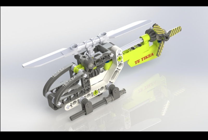
SolidWorks project-based course on how to make a Lego
helicopter like this. This course is mostly
designed for people who already have a little bit
of SolidWorks knowledge. But now I want to practice
those skills in a fun way. My name is John Olson and I'm a design engineer and
product designer, and I've been using
SolidWorks since 2006. I previously created a range of SolidWorks courses that take people from being
complete beginners all the way up to
being competent users. But for this one, I wanted to do something a little
bit different. During the course, we'll create a complete Lego
helicopter assembly, will build every single
part from scratch. We'll put them together and then we'll even add mechanical mates that allow the blades
and the tail rotor to spin around like this. The course isn't really designed
for complete beginners. It's more for people who
know a little bit about SolidWorks who are maybe a little bit rusty
and want to practice. Having said that, if
you are completely new, then we do start off fairly slow and then speed
up as we go through. So feel free to give it a try and just follow
along the videos. And if you do get
stuck anywhere, then just send me a message
and I'll try to help you out. With that in mind. Let's get started making our
Lego helicopter.
2. How to Use This Course: Before we actually start
building the Lego parts, we're just going to have a
very quick video that explains the best way to get
the most out of this course and how to use it. To use this course, you'll need your own copy of SolidWorks. The course is recorded
using SolidWorks 2021. But if you're using
a different version, then you can still
use the course. All the versions
are very similar. You might just see
some very small differences in things like how the interface looks
or minor tool options. If you do run into any problems, then please just
send me a message. This course does how exercise files that you can
download and use. These are the PDF of the
helicopter instructions and a SolidWorks model
of the finished chopper. You don't actually need these files to complete the course. They're just a bit of extra
information if you get stuck on apart and you want to
have a look at it in 3D. Now, solid works files
aren't backwards compatible. These files have been
made in SolidWorks 2021. So this means that you will
only be able to open them if you're using 2021 or newer. For example, SolidWorks
2020 or earlier, weren't open these files. However, the exercise
files also contain a finished version
of the helicopter saved us a step file. This will work with older
versions of SolidWorks. You just won't be able
to edit all of the parts like you would with
normal SolidWorks part. But you will still be
able to see it in 3D and measure it and spin
it around and so on. To use that step
file, just drag it into SolidWorks and
it should open. Those exercise files
can be found for download under the projects
and resources tab. This course does assume that
you have a little bit of SolidWorks knowledge
and you know how to do things like making
features and sketch it. It's designed more
for practicing SolidWorks skills than learning
completely from scratch. Having said that though, it
does start off fairly slow. So if you're totally
new to SolidWorks, then you can try just
following along. You can also slow down the video speed using the
controls on the player. If you do get stuck anywhere, then feel free to send
me a message or ask a question using the
Q&A feature below. And I'll try to get back
to you as soon as I can. Before asking a question. It might also just be
worth quickly searching the previous answers or searching online to see if
it's already been answered. That might just get
you a little bit of a faster response if
I'm not on my computer. If you do want to get the
Lego kit yourself and have a go at measuring it all
and making it yourself. Then the serial
number of a is 30465. It cost me about eight pounds, which is about ten or 11
US dollars, I believe. Then just warned final note, this course is taught using
metric, using millimeters. If you prefer to use
something like inches or a different set of units,
that's absolutely fine. You can either
change your units to millimeters or when you're using the smart dimension tool, you can input the
millimeter values that are used on screen. But before you press Enter, you can type in MM
for millimeter. This will then convert
the millimeters to inches or whatever kind
of units you are using. With all that out of the way, let's jump in and start making the first parts of
our helicopter.
3. Creating the Axle: To create the Lego helicopter, we're going to go through and follow the Lego instructions like you would if
you were making the lego model in real life, the kit comes with 70 pieces, but there's actually any 31
unique parts because some of them are used more
than once over those 31. Some of them are very
similar to each other. So we don't really have to make 31 completely different parts. Starting with step one here, we've got four different parts
to make this first stage. We're going to make
those parts one-by-one. And we're gonna start
with probably the simplest one, the axial here. If we look at the instructions, we can see there's a number
three next to the axial, and that indicates
the length of it. That means that it's
actually three bricks long. If we put it inside
the brakes like this, you can see it goes through
three sets of Brex. We're going to
open up SolidWorks and start to create this part. Want SolidWorks is open for you. Just start a new part. So here we are in a
completely blank part. When we start a new
Solid Works part, we usually start on one of
these three default planes, the front plane, the top
plane, or the right plane. Now sometimes when you look at the items you're
making in SolidWorks, there'll be a really
obvious top or side or front of the part. And you can line those up with
the planes in SolidWorks. But actually in the case of
this part of the Lego axial, it doesn't really
matter too much. Which direction is the front, the top, or the side? In this part don't
get too hung up on which plane you
should start on. In this case, I'm going to
start on the front plane, so I'm going to left-click
to select that plane. And then I'm going to choose
sketch from the pop-up menu, which will start a new sketch. Now we've moved to a normal to view and we're sketching
on the front plane. The first thing
that I'm gonna do is draw that cross shape, which is a cross-section
of the axle. To do this, I'm going
to draw two rectangles. So I'm gonna go to
the Sketch tab, choose the rectangle tool, and we want to choose
a sensor rectangle, which is the second option here. You can click on the little
drop-down and you can choose center rectangle directly up there on the command manager. Or you can just choose
the tool and you can choose center rectangle
here on the left. So if we look at the
little icon in the tool, you can see there's two numbers. Number one indicates
the first click. The first click sets the
center of the rectangle, and then number two indicates a second click that sets the overall size
of the rectangle. I'm going to move into
the graphics area. I'm going to start
at the origin, and I'm going to left-click
once at the origin to set the center of the rectangle
and then move the mouse out. Then I'm going to click again to set the size
of the rectangle. We want something like this. And then remaining in the
sensor rectangle tool, I'm going to go
back to the origin and I'm going to draw
another rectangle, but this time in this
sort of direction. This one should also be
linked to the origin. And then I'm going to
press the Escape key just to close the
rectangle tool. Now when you drawing
his sketches, it's a good idea to always try to link them
to a fixed point, which in this case
is the origin. This then allows you to fully define your
sketches so they won't move around
or change shape or size when you
don't want them to. Now that we have
our two rectangles, we're going to use the
smart dimension tool to set the size of them. Jews, the smart dimension tool
from the command manager. And then I'm gonna
set the size of this rectangle at the top here. You can see when I choose
that line is coming up on my view as 36 millimeters. But I'm gonna change
that to 1.8 millimeters, which is what I've
measured from the axial using my digital calipers. Now you can see when I had
that first I mentioned the whole sketch has
resized automatically. This only happens when you add the first dimension
of the sketch. Then for the height here, I'm going to choose this
line by left clicking, and I'm gonna make
that 4.7 millimeters. Now we want to make the second rectangle the same
size as the first. We could add some
more dimensions, but instead we're going
to use relations. I'm going to press
Escape to close the Smart Dimension tool. What we're going to do is select this small line that
we've already mentioned. Left-click on it to select it, and then hold down
the Control key. This allows you to
select multiple items. Then we're also going to
select the second line here. Now I'm going to release
the Control key. And you can see we
get this pop-up menu with different relations on it. From the pop-up,
I'm going to choose this one which is make equal. You can also choose it here on the left is exactly
the same setting. By clicking that it
means that both of those lines are now
an equal length. They're both the same size. And if we click on
one of those lines, we can now see we've got the equal symbol on
both of the lines. Then we're going to do the
same thing with a longer line. I'm going to select the one
that we've already mentioned, hold down Control
and then select the second one and
then release control. And then from the
menu that pops up, Let's choose make equal. Those lines are now
the same site and you'll notice that the entire
sketch has turned black. This means that
it's fully defined. We also have a message down here that says the
sketch is fully defined. This is because both of
these rectangles are fixed to the origin so they
can't move in position. Then we've set the size
of both of them as well so they can't
change in size. We could now extrude this
cross-shaped profile to make our axial shape. But actually if we
look really closely at the axle and we looked
at it from the end, we can see that these edge faces aren't actually
completely square. They're slightly rounded. This is so that we
can put the axle into a round hole and it will
still spend around properly. If we actually
look at that part, it's going to be really hard
to measure that radius. But what we do know is
that the widest length across the axial is 4.7. What we can do is get the circle tool from the sketch tab. Then let's draw a
circle. Let's fix at the origin and drag it
out to about this size. Then press the Escape key
to close the circle tool. We can then left-click
to select that circle. Hold down control, which allows you to select
multiple items. Then we can select one of these small straight lines,
then release control. And from the menu that pops up, Let's choose make tangent. Now that circle is exactly touching that small
straight line. That will just give us that
slight radius that we have that that lets the axle
spin properly in the hole. Now we have everything we
need in terms of our sketch and we can extrude this
profile to create the axle. We can stay within the sketch. We don't have to exit. But let's go to the
Features tab and let's choose extruded boss base,
the first option here. We can now say that we don't get any kind of preview
for the extrude. And that's because
we've got these overlapping profiles
within the sketch. So SolidWorks
doesn't really know which areas of the sketch
we want to extrude. So we have to choose
those manually. And you can actually
see if I hover over these different
enclosed areas in the profile, they turn red. And that indicates that we
can select those areas. Let's select all the
areas we want to extrude. There's four outer areas of the cross shape and then there's that center
section as well. Now we can see there
on the preview we've got that cross shape, but the edges of the
crosscut a slightly curved. If you're having any trouble
selecting those areas, you might just have
to click down here in the selected contours
box here on the left, and then choose those
five different areas. So we've got that center
section and then we've got those four sections
around the outside. Now we can extrude
this actual shape, the exact length that we want. But before we do set the length, I'm gonna change
the end condition from blind to mid-plane. This means that
instead of extruding and just one single direction, we're gonna be extruding
in two directions from the sketch by
an equal amount. Then we can set the exact length and we know from
measuring it with the calipers that that's
23.45 millimeters. And we can see on the
preview that we're gonna be extruding equally
in each direction. When you happy with
that, you can press Okay to create that feature. Now we've created that
basic actual shape. Now if we look at
the axial part in real life very closely, there's actually
a lot more detail than we can see
here on the model. We've got some parting lines on there from where the
mold moved apart, we've got some ejector pin marks from probably where the part
was pushed out of the mold. And sometimes you've even got small part numbers
and things like that. In this case, we've got
some slightly rounded edges to help you put the power
into the other bricks. It's really up to
you how much detail you want to model at this stage. This really is a trade-off
between how much time you want to spend and how accurate
you want your parts to be. I would personally say
that we don't actually need all of that
super fine detail. But what we will
do instead is just round off the edges
of the axon here. Let's select the fillet
tool from the Features tab. And I'm going to make
a filler that's nought 0.5 millimeters in size. It's just symmetric,
a circular profile. And I'm going to select these
four edges around here. There's four on this end, and
then there's another four. On the other hand,
if you find that you accidentally select the
wrong face or edge, you can just click it
again to de-select it. Again to add those four
fillets on each end, 18 total, and then press Okay. Now we've got our basic
axon model there, and that's all there
is to this first part. We can now save the part. And you can do this by
pressing Control S. You can press the Save icon or
you can get a file save. I'm gonna go to my
working folder where I'm going to put all these
different Lego parts. And I'm gonna call
this part something descriptive like axial. Now before you press okay, whenever we're saving
parts in SolidWorks, try to avoid quite
generic names, things like block or
axial or connector. That's because if you create
a similar project in future, may be sitting there isn't lego, but something that
also uses an axial, then it might cause
problems to your assembly. If you've got multiple parts named the same thing in
different locations, you might end up using the wrong part in your new assembly. To try to avoid this,
I'd recommend adding some kind of unique
identifier to your paths. It could be just something like the date or it could
be a part number. You can maybe even
write something like Lego chopper axon. But what I'm gonna
do is write axial. Then I'm just going
to add on 30465, which is just the model
number of these like Okay, I'm going to add that
number to all of my parts just to make them
unique to this project. I'm gonna say axial 30465 and
I'm gonna save that part. That's all there is
to that first part. So we've got one
down 30 to go back. Actually, some of
the later ones are very similar to
these early ones. So we can just copy and paste them and make some
small changes. So it's a very quickly recap
this part we just made a simple extrude using that cross shape with
the rounded edges, and then we fill it
at the edges there. In the next video, we'll
start making the next part, which is not right angle being, which makes up the
side of the fuser larger the body of
the helicopter.
4. Making the Right Angle Beam - Part 1: Welcome back. In this video, we're going to make
the second lego part, which is the right angle beam, to start off open SolidWorks
and open a new part. As before with the first part, it doesn't really matter
which plane you start on. In this case, I'm gonna start
on the front plane again. So choose the front
plane and then select sketch from the
menu that pops up. Now if we look at the beam part, we can see it's basically
made out three rectangles. They're at different
angles to each other and the ends
of those around it. So we can use the
slot tool to draw this basic shape from
within your sketch. Let's go up to the sketch tab
and choose the slot tool. And we want to choose
the first option, which is a straight slot. We can see on the tool as usual, you've got these little
numbers on the icon and they show you what each
click does within the tool. Number one sets the
left-hand side of the slot. Number two, since
the right-hand side. And then number three sets
the size of the slot. Let's go into the
graphics area and start at the origin
with the first click. And then let's draw our slot, the goat to the
right horizontally, something roughly like this. That's going to be the
bottom of our beam. We're now still
within the slot tool. And let's start another slot at the center of this
right-hand point, going upwards and to
the right at an angle. It doesn't have to be
exactly the correct angle because we will add
dimensions in a moment. We'll go upwards, something
roughly like this, and then finish that slot there. Then let's start a
third and final slot that starts from
the center point on the right here and goes
directly upwards, vertically. So you should have something
like this and then we can press escape to
close this lot tool. Now the first thing
that we're going to do is just select all three of these slots and make sure they're all
the same diameter. So let's select the rounded
edge of each slot in turn. So I'm gonna select
this one on the left. You're going to
hold down Control and then select this
one in the middle. And then keeping
control held down, select this one on the right, and then release control. And then from the
menu that pops up, I'm going to choose make equal. That will make the radius of all of these three slots the same. Now we have a rough
overall shape of the beam and we can start
to set the exact size. So let's choose the smart dimension tool from
the sketch tab. And the height of that slot from what we've measured
with the calipers, we know is 7.4 millimeters. So when we add that
first dimension, it resizes the entire sketch
to suit that dimension. Next, we want to set the length of the
bottom of this beam. And to do this,
we're going to count how many circles are in
that bottom section. So if you look closely at
the partner is actually seven different
circles in there. We also know from measuring the circles that they're each
eight millimeters apart. And we know that the diameter
of them is 4.8 millimeters. I'm going to get the circle
tool from the sketch tab. And I'm going to draw a circle
here on the left-hand side of our part is lined
up with the origin, which means it's also concentric with that curved
part of the end of the slot. Then I'm going to use
the smart dimension tool to set the diameter here to 4.8. So we've got the first circle that we need there on the left. We know that the seven of those, and they're spaced eight
millimeters apart, we can pattern some
more of those circles along to set the exact
size of this beam. Press Escape to make
sure you're not in the smart
dimension tool still. And then left-click to
select that circle. Then I'm going to go to
linear sketch pattern, which is on the sketch tab. We can now pass in
this circle along. So we know we need
seven instances. So I'm going to
increase the number of instances to seven. And we also know that the
spacing is eight millimeters, so I'm going to set that
here as eight millimeters. Now if you don't see a
yellow preview like this, just make sure you
have that circle selected in the
entities to pass inbox. And then make sure you also have a direction selected
in direction one, you might just need
to click in that box and choose one of the straight lines going
in the x-direction. Now one last thing we need
to do before we press okay, just put a checking
this box that says dimension x spacing. This will just mean that the
eight millimeter spacing will be set when we
create the pattern. Then when everything looks good, press Okay to make that pattern. Now we can see
we've got seven of those circles and we've got the eight millimeter
spacing there. So all of those circles are black because they're
fully defined. What we can do now is grab this end point of
the lowest slot. You might have to zoom in a
bit to be able to see it. So grab that and
left-click and drag it. So it's lined up with
that right-hand circle. The circular edge
on the right-hand side of that bottom slot should be concentric with
that right-hand circle. So what you can do is just drag that sensor point of the slot along and then hover over the edge of that
right-hand circle. And then you should
be able to see the center point of the circle. You can then move the sensor
point in this slot back to the center point of the
circle and release it, and that should link it there. Now we know that that lower
beam is the correct length. Next, we can move these
other sections around a bit. Firstly, let's just
move this down a bit. And then let's get the
smart dimension tool and let's add an angle in there. This is a 135 degrees. Now we can set the length
of these two extra slot. Again, let's select
the circle tool. And we know that this
vertical section has got three holes in it. So use the circle tool to draw one circle here at the top, another circle
here at the bottom of the vertical section. And then a third circle in the middle of that
vertical section. So it should be coincident
with the midpoint of that center line that goes
down the middle of the slot. Then we can select all
three of those circles. So remember hold down Control
to select multiple items. Then just left-click to
select those three circles. Then keeping control held down, let's also select one of those other circles that
we've already defined. Then release control and
just choose make equal. That will make those three
circles on the right-hand side the same diameter as all
of the other circles. We can then just set the
distance between the holes. So use the smart dimension
tool and choose, for example, the top one and the sensor on and set that to
eight millimeters, that standard distance there. Then the final thing we
need to do is just add that slot in the middle of
that diagnosed section. To do this, we'll use
the slot tool again. Choose the tool this time
instead of a straight slot, we're going to use a
sensor points lot. That's the second option here. So this means that
we're going to start from the
center of this law. We're going to move outwards
and then set the size. And if we look at the
numbers on the icon, we can see number
one, the first click sets the center
point of this law. So let's zoom in a little bit. Let's start the slot from the center point of
that diagonal section. And then we're going
to drag the slot upwards, something like this. Set a rough length
of the slot and then drag it outwards and
then set a rough size. Then once you've got
the slot in place, press Escape to
close the slot tool, and then we can make
sure the slot is the same diameter as
those other circles. So select one of the
circles, hold down control, and also select one of
the circular edges of this slot and then
choose make equal. We know that slots
to the correct size, but we can still move it around. If you're ever not sure
why selling steel blue, why it isn't fully defined. You can just left-click and
drag the points around. And that should
give you an idea of what it needs to
be fully defined. In this case, we need to use the smart dimension
tool and we need to set the correct spacing
for the length of that slot. So that length there should
be eight millimeters. So that double slot is basically two holes that
are joined together. Again, we're still not
quite fully defined. So if I grab one of the
points and move it around, you can see we just need
to set the distance from the corner of that
beam to the slot. That should be
eight millimeters, because the space in-between
all of the holes is eight millimeters and that should fully define
your sketch there. And if you find you're
not fully defined, you might just need to add
some further spacing between the holes to make sure all of the holes are eight
millimeters apart. And then the size of
all of the holes should be 4.8 millimeters diameter. That gives us the
overall profile that we need to create that bean shape. And we can now use that to
create an extrude of the beam. So staying within the sketch, let's go to the Features tab. Let's choose extruded boss base. And then first let's set the width of this
beam so we know that 7.85 us change it from
blind to mid-plane. There are playing is down
the middle of the beam. This will just
make things easier when we need to mirror
some features later on. Then let's click in the
selected contours box and let's choose the areas of the profile that we
want to extrude. So we're just going to select those gaps in the beam area. So it looks something like this. And as well as that
main beam shape, we also want to choose the
last and the first circle. That's because if we look at
the real part, these first, unless circles are actually cross-shaped so they can
fit in the axial part. So we're going to cut
those separately. Then press okay, and now we've created the start
of our beam there. So you should have a shape,
something like this. Let's rename that first
feature on the left by doing a slow double-click on it or
selecting and pressing F2. And I'm going to call that beam. Now if you've seen any
of my other videos, you've probably
seen that I like to rename a lot of features. You don't have to do this. They can save you a lot of
time in the long run just by making a model a little bit more organized and easy
to understand. Now that we've made
the basic beam shape, we're going to cut
those cross-sections out where the axons will fit in. I'm going to start another
sketch on the front plane. Let's start with the
left-hand one down here. Firstly, get the circle tool. Draw a circle at the origin. So it's concentric without rounded edge of the
end of the beam. This circle is the same
diameter as the other. So use the smart
dimension to set that as 4.8 millimeters. But we also know that he's got that cross shaped to
fit the excellent. Let's go to the rectangle tool. Let's choose the
center rectangle, and then let's draw
two rectangles that make a rough cross
shaped like this. And then use Smart
Dimension to set the width of one of
those rectangles as 1.8. We can now use relations to fully define the
rest of the sketch. Firstly, I'm going to select
the small edge of one of those rectangles
and then hold down control and select
the other small edge. And then make those
the same length. So press make equal. So they should both
be 1.8 millimeters. Then next let's select
one of those small lines. And then also select the
circle and make those tangent. And then do the same for the
other rectangle as well. At this point, you should have that cross shape with a
slightly rounded edges. And it's basically the same
profile that we use to create the axial
in the last video. Now if we look at the real part, there's actually
also another area cut out here to the
right-hand side. To create this cutout area. First, we're going to select that circular edge on
the second circle there. And then go to the Sketch tab
and choose Offset entities. We want to offset 1.3
millimeters outwards. You circle should be exactly touching the edge
of the beam that if you find that your
yellow preview circle is smaller than the
IgE you selected, you might just need to press
reverse here on the left. Then press Okay to offset
that circular edge. Then we're also gonna
do the exact same thing for the first circle we drew. So select that
circle on the left, go to the Offset
Entities tool and then Offset 1.3 millimeters outwards. The next we're going to select this upper straight
edge of the beam. We're going to offset that
one millimeter downwards. We're gonna do the same for
the bottom edge of the beam. So select that straight
edge on the bottom and then offset this one
millimeter upwards. So we're building up a profile that we're going to cut out. Then finally, we just need to
fill in a little gap here. So let's choose the
Line tool and let's add a small straight line
going from the edge of this rectangle out to
that circle there. And then the same on
the bottom as well. This looks like a
fairly messy sketch, but we're gonna cut out
specific parts of it. And this will become
more clear in a moment when we
actually make the cup. Before we actually
do make that cut, we need to make
the same sketch on the right-hand side for
that final circle as well. So zoom out and basically follow the same process for this
area on the right-hand side. We're gonna do this one a
little bit more quickly. First I'm gonna get
the circle tool. We're going to draw a circle which is concentric with the end of the beam here and set
that to 4.8 diameter. Then I'm going to use
the sensor rectangle to create those to
censor rectangles. I'm going to set
the size is 1.8. I'm going to make both small
edges of the rectangle the same size by using
the equal a relation. And then I'm going
to set the length of the rectangle by making those small edges tangent
with the edge of the circle. Then if you remember, we use
the Offset Entities tool to offset those circles
1.3 millimeters, you might need to
choose them both separately and do two
separate offsets. You might be able to
choose them both and then do the offsets in one single go. Then again, we're
going to select those straight edges
on the outside of the beam and offset those worn millimeters
inwards, one on each side. Then finally, just use
the line tool to add those two small lines to
join that small cross part. The rest of the cutout. We're now ready to make those cutouts from still
within the sketch. Let us go to the Features tab and let's choose extruded cut. And then click down here in
the selected contours box. We want to choose these
five sections of the cross. We also want to choose the extra small
rectangle section and then also that kind of
wedge-shaped section there. Then for the type of
code instead of blind, Let's go for through all both. This just means that
you cut through the entire model in
both directions. If we now zoom in and
look at the preview, you can see we've
got two small areas that we also need to cut. We also need to select these two small wedge-shaped sections, one on each side. And then when you've
got everything, it should sort of look
a bit like this, sort of like a gravestone
on a half-pipe almost. Then let's go to the other side and do the exact same thing. We're going to choose these
five sections of the cross. That wedge-shaped part,
the small rectangle, and then those two small wedges. When you're happy press Okay, and it should look
something like this. We've cut out the area for
the axial on both sides and I'm just going to rename
that feature as axial cut. The general shape of the
part is complete there. If you stopping at this point, you can save your partner. I called mine corner beam
seven by four by three, just because it's seven
long by four by three. Then I put that number on
for the kit which is 30465. If you're not stopping, you can just continue directly onto the next video where
we'll just finish off some small
details of this part.
5. Making the Right Angle Beam - Part 2: In the previous
video, we started to create that right-hand beam. Now this is one of the
more complicated parts, so it's a little bit drawn out, but we can actually
repurpose this part to create a few of the other
beam parts later on, and that should
save us some time. So continuing on from
that previous video, we've got the basic beam shape. In this video,
we're going to add the final finishing details for the first set of details
that we looked at the beam closely and we
looked at the holes. You can see they've actually
got a wide hole around them, which only goes in
a small distance. To create this,
we're going to start a sketch on the side
face of the beam. So select the face of the
beam by left clicking. And then from the
menu that pops up, choose sketch, then select the edge of all of the circles. Remember you need to
hold down Control to select multiple items. We also want to
select the slot here. You'll need to select the four different elements
of it separately. So there's two curved edges and then there's two straight
lines connecting them. Now we want to offset
these edges so we can make that
slightly larger cut. But sometimes you'll find with the Offset Entities
tool when you select the tool
and try to offset, sometimes it doesn't
seem to work like this. If this happens to disclose
the Offset Entities tool, we've still got all of
those edges selected. And then instead of offset
choose convert entities, we've now converted all of those edges into new
sketch entities. We can then select all of
those sketch entities. You can do this by
pressing Control a, which is select all or you can just drag a box
around all of them. And now we can offset
those converted edges. So sometimes if you select an edge directly and
try and offset it, it won't work if you
convert it first and then offset that converted
line, it will work. We're going to offset
0.7 millimeters. And then before you press OK, here in the construction
geometry options, we want the offset
geometry to be solid, so there shouldn't be a
check mark in that box. But we can actually
make the base geometry into construction geometry. If we put a check in that
box when we press Okay, it means those original
baseline that we selected will be turned
into construction lines. Let's press Okay, and if
we zoom in a little bit, we can see there's original
selected lines are now construction lines for the
offset lines are solid. We can now do an extruded cut. And we've measured the
depth of that car as 1.25. Now, just a very quick
aside to measure the depth of holes like this
using your digital calipers, what you can do is just open the jaws of the caliper like you're going to
measure something. And then if you look
at the end here, there's actually little tablet
sticks out at the bottom. You can use this to measure
the depth of things. After making that cut feature, I'm going to rename
it as whole surround. The next thing that we're
going to do is cut out the small cavities
between the circles. Start another sketch
on this face. And first we need to offset
all of these circular lines. So again, let's select the
edge of those larger circles. And we're also going to
select the edge of this law. Now with the slot, instead of selecting each
element individually, you can also just
right-click on one of them and choose,
select tangency. And that will select
all the lines connected to the one that
you right-clicked on. Then I'm going to
offset those edges. And again, if you find
the offset doesn't work, remember that you can
first convert those edges, and then you can select all of those converted edges
by pressing Control a. And then you can offset
those converted lines. Then let's offset
0.55 millimeters. And again, we want to make
the baselines construction and we want to make the
offset lines solid. So now we have all
of those lines, they're larger than the
circles in the slot. Next, we just need
to offset the edges inwards so that we can
cut out the correct area. I'm going to select each
straight edge in turn and offset it inwards
one millimeter. Then let's do the same
for the upper one here. Then the same with the
diagonal one here. And also on the other side. Then finally just the
short vertical one here. And also on the other side. Now we can cut away those
cavity areas between the holes by using an extruded cut which
is on the Features tab. This current is three
millimeters deep, It's blind. And then in the
selected contours, Let's just choose all of those. So of our glass shapes
that are between the holes should have all of those wounds between the circles and the
slots like that. And then press Okay
to create those. And let's rename that
feature as cavity cut. We're almost done now one of the final things we'll do is
just get the fillet tool. Let's choose a 0.5
millimeter filler, just a round fillet symmetric. And let's round off the inside
edges of those cavities. We want to select
these four edges which are in-between
each set of holes. He can select them manually. You should also find that
when you select one you get this edge selection
toolbar pop-up. This will give you
different options to select multiple edges
at the same time. I'll show you again
with this cavity. When you select the first edge, we get this puppet toolbar. And then if we just
hover over for me, it's that first option
that will allow me to select all four edges
within that cavity. That just saves a
little bit of time. So I'm gonna do the
same thing for all of these cavities that
are between the holes. So as we go around, there are other options on the
Edge Selection toolbar. Most of those aren't
really relevant to us. Let's just try and stick
with that first one. For each set of cavities, we can choose four
edges at the same time. It might take a little bit
of time to select these. You might need to
spend your model around a little bit as we go around the corner to help you
select the correct edges. And if you find that you select the wrong
face or the edge, just click on it again
to de-select it. When you've got all of them, it should look something like this. We've got all of those
internal corners there. But we're going to leave the
ones on the edge here for now because we're going to
mirror these fillets over. And if we mirrored those, it would cause a problem
because they actually go all the way through press Okay, to create those fillets. And it should look
something like this. We've got all of
the detail that we need on this first slide, but we don't have any of
it on the opposite side. But because we used
a mid-plane extrude, we can actually just
mirror everything over. So let's select the front
plane by left clicking. Then that's also
hold down control and select those three
latest features. It's the whole surround, the
cavity cut and the fillet. We should have three items selected as well as
the front plane. Then we can press mirror
and we can see we get a yellow preview like this
for the mirror plane, we've got that front
plane that we selected. And then for the
features to mirror, we've got the whole surround, the cavity cut and the fill it. If you find that your preview or you mirror it doesn't work, try going back into that
first feature and just making sure that you've got
a mid-plane extrude there instead of
a blind extrude, that just makes sure
that the front plane is at the middle of the model. So we can use it to mirror
these items over. Press OK. And now we can see
that we've mirrored those features over
onto the other side. Then the final thing that
we need to do to finish off is just use the
fillet tool again, keep the same settings. So 0.5 size, it's a
symmetric round fillet. We're just gonna get these
four edges here on the left. And the reason that
we didn't add these to the previous fillet before we did the mirror is because these visits actually
go all the way through. We can't actually
mirror them through if they're already
all the way through. Then going up here to the top, there's another
four on this side. So there should be
a edges in total. And then press Okay to
create that fillet feature. Now we have created
that being part. And the final thing I'm
gonna do is just change the color of it so it suits the color in
the instructions. You don't have to do this just might make it a little
bit easier to follow the instructions if
all of the parts on screen match with the
parts in real life. I'm going to open the
Appearance scenes and Details tab here on the right. I'm going to choose appearances. And then here in appearances
I'm going to choose something like a
plastic medium gloss, and I'm going to go white color. And then double-clicking
on that color applies that appearance
to the whole part. Then the final thing to
do is just save the part if you didn't already save
it in the previous video. As we mentioned before, I'm gonna save this
one as corner beam seven by four by three because there's seven
holes along the bottom. There's four at that diagonal corner because you remember that slot counts as two holes and then this three on
that vertical section. And then also I'm
just going to put that reference number
on the end, 30465. And then we have our
finished second part. In the next video, we're gonna do something a
little bit simpler. We're going to make that
friction pen parts.
6. Building the Friction Pin: The next part that
we're going to make is a very small part of it is
used quite a lot in lego. Will be able to use
it multiple times, and that is the friction pen. This is often used to connect different parts
together in SolidWorks, let's start a new part. And this time I'm going
to start sketch on the right plane because
I'm actually going to start from the middle of the
part and then we're going to model it outwards
in both directions. I'm going to start
sketch the circle tool, and I'm going to
draw two concentric circles fixed to the origin. These are going to
be that wider ring at the center of the connector. I know that the inner
diameter is 3.5 millimeters. We know that the outer
diameter is 5.85, so we'll add both
of those dimensions that should fully
define the sketch. And we can then do an
extruded boss base mid-plane. The thickness of this
is 1.6 millimeters. We're going 0.8 in each
direction, 1.6 in total. This is that thicker section at the very middle
of the connector. I'm going to rename that feature as something like middle ring. Next up, I'm going to
start another sketch also on the right plane. I'm going to use
the inner circle so we can get the
same inner diameter. I'm going to select
that circular edge and then press convert entities. So now we've got that
circle in our sketch. Then I'm going to get
the circle tool again. I'm going to start
at the origin. If I go to a normal two view, you can see a bit more clearly. This circle is a little bit
smaller than that first one. For the size of this is actually 4.7 millimeters diameter. Then we're going to do
another mid-plane extrude. So we're gonna get Features
extruded boss base going to set it to mid-plane. And this warrant is 14.7
millimeters in size. So now we have that wider
section in the middle, we've got the same boar or inner diameter
all the way through. And then we've got
that smallest section that goes out to each side. I'm going to call
that second feature something like out-of-body. The next thing that we've got is a small rim right
on the edge here. I'm gonna start a sketch
on the outside face. I'm going to select
that inner diameter and convert it using
convert entities. Then I'm going to
get the circle tool, start another circle which
is concentric with that one. This one is a little bit larger
than that widest section, but it's not quite as large
as that middle section. The size of it is
5.25 millimeters. Then we can just
do a blind extrude outwards 0.5 millimeters. Only sticks out a
really small amount like that, just off the end. We've still got that same
inner diameter all the way through and I'm going to rename that new feature as outer rim. It's exactly the same
on the other side so we can mirror that outer
rim feature over. I'm going to select
the outer in feature. I'm going to also
select the right plane. And then I'm going
to press mirror. We have the right plane
here as the mirror plane. Then we've got the
features to mirror as the outer rim and
then press Okay. And that rim is also
added to the other side. There's a lot of extra
detail on this part that we don't necessarily need to add
for the SolidWorks model, there's some really tiny numbers which are probably
the part number. There's some little
extra ribs that may be give it a bit more
friction in the hole. And there's even some
ejector pin marks on there from when
the park was molded. The only extra detail that we're going to add is this loss. So to do this, Let's start a
sketch on the front plane. Then go to a normal to view
and choose the slot tool. The version that
we want to use is a center point straight slot. This is a slot that
starts in the middle and goes out equally in
both directions. So start from the origin and draw a slot horizontally
out like this. We know from measuring it that this is one millimeter high. We also know that
the total length of the slot is 6.9 millimeters. If we use Smart Dimension
and try to set the length, we've actually got the
wrong length there. We've got the length between the two centers of
those curved ends. And we want the total
length to get around this. We can hold down Shift when I mentioning this will dimension to the outside of the curve. Hold down Shift, select the very outside here on the left
and also on the right. And then we can set
that dimension as 6.9. Then I'm just going to use
that slot shape to make a cut so you can go to
Features extruded cut. We can go through all both. This will cut through all of your model in both directions. And that just gives
the connector a little bit of flexibility in the middle there so it can
fit into the blocks properly. I'm going to rename that
feature as middle slot. And then the final
thing we need to add is just a two slots,
one on each end. These are perpendicular
to that first slot, so we need to start
on a different plane. If we quickly hover
over the planes, we can see we don't want to
start on the front plane. The top plane will be suitable. Let's start sketch
on the top plane. Again, you can go to
a normal to view. It just makes it a little
bit easier to draw the slot. I'm going to choose
a slot tool and a center point
straight slot again. And I'm gonna start the slot at the midpoint of one
of these outer edges. If you hover over
the edge there, you should be able
to pick up the center point of that line. I'm going to draw
the slot out like this horizontally to the side. And then the size of it
is one millimeter high, so it's the same
as the middle one. There's actually a
slot on each side. So before we set
the length of this, we can mirror this slot
over to the other side. To do this, we'll add
a center line and you can do this by going
up to the line tool, clicking on the
drop-down next to it, and choosing center line. Then start the sensor line at the origin and go
vertically upwards. It doesn't matter about defining the top of it because
it's just a center line. Then we can use that
center lines and mirror that slot profile over
to the other side. To do this, go to
the Sketch tab, choose Mirror entities for
the entities to mirror. This is what we actually
want to mirror. So we want to select
that slot that we drew. Then for the mirror about point, we can choose that
vertical center line. We can see that the
yellow previews in the correct place so
we can press Okay, and now we have the
two slot profiles, one on each side. We can now set the
exact length of them. We know that the
distance between those two slots is
8.5 millimeters. We can use the smart
dimension tool. Again, we can hold down Shift
when we're dimensioning. This lets you damage
into the outside of an arc and we can add the 8.5 millimeters in and that should fully
define your sketch. And then just as a double-check
this dimension here, the length of the slot from the end should be
3.6 millimeters. And we can see that I is, we don't really need
to add that dimension, but it's just there
as a double-check that we've got all
the sizes right? And then we can go to
Features extruded cut. And again, we can choose
through all both. And that will cut both of
those slots, one in each end. And again, they just give
a bit of flexibility to the connector to allow it to actually compress
into the holes. Before I save the part, I'm
just gonna go to appearances. And I'm gonna
change the color of the part to match
the real-life part. I'm gonna stay with a
medium gloss plastic and I'm going to go for
something like a dark gray. In real life, the part is
probably more of a black. But actually if you
choose the black, you can sometimes lose
some of the details there because the black
is a very dark color, I tend to go for a dark gray
and it just lets you see the edges and the detail of the part a little
bit more clearly, if you need to select it.
This part is finished. We can now save it. And I'm going to save
it as friction pen. And then just put that
number on the end, 30465. So we've now made three
of the four parts for the first stage and
the next one is fairly similar to this
one is also a connector, but just with some
small differences.
7. Making the Pin with Bore: The fourth and final part of this first stage is also
a type of connector, but it's got this hole in the middle or bore
in the middle. So I'm going to call
this one pin with war. Let's start a new part as usual. And light with a lot
of SolidWorks models, there's a few different ways you could model up this connector. It doesn't really matter
which way you model it as long as you end up with
the correct end result. From looking at the
part, I'm gonna make the widest section of
the connected first. And the more that you
practice with SolidWorks, the easy you'll find
it to just look apart on very quickly assess how you're
going to build up. I'm going to start a
sketch on the right plane, get the circle tool and draw
a circle at the origin. This is 4.7 millimeters
in diameter. And then let's do a
mid-plane extrude. And it should be 22.7
millimeters long. This is our main pin shape, so I'm just gonna call
that feature pin. And then there's also a
wider section in the middle. I'm going to start another
sketch on the right plane. I'm going to get the
circle tool again and draw a circle at the origin
that's a little bit bigger. This one is 5.9
millimeters diameter. Then we can do another
mid-plane extrude, go to extruded boss
base, choose mid-plane. And this one is 9.6, so it's a bit smaller than the entire length
of the connector. Then let's just call that
feature something like middle. Next we've got the wider sections at the end
of the connector. I'm gonna start a
sketch on this N face. Get the circle tool and draw
a circle at the origin. Because there's n
face isn't open. We don't need anything
in the middle. We don't need any kind
of inner diameter. Let's just get the Smart
Dimension and set this circle to 5.25 millimeters diameter. So it's the same size
as the outer rim of the pin that we made
in the last video. Then it's also extruded
blind is 0.5 outwards. Let's call this
feature outer rim. And then as before,
there's one on each end. So we can mirror this over. I'm going to select
the outer rim feature. I'm also going to select the plane that goes down the middle. So for me this is
the right plane. And then I'm gonna choose
mirror and we've now mirrored that REM over
to the other side. Now if we look at the part,
there's a cavity on each end. This cavity doesn't go all
the way through the part, but we're actually going
to add the middle section afterwards so we can cut
all the way through. Now, it will just make things a little bit easier in
terms of modelling. I'm gonna start sketch
on the right plane. You could also just start
on the end face here. I'm going to go to
a normal to view. And if we look at the
par is not actually a fully circular
cavity in the middle, It's more sort of a rectangular
shape with curved edges. From measuring it,
we know that it's 0.85 millimeters from the edge. So I'm gonna select this
main outer rim edge. And then I'm going to
offset 0.85 inwards. If we go to the end view, you can see that a
little bit more clearly, then the width of
the cavity is 2.2. I'm gonna go back
to the end view. I'm gonna get a
sensor rectangle. And I'm going to start
this at the origin. I'm going to draw a
rectangle that's 2 too wide. Then for the height of
the rectangle there, it doesn't really
matter as long as it covers the entire circle. I'm just going to grab
one of these corners and just drag it around and
I'm going to fix it. So this outer circle here that
fully defines the sketch. So we're just going to cut
out that middle section. So I'm gonna go to Features
extruded boss base. And then I'm going to
do through all both. And I'm going to choose
that center section is a rectangle shape with a
curved top and bottom. So we're going to cut
something like that. It might not quite look
right at the moment because we haven't added
all of the other features. But as we add those, it
should look more correct. I'm going to rename that
feature now as bore cut. And then next I'm going to
cut a slot, one on each end. So to do this, I'm gonna start a sketch on the front plane. I'm going to go normal two and
get the sensor points slot tool start from the
midpoint and the end here. And similar to that pin that
we made in the last video, we're going to draw a
horizontal slot out like this. And then we have
two of these slots. So I'm going to add
a center line in the middle of
vertical center line. And I'm going to
use that to mirror that original slot over
to the other side. So we've got one on each side. Then let's make these
slots one millimeter high so that the same size as
that previous connector. Then the distance between them
here is 17.8 millimeters. So remember hold down Shift to dimension between the two arcs. Then we can do an extruded
cut through all both. And that cuts those
slots on both ends. And now you see if
we look at the end, it looks a little
bit more correct. It looks closer to
the real lego part. I'm gonna call out
feature slot cut. And then we only have to add
that ball in the middle. We can start another
sketch on the front plane, going to go normal to
get the circle tool and draw a circle at the
origin about this size. Then I can use Smart
Dimension to set this as 7.4. We can use this to make
a mid-plane extrude. And the width of this
is 7.8 millimeters. That adds that circular
section in the middle. Let's call that something
like middle body. We're almost there
with the part now the next thing we need to do is cut a hole
through the middle. So again, start another
sketch on the front plane. Use the circle tool,
draw a circle at the origin and set the
size there as 4.8. We can then do an extruded cut through all both to cut that
bore through the middle. Again, it's that
same hole size that we've used on a lot
of the parts so far. And this just allows everything
to fit together properly. Let's rename that
hole as middle ball. Now we've just got
that wider Renuka to make on both sides. Let's start a sketch
on this face. Get the circle tool again. Draw a circle that's
concentric to that center section and the
diameter of this is 6.1. Then again, we can make an
extruded cut and this is 0.75 deep and it's a blind cut. And let's call that something
like middle rim cut. All that remains is to mirror that over to the other side. I'm going to select that
middle rim cut feature. I'm going to select the plane
that goes down the middle. So for me this is
the front plane. And then I'm going
to press mirror and that preview looks correct. So let's press Okay. And
if we spin it around, we can see we've got that
correct drinker on both sides. This part is now finished in
terms of modelling as usual, I'm just gonna change
the color so it matches the real-life part. If we open the Appearance
scenes and Details tab, we can see that there isn't
really a default color that matches that sort of lime
green color of the lego part. So let's choose
something similar, just third, generic
green like this. Then what we can do is go into the display manager to do this. Click here on the left
on the display manager, and then right-click on
that green appearance and choose Edit appearance. We can now set at Green, which is a little bit closer
to the real life one. I'm just going to
play around in here. And I think that is
pretty close there. It doesn't have to be exact. As I mentioned in
a previous video, you don't have to change
the color like this, just makes it a little bit
easier to actually make the leg or assembly when
you've got all the parts. Finally, let's save this part
and I'm going to call it something like friction
pen width bore, and then put that number
on the end, 30465. Now we've created
those first four parts that we need for that
first assembly step, and we'll start putting those
together in the next video.
8. Creating the first Subassembly: Now that we've created
those first four part, we can use them to
make an assembly of the actual Lego helicopter. The first thing that we need
to do is make sure we've got all four of
those parts open. You can either just
drag them into SolidWorks or you can open
them in SolidWorks normally. Now once you've parts are open, you can switch between
your open windows by pressing control and tab. You see we've got all
four of them open. Now before we actually
start making the assembly, we need to just
have a little thing about which part we're
going to start with. You might think that the
best one to start with is this large side
part of the fuselage, the large right angle beam. That actually if we look
ahead in the instructions, we can see that this
green connector is right at the
center of the model. It's probably best if we line that up with the center
of the assembly. This will just help
us later on if we need to mirror it any parts
over to the other side. Go to this green friction
pin with ballpark. Then from within that part, Let's go to File make
assembly from power. We're now taken to an
empty, blank assembly. And you should see you for open documents here on the left. And these are just parts
that are open in SolidWorks. So if you don't see
your parts there, you can just click Browse
here at the bottom and you can find the parts wherever they're saved on your computer. So firstly, we need to select
the part that we want, which is the friction
pen with ball. Left-click to select that. And then I'm going to go
down a little bit and I'm going to select
Graphics preview hit. This just means
that when we move the mouse into the
graphics area, will be able to see that
following the mouse around and see where
it will be positioned. Now let's make sure that part is rotated to the
correct orientation. You should see this small
rotate menu and you can use these buttons to
rotate your part by 90 degrees in
different directions. If you don't see that menu, to scroll down a little bit and make sure you have a
check mark in this box. Show rotate context toolbar. Let's rotate the part
around so it matches the orientation in the
Lego instructions. We want this hole
through the middle, it to be pointing directly upwards instead of
pointing forwards. So we want to rotate
around the x-axis. So I'm gonna click
this X button. And now that hole is
facing directly upwards. And then let's place
this part anywhere in the graphics area
by left clicking. This part is now inserted into the assembly and we can
see that it's fixed because there's a small f in brackets next to the
part in the parse tree. Also, if we try and
drag the part around, we get a small message that says the components fixed
and it can't be moved. However, if we go to a top view and we looked at
the default planes, we can actually see
that the right plane isn't lined up with
the middle of the par. So this isn't really
what we want. We need to make it. So
this part is free to move around and then we can put it in the right place
and fix it there. To do this first, go over to
the friction pin part with ball on the left and
right-click on the part. And from the menu choose float. This will unfixed the parts
so we can now move it around. And we can see that the F for
fixed as disappeared from next to the part name and it's now being replaced by minus, which means the
part isn't fixed. We can now expand the
part and we can line up the planes from the part where the planes from the assembly. Let's start off with the
front plane from the part. So select the front
plane and then hover over the default
planes in the assembly. And there should be
one that's roughly lined up with that front plane. So in my case it's
the top plane. If we hold down control, we can select both of those planes, the front plane from the part and the top plane
from the assembly. Then if you release control, we can add a coincident mate and that will align
those two planes up. Then let's choose the next one, the top plane in the pot, and then hold down control
and select the front plane in the assembly and then release control and add another
coincident mate. And then finally, let's do
the same with the right plane in the power and the right
plane in the assembly. Now we can see that
we no longer have that minus symbol next
to the partnering. Now it is fully defined. And we can also see it says fully defined down
here on the right. Now if we go to top view, we can see we've got
the right plane of the assembly at the
middle of that part. This will just make things much easier if we need to mirror over any parts from one side of the chopper
to the other side. Now that we've fixed that
first part in place, let's insert the
remaining three parts. You can do this by going
to the Assembly tab and choosing insert components. We can see we've got those
other parts open there. Again, if you don't
have them there, you can click Browse and just
find them on your computer. Now before I insert the parts, I'm just going to click
on this pin icon here. This just pins this menu open. So it means we don't
have to reopen it every time we want to
insert a new part. Firstly, I'm going to
insert the axial part. I'm going to use those
rotation buttons to just rotate it around so
the correct orientation. So it lines up with
the Lego instructions. And then I'm going to
left-click to place it in roughly the
correct position. You don't have to rotate
it at this stage, it just makes
things a little bit easier when we add
the mates later on. The next part I'm going to
insert is that corner beam. And again, I'm gonna
rotate it round to the correct orientation and then place it in roughly
the correct place. Then finally I'm going to
add the friction pen and again rotate it round so it's
in the correct orientation. And then when you're
done, you can press OK to close that insert
components menu. Now we can see we've
got all the parts that we need in the assembly. The only one that is
fixed is the green one. The other three
parts of Ogata small minus next to them
in the street. And that just shows that
they're not defined. And we can move them
around in space. Now we can start to add
some mates to fully define those other
parts in the assembly. With Lego is fairly easy to
see how parts fit together, so the mates are
fairly easy to add. For the first one, let's attach the beam to the
sensor connector. All we need to do is select a circular edge of the
peg on that connector. Then select a circular
face or edge on the corresponding hole that
goes into on the beam. Remember if you
hold down control, you can tell that
these multiple items we know from the
instructions that the whole we need
is the fifth one along from the front. So
it should be this one. When you have your
two circular faces or edges selected, release control. And then from the
menu that pops up, we can add a concentric mate, which is this one with
two circles on it. If you can't see that
pop up for any reason, you can also choose
the mate tool up here on the Assembly tab, and then you can add a
concentric mate there. Now that we've added that
first concentric mate, the hole in the beam is lined up with the peg
on the connector. But we can still rotate the beam and we can still
move it in and out. So we need to add more mates. Firstly, let's zoom
in and let's choose that flat face on top
of the connector. Hold down control, and also choose a corresponding
face on the beam. I'm going to choose this large flat face on the
top of the beam. We're gonna release
control and then I'm going to add
a parallel mate. And then finally, let's
just move the beam in to the correct distance
from the connector. If we spin the assembly round, we want the outside of the connector to be lined up with the
outside of the beam. So let's select
those two sets of faces and adequate
incident mate. Now we can see here next to the corner being part
in the parse tree, we no longer have that minus, so that means that part
is now fully defined. We can also expand the mate's
folder here at the bottom, and we can see all of them
makes that we've added if you need to adjust them or
delete them for any reason. Now it's just a case of adding the mates for the
remaining parts. Next, let's move
on to the actual. At first glance,
this one looks a little bit tricky
because of the shape. But actually if you remember, these top edges are curved. We've also got the
curved edge in the corresponding
hole on the beam. We can line those up
using a concentric mate. Again, I'm going to select
that curved edge on the axle. Also select a curved
edge on the beam, then add a concentric mate. Now if we move the
actual around, we can see that it can actually still spin around in the hole, and that wouldn't be able
to happen in real life. We need to lock the
rotation of it. We can do this pretty
easily just by selecting one of
the flat faces on the axle and then selecting a corresponding flat face
on the whole in the beam. Then you could add
a parallel mate. In terms of the left,
right position, we want the axon
to be completely lined up in the sense
of the assembly. What we can do is expand the axial part on the
left in the parse tree. Then let's find the plane that goes down the
middle of the axle. That should be the front plane. Then let's make that coincident with the corresponding
plane of the assembly, which is the right plane. And now we can see
that the axial is also fully defined and it's lined up in the
center of the model. Then finally, we'll
just add some mate so that final friction
pin connector, I'm gonna move it to
roughly the correct place. I'm going to select a
circular edge on the pen, hold down control
and also select a circular edge on the
whole leg goes into, and then we can add
that concentric mate. And then on the
bottom here I'm going to select this face on the pen, and then this face
on the connector. I'm going to make
those coincident. Now if we look in
the parse tree, we can see we've
still got a minus next to that friction pin par. That means it's
not fully defined. And that's because
we haven't actually locked the rotation. That pain can still spin
around within the whole, this doesn't really
matter within the model, but if you want to lock it in place just for completeness, then you can do that
pretty easily just by adding something
like a parallel mate between one of these
straight edges on the pin and say a straight
edge on the beam. Now we can see that all four of our parts are fully defined. And then down here on the right, it says the whole assembly
is fully defined. Now, well done. We've completed the first
stage of the Lego chopper. At this point, we can save
the assembly by pressing Control S or clicking
the Save icon. And I'm going to call
it something like stage one, Lego helicopter. Just because it's the first
stage of the instructions. And then I'm also just going to add that number that we've added to all of the other parts
from the kit, 30465. So we have our assembly
all saved there and we've completed the first stage. In the next section,
we'll move on to stage two of the instructions. And for that we'll be
creating three new parts, but two of them are very similar to parts that
we've already created. We should be able to make
those pretty quickly.
9. Creating a Longer Axle Using Configurations: This was where we previously
left our assembly. We complete the first stage
of the Lego instructions. So now we're moving
on to stage two. And if we look at that
in the instructions, there's actually a
smaller sub stage within it that we add to
the first stage, we also need to create
three new partners. We need a longer axle, we need the right angle beam, and then we need the small
bush that fits onto the axial. Let's start off with the
simplest one, the axial. If we look at the parts closely, we've actually already created the actual shape that we
used in the first stage. We just need to increase the length of it
for this version. But what we can do is create a configuration within
the axial part. This allows you to have
multiple versions of the same part within
one single-part file. To get started with S, Let's open the
existing actual file, the one that's three long. So you can click on it in
the assembly and press Open, or you can just open it directly from where it's saved
on your computer. This is the axle that
we've already made. It's three bricks long. We now need a version of
this that's six bricks long. It doesn't really
make sense to make an entirely new part because the only thing that's going
to change is the length. Instead, this is a great
example of when you can use configurations to make
the configurations. First we need to go to the
Configuration Manager. That's this tab up here. So click on the
configuration Manager tab. We've got one default
configuration under that. That's just the standard part. Every part starts with one
default configuration. Before we add any
new configurations, Let's rename this default one. You can do this by doing a slow double-click on the
name where it says default. Let's just call
that a three long. We still just have that
one single configuration. We've just changed
the name of it. The next thing that
we need to do is add a second configuration
for the longer axle. You can do this
by right-clicking where it says Axel
where the filename is, and then pressing
Add configuration. First we need to give a
name to the configuration. So let's call it six
long and press Okay. Now we can see we've got two
configurations and you can select which one is active just by double-clicking on the name. At this stage, both
of our configurations are exactly the same. So changing between them weren't actually changed how
the model looks. What we need to do now is go into the sixth configuration and adjust some of the parameters to make it different from
the three configuration. So double-click on the
sixth configuration to make sure it's active. Then let's go back
to the design tree and we can adjust
some parameters. The only thing that
we need to change is the length of the actual. We can do this by editing
that boss extrude feature, the first feature, click on
it and press Edit Feature. We can now change the
length of this extrude, but just for this configuration, before you actually
change anything, let's go down here
to the bottom, and let's change from all configurations here
to this configuration. That means any changes we make to the length or
anything else in the extrude here
will only apply to this configuration that
we're currently in. We can then adjust
the length here. So let's change this to 47.5 millimeters and then
make sure you've got this configuration
selected and press Okay, now we have that
longer axle there. And if we now go back to the configuration manager and we double-click on the
three configuration. We should see that the
three axial is shorter. And then we can
double-click on the six and the six axial is longer. This is a really great way
to save time by having different versions
of the same part within one single-part file. The final thing that
we're going to do is just change the appearance of that longer axle so that it
matches the real-life par. To do this, let's make sure we're in the sixth
configuration. So double-click on
the name and then go down here to where
it says display states. Right-click on the
default display state. And then let's choose
Add display state. So we're just adding a
new display state here. We now have to display states, the original default one and the new one
we've just added. Let's right-click on that new
one and press properties. We can then change the
name so it says six loan. And we can also check this box. It says link display
states two configurations. It just means whatever
display changes we make in this configuration will only
apply to this configuration. Then press okay,
and now we've got our specific display state
just for this configuration. Now we can go and set
the appearance in the appearance scenes and
Details tab here on the right. Let's expand the appearances. Let's stick with the
medium gloss plastic and let's make the
axial dark gray. Now the longer axle is the correct dark
gray or black color. But if we go back
to the three axial, the short racks or we can see that still also the
correct gray color. And that's all there
is to it really. So it's quite a simple part. You can now save this part. And then in the
next video we'll be creating the next part
of the right-hand beam.
10. Making the Right Angle Beam: The next part that we need
is another right angle beam. It's similar to this one, but it doesn't have
the diagonal corner there and it's not
quite as complex. But what we can do is actually
use that original part as a starting point and just make some changes for this new power. Let's open that original
corner being part. You can either click on it
in the assembly and press open part or you can
just open it directly. Before we make any changes. We're going to re-save
this part as a new part. To do this, we need
to go to File Save. At this stage, you might
get a pop-up like this. We want to choose save
as copy and open. This will save the
part as a copy, so we'll keep the original
part and then it will open the new file so
we can edit it there, select, save as copy and open. Now if you don't get this
pop-up, don't worry, you can just open the
usual save our Xbox. And then we can select
save as copy and open from down here on the left
is the exact same option. We want to change the
name of this from corner beam to something
like right-angle beam. And let's change
it to four-by-two because it's got
four holes along the bottom and two other
side before you press okay, just double-check that
you've got savers, copy and open selected here so that we don't save over
the original part. Then you can press
Save. And when we go back into the part, you should see the filename at the top now says right
angle beam four-by-two. You may also get a pop
up asking if you want to keep the original document
open, this is up to you. I'm going to close
it in this case, just so don't get confused and make changes to the
wrong one by mistake. We can now edit this
part and we can make changes to create the
new part that we need. The first thing I'm
gonna do is drag the robot bar up to
the first feature. You can do this by hovering over this blue bar at the bottom
of all the features, you get this little hand symbol. And then left clicking and dragging and moving that bar up. Let's drag it all
the way up to below that first feature,
the beam feature. This moves us back to that
first feature in the model. We can now edit that first feature and we're going to edit the sketch that underlies the feature and makes
up the feature. To do this, click
on the feature in the design tree and then
choose Edit Sketch. If we look at the sketch here, we can remove a lot
of the detail and we can adjust it so it
suits that new part. Let's start deleting the
areas that we no longer need. We don't need this slot here
on the right-hand side. We also don't need
those circles. We don't need this
slot here as well. We can change this angle from
135 degrees to 90 degrees, and that'll give us
that right angle edge. Then we can use Smart Dimension to re-add some dimensions in. We need to add eight millimeters between these two
holes on the right. And we can see that we've
lost either the dimension or the relation that fixes
the size of this hole. We can select that circle, and then we can select
the original circle and we can make
those both equal. This is looking almost correct. Now the sketch is
fully defined again, is just that bottom
edge is too long. It has seven holes and we only need it to
have four holes. If you remember back
to that early video, we added all these extra
holes by using a pattern. We can edit the number of
holes in that pattern. To do this, have a look around the pattern and you
should see a number seven somewhere that indicates those seven circles
that we patterned. If you can't see
that number anyway, you can just click on any
of the pattern densities, so any of the circles. And then you can right-click up here where it says pattern. You can press Edit Pattern and then we can adjust
the pattern there. But a much easier way is
just to find that number, the number of instances
in the pattern, and then double-click on it, and I'm gonna change it
from seven down to four. Now we can see we've only got four circles on the bottom
there instead of seven. We've also lost that relation on the right-hand side of this
law, I'm going to zoom in. I'm gonna grab the
center point of that slot and I'm
going to drag it in. So it's concentric without
right-hand circle. That should fully
define your sketch. Now we have the profile that we need to create this new part. Now that was probably
only a little bit faster than drawing
out from scratch. But we've actually got
all the other features already in the model that
we can reuse as well. So it's gonna save
as time there. Now let's exit the sketch and we should have something
that looks like this. We should have these four holes. And then on the
left-hand side here, it should be filled in because that's where the cross
hole is going to be. The next thing we can do
is move down one step. Let's grab the
robot. Borrow again, left-click and drag
it down one step, It's beneath that act. So Kurt feature, and
we can see that we've added in the axial cut
without any extra work. So we don't have
to redraw all of that shape and cut it
all out correctly. However, if you look
here on the left, we can see we've
got some kind of warning symbol on that feature. And if you expand that feature, we can see the warning
is on the sketch. And if we hover
over this sketch, it says unable to offset one
or more sketch entities. Let's edit the sketch and
see what the problem is. Now if we look at the
sketch, we can clearly see the problem is
because we deleted that profile section
on the right. This part of the sketch here on the right has lost all
of its references. And you can see some
of the colors there or that kind of
greeny brown color, which indicates a
missing reference. The good thing is
we don't actually need that part of the
sketch on the right. We can just drag a box around
it and we can delete it. So all we need is this part
of the sketch on the left, and then we can exit the sketch. And now we no longer have
any error messages there. Now we can go down
one more feature. So drug the robot
bar down again. So again, we've added in
those whole surrounds, but we've still got some kind
of error on the feature. Again, let's edit
the sketch that underlies the feature and
see where the problem is. And as with the previous sketch, we can see because we've deleted some of that extra profile. We've got some parts in
the sketch which are referencing things
that no longer exist. So we can just delete all of these extra entities
here on the right. We no longer need them. If you find that
you sketch turns blue and becomes
undefined like this. You might just need to use
the smart dimension tool to add in some dimensions to
fully define the sketch again. Then when you're happy, you
can exit the sketch and you can see we've no longer got
any errors on that feature. The next feature
is the cavity cut. So drag down again and we can see something's
gone wrong here. This one isn't quite right. Expand the feature and
let's edit the sketch underneath it and see what
the problem is with this one. Firstly, let's delete all of these extra entities that
we don't need on the right. Then let's zoom in
and see what's going on with those
remaining entities. I've lost some relations
and dimensions here. I'm going to use
Smart Dimension to re-add in the distance of
this line here on the right. I'm going to add in a
distance for these circles as well that are fully
defined the sketch. Then if we take a
close look at the par, it's actually slightly
different to the other beam. Some of the areas
around the cavity or a little bit thicker
than the other part. I'm going to delete
that line here. And then I'm going to
offset the edge again, but this time is 1.3
instead of one millimeter. And then you'll just need to
drag the bottom with a line down so it hits the circle here. For this horizontal
alignment can drag it over to the left-hand side
so it's out of the way. Then let's finally add another offset line from
this horizontal line. This one is also 1.3 and then just drag the right-hand
side of the line over. It, hits that circle. The walls are just a little bit thicker around the inside of that right angle bend just to avoid the two cavities
merging into each other, you should end up with
something like this. It's a little bit
of a messy sketch, but we can exit the sketch
now and see how it works. If we look around in 3D, we can see that that feature really hasn't worked properly. So what we need to do
now is edit the feature itself and select which
areas we want to cut out. Click on the cavity Kurt
feature and press Edit Feature. And let's just
completely clear all of these areas in the
selected contours. So right-click somewhere
in that box and press clear selections. Then let's reach use the
areas we want to count. So we've got this one here, we've got this one here, and then we've got
this one here. And also that small
section at the top. The depth of the cut is the same as before,
three millimeters. So press Okay, and
those new cavities are cut and it should look
something like this. We can then drag down again
to add the fillet is back in. And again on the feature,
we've got a warning. So this time let's
edit the feature. And we can see we've
got some missing edges there from where we've taken
out the previous cavities. So we can remove those
missing edges and then we can re-add in the
ones that were missing. In total, there should
be 12 different edges and it should look like this. And then when you're
happy, press Okay. Next let's drag down
below the mirror feature, and that all seems to
have worked correctly. If we spend the part around, we can see we've
mirrored everything onto the other side correctly. Finally, let's drag down below
the final fillet feature. And we've got a final error
because we're missing some edges from the cross shape that we cut out on
the right-hand side. Edit the fillet feature, and let's just
right-click and press Clear all missing references. Then you can press Okay,
and you should be finished. And there we have our new
right angle beam is a lot faster than making
the original one because we could change
all those features. Let's go into the appearance
scenes and Details tab, and let's set the color
as a dark gray or black. This part is now finished
so you can save the part. And in the next
video, we've just got one more simple parts to make, and then we can move on to
stage two of the assembly.
11. Creating the Small Bush Part: The final part that
we need for stage two is called the bush. It's a little stopper
that fits onto an axle. And it's very useful when you're working with those axons. Make it, let's start a new part. And let's start sketch on the front plane using
the circle tool. Draw a circle at the origin and set the size of it as 4.8. And then we also have
a larger circle, which is the outer
diameter of the bush. The size of this is 7.3. Then we need to draw
that cross shape in the middle of
the inner circle. Get the center rectangle
tool and draw to censor rectangles similar
to how we drew them for the axles in
the previous part. The width of that
rectangle is 1.8. Then we can add an
equal relation between those two different rectangles between the small edges of them. Then we can also select
the small edge and we can make it tangent with
that inner circle. Then we can do the same for the second rectangle and that should fully define your sketch. So we've got that cross
shape in the middle. Next up we want to
extrude everything apart from that section in the middle where
the axel fits in. So let's go to Features
extruded boss base. As usual, we'll use
a mid-plane and the thickness of this
power is 3.95 millimeters. Then for the selected contours, we want to choose
everything apart from that cross-shaped
with the rounded edges, that large outer section,
these corners sections, also those small wedges, work your way around and get all of those corners sections. And make sure you also get those tiny little
wedge sections that give the curve to the
inside of the cross shape. When you've got everything, it should look something like this. Press Okay, to
create that feature. Now we just need to add
one more feature that is a groove that goes around
the outside of the bush. To do this, Let's start a
sketch on the front plane. Let's get the circle tool and draw a circle at the origin. The size of the circle is
5.8 millimeters diameter. And then we're going to go
to Features extruded cut. We're going to do
a mid-plane cut. The thickness of it
is 1.3 millimeters. And before you press okay, let's check this box. Flip sides occur. This means we'll cut everything outside of the circle
instead of inside it. Then press okay, and we should
have something like this. That's the completed pop,
finish off the power. We can just save it and
let's call it small Bush. And let's put on
that number, 30465. Now we've got those
three new parts that we need for stage two, and we can create that
in the next video.
12. Making Stage 2 - The Fuselage: We've now created
those three new parts that we need for
the second stage. And I've got those all
open in SolidWorks. We've got the long axial, we've got the right angle beam, and we've got the small brush. I've also got that stage one assembly that we
made open as well. Now if we look at
the instructions, stage two is actually
a smaller sub stage that is then added to stage one and some more
parts are added. So we could just make the
entire chopper assembly just as one single assembly. But actually we're
going to follow the instructions and we're
going to make each of these subassemblies
in the instructions as a sub assembly
in solid works. This will hopefully
just make it a bit easier to
understand what's going on and to actually follow the Lego instructions
a bit more clearly. So the first thing we
need to do is make that small sub assembly with the right angle beam
and the longer axle. Let's go to the
right angle being part remember you
can switch between open documents by
pressing control and tap from within that part. Let's go to File make
assembly from part. I want to choose the right
angle beam four-by-two. I'm going to turn on
the graphics preview. And then I'm just going
to press Okay to insert that part fixed to the
origin of the assembly. Then if we just spend
the assembly round, we can see that the part seems
to be lined up correctly, so the default planes are going down the
middle of that part. We can now insert
that larger axial, the sixth long axial
to this assembly. You can do that by
going to assembly, choose an insert components, and then selecting
the actual power. And then I'm just going to
left-click and place it in roughly the right
position about that. Now if you find when
you act or parties inserted that it's
the smaller gray one. Or you need to do is left-click on the part
in the graphics area. And from this drop-down, let's just choose
the six long axon. That drop-down allows
you to select which of the configurations you
want to use for that part. Now it's just the
case of meeting these two parts together. So let's zoom in, select a
circular face from the axial, and then also select
a circular face from the axial hole in
the right angle beam. And let's make those concentric. We also don't want the axle to spin around
because that wouldn't happen in real life because
it's stuck in a cross shape. Instead of adding
those parallel mates like we did with
the previous stage, what you can do is just expand the mates or the
bottom of the poetry. That's fine. The latest might be only one that we've added
that concentric mate. Just right-click on it and
then press lock rotation. This just means that that part won't spin around
within the hole. Now we've got the
actual in the hole, the rotation is locked and we just need to set the
left-right position. Let's move it to roughly
the correct place. And then let's expand
the axial part. Let's find the plane that's
at the middle of the axle. So it's the front plane. And then hold down
Control and then select the corresponding
plane from the assembly. So for me it's also
the front plane. And then we can add
a coincident mate. Those two planes are lined up. There. We have our small
sub-assembly for stage two. So it's a very simple assembly. You can now save this and let's just call
it something like stage two, Lego
helicopter 30465. Now in SolidWorks, I've got both of those assemblies open. I've got stage one that
we previously created, and I've got stage two
that we made just now. But actually stage two in the instructions is
a combination of this new smallest stage to assembly and the
original stage one. We need to make them both
into a new assembly. What I'm gonna do is
press Control and Tab to go to stage one. And then we can go to file
make assembly from assembly. Again, this takes us to
a new blank assembly. We can choose stage
one here on the left. And then let's press
the green tick and that should insert stage one fixed to the
origin of this new assembly. It should be inserted
something like this. And then if we double-check looking at those default planes, it looks like they are correctly at the center of the model. We can now insert that
second sub-assembly. Go to the Assembly tab,
go to Insert Components, and let's choose stage two. So I'm going to move that
roughly the correct position. You might need to rotate it around using those
rotation buttons. And then I'm just
going to left-click to position it in about
the right place. Looking at the instructions, it looks like it should
be roughly about there. We can then add some mates. They're actually properly
lock it in place. We can see that they small
gray axle needs to go through this third hole on
the right angle beam here. Let's zoom in a little bit. Let's choose that circular
face on the triaxial. Also choose the circular face inside that hole on the beam. And let's add a concentric mate that moves that sub-assembly, something like this, but we
can still rotate it around. You wouldn't be able to do
this in real life because the axons would crash
against the beam. So first let's select
the two flat edges of each of the beams and
make those parallel. Then we just need to set the
left right position again. We could add a
coincident mate between those two faces with BIM
that are next to each other. But actually there's
probably a small gap in there just to allow the
parts to move around. What we'll do instead is we'll
go down in the parse tree, will expand the
stage to assembly. We will find the plane that
goes down the middle of it. So for me this is
the front plane. And then we align
that plane up with the middle of the new assembly. Line it up with
the right plane of the main assembly and we'll
make those coincident. Now that stage to subassembly is exactly in the
middle of the assembly. And if we zoom in, we can
see that there is actually indeed a small gap
in-between those two parts. Now the final thing that we
need to do for this stage is add that small
bushing in place. Let's go to the Assembly tab, go to Insert Components, and then select that bush part. If you don't see it
there, you might just need to click browse and find the bush part wherever
it saved on your computer. I'm going to rotate it around so it's in the correct orientation. And then just zoom in
and I'm going to select a circular edge from the axial and also a
circular edge from the bush. And I'm going to add
a concentric mate. I'm going to lock the rotation. If I go down to the bottom
here and expand the mates, we can see that this
concentric mates at the end is the latest one. If you've just got two circles which aren't filled
in, in the middle. It means the rotation
isn't locked. I'm going to right-click
on that May and I'm gonna choose lock rotation. Now if you look at the symbol, you can see the inner
circle is filled in. So that indicates that
the rotation is locked. Now the bush can't rotate and it can only go along the axon. So the final thing
we need to do is just move it into the
correct position. Let us choose this
outside face of the beam and then this
face of the bush. And then let's add
a coincident mate. And it should look
something like this. And all of our parts
should now be in the correct position and everything should
be fully defined. We can now save our
assembly and let's just call it something
like main assembly, like our helicopter 30465. Well done for making that
second stage already is looking a lot more advanced
than just a few videos ago. In the next section,
we're going to move on to stage three. And we need to create
two new parts, and then we need to add
those to the new assembly.
13. Creating the Long Pin Part: We're now onto stage three. And for this we
need to new parts. We need a longer friction pen and we also need across block, which allows us to join a pin
and an axle at 90 degrees. Let's start off with
a friction pen. And looking at this
longer version, it's pretty similar to that first friction pin that we made. So we can use that
as a starting point and then we can just make some
adjustments to the model. Let's open that original
friction pin file. Here is I'm just going to
drag it into SolidWorks. And then we're going
to save this as a copy and then modify the file. So once the file is opened, the first thing we're going
to do is save it as a copy. You can do this by
going to File Save As. And then from the menu, Let's choose save as copy and open, which is this bottom one. Let's give it a new
name, something like long friction pen,
and then press Save. And if you get a
message asking if you want to keep the
original file open, It's up to you personally, I've closed it just to avoid any confusion
with that file. Now we can modify this
friction peer modal instead of making the new
one completely from scratch, the first thing that
I'm gonna do is drag the Roebuck bar up to
below the first feature. That first feature is the ring that's in the middle of the pen. And this is actually the same on both the short paint
and the long pen. We can just leave this as
it is and we can drag down below the next feature,
which is the outer body. Now this is where things
start to differ a little bit. On the original pin we extruded in two directions equally. But on this longer pain, we want to extrude in
one direction and then the other direction needs
to be twice as long. All of the other
sizes stay the same though the inside and
outside diameter. To adjust the width first, we've got to edit this feature. Click on the outer body feature and then press Edit Feature. And let's change
the end condition here from mid-plane to blind. Now we're just extruding
in one single direction. For the first
direction, we're going to extrude 7.5 millimeters. Then we want to extrude twice that distance in
the other direction. You can do this by clicking here where it says
direction too. For this extrude, we're
going to continue with the blinding condition, but we're going to
extrude 15 millimeters. So it's doubled the length
of the opposite side. So we're extruding one side by 7.5 and then the other
side by 15 at one. That looks good.
You can press Okay. Now that we've got
the basic shape, we can drag down below
the next feature, which is the outer rim.
That is all the same. We're just extruding
that small amount by 0.5 millimeters from
the end of the pin. But if we drag down below the
next feature, the mirror, we can see that this rim on this side is in
the wrong place. We can just completely delete that mirror feature and let's just draw
another ring manually. So spin the pen around, start sketch on this end face. Let's choose that inner edge
and press convert entities. And then let's choose
the outer edge on the other side and press
convert entities again, you should have two
concentric circles. One of them is the size
of the inner diameter and one of them is the size of the outer rim on the other end. We can then extrude that
0.5 millimeters outwards. We should have the overall
correct shape there. Now, we can rename this
feature as outer rim two, and then we can drag back
down below the next feature. This next one is
the middle slot. And if we look at the model, this is actually in the
wrong position now. It's struggling
that wider part in the middle when it should be
further over to the right. What we need to do is edit the sketch underneath
that middle slot feature. Click on the feature
and press Edit Sketch. And I'm going to go
to a normal two view. So we can see quite clearly
where we're cutting. The size of this
law is the same. It's still 6.9 by
one millimeter. We just need to
move the position. To do this, we need to delete the coincident relation that anchors in place on the origin. Click on the point
at the center of this law and then delete
the coincident relation. Depending on your view settings, you might be able
to just click on the coincident icon
and press Delete. If you can't see it there. Then actually click on the
center point of that slot. And then you should
be able to see the coincident relation
here on the left, and you can then delete it. Now that that coincident
relation is gone, we can move that slot around and you can
see it's turned blue. Let move it to roughly
the correct position. So my light here. Then let's
set the up-down distance. So to do this, let's select that point in
the middle of the slot. And then let's also select the origin and let's
make those horizontal. And then for the exact left, right spacing, I've measured it from the end of the pen here. Let's get the smart
dimension tool. And let's add a dimension
from the end of the pin to the outside
curved edge of the slot. Remember you can hold
down shift to dimension to the arc that I mentioned. There should be 4.3 millimeters.
Then just press Okay. And now we can see
that slot is going through in the correct place. Now we can drag back down below the final feature to start
in those final n slots. And I'm just going to rename
this feature to say n slots. Now if we spin the model around and we looked at those slots, one of the ends looks correct, but the other one the slots
in the wrong position. So again, we need to edit the sketch underneath
this feature. Click on the feature and
then press Edit Sketch. If we now go to normal two view, you can see the one on
the right is correct, but the one on the
left needs to be moved outwards to the left. So that's also on the
outer edge of the pen. To move this lock first, we will have to move the center line that
is mirrored about. So click on the center line, click on the point
that's fixed to the origin and then delete
the relations there. That center line is now
free to move around. Next up, we know the
distance between this law should be 15.85
from measuring it, I'm going to
double-click on this 8.5 and I'm gonna
change that to 15.85. And that will move
the slots apart. We're still not quite in the
correct position though, and we're still
not fully defined. So what you're going
to have to do is grab the center point of
this left-hand slot and then just drag it out. So it's at the midpoint of the
left-hand edge of the pen. That should fully
define your sketch. This one on the right is fixed at the midpoint
of the right-hand edge. And the one on the
left is fixed at the midpoint of the
left-hand edge. And the distance
between them is 15.85. So in this case,
because we've got those other relations
and dimensions, it means that it
doesn't really matter where the position
of the center line. It can only actually be in that one position
in the middle. Then when you're
happy press Okay, and that will create those cars. Then the final thing we need to do is just change the color. Let's go to the
Appearance scenes and Details tab on the right. And let's choose
a standard blue. And now this part is
finished so you can save it. In the next video, we'll be
making a completely knee pop the cross block that allows you to join an axial and a pen.
14. Making the Cross Block Connector: The next part that
we're going to make is called across block. And it basically
allows you to join a pin and an axial
at 90 degrees. Now I feel like I say
this quite often, but this part really
could be made in quite a few different ways. Just for now, I've
hidden the design tree, have a look at this part in 3D, and maybe pause
the video and have a little think about how
you would make this, what steps you would take. Let's actually
start modeling and see if we add the same ideas. I'm going to start
a new part and start a sketch on
the front plane. And I'm gonna start
with the part where the pin goes through. I'm gonna get the circle tool. I'm going to draw two concentric
circles at the origin. These are for the outer size, which is 7.4 millimeters. And then the inner ball, which is that usual 4.8 that we've used in quite
a few parts so far. Then I'm going to do
a mid-plane extrude. This part is actually the
same width and height. The Extrude is 7.4 as well. This is the area where
the pin will fit in. So I'm going to rename
this as pin side. Next up looking at the part, I'm actually going to
make those little sort of ears that come off the top. To do this, I'm
gonna start a sketch on a plane that goes
through the middle. So for me it's the top plane. Starts to catch on there and
I'm going to go normal too. Then I'm going to get
the line tool and I'm gonna draw something like this. I'm going to start at the
midpoint here and go down to the other midpoint and then go out to the
right-hand side. And then I'm going to start
a new line across the top. That's the same as
the bottom one. Now we're going to join
this open-end using an arc. You can go to the Arc tool and we're going to
choose a tangent arc. Start from one of the
open ends of the line and go round and finish
at the other line. So it's tangent here at the
top and also at the bottom. We can then use Smart
Dimension to set the size. Let's start here on the very left and go out to the
outside of the arc. Again, you'll need
to hold down Shift to dimension to the
outside of the OK. And let's set that length
as 15.4 millimeters. This profile is going to make up that little ear on
the top of the part. We want to extrude
this area upwards, but we don't want to extrude
in the middle of the part. We want to extrude on the very edge of that circular section we've already made. When we make the
extrude feature, we can actually offset
where it starts from. To do this, go to
features and just choose the standard
extruded boss base. Firstly, we want to extrude in a blind direction
one millimeter, but before you press Okay, Let's offset the start point. You can do this by clicking
on this from drop-down here. And let's change it to offset. We can then set the
offset on my own. We know that the
total diameter of that circular section is 7.4. We want to offset half of that, which is 3.7. So
let's write in 3.7. Just before we press OK, we can see we're extruding
in the wrong direction. We're extruding upwards. When we shall be
extruding downwards, we can correct this just
by flipping the direction, by pressing the reverse
direction box here on the left. And when your
preview looks good, press Okay to make
that first year. And I'm gonna call that feature
something like side ear. We can then mirror this
over to the other side. So select that feature, then also select the
appropriate plane. For me, it was the top plane. And then press mirror. The preview looks good.
So let's press Okay to mirror that air
down onto the bottom. Next up I'm going
to draw that rib in the middle that joins
the two years together. I'm going to start sketch
on the appropriate plane. That's the one down the
middle, the front plane here. And then I'm going to go
to a normal two view. I'm going to select these three edges and
convert them all. And then I'm just gonna
draw a line across the middle there to
close the profile. We can then extrude that
and do a mid-plane extrude. This is Warren, 0.4
millimeters wide. Hopefully you can
see we're starting to build up the shape now and I'm going to rename
that feature as middle rib. Next up I'm going to
add that circular part where the axle goes through. So I'm gonna start
sketch on the top plane. I'm going to get the circle
tool and go normal too. And I'm going to
draw a circle that's concentric with that
circular edge on the end. I'm gonna start at the midpoint
of that circular edge. I'm going to go out and
set the size as 5.7. I can then do a
mid-plane extrude, and I'm going to
set that as 7.4. So it goes exactly up to the edges that
we've already made. And I'm going to
call that feature something like axial body. So we're almost there now
the next thing we're gonna do is count the cross
shape for the axial. Start sketch on the top plane. And we're going to
draw and cut out that usual shape that we've
done quite a few times. Now, get the circle tool. Let's draw a circle that's
4.8 millimeters diameter. Then get the center rectangle. We'll draw our two
center rectangles, will make the rectangles the
same width, which is 1.8. And then we'll add
those tangent relations to join the rectangles
with the circle. When you've done both of those, we can do an extruded cut. We can go through all both, and we can choose those
usual five sections to cut out that
cross-shaped actual area. Then I'm going to rename
that feature as axial cut. The next thing we
need to do is cut a slot through the middle
of the axial section. You start sketch on the front
plane, get the slot tool. I'm going to get a
center point slot, and I'm gonna draw a slot somewhere in roughly
this position. We can set the position
mostly using relations. So firstly, let's
select the origin. Let's also select the
center point of the slot, and let's make those horizontal. Then let's get the center
point of this law. Again. We're line that up
with this edge above here. You might need to
add a coincident. Now you might be able
to use a vertical depending exactly
what you select. Then let's select the
outer arc of this law, and let's make that tangent
with this lower edge here. And then finally, let's set
the width of the slot has one millimeter and that should
fully define your sketch. If it doesn't, you might
just need to add in a few more relations or
dimensions to do that. We can then use this
large shape to do an extruded cut
through all both. And we can call that
feature acts or slot. Then we've just got one
final set of features to add that wrinkles around
where the pin goes in. So let's start a
sketch on this face. Get the circle tool, and draw a circle at the
center point of that whole. Let's set the size of
that as 6.2 millimeters. And then just do an
extruded cut blind 0.8 to cut that
little rim section. I'm going to call
that one pin rim. And then we can just
mirror that over to the other side to
finish the modelling. So select the pin rim, also select the
appropriate plane. For me, this was
the front plane. And then if the
preview looks good, Let's press Okay to create that mirror and we
now finish modelling. So actually in the end
the part wasn't too bad. We just went through
it logically and built up out of
simpler features. We can now open the Appearance
scenes and Details tab, and we can add the
appropriate color, which is dark gray or black. We're now totally finished,
so we can save this part. Let's call it cross block 30465. In the next video, we'll
take these two new parts and we'll use them to
complete stage three.
15. Building Stage 3 - the Upper Fuselage: Now that we've created
those two new parts, we can move on to stage three before we actually
start making it. Make sure you've got all
the documents we need open. So we've got the
original main assembly, we've got the axial part, we've got the small bush part, and then we've got the two
new parts that we just made, the long friction pen
and the cross block. Looking at stage three, there's actually a
smaller sub stage that we're going to make first, let's start off with
our crosswalk piece. I'm gonna go to the
crosswalk piece and then I'm going to go to File make
assembly from part. We're now in a new
blank assembly. I'm going to choose that cross
block part and then press Okay to insert that part fixed to the origin
of the assembly. Next, I'm going to insert those two other
parts that we need. So I'm going to go to
Assembly, insert components. And before I insert them, I'm just going to
pin that menu open. Firstly, I'm going to insert the axial, something like this, and I'm going to switch
that around so it's in the correct orientation and make sure you've got the
actual lists six loan. Then I'm also going to insert
that long friction pen. You might also need to
rotate that around. You can then close the
insert components menu and we'll start
to add some maze. Let's start off with the axle. I'm going to select
a circular edge of the axle and then a corresponding circular
edge on the cross block. Then I'm going to make
those concentric. I'm going to lock the
rotation of the axle. So you can do this by
expanding the mates. We can see that the
concentric mate isn't locked because the circle isn't
filled in in the middle. So we can right-click on the mate and we can
press the lock rotation. And now you can see the circle is filled in in the middle. And then I'm just going
to send to the axis, I'm going to move it to
about the right position. I'm going to expand
the axial part in the street and find the plane
that goes down the middle. And then I'm going to
make that coincident with the plane that goes down
the middle of the assembly. The axle is all fixed in place. Now if we look at
the instructions, the orientation should
be something like this. Next step we need to put
the pin into the hole. We need the large section
of the pin facing upwards. So as we look at
it at the moment, the pin is 180 degrees outlets
in the wrong direction. If you do have it in the
wrong orientation like this, you can either just rotate
the part by holding down the right mouse
button and dragging the part around,
something like this. What you can do instead
say you in this position is you can just add the
concentric mate the wrong way round like this by selecting the two circular
edges and adding the mate. Now we've got that concentric mate boats in the
wrong direction. If you find that concentric mate and then right-click on it, you can then press
Flip Mate alignment that will spin them around
to the opposite direction. So it should be
something like that. Then let's add another mate. So let's rotate the
whole assembly around. Let's add a coincident
mate between the bottom of that long friction pen and the
bottom of the cross block. And then if you want, you
can just start a final mate to stop that long friction
pins spinning around. So you can maybe select
a straight edge and then another straight or Jim across block and make those parallel. We can then save this stage. So let's press Control S. And this is stage three
of the Lego helicopter. We can now add stage three
to the main assembly. I'm going to press
control tab to switch between my open document. And I'm going to go
to that main assembly that we've already
been working on. Now let's insert that new stage three sub assembly
that we just made. So go to these empty tab, choose Insert Components
and find stage three, and then left-click to place it somewhere in
the graphics area. And if you want,
you can rotate it around to the
correct orientation. Just looking at
the instructions. It should be
something like that. It doesn't matter too
much if you don't get it right before you insert
the subassembly, because you can just rotate
it around by holding down the right mouse button and dragging the subassembly around. Now let's make this in
the correct position. So let's choose a
circular edge here. Let's choose the
corresponding edge in the beam and add a
concentric mate. Let's just drag it to about the correct position,
which is about here. Then let's make the top
of this cross block parallel with the
top of the beam. Then we've just got to set
the left, right distance. So we want a exactly in the
middle of the assembly. So perhaps we could
make one of these edges coincident with one of the
edges of that front beam. But what we'll do is we'll
use the planes just to ensure that it's exactly at
the middle of the assembly. Expand that stage three
subassembly in the parse tree, then find the plane that
goes down the middle. So for me this is the top plane. And then just line that up with the corresponding
plane in the assembly, which for me is the right plane. And so I'm gonna make
those coincident. So we're really starting to see that shape of the chopper
fuselage coming out. Now, the last thing
that we got to do in this stage is add one
more of those Bush parts. Now you can just go
to Insert Components and then find that
part and insert it. If you spin the model around, you can see we've actually already got one of those parts. We can just copy it from the
assembly to add a new one. You can do this just by
holding down the control key and then left clicking and dragging from an existing part. Then release the left-click and you should insert another
copy of that part. We can then make
this in position. So I'm going to select a
circular face on the bush, also a circular face on the axle and make
those concentric. I'm going to lock the rotation. I'm just going to expand
the Mates here on the left. I'm going to right-click on the latest concentric one
and press lock rotation. Then I'm just going to
select this outer face of the beam and the interface of the bush
and make those coincident. So stage three is now complete. In the next video, we're
moving on to stage four. We need to make two new parts. They're both quite simple beams, so they should be
pretty quick to make.
16. Building the 7-Long Beam: We're now moving on to stage
four of the instructions. For this one, we need
to make two new parts and they're both
pretty simple beams. What we're going to do is open
one of those early parts, the corner beam, and
then we're going to re-save that as a
copy and modify it. Let's open this original
corner being par. When you've got it
open, Let's save it as a copy by going to File Save As. And then choose save
as copy and open that I'm going to
change the name and it's a beam and
it's seven long, so I'm gonna call
it BIM seven long. Just as a double-check,
make sure you've got savers copy and open,
and then press Save. You can then close the
original file if you want to go into modify this part in a similar way to how we did
with some of the other parts. I'm going to drag
up the robot B2 below the first feature. You don't have to do this. Sometimes it just
makes it a bit clearer to see what exactly
you're working on. Then I'm going to click
on that first feature and I'm going to edit
the sketch underneath. For this one is
just a single beam. It's got seven holes, so we don't need any of this
stuff on the right, so you can drag a box around
that and delete that. All we need is this
along the bottom, and that's really all
there is to at this stage, you can exit that sketch and you'll probably see
something like this. Now, actually, if we
look at the part, we do want to extrude
the hole on the left. So what we'll need to do is edit the actual feature this
time instead of the sketch. So edit that being feature. And then in the
selected contours, just clicking this
box so it's active. And then just click
on the inside of that circle on the
left to de-select it. We want to extrude
something like this. So it's a beam with
seven holes in it. Then we can drag down
below the next feature. This is the actual curve, or in this part we don't
actually have an axial cut. We can just completely
delete this feature. So I click on it
and press Delete. And you can also delete the
sketch that's underneath it. The next we can add
the whole surround. So let's drag down again. We can see we're missing one of the whole surrounds
on the left. And we've also got some kind
of warning on the sketch. Let's click on that feature and let's edit the sketch
underneath that. Now if we go to a
normal two view, you can see we can delete all of this stuff on the right
that we no longer need. When you remove
those, your sketch might become undefined. So if your entities
turn blue like this, just use the smart dimension
to add in another dimension. Then I'm just going to
get the circle tool and I'm going to
add another circle on the left here where it's
missing. Draw a circle there. I set the rough size and then select that
circle and one of the other circles that's already fully defined and
make those equal. We should have
something like this. All of the holes, I've
got those wider circles. You can then exit the sketch. And we should have all seven
of those holes around cars. Then we can drag back down below the next feature,
the cavity gut. Again, we're missing
a cavity on the left and we've got some kind of
warning on the feature. Let's click on a feature and
edit the sketch underneath. If I go to a normal to view, again, we can delete
all the stuff on the right that we don't need. If you lose any dimensions, just re-add those in. Then all we need
to do is just add one more large circle
here on the left. You can use the
circle tool to do that and you can
make it the same size as the other ones by using
that make equal relation, your sketch should look
something like this. So let's exit the sketch. If you find that
the feature isn't created properly like mine here. What you can now do is edit the cavity coat
feature itself. So click on the feature
and press Edit Feature. And then in the
selected contours box, just clear all of the
existing selections. And then choose those gaps
between all of the holes. We're going to be
cutting the same depth, which is three millimeters. When you've got all
of them selected, just press Okay
to make that cut. Then let's drag down
again below the filler. We can see we're missing
fillets here on the left. We've also got a warning
on the fillet feature. That's because we've
removed some of the edges that were
previously filleted. Click on that, fill that
feature and press Edit feature. For me, a warning popped up that said we're missing some edges. These edges have been
automatically removed from me. If you have edges in the box here on the
left, I've got warnings, then you can just
delete those manually by selecting them
and pressing Delete. And then it's just a
case of adding those for extra edges
on the left here. We should have all of
those internal edges and then press Okay, and
that feature is made. Then finally we can drag down below the last
feature, the mirror, and we can see that
everything is being mirrored correctly onto the other side. So this part is finished
in terms of modelling. Now let's just change
the color as usual. So open the Appearance
scenes and Details tab. Let's choose a green color,
which is pretty close. Then let's go to
the Display Manager and edit that appearance. And let's change the color to be a bit closer to
the real life one. And then this part is
complete so you can save it. In the next video,
we'll be making a very similar part to this. It's basically the
same part of it. It's only five long
instead of seven long. So that should be
a very quick one.
17. Making the 5-Long Beam: In the previous
video, we created this seven long straight beam. And in this one we're just
going to modify this. So it's only five long. As with the previous
video first, we're going to save
this as a copy. Open the seven long beam, and then go to File Save As. And we want to choose
save as copy and open. Let's change the name
from beam seven long to beam five long and press Save. Now we just have to make this
part a little bit shorter. So as usual, I'm gonna go
back to the design tree. I'm going to drag up to that first feature and I'm going to edit the underlying sketch
on that first beam feature. I'm going to click
on the number of instances here where
it says seven. And I'm gonna change
that from seven down to five and press Okay. If you can't see
that seven anyway, you can just click on
one of the circles. And then here on the left
you can right-click on the pattern relation and
you can press Edit Pattern. And then we can change it from seven pounds a five
there and press Okay. Now we only have five
holes and we've also lost the relation on this
right-hand side of this law. I'm going to grab
that center point on the right and I'm
gonna drag it in. It's concentric with
that right-hand circle. Then let's exit the sketch
and you can see we now have a beam that's five long necks. We can drag down below the next feature,
the whole surround. Let's edit the sketch that
makes it this feature. And let's just delete those
two extra holes on the right. If you find that
your sketch turns blue and becomes undefined, you might just need to add
some more dimensions in there. Let's exit the sketch
and we've now got that whole surround
on those five holes. We can then drag down below the next feature,
the cavity cut. Again. Let's edit the sketch which is underneath the feature. Then let's delete those
extra two circles on the right and
exit the sketch. If you find that
your cavity curtain now isn't made
correctly like this, you can edit the
cavity cut feature. You can then clear all of the items under the
selected contours, and then just re-select those
cavities in the middle. Then drag down again
for the fillet. Again, let's edit
the feature and let's remove any
missing edges there. Then press okay, and
that's all looking good. We can drag down below the
final feature in the mirror, and we can see that
we correctly mirrored the items onto both sides. This was a very quick part of
the final thing we have to do is just change
the color to white. So open the parents scenes and Details tab and
choose a white color. Then you can save the part. And in the next video,
we'll be adding these two new parts
to stage four.
18. Stage 4: Creating the Tail Boom: Now that we've made
those two new beams, we can complete stage four. Got that main assembly open. I've also got those
two new beams opened. First, I'm going to insert those new part into
the main assembly, goto Assembly,
insert components. I'm going to pin this menu open. First. I'm going to insert the five long one and
I'm gonna spin it around so it's in roughly the correct orientation like this. Then I'm going to
insert the seven and they're gonna spin
it around as well. We can then fix these in
place using some mates. The first one is the
small white one. So let's zoom in a little bit. Let's select this circular face. And then let's select the
corresponding long face on the friction pen and
let's make those concentric. Next up, we should
also be able to make the long blue pen concentric with one of the holes
further back on the beam. So let's choose those
two circular faces and make those concentric. You can see that
lines at the beam. So it's in exactly the
right orientation. Then let's just
choose the bottom of that short beam and then choose the top of that green connector. Let's make those coincidence. So we've now added that
being part in place. Next up, if you look
at the instructions, we actually need
to add another of those small black friction pins. We'd like you instructions.
It can be quite easy sometimes the mess
these little steps. But I think that's
sometimes kind of part of the fun trying
to figure out what you missed and why
something doesn't fit together or why you've got
some extra parts leftover. We need to add another
friction pen to do this, you can't find the
file on your computer and insert it directly. We can just copy one from
the assembly already. To copy it from the assembly, Let's hold down the
Control key and then left-click and drag from
one of the existing pins. And then just release
the left mouse button to place that new pi. Then going to make that
pin into this hole at the back using concentric mates. I'm going to set the
position like so by adding a coincident
mate on the bottom here. Then I'm just going
to lock the rotation. I'm going to go down to the
bottom of the parts tree. I'm going to expand the mates. I'm going to find that
latest concentric mate, which is this one. And I'm going to
right-click on it and I'm going to
press lock rotation. And then we just
have to position this long green
beam at the back. First, let's add
a concentric mate between that first
hole and the blue pen. You can see now we can
actually move up and down and we can rotate
around as well. But if we add another
concentric mate here between this black pen
and the second hole, we can no longer rotate. We can just move up and down. Then to fix the up
and down movement, Let's just choose this top
face of the beam and then the corresponding face
on the green beam and make those coincident. And then stage four
is now complete. So we've started to build up that tail section on the
back of the chopper. At this point, you can
save your assembly. And in the next video we'll
be going onto a stage five and making one new part.
19. Making the One-Sided Pin with Bore: Welcome to stage five. This is a pretty quick stage. We've only got to
make one new part. We've actually already made
most of it for another part. It's very similar to this friction pen with ballpark
that we've already made. So let's open that part. You can either open it
by clicking on the file directly or you can
go to the Assembly, click on the part in
the graphics area and press open part. Now we basically want to
make this exact same pen, but we only want one of
these arms coming off it. We don't want both
of them. So we could just keep this one
and then cut one side off. But it's probably a
little bit less messy to adjust the original features. First, let's save this part as a copy from within this part, Let's go to File Save As, Let's choose save
as copy and open. So make sure you have save as copy and open
selected down here. And let's rename the part. Let's call it something like one-sided friction pen width, ball, and press Save. I'm going to close
the original part and then make some small
changes to this part. If you remember when we
made this pin first, we made that long
center section. And we did this using
mid-plane extrude. We need to just modify the
original center section instead of going out
in both directions, it only goes in one direction. To start off with
this, Let's edit that first feature,
the pin feature. Firstly, we don't need to
go in both directions. So instead of a mid-plane, we can change it to blind. Also, we only need to extrude half of the original distance. Originally it was 22.7. So we just need to have that. If you're not too hot on maths. And easy way to divide this by two is to just click in the box. And then after the number, just slash two and
then press Enter. This will divide
that number by two. That's now being divided
by two is 11.35, without us having to
do any of the maths. Then let's press Okay
to accept that feature, Let's do the same for
the next feature. I'm going to edit
this middle feature. I'm going to change it from a
mid-plane to blind extrude. This means we're only extruding
in warm single direction. And then I'm also going to half the amount that we're extruding. I'm going to click after the
number in the box and I'm gonna put slash two
and press Enter. And that will divide
that number by two. And then I'm going to press
Okay to accept that feature. Then let's drag down again. We've got the same outer rim
so we can just leave that. Then if we drag down again, the mirror features
got an error on it. But we don't actually
need this mirror feature because we've only got one side. We can completely delete that. Next, Let's drag down
again to add the walker. And with this, you might
find that you get an error. If we click on that feature, we can see the error says cannot locate the
end of the feature. Let's edit that feature and see exactly what the problem is. Now the problem is we're trying
to cut through all both. But the sketch is actually right on the end of
the part already. So there's nothing for it to
cut on the left-hand side. So SolidWorks is getting
a bit mixed up here. To fix this, Let's just
uncheck this direction to box. Now we're just cutting through all in one single direction. You might need to
flip the direction by clicking the reverse
direction box here. Now we can see the previews
working correctly. We're going through
all the model in the correct direction. So you can press Okay
to make that cut. Let's drag down again
below the next feature and the slot cut has
been created properly. If we actually look at
the sketch underneath, we've still got that slot
on the left-hand side. But because there's
nothing there, It doesn't really matter that there's nothing
to cut there. So we can just leave
that as it is. Next, we can drag down again. So there we've got
the middle body. We can go down again. And then we've got the whole or the boar through the middle. Then for the next one we've
got the outer rim curr, and then for the final
one, the mirror with mirror that Renuka
onto the other side. So that's that part complete and it's already
the correct color. So we can just save that. In the next video,
we'll be putting this part into stage
five of the assembly.
20. Stage 5: Adding the Tail Rotor Transmission Housing: We're now onto stage five, and this is a pretty fast one. We only need to
add two new parts. The first one of those is this existing friction
Pim with Bohr. Let's hold down Control. Left-click and drag from that
part in the graphics area, and then release the
left mouse button to add a new copy of that part. Then the second part is that pin with just one side
that we just made. You can insert this by going to Insert Components and then finding the file
on your computer. So that should be
called one-sided friction Pim with board. And before I insert it,
I'm just going to spin it around so it's in the
correct orientation. I'm going to add mates to
this left-hand part first, just to make sure that we
get the holes lined up correctly between the
two new green parts. I'm going to select the
hole on the beam and the circular face of the peg
and make those concentric. Then I'm going to
drag the part out. And actually we want this hole
in the middle to go along, so we might need to rotate
it around a little bit. It should be in this
sort of orientation. Now to make sure this
is lined up correctly, Let's click on the part. We can now see you in the street and we can expand the power. And then let's select one of
the planes down the middle. So for me this is the top line. We can then make
that plane parallel with one of the top faces
of one of the beams. This just means that that
hole is lined up correctly. We know that the
par isn't twisted. The next thing we want
to do is make sure that hole is exactly in
the middle of the model. Now with some of the
parts we lined up the outer face with the
outer face of the beam. But with this part is
really important that the whole goes down the
middle of the model. So what we're gonna do is
expand the part again. We're going to choose
the plane that goes down the
middle of the part. And then we're
going to make that coincident with the
middle of the assembly. And then that front part
should be fully defined. We can now add some mates to that final part on
the right-hand side. First, I'm just going
to line up the peg on the bottom with a hole
in the back of the beam. I'm going to make
those concentric. And then I'm gonna
select the board that goes through the middle
of this front pin. And also select the board
that goes through the middle of the back pen and
make those concentric. This is where the
actual we'll go through that actually
runs the tail rotor. So it's important that
these aligned up. And we can see that we
only actually needed to make a fully defined
that part of the back. We can then save the assembly
and stage five is done. In the next video, we'll
start on stage six, which includes modelling
up and adding some gears.
21. Creating the 9-Long Axle Part: We're now onto stage six. And for this we need to
make three new parts. So we need a longer
axon or larger bush. And also we need
to make the gear, which is fairly complex. But we'll start off
with the simplest part, which is the axle. To make this, let's open
the existing actual power. You can do this from
within the assembly by clicking on the axle
and pressing open part. Or you can just open
the part directly by double-clicking wherever
it saved on your computer. This will be a very
quick part to make. All we need to do is add another configuration
with a different length. So you might remember if we go to the configurations manager, we've got those two
existing configurations. We've got the three long and
we've got the sixth long. We now need to add a nine long. I'm gonna make the three axial active by double-clicking on it. Just because it's the
same color as the axon. When you add a new
configuration, it's based on the one
that you currently in. Make sure you have
the three active. And then right-click on the
file name at the top here, and then choose
add configuration. And then let's call this
19 long and press Okay, Make sure you in the
nine long configuration. So it should be active here and then go back to
the design train. Now it's just a case of editing the length of
that first feature. Let's click on the
existing boss extrude feature and choose Edit Feature. Now we just need to
change the length before you do just double-check that down here under
configurations, it says this configuration, they should be
automatically selected. This just means that any
changes we make now will only apply to this configuration
that we've got active. Then let's just
change the length to 71.5 millimeters and
then you can press. Okay. Now we should have a
longer axle like this. And if you go back to the
Configuration Manager, you can see we've got three
different configurations. We've got the short three, we've got the longer six, and then we've got
the longest one, the one we just added, the nine. The three and the
nine are gray in color and the sixth is black. Then you can just press Save
and that part is complete. A very simple part of that in the next video will be
making the longer pushing.
22. Making the Large Bush Part: The next Lego bit
that we're going to make is the large bush. And this is a fairly
simple model. So let's start a new part and let's start a sketch
on the top plane. First, I'm going to
get the circle tool, draw a circle at
the origin and make that 5.7 millimeters diameter. Then let's do a mid-plane
extrude and extrude this 5.1. This is gonna be the
center of the bush, and we'll call that
feature and middle body. Then I'm going to add those
wider rims on each end. So I'm going to start a
sketch on either end, face, the circle tool
and draw a circle that's coincident to that
circle we've just made. The diameter of this
is a little bit wider, so at 7.4 millimeters. And then let's do
a blind extrude just in one direction
going outwards, that's worn 0.4
millimeters thick. Then I'm going to
call the outer rim and we need one on the
other side as well. So we can mirror this. I'm going to select the
outer room feature. I'm going to select
the plane that goes down the middle
of the model. So that's the top plane. And then I'm going
to press mirror. You could also make
this whole section with a revolve boss base
feature if you prefer. That's the general
overall shape. What we're going
to do now is cut out the cross
through the middle. I'm going to start
sketch on the top plane. You could also start on
one of the interfaces. And we're going to
draw the actual shape that we've done quite
a few times now. Get the circle tool, draw
a circle at the origin, make that 4.8
millimeters diameter. And then get the
center rectangle tool and draw to censor rectangles. Make them both the same width, which is 1.8 millimeters. Then set the length of
them by attaching them to the end of that circle
using tangent relations. When you've got that profile, we can do an extruded
cut through all both. Remember, we need to select all five of those areas
in the actual shape. On the preview we're
cutting through like that. Then let's call that
feature axial cuts. Next up, we'll cut the slot
that goes through the middle. So we can either
start on the front plane or the right plane. Let's start a sketch there. Guess center point slot tool. I'm going to start
at the origin, go up like this. And then for the size is
one millimeter thick, the length of it is 4.8. I'm going to dimension to
each n by holding down shift. So we can dimension to that, OK? And it should look
something like that. You can then do an extruded
cut through all both. This just gives a bit
of flexibility to the bush to allow you to fit
the axial part in properly. Let's call that
feature slot cut. Then the final thing we're
going to do is just cut away that scalloped circular
car at the top. Only one end of the
Bush has these cuts. I'm going to start a sketch
on one of the n faces. Either one, it doesn't matter. I'm going to go normal too. These curves are a little bit tricky to measure in real life, but I measured the shortest
distance between the curves. First, let's draw a
circle at the origin. And the size of that is 6.4, and that represents
the shortest distance between those circular cards. We've then got some
smaller circular sections that we need to cut out
from the outer rim. So firstly, we're going
to use a central line to draw exactly where
we want these cuts. Select a center line
by using the drop-down on the line tool starting
from the origin. And let's go up and write
at about 45 degrees. Then Get Smart Dimension. And let's just add,
as I mentioned here, to make this line 45 degrees. We'll then get the circle
tool and we'll draw a circle at the end of that center line,
somewhere around here. We can make it any size, something roughly like this. Then what we'll do is
select that circle, hold down control,
and also select that first largest circle
that we just drew. And then make those
two circles tangent. That means the two circles
are exactly touching. We're gonna cut away this
overlapping area here. First though, we need
to figure out how large this outer
circle needs to be. And to do that, I
measured the curl across the outside in between here
and here on the real model. And that should be
2.3 millimeters. I'm going to get the
point tool and I'm going to add a point on that circle, which is also coincident
with that main outer circle. We want to add
these points where the sketch circle crosses
the main outer circle. You should just be
able to hover over the intersection and
add the point directly. And you'll see these
two relations symbols that indicate where
at the intersection of those two circles. But if you're having
trouble, you can just add the point to
one of the circles. Say for example here. Now that point is fixed
to that sketch circle. We can move it anywhere
around the circle, but we can't move
it off the circle. Then let's select that point, hold down control, and also select that
main outer circle. We can then add another
coincident relation. This point is now coincident
with both circles. The only position it can be is where those two
circles cross. Now we just need to
set distance between those two points and
that is 2.3 millimeters. Get the smart dimension tool
and just add that distance. Make sure you get the
diagonal distance. You might just have to
move your mouse around a little bit before you
place the dimension. Then you should be fully
defined, something like this. We're just going to cut away that little
semicircular section. And we're going to do the
same four times around. To add the remaining
three circles, we can use a circular
sketch pattern. First I'm going to select
that smaller circle we drink. And then I'm gonna go to
the Sketch tab and I'm going to choose circular
sketch pattern. This is underneath a
linear sketch pattern, so you'll have to click
the drop-down there. Now hopefully you'll
get a preview like this where everything looks
correct already. But if yours looks different, just make sure you
have the settings. We want a pattern for instances. It should be equal
spacing 360 degrees. And then the center
point of the pattern is the center of the
main circular body. So that should be lined
up with the origin. If yours looks different than clicking this top box and
press clear selections. And then just choose the origin or the center point
of that large circle. Then press Okay, and that
circular pattern around. So we've got four
of them. Now if you find that your pattern
isn't fully defined like this, you can just drag it around and then add in some more relations. First thing I'm going to
drag that center point of the parts and
back to the origin. If you find that you
still not fully defined, you can try adding a tangent
relation between one of the small circles and
that large center circle. And you might just
need to add one more as well like this, and that should fully
define your sketch. Now we're going to cut
away those small circles. So I'm going to get a
Features extruded car. For the selected contours, I'm going to choose the
overlapping circular area. So you can just click on the
area or you can click on the entire circle and that
will select the entire entity. Then let's cut downwards
just through that top rim. I'm just going to cut down 1.4, which is the
thickness of that top bring the top should be
sort of scallop like that. And I'm going to call
that scallop car. This part is now finished
so you can save it. I'm going to call mine
large bush 30465. In the next video, we'll
make the first year that actually drives
the helicopters rotors.
23. Making the Bevel Gear: We're now going to model
up the first year. It might look like
quite complex part, especially once we
start modelling, it is not too bad. Let's start a new part
and start sketch on the top plane will
get the circle tool. And we're just draw the circular
body of the gear first. This should be 7.7
millimeters diameter. Then let's do a
mid-plane extrude, and we'll extrude it
eight millimeters. Then let's call that
something like gear body. Now we're going to draw a
single one of the gears teeth, and then later on we'll
pattern this around. Let's start a sketch
on the top lane. Go Normal To get a sense
of rectangle tool. Draw a rectangle
fixed to the origin, and this is going to
represent one of the teeth. This should be 1.5
millimeters wide and the total height of it
is 13.4 millimeters. But we actually only want to
extrude that top section. Before we extrude. Let's select this outer circular face and press
convert entities. That now adds that
circle into the sketch. We can now just extrude
that top section. Go to the Features tab and
choose extruded boss base. Then for the selected contours, Let's just choose
that top section. Then we can do a mid-plane
extrude three millimeters. So it's just the thicker part
of the gear in the middle. And I'm going to rename that
feature as tooth middle. Next we'll do a similar thing for the outer part of the tooth. Start a sketch on the top plane, get a sensor rectangle again, and draw another
rectangle at the origin. It's the same thickness
as the first tooth. We can link it to
the outside there. But the height of it
is a little bit less. This one is only 12.6. Again, we'll select
that circular edge and we'll convert it. And then we'll do an
extruded boss base and we'll just extrude
this top section. This time we're going to
extrude the full-width, so it's eight
millimeters mid-plane. Let's call that feature
something like tooth outer. You should now have
something roughly like this. And next up we're going to angle off the outside
edges of the tooth. We can do this using a chamfer. Let's select the chamfer tool. This is underneath
the fillet tool. So go to the Features tab, click on the
drop-down underneath filler and then 2D chamfer. Make sure that you're
on this first option. This is called an angle
distance chamfer. And then set the distance as 1.5 millimeters and set the
angle is 45 degrees. Then we can just
select this edge on the front and the
same one on the back. We've angled off those teeth. Next that we need to add a
few more smaller chamfers. So again, select
the chamfer tool. These ones are 0.5 in size
and they're also 45 degrees. We can then select four edges. So it's these two on the front and then the same
two on the back. We've now created one of
the teeth that we need. We can now use a
circular pattern to pattern this all
the way around again. To do this first I'm going to select everything
we want a pattern. It's the tooth,
middle tooth outer, and then the two
chamfer features. You should have four
items selected there. And then we can select
the circular pattern. This is on the Features tab, and it's underneath
the linear pattern. So click on the dropdown and
choose circular pattern. Over here in the property
manager on the left. For the features and faces, we are going to have those
four items selected. The tooth middle to the
router and the two chamfers. For the instances
we should have 12, That's just the number of
items we're going to pass in. And then we should
have 360 degrees and we should have
equal spacing. Then we need to choose a
circular face or an access to pattern around clicking
this box on the top, and then just
choose the circular outer face of the
main gear body. Now you should see
on the preview that we've got 12 instances there. You can adjust the instances
here if you need to, but let's say it
to 12 and press. Okay. Now we've added all of
those teeth to the gear. You should have
something like this. This is pretty much
our gear shape. The only thing we've
got to do now is cut out that actual
hole in the middle. To do this, Let's start
sketch on the top plane. And let's draw that
usual actual shape that we've done loads of times. Now, let's draw a
circle in the middle, set that to 4.8 millimeters. Get the center rectangle tool, draw those two
center rectangles, make those both 1.8
millimeters wide, and then set those
so that they're tangent with that circle. We can then do an extruded cut to cut out that cross shape. We can do through all both. So it goes all the way
through the model. Then finally, let's rename
that feature as axial cut. So you should have
something like this. This is a representation
of the gear part. Then to finish
off, we can change the appearance and
make it a dark gray. Then I'm gonna
save that. And I'm going to call it bevel gear because the edges are
beveled or angled 12 tooth. So bevel gear 12230465. This part is now finished. In the next video,
we'll be putting all these parts
together in stage six.
24. Stage 6: Adding the Tail Rotor Transmission: Stage six, Let's go. So before we start adding
to the main assembly, Let's make sure we've
got everything open. I've got the main assembly. I've also got those
three new parts, the large bush, the longer axle, and the bevel gear. Before we start adding
to the main assembly, we're gonna make that
small six sub-assembly. Let's go to the axial
and let's go to File, make assembly from part. Then just choose
the axial and we'll insert it fixed to the origin. This should be the
axial That's nine long. If you've got a smaller one, you might just need to click on it and choose the nine
long configuration. Then let's insert the
two remaining parts. So go to Insert Components, insert the bevel gear and you might need
to spin it around. Also insert the large bush and you might need to
spin that as well. Then let's add our mates. I'm going to zoom in a
little bit and I'm going to select a circular face
inside the bevel gear. Also circular face on the
outside edge of the axon. I'm going to make
those concentric. And I'm gonna lock the rotation
by expanding the mate, right-clicking on
that concentric mate and pressing Lock rotation. Then if we look at
the instructions, the end of the bevel gear is lined up with the
end of the axon. So let's add a coincident
mate between those two faces. It should look
something like that. Then next that's
positioned the bushing. Select a circular
face on the bushing. It can be anyone and also select a corresponding circular face on the axle and make
those concentric. Now it doesn't matter too much which way you get this round. But technically, according
to the instructions, the side of the bush part with the cutout should be on
the same side as the gear. If yours is in the
opposite direction, you can just right-click on your concentric mate and then
press Flip Mate alignment. I'm also going to lock the
rotation of that bush by right-clicking on
the concentric mate and pressing Lock rotation. Then let's just move the bishop so that H touching
the end of the year. To do this, you can just add a coincident mate
between the bush. And again, there we have our fully defined assembly that let us save this and
call it stage six. Now we cannot the sub-assembly
to the main assembly. Let's go back to
the main assembly by pressing control and tab. Go to Insert Components and choose that stage
six sub assembly. I'm then going to
align the axilla up with the holes
that go through. I'm going to choose a circular
face on that sub-assembly. And then I'm going to
choose one of those holes and make those concentric. For this one, we
don't need to lock the rotation because we actually
want this part to spin. Because that's what drives the rotor blades and the tail rotor. We are going to set
the distance though. So I'm gonna select
this face and also in the back of the bush
and make those coincidence. Then finally to finish off, we just need to add
another gear at the back. If we hold down control, we can left-click and drag
from an existing part. So let's do that without gear, hold down Control left-click
and drag and then release the left-click
to place a new gear. Let's select a circular
face inside that gear and also a circular face on the axle and make
those concentric. Now at this stage just
makes sure that your gear is actually properly
lined up with your axon. If it is a bit
misaligned like this, then you might just
need to select a flat face inside
the actual hole on the gear and then a
corresponding flat face on the axle and just
make those parallel. So it should be lined
up properly like that. And then finally, let's
just select this N face of the gear and also the
interface of the axial. And make those coincidence. We can see we've got
a small gap there that doesn't really
matter at this stage, just gives a bit of clearance to allow the axle to spin around. And if we zoom out, we
can see this is basically the driveshaft that will
run the tale writer. Stage six is now complete so
you can save your assembly. In the next section, we'll
be moving on to Stage seven, which only has one new part.
25. Creating the Two Block with Axle Holes: Now onto stage seven, and we only actually need
one new part for this is a short block that's too long and its got two
actual holes in it. This is a very quick
part to make an only actually need worn feature. Let's start an IPO and start
a sketch on the front plane. Select the slot tool and draw a center point slot from the origin going
outwards like this. Then the size of this is 7.4 high and across the
outside it's 15.4. Now we just need to draw
the axial whole profile that we've already
done loads of times. Although there are
two, we can just draw one side and then we can
mirror it to the other side. Start off with the circle tool, draw a circle that's
4.8 diameter. Then get the sensor
rectangle tool and draw those two
center rectangle's. Make those 1.8 wide and
both the same width. Then add that tangent relation to set the length
of both of them. Then we just need
to copy that same profile onto the other side. To do this first, we
will draw a center line. So select the center line from underneath the drop-down of the line tool and just draw a center line
from the origin, going directly
vertically upwards. Then select those items so
we can select the circle, hold on control, and also
select both of the rectangles. You can right-click on
one of the lines in the rectangle and
press Select chain, and this will select
the entire rectangle. You don't have to select
the lines one-by-one. Then let's also select
the center line. Now because we've only got
one center line selected, if we press Mirror entities
on the sketch tab, it will automatically mirror everything about
that center line. This only happens
when you've only got one center line selected. And it should automatically
mirror everything like this. If you have any
problems with that, you can choose the Mirror
Entities tool first. Then you can select what
you want to mirror. So it's the circle and
the two rectangles. And then you can choose
where you want to mirror it, which is
that center line. So now we've got
the profile that we need before we extrude this, I'm just going to check that
between those two holes, we've got that correct
eight millimeter spacing that we had for the other paths. If I quickly use
smart dimension, we can see, yes, we do have
eight millimeters there. Now let's just do a
mid-plane extrude. So I'm gonna go to Features. I'm gonna choose mid-plane. And this is four
millimeters exactly. Then for the selected contours, Let's choose everywhere apart
from those actual curves. It's the large main area. And then it's those
corners around the cross. And then also those
small wedge shapes at the end of each
arm of the cross. Then it's just the
same on this side. So it's the corner sections. And then the small wedges, those two for each arm. So there should be
eight in total. When you've got all of
those, make sure you're on a plane four millimeters
and press okay, this part is now finished. So let's change the
color to a dark gray. Then let's save the palette. And I'm going to call it
to beam with axial holes. And then 30465 and press Save. In the next video,
we'll be making Stage seven using this part
and some existing parts.
26. Stage 7: Building Up the Main Rotor Hub: We're now on to Stage seven. So firstly, we're going to
make this small sub-assembly, and then we're going to add
that to the main assembly. Before we start, make sure you've got the main
assembly open. I've also got opened
the axial part and the two beam with
axial halls part that we made in the last video. And I'm going to start
with the actual part. So I'm going to open
one of the axial parts. I'm gonna go to File
make assembly from part. I'm going to pin the
insert menu open. And first I'm going to insert an axle just fixed
to the origin. So choose the power
and then press the green tick at the
top-left to do that. Then I'm going to
insert another axial. This time I'm not going
to click the green tech. I'm just going to
left-click somewhere in the graphics area that will insert another accident
that isn't fixed. And then I'm going to
insert one of those new two-block with
actual whole pot. And then I can mirror
the second one over because it's on the
other side of the assembly. For your axons, make sure that they're the three
long configuration. You might just need
to click on them and choose three long from
the drop-down menu. Now let's start to add our mate. I'm going to select
circular face and a corresponding
circular face. I'm gonna make those concentric. And I'm gonna do the same
with this one at the back. And then I'm going to lock the
rotation of both of those. So I'm gonna expand the Mate, right-click on each
concentric may in turn and press
the lock rotation. Next I'm going to
make the two ends of the axial lined up. Let's select both of those faces and just make those coincident. We can now move that
to block in and out, and we want to make
it so the inside face of it is at the center
of the assembly. It's not quite in the middle, but just off to
one side exactly. So let's select this inside face and then also select
the plane that goes down the middle of the assembly and then
add a coincident mate. We are now fully defined, but we're still missing that tubing part on the other side. So we can mirror this over. To do this, I'm going
to select the part. I'm also going to
select the plane down the middle of the assembly. And then I'm gonna mirror. To find the mirror command, we need to go to
the Assembly tab. Click on the drop-down under
linear component pattern. And at the bottom now you
should see mirror components. Then you can choose
the next arrow. And we can see on the preview
that all looks correct. So we can press OK.
And there we have created that serve
assembly for Stage seven. We can save this as Stage
seven like our helicopter. Now let's go back to
our main assembly and let's insert this
new server assembly. Use Control tab to go to the main assembly and
then go to Assembly, insert components, and choose that stage seven assembly
that we just made. You might need to rotate it around to the
correct orientation. We want to fix it
up here somewhere. So what I'm gonna do is
select a circular face inside the actual hole and also select the corresponding
face on the axle. I've made those concentric. I'm gonna lock the rotation. You can actually do that from the smaller pop-up
menu that comes up. If you don't see that, you
can also scroll to the bottom and you can do it in the usual way by expanding them eight, right-clicking on the mate
and choosing lock rotation. Now to finish off, we're just
going to put that new stage seven sub-assembly exactly in
the middle of our assembly. So perhaps we could
just make the faces of the
corresponding parts. But instead I'm gonna use
the planes just to make sure that the sub-assemblies right at the middle
of the model. To do this, I'm gonna find
the assembly in the street. She'll be the latest one. I'm going to expand
that assembly and then I'm going to choose the plane
that goes down the middle. Then I'm also going to
choose the plane that goes down the middle
of the main assembly. And then I'm going to
make those coincidence. Now we've finished
for Stage seven, so you can save your assembly. That was quite a simple stage. They're in the next video
we'll go into a stage eight. We don't actually need to
make any new parts for that because we've already
got everything we need.
27. Stage 8: Adding the Helicopter's Nose Section: Carrying on from Stage seven, we don't actually
need any new parts, so we can go directly
onto stage eight. We are going to create the small sub-assembly for stage eight. We probably don't really need to do it because it's
only two parts. But we're gonna stick
with the same process that we've used so far. Before we make the assembly, Let's make sure we've got
the appropriate parts open. We can open the axial part. You can click on it in the
assembly and press open part. And then you can
press Control Tab to go back to the main assembly. And then next we need to
open the small brush. You can also click on this in the assembly and
press open part. We can now start the new
assembly so we can go to file, make assembly from part. We can choose the axial and we can insert that
fixed to the origin. Makes sure that you're
using the three long axial. So you might need to
click on it and choose the three long configuration. Then will also insert
the small bush part. We only need those two parts. We can now make them
directly together. So I'm gonna get a
circular face from each part and make
those concentric. And I'm going to
lock the rotation. I press the lock
rotation but are there but I think I
actually pressed it twice. I'm just going to check
that that's locked. And if we expand them HCI, we can see it's not locked. I'm going to right-click
and press lock rotation. Then for the left, right
position of the bush. If we look at the instructions, it's not really
clear how far along the axial we should
put that bush. Let's look a little bit
ahead in the instructions. If we go to the main assembly, we can see that this
right angle beam should be in-between
the two bushes. So let's measure the
length of that and that should give us the
spacing for the bushes. You can do this using
the measure tool. You can find this on
the Evaluate tab. And let's just find out
that length is 7.85. Let's go back to our
assembly and we can now use this dimension to set
the spacing of the bush. We know now that we need a gap 7.85 millimeters
between the two bushes. So let's select this face that's also select the plane that goes down the middle
of the assembly. And let's set a distance mate. We want 7.85 in total, but we're actually meeting to
the center of the assembly. We only actually need
half of that amount. To figure this out,
we can write in 7.85. And then before you press okay, also write slash two
and then press Enter. This will divide by
two what we wrote in 7.85 divided by two, which equals 3.9 to five. So we can then press
Okay to add that, that assembly is fully defined. We can save that as stage eight. Now let's go back to
our main assembly and insert that sub assembly. It go to Assembly,
insert components, and choose that stage
eight sub assembly. I'm going to spin it
around like this, and then I'm going
to fix it in place using concentric mates. Also going to lock the rotation. We probably don't need
to do it for this one, but I'm just gonna do
it for completeness. Then for the left,
right position, I'm gonna make
this outer face of the beam coincident with
this interface of the bush. Now we know that it's
exactly in the middle of the model because we measured that middle section already. Then to finish off,
we just need to add warm or bush to the other side. Let's insert another one of the bush parts so you
can hold down Control, left-click and drag from an existing bush part
and then release the left mouse button
to insert a new one. We can then make that in
position using concentric mates. We can lock the rotation. Then I'm just going
to drag it out. So I've got enough space to add a coincident mate in there. And we're now complete
with stage eight, very quick stage they're in. The next video will
be modelling up another part which forms the
outer frame of the cockpit. Then we'll be adding
that in stage nine.
28. Create the Right Angle with Curve Part: Welcome to stage nine. And for this one, we need
to make one knee par, and it's pretty similar to this right angle beam
that we've already made, but it's got an extra
curved edge along the top. We can use this existing
part and we can make some changes to that from
within your assembly. Let's open that right
angle being part. You can also just open it directly from wherever
you've saved it. Now let's save this as a copy and make some changes to it. So go to File Save As, choose save as copy and open. And if you don't
get this pop-up, you can also choose save as copy and open from down
here on the left. Now let's rename it. So it's
actually five by three long. So let us say right angle
being five by three. And then I'm going to
also say with curve. So it's right angle beam
width curve five by three. So we'll save as copy
and open and press Save. And then you can
close the original document if you need to. First, I'm going to drag up
to the very first feature. I'm going to edit the sketch
that's underneath it. And I'm gonna change it from four-by-two to five by three. Firstly, we need five
holes along the bottom. So I'm going to double-click on the number four for the pattern, and I'm gonna change
that to five. And that should add a fifth
circle here on the right. However, if we look
at the sketch, we can see that the
vertical section is still linked to
that fourth hole. So let's zoom in. Let's delete those
coincident relations. There's actually three of them. We don't know which one
is the correct one, so let's just
delete all of them. Then when we no longer
have those relations, you should be able
to drag that slot out to the right-hand circle. You probably have to drag
them out one by one. So I'm gonna start
with the lower one. And then I'm also going to add
that vertical upright one. You should be again
fully defined with five circles
along the bottom. We also need to make that
vertical section three high. But we didn't actually
use a pattern for that because there was
any two holes in it. So instead, let's
double-click on the dimension here will change it
from eight to 16. We know that the spacing between holes is eight millimeters. If we add another
eight millimeters on, that will give us space
to add that third hole. And then let's just
add an extra circle using the circle tool and we'll make it the same diameter as the others by using
an equal relation. You can then exit the sketch and we should have
something like this. Now if we look at
the actual part is not as thick as this, so we now need to
edit the feature. Let's edit that being feature. And let's change the thickness
down to four millimeters, but keep it as a mid-plane. We also have an axial or a cross shape on this right-hand
hole and the top hole, clicking selected contours and then choose those two circles. So it's the one in
the right-hand corner and the one at the very top. Then when you exit the feature, we should have
something like this. The holes on the left, right, and top are
all filled in. Now we can add those axial cuts. So let's drag down
below the next feature. So we've got the
first one correctly, but we need to add
two more days. Let's edit the axial cut. Now for this lower coat, we can actually just
mirror the one on the leftover because they're both the same but just reversed. Let's get the center line tool. And let's draw a
center line going up from that middle circle, going directly
vertically upwards. We can then use this
for the mirror. Then I'm going to drag a box around everything
here on the left, except for those two
horizontal lines. So it's everything
else here on the left. We don't need to
select those lines because they already go
over to the other side, so we don't need to mirror them. Then I'm going to choose Mirror entities from
the sketch tab. For the mirror about point. I'm going to choose that new vertical center line
that we just made. For the preview. You should
have something like this. So we've mirrored
everything apart from those horizontal
long lines. Then let's press
Okay to add those. And then we can just drag
those horizontal long lines out so they touch that
large circle like this. And then we have the correct
profile for us to cut out. And that was a very easy way
to add that second sketch. Now we just need
to draw a similar profile here at the top. Let's just do this one manually. So let's get the circle tool. We'll draw a circle
out that's 4.8. Then let's use the
center rectangle tool to add our two rectangles, will make those the same
width and will make them 1.8. And then we'll make the
ends of them tangent with the ends of
that 4.8 circle. And then if you remember,
we had to offset the second circle by 1.3. I'm going to select
that circular edge and offset that 1.3
millimeters like this. And then also select
this one and offset it. And just make sure that both
of the lines or solid lines, so you don't have any of those construction geometry
options selected. Then next, if you remember, we offset these outer
lines by one millimeter. So let's select this one and offset it inwards
one millimeter. Then also this one
on the other side, offset at inwards
one millimeter. Then finally, we
just need to add those small lines here and here. We can then exit that sketch and we've got
everything we need. You'll probably find
that we're still just cutting out that
area on the left. So now we need to
edit the feature. Then we need to go into
the selected contours box and we need to choose
those new profiles to be. Here in the corner is all
those areas of the cross. Then it's that little
rectangular area and also that wedge-shaped area. Then also those two
little tiny wedges. Then at the top here
is the same thing. It's the five areas
of the cross. It's the little rectangle. It's the two tiny wedges. And then it's the larger wedge. Then press okay,
and now we've cut out those three axial cuts. And it should look
something like this. Next we can drag down below the next feature that's
the whole surround. So when you do that,
you'll probably find they've got some kind
of error on the sketch. That's just because
we've changed the number of holes
in the model. Let's click on that feature and edit the sketch underneath it. We can just delete that extra
circle that we don't need. And then let's just add
in this fourth one here. Let's just select that
circular face and let's offset 0.7 like this. And then press
Okay, and we've now cut out all of those
room cuts correctly. Now let's go down
below the cavity cut. So we're cutting out these two cavities on the left correctly, but we still have an
error on the sketch. We're also missing the
cavity on the right. Let's edit the sketch
and we can see immediately that there's a
lot of areas in this sketch. So it's probably easiest just to completely delete
everything in this sketch. Let's press Control a
and then press Delete. So starting again from scratch. Firstly, if you remember, we offset the circular lines
of the existing whole ribs. So let's select the outer edges of all four of these holes. Let's convert them
first and then select those for
converted circles. And then let's offset
those circles. We just converted them first because sometimes
offsetting directly like this doesn't
quite work when you've got multiple edges selected. Then let's offset
0.55 millimeters. And before you press OK, we
want the base geometry to be construction and we want the
offset geometry to be solid. Then we can offset the
large outer lines. From here. This top one is one
millimeter inwards, same with the bottom,
11 millimeter upwards. Then on the right here is
one millimeter as well. But on the inside here on the
left is actually a little bit bigger to allow for
the cavity in the corner. So let's select this
one and offset that 1.2. Then let's zoom in. Let's select this curved
edge and convert it. Then just drag the edge of
that curve around until it touches this other straight
line, something like this. Then also drag down
the straight line on the left so it touches
that new curve. You might have to zoom in
to get this exactly right. The end of the vertical line, it should be exactly
touching that curved line. It looks like a really small gap there that we're
going to cut out. But actually once we
add the fillets in, this will add more material. Let's now exit that
sketch and you might get some warnings or
some areas like this. You can just ignore
them at this stage. Then we can edit the
cavity cut feature and we can choose which
areas we want to cut out. Here in selected contours. Let's just choose
those three areas. So it's these two on the left and then the vertical
one on the right. And we're still cutting down
blind three millimeters. So you don't need
to change that. Then just press Okay. And we've got those
cavity curves like this. Next we can drag down again for the fellows and you probably
have to edit this feature, click on it and
press Edit Feature. And I'm just going to clear
the entire selection. And then I'm going to
re-add in those 12 pillars. We've got four inside
here, for inside here. Then also for inside
here on the right. We can see by adding
that felt that it gives a bit more material there on the right where that
really small section was. Now before we drag down
below the mirror feature, there's actually an extra
curved arm at the top here. To draw this, Let's start a
sketch on the front plane. And we'll use the spline
for this because it's not actually a constant
curve all the way round. Get this blind tool,
which is this one. We're going to start at the
midpoint here on the left, and then just go directly up to the midpoint
here on the right. We don't need any extra
points in this plane. And it should look
like a straight line. Initially. We now have this spline
and if you click on it, you should be able to
see these handles. And we can move it
around to roughly the correct position,
which is like this. Now if you don't
see those handles, you can just go
into your options, then use the search
function within the options and just
type in spline. And you should be able
to see an option that allows you to turn on
those spline handles. Now for this curve,
we could just eyeball it and get something
that's pretty similar. But actually we can add
some tangent relations, which should get
it exactly right. Before we add these, we're
going to add some sense of lines to help with
adding the relations. Get the center line. And
then here on the right, Let's draw one from
the endpoint of the spline going
outwards horizontally. And then here on the left, Let's draw another one from
the end of the spline, but going downwards vertically. The center line should start from the end points
of this flying. We can then select the
spline and select one of the center lines and
add a tangent relation. Then do the same thing
on the other end. That will just mean
that the spline joins the endpoint or
the correct curve. Next step we're going to
offset this spline inwards. So we've got the correct curve of the area we want to extrude. I'm going to select the spline. I'm going to offset and the
thickness of it is 3.7. And make sure you don't have any construction geometry
options selected. We want both of the lines, the base and the offset
one to be solid lines. Now we've got two
lines that follow the same curve around like this. Before we can extrude this, we just need to add
in some extra lines at each end to
close the profile. So zoom in a bit. Let's choose this
curved edge and this straight edge and
press convert entities. Then let's do the same
on the other end. So zoom in, select the curved edge and a straight edge and press convert entities. We're now going to extrude
the inside section. I go to Features extruded boss base in the selected contours. I'm gonna choose
that middle section. And then we can do
a mid-plane extrude and it's the same thickness
as the rest of it, so it's four millimeters. Now if you have
problems making this, if you find you don't get
your preview like this, just make sure you have
thin feature on Chet. Sometimes this feature is
automatically selected when you've got a sketch with overlapping lines like this. We don't want thin feature, we just want a normal extrude. Then when all is good press. Okay, and we've added that
extra section at the top. And then I'm going
to rename that as something like curve. Now we just need to
cut out the cavity inside that top curve. To do this, Let's start
sketch on the outer face. Then I'm going to select
the inside curve. And I'm going to offset
this 0.8 millimeters. That's the wool things. Then let's also do the same
with the outer curves. So select the curve,
press offset entities and then offset inwards 0.8. We also need to add
just two more lines. So I'm going to select this
curve and press Convert. And then they're going
to drag the end point of the converted lying around. So it goes all the
way around like this. Then let's do the same
on the other end. So slightly curved
face on the end, press convert entities
and then just drag the line around so it's a
little bit longer like this. Now we just need to
extend the curve of that inner spline so it touches that new line that we just drew. You can do this
using the trim tool. The trim tool actually
allows you to extend items as
well as trim them. Let's choose Trim Entities. Make sure you're on
the Power Trim option. The first option to trim all you need to do is hover
over the line you want. Hold down the left mouse button and then just move the mouse to the line you want to extend
two. And let's do the same. On the other hand, click on the line you want to
extend and hold down the left mouse button
and then just move the mouse over the line
you want to extend to. We can then cut out
this middle section. So let's go to
Features extruded cut. And it's just a blind cut,
1.4 millimeters deep. For the selected contours,
choose the intersection. And again, make sure you don't have thin feature selected. You might need to
uncheck that option. We're making a cut at
something like this. And let's call that curve cut. Now let's drag down below
our mirror feature. So we've now got the
fillet on the other side. We also want that cavity
cut on the other side. Let's edit that mirror feature. Then clicking the
features to mirror box. And let's also add a cavity cut. You can just click on it
in the graphics area. Or you can expand the
second feature tree and you can choose the
curb cut feature there. Then the final
thing to do is just add in the remaining fellows. Let's drag down below
that final feature. And then we've only got the
fillets on the left cell. Let's edit that feature. Let's add the remaining
eight fillers. There's four here. And as we add the one in
the top right corner, it gives even more
material there. Then there's a final
four up here at the top. You should have 12 in total. And you can see
now we've got that extra material there
in the corner. You can then save this part. And in the next
video, we'll complete stage nine by adding this
to the main assembly.
29. Stage 9: Create the Cockpit Side: Welcome to stage nine. This is a very quick video. We only need to add
one single part. That's the part
that we just made, that right angle
with a curved edge. Open the main assembly. Also open that right angle beam with curved part
that we just made. And then from within
the main assembly, let's go to assembly,
insert components. Let's choose that right
angle beam with curved part. Let's insert it and spin it round to the correct
orientation. We can then zoom in, I guess, circular edge inside
the actual hole and also circular
edge on the axle. And we can make
those concentric. We can lock the rotation
from the pop-up menu. Remember you can also go down
to the mix at the bottom of the part street and you
can lock the rotation there. We can then just move it
into the correct position. Let's select this
inside face and also the outside face
of this bush part. And let's make those coincident. That's all there is
to it probably one of the simplest assembly steps
that we've done so far. So you can save your assembly. In the next section, we'll
be going onto stage ten. And for that we need
to make two new parts, but they're pretty similar to
things we've already made.
30. Make the Three-Long Cross Block Part: Welcome to stage ten. For this one, we've got
to make two new parts. You've got to make across
block that's three long. And we've also got to make an axle with a pin
connector in the middle. We'll start off with that
longer across block. And if we look at it,
we've actually already made something very similar. We've made one with two
holes instead of three. Let's open that existing parts
from within your assembly. You can click on the
part and press Open, or you can just open
the part directly. The part that we're now going
to make his very similar, except it's got two holes here on the right
instead of one. Let's save this and make
some changes to it. Go to File, Save As, and then choose save
as copy and open. And remember, if you
don't get this part, but we can't just choose it from the options down
here on the left. And let's change the
name to something like cross block three long. Press save as copy and
open, and then press Save. And then you can close the
original document if you like. Now let's have a quick look
how we could modify this. First we have the
pin part and then we added those two ideas. Then we added the middle rib and we cut out the actual home. Perhaps we could just use this
finished part and we could just add on an extra
hole on the end. But having to think about it, it might be easier if we extend those ideas and then we
can add the extra hole, but it was still
have all the correct rib and everything
in the middle. Let's edit this sketch underneath
the side here feature. Let's change this 15.4 so we can fit an
extra hole in there. We know that the
holes are always spaced eight millimeters apart. So let's just
double-click on this 15.4 and add eight millimeters. So you can just write
plus eight millimeters. That should be 23.4 in total. We can then press OK
and exit that sketch. And then we can drag down
to at the second warning. And then we can keep going down all the way to the bottom. And we've pretty much got
everything we need that we just need to add that
second pinhole in. To do this, I'm going
to go back above the pin rib because that rim
will apply to both holes. Then we can start
a new sketch on the plane that goes down
the middle of the path. So for me this is
the front plane. I'm going to get
the circle tool. I'm just going to draw a circle. There should be
eight millimeters from the original pinhole. We also need a second circle for the hole that goes
through the middle. So firstly, let's make this larger one tangent
with the outer edge. You might also just
need to make sure that the center of it is lined up horizontally
with the center of the original circle like this. That should fully define
that large outer circle. Then the smaller
inner one should be the same diameter as the hole through the pin on the left. You can select both of those
edges and make them equal. And you should have
something like this. We can then do an extruded
boss base mid-plane. And let's get the full width. So 7.4 millimeters. That takes us out to
the side like this. And that's cool, that
second pin body. Then we also need to cut that
hole through the middle. So I'm going to start another
sketch on the front plane. I'm just going to select inside that face there and
press convert entities. So that will make the outside
of the face we've selected, which is the circle we
want into a new circle. We can then use an
extruded cut and we can go through all
to cut out circle. And let's just call out
something like second pinhole. So by making it this way, it means we've automatically got that correct cavity area
in-between the two pinholes. We can then drag down below
the pin room feature. So we've cut that out
with the first hole. We also need it from
the second one. Let's edit the sketch
underneath that feature. Let's add another circle that's the same size
as the first one, but let's lined up
with the second panel. You can just select
them both and make them equal like this, and then exit the
sketch and you should cut that rim cut correctly
from both of the holes. Now before we go
down to the mirror, I'm just going to round
off the inside edges of this cavity here. I'm going to get the fillet tool and I'm going to
set a fill at this 0.5 and I'm going to add it to all four of those edges
inside the cavity. We can then drag down
below the mirror feature. Let's just edit that feature. And we'll add in that
fillet that we just created here in
features to mirror. Let's just zoom in and
select that fillet. And then we have our
finished part like this. And let's change the
color to that lime green. And I'm just going
to edit the color to more closely match
the real world. Then you can save the part. So that's that one
finished in the next video will be making the axle with
a pinhole in the middle. And then after that we'll
be making stage ten.
31. Create the Axle with Bore Part: Welcome back. The next part
that we need for stage ten is an axon with a ball
or a hole in the middle. We've made a part that's pretty similar to this already there. This one is a friction
pin with a bore. Let's open this part and
make some changes to it. We want to make something
very similar to this, but instead of the
pins on the side, we want an actual. First. Let's save this part as a copy, go to File Save As, and then choose save
as copy and open. Let's call this
part acts or with Bohr and then press
save as copy and open. You can close the original part. Now let's make some
changes to this. So I'm going to
drag up all the way to the first feature, the pin. I'm going to edit the sketch
underneath that feature. We want to change
it from a round pin to that cross shape,
the actual shape. Let's change that circle to 4.8 standard size that
we've been using. Let's also use to
censor rectangles. We'll set them the same
width, 1.8 millimeters. And then we'll fix
the length of them to the outside of that 4.8 circle. Now when you exit the sketch, you'll probably get an
error because we've got overlapping lines
in the sketch now, you can ignore this error
and just rebuild anyway. And if you get a
secondary like this, you can ignore that as well. And if we click on
the feature here, we can see we get the error. The sketch has
self-intersecting contours. We now need to edit
the feature itself. So click on the pin and
press Edit Feature. And then hearing the
selected contours, Let's zoom in and let's choose those five areas of
the cross-shaped axil. It's the middle, and then
the four outer crosses. We want to stay as a
mid-plane extrude. But for the length
is slightly longer, it's going to be 23.4
millimeters and then press OK. Next we can drag down and we can keep
that middle the same. Then for the next four features, we don't need any of these because these are
just for the pin. This is the outer rim, the bore, the slot,
and the mirror. We can delete all for those. They're all actually dependent
on the outer rim feature. If you just delete that
first outer room feature, it should automatically delete the other three
features as well. Then you might also just
have to delete the sketch. And then we can drag down again. We can add that middle
body and the middle ball, which is the hole
through the middle, we cannot the rim cut. And then finally we can mirror
it over to the other side. That's almost all that we need. We'll just add some fillets,
get the fillet tool, and we'll add a 0.5
millimeter fillet, these four edges on the end. And then the same for riches
on the other end like this. That's all of the modelling. Now we can change the color. So I'm gonna go to a parent says this isn't quite a black, it's more of a dark gray. But remember, we've already used dark gray in place of black. I'm going to select
a light gray. And that looks correct. Then you can save your part. In the next video, we'll
use these to new parts with the rest of the parts
and will complete stage ten.
32. Stage 10: Make the Main Rotor Hub Section: We can now make stage 10 first. We're gonna make this
smaller sub stage. First, make sure you've got everything that you need open. So we've got the axial, we've got the cross
block that's three long. We've got the friction pen, we've got the small Bush. We've got the axle with Bohr, and then we've got the two
beam with axial holes. Now it doesn't really matter too much which you start with. I'm going to start
with this one. Just because it's right in
the middle of the assembler. I'm gonna go to File
make assembly from part. I'm gonna pin the
insert menu open because we've got quite
a few parts to insert. First I'm going to insert
that cross block three long. I'm gonna rotate it around to the correct
orientation like this. Then I'm going to insert all of the other components
at this stage. Firstly, it's the
small axial there. Next It's the friction pen. I'm going to insert
that new axle with board that we just made. Also the small brush. Then finally I'm going to insert that to beam with axial holes. Then you can close the
insert components menu. Now before I actually
made anything, I'm gonna check that
first component is lined up properly with
the assembly planes. I'm going to go to a top view and I'm going to hover over
the plains in the assembly. And we can see that it's offset
from the assembly planes. So to fix this again, to right-click on the part in the street and then press float. We can now move it around
to wherever we want. I'm going to expand that
first part across block part and find the plane
that goes down the middle, which is this one. And then I'm going to line that up with the assembly plant. Then I'm going to
do the same for the remaining two planes. I'm gonna get the
front plane here and line it up with
this plane in the part. Then I'm also going
to get the top plane and line it up with this one. Now that cross block
part should be fixed to the assembly
in the right position, then it's just a case of meeting all of the other parts in place. I'm going to start off
with a small Axel. I'm gonna make that
concentric with the hole at the front and I'm going
to lock the rotation. I didn't quite lock that one. I think I clicked
the button twice, so I'm going to expand the mate and I'm going
to lock it here. I'm then going to send to the axial by getting the
plane that goes down the middle and aligning that up with a plane that goes down
the middle of the assembly. And when we do things like this, you can really see the value of using those mid-plane extrude. Next, we can make the friction pen lined up with the whole. We can lock the rotation and then I can drag it
down to the correct place. And I'm gonna make the bottom of the friction pen and the
bottom of the beam coincident. Next up we can add that new
parts so we can make that concentric with the
friction pin on the top and we can
lock the rotation. For the height of
this top piece. I'm gonna make it so at
least two interfaces are both touching, so
they're coincident. But if we look at
the part, we can now see the pain is sticking
out at the top. So this may cause us
some issues later on, but for now we'll leave it as it is and we might come
back to that later. Next up we can make
the bushing place. Let us select the circular face, also a circular face on the axial and make those concentric. And let's lock the rotation. Then let's just make
the inside face of the bush and the outside
face of the beam. Then finally, let's move the two beam with axial
holes into place. I'm going to get the
circular face inside here and also on one of
the axial connectors. And then I'm going to
make those concentric. I'm going to lock the rotation. Then I'm just going to
make this outside face and the inside face of the beam. We've almost got that sub stage from stage ten that we need. We just need to mirror
over two more components. Let's choose the plane
that goes down the middle. For me, this is the right plane. Also select the two beam with axial hole and then
the bush part. And then go to assembly, go to the drop-down underneath linear components pattern and
choose mirror components. So we've got the
right plane selected and we've got those
two parts selected. We can then click Next. And we can see on the
preview that looks right. So let's press Okay. And those two new
parts are added. And there we've got that
sub-assembly created there. So let's save this and
let's call this stage ten. We can now insert this stage
ten to the main assembly. So let's go back to
the main assembly. Let's go to Insert Components, find stage ten, and then put it in the assembly
somewhere about here. Then to actually
meet it in place, let's select this circular face, and let's also select a
circular face inside this part. And let's make those concentric. And let's lock the
rotation there. And then for the
left-right position, Let's just make sure
it's in the middle. We could line up the outer face of the bush and this beam. But instead we'll use the planes that go
down the middle of the assembly just to make sure it's definitely
in the middle. Let's find the plane that goes down the middle of stage ten. And let's line them
up with a plane that goes down the middle
of the assembly. Like so. Now if we zoom in,
we can see we've got a very small gap between these parts that's just due to the tolerance and the way that we've measured these parts, we might be slightly off
with measuring them. There we've completed stage ten, so we can now save this. In the next video, we'll
move on to Section 11, and we've only got to make
one new part for that. And it's pretty similar to
things we've already made.
33. Create the Four Beam with Extension Part: We're now onto stage 11. So we've almost
finished the first page of the instructions. For this. We've got to make one new part. This is a beam that's for long, that has an extension on it. Now to make this part probably the most similar
one that we've made so far is this right
angle beam with a curve. So let's open that
part and then save it as a copy and
make some changes. Let's go to file, save as copy and open. I'm going to name it
as something like full beam with extension. And then save as
a copy and open. You can close the original file. Now to create the
full beam first, let's delete everything
we definitely don't need. We don't need this
curve on the top, and we also don't
need the curve car. But actually if we try
to delete the curve, we can see it's got
some child features. So if we delete the curve, these features will
also be deleted. One of them is the
mirror feature. And we actually want to keep the mirror feature because it mirrors the whole surrounds
over to the other side. So before we delete
this curve feature, Let's first edit
the mirror feature. And let's remove that curve cut from the features to mirror. We can then exit
that mirror feature. We can now delete that
curve feature and the curve cut feature and it won't
affect the mirror. You can also delete
the underlying sketch that will be
leftover afterwards. Now we can start to edit
the rest of the part. Let's start off by editing the first feature and editing
the sketch underneath it. That's the beam. Now firstly, we only need to be for long. We don't need five
holes, we need four. Let's double-click
where it says five. Let's change that down to four. We can then delete this
vertical section on the right, and we can delete those
two extra circles. Then we can drag in the
outside of the slot. So it's concentric with
this right-hand circle. We should have a full
long beam like that. Let's press Okay. If
you get any errors, you can just ignore those. And we should have
something like this if you drag back to
the first feature. However, we've only got
one side filled in. We want both sides filled in because there's an axial
cut on both sides. We need to edit the
beam feature itself. Let's edit the feature. And then in selected contours, Let's just choose this circle
on the right-hand side. When you exhale, you should
have something like this. It's a full long beam, but it's only got two
holes in the middle. Then let's drag down
below the actual cup. And we can see this
is sort of worked, but we still need to
make some changes. So let's edit this sketch
underneath this as well. First off, we can delete all of this stuff up here because
we don't need this. And now if we look at
the remaining sketch, this part where the axial cut on the right is actually
in the wrong place, is being mirrored about that third hole as if we've still got five
holes in the beam, but we've only got four now, so we need to move
that mirror point somewhere to the left. What we can do
instead of deleting this and redrawing all, we can actually just
move that mirror point. Click on the bottom end
of the center line. And there should be a few
coincident relations. You can delete both
of those relations, and then we should
be able to drag that center line around. And that will move where the mirrored part
of the sketches. To get to the correct place. Let us drag it to the
left a little bit. And then you can drag
down and just hover over the midpoint of
that bottom line. When you get to
about the mid point, you should see a midpoint
relation appear. You can then release the
mouse button and we should lock that sense alone in the
correct place in the middle. You should see your
sketches now fully defined. We can then press Exit Sketch, and that should work correctly. You should have a feature
something like this. Now if you have some
problems at this stage, if yours looks a bit different, you might have to go in and
edit the feature itself, and then just edit the
selected contours. You might need to
choose all the areas we want to cut out correctly. So it's the cross
area on both sides. It's also that kind
of wedge-shaped. And then it's the
little rectangle that joins the two
sections together. We should come out with
something like this. Next up we want the
whole surround. Let's drag down
below that feature. And again, we've got a
warning on the sketch because we've lost some
relations there somewhere. Let's edit the sketch
underneath the feature. Just delete all those extra
entities that we don't need. We only really need
two circles in the middle for those
two central holes. Then press Okay, and that whole surround should be created. Next we can drag below
the cavity cuts. Now we only need the
cavity cut in the middle. So again, let's edit the sketch underneath this
cavity cut feature. And we can delete all of
this extra stuff up here. We can also delete this
stuff on the right here. If you find that your
circles become undefined, so if they turn blue, then you can add in some
extra dimensions. If you need them.
You can then exit the sketch and you
see for me that's cut out the correct area. For you. You might just need
to go in and edit the feature and choose
that central cavity cut. The depth here should
be 1.4 millimeters, so it doesn't quite go
all the way through. Next, you can go down
below the fillet feature. And you'll probably just
have to edit this and remove any missing edges there. So we should just have those
four edges in the middle. Next we can drag below the
mirror and that will add the cavity cut and the whole
surround on both sides. And we can go all
the way down to the bottom below
that final filler. And then we can edit
that and we can remove any missing edges. You should just
have eight of them, four on each side. We're now almost done. We've just got to add the extension on the
right-hand side. Let's start sketch
on this outer face. And the extension profile in the middle is just
a normal circle. So we'll get the
circle tool will draw a circle that's five
millimeters diameter. So it's just a little
bit larger than the usual 4.8 that we use. Then let's draw a second circle and you can link
that to the outside. If you need to set the
size for that is 7.4, we can then extrude
this profile upwards. But before we do, we need to cut out those scallops
on the corners. Now these are pretty similar to that large bush
part that we made. If I quickly go
back to that part, It's the same sort of cut. So as these corners
sections cut away, we can just have a quick
look at that sketch to remind ourselves
of the dimensions. It's an inner 6.4
millimeter diameter circle. And then there's those
four outer circles that I've got a gap that's
2.3 millimeters. Let's go back to that
part that we're working on and copy that kind of sketch. First I'm gonna
get a center line, going to draw a center
line from the middle of the sketch going up
and to the right. And I'm gonna make
sure that it's at 45 degrees to the vertical. I'm then going to add a circle at the end of that center line. And we also need to add another circle in the middle
of the two concentric ones, and that circle is 6.4
millimeters diameter. Then if you remember,
we made the outside of this small circle tangent
with the 6.4 circle. This means that there are
exactly touching each other. Then we added two points
on that small circle where it intersects with the
outer circle of the par. Get the point tool zoom in a little bit and
then just hover over the intersection
between the outside of the part and
that small circle. Now when you've added
those two points, you should be able
to drag them only along the outer edge
and the circle. If you find that you're missing
one of those relations, you can click on the point, hold down control and
also select the circle that you're missing and then
add a coincident relation. Then let's just get smart dimension and
let's set the size across that gap as
2.3 millimeters. That should then fully
define your circle. We can then pass in this circle around, so we've
got four of them. Let's select the circle, go to the Sketch tab, click on the linear
sketch pattern drop-down, and then choose circular
sketch pattern. In the settings we want
to choose four instances, 360 degrees and equal spacing. If you find that
you're patterning around the wrong
point like this, what you can do is
right-click here in the first box and press
clear selections, and then zoom in. And then for the
center of the pattern, Let's choose the center
point of the axial circle. And you see now we've
got the correct preview so we can press Okay. Then if your sketch
is still undefined, you can just add some
tangent relations between the small circle
and the 6.4 circle. You might have to
add two of them. And when you're
done, your sketch should look something like this. We now need to extrude
a certain area here. So let's go to Features
extruded boss base. We're doing a blind extrude. It's 3.85 high. Then in the selected contours, we need to choose this
inner circle here. And then we need to choose these four outer
areas of the circle. Then let's press Okay, and it should look
something like this. We can rename that as extension. You can then save this part. The color doesn't
need to change. And in the next video,
we'll go on to stage 11, and we'll add this part in that.
34. Stage 11: Make the Upper Fuselage Section, and Troubleshooting: Welcome to stage 11. We're now halfway through the
stages and we've actually made a lot of the parts that are needed in the latest stages, so they should be a
little bit faster. Now this stage
appears very simple. There's only one part
to add, but actually, we're going to have a look at some troubleshooting and
some things that can go wrong when
you're working with modular parts like Lego. Before we start,
make sure you've got the main assembly
open and make sure you've got that
for beam extension that we just made open as well. Let's insert that part now. So let's go to assembly,
insert components. And we'll choose that
full beam with extension. And we'll put it in a
position like this. Now, we know it
attaches in this place, so I'm going to choose
a circular face here on the axle and also inside
that hold on the full beam. And I'm going to make
those concentric. And I'm gonna lock the rotation. And I'm also just going
to bring the part into the correct distance by choosing the inside face here and the outer face here and
making those coincident. So at first glance, it looks
like our stage is completed. But actually, if we
look more closely, we've got some problems. The parts from the
different stages don't quite fit together here. And if we look from the side,
it's really obvious this axial and this actual
hole don't line up. Now some of this might be due
to the flexibility of Lego. When you make this in real life, the parts are gonna
move around a little bit and maybe
bend slightly, and that will allow these
small changes to fit together. It might also be due to small
differences in measurement. For example, one part
could maybe be measured 0.05 millimeters to large. And then over a number of parts, that small difference
will add up. But if we look at the side
of our assembly here, we can see something
obviously isn't quite right. It's not just a small
difference there. Let's do a little bit
of troubleshooting. Let's get the measure tool from the Evaluate tab and start to try and see
what the problem is. We know that the nominal
or the usual size between sets of holes should
be eight millimeters. That's a pretty standard
measurement throughout Lego. Just looking at our assembly, it looks like all of this bit on the left is a little bit too far back or too far to the left
as we're looking at it now. So if we try measuring,
say from here to here, it's coming up at the bottom
as a 16.97 millimeters. Now if we were expecting
eight millimeters between holes than we'd expect that
to be a multiple of eight. So it should be 16, not 16.9. Maybe we've got some
kind of problem with this corner beam pot
without diagonal section. If we made that Shorter, who bring everything
forward and down a bit. And that seems like it would
solve a lot of our problems. So let's open that
corner bean part and let's have a look
at it more closely. Click on the pot and
press open part. And then when we're in the part, Let's edit that first
sketch, the beams sketch. Now the problem is when
we first made this part, ours a little bit lazy, I didn't measure everything. I assume that
because the distance between these holes along
the bottom is eight, then it will be the
same egg millimeters between these holes going
up the diagonal here. But if we think about
this logically, because of the angle that
won't work properly. We want the distance between two sets of rows to be
a multiple of eight. And we also want the
distance between two sets of columns to
be a multiple of eight. If I add in some dimensions, we can see that we're off, they're saying 16.9 when
it should be 16 exactly. This diagonal corner
section must be to lower. And actually, if I go back to my Lego part and I
measure it properly with the calipers is smaller
than eight millimeters. I can now delete that
dimension and I can fix it. We should have 16
between these two holes. And then because we've got
a 45-degree angle there, it should also be 16 between
these two sets of holes. And now if we measure this, we can see that's actually
a little bit less. We had that down as eight
is actually more like 6.6. That's where our problem lies. Let's make that change
and then exit the sketch. And this is the
beauty of SolidWorks. He can go back to any stage in your model and you
can make changes. And then that can
drag through to your final finished assembly. You don't have to start
everything again from scratch. Now let's go back
to our assembly and see how that affects things. Your assembly should
update automatically. If it doesn't, you can
rebuild by pressing Control B or pressing
rebuild up hand. So if we zoom in a bit,
we can see we've No Logo got clash on the gear
that we had before. And also it looks
like the axial and the axial whole
are lined up left, right as we're looking at it. But there's still a
bit off up, down. So we're getting closer
to the correct solution, but we've still got
a bit of a problem. So let's get the measure tool and we'll see where we
are still going wrong. Let's say measure between
these two axons here. So the distance
here should be 8 to fit in with that standard
eight millimeter spacing. But it's actually
coming out as 7.6. And the reason is this axle with a ballpark is actually sing too far down in that
ten sub assembly that we made in the last video. Let's open that
sub-assembly and fix this. I'm just gonna click on one
of the parts are can see where the sub assembly
is in the parse tree. And then I'm going to click
on stage ten and press Open sub-assembly back
in our sub-assembly. So the vertical distance
between this circle and this circle should be
eight millimeters. If we get the measure tool, we can see that 7.6, we need to move that section
up zero-point for. To do this, I'm gonna
expand the Mate. I'm going to delete
that coincident mate that we've already added. You could also just edit it and change it to
a distance mate. If you hover over them makes their surfaces should
be highlighted, so you should be able to
find the correct one. Now if we try to select
the two circular faces and make those a certain distance apart,
eight millimeters. Then you find that we can't
really do this because the distance mate is trying to set the shortest
distance between them, which will be a diagonal line. We actually just want
a vertical line. If we can't animate directly, instead we can use the planes. Let's find the plane
that goes down the middle of the
axle with ballpark. And also find the
plane that goes down the middle of the cross
block three long part. And then we can just
add a distance mate that is eight millimeters there. We do have a small gap
in-between those two parts now, but we know that the actuals
are at the correct spacing. Now let's save
that sub-assembly. Let's use Control
tab to get back to the main assembly and
see how we're looking. Right? We can now see
from the side that the axons are lined
up correctly. However, we've still
got one final issue. This axial part with a sensible seems like
it's slightly too wide because it's making
these two beam with axial part clash
with that latest for being with the extension
part that we added. Let's open the axle with ballpark and have a
closer look at it. Now if I double-click
on that middle feature, we can see the
width of it is 9.6. And actually it's another
case of me being lazy. I didn't measure this properly. It should actually be
smaller for this one, it should only be 7.4, which is that standard
width of the block. You should be able to
double-click on that 9.6 and then change it to 7.4. If you can't do it directly
there in the graphics area, you can also edit
that middle feature and just change the width
of the mid-plane to 7.4, then the diameter of
the actual circle should also be a bit bigger. So if you double-click on that, it should be 7.4
as well, not 5.9. It should look more like this. Now let's save that
part and go back to the main assembly and
see how it looks. Yes, now we can see everything
lines up correctly. We do have a small gap in there. That's okay. That's just for the tolerance between the parts, maybe where they're
being measured slightly differently
to each other, or maybe just to
allow them to fit together properly
without being too tight. This stage is now done. I just wanted to show
some examples of even when you're making
parts that you think you know that I mentioned off, always be careful and maybe double-check your
dimensions as you go. In the next section,
we'll go onto stage 12, which only involves
two new parts. And they're both pretty simple.
35. Creating the 7-Long Axle Part: We're now onto the second
sheet with the instructions. And we wanted to stage 12. For this one, we only need
to make two new parts. And the simplest one is just
an axial that seven long. Let's open the existing
axial part and add a new configuration on the
Configuration Manager tab. We've already got 369. We now need to add seven. Right-click on the actual
filename there at the top, and then press Add configuration and cool this new 17 long. Now make sure your seven long
configuration is active. You can double-click on
the name if it's not, and then go back to
the design tree. Then click on that
first feature, the extrude and
press Edit Feature. Now down here and make sure
you're on this configuration. You should be on
that automatically. And then we just need
to change the length. It should be 55.5 millimeters. Then you can just press Okay. Now we've added that
extra length and we can go back to the
Configuration Manager. We can just change the color. Make sure you're on the
seven long configuration. Go to the Appearance
scenes in details tab. And let's just make it a yellow. Now we should have 3679 and then you can
just save your part. So that's all there
is to that one. Probably one of the simplest
ones that we've done. In the next video, we will
be creating an axial joint that lets you join two axons
together at 90 degrees.
36. Making the Axle Joint Part: We're now carrying
on with Stage 12. And for this one we're
making the axial joint part. This is a little bit
harder than the act, so we just made, but luckily we've got a part of
this halfway there. That's the large bush part. Let's open that from within
the assembly somewhere. And then we'll save that
and make some changes. Go to File Save As, and choose save
as copy and open. And I'm going to put the
filename down as axial joints. We need to now add another
section to this part that can hold an axial
perpendicular to the first one. To start off, let's start a
sketch on the front plane. Let's get the circle tool and
draw a circle about here. That should be 5.7
millimeters diameter. It should be lined up
vertically with the origin. And then the distance to the
center of that circle from the bottom of the
existing power is 11.9. We can then do a mid-plane
extrude 7.8 millimeters. And I'm going to call
that middle top. Next we're going
to add the rims. I'm gonna start a sketch on
either of these n phases. I'm going to get
the so-called tool, and I'm going to draw a circle that's a little bit bigger. This one should be 7.4. Then we can do blind
extrude Warren 0.4 millimeters and make sure
it's going inwards like this. This just adds that
rim on the end. So I'm gonna call
this one top rim. We can then mirror this over because there's
one on each side. So let's select that
top Room feature. Let's select the plane
down the middle. So for me this is
the front plane with both those items selected. Press mirror, then press Okay, if the preview looks good. Next up we're going to
add this section that joins these two bodies together. Start sketch on this
plane, the right plane. Then go Normal To and get the line tool and draw a
sketch something like this. Start or the midpoint here. Go out to the left horizontally, a little bit beyond the
end of that existing body. Then go downwards and
pick up the outer line of the second body to about here. Then go over to the right horizontally to
pick up this edge. Then go vertically
up to this end, then get back to the midpoint, and then go back up
to the start point. Then this line on
the left-hand side should be exactly vertical. So you can click on that and
out of vertical relation, this should give you a sketch which is almost fully defined. We just need to
add one dimension. Let's just get smart dimension and adding one millimeter here. You should have a closed
profile, something like this. We can then select this
align in the middle. Then here on the left,
choose for construction. That turns this solid line
into a construction line. We can then select everything in the sketch and we can
press Mirror Entities, and that will mirror
everything we've selected about that center line. That should give you a solid profile that looks like this. We can then extrude this shape
using a mid-plane extrude. So let's go to Features
extruded boss base. Let's give mid-plane and 5.7 millimeters is the same as the inner diameter
at the bottom. I'm going to call that feature something like axial joint. Next, we just need to cut away
this curved section here. I'm going to start a
sketch on this flat face. I'm going to go normal too. And I'm just going to
get a corner rectangle. I'm going to start
from this corner and go down to this corner. And that should fully define your rectangle because the
opposite corners are fixed. We can then just go to
Features extruded cut, and let's do a blind cut in this direction away
from the main body. It doesn't really matter what the distances as long as it cuts through that
curved section, I'm just going to leave
mine as about five there. We've now cut away the extra
section and the joint is exactly the same size
as that lower diameter. I'm going to call
that one side cut. And we then want to mirror
this over to the other side. Select the side cut, select the plane that goes
down the middle of the model. This should be the right
plane. And then press mirror. And if the preview
looks good, press okay, so we've now cut that curved
section on both sides. Next up there's a little
wall inside this gap here. To draw this, start a sketch on the right plane and then
get a corner rectangle. And let's just draw
from the bottom corner here up to this corner here. And again, not should fully
define your rectangle because you've defined the two
outer opposite corners. Then let's do a mid-plane, extrude 1.4 millimeters
mid-plane and press Okay. And let's call that
something like middle wall. Now the bottom of
this overhanging phase is actually angled. Probably don't really
need that extra detail, but we're going to add it
for completeness anyway. First I'm going to select the plane that goes
down the middle. This should be the front plane. And with that selected, choose the draft feature
from the Features tab. This feature lets us how
to draft angle to a face. We should have the front
plane selected here. And then for the faces to draft, let's just choose
this face here. And we'll set a draft angle
of 30 degrees and press Okay. And it should add, if
we look from the side, a slight angle like this. If you find that your angles
in the opposite direction, what you can do is edit that draft feature and then
just flip the direction. You can do that just by pressing this reverse direction box. Then let's just add the
same on the other side. So let's select that plane
again, the front plane. Also select the draft
feature and then choose the face you want to
draft and set three degrees. And you'll have to reverse the direction on this side compared to the other side because we are drafting in the
opposite direction. If we look from the side, it
should look something like this with those
two angled edges. Next step, we can actually
cut the actual hole. Let's start a sketch
on the front plane. Let's go Normal To and draw the axial cut that we've
drawn loads of times. Now, he starts with a
circle that's 4.8 diameter. And then there's two sensor rectangles that are
the same width, That's 1.8, then the length of them is set by making them
tangent to that circle. We can then do an extruded cut and we can go through all both. And we can select in
the selected contours, all five of those areas
of the cross to cut out. When you've made that
you can call it axial cuts were now almost done. All that remains is to add the slot through the
middle of the top. Start a sketch on the
right plane and get this lock tool and get a
center point straight slot, and draw it roughly
in this position. For the size, it should
be one millimeter high. It should be 3.8 long along
the middle of the slot. The middle of the slot. So the center point is lined up vertically with the origin. And then the position to
the middle of this law is 11.9 from the very
bottom of the pot. Then to finish off,
we can just do an extruded cut
through all both. And let's call that
one top slots. This part is now complete
so you can save your part. And in the next video, we'll use these parts to
complete stage 12.
37. Stage 12: Adding the Main Rotor Shaft: Now that we've made
those two new parts, we can start to make stage 12. As usual, we start with
the small substage. Make sure you've got the
parts that you need open. We should have the axial, the large bush and
the actual joint. I'm going to go to the
axial and I'm gonna go to File make assembly from parts. I'm going to pin the insert
components menu open, and then I'm going to
insert the axial first. So that's fixed to the origin. It doesn't matter that
it's the wrong size. We'll fix that in a moment. But first we'll insert
the rest of the parts. I'm also going to
insert one more Axel. I'm going to spin that around
to the correct orientation. And then the actual joint that should be in this
kind of orientation. Again, it doesn't matter if you don't get these
exactly right because you can rotate them around
when you're adding the mates. Then finally, I'm
going to insert that large bush as well. And I'm gonna spin
it around like this. The end where the cuts should be facing downwards like this, which would be facing
outwards from the screen. But again, you can spin that around later on if you need to. Now let's make these
axons the correct length. Start with a fixed one, will make that seven long. Click on the part and
then from the drop-down, choose the seven
long configuration. It should be the one
that's yellow in color. And then for this
one at the top, we can click on it and
that should be three lung. Then we can just make our
parts together as usual. Let us select a circular face on the actual joint and then a similar circular
face on the axial. Let's make those concentric
and lock the rotation. If you find that your parts
aren't lined up properly, you might need to select
a flat face on the axle and a flat face on the joint and then make those parallel. Then for the position
of the actual joint, I'm just going to drag it
out so we can see inside it. Then I'm going to select
this inside face at the top. And then also select this
top face of the axial. And I'm gonna make those coincidence just
so that it's touching. Next, I'm going to
make this large bush concentric with
the actual joint. I'm going to lock
the rotation again. Then I'm just going to drag
it down and I'm going to make those two faces coincident
so that they're touching. As I mentioned, the end
where the cuts should be facing down to the
open-ended the axial. It doesn't really matter too much if you get it
the other way round, but that's just what
the instructions say. And then finally, let's
select that small axial and let's make that concentric with
the actual joint. We can lock the rotation and then we can move
it to the middle. We can meet it in place using the plane that goes down
the middle of the actual, also the one down the
middle of the assembly. We should have
something like this. We've got the large axial, then on top of it we've got the actual joint with a small
axial going through it. And then underneath
that we've got that large bushing
just as a spacer. We can then save this
silver assembly. This one should be
called stage 12. We can now go back
to the main assembly and insert this sub-assembly. Let's use Control and tap. Then let's go to
insert components, will find that latest stage 12 and insert that subassembly. The axial goes through
this hole here, rotate your model around
and select that whole. And then also choose
a circular face on the axle and make
those concentric. Now we don't need to
lock the rotation for these because
we actually want this axle to spin
around and this is how the helicopter
blades rotate. Then let's just set the height. So let's choose this top face and then the corresponding face on the bottom of the bush. And let's make those coincidence so they're touching each other. So you should see that
this new stage 12 assembly can spin around
within that hole. Now if we look at
the instructions, There's also another gear
that goes in this gap here. In real life, we
have to insert this as we slide the axle through. But in SolidWorks we can
just start it afterwards. To add the extra gear, Let's copy one of
the existing ones. So hold down Control, left-click and drag from an existing gear and then
release to add that new part. First, I'm just
going to rotate it to about the right orientation. You can do this by holding down the right mouse button and
dragging the part around. Then let's select one of
these circular inside faces and a corresponding
one on the axial, and let's make those concentric. Now we do want to
lock the rotation, but you probably find
that your axial and you gear aren't quite
lined up like this. So to fix this, let's just
choose a flat face inside the gear and then also a corresponding flat
face on the axle. And let's make those parallel. We can then just move this gear up to the correct position. Let's put it in the
middle here somewhere. Let's just select
this upper face of the gear and the lower
face of the beam here. And let's make
those coincidence. This stage, these two gears aren't meshed together properly, so they don't actually
affect each other. But that's something we'll fix once we made the whole assembly. But for now you can
save your assembly and stage 12 is complete.
38. Stages 13, 14 and 15: Building Up the Other Side of the Helicopter: We're now onto stage 13, but we're actually going to do 131415 in one single video because they're all
fairly simple stages. And we've made all of the
parts that we need already. If we look at 13 first, this little symbol
on the instructions means we have to
spin the model over. Let's rotate our
SolidWorks model. So we're looking from the
underneath like this. We now need to add one more
gear and one more large bush. First, let's find
the large bush. There's one in the middle there. Let's hold down control and
left-click and drag from that Bush and then release and that she would
insert a new Bush part. Then let's find a gear
and do the same thing. Hold down Control,
left-click and drag from the PAR and then released
to add that new part. We can then make those in place. I'm going to start
with the large brush. I'm gonna rotate it about
the correct orientation by holding down the
right mouse button and dragging the part around. The curves should be
facing downwards. Again, it doesn't really matter
too much if they're not. But that's just what
the instructions say. Then let's select
a circular face on the bush and also on the axle
and make those concentric. We do want to lock the rotation, but if you're a bit
misaligned like this, you might have to zoom in
and select a flat face on both the bush and the actual
and make those parallel. Then let's just choose this
top face of the Bush and then the bottom face in
the beam and make those coincident so
that they're touching. Then let's do the same for
the gesso, rotate it around, choose a circular face
inside the gear and also circular face on the axle
and make those concentric. Then choose a flat
face on the axle and a corresponding flat face inside the gear and
make those parallel. Then let's just make the bush
and the gear coincident. It should be
something like this. This gear is just
on the bottom to give you something
to grab onto so you can actually rotate
the blades with your hand. That stage 13 complete. Now let us look at
the instructions for the next stage, number 14. For this one, it says we
want to spin around again. So we're going to
rotate the model again back to the original
view from the top. And if we look at the picture, what we're going to do is add on another of those
white corner beams. And then we're going to
add on to small bushes. But we've already added
them on one side, so perhaps we can just mirror
them to the second side. First, Let's select
the mirror feature. So go to Assembly, click on
the drop-down underneath linear component pattern and
choose mirror components. The mirror plane we
want the plane that goes down the middle
of the assembly. If you expand this second
feature tree here, we want this one which
is the right plane. Then for the components to
mirror, we want to zoom in. We want to select these
two small bushes. We also want to select
this white corner beam. But if we click on
that white beam, you'll find that
we actually insert the entire stage,
all of stage one. And we only actually want
to mirror one single part. The problem is because that part is within a sub-assembly, we can't just mirror
that specific part. Instead, what we'll
do is just close the mirror and then we'll
just insert a new white part, not as a mirror, just
as another part. And then we can mirror over
the bushes after that. To add that new
white corner piece. Let's hold down control and
left-click and drag from the existing one and then release and that will
insert a new part. We can then make this in place properly using the
existing holes. Let's select inside this
first hole on the beam. And then let's also select a circular face on
that front axle. We will align those up
concentrically and we're locked the rotation so
that part can't rotate. That should put us in
the correct place. And then we just need to set
the left-right position. We actually want the outside
face of that green pin to be lined up with the outside
face of that white beam. So let's move the
beam in a little bit. And then let's choose
these two faces and make those coincidence. So we've now added that second
side of the body there. Now we can use the mirror to
add those two small bushes. We can do this because these
are just individual parts within the main assembly
than not sober assemblies. You can mirror subassemblies, but you can't mirror
specific parts from sub-assemblies to mirror
these small bushes. Let's select the plane that goes down the middle of
the right plane. Hold down Control.
And let's also select those two small bushes. Then go to linear
component pattern and choose mirror components. Here we've got the right plane, we've got the two small bushes. Let's click Next. That preview looks good. So let's press. Okay. Now we've added those
two small bushes and we completed stage 14. Moving on to stage 15,
This is pretty similar. We just need to
add two new parts from one side to
the second side. These are the four
beam with extension, which is an individual part, and also the right
angle beam width curve, which is also a car. So we can mirror
both of these over. And instead of
creating a new mirror, we can just add these
to the existing mirror that we made in the last stage. To do this, go down to the
bottom of the parts tree and click on the mirror feature
and press Edit Feature. Then make sure you're in this
components the mirror box, and we can just choose the extra parts that we want to mirror. Let's choose this first one, the right angle beam with curve. And then also choose
that one at the back. That's the full beam
with extension, we should now have four items in this components to mirror, to small bushes, the
right angle beam with curve and the full beam
with the extension. Then you can press Next. And the preview should
look something like this. If you find that
one of your parts looks a bit back to front, like it's the wrong way round. What you can do is
find the part here on the left and then choose the correct orientation from
these options underneath. Now if you're on an older
version of SolidWorks, your interface might be
slightly different here, but there should be
different options for you to choose the
orientation of the power. There should be
three orientations that look completely wrong, like the part is back to front. And then there should
be one of them where the part is the
correct way round. So just choose the correct
option and then press OK. And those parts are
mirrored and we're really building up the
shape of the chopper. Now, if you find that when
you have made the mirror, one of your part's easy
in the wrong orientation. You can just go down
to the bottom of the part street and edit the mirror feature
and then change the orientation within
that mirror feature. You can then save
your assembly there. And in the next video, we'll go onto stage 16.
39. Making the 2-Long Axle Part: We're now on stage 16. And for this we
need to new parts. The first one is pretty simple. It's just a smaller axon
with some extra details. The second one is probably the most complex part
we're going to make, but we'll start off
with an easy one, the axon, let's open an
existing axons can be any size, and let's make some
changes to that. We need to add a two
long configuration. Go to the Configuration Manager and right-click on the part name at the top and press Add configuration for
the new part name. Let's call it too long with cars because there are
some extra details come out of this smaller axon. Make sure you've got
that two configuration active and then go back
to the design tree. First of all, set the length. So let's edit this
first feature. Make sure you're on the
disk configuration option down here should be on
that automatically. Then set the length as 15.6
millimeters and press Okay. So at this stage it's
pretty similar to the other axis, is just shorter. If we look at the part though, it actually has small cutouts
that go round as well. To make these will do a set on one side and then will
mirror it to the other side. Let's start sketch
on the plane down the middle for me,
it's the front plane. I'm going to go normal to get the circle tool and just
draw a circle at the origin. This should be 3.8
millimeters in diameter. We'll now use this circle to cut away the extra material
that we don't need. To do this, let's go to
Features extruded cut. So we want to cut blind
one millimeter deep. We want to select this
option flip side to cut. So we're gonna cut everything
outside of the circle. So it's gonna be these
extra areas out here. We also want to offset
where the cut-offs, it shouldn't be in the middle. To do this, let's go to
the left and clicking this from drop-down and
choose offset. The offset length can
be 3.5 millimeters. You can go in either direction. It doesn't really matter, but we want to be cutting outwards. You might need to flip the
direction of your car. If we look from the
side of the curve, should be going outwards
to the end of the axon. This coding line,
this arrow here should be pointing
outwards like this, and not inwards like this. Then let's press Okay
to make that cut. And you should have these four
ridges cut out like this. So it doesn't go
all the way down. It's just a little extra cup. And I'm gonna call
that feature side cut. We then just need to add this
to the other side as well. I'm going to select
the plane that goes down the middle of
the front plane. Also select that side
cut and press mirror. And then the preview looks good. So I'm going to press Okay to
add that to the other side. Now if we go back to the configurations and
we go through them, we should see that
sidekick hasn't affected any of the
other configurations. This is because we
made that feature in the two long configuration, the features that you
add will only be added. So the configuration
that you are active in, unless you turn them on later in the other configurations. Let's go back to that too long with cuts
that we just made. And let's just change the color. Go to the Appearance
scenes in details tab, and let's make it a red. Now we should currently
have the two, the three, the six, or 79. You can then save this part. In the next video, we'll go
on to that tail rotor part, which is fairly tricky, but we'll build it
up stage by stage.
40. Creating the Tail Fairing Part: The next part that
we're going to make for Stage 16 is a bit of a non-standard part
and it's probably the most complex one we're gonna make in the entire course. The tail fairing that fits on the end of the helicopters tail. Let's start a new part
and get started with this star sketch
on the top plane. And we'll start off
drawing a section that has the two blocks because we know they're a pretty
standard size. Let's get the slot tool uses center point slot and draw a slot at the origin like this. It should be 7.4 high and then 15.4 across
the entire length. Remember if you hold down shift, you can dimension to the
outsides of the slot, then I'm just gonna do a blind
extrude seven millimeters. This doesn't have
to be mid-plane and I'm gonna go
downwards like this. And let's call that
feature to block body. Next, I'm going to make
an entirely new body for the area where
the actual fitting. Start a sketch on this plane
that goes down the middle, the right plane,
then go Normal To. And let's draw
something like this. Start off with the circle tool. Draw a circle that's lined up with the middle of
the part like this. And then we'll get the
line tool and we'll draw three lines coming off it
on the bottom like this. The center of this
circle should be vertically aligned
with the origin. It should be touching the
top edge of this part. So let's select the circle and that top edge and
make those tangent. The diameter should
be 7.4 in size. It's the same as that
first body that we made. And then to this bottom
line from the very top of the part should
be 10.2 millimeters. We can then extrude
this, but we need to offset where the extruded. So let's go to
extruded boss base. Firstly, in the
selected contours, we need to choose
both of those areas. It's the rectangular
area at the bottom, and it's also the
circle at the top. We also need to offset the
start point here on the left. Let's go to from,
let's choose Offset. For the offset distance will
make this 24 millimeters. It will then do a blind extrude, and this is 7.85 millimeters. The direction of
it should be going back towards the existing body. To check the size. Once
we made that new body, we can get the measure tool and the entire length
here should be 31.7. I'm going to call that
feature acts or body. Next we're going to draw a
sketch on this end phase to cut the axial L. But we're not actually going to
cut the actual yet. We're just gonna use that sketch to line up some other features. First, let's start sketch on this N face and let's draw that usual actual profile
that we always draw. We've got a 4.8 millimeter
circle in the middle. Then we've got our
two center rectangles will make those the same
width, which is 1.8. And then we'll link
those to the size of the 4.8 circle by using those
two tangent relations, we also need to cut out some more material
for the cavity. To do this, we're gonna select that small
circle, the 4.8. And let's offset
that outwards 1.3. That should be touching
the outer curve of that new body that we made. Then let's get the
circle tool again. We'll draw another circle down here directly below
the first one. We'll make it the same
size as that large one. So you can select both of
them and make them equal. It should be lined up with
the origin vertically. And then the distance between the two circles should
be eight millimeters. That should fully define
that circle will also offset these outer edges
inwards one millimeter each. Do the right-hand side and also one millimeter on the left. Then it's also get
the line tool. And let's just extend
these lines downwards. This just gives us the
full profile of the area we need to cut out for
the axial and the cavity. We are going to
count this cavity, but before we do that, we're going to make the fairing. So let's exit the sketch, then start a sketch
on the same end face. Firstly, I'm going to select this outer top circle
and press Convert. So we've now got that
in our new sketch. Then get a center
line tool and just draw a center line
down from the very top of that circle down to the center point and then
directly out to the left. We can then use the trim tool. Make sure you're on power trim, and we can trim away the
rest of that circle. So we just want that
top left quadrant. Now the reason we drew the
other axial cut sketch first is because we're going to use the
lines within it to lay out this other sketch
that we're in now, make sure you can see
the actual sketch. You should be able to
see it by default. But if you can't, you can click on the Sketch and press Show. Then hover over the sketch, and let's choose this
left-hand vertical line, then press Convert,
and that line is now added to our current sketch. You can then select
the line and on the left here press
for construction. We'll also select that lower
circle and convert that. And then also make
that for construction. So click on it and then choose for construction on the left. Now we know that the fairing
kind of curves inwards. We also know that the
thinnest part of the wall is 0.6 at the very bottom. I'm going to select that
vertical construction line. I'm going to offset 0.6. I'm gonna make the offset line into a construction
line as well. And then press Okay,
I'm also going to get another center line and
I'm going to draw a line out from this intersection of the inner line and the
circle directly to the left, we should have
something like this. We're going to use this
point on the left as a guide for the curve
of the fairing. And this will all
become a little bit more clear in a moment. Let's get the Arc tool. Let's choose a three-point arc. And let's start an arc from the bottom of this existing arc at the top and go
down to about here. And then pull out and set the
arc, something like this. Then select that top
arc and the new arc that we just drew and
make those tangent, those two arcs now join each
other with the same curve. Next we'll select this
end of the small line. Will also select
that new arc that we drew and we'll make
these coincident. That means that the arc now goes through that point
that we selected. And then the total
height of this part we know from measuring is 15.4. I'm going to get the
smart dimension. I'm going to add a dimension
from the very top of the part to the end of that
long arc on the bottom, you should have
something like this. Both of those arcs should
now be fully defined. This gives us the outer curve of the fairing that
we're going to extrude. To set the wall thickness of it. Let's select both of those arcs. And then let's offset
Warren 0.5 inwards. Make sure that the
offset line is solid and also the
baseline is summit. You should have
something like this. And then just get the line tool and let's just
close the profile. So let's draw a line across
here and a line across here. Let's also draw
another line along here where the two arcs join. Because we're actually
going to extrude two sections of this
profile separately. So you should have a
fully closed profile like this with a line across
the middle as well, which breaks it
into two profiles. Now from within the sketch, let's go to Features
extruded boss base, and let's just extrude that
top part of the profile. So let's choose
that top part and the selected contours
will flip the direction. So we're going back
towards the original body. From the end conditions,
Let's choose up to body. And then let's choose that
first body that we made. Your preview should
look like this. You can call that
feature fairing top. We're now going to extrude that bottom section
of the profile, but we're going to extrude
this one a little bit further. Expand that fairing
top feature and underneath that you
should see your sketch. We can reuse this sketch
again in the next feature. Select that sketch and then
choose extruded boss base. Then in the selected contours, Let's choose that bottom
part of the profile. You might need to click
into two areas separately. Then let's flip the direction
and we'll just do a blind extrude 38.2
millimeters and press. Okay. It should look like
this and I'm going to call that feature
fairing bottom. Next, we can cut away these little areas
that are sticking out. So let's start a sketch
on the front plane. Let's go normal to select this lower arc curve
and press Convert. Then just drag that top
end of the lineup so it joins exactly with the
outside of the part. Should be just where this top
curve start around there. Then get the line tool
and just close that profile with two straight lines, one horizontal and
then one going vertically up to that top point. We can then use that
profile to cut away. So let's go extruded cut, let's go through all both. And let's call that
fairing side cut. Next, we can fill in
this top part here. So let's spin around. Let's start a sketch
on this face. Go Normal To get the rectangle tool and
a corner rectangle. Let's start from
this bottom corner and go up to this
top edge like this. And then you can drag
this bottom left corner to the
corresponding corner on the existing part that should fully define your
rectangle like this. Then let's just go
extruded boss base. Let's flip the direction so it's back towards the
rest of the part. We can choose up to next. It should look like this. Press, Okay? And let's call that
fairing corner. Next, we can actually
cut away the axial area. Let's go and get that
original sketch that we drew, Sketch three for me. Let's do an extruded cut
for the selected contours. Let's zoom in and choose those five areas
of the axial cut. Will also choose the
rectangle part at the bottom and the
two small wedges. And then we'll also choose
that currency area, which is sort of like
a wedge on its side. Then for the end condition, Let's choose up to surface and will choose
this surface here. Now the reason we didn't
make this cut before we made the fairing is
because the fairing would have actually filled
in some of that car. Let's call that something
like axial cuts. Next we can round off the edges
inside the actual curves. So let's get the fillet
tool is 0.5 millimeter. Fill it and let's round off
these four inside edges. Next we can cut the holes
on the original block. So let's start sketch
on this top face. Let's add two circles, each one concentric
with the outer curve of this law should be the same size and they
should be 4.8 millimeters. Again, we didn't cut these first because when we
added the fairing, it would have filled in
some of those holes. Just as a double-check the
distance between them. It should be that standard
eight millimeters. Then we can go extruded cut, and we can just
choose up to surface. And we can choose this
bottom surface here. So it's just cutting
through the original block. Let's call that one block holes. Next there's a wider rim
on the top of these holes. So let's start another
sketch on the same face. Let's select those two
edges and offset them. And if you find that
you can't offset them, you can convert them first and then select the converted
lines and offset those. The offset distance
is 0.7 outwards. We can then use those larger
circles to cut that rim. So let's go extruded cut, Let's just go blind
0.5 millimeters. We can call those rim cuts. We've built up a
lot of the shape now there's a bit
more to do them. We've got one more detail
on the backside here. This is a small stopper
underneath those holes. Let's start a sketch
on the front plane. Get a center rectangle, and draw a center
rectangle about here. The size of this is
13 millimeters long. It's 0.50.5 below the bottom of that first block
that we made. And then the center
of it should be lined up with the origin like this. It should be that
kind of position and should be fully defined. We can then go to Features
extruded boss base. We actually want
to extrude it from that curved surface.
Here on the left. Let's go to from the drop-down, let's choose Surface,
face or plane. And then we can choose
that surface there. Then let's just do
a blind extrude upwards 0.5 millimeters. You can call that stopper. We're nearly there now. Just a few more details. Let's get the fillet tool. Let's add a one millimeter
fillet on this end here. Now we can cut
that fairing curve to the exact shape
from the side. Let's start a sketch
on the front plane. Go to a normal to
view like this. We want to be looking from
this side, from the back. You might have to
press normal to twice to flip your view around. Then get aligned tool and
draw something like this. Start from this
top right corner, go out to the left
horizontally and then go down and join the outside edge and then go vertically up
to that corner again. The top-left corner
of this triangle is 3.8 from the original body, and the height of the
triangle is also 3.8. Then get the line tool again and draw a vertical line going down from the bottom of that
triangle that we drew all the way down to the
bottom corner of the par. Then horizontally
over to the left, not quite to the far edge, but just to the edge of
this fillet like this. We can then zoom out a bit. We can go over to the right, put a point here,
and then go back up to the start point
with another line. Then for the dimensions, this point here is 2.5 from the edge of
that original body. And then the distance from
the very top is 10.4. That should fully
define your sketch. Will then cut away these
two enclosed sections. So let's go to Features extruded cut in the selected contours. Let's choose this top triangle, and we'll also choose
this bottom profile. We can do through all both. And that should give you that
fairing shaped like this. So we can call that
fairing main cut. Now let's just add
a few fill it. So get the fillet tool. Let's add a five millimeter
fillet on this bottom edge. And this is a little bit
of an approximation, but it's good enough
for our purposes. Then let's get a one
millimeter fill. It will add it onto
this sharp edge here. And then I'll say
these three edges on the right-hand side here. Then the modelling
is finished so you can save your part and let's call it something like
tail fairing, 30465. Then finally, I'm just
gonna change the color. So let's open appearance
scenes and details will choose a medium
gloss plastic. We'll make it the green color. And then we'll go in,
we'll edit that grain to be more like that lime green
of the original pause. Then this part is
totally finished, quite a long video there, but the next one
is much simpler.
41. Stages 16 and 17: Making the Tail Section: In this video, we're going
to create Stage 1617. They're both fairly
simple stages and follow on directly
from each other. Make sure you have all of the
parts that you need open. So we have the tail
fairing, the friction pen, the axial and the cross block
three loan to start off, I'm going to go to the axial
part and I'm going to go to File make assembly from part. Then as usual, I'm going to pin the insert components menu open. And I'm gonna insert
all of the components. I'm gonna start off
with the axial. It doesn't really
matter that this is the wrong size because we
can change that in a moment. Then I'm also going to
insert the tail fairing. Spin around. Next is the cross
block three long. I'm going to spin
that around as well. And at this stage I'm also going to insert the friction pens. And there's two of those. We can then close the insert components menu and start to put everything in the right
place for the axle. I'm going to click on that
and I'm going to choose that small configuration that we added that to long
configuration. Then I'm going to make the axial concentric with the actual
toll on the fairing. Sort of hard to see exactly how far this axle goes
into the part. But what I'm gonna do is
expand the axial part. I'm going to choose the plane
that goes down the middle. So that's the front plane. And then I'm just going
to make that coincident with this outer face
of the fairing. I'm also going to lock
the rotation of the axle. So I'm going to expand the
Mates here at the bottom. I'm going to right-click on
that first concentric mate, and I'm going to
press lock rotation. Then I'm going to make
that cross block in place using similar principles. So I'm gonna select
a circular face, also a circular face
inside the actual hole. I'm going to lock the rotation. And then I'm just going to make these two faces coincidence. It should be
something like that. And that stage 16 done. Then for stage 17, we just need to add these two friction pins. I'm going to choose
these two faces and make those concentric. I'm going to lock the rotation and then I'm going to
drag the pin down. It's a little hard to see how far these one should go down. They actually do stick out
with the bottom a little bit. So it should be something
sort of like this. What I'm gonna do is go
up to the top of the pin. And then I'm going to choose
this bottom face of the rim. Then I'm also going to choose this top face of the inner
wrinkle on the fairing. And I'm going to make
those coincident. Then it's exactly the
same for the second pin. So first I'm going to
make it concentric. I'm going to lock the rotation. And then I'm going to
choose that interface and then the bottom
face of the rim. And I'm going to make
those coincidence. So it should be
something like this. Then we can save this
assembly as stage 17. In the next section,
we'll go onto stage 18 and we've got to make
three new parts for that.
42. Making the Pin with Axle Part: Welcome to stage 18. For this, we've got to
make three new parts. And the first one
is pretty simple. It's just the
friction pen has got an axial that's two blocks
long on one side of it. First I'm going to open one of our existing friction pins. I'm going to spin
around and have a look, and there's one underneath here. So I'm going to click on
that and press open part. Then let's save this
part as a copy. So go to File Save As, choose save as copy and open. And I'm going to call it
friction pen with long axial. We can then close the
original document and now let us make some
changes to this new part. Firstly, I'm going to drag up to that middle ring,
the first feature. We actually only want this to be half the thickness it is now. We only want it to go in one direction instead of mid-plane. Let's edit that feature. Let's change it from
1.6 down to 0.8. And let's change it from
mid-plane to blind. Then you can exit
that feature and we can go down below the
next one, the outer body. This one also needs to
be half the thickness and also just going
in one direction. So let's edit the feature
for the value here. We can divide this by two. So just click in the box
and after the number, just put slash two
and then press Enter. That will divide
that number by two. So that should be
7.35. We can then make this blind instead of
mid-plane for the outer rim. Let's keep that the same. Then for the mirror feature, we no longer need that
because we've just got the rim on one side so
we can delete that. The middle slot, we
don't need that either. You can also delete that and you can delete the
sketch underneath that. Then for this slide slot,
we can keep that as it. We've got the pin
half of the part. Now we need to add the
axle to the other side. To do this, Let's
start a sketch on this face and we'll draw
our usual axial shape. Get the circle tool, draw a circle at the origin, that's 4.8, and then draw
our two center rectangle's. Hopefully not too bored
of this profile yet. They should be 1.8 wide. And then the length of
them is set by adding those tangent relations to link them to that full 0.8 circle. Then when you've
got that profile, we can extrude it as normal. So let's go to Features
extruded boss base, and in the selected contours, Let's choose those five
areas of the cross. You might also need to click on these outer areas as well, just because of the way
the sketch is made. We should have
something like this. Now the total length
of this part is 23.8, but that includes the area of the pin that we've
already made on the left. We don't actually
have to calculate the length that we need
to extrude this side. Instead, we can just use offset
from surface to do this, go to the end condition
drop-down and choose Offset from surface than in the surface box. Let's choose this
end phase here. Then for the offset distance, we can write in
23.8 millimeters. Then you might need to
flip the direction of the extrude by clicking this
reverse direction box here. And you should see a preview,
something like this. Now if you can't see this, you might need to press this
reverse offset box here. If you can't see
preview dry unchecking that reverse offset box. This means that our Extrude
is going a length of 23.8 millimeters from that face that we chose on the left-hand
edge of the pen. Let's press Okay to make
that as a double-check, you can go to the Evaluate tab. You can get the measure tool. The entire length here
should be 23.8 millimeters. Then let's just call
this feature actual. Next we can add those little fillet to the end of the axon. So get the Philip
tool set 0.5 in size and just select
those four outer edges, like we usually do
for the axial part. Then finally, we've
got a little gap here that we shouldn't have, so
we're gonna fill that in. So just start a sketch
on this face here. Let's choose the outer rim
and press convert entities. And then let's just
extrude that circular area 0.8 outwards in this direction. Just a fully fill
in that base there, and let's call that
axial base there. We have a friction pen on one side and a double
axle on the other side. And we can save that.
In the next video, we'll make the tail rotor.
43. Creating the Tail Rotor Part: The next part that we're going
to make is the tail rotor. This looks like it
could be a fairly complicated apart, but
it's actually alright, once we get into it, Let's start a new part and start
sketch on the top plane. And first let's
draw that in a REM. We can do this by drawing
two concentric circles. The inner one is 4.8 millimeters and the
outer one is 7.4. Then do a mid-plane extrude. And the width of this
is 7.8 millimeters. And let's just call
that feature hub. Before we start
adding the blades, we're gonna cut away that top
rim at the top of the hub. So I start sketch
on this top face. Then select the inner
circular edge and offset that outwards
0.7 millimeters. We can then do an extruded cut, so we'll go downwards
0.8 millimeters. And let's call that
feature rim cut. Now we have this on
both sides of the hub. So let's select that
rim cut feature. Let's choose the top plane
and then press mirror. And that preview looks good. So let's press Okay. We now have that feature on both
sides of the hub. We can now actually start
to draw the blade shape. Let's start another
sketch on the top plane. Let's go to a normal two view. So we're looking directly down. Firstly, we'll add a center line because the blade
is symmetrical. You can choose this from the drop-down next to the line tool. Let's start from the origin and just go directly vertically up. Then let's get the
line tool and start to add our actual blade shape. I'm going to draw profile
something like this. Let's start at this point where the center line goes
through the outer rim, go directly out to the
side horizontally, and then go up and left. And then go up and
write like this. And then go back
in horizontally to the middle to where
the center liners. We can now mirror this off with a sketch to the other side. If you press control a that will select everything
in the sketch. Because we've just got
that one center line. We can just go to the Sketch tab and we can choose
Mirror Entities and everything will
be automatically mirrored around
that center line. You should have this sort of enclosed profile that's
kind of a coffin shape. We can now start to
add some dimension. So let's get the
smart dimension tool. The width of this
first line along the bottom is four millimeters. This distance here
is 2.85 millimeters. Then this widest width
ear is 6.7 millimeters, and this width on the
end is 5.25 millimeters. Then the total
length here is 16.8, and that should fully
define your sketch. Now actually if we
look at the blade, the end of it is curved and it's a little bit
longer than this. Let's select this
small line here and make it for construction. You can do this by
selecting the line and clicking for construction
on the left. Then let's get the Arc tool and let's choose a three-point arc. And let's just go from the
left-hand edge here over to the right-hand edge and just drag your arc out. So
it's something like that. Let's set the height of this
arc has worn millimeter. So you'll have to
hold down Shift to dimension to the
outside of that curve. We're now also just
going to extend the bottom of the
sketch a little bit. So we've got a root
that goes into the hub. Let's click on this first line and make that full construction. Then let's go to
the line tool and let's choose a midpoint line. You can get this by going to the drop-down underneath
the line tool. This is a line that
goes out equally in two directions
from a midpoint. Let's zoom in. Let's start about here and
go out directly to the side horizontally and make sure you don't get any of the
automatic relations. So don't click on any of these
curved edges of the arc. Then let's just get a
normal line and we'll start at the bottom of
this diagonal line. And we'll just follow the
same angle down inwards like this until you hit that new
line that we just drew. We can then drag it
in the outer point of that midpoint line so that it touches that new diagonal line. Then let's just select
that new diagonal line and also select the center
line and press mirror. And then we should have
that on both sides. So we should have a
closed profile again. You should have
something like this. If you find that your
diagonal line is wonky, if it's not lined up with
the diagonal line above it, then what you can do
is select both of them and choose make co-linear. Then let's just fully defined
the sketch by getting smart dimension and adding a dimension between
here and here, and setting that
as one millimeter. So we just want it a bit of extra material there
to attach to the hub. And you should have a sketch
that looks like this. We can now do a
mid-plane extrude. Let's go to Features
extruded boss base. Let's go to 0.2 in size
and set it as mid-plane. But before you press okay, you don't want this new
blade to be merged with the hub yet because we want
to add an angle to it, you can make this into
a separate body by unchecking merge result
here on the left. Then if you press Okay, you can see here in the
solid bodies folder, we've now got a
two after it that indicates we've got two
bodies in the model. And if we expand that folder, we can see we've got the hub and we've also got
that new blade. So these bodies aren't
connected to each other and we can make
changes to them separately. At this stage, I'm
also just going to rename that new
feature as blade. Now if we look from
the end of the blade, is actually got a curve to it
on the top and the bottom. To add this, Let's start a
sketch on the front plane. Let's go normal too, so that you can see the blade. You might need to
press normal to twice so that you flip
your model around. Now let's get the
line tool and we'll start aligning this top
corner on the left. And we'll go over to the
top corner on the right. Then let's get the Arc
tool and let's get a three-point arc will start
also on the left-hand edge. And we'll go over to
the right-hand edge and draw something like this. Then these two answer
the straight line and the ARC should be
lined up vertically. So select them both and
press make vertical. And then the same
on the right hand, they should be vertical as well. And then select
the arc and select the straight line and
make those tangent. So that just means that the arc exactly touches
that straight line. Then the length here on
the left should be 0.5. Now the ends here,
they shouldn't be free to move in and out. They should be fixed to that
widest part of the blade. Let's select one of
those endpoints. And let's also select this widest edge here and
make those coincident. And then let's do the
same on the other side. Let's select this point and also that widest outer edge and
make those coincident. If you were in a normal to view, then you might just be
able to drag those to the correct line and
add that automatically, but sometimes it can
be tricky to add that. Then finally, let's select these two endpoints of the arc, and let's make those
line-up horizontally. That should fully define
your sketch like that. We'll then get the line
tool and we'll close the profile by adding
a small line here. And then the same small
line on the other side. We also want to
mirror this profile over to the bottom edge. So let's get a center line. Let's draw a line that goes out horizontally from the origin. And then let's just
press Control a to select everything
in the sketch. And then let's press Mirror
Entities and that should mirror that profile onto the
bottom side of the blade. We can now use this profile to cut away the curve of the blade. So let's go to Features extruded cut, the selected contours. Let's choose those four
areas of the profile. There's two on the top and
two on the bottom as well. For the end condition
we want to use through all going
in this direction. But before you press Okay, we actually only
wants to cut through the blade body,
not the rim body. Go down to the very bottom
of the property manager here on the left where
it says feature scope. Make sure you have
selected bodies chosen and then uncheck that
auto select box. If you don't see the
feature scope there, it means that
you've just got one single body in your model. You need to go back to when
we extrude it that blade, and you need to edit
the feature and uncheck that Merge Result box. But if you do see
the features go, Let's uncheck auto select. And then let's just choose the body that we want to occur. So it's just the blade body. You can just click on that
in the graphics area and you should see the blade body
goes into the box down there. So this means a cut that we're
making is only applying to that blade body. Press. Okay? And we can now see
that we cut the curve on the top and the
bottom of the blade. Let's call that blade curve. Now we want to give a bit
of an angle to this blade. To do this, we can rotate it, but first we're going to add an access which will make
it easier to rotate. We can add the axis
using two planes. So first let's select
the planes that we want. So for me it's the top
plane and the right plane. Since the two planes that
go through the middle of the blade with both of
those planes selected, go to the Features tab,
click on the drop-down underneath Reference
Geometry and choose access. You should get a
yellow preview like this for where the axis
is gonna be added. If you don't see this,
make sure you're on the two planes option
here on the left. And just make sure
you've got both of your plane selected there, the top plane and
the right plane. Then if you press okay,
the axis is added. We can now use this access
to rotate the blade. And to do this,
we're going to use the Move slash copy
bodies command. You can find this in Insert
Features, move slash copy. You can also search for commands using this search box
up here on the right. To do this first click
on the dropdown and make sure you're on
the Commands option. And then just clicking
the box and start to type in the name of
the command you want. So I'm gonna start
to type in move MOV. And we can see that the
move slash copy bodies. We can now open this tool just
by clicking on it up here. Now in the move slash
copy body tool, if you're a property manager,
looks different to this. If it looks like this, then just go down to
the very bottom and click on this box that says
translate slash rotate. So it should look
something like this. First we want to select the
body that we want to move. Let's click in this
box at the top, and then let's select
the blade body. We can then rotate
his body around. Let's go down to
the rotate menu. Let's click in the first box. This is the rotation reference, which is the point where you
rotate your body around. Let's click on that box and let's choose the
axis that we added. We now just need to
set the angle of rotation around that axis. Let's try ten degrees so
that blade looks like that, and that's not quite enough, so that's up to 15 degrees. And you should see a preview of the blade rotating slightly. Now make sure you don't have
copy selected that would add a second body and
then just press Okay. Now the blades at the
correct angle and we just need to pattern it around
so there's three of them. So let's go to the Features tab. Click on the
drop-down underneath linear pattern and
choose circular pattern. Before you do anything else, let's go down and let's click in this body is option
because we want to pattern the entire blade body and then select that
blade body to pattern. We want to set three instances. It should be equal
spacing 360 degrees. Then we can choose
the reference to pattern that body around, clicking this box at the top. And now we just need to choose a circular face in the hub. I'm going to select
this inside face. And when you do this,
be careful that you don't select the
axis by mistake. You should see a
preview like this. We're gonna pattern that
blade around three times. Let's press Okay,
and we've added those three new bodies there. Now if we look in the
solid bodies folder, we've got four bodies. So we've got the
hub in the middle, and then we've got the
three rotor blades, which are all separate. We can now join
these bodies into a single body using
the combined feature. You can find this in
insert features combine, and also you can use that search box on the
top right if you want it. If I type in CEO and B, there's the combined tool. I'm going to click on
that to select it. We're now in the combined
tool for the operation type. Make sure you have add selected. This will just add all of the bodies together
into a single body. And then for the
bodies to combine, let's just choose all
four of those bodies. It's the internal router and
then it's the three blades. And then press
Okay, and now we've just got one single body again. You can then save this
part and I'm going to call mine tail rotor 30465. And let's change the color
to that usual dark gray. In the next video will be making the half bevel
gear that actually spins the tail rotor around.
44. Making the Half Bevel Gear Part: The next part that
we're going to make is the half bevel gear. This is used to turn
the tail rotor around, starting EPA and start
sketch on the top plane. And first we're going
to draw the main rim, get a circle and draw a
circle at the origin. This should be 12.6
millimeters in diameter. And then we can just
extrude this upwards, 0.4 millimeters blind. And let's call this
first feature main rim. Let's start a new sketch
on either side of this. Then get the circle
tool again and draw two concentric circles. The smaller one is seven millimeters and the
larger one is nine millimeters. And then let's just do a blind extrude with that ring shape. One millimeter. This is just a little ridge on
the back of that gear. I'm going to call this rear rim. Then that spin around
to the other side. Start a sketch on this face. Get the circle tool again
and draw another circle. This one is 7.8
millimeters in diameter. Then it's a blind extrude
2.6 millimeters high. It should be
something like this. And let's call that
one front hub. We should have
something like this. This is the basic
shape of the gear. We're now going to
draw one of the teeth. Let's start a sketch on
this large face here. Let's go normal too. First, let's select
these two circular edges and then press Convert. And both of those
circles should now be added to your new sketch. Then get a sense of
rectangle tool and draw sensor rectangle at the
origin, something like this. We'll set the width
of this as 1.5. So it's the same as the
previous gear that we made. Then for the height,
you can make this small top line tangent
with the outer circle. That should then fully
define your sketch. So we can use this
for an extrude. Let's just extrude
this area up here. So it's just one tooth and it's the same height
as that middle section. So it's 2.6 millimeters. You should just have one
of the teeth like this, and I'm going to call
that gear tooth. We can now use chamfers to angle off the
edge of this tooth. Get the chamfer tool, this is underneath the fillet
tool on the Features tab. The size of the first one
should be 1.5 millimeters, is a 45-degree angle and it's just an angle
distance chamfer. Then we can add that chamfer
to this outer edge here. Next we'll just chamfer
to more riches. These ones are 0.5
by 45 degrees. So get the tool again, set 0.5. And let's just jump at
these two angled edges. You should have
something like this. That's the first
tooth completed. We can then pattern this around. So there's 12 of them. Let's select that
gear to feature and also those two new
chamfer features. Then let's go to Features, press the drop-down
underneath linear pattern, and then choose
circular pattern. Make sure you have those
three features selected. Will set 12 instances
equal spacing 360 degrees. Then clicking this top box for the direction of the pattern. And then we'll choose
a circular face. I'm going to select this one. And you should see a
preview like this. Make sure you've got 12
instances and then press okay. And we should have added all
of those teeth to the gear. Then one of the last things
we need to do is cut out the actual hole in
the middle of this gear. First I'm gonna start a
sketch on the top plane. I'm going to go normal to this actual hole starts like
the usual one that we draw. So first I'm gonna
get the circle tool. I'm going to draw a 4.8
millimeter circle in the middle. Then I'm going to get a
sense of rectangle tool and draw to censor rectangles. They're both the same
width, which is 1.8. And for the length they're
both linked to the outside of that 4.8 circle using
tangent relations. This is the same as the usual actual sketch that
we normally draw, but there's actually some
extra detail in this one. Let's choose the center
rectangle again. Let's draw another
sensor rectangle here. There's a little bit longer, and then another one going
in this direction as well. Let's make these
short edges equal. The width there is
0.85 millimeters, and then the length here
is seven millimeters. And that's the same for
both of the rectangles. So you can make both
of those long edges equal and that should
fully define your sketch. It should be
something like this. It looks like quite
a messy sketch, but we're now going to just
extrude certain parts of it. So let's go to
Features extruded cut. Let's choose through all both and then clicking the
selected contours box. And probably the
easiest way to do this is zoom in a little bit and first click on one of the outer lines of those
thinner rectangles, and that will select
the entire rectangle. Then let's do the same with
the second thin rectangle. Click on one of the outer lines, and that will select
the entire shape. Initially we should just have this thin crust
shaped like this. We also want to extrude
the usual actual shape. So let's move around. Let's get this long rectangle
bit here with a curved top. It's also that small square
in the corner there. And then it's the other long
rectangle going horizontal. So for this one it's
a horizontal section. It's the corner square, and then it's the
vertical section. And then it's the same on
the other side as well. You should have a
shape like this. And then if we press Okay, that hole will be cut. If I go to a normal two view, you can see the
exact shape of it. So it should be
completely symmetrical, both horizontally
and vertically. If you find that you've
missed any areas, you can just edit that cut
feature and then you can add the missing areas using
that selected contours box. I'm going to call that
new feature acts occur. And then the final thing
we're going to do is just round off the
inner corners here. So get the fillet tool and
set at 0.5 millimeter fillet. That's choose these four edges. If you choose the
wrong one like this, you can just click it
again to de-select. Now we finished the modelling
so we can change the color. So I'm gonna go to the Appearance
scenes and Details tab. I'm going to choose a
medium gloss plastic. And I'm gonna say
as green colored. Then I'm just going
to save that part. And I'm going to call
this 1.5 bevel gear T12 tooth because it's
only half the size. And I'm going to put that
number on the end, 30465. In the next video, we'll take these new parts and
will complete stage 18.
45. Stages 18 and 19: Adding the Tail Section: Welcome back. We're now on stage 18. First, make sure you've
got the parts open. We have stage 17 open. We've got the small Bush, we've got the half bevel gear, we've got the friction
pain with long axial and we've got
the tail rotor. First. We're just gonna make
that small sub assembly. I'm going to go to the tail
rotor part and then I'm going to go to File make
assembly from power. As usual, I'm gonna pin open
the insert components menu. I'm going to insert that
tail rotor part first. Then that's also insert the friction boom
with the long axial. And let's also insert
that half bevel gear. We can then just
make these together. So firstly, I'm going to select this circular face and this one, I'm going to make
those concentric. If you find that your pin
is the wrong way round, you can just expand the maze. You can right-click on
the concentric mate and you can press
Flip Mate alignment. At this stage, I'm
also going to lock the rotation because it's quite
a stiff pin in that hole. Then I'm just going
to drag the pin down a bit and make sure that this outer edge is coincident with this
outer edge of the rotor. Then let's do something
similar with a bevel gear. So let us select
a circular edge. You could select one
of the internal edges, but they're very small,
low circular ones. So it might be easier to
select that main outer circle. And then let's choose a
circular edge on the actual. And let's make those concentric. And I'm also going to
lock the rotation there. Then I'm just going to
pull the gear up a bit so we can see the gap
in-between them. Then what I'm gonna do is choose this top face of the rotor here, and then spin around
a little bit. Also choose this outer face of that raised part of the gear. Those two should be
touching each other. So let's make those coincidence. This is only a very
small assembly and we can now save that. And let's call that stage 18. Tend to complete stage 18. Let's go back to stage 17. And then let's go to
Insert Components. And let's choose that stage
18 that we just made. We can then insert
that and spin it around to the
correct orientation. Will also insert this
small bush part. Firstly, I'm going to
choose this interface of the hole and then a circular face of the axial
and make those concentric. We don't need to lock
the rotation because we want the blade to spin
around in the whole. I'm then going to choose
this face and this face and just make those coincidence so they're touching each other. Then let's add the bush to
hold that row two in place. So let's select this
large outer circular face and also select a circular
face on the axon. This concentric mates
should be locked because there'll be locked together
because of that actual shape. And then for the
left, right position, I'm just going to pull
it out a little bit. I'm gonna make this
outer face of the axial and the outer face
of the bush coincidence. We do have a little bit
of clearance in there, but that will just help
the rotor spin around. And you should find that
the tail rotor can spin around within that
tail rotor housing. And you can then save
stage 17 will now go directly onto stage 19
because it's a very simple one. We've just got to add this
stage 18 to the main assembly. Let's make sure we've got opened the main assembly for me. I'm going to find that
in my recent documents. And then let's go to
Insert Components and choose stage 17. Because remember, stage 17 is actually 1718 joined together. So it should look like this. Let's rotate it around, so it's in this orientation. We can then fix this tail
rotor section in place. So let's rotate around. Let's select this
pin at the back. Then let's select
that second hole from the back on the main body. Let's make those
concentric and lock the rotation so that this
doesn't move around. Then in terms of the
up-down distance, Let's choose this top
face of the fairing, then this bottom
face of the beam. And let's make
those coincidence. We've now got a tail
rotor on our helicopter. I think this is looking great. At this stage. You're
probably fine that you can't spend the
tail rotor around. But this is something we'll fix after we've completed
the whole assembly. You can now save
your main assembly. And in the next section, we'll go onto stage 20, which needs one new part.
46. Creating the Pin with Large Bush Part: We're now onto stage 20,
so we didn't really, well, we've only got three more
stages to go for this. We only need one new part. It's basically a pen with a large bush on the end where
you can put the excellent. It's very similar to
the friction pen. So let's open the friction pen and then let's save this as a
copy and make some changes. Go to File Save As, and then choose save
as copy and open. And let's call this one
pin with large bush. And then you can save it and you can close the original file. Let's make some changes. And if we look at our
part, it's actually very similar to this normal pen. It's just got that extra section on the end where
the axel fits in. The only things that
we need to change on the original pin or
the slot curves. So first let's edit that sketch underneath the
side slot feature. And we'll go normal too. And we only need the
slot cut on one side. Before we delete this
slot on the left, then we will lose our
dimensions there. So instead of deleting it, Let's select the slot and let's
make it for construction. This means it will be
ignored by the feature, will only have that
slot on the right, will retain all the dimensions
in the sketch there. And we can then exit the sketch. And now you can
see we've only got the slot cut on one
side of the pin. There is actually a
slot on the other side, but it's just 90 degrees
from that original slot. What we'll do is edit
that middle slot sketch. Let's go Normal To, and let's sketch another slot on
the left-hand side. Get this lot tool, a center
point straight slot, start from the midpoint
of this left-hand edge and then draw our slot that's the same size as the middle one. So we can just select both of the slots and we can
click make equal. Then let's exit that sketch. And you can see that's locker is now on the end as
well as the middle. Basically got one slot
on the right-hand side, and then we've got
another slot on the left, but he's 90 degrees offset. We can now model up the section on the end where
the axle goes in. Now we could make this with a
series of circular extrude, but actually in this
case it's probably easier to use a revolve. So let's start a sketch on either the front
plane, the top plane. It doesn't really matter
because it's a revolve. So we can use either one. I'm going to choose
the front plane and then I'm going
to go normal too. It will start to draw
our revolve profile. Because it's a revolve. I'm gonna start with
the center line that we can revolve around. Get the center line,
Let's go out from the origin to the
side horizontally. Then just get the line tool and let's draw something like this. It's a profile that's
kind of wider at the end and then it's thinner in the middle and then wider again. Then there's a little wide
section here on the right and then go back to the middle and then close the profile. This is basically
a cross-section of the area where the
actual face into. Now we can start to
add some dimension. So let's get this
Smart Dimension Tool. I'm going to start with
this left-hand edge. If you find that you try
to add a dimension between lines and you get an angle
instead of a distance, then it just means that the
lines aren't parallel in this case and need
to make sure that that center line is
completely horizontal. And then I'm going to start
to add the actual sizes. I'm going to click
this line on the left. I'm also going to
choose the center line. Now you can see we've
got the dimension between those two lines
following the mouse around. We could click to place
this, but before we do, we're actually going
to move to the other side of the center line. This will automatically
double that dimension. It will give you a full
diameter dimension. Instead of just a radius. We want to add that dimension, but then move over the center line before
you place the dimension. Then let's set this
to 7.4 millimeters. So it looks like this I mentioned is just
floating in space. But actually what
it's showing is the full diameter
distance there. So it's the distance
to the center line and then the same
distance again. And then moving on the
length here is 1.4 millimeters, the diameter here. So let's click on the line. Let's choose the center line. Let's move to the other
side of the center line. And then let's set the
diameter there as 5.7. Then this diameter here on
the right should be 5.9. And the length of this
part on the right is 0.8 millimeters. Will then select these two lines and make those co-linear. They are spaced out
at the same distance. Will also choose those two lines again and we'll make them equal. So that makes them
the same length, 1.4. And now to anchor
the position in space so we know
the total length of the pin from one side to
the other should be 23.7. So I'm gonna write
that in. Then finally, we know the distance
inside here should be 5.1 millimeters and that should
fully define your sketch. Overlaps the end of the pin
a little bit like this. We can now use this profile
to do a revolved Boss Base. So let's go to Features
revolve boss base. And you probably
automatically get a preview. That's because
we've got a center line in the model that's automatically being chosen
as the axis of revolution. If you can't see the preview, just click in this box
up here on the left, and then make sure you
have that center line chosen for the axis
of revolution. And we want to
revolve 360 degrees. We've got preview.
Looks good press. Okay. And we've now added
that new section on the end. And you can call that feature
something like large bush. Now we need to cut out the
actual shape in the middle. So let's start a sketch
on this end face. Let's go Normal To, and let's draw our
usual actual shape. You might be happy
to hear that this is the last time we're going
to have to draw this. There's a circle at the
origin, that's 4.8. And then it's o2 sensor
rectangles that are the same width, 1.8 millimeters. And then the length of
them is set by that 4.8 circle using those
tangent relations. When you've drawn it, let's
go to Features extruded cut. Let's just choose
those five areas in the selected contours. And then for the end condition, we don't want to cut
all the way down here. We actually only want to cut to this face on the
inside of the rim. For the unconditioned,
let's choose up to surface. And then for the surface, Let's choose the
end surface there. We're just cutting
inside that wider bit. That's why we've
got that little rim on the end of the
revolve that we had it. Let's press Okay, and let's
rename that as axial cut. Then finally, we
just need to add the slotting on this end. Let's start a sketch
on the front plane. Let's get the slot tool and a center point slot and draw a slot in
this kind of position. The length of this slot
should be 4.8 and you'll have to hold down
Shift to dimension to the outsides of the arc. The thickness of it
is one millimeter. And then the slot
should be lined up horizontally with the origin. So if yours can
move up and down, then just select the
center point of that slot. Also select the origin and
press make horizontal. And then from the end here, we know that it should
be half of 5.1, so it's 2.55 millimeters, then that should fully
define your sketch. So you can go to Features extruded cut and we can
go through all both. And let's call that
feature at Bush slot. Then let's just change the color to that sort of
light gray color. Then this part is complete
and you can save it. In the next video,
we'll use this part. So complete stage 20.
47. Stage 20: Starting the Skids: We're now onto stage 20. And this is quite a fast one. It's got a really small
sub-assembly with just two parts. We could just add these
directly to the main assembly, but instead we're going
to follow the process that we've used all
the way through. Make sure you've got
open that new large Pim with brush that we just made, and also the cross block. You can then go to either
one of those and choose File make assembly from parts. Then I'm going to pin
the insert menu open. I'm going to choose
that crosswalk file. And I'm gonna insert it fixed to the origin
of the assembly. Then I'm also going to insert
that pin with large bush. Let me can mate them together
using a concentric mate. So choose to circular faces, one on each part and
make those concentric. You don't really have
to lock the rotation for this one because
it could spin around. But what I'm gonna do is choose this face and this flat face. And I'm gonna make those
parallel just so that the final axons
that make this kids at the helicopter aren't wonky. Then let's just
choose this face and this face and make
those coincident. So you should have
something like this. It's a very simple sub assembly. We can then save
this as stage 20. Then let's go back
to our main assembly and let's insert this
new server assembly. I'm going to spend
my model around and start on this side first. So I'm gonna go to Insert
Components and find stage 20. And then I'm gonna
spin it around and I'm going to put
it roughly there. The bushing part where
the axle goes in to be facing to the front
of the helicopter. Then let's just move it to
about the right position. And let's choose a circular face here and also inside here. And then make those concentric. And I'm going to
lock the rotation. Then let's choose the outer
face of the Bush and then the corresponding face on
that cross block part. And let's make
those coincidence. We should have that one's good holder on the back like that. Then if we look at
the instructions as also actually another
cross block on the front, that's just a single part. What I'm gonna do is
hold down Control, going to left-click and drag from this cross
block at the back, and then release the
left mouse button to insert a copy of that part. We can then make it in place. I'm going to make these two
circular faces concentric. I'm going to lock the rotation. And then like with
the one at the back, I'm going to select the
outside of the bush and the other side
of the cross block. And I'm gonna make
those coincidence. We've added the two *****
holders on one side. We also have them
on the other side. We can mirror these over. So let's go down to the
bottom of the parse tree and let's edit our mirror
components feature. You can click on this
and press Edit Feature. Then in his components,
the mirror box, Let's choose firstly
that new cross block and then also that
sub-assembly at the back. You can click on either part
and it should say stage 20. Then we can press Next, and the preview looks good. So let's press. Okay. We've now added those get holders onto
the other side as well. We'll finish those kids off in the next section so you can
now save your main assembly.
48. Making the Light Stud and Pin with Stud Parts: We're now on the
second-to-last stage. And for this, we've got
to make two new parts, but they're both very simple, so we'll make them
in one single video. We have to make the
light cover stud and we have to make
the pin with a start. We'll start with
opinion withstood. And this is very similar to
one that we've already made. That's this one at the end, the pin with the axial. Let's open that
friction pin with axial part and then save
it and make some changes. So it should look like this, but instead of the axial here we want to add a little stud. Let's go to File Save As, and then choose save
as copy and open. Let's call apart friction piton with start and then save it. Then you can close the
original document. Instead of an axial
here on this side, we just need a small study
you can put a brick onto. Let's delete the
last three features. They are all the features
related to the axle. You can also delete the sketches that
are underneath them. And then all we have to do is start a sketch
on this interface. Let's choose the inside circular
edge and press Convert. Then let's open the circle tool. I'm going to go normal too,
so it's a bit clearer. I'm going to draw a
circle at the origin. The outer diameter
of that is 4.9. And then we just need to do
a blind extrude with this. The height of that
is 1.8 millimeters. So press Okay to add that stuff. That's it. That's all there is to it. So let's just change
the color of the spot. Let's go to the Appearance
scenes in Details tab, and let's change it
to a blue color. And then finally, I'm
just going to rename that latest feature as stirred. And then you can save your part and we'll go on to the next one. That's a little stud that fits
onto the end of this pen. Let's start a brand new part. This is a very
simple one as well. It's only got two features. The first one is a revolve, so let's start sketch
on the front plane. Let's get a center line and
draw a center line from the origin directly
upwards, vertically. Then get the line tool and
draw something like this. Start at the top point of that center line and go out
to the left horizontally, then go vertically down, almost all the way down. So you're in line
with the origin, but not quite that far down. Then go a little bit over to the right-hand
side horizontally, then go directly
down to the origin. And then in a little bit more, and then go upwards, then in back to
that center line, and then go back up
to the start point. Then when you've got
a closed profile, we can start to add
some dimensions. The main outer diameter
is 7.8 millimeters. To add this, select
that vertical line on the left-hand side, and then select the
center line and then move over to the other
side of the center line. And we can add that
full diameter distance. That should be 7.8. When you add that first I mentioned it should resize the entire sketch. Then this inside diameter here is exactly five millimeters. This little step-up here is
six millimeters diameter. And then the height
of that step is 0.2. So it's just a tiny little step. They see inside
lengthier is 2.1. Then the total height from
the very bottom is 3.1. That should fully
define your sketch. If you're not fully defined, then just make sure these
lines at the bottom or horizontally inline
with the origin. Then let's use this profile
to make a Revolve Boss Base. So let's go to Features
revolt boss base. You should automatically
get that preview because we've just got that center line that we're going
to revolve around. If not, you can choose
that center line as the axis of revolution. And we're going to revolve all
the way round 360 degrees. And then it should
look like this. It's a very simple part. I'm going to rename that
feature as main body. Then there's just one more
feature inside the capsule. We're going to spend
the part over. I'm gonna start a sketch
on this inside face. Select that face and then
press convert entities. We've now made the outer
circle of the face into a new circle
in this new sketch. Then we can get the
center rectangle and draw a rectangle
at the origin, just make it a little bit bigger than the circle like this. We're going to set one of the
sides as 4.8 millimeters, then the other side should
be the same length. So choose those two sides
and make those equal. So we've got a
square that's 4.8. And this just gives
a little bit of grip to allow these
parts of grip onto Normal brakes and onto that pin withstood that
we've already made. We can now go to
Features extruded boss base and in the
selected contours, Let's just choose these very
small wedges in the corner. There should be four
of the main total. For the depth, you can
choose up to surface. And then we can choose
that very bottom surface. So this just makes the
inside a little bit narrower to allow it to
fit onto the other breaks. So let's call this
gripping ribs. Then to finish off, let's
just change the color. So let's go to appearances which use a Medium Gloss red plastic. And then you can save your part. And let's call this
one light stud 30465. We now have both
parts that we need. And in the next video,
we'll go into stage 21.
49. Stage 21: Finishing the Skids and Tail: Stage 21, the
second-to-last stage. We're going to make that
little sub-assembly first, make sure you've got opened
the friction pen with stud and also the lights
did that we just made. Then go to either one of
those parts and let's go to File make assembly from part. You can pin the
insert menu open. And first let's insert
the friction pyramids stood fixed to the
origin of the assembly. And then let's also
insert the light stood. We can then make these in place. So let's choose a
circular face on each one and make
those concentric. And if you find that your stirred spins the
wrong way round, you can just expand them mates. You can right-click on
the concentric mate and you can press
Flip Mate alignment. I'm also going to lock
the rotation of this. We probably don't
really need to do this, but it's just for completeness. Then I'm just going to
select this face on the Penn and his
face on the stud. Join those together using a
coincident mate. That's this. So assembly finished a
very simple one there. Let's save this and
let's call it stage 21. Now we can go back to
our main assembly and we can add that mu sub
assembly to the main one. Firstly, looking at
the instructions, we need to flip the model over and we need
to spin it around. We should be looking
from this kind of view. Then let's go to
Insert Components. Let's choose that stage 21, unless insert it
somewhere around here. Then let's just zoom in and let's add a concentric mate by selecting those
two circular faces and making those concentric. And I'm going to lock
the rotation as well. Then let's just
move this part into position by selecting, say, this inside face here, and then the
corresponding face here, and making those coincidence. So you should have that light stood on the back of
the tail rotor there. And that's just the
navigation light on the back of the helicopter. To finish off this stage, we also need to add the skids. These are made from
the axial part. Let's find an axial already
exists in the model. Any of the axons will do. Then hold down Control, left-click and drag
from an existing axial, and then release the
left mouse button. And that should insert a
new copy of that part. The axons that we
want our six long. So I'm gonna click
on the part and then from the configuration
dropdown that should appear. Let's choose six long. We can now make this in place. Let's zoom in a little bit. Let's choose a circular face
on the axle and then the corresponding circular face
on one of the good parts. So it should look like this. Now if you find that
you're actually is misaligned with the axial hole, then you can just drag
out a little bit, choose a flat face
on the axle and then a corresponding
flat face in the actual hole and
make those parallel. Then for the actual
depth of the axial, Let's spin around
and let's choose that face in the very
back of the axial whole. So it's the inside
cross face and then spin around and also choose
the end face of the axle. And let's make
those coincidence. That should pull the axial
back to the correct distance. And then there's
just one more on the other side that's
the same position. We can use our mirror for this. Let's go down to the very
bottom of our part string. I'm just going to minimize
the sub-assemblies to make it a bit idea. And then click on the
mirror components feature and press Edit Feature. Then in the components,
the mirror box, let's just select the
actual that we just added. Let's press Next. And that preview looks real
good too. Let's press. Okay. We now have the axons that make up
the skids on both sides. We've also got that
light on the back. Stage 21 is complete. We've only got one
more stage left. And for that we've got to make those all important
rotor blades.
50. Making the Main Rotor Blades: We're now on to the
final stage, stage 22. For this, we've only got to make one new part, the
main rotor blade. To do this, we're going to
modify the large bush part. Let's find that part somewhere within the assembly and open it. And then let's go File Save As, let's choose save
as copy and open. Let's save this as
large rotor blade. You can then close
your original part. If we look at the rate
of labor on the right, it's a large bush and then
there's sort of a pin area, and then there's the
actual rotor blade. We can keep this large bush
part exactly as it is. We don't have to
take anything away. We're just going to
add some new features. First, let's start a sketch on the right plane
or go normal too, and get the circle tool and draw a circle
somewhere down here. It should be the opposite end to where those scallop cuts off. Then the diameter should
be 7.4 millimeters. And there's also a
smaller circle inside this one, this 4.8 millimeters. They should both be lined up
vertically with the origin. And then for the position
from the very end here to the outside of
the circle is 15.6. And you can hold down shift to dimension to the
outside of that circle. You should have to
fully defined circles which are a little bit away
from that existing body. We can then go
extruded boss base. Let's go mid-plane,
7.8 millimeters. And that should insert
a new body like this. And we can call that
something like pinhole. We now need to join these
two bodies together. So let's start a sketch on
this face, on the first body. And then let's select
the outer circle and press convert entities. We should have a 7.4
millimeter circle. In this new sketch. We can then just go
extruded boss base. And from the drop-down, let's choose up to surface. And then let's
select this surface. You should join these two parts together, something like this. And we can call
that feature join. Next before we start
actually making the blade, Let's cut out the small rim
on the top of this pinhole. Start sketch on this top face. Choose the inner circle and
then just offset that 0.7. We can then do an extruded
cut downwards 0.8. You can call that feature
something like REM cut. We now have the outer rim on one side and we also want
it on the other side. So let's select that
rim cook feature. Also select the
plane that goes down the middle and
then press mirror. And when the preview
that's good. Just press. Okay, so we have that
rim cut on both sides. Now we can start to actually
make the rotor blade shape. First that we've got a
bit of a root section that's a little bit wider
than the main blight. To draw this, Let's
start a sketch on the right plane
and go normal too. Firstly, I'm going to select the outer circle of the pin area and press convert entities. So we now have that
circle in this sketch. Then get the line tool and draw a profile, something like this. From this outer
point of the circle, I'm gonna go directly down
and then directly across. And then I'm gonna go
upwards and slightly right, so we've got a little
bit of an angle and we're going to
join that circle. So we don't want to
go up vertically. We want a little bit
of an angle like this. And let's join on that circle
somewhere around here, that, that widest point. We can now set some sizes. So let's set the total height
here as 25 millimeters. The width across
here should be 6.4. Then over here, let's
just select the circle, also select the line and
just make those tangent. And that should fully
define your sketch. And then just before we extrude, Let's just round off
these bottom corners. I'm going to go to
the Sketch tab. I'm going to choose
sketch, fill it, and then set a size
of one millimeter, and then just select
those two bottom corners. We can now extrude
this closed area. So let's go to Features
extruded boss base. And I'm going to choose
that area there. And then we'll do a mid-plane
extrude three millimeters. You should have
something like this. It's like a really small
section of the blade. Let's call that
feature blade root. We can now draw the rest
of the main blades. So let's start another
sketch on the right plane. Firstly, again, let's
zoom in and let's select this circular
edge and press Convert. You can either select
the full circle or just that bottom edge. I've just selected
the bottom edge. Then I'm going to
get the line tool. And from this left-hand corner I'm going to go all the way down vertically about that. And then I'm gonna
go in at an angle, and then I'm going
to go horizontally across and then vertically
up to about here. And then into this angled line. And make sure you don't
get the midpoint. We should be somewhere
above it about here. Then I'm going to get back into the right-hand point
of that circle. You should have a
fully closed profile, something like this. Then let's set the size. So the total length here
from the very end should be 63 to this small end
section here is 4.6. The length of this
angled part is 11. And then going up to this corner from the very end here to this part should be
15.6 millimeters. The lengthier should be 4.5. And then finally,
the total width of the blade should be 11.2. And that should fully
define your sketch. I'm just going to
rotate it around so it's a little bit
clearer for you to see. We can then extrude this
using a mid-plane extrude, Let's go to Features. Let's do a mid-plane,
two millimeters. If you selected that full
circle on the right-hand side, you might just now have to
click in selected contours and choose that and closed
profile for the blade shape. But we should be extruding
two millimeters mid-plane. You can then call
that feature blade. Now before we round this off, there's a slight edge on
the back of the blade. So for the airfoil shape, and we'll make this
using the chamfer. First select the chamfer tool is underneath the fillet tool. And for the chamfer type,
we want to choose distance, distance, not angled distance. If you're on a different
version of SolidWorks, your interface here might
look slightly different, but they should
still be an option called distance, distance. Let's select that one
distance distance. And then down here
at the bottom, instead of symmetric where
you want asymmetric. This just means that we can make a chamfer that
isn't symmetrical. Each side of the angled cut
will be a different length. For those two different lengths, we want to put 0.4 as the first one and then five millimeters
as the second one. And then let's
select that trailing edge of the blade like this. You should get a preview
like this if yours doesn't work or if it looks like
it's the wrong way round, then try just flipping that
0.45 millimeters on the left. So try putting five
millimeters in the first box and 0.4
in the second one. Then let's also select
this bottom edge. If you find that you
can't select both edges, then you might need
to add this feature as two separate chamfers, but it should work correctly
like it does in this video. Then let's add those chamfers. And we've just added
a slight sort of airfoil shape to the
back of the blade there. Then let's get the
fillet tool and let's round off that chamfer. I'm going to add a
very large fillet, 50 millimeters to this edge on the top and also the
same edge on the bottom. Next we can round off
some of the outer edges. So I'm going to get
the fillet tool again, this time set to millimeters. And let's choose 123 edges. Then on the corner at the front
is a bit of a larger one. So let's get the
fillet tool again. This one is 20 millimeters and it's that front edge there. And then to finish off,
let's get one final filler. Set 0.5. And let's just add
the front edge there. You should select the entire
way round automatically. Let's also do the
same on the bottom. If you find that you don't
select the entire loop, just make sure you've got the
tangent propagation option selected on left
and then press OK. And there we have our
large rotor blade and you can keep the
color of the same. In the next video, we'll add
this to the final stage.
51. Stage 22: Finishing the Helicopter and Adding Mechanical Mates: Welcome to the final stage. In this video,
we're going to add the rotor blades to
finish off the model. We're also going to fix some of the colors that are
a little bit off. We're also going to add
the final mate so that the blades and the tail rotor
work together properly. Firstly, make sure you've got
your rotor blade part open. And from within
the main assembly, let's go to insert components. Let us choose that
rotor blade and just place it in
the main assembly. We can then make it
in place as usual. So let's select a circular
face on the blade and also on the axle that goes through where
the blade attaches. Let's make those concentric. And you can lock the
rotation as well. And then I'm just
going to zoom in. I'm going to select this face and the corresponding
face on the blade, and I'm going to make
those coincidence. Then we want to add an opposite
blade on the other side. To do this, I'm just
gonna hold down control and left-click
and drag from that existing blade
and then release the left-click and that should insert a copy of
that blade part. Then I'm going to rotate
it around by holding down the right mouse button and
just rotating the part. And then we're going to
select a circular face on the axle and also a
corresponding face on the blade. And I'm going to make
those concentric. I'm going to lock the rotation. But first you might have to just move it to the correct angle. So I'm going to
select two flat faces and just make those parallel. Then I'm going to select the
interface of the blade and the outer face at the hub
and make those coincident. There we have our
finished helicopter. We've got all the parts
all assembled correctly. Now, you should find that you can spin the blades
around like this. However, to fully finish, we need to add some mates so that when you turn
the main blades, it also turns the tail rotor will do that in just a moment. But before we do, if
we look at our model, we can see that the green colors don't quite match
up with each other. That's because I
just added these by eyeballing the color
as we went through. I didn't make sure that they
were the exact same color, but now we've got all
the parts together. We can see there's a
bit of a mismatch. I'm just going to edit
some of those colors. Now you don't have to do this, but it just makes the model
look a little bit better. So from within the assembly, I'm going to go to the
Display Manager tab. And we can see here all
the different colors of all the different
parts of the model. So firstly, I'm
going to find one of the greens that
looks correct, that looks close to the
actual real-life par. I think this fairing part of the back looks
probably the closest. Here on the left, I'm
going to click on the green parts one-by-one. And I'm going to find
that tail fairing part. You should see as you select the different green
colors on the left, you get a very faint box around the parts in
the main assembly. And I can see when I select
this one on the left, that is actually the tail
fairing on the right. You see it's got that
very faint box around it. Now we have the
correct ones selected. I'm going to edit
that appearance and find out exactly
what the color is. Let's right-click on the parents and press Edit appearance. And then if you scroll down
to where it says color, we can see the color
that's selected. And down here we can
see the RGB value. This is a numerical value that
tells you the exact color. So we can see it's 177 red, 255 green, and eight blue. I've now made a
little note of that, of the color value, and I'm
gonna close this color. We can then edit the
other colors and we can change them to match
this exact color. One-by-one. I'm just going to edit
the different greens in the model and I'm going
to change those values. As I said, you don't
have to do this, but it just makes them
modal look a little bit more standardized
and a little bit better. I think one-by-one, just edit those appearances
and go down and change the value to the
one that we just wrote. So it's 1772558. Now this is a little bit
tedious and you can see that it probably would've
been better if we did it as we went through. But there's only
about four or five of them that needs
to be changed. And you might find that
yours are very close anyway, so you don't need to do this. When you done, we should
have the same green in all of the parts. We're now going to add the
Mechanical Mates so that the blades and the tail rotor
work correctly together. Firstly, we've got the main
rotor that moves around. And then we've also got
this transmission part that goes along the tail. The first thing we need
to do is just line up the gears so there's sort of
meshed together properly. Zoom in a bit. It's
kind of hard to see, but we want to move
the gears around. They're not actually clashing. There's a small
gap between them. So hopefully you can see
that I've moved them around so they're not really
overlapping each other, but they're lined up correctly. And it doesn't matter too much if you are a
little bit off, it's mainly just for visuals. We can now add the
Mechanical Mates between the two assemblies. To do this, let's go
to the Assembly tab and select the mate tool. Now we need to choose the
mechanical mate section. So click on this mechanical tab. If you've got a different
version of SolidWorks, you will lay out might be
slightly different here. You might have to scroll
down to the bottom and you might find the
Mechanical Mates down there. But within the Mechanical Mates, we're looking for gear
mate, which is this one. Select that gear mate. And the first thing
we need to do is choose two
different selections. These are basically
two different gears. I'm gonna make sure I'm in that mate selection box on the left. We want to choose two
different circular faces, one on each sub assembly. So one of the main rotor blade and worn on the transmission. For the first one,
I'm going to zoom in. I'm going to choose
this bush here, which is on the
transmission of assembly. We've selected that bush and basically we've selected
that whole assembly. Next step we need to choose
another circular phase, which is on the rotor
blade assembly. I'm going to zoom in. I'm going to choose
this one up here. We have two circular
faces selected, one on each subassembly. We now need to set
the gear ratio. This determines if we turn
the rotor blades once, how many times will the
transmission turnaround? If the gear ratio is the same and the rate of
lights turnaround once than the transmission
will also do one revolution. So it will also
turn around once. Now if we look at the two gears, they're actually the same size. So we do want that
one-to-one ratio. If, say this gear at the
back was twice as big, then you might want to have a different ratio, two-to-one. Here on the left, we
can set the ratio. And if you've selected the
same selections as me, then you probably get the
same ratio of 5.75.7. And this is based
on the diameter of the faces that I selected. If you made a
different selection, then you might have
different numbers in there. We need to set a
one-to-one ratio. But actually your 5.75.7
is a one-to-one ratio. As long as those two
numbers are the same, then it will be a
one-to-one ratio. So make sure that those
two numbers are the same. If you select a different faces
than maybe just change it to one-to-one and then press
Okay to add that mate. Let's have a look and
see if that works. I'm gonna try and spin
around the main rotor. And you can see as I turn it, it does actually turn that
transmission at the back. If I zoom out a bit, it's a little bit easier
to spin it around. You can see that is working. However, if you zoom in and
you have a look at your gears and you find that
one of them seems to be turned in the
wrong way round. You see as I turn this gear, the other one seems to
be turning backwards. What we need to do is just
reverse the gear mate. If you're still
in the main tool, you can select the meat
down here and then just press reverse if you're
not in there make tool, Let's just zoom
down to the bottom, expand their mates folder. Then let's edit that gamete. So let's go all the
way to the bottom. It should be the latest one. You can right-click on it
and you can press reverse. You can press Edit mate. And then from within
the property manager, you can click the
reverse box here. I'm going to press reverse
and then press Okay. Now you should see when
you turn the kids, they mesh together properly. We've done the main blade
and the transmission. Now what you also want to add the tail rotor before you actually start to
add the Mates here, Let's just try and manually
spend that tail rotor around. So just left-click
and try and drag the part around and
see if it works. And you'll probably
find that you can't actually rotate it. You get a message
saying that it's fixed. That's because this
tail rotor is actually a sub-assembly and by default, subassemblies are
inserted as rigid. So that means the parts
within them can't move within the larger assembly. But luckily, it's pretty easy to make these
subassemblies flexible. What we need to do is finally, appropriate sub-assembly
should be staged 17. And then click on it
in the pot straight. And then from the pop-up menu, Let's just choose this option. Make sub-assembly flexible. I'm gonna click that and you can see now here on the left, the icon has changed. You can see for
example here stage 21. This is a rigid assembly,
this kind of icon. And then a flexible assembly is a slightly
different icon here. Now if you go to
the graphics area, you should be able
to spin that rotor around just by dragging it. We can now just add
the second game ate in the same way as we
did with the first one. Firstly, let's rotate our parts around so they're
meshed correctly, so they're not overlapping
with each other. Then we can start to
add the gear mate. So I'm gonna go
to the move tool. I'm going to choose
Mechanical Mates, and I'm going to choose gear. Then I'm going to choose
a circular face on the transmission of
assembly, for instance, this one on the
axle, and then also a circular face on the
tail rotor sub-assembly, for example, this
one on the hip. Now you can see because I chose parts that are
different diameters, we have a ratio that's different here in the property manager, but we actually want a
one-to-one ratio as well, because both of these
gears have 12 teeth, so they should move
together at the same rate. In these boxes on the left, I'm just going to change
it to a one to one. If we just try and
rotate the parts around, I can see that that the
gears on machine backwards. I also need to reverse
the gear mate. I'm just going to line them
up again and I'm going to click that reverse
box on the left. Now we should see
that they're meshing together properly in
the correct direction. I can press Okay to
add that gear mate. You can then close the shop. Now if we zoom all the way out, we should see that when
we turn the main rotors, it turns the tale writer. That shows we've added
the gametes correctly, well-done, this assembly
is completely finished. We built all of these parts from scratch and we made it
work in Lego helicopter. At this stage, you can
save your assembly. We're completely finished. If you want, maybe you can make another assembly
using the same parts. If you do, please
upload a picture of your design by completing
the assignment in section. That assignment is
completely optional. You don't have to do
to finish the course. If you're sick of Lego,
you can finish here. Thanks for taking the course. I hope you enjoyed it
and you maybe learned a little bit or practice
your SolidWorks skills. I hope to see you again, maybe
you're on future courses. Thanks.
 Johno Ellison, Professional Design Engineer