Transcripts
1. Hello and Welcome to this Course!: Hello and welcome to the course SketchUp free by Farber Academy. Sketchup is a 3D CAD drawing
program with which you can easily and intuitively
model and design products, furniture, and entire interiors. The great thing about
it is that there's a powerful free and
web-based version that runs in your browser. This course is also
suitable for beginners and we'll show you in
more than four hours the most important tools and techniques that you can
start your own projects. First of all, we lock in
together to sketch up, we looked at how the
program is structured. And We start in a
playful way without too much theory so that you develop a feeling
for the program. Everything in this course
is learning by doing so, you are always encouraged
to draw along as we go step-by-step through
the different projects. We will start from
the simple would join to our first
piece of furniture to a more elaborate desk With
Groups and components and also a whole
staircase situation. Sketchup has some
special tools and hex that will make
the modelling easier. We will build different
geometric shapes that you need here and there. And we will go through the shortcut training
course so that you learn how to use the
keyboard like a pro. We will get to know the
Follow me tool that lets you draw more complicated
shapes and you learn how to use the 3D model
library where you find countless objects that you can use for your projects. Last but not least,
we will learn to present our furniture
in an appealing way. That means accurate
technical drawings, as well as beautiful
perspective views that use shadows
and fog effects. Finally, you'll learn how
to integrate your furniture quickly into a realistic
room situation. This course is for
you if you are a professional or a hobbyist, or just a creative
mind who wants to plan and visualize furniture, interiors, or basically
any kind of object. This course will give you all you need to know so that you can realize your own
projects in SketchUp. All right, then I
hope you have fun drawing with SketchUp
and let's go.
2. Intro: How to get to SketchUp: Okay, let's get started. I'm using the Firefox browser. You can use whatever
browser you like. It doesn't really matter
because sketch up in the web-based version runs basically the same on
all of them on Chrome, on opera, on the
Windows browser. Whatever. The first thing we
need is access to sketch up. So we're going to sketch up.com and we see where on
the website of Trimble, the vendor of sketch up. And what's interesting
for us now is the category
Plans and Pricing. And we're going to
personal use because this is where we find the web-based free
version of SketchUp. So this version here on
the left, except cookies. This version here
on the left is the one we're working
with in this course. It doesn't have
all the functions that the professional
versions have. And it's not, it doesn't
come in a desktop version. But I think to get started in SketchUp and to do
your own projects, this version really
can do a lot. It's a powerful tool. And the best thing,
of course it's free. So if you're using Sketch
off for personal uses, for your own product,
for your own remodeling, for your own kitchen,
building, bedroom, whatever. You can, use this
version for free, you get ten gigabyte
of Cloud storage. So you can switch also between computers or between
operating systems because you have this Web-based account that you can access
from wherever you want. The next thing you need to do is just click sign up
and it redirects you to a site where you register on Trimble or with Trimble. And I'm registered Of course, I already have my account. If you have your
account, just continue. If you don't have your account, you need to create one. Now, just follow the
instructions and I see you on the front
page of SketchUp.
3. Intro: The Home Screen: Okay, So here we go. This is our home
screen and SketchUp. Well, this is my home screen. Mine might be a little bit
more cluttered than yours because I already have some projects and if
you are starting fresh, there won't be any
recent fires here. But if you have
created files and you've saved them than you
see your recent files here. And if you want to
see all of them, go to Trimble
connect because this is your ten gigabyte of
cloud storage right here. It has this folder
and sketch up. You can create folders
and save your files here and add models,
important moments, whatever. But let's go back
to the home screen. And if you're starting
fresh while you can either open something to do already have from your device or you can create something new, which is what we
are going to do. So once you are
creating something new, make sure that you
are drawing in the right scale with the
drop-down menu here, you can select the scale
that you want to be in. Throughout this course,
we will be drawing in the decimal system
in millimeters. And so if we click here, we automatically get
a new sketch up file. And here we are. This is our sketch up
world, so to speak. We have horizon, we
have the ground here. We have this little
figure that's always following
around with his look. This guy is playing
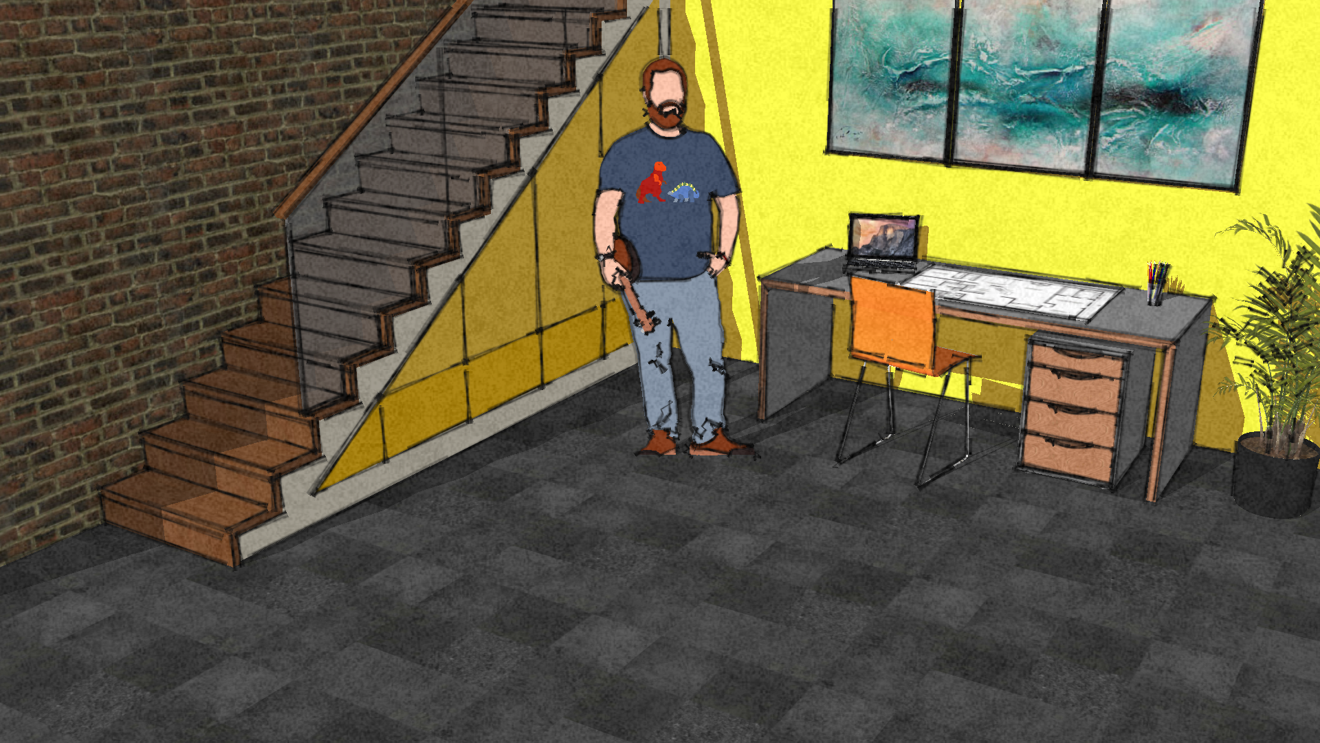
ukulele and wearing a very cool dinosaur t-shirt. We could delete this figure, but let's leave him here
always for a scale. So you see this as the height of one person and you can always
have this reference height. First of all, let's
name this file. You see here it has
a Name untitled. So let's click here. And then you can Go to your
SketchUp folder and save it. I call it and navigation
and override my file. Now you see it's in
the process of saving, and now it's saved. So you have your auto
save function always on. You can see it here
in the app settings. So this is your menu. You go to your app settings
and you see auto save, autosave as always
on and should be always on minutes between saves. Normally it's five. I always have it on
two minutes because in five-minutes a
lot can get lost. So let's close this menu here.
4. The Basics: How to nagivate in SketchUp: Okay, so back to the navigation
you already have seen you can use your mouse wheel for scrolling and
scrolling and zooming, so-to-speak, zooming in and wherever the mouse
is he will zoom to. So if I have the most here, I will go to the horizon. If I go back and I
put the mouse here on the guy with the ukulele
and the dinosaur shirt, we will zoom into the dinosaur. And then the mouse
wheel also can click. You can click on the
mouse wheel and you see you get this Rotate tool, which lets you orbit
around a certain center. This is very helpful. So always, if you wanted
to rotate heavier, finger on the mouse wheel
and click the mouse wheel. And if you want to move
in one direction only, and for example, parallel
to this green X's here. Well, click the mouse wheel
to get the orbit tool and then hold down
the Shift button to get this wide hand here. This pen tool lets you move in one direction
around your object. And basically, that's all about the navigation
and SketchUp. So once again, you can zoom
in with the mouse wheel. Zoom out with the mouse wheel. You can click the
mouse wheel and rotate around your dinosaur guy. Or you can hold down
the mouse wheel and hold down the Shift button and then you move
in one direction. In your SketchUp world. That's about it. Try to be comfortable with those three ways of navigating. And I will say this, I will say this often and of course always heavier
left hand on your keyboard. And I personally I have the
thump on the space button because the space button always gives you the mouse here
in the select tool. So for example, if I have now the line tool and I
hit the Space button, you see that I'm going
back to the most tool and I have my pinky on the shift button so I can always get this hand
here for panning. And also the other
shortcuts are very easy to access if you have
your left hand on the left side
of your keyboard. So that's all for the
navigation in SketchUp.
5. The Basics: Just try it!: Before we get into the nitty-gritty details
of what SketchUp can do. Let's just try it out. Let's just get a feeling for the program and
play around with it so we can build
something now very, very quickly, we're using the rectangle tool
on the left side. This is the, this is your toolbox and we
get the rectangle. And then we click once for opening the rectangle
and we click twice. For closing it. You never hold it. You're always click once and click a second
time to close it. So now we have this 2D object, which is just like a
very big sheet of paper. But you can very
quickly get something into the third dimension
by using this tool here, the push and pull tools. So you take it and
you'll see once you hover over the plane, it is marked with
those blue dots. And you click on it once. And then you can pull your
face and you can also, you can push it down
below the ground, but we're just building something like this ground
floor, so to speak. Now we can take more rectangles
and put them on there. On their face here. This is what we're going to do. We're going to make
those kinds of frames here just to see how quickly we can build
something in 3D with SketchUp. Now once again, back to
the push and pull tool. And just as an exercise, we're pulling those
rectangles from the ground where I'm pushing them a
little bit further down because they're a little
bit too high for my taste. I'm building something
like a, like a staircase. But just to get the feeling, you click once and
you push them down. Now we can also go to
any other phase that we want to pull like this
one and we pull it out. We pushed the other ones in to get them on
the same level. Now you see that SketchUp always goes to reference points, so it already
recognizes our heart. Okay, I've got this edge here, so I'm going to go exactly below the edge
and you click there. And then everything is
in one straight line. We have built this kind
of staircase here. We can take the
rectangle once more and we can also push
something through the ground. I'm taking the push and pull tool once again
and I'm going over the new rectangle and you'll see that I can push something away. Now I can push it all the way down and this
is what I'm doing. I'm creating this kind
of basement here. Let's get, let's get the
rectangle tool once again. And now we're going
on the edge here and we're drawing this
rectangle on the face. And once again with
a push pull tool. We are extruding it. Now we have some kind of a swimming pool with
a diving board. And let's go ahead
with this idea and really visualize this in
a very, very quick way. So let's put some
colors on there. On the right side here there's
a panel with materials. So we go to the materials, we have all the colors
that are being used now. Those are the colors that
are on the figure here. But if you want to see all the colors and all the materials, you go to browse. And then we select some colors
here from the color panel. Now, select whatever you want. I'm choosing those those
yellow colors here. This is just a very
quick exercise to get a feeling for how to use colors and materials and maybe some green for the grass there. Now if this is a swimming pool, this has to be water, of course. Let's see if we've
got some water. Yes, there is a water panel and we have this
transparent water. And now I'm applying it
to this surface here. And transparent water means that now we can see into this pool, we can see everything
down there. And this is how you can quickly visualize
something with SketchUp. Now the cool thing also
is that you may not have the rendering options
like other programs offer you, but you have those
styles here on the right side also
in this panel. You can choose a style
that really fits you. So let's, let's make it, let's use one of those assorted styles to
make it look like it's, it's drawn by hand. And now this is a
very rough style. I personally, I like
this style a lot. So now we've got it says
scribble on Mesa night. So this looks like
something that was hand-drawn on a natural surface. And it has those very nice
hand-drawn lines here. Now, you can actually make something look like
you've drawn it by hand. You can visualize something
really, really quickly. This is the big
advantage of SketchUp. So first of all, it's a
very intuitive program. Everything is directly in 3D, which means you do not
have to rethink everything from 2D and 3D and
translated in your mind or, or have another step to
get it from 2D to 3D. But everything is directly
in the third dimension. I hope you get a little taste now for what SketchUp can do. It can be very, very quick. It can be, you can do something
without any measurements. You can just try out stuff. You can visualize stuff
very, very quickly. But you can also do
something very precise. You can do something of course, exactly to how you picture it
or how a customer wants it. And this all with outer
complicated user-interface. So this is all what
you've got in SketchUp. It's very, very
easy and intuitive to learn and let's go
into the basics now.
6. The Basics: A look at the User Interface: Okay, Just a quick look at our user interface
that we have here. It's very clean,
it's very simple and very minimalistic
and sketch up. So we just have our toolbar here on the left side
and you see some tools. They have those little
arrows beside them, which means that
there are more tools behind those which are similar. So we have, for example, not only the straight line, but you have this very
wild, crazy freehand line. This is the case with
other tools as well. So this toolbox is
quite powerful, but you have all the tools
hidden behind other tools. Then on the right side you
have another panel here, which lets you go
into the 3D library, for example, the 3D warehouse. Or you have a mentor or instructor where you
can get some help. You see some how you
should use a tool, for example, in other
tape measure tool, you can always look into
the instructor panel here to get some extra
information on the tools or on how to build something
in SketchUp and much more that we are going to discover throughout
the course. And on the bottom here you
have a very important line. Well, first of all, you
have another help menu here you can go to
the help center. You have the menu for changing your language
very quickly. And then you have this panel here where you can sweat switch between the mouse
and the track pad. In case you are somewhere you don't have
your miles with huge, you just have your trackpad. Well, if you click here, then your navigation is
optimized for the trackpad. And you should use this in
case you don't have the most, but let's go back to the most. This line here is very important because it tells you
what the tool can do. So, for example, if I go to the line and it says click
to set first endpoint, and we click and then
it says click to set second endpoint and we click
and now we have aligned. And also it says something about the additional
functions of the tools. So whenever you select a
tool for the first time, you should check out this line and see what
this line tells you. Finally, we have this
measurements indicator here. So whenever you are
drawing something you see now it displaced the length of the line here, for example. Or if you are making
a rectangle and Charles to the two-dimensions
of the rectangle. And you could enter something, you don't click on the
box if you want it, want to enter a dimension, but you just say five thousand, five
thousand millimeters. Now, we have made
this square here, but let's select and
delete it once again.
7. The Basics: Line, Face and Object: Okay, so let's get started. Well, the first thing
that I'm changing is the style because I do not
really like this style. I'm going over to the right
side here through this panel. And I'm using the shaded with textures style because
it's very, very clean. It has only the white
as the background. There is no horizon and
we don't need it here. But I don't want to
get too distracted. So I'm always using
this style for drawing. Let's look at the first tool, which is this pencil here, at least it looks like a pencil. It's the line tool. Of course you can do aligns with this thing
and you see SketchUp always orients itself parallel to the axes that you see here. If your line is green, then it means you are
parallel to the green axis. If you're going
up and it's blue, then you see it's parallel
to the blue axis here, and red is parallel
to the red axis. Now, you'll see that sketch up always jumps to those
reference points. You'll see that it says here
on point or from point, which means that SketchUp
automatically sees a ha. If we go exactly this
distance on the green axis, then we can make a perfectly perpendicular
rectangular shape. And if we click, we can apply this and we
can close the rectangle. And you'll see four lines
in the same lead on the four lines on
the same level are always being close by SketchUp. So we have this face
here in the middle. The same goes with
triangular shapes. If they are in the
same, the same level. And you can of course, use the same tool for building something with the
right dimensions, which is what we're going to do. Now, let's go back to the start and
you'll see that I'm navigating always with
the mouse button. I have my index finger either on the left mouse
button or on the wheel. So I click the wheel now and
I see I can orbit around. And if I hold down
the Shift button, I can pan so I'm moving exactly
to where I wanted to be. So let's start here. Really on the bottom
of this guy's feet. Let's draw a square meters. So what do we need
for a square meter? We need basically four lines
that are all one hundred, ten hundred millimeters long. Let's start by clicking. Never click and hold the button. Always click once and then
click twice to end it. But before you click twice, make sure first that you
are parallel to an excess, either parallel to the red
Xs or to the green X's. I'm going along
the red axis now. I type in one hundred, ten hundred, and I press Enter. Now we have one line of 1000 millimeters and you'll
see it in the right bottom. It says length 1 thousand. I'm going into the
green direction now, also one hundred,
ten hundred Enter. I'm going into the
red direction once again now I could type in
one hundred, ten hundred, or I could rely on
SketchUp intelligence and go from this
end point to here. And it says from point I can now click and you see also the
length is displayed as 1000. So it's, it's the right point
that we're looking for. And I close this
thing and now we have a 1000 by one hundred, ten hundred millimeters
is square meter. Okay, so basically that's
what this line tool can do. And you see that the tools here on the left side there is sometimes an arrow, which means if you
click on this tool, you will see another
tool that's behind it. So if we have the
line tool here, we also have the free hand tool, which lets you make
very, very wild shapes. And well basically you
do not need this neat. It's very often, unless you are some kind of artist
and you might need it. But let's delete
this once again. We can delete everything by
using the eraser like this. So we get this eraser here and we click on the things that we do not want to see anymore. But sometimes you'll see this
can be quite a lot of work. You can also hold the
left mouse button so you hold and you hover over
everything that you want to delete and you
release and then it's gone. But my preferred way of deleting
things is that I go back with space to the mouse
tool to select tool, which lets me select everything
that I want to delete. If I select, for example, this big rectangle over here,
everything is selected. I press delete and it's gone. The Delete or Backspace, it's, it deletes the object. But I'm going to show you one more little trick
with this thing. It's the same in
other CAD programs. It's a difference if
you're going from the left top corner
and create this frame, or if you're going from the right bottom corner
and create this frame, you see this one is dotted. And the other one is closed. Whereas the difference,
the difference is that everything, if you wanted to
delete this thing with the closed frame that goes from the top left to
the bottom-right, then everything has to be
exactly in this frame. Now everything is selected. It wouldn't work if
you had it like this, because now nothing is
really fully in the frame. Every line that we have is
only partially in the frame. Nothing is selected here. This is a difference with
the dotted line frame. If I'm only, if I'm
only scratching the edges here like this of the rectangle that
I want to select. If I'm selecting basically
two lines and one face, so I release it and you see 12 lines selected and
one phase selected. They were only being
scratched more or less. They were not fully
in the frame. Now I want to delete
this whole thing. I opened up the frame, everything is in the frame. I deleted with delete
and everything's gone. Good. Now let's continue
with the square meter. Let's go from one
square meter to one cubic meter.
How do we do this? We go upwards, of course, let's select the
line tool again. Now I'm going here to this wild, crazy hint line freehand. And then I'm going to
the normal line tool. And now SketchUp can of course
recognize those endpoints, which is where we want to start. Let's click on one end
point and go upwards. So it has to be blue because we want to be parallel
to the blue line. It should be a
perfect cubic meter, everything perpendicular. And now, how far do we go? Of course, one hundred, ten hundred millimeters, 1 thousand Enter.
And there we are. Now. We go to the
left and you see, I could use once against
ketchups intelligence. And it says from point, you can also type in
1000 if you like. And we can build this rectangle. Now if I'm clicking here, this thing will be closed. And you see we got
a perfect cube. This cube now is
gray on the outside. This is only sketch
ups way of displaying, whereas that something is inside or something
is outside now, it's exactly the other way around as we would
like to have it. So everything normally that's on the outside is
white and not gray. Now it's reversed because of the way we started
with a drawing. But that's not that's
not a problem. You can select everything and right-click on your selection
and then reverse phases. And you'll see now that
everything inside is great, everything outside is white. Let's close this
thing once again, I'm selecting the
line tool again, and I'm going from
endpoint to endpoint. And now two phases are being
close by this one line. If I click and you see
we've got this white cube of one meter by one
meter by one meter. Okay, now let's
modify this thing.
8. The Basics: The Select Tool: Okay, So just as a little
recap of what we've done here. Well, the line tool
lets us draw a line. So we've got this
one-dimensional thing. Let us draw a square
for example, or well, this is a rectangle, so we've got a
two-dimensional object, or we've got this
three-dimensional object. Basically this is everything
that's SketchUp does. Everything else is
just a modification of those three things. You go from line to
face two objects. This is also being represented
in how you can select things with the Select
tool by clicking. You could click
on the face or on the line just once and you
see it's selected now, or the faces selected. If you click twice, you see that not only
the face is selected, but also the surrounding
lines that make up the face. Here. You click three times
and with a triple-click, you select the whole object. Now, this is very important also if you
want to delete things, It's a difference if
you want to just delete one phase or if you want to
delete the whole object. So just as a reminder, the select tool can
make those frames here, the dotted frame
or the full frame. And it can also select things for you by clicking
and there is a difference. You click once, you click twice. Now you see that also the
neighboring faces are connected or you click
with a triple-click. You see everything is selected. Alright, so much for the line, the phase and the three-dimensional
body that we've created.
9. The Basics: The Rectangle and Push and Pull: Okay, let's continue
with this cubic meter. I realized that I haven't
saved this thing. So we can either click
here or click on Save. It doesn't matter. And it asks you to save to somewhere safe
to real projects. I'm saving it here and I say, well, this is cubic meter. It has got the name
cubic meter here. And it will save in
the autosave interval. I think it's every two minutes. Let's check this
again. App settings. Minutes between
saves two minutes. That's perfectly fine for me. Now. We don't need this anymore. I'm going to select it and
press delete, and it's gone. Now, what we've done here with the cubic meter
has been a little bit complicated because we've drawn
every line of this thing, every one of those 12 lines, we don't need to do this if we want to build
something in SketchUp, It's far easier because we
have the rectangle tool. You use the rectangle tool
here on the left side. You click, you get it, and then you click once
to open the rectangle. And then you see on
the bottom here, it gives you the dimensions. What dimensions do
we want to have? We want to make this
a perfect square. So 1000000 comma, that's how you separate
the two-dimensions. Comma one hundred,
ten hundred Enter. And now you have the
perfect square here. Please. Whenever you want to make
a rectangle or a square, never draw it by hand, but use the Rectangle
tool that you have. And you see those
diagonal lines here. You'll see one line for
the golden section. So if I click here, it says golden section. That means we have
something that is aesthetically very
pleasing for the eye, for the human eye,
because we see this relation from this
side to the longer side. There's something that has
a very pleasing relations. If this was one meter in
reality than this would be 1.68 or something meters. And this relation, the ancient Greeks
already discovered that, that this is
something that makes things look quite pleasing. Then there's another line
here and you'll see it. It says square. So whenever you see this line, you know that you're
already doing a perfect square if you
want to lock onto this, because it always gets lost
when you move them out. If you want to lock onto this, try to find the square diagonal once again and press Shift. And you'll see now the blue
lines are much heavier. And you'll see that I can't
do anything wrong here. I can only make the
square bigger or smaller, but it never, but it never
loses that I mentioned. And I can make it
perfect square. Now, those two
additional guiding lines you have with the
rectangle tool, you have to the golden section. You can also lock this with the Shift tool and
you have this square. Now, I want to delete
those things again. Let's select everything. Oops. Let's go back to our
square, which is 2D. Well, how can we
continue from here? If you want to get to the
cubic meter, we can of course, use the align tool once again, but please don't do that. Be smart and use the
push and pull tool. So this is the thing that makes sketch up as a
program really stand out because you can do
everything in 3D very quickly with the
push and pull tool. If you hover with this push
and pull tool over the face, you see that all those
blue dots appear. If you click, you can push or pull this face and
let's do this. Let's click once. And then you see we
can pull it upwards, we can pull it downwards. And how high do we want to go? Well, we want to
use this reference. You can also type,
Let's do this. We can type one hundred, ten hundred because
it's a cubic meter, or we could have used a
reference point here. Those two objects are
completely identical. But building this one, the right one, has been so
much easier and faster. Whenever you're
building something. Don't go back to the line
tool and draw it by hand. But use the rectangle tool and separate the
dimensions for the comma. Use the push and pull tool
and pressing P Now to get with the shortcut
faster to the tool. And you don't even have
to type in the height. If you have something
as a reference point, you can go on this edge here, you click, and then
you've built the cube. Alright? And of course it doesn't stop there with a push
and pull it to. This thing is a really fun
thing because you can easily manipulate everything
in your sketch so you can build something. You can manipulate all
the phases that you have. You can push them and
pull them as you wish. And if you if you press Control, you'll see that a
little plus sign appears next to the two, which means that
you now can start a new object from the face
that you are selecting. So if we are clicking
and clicking once again, we've built a new object. Now, this happens with this little plus sign
that we have here. So you can either continue the same object
and push it or pull it. Or if you are pressing Control, you can build a new object. So much for the
push and pull tool. I'm going to delete
everything now. I'm selecting everything
once again with the frame and pressing delete.
10. The Basics: Helpful Guides and Offset: Okay, so you've seen the
basic drawing tools, the line tool, the
rectangle tool, the push and pull tool. And we are going to modify this cube to
get our first object. And this is how we get to know
other tools along the way. I think it's better to do some learning by doing
and applying those tools directly instead of going over them theoretically
too much. One important tool that we're using here now is
the tape measure. So you find this
tape measure here. It looks like a tape measure. And what does it do? Well, it measures
dimensions and lengths. You can go, for example, from this point to this
point and you'll see, of course, 1000 millimeters. Or you go diagonally
and you see 1414. And if you see, when you see this little wave in
front of the number, it says that it's roughly 1414. And this is one thing you
can do with the tool. If I click escape, I go, I go out of
the measuring mode. We can also use this tool
to give us guidelines. Here. You'll see that it now makes a perfectly
straight line that, that vanishes in
the horizon there. So it's an infinite
line that you have, but those are really great because they help
us construct things. So for example, if we want
to divide this in half, we can go and look for
this blue dot here, which is exactly half of the, the surface here that
we want to have. Now, we want to
divide this again. Then we have to go
250 millimeters. We have to enter the
250 and press Enter. And now we've got this
perfect line here. We can do this once
again by going from this line to creating the
next line, 250 milliliters. Now we have four equal parts
of the cubic meter here. And those lines are really
great because now you have intersection points that you can connect with your line tool. I was pretty fast now
I pressed the button because I'm used to using the
shortcuts, but of course, you can find it
here, the line tool, and then you connect those intersection buttons,
those intersection points. And now you can use the push
and pull tool for example. And you could modify this thing to be live
staircase or whatever. Please, whenever you want to sketch something
onto the object, imagine this is
your pencil marker. When you are building
something in your workshop, you're using the
pencil marker to mark a certain area or to
draw a certain line. And this is exactly what
this tape measure is for it. You can use this to
create those lines. Those lines don't cost anything. They don't cut the block
like a line would do this. Because if you do the
same thing with the line, you would have to
draw a line from here to there and then to here again. But that means that you have
created an extra line here. You don't want to have
a lot of extra lines. You just want to
have the lines that you need and nothing else. When you see if
you want to delete this, you're in trouble. Because now we've delayed, deleted the whole face here. We don't want to do that. I'm undoing this once again. Now let's use the
tape measure to create exactly four quarters of this surface that we have here. We're dividing it in four parts. I'm going exactly
to the middle of this line here.
And I click once. I'm going from this
edge also to the middle of this line here
and I click and now we have four equal parts. Now we take the line tool and we connect the middle with the
other middle of the line. And once again, from
endpoint to endpoint. And we have created this quarter of the
square meter here. And basically we
want to keep this, this, this is the rest
that we want to delete. So we use the push
and pull tool. Because with the
push and pull tool, we can also delete stuff. So if you push this
all the way to the bottom where it
began and you see, Let's get, it gets a little
strange coloring here. And you click once
and it says on face, if you click now
everything vanishes. So this is also how
you can delete. We could delete this now
by going all the way down and clicking on face
and then everything's gone. This is also a way
of deleting stuff. Sometimes quite helpful when you're in the push
and pull tool. Now back to the Select tool. I have my thump on
the space button, so I'm pressing
space as a shortcut. I'm selecting this guideline, I'm selecting this guide
and I'm deleting it. Okay, now we want to
bring this thing down to a height of 250 millimeters. And how are we going to do this? Well, I could either use
a tape measure and say, okay, I'm making a line here, so see where I'm going
with the push and pull tool because it uses
the reference part. Let's do it like this. Let's
use the push and pull tool and some subtraction
mathematics. So let's click here. If this is one meter of height, we want to get to 250. How much should we subtract? Well, 750 millimeters,
of course. And there you go. This is the outer shape of the
box that we are building. Now. If this box should
be open on the top, then we have a
very helpful tool, which is the offset tool. And you'll find
it where you find also the push and pull tool, but you have to click
on this so the arrow, where the arrow is, and you'll see that there's this
offset tool here. Or you can press F4 off set and then you get
this tool and you'll see it always jumps to the
edge with a red point. And if you click once, you can now draw a smaller or a bigger version of this query that we have here. Now what do we want to do is we want to make a
smaller version. It says on the right side here and the bottom it says distance. And this is the distance from
the edge that we have here. So the distance should be 20
millimeters because this is, let's say this is a
wooden box and it has a thickness of 20 millimeters. So 20 and enter. If this box should
be open on the top, we take the push and pull tool. We push down on the top. And also we want to make the bottom with a thickness
of 20 millimeters. If this box now is
250 millimeters, then we have to enter 230, so that we leave 20 millimeters
for the bottom there. And this is our
first little box. Now let's see how we can create lines that
are not straight.
11. The first Object: Making a simple Dovetail Joint: Okay, there we have our box. We have to lower it
still a little bit more. So we go to the push
and pull it too. This is just an exercise now, but you get to know how
the push and pull works. We click on this upper surface
here, on this upper face. And we lower the box, 100 millimeters more, 100
Enter. And there we go. So what we basically
have here is a drawer for piece of furniture. And we want to apply a dovetail woodworking
connection here. We're only going to put it on one corner and
not all of them, but so that we get
to know new tools. Okay, so let's start with
the guideline again. Let's use the tape measure. Then create one line that goes 20 millimeters from the edge and then also to the other side. Because we are displaying
the material thickness here, you'll see 20 millimeters
is exactly what we have here as to thickness of
the walls of this box. And this is the area where our dovetail
connector should be. I'm speaking of only one. Normally you would
put more on there, but this is just an exercise. We continue with the tape
measure and the guidelines. And we go on to the edge
here and go 25 millimeters, 25 inside the box. From the top, also 25
millimeters into the box. The good thing about
SketchUp is you see it here. It already recognizes. Or it suggests that
I once again use 25 as my length because
it has seen this, okay, this is 25 millimeters, so this will probably
also be 25 millimeters. So I can just click, I don't have to
enter any numbers. I just click. We have those
intersection points here. Now for the dovetail connection, we want to start from
those intersection points, but we need a line
that is not straight, but a line that has
a certain angle. How can we do this? Well, there's another two here. It hides behind the
tape measure as well. And you see it here. It's the protractor
that we're using now. And then you see you
get this circle tool here and you go to the
intersection point, you click once, and then
you go to the excess, that should be your reference. Now, I'm using the horizontal
line as a reference. I click once and
then I can open, align with the angle. This is also a guideline. You'll see it's dotted as well. What angle do we want to have? Well, let's go with the
angle of 25 degrees. And we're doing the
same thing here. So click on the
intersection point, go into the direction
that should be a reference horizontal line. In this case, click
once and now open the angle and also here
Twenty-five degrees. So enter 25. Now we have all the
lines that we need. And we can connect them
now with the line tool. So let's take the
line tool and go from this intersection to this intersection, to
this intersection. And from this intersection to this intersection
and to the top. Now, we can delete most of the guidelines because
we don't use them anymore. We can delete the
angular guidelines and also these
horizontal guidelines. I don't need them anymore and we are left with this thing now the rest is basically just drawing by
painting by numbers. We can use the line 200. Once again. We use the endpoint to
go on this line here. And then we're going
all the way down here because this is 11
piece of wood, so to speak. And I am zooming in because
I want to snap onto this end point and I don't want to type in
any measurements. I just want to snap to this
end point and it says online, okay, That's what we're doing. And I connect those
two endpoints. And now basically our, our dovetail connection
is almost finished. I'm deleting the guidelines now. I don't use them anymore. Okay. It needs one more aligned
on the top here it needs disconnection line and now it looks like a
dovetail connection. And I say it looks like it
because it's not really one. We haven't really constructed parts that have
exactly the shape. We have only drawn lines onto the surfaces so that it looks
like adopter connection. But that's perfectly fine. This is a way of
building in SketchUp. There are other ways as well and we're going to
come to that later. But for now, what we can
do is we can experiment once again with the
material and use colors. So I click here on the material, and I'm going to the magnifying glass here
to the Search option. And I'm selecting
colors once again. And let's do this with some, with the colors that you like. Just making clear that there are two separate parts
here, okay. All right.
12. The first Object: Addition vs Subtraction: We've built this box here, but as always in life, there are different
ways that can get you to your desired result. And with SketchUp,
It's the same. So you can use
different methods of building. What we've done here. We've had a big box and
we manipulated the box to get this smaller box
that we had here. Now, we have what I call addition and subtraction methods of building and sketch up. If you use the addition method, it means that you start from scratch and you build
every part of this box. I'm starting from scratch and start with the square of
500 comma 500 millimeters. Then I used the
push and pull tool to get the bottom thickness
of 20 millimeters. Then I use the offset tool for the wall thickness
of 20 millimeters. I used the push pull
tool once again, and I go up to 130 millimeters. So that in the end our box, I'm going to measure
this once again. He has a height of
exactly 150 millimeters as it is the case here. So we've now started
from scratch. We started with one part and we added the other parts to it. So this is this the
addition method. If we use the
subtraction method, we create the outer shape, the outer body of
this thing first. So also 500 comma, 500 push and pull
to 150 millimeters. And now we basically have the thing that
contains the box. We have this body and
in this body is a box, is, there's the hidden box, so to speak inside. So we have to subtract
everything that's not part of the box
from this thing here. Once again, also with
the offset tool, 20 millimeters as
a wall thickness. Then I'm going to push
this down 130 millimeters. And there's the box. So I don't know what
was faster now. But in this case I don't really I don't think it
makes really a difference. But for a lot of things it
really makes a difference. So I want you to be aware that there are
different methods. You can either start by building the outer shape
like here and then subtract everything
that you do not need. Sometimes this is very helpful. Sometimes the other
way is better when you add all the parts that
you need for your box, or for your furniture, or for your house or whatever
you are doing. But just be aware that there
are different methods. Then take everything away. That's not part of the statue
that they are building. But if this was would of course, you would do it with
the addition method because he wouldn't want
to waste any of the woods. And this is normally
what you use in reality, but in SketchUp, the material costs are
basically 0 and they are 0. Your material doesn't
cost anything. And so sometimes it's faster to use the
subtraction method. Just wanted to make
you aware of this so that you can decide how
you build your models. Now let's go to
the next exercise.
13. Round Shapes: The Standing Table: So here we are back again. And since we didn't
do any round shapes, this is our next exercise. Now, we are looking at a table, a picture that I imported
into SketchUp because you can import PNGs and JPEGs
into your model. We're looking at
the side view of this standing table
which has around top, around poll here and
around metal base. We've got all the
measurements that we need. And we are going to start
to draw this thing. Now. How can we create round shapes? Well, there is a tool for that. We have a tool for circuits, but it's not here. For some reason. It's down
here where the rectangle is. So click on the
rectangle and you see, okay, we've got
this circle here. This is what we need now, circle shortcut C. Now
we start the circle. First is the base. And you see it has got the
radius of 250 millimeters. So you click once and then
you can enter the radius 250. Enter. And there's our
base for the table. Now this thing has got a
height of 20 millimeters. So we use the push and pull
tool and say 20 millimeters. Then we see the poll has got
a radius of 225 millimeters, is 990 millimeters high. So now we should of course
start in the middle. How do we find the middle? I'm always going back with
the space to the mouse. I click on the face. I take my circle tool and
then it automatically, if I go to the edge, then it will always
point to the center. The center is this blue
point in the middle. And you see it, it always
wants to be in the center. And I can start exactly
with my pool in the center. And now we have a radius of 25, again of 25 millimeters. 25 enter. I'll take the push
and pull tool. I pull this poll up
990 millimeters. There we are. And now we need
this plate radius of 400 millimeters, 40
millimeters strong. So let's start again
in the middle of this pole and take
the circle tool. You see it's hard to
find the center here, but once you go to the
edge of the circle, it shows you the center. So it always shows this line towards the
center and then you go towards the center
and it locks the center. We have a radius and I forgot what's the radius I
have to look at once again. The radius of this thing
is 400 millimeters. So 400, which means the
diameter is 800 millimeters. Now we take once again
the push and pull tool. We pull this up 40 millimeters. Now we've got this
thing in the middle. I select this circle and I
just deleted and it's gone. Another thing, if I pull this thing up and I go to
this reference point here, I can of course also use the offset tool that
we used earlier. And I'm taking the
offset tool can create some kind of tube. For example, I can make a tube is completely
hollow now because the push and pull tool allows
you to delete stuff and we've deleted the bottom
now and I've got a tube. But let's delete this
thing once again. And let's continue with a
table because the colors are still missing and you
see this little number here, see O6 and M O6. This is the color
that we apply here. Now, let's go to the material panel here we see that the
colors have numbers, so this is color B or five. We want see O6, you'll see the system of the colors is always
eight color grades. So it starts here
and it ends there. And B starts here
with number B1, and it ends with B8 here. We're using now C6. So this is C1 23456. We take it, we take the
bucket and we apply it onto the surface here
and also onto the bottom. And the rest is the color MOC, which is this gray
tone down here, the pole and on the
foot of this thing. And this is our table perfect.
14. Round Shapes: Working with Reference Points: One more thing
that I want you to be aware of when
you are drawing and SketchUp so that
your drawing will become more accurate
and probably easier. Also, we have
reference points and sketch up just like in any
other CAD program as well. So I've created this overview
as a document for you in case you want to maybe print it as a cheat sheet
or just have a look. You'll find it in the materials and then you see their
names and what they can do. So let's have a
closer look at them. If I take the line
tool now and you see that here I am
in the blank space. I mean, there's white
area and there's nothing attached to the
tip of the line tool. But once I hover over an object, you see that I have different points attached
to the tip of the pencil. And you see also there's a
little description given endpoint, midpoint on face. And we should use them
to draw accurately. So if you want to, for example, if you would like to continue this bottom line
here of the box, then you should of
course use the endpoint. You see that this tool already wants to snap onto the endpoint. That means you will
be 100% accurate. Once you click here on
this endpoint, you are, you can be sure that you are definitely on this endpoint
and you don't have any gap between the new line and the line that
you're continuing here. You see also that there's a dotted line now
it says from point, which means that
sketch up proposes you align because it sees this
endpoint here and it thinks, well maybe you want to continue from this
point downwards. And if you click here, this point that you've
created now is exactly under this corner point of
this box that we have here. The same goes for
other points as well. So for example, if you wanted
to continue something from the surface of this box here and you go to any
point on this face, it says on face it gets
a blue diamond shape. And once you create
a line from there, you can be sure that your starting point
is on the face here. And another very helpful
point is the midpoint. So whenever you want to create the middle or you
want to find the middle of something where you
could of course measure it if you wanted
to find the middle here, we see the length
is 150 millimeters, so 75 would be the middle. And you'll see it automatically snaps here with his
light blue round. 0.75 is the midpoint
of this line. And you see that if I wanted to continue my line
here in the middle, I could just go to the
midpoint click here, and then go over
there, for example. Also with round shapes, we have our reference points. So if I Go to the surface here you see on face and I could
start on the face. But then also we have endpoints because the circle
is not a perfect circle. It has 24 segments. So it snaps onto one of
those segments here. But it also, it shows
you the center. And now if I go inward, it can also snap on the center and I could start
on the center here. Okay, so much for those
reference points, get yourself acquainted
with those points because this is the way
how you can draw very accurately in SketchUp
because you snap onto an existing point and continue your
drawing from there.
15. The Bench: How to import a File: For the next exercise, we're going to import a model. The model is provided for
you in the materials. You save it on your
computer and then you can open it from the device. So we're on the home screen now you can go open from device, you can find the
fire and open it. And this is how you import
a model into SketchUp. So it says here you are
viewing a temporary file. That's because it hasn't been saved for the first time now. So you could click here and give it a name and then save
it until your projects. And I already have it as bench, so I call it bench to I save it. Now we can start working.
16. The Bench: Building the Box: Okay, so what do we see here is the next thing that
we're going to build, the next piece of furniture, it's this bench here
with the three boxes underneath three different color grades that we have here. And this bench has the round
edges and smooth and edges. That's something that
we're going to learn. We're going to learn
some new functions and some new tools here. And we start just by
building this box. You'll see this box here has the measurements given by 500, by 500 by 500 millimeters
and very easy measurements. And then we do not
have a circle. We have this arc here and new
tool that we're gonna use. And we are going to
start building now. Now, of course, we could do this by drawing with the
lines five hundred, five hundred and so forth. But of course we're
not going to do this. We have learned that there's this rectangle tool and
this is what we start with. So we open the rectangle
on the ground, 500 comma 500, Enter. And there we go. Now we get the push
and pull tool. We pull this thing
up 500s millimeters. And now we're using the
substructure method. So basically everything that
is box is already here now we just need to carve the
material out, so to speak. And for this we take it, we are taking the
offset tool once again, you find this where you find
the push and pull tool here, the offset tool or
press F4 off set. And then we have a
material thickness, the offset of 15 millimeters, 15 enter and there is the wall. Now we want to push this top all the way
down to the bottom. We take the push and pull tool. Once again, we push it down. And now if I go all
the way down here, 500 millimeters, this would
be a box without a bottom. That's not good for a box. I'm undoing this again and I want to have
the same thickness. I want to have 15 millimeters, the same material thickness. So I push it down 500
minus 15 millimeters. So I push it down 585
millimeters enter. And there is our box. Now we want to make this arc. Here. It has a width of 100 millimeters and it's exactly in the middle
of the other box there. So how do we get there? We have to construct
it with guides. So let's get the tape measure because the tape measure
cannot only measure, but it can give us guides. If you're going to the edge
here you see the red square. You click once. And now. You could calculate
in your head What's half the distance between
0500 millimeters, it's 250. But you could also use this
blue point here that sketch up shows you this
blue light blue point is always the middle of a line. So let's go here directly, 250 millimeters, and
click there we are. If we want to create
an opening of 100 millimeters here exactly
around this middle point, we have to make
another guideline, 50 millimeters to the right, and then one more guidelines, 50 millimeters to the left. And there we are. Now for creating this arc, we cannot use a circle tool. We need our arc tool and
you see the Arc tool here. You get different
types of aurochs. But the one we need is the
classical two-point arc. Now because we have two
intersection points here, we click once on the
left intersection and twice for the right
intersection and then we go down. You can press the
arrow for down. And you see now I
can only go down. How far do we want to go down? It says 50 millimeters
there on the other box. So we're going down 50
millimeters and there's our arc. Since I have my thump
on the space button, always I press base. Now I'm in the selection tool. Once again, I select the
guides and we can delete them. And our heart is not yet opened. How do we open this? We use
also the push and pull two. We do not delete it by manually delete it,
manually deleting stuff, but we take the push
and pull and we push this area inwards
until it says on face. And it has this strange
blue white coloring. And you click there and
there, you've deleted it. Now we have our opening here. Now the next thing that
we want to do is to color this box and the same color that the other the
original box is. And how can we do this? Well, you could go to the
Materials menu and see what colors this and try to
do it manually or something. But this is not the
way you should do. You should go to the bucket
here and click on the bucket. And there you have
this little pipette, which means that you
can sample material. So let's sample this color here. And now you see we've got it
here in our material window. We've got exactly the
color that we need, and we also got the bucket
now to color things. Now let's color the front with
one-click and there we go. That was very easy whenever
you want to have some color, don't go looking for the colors, but please take
the pipette here, the sample material
thing now I could select the other yellow color, I could put it on there. That's how you get the colors that are
already in your model. We've got this box colored. Now. What are those lines here? Those lines are
the measurements. And let me show you just
very quickly how you can also give the dimensions
to your model. So you have the
tape measure here. Behind the tape measure,
there's way more stuff. So there's also this little tool here, it's called dimensions. You'll get this white
mouse and it wants to either snap to a point, to an endpoint or two
markets to select a line. Now if we want to give them mentioned to this
bottom line here, you click once to
the first endpoint, you click twice for the second endpoint and
then you can open up. There's 500 millimeter
measurement here. And we're doing the same here. To make everything a
little bit less messy. I always take I always
put them overlapping so that they have the same
intersection points here. It looks a little bit cleaner. And what you also could
do if you have one line, you do not need to click once and twice for the endpoints, but you could click on the
line as long as it's blue. Sometimes it's a matter of
where you position yourself so that it's easier to go the direction that
you want to go in. I'm going this
direction upwards 500. And this is how you can put
dimensions to your models. Something very, very
important because if you use your model to
communicate something, somebody else needs to know
what measurements you have. Now if you want to cheat
with the measurements, you can double-click on the
line and you could say no, it's not 500, but it's 499
millimeters, for example. You can write whatever
you'd like in there. But we're not lying here. This is 500 millimeters, so let's leave it that way. Okay, so our box is finished. Now, let's build
three more of them, but in a very, very quick way
with a very helpful tool.
17. The Bench: Move and Copy: All right. We have one box. We want to have three more boxes to get to this bench here. How do we do this? Well, we
copy what we already have. We don't draw something new. So to copy what we have, Let's select this whole thing. Now I could do this with
the frames, but, you know, we've got other objects here that could be
selected then as well. I don't want to have this. So let's just triple-click on the object and then
everything is selected. Triple-click is sometimes
really, really helpful. Then we need this move tool because we want to
move the box where we want to duplicate it
by moving it M for move. And then you go to
the end point here, go to the endpoint on
the left bottom corner. Click once and you see
now you can move the box. That doesn't really help
us and duplicating. But if you press Control, you'll see that now you get a duplicate of the
original and you can go, you can place it
wherever you like. Let's stay on the red Xs here. Let's go along the red axis into the direction of this bench and just click one more time
now to place the box here. Now we've got a
perfect duplicate. We need to more of this. Now, this thing is
already selected. So once again, I'm going to the endpoint and I'm
moving the original know, I'm pressing Control and
I'm moving a duplicate now. Now how far do we
want to go here? Well, in this bench here we have a little gap of five
millimeters between the boxes. So let's do the same here. So if I was to go 500
millimeters exactly, I would be I would be glued
to the first box here. So let's go 505 millimeters on the red Xs and press Enter. Here we are perfectly
placed with the middle box. And now let us do
this once again. Go through the endpoint on the left press
Control and go along the red axis and 505 millimeters in
distance to the right. Here we are. Okay. Perfect. Whenever we want to duplicate something and sketch
up its copy paste, and it can be done
with Control C, control V. So now I have a new box and I could
place it wherever we want, but it doesn't have
any reference. Now, if you want to
move the first box exactly 505 millimeters
from the original, then use M for move, go to an endpoint and
press Control so you can always place a duplicate in reference to the
starting point. All right.
18. The Bench: Sampling an Applying Colors: All right, so we've got the three boxes now
perfectly aligned. And well, what's missing is the right color on
the other two boxes. So once again, we're going to sample the materials or go to the bucket
here on the left, take the sample
material tool and let's sample the middle box here from the original and apply
this color here. Now I'm in the bucket tool. I could go back to the
sample material thing. Or if you are, if you have the bucket,
just press Alt. And then you see if
you hold down Alt, you get this, you get the
sample material tool. So let's sample the
darker yellow color and put it on there. And there we go.
19. The Bench: Building the Bench and smoothening Edges: Let's build the bench. We're not constructing
out of the blue, but we're using the
guide lions again, the guides with a tape measure. And we're going to the site of those boxes here and we're
using them as a reference. From this edge,
we're going to go five millimeters into the
direction of the red Xs. Because we want to give
the bench some space. All the gaps that you see here, they're all five
millimeters in-between the boxes and between
box and bench. So we have now a five
millimeter line here. We're going to make
another one with the material thickness
of the left foot, which is 50 millimeters. So go 50 millimeters with
the other guideline. Now, we need some markers
here on the side. And for this I'm going to
go on the edge here and I just click basically twice on the edge to get
this infinite line, which is the extended
line of those boxes here. And I'm doing the same
on the front side. Now what we have is the
shape of the left foot. We have those
intersection points here. And what we can do is of course, get the rectangle tool and connect just the
intersection points. And there we have the basic shape that
we pull upwards with the push and pull to upwards to this reference point
of the first box. So let's click here. Now, since this foot is a
little bit higher than the box, so the box can move. We pull it once
again and we say, make this five
millimeters higher, so five and then Enter. And now we've got
the first foot here. How can we get the second foot? Well, we just duplicate the
one that we already have. Triple-click on
this one to select everything and get
the move tool. Go to the go-to one
endpoint that you have a. Now, how far do we go? Well, first of
all, press control because we want to move
a copy of this thing. How far do we go
towards the right now? Well, I could calculate 50 plus five plus 500 plus five plus
in 500 plus, and so on. But if I go to this
endpoint of the box, I see my distance down there
with the measurements. It says 1565. So this would be the distance without the five millimeter gap. Now I add five millimeters, and of course now that's 1570 millimeters,
1570 and Enter. And now we've got
the second foot on the position
where it should be. All we need to do now
is to create the top. Let's go back to the
Select tool press Space. And let's select the top of this foot here and get
the push and pull tool. Because now we're extruding
the top from the foot. And if I was to do it like this, I wouldn't have a new piece. Let's press Control
and you'll see now we're starting
from a new phase. We are having the
separation line in-between. Also, this is 50
millimeters in height. So Andrew 50. What we can do now is once
again back to the Select tool. Select this face, get the
push and pull tool and pull it all the way over
to this endpoint here. And there we have our bench. Now what's missing are the
round edges that we see here. How can we do this?
Well, we already used the Arc tool and basically all we need now is
an arc on the site. So let's get the Arc tool once again and go to the middle here, to the midpoint, and
then go to the top edge. And you said, you see it
says tangent to edge. And you see here
there's this pink line, which basically means
that now we have a perfectly symmetrical
shape of the arc. Let's click here. Now we want to erase this part. So let's go back to
Select, select this part, get the push and pull tool, and push this all
the way to the back, to the endpoint and
then it's gone. You see we've got
this edge here. And now we want to
make the other edge, of course, get the art
tool or press a for AHRQ. Go to the midpoint, go to the edge
here until you see tangent to etch in
the line is pink. You always have to click twice
to apply the arc function. And once again, let's
go back with space. Hit the Space button, select this shape here, and let's pull it all the
way back so that it's gone. It's gone. Okay? Now, you see that this bench has got very,
very smooth edges. You don't, you don't
see any lines. Here. We see the lines, but you can smoothen any edge. You can basically hide the edges so that you
don't see them anymore. And you can do this
with the eraser. If you just use the eraser, then you would of
course kill the line. You would erase the line. That's not what we want to do. But just like many other tools, it has got the additional
function you'll see here. Well, hold control to
toggle or soft and smooth. And let's what are we gonna do? You see we have this
little smooth edge that appears when you hold
down the Control button. And now we can, we can soften all the edges that we do not want
to see anymore. And we're doing this also
on the other side here. Also with the
frontline chloride, there is the bench. Now of course we want
to have this color. How do we get this color? Well, we sampled the materials, so go to the bucket, go to sample material. Now we have this little pipette. And let's sample this
color here and apply it everywhere on the
outside of this bench. And also on the back here. We've now duplicated the
bench that we had perfectly. Now, we want to get rid
of those guidelines here. We could go back to
the Select tool, select them and delete them. But if you have a lot of them, you can go to this panel here. It says display. What you can do. You have this button
here, delete all guides. So let's delete our guides
and you see they are gone. Let's hide this
panel once again. We have finished building
the boxes and the bench. So one of the most important
things to remember, don't build things from scratch that you already
have in your model. Copy them by selecting them, triple-click, move em,
and press Control. And then you can move a copy.
20. Summary: What we've learned so far...: Okay, let's go quickly through a little summary of
what we've done so far. We started with just trying
out what SketchUp can do. And we built this kind of
swimming pool here with the diving board and we applied some colors and also
there's water texture here. This was very quick, it was without dimensions. But remember that SketchUp
is also good for this. Or if you just want
to try out something, if you just want to be quick, make a quick sketch
of something. Sketchup allows you to do this
in a very, very fast way. And you can be directly
drawing in 3D. And this is one of the big
advantages of SketchUp. Then we went into the details. We learned the first tools, the line tool, the
rectangle tool, and the push and pull tool. And basically this is
all that SketchUp does, maybe 1000 variants of this. But basically every model
that you will ever build is made up out of lines that form rectangles or other shapes, and then three-dimensional
objects. And remember that you have
shortcuts for everything. So I put the shortcuts here, L for the lines off
of the rectangle, P for the push and pull two. And then we saw that we have different methods of building. We can build this box either
by the subtraction method. We start by building a big box. Then we take everything out
that is not part of the box. Or you can start
from scratch and start with the bottom
and work your way up. And this is the
difference between the subtraction method
and the addition method. And now, with building this box, it really doesn't make
too much of a difference. But once you're building
more complicated models, it can make a difference. Which method you use. You saw that I now use
the F key, the offset. We learned how to
offset a frame for this box here and inner
frame for the outer frame. And then also here we
used the guidelines. So t is the, is the tape measure. And with a tape measure, you can create guidelines
if you start from a point on the edge of a line or if you start
from an endpoint, you can create
guide points here. And then of course, for this angular line, we use the protractor tool. So once again, you find it here. This is the protractor. And with the protractor you establish first a
reference line. Then you can open up your angle. So a guideline with
a certain angle. And of course, if we
want to delete things, we always have the
eraser on the key. And we could delete
our lines here. Or you go back with
the space button to the select tool and you select your line and
you delete the line. Okay? Then we had a look
at round shapes. So we looked at the circle tool. The circle is on the
key C. With the circle, we created this table here. And then also you can import
files into your model. So you can import
JPEG or PNG files. This is what I've done
here with my table. And sometimes this
can be helpful like in this case or when
you have a floor plan, you import the floor plan
and then you can draw all the walls and all the
objects in your floor plan. One more thing
that's very helpful for drawing accurately
in SketchUp are the reference points
or the points where your tools
automatically snap on. So for example, this
is an endpoint. We can use this endpoint to continue the box
that we have here. Then also Sketch Up, uses the reference x's. So if I go along here, it will be always parallel to the red axis that we have here. If I go upwards,
it's parallel to the blue axis and we
have more points. We have points on the edge, we have points on the face. We have midpoints as well as
the midpoint of this line from here to here is the
blue point in the middle. I'll never measure your
midpoints or something. Always find them through the midpoints that
SketchUp shows you. Okay, then we built
this bench here with the three boxes that have
three different color grades. And we started by
building this box. There was nothing new. But then we learned how to
apply the measurements here. And you find the
measurements here. This is the tool dimensions. And then you can go from endpoint to endpoint
for example. Or you could click just once on the line that
you want to measure. Then one important lesson
is to never built something that you already have
in your model if you want to get a
second version of that, always use the copy function. So the copy and paste function, which you find in the move tool. So triple-click on the object to select your object and
then go to the Move tool. And you see with the move tool you can now move your object. But if you press Control ones, you'll see that now you can move a duplicate of your
original object and you could simply copy and
paste what you already have. One more helpful tool, it's the Arc tool. You'll find it under letter a and then you get
this pencil here. And then let's you
create a two-point arc. And you could also, for example, use a midpoint as
reference if it should be half the
height of the box, you could create this
very strange opening here in your box so that everything falls
out of the box. Great. Then you have also
the option to paint everything with either
textures or colors. And you find the bucket, the paint bucket
on the letter B. With this bucket, you can
color everything as you wish. If you press down the Alt key, you'll see that you get this
sample material tool here. So if I now wanted to have
this bright yellow color, I click once and now I
have it automatically in the bucket and I could paint
everything in this color. Okay, then we built
this bench here. We use guidelines
to build the bench. And then also we used a new. Then also we use the Arc tool to create a round edge
here on the side. And we also smoothen the edges. So how did we do this? Well, we use the eraser
and the eraser has a, has an additional function. I'll go over here to
demonstrate this. It has this additional function when you hit the Control key, this little sign appears next to the eraser and you'll see that now if you click on the line, you hide this line
and use smoothness. Last but not least,
we learned how to change the style in
SketchUp so we can quickly change the
appearance of our model if we wanted to present
it in a different way. For example, normally we are somewhere here in
the default styles, but you can check all those different styles
that you have here out. We have the style builder
competition winners that are sometimes really nice styles with different backgrounds here. And you choose
whatever style fits the way you want to
present your model. Okay, that was a quick
summary of all we had so far. So let's now continue
with some new tools.
21. Shortcut Training: The Intro: All right, Here we are in the SketchUp shortcut
training Park who are, so this is what we see here. We're going to build
those things but very quickly because we are using
the shortcuts in SketchUp, I recommend you
download this PR coup. You'll find it in the materials. You can then download
it on your device. You can import it from your device here with
the import function. And then we can get started. In the beginning
you have the sketch up 12 essential
shortcuts document here. You can also find this in the materials and
print it out for you so that you have
a little cheat sheet for all the shortcuts. You'll see the tools here. On the left side, you'll
see the shortcuts that you have for them and then
you see what they can do. And I've added also the
additional functions that you can always check here
in the line below. Whenever you select a tool, remember they have
additional functions. All right, so we are going to dive into this shortcut
Park2 right now. I hope you are
ready and let's go.
22. Shortcut Training: Part 1: Okay, So everything
behind the red line, behind the red Xs are the things that we're
going to build. The first instruction
that we have here, it has changed the
style where you see we're on the gray
style with the horizon. You can choose the
style you prefer. I would recommend you use one of the default styles
because they are very clean and they
have straight lines. And I'm using the one where I don't have so
many distractions. Everything is white.
Everything also looks better in the
white background, so okay, we changed this daily. Next instruction at the
first shortcut lines. So we have to draw
this line which has 1750 millimeters long. Don't go to the toolbar now, but use the shortcuts. So L on the keyboard
for our line. Let's go parallel to the excess year 1750
millimeters enter. And there is our line. If we want to exit
this tool now, press the space
button and there we are back in the select
tool and we're moving on. So we have to build a
line now once again, the same line, 1750 millimeters,
and then guidelines. So with a tape measure, we have to build one
to 150 millimeters from our first-line and then
another 1500 millimeters. So let's see if we can do this. L for the line tool. Once again, it has to
be read parallel to the axes, 1750 millimeters. There we have our line space. And now we go to T, the shortcut for
the tape measure. And you go to the edge here it's important that you
see the red square. You are on the edge
and you're going into this direction where the
excess is the green one. And now we have to go 250
millimeters in this direction. And once again, we're
doing the same but with 500 millimeters Enter. And here we are. Now you'll see also there are
those not infinite lines, these lines that have
the endpoint here. One on the left,
one on the right. And how can we do this? Well, if we start from the edge, it will always be
an infinite line. But if we start at the endpoint, then we will always
get the short lines. So exactly 500 millimeters. We create this intersection
point and we create another one which intersects
also with this line. And you see you've got a
little cross on the nth there. So we've got our lines and this was the shortcut T
for the tape measure. Now once again press the space button to
get out of this tool. Erase. So let's clean
up E for erase. You get the eraser and
let's clean this up. You'll see if I tried to click, it's sometimes hard to
really click on the line. What's easier is
to just hover over it with a Clicked mouse button. And then you can
delete those lines. We don't need them anymore. Let's go to the next tool,
the protractor tool. So we've once already used this one for the dovetail
connection that we built. And you see here, we need to make this
angle of 35 degrees. This is where the protractor
tool comes into focus. We first built a
line once again, so L for the line. Let's leave a little
bit of space there. And built this 1750
millimeter line. There we go. I'm going out of the tool with the space key and now I
want to use the protractor. Where do I find it?
I didn't find it. I find it where the
tape measure is. And you see here this is the protractor tool
and now we want to make this angle
of 35 degrees. So let's go to the endpoint,
the green endpoint. Click once and now establish
a reference lines. So go along the red axis. Because we can now open now the 35 degree angle and you'll
see it with a protractor. It snaps at 45 degrees, it snaps at 90 degrees
and add 135 degrees. But we want just to have 35 degrees and we have
to enter this manually, 35, press Enter. There you go. And to complete this triangle, we now take the line
tool once again, L. And we go from this endpoint to the intersection
point here online. And we continue to
the other endpoint. And there we have our
triangle perfect. Now let's move to the
next exercise, rectangle. We have used this
already extensively. So let's press R
for the rectangle. And this one has a golden section and
this one is a square, so they are not measurements, but I hope you remember
how this goes. So you open the rectangle
with one-click. You try to find the
golden section. There it is. You
see golden section. That's exactly what
we want to have. And if you want to
lock onto this, then press Shift, hold
down the Shift key. And now we can only open the rectangle that has
the golden section. You see constraint
online golden section and let's anthers now. Okay, this is our rectangle
with the golden section. Now, we are making a perfect square with
the same tool and you'll see you have the other diagonal
line, the square line. Let's hit the Shift
key once again. And we are constraint on line square about this
size. That's fine. Now we have used
the rectangle for a rectangle with golden section
and one perfect square. Push pull. One of the essential tools and sketch up that makes
this program so special. And we're going to build this
block here that you see. So first we're going to
use the rectangle and make a rectangle of 1500 millimeters
by 3,500 millimeters. Alright, are 3,500
comma one hundred, ten hundred, five hundred. There you go. Then p for the push
and pull tool. And we pull this up. And of course you could now entered 2
thousand millimeters. Or since we have a
reference point, just go to the reference here because this is also
2 thousand millimeters. Alright? Now we move the
block that we just built, and first of all, we
have to select it. So I would suggest you use the Triple-click,
Triple-click the object. Now we can move it. M is for moving. And it says here it has to be 7,916 millimeters from
this point to this point. So let's exactly use
this endpoint here. So we are moving along
the red Xs here. And let's enter the
7,916 millimeters. And there we've placed the block perfectly and now we
have to create a roof. How can we do this? We can also use the
Move tool, but first, we create a line and we're using Sketch apps
reference points. Once again, we're not
measuring anything, but we're using this
point, the midpoint, the blue round midpoint
that we see here. And we go from
midpoint to midpoint. If you now take the move tool, you can select the line and move this line here
and everything else will move with it because it's glute magically
glued to this line. And we want to go
along the blue X's. And it says 1750 millimeters. So make sure that you
are going upwards along the blue X's type
in 175 O Enter. And there we have created this
roof structure now, okay? Now, move copy one, very, very important functions,
so you don't have to birds things from scratch, but you copy paste them. Now how can we copy paste? We select our object
that we want to copy. We press M for moving, we go to an endpoint
or let's go to the other endpoint and we
have to be exact here. It has to be 8,102 millimeters, our copy from the
original object. So let's go to this
endpoint and let's move it, but press the Control
button, the Control key. And you see now we are
moving the duplicate object and let's move it
8,102 millimeters. And now we've moved the object and I'm still in
the moving tool. Let's take the endpoint here
and let's move this thing. It says 7,566 millimeters. Now, move it but make sure
you press the Control button, makes sure you're moving
along the red axis and go 7,566 millimeters
into this direction. Let's move it a little bit further outward because we want to see inside the
other object there.
23. Shortcut Training: Part 2: Now we see there's another
thing we have to do. We have to stretch this
building here because this one, it says 2300 millimeters. And we have here, you can measure always also with a tape measure. What
do we have here? We have one hundred, ten hundred, five
hundred millimeters. So we have to pull this thing
back 800 more millimeters. So go to P for the
pool type in 800. And let's measure this
thing once again, let's go to T for
the tape measure. Let's measure the distance. The distance from here to
here, 2300, that's perfect. Okay. The next tool, the next
shortcut would be offset. And you see the offset
here of 200 millimeters, that's the wall thickness. So F is for offset. Go to the face here, click once and you can open, we can open this tiny house here with an offset of
200 millimeters and push this face inward
with the p with a push tool. If we want to go
back all the way, we would go to 1300 millimeters, but we don't want this Ob mouse. We're going back only 2100 because the wall thickness in the bag is also 200 millimeters. Now let's look at the next
thing, rotate and circles. So we have to move our house, once again, a copy so that
you memorize the shortcuts. Once again, let's
move this thing. Let's just place it
by, by feeling here. And let's rotate this thing. Rotate as q. If I go here, it would rotate very,
very strangely. And we don't want to have this. Let's have a plane surface
here that's level. And let's go inside
the house and turn this thing 90 degrees
at snaps at 90 degrees, the houses in the
right position. So the next thing that
we do is to create this circular window here they are not measurements given, but let's assume that it's exactly in the
middle of this wall. How do we get to the
middle of this wall? Well, we are using
the tape measure. Once again, the T
for tape measure. We are going to
the midpoint here and from the bottom
to the midpoint here. And now we have the
center of this wall. The shortcut for a
circle is c. Now, there's no measurement
given here, so we can just create a circle
without any measurements. Let's do it like this and then go to P for pushing this in. And you see, we want
to make a window, so we want to push all
those materials away. We go all the way back
until we see on face, we click once and now
we can see inside the house we don't need
those guidelines anymore, so let's select them
and erase them. Okay, The next thing, the arc tool for creating
this window with the arc. So we have to move
our house again. Let's triple-click here and move the house and all
measurements given, but hit the Control button
to move a duplicate of it. And now you see we have to
rotate this thing once again. So q for rotating, go inside the house
and turn it around 180 degrees so that the
opening points the other way. Okay, Now the next thing is to create this window
inside this wall. Let's look at the
original windows, or it's 600 from the left side, 600 millimeters from
the right side, 600 from the bottom. And it has a height
of 800 millimeters. And then there comes this arc. So let's use the T shortcut
for the tape measure for the guidelines were creating
the first guideline, now 600 millimeters
from this side, 600 millimeters from
the other side, 600 from the bottom. 800 millimeters in height. And now we can use
the rectangle, connect the intersection points, and push this all the way in
until we see the on face. And we click once now
we have the window, what we need now as the Arctic. The Arctic has got 350
millimeters in height. We need this two-point arguments again because we have
the two points here, this endpoint, this endpoint, and now we're going upwards along the blue exon,
350 millimeters. Hit Enter, and we can push
this material once again away until we see on phase offset limit
to 200 millimeters. That's fine. And there we have our window. Hit the Space button,
select the guidelines. We don't need them anymore. There's our house. Okay. One last shortcut
that we have paint. Well, it doesn't have the letter P because there's
this push and pull, but it's B for the bucket. This is the tool that
we're going to use, but first we have to
duplicate the last object once again and move
it along the red Xs. And now we can sample the color. How do we sample the color where we go to before the bucket? You see the color panel
automatically opens. Now we have the bucket, but what we actually want is the pipette and you get the pipette for us
to sample material. By holding down the Alt key. Press out, you get
this pipette here. You can click once to
sample the red on the roof. And now if we apply this, well, it would be
applied to everything. So there was my mistake. Everything was selected
here on this object. So I'm, I'm undoing
this once again and make sure that only makes sure that nothing
is selected here. So let's do this once again, let's go to B for the bucket. Hold down the Alt key,
sample the color, and then apply the
color to the roof. Let's do this with
the floor as well. So let's get the blue
floor color here. And the same for the
yellow colors inside. Just a quick painting and exercise for our
little tiny house. One last thing, you see
all those measurements. We want to repeat this again so that you can memorize this. There is no shortcut for it, although you could put
a shortcut on there, but you find this here. You find this with a tape
measure, the dimensions tool. And let's just put some
basic dimensions here, go from endpoint to
endpoint and draw this out. And do this once again
on the front here. And maybe, maybe with a
total height of the house. So let's go to the back. Let's go down to
the middle point. And let's put the
general height here. And now our little
house has finished and also our sketch up
per Coors finished. I hope you memorize
those shortcuts. You have the cheat sheet here to print it out and to really, really memorize
all the letters on the keyboard to work
much faster in SketchUp.
24. Shortcut Training: Assign and Change Shortcuts: One more helpful
thing if you want to customize your
keyboard shortcuts, you can do this by going to
the search function here. And you could look
for something. No, I've looked for line, you see L is the
custom key for a line. I always have the
undo on the wipe. I like it better that way. And you can find any
tool that you like and customize the keys. And you could, if there is some tool that you
use very often, but there's no
custom command yet. You could assign a
shortcut to this command. All right.
25. Groups and Components: Build to Look vs Build to Build: Okay, now let's look at two fundamentally
different ways you can build your
models in SketchUp. So we have this left way that
we've been using so far. I call it the bill to
look way because you're building things only
to look a certain way. You're not really building
every single piece. We didn't put four pieces
here that make up the box. And then this inner, inner peace, the bottom here. We just had one big box and we manipulated it so that
it looks like a box. And also this stuff
tech connection is not really a
dovetail connection. We just drew the lines on the outside of the box so
that it looks like one. And you see that I still can move every
face and every line. I can move it around and
everything is glued together. So I couldn't I couldn't
show you the this piece here inside of the box because it's just glued
to everything else. Then there is this other way I call it the build
to build wave. Because here we are
building things like we would put
them in reality, like we would put them in our
woodwork shop, for example. We have four wooden pieces here with a dovetail connection and then also the inner
bottom of the box. And you see now that here we really have the pieces like
they would be in reality. And it also means I
can move them around because they are either
a group or a component. And this is one very critical
distinction in SketchUp. So here once again, you see this is
just one big piece. If a triple-click on it, the whole piece gets selected. Here, if I click on a PCA, you see that the whole piece now not only this face is selected, this is one component
for itself. I could move this piece around. Well, how do we create
groups and components? Let's say this is our object
and then you triple-click on everything that should be one components or you
select everything, you right-click on it
and then you have either hear ME component or make group. Whereas the difference,
the difference is that a group always stands by itself and is a single
piece and a component. I'm doing this again
with a component. Right-click on it
and make component. Now we can name it, I just call it block. Now you don't see any difference between this group
and this component. But if I duplicate this component and
duplicate this group, you see that there is a
difference now because if I double-click on my group now and I'm in the
group editing mode. I can change my group here, but the original group, so the block here, it stays exactly the same. Let's not the case
with components. So if I double-click
here to go into the component editing mode, if I change something here also the original will be changed. That is the big difference. So a group always is
like a single piece. This piece has
nothing to do with this piece, but with components. This component is directly
related to this component. And as a general rule when to use either a
component or a group. Remember that when you
have several parts that look the same and basically
have the same function, then you should make
them a component like those two pieces here
are the same pieces. They are components. Also this piece and
this piece is the same. And they are components. You see it if I
double-click here and I change something
on this component, you see that also on
the other component, it's being changed
simultaneously. Here. This is only a group, this bottom piece
is only a group, or we'll only, it's a group. I could have made this
a component as well, but there is no need
for making a component. We only have this
bottom piece once and it doesn't have to be
connected to anything else. So this is a group. Those are two different ways
of building and sketch up. Either you build something
just to look a certain way. This is also very fine. The thing is just that everything is connected
to everything else. But this way of
building is very fast. So if you want to really
just sketch something and sketch up as great for that if you just want to visualize, I don't know your
kitchen counter very quickly and put a
new texture on it. Or maybe add apart, then this way of building
is perfectly fine. But if you really want to
build professionally and every piece should be built
as would be built in reality. Then you have to right-click
on the thing that you're building and you make it
either a component or a group. Nothing sticks together. It's really a single
piece by itself.
26. Groups and Components: Introduction to the Desk: Okay, Now we are applying this new knowledge and
everything else that we've learned so far by building this desk
that we have here, we have a very
minimalistic desk. It has four parts, so you'll see two feet, which are components because
they are basically the same. And then we have the tabletop, which is a group. And we have this cross
beam here, this traverse. Also it's a single-part, so this is also a group. Then we have this cabinet
here with the full drawers. Three of them are the same. And this here is
for a paper or for little things, a
little bit smaller. And we are going to
build this thing very quickly using groups
and components and then also protects to
and colors on it and see how we can present something for somebody else very quickly. With SketchUp, I
suggest you download the model and open
the model so that we work in the same model. And whenever I'm too fast, you can look up the measurements
here that are given. Alright, so let's start
and build this table.
27. Groups and Components: Modelling the Desk: Okay, we are drawing
here in front of the original
desk that we have. I'm going over here so we can see the measurements
a little bit better. And we start by
building the left foot. The bottom of the left foot
is 800 by 40 millimeters. So let's create a
rectangle that's work also with the
shortcuts now. So R for rectangle, 800 comma 40, and
there's our base. Now we pulled this
upwards 750 millimeters. And now we have the basic shape. And what we need now I can pull this thing up is this miter
joint that you see here, a 45-degree angle.
How can we do this? Well, we haven't
used it in a while, but this is the
protractor tool that you find where you find
the tape measure as well. Go to the protractor tool and then go to the
endpoint here. Makes sure that you snap onto
the endpoint that you have this red Xs symbolized in the protractor
to that it's red. And then establish
a reference line. Click once. And now you can open the
angle, it's 45 degrees. And there we go. Now, we can go back
with the select tool or you can go directly to l to the line because we
are connecting now this intersection point
with the endpoint here. And then we have this
triangle that we are going to push away with P
towards the end here, towards the end point, and there's our miter joint. Now we can select this
line and delete it. Great, So this is the
first part of the table. Let's make this a component now. So triple-click on it, right-click on it
and make component. Now we can name it. I say it's the foot and you
could add a description. We don't need this now
and let's just go to, Okay, and there's
our first component. Now we want to have
the second foot, and of course we are duplicating the first
components or go to em, go to a corner point, and then move a duplicate by pressing the
Control button once. And you see that this
table has a length of two meters of 2
thousand millimeters. So let's go along the green x's. 2 thousand millimeters
Enter and this side, the right side, is not yet
in the right position, so the miter joint is
facing the wrong way. So let's turn this thing around. For rotating. We've used q for rotating. You see this is Q, this is the tool for rotating. But if you are still in
the move tool and M, you see that you can
also rotate things by going to these
little red crosses that you have here
on the object. Choose the right one. You have to go to the
top of your foot. You can hover over this red
cross that you have here if you are in the move
tool and then you turn it around 180 degrees, I don't really
need to enter 180. I just see that it snaps onto the red axis here now and
this is perfectly fine. So let's turn it around. Okay? Now I want to see that really this distance here
is two meters. So let's get the
tape measure with T and measure from endpoint
to endpoint and a C. Well, I forgotten that there's this material thickness
of 40 millimeters. I'm 40 millimeters too far
in the right direction. Let's go to M and move
this thing back along the green X's 4040
millimeters Enter, and now we are positioned. Okay, the next thing
that we are going to build is this traverse that
we have here on the table. So let's quickly see which
measurements it has. 120 millimeters in height and then we're going 26
millimeters in Ward, and the material itself
is 28 millimeters. Memorize those dimensions and we start with the guidelines. We're going to set
a first guide, 26 millimeters from the back, and then another
128 millimeters. And then one from
the beginning of this miter joint of
120 millimeters. And now we have the outline of our piece and we are connecting those
intersection points. We can pull out this rectangle here and go all the
way over here too, on face in foods. Maybe a strange name
on face and foot. But now we have our piece and you'll see that it's not yet a connected piece, it's just lines and faces, but we want to make this a group so you can triple-click on it, right-click on it,
and then make group because we only have one of
those in the whole drawing. And we can once again
delete the guidelines. We don't need them anymore. Okay, now we start opening the tabletop and we're
doing this the easy way. So we're just connecting diagonally those
end points here. So take R for the
rectangle tool, go to the endpoint here, go to the other endpoint. Now we have the basic shape for our tabletop and
we pull this thing upwards and it's
also 40 millimeters. And there's our tabletop. What's missing? Are those joints here? Now we could do this again
with the protractor, but let's do it in a different
way just to practice it. Take the tape measure with T and then go here on this edge and use the foot as a reference line that you
go 40 millimeters inward. Then take l for the line tool and connect,
intersection and endpoint. Take P to push all that. We don't need a way
to the end point. Let's delete the guide. And here we are. We're doing the same
on the other side. So T 40 millimeters for the line tool to
create the shape. And then we are going to select the triangle and push it all the way to the back so
that it's gone. Delete the guideline, and
there's our tabletop. You'll see that it's still
not yet a connected object. It's not a group or components. So let's triple-click on this tabletop and right-click
it to make it a group. And here we are. Now. It's still a little
bit too high. We have to position
it and move it with m moving from
endpoint to endpoint. And the table is finished.
28. Groups and Components: Building the Cabinet: Okay, now let's go over to this little cabinet
that we have here. You'll see all the
measurements that we need are given four, to make it more simple, all the gaps between those
drawers are five millimeter, and you'll see that we have
three times the same drawer. So those are components. Then we have this little
drawer on the top for smaller stuff or
pencils and paper. And you see that
even though this is electro for really practicing
groups and components, we haven't built
every single piece. We are not building
it like it would be. But in reality, this is actually a mixture
of this build to build and boot to look way
of constructing in SketchUp. Because if we really created
every single piece here, this would stretch this
lecture into infinity or well, to make it just a
little bit too long. We are not building
every single piece and the same goes
with the cabinet. We're not putting really
four different pieces. And then the back piece, we are building this
out of one big piece, but we are using
groups and components to practice this
way of building. Now let's start with
building the cabinet. And you see it has on the
base a measurement of 575 to 450 millimeters. So let's go to the rectangle tool R and open the rectangle with
575 comma 450. And this is the base
for our cabinet. And now we're pulling
this thing upwards. It says 640
millimeters in height. Let's create an offset
here in the front with F. And let's go on the edge here
and make an offset of 20. And push this
opening not all the way to the back because then we would see through the cabinet. If we went all the way, it's 575 millimeters, but also in the back-test 20
millimeters of the material. Let's go 555 millimeters
backwards or inwards. And there's our cabinet. And let's triple-click on it
because there it's finished. And let's make it a group. And let's continue by putting
those four feet on it. So you see those
feed 50 millimeters from the edges and then
20 millimeters in height. So let's create those
circular shapes here. So move yourself so that you
can see on the bottom here, we are helping ourselves
with guidelines. So T for the tape measure
and 50 millimeters from from every edge that we
get the intersection points. Then see for the circle tool, let's go to the intersections
and create a circle. Those are 25
millimeters in radius. Let's just create one and pull this one out
20 millimeters. And now since we have four of them that are
basically the same, That's triple-click on them, right-click on them, and
then make it a component. And I call this foot, while I already have a
component with the name food, calling it food to
very creative name. And now I am going to hide the cabinets or
right-click on it and hide it so that we
can really focus here on, on those feed. And now we can move this thing from center to
the intersection point here. So m for the move tool, go to the center and with
control you create a duplicate. Let's put a tier. We're doing the same ones again from the center of the original. We are moving with M and control a duplicate to the
other intersection point. And we're doing the
same once again here and there are our
feet perfectly placed. Now, let's cue the guidelines. And here, over here, we have the display panel and what we want to see
now is the cabinet. So go to unhide. And unhide. The last thing that we've
hidden, There's our cabinet. Now to make sure that the Cabinet and the feet are connected because
now they are not. Let's also select
this whole thing. And you see now the feet
are selected as well. So I'm opening this
selection frame here with the Select tool. And now everything
is selected and we are creating a group. And you see now the
group is extended also, it's including the feed. And if I wanted to
move something around, everything is moving now
because it's connected. Okay, so this is the way
you could, for example, connect groups and
components and food groups in
components or groups, in groups or components
in groups, whatever.
29. Groups and Components: The Drawers: Okay, now let's build our
boxes are drawers here, and let's start with
the bottom drawer and you see the
measurements 550 by 400. So let's go to our open up
the rectangle, 550 comma 400. There's our base. Let's pull this box upward, 160 millimeters in height, 160. And now let's create
an offset with f. And here it shows
15 millimeters is the material of the boxes
From the Edge 15 millimeters. And now we can push
the bottom inward. 160 millimeters is
the total height. And if you want to leave 15 millimeters for
the bottom part, let's go down 145
millimeters, 145. And there's our box. Now we have to create
this opening here you see 100 millimeters
from the left side, 100 millimeters from
the right side, which leaves 200 in the middle, and it's 25 millimeters deep. How can we do this very easily? Well, t for the tape measure the guidelines and let's
go 100 from the left, 100 from the right. Well, that's basically
all we need. Now. You can go to the a, the Arc tool and go from
intersection to intersection. And now we create this opening if you
want to make sure you going really along the blue axis and you're not going
anywhere else. Hold down the Shift key so you are locking
onto the blue axis. So you see I can only go
either downwards or upwards, but I cannot go anywhere else. And now I'm entering
25 millimeters. There's our arc. We can push the material, we don't need a way. And there's the opening. So let's also delete
the guidelines. And this is the first box. And since we have several boxes, well, three of them, which are exactly the same, Let's triple-click, right-click
and make a component. I call it a drawer. Now we can place it
inside the cabinet, so select it and then
get m for the move tool. And you said you see
corner of drawer. Now it's always giving us
the name of the component. Whenever we go to the
component and go to the corner and put the corner on the endpoint
in the group here. And you see it's not
exactly the right position. We have ten millimeters
of the gap, but we want five. And also down here we
want five millimeters. So let's place this
five millimeters higher and also five
millimeters to the right. There it is. Now let's create a
duplicate of this. Components are also em, go to the endpoint, the corner of drawer. And with control you
create a duplicate. Now, you could go
here 160 millimeters, but we also need five
millimeters distance between the boxes. So 165, there's
the second drawer. And let's do this once again
with the third drawer. Let's go 165 millimeters
along the blue Xs. And here we have
our three drawers. Now we need the last one, this smaller piece
with 95 millimeters. How do we do this where we're not creating
one from scratch, but we are using this one here. So let's move a duplicate
outwards m and control. And let's move this
here so we have a little bit more
space to work on it. And what do we have to do? Where we have to
basically just lower, lower all those phases
that we have here. That we have 95
millimeters in the end. And I'm establishing a
guideline now just to give us some hint to where we need to go 95 millimeters
from the bottom. This is where the top of
the drawer has to be at. Now, since this is a component, if I was to change something
here on this component, it will change all
the other ones. You see everything is connected here because
it's a component. But what can we do? We can right-click on
it and make it unique. So that this is a
unique component which is not connected to the
other ones anymore. So you see this if I
double-click to go into the editing mode and
I change something now it's only changed
on this component. It's basically the
same as a group. Now, we go into the
editing mode here. So double-click on
this component. Then you can select the faces that you
want to manipulate. So we have this face on the top here and then also the round face
that we have here. And how can we now
select both of them? If I click here,
this is selected. If I click here,
this is elected, but I wanted to have both. You see here for your select tool the
additional functions. So shift means add or subtract,
and this is what we need. So hold down the Shift key
and you see that you get this little plus and minus sign on your mouse selection tool. And then you can click on
the faces that you like. And both are selected if you want to unselect one of those. Or let's say now I've selected the front and I do not want
to have the front selected. So I click once again
and I de-selected again. With shift. With
holding down Shift, you can select or deselect
additional parts. Now, let's move everything that we've selected
M for the move tool. Let's move everything down to this baseline that we've established as 95
millimeter line. Click once. And now we've
lowered everything. And let's click somewhere. Let's go to the selection
tool with space. And click somewhere here in the area that is not component, and we exit the editing mode. And now we can also delete
this guideline here. And there's the final
drawer that we have now and we can move it
inside the cabinet. First. I'm moving it
onto the other drawer, and now I'm giving it
a five millimeters of space along the blue
X's five millimeters. And there we are. Okay, So this is the carbonate. Well, we still have basically five different parts now because this is one part, the cabinet itself and
then the four drawers. But let's also make
this one big group. Select everything
and make group. So this is now one
single piece and we can, we can move it under the table. I'm putting this exactly here on the foot and then I'm moving it. Now we don't need
really a measurement. I'm just putting it here so that there's a little
bit more distance. Will think this looks better. Okay, Now, let's put some
color and textures on there.
30. Groups and Components: Color and Texture: Well, before we put colors
and textures on there, one more thing regarding
groups and components. So we have now components and groups mixed
together in this group here, if you want to undo this well, right-click on it
and then explode. Then you see you have your
single components once again. And if you want to undo this, you can once again right-click on the
component and exploded. And then you see you are
back with the single faces, with the single lines that
you could all manipulate or, or edit as you wish. But I'm undoing this again. So here we have the
full component again. Let's put some
textures on there and we're using the same
ones that we have here. So we're using this what
texture for every What part. And then this laminate here. There's great surface
for every other area. And we go to the materials
with the shortcuts we call, could go directly to B, to the paint bucket. And then we see now the materials that are already
in use in the drawing. So you see here in
model when you, when you go to
this little house. But we want to go here to browse the materials
because we want to have the full range of materials and you can check
them out if you like. So there's all kinds of stuff. So you have even 3D
printing textures. If you are, then you have
asphalt and concrete. And here of course
are all the colors. You have transparent glasses, for example, this
is sometimes nice. If you go here to the, those textures with the
diagonal shape, then you can make
things see-through. So you see, now
this would be like a glass tabletop and you have basically
all that you need. Here. We have the wood
surfaces and well, to be honest, those
are not the best, is. I'm going to show you later
in the course how you can get really
high-quality textures. But for now, let's use
this texture here, this rather wild wood texture, and let's apply it first
of all, the drawers. So now if I wanted to
put this on the drawer, you see everything
is one big group. So I have to really select the pieces that I want to color. I'm undoing this again. And now first I'm selecting, I'm going into the editing mode by double-clicking
on the cabinet. And now I can select the
color and really select only the drawers because everything else does not
have the same texture. I'm doing the same here with
the tabletop and I'm giving, I'm applying this material
only on the edges. The front. Let's go through
this whole table and put this material
on the edges. And then also here down below. You see now that since the feet are components that have
only colored the left one, but automatically the other
one is colored as well. Now, we need to apply this gray, dark gray, dark gray color
here on everything else. So let's go to the colors or you choose whatever color you like. I'm choosing this gray here. And once again, as a reminder, you see the name of the material when you scroll all
the way up color M O5. I'm going into the editing
mode and applying the color. Also for the tabletop. The bottom and this other
beam that we have here, the whole beam is colored and then also
of course, the cabinet. So everything is colored. Now, I hope also on the back, Here's everything has its color. Now let's see how we can present our model
in an appealing way very quickly and also get
file that we can export.
31. Groups and Components: A quick Presentation: Okay, so we want to present
this model in a nice way. Maybe for a customer or
maybe just for yourself. And let's get everything out of the way that we
do not need anymore. So we could either delete this, but let's just hide this
by right-clicking on it. Hide, and now it's hidden. And once again, if you
want to see it later on, go to display and then unhide
either all or the last one. Now it's the last one
that we've hidden. So you could unhide
this once again. Now we only have our table here. The first thing, which
is always very helpful. The first thing that
I'm going to do is to give some basic measurements. So here we go to the dimensions tool and I'm just giving the basic measurements. Just have it for yourself. As a reminder, the basic
measurements are very helpful. Now we could present it, of course, in this style, but let's give it a
little bit more appeal by applying another style. So go to the style panel. Just as with the
materials you can, you can just experiment
with those digested. You see here normally we
are in the default style, which is great for
drawing because it also renders everything very quickly. But if you want to present
something, sometimes, for example, like
it was hand-drawn, you can go to, for example, a style competition winners here and you have some
very sketchy style. This style is maybe a little
bit too sketchy for me. But then you have all kinds of different styles that you can choose from with
different backgrounds and you select whatever
style you like. I always liked this
assorted style here and I'm choosing
this for now. And what we can also do now we have those
measurements here, but maybe they're a little
too small or you don't. You want to have
a different font. You can go to this info
panel here, model info, go to this capital T here, and you see the
options for the text. So you can, for example, switch from Open Sans
to permanent marker. Maybe it fits a little
better to the style. We can make the measurements bigger so that we
can see them better. And you can even truth
the endpoints of how those measurements
should look like. And then you go to update all dimensions and you'll see now we have a different font, maybe a little bit more fitting to the standard we've chosen. And now we could export a
screenshot here where you can always do your screenshot with Windows or with a mag
tool for Windows, it's Shift Windows key and S. If you press
those together, you get this menu
here and you can always make a quick
screenshot here. And then you would
find it here on the right side in
this Windows panel. But the professional way that sketch up has for you
is going to the menu and download what do you
see as a PNG image file. So go to PNG. And now we are in this
dialog window here and you can now adjust
the view as you wish. So you can do this manually by going into
this window and rotating. Or you can go here
and pick a view so you can have those default
views from SketchUp. You could adjust the image
size that you see here, you see the pixel that you can adjust, but let's leave it. This is a high-quality
image and then you could go Export as PNG and save
it on your computer. This is the way you
can quickly present something in SketchUp and
then export it as well. Now I'm going back to the
normal default style. This one here are
shaded with textures. And we continue with
the next lecture.
32. Geometry: How to Multiply and Divide: Okay, let's do some basic
geometry in SketchUp, but don't worry, it's not
going to be two mathematical, we are building some
more complicated shapes that can be very helpful in SketchUp than we
are learning how to build shapes that we
already know how to build, but in a faster way. And we are using a new way of
applying text in SketchUp. So let's start by making a grid. How can we make a grid
with the guidelines? Well, first of all, go to
the tape measure to T and go from the green X's 3 thousand
millimeters to the right. And how can we create ten
more lines here to the right? Well, we could do it manually, but we can also do it faster
by selecting this line and then getting
the Move tool and moving a duplicate
by pressing control. And now we are going 3 thousand millimeters
towards the right. And before you do anything else, hits the multiply key, this little star
that you see now in the box where it says
distance on the right. And then enter ten because we want to have
ten more Alliance. And you see this is
how you can move the apply objects very, very quickly in SketchUp. This is very helpful if you're building a staircase,
for example, and you want to have ten steps that all have the same distance, use the multiply function. So once again, if you
have, for example, a line and you want to duplicate this line ten times with the same distance
towards the back. Move it once and before
you do anything else, hit the multiply key and now duplicate it 20 more
times, and there you go. N1. Very interesting function
with the line, by the way, is also that you can right-click
on it and divide it. If you want to have 20 pieces
of this line go to divide. And now you see on the
bottom here it says segments and then it also says
segment length here. And you can do this
now with the mouse. If you go left, you create less segments. If you create, if you go right, you create more segments. You could also enter
the number of segments. Now let's do 12 segments. Click once and then you see, now you could select the single segments and delete them or do whatever
you wish with them. But let's continue
with this grid. We need one more guideline here. So go to the tape measure
once again and go Three thousand millimeters
from the red Xs. And well, maybe one more line. Another line here, 3 thousand millimeters from the
first guideline. Okay.
33. Geometry: Using the 3D Text: Okay, let's check out another way of using
text in SketchUp. You'll find it where
the rectangle is, and you find that where there's
letter is the 3D texts. So if you open this, then
this window will pop up. You can enter your text here. And the first thing that we're going to
write as a pyramid, because we are going
to build a pyramid. You can choose the
font and the height, and we are going to
have it extruded now, 152 millimeters and okay, and then you see you get
this extruded writing here. There's extruded texts. And we're going to
do this once more. And we're going to
write prism now. And you can experiment
with the fonts. I'm going to choose
the Open Sans font now and put my prism here. And once again,
I'm writing prism, prism with five sides. And now I'm leaving
the extrusion, but the text is still
going to be filled. I'm choosing this
Oswald font here. And you'll see now
that it's a flat font, so it's a 2D object
and it's still filled. You see the gray areas, so the font is filled. Once again, another object ID we're going
to build is the sphere. No. Fear. Choosing another font and
putting my sphere here. And last but not
least, once again, 3D text to create a segment. I just, I just call it segment. And this, we have
this handwriting font here and not extruded
and not filled. And let's put it
here and you see now there's no
filling on the text. And this text is very
interesting. It looks cool. So you have an object, you can double-click
on it and you can edit the object
because it's a group. So I could, for example, extrude now one
letter into infinity. You can move it around just
like any other object. So you could click on it
and move it or turn it, rotate it, stretch it, whatever. We remember. We also have the 2D text here where you'll find
the tape measure. You have the 2D texts. And the difference between those different
texts is that you can always edit the 2D texts. For example, I could 2D text
in here now and I click, but I can still edit it. And this wouldn't be
possible with the 3D text. And also the 2D text is always readable no matter
how you position yourself, you can always read
the two detects. But sometimes the
3D text is cool because it looks
like a real object.
34. Geometry: Special Objects: Okay, now let's start
building those objects here. Let's start with the pyramid. We take the rectangle
and we search for the square help line
here, the diagonal line. And we lock onto this line by holding
down the Shift button. And we create a square
norm measurements needed. And then we create two guidelines that give us
the center of this square. Then we take the line tool with L and create the top
of the pyramid here. And this top is connected
to the corners, of course. And now if I wanted to
stay in the line tool, but I want to start a new point. Just hit the Escape button. So you still have
the pencil here, you still have the Line tool. You can move to a
new endpoint and connect endpoint to
endpoint and here as well. And we're deleting this
inner line once again with l back to the line tool and
closing this pyramid. Now I also delete
these two guidelines. And you see that the higher
the pyramid is gray, but it should be white because the outer
phases should be white. So let's triple-click on the
object to select everything. Right-click on it
and reverse faces. So now everything is
white on the outside, and this is our pyramid. Now let's move over to
the prism and we have a tour for building the base of the prism and
surprise, surprise. It's the circle tool. We have a circle tool here, but then we have this
polygon tool here. There's only one difference. And I can show you if I
select the circle tool, you'll see it says sides 24, which means that if
I create a circle, it's made out of 24 segments, 24 sites that you see here. So you see it's not
a perfect circle. It has 24 sites. And if I take the polygon tool, you'll see that it
says sides six, okay, and now we have this
polygon with six sides. But it really doesn't
make a difference. You can always go to see
for the circle tool. And then you can, you can enter the number
of sites that you need. If you wanted to
make really a very, very round circle,
select or enter 99. And then you have 99 sites, which is the highest number that you can enter in SketchUp. And then you have a very, very round circle with
99 segments or sides. But you can also go to the
circle tool and enter three. And then you have a polygon
with just three sides. There's our base of the prism, so let's extrude
this thing here. No measurements needed here
also make a nice prism. And now the prism
with five sides, well, you probably
have guessed by now. We can take the circle tool and we are still in the
three-sided mode, but let's enter five. So you see here it says
five now and Enter, and now we have five sides. We can make this pentagon
shape and also extruded. So we have a prism
with five sides. I'll take the other
Prism has a reference. Let's move over to this fear. And this fear is a little
bit more complicated, but we will get there. So we use the circle
tool once again, and you'll see that I still have this polygon shape
with the five sites. So I enter 24 to get
a better circle. But actually to get a really, really nice sphere,
which is round, which is really
around, we have to start with a really
good spheres. Hit the C key ones again, and then enter 99
because we want to know, we now want to have a
circle with 99 sites. And let's open up
a circle here in the middle and then
go to the center. Now we want to have
a circle which is perpendicular to the first one. We press the arrow key
to the left and you'll see our circle
tool now is green. And we click on
the center and we open up another circle here. We don't need any measurements. Just open up a circle. Okay, how can we create a sphere now from those two
intersecting circles? Well, we have a tool for this, which is the Follow Me too. So you'll find it here where you find them push and pull tool. And the follow me tool
always needs a face. So now we have the face
of the first circle here. And it needs a path that
this face can follow. Our path should be now
this other circle here. Let's try this. First.
I'm going back to the Select tool and I
select my path to follow. So I click on the
first circle here on this outer line
of the first circle. And then I get to follow me too. And I click once on the face. And you see now it
has created a sphere. Then one last thing, how can we create a segment that looks
like a piece of pie? Well, we also have
here the arc tools, and then we have this PIE tool. We can define a starting point and then once again
a reference line. And now we can open
up this piece of pie and enter an angle. For example, let's make it
a 45-degree piece of pie. And we can extrude this. And then we have
created this certain, this kind of segment here. This was some very basic
geometry and SketchUp. Remember that you
have 3D text and 2D Text and sometimes 3D
text is purchased, sometimes 2D text is better. And you have the circle tool, which lets you create polygons with a number
of sites between 399. And you have the Follow
me tool that lets you create spheres
of perfect sphere. And there is much more in
the toolbox, for example, you also have this PIE tool which lets you create
those shapes here. One last thing, we don't
need the guidelines anymore. So instead of manually selecting
them and deleting them, let's go to display and
here this button Delete all guidelines and now everything
looks very clean again.
35. Staircase: Quick Floors: Let's build a staircase
that connects two floors. Very simple staircase. And this lecture is less about the theory of how
to build staircase, more about helpful tools and tricks of SketchUp that we
can pick up along the way. So let's start with a floor here on the ground
and no measurements needed. Let's just open up a
rectangle and draw a floor which has a height
of 200 millimeters. And then create a
wall here with T, with a tape measure
also 200 millimeters. And we are drawing a line, pulling up this wall to a height of 2500
millimeters to meters 50. And then also here, let's create the second
floor, 200 millimeters. And let's pull this floor out. All right, so those
are the two floor. Instead we are going
to connect with a staircase really quickly. Okay, let's delete
the guidelines and triple-click on the
object to make it a group. Now we can start
with this stairs.
36. Staircase: Building the Steps: Okay, so let's build
this staircase. Well, normally you would have
to go into the theory of stairs and calculate how
much steps do you need? How much distance is there between the steps and all that? But I've done this and you can
just follow me and we will build a very, very
simple staircase. And we start by
putting a guideline 3,600 millimeters from
the corner there. And this is where our
stairs should start. So we begin by drawing
the first step. So take the rectangle tool, go to the intersection point and open up the first step with the dimensions of 290
comma 800 millimeters. So pretty standard dimension
for a normal step. And then we pull this
upwards 40 millimeters. This is the first step. And now since we have
several of them, Let's make this a component. And I call this steps because
we have several of them. Now of course, the staircase
wouldn't start here, lying on the floor like this. Let's put this step 40
millimeters down so that it's really in the
ground. As you can see here. This there actually is
not the first step, but it's the one that helps us create all
the other steps. And now we have one component and we
want to create 15 more. So let's go to the edge of this group with the
Move tool with em, hit the Control key, so you move a duplicate
of this thing. And then let's put this here to the endpoint
of the group. This is where I will
stay cathode end. Let's put this here. Click once and now before
you do anything else, we want to sketch
up now to divide the distance between the
first step and the last step. So we actually press
the divide key, which is the backslash
key on my keyboard, it's on the seven, so backslash and then 15 because we want to have 15
steps there and then enter. And then you see SketchUp can
divide and put 15 pieces, 15 components with the exact same distance
between them here. So it builds us our stair. And this is very helpful. I'm doing this once more. And you already know that we
can multiply with SketchUp. So we have one piece or
a line or a component. And I go here and
I move a duplicate of this thing now
with M and control. And now if I go here and I
place it here and I say, well multiply so times ten, for example, you
see SketchUp has created this Stairway to
Heaven here, this thing. But this is just a reminder. You can divide n, you can multiply with SketchUp, something that is
very, very helpful, especially if you are
building stairs and things, objects have to have the same distance between each other. So let's do this once again, I'm moving the first step. I'm moving it here
to the endpoint. I say backslash 15 because we want to have 15
pieces and there we are. Okay, we don't need
this guideline anymore. Let's kill the guidelines. And also we don't need
the first step anyway, more this was just to help. And also this last step. Normally you
wouldn't really have the last step here
because it would end on the first floor. So let's delete this
step as well and then select all of these steps
and move them to the wall. Let's go to the corner of the last step here and put
it on this edge in group. And now our staircase is
in the right position.
37. Staircase: Creating Stringers: Okay, we have this steps, but we need this stringers on the left and on
the right side. And we are constructing those drinkers with
the guidelines. The guidelines from
the tape measure, but from the protractor tool every once in awhile we
need the old protractor. And let's start here on the
end point of the upper step. Create a reference line, and then go to
another end point. So that now our guideline is really hitting all of
those endpoints here. And we're doing the
same once again with the protractor tool for
the upper corner here. So go to the endpoint, create a reference line, and then go to a corner
of another stair. And so this is the outline for our stringer or the
first string, string. And since we wanted to have
a little bit of material on the string S for
placing the stairs. We move this line with
the Move Tool M from the endpoint here we move it
50 millimeters downwards. And this one, the
other guidelines, we move 50 millimeters upwards once more to make sure you move along
the blue X's, hit the Arrow key for upwards, and then you see you get
this thick blue line. And now let's go 50
millimeters upwards. And there we go. Basically this is all
we need now we can start connecting the dots. Let's take the line tool. Let's start here. Endpoint in group. Let's go to this
intersection point here. All the way down. Next intersection point,
next intersection point. And let's go up again. And here we don't really
have an intersection point. We have sketched ups
intelligence that shows us, if you place the
last point here, you are directly over
these other points. So let's use Sketch
apps intelligence to go to this point online. And let's go, let's go
here to the endpoint. And now you'll see
that we've created the outline and we can
delete the guidelines. We don't need them anymore. This piece is not so nice. We have this very
sharp piece here. So let's cut this just
with the line tool with L. And we select this line and
this line and delete it. And then also down here, where this would be something
for people to trip over. Let's also cut this thing here. Let's establish a
guideline going from the midpoint and the
first step, Let's go. How far do we go? Well, it's also go
50 millimeters with the guideline outwards and connect this intersection
point with this one. And let's delete this guideline here and also this
line on the floor. And now the outline is finished. So let's make this a 3D object. So let's pull this stringer out. And how far do we go? Let's do this. 50 millimeters. There is the stringer. We don't need the
guideline anymore and we can make the component out of
the Stringer May component. Let's call it stringer. Now of course we can duplicate the first Stringer and move it with M and Control 850 millimeters
along the green X's, 800 plus 50 millimeters
of the material itself. There we have our staircase.
38. Staircase: How to intersect Objects: Okay, now if you wanted to build this staircase in reality, you would have to find a way to attach the steps
to the stringers. And normally, if this
was a wooden staircase, you would have tenants here. And let me show you
this very quickly. I hide the stringers
and then I go to one component into
the editing mode. And I'm quickly, I'm quickly
making some guidelines here, eight millimeters and 13
millimeters to this side. From this side, a
rectangle and now an arc, an arc of ten millimeters. And we delete those lines. I can delete the guidelines. Of course, I want to
have this shape on the opposite side of
the step as well. I'm selecting once
this area here, this face here, and then
I'll get the move tool. And now I don't take
it somewhere here. I'll grab it here at the
endpoint of the corner. Because now I'm
moving a duplicate. You see, I hit the Control button and now
I'm putting it on here. What I'm doing is I'm
pulling this out 30 millimeters because the
thickness of the stringer, the material is 50
millimeters and I'm doing the same here, 30 millimeters. And now we have
those tenants there. And I'll unhide my
stringers once again. Now if we wanted to
build this in reality, we would have to know where exactly are the steps positioned on the stringer because now you see there is nothing
on the stringer. We don't know where to cut
our openings for the tendons, but we can do this
with the intersection. So first of all, let's move this
stringer a little bit more to the left so that we only intersect
with the tenant. Let's go 20 millimeters
in this direction. And you see here, now, the only the tenant is
intersecting with this part of the stringer and we have to
go into the editing mode, double-click on the
stringer and select the face so that this face
that you want to intersect, the tenant width is
selected and as blue. And then right-click on the face and you see here
intersect phases intersect with model. Now let's leave the
editing mode for the stringer and let's see
what we have here is C. Now that we have
the exact positions where our openings
should be created. Now you see since those stringers
are the same component, we also have those markings on the other stringer
buddies on the wrong side, you see it on the outside. We need this on the inside. There is a tool for
flipping our components. So right-click on the component and then you have flip along. And now you have to figure
out which x's do we, do we need for the flipping? So we flip along the green X's. Let's do this. And you see we have now the markings on the
right position here. Okay, let's assemble
the stairs once again and move the components
back to where they were. Also, let's move
the whole staircase little bit more inward. So let's go here.
39. Follow Me: The Basics: Okay, let's look at the
follow me tool in detail. We already used it when we
were creating the spheres. But this tool can do
more than just spheres. But it's a little
bit complicated. So let's see how this
thing really works. First of all, as I
already told you, we need a path. Create a line, no
measurements needed. Just go along the green X's
here and create a line. This is our path
and then we need a face so that the face
can follow the path. We start with a circle. Let's make a circle. And before we place the
circle here on the end point, Let's hit the Arrow
key for left. That our face is perpendicular
to the path because this is one of the
conditions that you have to meet when you use
the following me tool, your face has to be perpendicular to the
path that it follows. Now let's apply the
following me tool. Let's select the path first, then go to the tool and
click on the face ones. You see now this phase, the circle is extruded all
the way along the path. This is how the
Follow me tool works. It also works when you
have any kind of path. So for example, let's create
something really wild, some crazy shape here. Just click anywhere and
create a wild path. Now let's do this with a
rectangle, go to the point. But before you go to the point, make sure you hit
the left arrow key. And let's create a rectangle. But just for fun, let's
also press Control ones. We are really opening
up this rectangle around the center here. And now, let's select
this whole path here. Let's select all the crazy lines that we've drawn
this as our path. Then we go to the
Follow me tool and we click on the
face, click once. And there we go. Now we have this, well,
this artwork here. You see all these
intersections are done in perfectly geometric way. If you wanted to
recreate this without the path tool, well, good luck. This would be a lot of work. One more thing when
you use this tool, I'm undoing this now. Once again, you could also
first select the tool and then click on the face
and then follow the path. But in my experience, this is not a great way of doing this because it can
make mistakes here. If you select your path first, you can never make a mistake. You select every
line on the path. You go to the tool, you click once on
the face and it's finished with just two clicks. And of course, apart
from doing this, those artworks here, it has a very practical application
and we see about that now.
40. Follow Me: The Cone: Now let's create a colon
with the following me tool. And the base of a
cone is a circle. Let's make a circle. And the circle will be our
path that we follow along. And then we need a face. And the face is going
to be a triangle starting from the middle
upward and to the path. And then this
triangle will rotate around this path here
and we'll make a colon. We start in the center
now with the triangular, but how do we find the center? Well, once again, you
know that you go from to an endpoint here
on the circle, then it already shows you the center here and
you can go to the center, or you can also select the circle and right-click
on it and find center here. And then you see you
have this little dot in the middle and this is your center that
you can snap onto. So let's use the line tool go upwards also a known
measurements needed. Then go to an endpoint on the circle and back
to the center. And here we have the triangle. Now, making a cone
is quite easy. We have to select our path. So click on the circle, go to the Follow me tool, click into the triangle. There's our cone.
41. Follow Me: Softening a Tabletop: So let's say we wanted to create a round edge it on a table top. So first of all, let's
create a tabletop, just open up a rectangle
and also here, no measurements needed and pull this up so that it
looks like a tabletop. Now we have a heavy tabletop and let's say we wanted
to give this thing a lighter appearance
by undercutting this, which is quite a trend
now in tabletops. And we do this by drawing
a line from a point here, from any point in the
upper third of this edge here to, let's say here. Then we apply the
Follow me tool. We select a path. And once again,
we're doing this by double-clicking on the face. We don't need to select
all the four edges. Then I go to the Follow
me tool and I click on the triangle that
we've created here. Now we've done this,
we've undercut this table here to make it appear
much more lighter. And now we want to also
create a round edge because this would be very uncomfortable if you
put your hands on here. So let's make an arc. Let's go to this point on the other edge where
the IOC goes pink. So that means we
are symmetrical now and we double-click to set the arc and then we select our path by
double-clicking on this face. Here you see all four
edges are selected. We get the following
me tool and we click on this area here. And we've rounded
the edges here. Now. Now maybe those lines here, they are a little bit annoying
because in reality you wouldn't see them as much
as you see them here. So we could, for example, right-click on them
and soften them. All. We use the tool for softening, which is part of
the Eraser tool. So hit E for the eraser tool
and then hold down control. And now you can soften all the edges that
you want to soften. This looks a little
bit more smooth. Now, remember the
following me tool is very helpful when you
have straight lines and hard edges and you
want to soften them, then you can use
the argue can use the following me tool
and soften the edges, not manually by, by using
this follow me tool.
42. Follow Me: An easy Picture Frame: Let's build a picture frame. Let's start with a path
which is a rectangle. And I'm choosing this
golden section here. Now. This is our path. Then we create
another rectangle. Make sure you hit
the left arrow key to make it perpendicular
to the first one. Go to the midpoint here, or you can choose any
point on the line, but I'm going to the midpoint where it snaps onto
the midpoint and then I'll make this
small rectangle here. Now we can create a cross-section that we want
to see on the picture frame. So I'm trying to
make this look like a classical picture frame. I'm taking the arc tool with a and I'm going
somewhere here on the edge and I
create one arc here, like this, for example. Another one down here, another one here, so
you can continue this, but let's leave it like this. And let's delete those two lines that we do not need anymore. This is our cross-sector now, then we must select our path. But since those four
lines here that our path make up
this closed surface, we can just click
into the surface. And that means our path
already is also selected. And you see this when we go to the following me tool
and I now click on the cross-section that it makes this perfect
picture frame here. Now I triple-click on this whole thing and
I'll make it a group. And let's just for fun, just import a picture. So I'm going here to the menu to import and I import
it from my device, import file my device. And I'm importing this
classical painting here and sketch up asks me, Do you want to import this as an image file or as a material? So if we imported
this as a material, you could apply this to
any surface like you can apply colors
and other textures. But let's import this
as a picture and now I'm placing it in
the picture frame. Well, you see the dimensions
don't really match. So I'm doing what we
normally shouldn't do. I'm stretching the
Vanguard picture here so that it fits
into the picture frame. Nobody notices this any
way with the modern art. And there we go. We have a picture frame. I'm also quickly
applying a color to make this a golden
picture frame here. And well, this inside part would not be golden in reality, this would be white. So let's make this white. And there's our picture frame.
43. Follow Me: How to do "Wood Turning": Now let's make another
special object that looks like a wood turner
would manufacturer it. So we start with a circle as the base because
this will be our path. Then we go from the
center upwards. And also I'm just
drawing this by, by feeling more or less so no measurements that
I'm using here, but I'm doing it like this. And then I'm going here. I'm giving this, this table
like angular line here. And then here just for
decoration, I'm creating arcs. I'm creating a small arc here. This is just a
decorative element here. Then I'm moving or
duplicating this arc. I'm duplicating
those two arcs now. Maybe also an arc down here. And I'm deleting the
parts that I don't need. Also moving this
line a little bit higher. Maybe like this. Now just to show you what possibilities we have
with the following me too, I'm placing the same table leg inside this rectangle here, and into the center
of the rectangle. I'm placing a duplicate
here, deleting the guidance, and then you see what we can
do with the Follow Me too. Now I select the path that we want to follow and
then I go to the tool. I go to my face. And then you see you have this antique looking piece here. And you can do the same width, the rectangle shape,
and then go to the Follow me tool
and go onto the face. And then you see this
looks like antique, a classic piece of a table. And then we can delete
our guides here. You might not need
this very often, but remember that
when you do you have this follow me tool here, which lets you create
very special shapes.
44. 3D Warehouse: An Introduction: Now let's look at
a functionality in SketchUp that can save
you a ton of work. And I'm talking about the 3D warehouse that we
see here on the side. If we open this, well, it doesn't open a panel like
with the other symbols, but it opens this window here, which is basically a browser. Just like any other browser, you can go backwards
and forwards. We have a search bar here. And now you have access to all the models in
this warehouse. Where do they come from? Well, this 3D Warehouse connects you with all
the other creators out there that built models and then upload them and you
can download them, import them in your own
model and work with them. You could also as a creator, upload your own models here. This warehouse is incredible
because there is so much in here from
all walks of life. So you can see the categories
that you have here. I suggest you just take some minutes and browse
through those categories because there's
basically nothing that doesn't exist here
in this really Library. You even have food objects
here if you want to. If you want to decorate
your restaurant, for example, or your kitchen, you have events stages
in case you want to build a model of the Rolling Stones
playing in your backyard, for example, let's just check if they even have the
Rolling Stones. Well, we actually have a model of the Rolling Stone
said you could import. But seriously, this
library is very, very helpful and you do not have to build
everything from scratch. Let's just try to import a
model and see how this works. Let's look for just
a simple chair. And you see we have the search results here
in four different tabs. You see it starts with
the product category. And it says here models of real-world products from
verified Companies. Those chairs really exist and very often the manufacturer of the chair uploads this product
and you can download them. Then we have other
models here that are not from verified Companies, but are from other creators
uploading their own designs. And we have collections. So for example, you see
here the number two, you see here the
number ten, number 12. That means if we click on this, there are 12 chairs
in this collection. Somebody has made
collection and has put 12 different shares in this collection.
Let's go back. And then we have
also the catalogs. And here you have, for example, companies that upload
the whole catalog. So the whole catalog
of launch chairs, for example, here,
is represented now. And this is how you
can realistically, in a very quick way design your own apartment
or your house with the existing models and you just import the stuff that you like and that it fits
whatever style you like. But let's go back to the model tab here and see
how they importing work. So those are all
our search results. We can sort them here now
it's sorted by relevance. Very often it's interesting
to sort by popularity because very nice models are downloaded very often or sometimes we have those design classics here. For example, like
this, Barcelona chair, very recognizable design object. And you'll see a preview here and then you see
the model information. You'll see who has built it. So Adam has built this model. You have the model info here. One of the most
important things to look at is the file size. Because we don't want to
clutter our model with three gigabyte of
imported objects. So this one here is very slim, it with just 100 kilobytes. And that means we
can download it very quickly and it doesn't
clutter our models. So let's just place it here. And you see if I click on it, it's always a component. They are always components
when you import them. And you can either go into the component editing mode
if you wanted to edit something here or you exploded. And for example, I'm applying
a different color. Now. I've changed the
look of this object.
45. 3D Warehouse: How to get better Textures: Let's look at how the 3D
warehouse can provide us other end Better
textures for our model. So we have the material library here and we have
those categories, but sometimes, well, we
have a limited choice. So for example, in
the wood category, there's a lot of lowering
textures that we have here. We have some low
definition textures and some very wired
texture textures. So we don't have the best
material choices here. But if we go to
the 3D warehouse, we find all kinds of
different textures. And now we can look
for wood grain, wood texture, wood
veneer, or simply would. Let's try it with wood. You see you could now
import a model with a certain texture and use
this texture from the model, a texture that you like or are there also here in the models. There are a lot of material
collection where people have assembled different
wood textures, for example. And you could import a
selection that you like. Now, I'm trying this
with this one would map. And now we can place
the model somewhere. And then since this is a
component, Let's explode it. Then we can, for example, use be the paint bucket and Alt to extract the
material here. And then I could put it on here. And you see now this doesn't
have the right direction, but, but this collection
is very nice. It has the grain in the other direction on the
backside of this panel. And then you see we now
have a very nice texture. And what we also see instead, when you go here to model. Then you see all the materials
that you currently have in your model and you see that they are now those new materials. They are not here in any
of those categories. In, for example, in
the wood category, but you have them here. So you could select one of those textures and apply
them to your model.
46. 3D Warehouse: Let's clean the Workspace!: And the more you import
from the 3D warehouse, the more high-quality textures
you have in your model, the more cluttered
your model is, and the slower your
model will behave, especially the web-based
version of SketchUp. So let's say we
now want to just, just want to have
one texture here and we choose this texture
and put it here. That's all we need. We don't
need all this anymore, so let's select it,
Let's delete it. But even though it's deleted, we still have the textures
in the model and it's still in the background
as a component, you see here the
components in the model. If you go to your
component panel, it shows the components
that you have. Now we have tie the guy from SketchUp and then
they would map here. And also we have
all the materials or the textures that
we don't use anymore. And we have a button
for cleaning this up. So there's this thing here,
purge unused components. So let's, let's clean up. And also we're doing the
same with the materials. Purge unused materials, and
you'll see it's much cleaner. Now we just have the
materials and components we are actually using and
sketch up runs faster now.
47. 3D Warehouse: Textures from other Sources: There's another way of
getting good textures. You can import them. So you have the import
function here and you can import a file either as a JPEG or a PNG
file from your device, or if you have it saved in your Trimble Connect
folder from there. And where do you find them? Where you can either upload your own images or you go to
specialized sites for that. One of those sites
that I'd like to show you is pulley haven.com. You'll find all kinds of high-resolution pictures
here, textures. Let's browse the
texture category. They are all creative comments, so they are licensed free. You can support this side
with Patreon if you like it. And then you see
on the left side all those different categories, Let's go to the wood category. There are many
more subcategories here so you can
browse through that. You can see they have those previous year
and you can click, for example, on plywood. You see what plywood
looks like here, and you can download
the file here, you can choose your quality now for k would be way too big. Let's have, let's have
it in a smaller quality. You download it, save it. And then once again, we import
the file from the device. As a material. You see I cannot place
it in the empty space. I have to hover over
my square here. And then I could, I could place it, for example, here on this corner
point and I opened it up to fill this area here.
48. 3D Warehouse: Working with Live Components: Let's say you want
to build a window. You have this wall here, you have this opening, and you want to
have a window here. If you just wanted to simulate a window where you
could do it like this, you create a rectangle here, you create an offset so that you simulate the
frame, for example. Then you could pull out the frame and simulate
a window very quickly. Apply the transparent
material here. Maybe then also for the
frame, the wood material. But honestly this
is not a window, this is just the
simulation of a window. But since we have the
3D warehouse here, Let's go window shopping. So first of all, I am
deleting this again. And let's see what
we have in stock. So let's just search for window. I'm just taking this one here by clicking directly here
on this Download button, you can directly
download your model. And this is a very tiny model. It's just very simple. And you see, of course it
doesn't fit into our openings, so we have to modify this. Let's use the scale tool. So S for the scale tool. And then we could scale
this into the opening. There we go. But then you see, this is also not the
perfect solution. Since we have use the scale tool now the
frame is quite distorted. So you'll see here this
frame is very white. In this frame here is very thin, but they should have
the same sizes. Well, if you just wanted to have a quick window simulation,
this would be fine. Nobody notices here
the differences and nobody really cares if the window is not the
object you want to show. But then if you really wanted to have the next level
of window building, then let's look into
the 3D warehouse again because we have live components
and you see them here. Right now they are shown here on the top curated collections. And either you see them from SketchUp or you see
the sketch up labs. And you have those
different collections. So let's go check the window collection out
window life components. And you see here you have different types of
windows or even a facade. Let's go with the contemporary
window here you see here this blue arrow or this
thunderbolt live component. Let's see how this
contemporary window looks. And let's download it. Now we can place it inside
the opening and you see, of course, also this
one doesn't fit. But once we position
our window here, we get this panel
on the right side. So this is what makes life
components very special and SketchUp because you can
change them with this panel. This is what live
components mean. We could now say the
window should be, should be this wide, it should have this height, it should have this number
of openings and so on. I'm just going to quickly, quickly adjust this window here. So first of all, I'm
turning it around because the exterior
is now on the inside, so let's turn it
around so that we have the woods facing the
inside of the house. Those are the dimensions
of the opening. So I could go here now. Width of the window,
well, 2200 millimeters. And you see the window
now is stretched so that exactly it exactly
fits into the opening. The height should be 1370. And what if I don't like
this type of window here? So you'll see this
is a window that you slide open and you could
even simulate this. You could go here to lower opening and then
you open the window. I want to have a different
type of windows. I go here type. And then let's have
casement window. And let's, we could
also open the window, but let's leave it as it is. We can adjust, for example, the material here and we say no, it shouldn't be cherry, it should be walnut, for example, we get
this kind of window. Of course, not only
do we have windows, but we have much more
in the live components. So I've assembled just
a quick collection of those components
that you see. What is possible with them. You can basically
build your whole house by those prefabricated
components. For example, here you have floor tiles, you have fluorine, so we could adjust the
size of the tiles, the color of the
material and all that. Then you have interior staff, you have Office
interior like the desk and chair and even the screens. You have the shelves,
you could even hang a green wall for example. Or you have doors whenever Windows of course
you have doors as well. You have those facade
elements are just as wooden, wooden elements here, exterior
furniture, roof elements. And the cool thing about
those live component is you can still edit them. So if you right-click
on them and you go here, configure
live component. What you see is this panel here. So with the roof trusses, we could, for example, adjust the span of the roof trusses or the
height in this case, or how they are built,
or how thick they are and all that. Also, since they are not
only live components, but then also still
components, you could, for example, click on one
and detached definition. And what do you have now is
just a normal components. So you could go Edit
component and then you see, you could edit this component just like any other component. And you are not anymore in
the live component menu, but you see the
other components are connected so they get
the same changes. If you don't want this,
make the component unique, and then you will
only change one. But so much for the
live components so they can really make your life easier when you know
how to use them. But especially if you
have windows and doors, this is very, very helpful.
49. The Scale Tool: Intro: Okay, now let's look at a tool that we
haven't used so far, but which is very
helpful, the scale tool. And for that, Let's build
just a rectangle on the floor here and just build a 3D object nor
measurements needed. But let's put some
dimensions on this thing. Just a basic dimensions, the height, the width, and the length of it. So that we can see how
they change when we use the scale tool and
scale this object. So the scale tool is here where you find
also the move tool. And it's S for scale. So the S key is a shortcut. And then you get this
mouse which lets you select faces or you could
select the whole object, but let's start with a
face and click once on the face and you see you
get those green cubes here. And you can click on them
and then you can stretch your object in a
certain dimension so you can either
stretch or diagonally, or you could do this with those points and
stretch it lengthwise, or you stretch it horizontally. That's what those
points are for. You see also that the
measurements automatically change here on the side because they are attached
to your object. And if I go back to the Select
tool with the space key and I select everything
and then hit the scale tool with SUSE. Now, the whole
object is scalable. You can scale something and you see that you have
a factor of scaling. When you look at the measurements box
in the right corner, it says scale and
now it says 1.5. So this is 1.5 times bigger
as the original object. You could enter
two, for example, and then you have doubled
your original object. Of course, you can also
do this with just 1. So you go, you go to this
point here, for example, in the middle, you
click ones and you see you're only changing
one-dimension. And it says on the green scale, for example, now 0.5. So we are reducing this dimension by half
by the factor of 0.5. And this is basically what
the scale tool can do. This tool also has
additional functions. You see it here. Control toggled
scale about centers. So let's go to, for example, this point here. Click once to
stretch this thing. And now if I press Control, you'll see that it automatically stretches this thing
in both directions. And also shift for
toggle uniform scale. So let's hit the shift key
and hold down the Shift key. And now you see you're
stretching all dimensions here by hitting the
shift key ones. There's another thing
we can do besides using a factor for scaling. We can use exact measurements. You see that this side here
is 16 thousand millimeters. Let's say we want to make
this side three meters long. I can enter 3 thousand, but I have to enter MM, four millimeters so
that it's not a factor, but it's a length of 3
thousand millimeters. Then Enter and you see
now it has adjusted the length of this
object or the width of this object to 3 thousand
millimeters exactly. This is very helpful if you
want to scale something, not with a factor but with
a concrete measurement.
50. The Scale Tool: Scaling a Model: The scale tool is very helpful if you haven't
existing model, anyone at adjusted to a new situation or you
download a model here from the 3D warehouse and you want to scale it to different
dimensions. Well, I am doing this with
a table here, for example. Now for my taste, this
table is too high, so I'm selecting
both of those feed. I'm hitting the S
key to scale it. Then I'm going here to
this point because I just want to bring those feet down. And now I could enter
effector or I enter a length. And now this should
be a couch table. So I say, well, It's 400
m, m 400 millimeters. I entered this and you
see the table legs are smaller now and I also
move this plate down. I don't scale it, I just
move it on the feed. This is the way you can
use your scale tool. It's very helpful and
remember that you can either scale with a factor with measurements, but for the measurements
you have to enter millimeters so that SketchUp recognize as now
you are using a dimension.
51. The Scale Tool: Scaling a Floor Plan right: There's another way of scaling apart from using the scale tool, we can also use
the tape measure, but this scaling function
is a little bit different. So you'll see that I've imported a floor plan here
just as an example. But this is where this tape measure scaling
function comes in quite handy. So you have imported
this floor plan, but of course it's not
in the right scale, so those are not
really 16 meters. Let's see what it
actually is here. So it's, well, it's 42
meters, It's way too big, so we have to scale this
into the right dimensions. And this can be done
with the tape measure. So if you want to
work on a floor plan, this is really helpful. So you take the tape measure
once you've imported your floor plan
and then you go to the biggest dimension
that you can find. So here it would be
those 16 metres. Then we go to this line that shows us the length
and we click once. We click twice, try to
be as exact as you can. Now before you do
anything else here, see in the corner, in the right corner it is displayed length
42,443 millimeters. And this should be 16 thousand millimeters now
because it's 16 meters. So let's enter 16
thousand and enter. Then SketchUp asks you, do you want to
re-size the model? There's a big difference between the scale tool and using the
tape measure for scaling. Because if we click Okay, now we have scaled, our whole model is not only the floor plan
but everything else. So you'll see here this block, I've just put this
here as an example. This block has been
scaled as well. I'm undoing now the last step, so I'm putting it back
to the original size. And you see here, this side here would be something
like five meters. And if I, if I go into the right scale
for the floor plan, again, this side is
1900 millimeters. So everything in this
model gets scaled, not only the floor plan, but everything else as well, because you're changing the
whole scale of your drawing. But let's check what
measurements we have here now it should be 16 thousand, and yes, we have 16
thousand millimeters here. Now, I could start, for example, drawing the walls. I could go here with the
rectangle tool and I could create or recreate
this floor plan here in the exempt scale. And I could build a model of starting
from the floor plan.
52. Staircase 2.0: Intro: Okay, So we've built a staircase with two stringers and 14 steps. And what if we wanted to have a different
type of staircase? So we do not want to build a new staircase
completely from scratch. But since we have
components here, we can modify them so that we get another type of staircase. By another type, I
mean a staircase that doesn't have stringers but
which is attached to a wall, a wall that we're going to build exactly here where
the left stringer is. And then also closing the gaps, the room here between the
steps and also this room here. We want to use it
for storage space. And we're going to
build a Cabinet inside this space here. In this exercise, we
are going to learn how to modify our object, how to add things, and then also how to create a realistic room situation that later on in
another lecture, we are going to present
in a realistic way.
53. Staircase 2.0: Modifying Components: First of all, let's not
work in this model, but let's make a duplicate of it and work in the duplicate. So since we've used components, and those components
are of course still connected to
those components. Which means that if I'm going into the
component editing mode here and I'm changing the
stairs like this, for example. What happens is that also the
original model is changed. So what can we do? Well, we select everything in the new model and
then make it unique. So once again, the reminder, if you want to make
your components independent from the
other components, make them unique by
right-clicking on them and then you go into the editing mode. And now I can change
anything the stairs here, but nothing has changed
in the original object. I told you we would build a close staircase which
is attached to a wall, which in turn means that we
don't need the string is anymore which hold the
weight of the steps, but we can delete them. And then you see, of course, when we don't have stringers, we don't need those
tenants anymore. So let's go into the
component editing mode and push them back in and you see the magic of working
with components instead, whatever you're doing
on one component, you're doing to all the
other components as well. And on this side
we're doing the same. So push the ten and
delete the lines here. There we go. So we have some
free-floating stairs now, but they need a
wall on this side. Now we can build a
wall by going to the editing mode of the floor. So double-click on the floors. What we've usually
done as we would use the tape measure with T and then draw the thickness of
the wall onto the floor. So for example, 200 millimeters then get the line tool and go from intersection point to intersection point and
then pull up the wall. But let me show you something that you can
always do is you can always select the
line that you already have and just move the
line as a duplicate. So you're moving it
with M and control. And then you're going
along the green X's here, 200 millimeters from
the original line. Maybe this way of building
is a little bit fast, faster than building
with the tape measure. There is the wall. Let's leave the editing
mode once again and let's look how the stairs are placed. Well, you see there's still the gap between the
stairs and the wall. Let's select all the
steps that we have. I'm doing this by going from the left corner to the right corner here
and opening this closed frames for everything
that's completely in the frame will be marked everything which is not
completely in the frame, like the floors, will not be selected now and you see only
the stairs are selected. That's what I want to have. And then I take them move tool. And I go, for example, to the midpoint here. And I go over along the green X's to the face of the wall, and I click once. And now the steps are
perfectly placed. Okay, Now the next thing that
we want to do is we want to close the space here
between the steps. So this is rather easy. We go into the editing
mode of one component. I always use the
first step here. Then I move this line, move a duplicate of this line, and I move it 40
millimeters into the step. And now we have this area here
that we can pull upwards. And now I would suggest
you press Control ones so that you see you get this line which divides those two phases. I'm undoing this once
again by pressing control one's more so you'll see this would be one piece now. But if I press Control Ones, we have two pieces. And in reality those would be two pieces that you
piece together. If this was a wooden staircase, you would have this
horizontal piece and then the vertical piece and
you would connect them. We, using this line here
that we get with pressing Control ones to simulate that there's a new piece now
that we've created. Now what I don't
like is that we have this excess length here, so this step is a
little bit too long. So let's go into the editing
mode of the second step. Because there we have
a reference here and push this a little bit inward to the
reference point here. And then those steps
are perfectly aligned. Now this staircase is close, but it's not really finished. So you see that the first step is still hanging in
the air here and the last step here on the
top is this weird part. Let's take care of this. And if I wanted to push
this inward, what happens? Well, I'm pushing all the
other pieces also inwards. And that means that
we first have to make on this piece here
a unique components. So also right-click on the
component, make unique. Now let's go here and you decide either
you go all the way up or you go all the way
down with this thing. I go all the way up
and just put it here. Then let's move down
to the first step. And of course also make it
unique because we are making some changes that
are very unique to this piece and we don't want to have them on the other steps. So right-click on
it and make unique. Now you'll see the navigation might be a little bit tricky, but this view will
work just fine. Go into the editing
mode and then move this line also 40
millimeters inwards. And now we're pulling this area down to the
floor and also here, since we are creating
a new piece, Let's press Control ones
and then go here on the face of the floor component. Now the staircase is closed
but not yet finished since we want to make
use of this space here. And then we also need
a railing for decades.
54. Staircase 2.0: Creating the Storage Space: Okay, Let's continue. Well, personally, I am a
little bit tired of looking at only wide surfaces and
on the wide staircase. Let's bring some color
into our model here, just to make the staircase a little bit more
distinguishable from the rest. First of all, you
see we still have single steps and this
is not what we want. What we want is one single
connected staircase groups. So select all the stairs, right-click on them
and make them a group. And we see we have one
big group of staircase. And that makes also the coloring
easier or the texturing. So go to the materials, choose whatever
material or color you think fits to the
staircase best. I think it should be
a wooden staircase or I'm using the wood veneer here. This dark wood texture. It's not the best texture, it's not a really
high-quality texture and also the grain direction
doesn't really fit, but it will do the job. And I have at least some
color on the staircase. And now what we
are going to do is we build a storage
room down here. And the way we are doing
this is we are not building every single piece
of this cabinet that comes down here
with the stairs. We have really built
every single piece as we would build it in reality, but now we are only drawing the outline so that it
appears like a storage room. And then we have
a quick sketch of how this situation in
reality could look like. Now, let's begin
with a rectangle that goes all the way from the lowest
point of the stairs. Where the staircase is
anchored in the floor, to the highest point
of the staircase, to this top end here. We just create a rectangle. Now what we need
is this part here, the lower part,
which is a triangle. Basically. How can we get this? You could, for example, use the line tool
and really cut with the line tool along the
stairs and go all the way up. But that's not
really how we do it. We have a faster way for this, which functions with
the intersection tool. First of all, let's select the rectangle by
double-clicking on it. And then also let's
hit the Shift button. So you see you get this
plus and minus sign next to the selection tool, which means now we can
also select the group. Now the group of
staircase is selected or as well as the
rectangle here. And then we right-click on this and intersect faces with model. What happens now is
that our staircase has basically cut our
rectangle into halves. And we don't need the
upper half anymore. So I'm selecting the line that makes the upper triangle I, and I am deleting them. And now we have this face here. And when we want to take this and put
this somewhere else, you'll see that it's still
connected to the staircase. To make this a
little bit easier, we double-click, we
make it a group. So now every single line here, as well as the surface is, is put in a group,
in one single group. And now we can move
this layout here. When we now look at the stages, either we still have the
leftovers of this intersection. This gray rectangle here, which is a leftover of
the first rectangle. And let's select
and delete them. So let's go here and open
up this closed frame from the top-left to the bottom-right so that
we have a closed frame. And now you remember that
only the pieces that are completely inside this
frame will be selected. So the only pieces that are selected now are
those leftovers here, you'll see that
they're all blue and I delete them by
going to the lead. Okay, let's continue with this layout here and draw some doors and
some draws on here. So I propose we use
the lower part, four drawers and then
the upper part here for some vertical doors that indicate that there's
some storage, storage space behind them. We start by going into
the group editing mode. So double-click on the group and then take the
tape measure tool. And then we are connecting
two of those endpoints. It doesn't matter which one of those corner points you use, because now they're
all connected here. And we move this line a
little bit to the right. So go along the
red axis here and go 150 millimeters to the right. And now let's create
a guideline from the bottom also 150
millimeters upwards. If you see that
SketchUp now recognizes the 150 millimeters
because we've used them just before also
with a tape measure tool, and now it snaps onto
those 150 millimeters, which is very helpful. So let's go 150 from there, then also 150 millimeters
from the right side. And you see also
here I don't need to enter any measurements. I just let the tape measure
to snap onto the 150 because SketchUp is smart and remembers the previous commands. And what we can do now is we get the line tool and we
connect this triangle here. And now we have
those blinds here running all around this
triangle which is based at, we wouldn't really use, we are only using the
space inside the triangle. And this is also a way of making this aesthetically a
little bit more pleasing. We don't go all the way to the edges and relieve a
little bit of space here. Now for our draws, the trip B down here, we create another guideline. And we go from the
first line that we just created with 150
millimeters from the bottom, we create another line, 300 millimeters from
the first line. So that will be the separation
between drawers and Doris. And then we connect the
intersection points. And now we have to divide
this space here into drawers and doors that
have the same width. Let's use Sketch apps
divide tool for this. So we select this line here and right-click on
it and divide it. And now you see you go left, you make less segments, you go right, you
create more segments. And I would say you create segments of this length
here, 589 millimeters. That's basically pretty close to a standard door shape
in a household. So that means we have 1234
segments of 589 millimeters. Let's click here
and then you see, you can select now
those segments. And we take the line tool, we connect endpoint to the
point on the top here, and we go down. So we create the
doors and drawers. And also here. In reality now this
space would be probably a little bit too small to make a
drawer out of it. And this triangle would be
too small to make a door, so they would
probably be closed. So we would have four
drawers and three doors. And and we could use
this storage space here. Now, this thing is all
flat. You'll see it here. It doesn't have a
third dimension yet. We've only drawn the outlines
of our storage space. And what we will do now is, well, first of all, we are
deleting the guidelines. We don't need them anymore. Also this diagonal guideline,
this vertical guideline. And what we can do now is
we can pull the doors out, let's say 20 millimeters, a standard standard
thickness for a door. And let's pull all those
phases 20 millimeters outward. Don't enter any measurements. Take though, take the reference points that you've created. Now we've indicated those
doors and I say indicated because because normally you would have the gaps
in-between drawers and doors. But really we just want to have the appearance of how we
would put this thing. Now we could put it
into place so we can select this
group and move it, move this point to the
corner point here. And let's move this thing
a little bit further inwards because this looks
better in my opinion. So you have the edges of the stairs on the same level as you would have your doors. So you see here, they are the same level. That's how we indicate
the storage space. And once again, I say indicate because we really
haven't built it, we have just created a facade. But that's perfectly fine. We just want to see how a thing looks and presented
maybe to somebody else. We don't need all the details. We do not need to create
a piece by piece. Okay, and also here Let's
put some color on this. And for this we have to go into the group editing mode and
then go to the materials. Once again, you choose
whatever color you like. I'm going with
this yellow colors here and to spice it
up a little bit up, I'm using a darker tone for the, for the drivers here. But you choose
whatever you like. And there's the staircase. Now, let's take care
of the railing.
55. Staircase 2.0: Building the Railing: Okay, so let's continue
with the railing. And since this is a rather
modern looking staircase and the minimalistic
storage room here, we're also going
to build a rather simple railing that will
be made out of glass. And it will not go all the way down to
the bottom because I don't think we need a railing here on the first two steps, so it will start
at the third step. And let's start by hiding
what we don't need. We hide this Kevin add here. And then we can focus on the
staircase and the readings. So we are going
to start by using the same operation that we
used for the storage room. We open up a rectangle
and as I said, we're not going to start
at the bottom here, but let's start here
on the third step. That's high enough. And then we're going all the
way up to the highest point of the staircase and
open up this rectangle. Then we want to have the intersection of
those two pieces. So select the rectangle and then hold down shift to
select also the staircase. Click on the rectangle
with the right-click and intersect faces with model. And now what we can do, we can also get a duplicate
of this upper part here. Let's just move it all
the way over here. Maybe to this endpoint. This will be now our base
for building the railing. And we can delete
this rectangle here. We don't need it anymore. There we go. So let's draw the outline of our railing
onto this piece here. So first of all, how high is the railing going to be when you want to put your hand on it? Well, let's say it's
850 millimeters. So let's create a
guideline from the base of the first step where the rating begins all the way
upwards, 850 millimeters. And we're going
to do the same on the highest step, 850 upwards. And now we have intersection point
here, which is helpful, but we need another
intersection point here so that we
can connect them. And I'm doing this by just
going here onto the midpoint. And what happens when you
double-click on a midpoint. It gives you a guideline of the direction that
the line was in. So I'm getting this
vertical guideline and this gives me this
intersection point here. And then I can also create
a line that goes down here. What we see here is the
outline of our railing. We don't need this
vertical line anymore. We don't need this
horizontal line anymore and this
horizontal line. And also we don't need
the guidelines anymore. Well, I'm not deleting
them manually, but I'm going over here to the display panel and then
I say, delete our guides. There we are. Okay, so in the next step, let's give this piece
a material thickness. How thick are those
glass ratings? Well, let's say between
1620 millimeters. Let's go and push this too. I'm pushing this
to 18 millimeters. In reality, there's
probably wouldn't be one big piece of glass. This would be three pieces. And now since we
have 12 steps here, let's divide this thing
into three parts. So let's go with
every fourth step. We are drawing this line
that just indicates that there are three
panels of glass. And let's also
make this a group. So triple-click on it, right-click on it and
make the zoo group. Now I think we can also
apply the material and which one we're
going to apply. It's pretty clear, well, in the best sense of the word, it's going to be class so that we can see through
this whole thing. If you like the blue glass here, stay with the blue gas and
there's also this gray glass. Some other variants of it. Well, they look, they
look pretty funky. This a safety glass here. So you see the see the wires that are inside
the safety exists. I'm going with the gray glass, which is rather neutral
but still transparent. And then we can place this
object to where it belongs. So let's go to the third step. Place it here and let's see. It would be on the
edge on the stairs, but I think in reality
you would have a groove on the step and then it
would be in the groove. So let's just indicate
this also by going, by going 30 millimeters
to the left. So we have a little
bit of distance here. And it's not directly on
the edge of this decade. Now let's also create a
quick hand rare so that you can put your hand on a wooden handle it and
not on the glass itself. That it's a little
bit more comfortable. And restart just by
drawing an outline of the handrails or a
cross-section of the handrail. I'm starting here on this point. I'm going 20 millimeters
to the right. 40 millimeters upwards. Then I'll continue again down here from the
starting point. And I'm going to cover the
rail, the material thickness, 18 millimeters and then 20
millimeters to the left side, and once again 40
millimeters upwards. Then I'm closing this
rectangular here. Now if this was a cross-section, this would be a little bit
uncomfortable on the hands. So let's put some
rounded edges on here. We are doing this first
by creating guidelines. Let's go inward, let's say eight millimeters inwards
from every edge. You see SketchUp remembers
the eight millimeters, so it automatically snaps on eight millimeters
on the distance. And now let's get the Arc tool connect those
intersection points. And what we can do is we can double-click on the
intersection points. Then you see SketchUp
automatically cuts everything away that we
do not need anymore. So we get those round edges. We don't need the
guidelines either. So let's go to the delete or guides button
here and close the panel. And once again, now we have the outline
for the hint rare. And we need to get
it all the way up to the highest point of those glass panels here.
How can we do this? Well, we cannot do it by using the push and pull
tool because we can only go horizontally. So you probably have
guessed by now, we need to follow me to, uh, once again, we, we basically have a path here
which is the hand rare. But since this path
is part of a group, part of this whole
railing group, we cannot use this path. And for this we create a
help line, so to speak. So we are just creating
one line with L that establishes a path from the endpoint here to
the end point here. And this will be our path. So let's select the path, then select the tool, the Follow me tool, and click on our face. And there we go. There's our hand rail. Maybe this ending
here is not so nice. And now we can use the push
and pull tool and pull it, let's say 30 millimeters down. And let's do the same
on the upper part here. And pull this upwards
30 millimeters so that it looks a
little bit better. And there's our handrail. Well, it's still white. In my case, of course, I wanted to have the same
material as the, as the stairs. So I'm going with the
same vertex to a year. Well, first of all, I'm
making this a group so that it's locked into a
group make group. Now I'm using of course, the same wood texture here. There's our hand red
and now we can also unhide our storage room by going to the display panel and unhide all and there we go. One last step, since
this handrail is connected to the glass panels, I'm selecting both
and then I'm going to make this one big group.
56. Presentation: Intro: Okay, so in this
lecture we are going to look at how to present
something in SketchUp. We already had a quick
presentation lecture, but this time we're
going to go into more detail and also
see some more functions on the right side here
that we can use to present something either in a
rather technical way, so like a technical drawing
or something that is visually more appealing with scenes and different styles and
components and all that. What we need is the staircase
here that we built. So I hope you still have it. If not, you can download it from the materials
and import it. Also, we need the
desk that we built. And the first thing is
that we're going to import it and also the desk you
can find in the material. So either you still
have the desk on your computer so imported
or if you don't have it, go to the materials downloaded
and import it here, I'm going to quickly
import this thing here. I haven't not on
Trimble connect. There it is important
as component. I will just put it
here on the floor. Okay, what do we
don't need anymore? Is the first staircase so we
can select it and delete it. Let's look over here at the components and to the components that
are in the model. You'll see we have, well, I have and
you probably too, we have some more
components that are unused which belonged to the staircase that
we just deleted. So Sketch Up has a
way of still keeping the components inside the model of although you've deleted them. And I already showed you you can purchase unused components by
going to this button here. Then you see now we
have less components. The whole drawing
is less cluttered. And we deleted the leftovers of the first decades and the
same goes for materials. Well, now there wasn't any
material on the first stair, so we couldn't delete
anything here. But in case you are
deleting components, make sure you are deleting
them also here in the component window when
you don't use them anymore. And the same goes for materials. So your whole drawing will be less cluttered
and more ordered. Okay, let's start with the desk.
57. Presentation: Technical Drawing and Perspectives: Let's look at the desk and
let's say we wanted to build this thing in our
workshop in reality, or we wanted somebody
else to build it. What we first have to do
is we have to communicate all the details that make up this desk so we need
good technical drawings. And SketchUp is a 3D program, but it can also give you 2D
drawings of your objects. And let's see how that goes. So first of all, we have the basic measurements here of the table,
which are fine, but you'll remember
that we changed the font here for
the measurements. But let's change them
back again because they, or not really a technical font, they are more like a
hand-written fonts. So we go here to this info button and you
see the big capital T here. We already did this,
but once again, the font should
be Open Sans now, and this is not because it
comes from a different model. We've imported this. So now we have the
standard options here for the style of the dimensions and the endpoints and all that. We can just go to update
all dimensions and you see they're much more technical
now, much cleaner now, let's say we now wanted to just give the
perspective here of the front so that we only see
the front edges and faces. You see that now we, we see the front, but we also see everything
that's behind the front here. We see those lines here that go to a certain vanishing point. Because this is how the display
now and sketch our books, we have a vanishing point and all those lines go to
this vanishing point. You may remember this from drawings that when you
have a vanishing point, you have those lines here that
go to one vanishing point. You can have several points in architecture drawings,
for example, you have sometimes three vanishing points
where your lines go. And this is good
because this is the way we perceive reality
also as humans, we have vanishing
points and so this makes the display
more realistic. But when we have a technical
drawing, we don't want this. So we go here to the scenes and we're going to learn more
about the scenes later. But what's important here
is that you can switch between perspective and
parallel projection. And if we go to the
parallel projection, you see that we can position
ourselves exactly in front of enable and we don't
have those lines that go all the way
to the back-end. Now, I can do this manually, but this is very hard. I wouldn't recommend
you to do this, but I can do this also here with those
symbols that we have. There's a house
and the house has shown from different
perspectives. And you can now choose
which perspective you want. We can go here and look at everything
from the top and you see that this is a perfect view from the top
and no other lines are here. There's only our rectangle. This is the desk from the top. Then we can go to the site and this is the view
we want to have. This is a perfectly clean
view where we only have all the edges that
are in the front that are facing
us as the viewer. And the same goes here
with the staircase. You see we only
see the staircase. And so we can get to
our technical drawings because we don't want all those lines that go
to a vanishing point. Here you can switch back
to perspective and you can switch to the
parallel projection.
58. Presentation: Creating a Section: Now what if we wanted
to show the inside of the container here
and to show how it's built or the
inside of the desk, we would have to
make a cut through the desk and we have
a tool for there. There is the section tool, which you find here where
the tape measure is. And it's here right in the middle section
plane it is called. And you see here we
get this red square. And now I'm using the
orbit tool again so that I have a little bit more of a
3D perspective on this thing. And you see we're still
in the mode here, in the parallel projection mode. So everything looks a
little bit different than we are used to because we don't have this
vanishing point anymore. But the important thing is
I can now create a plane, a section through
a plane somewhere, and you see that it jumps
from red to green to blue. And that means we can
also once again use the arrow keys to really
lock it on a certain view. And now I'm locking it
with the left arrow key to the green axis because this is the
section I want to show. So I'm going here, for example, to this point on the
desk and you see it opens up quite a
huge rectangle here, which now cuts through
the desk here. And this rectangle is
basically also an object. So I can go back to
the Select tool. I can select the plane, and then I can move
the plane with M. And I could say, okay, cut exactly through
this container here. I see the inside
of this container. And I can do the same
with the staircase here. I could see the section
of the staircase. But what do we want to show now is the inside of
this container here. And I can also
switch my views or I could right-click on this
plane and say reverse. So the view is reversed and
you see everything that's behind the plane is not
shown, it's hidden. You see always the direction because you have the
arrows here on the plane, so it goes this way. And now we see the other side that's
reverse it back again. You can leave those
planes in your drawing. If you don't want to see
the insights anymore, you can just make them
not active anymore. So the cut is activated. Now if I go here, it's not activated,
it's deactivated. You're still see the plane, but you can see your
whole object here. And now for technical
drawing, I don't like that. I have the staircase
in the background. So actually I'm really, really going once again
to the plane and I say reverse because I want
to see the other side. So this is a much cleaner view. And what I need now are those symbols here because
I want to position myself so that I
see only the edges here of the object and not those lines that
I don't want to see. So I'm going no,
that was not right. I'm going sometimes I
have to I'm going here. Now you see those
lines are blue. That's because the
section is selected. So I'm clicking here and
everything is black. We have those black lines here. And if this was a
technical drawing, I think we wouldn't really
need the colors and the textures here so that it's a little bit
less distracting. I am going to change
the style and I'm looking for a style that doesn't have
colors and textures, something like
this or like this. And in this case the
wireframe line is really nice because we only get the
outlines of our object. And also I see the red
line here and the ground, which is the red axis. And in this case I'm
going to hide the x's. You see here we have
the display panel. And you could also select the
plane that we've created. What I want to hide
now is the X's. You see the red line is gone. And now for technical drawing, we need, of course,
measurements. So let's go over here and put some of the
important measurements here. This is now a very
clean technical drawing where you could put all the information that you need to build this
thing or that somebody else needs to build
this thing and so on. Then of course you could
download it as a PNG, for example, and print it out.
59. Presentation: Working with Tags: But let's leave this
view once again. I'm turning around with the, with the orbit tool and
then I'm going back here to the perspective so that it looks a little bit more
like the real-world. And I'm going back
to another style, the normal style
that I use here. And I'm going to the display
to show the section plane. And since this is an object, one more thing you can
do with it, for example, is you can also rotate it to have some crazy view
of your object. If you wanted to have this. You can do as you please with this thing because
it's an object. And you can also
delete it like this. There we are back
in our normal mode. And one more thing
that you probably have noticed by now on the right
side here is this thing, the tags, they can also be helpful if you want
to present things. So sometimes you want to
focus only on one thing. You can create tags here, which are similar to layers that you have
in other programs. First of all, let's create one. And let's say this is
the tag for a staircase. So all the things that belong to the staircase should
be on this tag. So we have three objects, we have the railing, we
have this decades itself, we have the storage room. And now I can assign a
tag to those things, to those three objects. I can click here
and activate this, or I go here and then I
have some extra options. For example, assign tag, but basically this is the same as clicking once on the tag. And you see I get this tech
tool here, so I click here, this should be in
the texts decades, this should be in the
texts decades and decades would be in
the text decades. Now, we still have
three different groups, you see it, but they're
all part of this tag. And now I can hide them by clicking here or
view them and view them. And this is very helpful, especially if you have bigger
models and you want to focus on one certain
part of the model, then also, you can do
more with the texts. You can assign colors. For example, if you go
here to the options, you can edit the color that
the tag has and then also. But you'll see here you
have line types that you know from technical drawings
that you can assign here. Let's just try this. Let's just select this line
and it has this color here. And then we go to Okay, and you see it automatically
has this new line type. It doesn't have the color. Why doesn't it have your
color where you have to go here first and
activate the colors. So now everything that is part of this tag staircase
has this orange color. And you also see that now everything else in
the model is white. So here are a SketchUp guy
is white or desk is wide. It doesn't show any
textures or colors except for the color
on our tag here. And of course you can
delete the tag once again and everything
goes back to normal. And then SketchUp
asks you to sign another tag or
delete the entities. So we do not want to
delete the entities. We want to just assign
the untagged tag. And then we also have
to click here so that we get our textures
and colors backwards again. But if you have a lot of
objects in your model, and let's say you're
building a house. Try to group everything
with texts so that you can really
focus on certain things. If you want to
present your model, you can even create a folder. And the folder would be, for example, ground floor. And then you have certain things that are part of
the ground floor, like every piece of
furniture, for example. Much for the tags, you also have this tech tool here where
the tape measure is. This thing here is a tech tool, so you could click here and
then you can apply a tag. And now we don't
have created attack, so it can basically apply a tag. But once you've created a tag, you can go to the tag
tool and apply it.
60. Presentation: Putting things into Context: All right, Now we've
looked at presenting this table in a
technical way by putting a cross-section through
the table and by focusing only on measurements and no distracting textures
and colors and all that. That is great for a technical
drawing that you need for really building a piece of furniture in your workshop, communicating the
technical details of this piece of furniture
to somebody else. But if you really
want to make this visually appealing in
your presentation, then you always have to
put things into context and not just present things
in a vacuum like this. A realistic context for this furniture would be
to put it in a house. And this is why we have
the decades model here, and this is what we
are going to do now. First of all, we
are going to move everything towards
the origin or well, not only towards, but
exactly on the origin, that's the center of the
whole SketchUp world. So let's put it there.
And then we also take this guy from SketchUp
and put him here. So it's always nice
to have some kind of identification
figure for the viewer. And then let's also go to the model here and let's stretch it a little bit further
so that we have a little bit more
room for the desk. I'm going to pull
this out one hundred, ten hundred, five hundred
millimeters more. And then I'm taking desk and I'm putting
it here on the corner. What we do not really
need anymore of those measurements here because now it's all about the visuals. It's not so much about
the technical details here with this presentation. And the desk wouldn't
be here on the corner, would probably be
here somewhere. You see this is already
a little bit better because we have a situation
that's closer to real life, but still, there's the wall
is why the floor is wide. So let's just quickly put
some texture on there. I'm going to the material panel. And now you can
choose a material that you like for the flooring. I'll go to the tiles. Let's take those titles here. The black tiles for this wall. Well, I'm choosing the bricks. Now for this wall, maybe we pick up a
yellow color tone here that we already have on
the storage front doors. So I'm putting a
yellow color here. In this situation looks better, but the desk is still a little bit naked and a
little bit empty. So let's change that because
now desk is ever empty, there's always something on it. We can go look for some
realistic components. And by the way, we have
this component panel here and it shows us all the components
that are in the model. But then also we have
this search bar here on the right side that lets us directly search something
in the 3D warehouse. Let's look for a
laptop that we can put on the on our desk. And I'm going here to the models to select
this laptop here I'm directly downloading it
and putting it onto the desk. You see this model still has a guideline for whatever reason. And I'm getting rid
of the guidelines. And then also I'm turning
this laptop around like this. Maybe I'm scaling it a little bit bigger because
this is a tiny laptop now. Of course we now can put
more things on our table. I think you know how it works. Select anything from
the 3D warehouse. I'm going to fast-forward
through this now. Now we have a much more
realistic contexts. So this is the way this whole situation
could look in real life. And remember you have the 3D library where you
can find thousands of models that you can import and make your whole situation a
little bit more lifelike, a little bit more realistic. And also, you can still adjust everything if you don't like the color of this
chair while you could, of course adjusted
because this is a group and then you could
put another color on there. Now let's continue
to see what else we can do to present our models.
61. Presentation: Using Shadows and Fog: Okay, now let's see what
else we can do to create a nice presentation
of our model. We have the display panel
that you already know. Here, for example, you can
decide what you want to show. I always like to not show the x's because I find them a
little bit distracting. And then also here we
have the shadows mode, which is very interesting. Especially if you're building
whole architectural models, you can switch on the
lights so to speak, and you can see where
the shadows fall. And you have two sliders to
position your light source, which basically
simulates the sun at a certain time of day, at a certain date. And you can now
position the shadows. And especially for
architectural models, this is nice and helpful. So you have Windows or you
have a balcony and you simulate where is
the sun going to be at a certain time of year. This is helpful
now in our model. I always like to have
some kind of shadow. Now in our model, we can simulate the shadow here. And it gives our objects
a little bit more depth. But then also it looks a
little bit unrealistic because we have a shadow
coming from the railing, for example, or hear
from the staircase. And you wouldn't find
this in a real house. Now we don't have a roof, which means of course the sun comes directly onto the railing. So in this case, I would not I would
not have the shadows, but let me show you
when I would have them. For example, if I move this
whole thing somewhere here, I just wanted to show the table. And you see the table
is kind of floating now because we have created it or we have put it
on our ground floor, which is already 20th
century meters or 200 millimeters higher than the
floor of the SketchUp model. What I'm doing now is I'm
selecting everything and I'm moving everything to
100 millimeters lower. So that our ground is really the ground of the
SketchUp model as well. And we see here now the shadows
are where they should be. Now if we only wanted
to show the desk, I think this would be a
nice realistic presentation and you could download it
as a PNG file, for example. I'm turning the
shadows off again. And there's one more
thing that we have here. We have fog. If I activate the fog, you see it's getting all 40. With those two sliders here, you can make very strong
fog or a very light fog. The fall can also help you
to blur some things in the distance that you
don't want to show and just show things
in the foreground. You could also use a
background color here. Now the background
color is white, but if you go here, you
could, for example, create totally red background or blue background in case the white background
is too boring for you and you want to spice
it up a little bit. You have the background
colors here.
62. Presentation: Working with Scenes: Okay, there is another feature in SketchUp that's
pretty cool to visualize something that
should be more dynamic, more than just a
snapshot of your model. We have the scenes panel here. We already used it
to change between the perspective and the
parallel projection. Before we come to the scenes. Well, in the perspective mode, you also have this
drop-down menu here below all the symbols. And you can go to a 2
perspective, for example. And you see the further you
go out from your model, you zoom out of your model, the more distorted
those lines become. This is sometimes good in very
big architectural objects, you can create a more
realistic perspective. And I'm going back here. And then also we
have this field of view button and the slider here. So you can go all the
way down and you create something that looks basically like the parallel projection. So there's not much
difference here. But then you can
also go all the way into your model and
also distort the line. So this looks a little
bit more dynamic note because you have lines that
do not seem very static, but a very dynamic. And you can play around
with this if you need something to
appear more dynamic, if you're modeling a
sports car, for example, and you go all the way to the
front of the sports car and everything else gets a
little bit distorted here, then that would be
fine for our model. This is not really fine. You see how distorted
this looks now, I'm going back to the value of, I think at 30 it is always. Okay, but the important
thing that I wanted to show you is this bar here. So it says here there are
no scenes in this model. But when we click
on this plus sign, we add a scene. And I'm going here
to add one scene. Let's say this
should be a scene. Then I'm adding the scene. And you've seen we
get the scene one. We can also give
it another name, something like
start or whatever. And then wherever we are, wherever we move around
and we click on the scene, we go back to the start, back to Scene number one. Now with several scenes, we can basically shoot our
own little movie here. For example. I'm going here adding
another scene. And then I'm going here
adding a third scene. Then we have this
sequence of scenes. And now I'm just, I'm
calling this middle, I'm calling this the ends. Now what do we can
do is we can watch the movie by going to
the play button here. Well, it's not a movie,
it's an animation, but you see that now
it goes to the start, it goes to the middle, and it goes to the end. With the settings here, we can also say, well, the transition time
should be shorter, it should be longer
between the scenes. The delay time should be longer. You can also disable
the scene transition, so it just jumps from
one scene to the next. So you see here,
jump, jump, jump. I always liked those
smooth transitions here. Then also let's say you
wanted to only highlight the desk and the things on the desk, but
nothing else here. You could also do this. So let's, for example, let's select the desk and everything that
we want to highlight. And then right-click on it and go to select,
Invert Selection. See now everything but the
table and the objects on the table are selected and
now I go to hide them. I also don't like the x's here, but I think they
are distracting. So I'm going down here to the
display section and I say, don't show the x's. And now we can totally focus on the object and add
this as a scene. And sketch up tells me, well, you've made some changes to
the original style because the original style
contains the x's and i've, I've hidden the x's now, so I'm going to save
it as a new style. And you'll see we have the, we have seen number four. And I call this focus table. And what I could
also do is I could switch the scenes around here, but let's leave it
where it is and then let's see what the
animation looks like. Goes from the whole
room situation to giving us the focus on
the table and back again. Basically those scenes enable
you to make a video of your model and of the pieces
you want to highlight. For example. You also
can decide here, if you go, for
example, to one scene, to the right side, you
have some more options. For example, you could
describe a scene, like you would describe
a movie scene. You can say please
included in the animation. If you uncheck this box, it wouldn't be included
in the animation. And much more things that you
can select and de-select. But let's leave it
for now as it is. And then of course, you
can also delete scenes by going here to the trash can. And one more thing,
you can always use the scenes to export
images, of course, and that's very helpful because if you click here, for example, you always go to the
scene where there is nothing else but the table and things that
are on the table. And you could now for example, export this will download it as a PNG file and you
can position it here. We've already done this, but Let's do it once
again and then export it. And you see here that
you can also directly go to other scenes and export them. For example. We could export this thing here, export as a PNG. Then save it on our hard drive. Then you see on the right
side it automatically edit the last image export
here as a new scene. And one more thing I want to show you when you
have a model like this and you only want to
export the model and nothing and no background. Then go to download and put it in the way
you want to present it. Then we can go to
transparent background, export it as a PNG. You see the difference between
those two pictures here. This one has got the white background and this one is without
the background. So if you wanted to
import, for example, this object here onto your website without an
annoying background, you could do it like this. Remember, you can check the transparent background
box and you get the image without
the background.
 WerkStrich, Zeichnen fürs Handwerk