Transcripts
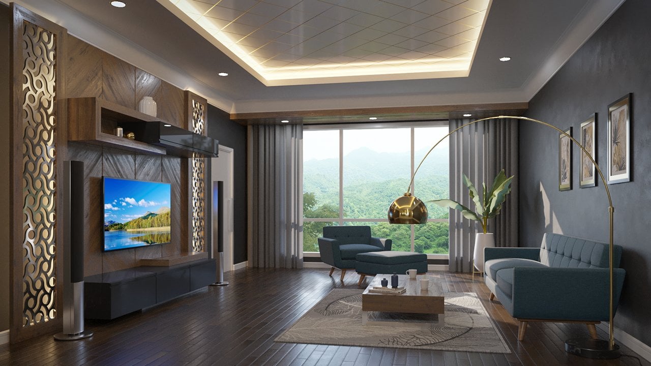
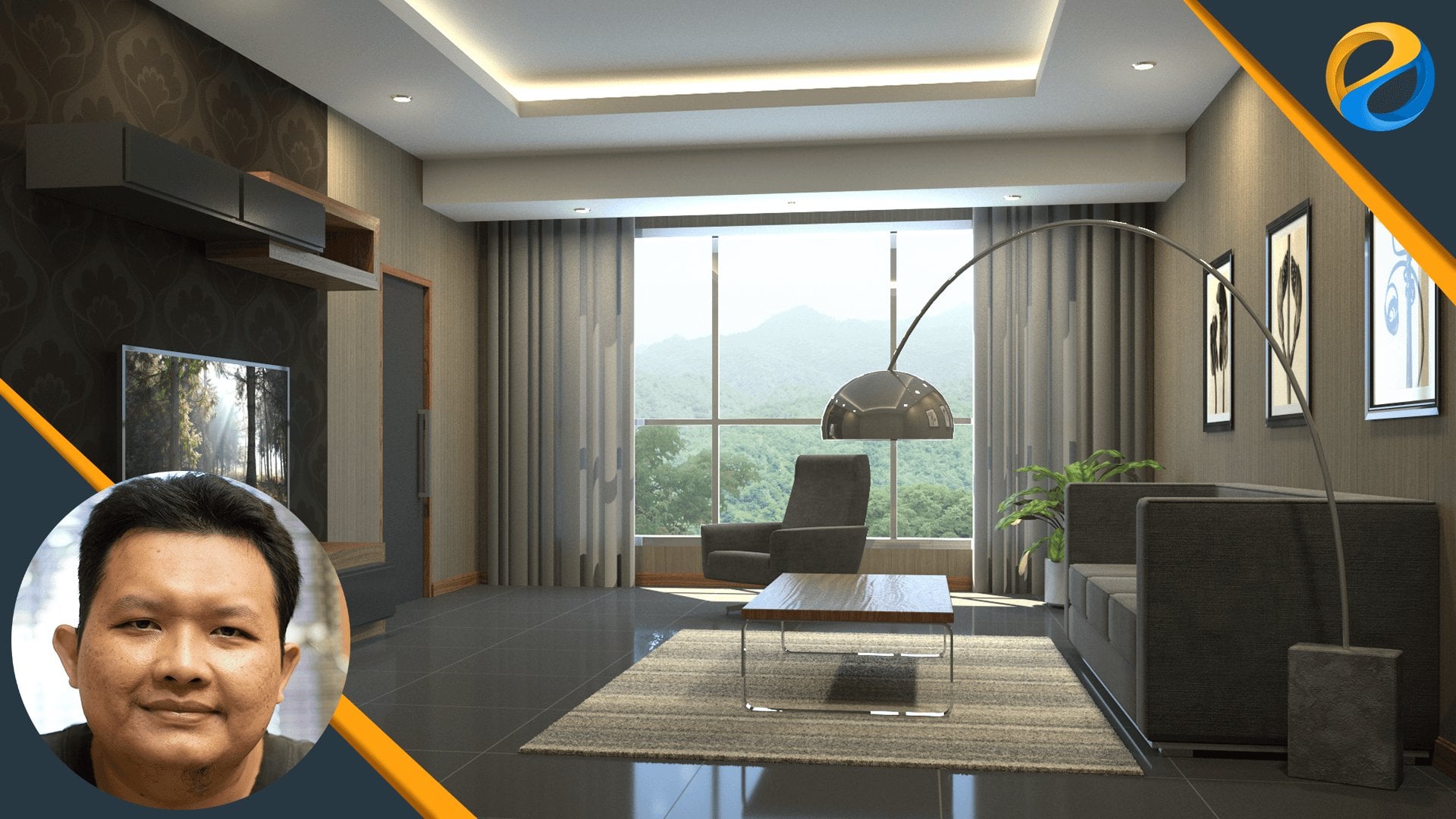
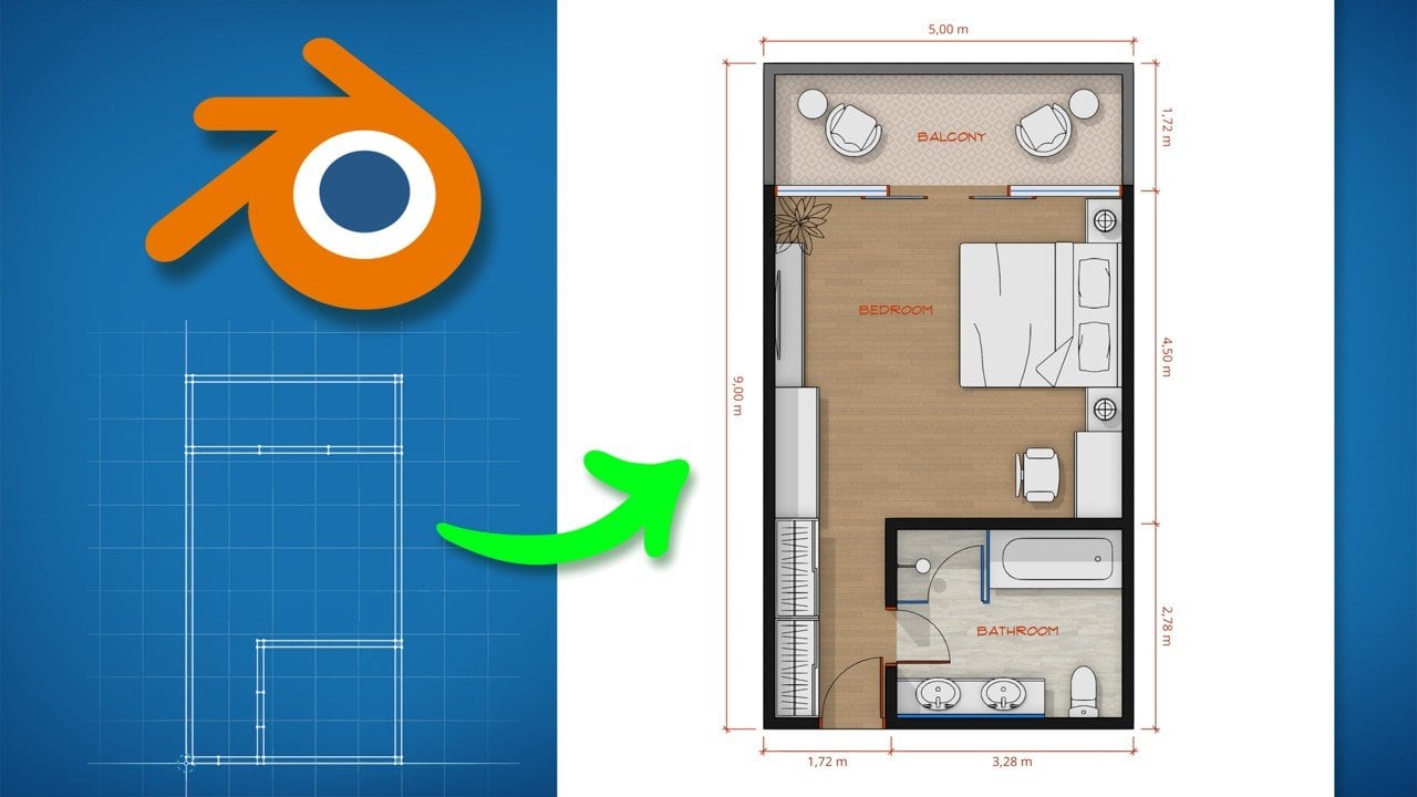
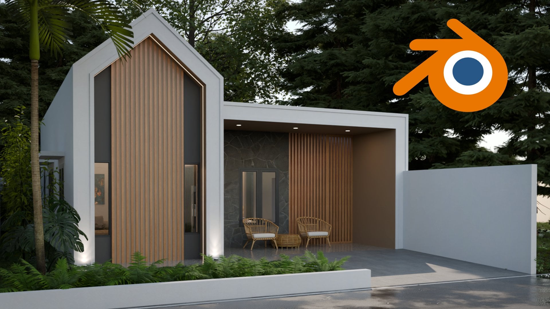
1. Introduction: Assalaamu'alaikum, my name is Widhi Muttaqien. In this online course, you will learn SketchUp Free or also known as SketchUp for Web. You will start from the very basic and then move up gradually to the advanced level. The curriculum is carefully crafted so you will learn SketchUp in the most effective and efficient way. In less than 7 hours, in sha Allah, you will be able to master all the available tools and use them to create a 3D house design like this from start to finish. I am an entrepreneur, who is also an academic lecturer in computer graphics. In terms of teaching online courses. By the time I record this video, I have over than 27,000 students on Skillshare alone. With over 80,000 students in total worldwide. For almost 20 years, I've worked on hundreds of architectural visualizations like these. I have clients on every continent in the world. Long story short, in this field, I am both a teacher and also an experienced professional. There are so many things you will learn in this online course. There are just too many to explain in this short video. To see the details, you can scroll down to the curriculum section. But, just for a quick summary. This online course consists of 9 chapters, apart from the introduction chapter. In the first chapter, you will learn the interface of SketchUp Free as well as its basic features. You will learn to import 3D models from the 3D warehouse. Then learn how to do navigation, and use different types of "views". Next, you'll learn how to use the "scenes" feature. And then we will discuss how to change the appearance of the 3D models using "Styles". After that, we will discuss various commands related to files. And also learn how to create a "custom shortcut". In the second chapter, we will discuss basic 3D modeling techniques. We'll start by learning the line tool. Then discuss the concepts and features of "inference" in SketchUp. After that, we will discuss the "Rectangle" tool. And then discuss one of the most important tools in SketchUp, called the "push-pull" tool. Also in this chapter, we will discuss various object selection techniques. And techniques for deleting objects. Finally, we will cover how to use the "offset" tool. The third chapter is a practice chapter. First, we will model this "planter box" object. Then create a 3D model of this cabinet. After that, we will try to create a 3d model of this pet house. In the fourth chapter, we will focus on object manipulation and object management techniques available in SketchUp Free. There are many things that we will discuss in this chapter. Some of them are, object transformation, from the basic to advanced techniques. Then, learn how to use "tags" to manage 3D objects more easily and quickly. Next, you will learn various duplication techniques. Then learn how to group objects either with the basic "group" method or with the more advanced method using "component". In the fifth chapter, we will discuss various advanced modeling techniques. You will learn how to use "Rotated rectangle". Learn the ins and outs of the "circle" tool and the "polygon" tool. Then learn the concepts and techniques of smoothing 3D object surfaces. Then, you will learn how to use the "Freehand" tool as well as the "Arc" tool. And then create 3D text objects. And finally, learn to use the "follow me" tool. The sixth chapter is a special chapter for 3D modeling exercises. We will make use of the advanced techniques discussed earlier. We will start by modeling this coffee table. Then learn to model a classic gate like this. Then learn how to model a "square pillar" like this. Next, we will discuss the techniques for creating a double-sided door. Starting by making the door frame, then the door leaf. And finally, we'll create the doorknob. Next, you will learn how to model a book like this. The last project in chapter six is creating a stair and its railing. You will learn a simple yet effective method for defining the stair steps without doing complex calculations manually. The seventh chapter focuses on discussing measurement and annotation techniques. Here you will learn the "Tape measure" tool, and then also the "protractor" tool. Next, you will learn different methods for assigning labels such as for dimensions or simply for adding comments. Then, we'll cover how to create cutouts of our 3D model using the "section plane". And finally, you will learn how to create "custom axes". In chapter eight, you will learn to use materials and textures. In addition to learning to use the materials provided by SketchUp, you will also learn to create your own materials and textures. After that, we will discuss various methods of manipulation for textures that are already attached to 3d object surfaces. We will cover both flat surfaces and also curved surfaces. In the last chapter, or chapter nine. We will create the final project which is a house. We'll start by importing the reference image. Then model the walls. Add windows and doors. Then create the floor, the surrounding area, and also the carport. We will create the roof which will be a double-stacking type. Then make a large canopy that covers the terrace and carport area. Finally, we'll add ornaments for the house facade. This is the final result. In sha Allah, you will be able to create a house 3D model like this, and even more, if you follow this course from start to finish. So, don't wait any longer. Join this online course now, and improve your skill in the Architectural field. Wassalamu'alaikum.
2. Information and Disclaimer: Before we start, there are several things that I need to clarify about this online course. The first is about the curriculum. I have carefully developed the curriculum so that the subjects are placed sequentially. Each lesson you take at one level will become the foundation for other lessons at the next levels. Therefore, it is important that you take this course in order, step by step. Not jumping around randomly. If you watch the lessons randomly, you will most likely be confused at some point. The second thing that I need to remind you of is that you need to practice. For each video lesson, try to practice it yourself at least once. This course is not just about theory. Most of the lessons are practical skills. So again, you need to practice, if you really want this online course to benefit you. Next, is about the operating system. You might already know that SketchUp is available for both Windows and Mac OS platforms. For this online course, I recorded the entire lesson using a PC computer with Windows 10 operating system. In general, all the lessons you find in this course can also be practiced on Mac computers. What may be slightly different is the shortcut. Because the Mac and PC keyboard layouts are slightly different. Generally, you can substitute the Ctrl key on the PC with the Command key on the Mac computer. Other than that, if you're on a Mac, you may have to spend a little time browsing the internet looking for any additional information you need. If you use SketchUp for Web, you can be sure that you will always use the latest version available. I recorded this online course at the end of 2021. So everything related to the software, be it the interface or its features, are the ones available at that time. If you experience any differences in the SketchUp you're using. Most likely it is due to the software developments that occurred after 2021. You may contact me if this happens. If the changes are not too significant, I can just update the lesson video. But if the changes are extreme, I may need to recreate the entire course. Throughout this course, I may show a lot of pictures and or videos. Please notice that some of these contents are created by other people. I merely use them as sources of inspiration or reference. If I can find the owner's name, I will show the name in the video. Otherwise, I'll just put the source URL of where I got the image or the video. Again, I never claim these images or videos as my own.
4. Starting SketchUp Free: In this lesson video, we will cover the initial steps to use SketchUp Free. The official name for SketchUp free is "SketchUp for Web". It is named like that because it runs entirely within the internet browser. So, to be able to use it, there are a few things that you need. First, of course, you will need an internet connection. Second, you will need a modern internet browser that supports OpenGL 3D rendering. Now, you don't need to worry, because generally, most of the internet browsers already support it. Throughout this course, I will be using Google Chrome. But you can use any browser you like as long as it can run SketchUp without any problems. Just to be safe, use the latest available version to avoid any issues. Next, for hardware specifications or other details. You can open the following link On this page, you can see for yourself the minimum specifications and also the recommended specifications. This section contains information for PC computers with Windows 10 OS. And in this section, you can find information related to Apple computers or Mac OS platform. One important thing to note is that, on whatever platform you are on, you are strongly advised to use a standard mouse that has 3 buttons or a scroll-wheel. Although SketchUp supports trackpad input, you will be way more productive using a standard mouse. After the hardware and software requirements are met. Next, you can open the official SketchUp website and that is "https://www.sketchup.com/". If you don't have an account yet on this website, then you need to create one first. After that, you can just look for a link to go to SketchUp for Web. Then click the "Start modeling" button to get started. Or you can directly open this link "https://app.sketchup.com/app". To make it easier later, you can just bookmark the link. There is one unique feature, only available in modern internet browsers. And that is making a web app such as SketchUp look like a regular desktop application. If you're on Google Chrome, you can click on this little button that says "install SketchUp for Web". And if you're on Microsoft Edge, you can press this button. I'm not really sure about other browsers, as I only have these 2 on my computer. They may or may not support this feature. Essentially, if you click on the install button, the "SketchUp for Web" icon will appear on the taskbar just like any regular desktop application. Of course, if you use SketchUp often, this icon can help you to access it more quickly.
5. UI basics: In this lesson video, we will cover the basics of the user interface. The first time you open SketchUp free, you will see something like this. This is called the "home" screen. From here, you can simply click the "start modeling" button to open the SketchUp working interface. But, by default, SketchUp uses the "Imperial" unit standard commonly used in the US. Or in other words, using inches and feet as the measurement units. The majority of countries in the world do not use inches or feet but we use the "metric" standard. To start a new file using metrics, we can click on the caret icon. You can see 3 options for the metric system, "millimeters", "centimeters", and "meters". If you're working on interiors, it is better to use "centimeter". If you're working on exteriors, then I suggest you use the "meter". For now, let's use "centimeter". Once the SketchUp interface opens. You will see a character in the center of the screen. You need to know that this character object changes from time to time. So, when you open SketchUp, it's likely that you will see a different character object. This is not a problem because this character object is used only as a scale comparison. You can delete it if you don't need it. At the top left of the screen, you will find the icon for the main menu. If you click on this icon, you will see various links and or commands. Like this "home" link, for example. It is used to return to the "home" screen. Then, in here also, there are various file operations such as "new", "open", and so on. You can find a link to open the "settings" window. If you previously created the file using "imperial" units and you want to switch to "metrics", you can change it via this drop-down list. We are currently using the metric system, so there is no need to change this again. Now, notice at the top there is an "autosave" option. By default, this option is active. With this, SketchUp will frequently save the file for every 5-minute interval. Here you can also change the language used in the interface. This course is in English, so we will use English also for the interface. Apart from this "settings" screen, you can also click on this globe icon to change the language. Next, on the "accessibility" tab, you can set the axis color as well as the "inference" color. We will discuss "axes" and "inferences" in other lessons. These color options can be useful for people with color blindness who may have difficulty seeing certain colors. But while taking this course, I do not recommend you change the color settings from the defaults. As this can lead to confusion later down the road. This also applies to the "navigation" tab. Just leave everything to the defaults. Click the X button in the upper right to close the "settings" window. Next, on the left side, you can see the tools. This is the "select tool", "eraser tool", and so on. We will discuss these tools in more depth in future lessons. Now, if you notice. There is a tool icon that has a small arrow symbol on its right side. Icons like this contain not only one tool but several tools at once. For example, this icon contains 2 tools. The top tool is called the "paint" tool, which we can use to apply color or material. While the tool below which is called the "sample material", is the opposite. We use this to extract material from objects. You can see when I activate the "paint" tool, there is a panel that opens on the right side. We will cover the right panel in a moment. For now, we can hide it first by pressing the arrow button in the upper right corner. One thing you need to remember is that, in the free version of SketchUp, some of the tools or features are not available. For example, if you click on this icon. Only the top tool named "outer shell" can be accessed. The other tools appear to be inactive. If you try to click on one of these tools. You will be prompted to "upgrade" your license. If you are interested in "upgrading", you can also do it via clicking the "upgrade now" button below. Now, let's discuss the UI concept of these panels on the right side. Every time we click on an icon from the right bar. The associated panel will open and listed in the panel list. Then the icon will turn blue. For example, if we click on this icon called the "entity info". And then click on the "outliner" icon. You will see all these panels appear in the large panel list. The more active panels you open, the taller this panel list area will be. Now, notice that this "entity info" panel looks empty. This is because there is currently no object selected. If we use the "select" tool. Then click on this character, for example. This panel will display information related to the character object. You can see that the "outliner" feature is not available in the free version. You need to upgrade the license to be able to use it. Alright. Next, to expand and collapse these panels, you can do so by clicking on the title area or the names of the panels. Click to collapse and click again to expand. When a panel collapses, its icon will turn black. So, in conclusion, these icons are blue if they are in the panel list and also expanded. If one of these conditions is not met then they will look black. Now, if you pay attention. At each of the upper right corners of these panels, you can find hidden X buttons. The difference between the X buttons and this arrow button is that, if we press the X button, only the corresponding panel will be closed or taken out from the panel list. While this arrow key is used to close the entire panel list. We can see that when a panel is no longer in the panel list, its icon returns to black. We will discuss the functions of all of these panels gradually in the upcoming lessons. But there is one panel that is unique as it does not reside inside the panel list. This is the "3D warehouse" panel which we will cover in the next lesson.
6. Importing from 3D warehouse: In this lesson video, we will discuss the 3D warehouse features. Basically, the 3D warehouse is an online service where SketchUp users can download and upload 3D models. To access the 3D warehouse, we can do it internally, within the SketchUp work interface, or externally via a web browser. Since we already have the SketchUp interface opened. Let's first discuss the first method. Previously we have briefly reviewed the panels on the right. Now, to open the 3D warehouse, you just need to press this icon. Unlike the other panels, the 3D warehouse panel will open as a separate window. It is not listed or placed within the panel list. This is necessary considering that we need a large area for browsing the content. In the 3D warehouse window, you can search for 3D models by category, or you can also use the "search" feature. For example, I can select the "architecture" category. Then, to further narrow the results, we can define the subcategory here. For example, "houses". Now, only the 3d house models are shown in the search results. Here, you can see several tabs. The "products" tab will display 3d models of products that are sponsored by the manufacturers. If you just want to see 3d models of houses in general, you can go to the "models" tab. So here is a list of house models that you can download. Now, let's try the "search" feature. For example, we can type here "compact house". Then press Enter. Make sure we are on the "models" tab. You can further refine your search results using the "filters" on the left. Let's say you want to specify how many megabytes the minimum file size is, and how many megabytes the maximum size is. If I set this minimum value to 0 and the maximum value to 10. Then, the 3d warehouse will only display 3d models whose file size is 10 megabytes or below. Let's try to import this house model. For that, you can click on this little button. Or, if you want to preview the model first in 3D, you can click on the image. Let me close this cookie message first. Click on this link "see more details". Then click on this button at the center. Wait a few moments until all the data is finished downloading. And now we can see the model in 3D. We can click-drag to rotate the view. To import this model into our file, simply press the "download" button. Wait a few moments until the 3D model appears on the screen. Then you can move the mouse to determine the position of the object. After that, you can click to place it. It is important to remember that, by default, after we import a 3D model, the active tool is now the "move" tool. When the move tool is active, if you click on an object, that object will move along with the mouse. If you don't want this to happen, then you can activate the "select" tool by pressing this icon, or simply by pressing the "Spacebar" on the keyboard. Now, let's look at the second method of accessing the 3D warehouse. Please open a web browser application that you have or open a new empty tab. Again, for this, you can use any web browser. I'm currently using Google Chrome. Then you need to open the following link "3dwarehouse.sketchup.com". If you use the free version of SketchUp, you already have an active account. Usually, 3d warehouse will detect the account and automatically log in with it. If not, perhaps you are using a different computer, you need to first log in with your SketchUp account. In general, the way we search for 3d models here is the same as the previous method. We can use the category feature or the search feature. I will try to open the "houses" subcategory again as before. What differentiates this method from the previous one is that when we press the "download" button, the 3D model will not be directly imported into the currently open SketchUp file. First, it will ask you for the file version. For example, I choose the lowest version available here. After that, the data will be downloaded as a native SketchUp file, which is in "SKP" format. After the download process is complete, we can then open or import the file. We will cover how to open or work with files in the future lesson.
7. Navigation: In this lesson video, we will cover how to navigate the viewport. In SketchUp, we can navigate the viewport using 4 methods. Using a Mouse, Trackpad, navigation tools, and finally the "walk" tools method. Let's discuss all of these, one by one. The first is the mouse method. Of all the navigation methods, the mouse method is the fastest and most convenient. For this method, you need a standard mouse that has a scroll wheel. For the record, generally, a standard mouse has 3 buttons. The left and right buttons are probably very obvious. But, what many people do not realize is the existence of the middle mouse button. You can access this button by pressing the scroll-wheel down. Not rotating it, but pressing it down. This is important to discuss because most navigation operations in SketchUp are conducted using the middle mouse button. If you press the middle mouse button. Then move the mouse around, the viewport will rotate. This type of navigation is known as "orbit" or "orbiting". If you rotate the scroll-wheel. Then you will zoom in or zoom out of the view. And lastly, if you hold down the Shift key while pressing the middle button, you can move the viewport to the right, left, up, or down. This type of navigation is commonly referred to as "pan" or "panning". So again, use the middle button to "orbit" the viewport. Scrolling to "zoom" the viewport. And Shift plus middle button to "pan" the viewport. The second method of navigation is using the trackpad. Although using a mouse is the best method, sometimes we are forced to work with our laptop's trackpad. When this happens, you need to enable trackpad mode first. To do this, you can open the main menu. Then select "app settings''. In the navigation section, you need to change this option to "trackpad". Another way to do this is to press this button below, and then select "trackpad". So, this is "mouse mode", and this is "trackpad mode". Unfortunately, I'm using a desktop PC that doesn't have a "trackpad" when recording this lesson. So, I can not practice it directly. But in short, you can see the guide on this settings window. To "orbit", you can swipe with 2 fingers. To "pan", you need to hold down the Shift key. And to "zoom", you can hold the Ctrl key. If you don't like the default settings. You can choose a different scheme in this drop-down list. If you change the 2-finger swipe to "pan", for example. Now, the Shift swipe is used for "orbit". Likewise, if you change this to "zoom", then the Ctrl swipe changes to "pan". For now, I will set this to its default, which is "orbit". One thing to note for the zoom method. Some trackpads support the "pinch gesture". If you happen to use a trackpad like this, you can use a pinching gesture to zoom in and out of the viewport. So that is how you navigate the viewport using trackpads. For the rest of the lessons in this course, I will be using a mouse. Okay. The third method of navigation is to use the "navigation tools". You can find these tools at the bottom icon. So, this tool is for the "orbit". This tool is for "panning". And this one is for "zooming". In addition to the 3 standard navigation tools, there are also 2 additional tools that can help us to zoom to a certain area. The first is the "zoom window". We need to zoom out far enough to see the effect clearly. So, to use this tool. Just click-drag to make a selection box in the viewport. When you release the mouse, the viewport will zoom directly to that box area. Next up is the "zoom extents". If you click this icon. Then the viewport will zoom automatically so that all objects are visible in the viewport. We will often need this "zoom extents" feature. Therefore, I suggest you memorize the shortcut, Shift + Z. For example, if we rotate and zoom the viewport so that it is far from the center point. Just press Shift + Z to change the view so that everything is visible again. The fourth method of navigation is using the "walk tools". If you click on this icon, you will find 3 tools, "walk", "position camera", and "look around". The first tool you may need to use is the "position camera" tool. The purpose of this tool is to make it easier for us to go to narrow places that are difficult to see with ordinary navigation methods. For example, we want to have a look at this area. Just click on the "position camera" tool. Then click on that location. After the view is at that point, we can still adjust the height of the camera by changing the numbers below. But you don't need to click on the text field to change it. Just type the number directly on the keyboard. For example, I type 180 then Enter, or 150 then Enter, etc. Remember that we are using centimeters, so those numbers we type in are in centimeters. Also note that after clicking with the "position camera" tool, the active tool is now the "look around" tool. This tool is similar to how navigation works in most VR or Virtual reality applications. Essentially, you can click-drag in the viewport to look around, while your feet stay in place. The last tool is the "walk" tool. To use this tool, first, you click and hold in the center of the viewport. When you move the mouse up, you will move forward. If you drag the mouse down, you will walk backward. If you drag it to the right or the left, then you will turn in that direction. It should be noted that the further you drag the mouse from the initial point, the faster you will move. Now, when you use the walk tool or any tool in Sketchup. You will see additional information about the tool below. We can see, when in walk mode, pressing Ctrl can make you move even faster as if you are running. Then, if you press Shift, you can move as if you are doing viewport panning. The last one is the Alt key. By default, if you use the walk mode, you will not be able to move through walls or other 3D objects. By pressing the Alt key, the "collision detection" feature will be turned off so you can freely walk through objects. The last feature we want to discuss is "zoom selection". This feature is similar to "zoom extents" but works only on objects that we select. For example, if our view is far away. Then we want to focus on this object only. We can use the "select" tool first to select the object. Then right-click, and then select the "zoom selection" command. We can see the viewport directly zooms towards the object. To return to see all objects in the file we can use the "zoom extents" command again by pressing Shift + Z.
8. Standard views and FOV: In this lesson video, we will cover several viewport features in SketchUp. First, we will discuss the "standard views", then the "2 point perspective". And finally, how to control the FOV or "field of view". "Standard views" are the types of views commonly used such as front view, top view, side view, and so on. To access the "standard views" you can open a panel called "scenes". At the top area, you can see icons that look like a house. This is the front view, this is the top view, the back view, and so on. Now, you may be thinking, why are these views no different from the usual perspective view? Meaning, they still look 3D. Usually, we refer to these views as flat or 2-dimensional. Well, to get a 2-dimensional look, you need to press this button, which will activate the "parallel projection" mode. Now the viewport becomes 2-dimensional as it does not process any vanishing points. In other software, this "parallel projection" mode is also known as "orthographic" or "isometric". You need to know that in this condition, you can still navigate the viewport. Such as performing "pan", "orbit", and "zoom" just as usual. To re-enable the perspective effect, simply press this upper icon. Now, notice when the perspective mode is on, you can see an arrow button here. This button is hidden in the "orthographic" mode. This arrow button is useful for accessing the "2 point perspective" as well as the "FOV" options. Basically, with this "2 point perspective" option, the viewport camera and its target will be made flat horizontally. This makes the vertical perspective seem to disappear. You can see all the vertical lines on the 3D model appear to be perfectly straight. In this condition, if you perform a "panning", the "2 point perspective" effect will be maintained because the orientation of the view does not change. But if you perform an "orbit". Because the view orientation changes, the "2 point perspective" effect will be gone. Next, is the FOV or "field of view" setting. Essentially, this value determines the width of the viewing angle. If we compare this with cameras in the real world. Changing the FOV is similar to changing the "focal length" value. A 24mm lens, for example, can fit more objects in the view than a 200mm lens. But in consequence, the perspective distortion is stronger on the 24mm lens. What makes "focal length" different from FOV, is that FOV is not calculated by measuring the focal length of the lens, but by directly measuring the angle of the view. So FOV uses "degrees", not millimeters. The smaller the FOV, the narrower the view will be and with less perspective distortion. While the opposite applies. If the FOV value is greater, the view will be wider and with stronger perspective distortion. Usually, in order to work comfortably, I never set the FOV value larger than 45 degrees. I use high FOV values like 60 to 70 degrees, only for presentation or final rendering. For now, I set this to its default value which is 35 degrees.
9. Scenes: In this lesson video, we will cover the "scenes" feature. In SketchUp, the term "scenes" is used for storing the condition of the view. Including the camera position, orientation, and other related viewport effects. The reason why we want to store this information is so that later we can recall them again easily without having to navigate the viewport all over again. "Scenes" also allows us to create simple animations when transitioning from one view to another. To create a "scene", we first need to prepare the view using navigation techniques. You can use the "2 point perspective" feature if you want to. You can even change the perspective mode and or change the FOV value. All these conditions will be saved as well. After you are satisfied with the view, to save it as a scene, simply press the "plus" button. Now we have a "scene". We can rename the scene by clicking on its name. For example, we can change this to "garage area". To create the next scene, the process is basically the same. First, we need to find the angle for the view. We can also set the perspective mode and or the FOV value if needed. Just for example, let's set the FOV to 60. After that, we can click the plus button again. We can rename this, for example, "backyard area". And so on. If you have a lot of scenes, to call a specific scene just click on the thumbnail image. SketchUp will create a transition or the camera movement animation from one scene to another. Now, let's set the view so it is looking from above at the front of the building. Then save this view as a new scene. Rename it to "birds-eye front". So now, we have 3 scenes. You can adjust the order of these scenes by click-dragging on the thumbnail. At this point, you may be wondering. What is the benefit of arranging the order of these scenes? The answer is the feature that we are about to discuss. And that is the animation feature. If you select the top scene. And then press the "play" button. SketchUp will animate all the scenes in sequence by adding transitions between them. When it reaches the last scene, the animation will loop back to the first scene. If you want to set the duration of the animation, you can press this settings icon. In this window, you can set whether you want to use transition or not. Then, you can also set the duration of the transition in seconds. And also the duration of each scene will be displayed before the next transition starts. I don't want to change anything now, so I just hit "cancel". Next, if you want certain scenes not to be included in the animation, you can press this arrow button. Then turn off the checkbox "Include in animation". In this settings panel, you can provide a description for the current scene. You can also specify what properties are stored in the scene, such as "hidden objects", "fog", "shadows", and so on. Perhaps most of these terms still confuse you. But don't worry, we will discuss all of this in time, In sha Allah. For now, we can collapse this section by pressing the arrow button again. The last thing we need to discuss is deleting scenes. To delete a scene, simply select the scene we want to delete. And then press this trash button. SketchUp will display a warning message. This is important because you cannot undo or bring back deleted scenes. For example, if I press "delete". You can see the "undo" button above is inactive and pressing Ctrl + Z has no effect either. So this is one thing you need to be aware of when working with scenes.
10. Viewport effects: In this lesson video, we will cover several viewport effects that we can use in SketchUp. The first is the "styles" feature, then "shadows", and the last is "fog". The term "styles" in SketchUp are basically visual effects that affect how the viewport renders 3d models and background. "Styles" are purely cosmetic and do not affect the 3d model or the material. If you open the "styles" panel. At the top, you can see the currently active style named "architectural design style". If you open the tab "in model", which has a symbol of a house. At the bottom area, SketchUp displays all the styles that have been used in this file. Currently, only 1 style is listed, the "architectural design" style. The same "style" as the one above or the one currently active. You can edit the style settings by pressing this pencil button. But unfortunately, this feature is only available for the paid version of SketchUp. Don't worry, in SketchUp free, we can still use a variety of ready-made styles. You can do so by opening the "browse" tab, the one that has a magnifying glass icon. Here, you will see "styles" grouped into categories. Some of them are "Assorted styles", "color sets", "default styles", and so on. If, for example, we choose the "monochrome screen", then the viewport will look like an old monitor screen. If we choose this one "pencil on tracing paper", then the viewport will change to look like pencil sketches. Another example, we can choose this one called "whiteboard with dry erase". We will get this unique whiteboard look with marker scribbles. Feel free to experiment with these various "styles". Now, even with these unique "styles" active, we can still navigate and work in the viewport just as usual. Please be aware that you may get a bit of lag working like this. This really depends on your computer speed as well as how complex the style is. To return the "styles" to the default, you can go to the "default styles" category. Then select the style at the very top left. Or, if you remember the name of the active style when we first started the file. It was the "architectural design" style. Well, you can find the style here. After using different styles, if you open the tab "in model" again. At the bottom area, you will find all the styles that you have used before. You can re-activate previous styles from this list if you want to. Notice that currently, we have 2 styles with the same name, "architectural design". We can choose this one. And if you want to clear this list from other unused styles, you need to click on this "purge unused styles" button. Now, just like before, only the "architectural design" style is available. Next is the "shadows" and "fog" features. If you open the "display" panel. You will see many options and features in this panel. We're not going to cover all of these yet. We will only focus on the "shadows" and "fog" features. By activating the "shadows" feature, the objects in our file will produce shadows. We can adjust the position of the sun by setting the time here. Of course, if we set the time to morning hours, the shadow will be longer sideways. Meanwhile, if we set it to high noon hours, the shadow will be shorter or pointing downwards. Besides time, you can also control the date. Essentially, this determines the sun's position against the globe's latitude. Feel free to experiment with these sliders to find the shadow position that you like. Next, we use the "fog" options below to display fog or mist. This feature can be useful if we want to simulate a building that is located at high altitude regions which are often covered by fog. We can use the "distance" value here to determine how far we can see. The higher this value, the farther our visibility will be. And the lower the value, the shorter our visibility will be. If you want the area in front of your eyes to be completely clear. You can also drag the left node. So, the way these 2 nodes work is like this. Assume that this left border is the position of our eyes. And this right border is the farthest point. This area is uniformly clear of fog. While in this blue area, the fog gradually changes from clear to dense. And finally, in this area, the fog is uniformly dense. Anything in this area will be fully invisible. By default, the fog color will follow the background color which is related to the style we are using. But you can use any custom colors by disabling this checkbox. Then choose the color below. For example, we can choose this green color. Now the fog is colored in green as if it is a poisonous gas.
11. Model info: In this lesson video, we will cover the "model info" panel. We can use this panel to set the display unit, adjust the snapping values, and also control the dimension objects in our file. To access the panel, you can press this icon. Now, before we continue. You need to understand that the settings in this panel are specific to the current file only. If you start or open another file, the settings in this panel may look different. There are 2 tabs here. The first is "units" and the second is "text". Let's first take a look at the "units" tab. In this tab, we can specify what units we want to display for the length measurement. Is it "cm", "m", decimal inches, fractional inches, Etc. Please note that changing these options will not change the size of your 3D model. Only the way we measure is different. Just imagine if there is an object in front of you. Then you measure the object with various types of rulers with different units. Of course, the object will not change its dimension. However, the measurement results will vary because the units used are different. Then in this section, we can determine the level of precision. For now, I will stick with cm. Then for the level of precision, I choose the 1 digit behind the decimal. Next up, is the "length snapping" option. Basically, with this option turned on. All the tools in SketchUp that use length measurement will stick every time it reaches a certain value. We can specify that value in the "snap interval" field. We haven't discussed any tool for modeling. But, just to give you an example. If I set this to 10cm. Then I use the line tool. Pay attention to the length value that will appear in the text field below. We can see the numbers will always snap per 10cm. In this condition, it will be difficult to get a value increment smaller than 10cm. Unless we use the inference feature, or we type the value manually. We'll cover all of that later in a future lesson. Let me undo this first. Now, if I change this value to 1cm. When I draw a line, the length of the line will always snap per 1cm. I'm sure you understand by now, what this "length snapping" feature does. For now, I will set the "length snapping" at 1cm. Again, just a reminder. The settings in this panel only apply to this file. Another file will be a different story. Next, is the setting for rotation or angle units. To measure angles, SketchUp only supports degrees. That is why you won't find the settings to change the unit. But here, we can determine how precise the degree value is. For angular measurements, in this course, we will not be needing small precise values. So, it will be enough even if you set this to integers. Next, is the "angle snapping" feature. Essentially, the principle is similar to the "length snapping". It's just that it is used by tools that use angles or rotation values. Now, you need to know that this "angle snapping" feature is not as strict as the "length snapping" feature. It will only determine the number of lines present in the "protractor widget". So, what is a "protractor widget"? Well, basically it is a visual aid in the form of a circular ruler. All tools in SketchUp that work with rotation will use this widget. For example, when using the "rotate" tool. Don't worry, we'll cover this tool later in more detail. For now, pay close attention to the amount of these small lines around this widget. When later we use the "protractor widget", the angle values will snap to these small lines. If I change this to 45 degrees, for example. The number of small lines is now only 8. If I set this to 10 degrees. Then we can see that there are 36 small lines. For now, I'm setting this to the default which is 15 degrees. Next, let's move on to the "text" tab. The options in this tab are closely related to the "dimensions" tool. To access this tool, you can click on this icon. Then select this tool. We will cover this tool more in-depth in a future lesson. For now, you just need to know that we use the "dimensions" tool to measure objects and display the measurement visually. To use it, we can click to determine the first point. Then click again to specify the second point. Then drag the mouse in the direction that we want. And then click to confirm. We can see that the font type, the font size, the text location, and also the endpoints style follow the settings in this panel. If I change the font size to 20. Then I choose this third option for the "align to" setting. And then I choose this endpoint style. When we create another dimension, for example, from this point to this point. We can see that this dimension object looks different from the previous one, as it follows the settings we have just made. Suppose we already have a lot of dimension objects in our file. And we want to change all of them at once. We can hit this button, "update all dimensions". Now all the dimension objects will be standardized according to the settings we are currently using in the "model info" panel.
12. Working with files: In this lesson video, we will discuss various features related to files. In general, we can store files in 2 types of storage. In the cloud or on our computers locally. Trimble, the company that owns SketchUp, provides a cloud storage service called "Trimble connect". So "Trimble connect" is similar to Dropbox, or Google Drive, or other cloud storage services. The difference from the others is that "Trimble connect" only focuses on managing data related to their software, one of them is SketchUp. When you register as a SketchUp user, you are given 10GB of free storage space on Trimble Connect. This is fairly large considering that SketchUp files are relatively small in size. If you want to save files to Trimble Connect. You need to give it a name first. To do this, simply click on the "untitled" name above. A window will open. And you will see this "SketchUp" folder. We'll discuss this folder later. For now, just click on this folder. Then provide a name for the file that you want to save. Just for example, I name this file "learning 001". Then click the "save here" button. Alright. Next, let's discuss how to manage files and folders inside "Trimble connect". If you open the main menu, then go to the "home" screen. Then click on the "Trimble connect" button. And then press the link above that says "projects". This is your main folder in "Trimble connect". Now, the "SketchUp" folder you see here is actually a project folder. If you are a paid user, you are free to create your own project folder without any restrictions. For the free version users, you cannot create a project folder. So you only have this one project named "SketchUp". But don't worry, you can still create subfolders inside this SketchUp folder. So first, go into the "SketchUp" folder. Once inside, you can create a new folder by pressing the "Add folder" button. Then specify a name, for example, "houses". Press Enter on the keyboard or click on this "create" button. We can create another folder. For example, let's name this one "apartments". Etc. Next, if we click on the "houses" folder, for example. We are now inside the "houses" folder. To check our location in the "Trimble connect" file structure, we can take a look at the "breadcrumbs" link above. To return to the parent folder, which is the "SketchUp" folder, simply click on its name. And now, we are back in the "SketchUp" folder. To open a file in "Trimble connect", just click on the file thumbnail or click on the file name. To delete a file, you can click on this dotted button. Then select "delete". From the same menu, you can also click on "details" to see more detailed information about the file. And you can also click on "history" to track the changes made to the file. Now, let's discuss how to work with local files or files that are stored in our own computers. Let's reopen the "learning 001" file again. To save this file locally, you should not use the "save as" command, as this will save the file in the cloud or in "Trimble connect". What you need to do is select the "download" menu, and then select "SKP". "SKP" is SketchUp's native file format. You can choose the version of the file that you want to download. Just for example, I choose the 2017 version. Then press OK. From here, you either need to choose the folder location and also the file name, or the file will just go directly to the "downloads" folder. This depends on your browser download settings. So that is how you save the files locally. Now, what if we want to do the opposite. We want to open a local file in SketchUp Free. You can do this in 2 different ways. The first method is to go to the "open" menu, then select "my device". And then just pick an SKP file on your computer. If the file is large, SketchUp will give you a warning. Just press "open" to continue. And the file will be opened. It should be noted that opening a file like this does not automatically save the file in the cloud. So, just to be safe, you can save the file using the methods we discussed earlier. You can press the name above, or by pressing the "save as" button in the menu. Or you can also press the "save" button. Just like with other software. If you haven't saved the file yet, clicking on the save button will be the same as when you use the "save as" command. The second method to open local files is to upload them first to "Trimble connect". For this, we can open the "home" screen. Then open "Trimble connect". Select the folder where you want to upload the file. For example, I select this "houses" folder. Then press the "add model" button. The file browser will open. Find the location of the file, and then select the SKP file you want to upload. Then click "open". The file will then be uploaded to "Trimble connect". When the upload process is complete you will see the file here. You can then open the file just as we discussed earlier.
13. X-Ray and custom shortcut: In this lesson video, we will discuss how to create custom shortcuts in SketchUp Free. And then we'll discuss the "X-Ray" and "View back edges" modes. In general, SketchUp already provides shortcuts for commonly used tools and commands. But there is still a chance that the commands you use often don't have default shortcuts. For this, you can create your own custom shortcut. Just for example. There is one feature that I often use, but it's a bit inconvenient to access. This feature is the "X-Ray" mode. In the desktop version of SketchUp, you can access this X-Ray feature from the menu. But unfortunately, this menu does not exist in SketchUp Free or the web version. So, by default, to use this feature, we need to open the "styles" panel. Then choose the category "default styles". Then activate the "X-Ray" style. To exit from the X-Ray mode, you need to click on another style in the "browse" tab. Or go to the "in model" tab and click on the previously active style. As you can imagine. If you are in the modeling process and need to quickly turn this X-Ray feature on and off. It would be better if we can access this feature with a keyboard shortcut. To create a custom shortcut. First, you can click on this magnifying glass button. Or you can also press Shift forward slash. The "search" window will open. In this window, you can search for various features or commands available in SketchUp. For now, just type here "X". The "X-Ray" setting will appear in this list. You can turn on or off the "X-Ray" mode in this window using this switch button. But, again, this is as inconvenient as accessing the styles panel. What we want to do is hover the mouse over this box. This box is used to display and assign keyboard shortcuts to the corresponding command. For example, we want to use the letter X to toggle the X-Ray feature. So, just click this box. And then press the letter "X" on the keyboard. Now, the letter X is assigned as the shortcut for the X-Ray mode. We can test it by pressing X on the keyboard. As you can see, the shortcut is working fine as expected. From now on, in this course, I'll be using the letter X shortcut to toggle the X-Ray feature. You can search for other commands and assign keyboard shortcuts using this method. But please keep in mind that other than the X-Ray shortcut, I'll be using standard shortcuts throughout this course to avoid confusion. Now, let's discuss how to reset the shortcuts. Imagine a scenario where you have to work on a public computer and most of the shortcuts have changed. You can reset everything to default by clicking on this question mark symbol. Then press the "reset all shortcuts" button. I'm not going to press it as this will reset the custom shortcut for the X-Ray mode. After you are done, just click anywhere to close the "search" window. For those of you who have used older versions of SketchUp, at this point, you may be wondering. So, what is the difference between the X-Ray mode and the "view back edges" mode? By default, you can use the letter K shortcut to toggle the "view back edges" mode. When compared to X-Ray, the "view back edges" mode will display the edges that are behind other objects in a dotted line style. Also, this mode does not display color or texture on back faces. All that you see is the color of the faces that are directly visible to your eyes. When I press X to activate the X-Ray mode. You can see, the edges are rendered in a regular solid line style. And even though it looks transparent, we can still see the color and texture of the faces. You can go back and forth between these 2 modes with the shortcuts. Press K to activate "view back edges" mode. And press X to activate "X-Ray" mode. To return to the standard mode, you need to press the current mode shortcut again. For example, if you are currently in "view back edges" mode, you should press K to return to standard mode. But if you are currently in X-Ray mode, you need to press X to return to standard mode. One thing that is common between these two modes is the ability to access hidden edges. In "view back edges" or in "X-Ray" modes, I can draw new lines by snapping to the points that are behind other objects. This is not possible in standard mode, as you can only draw on surfaces that are directly visible. And then, in these 2 modes, you can also select the back edges with the "Select" tool. You can even erase them, making it easier when you need to clean up the geometry. So those are the benefits of working in X-Ray mode or "View back edges" mode. You don't have to worry if you are still confused by these commands, such as creating lines, selecting edges, and so on. We will discuss all of these in detail in future lessons.
14. Line tool basics: In this lesson video, we will cover how to use the "line" tool. Let's start with a new file. We can open the main menu and press the "new" button. Activate the "select" tool or press "Spacebar" on the keyboard. Select the character in the center. Then press delete. To use the "line" tool, we need to press this pencil-shaped icon. Or you can also access it by pressing the letter L on the keyboard. Before we start using the line tool, pay attention to these 3 lines. These lines are the 3 axes. The red one indicates the X-axis or the right and left directions. Then the green line shows the Y-axis or the front and back directions. While the blue line shows the Z-axis or the up and down directions. Memorizing the color and direction of the axes is important because we will use them as long as we use SketchUp. In fact, the axes' directions and their colors also apply to other 3D software. So remembering their colors will also help you in using other 3D software in general. Again, I repeat, blue is the Z-axis, green is the Y-axis, and red is the X-axis. Alright. There are actually several methods for creating lines with the line tool. We will discuss them step by step. For now, just click and release on the center area of the screen. Watch as you move your mouse. The line sometimes turn red, green, or blue. When it is red, it means that the line you are going to make is parallel to the X-axis. If it is green, it is parallel to the Y-axis. And if it is blue, then the line is parallel to the Z-axis. Now, I'm going to make a line parallel to the Y-axis. As you can see, after one line has been created, this method will continue creating the next line. If you want to stop, you can press the Esc key. But for now, I will continue to make another line parallel to the X-axis. Then continue to make another one, parallel to the Y-axis but in a different direction. Now, notice that at this point, SketchUp helps us to snap so that it aligns with the starting point. This is an important feature in SketchUp called "inference". Click here. Then click on the starting point. Notice that whenever we create lines that form a loop or closed area, SketchUp will automatically fill the area with a surface. In SketchUp, this surface is called a "face". So that is the first method of creating a line. Let's delete everything by first pressing Ctrl + A. This will select all the objects in the file. Then press Delete. Let's try the second method. Essentially, we are going to perform click-drag, instead of doing click and release like before. After pressing the mouse button, you must hold and then drag the mouse. In this condition, you can also inference to X, Y, or Z-axis. After that, just release the mouse. If you notice, this method does not continue the line creation process. So, if you want to draw only a single line, you may want to use this click-drag method. But if you want to form a shape with multiple lines, then the first method is more suitable. The third method provides more precision as we use the keyboard to type in the length value. Now, this method is not actually a stand-alone method. Meaning, this is just an additional step to the first and second methods. But, most likely you want to use this with the first method. Because with the second method it becomes inconvenient, as you need to press down the mouse button while typing. So, again, to use keyboard input it is better to use the first method or the click and release method. For example, I want to create a line, 1 meter in length, in the X-axis direction. Click here, then drag until the line turns red. In this condition, type 100 on the keyboard, then press Enter. Let's continue. Move the mouse until it snaps on the Y-axis or the green color. Then type 200. Notice that the number we type will appear at the bottom right text field. Then press Enter. Then move the mouse in the X-axis direction. Type 100, then Enter. To close the shape, in this case, it will be easier if we just click directly on the starting point. In addition to making lines that are parallel to the axes, you can also make lines with free orientation. And SketchUp allows us to use these free lines as a reference for the next line inference. For example, we can use the line tool. Then click here and create a free line that isn't parallel to any of the axes. When we draw the next line, the line will turn magenta when it is straight against the previous line, or, when it is perpendicular or at 90 degrees to the previous line. The conclusion of what we learned so far. There are 4 colors of inference. Red means parallel to the X-axis. Green means parallel to the Y-axis. Blue means parallel to the Z-axis. And magenta is parallel or perpendicular to the previously created line. There are still other inference features we haven't discussed yet, we'll go over them in future lessons.
15. Inference locking: In this lesson video, we will cover inference locking techniques when using the "line" tool as well as how to correct reversed faces. If you activate the "line" tool or any other tool in SketchUp, you can access the references for that tool by opening a special panel called "instructor". You can learn the basic techniques as well as different ways to use the tool with the "modifier keys". For the "line" tool, we can use the Shift key and the arrow keys on the keyboard to lock the inference direction. We'll cover all of these features in a moment. Let's close this panel first. In addition to the "instructor" panel, you can also rely on the bar below to get relevant information about the active tool. The first method of inference locking is by using the Shift key. To practice this technique, suppose we want to create a 3D L letter shape using only the "line" tool. Make sure the line tool is active. If you click and release, you can rotate the mouse around, and SketchUp will help you to snap or inference to the X, Y, and Z axes. If, for example, you want to lock the inference on the Z-axis. First, make sure the Z-axis is active indicated by the blue color. Then in this condition, press and hold the Shift key. Notice how the blue line becomes bolder. The inference is now locked at the Z-axis. In this state, even if you rotate your mouse, the inference always stays in the Z-axis. To unlock the inference, simply release the Shift key. So again, I repeat. First, you need to move the mouse until the axis you want to inference becomes active. For example, the X-axis or the red one. Then hold down the Shift key. The line will be red and look bolder. Let's start creating the letter L. Drag the mouse to the right until it's about this far. Then click to draw the line. Release the Shift key, and move it up until it's blue. Then click here. For now, we don't really need the Shift key. Draw a line parallel to the X-axis to the left. Then up again parallel to the Z-axis. Now, from this point, to make a line that ends at a point that is parallel to the point at the beginning. In general, if there aren't too many objects in our file, SketchUp can recognize and offer inference to this starting point. If this blue line does not appear, you can trigger it by moving your mouse cursor over this point and staying there for about 2 seconds. When you return to the line above, the inference line towards the starting point will be provided by SketchUp. But if the previous method doesn't work, this is where we can use the inference locking with the help of the Shift key. To do this, just as we discussed before. First, you need to find the X-axis inference. Then hold down the Shift key. Now the line will only move in the X-axis direction. While in this condition, if you click on the starting point, the point created will be parallel to the starting point. From here, you can move the mouse to the starting point again. Then click to create a closed area. SketchUp will automatically create a "face" in the closed area. Besides the Shift key, you can also lock the inference with the arrow keys. I prefer this method over the Shift key method because it is just faster to perform. But you do need to memorize the formula. The up-arrow key is for locking on the Z-axis. The right-arrow key is for the X-axis. The left-arrow key is for the Y-axis. And finally, the down-arrow is for locking the inference to the last line created. Either be parallel or perpendicular to it. Let's try using this technique to add thickness to this L letter shape. Now, I know that in this case, the "push-pull" tool will be the easier solution. But currently, the goal of the lesson is to learn inference locking. Alright. So, click on this point first. Now, we want to inference the Y-axis. When you use the arrow keys method, you don't need to move the mouse first in any direction. The mouse cursor can be anywhere, it doesn't matter. Now, press the left arrow key. As you can see, the line is constrained in the Y-axis direction. Click here. Then press the up-arrow key to lock to the Z-axis. Move the mouse to this point, and then click. Move the mouse to this point again. Then click to create a closed area. For the rest, I will use a combination of the Shift key method and the arrow keys method. Just for the purpose of practicing. Click on the point above. Move to the X-axis direction. Then hold down the Shift key, and then click on this point. Move the mouse cursor back to this point and then click again. Click here. Press the up-arrow key. Click on this point. And click again. Click here. Press the right-arrow key. Click this point. Then click again. Click this point. Move down until it is blue. Hold Shift, then click on this point. And click again. Finally, we close it by making a line from this point to this point. And now we have a 3D L letter shape. Before we end this lesson. Notice that the surface color of this object looks darker. Not white as usual. Dark faces indicate that the surface is pointing backward. Or also known as "flipped normal direction". This condition can be a big problem if you are planning to export the model to other 3D applications. To fix this issue, since all the faces are inverted, you can just press Ctrl + A to select all of them. Right-click on the object. Then select "reverse faces". Press "Spacebar" and click anywhere to clear the selection. And now all of the surfaces look white as usual. There are other methods for fixing "flipped normal direction", but we will discuss them later, in sha Allah.
16. Rectangle tool: In this lesson video, we will cover the "rectangle" tool. As the name suggests, we can use the rectangle tool to create rectangular shapes. To access it, you can click on this icon or you can also press the letter R on the keyboard. As with the "line" tool, there are several methods for using this tool. The first method is by performing click and release. For example, you can click here. Then move the mouse. You will get inference when the rectangle is in a perfect square ratio. You will also get an inference when the ratio between the length and width is at "1.618". This value is commonly known as the "golden ratio". You can search online what this "golden ratio" means. Then you can just click to confirm. So that is the first method. The second method is by performing click-drag. For example, you can click and hold your mouse at this location. And then drag it. In this condition, SketchUp also provides inferences for the "square" and "golden ratio" sizes. Once you are satisfied with the shape and size, just release the mouse button to confirm. One important note about this method is that if you make the size too small or you release the mouse too quickly, SketchUp will not consider this method valid and will automatically switch to the first method. For example, if we click-drag and quickly release the mouse button. Instead of creating the rectangle, we are switching to the first method. So, now we have to click again to create the rectangle. This is one thing that you need to keep in mind. Next up, is the keyboard input method. For this, you can use both methods. But, as with the line tool. For keyboard input, it is easier if you start with the first method or by performing click and release. So, for example, you can click here. Then, since rectangular shapes have length and width values, you must type in two values. To separate the two values, we need to use a comma symbol. For example, I can type 100, comma, 200, then press Enter. And now we have a rectangle that is 1m wide and 2m long. Sometimes, we want to create a rectangle whose center point is at a certain location. For this, we can use the Ctrl key. For example, we want to create a square centered at this point. First, make sure the cursor position is right at that point. Then make a rectangle as usual. In this condition press the Ctrl key. You don't have to hold the key, just press and release the Ctrl key to activate the center mode. If you press Ctrl again it will deactivate the center mode. So now the rectangle will be created from corner to corner just as before. We can see that when this feature is active, the center point of the square will be locked at the location that we clicked at the beginning. You need to be careful with this feature, because you may trigger the center mode accidentally. That is when you use other shortcuts with the Ctrl key, such as pressing Ctrl + Z for "undo", or pressing Ctrl + A for "select all", and so on. At least that is how it was in the SketchUp Free when I recorded the video. Next, let's discuss the keyboard input revision technique. In SketchUp, after you create a drawing object, whether be a line, rectangle, arc, circle, and so on. You can still revise the size or the parameters by typing the values on the keyboard. Provided, you haven't done anything else after creating that object. For now, I will give you an example using the rectangle tool. But you can apply this technique to the other tools as well. For example, I can click-drag like this, to create a random-sized rectangle. As long as the size of this rectangle is still visible in the text field below, or you haven't done anything else, you can still revise the values. Just type it directly on the keyboard, for example, I type in 200, comma, 100, then Enter. If you changed your mind again. Just type again, 300, comma, 50, then Enter. Again, this technique applies to all types of drawing objects, not just rectangles. While using the "rectangle" tool, you may have noticed a small blue rectangle that keeps hovering around the mouse cursor. This blue rectangle is not just a decoration. It serves the purpose of indicating the active "drawing plane". What "drawing plane" means is a flat area that will be used as the reference to place the rectangle. The blue color indicates that the drawing plane is perpendicular to the Z-axis. So if we create a rectangle. It will be perpendicular to the Z-axis. If we want to change the drawing plane, for example to one that is perpendicular to the X-axis, then we can press the right-arrow key on the keyboard. So basically, the technique is the same as locking inference in the line tool or other tools in SketchUp in general. We can see that now the small rectangle is red. If we press the left arrow. Now it is green or using the Y-axis as the reference for the drawing plane. Suppose we want to create a vertical face on the side of this rectangle. This will be an easy task as we have already locked the drawing plane to the Y-axis. Just click on this point. Then move to this point. Now, at this point, you don't need to click it. Just hover over it for about 2 seconds. But if you do click on it that is fine also. Move up, and then click on this location. Next, besides locking the axis, the "drawing plane" can also change automatically if we move the mouse on certain surfaces or if the points are oriented in a certain axis direction. For example, currently, the drawing plane is in the default state, which is blue or perpendicular to the Z-axis. If we click on this point. Then drag the mouse to this point. SketchUp automatically detects that we want to create a rectangle on the X-axis drawing plane. And if we click, then we have a rectangle facing the X-axis.
17. Push/pull tool: In this lesson video, we will discuss the "push-pull" tool. If you have used other 3D software before, such as 3ds Max or Blender, you have probably used a tool called "extrude". Well, in SketchUp, this tool is called the "push-pull" tool. Essentially, we can use this tool to pull a face out of the surface or push it into the surface. You can access the tool by pressing this icon or you can also press the letter P on the keyboard. Since this tool works on faces, of course, we need to have some faces to practice with. We can use the "rectangle" tool to create a rectangle shape on the floor. Now that we have a face. Activate the "push-pull" tool by pressing the letter P. As with the previous tools, we can use the click-drag method or the click-release method. We already knew that the click-drag method has some limitations. So we are going to use the click-and-release method instead. Click release on this face. Then move the mouse up, or you can also move the mouse down. Then you can click to finish the process. Now, we have a 3D box. As with other tools, you can also use the keyboard input and or revise the values after the process. Since we haven't done anything else after the "push-pull" process, you can still see below, the height measurement of the push-pull process we just did. If you type on the keyboard 100, for example. Or 300, and so on. Then the push-pull distance will be revised with those values. From here, I hope you have understood the basic concepts or general concepts of how the tools work in SketchUp. Next, if you do push-pulls on the front face. Then we are basically moving the face back and forth. If we push this face farther than the face behind it. Then the faces will be inverted. We have discussed previously about these flipped normal faces. They will look darker than the usual faces. Let's undo this first. Sometimes we want to create multiple segments on our model. Let's say we want to pull this right side while creating a new segment. To do this you can press and release the Ctrl key. Notice, there is now a plus symbol in our mouse cursor. This plus symbol indicates that the "push-pull" tool is in "new face" mode. In this condition, when you perform pull. Instead of moving the existing face, SketchUp will create new faces for us. So you will see visible lines here. As long as the "new face" mode is active. Every time we click and then drag, we are creating new faces. To return to standard mode, simply press and release the Ctrl key again. We can see now, there is no plus symbol in the mouse cursor. In addition to the "new face" mode, you can also use another mode called "stretch". To access it, you can press and release the Alt key. There is now a small arrow icon on the mouse cursor. In this "stretch" mode, when you click and drag the mouse up, the existing face will be moved up while dragging the surrounding points and edges. This is similar to moving the face. But at least you can do this faster, because you don't have to switch to the move tool. We'll cover the move tool in a future lesson. Let's undo this first. So again. Just to conclude the lesson. If you use the "push-pull" tool in the standard mode. This is the result. And if you use the "new face" mode, which is by pressing Ctrl. This is the result. And finally, if you use the "stretch" mode, that is by pressing the Alt key. This is the result. You can see how each mode produces a different effect, which can be useful in different scenarios. Now, let's try combining the "push-pull" tool with the "line" tool and also the "rectangle" tool. Press L on the keyboard to activate the line tool. If you hover your mouse over the center of this edge, you will see a Cyan colored dot and also a tooltip that says "midpoint". So this Cyan point shows that we are snapping at the middle point of an edge. Click. Then find the other midpoint of this edge. Then click again. When you draw a line on a face like this, SketchUp will divide the face according to the line you have created. Now, let's use the "push-pull" tool by pressing the letter P on the keyboard. Then click on this face and drag it up or down. We can make a geometry similar to stairs. Another example, we can use the line tool. Then draw a line from this top edge to the side. We now have a triangular face. Keep in mind that we can use snapping when performing push pulls. So we can click here, then if you snap to the line or point at the back. The extruded triangular face will disappear. As if the object was cut by a knife. We also need to remember that we can use the "line" tool to create many connecting lines. Just for example, we can press L. Then click from this top line. Then click here. And so on until it forms a curved pattern like this. Now, press P. Then push this face until it snaps to the point at the back. And here is the result. With the same technique, we can also create a hole through the object in the middle of the surface. For this example, we can try to create a rectangle in this area. So press R and create the rectangle shape here. From this example, we can see that the rectangle tool can be used on a surface. Then press P, then click in the middle of the face. Now, if we push this back just a bit. We have a shape that looks like a window with glass. But if we click and drag the mouse until it snaps to a point at the back. Then click. You can see, we just created a tunnel that goes through from end to end. From all these examples, you can imagine various kinds of 3D objects that you can create only by relying on the "line" tool, "rectangle" tool, and also the "push-pull" tool.
18. Selection basics: In this lesson video, we will cover various methods for selecting elements in SketchUp. For this, we need some objects to practice with. Press R to activate the "rectangle" tool. Then create a big rectangle here. Then create a smaller one. And lastly, create another one in the middle which intersects the two previous rectangles. After you are done, press the Spacebar to activate the "select" tool. Before we continue, you need to know that in SketchUp and other 3D software in general, lines like these are commonly called "edges". So, the surface is called "face". While the line is called "edge". When the select tool is active, we can click on a face or edge to select it. Now, let's discuss how to select multiple elements. Previously, we discussed the Ctrl + A shortcut. This is useful for selecting all objects in the file. We can click on an empty area to clear the selection. The next selection technique is "double-clicking" and "triple-clicking". If we "double-click" on a face, that face and all the edges attached to it will be selected. You can also "double-click" on an edge. As you can see, that edge and the faces directly attached to it will be selected. Now, if we do "triple-clicking" or quickly clicking 3 times on one of the faces or edges. Then what will happen is all connected elements, faces or edges, will be selected. Please note that this technique is different from the "Ctrl + A" method. Triple-clicking will not select disconnected elements. To be clear. Let me create another rectangle that is separate from the others. Activate the "Select" tool again, and click on an empty area. Now, if we press Ctrl + A, everything will be selected. But, if I "triple-click" on this face for example. Only the edges and faces of this structure are selected because they are connected or touching each other. While this rectangle is not selected. Using the "select" tool, you can also create a selection box by performing a click-drag. However, you need to keep in mind that the dragging direction will affect the selection behavior. If you drag from left to right. Then you are doing a "window selection". Meaning, only edges or faces that are truly inside the selection box will get selected. But if you drag the mouse from right to left. Then you are doing "cross selection". Meaning that all edges or faces that are inside or touched by the selection box will get selected. This selection behavior is similar to the one you can find in Autocad software. So again, I repeat. If you do a selection like this, from left to right. Only the faces and edges inside the box get selected. If you do the same thing, but from right to left direction. Then all the edges and faces inside and or touched by the selection box will get selected. If we already have a complex 3D model. It's a bit difficult to select edges or faces in one go. Sometimes we need to perform multiple steps to get the selection right. This is where adding and subtracting selection techniques can help. For these techniques, you can actually see the reference below, or from the "instructor" panel. You can use the Shift key to toggle the selection. The Ctrl key to add selection. And Shift + Ctrl keys for reducing the selection. For example. If I hold down the Ctrl key, a plus symbol will appear on the mouse cursor. Every time I click on a face or edge. Then that face or edge will also be selected. Now, if I hold down the Shift and Ctrl keys together, a minus symbol will appear on the mouse cursor. In this condition, if I click on the selected face or edge. Then that face or edge will no longer be selected. And the last one is the Shift key. With the Shift key pressed, clicking on a face or edge toggles its condition between selected and unselected. Now, it should be noted that you can also use this combination of Shift and Ctrl keys with the click-drag selection technique. If you hold down Ctrl then click-drag. This will add to the selection. If we hold down Shift and Ctrl, then click-drag. Then this will subtract the selection. And if we hold down Shift then click-drag. We toggle the elements between selected and unselected. Until this point, you may be wondering. Why do we need to select edges or faces? The answer is so that we can perform more advanced commands such as deleting elements, zoom extents, move, rotate, scale, etc. We will discuss all of these gradually.
19. Erasing techniques: In this lesson video, we will discuss erasing techniques in SketchUp. For this, we can use the "Select" tool and the "Eraser" tool. The first erasing technique is to use the "select" tool. Basically, we need to create the selection first. We can use all the selection techniques we learned earlier. After that, we press the "Delete" key or the "Backspace" key. For example, we can select the face in the middle, then press Delete or Backspace. Now this face area is void. Let's undo this. Next, when removing edges, there is one thing that you need to pay attention to, and that is the thickness of the lines or edges. Edges that look thin like this indicate that they have 2 faces attached to them. And if you select edges like this and then delete them. The surrounding faces will automatically be connected so no holes will be created on the surface. But if you see edges that are thick, there can be 2 possibilities. First, they only have a face attached to them, like the edges in this border area for example. Or the second possibility, those edges have no faces at all. Like this edge, for example. If you select and delete an edge like this. It does not affect the geometry. But, if you select and delete thick edges that are on the borders like this. Then the faces attached to it will be deleted also. So, this is something you need to pay attention to when removing edges. Let's undo this again. Now, let's discuss the "eraser" tool. You can access it by pressing this icon, or you can also press the letter E on the keyboard. Basically, we use the "Eraser" tool to erase the edges. For this, you can use the click-and-release method or the click-and-drag method. For example, I can click and release on the thin edges in this center area. You can see the edges disappear without causing any holes on the surface. As with the previous technique, if we click on thick edges like this, the faces attached to them will also be deleted. Let me undo this again. The second method is the click-and-drag method. So click and hold the mouse button, then drag the mouse cursor until all the edges we want to delete become blue. When you release the mouse button, all the blue edges will be removed.
20. Offset tool: In this lesson video, we will cover the "offset" tool. Essentially, we can use the "offset" tool to create a new face from an existing face by expanding or narrowing it. To understand it, let's just see this in action. Since the "offset" tool works on faces, we need to have some faces to work with first. We can press R, then create a rectangle like this. Then, to use the "Offset" tool, we can first press the "push-pull" tool icon. Then choose this third icon. Or, you can also use the shortcut by pressing the letter F on the keyboard. To use this tool, hover the mouse over the target face. SketchUp will display a red dot on the outer edges of the face, in the closest location to the mouse cursor position. This red dot is important because it will be used as the reference for measuring the offset distance. If we click here, then move the mouse. We can create the offset going in or going out of the original face. Let's first try going inward. Click to complete the process. And here is the result. Now, let's try the other direction. Click here. Drag the mouse out. Then click again. So, this is the result if we create the offset going outward. For now, let's undo this first. When using the "offset" tool, as with other tools, you can also use keyboard input and also revise the values just after you use it. Just, for example. We can click and then drag a little outward or inward. Then type the distance value. For example, 10. Then press Enter. This new face is created by measuring the distance from the red dot to the inner line for 10 cm. Since we haven't done anything yet, we can still revise the offset value. For example, we can type 20, then press Enter. If you want to revise the offset direction with the keyboard, you need to add a minus before the number. For example, type minus, then 30, then Enter. We can see now, the offset is going outward. In this condition, if you type, for example, 50, then Enter. The offset direction will not change. In fact, the distance will just increase. To reverse the offset to inward again, you need to use the minus symbol again. For example, type minus, 10, and then Enter. We can see that it is heading inward again. Let's undo this again. One thing to keep in mind when using the "offset" tool. In the version of SketchUp Free that I use, when recording this video. I cannot move the mouse cursor outside the offset face area if I want to revise the values with the keyboard. For example, if I offset this face and then move the mouse out of the face area. I can no longer revise the values with the keyboard. So again, if we click to create an offset. Then click again to confirm. Do not move the mouse outside the offset area. In this condition, we can still revise the offset value using keyboard input. After we are satisfied with the result, only then can we move the mouse outside. I don't know if this is considered a bug or not. And this behavior may have changed when you are watching this video. The last thing that we want to discuss is the overlap feature. We can see that the modifier key for this feature is Alt. To see this clearly, we need a face that is more complex than this rectangular shape. Press R. Then add a small rectangle on this side. Press E. And delete this line. Now we have a turning face. Next, pay close attention. When we press F to activate the "Offset" tool. Then click on this face and drag it in. We can see when the offset value exceeds the size of the available space, or commonly known as "overlap", SketchUp will remove the edges in that area. If we press and release the Alt key. The overlapped area will not be removed by SketchUp. You can toggle between these 2 conditions by pressing the Alt key. If you click while in this condition. Then you will have an additional face. Generally, we do not need something like this. But at least we know how to create one in case we ever need it.
21. Project: Planter box: In this exercise video, we are going to create a simple planter box just like this one. The length is 2m. The width is 50cm. And for the height, it is 40cm. The thickness of it is 10cm. And the inner depth is 30cm. Before you watch the rest of the video, you can try creating this by yourself using all the tools we discussed earlier. You may pause the video now. And later when you are done play the video again. Alright. So, to model a planter box according to the dimension specified earlier. First, we need to press R to activate the "Rectangle" tool. Then click here, drag, and click here. Now we need to revise the size. Type 200, comma, 50, then Enter. Next, use the "push-pull" tool by pressing P on the keyboard. Click on this face, drag the mouse up a bit, then type 40, then Enter. To create an inner frame on the upper face, we can use the "offset" tool. So press F, click and drag it a little, inward. Type 10, then Enter. Use the "push-pull" tool again. Then click and drag down a bit. Type 30, then Enter. And we're done. This is the final result.
22. Project: Simple cabinet: In this exercise video, we're going to create a small cabinet that looks like this. For the dimensions, you are free to use any values. As long as the geometry is more or less the same. But if you want to know the details. The length is 60cm. The width is 50cm. The total height is 140cm. The height of the feet is 10cm. And the thickness is 3cm. Now, for the handle. The width is 3cm, and the height is 35cm. Again, you may use different sizes as long as they look similar. Just as before, you can pause the video and try to create the model yourself from start to finish. When you're done, you can play the video again. Alright. Let's start by pressing R to activate the "Rectangle" tool. Click, then drag, and click again. Revise the dimensions by pressing 60, comma, 50, then Enter. Activate the push-pull tool. Then click and drag up. Type 10, then Enter. Next, we want to do a push-pull but by creating a new face. For this, we can press and release the Ctrl key. Click and drag up a bit. Type 130, then Enter. To create an offset on this face, we can press F. Then click. Drag the mouse inward. Type 3, then Enter. Repeat the step before, but now we use a smaller value, 0.2. Let's zoom in until the gap area is clearly visible. Use the push-pull tool again. And drag this inward by 5cm. No one will ever see the inside part, so any value for the depth of the hole doesn't matter. Next, to model the handle part. We can press R. Then click here. Move the mouse to the bottom right. Then type 35, comma, 3, and Enter. So here is the result so far. Then press P. And click, then drag forward. Type 4, and then Enter. Next, press F. Click on this side. Drag inward. Then type 1, and then Enter. Press R, then create a rectangle from this point. Until the bottom. Let the mouse cursor sit for a moment at this point. Then drag it back, and click. Press E, and delete this line. Use the push-pull tool. Click this face and snap to this point. And our cabinet is done. This is the final result.
23. Project: Pet house: In this exercise video, we're going to build a pet house for a cat or dog like the one you see here. For the width, it is 50cm. The length from the front to the back is 80cm. The height from the point before the roof to the floor is 60cm. The thickness of the roof is 5cm. The thickness of the walls is also 5cm. Then from the wall to the front roof is 8cm. The back side is also the same, 8cm. For the other measurements, it is okay if they are slightly different. As usual, you can pause the video and try to create the model yourself from start to finish. When you're done, you can play the video again. By now, I'm sure you are already familiar with the "line" tool, "rectangle" tool, "push-pull" tool, "eraser" tool, and also the "offset" tool. Therefore, from now on, I will try not to give too detailed explanations to save time. Alright, we can start by deleting this character first. Press R to activate the "Rectangle" tool. Click, drag, and click again. Revise the size to 50, comma, 80, then Enter. To add height we can use the "push-pull" tool. So, press P. Click and drag it up a bit. Type 60, then Enter. To make a slope on the roof, we can activate the Line tool by pressing L. Find the "midpoint". Click, and then click again on the left edge. Move the mouse to the right-side edge. Make sure the inference line to the previous point is still visible. Then click. And click again on the point above. Press P and push this face all the way, until it snaps to a point at the back. One important technique in SketchUp in using the "push-pull" tool or any tools in general, is the "repeat" feature using the double-click method. After we push a face using a certain distance, to repeat the same process to other faces, just double-click on them. Remember that we need to do this while using the same tool which is the "push-pull" tool, not the other tool. Alright. Next, to add thickness to the roof. If we pull directly like this, we will lose the edge line. We need the edge later for pulling the face to the front. So, what we need to do is press the Ctrl key first, so that the "push-pull" tool goes into "new face" mode. You can see a "plus" symbol on the mouse cursor. Then click, drag a little, type 5, then Enter. For the left side, just double-click the face. Next, press Ctrl to disable "new face" mode. To finish up the roof, there are actually many approaches that we can use. But, in sha Allah, this method is the easiest. First, just push this face a bit. Then pull this one up about this far. And then pull this face until the two shapes intersect each other. Okay. Next, you can push this face until it snaps to the edge or point at the back. And for this face, just double-click it to repeat the process. Next, to clean the excess edges. Press E for the "eraser" tool. And just click-drag on the edges we want to delete. Now, for the back side, we don't need to rotate the view. Just press X to activate the "X-Ray" mode. Delete this edge and this edge also. Besides the "X-Ray" mode, you can also use the "view back edges" mode if you want to. Press X again to return to the standard mode. Next, press P again. And pull this as far as 10cm. Then for the other side, we can use the double-click method. For the front roof, we can pull this face as far as 8cm. And because the part at the back is the same, we can use the double-click method again. The roof is finished. Next, we want to add thickness to the wall. For this, we can offset the face below. So, press F. Click here, drag a little. Type 5, and Enter. Press P again. Push this until it snaps to the point above. So now, we have something like this. Next, we're going to create a hole for the door. But before that. You may often see a hovering tooltip like this on my screen. This is a bug in SketchUp. Hopefully, this bug is already gone by the time you watch the video. Although this bug is minor because it will disappear eventually when we perform other things. But if you feel annoyed with this tooltip, you can make it disappear by activating the "move" tool. Or you can also press M on the keyboard. Then move the mouse around just a little. As you can see, the tooltip has disappeared. Alright. Let's continue with making the door hole. Press R for the "Rectangle" tool. Then press Ctrl to use the center mode. Find the "midpoint" on the bottom edge. Make sure it is the edge at the front side of the wall, not the one behind it. Click and drag. Type 25, comma, 70, then Enter. Then press E. And delete the three edges below. Finally, we can press P and push this face until it snaps to the edge or point at the back. And Alhamdulillah, we have finished creating a pet house model. As we discussed earlier, to clear this tooltip, we can press M and drag the mouse around a bit.
24. Transformation basics: In this lesson video, we will cover the basic techniques of object transformations. The term "transformations" in computer graphics are the changes related to the movement, rotation, and scale. In SketchUp Free, you can access the transformation tools by pressing this Icon. This is the "move" tool. The shortcut is M. This is the "rotate" tool. The shortcut is Q. And the last one is the "scale" tool. The shortcut is S. So again, I repeat. This is the move tool whose shortcut is M. This is the rotate tool whose shortcut is Q. And this is the scale tool whose shortcut is S. In general, there are 3 approaches to using these transformation tools. First without any previous selection. The second is by selecting the object first. And the third is using a group or component. Let's see the first method, that is without any selection. If there is no object selected in our file. To use the move tool, we can click on a face or an edge or even a point to move it. For example, we can click on this face. The face now follows the mouse cursor. In this condition, just like with other tools, you can press Shift to lock the active inference. You can also press the arrow keys to snap to a specific axis. After that, click again to confirm. The moving process is complete. Now you are free again to choose faces, edges, or points to perform a movement. As with other tools, you can type in the distance value with the keyboard and also revise it afterward if you want to. For example, I can click on this edge, then press the right arrow to snap it to the X-axis. Move it slightly to the right. Then type, for example, 30, and Enter. We can revise the distance again by typing 50, for example, then Enter. Another example, we can move a single point. Click on this point. Press the up arrow to snap to the Z-axis. Then move it. And then click. So that was the first approach. The disadvantage of this approach is that we cannot move multiple elements at once. The second approach is by selecting the object first. Essentially, we first need to use the "select" tool. Select the edges or faces that we want to move. After that, we can use the "move" tool or other transformation tools. To see an example, we can press Spacebar. Then hold down Ctrl. Then click on these faces to select them all. This second approach allows us to select and transform multiple elements at once. After you have a selection like this, press M to activate the "move" tool. Now, in this condition, wherever you click, the move tool will become active and lock the selected element position. If you click again, then the moving process is complete. So, the conclusion. With this method, we can select multiple elements and the mouse cursor can be anywhere when performing the movement. In this condition, if you want to clear the selection, just press the Esc key on your keyboard. Now, you can use the "move" tool using the first approach again, that is without prior selection. The third approach is with groups or components. I know we haven't discussed groups and components yet. But in short, both features are used to combine edges and faces into a single entity. Let's just see an example. Suppose we want to move this whole 3D model. By default, we need to use the select tool and then click-drag like this to select the whole model. Or you can also perform a triple-click for this. Only then we can activate and use the transformation tools. As you can imagine, this will be inconvenient if we have to move this 3d model frequently. With "group" you can select objects a lot easier. To do this, first, make sure the object we want to group is selected. Then just right-click on the object. You will see 2 options, "make component" and "make group". We will discuss each of them in more depth in future lessons. For now, let's try the "make group" command. Now all of the elements are combined into a single object. With this, we no longer need to make a selection by click-drag or triple-click if we want to move them. Just activate the transformation tool, for example, the "move" tool. Then click on this group object. And move it in the direction that we want.
25. Advanced transformation: In this lesson video, we will discuss further how to use the transformation tools, which are the "move" tool, "rotate" tool, and "scale" tool. In this file, I have prepared 2 boxes of different sizes. And also a chair model that I downloaded from the 3D warehouse. I'm sure by now, you already know how to create boxes like these and can download 3d models from the 3D warehouse. So, there is no need for me to explain the whole process from scratch. First, we will discuss the "move tool". In the previous lesson, we discussed various approaches to using transformation tools. And in the process, we used the "move" tool a lot. But there are still things that we haven't covered yet. One of them is "point snapping". For example. Let's say we want to attach this little box to this larger box using this point and this point as the references. To do so, we must first select all the elements from the small box. Make sure the "select" tool is active. Then triple-click on this box. Press M to activate the "move" tool. Then hover the mouse over the point that we want to snap. Then click and release, and then move the mouse until it snaps to this target point. Then click again to confirm. Alright. Now that the two boxes are attached perfectly. We can activate the "eraser" tool, and erase this line, and also this line. This will connect the faces. Next, if the object that we want to snap is a group or component like this chair, for example. Notice that, a group or component object has a box that surrounds it commonly known as the "bounding box". We can use this bounding box for snapping. Just for example. Make sure the move tool is active. We can hover and click on a corner of the bounding box. Then click on the target point in the corner of this object. The group object will move and snap based on the reference points. Let me undo this. The last thing I want to cover in terms of the "move" tool is its rotation feature. Yes, it may sound weird. But that is just how it is. We can rotate using the move tool if the object is a group or a component. If I hover the mouse cursor to this chair object. You can see that on each side of the bounding box there are 4 red plus symbols. If we move the mouse on one of them, the rotation feature will be active. Let's say, I want to turn this chair so that it faces to the right. We can choose the front plus symbol at the top. Click, then rotate until the line snaps and turns red like this. Then click again to confirm. Next, we will discuss the "rotate" tool. Previously I mentioned that we can access the rotate tool by pressing this icon. Or you can also press the letter Q on the keyboard. In general, we can use the "rotate" tool on edges, faces, or several selected elements at once. Essentially, it is the same as the "move" tool. So for now we will only focus on group or component objects. When the "rotate" tool is active and we hover the mouse cursor on a surface. We can see that SketchUp will always detect the normal direction of the surface and align the move tool in that direction. In this condition, if you click to perform rotation. First, you need to define the initial reference line. For example, we pick the line here. Then click. Rotate the mouse cursor. Until we get the desired angle value. Then click again to confirm. We can see that the chair becomes disoriented. Generally, we don't want to rotate objects like this. Instead, we prefer to use standard axes like X, Y, or Z. So, let me undo this first. To lock the axes, just like other tools in SketchUp, you can use the arrow keys on your keyboard. For example, let's say we want to use the Z-axis as the rotational axis. For this, we can press the up arrow. Now, no matter which surfaces our mouse cursor is on, the orientation of the "rotate" tool remains locked on the Z-axis. In this condition, SketchUp expects us to determine the center point of the rotation. If we pick this bounding box corner, for example. This chair later will rotate using this corner as the rotational axis. So, after you click, specify the initial line reference. We can align this with the X-axis. Click. And then rotate it so that the line is parallel to the Y-axis. Then click again. And here is the result. So that is how we can use the "rotate" tool. Finally, let's discuss the "Scale" tool. Previously I mentioned that we can click on this icon or press the letter S on the keyboard to activate the "scale" tool. When the "scale" tool is active. If you click on a group or component object, you will see cube-shaped nodes in the bounding box area. At first glance, it may look complex. But it is actually simple. Unlike the other tools that can use the arrow keys to lock the axis inference. The "Scale" tool doesn't need the arrow keys, because all the axis locking features are at these nodes. If we click and drag on the center nodes. For example this one, or this one. Basically, we are scaling on one particular axis. This is the X-axis. This is the Y-axis. And this is the Z-axis. If we use the nodes at the center of the borders, then we are scaling using 2 axes at once. For example, now it uses both the X and Z axes. And this one uses the X and Y axes. And so on. Lastly, if we drag the nodes at the corners. We will scale the object on all three axes at once, without any distortion. Or in other words, "uniform scale". Alright. Now, sometimes we want to change the size of an object but want to keep its center point location. For this, we can use the Ctrl key to toggle the center mode. So this is in the standard mode, and this in center mode. That is how we use the "scale" tool. In this lesson, I do not cover the keyboard input method, and not also the revision method. Because in general, the technique is the same as the other tools we have discussed. I believe, in sha Allah, you already know how to use these features on the transformation tools. You just need to remember that if you are using the move tool, the measurement is for length or distance. So the unit can be centimeters, meters, or inches, depending on the file settings. But if you use the rotate tool, the unit will be in degrees. As we are working with angles. And if you use the scale tool, the value is in percentage but without the percent symbol. So, 1 is equal to 100%. 2 equals 200%, 0.5 equals 50%, and so on. This is something that you need to keep in mind.
26. Working with Tags: In this lesson video, we will cover the "tag" feature in SketchUp. Essentially, we can use "Tags" to organize 3d models by associating names to them. This can be helpful when we need to work with a lot of objects. If you have used older versions of SketchUp, you might already be familiar with the "layers" feature. Well, "tags" are the successor to the "layers" feature. So again, what used to be called "layers" are now called "tags". To access the "tag" feature, you can open a panel called “Tags”. If you are opening a new file, or you haven't created any tags before, this panel will appear empty. To create a new tag, simply click on this plus icon. Then you need to specify the name. Just, for example, I name this "roof". Before you click OK. If you click on this caret button. You can specify a custom color for this tag. By default, SketchUp will assign a unique color to each tag. So you don't actually need to pick the color manually yourself. Please keep in mind that these tag colors are different from the material colors. The tag color is only used to differentiate one tag from another. We will see the function of these colors at the end of the lesson. As for the material color, we will discuss this in-depth in another lesson. Just, for example, we can choose a purple color for this “roof” tag. Then, you can also see that here we can define the style for the lines. Unfortunately, this feature is only available for the paid version. For now, just click the "OK" button. Now we have a tag named "roof". To associate 3D objects or elements with a tag, first, we need to create a selection. For example, I can select this face and also this face. Next, select the tag that you want to assign to. We can click on this dotted button. Or we can also just right-click with the mouse. Then press this button "assign tag". To check whether the faces are already assigned to the "roof" tag. We can try pressing the eye icon. We can see the faces become hidden when we turn off the eye icon in the "roof" tag. From this simple test, we know that the faces are already assigned to the "roof" tag. And we also know that this eye icon is used to show or hide 3d objects. Now, if we look closely. The middle edge is not listed as the “roof” tag. So we can conclude that if we select 2 faces that are next to each other, the edge between them will not be automatically selected. In order for this edge to be included also in the “roof” tag, just click on it to select it. Then right-click here. And click the "assign tag" button. The edge will also be hidden as it is now part of the "roof" tag. Next, let's select all the elements of this model. Then assign everything to the "roof" tag. So now, they all will be hidden when we hide the “roof” tag. Then, create a new tag by pressing the plus icon. Name this tag "wall". And choose this light blue for the color. Then click OK. Currently, we have 2 tags, "roof" and "wall". Next, use the click-drag selection technique from right to left to select only parts of the wall. Make sure the selection is correct. You also need to pay attention to the inner ceiling. If it's not already selected, you can hold Ctrl and double-click to select the face as well as the edges. Alright. Then to assign this selection to the "wall" tag we will explore a different method. Now we use the "entity info" panel. We can see in this panel that the selected faces and edges are associated with the "roof" tag. If we click here. Then select the "wall" tag. Now, these faces and edges are assigned to the “wall” tag. So, that is the second method of assigning objects to a certain tag. Let's close this panel first. And let's return to the "tags" panel. We can check these two tags by pressing the eye icons again. This is the “roof” tag. And this is the “wall” tag. From this example, we can conclude that we cannot register an object to more than one tag. Previously the faces and edges in this section were listed as the "roof" tag. Once we assign them to the "wall" tag, their connection to the "roof" tag is automatically removed. Just for information. For a long time, SketchUp users have requested the multiple tags feature. But until the time I recorded this video, this feature had not been realized. Next, if you look at the upper area of the "tags" panel, there are still some icons that we haven't touched. First, is the "create folder" icon. This can be used to create folder structures inside the "Tags" panel. Unfortunately, this feature is only available for the paid version of SketchUp. So we have to skip this. Then, if you already have a lot of tags in your file. You can use this search feature to find certain tags based on their names. And the last one is the "color by tag" feature. If you click on this icon, all objects or elements in the viewport will be colored based on their tag associations. This can help us distinguish one tag from another visually. We can see the purple color that we picked earlier for the "roof" tag. And the light blue color that we use for the "wall" tag. To turn off the feature, simply click on the same icon again.
27. Advanced element selection: In this lesson video, we will cover several additional techniques for selecting elements. If you right-click on an element, for example, this face. Then click on the "select" menu item. You will find some selection commands here. Let's discuss all of this one by one. The first is the select "bounding edges" command. This command will select all the edges that are in contact with the selected face. This is similar to the double-click technique we discussed earlier. So, if we double-click this face, for example. We can see, the result is the same as when we use the "bounding edges" command. Now, if you want to apply this technique to multiple faces. First, you must select the faces. With the "select" tool active, you can hold down Ctrl or Shift, then click on the faces. After that, right-click on one of the faces. Remember, you need to right-click on one of the selected faces. If you right-click on an empty area, the selection will disappear. Alright. After the right-click menu appears. Use the select "bounding edges" command again. We can see that all the edges that are touching the faces get selected. You can also do this with the double-click method if you prefer. The trick is to hold down the Ctrl key, then just double-click on all the faces you want to select. As you can see the edges will get selected also. The second command is the select "connected faces". Basically, by using this command, all neighboring faces that are attached directly to the selected face will be selected as well. Faces that are far away or not directly in contact will not get selected. We can see that this part, and this part, and also this part, are not selected. If we do the select "connected faces" command again. Then the selection will continue to spread to their neighbors. This is similar to the "grow selection" feature found in other 3D software. What you should note is that this command does not include selecting edges. You may notice that none of the edges are selected. If you want to select the edges also, you can use the first command, select "bounding edges". The third command is the select "all connected". This command will select all the edges and faces connected with the selected element. So, this is similar to the triple-click method. We can see the result is the same. Next, let's first discuss the "invert selection" command. As the name suggests, we can use this command to invert the selection. Alright. Next, let's discuss the select "all on same tag" command. We've discussed "tags" before. So, I expect you already know what tags are and how to use them. Previously we have discussed how to show or hide objects using tags. We also discussed how to display different colors in the viewport based on the tags. What we haven't discussed is that with the help of tags, we can also select objects quickly. To do that, first, we must select the object or element that is part of the tag that we want to select. Then right-click and use the command select "all on the same tag". Now, all the members of that tag become selected. The last one is the select "all with same material" command. The way this works is similar to the previous tag selection command. It is just that it works based on materials, not on tags. We haven't discussed the material yet. But I will try to explain this real quick. Activate the "paint" tool. Choose this red color. Then click on the 2 faces above. Then choose a brown color. And click on the faces that are on the sides around the roof. Again, we will discuss materials in more depth in later lessons. After we have 2 types of materials like this. If I right-click on this red face, for example. Then use the command select "all with the same material". This face, next to it, will get selected. If I do the same thing with the brown-colored face. Then all faces with the same brown material will be selected. Now, if you select this face and also this face. Both have different materials. If we right-click and use the command select "all with the same material". We can see all faces, both red and brown ones will be selected.
28. Duplication: In this lesson video, we will discuss the 3 methods for duplication available in SketchUp Free. The first is to use the standard "copy and paste" method. The second is to use the "move tool". And the last one is to use the "rotate-tool". After these 3 methods, we will also discuss how to create multiple duplications using the multiply and divide methods. The first method is the "copy and paste" method. Notice that I am now using the "select" tool. If we select this group object for example. Then press Ctrl + C, then press Ctrl + V, and we move the mouse. We can place the duplicate to the location that we want. Then click to confirm. You can see that the Ctrl + V command will automatically change the active tool to the "Move" tool. For now, let's go back to the "select" tool by pressing the Spacebar. In addition to using shortcuts, you can also use the right-click menu to perform "copy and paste". To do that, you need to right-click on top of the object. At the upper area, you'll find icons for common commands like "cut", "copy", "paste", "paste in place" and "delete". If we want to do a duplication, you must first click the "copy" button. Then to "paste", we can press this icon. Just as before, you can move the mouse to set the location. And click to confirm. Now, if you want to paste at the exact location as the original object, you can use the "paste in place" command. For example, I can right-click on this object. Then choose this icon "paste in place". At first glance, it seems nothing happened. But if you use the move tool, and try to move this object. Turns out there are 2 objects here, at exactly the same location. The second method is with the "move" tool. For this, we need to use the Ctrl key. Pay attention when the "move" tool is active. Pressing Ctrl once will activate the "duplicate mode". You can see a plus symbol on the mouse cursor. If I press Ctrl again, it will activate the "stamp mode". You can see the stamp symbol on the mouse cursor. And if I press Ctrl again, the "move" tool returns to the "standard" mode. Let's first look at the "duplicate mode". Press Ctrl once, until you see a plus symbol on the cursor. In this state, if I click on an object to move it. We don't actually move the original object, we are moving the duplicate. Click to confirm. If you want to duplicate again, just repeat the process. Press Ctrl, click, drag, then click again. And so on. Sometimes, we want to quickly duplicate many of the same objects. Of course, it will be inconvenient if we have to repeatedly press the Ctrl key and then click and click again. For this scenario, we should use the second duplication mode called the "stamp mode". For this, we need to press the Ctrl key twice. Until the stamp symbol appears at the cursor. Then click on the object that we want to duplicate. After that, every time you click, a new object will be created in that location. If you want to end the stamping process, you can press Esc or press another shortcut tool, for example, pressing Spacebar for the "Select" tool. The next duplication method is with the "rotate" tool. Conceptually, it is similar to the move tool. It is just that we are duplicating the object while rotating it, not while moving it. Then, another difference is that there is no "stamp mode" on the "rotate tool". For example, we can activate the rotate tool by pressing Q. Then press Ctrl to activate the "duplicate mode". You will see a plus symbol on the mouse cursor. Now, suppose we want to rotate using the Z-axis. For this, we can press the up-arrow key. And we want to use this point as the center of the rotation. So click on it. Then we can move the reference line to align with the Y-axis. Click and rotate until it snaps at 90 degrees. Click again to confirm. Just as we discussed before. In this condition, we can still revise the degree value. For example, we can type 30, then Enter. Next, I need to mention the issue of duplicating elements such as faces or edges. In general, all the duplication techniques that we discussed before, be it with the "copy and paste" method, "move tool" method, and "rotate tool" method, we can use all of these methods also on elements. So it doesn't have to be a group or component object. However, there is one limitation. That is, you can't do a copy and "paste in place". Even though you can, in theory. But because SketchUp automatically combines elements that are in the same location. When we perform "paste in place" on elements, they will just merge with the original element. So there is no benefit in doing that. Unless, we are pasting inside an empty group, which we are going to cover in later project lessons. At this point, you may be wondering. What if we want to duplicate multiple objects but uniformly based on distance or angle? Well, we can do that with the help of keyboard input, and that is by adding the multiply symbol or the divide symbol. Let's first look at the multiply method. For example, let's say we want to duplicate this object 10 times in the X-axis direction per 1m. First, activate the "move" tool. Press Ctrl once. Then click on the object. Press the right arrow and then move a little. Click again to confirm. Type 100, then Enter. Now, here's the trick. You need to type on the keyboard the multiply or the "Asterisk" symbol, then type 10, and Enter. We can see that the object has been duplicated 10 times with a uniform distance of 1m. In addition to typing the "asterisk" symbol in front of the number, you can also place the symbol after the number. So you can type in this format. And, you can also use the letter X instead to replace the "Asterisk" symbol. You can use this format X 10 for example, or vice versa 10 X. But, you need to remember. Because previously, we have set the letter X as a custom shortcut for the "X-Ray" mode. We can no longer use the letter X in the duplication format, if the X is at the front of the number, like this "X 10" format. But, if the X is on the back, after the number, you may still use this format. Just to be safe. In this course, I will only use the "asterisk" symbol for multiple duplications. The second method is by using the divide symbol. For this method, we first need to define the farthest position of the duplicate. After that, we can determine how many duplicates will be from that position to the original object position. For example, while in the "move" tool, press Ctrl for "duplicate" mode. Click and drag this object a bit further, in the direction of the X-axis. Then click again. Now hit the divide symbol or "forward slash". Then type 3, for example, and Enter. Now we have 3 new duplicates that are uniformly spaced based on the farthest location. Next, you can also use the multiply and divide methods with the "rotate" tool. For example, we can press Q for the "Rotate" tool. Press Ctrl for the "duplicate mode". Then press the up-arrow key to lock the rotation on the Z-axis. Click at this point. Then move the reference line to any angle that you want. Click and rotate it this far. Click again to confirm. We can type 20 and Enter. This will revise the rotation angle to just 20 degrees. Now, if we type the "Asterisk' symbol, then 5, and Enter. We have 5 duplicates that are 20 degrees each apart. If we type Asterisk, then one, and Enter. Now we are back to only having 1 duplicate. So that was the multiply method. Next, we will try the divide method. If we type 180, for example, and Enter. The distance of this duplicate to the original is 180 degrees. And in this condition, if we type the "forward slash" symbol, then 3, and Enter. Now we have a total of 3 duplicates. The angle between them is uniform, which when added together makes a total of 180 degrees. I know that it is a bit difficult at first to use the rotate tool, especially for duplication. But with practice, in sha Allah, it will get easier and easier.
29. Group basics: Previously, I have mentioned several times about "group". In this and future video lessons, we'll cover the "group" feature in more detail. In general, we use "group" to wrap or combine edges and faces so that they become a single entity. With this, we can select and move them easily, and also enable some transformation features that are only available for group objects. We have discussed the transformation features of group objects in-depth in previous lessons. In this file, I have a bench model that I downloaded from the 3D warehouse. I also made some boxes just to help explain the group concept. You can see that I can select the edges or faces of this bench model individually. This indicates that this model has not been converted yet into a group. To create a group, first, we must select all of the elements. We can triple-click like this. Or you can also click-drag as usual. Then right-click on one of the selected faces. Remember, do not right-click outside the selection area. Because that will just cancel the selection that we currently have. So right-click here. Then choose "make group". This bench model is now a group object. We can try clicking with the select tool. You can see that the entire bench model is selected, and it is now enclosed inside a bounding box. Until this point, I believe you already understand most of the techniques because we have used them before in previous lessons. Next. Let's say we want to edit this bench model again. Well, we can do that, but not directly as before. We need to go inside the group object first. To do this you can right-click, and choose the command "edit group". Or a faster way to do this is just by double-clicking on the group object. Now, we are inside the group object. We can see all the elements of the bench model clearly, while other objects outside of the group look gray. We can select and edit all the elements in this model as usual. For example, we can pull this face. Etc. To exit from a group, just click anywhere in the area outside the group. Now, we're back outside just as before. And so, we can select objects again as usual. One thing you should keep in mind is that elements that are inside a group will not merge or intersect with other elements outside of the group. So, we can use the group feature as a method to isolate the editing process. Just for example. If we create a rectangle. Then create another one that intersects with the previous one. In the intersection area, the elements there will automatically become independent or separate entities. If we choose all of these, then create a group. And then, we create another rectangle that overlaps like this, for example. Even though it looks like it is intersecting the existing geometry, it doesn't actually affect any elements in the group. We can select this group object and move it without affecting the rectangle we just created. This also applies the other way around. Meaning, if we double-click to go inside this group object. Then we create a rectangle that overlaps everything like this. Because we created this rectangle inside the group. It will only merge and or intersect with other elements that are inside the same group. It won't affect elements that are outside the group. Now, what if we want to turn a group object back into ordinary elements or geometry? We can do that using the "explode" command. So, for example, we can right-click on this bench object. Then select "explode". Now each element of this object can be selected directly again. When you perform "explode", you need to pay attention to whether the elements in the group are in a state of intersecting or overlapping with other objects. For example, if I explode this group. Then this area will be automatically merged or intersect with elements that were outside the group. So, again, this is one thing you need to pay close attention to when performing "explode" on a group object. One of the features available in group objects that is not available in ordinary geometry is "locking". This feature allows an object to be protected from all kinds of changes, such as moving it, or double-clicking to edit it, etc. To perform "locking", just right-click on the group object that you want. Then choose this "lock" command. When an object is locked, the edges and bounding box will appear red. This feature can be helpful if we want to protect certain objects from any accidental changes. To perform "unlock", just right-click on a locked group object. And choose the "Unlock" command. Now the object looks blue. You can now edit the object or do transformation just as before.
30. Group advanced features: In this lesson video, we will continue discussing "group". First, we will discuss the "nested groups" feature. And second, we will discuss how to take advantage of an empty group. In this file, I have a bench model that I downloaded from the 3D warehouse and also a pet house model that we have created earlier. First, we'll cover the "nested group" feature. In SketchUp, we can put a group inside another group in a hierarchy. This feature can help us in organizing complex 3d models. For example, this bench model. The seat part is still separate from the legs. If we directly attach this to the legs without using a group, the edges and faces will automatically intersect each other. It will be difficult if we later need to revise the model. For this, we can try grouping them in multiple layers or also known as "nested groups". First, triple-click on this wooden plank. Right-click, then choose "make group". Do the same with the other wooden planks. Triple-click, then "make group". Triple-click again, then "make group". Alright. Next, we can click-drag from right to left like this. Then join them all into another group again. So now, these four wooden planks are a single group object. We do the same for the legs. Triple-click. And select "make group". Then this leg, turn this also into a group. Next, select these two leg groups. And we wrap them again as a single group. Next, before we combine all of them into one group. We need to lower this top seating part so that it attaches to the legs. I think this is where the standard views can help. Let's open the "scenes" panel. Then activate the front view and also the orthographic mode. Press M. Click on the point below and move it down. If you need to, you can press the up-arrow key to lock the movement on the Z-axis. Then click again on the point on the upper leg to snap to it. If you are done. Use the select tool again. Select both group objects. And perform "make group" again. So, all these bench elements are now a single group object or entity. We can edit nested group objects just like we can edit regular group objects. It is just that we need to do several double-clicks to reach the groups that are deep inside. For example, if we double-click once. At the first level, we can find 2 groups, one for the seating and one for the legs. If we want to access this wooden plank, for example. We need to double-click again to go inside it. Now we are inside the seating group. Here there are 4 sub-groups. We can double-click again on this group for example. And finally, we can access the faces and edges of this plank object. Basically, we are currently inside a group, which is inside a group, which is inside a group. Now, if we are done editing the object. We can click on an empty area, to go back up one level to the parent group. If we click again, we're going up to the next level parent group. And if we click again, we are back outside. Next, what if we want to explode the "nested groups" object? For this, you also need to do it in multiple steps. Just like opening a gift that is wrapped in multiple layers. The first "explode" command will only open the group on the first level. So now we are left with 2 separate groups. If we explode this leg group, for example. We now have 2 separate leg groups. And so on. Until all that is left is the standard geometry consists of faces and edges. From these examples, I'm sure, in sha Allah, you already understand the concept. Next, let's discuss "empty groups". To explain why and when we need an empty group, I'll just give you an example. Imagine that this pet house model is a real house. And this door hole is a window opening. Suppose, we want to create a hat or canopy just above this window. But we want to do it non-destructively. For this, we can use an empty group. To do this, first, right-click on an empty area. Then select "make group". Now, we are inside a group, but there are no elements yet in this group. That is why we call it an "empty group". Now, what is great about "group" in SketchUp is that although we are inside it, all inference or snapping features to the outside objects remain active. So, we can press R. Then click on this point. Hover to the right, to this point, for a while. Then move up. And click here. We can revise the size. For example, 25, comma, 5, and Enter. Then press P. Click here. Move forward a little. Then type 10, and Enter. Now, suppose we want to make this canopy wider to the side. We can use the push-pull tool on the right side and then on the left side. But for now, I want to try using the "scale" tool. Just so we can practice the tool. But first, use the "select" tool. And then triple-click on the box. Then press S for the scale tool. Press Ctrl to activate the "center mode". Click on the cube in the middle and drag it to the right. Until we like the size of it. Then click again to confirm. After it is done, to exit from the group, we can press Spacebar, and click on an empty area. So, we've just created a hat or canopy inside an empty group. Because it is a group, we can easily raise or lower it with the move tool. And if later you decide to remove this canopy away. Just select it and delete it. As you can see, the face in this area is not damaged. If we use the usual method, that is without the group. Removing the canopy part will leave a hole in the model.
31. Component basics: In this lesson video, we will discuss "Components". We can say that "Component" is a more sophisticated version of "group". Because you can find all of the "Group's" features in "Component". While there are some features you can find in "Component" that are not available in "Group". We will look at these features in this lesson. In this file, I have prepared a pet house model which we have created before and also a pet bowl. To create a "Component", the method is similar to how we create a "Group". First, we need to select the elements. Right-click, and then choose "Make component". Or you can also use the letter G shortcut on the keyboard. Next, we need to provide a name for this "component" object. So this is the first difference with the "group" object. If you remember, for "group" objects, we don't need to give them a name. Just for example, I name this component "pet house". Then, in the "Description" field, we can input some texts. For example, "a house for a cat or dog". For now, just leave the parameters below at their default settings. Click "Ok". And now we have a "component" object. Again. Because "component" has all the features of a group. So everything we learned earlier about groups also applies to "components". For example, we can double-click to go inside it. We can also make "nested components", or have a "component" inside another "component". Or even "group" inside "component". Or vise versa. Then, we can click on the outer area to go back outside. We can "lock" and "unlock" components. And we can also "explode" them to standard geometry. Because of these similarities. We don't need to go over everything again. We will only focus on features that are unique to the "component". Okay. When we create a "component", we basically store the model in a special library, which we can access via the "Components" panel. We can see the "pet house" component that we created earlier here in the list. If we create another "component". Let's say, we can triple-click on this bowl object. Then press G on the keyboard. Name this one "pet bowl". Then press OK. Now, the "pet bowl" component also appears in this panel. The nature of this "component" list is like a blueprint or asset library. Meaning, whenever we need it in our file, just click on it. Then click again to create a duplicate of it. And so on. Even if I delete all these component objects from the view. Including the original one. We can still recall the object without any problem. As long as that "component" is still listed in this panel. So this is the second thing that makes a "component" different from a "group". The next "component" feature that I think is the most useful is the "instantiation" feature. Essentially, it means that every duplicate of the component object is still related to one another. Or in other words, they are actually the same geometry that is displayed over and over again. If, for example, I go inside this bowl component by double-clicking on it. Then I pull this face. We can see that the other component objects have changed also. You can imagine a scenario where you have hundreds of uniform objects, such as fences or railings. And you need to revise the model. If all the objects are the same "component". You just need to edit one of them. All objects will follow automatically. If they were not "components", you need to edit them one by one. And that would be a waste of time. Imagine that we want to create a residential complex and the pet house model is a real house. We can create the house by clicking the component on the "Components" panel, and then clicking in the viewport. And so on. Besides this method. To duplicate a component, we can also use the "copy and paste" method. Like so, for example. Or you can also use the "move" tool and the "rotate" tool. For example, I can select this one with the select tool. Press M. Click at this point. Move a little and then hold down Shift. Press Ctrl to enable duplicate mode. Click here. Then type an asterisk, 10, and Enter. All of the component objects, either the ones we created from clicking the "components" panel or the ones we duplicated with the various methods. All of them are still related to one another. So, if I double-click to go inside one of these component objects. Then pull this face at the roof. All the other roofs will change also. Sometimes, from the many duplicates that we create, we want to make unique changes only to a certain object. For example, for the house at the end, we want to add a side window. To do this we can use 2 approaches. First, we can just "explode" the object. Because now the model is just an ordinary geometry. We can edit it directly. Let's say we create a rectangle here. Press P. Push this until it snaps to the back wall. Now it has a window. So that was the first approach. The second approach is to use the "make unique" command. We want this second house to have a higher door than the others. First, right-click, then choose the command "make unique". This command will duplicate the existing component. You can see this new component, "pet house number 1". So now, this object is this "pet house number 1" component. It is no longer linked to the "pet house" component. Because it is different. If we double-click on it. And push this face upward, for example. We can see that the other house models are not affected. Again, all these house models are linked to this component. While this house model alone is linked to this component. And the house at the far left is not a "component" object at all, but an ordinary geometry. Because we "exploded" it before. The last thing that I want to discuss is removing the "component". Suppose we want to remove all of these "pet bowl" objects and also this second house from our file. For this, we can select all of them. Then press Delete to delete them. It looks okay. However, if you save this file and check the size. The file size is still similar to the previous version. This is because the data from the "pet bowl" model as well as the "pet house number 1" are still stored in the "Components" panel. To completely clean the components from a file. Besides deleting them from the viewport, you must also press this button "purge unused components". SketchUp will check the file and if it finds any unused components, they will be removed from the memory. So, now, in this panel, only the "pet house" component is listed.
32. Component advanced features: In this lesson video, we will cover more components' features that we haven't discussed yet. If we create a new file. We'll see a character in the center area. When we rotate the viewport, notice how this character is always facing the camera. This is what we call the "billboard" effect in 3D software. Besides for characters, this billboard feature is also commonly used for trees or foliage. In SketchUp, the billboard effect is actually part of the components' features. This character is a component. If you open the "components" panel. You can see the component for the character is listed here. This is the name, and this is the creator. If you click on this caret button. You can access the various settings that we saw earlier when creating a new "component". You can change the name and also the description if you want to. What we want to focus on now is the various settings in the "alignment" section below. The first is the "glue to" setting. This setting allows the "component" to stick to the surface. If we set this to "None". This means that it will not be able to stick to surfaces. In this condition, you can access the 2 checkboxes below. The "always face camera" option is the one that causes the character to always face the camera. If we turn off this option. And we do a viewport rotation. At certain angles, the character will look flat. Then, if this option is on, we can access the option below it "shadows face sun". But to be able to see its effect, we must first activate the shadow feature. So, go to the "display" panel. Then enable the "shadows" option here. Now, if we turn off the "shadows face sun" option. And we rotate the viewport. At some points, the shadow looks flat or looks like a thin line. This is because the side of the character is now facing the sun. If we activate this option, then wherever the character is facing, the shadow will always face the sun. So, it will never look flat. Alright. For now, let's turn off the shadow effect in the "display" panel. Then close the panel. Then, we don't need this character anymore. So, we can delete it. Don't forget to use the "purge unused component" command if you really need to clean out the file. Let's discuss the "Glue to" feature. For this, we will need several types of surfaces. So, create a rectangle. About this big. Then pull it up. Press Ctrl. And pull this side. Then press Alt and pull this face up. Our goal is to have 3 different types of surfaces. Vertical surface, sloped surface, and horizontal surface. Okay. Next, create a small rectangle here. Pull up to form a box. Select all of them, and press G to create a "component". Just type "box" for the name. For now, let's use the "none" option. Then click OK. Now we have a "component" object named "box". If we try to add the component by clicking on the list and then hover the mouse over various surfaces. We can see the orientation of the "box" component does not change. It always faces up. We can press Esc to cancel it. Now, let's try to open the parameters again. Change the "glue to" setting to the "Any" option. If we repeat the process. Click and position it on a surface. The orientation of the component object will adapt to the surface where the mouse cursor is located. We can place it on vertical surfaces, on sloped surfaces, or on flat horizontal surfaces. Again, this is possible because we use the "Any" option. You can also limit the types of surfaces that this component can stick to. Just for example, if we choose "sloped". Then this component will only be able to stick to the sloped surfaces. It will not stick to vertical or horizontal faces. Although at first glance, for the horizontal surface it looks like it is sticking. But this is only a coincidence because the default direction of the "box" component is indeed horizontal. For now, let's use the "Any" option so it can stick to all types of surfaces. Each component object will have its own axis orientation or also known as the "local axis". To see the "local axis", you need to double-click to go inside the component object. You can see, the X, Y, and Z axes inside this component are different from the one outside. Knowing the orientation of the "local axis" is important because it determines the position of the "component" when it attaches to the surface of another object. The formula is the outside surface will be aligned with the ground level of the local Z-axis. All elements that are in the negative Z-axis region will be below or inside the surface. While the elements that are in the positive Z-axis region will be above the surface. So that is the formula. If you find components that are upside down when you try to place them on a surface. You need to fix it by going inside the component object first. Then rotate and position the model so it matches the formula we discussed earlier. You can also fix the issue using the custom axis method. But we will discuss this in later lesson. The last feature we need to discuss is the "cut opening". This feature allows components to dynamically punch holes in the surface they are attached to. This can be very useful if we want to create components such as windows or other objects that require openings on the surface. For now, turning this option on or off does not affect anything as we haven't prepared the "box" component yet. In order for a component to create a hole on the surface, you must ensure 2 things. First, the outer edges must be exactly at the ground level or zero Z coordinate. Second, you need to make sure the model forms a hole. Or in other words, all faces that block the hole must be removed. So, this face, for example, should be removed. Then we can offset the face above. And do a push downward. You can push beyond the ground level. Finally, this face should also be removed because this will also cover the hole. After the two conditions are met, then the component will automatically create a hole or opening on the surface to where it is attached to. Please note that the holes are dynamic, not permanent. Meaning, if we delete the "component" objects. The holes will be gone, and the surface will be just as before.
33. Hiding objects: In the earlier lesson, we discussed how to use "tag" to hide and unhide objects. In this lesson video, we will cover the alternative methods of hiding and showing objects directly without using "tags". In this file, I have prepared a group object, a component object, and also some standard geometry objects. To hide objects directly, there are at least 2 methods that you can do. First by right-clicking, and second by using the "entity info" panel. For the first method, for example, we can right-click on this group object. Then select "hide". The group object has disappeared from the view. We can also hide faces and edges directly. For example, we can right-click on this face. Then select "hide". We can see a hole in the model because one of its faces is missing. Perhaps, the most unique of all is hiding the edges. If we right-click on an edge. Then select "hide". The edge becomes invisible, but the geometry or shape of the model is still intact. I use this technique a lot to make geometries look cleaner. So, again, hiding the edges will not cause the model to have holes. The second method is via the "Entity info" panel. We can also use this method on all types of objects. Be it group objects, components, or elements in the standard geometry. For example, we can select this component object. Then open the "Entity Info" panel. As we mentioned earlier, this "Entity Info" panel displays various information regarding the selected object. You can see the name here. And you will also see the definition name here if the selected object is a component object. This definition name is basically the name of the component in the "components" panel. Then we can see the material. And also the tag. At the bottom of the panel, we can specify whether this object casts shadows and or receives shadows on its surface. We can also "lock" and "unlock" with this icon. And finally, what we really want to focus on is this eye button. If we click on it, then the object will become hidden. And after that, the "Entity info" panel will look empty because there are no more objects selected. Now, let's see how we can use this method on the standard geometries. First, we can use the "select" tool to select multiple faces or edges. Next, click this eye button again. The faces and edges are now "hidden". So that is how we hide objects. Sometimes we want to know or take a peek at which objects are hidden without intending to show them. For this, we need to open the "display" panel. And, in the "view" section, you will see 2 checkboxes, "hidden objects" and "hidden geometry". What "objects" means here are models in the form of "groups" or "components". So if you activate these "hidden objects". Then all hidden groups and components will become visible. But only in a semi-transparent preview mode. Meanwhile, what "geometry" means here are models that are still in standard form. The ones that we can directly access their edges and faces. So if we activate this checkbox, then all the edges and faces that we "hide" will become visible. But, again, only in this semi-transparent condition. While in this condition, you can use them for inference or snapping. If you don't need to see them anymore, just turn off the checkboxes. All hidden objects will again become invisible. So again, these checkboxes are used only for previewing the "hidden" objects. If what you want is to return all the "hidden" objects to regular visible objects. You can press the buttons in the "unhide" section above. The "All" button will cancel all hidden objects. The "selected" button will unhide only the selected objects. While "Last" will unhide the object we hide the last. Perhaps, the "unhide all" and "unhide last" buttons are clear. But for the "unhide selected", this may still confuse you. How can we select an object if it is "hidden"? Well, to use the "unhide selected" command, we must also use the preview hidden object feature we have just discussed. So, for example, we can enable this checkbox so that all group and component objects become visible. Although, only in semi-transparent mode. Then, you can use the "select" tool to select the object. Only then can we click the "unhide selected" button. As you can see, now the hidden component object is back into a regular visible object.
34. Rotated Rectangle: In this lesson video, we will discuss the "Rotated rectangle" tool. Sometimes we need to create a "rectangle" that is not parallel to any of the standard axes. For example, when we need to create sloping surfaces such as roofs or carports. Let's say, we are required to create a roof with a certain angle such as 30 degrees or 15 degrees, and so on. In this case, we can use the "Rotated rectangle" tool. Yes, we can use the regular rectangle tool and create a flat rectangle on the floor. Select it using the select tool. And then we rotate it using the "Rotate" tool. But with this workflow, you need to perform multiple steps and use multiple tools. With the "Rotated rectangle" tool, the process will be faster. To access the tool, you can press the "Rectangle" icon and then select this second icon. You will see a protractor widget similar to the one in the "rotate" tool. Suppose we want to create a 1 by 2 meters plane with 30 degrees angle. We can click here. Then move the mouse so that the line is parallel to the X-axis. Type on the keyboard 100, then Enter. Now, we are at the second session of this tool. We need to determine 2 things, the length of the rectangle and also the degree of the angle. You need to remember that in this condition, we can still navigate the viewport such as rotation, zoom, and panning. And like other tools, you can rely on the mouse alone. But to be more precise, you can type the value with the keyboard. First, you need to input the length value, for example, 200, then a comma. Then, you have to type in the degree value for the angle. Let's say, 30, then Enter. And here is the result. Once it is done, you can still revise the size of the rectangle, but not the angle value. For example, we can type 200, comma, 200, then Enter. And here is the result. If you need to revise the angle, then you need to do it manually using the "rotate" tool. Sometimes, you have no idea of the angle value that you need. However, there are already points in the existing model that you can use as references. In these scenarios, you can still use the "rotated rectangle” tool to create sloped surfaces. For example, suppose this box is the terrace area of a house. While this lower rectangle is the road. Let's say you need to create a carport that slopes from this terrace to this road. You can use the line tool and create a line here and then another one here. But it will be faster if you use the "rotated rectangle" tool. Simply, click and release at this point. Then at this point. Then hover the mouse until it snaps to the edge below. And then click to confirm. And here is the result. If you need to cover the lower part to make it look solid. You can also use this “rotated rectangle" tool to create a flat rectangle. So, in this case, you don’t need to switch to the regular rectangle tool.
35. Circle and Polygon: In this lesson video, we will cover the "Circle" tool and the "Polygon" tool, and also all things related to these two, such as surface smoothness, and also their specific entities. Let's start by discussing the "Circle" tool. As the name suggests, we use the "Circle" tool to create circles. To access this tool, first, we can click on the "Rectangle" tool. Then select this third icon. Or, you can also press the letter C on the keyboard. In general, the way this tool works is similar to the other tools. You can use the click-and-drag method. Or use the click-and-release method. After the circle is created, you can also revise its size by typing the radius value on the keyboard. For example, 30, then Enter. Or 100, then Enter. Etc. Remember that what we type here is not the diameter, but the radius. A radius is half of the diameter. This is basic math, so I'm sure you already understand it. Next, besides the radius value, you can also revise the number of sides. Until this point, you may be wondering? Doesn't a circle only have one side? Then why do we need to set the number of sides? Well, the answer is this, in SketchUp or in 3D software in general. When you see a curved line or surface, it is not actually a smooth curve. If you zoom in close enough. For example to the border of this circle. You'll find that the circle is just a large collection of multiple straight lines or edges. The more edges or sides, the smoother the curve will look. But of course, it comes with a consequence. The more edges a model contains, the more data the computer needs to process. So, we don't always necessarily want to have the maximum number of sides. Sometimes we need to reduce the number of sides just to maintain computer performance. To control the number of edges or sides on a circle, we can use keyboard shortcuts. Use Ctrl + minus to reduce the number of sides. And use Ctrl + plus to add the number of sides. You should note that I am pressing the plus and minus keys on the "Num pad" area. Not the ones on the left area near the letter P key. If you're using a laptop or a slim keyboard that doesn't have a "Num pad" area. You need to add the Shift key when you want to access the plus key. Why? Because this plus key was originally assigned for the "equals" symbol. So again, I repeat. After creating a circle. Typing a number on the keyboard will revise the radius value of that circle. To reduce the number of sides or edges, you can press Ctrl + minus. And to increase the number of sides, you can use Ctrl + plus when using the "Num pad", or Ctrl + Shift + Plus when using the key on the left side. Like the other tools. You can do all of these keyboard inputs during the creation process. For example, we can click here. Move the mouse. In this condition, we can press Ctrl plus, or Ctrl minus to set the number of sides. For now, I'm setting this to 12. With this method, you can see the number of sides in the tooltip near the mouse cursor. You can also type the radius value. For the radius value, you can see the number at the bottom right text field. After you are done, you can press Enter to confirm. Next, let’s discuss the "Polygon" tool. To access this tool, you can click again on the icon where the "Rectangle" tool is located. Then select the fourth icon. The word "Poly" means "many". And the word "Gon" means "side". So the "polygon" tool is for creating shapes that have many sides. In general, all the methods we learned earlier for the "Circle" tool also apply to the "Polygon" tool. Because both are very similar. Just to prove this. We can use the click release method. Then we type the radius, for example, 80. And set the number of sides with Ctrl + Plus or Ctrl + minus. Let's say we want to set this to 12 sides, the same as the previous circle. Up until this point, you might be wondering. If they are very similar, why do we need 2 different tools? Well, you will know the answer when you convert them into 3D geometries. If we use the "push-pull" tool and drag the face up from this circle. You will find the side surface looks smooth. But if you try to pull the face from this polygon. The side surface does not look smooth. We can clearly see the edges on the side area. Notice if we click on this side, all of the side surfaces get selected as if they are all a single face. Meanwhile, on the polygon, each of its faces can be selected separately just like regular faces. Although, as we know it, both geometries have the same number of sides, which is 12. Now, this condition also applies if we create holes from these 2 tools. Just for example. We can create a large rectangle. Then pull the face up. Press C to activate the "Circle" tool. And create a circle on this face. Then, activate the "Polygon" tool. And create a polygon, next to the circle. You can add the sides if you want. Then, if you use the "push-pull" tool to push these two faces back until they form holes. You can see the difference in the surfaces of these two holes. The hole surface from the circle looks smooth. While the hole surface from the polygon looks flat or separated. And due to that, we can select each of these faces independently. At this point, you might be wondering. Then what if we want to turn a smooth surface like this into a flat-looking one like this? Or vice versa? Well, don't worry, we will discuss all of that in depth in the next lesson. The last thing we need to discuss in this video is that the "Circle" tool and the "Polygon" tool will automatically create a special entity. For example, if I create a polygon like this. At first glance, there is nothing unique about this object. But watch as I use the select tool and select this edge. Instead of selecting only one edge, all edges around the polygon will get selected. And if we open the "Entity Info" panel. It turns out that it is registered as a special entity called "Polygon". The unique thing about this entity is that you can change the value of the radius as well as the number of sides here. You can still do this, even after you've done other things. For example, making a line or rectangle, etc. If you click again on one of these edges. You can still change the radius and the number of sides or segments. Just remember that what you need to select is the edges, not the faces. If you select the face, like this. This face is registered as a regular face object, not a special "polygon" entity. Alright. This entity behavior also applies to the "Circle" tool. You can create a "circle" here, for example. Use the select tool and select one of the edges. As you can see, all the edges on the circle will be selected. And in the "Entity info" panel, it is listed as a special entity called "Circle. In the next lesson, we will go over how to create connected edges like this manually and also how to disassemble them. For now, let's see how the circle or polygon entities interact when they are intersecting with other lines or edges. If there is a line that intersects this circle. The circle splits into 2 independent circle entities. We can select this one and define its radius and the number of sides. And we can also select this part, and define its radius and sides independent from the other part. However, if we push or pull faces from a circle or polygon. Then try to select the edges again. In the "Entity info" panel, although we can still see the radius and the number of sides values. Only the value of the radius can be changed. The number of sides or segments is locked. So those are the unique things about circles and polygons that you may need to know.
36. Softening and Smoothing surfaces: In this lesson video, we will discuss how to control the smoothness of 3D models' surfaces. Previously we discussed the "circle" tool and also the "polygon" tool. We already know that with the same number of sides, the 3d model that we create from a circle will have smooth and connected faces at its sides. While the 3d model that we created from polygons, the faces at the sides look flat or separated. In SketchUp, there are actually 2 different attributes that we can use to manage all of this. The first command is "soften" and the second is "smooth". In short, we use "soften" to hide edges and make the surrounding faces can be selected as a single surface. While the "Smooth" command is used to make the surface not look flat or separated. Let's first discuss the "Soften" command. For this you can right-click on the edge you want to hide. In the right-click menu you will see this command "soften". When you click on it, the Edge will disappear. And if you try to select one of these 2 faces. Then the two faces will be selected as if they are a single face. This is what differentiates the "soften" technique from the "hide" technique that we discussed before. If we use the ordinary "hide" technique. Edges will also disappear, but the surrounding faces won't merge together. We can still select them individually. Alright. Let's first unhide everything by opening the "display" panel and choose this "unhide all" command. The second method to "soften" edges is through the "Entity info" panel. For example, we can select this edge. Hold down Ctrl or Shift. And select these 2 edges also. Be careful not to select any faces. Because if a single face is selected, then this technique will not work. So, again, make sure that only the edges are selected. Then in the "Entity info" panel. You will find these 2 buttons, "soften on" and "smooth on". Click on the "soften" button, then the three selected edges will become hidden. And all of these faces are now treated by SketchUp as if they are a single piece of surface. Now, even if you turn on the "soften" mode. If you look closely at the surface in this area. You can still clearly see the lines that separate the dark and light shadings. This is very different compared to the surface on the side of the circle 3D model. The shading here looks smooth with fine gradation. Well, this is what the "smooth" function is all about. To access it we need to use the "Entity info" panel. But first, we need to select the edges that we want to edit. Because the edges that we want to "smooth" are already in a "soften" condition, so they are hidden. We need to use the "display" panel first. And enable this "hidden geometry" checkbox. This will make all the hidden edges and also softened edges become visible again. Although, they are in the form of dotted lines. We can select the edges that we want to edit. Remember, just like before, you are only allowed to select edges for this process. You should not select any faces. Then, go to the "Entity info" panel. And click on the "Smooth on" command. To really see the effect clearly. We can hide all softened edges by pressing this checkbox again. Now you can see that this surface looks as smooth as the surface on the side of this model. To return the edges from the "soft" and or "smooth" states to the normal state. We can use the "Entity info" panel again. For example, we want to make some of the edges in this model back to normal. First, we need to enable this "hidden geometry" option so we can see and select all hidden edges. Then select the edges that we want to edit. For example, I select these 3 edges. After that, open the "Entity info" panel. If the selected edges are softened, then you will find this button labeled "soften off". Likewise, this button will say "smooth off" if the selected edges are already in a "smooth" state. Press this button to disable its "soften" effect. And press this button to disable its "smooth" effect. Now, we can turn off the "hidden geometry" option, to check the result. One common problem when we want to "soften" or "smooth" edges is when we open the "Entity info" panel, the "soften" and "smooth" command buttons do not appear. Although we already checked that we only have edges selected and no faces at all are currently selected. Well, this usually happens because we accidentally select an edge that is in "welded" condition. We will discuss "welded" edges in a future lesson. But for now, to fix this issue. Just right-click on the problematic edge. Then select the command "Explode curve". This will return the edge to its default state. This way, if we select the edge again. We can access both the "soften" and "smooth" parameters as usual.
37. Freehand and Arc: In this lesson video, we will cover how to draw lines freely using the "Freehand" tool. And then learn how to create curved lines and its variations using the "Arc tool". To access the "Freehand" tool, you can click on the "Line" tool icon. Then choose this second icon. We learned that most of the tools in SketchUp are easier to use using the click-and-release method. This tool is a bit different. You can only use it with the click-drag method. So click and hold, then drag the mouse to draw the shape that you want. When you are done, just release the mouse. So, practically, it is similar to the "pencil" tools you can find in graphic software such as Photoshop, or Paint, and so on. Now, when you draw a freehand line while one of the ends touches the end of another line, SketchUp will automatically connect the lines. And, if you make the freehand lines form closed areas, they will be filled with faces automatically. This also applies when the freehand lines intersect each other. Again, all closed areas will be filled with faces automatically. By default, the "Freehand" tool will draw on the floor or use the Z-axis as its "drawing plane". However, if you rotate the viewport so that it is parallel to or at least nearly parallel to the Y-axis. Drawing in this condition will activate the "drawing plane" that is perpendicular to the Y-axis. And this also applies to the X-axis. So, if we rotate the viewport in such a way, until the camera is almost parallel to the X-axis. The "Freehand" tool will automatically use the X-axis "drawing plane". At this point, you may be wondering. Can we snap on a certain "drawing plane" with the arrow keys on the keyboard? The answer is no. At least, that is how it is in the SketchUp version I'm currently using. But don't worry, because like the other tools, we can easily use the "Freehand" tool to draw on the surface of other objects. Next, let's discuss how to draw "Arcs". What "Arc" means is a curved line that has a center of rotation. Or in other words, it is part of a truncated circle. In SketchUp, there are many types of tools that we can use to create Arcs. You can access all these tools by pressing this icon. This is the standard "Arc" tool. This is the "2 point Arc". This is the "3 point Arc". And the last one is the "Pie" tool. Let's first discuss the "Arc" tool. To use this tool, first, you need to click to define the center point or the center of rotation. Then specify the starting point of the curve and click there. Move the mouse to define the endpoint. For example, I want to make this arc 180 degrees or a half-circle. Click to confirm. Once finished, you can still revise the angle. For example, I can type 90, then press Enter. We now have a quarter circle. If we type 270, and Enter. We have three-quarters of a circle. And, uniquely, if we input 360, then press Enter. We have a full circle. Because it forms a closed area, automatically, SketchUp fills it with a face. And just like the "Circle" and "Polygon" tools, you can also adjust the number of sides by pressing the same keyboard shortcuts Ctrl + plus or Ctrl + minus. Next, Let's discuss the "pie" tool, which is the icon below. The reason why I want to discuss this tool first? Because the way this tool works is still similar to the "Arc" tool. So basically, you need to click to define the center of rotation first. Then click to define the starting point. Drag and click again to define the endpoint. As you can see, the only difference between this "pie" tool and the "Arc" tool is the presence of these lines. The "Pie" tool will automatically create a line from the starting point to the center point, and also from the endpoint to the center point. And because this area is closed, SketchUp also creates a face in that area. As with the Arc tool, you can also revise the angle values with the keyboard. And set the number of sides with are Ctrl + plus or Ctrl + minus shortcuts. Next up is the "2 point Arc" tool. This tool also creates Arc, but it uses a different approach. Because many users prefer to use this tool compared to the other Arc tools, SketchUp provides a default shortcut for this tool and that is the letter A. So again, in addition to pressing the icon on the toolbar, you can also press A on the keyboard. The way this tool works is like this. First, you need to click to determine the starting point. And then click again to determine the endpoint. After that, you can move the mouse to specify the radius value. And then just click again to confirm. After the Arc is finished, you can still revise the radius which in this tool is called "bulge". It is named differently because the value of this "bulge" is actually the distance from the line formed by the 2 starting and ending points, perpendicular to the furthest point in the curve. Then, just like the previous tools, you can also control the number of sides or segments with Ctrl + plus and Ctrl + minus shortcuts. The last tool is the "3 point Arc". The way this tool works is that you define 3 points, and SketchUp will create an arc that automatically passes through those three points. For example, I click here, then click here, and click here. You can see that this Arc is created automatically by passing through all the points I clicked on earlier. Another example. I click here, then here, then here. And here is the resulting Arc. So those are the 4 different tools for creating Arc shapes. Just to sum up. If you want to create an arc based on the center point, then you should use the "Arc" tool or the "Pie" tool. If you want to create an Arc from the available 2 points, then you should use the "2 point Arc" tool. And if you want to connect 3 points with an Arc shape, then the "3 point Arc" tool is the most suitable tool. One important note about these four tools is that they will all generate a special entity called "Arc. So if you use the select tool and try to select one of the edges from these arc shapes. All the edges on that Arc will be selected. And if you open the "Entity Info" panel. You can see that this Arc is registered as a special entity called "Arc." And, similar to the "circle" or "polygon" entities, you can change its radius and segment from this panel.
38. Welding and Dividing edges: In this lesson video, we will discuss how to connect edges using the "weld" command, and then how to separate them using "explode". We will also discuss their effect on the push-pull operation. In this file, you can see some drawing objects. As we already know. Each edge in the rectangle object and also the regular line object can be selected individually. However, if we select an edge on a circle, polygon, arc, or freehand line, all the edges of that object will get selected. This is the default state of these drawing objects. In general, we can connect or merge edges using the “weld edges” command and separate them again using the “explode curve” command. We have mentioned the "explode curve" command before. But to refresh our memory. Let's just see another example. If we select edges on a circle, they are listed as a special entity called "circle". Now, if we right-click on the edges, then select "explode curve". Notice that we can now select each edge of the circle individually. The consequence of the "explode curve" command is that the previous special entity will be gone. So, even all the edges are still complete. They are no longer listed as a special entity. Next, let's cover the "Weld edges" command. For this, you need to first select the edges. As an example, we want to weld the four edges that belong to this rectangle. In this process, it doesn't matter if you select a face. The "weld edges" operation will work on the selected edges and ignore the selected faces. So, you can use the double-click method. Then right-click over the selection, then select the "Weld edges" command. You will see that now these four edges are joined or connected. Edges that are joined via the "weld edges" command will be registered as a special entity called "curve". At this point, you may be wondering. How about we weld all the edges of the circle? Will they turn into a circle entity again? The answer is no. At least that is how it is in the SketchUp version I'm using. Whatever the shape is, if we perform the "weld edges" command, the result will become a "Curve" type entity. We already know that the "Explode curve" command can break a curve entity into independent straight edges. But, what if we want to split a straight edge into several independent pieces with uniform length. For this, we can use the "divide" command instead. For example, we can create a straight line, like this. Then right-click on this edge. Then select "divide". Now you can move your mouse cursor closer to or away from the center of the edge. The further you move away from the center point, the more points will be created on that edge. In this case, you can also type the number of segments directly with the keyboard. For example, I can type 3, then Enter. Now, even though these edges seem straight and connected. If we use the "Select" tool and try to make a selection. Turns out, there are 3 independent edges here. Another example. Let's say, we want to create a cupboard with 6 wooden planks on one of its sides. We can create a rectangle here, for the base. Then use the select tool. Right-click on this edge. Choose "Divide", and type 6, then Enter. If we pull this face up. We can see that this side is divided into 6 equal parts. You can imagine, how inconvenient it is if we have to create these six edges manually, one by one, using the line tool. One of the reasons why we want to "weld edges" or create "Curve" entities is for the convenience of producing "soften" and or "smooth" surfaces. Let's see the following example. Create a fairly large rectangle. About this big. Use the select tool and click-drag from right to left so that the front edge is selected. Then press Delete. We want to create a curve shape that looks like a letter S using the "2 point arc" tool. So, press A. Then click here. And click here. Then set the direction and size of the "bulge". Click again to confirm. Then click here. And here. Then move a little, and click again to confirm. Press E. And erase the excess edge. Now, before we perform push-pull. Notice that currently, this arc and this arc are 2 separate entities. If we pull the face in the center. This is the result we have. We can see this visible edge, because the two arcs are separate entities. And also, the edge here is neither "soft" nor "smooth". This is because the edges here were also separated. Meanwhile, all the edges in the curved area are in "soft" and "smooth" conditions. Alright. Let's undo first. Now, use the "select" tool again. And drag from right to left to select these three objects. So, this edge, arc one, and arc two are all selected. Right-click and choose "weld edges". The three objects have now merged into a single "Curve" entity. Now, if we repeat the process. We pull the face again. This is the result. The entire side surface from this end, all the way to this end, all in a "soft" and "smooth" condition. From this example, you can see for yourself how the "weld edges" command can help us to save time when we need to create "soft" or "smooth" surfaces.
39. 3D text: In this lesson video, we will learn how to create 3D text in SketchUp. The process is quite simple, we just need to use a special tool called the "3D text" tool. To access it, you can first press the "Rectangle" tool icon. Then click on the icon below. A window will open. In this field, you can type the text. For example, I type "Example". Then here you can specify the font. I'm using "Open sans" for now. Then I set the style to "Bold". Here you can specify the height of the text. Let's just input 50cm. Then, we use this checkbox to determine whether the inner area of the text will be filled with faces or not. If you turn this off, then only the outline or the edges of the text will be created. For now, let's see the result if we turn this option off. Then, this last checkbox is to determine the thickness of the text. We can input the thickness value in this field. For example, 20cm. This feature has a similar effect as if we use the "push-pull" tool. Basically, if this option is off, then the text will be flat. In the version of SketchUp that I'm using when recording this video, this second option only works if we activate the first option. So if this is off, this option will automatically be off also. For now, let's see if we turn off these two options. Click OK. And now, the text has been created and we need to position it to the location that we want. Click again to confirm. Now, let's try using the "fill" option and the "extrusion" option. Click on the "3D text" tool icon again. Type "Example" just like before. For the type of font and style, just leave them at the default. You can see that SketchUp reuses the same "Height" and "Extrusion" values that we used before. Let's enable this fill option now. Then click OK. Position the text, then click to confirm. And here is the result. This text, although still flat, is filled with faces in its inner area. Next, let's first create a rectangle here. Then pull the face up. Alright. Use the "3D text" tool again. Type "Example", the same as before. And just leave the font settings. Now make sure both the "fill" and "extrusion" options are active. Then click OK. After the text appears. We can move the mouse over an existing surface. We can see that the text will automatically align on the surface where the mouse cursor is pointing. Click to confirm. And here is the result. Unlike before, this text object has thickness. The last thing that we need to discuss is the entity type. If we select a text object. And then open the "Entity Info" panel. We can see that the text object has an "instance" name as well as a "definition" name. From these parameters, we can quickly tell that the object is actually registered as a "Component". We can prove this further by opening the "Components" panel. Make sure we are on the "Home" tab. As you can see. All the text objects we created earlier are listed here. Since they are all "Components", all of the "Components" features apply to them. For example, we can easily create a new instance of them. You can also lock them, explode them, etc. And if you want to delete a text object. Don't forget to press the "purge unused components", so that the leftover data is cleared from the file.
40. Follow Me tool: In this lesson video, we will cover how to use the "Follow me" tool. Essentially, this tool will create new geometry by dragging a face along edges. So, for this tool to work, you need at least 2 elements. First is the face that you want to drag. And the second is the edges that you want to use as the path for the dragging process. Let's take a look at the following examples. First, we want to use an "Arc" shape for the path. Click here to define the center point. Then move towards the Y-axis. Click. Then move the mouse again until it forms 180 degrees. And click again. Now we have the first requirement which is the path. Next, we need to create the face. For this, we can use the "Polygon" tool. To create a "Polygon" at this point that is perpendicular to the X-axis. You can first press the right-arrow key. And then click. Move the mouse to adjust the size. And click again to confirm. Now we have all the requirements to use the "follow me" tool. We have the path in the form of an Arc. And we have the face in the form of a polygon. There are 3 methods to use the "Follow me" tool. The first method is without any prior selection. To use this method, make sure that none of the objects are selected. Then activate the "Follow me" tool by first clicking on the "push-pull" tool icon. Then click this icon. Next, you need to click on the face. Then drag the mouse across the path which is the "Arc" in our case. Until we reach the end, click to confirm. And here is the result. The advantage of this method is that we can stop the dragging process halfway. For example, let's undo this first. We can click again on this face. Then drag following the shape of the Arc, but only up to this point. Then click. And here is the result. So, again, this first method allows us to use only part of the available path. Now, if we want to use the entire path, and don't need to stop halfway, the second method will be more suitable for us to use. So, I undo this again. For the second method, you need to select the path first. So, use the select tool and select the Arc object. Then, in this condition, you can click on the "Follow me" tool icon. Then click again on this "Polygon" face. And here is the result. The entire Arc shape, from start to the end, is automatically used as the path. So that was the second method. Let's undo this. We will use these edges and faces again later. Next, to see the third method we need to prepare an object, for example, a box. We can start from a "rectangle". Then pull the face up. Now we want to create a circle at this point. Press C, then press the left-arrow key to make it snap to the Y-axis. Then click on this point. Move, and click again. Now, if you notice, we actually have all the requirements for the "Follow me" tool. This is the face. And this rectangle is the path. We can use the first method. Like this. Or use the second method by selecting all the edges first, then use the "follow me" tool and click on the face. But what we want to focus on now is the third method. Essentially, this method is almost similar to the second method, in that we must first select the path. The difference is, instead of selecting edges, what we select is the face in the center of the path. By selecting this face, SketchUp will understand that what we truly mean are the edges around this face. So, in this condition, all we need to do is click on the "Follow me" tool. Then click on the face. And here is the result. For now, let's undo this until we have a clean box object like this. Next, we will discuss the behavior of "welded edges" compared to ordinary separate edges when they are used as the path for the "Follow me" tool. If we select an edge in this Arc. Since it is a special entity, all edges will get selected. And if we use the "Follow me" tool, then click on this face. The side surface looks smooth. Or in other words, the resulting edges are "soften" and "smooth". Let me undo this first. Now, if we right-click this Arc. And perform "Explode curve". The previous "Arc" entity is now just regular individual edges. Even though these edges are not welded together, you can still use them as the path for the "Follow me" tool. Just select all the edges. Click on the "Follow me" icon. Then click on the face. The result is almost the same as before. But the side surface no longer looks smooth. You will find edges like this along the path. Let me undo this again. If we select all these edges. And perform "Weld edges". Now, these edges are again joined together as a single "Curve" entity. If we try to use this again as a path for the "Follow me" tool. The result is similar to the initial Arc object, that is the side surface looks smooth. If you remember previous lessons. This behavior is similar to the "push-pull" tool, that is welded edges will create "soften" and "smooth" surfaces. In addition to creating new geometries, the "Follow me" tool can also cut out or subtract existing geometries. For example, we can use the "line" tool. Then click on this edge, and click on this edge again. So now we have a triangular face. If we drag the face along the rectangle path, it will certainly collide with the existing box geometry. To see this, we can use the third method. So first, select the face in the path area. Then click on the "follow me" tool icon. And click again on this triangular face. And here is the result. Instead of creating a new geometry, the "follow me" tool cut off the top corners of the box. Another example. We can press A. Then create an Arc in this bottom corner. Now, use the select tool, and select the face at the bottom. Use the "Follow me" tool again. Then click on this face. And here is the result. From these examples, I'm sure you can imagine various unique geometries that you can create using the "Follow me" tool.
41. Project: Coffee table: In this exercise lesson, we want to create a "coffee table" model. This is the final result of the model. For the dimension. Its length is 120cm. The width is 70cm. And the total height is 35cm. For the legs, it is 5 by 5cm. The thickness of the "Tabletop" is 5cm. And the thickness of the console below is 3cm. This is how the table looks like when viewed from below. You may use your own sizes if you want. The goal of this project is not about measuring but more about making use of the "group" feature. So, you must use "grouping" in the 3d modeling process. The top part is a group. Likewise, the legs, each of them is a separate group. You can pause the video now and try to create this yourself. And after you are done, play the video again. Alright. To create the coffee table, we can start with the Tabletop part. Press R. Then create a rectangle on the floor. Revise the size to be 120cm for the length, and 70cm for the width. Next, press P. Click on this face and drag it up a bit. Press 5, and Enter. To simplify the process of making this table. So that the top part is separated from the legs, we need to first group all these elements. So, use the "Select" tool and triple-click on the object. Then right-click and select "make group". Then we want to raise it up by 30cm. Press M. Click on a point on the object. Move it up in the Z-axis direction. You can press the up-arrow key, just to be safe. Type 30 then Enter. Okay. Now, we can start making the legs. You can create the model first and then later group it like how we did on the "Tabletop" part. But I want to explore an alternative method, which is basically using an empty group. So, right-click on an empty area, then select "make group". Now we are inside a new group that is still empty. Press R, and create a rectangle from this point. You can press the up-arrow key to make sure the "rectangle" is on the Z-axis "drawing plane". Click, and click again. Resize it to 5 by 5cm. Now we have the basis for the push-pull process. Press P, and pull this face down. Type 30 then Enter. The first leg is done. Press Spacebar and click on an empty area to exit this group. Next, we want to duplicate this leg to the right using this point as a reference. Press M for the "Move" tool. Click on the reference point. Move it to the right. Then press Ctrl to activate the "duplicate mode". And snap to the point in this corner then click on it. Next, to duplicate the two legs at once in that direction. First, select both with the "Select" tool. Press M again. Use this point as the reference. Click, and move them. Press Ctrl to enable duplicate mode. And click on the point in this corner. We have finished making the legs. You can consider that this model is complete. Because you can find tables with a simple design like this. But we want to add some kind of additional console to strengthen the legs. For this, it's easier if we just edit from the "tabletop" object. Since it is a group object, we need to double-click it to go inside it. Press F, and let's offset this bottom face by 2cm. Then we offset it again as far as 3cm. Next, we can activate the push-pull tool and pull this face for 3cm. And Alhamdulillah, this table is finished. Use the select tool and click in an empty area to exit the group. You can select all of them and create a "component" entity if you want to.
42. Project: Classic gate: In this exercise lesson, we will create a model of a classic-style gate. It will have 2 sides, the front, and the back. For the dimension, the length of the wall is 5m, the thickness of it is 40cm, and the height is 350cm. Then for the gate opening. The width is 150cm. The height to the point before the arc is 210cm. And the thickness of the ornament is 30cm. And lastly, for the shape of the profile, we'll create something like this. The outer side is just a line. While at the inner side, there are multiple corners and an arc in the center. For the size and shape of the profile, it is okay if what you create is slightly different from what I have. And as usual, you can pause the video now. Later after you are done, you can play the video again to see how I created the model. First, we need to make the wall. Press R, then create a rectangle. Change the size to 500cm for the length, and 40cm for the thickness. Press Enter. To add height, we can use the push-pull tool. Click and move it up a bit. Type 350, then Enter. The wall is basically done. Next, we want to create the opening. Press R. Then press Ctrl to activate the "Center" mode. Then find the midpoint. Click, move it, and click again. Revise the size to 150 for the width and 420 for the height. Then Enter. Remember, that 420 is the total height for the whole rectangle. So for the area that is attached to the wall, the height is only 210cm. Press E for the "Eraser" tool. And delete all the excessive edges below. To create the arc above, we can press A. Click here, then here. Drag it up until it snaps to a "Half circle". To make the arc shape smoother, we can press Ctrl + Plus several times until the number of sides is about 20. Then click to confirm. Press E and delete this line. We now have the basic shape for the gate. Press P then push this face so it snaps to the edge or points at the back. Next, we want to create an offset but only around the gate area. Not the entire face. For this, we can first select all the edges on the shape of the gate. Press F for the "Offset" tool. Then click on the line and drag. Type 30, then Enter. This is what we have so far. Next, press P. We want to do a pull but we need to keep the current boundary line. For this, we can press Ctrl to activate the "new face" mode. Click and drag this out a bit. Then type 10 and Enter. Next, we want to create the profile for the entire gate on the face at the bottom. Press L for the "Line tool". Zoom in. Draw a tilted line at this corner. Then draw another line from this point, all the way to the back. Make it look like a stair shape. Then press A, and create an Arc in this section. If you don't like the profile shape, feel free to create your own shape. Press E and remove all the lines that we don't need. Next, we want to use the "Follow me" tool to apply the profile we just created. To make the process easier, we can first select all the edges that will become the path. Right-click on them, then choose "Weld edges". Now, all these edges are a single curve entity. We are going to use the second method of the "Follow me" tool. For that, we need to make the icon active first. You will see why this is important. Then use the "select tool". And select the path. Now, if the "Follow me" icon is not visible on the toolbar. After selecting the path, you have to click the "push-pull" icon first. This will cancel the edge selection. Alright. So after we have the path selected. Click on the "Follow me" icon. Then click on this face. And here is the result. You can see here there is a problem with flipped faces. This is because there was an interior face between the profile and the wall. We will discuss this more in-depth in a future lesson. You can reverse the face as we discussed earlier. But for now, let's undo this. And use the eraser tool to erase this line. This will remove the interior face. We will add the line again later when we want to duplicate the profile. Alright. Let's zoom out a bit. Select the path again. Click on the "Follow me" tool icon. Then click on the face. And here is the result. For the outer side, the process is similar. First, we select all the edges that will become the path. And join them all with the "Weld edges" command. Make sure the edges are selected, then click the "follow me" icon. And click on this face. This classic gate is finished. But only for the front side. To create another one for the backside. First, we can recreate the line that we erased before. This is so we can separate the faces easier. Then drag a selection from left to right. Remember, don't do it from right to left because this will also select the surrounding walls. So, again, click-drag from left to right. Make sure all the profile elements fit inside the selection box, and that no other edges or faces get selected. After that, press M for the "Move" tool. Click on one of the points. And press the left-arrow key so that it locks on the Y-axis. And press Ctrl to activate the duplicate mode. Click to confirm. We now have a duplicate of the profile model. To flip this model so that it faces backward, there are at least 2 ways that we can do this. First, we can press S to activate the "Scale" tool. Then drag the middle cube all the way until it passes through the cube behind it. The scale value happens to be correct, which is minus one. If it is not, you need to type minus 1, then Enter. So that was the first method to flip objects. Let me undo this first. The second method is way easier. First, right-click on the object. Then choose "flip along". And select "green direction". We use "green" because the flipping direction is on the Y-axis. Okay. Next, we need to clean up the edges and faces on the back because the wall object already exists. We can just click-drag from right to left to select all of them. Then press Delete. For the last step, we can select all the elements. Press M. And click on this point. Press the left-arrow key to lock the movement on the Y-axis. Move the mouse until it snaps at the edge or a point on the wall. Click. And alhamdulillah, this classic gate model is finished, both the front side and the backside.
43. Project Square pillar: In this exercise video, we will create a square pillar just like this. The shape of the upper crown will be exactly the same as the lower base. So basically, we only need to create one of them, and just duplicate and then flip it. For its dimensions, the width and length are 60cm. The height is 300cm. The base of the foot or crown is 10cm. While the distance from the outermost point to the center core is 12cm. For the details on the center part, this space is 7cm, then this is 3cm, and this is also 3cm. As usual, you can pause the video and try to do it yourself first. Let's start by creating a rectangle. Make the size 60 by 60cm. To add height we can use the push-pull tool. Set the height to 3m. To limit the area that we will be using for the crown and foot so that it does not exceed 12cm, we can first create a rectangle from this top point to the bottom. Then revise the size to 300, comma, 12, then Enter. So the width of this area is only 12cm. Ideally, we use the guide feature for this. But since we haven't discussed that feature yet, we can just make use of what we have learned so far. Next, for the base of the lower foot, we first create a rectangle. Revise the size to 12, comma, 10. Then create another rectangle above. Something like this. Press A and create an Arc from here to here. To make the corner less sharp, we can use the line tool. And draw a tilted line. Draw it also in this corner. Then press E. And delete all the edges that we don't need. Alright. Next, we want to duplicate all these shapes to the top. We can use the "Select" tool, then click-drag from left to right. Press M for the "Move" tool. Then press Ctrl for "duplicate" mode. Click and move the mouse here for now. To make the process easier later, we can group all these edges. Then right-click, choose "flip along", and then choose "blue direction". Zoom out a little. Move this point so it snaps to the corner above. So the shape or the edges are similar to the one below but flipped. Now, in order for the "Follow me" tool to work, we need to "Explode" this group into regular edges. But make sure that this arc is still a single entity, otherwise, we need to perform "weld edges". Next, select this edge, and then Delete. As we discussed before. For the "follow me" process, we need to activate the icon first. Only then, we use the "Select" tool. And then select the top face. Click on the "follow me" icon. Then click on this face area. And here is the result so far. Next, we want to add details in the center. Press F to use the "Offset" tool. Then offset this as far as 7cm. Just like the "push-pull" tool, we can also repeat the last offset process by double-clicking. So, we can quickly perform the same offset to the other sides. Back to the front side. We offset this face again for 3cm. Then double-click again to repeat the process. Use the Select tool. Right-click on this face, and choose "select connected faces". Zoom in. Use the "Move" tool. Click at this point. Press the left-arrow key. Move this back for 1.5cm. Then select the center face. Use the move tool. Click, press the left-arrow key. And move it until it snaps to the point in front. Then click again. Okay. Next, right-click on the center face. Perform the command "select connected faces" 2 times. And finally, use the "select bounding edges" command. We want to convert all these into a "Component" that can create a hole in the surface. So, right-click. Choose "Make component". You can also press G for the shortcut. Name this component "column detail". Then, I want this component to "glue" only to vertical surfaces. Activate the "Cut opening" option so it will be able to create holes on surfaces. Then click OK. Now, if we open the "Components" panel. We can see that the component we just created, the "column detail", is already listed here. Click and place this "component" to the right side. Then let's attach this also to the backside. Now, notice that, if we have edges intersecting with the border area of the component, sometimes the "cut opening" feature doesn't work. If this happens to you, there are 2 things that you can do. First, you can use the "Select" tool. And manually select and delete the faces that are blocking the hole. So that was the first method. The second method is by using the eraser tool and just removing the majority of the edges. What we only need is actually this endpoint for the snapping target. We can try again placing the "Component" on this side. Make sure it snaps at this point. You can see the "cut opening" feature works without any problem. This pillar model is finished. If you want, you can select the object like this. Then perform "Explode". And then select all and combine them into a single "component". This is necessary if you want to make multiple duplicates of this square pillar model. Personally, I don't really need it. So, I just save the file as is in this condition.
44. Project: Two-sided door - Part 1: In this exercise, we will learn to create a complete door that has 2 sides, an outside, and an inside. We will start by making the frame, then the door leaf, and finally the knob. For the width of the door, we'll use 90cm. The total height is 210cm. The thickness of the door leaf is 3cm. The diameter of the knob is 8cm. And we design this door to be installed on a wall whose thickness is 15cm. After modeling, we will discuss several methods to place 2-sided components like this door to 2-sided wall objects. Because this exercise is quite long, we will divide it into 2 lesson videos. First, let's model the frame. Press R. We want to create a square that is perpendicular to the Y-axis. So, press the left-arrow key on the keyboard. Click, move, and click again. Revise the size to 90 by 210cm. Press Spacebar. Select the face and the bottom edge. Then Delete. This will be the path for the "Follow me" process. Now we need to create the profile. Use the "Rectangle" tool. Press the up-arrow key to lock it on the Z-axis. Click on this point, move, and click. Resize it to 6 by 15cm. We use 15 because it is the thickness of the wall. Okay. Let's zoom in. To make this corner less sharp, we can press L, and create a tilted line like this. Press E and remove these 2 edges. Then, for the back part. Use the "Rectangle" tool and create a rectangle from this corner point. Later we will use 3cm for the thickness of the door leaf. So revise the size of this rectangle to 3, comma, 1. and Enter. If you are still confused about what this is for, we use this rectangle to create a cut-out for the door leaf. Select and remove these edges. Alright. Now we can perform the "Follow me" process as we already have the path and also the profile. As usual, we need to show the "follow me" icon first. Then, use the select tool. Select all the edges that will become the path. Click the "follow me" icon. Then click on the profile face. The door frame is done. Just to be safe, we can select all these elements and convert them into a group. Next, we want to create the door leaf. We need to view the door from the inside. Press R to use the "Rectangle" tool. Snap to this point. Press the up-arrow key so it locks on the Z-axis. Click, and drag until it snaps to this point, and then click again. Activate the "push-pull" tool. Let's zoom out first so that the top area of the frame is visible. Click and drag this face until it snaps to the point above. After that, we can use the "Select" tool. Triple-click. Then right-click, and then select "make group". So now, we have the door leaf object separated from the frame object, because each is a different group. Next, let's create the knob. We can start by creating a circle on the floor. Now, it is important to straighten the initial line orientation so that it aligns with the red or X-axis. The reason for this is that we want to have a point in the circle that precisely attaches to the profile face. Then click to confirm. Revise the radius to 4cm. Remember what we input is the radius. So the total diameter is 8cm. Zoom in. To create the profile, we can press R. Then press the left-arrow key. Snap to the center point of the circle. Click. Move it towards the X-axis. Let it sit for a while. Then move this up. Type 4, comma, 9. And Enter. Now we have a face where we can draw the profile shape. Press L for the "line" tool. And just draw the shape for the knob profile. Feel free to experiment with other shapes if you want to. Okay. Press A for the "Arc" tool. And create an Arc like this. Press E and remove these edges. Use the line tool again. And draw a line at the top like this. Press R, and create a rectangle around here. Delete this edge. If you want, you can still "adjust" the points in this profile with the "move" tool. Press E and delete all the edges that we don't need. Finally, we now have the path as well as the profile for the "Follow me" process. Activate the "Follow me" icon first. Use the Select tool. Click on the face in the circle area. Click the "Follow me" icon. Then click on the profile face. And here is the result. The knob model is done. Since we are going to use this model multiple times, we need to convert it into a "component" object. Name this component "door knob" or "door handle". Then, for the "Glue to" feature, we can select the "Any" option. And since we don't need the "Cut opening" feature, just leave this option "off". After you are done, you can click "OK". Now, if we double-click to go inside the knob model component. As we discussed in the previous lesson. The area to which the "component" will be attached to other surfaces will be in the XY plane. So, the orientation of this doorknob is already correct. But if you pay attention to the center point of this component. It is not exactly at the center of the model. This is actually not a big problem, because, even under this condition, this component will stick to surfaces with the correct orientation. But, if you want this model to be perfectly at the center of its local axis you can just move them. You can also use a feature called the "custom axis", but that will be a topic for a more advanced lesson. For now. Remember that the diameter of this model is 8cm. So, we can triple-click. And use the "Move" tool and drag everything in the Y-axis direction. Type 4, then Enter. Then move them also in the X-axis direction. Type 4, and Enter. Press Spacebar, and click on an empty area to return outside. Since the video duration is already quite long, we will continue the project in the next lesson.
45. Project: Two-sided door - Part 2: In this video, we will continue the project from the previous lesson, and that is making a double-sided door. We've already made the frame, the door leaf, and finally, we made the handle or the doorknob. We even already converted this doorknob model into a "component". But we haven't attached this to the main door model yet. Let's click on this "Door handle" component, then find the most suitable position on the door leaf surface. And click to confirm. To make the knob again right behind the previous knob position, we first select the object. Rotate the view to see from the backside. Press X to enter the "X-Ray" mode. Then press M, and press Ctrl. Now the "Move" tool is in the "duplicate" mode. Click on the knob object, and move it back. We can press the left-arrow key to snap to the Y-axis. Then click. To mirror the model, we can right-click. Select the "flip along" sub-menu. Then select "component's blue". At this point, you may be wondering. How come we chose "blue", not the green one? The answer is, it is because the flip process is based on the local coordinates of the "component". Not the world coordinates or the global axes. Previously, when we are inside the component, we have seen that this direction in the local axis is the Z-axis or the blue one. That's why we chose "blue". Next, press X again. Then press M, and click on the point at the bottom of the knob. Move it towards the door. Press the left-arrow key to lock the movement in the Y-axis. Then click on the surface of the door leaf. So here is the result so far. Alright. We can delete this object because the data is already stored in the "component" panel. Next, we can select all of them and convert them into a "component". For the name, just use "door". Then, for the "glue to" option, we want this "door" to only stick to vertical surfaces. Then we don't need to activate the "cut opening" option because this feature only works on one-sided surfaces. If you have a complete wall. Meaning it has 2 surfaces back-to-back. The "cut opening" feature will only work on the front surface and ignores the backside surface. Now, if you're using SketchUp Pro, there's a plugin called "Double-cut" that can automatically punch holes at the backside surfaces. But unfortunately, SketchUp Web or the Free version does not support plugins. At least that's how it is when I record this video. But don't worry, there are plenty of workarounds that we can use. We'll cover that in a moment. For now, just click OK. Now, the door model is already registered as a "Component" entity. Let me close this panel first. Before we continue, if we double-click to go inside this "component". We can see that the door model is aligned to the Z-axis. The area that will be attached to the surface is supposed to align to the XY plane. We've discussed this before. Essentially, we need to fix it by rotating the model 90 degrees. For that, we can press Ctrl + A to select everything. Press Q for the "Rotate" tool. Move the mouse to a point on the X-axis line. Make sure the "protractor" is red. Click, move the mouse up, click again. Move it so that the line is straight towards the Y-axis. Then click again to confirm. You need to make sure the point in the corner of the door model is at the center of the "component's" coordinates. And again, also make sure the door model is in a flat condition aligned to the XY plane. After that, we can go back outside. Just to test whether our door "component" is working as expected. We can build a wall. For the size, just use 400 by 15cm. Press P, and make the wall height 300cm. Let's first delete this object so it's less confusing. Open the "Components" panel. Click on this "door" component. Move until it snaps on the edge at the bottom, then click. We can see that the door "component" is able to stick well to the surface. But, in this current condition, it does not create a hole on the wall surface. Even if we try to activate the "cut opening" option on the door "component", it will not be useful because the wall has 2 sides. There are many different approaches to solve this issue. But what I think is the easiest and cleanest method is by grouping the wall first. So, triple-click on the wall object. Right-click and convert it into a group. To create the hole, we need to double-click to go inside the wall group. Then press R, and create a rectangle from the top corner of the door to the bottom corner. After that, press P and push the face until the hole is created. This process does not affect the door component because it is outside the wall group object. We can go back outside and see the final result. Now, until this point, you may be wondering. Why can't we just create the rectangle directly on the wall without grouping it first? And then push it to create the hole. Well, because the door has a "glue to" feature. It will stick to wherever the surface goes. So, when you push the face, it will follow and shift from the initial location. Just to prove this. I can explode the wall object again. Then place another door component in this location. Press R and create a rectangle exactly where the door is. Notice if I press P and then push this face to create the hole. The door moved backward. So, this method will require you to do an extra step moving back the door to the correct location. While when working on complex projects, you naturally group the wall object anyway to keep things organized. So, in practice, there are fewer steps to take if you use the first method. However, if you insist on not using the grouping method, you can also use the "unglue" command. Let me undo this first. So currently, we have the door component placed, the wall object as a standard geometry, and we also have created the rectangle on the wall at the door location. To perform "unglue" we need to select the door component first. You can use the X-Ray mode to help select the door component. After that, right-click and then choose "unglue". Now, if we try to perform push again on the rectangle area. The door component will not move along. So this is another alternative method that you can use.
46. Project: Book: In this exercise video, we're going to create a book model like this. For the size, we don't need to use an exact value since this is just a 3d model for room decoration. We can freely change the scale later when needed. First, let's create a "rectangle". Press A and create a half circle at one of the ends. Then we can add an arc also in this area. Just a small one. Then select the face. Use the "Move" tool. Then press Ctrl for "duplicate" mode. Click and move. Press the left-arrow key. And just put it here for a while. Press S for the "Scale" tool. Drag the middle cube and make it flipped. Type minus 1, then Enter. Then use the "Move" tool again and move this face straight on the Y-axis until it snaps to the opposite side of the previous arc. Press E, and just delete all the edges that we don't need. Next, we use the "Select" tool and double-click on this face. Then hold down Shift and Ctrl, and click-drag from right to left on this side. So now, only the edges of this letter U shape are selected. Press F for the "Offset" tool. And click and drag until we have the basic shape for the cover. Next, press A again. And create an Arc in this area to form the paper curve. Press E and delete this edge. So, this is what we have so far. Next, if we directly perform push-pull on faces like these. I mean flat faces that are positioned next to each other. The result of the "push-pull" process will be a bit messy. Because one or some of the faces will be considered as holes. To avoid doing the extra work of repairing the model. It's a good idea to double-click one of the faces first. And convert it into a "Group". After that, we just pull this face up. You can do this as many times as needed until you are satisfied with the shape. Again, we do not use a specific size. We are just eyeballing it for now. Next, we can erase this edge, and also this one to make it look clean. Next, use the "Select" tool and double-click to go inside this "Group" object. Press P, and pull the face until it snaps to the top point of the cover. Usually, for hardcover books, there is a small gap from the edge of the cover to the paper pages. So push this a bit. Then, for the bottom part. Since we want to use the same distance, just double-click on it. Use the select tool and click on an empty area to return outside. And, this is the model of the book so far. You can consider this book model is finished. But I want to add more small details to the corners of the cover. Press A, and create an Arc in this corner. And double-click. Then, select the face. Previously we used the "Move" tool a lot to perform duplications. Now, I want to use an alternative method which is using copy and paste. So Ctrl + C, then Ctrl + V, place this face on the part of the cover on the opposite side. Use the "Move" tool. And snap this point to the corner. Then, for the bottom area. We don't need to press Ctrl + C anymore. Just press Ctrl + V. Click. Then, besides flipping using the "Scale" tool, in this case, we can also rotate the elements using the "Rotate" tool. So, press Q, and rotate this face 90 degrees. Press M and snap this point to the corner. To duplicate this face across. It's a good idea to double-click first, just to make sure everything is selected. Press Ctrl + C to copy. And zoom the view to the opposite area. Then press Ctrl + V. Snap this point to the corner. Finally, we can use the "push-pull" tool to cut the corners. Press Esc first to clear the selection. Push this face and snap it to the back so it cuts the corner. For the other corners, we can just use the double-click method. Let's do the same with the top ones. Alhamdulillah, we have completed the book model. You can combine all of these into a "component" if you want to, and use it to decorate your interior projects. You can place it on a shelf, or on a table, etc.
47. Project: Stair - Part 1: In this exercise video, we will create a model of a stair complete with the handrail. We'll start from the basic element of the stair riser. With this, you will be able to determine the height of the stair without complex calculations. Then add the details for the stair's tread. Then create the railing poles. And lastly, create the handrail. Because the total duration of this project is quite long, I divided this lesson into 2 videos. Before recording the video, I already made this model. I'm sure, by now, you can create something like this yourself. In general, you can use any dimension. But one of the key measurements is that this length should be more than 120cm. And for the height, it should be more or less around 300cm. Just assume that the surface above is the second floor of a building that we want to use as the target height for the stair. Alright. The first step in creating a stair is making the raiser. Oh yes. Previously I "grouped" this object so that it does not intersect or merge with the stair objects we are creating. Okay. Press R and create a rectangle here. For the size. By standard, the maximum footrest distance is 35cm. But, because I live in Indonesia, and rarely do people here have feet longer than 30cm, let's just input 30. And for the width of the stair, make this 120cm. Next, this is important. For the height of the stair riser, the standard values commonly used is between 12 to 20cm. Just for example, we want to use 19cm. Again, this value depends on your preference or project condition. You can input 20, 18, or 17, and so on. Basically, the value we are setting here is the maximum height we can allow. Because later we will scale the entire stair down a bit so that it snaps to the surface of the upper floor. So, for sure, the final value will be slightly lower than the height we are setting now. After you are done, we can select all of them by triple-clicking. Change it to "component". And name this "stair riser". Alright. Next, we can move this component to the right. To about this location. Then, while still using the "move" tool, press Ctrl for "duplicate" mode. Click on this point. And move it until it snaps at the top left corner of the original object. For the remaining steps, just type the asterisk symbol then 17, then Enter. So now we have 17 duplicates. We can delete the top one because it's too far from the top floor position. Next, to make scaling the whole steps easier, we can first select all of them. Then convert them into a group. So we have a group which contains several "components". After that, we can press S to "scale", and use this top node to shorten the entire stair until it snaps at the edge of the top floor surface. So, again, we need to make the top step level with the top floor. Then, use the "Move" tool. Snap at this point and move it on the X-axis until it snaps to this face. Now, we have the correct basic shape that we can use for the height reference. Next, we will add additional details. First, we want to add some thickness to the bottom of the stair. For this, we can use the line tool. Draw a guideline from this point to this point. If you think this is too thin, you can select the line, and just drag it to the left as far as you want. Let's just say we want the bottom to be this thick. So, again, we will use this line as a guide or snap targets. What we need to edit is the riser component object. First, we need to go inside the stair group object. Here you can find the "component" objects of the stair riser. Since they are "Components", editing one of them will automatically change the others. We can double-click this one, for example. Then press P then press Ctrl. Pull the face at the back about this far. Then, select this edge. Activate the "Move" tool. Use this point as a reference. Move this along the X-axis until it snaps to the guideline we created earlier. Do the same for the edge above. Drag this point, using the X-axis. Until it snaps to the guideline. Next, some stair models have some kind of tread made of wood or other solid materials. If you want to make something like that, you don't want to add that above the existing stair riser height. Because that will make the riser height not uniform anymore especially on the bottom-most step and top one. So, suppose we want to add a 2cm tread layer. First, we need to push this face as far as 2cm down. Then press Ctrl to enter the "new face" mode. And pull it up again as far as the same value, which is 2cm. Then, if you want to add a stair nose or curved edge, we can pull this face. Press A and create an Arc. We can make it a half-circle or less if you want to. The function of this arc is to blunt the stair nose thereby reducing the risk of injury. In principle, the nose should also not be too long as it can make people stumble on it. We can go back outside to see the result so far. Alright. Now, we can safely remove the top-most step. Next, you may notice these lines on the side of the stairs. We actually don't need to remove them. They will not be visible if we perform the final rendering. That is if you later use rendering software such as Lumion, V-Ray, Blender Cycles, D5 Render, and so on. But if you want the sides of the stair to look clean when you view them in SketchUp, you can make use of the "hide" feature. For example, we can double-click on one of the "components" of this step or riser. Then just right-click on the edge that we want to hide, and then choose "hide". We can also first select several edges. Right-click and choose "hide". Again, this is purely cosmetic. And does not change the geometric structure. In the center area, it looks like there are lines intersecting with each other. Well, this is actually the guideline object we created outside earlier. Now, we don't need to erase this line. Just move this line upward. Later, we will use this line as a path for the "handrail". Because this video duration is already quite long. We will continue creating the "handrail" in the next video.
48. Project: Stair - Part 2: In this exercise video, we will continue with our previous project, creating a stair model. Now, we will focus on creating the handrail. We will start by making the railing poles. And we will continue to make the handrail's grip. Let's zoom in to the first stair step. Use the "Rectangle" tool and create a 6 by 6cm square. You can adjust the position again if you need to. I'm making this almost touching the border. Press P, and pull it for only 1cm. Then press F and "Offset" this top face for 1.5cm. Pull the center face up by 95cm. So now we have the first railing pole at the bottom step. To make it easier for us to duplicate this pole to the upper steps, we can add a point for the snap reference. For this, we can just create a rectangle from a corner at the surface of this step. We'll use this rectangle temporarily. Later we will remove it after the duplication process is complete. Next, triple-click on the pole. Hold down Shift and double-click on the rectangle. So that everything is selected. Then right-click, and choose "make component". We can name this component "stair railing". Then click OK. Alright. Next, use the "Move" tool. Press Ctrl. Click on this point. We don't need to put a railing on each stair step. For now, we want to put one for every 2 steps. So click on this corner point. After that, type the asterisk symbol, then 8, and then Enter. Now we have a total of 9 railing poles. And, because we have set the height to be uniform. We can see that the position of the top pole is precisely on the floor. We don't need the rectangle anymore. So, we can select one of these pole components. Double-click, to go inside it. And double-click again to select the rectangle, then press Delete. This is the result we have so far. Next, we will focus on making the handrail. For this, first, we can "move" the guideline in the Y-axis direction to align it with the existing railing poles. Try to inference to its "midpoint". Okay. Then we can also adjust its position vertically. You may have guessed that we are going to use the "Follow me" tool to create the handrail. For the profile face, we can start from a rectangle. Press Ctrl for "center" mode. Press the right-arrow key to snap to the X-axis. Then create it at the endpoint of this line. Next, we need to revise the size. Let's just make it 10 by 10cm. Before we rotate the face to align the path, we should first create the profile shape. Because it will be easier if we do this when the face is still straight vertically. Press A and create an arc at the top. Press E and delete the edges that we don't need. Okay. Then double-click. Press S and drag this bottom part up. I think this is still too big. We can also pull the top down a bit. So, overall, the shape is flatter. To make this face perpendicular to the path line, we can press Q for the "Rotate" tool. Move the mouse so that it snaps to the center point. Press the left-arrow key. Then click and move until the reference line is straight up. Click again, and now we can move the mouse and make it stays on the path line for a while. After that, we can rotate it and get a magenta inference like this. This indicates a direction that is perpendicular to the path line. Click to confirm. Next, to perform "Follow me", don't forget to activate the icon first. Then use the "select" tool, and select the line. Click the "Follow me" tool icon. Then click on the profile face. Now we have the basic shape for the handrail. It is still too short at the moment. To extend it, just use the "push-pull" tool. Pull this face down. And use the same technique for the top face. To about this location. Now, if we press X. We can see that the path line is still inside the handrail object. We don't need it anymore, so it is safe for us to delete it. This stair model is actually finished. But I still want to give it a final touch, which is adding lines in the intersecting areas between the stair and the other objects. We can use the "Line" tool. And just draw a line here. Then we can also add a line in the top area. These lines are purely cosmetic. We create them outside the stair components, so they won't disturb the existing stair geometry. And I think we can call this stair project finished.
49. Tape Measure: In this lesson video, we will discuss a tool called "tape measure". This tool is quite unique because it has many features. Besides being able to measure length, we can also use it to scale models with precision. And the most commonly used feature of this tool is for creating "guides". Let's see the first feature which is measuring length. To activate the "Tape measure" tool, besides pressing this icon, you can also press the letter T for the shortcut. Notice that currently, there is a small plus and minus symbol on the mouse cursor. This indicates that the "Tape measure" tool is in guide creation mode. So, the default mode is to create "guides". Now, to use this tool as a length measurement only, you need to press the Ctrl key once, until the minus and plus symbols disappear. In this condition, if you click on this point for example. Then move the mouse to this point. You don't need to click it. Just hover the mouse cursor over it. You'll see the length value appear as a tooltip and also appear in the text field at the bottom right of the screen. We can see that the length or distance of these 2 points is 80cm. Press Esc to cancel. Another example, we can click at this point. Then move the mouse to this point. We can tell that the height is 35cm. We can press Esc again to cancel. Apart from point-to-point measurement, we can also do it edge to edge. For example, from this edge to this edge. We can see the length is 12.5cm. So that is how we use the "Tape measure" tool to measure length or distance. Next, to scale a model using the "Tape measure" tool, we can do this by clicking on the target point or the target edge. So, for example. If we click on this point, just like before. Then move to this point. We know the length of this side is 80cm. But now we click on the point. Then type another value, let's say 40. Then Enter. SketchUp will throw a question, "do you want to resize the model?" If we click "OK" or simply press the Enter key. All of these models will be scaled, using this side length as a reference. So now, this side is 40cm long. And all the objects in the file will also be scaled accordingly. Again, please keep in mind that this process will affect everything in the file. Not just the object we are measuring. I undo first so that the size returns to the original. The last feature of the "Tape measure" tool that we want to cover is for creating "guides". The definition of "guides" in SketchUp is a special object in the form of lines and or points that we can use for snapping or inference. By default, if we activate the "Tape measure" tool, the active mode is the "guide creation" mode. This is indicated by the minus and plus symbols on the mouse cursor. As an example, we want to create a guide that is 10cm away from this corner. Click this edge, then move to the right. Type 10, and Enter. You can see that, unlike regular edges, the "guides" are displayed as dashed lines with infinite length. Another example, we want to create a guide from this corner to the left as far as 10cm also. Press T. Click, drag, type 10, then Enter. Now, what if we want to create a horizontal guide on this side, but in line with the line or point above this door. For this, we can make use of "axis locking". So, when the tool is active, we can click on this edge. Then press the up-arrow key so that it locks on the Z-axis. In this state, you can move the mouse until it snaps at a point on this door. Then click to confirm. And we have a guide like this. With guides, we can create 3D models with precision more easily. Just an example. We want to create ventilation holes of 10 by 10cm, 4 holes, from this guide to this guide. We can press R for the "Rectangle" tool. We can easily snap to the point where these guides intersect. Click and drag. Type 10, comma, 10, and Enter. Then select this face. Press M, then Ctrl. Click the point on the top right, and drag it until it snaps to the point where the guides intersect on the right. Click again to confirm. To create the remaining squares, we can use the divide method. So, type the forward-slash symbol, then 3, and Enter. To punch the holes, we can press P. Push this face until it is hollow. And just double-click on other faces to repeat the process. From this simple example, you can see how important the "guides" feature is in creating precise 3d models quickly. In addition to lines, guides can also be made in the form of points or short lines. To create a guide like this, you need to start by clicking on a point, not on an edge. For example, we can press T for the "Tape measure" tool. Make sure we are in "guide" Mode. Then, we can click on this point for example. Move down and click here. You can also use keyboard input if you want. You can see this guide is short and ends with a point. We can use this line and also the point for snapping or inference just like the long line type guides. So, again, if you click on an edge and drag, then the guide will be a long line type. But if you click on a point and drag, then the guide shape is a point and a short line. Finally, if you have too many guides in your file. You may need to delete them or hide them temporarily. To do this, you need to open the "display" panel. You can "show" or "hide" guides using this checkbox. If you want to delete a certain guide, you can use the "Select" tool. Select the guide, and then press Delete. Alternatively, you can also use the "Eraser" tool just like how we erase geometric edges. Now, if what you want to delete is all the guides in the file, without exception, just press this button "Delete all guides". You can see, all the guides in the file are gone.
50. Protractor: In this lesson video, we will discuss a tool called "Protractor". We can use this tool to measure angles and also create guides in the form of a line that we can tilt at a certain angle. To access this tool, you can first click on the "Tape measure" icon, then click on this icon. At first glance, this tool looks similar to the "rotate" tool, but its function is very different. To use it, for example, we want to know the angle value between this edge and this edge. First, we have to position our mouse cursor at the point of intersection. Make sure the orientation of the "gizmo" aligns with the measuring plane. In this case, it is the Y-axis. You can press the left-arrow key to lock the axis. Click on the point. Then find the first reference line. Usually, for the first reference line, we choose a straight one whether it is horizontal or vertical. Click. Then find the second line, which is usually the tilted one. Then click again. You can see in the lower right column, that the angle value is 16.6 degrees. And you can also see that this tool has just created a guideline that is angled at 16.6 degrees. If you revise the value, for example, you type 45, and then Enter. Now the tilting orientation of the guideline changes to a perfect diagonal. If you no longer need this guide, like other guides, you can just delete it, for example with the "Eraser" tool. For the next example, we want to create a roof that slopes exactly at 30 degrees, above this box. To make it more challenging, I made this box slightly angled so that we can't use the usual inference to the X or Y-axis. Now, for cases like this, we can rely on the Shift key for custom inference to certain faces. So, activate the "Protractor" tool again. Then, hover over this surface, until you see a tooltip that says, "On face". In this state, press and hold the Shift key. You will see a magenta color. This color indicates that the custom inference is working. In this case, even if we move the mouse outside the face area, the orientation of the "Protractor" tool stays aligned with the initial reference face. Then click on this point in the top left corner. After clicking, you can release the Shift key. Then, just like before. Click on the flat line. Move the mouse up and then click. Revise the angle by typing 30, and Enter. Let's do the same for the corner on the right. Move the mouse to this face first. Hold down Shift to lock the inference. Click on the point. Click on this edge. Move up. And just type 30, and Enter. And here are the resulting guides. With 2 guides that intersect like this. We can press L for the "Line" tool. Click at this point. Then click on the intersection point above. And finally at this point. Now we have a triangular face. With this, we can press P and push it until it snaps to a point or edge at the back. And we have the basic shape for the roof. You can continue modeling the roof using the same technique as when we created the pet house model. For now, if you want to delete these guides. Just as before, you can open the "Display" panel. Then press this button "Delete all guides".
51. Dimensions and Text: In this lesson video, we will learn how to use the "text" tool and also the "dimensions" tool to add annotations and or labels to objects in our file. First, we will cover the "dimensions tool". You have seen me use this tool many times before. But I haven't explained the tool in detail. To access the "dimensions tool", you need to first click the "Tape measure" icon. Then click on this icon. The first method to use this tool is to click on a point, then click again on the second point. Then you can move the mouse to determine in which direction the dimension text will be placed. After that, click again to confirm. We can do this technique also on separate objects, even on points that are not at the same level. For example, this point and this point have different heights. If I click on this point. Then try to click on this point. In this condition, you must carefully determine the text direction. Because it will also determine which axis you want to measure. If you drag this to the Z direction, what we measure is the X-axis distance from the 2 points. But if you drag it to the X-axis, the distance measured will be in the Z-axis direction. So again, when the points we want to measure are not at the same level, determining the direction of the dimensions text becomes very important. The second method is to click on an edge. This only applies when the two points you want to measure are connected by an edge. For this technique, you need to avoid the "midpoint", because somehow SketchUp will assume the "midpoint" as a point as well. So click on this area for example, and drag. And click again. Another example. You can move the mouse to this edge. Until you see a blue color on the edge. Remember we need to avoid the "midpoint" unless you really want to measure from that point. Then click. Move the mouse, and click again. Next, you need to know that all dimension objects are dynamic. Meaning, they will adapt or change when the elements they are referring to change. For example, if I push or pull the face above. All dimension values associated with this face are automatically updated. Likewise, if I push or pull the face on the side, for example. All dimension objects connected to it will also change their values. Next, you can also change or revise the position of the dimension text. To do this, you can use the "move" tool. But if the "Dimensions" tool is still active, you don't need to switch to the "move" tool. Just hover the mouse over the dimension object, and then click and drag. For this process, you need to be careful though. Because, if the points are not leveled and you change the orientation of the dimensions, the measured distance will be different. Next, we'll cover how to change the appearance of a dimension object. If you remember well, in earlier lessons, we discussed how to change the appearance of dimensions via the "model info" panel. That is by going to the "Text" tab here. Please review this lesson again for more details. What we haven't covered yet is that we can also change the appearance of the dimensions via the "Entity info" panel. For example, we can select this dimension object. Then in the "Entity info" panel, you can change the font to "Oswald" for example. Change the size to 20. Then change the text placement to be outside. Etc. You can see the changes directly on the selected dimension object. Until now, you might be wondering. Then what is the difference between changing the settings in the "Entity info" panel and the "Model info" panel? Well, the difference is that the settings in the "Entity info" panel are local. While those in the "Model info" panel are global. So, if you want to change the appearance of certain dimensions or only the selected ones, you can go to "Entity info". But if you want to change the appearance of all the dimensions in your file, then you need to open the "Model info" panel. Lastly, what if we want to delete these dimensions objects? Unfortunately, in SketchUp Free or the Web version, there is no command that can delete all dimensions at once. At least that's how it is in the version I'm using. You must first select it with the "select" tool. You can select just one object, or several at once. Then press Delete. You can also use the "Eraser" tool if you want to. Or you can also right-click on the object, then choose "erase", or click on this trash can icon. The second tool that we want to discuss is the "text" tool. You should note that the "text" tool we want to discuss now is not the "3D text" tool that we discussed earlier. We use this tool to create a 3D model. What we want to discuss now is the "text" tool, which is the one without the word "3D" in front of it. The function of this tool is to add labels or comments that can be attached to points, edges, or even faces. For example, we can click on this surface. Then move the mouse to determine the position of the text. Then click again. Now, we can type the text. For example, I type "Please check this wall". To confirm, you must click outside the text area. Just like the dimension objects, text objects are also dynamic. You can click and change its position if you want. You can edit the text content by double-clicking on the text. For example, I'm adding the text "section" behind the previous text. Click outside the text area to confirm the changes. And if I push or pull the face, this "Text" object will follow. Then, you can also change the appearance of the text by opening the "Entity info" panel. For example, I can change the font size to 20. Or change the font type to "Lora." And so on. Finally, to delete text objects, the method is basically the same as how we delete dimension objects and or other objects in general in SketchUp. For example, we can press E for the "Eraser" tool. And just click-drag like this to delete it.
52. Section plane: In this lesson video, we will cover the "Section plane" feature. In short, we use this feature to create a plane that can cut through 3d models. We can use it to display the hidden views of a building such as cross-section, floor plan, ceiling plan, etc. To keep things simple, for this lesson, I'll be using the pet house model we created earlier. You can use a more complex model from the 3D warehouse if you want to. To create a "Section plane" you need to press the "Tape measure" icon, then click on this icon. The first step is to determine the orientation. You can press the arrow keys on the keyboard just like we use the other tools. Or you can also hover your mouse on a surface that you want to reference. Although rarely needed, you can even inference on slope surfaces like this roof. For now, we want to create a perfect horizontal section plane. In other words, perpendicular to the Z-axis. So press the up-arrow key. Then specify the height location, and then click it. As you can see, this pet house seems to be cut off by the "section plane" object. Just like the "guides" and "dimensions" objects, the "section plane" objects are also dynamic. You can press M to use the "Move" tool, then click on this object and drag to move it. You can see how the "section plane" object's position affects the appearance of the 3d model. And you can also see that the "section plane" object can only be moved in a certain direction indicated by these arrows. This is not a limitation because we don't need to move the section plane sideways. Why? Because a "section plane" object actually has an infinite width. Currently, the size does look small, but that is because the size of the 3D model in our file is only as big as this pet house. If we use the "Rectangle" tool. And create a rectangle in this location. We can see that the "section plane" object automatically resizes to accommodate the newly created object. In conditions where there is an active "section plane" like this, we can still work as usual. For example, performing pull on this face, etc. However, all elements that are outside the "section plane" visible region will appear truncated. In addition to moving the "section plane", you can also rotate it with the "Rotate" tool. Rarely we will need to rotate a "section plane", because it will be easier and faster to just create a new "Section plane" for the orientation that we want. But, the feature is here if you ever need it. For example, we want to rotate the "section plane" using the Y-axis. You can press the left-arrow key. Then click to specify the rotation point. Move and click to define the initial reference line. Rotate and just find the angle you want, then click to confirm. You can also use the keyboard input just as usual. So this is the result after the rotation process. Let me undo this. There are several things we can do to further organize the "Section plane" object. If we right-click on a "Section plane". We can adjust the cutting direction with this "reverse" button. You can see that the direction of this arrow has changed. Now, the visible and cropped parts of our 3d model are reversed. To flip it back again, we can use the same method. Then we can also set whether the "Section plane" is active or not by right-clicking. Then click on this "Active cut" checkbox. If it is not active, then the 3d model in our file will not be truncated. To reactivate it, just use the same method, right-click again and click on this "Active cut" option. For now, I want to deactivate this "Section plane". And let's try creating a new "Section plane". Move the mouse to the side so that it inferences the X-axis. Then hold down the Shift key to lock the inference. And then click on the point at the center of the roof. Now we have a second "Section plane" object perpendicular to the X-axis, precisely at the center of the object. Now, you need to remember that SketchUp only allows one active "section plane" at a time. If you try to right-click on the horizontal "Section plane", then select "active cut". This one becomes active, and this one automatically becomes inactive. At this point, you may be wondering. What if we have a lot of "Section planes" and we need to quickly go back and forth between them? For example, when we are doing a presentation. For this, we can use the "Section plane" feature alongside the "scene" feature. But because the duration of this video is already quite long. We will continue that discussion in the next lesson video. So make sure you save this file as we are going to use it again in the next lesson.
53. Multi-sections presentation: In this lesson video, we will continue discussing the "Section plane". We'll be using the file we last saved from the previous lesson. As a reminder. In this file, we have a pet house 3d model and two "section planes", a horizontal one and a vertical one. When we do a presentation, we often need to go back and forth between showing the perspective view, the cross-section view, the floor plan view, etc. For this scenario, it will be easier if we use the "Scene" feature together with the "section plane" feature. But before that, we should first discuss the settings in the "Display" panel that are related to the "Section plane" feature. In the "display" panel, you can see these 2 options. The first option, called "Section planes", can be used to show or hide all "Section plane" objects in our file. Then, we can use the "Section cuts" option to show or hide the cut-off effect on the 3D model. So again, I repeat. This is for controlling the visibility of the "Section plane" objects. While this one is for controlling the effect. Now, you need to remember that, if we change the settings in this display panel, we also change the "styles" parameter used by the file. This will affect when we later save or update the active scene. Alright. Just for example. Let's say we want to create 3 scenes. The first one displays a perspective view. The second is for the floor plan. And the third is for the side cross-section. To create a new scene, we need to open the "Scenes" panel. Then click on this plus button. Rename this first scene to "perspective". Then just find the best angle for this scene. Next, in this scene, we don't want to see any "section plane" objects and also their effects. For this, we can open the "display" panel. And make sure both of these options are off. After that, we can return to the "Scenes'' panel. Then click on this button "Update scene". SketchUp will display a list of parameters that will be stored in the "scene". You can just leave everything active. Although the most important things, for now, are the "Camera location" and the "Active section planes'' options. Click OK. If SketchUp asks about "styles''. This happens because we changed the checkboxes in the "display" panel earlier. The safest thing that we can do is just create a new style by selecting the "save as a new style" option. Later, we can easily purge all unnecessary style data from the file. We'll discuss that in a moment. Click "OK". Next, we want to create another scene for the floor plan view. In the "Scenes" panel, we can press this plus symbol. Then, change the name to "Floor plan". For this scene, we need to enable the horizontal "section plane". So, go to the "display" panel and enable these two options first. Now, to change the camera so that it looks perpendicular from top to bottom. Apart from pressing the top view button in the "Scenes" panel. We can also right-click on the "section plane". Then select "align view". The camera will change so that it aligns with the "section plane" direction. But the viewport is still in perspective mode. Click on this icon to activate the "parallel projection" mode. This will make the viewport look flat or 2-dimensional. We can still zoom or pan if needed. After that, we can hide all the "section plane" objects again so that the 3D model looks cleaner. Then we can press "update scene". Just as before, SketchUp will display a list of parameters to be saved. Just click OK. Then, make sure we select "save as a new style". And click "OK" again. Finally, we want to create a scene for the side cross-section. Click this plus button again. Rename it to "Cross section". Open the "display" panel and activate this option first, so we can see the "section plane" object. Right-click on this "section plane". Then select "Active cut". Right-click again, then select "align view". You can still adjust the view if necessary. Next, we can press this option to hide all "section plane" objects. Then press "update scene". And, just as before, click OK. For this scene, SketchUp no longer asks what to do with the "Styles". This is because the settings in the display panel are exactly the same as in the previous scene. Currently, we have 3 scenes with different views that we can access quickly. This is the perspective view. This is the floor plan view. And this is the side cross-section view. You can see that SketchUp automatically adds animations when transitioning between scenes. If what you need is faster responses, you can remove the animation by clicking on the gear icon. And turn off this checkbox. Click OK. And now we can move between scenes instantly. Before we end this lesson. I want to show you how to clean the file from any unused styles data. First, open the "Styles" panel. Then in the "in model" tab. Here you can see all the styles presets that were created automatically when we saved the scenes. We only have 3 scenes, 2 of which have the exact same style. So, we actually only use 2 styles. But there are 3 styles stored here. To clean the styles data, just press this button "purge unused styles". SketchUp will automatically detect all unused "Styles" and delete them. Although, in general, you don't need to do this cleaning process. Because the size of the style preset data is not too big. But if you have lots of scenes with different "Display" settings, and each time you create a scene you choose to create a new style. You can end up with dozens or even hundreds of styles that you don't actually use. So, to certain extent or in some cases, doing this "purge unused styles" process can help you save storage space.
54. Custom axis: In this lesson video, we will cover several techniques for creating a custom axis. We'll discuss the "axes" tool, then the various right-click methods. And finally, we will discuss its application to the "Group" and "Component" objects. Before we get technical, let's first discuss what a custom axis is and how it can be useful. Basically, with a custom axis, we can determine the direction of the X, Y, and Z axes. And also determine the center location of it. With custom axes, we can work on 3d models with various orientations easily. This is important because, in the real world, objects such as buildings or houses are not always parallel or perpendicular to each other. So, it is very likely that sooner or later you will have to work with angled models. Suppose we are given a task to create a model on top of the box provided. We can see that the orientation is slightly angled. While we are required to build everything aligned with the box. The main tool for changing the axis is the "Axes" tool. You can access it by first clicking on the "Tape measure" icon. Then click on this icon. Currently, the center point of the axis is here. To move the center to this point, for example. Just click on it. The next step is to determine the direction of the X-axis or the red one. Let's make it towards this edge. Click. And next, we have to determine the direction of the Y-axis. Let's just make it aligned with this edge. Click again to confirm. And we are done. Now the axis center point has moved, and its orientation also has changed. So to conclude. The process is as follows. First, you need to determine the center point. Then the direction of the X-axis. And then the Y-axis. And it is done. For the Z-axis, we don't need to set it again because it will automatically follow the orientation of the X and Y axes. With this new axis, we can easily create various drawing objects that are aligned with this large box. For example, create a rectangle or a line and so on. Now, if you are done making the model or doing what you need to do. To return the axis to its original condition, you can hover your mouse on one of the axis lines. Which color doesn't matter. Then right-click. And select "Reset". The axis center point will return to its original position, as well as its orientation. So that is the basic use of the "Axes" tool. Besides using the "Axes" tool in the toolbar, you can also use the right-click method to create a custom axis. For example, we want the axis to move and automatically align with the face above. For this, we can just right-click on the face. Then select "align axes". As you can see, the axis center has moved to this point. The disadvantage of this method is that you cannot freely determine the direction of the axes. The Z-axis will always be perpendicular to the plane of the face. So if we right-click on the face at the side like this. Then choose "align axes". This will make the Z-axis go horizontal. In conclusion, although this method is fast, it is not as flexible as using the "axes" tool method. For now, we can right-click again on one of the axis lines, then select "reset". The last method is to use right-clicking also, but we do this on the axis lines, not on the face. So, Let's right-click here. After that, choose the "place" command. From here, the process is similar to the "axes" tool. So first, you need to click to recenter the axis. Then move the mouse to determine the direction of the X-axis. Click. Then move again to determine the direction of the Y-axis. Then click again to confirm. We can see the axis has changed. Since the process is similar to the "axes" tool, we can assume that the "place" method is just a shortcut to the "axes" tool. At this point, you may be wondering. What about the group and or component objects? Don't they already have their own local axes? Can the techniques we just discussed be able to change their local axes? The quick answer is yes, in general. But only if we do it inside the object. For a more detailed answer, there are some differences regarding the type of method and also the type of object, whether it is group or component. Let's first focus on the "group" type object. Let's say I selected all these objects. Then convert them into a "group". You cannot change the local axis of this object from the outside. So, double-click to go inside it. Then, you need to remember this carefully. If you use the "axes" tool method or the "place" method, the effect will be permanent. For example, I'm using the "place" method now. Alright. If we exit the group, then we enter again. The local axis condition will be the same as the one we set earlier. But if you use the right-click method on a certain face and choose "align axes". This method is not permanent. So, if we exit the group. Then double-click to enter it again. The local axis condition will return to the last state that we set. So that is how different custom axis methods affect the group object. Now, for the component object, there is a slight difference. To see an example, we can "explode" this object first. And convert it into a "component" object. Just use the provided name. Next, double-click to go inside it. What you need to keep in mind is the following. For the "align axes" method, just as before, this is also not permanent. The effect can be permanent if we use the "axes" tool method or the "place" method, but you need to confirm it. For example, we can right-click on this axis line. Choose "place". And click on this point, and set the X here. And the Y here. The local axis of this component has changed, and we can start working with it. But this condition is still temporary. If we try to exit this component object, SketchUp will display a question. Do we really want to change the axis or not? If we click "OK", then the current local axis becomes permanent. But if we select "cancel", then the local axis will return to the previous condition. The reason why we need to confirm any axis modification is that "component" objects are instances of each other. Meaning that changes to one object, including axis changes, will affect all other objects of the same "component". So you have to be extra careful with component objects.
55. Material basics: In this lesson video, we will cover the basics of using materials. The term "Material" in Computer Graphics is a collection of parameters that we can apply to 3d object surfaces to adjust their visual appearance. Materials have different levels of complexity. Some contain only solid colors. Some have transparency effects. Some use data from image files to display textures. Etc. For this lesson, I'll be starting a new file with no 3D models at all, except for the character which is automatically generated by SketchUp. For the target object, let's first create a rectangle. Feel free to use any size. Pull it up. Press Ctrl, and pull the face on this side three times. Okay. The main tool that we use to apply materials is the "paint" tool, which is the icon that looks like a bucket. In other graphics software, this tool is usually called the "fill" tool or sometimes called the "bucket" tool. So, no wonder the shortcut for this tool is the letter B, because I believe it was taken from the word "bucket". If we activate this tool, we will see the "materials" panel automatically open. This makes sense because to use this tool, we must first select a material. If there is no material selected and we try to click on a face. Nothing will happen. Just for example, we can click on this material to select it. Then click on the face that we want. We can try again with this material for example. And click on these faces. Besides activating the tool from the toolbar or using the shortcut B. We can also activate the paint tool by selecting a material. For example, the active tool is currently the "select" tool. If I click on a material in the "materials" panel. The "Paint" tool automatically becomes active. And we can directly apply it to any face we want. We will cover the "paint" tool in more depth in a future lesson. For now, let's focus on the "materials" panel. Just like the "Styles" panel, the "Materials" panel is also divided into 2 tabs. There is the "in model" tab whose icon looks like a house. And there is the "Browse" tab whose icon looks like a magnifying glass. The way these tabs work is also similar to the "Styles" panel. So in this "browse" tab, you can access all the material presets that SketchUp provides. Here, materials are grouped into various categories. You can click on the category name to see the materials inside it. And click again to close it. Meanwhile, if we open the "in model" tab. In this tab, we can see all the materials used or have been used by the 3D models in our file. At this point, you may be wondering. We started with a new file. How come there are already a lot of materials in this tab? The answer is simple, all these materials belong to this character. If you notice, this is the color of the skin. This is the color of the shirt. Etc. If you want to clear these materials from the file, you must first remove the character from the view. And because it is a component. You will also need to open the "components" panel. Go to the "in model" tab and perform memory cleaning with this "purge" button. After all of those, only then can we do the cleaning on the material data by pressing the "purge" button. SketchUp leaves some materials behind because these materials are already attached or used by the box object. For now, let's close the "components" panel. And let's open the "browse" tab of the "materials" panel. As I mentioned earlier, materials have different levels of complexity. The simplest ones are those containing only one solid color. For example, you can open the "colors" category. Here there are many colors that we can choose. For example, we can choose this pink one. Then click on a face. If you use the paid version, you can further edit the color of a material as you like. For example, we want to change this pink color. You need to first open the "in model" tab. Click on the material, then click on this "edit material" button. But, again, since we are using the Free version, this feature is not available to us. For the Free version of SketchUp, you can only use solid colors provided by SketchUp. But we can still use custom image files as colors or textures. We will discuss this in another lesson. Besides solid colors, SketchUp also provides materials that use textures. For example, in this "asphalt and concrete" category, we can find many materials that use texture. For example, we can pick this material. Then click on this face. And here is the result. The next type of material is the semi-transparent materials. For example, you can open the "glass and mirrors" category. In SketchUp, you can easily identify semi-transparent materials by these diagonal lines. So, again, all materials whose thumbnails have diagonal lines. They are semi-transparent materials. If we choose the blue one, for example. Then click on this face. The surface of this face is now see-through. You can create a glass effect with this material. We can try another, for example, this green one. And click on this face. In this category, you can also find some materials that are semi-transparent but also have texture. The last type of material is the one whose transparency is determined by a texture. For example, you can open this "landscaping" category. Here you will see some unique materials. We can click on this black fence for example. Then click on a face. And here is the result. If in the previous glass material, the level of transparency is uniform throughout the surface. This material is slightly different, because some of its surface areas are solid and some are transparent. So those are some examples of different types of materials provided by SketchUp. Feel free to experiment with these materials. Until this point, you may be wondering. What if we want to remove a material from an object? Well, you need to know that in SketchUp, or in other 3D software in general. Every 3D object needs a material for it to be rendered or visible on the screen. So the process of removing a material from an object, is not actually removing it. We are only returning the default white material to the object. To do this, you need to first select a face or it can be several faces at once. I'm just triple-clicking to select all of them. Then open the "Entity info" panel. Here you will see the "material" parameter. On the right side, there is a button with an X symbol. Click on this button. SketchUp will ask to make sure if we really want to apply the default material. Click "yes". And now, all the faces are back to having the default white material.
56. Advanced material: In this lesson video, we will further discuss various techniques related to materials. We will discuss several methods for applying materials to multiple faces. Then applying materials on "group" or "component" objects. And the last one discuss the various modes available in the "paint" tool. Just a reminder. Earlier, we discussed that we can use the "paint" tool to apply materials to objects. And the shortcut for this tool is B. In this file, I have created some kind of building facade. And also use the door "component" we created earlier. Now, let's cover how to apply materials to multiple faces at once. The first method is the manual method. For example, we want to use a wooden planks material for this ornament block. For this, we can open the "brick, cladding and siding" category. Here we can find several wooden planks materials. Let's just pick this one. Then click on this face, this face, and also this face. So that was the most basic method. The alternative method is we select the faces first, and then use the "paint" tool. Let me undo this. So first use the "select" tool. Select all the faces that we want to target. Then, in this condition, where we have multiple faces selected. If you use the "paint" tool on one of them. The entire selection will change their material. So, this is the second method but still a manual method. The third method is to use the "entity info" panel. For example, we want to use a cement-like material on this face as well as this face. We can use the "select" tool first. Select these two faces. To open the "Entity info" panel. Besides opening it from the icons on the right. You can also right-click on one of the faces. Then select "entity info". Previously we discussed how to return the material to the default, and that is by pressing the X button at this location. Currently, the X button does not appear. This is because the material on the selected faces is already a "default material". What we haven't covered yet, is that we can also apply new material by pressing this thumbnail or the text. The "materials" panel will open. In the "browse" tab, we can open the "asphalt and concrete" category. Then choose this cement material. You can see that the two faces have changed their material. The next method is to use the "Select connected faces" command. This method is suitable for faces that are connected or clustered in one place. A good example of this is this ornament block. First, right-click on the main face. Then use the "select connected faces" command. You can see that the faces on the sides have been selected also. In this condition, we can try to find the material. For this, I only want to use solid colors. So, open the "colors" category. Keep scrolling down to the bottom. And choose this gray color. And then click on one of the selected faces. And here is the result so far. The next method is to apply the material to "group" or "component" objects. For example, this door is a "component" object. If we choose a material. Let's find a "wood" material. For example this one. Then we click on the "group" or "component" object. You can see that all the faces inside the object change. Sometimes this is what we expect, but sometimes it is not. For this example, we don't want the knobs or the handles to turn into a wooden material. We want them to look like metal. For this, we need to go inside the object first. And within this door "component", the knob objects are already grouped as "components". Basically, they are "components" that exist inside another "component". This will make our job easier. Just select these two knob "components". Then use the "paint" tool, or you can also use the "entity info" panel. It's all up to you. Let's use the "entity info" panel again. Click on this material parameter. Select the "browse" tab. Go to the "metal" category. Then we can choose this material for example. After that, we can exit the group object. And here is the result so far. Next, we will discuss the material sampling techniques. For material sampling, there is a special tool called "sample material". However, accessing this tool via the toolbar is a bit of a hassle. It will be faster if we use the shortcut in the "Paint" tool. So, when the "Paint" tool is active, just use the Alt key to activate the "sample material" tool. You can hold down the Alt key, or just click and release it. By using the press and release method, the Alt key works like a toggle. You will see the cursor change to an eyedropper symbol when the sample material tool is active. Just for example, we want to use the same cement material for the wall surface at the back. For this, we can try to find the material in the "in model" tab in the "materials" panel. But, as you can imagine, if you already have dozens of materials used in your file. Searching for the material in this panel might be too time-consuming. This is where the sampling method can help. In that, we can directly pick the material from any 3D object in the viewport without having to select it in the "materials" panel. While the "sample material" tool is active, if we click on a face. The material attached to that face will be selected in the "materials" panel. Then, the "paint" tool will also be activated automatically. So we can directly apply the material to other faces. For example, on the face at the back. And also at the side. When the "paint" tool is active, you can see several modes below whose names all start with the words "paint all". Let's discuss all these modes one by one. For practice purposes, first, let's select all these objects. Then press M for the move tool, and press Ctrl for "duplicate" mode. Click on this point and move it to the right to create a duplicate of it. Then, open the "browse" tab. In the "brick and siding" category, we can choose this gray brick material. Now, suppose we want to replace all cement material with this brick material. If we just click like this. Only this face will change. Let me undo this. If you want all the cement material in the file replaced by this gray brick material. You can press and release the Shift key. You can hold down the Shift key also if you want. You will see 3 separate red squares on the mouse cursor. In this condition, if we click on this face for example. All faces with the same cement material, in our file, will change. So again. We can choose this red one, for example. Shift and then click again. All faces with the same material turn into red bricks. So that was the first mode called "paint all matching". The next mode is the "paint all connected" mode. Its function is to replace the material on the faces that are directly connected. For example, we want to change this wooden planks type to this one. We can choose the material. Then press the Ctrl key. You will see 3 small red squares that stick to each other on the mouse cursor. In this condition, if we click on this face. Then all the faces with the previous wooden planks material are replaced with the new wooden planks material. But keep in mind that this mode only works on faces that are connected directly. It will not affect separate faces even if they are still in one object. For example, this face and this face. Although the material is the same, and both are still in the same geometric structure. They are not directly connected. So if I choose this material, for example. Press Ctrl and click on this face. All these faces changed. But this one does not. Let me undo this first. To change all of the same material, but only on the faces that belong to the same object, you can use the last mode, called the "Paint all on the same object" mode. For this, you need to hold down the Shift key and Ctrl key at the same time. If you click on this face. Then all the faces that use the red brick material will turn into the new material. Including this face. But faces that are on other objects will not be affected.
57. Creating custom material: In this lesson video, we will discuss how to create our own "custom material". As we discussed earlier, in SketchUp web or the free version, there is no feature to edit materials. So, the only way to customize a material is by creating a new one. To do that we simply need to import an image file. Before we can import an image file, there are at least 5 things that you need to pay attention to. First, is the source of the image. For this, you can take pictures using your camera. Of course, for high-quality results, you need a good or professional-grade camera. And you also need adequate "graphic editing" skills to further refine the images in Photoshop, Gimp, or Krita. The goal is to make the images look good and also to make them seamless when they are tiled or placed side by side. If the first option is not possible, the second option is to download the image from the internet. There are many good websites that provide images for 3D textures, both paid and free. Just make sure the images you download are safe from copyright issues. And the last alternative is that you can draw it yourself from scratch using Photoshop, or Krita, etc. We won't be discussing all of these techniques, as they are beyond the scope of this online course. I do have some online courses on Photoshop and Krita if you are interested in learning them. For now, just for example, here I have some texture images that I downloaded from "textures.com". And also a very small image file, which is 16 by 16 pixels. The reason why I created this is so small, is that it only needs to contain a single color. This is one way to be able to create custom colors in SketchUp free. The second thing you need to pay attention to is the image file format. You need to keep in mind that SketchUp free can't import all types of files that the paid version can import. You can only import PNG and JPG image formats. If you get an image file in a format that is not supported by SketchUp Free, for example in TIFF, TGA, EXR, and so on. For cases like this, after you download the file, you need to first convert it to PNG or JPG using graphic software such as Photoshop or Krita. Next, the third thing that you need to pay attention to is the image file size. Please remember that SketchUp only supports image files with a maximum size of 1024 by 1024 pixels. When you use an image whose size exceeds this maximum value, SketchUp will automatically reduce the size. But the problem is, usually, the image resizing process by SketchUp is not that good. So, it's better that you resize it in Photoshop or in Krita first. Make the image not exceed the maximum limit. Only then import it into SketchUp. Next, you also need to pay attention to the name of the image file that you are going to import. Why? Because SketchUp will name the new material according to the image file name. In the paid version of SketchUp, you can easily change the name of the materials. But in SketchUp Free, there is no feature for that. So the material name given at the beginning will stick forever. At least that's how it is when I record this video. And the last thing that you need to pay attention to is you need to prepare the 3D object before importing the image. This may sound trivial, however, selecting the "target face" is part of the process of importing textures that can not be skipped. So, if your file is completely empty. There are no faces that you can target for the new material. This will cancel the entire process of creating the custom material. Alright. So again, these are the things you should be aware of when you want to import image files to create custom materials. After all the preparations are complete, it's time for us to import the image file. For this, there are 2 methods that we can use, using the main menu, or using the drag and drop method. Let's first look at the first method. Click here to open the main menu. Then select the "import" menu. And choose "my device". We did this before in an earlier lesson when working with files. But what we imported are SKP files. Now, we will try to import an image file. You can click on this "my device" button to open the file browser. Just select the image file you want to import. For example, I choose this file. After that press the "open" button. If the file format is supported by SketchUp, then this window will appear. SketchUp provides an option, whether we want to import the file as an "image" or as a "material". For this "image" option, we will discuss this further in a future lesson. For now, we want to create a custom material. So we choose this option. After that, we are asked to choose a surface or face where we want to apply the material. We can select this face by clicking on it. Then, we need to adjust the scale of it by dragging the mouse. After that, just click to confirm. And here is the result. The second method is by dragging and dropping the image directly from the file browser to the SketchUp interface. For example, we want to import this image. Just click-drag this image and drop it over the SketchUp workspace. It doesn't really matter where you drop it. Just as before, we will be asked to choose whether we want to import the file as "image" or as "material". From here onwards, the process is exactly the same as before. We can choose "material". Then click on the face that we want to apply the texture to. Now, this image file is unique. Because it is just a solid color, it doesn't matter how big you scale the texture. It will always look the same. Click to confirm. So far, we have 2 custom materials that we created by importing image files. Besides the viewport, you can also view the two materials in the "materials" panel under the "in model" tab. You can see that the names of these materials are the same as the names of the image files we used to create them. The last thing that we need to discuss is the default size of the texture we import. Let's say, we want to use this material on other faces. If you do this via clicking on the "materials" panel, then clicking on the target face. For example, this one. You can see the size of the texture looks very large. This is because, by default, each pixel in the texture image that we import will be considered by SketchUp as 1 inch square in size. So I repeat, every 1 pixel of the image will have a default size of 1 inch square in SketchUp. The texture scaling that we did when importing the image only applies to the face we used as the target. The scale value does not affect the default scale of the material. If you want to quickly use this material along with its current scale, on other faces, then you should use the material sampling technique instead. So first, sample the material with the "sample" tool. Only then click on the faces that you want. As you can see, the size of the texture follows the scale of the face that we sampled before. At this point, you may be wondering. Then, what if we want to revise the scale and or the orientation of existing textures that are already applied to 3D objects? Well, we will discuss this in the next lesson.
58. Texture transformation and projection: In this lesson video, we will cover how to adjust the position, rotation, and scale of a texture that is already attached to a surface. Then we will also discuss the "texture projection" feature. When we use a material on the surface. Sometimes the position, scale, and orientation are not always exactly what we want. To transform the texture, you can right-click on the face. Then select the "texture" sub-menu, and then select "position". If you do this correctly, you will activate the texture transformation mode. In this mode, you will see the texture is displayed over the surface in a semi-transparent state. In this mode, you will see 4 "control nodes". One is red, one is green, blue, and yellow. In most common situations, you only need the red and green nodes, and almost never need the blue and yellow nodes. The function of the red node is to adjust the position of the texture against the surface. Now, to be able to use these nodes, you do not use the click-and-release method. But you should use the click-and-drag method. If you use the click-release method, you're just moving the node to a different location. This has its benefits, but we'll discuss that in a moment. We can right-click and select "reset" to return the nodes to their original position. For now, by using the click-and-drag method, you can move the mouse to adjust the position of the texture. Please keep in mind that for the red node. You actually don't need to touch the node to move the texture. Wherever you position the mouse cursor. As long as you are still in texture transformation mode. If you click-hold and drag your mouse, you can change the position of the texture. The second node that is commonly used is the green node. We use this node for 2 things, setting the orientation and also adjusting the scale. Just like before, you need to use the click-hold and drag method. Not the click-and-release method. In this condition, if we drag the node closer to or away from the red node, we are controlling the texture's scale. Then, if we drag the node in a circular motion, we are rotating the texture. From these examples of scaling and rotation, you may already notice that this green node works based on the position of the red node. So, wherever the red node position is, that will be the center of the scale and also the center of the rotation. We can make use this condition to further control the transformation process. For example, we can use the click-and-release method to move the red node here. So now, if we scale or rotate with the green node, we use a new center point that is different from the previous one. Let me reset this first. Next, we can use the blue node to scale non-uniformly, including "skew" or "shear" distortions on the texture. Then this yellow node can be used to create a "perspective" distortion on the texture. As you can see, the distortion effects can be too extreme when we use the blue node or yellow node. That is why these two nodes are rarely needed. To exit from the "texture transformation" mode, just activate the "select" tool or any other tools. Or you can also exit by clicking on an empty area in the viewport. Now, if you are not satisfied with the texture transformation and you want to restore the texture to the default. You can right-click on the face. Select "texture", then select "reset position". The next feature we want to discuss is the "texture projection". By default, the texture that we apply to a surface will automatically face the direction where the surface is facing. With the "texture projection" feature we can force a texture to face a certain direction regardless of the orientation of the surface it is on. It is called "projection" because it works like a video projector that shoots pictures in one direction. To use this feature, you at least need a face that will be used as the reference for the projection direction. For example, I will use this face as a reference. And later, we want the texture to be projected on the surface of this box. First, we need to apply to this face a material that has texture. At this stage, you can still adjust the texture transformation. Until you are satisfied with it. Next, change the texture on this face to a "projection" type texture. We can do that by right-clicking on the face. Select "texture", then select "projected". After that, to project the texture from this face onto other faces, we must use the "sample" tool. Click on this face. Then just click on the faces that we want to make as the target. And that's it. Notice that when the texture is on faces that are perpendicular to the reference face, the texture looks normal. But on faces that are facing to other directions, the texture will get distorted. It is as if the texture is being pulled in this direction. Now, suppose we rotate this face on the Z-axis to about 45 degrees. Then we sample the material again. And reapply the material to the faces in this box again. When the camera is viewing from an angle like this, the texture looks normal. But if the camera is looking straight from the front or right from the side, the texture will look a bit stretched. Especially if we look at the top side. The texture looks like it's been pulled diagonally. So that was the "texture projection" feature. Personally, I have never needed this feature. But perhaps this feature can be useful in certain scenarios related to your work.
59. Texturing curved surfaces: In this lesson video, we will focus on setting up materials or textures on curved surfaces. We need to discuss this topic separately because not all texturing methods that work on flat faces can fully work on curved surfaces. This is a limitation of SketchUp in the version I’m using when recording this video. Hopefully, things get better in the version you're using. If you have a curved surface like the surface on the side of this cylinder, for example. As we discussed earlier. Basically, a curved surface like this consists of many faces. But the edges are in a soft and smooth condition. If you try to apply one of the materials provided by SketchUp. The material will cover all faces without any problems. Essentially, if we use the "paint" tool, then it will respect the soft and smooth settings on edges. Now, this condition is a bit different if we use a custom material. Let me undo this first. For example, if we try to import an image to be used as a material. Then choose a curved surface as the target. Let's make this texture just about the height of the cylinder. We can see that the material is applied to only one face. Not the whole surface. In conclusion, the custom material creation process doesn't care about soft and smooth settings on edges. Unlike the previous "paint" tool method. If this ever happens to you, the solution is to use the "sample" tool first. Click on the face that already has the material. Then click again on another face in the curved area. Now, all the faces in the curved area are using the same material and also the same scale that we set at the beginning. The second problem with curved surfaces is when we want to adjust the texture transformation. We can not right-click to edit the position of the texture because the "texture" menu item does not appear. The workaround to this situation is to use a dummy object that has a flat face. For example, we can create a box object. Then sample and apply the material from this cylinder to one of the faces in the box. From here, we can right-click, select "texture", then select "position". And adjust the texture transformation as you like. After that, sample the material again. And apply it back to the curved surface. As you can see, now, the scale of the texture in this cylinder has changed to the size of the texture on this face.
60. Importing reference image: In this lesson video, we will cover how to import image files not as "materials", but as "image" objects instead. This feature is useful if we want to create 3d models based on reference images such as technical drawings created in drafting software like Autocad, or FreeCad, etc. Just as with importing images for materials. You can import image files to be used as "image" objects in two different methods. You can use the main menu, then choose "import", and so on. Or you can also use the drag-and-drop method directly from the file browser. Here I have a house floor plan image that I downloaded from the website "civilengdis.com". Feel free to use your own image if you have one. Drag the file directly into the SketchUp interface. Previously we used the "material" option. Now we use this "image" option. The next process is to set the location and the size of the image. Click on the starting point, drag the mouse, then click again to confirm. And we have successfully imported the image file. You can delete this character if you don't need it. Alright. If we have an "image" object selected, and then we open the "entity info" panel. You can see that this object is registered as a special entity type called "image". What's unique about this object type is that we can set its dimensions, by inputting the "width" and "height" values in this panel. If you already know for sure the width and length of an image, in comparison to the real world. You can just enter the values in these fields. Unfortunately, for this image, I don't know for sure so we can not directly input the values. However, there is an easy way to fix the image size by examining the dimensional information contained inside the image. If we look closely at this terrace area. Its size is 370cm by 140cm. So, we can guess that the distance from this line to this line is 370cm. While, from this line to this line is 140cm. By knowing this information, we can use the "tape measure" tool to resize the image, so we have a one-to-one scale. Make sure the "tape measure" tool is active. You can also press the letter T if you want. Zoom in at this point. Click. Then zoom out. And zoom in again at this point on the right. Then click again. You can see, the number on the bottom right currently shows 388cm. You may have a different value. Type in the new value, and that is 370, then press Enter. SketchUp will ask if we want to scale the model. Click "OK" to confirm. Now, the size of the model has changed based on the reference length of the terrace. Just to be sure, we can use the "tape measure" tool again. And measure from this line, to this line. You can see in the lower right field that the distance is now 370cm. We can also try measuring from this line to this line. The length is already around 140cm. We can safely assume that the image is now scaled correctly based on the dimension values shown on it. Next, we want to protect this image from any accidental changes. We have discussed in early lessons, that the locking feature is only available for group or component object types. Now, the image object is kind of strange. If you right-click, you won't find the option to convert it into a group object. And so, by default, the lock feature is also not available. I don't understand why SketchUp makes this limitation. Perhaps this situation already changed when you watch this video. But for now, there are at least 2 ways to solve this issue. The first method is to "explode" the image object first. If you do that. The image object will turn into a regular rectangle or face. This way we can convert it into a group and then apply the "locking" feature. The second method. We can create a dummy object first so that we can group it together with the image object. For example, let's just make a line, like this. We will delete this line later. Now, if we select both objects. The image and the line. Then we right-click. Notice that the "make group" command is now available. After they become a group object. We can double-click to go inside it. And select this line. Then press delete. We can go back outside. Because the image object is now wrapped inside a group object. We can right-click and choose the "lock" option to protect this object from any changes. But, before we "lock" the group object. In later lessons, we will often need to hide and show the reference image. To make this process a lot easier, it is better to use the tag feature on this group object. We can not assign tags on locked objects. That is why we need to tag it first before locking it. Open the "tags" panel. Then create a new tag, and name it "ref" for reference. Then, we assign this group object as a member of the "ref" tag. Now, we can easily use the eye icon to perform hide and unhide. After tagging the object, we can safely lock it by right-clicking. Then select "lock". This red color indicates that the object is locked. Notice that with this setup. Even if the object is locked, we can easily hide and unhide it. In the next lesson, we will start modeling the wall based on this reference image.
61. Creating the wall: In this lesson video, we will cover the technique for creating walls based on a reference image. We already imported the reference image in the previous lesson. And we have tagged the object and also have "locked" it to protect it from accidental changes. To create walls, there are many methods that we can use. Here I will use the method that I think is the easiest in the scenario where we already have a reference image. Basically, we first need to create the base column that has the wall thickness. Then use the push-pull tool to follow the reference image. So, the first step is we need to determine what is the standard wall thickness used by this house plan drawing. We can zoom into this corner. Then press R, and create a rectangle according to the reference image. You can see the value in the lower right field. We can estimate that the thickness of the walls is 20cm. So, revise the rectangle size to 20 by 20cm. Then Enter. Next, to create the base column, we can pull this face up by 300cm. Press Ctrl to activate the "new face" mode. Pull this until we reach the window border. If you find a window opening, just close it for now. Then pull again to the border of the main door. We can easily tell that this is the main door, by looking at the visual conventions present in this floor plan. If you notice, the floor plan that we use is a bit unique. Because, instead of using door symbols. This floor plan only uses the letter "D" for indicating doors. So, this "MD" stands for the "Main door". Then this "D1" and this also are door type one. I believe they are doors with a wall thickness of 20cm. While "D2" is the second type of door. That is, the wall is only 10cm thick. I don't know about your country. But the way this floor plan is drawn is a bit different from our habits here in Indonesia. But this is not something difficult to understand. For now, wherever you find door or window opening areas, just close them with the push-pull tool. But, make sure you use the "new face" mode so that there are edges at the borders of the openings. Then for this corner, we can pull as far as 20cm. And so on. We can pull this. For branches or junction areas, just input 20cm. I'm speeding up the video, so it doesn't get too boring. When you need to revise the previous push-pull operations. Don't forget to press Ctrl to use the "standard" mode. After that just press Ctrl again, to return to using the "new face" mode. For this corner, we can type 20. We can pull this one. The letter O means "opening". Meaning that there are no doors in this area. I'm speeding up the video again. When you use this method, you need to be extra careful when connecting or bridging walls. If there are 2 wall lines like these. And then you need to create a wall in the middle connecting the 2 walls. In such a case, just make one of them straight. Then pull to create the connection wall and let it pass through the other wall. We do this, because, if we try to pull the connecting wall from 2 different ends. It may end up not precisely connected. Again, this is because we use a regular image or a raster image as a reference. We cannot expect it to be 100% precise. Alright. So, let's just pull this to the border of this window. Then we continue to pull this again, just make it pass through the reference image. Later we will intersect this wall with another wall pulled from the opposite side. Let me just show you right away. We pull this until the window. And so on. From here, we can pull this to the border of the other wall. For the excess wall, just use the push-pull tool in the standard mode. And push this face until it snaps to a point on this wall. Let's rotate the view and focus on the center area. Now, because this wall is a continuation or parallel to the wall in front. It will be easier if we just pull it from the existing wall. Later we can delete the opening area. For this junction, just type 20. Pull again. Type 20 again. Now let's focus on the right side of the house. There will be a door here. So we pull this face until the door border. Then we pull again until it penetrates the sidewall. It is the same for this wall. We can pull this face through until the outer border. Next, there will be a door in this area. So let's pull this face first. About this far. Then pull again as far as 20cm. If the ends don't match. We can right-click on the face at the end. Then choose "select connected faces". Use the move tool, and press the right-arrow key so that it locks on the X-axis. Just drag it back and forth until it matches the reference image. We can pull this face now. However, it would be easier if we first create the walls for the toilet area. Press R and create a rectangle in this corner. We can see that the thickness is about 10cm. So just input 10, comma, 10, then Enter. Then press P, and pull this face up for 300cm. Press Ctrl, and pull the face on this side. There will be a door in this area. So we pull this again until it touches the main wall. For the rest, the process is basically the same. And finally, we pull this face to create the door area. The wall is almost finished. We just need to fix this opening area. Just select from right to left like this. Then press Delete. Now, you may notice that there are reversed faces like this. Don't worry, we will fix all the reversed faces quickly after cleaning up the model. So, here is the result so far.
62. Adding wall openings: In this lesson video, we are going to create openings on the wall at the door and window areas. For the maximum height of the door, we want it to be 220cm. Let's create a guide by pressing T for the "tape measure" tool. Then click from bottom to top, and type 220, then Enter. To access the bottom part of the model, we need to hide the reference image first by opening the "tags" panel. Then click on the eye icon of this "Ref" tag. To create the door openings, we can use the push-pull tool. Push this face until it aligns with the guide above. For the other door areas, we can double-click to repeat the same process. Alright. Next, we want to focus on the window areas. For the maximum height of the windows, we want it to be the same as the doors. What we need to determine is the bottom border of the windows. Suppose we want to make it 50cm high. So, press T again. And make a guide as high as 50cm. Now, for the window openings, what I usually do is just push or pull the face several times. So, first, push this face until it snaps to the guide below. Then just double-click on the other window areas. Now, for the toilet ventilation, the height of the bottom border should not be the same as the other windows. But for now, let's just make everything the same height. We'll fix them later. After we push all the window openings. Press Ctrl, to use the "new face" mode. Then pull this face up until it snaps to the upper guide. And as before. We can double-click on the other window areas. And finally, we pull the face again until it is at the height of the wall. And as before. Double-click on the other areas until they are all aligned. Okay. Next up, it is time to punch holes in the windows. Press Ctrl first, to use the standard mode. Push this until it snaps to the edge on the back. For the rest of the windows, we can double-click just like before. Until all the window areas form holes. We're almost done. There are still 2 windows left that we need to fix as their bottom heights are still not correct. First is the window in the kitchen, and second on the toilet. If we unhide the reference image. We can see that the window in the kitchen area is located in front of the stove. We all know that stoves are placed on "tabletop" surfaces. Usually, the height is between 80 to 90cm. So, the bottom height of the window must not be less than 90cm. Then, for the window in the toilet. This is not an ordinary "window", but a ventilation window. You can see the letter V here comes from the word ventilation. Usually, it is smaller than a regular window and positioned at the top. So, let's go back to the window in the kitchen. Make a guide 110cm high. Then pull this face until it snaps to the guide. For the toilet ventilation. Press T and create a guide 30cm from the top. Then create another one 70cm from the top. Next, use the push-pull tool to push this face until it snaps to the guide on top. And pull this face until it snaps to the guide below it. After you are done, you can remove all the guide objects. And here is the result so far.
63. Cleaning up the model: In this lesson video, we are going to clean the wall model from edges that we don't need. At this point, you may be wondering. Why do we have to bother cleaning out the 3d models? Why not just leave the edges as they are? To make things clear. Let me first create a rectangle. Then pull this up. Then using the "new face" mode, pull this face to the side 2 times. Now, at first glance, there seems to be no problem with this 3d model. But if you activate the X-Ray mode. We can see that, it turns out there are faces here, and also here. Let's just call these kinds of faces "interior faces". So, why did we end up with these "interior faces"? Well, this is due to SketchUp's behavior that when it finds edges that loop and form a closed region, it will automatically generate a face in that region. To see the faces directly. Let's return to the solid mode. And delete this top face. As you can see, there is a face here and here also. The structure of these hidden faces is commonly referred to as a "non-manifold". You can search online what a "non-manifold" means. Essentially, if you intend to export this model to another 3D application, such as for 3D printing, or for rendering, or perhaps you want to use it inside a game engine. You will face many problems later down the road. The second reason why we need to avoid having "interior faces", is because they are the main cause of reversed faces when we perform push or pull. Again, this happens because there are edges that loop around, or form closed regions. In these regions, SketchUp creates interior faces even though we don't intend to make them. To fix or remove "interior faces", we can simply make the edges not form unnecessary loops anymore. You can see the process more clearly when you activate the X-Ray mode. If we press E for the eraser tool. Then delete this edge, for example. The "interior face" attached to the edge will disappear. Edges that do not form a closed region will not be able to hold a face. But, to play safe, we should just delete all the edges that we don't need. As this will automatically delete all the interior faces. Alright. Let me delete this object first. So, to clean up the model, just use the eraser tool and erase all the edges that we won’t be needing. But some areas usually become problematic. And those are the areas where we penetrate one wall into another. The problem is that these intersecting faces don't actually create edges in their intersecting areas. So, if we delete the edge above, for example, the face attached to it will also disappear. If you have a hole like this in your wall, you can use the line tool, and draw a line from this top point to the bottom point. So that was the first solution. The second solution is that we first create the necessary lines before cleaning up the model. Like this. Now, because there is already an edge in this corner. If we delete the edges on the top, the faces on the bottom will not disappear. We can do the same on the wall area next to it. Again, this problem usually only occurs in areas where we pull or push faces that penetrate other faces. After you are done, you can continue the process of cleaning the model. Because all the processes are repetitive and there are no new techniques that we can discuss. I’ll just speed up the video, so it doesn't get boring. To clean up the bottom parts, we need to hide the reference image first. If you find a hole like this, it is most likely because we accidentally erased the line with the eraser tool. To fix it, just redraw the line. The surrounding faces will be created by SketchUp automatically. So, again. You don't need to panic if you find a hole in the wall. Because it is very easy to fix it. After the top and bottom are complete. Now we can clean up the outer wall areas. If you're using SketchUp Pro, there is a plugin that you can use to automatically clean up your 3d model. Unfortunately, as I mentioned before, SketchUp Free or Web, does not support the use of plugins. So, we have to do this process manually. After the outer wall is finished, we can move on to the inner wall. The process took a while, so I'm skipping the video. I'm sure, in sha Allah. By now, you have understood the technique. After all the unnecessary edges are removed. Now it is time for us to fix the reversed faces. You can do this manually. And that is by right-clicking on the face and selecting "reverse faces". Just as we discussed in earlier lessons. However, this will take some time, because only the selected faces get affected. Imagine if there are hundreds of reversed faces in our model. To fix all faces at once. A faster and more precise method is to select a face. This face will be used as the reference face. It doesn’t matter which face, as long as it has a correct orientation. For example, this face. Then right-click on that face. And choose "orient faces". SketchUp will evaluate all the faces in the model against the selected face and try to match their normal orientations. As you can see, now, all the faces that were flipped or were looking dark become white. Everything is fixed automatically. So, you understand now, why we need to clean up the model first before fixing the reversed faces. It will be much easier to fix the 3d model once it is already clean.
64. Creating windows: In this lesson video, we will start creating windows and ventilation. If we look at the reference image. For the window at this side. It consists of 3 casement windows. And between them, there should be 2 frame columns. To play safe, we can first select all the wall models. Then convert them into a group. Alright. For the thickness of the frame, let's make it 6cm. We can start by creating an empty group. So now, we're inside a group. Create a line guide as far as 6cm. Then create a rectangle for the first frame column. Now, to divide this window into 3 parts. You can calculate everything manually. However, it would be much quicker and easier if we let SketchUp do the math for us using the duplication technique. So, to do that, double-click on this column. Press M, then Ctrl for duplicate mode. Drag this point until it snaps to the far right of the window opening. Then, to create 2 centered columns, just type the forward-slash symbol, then 3, and Enter. Now we have 3 uniform casement areas without the hassle of counting them. Then, create a guide at the top for 6cm. And then at the bottom for 6cm also. Create a rectangle at the top following the guide provided. Then at the bottom also. Use the eraser tool to clean all the edges that are not needed. This also includes removing all the line guides. Okay. Next, we can select all the faces in the middle. We will need this later to create the frames for the shutters. For now, just press Ctrl + X to perform a cut. Then push this face back. To be able to snap easily, you can press X to use the X-Ray view. Or, since we know the thickness of the wall, you can also type 20 if you want. We can check the model again from behind. After that, we can exit the group. So currently, we have the wall model as a group. And this window frame is another group. Let's continue creating the shutters' frame. Since we already used cut, we can right-click and use the "paste in place" command. Just to be safe, we can immediately group all these faces. And since it is a group, we need to double-click to go inside it. For the frame size, I want it to be 8cm. We can press F for the offset tool. Input 8, then Enter. For the others, just use the double-click method. Just like before, we need to select all the faces in the middle. Then press Ctrl + X. For the thickness of the shutters, let's set it to 3cm. Double-click to repeat for the other windows. After that, we can exit the group. You can see that the shutter frame is a separate group, just like the other objects. To create the glass, we can use the "paste in place" command again. We can just create the glass right here. But for now, so that you can see the process clearly. I'm moving this to the front along the X-axis first. Please note that when creating glasses for architecture. You can just use one-sided faces without giving them any thickness. That is fine, if you intend to only work within SketchUp. But if you plan to export this 3D model to another application for rendering. Keep in mind that not all rendering engines support single-sided glass objects. You will get weird rendering results. So, to play safe, you should make the glasses have some thickness, just like the glasses in the real world. For the thickness of the window glass, you can use standard values around 5mm to 1cm. There are even thicker glasses, but they are commonly not used for windows. In theory, the larger the glass area, the thicker it should be. For this window glass, let's just set the thickness to 6mm. And just double-click for the others. Next, select all of them. Then convert them into a group. Move and snap to the frame. Then we move it again in the X-axis direction as far as 1.2cm. And the window model is finished. We will deal with the materials for the house model later. But for now, I just want to make it clear that the center parts are indeed glasses. So, you can assign a transparent material to them. And for the main frame and the casement frame, we can use this brown color. Next, let's focus on the ventilation window at the toilet area. For this one, we want to create a zigzag window. Just like before, we can start by creating an empty group. Then create a rectangle in the hole area. Press F and offset it by 6cm. Select the center face, then press Ctrl + X to cut it. Press P and push it all the way to the back. The frame is ready. Now, we can exit the group. For the glass, we can perform "paste in place". So that you can see the process clearly, for now, I can move this towards the Y-axis. We want to split this glass in half. We can use the line tool and draw a line from the midpoint on the right to the midpoint on the left. Then, we want the distance between the glasses to be 5cm. For this, we can push this face first, as far as 5cm. Then use the eraser tool to erase all the edges that we don't need. For the glass thickness, let's just use 6mm again. Then, we pull this face up a little. About this far. The glass is finished. Select all of them and turn them into a group. Move and snap it to the frame. Then from here, we can move it again, using the Y-axis, to about 5cm. Let's check the model again from the front and back. Looks like everything is fine. And just as before. We can apply some materials just to help to indicate that there is glass in this area. Since this video is already quite long, we will continue creating other windows in the next lesson.
65. Window duplication and modification: Let's continue with our house project. In this video, we will cover the techniques of duplicating the windows, fixing the wall sizes, and finally modifying an existing window model. Let's start with duplicating the window. There are 2 conditions that make this job challenging. The first condition is that several windows in the house have the same size. So, it would be a waste of time to recreate everything from scratch. The second condition is that we built this model using a raster image as the reference. So, we should expect a certain degree of inaccuracy of the size values. For the solution, there are 2 approaches that we can take. First, we can simply duplicate and place the existing window, and then we adjust the wall according to the window size. Or the second approach, we first fix the window holes so they have standard sizes. Then we create the window based on that size and then duplicate it. I'm going to show you each of these 2 approaches. For the first approach. This window is 160cm wide, and this one is 150cm. If these dimensions are right, then you need to recreate the second window from start to finish. But I'm pretty sure that these two windows are actually the same size. Why? Because, first, there's nothing behind this window that restricts it from using the same size. Second, if we look at the reference image. Both windows have the same code, namely "W3". But notice that the one below has an additional gap that doesn't exist at the above window. I'm sure that this is a human error and the gap should not be there. But, we can use this as an opportunity to discuss the process of revising the window hole. The first step is that we select all the objects of this window by click-dragging from left to right. Make sure all of them are selected. Then press G to convert them into a component. We use the component because later this window will appear repeatedly in our file. Rename it to "window 160". Click the "OK" button. The window is now a component object. Then press M, then Ctrl. Drag this point so that it snaps to the right hole’s left corner. We can see that there is an overlap for about 10cm. To fix this, because we grouped this wall object before. We need to double-click first to go inside it. Then use the push-pull tool. Sorry, let's first select the face here. Then push this first to the right, and pull it back until it snaps to the window frame’s border. And this window area is done. So that was the first approach. Basically, we adjust the window hole to match the size of the window. For the second approach, we first fix the size of the holes. Only then will we create the window and duplicate it. For example, the window in this room area. If we measure the width, it is 101.1. I believe the original width is 100cm. So let's just create a line guide at 100cm. If we zoom in close enough, we can see the size difference. Next, for the other window holes, the process is basically the same. They are all 100cm wide. So create a guide as far as 100cm. This includes the window in the kitchen area and the window in the front area. After you are done, you can double-click to go inside the wall group object. First, push or pull this face away, then return it again until it snaps to the guide. Do the same for all the other window areas. Alright. Next, we can start creating the windows. The process is similar to making windows on the left side of the house. The difference is that there are only 2 casements here. To save time, I'll just speed up the video. At this point, I changed my mind and prefer to use the black color material for the window frames. Then, we select all the window objects. And convert them into a component object. Let's just call this one "window 100". Click OK. Then we duplicate this object with the move tool. And use the rotate tool to rotate the window so that it is facing the X-axis. Do the same for the window in front. Rotate the window. And move and snap it into the hole. Next, we will discuss the technique of modifying a component object. Because the kitchen window is similar in width to the other windows. Instead of creating it from scratch. We can try to duplicate this window and then modify it. Let's first measure the height difference. The window in this kitchen is only 110cm high. While the height of the bedroom window is 170cm. So there is a 60cm difference. Just remember this 60 number, because we will use it later. Alright. So, first, let's duplicate it with the move tool. Make sure the top corner points snap perfectly. Then, if we edit this window directly. Because it is a component. All other window objects of the same component will change as well. We discussed this issue in-depth earlier in the lesson about components. Essentially, we must turn this window into a new component, so that it is independent of the previous component. To do this, just right-click. And choose "make unique". Now, what just happened is, SketchUp creates a new component which is a duplicate of the "window 100" component. We can see the name is "window 100" but with the addition of the number 1 text behind it. If you open the "Entity info" panel. This window object is linked to the "window 100 1" component. While the window next to it is still connected to the "window 100" component. To avoid confusion later, we should rename this new component with a more meaningful name. Let's just name this one "window 100 short". Because this window is a shorter version of the "window 100" component. Please note that you can change the component’s name directly in the "entity info" panel. If you do that, automatically, the name in the "components" panel will also be changed. Now, it is safe for us to make changes to the kitchen window. Because, again, the kitchen window component is independent of the other components. Yes, in the case of this kitchen window. Because there is only one in this file. You can simply "explode" the component and make changes from there. But let’s just assume that in this file there will be several similar kitchen windows. So we can use this opportunity to discuss the "make unique" feature for component objects. Next, what we need to do now is to raise the bottom part of the window by 60cm. For now, we can right-click on the window object, then choose "invert selection". Then right-click on another object, and select "hide". With this, we can focus on the kitchen window object without being distracted by other objects. Double-click to enter the component. Within this component, each part of the window is a group object. Let's double-click on this frame object. Then, this is important. Make a selection of the bottom area by dragging the mouse from left to right. If you drag from right to left, then the top area may get selected also. Press M. Move the selection up in the direction of the Z-axis, then type 60, and Enter. Click on the outer area, to return to the component level. For the other groups, the process is basically the same. Double-click to enter the group. Select the bottom area. Then move them up as far as 60cm. The last one is the glass. After you are done, you can exit the component object. Then open the "display" panel. And press "unhide all". So those are several techniques for duplicating and modifying windows. For the window parts that are still brown on the left side of the house, I will change them to black later "off the record".
66. The doors: In this lesson video, we will continue with the house modeling project. Now we will create the main door at the front and also a folding door at the side. Let's start with the main door. Earlier we discussed how to model a detailed door using the "follow me" tool. In this video, we will explore another method which is much simpler. First, create a new empty group. Press R, and then create a rectangle in the area of the door hole. Use the select tool. Double-click to select the face and its edges. Then hold down Shift and Ctrl. And click drag from right to left in the bottom area. Now, only the edges that make up this inverted letter U are selected. Press F and offset the edges by 6cm. Then select the bottom edge and also the middle face. Then press Delete. Push this face as far as 20cm. The door frame is finished. Now we can exit the group. Next, create a new group for the door leaf. Because the door will be opened towards the inside. Let's turn the view to see from the inside. Create a rectangle in this frame area. Then push the face as far as 3cm. The frame and the door leaf are finished. For the handle, let's create a simple one. For the width, we want to use 4cm. The height is 60cm. Its center point should be exactly at a height of 1m. We can create guides for this process. Make this one 70cm high. Then from this guide up for 60cm. Then another one from the border at 7cm. Then from this guide, we make another one at 4cm. Next, create a rectangle by snapping to the guides. Press P, and pull this for 8cm. To create the hole. We can double-click first. Hold Shift and Ctrl, and drag from right to left. Offset these edges as far as 4cm. Then push this face until it forms a hole. After you are done, you can erase all the guides. Select all the elements of the handle model. And press G to convert them into a component. Name this component "door handle". For now, I don't want to use the "glue to" feature. Just click OK. Next, let's set up the material. For the frame, we use black just like the window frames. But for the door leaf, I think it will look more interesting if we use a wood texture. For example this wood. Feel free if you want to experiment with other materials. And finally, for the handle. I want to use metal material. Looks like this one fits because it looks like stainless steel. Then, since there is only one main door object in our file, we don't need to convert this into a component. But we still need to group it, so that at least it will be easier if we later need to select it. Alright. Next, we will focus on the door at the side of the house. If you look at the floor plan image. There is actually no reference for any door on the side of the house. It could be that it was intentional that the opening has no door at all. But for practice purposes, we are going to make use of this opening to create a folding door. In general, all the techniques we will be using are the same as the previous. First, let's create an empty group. Then create a rectangle. Double-click on the center face. Shift Ctrl and drag to remove the selection below. Offset these edges as far as 6cm. Then, select the faces and edges below. Then press Ctrl + X to cut it. Next, push the face as far as 20cm. The door frame is finished. Now we can move on to the door leaf. Create another empty group. Right-click and choose "Paste in place". Now, suppose we want to create 3 doors that can be folded. For this, we can right-click on the edge below. Then choose "divide". Type 3 and then Enter. Now, there should be 2 points along the bottom edge. We can use the points for snapping targets when creating lines. We can create more lines at the next points. But we don't need to do that. As we only need to create one door leaf, wrap it into a component, and then duplicate it. So now let's just focus on this door first. Offset this face, by 10cm. This glass is quite large. That's why I made the frame size larger. Then, select this face and then cut it. Use the push tool and make it 3cm thick. Go out from the group object. Then create a new group for the glass part. "Paste in place" the face that we cut earlier. Because the glass is quite large, let's make it 7mm thick. And let's exit from the group. Move this in the X direction for 1.2cm. Before we duplicate the object, it's a good idea to apply the material first. Use the black material that we used for the other frame objects. And use the same glass material also. Next, because this folding door leaf will appear more than once. It will be better if we convert it into a component. We can name this one "door folding". After we have a component object. We can duplicate it with the move tool. Then type an asterisk, then 2, and Enter. For the door handle, we can reuse the component handle that we made for the front door. Drag this to the side of the door. Let's close this panel first. So that you can see the process clearly, I'm moving this forward first. Use the rotate tool. And rotate it 90 degrees clockwise. Then create a guide at a height of 70cm. And then create another guide from this line to the left as far as 3cm. Press M, and move this handle until it snaps to the point where the guides intersect. The handle is finished. We can delete all these guides. Now, for all the other doors inside the house, I have to skip them because they won't be visible from the outside. Also, because technically, the modeling process is similar to the front door. So it would be a waste of time if we have to discuss them again.
67. Floor, environment, and carport: In this lesson video, we will create the floor, the environment, and also the carport. First, I want to hide these axis lines, so they don’t get in the way. Open the "display" panel. Then click on this "axes" checkbox. Next, to make it easier and safer. We can select all of these models. And wrap them into a group. Most likely, later, we will need to show and hide this wall group object. So, we should assign a tag for it. Just name this tag "wall". And register the group object to the "wall" tag. Alright. To create the floor, we can start from the bottom part of the wall. Create a rectangle that snaps from this point, until this point. Then create another one from here to here. After that, we can hide the wall object by using the tag. Then we can erase this line. In the reference image, there is actually no information about the land or the environment. So, for this, we can just make it up on our own. For the left side, or the right side of the house to be exact. We can give it a space for 150cm. For the backside of the house, we can give it the same space at 150cm. And for the left side of the house. Because there is no door on this side, let's just make it smaller at 100cm. Next, for the carport area, I want to make it a bit bigger than what is drawn on the floor plan. Let's set this to 550cm. At least it can fit in a family-size car. For the terrace area, based on the floor plan, the length forward is 140cm. Next, we can use the rectangle tool, and create a rectangle that covers the entire ground area. Then press L and draw a line here. Make sure it's in the Y-axis direction. And then here also. For the terrace, we can create a rectangle. Now we can delete all these guides. Next, we want to create a walkway for people from the carport to the door on the side. We can make the path 1m wide from this wall. Then from the back wall, we can limit it to 450cm. Use the line tool, and create a line for the path in the carport area, up to the boundary of this left line. Now, we want to create a border wall or a parapet with the offset tool. First, we can double-click on this large face. Hold Ctrl and double-click on this face also. Then hold the Shift and Ctrl keys, click-drag from right to left on the edges that we don't want to offset. Then press F and offset these edges by 20cm. Press E and erase all these guides. Oh sorry, I forgot to create the edge here. Alright. We can erase the guide now. And also this edge. Next, create a line guide as far as 20cm here. Then draw a line on the guide. Press E and remove all the lines and guides that we don't need. Alright. Now we have all the faces that we need to perform push-pull. For the main floor, we want it to go up 50cm against the front road. Just assume that the house is in a flood-prone area. So we need to raise the house to anticipate flood conditions. Press P, and pull this 50cm. For the terrace area, it can go down 5cm from the main floor. So we pull this up for 45cm. For the border wall or parapet, let's pull this for 40cm. And for the grass area, we can pull this for 30cm. This is also a grass area, so we can double-click it to repeat the pull. Then, for the walkway, let's just make it as high as the parapet. Next, for the carport area. Let's remove this edge first. And also all the edges that we don't need. Because the surface of the carport is a slope, we can use the "Rotated rectangle" tool. We discussed this tool earlier, but only now have we had the chance to use it. Click here, then here. Then at this point above. It is basically done but the face is reversed. We can right-click, then select "reverse faces". And, if we look at the bottom. There are a lot of edges and faces that we don't actually need. Just remove them so the model looks cleaner. After the model is complete. Now we can move on to applying the materials. First, let's find the material for the grass. I think this material will be fine. Click here, and also here. Then, for the walkway and carport areas, we can look for a material that uses stones. I think this will be nice. For the terrace area, it seems more suitable if we use a marble material. Let's pick light-colored marble. Next, for the floor inside the house, we can use a parquet material. I think this one should do it. Feel free to use other materials if you want. After all the materials are done, we need to pay attention to the appearance of the lines again. Sorry, I forgot to remove this one before. Alright. To play safe, we can first select everything and convert all of these into a group. Then open the "tags" panel. Let's close this material panel for now, so it doesn't get in the way. Create a new tag. And call it "ground". Assign the model to that tag. Now, we can hide and unhide the entire ground model quickly. Next, if we unhide the "wall" tag. We can see that the main wall model overlaps with the ground model. We can use the move tool to move this up along the Z-axis by 50cm. At this point, you can consider that the wall and the ground models are finished. But, notice that the edges where the floor and the wall meet are clearly visible. Again, these lines won't be a problem when you render them. But they can be annoying if you need to present the design directly in SketchUp. We have discussed this technique before when we model the stair. Basically, we can use the hide command on edges or faces. But, let's review the technique again. Let's say we want to hide this edge. We need to double-click first, to go inside the group. Then right-click on the edge. And choose "hide". The edge is not deleted. It is still there, but hidden. Now, for the floor area. We can first hide the "wall" tag. Then we need to select all the edges around this main floor. To do that, we can double-click on this face first. Then hold Shift and click on the middle face. To hide the edges, we can right-click on one of them. And choose "hide". The edges are now hidden. But this is only halfway. Because the edges around the bottom wall are still not hidden. So, first, hide the "ground" tag. Then go inside the main group of the wall and window. Then double-click again to enter the wall group. Next, we can double-click on the face below. Right-click, and then choose "hide". Yes, this will also hide the faces. This is fine as we don't need to see the faces at the bottom. Do the same for the faces here. Just hide all of them. So now, at the bottom, there are no more visible edges or faces. If we go back out. And then unhide the "ground" tag. You can see the area between the wall model and the ground model has no visible edges anymore as if the surfaces are connected. You can use the same technique for all connecting edges that you want to hide.
68. Modeling the roofs: In this video, we will model the roof for the house project. We can start with the rectangle tool. And create a rectangle from this point to this point. Then, pull this face up for 30cm. For the slope of the roof, we want to make it 30 degrees. Use the "protractor" tool. Press the right-arrow key to snap to the X-axis. Click here, then here. Move up a bit, and then type 30, then Enter. Use the same technique for the other side. Type 30 also, and then Enter. Next, press L and draw a line following the existing guides. Now we have a triangular face. Press P and push the face all the way to the back. Press E and delete all the guides and edges that we don't need. Alright. Next, for the roof details. The technique is similar to when we created the roof for the pet house model. So, press P, then press Ctrl to activate the "new face" mode. Pull this for 20cm. Then this one, also for 20cm. Press Ctrl, to use the standard mode. Push this one first. Then pull this one. Then pull this one again so the faces are intersecting each other. Then, push this face until it disappears. And just double-click on the face next to it. Press E, and delete all the excess edges. Next, pull this face 50cm forward. For the backside is also the same, so just double-click on it. But for this side, we only want to pull this as far as 40cm. And let's erase all the excess edges. For this side, we don't need to pull the face because later there will be a second roof. But we can delete these edges. Next, we want to add the roof tiles. For the roof tile, we don't want to model it one by one. We are just going to rely on texture. But, we at least need to create the surface to place the texture. The process is basically the same as how we made the base of the roof. So, press Ctrl for the "new face" mode. Pull this for 5cm. And do the same with this one. Next, I'm speeding up the video because there's no new technique that we need to discuss. For the roof tile, we can pull it a little as far as 5cm. Just so we can see a separation from the main roof part. Erase all the excess edges that we don't need. A clean surface will be useful when we apply the material. To add the roof tile texture, we need to first select all the faces. We can start by selecting this face and this one also. Right-click, and then choose "select connected faces". And just repeat that again. Right-click, and then choose "select connected faces". For this side, we have too much selection than we need. This is because we didn't pull the face in this area before. So, hold down Shift and click on this face. For the other side, the selection is already correct. Next, let's find a material for the roof tiles. We can open the "roofing" category. And let's just use this one. Click on the faces to attach the material. For the sidebar areas, we want to use only solid gray color. And for the bottom surface, let's use a wooden plank texture. I think this one looks great. Okay. Next, as usual, we want to group this model to make it more organized. But before that, we need to hide the "wall" model and also the "ground" model. Then we can select all the elements. And create a group object. Next, create a new tag. And name it "roof small". Register the roof group object to the new tag. This way we can hide and unhide the model quickly. For the final touch. If you notice, just like the previous ground model, we can see the edges clearly in the border area where the wall and roof meet. To hide these edges. We can do the same as before. Go inside the roof group object. Double-click on this face. Right-click, then choose "hide". Then, the next step is to hide the edges that are at the top of the wall model. Let's hide the roof model first. Then, go inside the wall group. Double-click on the face at the top. Then right-click and choose "hide". Again these are just cosmetics. Just to make the surfaces look continuous and not disconnected. Next, we want to create a roof on this side that is larger than the first one. Technically, there's nothing new that I need to explain. The only different thing is the size. So I'm going to speed up most of the video to save time. We can start by creating a rectangle. For this roof to be slightly higher than the previous, we can pull this up as far as 40cm. Press Ctrl and pull this even higher. Press T. We want to create a guide so that the big roof is at least 20cm away from the small roof. So click here, move up, then type 20 and Enter. Now, for the front, I use the "protractor" tool. Press the right-arrow key. And from this corner point, create a line guide that tilts for 30 degrees. I do this so that the roof has different heights. This is purely aesthetic, just to make it less uniform. Press L and follow the guides. Press P and push this face back until it disappears. For the next process, I'm speeding up the video. For the front and back, we pull the roof as far as 50cm. But for the left side, 40cm should be enough. Then for the right side, because there is already a roof here. We can pull this for only 30cm. Before we continue the modeling process. I want to group the model and assign a tag. So, first, let's hide the other models. Then select all parts of the roof object. And convert them into a group. Create a new tag, and name it "Roof big". Assign the group object to the tag. Okay. Now, we can continue the modeling process. Go inside the group object. First, we can remove all these excess edges. From here, I'm speeding up the video again, because all the techniques are exactly the same as the previous roof. For the roof tile detail, the thickness is 5cm also. And then we pull the side surfaces also by 5cm. Then we need to remove the excess edges. To select the roof tile area, we can select the 2 faces at the top. And then use the "select connected faces" command 2 times. Use the same materials as the ones we used for the small roof model. Including the material for the sidebars, and the material of the bottom surface. Finally, double-click the face below. Then use the "hide" command so that later the lines are not visible. And we have finished modeling the large roof. We can unhide all the models to see the overall result so far.
69. The canopy and Facade: In this video, we will model the canopy and also the overall facade of the house. Let's start with the canopy first. Press T, and create a guide 30cm from the top of the door. Then from this guide, make another one as far as 30cm. Press R and create a rectangle here. Pull this face until the border of the terrace area. Press Ctrl, and pull the face on this side until the edge of the sidewall. Then pull this face until the wall behind it. Press E and clear all the excessive edges and also the guides. Next, we want to add columns to strengthen the canopy. But we want a space here for 1m so people can walk through it. We know that the total length of the terrace is 140cm. So, we can make a guide here as far as 40cm. For the thickness of the column, just make it 20cm. And we also want to add columns on the right side of the building. Make the width 20cm also. Don't forget that we need 1m space here for people to pass through. And finally, we make the second column as far as 40cm as well. Now we have all the guides that we need. Next, we can create 3 rectangles in the locations where the guides intersect. Press P and pull this face until it touches the terrace floor. For the right side of the building. Notice how the column is not exactly aligned with the parapet below. I think it would be better if we can align them. Double-click to enter the ground group object. Use the push-pull tool, to pull this for 20cm. Then we push this side also as far as 20cm. So now, the column will be exactly aligned against the parapet. Use the push-pull tool, and just pull the two faces above until they snap to the parapet below. Next, let's delete all the guides. And triple-click on the canopy model. Then Convert it into a group. Alright. Next, in the area between these columns, we want to create some sort of "vertical bars". To make the bars spread across the opening uniformly. You can use the following method. First, create a guide to determine the thickness of the vertical bar. Let's just set it to 10cm. Then create a rectangle following the guide. Because we have grouped the canopy object before, this rectangle will not merge or intersect with the canopy model. Then, double-click to select all of them. Press M and Ctrl. Then snap this point to this point. Next, type the forward-slash symbol, then 6, and Enter. So basically, the method is similar to creating the columns on the window frames. The difference is that, we snap the initial columns outside the boundary of the gap. Next, we can delete the overlapping rectangles. And also this guide. Give the bars a thickness of 10cm. Use the double-click method to repeat the process. Next, triple-click on this bar. Hold Ctrl and triple-click also on the rest of the bars so we have all of them selected. Then convert them into a group. You can leave it like this if you want to. But, I think I prefer to move the bars a bit to the center. So, use the move tool and move this in the X-axis direction for 5cm. For the material, I want to use the same wood as the main door. So press B, then press Alt, and pick the material. Then apply the material to the vertical bars. And here is the result so far. For the material at the bottom of the canopy. I think it will look nice if we use the same wooden planks material on the roof. So first enter the canopy group. Choose the material. And click on this face. Okay. Next, we want to give a natural stone material to the back wall in the carport area. To make it easier later in case we need to revise the material. I think we should create a new box object. We can start from a rectangle. Then pull the face for 1cm. Select the face in front. And let's find a suitable material for this wall. We can try the "stone" category. Or perhaps the "tile" category. I think this black one looks great. But still, the scale is a bit too small, and also the pattern is too generic. It will look more interesting if the pattern is diagonal. So, let's fix it by right-clicking on it. Then choose "texture", and then choose "position". Drag this green node, up to 45 degrees. And move it away a little so that the scale is bigger. After you like what you see, you can click on the outside area. And finally, we can triple-click on this object, and convert it into a group object. Alright. The last ornament that I want to add is on the left side of the building. I want to make the impression that there is a chimney here. Even though it is actually just a thickening on the wall. For this, we can create a rectangle right in the area of the window. Press F and offset this out by 30cm. Select the center face, then delete it. Then pull this whole face for 20cm. For the bottom face, we can pull it until it touches the grass. And for the face above, we can pull it all the way through the roof. Remember this is not a real chimney, so we need to cut off the top part. We can use the line tool. And look for the "intersection" inference, and then click on those points. After that, we can push this face until it disappears. For the material. We can triple-click first. And just use the same rock material as the carport. Finally, we can group all these objects. Alhamdulillah, we have completed modeling the house facade. If you want, you can also add a wall thickening ornament here, around the folding door area. The method is exactly the same as the one we did on the left side. But in my opinion, it just feels too crowded. I prefer the current state as is. So I guess our house project is officially complete.
 Widhi Muttaqien, CG expert & entrepreneur