Transcripts
1. 00-01 Introduction: Blender is a well known
free and open source to the software used by many professionals to create
stunning to the animations. You may also have seen a lot of pretty architectural
visualizations created using Blender, but not many people realize
that Blender is also capable of producing
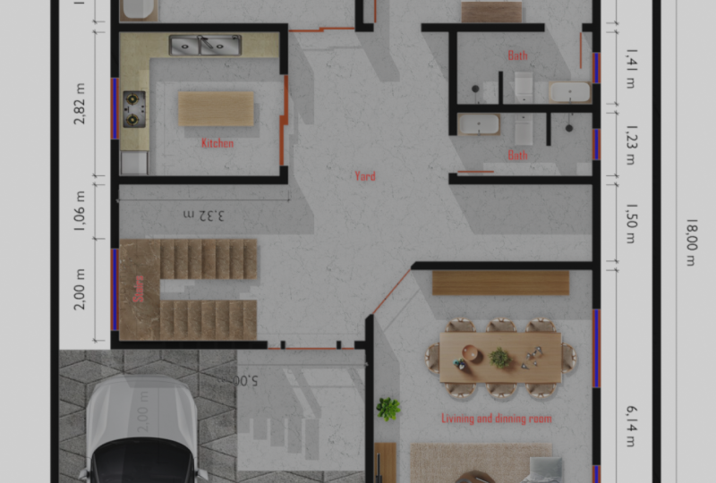
beautiful floorplans such as these
quickly and easily. If you are tired of creating the same boring
looking floor plans, or perhaps you to stop wasting too much money on
expensive software, web app, or AI credits, just to deliver nice looking
floor plans to your clients. Well, look no further. In this course, I will guide you through the
complete process from start to finish to design and create floor
plans using Blender. Assalam Molecu, my
name is Widhi Taken, founder of Expose Studio. For more than 20 years, I have been involved with
hundreds of projects, including architecture,
interior design, master plans, and so on. I have worked with many
clients all over the world. Besides doing projects, I
have also been teaching TD and computer graphics
academically since 2000. In short, I have both
professional expertise and teaching experience. So why do you want to use
Blender to create floor plans? There are at least six reasons. First, Blender is free
or more cost efficient. With Blender, you
can replace a lot of expensive tools
such as CAD software, image editing software,
three modeling software, rendering plugins, and so on. I know that some web apps can help you create floor plans, and they offer free
tiers or versions. But most likely you will end
up paying a lot of money as the free tiers are so limited in features or
furniture library. You may rely on
different AI tools to generate floor plans, but those also can cost
you a lot of money, as you need to purchase credits
to be able to use them. Second, Blender is precise. Unlike many to vector
graphics software that are not geared towards
architectural drawings. Blender can handle
measurement units precisely. The floor plans you created
in Lender will not only be useful for conceptual drawings or for pi in presentations. These floor plans can be used later in a treaty
design process as the basis to model the digital tween of the building or the
project in general. Third, rendering
a floor plan like this in vendor is insanely fast. You can render a
four K resolution in just a fraction of a second. The fourth reason is
that the workflow or the process of creating a
floor plan is also very fast. Why? Well, this is because vendor has a feature
called the Asset Browser. Essentially, it allows you
to create a library of assets such as poitre
blocks and materials. Once you have them set up, you can quickly drag and drop
the assets into your scene. So most of the time, when creating floor plans, what you need to create are
only the walls and floors. The fifth reason is that
you don't even need to create all your feature
blocks from scratch. You can download
them from the web in the WG DXF, or SVG formats. And the sixth reason,
you can easily generate this nice looking
line effect that has a handraing feel to
it. Don't worry. You do not need to draw
these lines manually. These lines are actually dispensil strokes with
a line art modifier. You can easily specify
their thickness, colors, linestyles and so
on to match your own style. So do it now and make
Blender your unfair advantage in the architecture
or interior design fields. Have fun learning salamuacum.
2. 00-02 Exercise files and conventions: Welcome to the course.
Before moving on, there are several
important things I need to mention
about the course. Although you can take
this course directly, if you are new to Blender, I strongly recommend you take an introductory
course first. This is because there are many fundamental things that I won't be discussing
in this course, as I assume you already
understand them. This includes navigation,
UI modification, object creation, transformation, and basic TD mesh modeling. If you're interested,
you can take my Blender for essentials course
series here on Skillshare. There are three courses
in this series. In the first course, you
learn the fundamentals of Blender before moving
on to remodeling in depth. In the second course, you
learn about material creation, texturing and UV Mapping. Finally, in the third course, you learn about lighting, cameras, rendering
and post processing using cycles rendering engine. Next, it's about
the exercise files. You can download all the
exercise files for the course in the resources section of this lesson in case
there is a problem, as a backup, you can also download the files from
the following link. Please pay attention
to the capitalization of the letters as this
link is case sensitive. You can download the
files one by one, but it will be easier
if you just click this download button to download them all
in one zip file. The text you see here depends on where you are or your
language preference. It says, download Samoa
because I am in Indonesia. You'll see the text,
download all if you are in US or UK or other English
speaking countries. As you can see, the
files are named based on lesson with additional
chapter code in front. Next, it's about the
structure of the course. I have carefully
crafted the curriculum so that everything is
spaced sequentially. Each lesson you take on
one level will become the foundation of lessons
in the next levels. Therefore, it is important
that you take the course in order step by step,
not jumping around. If you take the course
by jumping around, most likely, you will get
confused at some point. The second thing
I need to mention is that you need to practice. For each video, please try out the lesson yourself
at least once. The course is not
just about theories. Most of the lessons
are practical skills. So again, you need
to practice if you really want this online
course to benefit you. In this course, I'll be using a PC computer with a Windows
ten operating system. So every shortcut I mentioned in the video will be for
PC and Windows OS. If you are using a
Linux OS, most likely, you won't find any difference in terms of keyboard shortcuts. However, if you are a Mac user, you will find some differences. I believe most Mac users
already understand that the command key in Mac is often used to replace
the Control key in PC. In the option key in Mac is often used to replace
the key in PC. But the thing is about vendor. I found that most of the
control shortcuts in PC in Mac mostly become
this control key and not this command key, although there are some
shortcuts still use Dcmankey. Essentially, if you are
using a Mac computer, you may need to check the menu or the preferences window or the official vendor's
online documentation for the keyboard shortcuts. In this course, I'll be using Blender Version 4.4
and version 4.5. So all the Y features and shortcuts are related
to these two versions. If you are watching
this video and have Blender Version five
or six or higher, you might find some
differences here and there. In such a case, I recommend you check my course list as
I might have already released a new version
of this course that is better suited for the version of the Blender you are using. There are at least two
things that you need to have if you want to work
in bender comfortably. First, you need a standard
mouse with a scroll wheel. Usually, if a mouse
has a scroll wheel, you can press on
the scroll wheel to activate the
middle mouse button. We will use the scroll wheel and also the middle mouse button a lot for viewpoint navigation. You want to avoid using minimalistic most
products that do not have any scroll
wheel or middle buttons. The second thing that you
need is a full size keyboard. What I mean by full size is that the keyboard should
have a numpad area. This is important
because a lot of Werner's navigation
shortcuts are placed in the numpad area. Yes, there is an option in Blender preference window to
simulate the numbered keys, but that will be at the cost of overriding other
important shortcuts related to TD modeling. So again, you really
want to invest in a decent full size keyboard if you want to use
Blender for long term. Throughout the course, I may
display images and videos. Some of these contents
are not made by me. Please note that I am using them merely as references
or for inspiration. I never claim that these images
or videos are made by me. If I can find the owner's name, I will credit him or her by putting their names on
top of the content. Otherwise, I will
display image or video with the URL link
of where I found them. As for stock images or videos, if I don't specifically state
that they are made by me, most likely the copyrights belong to the respective
owners, okay?
3. 00-03 Macro overview: In this video, I will give you an overview of what we will create and explain the benefits of the workflow that
we will be using. You may already know
from the course cover the floor plan that we are going to create is very simple. It is basically a
typical hotel room. When I say typical, I mean it is typical typical like
it is everywhere. You can see this layout in many apartments and
even hospitals. But don't let its simplicity
discourage you because the workflow and the
techniques you learn in this course can easily
be applied to larger, more complex floor plan. I have used these
same techniques for all my architecture and
interior design projects, and the results have
been excellent. What makes the workflow
great is that you will have a scene that
renders lightning fast. Just to prove this, if I
press F 12 to render it, I'll get the result
instantaneously. 0.5 seconds to be exact with an image resolution
larger than three k. Essentially, you can just ignore the rendering
time completely. If you wonder why
this is possible, it is because we are not using cycles or EV to
render the image. Instead, we are using a lesser rendering engine
called the Workbench. Don't worry. This is not some third party renders
that you need to purchase. It has always been
part of vendor. When you use the TD
viewport inside mode, you are actually using the
Workbench rendering engine. One of the workbench features the di is its global shadow. With this, you don't need any sunlight object to create
a shadow effect like this. You can simply drag this sphere around to control direction. You can also control
intensity quite easily. As you can see, this workflow supports both colors
and textures. You can use image
files as textures, and with a bit of creativity, you can create black and
white textures to mimic hatch patterns that you
often see in a drawings. You may also notice
that in run result, we have lines that look like
they were drawn by hand. Don't worry. You do not
need to draw them manually. These lines are grease
pencil line art effect. They are generated automatically based on your scene
and preferences. You can have as many
variations as you like, each with its own
thickness and color. If you don't like them,
simply hide or remove them. The next benefit of
using this workflow is that you can produce four
pens with correct scales, meaning that if you
set the scale to 50 on an A four paper, for example, then rendering
result will do exactly that. It will have the size 150 of the original size when
printed on A four paper. On wondering result,
besides the global shadow, you can also see
subtle shadows on corners and between
furniture blocks. These shadows somehow
indicate depths. For example, the wardrobe looks like it is higher
than the minibar. The minibar looks higher
than the TV cabinet. The desk looks higher than the nightstand and
so on. Why is that? Well, that is
because they do have different heights as they
all exist in a tv space. You only need to set the
height of the objects, and the shadows will be
calculated automatically. You might be thinking, Wow,
that looks complicated. I don't want to
deal with three D when creating floor pans. Well, I have three
answers for that. First, most of the time, when creating floor pans
in Lander, that is, if you follow the workflow, you only need to work
from the top view. Even when you need to adjust the height of the
furniture blocks, you only need to type in the
Z coordinate value here. And most of the furniture
blocks, in this case, only have three height values, 50, 30, and 10 centimeters. So they are very
easy to remember. Second, you do not need to recreate everything from
scratch for each project. Mostly, you only need to
create the wall and the floor, which is very easy to do. Drafts such as the materials
in the furniture blocks are done simply by dragging and dropping them from
the Asset Browser. We will discuss how
to manage assets using the Asset Browser
in depth in its course. Third, you don't need to draw the furnished blocks yourself. You can just download
them for free, or you can produce them
from any marketplace. We will discuss in detail how to convert and import
CAD files such as DWG N UXF and also how to import common vector
graphic files in a CG format. Okay, guys, so let's
go into the lesson.
4. 01-01 Preparations: Before we start lessons, there are sew important things
that we need to prepare. First, we need to
install some madns. Second, we need those signs
of raw custom shortcuts. Third, we will set
the M German unit, and finally, we will cover
the snapping options. There are four addons
that we will be using to create four plans using
vendor. Don't worry. These are free addons and are available in the official
extension repository. I hope you already understand how to install addons in vendor. But in case you don't know yet, here is a quick guide
on how to do that. Let's say you want to install the dimensions
lines add on. Go to the edit menu and then
open the preferences window, then open the Get
extension tab in a search box by dimensions
or just DN for short. Then will filter Di only show addons that have the word
them in their names. This is the addon that we want. I have already installed it, which is why it does not have the installed
button active. If you haven't installed it, you'll see the installed
button up here. Just click on the button
to install the add on. Okay? So that is basically how you can install
official addons in vendor. Use the same tennis for the rest of the
addons in this list. Quick explanation of why
we need these addons. The extra mesh
objects addon will enable us to create a
single vertex object. This is essential to
our workflow which relies heavily on 0.2
point modeling techniques. The second add on is
the magic UV addon. This addon has a lot of
features related to UV Mapping. One specific feature
we will be using is the UVW box
projection mapping, which allows us to use real german units to
specify factual sizes. The third is the
dimensions lines add on. This is essential for setting up the camera and image
resolution to fit reword paper sizes and also for adding dimensions
to our floor plans. And finally, the one, two, three slack add on. This add on will activate custom shortcuts so that
when we press numbers one, two, and three on a keyboard, instead of isolating
the collections, it will directly activate
the vertex mode, H mode, and phase
mode respectively. Now that we have the
add ons installed, we need to create five
custom shortcuts. The first one is the
V shortcut to create a single vertex at
a cursor location. To set this up, you can
craft Shift A, then mesh. Notice that we have this option
now called single vertex. Please note that this is
only available if you have already installed the
extra mesh objects add on. Inside this sub menu, you can find the at
single vertex command. Now, this is very important and you need to
be very cautious about it. You need to right click
on a command just change Shopcat and then press the V
letter key on your keyboard. Remember that after you press
the change Showcat button, you do not want to press anything other
than letter V key. If, for example, you
white click instead, then every time you
perform White click, then will create a
new vertex instead. If that ever happens, you may need to go to
the preferences window and fix the key map manually. All right. The
next two shortcuts are five to show or
height the wire frames, and F six to show or height
the normal direction of lay. For these two shortcuts, you can open a
viewport Olay panel. In the geometry section, you will see to check boxes. This one is used to show
and height the wire frames. While this one is used to show and height the normal
direction Olay, it is useful to quickly
detect any flip faces. Essentially, you want to avoid red colored faces appearing in your rendering or
facing the camera. Set the Wireframe shortcut, simply right click
on this checkbox. Choose change shortcut, then
press F five part away. Next, you need to right
click on second checkbox. Choose change shortcut,
then press F six. Now you can press
F five to toggle the wireframe and press F six to toggle the normal
direction of lay. Okay? The next
custom shortcat is Shift Control L for selecting
linked flat phases. You'll find the command, you
need to be in edit mode. Then open the select menu. Then select Linked. What click on commanded says
linked flat faces. Jose change Showcat and then hold the Shift
and Control key, then press L. This showcat
will be useful when we later need to select multiple phases that are
at the same flat plane. For example, to select
these top faces, we can simply
select one of them, then press Shift Control L. Notice how all of these
top pieces get selected. Last custom shortcut
that we want to create is Shift E for extrude manifold. For this, make sure
you are in edit mode, select a phase,
and then press out E. This will open up the
extrude commands menu. What we want to target is this
extrude manifold command. So right click on
it, change shortcut and then hold the Shift key
and press the letter E key. All right? So what
is toot manifold, simply put this
extrude command is useful when you need to
extrude pass in border areas. For example, if you
select this space and perform the standard
extrude using the E shortcut, it creates these
additional edges or pass around the
explsion border. Let me undo this. Now, if
you press Shift E instead, which is our custom shortcut or the extot manifold and
bring this space down. Notice that we now get
a pre result, okay? For all of lessons
inside the course, I will be using the
metric system but set length value to centimeters. To set this up, you need to open the syn tab in a
properties editor. Make sure the unit
system is set to metric and set length
parameter to centimeters. Okay. As for snapping, I may switch the
snapping options to different modes
along the way. But usually I always
stop with the closest as the snap base and vertex
as the snap target. Lastly, you may find it I almost never turned on or use
the Snap icon up here. My preferred method of using the Snap feature is by
holding the Control key. This way, the Snap feature is only activated
whenever I need it. It does not always turn on, and I don't need to
go back and forth to the top area to
press the Snap icon. Give you an example
of how this works. Say, we want to move the T
cursor on this corner vertex. We can hold Shift, then
click and react the mouse. In this condition, also hold
the control key to turn on the snapping feature and then snap it to
our target vertex. Again, this is just my
personal preference. If you find it difficult or inconvenient to press
the control key, then you may use the
Snap icon instead. Use example of
depositioning the cursor. You can turn on the Snap
icon, then hold Shift, and wreck the right
mouse button to snap the Tcursor to another
vertex location.
5. 01-02 Point to point modeling basics: In this last and video, we will discuss the basics
of 0.2 point modeling. The term 0.2 point is
not an official name. It is just a name that I made up for a modeling
technique or approach that relies heavily on vertex placement
and manipulations. In my experience, this
modeling approach has proven to be very effective
in architectural modeling, including when we need to
create four plans in Blender. For now, we will focus on
working in a top view mode. So click on this
Zetter icon or simply press seven on a Numpad to
activate the top view mode. Before we do anything, let's first configure the
snapping options. For point to point modeling, most often, you only need
two modes for snapping. First, you can set the snap
base to closes and then set the snap target to
grade or vertex or age. You can also turn all of
them on at once if you want to by holding the Shift key
and clicking on the options. So this is the first snap
mode you want to use. Later, when you want
to place furniture, you may also want to use the active option
for the snap base, and then edge center
for the Snap target. For now, let's use
the first mode, which is using
closes for the base. And let's activate these
three options, grade vertex, and edge for the Snap target, you can have the Snap icon turn on like this all the time. Personally, I prefer to use
the Control key method. Basically, I leave this
snap icon turned off, and whenever I need
to use snapping, I simply hold down the
Control key. All right. Let's say we want to create a vertex at this point in grade. First, we can hold down the Shift key and then with
the right mouse button, then hold Control to activate
the snapping feature. Make sure the three
D cursor is at the correct location and then
release the most button. After that, press
V on a keyboard to create a single vertex at
the three dcursor location. By default, the command will activate the edit
mode right away, but it is not always
in a vertex mode. So just make sure you are in
vertex mode by clicking on the Vertex icon upar or by pressing the number
one key on a keyboard. Currently, the
vertex is selected, but it is not the
active element. Notice that it is orange. You can move the vertex around while in this condition
because it is selected. However, I prefer to make the vertex reactive element
so that the color is white. To make it the active element, you can simply click on it. Again, it is not a mass that you have the vertex
the active element. It's just that having it in white can make it
easier to spot, especially leader when
you move the vertex along a certain axis as it gets
blocked by the axis line. All right? The first technique we are going to discuss
is moving the vertex. You can move a vertex
using the move Gizmo. You can move it along
the X axis along the y axis or free using the zip in constraint or
using the white circle. Besides the Gizmo, you
can also use the G shortcut to move the
vertex by default. This will move the vertex
freely on the X and Y axis. If you want to
constrain the movement to only on the x axis
after pressing G, you can press X, and
with the same concept, you can move it along the
y axis by pressing Y. Okay. Now, most of the time when creating floor plans or architectural
modeling in general, you want to move objects
using precise measurements. If the target length
is whole number, you can easily make use
of the grid snapping. But if the number is
not a whole number, you can use less action
panel that shows up at the bottom left corner of
the CD viewport editor. Essentially, every time
we perform a command, the settings for that command
will appear on this panel, giving us easy access
to revise the values. For example, you want to move this vertex 35
centimeters to the right. You can move it
like this first in an open glass action panel and then revise the value to 35. If you want a faster workflow, you can use the move shortcut and then input the
value on the fly. Say, we want to
move this vertex in Y axis by 72 centimeters. We can press G then Y and
then type 72 then enter. Now, if you want to move
the vertex on Y axis, but this way or in reverse, you need to input
a negative value. Good thing about bender
is that we can press the minus K before or
after we input the number, so it does not have to
be before the number. For example, let's
say we want to move this vertex 55
centimeters this way. We can press G, X, and then type 55. Basically, we forgot to press the minus key before the
number. Don't worry. We can press the minus key now. Right now, the vertex goes
in the opposite direction. If you press the
minus key again, the direction will flip again. So in this case, the minus key acts as a togal
for the direction. If you're happy with result, you can press Enter, and if you still want
to revise less input, you can still do so using
less action panel, all right? The next important
technique in 0.2 point modeling is the
vertex troot command. To use this command, first, you need to have at least
one vertex selected, and then you can use the
keyboard shortcut, which is E. So yes, the keyboard
shortcuts for phase extrude, H extrude, and vertex extrude
are all the same in Lander. After you press E, you can then move the vertex to any location that you like. Essentially, at this phase, we can use all the
constraint methods for movement that
we've just discussed. For example, we can press X
to constrain the movement to the X axis or press Y to
constrain it to the Y axis. After that, we can
click to confirm. You can also type in the
distance on the fly for example, the press E, then X, and then I type 50 then enter, the new vertex will be placed 50 centimeters to the right
of the original vertex, and as always in Blender, you can still revise the
left action performed by Blender via the panel
at the bottom left corner. If I type here -60 instead, now the new vertex is located on left side of the original at a distance of 60 centimeters. Okay? Now, if for
whatever reason, you want to cancel, you can do so by pressing
right mouse button. But please be aware that this can result in double vertices. This happens because
when you right click, the vertex has
already been created. What you are canceling is
only the movement of it. Basically, if you cancel, you may need to press Control Z one to prevent
double vertices. Vertex extrusion is not
limited to just one vertex, meaning that you can perform it on multiple vertices at once. If you select vertices that
are not linked directly, performing a vertex extrude will not generate
additional phases. But if you select two or more vertices that are linked directly by
an age or edges, extruding them will
automatically generate phases. Depending on the situation, you may need or not need
these additional phases. If you do not need these phases, simply set all by pressing A, then press X to open the delete menu and then
choose only phases. This will remove
only the phases, but keep the edges
and vertices intact.
6. 01-03 Point to point modeling intermediate: In this video, we will continue our discussion on 0.2
point modeling techniques. One of the important
features used in 0.2 point modeling is
the Automrge option. You can turn on or off this
feature by clicking on this icon in the top right
corner of the TD viewport. Please note that this feature
only exists in edit mode. You won't see it if you
are in the object mode. Now, if you have
this icon turned on, you can click on
the option button to access the parameters. You need to make sure that both of these options are turned on. This way, when edges overlap, Blender will create vertices automatically in the location
where they intersect. We'll see how this
works in a moment. You also want to make sure these two options are turned on. We won't discuss these two
features in this video, but they will be useful later to maintain UV Mapping when
you edit the vertices. Again, for now, just make sure that these four
options are turned on. Okay? With the auto
merged feature active, when you perform
a vertex extrude that creates overlapping edges, Blender will automatically
create vertoss at the locations where
edges intersect. This feature can
save us a lot of time than having to create
the verticies manually. But please note that this automrge feature is
like a double edged sword. It means that it can easily ruin your TD model if you have it
turned on unintentionally. My advice for this feature is that you only turn it
on when you need it. Once you are done using it, make sure you turn it off again. For example, when
creating floor plans, you may want to have the
automrge feature turned on. But when you are making the building or just
remodeling in general, you may want to turn
the feature off, okay? Now, what if you
forgot to turn it on, but you actually need
to have it active. Say you through this vertex in x axis direction
overlapping another edge. You were hoping to get a
vertex at the intersection, or even you created
multiple edges like this, only to find out that
the automorge feature was turned off all this time. Fixing this issue
is very simple. First, you need to turn
on the automrge icon, and then you need to
perform a transformation. Why? Because any
transformation commands will trigger the
automog feature. Of course, we don't actually
need to change the geometry. The trick here is to perform transformations that do
not change the geometry. For example, you can move at
zero distance using G and zero or rotate using a zero degree by
pressing R and the zero. All scale using a value of
one by pressing and then one. Any of these will do. For now, I want to use the
scale of one technique. First, the elements
need to be selected. In my case, I just press A to select and then press
for the scaling command, then one then enter. Osblender Blender
automatically creates vertices at the intersection locations without changing the geometry. The next important
techniques are vertex or H duplication. To perform duplication, you can select one or many
vertices or edges, and then press Shift D, and then move the new elements to the location that you want. If you select two vertices that are linked
directly by an edge, then DH will also
get duplicated. You can use any
access constraint while moving the new
vertosis or edges. I know that this is quite basic, but if you use this method together with the
auto merge feature, you can create a vertex at an edge at the
precise distance or even create multiple
parallel lines that are attached to an
edge pretty quickly. To show you what I mean,
let's say we want to extrude this vertex in the X axis
direction by 1 meter. We can press E, then
X and then type 100. Now, we want to
create a new vertex exactly 20 centimeters
from the left vertex. We can select the left vertex. Make sure the auto merged
option is turned on. And then Shift D, then X, then 20, then enter. Because of the
autonomous option, the new vertex
will automatically intersect with the
existing ge, right? Now, if we extrude this
vertex down by pressing E Y, then -50, for example. Let's say we want to
turn this age into multiple parallel lines
for every tens meters. If we select these
two vertices and throw using the extrude
method or by pressing E, you get additional edges connecting the original
none vertices. In this case, we only
want the vertical edges. So instead of using extrude, we can use the duplicate method, press Shift D, then press X, then type ten, then Nan. To repeat the duplicate process, you can press Shift R as
many times as you need. Be auto merge is active, all these vertices automatically attach to the existing edge. The next two
techniques we want to discuss are the loop cut
and subdivide commands. Both are useful to create
vertices at the center of ages. The loop cut command is faster to perform when you
only want to add one or more vertices
to an edge or edges that are connected
via quad phases, but you may also need to
use the subdivide command when you want to add vertices on multiple disconnected edges. Let's see how to use the
loop cut command first. You can find the
command in each menu, but because this command is very important in through the
modeling inside vendor, you may want to
memorize the shortcut, which is Control R. Now, the loop cut command behaves
differently when used on quad faces versus when
used on a single edge. Let's see how it works
on quad faces first. After you press Control R, you can hover the mouse over an edge that is part
of a quad phase. Now this Blender provides a preview of the new edges
that will be generated. Well, in this condition, you can rotate the scroll wheel to add or reduce the number
of edges you want to add. And after you click to confirm, you still need to move the mouse who slide the edges
along the face. You can then click to confirm or wide click to cancel
the sliding process. If you do cancel the
sliding process, the new edge will be centered or equally spaced out. Okay? So there is how loop cat
command works on quad phases. Now if you press
Control R again, but now you hover on a single edge that does not
belong to a quad phase, you can see the preview of the vertosis that will be added. You can scroll up and down to define the
number of vertices. But after you click to confirm, unlike before, you do not
need to slide the vertosis. So again, recap Control R will perform loop cut and slide
if done on quad phases, but it will only perform
loop cut without any sliding when done
on independent edges. Next is the subdivide command. This command can add vertices, e loop cut command, but unlike Loop Cut command, you need to have at least
an edge selected or two vertices that are
linked by an edge selected. This command will do nothing if you don't have
any edge selected. For example, we can select
this vertex and this vertex, and then we use the command, you can right click and
then choose subdivide. You can then define
how many vertices you want to add using
less action panel. For a single edge like this, the loop cut command
is quicker to perform because you don't need
to select anything first. One scenario where you
want to use subdivide is when you want to add
vertices or multiple edges. For example, on edge, then this edge, and in
this edge and so on. After you have
them all selected, you can Rotlick and
then choose subdivide. You can go back to vertex mode to clearly see the vertices. As you can see, the subdivide
command just created new vertices at the center of each edge we selected before. A
7. 01-04 Point to point modeling advanced: We will continue discussing the point to point
modeling techniques. We will discuss vertex bevel, the spin command, offset edges, and finally avoiding phases. First is the vertex
bevel command. You can access this command from the Vertex menu,
then vel vertices. As you can see, the shortcut for this command is Shift Control B. Please note that this command is different from the
He Bevel command, which uses Control
B as the shortcut. Again, we are not
currently discussing gBvl but vertex bevel, because you will use
this command a lot, especially when working
with floor plans. I recommend that you memorize the shortcut instead of
relying on the menu. Just like the bevel
command for ages, this command will also turn a sharp corner into round shape. To use it first,
you need to select the vertex or vertoss
you want to target, then press Shaft Control B. As you move the mouse cursor
closer or further away, you can see that by default, then that only
creates two vertices. While in this condition,
you can rotate the scroll wheel to increase or decrease the number of vertices. The more vertosis you have, the smoother the curve will be. After that, you can
click to Confirm. Just like with any other
commands in Blender, you can revise it
using action panel. As you can see, the parameters
are the same with H vel. The only difference
is that the mode up here is set to
vertices not edges. The two most
important parameters are the width and segments. The width controls how far
the bevel goes measured from the original vertex to
one of the ends of the curve. So again, it is not measured from here
to here diagonally, but from this point to this point or from this
point to this point, the segments value controls the number of vertices
that form the curve. This is the one we define when we rotate the scroll wheel. You might be tempted to use a very large number for
the segments value. Yes, that will make
the curve smoother. But remember that having too many vertices will make it harder later when
we need to edit. My point is, you should use a number that is
optimal for your needs, not less and not more. If the model is far
away from the camera, you don't really need
a lot of vertices. Personally, I usually use
value 6-12 for planes. Okay? Another
interesting command that can create a round
or circular shape is the spin command. Please note that
this command uses the T D cursor as the
center of its rotation. So you want to make sure
that the TD cursor is located in the correct position before performing
the spin command. For example, I want
to spin this vertex, so I select it first, and then I hold shave and wide click here to move
the TD cursor. Next, to access
the spin command, you can open the mesh menu. The next root then spin. You can also use the shortcut
of E and then use spin. But my favorite way of accessing spin is
through the spin tool, which is this icon ad
tool panel on the left. I prefer the tool because the process is more
interactive to spin. You need to drag one
of these plus nodes. After rotating the plus node, if you only want to
revise the spin angle, you don't want to drag
the plus nodes again, as that will trigger
another spin. What you want to do instead is drag the moss inside
this circular area. Or if you want to use
a precise values, you can use the last
action panel for that. You can define how
many vertices are generated using these
steps parameter, and you can define
the angle value here. For example, I want
the angle to be precisely 90 degrees
after you are done, don't forget to turn off the spin tool by switching
to another tool. For example, the
move tool, right? The next command we want to
discuss is the offset edges. Essentially, offset will add new edges besides restructed
edges in a certain distance. Please note that this is not one of default
commands in ender, but it is a command from
the edit mesh to add on. Before we discuss how it works, I need to mention
that the command only cares about the
main unit system that you set in the SN panel and does not care
about length setting. It means that in my case, it will use a meter as the
unit, not a centimeter. I hope this gets
fixed in the future. Currently, it is just
something we need to leave with to
use the command. First, we need to select
an edge or multiple edges that we want to offset and
then Right click mesh tools, and then offset edges. We can then use
less action panel to define the offset distance. Again, this value is in meters. So if you want to offset
by 5 centimeters, for example, you
need to input 0.05. If you want the offset to
go in another direction, you can add a minus symbol
in front of the number, but this method is to throw. The faster way to do this is simply by clicking
on this flip icon. This angle value, we rotate
the offset result into this space using
the original edges as the center of rotation. So yes, you can also flip the direction by putting
180 in the angle field. But again, clicking on this flip icon is
much more convenient. For creating today four planes, just leave this angle
value at zero, right? The last thing that
I want to discuss in this video is
not a technique, but rather a tip on how to
approach 0.2 point modeling. Essentially, when using the
0.2 point modeling approach, you want to avoid using phases. We will add and work
with phases eventually. But having phases in the
early stage may slow down the workflow as it
adds unnecessary steps. You will understand this better when we do some exercises. For now, I just want
to point out how phases get generated
automatically and how to deal with them. If you extrude a single vertex or vertices that are
not connected directly, Blender will not
create any phases. But if you select
vertices that are connected or ones
that form edges, extruding them will
generate new phases. There are two ways to
deal with these phases. First, you just ignore them. For this, you may want to use the wireframe mode
because in this mode, the phases do not look
solid and so will not block any potential
vertices or edges behind them. Second, when there are
already too many phases, you can remove them by first pressing the a key to
slack all elements, then press X to open
the delete menu, and then choose only phases. Do not use phases as
this option will delete all vertices and edges that
are attached to the phases. The only pass option
is what we need, as it only removes the phases while keeping the edges
and vertices intact.
8. 02-01 Creating walls method 1: In this video, we will discuss the first approach
of creating walls. Please note that I'll
be using metric for the unit system and use a
centimeter for the length unit. So essentially,
everything type regarding the length or distance values
will be in centimeters. As for the snapping mode, I'll be using the closest and
vertex options. All right? First, let's delete
the default cube seven to activate the top view. We want to start with something simple for the first exercise. So we will create a floor
plan for a hotel room. The size should fit
inside a rectangle 5 meters wide by 9 meters long. Make sure the t d cursor is
at the center of the world. If not, you can press
Shift C to center it, and then press V, which is our custom
shortcut to create a single vertex at a
tree cursor location. Make sure that you
are in vertex mode, not the edge mode, and
not the face mode. Activate the move tool and
click to select the vertex, so you can clearly see later. Press E for extrude, then X, and then
500 and then Enter. Then press A to
select all vertices, press E for extrude,
Y, then 900. Basically, we now have
the total area of the room which is 5
meters by 9 meters. Next, we want to avoid
looking at this large phase. For this, we can activate
the wireframe mode either by clicking on the icon or by
pressing the shortcut Shift Z. Another way to avoid the
phase is by removing it. We have discussed this before. Essentially, we can
press A to select, then press X, and then
choose only phases. Okay. Next, we want to add
thickness to the wall. We can start by selecting these two vertices
at this stage. You want to make sure that the automrge option is turned on. Press E for truth
then X and then type 15 15 centimeters is the most common wall thickness
in my country Indonesia. For the other sides, the process is
basically the same. First, we need to select
the verticies then press E, Y -15 then enter, and then select these
verticsis on right side, press E X -15 then enter. Last but not least, select
the vertosis at the bottom, press E Y, 15, then enter, all right. Outdoor walls are done. Let's move on to adding
the entrance door. The door should be
around this position. This is because on left side, there will be a wardrobe, and on the right side, this is where the bathroom will be. Yes, this kind of room
layout is very common. You can see it in many hotels, apartments, and even hospitals. First, select these
two vertices, shift D, then X, then 60. For the entrance, we will use a standard 90
centimeters wide door. So press Shift D X
90 and then enter. From this point,
we want to create a letter L shaped wall that
encloses the bathroom. We will use the same
wall thickness, which is 15 centimeters. Press shift D X 15, then enter. X, you select these
two vertices, then press Shiv D Y, then 270. Oops, sorry, guys, my bed, we should use extrude instead. So press E Y, 270, then enter. Then we can select this vertex, press E to extrude then X. Besides inputting
a certain value, we can also use the mouse to
define the extrusion length. Hold control to snap to one of the vertices
at the far right. Then you can select this
verticies press E, Y -15 enter. Next, we want to create a
balcony from the top wall, as far as one 50 centimeters. We will not use a solid
wall before the balcony, but rather large glass
windows and doors. But still, we need to
create the wall lines, at least for guidance on where to put the
windows and doors. So select these vertices, then shift D Y minus
150 then enter. For the wall thickness,
we can press E, then Y -15 then enter. Next, we want to add a
door for the bathroom. The door should not be touching the bottom wall because later, we will use this area
for bathroom stuff. I am thinking of
adding wash basin counter around here
and a toilet here. And then this area
will be the shore, and this area will
be for the bathtub. For now, let's assume that the depth of the counter
is 50 centimeters, but we want to add a safety
gap of 20 centimeters. So select these two
ertosis Shift D, Y, 70, then enter. As for the door width because
this is a bathroom door. Let's make it 80
centimeters wide. Shift D again, Y,
80, then enter. Last thing that we want to create is the opening
to the balcony. For the door, we want
to sliding doors, one that goes to the left, and one that goes to the right. Each of the doors will
be 90 centimeters wide. For the opening, we
cannot have them exactly 90 centimeters
times two. We need at least
10 centimeters of the doors remaining on the
left and right of the opening. Essentially, we need to make the opening 80 centimeters plus 80 centimeters equal to one
60 centimeters in total. First, we can duplicate these
two vertices to the right. It does not matter
where they are for now, and then shift D X and then
type 160 and then enter. This way, the distance
between its vertex and its vertex is
one 60 centimeters. There are several ways to make this opening exactly
at the center. One easy method is to divide
the movement distance. For this, first, we
need to turn off the auto merge feature so that the vertoss will not
automatically merge together. Then direct this to the left, while holding control
until it snaps to the left vertosis and then
move them to the right, while holding control
so it snaps to the right vertosisOpen
last action panel, then divide the move
value by two and enter. The opening is now
precisely at the center. And that's it, we
are done creating the bases for walls
and the doors. Although we covered
a lot of phoenix, there are actually other methods that we haven't used yet. These methods may be more suitable and useful in
different scenarios. We will cover them
in next video.
9. 02-02 Creating walls method 2: In this video, we will create the same hotel room layout
as in the previous video. As always, I like to use metric and centimeters
for the length unit. And I also use closes and vertex for
the stamping options. The reason we have this video is that the previous
approach is more suitable for
exterior walls where the lengths are measured
from the outer borders. For most interior walls, people usually measure the
walls from their centers. To easily achieve this, it would be better if through pass or for vertices at once. Although the approach
is different later, you can freely mix and match all the techniques
depending on your needs. In this approach, we will
need to start with the phase. So let's create a plane object, press Shift A, then
type plane, then enter. We want to make this plane
as large as dual thickness. So let's change both the X and Y dimensions
to 15 centimeters. As always, because the scale is now not in its
default values, we need to press
Control A, then scale. Having all scale values
at one is very important. Otherwise, odd length numbers that we input leader
will not be correct. Next, go to edit mode and then activate
the wireframe mode. For now, you can be in phase
mode or in vertex mode. Make sure the vertices
are selected. And then press E X 500 enter. Now, you might be thinking, are we supposed to avoid phases? As they can make the
workflow harder? Yes, at this stage, phases do make our flow harder. Just to prove this, if you
activate the phase mode, there are actually four
phases here. Why is that? Well, to give you a
better understanding, if I drag this phase up, we can see what is
actually going on here. Basically, each of these
edges gets extruded, creating four new phases that
overlap with each other. Again, you can
ignore them for now, or you can also remove them. What is important
is that you need to have the
atomrgeoption turned on. To clean up the mess, we can trigger the auto merge
by pressing a for scale, then one, then enter. Currently we have removed
two of the phases, and we still have the
remaining two phases. Let's just ignore them for now. Next, we can select the
two phases at the end. Then press E Y, 750. This will be the wall
before the balcony. Press E again, Y 150. This is for the top border wall. Now, to connect
these two phases, I'm going to cover
several techniques. If you are in the phase mode, you can press E to extrude X and snap to the far right
vertex using the Control key. You can do exactly the same
if you are in a vertex mode. That is, if you select the four vertices that
make up the pace. If you happen to
be in edge mode, you can also select this edge, and then you can
extrude it until it snaps to the
right border edge. One technique that
I want to show you is to connect to edges
using the field command. For this, you need to select
this edge on the left, and then this edge on the right, and then press F on a keyboard
to generate a new phase. As you can see, there are many different ways
to connect the walls. Before we continue, let
me recap why we want to extrude theses instead
of edges or vertices. Although it is a bit messy, we can use phase extrusion
to quickly create interior walls or walls that use the centers as the
basis for measurement. Not border to border as
with the previous video. Next, let's create
the entrance door. Strike this edge,
Shift D, X then 60. Shift D again, X 90, you can continue
duplicating the ge, but I want to use yet
another approach, which is basically
duplicating phases. Now, if you go to phase mode, you don't see any phase here. In this condition,
you can simply use vertex mode and select
these four vertices, Shift D to duplicate, X, then move and snap them here. Again, this is possible
because we have the automot feature active next, we can press E Y to seven, then E X, snap it here. If somehow you forgot to hold
the Control key to perform a snap and you move the
verticies beyond a border edge, don't worry, as Bender already created new ertosis
at the intersection, you can safely delete
the excess Vertoss. You may see some
phases disappear, but this will not be a problem. Okay, to create the
bathroom door opening, you can use the same age
duplication technique. We can select this
vertices press E, Y, then 70, then press
E again, Y 80. For the opening on the balcony, I'm going to show you
yet another approach, but this is only possible
if the wall has a phase. Essentially, we will be
using the loop cut method, so press Control R,
and then click here. While click to cancel
the sliding process. This method will create a new
age exactly at the center. To make the edge spread and create one 60
centimeters opening, you can make use of
the H v command. Remember, not the vertex val, but the h vel. So you do not press
Shift Control B, but instead, Control B. Make it about this wide. To make the opening precisely
at one 60 centimeters, you can revise the value to 80 Remember that in age bevel, width value that you input does not measure from
border to border, but instead from the center
to each of the borders. So the total width is
now one 60 centimeters. Just to recap, if you need to quickly create interior walls or walls that are measured using their centers instead
of their borders, you can make use of
phase extrusions. You can still be in vertex
mood to use this approach. For example, you can
press E Y Glick here. Reps E, X, Glc here, and so on. If you have stro the
vertices beyond the border, you can easily fix this by simply deleting the
remaining vertices. As you can see, you can quickly create thick interior
walls with this method. Of course, we're not
going to use this layout, but I am sure you get the idea.
10. 02-03 Windows and Doors: In this video, we will cover how to draw
windows and doors. Now, before we continue, you need to know that in
real project scenarios, most of the time, you only need to create the
walls and the floors. Other objects such as
windows, doors, furniture, foliage, vehicles, et cetera, are mostly available
from the library. The objects in your
library can be from your previous projects or
downloaded from the Internet. We'll discuss how to
create a library inside vendor later using a feature
called the Asset Browser. For now, you still
need to discuss the basic techniques
because you need to create the library
objects at least once. And even if you download the
drawings from the Internet, you may still need to modify
them now and then, right? The windows and doors should be a separate objects independent
of the wall object. But in terms of the
creation process, besides creating it
from a new object, you can make use of the existing pass or
vertices in the wall object. I'm going to show
you both approaches. For example, we want to
create a window here. You can select the
phase in your object, or if the phase
does not exist yet, you may also select
the vertices or edges, press Shift D to duplicate
and raise it somewhere else. Remember, we need to make the
window a separate object, so press P and then
choose selection. This way, if you press step to go back to
the object mode, now we have two
separate objects. The wall object
and window object. Okay. Next, let's activate the edit mode and make sure the auto merged
option is turned on. Select the left edge. Let's see that we want to make the left and right
frames 4 centimeters, press Shift D X, and then four enter. Do the same with the right side. Shift D X minus four. To create a new
line at the center, we can select the two edges, and then Right click and
perform the subdivide command. To have thickness on the glass, you can increase the
number of cuts value. But if you need a
precise thickness value, you can perform an edge Bevo instead by
pressing Control B. You can input 1 centimeter, which makes the total glass
thickness to centimeters. Yes, 2 centimeters is too
thick for rear window glass, but we are only making a
conceptual floor plan, not a detailed
technical drawing. At this stage, it is more important for the glass
line to be visible. Okay, press step to go
back to the object mode. Now, we want to center
the origin point. We can do this by going
to the object menu, then set origin and choose
origin to geometry. Finally, we can move the window object and snap
it to the corner point. So this is the first approach. You may be tempted to duplicate the window object to
the other opening. But it will be more
time efficient if we do that leader after the
material assignment is done. We will discuss that
in the next lesson. For now, let's discuss
the second approach, which is basically creating
new object from the start. Let's say that we want to
create a sliding door with centimeter sick and
90 centimeters wide. First, we can hold
Shift, white, click, Andre and hold Control
and snap to this point. Press V to create a new vertex. Make sure we are
now in vertex mode. And let's click on
vertex to select it. Press E Y minus three, Enter, then A to select all, E X 90, Enter. Then while we still have
both Vertocs selected, we can press Shift D, then X minus four, Enter. X, select these vertices. On second thought, let's make the frame thickness
6 centimeters. So Shift D X six. Let's revise these two vertices, press G to move X minus two. For the middle glass, you can use the subdivide
command as before, but I want to show you
a different approach, which is basically
using H duplication, Shift D Y minus one. Then select this Shift
D Y one, all right? Again, we can duplicate this object leader after
we have the materials. Let's move on to drawing the door objects. Just
like the windows. I'll be showing you
two approaches also. First, we'll make use
of the existing wall. And second, we will
create a new object, select the wall object,
and go to phase mode. Currently, we already have a
phase in the entrance area. So select it, then press Shiv D and place
it somewhere else, press P, and then
choose selection. Go to object mode and select the new door object
and activate DH mode. Select this, if D X four, Enter. Select the other he Sif D, X minus four, enter. Next, select this vertex. Let's say that the door leaf
thickness is 3 centimeters. We can press E X minus three, select the two vertices, then E Y, and move
to about here. Now, we know that the
opening is 90 centimeters. We need to reduce it by
four and 4 centimeters. In such a case, we can let Bender do the
calculation for us. Just type here 90 minus four
minus four, then enter. The length of the door
leaf is not correct. To create the door
swing notation, we can use the spin command. Remember that the
spin command uses the tri cursor location
as its center. So hold shift and right click and control to
snap to this vertex. The tricursor is now on the
right side of the leaf. But what we want to spin now
is not the right vertex, but rather the left vertex, this is so that
leader, you don't need to do any
unnecessary cleaning up, activate the spin tool
and rotate the plus icon. You can input 90
degrees for the angle, and then I think ten steps
are enough for our purpose. Notice that 90 degrees
makes the edges overlap. This one' be good,
so let's reduce the angle value to
almost 90 degrees. So it is almost touching
the other vertex. After that, we can move
the vertex using the G shortcut and snap it to the
vertex at the door frame. Next, we can select
these two edges, press X, and then choose
edges. The drawing is done. Now we can go back
to object mode. Notice that your original
location is currently too far. Before we use the origin
to geometric command. Now, we want to move the
origin to a specific vertex. For this, you can use
the control period shortcut to activate
Defects only origin mode. In this mode, we can move the origin point independently
of the geometry. So just move it
and snap it here. Don't forget to
turn off the mode again by pressing
Control period. Now we can move and snap this door drawing to
its opening. Okay? The last drawing object we want to create is the bathroom door. We will be using the
second approach now, so hold Shift and roll click drag and snap using
control to this vertex. Press V to create a new vertex. Make sure we are
in a vertex mode. Press E X and snap it using
the mouse to this vertex. Press A to select, then E, Y, and move the mouse
to snap to this vertex. Next, shift D Y, four. Select the two vertices up here, then shift D Y minus four. To create the leaf,
we can extrude this vertex on YX
is 3 centimeters. Select these two vertices, then E X and move
it to about here. As revised length value, we know that the door
is 80 centimeters wide, type here 80 minus
four minus four. And then we can delete
these two ages. Next, we want to move
the three de cursor, so hold Shift and while click
and snap to this vertex. Select this vertex, activate the spin command and then rotate the blue icon to
almost 90 degrees. Finally, we can move
and snap this vertex to the vertex at the famous
corner, and it is done. We don't need to fix the origin if we use the second approach.
11. 02-04 Adding depth and color: In this lesson video, we will add faces to
the floor plan model, adapt using extrusion, and finally add color
using materials. First, I cite everything
except the plane model. Now, if you activate
the solid view mode, it looks like the
pass are all fine. But if I turn on the
normal direction overlay, we can see how the pass are flopping between facing
down and facing up. We also don't have any
faces on the floor areas. The easiest way to
fix the normals while creating the floor faces
is by going to edit mode. Selecting all of the elements, press X, and then
choose only phases. This will remove all the pass, leaving only the
edges and vertices. Next, we can press A to select, and then press F to
perform the field command. Then that automatically
fills out all the areas enclosed by edges. And also, as you can see, the normal directions
are all now uniform. Please note that when you press F to perform
the fill command, sometimes Blender creates a face that covers the whole object. If that ever happens to you, simply delete the face. Currently, Blender doesn't
do that to my model, so I don't have to do
anything to fix it. Again, if you spot the large
face that covers everything, just select the face
and then delete it. Next, we need to
separate the faces that belong to the floor from the faces that will
form the walls. Remember to also
select the faces on the door as there will be
no walls in these areas. As for the windows, if the windows are not
full height windows, you need to treat the
pass as two of faces. In this case, because these windows are
full height windows, you also need to select them
together with the floors. After that, we can press P to separate the pass and
then choose selection. To make our scene
more organized, let's rename the floor
object to floor. And that's also in the
wall object to wall. All right. Now, we are going to add depth or
thickness to the wall. So make sure the wall
object is selected. Go to edit mode and
select all the faces, press E to extrude, and then type 50 for the walls below the windows
or walls on the balcony, for example, they will have lower shadows than
the four walls. Therefore, we can select them so that only the four
wall faces are selected. Press E again to extrude, and then type 50 then enter, the wall model is
basically done. For now, let's work on the
doors and windows model. Select all the objects. We want to move these objects so they are higher
than the walls. Press G to move the Z then 110. Now they are slightly
above the walls. Before we continue, notice that the doors and windows
generate shadows in viewport. Depending on your
artistic preference, you may want or don't
want the shadows. If you only want shadows from the wall object and not
from the doors and windows, first, you need to select them, open the object tab, then open the viewport
display category. The option you want to deactivate
is this shadow option. But if you just
click on the option, only the active
object gets affected. If you want to control
all selected objects, you need to hold
the Okey and only then do you click on the
option to deactivate it? Notice how the doors
and windows now do not cast shadows in the viewpod
before we continue, let's first rename
these objects. We can name this one dot 90. As for the bathroom door, we can name this one
door dot 80, and so on. Feel free to give them
names as you see fit. I'll just speed up the
video to save time. Okay? Next, we'll add colors to the model
using materials. Let's select the
wall object first, and then open the
material panel, create a new material, and let's name this black. Now, you need to know
that we won't be using the cycles rendering engine
to render the floor plan. Instead, we will use the
Workbench rendering engine. What is unique about this engine is that it does not
care about any of the PBR material settings or the nodes that you have
in the shader editor. The only thing that
matters is the viewport display
settings down here. Okay? Just to prove this, if we change the renderer
to the Workbench engine, and go back to the
material panel. Notice how all the PBR
parameters are not resb. To control the look
of the material, you can access the
viewport display category. Here, we can change the color. Let's make it almost
black. All right. For the walls on the balcony, we want to make
them look brighter. The idea is that we want to show that they are not
a full height wall. Select all the faces using the
linked flat faces command. I use a custom shortcut
for this command, create a new material slot, assign it to the faces, and create a new material. Rename this to gray, and we can change
the color to gray. This way, people will notice that the walls
are half walls. We can press seven to try looking at it
from the top view. Next, let's tackle
the floor material. For now, we can name
this material floor. We may change this to
different floor types later. Let's change the
color to yellow. Next, other doors and windows. Let's check the
normal direction. As you can see, some of
the normals are flipped, but the first door is fine, so we can give it the
material right away. Name this material red let's pick over color
slightly orange. Okay. For the bathroom door, we know that the faces are flip, select all faces by pressing A, then press out N and
then choose flip, go back to object mode and apply the same material
as the previous door, which is the right material. Next is the window object. As you can see, the
faces are flip. So go to phase mode, and all faces, press out N, then flip as the
starting material, we can also use the red material and then select these two faces, create a new material slot and then assign it to the faces, create a new material,
name this white. The color is already white or
enough white to be precise. I don't think we need
to change the color. Next, set the center face. We want a color to
simulate glass, so create a new slot,
assign it to the face, then create a new material, name this one blue and
change the color to blue. Okay. Now that we
have the materials, let's duplicate this
to the right side. Make sure you have the closest and vertex snap
options turned on. Next, we want to duplicate
using the instance method. This is because the window on the left and the window on
the right are identical. So press out D X, and snap it to the right vertex by pressing the control key. The last object is
the sliding door. We can select all
of the faces and then class shift and to make the normal
directions uniform, let's check the normal
direction again. All is good. Next, we can start by assigning
the red material. Just as with the window object, we can select these two
faces and then assign a new slot and use
the white material. Last but not least,
select the center face, create assign a new slot, and for this, we can
use the blue material. Okay, to create
the sliding door, we can use the
modifier code mirror. Please note that the mirror uses the origin location as
the center of reflection. Essentially, for this to work, we need to move the
origin location to the center of the opening. So press Control period to turn on the
origin editing mode. Then change the snap option
to target edge center. Move and snap the origin point, so it snaps to the center
of the edge at the opening. After that, make
sure that you press control period to turn off
the origin editing mode. Add a new modifier called
mirror, and that's it. I think we are done
with this video. We'll add textures to the floor
object in the next video.
12. 02-05 Workbench render settings: In this video, we will
discuss rendering settings that work best for to
conceptual floor plans. The first thing that you
want to do is to change the rendering engine from
cycles to Workbench. We've done this in
the previous video. So just make sure you have Workbench engine
currently active. Please note that Workbench
engine is actually the rendering engine that
processes solid viewport mode. That is why you'll find that
most of the settings using this options panel
are similar to the settings that you can
find in render panel. For now, let's activate rendering mode so you can see the changes right
away in a viewport. The three categories, you can
leave them to the default. As for the lighting category, what you want to use
is the flat option. Then in the object
color category, you want to choose texture. This way, the textures
will show up in rendering. Next, we want to have a bit of directional shadows
in our rendering. For this, we should
activate the shadow option. Usually, I don't want the
shadow effect to be too strong. So I set this
setting to only 0.3. If you don't like the
shadow direction, you can control it by
clicking on this Garcon and then wag around the sphere until you like how
the shadow behaves. Personally, I prefer
the light to be at the top left corner
so that the shadows are cast to the bottom
corner. All right. Next, you want to turn
on the cavity option to get an AO or abnocusion
effect in rendering. Essentially,
Abnclusion effects are soft shadows that appear on corners or graftss which can add more depth to the overlook
of our floor plan rendering. But unlike pure AO, the KVDuption also adds bright highlights on sharp corners or
protruding surfaces. This is what the
rich option does. So again, the rich option
creates highlights, while the option creates shadows
just like the AO effect. Personally, I do not like the highlight effects
in my wanderings, so I usually set the
rich value to zero. As for the value value, I usually go with one so that
the shadows appear subtle. Next is color management because we don't use any lighting or light
objects in our rendering, and we also want
the white color to be white as it is in rendering. We should not use any
view transform effect. So first, make sure
the SRGB option is active and then set the view transform
option to standard. Okay, last but not least, we want the background
to be white to simulate paper color for this. We need to go to the a tab and then set the color
here to pure white. To hexoismo code of FFFF, and there is basically
rendering settings for creating two conceptual
for pens in Blender. Because we are now using
the Workbench engine, rendering time is very fast, usually in just a split second.
13. 02-06 UV Mapping and texture: In this video, we will add
textures to the floor faces. Now, if you are in solid mode and you want to see
textures in the viewport, you can do that by opening the option panel
and then activate the texture eruption here or you can just open
Vander view mode. You will see the textures
leader because we've already turned on the texture
eruption before, okay? Make sure the floor object is selected and then open
the material panel. Currently, the floor has only
one material called floor. That's first create texture
for the bathroom floor. So we name this material
to floor bathroom. Now, if you check the
Viper display category, there is no way you can
add a texture here. To add a texture, you need to
open the shader editor and then create an
image texture that connects to the base
color input slot. To recap, the Workbench render does not care about the nodes you have except the texture that blogs into the
base color node. If you have the wrangler
add on installed, you can simply select the principle SDF node
and then draft Control T. This will automatically create an image texture node with all the supporting nodes. Next, we can click the open button and then choose the image file
you want to use. I already provided these images in the downloadable
exercise files, if you want to follow
along, by the way, as a disclaimer, I did not
create these textures myself. I downloaded them from
shar textures.com. This one is supposed to
be for the bathroom four. This one is for the
main room area. This one is for
the balcony area. As for this unique
looking texture, this is for leader when we
create the hatch effect. For now, just double click
or the marble tile texture. If the texture does not
show up right away, this is because we haven't defined the UV Mapping
for the phases. So go to phase mode and then
just press A to select. Now you can use one of the default UV Mapping
commands provided by Blender, but I prefer to use
the magic UV add on, as it can create UV maps
based on real world scale. I won't go into too much
detail on this add on. If you are interested in
learning UV Mapping in depth, I recommend that you take
my basic Blender courses. For now, just open the edit
tab in white side panel, UV Mapping and then UVW, and then press this box button. This will perform
a box projection to the selected phases, so now we can see the texture. By default, the command uses 1 meter for the texture size. I think we need to make
this a bit bigger. 1.5 meters should be enough. So this is the result so far. Currently, the floor tiling
direction is this way. We want it to go this way
or horizontally to do this, we cannot use the mapping node. Again, the work bench
does not care about the shaded nodes except
the image texture node. Just to prove this, you can try rotating the zero
rotation value here. The texture does
not do anything. Even if you type the value
directly such as 90, the texture just stay
still due to this fact. You can safely delete these two nodes as they
have no effect whatsoever. So how can we turn
around the texture then? Well, you need to
rotate the UV Mapping. One way to do this is
by selecting the pace, you want to rotate and then go to the UV Mapping workspace, select the elements
by pressing A, then press R for
the rotate command, then type 90, then enter. So again, this is
one way to do it. You can also scale or move the UV map inside the UV
editor if you want to faster and my preferred
method to do this is by using the magic
Va. Basically, after you apply
the books mapping, you can revise the erotation
value to 90 degrees, and there you have it
horizontally aligned marble tile. Let's add the texture
for the main area. We can select this face and also the faces at
the door areas. Don't forget to face
before the balcony. Next, material panel,
create a material slot, assign it to the faces, and then create a new material, name this one for the parquet. Okay, we can create
the image texture manually by clicking and dragging from the
base color slot. Then type image then enter, click to place the node, and then click the open button. You can use the architecture
that I provided, and here is the result. I think the sides and
orientation are already correct, so we don't need to
change anything. The last floor texture
is on the balcony. Select the face, create
a material slot, assign it to the face, and then create a new material. Let's name it floor dot ceramic or any names that you prefer. Next, you need to create
an image texture node. Click the Open button, and let's use this texture
by clicking on it. I think the scale and
orientation are already correct. So there you go. All the
floor textures are done. Up to this point, you
may be wondering, what if we want to add hatches, such as line or stone patterns, et cetera, like how we
do it in at software? Well, the concept is basically the same as adding texture. You just need to create or provide the texture
for the hatches. Personally, I don't
like using hatches in my conceptual pro plans because it makes them
look like at drawings. But everyone has
different needs. You may want or need to add
hedges to your projects. To show you how it is done, I'm going to change
the balcony wall from a plain gray color to
a diagonal line hatch. First, select the wall object. What we want to change
now is the gray material. I actually do not want to delete this material because I will use this
material gain leader. I need to click on a shield icon to add a fake user to it. Now we can safely
delete the material. Use that if you open
the material list, we can see that now
the gray material has the letter F in front of it. F means fake user. With this setup,
then will not erase the material if you later
close and reopen the file. Let's create a new material, name this material,
H line white. For safety reasons, I want to add a faith user to
this material also. This is a leader,
the material will still be available when
you download the file. Just as before, we can create a new image texture node
and then click Open. For now, you can use the
file that I provided. Note that I created this
texture using Krita. The image size is quite small, which is only 64 by 64 pixels. This course is not about Krita, so I have to skip the process
of making this texture. Notice that the texture
does not show up because we haven't added any
UV Mapping to the phases. So to fix it, go to phase mode. Make sure all of these
phases are selected. You can also simply
press A to select all, and then use the magic UV
box projection command. Currently, the texture
becomes horizontal because the command uses the
options from less action. Don't actually want 90 degrees, but rather 45 degrees. Sorry, I don't want it to
go this way but this way, so refs to value -45 degrees. As for the scale, currently
it looks too big. Let's change the
size to 0.1 meters. I still think this is too big. Let's try 0.05 Okay,
this looks nice. Essentially, if you want
to add hatching effects, just use the appropriate
texture file. You may also need to just scale in rotation to get
the resired look. Again, as I mentioned earlier, I actually don't like using
hatches in this project, so let me change this
material back to gray. At least by now,
you already know how to add hatches if
you ever need them.
14. 03-01 Wardrobe: Starting with this lesson, we'll focus on techniques for creating or adding furniture
to our floor plan. Let's activate the
wireframe mode. For now, I'm using the closest and vertex
options for snapping. Let's start by creating
the wardrobe, hold Shift, white, click and drag, and we'll control to snap
to this corner vertex. Press V to create a new vertex. Make sure we are
in a vertex mode. You can click on a vertex
to make it selected, so it has white color. Press E X, and snap to
the vertex at the right. Press A to select. Then E Y and then snap
it to this vertex. For a single wardrobe cabinet to 70 centimeters is quite long. I think it will be easier if you just create half
of length later, we can cut it for
the other half, so we can add a divide
symbol here, then to enter. Okay? Before we continue, make sure the automorg
feature is turned on. Go to phase mode,
select the pace. Then press I, then three, then enter, go to vertex mode, select this vertex at the top, and one at the
bottom, press E X, and click at the bot here. Press X, and choose vertss. Next, we can select all
the diagonal edges. And then press X, and choose
edges to remove them. Let's say that the ward
group has sliding doors. For this, you can
select this edge, then shift D to
duplicate X minus three, then enter, press Shift
R, repeat the process. We want to split the
door into two leaves, select these three edges. White click and then
choose subdivide. Usually, the edges of the sliding doors are
not exactly parallel, but they overlap slightly. So select this edge, graphs E, Y, then five. Next, we can select
these three edges and then remove them All right. In floor plans, most wardrobe
cabinets show a pole in the center and then some clothes hangers crossing the
pole to create the pole. We can select this edge, and then shift the X
and then snap it here. Divide the distance by two, so the edge is at the center. But we want the pole to have a thickness of 2 centimeters. So we can move this 1
centimeter to the left. Then we can shift the
X and then then enter. Next, for the clothes hangers, we can select this edge at
the center of the pole, Shift B, Y, and move it up here. We want to separate
this edge first so we can focus on working on
it without distractions. Press P, then choose selection. Go back to object mode,
sect this object. First, we need to
move the origin, so it is at the center
of the geometry. For the hangars width, we can set it to 35 centimeters. As always, after
setting the dimensions, we need to apply
the scale so that the values are all
back to one. Okay. Let's move the hanger to here. Create the other
hangars interactively, we can use R modifier. The H does not have any
thickness in Y axis, so we should use the
constant offset instead. All values should be zero
except the Y distance. Let's make it -8 centimeters. And then increase
to count value, so it fills up wardrobe space. I think I will go
with 15 move this, so it is roughly at the center. To add some randomness, we can first apply the modifier. And then go to He mode. Select this one, for example, press R and rotate
it just a tiny bit. Do the same with some of
the edges to make them look more randomized. All right. Currently, the hangers are a separate object from
the main wardrobe object. Make sure we are in
the object mode, select the Wardrobe less, and then press Control
J to join them. Next, we can perform
some cleaning up. Go to Vertex mode
and then select all unnecessary vertoses Press control X
to dissolve them. Next, we can remove
all the phases, select all elements
by pressing A, then X, and then
choose only phases. After we are done
with one warbbe, we can duplicate and flip
it to fill the upper area. So press shift D, Y, and move it here. You can leave it
looking identical, but I want to flip
it vertically. So press Control M, then Y. Finally, we can rect Y axis arrow and snap
it to this wall corner. For now, we will consider
these wardrobe blocks done. Later in next few videos, we will add faces to
these wardrobe blocks.
15. 03-02 Bed nightstands and lamps: Let's continue adding more
furniture to our floor plan. Now, we want to draw the bed, which will go this way. And later, we also create two nightstands each
with a round table lamp. Personally, I don't like
drawing the bed horizontally. I think you also agree that it will be easier if you
draw it vertically. Later, we can rotate it to
fit the pens orientation. We can start from this
location on the grid. For this, we can change
the target option to grid, and then hold shift,
Rod click and drag, then hold Control and snap
it to this grid point. Let's change the option back to vertex before we forget, right? Press V to create a
new single vertex. Make sure we are
now in vertex mode. We will be making
a king size bed. So for the width, I want to make it
190 5 centimeters. Press E X 195 then enter. Then press A to select, press E, Y -220 then enter. Again, the bed size is 190 5 centimeters wide
and 220 centimeters long. These values are
not exact numbers as they depend on the type
of the bed you are making. Activate the edge mode and
then select the top edge. We want to create the headboard. Don't forget to turn on
the automat feature. Press Shift D, Y minus seven, press shift D again. Y. Move the manually with the mouse to
above this position. This new line is
for the blanket. Activate the vertex mode, select this vertex, shift D X, and move it to about here. Press E and then
raise it around here. On this sub Blender
automatically creates a vertex
in intersection. This way, we can safely
delete the outside vertex. Press E and place
the new vertex here. Press E again and snap
it to this vertex. We can then select
this g and remove it. We also don't need this vertex, so press Control
X to dissolve it. For now, let's remove all the pass in the
model by pressing A, then X, then choose only pass. Next, select this
vertex, Shift D, Y, and click here, and then press E X. Make it slightly overlap
the tilted edge. Press X, and choose vertices. To make the blanket feel softer, we can select these
three verticCs and then press Shift Control B, we need about three
or four vertices, but make the curve
size not too big. Finally, we want to make
this line a bit curved. We can select the H or
these two vertices. White click and
choose subdivide, make it to vertices. Select the new vertices, press S for scale, Y, and make them roughly
about this size. Move them to the left,
just a tiny bit, and we have a nice looking bed complete with a soft
looking blanket. But a bed does not
look complete without some pillows on top of it
to create the pillows, you can start with
a different object, but I'm just going to start inside the existing bed model. We can select this
vertex, for example, press sheet D and
place it about here. Press E Y, and place it here. Select both vertices, press E, X, and then place
them about here. Next, select the four vertices. White click and
choose subdivide, revise the number
of cuts to four. We don't actually need
the inner vertices, so select them and
then just delete them. The reason we need
so many vertices on pillow borders is so we can sculpt the shape to make
it look more puffy. So like, two
vertices just before the corners and then
press as to scale them. After that, we can select these upper vertices and
also the lower ones. Press, X and then scale
them out just a bit. I think the corners
still look too sharp. We can select the vertices
and then scale them inward. Feel free to keep
adjusting these vertices. Personally, I think the pillow
shape already looks nice. To create the pillow on
the right side of the bed, we can simply
perform a duplicate. You can quickly select
the whole pillow by pressing Control L or by hovering on one of the vertices and then pressing L. Next, press Shift D X, and move it roughly
to this location. If you want to make these
pills exactly at the center, you can select both
using the shortcut and then make sure you set the
snap base option to active. Nope, sorry. I mean median. As for the snap target, to set it to edge center. Now we can move this on
the x axis direction and snap it to the center
of this edge. All right. Before we forget, let's change the snap settings back
to our default settings. As a final touch, we want
to add some wrinkles, depending on your style or
your personal preferences, you may or may not
need these details. Essentially, you only
need to select a vertex to start and then perform
several extrusions. I'm trying to make
the lines randomized, not symmetrical, so
they look more natural. This is the result
we have so far. If you also want to add
wrinkles in a blanket area, you can start by duplicating an existing vertex
in axis direction. Then perform ephral
extrusions just as before. Let's do the same
with the right side, Shift D first to
duplicate a vertex, press E to extrude and just add more wrinkle
shapes as needed. And our bed furniture
block is done. Next step, we want to draw the nightstand
on the left side and on the right side of the bed because it is
a different object, you should not create it
as part of the bed model. The three de cursor is still at the corner of the
bed, which is fine. We can start by pressing V
to create a single vertex, then press E X and
click here for now. For the length. I
think I want to set it to -60 centimeters. Then press A to select. Then press E Y, and
place them here. Let's revise the value to -50. This way, we have 60 by
50 centimeters notten. Next, we can press
Shift V Y, then three. This is just to indicate
the cabinet door so people can tell the front
direction of the object. For now, we don't
need any phases. So press A to select
all, press X, and then chooe only phases, press step to go back
to the object mode. Before we duplicate
this to the right, let's rename the Bd
Object to bed dot King. And then rename nice
ten object to NTN. Now we can duplicate
the object to the right using
all the shortcut. This way, they are
still both connected, dig this and snap it to the vertex at the
corner of the bed. This object we want to create in this video is a
round table lamp, press Shift A in tight circle. For the lens dimensions, let's make it 30
by 30 centimeters. Press Control A, then choose scale to reset all the
scale values back to one. Next, we want to place the lamp, so it is at the center
of the nightstand. For this, we can first change the snapping options to active and target
the edge center. Now we can move this on
the x axis and snap it to this edge and then move this on Y axis and snap
it to this edge. Okay. To create length shade, we can press Shift
D to duplicate, then press S, and make
it a bit smaller. Shift D again, S and make
it roughly the size. Select all the circles, but make sure you select
the large circle last. Press Control J
to join them all. Finally, to indicate
the shade frame, we can select these two
vertices and then press F, and let's do the same
with these two vertices. Press F to create a new age. Currently, the new edges do
not intersect each other. They also do not intersect
with other vertices. To fix this, we can select
all of the elements, make sure the auto
merge is active, then press S one and then enter. Now we have a vertex at the
center as the result of free intersection.
And there you go. We have the table lamp model. Before we duplicate the model, let's first rename it
to lamp dot table, then perform an
instant duplicate by pressing of D X and
snap it to this age. Now that we have all the
models that we need, we can select all of them
rotate by pressing R, Z -90 then enter. Move them so they
are inside the room. Please note that later, we will add a study desk
around this location. That is why we want to push them up just before
the sliding doors. Oh, sorry, guys,
I haven't changed the snap options back
to closes and vertex, move them down again, and then move them up and snap them to the vertex on
the sliding door corner. Finally, we can move them to the right and snap them to the
corner vertex on the wall. A hula, our floor plan now has a bed model complete with the night stands
and table lamps.
16. 03-03 Line Art effect: Now that we have several
furniture blocks, let's discuss how
we can make them visible in rendering
using line art effect. Currently, if we activate the solid view mode or
the rendered view mode, Blender displays the furniture
blocks as wireframes. Unfortunately, these
wireframes will not show up when we
perform image rendering. To enable image
rango in Blender, we first need an active camera, and we also need to set the
image resolution correctly. Let's tackle the image
resolution first upon the output panel and
then change both of these values to at
least 2000 pixels. Also make sure that the
percentage value is at 100%. Next, we need a camera, press Shift A type
camera then enter. Place the camera roughly
at the center of the plan. Currently, it is at
zero Z coordinate. Let's place it higher,
say, the meters. By default, newly
created cameras are in perspective mode. For our floor plan, what we need is an
orthographic type camera. Essentially, this type of
camera renders the scene flat. Just as we see the scene
from the top view mode, later, I will show
you how to set the camera based on
reward paper of size. For now, we can just direct this orthographic scale value up to make all the
objects in frame. I think ten is enough. After we have the camera, now we can press F 12 to render the scene
as raster image. As you can see, the walls and floors are exactly as they
appear in a viewport. Even the shadows are identical. The problem is that our
furniture blocks are invisible. This is where the line art
effect can come in handy. Please note that
line art is actually a modifier that you need to attach to a grease
pencil stroke. Don't worry. We
don't need to draw any grease pencil
strokes manually. The stroke object is needed only to host or to
contain the modifier. The manual way of
setting this up is first you create a grease
pencil stroke object. You can press Shift A, grease pencil, and
then choose stroke. Next, you need to add a modifier code line art
to that stroke object, and then you need
to set the primes, but this method is too long. So let me dead the object again. I believe that since
Blender version 4.1, you can skip this manual setup to do that after
you press Shift A. Instead of creating a
grease pencil stroke, you can select this
option, sin Line Art. D Nuri bot these other options as we can easily switch
between the smooth leader. Notice that we just created a grease pencil stroke
object that has the line art modifier attached
to it out of the box. The object itself
is invisible in the viewport because it does
not contain any strokes. In other words, it is
an empty stroke object. Essentially, its only purpose is to contain line art modifier. If you cannot see the line art effect in the viewport already, you may need to increase
line vardius value. The value is based
on the same unit, which is meter in our case. Let's say we want the line
thickness to be 2 centimeters. We can input 0.02. Now, if you use Blender
other than version 40.5 0.2, the line radius value is
not based on the same unit, but it uses its own
arbitrary unit. If it is the case, just
find a value that you like, or until you can see line
art effect in the viewport. Please note that this effect
requires an active camera. If you delete the camera or even just move the camera
off to the side. Any objects that are outside the camera frame will
lose the line art effect. So this is one thing that you always need to keep in mind. In this condition, if you
press a 12 to render an image, you should see thick black
lines on furniture blocks. Not only that, but the walls, doors and windows also
have thick black lines. Based on what you
see in andro image, there are two things
that we need to do. First, we want to create two types of lines
thick and thin. The thick lines should
be for the walls, while the thin lines should be for the rest of the objects, including the furniture blocks. The second thing that
we need to do is to have surface color
behind the lines on furniture blocks to
create line variations. First, we need to separate the objects into
different collections. We can rename this
collection to thin. And then create a
new collection. Rename this to take. You may create more collections if you need more
line variations. For example, red collection, blue collection, and so on. For now, let's move
line art object and a camera object to the
main scene collection. This is not a must. It's just so that later, we can find the two objects
easier in the outliner. Okay? Next, move the wall
object to the tick collection. And while we're at it, let's create a sub
collection inside the thin collection
called furniture. Select the bed,
lamp, nightstand, and wardrobe objects and then move them to the
furniture collection. You can also create
a collection just for doors and windows
if you want to. Next, to create more line types, we need to select
the line art object, and then in the modifier panel, add a new line art modifier. So, yes, we now have two
modifiers in a single object. You can add more wine
art modifiers as needed. To make things more organized, we can rename the
first modifier to tick and then change the
source type to collection. Next, we need to target
the tick collection. By doing this, only
the objects inside the tick collection receive line effect from this modifier. I still think 2
centimeters is to take. So let's reduce this to just
1.5 centimeters or 0.015. For the line color,
we do want black. But in case you are wondering
how to control the color, you can control the color
at the material level. Currently, Bender uses
a material named black, but with some numbers behind it. If you click on
the material list, are also other materials with numbers behind their
names. Why is that? Well, this is because Blender automatically creates
several materials for the grease pencil stroke because we already had
a material named black. The new material gets
additional numbers behind it. If you remember, we created a material called
black for the Wall. Although the material was for surfaces and the new
materials are for strokes, Blender still does not allow these materials to
have identical names. So let's just change the
name to stroke dot black. This way, we can tell that this material is for
coloring strokes. In case you want to tweak
the material color, you can set the color
here in the color field. Again, I do want a black color, so I don't need to
change anything for now. All right. Let's go back to the modifier panel and focus
on the second modifier. We can name this one thin. Make sure it is in
a collection mode. And then we target
the thin collection. Now, this layer belongs to
the grease pencil layer. We don't need to worry
about it too much. Just set the layer
name to the same as the first modifier
for the material. We can also use the same
stroke dot back as before. Finally, for the line thickness, the set is to just 1
centimeter or 0.01. This way, the thin collection will have nice sharp back lines. We can try pressing F 12 again to perform
an image vendor, and this is the result so far because the video
is already quite long, let's continue our discussion
in the next video.
17. 03-04 Adding surfaces to furniture blocks: In this video, we are
going to continue working on perfecting the
furniture blocks rendering. Previously, we added
the line art effect, which makes the lines or edges inside the furniture blox
visible in rendering. The lines look nice. But overall, the furniture
blocks are still hard to read. I prefer them to have
white colored surface, so we have more separation between the furniture
and the floor. One approach that
you can take is just adding the faces
using the F shortcut. As an example, we can
select this bit model. Now, if you are having trouble
selecting the Bt model, it is likely because
line art object is blocking the most pointer. We can hide Line Art
object in a viewport. Don't worry as long as
the camera icon is on, I will still be visible
when we render the scene. West try selecting
the bed model again. Press the board K to activate
the local view mode. Go to Edit mode, select all
elements by pressing A, and then press F to add phases. Go back to object
mode and a sign the white material that we
already created before. Go out from local view mode. Currently, the bed model is at the floor height or
at zero z coordinate. Let's bring this up little,
say 10 centimeters. Now, if you press a 12
to render the image, notice that not all lines
are visible in rendering. There are actually lines in a blanket area where are
currently invisible. In conclusion, the
line R modifier does not take into account
edges that are on faces. We can mitigate this issue by using the freestyle age tag. To do that, make sure
you are in edit mode. Select all edges,
white click and choose this option
mark freestyle age. You will see that the edges are now colored in green highlights. Basically, by marking
the edges as freestyle, we are telling Brenda
that we want to render them as visible lines. Please note that
this can only work if Line Art modifier
has the correct option. If you select Line Art object, then open the modifier panel. Inside the He types category. You can find an option
called H marks. This is the option that will
render the freestyle edges. It is turned on by default. Less press F 12 and see
the rendered result. As you can see, now all the edges are
visible in rendering. Again, this is the first
approach that you can take. Suddenly, I don't like this first approach because sometimes it can
lead to problems. The first problem is
the overlapping faces. In certain cases, you will get strange artifacts in rendering results due to these
overlapping pass. The second problem is that
line that exists in the middle of two adjacent faces may
appear thinner than the rest. My preferred approach is to have the face and the lines
on separate levels. Based on my experience, this approach proves
to be more stable. No strange artifacts
due to overlapping faces and no lines that look
thinner than the other. Yes, it requires
a bit more work. But again, remember
that you only need to create the
furniture blocks once. After that, you can reuse them again and again for
future projects. So how can we do that then? First, let me return the bit
model to its original state, select all the
elements and remove all the pass using the
only phases command, then select all the edges, white click and choose
clear fistle edges. So yes, in the second approach, we don't need to use
the fistle edge mark. What you need to do is like all the vertices of edges
around the objects border. You can do this quickly using the shortest path
selection technique that is using Control shortcut. For example, we can
select this edge, Hull Control, and then
click on this edge, and then on this
edge, and so on. We need to do this until all the edges on the
border get selected. Then duplicate the
edges by pressing Shift D Z minus one, then enter. Next, press F to create a phase. As you can see, the new phase is just 1 centimeter
below the edges. Let's check the
normal direction. If the phase looks red, then you need to
select the phase, press out N, and
then perform a flip. After that, you can go
back to object mode, press F 12 render, and here's the result. Next, let's apply
the second approach to the lens and I stands. Select the lamp object,
and also this one. If it is hard to select the lamp object in
solid view mode, you can switch the view to the wire framework
first for the lens. I want them to be higher
than the bed so they cast longer shadows into the scene because we have two
objects selected. To bring them up together, you need to hold the l key and then click on
a Z coordinate. You can position them
at 30 centimeters. As for the night stands, we can position them at
the height of the bed, which is at 10 centimeters. All right. Now we can
focus on lamp object. We only need to
edit one of them, as they are both in census or share the same geometry data. Go to Local view mode, activate the vertex mode, press out A first to make
sure nothing is selected. Hover the mouse on one of the vertices and then press L to select
all linked elements. Press CFD, Z minus one. Next, we can press F
to create a phase. The phase is not
flipped, which is nice. Go back to object mode, and then we can
assign the same mode, material Fs to bed. Now let's focus on
outstand object, activate the local view mode, and then go to edit mode. Unlike before, where we had to select all border vertices. For this object, we only need to select four vertices
at the corners, Shift D Z minus one. Then press F to
create the phase. The normal looks fine. We can go back to object mode and assign the white material. We can try to render an image
again by pressing F 12, and here is the result so far. Nightstand and table
lamp now look way better because we use
different heights. The lamp models cast longer shadows on
their surroundings, while the bed and knife
stands cast shorter shadows. All of these can really help the viewers to understand
the floor plans much better. Finally, we can work
on wardrobe model. First, we can rise these
to 50 centimeters. Before, I use non
instance duplication for the other wardrobe. So let's just delete it for now. We can make use of
local view mode so we can work
without distractions. Just like knife stand model, you only need to select
four corner vertices. Then press Shift D Z minus one. Next, you can press F
to create the pace. Go to solid view mode and check whether the
normal is flip or not. Indeed, the pace is flip, so press out N and then flip. Next, we can assign the
white material to the model. For the other wardrobe, we can perform
instance duplication, press D, Y, and move
it to both here. Press Control M, then Y
to mirror it on Y axis, move it to the right, and
then move it back to the left while holding Control to snap it to the first wardrobe. We can now exit the
local view mode, hit F 12 to render the scene. Guys, this is basically how
we create the furniture.
18. 03-05 Tables and counters: In this video, we
are going to add the desk bathroom counter
and the other cabinetry. For the start, we can make use of the existing
nightstand model. It already has the front
leaf and white face, so that will save us
quite a bit of time. Activate the wireframe mode. So like the nightstand model, Shift D, Y, snap it to the wall. We want the desk to look
taller than the nightstand. So let's change the Z
coordinate to 30 centimeters. Then for the depp, we want it to be
at 65 centimeters. To reset the scale
value, as always, we need to press Control A, then choose scale. Okay. Next, go to vertex mode, press A twice to reset all, select only the top
vertices and then move and snap them
to the nightstand. Now if you want to revise the front leaf line to be
exactly 3 centimeters, you need to turn off
the automot first, drag and snap this
to the left border, and then move it back to the
right for 3 centimeters. The model is basically
done. Let's rename it. Now, if you want to find the
active object in your liner, you can press the period
key on the numpad. So just like in a
three D viewport, your liner will focus
on the active object. Let's rename the object to desk. All right. Price of 12, and here is the result so far. Next, we want to create
the bathroom counter. We can duplicate this object by pressing CFD and
then move it here. Press R, Z -90, then enter, move it and snap it to the bottom left
corner of the bathroom. Next, we want the width of the counter to be
200 centimeters. So just input 200 in
a dimension field. As for the depth, we want
it to be 53 centimeters, which is basically a
50 centimeters body plus 3 centimeters leth. Let's apply the scale. Go to the edge mode,
select the leaf line, snap it first to the top, and then move it back as
far as free sunimters. The model is done. We can name this object
bathroom dot counter. Next, we want to create a
minibar and artific cabinet. Basically, the process is identical to how we created
the desk and the counter. We can first duplicate the counter object using
the shift with shortcut, then press R Z -90. We can then snap this
to the bottom of the bed and then snap
it to the left wall. Go to vertex mode,
we select all, select the vertiss
at the bottom, and move them up and snap
them to the wardrobe. Next, we can select
the vertices on the right and then move them so they snap
to the right side, corner of the wardrobe. Lastly, we name the
object to minibar. Okay. Next, for the TV cabinet, we can duplicate
the minibar object, press Shift D Y, and snap it to the
top line of the bed. Go to vertex mode. We can move these vertices
back as far as 20 centimeters. Then we can swap these
bottom vertices, move them down, so they
snap to the Miibrs border. Now we want the TV cabinet to look shorter than the M bar. So set the Z coordinate
at 10 centimeters. Press F 12 to render the scene, and this is what we have so far. Next, we want to create mounted TV just
above the cabinet. The easiest way to
do this is by using the TV cabinet model
as a starting point. So we can select the TV cabinet, shift D X, and move
to about here. And then, oh, sorry, guys, I forgot to name
the TV cabinet object. Let's name this cab a short
form of cabinet then TV. Okay, let's go back to our TV
model and name this one TV. We don't want this TV model to overlap with the TV cabinet, so let's bring this up a
little to 20 centimeters. Next, we need to
center the origin. We can open the object menu, origin, and then choose
origin to geometry. For the TV width, let's set
this to one 20 centimeters. This is a common size
for 50 inch TVs. Now, before we set the dp, let's first move this edge
almost to the center, go back to object mode, and then set the depth
to only 6 centimeters, press Control A, and
apply the scale. Now, if you go to phase mode, we can see that currently the
model has only one phase. For now, we can just
delete the phase. We will recreate
the phase later. Next, go to He mode, select this edge, press, Y, and make it roughly the size. Now we can select all, but you select the
H at the center, press Shift D Z minus one, and then press F
to create a phase. Go to solid view mode. We need to check whether the
phase is flipped or not. If it is flipped
or colored in red, we can select the pace,
press out and choose flip. After that, we can go
back to the object mode, move this back, so it looks like it is
mounted on the wall. Press F 12 to render the scene, and here is the result. Now, you may notice that the bottom nightstand
does not show any lines. This is a known small bug
in line art modifier. This happens when we edit the desk and snap it
to the nightstand. Blender thinks that the
model is being blocked by other objects and
therefore hides the lines. To fix this is quite easy. You can try hiding and then
showing the render icon of line art object to force it
to recalculate the effect. If that does not help, you can try selecting
the nightstand model, moving it somewhere else, and then snapping
it back in place. Usually this fixes the problem. It is a small bug, but it is a bug nonetheless. I hope this gets
fixed in the future, so you don't experience this
problem with your file.
19. 03-06 Creating a toilet using a reference: In this video and the next, we will create the
toilet and in blocks. But unlike before, we are going to use references to start. Let's hide the line
art from the viewport with the camera icon on so we can still
see it in rendering. There are two ways to import reference images into Blender. First, you can create a reference object and then
choose the image file. Or the second method, you can simply click Dreck the image into the TD Viewboard. For now, let's use
the first approach. Shift and click here
to move the TD cursor, press Shift A, image,
and then reference. Blender will ask you to
pick the image file. I provide two images that
you can use right away. One is a toilet and the
other one is a sync. We want to create a toilet, so double click on
the toilet image, and here is the image. To make the image more subtle, you can open the data panel, activate the opacity option, and then slide the
value down until the white color is quite
weak but still visible. Then this is optional. If you want to protect the image from any
accidental transformation, you can lock all these fields. Okay. Next, we need to
find the center point of reference image and then move the precursor
to that location. Press V to create
a single vertex. Make sure you are
in vertex mode. Press E X, and move
it to about here. And then E again, Y, and move it up here. You can select the vertices, and move them again if needed. Select the top vertex, E X, and snap it to
the first vertex. Let's move this up a bit. For now, we won't be needing
the automorge feature. We will use it later
when the time comes. Press Shift Control B
to perform vertex vel. You can make it four or
five verteices next, we need to select the
vertex at the bottom, press Shift Control B again, and rag it far enough that it follows the
curve at reference. For this curve, you may need about ten to 12 vertices
to make it look smooth. Now, because we wav it too far, you will get double
vertices at this end, but don't worry, this will get
fixed automatically later. All right. Next, we can
select this vertex, press E, Y, and move it here. Then select this vertex, Shift D Y, and move this here. I D again, Y, now move it here. Press E, X, place it here, E again, Y, and move it here. Press E, and place
the vertex here. Shift and select
this vertex and then press F to create an H.
Let me adjust this a bit. We can select this
top vertex Shift Control B and make it like this. And just smooth out rest of vertices below using the
same vertex vo technique. Okay. Next, we want to
create the flash button. For this, we can use a circle. I don't think we
need too many thesis as the circle is small. I think 20 is more
than enough and make the size smaller
also. Move this up. Press to scale it down and
just take the position, so it aligns with the reference. Please note that
you don't want to move the circle on the x axis. You need to keep it straight in Y axis as this is the
center of the model. Next, we want these
edges to intersect. For this, we can turn on the auto merged option and
then select all elements, press as one, then enter. Now we can safely delete
the accessive vertex. Notice that the vertexes at the bottom have already
merged together. To create the left
side of the model, we can use the mirror modifier. Now we have graph side. Don't forget to turn
on the Bisac option so that we don't have double
vertices in a circle area. Basically, Bisac will
cut the model in half. After that, we can
apply the modifier. Now that the model is done, we don't need the
reference image anymore, so we can safely relate it. Currently, the toilet model
is not at the correct scale. Let's say that from
the product's website, we know that the length of the
product is 70 centimeters. You can input 70 into
dimension field. Notice that changing
the dimension automatically changes
the scale value up here. To make the X dimension
value followed Y dimension, you just need to copy the y scale value
to the scale field. Blender makes this
process really easy. Just hover your mouse over
the field you want to copy. You do not need to click
or select the text. Just press Control C
to copy the value. Then hover the mouse
on the scale field and then press Control
V to pace the value. As you can see, the
X dimension value has changed accordingly. Now that we have
the correct size, we can press Control
A and choose scale. This will reset or apply
the scale. All right. Next, we need to
create a phase below the edges just like the
other furniture blocks. Go to vertex mode. We can press L to try to
select the outer vertices, shift D, Z, and move
it down quite far. We'll move them up again
later when we have the pace. We can try to
isolate the vertices by selecting and liting the
ones that we don't need. For the rest, we can hover
and use of shortcut to select them and then press delete and choose
vertices to remove them. Now that we have only
the border vertices, you can select them
by pressing L, then press F to create
a phase from them. Let's check the
normal direction. It is currently flip. So let's fix it by
pressing out N, then choosing flip
position the phase, so it is at -1 centimeter
just below the lines. Okay, go back to object mode, assign white material to it. Rename the object to toilet. Finally, we can move the
object into the bathroom area. Currently, the object is at
zero or at the floor level. Let's rise the position, so it is at 20 centimeters. This way, it has a longer
shadow than the bed. Press R Z 180, then enter. Move it up a bit and then move it down while
snapping it to the wall. Crener the toilet,
you can move it to the side and snap it
to the right wall, then move it to the left while snapping it to
the left counter. Then divide the distance by two. The toilet is now
exactly at the center, press F 12 to render the scene, and here is the result.
20. 03-07 Creating a bathroom sink using a reference: In this video, we will create
the bathroom syn block. We will use reference image just like the previous lesson. But now we will use
the second approach, which is basically
dragging and dropping the image directly
into the TD viewport. Let me just show you right way. Upon file explorer and find
the s image I provided next, click and drag and
then drop it into Blender TD viewport,
and there you go. Blender just created
reference image for you. Next, we want to avoid
bright white colors in reference image because they may interfere when you need to
see the selected elements. So turn on the opacity
effect and lower the value way down until the
image looks quite subtle. Okay. Next, we need to find the center line of
the product and then place the T cursor
at that location. Press V to create a vertex, then E X and place it here. We can select the vertex, so it looks clearer. Press E, the Y. Then E again, X, snap it to the first vertex, lower it down a bit, select this vertex and press Shift Control
B for vertex bevel. I think three to four
vertexes are enough. Do the same with
the upper vertex. Next, we can duplicate one vertex and place it
at the top left lever. Press E Y, place it here. Select the two
vertices, press E X, and try to match the reference, press to select
the whole island. Then press Shift Control
B to bear the vertices. Let's switch to the
wireframe mode for now. Move it down, so it is
on top of the circle. We need to do this because the reference photo was not taken perfectly
straight from the top. That is why we also need to bring the phosphate
vertsis down. It should be slightly above
the line at the level. All right. Now we want to
create the drain hole. We can press Shift A circle. We ertosis should be enough. Move this down until it
matches the reference. So, I forgot to turn off
the autonomous feature. We will use it later, but for now, we need to turn
it off to play it safe. Just the scale and position, but avoid moving it
in X axis direction. We can make use of the circle
for the levers bottom. Chief D and move
the circle here. Then we can tweak the
scale and the position. After that, we can create
a large circle for the inner surface.
Create a circle. For this one, we need more vertices as the
size is quite large. Move it down, press as to scale, and then scale again, but
now only use Du axis, adjust the position
again as needed. Next, we can select these vertices and then press
Control X, resolve them. Use the subdivide command to
add a vertex at the center. Move the up a bit
and then lv out the vertex and create a curve
that follows the reference. Feel free to tweak them again until you
like how they look. Lastly, we need another
circle for the outer surface, rest, sat A, then circle. For this one, we need more vertices to make sure
look off looks smooth. I think 42 should suffice tweak the scale
and also the position to match the reference and
then perform another scale, but only on the Y axis. Okay? I believe we have all the curves that we need so we can safely delete
the reference image, strike the object again, and activate the edit mode. Now, we need to turn on
the automrge feature, A, then S, one, then Enter. This will force all
edges to intersect. Now we need to clean up the model of any
unnecessary vertices or edges now for the
center line area, we can worry about this leader
after we apply the mirror, go back to object mode, and then add a mirror
modifier to the object. As always, we need to activate bisect to prevent
double vertices. I think is good. We can apply the modifier. Go back to edit mode and remove the edge at the
center of the facet. Then this is not St, but I prefer the origin
pin to be at the center of the geometry and
the model is done. Let's say that we know
from the website or brochure that the width of the
product is 60 centimeters. We can input 60 in the
X dimension field, then copy the X scale value
to the Y scale field. Press Control A, then choose scale to add a phase
below the lines. We can try selecting all
vertices on the outer border. We can press L or just hold out and click on one
of the vertices. Notice that level vertices
are also selected. No problem. We can
press Shift D, Z, and move them down. Now we can focus on removing
the unwanted vertices. You can select the vertss near the border and then lead them. Then use to also for
the leftover island, we can use the short cut
and then delete them. Let's do the same
on the left side. Delete these vertices L to select the leftover,
then X vertices. We can now press L
to select the border vertices and then press
F to create a phase. Go to solid V mode and
check the normal direction. And ye the phase is flip, select the phase
out and then flip. Finally, we can move the phase, so it is 1 centimeter
below the edges. Go back to object mode. Assign the white material. We name the object to
bathroom sink. All right. Press seven, you activate
the top view mode, move the syn block to
the bathroom area. We know that the
counter object is at the height of 30 centimeters. We can set the syn position to 35 centimeters so that it is
slightly above the counter. Press R Z 180 then enter. Just its position, it really depends on the
resign you want to achieve all B to perform instance duplication
and then move it here. To make both things centered
against the counter, we need to change
the snapping options to median and H center. Then Reg reacts arrow
and snap the mouse to the center of the counter
rhamul it is done, press F 12, and
here is the result.
21. 03-08 Importing CAD drawings part 1: In this video, we will explore more ways to add furniture
blocks to our floor plans. Previously, we learned the
hardway which involved creating from scratch and then creating them based
on image references. Now we will cover the
easier ways which are downloading them from the web and then importing
them into Blender. Because currently not many
architects use Blender, most likely, you won't find any furniture blocks in
a blend file format. Instead, you can find a
lot of them in the WG, DXF, and SVG formats.
Don't worry. You can still make
use of them by converting them or importing
them into Blender. You can find a lot of
online resources to know the details about
each of file formats. In this video, I will only focus on things
that matter to us, which are things that relate to how we can bring
them to Blender. First of all, all of these three formats are
vector graphics formats. DWG and DXF formats were
designed by the same company, which is Autodesk, the
creator of Autocad. Both formats support two D and three D data and are designed to take of
research numbers. Both can also contain
metadata such as layers and attributes that are essential for engineering
and construction. No wonder that both
are heavily used in the architectural field as
they were designed for that. On the other hand,
the SCG file format can only contain to the data. It lacks support for
complex metadata, unlike the previous two formats. This is no surprise because
it was designed first and foremost for graphic design and support for web browsers. Nonetheless, you can
still find a lot of free SVG assets that you can
use in your floor plans. All right. Now, you need
to know that vendor only supports importing
the F and SVG formats. It does not support
importing DWG. Why is that? Well, this is because both DXF and ASVG are
open source file formats, while DWG is a
closed source format and a proprietary file
format owned by Autodesk. Software companies need to pay royalty fees to Autodesk
in order to use DWG. This is the biggest reason
why it's very hard to find free software that
can work with DWG files. The only way that you can
import DWG files into Blender is by converting them
first into the XF files. Because of this, we'll first
focus on how we can convert DWG files and later on how to import the
XF and SCG files. Let's say that we
browsed the Internet for free cat drawings of chairs. We then stumbled
upon this DWG file on a website called
dwgmodels.com. Or suddenly I like
this chair for the balcony and this
office chair for the desk. But again, the
challenge here is that the file is provided
in DWG format. After you download the file, there are at least three ways that you can do with the file. First, you can use
free online converters to convert the file to
the ACF file format. The second method is to
use a free CAD software that supports the WG to
the cefFle conversion, and last method is to use uphead CAD software
or converter. Let's see each of these
methods in action. For the first method, there are many websites that offer file
conversion functionalities. What I often use is a
website called icon.com. I like this website
as it does not require you to sign up or
give up your email address. To use it, you upload the
DWG file using this button. Then ooe DXF as the
target format and then click Convert for it
to process the file. And then click the
Download the cef button. Now, let's see an example
of using second method. There are not many
options for this method because of the royalty
reasons I mentioned earlier. One free kat software
that I tested work well for this
task is NanoCdFive. Please note that the
newest versions of NanoCD are pro or
paid software only, but the company decided to make the older version or
Version five free. Basically, you just need to open the EWG file and then
use the Safe command. Make sure you choose
the DXF file format. Any of the versions is fine. Blender can import DXF, both the 2013 and 2010 versions. Lastly, let's see
the third method which is converting the
file using paid software. Won't feel limited
on this option because all paid CAD
software that I know of is able to perform file conversion
between DWG and DXF. The only downside is that, well, they are paid software, so you do have to pay for them. The cheapest option that
I can find is QCD P. Please note that QCAD is available in two
different versions, the open source version
and the pro version. Unfortunately, the free
and open source version can only work with the XF files. Only the Pro version supports
both DXF and DWG formats. Personally, I own UCAT Pro
and use it all the time, work with both DWG and
DXF without any problem. The process is straightforward, just like how we
used NanoCt before. Just open the DWG file. And then save it using
the saves command. Make sure you select any of the XF formats available
in a drop down list. Blender supports importing the
F up version 2018 as well. Okay. But before we continue, there is a very
important issue that you need to know when importing
the XF to Blender. You see, Blender the asfimporter has a flow or bug when
importing ellipses. If you cut an
ellipse object from one certain point to another
point in a CAD file, the ellipse will come as a whole ellipse or uncut
when imported to bender. This is not a problem when
you use any converter, as it automatically converts
ellipses into polylines, which is great, but that is not the case with
common CAD software. Neither Nanocd or QCD will do this conversion
automatically. Essentially, you need
to convert the ellipses yourself when converting
them to the XF format. That is, if you are
using CAD software. Again, this is not the
CAD software's fault. This is in the DXF
importer add on in Lender. I hope this gets
fixed in the future. To mitigate this issue, there are at least three walk arounds that you can
do in Cat software. First, explode everything. Basically, you need to strike all objects and then
perform Explode. All CAD software has
the Explode command. Second, you can select only the ellipses and
then explode them. For example, in QCad, you can press GF to open the
selection filter window, select ellipses in
the entity type, click Replace the
current selection. This will only select
ellipse objects, and then you can hit
the Explode button. The third approach
is to just remove everything except the
models we want to use. Hopefully, the model does
not contain any ellipses. For example, we can
select this chair. And in this chair also, invert the selection and then lead, you can move this chair so
it is closer to the center. Okay. Now, you may notice
these strong curves on the chair models. Don't worry. These are arcs, not ellipses, so they won't give us any problems when we
import them into Blender. Now you can straighten this
chair in CAD software, but I'm going to
leave it as it is, so I can show you how to fix this type of tilting
inside vendor. After we are done, we can save the file as the X file format. I know that I am showing
you the process in Qcad, but I'm pretty sure
you can do the same with any CAD
software of your choice. Again, if you don't want to bother with this CAD
editing process, you can just use the online
converter method, right? Because the video is
already quite long, we will continue with importing process in the next lesson.
22. 03-09 Importing CAD drawings part 2: In this video, we will import all the DXF files we
have converted before, and later we will also discuss
how to import SVG files. Import files, you can open
the file menu, then import. Please note that all
these Import commands in Blender are
basically add ons. So if for some reason, you cannot find the DXF
option or the SVG option, you may need to open
the preferences window, then go to the add ons tab
and search for the XF. Notice that, I already have the Import and Export
modules for the F installed. If you cannot see these add ons, you need to open the Get
extension tab and then type the F. If not
yet installed, you can press the
install buttons that should appear
on the website. After you have the add ons, the next thing you
need to be aware of is the active collection. You see, when importing
the X ray files, Blender will place the models inside the active collection. In the outliner, you can tell
which collection is active, but it's darker icon. To make it easier to manage, let's create a new collection. And name it Import. This will be our
temporary collection to store the imported models. We can delete it once
we no longer need it. Just make sure it is currently
reactive collection. Now let's import the file because we want to
import a DXF file, use the DXF option here. For now, we are going to import the DXF file generated by
nanocad if you remember, we didn't fix or explode
the ellipses in this file, so expect to see some errors. As for the import options
on the right side, you don't need to
change anything except the unit scale value. I know that the files we want to import use millimeters
as the unit, while our Blender
scene uses meters. Basically, we need to scale
down the sides to 0.001, press Enter, and then press the Import button,
and there you go. Notice these large shapes. They are the uncut Ellipses
bug that I mentioned earlier because they are
all inside a collection, we can easily select
them and then read them. Now, let's try importing the
X ray file generated by QCD. Make sure the unit
scale is correct. By default, Bender
uses less settings, so we don't need to
change anything. Click the Import button. And here is the model. We can move this down so
we can see it better. You can start working
on this model, but I want to show
you how to work with the DXF file from the
online converter. So let me lead the subject, and let's perform the
DXF input command again. But now we choose the one
converted by the NICO website. Make sure the scale
value is correct, and then press Import DXF, and here is the result. By default, D NA website converts
ellipses into polylines. That is why we don't have any ellipse problem
with this DXF file. Now, let's clean up the model, so we only have this chair
and also this share. Fe we can hide the
other collections. I think we should also hide the camera object so it
doesn't get in the way. Notice that the chairs we want to use are inside
this one object. Because of this, we can select all the other objects.
And then read them. You may have already noticed
that most of the objects imported from the F files are curve type objects,
not a mesh type. What we want is to
convert them into meshes. But before that, there
is one parameter that you need to know in a curve
object called resolution. Essentially, this value controls how many segments are used
to run around curves. Higher values mean
smoother curves, but of course, more memory
is needed to process them. By default, it is set to 12. But I think for this model, ten is more than enough. To convert the model to mesh, simply rightly, just
convert to then mesh. Now this object is
mesh type object, note the icon in the outliner. Now we can go to vertex mode. Select only the chair model by holding Control and while
clicking and wagging, if you see elements
not being selected, this is because they are being
blocked by other elements. This is the solid view
mode, default behavior. We can change the view mode to wireframe and then create
the selection again. Now that we have
vertices selected, we can press P then selection to separate them into a
new independent object. Now we have two
separate objects. Okay. Next, select the
main object again. We want to extract
only the office chair, select the verticies, then press Control I to
invert the selection, and then let the vertices. Currently, we have
the chairs that we need in two separate objects. We can press G and move this one so it is closer to the
center, all right. Before we edit the hare models, let's first discuss how we can import SVG files to Blender. For our practice, I created
this drawing inside inscape. For those who don't
know, inscape is a free and open
source vector editing software comparable
to a b Illustrator, affinity designer,
oralraw and the like. Now, you may find SVG
images such as this one. Yes, you can import
complex SVG like this. But you need to know that the import process will
only bring in the lines. All the fields, whether they are solid color or gradients
will not be imported. There is a special add
on that can import complex SVG graphics into
Blender responsible objects, but we won't be discussing
the technique as that is more suitable for
to animation workflows. Great thing about SVG is that Blender can import
lines correctly, even if we put complex path
effects inside inscape. For example, notice that most of the paths in this file use
the B Spline path effect, so they are not
ordinary spine pads. Let's go back to Blender. One thing you should know before importing SVG files is that Blender will not place the imported model inside
the active collection. Instead, it will create a new collection and have
the same name as the file. So this is a bit
different from importing the XL files upon the file menu, then in fort, choose ACG and
then select the SVG file. Notice how small the model is, this is another thing that
you should keep in mind. You see, the AVGiFle
uses an AF paper layout. It is why when we import it, the object will have the
size of an AF paper. Notice also that
the imported model consists of multiple objects, just like the original SVG file. We can combine them all using
the Control G shortcut. As for the resolution, I don't think we
need 12 segments. As you can see, even the value of three looks smooth enough. After that, we can rightly
convert to then mesh. Next, let's center the origin
point using the origin to geometric command and then
change the name to plant, then press and move the object
to the thin collection. I hit the tin collection, so we can see the
plant object again. Let's move this to the left corner of
the room near the TV, press S to scale it up. Then press air to rotate and just find your
rotation that you like. Now, for plant blocks, I usually place them
just above the wall. So let me unhide the wall and
then move the plan upward. I think 105 centimeters
should do it. Personally, I don't like adding pass to plant or three blocks. I like them to look transparent, but feel free to add pass
if you prefer it that way. Finally, to apply
the scale values, you can press Control
A, then scale. Let's render the scene, and here is the result. A
23. 03-10 Importing CAD drawings part 3: In this video, we will continue working on
imported care models, which are the two chairs from Audi X file generated by
any online converter. Let's start with
the office chair. We can use the origin to geometric command so that the origin point
is at the center. Go to vertex mode. CAD drawings usually have
a lot of double vertices. We can fix this by merging vertoses that
are close to each other. Press A to select. Then press M for merge, and then press B or select
the by distance command. As you can see, 12
vertoses have been merged. Next, to make all edges
intersect correctly, we can activate the
automrge feature. Then press S one, Enter. If you find floating vertoss, you can select them
and then remove them. This model is quite good as it has almost no
excessive edges. Next, you may want
to just ignore this if you don't have
time, but personally, I don't like how these areas are overcrowded by vertices
compared to the other areas. We can select two
vertices and just one and then press Control
X to dissolve them. We can do the same with the
vertices at the bottom. Select for every three vertices, and then you solve them.
Just leave the one. For the other side, we can use the mirror modifier
to object mode. Then in modifier panel, add a mirror modifier. Make sure the bisect option is on and then apply the modifier, or you can also press Control A, and choose the visual
geometry to match command. As you can see, both
sides are now identical. All right. The
next thing that we need to do is to
create the phase. For this, you need to
select the other vertices. We can start with this
one, Hold Control, and then click clicking on the other vertices by following the silhouette
of the model. Be careful not to select vertices that do not
belong in a border area. Keep selecting until we are
back to where we started. After we have the selection, we can press Shift
D Z minus one, then enter, press F
to create a phase. Let's check whether the
phase is split or not. It is currently flip, so go to phase mode and
then press out N and choose flip sine white material. The scale values
are already at one. We can change the name
to chair dot office. Press M and move this object
to the furniture collection. To see the chair again and be able to position
it in a plan, we need to unhide the
thin not collections. Here is the chair model. Move this so it is in
front of the desk, press R, Z 90, enter. We know that the desk is at
the height of 30 centimeters. We can set the chairs Z
coordinate with the centimeters, so it's a bit lower
than the desk. This way you can slide it
under the desk if you want to. Lastly, if you want to place the chair precisely at
the center of the desk, we can change the snapping
mode to active He center. Then drag Y arrow and hold control to snap it to
an edge on the desk. After you are done, press
F 12 to render the scene, and here is the result so far. Next, let's fix the
launchair model. First, we can center
the origin point. Then go to vertex mode, press A, and for merge, and then choose by distance. 13 vertices have been merged. Next, we can force
the auto merge. But before we do that, lease be aware that
these vertices might merge into one. Why? Well, this is because
the auto merge feature will merge vertices that are
closer than 1 millimeter, such as these vertices. You can adjust the threshod
value if you want to. But for me, I don't mind
losing these vertices as they are too small anyway to get notice in a
flow pen drawing. Sub press A, a one, then enter. Now, all intersections are corrected and we lose the small round curve
at the arm valves. Again, I have no
problem with this. We can dissolve
the center vertex and navel the two corners. I also prefer to have this
curve be just a straight line. We can resolve the vertices. Then these vertices also
control X to resolve them. We'll use the mirror
modifier leader for the right side, all right. Before we can perform a mirror, we need to straighten the model. In other words, local coordinate must be aligned to
the center line. There are many ways that
you can do this in vender. One way to do it is to first straighten the model and
then apply the rotation. For this, we need at
least two vertices that align perfectly at
the center of the object. But suddenly, I'm not sure if this vertex is
correctly at the center. So let's recreate
it just to be safe, select these vertices
and then resolve them, then select these two vertices. White click and then
just subdivide. Now we have this vertex
exactly at the center. Next, we need a vertex or H as a reference point that aligns vertically
to the new vertex. This is so we can
rotate and snap using the vertex at the back
and reference plane. We can create reference easily by selecting
the new vertex, press Shift D, then Y. Remember, you need to constrain the movement
to the Y axis. Otherwise, the rotation
will not be perfect. Press E, Y, and place it here. Select the two
vertices or the edge, then separate it
into a new object. So now we have two
separate objects. Okay. Next, we need to move the origin point of the
chair to the new vertex. Make sure the snapping options are set to closes and vertex. Press control period, then move and snap it
to the new vertex, press control period again
to turn off the origin mode. Now, we want to rotate this chair and snap it
to our reference line. To enable snapping
while rotating, you need to turn on
the rotation option in a snapping panel. Now we press R then Z. While in this contion we can press B to define
the base point, select this vertex at
the back of the chair, and then bring it up and snap
it while reference point. Now that the chair
model is straight, we can apply its rotation by grasping through A,
then choosing rotation. As you can see, now, all of the rotation
values are at zero. We won't need the
reference line again so we can safely
delete it. All right. Before we mirror the model, let's optimize the
model even more. I think we can reduce
the vertosis around this corner and these vertoss are all in just a single
line which is unnecessary. And I missed this one vertex. Okay. Now we can mirror the
right side to the left side. Sine and mirror modifier, activate bisec to prevent double vertices and then
apply the modifier. Everything seems to be okay. Next, we want to add a phase. As usual, we need to select
only the border vertosis, hold the Control
key, and then keep clicking on the vertosis
around the model. After that, we can press
Shift D Z minus one, then enter, press F
to create a phase. We can check the
normal of the phase. This one does not fit, so we don't need to fix it. Assigned white material to name the object to
chair dot Launch. Press and move this object
to the furniture collection. We no longer need
Import collection, so we can click on it and then choose let hierarchy. All right. Let's unhide the tick and the thin collections to see
the complete floor plan. So I and move the chair
block to the balcony area. Set Z coordinate
to 20 centimeters, just like the previous chair, press R, Z, then
180, then enter. Oops, sorry, guys, I
think I missed typing the number one key and
place the chair here. On second thought,
I think it will be better if we rotate
it a bit press R, Z -30 then out D, then X and move the
duplicate here, press RZ 60. To place the two
chairs at the center of the balcony, we
can strike both. Then in the snapping panel, make sure we use the median mode and then snap the
models to the edge. Oh, sorry, guys, I forgot to
turn on the center uption. Let's try this again,
snap them to the edge. Okay, render the scene, and here is the result so far. Now, I am thinking of adding a small side table just
beside each of the lung has. We can start by placing
the t cursor here. Shift A and choose
circle for the radius. We can set it to 25 or
perhaps 20 should be enough. And as always, we can
go to vertex mode, Shift D Z minus one, then press F to create a phase. Let's check the
normal direction. It is currently flip, so we can press
out N, then flip. Go back to object mode,
assign white material. Rename the object
to table dot side. Then press and place this inside the
furniture collection. For the height of the table, we can set it to 20 centimeters,
just like the chairs. Move it just beside
the right chair. Press out D, X, and move it to the left
side of the left chair. I just I bowl it for now. All right, press F 12 to render, and here is the result.
24. 03-11 Glasses and mirror: In this video, we will add the glasses and mirror
to our floor pan. What I mean by glasses
is the glass panels that form the show
cubicle, including door. And what I mean by mirror is the mirror on the
bathroom counter. Now, you may have noticed that I already created the bathtub
and also the shower head. I did not record the
process because by now, I believe you already
understand how to create them. Basically, I used a
simple extrusion method to create the rectangular base. Then I round the inner surface using the vertex vel command. Of course, this side has larger vel amount
than this side. As for the drain, I just used a circle for the short head, you can see that it is composed
of three simple shapes, a circle and two rectangles. Again, there were no new techniques data
used in this process. Okay. Let's first create
the shore cubicle, activate the wireframe mode. Currently, I am using closers and vertex as the
snapping option, hold shift, and then
click andrag and hold the Al key to snap the T
cursor to this corner. Press V to create
a single vertex. Make sure we are in vertex mode. We want to have a show room
with a width of 1 meter, so press E Y -100 then enter. Then press E X and
snap it to the wall. Now, we need to turn on
the auto merge feature. Select these two vertices, press E, Y, three, and three. Now, I know that
short glasses are only about one cenimeter
to 1.2 centimeters thick. I intentionally made
these two cenimeters so it shows clearly
in a floor pen. Okay? Select these vertices, press E X minus three, for the door, I want a bit of space from the box
corner to the hinge. This is the leader. If you decide to add the
handle to the door, there will still be room for it. Select the verticies Shift D, X minus five, then enter. As for the door leaf, I want to make it 75 centimeters long, rest, shift D X -75, then enter. Now for the short door, I prefer to have it open
so people understand which direction the door swing because we already
have the face. We can make use of
it, select the pace, and then press Y to split it from the
rest of the elements. Now we can move
it independently. Next, we want to
rotate the face. Be careful not to
overlap the pace with the other elements as we currently have the
automor turned on. Press R, Z, 90, then enter. Move it closer to
the hinge location. Press G, then control
to snap it here. Okay? Next, we want to create an arc to
indicate the door swing. Just like before,
we can start by placing the TD cursor
at the hinge location. Then activate the vertex mode, select this vertex, and
then use the spin tool. Click and drag the plus node until the arc almost
touches the left end, then we can select
these two vertexes, press F to connect
them with a new age. All right. We can
go to Object mode. Sino material. This time we want to use the
blue material. I almost forgot. Let's check the faces
normal direction. Most of the faces are
red, except this one. We can select all the faces, then shift and first to
make the noroms uniform, and then press out
and choose flip, go to object mode, and hide the normal
direction of lay Currently, the glass object cases
shadows onto the floor. I prefer it not to
cast any shadows. For this, we can open
the object panel. Then in a viewport
display category, turn off the shadow option. Lastly, for the height, I want it to be as
high as the doors. For this, we can
simply rag it up and snap it to one
of the door objects, or you can also input 110 in Z coordinate Press F 12 to render the scene,
and here is the result. The last block we want
to create is the mirror. This should be easier
than the short box. Let's activate the welfame mode. Move the predecursor
to this corner, press V. Make sure we
are in vertex mode, press E X, and snap it here. Select both vertices,
press E again, Y, five, then enter. Go to object mode. We can move this up
to 110 centimeters, just like the shower box. I also prefer not to
cast any shadows. As for the material, we can
use blue just like before. Let's check the
normal direction. This one is fine. Humilla.
Let's name the object. Oh, I almost forgot. We have named shower
cubical object. Let's first name this one. You can name it show
cubicle or enclosure. I'll just name it box,
so it is shorter. As for the mirror object, we can simply name it mirror. Let's render the scene again, and here is the result. Basically, we have created all the blocks that we
need for the floor plan.
25. 03-12 Transferring data across files: In this video and the next, we will discuss three methods
to reuse assets in Blender. This way, we only need
to create them once. After that, we can keep reusing them in the
future again and again. The three methods that we
are going to cover are Open, copy and paste and
Asset Browser. In this video, we will focus on the Open method and then
the copy and paste method. And in the next lesson, we will discuss the
Asset Browser method. After several floor
plan projects, you may end up with a lot of furniture blocks that are scattered across multiple files. The most common way
of pulling assets from other Blender files is
through the Open feature. To use it, simply
open the file menu, then a pen, and then browse to locate the file
that you want to target. Let's say you want to pull an object called car
from a Blender file, floor plan 001 dot BEN. After you find a blend file,
just double click on it. Notice that a bend file is like a folder structure which consists of more
subfolders inside it. If what you want to
import is material, you need to choose
the material folder. If what you want to
import is the collection, then what you want to open is the collection
folder, and so on. Because what we want to
open now is an object. We need to open
the object folder. Here, you can see the list of all objects stored in
the current Bn file. You can scroll and find
the object manually. But if list is very long, it would be faster if you use
the search feature up here. That is, if you know
the name beforehand. Say we want to search for car. Notice that vendor now
filters the list to only display objects whose
names contain the word car. These three objects are included because the word
card contains car. Okay? Select the object
you want to import. As for the settings, you can leave them as they are. Click the open button
and here's the object. If it is not visible
in your viewport, you can select it first in your liner and then
move your mouse over the TLD viewport and press
the period key on Numpad. The TD viewport will zoom
in on a selected object. Another way of
bringing assets from one n file to another is via
the copying piece method. First, you need to open the Bn file where the object
you want to copy exists. Struck the object and then
press Control C to copy. You can also right click and
then choose Copy Objects. Now, to paste the data, Blender offers several
flexible ways. You can open a new file or another file in
the same window. You can also open a new vendor session in a
different window. All of this will work, and believe it or not, even if you close vendor
and turn off your computer, the next time you turn on your computer and
then vendor again, you can still paste the object using the
Control V shortcut. How is this possible? Well, this is possible because
vendor doesn't actually use the system clipboard or the temporary RAM
to store the data. Instead, it uses an external
file on your storage device. Long story short, I just works. Okay, guys, so these are the first two methods
that you can use in Lender to reuse or transfer assets from
one file to another. In the next video,
we will discuss a more advanced method
called Asset Browser, which can make your workflow way faster and more enjoyable.
26. 03-13 Using the Asset Browser part 1: Previously, we have discussed the open and copy pase methods. These methods are helpful
if you only need to transfer one or just a couple of objects between bank files. But if you want to manage
hundreds of assets and be able to access them quickly and easily for future projects, then using the Asset Browser will be much better approach. You can access the
Asset Browser, just like any other
editors in Blender. Simply choose an area
you want to use, click on the top left icon and
then choose Asset Browser. You can also use the shortcut, which is Schiff one. With the Asset Browser, you can save and manage to
remodels materials, poses, brushes, and so on. Basically, all assets
that can be stored inside a blend file can be
managed by the Asset Browser. Just to give an example of
how powerful it is here, I have several bowls and vases. You won't see these objects in your Asset Browser because these are not vendors
standard assets. I modeled some of them myself, dress, either
download or purchase. To put these assets
into my scene, I can simply drag and drop them to any location
that I want. Note that this process detects
surfaces automatically. Let's say I created a box. Imagine that this is
a table or a counter. If I dig an asset to the
top part of the box, it will snap to the top surface. This also works on
the side surfaces. This can be very helpful
when you need to paste paintings or
other wall decorations. Besides tre models, you can also save and
reuse materials. For example, I can assign
this gold material to the bowels or assign this stainless steel material
to these vase and so on. As you can see,
the Asset Browser makes walking with vendor
fast, easy and fun. Yes, you still need
to create the assets, but you only need
to do that once. If you have the budget, you can also just process them. Okay. So how can we save our furniture blocks
into the Asset Browser then? Save an asset to
the Asset Browser, you need to go through
these four steps. First, you need to
register the path. Second, you need to save
the file in crack path. Third, you need to mark
the object as an asset, and four, you can create catalogs to categorize
the assets. Let's see each of these
steps one by one. Okay? So the first step is to register the path or the
location of the folder. Later, any objects inside
the files that you place in the folder will be eligible
to be marked as assets. Let's say you already
prepared a folder coded for plans in your
local storage device. In my experience, you can
also use dynamic folders that are linked to
online storage services such as Google Drive, drop box, and like. This way, the assets are synced to the
cloud automatically. After you prepare the folder, you can open the
preferences window, then open the file pad tab
and look for Asset libraries. From here, you need to
press the Plus button, Browse and find a folder. Make sure you are
inside the folder, and then click the Ad
Asset Library button. Now, there is a new folder
here called four plans. Also, if you open the Asset Browser and then click on the
top Broke down list, you'll see our new option
called four plans. So by now, you understand
that the names in this list are basically just folder names registered in a
preferences window. The second step is to create and save a file in the folder. Let's just open our latest
floor plan Bank file. Go to File, Save S, and then find the
floor plans folder. We can name this file
furniture blocks 001, or any name that
makes sense to you. And that's it concludes
the second step. The third step is to mark
the objects as assets. You only need to
do this on objects that you want to be listed
in your Asset Browser. For this, simply right click on the object's
name in the Outliner, and then mark as asset. If you see an icon that
looks like a stack of books, then you know that the
object is an asset. If you change your mind
and want to return the object to a non asset
or ordinary object, you can Rot click on it again and then choose clear Asset. If you want to mark a lot
of objects as assets, it will be faster if you
select them all first, and then Rot click and
then choose Mark as Asset. All right. Now, you
may be wondering, what about the
walls, the floors, and the camera object then? Well, objects that
are not marked as assets will not
big the assets, so you can just list them. But if you prefer to
have a cleaner file, feel free to delete the
objects that you don't need. Just remember that after
marking the assets, you need to save the file. Let's open the Asset Browser and then open floor
plans folder, you can click all
or unassigned to see the furniture block
assets that we just created. Now, try dragging and dropping an asset
into the viewport. If it doesn't work
the first time, it might be that Blender is still processing the
files in the background. Just wait for it
and then try again. Currently, all of the assets
are working as expected, but they all exist inside a default category
called unassigned. Of course, having assets tagged as unassigned
is not that helpful. This brings us to
the fourth step, which is creating catalogs. To create a new catalog, you need to click on this
Bloss button and then rename the catalog to something
meaningful, for example, chairs. Next, go back to the
unassigned catalog select the hair assets, and then re and drop them on
top of the hairs catalog. Another example, we can create a new catalog called cabinets. Next, so like all the
cabinetry blocks. And then write and rob them on top of the cabinets catalog. So now we have a chair catalog
and a cabinet catalog. Feel free to add more
catalogs as needed. Leslie, this is important. You need to click
on this save icon, and also, you need to
save the file. All right. There are still several
things that I need to explain regarding
the Asset Browser, but because the video
is already quite long, we will continue the
discussion in the next lesson.
27. 03-14 Using the Asset Browser part 2: In this video, we will continue discussing Asset Browser
feature in vendor. Previously, we have done all four steps to put our TV models into
the Asset Browser. But if you notice, currently there are still
problems with our assets. First, we can see a lot of
unnecessary duplicates, such as two bathroom sinks, two table lens, two
nightstands, and so on. Second, the thumbnails or the previews are not that clear. Somehow Blender only
renders the pass and dismisses all the
edges. The third. We also want to store the floor plan materials
in the Asset Browser. Let's tackle each
of them one by one. To modify an asset, you need to open the bender
file that contains the asset. You can open the file directly. That is, if you remember
the file location. But if you are in another file and you see an asset
that you want to edit, the fastest and easiest way
to access the assets file is by clicking on the asset and then choosing
open Bend file. The file will be opened
in a new window. So now you have two
bundle sessions open at the same time. If you are done
with this window or bender file, you can close it. And let me set this to full screen so we have
more space to work with. To remove an asset, you can simply
delete the object. That is, if you don't
need the object anymore. However, if you only want to remove the object from
the Asset Browser, but still keep the
object in the file. Then you can perform the
clear upset command instead. After that, remember
to save the file. If you want to add more
assets to this file, you can use the Open feature and then mark the new important
object as an asset. For example, I want to add a card block from another
file into this file. I can simply go
to the file menu, then opens to find the file, I want to import an object, so I double click
the object folder, select the object that I want, and then click the open button or just double click
on the object. Now that the object
is inside the file, I can wrote click on it in the outliner and then
choose mark as asset. Now, if you go to the Asset Browser in the
unassigned category, you'll see the new asset
that we just marked. Again, you need
to save the file. Otherwise, the changes
will be reported. The same concept also applies when you need
to modify the asset, you are free to make changes
to any of the assets. Just remember to save
the file after it. All right? Next, let's fix the thumbnails or the
previews of the assets. For me, these previews are actually fine because
I created them. I know exactly what they are
just by reading their names. However, if you work in a team or have many
of these assets, having clear previews
can greatly improve your workflow and help you
avoid potential problems. To create custom reviews, first, you need to
select the asset. Next, upon the panel
on the website, you can press and to open
or close the right panel, just like in a TV viewport, then in a preview category, you can see the
current thumbnail or the preview of the asset. Then provides for ways
to adjust the preview. The default method is
pressing this button. Basically, the result is like
the one we currently have. The second method is to click on a small arrow button and then
choose renderactive object. Basically, with this method, you can select any object
in SN and then use that as the preview instead
of the actual object. I don't know why we
want to do that, but the option is here. The third method is to capture the viewport and use it
directly as the preview. Essentially, you want
to make the TD viewport look as good as it can
to represent the asset. Then press the capture
screenshot preview button. In this condition,
you need to draw a square area to
refund the preview. Unfortunately, in
bender 4.5 0.2, which I'm using
now, this feature causes an error and
will crash bender. So I am pressing
Escape to cancel it. I hope this bug gets fixed, so you can try this feature. The fourth method is using an
image file as the preview. Currently, this is the
only option that I can use as the third
method is broken, so I can press the print screen key on the keyboard to
capture the screen. Open Krita or Photoshop or any image editing
software of your choice. Crop the image, so it only
displays the asset and then save the cropped image
as a JPG or PNG file. Back in Blender, you can
select the asset again, open the side panel, and then click on this button. Locate the image you
created before Cleta, and then click Load
custom preview. As you can see, now
the preview looks so much better as it clearly
depicts the asset. Feel free to use this method
for the rest of the assets. Besides the furniture blocks, you may also want to save the materials in
the Asset Browser. For this, you can select the object that
uses the material. Then in the material panel, you can right click
on the material and then choose mark as Asset. This method is suitable when you only have
a few materials. However, if you have a lot of materials that you need
to convert into assets, a better approach is
to open the outliner. Use that by default, the outliner is in
the view layer mode. We need to change this to
the Blender file mode. Essentially, in this mode, you can browse the
data in your file just like when you
perform the open command. So you can see objects, collections, and so on. Because we want to
access the materials, we need to open the
material folder. Here, you can see
all the materials contained inside the file. We can select multiple items using the control or Shift key, just like you normally select
files in a file browser. And then click and
choose Mark as Asset. After that, don't forget
to save the file. Now, all of these materials will show up in
your Asset Browser. If you want the liner to go
back to its default mode, simply click here again
and choose View layer. Okay. The next step is optional. You can create a new
catalog called materials and then open the unassigned category, select the materials. And then drag them all and rub them on top of the
materials catalog. Don't forget to save the
catalog and also save the file. Currently, the
previews are unclear. You can use the technique
we just discussed to create a custom preview
for each of the materials. However, the material assets
are already functioning. Just to prove this, if I drag the black material
onto the card block, the car turns black, right?
28. 04-01 Camera settings and adding labels: In this video, we are going
to set the camera and also run resolution so that it
matches reword paper size. After that, we will add
labels to our floor plan. You can calculate and
set everything manually, but it will be way
faster and easier if you use an add on called
dimensions and lines. We already installed and
activated this addon before, so just make sure that
it is not turned on. Notice that in right side panel, you'll see a tab called
dimensions and lines. To be able to set
the camera first, we need to tell the addon which camera object
we want to control. Notice that currently
it says none. We only have one camera object, so let's hide it
and then select it. Next, click this button that says set selected
object as camera. Now the add on knows which camera object
we want to control. After that, you need to specify the paper size and scale value. My printer can only paint
a four paper at maximum. So I prefer the paper
size to be a four. And because the floor
pen shape is vertical, we should be using
portrait orientation instead of landscape. To make it portray, you need to turn off this white option. For the DPI value, 300 is a standard for
high quality printing, so we don't need to change it. As for the scale value. This is the value that we
can put as label this way. People can easily
calculate the real size of the elements directly
from the printings. We don't know yet what
the best value is, so we leave it at 100 for now, press zero on the
Numpad or click on icon to activate
the camera view. Okay. Now, we need to click on this big button that says
set camera and resolution. Two things just happened. First, the camera
ratio now follows the A for paper size in
portrait orientation. Second, if you open
the output tab, you can also see that the
image resolution has changed. As you can see, this add
on is very helpful to set all these output
settings automatically. Currently, the
floor plan drawing is too small compared
to the paper size. It would be better if you can make use more of
the empty space. So let's try 50 for the
scale value and then press the set camera and
resolution button again. Okay? I think 50 is a good
scale value in our case. Finally, if your camera
is not exactly centered, you can move it
using the shortcut. But first, you need to
make sure it is selected. You can select the
camera object in yourliner or if you have
the camera view active, simply press the border
until it turns yellow, then you can press G to move it. Try to make the floor
pen at the center. Okay. The next thing we are going to do is add
labels to the floor pen. This process does not
require any add ons. Everything we will be
doing is just using the standard features
that exist in vender. Before we create any labels, it is a good idea to contain all the labels and later the dimensions inside
the collection. So right click Onsen collection, and then choose new collection, rename it to Dim or any
name that you prefer. Make sure the new
collection is active, hold Shift and click to
relocate the three de cursor. To create a label, we
can press Shift A, fine or type text, then enter. To edit the text, we need
to press the tab key. Basically, we are
now in edit mode. In this condition, you can edit the text like you
normally edit them. I want to add a
scale notation so that people understand the
scale of this drawing. Remember that we are using
one by 50 for the scale. After you are done, press tap again to go back to
the object mode. Now, if you put this text
way above the others, say, 200 centimeters and
then move this around, you can see that it cases
a shadow on other objects. We don't want texts
to cast any shadow, so let's open the object tab. Then if you put
this play category, turn off the shadows option. All right. Next, let's
tweak the text parameters. For the text alignment, I want it to be at center horizontally and at
middle vertically. For the font, I want to use
a more handrawn style phone. To use the custom
phone in Blender, you need to first
Import the phone file. To do that, you need to
click on this folder icon. This will automatically bring us to the system phone folder. So, yes, the phones you see here are phones that are
installed in my system. Yours may be different. You pick the phone
that you like. Personally, I like to use a
phone called Flux Architect. I select the regular type phone by just double clicking on it. If you also want
to use this phone, you need to download
it first squirrel.com. Don't worry. It is
completely free. Once you download
and install it, you can then pick the
phone just like I did. Okay, to control the
size of the font, you can do that by
adjusting the size value. I believe the size value is based on the same unit
which is in meters. So if you want the font to
be 50 centimeters in size, you can input 0.5. Finally, you can
define the color. Just like the other objects, text colors are defined
through material. So upon the material panel, you can create a new
material for this, but I'll just use the
existing back material. Let's try to render the same
and see the results so far. It looks nice, but I think I want to revise the
position of the camera, select the camera, press G, then Y, and move it like so. Then let's move the text
also to about this location. Okay. Next, we want to add
more labels to the floor plan. We can select the existing
label, press sheet, and move it to the balcony area, press step, and edit
the text to balcony. Press tap again to go
back to object mode. I think the size is too
big for a room label. So let's change the size to 0.2. And finally, we want to
change the color so it looks different from the rest of the elements that mostly
have black lines. We can use the existing red
material for this text. Okay? For the other areas, we can simply duplicate
the text on the balcony. Press tab and change
this text to bedroom, then tab to exit, Shift D and place the text here. Press tab and change
it to bathroom. Tap again to exit the edit mode, press F 12 to render, and here's the results so far. You can add more
labels if you want to. But for me, I think
this is enough.
29. 04-02 Adding dimensions: In this video, we will add
dimensions to the floor plan. For this, we will be using the dimensions and
lines add on again. Before we create any dimensions, there are three things
that you need to set. First, you need to determine whether you want to
display the unit or not. Most of the time, you
want to show the unit. I choose middle and then
turn on the show option. If you are in the US, you may want to use fit or
inches instead. Okay. Next is the font. If you click on this
drop down list, Blender only displays
fonts that exist or are already imported
into the blend file. Currently, we only
have two fonts. You can go with the flux Architect font again
if you want to but I want to show you
that you can easily import more phons using
this lot fun button. Just, for example, I want to use Noto Sans for these
playing numbers. For your information, Noto Sans is a free phone
created by Google. You can download the phone for free from phones google.com. Now we have three phones
available inside this Bn file. Just make sure the one that
you want to use is selected. Okay. Next, you need to
specify the dimension type. I think it is better
to just show you this image so you can see the differences
between each option. Personally, I like the
default slope option, but feel free to use other
types if you want to Okay. Now that we have
covered the parameters, we can discuss the
creation techniques. The add on provides two
methods to create dimensions. The first method is by
utilizing existing vertices, and the second method is by manually clicking
with the mouse. Personally, I prefer
the first method, but let me explain the
second method first. After that, we'll discuss
the first method. If you click on this real
time mouse dimensions button, you can create a dimension by first clicking to
define the first point. Move the mouse, and then
click again to define the second point and then move the mouse to define how far
label should be placed, and then click again to confirm. As you can see, the
creation process is similar to most dimensional
tools in CAD software. Now, if you want to
change the color, you can do so by
altering its material. Notice that the
dimension objects, use a material named color
Bis Mt you do not want to switch this to another material as that will only change
the current object. If you want to change the color of all dimensioned
objects globally, including the future ones, you should change the color
in this material instead. Personally, I like red, so the dimensions look more coherent with
the room labels. Okay. The reason
why I don't like the most technique is due
to its snapping feature. Sometimes it's just
hard to snap to vertex. Even if we press Y to
constrain the direction to the Y axis and then
try to snap this vertex, it may end up snapping to
the top vertex instead. That is, if we are looking
from the top view, I hope this addon gets
fixed in the future, so the snapping feature is
more robust and intuitive. As of now, I prefer the first method which
uses vertex selection. But before we discuss
the first method, let's discuss the anatomy
of the dimension object. You see, indra doesn't actually have a narrative
dimension object, so the don developer creates dimensions using two types of
objects combined together. The first object that forms the dimension lines is
basically just a mesh object. And the second object is a text object which is
parented to the first object. That is why if we move
the dimension object, the text object follows. But if we move the text object, the dimension object
stays long story short. If you want to
delete a dimension, you need to select both the line object and the text object. Only then can you press
delete key, all right? To use the first method, first, you can snap the precursor to the starting point where
you want to measure. Let's just say at the
bottom left corner, press V to create a
vertex at that location. Before we can perform extrusion, make sure the snapping
options are set to both vertex and he center. You can do this by first
selecting the vertex option, hold shift, and then
click the center option. So again, we now have both
of these options stand on. Next, we can press E to extrude the vertex X and try to snap to the center
of the middle wall. Press E again, X, and snap it to the right corner. Next, extrude again using Yaxs until at the
center of this wall. Extrude again on the
Yaxs and snap it to the center of this wall.
And then extrude again. Y until at the top right corner. Next, press E X and snap
it to the top left corner. Finally, press E again and snap it to the
bottom left corner. Now we have created all the vertices we want
to use as the reference. Go to object mode. You may want to change the name of the object to something else. For example, ref, which
stands for reference. We do not want this object
to show up in the rendering. So turn off the camera icon. Next, we want to make sure that this object is at
the zero level. The reason for this is that
we don't want to dimension objects floating above the
drawing and casting shadows. Yes, you can disable the shadow just like
we did with labels, but it's better to avoid
it from the start. After that, go
back to edit mode. Make sure you are
in vertex mode. Select the two vertices
at the bottom right. Then press the dimension
from two vertices button. To control the look
of the dimension, we can make use of the
last action panel. The most important checkbox
is this switch sides button. As the name implies, it switches the side of where you want
to have the lines and label. Then below it, you can
see two categories. This category controls the
dimension lines or arrows. While this category
controls the label. Feel free to play around with each of these values
to know what they do. I will only cover five of them, which I think are
the most important. First is the dimension offset. This primeter controls how far the dimension line extends
from reference vertices. For now, I think 0.3 or
30 centimeters is enough. The second most important
primeter is the text size, which controls the
size of the text. Let's make this 0.25. The third is the decimal places. This controls how
many numbers or digits appear after
the decimal symbol. Are not making a detailed
technical drawing, so I don't think we need
more than two digits. The four parameter is
offset from main line. This controls how far the text is from the
dimension baseline. I think 0.05 is
enough in our case. Finally, the rotation
along center this primeter controls
the orientation of the text against
its baseline. You only need to
change this value if the text is facing
the wrong direction. Okay? Now, after you have
the primeters that you like, you should turn off
this option that says rewrite redo panel changes. Essentially, if you
have this turned on, every time you create
a new dimension, the add on will
reset the settings, but if you've turn this off, it will remember left setting, and we'll use that for
the next dimension. Can continue by selecting
these two vertices and then clicking the dimension from two vertices button again. Select these two vertices, and then click
this button again. Next is the top dimension. Select this vertex and in this vertex, create
a new dimension. Then select this vertex and in this one and create
a new dimension. Next, these two vertices at the bottom, create
a new dimension. Notice that this one is going
in the wrong direction. Simply click the switch
side checkbox to fix it, and we also need to
rotate it 180 degrees. Set the offset from
mainline perimeter to minus value, say -0.25. Finally, these two vertices, create a new dimension. We need to switch the side again for this one, and we are done. Before we render the image, I think I want to move
the scalable up a bit and also let's
change the size to 0.4. Okay, press F 12 and
here's the render result. The last thing that I need to cover is revising the dimension. Now, because the add on generates regular measures
and text objects, you can edit them manually like you edit any other
object in vendor. However, if you want to edit them by using the parameters
we discussed earlier, first, you need to select
the dimension line. Remember, not the text, but the dimension line. And then click on the remake dimension load settings button. Basically, the add on recreates
the dimension object. This way, you can access the
last action panel again. From here, you can make
any changes that you like. For example, I want
to turn the text so its upper part is
facing right side, and then change the
dimension offset to 0.5 and so on. Alhamda. Our floor plan is
officially finished. I know that this is
very simple floor plan, but the technique is the
same whether you want to create smaller or
larger floor plans.
 Widhi Muttaqien, CG expert & entrepreneur