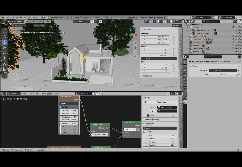
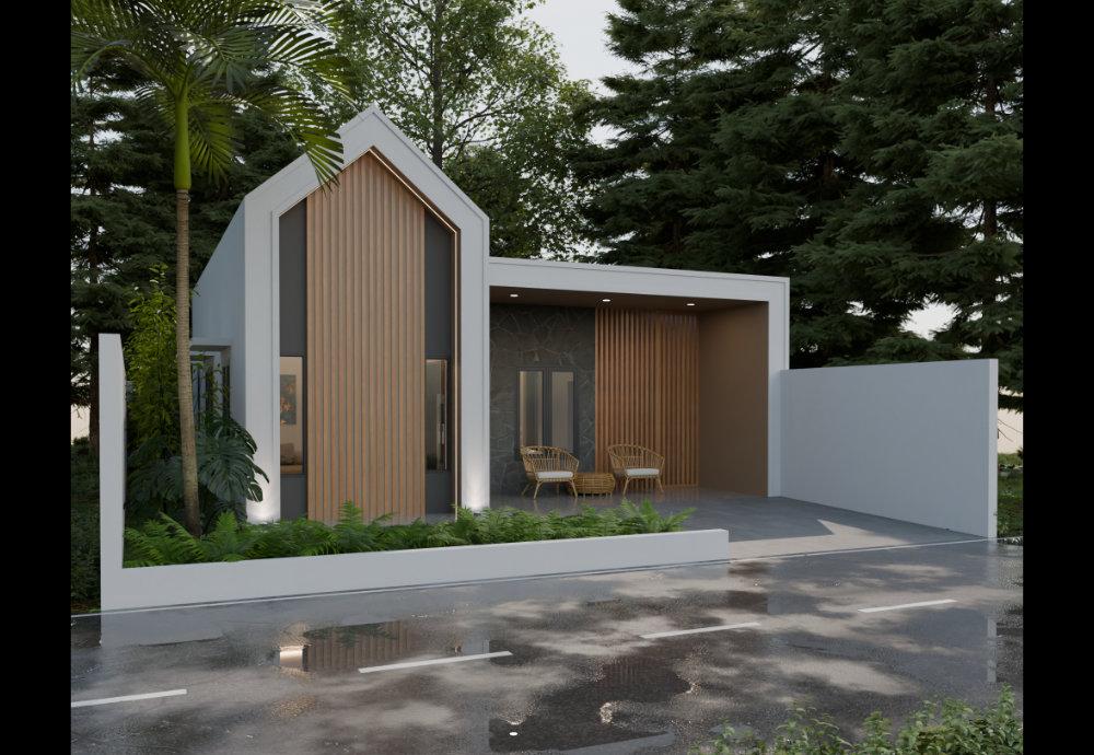
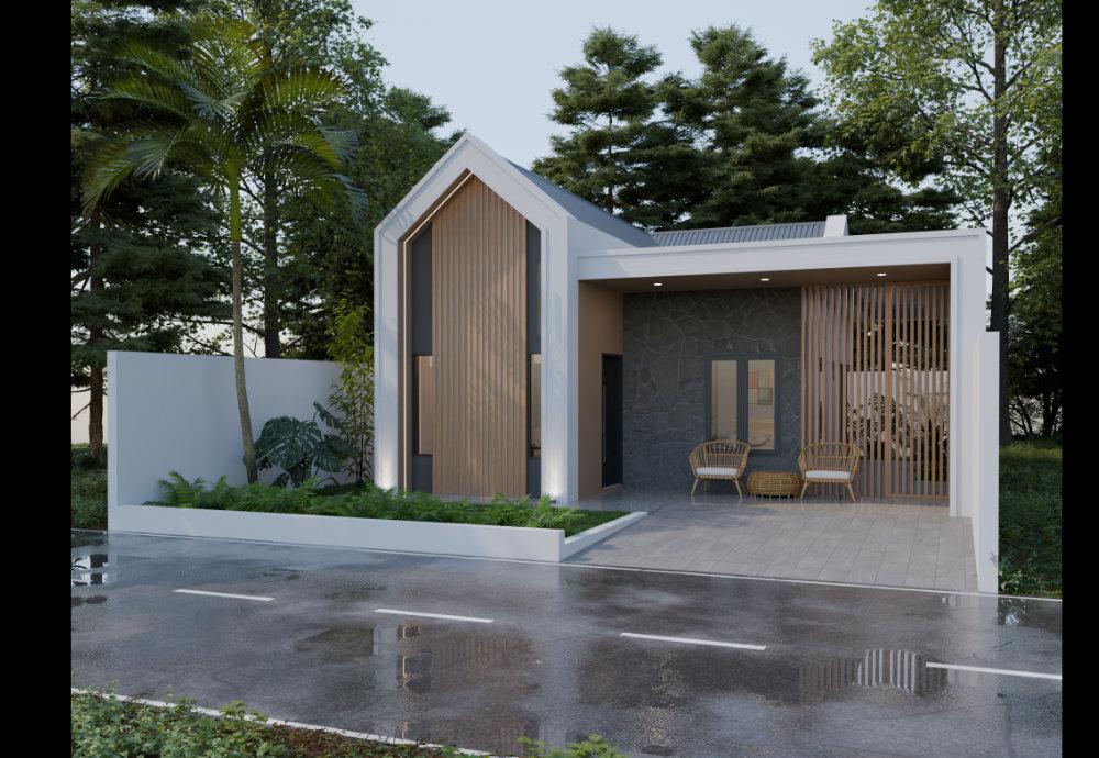
Transcripts
1. 00-01 Introduction: A Sala Molecum my
name is Wide Mutakin, founder of Expose Studio. For more than 20 years, I have been involved with
hundreds of projects, including architecture,
interior design, master plans, and so on. I have worked with many
clients all over the world. Besides doing projects, I
have also been teaching treat and computer graphics
academically since 2000. In short, I have both
professional expertise and teaching experience. As you may already know,
Blender is currently the most popular and
widely used free software with around 20 million
active users worldwide. However, few people know
that Blender is also fully capable of doing architectural design
and visualization. I know this for a fact because I have been using Blender
for almost a decade now to tackle all kinds of architecture and interior design projects with great success. Like many others in the
architecture industry, I started with the common
tools such as AutoCAD, SketchUp, FilsMx, V-Ray,
Krona, and the like. But after trying out Blender and seeing how rapidly it
is being developed, I was often believer that one day Blender will take over
the treating industry. I decided to jump ship and fully commit to Blender
ahead of other people. It was not smooth sailing
at first because back then, almost no one used Blender
for architectural projects. There were hardly any videos or blogs discussing the topic, not to mention online courses. I had to develop
my own workflow by putting all the puzzle
pieces together myself. All these struggles
finally paid off. Now Bender can replace almost all of my
previous software. I can design directly in TD
and provide my clients with visualizations so much faster compared to my old
conventional workflow. Bindra has everything
that I need in one place. It has robust to modeling tools. It has modifiers and geometry nodes for
procedural workflow. It has cycles for
photorealistic renderings. It has EV for real
time rendering. It has a note based compositor
for post production, and it even has a
video editor built in. After years of perfecting
the workflow in its course, I want to share with
you how I handle architectural projects
using Blender to ease out the learning curve. We will start with
something simple, which is designing a
small single story house. With this project,
you will learn how to design a floor
plan from scratch. Then you will use the floor pan to model
the walls, the roof, the facade, the windows, the doors, and the rest
of the house details. After that, we will add the UV mapping and then assign the materials
and textures. Once the architecture
is complete, we then move on to adding more
details to the project so that the house does not appear empty and lifeless in rendering. We will add furniture
to the front porch. We will also add furniture
to the interior, which includes the front
bedroom and living room. Next, we will create
the lighting on the interior ceilings and then create the lighting
outside the house. After that, we will
add vegetation around the house area
and its surroundings. We will add grasses, small plants, and
enlarged trees. Please note that I'll be using two paid addons
for this process. Geo-Scatter and botanic. Yes, you can replace these two addons with
three alternatives. However, I want to show
you my workflow as I. So these two addons are
the ones I'll be using. As the final step,
we will create two different camera views with two different
lighting scenarios. One view will be
slightly from left. This one will have
afternoon lighting, while the other view will
be slightly from right. We want lighting in this
view to have a morning vibe. So join now and
make Blender your unfair advantage in the
architecture field, have fun learning Wsalamocum.
2. 00-02 Exercise files and conventions: Welcome to the course.
Before moving on, there are several
important things I need to mention
about the course. Although you can take
this course directly, if you are new to Blender, I strongly recommend you take an introductory
course first. This is because there are many fundamental things that I won't be discussing
in this course, as I assume you already
understand them. This includes navigation,
UI modification, object creation, transformation, and basic TD mesh modeling. If you're interested,
you can take my Blender for essentials course
series here on Skillshare. There are three courses
in this series. In the first course, you
learn the fundamentals of Blender before moving
on to remodeling in depth. In the second course, you
learn about material creation, textures and UV mapping. Finally, in the third course, you learn about lighting, cameras, rendering
and post processing using cycles rendering engine. After completing the
three essential courses, you may also want to
take the first course in the Blender four
architecture course series. This course discusses in depth the process of making
floor plans using Blender. This is very important, as almost all architecture and our interior projects
start with floor plans. Having the skills to create precise and beautiful
floor plans can be the determining
key in getting clients or winning project bids. Next, it's about
the exercise files. You can download all the exercise files for
this course in the resources section of this lesson in case
there is a problem, as a backup, you can also download the files from
the following link. Please pay attention to the capitalization
of the letters, as this link is case sensitive. You can download the
files one by one, but it will be easier
if you just click this download button to download them all
in one zip file. The text you see here depends on where you are or your
language preference. It says, download Samoa
because I am in Indonesia. You'll see the text,
download all if you are in US or UK or other English
speaking countries. As you can see, the
false are named based on lesson with additional
chapter code in front. Next, it's about the
structure of the course. I have carefully
crafted the curriculum so that everything is
spaced sequentially. Each lesson you take on
one level will become the foundation of lessons
in the next levels. Therefore, it is important
that you take the course in order step by step,
not jumping around. If you take the course
by jumping around, most likely, you'll get
confused at some point. The second thing
I need to mention is that you need to practice. For each video, please try out the lesson yourself
at least once. The course is not
just about theories. Most of the lessons
are practical skills. So again, you need
to practice if you really want this online
course to benefit you. In this course, I'll be using a PC computer with a Windows
ten operating system. So every shortcut I mentioned in the video will be for
PC and Windows OS. If you are using a Linux OS, most likely, you won't find any difference in terms
of keyboard shortcuts. However, if you are a Mac user, you will find some differences. I believe most Mac users
already understand that the command key in Mac is often used to replace
the Control key in PC, and the option key in Mac is often used to replace
the key in PC. But the thing is about vendor. I found that most of the
control shortcuts in PC in Mac mostly become
this control key and not this command key, although there are some
shortcuts still use domand key. Essentially, if you are
using a Mac computer, you may need to check the menu or the preferences window or the official vendor's
online documentation for the keyboard shortcuts. In this course, I will be using Lenard version 4.3 to 4.5. So they features and shortcuts are related
to these two versions. If you are watching
this video and have Blender version five
or six or higher, you might find some
differences here and there. In such a case, I recommend you check my course list as
I might have already released a new version
of this course that is better suited for the version of the Blender you are using. There are at least two
things that you need to have if you want to work
in bender comfortably. First, you need a standard
mouse with a scroll wheel. Usually, if a mouse
has a scroll wheel, you can press on
the scroll wheel to activate the
middle mouse button. We will use the scroll wheel and also the middle mouse button a lot for viewport navigation. You want to avoid using minimalistic mouse
products that do not have any scroll
wheel or middle buttons. The second thing that you
need is a full size keyboard. What I mean by full size is that the keyboard should
have a num pad area. This is important
because a lot of Blender navigation shortcuts are placed in the numpad area. Yes, there is an option in Blender reference window to
simulate the numPaed keys, but that will be at the cost of overriding other
important shortcuts related to TD modeling. So again, you really
want to invest in a decent full size keyboard if you want to use
Blender for long term. Throughout the course, I may
display images and videos. Some of these contents
are not made by me. Please note that I am using them merely as references
or for inspiration. I never claim that these images
or videos are made by me. If I can find the owner's name, I will credit him or her by putting their names on
top of the content. Otherwise, I will
display image or video with the URL link
of where I found them. As for stock images or videos, if I don't specifically state
that they are made by me, most likely the copyrights belong to the respective
owners, okay?
3. 00-03 Installing the add-ons: In this video, I want to explain the add ons that we will be
using throughout the course. The term addons and vendor are basically plugins
in other software. Essentially, they are small
computer programs that can be attached to the main software to add its functionalities. There are six addons in
total that we will use. Three of them are
official addons, while the other three
are external addons. Let's first discuss
the official addons. Please note that Blender
official addons are hosted in one centralized repository at extensions.blender.org
slash addOS. All the addons you
see here are free. They are developed and
submitted by the communities, and each of them
has gone through staff reviews and
approval process. The website makes it easy for us to search and
review the add ons. If you like a certain addon
and decide to install it, there are two ways
that you can do so. The first method is to click
on the Get addon button. And then click drag
this area and release it on top of your vendor
application window. After that, just follow
the instructions. The second method is via
the preferences window. You can open it by going to the Edit menu and
choosing preferences. Next, you need to open
the Get extension tab. Make sure you set these
to add ons and teams. You can scroll and
browse the add ons. All these add ons
are basically the same as what we saw
before on the website. If you already know
the name of the addon, you can simply type
it in search field. Then to install the add on, just click the Install button that appears on the right side. The three official
addons that we'll use are 123 select White
Mouse navigation, and Magic UV add on. For example, we want to
install the 123 select add on. Just search here 123. Then click the Install button. You can do the same with
the other two addons. Now, because there will be a dedicated lesson
on Magic UV addon. In this video, we
will only cover the 123 select addon and
most navigation addon. If you install the
addons correctly, you'll be able to see
them in the addons tab. The 123 select addon will let you activate the vertex
mode, edge mode, and phase mode directly from the object mode using
the number one, two entry keys on the keyboard. Please note that they are
the number of keys on left side of the keyboard,
not on the numpad. The reason why these addons is important is that by default, when you are in the object mode, pressing the number one, two, and three keys on the keyboard will isolate
collection number one, collection number two, and collection number
three respectively. Only when you are in edit mode, you can use the number of keys
to switch between vertex, H and phase mode. The problem is that
we often forget whether we are in the edit
mode or in the object mode. To clearly see the problem, let me turn off the
add on for now. For example, you think
you are in edit mode, but actually in object mode. If you press the number one key to access the vertex mode, what happens is that you end
up hiding all collections, except the top collection. Pressing number two will hide everything except the second
collection, and so on. As you can imagine, the default
setup can drive us crazy. With this add on installed, every time you press
the number one, two, and three keys, you always
end up in edit mode. Number one, will
activate Vortex mode. Number two, will
activate H mode, and number three, will
activate face mode. The second add on is the right
moose navigation add on. Essentially, this
addon will trigger the walk fly mode in bender simply by holding
the rightmost button. It is the same
navigation behavior that you can find
in Andrea engine, the five prender,
and twin motion. So if you often jump between the software and
vendor back and forth, you will truly
appreciate the add on. Please note that by default, vendor can perform
Wokfly navigation mode. You have to hold, shave, and then press the Tilda key, which I think is not
that convenient, especially if you need this Wokfly navigation
mode very often. So to use the add on, simply press and hold
right mouse button. Without releasing
the mouse button, you can look around by moving the mouse and to move around, you can use the WAS ND case, W to move forward, A to move left, S to move backward,
ND to move right. You can also use the Q and
E case to move up and down. So basically, it is the
same navigation control available in almost all
Prozent three games. If you are done, simply release the right mouse button to go back to the standard
navigation mode. Now, you may be wondering if you use the Mouse
button to navigate, how can we perform
right click then? Do we lose the ability to open the contextual
menu? Don't worry. RlickFunctionality still exists. And so you can still open
the contextual pop up menu. Just don't press the right
Mouse button too long. If you only perform, click
and release quickly, right click pop up menu
will still show up, okay? I understand that
not all people like this behavior that
is totally fine. You don't have to install the add on if you don't want to. You can keep using the
default shift till the shortcut or as the
alternative method, you can overwrite the shift till the shortcut with just the WK. We will discuss this approach in the next video when we
discuss custom shortcuts. The next types of
addons I will be using throughout the course are the external or
third party addons. They are called external
because you cannot find them in your official
extension repository. The three addons
that I will be using are Blender kit,
Geo-Scatter and Botanic. Please note that Geo-Scatter
and Botanic addons are paid addons that you can purchase
from superhgmrket.com. Blender kit is to be different. The addon itself is free, but some of the assets inside
its library are not free. Although later, I will only
be using the free once. I won't discuss these three
addons in detail now, as there will be dedicated
lesson videos for that.
4. 00-04 Custom shortcuts: For most inputs or the standard keyboard
and most operations, I believe you won't find any
problem understanding them. As I use an add on
called screencast keys. This add on displays
the input at the bottom left corner
of the TD viewpoard. Simply pause the video if
you miss the input data use. The problem is that not all of the shortcuts data will be
using are default shortcuts. That is why I need this lesson video to explain
these custom shortcuts. Please note that you
don't have to follow all the settings that I have
at least with this video, you will understand
later why I am pressing certain
keys or shortcuts. There are five custom shortcuts that I'll be using
throughout the course. First is F five for showing
and hiding the wire frames. The second one is F six for toggling the normal direction
of the phase orientation. Next is W to trigger the
of identification mode. Note that this can be
useful if you don't like using rightmost navigation addon that we discussed previously. Next is the period key to activate the effect
originally mode. And finally, the shift E shortcut to activate the
to manifold command. If you already know how to create custom
shortcuts in ender, feel free to skip rest of the video and just move
on to the next lesson. Let's review how to set these custom
shortcuts one by one. When modeling, I
often need to see the edges or the wireframes of the objects in the viewport. And I also often need to check the normal directions
by default. You can access the two settings from the viewport
overlay panel up here. This is for turning on or
off the wireframe display. This is for turning on or off the normal
direction also known as phase orientation because going back and forth to access this panel can be
time consuming. I want to sign F five to toggle the Wireframe display and F six to toggle the phase
orientation display. To set this up, simply Rod
click on this checkbox, choose change shortcut, then press the F five key
on the keyboard. Do the same with the phase
orientation checkbox, but press F six key instead. Now we can toggle the Wireframe display
by pressing a five we can toggle the phase
orientation display by pressing F six. All right. Next, we want to
uprite the walk fly notification mode from
Sheftiler to W. For this, we can open a
preferences window. Then in the key Map category, make sure you are in the name
mode and search for walk. Notice that in a
TV view category, the WF navigation mode is still using the default
shift till the shortcut. We can press this button and then press the W key
on the keyboard. After this, every time you need to activate the W fly mode, simply press W and you are
in that mode. All right. Next, is changing
the effect origin only mode shortcut to
use the period Key. Please note that the period
or the point key that we are discussing now is the one located in the main
area of the keyboard, not the one on numpad. I don't want to change the
period key on numpad as it is useful to focus on selected
objects in the viewport. By default, when you
press Control period, you are activating the
effect origin only mode. In this mode, any transformation operations such as moving, scaling, and rotating will only affect the origin
point of the object, other geometry of the object because I use this feature
quite a lot when modeling, I prefer to just use the period key without the hassle of holding
the control key. Now, by default,
the period key is used for accessing the
pivot point pie menu. I use this default shortcut, as I can easily
access the feature up here via the
pivot point panel. Again, you don't have to follow my preferences
if you don't want to. To send a period key to
the edit originally mode, you can first open the
preferences window. Then open the key Map tab. Make sure you are in
a key binding mode, type in period inside
the search field. You will see a key
map entry under the object mode called
Context toggle, expand it, and then turn
off the Control key, so the highlighted color is off. This way, we don't need to hold the Control key anymore to
access the origin only mode. Now, if we press period, we can move the
origin point around. If you are done,
don't forget to press the period key again to go
back to the standard mode. Okay? Left shortcut
we want to sign is Chief E for the
abstract manifold command. I won't discuss in depth
what extrude manifold does in this video.
Long story short. It helps with creating clean topology when extruding
pass on border areas. In certain cases, I prefer the extrude manifold over
the standard extrude type, especially when modeling
walls to set this up, first, you need to be in the edit mode, and you also need to have at
least one phase like that. Okay, open menu, and then
the extrude sub menu. Here is the extra
manifold command that we want to overwrite, right click on the
menu item and then choose ESN shortcut
while in this condition, press Shift E, and that's it. We cannot perform extra
manifold by pressing Shift E.
5. 00-05 World lighting and material assets: In this lesson video, I want to explain how I
set up dot lighting and explain how to extract the material assets into your
own local asset library. The first is about dot lighting. As I mentioned before, this course was designed to be the continuation of the four
courses I published earlier, which are the three
essential courses and one course on fool plan. So you may want to
review these courses again if you need an
in depth explanation, especially on lighting
and rendering. For now, I just want
to quickly explain how I set up the lighting so
you know how to use it. In Blender, you can access to lighting via the properties
editor in volt panel. But if you want more control, you can use the shader editor. Just make sure you set
the mode up here to volt. Let me explain the
editor a bit, okay? So these are the nodes that I set up for generating
the wt lighting. I will be using the
setup throughout the course to light
our house project. Essentially, in the setup, we have two sources of lighting that are
combined into one. This is the first light source, and this is the
second light source. The four nodes at the bottom use an EXR or HDR file
aterte source. Because it uses a file
captured from the real world, it tends to generate more realistic results
out of the box, while the two nodes up here use a procedural method to generate both the
sun and skylighting. Because it is procedural, we can easily control how it looks simply by taking
the parameters. The node that combines the two lighting
systems is this node. If you set this to zero, the SN will only be by the
procedural lighting system. And if you set this
all the way to one, the N will be it only
by the EXR or SDR file. I usually set this to
around 0.7 to 0.6. This way, the sun will mostly
be laid by an HDR XR file, but I still have the
ability to control the sun's position
via these parameters. All right. In this course, I'll be using a lot of
materials and textures. If you already downloaded
the exercise files, you can find the textures
inside the textures folder and you can find
all the materials inside a vendor file
called materials. The first step you
want to do is to move the texture files into
your own texture folder. Folder can be anywhere. It is really up to you. Personally, I like to paste the textures inside a folder on Google Drive that mirrors automatically to a folder
in my local drive. This way, it always
sings automatically. Again, you may prefer other
cloud services or prefer local network storage or just have your own
way of doing things, and that is totally fine. For the purpose of this lesson, I just copy and paste the texture files into
an example folder. Okay? After you have
texture files in place, you want to import
the materials into your own asset library
or asset browser. For this, you can simply move the materials file I provided
into your asset folder. If you haven't set
any asset folder, you can create a new folder in any location that you like. Again, I usually use a Google Drive folder
to play it safe. For now, I just use a dm folder called
example asset folder. After that, you need to tell vendor that the folder
is your asset folder. For this, you can open
the preferences window. Then open the file pads tab. Here, you can see a category
called Asset Libraries. Basically, this is list
of folders that you want vendor to look for when displaying content in
your asset browser. To register a new folder, simply click the Plus button and then browse to
your asset folder. If you're already there, click the At Asset Library
button down here. Now, you can copy or move the materials file
to the asset folder. After the file is inside
the Asset folder, you need to open the file. Ons that the file looks empty. But if you select the up object and then
open the material list, you can see that the file
contains a lot of materials. Again, these are the materials I'll be using in its course. Now, if you encounter
materials that look purple, this is because the links to the texture files are missing. To fix all the missing
links at once, you can open file menu, choose external data, and then
choose find missing files. Just browse to the
texture folder you said before and then press the
find missing false button. Nor will try to find
the files and relink them to the corresponding
material data automatically. After that, you need
to save the file. At this point, if you open the asset browser and change the active folder
to example asset folder, or the name of your asset
folder you registered before, you will see the materials, but you may still
have two problems. First, some of the thumbnails are still showing purple color. And second, the assets are all inside the
unassigned category. To fix the thumbnails, you can force Blender to
recreate the thumbnails by turning off and then turning
back on the asset option. To do this real quick, you can open the
outliner editor, but change the mode to Blender file and then open
the materials folder. Use the Shift key to select
all of these materials. Right click and
choose clear asset. And then click again, and then mark as offset, Blender should regenerate
all the thumbnails. This process can take a while depending on the number
of materials you have. I'll just speed up the
video to save time. Okay. So that fix
your first problem. To fix the category, you can create a new category by pressing the plus
button up here, name it to something
meaningful such as metals, woods, or walls, et cetera. Click on this icon to save
the category and then dreg the material that you want from the unsan category to any
category that you like. Just keep doing this until all materials are organized within the correct categories. After you are done,
remember to save the file. And that's it. The next
time you open Blender, you should be able
to see the materials in your Astec browser.
6. 01-01 Sketching out the floor plan: In this video, we will start
sketching the floor plan. Now, you might be accustomed to sketching floor plans
using pencil and paper. That is totally fine. I just want to show you an alternative method of sketching four plans right inside Blender using precise measurement
units from the get go. You can also use this method as the next stage process
from the pencil and paper. Essentially, we will be using mostly vertex extrusion with
the automorgeoption t one. Let's start by deleting
the default cube. Press V to create a single
vertex at at cursor location, which is currently at
the center of the world. Now, I know that
lens size is ten by 16 meters to draw a
line for 10 meters. We can extrude the
vertex by pressing E, then pass X to constrain the X root to the
axis direction. Then type 1,000, which equals
to 10 meters the enter. Next, press A to
select both vertoss, then press E Y, 1,600, the Nenter Oops. Sorry, guys, I tucked
in too many zeros. Okay, 10 meters by 16 meters. Let's activate the
ware frame mode. For now, we don't want
to deal with phases, so press A to select all X
and then choose only phases. We now have the size of lend. However, for the main building, it only occupies a center area
of 6 meters by 10 meters. We can start sketching the
layout by selecting the bottom left vertex that may
be with the move pull. And from now on, we will be using the
automorg feature. Make sure these two
options are turned on. Okay, press E Y 400. We want to have a
small green area to the left of the house. Press E X 150 enter. Then extrude again
xs for 10 meters. Next, we can perform
extrude again, X 6 meters, plus E to extrude again, use YXs as far as -10 meters, and then we can extrude and
snap it to the left vertex. Again, this will be the main
building area of the house. Next, we want to spit the front area to define the
front porch of the house. So type E X, 300, then enter, E again, Y 200, then press E X and snap it here. Next, we want to create
the master bedroom. You can extra this vertex for pre meters and then press
E X and snap it here. The room at the back, let's
make it the same size. So extrude the vertex minus
three needles in Y axis. Then extrude again,
3 meters index axis. Finally, extrude the
vertex on Y axis and snap it through the
top age. All right. Next, we want to create
a bathroom in this area. For this, we can start by duplicating the vertex
at the room corner. Press if D to duplicate
X 120 then enter. With this, we have about 1.2 meters of space for
people passing by. Let's connect the vertex, press E Y, and snap it here. Select this vertex again, press E X, and snap it here. And we have layout for the main building or
interior of the house. Just to recap, this will
be the living room area. This is the dining room area. This is the first bedroom
and second bedroom. This will be the bathroom, and this will be
the kitchen area in terms of the building size, we are creating a small
or compact house. But in terms of grand size, I think it is quite
spacious compared to most available lots
in dense cities. Let's add more details
to the outdoor area. We want to add 1 meter
extended four at the front. Then pass E X and
press it about here. I think I want to make this
for 50 centimeters long, and then we can extrude it on y axis until it touches
the front edge. I want to make a cardboard
at least 4 meters in length. Let's just connect
this routex to the top and then connect this
one to the right border. We also want to through this vertex at the back
to the right border. Now, I'm thinking of adding
a planting area here. We can press E X -100, then press E again, Y and then snap it here, then E X and snap it here. And that's it. We are done
sketching the floor pen. When working on real projects, you may need to spend
more time sketching out different layout variations to meet exactly what
your client needs. Because there are no new
techniques to discuss, this is the only
sketch we create. We'll use this sketch to
proceed to the next stage. But
7. 01-02 Wall, door, and window lines 002: After we have the stretch
of the floor pan, it is time to add thickness to the walls and then add lines
for the doors and windows. Before we begin, I need to point out that in my
country Indonesia, the most common wall
thickness is 15 centimeters. That is why I am using this value for all
the wall thickness. Of course, in real projects, you may need to adjust this
value accordingly, okay? The fastest way to add
thickness to the walls is by extruding similar
ones all at once. For example, we can
select all the wall vertices that should be
thickened to the right side. Then we can press E X, then type 15, then enter. Next, we can select all wall rotoss that should be thickened
to the left side. After that, press E
X -15, then enter. Let's do the same with all the wall lines,
taken to the bottom. Select all of the vertices. Then press E X -15. Sorry, I mean Y, not X, and then press Enter. Finally, we can select all vertices that
should be taken upward. Then press E Y, 15. I forgot this wall
section press E X -15, enter. All right. Next, let's fix some errors. First, we don't need
a wall in this area. So select the H, press
X, and choose edges. We also don't need these edges, as they all will be part of
the same floor material, press X, and choose edges. These two edges are
also not needed. And this small one
also, we can delete it. I think we have removed all the unnecessary edges we cannot move on to
adding the door lines. Et's start with the door
in the second bedroom, select this edge,
and then you can either plate this
edge or extrude it. Let's extruding
it by pressing E, then Y, 90 then enter. In my country, the
most common door width is 90 centimeters, so this is the value
I will be using. As for bathrooms, usually
the doors are a bit smaller, ranging
75-80 centimeters. In our case. I want to make
it 80 centimeters wide, so press E Y, 80 then enter. This door should use the
standard size again, sub press E X, 90, then enter. Next, for the entrance door, you can raise it touching the top or bottom borders depending on the layout
you want to create. I think I'll go with
the top lineman. Usually, front entrance doors are wider than standard doors. But for now, I'll just set this to the same width
at 90 centimeters. Next, we want to create the lines for the doors
in the kitchen area. We are still missing line here. We can fix this using the
vertex extrude command, or if the vertices
already exist, we can select both vertices and then pass J to connect them. Okay, the kitchen door is a bit different because we want
to create sliding doors. Let's say we want to
have three door leads, each with 90 centimeters
width, we can pass E, Y, and then 90 enter let's
35 the number to 90, multiply it by three and enter. Again, we will put sliding
doors tier in its opening. Now that the doors are done, we can move on to adding
the window lines. We can start with window
in the main bedroom. I am planning to have an L
shaped column on its corner. There is Y. I need to add 15 centimeter safety space to the left before
the window opening. And then for the window itself, I want two leaves each
with 60 centimeters width. So press E, X minus
120, then enter. I also want another
window on each side, create a 15 centimeters
bedding force. And then extrude this
down -60 centimeters. Next, we want to create a
window for the bathroom. For now, we can place
the new edge here. The width of the window
should be 60 centimeters. So press Shift D to duplicate, then Y -60 then enter. To center the opening for us, we need to turn off the
auto merge feature and then move these two edges down
until they snap to the bottom, then move them up, so
they snap to the top and then simply divide the
distance value by two. Next, the window in the kitchen can be created using
the same process. We can start by extruding or duplicating the left
g to the right and then extruding as far as
60 centimeters as before, we can move these two
edges to the left border. We move them to the right border and then divide the distance
by two to center them. As on Yoo merge icon, and let's force it to work by pressing as then one then enter. Next is the second bedroom. Later in this bedroom, we will add two beds, one on the left and
one on the right. Basically, I want a
window at the center on each side and another
one at the bottom left. Now, besides
extruding the edges, we can also create
the window line by duplicating the
existing window lines. Just press Shift D to
duplicate the edges, X, and then press it here. To center the edges, again, we need to turn off the
automorgoption first, move this to the left border, then move this to the right and then divide the
value by two, okay? Next, select this H. You need to turn the
automousotion back on. Later, we will add a
wardrobe in this area. So let's extrude DH on axis
for 50 centimeters first, and then we extrude again
for 60 centimeters. Oops. Sorry, guys, I think I didn't press the
enter key correctly. Let me change this
to 50 for now, let's do another extrusion for
60 centimeters. All right. Now let's focus on
the front side. Later, we will create
an extruded post up ornament with about 40
centimeters thickness. So for the window,
we need to start at least 40 centimeters
from the left corner. Currently, we are working
with whole numbers. So we can easily
calculate that we need an additional 25
centimeters distance. But imagine if you need to
work with fractional numbers. In such conditions,
it is easier to just let Vendor calculate
the value for us, so you can just extrude
it as far as the gap. And revise the value by reducing
it with dual thickness. Okay. Let's add the same 25 centimeters
gap on the right side, and then we can start
adding the window line. Now I want this window to
be smaller than the others. Let's make it 40
centimeters wide, so it is as thick
as dual ornament. Let's also add the line
on the right side. Press E X -40. Next, let's focus on the main
room or the central hall. First, we want to divide
the all into two sections. By looking at the grades, we can quickly tell
that the whole area has a length of about 7 meters. So the center line should
be at 3.5 centimeters. We can press Shift D to
perform a duplicate you can perform cut and slide command as we do have office
on left wall. But I want to avoid commands
related to phases for now, so you guys can see how it is done if there are no phases. Okay? This will be the line separating the living room
from the dining room. We want each area to have large window with
multiple leaves. We can start by
duplicating this edge. Then extrude it as far
as -60 centimeters. We want to have three leaves. So let's multiply
the value by three. To place these lines
at the center, as always, we can first
tune off tomorge feature, move and snap them
to the bottom edge, and then move and snap them to the top and then divide
the value by two. Leader in living room area, I want to place a long TV
cabinet at the bottom, and then place a sofa
at above this location. So the window should be between these two or where
the coffee table is. I think we should only create
two leaves for this window. We can do puck a DH
to the bottom like saw and then exclude it as
far as one 20 centimeters. Move lines to the
top and then move them down until just
before the TV cabinet. Let's round the
value to minus 160, but then we divide it by two. Finally, we want to turn
the tomo ation back on and then for S two by pressing
A as one then enter.
8. 01-03 Creating the floors: In this video, we'll
create the floors. Basically, we want
to add faces and then add some thickness
using the extrude command. Now, before we start, the phase creation process works best if the areas for
rectangular shapes. You want to avoid
complex shapes such as letter L or letter U shape. In my experience,
Blender may fail to create pass if the
shapes are too complex. In our case, this area, this area and this area are
considered complex shapes. So let's extra this
vertex to left border and then let's extrude
this one to the right. And I think we also need to extrude this
vertex to the right. And finally, extrude this vertex to the bottom. Don't worry. We can remove these
temporary edges easily once we have the phases. Now, before we add the phases, you also want to make
sure that we don't have any existing phases to do that. We can simply press A to select, then press delete or X and
then choose all phases. Okay. Now that the
model has no phase, we can press A to
select and then press F on the keyboard
and here's the result. Please note that this process does not always
deliver clean results. If you activate the
solid view mode and then you see this flickering
surface on the model, you can be sure that there is an overlapping phases
issue in the model. This usually happens
vendor creates one large phase that covers the entire
silhouette of the model. If that is the case, simply click on the center of the model to try to
select the large phase. Noice so the selection highlight
covers the entire model, then press X and two phases. Now that large phase is gone, you can easily select individual phases belonging
to each of the areas. Next, we can combine
phases that should belong to the same object
or have the same material. For example, this phase and this phase should have
the same material, so we can merge them together. Merge or combine multiple
phases like this, the shortcut is the same
as we created the phases before and that is by
pressing F on a keyboard. An example, we can strike
all areas there should be grass and then press
F to combine them all. Then these phases should be the same material
press F to merge them. For this phase, I think I want
to have a unique material, so I'll just leave it
like this for now. The next step is to
separate the pass into independent objects based on their materials and
also their heights. For example, we can
select these faces. I'm going to use the same
material throughout, and also their heights
should be the same. As you can see, I also selected
the faces at the doors. Oh, sorry, guys, this is the wrong phase. It
should be this one. Again, you also want to select the faces indoor
areas, all right? And then pass P,
and you selection. Another example, we can select
the bathroom four and then the faces at the sidewalk
in the front porch, they will have
different materials, but they should be
at the same height, press P and then
choose selection, then we can select
the grass phase. Separate this also into a new object, and
for the carport, we can first combine the
two phases using the F shortcut and then
press P selection. Then this phase should
be a separate wall. Next, we can hover
on this phase and then press L. This will
select the whole element, and then we can
separate this phase. Sorry, on second thought, I think I don't want to create a high wall in
front of the house. So let me select these two faces and then separate them as an
independent object. Now we can hover on its face, press L to select the
whole loose part, and then press P
and then selection. Basically, the only part left on this object is the wall on the inner or
the main building. If we go to object mode, we can see that what was
originally a single object, our fall pen is now divided into multiple
independent objects. Please note that at this stage, I usually don't jump into
the modeling by the way. In real project scenarios, I use these models to generate
a conceptual floor plan for something that I can show
and discuss with my client. Usually, the floor
plan design of the room layout process takes the longest time compared
to the other processes. It is an iterative
process where you try to come up with the best layout
solution for your client. If you are an architect
or an interior designer, you should already be
familiar with this process. However, in this course, I need to skip the floor
plan creation process, as I have already published a course that focuses
on this topic. Feel free to check the course
out if you are interested. As for the course, I will
assume that you have already passed this floor plan design stage
with your client. And so now you are
ready to move on to designing the
house in ready, okay? Now we want to assign different heights to each
of the floor objects. For example, for the bathroom
and the outdoor floors, we can set Z coordinate
to be at -5 centimeters. As for the grass area, that sets the Z value
to -10 centimeters. For the carport, we can
start with -5 centimeters. But then we bring down
the front heights. Let's first remove these
additional vertices by selecting them and then pressing
Control X to dissolve them. And then we can select
the front edge and set the height to
-15 centimeters. Oh, sorry, we still have
this one vertex that gets in the way press Control
X again to dissolve it. Next, we can move this phase
down to -5 centimeters. Okay? I think we are now ready to add
thickness to the objects. Essentially, in this process, we need to extrude the pass so the bottom parts are at
least at -50 centimeters. For example, we can activate the phase
smooth, select the phase, press E to extrude about here, and then while the bottom
phase is selected, we can set the global
Z coordinate to -50. Of course, you can
set it to any number you like depending on your
project requirements. Remember that if you extrude the phase
in minus direction, the resulting phases
are usually flipped. So it is a good idea to always fix the normal
directions after that. You can quickly do so by
pressing A to select and then pass shift and to apply
a uniform normal direction. Now, if you want to add
thickness to tilter surface, such as the cardboard phase, after pressing E to extrude, you want to press
Z several times until the blue axis that you
see is perfectly vertical. Otherwise, the extrude direction will also be tilted following
the phase direction. To flatten out the
bottom surface, we can first press S for
scale NN Z, and in zero. Finally, we can set the global Z value
to -50 centimeters. We will extrude the main
building leader, but for now, I want to extrude just
the outer wall so I have something to compare
against the front wall. So make sure all the
faces are selected. Press E, 200 then enter. The slack one of the
faces at the bottom, Shift G, and choose co pranar. This will automatically
select all the bottom faces. Then press E, bring
it to about here. Set the global Z coordinate
to -50 centimeters. This should help us determine the height
of the front wall. We can start by
dissolving this H, then select the face, extrude
and strap it to the bottom. So it should be at
-50 centimeters, also, just like the rest. Select the top face, and then
extrude it to about here, and then set z
coordinate value to 30 centimeters plus A to select, and then press shift, and to make the normals
uniformly facing outside, let's check the
normal directions. I forgot to fix the carport, select all of the faces, and then press shift, and Okay. Next, we can work on
the outdoor floors. I think I just want to create two types for the
outdoor floors, so we can just combine these
two phases by pressing F and then press P to separate the new phase
into a new object, then select the bathroom floor, then press P to separate
this into new object. So again, these are now
independent objects, although they are all
at the same height. Next, we can select
these three objects, press tab to go to edit mode, select all of the faces, extrude and snap it
to the corner vertex. This will make the bottom faces exactly at -50 centimeters, press A to select, then shift and to make
the normals uniform, let's check the normals again. Everything looks
fine. Finally, we can edit the indoor floors. We can press the
fourth slash key on a numpad to activate
local view mode. Just as before, we can
select all of those faces, press E to extrude, then set the global
Z coordinate value to -50 centimeters. Then press A, shift N. Press the fourth slash key again
to go out of local view. Because the video is
already quite long, we will continue
the process which is extruding the wall
in the next video.
9. 02-01 Extruding the walls: In this video, we will extrude the inner walls and then move on to fixing the door
and window openings. Select the wall object, press four slake on the numpad to
activate local view mode. This way, we can work on Wall object with
viewer distractions. Select all by pressing A, extrude the faces for
50 centimeters first, and then extrude again
for one 60 centimeters, and finally, extrude again
for one 40 centimeters. Make sure that the
total height of full is now at 3:50 centimeters. The reason we perform multiple
extrusions is so that we have global or common lines
for windows and doors. Essentially, I want
the top line of windows and doors to
be at 210 centimeters. Let's check the normals. Just to play it safe.
Okay, all is good. Let's move on to fixing
the door openings. To connect the top wall
of the door openings, you can do this in
two different ways. The first method is to
select the two faces on the opening and then click
and then choose which faces. This method is cleaner as it does not leave you
with interior pass. Okay? The second method is to use a simple
phase extrusion. Note that you need to have
the atomrg feature turned on. To do this, you select
one of the pass, press E to extrude, then snap it to the wall
or face in front of it. This method can be very
helpful when you need to connect a lot of door
openings of the same size. Basically, you simply
select one phase, then press Shavar to
repeat the command, and you just repeat the
process, select a phase, Sitar, select a phase, Shavar, and so on. Unfortunately, we
cannot use Shift R for bathroom door because
the size is different. So for this door, we can press E and you
snap it manually. The drawback of this extrude
method is that it will leave you with many interior
faces, but don't worry. You can quickly remove all
interior faces in the model, even if you have
hundreds of them, simply open the select menu, then select all by treads. And then choose interior faces. With this, all interior faces
get selected automatically. The only thing you need to
do now is to delete them, press X and then choose faces. Now, I just realized I made
a mistake in this area. This should be where
the sliding doors are. Let's fix this really quickly. We can select the two faces on each side and also select
the two faces on each side, right click and then
choose Bridge faces. So yes, the bridge
faces command can be used to connect faces as
well as to create holes. In fact, it is the
command that we will be using later to
create window openings. But let's first deal
with this phase. I think we should
separate it for now, as we may need to use it later
to patch the floor model. I don't think there
are any more doors to deal with, okay? We can move on to fixing
the window openings. Again, we will be using the Beach faces command
in this process. First, you need to select the faces where the
window is located. I usually use IFrame
mode in this process, as I can easily select
both faces in one go. And then White click and
then choose Beach faces. Let's move on to the next
window, select the two faces. White click Breach faces. Because I'll be using the same technique for
the rest of the windows, I'm speeding up the
video to save time. I Next, we need to deal with windows
that have unique sizes. For example, the bottom part of the window in the bathroom
should be higher. To edit this, it
will be easier if we first turn off ato
merge option and then move this up until it
touches the top border and then move it down as
far as 40 centimeters. Okay, another window that we need to add it is
in the kitchen area. The bottom part should
be at 100 centimeters. This is because we will add a kitchen counter and stove
just behind this window. Then select the top face, snap this to the bottom, and then move it up
by 40 centimeters. You can also just type in Z coordinate value
if you want to. All right. I think that is
all for the window openings. We can press the board G again to go out of
local view mode. Oh, sorry, guys, there is still one thing
that we need to do. We need to extrude the world
downward to prevent gaps. So let's go back to
the local view mode. So like one of the bottom faces, press Shift G, and
choose coplanar. Then press E to
extrude the faces. Let's set the Z coordinate
value to -50 centimeters. Go back out of local view mode, and here is the result so far.
10. 02-02 Roof base: In this video, we will create the base
model for the roof, but before we do that, we need to quickly fix
the floor in the kitchen. Remember that we left one
phase at the door area. Let's select the phase object and also the main floor object, activate local view mode. Well we have both selected with the main floor object set
as the active object, we can press Control
J to join them. There are multiple
ways to fix the model, but I will just redo
the extrusion process. We can select one of the
phases, press Shift G, and choose coplanar, in the selection by
pressing Control I, and then lead these phases. Currently, the phase is not yet connected
to the main floor passes because we have the
autonomous option active, we can force it by
pressing for scale, then one then enter. Now that the phase is connected, we can press A to
select all faces, press E -50, then enter. Because we are extruding
with minus value, Bender usually
creates flip normals. So press A and then shift and to fix the
normal direction. It is done, we can
now go back out of local view mode and move on to creating the
base model for the roof. To create the roof, it will be easier if you start from the existing
vertices at the wall. Let's start by selecting this vertex and
then this vertex, then this one, and finally, this one, press F to
create a new phase, go to phase mode and make sure the phase is
still selected. Press P, then selection to separate this
into a new object. Go to object mode and
select the new object. Go to vertex mode. Let's move this
vertex on the X axis. So it is aligned
with this vertex. Basically, we want to
make DH straight. Okay? And then press Shift D Y, and snap it to this vertex. On second thought,
I think it should snap to this point
instead. All right. Next, select the two vertices, then press E X,
and snap it here. So now we have the
lateral L shaped phases. Let's activate local
view mode for now. Besides using the measure tool, you can quickly
see the length of selected edges via
viewport overlay feature. To access this feature, make sure you are in edit mode and then click on this icon, which will bring up the
Edit mode overlays panel. Now, if you activate this
edge length checkbox, every time we select edges, then will display their length automatically in the viewport. It says here, three
15 centimeters. Let's check this edge. This one is also
three 15 centimeters because the two edges
have the same length. It will be easier if we need to create tilted troof
with a uniform angle. Let's turn off the
edge length of lay. Next, we can select these
two vertices and then press J to create an H
that connects the two. And I don't think we
need this g for now. So let's just select it and then press Control X to dissolve it. Okay. Later, we want
to create gutters or rain water channels along
the outside border of roof. The easiest way to do this is
by using the inset command. Go to phase mode, select
these two phases, press I for inset. We want the gutter to
be 15 centimeters wide, so type 15 then enter. Next, go to He mode, and then move this
He along the y axis, so it snaps to the front border. And then we can move
this edge on the x axis, so it snaps to the right border. Again, this works because we have the automous
option turned on. To create a center line, we can press Control
R and click here. Then right click to
cancel the sliding. Next, we want to
create a roof that is tilted exactly at 40 degrees. To do this, first, we need
to hold the shave key and then right click and reg to move the tre cursor
to this location. And then we want to
use the T cursor as the pivot point or
the center of rotation. Select these two edges. We want to duplicate
these edges and rotate them right the way
as far as 40 degrees. So press hit D, then press R Y, and then 40, then
minus the Nana. We don't need this vertex, so let's resolve it. Now that we have a guide
of where 40 degrees is. We can select these two edges, and let's change the pivot
point option back to median. Because the width and
the width are the same, we can easily make all roof
faces tilt at the same angle, but don't forget to
turn on edge snapping, move these vertices
up onto the axis, and snap them to this edge. Now, we have a tilted
roof at 40 degrees. Lead this vertex, and
this vertex should already be attached to the guide age due to
the amerge feature. To prove that they are
all at 40 degrees, we can try creating a box on
them using the AD cube tool. You can see that it has
a 40 degree rotation. Don't worry about
these small numbers as we can ignore the effect. Let's create a box
again on each side. You can see that it
is at 40 degrees. Again, this is also
at 40 degrees, last one, this is
also at 40 degrees. So all is good. We can lead these
boxes as we don't need them anymore. All right. Next, we need to detach
the center roof from the gutter. Select these phases. Press P selection,
go to object mode, and then select the roof object. I think it would be easier if we first set the
origin to the center. Then we can press G, Z, ten, then enter. Next, we can select
the Gutter object, then select all the edges
at the outer border. Then press E Z, 20 then enter. On second thought, I think
20 is a bit too high. Let's revise this
to 15 centimeters. Next, we want to select all the edges in
the inner borders. Press E Z, and strap it to the bottom
part of the roof object. To add thickness to
the gutter model, we can add a
solidified modifier. I always use the complex
mode as it gives more consistent or uniform thickness throughout
the surface. That's like all of the faces, and then press shift and to make the normal facing
outside uniformly. I think the gutter
model is done. Finally, we can
also add thickness to the roof object, as before, we can use the Stif modifier, change the mode to complex, and then set the offset
value to positive one, and that's roof
based model is done. We can go out of local view mode and here's the results so far.
11. 02-03 Scandinavian facade: In this video, we will create
a Scandinavian ornament for the house front facade and also on the side because later, we will also have a
concrete slab in this area, and the height of it
should be at this line. I want to revise
the height of roof, select the gutter object
and roof based object, press G, Z, and then
type 30, then enter. Next, we can start
with the front facade. It will be easier
if we start with one of the existing
edges on it corner. We can select this ge, then press E, Y -40, select the face, then press P, and then selection to separate
it into a new object. Go to object mode, select the new object,
go to edge mode, and select the bottom edge. Move it down and snap it to one of the edges on
the front floor. And then we can
move this edge up until it snaps to the
top part of the gutter. Next, we extrude this edge
in a negative X direction. Basically, we want to rotate this pace 40 degrees just
like the roof angle. Hold shift, white
click and rag and snap the precursor to this
vertex at the corner. Sorry, we need to change the
snapping back to vertex. Snap the tree cursor again
so it is at the corner. Go to phase mode and
select this stop phase. Use the tree cursor as
the pivot point mode. Press R, Y, 40, then enter. Set the pivot point
back to median. Now, I want to move the
origin to the center of roof, press control period to
activate the edit origin mode. Then press G and snap the most cursor to the
top vertex of roof, press control period again to
go back to the normal mode. Now we can assign
a mirror modifier and turn on the bisect option. Let's also add the
solidify modifier to add some thickness. Change the mode to complex, set the thickness
to 40 centimeters, and then change the
offset to one so it goes in I think it is done. You can apply all
the modifiers one by one or simply press Control A, and then choose visual
geometry to mesh. Okay? For the side facet, we can duplicate this object
by pressing Shift D then Y, and then press R, Z, 90 then enter. Change the snap base to active and then move and
snap it to this vertex. Now, we want to snap the
border to the border of roof. So let's change the snap
base option back to closest, move and snap the ornament to one of the vertices
at the border. As you may have already guessed, we need to move the
roof border back a bit. So also the gutter object and
then activate the lf mode, go to vertex mode. Select all fours and then select all the vertices
at the right border, and then move them
on the x axis and snap them to the vertex at
the back of the ornament. Alright. The last thing that we need to do is to fix the model so it does not
penetrate the wall below it, activate local view mode. Next, we can strike all the interfaces then
press X and choose pass. Next, select the
edges at the bottom, and then press F. Then hold out and click on one of
the edges at the back, press F to create a phase, and then I'll click
on this front edge to select the whole edge loop. Press F again to create a phase, and then we can select all
of the faces at the bottom. We can go out of Local
view more first to see the other objects and then move the faces up and snap it to
the border of the main wall.
12. 02-04 Creating the roof slab: In this video, we will create the roof slab and also
the supporting side wall. We can start by selecting one of the edges at the
top of the wall. We can extrude it in the X axis direction
and snap it here. Go to phase mode and then
select the new phase, press P to separate
it into a new object. Go back to object mode and
then select the new object. Make sure we are in
edge mode and then select and move this edge to
the border of the main wall, and then move this edge until just before the front ornament and then move this edge
until the back ornament. Press Control R, click here, and then snap it to this vertex, select the edge at the back, and then extrude it in Axis
direction until its vertex. Next, select these two edges, and then extrude them in Zaxis direction until they
snap to the bottom vertex. Currently, we have
some overlapping pass. To fix this, we can select the outer wall object and then
activate the face smooth. To select several phase loops, you need to hold the
key and sheaf keys, and then keep clicking on edges perpendicular to the direction of the phase loop
you want to select. After we have a selection like
this, we lead the phases. Now we have some
holes in the model. We can first fix the front
part to patch the hole. We can activate the edge mode. Hold out and click on any of
the edges around the hole. And then press F to close
the hole with a new phase. Go to phase mode and
move this phase, so it snaps to this vertex. Next, let's fix the
hole at the back. Just as before, we need
to select the edges at the border of the hole and
then press F to patch it. The position is already correct, so we don't need to move it go back to object mode and select the
concrete slab object. Now we need to add
thickness to this model. Previously, we used
solidify modifier. I want to show you an
alternative method, which is basically using a variant of the
extrude command. Make sure all of the faces are selected and then press out E to open the extrude panel and then chooe extrude
faces along normals. And then we can revise the
value to 40 centimeters. Now, this is very important. You need to turn on the
offset even checkbox. Otherwise, the surface
thickness will not be uniform. All right? You may already understand
that having a roof slab with a 40 centimeter stickness can be quite expensive to build, especially when there is nothing on top that needs
structural support. We can create an inner
area and make it thinner to save money
on construction. For this, we can selack
all the faces on top and then press
I to insert them. Then type 15. Let's activate the local
view mode for now. As you can see,
the inset command created a base for the parapad, but we do not need any
parapaths near the inner wall. So let's move this edge, so it snaps to the left border. Move this edge also
to the left border. And then move this
edge to the back. Next, we can select all of these phases and then use the
extrude manifold command. Besides using the extrude panel, you can access extrude manifold
by using the tools panel. Just bring these pass down
four -25 centimeters. So again, now the
real thickness of the concrete strap is
only 15 centimeters. But because we have a parapd, it looks thick from the
front at 40 centimeters. Let's check the normals, okay? Go back out of local view mode, and here's the results so far.
13. 02-05 Fixing the upper wall: In this video, we are going
to fix the upper wall, so it fits with the new
roof and concrete slab. Currently, we have this wall penetrating the concrete slab. We can select all the
faces on top of this wall. You can hold shift and just
keep clicking on faces. Or you can also hold
control to select phases using a closest
path algorithm. I still have the
extra manifold tool active from the previous lesson. So just make sure it is
active and then drag this handle down and
snap it to this vertex. Now we have a nice flat slab. Let's check again just in case something is still broken. Okay. Next, we want to patch
the hole in this wall. With the same object, we also want to patch the
entire upper wall. Select the wall object, press the forward slash key to
activate the local view mode. Go to face mode and select
one of the faces on top, press Shift G, and
then coplanar. We only need to fix the wall, so we select these
phases and we also don't need these phases as they will penetrate
the side ornament. Now we can press
Shift D to duplicate. Right click to cancel the
movement and then press P and selection to separate
the pass into a new object. Go to Object mode, and then click or click again
to select the new object. Go to phase mode and then
press A to select all faces. Remember that before we move the roof 30 centimeters upward, so let's press E, then 30, then enter. Next to patch the whole, we can select this phase, then extrude it until it's vertex and then extrude
again until it's vertex. Then select these two phases then Right click and
choose Bridge pass. Next, we can select the
three faces at the bottom. Press E and strap them here. Let's go out of local view
mode and check the right area. We have pass
overlapping with side ornament. Go to phase mode. Select the two
faces and then move them so they snap to the
back of the ornament. Next, we need to fix the wall
hole in the front facade. Let's first select
both the upper wall object and roof object and then activate
the local view mode. Currently, we don't need
all these extra edges. We can select them by holding out shift and just clicking on the edges to select them and then press Control
X to resolve them. Next, we will need one
edge loop at the center. For this, we can press
Control R, click here. Then click to
cancel the sliding. Select these two phases, extrude and snap them to the
bottom of the roof object. Finally, we can select
only the center edge, move it and snap it to the
second vertex at the top, and I think we are done. Let's check the normals
just to be safe. A is good. Go back out of local view mode, and let's check again, just in case there are some errors. I believe the upper wall
is already correct.
14. 02-06 Creating the skylight roof: In this video, we will create a skylight at the sidewalk
on a concrete slab roof. I want to skylight to light the back area, not
the front area. Select the slab roof object, go to edge mode, and
then select this edge. Press Shift D to
duplicate the edge, Y, and strength A
to this vertex. Please note that leader, we will add a side gate with a swing door below this line. So we should move
this back a bit. I think 50 centimeters
is enough. Next, let's select the edge at the back Shift D
Y -50 then enter. Next, to create a
space from the side, we can select these two edges. Shift D X, 40 the enter. The same with the other side. We can select these
two edges, Shift D X. But first, we need to
snap them to this vertex. Only then can we move
them only X axis as far as -40
centimeters? All right. The next step is to
create holes in the roof. We can select the two phases. Let's activate the
local view mode. Now, to create holes
out of these phases, there are actually multiple
ways that you can do it. For now, I want to show you the intersect knife
method to do this. First, we can extrude the
phase until it penetrates the bottom area and then press Control plus to expand
the phase selection. Next, open the phase menu and then choose Intersect Knife. We just created a hole, but there are still
pass blocking it. To see the hole, clearly, we can select these left over
faces and then delete them. These two phases also,
we can delete them. One onside of this
method is that we usually get double verticies
around the whole area. We can fix that quite easily
by pressing A to select, and then press M, then
B or by distance. Notice down here, Landra says that it just remove 12 vertices. So basically, the concrete
part of the Skylot is done. Next things that we
need to create are the metal frame
and a glass panel. For this, we can make use of the existing rotoss on
a concrete proof model. Select the for vertices, press F to create a new phase, and then select the phase, then press P to separate it as soon as
you independent object, go to object mode,
select the new object, and then set the origin point so it is at the
center of the object, and then we can
move this up a bit, press Shiv D to duplicate Z
and move it roughly here. We will need this object
leader photo glass panel. Let's go back to
the first object. We want to use this phase
to create the metal theme. In my country, we often use hollow metals for this
type of construction. We can press I, then
five, then enter, and then we can delete
the center face, move these pass and snap them to the bottom
vertex of the slab. Next, we can extrude
the faces upward. It should be higher than the slab thickness,
say -25 centimeters. Okay, I think the height
is just about right. Let's check the norms. They are red, meaning
that they are flipped. We can press A, then
shift N. All right. Next, we want to
divide the frame into eight sections
or in other words, create Stephon
grills or gratings. We can start by selecting
the face on the side. And let's turn off
the automrge feature. So Brutss and edges one
merge or cut automatically. Shift D, Y, and move it here. Extra the face four
5 centimeters. Select the hose
element by pressing L. Move these faces so it
snaps to the right border, and then press Shift
D to duplicate, Y, and snap it to the other end. Divide the distance by
and then pass shift R six times Dis like, and then move the most cursor
on top of this element, and then pass L, and
then lead to phases. Currently, these
gratings are to take. To easily define its dimension, we need to first separate it
into an independent object, selecophas in each
of the gratings. And then press Control L
to select the whole parts. Press P then selection. Go to object mode and
select the new object. Let's center the origin first, press Control period to
activate the edit origin mode. Move the origin up until it snaps to the top
part of the object. Don't forget to turn off
the dit origin mode again. Now we can easily control its size using the
dimensions input fields. Let's try 15 centimeters
or perhaps 10 centimeters. I think 10 centimeters
looks better, okay? Next, we can select the
object we duplicated before. Again, we will use this
photo glass panel, extrude the pace as far
as 1.2 centimeters. We don't want the
glass panel to be the same size as the
metal frame below it. We want it to be 10 centimeters
wider on each side. To do this, we need to
select all the side faces, hold out, and then click
on this corner each. Now that we have the
side faces selected, we can then flatten the faces
using the out as shortcut. If you ever forget the shortcut, you can go to the
mesh menu transform and then shrin fatten. After that, you can
move your mouse to shrin or flatten
the side faces. That's revise the command by first activating the
offset even checkbox. This is important to make the offset uniform and then change the offset value
two times c ceimals. Now we can move
this down and snap it to the top vertex
of the frame object. And that's it, we now
have a skylight on the sidewalk area or on
a concrete slab roof.
15. 02-07 Creating the ceiling: In this video, we will create the ceiling
for the whole house. Now, if you go inside the house, especially inside
the whole area, the architecture is actually
a good candidate for a full height
ceiling or a ceiling that follows the triangular
shape of the roof. But in this case, I
don't want to do that. I want to show you guys
how I model drop ceilings. That is why I prefer to have
a flat surface ceiling. Okay, the easiest way to create a ceiling is to start
from the floor object. So select the floor and wall objects and then
activate local view mode. Make sure the floor
object is selected. Go to phase mode,
select this phase. This phase and this
phase Ops, sorry, guys, I forgot that the bathroom floor is
a separate object. We'll add that in a moment. Let's continue by
selecting this phase. Next, press Shift D, Z, and move the new
phases to about here. Press P to separate them. Now we can go back out
of local view mode. And then try to find the
bathroom for object, select it, and then activate
bloc of view mode again. Select the top phase,
duplicate it and move it up, separate the phase
as a new object, and then we can exit
from local view mode. Now that we have the
bathroom sealing object, we can select it along with the main sealing object
and also the wall object, activate the local view mode. We need to align the
bathroom sealing object, go to phase mode, and
select the phase. Move the phase up, so it snaps and it's aligned with
the main sealing object. Go back to object mode. Shift select the
main sealing object, and then press Control
J to join them. The center the origin, as I mentioned before, I want to create drop
ceilings in the whole area. I want to create
two drop ceilings. One should be in living area, while the other one should
be in a dining area. Select the He at
the front border. Oh, sorry, guys. Notice that currently the model has so many vertices
that we don't need. This will make modeling
the drop ceiling harder. We can fix this really quickly by pressing A to select and then press X and then choose Limit solve or just
press L on keyboard. Now we are left with only
the important vertices. We can continue selecting the
edge at the front border. Make sure the automos
option is turned on. Chef D to duplicate, then Y and then snap it to the vertex at the
center of the hole. We also need to extrude this
vertex to the back so that the pace in the whole area forms a nice rectangular shape. Again, this is so we can make
the drop ceilings easier. Next, select this phase, press I to perform
an inset command. Type 50 then enter. Let's do the same
with left phase. We can perform inset
for 50 centimeters. Next, select both
of the interface, press E to extrude, and let's make it
10 centimeters. Extrude again for
another 10 centimeters. Next, we need to select the face loops of
the upper areas. We can hold out, and shift
and click on the upper edge. Press out E, and then choose
extrude faces along normals. Turn on the offset even
checkbox to make the effect uniform and then set the offset
value to 15 centimeters. And now we have two drop
ceilings in the whole area. Next, let's add a recess
ceiling in master bedroom. Select the H on white border, press Shift D, X, and type ten the nenter. I think 10 centimeters is
enough for our purpose. To add the void or recess, we can select the new phase, press Y first to split
the phase into se part. With this, we can move it
independently by pressing G, Z, 15, the Nanter. To connect the surface, we can select these
two edges and then press F let's do the same
with the bathroom ceiling. The gap should be on the side. So select the edge, press Shift D, Y, minus ten, then enter. Select the new phase,
press Y to disconnect it. Press G Z, 15, then enter. Go to edge mode,
select the two edges, and then press F. I don't think we need to add any recess lighting
in the kitchen. As for the bedroom at the back, we can add a recess
light on each side. The process is
basically the same. We can start by
selecting the edge, duplicate and move it
by 10 centimeters, and then select the new face, press Y, and then G, Z, 15, select the two edges, and then press F
to connect them. All right. Now, for
the ceiling object, we may or may not
add thickness to it. If you do want to
add thickness to it, you can use the
solidify modifier. But if you prefer to just leave it as one
surface like this, you may want to fix
the normal direction. Currently, the bottom area
is all red or flipped. This is not good, as
this is the side fixing the camera we meaning to
create interior renderings. To fix this, you
can slack all of the faces and then
press out nos flip. Now, we can see that the
bottom side is blue. Obviously the ceiling
is currently too high. We want it to be at
280 centimeters. So let's just input 280
insive coordinate field, and that's it, we are done. Let's walk around inside the house just in case
there are still any errors. The rope ceilings in the
whole area look good, no bed gaps or
anything like that. Let's check the second bedroom. There is a ceiling in this
room is also correct. Et's check the bathroom. This is the recess
ceiling where we can lead place along AD strip. Finally, we can check
the master bedroom. The ceiling looks fine. This is where we will place
the bed leader. And I think the side
window is too big. Well, we can fix the
leader if we need to. Let's press the
home key to go back out and let's exit from
local view mode. No
16. 03-01 Adding the windows | Part 1: Starting from this video, we will model all the windows and doors of our house project. First, we can select the wall object and then
activate the local view mode. Let's start with the front
window in the master bedroom. Make sure we are
in a phase mode, hold out and click on this edge to select
the whole phase slope, CFD to duplicate, and right
click to cancel the movement, and then press P to separate
it into a new object. Go to object mode and then
select the new object. Go to phase mode, press A, then out E, and choose
extra pass along normals. Turn on the offset even option, and let's make it 4 centimeters. Now we need to divide the
frame into two sections. We can start by selecting
the side phase. For the next operations, we need to turn off the
auto merged feature, shift D X, and then pass E four. Then Control L to select
all linked phases, move and snap this to the left and then move and
snap this to the right, but we revise the distance
value by dividing it by two. We have finished the
main window frame. Next, we need to create
the frame for the leaf. We can select this
edge and this edge, and then press F
to create a pace, select the phase and then
insert it for 6 centimeters. Separate the centerfas. We will use it later
for the glass, and we also need to
separate these phases. This will be the leaf frame. Okay? Now we can go
back to object mode, select the leaf frame object, go to face mode,
press A to select. Extrude them to the back side
as far as -3 centimeters. Let's fix the normal
direction by pressing Shift N. This will make
all pass pace outside. Next, we can select
the glass object. We can extrude the
face to the back as far as minus one centimeters. Press A, and then Shift N to
fix the normal directions, go to object mode. We need to move the glass
object to the back a bit. We can press G Y and
move it back slightly. Revise the value to
one centimeters. Before we can start duplicating
anything in vender, it's a good idea to first name the object properly and
also applied materials. This can save us time from
having to name them one by one or assign the materials
to multiple objects. For this project, I want all the window frames to have
a black aluminum material. So just drag the material from the offset browser to
the main frame object. And for the left frame, we can pick the
same material from the list as it already
exists in the scene. For glass window, we can use material called
glass dot Window. To make the window glass
look more realistic, I usually add a rubber
border around the glass. You can create it as
a different object, but I prefer to just assign the material on faces
created via inset, select the face in front and
also the face at the back. Press I to perform
inset then type one. Essentially, we have 1
centimeter gap for the rubber. To assign rubber material, we need to invert
the selection first. We can do that by
pressing Control I. Now that we have the
border faces selected, we can create a
new material slot, press the sign button, and then react rubber black
material to the new slot. All right. That's center the origin point
of glass object, the leaf frame object, and also the mainframe object. This will make it easier when we later need to
duplicate or move them. Now, we can duplicate
the leaf frame by pressing ShifD X and
then snap it here. I don't have any pen to create an animation where the window
is opening or closing, so it's better to just join other frame objects
as one object, select all of them, and
then press Control J, and let's strenm the object
to something more meaningful. To find the selected
object in your liner, you can press the period
key on the numpad. Let's rename this
object to window.001, or any name that
makes sense to you. Next, select the glass object. We can rename this
to window glass.001. Now, to copy the glass object, we can use the dubicate
instance method, which is by rushing
out the nut shift D, having instances in your scene can save your systems memory. We can look for another
window that has exactly the same size and
vision as the current window. For example, the window in the living room
is the same size. I believe that is the
only similar window to the front window
in this project. Select the two glass objects
in the frame object, press out D X, and then move them
to about here, and then press R Z
-90, then enter. Next, we can press G and
snap it to this vertex. We have two windows done. We will continue adding more windows in the
following videos.
17. 03-02 Adding the windows | Part 2: In this video, we will
continue working on windows. Please note that
because I will be using the same techniques as in the previous video to save time. I won't explain each
step in too much detail. If you find the video
a bit confusing, you may need to rewatch
the previous video where I go into everything
in more detail. Okay? Let's first focus on a small window in
front of the living room. Select the whole object,
and then go to phase mode, hold up and click on EH to select the phase loop
at the window opening, Shiv D to duplicate, and then click, press
P to separate it. Go to object mode, and then select the new object, go to phase mode, and then press A to
select all phases, press out E, and then choose
extra pass along normals, activate, offset even, and set the offset value
to 4 centimeters. Apply the dark aluminum material just like the previous window. And let's also center
the origin point. Premium the object to
window single tall.001. Personally, I prefer not to
have a live window here as the whole area
already has plenty of air flows from
the side windows. Basically, we don't need to add any additional frame
to this window. The only thing we have to
do now is to add the glass, and easiest way to do this is to just copy the existing
glass that we have created. We can select this glass object, and then we should use ordinary duplicate, not
instance duplicate. This is because we will edit the glass so it fits
into the new frame. So press Chef D, hold control, and snap
it to this vertex. And let's move this back
as far as 2 centimeters. Okay. Next, we want
to edit glass object. We can first select the
frame and glass objects, press the fourth
slash key twice. Currently, only the bottom
left corner is correct. We need to fix the
other corners, go to vertex mode. Sorry, to play it safe. We only want to edit
the glass object, go to vertex mode. Select only these upper vertices and then move them and
snap them to the top, we select all and select only the vertices
on the right side, move them to the left a bit, and then move them to the right and snap them to
the left border. Go back out to object mode. And I think this window is done. Let's rename the glass object to window glass single tall.001. Now, select both objects. Go out of local view mode because the left window
is exactly the same. We can use the Instant
duplicate command or CD to duplicate the objects then X and then snap them here. And now we have the two
small windows in front. Next, let's walk on a
large window at the side. Again, the techniques
are basically the same as the front window
in the main bedroom. The only thing that is different is the number of sections. This window will have three
sections instead of just two. Let's start by holding out and
then clicking on this age, press Shift D, white click, then P, go to Object mode,
select the new object, and activate the
local view mode, select all the faces out E, and extra pass along
normals, turn on, offset even and make
this 4 centimeters deep. To create the sections, we can start by
selecting this phase, shift D, Y, and move it here. Extra the face for
4 centimeters. Let's check the
normals. All right. You can press Control L or hover with the mouse
and then press L. Let's move this to the back and then move this and then snap
it to this vertex, then press Shift D, Y. But then we press B first, so we can select the base point
for the snapping feature, click on vertex at the back, and then click on this vertex, so the base point snaps there, and then we can divide the
distance value by three. Press Shift R to repeat
the duplicate process. Next, we can then select
office on first column part, Control L to select all of
the connected elements and then press X and then faces now the window
has three sections. Let's create the leaf frame
by selecting this edge, and then also this edge, press F, select the new phase, press I, the proform inset, make it 6 centimeters. Next, we can separate
this phase by pressing P, then hold out and
click on this edge, and then separate
these phases also. Go to object mode. Let's create the glass first. Sorry, guys, on second thought, I think it will be faster if we just duplicate
the existing glass. So let's delete this
subject for now. Select the frame object,
go to phase mode, and extrude all the faces
for -3 centimeters, press A, and then shift
and to fix the normals. Before we duplicate this frame, press first center the origin. We can center the origin
of the main frame also. Again, for glass, we can duplicate a glass object
that we have created before. We can use this one.
Remember, we need to use the ordinary duplicate,
not insens duplicate. So press Shift D, Y, and snap it here. At the glance the glass fits inside the frame,
but it does not. We can activate local
view mode again and then press three to see the
model from the right view. We can see that there is still a gap between the
glass and the frame. Make sure the glass object is selected and then
go to vertex mode, select all the
vertices on left side. Move them so they
snap to this vertex. The third part should
already fit into the frame, so we don't need to do anything. Next, we can assign the dark aluminum material
to the leaf frame model, and let's do the same to
the mainframe object, select both the leaf frame
object and glass object. Press out D Y and
snap them here, and then just press shift
to repeat the command. Again, we are not
going to create any animation where window
leaf is opening or closing. That is why we can
join all the frame objects as one object
by pressing Control J. Finally, let's name this
object windows 001. Sorry again, guys, I forgot to name the glass object
before duplicating. Let's fix the names now. We can name this glass object
window.glass.triple.001. For example, select the name and copy it so we can reuse it
for the next glass object. Select this one, edit the name, and just space the
name we copy it. But you need to change the
trailing number to 002. Usually, if you just
page the same name, Blender automatically
changes the number at the back to the
next available number. So if you just page with
Control V, then press Enter. This time, Blender will change the last numbers in
the name to 003.
18. 03-03 Adding the windows | Part 3: Before we work on a
window at the bedroom, let's first finish
up the skylight. We can rename the glass
object to skylight dot glass. As for the frame and gratings, we can join them
using the Control J shortcut and then rename
it to skylight dot frame. So again, this is skyletGlass,
and this is skylight. Okay. Let's assign
the materials. Oops. Now, if your UI areas are connected like this and you
want to disconnect them, you can click on
the header area of the bottom editor and then
choose move straight area. Hover your mouse
cursor up until you have a preview like this
and then click to confirm. Now each area becomes independent
again just like before. However, if you are using
vendor version 4.3 or below, and you have auto
connector areas like this, when you try to right click
on one of the header areas, you won't find the
split area option. In such a case, you can move your mouse to the
top border instead, right click gos
horizontal split, and then you can right
click on this border, slat join and move
the mouse cursor up. Okay, let's continue with
the material assignment. For the glass object, we can assign the
glass window material. As for the frame object, we can assign the metal aluminum drag material, and that's it. The skylight is done. Next, we can work on the
window in the second bedroom. Again, you already know
all the techniques. So I won't explain them in too
much detail in this video. Select the phase
slope at the opening, Shift D, right click,
and then press P, go to object mode, and select the new object, select all of the phases, perform extra lo normals. Turn on offset even
and set it to four. Select these two edges
and then press F, select the new phase, and
set it for 6 centimeters. Delete the center phase, select these phases and then
separate them *** object, go to object mode and
select the new object, extrude all of the
pass -3 centimeters. Shift and to fix the normals. Next, we can assign the dark aluminum material
to the frame objects. And then we can select both of these objects and then press
Control J to join them. Let's center the origin point and then rename it to
window.single.001. As for the glass, we can
duplicate the glass object on the right by pressing Shift
D Y and snap it here. The upper and bottom vertices should already fit the frame. What we need to fix are the
vertices on the right side. We can activate
the local V mode. Make sure you only
select the glass object, go to vertex mode, select only the right vertices, move them to the left a bit and then move and snap them
to the frame border. Let's rename the glass object
to window.glass.single.001. And this window is done. Currently, we have two
more windows that are the same size or exactly the
same type as this window. So make sure both the frame and glass
objects are selected. Press out D to perform duplicate instance Y
and move them here. Press R Z -90. Move them closer and then press G and snap
them to this vertex. Next, we can place the same window here
at the main bedroom, press out the Shift Z, and move it roughly here. Let's zoom in so we can clearly
see the window opening. Press R, Z -90. Move this to the right a bit so we can see
the target vertex, press G and snap them
here, and that's it. We will add the
window in the kitchen and bathroom in the next video.
19. 03-04 Adding the windows | Part 4: In this video, we will create less two windows of
our house project. First is the window
in the kitchen, and then after that, the
window in the bathroom. Before adding the frame or the glass to the
window in the kitchen, I changed my mind on how
white the window is. Currently, it is 60
centimeters wide. I want to make it
1 meter instead. We can select the
face on left and then press G X 20 the nenter. Select the face on
the right side, press G X -20 the enter. Next, we can select the glass and the frame
object in the bedroom. Press Sif D X and
then snap them here, move them up a bit, and then move them down and
snap them to this vertex. While we have both
objects like that, we can activate the vertex mode, select all of the vertices
on the right side, move and snap them here, and then select the
vertices at the top, move them down,
and then move them up and snap them
to the top border. We can center the origin
points of both objects. Rename the frame object
to window dot Kitchen. As for the glass object, you can rename it to Window
dot glass dot Kitchen. All right. Next, we want to add window to the bathroom because it
will not have any lifts. We can create it by duplicating the front window in
the living room area, activate local view mode, so like only the glass
and frame objects, press Shift D, then Shift Z, and then move them closer
to the bathroom opening. Then press R Z 90, then enter. Move them on Y axis
and snap them here, and then move them on X
axis and snap them here. Go to IFrame mode and
activate the vertex mode. Select all the vertoss
at the bottom, move them up and then move them down and snap them to
the bottom border, and then select the
vertoss on left, move them to the left, and snap them to
the left border. Well centered the origin points let's rename the frame
object to Window Dot toilet. I don't think we
need any numbering as there is only one
toilet in this project, and then we can rename the glass object to
window glass dot toilet. Okay. Next, we need to edit the glass so
it forms a zig zag, select both the glass
and frame objects, and then press the
fourth slash key twice, so we can focus
on these objects, select only the glass
object, go to edge mode, press Control R to
perform a loop cut, and then right click
to cancel the sliding. Now, to split the glass into two parts using the
edge selection, we can press out M and then
choose pass by edges next, we can go to phase mode, then hover the mouse on the top part and
press L to select it. Move it back. You can use
an exact number for this, but I'll just e bold for now. Currently, the glass
object has holes. To fix this, we can activate
the edge mode, hold out, and click on one of the edges, and then press F to patch it. Do the same with the top hole. I'll click on the edge. Empress have, and that's it, all the windows in
this house are done. In the next video, we'll
start working on the doors.
20. 03-05 Creating the sliding doors: We have done all the windows, and from this video onward, we will start working
on the doors. But before that, let's preview what the windows look like
in rendered view mode. Now, if you ever encounter strange pink colors like this in your rendered viewport
or rendered results, this is because by default, Blender replaces all
missing textures with a bright pink color because the color comes from the
background or the surroundings. I'm pretty sure this is due to the missing
environment texture. To fix this, you need to
open the shaded editor. Make sure this is set
to word and not object. Here, you can find a node that loads the
environment texture. To relink or replace
the texture, simply click on folder icon. Then open the
exercise file folder that I provided inside, you should see a
folder called EXR. If you go to that folder, you can find a file
called Straw Rolls field. As a disclaimer, I did not
create this EXR file myself. I don't load it
from plyhaven.com. Okay? So this is
what we have so far. Notice that only the windows
have the correct materials. The walls and rests
are still using vendors default material
which is colored in white. Notice also that because the skylight glass object already has the
correct material, the sidewalk area looks
bright with the gratings casting nice looking shadows
on the side wall, alright? Now, let's focus on sliding
doors in the kitchen. As usual, for a glass object, we can duplicate it
from an existing one. Say this glass on
a bedroom window, let's go back to
the solid view mode so it's easier on the system. Select only the glass and
the main wall objects. Press the fourth slash key to activate the local view mode. We can start by
creating the frame, select the wall object, turn on the web frame overlay, go to phase mode,
select this phase, hold Control, and
then keep clicking on the other faces
until this phase. We don't need to select these button pass as they
are located underground. CFD to duplicate, then Right click to
cancel the movement, then press P, and choose selection to separate the
pass into a new object. Go back to object mode. And then select the new object. If the first click
did not select it, you can click again until the
frame object is selected. And let's also select
the glass object. Press the fourth slash key twice to focus only
on these two objects. Now, if you strike
the frame object, you can see that
the origin point is too far away. Let's center it. As for the material, just like the other
frame objects, we can apply the existing aluminum rock material
to this object. Next, go to edge mode. We can select this
edge and edge. Press Control X to resolve them, select all of the
pass by pressing A, and then dE, choose extra
pass along normals. Turn on offset even, and then set the offset
value to four. All right. If you open the item tab, you can see that the
frame object width is 270 centimeters. It means that it should fit
in roughly three doors, each with a 90
centimeters width. But for sliding doors, you always need a bit of
overlapping between the doors. So instead of exactly
at 90 centimeters, we will create each door to be 6 centimeters wider
or at 96 centimeters. We can start by selecting
this edge and then press E Y -96 then enter. Go to phase Mode and
select the phase, separate it into a new
independent object. Object mode and then
select the new object, let's center the orgion it
is easier to select or move, go to phase mode and
select the phase. Let's perform an inset
as far as 7 centimeters. We can relead the
center phase as we will use the glass object
from an existing one. Next, we can select all faces, then press E and
move it that way. We can revise the
value to minus three. Now, because we are
using a minus value, usually the normals are flipped, press A, then shift N
to fix the normals, next, we need to
create the handles. We can start by
pressing Control R, clicking on each edge, and then clicking to
cancel the sliding. Do the same with the right side. Control R, click and click. After that, we need to
select both edge loops, hold Shift, and out, and then click on each edge. And then we can pass
Control D to bevel edges. Make it 7 centimeters. Remember that the
bevel width value is half of the center, meaning that the result
is seven plus seven, which equals 14
centimeters in total. Next, go to phase mode, select only the two center
faces on each side, and also two center
faces on each side. And then press I, then one, then I again, and
then one again. Press out E, and choice
extrude pass along normals. Move it a bit and then revise
the value to minus one. This is the result so far. Next, we want to assign a different material
to the handle part. First, we can press Control plus twice to grow
the selection. After we have these
phases selected, we can create a
new material slot and then assign that slot
to the selected phases. For the handle, I want to use a chrome material or a metal that looks
like stainless steel. In my asset library, I name this material as
as for stainless steel. Bret this to the new slot. To see the materials, we can activate the
rendered view mode again and hide the
white frame of lay. So this is what we have so far. Next, we want to duplicate
the glass on the left, press Shift D, Y, and move it here for now. Zoom in one frame object, press G, and then snap
it to this vertex. Activate the wireframe mode
and then go to vertex mode. Dis select all vertices and then select the
vertoss on left side. Drag and snap these vertices
to the left border. Then select only
the top vertices, move and snap them
to the top border. Center the origin point. And then from the top view, we can move the glass
object to the left, divide the distance by two. So it is exactly at the center. Before we perform
any duplicates, let's rename the objects. We can rename this
glass object to window dot glass
with sliding 001. Now you can change the window to door if you want to select the frame object
press period and then rename it to sliding 001. Next, we want the glass object to be the child of
the frame object. To do that, you need to
select both objects, but make sure you select the
frame object last and then press Control P and then
choose Object K transform. Now, because the glass is the
child of the frame object, if we move the frame object, the glass automatically follows as if we are both one object. The reason why I prefer
a child parent hierarchy and not to join them as one
object is so that later, we have more freedom to exclude the glass object from tracing
or shadow calculation. This is especially important when you want to
animate unreal engine, for example, to duplicate
the sliding door, we can select both the
frame and glass objects. We want an instant duplicate, so press out B, Y, and move them here, and then move them on
the X axis direction as far as -3.5 centimeters. Let's do another of D, then Y and then move them on the axis for -3.5 centimeters. So we have created all
three sliding doors. Next, we can rename the frame object to
sliding dot frame. The last part of
the sliding doors that we need to create
are the bottom rails. There are many variations of sliding door products and
bottom rails in the market. For this one, I want to have a base rail with the
same color as the frame. And then on top of
it, we want to create the rail rods with a
more glossy material. The easiest way to start is
by copying the top face, so Shift D Z, and snap it here. I forgot to mention
that all this time. I turn off the atomos feature. So make sure you have
it turned off also, press E to extra the phase. We only need two millimeter
stickness for B. It's going down because
the phase is flipped. For now, input a negative
value so it goes up, and let's flip the pass
for now by pressing A then hit N Next, to create the
rayos, we can start with the existing H
at the base border. Press E Z one, then enter. For now, I think we can separate the phase
into a new object. We can merge it back
later once it is done. Select the new object.
As for the material, I want to assign a Black metal. You can use the one called
metal black glassy. Then we can go to phase mode, extrude it for 1 centimeter. Select these two top edges and then press Control
B to bevo them. Basically, we want to add a
bit of roundness to the rail. Let's check the normal
directions. All is good. We can select all of the faces, move them on the X axis, so they are roughly at the
center of the sliding door. After that, we can press
Shift D X and input -3.5. For the third rail, we can just press Shift R to
repeat the process. If you are done, you can
go back to object mode. Shift select the
mainframe object, and then press Control
J to join them. Finally, it is done. We can try previewing the
models in rendered view mode, hide the well frame overlay. Everything looks okay to me. Let's go back out of
local view mode so we can see how the sliding rods interact with the other objects. I like the results so far.
21. 03-06 Creating the entrance door: In this video, we are going
to create the entrance door. Currently, the door width is 90 centimeters. I
changed my mind. Now I want the door
to be at 1 meter wide because this change will also affect
the floor object. We need to select both the
wall and the floor objects. Go to Local view mode, press seven to
activate the top view, and then use the B frame mode. Again, make sure both objects are selected and then
go to vertex mode. Select these vertices,
then press G, Y minus ten, then enter. Now we have a total
width of 1 meter. Next, we can focus only
on the wall object. Go to phase mode, select this one, hold control, and then click on this one. Separate them as a new object. Select the new object,
go to edge mode, and then select these two edges. Control X to dissolve them, select all of the phases out E, and then choose extra
pass along normals. Turn on offset even and
make it for centimeters. Go to object mode, center the origin and let's assign the existing dark
aluminum material. All right. Now, for the direction
of the door, most people will prefer the door to open to
the left as it is the direction where the wall is located or the
cabinet to be exact. But personally, I prefer to open to the right so
that the door can swing almost 180 degrees
and also to prevent the door from bumping into the TV cabinet or
blocking the TV. You may not agree with me, and that is totally fine. Essentially, this
explains why I will create the handle
on the left side and not on the right side. Okay. Go to edge mode, select these two edges, and then press F
to create a phase, select the face, and
then separate it. Go to object mode and select
the new phase object. Press the fourth key twice, so you can focus
only on the object. Go to phase mode and
extruding -3 centimeters. Press A, then shift, and to fix the normals, go to Object mode, and then center the origin. Alright. Next, we want to
create a smart Log panel. Ideally, you want to create it based on real world
product reference. But for now, I just want to create a simple
generic panel. For this, we can use the ADCubeTol click
and drag another leaf. Now, usually, if you create
an object using the tools, the local Z coordinate
will be rotated based on the surface of where
the object was created. Just to prove this, if you activate the
local transformation, notice that the Z axis is
going depth way, not going up. You can work on a model like
this without any problem. But if you prefer it to have
the default orientation, you can press Control A
and then choose rotation. Now it has the same
orientation as the world. That's turn it back to global. Let's adjust to dimensions. For the X dimension, we can make it less
than 1 centimeter, say, 7 millimeters. For the Y or the
width of the panel, we can make it 9 centimeters. As for the Z dimension, we can set it to 29 centimeters. Again, these numbers may vary depending on the
product you want to use. Select the center face. I set it to about
1.6 centimeters. Select the bottom edge. Move this up to roughly
15 centimeters. Go back to object mode. For the main material
of this panel, we can use the brushed
aluminum material by dragging the material
directly onto the object. So you can do that besides dragging the material
onto the material panel. Now, select the central phase, create a new slot, assign
it to the selected phase. And for this one,
we can just use the existing material called
the metal black glossy. Later, we will move this through the surface after we
add the slats ornament. Let's preview what we have so
far in rendered view mode. The materials are good, but I think we need to
adjust the position a bit. Let's make the height or coordinate 100
centimeters and then go to the side view and
move it to roughly here. H. All right. Next, we want to
create a handle bar. We can use the AD cube
tool again, as before. Make it roughly the size. Apply the rotation, so the
object's orientation is the same as the
world for the size. I think we can make the X
dimension 3 centimeters. As for the Y dimension, let's make it 7 centimeters. And then 120 for
the Z dimension. And then set the Z coordinate, so it is at 100 centimeters. Press Control A, and
then choose scale. So we have all the scale values
reset back to one, okay? Go to H mode, press Control R, and make it to segments and then thus as Z N scale edges
out to about this wide. After that, we can select the top face and also
the bottom face. Extrude them as far
as 3 centimeters. I think the model is done. Let's go back to object
mode for the material. We can use the existing
standars steel material, which is called method doss. Let's preview the object
in rend view mode. Looks great. Next, we want to
create the slats ornament. For this, we can
start by duplicating the main leaf object in
the X axis direction. Set the slate with 2.5 centimeters and make the
thickness to only 1 centimeter. Control A and choose scale to apply the scale
back to the default. Okay. Now we can snap this
back to the left object, snap this also to
the right border, but I prefer it not too
close to the border. To duplicate the straight
bar to the left, you can make use of
the array modifier. We want to use an
exact distance value, so choose constant offset. We do not want to upset
it in X direction, but rather in Y direction. I think minus five
should be a good number. Increase the con value. I think you can see this
better from the side view. But sorry, let's first
move the handle to the left almost touching
the Smutock panel. Okay. We can select the shred object again and revise the C value. I think 14 is already
a good number. After you are done, you
can employ the modifier, so you can select and edit
the resulting phases, select this phase, and then g it and snap it to
the left border. Now that we have
the reds finished, we can move the smart rock panel and snap it to the strat object. Do the same with the
handlebar object. Let's check the
normals. A is good. We need to combine them all into a single object, so select them, but make sure you
select the leaf object last and then press
Control J to join them. Finally, to create all the parts on the left side of leaf, we can use the mirror
modifier tonn bisec to prevent the
verticies or ages. Now we have the parts
also on left side. We can apply the modifier and activate the render view
mode to preview the model. I may need to take the
position of each part of record I using
mostly the move tool. So I don't think I need
to explain the process. For now, you can go out
of Local view mode. We need to rename
the frame object, but instead of using the Oliner, you can also rename objects by pressing the F to
keyboard shortcut, name this one door dot
entrance dot frame. Before hitting the enter key, I think we should copy the text, select the door if object, press F two, and then page the text and change it
to do dot entrance, dot if, and we are done. This is how it looks
from the outside. Let's go inside the whole area and this is how it
looks from the inside. Quick update after reviewing
the video recording, I realized that I
forgot to duplicate the phases when creating
the door frame object. That is why currently the wall object in a door
area has a hole. To fix this real quick, we can go to gmode, hold out, and click on one of
the edges of the hole, and then open the phase
menu and choose great fail. If the result looks ugly, you can try changing
the span value until the result looks
correct, and that's it. The entrance door is
done, Al handla. But
22. 03-07 Creating the bedroom doors: In this video, we will create
the doors for the bedrooms. We can start by
slatting the wall up jake and then switching
to the local view mode. Select all the phases around
the bedroom door opening. Duplicate them and then separate them to create a new
object for the door frame. Go to Local view mode twice
to focus on the object. Go to edge mode, select these two edges, and
then dissolve them. Select all phases, press out E and extrude them
along normals. Press four, and then turn
on the offset even option. Next, select these two edges, and then press F,
select the face, and then separate it
into a new object. Go to object mode, and then select the new object, select the pace, and then
extrude it for -3 centimeters. Press A, then shift N. Okay. Select both objects and then
center their origin points. We want the door
to open this way, so the handle should
be on the right side. Let's start with the
handle on the other side, hold shift, and right
click on this location. To make the TD cursor exactly
at 100 centimeters height, we can open the view panel. Here, you can see the
TD cursor coordinate. Just input 100 in
the field, right? Press Control one to
activate the back view. We want to create
a small cylinder. We can press Shift A, then type, seal then enter. I don't think we will
need more than 24 Cs. For the radius, we can
set it to 3 centimeters, which will make the total
diameter 6 centimeters. As for the depth, 1
centimeter should be enough. Finally, we want the cylinder to align with our viewing angle. To do that, we need to change
the align option to view. Okay? Go to phase mode. For now, we won't be needing
the automog feature, so make sure you turn it off. Press seven, select the phase, penetrating the
door, and then move it on the t axis
and snap it here. After that, we can select the front face and then
perform an inset for 1 centimeter or perhaps
just 5 millimeters and then insert it
again for 1 centimeter. Extrude the phase to about here. Next, we want to tilt
the phase 45 degrees. Please note that we do not
want to use rotate command, but rather the shear command, move the mouse to
see the effect, press Y, or perhaps X. I think Y should
be the correct axis. Oh, sorry, guys. This
should not be set to view but global and change
the offset value to one. Okay. Next, we can
extrude this phase, press X, and make
it -11 centimeters. To make the pace
at the end flat, we can press X, then zero, press Control
plus two grow the selection. Press seven to see from the top. I want the gap from
the door leaf to the handle to be
run 4 centimeters. So move these phases down. We can make use of the grid to tell where 4 centimeters is. I think the handle
needs to be longer. Select the face and
move it -2 centimeters. To make the corners less sharp, we can perform a vel, a tiny bit, hold out
and select this H lobe, perform a vel again. And then select this H
lob and bevel it also. Go to phase mode and select this phase loop extrate
the phase inward a little. I usually the center of the door handle is 4
centimeters from the door age. We can move the handle
object to the left and then move it to the right as
far as -4 centimeters. But I think minus
five looks better. Okay. Next, we want to create the bottom part of the
handle or the keyhole part. Go to phase mode. Select the phase loop
at the outor area, press Control plus multiple times until we have the
outer ring phases selected, and then we can press Shift
D Z minus nine, then enter. On second thought,
minus ten is too close. Let's make it minus ten. It looks weird now because the front part
is actually a hole. We can hold out and slack the edges around the
hole and then press F. We need to make it smaller, so press S and make
it about this size. Finally, we can extrude it
to the back just a little. I think the model is done. In object mode, you can right click and then just
shade auto smooth. Assign the stainless
steel material. As for the center
area of the keyhole, I prefer a brush
type metal surface. So make sure the
face is selected, create a new material slot, assign it to the face. And then let's use this one
called metal SS brush darker. For the handle on
the other side, you can duplicate the
object on the y axis, then press Control M and then Y, break the Y arrow, and snap it to the
vertex at the door. Now, if you perform a mirror and then
you apply the scale, you will get flip normals. So we need to fix it by selecting all of
the faces and then pressing Shift N. Now all
faces are facing outside. Next, we can assign the dark aluminum material
to the frame object. As for D leaf object, we want to assign
a word material because the material
uses textures. We need to define UV
mapping on the object. We can easily do that
using the Magic UV add on. Select all the phases, open the tool panel. Sorry, I mean the edit panel in the UV mapping category
inside the UVW subcategory, click on the books
button and then change the size of the
texture to 1.5 meters. Go back to object
mode and then click and react this wooden material
onto the door leaf object. Let's review the objects
in rendered view mode. We can hide a well frame overlay to see the materials better. Sorry, guys, I am
changing my mind again. I think the handle
looks better in black. But first, let's join the
two handle objects into one. And then change the
metal SS material to the black glossy material. It looks better this way. As for the keyhole area, we can use another
metal material or perhaps just use the existing
dark aluminum material. I believe the
materials are done. For now, let's join all of
these objects into one. Eater. If you need to animate
the door leaf, you can easily
separate them again. We name the object
to dot 90 x 210001, or any name that
makes sense to you. Now, because we join all the
objects to the frame object, which does not use the
auto shade option, the shading on the handle
looks a bit strange. To fix this, simply apply
the auto smooth again by right clicking and then
choosing shade out of smooth. Now the handle looks corcck. Next, we want to duplicate this door to the second bedroom. We can go back out
of Local view mode. Shift select the object, and then go to Local
view mode again. Let's use the solid view mode, so it is easier on the hardware and activate the
web frame overlay. Select the door,
press Shift D, Y, and move it here, and then
press R Z -90 to rotate it. For the second bedroom, we don't want the door
to open this way, but this way
instead, we can flip the door by pressing
Control M, then Y. Please note that every time
you flip or mirror an object, one of the scale values
will be negative. As long as you do
not apply the scale, the normal directions are fine, so we can just leave it as a to snap the door
to the opening, we can press G, then press B and pick the corner
vertex, move, and snap it to the
vertex at the opening, and there you have it, the bedroom doors are all done.
23. 03-08 Creating the bathroom door: In this video, we will
create a bathroom door. We can start by selecting
the whole object, go to face mode,
select this face, hold Control, and then
click on this face. Shift D, white click, press P, then selection. Go to Object mode and
then select the object, press the fourh Key twice. Go to edge mode, select
these two edges, and then press Control X. Select all faces, press out E, and perform extra lognormals, make it 4 centimeters, and then turn on the
offset even option. The door will open this way, so the left part
should be at the side. Well, the handle should
be at the left side. Select this edge, hold shift, and also this edge, press F, select the
face, and separate it. Go to object mode, select the new object,
select the face, and then press E minus three, then enter, press A, to strike, and then shift
to fix the normals, we can set both objects and join them by
pressing Control J. Assign the metal
aluminum white material, and we have the frame
left of the door done. Next, we want to create the
handle at this position. We can hold Shift and
then hide click here. Press three, two
C from the side. Sorry, not three,
but Control three. Basically, we are looking at the scene from the
negative X axis direction, then press Shift A, type UV sphere, then enter. I think the amount of segments
is enough for our purpose, but we need to
revise the radius. We want to handle to
be 6 centimeters in the middle because this
is a radius value. We need to input half
of it or 3 centimeters. We want the sphere to
be lined to our view, so change the line
option to view. Currently, the origin point is already at the door surface. We want to keep it that way. That is why when we need to
move the handle forward, we don't want to move
it in the object mode, but rather only the elements
inside the edit mode. Make sure all of the
elements are selected, press G, X -5.5 then enter. Okay? Select the center
vertex at the front, then press Control
plus four times. So we have something like this. Move the ertoss
back a bit and then press Control minus once
to shrink the selection, and then move these
vertices back much further. Next, we can focus on the
back side of the handle. Now, if the door leaf object
is getting in the way, you can press the
fourth sky twice. All right. Select the
center vertex at the back, then press Control
plus three times, and then press F to replace the elements
with a single phase, press S and scale it down with Press I to perform inset and
make it about 2 millimeters. Now, before we
extrude the phase, remember that the
origin point of this object is located at
the door leaf surface. Press E to extrude, and then move the pace to
about here. Extrude again. Then scale the face
to about this size. Perform another extrude
to add some thickness. Now let's open right
panel by pressing and if we set this to local, the phase is actually
facing the Xaxis direction. Notice, if I change
this to local, you can see that the zero
is pointing that way. Essentially, if we want the phase to be at
the origin location, we need to set the Z
coordinate value to zero, not the X coordinate. Okay? And then select
this edge loop. Let's make this at
2.5 millimeter. And for this edge loop, we can make it closer also
towards the orgiinToo much. Okay, press Control R, and create a loop
cut around the base, but slide it closer
to the center. Drag the X arrow and
strap it to the center vertices so the faces
form a flat surface. Control R again to create a loop cut and slide
it about here. Go to phase mode, hold out and click on one of these edges to select
the phase loop. Then through the
pass to about here. As a final touch,
I think I want to bevel this corner of bit
to make it less sharp. If you are done, you can
go out of local view mode, Shift select to the object, and then activate the
local view mode again. Now, before we
duplicate the handle, let's first adjust its position. We want the handle to be
a 100 centimeters high. Let's move the handle
to the edge of the door first and then move it to
the side for -7 centimeters. Let's assign the stain
of steel material. Now we can duplicate
the handle object, Shiv D, then X, press Control M, and then X, move it and snap it
through the door. Okay? We can finally
select all of the objects and then press
Control J to join them. Go to face mode and
select all faces, press shift, and to
fix all the normals. Go back to object mode, right click and then choose shade auto smooth and
the door is done. We can see that the
shading looks correct. And also, there are no
flip normals in the model. We can switch to the
random view mode to check the materials. The materials are fine. I'll name this Object
toilet leader of record.
24. 04-01 Facade details and window canopies: In this video, we will be adding more details
to the front facade, and after that, adding
canopies to the windows. First, we can
select this object, go to phase mode and then
select these three phases, duplicate the phases,
and then separate them, go to object mode, and select the new object, activate the local view mode, press Control R, and then create four loop cuts
along the shape. While in a phase mode, hold Shift Alt and
click on this edge, and also on this edge, press Control I to
invert the selection, and then delete them, select and then extrude them
for 2 centimeters. I we can do the same with
the vertical fact ornament. Select the four faces in front. Shift D, right
click, P, selection, go to object mode, select the new object, activate the local view mode. Go to edit mode, control R, create four
H loops in the center. Hold Shift O and click
here and then here, control I to invert the
selection, and then X, and choose phases press A, and an xt root for
2 centimeters. Next, we want to add
canopies on top of the windows on left side of the house and also
on the back side. We can start by selecting
the manual object, activate the local view mode. Go to edge mode, and then select all edges located on top
of the window openings. After that, press Shift D Z, then 15, then enter. To make editing easier, let's separate these
edges into new object, go to object mode and then
select the new object. Go to H mode and then press
A to select them all. Then press E Z, ten. Go to phase mode, then
press A to slack. Next, press E, and choose
troot log normals. Notice that one of the
phases is going in reverse. This is because all
these phases have different normal directions
from this one. No problem. For now, we can set the
distance to 50 centimeters, and then we can fix the
one in the kitchen. This like all pass, Hover the mouse and then press L. Move it first in a
positive Y direction, and then move it back and snap it to a vertex on the wall. Alright. I think I want this canopy to be shorter than vs by about -15 centimeters. Okay. Next, we want each side of canopies to be wider
up to 20 centimeters. You can do this
manually one by one, but I want to show you a faster method using the
string fatten command. For this, we need to
select all the side faces. You can hold Shiv and
out and then click on the horizontal edges to
select the center face loop. After that, we can press Control I to invert
the selection. So now only side
faces are selected. Next, you can press
out to perform string fatten if you ever
forget the shortcut, you can also access the
command from the mesh menu, then transform and then
choose string fatten. And then you can move
your mouse up or down to fatten or string
the selected phases. We want to do this
in a precise manner, so we use less action
panel instead. Just to be safe, make sure the offset even
option is turned on. And then type in 20 in the
offset field. All right. Let's check the
normal directions. All is good and we are done.
25. 04-02 Front facade slats: In this lesson video, we will model the ornaments in the center area of
the front facade. Essentially, we will create a block or wall panel and then add vertical
slats in front of it. We can start by selecting
the wall object. Go to edge mode, select
the center edge. Press E, Y, then minus five, select the generated phase, press P to separate it, go to object mode, and then select the new object. Pass for center the
origin point and then move and snap this object to a vertex on the front four. Okay. Next, we can
go to phase mode. Extra the phase
upward to about here. Let's check the
normal direction. It is currently flipped. We can press A and then
press Shift N to fix it. Now to snap the face to
the edges at the top, we need to activate
the edge option in the snap target category. Now, if we move the face
up and then hold control, we can snap it to the top edge. Next, to make the central shape sharp or become a triangle, you can press Control
R to add a loop cut. Alternatively, you can just select the two edges at the top, wrote create and then
choose subdivide. Select the new
edge, and then move it up and snap it to
the top center edge. So now we have the base block or panel for the slats
ornament. All right. Next, to create the slats
or the wooden strips, we can start by placing
the tri de cursor at the corner location
of the base object. Oh, sorry, guys, currently, we are snapping two
edges, not vertices. Let's change the snap target
uption back to vertex. Then hold Shift and right click and right to
this corner vertex. To create a single
vertex at this location, we can press V. Make sure
we are in a vertex mode. Then extrude the vertex in X
direction for 5 centimeters. Press A to select both vertices, and then extrude in x direction
for only -1 centimeter. Go to phase mode and
then select the phase. Extrude it to about this high. Let's check the normals. The faces are flipped. We can press A, then
shift N to fix it. Now to add more strips
to the right side, we can use array modifier. So in the modifier panel, click the Modifier
button type array. The direction is
already correct, but we need to make the distance twice the size of the object. So change this value to two. Essentially, we now have five, five, and 5
centimeters in length. The only thing we
need to do now is to just the count number to find one that best
fits the base object. Turns out the base object
width is a multiple of five, so we don't need to
do any additional adjustment which is nice. Next, we can go to phase mode and then select
the top phase. And then move it up
all the way to the top until it goes through the
Scandinavian ornament. We do this intentionally
because we want to use the ornament as a subtraction
bullion for the threads. So go to object mode, and then in the modifier panel, assign a bullion modifier. Now, if you are using Vander
version 4.5 or above, you may want to use the
Manifold option as it is faster and produces
better results overall. If not, then you can
use the exact mode, but make sure you turn
on these two options. Also, make sure the
difference option is on. Then click on a Picker icon and select the Scandinavian
Ornament object. Okay, to apply all the
modifiers at once, we can press Control A, then choose visual
geometry to mesh, activate the
wireframe view mode, and then go to Vertex mode. Hold Control and ad click
drag to strike all of the vertices at the top that we don't need, and
then lead them. And there you have it. The front slats
ornament is now done.
26. 04-03 Side partition and hidden gate: In this video, we will create a partition and
also a hidden gate. The style of the partition will be similar to
the front facade. That is, we will use
struts or wooden bars. And then at the right end of it, we will create a
hidden door that blends nicely with
left wooden bars. Okay? You can start by placing the precursor at the corner
vertex of this wall. Then press V to create
a single vertex. Make sure we are
now in vertex mood. Press E Y, ten, then press A E X five. Swap the face and then extrude it all the
way to the ceiling. To add more bars to the right, we can use the array modifier. Set the factor X value to two, increase the count number. So we have only 1 bar
penetrating the wall. Press Control A, and choose visual geometry to match
to apply the modifier. All right. Next, we want
to create the door. Let's activate the
local view mode. The width of the door should be at 90 centimeters at maximum. Now, we know that the bar
is 5 centimeters wide, and the gap is also
5 centimeters wide. So we can just select 9
bars to create the door. Go to phase mode. Make sure nothing is selected, hover the mouse
over the right bar, and then press L. Repeat it until we have
9 bars selected. After that, we can press P to separate them
into a new object. Go to object mode and then
select the door object. Notice that currently
the object has a width of 85 centimeters, which is just under
90 centimeters. Currently, the origin
point is still located at the origin
of the original object. You need to move it
to the right corner. So press control period to
activate the edit origin mode, press G, and then snap it
to this corner vertex. Don't forget to
press control period again to exit from
the edit origin mode. Having the origin of
door at the corner is useful when we later
need to animate it. We can move and snap the door object to
the partition object. Next, we need to create
the upper and lower fames. For this, we can
select the top face at the right, press Shift D, right click, and
then press P. Go to object mode and then select the new object, go to edge mode. Select this edge, and then move it and snap
it to this vertex. Next, we can extrude the
face down for 5 centimeters. Et's check the normals. The object is fine. But it turns out that the other two
objects are all flipped. We will deal with them later. For now, we can press Shift D, Z, and snap it to the bottom. Now that it is done, we can go back to the
main door object. Less first fix the
normals by pressing A, then shift N. The
door is now blue. Go to Wil frame mode
out A to dislike all. Then select only
the top vertices, move them down and snap them to the bottom vertex
at the top frame. We can do the same
with the bottom part, press out A to dislike all, then select all of
the bottom vertices, and then move them
and snap them to the top vertex of
the bottom frame. Go to object mode, select both the frame
and the object. And then press control
J to join them. So this is the result. I don't think we need
to create any handles, as we can easily use
the bars as handles. Finally, we can select the
main partition object, select all the fixes, and then press shift
and to fix the normals. So now all objects have
correct normal directions. Let's exit the local view mode, and here is the result so far.
27. 04-04 Roofing sheets: In this video, we will add
more details to the roof. Some people may prefer to fix the roof details using
textures, but in this project, we will create them in
three D. Essentially, we want to create
metal roofing sheets on top of the existing
roof based model. We can start by selecting
the base roof model. Go to Local view mode, press sheaf C to center
the three cursor, Shift A, and create
a plane object. Set the X dimension to 12 centimeters and
then apply the scale, so all the scale
values are at one. Go to edge mode and then press Control R and create four loop cuts along
the y axis direction. Then select the two
edges in the center and move them up for
2.5 centimeters. To add more roofing modules, we can use the UI modifier. Make sure you turn
on the merge option so that the border vertices
are merged automatically. Later, we can tweak the con value depending on
the length of the roof base. For now, we can make
the roofing sheet thicker by adding a
solidify modifier. I usually use the complex mode to make the thickness even, and let's make this
positive so it goes up. For the thickness, I think one centimeters is
already correct. Now, we want to move the origin to the
bottom left corner. So press control period, then, and snap it to
this corner vertex. Press control period again to exit from the
origin editing mode. Okay. Next, we need to place the roofing sheet
on top of the roof base. We know that the roof
angle is 40 degrees, so we can type 40 in
X rotation field. Then to rotate this way, we can type in 90
in Z axis field. Now, because we already have the origin at the
corner of the object, we can choose active as the snap Base option
in the snapping panel, presG and then hold Control
to snap it to this vertex. Now we can increase the count
number as much as we need. Make it past the
roof based model. Next, we need to
mirror the roof. There are plenty of ways to make symmetrical
objects in Blender. For now, we will be using
the mirror modifier because the mirror modifier will use local coordinate of the object and not the global coordinate. To make things easier
later down the road, we need to apply all the
modifiers and also the rotation. So first, press Control A, and then choose visual
geometry to mesh. That should apply
all the modifiers. Notice that currently
the rotation values are not set to zero. Press Control A again to open the applied pop up menu
and then choose rotation. Now, all of the rotation
values are zero. Please also note that the mirror modifier uses the origin point as the
center of reflection. Basically, we need to
move the origin point to this location for
the mirror modifier to produce the correct result, press control period to activate the id
origin mode, press G, hold control, and
snap to this point, and then press control
period to exit. Now we can assign
the mirror modifier, turn on bisec to prevent
double vertices, all right? Before we do anything
to this roof shad, we can duplicate it first
and then move it aside. We will use the duplicate
leader for the side roof. Next, we need to select the base roof object,
go to phase mode, and then select
these two phases, Shift Z, and move them up. Press B to separate
them into a new object. Go to object mode.
Select the new object. You don't need to
solidify and modifier, and then go to phase mode, select all phases and then press a Z then zero then enter. Next, we can extrude
the faces down like. Currently, the
feces are flipped. We can press A, then
shift N to fix them. The main reason we have this object is to cut the
roofing sheet in this area. We do not want it to affect the other sides to put it safe. We can extrude this side. Then we can extrude
this side also. Then select the faces
on the side and just move them so they enclose
the roofing sheet. Okay. Next, we can select the roofing object apply
the mirror modifier, then sign a Bollan modifier. Again, you want to use
the manifold option. If you are on Blender
4.5 or above, if not, you can use
the exact mode, but turn on these
two options below. Then make sure you are in
intersect Bollan mode. Click the object, pick a icon, and then click on the
object we prepared before. After we have the result, we can apply the modifier, and then we can delete
this temporary object. So that is basically how
you model a roofing sheet. We can do the same
with the other side. Select the roofing shoot object, press R Z 90. Next, we can move
it and snap it to the top vertex Sorry, it should be the second vertex
just below the top one. Now that we have the shade
in the correct position, we can select the
base roof object, select the two faces on
each side, press Shift D, then Z, press P to separate
them into a new object. Go to object mode, select the new object, delete
the slide five modifier, and then go to phase mode, select all pass and
then press S Z, then zero, then enter. Next, extrude the faces down. Extra this side. The next
root this side also. And just select and
move this side. Again, we need this object to
cut the sheet on this area, press A, and then shift N to
fix the normals. All right. We can set the
roofing sheet object. Apply the mirror modifier, add a Bollan modifier, turn these two options on. Make sure you are in the
intersect Bollian mode. Click the object pick icon and
then click on this object. After that, we can apply
the boolean modifier, and then we can
delete this object, and here is the result so far. Because the video is
already quite long, we will continue adding the roof ridge in
the next lesson.
28. 04-05 Roof ridge: In this video, we will
continue working on the roof. Previously, we have done
the roofing sheets. Now, we will focus on the top enclosure
or the roof ridge. For this, we can
start by selecting the base roof object
Go to edge mode, select the stop he
and then stop edge. You can see this better
if you are in Vrame mode. Okay. Shift D Z, and move them to about here. Then press B to separate them. Go to object mode and
select the new object. Next, we need to convert the
object into a curve type, white click, and then choose
convert to and then curve. Next, open the data tab. In the geometry category, find the b of the perimeter
and set it to 5 centimeters, which makes your overall
diameter 10 centimeters. At a glance, it looks okay. But if you look closely, the center diameter is actually
smaller than the sides. One way to fix this issue is to convert the curve
into a two d curve. Let's press the four ss kit
twice so we can focus on the object so this
is the three D mode. You can see how the diameter
becomes smaller as it turns, and this is the two D mode. The diameter keeps its
size when turning. Okay. Next, we can specify
the resolution value. We want to use this
number possible. I think one is enough
for our purpose. After that, we can convert
the object back to a mesh. Go to phase mode, hold out
and click on its edge. Control plus, then press Control I to invert
the selection, and then lead the pass. Let's go out of Local view mode. Move the ach Object up. Make it so it is just
above the roofing object. Then go to age mode. Now, don't worry if you see strange lines like
this in the viewport, this is just a bug in a
viewport shadow effect. I hope this get
fixed in the future. But if this bothers you, you can open the
viewport sharing panel. Then turn off the shadow option. Again, this does not
affect our three models. Usually this bug appears when we have complex
models in viewport. Let me just turn this off so the video does
not look confusing. Okay. Let's continue
with the edge selection, hold shave and out, and then click on this edge, and also on this edge. Then press E Z and move them down until
we don't see any gap. And that's it, the
roof model is done. Let's assign the material. I want to use this one
called metal dark gray dope. Now, if it looks too
dark in the viewport, this is due to the viewport display option of the material. This color does not
affect the rendering. It only affects how it is being displayed
in the viewport, so you can set it to any
color that you want. Okay, we can sign
the same material to the roofing sheets besides click rigging from
the asset browser. You can also sign
materials using the link transfer data
method to do this. You need to select all objects. You want to sign
the material too, and then select the object. You want to copy the material
from the left and then press Control L to open the link transfer
data pop up menu, and then choose link materials. Now, all these objects are using the same dark
gray metal material. All right. We can activate Render View mode
to preview the material. Aha Dilla, I think we have
done a pretty good job.
29. 05-01 Magic UV add-on: In this video, we will discuss how to use
the magic UVAdon. We already installed
this add on before. So just make sure you
already have it active. Please note that the magic
Uvadon has a lot of features. There are just too many to cover all of them in a single video, and probably you won't be
reading all of them, also. If you are curious
to learn more, you can open this link to
access to documentation. As you can see, it is a very, very long list to the bottom. This video, I will only be demonstrating two of
my favorite features, which I use all the
time for my projects. For practice, I already modeled this very simple house or
band of record to save time. As always, if you want to work
in real measurement units, the model should have
default scale values. So if you decide to
use your own TD model, just make sure you have
applied the scale. As for the textures, I already downloaded two sets of textures from ambiencg.com. One set is for the
roof and another set is wooden Bang texture
for the walls. All right. Let's say we want to texture this Brnhouse model with
a wooden bang texture. Make sure the
object is selected, and then create a new material, namely material wall or wood. And then open the shadow editor. Make sure we are in object
mode, not the word mode. Now, select the main
principle BSDF node. Then press **** Control T. Let's select all of the
wooden pen texture, except for this one, as this
is just a preview image. Click this button to confirm. Let's switch to the material preview mode to see the texture. Currently, the texture
does not show up because the three D model does
not have a proper UV map. In fact, it doesn't even
have a UV channel yet. We are going to use the Magic UV addon for projecting the
texture and at the same time, create the UV channel. First, you need to
be in a face mode. And then like all the pass you want to sign the UV map too. I know that the roof will
have a different texture, but that's like all
of the pass for now. Then in the side panel, you will find a tab
that says edit. Here, you will see three panels belonging to the Magic UV done. Please note that these panels only appear when you
are in edit mode. They do not appear when you
are in the object mode, except for the copying
page UV map panel. Okay? As you can see
in these panels, you can find checkboxes that control the visibility
of the parameters. What we are interested in now is the third one that
says UV mapping. Here, you can find the
two commands that we are going to discuss box
and the spanner. Now, notice this option here. If this is on, the Magic UV add on will create a new
UV map channel for us. If this is off, it will
just use or overwrite the existing channel because currently we don't
have any UV channels. You want to make sure that
this option is turned on. Okay? Now, let's click on this
box button right the way, you can see the wooden pen
structure on the model. Now, if these yellow selection
highlights bothering you, you can actually turn it off. You can do so by clicking
on this icon and then turn off the faces
option, right? After you click this box button, you can access the
less action panel on the bottom left corner
of the CD viewport. Notice there is a
size field here. Currently, it is set as one, meaning that it projects one texture tile in
the size of 1 meter. So again, this number
is not 10,000, but one with four decimal
numbers behind it. If you want to make the
texture size to meter, simply type two here
and then enter. Until this point, you
may be wondering, doesn't this feature already exist when we use the
Q projection mapping? Yes, that is correct. But Magic UV provides more
parameters to work with. You can rotate the texture
based on local axis, and we can also
offset the texture. Just for example, let's say you want to
texture projected in Yaxs direction to be aligned
vertically not horizontally. For this, you can simply
type 90 IY axis rotation. I know that this is not
the correct orientation, but you get the idea, or perhaps we want to rotate the texture
in Z axis direction. We can input 90 here and so on. One thing that I
don't like about magic UVAdon at least
in the current version, is that it does not use the standard way of
naming the UV channel. As you can see, it's giving
a name for the UV channel. This is not a problem if you
are just working in Blender. But when you export the model, other software or game
engines sometimes are devoted to f UV channels
by the name of UV Map, but at least you can rename
the UV channel quite easily. For now, we will just
leave it as is, okay? So that is how you use the box projection
method using the magic UVAdon the next feature is
the best sanar command. The box method is great
for straight surfaces or surfaces that are perfectly aligned with local
axis orientations. But for slopping or tilted
surfaces like the roof here, the texture actually gets distorted if you
use the box method. This is where we need the
best spanner command. But before we use it, make sure the two faces in
roof area are selected. And let's create a
new material slot and then create a material. Rename it to roof, for example, and then click this
sign button to assign the selected
faces to this material. Next, initiate the editor. You can select the
main material node and then press Shift Control T. We want to select
all the files from the roof texture set
except the preview image. Okay. To use the
best Pinar command, you need to select
only one phase or multiple phases as long as they are facing
the same direction. In this case, you do not want to select these two
phases together. As the projection result, we just be using the average
angle of both phases. So select this phase only and then click
the Best pinar button. Now the texture is correctly projected based
on a phase angle, but we still need to fix the
size and the orientation, which we can easily do by accessing the
last action panel. Let's make the size
also 2 meters. As for the rotation, we should turn the
texture 90 degrees. Alright. Next, we can select
the pace on the other side. Click the best
pander button again. As you can see,
the Magic UV addon will use the settings from the last time
we use the command. The size is already correct, but the rotation is flip. This should be -90 degrees,
and there you have it. Because the Magic UV add on does not use the mapping node
to rotate the texture, but it rotates the UV
islands inside the UV map. It will not break the
normal map directions, so it is a very safe, quick, and precise way of projecting
texture onto our TD models. That is, if your model consists
of mainly flat surfaces,
30. 05-02 Front and top materials: In this video, we
will add materials to the front area of the house
and also the top area. But first, I think the
front wall is too high. I don't want to add any
fence in this area, but I do want to
add small plants here. Select the top phase. Currently, it is
at 13 centimeters. Let's set it to 10 centimeters. To add textures to an object, the object must
have a UV mapping. We discussed how to use
the Magic UV atom before. Now, let's use it on all
of the objects at once. Press A to select all
objects, go to phase mode, and then press A to select all of the phases in this condition, we can open the Edit tab in
the UV mapping category, click the box button, and let's set the box
size to 2 meters. Now all of the faces have
a uniform UV mapping. We may need to just
some of them leader, but for now, we have a
nice starting point. While adding
materials, let's also rename the objects to
make them more organized. We can select the
Outer wall object. Let's rename this
to W dot Outer. As for the material, let's use the one called
Wall of White. Next, we can select this one. Rename it to wall dot front. For this, we can use the
same wall of white material. Next, select this one. Rename it to w dot
divider dot carport. We can use the same
material wool of white. For the carport object, we can just name it carport. We will be using a texture now, so let's activate
render view mode. Let's find the material
for the carport. I think I'll go with this material called
floor parking paving. Personally, I like the
tiling to be a bit bigger and going vertically
or in the wide direction. So go to phase mode,
select the top phase. Use the best planar method, set the size to 3 meters, and then rotate the
rotation value to 90 degrees. All right. Next, we can select
the grass object. Let's rename this
object to grass. Later, we will use an addon to scatter to degrasbads
on this object. But for now, we can apply material called
ground dot grass. Next, we can select the
front floor object. Rename it to for dot dot front. As for the material,
you can assign this material called
marble Karen Gray. Okay, guys, from
this point forward, I won't be using
any new techniques, so I'm speeding up the
video to save time. Essentially, I just
select an object, give it a name, and
apply a material, and just repeat the process. I The roof Gutter object
is a bit different. We want to assign two different
materials to an object. First, we can assign
dual of five material. Then to be able to select the outer and inner
faces separately, we need to apply the
solidified modifier first. Now we can select all the interfaces then create a new slot, assign a new slot, and then let's use the
stainless steel material. Next, we can select the
remaining interfaces. And then assign them also to the second slot, and that's it. So the gatto looks like an
ordinary wall from below. But if we view it from the top, we can see that it
is made of metal. Finally, we can
select this object. Rename it to facade
triangle side. And then assign the
wall of white material. We will continue adding more
materials in the next video.
31. 05-03 Wooden slats textures: We will continue
naming and assigning materials to our house project. Now, we will focus on slat
objects, and after that, the rest of the objects, we can start with a partition
on the side of the house. Let's name this object
slats dot side. And for the material, we can assign a material called
wood generic semi gloss. The UV mapping is basically done because all of the valves are going in a
vertical direction, just like the textual direction. For the door part, we can name this object slabs dot door. Use the same material
with generic semi gloss. Let's use the material
preview mode, so it is easier on hardware. And also let's activate
local view mode. Unlike the previous
partition object, not all of the wooden bars in the object are
going vertically. The top and the
bottom frame parts are going in
horizontal direction. We can fix this quite easily
by going into the pace mode. Hover the mouse cursor, and then press L to select
the top frame element, and then do the same
with the bottom frame. Press L to also select it. Next, open U
variating workspace, and then press A to select. Then press R 90 then enter. Now the word grains are
going horizontally. All right. Next, we can work on the slats,
front facade ornament, select the slat object, and then rename it
to slats dot front then sign the same wood material
with genetic semi gloss. The texture orientation
is already correct. Next, we can select these object name this
object, facade slat base. As for the material, we want
to use a different material, but still similar to
a wooden brown color. Let's use this one called
Wall cover pastel Brown. The slab ornaments are done. Now we can focus on
the remaining objects. Let's select the
window canopies. Rename it to Windows dot E. An sign wall of
white material. Let's activate render view mode and hide wil frame overlay. So this is what we have so far. Let's finish up the
floor on the sidewalk. We can name this one floor dot X for exterior, then do side. For the material, we can assign a simple cement or
concrete material. I think this concrete pedestrian
material should do it. Next is the inner floor. Let's name this
one floor dot Min. And for material, I want
to sign a white marble. We can use this one
called marble Cara White. Okay. Next, we can try to find the remaining
objects that we haven't named yet from
the Outliner editor. Let's check this
one called ot 009. Okay? So this is the
bathroom for object. We can activate the local view
mode and rename it to for toilet for material I think I want to use the one
code tile bad UBC gray. Go back out. And let's check
the next object code t011. This is roof based object. So let's name it roof base. As for the material, I
think you can assign this wall gray material. Okay. Next is the object. This is the sealing Object. You can rename it
to sealing Min. Usually, for sealing objects, I use the material
code plafan.it. Finally, we can select
this word 022 object. Turns out this object is
the roof ridge object. Let's just rename it
to roof dot ridge. The object already
has the material, so we don't need to
assign any new material. I think we have renamed
all of the objects in the scene. Oops. Sorry, guys, we still have
this train 001 object. This is the side
Roofing sheet object. Let's rename this object
to roof spandex 002. And then we can select the
front roofing sheet object. Currently, it is called plane. We can change the name
to roof dot Spandex 001. I guess we have named
all of the objects, but we haven't finished
with the materials. In the next video, we will
add additional colors and textures to some of
the walls and ceilings.
32. 05-04 Accent wall materials: In this video, we will add some excell materials
to our house project. We can start with the
front area of the house. Select the main wall object. Go to face mode. Select the faces in this area. Don't forget the two
faces at the bottom. Create a new material slot, assign it to the
pass and then choose this material code
cover pastel black. Okay. Go back to object mode. We need to repeat the process
on the upper wall object. Select the pass and
then create a new slot, assign the slot, and then assign the same will cover
past black material. All right. Next, we want to add a stone texture to this side of the wall object. Select the wall object.
Make sure you are in a face mode and then select
all the faces in its area. After that, create
a new material slot and then assign it to
the selected phases. As for the material,
I want to use a stored material called
Wall Stone tiles. It looks nice, but I think we can make the tiling
better for this. We can go back to phase mode, make sure all the phases
are still selected. Open the UV editing workspace. Press A, then G, and let's move this UV to the center so we can easily compare it
against the texture. Personally, I want the
stones to look bigger. For this, we can press S
and make the UV smaller. Next, we want the texture
to look less repetitive. You can do this easily
by rotating the UV, so press R and then rotate
the UV just a tiny bit. Let's go back to the
layout workspace. I think the stone texture
already looks nice. Next, we want to add a different color to
all of these vases. Now, I want to use a
different approach instead of adding
multiple materials across different objects. Let's create a single object that covers the entire surface, but we don't want to create the object from
scratch to save time. We can start with existing
pass in wall object, select all of the
faces and the side. Then press Shift D,
then right click, press P to separate
it into new object. Go to object mode and
select the object. Select the edges at the top. And then bring them down. Sorry, guys, I should
also select this edge. Let's move them down again, and then move them up and
snap them to this vertex. Next, we can press E
X and snap them here. Press E again, Z, and snap them to
the bottom floor. So now we have this flat
object for the wall covering. If you want to
clean up the model, you can use the shortcut and use the limited
dissolve command. Optionally, you can do
that manually by selecting the edges you want
to remove and then pressing Control X
to dissolve them, or you can also just
leave them as they are. But before we continue, we need to cover the wall
just below the door. You can select this edge, then press E Y, and snap it here. All right. Let's check the
normals. All is good. Although we won't be
using any texture, let's apply box mapping
with a size of 2 meters, just in case we want to change the material to one
that has textures. Now we can add thickness to the model by assigning
a solidified modifier. Set the offset value to one, but change the
mode to complex to make the thickness
uniform across phases. I think 1 centimeter
is too thick. Let's make it only 1 millimeter. Next, for the material, we only need one
slot for this object and use the one called
wool cover past brown. If you remember, this is the same material we used
for the base sled object. Let's previewed material
in rendered view mode. So this is the result
we have so far. The next axon wall we want to
create is at the sidewalk. Select these two large pieces, create a new throat
and then sign it. We want to use the same store
material as the front wall. Currently, the stones
look too small, and the repetition
is too obvious. But select the faces again. Open the UV editing workspace, press A, then G, and then move this
UV to the center, press S to make it smaller, and then press R to rotate it for about ten to 20 degrees. I think I want to make it even
smaller, just a tiny bit. Okay. It looks better now. After some considerations, I decided to revise
the front facade. I want to change
the inner material, so it is the same as the porch. We can select all
of the inner faces. Then create a new material slot, assign the slot to the faces, and then use the pastel raw
material. And that's it. I believe the materials for
the house are all done. But
33. 06-01 Adding furniture to the front porch: In this video, we will add
furniture to the front porch. We are going to add two
armchairs and a table. I'm thinking of using Ratan based furniture
for this project. We won't be modeling the
furniture from scratch. Instead, we will import the furniture from the
Bendrokit Library. If you have been using
Blender for quite some time, you may already know
what Blender kit is. For those of you who don't know, Blender kit is an online service where you can get thousands of high quality curated
assets related to three D specifically
for Blender. You can access the website
at blenderkit.com. When I recorded this video, it had more than 100,000
assets in total. Some of them are around
60,003 D models, around 27,000 materials and textures and many
other types of assets. Now, to be able to
download these assets, you need to create an account. Don't worry. Creating an
account is totally free. If you open a subscribe page, you can see here that if
you are on free tier, you can download all
of the materials, which is very generous,
if you think about it. As for the three D models, you can download
about 30% of them. If you choose to
subscribe whether you are in filans or the
corporate tiers, you can download
all of the assets without any restrictions, right? So make sure you create
an account first. And then after that,
you need to download the add on by going to
the download Benoit page. And then click on this
big Download button. You can follow the tutorial down here to install the add on. Back in Blender, open
the preferences window. You need to make sure that the Blender kit addon is active, and then you need to login with your credentials so that the addon can connect to
the Blender kit server. If the addon is active, you'll see this floating
UI in a top part of the TD viewport to
search for TD models, you need to activate
the first icon. The second icon is for
materials and so on. Let's search for Ratan Chair. Notice that we get
around 6,000 results. If you don't see any thumbnails, you may need to close and open this eye icon to refresh it. If the thumbnail has
a padlock symbol, it means that the
asset is a paid asset. If you are not in paid tears and wish to search
only for free offsets, you can make use of the filter function by
clicking on this funnel icon. And then turn on the
free First checkbox. Now, Blender kit will list all the assets first
before the paid ones. Besides hovering
over the thumbnails, you can also right
click on them to see more information
related to the asset. For example, you
may want to know the far size to determine whether it fits your
project or not. Okay? I think I want to use this atan chair to
download the asset, simply drag and drop it
into the three scene. Just like the asset browser. This process also detects three
D surfaces automatically. Release the mouse
and wait for it to be downloaded,
and there you go. You just downloaded the asset. Please note that a lot of Blender rocket assets
consist of or are composed of sufro objects so when you want
to move the asset, you cannot just move one of the objects to make things
easier than the kid usually puts the objects
inside a collection and also provides an empty or a helpful object
that you can select. All of the objects of
the same assets are linked or are the children
of the empty object. Now, if you are having a hard time selecting
the empty object, you can just select
any of the objects in the asset and then press the open bracket
key on the keyboard. If it has a multi
level hierarchy, you may need to press
the open bracket key several times until the
empty object is selected. After you have it selected, you can then perform any
transformations that you like. You can rotate it 180
degrees, press R, Z, 180, enter, and let's move it back to
barely penetrating the window. Okay. Next, we want to find a table that
matches the chair. You can try searching
for wooden coffee table. Let's use this one, drag and
rope it next to the chair. Let's close the icon to
hide the thumbnails. You can select any
of the objects, but then press the
opening bracket key to select the parent
empty object. Let's move it to the left first to compare it
against the chair. Press as to scale it, and then try to make the top of the table slightly below
the chair cushion. Then we can move
this to the back, make sure it does not
penetrate the wall. All right. Next, we want to duplicate
the chair and place it on the right side to correctly duplicate
objects with hierarchy. You cannot just duplicate
the parent or the children. You need to duplicate
all of them at once. To quickly select all
objects within a hierarchy, you can first select
the pattern object, which is the empty
object in our case. And then hold shift and press
the closing bracket key. You may need to press
it several times if the outset has a
multi level hierarchy. Now that we have all
of them selected, we can press out D X and
move them to the right side. Again, we use AD to create
instances of the originals. Okay, guys, the three D
models are basically done, but I still don't
like how they look. As you can see, the chair color is too pale compared
to the table. To make them look uniform, we can just use the
tables material. Let's first fix the name because currently wood one
is too generic. We can rename it to Wood
Ratan dot DFO next, select the main object of the chair to assign
a table material, simply click here and then
type in Wood Ratan then enter. Now, the main object
looks better, but the strap or tie object
still looks too pale. I don't think I want to
use the same material, so let's just adjust
the existing material. Currently, it is called Ratan. Let's rename it to
wood Ratan dot Thai. Okay. Now, let's open
the shader editor. Make sure you use the object
mode and not the word mode. To alter the color, we can
modify the texture node. So let's move these
two nodes to the side, Shift A, then type hue. Click and move this node
to the existing connector. To make it less pale, we can increase the saturation. We can try 1.5. I think this is way too strong. Let's try 1.2. Okay? This is enough. Again, we don't want it to look exactly like the
main atan material. Let's change the value to
0.9 to make it a bit darker. And that's it. I think we have the final
look that we need. If you need more decorations
such as flowers, glasses or plates, feel free to use the nrocet surface
just as we discussed.
34. 06-02 Adding realistic grass: In this video, we will add realistic grass to the grass
object in our house project. For this, we will be using
an addon called Geo-Scatter. If you don't know
what Geo-Scatter is, it is a paid addon that you can purchase from
superhivemrket.com. It is very useful to scatter a lot of objects
onto the surface. Mostly, it is used to populate the scenes with grasses, rocks, plants and trees, but you may also use it to
scatter other objects. Yes, it is relatively expensive, but it is totally worth it. I've been using this addon
for several years now to add vegetation to all of
my architectural projects. For this lesson,
I will assume you have already purchased the
addon and installed it. For now, let's close
the Blender addon, so we have more space in
the viewport to do that, we can open the
preferences window and then turn off
the Blender add on. While we are at it, make sure that the Geo-Scatter
addon is active. Okay, to access the add on, you need to open the panel
or the right side bar by pressing and then find and
open the Geo-Scatter tab. Currently, the tab does
not show any parameters. This is because there
is no emitter object selected to click
on emitter object. You can click on the
drop icon up here. And then click on grass Object. Notice that now the name of the object is
displayed on top. Please note that Geo-Scatter
offers a lot of features. We won't be discussing all
of them in this video. For example, to start
scattering objects, you can choose either
the manual method, the quick method, or
the biome method. The easiest and fastest
way to add grass to our scene is by using the
Biome scatter method. Click on this open Biomes
button to open the biome brry essentially what bio means in Geo-Scatter term is a
collection of scatters. So instead of scattering
on one object, you can mix different
objects and make them interact like they normally
appear in the real world. Notice that I have a lot of these biome presets
on my computer. This is because I also have
another addon called Botanic, which added a lot of additional biome
presets to Geo-Scatter. We will discuss this add
on in the next video. For now, let's use a
biome called Lawn 01. Click on this
button to apply it. Wait for it to load. Okay, it's all done. As you can see, the grass
looks very realistic. Again, this is the biome. That is why it consists of
more than one type of object. Personally, I don't want to have these small white
flowers in the grass. These flowers are controlled or generated by this scatterem
called clover flower. The flowers will disappear from the viewport if you click
on the monitor icon. To completely remove the flower
component from the biome, you need to select it and then click on this minus button. Alright. Now, if
you zoom out a bit, you can see that
some of the grasses are penetrating the front wall. You can also see
on the side wall. There are many ways
to tackle this issue. If you go to the
calling masks category, there are several
methods provided by Geo-Scatter to mask or
limit the scattering. You can use upward obstruction, basi area, vertex
group, and so on. For this project, I want to focus on the material
slot method. For now, that side, the whole biome by
clicking on log item, not the sub items, but the main top item. Okay? And then click
on a Hight icon. We need to edit the mesh
of the grass object. Let's activate the
material preview mode, so it is less demanding on
the computer's performance. Select the graph object, press the Slash key on Numpad. Let's switch the panel to the item tab for now so we
can see the coordinates. Go to edge mode and
then select this edge. Make sure you turn on
the automoge option. Press Shift D X minus ten the
Nant, select these edges. Then shift D Y, ten, then enter. Next, we need to assign a different material
to this large phase. So create a new slot, assign it let's open
the outset browser. We can use this ground
mud leaves material. Again, we want the
biome to only grow on the mud leaf material and not
on the ultragrass material. Hopefully, with this, the grass objects will not go through the walls anymore. Okay. Let's go back out
of the local mode. Open the Geo-Scatter tab again. And Anhed Dolon 01 biome, go to the cooling
masks category. Next, you need to choose which material will
exclude the scattering. In our case, graphs.
And that's it. We still have cephalgrap grades going through the side wall, while the front wall
already looks clean. If you want to make it perfect, you can slide the edge
to the left a bit. I may need to do
that off record. Let's activate Brander vim because the grass
object goes all the way to the back and
right side of the house, practically, all the grass
from the house is done. Again, if you ever
need to reduce the grass from going through
certain floors or walls, just use the material
masking technique I just showed you, all right.
35. 06-03 Adding plants around the house: In this last and video, we will add some vegetation around the other
area of the house. We are going to add shrubs or
small plants at the front. Then one large tree, and then more plants
around the house. For this, we will
be using Botanic. For those of you who
are familiar with it, Botanic is a paid
addon and library containing three models of plant species from
around the world. You can purchase the addon
at superhivemrket.com. The addon offers many features
such as wind animation, materials for different seasons, transform random miser, and even some
scattering features, although not as sophisticated
as the Geo-Scatter don. I already mentioned in
the last video that this addon also adds more
biome presets to Geo-Scatter. That is, if you own
the Geo-Scatter done. By the time I
recorded the video, the library contained around
1,300 assets consisting of over 1003 D models
and 185 biome presets. I own the full
version of Botanic and have used it for all
my architectural projects. I understand that the price may be too high for some people. However, it is
worthy investment. Why? Because you
only need to pay once for the current addon
and all future updates. Polygonic, the company behind Botanic
continually improves the addon and adds more assets to the
library year after year. Okay, from this point forward, I will assume that you have purchased and
installed the add on. Back in Lender, if you have
botanic installed inactive, you'll see a tab in the end
panel called polygonic. But for now, let's
hide the grass biome so it is less demanding on
our computer. Don't worry. The monitor icon will
only affect the viewport. You'll still see the grass in rendering because the camera
icon is still active. All right, click
the polygonic tab. Please note that polygonic has its own asset
browser called gon. Use Ngon, you need to press
the assets button at the top. Then in this condition, you need to select a UI area that you want to turn into gon. That's the bottom area. Now this area becomes
the gon asset browser. Later, if you want to bring this area back to
its original editor, you can click on this
X button, right? We want to add small fans
just behind the front wall, hold the shave and
then right click here. The ngn browser uses the red course location
to place the assets. You can determine the category of assets that you
want to browse. Let's open the shop category and then find the
pens you want to use. I think these plans are
too big for our needs. Let's try a different category, say, the plans category. Okay, I think these
plans are perfect. We can use all four variations so they look more natural
and less repetitive. You can click on the button
below the thumbnail to place the asset in the scene at a three d cursor location, arrange the assets so
they nicely line up. I think we should use
the solid view mode in this process so it's
easier on hardware. To quickly select all the plans, we can press C to activate the circle selection tool and just click and
react to select them. Then press all D, then X and place them here. Press C again to
select all the plans. I think the plans are too big, so press F and
make them smaller. Move them to the right. We can select these two plans out D, X, and place them here. Press C, and select
all of them again. Press to scale. I think I want to move
them to the back a bit. Now, to quickly
randomize these plans, we can use this random button. You can keep clicking on a button until you
like how they look. All is good, except
for the left plan. We can prove from rotate, scale, and move until it does not
go through the left wall. I think this area
is a bit empty. We can move the plans around
to fill the empty area. Let's activate the
random view mode. Okay. Next, I want to add a large palm
tree in this location. Shift right click to
place the t cursor. You can find palm trees inside the tropical category.
Let's pick this one. It's too big. We can press and scale it down
to about this size. Then press R Z and rotate it. Feel free to tweak the transformation until
you like how it looks. Okay, guys, that is
basically how you can add trees or plants using
the botanic library. There are no new techniques
that I can show you. So I just speed up the
video to save time. Once you are finished,
click the X button to close Engon and restore
the original editor. Press N to hide the panel and turn on
the rendered view mode. The pans in the front look nice. I am also happy with
the ones in the back, although we can only see
them through the partition. For now, let's bring
back the grass biome so we can see how it
looks against the plans. Okay, guys, this is the
result we have so far.
36. 06-04 Front road and surrounding grounds: In this video, we will create a road in front of the
house and after that, create the grounds
for the surrounding. Hold Shift and right
click on this vertex TSODRrod will be at the same level as the bottom
end of the cardboard, Shift A and create
a plane object. Now, for the root material, we will be using
this PBR texture set that I downloaded
from cgboca.com. I know that the texture
size ratio is two by one, so we will need to make the plane object in
that size ratio. Let's open the item
tab in the end panel. We can set the width
to 500 centimeters, and the length should
be two times of it or 1,000 centimeters. Price control A and
then apply to scale. Now we can move this
forward and then move it back and snap it oh, sorry, the snap based setting
should be set to closes. Now we can snap
the rod correctly to the end of the
cardboard. Okay? Because the size ratio
is already correct, we can assign road material. I really like how this
material simulates wet road, creating the atmosphere of rain having just passed through. To make the road longer, we can select left he, press E X, and rag
it to about here. We can do the same
with the write g, press E X and then wag it. Okay? After reviewing the video, I decided to insert
this section in case some of you have trouble
following the lesson. In edit mode, you can access the options panel at the
top right of the viewport. For this lesson, make sure these two options
are turned on. Why? Because with these
options turned on, you can extrude or drag edges, and Blender will automatically
fix the UV mapping. Let's compare this with
when these options are off. Notice how the texture stretches
when we move the edges. Also, when we extrude, the resulting phases will
have no automatic UV mapping, which makes the
texture look weird. Yes, in certain cases, you may want to
stretch the texture. But for this lesson, make sure you have
these two options on. Okay? Now, let's
continue with lesson. Next, to create the
surrounding ground. We can first select this edge, move it to the left
and snap it here. And then move this
edge and snap it here. I think we should switch to
the material preview mode, so it is easier on hardware. For now, we want to hide
all the plants and grasses. One way to do this is by hiding the collection
in the outliner. If you move your mouse inside the Outliner editor and then press the minus
symbol on the numpad, this will collapse
all the collections. As you can see, both
the Geo-Scatter addon and Botanic addon created
their own collections. This makes controlling
their visibility easier. Now, the viewport
feels more responsive. Go to age mode, select the
three edges at the front. Press E, Y -400. Then select the three
edges at the back, extrude these edges in y axis direction and then snap them to the vertex
at the back wall. Then extrude again
two bodies far. Okay. Now, select the
three faces of the road. Then press Control I to
invert the selection, press P, then selection. Go to object mode, and select the new object. Next, we can delete the phase
of lapping the house area. Let me bring this up first. As you can see, we have large
phase in the house area. So you select the pace and
then delete it. All right. Next, we want to make
the front ground a bit higher press control R and then add a loop cut here. So these three phases, then move them up a bit. Let's assign the
grass material now so we can clearly see
which object is which. For the ground at
the house side, we want to have two
types of grounds. The ground close to the house
will be for smaller plants, while the ground further
will be for large trees. We can extrude the side and then do the
same with the side. And finally extrude the
ground on the back side. Next, we can then
select the faces, press P to separate them. Basically, we now have three objects for
the surroundings. Let's renamed rod object. While in the outliner,
you can press the period Key on the numpad to
focus on selected object. Rename me to nv dot Road. ENV stands for environment. Next, you can
select this object, rename it to NV dot close. And then select this object, rename it to nv dot far. Finally, to make
things more organized, let's select all three objects, press M and then choose new collection, name
it environment. Then press the minus
key to collapse. Now that we have all
the surrounding objects inside the environment
collection, we can easily hide or show
them via the Ot liner, right?
37. 06-05 Setting up the cameras: We have added the ground
object for the small plants, and we have also added the ground object
for larger trees. But before we add vegetation, let's first create the cameras. This way, we can easily hide the vegetation models in a viewport and only show
them in the rendering. As a reminder, we can
only perform rendering in Blender if we have at
least one camera object. That is why we need to
create the cameras first. For now, we want to place the new camera in
Mint collection. So make sure it is
currently active. Then press Shift A type
camera and then Enter. Let's name the camera camera
dot fun dot LV currently, the camera object is
at the cardboard, as there is where we put
the three cursor before. One way to set up
the camera view is to align it
with the viewport. So first, you can adjust the viewport
like you normally do, and then press Control
of Numpad zero. This will align
the active camera to the current viewport
viewing angle. The result may not be
perfect by the way, so you may need to
tweak it further, but let's first adjust
the parameters. Personally, I like to start with a focal length of
35 millimeters. I may increase it or
decrease it if needed. The second method of controlling the camera view is by using
the navigation method. For this, make sure you are in a camera view mode and then activate the walking navigation. As a reminder, you can use either the
right click and hold method or by pressing the
W key on the keyboard. While in navigation mode, you can use the W as and D keys to move around and use
the mouse to look around. You can also use the Q and
E keys to move up or down. Basically, it is
similar to how you control a first person character
inside the three game. All right. Next, let's
create the second camera. Besides using Shift A method, we can perform a
copy in piece in your liner to duplicate
the first camera. So make sure your mouse is in your liner area, fast Control C, and then Control V. Let's rename the new camera to
camera dot front dot right. Okay. Now, this is important. You need to click on this icon to make it the active camera. This way, we can
control it using the w navigation method
just like before. Feel free to move and rotate the view until
you like how it looks. Okay, guys, we now
have two cameras with two different angles that we can use to
render the project. One last thing that I
think we should do is to place the cameras inside
a dedicated collection. So select both camera
objects, press M, and then choose new collection, name it cameras, and then
click on the Create button. Now all the cameras are inside
the cameras collection. Personally, I prefer to place the camera
collection at the top, so it is easier when I need to switch the active camera. H.
38. 06-06 Surrounding vegetation: In this lesson video, we are going to add
the surrounding vegetation to the house project. Let's start with the
near ground object. We will use the biome
feature from the geoscatter addon just like how we add
grass to the house area. So open the Geo-Scatter
tab in the end panel, and then we need to close
the current emiter and then pick the ground object so it becomes the active emiter. Next, we can open
the biome browser. For this ground object, we want to pick aggress biome that has weeds or wild plants. I think I'll go with
this forest 01 biome. Click the button below
to apply the biome. As a reminder, we
don't see anything in the viewport because we hit the Geo-Scatter
collection before. To preview the biome, you can render the
scene by pressing a 12. As you can see, we now have these wild grasses in the front and
surrounding the house. There is one small leaf
penetrating the wall, but I don't think we need
to fix this because it is normal to see some grass growing out of the
floor or wall corners. However, in case you see too many of these and you
want to reduce them, you can use the same method we used earlier at the
front wall area. Okay, so the vegetation near
the house is basically done. Next, we want to work on
the outer vegetation, close the current emitter, and then pick the
outer ground object. Let's open the Bum
browser again. I have hundreds of
these Biome three sets, so it's better to just use
the filtering feature. For now, select the
coniferous type biome. Now, the browser only shows the coniferous type
and hides the others. Let's just pick the
thickest one called Bom 06. I now, when the addon detects too heavy or too many the
models in the scene, it will offer to display
the objects as bounds, meaning that the models will
be displayed as bounding boxes or simple wireframe
boxes in a viewport. Don't worry. They will still appear as trees in
rendering results. Usually, you want to agree with this offer by clicking
the Okay button. But again, even with the
bounding boxes option, you won't see anything
in the viewport because we hide the
Geo-Scatter collection. If we press F 12 to
render the scene, you can see the trees
that we've just added. You may notice that currently the rendering is
slower than before. Overall, I already like the
trees at this camera angle. I just want to add one
large tree in this area. For this, we can place the tree manually using
the Botanic addon. So open the polygonic tab, click the broth assets button and then choose the
bottom UI area. Filter the list, so it only
shows the botanic assets. Usually, we can find large trees in the
deciduous category. Let's pick this
green Azure tree, position the tree cursor
at the back of the house, and then click to spawn button. Currently, it does not show in the viewport because the
botanic collection is hidden. Press Numpad zero to
activate the camera view. Again, we want the tree to show up in this
area in rendering. Let's move this to the right. And I think I want to move
this to the front just a bit, press F 12 again to
render the scene. I guess the trees for
this viewer then. Let's move on to the view
from the right camera. We don't want to
overwrite this rendering, so let's change the active
slot to slot number two. Next, make the second
camera de active camera. Then press number zero to
activate the camera view. Press of 12 and wait
for the rendering. I think I want to add
a tree in this area. I also want to add a
short tree in this area, so it does not look too empty. For the left three, we can instantiate the existing
large ester tree at the back, but I want to make it a
bit smaller than all D, Chief Z, and then place it
on left side of the house, press R Z, and rotate it a bit. Then as to scale it down. Let me check the
rendering again. I think this should go to
the back just a little. Next, we need a
short thick tree in this area to cover the
bright background. So let's find the tree. I like this one called
JaglinsRgia a summer. Click on a button to spawn it. I want this tree to be
basically a background tree, so it should be behind
existing large Azer tree. I also want this
to go lower into the ground and smaller in size. Let's preview the changes. Okay, I think I want this
tree to go even lower, and I want to see the tree
trunk at both this location. So let's go back to
the three viewport and move this tree to the front. Next, let's move this to the
left and then move it down. Render it again, and
wait for the result. Okay, guys, so far,
I like how it looks. I may just in leader
of the record, but I will only be using the Sametis that
I just showed you
39. 07-01 Adding interior details: In this lesson video, we will add lighting to the interior and then move
on to adding some furniture. Please note that
because this course focuses on architecture
and not interior design, we will only create
things that are visible from the outside
through the windows. We won't create all the
furniture inside the house. I do have a plan for a separate course on an
interior design project. In that course, I will use
bender for modeling and texturing and then use real engine to render a
house tour to the animation. I hope the course is ready by the time you watch
this video, okay? To start, we can search
for the ceiling object, activate the Local view mode. And then go to Phase mode. I'll click on its edge, then shift I'll
click on its edge. Basically, we want to select all hidden phases that are
supposed to emit light. Okay. Next, create a new
slot, assign the slot. Now, this material is a bit different from
the existing ones, as it should emit
light into the scene. Let's start with a new material. You can name the material
glow dot hidden. Change the shaded type from
principle BSDF to emission. As for the color, it
would be easier to get realistic colors if we are
using the black body node. I have discussed
the black body node before in the essential course. So I hope you already understand what it
is and what it does. Besides creating the black
body node in the Shded editor, you can also directly create it inside the properties panel. Just click here and
then choose black body. Note that Bender automatically created the node in
the shaded editor. For the temperature value, you can set this
to 3,500 kelvin, so it feels quite warm. As for the strength, I usually start with 50. You can just a liter if needed. Let's review the lighting in rendom view mode. Looks okay. Let's go out from
the local view mode so you can see the overall look. Now, notice that the interior
looks pale and not warm. Well, this is because we have the first GI
approximation active. Again, we discuss this feature in depth in the
essential quarters, so I won't go into too
much detail in this video. Essentially, if you want to have more realistic
lighting behavior, you either turn off the feature or increase the bone's value. Notice that if I increase
the viewport bones value, we start getting that warm interior lighting that we need. For the next step,
let's first sight the vegetation by hiding
the botanic collection. This will make the
viewport feel more responsive. I changed my mind. I think 50 is too strong. Let's try 20 for
the strength value. Let's see how it
looks in wondering. Okay, so far so good. Next, we want to add some
furniture inside the house, perhaps some paintings
on the wall, a bed, and then a
sofa in this area. Previously, I showed you how to add assets using
the Bendoked addon. Now, I want to show
you how to add furniture using another
addon called Interniq. Interniq is a paid addon and library developed by polygonic. So yes, it is the same company that
created the Botanic addon. Basically, the way
we add assets into the scene is similar to how
we use the Botanic addon. We can start by selecting
the floor and wall objects. Activate the local view mode. Hold Shift and right
click at this location. In the polygonic tab, click on the Bros assets button and then strike lower UI area. Next, filter the assets to only show the
internic category. Then go to furniture
and then beds. Pick the bed that you like. I think I will go with this one. The bed is actually not
oriented correctly, but I think this is
fine as we just need the top of the bed to be
visible through the window. Okay. Next, we want to add
a painting on the wall. Place the precursor at the wall. Then go to the decor category
and find one that you like. Sorry, there is a
painting category here. I think I want to use this one. It's too small. Let's
make it bigger. Press number zero, so
you can see it from the camera view. All right. The next furniture
you want to add is a sofa in the whole area. You can find different sofas inside the furniture category, inside the setting subcategory and just find the
sofa that you like. I think I want to use this one et's move this a little so that it
doesn't go through the wall. Also, we can move this
to the back. Okay. Lastly, we can place another
painting on this wall. Go back to the decor and then
paintings category again. And let's pick this one. It has three frames
in one object. And the size is
just about right. Let's go back out
of local view mode, press Numpad zero, but
activate the first camera. I don't want to override the
current rendering result, so let's use slot number three. Then press F 12 to
render the scene, and wait for it to finish. Okay, I'm happy with
this camera view. Let's use slot number four now and switch the active
camera to the second one, press F 12 again, and wait for the result. Okay, guys, I am also happy
with this camera view. Again, this is the
front left camera. And this is the
front right camera.
40. 07-02 Exterior lighting | Part 1: In this video, we will
focus on exterior lighting. We will add a large area
light just below the skylight void and then add
three do lights at the front porch area. We can start by placing the
tre cursor on skylight glass. Shift A us area light. First, we need to change the area light type from
square to rectangle. This way, we can set the size X and size Y
values independently. Now, to make the area light exactly at the
center of the glass, you can select both objects, but make sure the glass
is selected last, so it is the active object, then perhaps shift F and
choose selection to active. Now we have the area light exactly at the
center of the glass. We need to move it down. Perhaps we can see this
better from the bottom. Move it so the light does not
get blocked by the grills. You can keep
adjusting the size so it better fits the
skylight void. Next, for the color of light, we want to use a
black body node. If you are using a newer
version of vendor, you can select color
by temperature directly within main
light parameters. But if you are using lender
older than version 4.5, you need to press the use
nodes button down here. Then click here and
then choose black body. We want this area light
to simulate a blue sky. So let's change the
temperature value quite high, such as 8,000 Kelvin. Let's preview the light effect using the render view mode. I think ten is too weak. Et's try 50, too
strong. How about 20? Okay, I think 20 is about right. Next, we want to create three downlights in
the ceiling area. Now, I actually
already have a lot of down three D models
in my Asset library, but I want to show you how
to model one from scratch. Later, you can save the
model in your library, so you can use it again
and again in the future. We can start by
placing the TD cursor here and then create a cylinder. Set the radius to 6 centimeters, and then set the depth
to only 1 centimeter. Now we can start
modeling the shape of Danlight to phase mode
and select the top phase. Set the local coordinate
of this phase to zero. Then select the bottom phase, press Control B and make
it around three segments. Select the center phase, and then in set
it just a little. And then perform another
inset just as before. But then we move the phase up to form the glowing
part of lamp. Make sure it does not
penetrate the top phase. Okay. Next, go to edge mode and select
these two edge loops. Right click and choose Mac shop, go to Object mode, and change the shading
mode to Auto smooth, and we have the tree
model finished. We can now move on
to the materials. I'm thinking of white
metal a base material. Let me first close this gon browser and switch the editor to Blender
default asset browser. We can browse to
the metal category. Let's use this one
called metal alum white AlrFor the centerfas, we want it to emit light Make sure only the
center face is selected, create a new material
slot and assign the slot. Now, instead of creating the emission material
from scratch, we can start from the
existing emissive material called glow hidden. If you remember, we use this one for the
interior ceiling, but we want to have separate
settings for the interior. So we need to click this button first to
duplicate the material. Rename the new material to glow LED exterior front or any
name that makes sense to you. We do want the color to be warm, but not as strong
as the interior. So I think 4,500
Kelvin is enough. Let's activate under view
mode to see how it looks. I think 20 is too weak
for the exterior. We can try 1,000. Now it is too bright. Let's try 200. I think 200 is enough. Before we duplicate the object, it is better to name it first. Let's name this
lamp.led.exterior.001. Models that currently
lamp object and the light object are inside
the cameras collection. Let's move them by pressing and then create a
new collection called Lights. And finally, we can move this collection up just below
the cameras collection. All right. Let's select
the lamp object again. We want to perform a
duplicate instance, so press out D X and then
place it around here, press Shift R to repeat
the left command. Now you can select the three
objects via the outliner. But imagine that you
have hundreds of instances scattered across
different collections. In that scenario, you can press Shift L and then
choose object data. This will make vendor select all objects that have
the same object data. Okay? Now move
them to the right. I'm just eyeballing it for now and then move
them to the left. But then divide
the value by two. This will make the trillm
objects centered Okay, guys, I think we are done
with the dom lights. I may need to tweak
light intensity, a bit off record.
41. 07-03 Exterior lighting | Part 2: In this video, we will continue working on
exterior lighting. We'll add an LED strip
along the front facade, and then add two
ground spot lights. We can start by selecting
this object and then activating the local view
mode. Go to phase mode. As you can see, I already have
these interfaces selected. Just make sure you also
have these phases selected. Then press Shiv D and right
click to cancel the movement, press P to separate
the new faces. Go to object mode and
select the new object. Let's first center
the origin point for the width of the ID strip, we can set it to 2 centimeters. Press Control A, and
then apply the scale. Next, you can add thickness to the model using a
solidify modifier. Set the offset value
to positive one, set the thickness value
to only 1 millimeter, and set the mode to complex so that the
thickness is uniform. All right. For material, we can start by removing the second slot and then we can assign an
existing globe material. Duplicate the material. A name the new material
glow sat dot front. Let's exit local view mode. We want to put the object
inside live's collection, sores and then use lights. Before we make any
changes to the material, let's render the scene to
preview the current settings. I think the light is too
strong and too yellow. For the color temperature, we can set it to 4,000
Kelvin and for the strength, I think five should be enough. Let's Render seen again
to preview the light. It looks so much better now. Next, we are going to create
two spotlights on the floor. We can press the
tide cursor here. Press shift A, then
type cylinder. Set the radius to only five and set the depth to five or so. Or, sorry, let's make it ten. Activate the local V mode. Go to phase mode, and then select
the bottom phase. Set the local Z
coordinate to zero. Select the top pace, and then
press Control V to abate. Make it about three segments. Select the center face, and then insert it Go to He mode and then
shift out this He loop, white click, and mark sharp, go to object mode, and turn the object
shading to a smooth. Currently, the normal
looks a bit strange. We can fix this by increasing the auto smooth angle,
say, 45 degrees. Okay, for the base material, we can use this one
called metal dark gray. Next, select the
top center face, and then press Control
naped plus several times until all of the
top faces are selected, create a new material
slot and then assign it to the
pass for this spot. I think I want to use the existing stainless
steel material. Finally, we want to add an emissive material only
to the top center face. Let's create a new slot for
it and then assign the slot. Let's start with the
existing globe material. Duplicate the material. We actually don't
want this material to contribute lighting
to the scene. So let's rename this
material to globe that fake, set the color to white
or 6,500 kelvin, and then set the
strength to only one. The reason we are
doing this is that we want to use an
IF slide profile. I have discussed IF in
depth in essential course, so I won't explain it
again in this video. Long story short, we need light object to
use this feature. Let's first go back
to phase mode. Currently, the T Dcursor is exactly at the
bottom of length model. But imagine that we move the T Dcursor accidentally
somewhere else. One way to center the
Tcursor is to align it with mesh element such as
vertex, H or phase. Currently, the top center
face is still selected, press shift F, and then
choose cursor to selected. The three Dcursor is now
exactly at the phase location. Okay, go back out
to object mode, press Shift A, then
create the point light. Move the point light up
just a bit because we want to use the black body
node and also IS t profile. We need to turn on
the node feature. For the color temperature, we can set this to 5,000 kelvin, so it is almost white, but still innuum spectrum. Now, before we exit
the local view mode, that's parandlit object to the mp three D model,
select both objects, but make sure the three D model
is selected last and then press Control P to parandlt
object to the lamp model, and then object Keep transform. Now, if we move lamp model, the light object
automatically follows. Let's exit from local view mode. Next, we want to center the lamp object against
the edge on facade wall. For this, we need to set snapping options to
active in each center, move and snap the lamp
model to this edge, and then make it
closer to the wall. Set the point lot object, and open the shaded Editor. Press the home button to Zoom extend all the
existing nodes. Now, let's switch to
the render view mode. As we expected, the
point light emits light in all directions. To use an IS profile, we need to plug an IS
structure node into the strength input slot
of the Mission shader. Then choose external and click the folder icon to find the
IS file that we want to use. For now, I want to use an IS
file called T lobe umbrella. Noice sound lights now
emit in a certain pattern. We can see different patterns if you use different IS files. Again, for now, I want to use the three lob
umbrella IS file, but we want the pattern to
shoot upward, not downward. So press R Y, 180, then enter. Personally, I think
light is too strong. You can control the light
intensity into ways now, either from the main
light power perimeter, say five watts or
perhaps three watts. Or you can also
control the intensity using the strength value
in the IS texture node. The value you set here
will be multiplied by the power value
lightment parameters. Okay, I think this is enough. Finally, we can duplicate the
lighting to the left side. Remember to select
both lamp model and light objects and then press out D X and snap them to this edge. Press F 12 to render the scene, and wait for it to finish. Okay, guys, here is
the rendering result. Overall, it already looks nice. Although I still think the spotlights are
a bit too strong. You should already know
how to tweak them, so I'll adjust them
leader of record. O.
42. 07-04 Bevel details and lighting scenarios: In this video, we will add small bevel details on windows and doors
in the front area, and after that, create
multiple word lighting scenarios so each camera can have its own
unique mood or tone. This is the rendering result
from the last lesson. If you zoom in close enough, you can see that the window
frame looks too flat. This partition door also
needs a bit of a gap. Then this door and its
windows can really make use of a small bevel to make
them look more realistic. As for the side and back areas, you can also add
bevel details to the windows and door if
you want to render them up close or create an animation because the
technique is basically the same. I will only focus on the
front side of the house. Okay? Let's go back
to the T viewport. So like all the windows and
doors that we want to add, the bevo modifier, too. After that, you can open the modifier panel and
then add bevel modifier, Sedimon value to
only 2 millimeters. Now, Benner does not actually assign the modifier to
all selected objects. It only assigns it to
the active object. To make all selected
objects also receive the same modifier
as the active object. You can press Control L and
then choose Copy modifiers. Now, if you see the
objects up close, you can see double
edges on corners. You can see them on door fame and also the two front windows. Let's render the scene. But for now, we want to use the first camera or
the front left camera. I also want to keep
the previous render. So let me change the
active render slot to two press F 12 to render
in with for the result. Okay, here is the rendering
result, as you can see. Although the effect is subtle, these small gaps created by the Babel modifiers add realism
to the rendering result. Last thing that we want to
discuss is how to create multiple lighting scenarios
inside a single scene. Let's say that we are
already happy with this lighting for
the first camera or the front left camera. It has strong afternoon
ambience to it. The sun is low and
positioned at the back of the house with a nice yellowish color to
the overall tone. But for the second camera, we want a different lighting
condition for this camera. We want to see the
house in the morning. So instead of yellow, we want a bluish color
coming from the environment. To do this, first,
open shadow editor. Make sure we are working in word mode and not
the object mode. Currently, I named this
word lighting straw because that is the name of the XR file I use
in this lighting. To make it clearer, let's
rename it to afternoon. Then make sure you
click this shield icon. With this, vendor will
assign a fake user to the lighting data so that it will not be purged or erased, even if later save the vendor file with the
lighting not being used. So again, this lighting
is the first camera. To create a new world lighting
for the second camera, we can start by
pressing this icon. This will duplicate
the existing lighting into a new lighting data. For this one, we want
to mimic morning, and we also need to protect this lighting from
being deleted. Okay. Please note that by the
time I recorded the video, there was no feature
in vendor that can log in a certain camera with
a certain word lighting. So you need to switch
lighting manually. Don't worry, it is quite easy. Simply click on
this button to see the list of all the
available word lighting. And just click on the
one you want to use, and then you also need to make sure you have the
correct active camera. For now, let's focus on
just the morning lighting, it looks like morning. The easiest way to
do this is to use an XR or HDR file
captured in the morning. Specifically, I want
to use one that has a bluish tone or
cool ambient color. Feel free to experiment with
different XR or R files. But for the current project, I want to use this
file provided by polyhaven.com called
Rog Land O rocast. Click on this folder icon. Open the folder where
the file is located. And in the blue click
on it to open it. Let's preview the lighting
using rendered view mode. Notice of the colors
now look bluish. It is quite different compared to the
afternoon word lighting, as this one looks
more yellowish. Let's set it back to morning. Now for the sunlight direction, instead from the back side, I want it to shine
from the front side. Notice that currently
the sun rotation value is at 30 degrees. From this, we can
conclude that if we want to position the
sun contro clockwise, then we need negative values. For example, if
we set it to -90, the sun is shining straight
from the left side. We want the sun to be
roughly at this position. So let's input -110. Now the sunlight direction is a bit tilted and looks
more interesting. Next, we also want
to add some gubs or tree shadows in its area so that the spotlight effects
become more prominent. For this, we can make use
of the existing trees. We should use the
instant duplicate method so we can save the
system memory. Let's unhide the
botanic collection. We can duplicate this tree, press out D, then shave Z
and move it to about here. Next, we can rotate and or move the tree until we like how the shadow falls onto the house. I move the tree quite
far because I don't want to block this nice leaf shadow
coming from the palm tree. I know it does not make sense to put a tree in the
middle of the road, but the camera will
not see the tree, so it should not be
a problem, right? We cannot render
the scene again, but make sure the second
camera is the active one, and also we are using the slot where we rendered the
front right camera before. After that, we can press
F 12 to render the scene. At this point, I realized that
the sunlight is too weak, so let me cancel the rendering and go back
to the shader editor. Essentially, we want
to make the sky and sun texture stronger in comparison to the
environment texture. For this, simply lower the mixed shader factorial
value to around 0.6. Let's render the scene again. Okay, guys, we're
wondering it's done. Overall, I am very
happy with the result. We have a nice dark tree
shadow in this area, and yet it does not block the palm tree from casting
a shadow onto the house. Also, if you notice we have these small gap details
in windows and doors. So lhanda, our house project
is officially completed. To recap, this is the final
render of Rufer camera. It has an afternoon mood
or a yellowish tone. As you can see, it already
looks nice out of the box. We haven't added
any post processing or compositing to it. And this is the final render
of the second camera. Unlike the first camera view, this one has a morning mode to it due to the bluish
or cool color tone. Again, we also haven't done any post processing or
compositing to this image. Both images are coming out
of cycles rendering as is.
 Widhi Muttaqien, CG expert & entrepreneur