Transcripts
1. Intro: This video is for
those of you that are intimidated with Grasshopper
and want to get started, I'm sharing with
you some techniques that you can use on
many other designs. So let's get started here will be creating
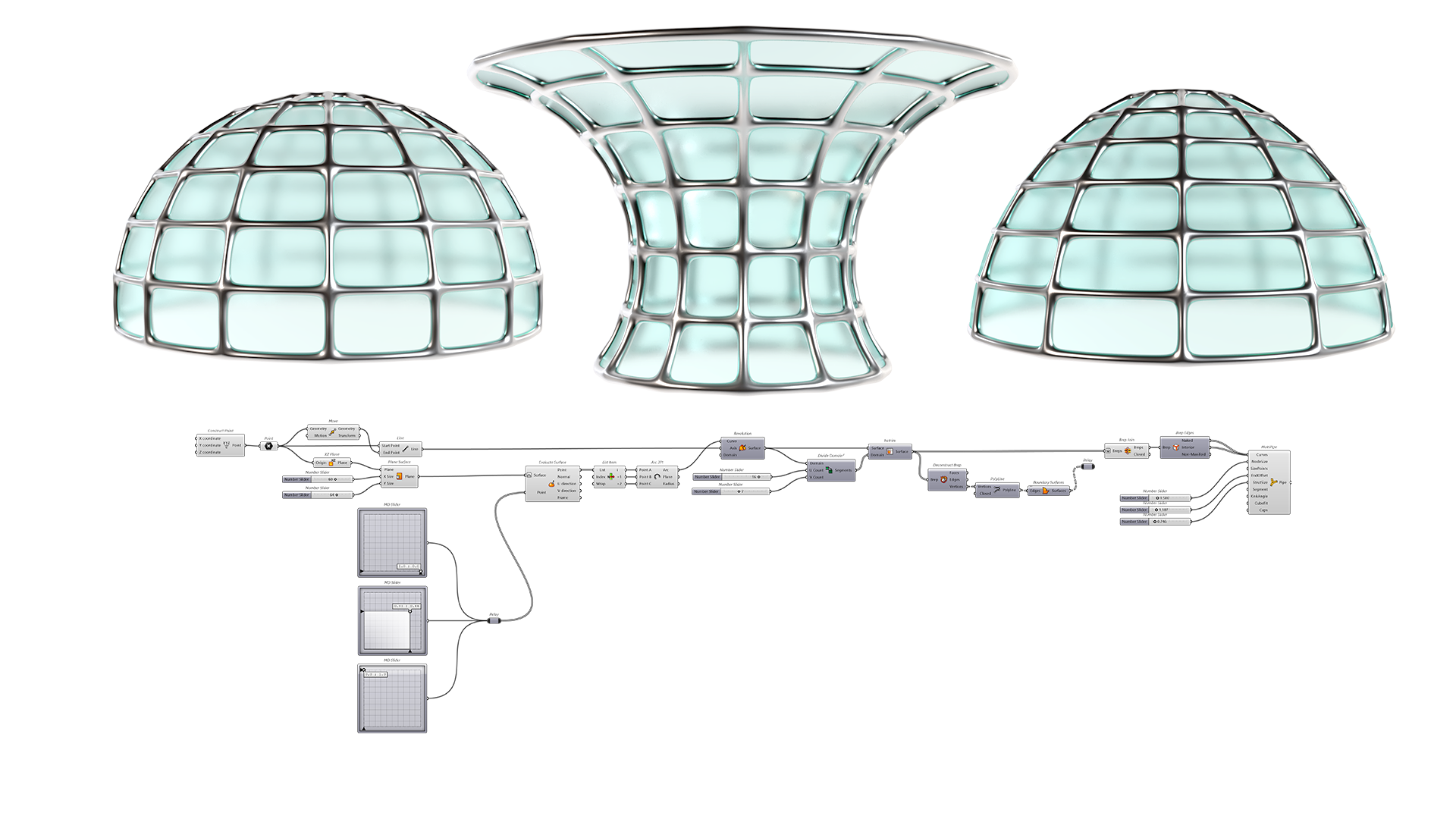
this dome shape. We start by creating
the base surface plane, then extracting some points. We can always change these around to create other types of forums that are not
necessarily domes, more flared towers
and things like this. At the end, we're able to subdivide it and
create two options. One that's faceted, one
that has smooth curves, and we'll be using two
different methods. One of them being
sub D multi pipe, and then also just a
regular pipe at the end. These techniques
are super useful, not just for domes
and things like this, but for techniques that you can use and bring it
into other designs that will help and increase
your knowledge with Grasshopper and therefore
making you unstoppable. So let's jump in
to the tutorial.
2. Base Surface: Alright, so the
first thing we'll do is go here instead of right now, I'll type in units and
we'll be working with feet. Decimal is okay. And
inside of grasshopper, we'll go to File New Document and we'll start with
a brand new document. Now as you can
see, we have the x y coordinate system
here by default. And so what we'll do is create a point right at the origin. So what we'll do is go
here to construct point. And this will give us a parametric reference point that we could use to
create our script. You're always going to
need a reference object or reference point where up your design is
going to be located. So now we'll take this point. And what I'd like to
do is route it through a empty point component, which we will input into here. The reason why is
because then we can set a different point and
change the location. And also notice that we have
this point at the XYZ 0, which means it's going to
be at the origin point. We can always change
that by creating a slider and moving it in the x, y, or z direction. For now, we'll keep it here at the origin point with
this point component. Now we can bring in a reference
plane or a reference x, y, z coordinate system that's going to allow us
to create the dome. The reference plane that I
like to use is x, z plane. And this, as you can see, it creates a reference
plane here at the origin. But what we need
to do is plug in that point into the origin. It now it's tied to that. What it means is that when
we move that point, well, this reference plane will
move with it because it's down here in the logic
with this plane. Now we can start by
creating a surface. So when we create a surface, we'll double-click
here and go to a surface component
or a plane surface. As you can see, this plane is
created here at the origin. So what it's asking
here, on the inputs, it says plane, it says x and y. So we need to take this plane, plug that into the plane input. And what it does is it
will use this reference x, z plane as a reference. And we can always change the location and everything
will move accordingly. The reason for this
is because the logic, that's how it
functions, it kinda goes from left to right. And so the things on the right will not affect
the things on the left. But the thing is that the left will affect the
things on the right. So what we'll do now is
create our x and y extent. Which means that we can create a surface here that will be
a reference for our dome. So we'll go here two x 30. And you can either control C, Control V to create a
copy of the slider. You can also slide
it down, tap Alt. That's the way that I
like to create a copy. We can plug this SR Y. So the Y is going to
take care of the height. So we can always
go to the slider, right-click and change the name. We'll call this height. We'll call this radius. Now we've created this surface that we can change the
radius, mess that up. We have the height, which we can change here. And this is going to be that reference surface
that I mentioned that will allow us to
create that base geometry. And this is a technique that
I like to use a lot for base domes and G,
symmetrical structures. Because you can change things visually to affect your design. And we'll be going
over those things. So for now, we have this. Now let's move on to creating the reference points to create the segment that will
create the overall design.
3. Base Points: Once you have a surface
like this plane surface, the cool thing is that
there's a technique that I like to use called
evaluates service. What it can do is create
points along this surface. So we can use the master
to create geometry. So we'll take this
and we'll start by bringing in evaluate surface, which is this icon with the half dome and a
point going through it. What it will do is create a point somewhere
on the surface. And let me show you how
we'll take this plane, plug it into the surface input. Now for the point, we're going to bring
in an empty slider. And this is not going
to work right away, but let me show you
how to get it working. So we'll go to empty
slider and it says 0.5.5 will go ahead and plug this in to the point input
and I'll hold down shift. You don't necessarily
have to do shift unless you're adding
additional ones. But once you plug that in here, now you see that it
says 0.5, right? So if you look at
this as a graph, it goes 12345, so 0.5 and
then 12345, but it's 0.5. So that means that this
graph goes from 0 to one, from 0 to one, and
the x and the y. And it's going to
create a point right in the middle of it, which means it's going to be in the center. Now what happens? It's actually moving
it by 0.50.5, which means that it's moving
it by the actual dimension. If we want it to move by referencing this surface
as the 0 to 10 to one, you need to go to right-click on the surface and re-parameterize. This will literally turn this surface into
0 to 10 to one, and therefore this graph will make it so
it's in the center. Now we can move this around
to the right, down, up, left. And so we have this
way to create points. Now this is just one
of the points, right? So I'll go here at the top where we'll start
here at the bottom. Sometimes it snaps
to a direction. So it's kinda hard
to move around. So just make sure to click, bring it down bottom-right. So now with this empty slider being plugged into the point, this serve as being plugged into this component which will
evaluate the surface. And now it converged
it from 0 to one. Now we can take this. We have the first. Now I'll slide this down, tap Alt to make a quick copy. Now, add another input
by holding down shift. The thing is that
they are overlapping, so we'll make sure to
move this over now. So this is the first. This will be the second.
We can move this here. Just also make sure that these
are plugged in an order. So this is the first down
here and this will be the second and this going
to be a third up here. What I'll do is I'll take this, slide it down, tap. Now we can hold down shift
and add another input here. As you can see, once again, it's overlapping, so I'll
zoom in and bring this over. In reality. What's happening here is
we've created three points. But the one that's going to
be moved the most is this one because this is really
what's going to create that dome or arc. So let's do that. Now that we've
created these points, let's go into creating
that geometry. So we'll take, there are
different ways of doing this. So let me show you those.
4. Base Arc: When we use the empty slider
and the evaluate surface, we've actually
extracted three points, but they are all inside
of this component. And we want to use
them independently. If we're going to create an arc or if we're trying to
do different things. So your two ways of changing
what this looks like. We could create three
different evaluate surfaces. Plug one into each
to get 1 output. But this is not too efficient. We still have the three points and we can plug them
in individually. So that's one way to do it. It's a little bit
inefficient. Like I said. Well, let's go back to this one and putting it all
into one component, which means that it's evaluating it all
inside of this one. But now we have here
a set point output. We have three points and we
actually want them separate. We don't want them all in here. So what we'll do
is we'll go here to item or something
called list item. This is where we're
actually able to take this information from point
and plug it into the list. And we're able to pick
out just one of them. If I took this point
and I plugged it into something
called a point list. This will give me how
it's organized. 012. So if I go here, well, if our index is a 0, well it's going to be this one. If I put the index of one, is going to pick the middle one. If I put index of two, it'll pick the top one. So we know that this is 012. And so when we bring in something called
the list item, well, we can go down here and add 12, and we know that this is 012. Now, we can plug those
into the ark component. Now, obviously, one of the things we can do so
before we go into this, I do want to share
one last thing. The easiest way to put
this together would be using interpolated curve, which will interpolate
between those, which means create a curve
that goes through those. And it kinda makes up
what's in-between. There's also a degree
that we can change. So that's one way
of creating an arc, but that's not a true arc. That's not a true
circle segment. This is just a curve that interpolates
between those points. We can also change this
and it will change that. So this is how we'll be creating the segment
at that dome. With this, That's
one way to do that. There's also a NURBS curve which will take those points and rather than
interpolate through them, it will use some kind
of festival reference that this will create
more of a smooth curve. But even if we bring it up here, it's not going to go
past the extents. So those are the two ways
that we can create an arc. But the reason why went
in this direction is because I want to
create an arc segment. When we go to an arc, we can create an arc
with three points. So that's why we use this is to use the first is going to be a, the second is going to be B, and the third is going to
be C. So now it's created a true arc or a segment of an arc that we can change
just by moving the midpoint. And we can also create a gap, Let's say at the top and move
things around like this. You can also bring the
bottom one N or up. But we, the most part I think the idea
is to keep this one on the ground because that's what actually sits on the ground
and reads the structure. So with that being said, we've created this segment. Now, let's have fun
and create the form, which is going to be
pretty straightforward.
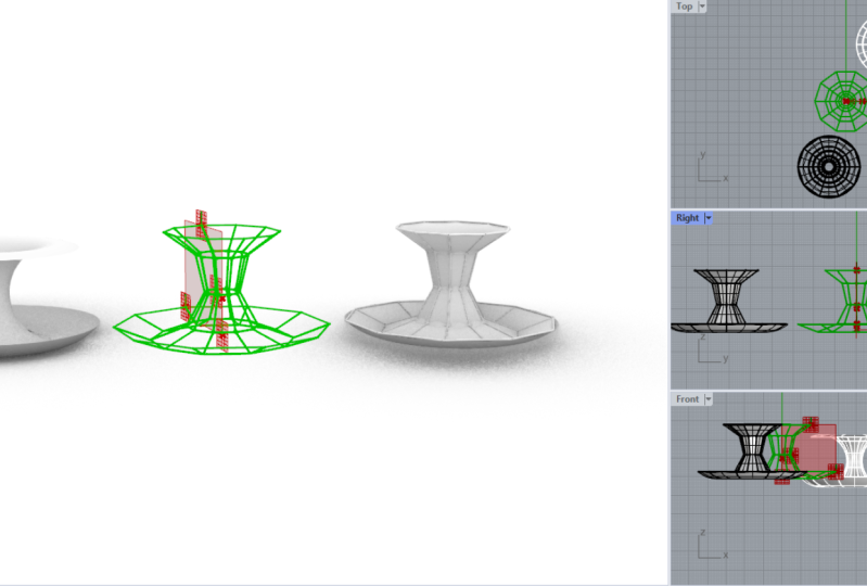
5. Base Form: What we'll do is we'll take
this arc and we need to revolve it around a center line. So what we need to do is take this original point and we need to create a
line segment with it. So to do that, we'll
take this point. And this point is going
to be the point that we move up to revolve
something. We need an axis. If we just take this point
that is located here, and we plug it into
a mood component, which means it's going to
move it up by default. Which means that if you
look at the input here, it says 000 comma 0 comma ten, which means it's going to be moving up in the
z-direction by ten. Why? Because 000 comma 0 comma
ten is the XYZ coordinate system and it's using that as a vector to move the point
once it moves it up. I mean, we can also go here to a unit C and change the
height, which won't matter. So let me show you why. So we're moving this up by 15. Now, I'll go to a line
component and create a line from the starting
point to the ending point. And it will create this line segments that we're going to be using to rotate around. The reason why you don't need 15 is because even
if you don't put 15, you're still going to have
a small line segment. And that line segment
is probably enough, or you don't even need the z
vector is probably enough. Not probably it is
enough to revolve or revolution from this
axis center, right? Because this is where
it's going to pivot from. Think of it as like a nail
being put into a board. And then this is
going to be like a line segment that
we're going to be creating a radius around. That is just a rotation
kind of thing. So we'll go here to this arc, I'll get into the input. And now we are able
to see the form. So it's a, really,
for me, honestly, it's one of my favorite
techniques for creating symmetrical
dome shapes because of the ease of being
able to move this around and change forms like so. You can even do some
flared forms like this. This is more of a form
finding exercise. We can have all of these forms being taken care of with just one script
and having to do, not do the work over
and over again, which sometimes gets
inefficient when we can create one script that takes
care of those designs. So with this, now
we'll be moving on to some techniques
for subdividing. So what I just did
here was they took everything and I'm
just hiding it. But actually I undid
that because they want to be able to see
all the steps for now. We'll be creating the
subdivision next.
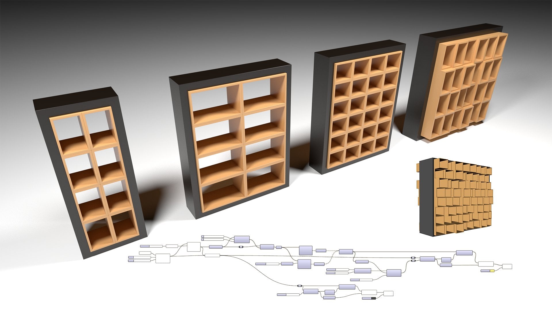
6. Subdivide Form: Here is where it can get really complicated in the sense that
to sub-divide a surface, there are many
different techniques. In many different methods. Some of them being plugins. So if we have, if we take
a look here at lunchbox, lunchbox is really,
really useful. You can find that
at food for Rhino and you can download the plugin, install it, reset grasshopper, and then you should have it in. The cool thing about having
lunch box is going to be having all of the options
to sub-divide a surface. These are already
created for you. Great, because they are free and they have a lot
of capabilities. But I feel like I want to start slowly by sharing with you the most basic way of subdividing
a surface by default. So the way that I subdivided
is using isotropic. You don't need a plug-in
or anything that already comes by
default with Rhino. And there are a lot of things
and methods to that too. For now we'll be using it as
just regular subdivision. So we'll go to the service, will go here to isotropic
and bring in ISO trim, width, divide domain squared. These two always come
in together because This takes care of the work, the subdividing, and this
takes care of how it's, how much it's going
to divide it by. So we take this surface
and we plug it both into the domain and the
surface input. Then the segments
will be plugged in. And you'll see that
automatically it's working. Why? Because when we go here and we hover over the u and the v, we see that there's
numbers in there already, so we don't have
to put anything in unless we want to
change it to 1010, does not look like what I want. So we'll change this, will go to five. Copy this over. Now we have the subdivisions taken care of by this.
Here's what happens. As your logic grows. Your script is going to have
information here at the end, which means that
it's towards what you're, what you want to do. And some of the stuff back
here is not as important and actually contend to overlap with some of the
things that you have. So if you see these dots and these things that are kind
of getting in the way. But we'll take this, will also take this surface
and disabled the preview. So now the reason why that
was happening is we had this surface and the subdivided
one on top of each other. We don't want that, although
we could always come back to this surface and use it, right? Because we will, all we're
doing is disabling it. The most important thing
is going to be down here. And let's take a look to see if all of these parameters still work. They all work. And that's the most
basic subdivision is going to be
rectangular subdivisions. This, these are just surfaces, so technically there's no
thickness to anything here. That's what we'll
be moving on to, is taking this and
rather than them having rounded off segments, we're going to do straight
segments. This way. We have two ways of
subdividing the surface, not just by using isotropic. Isotropic plus some
additional things that we can do and
I'll share with that, let's go over those things.
7. Development Wireframe and conclusion: First thing we'll
do is we'll go to deconstruct be rep.
What that will do is basically take all of
these and explode them into or in the same way that we extracted some
points in the last one, well, we need to extract
some surfaces here. So what we'll do
first is list item. We just picked one of all of the surfaces
that we're in here, one out of 40, the
index is of 0. So if we were to take the
midpoint of all of these, this would be index 0. With that, now we can go
into the deconstruct be rep, and this will deconstruct this into the surface
edges and vertices. Now what I want to do is take
these vertices and let's plug them into a pointless
point list will always show you how the
information is organized. And if you can't see, it, will change the size
to something like 1.5. And you see here we have 0, we have one, we have two, and then we have three. So we're going to
connect the dots to create that line
segments gonna be 0123. And then it's going to
close into a polyline, will take vertices,
will go to a polyline. And we'll plug those vertices
to the vertices input. And it will create a
line segment from 0123. And when we go here to close, we'll go to set boolean to true. And it will actually
close that down. Well, since we've done
this just to this one, well, if we do it
to all of them, so we'll override this. Now. We have it created
for all of them. All we need to do is take
this information here. So this one, you don't need it. This was just to extract one
to see how we can do it to one it now we're overriding that and we're
doing it to all of them. With this closed polyline. Well, we can create a planar
or a boundary surface. Now we can take this
disabled preview, this disabled preview. And so now we have two
options. Delete this one. I'll leave this one here just
to show that we use that. And for the surface
output, well, what we'll do is
we'll bring that into a geometry empty component. By bringing this into
a geometry component. Well, we'll just bring this out here because that's option one. And we can kind of group it. So Control G to group. And then we can call
this option one. Got my texts, option one. And this other geometry
is going to be, it's all copy this down
here, like this here. Disable the preview.
It's a little bit redundant in the sense
that I could use that. But sometimes if you have
these geometry components, it's good to keep
them consistent. So we'll go here to option two. We can disable the
preview on this. But we have this option
faceted like this. Or the other option, which is going to be
the rounded off once. Next we'll be creating
the wireframe. So we'll take either one of these two will go
with option one and will be joining
it using B-Raf join. The reason for this is right now 50 surfaces and those 50
services are separate. The other way to check this, It's not just the check of
ring here at the output. We can middle click and bake. We can take all of those
and move them over and see if we'll go to shaded mode. And we'll see that
actually here. They're separate, which is fine. But what happens is if we were
to turn these into pipes, then we'll have overlapping. We have two lines here, one here, one here, and they're overlapping, which means we will have
redundant geometry. So the reason that's the reason why I go here to be rep join. Is because now as the output is, has one open B-Raf. And I can also check
that by baking it. And now when I move it over, this is a solid dome, but it does keep the creases, but they are singular. So one per each, they're
not overlapping. Now we can take this. Let's go back. Now that it's joined, we're going to be using the next component
called Europe edges. Now I will disable
the preview on the joint B reps and
just use this and will be extracting a difference between the naked curves
and the interior curves. Why? Because right now we have all of these minds are inside
of this component. We need to take them
out and separate the outside wants
from the inside ones. So I'll go here to
a curve component. Plug-in the naked ones, which are the outside once
and then the interior ones, which will be nice
on the inside. Now with this, I would actually start using
the next component, which is called a multi
pipe sub D multi pipe. So now we'll start by doing the interior lines
into the curve input. And by default it's
going to work. Now, the important
thing is going to be to know how to
use this multipath. The way that I use it, I use
three different sliders, so I'll go to 1.500. I'll create three
different sliders with the same value starting. And I'll plug in. The first one is going to be the node size. It's going to increase in size. We are going to adjust that. Then we're going to
have the end offset, which we also want to
be able to adjust. And then we have
the struts size. Now we can decrease
the spread size. And some of these other
parameters will help us work. More of the connections will decrease some
of the size here. And here we have more of that connection portion That's taken care of the
inside portion. Now if we take this, we'll be using a multi
pipe for this one and just a regular
pipe for this one. I'll copy this slider over. That's two ways to
create a structure. So you can use regular
pipes or you can use something like
sub D multi pipe, which will take care
of the connections and actually make it
look a lot nicer. We can always go back
to something like this and then increase, make it more subtle
or the connections. And at the end, we
have this pipe, we have the inside wireframe. And if we wanted to, we can also change that
option from these that are rounded to this one that
is straight sections. Now the only thing is we do
need to flatten the input. Because right here we
see a dashed line, which means that it has
information that is grafted. We won't get into
that right now, but just make sure that
that is flattened, which means it will take care of it and it can
do both of these. So we have two options
for creating domes. The technique that we went
over is going to be reading the base geometry using
the reference plane, a surface, and extracting
points from it. Then revolving it
around a center axis, which was taken care of by that small line
segment down here. Then at the end, we sub-divide the surface and turn it into a
wireframe design. We also have here the surfaces
that cover that don't. It's not just a dome form. It could be many
different forums. So we saw that we can
create a flare like this, more like a toroidal design. And if we haven't
gone crazy here, we can always increase
our subdivisions for the U and V count. With that, we are
concluding the tutorial. This is a very useful technique, not just for forums like this, but for creating
parametric forms using this type of method. So thank you very
much for being here. I really appreciate
you coming by. Let me know if you have any questions and
if you enjoy it, it also let me know. I'd love to do more
tutorials like this re-share techniques so
you can get closer to becoming more proficient with your parametric
designs and you can use them in your future designs for your clients and
things like that. So thank you very
much once again, and I hope to see you next time.
 DCO Graphicstudio