Transcripts
1. Intro: In this video, I'll be sharing
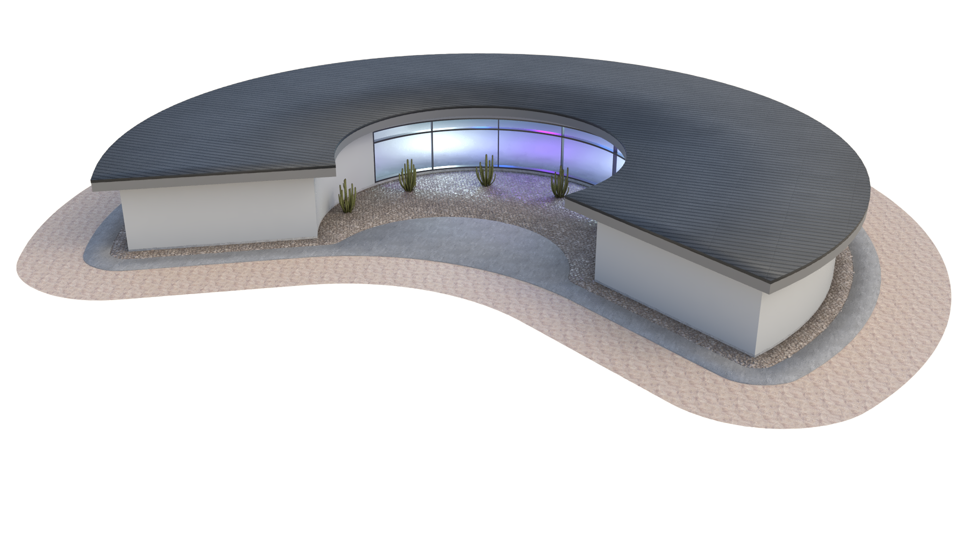
how to create this design, which is a courtyard building, that is a single
standalone building that is fully parametric. I'll be going over a lot of techniques that are useful for many other designs
will be creating this design that has walls, it has openings, it has roof, roof overhang, and a few details that are useful for
buildings like this. There's not going to be a lot
of detail going into this. This is a base form. From this. We can take that building and develop it using some
rhino modeling and save ourselves some
time in designing and kind of coming up
with the best design. So what we'll do here is let me share with you some
of the parameters. The building form. This is
the depth of that building. And like I said, the concept is going
to be to create some, a building that will shelter you from all sides from the sun. And you can even do some
planting on the inside. I'll share with you here. Let's see some of the Let's hear the depth of
the foundation. We have the overhead. Here, we have that form. And one of the most
important things, of course, is going to be the door opening. And we have it here, so where it creates
an opening through both the front and the inside. But we also have that
ability to make it. So it's not necessarily
all the way in. Let me show you how
we can make it. So it's only that
window on the inside. I'll be sharing how the
program works by walking through all of the
steps in detail. This way you can understand
how it all functions. The program is a little
bit intimidating at first if you've
never used it. But once you get
used to it, you'll see how important it is to understand it and how you can
use it to your advantage. I'll also be sharing the
script so you have it by your side as we move
through the exercise. This way you can always reference
back to what I'm doing. So hopefully you're excited about getting started
with Grasshopper. And let's jump right in.
2. Base form: So the first thing we'll
do is bring in a point. So I'll go here to
construct point. Then we'll move this point
here over to the right. So we'll take this point and
I like to route it through another point components so
we can change the location. Now we can use this
one and now move it. So I'll go here to
a mood component, will plug the point into
the geometry input. Now we can move it in
a specific direction. In here, I'd like to
go in the x-direction. So double-click unit x
and bring in a slider for the size of the
length of the arc. So let's go here to 15. Now with these two points. Now we're going to bring
in the arc component, which is the one that I like to use this arc three points. And the reason for that is
because it actually gives you some control as to how far apart these
points are going to be. And then there's
going to be like this amplitude that's going to be going into this direction. So what I'll do is
I'll take this point and this point and create
a line in between the two. They'll go to a line
component between the start point being the
first starting point. Then that geometry that I
moved in the x-direction, That's going to be the
endpoint for the line. With this line segment. We now want to get the midpoint. So I'll go here
to a curb middle. This will give me the exact
midpoint of that line. Now we can take that line
or that mid point and move it in either the y,
positive or negative. Let's go here to
move this point. I'll put that midpoint
into the geometry and then the motion is going
to be unit y. And negative. This way it moves it
in this direction. Now bringing the slider. So I'll go here to 15. Now I can move this slider around and have the
amplitude of the arc. So with those three points, I'll admit, I'll
hide this midpoint. And I'll take this
point that we moved up, that's going to be point B, that's going to be
the middle point. Then we're going to plug in
the first into point a, then. And point C, we're going
to be doing this one, the one that we moved
initially in the x-direction. So we'll go here to
point C. With this, we have the ability to
create the length building. We're going to have
the arc amplitude. That's going to be the base
geometry for this building. With this, now we can
take this arc and we can offset it with the
depth of the building. So we'll take this arc, we're going to bring in the offset component, offset curve. We'll plug in the arc into the per input it now we'll give it a distance
book cohere to 15. And the reason why I do
15 is because I want to do more than ten. That way we have more
than from 0 to 100. And this way can just move
it around at that level. So we'll go here to this one. And we can move this around. And we see that
we have offset it by whatever slider we have here. Now what we need to do is create the line segments that are
going to close this down. So to do that, we're going to, we already have the points here, but it's okay to bring in this component
called endpoints. Which what it'll do is it'll give us the end
point for this arc. I'll create a copy of that
component so we can create the start and end points of the other arc here
that we offset. Now we can connect it
using a line component. We're now going to create two line segments between the start and start point and then the end
and the end point. So we'll go to start and start
going into that endpoint. And we'll do the
same thing here. We basically close
that down and we can see that line segment a
little bit better this way. The cool thing
about this building form is going to be that it's going to create a
courtyard on the inside. And that's the concept of this. This would be a structure that would actually
be in the desert or something like that
where it would cover from Sun most of the day. And you can actually
either gathered in here or plant on the inside. So with this, now we
have those two segments. And this now we can
actually create the walls. But what we need to do first
is joined that together. So I'll go here to a join. Curves, will join
the first dark. The offset are hold down
shift to add another curve. And then I'll hold down shift
to add those other two. Then I'll go to the
input button it. And then here at the output, it says one closed planar curve. And that's great because
that's what we can use to create our floor plan. What I'll do is
I'll go back here and we'll make sure it's a smaller building
at first because we can always make
it really large, but we want to keep it tight. Let's go here to something 25.
3. Walls and openings: Okay, Now with this, we're going to create the walls. But we need to do is
go here to this curve. Now we're going to offset it. I'll double-click here. Offset curve. Then I'll plug in this
curve until the input. And automatically it's going to offset to the inside,
which is good. But we want to give
it a specific value. So we'll go here to 0.5. Now we can create the walls. So the way to do that,
this technique is going to be to create a surface
between these two. And as long as they're
on the same plane, you can do this. So bring in boundary surfaces, will take the outside curve and the inside curve and plug
them into the input. Then as you can see here, they're going to overlap. So the way to fix
that is right-click on edges and then go to flatten. This will make sure
that it creates a surface between
those two curves. And now we can take this and extrude it for a wall height. So now we can take this, we'll go here to
extrude the surfaces. The direction, we'll go
here up in the z direction. So it goes up. And we'll bring in a slider to do the height of that extrusion. It will go here to 12th. Now we can disable
the premium on all of this stuff and see that we have basically
the wall height. They can care. For this next part, we need
to create the opening. Now, the opening is going to be located here in the middle. So we can either use
this midpoint or we can pick a point along
that initial curve. Either, either way. When you extract that
point, like this one, this midpoint that
was smoothed in. Now we can use that to create our line that's going to be extruded to
create that opening. So I'll go here to move.
We're going to move. This point in the x-direction, will go here, X or unit x. Then we'll plug in a value, let's say 4.5 in
the x-direction. Now what happens is since
we're doing it from the midpoint to one side
and then to the other side. We actually need to
divide this by two. We will take ten divided by two. And when you do division by two, it's going to give
you a component that has two at the bottom as B. So we can plug in the
ten into the a and then the result into the vector. Now we can do the same thing
in the opposite direction. So I'll go here to negative a plug-in the vector
into the negative input. Now, the result, I'll hold down shift and add it
into the motion. Now we have two points
that have been moved from the center by half
of the overall length, which gives us the true length
between these two points. With that, we can take
those two points and create a polyline between those two. So I'll take that geometry
which are going to be the points that are
moved into the vertices. And if two tennis too
small, which it is, let's go here to
another value and will increase the maximum 50. Now, we can take
this and extrude it up to be the height of the
door or up the opening. So we'll take this polyline. We'll go here to
extrude direction. It's going to be in the unit Z. The height is going to be, we'll bring in a slider 8.5. Now with the surface, we can take this and extrude
it in either y or yeah, we have to do it in
the y-direction. So one trick is
going to be to move this in this direction
and in this direction. Or move this surface in this direction and then
extrude it in the opposite. So let me show you that trick. And that's to make sure that it intersects the form completely. We'll take this in wool first, move it in the neck in
the positive y-direction. We'll plug this in. We'll
bring in the unit y, and we'll bring in a
negative component because we know we
want to move it in. The positive y will have the negative here
because we need that. But we'll take this and move
it and save 15 this way. Then I'll take this and
disabled the premium. And I'll take this and
extrude it in the negative y. So I'll take this ring
in an extrude component. We'll plug in this surface
into the extrude base input. Now the direction is
going to be negative y. So I'll copy this
slider down here. So I'll slide it, tap
Alt and make a copy. Then bring in a negative value. So I can extrude it in
the opposite direction. Now, if I do the same amount, well it's going to shift
it by the same amount. So we can kinda do
some thinking like this and then extrude
it further this way. If we want it to, let's say, open all the way through
to the other side. Now we could have a different
size opening this side. And we can do that by going
back to the original curve, may be taking this heading, the midpoint of this one, and then doing that same
process that we just did. But for now, we'll
keep it simple. We'll have this extrusion that intersects this and
we'll subtract it. This will do is create
the opening for the courtyard and
possibly the front entry. Now this is going
to be a basic form. So don't expect to
see a lot of detail. Some of those
scenes can be taken care of inside of the modeling. So for now, what we'll do is we'll take this form
and we're going to go to a different
solid difference. We're going to take
the walls into a and then this box
into your app B. Now it's going to subtract it. So now I can take
that form that we have here and
disable the preview. I'll do the same thing
with the box down here. We still have base
surface previewed. So I'll disable the preview
either by right-clicking and clicking on preview
or select multiple, and then do middle click
and disabled preview. Now, I do like to show if you don't see the things
the way that I see them, it's because you
don't have display and all of these enabled
and I like to have that. So you can see, read the icon. So you can see the
icon, read the inputs. And it makes it a
little bit easier. So with that being said, let's move some of these
parameters around. Let's take a look at the
building and what it does. So this is going to be these
two points in-between. That's going to be that arc. The opening. We can kinda see that opening
through the size of this. And the, there's going
to be an offset. That's going to be that offset. And then here, height. What is going to be the
overall length and the width? We have lots of parameters. And that's kinda the form
that we're trying to go for. Next thing we're going to do is not only do we
want to subtract it, but we also want the form where
the window is taken away. So if we want to
bring that back, there's we can do an intersection or solid
intersection between the walls. That solid. So we'll plug in that
extrusion into B reps B. Then disable the preview here. And so now we have
where they intersect, which is going to be the same place as where
the openings are taken. And I see a bit
of an issue here, but I'm going to change
some of these sliders here. What I'm doing is I want to take this and make it a
little bit wider here. So it kind of creates
a clean opening here. And I actually don't want
it to offset that morning. We have this one at ten
and this one like so. So sometimes we can use some of the components that we don't
necessarily want to preview, but we can use them as guides to see how our model
is intersecting. And the reason for that
is a lot of the times you don't want to
preview everything. This way you can focus on
the things that you're changing and most of the
stuff that you're changing, it's going to be kinda upon the right-hand
side, the outputs. So just keep that in mind that some of these you may
not want to have on later on, but you might, might want
to keep on to reference. So with that being said, we're now going to move on to
creating the roof overhang. Then we're going to create a small detail to
connect between the two.
4. Roof: On this next part,
what we need to do is take that bottom outside line, bring it up, and
then offset it to the outside to create
a roof overhang. So we'll take we'll go back here to where we joined
this base form curve. What I'll do is I'll give
myself a little bit of room. So I'll take this
and move this down. Then I can take this
and move it up. So I'm going to move this
curve in the z direction. So we'll go to unit
Z. But I may not even need to do that
because I already have the height extrusion
of the wall. This is the height of the wall. That's the height of the window. If this is the
height of the wall, then I can use that Z vector that I had already created for that wall as the
vector for our motion. Now we can take this, now that we move that line up here and we can offset it
to create the overhang. So I'll bring this down here. I'll go to Offset. And I'll bring that geometry
into the curve input. And the distance, well, as you can see, it's
offsetting to the inside. So I'll bring in a
negative component. This way it offsets
to the outside. And I can now use a value of, let's say 2.5 to
create that overhang. Now with this, I can create a boundary surfaces and extrude this up to create
the thickness of the roof. So go here to extrude. We'll bring in that surface
into the base input. And the direction is going
to be unit Z, or going up. And I'll go here to 1.50. Now we've basically taken
care of the roof form. Now it looks super basic. So what happens is typically
you're going to have the roof rafters and then you're going to
have aphasia out here. And so we can do that because we have this curve
that creates this form. But what we can do is take that offset and offset it
again. So I'll copy this. Tap Alt and plug in that curve again to the input that's
offsetting by two. So we'll just say
here to point, to. Now create a surface
between these two. Using that same technique, we will use boundary surfaces. And we'll plug in
the outside one. The inside one will
flatten the input. So we know it's just
creating that surface here. And what's going to be
different about this? And it's a good trick for
a good technique is to, since I know how
much I'm extruding the roof by the aphasia. I want it to go past the bottom. I actually have to
take this surface, move it up and then extrude it down by more than
thickness of the roof. So with all of that being said, let me
show you what I mean. We're going to
take this surface, we're going to move it up by the same amount
as this extrusion, this surface into the geometry
and the extrusion into, or that same vector
into the motion. Now we can kind of forget
about it down here and even disable the preview on this it now we can
extrude this down. And if we use the same amount, well, it's going to just
extrude down the same amount. But if we do more, we can actually pick
the overhang amount. That's like that's super
useful one to know. So we'll go here to extrude. We'll use this geometry
into the base input. Then the direction is
going to be negative. And it's going to be. This value. Plus we're going to add
the overhang amount. If that's what you want, we can actually pick a specific value that's more than,
more than this. But if you want an
overhang value, this is how much, this
is how you would do it. 1.36 plus D overhanging amount. So I'll do 0.25. Then that's going to be
down in the z-direction. So we can actually do the z
vector here, then negative. Then the result is going
to be the direction. Now we can have this be the overhang amount and it's
tied to the height of two, match the height of the roof. If we go to a foot, Ruth rafter and
there's going to be 0.56 inches overhang here. The cool thing about this, in my opinion is that we have
a different material here. We have a roof rafter here. And technically, if we move the curve up here
and we extrude up, that would be the roofing
material. So let's do that. Let's make sure
to do this clean. And remember that we created this boundary surface down
here that we moved up. Well, we don't need
to move that up. We need to copy the fact that that was moved up and
move something else up. We're going to move
the outside line up. So take that curve, I'll plug it into the input. And now here we have
the outside curve. Well, now we can turn that into a surface, boundary surface. It now it can extrude that
up for the roofing material. So I'll go to extrude in unit z and I'll do 0.250. So we have roofing material, we have Asia or outer trim. We have roof rafters. And here we have outer walls. We have our window. That concludes the basic
form of the building. Now I'm going I am
going to create here a, another basic TRIMP form. And I'm going to show some
tricks to get that done. Other than that,
those are kinda the techniques and the tricks that I wanted to share
for the most part, though, disabled
preview on everything except for our outputs. This way I don't have things
overlapping and it's a lot easier to visualize things. And one of the things
I want to share too, is you can always change
the form of the building. So this is fully
parametric and we can change the location of
where we want this design. The idea is that we're going
to align this east and west. And then the sun is
going to go around here. And we're going to
have the ability to plant and gather
on the inside, whether this is a
really hot climate or you just want some privacy. But with this, let's
go to the next part, which is going to be the form between the
wall and the roof.
5. Trim Detail: What we'll do is we'll take
all of this portion of the design that kinda
takes care of the roof and middle click and
disabled premium. And we'll go back to the place where we had
this initial line. Now this line here we did move it up to create
the overhang. So we go back here to this one. Now, what I wanna do is create the overhang design
or the trim between the overhanging
the wall will take this and we'll go
to offset curve. We'll plug that into the input. And it's offsetting
to the inside. So I'll bring in a negative
value and offset it to the outset. I'll say 1.5. That would be a little
bit smaller than that. Now, the next thing
we're going to do, which is a little bit
counter-intuitive, is take this and offset it
back to the inside. This way. We can then move it down
and create a slope form. So with that, we'll take
this and we'll offset again. Copy the offset, plug the
offset into the input, and then use a different slider that offsets it to the inside. Now, I wouldn't do it
exactly the same amount. I would do it a little
bit to the inside. And you'll see exactly why this. For this next step, we'll take this and we'll
move it down. It will go to move. We'll take this curve, plug it into the geometry input. And then the motion is
going to be negative. Because we want to
go down and then Z in the downward vector. Then I'll create
a offset slider. Now we can move
this up and down. Well, the reason why we
did this is to create a slope line between
these these two. Now we can take a
loft component. We can loft this top one and this one that we
brought in and down. So we'll take that and this
one holding down Shift, we'll add the other input. And when we flattened the input, it will create a slope or a diagonal between
those two offsets. So this is why we offset it to the outside to
create an overhang. And we offset it
back to the inside to make sure that
we have a slope. The reason why we want to
keep a little bit more than the wall is because
we're going to subtract it from a form. To do that, we're
going to take this. We're going to plug it into
a cap falls component, which will make sure that
this is actually a solid. It will actually give us a solid between those two slopes. It'll give it a cap at the
top and a cap at the bottom. What we can do now is use that
solid and subtract it from a form that we have with the polyline that
we created at the beginning. Some of these designs do get
a little bit complicated and I want to be able to
explain everything completely. So if you do have any questions, if I went over some by one
over something too quickly, please let me know
in the comments. I want to make sure to have everything clearly
explained for you guys. So now that we've
created that solid, we're going to take that
initial line. This one. We're going to extrude it
by the height of the wall. This way we create a solid
from that extrusion. And this goes into creating things that you're not going to see in
the final design, but it'll help you in
completing your design. So I'll use this bottom
one and I'll plug that into a boundary surfaces
to create a surface. And I will extrude this
up by the same height of the wall so that this is going to be the
height of the wall 12. And I'll take this and I will extrude it up by
the same amount. Now I can either bring in an extrude component and plug them in or I could have
just copied this one. So either way, we want to use the same vector that we used for that
one, for this one. Now, as you can see, it actually turns
it into a solid. So I want to disable preview because I don't
want to preview that, but I do want to use
that as the solid that I subtract from this. So I'll go here to
solid difference. Now go to solid difference
between the reps a, which is this, and be reps B, which is going to be solid,
that I just extrude it. What it will do is give me the, what you see in green, which is the result of that. And I can disable the
preview on everything else, including that form. Now I've created this really
neat trim that is free. It's kinda that clean
connection between the wall and the roof. So now let's go back
to this roof section. Enable the preview and
enable the preview here. So now that looks a lot cleaner. And it kind of takes care of
that, that connection there. All we would need to do
here is apply materials. And inside Rhino modeling, just getting some of the details for the windows and
stuff like that. And that's what
we'll be doing for the final result that'll be
showing in the thumbnail of stuff is some more
modeling that I do that I'm not
going to be filming, but this will just go
over the overall form. So the last thing that
we'll do is create the base form or the
base foundation. Now, what I'll do is I'll just take that overall
form and I'll be extruding it down to
create the floor slab. And we've basically taken care that back here where
we created the circle, the boundary surface that we extruded to subtract
from this form. Well, we will take this, will extrude this down. So we'll take this
boundary surface, go to extrude that
into the base input, and then go to negative Z. And we'll just bring in a
slider will just say 1.5. That concludes the tutorial. Like I mentioned earlier. If you have any questions, please make sure to let me know. I would love to know
where you got stuck. If I got, if I got something
wrong or if you have future ideas for videos,
please let me know. I'd love to know some feedback. And thank you very
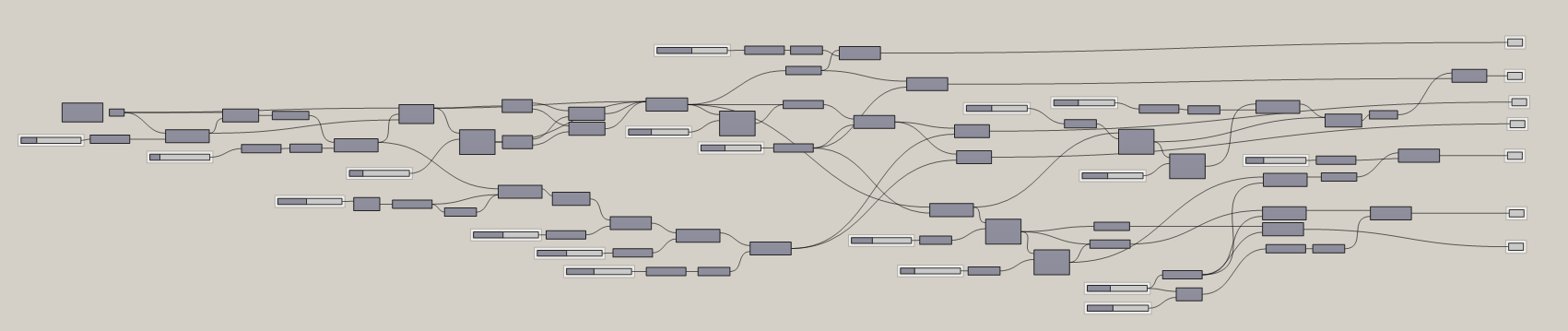
much for watching. So what I've done
here at the end is just cleaned up the outputs, brought them all out here. And then done the same
thing with the inputs. Just kind of cleaned
them up, labeled them, and then I group them
together so I can see which are the inputs that
are the most important ones. There are some that are not as relevant that I don't
necessarily highlight. But yeah, if you
have any questions, so I'll have both of these
under the script vault portion of my website and consider
becoming a member. That really helps me out. And I'm pretty sure you
guys will learn a lot from a lot of the things
that I have here. So thank you very
much for being here. I hope you enjoyed this content. Let me know if you
have any questions and I hope to see you next time.
 DCO Graphicstudio