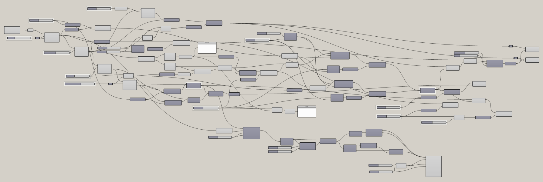
Transcripts
1. Intro: In this video,
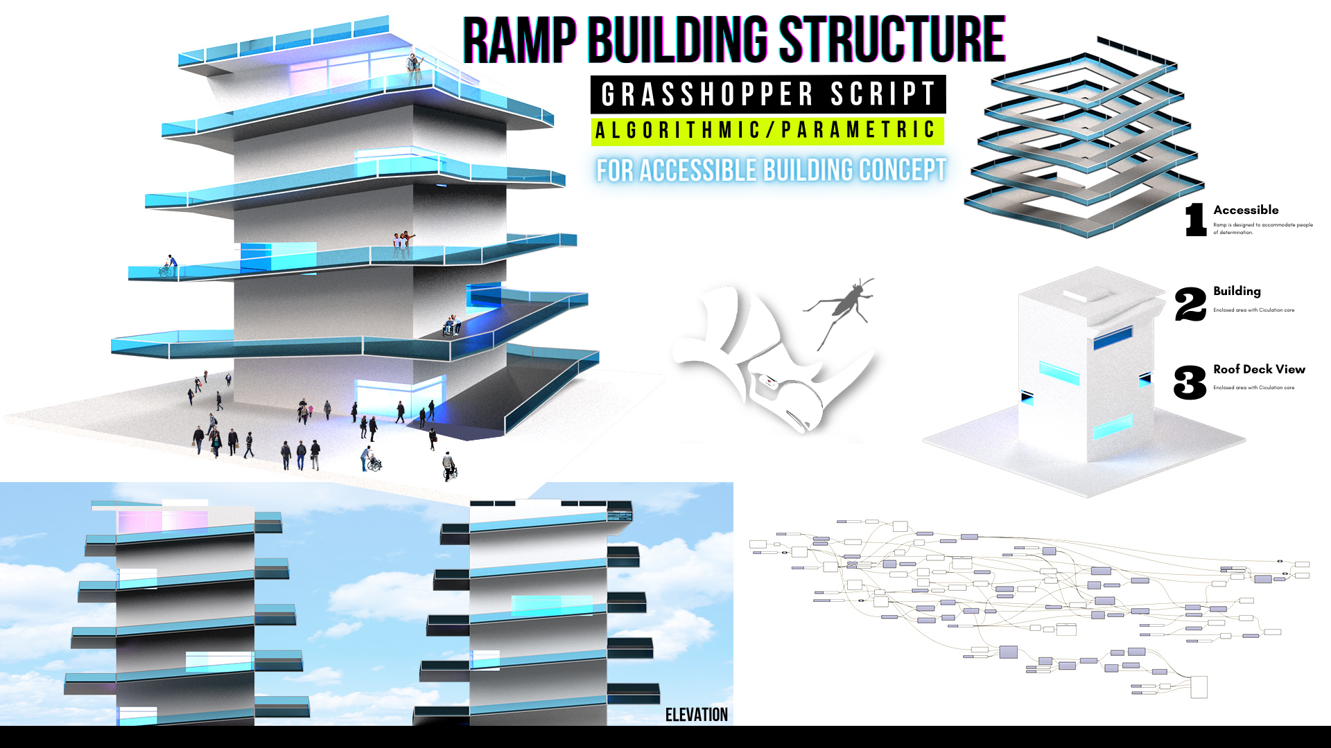
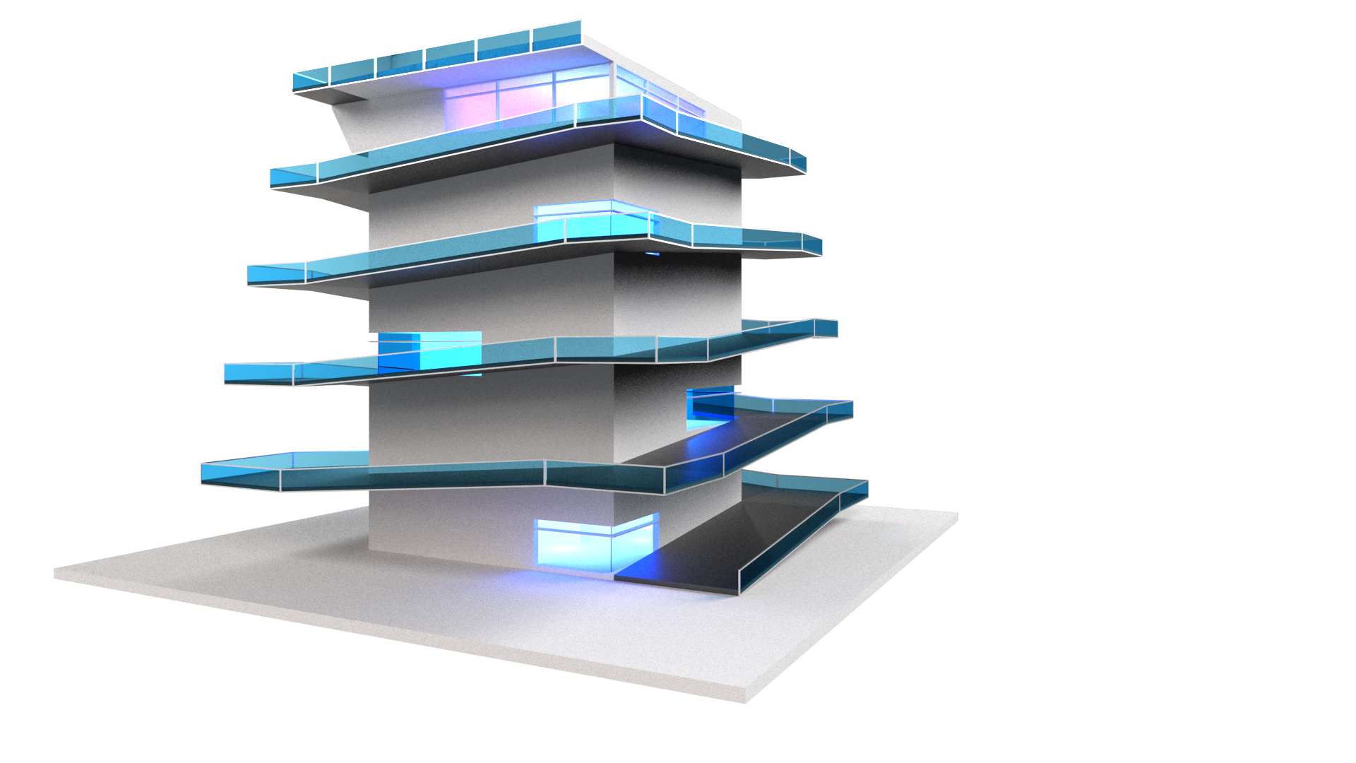
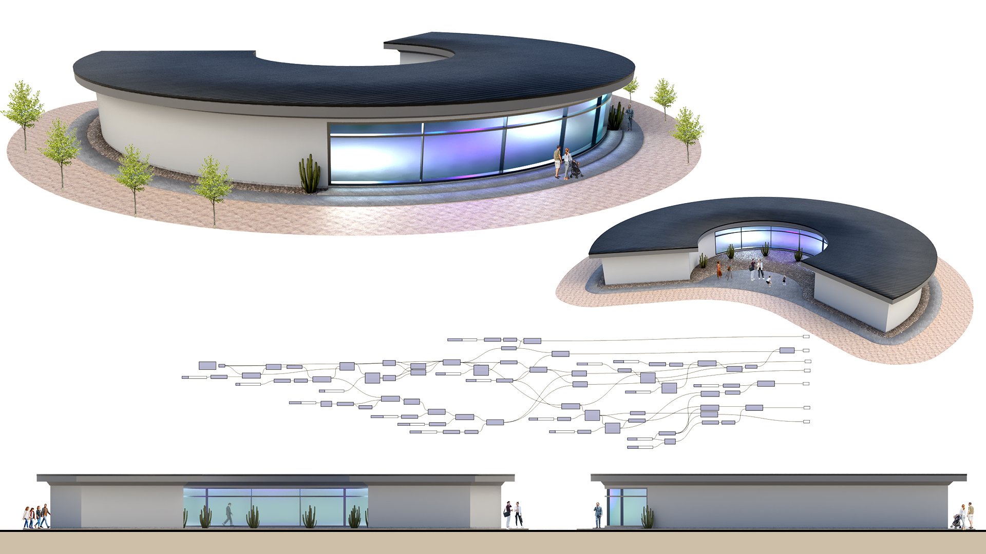
I'll be going over how to create this design. This is a building that has a ramp that surrounds
the entire building. We also have an inside space
and a circulation core. I'll be going over all of
the steps in detail here. So thank you very
much for being here. I'll be sharing how the
program works by walking through all of the
steps in detail. This way you can understand
how it all functions. The program is a little
bit intimidating at first if you've
never used it. But once you get
used to it, you'll see how important it is to understand it and how you can
use it to your advantage. I'll also be sharing the
script so you have it by your side as we move
through the exercise. This way you can always reference
back to what I'm doing. Hopefully you're excited about getting started
with Grasshopper. And let's jump right in.
2. Base Reference Forms: The first thing
we'll do is type in units here inside of rhino. And let's work with feet
and then feet and inches. The reason for this is this is going to be a fairly
large structure, so Pete would work. But honestly any units
that you use would be fine for this design. So now let's move on here
inside of grasshopper, I'll create a new document. Now I'll go here
and create a point. So I'll go here to
construct point. And this point, I'd
like to route it through a point component. This way we can change the
location of the design. Now we can start here using this reference point to
create our base form. I'm going to be
creating a rectangle. And so we'll go
here, double-click, and we'll bring in a
rectangle component. The plane. We can plug in the
point into the plane, which means that that will be the location of where
it started from. And now let's change
the x and y size. I'll double-click and
bring in a slider. I'll type in 12th. And now I'll plug, I'll take
this and actually create a copy because I want to
separate inputs for the x and y. This is going to be
the center core of it, which would house the
elevator and the stairs. So we'll keep it here so we
can change the dimensions. Next, we'll move on to basically creating the base curves for where the forms
are going to go. So this is going to
be the elevator. Now we're going to offset
another line to kinda create that building inside space. It will take this and
we'll go to offset curve. We'll plug in the rectangle
and to the curve input. Now the distance that's going
to be the offset amount. I'll take this, slide it over, tap Alt and create a copy. I can just quickly create a slider That's just copied from that original one. Now we have this space that has been offset by
that specific amount. So we'll go here to 30. And so that's the
building. Next. We're going to be
creating the ramp area. So it will basically
be doing this again. So I'll take this,
slide it over, tap Alt, free to copy. And now I can plug in this
curve into this offset. And notice that they maintain, so we'll have 30 here. But it maintains that even though we're changing
the slider on this one. So they're all depending on each other as we go down
the logic here. So with that being said 30, it's a little bit too
much for the ramp, so we'll kinda decrease it here. Maybe this is a little bit
too much for the building. And lastly, we're
going to be creating a slope form for the ramp. So I will be taking this
an offsetting this again. So slide it over tap Alt. Now, this is going to be where the form will
be subtracted. So what I'm doing
here is basically creating with this logic some base curves
that will determine the minimum and maximum
of the elevator, the circulation
than the building, the outside circulation. And then lastly, the subtraction of the form using the space
between these two. And of course this will make
more sense as we go along. And so for now, let's start by creating the elevator tower.
3. Core and Floors: What we'll do is we'll go
here back to our rectangle. Now we're going to turn
this into a surface. So I'll double-click here. Go to boundary surfaces. Now we can extrude this
to a specific height. So I'll go here to
extrude in which direction unit Z is when
we extrude something, it's going to ask us
for our base geometry, which is going to be the surface
that we want to extrude. And the direction is
going to be a vector. So it has a z vector. So basically going up. And now we can plug in a value. So I'll take this
one's again Alt Copy. Now we're reading
the building height. So now that we have
that base form, we can move on to
creating the floors. As you can see, we have our base rectangle and we
have our offset rectangle. Well, we need to create a
surface between those two. The way to do this is to
bring in a boundary surfaces. Now we can plug in both
of those holding down shift to add another input
and flattening the input. This way. It only creates a
surface between these two. Otherwise, it will actually overlap them and you
don't want that. Now with this base form, now we can create the array
or the floors will take this, will go to a move components. And we'll also bring
in a series component. This is the technique
that I use to create an array of
copies of any object. What we'll be doing
is taking this, copying it up vertically, using a specific
amount as the step, and then being able to pick
how many we want to copy. So we'll take this surface and that's what we want to move. So we'll plug that
into the geometry. Now, we do want to move
this up in the z-direction. So double-click here
and bring in a unit Z. Now I can plug in that unit z into the motion and see that I can plug in a value for the
height so I can say 12. Copy this 12 feet
from the first one. What happens is since
this is only one number, we want to create a series
of numbers that steps by 12. Login that 12 into the step. And I'll unplug it
from the z vector, because now we're creating
a series of numbers, stepping by 12 and creating
a default count of ten. And we can change that. So let's plug this into
the, the Z vector. And it's created ten copies. So 12345678910. And if we want to
change the count, well, here under counts,
we can save five. Now, we can change the
number of floors that we have by using the
count slider here. And the step is
going to be by how much will go here at five. Okay? So we basically created the
inside the circulation tower. Now we've created the floor. We're working with base forms, so we're working
with just surfaces. Now we're going to be
creating the fun part, which is going to be the ramp. There are a few
techniques that we'll go over that will be super-useful. And then we'll be moving on to subtracting the form of the ramp to kind of give it more of an architectural design. And also to create more variability within
our parametric design. So we'll be moving on
to that right now.
4. Spiral Stairs: Alright, so at this point, we're going to take these lines. So between this one
and this one out here. And that's what
we're going to be using to create the ramp. Now the reason why we have this line here is
because technically, we only have a minimum
distance for a ramp. And this leftover portion, it's actually going to be
four subtracting the ramp. And you'll see that in a second. So let's create the ramp between this line and this offset. To do that, we're going to
start by selecting this line, which is the offset
from the inner core. We're going to explode it
using the explode component. Explode curve. This is going to explode
it into segments, so it has four
different segments. Now we're going to take
one of those points. So we have line
segments and we have vertices which will be
these corner points. I'll go here to item or list item because all
of these vertices, we're actually inside
of this component. And to just pick one
of those points, we need to plug-in the
vertices into the list. Now we have just one
of those points. And when I hover here
it says five points. And here we only have 1. We need this point
to then move it in the negative y-direction. And I use this widget
here instead of Rhino to guide myself as to which
way I want to extrude. So we'll take or move something, so we wanna go negative y. So we'll take this
point and we'll move it in the y direction. But in the negative. So I brought a y vector
negative components, and I'll plug those in. And now I'll be able to pick this point and move
it in the y-direction. So I'll take that point, but it into the Move Component. And now this negative is
going to be plugged in. As you can see, we don't have that specific distance
into the factor here. So what we need to do is to figure out what
that distance is. And it's nothing more
than 11 plus 11. Because from here we
offset by 11 and then 11. So we do a mathematical addition this way because
we know this can change also, so can miss. So we have to make sure that these two sliders
get added together. We'll add nine plus 11. And it doesn't matter
the order here. Now we can plug this
result into the factor and this will make it so
we move that point exactly to that
specific location. And when we change the sliders, we'll keep it there. The recent removing
that point was once we have two points
now we can create a line segment between
the start and end point. And with this line,
now we can extrude it in this direction and create the ramp that will
actually be going at a different frequency
than the floors. So we'll take this and
now I'll actually need to know how long this segment is. So I can extrude or move
this line all the way out to here to knowing
that specific length. And so what we've done back
here is we exploded it will, if we exploded it, we can
select one of these lines. So I'll go here to list item. This time I'll actually be
picking one of the segments. And coincidentally
or not so much, is that that first is actually the first up
that first line segment. And when we pick the
first line segment, it's actually the
same as this one. What's cool about that
is now that we have one line segments where we
can extract the length of it. So like if I go here to length and then bring in
quotation marks for a panel. We can see that in
here we have 94, so that's how long
this segment is. So that's how far I need to
move it in that direction. Now, what's cool is that a
motion would plug in a vector. And a vector can
be a line segment. So we can take this line, plug that into the
geometry and the motion. Well, we can just plug
in that line segment. But it's actually yeah,
it's not working. So we're actually going
to have to move it here. Looking at the widget
in the x direction. Now plugging that
length into the factor because that's by how
much I want to move it. And we'll plug in the x
vector into the motion. So now we've created this line segment,
this line segment. And all we need to do now is lifted and raise it
up to create a slope. The other thing that's
important is understanding and knowing what the
slope percentages and this would be
for people that are of determination
is they would want to access the ramp
and be able to use it. I'm maintaining the minimums and maximums of ramp requirements. So we'll do that. We'll make sure to take
this and move it up. So we'll take this line segment, plug that into the
geometry to move. And we're going to be moving
it up in the z direction. By how much? Well, we can just say 1.500. And we'll move it
up by that amount. I'll disable the preview when
I was here on the ground. And now I can create a loft
between those two segments. Some kind of organizing
things here. So I can bring in
a loft component. And this would be similar to what you would do
instead of Rhino, is take this first line, will move this down
and then hold down, Shift, add another input. And now we've created
the ramp slope. With this ramp slope, now, we can have the basic segments to rotate around and
move up vertically. So that's what we'll
be doing next. And then I'll show you how
to create the landings. So there are a few
techniques here that are a little bit confusing, a little bit tricky
if you're fairly new. But if you stick with me and you work with through
the steps here, I'm pretty sure you'll
be able to achieve everything without any issues. So let's move on to creating the array and then
moving them up vertically. So we can create the ramp. This technique, we have to make sure that our building
is actually square. So for now we'll take this
slider and we'll plug both Twenty-six into the x and y. And the reason for
that is because this circulation system is
going to be symmetrical. So we want to create a center point so we
can rotate this around. And that only works if it's
perfectly symmetrical, which means they would
have to be square. That's for this example that I want to keep
fairly simple. There are other
techniques that I can show you later on in other tutorials where we
can break that symmetry. There are few more
steps involved, but they're also
really useful to know. So we're now, we'll
take this and we'll go to our tower,
which is up here. And we want to get the
midpoint of this tower. So I'll go here to
an area component, which will give me
the center points of any object that I create here. So I'll take that extrusion, plug it into the geometry. And the center point, the
centroid is what I'll be using as my rotation point. So I can rotate this
around the building. So I'll go here to rotate. There are different
ways to rotate. We'll be using just rotate
an object in a plane. The centroid will
go into the plane. The Loft will go
into the geometry. In automatically copies one because we basically
rotated it once. Now if we want to rotate
it more than once, well, this is where we need to
bring in a series component. In the same way that we
have a series component. Here will go to Series. The step is going to be by
how much it's going to step. So 90 degrees count is
how many will a slider, we'll just say 15. And start. It's okay if it starts at 0. The important thing is when
we rotate using degrees, we do have to change
this angle two degrees. So it works correctly. And now we can plug
that in and see that we've actually
created a bunch of copies. Now what happens is,
since we're creating them here all on the same level. Well, they're all overlapping. What we need to do is to make sure that
they don't overlap. We need to take these
and do a series of movements up by the same amount. As the slope height. We'll take this and we'll
go to Move Component. We'll plug in the geometry in. The motion will go to z. We need to bring in a series
component once again. This time. Well, we know how many copies we want
because we want six. So we do the same amount of
copies as ramps that we have. And the step is going to be the amount that it's
going to go up by, which is this number. Now we can plug in the
series into the factor. Notice that now all of the ramps are moving up progressively bleed
by that same step. Now what I'll do is I'll take
this one and I'll disable preview because we're
seeing the old ramp. Now when we start here, it ramps up, then it
moves up by that amount. Then it ramps up again, then it moves up by that amount. So now we can add more ramps to work our
way around that design. And it kinda works
independent of the building. This way you can
either start or stop anywhere before or after, right? So in my opinion, that's
a really neat trick up. The only thing is that now we
don't have a landing here. We need to do the exact same
thing that we did to this. But we need to do
it to the landing. So what we'll do is disabled
the preview on all of this. And we'll go back to this one. Now remember that
we have created this line segment to
create this ramp. Well, we're going to take that line segments and we're
going to extrude it in the X-direction by
the same amount as the this is between
those two points. So we'll go to extrude in unit x. Wrong one. That's right, unit x. And now here we're going to plug in that same addition here, because that's what we
use to move this point. So this is the result of those two offsets will be
used to extrude the landing. This will cost one issue and
you'll see it right now. Is that if we were to slow
down here a little bit, if we take a look at our final design,
this one fits here. Now we just need to
rotate it and move it up, rotate it and move it up and
do that over and over again. So what if we did that? We took all of this, copied it down, tap Alt it. Now this extrusion will be
plugged in here to rotate. And then it will
create the landing. So that's basically we copied the steps here and
we copied them here. The only issue that causes is that now we don't have here. You've got at home here. Oh, yeah. That works. Okay. So with that, the
only thing is we don't have a landing
here at the start. We can go back to which we
don't technically need, because here we would
be at the ground plane. So whether you want that or not, that is something
that we can add. But with So I guess
that issue would only come up if we
extruded this one, which means that it wouldn't
do the last landing. But if we do this first
one than it does. So now we can take
all of these ramp, the ramp and move
it up and down. And it will move up
and down with it. And it's going at a different
frequency than the floors. So it will intersect
in some points, but it won't and others. Now what we're
going to do is take those two separate surfaces and we're going to
join them together. Using P REP join. I'll flatten the input just to make sure that here
as the output, we only have one open up. And then I'll disable
the preview on that.
5. Extrude Forms: Well, here for the first
one, we have eight. Bring this to ten. Okay. So now we'll take, we'll start creating the solids. Because this, the distance between these
two lines, these two curves, we're going to be
creating a slope to cut away the ramp will take this will go to Extrude because we want to extrude this up to give it some thickness will go
up in the z-direction. Now, I'll disable
the preview on this. And now we've basically
extruded the ramp. We're going to do the same
thing with the floors. The cool thing, we already kind of have it taken care of here. Now, obviously, the factor
is going to be important if you want to change that, how thick the ramp
is going to be. And we'll do the exact
same thing to the floors. So I'll copy that down
and I'll bring in our arrays which are here. I'll take the geometry
output and plug that into the reps. Actually
this is VRef joints, so I'll delete that. This is called a relay. When you double-click
on the wire, it brings something
called a relay. And sometimes you can unplug it here and then plug it back in without having to go back. And then you can select
it and delete it without having to go back all
the way to the original, which is not a big deal. But sometimes you can save a
little bit of time this way. Okay, now we've
created the floors. Cool. So now at this point we're going to
subtract from the overall form, will take from these two, will first move, bringing
to move component. We're going to be
moving this line here into the geometry. Now, we're going
to move this up, go here to unit z, and plug in a number
for the vector. So I'll go to 150. Next, I need to create a slope between this one and that one. Will easily create
that by going to loft between this
line and this line. That's actually incorrect. It's actually this
outer 1 first. And then I'll hold down
shift to add this one. I'll type in flatten for sure. This way it works. Otherwise, sometimes when you
create an offset or a move, they have an issue
wafting together. But now with this, we can
take this outer line, move it up by that same amount, and create a solid. So you'll see here
that I'll take this outer line and I'll move
it up by the same amount. So I'll take this tap Alt, make a copy down here, and we'll take this curve
and move it up. Also. Now I can do another
loft between the outside one and holding down shift
the additional one. Now I can take these two
and join them together. They'll go to join Europe. And holding down Shift,
I'll add both of those and then
flatten the input. Then I'll disable the
preview on all of this. Now, we can take this and
bring in a cap holes, which will give it a top
and turn it into solid. And now with this, we can take that and
subtract it from our ramp. We'll take this and we'll
go to a solid difference. And we'll subtract be reps B, which would be this
solid from our ramp. Now I can disable
the preview here. And let's go. That locked. Now the ramp is progressively
going in as it goes up. And this is determined
from our offsets here. So the more offset we
have to the outside, the more of a slope will
have to the inside.
6. Walls: And also if we bring
back our Loft, will be able to see that this
would technically be part of the skin, right? We can bring this up here. And if we make it low
enough, it actually won't. We'll overhang at some
point where the ramp, the useful portion
of the ramp will be here where there's enough for
people to go up and down. And then here it
could get wider. So those are some
of the cool things that we can do exploring here, a parametric design here to 100. And we can even tie it. So right now it's at a 100. And we can tie it to the
same height of here. This one unit Z. We can plug that into. And actually, what happens
is this unit z should be not the Z vector because it's a Z vector
going into z vector, but it'll go a 100 going up. That is the conclusion of the overall form
of this building. The idea was to create a building form that
we can change the size of. So that's going to be the
center core of the building, which can house the circulation. They'll take an
elevator and stairs. Then we have the building form, which is going to
be usable workspace between the elevator
and the ramp. Then we have the ramp, which is determined from
the initial offset. Then the additional
offset as a tapers down as it goes up. Now lastly, what I wanna do is create some walls to create the enclosure
for the building. Then create some
openings that will be aligned to where the
ramps are going to be. So this are the two things. The other thing I want
to show is let's go back to the ramp and let's add
more segments to the ramp. Now we have this
ramp and we'll add more because I feel
like it would be neat to have the ramps possibly go a little bit higher
than the building itself. Okay, Now with that, let's disable the
preview on the facade. It's going to be this
locked back here. Do Control G to kinda
create a group. Now this is in
white because they changed the default color. And you can do that by
right-clicking on the group, go to color, change it, and then make that
your default color. Now, what I'll do is let's focus on creating what
we talked about. But let's also
notice that we have, we're previewing some stuff that we don't need to
look at, which is this. Okay? So now let's create the walls. Now. To create the walls, we
need to go all the way back to this base curve, offset it to the inside, and extrude it to the same
height as the walls will take. That will bring in
it an offset curve. I'll bring in that
offset curve into input. It's offsetting to the outside. I'll go here to a
negative component. This way we can change the
direction and we'll go to 1.5. Now I can add that as input. So we'll take these two and create a surface between those. So I'll go to here to boundary surfaces and plug those
two into the input. And then right-click
and flatten. This way we create the surface
between those two lines. Now we can take this and extrude it using an
extrude component. And we're going to be
extruding this up in the z direction by the same amount as the
walls or as the floors. So let's go back to the floors. And let's take a look
at what we have here. So the extrusion is done after we did the
array, which is here. And it's telling us that we are stepping by 12 and
we have eight. Technically, that's a
multiplication because we have, well feet times eight floors
and that gives us 96 feet. That is what I can use in
the unit Z to extrude up. And I'll plug that as the input. And the walls will
be going all the way up to the last floor. Now if you didn't
want it to go all the way up to the last floor. What you would do is
rather than eight, you do minus one. Which is actually what I
want to do because I want to have a roof, open roof deck. We'll do minus one and
then plug that into B. So now we've gone all the
way up to this floor, but not all the way up to here because I want to have access to this area and for it to be
more of like a lookout design. Great. So now we've created
those walls, but what happens is, oh, the other thing here's one thing that kinda slipped
my mind because we're trying to cover a lot of information in a
short amount of time. When we move, when we
create the slope ramp, this is going to be how
much it's gone up by. So if I said 1.5, the ramp is going up 1.5
from beginning to the end. And the way to calculate what the ramp
slope is going to be. So let's say if I
change this to five, the way to know the
slope of the ramp is going to be rise over run. So five divided by r1 and that's gonna
give us a percentage. So the run is going
to be a length. Here. When we take a look at this
curve, we know the length. So we'll divide
it by the length. Either out of the panel. I actually like to do it
out of the component. And that gives us 0.03, which we do a multiplication. By 100. I can do 100 on a slider, or I can just type in
star or multiplication. And that way I can
just do by 100. And so in B will get 100. And now when I bring in a panel, it will take it
into a percentage. So 3% slope. And when we're talking about
a slope, let me see here 3%. We'll do one divided by 12, which is 0.08, and
that's the maximum. So if we do it over, we
move this over a couple. It's going to be 0.08 that
we don't want to go over. So now here, it looks like we're probably okay if we
increase this to more. So what we need to
do is now go back to the spot where
we have a ramp. And now we need to decrease
the count because we have too many copies of the ramp. So let's go back here. Something like this, where
we can go up the ramp, makes sure that it's
within that we have let's say going up five feet
from beginning to the end. The length is rice. Five, run a 137. That gives us this percentage, which means that we can
actually probably go up more. So what I'm seeing
is that we can probably bring this
down a lot more just to make it comfortable
for people to walk up. And we'll use that
as a parameter to make sure that
we're good here.
7. Openings and Video Conclusion: Now we're gonna move on to
taking the outside wall. We're going to take this ramp. We're going to
disable the preview. And we're going to bring
back our original ramp, not this one, which was a joined be rep. And we're going to
also figure out where that intersects with the wall. Where that intersects with
we have the wall up here. Then we want to
get that location. So we'll go here to
intersect at the top. Then be wrapped with B wrap. Now we want to plug in the walls and then login ramp. And so that gives us that spiral that then we want to intersect. Let's see here with the
floors, that's what it is. So now with these
with this line, we want to intersect with
the Florida will go to intersect B rab with curve. And we'll plug in this
curve into the curve input. And the B-Raf is going
to be the floors. That is what we have here. Right here. What we'll do is we'll take
this all the way out here. And my apologies into a little
bit to figure that out. So where they intersect, where the ramp intersects
with the wall, we get a spiral or where that curve intersects with
the floors at this one. Which are these, then
we have a point. Now what we're going
to do is where that point is located. We're going to create
a, an opening. So we'll go here to a cylinder. And where those points are
located around the building, which they will vary
depending on the slope, frequency and those
kind of things. Now we can take this curve, plug that into the base. Then the radius will
be the opening size. So we'll go ten. And then the length, which
is going to be the height. I'll do ten again. So can you just copy that? Let's look that into the length. Now let's flatten
the input because I think not graphed
button the input. And it's because I'm
using the curves, It's actually has to
be that point input. Now we can take the points
where they intersect and subtract them from the walls. Now notice that these
cylinders are open, so we do have to I've
been capitals and turn that into a solid B rat so we can subtract
it from the walls. Go here to difference,
a difference. And we'll take the
o here, the wall. Your EPS, and then end to be reps B will
go the cylinders. And I'll disable the
preview on this. Let's go back and disable the preview on a lot of things that we don't need anymore. Now we'll go back here, disable
the preview on this one. We'll disable the preview on. And we'll bring it back. Now we can see the
openings here. Now. We will be, I will be doing some
modeling afterwards to create a rendering to show. What this can possibly do. And for me, the cool thing about this design would be to
share it with people that are of determination or people
that are in a wheelchair or can't really access
buildings like this. This would be really
cool place for you to be able to walk up some area on the inside for
maybe shops or something. And then up at the top, you can have a lookout point. There's the excellent
actually one last thing I do want to do and it's the railings for the ramp. I want to create a railing
on the outside for the ramp. Wanna do it parametrically. So I will I'm going
to give that a shot. And the way to do
that is going to be the same way that we did. The intersection here. We're going to see where
the ramp intersects with the lofted form that we did have a lofted form that we're not previewing,
which is this one. And where that intersects
with the floors, which would be here. Take this and I'll group it because I want to
remember that one. So that is the ramp. And we're gonna go back and look at where that intersects with this intersect or under
the Intersect down. The rep with B-Raf will do that ramp where
that slope into a, then B will do the floors. Now we can basically disable the preview on both of those. That, and, and basically the curve will disappear. But we now we have it here. So let's take this and
bring in an extrude unit Z. Then I'll do 3.5 plus the floor because it
starting from down here. So it's gotta be plus
the floor thickness, which is here, 1.8. Now we can use that
output or the vector. And we have faded the
railing or the building. Of course, there would, we would need a structure
for this, right? Like how is this going to
overhang all the way here? But those are details that
we can get on into later. For now, I wanted to
go over how to create this building form or
those of determination. And I'm like I said,
I'm going to be doing a render to show what
it would look at, what it would look
like at the end. And I will put that
as a thumbnail. So please let me
know if you have any questions and if you
enjoyed the tutorial. I know there were some places where you may have gotten
a little bit confusing. So please ask me questions. I can do follow up videos
to clarify anything. Thank you very much
for being here. If you enjoyed the content
and make sure to give it a like and subscribe
for future videos.
8. Bonus Content: I've gone ahead and decrease the parameters to an amount
where building Wilson to over whelming in the sense that we don't want too many rams Gruden want the
building to be too big. You just want to be
able to visualize what the script can do. And so what I'll do now
is clean up the script. I'll do a time-lapse of this so you can see how
I organized it. And then we can go on to possibly doing a few more
things with the script.
 DCO Graphicstudio