Transcripts
1. Class Introduction: Hello and welcome to the
complete Guide to Shape. In this class, we'll be focusing on three D sheet metal modeling. Three D sheet metal models
are vital to understand. It's a way in which
you can design and manufacture cheat
components quickly. I'm Matthew Alexander, the
instructor for this class. And I'm a professional
mechanical engineer with over ten years
of experience. Throughout my time
as an engineer, I've designed hundreds
of components. Key aspects to design
and creation within engineering is through the
use of computer aided design, also known as D. D can be conducted using many
different software packages. Where On Shape is one of these. On Shape is an
amazing cat package, crammed full of useful features, has intelligent file storage, and is extremely intuitive
to actually use. This cannot be said for
other cat packages. What's more is that
On Shape is going through rapid
development and updates, yet you don't need to download any patches as on Shape works
through your web browser. This also means that
you can run on Shape on a low performance
computer if needed. To top it all off, students and hobbyists can get easy
access to On Shape for free. Today, this class covers the core features in three
D sheet metal design, but On Shape also offers standard three D
Parametric modeling, technical drawing creation, and assembly design to ensure you truly understand
how to use on shape. This class is structured
with over 15 video lectures and three exercises at the
end to get some practice. As a vital part of
your learning journey, I hope to see you enroll
and enjoy this class.
2. Setting up an Onshape Account: Hi everyone. In this
lecture we're going to look at how we can gain
access to on Shape. To start actually using it, we can never get to the
main page where you should see a page looking
something like this. We can then go up to
this pricing button. We'll then be able
to see all the different plans that
on Shape offers. These are the paid
plans standard might be the one
you might want to use if you're going to be using on Shape
for commercial use. However, for this learning
aspect of this course, we can scroll down to the bottom and we can see two
different plans. We've got students
and educators. This course is about learning. You might think this
will be suitable, but you may need to have
a university or college, or school e mail address
to sign up to this one. We can use the Hobbyist
and makers plan. This is not for commercial use. Your projects will be
visible to the public, but it's really a useful plan to be able to learn
how to use on Shape. Once we're in this page, we can click on this
Get Started button. Then we just need to
fill out the details. I've filled the details out As an example, in this box here, which is for best
description of you, I've put Hobbyist and Maker, which would be perhaps
suitable for yourselves. Just need to then
click Get Started and fill in a few more details. Then on this page, again, filling out the normal
details that you have. Clicking this, I'm not
a robot recapture, then we can create an account. Then what happens is on Shape, we'll send you an e
mail and you need to go into your e mail account. And the account, we just
need to go and confirm on the e mail side of
things that everything is okay. I'll just
go and do that. Now, it turned out that my e mail went through
to my junk e mail. So just remember that it
could pop up in there. And then just need
to click this, activate your account button. Then we just need to add a password and meet all
the pass requirements. And click Get Started. There you go. We're
into on Shape, and we now have an
account to work from. Let's dive into the next video, or navigation and controls.
3. Navigation and Controls: In this lecture, we're
going to have a look at navigation controls and view representations in a three
D model or assembly. You can hold the middle
mouse button down, then move the cursor
around the page to rotate the part in
the white space. And we can hold the
control key down, hold the middle
mouse button down. And move the cursor
around the page to pan the part around the part
has the same orientation, but you're moving it around. Then we can use the scroll
wheel in and out to zoom. This is similar to how
we work with drawings. What we can use is the middle mouse button to hold that down and pan it around the page to actually pan, hold the middle
mouse button down, then move from side
to side to pan. Then we can use the
scroll wheel to zoom. Note how when we
pan in a drawing, I don't hold the control key down. You don't need to do that. Now, we can actually change
those options if you wish. I can click on my Name, select my Account,
and go Preferences. And then I can scroll
down to mouse control. What I've just described to you is the solid works variant. But you have got others
which you can try. I'd recommend trying these and seeing which one
works best for you. If I reference any mouse
controls in the future, it will be based around
the solid works variant. We can return back to the document and we can start to talk about
keyboard shortcuts. You have some of the standard
shortcuts like you get in other software like
Control and control Y, which is undo and redo. But we also have some specific keyboard shortcuts in shape. For example, I can
press the P key, which hides and shows all
the planes in a model. That can be pretty useful. We also have the ability to show the view normal to
the surface that we select. One way in which we could
do this is to select a surface with the
left mouse button, then right click, then
select View normal two. However, there is a
quicker way to do this. If I rotate the part around, I can then click
this surface again. Then what I'll do is
I'll press the key. It does the same thing
but a lot quicker. And you'll use that quite a lot. So it might be one
worth remembering. We've also got another shortcut
which is quite useful. I could have a number of
surfaces selected and then I can just press the spacebar
to deselect them all. The alternative would be to have all these selected and just
click until the white space. If there are any other shortcuts you'd like to know about, you can press this
question mark and then go to keyboard shortcuts and it comes up
with a full list. If on chap were to
add any more in, this is where you could
look to see them. Some of these may
not be worth it, but it's probably based
on user preference. Okay, now let's talk about
the view representation. We can go over to this icon here and select the down arrow. We have various representations
from shaded all the way through to Curvature
visualization. Let's have a look at those. Let's zoom in a little bit. You can see that shaded
is what we have. Now we have shaded sections on the surfaces and black
lines at all the edges. I can remove these edges by going to shaded
without edges. It may look a bit nicer, but I really think
the shaded version is much easier to work with. We then have shaded
with hidden edges that shows you all the
lines which you can't see, the black lines in places
where you can't see them. Then you have hidden
edges removed, which is like a wire frame. Then we have hidden
edges visible, which is a bit like before, but as a wire frame. Then you have translucent, which looks a bit like glass. You have Kircher Visualization, which is not really
something that I use, but it is something
that has been used by people in the past. I really recommend using
the shaded option. I really think it's
the easiest one to be using and working with. Lastly, we have in this
option section view, I'm just going to press the key to turn these planes
back on and then I'm going to click on the Tria manipulator
just to align the view. What I want to do, this window popped up for section view. That means I need
to select a plane. I can select the right
plane and we get a section. Now I'm going to press the key so that it views
this section normal. That's a really useful
tool and you will probably need to use this in
your on shape career. One of the brilliant
things you can do in on shape is you can
actually do a second. I can section in two planes,
that's really useful. We also have this arrow key, which allows us to travel through the section depending
on where we want to go. We could put a number in here, say ten for example, or we can just drag this arrow. To escape this section view, we just simply hit the cross. Okay, This is an introduction to the navigation controls
and view representations.
4. Your First 3D Sheet Metal Model: In this video, you're
going to create your first three D sheet
metal model in on shape. Follow along with
my instructions. Click on Sketch, then
click on the top plane. Then we're going to create
a square on this top plane. We can click the
Dimension button up here. Then click this line. And
then click this line. And then we can change the
number to 70 millimeters. Then we can create another dimension
between these two lines, and then change that
value to 75 millimeters. Then we can also dimension
one of these lines to the mid plane to turn
some of the lines. Black can do 75
millimeters divided by two to get our 37.5 And then
we can do the same here, or we can just write 35
millimeters as that's halfway between 70
exit the sketch. Then we can click on this
button here, sheet metal model. Then we can click thicken. Then we can select our sketch, and you can see it's
extruded the sketch. Then we can click
the green check mark to start off our first feature. Then we can click on the
****** Feature tool. Click on one of these
edges up the top here, on the side here,
that's this one. Then we get a new window come up and we can change
some of those values. We can just change the
orientation of the model like so we can change the
angle in this box here, perhaps something
like 110 degrees and maybe 80 millimeters
in distance. Then we can click the
green check mark. Then we can create
another ****** on the top and add to
what we've just done. We can click on this edge. Let's just change the view. And we want to change the
angle a little bit more. We could go with
something like 150, that perhaps a bit too much, 140 degrees, and that
looks much better. Then we can change the
distance to something like 50, or perhaps a little bit more. 65 looks much better. And then we can click
the green check mark. Then we create another ******, and we'll place it on the
end so we keep on going. And you can see the ****** has gone in the wrong direction. When we change the
view, we can click this arrow to change
the direction. Then we can change the angle. We can change it to
something 90 degrees, that's probably a K actually, And just make it 5 millimeters or 10
millimeters in length. That looks much better. Click the green check
mark and then we continue this again.
Another ******. Again it's going red, so that means the
****** is clashing. So we can change the direction, and then we change
this distance, but we'll keep the
90 degree angle. We'll probably go with
something like 10 millimeters. That looks pretty good. Perhaps 7 millimeters. Okay. And then the
green check mark, it's taken pretty good shape. So this will be a phone holder. You can see it's roughly there, but we want to place a slot for where the cables will
go. We can add that in. Now we can look at
the flat pattern of the sheet metal part by
clicking on this button. Then we can place a sketch directly onto the flat pattern. So we'll create a
rounded rectangle, but we start with a rectangle itself. We can zoom in a bit. And then we can place
a rectangle just so then obviously we're can it to put some
dimensions on that as well. We can use the dimension tool and start placing
some dimensions down. Perhaps something
like 10 millimeters wide is going to
be working for us. Then we need to make
sure it's central. We can just quickly
take a measurement, and that's 70 millimeters
between those two yellow lines. That means we know to change the edge distance
from here to here. And then we can
dimmention that to be 30, then that will give
us a centered slot. Then we can dimention
the length of the slot. We could put something like 150, then we can put in
some rounded corners. That corner is obviously
far too large, but we can change that size. So we can change it
to 5 millimeters, and then we'll do that in
the other corners as well, like so then on the
other end as well. Then finally this corner here, all the lines is turned black, which means it's a
fully completed sketch. Then we can go to
our next feature, which is to use extrude, but remove the material, remove has been selected and then we can hit the
green tick when we're happy. Then you've got that slot in our sheet metal component
as you can see. There you go. There'll be
a slot for your putting all the cables in and
it's a phone holder. You can create some
really simple shapes with the sheet metal
design package, but it works really effectively. It's a really good
package to learn. Congratulations on your first
Three D sheet metal model.
5. Part Modelling vs. Sheet Metal Modelling: With engineering
design, there are two primary forms of
parametric modeling. They are three D part design, which could be used for most of the time when
designing components. But there is also parametric
sheet metal modeling, which as I'm sure
you've worked out, is used to design sheet
metal components. The basic concept of
sheet metal modeling is that these components
are manufactured using a laser cutter or sheet metal
stamper or waterjet cutter to cut a flat profile, then it is folded using a press. The folds we have in the
sheet metal components have a minimum internal bend radii and a bend allowance
associated with that material. Which accounts for
the extra length required in the
folds that are made, which is required due to the
mechanics of metal folding. Examples of parts that you
would model using sheet metal, parametric modeling would
be premium metal posters, air ducting, computer
cases, and loads more. These are examples of
components that I have designed and manufactured
using this modeling practice. One powerful reason
why you might design components using this
modeling practice is that sheet metal components are typically much
cheaper manufacture because you can use
stock sheets of metal and the machines
will be standardized. Limited manufacturing
simulation time and effort is required in comparison to traditional
manufacturing methods like milling and turning. For hobbyists learning this modeling practice
will likely be a smart way to
create designs and products that you can
actually make for yourself. Businesses are just
as interested in the cost benefits of
sheet metal design. Learning this for
professional purposes would be worthwhile.
6. Sheet Metal Model (Part 1) - Selections: To create a three D part model with the sheet metal tool set, we create a document as we
would perform when creating a standard three D model by clicking Create,
then Document. The three D sheet metal part modeling feature tools are under this drop down menu where
we have sheet metal model, ******, hem, tab, make, joint corner, bend relief and
finish sheet metal model. We also have the
sheet metal table and flat view here on the right
hand side of the screen. We'll go through each tool as a thorough guide to all
of these feature tools. The starting point is with the sheet metal
model feature tool, which is probably why
it's first in the list. When we select
sheet metal model, this pop up window
appears where we have a similar layout to many of the other feature tools
like revolve and extrude, whereby we can create
this feature tool in a few different ways. We have convert extrude and thicken or require some
geometry to work from. We can't complete this step
until we add geometry. Our feature text in the
part tree turns red. This icon comes up saying, the feature failed to generate. We'll delete this feature
tool and retry with geometry. We'll start with the
convert model option. I've created a simple
model which is a rectangular object with large rounded corners
on the bottom edges. This is a standard parametric
model which we have created where we may have subsequently realized we want to make this
into a sheet metal model. We can select sheet metal model and choose the convert option. We can select the part where you can see a yellow outline around the perimeter of the part when I hover over this part
to satisfy this box, we can then choose
faces to exclude. For example, I may want to
lose this face and these two. Then I can select this
box and choose which faces I would like on shape
to consider as bends. If you struggle to select
one of these side faces, then try spinning the model around and select
the other side. We can choose to keep the
initial shape we used to create this sheet metal
feature and specify offset from it by entering
a number in this box. Next we'll look at
the extrude option. Again, I've created
a simple model with a rectangular sketch with one rounded corner
and a curved surface. I can select sheet metal model, then select extrude, and we can pick lines that
we want to extrude. For example, I can
select this line and we can see a sheet of
metal extrude outward. We also have the box arcs
to extrude as bends, which would be treated
as folds in the model. It is important to
select these correctly, otherwise a flat
pattern that you would cut out in manufacturing
will be wrong. You'll see later in
the lessons how we can unfold a sheet metal
model in shape. I'll also select this edge
as an edge to extrude. We have multiple
ways in which we can specify an extrude length. With blind, up to next, up to face, up to part, and up to vertex. If I select blind, I can simply specify a
distance in here. For example, 25 millimeters, where this length is
then 25 millimeters. We could then select
a symmetric option, where the total extrude
length from here to here is 25 millimeters, but the extrude is centered
around the sketch. Or I could have selected the second embosition option
such that we can specify an extrude direction in
the other direction to an independent value like
75 millimeters using blind. But I also have the option to select these other
extrude options. We also have this
arrow in the window, which allows us to flip
the extrude direction. Should we wish, we could have selected
the up to next option. Which means the extrude would be extruded until it meets an
element within the model. In our case plane one. If I flip the direction
no extrude is made because there is no
three D object to contact. Using the up to next option also gives us an offset
distance tick box. This allows us to provide a
gap between our plane and the sheet metal model by the amount
specified in this box. Alternatively, it can be used as an overlap rather than a gap. By collecting on this arrow, I could select up to face and then select this
curved surface. Where you can see this edge on the metal sheet is also
curved matching this part. I alternatively could have
selected this flat surface and the sheet metal will pass straight through
this curved surface. By selecting up to part, we get the same effect as before meeting this
curved surface, where I do not get a
way in which to get the sheet metal to
meet this surface. In the current
revision of shape, it appears that the
object must fully encompass the extruded
sketch to generate. I can demonstrate what I mean. If I hit the back
view up on here, you can see that the
sketch we want to extrude is fully bounded
by the gray surface. In doing so, we were successful in getting
the sheet to generate. If I reduce the height
of the surface such that only part of the sketch
is bounded by surface, the sheet metal
will not generate. We cannot see the
sheet, the tree, the feature has
turned red and we can see that the part referenced
is still the gray surface. Lastly, we can select
the up to vertex option, which is simply extruding
up to a point like so. Next we can look at the
thickened operation, where we can start
with a closed sketch and extrude in the
direction of the thickness. In this box, we can select all faces or
sketches to thicken. In this box, we select
edges to create bends. Recall from earlier that it is important to select
these correctly. If I select this central face, we can see that the
area is thickened. Selecting the tangent
propagation option then selects the
remaining faces. However, my recommendation
for most cases would be to instead pick the flat
faces in this top box. And then select this box for
edges or cylinders to bend. This way it picks up on the radio magnitude
and the bend angles. This will help for
later in the lessons. We can also include an offset
from the original surface selecting by entering a
positive number in this box, we can change the
side of the surface. The shape is extruded
by toggling this arrow. In the next lesson,
we'll look at these general material
and relief options, some of which are fundamental
in sheet metal design.
7. Sheet Metal Model (Part 2) - General, Material, Relief: For each of the three methods for creating a
sheet metal model, convert, extrude, and thicken. We have different
selections to make here, but all have common general
material and relief sections. The general section is
where you enter a couple of the most important
parameters into your model. Your material thickness and
your minimum internal bend, radii, the radius that will be defaulted to when you
make folds in the model. At this point in the lessons, I simply mentioned
that you could put any numbers in these boxes. You wouldn't want to, if you are thinking of manufacturing
a component though, make the material
too thick and there won't be machines that
can fold the material, make the default
internal bend radii too small and your part will
crack rather than fold. Will cover standard parameters
later in the lessons. For now, we'll put in 2 millimeters for
material thickness. As I have mild steel in
mind for this component, I'll consider a two millimeter
internal bend radii. Of bend. Radi is one times the
two material thickness, in this case, sometimes
noted as one. In this section, we can toggle
which way the material is thickened and a checkbox for toggling which direction
is considered being up. This toggle has limited value, only really a sivention, not something to dwell on. Next we have the
material section, which is where
parameters are varied to suit different materials
and thicknesses to ensure that our flat
pattern is cut out at the correct dimensions to ensure the folded part is
dimensionally correct. This is all to do with the
fact that in the folded state, this inside edge is shorter
than it was before folding, this outside edge is longer
than it was before folding. Effectively, the folding
process stretches the outside of the metal and crushes the inside of the metal. Somewhere in between the
inside edge and the outer de, edge will be a line that is
known as the neutral line. This neutral line will be the same length as it
was from before folding. It has neither been
stretched or crushed, depending on the
proportion of crushing and stretching due to
material properties and the amount of crushing and stretching we are
requesting due to the thickness and
bend radii we ask for will determine where
this neutral line is. The bend K factor and
the rolled K factor are metrics that characterize the position of
this neutral line. Can be calculated by
dividing the distance from the inside edge to
the neutral line by the material thickness. Now we can't easily measure
where the neutral line is. We rely upon experience
of others who perform tests to
extract these values. Once we input those numbers on shape is then
able to determine how much material
it should add to the flat pattern to make sure we end up with our
modeled component. For now, I'll leave the
default on shape parameters. We will talk about the
real world factors later on in the lessons. Lastly, we have the relief section to make things clearer. I'll be using this
new model that I created using the
convert option, selecting this part,
removing this top face, this small face,
and this side face. Then selecting these
four curved surfaces for surfaces to bend. One option I didn't
touch upon in the previous lesson is what the include bends feature means. That is clearly
demonstrated here, where if we untake the box, the bender cuts the corner of
the part we converted into a sheet metal zero clearance and including the
bends for clearance. The sheet metal moves outwards to ensure we don't
overlap the sheet metal. With this blue block, we can vary the
minimal gap option where you can see the effect. We might add a clearance or
a gap in our model to make sure that when we
see a variation in the tolerance of our part, we don't get an awkward clash
between these two folds. We can change the corner
relief type and size amount. The size may change to scale depending on
which type is selected. Sometimes your geometry
will turn red, which means there is an issue. Increase the size
or scale to make the feature generate and
provide adequate relief. Relief is put into our models to avoid stress concentration
features which can cause premature failure of components when
subjected to load. Or you may see tearing during manufacture with
inadequate relief. Furthermore, we have bend reliefs where you can
see how the relief feature changes as we change the type and
the scale values. Personally, I find
the ob round options to be most sensible in the
majority of the cases, if not all applications, as it will be the most
structurally resilient geometry. We do also have the tear option, which I personally rarely use.
8. Flange: In this lesson, we'll look
at using the ****** tool. You'll use this one quite a lot. We can start off with
a simple sketch, thicken it using two
millimeter steel and two millimeter
internal bend radii. As a default with o bram
reliefs At a scale of one, we can select the ****** tool
from the drop down menu. We must first select an edge or a side face to turn
into a ******. Where I'll select this face, we can choose an alignment. The difference
between the three, you can see visually moves
where the ****** sits. You can select the Help button on this tool to take you to an on shaped page that shows the difference between
these three options. It shows where the two
surfaces from the end fold intersect the
unfolded sheet. Ultimately, this option
means very little on the folded part if your end
dimensions are correct. Next we must specify
an end point. We have blind, which is a simple length
dimension of the ******. Or up to entity like a plane, or up to entity with an offset. Again, we can use a plane. As an example, we must
select an angle option, which could be a bend angle. Where the bend angle
is from here to here. Or we could select the
align to geometry option. Again, a plane is an element
on shape will accept here. Or we could select angle
from direction and add or subtract an angle and flip
that angle direction. By toggling this button. In our model, we have a radius which has already been defined. This comes from
the default option selected in the sheet
metal model feature. We can ensure this checkbox is selected to use those
default parameters, or we can change that value. By unchecking the box and
entering a different number, we can create a partial ****** which gives a bunch
more values to select. Effectively, this
option only creates a ****** on a portion
of the edge selected. We can select hold adjacent edge to not
lose material here. Not selecting the option moves this material back up
to the flat section. From this fold we
can specify how far this edge is away from the end point of the
****** edge selected. And we can flip which
side is folded at a second bound to using the
blind method as before, or by selecting an entity like with the
internal bend radius. We have inherited
our bend reliefs from the sheet metal
model feature. If we updated the better reliefs in the sheet metal
model feature, we'll see that
reflected here too. We can use this feature tool for a more complex ****** by
selecting multiple edges. Selecting per chain, where each of these edges will
become partial *******, each of the bounds specified
in the boxes below.
9. Hem: The Hem feature tool is the
next that we'll look at. A Hem is a folding over of
edges which can make edges safer to handle but also provide some extra
stiffness to a sheet. We can start off with a
simple sheet metal model of a rectangular sheet, two millimeter in thickness, and 2 millimeters for the internal bend radii with
shaped standard K factors. 1 millimeter minimum
gap size for release. With 6.5 millimeter
round corner release, we can select the hem tool, where we can simply
select one edge with this box selected to
create a simple hem. We can change the hem direction
by toggling this switch, as well as change the shape
between these options. Straight rolled and tear drop. The type you use might depend on the tooling that the
manufacturer might have. The good thing is that this will be easy for you to adjust. If needed, just choose what you prefer in your models and
adjust later if required. Firstly, we'll start with
the straight option. This option gives a hem ****** parallel to the original sheet, which we can flatten by selecting
the flattened checkbox. Now, it doesn't look
particularly flattened now. And that's because this
feature tool has inherited a minimum gap measurement of 1 millimeter from the sheet
metal model feature tool. We can change that to
not 0.2 millimeters, then regenerate the model to see the hem is now flattened. I'll reintroduce that
minimum gap clearance. We could choose to not
flatten the hem and instead choose a minimum
internal bend radii. Again, worth not going
below the minimum recommended that will
cover in a later lesson. With the rolled hem, we optionally get the
inner radius measurement, like with the straight option, but get a new parameter, which is angle changing. This value gives a pretty clear explanation of what it is doing. If you go too far, the hem
may clash with the geometry, signified by red outlines appearing or the angle
may not be great enough. A minimum hem angle of
108 degrees is required. You can see this detail by
hovering over the angle box. For the tear drop shape, we can select the inner radius. And also we can enter a minimum gap between
the end of the hem and the flat section of the
sheet by leaving this box unchecked and specifying
a value in this box. Or we can inherit a minimum gap value from the sheet metal
model feature tool, which we set to 1
millimeter previously. Furthermore, we can
specify a length of hem, which has the visual appearance of making the hem
shorter or longer. We can specify the hem
alignment as in place, which is where the
curvature would start, at the edge that was
selected or outer, which is where the
bounding surface of the curvature would be in line with the end of the
original flat sheet. Lastly, we are able to alter
a bit of detail around the corner types where we can choose from closed and simple, where the effect of these
is quite visual and I would say is a free choice for when you design your own components.
10. Tab: The Tab Feature tool is a
clever and very useful tool. I think the most benefit it has is for making
assembly models significantly quicker than in many other standardized Cat
packages that I've used. We can demonstrate
how this simple tool works with this simple
model containing this blue model of a simple flat sheet with
******* at each end. A second part is then
created about the top plane. Each part has the
same dimensions. The top part is gray as it is a separate part
from the blue part. We can see that they are two independent parts down
here below the feature tree. And we can hide and show
them independently. A tab is a piece of
material that we can add to the model at a position that
is parallel to a surface. We can draw a
profile on any plane parallel to the surface
we want to add a tab to. We want to add a
tab to this ******. And this ******, we'll
choose the right plane. In order to create
a tab profile, we'll simply draw a
rectangular profile like so, and dimension the tabs
in place on the sketch. Then we can select
the tab feature tool. Select the tab profile,
the one we just drew, which we could do by
selecting the sketch in the feature tree or by clicking both profiles
in the model. Then we need to
select which surfaces we want to add the tab two, we're going to select this
****** and this ******. Now if we hide part two, you can see that we have
tabs added to the part easy, but we can take this further. This is where the real
value in the tool is. We can bring back part two
into the visible space, then open the feature
tool in the tree. By double clicking, we can select surfaces where we want material to be
subtracted from. We can select these
two faces on part two. We also have a
subtraction offset value, which effectively
adds a gap around these tabs such that
they will fit together. Hiding part one and part two
independently shows you that we've gained material on part one and lost material
on part two. This gives us a slot
and tab arrangement. A slot and tab
arrangement allows the components to be
placed together correctly, stay together, to
allow you to perform other actions to the
component in the real world. You might need to drill or weld, or rivet the
components together. Slot and tab arrangements
mean that you don't need your hands to
hold the parts together, making the post folding
processes easier for you. Another slot and tab arrangement would look something like this, with the tab simply being the height of the
material thickness. Another arrangement could
look something like this.
11. Make Joint: The make feature tool
can be useful for closing a gap in a
sheet metal model. A model we can use
to demonstrate its functionality is with
this simple model made from a simple parametric part model converted to a sheet metal model with a two millimeter
internal bend radii set to the default bend radii. We have this gap between this
surface and this surface, which we'd like to
close and join. I could add ******* into
the model to connect it, or I could draw a sketch
connecting the two segments and create a new sheet metal
model to join it altogether. Alternatively, we could use
the Make Joint Feature tool. We then select the
two edges we wish to join this one and this one. You can see it's filled
in the material. Now we can leave the join
as a rip feature with an edge joint where the two
edges are just about to meet. Or we could change
to a butt joint where one surface overlaps
the end of the other. There are two orientations to choose from in this
drop down list. Or we could have the
two pieces join up with each other by adding
a fold between them. By selecting bend where leaving this check
box ticked means that our two millimeter
internal bend radii is inherited from the sheet
metal model feature tool. Unchecking the box gives us some freedom to adjust
the bend radii, that is the make
joint feature tool.
12. Corner: When we make a sheet
metal model like this, we have the default
corner reliefs set up in the sheet metal
model feature tool. In our case, I selected simple. We may wish to change from
the default corner relief. We could do so by altering the default corner reliefs here. But there is an
alternative method using the corner feature tool. Using the corner feature
tool also allows us to have different corner
reliefs in each of these four positions if we
wish that to be the case. But if we were to just change the sheet metal model feature, all reliefs change together
and they are all the same. It's worth noting that
the model will work correctly if your default
corner reliefs are very large and you change the
corner relief to something smaller afterward using
the corner feature tool, where you effectively add
material back into the model. The corner feature tool modifies
existing corner reliefs. They must first exist in the model before we
can use the tool. These are simple
corner reliefs in the model which can be modified. We can select the
corner feature tool, where we must select an edge or vertex of the existing
corner, like so. Our model then changes visually, which can then be modified in type and size with
this drop down box where we get the same reliefs as the
sheet metal model options. Square sized rectangle,
scaled sized, round, scaled closed and simple. The size and scale can then be increased or decreased with
the value in this box, which is either a length in millimeters or scale value 1-2
13. Bend Relief: When we create a
****** like this, we inherit standard bend release from our sheet metal
model feature tool, that's this cut out to prevent tearing or stress
concentration points in the components
that we design. We may wish to deviate from
the inherited bend reliefs. In some instances, we can do that on a
case by case basis. By using the bend
relief feature tool, we can select the tool. And then part of
the bend relief, that could be this edge here, for example, That
brings up a window which allows us to alter
the depth of the relief. I can change this value to
extend the cut out length. We can change the
type if we wish Entering scale parameters
on the scaled relief types. Should we wish, we could remove the relief
and leave a tear. But I generally wouldn't recommend this for components
that you'll design. We also have another tick box
called extend bend relief, where its use can best be
explained with a new ******. I can create a new
****** on this edge, which when I make my selections, shows up red in this tree. That's because when I show you the flat pattern by
selecting this button, these two edges touch, this would be a water jet
cut or laser cut part, where you would end up with a
gap known as the Curfwidth. This is the cutting tool width. In our case, with the
laser or water jet, you need relief in this zone to correctly get
the ****** feature. In the real world, this gap appears in on shape in the
form of a bend relief. We can select the
bend relief tool, select this edge, and
click extend bend relief. That removes the material
in this location. Extending the relief cut out here all the way to this edge, leaving a gap in
the flat pattern. This feature still
appears red in the tree, but the bend relief
feature afterward, shown in black, signifies
that the model is okay. The key thing to note is that the flat pattern is not touching in this location and it
doesn't overlap with itself. That is your first measure of whether your component
can be made.
14. Finish Sheet Metal Model: For some models, we may want
to perform post processes. Once we have cut the
flat pattern and folded the component
in the real world, some features might include welding or drilling
holes in situ. Though we could cut
the holes up in laser cutting or
water jet process, we may want to alternatively
do this as an assembly. As sheet metal fabrication isn't as accurate as
typical machining, we can avoid mismatch
hole positions. We may want to show these parous process features on
the model as well. But not modify the
sheet metal component for drawing we'd send
to the manufacturer, which we can do so by using the finish sheet metal
model feature tool. I have to say this feature tool is not something I've seen in other cap packages before,
but it really should be. This is a great tool
for sheet metal design. We have this sheet
metal model and we'll go over how the model
has been constructed. You want to have all the
sheet metal model features in one section sandwiched by
the sheet metal model at the beginning and finished sheet metal model at the end with any features you do
not want to show on the flat pattern before the
start sheet metal model. After the finished
sheet metal model, we can right click on
the last feature before the finish sheet
metal model item in the tree tab one and select
roll to Here in the model, you can see that we only have the sheet metal
features, *******, and corner relief with this gray component
nicely jigged into this blue component via these
tab features on both sides. After this, we want to
add this blue component to symbolize corner welds
here on each corner. I also want to add holes
and rivets in this ******, and the opposing ******* too. I don't want these features to show up on the flat pattern. You would select the finished sheet metal model feature tool, which is as simple as
selecting the tool, then selecting the part, and then clicking on
the green check mark. If we roll to this extrude, you can see that the
model now contains these extrudes in each of the
corners representing welds, which, when we view
the flat pattern, do not appear in the
sheet metal model. We can then finish the second
sheet metal model and add some holes which we intend
to drill as an assembly. If I change the
sheet metal model to model two in
the flat pattern, we can see that the holes
are not in these *******. And that's because of the finish sheet metal model feature tool, I could suppress the finished
sheet metal model feature and the holes then reappear, affirming what the
finished sheet metal model feature is doing. To finish off the model, we can show the rivets
that we've put in.
15. Flat Pattern and Sheet Metal Table: Where sheet metal
parts are cut when in a flatform and are
subsequently bent. An important piece of information
we must communicate to a manufacturer is the
flat pattern that your component starts off
with before it's bent. Thankfully, on Shape
provides us this information so we can easily create a
view for our manufacturer. I have this simple
model created from an extruded block using the convert function in the
sheet metal model tool. I also have this partial ****** created on this edge here. Note that there are four
separate pieces here. We see that below
the feature tree and can select each
part individually. There are no bends
in these corners. However, the ******
does have a bend. The default two millimeter
internal bend radii specified in the
sheet metal model. We can select this button here in the right hand
side of the screen, which when we hover
over the tool we see is called the sheet metal
table and flat view button. Once selected, our center
pane splits into two. The model is shunted
over to the left and a table and flat
view shown below. First of all, if I were to
start a new sheet metal model, that would create effectively
another component, which we would be able to
see in this drop down menu. You can see this appear in the tab lesson below that we have detail about
bends within the model. Currently, there is only one in the model which we can
select in this table, which highlights
the three geometry both in the flat pattern
and the center pane. I can also select
the three geometry and see it highlighted
in the table. I can adjust the
radii which updates the model because our sheet
metal model feature tool contains default bend reliefs. These update two based upon the new bend radii
value we give. I can also right click the line and change
the bend to a rip. In doing so the line moves to the bottom in the
other joints section. The three D also updates to a rip joint which
looks like this. Converting to a rip joint means these two parts are
now not connected. Our part count is up to five. Now we have five separate
parts in the flat view, we can revert this process
by selecting bend with the type drop down menu on
the other joints section. To reinstate the bend joint, we can make the rip joints
into bends as well, which will default
the bend radii from the sheet metal model
feature 2 millimeters. In this case I could do
this to the other joints, two, where when there is
just one rip joint left, we only have one part. If I convert this
last joint to a bend, you'll see this message saying the part
cannot be unfolded. This is something
to bear in mind. A manufacturer will
share feedback to you in such a case saying they
cannot bend such a shape. It would also require welding
to achieve with rip joints. We can alter the style
where the differences are explanatory from how it looks
in the three D. Lastly, we can create a flat pattern
drawing by right clicking on the flat pattern and
selecting DXF DWG port. Or by creating an
shaped drawing, we can make some
drawing selections. I'll change the
scale to one to two, which we can place with the
left mouse button click, we can hit the escape
key as on shape, as automatically defaulted to the projection
view feature tool. This allows us to modify
our flat pattern. We can grab the brown
circle near the text by left clicking and holding and drag the text into white
space for drawing clarity. Not to dwell on drawings here. But two other key elements for sheet metal drawings are the
bend definitions and nodes. To put the bend component
into the drawing, we can select the Insert
View Feature tool. Then select Insert button. Then select one. Then place a view with
the left mouse button. Then we can add a
projected side view by left clicking again. For sheet metal components, the material you use, the thickness of the sheet, and the internal bend radii, are all vital pieces of
information to include. See my lessons on on shaped
drawings for more details.
16. Bend Relief. Minimum Bend Radii and K-Factors: To make sure that you design components that can
be manufactured. There are a few thoughts
worth bearing in mind. First is the sheet
metal thickness. In question, though, on shape, would allow you to put any
number possible into this box. There are limitations on
the maximum size you can put in based upon the
maximum size you can cut. Typically for around
10 millimeters. But this does
depend on material, the maximum size
that you can fold, which would be limited by the maximum press
force that can be generated by a folding machine beyond a certain thickness, perhaps beyond 10 millimeters. You probably won't create with the sheet metal
design work bench, but instead the
standard three D, parametric modeling
using extrudes and revolves, et cetera. You'll also find
that you won't get any thicknesses of sheet
metal that you want. Sheets come in
standardized thicknesses, most commonly being manufactured
to standard wire gauge, that's what the SWG
acronym stands for. You may want 1 millimeter or two millimeter or one
16th of an inch sheet. You could ask a supplier if
they stock those thickness. I'll find the closest standard
wire gauge thickness. I've generally found
that 1 millimeter and two millimeter sheet thicknesses
are readily available, at least in the United Kingdom. The maximum sheet size I've folded is around 5 millimeters. I'd assume that folding up to these thicknesses should
be achievable beyond this, and you may want to check
capability with your supplier. The next design parameter
to bear in mind is the minimum internal
bed radii to avoid cracking on the
outside of bends. This really does vary between the sources you might find on the Internet or in textbooks
or between suppliers. Having said that, I have had success with
1 millimeter and two millimeter mild steel with internal bed radii of
11 times the thickness, meaning 1 millimeter and two millimeter internal
bend radii respectively. For heat treated
aerospace grade aluminum, 1 millimeter thick internal
bend radi of three for two millimeter
thick aluminum sheet five has been
successful for me. If your part requires smaller
bend radi than this guide, you could check with
your supplier to determine a value from
their experience, or you could run trials with actual components
on the materials that you intend to use. The final design parameter
to consider is the factor. The K factor can influence the length of ******* and hems, anything that includes a fold, this may not always
be important to get perfectly right on shaped. Default values can suffice
in most cases, however, if you use holes on
******* or hems that need to align with other
components once assembled, you may have a greater need to have your K factor correct. Again, experience of
others seems to vary with the best guide that I'm familiar with is a K factor of not. 0.4 can work well for softer materials like non
heat treated aluminium. 0.43 for heat treated aluminium
and 0.45 for mild steel. Running trials would be
a way of determining more accurate
factors if required. A way around using
accurate K factors would be to cut features that are critical for alignment after the component
has been folded. A very typical example
of this is with holes drilling as an assembly for rivets is a common practice.
17. Exercise Set Introduction: Hi everyone. In this lecture I'm going to introduce you to three D sheet metal paramagic
models made in on shape. These are our exercises. You should have a creating
these for yourself to solidify your understanding
with sheet metal modeling. We have this exercise
as the first one, this one as the second one, and finally, this one
as the third one. The drawings for
these components can be found in the
resources section. You should have a creating these models from those
drawings from scratch. Best of luck. In
the next lectures, I'll be going over work
solutions with you.
18. Exercise 3.1A - Solution: In this video, we're
going to go over the exercise 3.1 solution. Remember that the drawings
are in the resources section. First of all, we'll create
a sketch on the top plane, and then we'll
create a rectangle and then we'll dimension it. This dimension will
be 100 millimeters. Then we can place a
dimension from this line to the center plane of
100 millimeters, and then an overall width
of 200 millimeters. Finally, we'll
create a dimension from this line down
here to the mid plane, that will be 50 millimeters. Then we can hit the
green check mark to complete the sketch. Now hopefully you realize that a good way to
create this model will be from a
sheet metal option. We'll create an extrude
to start off with. We can put in a depth
of 50 millimeters, then we can hit the
sheet metal model. Then we can make sure we
hit the convert option. Then we can select this part. Then we need to select
which faces to extrude or exclude the top
face as the first one. Then we can choose to keep the
radius or the input parts. We can keep the thickness and bend radius to 2
millimeters as that's what we have on the drawing and we'll keep those relief values. Then we can hit the
bottom for sheet metal, flat pattern and table and we can see all
our joint types. Then we can start to change
some of these joint H, which we can identify
as one of these joints. That's a joint we
want to have there. This is also a bend
joint. We want there. You can see the relief have
been put in automatically. All the bottom joints
are now bends. We want all these four corners
to be rips at the moment, but we want to just
change the style. We can just check these
styles to make sure that this long length overlaps the
short length direction one. But joint is the one
that works for us. In this case, we can just go around the other joints to see
if that's the correct one. That's one of the other
joints off the screen. And this one is of
course correct as well. The long length overlap
in the short length. Finally, this one,
which is also correct, it's taking good shape, but obviously there's
a few more parts. Need to do a few more features. And we can start
that off by creating a new plane and making sure
that is at the top level. The top of the sheet metal
part that we've just designed, 25 millimeters
works well for us. Then we can create a sketch
on this newly formed plane. We'll just hit the top view. And then we'll create a plane, a sketch on plane one. We'll create a rectangle. This will be our new part. Then we can go to the
sheet metal model feature and then select sketch
two that we just created using the
thicken option. Now we can see that the thicken has gone in
the wrong direction, so we can toggle
that direction with this button and now it's
flush with the gray part. Thickness and Bend
radio are fine. So we can hit the
green check mark. We also need to put it
in the tab features. We'll create another sketch on plane one and we can start to draw those rough tab dimensions or features in the sketch. We'll just quickly create
some sketches and we'll use the yellow dash lines to align the tabs on the
different *******. This yellow line, for
example, here, vertically. And then we can draw that
rectangle all the way across and making sure that that's constrained the
geometric constraints. Rather than actually dimensioning everything
with numbers, dimension for some of the
values we need to do. We can dimension
from here to here, the length of that
particular tab. And we can put in 50
millimeters there. We need to make sure
that's central. We can grab that edge, and we can do it
to the mid plane, and that will be 25 millimeters. Now this one has been
constrained geometrically, so are those yellow dash lines. We don't need to put any
numbers on that right hand tab, but we'll dimension
this tab up here. 75 will be good for
this particular tab, and then we can make that
length 25 millimeters. Now that will also mean that this bottom one is
fully constrained. Two from here to here, we'll add in 75 millimeters. Then the length of the tab is
25, like on the other side. Of course, you've guessed it. This tab feature is fully
constrained as well, symbolized by the lines all
turn black green checkmark. Now we need to create
our tab feature using the sheet metal tab tool, drop down menu tab. Then we can select the sketch, we've just used sketch three. Then we have the
substraction scope out on all the *******
that we intend to remove these three *******. And this fourth ******
over here as well. Then we can hit the
green check mark. There you have it. There is the solution for exercise 3.1 A.
19. Exercise 3.1B - Solution: Hello and welcome to the
exercise 3.1 solution. We can start this off
by choosing any face on the drawing and
start from there. It really is many starting
points you can have. I'm going to choose one
of the bottom faces. I'm going to draw a rectangle on the top sketch and mention
it as per the drawing, 50 mile in width, 100 mill in depth. And then position that centrally around the three
planes that we have. Start off with in
the shaped model. I can just readjust those just to make it
look nice and neat. Hit the green tick to
accept that sketch. Then I can go to
sheet metal model and thicken this model, two mil thickness and two mill internal bend
radii standard. We can choose our
sketch that we've just created and then
kick the green tick. Then this is simply a case of adding in a bunch of *******. We can add one in here, have the distance to
be 80 millimeters. Change this to outer
such that we don't extend the width of this original shape,
it's all contained. You can see that if
I just change to inner actually
extends the shape, I want to use the outer option, hit the green tick, then we add another
****** at the top. Now this one will be
slightly different and it'll be a distance
of 50 millimeters. But we mustn't forget to change the bend shape at the
top from inner to outer. I'll just change it like that. The ****** looks to be the same length as
the original shape. And I'll hit the green tick. Add another ****** at the top. Change the direction,
change the distance to 80. Once again, we're
going to change this from inner to outer. You guessed it Once again,
add another one in. This is how a lot of
sheet metal models are created using these
****** options. It's probably one of the
most common features. You'll use again 50 millimeters using the outer option and
then accept the green tick. We add another one in. This
is slightly different. I want to make sure
our ben ****** is pointing back
downwards again, 160 millimeters in length. We can see that using
the inner option, actually we get it lining up where it should be
per the drawing. If we use the outer option, you actually get a red line and the feature would collapse.
It wouldn't work. We can see that
material would run straight into some of the other ******* that we've
already put in. In this case, we need to use the inner
option such that it runs side by side with the
first ****** that we put in. Okay, now we can add
some final ******* in. These are the final two.
We can add them here. We need to change the direction, then make sure
it's 25 millimeter in distance, which it is. Then we can hit the green tick. We can do one on the
other side as well. Change in the direction
25 millimeters. Using the inner option, we can see we've got corner
release down here. That's because we have corner
release set in the default. They just happened to be what we needed in the first place. I can check those corner
release by going to the sheet metal model and
opening up the relief section. We can see that
what we wanted is actually what the drawing
asked for in the first place. We can then put in
our holes as well. I'm going to use
the whole feature. To use the whole feature, I
need to just put in a sketch with a point of where the
centerpoint of the hole is. I'm going to put those
center points in. Now I put two points in, then we need to
mention those points. This will be 10
millimeters from the top, will be 10 millimeters
from the bottom. Then we want 10 millimeters
from the side because they can strain together
these two points vertically. They both move with that
one horizontal measure. Then we can put a hole feature
on those center points. Change it 60-3 0.3 And add
a second one down here. And you can see
it's gone straight through to the other
****** as well. It's a through hole. You can
put two more rivet holes. These are 3.3
standard hole size. We can put them in in
this location as well. Again, two points, one
there and one here. It's a case of
dimensioning those, again 10 millimeters from
the edge on this side. Just need to move that hole
back across and then we can dimention 10 millimeters
there as well. Then it will be 13
millimeters from this edge. I need to read just that. From here up to here, that will be 13 millimeters. Once again, just check on
the other side that it's okay and 30 millimeters again. Okay, fully constrained. So we can hit the
green tick and add our whole features in here. And one here, 3.3 through hole. Finally, one large hole in
the middle of this component. And we put a point there as we have done with the
other two whole features. And we need to mention
that once again, common theme, 50
millimeters from here. And we'll just check
the width is 50, the first one is 40, check
this second one is 50, which it is green tick. And then we can use
the whole feature in the middle and we want this
to be 63.3 is a bit small. We can change this to 60. It's a through hole that's
gone through both of those pieces of material they have it there is the
solution to exercise 3.1 B.
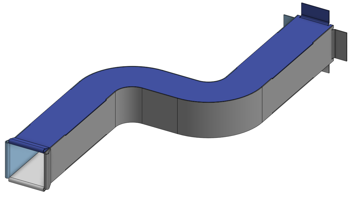
20. Exercise 3.1C - Solution: This is the solution to
exercise 3.1 C. This is a more advanced exercise where the assembly comprises of
four individual components. But we'll break it down
nice and simple and just go through the parts one by one and we'll get
there in the end. We can start by drawing
a very basic S shape, which is one of the
side components like so Then we can
start to dimension it. The core feature of the shape, this 200 millimeter dimension, this 250 millimeter dimension, We can just shuffle the
sketch up and then add in a new dimension here
of 25 millimeters. Don't worry about the
actual numbers themselves. You'll notice that some
of these numbers are slightly different to what
you see in the drawing, but that's because the actual numbers
are slightly hidden. I can add these other dimensions
in 100.150 millimeters, which you do see on the drawing. But it's because they
are stopping and starting from different places on the drawing than
in the sketch, which is why the numbers will
look slightly different. Don't worry too
much about getting the numbers right
on the first pass, because what we can
do towards the end is to adjust the
numbers in order to make them turn out correctly. At the very end,
as long as you get the general principle of
creating this component, that's really what matters. Rather than getting the
numbers exactly on, we can create a sheet metal
model from that sketch. And you end up with a
component that looks like so we can put in a
****** on one end. We make sure we select the inner blind and 25
millimeter distance, although we'll need
to adjust that to 20. We can at the blind distances from the end to 5 millimeters, we'll just need to
change it to outer. Then the distance of
20 millimeters can approve that feature's
end complete. Then we can add in a
hem at the other end. Like we just need to make sure that we get
the dimensions correct. We can have a total length
of 15 millimeters and all the other fields are
correct very broadly. That's nearly the
first part done. We just need to add
in a few more tabs. But before we do that will be easier to just put in
this second face as well. We'll do that now. It's almost an opposite
hand face all component. It's very similar to what
we've already just done. We can add in the
dimension of 250.200 millimeters and then the 25
millimeter offset as well. Then we can add this
mid plane in, again, 100 millimeters and again, this dimension here, which
will be 50 millimeters. That's a fully
constrained sketch. Just put in some radii as well, so that'd be 25 millimeters
and then also 75 millimeters. Okay. So we can extrude that sketch or make it to a
sheet metal components. We'll select all the different
elements of the line. Then we can select symmetric, select a depth, or 50
millimeters instead of the 25. Then we can hit the green tick. Add in the ******
again on the far end, change the bend angle, Change the bend
distances again to 5 millimeters to
match the other side. We've done that on one side, we need to do that on the other, but we're just changing the
****** alignment to outer. And then there's the second
distance for the blind. Then what we can do next is
focus on this hem again, at this near end,
just like last time, we just need to change
the direction of that using a tear drop. Change the total length of 15 millimeters and
hit the green tick. Then what we want
to do is add in the top face and bottom face. We need to add in a new plane from which we can
put a sketch on. We can offset that
by 25 millimeters using an offset feature. We can offset that
from the top plane. That's all we really need to do. We'll do that to 25 millimeters and then hit the green tick. Then we can align ourselves to the top plane and start
to create our sketch. We'll start down here, go from those two points when we
go all the way up to here, making sure we have a
vertical line and that it's aligned to this point. We can use the yellow guides to constrain our sketch in
roughly the correct location. It always helps to
do this carefully. We can click there, we
can move across again, use the guides to find out roughly the correct
location to draw the lines. And then we'll do it
all up to this point. This come all the
way back down again, making sure we use this
yellow lines again. Very faint lines. Then we can click here. Not quite there. There we go. We can click again, bring it all the way over to the left using the guides again. Then we've got just
one more place to click that gives us
a closed sketch. We just need to
add in our radii, we'll need to adjust
the value of this 25. We can see that
that's line on line. That's where we want it to be. We can do it again here. This is where you might get
some slight odd features where you might need to adjust the numbers based upon where your start and end
points of your curve are. We need to link that
just this value, we might change it
to 24 millimeters, that might be what
we need to do. Or 25 in this case. And just align the start and end points off the
curve to zero. I've just done there,
this number is going to be 75 millimeters
for this larger radii. Then we do this
again, once again, we just need to make sure that the curve lines up with
the other components, which it doesn't at the moment. That's again because
this point is offset from where it
should be aligning. That will correct
that might need to delete a constraint
like this red one here. Which we can do just by
clicking the delete key. And when we hover over it,
that is now line on line. Our general profile
is looking okay. We can hit the green tick. We can reorient our view, and then we can
create a sheet metal model from that sketch. We need to thicken this sketch. The thicken option, just have a quick check and it looks to be doing what we want it to. Its thickening in
the right direction, or this is the
correct direction, we want it to be flush
with the side components. We can add a ****** into this. We can change the
bend angle like that, Change the distance to 20
millimeters match the others. Then we can do a
partial ****** having distances from each
end of 5 millimeters, just like the others,
and hit the green tick. Just checking those bend
girls bend distances, ****** distances are the same, they're all 20 millimeters. Then again, we can focus on
adding in a hem at this end, we can do it just as
we've done before. We need to change the direction, like using a tear drop. And we can see that
they've all got the right total lengths,
15 millimeters. Add in the green tick to that, we can see that
the hem alignment, the outer is incorrect one. The in place option
is the correct one. There's one last
component to go. We need to add a new plane in again, just like
we did before. And add in an offset plane, 25 millimeters from
the mid plane, like. So you can see that's
just in the right place. Hit the green tick.
And then this is a sketch from which
we can draw upon, open a new sketch and we
can start to a profile, just as we did before. We need to make sure we
hit the right points. That's utterly key. Otherwise we're going to end up with something
not quite right. But remember, you
can always edit those afterwards if you don't have quite
the right numbers. It's very important to
be able to edit a model. You'll often be editing models rather than
just creating them. Even if you do go wrong, it's really good
practice for being able to edit and correct, that's probably a better
skill and be able to create something correctly
in the first place, just making sure we hit
all those right points. And then we use
the yellow guides again just to make sure that we are in exactly the right x
and y coordinate, just like. So then we'll do it once more
using these yellow guides. Faint yellow guides. And then the last
point just down there. Again, you might have seen
that just went slightly gray. So we've got a close sketch. Again, we'll add in our radii, remembering that we might
have to adjust these numbers, but also we may have to just
check the profiles correct. Which you can see it
doesn't quite line up here. We'll need to correct that
one. This one is correct. You can see it lines on
with the side component, but you can see
that point doesn't align this edge right there. We just need to add a zero in. We get a red lines saying
it's overconstrained. We need to delete one of
the geometric constraints. We can align this one as well, but it will say over constrained to find
this red constraint, hit the delete key, and then we may like to find another
one to delete as well. Possibly. Sometimes it takes a bit of trial and error to work out which one
you need to delete, make sure you're
still constrained. We'll just try a
few things here. Sometimes you can add
different numbers in to end up with the value that you need is just a product of the curves
and different thicknesses. Adding 26 millimeters got us to the right location or the
right profile that we need. That will suffice for
this particular model. We can add in the
other radii as well, 75 millimeters for
these larger radii. We can check those line on line. Sometimes again, as I say, because you've got the
different thicknesses, you can adjust the radii
by a millimeter and you might get the curve that you need just depends on
how you constrain it. Both of those large
radii look quite good. They look like they
are doing as we need, Making sure that there's no gap between all four of
those components. So we can hit the green tick. Then we can go to thicken
that sheet metal component, thicken, hit that sketch. We can see the sketch, it's being thickened in
the correct direction. We can hit the green tick again. You can see that these are
all four different colors, which symbolizes that they
are four different parts, which is exactly what
we are looking for. We can see that there's no
gaps in those locations. We don't need to worry apart from this location
here actually, which we just need to correct, we can have a closer
look at that. That's this one here, actually, that doesn't quite work. 74 does work, and that's because of the
way we constrained it. That looks to be a
bit odd as well. So we can take a
close look there, we can just readjust that. And then we might need to change some of these constraints as well to make sure it doesn't
go red and fight itself. 75 then does correct that. If we have a look at
the model afterwards, we can see whether it's
looking like there's any gaps which it doesn't
look like that at the moment. We can add in our
******* at this end, just like we've done
the other three. Change it to alter,
we've done the others. Change the distance to 20
millimeters and the direction, as well as the distances
from each end For the blind, for the ****** blind, that looks like it's consistent
with the others. We can see that they
are all 20 millimeters. They look all about correct. Just need to adjust that
to be outer because that will set to inner
on that blue one. But now they are
looking a consistent. Then we can add in this
final tear drop hem as well. We can just hit that edge there. Need to change the
direction again. It looks like it's got a
distance of 15 millimeters. So we can just hit
the green sketch now, very nearly there. But what we do have to
do is add in some tabs. Tabs, remember, are a way of nicely jigging
components together. We can do that by adding
in a rectangle feature. On one of these top faces. We can add that in on
both sides as well. We use the yellow constraints
guides to constrain our sketches nice and
evenly so they are the same helps Later on when
we're trying to dimension it, we can add in a
couple of dimensions. Then we can put a dimension
of 100 millimeters. Then we just need to
make sure we know where this box is in relation
to the component. And we can add in 50
millimeters there, because we put in those yellow, use those yellow guides
earlier for the other side of the sketch that is then linked
to that first rectangle. We can put in the
lower boxes to use those yellow guides to give
us a link left to right. Then we can add in
some dimensions, again, 100 millimeters
in length. Then we put that box somewhere as telling us where it is in space
on the component, again with a dimension
of 50 millimeters. Because of that link,
those yellow guides, the left and right, are
constrained in the same place. Then we can add
in a tab feature. We can choose our selection
scope to determine which of the components
will have material added and which will
have material removed. Then you can see that we
have tab arrangements such that this top
face has material added and the side
faces have material removed such that they
all jig nicely together. When you come to fit
this component together, all that remains is to put
this on the underside as well. We can do that in just the
same way as we did before. We get our sketches, find the right plane from which
to create that sketch on, we can adjust to the top view. Then we can draw our
rectangles on which represent the tab using yellow guide. Once again, that yellow
line. Thank you. Once again, down here to link the left to the
right side of the sketch, we have fewer dimensions
to put on dimension, the length of the tab. We can add in 100
millimeters there. Then we just need to add in
a dimension up here as well. We're going to dimension
that to be 50 millimeters. Once again, we don't need to do the right hand
side of that link. We can see that the upper
and lower surfaces, the tabs look to be
roughly the same location, which is what we
are going for now. We just need to put some
tabs down at the bottom. Again, we just draw those on the rectangle tool
just like so Again, dimensioning that dimension that to be 100 millimeters in length, then 50 millimeters from this, a horizontal line here. And that looks to be in
roughly the right place, left to right to top
to bottom surface, so we can hit the green tick. And then we can add in the tab feature
on that bottom face. I've forgotten the
right hand side, so we just need to add in
that sketch feature again, using those wonderful
yellow guides. I'll add in the dimension
there of 100 millimeters. Now we are ready to
correct that tab feature. Now we can hit the tab
tool and then we can use this sketch that we've just
created as the tab profile. Then we can slit the
subtraction scope as these side components,
they are faces. We select all four
of these faces. We can see that
as we click them, they are correct, showing
how they will be formed. At the end, hit the
cream green tick, and you can see that they
have correctly formed these tabs in each
of these locations. That is the solution
to Exercise 3.1 C.
21. Upload your Projects!: Hi everyone. Congratulations
on completing the class and having a
go at the exercises. Like with developing any skill practice
will make perfect. I'd recommend uploading any
of the exercises that you've completed or perhaps even
your own new project to the class project page so
that myself and others can see your creativity and be inspired to
design new products. You can upload your project by navigating to the class page, then selecting the Projects
and Resources tab. From there, you can click
Submit Project button, fill in a project title, upload a cover image, and populate a
short description. Feel free to take a
quick video and spin your model around so everyone
can see the whole thing. However, if you want to
keep your work private, but keep a record that
you've worked on a project, you can select the
private button. Then don't forget
to scroll up to the top and click on Publish. Now your learning
doesn't stop there. I'd highly recommend
trying to create your own new models based upon what you've
learned in this class. And be bold with the
models that you create, even if you think there might be a little taxing for
you at the moment. Alternatively, have other
classes in using on shape, which include
traditional three D, parametric modeling,
technical drawing creation, and assembly design. All of those will
augment what you've learned in this class
and help you become a more rounded designer and solidify your understanding
in how to use on shape. I sincerely hope
that you've enjoyed this class and would be very appreciative if you'd be kind enough to leave a
review. Thank you.
 Mathew Alexander