Transcripts
1. Onshape 3D Assemblies SS v2: Hello and welcome to the complete guide to on shape, where in this class we'll be covering 3D assembly design. 3d assemblies in cat is a step on from 3D modelling and is a vital step for ensuring products will fit together properly. Lots of modeling changes are typically made at this stage to ensure the assembly process goes smoothly. I'm Matthew Alexander, the instructor for this class. I'm a professional mechanical engineer with over 10 years of experience. Throughout my time. As an engineer, I've designed hundreds of components where key aspects to design and creation within engineering is through the use of computer aided design, also known as Cat. Cat can be conducted using many different software packages were on shape is one of these. On shape is an amazing cat package crammed full of useful features, has intelligent file storage and is extremely intuitive to actually use. And this cannot be said for other CAM packages. What's more is that on shape is going through rapid development and updates that you don't need to download any patches On shaped works through your web browser. This also means that you can run on shape on a low performance computer if needed. And to top it all off, students and hobbyists can get easy access to unshare for free today. This class covers the core features of 3D assembly creation, but on shape also offers 3D modelling, sheet metal design, and 2D technical drawing creation to ensure you truly learn how to use on shape for assembly design. This class is structured with over 10 video lectures and a capstone project to bring all the learning together. I hope to see you enroll and enjoy this class.
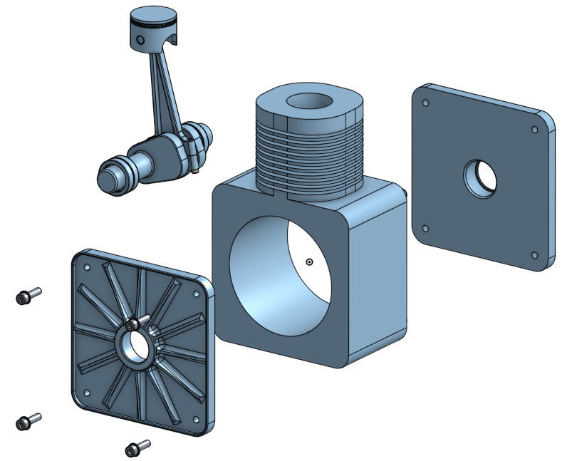
2. Why do we need Assemblies?: It is usually obvious as to why we use 3D models and engineering and design. There may be less clear why we use assemblies. Assemblies are useful for the following primary reasons. To articulate these points Visually, we use a simple NG model as an example. Now that this engine model is just for concept purposes, it is missing some important components and features to workers in a functioning engine. It is good, however, for demonstrating key assembly features. In my opinion, the primary reason for CAD assemblies is to see if all your components fit together properly. It may sound silly, but when I put together, assemblies are usually find that there are parts that don't fit together. You could end up with expensive and simple mistakes. If you don't create assemblies, you might find that these emb plates of the engine housing are not flush with the main housing or worse, that the bolt holes in the plate, do you not align with the main housing? Even simple cases like making sure that the piston fits in the Boer can be done incorrectly. Another valuable use for assemblies is to calculate the mass of all the components or subassemblies. Calculation we'll take the density from each components are not just apply one density or material to all of the components. You'll actually be smart and take all the densities from each individual component. Assembly is an odd shape, also allows to create the movement of components and animations can also be created. Andre panels that constraints or components to each other in a different way to other CAT softwares to easily build moving part assemblies. We can apply limits to movements, and that's spatial relationships to simulate gay meshes, for example. A nice use for this movement feature as it allows you to visually investigate if any clashes may occur. Finally, constructing assemblies allows you to create a bill of materials or bomb table easily, which is nicely automated to limit human error. These bill of materials tables in the assembly workbench then allow you to quickly and accurately at a Bill of Materials table to your drawing and call references from the table. Two parts. We'll explore the bill of materials table in the technical drawing section.
3. The Assembly Workspace: By default, when you create a new document in on shape, apart studio and an Assembly tab are creators. The part Studio tab is where you generate your components as described in the previous section of the course. And the Assembly tab is where you combine all of those parts together. You can however, create another Assembly tab by selecting the plus sign and then selecting Create Assembly. This will open a new assembly workspace and tap along the bottom bar. When you out within an Assembly tab, your workspace changes and that we have different tools on the top toolbar, as well as new site icons which perform different functions than in the past studio. And a slightly different bar on the left-hand side to our top toolbar, host the standard undo, redo and update all tools, as well as inset, which allows us to insert parts and assemblies into our current working assembly. We have mates, relations, name, positions, and display states. Now instance panel can, as usual, be shown and hidden using this left-hand button. This panel is slightly different from the part studio workbench, and then it displays components rather than features used to create a part. Next to each component, we have a number between the less than and greater than special characters. And this number refers to the instance number. For example, we have two end plates in this model and that is reflected and that we have instance one listed for the first component, an instance to for the one listed below it. We also see this with the bearings. If we go into the engine internals sub-assembly, then go into the needle roller bearing subassembly. You can see that we have several roles elements listed from one to 12. We have a second needle roller bearing noted by the instance to. So the bearing is the same as instance one. Look within the second roller bearing instance sub-assembly to again see that we have instance one through 12. You may have been expecting to see instance 13, 324, but this is not the case. Unique incidence numbers are listed only within subassemblies rather than across the entire assembly. Within our instance panel, we also have made features. This lists all the mates that are used to describe the motion and position between two components. You will see mate features for all assemblies and sub-assemblies. You can see that we have a list here. And also if we open up the needle roller bearing, we may have icons next to each of our components. This one here represents the components being fixed in all six degrees of freedom. The assembly that contains a fixed component will also have a similar icon, which is this icon here. We also have this icon here, which represents a component that represents a versioned part from another document. We can hover over each of these icons to remind ourselves what they mean. On the right-hand side of the workspace area, we have three icons. The top icon brings a panel showing our bill of materials. A bill of materials lists all components that create the top-level assembly. Detailing items such as the reference number or item number, quantity, part number, part description, material, and any other information you'd like to include. We can change between different bomb structures are using this drop-down menu to change between flattened and structured. Flattened shows all items on one level in the table. Structured, however, show sub-assemblies within the table that allows you to easily identify the BOM hierarchy. We can double left mouse button click on the assemblies, identifiable with these errors to show items which make up the subassembly, we can add columns to the table by selecting from this drop-down menu. You can also remove items from the bomb table by right-clicking and selecting remove column. You can exclude items from a bomb if we wish, by right-clicking and selecting Exclude from BOM, we can bring something back once it is being excluded by clicking on this button here. And then select Show excluded. We can then right-click in the excluded row, then select including bomb. This bill of materials will be useful for creating assembly drawings. The middle icon is used. Configurations. Configurations can become quite complex, but as an example, I can suppress the rotation of the bearing elements. Another use for configurations for assemblies could be to represent different gears within an automotive transmission. The third icon is one that allows us to create exploded views. Creating an exploded view is discussed in the technical drawing section, and so it is not included here. Note how we also get the measure, a mass property buttons in the bottom right-hand corner of our screen for measuring dimensions and mass, like with the part Studio tools.
4. Inserting Parts and Positioning Components: So let's create an assembly. We can click the Insert button from the top toolbar to start adding things to our assembly. Once the dialog box opens, we have three tabs to choose from. Current document, other documents and standard content. Current document refers to items from the past studio of the file that you have. Open. Items may include part studios, parts, sketches, or surfaces. Other documents refers to inserting these items from other files. And standard content refers to common components such as washes, nuts, and bolts, for example. The standard content is really useful and quick to use. We'll come onto this in a future video. Before we select one of these options, it would be a good idea to talk about two different strategies for managing documents. The first method is that you can create a series of parts within the part studio, then enter them into the Assembly tab and selecting the current document option. My current preference for document management would, however, BTUs a second strategy, which is to create parts in the part studio in other files, then have a separate file to contain only assemblies are mostly be showing this second way of managing files, but which you choose is up to you. I sometimes use the first strategy for just small assemblies. So to create our engine assembly, I'll select other documents. I then navigate to the files or light to enter into the assembly, which for me is by selecting recent files, I can add the housing to start off with by selecting the housing with a single left mouse button click. At this point, or may then need to create a version for the part I selected by clicking. Create a version in XXX. I can click the link which brings up a pop-up window, which prompts me to enter a version and description. Once happy, click Create, I can then choose between part studios and assemblies. I can then also felt a part studios for parts and sketches with these buttons here. If I have more than one part and a part studio, they will appear here, indented from the left-hand edge. By clicking the part studio, I would add all the parts to the new assembly. Or I can individually click Items part by part. If I click the patch studio all the items or retain the position from the part studio when inserted into the assembly. But they will not be constrained together. I'll slit the housing part with the left mouse button, which brings up the part in the graphics window. Follow the cursor in the pop-up window. The housing part appears in the position it was modeled in, in the past studio. So the origin is in the same location. If however, I move the cursor into the graphics window, you can see that a housing part follows. For the first component, I'd recommend simply selecting the housing part, then clicking the green tick in the pop-up window. Then select Insert again to add some of our other components into our assembly. This time, however, I'll click in the open space for each individual subsequent component so that they do not overlap one another. Then select the green tick. Once I have finished. When modelling these assemblies, one of the most important things to do at this point is the fixed one component in space. Other components will be kept in place due to their relation to this fixed component. You should choose a sensible component to fix. For example, the housing in our case, by right-clicking on the component and then clicking Fix. The fixed constraint means that the component is unable to move in any of the six degrees of freedom. They cannot translate, nor can it rotate about the x, y, or z axes. We can and affects a component by once again, right-clicking on a fixed component and then slept on fix. When we have a component fixed in our assembly, we get this icon appear in the instance list. To move parts around the assembly workspace, we can use one of two methods. The first is that we can have the left mouse button down on a part, then drag the cursor around the screen to drag the part around the assembly workspace. Alternatively, we can left mouse button click on a component which brings up the triad manipulator. We can move this triad manipulator around the part by hovering over the center circle, then holding the left mouse button down on the circle and move to a new location. You'll find that you can snap the triad to define the points on the geometry itself. The points that you can connect to our known as mate connector points. Once a position has been chosen, we can then move the part around the screen by holding the left mouse button on an arrow or encircle and then dragging that around the screen. Another important manipulation tool is by right-clicking on the arrow, where you can then select align with z or anti zed axis. We could do something similar with the angles by right-clicking on the encircle and then selecting either rotate 90 degrees or rotate 180 degrees. My housing is fixed in place. So if I try to drag it around the screen, I will not be able to. The same will be true for some of the degrees of freedom once you have created mates between components. We'll show an example of this. I can select this button here with the snap mode tool, which allows me to pick a make connector position with the left mouse button. This icon here symbolizes the mate connector. These mate connectors will snap to the major connector points. Remember the make connector points of these points here. We then hold the left mouse button down on this make connector that we just created and drag it to the location on the second part where we want the second mate connector to be. A pop-up window appears where we can change the mate type in this drop-down box. We can then alter the main connect to order and the offset. We can also change the orientation of the primary axis with this button here and the secondary axis with this button here. Something that is very important to understand is the primary axis, is this blue axis, or in other words, the z axis. We can remind ourselves of which colors referred to the x, y, and z axes. By looking up here on the manipulation cube and coordinate system. You'll want to align the z-axis or the blue lines for each mate. So in my example, I have the blue line in the axis of the piston and the piston ball. Five click the flip primary axis button. The piston changes from being the correct way up to the wrong way around. Clicking the secondary axis toggle changes the directions of the x and y-axis. And this is important for some of them make types. We can also say offsets and limits, but we will revisit this in an upcoming video. We can then exit the snap mode by clicking on the icon up here. Again. I can then try to move this Peston around the screen, but I cannot, not because the part is fixed, but because we are related or we have a mate to the housing which is fixed.
5. Mate Types - Part 1: Before we delve into the different mate types, let's just remind ourselves that makes attach two components by constraining one or more degrees of freedom. Remember that our degrees of freedom, our translation in x, y, and z-axis, and rotation about the x, y, and z axes as well. So remember that this movement is translation, and then rotation is obviously this sort of movement. So to make these mates, we need to link to make connectors together. Our make connectors look like this. Each with their own local coordinate system, symbolized with the blue, green, and red lines representing axes. When we link to make connectors, we more often than not need to make sure the blue or z axis aligns with each other. So you will need to carefully select the mate connectors. We also have made connect two points, which are these points here. These may connect appoints allow us to place, make connectors upon them. Connectors that are placed upon MEK connect two points are known as implicit make connectors. We can also create explicit make connectors, which will show look at in a later video. Imagine we wish to pick the midpoint of this edge on the lower part of this engine housing. If I were to arbitrarily pick a mate and try to select and make connector for this location, I can get the zone axis or blue axis to align in this direction or in this direction. If I move the cursor in the correct way. We know that this blue line is important to align correctly. But how did I do it? Fast? Like the first face, the move the cursor to that may connect to point. The blue axis of the main connector will align in the direction normal to the surface that I first hovered my cursor over. See how this works when I select the other face. Now let's have a look at some of the different types of mates. There are nine types, but the ninth is one that is not always the best one to use and does not always work for the features you may have in your model. We'll start by looking at the fastened meet. The fastened mate allows you to constrain two parts together to move all degrees of freedom between the two. So it cannot be translated nor can it be rotated. An example of where we could use a fast intimate in our engine model is with the piston pin in the small piston bore. We can do this easily by selecting our fastened mate. This button here. We can select this end phase of the piston pin, where the zed axis aligns with the axis of the piston pin. Then we can place the second make connector in the small piston ball. I can select the dimer interface of the small piston ball with May 3 connect the points appear carefully dragging my cursor from side to side allows me to change, which may connect a point I choose. In this model, oscillate the end position. Remember that we have our toggle buttons to change the primary axis or the blue axis and also the secondary axis. You may need to toggle these to orient your parts correctly. We can click on the green arrow when we are happy with the position. We also have an animate button with this play icon. You'll find, however, that with the fastened mate, but no movement appears, as there are no degrees of freedom. We will see something different for the other main types. See how when you move the piston around the screen, the piston pin follows. Next, we'll have a look at the revolute to mate, which allows revolution specifically about the zed axis only. So if you align the axes incorrectly, your movement either weren't work or will be incorrect. You need to make sure your z axes are aligned on the shaft axes. When using the revolute mate. I can select the revolute mate, hover over the diameter section of the crankshaft and position my cursor so that I select the midpoint. Then I select my second. I can select the large internal diameter of the main housing and carefully select this end point connector to place my second make connected down. Before I close the pop-up window, we can try the Animate button. You can see that the crank shaft moves in the fashion that we would expect. Ignore the reciprocal nature of the revolution. This is just representative. What's important is that the degree of freedom, which is free, is the one we desire. We can click on the green arrow to confirm the mate. Then we can hold the left mouse button down on the lobe of the crank shaft and drag the cursor around to show how the part can move. Next, we'll have a look at this slide mate. We can select this make type by selecting this button here. The slider mate allows translation between the two components in only the zed axis. Like to constrain the piston inside the piston ball of the main housing. So I need to make sure the z-axis aligns vertically on both the piston and the main housing. I can select this top surface with the make connector in this centre of the surface. Note the direction of the blue line on the map connector. Then for the second, I can select this top surface on the main housing and ensure I select the center point again with the blue axis pointing vertically. Again. Before clicking the green tick, we can see that the sliding motion between the piston and the main housing is correct. To let the connecting rod between the piston pin and crank shaft, you may need to hide the main housing from the instance panel. You can apply a revolute mates between the small end of the connecting rod and the piston pin like this. Then we'll add a cylindrical mate between the big end and the crankshaft. I've chosen to apply. A cylindrical may tear to allow some misalignment between the center of the big end and a shaft that it mounts to. A cylindrical mate allows translation in and rotation about the z-axis. We can select these make connect the points with the zed axis or blue arrow on the shaft axis. The animation shows that we can slide along the shaft and that we can rotate around it to both of which are what we want to allow in our assembly model. Yet when we click the green tick to confirm the mate, our mates show errors in the instance panel. See that there is a disconnect between the small end of the connecting rod and the piston pin. This is our problem. The piston should be rotated about the z-axis by 90 degrees. Our slider connection only allows translation in the zed axis, and so it is fixed in the misaligned position. There are two things we could do. The first of which would be to edit the slider mate to a cylindrical mate to allow translation in and revolution about the zed axis. Notice how our main features now shown no errors. Alternatively, if we undo the change and delete the slider, the small end and Peston aligned correctly. We'd need to then redo the slide connection. Now that we have the correct alignment, we can grab the lobe of the crank shaft. I'm rotated around, which shows us the basic motion of an internal combustion engine. In the next video, we'll look at the other mate types.
6. Mate Types - Part 2: Now we'll look at other types, but we won't be using the engine model for these. The first mate we will look at is the ball mate. The ball mate is one that allows rotation about the x, y, and z axes, but does not allow translation in any of these axes. This motion is something you'd find present in various joints in automotive suspension systems or shoulder and hip joints for example. Artificial joints may look something like this. That titanium insert system to the top of the femur bone to add a ball made our first like the implant and move it from the socket such that we will be able to select the correct make connections. We can select the ball mate icon, this one here, which as normal will open a pop-up window. It can be difficult to choose the correct ME connection point. But you should be able to determine if you've chosen the correct points once you manipulate the parts around, once you've finished the mate, I'll choose this point on the implant and this point on the socket. I have the socket fixed. So when I grab the bottom part of the implant, we can see that we are completely free in the rotation axis. Next, we can have a look at the pin and slot mate type. This is a simple model that can demonstrate this mate. This mate allows translation in the x axis and rotation around the z-axis of the pin. So we can select the pin slot mate with this icon here from the top toolbar, which brings up our standard window. Then importantly, the first component we select must be the pen. And we need to make sure the zed axis of the blue axis is aligned with the shaft axis of the pin. So like this. The second component which selects shall be the slot. We need the z-axis to be aligned with the orientation we'd like the pin to be in. So our z-axis needs to point vertically when viewing the model. In this way, the zed axis shall also be pointed upwards on the mic connector for the slot. I'll hover over this top face of a slotted part to pick up this center point of the slot with the blue axis pointed upwards, we need to make sure that the x axis aligns of the slot direction. So you may need to click this secondary axis toggle button to achieve this. Next, we'll look at the parallel mate type. With this very simple model containing just two blocks. A parallel mate allows individual translation movement along any axis and parallel rotation along any axis as well. I can select this icon here for the parallel mate and choose make connectors in these locations. I can then translate either of the blocks independently of each other in any degree of freedom. When I select one of these parts, I can then rotate one of the blocks where the other block will then follow. This becomes more interesting, but slightly more complicated. When adding limits to the mate. We will investigate this in a separate video. The eighth of nine mate types is the last that works with relations. This may type is the planar mate. A good analogy for the freedom that the plane on mate allows is that of an air hockey table. In a hockey, you'd have your POC free to translate in the x and y plane. And that the puck can rotate around its shaft axis. So zed axis. I can select the plane, our mate. So this icon here, I must first select the mic connector that will move around and rotate. So the puck, in our case, I'll choose this bottom surface of the shaft axis. Then my second will be the stationary point where the center of the table would be, is a sensible may connect to location to choose. I can then drag the puck around the table top. The ninth mate type is one that is perhaps use less frequently than the others, the tangent mate, this mate type does not use make connectors, but instead uses faces, vertices, or edges. I can demonstrate this by first deleting the planar mate. Then select the tangent mate icon. This one here. I can select the edge of the park is the first target. Then select this edge as the second target. Then I am able to drag the puck around the table with these two lines always in contact. This mate type currently is not supported with some features of one shape, such as relations. Where relations are an assembly tool we will look at in a future video. It's important to know that when building your assemblies, one mate type should be all that is needed to create motion between two components. If you find you're using more, stop and think if you are building your assembly in the correct way.
7. Offsets and Limits: As with most features in on shape, we can double-click on elements in a left-hand bar to edit them. We'll edit the pen slot Mate feature so that we can investigate offsets and limits. For the pen slot, we can alter the offset and limit properties. If we check the offset box, we have three new boxes appear. We can add an offset in these other direction, symbolized with this said icon and error. I could put two millimeters into this box such that the offset between the slots and the pin is two millimeters. We can see that if we rotate this model around. So despite them make connectors touching in the zed axis, we can add an offset. Regardless. This offset will be held at all positions during animations. We are also able to change the orientation of our pin using the rotate about x or rotate about y drop-down box in combination with the rotation angle. Now example, this doesn't help us, but you would likely find use with this option with other projects. Then we can check the limits box to alter the extent or limits to which we allow movement. Recall that the pen slot allows translation in the x axis and rotation about the z-axis. See that our symbols represent the minimum translation limit in x here, and the maximum translation distance in x here. We have similar icons for the minimum and maximum rotation angle about Zed. With these two lower icons. The center line of our slot length is 35 millimeters. So we can enter this into the x translation limits. Select the center point of the slot to be where we have all make connectors. So we need to put in minus 17.5 millimeters in the minimum translation and 17.5 millimeters and the maximum translation box. I don't mind the zed axis orientation of the pen. So I won't impose a value for these limits. You don't have to put numbers into each box. You'll need to adjust your values depending on a Mac connect to locations that you select. Recall the parallel mate from a previous video. When we rotate a single block, the other block rotated too. We can edit them mate to view the limits. You can see that for the parallel mate, we only have the ability to change limits are not offsets. I've applied some simple limits to illustrate how the parallel mate becomes more useful when limits can be applied. See how we're moving one of these blocks changes the other. And we still have the same movement when rotating the parts around of the mates we have explored. This table shows which of them have limits and offsets that can be imposed. Some mates like the slider regulates pen slots and planar have offsets and limits. Cylindrical and parallel just have limits. The fascinate has just offsets, whereas the bowl mate and tangent mate have neither offsets nor limits.
8. Grouping: When we create assembly models, we may have created Part Models or imported models from other software where all the components or several components are already in the correct positions. In many cases, components will not move in relation to each other. And to assemble these parts, it is often easier to not use mates. Mates are most useful to allow relative motion. In our instance tree, we have a new symbol, a pair, which symbolizes that this part is versioned. As a later version available. I can click the Refresh button from the top toolbar, which opens a new window. I can choose to update all components when in this tab. Then select update all. Or I can choose this selective update tab. Choose which components to update by checking these boxes. Then select a specific version. Once all the details on this window had been selected, we can click Update selected. Recall that when we first inserted this part into the assembly, we chose the part and not the part studio. This means that we only have one partner pair in the assembly. I'll reinsert the component as a part studio. I've added more detail to the connecting rod for the engine assembly, where four parts are already in their correct positions. I could use the fastened connection to fix these four components together. Or instead, I could use the group function to group these four compounds together. I can select this tool here and select these four components. Then select the green tick. These components then move together. Even if I only selected one part. We can then go to the top-level assembly and add the revolute mate at the small end of the connecting rod and the piston pin. Then I can add the cylindrical made to the big end of the connecting rod and the crank shaft. Crank, crankshaft around. We can see that the whole connecting rod moves as one. As intended. You may be tempted to use the fixed feature, but this would be incorrect. You would then not be able to move the components around. You should only really be fixing one component and adding mates or groups to that one fixed component.
9. Assembly Structure: Our assemblies can get rather overpopulated rather quickly. So it's a good idea to ensure that you have good structure to make sure the assembly is manageable. I'll add some more of the components that make up this NG model. Now, as you can see, we have quite a long list of components with little or no order. The first useful trick to be aware of when working with assemblies is that you can select an instance from the left-hand panel to light up the components or assembly in the graphic space. We can do the same in reverse by selecting a component in the graphics area, the highlighted item in the instance panel, something that you should make a conscious effort to do throughout them, part modeling process is to name your files from the part studio. This will have those names appear here in the instance panel. Otherwise, you will only get part one and part two. For example, you should name your assemblies as well. This January just helps in clarity and knowing what you're working with from the instance panel. Subassemblies are the next and in my opinion, the most important way in which we can manage assembly structure subassemblies, assemblies that contribute to your top-level assembly. You may wish to create subassemblies outside of this top-level assembly that you can use them in other files to. Ok, good example of this is is the needle roller bearing. It would be likely that I could use this needle roller bearing in other models. I'll open a new file and call it needle roller bearing to be our assembly file for the bearing. Operating in all of the components we need to create this file, then connect them together with the relevant mates, which in this case are all revolute mates. The cage can spin within the outer rays and the elements are also free to rotate in the cage. I'll speed up this task. Heading back over to the engine top-level assembly, I'll delete all the parts that would create the bearing and replaced by inserting the needle roller bearing assembly into the model. Will need to click this top here this time, then choose this file here. I'll insert two files as we need one at each end of the crank shaft, will connect the bearings to the crankshaft using a cylindrical mate. First using the bearing cage, then the crank shaft itself. And I'll do this to both ends as well. When I click the crank shaft, only the cage follows. We want the whole bearing to follow, which we can visualize by clicking the Solve button. We can clean up the connecting rod components in the assembly by creating a simple sub-assembly. Heading over to the connecting rod model. I can insert the part studio into the assembly. Then group these components together. I'll then rename the subassembly. Then we can head over to the top-level assembly. I replace the new sub-assembly with these four components. Here. We can then reattach the connecting rod to the crankshaft and piston pin structure. As you can see, it's already starting to type good shape. You can also create subassemblies on the fly. And you might do this for components that wouldn't necessarily be used in other models. For example, with the housing components or the engine internals. I could select the main housing and the two end plates, then right-click on one of them and select Move to new sub-assembly. An instance is created in the instance panel, which replaces the items we just had selected and puts them with a new subassembly, which we can open by clicking this angled bracket. We also get a new type of pay on the bottom bar, which we could rename to something that makes a bit more sense. I can then do the same for the engine internals. Remember that you can select assemblies to show in the graphics window which components are included. And we could also weigh these assemblies to by selecting the assembly and then clicking on the scales. You may have noticed that our list of main features in this location has shrunk. Don't think that we've lost any though. We can still rotate the crank shaft and see the correct motion. The mates are all still there somewhere. Indentation in this list represents the assemblies. With this make feature list is for the top-level assembly. This make feature list only shows mates between the housing and engine internal subassembly. We can see within a bearing sub-assembly that it also has a main feature list where this make feature list will contain just mates that exist within the bearing assembly. So this would only be the rolling elements within the cage and the cage within the bearing outer race. So when we talk about the mate between the bearing and the crank shaft, we need to go up and assembly level. We will find that mate in this list here, which is a main feature within the engine internals Mate feature list. So adding subassemblies cleans up where our components go, as well as organized our main features too.
10. Explicit Mate Connectors: In this video, we will explore how to create explicit may connect to locations when the standard implicit make connects locations do not offer a location suitable for us, we will have to specifically create a new position. An example in our NG model where we could do with putting in an explicit may connect a point is with the location of the piston pin within the small piston bore on the piston component. We used a fastener mate by aligning the end faces of the piston pin with this edge here. That is not exactly the correct way in which we should align these components. A better way in which we could do this is by creating a fastened connection between the center point of the pest and pen and the center point between these balls. This would be somewhere in this space around here. We could do this in several ways, will just show one way in which this could be achieved that we can create a sketch on the right plane, then place a point where the front plane intersects the right plane. And dimension this 15 millimeters from the bottom edge of the piston. When we rotate the piston around, we can see that it is in the center of the small piston ball. Let me go back to the engine and tunnels assembly. We need to re-import the piston along with the relevant sketches. Will then create a simple assembly consisting of just the component and the sketch. I can add a make connector on this point, where this is an explicit mate connector. I can then add a fastened mate between the piston pin and the Peston. By aligning this center point of this piston pen, they make connector on this point. Note the orientation of the zed axis, or the blue axis, is along the axis of the piston bore. We can see that the piston pin is evenly aligned within the piston. When we examine each end of the piston pin and see how recessed it is compared to the outer face of the piston. It will be easier and less error-prone though, to use implicit make connectors whenever possible.
11. Standard Content: In this video, we'll be going over what we can call standards content. Standard content should be thought of as common components like nuts, bolts, washers, and other similar components. To show this in action, I've tidied our engine assembly model up by adding the mates that we lost when replacing the piston. And to connect the endplates to the housing. In many assemblies you create, you will use a variety of fasteners of different lengths, nominal sizes, and fastener heads. We have eight falseness to add to our assembly. Will need to add the M8 bolts of roughly 30 millimeters in length. To add these components, we can select, insert from the top toolbar and select the standard Content tab. We then have a number of options to choose from. In the numerous drop-down boxes, we are able to choose between a number of different standards, iso in ansi and SAE for example, we can choose various categories, bolts and screws, or O-rings or pens, as well as many others. We can also choose different classes within each category and components to, for even more specificity. We'll stick with the bolts and screws, soccer head screws, and ISO 4762. Then I'll select the bolts of 30 millimeters in length with a thread length of 30 millimeters. To add a material of stainless steel and a plane finish. We can then select insert to see this component. I'll drag the cursor over to the graphics window and we can see that I'm may connect a point has been created and positioned in a very useful location of the underside of the bolt head in the center. So I can select the make connected location on the mating component to quickly position and locate the bolt. So I'll choose this location on the mating surface of the endplate. I can do this for all required locations. Hopefully, you can see this is a really easy thing to do. Usually, you'd have washes underneath bow heads and we can add those in too. Even though we've already positioned our boats. I can select washes than plain washes from the drop-down boxes and make sure that I have the MHC-I selected. I can press Insert and hover the cursor over the mic, connect to point that located the boat. See how the boat jumps out of the WHO by the washer thickness to allow us to insert the washer into the correct location. A really useful feature. We can tidy our model up by selecting the K key to hide all the connectors. And then also put all the fasteners into a sub-assembly.
12. Visualisation: In addition to the normal visualization settings we have seen within the part studio for changing things like shading and wireframe. You can also explore interference detection and section views to for assemblies. We can select the icon below of view manipulator and select interference detection. We can then select the connecting rod and the main housing, but no clashes identified. This box labeled interferences will state no interferences. And the visualization will stay as you had left it. Still have a shade of assembly. In my case. I can rotate the assembly around interposition that I think may have a clash.
13. Relations: Assemblies can also utilize what own shape calls relations. These relations at further fidelity on your motion of your assemblies through the use of the falling motion relationships, gay relations, rack and pinion relations, screw relations, and linear relations. They should hopefully be reasonably obvious as to what they do. But let's have a look at some examples. First of all, we can have a look at the gear relation. Relations work by identifying one or two mates together. And for a gear relation, we constrain teammates together that have a revolute degree of freedom. I have a simple model here with a fixed plate and two gears which are connected to the plate with revolute mates. I can add a good relation with this icon here from the top toolbar, a pop-up window appears, which allows us to select the two required mates. We can also specify a gear ratio in this box here and alter the rotational direction with this tick box here. You may need to toggle the direction of the rotation of the checking the animation. We can right-click on one of the revolute mates and animate to see if the relationship is as desired. We also need to make sure the ratio we select, correct. When I select the mates and enter the ratio, I calculate the ratio is being the number of teeth of the first revolute mate divided by the number of teeth of the second revolute mate. So in my case, it would be the number of teeth on the wheel because I selected the revolute mate first for the wheel, divided by the number of teeth on the opinion. The revolute mate, which I selected second, our wheel has 33 teeth and opinion has 15 teeth. That 3 divided by 15 is 2.2, which is our gear ratio that we need to add to in this box. And we can animate the motion and see that it is as desired. Next, we can have a look at the rack and pinion relation. There are a lot of these sorts of relations and engineering. This relates a revolution motion with a linear motion. Perfect example of this is in an automotive steering rack. Here is a model of such an assembly. To create this relation, I simply need to relate a mate with a revolute degree of freedom with a mate with a translational degree of freedom. In this model, the steering rack housing is fixed. There is a slider ratio between the rack and the housing and a revolute mates between the opinion and the housing too. The opinion through a number of shots and universal joints will be connected to the steering wheel that a driver we provide inputs to. I can select the rack and pinion relation and select this revolute mate of the pinion and this slider mate of the rack. We can put an arbitrary distance per revolution value of 25 millimeters. Then we can click on the green tech and check the motion is as intended. The motion works from both ends. Whether we rotate the opinion around or translate the rack back and forth. We can have a look at our third relation, which is the screw relation. These sorts of relations are common in engineering and you will often find these on manufacturing machine beds with two tables, a handle to rotate the screw, and ethics not attached to the back table. The tables are related such that they remain parallel to each other. We want to relate the revolution of this screw shaft to relate to a translation of this table. Fastened made connects the nut to the table and a cylindrical mate connects the nuts to the screw. I can click on the screw relation and add just a cylindrical mate to this box in the pop-up window. We then put a distance per revolution, two millimeters. We'll do in this scenario. We can then turn our handle and see that back table moves. Similarly, the relation works in reverse. We're moving the table and seeing the handle move very quickly. Lastly, we can have a look at the linear relation. To investigate this last relation, we can have a look at a simple model that you could find in a hobbyist 3D printer. As an example, in our simplified model, we have a frame with Rails and to individual sliders. But once you see the sliders move at the same rate, we simply need to relate to translational Mates together. We can click the linear relation icon, this one here, and then add these two slide domains to the mate box, then click the green tech. Check in the motion, we can see that both sliders move as intended. We could, for other scenarios, alter the relationship. For example, we could have the slightest move in opposite directions by checking this box here. And we can also change the linear relationship between the sliders. For example, I can change this one to a two. This will have one other sliders move it twice the motion of the fast.
14. 3D Assembly Project Introduction: Hi everyone. In this lecture I'm going to introduce to you the 3D assembly project using on shape. And we'll be carrying on the theme of building our simplified internal combustion engine. The parts can be found in the resource area, and these will be provided a step files, a colon file type to send to people. You can import these files and on shape. It's a good exercise for doing that. Actually, there'll be focusing on building the engine with the correct mate connectors such that it moves and rotates as expected. Best of luck. And in the next video, I'll take you through a worked example of how to build this assembly.
15. 3D Assembly Project Solution: This is the video solution for project 4.1 while we are building the simple engine as shown in the lectures. So to start off with, I need to download the files from the Resources folder. And then I need to import these into one shape. So I can go create import files and navigate to the location where I've download the step files to. So I can select all of these and then select Open. Then what I want to do is to split it into multiple documents. And then we just need to wait for that to import all of these files. So I'll speed this up. So that is all of our files successfully uploaded. So now I can delete all of these notifications up here to get rid of this number nine. And there we go. So to start off with, I'm going to create the needle roller bearing. So what I can do is I can, and I'm going to do that as a sub-assembly. So I can create a new file and call it needle bearing. Then I can go to the Assembly tab and then insert the needle roller bearing components. So go to other documents and then navigate to the relevant files. So I'm going to need the needle roller elements and the outer race and barren cage. So I'll input the outer race. And I want the part. Then I want to go back and get the cage as well. So just a single click. Then I want to go and get all the elements. So I can put those. So I put those there. And just wait for this to load. And we want to put the elements in here as well. So we need the number of elements. So I think it's 12 elements. So I'm just going to put 12 elements out in this space to start off with. And if I'm wrong, I can delete these at the end. Okay? So first of all, I want to fix the outer race into space. So right-click. And I can go fix. And I want to bring out the cage so that I can position these role is in the cage more easily. It can be a bit difficult if I've got another component in the way. So I'll just drag the cage out. And then I'm stuck gonna start putting revolute mates from the elements to the cage. And I want to make sure I get this center. Make connect to point. So just go through all of these. So sometimes I need to zoom in to make sure I click on the surface level. It makes me go. Whoops. Let me just need to keep going all the way around. And as we can any two of these, thankfully, we don't need to do this all over again. We can just use the same assembly again. So she's keep on going all the way around. So sometimes you can make mistakes and it's just, the escape key is usually something that's going to help you out. So remember that is a way to prevent your models from going wrong if you make an incorrect click, few more to go. So I just make sure you click the right met connected point. Zoom in to actually get the right surface. Otherwise it picks up on the wrong surface or it picks up on a line. That's not what we want. So two more to go. Two, the last one. And make sure we get the right surface. And there we go. Now that's all we have left to do for this one is to make sure we have a revolute mate between the cage and the outer race. So I want to make sure I pick up on the center may connect to a point like I have here. And then make sure I pick the same one, same center make connector point here as well. And we want to click Solve so that we can make sure all the elements follow as well. So click Solve and all the elements came over here as well. There we go. So there's our needle roller. So I'm just going to rename the needle roller assembly tab as appropriate. Now we can go back to the folder and then we can start to create the engine assembly. So we'll create a new file for this. So create document, and we call it engine. And what we want to do is we want to bring in, oops, sorry, that was incorrect. So we want to go to the Assembly tab and we'll rename this as engine whilst we're here. And then we go into insert, and then we navigate to our relevant files. So for me, I'll navigate to it like this. And then I want to bring in the housing and I want to have that end the correct place. So I'm going to select the part and then press Okay, and then I'm going to bring in the other files too. So navigate back to the same location. And then I can bring in the piston. And I don't mind where I put that in the screen. So I'm going to bring the cursor over into the graphics window like this. And then I need to find some more components. So I need to find the piston pin, which is this one here, right, for the load and put it over there. And then we continue. So we also need the how sorry, now we've already got the housing. We also need the endplates as well, and we're going to need two of those. So that's one rearrange. And we need a second one as well. Then we can go and bring the crankshaft in and wait for this to load as well. There we go. And we also need the connecting rod, which is this one here. And I'm going to bring the parts studio if you'll allow me. No, it won't because this is of course a step file. So we could bring in. So it works slightly differently when you've got step files, but this one or the bottom papists habit is an assembly so we can bring this one in. So what we can do is we'll bring in all four of these components. The boat. And then we've got stress this last bolt as well. Okay? And lastly, we're going to need the needle roller that we've just created as well. So we can bring in this needle roller at the bottom. And we need to Version aversion for that because we create a new part. So we can click on this, Create a new version box. And I'm okay with this name is V1 at the moment as an example. So we can create that and that will create a version one. And that'll allow us to actually input the bearing. So when you go to assembly, because it's an assembly, and I can click the assembly. And I'm going to bring in two. So we obviously now need to fix the engine housing in place. So right-click on the housing and click fix. Then next, we can input and put the crank shaft in so we can put it. So revolute mate or cylindrical mate actually would be more sensible on the crank shaft. So I can place this one here. And I also want to get the end may connect to point, just like that. Okay, We're also, I want to connect the connecting rod together as well. So I'm going to bring the crankshaft out so I can see it. And then I can put the connecting rod on the first need to assemble the connecting rod. So let's do that. So we can add fastening connections. So because it's not in the correct alignment, if this had come in all as one part all in the correct places, we could use the group function, but that isn't the case. So we can use a fasten mate. So I can slightly underside in the center and then select this center as well. And there we go. And then we need to put the bolts in place as well. So I can grab this surface. And then this under surface as well in the center. There we go. And then I can do the same for this bolt as well. And then pick up on this center. There we go. Okay. Then what I can do is I can connect this big end of the connecting rod to the crankshaft. So I'm going to use a revolute mate. So revolute mate. And then select the middle, may connect to point. So this one here. And then attach that to the crankshaft. So at this point they're in the middle. And we want to solve that, so it brings the rest of it across. Then what I want to do is put the piston pin in the middle. So I'm also going to use a revolute mate in this case. So revolute, pick the middle point. The middle point of this timeshare as well. So this one there. Okay, next, I need to put the piston pin in the piston. So what I can do is I'll need to add explicit make connector on the specimen. So I can do that now. So I'll bring that up a little bit closer. It's a bit easier to work with. So I need to go into the piston and create a mic connected point. So what I can do is measure the distance between these two lines, which is 44.665. So I can create a connector point on that line. Oops, so make connector point on this line. And then I can move them may connect to point such that in the zone axis, it is 44.665 divided by two. And then I need to make that a minus. So I put a minus in here and they go, it's in the middle where we expect it to be. So the multiple ways new, which you can make explicit make connectors, and this is just one of those. So I need a revolute mate between this may connect to point and the center of the piston pin. So I'm going to use this point here. Then what I want to do is I'm going to create a slider between the piston and the housing itself so I can choose the slider mate. So I'm going to choose the top surface and the same top surface over here as well. And then press Solve, and it brings a whole, whole assembly in alignment. So there we go. So just a few steps left. And what I need to do is put this, these end plates onto the main housing. So what I can do is I can get a fast and mate. And I can click one of these corners. And then I can click on the other corners on the housing as well. So I'm going to try this one. And you can see it's not aligned correctly, which is good in a way because we can show you how to resolve that. So it needs to be flipped around its main axis. So this primary axis, so you can click that. And then we need to change a secondary axis as well because you can see it's not aligning with all four holes. So I can click this second button to reorient the secondary axis. And there we go. So we need to do the same again. And if I click the right holes, this should hopefully be in the right orientation. So I think that losses May 1 connect to point. So try that again. So this point and this point, there we go. Yes, so sometimes you get it just right if you choose the right locations. So I also need to put the bearings in. So I'm just going to hide one of these from the From the tree. So I want to hide this one, I think. So I can pick hide. There we go. Now what do I want to do is I want to create a, this showed this bearing. Outer race needs to butt up against the shoulder in the endplate to so this this face here. So let's make sure we've got the right. So, oops, just hide that. And to make sure we got the center point. So this may connector. And if we angle it right, you can choose that surface pr solve. There we go. Got the bearing in there too. And then we could do the same in reverse. So just note that that bearing spoken out. So it wasn't quite, it wasn't correct. Prime axis needs to be flipped and solve and they go. So it's just gone the other way. So that was a little bit hidden, but it's now correct. So I can hide the this end plate and show the other one so I can put the bearing in as well. So I could use the fastened connection and I can click this face, pick up the middle center. They connect to point, and choose the right surface again so that one and just check is so integral to solve. And it's spoken out the wrong way. So again, I'm just going to flip the primary axis and click Solve. And it's gone in the correct location. Okay? So we can hit the JAK, so close that. And if we hit J key and the KCI, we can hide all the connectors and the mates as well. So if I hide hide the other end plates, we can then hopefully rotate this gear, this engine around and you've got the engine action that you typically expect. Okay, that's good. So we'll end up with putting in the fastness. So to do this, we need to click Insert and standard content. Then we want to put in some, some bolts, but some washes First as well. So we'll choose ISO washes, plane washes M8 staying still and plane. So we can insert those and put the Washington. And then we can put the Boltzmann, so bolts and screws. And we could choose socket head screws and mate and 30 million length. So just be careful when you're selecting the position and make connector that you don't choose it to be the other way round. So there we go. And then we can do the bolts on the other side as well. And then we hit the green tech as well. So to hide all of our mechanistic points, we can hit, Okay, and there we go. And then we can just sort out our tree as well. So I'm going to put all these fasteners into a sub-assembly. So I'm going to say move to new sub-assembly. And then once that's appeared, we can rename that to fasteners. And then I'll go back to the engine. And that's a little bit neater. And then I'm going to create a new one with labeled housing. So housing and plates and fasteners and make that into a new subassembly. And then I'm going to call that housing. Then I'm going to go back to the engine and I'm going to label the other components as engine internals. So that'll be the piston, piston pin, crank shaft, connecting rod with parts that make up the connecting rod and the needle rollers two and go to move to new sub-assembly. And then we can relabel that as engine internals. Come back to the engine, we then have a nicely arranged assembly. Will make connectors in relevant places, a sub-assembly for the needle rollers. And we can also just double-check that we have the correct engine assembly motion, which we do. So that is the video solution for project 4.1.
 Mathew Alexander