Transcripts
1. Introduction: Welcome to an
exciting journey of three D modeling with Blanda. In this comprehensive course, I will dive deep into
the art of modeling a slick and futuristic
cycle from scratch, whether you are a beginner
or an experienced artist. You will learn invaluable
techniques, tips, and tricks to bring your
concept into a three D form. I will be adding
details and refinement to the cycle as we
progress in this journey. By the end of this course, you will have the skill. And confidence to tackle various modeling
project with ease. So let's start building
the cycle in blender.
2. Modeling the Tyre: Right, so I will begin by
importing the reference image. Before I do it, keep an eye on the lower right hand side for any shortcuts that
I will be using. So first, I will switch
to the front view. All right. So now I
will press Shift A, and I will go to Image, and I will click on Reference. And I will browse
to the location, and I will click
on this image and then I will click on
Load Reference Image. And now I will move
this up in Z axis. And this line, which
represents the ground plane, I will align it with the
ground plane of our scene. So I'll press G and
press to move it up and just roughly align it
with the red line over here. Okay, so now I will take a
look in the perspective view, and I will push this back a bit, so I will press G, and then press y so that I can move it in the y
axis just a little bit. Somewhere here, and
now I will lock the selection for
this reference image. So I will come over here
and look at the filter. So this is the filter that will display the icons that
what I will be using. Let me enable the
selectable icon. And now, when I click this, it will disable the
selection of this object. So now you can see
I cannot select it, and I will quickly rename
this to reference. And now I will begin by
creating the front wheel. I will add a Toros shift A, mesh, and then I'll
click on Toros. And then over here, I can click to expand
for the settings, and for the minor segments, I will reduce this to
seven. Let me check. Yeah, seven is good. And now I will rotate this. So come over here to
the rotation section, and I will rotate this in the x. Yes, I will enter the value 90. So this is good. So I will switch to the
front view again, press g to move just following roughly
the reference image. Okay. And I'll
scale it, press S, and I will scale it down and just roughly matching
it with the reference, and then scale it out
just a little bit. This is good, and now I will
extract the top surface. So I'll press tab to
go into the edit mode, and everything is
already selected. So I'll select it, just click and ag anywhere, and I will switch to
the face selection. And I will select this
entire face loop. I will bring the mouse to
the edge and all click. It will select the
entire face loop. And I will add this
side to the selection. So I will hold shift and
then old click on the edge. So this way, I've
made the selection, and now I will extract this. The way to extract is I will press the shortcut
P on the keyboard, and then I will
click on selection. So it separates the selection.
I will click on it. And now I can press tab to
come back to the object mode. Now, these two are
separate objects. So I will select this part, and now I will go
into the edit mode, press tab, and I will switch
to the edge selection, and I will select the
central edge loop. So I will click on it, and I will press
Control B to bevel it. I'll move the mouse
somewhere over here, and I will use the
mouse wheel to add two more loop cuts
and click on it, so it gives me the
settings over here. Let me make this value 17. With three segments. Yeah, this is looking good. Now if I switch back
to the front view, I can scale this selection out just a little bit
somewhere over here. And actually, I will go to the object mode and select
these both objects, and I'll scale it out a bit more just to
follow the reference. As to scale, and I'll just bring it over here
roughly. This is good. Now I can add subdivision
to this tire rubber. So I'll go to the modifiers. Click on Ad modifier, and then I'll click on
subdivision surface. This is for the viewport. I will expand this a bit. L eves is for the viewport, and this is for the Randa. I will increase this
to two. T is good. And for this side
support over here, I will add thickness to it. I will add a modifier. Click on Add modifier, and I'll add solit five. The thickness is
going on the inside, so I'll bring this
outside in the negative, as you can see. Minus two. Is a bit too much. I'll
reduce this to minus one. Okay, so minus one is good. Now I will add a Bevel modifier. Click on Add modifier, and then click on Bevel. I'll scroll down. So the amount is ten centimeter at the moment. So I'll change this to
0.25. Let's take a look. Zoom in. Yeah, this is good. And now I will add a
subdivision modifier. I'll scroll up and
click on Ad modifier, and I will click on
subdivision surface. Scroll down. So this is
the subdivision modifier, so I'll increase the
viewport level to two. Okay. Let's take a look. And now because of the
subdivision modifier, we can see a gap over here. So what I will do is, I will select the top rubber, and I'll scale this
out in the green line. This is the y as you can see
y is in the green color. So I'll just zoom in a little
bit, so I can see better. Now I'll press S for scale, and I will press
y for the y xis. Just move the mouse slightly, maybe just about here, and then left click
to accept it. Okay. This is good. And now I will apply
Smooth Shading to it, right click, and then I'll
click on Shade Auto Smooth. Yeah, this is good. Okay,
so this is complete. And in the next video, I will create the
pattern for the tire.
3. Modeling the Pattern of the Tyre: I will start to create
the pattern for the tire. First, I will hide
the reference image. I will come over here and click on this button to hide it. I will go to the top view, and I will press Shift A, and I will add a circle. I will reduce the
vertices to seven, and I will reduce
the radius to 1.7. I can make it 1.8, just a little bit bigger, and I will switch to
the wire frame mode. I will select this
and just bring it in the center of this tire. I'll place it roughly over here, and I will bring this
to the top of the tire. I will switch to the front view, press G and move it
straight up over here. I'll just roughly place it
over here in the center. Now back to the top view, and I will switch
to the solid view, and I will press tab to
go into the edit mode. Everything is already selected. I will press F to
create a phase, and I will press
E to extrude it. I'll just bring it up over here. So it is quite thick. Okay, so this is good. I will press tab,
and I will press G to move it down so
it can penetrate. So we have some portion
of it coming out. So this is good. Okay so I
will go to the top view again. Now I will duplicate this, press Shift T to duplicate. And I will bring this
up here roughly. And now I will position this. I will switch to the
orthographic view. I will simply click on this x, so it will change to
the orthographic view. And now I will move this down. Rotate this and bring
it down further, almost half a penetrating. And then from this side. Again, I can press this y to switch to the
orthographic view from here, and I'll just press r to rotate, just making it equal
from both sides. This is good, and now
I can duplicate this. I'll go to the top view. I will press shift to duplicate
and middle mouse button, so I can bring it straight down. Somewhere here, and
now I can mirror it, press Control M, and then I can press y to mirror
in the y axis. Okay, so this is fine. I think it looks a
little bit smaller. I can scale this up, so I'll select all of these, and I will press tab. And I will press A to
select everything. And now I will scale. But before I scale, come over here, I will
change the settings. Change this from median
point to individual origins. And now I will press S to scale. It will scale in place without
changing the location. Maybe just down a little bit. This is good. I will press tab, and I will change this back
to the default median point. Okay, now while these
three are selected, I will press Control J, merge them into a single object. Okay. And now I will bring the Pivot point into the
center of this ring support. First, I will bring
the three D cursor in the center over here. Press and hold Shift S, and then click on
cursor to select it. And now I will
select this pattern, right click and set
origin origin 23d cursor. Now, the pivot point is in
the center of this ring, and now I will press
n on my keyboard. And I will collapse the
scale and rotation value. Press Control A, and then I can click on rotation and scale, press N to close it. And now I will add a
modifier called array. So go to the Modifiers, click on Add Modifier, and I will click on array. And I will increase the account. As you can see, this is
going in a straight line. Okay, I want to change this, so I will disable
this relative offset, check it, and then I will
click on Object offset. I will bring in my own object. So I will press Shift A. Come down to the empty and
then click on plane axis. So this empty, I will
link with the pattern. Okay, I will click the pattern, and then come over here,
click somewhere here. It will display the list, and then I can click
on this empty. Now these are linked. Now, now I will click
the empty and rotate it, press r to rotate it, and I can press y to
rotate along the y axis. Now you can see the pattern is traveling on the tire surface. So this is working. I'll
right click to cancel it. I will move in a better
position to see it. I will switch to the top view, and now I will press
r to rotate and press y to move
along the y axis. Now I can adjust the distance. Now I can adjust the
distance visually. This much is good enough
with equal gaps, all right, and now I can
select the pattern, come over here, and I can increase the account to
complete the circle. Okay. And now I can click
on the empty one more time, just to equal the
distance from here. So I will press rotate one
more time and press y, and I can hold shift while moving to get a
smoother transition, and I can just roughly make it equal equal distance for all. This is looking good, so the tire pattern is
successfully created. I will click on the pattern
and add the Bevel modifier. Come over here, click Add
Modifier and click on Pebble. Okay. And now I will
collapse everything. So I'll press Control A and click on visual
geometry to mesh. So all the modifiers
are collapsed. And now I can delete this empty. It is no longer linked and
affecting the pattern. So adding pattern to
the tire is complete. In the next video, I will create the
support for the tire.
4. Modeling the support of the Tyre: And now I will create the
support for the tire. This is the one that
I will be creating. I will press Shift A mesh, and I will click on Que. Press tab to go
into the edit mode, and I will switch to
the face selection, reselect everything, and I will select the part
that I want to delete. Hold shift to add
to the selection. These three faces,
I will press X and then click on faces
to delete these faces. I will switch to the front view. Switch to the wire frame, and I'll just scale this down. And then I'll scale
this in the red line. This is the x axis, press S to scale, and then press x to
scale in the x axis. And then I will
press tab to go into the edit mode and then select
all of the top vertices. And press G to move this
up somewhere over here, and now I will
select the bottom, switch to the wire frame and select all of the
bottom vortices, and then press G, move
it down, somewhere here. Okay. And now I will
select all of the otices. In order to go to the
orthographic view from here, I will click on the x, and I'll just scale this in
the y axis, somewhere here. And now I will apply the scale, press n. You can see
the scale is off. So I will press Control A, and then click on scale. Press tab to go
into the edit mode. Switch to the edge selection. I will select this edge. Shift click on this edge, and I will press
Control B to Bevel it, and then use the
mouse wheel to add more loop cuts and
just drag the mouse. Somewhere over here, I will
increase the segments. Yeah, this is looking good, and I will left click to accept it and switch to
the phase selection. Click on this phase, and I
will scale this in the y axis. In order to expand this as
a platform for further use. I will use this to connect
further up later on. And now I will add
thickness to this. Go to the Ad modifier
and click on solidify. The thickness is
coming on the inside. I will reverse this and I
will enter negative one. Okay. So this is good, and I will click on
this and then click on apply in order to
collapse the modifier. Okay? And now I will add
subdivision to this. But before adding subdivision, I will add loop cuts. Press tab. I will deselect everything
and press Control R, click, and then I'll
just bring it over here. Press Control R again, bring it over here.
Just roughly. And then same thing I
will do for the bottom. I will press Control R, click and drag to the bottom. Yeah, I can press G G to move it again and adjust it further. Somewhere over here. I will do the same thing for this side. Press Control,
click and then just move the mouse down
somewhere over here. And press tab. I will go back to the
object mode and then click on Ad modifier and then click
on subdivision surface, and then I will
increase the levels. Now for this one,
I will press tab, I will add more loop cuts
to keep this surface flat. Control R, click and drag, and control r one more time. As you can see, I can
tighten up this space. Okay, so this is good. And as you can see, the sides
are getting a bit round it. In order to make it flat, I can add loop cuts over here. So press Control R
and click and I can move the mouse up
somewhere over here, and then I can press
Control R one more time and bring the mouse closer
to the bottom edge. And now you can see, I'm
getting the sides of bit flatter. This
is what I want. Now I will align this as
per the reference image. I will switch to the front view. While this is selected, I will press r to rotate and
then just move the mouse, so I can just align it as
per the reference image, and then just click
to accept it. This is done. So
in the next video, I will create the
connection between the two.
5. Connecting the support with the Tyre: So in order to make
the connection, I will add a cylinder, press shift A, mesh
and click on cylinder. I will scale it down and
then scale it in the z, and then scale it down further. And now I will switch
to the side view. Click on this x and
switch to the wireframe. I will just move it in place, and as you can see, I need
to scale it down further. And I will rotate
this in 90 degrees. And I will switch
to the solid view just to see it better, and I need to adjust it
from the front view. Just bring it over here, just about here
roughly in the center. Okay. Now I can switch
to the side view. Just click on this x press tab, switch to the vertex mode. Let me bring this in first, and then take this
one all the way out. As you can see, the connection
is made successfully. I'll take the same connection, and in my front view, I will duplicate this shift D and bring it down over here. Roughly over here, and
it's looking good, just to make sure
there is no gap, and there is a little bit
gap. I need to fix it. Switch to the side
view, press tab, switch to the wire frame, select the vertices and
move it in the center. Same thing over here. Bring
it out further. Okay? Now, this is done, and
in the next video, I will continue making the
connection further up.
6. Modeling the Head Tube: All right. Now I will
start with the head tube. I will start with the cylinder. I will press Shift A mesh, and I will click on cylinder. And I will reduce
the vertices to sick and I will
reduce the radius. And I will go to the front view. And I will position it
somewhere over here. I will press Alt Z so
I can see through. I will press r to rotate it, just aligning it with
the reference image, press Alt Z one more time, to bring it back to normal, to scale in the local xs, press S to scale
and press Z twice. Okay, I will press
old Z one more time and press G to move it and
just bring it over here. And then I will press tab, select the top vertices, and then press G and Z twice so that I can move it in
the z in the local axis, and now I will stop
somewhere over here. I will press old Z to
bring it back to normal. So this is looking fine. I can press tab, go
into the edit mode, and I will select everything, and to bavel it, I will press Control B. Just to add a little
bit of a detail to it. I will switch to the front view, and I will press shift the to duplicate it and
just move it down, and I will scale it in, scale it in further
somewhere over here. This is looking fine, and now I will add
support to this. I will duplicate
this one more time, go to the front view, shift the and move
it down over here. Scale it outward just a little bit and go
into the edit mode, and I will select all of the vertices and bring
it down in local Xs. Press G and C. Yeah, this is good. Now select the bottom vertices
and press G and Z Z, so I can bring it up
just a little bit. And I think I can rotate it slightly just to make it look e, and I can scale it in
just a little bit. Okay. And now I can
copy this to the top. Press shift day, and I'll
just move it up over here. Okay, so the connection
is made. All right. This one, I will add some
babble detail to it. But before that, I
will apply the scale. So press Control A, and then click on
rotation and scale. And now I will add
Pebble detail to it. Press tab, everything
is already selected, press Control B, and just move the mouse to add the
Bevel effect to it. Press tab. Okay,
so this is good. I will apply Pebble
detail to this as well. Okay, I will first apply the scale and then add
Pebble effect to it. So in the next video, I will continue
working my way up.
7. Continuing Modeling the Front Set: Okay, now, I will continue
building further up. I will add a new mesh cylinder. Shift A mesh cylinder, and I will switch to the front view and just
move it here in place, scale it down, and
I can rotate it. And this time I'm matching
it more with the mesh. Okay, and scale it down
just a little bit. I will press tab, switch
to the wire frame mode, And this one, I will move it up. So I will press z twice, so I can move it
in the local axis. And this one, I can
just bring it up, press g and, z and bring
it just about here. Okay? So this is good, and I will press
shift T to dublicate, and bring it down and then scale it out and bring it down, scale it out again
and press tab, so I can bring the vertices all the
way up somewhere here, and I think I can scale it out. For the Pivot point, I can right click Set
origin to geometry. Now I can scale it Beta and
I can bring it down further. Press G and Z twice,
somewhere over here. I need to have babbling detail, but I will do it later. So I will duplicate
this one more time. Shift T and press Z twice, so I can move it in the
local axis, somewhere here, press tab and select all of the top vertices and move it
up following the reference, press G and z,
somewhere about here. Okay. And I will
push this forward, go back to the front view, press G and press x twice. I can move it forward
in the local x, and I can take
these two vertices, press G and x twice and bring it forward
following the reference. And I will switch
to the solid view. Increase the width of it, I will press S to scale and press y and just move the mouse. Yeah. And I can bring
this out further, press G and x x just
to balance it out. Okay, this is good, and I
think I will add a support. But first, I will
duplicate. Shift the. I will press C twice, so I can move it up over here
in local Xs, scale it down. And I think I can
bring all of these. Press G and X twice. Press G, and I can move
it in just a little bit, and then to add babble detail. I can press tab,
select everything, press Control P, and move the mouse to add
babbling detail to it. So in the next video, I will continue and add the handle bar.
8. Modeling Handle Bar: I have already added paveling
detail to these objects, and now to create
the handle bar. I will take this duplicate it, and I will switch to the
front view, shift D, and just place it over here, and I will center
the pivot point, right click, set or
origin two geometry. Now, if I look in the
perspective view, I need to rotate this
press r, rotate, I will press x for the x xs, and I will press
x one more time. Rotate this in the local x axis, and I can just
enter the value 90, press enter back
to the front view, and I'll just position it. Roughly over here, scale it out. I will rotate it so that the flat part is in the
correct orientation, and then scale it further. Now I can scale this in press
S to scale and press y. This will act as a support. Maybe I can move this down
just a little bit over here, and now I can duplicate this, shift t to duplicate
and right click, and I can scale this in, and I can scale this out. S to scale and press
y, and bring this out. Now you can see, maybe I
can scale this further in just to give a little bit more visual
difference to it. Now I can just continue
and scale this out, S to scale and press y, bring it out up to here, and I think this
is way too thick, so I'll reduce it,
scale it down further. And now I can bring this
out just a little bit. And in the next video, I will create the handle grip.
9. Modeling Handle Grip: Okay. Now I will continue and I will create
the handle grid. First, I will hide
the reference. Here's the reference,
and I will click the eye button, and
I will hide it. Okay. Before I continue, this handle bar needs
to have a slight band. So I'll press tab to
go into the edit mode, and I will add two loop
cuts in the center. Control R, use the mouse wheel and then left click
to accept it, and then right click to
leave it in the center. This is very good. Now
I need to bring these two inside inside this holder. So I'll scale this in. The way to scale it, I will scale this only in
the green line. And this is the y axis. Press S to scale, and then press y. And then I can just easily bring this in. Maybe about here. Left click to accept it. I can select the ns
from both sides. Okay. I can switch to the solid view and then
switch to the top view. And I will press G, and I
will move it in the red line. This is the x axis,
press G to move, and then press x and
just move the mouse, just to have a slide band. This much is fine.
Press tab to come out, and now I will make
for the handle grape, I will make a support over here. I will take this
and duplicate this. I will switch to the top few, press shift d to duplicate, and I'll just bring this out. Somewhere over here,
I'll press tab, go into the edit mode, switch to the wire frame, select all of these, and I'll reduce the thickness. Somewhere over here. Okay.
And then the pivot point, I can right click, set
origin origin to geometry. The pivot point
is in the center. Okay. Let me align this better. Okay, and let's take a look. It needs to be rotated
following the angle. Come over here,
press r to rotate, and then just align it. Yeah. So this is fine. Now I will create
the handle grip, so I'll press shift A mesh, and I'll create a mesh circle. I'll scale it down,
and then press tab. All of these vertices
are selected already, and I will press F to create a phase and then
press E to extrude. Somewhere over here. Now I will position this. Go to the front view. Just move this here in position, and I will right click. Set the origin to the geometry. So the pivot point
is in the center, scale it down, and I'll switch to the top view
so I can position it better. Bring this out over here. And I will rotate this
along the x axis. Press r to rotate and press x. I can rotate it in the x axis. I'll just type in 90. Rotate this in 90 degrees. I'll just scale this in slightly and press tab and just extend it just a
bit somewhere over here, and then I will position this. Take this in just a little bit and rotate this
following the angle, and then I can scale it just
a little bit. Push this out. L et me take a look
in the perspective. It needs to be centered
in the z axis, press G and z, and just move it out. Just roughly taking the
look. This is fine. Now I can add detailing
to this handle grip. First, I will center
the pivot point, right click, origin to geometry. This is good, and now I will press tab to go
into the edit mode. And then I will inet. I will select the phase, press I to inset. To add more detail to it. I will press I one more time
to create another inset, and then I'll just
push this out. The way to bring this out in local axes is I will
press g to move. I will press z twice. Z. Now I can bring this
out in the local axis. Ale bit, and then I'll
inset one more time. And I will inset one more time, and I'll push this in, press G and z twice, z, z, and then just push
this in slightly. I will insert one last
time. This is good. And now for the inner
part over here, I will add multiple loop cuts. I'll press control r, and then use my mouse
wheel to add loop cuts. Click and then right click. I can increase this
to thy. This is fine. And now I will switch
to the face selection. I will select
alternate pace ring. So I will hold Alt and
click on the edge. This will give me
pace ring selection. And now to add to the selection, I will hold shift,
and then Alt click. While holding the shift, I will keep on
pressing Old click, Old click in order to
add to the selection. So I will quickly go
ahead and select all of these alternatively and A click. These all are selected. And now I will press
press e to extrude. Okay. So just right click so that it stays in its
original location. And in order to bring
this out equally, I will use the shortcut
Alt S. I will press Alt S, and then just move the
mouse, so it will come out. I'll bring it out this, and then left click to
accept. This is it. Now I will add a
subdivision modifier to it. Come over here to modifiers, click and then click on
subdivision surface. This is good, I will
add levels to it, I will increase
the level to two. And this is it. O
handle grip is ready. So in the next video, I will take the handle grip and mirror it on the other side.
10. Mirroring the Handle Grip: I will demonstrate how the mirroring function
works in this video. This three D cursor over
here is very important, and the pivot point
of the object that gives the location
in the three D world. The easiest and the efficient
way to mirror is first, I will make use of
this three D cursor. I will select this
object because this object is in the
center of this cycle. Suppress shift S, and then
click on cursor to select it. So this will move the three D cursor to the
selected objects origin, which is the pivot point. Okay, I will click it. Now the three D cursor is following the pivot
point of this object. And now I will take this, and now I will move
the pivot point of this one to the location
of this three D cursor. So the way to do
it is select this, right click, set origin
origin to three D cursor. Click on it. And now you can see this dart is right here in the center of this
three D cursor. In order to mirror this, first, I will duplicate it. So press Shift D to dublicate, and I'll just right click, so it goes back to its
original location. And now I will press the shortcut Control M.
M is for mirror, and now it is waiting for
me to input the axis. So this is the green line, which is the y axis. So I'll just type in y. And as you can see, it has
mirrored in the y axis, following the pivot point, which is in the center. So now just left
click to accept it. Okay. So this is how it
is mirrored successfully. Now, I will repeat the same thing with
the support over here. All right. So let's first bring the pivot
point to the center, right click, set origin
origin to three D cas. So now the pivot point is in the center of this three D case. And now I am ready to
dublicate this n mirror it. So shift d to tubgate, and then right click so that it goes back into its
original location, press control to mirror, and input the axes, Y. And left click to accept it. As you can see, I
have successfully mirrored the handle
grip on the other side. In the next video, I will start to model
the break handle lever.
11. Adding Screw detail for Brake Lever: Now I will add a small
screw detail over here. So I will press Shift A, and and I will click on circle a Mash Circle.
Scale it down. Go to top view, press G and bring it in place, and I will scale it down, switch to the wire frame,
and scale it down. Then just move it
here in center. Somewhat roughly here in Center. Let me take a look in
the perspective view. I will move this up over here
somewhere and press tab. All the vertices are selected. I will press F to
create a phase, and then press E
to extrude down. This is fine. I can
bring it down further. All right. Now I will
add some detail to it. I will switch to the
phase selection and click on this phase and
press I to inset. I to inset again and press I to inset
again one more time. And now I will all click on this edge to select
a phase ring, and I will press E to
extrude, bring this down. Okay, then select this phase, and I will inset one more time, and press g and move
it down slightly. Just to have some
detail over here. And now I can add a pebble modifier to
it, click Add Modifier. Click on Pavel and I can
reduce this to zero and then hold shift and click and drag to add slight
Bevel detail to it. This much is fine. And then I will right click and click on Shade Auto smooth. Okay, so this is fine. And I would like to
add one more in set. Okay. I will show you how to mirror the detail
on the other side. So first, I will press tab, switch to the wireframe mode. I will select all of
the bottom vertices, and I will bring it down
to the center. Okay. And now the most important
thing is this pivot point. So let me isolate it. I will show you more clearly. So I will press
the forward slash, go into the isolation, and in order to mirror it, I will take this pivot point and bring it to the bottom
of this surface. So the easy way to do it is press tab to go
into the edit mode, and this phase, I will switch to the phase selection and
click to select this phase. Now watch carefully.
This is important. I can bring the three d cursor and move it to the selection. So hold Shift S, and then click on cursor
to select it. Click on it. All right, and now I can right
click in the object mode, tell the pivot point, go to the three D casa. Perfect. And now I can
add the mirror modifier. Go to the At modifier
and click on mirror. So let's take a look.
This is the axis. Over here, instead of x, I will click on Z. As you can see. It has perfectly
mirrored it upside down, starting from this pivot point. In order to reduce this gap. We can play with
the merge value. So click and drag to
increase the merge value. And now you can see it
has merged successfully. All right. So let's come
out of the isolation. So we can further adjust it, press forward slash again to exit the
isolation. All right. Okay, so now I can collapse
all of these modifiers, press Control A, and then click on visual geometry to mesh. So it will collapse everything. And now I can press
tab and select all of these vertices and
push them down slightly. And same thing, I
will check from here. This is looking fine, all right. So this is complete. In the next video, I will start to work on the
cable of this brake handle.
12. Modeling Cable for Brake Lever: Now I will start to work on
the cable for the break. I will add a mesh
cylinder, Shift A mesh. I will click on cylinder, scale it down, and I will
switch to the top view. Move it in place,
and I will rotate it along the x axis
in 90 degrees, and I will just scale it down. Move it in place
somewhere over here, and I can push this
in further in y axis. And as you can see, I can rotate this just to
follow the angle. Yeah, this much is fine. And now I will add
some detail to it, press tab, D select everything. I will click on this face, press I to inset, and press G, and y, I will just bring this out. I will inset this one more time, press I to inset, and inset one more time. And I can extrude this in. And inset one more time
just to keep the shape. Now I can apply the
Bevel modifier to it. And I will add a very
small value. Maybe one. Yeah, one is good,
but I will enter two, and I can add a subdivision
modifier to it. Click on subdivision modifier. And I will increase the levels. This is the one. This
is looking good. Now I will add the cable. To add the cable, I will switch to
the front view of this cycle. I can click on this. It will switch to the
orthographic view. Now I will start with the point. Shift A curve, and
then click on point. The point is created wherever
the three D cursor is, this is the point and first, I will change some
settings over here. I will click on three D. And I like to work
with Poly type. So click on Poly, and then I can just close it. So this point will be
the starting point. Let me just move it over here, just here, and now I
can press E to extrude. Bring it out, and I will
continue extruding it. I will bring this cable down. It will be connecting
somewhere here, and it goes down. Okay. Let's take a look
in the perspective and I will go into the object mode and I
will try to center this, press G and press x, so I can move it in the center, and now I will add
thickness to this curve. Come over here. Click on this, Object data properties,
scroll down, and expand the geometry, and under the Bevel, I can give the depth
value. Click and drag. This is way too much. All right. I can reduce it maybe 0.5. Let's try 0.4. 0.4 seems to be a good value. And now let's adjust the
position of this cable. I will press tab, and now
I can adjust these points. I will push it down
further, it goes in, and these ones, I will just
slightly push it forward, and this one as well. Yeah. It takes a
curve and goes down. Same thing with this one, just to keep this in a
nice flow, all right, and now I can add
subdivision modifier to it so that we have the
smooth shape of the cable. So come to the modifiers. Click on Add modifier, click on subdivision modifier. And I can increase
the viewport level. Okay? So this is looking fine. And now for this part, I can duplicate this one, shift D, and bring this
forward and bring this down. In the z, and I can move to the top view and bring
this in this position, and I can rotate this in 90
degrees along the x axis. I will enter 90. Let's take a look,
it's upside down. I will rotate it along the
x axis and expand this, so I can enter 180. Okay. Now I can position it, move it down, and bring this closer just to
match with the cable. And now I can adjust the rotation of it. I
will click on this. I can switch to the
orthographic view, and I will rotate this just to follow the angle.
Bring this down. Okay now it's time
to adjust the cable. Press tab, and I'll
just move it here. Take this one,
bring this forward. So just to make it straight
as it goes inside the holder. Okay. Now, let's adjust
the remaining part. I will select this one, and just move it in.
Let's take a look. Yeah. Let's bring this
further in the y axis. Maybe I can scale
this out slightly. I can press shift Z, so I can only scale in x and y, and now it's looking
much better. The brake handle and
the cable is done. In the next video, I will start to work on the
headlight of our cycle.
13. Modeling the Headlight: So now I will model the
headlight. I will select this. But first, I will adjust the
shape of this press tab, and I will switch
to the wire frame, switch to the vertex mode. Select all of these vertices, back to the solid view, and I'll just scale these in. Okay. And now to
select the phase, click on this phase, and I will inset it. Let me adjust the position, press I to inset. And then press I to
inset one more time. Somewhere over here, and then
back to the vertex mode. I will select front vertices, go to the wireframe mode, and I will select
these front vertices. And I'll just bring these forward straightforward
in x axis, press G, and press x, so I can move this forward in x axis, somewhere like this. And now I will add a loop cut, press control r, and then click and bring this
down just slightly. All right. And now I will
switch to the face selection. Click on this and
press I to insect. This much is enough, and I will switch
to the vertex mode, and I will be making a
triangle shape light. From the bottom, I will
select these two vertices. And I will merge them together. Press, and the first one, click on at center. These two vertices are merged, and now I have this
triangle shape. I will switch to the
phase selection mode, click to select this phase, and then I will extrude it out. Press e to extrude
and extrude this out. And then I will switch to the
edge selection. Old click. So it will select the
entire edge loop. And then I'll just scale
this out slightly. Okay. And now I will switch
to the front of this. Just to have a petal look.
Yeah, this is looking fine. And now I will go back to
the phase selection mold, select this front phase, and then I will inset this, press I to inset. I will inset this
little bit over here, and then I will extrude this in slightly, just a little bit. Okay. This is good. And now I can add some
Pavel detail to it. Go to the edge
selection, and click, select the edge loop, and then press
Control B to pavel it and just move the mouse. Okay. Same thing I
will do with this one. Old click and then
control B. I can pebble this hold shift to move
it more precisely. And then I can click
this one as well and then add a little pebble
detail to it. Move the mouse. Okay. Press tab back to the object mode.
Let's take a look. I can delete this edge
loop in the center. Okay. So I can click to
select the entire go. And then this one I can
just select manually, hold shift and click to
add to the selection, and now it's time to remove this go along with the ordics. The way to remove it is press x and then click
on dissolve edges. And this way will
remove the edge, and we have a smooth
straight line coming down. Press tap, All right. So this is looking fine. So the head light is
complete. All right. So in the next video, I will let me first unhide
the reference image. So in the next video,
I'll start to work on the main central
cage of the cycle.
14. Modeling Central Cage: I will model the central cage. I will switch to the front view, and I will start with a
circle shift A mesh circle. And this is the circle. I will rotate this
along the x axis. I will enter the value 90, and for the vertices, I need one, two,
three, four, 56. I will enter six, Okay, this is fine. I will just move it in place, and I will rotate this so that I will match this
top part to be flat, matching with the reference. Okay. Now I can go
into the edit mode, and I will adjust the shape by matching vertices with
the reference image. First, I will take these
and move these up. Take this one, bring
it all the way out. Take this one,
position it over here. And then this one, I
can bring it over here. And this one, I can
bring it over here. Okay. And this one I
can move it over here, and matching with the reference, and this one I can move
it straight in here. Okay. Okay, so let's take a
look. Yeah, this is fine. I will go back to
the front view and press tab to select everything, I will press A to select all the vertices and press
F to create the face. I will switch to the pace
selection, select the pace, and I will switch
to the front view, and I will inset this.
So I will press. First, I will go to the
wireframe mode and then press I to inset just
this much is enough, and I will start to
adjust the vertices. So I will select these two
and match with the reference. Bring this forward, bring this forward, match
it over here. And then this one
bring it over here. This can come over here. And this one can
bring it over here. Let's take a look, and then this central phase, I
will select this, and I will press delete, and then click on phase. Okay. First, I will bring
this in the center. So let's bring the three
D cursor in the center. So the short cut is press shift C. It will bring the three D
cursor back to the origin, zero, zero, zero,
and now this one. I will just take this
and the y value, I will just enter zero. Okay. This is good. This is now in the center. Now I will add
thickness to this. I will add the Modifier, click on Add Modifier
and click on Solid fy. And the T thickness, I will
start with the value seven. Seven is fine. So now I will bring the pivot
point in the center. Right click, set origin,
origin to geometry. So the thickness
is in the center. Let's take a look
in the top view. First, I will collapse
the modifier. Apply it, and now
I will right click set origin, origin to geometry. You can see the pivot
point is in the center. Now I can take this
entire object, press n, and the y value. I will enter zero. Now this is in the
center, very good. And now I will go
into the edit mode, and I will start to extrude
further, select this phase, go to the front view, and then I will extrude it, press e to extrude, and now I will switch
back to the vertex mode. And now I will
adjust the vertices, bring this up and
bring this forward. Straight, and then take
these two, push it back. Okay, and then I can bring
this down a little bit more, and now the remaining
part I will extrude, press e to extrude up till here, and then press e to
extrude further. And then this bottom part, I can take this up,
matching the reference. Okay. This overall needs
a bit more thickness. What I can do is press
S to scale and press y. So I've added a little
bit thickness to it, and now I will add a
pebble modifier to it, and I will reduce it to
I will start with one. One is big 0.5. Yeah, 0.5 is fine. Okay. All right,
in the next video, I will take this front tire
and duplicate this so that I can complete the tire setup at the back in the next video.
15. Setting up the Back Tyre: All right. So now I will take this front tire and I will duplicate this to
create the pa tire. So first, I will
hide the reference. So this is the reference. I will click to hide it, so we can see it beta. I will switch to the front view, and I will select all
of these and let me zoom in and shift click this
to add to the selection. Let me try to move and check
whether this is all I need. Yes, this is the
correct selection. Okay. Now I will duplicate this. I will press Shift
D to duplicate. And then middle mouse click so that I can restrict
this to the X axis, and I will just bring this back. Okay. Let me unhide
the reference, just to make sure I'm
following the reference. Yeah. And yeah, I
think this is fine. Yeah, it is aligned perfectly. Yeah. And now I
will rotate this. Now just notice as I
try to rotate this, all of these objects are rotating on their
own pivot point. I need to change the
setting for this. Change this back to the
default median point. So now when I try to rotate, I can rotate
everything together. Okay, this is fine. I can
still adjust the position. First, I will rotate this, and then I can position it, just make this straight, and now I can press
the g to move, so I can move it in place
somewhere over here. Okay. And now, I
will come over here, take this piece
and push this out. Okay. And I can take this and I can scale
it down further. Press S to scale
and press shift x, so that I'm only scaling down the thickness of it and
not the length of it. And this one, I will
scale it down as well. Press S to scale
and press shift. So that I'm only scaling
in the y and z axis, and the x axis is ignored. All right, this is fine. Okay, now let me fix
this in the front view. Zoom in, push this back. Now let me align this and
match it with the reference. Okay, this is fine. There is no gap in between. Okay. And this one I
can make it straight. I will select all
of the vertices in the wire frame mode and
just move it up straight. And this one just
push it up straight. And all of these I can select and bring them up just to
make it look straight. Okay. This is good. All right, so the
cycle is taking shape. And in the next video, I will start to work on
the seat of the cycle.
16. Modeling the Seat: Now I will start to model
the seat of the cycle, so I will start with
the up Shift A mesh, and I will click on Qb. Scale it down. And move it
up and move it up in z, and I will switch to
the front view and just position it roughly here
and scale it down further. Bring this over here. I will go into the
wire frame mode, and I will start to adjust the vertices and follow
the reference image. Bring this down.
Bring this down. Let's take a look, and now here, I will select these
four vertices and scale it out in the i axes. Okay. And select these
ones, scale this in. Sorry. Select all of these four vertices and
scale them in in the y axis. Let's take a look. Let me select these four
vertices again. Bring this out just
a little bit more. And this looks overall bigger, so I can scale this down. Okay. And then just
select these vertices. Bring these down. And I will add a loop
cut in the center. So I'll press control
click to accept. And then I will adjust
this in the front view, in the wireframe mode just
to follow the reference. Okay. Bring this forward. Let's take a look in
the perspective view. Switch to the edge selection. Click on this and
shift click on this. And now I will bring
this out in the y, so I will press S to scale and
press y to bring this out. Okay, this is good,
and now I will add one more loop cut
in the center and select all of these vertices at the pack and push it back. Okay. Same thing. I will select
these front vertices, and then push these
forward slightly. Okay. This is
looking much better. Now I will add
further detail to it. Old click to select the op, and I will press
Control P to Pavel it. Click. Okay, this
much is enough, and I will press e
to extrude and then right click to leave it
in the original place. The newly created phase is
just sitting over here, and then I will press t S, and then just push them in
equally from all sides. Okay, this is looking good. I'm preparing this to add
subdivision modifier later on. I will add another edge loop. I will press control r
and bring this over here. And press Control R and bring
this forward over here. Okay. And same thing, press Control R, and
bring this over here. And same thing, I will repeat press Control R and
bring this over here. And now I can add the
subdivision modifier, so I can fine tune it further. I will increase the
level to two. Okay. So as you can see, as you can see the bottom part, I need to add more loop
cut to make this flat, control r, and then
move the mouse down. Now this is looking better. Same thing over here.
Just a little bit. Okay, I will press I will
click to select the edge loop, and then I can bring this
forward just a little bit. I will press G G so that I can slide this back just
a little bit so that I can get a little bit
of rounded effect over here instead of a sharp corner. Okay, so I can right click and click on
Shade Auto Smooth. Okay, so the seat is complete. In the next video, I will model the setup of the padle as you can see over here in the
reference image.
17. Modeling the Setup for the Pedal: And now I will start to
model the pedal setup. I'll start with this
piece over here. I will duplicate this
shift t and move this out, and I will press n on my
keyboard and this rotation, I will reset the rotation. I will click and rag and
enter the value zero. This is all straight. All right. And now I will rotate this in 90 degrees and let
me position this. In my front view,
I will bring this down and I'll go to the wireframe mode so I
can see the reference, and I'll just align it over
here somewhere over here, and I will rotate this I
will enter the value 330, just to keep this top
part flat straight. Okay. Now let me adjust this in my perspective view G and
move this out in the y. This is good. And now I need
to bring additional piece. I need to bring a cylinder. I'll take the
cylinder from here, duplicate this shift
D. I will bring this out and right click and set
the origin to geometry. Okay, and I will position
this again in my front view. I will roughly center
it and scale this out. About here, and now press tab, press g, so I can move this in. And in my wireframe mode, I will select all of
these back to solid view, press G, and move this back
in the y. This is good. And now I will
collapse the scale, press Control A, click on scale, and now I will add the modifier. Bevel, and I will
reduce the value. I will enter value two, s 0.2. This is good, and now I will duplicate
this one more time. Shift the right click
and scale this in. Bring this out, press tab, and press G, so I
can bring this out. And now I can scale
this down further. Push this in just a little bit. Okay, I will take this piece, sorry this piece
and duplicate this, shift the, bring this out, and bring this out just
a little bit more. Now I can take this one and duplicate this and bring
this out somewhere here. And I can reduce the
thickness of it. Press tab. I will go to the
wire frame mode and select all of these
and just push it in. So the thickness is
just about this much. Now here's the important part. I think I can select these two and push it out
just a little bit more. Yeah. And let me
extend this further. I will take this
and I will go to my front view and switch
to the wireframe mode. Press tab, I will select all of these vertices and bring this
out all the way up to here. And then the top and
bottom vertices, I will scale these in, press S and Z so that I can scale this only in
the z like this. Let's take a look.
Okay, this is good. And now I will copy this
similar setup over here. I'll take these three objects. In my top view, I will duplicate these shift t and just move it over here.
Scale this down. Push this in. Scale this
down just a little bit more, and I will push this in further. This is all of the
support for the paddle. In the next video, I
will model the paddle.
18. Modeling the Pedal: Now I will model the paddle. I will start with the cube. Go to my top view. Shift A, mesh Que, scale it down, press G and move it in place
somewhere over here. And I will bring this up. I'll go to my wireframe
view and scale it down. Yeah. Press tab, I will go
into the pace selection, select the top phase
and the bottom phase, and I will delete these phases, press X, and click on pace. Okay. And this one,
I'll just reduce it. Press G and bring it over here. Okay. Now this one, I can collapse the scale. Press Control A, click
on scale, press tab, and I will switch to
the edge selection, lt Control click, and it will select the
entire ring of edges. And now I can bevel
it, press Control B, and I can add loop cuts with the help of mouse
wheel. So this is fine. In my top view, I can extend
this further ia frame mode, press tab, and I will select all of these and push them
out just a little bit. Let's note down this
value, make it 2.3, and same thing I
will do over here, move it in left, and
enter the value -2.3. Okay. This is good, and now I will add
thickness to it. I will go to the modifiers, click on Add Modifiers, and then click on solidify. Okay. Now let me
adjust the thickness, and I will click and drag
to adjust the thickness. Okay, let's take a look. And I think I can
scale it down further. Yeah. And I can
apply the thickness. Okay. Press tab and go
into the edit mode, and I will press Control
R, add a loop cut. Use the mouse wheel to
increase the loop cuts. Left click to accept it, Samthing on the other
side, press Control R, and use the mouse wheel to add another loop cut and
left click to accept it. So now I will switch to
the face selection mode, and I will click on this one and then rotate Shift
select this one. And now I can bridge it. I'll go to go to edge, and then click on
Bridge edge loops. Oh Now I can scale
this down further, looking way too big and
push this in further. This one, also, I can
reduce the scale here. Make sure there is no gap, and now I can add
Pebl modifier to it. First, I will apply the scale, press Control A,
and click on scale. Now I will come
over here to Mifi, click on Ad modifier, and then click on
Pebl reduce this, enter the value two. S. Two is too much. I
will enter 0.25. Yeah, this is good,
and I will right click and click on
Shade auto smooth. Yeah. Let's take a look. Okay. This is looking fine. I will take this piece
and duplicate it shift, move it over here, it down. Bring this out,
and take this one, I will scale it down further. Just to add more
detail over here. This is good. All
right, so this is done. In the next video. I will take all of these, the entire paddle setup, and mirror this on
the other side.
19. Mirroring the Pedal Setup: All right, so now take a look, how we can take all of
these and mirror it on the other side efficiently.
So let's begin. I will first select
the pedal setup. Click and drag, and then I
will add to the selection, shift click and shift click. Okay, I will press G and move to make sure this
is all what I need. Yes. And now the efficient
way to mirror this on the other side is I will
make use of three D gasa. All right, while all
of these are selected, let's change the pivot point. Right click and set origin
origin to three D Casa. So the pivot point of
all of these objects are following the three
D Casa over here. Okay. And now I can press
shift t to Dublgate, and right click to leave
it in the original place. And now I can mirror this. So I will use the short
cut control to mirror, and the screen line
is the y axis, so I will enter y and
left click to accept it. Okay. As you can see, I have mirrored this on the
other side successfully. Now the next step. The next step is this should
be flipped on the back side. So if I try to rotate, you can see, it's
not going to work. If I try to rotate
this along the y axis, it is not going to
work, so I need to change the pivot
point once again. I will deselect everything
and select this one. This will be the center where this paddle
revolves around. So while this is selected, I will ask the three
Dcursor to follow it. First, I will right click
and set origin to geometry. So the pivot point is
here in the center, and I will press Shift S and ask the three D cursor
to go to the selected. Click it. And now I can select all of
these objects again. Shift click Shift click
to add to selection, and I will change
the pivot point and ask the Pivot point to
follow the three D casa. So right click set origin
origin to three D casa. Okay. And now if I try to rotate it, press r to rotate, and I will press y to
rotate it along the y axis. And now you can see,
as you can see, I can rotate this successfully and adjust the direction
of the paddle. Okay. So let's enter
the value 15150. This is good. Yeah,
this is perfectly fine. This was the efficient way to mirror this on
the other side. This is done, and
in the next video, I will work on the tail
light of this cycle.
20. Modeling the Tail Light: And now I will work
on the tail light. I will select this one and disable the bevel
modifier for now. Press tab to go
into the edit mode, and I will switch to
the phase selection and click on this phase, and I will scale this out
as to scale and press y. Okay. And now I will
go to my front view. I will take this and
I will move this up. I will select the seat
and bring it forward. Okay, so the sage needs
a little bit adjustment. I will switch to the wire
frame and select the top part, and I will scale the
top part out a bit more and take the bottom one
and scale it in a bit more, just to have a little bit
more angle going on. Okay. Adjusting the frame, and now I can switch to
the phase selection. Select this phase,
press I to inset, and now I can extrude this out. Press E to extrude, and then just right click, leave it in the
original location, and I'll just this out, press G, and press. Bring this out in the x xis. I will switch to the front view, and I will take I will
switch to the vertex mode, select these verts, and
bring this forward. And now I can push this
in. Let's take a look. Yeah. And now I will go back
to the phase selection. Select this phase,
press I to inset. I to int one more time. And then this edge over here. I will click to select
the entire edge loop, and I will bevel it. Press Control B to Bevel. And now I can extrude this
selected phase on the inside. Press e to extrude, and then just push it in. Just to have a slight
detail going on. Let me t on the Bevel
and see the result. Okay. So this is good. So the tail light is complete, and I would like to
adjust the cage. I will select all
of these vertices and just scale this
in the y axis, just to have a little
bit of a shape going on. Okay, so this is done
in the next video, I will show you how
to adjust the handle thickness because it is looking a little bit
burky over here. So in the next video, I
will show you how to adjust the thickness and make it
look a little bit better.
21. Refining & Completing the Cycle: First, I will adjust
the central frame, as you can see a
visible same over here. So the way to adjust is right click and click
on Shade auto smooth. So it will fix all of
the unnecessary shading. And now let's adjust the
thickness of the handle bar. I'll select this, and I
would like to scale this. But I don't want to
scale it uniformly. As you can see, I would like to avoid scaling in the y axis. Okay, let me show you, press S to scale, and then press shift y to
avoid scaling in the y axis. And now I'm only
scaling in the x and z axis and reducing the
thickness of this bar. Okay. Same thing I will
do with this one, the handle grip, I will select
this and shift click this. I'll try to scale now. Press S to scale and shift y, and just reduce
it. This is fine. And now do the same thing
with the grip support, select this, and shift, click this on the other side, as to scale and shift y, and just bring it down. Looking fine. Now, Finally, this last piece, I will press S to scale and shift y
and just push it down. Let's take a look. I can
push this forward. Yeah. Okay. And now the cycle
is looking much better. Okay. And now we
have successfully completed the modeling of
this futuristic cycle. And I hope in this process, you were able to learn
a lot of techniques and shortcuts to model
this futuristic cycle.
22. Modeling the Platform: Now I will prepare the
scene for rendering, and before rendering it, I will create a platform, add lights, and camera
before rendering it out. I will first begin by
adding the platform. I will press Shift A and mesh, and I will click on a circle. And I will increase
the vertices. I will enter the value 100, and I will increase the radius. I will switch to the top view. Just to make sure the
radius of it is big enough so that the
cycle is inside of it, so that it covers the cycle. This is fine, and
I will press tab. Switch to the vertex mode, and all of these
vertices are selected. In order to create a phase, I will press F and
the phase is created, and I will extrude this do so that we have
some thickness. I will press e to extrude
and move it down. Let's make this -15. Okay. And while these bottom
vertices are selected, I will scale it out,
press S to scale, and just drag the mouse
out somewhere here. Okay. And now I will add
a loop cut in the center. Suppress Control R, and then
just click to accept it, and then right click to
leave it in the center. And I will bevel this. Control B, and just
drag the mouse. Yeah, a little bit of it. Whole shift and
increase the mouse slightly and left
click to accept it. This much is fine, and I will extrude
this part inwards. Press e to extrude. And just right click so that the new face is
just sitting right here. And then I will press the short cut old S to move this inside
uniformly from all sides. T just move the mouse and
left click to accept it. Press tab, come out of it, and I can add a Bevel
modifier to it. So come over here, modifier tab and
then click on At Modifier and click on Bevel. Okay. This is the maximum. So the default, this is fine. And I can right click and
click on Shade auto Smooth. So we have a smooth
shading on this one. Okay. So the platform is done. Now let's take a look
at this tire over here. It needs to have smooth
shading as well. So click and right click, click on Shade Auto Smooth. Yeah, this is
looking much better. Same thing I will do
with the back tire. Click on it. Right click Shade
Auto Smooth. This is fine.
23. Adding Lights & Camera for Rendering: And now I will start
to add lights. I will press shift A and then go to light
and click on area. So the area light
is being added, and I will switch to
the front of the cycle. Click on this, and I will
move this light up, press G, and I will move
this up straight in the C and just
bring it over here. And rotate this press r. I can rotate this,
something like this. I will switch to
the top view and position this and just
move it over here. Okay? I will go to the properties I will
change the color. Click on it, and I will
give it a warm color. Something like this.
Okay, let's take a look, switch to the right view, going back to the
front of the cycle. Now I will add the
secondary light. I will go back to the top view, and I will press shift A. Go to light and then
click on Aa light. And press g to move it back. And I will go to
the side view here, the front of the cycle, click on this x and move
this up somewhere over here. And then I will rotate this, rotate this inwards, and
go back to the top view, and I will reduce
the size of it. I will make it almost half, let's say 55, and I
will give it a color. I will give it a
bluish tone, Okay. And I will rotate
this from here. Push this back a little
bit. Now this is fine. I will check it in
the front view. Now I will add the
camera to the scene. I will press shift A, go to camera and click on it. Camera is added, and I
will switch to the camera, press the til the key, and then click on view camera. So this is the camera view. So I will press n
on my keyboard. And then click on view. I can expand this further. Lock the camera to the
view. Just click on this. And now I can adjust a camera just like I am moving in my
perspective view. Zoom out. Yeah, and I will
close this press n. And now I will
adjust the camera. I'm just positioning the camera. Okay. And then I can turn
on the viewport shading. Okay. So now I will
adjust the lighting, so I'll click on this light, and I will increase the
intensity to hundred. Okay. And I will select
the secondary light, and I will increase
the intensity to 30. Now I will change
the render engine. So come over here to
render properties, click on it, and change
this EV to cycles. Okay, so this is
looking much better, and I will enable the D noser for the viewport.
So click on it. So we have a smooth
preview, quick preview, and now I will come over here
in the world properties, and I will reduce
the strength value. Make it zero point A, just
to have overall darkness. 0.8 is fine. And now I will come back
to the light properties. And for this light, I would like to reduce the impact of this
light so that we can have a bit more impact
of the secondary light. So the way to achieve it, I will reduce the spread value. So I'll start with the hundred. I will reduce it to 100
to see the result first. 95. And now I will select
the secondary light, and I will increase
the intensity to 60. Let me adjust the position
of the light in real time. So I will move this
light press G, and I will move it in the X. I will push it back slightly. Okay. And I will go to
the front of the cycle. I will rotate this further in. I will go back to
the camera view. I will go back to the
world properties and reduce the strength
a bit more 0.7. I will select the
secondary light and go back to the front, and I'll push this out just
a little bit and rotate this in and bring this
down slightly more. Let's take a look. I'll try
to bring it down further. Select this light, and I
can reduce the intensity. I can reduce the platform
size just a little bit. So I can scale and press shift z to keep things a
little bit compact. And I can reduce the overall
intensity a bit more. Let's go for the 0.5. 0.55. All right, so now I am
ready to render this out. Come over here to
render settings, and this is all fine. Make sure the T noser
is on for the render. And the resolution is fine. And now I can hit the render
button to render it out. Go to Render, and I can
click on Render Image. Okay, so the
rendering has begun. So this was the process of setting it up and
rendering it out.
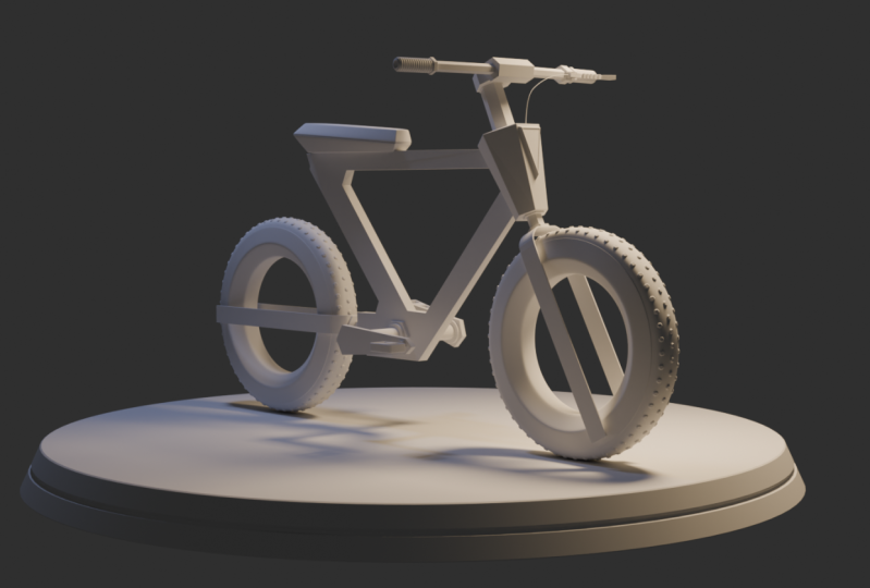
24. Conclusion: And this is the final result of modeling the
futuristic cycle. So I hope this was
beneficial to you. I showed you various
modeling techniques, tips, and tricks and how to
achieve certain tasks, using the modifiers
provided within Blanda. You can follow along and
build the same cycle as I have done over here or you can come up with your own ideas, and I'm looking forward to
seeing your modeling skills, using the techniques that
I have shown over here. So thank you very much, and do gp me your feedback. Take care and see
you in the future for more to come. Bye bye.
 Syed Khuram, 3d Artist