Transcripts
1. Introduction: Are you ready to turn your creative ideas into
detailed TD models? Whether you are an aspiring
engineer, a designer, or a hobbyist, this free
cad modeling course is designed just for you. Free CAD is a powerful, open source and
totally free tool that gives you the freedom
to design without limits. However, like any other tool, it requires the right guidance to unlock its full potential. In this course, you will learn how to create precise
three D models. You will learn how
to create sketches, choose those sketches to
create physical bodies, then create technical
drawings of those parts, and you will also learn how to conduct FM analysis in Free Cat. I'll walk you through
each step making show you understand how to carry
out every action. This is going to be a
project based course, where instead of going over what each tool in free CAT does, you will learn these tools
by working on CAD models of actual objects in a hands on approach with one
project every day. However, you can do it
faster if you have time, It is totally up to you. So why should we use Free cat? Be free cat is user friendly. It is customizable,
and best of all, it is completely free. There are no expensive
licenses required and no hidden costs like other CAD packages,
just pure creativity. So whether you're looking
to enhance your career, you are starting a new hobby or just want to bring
your ideas to life. This course is the
perfect starting point in computer ded design for you. So join us and let's create
something amazing together. Sign up today and start your journey into the
world of TD CAD modeling, choosing free cat. See
you in the course.
2. Downloading & Installation: So first thing
that we need to do is to download free cad. Okay? So for that, you need to head
over to Google or whatever search
engine you're using and just type Freecad. Okay. And this link will
pop up www.frecad.org. This is the official website. You can also download
it from other websites like sourceforge et cetera, but make sure that the source from where you're downloading is trustworthy and it's not infected with some
viruses, et cetera. Still, it is most appropriate and recommended to download
it from official website. Let's double click on that and you can just click over
here on Download now. Okay. Over here, now you can select the platform for which
you want to download. If you are on Windows, you would obviously
select this on Max, you would select this
whether you are using Apple Silicon or Intel Mac. Or if you're on Linux, you can go for any one of
these options R Best or X 86 or 64 space X 64
best Linux system. Okay. So I'm on Windows, so I will select this option. You can also choose
the portable option, which is in the seven
zip archive format. You can also download
that as well. And you have to remember
that make sure that Windows eight is the minimum operating system
required to run it. Okay? So Windows XP or
Windows seven won't work. However, they are very
old and I don't think anyone uses that nowadays. So I will just
click on this one, and the downloading
will start momentarily. It has started over here. However, I'm just going to stop it because I already have
downloaded the software. Okay. Also, as you know that free cad is an open source
and totally free software, you don't need to pay anything. However, if you want to pay or donate some money out of
the goodness of your heart, you can do so by
clicking this button. Okay? So I have
already downloaded it, so I will go to here
Downloads programs, and here it is free cad. Okay. Let's just don't
focus on this thing. Okay? So this is
the free cad setup. I'll just double click on it to start installation
and click yes. Okay. And now here we are. So just click next, obviously. Then this is the
license agreement. If you want to read it, you can. I will just click Next
and by clicking next, it means that you are basically accepting the license agreement. Now you can choose
to install for all of the users that
are on your computer or just for the one
user you're choosing from by which user you are
using your computer right now. Okay. So I'll click this option. Okay. And then select the destination folder
where to install, and then click next. Okay. So here you have three components like
free cut software, file associations and
a desktop shortcut. I will keep them all on and click next
and then click Next, and it will take a couple
of minutes or seconds depending on the speed of
your computer to install. Okay. And obviously, it's
going to take some time, so I'll just skip forward to the moment where it has
install the software. So here it is the free cat
1.0 has been installed, and I can either click
on this button to launch the software once I click
this finish button, or we can uncheck it
and launch the software ourselves by just unchecking
this option over here, this box over here,
click on Finish. And now, if you selected the
option to create a desktop, shortcut, now, if
you go to desktop, you will see this
shortcut over here. Okay. So this was all about downloading and
installing free cat. The next lecture will
be about CAD workflow, and then we will
move on to using frecad step by step. Thank you.
3. CAD Modelling Workflow: So in this lecture, we will talk about CAD modeling workflow. And this is not
specific to free cad. The methodology is same in almost not almost in all
of the CAD software, whether it is solid works,
Catia, or whatever. Okay. And it is
basically, for example, let's say you want to create
a CAD model of a bottle. Okay? So this bottle is going to look something like this. Okay? So there is going to
be the bottle itself. Okay. Let's say this is the bottle. Okay. This is the bottom. And there is going to be a
cap on top of this bottle. Part on my drink basically, in CAD, both of
these components, this bottle itself
and this lid or cap, whatever you want to call
it, they are going to be cared as parts. So this would be part one. This would be part two. Okay. Now you can create
both of these objects, this bottle and are in a single free CAD document or any other CAD software
document or file. However, it is
better practice to create them in the
form of assembly. Okay. Assembly basically
is combination of two or more than two parts that are combined to one
another using mats. We will study these
things and how to create assemblies in its own sections. Okay. So this bottle, this entire bottle
would be considered an assembly where this cap and this bottle down
the bottom part of this bottle are going
to be its two parts. Okay. So methodology basically
goes something like this. We create part models,
okay? Part models. And then if we are only
desiring to create part models, then we will just create a part model and our
project over there. However, if we want to create
a model of a geometry, sorry, model of an assembly which has more than
one parts like this, then we will first create different part models like
this gap and this portal, and then we will use those
parts to create assembly. Okay. So basically,
our majority of the focus is going
to be spent over here, creating part models. And then we will learn how to create assemblies
from those parts. Okay. Now the question comes, how card modeling workflow or how cared models of
parts are created. Okay? So for every object, let's say you want to create a three D cared model of a cube. Okay let's not go for a cube. Let's take this gap over here. Okay? So this caps looks
something like this. Okay. So for this gap, first, you will have to
create two D sketch. Okay? And then you will
use something called features to convert
this two D sketch into three D model
or three D geometry. In case of this gap, the first two
dimensional sketch could not be it most likely
would be a circle. So you will create a circle, then you will choose a
feature called pad in free cad to convert this two dimensional circle into a three dimensional body. So it will start to begin
it will begin to look something like this. Okay. Then you will have to
remove material to make the shape of
a cap from inside, so you will create another
two dimensional sketch over here or on the
bottom surface, okay? And then you will use that
sketch to remove material. Okay? And you will use pocket feature for
removing material. Okay. So basically,
your model will be created by a combination of
sketches and then features. Okay? So this is
how CAD workflow usually or this is basically the cad workflow and how
CAD models are created. Now one thing to remember
is that there are always more than one way
to create a single model. If you look at this
cap once again, we can either create
it by creating this circle as I just
explained over here, then using the pad feature, then removing the material
by using the pocket feature. Wherever there are
many features. So another methodology
or approach you can choose to create
this cap model could be like you create a sketch that looks something like this instead of a circle, you create a two dimensional
sketch looking like this. Then you choose another feature
called revolve feature, which will basically take this sketch two dimensional sketch, revolve it around 360 degrees. To create the model of a ca. So it basically depends
on your approach. There is no one singular way or single method to create
a specific card model. Okay? So to sum it all up, you need models, part models
to create assemblies, and a part model is created by first creating a two
dimensional sketch and then using tools cared features to convert that two D sketch
into three dimensional body. You can use features
to add material. And also you can use them to remove material
depending on your need. Okay. So this was all
for this lecture. In the next lecture,
we will go over the user interface of
free get. Thank you.
4. Introduction to FreeCAD: Okay. So when the first
time you launch free kid, you will be greeted
by this screen. This is basically the
splash screen of free. Here you can choose
the language, unit system, and
navigation style. We will go over the navigation
in detail in next lecture. Okay. However, you can either pick these
things right now, unit systems like millimeter
kilogram, second. These are the
different units for measurements used in free cat while creating different
type of models. Okay? So standard is millimeter
kilogram and second, meaning for length, millimeter, for mass kilogram and
for time, seconds. However, you can still change
these things later as well. Another thing you can
choose right now is to change or select theme. You can either select free
cad Light or free cad dark, which looks something like this. I will keep it on
free cad Light. Then simply click Done. So this would be
then from now on, when you close free cad and then open free
card once again, you'll be greeted by this screen instead of splash screen. That splash screen only opens or only appears the first time
when you start free care. Okay. So this is
basically the start page. Here you can create different
files like parametric part, assemblies, two D draft, BIM and architecture, an empty free cad file or
open an existing file. And there are also
some examples over here as well fread models. So this is a good time to explain how free cat
basically works. In the previous
lecture, we described the methodology or
workflow of CAD modeling. Basically, you first
need to create a sketch, then use features to
create geometries, three dimensional
geometries to create parts, and then you can create assemblies from
those parts as well. Okay. In free cad, to do all of these
separate functions to carry out the
separate functions like creating sketches, creating part models by using features and
creating assemblies, we have different work benches. You can select which
work bench you want to use by simply
going over here. Okay? So let me zoom in. You can see it over here. Currently, it says part design. You can left click on that
to select other Workbench, as well, you have a sketcher over here which
is used for sketching. This part and part design are
used for creating creating three digometries by
using features on sketches created in
sketcher workbench. You have other over here as well like FEM for
finite element methods. You have CAM workbench for
computer added manufacturing, BIM for architecture, and drafting for creating drawings
and many other as well. Okay? So when creating
a card model, we will obviously we can
either go start with the sketcher and then move on
after creating the sketch, move on to part design. However, the actual workflow inside free care is
a bit different. You can just select directly go to select the part
design, Workbench, and obviously, free cat
knows that to create a part, you need a sketch. Okay? So it will obviously
first shift you to sketcher and then
you create the sketch, and then it will move you back to the part
design workbench. Okay. So basically, you can
select workbenches over here. Okay. And also, if you want to create a
part file over here, this will directly open a new free care document
with part design workbench. For assemblies, you would select this option for creating
ranks, this one, and you have basically
the same options of these workbenches
over here as well. Okay. In this course, we will go over parametric
part part design workbench, we will work with
sketcher, assembly, drafting and finite
element method workbench. So which is over here. So most of the time
we'll be using this part design workbench. Let's go over there. We will simply left click and
by left clicking, it will create a new
free gad, Document. Okay. So now, once you create a free cat document
in part design workbench, your screen would look
something like this. Over here, you will have
this entire portion. This portion is
called as viewport. Okay. So whatever you create is going to be displayed over here. Okay. And on top over here, you have some options, these features like pad, revolution, and
pocket, et cetera, which we mentioned in
the previous lecture. Okay. On this side, okay, this is this
side over here. This side, you have
tasks and model. So you have one tab for
tasks and one tab for model. If you go over to model, here, everything you create will be displayed in the
form of a design. Like you create sketch one, that would be
displayed over here. Then if you apply
some feature on that sketch that feature
would be displayed over here. Under tasks, the free cat basically is telling you which tasks you
need to carry out. Okay. So under helper
tool over here, it tells you what
you need to do to basically create a model. Okay, depending on the
workbench you have selected. So we've created a
free cat document using part design workbench. So obviously, it is asking
us to create a sketch. And if we left click on this
sketch and zoom out a bit, we will move these plans
will appear in viewport. Okay. So these plans, basically we will
go into detail in next lecture while
creating our first model. So you will select a plan. Let's select this plan. Okay, now this plan is selected. And once I selected that plan, the workbench automatically
changed to sketcher. Because we have now selected a plan to
create our sketch on. So free cat, when we were
in part design workbench, it was telling us
to create a sketch. That is the task we
need to carry on. And for that, we had
to select a plan. And now we have selected a plan, we are now in the sketcher
workbench to create a sketch. Let's say we create
a simple rectangle. Let's simply create a
rectangle over here. Click on Close button
over here under tasks, close, then we can click on pad. Let's click on this button
over here over here. Okay. So once we closed
out of the sketch, the free cat automatically
moved us from the sketcher workbench to
part design workbench, as you can see over here. Okay? And now we
select this pad tool. It is creating a three
dimensional body. Let's click Okay,
and now we have a three dimensional geometry. Okay? Now, if we go to model, as you can see over here, we have a pad. This means that under
model in this design tree, this entire tree is
card as design tree, the drop down menus. So we have pad over here because that is
the feature we used. Now, if you expand it by
clicking on this button, you will see a sketch. Okay. So this is basically the sketch on which we
applied this pad feature. Okay? And you can
see it over here. So now if we create
another sketch, then that sketch would
appear over here as well. And then if we apply
another feature, that feature would display
over here as well. Okay. And one thing to note is that the free cad
is a parametric model. Okay, parametric
modeling software. So what does that
basically mean? So let's say now I select
this surface, go to tasks. Then under task, we have different tasks which we
can carry out right now. I just want to create
another sketch. So I will select this sketch
option, create sketch. It will change, move us again
back to sketcher workbench. Let's say I create
a circle over here. Let's create a circle,
something like this. Click Close. Now select pad once again and click Okay. Okay. Now if you go to model, okay, we have this different this is the original pad feature and
now we have the pad 1.001, which is for this cylinder. Now what we can do, since free kid is a parametric
modeling software, we can go to any one of these options or any one of these entries in
our design tree. Let's say you want to
change the dimensions of this sketch or how this
sketch actually looks like. You can just click
on this sketch. Left click to
select this sketch, go to tasks, okay. Or sorry, right click
on this sketch, and over here, you
would see dit sketch. Okay? If you do that,
let's left click on that. And let's say we
delete this line. So you simply select
this line with left click, press
the delete key. Okay. And then select
this line tool over here. We will go over the
detail of all of these tools in future lecture. So I'll just select
this line tool. Okay. Let's create
something like this. Okay. So now that
sketch has changed. Now if I close it, and as you can see, free cat automatically
knew that on this sketch which we have
just edited right now, this pad feature
was applied. Okay? So it automatically applied the pad feature to this
sketch without asking us. Basically, this is what a
parametric software means. Okay? So this is all about the user interface and a basic introduction to
free care. Thank you.
5. Navigation in FreeCAD: So in this lecture,
we are going to learn how to navigate in free care. Okay? The first
methodology to navigate in free cat is by using this
view cube over here. Okay? And you can find
this view cube in the top right side of top right corner of the view
board. It is over here. You can basically left click
on any one of these surfaces and free cat will directly change its
view to that surface. Let's say if I click
on this top surface, which says top over
here, left click. And now, as you can see,
the free cat has moved the model directly to
that top view. Okay. And if I select, let's say this small surface
over here like this, it will rotate it once again. Now if I select front, it will change its
view to front view. You can also rotate the model by clicking
on these arrows, rotate left, rotate
to the right, rotate to the bottom
and rotate up. This should be rotate down
and rotate up, not bottom. Okay. So you can also rotate
the model in clockwise and anticlockwise
direction as well by using these arrows. These ones. So this one would
rotate the model in counterclockwise direction
and this one would rotate it in
clockwise direction. Like this, as you
can see over here. You have this small
circle over here as well. If you click on that, it will directly or it will basically invert the view
of whatever you are on. For example, if we
are if I click now, now I'm at the bottom view. If I select this button, I've directly moved
to the top view. So to see the opposite side of your model from the perspective of whatever view you
are on right now, you can simply collect on
this small circle over here. And let me change it to
something like this. If you left click on
this cube over here, the small cube next to the
view cube over here, this one, and if you click on that, it will open a lot
of these options. Currently, we are in
orthographic view. You can choose to either stay orthographic view or you can also change it to
perspective view. Okay? And let me zoom out. Now we are in perspective view. Okay? And to move back
to orthographic view, you can either use these
V B and VO hot keys or just left click on this cube and select orthographic view. You can also click
on this cube to go to isometric view and it will change its view to isometric
view in just an instant. Okay. You have other options over here as well like fit all. If you select fit all,
the model moves to the center and basically
tries to fit itself to the it tries to fit
everything inside this viewpot. And if you select Fit selection, then if you have, let's say, more than one bodies or
the more than one feature, it will try to focus on
that selected feature. For example, let's say, I
left click on this face, now select click on this cube and click
Fit Selection. Okay. Now, since this
is just one body, so fit all and fit selection is basically the same while
creating assemblies, et cetera, where you will have
more than one bodies or in multibodies parts as well, you can use the fit
selection if you want to visualize or concentrate your
focus on a specific part. Okay. So that is how
to use this VwQuue. The second methodology
to navigate in free cad is using hot keys. Okay. And for hot keys, there are many
systems, basically. Okay. So currently, as
you can see over here, it says CAD over here. Okay? Here. And if I hover on this CAD
for a couple of seconds, it shows the CAD
navigation style, which is left mouse
button to select, mouse wheel to zoom in and out. Right mouse button and middle
mouse button to rotate and also middle mouse button
and left mouse button to rotate and also panning. So basically, it means if you are on this scared
navigation system, you will use the
left mouse button to select whatever
you are selecting. Middle mouse button, move the middle mouse button
and forward direction to zoom in in the backward
direction to zoom out. For panning, you
will have to press the middle mouse button
and then move around. Okay. And for rotating, you will need to press the left mouse button and then middle mouse button
and then start working. Oh, sorry. For rotating, you will need to
press the shift key and then the middle
mouse button. Not working once again. Sorry. Shift key and
left mouse button. Sorry. Okay. So I don't usually use the cared
navigation style, so I'm struggling to
understand it myself. So it is shift mouse button, then the left mouse button, and then you can move around
to rotate around the model. Okay. And this rotation is basically around the point
where you are cursor. For example, if I press my cursor over here
to this corner. Okay? Now, if I press the shift key, then the left mouse button, the icon changes to rotate. And then if I rotate, it rotates around that point. You can see that point as this
pinkish circle over here. Okay? And now if I move the mouse pointer to
let's say over here, now if I press the shift key then left mouse
button and rotate, it will rotate the model
around that point. Okay. So this is cad
navigation style. You can also change
this navigation style. If you just left
click and you will have options to change it to
any other navigation style. If I change it to Blender, now Blender is very
simplistic and I like the Blender navigation
style out of all of these. Okay. So Blender is basically
for Zoom, it is the same. Zoom in, move the
mouse wheel forward, and zoom out, move the
mouse wheel backward. Rotating, press
middle mouse button and then move around to rotate. And for panning, shift
key and then press the middle mouse button and
then move around to Pan. Okay. However, if you want to choose some other
navigation systems, you can do so as well. Also have options to use gestures if you
are using a touchpad. You have Maya gestures, which are basically
the gestures used in Autodisk Maya software. We have from Open inventor, which are basically Autodisk
inventors navigation system, avet Tinkercad, touchpad,
and many others. Okay. And you can
also go to settings and create your own Sorry, you can't create wrong. Okay. So sorry on that. Okay. So basically, these are different
navigation systems. So I would recommend
either using blender or card
navigation systems. Okay. If you have used
blender in the past, this blender navigation system will feel very easy
to understand. And out of all of
these, it is the most intuitive, in my opinion. However, it all your choice. If you have used
rabbit or Ivenor, feel free to use those
navigation systems as well, however, in this
course, I will be using blender
navigation systems, so I will change it to blender. Okay. And one more thing. Whenever I press a key, you can see which key
I'm pressing over here. Okay. So if you want to understand while creating
any model like let's say, I press any key to activate a hot key for
a specific feature, you would see that key
appearing over here. So this was all
for this lecture, how to navigate in blender. And in the next lecture, we will start creating
part models. Thank you.
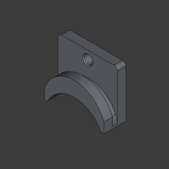
6. Day 1: Part Modelling - Simple Cube: So in this video, we are
going to be creating our very first
model in free kid. And that is going to be
this very simplistic cube with rounded edges. Okay. So let's close
this. I will close it. Click on this card. I
don't want to save it, and we will move to
this startup screen. So since we are going
to be creating a model, a physical three
dimensional geometry, which is going to
be basically apart. We're basically creating apart. So we need to create a free cat document in
part design workbench. And for that, we
have option over here under parametric part. Create apart with part
design workbench. Let's left click on that and we have a new
frecat document. It is unnamed, as you
can see over here. Okay. So let's start
creating our cube. So for this physical three
dimensional geometry, we will first need
to create a sketch. And the free cad is telling
us to create a sketch, as you can see over
here under tasks. So we will left click to
create a sketch. Okay. So now we have the choice of selecting either one
of these three plans. Now, you need to remember that in order to
create a sketch. So basically, to create a
three dimensional geometry, we need a sketch, and
to create a sketch, we require a flat plan, a flat surface on which that sketch is going
to be created. So when starting, you will have access to
these three plans. X Z, X Y and Y Z. Once you have
created a geometry, then you can use any one
of the flat surfaces of the geometry to
create further sketches. However, in the beginning, you will have to oe any
one of these three planes. So this X Z is basically
the front plane, XY is the top plane, Y Z is the side plan. Okay. So depending on
what you want to create, you will select the plan. Okay? So for example, let's go back to Power Point and let
me explain something. For example, let's go back to that gap we needed to create, which was something like this, from the front view. If you select front view, then you will have to create the sketch that looks
something like this. Okay. Then you will
use revolve feature, which we will use in lecture, don't worry about that to create this three
dimensional geometry. If you select the top plan
to create your first sketch, then you will need
to create a circle, then move it in the
upward direction to create a three
dimensional geometry. Then it will start looking
something like this, this is not helping. I'm sorry. Then it will start to
look something like this, then you will create
another sketch on this top flat surface to remove material to basically
create the shape of a cap. Okay, so there are
more than one ways, as I said, to
create a CAD model, and whatever approach
you are trying to use, the plan is going
to be dependent. Your plan selection is going
to be dependent on that. Okay? So let's close it and
move back to free care. Okay. So in this case, since we are going to be
creating a very simple cube, so it doesn't really matter
which plan we select. Okay, because the
approach is going to be Sam in case of this cube. However, for other
more complex models, the plan selection is going to matter a lot depending
on your approach. Okay. So let's say I
select this X plan, which is basically the top plan. Let me left click on
that. Okay, here. Now that plan has
been selected and free cat has moved us
to sketcher Workbench. So now we are in sketcher
Wpenge to create the sketch. For creating this sketch, you have all of these options from this point to over here. Okay. So let me zoom in on that. So this is create a point. So you can use this option to create
a single point. Okay. And let's see what is this one. This is polyline, which is
basically a continuous line. We have this line feature
then we have the arc, circle, rectangle,
polygon, slot, and spline. Okay. So from this
point to this spline, we have different types
of sketch elements. Okay? It can be a line,
it can be a circle. It can be a rectangle
depending on your need or a
polygon or an arc. From this point, from this
option over here, okay, not from this option,
just this option, this is the dimension too. Okay. So in the previous version of the free cat like 0.18
and 0.21 before 1.0, you basically had
to first create a sketch element like
rectangle or circle, then use the dimension tool to apply dimensions like
six millimeter length, width, radius,
whatever, six, seven, eight millimeter or
inches, whatever. On that. However, in
the newer variant, it is much more
simplistic and intuitive. While creating geometry,
the sketch sketch element, free cad directly asks us
for dimensions right there. However, you can still use these dimension tools
if you want to. Okay. From this point onwards, from this option to this option, we have different
types of constraints. Constraints are basically
conditions you can set on different
sketch elements, whether it is a rectangle,
line, circle, whatever. Okay? You can basically tell a line to be perfectly vertical or perfectly horizontal by using these constraints or if
there are two lines, you can tell one line to be
perpendicular to the other. Okay. Let's see what they do. Okay. So let me
demonstrate it right here. Let's say I select
this line tool. Okay. And it is always a good idea or it is
always recommended to continue your sketch from or to tie your sketch
to the origin. This point over here
is at the origin. Okay. So always it is not a requirement or
it is not necessary, but always a better idea to connect your
sketch to origin. And the best practice to do
it is starting at the origin. So I will left click
on this origin over here and start creating
a line. E. Okay. So as you can see, we have two dimensions. And when we move this when we move this sketch
mouse pointer around, these two numbers are changing. One of these is the length of the line and the other
one is the angle. Okay. So currently, as you
can see, let me zoom in. As you can see, the
length is highlighted. It is under blue color. Okay. And if we start
writing any number, it will change its length. Let's say I type 15. Now it says 15. If I still press taxpas Sorry, I can't choose backspace. So you cannot choose backspace. Okay. Let's say I type 15. Okay? Now, let's say you
have typed 15, but you don't want this line, simply press the escape key. Okay? Let me zoom
out, simply press the escape key and then
create the line once again. Okay. So this time, let's say I type
15 because that is the length I want
this line to have. Okay? Then after 15, you will press Enter, and then it free cat has now fixed the length of this
line to 15 millimeters. Now it is asking you the angle, and that angle is going
to be the angle of this line from this horizontal
angle from this one. If I move it down over here, now, as you can see, the
angle is zero degrees. If we move upward, the
value of angle increases, and to this point,
it is 90 degrees. Let's say I want to create
a line at 30 degrees. I will simply type 30, press enter, and now we
have a line let me zoom in. Now we have a line with the
length of 15 millimeters and the end at an
angle of 30 degrees. Let's say, now I select the line tool once again
and create another line. Let's say somewhere over here, starting at this over here. Okay. So let me create
something like this. Let me put that dimension
to be let's say 30, and just press center and just left lick it over here
to create this line. Okay. Oops, let me
change it to top view. Here. Okay. So you might accidentally use press
the middle mouse button and then move around to
rotate your view in sketch. Okay? That is not very helpful. It is always a better
idea to be looking directly at the sketch from the top view or the
front view, whatever. Okay. Since we are creating
the sketch on the top plan, so I will select this button
once again to move to top. Okay. So now we have two lines. One has the dimension of 30 millimeter and the
other is 15 millimeter. Now, if I want this line to be perfectly perpendicular
to this line, we can use constraints. For that, we will have
to select this line, press the Control key and
then press we will select this line over here
in this button, under elements, you can see
that you have two lines, one line, which is this
line and two lines, which is the second line. So in your sketch, whatever sketch
elements you will have are going to be
listed over here. Okay. And all of
your constraints would be listed
over here as well. Now we have these constraints, but we have not directly
assigned them ourselves. And that is because while
creating the lines, we created these constraints. For example, the
first constraint is the 15 millimeter dimension. Which we assigned to this line. The second one is the angle, which is the 30 degree angle, which we assigned to
this line or selves. Then we have another constraint, which is the starting
point or this point over here for this
third second line, then we have the length of the second line and then we have the sp point of the
second line as well. Okay. So now we have two lines and we have
created these constraints. While creating the lines, we didn't assign them ourselves. However, let's say, still, you want this line to be perfectly perpendicular
to this line. Okay? So you will
simply select one line, press the Control key,
and while holding it, select the second line. Now as you can see over here, both of these lines
are highlighted, meaning both of
them are selected. Now if I go over here and this one says can strand
horizontal vertical, you don't want that, then this one says can
strand parallel. If I click on that, it will make both of these
lines parallel. Okay so now both of these lines are parallel
to one another. And we have a new constraint, constraint six
over here as well, we don't want that,
let's just delete it. Once again, select this line and select both of these lines. And after parallel over here, we have constraint
perpendicular with the heart key of N. Now if
I select this constraint, Okay, it is not applying because it is saying
it is over constraint, so we cannot make
these lines parallel. To do that, to fix this, we'll have to press
Control Z to undo. Okay? Do it once again now. Now, let's select this line, then select this line and click on this
perpendicular constraint. Now as you can see,
once we did that, the angle between
these two lines become a changed to 90 degrees. Both of these lines have
become perpendicular. So this is how
constraints are used. For example, let's say
you create a circle, let's say we create a circle, we provided a dimension of 50 millimeter, sorry,
50 millimeters. Okay, here it is. Then we create many
more circles like this. And this time we did not
assign any dimension. We just simply we just
simply left click, create a circle, left
click again to release it. Left click to start a circle, left click again, release
to complete or circle. Now we have only assigned dimensions to this first circle. We have not assigned
them to this circle, this circle or this circle. We can still do that by going to this dimension
tool, left click on that. Click on this circle,
and now we can insert the dimension
for this circle. However, let's say I insert dimension to this circle using this dimension tool. Once again, you left click
on this dimension tool. You can expand it to open
up other dimension as well. I can stand diameter
radius if you want to insert a specific dimension. However, most of the time, you would be just use if you
are to use a dimension tool, you would just choose
this simple dimension. Okay? So it will
automatically look at the sketch element and it will basically automatically
suggest which dimension, which parameter you should
enter for its dimension. For example, if it
is a circle or arc, it is going to be either
radius or diameter. If it is a line, it will it will ask you
to enter its length. Okay? So let's say we
click on this circle. Okay, and left click over here, and now we have this dialog box. Okay. And it says
enter its diameter. Let's say we type
in 15 millimeter. 15 and press. Okay. Now for this circle, we applied this 40
millimeter diameter while creating the circle. Okay, that is one way and probably the most
simplistic way. For this circle, we first
created the circle, then use this dimension tool
to enter this dimension. Okay? And for these two circles, we have not assigned
any dimensions at all. However, let's say you want
this circle and all of these three circles to be of equal dimension, 15 millimeters. You want this circle
to be 15 as well, and this one to be 15 as well, to be equal to
this first circle. For that, simply press the escape key to exit out
of the dimension tool. Select this circle, press the
Control key or Shift key, both work, then select this circle and then
select this circle. Okay, as you can see over here, we have these three
circles selected. And if you look under
constraints, here, here, we have constraint equal
with the hot key of E. If I select it, all
three of the circle, the second and
third circle change its dimension to
this first circle to the one to which we have provided the
dimensions ourselves. Let's say this circle
and this circle for dimension less and you assign dimension to this circle. Then if you choose
this equal constraint, the first and
second circle would change their diameter
to this third circle. It is basically making all
of these circles equal. Now we have told free
cat that circle, this circle and this circle are equal and dimension
to this circle. Okay, we have applied a constra. Now, let's say, if we double click on this
number over here, which we inserted to be 15. Now let's say we make it 20. Let's say we want to change its dimension,
change its diameter. We write 20 over
here and click Okay. Now, we only changed the
dimension of this circle, but dimensions of this circle and this circle has been changed as well because these were
equal to this first circle. The constraints were applied. So this is basically
how you choose constraints and create sketches. Okay. So now let's move
on to creating our cube. For creating our cube, first of all, we will have
to delete all of that. Okay? So just you can either left click and create
a box and select everything. Or you can press Control A. Control isn't working. Shift A is also not working. So basically just create a box or we have all of the
elements over here, select everything
over here as well. For that, you'll
just have to press the left mouse button.
Move it upward. Okay? So here. Now we have selected everything. Press the delete key. Not working once again. What's going on? Okay. So
let's use this option. Select everything,
press the delete key, and everything is
gone. Okay. Okay. So now let's start
creating our cube. And for our cube, we basically will have
to create a square. Okay. So you can either use the line tool to
create four lines or directly use the rectangle tool because that is going
to be much more easy. So let's left click to
select the rectangle tool. Let's start over here
and move it upward. Okay. So we can either
left click right now and then insert dimensions by using
this dimension to letter, or we can insert them right now. I think right now is the
better idea. Let's just do it. For its length, we will type 50. Okay. So you can see, we have 50 typed over
here, press Enter. Now it has changed. Now instead of
asking for length, it is asking for its width, and that would be 50
ones again. Press Enter. And now we have a square, 50 millimeters of width and
50 millimeter of length. Okay. So this is going
to be our sketch, our sketch is ready. We are ready to apply
features on it, so we will simply left click
on this button over here, close to exit out of
this sketcher workbench. Okay. Okay. So once we did that, cad has switched us to
part design workbench. And in part design workbench, we can apply features
on the sketches we have created in
sketcher workbench. Okay. So the feature
we are going to be using for this case
is going to be pad, which is over here. You can also apply it from
over here as well under tasks. So now we have created a sketch. Under tasks, it is
showing us all of the different tasks we
can apply to this sketch. We can either choose to create a new sketch or apply any
one of these features. And pad is going to be the
feature which is going to be 90% of the time
in your modeling, you are going to be using. It is very, very common. In other softwares in
solid words, for example, it is called as extrude, but in free cat, it is pad. Another thing to remember
about these features. So as you can see, from
this point to this point, you have different
features which are in Jallow color and
then so you have in red color and then over here you have in
Jallow once again. So the features which are in yellow color are
basically additive features, meaning according to the
definition of the sketch, they're going to add
material to your model. Whereas these red ones
are subtractive features, meaning they are going
to be removing material. Okay. So for this one, we want to add material on
the basis of this sketch, so we will use this pad feature, which is over here, P D pad. Okay. Let's left click on
that and we have our padding. So once you selected the
pad feature, under tasks, this button, these options
will pop up pad parameters. Okay. So here you will
specify the parameters and basically the settings
of this pad feature. The first thing is type. Under type you will select how you want to
assign this pad features. You can either do it pad dimension, entering
the dimension, up to in the third axis, which is the Z axis, which you can see over here. So we created a
sketch on XY plan. Now we are using the
pad feature to pull it upward in along z axis. Okay? So the
dimension to which we want to pull it upward to create a three
dimensional geometry. Or you have other
options as well. If you expand this, you have to last to first, up to pace and two dimension up to shape,
et cetera. Okay? So two dimension is
basically going to be two dimensions like
upward and downward. Let's say you want to, let's just express it
right now over here. Okay. Let's say we type 20
on the upwards length one. Okay. After typing 20, don't press the
enter key because it will close you out
of the pad feature, simply left click somewhere
over here in this box. I will left click over here. It updates the view. Now it is 20 millimeters in the upward direction from
the sketch we created and ten millimeter in
the downward direction. If we change it to let's say 50 in the
downward direction, now it increases its length
in the downward direction. Okay. So this is
basically two dimension, or you can just
choose one dimension to only pad it in the
upward direction. Okay? Or you can
change its direction as well if you check
this reverse button. Okay? If you check this reverse, it changes its direction
to other side. If you uncheck, it changes
its direction to upward. Okay? So apart from dimensions, you have these options
as well up to phase to first to last and up to chef. These are not
relevant right now. Basically, it is up to phase
Rubis select up to pas, in the case that there
is another phase directly in the way of this
sketch that you have created, and it will basically pad this sketch up to
that specific phase. Okay. And up to shape is padding it up to a different
shape, okay, whether it is planar phase
or circular or spherical, whatever, or
cylindrical, whatever. Okay. So for this one, we're going to
stick to dimension, and dimension is going to be 50 millimeters because
we are creating a cube. Okay. Left click to
update the view, and you have other
options as well. Who check this
symmetric to plan, and this will basically put your sketch right in the middle and we selected
the lent to be 50. This would mean it is 25 millimeter in the
upward direction, 25 millimeter in the
downward direction. Okay. We don't want that, so I
will uncheck it once again. Okay. So you have some
other options here as well, far directions, sketch normal, sketch reference,
custom direction. This is basically the direction
of padding basically. Most of the time, it is
going to be sketch normal, meaning pad this add material in the z axis
directly normal to the sketch. Okay? You can check this to
also show the direction. Okay, it is zero, zero, one, moving in the
upward direction. Okay. You can also change it, but we're not going to
do that for this video, because we don't need to
do it to create a cube. Basically, this just means
that you don't need to concern yourself with every
single button in a free care. So you need to
focus on your task, what you're trying to create and basically use or try
to understand all of the features you need to create that specific shape
or specific model. Right now we are
creating a cube, so sketch normal words
for us for that case, we do not need to concern
ourselves with other options. Okay. So obviously,
it is going to be 50 because that is the
length of this line, the dimensions of length and width of the rectangle
that we created. Okay. I'm getting a bit story. Okay. I apologize for
that. Let's click. Okay, and now we have our model. Okay. Now our cube
is basically ready. You can just close it right now. But let's say we want to
round off these edges, or we want to round these edges basically to eliminate
these sharp edges. For that, we have a
tool called fill, and it is this one. Okay, fill it. Left
click on that to select. Now we are in
selection mode. Okay? So we'll basically
have to select everything we want
to apply Fillet on. So currently it is
displaying an error fill, Fillet not possible
on selected shares. We have not selected anything,
so just ignore that. Okay. So these kind of random error messages which
don't usually make sense, do appear in free kid. Okay. So let's say we want
to round off this edge. Let's say we select this edge
and under this checkbox, this edge seven has been listed. Now, if you want to preview
how this will look, you can select this
button to preview, and as you can see over here, it is showing us
the rounded edge. If you want to
select more edges, you will click on
this Select button. Let's select this edge, this edge, and this edge. Because these are the four
edges on which we want to apply this fillet feature
or this rounding feature. You can either select
these four edges, however, there is a much
more easier way to do it. Let's select all of these edges, press the delete key. And instead of selecting
these specific edges, let's select this phase. So when we select this phase, it will automatically apply the feature to all of
the edges of this phase. So this phase has four edges, one, two, three, four. Okay. So selecting for edges is difficult as compared to
selecting a single phase. So we will select phase. Okay. Then we will rotate
around and select this phase. Okay, rotate it
upward once again, or just click on this
button over here and go to isometric view pen to move
this move this model downward. Okay? Now click on this
preview button over here and it is applying or rounding off to
all of the edges. And over here under radius, we can select the magnitude
of this rounding. Currently, it is set
to 1 millimeter. This is basically the radius
of the circle to which these edges are going to
be cut off or rounded off. So currently it is 1 millimeter. We can increase to
a large number, but that looks something weird. So let's double click
on that and type one, and then once again, left click somewhere over here
to update the view. Okay. So if you want to apply this effect on all of the edges like
this one as well, instead of selecting everything, just simply click use all edges. If we don't want to do that, we will only select these
phases and we have applied or fill it of 1
millimeter radius, and now we simply
need to click Okay. Okay. Now we have our cube with rounded top corners
and bottom corners ready. So this is everything for this. Lecture. But let's move on to learning how to
save our documents. Let's say you want to
save this document. For saving, you can
either press Control S, and you can save your
document like this or you can go to
file let me zoom in, File and click Save or Save. Let's click on saves. We will select the location. Let's say I want to
save it on desktop. You will type the
name over here. Let's say simple Q. Okay. Oops, Caps lock was on. Simple cube. Okay. And it will save it as a free document with the
extension of FC SDD. Okay? You can select it is going to be free
gad, standard document. Okay, click on Save, move to desktop, and let's see it does
not appear over here. Let's move to desktop, and here it is simple cube. Okay. Now, let's say, now this this file will only open in free kit because
it is a free kat document. Now, let's say you
want to export this to other software like
let's say you want to render it in Bland or
use it for some kind of analysis in NCIS or
Comsole, et cetera. Okay? For that, you will
have to export this model, or you want to export it for three D printing,
let's say, Okay? For that, you will have to go to file and click on Export. Okay. So first of all, we will have to
select an object. So let's select this object or let's go to model and we
have this body over here. Left click on this
model, this body, which is basically this cube, or you can simply click
on this cube as well. Let's click on this body, go to file and click on Explore. Okay. Now you can export
it in different formats. There is TMF, which is
used for manufacturing, which is basically
three D printing. Additive manufacturing
format, MF, but most of the
time the STL mesh is used for three D printing. Okay? So it would be
this one dot STL. Okay. If I select, save it as STL, click Save. And now we have an
STL file over here, simple cube body STL, which can be used for
three D printing. Okay. And you can also export it in other formats as well. Like you have a lot
of options over here, IGS o or CA OpenScadFmat, you can use export it
in step format which is used in solid works a lot and
many other options as well. AtoDsk DW D, DXF, and many more. Okay? Here we have x3d as well, which can be used which is
sported in Blender as well. Okay. So you can export your model by choosing
these options. Okay. So this was all
for this lecture. And the next lecture,
we'll be creating a Lego block. Thank you.
7. Day 2: Part Modelling - Lego Block: So in this video,
we are going to be creating a lego block or lego brick, whatever
you want to call it. Okay, so this is going
to be the second day or a four course, which is basically going
to mean it is going to be the second project. Okay. So you're going
to learn a lot of new things in this while
creating this model as well. Okay? So first of all, let's look at its dimensions
or before dimension, let's just actually look
at this lego block. This lego block will have three bumps and
on its back side, it is also going to
have some three holes into which those bumps will go. Okay, to attach
different lego bricks on top of this spray. Okay. And it is going to have this fillet over here
on these edges as well. Okay. So let's do it. I will just close
this and we'll create a new parametric
part because this is once again going to be
a parametric model. Okay? So let me just turn on
magnifier and here we are. Okay. So I will create
parametric part. Let's do that. And
next thing you know we need to do is to
start creating a sketch. So we will go to tasks over here and click on
this Create sketch. And then we will have
to select the plan. However, whenever you are
starting a new CAD model, there are two things you
need to make sure of. Okay? First, you need to look at the dimensions or the drawing of the parts you are
trying to create. And basically, think of the approach you're
going to carry out. Just think of it in your mind. Okay? So plan your approach. For example, this is going
to be a ego Black as we have seen as created in
the in free cat. Okay, momentarily,
you saw the model. So we are going to
plan or approach. Okay? So the common sense
here is that first, we will create this
best rectangle, then pad it upwards and then create these bumps and
then on the bottom side, we will create two holes. Okay. So now we know
the dimensions, now we can plan approach. And for this approach,
we need to select a specific plan and we
will select X Y plan. Okay. So lets click on there. So the first thing
before creating every card model is to think
of your approach and have the dimensions of the parts
are rough dimensions like over here on piece of paper or some drying on in computer. Okay, at least have some
idea of dimensions. Do not make model with arbitratory
dimensions because it is going to mess up your model. Okay? And the second
thing is to make sure you are in the correct
measurement system. Okay? For that, as we know, we have our dimensions
in millimeters, 32 millimeters, 16
millimeter seven, 9.6. All of our dimensions
are in millimeters, you need to make sure that in your system of measurement in fread or any other CAD
modeling software. The unit for length
is millimeters. And we can do that by going back to free cad and
going over here. Okay, let me zoom here, this bottom right
hand side of screen. Here it says 182.69
in 200 millimeter. It is millimeter, meaning the unit for length
is millimeter. These numbers are basically
the dimensions of the screen. So you can zoom in, zoom out. These numbers change. So let's make sure
these are a millimeter. Left click on that,
standard unit of length is millimeter
as we can see. That is perfectly fine. Okay. Now let's start
creating our model. So first of all, we are going
to create this rectangle. Okay, its length is 32 millimeter and width
is 16 millimeter. Okay. So let's go
to fricatG over top to this toolbar
and select rectangle. It is over here.
Left click on there. And as you know, it is always a good idea
or it is recommended to tie your sketches to the
origin in one way or another. Okay. So we will start or
rectangle from the center. Okay? So it is at the center, left click, and then
drag your mouse around. Okay. So length
was 32 millimeter, I will type 32 and press Enter and width
was 16 millimeter. Let's type 16, press Enter. Let's zoom out a bit. So
here is our rectangle. Okay. So our best
sketch is ready. Okay, we need to extrude it
upward or pad it upward into z axis in up to 9.6 millimeters. Okay? So let's click on this
close button over here. Left click on close. Then we need to pad this
sketch in the Z direction. Okay. So you can directly click on pad under tasks
over here as well, or you can use this paired
button over here, this one. Okay. And I will do it. Left click. Now we
can pad it in Z axis. Okay. And you can see
the XYZ axis over here, here, okay, the bottom left
hand side of the screen. Okay. So in dimension, we are going to do
it by dimension. So it is going to be
double click on that, type 9.6, and then left
click somewhere over here. Don't press Enter because
it will just apply the pad parameters
we are writing over here and we'll exit
out of the pad tool. Okay? So left click over here
somewhere in this blue box. Okay? So now it is showing us the preview,
L's click on Okay. And now we have our
brick or block. Okay. So after this, we
need to create bumps. Okay, and bumps are
going to be on top of this flat surface. So when starting your
CAD model, first of all, you will have to
select a plan from those XY ZX Z plans that are given at the beginning of
each Ed modeling project. However, right now, you have
other flat surfaces as well. You can still access those plans as well
by going to model. And if you expand
this over here, let me zoom in, expand this
origin, clicking on this box. And here you have all of
those plans XY Ys and Zadx. You can still select them. If I left click on that. Now
this XY plan is selected, and you can still go to
task and then click on Create Sketch to create
sketches on those plans. However, on top of that, you now has these flat surfaces
of this brick as well. And you can create sketches on these flat surfaces as well. The condition for
creating a sketch on a surface is that it
needs to be flat. It doesn't matter it is at
a certain angle or not. You can create a sketch on any surface as long
as it is flat. So bumps are going
to be over here, so I will left click
to select the surface. Now it is selected because
it has turned blue, it has changed its color. Now we can go over here to tasks and click
on Create sketch. Let's do that. Now
the view changes to the one directly facing
the face we selected, which is basically the top view. Okay, as you can see it
over here on this cube. So now let's create our sketch. And for this sketch,
let's see what we need. We need two circles. Okay, so these circles with radius diameter
of 7 millimeters. Okay. And these sketches have to be equal distance from
this line to this line. Okay. So now we need to place them equally from this
side to this side. So basically, we need to do some calculations in our mind. So basically, this entire
length is 32 millimeters. Okay? Let me select the pen. Okay, so this is 32 millimeters. Okay. So we need to
find the distance from this line to the center
of these circles. This kind of calculations you will often have to carry out
while creating a card model. Okay. So that means that if
we divide this into half, like this, this is going
to be 16 millimeters, and this is going to be 16
millimeters as well. Okay. So this circle needs to be at the exact center of
this half rectangle. Okay, this is basically square. Okay. So basically,
if the point this to the midpoint or the mid line of this rectangle
is 16 millimeter. So for this distance and
this distance to be equal, it needs to be 16/2, that is 8 millimeters, and 8 millimeters over here. Meaning the center of
this circle should be 8 millimeters away
from this line. Okay. Similarly, the center
of this circle should be 8 millimeters away
from this line over here. Okay. So now we have figured out the
horizontal distances. I've typed a writ
in 18, it is eight. Okay. For vertical distance, the total is 16, so both of these should
be 8 millimeters away similarly from this top
line or this bottom line. So this distance should
also be 8 millimeters. These are the dimensions for or the distances from these
lines for our circles. Now let's go back to freak. First of all, let's just create two circles without any
arbitrary dimension, or we can provide the dimension without any specific position. Okay? So let's select this
circle tool. It is over here. Create circle by center. Okay, let's left
click on that and I will create one circle
somewhere over here. Its diameter needs
to be, let me see. Seven centimeter. I will
type seven press Enter. Now we have a circle of
seven centimeter diameter. Let's create another
circle over here, and we can either enter the dimension
for this one as well, but it is a better
practice to create this circle and then make the circle equal
to the other circle. So we have not yet assigned
dimensions to this circle. I will press the escape key, select both of these circles, and you can basically
select them by just clicking on this
one, left click. As you can see over here, this
circle has been selected. Then we can click on this
circle to select that as well. You don't need to press
Control or Shift key, which I said that you need to do it in the previous. You don't actually
need to do it. You had to press those keys in the previous
version of free kit. Now you don't need. So you can simply just left click
selected, left click selected. Both of these circles
have been selected. Now, this one has the
dimension provided to it of 7 millimeters and this
one has no dimensions. So now both of
these are selected, I will go to the stop to this constraints menu from this point to this
point constraints, and I will use the
equal constraint. Okay. Let's make them equal. So now the equal
constraint has been used, and whatever the dimension, a one circle is going to be the second circle will change
its dimension accordingly. Okay. So now we
have the circles, but we need to position them at our appropriate positions at millimeters from this line and at millimeter
from this line. Okay. So basically,
that means we need to insert dimensions
between this point, the center of these circles, and this line of our rectangle. But there is a problem. The
problem here is that we did not create this line or this line or this
line in this sketch. It was created in
a previous sketch, which was then
extruded or moved into third dimension into Z axis
using the PAD feature. So these lines do not exist in this rectangle does not exist in the current
sketch we are creating. In current sketch, there
are only these two circles. Okay. Now, even if we still try to select
the dimension tool, which is over here,
let's select that. Okay. If you click
on, let's say, the center of this circle and then we try to create
dimension between this center assigned
distance between the center of the circle and
this line, we can't do that. We cannot select
this sent circle. Okay? You are seeing
vertical dimension, but that is not to this
line of this rectangle. It is to this axis, this red line, which
is the X axis. Okay? We cannot assign dimensions or use these lines of this
rectangle as a reference. That is a problem
because we need to provide dimensions
to these lines. We need to assign the
position of the center of these circles according
to these lines. In free cat, there is a
tool to basically do that. Okay. So if you go to
the tap over here, here it is a tool. Okay, let me zoom in this one. It says, create
external geometry, and it says, create an edge linked to an
external geometry. So let's left click on
that. So it is selected. Let's zoom out. Okay. So to figure out that whether you have selected to specific
tool or not, you will see here
as you can see. Next to the cursor, we have the icon for
that specific tool. Okay. So if there is an icon, that means you have
selected a specific tool. Okay. So using this tool, we can extract lines or
edges or even points from a previously created sketch to be used as references
for our new sketch. Okay? So now this tool has been selected this tool over here,
ret external geometries. We can left click on this line. Now, as you can see, we
can select that line. Okay, we can click on that line. So let's left click
on that line. It has been created or converted into a
reference geometry. Okay. Let's do that for
this line, top line, and for this line as well. Okay, here. So now over here under the
elements for this sketch, first of all, you
have two circles, which we have ourselves created. But then you have these
three extracted lines or reference lines from previously created
sketch as well. Okay. And as you can see, these have different colors. These has a purple color to it. This purple color
basically denotes that or it represents that it
is a reference sketch. It is not the actual sketch or the equal sketch
elements of this sketch. For example, if I select a line tool and let's say I create a line somewhere
over here like this. Now this line is,
let me select it. It is this line. It does not
have the purple color. Okay? It does have purple
color to the points, but the line is not
in purple color. So that means that this line, it is not this line, it is not a reference line, whereas these lines
have purple color, meaning they are
reference lines. So let me just select this line and delete it
because we don't need it. Okay. Now we can use
the dimension tool and reference assigned
dimensions to these lines because we have created
external geometries over here. So first of all, let's
select the dimension tool. Okay. Let's click on the
center of this circle, and let's click
on this top line. Let's select the stop line. Click over here, left click, and then you can
assign the value. So overall is 16, half of it would be at that would position the center
directly at the center, or in the middle of this width. Okay. Eight millimeter,
press Okay. Then once again,
left click select, then this line,
move it over here, type 8 millimeters, press Okay. Okay. So now to
position these centers, these two circles at their
appropriate position, you can do two things. You can either
assign the distance between this center
and this line. Which is 8 millimeters. Or what you can do.
Let me go back. You can also do it by assigning the distance between these two centers of
these two circles. So once again, if this is from here to
here at centimeter, from here to here at
centimeter as well, total is 32, so at plus at 16, meaning the distance
between these two hoops, that can happen sometime. Meaning the distance
between center to center is 16 millimeters. Okay, eight plus 16, 28 plus 60, 24, yes. And 24 plus eight, once again, equals 32. Okay. So we can assign
dimensions from this center to this line over here as well as this center
to this line over here. Or we can assign the distance
between these two centers. Okay? So let's do that. Okay. Let's select this point. Let's select this point, and we can assign the distance. Let's make it 16
press. Okay. Okay. Now we have assigned
the distance, but there is still a problem
because as you can see, the distance from this line
to this line or this line to this point to this line and this center to this
line is not equal, which you can evidently see. We will have to assign distance either over here or over here. Let's do it over. Let's
select this center. Let's select this line
and write at millimeters. So from this line to this millimeter then from this center to this
center, 16 millimeter, which basically ensures that the distance between
this circle, this center and this line is eight millimeter as
well as we can see it. So we don't need to
assign it because if we assign too many dimensions which are not actually required, we don't need to assign
dimension over here, so it will make the
sketch overdfined and it is not a good idea to
overdefine your sketch. Only provide dimensions
where you need it, okay? So even if you don't
assign dimension over here between this
send to this line, the distance is going
to be at millimeters. Okay. So now,
everything is ready. So this basically meant
that we did not actually needed to create a
reference line over here, but we have, so
let's just move on. Okay. And as you
can see over here, it says redundant constraints, meaning there are constraints in this sketch which are
not actually needed. Okay? So let's click on
that. There are seven. Okay. So when you click on that, it basically resolves all of
the redundant constraints, and now there are no strands. Okay. So if you see redundant
constraints over here, it means that there are
constraints constraints applied in the sketch
which are not needed. When you click on
that, it basically automatically
resolves all of that. Okay. So now our
sketch is ready. Let's click on close. We have our two
circles over here, placed at their perfect
required position. Now we can once again go back
over here and click on pad. Okay. So as you can see, we can create bumps. Let's go back and see the bumps height
is three millimeter. Okay. So let's go back. Type three over here, left click somewhere over here to basically
update the preview, and you need to turn on
this update view over here. This button needs
to be take part to actually see the
preview over here. Okay. So this is perfectly fine. That is what we
need. Click Okay. Okay. So now we have our bumps and we basically
the next thing we need to do to rotate and create holes over here
for these two bumps. Okay. So let's do it. Let's select this
bottom surface. Go over here under task,
select, create sketch. Okay? So let's
create our sketch. Okay. So once again,
for these holes, we need the same positions
as for those bumps. Okay. And we can once again copy the same methodology we
followed over there as well, but we are going to do things
differently over here. Okay. So let's say let's first of all,
create reference lines. Okay? So once again, select this create
external geometry. We will select this line and this line as well as this line. Okay. Now, instead of creating two circles and then whatever we did for creating those pumps, we're going to do things
differently over here. Okay. What we're going to do, we're going to select
the line tool. Okay. And we're going to
create a line directly from the center of this line to
the center of this line. Basically a line cutting this rectangle right at
the center of the fifth. Okay? So now we want to find
the center of this line. Okay? So we want a
line originating at the center or
midpoint of this line. Okay. And this is basically
very easy in free care. Okay? For example,
this entire line is, as you know, 16 millimeters. So for example, if you start, you can see zero millimeter,
zero millimeter. It is basically the distance
from the origins both in X axis and Y axis. Okay? If you move, start to move along the X axis, as you can see, the number for X xs increases
let me zoom in. Okay. Now it is 9.82 whereas the other number
remains the same. Okay? Similarly, if
you go downward, since we are going in
the downward direction, so it is going to
be negative Y axis. So the number or
the distance from the origin along
Y axis increases, but in the opposite direction, and therefore, it has
a minus sign to it. Okay. So as you can see, when we go downward,
it is decreasing. If you go in this direction
or in this direction, both of those numbers
change because we are moving in both axes. Now. Since we know,
as you can see, here it is zero, and here
it is -16 millimeters. Meaning the length of this
line is 16 millimeter. Center is somewhere at not somewhere it is directly
at eight millimeter. Okay. Can find that very easily. If you hover, one more thing as you can see
when I move hover over here, or cursor only has the
symbol of the line tool, meaning the line tool
has been selected. However, if I move this line over to this reference or external geometry
reference line we created. Now there is that line tool, but there is also another
symbol next to it. This basically means that you
are going to create a line, but that line will fall or will originate on an already
created sketch element. Okay. So that means if we
start to a line over here, it will originate from this previously created
reference line. Okay. So this symbol, basically, it helps to know whether we have selected a specific
line segment or not, o, or whether we are on top
of line segment or not. Okay. So we need to find eight millimeter because that is where we want to
originate or line. Okay? So let's keep
moving downward, 5.6 now six, it is seven. And as you can see,
now it is -7.14, and if I go a little
bit downward, it directly snaps
itself or moves itself to the center which is
at eight millimeter. Okay? And if I go downward,
I'm still moving, but the dimension it is showing that it is still eight
millimeter meaning, the cursor has been snapped to the center or the
midpoint of this line. Okay? If I move away and
after a long time, then it actually
continues to go downward. Okay. So finding centers or midpoints of lines or circles
or whatever is very easy. Your cursor will
automatically snap itself to that midpoint. So this is the midpoint, left click, and then
we can create a line. Okay. So obviously, the length is going
to be 16 up to here, sorry, 32, up to this Okay, and the angle needs to be zero. For the angle, one more thing. As you can see, if
we go, for example, over here, if you go upward, the angle is increasing, but it is increasing
very gradually, 20.33 degrees, 22, 23, 24, 25. However, if we press
the Control key, and keep the control key pressed while holding
the control key. Now if you move around,
as you can see, it is moving at specific steps, five degrees, ten degrees, 15 degrees, 20, 25, 30, 35. Okay. So if you want to move
or directly, let's say, you want to create an angle, create a line at an
angle of 30 degrees. Okay? So you can either create just directly
enter the dimension and enter the 30 degree
number over here by pressing entering the dimension or if you don't want to
press Interdimension, simply press the tape key, and now we have not
assigned the length, but we can directly
assign the angle. Okay. You can either just type here 30 degrees and press Enter. Okay? Or you can press the Control key and
move to 30 degrees. Okay. So just to remember that while
pressing the Control key, your angle will snap to every new angle at the gap
of five degrees basically. Okay. We wanted to
create fix it at zero, so I will once again, press the Control key because if I don't press the Control
key and try to move around, it is very difficult for me
to find the zero degrees. Okay. So you can type, but when you are creating models and you become
very proefficient, typing takes a lot
of time, basically. Not a lot of time, but
more time than just simply pressing the
Control key, moving down. Now it is at zero and then moving in the other
direction up to this point. Okay, here, here. Here. Okay. So we have directly created a line up to this
point, this line. And we can tie this line or end this line
at the midpoint of this line over here because we have created this external
geometry over here as well. Okay. So here is our line. Next, what we can do, we
can create circles now. Okay. So our circle, obviously, this line is at the midpoint
of this line and this line. So basically, if you
create any circle, it is going to be that circle is going circle with its
center on this line. That circle will be right in the middle of this
width, basically. So let's create a circle over here and another
circle over here. Okay. Then we will select
the dimension tool. We could have done it while
creating the circle as well. But let's just select
this dimension tool, select one circle and type eight millimeter
7 millimeters. So the bumps are 7 millimeters, so the holes need to be a little bit larger hole to be a little bit larger
diameter than the bumps, let's say 7.15. Okay. So we have 0.15
tolerance. Let's click Okay. Then press scale to exit
out of the dimension tool, select this circle,
select this circle, and make them equal. Okay. So now both of these
circles are equal. Next, we need to assign. Once again, we can assign
distance, and once again, we can do the same thing we
did while creating pumps. Let's set the dimension tool, select this center, and
then select this center. Okay? This distance
was 16 millimeters. Okay. Then we can either assign this center to
this line distance or this center to
this line distance. Let's do it over here. Select this center, this line. Okay. This needs to be 8 millimeters type
eight, press Okay. Now, everything is
perfectly fine. Now, actually, we
don't need this line. We only created this line
for these circles to be perfectly at the
midpoint or the middle of this rectangle
elongates width. This line does not
need to be included in design of our holes. Okay. So we'll simply left
click on this line to select, press the delete
key, it is gone. Okay. So while
creating CAD models, you will often draw lines and other sketch elements
only for the reference. Okay? And then you
will basically have to delete them afterwards. So now, press close. Okay. So it is
giving us an error. Let's just ignore that.
Free cad often does that because it is open source
and free software. So it does not function as well as I
functions really well, but it does not
function as good as a traditional full on card package like solid words,
creo et cetera. Okay. So we have these lines, and we need to create holes
choosing this sketch, okay? So basically, we need
to remove material. Okay. And basically, what
this means that we need to remove material
in a fashion that is opposite to this pad feature. Okay? And the opposite
of this pad feature is this over here, pocket. Okay. So in the previous
lecture, as I mentioned, that these tools or these features yellow
color or additive, meaning the add material and the ones in red color,
they remove material. We need to use this pocket feature to remove material according
to this sketch. Let's left click on that. Everything else here is just the same as what was
that pad feature. So these bumps, the height of these bumps
was three millimeter, and as we know, the whole
depth is 3.5 millimeter. So we will simply type 3.5 over here for the
length of these holes, click over here and the holes have been
created, press Okay. Okay. Now our cube
sorry, not cube. Lego block or ego break
is basically ready. We need to just simply
fill it out these edges. If you don't want to, you can choose not to do that,
but let's just do it. Let's select this fillet tool, and now we cannot select
these direct phases. If I select phase
over here like we did for the cube
and go to preview, as you can see, it fillets
all of these edges, which we do not need. Okay? So I will delete this
phase over here, and instead of
that entire phase, I will select this
then this edge, and you don't need to press any controller Shift can just
simply click on the edges. And as you can see over here, under the filled parameters, those edges are being listed. Rotate around, select this edge, and then this edge. Then for radius,
let's just keep it at 1 millimeter because
that is perfectly fine and suitable for our model. Click on this preview button, and we can see the
preview of our fillet. Okay. Let's click Okay, because that is
perfectly fine and our Lego block is ready. Okay. So now we can
click on this button and go to Isometric View and
here it is our Lego block. We basically learned
about creating sketches, adding dimensions, and creating holes as well in this lecture. Okay. So this was all for
this lecture. Thank you. And in the next lecture, we will be creating
a spinning top using revolve
feature. Thank you.
8. Day 3: Part Modelling - Spinning Top: So in this video,
we are going to be creating this spinning top. And it is going to be
we're going to be using a new feature called the revolve feature or
the Revolution tool. Revolve or revolution
basically the same thing. Okay. So this is going
to be the spinning top, you're going to be modeling. Okay. So let's close it. Okay. Let's create a
new parametric part, go to tasks and we need to create a sketch. Let's
create a sketch. Now we have to select a plan. For Muins system we are still going to
stay in millimeters. And for sketch
plan, as you know, we need to plan our approach, and for planning our approach, we need to go over
the dimensions. Okay. So let's go. So this is basically going to be the spinning top we are
going to be modeling. Okay? This nurling part over here, it will
not be carried out. However, our shape is going
to be just like this. Okay. So obviously, as you can see, the height of the top
is 35 millimeter. This distance is
34.3 millimeter, and we have this gap over
here of 3 millimeters. Okay. So since we are
going to be creating this using revolve feature
or revolve revolution tool, and that is the most intuitive and the easiest
way to create it. We cannot choose it by
using padding, et cetera. Okay? So for example, if we try to create it by
creating a sketch over here, then padding it upward and then trying to create
this kind of shape and then creating another
circle over here and then padding it upward
to this point and then up to this point
and so on and so forth, that is going to be
extremely difficult. Okay? So instead of that,
what we're going to do, we will use revolution
feature, and for that, we will only have to create
the half sketch. Okay? Instead of creating
this entire sketch from the bottom up
or the top down, we will create this sketch. This line, this profile,
this line over here, small line of 3 millimeters, then this profile and then
this top line over here. Okay. And half of it is going to be looking
something like this. Okay? This top surface has the diameter
of 5.1 millimeter, so it is going to
be 2.5 millimeter, 2.55 millimeter, which
is half of that. This line will be the
same as 35 millimeter. Then the distance
the overall diameter from this point to this point of the spinning top is 34.3. So half of that would be
17.15 millimeters. Okay. In addition to that, we need vertical distance
from the top surface this point over here, okay? And that is, it is not
provided in this picture, which I obviously found
it on the Internet, but it is roughly at
about 20 millimeters. Okay? So we will create
this sketch, okay? And then we will
revolve it around 360 degrees to create
our spinning top. Okay. So revolution is basically
very similar to padding instead of moving your model and moving your sketch
in the third axis, which could be XY
or Z anyone and adding more layers to create a three
dimensional geometry, we are going to be adding
more layers or moving or two dimensional sketch
around an angle. Okay. And that is going to be 360 degrees to do a
complete rotation, which will basically
create this spinning top. So let's go to freaked
and start creating that. So for this one, since we
are not going to be doing the bottoms up approach going from this thing and
this the moving upward, for that, we would have
to select the top plan, which is X Y plan. This time we're going to
be creating this sketch. Okay? And this
sketch is visible. If you look at the model,
this sketch is going to be visible at or this surface or this side of this
spinning top is going to be visible at from
the front view. Okay? So basically, it means that we will need
to select the front plan, which is X Y plan. Okay? So we will select that and now we can create
start creating our sketch. Let me move around. Okay. So first of all, we will create this
vertical line or this vertical line
with the length of 35 millimeters. So let's do it. I will select the line
tool and click on this origin, move it upward, and since it is going to be 35, so let's type 35 Enter, angle should be 90, type 90, Enter, and
we have our line. Okay. Next, we need to draw this curved surface from
this point to this point. Okay. So before that, let's draw this
line, this line over here, off 2.5 millimeters. So let's do that. Okay. So once again, select
the line tool. It is going to be over here
and let's create this line. It would be how
much it would be, it would be 2.55
millimeters as you can see. So let's type 2.55 Enter and since it is going to be perfectly
horizontal line, so angle would be zero
degrees, zero enter. Okay. Now, we need to
draw this curved surface. Okay? So this curved surface, if you can look over
here or over here, it will basically begin
over here at this point, which is basically this line and it will end over
here, at this line. Okay? This line is 17.15 millimeters away from the center and 20 millimeters away
from the top surface. Okay. So first, let's create
this line from this point to this point with the
length of 17.15 millimeters. Okay. So once again, let's select the line tool. Let's create a line roughly
somewhere over here. It's length is going to
be 17 point. What was it? Five, 17.15, half of
34.3 millimeters. 17.15 angle would be zero degree because it is going to be once again perfectly
horizontal line. Okay, now. Now, this point is 17.15 millimeters away
from this central line. Okay. But we also need to
assign the vertical distance. So I will go to dimension
tool, which is this one, left click on there
to select it, then select this line, then select this line. We can assign the dimension. Let's type 20, press. Okay. Okay. So now we need
to draw this curved surface beginning at this point or
this curve beginning at this point and ending
at this point. Okay? For that, we have a
specific tool in free cat, and that is over here called B spline curve or spline
basically the same thing. So using this, we
can create curves and we can then dictate its profile by osing something
called control points. Okay. So for example, now I have this
slant tool selected, as you can see from the icon. Let's say I start a curve
somewhere over here. Let's say I start it over here. So this initial point, as you can see it as
a circle around it, it is going to be
first control point. Then let's say I create another
control point over here. Then as you can see, we are
beginning to create a curve. Let's say third control point over here and then over here. Okay. So once we've created all the control points
and we are finished, press the escape key to
complete our curve or spline. Then press the scape
key once again to exit out of the
B spline tool. Now we have this curved surface
or curved sketch element. We can control the profile
of this curve by using these control points or they are sometimes also called
as curve handles, okay? For example, if I left
click to select it, as you can see, now a
hand symbol appears. Now if we move in this direction
and in this direction, we can change the or
even up and down, we can change the
profile of this curve. Like this, I can move around these and I can also move
around these as well. They are tied to a certain
any other sketch element, then you won't be able
to move the ends. Okay. So this is how curves or
splines are created in frega and we are going to do
just that over here as well. Okay? So let's select
it and presally. Okay. Once again, let's create our spline over here
or curve over here. So select B spline tool. So our curve, obviously, it will begin over here
and end over here. Or in this figure,
begin over here. End over here. Okay. So meaning it will begin
over here and end over here. So let's begin over
here, okay. Left click. Move downward, and we will insert a curve handle
somewhere over here. Okay? Because if you
look at this figure, its direction begins to
change somewhere over here. So you need to put the curve
handle or control points at the point where the direction of the curve begins to change. Okay. So initially, it is
going in downward direction, and then from this point, it seems to go in the
horizontal direction. Okay. So I will create it somewhere over let's say
somewhere over here. We can still move it
around in later as well. Okay, let's create it over here and then the sketch over here. Okay? So now our
sketch is ready. We don't need to create
any other curve handles. Let's press the scalp
and press the scalp once again to exit out
of this sketch two. Now, since these are going to be starting
at end positions, we are not going to move
those curve handles instead of we will use this one to change to control
the profile of this curve. I will just move
something like this, like that is perfectly
perfect. Okay. Let's move it upward a bit. Okay. Like this. Okay. You can also assign certain distances or dimense to these curve handles as well. For example, if I
let's want this curve handle to be let's
say like this, these two curve handles
at a specific distance, I can do that as well. Okay. Okay. Next, we're going
to create a line over here, and it is going to be this line. Vertical line with the
length of 3 millimeters. So let's do that.
Select the line tool, click over here.
Perfectly downward. Distance would be length
should be three millimeter and angle would be 90 but
in downward direction. So it would be minus nine. Okay? If you write 90, it will draw three millimeter line in
the upward direction. So it should be -90
us enter via line. Okay. Here. Let's move down a bit. Okay. So we have this
line over here as well. Then once again, we have
another curved surface. Okay. Now, if we create a curve
over here from this line, this point to this point, then there is going
to be a problem. So for example, if I
create a curve from this point to this point, Okay. Now our curve has been created. Okay, let's hear. This curve has been created, but the bottom point of this spinning top on top of
which it is going to spin, it is a sharp pointy end. Okay? And in reality, if you look at even over here, it is not perfectly pointing. Okay? So for that, we are going to
delete this curve, and we will create
one more line. Okay. And this is going to be a very small horizontal
line over here. Let's create it over
here and its length should be like 1.5 millimeter,
nothing more than that. And since it is going to
be perfectly horizontal, so angle would be zero
degrees type zero precenter. Now we can create our spline and it'll begin
over here and end over here. Once again, left
over here to start, insert a curve handle or control point
somewhere in the middle. Let's say somewhere over here and then join it to this point. Okay. So we have created three points, starting
point, midpoint, which is going to be
the curve handle, we are going to use to
control its profile, and then the endpoint. Simply press escape. Press scare once again to
exit out of the spline tool, and then use this to control
the profile of this curve. I will simply move it
upward a bit more, a bit more, and that is perfect. Okay. Now our sketch is ready. Now we are basically
going to use the Revolution tool to
revolve this around in 60 degrees to create a three dimensional geometry
of a spinning. Okay. So our sketch is ready.
Let's click Close. Okay, so here it is. Now, sketch is ready, but we have missed one thing. We don't actually
need this line. Okay? So we can just select
it over here, press delete. But if you do that, the
entire sketch gets removed. So press Control Z
to return it again. Okay, go to model body, and here we have this sketch. Right click, click
on Added sketch. Now under added sketch,
we select this line. It is selected, as you
can see over here, three line, press delete. Now it has been
deleted. Press close, and here it is our profile. Now, we simply need to click
on the Revolution tool. Revolution tool is
right next to pad tool. This is the pad tool, this
is the Revolution tool. And if I do it, let's just
left lick to select it and you can directly see it has created the geometry
of our spinning to. However, let's look at what options this revolution
tool provides us, what parameter it provides. So first of all, we have type, and this type is
basically similar by dimension or up to
some other phase. In this case, there
are no other pairs and there are no first and last. You also have two
dimensions just like you had for the pad
feature as well. Okay? So let's just
keep it on dimension. Okay. Next is axis. And it is basically the axis
around which it is rotating. Okay. So our sketch looks
something like this. It was the mirror image of that, but uh, let's not focus on that. Okay. So this is
the vertical axis. Okay, this vertical
line of 35 millimeter. Whereas this one is this line of 2.5 millimeter is
the horizontal axis or the 1.5 millimeter
line over here at the bottom is also horizontal
axis of our sketch. Okay? So we can basically choose around which sketch axis, vertical or
horizontal, we choose to do this revolution to use
this revolution feature. So it is currently on
vertical sketch axis. So it is taking this line, this line, and it
is revolving Oops. It is revolving
this sketch around that vertical axis sketch axis. Okay. Let's say if we change
it to if you click on that, here it is horizontal
sketch axis, let's do that. Now it is revolving the entire sketch around
horizontal sketch axis, which is this one. So it is moving it in the
upward direction then revolving it around
that sketch axis. Horizontal sketch axis. And by that, we get
this type of shape. So we don't want that. You can also select the Bs x and y axis and
Z axis as well. So if you select best X axis, that is the same as horizontal sketch axis because this line that we created over here was directly on top
of horizontal axis. Okay? So it is the same thing. Similarly, we
select best Y axis, then once again, it is
revolving it around bass axis. So we want to revolve it
around vertical sketch axis. Okay? So let's select that
vertical sketch axis. Okay. Then we can select the angle up to
which to revolve. So currently it is 360 degrees, which we are going to do, but let's see if we
reduce this angle. Let's say we type 90. Let's type 90, left click somewhere over in the
bags to update the view. And now, as you can see
here was our sketch. It is only revolving
up to 90 degrees. Okay, so in other words, it is only creating one
fourth of our spinning top. And you can increase
this as well. And as you can see, it is increasing the angle up
to which it is revolving. And if you go all
the way to 360, it does a complete revolution, which is what we require. Okay. So you can also go
in the opposite direction. For example, 90 was this. In this direction,
if we type -90 -90 hoops -90 Oh,
it is not doing it. Okay, we can do it all here. It is not going in the
negative direction. Okay. And why it is not going
in the negative direction is because we have turned
down this reverse. If we uncheck it, now it
is in the other direction. Okay. So for example, we click on right
90. Now it is 90. This direction, let's
go to the top view. It is currently
positive 90 degrees in the anticlockwise direction, which is the positive 90, which is the positive
anti clockwise is positive, clockwise
is negative. If we do the reverse,
we don't need to write -90 over here, simply check this
reverse pass and it will change its direction
to the other side. We don't want that. Let's just continue
to increase it or let's just type 360 over here. 360, click over here. Rotate it around, and we basically have a
spinning tab ready. Okay. Let's click. Okay. Okay. Now the model
is practically ready, but there are small
very small issues. One the stop surface
is not perfectly flat, and this bottom surface is
not perfectly flat either. Otherwise, if we create a
spinning top like this, it is not going to spin, because the bottom
surface is flat. And we have a fix for that. We can just chooe
the fillet tool. File tool is very helpful in creating these
kind of surfaces, and it is very often used
while creating CAD models. So simply select
this fillet tool. First, we will select this
circular edge over here. Let's click on that. It is 1 millimeter, click on preview. And that is perfectly fine. So it creates a
fillet over here, it's just going to make it
easier to handle it basically. Okay? Press Okay, and
then rot it around. Okay. Then zoom in. And once again, we will do fill, select fillet tool once
again and click on this. Adds. Okay. So radius
is 1 millimeter. Let's turn on the preview,
see what that is. I think it is perfectly fine. Let's just try to increase
this radius to let's say something like 1.15,
press over here. Let's increase it
a bit more, 1.20. That is perfectly
good. Perfectly fine. Press. Okay. So basically, our spinning top is ready. If you want to, you can
create fillets over here and over here as well. Okay. But that is the shape
in this sketch as well. But I think there is some fillet over here, so let's just do it. Okay? So we will select
fillet tool once again, select this circular edge, and then this edge. Okay, turn on the preview, and that is, I think,
a bit too much. Okay? So instead
of 1 millimeter, we are going to write 0.5. Click over here. Okay,
somewhere over here too. Okay. So preview, yes, it is. It has updated its preview. So this is 0.5, and I think that is Perfect for this spinning to. Ready is a 0.5. Let's press Okay, and
our model is ready. So we can just save it, not save it,
whatever you want to do it. Let's just save it. And let's call it spinning
to because we are going to use it in the last class or at the
last project of this course. Click Save. I'll just save
it on desktop, click Save. It is saved and that is it. That is all for this lecture.
9. Day 4: Part Modelling - Tuning Fork: So in this lecture, we
are going to be creating a card model of
this tuning fork. Okay. And we are going to be using a new sketching feature. It can also be used
for features as well, you will see, and it is called symmetry or mirror, basically. Okay. So this is going to be the tuning fork we're
going to be modeling. So let's close this I will set this card and I will create
a new parametric part file. Okay, so let's do that. Next thing, you know, we
need to create a sketch, so I will go to tasks and
click on Create sketch. Next is we need
to select a plan. So let's go over the dimensions. Okay, so this is going
to be the drawing. So overall dimensions of this tuning fork are
going to be this. Its bass is going to
be six millimeter, 50 millimeter over
here, this length, then 6 millimeters
is going to be the distance between
this line and this line. Then its prongs are going to be with the length
of 70 millimeters. And the distance between them is going to be 12 millimeter, and the width of each prong
would be 4 millimeters. So since we are going to
be using a feature called mirror or symmetry as it is named in frecud
in other software, it is sometimes called
mirror or symmetry. So both terms can be
used interchangeably. We will only need to
create half of it. One half portion
and the other one, it will be automatically
generated by fread by using the
symmetry tool. Okay? So instead of making this sketch, we
can do that as well. But instead of
making this sketch, we are going to be modeling
this portion only. Okay. Meaning, instead of
6 millimeters over here, this portion would be
3 millimeters thick, then 50 millimeter,
then six millimeter. So the distance between
this point and this point would be 12 -12 we
added by two, sorry. It would be 6
millimeters once again, then 70 millimeters over here and four
millimeter over there. We only need to make this thing. Okay. So since we are
going to be creating a sketch and then using the paired command
to bring it upward, so it makes sense that we
create this on top lane. Okay. And secondly, since the
units are in millimeters, you have the dimensions
in millimeters, so our unit system should
be chosen accordingly. It is by default in millimeters, so let's keep it at that. Okay, so let's
select the top plan, which is going to be X plan, left click to select. Okay. And now let's start
creating our sketch. Okay. So first of all, we are going to start
from this point. Okay? So let's create this line. Select the line tool over here, and then we will start a
line right at the origin. It is going to be 3 millimeters, so its length would be three. I will type three, press Enter, and since it is going to be
perfectly horizontal line, so angle would be zero degrees. Let's type zero over
there and press. Okay, so type zero. Okay. So if, let's say, I type zero and before
pressing the Enter button, if I move around,
the angle changes. So after inserting a dimension, you simply need to press Enter to insert that dimension
basically into free kit. So let's type zero,
press Okay. Okay. Next, we are going
to create this line. Which is vertical line with
the length of 50 millimeters. So let's click over here, and it is going to
be 50 millimeter. And since it is going to
be perfectly vertical, so angle would be 90 degrees. So let's type 90, press Enter. Okay. Now, instead of
going in this direction, since we don't know the length of this line from
this point to this point, we can calculate it,
but we don't need to. We're going to do we
will create this line. Which starts at the base
and then up to this point. This line was 50 millimeters, this would be 50
plus this portion, which is 6 millimeters, so 50 plus six, it would be 56 millimeters,
perfectly vertical line. This line would start
here at the origin, but this time we will go
in vertical direction. So 56 would be length, type 56 plus center, and angle once again is going
to be 90 degrees because perfectly vertical line in upward direction, positive axis. So 90 degree angle is set, press enter, and here
we have our line. Okay. Next, we're going
to create this line. So this is going
to be the half of the distance between two prongs, and the total distance, as we know over here
is 12 millimeter, so half of it would
be 6 millimeters. So the line from this point to this point would be
6 millimeters long. Okay. Let's draw that. It will start at this point. So as you know, as
you can see that the cursor has the
line tool symbol and next to it is
the point symbol, which is point
inside across here. So this means that the line
we are going to create right now is going to be originating
from the selected point. If I move a bit downward, that point symbol changes to the line symbols or sketch
element like curve, et cetera, that kind of thing. Line segment or curve or arc, anything. It can be anything. So if you are about
to start a line on a point, it would
be this symbol. If you are about to start
originate a line from another line or a circle or
an arc or any other thing, then it would be this
symbol next to the cursor. So we want to start
at this point, which is the endpoint of the previously
created line segment. So let's try it, move
it around a bit. It is going to be 6 millimeters and it is a perfectly
horizontal line, so angle zero degrees. Okay. So now after this, we are going to once again
go in the upper direction. Oops. What did I do? I zoom them. Here it is. So we now are going to
create this portion. So this line we are going
to create right now. The distance between this point and the top is 70
millimeters as we can see. So that means that
the distance between the top portion over
here to this portion, this point over
here is going to be 70 minus the 6
millimeters because this six millimeter distance is counted inside
this 70 millimeters. So 70 minus six, that is 64 millimeters. So let's go to fregad and
we will start or line here. It would be perfectly
vertical line with the length of
64 millimeters. Type 64, press Enter. And since it is vertical, angle once again would be 90. So we will type
angle, press, enter. Okay, now let's zoom out a bit and this line goes
up to this point. Okay? So let's span by pressing
the shift key once again and then middle mouse button and then move
it around. Okay? That is if you have the
blender navigation style, if you have some other
style, the panning, the hot keys for panning would be different as explained in the previous lecture about
navigation in free key. Okay. Next, we need to create
this width of the prong, which is 4 millimeters. Okay? So it is going to be a simple horizontal line over here, starting
at this point. With length of 4 millimeters. Type four angle would
be zero present. Next, we will draw a line from
this point to this point. This line we know is 70 millimeters as we
can see over here. Okay, it is 70 millimeters. So let's type 70 the length. And since this is going to be
a perfectly vertical line, but it is going to be in
the downward direction in a long negative Y axis. So angle would be 90 but
with a minus symbol. So it is going to be minus, so we will type -90. Okay. Then press Enter and the 70 millimeter line is drawn perfectly in the vertical
direction but going downward. Okay. Next, what we
are going to do, we are simply going to
join these two lines. Join this to this. Okay. And we have our sketch. Okay. Let's press scap to
exit out of the line too. Now what we need to
do we need to create the similar sketch
over here as well. Okay? So we can either create that sketch just like we created this one
or in this case, we are going to choose
the symmetry tool. For the symmetry
tool, first of all, we have to select
everything that we need to create
a mirror image of. And we need this line, this line, all of these
lines that we have created. Okay. So you will have to create a box and select all of them, or you can go
selecting each one of them individually as well. However, but for some reason, we can also select sketch
elements over here, and we can just left click and move while the left
mouse button is pressed, you can move upward
to select everything. Everything is selected, every
sketch element is selected. All of these lines are selected, but for some reason
in free care, symmetry tool cannot be accessed if you select all of
these lines from here. You have to select them
right here in the viewpoint. Okay? So I will left
click over here to deselect them or
press Escape key. Now, once you press Escape key, you will exit out
of the sketcher. Workbench, so you will
have to go to model, left click on this
sketch and click on Edit Sketch or double click on this sketch to go
back to sketcher workbench. Okay. So just to be careful, don't select line
segments for creating symmetric profile by using
this elements window. Okay. Instead, just select everything like this over here. Okay? So now we have
selected everything, and over here at to
let meta on magifier. Okay. So here it
is the symmetry. Tool. It is. It is this one. I accidentally deselected
everything once again. Let me select everything. Now we can access this
symmetry tool. It is this one. Okay, symmetry as it says, create symmetric of
selected geometry. So we've selected our geometry. So let's left click on it
to create it symmetry. Okay. Now as you can see,
nothing really happens. Okay? That is because
we need to select an axis around which we need to create our
symmetric model. But before that, let's
see what options we have available for
this symmetry tool. There are basically
two checkboxes over here under
symmetry parameters. The first one is that
delete original geometries. If you check this box, it is basically going to
create a symmetric image, symmetric profile of the
sketch elements you selected, but it will delete
the original ones, which basically is going
to mean that you are basically flipping
the original sketch. Instead of creating a
duplicate symmetric or mirror sketch.
We don't want that. We want this sketch to
stay over here as well, so we will uncheck it. However, if you need to do that, if you need to flip a sketch, you can use this option. The second is create
symmetry constraints. And once again, you can it does not make much of a
difference in our case, but this basically applies all of the constraints in
the original geometries, original sketch
elements, and applies applies it to the newly created symmetric
profile as well. However, since we
are not going to manipulate the created sketch, the symmetric sketch or mirror sketch which is
going to be generated, this does not whether it doesn't matter whether we
turn it on or not. So I will zoom out, and that is all these
options we have. Now, as you can see
from the culture, the symmetry tool
has been selected, and now we basically
need to select an axis around which
we need to create. We want to create the
symmetric profile. Okay. And that axis can be
any single line segment. Okay? For example, if we hover on this line
segment, okay? Now, you can see in preview in black lines the symmetric image of the sketch we created. Okay? Similarly, if you
hover over this line, it will show you the
symmetric profile or the symmetric image of
the created profile. According to around
this line segment. Also, if we hover over this one, it is going to show us or review the geometry around
that line segment. And we can hover over these ones as well to see what would be created if we select
those lines as our axis. However, what we require over here is this kind of figure, for our tuning four. So we will select
this vertical line, which is basically this line to create symmetric
image around. Okay. So I will left
click on this line. Okay. Let's bring it over here. Now the preview is visible. Left click, and now our symmetric
image has been created. Okay? So our sketch, overall sketch for the tuning
fork is basically ready. Okay? So we can
close the sketch. Okay. So this is our sketch. However, as you can see,
there is a problem. We don't need this
line over here, around which we
created the symmetry. So for that, we can basically
go to you can either double click on this sketch or right click and then click
on Edit Sketch. Go back to it, select this
line with left click, press the delete
button, and it's gone. Now, close out of the sketch. It is still there
for some reason. Since we created this sketch
this original line that we created first included inside the geometry we selected to
create a symmetric image of, it basically duplicated
that line as well. That is why there are two
lines we deleted one instant. Now we also have to
delete it mirror copy, which is basically
the same line. We will have to go there again, select this line, delete
it for the second time. Now this is green. We can see the vertical axis over here. Basically, this means that
there is no line over here. So close, and that line is gone. Now we can simply click
on this pad button over here to pad this sketch. Okay? So here it is. Is height is going
to be 4 millimeters. So type four, press. Okay. Okay. So our tuning four is basically ready
according to this cut, but we are going to
do one more thing. Okay? So I previously
created models, we have been using
the fillet tool to round off the edges. In this case, we are
going to be using a different but very similar
tool called the JAM fA tool. It is this one right
next to Jam fer. And it says hamper the
selected edges of a here. Okay? So let's
select this and it works very similar
to the fillet tool. So we are going to
do we are going to select this edge
and this edge. Now, these two
edges are selected, and the size over here
is 1 millimeter. Okay. And the type is equal distance, which basically
means, for example, if you look at this edge, it is going to remove
material up to 1 millimeter in this axis on this
edge on this side, as well as on this side. If you click on this
button for preview, it's removed material
up to 1 millimeter in this side and in
this side as well, we can increase this as well. This is equal distance, meaning remove material
equally on both sides. You click on this type, we can select two distances. Now we can choose
different distances along each side, basically. So currently it is
four millimeter, and the second one
is 1 millimeter, meaning along horizontal axis, it is cutting material
up to 4 millimeters. But along vertical, it is
cutting up to 1 millimeter. So long horizontal,
it is cutting four millimeter, long vertical, it is cutting 1 millimeter, and we can change
it as well Okay. So by this way, you can
independently select distances around along both
distances or both axis. The third option is distance at an angle
and angle, sorry. This is basically it says that cut four
millimeter distance, but the second variable
instead of being a different distance,
it is angle. Cut 4 millimeters at the
angle of 45 degrees. And we can change the angles
and distances as well. For this one, we're
simply going to use equal distance and I will
type six millimeter, which it already was there. Let's type six and press
Okay to create JamFR. Now we're going to use the same feature
over here as well. Let's rotate this
model around on this edge and this
edge basically. So once again, I will select hamFR and I will
select this edge, rotate around, and I
will select this edge. Okay. So this time, if I turn on the
preview, as you can see, instead of cutting material, it is adding material along this axis and
along this axis. That is because it cannot apply. That is because this is not
the edge of a geometry. For example, if we had
selected, let's say, this line over here, it would cut material. This Tampi tool would be
used to cut material. And since this is the
inside edge, this time, the JAMFTol is going
to add material up to 1 millimeter along this side and 1 millimeter
along this side. Okay. So everything else, these distant types
are going to be SAM. So depending on the
edge you select, whether it is external
edge or internal edge, AMF tool is going to
cut or add material, and filler tool works
the same way as well. Okay? Depending on
the Edge you select, whether it is on the
inside or outside, it is going to either
remove material or add material to create
its desired geometry. Okay. So over here, to create a EM fed profile, it needs to add material, so it is going to add material. Okay. So let's turn
on the preview, and for size, I'm going
to select 4 millimeters. You can select other
variables as well. Let's press Okay,
and here we are. Or tuning fork is ready. Okay. So this was all for
this lecture. Thank you.
10. Day 5: Part Modelling - Flywheel: I so this is going to be the there for or fourth project of our course. And it is going to be modeling
card model of fly wheel. Okay? And for creating this, you'll be learning
new features like groove tool as well
as the polar pattern. Okay. So this is going
to be the fly wheel. It has a groove over here so that a pulley can be
mounted on top of it, and it also has a
hole in the center to enable it to be mounted
on top of a shaft and some holes over here as well. Okay? So let's just close it and start
creating it. Model. So I will close it, discard, and I will create a new
parametric part file. Okay. So before we go to task, and obviously we have to go to task and click on Create sketch. Okay. And then we will
have to select a plan. Okay. So before
selecting the plan, let's look at the dimensions. So these are going to
be the dimensions, let me zoom in, the
dimensions of this fly wheel. It's total radius from this
point to this point diameter, sorry, is going to
be 30 centimeter. Then you will have
the distance between the outer radius and
this inner circle over here of the distance between them is three centimeter then three centimeter
once again. Then these small circles of
three centimeter diameter, then a gap of three
centimeter over here as well. Then this middle hole, which is going to be
a hole obviously and its diameter is six centimeter. Okay. Now, if you look at
it from the front view, obviously, it is going
to look something like this 30 centimeter. This is going to be from
this point to this point, as we know, it is
three centimeter, whereas this overall, its height is going
to be six centimeter. And the height of this inner
region or the thickness of this inner region
would four centimeter. And there is going
to be a groove over here and over here
as well as you can see, and the radius of that groove is going to be 1.5 centimeter. Okay. So since we have this kind of
sketch from front view, so we can model it
by using two ways. Either we can create
this sketch and then use the pad feature
to pull it upward, then pad it once again. For this portion over
here, this outer rim, then we can chooe the
pocket tool to remove these to create these holes
over here and over here, and then we can
create the groove, using the groove feature. The second approach
would be using the revolution tool to
create this geometry. For that, we will have to create the sketch of half
portion of this sketch. Okay. So since creating this bulge using
the revolution tool saves us a lot of time
because we can just create this sketch
and then revolve it. However, if you go the pad
routes using the pad feature, create this circle, then we will have to create
this circle first, this 30 centimeter circle, then pad it upward, then use the pad feature, then create this circle, then use the pad
feature once again and the total number of features can increase in that approach. However, it still depends on your approach and however
you like to model. Okay. So let's close it, and let's start creating
the geometry. Okay. Let's go back to free gD and we will select
the front plan because we are going
to be choosing this sketch and use the
revolution feature. If you are to pad, if you
intend to use the pad feature, if you want to go that route, you will have to select
the top plan for it. Okay? Okay. So let's select, before selecting the plan, we need to make sure that we are in the right measurement system. Okay? So it is
millimeters by default. However, if we go
to the dimensions, all of these dimensions
are in centimeters. So that means we need to
change our measurement system. So let's go to free cad, click on this button, left click and we
simply need to select the one where the unit for
length is in centimeters. And if we go downward,
it is over here. Okay. However, for this one, the unit of length, it is the building juro system,
and for this one, the unit of length is centimeter than meter square for area and meter
cube for volume. And we don't necessarily need to evaluate
area and volume. We are only concerned with centimeters length
and centimeters, so we will simply select it. Okay? So now our proper dimension
unit system is selected. Let's select this front plan and start creating our sketch. Okay, so let's do
it. So first of all, we will create this rectangle from this point to this point. Okay, here to here. Now, the overall diameter
is 30 centimeter. So now since we are using
the revolution tool, we will have to create
the half of model. So the distance
from the center to this outer portion to this line is going to be
half of 30 centimeter. That is 15 centimeters. Okay? Then we have this portion from this
point to this point. The distance is
three centimeter, as we can see over here. Okay? So 15 minus three
comes out to be 12. Okay? Meaning the distance
from this point to this point, the length is 12 centimeter and the height is
four centimeter. And that is the rectangle
we will create right now. Okay? So let's go to free gad, select the rectangle
tool over here and start creating a rectangle
starting at the origin. Okay? Let's do it. Let's move it outward. So its length would
be 12 centimeter, as we have evaluated right now, 12 press Enter, then its height would be four centimeter
and press Enter. Okay. Here it is, or, let's pan it out or
let's zoom outwards. Zoom out. Here it is rectangle. Now we need to create
this portion over here. This is four centimeter from this point to this point
is six centimeter. Meaning, let's me zoom in. Meaning the distance
between this point to this point is 1 centimeter. Similarly, the distance
between this point to this point is 1
centimeter as well. From this one to this over here, it is three centimeter, as we know from here, as we can see here, and this distance is six
centimeter. Okay. So let's create it. So first of all, we
don't need this line because there is
no line over here. Okay? It is all one scale. So we will simply
left click, sorry, to first press scape to
exit out of the line tool. Now it is only single cursor, meaning no tool sketch
tool has been selected. So let's left click
to select this line, press delete, it is deleted. Now we can select the line tool and create our lines over here. Let's click on this
point and create a line. It would be vertical line, but first we have to
enter its dimension. So millimeter 1 centimeter, sorry, type one, press Enter. Now we have to select the angle. Since it is going to be
perfectly vertical line, angle would be 90 degrees. Type 90, press enter. Then we will create
one line over here. Once again, 1 centimeter length and ankle is also going
to be 90 degrees, but in the downward direction, so it would be -90. Okay? So -90, enter. Next, click on this
line, this point, the ending point of the
line that we just created, and now we will create this
horizontal line, okay? This one ops this one, which has the length
of three centimeter. Let's type three centimeter
first its length. Then since it is going to be
perfectly horizontal line, so angle would be zero
degrees type zero percenter. Then create a line over here. This line would be
perfectly vertical, but with the length of six
millimeter centimeter, sorry. Type six, enter
angle would be 90 because perfectly
vertical and in the upward direction.
Here it is. Next, we simply need
to create a line starting at this point
and indicate this point. Let's join these two points. Okay. So now we have
our sketch ready. Now we can simply
create the groove, and I will just
create it right now, but there is going
to be a problem. Okay? So let's
create the groove. Okay? For that groove as
we can see over here, let me move over here here. Okay. So it is half
circle, semicircle, which necessarily means
that it is an arc, arc with a radius
of 1.5 centimeter, and it goes around 180 degrees. If it goes complete 360 degrees, then it would be a
circle. So it is an arc. So we simply need
to create an arc right at the middle point
of this line, okay? This line that goes
from here to here. For this one, we can
simply go to the arc tool. Let's select this. It is
right next to the line tool. Okay. Now for this one, the mechanism is, first of all, you will need to select the
center of the R. For example, that center is here, I will just create an arc over here for
demonstration purpose. Okay. So let's
create an arc here. Now, this point
that we have just selected would be its center. Then we need to select the radius of the arc as
you can see over here. Let's say two centimeter,
type two enter. Then we have to select an angle, and this angle would be the
starting point of that arc. So this complete revolution, as you can see, we have
a circle over here. Okay? So in this circle, where do you want
to start this arc? If you want to start
it right here, here, you will type zero degree. If you want the starting
point over here, you will type 90 degree, or whatever your angle. Is the starting point
of that arc is. Let's say if we want to start
it at let's say 60 degrees. Let's type 60 here. Now, that arc begins over here at the angle of 60 degrees. Then we have to
select another angle, and that angle is basically
the total angle of the arc. In other words, the
total length of the R. If let's say 90 degrees, and now we have an arc, which is the length
of 90 degrees, starting at 60 degrees from the horizontal line
and digat over here. Okay? So this is how
you can create an arc. So let me just select
this arc and delete it. Let's select the arc
tool once again, and now we will create
an arc over here. So this arc, as you can see, it will begin or its center would be the midpoint
of this line, or the midpoint of this line. So if you just hover over
this line, move downward, it will snap to its
center and here it is. Okay, here, here. So now we can start our arc. This is going to be
the center point. Then we can move outward. Then we can select the radius. Radius is 1.5
centimeter as we know. Then we want this arc to start over here
and end over here. So it's starting angle
would be 90 degrees. Okay. Then it will go in this
direction and will go up to 180 degrees, 180, press enter. Now we have our groove as well, the geometry profile
for our groove as well. We simply need to delete
this portion over here. However, if we left click
on this line, press delete, it will delete this
entire line starting from this point to this point.
But we don't need that. We need this line over
here and over here. Okay. So you can either
just go to Line tool right now and create that line
or what you can do. Let me control
that, press control that to undo and what we can do, we can select this
tool over here. Okay, it is right before
the external geometry tool, and it is trim edge. So this tool is
basically going to trim sections of a line
from point to point. Okay? For example,
if I select it, now if I click on this line, it will only delete from
this point to this point. Okay? It will not
delete the entire line. In other words, it will
trim that line segment, which was from here to here. Okay? So it will trim it and
we divide it into two lines, this line and this line. Okay? So if I click
left click here. Okay. So now, since we have
not inserted any dimensions, et cetera to these portions, we just created a line. So when we delete this line, when we cut out this line, the entire sketch,
it gets messed up. Okay? For example, let's say if I select
delete this portion, nothing happens.
That controls that. To undo if I delete
this portion, once again, nothing happens. But if I delete this portion, our entire sketch is changed. Okay? It is deformed. Okay. So why is that? That is because when it
deletes this portion, it does not know the
distance between this line, the length of this new line and this new line that is created. Okay. So what you can do, we can delete this line, okay, or before
deleting that line, trimming that line, we
can go to dimension tool. Okay, or let's not go
to dimension tool. Let's select this line
and select this line, and let's mac them equal. Okay? So now this line
and this line is equal, and this line is
already 6 centimeters. Or let's just create
dimension tool. Select dimension tool over here. Click on this line and let's
make it six centimeter. So it was already
six centimeter, but we did not assign
that dimension. Okay? So now it is giving me an error that is this dimension is not
required, basically. Okay. So now what we can do, so we will delete this line and everything will be
sorted out hopefully. So let's select to
trim as tool once again and trim over here. Okay. And once again, this sketch gets messed up. Okay. So you can use this
trim edge tool to cut edges. However, sometimes it
is going to result in a lot of issues like
you can see over here. Okay. So these kind of
issues occur very often in free cad and the
reason for that is that it is an open source
and free software. Okay. In other pad
softwares like solid works or
Autodesk inventor, et cetera, these kind of things rarely happen or
they'll happen less often. Okay, these things used to happen way more in
the previous version. Okay, though in the
newer 1.00 version, things are still a lot better. So what we will do, we
will not use the rim tool. So I will press scap. I will select this line
and simply delete it. Then we will select
the line tool, create a line over here, starting here and ending here. Then another line starting
here and ending here. Okay, here. Now our sketch is ready. However, you will see that the revolution
would not be possible, which is once again an
error in free care. Maybe it happens, let's see. Let's close now we need to simply revolve this
sketch. Let's do it. Let's click on this
Revolution tool. So this time it carries
it out perfectly. So no issue. Or before that, let
me just control S and save this fly
wheel because we will also create groove by using
a different approach. Fly wheel. Let's type flywheel. Verian one. Okay.
So let's save it. And now we can simply click
on this Revolution tool. So we need complete revolution
around 360 degrees, and the axis would
be vertical sketch. That is perfectly
fine. Press Okay. Okay. So here it
is our fly wheel. Now we need to create
these holes basically. Okay. So let's do it. Let's select this surface. So obviously that hole is
somewhere here in the center. So let's select this surface
and click on create sketch. Okay? So obviously it is
going to be a circular hole, so we will use the circle tool. So I'll select the
circle tool and create a circle on its center. Okay. And this circle is six centimeter or this circle has diameter of 6 centimeters. So type six precenter. Okay. Now, we can go and create these small
circles as well. Okay? So in the previous version, they used to be
the polar array or circular array tool or circular
pattern tool in sketcher. For some reason, it is not
available in fricat 1.0. They obviously added
a lot of things, but they also removed
a lot of things. Okay? So that option is
not available in sketch. Okay, and sketcher, which
means that for these holes, we will have to create
a separate sketch and then use the
array feature or the polar array feature
basically in in feature section, basically, for
that newer sketch. So for this one,
let's just close it. And since we want
to create a hole, meaning we need to
remove material, so we would use the pocket tool. Let's click on that. It
is removing material. So we want to create
a complete hole. So instead of
inserting dimensions, we can simply go to type
and click on through, meaning remove material
through everything. Okay? And it will create a
full hole. Through all hole. Press Okay, and there it is, we have our central hole for mounting this fly
wheel on a shaft. Okay? Now let's create
these small holes. Once again, we will
select this surface and go to create Sketch. Okay. So for this one, we will only create one circle. And then we will
generate another circle by using polar array. Or polar pattern, basically. So first of all, I will select circle tool and we can
create a circle over here either on this vertical
axis or on horizontal axis. So let's create it
somewhere over here. Let's create this
circle and we know the diameter is
three centimeter. Okay, so type three
centimeter, press. Okay. So now we have a circle, but we need to position it
at its appropriate location. So we can either go to
create reference geometry, external geometry and create reference geometry out of this circle or these
lines that we created. But we don't
necessarily need to. Okay? We simply need to
assign distance between the center of this fly wheel and the center of this
circle, basically. So let's go to dimension
and let's evaluate them. Okay? So its center is
somewhere over here. Okay, the center
of this fly wheel. This central hole, this larger hole has the
diameter of six centimeter. So obviously, its radius
would be three centimeter, meaning the distance from the center to this point
is three centimeter. Then we have the gap over
here of three centimeter. So the overall distance from this point to this point
is six centimeter, and then we have a newer this
smaller circle, basically. Okay. So six centimeter, then this smaller circle has the diameter
of 3 centimeters, so its radius would
be 1.5 centimeter. So this distance was six
centimeter six plus 1.5. That is 7.5, meaning the
distance between the center of this circle and center of this
circle is 7.5 centimeters. Okay, so you will
have to evaluate or do these kind of calculations while
creating cared models. Okay? Just in your
head or on pepper. Okay? So let's do that. Let's go to dimension two, here, let's select this
center and this center. And this would be 7.5
centimeter and press. Okay. So now this circle
is positioned correctly. We can close out
of the sketcher, and let's select the
pocket tool once again. Okay. Let's select
the pocket tool. Once again, it is going
to be under type, we would select through
because we want to create a through hole.
Let's do it. Okay. Now let's go to top view here. We need this. So now we have
this one hole over here. But over here, as we
can see, we have one, two, three, four, five, six, seven, eight holes. So either we can edit this sketch that we just
created this circle and create these circles as well and then use the pair pocket feature once
again to create those holes. However, that is going
to take a lot of time. This time, we would
use this feature. It is polar pattern, basically. So it is going to create copies of this
feature, this sketch, and the feature that is
applied on it around a certain angle
for the number of times we want it
to create. Okay. So if you want to create create duplicates in a vertical
line or horizontal line, then for that, we have this feature called
linear pattern, and we will do that
in the next lecture while creating our heat sink. Okay? You want to
create copies of a feature in a circular
manner or at an angle, then we will choose
polar pattern. Okay. So for this one, simply click on this bucket,
which is this pocket, the final pocket, which
is the small hole, and we will click on
this polar pattern. Let's do it. And now, as you can see, it has already created one copy over here. Okay. But we don't
need one copy, we need eight copies. So now if you go over here, here we have certain settings. We have mode, we have angle, and we have occurrences. Occurrences is
basically the number of instances or
number of duplicates. So currently it is two, so it is only this feature
is only occurring two times, one over here, the original
one, and one copy. But we want total
of eight holes, so change it to, we will change this
occurrence to two at. Okay. Now it is
created at duplicates. The next option is angle. Okay. So currently,
we have selected at occurrences at an
angle of 360 degrees. So basically, it is creating at occurrences of the
feature that we created, and it is placing them
at an equal angle or it is present then at an equal angle throughout
the 360 degrees. Okay? So if we divide 360, let's do it 360/8. So it is 45, meaning the
angle between this center, center of this circle,
and the center of this circle is 45 degrees. Okay? We did not need to
provide this 45 degrees. I did that automatically. Okay? Now let's
say if you change this angle to 180 degrees. If we do that and then
left click over here, now it is creating
at occurrences, but only up to 180 degrees. And once again, these are at each consecutive circle is at at equal angle from
the previous one. Okay? So for this one, it would be 180 divided by at sort of 22.5 degree angle between
each consecutive circle. Okay? So you can select there. Okay. So next option is mode. And currently it is at
an overall angle which basically means at directly
at the angle that we select. Okay? So I will change
it once again to 360 because that is
what we want. Okay. And if we change it
to offset angle, then what is going to happen? It is going to create those instances at an offset of the angle that we selected. Okay? So currently, the
offset is 120 degrees, and it is only
creating three copies because only three copies are
possible at the settings. So for example, if
I type 90, Okay. Now it is creating four copies. Okay? So this is how the offset angle
mode works basically. Okay? It will neglect
these occurrences, so you can basically
select an angle. You can basically select
the angle between two consecutive two consecutive
consecutive instances or occurrences of the feature that you are creating
polar pattern of. And then throughout
the entire circle, it is going to determine how
many parts it can assign, and then it will basically
create those parts. For this time, this occurrence
is invalid basically. If we reduce this, once again, let's say if it at 1:40, 45, now we have at because
if we say the distance between two
consecutive instances or occurrences is 45 degrees, then around a complete circle, it can place at occurrences. So if we select
the offset angle, then we type the offset angle. Offset angle is basically
the distance or the angle between two
consecutive occurrences. If we do this configuration, selecting the offset angle
and saying 45, Okay. Then it is going to create
eight copies because at angle of 458 copies
are possible. Okay? Or if we select
overall angle. Now this time, by selecting
the overall angle, we can select the overall angle, but we cannot select
the distance between num each distance between
each consecutive occurrence. Okay. Instead, we will select the number of occurrences
that we want, and free CAD will automatically evaluate the distance between two consecutive
occurrences. Okay? So you have two approaches to creating your polar
pattern, basically. Okay? So this is what we
want. Let's press Okay. And as you can see, we have created
these holes. Okay. So this is how polar pattern basically works and how
you can create flywheel. So let's save it. So Oops, I control as I
press the controllers. So what should we do? Okay. Let's go back to
this original origin, original revolution
that we created. Let's click on double
click on that sketch, and we are here once again. Okay? So now we
are going to look at another approach for creating the groove,
basically. Okay? For this time, I'm going
to delete this arc, delete this line, and
delete this line as well. And then we will create one line starting over
here and ending here. Okay. Now let's close. So now we have the
complete fly wheel, but there is no groove. That groove, we're going
to create right now. Okay? And for that, we will choose this tool
called the groove tool. Sorry, this one here, the groove tool. Okay. So it is basically going to be the opposite
of revolution. Okay? So first of all, we need a sketch, basically. Okay? So for that sketch, we need to create, if you
look at the front view, we need to create that
sketch over here, and that is going to be
the sketch of an arc, Okay, which is going to
basically derive our groove. But once again, for that
sketch, we need a plan. Okay. So since this is
not a flat surface, we cannot select this surface
and create a sketch on it. For example, if we do it,
click on Create sketch, it says you need
a planar facepot for a sketch. We cannot do that. Okay? And also, we
cannot create a sketch on original XY and Z X
or those kind of plans. Okay. What we need is
a new plan over here. So basically, we need
to create a new plan. For that plan, we will
select this line. Okay. And if you see under the tasks, you
have certain options. You have Fillet, you have
JAMFAR and under here, you create a datum plan. So depending on
your requirement, you can also create new plans
for your modeling as well. Okay? So if I select this, create a datum plan. Now we can create a new plan, which we can use for
creating sketches. However, it is currently
in the wrong direction. We need to rot at it. Okay? So we want it over here. Okay? So basically, it
means we need to rot at it by 90 degrees
around X xs. Okay? So you can change the distance
of this plan if you salad, move it in excess by five
centimeter type five. Now it is moved over here, okay? Let's put zero over once again. If you want to pull this plan
in the upward direction, you would insert distance
in the upward z axis. Let's set five centimeter, move it in z direction. Type five over here, left click. Now the plan is moved over here, five centimeter
from this position of the line that we selected. Once again, I will
move it back to zero. Okay, we need to
rot at it. Okay? You can rot at it around X, Y, and Z xs as well. But we want to need to rotate this plan around X
xs by 90 degrees. Okay? Type 90 degrees over
here around X xs, left click. And now the plan is
in perfect position. If you go to the front view, we can directly face we are
directly facing that plan. Okay? So that is what
we need. Press Okay. And now we have this new plan, which we can left click to select and create
sketches on it. Okay. So let's just do that. Okay. For this one, once again, we will need to
create that same arc that we created for our groove. Okay. So obviously, we will
need to extract this line to be used as a reference
because we need the middle point of this line
as the center of that arc. So I will select this tool, create external geometries, and we will select on this line. Okay, so we have one line
created over here as reference. Next, we will select the
arc tool again hover over this line so that
it snaps to center, and here it is. Okay. Once again, the radius
would be 1.5 centimeter. It would start at 90
degrees and then we'll go in this direction
up to 180 degrees. Now, the arc has been created, but we cannot see it. That is because it is inside this three dimensional geometry. Okay? To see that arc, what you can do, you can
go over here this button. So let me turn on the magnifier. Okay. Zoom in, and it is
this button over here. If you click on this
drop down menu, here you can change the view of the view methodology
of you in your viewpot. So currently it is
as is basically, or which is by default, which means flat lines,
meaning everything. The edges are shown
and the flat lines, the geometry is
shedded as well as the as well as the lines or edges are highlighted
in black color as well. Okay? However, if
you change it to, let's left click on it again. Let's say shaded. Okay. Now, once again, it is shedded, but we
cannot see the lines. As you can see over here, there is no black line over here. Okay? They are not highlighted. The edges are not highlighted. It is only shaded. Okay. Another option is
no shading like this, which was previously selected or the default configuration. Okay. Or then we have wireframe. So by using the wireframe, what you can do is
you can basically see inside three
dimensional geometry. So we can see this is the hole. We can see these holes
over here as well. So we can see everything
inside the geometry, and what we required to see, what we wanted to
see was this arc, and we can see this arc as well, which is this one, and it
is inside this geometry. Next, we need to
create a line, okay, starting at this point
ending at this point. So now our sketch is ready. So let's close it
and move around. Okay? So here it is our sketch. So currently as you know, we are in wireframe mode, so we cannot see the
fly wheel itself. We can only see the
lines and we can only see inside of that
fly wheel as well. So we can simply reverse
change it back to our original what was the original
shedding or view, which was no shading. Okay? No shedding
mode, and here it is. Okay, or you can turn
on the shedding mode. Okay? Shaded with flat lines. This looks better in my opinion. Okay? So we need to select
create a groove over here. And for this one, we
would select this tool, groove tool, which is basically the opposite
of revolution. It is going to do a complete revolution after that sketch, but instead of adding material, it will remove material. So left click on
this groove tool. Okay, so it is not
doing anything because it's vertical
sketch axis, which is currently selected
over here is not valid. It cannot basically remove
material around there. Okay? What we need to do we
need to change this axis from vertical sketch axis
to this vertical axis, which is Z axis. So we will change
it to bass Z axis, and now it is removing material. Okay? Similar to
revolution tool, you can select the
angle here as well. For example, if we
select 180, Okay. Now it is only removing
material from this point to over here, this point. Okay? So this groove tool works, same as revolution tool. The only difference is that it removes material
instead of adding it. Okay? So I will try
change the angle again to 1360, sorry, and press. Okay. Now our flywheel is ready. We can also select the plan over here or
select the plan over here, right click and here it
is Toggle visibility. Or you can simply press
the spacebar key, which is the hot key for
it to hide it basically. Select it, press space bar, and now that plan is hidden. So this is how you can
model flywheel in free kit. So you basically
learned about creating polar pattern as well as
choosing the groove tool. So this is all for this
lecture. Thank you.
11. Day 6: Part Modelling - Heatsink: So this is going to be the
day six or sixth project in free cad modeling. Okay. And this time, we are going to be
creating this heat sink. And in the last lecture while when we were
creating the flywheel, we used the polar pattern tool. However, this time, we're
going to do the same thing, but it is going to
be linear pattern. You will see what
that is all about. Okay? So this is going
to be the shape. There is a bass over here, which is going to be directly in contact with electronic chip or CPU in computer if
it is used for that. And then you have the heat
sink and you have fins. You have one, two,
three, four, five, six, 78 and ten fins and ten fins over here
and ten fins over here, and there is a small gap
between them as well. Okay. So the dimensions for
this is going to be this. So it is going to be the
heat sink is going to be 75 by 75 by 75 millimeters, meaning the total dimension is going to be from this
point to its width, length, and height is going
to be 75 millimeters. There are going to be a total of ten fins in one row and
ten in the other row, so total of 20 fins, basically. There is going to be
the best over here, this bottom part is going
to be five millimeter, and then this portion over
here is 5 millimeters as well. Whereas the total thickness of the fin is going to
be 5 millimeters. So let's go back to frekad. I will just close this
and I'll click on new parametric part to create a new freaked document.
So let's do that. Okay. So just a second. Okay, now it's better. Okay. So first of
all, as you know, we have to go to tasks
and create a sketch. So I will go to task, click on Create sketch. Okay. Then, we need
to make sure that our unit system or system
of units is the proper. So by default, it is
in millimeters and we have our dimensions
in millimeters. So we don't need to
change anything. Okay. So for this one, we are going to be selecting
this top plan or X plan because we are going
to be creating this heat sink from
the bottom up. Okay. So let's click
click on that. And first of all, we're going
to be creating this base. Okay? So we will start
from this portion. And the dimensions
of this base is 37 multiplier by 37
multiplier by five, meaning its length is going
to be 37 millimeters, its width is going to
be 37 centimeters, and its height is going
to be 5 millimeters, which is going to be the
dimension we are going to be providing it while
applying the bad feature. Okay. So first, we will
have to create this. So basically, we will create
a rectangle with length which will actually
be a square with the length of 37 millimeters. Okay. So let's do that. Now we can create a
rectangle, as you know, by clicking on this
rectangle tool and then creating a
rectangle like this, like we have always been
creating rectangles. However, we are not going to be using this type of rectangle. Okay? So this type of
rectangle, as you know, is it is a rectangle, but it is sometimes also called as corner to corner rectangle. Basically, when you are creating this
rectangle, left click, you will select the first
corner and then move around to select
the second corner. So that is why this
methodology is called as corner to corner
rectangle. Okay. We can do that still over here, but that is going to be a bit difficult while creating the upper portion
of the heat sink. Okay. So for example, for this one, you will
need two rectangles. So first, we will
create this rectangle. Okay. Then we will have to create this larger rectangle on which these fins of the heat sink are going
to be placed on as well. Okay. So if we create that
corner to corner rectangle, there are going to be issues. For example, if we draw the
first rectangle like this, then creating the
second rectangle, something like this
and making sure that the center of both of
these rectangles is same, it is going to be
difficult. Okay? To to make sure that
the centers are Sam. Instead, I will just
press scape Control A, Control A, or you're not seeing the hard
key, so just a second. Okay, press Control A or just drag around and select
everything, press delete. So this time, we will create or rectangle by using a
different methodology. If you click on this
drop down menu right next to this rectangle button. Okay, let me turn on magnifier. Okay. So here it is. So for example, not for example, you can see over here that right next to this rectangle tool, you have this dropdown menu. Would left click on that, we have other options as well. Okay. So the kind of
rectangle we are going to be sing for this lecture is going to be the
centered rectangle. Okay? So left click
to select that. Now we have the centered
rectangle selected. Okay. Now if you left
click on the origin, and then move around,
as you can see, instead of selecting
the first corner, we are actually
selecting the center of that rectangle and then
selecting another corner. Okay. So this rectangle
is going to be created by this
means because later, we have to create another
rectangle and both of those rectangles have to be
at the same center. Okay. So now we have to once again, the other procedure is
going to be similar. Okay. So press scab, I will just create it again. Left click at the origin to make sure that the
origin is its center. Its length is going
to be 37 type 37, presenter, type 37,
presenter, again. And now the sketch for
our base is ready. So I will click on this
closed button over here and we will use
the pad feature. So I'll click on pad. Okay. And the length for
this pad is going to be, as we can see over here, it is this portion, so
it is 5 millimeters. So I will type five over here. Left click somewhere
over here to update the view and click Okay. Okay. So that is our bass or the portion
of the heat sink, which is going to be
directly in contact with the CPU or any other electronic equipment,
it is supposed to cool. Okay. So now we will left click on this top surface under tasks, you will create another sketch, so we will click on this,
create Sketch button. Okay. Now we will create
another rectangle once again using the centered
rectangle tool. Okay. So once again, we will start our rectangle at the center or sorry,
at the origin. And since we selected the origin as the center for the
previous rectangle, so they're both going
to be concentric. For this one, its
length is going to be 75 and width is going
to be 75 as well. Let's zoom out a bit, and that rectangle is going to
look something like this. Let's click on close, and now we are going to use
the pad feature on secain. Left click on pad on second. This is going to be, if you
look at the dimensions, it is this portion
from here to here. Once again, it is 5 millimeters. I will tag five over here, click over here to update
the view and press. Okay. Now, we need
to create the fins. Okay, these fins. So for that, obviously, we will
have to create the sketch on top
of this surface. So let's left click on
this surface to select it. Go to Tasks, click
on Create sketch. Okay. So now we have to
place or fins over here. Okay? So we have to relate that if we start creating
rectangles like this, they're not going to be
tied or connected to this previously
created rectangle. So we need some
external geometry. So I will click on this button. You choose this option,
create external geometry to create some reference
lines, okay? Extracted from the previously
created rectangle. So left click on that
and we will click. We can select either
any one of these line. These line, all of that
will work similar. Okay. So let's create this line. Okay. Then we will
go to rectangle. But this time, we are
going to be creating the normal rectangle or the
corner to corner rectangle. Left click and select this
option over here, rectangle. Okay. So we will create
one fin over here. Okay. So the width of
the fin is going to be 5 millimeters and the
thickness of the fin, sorry, and the length
of the fin is going to be 30 millimeters. Okay. There is going
to be another fin over here as well. Okay, 530. But for the let's
create that as well. Or let's not create it. I will do it later because
I want to show you something that is a feature in feature or a leg of feature
in frictF linear pattern. So I will start
creating this Fin. Okay. Now, obviously,
we don't need to create any morphins because we will
be using the linear pattern, like we used for the fly wheel
in the previous lecture. I will click on close, and once again, we will use the pad feature to
move this fin upward. And the height of
this fin is going to be 65 millimeter, as
we can see over here. Okay. So Type 65, click somewhere
over here and okay. Okay. Now we need to
duplicate this feature, which is this fine is
this pad feature pad 002, all over here. Okay, ten occurrences over here and ten
occurrences over here. Okay. So let's left
click on that, and then we will select this tool over here
called linear pattern. In the previous lecture,
we used polar pattern. This time, we'll be
using linear pattern. Left click on that,
and let's zoom out. Okay. Let's go to top view
to properly see everything. And once again, it is
going to be working very similar to not just
similar SAM to SAM is exactly the same as the polar pattern we used in the previous lecture
for flyaway. Okay. So you have two modes by
overall length and offset. Okay. So first, let's
look at overall length. By this overall length, it means that it is the total length
through which it is going to place its occurrences. Okay. And this length, currently it is 100 millimeters. It starts at the end over here, this point. Let me zoom out. This point over here, end of the first original occurrence to the end of this final
occurrence or the final copy. Okay, so that is right
now 100 millimeters. Now, we know that the width of this heat
sink is 75 millimeters, and the thickness of each
heat sink is 5 millimeters. Okay. So we need to place
fins starting at over here, and the last fin should
end somewhere over here. Okay? So we need to
provide the distance from this point to this point. Okay. And this overall length from this starting point
to this endpoint is 75, and the thickness
of individual fin is five sorry, this is 75. Okay. The distance from
this line, basically, the distance from this point to this point of this heat sink, the length of this heat
sink is 75 millimeter, and the thickness of
individual fin is five millimeter so the distance
we need to provide over here or the length
we need to provide over here for this
linear pattern is going to be 75 minus five. Okay? Because this distance
for this feature is calculated from this mode, and we want the last
fin to end over here. Because if you
directly enter 75, which is the length of this heat sink base of
this heat sync, type 75 over here, click Okay, click over
here to update the view. And then it places this last fin right at the end of this bass, which is out of the bass. Okay? So basically, over here, we need to type 75 minus five, five, which is the
thickness of the fin. So it would be 70. Okay. Now that fin
is placed over here. Next, we need to select the
number of occurrences. Okay? So we need how many
fins, ten fins. Okay. So you can select
whatever number you like. That's increase. As you
can see, it is increasing. And it will
automatically determine the appropriate distance between individual fin to satisfy the number of occurrences and the total length
we have selected. Okay. So let's type. Then Okay, so now
we have ten fins. Or the second methodology
is by offset. Okay? And in this offset, you will not select
the total length. You will select the number of copies or the number
of occurrences, and the center to center
distance between two fins. Okay. So you can select whatever distance you
like under here, offset. It is going to be the distance from the one fin
to the other fin, or it is basically the distance of a same point of a point on one fin or the first fin
or the first occurrence to that same exact point on
the next consecutive fin. For example, if you
take the distance to the first point to be here
at the start of the fin, then it would be distance from
this point to this point. Okay. If we say that this
distance is this point, starting from this
point to this point, then it would be that distance. So it is a distance between two same points on two
consecutive occurrences. Okay. So we can go back
to overall length. So depending on what
you're trying to create, you can chooe whatever mode you like overall
length or by offset. Okay. Now, this
is the limitation of using one of
the limitations of modeling in free cat and
it is in linear feature. Linear pattern
feature. And hopefully it is updated in
the future lecture. Okay. So if it was any
other PADD package, we can create we would
have been able to create the same row of all of these occurrences over
here as well. Okay. So in free cat, you can create linear patterns in
only one direction. Okay. So now if I want to
copy these ten occurrences of these ten fins
which I've created over here over here as
well, I cannot do that. Either I have to select horizontal sketch axis
or vertical sketch axis. We cannot select two axises. Okay. So you cannot create a
pattern or array, basically. For example, if you put one
feature over here and then create an array in both X
direction and Y direction. Okay, you cannot do
that in free care, but you can do that in other premium cat packages
like solid works, et cetera. Okay, so I will just press. Okay, let's rotate and now
we have one row of fins. Okay. Now let's say now we
need to create the second row. Now let's say we select this linear pattern,
which is a feature, and let's say now we try to use the linear
pattern feature again on this previously
created linear feature to create the second
row over here. However, in free cat, that once again is
going to be a problem. Okay? So for example,
if we try to do that, left click on this and then click on linear
pattern again, it will not carry
out the operation. It as you can see over here, only additive and sub
tractive features can be transformed using linear
pattern or polar pattern. So we cannot do that. Okay. So that is a limitation
in free cat, which I hope is corrected, very soon in a newer version. Okay. So the only way to create
this second row as well, second row is going
back to this pad, which was this first
fin that we created, and fortunately, free cat is a parametric modeling software. And the best thing about a parametric modeling
software is that we can go back to edit the sketch, which was over here and
modify it basically. And it will then carry out the subsequent operations
automatically. We don't need to do
anything further. So I will go over here. I will expand this pad, too, which was this first
fin that we created, and then double click
on this sketch, which is the sketch
for that pad. Okay. Zoom out and
here it is our sketch. Now we simply need to create
one more fin over here. So let's click on
this rectangle tool, start a rectangle over here. Width thickness is going
to be five or the fit is going to be five and
length is going to be 30. Okay? Now let's close, and then it
automatically applied the pad feature to that modified
sketch that we created, and then it also
automatically updated the linear pattern according to the edits we did to that sketch. Okay. So this is
basically how to use This is going to be
or heat in completed, and basically you
learned in this lecture that to use the linear pattern, and what are some of
the discrepancies or limitations of using linear
patterns in free cat. This was all for this
lecture. Thank you.
12. Day 7: Part Modelling - Gears, Sprockets & Shafts: I so this is going to be the day seven
or seventh project of our course in free cad. Okay. And this time, we're going to be
learning how to create gears, sprockets, and shafts. Okay. So this lecture is going to be a little
bit different because we will not have to
create any kind of sketch or do any
of those things. That is because free
CAD has built in tools to create gears,
sprockets, and shafts. Okay. And we will
see how to do that. Okay. So I'll just
close all of these. Okay. Okay. So we'll create
a new parametric part file, and this time we don't
need to go into sketching. The only thing we need
to do at this point is to select or appropriate
measurement units. And that is standard, we are going to be working in
that standard unit system. So we don't need to change
anything there as well. Okay. So first of all, we'll be creating gears. Okay. So for gears, free cad has a tool. You don't need to
create any sketch. If you go over here, okay, you click on this part Design. So currently you are in
the part design Wpen, so I will just go back. Okay. So this card, I will create a new
parametric part file which will take you to part Design Wpench and it will also create
this drop down menu, called part design
over here as well. If you left click
on that, here you will have different
type of options or tools basically inside the park design workbench
which you can choose. Okay. And there are
many options like you can create primitive
features, subtractive features. These are basically all
of the same things that are available over here as well. However, there is
one more option here or three more
options, basically. If we go down over here, we have these three options, Sprocket valued gear,
and shaft design wizard. So first of all, let's
select in valued gear. Okay? Zoom out and
there you have automatically created you have gear sketch automatically
created for you. For this, you only need to provide some
parameters over here. You need to provide
the number of teeth, module, and pressure angle. These are the three required or the most important features. There are other options
over there as well. Before we do that, let's go
back over here to PowerPoint and let's see what all those values those
terms basically mean. Module is basically the ratio of pitch diameter and
number of teeth. So number of teeth
is self evident that it is the total number
of teeth on gear. Okay, so for example, over
this, one, two, three, four, five, six, seven, eight, nine, ten, 11, 12. So number of teeth would be 12, the value of this in bitwel. Now let's talk about
this pitch diameter. So let's say we create
three circles over here, one circle over here, okay, which is at the root
of all of these teeth. Okay. Then another over here. Okay. So I'll just
create a rough circle, something like this. Okay. So this top circle, which
is at the peaks of gears, it is called a a dandom circle. Okay. And this bottom one is
called a dedendum circle. This is gear terminologies. Okay? Okay. Now if we
create another circle, which is not going
to be a real circle, meaning it is not going to be driving any specific
geometry over here. Okay. This circle is going
to be between both of these circles. Like this. Meaning, let's say if this
is one specific tooth, this circle will pass
directly through the middle of this
specific tooth. Okay. This circle, it
is an imaginary circle, but it is used to drive these different
kind of variables and parameters for gears. This circle is called
a Pitt circle. Okay. And this P over here is the diameter of
this pitch circle. Okay. Then you have two
different terminologies as well. Okay? This distance, okay, from the pitch circle
to the addendum circle, this is called as
addendum coefficient. Okay. Then we have this
distance over here, this is called as
dedendum coefficient. Okay, so these are the different
terminologies you need to understand to create gears using free cad value gear tool. Okay. So let's press close
and go back to free Gad. Okay. So first, you will have to select the number of teeth. Let's say I select 15. So now or gear has 15 teeth. Next, you need to
select the module, which is this term. So it is P by N, whatever number you put
over here, number of teeth, then it is going to
relate that number of teeth to whatever
module you create. Then using this equation, it is basically going
to the number of teeth the value of
N is entered over here and then value of M
module is entered over here. Using these two variables, free gad will automatically
determine P pitch diameter, and then depending on that, it is going to adjust the
sketch of this gear over here. Okay, so you can put any
number of Let's say 2.35. Okay. Here it is. Then you have pressure angle. So pressure angle basically is another terminology or variable. So basically, there are going
to be more than one gears, which are going to be connected or matted with one another. For example, you have
one gear over here, so I'll just create a circle, but do keep it in mind that
this is a gear and has teeth. It is going to be in
connection with another gear. As well. Okay? Because that
is why gears are used. They're used to transmit
rotatory motion from one shaft to another. Okay? So this gear is
mounted on one shaft. This gear is mounted
on another shaft. So the teeth of these gears will connect with
each other over here, which is called as matting
of the gears. Okay? So it is going to be
something like this. So this is teeth of gear one. This is teeth of gear two. Okay. So let's say
this one is moving, because this gear is moving, this teeth will collide
with this teeth. Okay? So it is going to
transmit some force over here, and that force is going to be, let's say, in this direction. Okay? So that force transmission
was in this direction, whereas the teeth this teeth on which this teeth collided, its top surface was
something like this. Okay. So if you create
a line over here, perfectly horizontal
line, so this force is being transmitted
at a certain angle. And this angle, which is denoted by Theta P in many
engineering textbooks, this angle is called
as pressure angle. Okay. And depending on whatever pressure angle you select
for matting gears, two gears which are going
to be matting with one another has to possess
the same pressure angle. Okay? And it is usually kept
at 20 degrees or 15 degrees. Okay. So I will go
over here, so here. Okay. So by default, it is 20, but then other
sometimes it is used, 15 is used sometimes 20. So that is this variable. Then you have high precision, which is the precision or
the finishing of the gear, and then you can turn it on or off or basically
true and false. Or external gear. For example, this gear can be used inside
planetary gear systems. Okay? So if that is the case, whether it is going
to be used as an internal gear
or external gear. Okay. So you can choose yes or no over here or true
and false over here. Then you have a
tandem coefficient and ddndum coefficient. Which is basically the distance between the pitch diameter to the stop position over here
and this root over here. Okay. So for example, If I increase this addendum
coefficient, okay, as you can see the
distance from this point, this is the pit circle basically to this top surface over here. Basically, from this point, Pit circle to addendum circle. This distance starts
increasing if I increase the value of
addendum coefficient, and it comes to a point that
gear becomes dotary point. Okay? So that is a
random coefficient. You can select that
according to your need. Okay. Similarly, you can chant the dandom coefficient as well. Okay, distance from
the pit circle to the random
circle or the root. Then you can select the
fillet coefficient of roots. So this is the root, and as you can see this portion over here, it is curved, meaning
it is filleted. Okay? So it is basically
this portion over here. Okay, it is not going to be perfectly or it's not going to be a sharp
change in direction. It is going to be filleted. Okay? So you can change the radius or the fillet
cofficient over here. So if you increase this,
the fillet increases. If you decrease, the degree
of fillet decreases. Okay? Similarly, you can change the filllet of profile
shift coefficient as well. And if you increase, it is going to be changing the overall fillt or the
smoothness of the gear. Okay. So once you're happy with your parameters
provided over here, you can simply click Okay. And now you have a sketch
ready for your gear. Now you can use this sketch to apply bad feature
evolution or whatever. So the common sense would say that you should
apply bad feature, so I will select Bad and let's say let's keep it
at 10 millimeters and press. Okay. And there you have gear. Now you can select this surface, go to tasks, click
on Create sketch. Okay. And it will give you a warning,
but just ignore that. Okay. Create a sketch over here. The warnings are continuing to be shown over here. But
I'll just ignore that. Okay? So create a sketch
over here, press close. And basically, the GUI is giving some problems
as you can see over here, we have black colors and everything is messed up with the GUI guides user interface. So it is obviously a
bug in free guide. Okay. So I'll just
control, control. Okay, so let's close it. What should Okay. So free guide crashed. Okay. So this kind of things
can happen in free kid because it is obviously
an open source software. So it is unfortunate
that happened, but it still shows you that it can still be
a part of the lesson, and it still shows you that this program can
crash at times. Okay. So I'll just go to Oops go to part design invalid
gear tool, press Okay. Then use the PAD tool. Click Okay. And here
we have our gate. Now let's try to do it again. Go to tasks, create sketch. This time, it is not creation. Okay. So I'll create a circle. Something like this or 15 millimeter would be the
right amount of radius, close, and then we can use the pocket tool
to create a hole. Okay. So under type, let's just select
through all because we want to create a rough
hole and press Okay. So this is basically
your gear ready and it can be mounted
on any shaft, provided that that
shaft is the radius less than this hole over here. Okay. So that is how
you can create gears. Okay. So I'll just close this and we will create
another parametric part five. And this time, we're going
to be creating sprockets, and they're created
very similar to gears. So you go to part design, you don't need to
create any sketch. You go to part
Design and click on this Sprocket tool
over here right on top of involute gear tool. So you click on so sprockets are basically a type of belt drives or chen are
used in chen drives. The most famous examples you can see is that they're used
in chen drives like this, and they're used in bicycles and many different
types of chen drives. Okay. So this sprocket
is similar to gear, but it has a bit
more pointy teeth, as you can see over here, and a chain is mounted on
top of two sprockets in a chain sprocket chain system or a chain drive, basically. Okay. So for example, let's say, the shaft between the shaft on which this small sprocket is mounted, it is
going to rotate. So by using this chain, it is going to transfer
this rotation from one sprocket to sorry one
shaft to another shaft. Okay. So using a chan drive which implements
sprockets and a chan, you can transfer torques
and force basically from one shaft to another shaft
at a large distances. Okay, so let's go to free k. Okay. So for this sprockets, you can select these
different parameters as well. You can select the
number of teeth. Okay, just like the gears and these different chan pitch and chan roller dimension and tool
width toothwidth as well. Or that is what you will
have to do if you want to create if you want to
create a custom sprocket, if you want to design a sprocket according to
standard dimensions, then you can simply use
this sprocket reference. And here you have all kind of standard sprocket dimensions. You have C from the
standard systems and see this and 160, you can just directly
select them. Okay. And you have
from ISO as well, some motorcycle and
some bicycle Sprocket says, well. Okay. So once you either
would have selected the standard dimension tool, dimension part or any
specific different chaNpage and other variables you want to insert by yourself
if you want to create a custom Sprocket. Just press Okay, go to pad. Okay, so we will have to go to Model and click
on this sprocket. So we basically have to select the sketch to apply pad tool. Okay. So click on pad, and here it is. Click Okay, and there you
have your Sprocket ready. Okay? If you want to create holes and other
things over here, like you can see over here, you have this hole, the central holes, then some holes over here
and these slots, you can create those as
well if you want. Okay. So this basically how
you create sprockets. Now let's move on to shafts. Okay, so I'll just
close this one. This file as well, create
another parametric file. And once again, we
will not go to sketch. We will click on
this part design, and we will click on this shaft design wizard.
So let's click on that. And here it is the
shaft design Wizard. So by default, it is going to be creating a stepped shaft, meaning if I go to
the front view, it is a shaft which has
two different diameters. It has two portions of
two different diameters. We have portion one over here and another portion over here. Okay. And you can
independently select the parameters for both
of these portions. For example, going
from left to right, this is portion one, and
this is portion two. And over here, you can select
the appropriate variable, appropriate number for
all of these parameters. Let's bring it out
a bit like this, so that we can see
everything over here. So over here we have the
length of P one and P two. For part one, it is 40 obviously it is going to
be in millimeters and part two is going to be it is
80 millimeters and we can change that we can enter
whatever number we like. Let's say I want part one
to be 100 and the second, so when I typed 100 the shaft
review updated over here, and this smaller portion changed its length
to 100 millimeters. Let's say I want this to
be what should it be? 75. Okay. So this is now 75. You can also select
the diameter. So by default,
currently it is 50. Let's say I want
this portion to be 30 and the other
portion to be 50. Okay. And let's say you want a shaft which
is not stepped, which is the same, which is
the same diameter all over. So you can simply select the same diameter for
both of these portions. So for example, part one, this
portion is 30 millimeter. So for second portion,
which is this portion, type 30 over here again, and now you have
a uniform shaft. It is going to
give you an error, but you can basically
ignore that. Okay. So let's say
now I wanted 40. Okay, now it is 40. Then you have in a diameter. So by default, it is
going to be zero. However, you will
increase this number or you will set a number of uron if you want
to make any one of these shafts or if you want
to make this shaft hollow. Okay. So for example, if for the first portion, let's say, I type 15, Okay. So it'll create a hole through this shaft
of 15 millimeters. And once again, now, if you insert the inner
diameter for only one portion, the first portion like
we did over here, the second portion
is still zero. But as you can see,
it is creating a hole throughout the shaft. Okay? So that is going to be the default approach for creating shafts using
shaft sit in frigate. However, let's say you want the hole over here to
be of different diameter. So instead of 15, let's say on the second portion, you can type the inner
diameter for that. Let's say 25 millimeter. Then it creates a different
diameter hole over here. Now you have 15 and 25. It is going to create
a hole throughout the shaft like this. Okay. So then you have
the start type edge type, which is nun, and it is going to be none by default, so
you cannot change there. So basically, about
this inner diameter. So it is basically going to be using the higher
number you select. So right now it is 15
for the first portion, 25 for the second portion. So it is creating a hole
throughout this shaft with the radius with the
diameter of 25 millimeter. Okay. Now it is 25. Let's say now I make this 128. Okay. Then it will only apply. I will create a hole using this 28 millimeter in a radius
applied to portion one. Whatever larger number is applied to entered over here
for the inner diameter, it is going to create a hole throughout the shaft according to of the dimension of
that ended diameter. So you can basically keep
one of them as zero, any one of them, and then insert diameter
over here, like 20. Okay. Okay. So then you have start edged sorry
you have constraint time. Okay? So obviously these
shafts are going to be used for a specific
mechanical engineering problem, or any other kind of problem. So there are going
to be constraints. So for example, over here, you have a constraints for
portion one and portion two. However, these constraints are not exactly for this constraint which is fixed over
here under portion one and force over
here are portion two. These are not for this portion and this portion separately. Okay, everything over here on
top like length, diameter, and a diameter is this
portion for this one, separate is separate
for this portion. And by one, we
mean this portion, and by two, we
mean this portion. But for constraints, by one, we mean the internal
inside of this shaft, and by two, we mean the
outside of this shaft. Okay. So currently, the inside
of this shaft is fixed, and you have constraints
shown over here as fixed. These are the symbols
for fixed constraint, meaning the inside of the shaft is not
going to be moving. Whereas the outside of the
shaft is set to force, meaning there is going
to be some force applied on this outside
surface of this shaft. It could be somewhere over
here or somewhere over here. Okay. So while you are creating when your goal is just to create the
model of a shaft, the constraints over
here are meaningless. You can simply left click
on that to select none. Okay. However, if you also intend to do some kind of analysis, finite
element analysis, then these constraints do
have a lot of meaning, and we will do that
in a future lecture. Okay? So you can select different type of constraints
like fixed force, bearing, gear, pulley,
whatever. Okay? But for right now as we are
just creating the model, we are learning how to
create a model of a shaft, so we don't need to
apply over here. Okay. So we will do
analysis, and over there, we will use these constraints for conducting finite
element analysis. For these kind of shafts. Okay. So you can select
other options over here like you can
select, basically. So depending on whatever
variables you select over here. So for example, I will
make the inner diameter to be zero, Okay, zero. Okay, so now this shaft
is not hollow. Okay. So this is how you can create
shafts using shaft visit. So that is all for this lecture. And in this lecture,
you learned how to create gears, sprockets, and shafts without
creating any sketch. Okay. So once you
create this shaft, you can click Okay, and
here you have your shaft. Now, you can select any
one of these surfaces. Let's say this surface
or this surface. Let's select this surface. Go to tasks and
create sketch. Okay. So by directly, you will
not be able to do that. You will have to make this
geometry independent. Okay. By making it independent, you are basically cutting
its ties to all of the previously
entered parameters. Okay? So if you want to create, let's say, now if you want to edit the parameters of the shaft, you can
double click on it. Okay? Drop down this revolution
and double click on it. And basically what Free cat basically did using the
numbers we entered, it automatically
created a sketch, and then use the Revolution
tool on top of it. Okay. So everything that we
have created over here, so if you manually created this sketch and then
use the Revolution tool, you would end up
with the same shaft. But the shaft design
visit gives us a much quicker approach or much quicker methodology
to create shafts. Okay. So now you can select
any one of these surfaces. Let's say this and click Create. So basically, when you create shafts using
shaft design wizard, they are locked or they
are not independent. Okay? So you will have to
create an independent copy to create sketches on top
on top of the shafts, created using shaft designs. I hope that makes sense. Okay. So let's press Okay, and
now you can create sketches over here and modify
everything if you want to. Okay. So this was all
for this lecture, and you learned how
to create shafts, gears, and sprockets without
creating any sketches. Now, still, if you want
to create the component, the mechanical elements by choosing the
traditional modeling approach of creating sketches, you can do that as well. However, these tools provide
us with a very quick way to create these mechanical
elements. Thank you.
13. Day 8: Part Modelling - Nuts & Bolts: So this is going to
be the AD project or day Ed in our
course on free cad. And in this lecture,
we are going to be learning how to use add ons, how to download
add ons and how to install add ons and how
to basically use them. So let's first go over
what add ons actually is. So as you know, in free cad, everything like creating parts, drawings, sketches, et cetera, is carried out in workbenches. And you can select all of
those workbenches over here. Okay. So these are the work pinches assembly
beam part design part, sketcher and many
more which we have been using to this
point in this course. They come with the free
cad pre installed. However, you can also install
more add ons on top of these in free cat to expand the functionality
of the software. And these addons
are usually made by the community of free CAD. And the reason for
their existence is because free CAD is an
open source software and everyone can contribute
to its development. Everyone can create some tools, and those tools can help with expanding the
functionality of the software. Okay. And the one we are
going to be using or downloading and
installing is going to be Fasteners workbench. Okay. So to install add ons, we need to go to tools, and over here, we
have add on manager. We need to open this. Okay? So simply left
click to open it, and it will take a
couple of seconds, and it will show all of the available add
ons like this. Okay? So currently it is still down connecting itself
to the Internet. So it will take a
couple of seconds. It will download the
icons and other files for all of the add ons
appearing over here. Okay. So it will take
a couple of seconds. So this basically is
your add on library. All of the add ons which are available for installation are available right here
are shown right here. And there are a lot of add ons. For example, there
is a two plus. It is an add on for
creating assemblies, and in the previous versions
of RCET before 1.0, the free cat by itself did not had a built
in assembly workpen. You had to install a two
plus to create assemblies, but now you can do it without
installing any add on. But if you still want
to use this add on, you can still install
it in, use it. Okay? So you have add
on for airplane design, animation, and all
sorts of things, okay? So you have BM bars, BM tester. This is for architecture,
cad exchangers, CFD, CFD OF open, which is open form
computational fluid dynamics, and many, many more. Okay? You can also
change the layout or the view of this library by clicking on these
icons over here. So you can click on this button. So it will be very small icons and that description
right next to them or this default
view or this list view. Okay. So for example, I'll go back to over
here and I will go to the search box and we
will type fasteners. Okay. So when you
start for fasteners, this fasteners
workbench, it appeared, and this is the one we
are going to start. Okay. So simply
left click on it, and then it will
open its detail. So this is basically
the GitHub page of this Fasteners workbench add on. Okay? And it shows all of the information
about it over here. Who are the developers, and it is basically
these two guys and everything else
about this workbench. To install it, you simply need to click on this Install butt. Okay? So left click on Install. It will take a
couple of seconds, and now it is installed. Okay? And if you want to uninstall an add on which
you have already installed, you need to simply once
again, go to Tools, open add on Manager, and I will do it over here. Okay. So once you
install an add on, you have to restart
the freekt software. Okay. So I will just
click Restart now. So it closed, and now it is going to restart
and here we are. Okay. So now if you want to uninstall or remove an add on which you have
already installed, you will have to go to tools, open add on Manager again. Once again, it will take a
couple of seconds to load. Okay. And Okay. So I will type fasteners because that is the
one we have fasteners, it is installed, and you
simply click on that, and instead of installing it, you will have these
two options over here. You can either disable it
or you can uninstall it. Okay. So you can also remove add ons which
you have installed. So I'll just close it, and I will create a new parametric file
to use this workbench. Okay? So create a new
parametric part file. Then what we will do,
we will go over here. And currently for this
parametric free cat document, we are in part design workbench. Instead, I will click
on it and we will move over to this
fasteners Workbench. Now, this workbench was
not available before installation of that
fasteners Workbench add on. We have installed it,
now it is available. So I will simply left
click to open. Okay. And now we are in
fasteners work pen. And as you can see, over here, instead of those pad and other additive and
subtractive features, we have different
types of fasteners. You have screws, nuts, bolts, and all other type of fasteners. So these are basically your
standard fastener parts. Okay. And you can simply just
click on whatever parts you want to be added or you want the model of a
specific fastener, you can simply click on that, and it will basically
appear in our view pot. Okay? So for example, let's say I go over here and
here we have hexagonal nuts. So here we have ISO, which is far from the international
standard organization 40 32 hexagonal Nut. So I will simply left click and here we have our hexagonal nut. Okay? So basically, this
fastener workbench, it provides you with
a repository or a library of different type
of standard fasteners. Okay? You can simply
just click on this, then save your part. You can simply click on
click Save and I can save it as hex Nut. Okay, saved. And now we already
have this part without without doing any
kind of card modeling, and we can use it in
creating assemblies. Okay. There are more features in this fasteners
workbench as well, but the gist of it
is that you have all of the available
almost not all of the most of the
standard fasteners available without
any modeling. Okay? You have screws like this, so we will have to delete it. So we have these different
type of screws this one. Okay. So these are
all standard parts. And depending on what you want, you can simply just click on it, and it will be at that
model that CAD model of that standard fastener will be created automatically by
using this Fasteners Workman. So this was all for this
lecture and for this project, and the goal of this
project was to learn how to install add ons to expand the functionality of
the software. Thank you.
14. Day 9: Part Modelling - Wine Glass: So this is going to be the day nine or the ninth
project of this course. And in this lecture, we are going to be creating this glass or goblet,
whatever you want to call it. Okay. So we will create this by using a new feature which you have not used in
the previous lectures, and that is going to be the additive loft and
subtractive loft features. Okay, so let's start
creating this. Okay. So I will
just close it and before going to creating a file, let's see
the dimensions. So this diagram basically
or this very rough sketch basically shows the
dimensions of this class. Okay? So the portion where
the liquid or whatever juice, et cetera is going to be
held is this portion, okay. And then we have a
stand over here. This is the thickness
of 5 millimeters and its radius diameter is 65. Then we have this
portion over here up to this point and this
portion and this portion. So basically, we have
some fillet over here over here and
over here as well, between the stand and the
actual chamber of the glass. Okay? So let's start
creating this. So first of all, obviously, we will have to create
a parametric part file and check or system
of measurements, and that is millimeters. And we have dimensions
in millimeters as well, so we don't need to
change anything there. Now, we simply need to go to
tasks and create a sketch. And then, as you know,
for that sketch, we will have to select a plan, and we will select
this X Y or top plan. Okay, because we are going to be creating this geometry
from the bottom zone. Okay. So we will create
this bass, first of all, and it is circular bass with
diameter of 75 millimeters. So let's start creating that. Okay. So I will select
the circle tool, and as you know, we have to connect or originate or sketches
from the origin. So I'm going to make the center of the
circle to be origin. Okay. So let's create it
and its diameter is 65. I will just type 65, 65 plus Enter and there
we have our circle. Okay. So let's just close it, and this is going to be
padded up to this portion. So this entire portion,
as you can see, from this point to this
point is 5 millimeters, so we can make it like
something like 3 millimeters. Okay. So let's the
sketch is selected. We can now pad it upwards. I will click on the pad feature over here, and here it is. For the length of this pad, it is going to be 3 millimeters. Type three, press over here, and that is perfect press. Okay. Now we're going to
create this portion. Okay? So it is going to
be a circle once again, and it's with the diameter
of 8 millimeters, and it will be
padded upwards using the pad feature up
to 45 millimeters. Okay, so let's start
creating that. We will select this surface, then click on Create
sketch under tasks. So we will create a sketch. And once again, this
sketch is going to be a circle once again
originating at the origin. Let's do it and
its diameter would be at millimeters type
at, press, Enter. And there we have our circle. Let's close it, click
on the pad feature over here once again to
bring it upward, and this is going to
be 45 millimeters. Type 45. Okay, and press. Okay. We have a
stand for our class. Now we are ready to create the chamber of the class itself. We are going to do that by
using the loft feature. Before we do that, let's just see how it
actually is going to work and what is
going to be the plan. So the loft feature is
basically what it does that it connects it connects
different sketches created on different
plans with one another to create a single
three dimensional geometry. Okay. So what we are
going to be doing, we are going to be
creating one circle over here at the top of this
rod that we created, and it is going to be one
circle on this phase. Okay. And again,
that circle will have eight millimeter diameter. Then this portion
of the glass has the diameter of 65 millimeter, and that portion or that 65
millimeter radius is away or above this eight
millimeter circle by the distance of
50 millimeters. Okay. So what we're going to do, we're going to be creating, I'll just move to front view. Okay. So here we will have
or eight millimeter circle. Then we will create a circle
somewhere over here with the radius of 65 millimeters. Okay? And that
circle will be 50. Let's see if we just 50, 50 millimeter upwards
from the surface, o or the original, the first circle
that we created. Okay? And for that, we will have to create a plan. Okay. Then we will create another circle
somewhere over here, which is going to be the
topmost surface of our glass, and it is going to
have the radius of diameter, sorry, 47 millimeters. And from this portion, it is going to be 50 plus
6,110 millimeters away. So basically, we will
create one circle over here, 8 millimeters, one circle over here with a
diameter of 65 millimeter, and this circle over here. With a diameter of
47 millimeters. Then we will use the loft additive
loft feature and it will basically connect
these three circles, or it can be any sketch. It has to be closed
sketch that is the condition for gas,
these are circles. So what loft feature will do, it will connect these
three circles and we add material between
these circles over here, over here, over here, and throughout this portion between these two as
well and between these two dictated by the
profile of these circles, creating the overall
body of the glass. Okay. So let's do it. Okay. So first circle
is going to be here. Okay, so I will
select this surface. Click on Create sketch. Let's span a bit, and I will click on
the circle tool, and we will create
a circle over here. And this is going to be same as the previous
circle we created. So that is 8 millimeters. So just type eight
and press, close. Okay. Now we do not we cannot just use the
log feature right now. We have to create those
two other circles as well. Okay, one over here
and one over here. But for those circles, we are going to
be needing plans. So first, we'll create
reference datum plans. Okay. And for that, once again, I will select
this surface. Okay. And then instead of
clicking on Create sketch, I will click on Create
Tatum plan over here. Okay. So left click on that, and it basically creates a plan right on top
of that surface. So if I look at it
from the front view, it looks something like this. Okay. But we do not
need it over here. Okay? We need it how much 50 millimeter above from this portion above
from this surface. Okay. And upward is as
you can see over here, o over here, it is in Z axis. Okay. So meaning we need
to move this plan in z axis by 45 millimeters. Okay. Once again, let's see 45. No, sorry it is 50.
Okay? So we need to move this upward by 50
millimeter in that direction. Okay? And we can do that by going over here under
attachment offsets, and here it is in z direction. We need to move it in
upward z direction. So here I will type 50. Okay. Let's type 50. Click over here somewhere
over here to update the view, and now the plan is over here. Okay. That is perfect. So click. Okay. Then we can create
sketch on it now, but let's just create the second plan as
well, the topmost plan. Once again, I will
select this surface. Okay, and click on
Create Tatum plan. Once again, let's move
to the front view, and this plan is going to
be upward in Z direction by 50 plus 60, 110 millimeters. So we will move this in z
direction by 110 millimeters. Okay. Click over here
to update the view, and now the plan is
over here. Click Okay. Now we have our plans, so let's start
creating our sketches. Okay. So let's select this plan, click on Create sketch. Once again, it is going to be a circle with its
center at origin, and its diameter is going
to be 65 millimeters. Okay? So let's create a circle
diameter, 65 millimeters. We have our circle, we can simply press close to
exit out of the sketcher. So now we have one circle over here and one
circle over here. Now, let's create third
circle over here as well. Okay. So for additive
love to work, there needs to be minimum
two sketches like this. Okay? In this case,
we have three, but there has to be
minimum two sketches. I will now create
the third circle, click on this plan, then create sketch,
once again, a circle. But this time, it's
diameter is 47 millimeters. Okay? So circle starting at the origin with
47 millimeters. Okay, and press. Okay. Now, we are ready
to create a loft. We are ready to choose
the loft feature. For that, we need to select
all of the sketches we need to implement or we
want to implement in loft. And that is this circle, this circle, and this circle, and we can select them over here or we can go to model. Okay. So this circle over
here is this one, Sketch 002, that is selected, press the control
key and hold it. Then we will select this set
003, which is this circle. Then sketch 004,
which is this circle. Now we have three
circles selected. Now we can go over here and
click on this additive loft. Once we click on
it, it will create a geometry by combining
those three sketches. Okay. So over here, we have two options. Ruled surface and close. This close option, it does not
do anything at the moment. Maybe they added it
to the software, but maybe it will have some functionality in
the future update. Okay, currently, it is useless. It does not do anything,
whether you turn it on or off. But this ruled surface, it does make a difference. So if you look at it from
the front view, okay? So we had a circle over here, a circle over here, and
a circle over here. Okay. It is combining those three circles and it is inserting material
between those circles, but it is also creating a
smooth or curve geometry. Okay? It is not directly joining this circle
to this circle. Instead, it is
going in this way, gradually increasing
the diameter of circles which are inserted
in between these circles. Okay, and it does the same over here in this
direction as well. However, if you turn
on this ruled surface, this basically forces
free cad to use the laugh tool by just connecting the sketches
that we created. And if you do it, or sketch
looks something like this. Now if you are after
this kind of share, you can just use it in this way. Okay? However, I want
a curved surface. Okay? So if you turn
it on ruled surface, it is going to be creating a sharp geometry directly connecting the different
sketches we have selected. But if you turn it off, it
will be curved surface, and that is what I'm
after for this project. So let's press Okay, and now we have our glass. But if we rotate, and look inside it, there is a problem
because it is not empty, we need to make it
hollow so that we can put some liquid or
other stuff inside it. Okay, so it does not serve
the function just like this. So how will we make it hollow? So we can make it hollow by once again doing
the same thing, but in opposite direction. Okay? And by opposite
direction, I mean, use the lof tool once again, but instead of adding material, we will remove material. Okay. So for that, once again, we will
need three sketches. One over here, one over here, and one over here. Okay. But to create
a sketch over here, we will need a new plan. Okay, somewhere over here. So for that plan, I will select this surface and we will create a plan with a reference
to the surface over here. Okay? So go to tasks after
selecting this surface. We will create a datum plan. So this plan is right here. We want it to be over here, and we know this distance
is how much it is. It is 45 millimeters. Okay, so we will move it in that direction by
45 millimeters. Okay, now or circle at this
plan is at correct position. For the other two sketches, we will use these plans which we created in the previous
for the previous loft. So once again, we
will select this. I will select this plan. Click on Create a sketch, and we will create one
more sketch over here. Okay. So this is going to
be once again a circle, but it is going to be a little bit smaller than this circle. Okay? So this original
circle was 47 millimeters, and I want the thickness of the glass to be 2 millimeters. Okay? So 47 minus two, that is 45 millimeter. Okay. So this one would be 45
millimeter and press close. Then we will create another
circle on this plan. Create sketch. Okay,
let's create a circle. Now, we cannot see the origin, and that is a problem because we cannot see
it because this plan on which we are
creating this sketch right now is inside
this geometry. Okay? So let's move to top view, and we will change the view
from a is to wireframe. Okay. Now we can
see the inside of the geometry as well and
we can see the origin. So once again, we will
start this circle at the origin, and let's see. Okay. So this was 65 millimeter,
this original circle. So once again, 65 minus two. The diameter for this circle
would be 63 millimeter because we need to leave some material for the
thickness of this glass. Okay? So it is going
to be 63 millimeters. Okay, press close. Now we will select this surface,
and now as you can see, we are seeing the glass
in wireframe view, basically, we can see
the inside of the glass. Okay. So now we will select
this plan and create sketch. Once again, it will be a circle and this portion is 8
millimeters, so at minus two, this circle would be of
diameter, 6 millimeters, create a circle, 6 millimeters, press Okay and press close. Okay. So now we can
go to Model tab, and these are the three
sketches we have created. This is the topmost
circle, sketch 005, sketch 006, this circle, and sketch 007, this circle. Once again, we need to
select all of these. And for that, we will have
to press the Control key. All three are selected. And what we are going
to do now is go to these red colored features which are destructive features, and we are going to be choosing
this subtractive loft. Okay. Let's click on that. And as you can see,
the color is red, meaning it is going
to remove material. And if you look at it
at the front view, it is removing this
internal material. Okay. Now we can go over here to let's
not do it right now. Okay. And for this
subtractive laugh, you have the same options over
here as well. Rod surface. If you turn it on, it is going to dust just
directly connecting the sketch, creating a sharp geometry, and if you turn it off, it will create a
curved geometry. Okay. So now let's press Okay. And change the view to as is, it already is an S is. Now if you move up, we can see the glass is hollow
from the inside. Okay. So that is what we wanted. Now this portion is empty and this glass can
serve its function. Now we don't need these plans. I will just simply
click on these plans, press space bar to turn
off their visibility. Click on this plan, space bar, this plan, space bar. Okay. Now let's add some filllets over
here and over here. I will select the
Fillet tool and we will select this edge over
here, this circular edge. Okay. And now let's just start increasing this
fillet radius over here. So what is the appropriate? You can pick whatever you want. I will keep it at
30 millimeters. Okay, 30 plus. Okay. And now you will also
create a filllet over here. Okay, here, and this is going to be let's keep increasing it something like
10 millimeters. Okay. Ten. Okay. So now our
glass is basically ready, but let's do one more thing. Okay? This portion over here, these edges are
really, really sharp. And if you see real glasses, these are surfaces or these
edges are not that sharp. They are somewhat smooth. Okay? So what we will do, we will add some
fillets over here on this edge. And this edge. So we will select
both of these edges. Okay. And for the radius, it is going to be
very, very small. Let's say 0.5 and click over here click over
here to see the preview, and that is the preview. So it is not properly working. On the one side is
getting filleted, so we have to go by
even smaller number. So 0.25, let's Okay. Now, that is really,
really good. We have curved surface over here and curved edge over here. Spresso and here. We have a glass ready. We can just Control S, and I'll just save
it as wine glass. Okay. So I'll just replace it on the
previously created file. So this is all for this
lecture, and in this lecture, we learned how to use additive
loft and subtractive loft. In the next lecture, we will
create a Zou shaped pipe. Thank you.
15. Day 10: Part Modelling - U-Shaped Pipe: So in this lecture,
we are going to be creating a zoo shaped pipe, and it is going to look
something like this. So this is our tenth project for CAD modeling in free cat. So this is the pipe we
are going to be modeling. Okay? It is going to be
zu shaped like this. It's the distance
between opening and end is going to be 120 millimeters and it will go straight upward, then there will be an arc over here and then
downward once again. The distance from the start this point after which
this arc starts. After this arc portion is
going to be 100 millimeters. Okay? And the radius of this arc is going to
be 60 millimeters. Okay? So Ora
diameter is going to be 25 NR is going to
be 22 millimeter, meaning the thickness is
going to be 3 millimeters. Okay. And we will create this
by using the sweep feature. Okay? Not the sweep
feature in other software, it is called Sweep,
but in FreeCAD, it is named as additive pipe. Okay? So for this, we're going to be
requiring two sketches. The first sketch is
going to be called profile and the second sketch
is going to be called path. And this additive pipe will sweep that profile
through a path, creating a three
dimensional geometry. So in this case, our
circle over here with the diameter of 25 millimeter
is going to be the profile. Then we will create
the path of this pipe, and that would be
our second sketch. And then we will use
additive pipe feature. So let's start creating it. Okay. So dimensions
are in millimeters, meaning system of unit is
going to be in millimeters. So first of all, let's create a parametric part file and
click on Create sketch. Okay? So first, we'll
create the profile and obviously this pipe
will be over here, then it will go upward and in this direction
then downward again. So this profile, this
circle over here would be created on the top
plane or X Y plan. Okay, so I will select XY plan. And select the circle tool to create a circle
starting at the origin. And its diameter is, as we know, 25 millimeter because that is the outer diameter
of the pipe. Okay? So let's close. Okay. So now instead of creating or applying any
feature on this sketch, we are going to be
creating a new sketch. Okay? And that sketch would be the path. So let's create it. Instead of clicking on any
one of these features, like we have been
doing to this point, I will once again click on
this create Sketch button. Okay. So once again, we will have to select a plan. And as you can see, if this is mad on top plan, the path will be
created in front plan. Okay. So this is top plan, the path would be in
this plan, X Z plan. So let's click on that here. Okay. So now, as you know, we created this circle, which is the profile sketch, and that profile sketch origin, its center was at origin. Okay? So now we will begin our path at the origin
from the origin as well. Okay? The basic condition for additive loft is
that the two sketches, the path and the the
path and the profile, there have to be there needs to be one common point
between them. Okay? So this
origin, as you know, it is the center of this
circle, the profile sketch. So our path will begin
at this origin as well, which will make the origin or this single same point
between two sketches. So first of all, we will
create a line going upward from this origin with the length of
100 millimeters. Okay. So let's do it. So click on the line tool and we will start a
line at the origin. Its length is going to
be 100 millimeters. So type its length, press Enter, then angle and angle is
going to be 90 degree because this line is going to be perfectly vertical
line. So press Okay. Then for right now, I will not create this arc. I'll create a single
straight line over here to here and then
going downward because that will show the features or different options inside this additive byte
feature, much more. After that, we will delete it and create this arc as well. Okay. So I will just
create a line over here with the length of how much
is it 120 millimeters, so 120 millimeters,
zero degree angle. Okay. Then a line over here. Going in downward
direction, once again, 100 millimeters, equal to the first line that we
created, and once again, it would be perfectly vertical, but in opposite direction,
downward direction, so -90 degree
angle, press enter. So this is going to be
our path for momentarily. Okay, so let's close it. Okay, let's zoom out a bit. And here, this sketch is going
to be our profile sketch. This sketch is going
to be our path sketch. And now we can use the
additive pipe feature, which is over here, right next to the
additive loft feature, which we used in the
previous lecture. Okay. So let's click
on this additive Pipe. Okay, so we need to
select a certain sketch, and it has two valid sketches
sketch and sketch 00, one. Okay. Now the first sketch we select is going
to be the profile. And our profile sketch
is this circle. So we can just click
on circle over here or we can select this
sketch over here as well. So let's just click
on this circle. Okay? The first sketch selected in additive pipe is
the profile sketch. So I will select this now as you can see,
everything here changes. The parameters have
changed. Okay. And under profile, if
you see over here, this is called let me zoom in. So profile, we have this
sketch that we selected. Under here, we need to
select path to sweep o. We need to select
the path sketch. And for that path sketch, I will click on
this object button and you can click on
any one of these lines. So let's just click
on this line. Okay. So once I selected, this sketch 001 became the path. Okay. And this is the
preview of our sweep. So this is the kind of geometry
it is going to create. So as you can see, it
is taking this circle, moving it in the
upward direction along this path and then moving in this direction along this path and then
moving it downward. Okay. So it is creating
this kind of geometry. Okay. Now, you should
see over here, we have this option
called corner transition. By default, it is going
to be untransformed, meaning it is going to take the orientation of
the profile sketch, and it will keep
that orientation consistent and will move
it along the entire path. Okay. That is why
up to this point, it is creating three D cylinder, and after that, it is basically creating a plan from this
point to this point, two dimensional surface. Okay. However, if you change
the configuration for this coordinate transition from transform to right corner. Okay? Now, it is
creating right corner, meaning it is taking
this profile, circular profile upward, then moving it up to this point,
moving it over here, rotating it at 45 degrees, then moving it over here to
this point and then downward. Okay? So if you want
this kind of pipe, you can create it by keeping this coordinate
transition to right corner. And you also have round corner. Okay. This is basically
the same thing, but it is going to make
this corner round. And over here as well. But I created this
strat line just to show these three different options because if I created
this arc over here, these three different options
would not have mated. Okay. But that is not
how our pipe looks like. Okay. So I will just cancel it, go to model, double
click on this get 001, which is the path sketch,
and we will modify it. Okay. So I will select
the arc tool over here. And as you know,
the first point is going to be the
center of the arc and the center of the arc is going to be the midpoint of this line. Okay, so just move it along and it will snap to
its center right here. Okay. Then we will need to
select the radius of the arc, which is going to
be 60 millimeters. And that is because the
distance between this circle, this starting point and end
point of the pipe is 120. So this arc radius is
going to be half of that. That is 60 millimeters. So 60. Okay. So it will start
at this point over here, move in this direction
and at this point. Okay, so that is our arc. Now, I will click on this line. We no longer need
it, so just delete. Okay, close and now we
have our modified sketch. Okay. So now we can click on this
additive path once again, additive pipe,
sorry, once again, and we will select this
circle to be or profile. And for the path, it is
going to be this profile. Okay. So now, as you can see, it is creating the
pipe along that path. So whatever the path is, if it is something
like this zig zag, it will continue to carry
it create three geometry. Along that path irrespective
of the profile of the bar. Now if I change for this case as there are no sharp corners. So if I change these
things to right corner, round corner or transform,
nothing really happens. Okay, because there
are no sharp turns in the sketch in the path. You can simply click Okay, and we have our pipe. But once again,
it is not hollow. So how will we make it hollow? To make it hollow, we basically have two options. We can just do what we
did with the glass, and that was using
the same feature. But instead of additive, that being subtractive,
and that is over here. Subtractive pipe. We can once again create a smaller circle over
here with the diameter of internal diameter
which is 22 millimeter, create the path again and
then use subtractive pipe. However, that is going to take a bit more time creating this circle over here and
then creating the path. Instead, what we can do,
we can use a new feature, which is over here. It is called thickness feature, and it says, max a thick solid. Okay? So if I click on this, and then if I click on
this surface, okay. So what it is going to do, it asks for thickness over here, which is 1 millimeter. Okay. And for or pipe, the thickness is 25
-22 3 millimeters. So instead of one here, I will type three
for the thickness. And what it is going to do, it is going to make
this remove material from this surface that
we have selected, and it will leave some
thickness over here, whatever we enter over here,
and it will basically, as you can see, remove
material throughout this plan this geometry as well, making the geometry hollow. Okay? Now, we also want to
remove material from this one. This has to be an
open end as well. Okay. So while choosing
this thickness feature, all of the ends you
want to leave open, you will have to
select it over here. So I will click on this select. This phase one is
already selected, so I will also
select this phase. Now under selected phases, we have phase one
and phase five. Now, if I click on the preview, our pipe becomes hollow. We have removed material
over here and material over here and throughout
this geometry as well. Okay. And underneath, you have these options skin pipe wrecked over an arc and
intersection as well. But this version, the free cat 1.0 in this variant don't
do anything at all. Even if you change
it, as you can see, nothing really happens. So maybe the different features are added to FreeCAD
in the later version, and when that happens, I will update this
lecture as well. Okay or I will just add a
new lecture where I will basically explain all of the changes made in a
newer version of freak. So just press Okay, and our zoo shaped
pipe is ready. Okay. So now our pipe is ready. I will just save it. Let's just call it. Pipe. Okay. And now, there must be a question
rising in your mind, and that is not about pipe, but about this glass we created
in the previous lecture. Okay. So if you remember, we made this glass
from the inside. We made it hollow by
using the what was it? Subtractive loft feature. Okay. So now you
must be thinking why we did not use the thickness
feature over here. Okay? So the explanation
to that is very simple because if we had used the thickness feature
while creating this glass, it would not have removed material from this
top portion only. Okay? So with subtractive loft that we have used
for this class, it removes material
from this point. To this point only. Okay? This portion
is not hollow. This stand is not hollow. This portion is not hollow. But instead of using the subtractive loft
loft which we have used, if you had used the
thickness feature while creating this glass, it would have
removed material all the way to this point
to this point as well. Okay? So it would have made the entire geometry
hollow from the inside. Okay, leaving the thickness
variable, whatever we enter. Okay. And that is not
how glasses look like. Okay, if you want to
go for that shape, you can choose the
thickness feature for creating the
glasses as well. Okay. So the thickness feature basically removes material throughout the entire geometry. Okay, it makes it removes intern material
throughout the entire geometry, and sometimes you
don't want that. Okay? So for that case, you cannot use the
thickness feature, but for the pipe that we
created in this lecture, it was hollow all
throughout. Okay? So for that, we can use
the thickness feature. So once again, this was all
for this lecture. Thank you.
16. Day 11: Part Modelling - Nameplate: Hi, welcome to the 11th
project of this course. And in this lecture, we are going to be
creating this nameplate. The basic goal of this
exercise or this project is to learn how to create three dimensional
geometries from texts, as well as create logos or create some drawings on the
basis of a reference image. And we're going to try to
create this free card logo over here by using the picture
of freakad logo, basically. So this is what we
are going to create. So I will just close this file, and like always, we will create a new
parametric part file. Click on Create sketch, and for this sketch, I'm going to be
creating this sketch on this ZD or front plan. So basically, this
name plate is going to be intended to be
attached to the wall, et cetera, in an office
or any other place. Okay. So I will
select on this plan. And it is simply going
to be a rectangle. Okay. So I will select
a rectangle tool, create a rectangle like this, and for its length, I will keep it as 80
and for its height. Basically, we can keep it
at what should it be 100. Okay? So it is this
kind of a rectangle. So we can simply press close
our sketch is ready for our plate and we only need to
apply a pad feature on it. Okay? And for the pad, I will just keep the length
to be 3 millimeters. Okay, and press Okay. So now we have our plate. Now, if you want
to, you can apply some fillets on these
corners as well, or that's just
store this corner, this corner, this corner and let's zoom out a
bit and this corner. Here we are. Let's turn
down the preview by clicking this pattern and
let's increase the radius, something like 5 millimeters. That looks very good. Les Okay. So now
we have our play. Now what we need
to do, we need to insert our text on top of it. Okay. And you cannot
directly click on If we just click on this face and
click on Create sketch, it will take us to the
sketcher workbench, but unfortunately, there are no text option available here. Okay? So we cannot create
a sketch by just clicking on a surface and
creating any text, basically, o in
sketcher workbench. We need to close it.
And what we need to do, we need to go over here on these workbenches and we need
to go to this workbench, which is draft workbench. And as the name suggests, this workbench is used for drafting like creating
drawings, et cetera. So this is the draft workbench. And once you do it, once you
enter the draft work peng, you will see this
canvas over here. So this basically 110
millimeter over here, ten that the scale is
written over here. So this is basically the canvas. And you can create,
as you can see, over here, lines, rectangles, arcs, circles, so much more, text, and so many other options. And you can use those
options to create. You can use those
tools to create drawings on this canvas. Okay. But the option we are interested in for this
project is this one. Shape from text. And as the name suggests, it can create a shape
from a text, basically. Okay. So I will click on it, and this is the option. These are the parameters
for this text. Okay, so we need to
first write the text, and this text is going to be
only in X and Y direction, meaning on this canvas because this canvas
is on XY plane, so the text will be
in X plan as well. Okay. So if you hover
over here, okay, you can see that these
numbers are changing. Okay? For example,
if I move over here, now it is 64 minus now it
is 1.85 and -69 in xs. So these are the coordinates of the starting
point for our text. So let's say, so it doesn't really matter if I write
the text over here, over here or over here because we need to create
a shap from this text, and we will eventually
have to move it from wherever the text is to put it on this
surface along this surface. Okay. So let's say I
click on this position. You can click on click
wherever you like. Okay. So these coordinates
doesn't really matter for this project, so I will click over here. So this is going to be
the starting point or the location where the text
is going to be written. And these are its coordinates. Okay. Next over here,
we have string. So string basically is what
the text is going to be. By default, it is going
to just say default, so I will change it and I will
change it to my name Omer. Okay, you can write
jour name if you want, or whatever you want to write,
it doesn't really matter. Then you have the
height of the text, and I'm just going to keep
it at 10 millimeters, you can change it as well. Like let's say 12. Now as you can see that there is no preview available over here. And that is one of the
limitation of this shape to feature text to shape
feature in free care. Okay. Finally, you have
this button over here? And it says font file. So you basically have to select the font select the font file, which is going to be used
for writing this text. Okay. And you can just do that by clicking on this button. Okay? And if you are on Windows, which I am on Windows, you will go to my computer. C or the disk where your
Windows is installed, go to Windows, and
then there would be a folder over here
called fonts, this one. Okay? So open there, and it will have all of the fonts installed
in your computer, and you can select
whichever fonts you like. So I'm going to
select where it is. There is a font
that I really like, and it is called century. Okay. So I'll select this
century. Click Okay. Now, if you are on Mac, Okay, so let me see here. So if you are on Mac, the location for your fonts
would be system, library, and then a folder called fonts, and you can select all
of the fonts over there. Okay. So that would be the
procedure for MAC Okay. So let's minimize
that. Here we are. So right now, I've
selected the font file. I've selected the height, its position, and also what
that text is going to be. So I can simply click. Okay. And once I did that, you can see the text
is over here. Okay. So now we are done for we have done what we needed to do in this draft workbench. Now what we can do, we
can simply click on this draft workbench
manual over here. It is over here and once again, move to part design workbench. So let's go back.
Now we are back in Part Design
Wpench and we have all of these features
available over here. Okay. So first of all, we need to go to model
to see the design tree, and over here, you can see we
have this thing over here, this component
called Shap string. This is basically this text. Okay? So first of all, what we need to do
we need to pick this shap string and put
it on top of this body. Okay, this body is our blade. Okay? So this is going to do? It is going to
create this or move this shape or which is
actually this text, and it'll make it a
subcomponent of this geometry. Okay? So now it is a
subcomponent of this geometry. Okay. So now we need to position it in its proper
position along this plat. Okay? And for that, we are going to learn
how to transform components in design
part design workpag. Okay. So simply just select
any one of these letters, any component or text, right click and you will have this option available to
you called transform. Okay, so left click on that, and this will make these arrows and these circles are
basically available to you. So you can move your
components along z axis by moving this
green green arrow, red axis will move it along
X xis and blue arrow. Sorry, red arrow will move
it along Xxs and blue arrow will move it along via z axis. Okay. And similarly, you can use these circles over here
to rot at it as well. If you click on this
red, for example, if you click on this blue, circle and move around. I will rotate the
text around Z axis. And this transform options, these tools are they're not
only for text, basically. You can move any kind of
other objects as well. For example, if I want
to move this plat, I can simply click on this plat, first close out of
this transform tool, right click on this plat, transform and I can move
this plat as well if I want. Okay. So right now, we need to move this text. So let's select it,
right, transform, and we need to align
it along this surface, meaning we need to rotate it
by 90 degrees along x axis. Okay. And you can
do it by moving this red circle like this, or you can insert the rotation increment
over here as well. So for example, right now
it is set to 90 degrees, meaning these circles will
these circles or these arcs, they will rotate the component, which is this text,
but in 90 degrees. So for example, if I change
this rotation increment to say something like
45 degrees. Okay. So now it is 45. Now if I use this circle
once again to rotate, now it is rotating
it by 45 degrees. So right now, this
text is at 45 degrees, then move it once again. Now it is at 90 degree. So we want it to be 90 degree, so that is perfectly fine. Now let's move it
backward a bit. Move it inside this plate
but not too much inside. Let's say something like here. So it is now a
little bit inside, like a very small
amount over here. Okay. So then you can
move to front view, and now you cannot see
the text for that, which you can do, let's move to this let's change the view in
the view pod to wireframe, and now we can see the text. So now we need to position it at its perfect appropriate
position on this nam plate. So move it left a bit by
using this red arrow, and then we will
move it upward to this position by using
this green arrow. Now it is in its
appropriate position. Okay. So let's close it. And similarly, one more thing, you can also set the increment
of translation as well, which currently it
is at 1 millimeter, meaning if I move this arrow
with each drag of the mouse, it will move this
component by 1 millimeter. You can change it as
well. For example, if I make it, let's say,
five, if I move it, it is moving by 5
millimeters with each rag of the mouse. Here. Let's press. Change the
view back to as is, Okay. So now we cannot see the text, but the text is
somewhere inside, and from this angle, we can see. Now we can simply select
this shap string, and now we are able to use
all of these features. And the feature which
we are going to be using is going to be
this pad feature. Okay because we want to create three dimensional geometry
on the basis of this text. So this text is going
to serve as our sketch. So let's click on pad,
and as you can see, it is padding it in
upward direction. Once again, we can
select its length. Let's say three millimeter, that is a bit too much. So 1 millimeter, that
I think is really, really good. So
let's press Okay. And now we have text. Now we have learned
how to create geometries on the basis of text. Okay. So now let's try to
create the logo over here. And for the logo, I have this image of the
free card logo. Okay. So this image
is going to serve as the reference file
or the reference sketch or reference image
basically for our sketch, and we are going to put
this image over here. Okay. And then we will create
sketch by tracing all of these lines on top of this
image of free card logo. Okay. So let's see
how we can do it. To insert a reference image, you basically have to go to
file and click on Import. Or you can simply
press Control I. So let's do it. I will go
to Desktop and fricat. So I will provide this image, frec logo image along
with its lecture, you will find it attached
in the resource files. And I will also
attach a couple of files a couple of font files
as well if you want to. Okay, if you want to use them. So let's add this Okay. So now, logo is there, but there are a lot of problems. Firstly, it is not in
its perfect orientation. It is not in its
proper position, and also it is not
in its proper size. It is way too big. Okay. So we need to adjust
all of those things. So first of all, you can
see over here we have this free cad which is
this image, basically. Okay? So right click. So first select it, sorry, left click to select, then right click and
click on Transform. So once again, we need to
align it along this plate. So we will move it
by 90 degrees in we need to move it in 90
degrees along X axis. So meaning this
red arc over here. So let's click on this red
circle and move it like this. Okay. So with each
drag of the mouse, it rotated the image
by 45 degrees. And once we moved, uh, once we move a bit, so we need to first, okay. So now it is at 45 and now
it is over here at 90. So the orientation
is now correct. Okay? So let's go to front view. Okay. And first turn on the Wireframe view by clicking on this button,
click on Wireframe. Okay. So let's press Okay. Now we need to scale
this model down a bit. Okay, we need to make
this a bit smaller. Like it fits over here on
this portion of our play. For that, you simply
need to select this image over
here and over here, you have X size and Y size, which is basically it's length
and height of this image. So what I'm going to do, I'm
going to reduce this image, reduce the size of this image in both X and Y direction
by 100 millimeters. Okay. So firstly,
it is to 70.90. So this one, I will
make it 170.90. Okay. And for this one, it is 325.13, I will
make it 225.13. Okay. So now let's see. It is still a lot big. It is still very, very big. So let's -100 more. So let's make it 70
and let's make it 125. It's still really, really big. So let's make this one as 80. Okay. Now it seems to
be of perfect size. So once again, select them out the image by left click,
then right click, click on Transform
and move it to it proper position
somewhere over here. Now, as you can see,
it is still very big. So let's bring it down a bit. So Xize make it 50 and
Y size make it 60. Now it is appropriate. It is of the appropriate size. So I will once again, I will select it, right click, transform, and move it down
a bit somewhere over here. Okay? Now this seems to
be the perfect position. So now we need to stay
in wireframe view. Now what I'm going to do.
What I'm going to do, I'm going to select
this surface, this surface of this plate, and let's see what
the surface is. It is this surface, obviously. So we will select this surface and click on task
and create a sketch. Okay. So now we don't we
cannot see the image, and that is because that freak logo image is behind this plat. So once again, I will change it to Wireframe view,
and here it is. So now what we need to
do, we simply need to create the sketch by
tracing this image. So I will use the line to start a line over here and press tab and set the angle
because we know the angle angle is going to be 90 degree and we are not
so sure about the length, so I will extend it
up to this point. So we have a line over here, then create another line from
this point to this point, then from this point
to this point, let's send the angle to zero. Okay. Here. And to change the
angle but not the length, what you need to
do, for example, if I create a line, it is first
asking me for the length. But if you don't want
to insert the length, but you only want to
insert the angle, simply press the tail key, and it will move
over to the angle. And the angle this time is
going to be -90, type -90, and then you can move around to change the
length arbitrarily, whereas it's angle is
going to be fixed. So up to this point, then create another line
from there to here, then this line then this line. I'm just going to make
these lines rather quickly. Then this line if you want to
create a real proper model, you can set the exact angles, et cetera, as well. Basically, we are dressing the
sketch on top of an image, so you will only do it if you don't have
appropriate dimensions. Then let's just connect
these two lines. Then we can create
this F as well. Here, here, one line over here, then this line then this line, so this line is not
really perfect. This line is not vertical, but let's just move on. I will make it vertical by using constraints like this in this. Let's select this
line, this line, this line, this
line, and this line. Let's see, they are not
selected this line, this line, this and this. All of these lines are
selected and these are all perfectly horizontal lines. I will go over here
and make them. Horizontal. Click
on this button, click on Constrain horizontal, and now those lines are
perfectly horizontal. Let's make this line perfectly vertical, select this line, click on this option and
make it constrain vertical. This line, once
again, it is already vertical because we can
see this symbol over here, and this line it is
also already vertical. Okay. So next what we can do, we can select this sketch fillle tool,
which is this tool. Okay, and create some
curved surfaces over here. So I will have to select
this line and this line, and it will create this fillet
over here in the sketch. Okay. And you can change
the profile of it by moving these handles. Okay. So similarly, I will select this
fillet tool once again, sketch Fillet once again, and create a fillt
over here as well. Then I will select this
line and this line. So that portion is
smoothed out a bit, then this line and this line. This edge is now also
smooth this and this, this is smooth as well.
Over here as well. Then over here, move down a bit over here and
then move over here. Then these two lines
to create this edge, then this edge is going to be filleted
then select this line, this line, so it will make this portion over here rounded. Then we will select this
line and this line, and it will make this
portion. Rounded a bit. Okay, so let's press close, and we have our sketch. Now what we can do, let's
change the view back to as is not as is to flat
lines, like this. And as you can see,
we have our sketch. So now let's go to model. It is this sketch, sketch
002, click on pad, and we can move it in upward direction to create a
three dimensional geometry. So it is going to be 1
millimeter Okay, and press. Okay. So here it is, we have our NAM play and basically we created the
three dimensional logo. Or basically we created a sketch by using
a reference image. Now if you want to add more
detail what you can do, you can select this
surface, click on task, create sketch, and that reference image is still
going to be there. So for example, if I now
change the view to reframe, that reference image is still there, and now what you can do, you can create these portions
as well if you want to. So over here, this
line and this line, so maybe extrude
this portion a bit and this portion a bit as
well. Let's just do it. Over here to here, then create a line here. Then this line, then
horizontal line over here, then this and then
join this over here, and then create the same
thing over here as well. This point to this point, then this it would have been a better idea to create some reference geometries from the previously created lines, but let's just move on. Like this. Press close, change the view
again to flat lines. It is not changed. Okay. So flat lines here. Click on go to model, click on this new sketch, which is these three
arrows type of images, click on pad once
again and let's pad them 0.5 half a
millimeter and press. Okay. So we have these
things over here as well. This is how you can create sketches from reference images. That was all for this lecture. And in this lecture, we
learned how to create shapes, three dimensional
geometries from text, as well as from reference
image. Thank you.
17. Day 12: Part Modelling - Spring: So this is going to be the 11th day or 11th project
of our course in free kat. And in this lecture,
we are going to be learning how to create springs and also
threads, basically. So basically, we're going to be learning two features which are additive helix and
subtractive helix. Additive helix would work
for creation of springs, and you can use the
subtractive helix for creating threads, basically. Okay. So let's create a
new parametric part file. Okay. And I will just
click on Create sketch. Okay. So for how this additive and
subtractive helix, they work, they take a sketch, for example, if I create a sketch
on this front plan, so I will move it
to the front plan. Okay. So let's say we
have a circle over here. Okay. And if we
create that circle, we only have to
create that circle. We can create it over here, over here, over here anywhere. Okay. And then it is going to create a helical
sweep basically automatically. So this additive helix
or subtractive helix, it kind of works
like the additive pipe and subtractive
pipe feature. So in pipe feature, we had a
circle or any other profile, basically, you had two sketches. The first sketch was the profile and the second
sketch was the path. And it basically
moved that sketch, move that profile sketch
through the path sketch. Okay, so this time, we will only have to create for additive helix
or subtractive helix, you will only have to
create the profile. Okay. And automatically,
it will create a helical path for us and we employ the additive
helix feature. Okay. So for example, if I select this Z plan, the front plan, it is selected, and let's say I create
a circle over here. Okay. This tool is basically
used for creating springs. So there is some
methodology that is specific to creating springs, and that goes along with this additive helix
as well. Okay. So first of all, you
will create a circle on this horizontal line
somewhere over here. Okay. And whatever
diameter right now we put to this circle, it is going to be the
diameter of the wire. Okay? Or another word, it is going to be the wire
thickness of the spring. So let's say I say
3 millimeters. Okay? Here it is. Next, we need to assign distance and Algalcon
this dimension tool, which is over here and
Algalcon this center, which is the origin to the
center of this circle. We need to assign this distance. So what this distance is
going to be this distance is going to be the
radius of the spring. So spring will go
up like this in a spiral or helical shape, and it is obviously going
to have some radius. So the distance between the original circle which whose diameter is going
to be the thickness and the distance
from that circle to the origin is going to be
the radius of that spring. Okay. So let's say I
type ten millimeter. Okay. So ten
millimeter press Okay, the circle is moved over here, and that is all we need. We we don't need to
create anymore sketches. Now this sketch is selected. We can go over here
and it is this one. Additive helix right
next to additive pipe. Okay. So I will click on that. And it automatically creates
a spring structure for us. So basically, it is
taking this circle over here and then
automatically creating for us a spiral or helical
path sketch and then basically employing the same
old pipe feature which we used in previous
couple of lectures. Okay. So to create this sketch, you have certain options. So first of all, you
can select the axis. So currently it
is vertical axis, meaning create this spring
along vertical axis. If I change it to
let's say horizontal. So let's make it. Horizontal sketch axis, nothing really happens because
this is right over here, and if you create a sketch
along horizontal axis, it is not going to created. Okay. So you can change
other axis as well. But the way the only axis along which it makes some sense is
the vertical upward axis. Okay. So we have created this
geometry along with Y axis, but be careful while changing these axises
because sometimes, so for example, right now, I changed a lot of axis around which the
spring has to be made, and sometimes the calculations
become very messy for frica to evaluate and it
freak may or may not crash. So I will once again change
it to vertical sketch axis. And we have this spring. Then we have some
mode over here, and you have a lot of modes. You have pitch height,
angle, pitch turns, angle, height turns and angles, and height turns and growth. So it is basically the variation of inputs
you want to enter, you can enter for
creation of your spring. So for example, if I keep it
at pitch height and angle, it is asking me three things
pitch height and con angle. Okay. So first of all, let's talk about what
these things are. Pitch is the distance or the gap between two
consecutive loops, or the distance between same point on two
consecutive loops. For example, if we take
this point over here, right over here, okay, a point, then the pitch is going to
be the distance between this point and the similar
point on the next consecutive. Loop over here. So it is
going to be this distance. And as you can see, right now, this distance is
4.67 millimeters. So if I let's say increase it, that this distance between two consecutive loops
is going to increase. So I set the page
to 8 millimeters. Let's click over here
to update the view. And as you can see, this
distance increased. Okay. Previously, there was another loop over here as well. Now it is deleted, because it had to ensure the
distance between two similar points on two consecutive loops
to be eight millimeter. Next, you have height and
height as the name suggests, it is going to be the
height of the spring. Currently, it is 80,
sorry, 14 millimeters. Let's say if I change it
to something like 50. Okay? And click over here to up. Now the spring is
from this point, it is up to 50 millimeter. If you want a longer
or a taller spring, you can increase
this height as well. Okay. Then you have
the cone angle. So currently, as you can see, it is simple flat spring, okay? Meaning it is not conical. However, if you want to create a spring which is
conical in shape, you can also increase this
angle over here as well. For example, if I change it to 30 degrees and
click over here, and it will update in
a couple of seconds. So it is basically doing
the calculations to create. So creating springs using this additive helix tool is quite resource
intensive on the computer. Right now, as you
can see, we have a spring which is conical. It is in a cone shape, and the angle of that
cone is 30 degrees. Okay. So if you want
a conical shape, you can enter the angle of
that cone over here as well. But I just want a
normal, simple spring, so I will once again
return it to zero. And once again, it will
create simple, normal spring. So this was pitch height
angle mode, basically. It was asking for pitch,
height and angle. You can insert the parameters in different
combinations as well. You can insert it in
pitch, turns and angle. In this case, the pitch and
angle is same instead of, it will take a couple of
seconds to evaluate now. We have pitch, we have angle, but instead of
height, we have tons. Okay. And that is the number of tons we want or number of revolutions we
want in this spring. So starting from this
and going over here, this would be one term. Then this would be another
turn, then another ton. So currently it is 6.25, meaning six tons and
a quarter ton more, which is this one over here. So let's say if I type five
tons and click over here. Now you only have five tons. As you can count them as well. One, two, three, four and five. Okay. Other combination is
height, tons and angle. In this case, you will select the height and up to
that certain height, how many number of tons you want and the angle
if you want con. So currently, the spring
is up to 40 millimeter, and let's say up to
that 40 millimeter, I want the spring to have, how much tons three tons. Okay. So be careful trying to put a very large number
like 40 or 50 in there. It is going to
crash the software because that kind of
spring is not possible. It is not possible to create a spring which has the
length or height of 40 millimeter and
has 60 or 100 tons. Okay? It is going to be
very, very difficult. So be mindful about what numbers you are
putting over here. Okay. Then you have
height, tons and growth. Okay. So this is this only
changes the growth over here. So instead of inserting the
angle for conical shape, you are inserting growth, and it is a number
or the growth of helix radius per term. Okay. So currently it is set to zero. For example, if I make it one or let's make it 2 millimeters. Okay. So this would mean that
with each additional turn, it would increase
the diameter, sorry, the radius of the spring
by 2 millimeters. So initially, this one
we created ourselves, and I think it was five
millimeter or eight. So for the next turn, it would add two to that radius. Then for that next t, it
would add two once more to the radius of that spring creating a conical
shape like this. Okay. Now you have
some more options for your spring over
here as well. Okay? So one is this left handed. So if you turn it on, it is going to change the
direction of the spring. Okay? Like this here. Okay. So currently, we have the starting circ
phase over here, which is facing us right now, and it is the ending phase is
in the opposite direction. If you click on left handed, turn it on, and it is going
to switch those two faces. Okay. Another option
over here is reversed, and it is basically going
to flip the spring. Okay? Or move it in reverse direction. So once everything is set and you have entered all of
the required parameters, you can simply press Okay, and you have your
geometry for spring. Okay. Now you can also use
the opposite of this feature, the additive helix, which is the opposite of it is going
to be subtractive helix. And that is, as you know, is going to remove material by carrying out the
same procedure. Okay. So how that
goes, let's just see. Okay? So I will just close it. Okay, and create a new
parametric part file, create a drawing, and I will create a
cylinder, basically. Okay? Cylinder. So let's
see I will create a circle. Let's make its diameter to
be how much it should be. It should be 20. Okay. Press close, click on pad, and I will pad it up
to 50 millimeters. Okay? So here we
have our cylinder. Now we are going to
remove material from the surface of the
cylinder in spiral manner. Okay. Sorry, helical share. Okay. So I will go over here, click on this body.
It is selected. Now we can go to task and create another sketch
inside this quanty. Okay? So click on Create sketch, and this time we will be
selecting this X Z plan. Okay. So let's select that. So we will need some
reference lines or let's just create
a circle over here. Okay? Somewhere over here. Or let's just press a sketch. I will create a reference
line using this line. I will click Create external geometry and
select this line. Okay. Now we'll select the circle tool and let's
create a circle here. Okay. And the diameter, let's make it something
like 5 millimeters. Okay, let's press close, and now we're going to remove material on the basis
of this circle. Okay. So for example, let's say if I
select this circle and click on additive helix. Okay. And as you can see, it is creating a spring
like we did in the previous when we
created the spring. So it is basically creating
a spring on top of that. Cylinder. However, if
we do the opposite, we select this circle and use this feature over here
called subtractive helix. So let's select that Okay. So now as you can
see, it is going to remove material
in helical shape. Okay so let's move
to front view. And wherever there we have this red color material
is going to be removed. Okay? So the height of this
cylinder was 50 millimeters, so I will just type the
height to be 50 plus o, and now it is up to this point, and then we can adjust
pitch, et cetera, as well. So let's just
increase the pit to something like ten, let's see. Okay. So that is it. Let's press Okay. And we have this kind of chef. So you can basically create threads using subtractive
helix feature. Okay. So this is all for this lecture,
and in this lecture, you basically learn how
to create threads using subtractive helix feature and springs using additive
helix feature. Thank you.
18. Day 13: Part Modelling - Screw Driver: So welcome to the 13th
lecture of this course. And in this project,
we are going to be creating this screwdriver. And the key feature we are
going to discuss or learn in this project is going to be
creating multi body parts. So up to this point,
we have been creating cared models with only
one singular bodies. Whether it was a
heat sink, a glass, there was only single one body. Of the time, the products you are going to be modeling are going to contain
more than one parts. Okay? So for example, if you look at this, let's
say, here, this assembly. Okay? So for example, over here, this is one part or
this is another part, this is another part, and
there are a lot of parts. Okay. There is one part over here and one over here as well. So your model, and over here, you can see all of the
individual parts as well. So your CAD model or the
products you're trying to be creating is going to be composed
of many different parts. So when you're
creating care models which have more than one part, these multi body parts, there can be two approaches. When there is
mechanisms, for example, over here, there's going to
be a mechanism which is going to be used to move this arm. When there is this
kind of mechanism, there is rotation between
two or more than two parts in a card model in a product, then you will create
every single part individually and then you
will create assembly. We will learn about assemblies
in a future lecture. Okay. So that is one option. Okay. However, when
you are creating multi body parts or models
with more than one part, where both of the parts are stationary, they're not moving. For example, I will close that for example in the
case of the screwdriver. Here we have this
handle and we have this internal screw
driver itself. Okay. So here, both
of these parts, these are two different parts, two different bodies,
but they are not moving. There is no mechanism. If there is ratchet mechanism over here in the screwdriver, then yes, then for that, you will have to
create an assembly. But if there is no motion, then you can just directly
create multi body parts directly in free kat without
creating an assembly. In this lecture, we are
going to learn that. Okay. So I will just close it, and I'll just create a
new parametric part file, sick the Mud system to standard, meaning in millimeter
because over here, I have the dimensions, and let's just okay where
are the dimensions here. So I have the dimensions, and the dimensions are
going to be in millimeters. Okay. So Okay, here it is. Dimensions are in millimeter. Okay. So one dimension
which I forgot to write, it is going to be
this dimension. So this region, the length
of the screw driver, this thing is going to be
140 millimeters. Okay. So this is the screw driver
we are going to be creating. There are going to be
two different parties, the handle and the
screw driver itself. Okay. So first, we'll
create the handle and then we will create
inside that handle, we will create
this screw driver. So let's go over to free care. We have selected
our Mumt system, then click on Create Body
and click on Create sketch. So first, we'll be
creating the handle. So for that, let's
think of the approach. So it is a spherical or
not spherical around kind of cylindrical kind of geometry. So the proper approach
to creating this kind of model would be creating
it using revolution tool, creating the half set
sketch, for example, here, this portion and then
going this curve portion, we will create it using spine and then this portion over here, and then this line
and this line. Okay? And then revolving
it around 360 degrees, we will get the model of the
handle of this screw driver. Okay. So let's do it. So let's select the front plan. Okay. So first of
all, what I will do, I will create a line, vertical line, and it is
going to be this portion. Its height is 20 millimeter. Okay? So a vertical line
length of 20 millimeters, type 20 press enter
angle would be 90, right 90 press enter. Then one line over here, it would be horizontal line. This portion over here is four millimeter
and for evolution, as you know, we have to
create the half sketch, this would be two
millimeter line. We will create a two millimeter horizontal line over here. Length two millimeter angle zero because that line is going
to be perfectly horizontal. Then this hole in which the screw driver
is going to be inserted, the dimension of the screw
drivers are five millimeter, so let's make that hole as five millimeter as well so that the screw driver in that hole is tightly
inserted or tightly fixed. So we will create
another line over here. At the top end of this first vertical line
that we created, and this is five, so half a five is
going to be 2.5. So the length for this
line is going to be 2.5 millimeter and angle once
again would be zero degrees. Okay. Then you will
create a vertical line going upwards from this
point to this point. So now the entire
height of this model, this handle is 90 millimeter and 20 millimeter is
the portion over here, and we are currently
at this point. So from here to here
would be 90 -20. That is 70 millimeters. So this line would be
70 millimeters long. Okay. So let's create it. Let's create a line over here. Length would be 70 angle
would be 90 and press. Okay. Then zoom out
a bit, move up. And right now we are
over here, this portion. Portion, this horizontal portion over here is two millimeter. Okay. So meaning you will
create a horizontal line over here with dimension of 2 millimeters angle
of zero degrees. Okay. So now we
have all our lines. Next, we need to create this curved portion and we will do it by
using spline tool. Okay? So let's click on that. So we will start or spline
over here at the top. Okay. So then we have
a little bit outward, then I will create another
curve handle here as well. Then one over here, and then I will go down a bit, create one over here, one over somewhere over here. Here and finally
connected to this point. Okay. So that is
our entire spline, press scape, and the
curve has been created. Press scape again to exit
out of the spline tool. And now, we need to set the
distance to this wides point somewhere over here to
this central z axis. Basically, the radius
of this handle. And that radius is going
to be the diameter is 35 millimeter radius
would be half of that, meaning 17.5 millimeters. So what I'm going to do
this point over here, this point, this is
the curve handle of that point and this is the
actual point on that curve. So this point over here
is going to be the furthest from the central axis. So I will click select
the smart dimension tool. I will select this point, and I will select the
central vertical Z axis. Okay. And let's put that
dimension somewhere over here, and this is going to
be 17.5 millimeters. Okay, so somewhere over there. That kind of seems
a bit too much. So let's try to decrease it. Let's type something
like 10 millimeters. That seems to be way
more appropriate. So this point needs to be the furthest from the central axis. So I will just simply
push this point a bit inward and a little
bit upward as well. Similarly, this one should go in as well and something like this. So I like this profile. So once the profile
is completed, we simply need to press close and there we have our sketch. Now, as you know, just simply click over here on this Revolution tool.
Next to feature. Let's click on that. The
angle is going to be 360 because we want complete revolution and
around vertical sketch axis, everything is perfectly fine. Simply press. Okay. And
there we have our handle. Now, let's start creating
the screwdriver. Okay. So now to this point,
what we've been doing. After that, for example, over here under task,
as you can see, we have create body over here. Okay? However, if I
click on any surface or any one of these
any surface of this model like select,
the options change. Now it is create
sketch, fill it, Jam fer, all of the
different things I can do on this surface. Okay. So basically, if I
click Create sketch now, that new sketch is going to be part of this same old body. Okay. So in order to
create a new body, you first need to
deselect everything. So I will deselect everything, and then over here, I can access the option of
create a new bod. But before that,
whenever there are more than one parts or when you are creating
model of a multibody part, it is always a
better practice or a very good recommendation
to name all of your parties. Okay, so just a moment ago, I selected or I clicked on this new body
button over here. That is why we have body one, which is the screw driver, and this body 001. So what I'm going to do. Sorry,
this body 001 is actually the screw driver
and this body is actually another body which
doesn't really exist. So it may be that I
accidentally created a body and then I went back
to create another body. What I'm going to do,
since this body over here, it represents
nothing, so I'm just going to select it,
press the delete key. Now it is deleted. Now this body 001, as
you can see, under it, we have this sketch and we
have the Revolution tool, meaning this is
actually the handle. For this one, what
I'm going to do, I'm going to right click and
go down a bit and over here, we have rename, or you can simply press
the hot key F two. I'm just going to
rename it as handle. So it is always a good
practice to rename or create write contextual names
for your multibody parts. Okay. Now let's zoom out. Now, let's deselect everything, click on this task button, click on Create body. Then for that new
body, once again, we will have to create
a sketch. Okay, here. So once again, we will have to select any one of these plans, and since we are going to be
creating this screwdriver, so once again what we will use, we will use the Revolution tool. Okay? Basically, once again, I will create it by
using X via plan. Or another approach
can be creating a plan somewhere over here. Okay and then creating a circle and then
using the pad tool. You can do that as well. However, I find the
revolution tool to be a bit more easy. So first of all, we need
to create our line. Okay? So there is going to be vertical line from this
point to this point. Okay, so we will be
creating this screw driver, but once again, we will
only create half sketch. Okay. So first, let's
just create a cylinder. And then we will create
this top portion as well. So it is 5 millimeters, so obviously we
will have to create a rectangle kind of rectangle
which is the height of 140 millimeter and the length or width
of the half of five, which is going to
be 2.5 millimeters. Okay. So let's do that and one more thing is
that rectangle should be 20 millimeter above
this origin point. Okay. Meaning that rectangle
should not start over here, it should start
somewhere over here. So first of all, let's change the view to wire frame so
that we can see inside. A rectangle should
start over here. Let's click on rectangle. We will create it this
corner to corner and click somewhere arbitrarily
arbitrarily, somewhere over here. This is the length.
This is going to be half a five, meaning 2.5. Sorry, 2.5 press Enter and its
height is going to be 140. Let's press Enter and there
we have our rectangle. Okay, press the scap to exit
out of the rectangle tool. Now, what we're going to do, I will select the
dimension tool once again, click this horizontal line of this rectangle and this origin. So this distance, as you know, from where did it go? Oops. Okay. This distance from this point to this
point is 20 millimeter. Okay? So I will write
for this dimension from this point to this point is
going to be 20 millimeters. Press Okay. Press close. There we have our sketch. Let's change the view back
to Wireframe from wireframe to flat lines and
click on Revolution. Complete 360 degrees, press. Okay. Now, let's
go back to model. Now we have another
body apart from handle, which is the screw driver. Right click on it or
simply press F two. It is selected. Left click
to select it, press F two. Now we can rename it, F
two is the hotkey for renaming and it is going
to be screw driver. Click and now we have contextual names for
parts inside this model. Now we need to create this
top portion over here. So what I'm just going to do, I will click on this surface and go to tasks,
create a sketch. Okay. Next, I'll create external geometry and we
will extract this circle. Okay. So then I will
select the circle tool. And we'll simply
create a circle just equal to this previously
created circle, meaning 5 millimeters,
press close. Okay. And we'll be creating this top portion by using
ag tool, basically. Okay. Next, what I'm going
to do, I will click on this and basically this circle is going to be the first sketch, and somewhere over here, we'll
create the second sketch. Okay. So let's click
on this circle, this top surface,
create a Tatum plan. Go to front view. Okay. And we will then
move this plan upward, meaning in Z axis by
two or 3 millimeters. Let's say four millimeter,
five millimeter. Okay. So 5 millimeters,
press. Okay. Then click on this.
I will click on this plan and create
a new sketch. Okay. So once again,
what I'm going to do, I will create
reference geometry, and I cannot create a reference geometry
because that is way below. Because we are not
creating any sketch on this plan basically. Okay. But we know
that the diameter of this circle is 5 millimeters. So I'll just create a circle. It is only going to be temporary for its diameter would
be five millimeter. Next, I will create a rectangle. But a centered rectangle. You will momentarily understand what I'm trying to create. Okay? So the top width
of the screwdriver is going to be 1.5 millimeters.
I will type 1.5. Okay. And then just
for this length, just move it up outward
up to that circle. Okay, like this. So this is going to be
an inscribed rectangle, but with the width of two
point sorry, 1.5 millimeters. Now what I'm going
to do, I'm going to press scap to exit out
of a rectangle tool, select this circle,
press delete. So we only needed
this rectangle, and I created that circle basically to align
this rectangle inside that circle which we created on the surface of that on that circular surface
of the screw driver. Whereas this rectangle is
going to be on this plan. So this is another thing that
you need to keep in mind while creating CAD
models that you will create circles, squares, sorry not spares,
circles, squares, and a lot more different kind of sketch elements
only as references. And then you just
have to delete them. Okay? So let's press close. Okay. Then press click on this plan and space bar to
turn off its visibility. So now, if you go to model, we have this sketch 002, which is the circle over
here and this e003, which is this
rectangle over here. And on these two
different sketches, we are going to be using the
tool, additive lag tool. And we know what the
tool is going to do. It is going to combine
those two sketches to basically create a three
dimensional geometry. And basically, the purpose, the goal over here of creating
this kind of shape is to to inform you or teach
you that for the lag tool, the two different
sketches that do not have to be necessarily sand. So we have been
using the lag tool we use the additive loft
while creating the glass. But in that time, both of the sketches or there
were three sketches, and all three of those
sketches were circles. In this case, one is a circle
and one is a rectangle, but the lafTol will
work just the same. So I will select this
sketch and this sketch. Okay? Both of those
sketches are selected. Let's click on this
additive loft. Okay. And as you can see, it is creating the
desired share. Okay? So simply press close. And now, if you want to, you can add some Jam
fA over here as well. Okay? So for example, if I
click on this TEMF tool, you can just leave it
like this if you want to. But let's just add a
little bit of jumper. I will select two edges over
here and one edge over here. Let's click on the preview. So it is this kind of share. Let's change the view. Okay. So that is not correct. So what I will do, I
will change the type of this jumper from equal
distance to two distances. Okay. The first distance, let's see which one
it actually is. Let's say I type 0.5, click over here to update. Okay. Nothing really happens. Let's increase this one. Nothing really happens as well. Let's increase this one. Okay. So let's select
the size two to be 0.5. Okay. Okay. So
basically the 0.5, size two is the
length over here, the horizontal distance
and size this one, 4.50 is the vertical one. Okay? So let's just keep
it at zero point Let's make it a very small
number, 0.25 Okay. And let's see if I
type two over here. Okay, let's keep increasing
that three, four. So five is a bit too much. 4.5. Okay, so this is
the shape we can get. So if you don't want to
create a chamfer over here, you can just leave
it at this point. But let's just create a
jumper and press Okay. And there you have your. We have our screwdriver, and we basically created it by using two different bodies. So now if I save this model of screw driver by simply pressing the Control S and then
saving it over here, let's save it as screwdriver. Okay. Then basically
what it is going to do, that freak document
is going to be containing both of
these two parts, this handle part and
this screw driver part. Okay. So this is
how you create two different This is
how you create parts or CAD models which have
more than one parts. But the condition is that those different or
more than one parts, those multibodies
inside a singular part do not have a certain
motion or mechanism. Basically when they are fixed. If there is a locomotion and certain motion or there
is some kind of a motion, then you would ooe
the assemblies. Okay. And we will learn that
in a future lecture as well. So this is all for this lecture. Thank you.
19. Day 14: Part Modelling - Ventilation Grill: So this is going
to be the day 14 or the 14th project
of this course. And in this lecture, we are going to be
learning how to create this ventilation grill. Okay, so it is going to be
a rather quick lecture, and we will basically
learn different types of sketch features
or sketch options, which we have not learned
in the previous lectures. Okay. So I will just close it and create a new
parametric part five. So if I go over to
the dimensions, so this is how that
ventilation grill is basically going to look like. It is going to be rectangular. Is length would be 1,000
millimeter and 100 millimeter. It is going to be this long plt, thousand millimeter long,
100 millimeter tall. And in it, there are
going to be openings for ventilation in
the form of a slot. Okay. And the length
of that slot would be 40 millimeters width
would be 30 millimeter, and there are going to
be 12 multiply by three, meaning 36 different slots. 12 columns like one, two, three, four, five, six, seven, eight, nine, like that, and then three rows,
one, two, three. Okay. And horizontally center
to center distance between two consecutive lots
or openings is going to be 75 millimeter and vertically from the one over
here over here to over here, vertically, there is going to be the distance is going
to be 30 millimeter. And the thickness of this
plat would be 2 millimeters. Okay. So basically,
we are going to be learning two new things
in this lecture. One, we are going to be
learning how to create slots, and secondly, we will
use rectangular array, which is a kind of
rectangular pattern which we or linear
pattern basically, which we have used in a
previous lecture for features, in this case, we will use
it for sketch elements, and it will not be
only limited to one direction going in this horizontal direction
or in vertical direction. We will do both of these things go in this direction
and in this direction, basically creating a table in directly in sketch elements, in sketcher Wpens basically. So let's go to free cat. The merrimds are in millimeter, so let's keep it at that and simply click on
Create a sketch. So we can basically
create it on top view or this XY plane or this front plan X plan.
It doesn't really matter. Let's just select
the front plan. Okay. So first of all, as you can see that it is
going to be a rectangle. Okay, this rectangle. Length 100 length
thousand height, 100. Let's create that simply click
on this classic rectangle, start it over here, move around a bit, and let's just leave the mouse and start
typing dimensions. So its length is
1,000 millimeter, so type 1,000 press Enter. Height is 100 millimeter, type 100, press Enter. And there we have our rectangle. Now we need to create
these kind of slots. So you can basically
create slots a longer way and a shorter way. The longer methodology
would be creating a rectangle like this and
then creating an arc. Okay, over here, then starting it over here and like this, and then creating another arc
over here and then deleting these lines, like this. So there you have a slot. However, this is very tedious and I'll just delete
that and it quite so happens that we have
a slot tool directly in sketcher workbench
for creating sketches, and it is over here. So I will simply
select the slot tool, and what I'm going to do, I'm going to create a
slot somewhere over here. We will only create one slot. Okay. So let's create a
slot somewhere over here. Okay. And its length is
going to be, how much is it? 40 and width is ten. So this first number, it is asking you, it is
going to be its length. So it would be 40 millimeter
type 40, press Enter. Then you have the angle, meaning basically the
orientation of this arc. We want it to be
perfectly horizontal, meaning angle would
be zero degrees. Type zero, press enter. Then it is going to
ask for its height. So if you increase
a bit too much, it is basically going to
turn into a circle, okay? So let's decrease that, and this is going
to be how much it it is width this ten millimeter. So just type ten. And there you have a slot. Okay. So let's close. And now I think it
is a good time to learn or explore some of the
different options over here, from this point to
this point. Okay. So for that
demonstration purpose, I will just create a new
rectangle over here. Okay. Let's just focus your
attention to this rectangle. Now if I select this rectangle, o, right now, as you can see, I have not selected anything, these options are blurred out from this point
to this point. Okay. But if I select these, these different options
become available. So starting at this point, here we have remove
axis alignment. So this is basically
going to remove the constraints which are
to its axis, basically. Okay. And it is basically going, for example, this line
is perfectly horizontal. These two lines are equal. It is going to remove
those different kind of alignments and constraints. Next to that, here
we have symmetry, and it works just like it worked for features
which we used in, I think, third or
fourth lecture. Okay. So for example, if I use it, click
on this symmetry. Okay? Now, everything
is selected, I simply need to select a vertical or horizontal or
basically any flat line. Okay? For example, if I
hover over this line, it is going to create
a symmetric part or symmetric profile
of this sketch, which is a rectangle
across that selected line. If I hover on this line, it is going to create
a reflection or mirror image over
to the other side, Sam over here, Sam over here. And you can simply select
these axes as well. For example, if I
hover over this, it is creating a new
duplicate mirror image of that rectangular
sketch over here. Okay? Like over here. Let's say if I click, now we
have two similar sketches. So this was the original sketch. This sketch over here is its
symmetric or mirror image. Okay. So you can also
create symmetric images or symmetry or mirror images of sketch elements
in sketcher as well. So let's select
everything, press close. Okay. Sorry, press Delete
to delete everything. Once again, I will
select this rectangle, and after that, you have this
option, which is offset. This is basically used to
create a concentric element or concentric basically concentric closed
shape sketch element around or out of or inside
that selected sketch element. So for example, if I delete it and if I click
on this line tool, I will create this
arbitrarily random shape, something like this. Okay, let's move it like this. Okay. Now if I
select everything, click on this offset, and as you can see,
if you go inside, we can create a duplicate
image or the duplicate of that sketch element inside
that originally created shape. And if we go out, we can create an offsetted duplicate on
the outside surface. Okay. So you can also select, you can go over here,
enter the dimension, which is going to
be the distance between the original shape and the newly created
shap duplicate. It can be in this direction
or in this direction. For example, if I go in downward direction
type, let's say, -20. If you're creating inside, then you will have
to create write the dimensions in minus
with minus symbol. So if I press Enter, now, the distance between
this line and this line is going
to be 20 millimeter. This line is this line is
going to be 20 millimeters. You can simply directly
create duplicates inside or outside provided that they have the same center by
using this offset tool. So this chap, which was the
original chap and this chap, they both basically
have their same center. Okay? So this is how
offset tool works. Then you have this option. This is basically very
simple. It is scale. You can basically enlarge or decrease the size of
selected sketch elements. So for example, if I
select everything, click on this scale transform, and then you simply have to select a point around
which you want to enlarge or make the
sketch element smaller. So for example, if I select this point, left
click to select. Now if I move around, I can enlarge it and
or make it small. And then you have to
basically select direction. So right now it is
asking me for direction. So let's say along
this direction. Okay. Then if you move away, it is basically making
that sketch shape larger. Okay? And if you go
in this direction, it is making it smaller around that selected point
and selected line. Okay? As you can also
enter in millimeters, the factor by which
you want to scale. For example, if I
write two over here, it is going to create
it is going to enlarge that originally created
shape by two times, basically making it double
of what it was originally. Okay? Simply press control Z to move back to its
original shape. Okay. So this is transform. Next, you have two different
patterns or arrays. Okay. So these
basically work like polar pattern and
linear pattern, which we have used for
creating features, meaning creating duplicates of a feature in a linear order or in a linear manner
across a line or a circle. So first of all, over here, so I will select everything. Okay. Firstly, over here, we have this polar or rotate
transform or polar pattern. To use this, you simply
need to select it, then go over here. Here you would need to enter the number of copies
you basically want, one, two, three, four, whatever. Let's say I type three. Three. Then go over here. Next, you will need to select a point around which
you want to rotate. Let's say if I select
this point and it can be any other
point as well, let's say I select origin. You can select any
point in your sketch. I can even select this point. That point does not have to be attached to that shape you are basically trying to create a polar transform
or polar array of. So if I select
this origin, Okay. Then it is going to
ask you for the angle. This angle is
basically going to be the starting point
of that array. So let's say if I go over here and now if I move around, Okay. As you can see, it is creating
three copies of that part. So one is the original part, then we have three copies. So basically, it is creating four parts, four occurrences. And you can adjust them starting at over here at whatever
angle you want. If you basically return
it to this point, it is going to put
everything over there, and you can go in this
direction or in this direction. And let's say if
I stop over here, now it has created
four copies in rotatory manner of
this original share. So this is basically
how polar array or Pal polar transform
basically works. Okay. Let's press Control Z, and I will simply just delete it because we
no longer need it. Next to that, we
have this option, move or array transform. And this is basically
going to be the option or tool we will use to
create duplicate copies of this slot that we
created over here or this opening for
ventilation on this plate. Okay? So for this,
you first of all, have to select everything
you want to create array of. I will drag a box like this. So this array this
slot is selected. And you can see over here that this lot which we created using this slot tool is basically
the combination of two lines, one line over here,
one line over here. So this is this line and
this line, and two arcs. So this arc and this arc. So basically creating it
is doing the same thing as which was while creating a rectangle and
then creating an arc, but just direct, it is
creating it a direct tool. So let's zoom out a bit so that we can see
everything like this. Now, let's simply click on this move or array
transform tool. So let's left click on there. Okay. So now before
doing everything, we need to focus over here. So turn our attention over here. So here it is asking me
for number of copies. This is basically
the number of rows. So how much do I want?
How many rows do I want? Sorry, not rows. It is basically the
number of columns. So how many columns, 12
columns and three rows. Okay. So in
horizontal direction, we want total of 12 open shafts. Okay. So over here, I will type this
number to be 11, not 12, because if I type 12, it is going to create
13 occurrences. 12 copies plus one the
original slot over here. Okay. So whatever the
number of columns you have, you will have to minus, you have to decrease
that number by one. Okay. And rows are
going to be three. Okay. So we have set
up the copies in rows. Now we can basically select
a point on this slot. We can select that
point over here, this arc or this arc. If it's like this arc,
it is going to be this center point of R.
If it's like this point, it is going to be
directly this point. Or if it select this line, it is going to be the
center point of this line. And whatever point
you select right now is going to be the
reference from which the center to center
distances between different copies vertically
and horizontally, are going to be evaluated. Okay. So what I'm going to do, I'm going to select this line. Okay? And now, if I move away, as you can see, it is
creating different copies. Let's zoom out a bit
different copies. And it is from this
point over here, this center to that
similar point on the next consecutive slot
or next consecutive copy. And we know from our dimensions, horizontal distance is 75
vertical distance is 30. Okay? So let's go over here. Let's type 75. So the first distance
it is asking you is horizontal distance. So type 75, press Enter. Okay. Now that centry to
center distance is fixed. Now we can change the angle. We can make it like this, like this over here,
wherever you want. But we want them in
perfectly horizontal manner. Okay? So angle would
be zero degrees. So type zero. So now it has created
the first row for us. Now it'll shift its focus
toward the second direction. And now if I move around, as you can see, it is
creating three rows. So the first two variables which were the center to center
distance and angle, it was asking those
in one direction, first direction, which was
the horizontal direction. Okay? Once that was set, it will change its focus to
vertical or second direction. Okay. So now, once again, it is asking us for a distance, and this is going to be
the center to center distance but in
vertical direction. And that is 30 millimeter. Okay? So we will type 30 press enter. And once again, the angle. Okay? And as you know, it is going to be like this. There is going to be
perpendicular or 90 degree angle between the rows and columns. So the angle would be 90. Now if you were to make
it downward over here, you will have to enter -90. But we are grating
it over here in the upward direction,
so 90 degrees. Type 90, press Enter. Now you have basically total of 12 columns and three rows, meaning 12 multiplier by 36 different slots
created on this plate. You can basically put one
more slot over here as well. Okay? So I originally said that you have to
create 12 columns. You can create 13
columns as well. Okay. So if you want to, you can just simply
press Control Z, and let's just do it Control Z, select everything again
for the practice. Okay. So select
everything again. Select the rectangular
or transform tool, or it is also called a
rectangular pattern. This time for copies, I would say 12 Rows
three once again. Now select this line. Horizontal distance, 75
angle would be zero. Then go upward. Distance would be 30 in vertical direction
angle would be 90. Now this seems more appropriate. So change it to 13
columns over here. Okay, so I will
change it. So now our sketch is basically ready. We can simply press gloss and just click on this pad tool, and what is the thickness
is 2 millimeters. It is a very thin plat. So type two, click over here to update
the view and press. Okay. And there you have your
ventilation grill ready. So that was all for this
lecture, and in this lecture, we basically explore
different type of sketch elements
like symmetry and different kind of sketch
elements which we have basically used in features
but not in sketch. In features, they are
available over here. Okay? Linear pattern, polar
pattern, and mirrored. The opposite of those sketcher
workbench while creating sketches are symmetry offset, polar array and rectangular
or simple array transform. Okay. And the difference between using it over
here, for example, if we had created just one slot and then
had used the pad feature, or the other way would
be creating this plat, then creating this slot
over here on this surface, then using the pocket tool to create this
opening over here. Okay? Then if you tried to
use this with this one, linear pattern, you would only be able to move
it in one direction. So you would be able to
create this one row, but the other two rows creating those would
be impossible. Okay? So the upside
of using polar, the rectangular array
or array transform in sketcher is that you can
create similar features in similar shapes basically in both X and Y axis or in both vertical
and horizontal axis. Okay. So that was all for
this lecture. Thank you.
20. Day 15: Part Modelling - Vented Rotor Disc: So this is going to
be the 15th lecture of CAD part modeling. And it is going to be a final
project for this section. After that, we will start
creating assemblies. And in this last
lecture or project, we are going to be
creating this rotor disc. So the nut rotate
disk vented rotor. Okay? It is used for
disc brakes in vehicles. It is also called a vented
rotor or vented disc. Okay. And the goal of
this project is going to be learning how to carry
out the boolean operations, as well as a little part
modeling exercise as well. Okay. So it is going to have this surface there
are going to be vents inside it from this point to opening on the inside
over here as well, and there is going to be
a lot of other stuff. Okay? So holes over here, some grooves over here as well. Okay, so let's
start creating it. So I will click on this start, or I will just close this model and create a
new parametric part file. So over here, I have the
dimensions in millimeters. So we are going to select the dimensions units in the system of units
to be standard, meaning length in millimeters. And we're just going
to start creating. So I will click
on Create sketch. So before I click Create Sketch, there is something that I
want to talk about in free. So right now, when, for example, if I close it, okay, this card, create a new
parametric part file. Now I created that file, and over here, as you can see, the helper task
or helper tool is assigning me the task
to create a sketch. This means that it has already created a body for us, okay? And for that body,
the software free cad is asking us to create a sketch. If I go over to model, here we have that body. However, if by some accident, instead of clicking anywhere over here or
somewhere over here, if you click by accident
inside this view port, let's say I click
somewhere over here. Left click. Okay, I left
click somewhere over here. Now, the task has changed from create sketch to create Body. So that basically means now if I go to model and over here, once again, I have that body. So now to create the sketch
for inside this body, I will have to click on
this Select This body, left click to select, now go to sketch and click over
here on Create Task. Create sketch story. And
that sketch will once again be created
inside this body. However, if you left click
somewhere over here, then look around over here, and the task is
saying create body. So you might think that the software is asking
me to create a body, and since obviously you
will be creating a body, so if you somehow
create click on this create body
over here instead of going over here and
selecting this body, if you click on
this create body, Okay, then it says
Create sketch. Okay. However, if
you go to model, now this time it has created
another body, body 001. And there is this default
body over there as well. So now if you create a sketch, it will be created
inside this body 001. Okay. So this
basically means that you basically have
created a shadow body, this body over here, which
has no sketch attached to it. So be careful while
working in free cat and avoid shadow bodies which have no sketches, et
cetera attached to it. Okay. So I will just close it. So this is limitation or defect, I can say in freekt which
you need to be avaable. Okay. So I will create a
parametric part file once again. My limits millimeter. So we are in body, so I will go to Task and
click on Create sketch. Okay. And I'm going to be creating this
from the bottom up. Okay? So I will select the
X Y plan or the top plane, and we can start
creating our sketches. So first of all, we will
create this larger outer plt. Okay? And it has a diameter
of 330 millimeters. So it would be 330 millimeters. I will create a circle with
its center at the origin and diameter equal to
330 millimeters. Okay. Let's zoom out a bit
and here we are. Then we have this portion
over here, another circle, which is 150 millimeter
in diameter, and that is basically
going upward over here. So it is going to be
coming up to this point, then will go upward, then horizontal, then downward, and then horizontal once again. Okay. So I'll create
the second circle now. Once again, its center
would be origin and diameter would be
150 millimeters because over here we have 150. So let's create
another circle from starting its center
at origin, 150. Okay. Now we can click on close, and here we have two circles. Now we can click on PD and basically start creating a plat. So if you look over
here, we have one, two plates, each with a
thickness of 10 millimeters. And inside, you have this gap
where the ventilation ducts are going to be placed or
vents are going to be placed. And the height of those
vents is 15 millimeters. Okay. So we will create
this entire region from this point to this point right now by this pad
feature over here. And then later we will create these vented ducts
in between them. By using the Boolean feature. So currently, we will have to pad it from this
point to this point. That is 10 millimeters
for this plate, then 15 millimeters for the ventilation gaps or the vent or the
gap for the vents. So that becomes ten plus 15, 25, and then the second plat
ten millimeter once again. So that is 35 millimeters. Meaning over here, the length of this pad is going to
be 35 millimeters. So I will type 35,
click over here to update the view. Click Okay. Okay. Those vents we will create at the end
by using Booleans. Okay. Now let's start creating this portion,
or this portion. So once again, I will click on this surface, create
sketch. Okay. So our first sketch
is going to be equal to this internal circle, which is the diameter
of 150 millimeters. I will create a circle
starting at the origin 150. Okay. We can also create the reference
geometry and then tie this sketch to that
reference geometry extracted from the
previous sketch. But we know that the
dimension is a 150, so we can just enter there. Now we need to create a portion expanding
upward from this surface. We know the thickness all over this entire disc
is 10 millimeters. Meaning this portion over here, so it is going to be
something like this. Let me try this
real quick. Okay. So it is going to be
like this going upward, then in this direction, and then in this direction, there is going to be
holes over here as well, these holes, one, two,
three, four, five, and thickness over here
is also 10 millimeters. Okay. So since thickness is
going to be 10 millimeters, this means that I
will have to create another circle and diameter for that circle should be 150 millimeter plus the
thickness of ten millimeter, and that comes out to
be 160 millimeters. 150 plus ten equals 160. So let's create that
160 has it created, why can I not see it? So let's delete it, and let's create it once again. So this is first circle, this circle that we created, and then we will create
the second circle. 160. Press Enter and right now it is over
here. Press close. We have this sketch over here, click on pad and how much
padding we need to create. It is 40 millimeter over here from this point to this point. 40 press and press close. Okay. Then what
we're going to do, we're going to
create this portion. Okay. So what I will do, I will click on the surface, this surface, create sketch. So first of all, we will
have to close it basically, and then after closing it, we will start creating
this holes and these other four smaller
holes for bolts as well. Okay. So first, simply create
a circle up to this point, or up to this point, whatever, let's create it
up to this point. So we know this outer circle has the diameter
one 60 millimeters, so create it one 60 millimeters, press Okay, press
close, and once again, we're going to use
the pad feature and it is padding it in
the upward direction. We don't want that. We want to pad this in the
downward direction. Okay? And the thickness
is 10 millimeters, so I will keep this
length as ten. The only thing I will change is I will check
this reversed box, so the direction is downward in the downward direction
because if I don't do that, it will create 40 millimeter
up to this point and then ten millimeter on
top of that as well. And we don't want that. The
distance from this point to the top of this
portion is 40, not 50. Okay. So for that, I will have to check this
reversed option over here to make sure that this padding is in the
downward direction. Peso. Okay. Now we can create
these holes over here. Okay? So let's start creating. Let's start creating those. And these holes are
on this surface. So I will select this surface, left click to select,
then click Create sketch. Okay. Firstly, let's
create the central hole. So it is going to
be a circle and its diameter is 70 millimeters. Let's create it circle Center at the origin 770, 70, Enter. Here it is. Next, we have one, two, three, four
circles over here, and these do not have
direct diameter, so we will just have to enter the diameters for
those arbitrarily. Arbitraly. I will create one circle
over here somewhere in the middle and let's make it. Let's increase its size.
That is a bit too big. 525 seems to be reasonable
amount, 25 millimeters. Okay. So we have this
circle over here, but we need to position it
in its correct position, and that is the distance
between the center of this smaller circle to this outer larger circle and this internal smaller
circle should be equal. Okay? It will
basically ensure that this circle is right in between this circle
and this circle. Okay. And we can
evaluate that distance. This larger circle, as we know, it has the diameter of how
much 150 millimeter diameter. That means it will have
the radius of 150/2, and that is 75 millimeters. I don't think I need to
pull up the calculator. It is 75 millimeters, meaning the distance from
the center to this point, where the cursor is right
now is 75 millimeter. Similarly, the diameter of
this circle is 70 millimeters. So its radius would be
70/30 5 millimeters, meaning the distance from
this point to this point. Okay? This point is 35
millimeter and the distance from this point to this
point is 75 millimeters. We simply need to
evaluate the distance between this point
and this point. Okay? This distance, basically. Okay. So now from here to here, 75 millimeter here to
here, 35 millimeter. And the difference
of that would be distance from here to here. So 75 -35, 75 -35 40. Meaning the distance
from this point, the circumference
of this circle to circumference of this
circle is 40 millimeter, and half of that would
be 20 millimeter, 40/20. Meaning now I can just
select a dimension tool, select this circle and
select this point, and I can assign this distance
to be 20 millimeters. Simple as that. Okay. So now that circle is in its
correct position, so you will have to
do these kind of calculations while
creating card models. You can either do
them in your head or you can just pull up a piece of paper and do
these calculations there. So right now, we need
similar circle over here, over here and over here. So for that we know that we
know that we have a tool, and that tool is over here. It is called rotate, transform or polar array.
So I will click on that. How many copies we want? We want three because in total, we want four circles, so three copies plus the
original means four. And we will start it over
here from this axis, this red line, so
left click on that. Okay, so that would be
the starting position and move around.
Sorry, I messed up. So once again,
select this circle, click on polar transform three. So the first selection is
the center around which those polar arrays or the copies are going
to be generated, and that center is going
to be the center origin. So I will click that
the starting point. Then the next selection
point would be the starting point
and it would be this line then we will just go completely around up
to this point. Okay. So that is perfect, left
click and we have our sketch. Okay, so one, two, three, four, five, all of these
circles are created. We can simply close
out of this sketch, and since we want to use these
circles to create holes, so the feature we
will be using for this sketch is
going to be packet. So I will click on
that. Now, obviously, we want through all holes, so we don't need to put
any dimension over here, any length, we can simply change the type from dimension
to through all. Okay. And as you can see it
creates through all folds. Let's press Okay,
and here we are. Now let's turn our attention to this surface and
creating these holes, as well as these grooves. Okay. So let's start creating those. I will click on this surface. Obviously, this is going
to be the surface on which we are going to
be creating the sketch. Okay. So first, we will
create these grooves. And as you can see,
these grooves are in a curved shape,
something like this. Okay. So what we will do, we will create them by using
the subtractive Laugh tool. Subtractive laugh or
subtractive pipe, sorry. Subtractive pipe tool. Okay? Not log, subtractive pipe. Meaning, first we
will create a path, and then we will
create the profile. Okay, so let's first
create a path. Since the path is, as you
can see in a curved manner, so we will select this curve
tool or the Bs plant tool, and we will start it
somewhere over here. Okay? And I will insert the next curve handle
somewhere over here, somewhere in the
middle of the surface here in the final over here. Press Scape to exit to complete that curve and then scap again to exit out
of the curve tool. Now, let's drag
this middle curve to this point and this
one to this point, something like this. Okay? That is perfect. Let's close. So this sketch is
going to be the path for our subtractive pipe. Now we simply need to create the profile because
subtractive pipe, just like the additive
pipe needs two sketches, one path and one profile. And as you know, I said
that the profile sketch needs to be connected
to this path sketch. Meaning we will have to create
sketch on a plan which is passing through this
point, or this point. It can be this point
or this point. Okay. So what I will do, I will simply select this point, go to tasks and click
on Create at Atom plan. We will simply create that plan. Okay. So right now,
as you can see, it is just creating a plan
like this and we don't like that it we want it in
the opposite direction. So what I will do under references, if you
look over here, the first reference is this
vertex that we select. Vertex are basically points. Okay? So these are the
terminologies of CAD modeling. Okay? It is the same in
computer edit design as well as in polygonal
modling softwares like blender, et cetera. Okay. So for example, if you have a triangle,
Okay, like this. This triangle is not going to
be spawned out of nothing. Okay? First of all,
you will have points. You will have points,
one point over here, one point over here, and let's say another point is over here. So these are the three points. These points are called vertics and the plural
is going to be vertices. If we join this
point to this point, and this to this point, then these lines, basically, which are from one
point to another point, these are termed as edges. This is an edge,
this is an edge. Now if I create this
third edge like this, so we have three edges, but this region inside it
is enclosed from all sides. When it is enclosed
from all sides, this region is termed as Paz. Okay. So this is computer edit design as well
as CGI modeling terminology, Vitis edges, and phases. Okay. Now let's go
back to modeling. Okay. So as you can see, the first reference over
here is reference one. Instead of reference one,
over here, we have Vitis. So we will select the
second reference. I will click on the
second reference button, reference two over here.
Left click on there. Now, whatever we select is going to be that
second reference. Okay. And second reference, we can either select
this surface or it would be better if you
selected this surface. This will basically align that plan according
to this surface as well as it will make
sure that it is passing through this vertex that
we selected initially. So I will left click on
that surface, this surface. And right now, as you can see, it is creating a plan
which is aligned with this surface as well as it is keeping that
vertex inside that plan. That vertex is on
top of that plan. So now we have a plan
let's press Okay, and we will select this plan
and we will create a sketch. Okay. And it would be
somewhere over here. So click on circle tool and hover over to
select that point. So just we can rotate to make sure that
we're selecting that point. Let's select this point, and as you can see, we
can create a circle. Right now, if you
look over here, the dimensions or the
width of this groove is 10 millimeters over here
and over here as well, meaning the diameter of the circle should
be 10 millimeters. So 10 millimeters
press enter and close. Okay. So right now, we have our profile sketch
and our pase sketch. Now we no longer need this plan, so we cannot delete it
because if you delete it, this sketch is going
to disappear as well. So I will simply select it as scap to turn off its
visibility to simply hide it. It still exists,
but we cannot see. Okay. Now, Let's select this circle because
this is going to be the profile sketch and click
on this subtractive pipe. Left click to select. Profile sketch is selected. It is sketch 005,
which is the circle. Now, some over here, click on object which is
going to be the path sketch. The second sketch
we are going to be selecting is going to be the path sketch and I
will select this line. As you can see, it is
showing me this red color, meaning material is
going to be removed. Simply press Okay, and here
we have our groove. Okay. Now if you want to create
a little bit of fill it, we can do it as well. So I'm just going to
keep it as it is. If you want to create it,
you can simply fill it these edges as well as
these edges over here. This edge internal edge
and over here as well. Now let's go to top view and we have this
groove over here. Now, we want this same
groove over here, over here, and
over here as well. And we know to create
patterns of features we have polar pattern over here. So I will simply select
this subtractive pipe, which is this feature and
click on this polar pattern. Okay. So first of all, we will have to select
the axis around which we are going to be creating
this polar sketch. So currently it is
normal sketch axis, meaning it is creating
copies around this sketch. So for example, if I
increase to three, it is creating
somewhere over here, and that is not
correct position. We want to want the copies to be created
around the central axis. Okay? So for this axis, I will change it from
normal sketch axis to bass vertical upward axis
that is Zi bass Z axis. Okay. Now the second copy
is placed over here. Angle is going to be 360
because we want it all around, and there are going to be
four occurrences like this. Okay. And that is
perfectly fine. Press Okay. And here
we have four groups. Now we can create these holes. Okay. And as you can see, there are three holes to the right side of this curve
and four to the left side, this other side of the curve. Okay. So you create that. So once again, click
on this surface, go to task and create sketch. Let's create or circles. So the circle tool, create one circle
somewhere over here. What should it be time? Let's make them 20. Okay, create another over
here and another over here. Okay. Let's position
them correctly, and this one is now accidentally tied to
this vertical Y axis. I will select this
circle and delete it and create a
circle over here. If it is tied to
the vertical axis, we can only move it
along that axis. I could not have moved
that circle left or right. I'll create another
circle over here. These are the three
circles to the right. Okay. These three circles. Now let's create these. Okay. So once again,
the circle tool, let's create one over here, one over here, one over here. No need to insert
the dimensions. Okay, we will do
it after creating. Okay. Now let's put them at
their respective positions. If you want to really
careful about it, you can create a curve and then align these circles
on that curve. Okay. So here we have
three on this side, four on this side, circles, and I think the positions
are about right. Now there is only one
circle we have assigned dimensions to, that
is perfectly fine. We can simply select all of
these circles by creating a box and simply click on
this equal constraint. Click on that. It
is not working. So let's select all of
these circles individually, one, two, three, four, five, six, and at last, select the circle which has
dimensions provided to it. Now if I click on
equal, now it works. The dimensions for
that circle to which we have provided the
dimensions 20 millimeter, those dimensions are
applied all over the sketch to all of the
circles that we selected. Now, simply select all of them, click on polar pattern
or polar transform. It is going to be once again, three copies, three plus
one this original copy. It is going to be
around this center, so it's left click to
select this center, starting at this
angle and then going around up to ending over here. Okay. So we did not have to
create the circles over here, here, here, here, here and here. Okay? Or if we had created the holes using only
these circles and then use the polar
pattern for the feature, the results would have
been SAM as well. Okay. So let's close
here we have our sketch, click on pocket, and once again, these are going to be holes. So just change the type
two through all instead of inserting dimensions
and click Okay. Okay. So here we have holes. Now let's start
creating those vents. And for those vents, we are going to be
creating another geometry. Okay. What we are going to do, we are going to
unselect this body, let's rename this
body to left click, click on rename, and let's type, let's call it disk. Okay, so this is the disk. Click on task. And start
creating this body. But before doing that, let's
change the appearance of this body to basically differentiate between
the two bodies when we have more than one body. To change the appearance,
we have two options. We can simply right click and click on this
appearance button. Its hot key is Control
D. Left click on that, and here you can either select a certain material and
apply it to this geometry, which is going to be required in the later sections of
this course when we will be conducting finite
element analysis or you can simply click on this customer appearance over here and change this
different colors. We have ambient diffuse MSF. V basically, most of the time you'll be working
in diffuse colors, double click on
this diffuse color and select whatever
color you want. For example, if I select
something like green, press, close and right now, as you can see, our body
has the green color. Okay, or if you don't want
a certain specific color, you can simply right click and click on
this random color. It will basically assign a
random color to your geometry. Let's click on it again. It will assign a
different random color, once again, a different. That is how you can change the appearance of
your geometries. Now let's start creating
that second body. So go to task,
deselect everything, click on Create body. For that, we will have to create a sketch, and for this sketch, we will select once
again the top. Or XY plane. Here it is. So select X
yplane I'm not going to hide this body because we are
going to be requiring this far as a
reference, basically. Okay? So instead of hiding this, I will go over here and
change the view from flat lines to frame. Okay. The sketch of that
body is first of all, going to be a circle, with its center at the origin. And somewhere over here. It should be smaller
than this circle, this internal circle
of this disc, but not way behind that. So somewhere over
here is perfect. Now, press close, and now
what we're going to do, we're going to use
the pad feature, and the pad feature is
the length of this pad is going to be the height
of those vents, and that is over here,
15 millimeter, okay? From this point to
this point, it is 50. So type 15 for the length, press over here to
update the view, press. Okay. Okay. Now what
we're going to do, let's keep this body
over here as well. Okay. So now let's clear
something else as well. We will do it at the end. It is not needed right now. So once again, we will
select this surface, click on Create sketch, and now we will
create the sketch for those vents, basically. Okay. And as you can see, those vents are going to
be in a curved manner, like a spiral, basically. Okay. And the opening, the gap from this
point to this point, the width of those openings
at the outer side, it is going to be
40 millimeter at the inner side over here, it is going to be 10
millimeters. Okay. So let's start creating those. So what I will do, I
will create a spline. Okay. Let's start it over
somewhere over here. Somewhere here would be nice. It can be any location or let's create them over here so
that we can see them better. Okay. First of all, let's click on this circle and we will create external
reference geometry. Click on this external
reference geometry and click on this circle. Now, select the
spline tool and start crecting this curve
from this location. And it would be
something like this. This curve handle would be somewhere in the middle and then somewhere over here
outside of this opening. Okay. This outer
portion like this. Then press cap to finish
that curve, presses. Then we will create the second
curve somewhere over here, right next to it, and
it is going to have the same profile as well. Okay. Now, scap twice to
exit out of this plan tool. And let's start moving these to create the shap basically. Something like this, then you simply have to select
the dimension tool, select this point,
the end points of both of these curves, and this distance is going
to be 40 millimeters. Similarly, the distance
between the starting points of these two curves is going
to be 10 millimeters. Type ten, press okay. Okay. Now let's create
a line and join these two lines so
that we can apply features to this geometry. Okay, let's press close. So here we have the sketch. Okay. Let's pad it, click on the pad feature. Okay, so the wire is not closed, meaning the sketch
is not closed. So we will simply have to go back to model under
this geometry, click on this sketch once again, and basically we
will inspect it. So there is no
portion over here. Okay. So what we can do, we can simply create a circle. Okay? Create a circle
just like this circle. Okay? Starting it over
here, ending over here. We have already created
the reference geometry, so it would be very
easy to just create a circle and its diameter
should be up to this point. Okay. So now we have the circle, but we only need this portion from this point to this point. We don't need this
entire circle over here. So for that, we
have the trim tool. So select this trim tool
and basically trim out. We can either trim it over here, but that would be pointless, so trim it over here. I will cut it from
this point going all the way to this point. Okay? So let's click on that. It's not removing,
so it has removed, but there are some
portions still remaining. It is giving us a
lot of errors. Okay. So I think what I will do, I will press controls it, controls it, controls it, and now the circle
is there again. Ignore all of these. Okay.
So here is the circle. So I will simply
delete this circle. We basically have to join
these two surfaces together. Okay. And we can do it by simply creating a body
somewhere something like this. Okay? So create a line. Here, then from here to here and then basically join
this to this point. Since whatever we pad how
much we pad on this surface. This portion over here,
it is going to be inserted right inside this
already created geometry. So it would not make
any difference. We can create geometry, something like
this over here and then use the pad
feature again on it. It would not make any
difference because that additional padding
would be fused with this cylindrical padding that
we have already created. Okay. So over here, it
does not really matter, but it ensures that the surface right now
is an enclosed surface. Okay? And we can basically
use pad features on it. Let's press close. Now the sketch looks something
like this. It is enclosed. So we can use the pad feature, so click on pad and yes, we can use the pad feature, but it is going to be in the downward direction
because we want it to be just level with this
cylinder, this disc basically. So its length would be 15 because that is the
height of those gaps, and I will reverse it. Press Okay. Now let's
go to top view, and this is the portion
that we have just created. This pad is this portion. This final pad, zero,
zero, four. Okay. But we want this
portion over here, over here, here, here, all over this geometry because there are going
to be vents everywhere, not just over here. Okay. And for that, once again, you have the feature called
polar pattern. This one. Select that once again, it is going to be
around base Z axis. It is creating another
copy over here. So let's start
increasing the number. Obviously, it is going
to be 360 degrees. So right now it is
three, one, two, three, one went over here, one went over here, one
went over here. Let's keep on increasing. Okay. And eventually it
will be a bit difficult to evaluate or a bit time consuming to evaluate and create
for the free kid. So let's keep on increasing. So currently it is 14 vents. Let's keep increasing more, 15, 16, 17, 18, 19. I think 19 is enough. Press, and we now
have this geometry. Now what we are going
to do, let's change the view again to flat lines. Okay, so we will have
to simply select this body and change
to flat lines again. This body, double click on that, change the view to flat lines, shaded or flat lines. So currently it is shaded, I'll change it to flat lines. Okay. Now what
we're going to do, this is the disc body, and this is the body, and I'll just
rename it to vents. Okay. So now what
we're going to do, we are going to subtract this vents body from
this this body. And basically, it will
remove the material from the positions inside
this disc body where the regions
which are common between this disc body and went body, creating those gaps. So let's do it. Okay. First of all, we will have to position
it correctly. So for example, if I look at the right from the front view, it is right over here, but we want it somewhat
above this bone. Okay? So every click
on this vent body, right click and
click on transform. Okay. So the distance between this point and this
point is 10 millimeters. So transform increment
should be ten. Let's move it upward by one. Okay. That is perfect because the increment
over here is ten, and we have only lifted
it by singular movement, basically, meaning
it has been lifted. This entire geometry has
been lifted upward or transformed in the upward
direction by 10 millimeters, which directly puts it at its
appropriate position. Okay? Press. Okay. And now we are going to be using
the Boolean features. Okay. So first of all,
what you need to do, you need to know basically is know about active
and inactive bodies. So right now, let me turn on the magnifier.
I'll close this. Okay, let me turn
on the magnifier. Okay. So if I zoom over here, you have the disc body
and the vent body. But as you can see
the disc body is highlighted as well as
its name is in bold, whereas the vent
party is not bold. This basically means that disc
party is the active body, meaning the disc body is
the body on which we can now just directly go over
and create sketches, et cetera, or it is basically, according to free ket,
it is the body we are working on right now. If you click on right
click on this vent party, here is uh, here it is written, active body, and next to that, we have a box which
is tick mark, meaning it is active body. Then you have this vents body. If you right click on that, the tick mark is not present in the box right next
to active body, meaning it is inactive body. Okay. So that is the difference between active and
inactive bodies. Now, understanding
the difference between an active body and inactive body is necessary because when you carry
out a boolean operation, two or more bodies are going to be converted into one body. Okay. So whether you choose any one of
the three features, fuse cut or common features, these are the three features present in the boolean feature. Whichever you choose, initially, at the start of that
boolean operation, there are going to be
more than one bodies. And at the end, there is
going to be only one body. Okay? And whatever
that one body you want there to be should
be the active body. For example, if we
want the vents to survive after carrying out
this process of boolean, then we should make this vents
body as our active body. Similarly, if you want
a disk to survive, the disc should be
our active body and we want the disc to survive after carrying
out the operation. We want to subtract this vents body from this disc body, not
the other way around. Meaning the final body
should be the disc body, and therefore that should
be our active body. So right now it is
our active body. So basically,
deselect everything, so everything is deselected. So you do have this green
highlight over there, but that basically suggests
that it is an active body. It does not mean
that it is selected. Blue highlight means that
body is certainly selected. Okay, so I will unselect it once again by left
clicking over here, and over here, we have
boolean operations. Okay. So left click on that. And you might have noticed
that the active body, which was the disc has been
disappeared. It's gone. Okay. So that basically suggests that our selected active
body was the correct. We corrected we selected
the correct body. Right now, over here,
you will have to select whatever you want to add, fuse or create common geometry between to that active body. Okay. So obviously,
active body we cannot add the active
body to the active body. That is why it has disappeared. And right now we can select only those bodies we want boolean operations
to be applied to the bodies we want added to the active body or seirected
from the active body. Okay? And what we
are going to do, we're going to click on
this add body over here, and that body is going to
be obviously this body. So just simply click anywhere. And now our body has returned. Okay. So over here, you have three options. Currently, it is set to fuse. If you left click on that,
you have fuse cut and common. Fuse is basically going to merge different bodies together. Okay. So right now, if I click, Okay, over here, as you can see, there is only one body now. There is this disc body
and under that disc body, we have the boolean operation, and then inside that
boolean operation, we have the parameters
for that vent body. But overall, we
only have one body. Meaning we have added that
vent body to this disc body. Okay, but that is
not what we want, so I will simply
press Control Z, go back to Bolan, add body, select this body. Okay. The other
option is common, which is, as you can see, it is going to create common
material or it is only going to leave the regions which are common between these
two geometries. However, there is a
condition for it. For example, if I click on select the common
and click Okay, it is going to give us an error,
22. Day 17: Assemblies - Gear & Shafts Assembly: So this is going to be the
second lecture for assembly, and overall, it is going
to be our 17th project. And in this project, we
are going to be creating this gear shaft assembly. We have two shafts, and
on those two shafts, we have gears mounted
on top of it. So we are going to be
creating this assembly. So there will be rotating once we have
created the assembly, but sometimes it is
a bug in free cat that if you create an assembly, everything is moving,
everything is functioning, then you save the file
and you open it again and it might be that the
gears are no longer moving, but the assembly is
overall perfectly correct. Okay. So what I'm
just going to do, I'm going to close this, okay. These are the files of different parts in
that assembly as well. Okay? So for parts, I have already created the
models for these parts. Here they are. Okay?
So we have gear one, Gear two, and we have
Shaft one and Shaft two. These four parts
will be provided to you with this lecture under
the resource section. Okay. So I will just go to free gad and create
a new assembly. I'm not going to
model those parts because they're
going to be included in the resource section. However, if you still
want to create it, here we have the dimensions. The shaft one is going to be 50 millimeter diameter
shaft two with 60, and you can just pick their
length arbitrarily hundred, 120 depends up to you.
That is your choice. It doesn't really matter. Then we have the gear. You can simply use the Gear value tool. We have learned how
to create gears, so it's going to be the only parameters you need to enter are
going to be module. For gear one, that module is 3.33 and number of teeth
is going to be 30. And for G two, you will
enter the model of six and number of
teeth to be 20. That is, if you want to
model them yourselves. So however they will still
be included in the resource. You can simply download them and use them in your assembly. Okay. So now let's start
creating the assembly. So obviously, we will create
a new assembly document. Okay. Then we will
add more components. So we will click on this button,
Insert component, Enter. Then we will open
file to open to basically browse to the
component folder and then insert the part files. So I have them over here and desktops you can put
them wherever you want. So I'm going to be
including gear one, Gear two, Shaft
one and Shaft two. So this file is
basically the file of the assembly that
I've just created that I showed you in the
beginning of this lecture. Okay, so I'm not
going to include that because that is
an assembly document. Okay. So gear one, gear to shaft one and Shaft two, insert them into
this assembly file, and then obviously
we will have to save our assembly assembly document so that we can insert
components into it. I will simply press Control S, and let's call it
gear shaft assembly. Okay, ***. You can write whatever you want. Okay. So now we just simply need to insert our components. So first, I will
insert the shafts. You can insert the gear as well, but let's insert the shaft one. Simply we will left
click on shaft one. Here it is, the
body of shaft one. Okay. Here it is, we can move it around, but
let's just keep it over here. Left click over here, and now it is install or inserted
into our assembly. Then select Shaft two. Move it somewhere over here. Let me move it over here. Then gear one. Here
it is gear one. Move it over here, then gear. Two and then move this. I'll just move this over here. This small gear will be
mounted on top of this shaft. This large gear will be
mounted on this shaft, and then there will be
connected in an assembly. The teeth of both of these
gears are going to be matted. Okay, let's press. Okay. So you might have
noticed that there is no fixed geometry or fixed body right
now, or anchor body. And that is because
there is no fixed body. We cannot select any
one of these joints. The only joint we can
currently carry out or use is going to be this
toggle grounded or fixed. So we will have to max
certain geometries grounded. And what I'm going
to do, I will click on this toggle grounded. Okay, here, toggle grounded, or we have to select
the geometry and then click on Toggle grounded
to make it grounded. So simply click
on this geometry, this shaft, click
Toggle grounded, and now you have the
lock sign over here. We cannot move it
and it is grounded. Now we can use these
other joints as well. So first of all, let's mount this gear on top of this shaft. So obviously, we will want this gear to be mounted on the shaft and it should
be able to rotate. Moving it up and down
is not requirement. If we require the up and
down motion as well, we would have created this
joint, cylindrical joint. But we don't mount that, we only want rotation, so our joint would
be revolute joint. So what I will dock on
this revolute joint. Zoom in a bit select
this surface, and this would be
mated to this surface. Okay. So the gear
has been connected. If you want to move
it up and down to put it at a certain
specific location, we can do that too. But let's just keep it at zero. Okay. Press Okay. Now we can rotate the gear and it is mounted
on top of this shaft. Now let's do the same
thing to this gear. Okay. Once again,
revolute joint, this surface and this surface. Perfect. Click Okay. So both gears are mounted on their respective shafts and
we can move them around. However, we can
rotate this gear, but we cannot rotate this gear. Okay? If we try to the whole shaft along
with the gear moves. That is because this
shaft is not fixed. Okay. So now what we
need to do first, we need to put this shaft at
its appropriate location. Okay? So to ensure that first
create a parallel joint, create a parallel joint between this surface and this surface. The top surfaces of the shafts. Okay. Let's click Okay. Where did the shaft go? Okay. So here it is. Now, after creating that
parallel joint, as you can see, between this surface
and this surface, we can rotate this gear as well. The reason we created that
parallel joint is to make sure that this surface in
this surface is parallel, meaning the shafts are aligned. They're not at a certain
angles from one another. Now, if you look at
it from top view, we can see that the shafts
are perfectly aligned. Now let's just
select this shaft, select it and move it
inwards and put the, the teeth of the gear at their somewhat appropriate
location, something like this. Okay. Okay? Let's
zoom out a bit, go to front view, and they
are not perfectly aligned. So now let's move this
up a bit and like this. Okay. Well, let's
go to top view. We simply have to align
everything for now. Okay? So let's move them
something like this. So these teeth are perfectly meshing or matting
with one another. Okay. Now we are ready
to create gear joint. Now if you rotate this
one, as you can see, this one rotates, but the
other one is not rotating. There is no collision defined
between these two gears. I will once again have to
correct the like this. Perfect. Everything is in
its place to isometric view. Now let's start creating
the gear joint. Okay. But before doing that, to make sure that
we accidentally not move this shaft away. Let's simply click on
this shaft and make it grounded or fixed as well. Now, this shaft cannot move, this shaft cannot move, but
these gears can rotate, but I'm not going to do
that because if we do it, we will have to fix their positioning
once again manually. Okay. But they can still rotate, but the shafts cannot be moved. Now we will have to
create the gear joint. Before creating gear joint, let's just hide these two
shafts. Click on this shaft. Space bar, and it is hidden or its visibility is turned off. Same thing with the
other shaft, selected. Space bar, it is hidden. Okay. But there
are still shafts, as you can see from
these lock signs. Now let's go to this option. The last option, expand it, and here we have
two kind of joints. We have gear joints
and back joints. We want to create a gear joint, obviously, we will
click on this one. Okay. Then you simply
have to click select the internal surface or these edges of both
of these gears. Okay? So the first gear
the first surface, the internal surface
of the gear you select first would be over
here under radius one, and the second one
would be radius two. I will talk about what
this radius actually is. So we will select this surface. So that is gear one selected, then we select this gear that
is gear two selected. Okay. Now let's talk about this
radius one and radius two. This is basically asking the free cat is
basically asking us for the pitch radius or pitch
radii of both of these gears. Okay. And we know that the diameter of gear
one is 100 millimeters, so its pitch radius
would be 50 millimeters, half of that diameter. Similarly, the diameter
pitch diameter of c two, the larger gear is
120 millimeter, so its radius would
be 60 millimeter. Okay. So radius one would be 50 millimeters and just make sure that you
are working in millimeters, which we are. So it would be 50 millimeter, and then radius two
would be 60 millimeter. Okay. Now if you want to reverse the rotation
of direction, we can uncheck it or
just leave it checked. Okay. Now, the radius
is selected, press. Okay. Okay, the joint
has been created. Now let's turn on
the visibility of the shafts once again.
So we have this pad. This is the shaft,
selected space bar. That shaft is shown. Is visibility has
been turned on, and then we have this
pad over here. Okay. And next to that, let me
turn on the magnifier. Okay. Here, as you can see, this button, we have
this visibility symbol. Okay? So this packet
is turned on. It is for the gear, but this pad is turned
off, basically. To turn it on, we can either click on this
visibility icon over here or we can select
it and press pass bar. Okay. Okay. So go over here and we have
this pad over here. Okay. Let's turn it. So this pocket let's turn this pocket on.
Let's turn this pad. Okay. So where is this shaft? It is body one, yes,
it is over here. Okay, here. So its visibility
has been turned off. Okay. Now, for example, this body 003 is actually
this larger gear. Okay. And while creating it, we first created the sketch, then we padded it upwards, which is this pad
feature added over here, and then we had to create the whole through the
middle of this gear, and that is the packet. Okay. So let me just turn off the visibility
of the shaft again. Okay. So currently, it is
showing us this pocket. However, if I turn
down this pad, which is before
creation of this hole, which is the pocket feature, if I turn it on, as you can see over here, the hole disappears. Okay. That is because
it is currently right now showing this body 003, which is this gear only up
to this paired feature. It is not showing us
this pocket feature, and we should turn
this on as well. Now it is showing everything. Okay. Similarly, this body
001 is the second shaft. It only has a paired feature. There is no holes
in it, and there are no other features
applied to it. Okay? So let's press. Click on this visibility icon
to turn its visibility on. So now we have the
gear joint created, so let's test it out. If I select this gear
and move it around, as you can see, the second
gear is rotating as well. This is basically how you
can create gear joints. If you move this one around, the other one will rotate
as well as you can see that if you rotate one gear in anti
clockwise direction, the other will rotate
in clockwise direction. For example, let
me rotate this one in Sorry clockwise direction, as I'm rotating it right now, the second gear is rotating. In antiglockwise direction. And that is basically
how gears work. Now you can connect
another gear over here, create the joint, create gear joint with
that gear as well. Then if you rotate this one, that gear two will
rotate and then consequently gear three
will rotate as well. And you can create large
assemblies basically using this practice and these
techniques involving gears. So this is all for this lecture. Thank you.
23. Day 18: Assemblies - Gear & Rack Assembly: So this is going to be
the 18th project of this course and third project in the assembly section
of this course. And after that, we
will move on to finite element analysis and other types of
engineering simulations. In this project, we will
be creating this gear and rack assembly or rack
and pinion assembly. Okay. So this assembly
has three parts. We have this bass, this
gear, and this rack. This gas and this bass was modeled using traditional
CAD modeling techniques, then this gear was created
using envolteGear tool, and this is actually the
same gear A which we used in the previous lecture for
gear shaft assembly. It is the gear A
from that lecture. Then we have this rack. Now, there is no direct option
like creating this gear. There is no direct
tool using which we can create this gear, this rack. You cannot create a rack by using the same nvalueGear tool, which we have used
for creating this. Here. Okay, so there are two options for
creating this wreck. The first option is
to just model it, create a sketch, and then use any features
like pad, et cetera. Okay. The second option
is using an add on, and that is exactly
what I have done. Okay? So I will just close it, close this one, close this one, so all of these parts. So I've just gone to add ons, and there is an add on which can really help in
creation of gears. Okay. And it is this one. Gears workbench. Okay. So I've already
installed it, so I recommend you
install it as well. And once it is installed, it is going to ask you
to restart free cat, you do that, and then it
would be ready to use. Okay. So before
creating that assembly, let's have a quick overview
of how this add on works. So let's create a parametric
part file and change the workbench from part
design to gear. Okay. So this gear workbench, it kind of elevates the capabilities of free
gear to model gears. Using the built in
volute gear tool which you used in the
previous lecture, you can create
normal spur gears. However, if you want to
create other types of gears like worm gears, racks, internal gears, et cetera, you don't have any
built in option. Okay. And this gear workbench allows you to create those different types
of gears as well. For example, we have this
normal normal value gear. Okay, it is going
to be spar gear. We can also create
internal envelope gear. We can also create wreck. We can create cycloid
gear, cycloid wreck, bevel gear, crown gear, worm gear, and all
different types of gears. Okay. And to create it, let's say if I create a
normal envelope gear, which you can do by using the enveloped gear tool
already present in fricat, let's just see how
it carries out. So you simply left click
and there we have our gear. Just create it, then we
will move on to model. And over here, we have
this enveloped gear. So in a way, it kind of did the same thing of using that
same enveloped gear tool. Now you can click
on it, select it, go over here to its
property over here, and here you can select all
of its properties a tandem, angular back, pitch diameter, root dimeter transverse
and all other values. Okay. You can select
everything over here. Okay, or if you double click. Okay. So we cannot access the enveloped gear tool
because we are not in we are in part design, gear works not in
part design workmen. Okay. So here we have a
body which is this gear. And let's say if I click on it and delete it,
that gear is gone. Then let's say I want to create an internal gear.
Let's create that. And once again, here we have
internal enveloped gear, and over here we have different properties
for that as well. So we have num points this
is basically it denotes the accuracy of how accurate this shape
is going to be if you try to three D
print or something, then you have the height,
which is going to be this height,
padding basically, then you have the module of
the gear, number of teeth, thickness, all of the
values you can insert. So that is how you can
create nvalute gear. But we want to create
this envole rack. Okay? So I've just created this nvalue rack to
edit its parameters, I will simply select
it, go over here. Okay. Here we can
select its height, its module, number of teeth, and thickness, et cetera. Okay, so I'm not going to
change anything except module. Okay? Or gear, which has already been created which you've used in the
previous lecture, it has the module of
3.33 millimeters. Okay. And for a gear and for a rack and pinion
assembly to basically work, the module of the rack and the gear needs to
be somewhat close. Okay? So I will just make
it exactly the same. 3.33 plus enter, now we have our rag with a module of
3.33 millimeter module. Okay. So that is how you
can create this rack. I've already created it and
the files will be provided to you along with this lecture
under the resource section. So let's just move on
to creating assembly. So click on Assembly, create a new assembly document, and let's insert parts. Okay. Go to Insert components, click on Open File. Move to navigate to the location where you
have stored all the files, so it is going to be this one. So there are going
to be three parts. This file is actually the assembly which I
created previously, which I showed at the
beginning of this lecture. So there is going to be
this bass, gear, and rack. Okay, let's add those
three, press open. Okay. And these
three files will be provided to you
with this lecture. So I'll just mention it again. I've showed you how
you can model it by choosing the work pen, but you don't need to
if you don't want to. Okay, so you can just
chooe these files as well. So let's just include the base. Okay. So I will have to save it. I will just save it
as gear g as M. Okay. Let's save it, and
here we have the base. Okay. Then let's
bring in our gear. Here we have the gear. Okay. And then we have the rag. Okay, let's rotate it and
move it upwards as well. It's proper orientation.
Let's press. Okay. So the first thing
is that we need to have a grounded part and it
is going to be this bass. So let's click on it and click
on this toggle grounded. Let's make it grounded.
Or you can simply press Ghatkey and now it
is grounded. Okay. Now let's put this gear
on top of this shaft, so we will create a revolute
joint, which is this one. This surface will go
over this surface. Okay. And it is not really doing well.
It is going inside. We can move it out by
using this offset, but there is a
better way to do it. Okay. So I will just close I will once again
create a revolute joint. But instead of selecting this internal surface and this outer surface
of this shaft, I will select this circular edge on the gear and this
circular edge on the shaft. And that places the gear right on top of this plate basically, right at the beginning
of the shaft. Press Okay. Rotate it,
yes, we can rotate. Okay. So the gear is
mounted perfectly. Now, this rack is going
to be placed over here, and it is going to be allowed
to slide over this edge. Okay, because it is going to
be moving left and right. Okay. And for that, we have a joint since we need
sliding on this surface. So we will create a sliding
or slider joint. Okay? So let's create it.
Let's select this edge. Okay, this edge and let's move over here
and select this edge. Now it is over there. Let's see if we can slide
it, we can slide it, but its direction is not proper. What we will do, we will go over here under the parameters,
we have rotation. I will simply rotate
it by 90 degrees. Once we do it, it is in
its proper direction. Press now we can
slide it like this. Now let's create the joint. Okay. So let's rot it,
something like this. First, we will have to position the teeth of the gear
and the rack perfectly. Let's say something
like like this. Then we will create the
pinion rack and pinion join. Now, once we do it, there is going to be a problem. And let's just create it and we will address
the problem later. So we need rack and pinion join. Let's create it.
There is going to be we first have to
select the gear, the internal surface
of the gear, and this one of the
edge on the pinion. Okay. So let's select
this surface of the gear, internal edge of the gear, and let's close it first
and select this best, pre best to hide it so that
we accidentally do not create a rack and pinion joint between the shaft and this rack. To avoid it, let's just
hide the best momentarily. Let's once again click on
this rack and pinion joint. It is over here. This one. Oops. Let's select
this rack and pinion gear. Then we will select this
edge and this edge. Or we can rather select this surface and the
surface as well. The effects are
going to be sand. Okay? So I will select
this circular edge of this gear and this
edge of this pinion. Okay? So now previously when we created joints
between two gears, we had over here, we had two radiuses
or two radii, and they were asking us
the fret was asking us for the pitch radius of
both of those gears. This time, one is opinion. It has no radius. It
has infinite radius, and there is only one gear. So we will provide the pitch
radius of this gear only, and that is 50
millimeters. So 50 plus. Okay. Now, let's go over here, click on this pad and turn
on the visibility of bass. Okay. So now, if we click
on this gear and rotate it, as we can see, sorry, if we slide it, we can see that the gear
is rotating as well. If we go in this direction, the gear moves in the
opposite direction. Okay. So now, if we
rotate, sorry, not rotate, if you slide this wreck from this right side to
this left side in this direction which is
negative X direction, if we move it in that direction, the gear should be rotating
in clockwise direction. And let's check that
if it is happening, yes, it is going
in that direction. Okay. And if you slide this g along the X axis from this left side
to right side, the gear should rotate in
anti clockwise direction. Let's see. And as you can see, and yes, that is happening. Okay. And you can see
it is evident that the gear is not rotating
in its proper direction. Okay? If I move to the right, the gear should be moving
in it is going right. Okay. Okay, so it is moving
in its accurate direction. Okay? Moving right, the
gear goes anticlockwise, moving left, the
gear goes clockwise. However, it might be possible that that is
not the scars for you. So sometimes in free
get these directions for this rack and pinion
gears are inverted. Okay? So this time it
worked perfectly for me. However, if it is not
working perfectly for you and the gear is moving in
the opposite direction, for example, if you move
it to the right side, the gear actually moves
in clockwise direction, which is the wrong direction. Okay? And if that is
the case with you, all you simply need
to do is go over here under joints, Okay. And here we have rack pinion. Okay. Double click on that, and you don't have to
double click on that. I'm just clicking it to
show what is the error. So here we have pitch radius. Okay. And obviously, the
radius has to be positive. The radius cannot be -50. Okay? And if I try to type it, that doesn't really work. I'm pressing the minus sign, minus K, but it is not working. However, the free cat, it determines the direction
of the rotation of the gear from this radius. Okay? So if sure direction is
invited, it is flipped. All you need to do, click
on this rack pinion, single click, not double click and go down to the properties. Okay. And here we
have that distance. Okay? It is actually the
pitch radius which we entered while creating that RainonGearo, rack and pinion SM joint. Sorry. Okay. So what you need to do if your direction is invited, you double click
on this distance, and over here, we can set that pitch radius to
be negative. Okay. So if your direction is
flipped when you enter, when you create this
rack and pinion joint, you need to go over here, click on this distance, and
just put a minus next to it. Okay? So right now, for me, the direction
is perfectly fine. So if I put -50, which is actually absurd, like, how can there be -50
millimeter radius? But freeke determines direction from that number
entered over there, and sometimes it can be helpful to basically
solve your problem. So for me, the direction
was perfectly fine, but I still changed it to -50, and now for me, the direction
would be wrong now. So previously when I moved this rack in the
right direction, the gear was moving in
anti clockwise direction. But right now, if I move
it in right direction, the gear is moving in
clockwise direction. Okay. So by controlling
the over here, c pinion, changing the symbol
of this plus or minus changing the
symbol of this Distance, which is actually
the pitch radius, you can change the direction of the count clockwise or anticlockwise direction of
the gear in which it rotates. Okay. So if the direction
is opposite for you, you can change you can just put a minus symbol over there and it will just fix your problem. Okay. So that is how you can create rack and pinion gears. And that is all for this
lecture. Thank you.
24. Day 19: FEM - Simply Supported Beam: So this is going to be the
19th project of this course, and from this project
or from this lecture, we're going to
start carrying out engineering simulations
using free care. Okay, so let's
first go over what finite element analysis and engineering simulations
are carried out. So finite element
analysis is basically a technique to carry out
engineering simulations. So why do we need it? So for example, let's say, Okay. Let's say you have a body or
a problem that is like this. It is a cantilever beam problem. This surface is fixed. Okay. And we have some
force acting over here. Let's say 1,000 Newton
or 1 kilonewton. Okay. Now if you want to evaluate the deflection
or the stresses or another components
which are going to be happening in this
body under this load, you can do analytical you can implement
analytical method, which is basically using
the formulas of stresses, et cetera on this body and eventually determining what is going to
be the deflection, how much stresses
are going to be generated and much, much more. Okay. However, for example, now carrying out this
analytical method for this beam is easy. I mean, you can simply, for example, if you
look at stress, it is F divided by a
force per unit area. You can simply
this is the force, calculate the top area and it
is this rectangular shape, which is going to be easily
determining its area, and you can just directly
evaluate its stress. However, what if your body is not this simplistic in shape? For example, if it looks
something like this, if you beam, let's look
something like this. Then you cannot and the
force is being applied all over this portion or
there is one force over here, another over here,
another over here, another over here,
then this side is fixed or this side is fixed. There can be a lot
of configurations. Okay. And now doing
that for now, using the analytical
method using the equations of
determining stresses, et cetera, for this kind of shape is very, very difficult. Okay. And that is where finite element analysis or
FEA for short comes in. Okay. It can be used
for fluid simulations, which then becomes a VM
finite volume method. But essentially, it
is both of these are basically the work on
the same principle overall. Okay. So for this one, what is finite element analysis, what it does instead of applying
these kind of equations on this entire body like we
can do for this simple beam. Instead, it will
divide this body into very small pieces
like this, like this. Okay. And those pieces
are called as elements. Okay. An. Okay. So originally, let's say you had something a bar or a beam
that was like this. Okay. So now with finite
element analysis, instead of applying
all the equations on this entire body, you will divide it
into small elements. And those elements
will be separated from one another by nodes. Okay. And these corners
are going to be node. This corner over
here, another node, another node, another
node like this. So if you look at
the strat line, there will be one node
over here, let's say, another node over here,
another over here. Let's put another over here, and now we have another element, then we have another element, then we have another element. Okay. So we have
one element two, three, four, five over here, and the six over here. So we have six elements and
we have a total of one, two, three, four,
five, six nodes. Now, what is finite
element analysis does? Instead of applying these
equations to this entire body, it is going to apply to these
elements, and by elements, we mean it is going to
apply it on these nodes. So this method is going to determine stresses on this node, this node, this node, this
node, all of these nodes, and then eventually
it will merge all of the results together
to create basically, it is called a stiffness matrix, so it will create a large matrix and will solve all of that. Okay. And eventually it
will output the results. Now, carrying out this
operation manually is very, very difficult because
there are going to be at times 100,000 millions of nodes. And you cannot just take
a piece of paper and pen and determine all of the determine the
deflections and stresses, et cetera at all of those nodes. It is going to be
extremely time consuming. Okay. That is where
computers come in. So computers and computers, we have processors
and GPU et cetera, which are very, very
efficient and determining. Applying equations on
all of these elements and basically
outputting the results. Now, the accuracy of these
results, these analysis, they will give you a result, but that does not mean it is the accurate result
or the actual result. For example, let's
delete all this. For example, you have a beam. Looks. Let's turn
off the magnifier. For example, you have
a beam, like this. You divide it into elements, which is a process
called meshing. And the collection of all of these elements is called a mesh. Basically, when
you create all of these elements or you
create this mesh, you will divide it into many, many small parts,
like this. Okay. Let's say you create mesh or you divide this
entire geometry into, let's say, 1,000 nodes. Okay, then you carry
out the analysis and the stress sigma comes
out to be five Gigapasca. Okay. So now you
have this result. Now, this is a result, but it is not
necessarily the result. Okay. You don't know that it is the actual direct result because the accuracy of this
result is going to depend on how fine or
how dense the mesh is. Okay. So what you're going to do to determine the accuracy, you first had 1,000 nodes, you again, carry
out this analysis. You create another mesh, but this time you
have 2000 nodes. Okay. And from these 2000 nodes, let's say the results come
out to be five point, let's say two GegaPsker. Okay. Then you carry
out the operation once again with 3,000 nodes.
Simulation once again. Sorry. And this time, the result comes out to be, let's say, For this time, let's say it is 5.25. This time it is 5.24 ggapsker. Then you carry it again
with let's say 4,000 nodes, you're increasing the
number of elements, meaning you're making each
individual element smaller. So let's say this time,
the result comes out to be 5.241 giga basker. Okay, then you carry
out once again, then it is 5.24 15 gigabascle. So what is going to
happen that with each increase in the density or increase in the
number of elements, which is also going to result in increase in number of nodes, Ju results are going to
converge on a number. Okay? And if we
are to chart this, create a graph out of this, it will look
something like this. Okay? So let's say on xs, we have the result. It can be stress, it
can be deflection, it can be anything. On X accessory, we
have number of nodes. With each increase
in number of nodes, u and result is going to be converging toward
a singular number. Let's say we don't know yet, but let's just assume the actual result is
somewhere over here. Okay. Okay, next to this kind of next to this
much this deflection. Let's say this is
100 gigapascal. Okay, let's assume that the actual value
is 100 gigapascal. Okay. So when you
start your analysis, here you have less
number of nodes, then you have more number, more, more, and you keep on increasing the
number of nodes. So your results, they might
start somewhere over here. So maybe initially with a
very few number of nodes, let's say, or very few just
let's not put any number, you get 150 gigabkle. Then when you increase the density of the mesh or increase the
number of elements, then the next number comes
out to be, let's say, 120, then 115, and eventually slowly with each
gradual increase in number of elements
or the number of mesh, your result will continue to converge on this number. Okay? Now, it does not necessarily will start from
the top to bottom. It can go in this
direction as well. However, with each increase
in number of nodes, it will converge on
an actual result. Okay, so in this case, we assume that we assume that the actual result
is 100 gigapascal, but in reality, that is not
going to be the option. You won't be knowing the actual
result because that would just eliminates the need of
carrying out this simulation. So what you will do, you will need something called this is not something you carry
out in finite free kit, but this is basically
the general procedure. This all is a general procedure of carrying out FEA analysis. Okay? So what you will use, you will use something
called convergence factor. And it is basically going
to be a percentage, and it is the percentage of how much error from
the actual value. You don't know the actual value, but how much error or how much convergence
factor you can tolerate. Okay? So let's say your
convergence factor is 5%. Okay. So now, this
means that when the result in the
deflection or stress, whatever, let me turn it off. Okay. Whatever numbers
you are interested in, whatever quantity you
are interested in if the difference in the results is less than 5% for each consecutive mesh refining or with each increase
in number of nodes, then you can basically stop and take whatever
results you have. Okay. So for example, if the actual result is 100, o on first mesh, you get something
like, let's say, 110. Then you carry out the operation
once again, you get 102. Now, this is how much difference I think it is at
percent difference. Okay? From this value
and between this value, the difference is 8%. And you cannot stop
the result right now. Let's forget about this. Then you carry out the
operation once again and next time your result
comes out to be 101. Now the difference 102-101, this result is one person, which is less than your
chosen convergence factor. So you can basically
just stop over here. And one key thing to remember while carrying out
finite element analysis, whether you are carrying
them out in fregad or any other software is that when you increase
the number of nodes, just accuracy is
going to increase, but also the computation
time taken by the computer is also
going to increase. Okay. So that is all about
finite element analysis. Now, how it is carried
out in free cat. So this is the path or the
procedure of carrying out finite element
analysis in free cat or carrying out any
engineering simulations. First of all, you will have
to create the geometries. You can create it
in part workbench, part design workbench,
architectural workbench, which we are not going
to do in this course, but you can still do that
or any other workbench. Basically, you can create
you need to create a solid body in any one
of these workbenches. We're going to be carrying
out in part design workbench. Then after that, you
will move over to finite element method workbench
or FEM workbench. There we will first have to create an analysis
container where we will assign material
constraints and loads. So material, meaning
what material that solid body is going to be
made of, then constraints, it means with pace or
the side of this body is fixed and then fixed or moving and all those
kind of constraints, then you have loads which are how much force or any other
kind of thermal load. It can be thermal load, et
cetera. They will be applied. And after applying loads
and assigning material, we will move on to
creating the mesh, which is basically dividing
the entire geometry into small elements with nodes. And there are two mesh
creators in free cad. You have the G mesh and Net gen. Both carry out the operation using different
kind of parameters, basically, but the end
results are mostly the same. Then you have the solver, which is the software
actually going to analyze or carry
out the simulation. You have calculx
Zetiat and Elmer, three solvers in free cad. We are going to be using calculx because it is most
commonly used and it is, I think the most accurate. And once the solution, the simulation is carried out, we will move on to plotting
and visualization, basically, creating graphs and charts to determine
the results. Okay. So now let's go over to free
cad and basically carry out a simple finite
element analysis. Simulation. Okay. So we
will be carrying out a simple simply supported
beam simulation. So first of all, we will
have to create the beam. It is going to be a
very simple beam, so I will create sketch. Let's make it on XYZ plan. Okay? We will create
a simple rectangle, Let's make its width to
be 20 millimeter and height to be 30 millimeter.
Let's press close. Okay. Now, click on this
pad feature over here and its length is going to be
250 millimeter. Let's see. That is enough.
Let's press Okay. So now we have completed
the first step. We have a solid party. Let's move over to let
me just turn this off. Okay. Okay. Now let's move over to finite
element method, Workbench. Okay. So simply click on this workbench dropdown menu
and move over to FE M. Okay. So now we are in finite
element method workbench. But you can see, we
don't have access to all of these options.
They are grade out. To access them, we first have to create click on this
button Analysis container, which is basically going to
create an analysis container here over here in the
model design tree. Okay. And it is basically
going to store all of the settings or parameters
involved in that simulation. So I left clicked on that, and now we have this
Analysis container. And after that, all
of these options will become available to you. Okay. Now, the first step, as you can see is
assigning the material. To assign the material, you just simply select
the body or you don't necessarily have to
select the body body. If you have multiple bodies, then you will have to
select each one of the individual bodies
and then apply material. But here we just have
one. So this body does not need to be selected. You simply need to
click on this option. Okay, right next to the Okay, right next to this
analysis container, this button, material for solid. Okay. So let's left
click on that. Okay. And here you can
assign your material. You can create a custom
material, and for that, you simply have to
check this box, use this task panel. And here you can assign your
custom values for density, Jung's modulus, poison
ratio, and other properties. Okay. That is if you want to use a custom material
for this simulation. However, if you don't want that, you simply uncheck this
box, click on this button, and here the free gad has a library of a lot
of materials. Okay. And what we are going to
be using is going to be let's move down.
There would be here. Under steel, we have
different types of steel, and we are going to be
using this calculx steel, which is basically a simple
steel or structural steel. Okay. So let's select
that and click. Okay. And once we selected this, you can see it has its
a lot of properties. Is density is assigned
its Jung Modulus, poison ratio, and all
of other properties. You can also edit
these materials, edit the library
of the materials by clicking on this
launch editor. And here you can edit any one of these materials from the
library present inside. C but that is not recommended.
I don't recommend that. For example, if you
want to do this, you can simplicl let's say calculic steel and you
can change its name, you can change its author, you can change its
physical properties, you can change its appearance
and all sorts of things. Let's just cancel because
I'm not going to do that. It is selected. Move up. Let's say and click. Okay.
Now, the material is assigned. Let's move on to the next step. What is the next step, assigning
constraints and loads. Let's do that. So constraints
and loads are over here. From this point to this point, spring, we have constraints, and from this point
to this point, these four, we have
forces or loads. And then you have thermal
loads over here as well, which we are going to be
using in the next lecture. Okay. So since it is a
simply supported beam, meaning this edge and this
edge are going to be fixed. Okay. So this is the
fixed boundary condition. So let's left click on that. Then we simply need to click on this Add
button over here, and now once it is pressed, it has a pinkish outline. Now we can select
all of the faces or edges we want this
constraint to be applied to. So we want this edge.
So let's select that. Now it is selected. And let's move around, rotate, and we will select this
edge over here as well. So both of these are
selected and you have this symbol or notation
of fixed support. Let's press. Okay. Now we have our boundary conditions
or constraints. Next step is assigning loads. Okay. For assigning loads, we have force load, we have pressure load, we
have centrifugal load, and we have gravity. And apart from this
fixed support, you have other kind
of supports as well. You have rigid
body displacement. If something is moving, you have contact,
spring, and tire. Okay. So now let's
move on to loads. So what kind of load we are
going to be implementing, it is going to be force. So we will select force load
once again in this task bar. In this panel, we
will simply click on Ed and the force is going to be applied in uniformly distributed
manner on this top surface. Let's select the top surface, and currently it is
going upward direction, which is the wrong direction. So what we will do,
we will simply click on this button over
here, reverse direction. Now it is going in the
downward direction. Okay. However, if
you want to assign a complete some other
direction like let's say in this horizontal manner along X axis, you can do that as well. For that, you simply
need to click on this direction
button over here, left click on that, and it says, select an edge or phase. So it is asking
us for an edge or pace to align the
direction of this force. So what you need to
do, let's say you want it along this X axis. So what you will
do, you will select this pace this edge over here. So this edge is selected
now and click on direction. Now it is in this direction. If you want it in the
opposite direction, click on this button and it
will change its direction. But we don't want that,
so I will just delete it. I will close it and once again, click on this force load, click on Ed the top surface. Let's reverse the direction
in the downward direction, and the magnitude is going
to be 2 kilonewtons. Meaning it is a newtons
so 2000 newtons. Okay. Press. Okay. And we have all of the
forces applied as well. Now the next step is generating
a mesh. So let's do that. So for generating a mesh, what you need to do, let's
first move to isometric view. Okay. First, you will
need to select the body. Okay. So the mesh
options are over here. You can generate a mesh by
Netgen or G mesh. Okay. But these are grade out.
You cannot select them. So to enable them, simply select the body, and now both of these
options are enabled. Let's create a
mesh using NtsGen. Okay. So lets click on that. So here you can
select the order of the mesh Order of the element and basically the second order, if you turn this
on, your elements are going to be second order, and if you turn this off, it
is going to be first order. This basically means
that, for example, if you look at over here
at the elements here. If the element is a
second order element, then it means that
there is going to be another node in the middle
of the element as well. If it is first order,
then the nodes are only going to be at the edges. Meaning if it is second order, there are going to be more nodes and hence higher accuracy. So the size of elements is going to be automatically
determined by freekt. We can select the minimum
size and maximum size. Let's say we say the maximum
size is 100 millimeters. The smaller this number is
going to be more finer or more denser your mesh
is going to be and hence you will have more
nodes and higher accuracy. But on the negative
side of that, the con of that is that
the processing power or the time required
for the analysis is also going to be higher. Okay. So let's select harder. 1000100 to be maximum
size, click Apply. And here we have our mesh. Okay. And you can see the
stats of this mesh over here. You have the node
count, you have the triangle count and
tetrahedron counts. So we have 92
triangular elements, 91 tetrahedral
elements and 53 nodes. So for example, right now, if I make this make
size to be 50, change it to 50 and then
click on Apply once again. Okay. Now, once
again, this is 53. So according to free cat, this mesh is appropriate enough. However, if we look at
click this second order, which means it is
going to insert nodes at the middle
of elements as well. So nod count should increase. So let's turn this
on and click Apply. Now we have 242 elements,
42 nodes, sorry. Okay. Meta triangles and the
tetrahedrons are the same. Okay. You can also create
make the mesh very finer, but you click on changing
this Finness option a. Well, let's make it very
fine. Now click Apply. Now we have 217 nodes. The nodes are less, but we have increased the
number of triangles. Okay. So usually in my practice, it is better to leave
this at moderate. Okay? And let's click. Okay. Let's keep it at 50. Okay. Click Okay, and
now we have a mesh. Next, we need to carry
out the analysis. Okay. And we will do it by using
the calculx analysis. Calclx solver basically. Okay. So for that, you simply need to click
on this big S over here. Okay. So it is solver calculEtendd,
simply click on that. And after that, if you expand
it down, after clicking it, you will see this solver
CCX tools over here, which is basically this solver which we have just created
by click on this a button. Okay. So double click on that. And here you will select the type of analysis
you are carrying out, whether you're carrying
out static analysis, thermomechanical
buckling frequency or just checking the mesh. Okay, we're going to be
carrying out static, so just keep on static and keep this working
directory to be default. So what is now going to
happen that fricat is going to create
input file where it is going to store all of
these constraints and these loads applied and the mesh settings
for this analysis. Okay. So you will
have to write it, and it is going to store it
in this working directory, but it is going to be temporary. Okay? So let's just click on write Dart I NP or input file. So it checked its dependencies
and the write is complete. It only took less than 1 second. Okay? So now everything
is ready, let's press. So if we don't need
to press close, after writing the input file, simply click on this button. Run calculus. Okay, press, click
on this button. Now, as you can see over here, where was it here? So calculx first started, then it was running
and then it stopped. So basically, in 1.1 second, as you can see, over here,
calculx done without error. Okay? So in 1.1 seconds, this analysis was
carried out and we have these results shown
over here as well. Now let's move on to extracting or visualizing the
results. Click close. And now we have these three
options over here as well. CCX results, CCX Dat file, this is basically the data
file for these results, and then you have the
pipeline CCX results. Okay. So this pipeline
CCX results is basically the visual representation of the bodies you are
seeing right here, this legend over here
as well as this body. Okay? So you can simply
double click on it, and currently it is
on surface mode. I like to change
it to nord mode. Okay. Sorry, outline mode. Basically, it is
going to show us the initial the outline
of the original geometry, and then we can basically we can easily see with that option set, we can easily see
the results and different values of deflection
stresses on this body. So if you don't, if you
keep it on surface, what is going to
happen, as you can see, it is grade out. So it is going to be
free cad is going to be showing us the
results as well as the body right on
top of one another, and it becomes very difficult to see or observe the
actual results. So let's change it to outline. Click Okay. And head
over to CCX results. Now, if you want to turn off the visibility of the mesh
or these constraints, you can just simply turn off their visibility by
clicking these buttons. This is the fixed
support constraint. You can turn it off and
it basically disappears. You can also hide this
force constraints, the symbol for that,
the representation for that or you can also
turn off the mesh. So right now, when I
turned off the mesh, we are only seeing the
outline of the body. Okay. So now if you click on this double click on this
CCX results, let's do that. And here, we can evaluate
different quantities. So for example, we have
displacement magnitude, which is deflection. Who you select that. Here, we can see the different
deflections of this body. So this is the maximum value. This is the minimum value, and the maximum deflection occurs right in the
middle of the beam. And that is basically
the correct observation because it's a simply
supported beam, and it is going to deflect
right in the middle the most. Now what is that
maximum deflection? Over here, you can see,
it is 18.95 micrometers. It is very small deflection. You can also animate
or visualize the reflection by
clicking on this button. Just click on this checkbox, which says show and
then move around. Okay. And it is
very, very small, but if you notice the
beam is deflecting when you increase when you move
this slider to this side. Okay. So this is obviously
an exaggerated animation, but it is basically showing how the body is going
to behave or how the deflection is
going to look like. Okay. And the
magnitude is 18.95. So we need to
remember this 18.95. Okay? Let's write it over here. Create a new slide. Let's just type it over here, 18.95 95 micro meter. Just don't's smoother. Okay. Okay. You can also visualize displacement
in X direction, Y direction, and X
axis, and also C, determine the quantity or the magnitude of that deflection in each one of
these axes as well. So in Y axis, it is
266.45 nanometers. In Z, it is 1.92
nanometer like very, very small number, and in X, it is 4.60 micrometer. Okay, you can see the
one miss stresses. The maximum stress
is 18 megapascal, minimum is at 196 kilopascal, maximum principal stresses,
minimum principle, and all other
properties as well. Now, this was a static
structural analysis. So these options
like mass fluate, equivalent plastic
strand, temperature, et cetera, are not available. Okay. So here you can basically
evaluate the results, and you can basically
see what the results are by double clicking
on this CCX results. Now for this mesh, let's double click on this mesh. We had 242 elements, and the maximum
deflection given by free cad was 18.95
micrometer. Okay. Now, let's say you want to carry out this
analysis once again, but with a much more finer
mesh with more elements. Okay. So let's do it. For that, let's close. Let's turn on the
visibility of the mesh. And first of all,
what you need to do, you need to delete
or purge all of these results
calculated right now. For that, you have
a button over here. Okay. It says purge results. So simply left click on that. Now it has deleted all
of the results and we can once again carry
out another analysis. Okay, so let's do that. Let's select double click on this fine mesh or mesh
net chin or mesh. And this time, let's make
the max size to be five. Okay. So this is going to
be a comparatively very, very denser mesh,
click on Apply. Now we have 8,891 nodes. Previously, we had something
like 200 and something. Okay. And as you can see from
the visibility over here, it is shown the mesh
shown over here. The mesh is very, very dense. Okay, so this is 8,000, but most of the time
when you're doing carrying out actual simulations, this node count
and triangle count or the total element count is going to be in the millions. Okay. So previously, we had
something like 242 nodes, and our result was
18.95 micrometer. So now we have increased greatly increased the number of nodes or the mesh density. So let's press Okay, click
on this solver CCX tools. Okay, input file once again. It is completed, and this time it took
a lot more than that. It took 0.3 seconds. And now let's run the analysis by clicking
on this run calculus. And this time the time
is going to be higher. So previously it
was 1.3 seconds. So right now this analysis was carried out in 1.9 seconds. So the time taken was increased because the mesh is
now much, much denser. So let's click close. Okay, so click on
the CCX results. Okay. So right now, if you click on
this displacement, the maximum displacement
is 22.13 micrometer. How much is it? It is 2,222.13. Okay. And unit is
again micrometer. Okay. So let's very quickly. Let's click Close and purge
all the results once again, double click on the mesh, and let's make this
two millimeter. Okay, Max size.
Make the mesh even more denser. Click Apply. And let's see. Now we
have 145,119 nodes. Okay. So let's carry out
the analysis with these. This mesh, once again, click on the solar CCX tools, write the input file. Okay, and run calculus.
So it is running. This time, it is going
to take a lot longer, 4 seconds, 5 seconds, 6 seconds. Let's see how much
longer it takes. This is going to
be also depending on the speed of your CPU. If you have a faster CPU, the time taken is going
to be very, very low. And if you have a low CPU with low speed or low
clock speed basically, like an old processor
like RI three, et cetera, fast gen or second engine, then it is going to be
really, really long. So 34 seconds how much
longer is it going to take? Let's just wet a
couple of seconds. I'll just skip forward to the point when this analysis
has been completed. Okay, so it took something like 110 seconds to carry
out this analysis, and that is because the
number of elements, number of nodes
was in thousands, 100,000, something like that. Okay, so let's press close, click on double click on
the CCX results once again. And this time, the maximum
deflection is 23.26. How much? 23.26. So
now, as you can see, we like from this analysis
to this analysis, we basically
increased the number of nodes by like
ten times. Okay. But going to this one, we once again double
the number of nodes. And if you continue. So if you continue carrying out this simulation
with a finer mesh, these results are
going to be converging at a single number. Okay. That number is going
to be the correct number, but you will most likely never
reach that actual number. Okay, you will
always be hovering around Jure actual results, but you will never come
right on top of that. That is something that does not happen in numerical analysis. Okay. So this basically means that whatever
the actual result is, this result 23.26 is more closer to the actual result than compared to
these two results. And this result is more closer to that actual
result than this result. Okay. So if you want to carry out this
analysis, once again, the more denser
you max your mesh, the more closer you are
going to be approaching or converging on
that actual result. Okay, let's say you
carry out the analysis once again and the result
comes out to be 23.23. Now, that error is
very, very small, it is 0.03 micrometer. And it is basically depending on your analysis
or depending on your study, if that amount of deflection or that amount of error
is negligible, then you can
basically ignore it. Okay, and just carry
on with the result. So this is basically how
finite element analysis is carried out in
free care. Thank you.
25. Day 20: FEM - Cantilever Beam: So this is going
to be the die 20 or the 20th project
of this course. And it is going to be, once
again, like the previous one, it is going to be a finite
element problem project. And we are going
to be carrying out an analysis on a
cantilever beam. So as you know,
first of all, like we have discussed in
the previous lecture, the first thing that
we need to carry out or do is to create a geometry. So I will create a new parametric
part free kat document, and we will just go on
to create a geometry. So I will keep the mits
to be in millimeter. So I have already
created a body, so go to tasks and we
have to create a sketch. So let's create a sketch. So once again, I'm going to
be selecting the right plan, meaning XYZ plan for this one. And it is going to be
a simple rectangle. Okay? So we'll
create a rectangle. Its length is going to be 30 millimeter and height is
going to be 10 millimeters. Okay, press close. Now we need to use
the pad feature to create a cantilever
beam basically, and we will use the pad feature, click on this pad,
and its length is going to be 500 millimeters, meaning half a meter. Okay. So it is going
to be a very long B. Okay, suppress. Okay. You can create
whatever shapes you like, these dimensions and the
magnitude of loads, et cetera, don't really matter because the purpose of these
lectures is to teach you how to
carry out or learn how to carry out finite
element analysis. So we have the body. So let's simply we
can now move on to finite element method
workbench FM workbench. Let's click on that to open it. And here we are in
the FM workbench. And the first thing, as we've discussed in
the previous lecture, to carry out an analysis, we have to create an
analysis container. Okay. So let's do it. Let's create a container. Now the next step is
to assign material. Let's just move over
to the model tab. Here we have the analysis
and we will create material. Okay. So let's
create the material. And once again, we will
choose our material. We will not create
a custom material. So this option over here will stay unchecked and
we will select once again Calculx steel or we can select
any other material. Let's select something else. Let's select generic aluminum. Okay. So let's select that
double and click Okay. Now the material
has been selected. Next thing we need to do is to assign
boundary conditions. So this is going to
be a cantilver beam, so either this end or this end over here
needs to be fixed. Okay. So we will choose this constraint or fixed
boundary condition. Then rotate a bit and we
will make this phase fixed. Okay. So click on
Add over here to add all of the surfaces
which are going to be fixed, click Add, and it is
going to be this surface. Okay. So now we have
the representation that the surface is fixed or the
fixed boundary condition. Fixed surface boundary condition has been applied
to this surface. Express, Okay. That is the only constraint or boundary condition
there is going to be. The rest are going to be loads. So first, we will create
a force load, this one, on this force load, add, and the surface this load is going to be applied on is
going to be this surface. Okay. Once again, that direction is in
the upward direction, which is wrong, so we
will have to reverse it, and the magnitude is going
to be 4 kilonewtons, meaning, and over here, as you can see, it is in Newton. So 4 kilonewtons would
be 4,000 newtons. Okay, so type 4,000
and click Okay. Now, apart from that load, we will have to
insert we are going to add another load as well. Once again, it is going
to be force load, and we will click on add and it is going to be
over here, this edge. Okay? So there is
also going to be a point load at
this edge as well. Once again, we will have
to reverse the direction because it is also going to
be in the downward direction, but as you can see, it is not
in its accurate direction. Okay. So let's just turn
off this reverse direction. And since this is not a surface, this load is on the edge, so we will have to manually
specify its direction. Okay. So we will
click on direction. Okay, so we will have to
select an edge or a face. We want the direction of this
force along this surface, or along this vertical edge. Okay. So its direction is
going to be along this edge, but it is going to be applied
over here on this edge. So we will select this edge, left click to select, then click on direction. Now it is in downward direction. Okay, that is perfect. If you click on reverse, now it is in upward direction. So uncheck this reverse box, reverse direction checkbox and its magnitude is going to be 1.5 kilonewton,
meaning 1,500 newtons. Press Okay. Now all of the boundary
conditions are assigned. Next, we need to
generate the mesh. So for that we know we need to select the body and
we can generate mesh using Net chen
mesh generator or GMsh mesh generator. In the previous
lecture, we created the mesh using Netten sorry, and in this one, we are
going to be carrying out using G mesh. Okay. So the overall results of both of these measures
are basically similar. The menos over here in the settings are
somewhat different. For example, I will cancel it, click Select the body and
create a mesh using Net chen. This Net chin mesh
generator is asking us for the maximum size of the
elements, the minimum size, whether the elements
are going to be second order or
the first order, Finness and some other criteria. Then it also shows
the number of nodes, triangles, and tetrahns
it created in the mesh. However, if we select on
click the GMsh button, create a mesh using GMsh, it also has the
element dimension. So it is asking us whether we want to
create two D elements, three D elements or
directly from the share. So if you select the shape
to be two dimensional, like if you had
selected this phase, then the elements would
have been two D if we had selected this
from shape option. So currently, the selected
geometry is three dimensional, so this shape and this three D option basically
means the same thing. Okay? So we can select the shape or the dimensions
of the elements. We can also select the order, first order or the second order, the interface is a
little bit different as compared to net gen
mesh generator. And over here, once again, we have maximum element size
and minimum element size. And we can even leave
them as they are. So this basically means zero. If we insert zero over
here and zero over here, this means a so free cat
is automatically going to evaluate the maximum and
minimum size of the mesh, where the maximum
and minimum size of the elements wherever
it is needed. So if you click apply, it is going to generate a mesh, and here we have mesh. Okay. And if you want to know the number of
elements and nodes, you get a dialogue box
where you can directly see how many elements and nodes or in your mesh like we have
in the Net chen mesh. Instead, you will have to look somewhere in this dialog box, and it is over here, here. So we have 309 nodes
and 300 elements. Okay. So this is the
automatically created mesh. Now we know the length
is 500 millimeter, and this is 30 millimeter, and this is ten millimeter, the height is 10 millimeters. Meaning overall
the dimensions of our Beam are in millimeters, up to 500 millimeter. So let's say you want to make each element with the max
size of 1 millimeter. There will be a lot of elements. Okay. So if you let's say write a very small number over here like something in nanometers, there are going to be the
mesher is going to create a mesh generate a mesh where the number of elements
would be in millions. Okay? And that is not recommended unless you
need that much accuracy. You need to carry
out the analysis in that much mesh density. Okay. However, right now, we only have 300 elements, and this is very, very low. So instead of Auto, I'm going to limit the maximum size of the
elements to be, let's say, two millimeter. Okay, so I will type
two, then click Apply. It will generate a
mesh once again, and it is going to
take a while to do it. Okay? So now it has been
completed, and as you can see, it is a very, very dense mesh. And we have 122,832 elements. So that is weird denser
than we need it to be. Okay, so I will make it a little bit coarser.
Let's say five. So you will have to do a
trial and error over here. I can just carry out the
analysis using this, but it is going to be
very time consuming and I may not or this kind of dense mesh is
basically not necessary, in my opinion for this
analysis. It is not needed. Okay. So just carrying out an analysis with a
very dense mesh just because you can doesn't
really make sense. Okay. So I will make them five, click Apply, generate
a mesh once again. And this seems pretty
much reasonable to me. Okay? And we have 11,515 elements and somewhere
13,630 nodes. Okay. So let's press. Okay. And we have second order
elements meaning we have nodes inside in the middle
of these elements as well. Okay. So let's press Okay. And now we are ready to
carry out the analysis. But first, we will have
to insert the solver. And we will be using
calculx solver. So just simply click on
this big S over here. Okay. Now let's expand it, and here we have
solver CCX tools. Let's double click on
that to open them. Okay. So once again, we are going to be carrying out a static structural analysis, so we will keep it
this on static, and we will write the input
file. So let's click on that. Write completed, press close
or sorry, not press close. Run calculus. Okay. So now we are ready to carry out the
analysis. So let's do it. Let's see how much
time it takes. So I currently have
Rison 550600 CPU, and this speed is going to be depending on the time
taken by this analysis. Any analysis is going
to be depending on your CPU processor. Okay? So I have 12 cores. My processor has 12
cores, son 550600, and here you can see it is using up to 12 CPUs for
stress calculations and 12 CPUs for systematic symmetric stiffness and
mask contributions. Okay. The more cores you have, the higher clock speed
of your processor is, the less time it is going to take to carry out this analysis. Okay? So the analysis
is complete. Let's close. And let's first turn on
this pipeline CCH results and change the mode view mode
from surface to outline. Okay? Press Okay, and let's
hide the mesh as well. Okay? So this is the mesh, FEM mesh, G mesh. So let's turn off
its visibility. Okay. And we can
hide this as well. Okay. Now let's double
click on results. It is these results,
CCX results. Let's double click on
that, and let's see the results for
displacement or deflection. The maximum deflection is
70,080.99, once again, we can animate it like this and obviously it is an exaggerated
and let's increase it. It is very exaggerated and the analysis is predicting
very large deflections. So this is the factor
of exaggeration. For example, if I
increase it like one, the factor to how much this deflection is
exaggerated is by one. Okay? And we can increase it. Okay. So this slider
or this animation basically not just
in free cat in all finite telemet
analysis, analysis, like if you're
carrying them out in Ns and these animations basically they are meant
to show you the behavior or in which direction the
deflections can take place. These are not going to
be actual deflection. The beam is not
going to deflection. It may or may not, but this does not actually mean that the beam is going
to be deflecting exactly like this or to exactly this extent if
this beam is exerted, if this beam is subjected to
this much load in reality. Okay. And we can examine
other results as well. So one miss stress, maximum principle stress, let's
see how much is one miss. The maximum is 3,458 megapasle and we can just visualize other results as well. Okay. So let's clause, and let's click on this. I we cannot turn off the visibility of
this body. Oh, sorry. The body over here is also the visibility of the initial body is
turned on as well. So it is the pad let's
turn off that as well. Now we only have the
outline for the body, and now if you go
to CCX results, let's select this, we can
only see the results. The maximum, if we
look at displacement, the maximum deflection is over here and minimum
deflection is over here. That is expected
because this side of the cantiliver beam is fixed
and this side is free. So this was all
for this lecture. So we generate used a mesh
using GMs in this lecture, unlike the previous
one, and we carried out an analysis can deliver beam
stress analysis as well. So that is all for this lecture. Thank you, and see you
in the next lecture.
26. Day 21: FEM - Heatsink Thermal Analysis: I so this is going to be the
day 21 or the 21st project of this course, and it is going to be a thermomechanical analysis
for this heat sink. This is the same heat
sync we created or modeled in the six
or six project, and you can just choose that
geometry or you can also access the geometry file under the resource
section of this lecture. Okay. So the geometry is ready. Let's just head over
to the FEM workbench. Okay. So first of all, like always, we will have to create an analysis container. Let's do that, and then we will have to select the material. Okay. And the material
we are going to be selecting is going to be copper. And that is because copper is a very good conductor of heat. So let's select copper, and the next step would be
assigning boundary condition. Let's expand this analysis, so we have this material
applied over here. Okay. So since this
is going to be the thermal analysis or
thermal mechanical analysis, this means that we can select we can either select only the thermal
loads or we can select both thermal
and mechanical loads and boundary conditions,
or constraints. So we can select these boundary conditions
like force loads and fixed boundary
condition like we've been carrying out
in the previous lecture, or we can use loads. Okay? And the thermal condition that you basically
have to assign for every thermal analysis
where heat or temperatures are involved is going to be the
initial temperature. So this basically means that whenever we carry out
engineering simulations, whether in ANCS or any other, we get the engineering
simulations in general, we are basically trying to replicate the
natural real world. And we are trying to evaluate how this product that
we are designing or this part we are
designing is going to behave under XYZ loads
in the real world. Okay. So in case of
thermal analysis, obviously there is going to be the ambient temperature or
the environmental temperature of the situation of
the room or the place where this heat sink or any other part is
going to function. And this initial temperature
is that temperature. Okay? The operating
room temperature of the region where this heat sink is going to be implemented. So I will select it
to be 300 Kelvin. So you will always have to
create this constraint, initial temperature, select
whatever room temperature you want or initial
temperature room temperature, basically the same thing. So I'll just keep it at 300, which basically means something around 27 degrees Celsius. So let's press Okay. Okay. The next load is going to be heat entering this
portion over here. And it is going to be
inserted using this load, heat flux load, heat
per unit surface area. So depending on the type of this heat flux or the
type of heat flow, whether it is convective
conductive or radiation, we can choose all of
these three options. So surface convection would be chosen if it is
convective heat transfer. Surface radiation would
be chosen if it is radiation based heat transfer
and surface heat flux, meaning conductive
heat transfer. Okay. So this is going
to be conductive, meaning solid to
solid heat transfer. So we're assuming that
heat is directly entering this bottom surface from
the electronic component, it is trying to cool via
solid to solid contact. And this heat is
basically 250 warts, but here we have to
insert it in heat flux, mean per meter square. So this is 33 by 33, I think I don't
exactly remember, but I think it is 33
by 33 or 35 by 33. So I've calculated in this
value heat if the vatage at total amount of heat in vats entering this
surface is 250 vats. So this becomes this heat flux, that same 250 vats per meter
square for this surface comes out to be somewhere around 230,000 vats per meter square. Okay. So let's just select
that and click over here. So the magnitude is selected, then we have to
select the surfaces. So for that, click on
this Add button over here and it is only going
to be this surface. Okay? Here. Click. Okay. So now we have a surface on the set sink where
heat is entering. Okay. Now we need
another constraint. We can either select all of
these surfaces and assign temperature or heat evaporated into the atmosphere values, or we can just assign temperatures
to these top surfaces. So what we're going to do,
we are going to create a temperature difference
so the heat flow occurs. So we will create a temperature
boundary condition, meaning directly
entering temperature. Room temperature is once, and the magnitude of that
temperature is going to be 300 Kelvin, meaning
room temperature. So we are going to assume that heat is going
to enter over here. Okay. And these top surfaces of the fins of this
heat sink are going to be staying at
room temperature. So it is basically
an assumption. Okay? And that room temperature, as we already know,
is 300 Kelvin. Okay. So magnitude is set. So click on add to add
all of the surfaces. You can see that button
this Add button over here has a pinkish encircling to it, meaning it is selected. Now we need to simply select
on all of the surface. We want this 300 Kelvin temperature condition
to be assigned to. So this is going to
be this surface, all of these top surfaces. So let's select them one by one. Here we go. So this surface,
this one, this one, this one, and like this. Okay, so let's press. Okay. So we have all of
the required conditions. Next, we need to create mesh. For that, let's select the body. We can create it using
Net chen or GMsh. Let's just move
over with G mesh, and first, let's just create a default, mesh
choosing autosizing. Click apply let's
see what it creates. 7,000 elements. Let's refine it a
bit and restrict the maximum size of the
elements to be 5,000. Sorry, five millimeter. Okay? So the max size is five, minimum is automatic.
So click Apply. Let's see what
happens this time. This time we have a
relatively finer mesh with 32,000 elements. Okay? So that is perfect, I think. Let's press Okay. Next step is, as you all know, we need to create the solver, calculate solver,
double click on that. And since this time
we are conducting a thermomechanical
analysis because our loads are thermal, so we will have to select this thermomechanical
option over here and then write
the input file. If you still go with static and try to
write the input file, it is going to give us an error. And it says static analysis, no mechanical boundary
condition defined. So we have not assigned any
mechanical boundary condition like forces loads
or fixed surfaces, so that is not going to work. Okay? So let's select
thermomechanical, write the input file.
It is completed. Let's run the calculus
to start the analysis. So let's see how long it takes. Okay, so at second and I
think it is completed. Okay, 11 seconds, 11.5 seconds. So let's close, and let's
turn off everything. Okay? We don't need these
symbols for constraints. Let's turn off the
mesh visibility, mesh visibility as well, and let's turn off
this shedding as well. So nothing is visible. Okay. So now we will double click on CCX results and let's
see the results. First of all, let's
look at temperatures. So the maximum temperature
in this entire geometry is 329 kelvin that is obviously
going to be over here, and the minimum is 300 kelvin, which we restricted on top. So there is basically a very little
temperature difference between this entire body. So what we're going to do and you can see that it
is entirely red, meaning 300 minimum,
329 maximum, only 29 degree kelvin. Difference. What
we're going to do, we're going to purge all of the results and let's
turn on the body. And where is the heat flux here. So this is the heat flux
inserted at this bottom surface. And what we are going to do, we are going to increase its value. So it is 230,000. Let's make it very, very big. Something
like 999,000. Okay. So that there is a much wider
temperature difference. Okay? Or what we can do, let's simply delete
this heat flux. So let's turn on this
temperature constraint. So the top surfaces are
restricted to be at 300 kelvin. So what we're going to
do, instead of heat flux, we're going to just set
another boundary grandation. It is going to be
temperature and we are going to be
selecting this surface. And magnitude is going to be
let's set something very, very high, let's
say, 1,000 kelvin. Okay. This surface
is 1,000 kelvin, very hot and this surface is the top surface is 300 kelvin. Obviously, there is a
temperature difference, so heat will flow
from this bottom side to this upper slide. Let's keep the mesh as it is no need to
regenerate the mesh. Let's double click on solver, write another input
file and run calculus. So the reason I'm doing this
again is because there is no clear temperature gradient forming inside this geometry. The maximum temperature and the minimum temperature
are very, very close. So the temperature
difference throughout this body is not
very noticeable. So that is why I changed the temperature over
here to 1,000 Kelvin. So press close, let's
hide everything. Let's click on CCX results. And this time, we can see a much more noticeable
temperature grading it. Okay. So here it is. We can also show,
let's animate this. Okay, so obviously
this is once again, it is going to be very,
very exaggerated. So basically, because of
this temperature gradient, the heat is going to be flowing temperature
difference because of this temperature difference
no temperature gradient, temperature difference, sorry. So because of this
temperature difference, high temperature
over here and low temperature here at
the top surfaces, heat is going to flow from this bottom surface
to the top surface. And because of that heat flow, stresses are going to be
generated inside this body. Okay. And because
of those stresses, the body is also going to it
is subject to deflection, but deflections are
going to be very, very, very small because
due to thermal stresses. Okay. So if you look
at displacements, so the maximum deflection
possible is 1.28 millimeters, and it is possible over
here on these surfaces. Okay, here. And minimum is
like in micrometer, so very, very small, and this is very
exaggerated deflection view. Okay. So other thing, we can see one miss stress. So these are stresses
generated because of the temperature
difference or thermal loads. So these are thermal stresses,
not mechanical stresses. The maximum is 343.35 megapicles over here on
these kind of surfaces. Okay. So we can also see
maximum principal stresses, minimum principle,
maximum shear or stress ca stresses and other variables. So this was all
about how to carry out thermal analysis or
thermomechanical analysis, which we've just
carried out because it was a thermomechanical
because we predicted or we analyzed the stresses generated because
of those thermal loads. As well as we also generated
a temperature gradient. It is a thermal analysis as well as a
mechanical analysis. So overall, a
thermomechanical analysis. That was all for this
lecture. Thank you.
27. Day 22: FEM - Thermostructural Analysis: So this is going to
be the day 22 or 22nd project of this course. And once again,
it is going to be a finite element method
analysis problem. And this time, we're going
to be conducting an analysis with both thermal and
mechanical loads. Okay? So it is just going
to be a cantilever beam, so I will just create
a cantilever beam, okay with part
design work pinch, and I will have to
create a sketch. So let's select the right plan. Okay. And once again, we will create a rectangle. Okay. So let's
create a rectangle. Let's make it 20 or
let's make it 30, and its height is
going to be ten. Okay. Let's close pad, and its length is going
to be 350 millimeters. Okay. So let's make
the height length 350, and here we have
our cantliver beam. Okay. So but this time, we are going to be
having this phase is obviously going to be fixed because it is going to
be a cantliver beam. We will have a point
load over here and a heat source applied to
this bottom surface, okay? And not a heat source, but rather we will have
this bottom surface to be kept at a
certain temperature. Or let's make this surface over here at a
certain temperature, and we will not choose
a point load over here, but rather we will try to insert a point load right here at
the middle of this surface. Okay. But right now,
as you can see, if we go over to let's
go to FM work pinch, create an analysis
container and go to model. Okay. So first step would be obviously selecting
the material. So let's do that. First, let's change it to isometric view. So let's move it over here. Okay. So material, let's
select the material, and it would be this one
because it is a solid material, so we will click
material for solid. So I will make it steel. Let's make it steel, this normal steel,
calculate steel. The material has been
assigned and we can see it over here
under the analysis. The next thing is
obviously, as you know, is creating boundary conditions. Obviously, one
boundary condition would be over here,
fixed surface, then we would have another boundary condition
on this surface, which is going to be a temperature, a
certain temperature. However, we want to assign force right
here in the middle. Here, a point load right here in the middle or let's
say if you had to insert a point load at any point on the top surface,
how can you do that? Because because directly
you cannot do that. For example, if you click on this force load,
let's select that. Over here, if you click on Ed, we can select edges or faces. We can select this edge, we can select this edge, this edge, any of these edges or the surface or the top surface. If we apply any load
on the top surface, that is going to be uniformly distributed load all
over this surface. So directly, there is
no way of inserting point load somewhere over
here, and we need to fix that. So let's say what we will do, not let's say, what we
will do, we will cancel. We will move back to
Pisign workbench, and we will create a sketch. So firstly we will have to
select this body so that we are not creating any
sketch in other body. So let's make this body active, go to task and click
on Create sketch. Okay? So we selecting
the stop surface. Let's select that
and click Okay. So it's not working, okay. So basically, we will have to select this
surface, not entire body. So we had the entire
body selected. So just select this surface. Tasks, create sketch. Now we can create
sketch on this surface. Let's rotate first. Okay. So what we will do, we will first create reference lines by using
external geometry. So we will extract one of
these ength the long line, horizontal line, and one
either this one or this one, vertical line. Okay. And what we now are going to do, let's insert this one as well. Okay, so we are one, two,
three reference lines. Okay. So Oops, I
clicked on Close. So let's go click on this
model and it is this sketch, sketch zero, zero, one. So double click on
that to open it. Okay. So we have the
reference sketches right now. We will love to
rotate it once again. So what I'm going to
do, I will simply draw a line, and I will write. Let's draw it somewhere. If you want to draw it
right in the middle, you can just directly move
around and your cursor will snap to the center of this reference lines that
we have just created. Okay. At anywhere else, you have to manually
eyeball and just insert. So let's insert it
somewhere over t over here. Let's
put it over here. Okay? Close to this
fixed support end. Okay. So let's create a line. So up to this point,
so it's width. We already know, but let's
just make it up to this point. Okay. Press the tab
key first chance, the angle angle would
be zero degrees. So zero enter. It would be a vertical line. Now, it should be -90, but these angles are in
reference to the surface. This is a top surface,
and from that surface, this is horizontal axis, and its length would be up to this line that we
have just extracted. Let's move around and once it snaps to that point at
30 millimeter release. Okay, press close. And here we just have a
line on this surface. Now let's move back
to FM workbench. And now let's click
on force load. Click on Ed and now we can
select this edge as well. Now we can insert
loads on this edge. If you have a surface
and on that surface, if you want to assign point
loads on top of the surface, it is not technically
a point load, but rather edge load. But still, if you are looking at the front view in a two
dimensional manner, it is still a point load. So if you had not
created this edge, this line over
here, this sketch, any load applied on the
surface would be universally uniformly distributed all
over that selected surface. So if you want to specify
loads on a certain surface, you will have to manually
create a sketch. You don't need to use
any pad features, create the sketch and use
the lines or circles or any other shape on the sketch
to assign point loads. Okay. So the magnitude
for this one is going to be 3,000 Newton, meaning three kilo Newton and direction needs to be in
the downward direction. Currently, as you can see, it
is in the upward direction, so we will select this
reverse direction to make it go downward. So why it is not changing
direction, let's see. Let's change its direction
by using an edge. Okay. So let's select this
edge and click on direction. Now let's see that direction. It is still in the upward.
So let's click on reverse. Now it is in the
downward direction. Okay? So now it is in
the downward direction, we specified this direction
by choosing this edge. We have done this in the
previous lecture as well. So let's press Okay. And now we have a point load of three kilonewton over here. Apart from that, we are
going to add another load, and it is going to be uniformly distributed
over the surface. So we'll simply
select the surface, click Add or click Add, and then click
surface. Sorry. Okay. Let's reverse the direction, and this is going
to be 1 kilonewton, meaning 1,000 Newton. Okay. Also, there is
going to be temperature. This edge of this Cliver beam, the edge which can be deflected. No, sorry, not this one,
but rather this edge. Okay. So this edge, the fixed edge or the fixed
end of this beam is going to be kept at a very
high temperature. Okay. So we will once again select temperature
condition over here, select click on this Add button and select this surface. Okay. And this temperature is
going to be 2000 Kelvin, very, very high temperature. Okay. So 2000 would
be very, very high. I think the steel
would basically melt. So I would change it to let's
say something like 800. Okay. So because if you select temperatures which are above the melting point of a material, then the finite element analysis is basically going to
provide you an error. It will not show
you the results. O. So the temperature is
assigned, everything is set. The only two things we
need to do more is one, we need to select
a fixed support. So there needs to be a fixed support or
any other constraint, if there is a mechanical load, and there are two
mechanical loads, force over here and force
all over this surface. And this constraint is also we are going to be
applying to this surface. So just select this surface. Click Ed, select the
surface and okay. So now the surface is fixed, as well as it is subject to
a very high temperature. Okay. And also, what
we're going to do, we are going to set room
temperature, click Okay, and let's keep it at
300 Kelvin or which is approximately equal
to 27 degrees Celsius. Okay. So everything is set. All of the boundary
conditions are assigned. Now let's move over to we need to assign the
temperature over here as well, because there needs to be
temperature difference in order to have a
certain flow of heat. Okay? So this is
at 100 Newton at 100 Kelvin soy that surface the fixed end of
this stilver beam. So this free end is going
to be at room temperature. Okay? So just once again, we will create this
temperature load, temperature boundary condition. Can add, select this surface, and it is going to be
300 Kelvin suppress. Okay. So there is 800
calvin over here, 300 kelvin over here. There is a temperature
difference, so heat will flow from
this end to this end, from the fixed end to free end, and on top of that, there is this mechanical
load as well. Okay. So everything is set, all the boundary
conditions are assigned. Now let's move on to
generate the mesh. Select the body
and create a mesh. Which one should we choose? Let's choose the G mesh. Okay. So from shape, meaning three dimensional
and second order, let's make them second order. Let's first generate a mesh using default
automatic settings, automatic sizing, click apply, and here is the mesh. Okay, so let's make
it a bit finer. Make the maximum size to ten. And currently, we only
have like 305 elements. We can see over here. Okay. So with the size
ten, click Apply. Now we have 2036 elements. Okay. So let's
create a mesh. Okay. And for the time right now, let's hide all of
these constraints. Okay, these notations or indications of
those constraints. So now mesh is generated, and we are ready to move on
to carrying out the analysis. So let's click on this solver. Create a solar object over here. Let's double click on that. It is going to be
thermomechanical. So let's select that and
write the input file. And the input file is written, but we have some errors, error in Get ref agin ore. So it is kind of giving us
some errors in the mesh. Okay. Let's see what happens. Let's run the calculation,
the analysis, and it is everything
is calculated. It only took 0.9 seconds. There may have been some error according to
free cad in the mesh, but it is not crucial
enough to have a relation. Basically, we can still
carry out the analysis. Free card but still able
to carry out the analysis. And for this one, let's hide the body and hide this as well. Let's click on that, change
it to surface to outline, click Okay, let's hide
the mesh as well, and everything is ta. Okay. So let's now click
on CCX results, and here we have the results. So currently it is set to none. If we look at displacement, so we have high
displacement over here that is expected because
it is a can't deliver beam, and the maximum possible
deflection is 10.17 millimeter. We have the one misi stresses, and the mag stress is
generated over here because the surface is fixed and it is moving in the
downward direction. So majority of the
stresses are going to be generated at the fixed end. Okay? We can also see the temperature curve or
the temperature gradient. So high temperatures over here, low temperatures over here. Okay. And we can see all other values as well,
maximum principle, maximum. And minimum principal stresses and different types
of displacements. So obviously, so
we can close it, and let's show the mesh again. So obviously, the
accuracy of the results will increase if the
mesh density is higher. So let's just try
it one more time. Okay? So perche all the results
by clicking this button. Okay. Then click on this mesh. And let's make it 5,000,050, so five millimeter. Okay. So 50 would make the
mesh coarser instead of making it finer and
tenser. So let's try that. Let's generate a
mesh, and this time, we have 8,136 elements. Let's make it even more fine. Let's make this to 2.5. Okay. Let's double
the element size. So click Apply and this time, it is a very dense mesh. Okay. And we have
47,154 elements. Let's try that one.
Okay. So obviously, it is going to take a much
longer time, but let's see, write the input file even
that is taking longer, once again, we get this error, but we can just
ignore them because it is not interfering
with our analysis. So run calculx and this time it will take comparatively
more time. Okay. Okay, let's just close it. I just so let's purge,
there are no results. So this time, what
we are going to do, let's show all of these
forces and constraints. So we have a point
load over here and uniformly distributed load
on this entire surface. So what we are going
to do, we are going to delete this uniformly
distributed load. So this is this 14001, left click to select
it and delete it. And what we are
going to do, this is the constraint force, it is this point load over here, and we are going to
make it a bit higher. So let's make it 8,000 or
Newtons or eight kilo Newtons. Let's hide everything once again because there is no need to
see all of these symbols, keep the mesh as it is, double click on solver, write the input file, and once again, we get the
error and run calculus. Let's see how long
it takes 6 seconds. I'll just skip forward to
the moment it is completed. So it took 34 seconds. So let's close, and we
don't need to see anything. So we'll just click on this solve CCX results,
double click on that. And here we have all
of the variables. So displacement obviously
is going to be over here, and it is much
smaller displacement, maximum deflection possible. And it is either due to it is
much more accurate result, but this reduction is
due to the removal of this uniformly distributed load. Okay. We also have the temperatures and we
have the one miss stress. Okay. So once again, the stresses are
generated over here. Okay. So if you look
at the deflection, let's change it to
isometric view. Let's animate the
deflection, like this. And as you can see, if
you look at from this, side, this view, it is not directly going
downward on this edge. And that is because
the force applied is over here and not over here. So in the previous lecture, lecture before that when we did the previous
Cantilever beam, the beam was going
directly downward. Okay? That was because there was only force applied
being over here. Now we have force somewhere
over here as well as we have temperature
here as well. So temperature is causing
thermal expansion, which is visible extremely it is an extremely
exaggerated depiction, but still it is showing
thermal expansion as well as deflection from this
portion, from this end. So this was all
about this lecture, and in the next video, we will do we will move on to creating
engineering drawings. Okay, so thank you.
28. Day 23: TechDraw - Part Drawing: This is going to be the 23rd project of this
course and in this lecture, we are going to be starting
creating drawings. This is the pipe we
created while working on part models and we
are going to be using it for the
creation of drawings. If you have already
modeled it and saved it, you can use that model, or you can use any other
model if you like, whatever model, or you can
use this model which will be provided to you under the resource sections
of this lecture. Okay. So once you've
created the model of the part you want
to create drawings of, first of all, what
you need to do, you need to go over here, click on this part design
Wpench dropdown menu, and move over to Tectra. TecraO the technical drawings is the workbench used for creating engineering drawings
in free cad. Okay? So now, as you
can see over here, we are in tetra workbench and we have all of the
tools available here which are associated or which are contextual to
that workbench. First of all, to
create a drawing, we require a page because every drawing
needs to be on a page, so we will create a page. For that, we need to go over here and we have
these two options. One is, as you can
see, let's see. Okay. So here we
have this option, the very first option, this one. And if you click on that, it
says insert default page. So it is going to
insert a default page, which you can see over here. Okay. So this is most of the time going to
be a blank page, meaning no lines, no
title block, nothing. Okay. And over here, as you can see, it says, page. Now, this model, this
CAD model and this page, both of these things
are stored inside the same free cad
document file dotfcTD. Okay? Here. Okay. So
all of these files which we have created
while working on this course, they
store everything. For example, right
now, we're using this file pipe dot FC STD. This file contains this CAD
model as well as this page. Okay. And if we carry out
some analysis in FEM page, that would also be stored inside the same free cad document. So everything is stored
in the same document. Now, this was blank page, which we created by
using this button. Now, if you close it and
over here, as you can see, it's marked as
page, just a page. Okay. So if you close it, and instead we click
on this option, it says insert page, but not a default page, rather it is going to insert
patge using a template. And 99.99% of the times you
are going to be doing there. So let's just do
it. Click on that. And now the free cad
will directly navigate to the directory where all
of the templates are stored, and they are stored
in the form of SVG documents or vector files. Okay. So we have a 00 documents, then we have A one,
A two, A three, a four, then we have the NC
standard and architectural drawing pages and other
US letter page as well. So you have many
different templates. We are going to be
using these templates. Okay. So we can
select any one of these standard pages.
So we have a zero. And for each
standard for a zero, you have one blank page, you have an advanced
and one minimal. So these advanced and
minimal they dictate how much information or how much basically
information and outlines, et cetera, are going
to be on that pad. So for example, if we
select, let's say, a three landscape blank, these pages are
going to be blank, a landscape apart from A four. A four is available in landscape as well
as portrait mode. Okay. So for example, if I select A three Landscape
blank, let's open it. Now, this page will have the dimensions of a
standard a three page, but it is going to be blank. Over here, as you can see, this new page that
we have created just now is marked as page 001. It is the second page
in this document. The first one is over here, which was that initial
blank page we created. We can close it and we can still see both of these pages
available over here. We have not used
any one of them, so I will just select
it and delete it, select this other page,
delete it as well. Let's insert another
page using template. This time, I will insert a
three landscape minimal, okay? So most of the time, I like to work in a three pages because it is the most optimum size
of page, in my opinion. So you can pick
whatever you want. So let's select a
three landscape with minimal outlines and
details. So let's open that. And here we have the three
minimal outlined page. So we have this title block
over here, some information, and this page, we have the
markings over here as well. So we're going to be
working on this patch. So obviously, on a
page on a drying page, we are going to insert
different views of the part. So over here, we have the part. To create view, the first view is going to be this
one, insert view. You have other options as well. You have broken view, you have active view and other option which
becomes available once we have some views of our
part created over here. So first of all, obviously, we are going to be
creating this part, the drawings of this part. So what I will do go to page, go over here, select this body. Okay, now the body is selected, move over to patch again
and click on this button. It says, insert view. Left click to select it. And now, as you
can see over here, we have the view the
front view of that part. Okay? Because if we go
over to this card model, move over to the front
view and this is the view, which has been
inserted over here. Okay. And here we have some
settings for that as well. The first setting is going
to be which you need to make sure or to concentrate on
is going to be this scale. So currently it is page, and by page is most of the
time going to be dependent. It is going to be
one to one ratio. Meaning, if this size is,
let's say, for example, I don't exactly remember, let's measure it over here, or let's just move it over here. So if in the real
part over here, the distance between this
portion and this portion is, let's say, 50 millimeter. Then on the page, the distance
between this line and this line is going to be
50 millimeters as well, meaning the transition
from the actual part or to the drying is going to be one to one ratio in terms
of its dimensions. Okay, so if your part is smaller than the
size of this sheet, you won't face any problems. Okay. The part can be a bit big and it could be difficult to
place other views over here, but most of the time it
will not be an issue. However, let's say
you are designing something like a huge
cran, et cetera. Okay. Huge cantlever beam
used in construction, et cetera, that is going
to be very, very long. Obviously, it is going
to be much larger than the size of a
piece of pepper, whichever templates you pick. So for that, you will
have to use other scales. Okay? To change the scale, you simply need to click over here and you can also
select automatic, which is something free cat automatically
determines what scale is best for this
drawing, for this part. However, in my experience, this doesn't usually work the right in the correct manner. So instead, what you need to do is you need to go to custom. Once you do that, these options
become available to you. So currently it is one to one. If I change it to 122, the model becomes smaller. This means that the model, the actual part is two times larger than what it appears
to be on this page. So if you measure this distance
to this point over here, this distance from this line to this line on this
piece of pepper, the actual dimension is going to be twice of that dimension. So it is one to two ratio. You can increase it again, and you can also go below zero. For example, if you type 0.5, Okay. So you cannot do that. For that, you will have let's say you are creating
something very, very small and you want it to appear large on
the piece of paper, then you would
increase this number. Okay? So two to one, meaning the part is half the size afforded actually
appears to be over here. So obviously, for this one, I think the most appropriate one to one fits on the page as well, but if you go one to
two, in that way, we can put some more views over here on this piece
of pepper as well. I will use one to two ratio, meaning the actual part is
two times larger than what it appears to be on
this piece of pepper. Okay? Then you can change what view it is going
to be the central view. By default, it is going
to be the front view. However, you can
still change that. If you select this button, it will be rotated to the right. So now we have the right view, then you have the left view. You can rotate to
the top as well, rotate up, rot it down, rotate clockwise, rotate antiquar clockwise
or counterclockwise. Then you can directly move
over to isometric or camera, whatever the camera
is facing over here. So for example, if I
change the camera to like this and let's say you
want this view over there, go over to this
this portion where this model is viewing is in the view instead
of the page, okay? So set up your view, go to the page and click
on this camera button. Okay. And it will just transfer the current active view in the view port over here to this piece of
pepper or drying. Okay. And if you just want to
go back to the front view, you can simply click
on this button. Okay? And by default, I like to put the
front view over here. Now, along with this view
over here, here, here, and in all its directions, you can set projection
views as well. So for example,
this is front view. Over here, we would
like to put the view, the view from the right
side of this part. For that, we will have
to check this box. Okay. So over here we
have the left view. If you check this box, we will have the right view. Okay. So currently, as
you can see, over here, once you turn on these
projection views, once you turn on these
projection views, these options become available. Okay. So let's go over
projection a bit later. Underneath that we have
this auto distribute. If you turn it off, then you can set whatever
distance you like. And if you turn the
auto distribution on, then you can set the distance. For example, let's
say we set ten. Okay, click Apply. Now, the distance
between these two views, it is ten millimeter
along X axis. Okay? So let's put a top
view over here as well. Let's put a view over here. Okay. So using this button, you can set you can
select or adjust the distance between
each views along X axis. And using this option, spacing, you can select the vertical
spacing between views. So if you turn that to ten, once again, type ten,
click on Applei. This view becomes much
closer to this view. Okay. So I will just
return it to 15 because that is the optimum distances. Okay. You can change it
to whatever you like. Okay? And if you turn it
off, then what you can do, you can simply go over here
and just select these views, and you will have to
select them by selecting the small greenish
outline around it. Okay, or you can just click on this text over here as well. Just left click to select. And while keeping the left
mouse button pressed, you can move it around and
put it wherever you want. Okay? And so you can put
it up like this as well. Okay. So now let's move over
to this option, projection. And currently, it says
first projection. Okay? So in engineering drawing, technical drawings, you
have two different kind of projections. And these projections basically
determine according to what perspective these
left and right directions, top to bottom directions
are judged or decided. First currently it
is on first angle. So first angle projection basically means
that these views, this left view, right view, bottom view, all of these
views are going to be named from the perspective
of the pepper. Okay? So this view over here, it is the right view
because it is to the right side of the front
view on this sheet of pepper. Similarly, this is the left
view because this is to the left side of this front
view on this piece of pepper. Okay? Similarly, if we
change first angle to third angle and click
Apply, Okay, click Apply. Why it is not working, let's turn off these views. Okay, click Apply and
select it once again. So set it to Auto distribute, create a view over
here, click Apply. Why is it not changing? It should change. I think
it is some kind of a bug. Let's change it to
page, click Apply. I think changes again as well. Okay. So let's put third angle. Okay, now it has changed. Okay, so left. So this is nuisance which we often face in
free cat like you have to delete and then
insert a lot of things to make sure that the free cad
updates or parameters. So right now, this view
is the right view. Previously, this
was the left view. Okay? Over here, the
label over here was left, and this was the right
view. Now it has changed. It has changed because
now we have moved over to the third angle projection. Okay. And if you put
another view over here, previously over here,
we had the bottom view, but this time it
is the top view. And if you put another
view over here, the bottom view is
on this bottom side. Now, these projections are from the perspective
of the viewer. This view right now is called
right view because it is to the right side of this front view
according to the viewer. Same thing with the
left view, the top view because it is at the top, and then it is at the bottom. Okay. Similarly, you
can put other views like this angled views
over here as well, front top, right, left
to right, as well. Okay? You can put a lot of
views, even the rear view. But the rear view and
the front view are same, so they're not needed. So ideally, when you're
creating a drawing, you should not have more than not more than you should only have as much
views as needed. Okay? For example, right now, the left view and
the top view are left view and the right view
are practically identical. So we don't need both of them. Okay? So what I'm going to do, I'm going to remove
this left view. Okay? Then let's
move it over here. Then if we move this one, the central view, which is the front view,
everything moves, and we can move it
along Y direction and X direction as well,
horizontally and vertically. But these views, this
is the right view since it is a projection view,
not the central view. We can only move it in X axis. Similarly, we can only move these views in wide
direction. Okay. So let's place them over here. Let's move this one up a bit, let's move this one over
here and move all of them to this side of the
pepper like this. Okay. So once you
have set up all of your central views and
the projection views, simply press Okay, and
there we have our views. Okay? Now over here, it says front,
bottom, right, top. Now this is correct because
it is the top view, this is the front view,
right and bottom. But let's say you want to
change this label over here, you can select individual view, left click, move over here, and here it says label. You can write whatever you
want over here and would also update its notation
over there as. Okay. So I will just move it, change it back to bottom. Okay. So now we have
these three views. You can still move them around. Now as Okay. Now let's put another view. Let's put this image like this shaded image on this drawing somewhere over here in this isometric manner. So first of all, let's
change our view in this viewport to isometric
view, isometric. Now we have this view
in the viewport, and what we are going to do, we are going to just
insert this active view in the viewport over to this
document somewhere over here. For that, you will have to go over here and click on
this camera button. It says inside active
view. Left click. And you can change its position like you can change whether it should have
background or not. If it has background, then what kind of colors you can select
over here as well. But I'm just going to
keep it as no background, and I'll just keep its
dimensions as they are. Okay? Let's press Okay, and over here we have
the active view. Okay? So let's put it
somewhere over here. Okay. And for this one, over here
under this design tree, if we select this active view
and go to these options, we can change this
label as well. So instead of it's
saying active view, let's just remove this
label altogether. Okay, we don't need
this label over here. Okay. And once again, I will select this active view, and over here we have
the option of scale. So it is 121 right now, I will change it to 122, and it enlarges, so
let's make it 0.5. Okay. Now it is smaller. I think 121 would be better. One like this. Okay? So this is how you can insert active views
into the ranks. Next, we have the section views. Okay? The section views
are the views which are somewhere inside
if you want to see inside of a certain part. Okay. Let's say if we want to, we have this front
view and we create a section line right through the middle in
the vertical direction. Okay? So there is going to be
a plan inserted over here. So obviously, we are seeing
it from the front view. Let's move it over here. We
are seeing it like this. Over here in this front view, but it is actually a three
dimensional product. Okay? No product, three
dimensional part. Okay? So let's say if we
create a plane, okay, a section line or section plan, right cutting it through right
through the middle, okay? And then if you look at it from this left side or
the right side, what view would it be? Okay. So since that view
would be inside of this part. That is why it is
called section view. Okay? So for section views, you will have to first
select a certain view where you want to insert
that section line. Okay. So we'll select
this front view. Now while it is selected, click on this option. Okay? It says, insert a simple
or complex section view. So let's click on that, and then we have
these options. Okay. Rotate it, rotate. Okay. So let's see
where it is inserted. Click on this button update now, and as you can see it is inserted this section
view over here, and here we can see a
dotted line as well. Okay. Now, which view
it is going to be, you can control it by using
this clock over here. So it is basically
an orientation or the map of this section
line or the section then, but you can think
of it as a clock. So currently, the clock
is going like this. Okay? And meaning it is cutting the part
through the middle. Okay? This is the section line, meaning it is going
to be cutting this part somewhere over here, and we are seeing the inside
of this part from this side. Okay. And that can be
seen by this arrow. So the cutting
line is over here, and we are seeing it
from this left side. Sorry. We are looking
at it from this side. Okay. So this side. Okay. And everything we are
standing over here, we are looking at it
from this side and everything between
the viewer suppliers yourself where the
pointer is right now and everything between the viewer
and this section line, which is actually
a section plan. But because it looks like
a line because we are looking at it from its direct to bidimensional front view. Okay? So this line is actually a plan facing
this direction. Okay, left side of the monitor and the
right side of the patch. So the left side from
the perspective of the viewer and the right side of the monitor of your screen. Okay? So you are standing
somewhere over here and you are looking at
this section view. And this portion,
everything between this section plan or the
section line is removed. So you are seeing this portion from here to here and here. Okay? So over here,
there is a hole. This hole is visible over here. And then this part
beneath that is basically this portion from this
point to this section line, and then this
portion over here is actually from this
line to this line. Okay. So this is how you can create directly
insert section views. Now you can change a
lot of things about the section views as well. So first of all, over
here we have the scale. So by default, it is going to be the same scale of
this view over here. So this was one, two, two, meaning the part is two times larger in actuality of what
it appears to be on the page. Same scale is transferred over to this section
view as well. But if you want to make
the section view larger, you can do that, change it
scale over here as well. So for example, if I put two, sorry, one and update. Now, this is one to two ratio, but this is actually
one to one ratio. Okay? So the section
view does not have to be necessarily the SAM
scale of of the scale, the section view does not have to have the same scale as of the view from which that
section view is created. Okay. So right now,
this section view is created from this front view, so front view has
scale of one to two, but this section
view has one to one, so they don't necessarily
need to have the same scale, but it is a good recommendation to keep them at the same scale. So I will just keep it 0.5, meaning making this view
half of it actually is. Okay, so 0.5, update, and now both of these
are of the same size. So I'll just put it over here. Now let's move on to
this section line. Currently, it is over here. Using these buttons,
one, two, three, four, these arrows and this arrow
and this arrow over here, you can also rot at this section line of
section plan as well. If you use these buttons, these buttons will rotate
this section line, which is currently
going vertical over here by 90 degrees. For example, it is
going currently over here and if you
select this button, it says, pleas set view
direction viewing up Okay. So what is it is going to do
if you left click on that? Now, it is going to insert the
section view horizontally, and it will place the
viewer somewhere over here, meaning the section
view is over here, the section line is over here, and we are basically looking at that portion cut portion
from the bottom. Viewer is viewing that model
in upward direction. Okay? As it says, reset view
direction looking up. So the viewer is looking up. Now if we update, now the section line,
let's move it over here. Now the section line is
horizontal over here. Okay. So this one is going
to be the same thing, but the viewer will
be placed at the top. Okay? The section line
would stay the same, but previously the viewer was over here looking in
upward direction. Now the viewers viewer
would be at the top, looking at looking at
this part downward. Okay? And if you update now, now we have a different view. You can select this option. Okay, line directly going
through the middle. Update, but the viewer is
placed over here to the right. And then over here, the
viewer is placed to the left, which was its initial position. Okay. Similarly, let's say
you are happy with this view, the viewer is over here
looking from this left side, but you want to rotate
this section view. Okay? So you can do that by
choosing these arrows. Okay. So this is going to rotate this section line in clockwise, and this is going to rotate it in anticlockwise direction. So if you rotate clockwise, it is going to rotate
it by ten degrees. So right now, as you can see, it is going to be
something like this, meaning negative 40 degrees. Okay. So up that now. Now as you can see, the
section view is at an angle, and that angle is negative 40. And the viewer is
placed on this side. So these arrows over here represent from which direction
the viewer is looking at. Okay? So the viewer
is over here, he's looking at in
this direction, okay, from this to
this direction. The direction the cursor
is moving right now this direction and from
that viewpoint, this section view is created. Or you can just sell directly
insert angle over here. Let's say if you
type 45 plus 45, and upt now it is in
positive 45 degree angle. And it's 45 is calculated
from this vertical line. So if you have a
vertical line like this, the angle from this
point to that point would be 45 degrees. Okay. So moreover, you can change this section size
of the section as well. Okay? So let's make it
smaller, larger, update. Okay. Now it is showing us less. For example, if you
make it, let's say, 30 and in that direction
30 as well, update. Now it has directly
put it over here. Okay? So you can
change the control, the location of
this section plan by using these
coordinates as well. Okay. So what I'm going to do, I'm just going to click Cancel because we have messed so
many things over here. Click on this front view again, click on this
section view again, and let's select this
direction the This one, sorry. Okay? The viewer is over here and is looking
at from this side. Okay? Update, and we have
a section view over here. Okay. Let's place it somewhere
over here and press. Okay. So this is how you
can create section views. And once again, we have
this section so you can select this and change this label to
whatever you like. Let's call it section one. And over here we have
section one. Okay. Let's move this top
view to the top and this bottom view
somewhere over here as well. Okay, so the section
view has been created. Let's create a detailed view. Detail view is a view
extracted from another view, but showing a portion of that
view in a much more detail. So for example, right now, we have this hole, okay? So if you want to create
a view only of this hole, of this portion, somewhere
over here, but much larger. Okay? For that, you
would chooe detail view. And for detail view, you simply left click to
select a view, once again, just like the section
view, move over here, and here we have the option
of insert detail view. Left click, and now we have the parameters
for that detail view. So directly, it is inserted a detailed
view at the center. So whenever you create
a new view whether it is a detailed view or a section view or any
other kind of view, by default, free
cat is going to put that right here at the
center of the drawing sheet. Okay? So I will just move it over here. Let's
move it over here. Okay. And now let's move it over here so that
we can see it better, and then we will move it
to its proper location. Let's zoom in a bit and here. So we have the detailed
view over here, on top of that, not
but on top of that, we have this circle, this dotted circle
over here as well. So basically, this dotted
circle represents what portion of this bottom view is going to be shown over
here in the detail view. Okay. And if you want to change it, what you
will have to do, you will have to
click on this button, which says drag
highlight, left click. Now that circle has become
green and it says drag. So simply left
click to select it. And while holding
the left click, you can move it
wherever you want. Let's put it
somewhere over here. Okay? We want to show
this entire circle, this circle and both of these
circles on this detail. Okay. But right now, as you can see over here, this
is not showing everything. Okay? For that, you
can use these options. So first two options
are X and Y axis. So these X and Y axis
basically represent the location of
your highlighter. Okay? So click on tag highlight
if you move it around. You can see the X
and Y values change. So these are the coordinates
of this highlighter. Okay? This circle which controls what portion of this
view is going to be shown over here is
called a highlighter. So let's move it over here. So we're just going to assign its location by just
selecting it and dragging it instead of instead of entering X and Y coordinates over here because
that is much more easier. To make this circle larger, you need to increase
its diameter. By default, it's ten millimeter. Let's increase it, and now when we increase
it, as you can see, more and more, the
circle is getting larger and more more options. Bigger portion is
shown over here. Okay? So let's make
it 14, 15, 20. Okay? Now, we can see both circles over here and a little bit of portion
of the pipe as well, instead of that, along
with the app opening. So this is the smaller circle, the inner radius inner diameter. This is the outer diameter, and this portion over here is a little bit of portion
over here of this pipe. Okay. So that is perfect. Now, what we're going to do, we are going to
change its scale. We want to show this portion, which we have over here in
one to two ratio scale, and we're going to
show it over here in a much more larger scale. Much more enlarged image. So you can change to do that, you need to change
this scale factor. So currently it is one.
If you make it two, no it is this detail
view has en last. But the view actual view inside it is still
of that same size. For that, you simply have to update any one
of these options. So once again, let's change
it to page and custom. You simply have to play
around with these options, so there is no
direct update button over here in the section view, simply just change
these settings and it will update its view. Okay. Right now, as you can see, it is showing us this
portion over here inside this dotted circle in
much more detail over here. So if there is a portion
you want to focus on and show a bit more
detail of that portion, you can do it by
creating detailed views. Okay? So let's put it somewhere over
here and press. Okay. Now if we zoom in, next
to this dotted line, this highlighter for
this detail view, which we have just created, there is one written over here. So this means that
this portion is shown in detail view number one. So now, what we need to do, we simply need to select it, go to its label over here. It is detail, so let's
make it detail one. So that if someone
looks at this portion, he is going to know that this is the detailed view of
this portion over here. Now we have the detail view. Okay? So let's put it
somewhere over here. Okay? So now we have all
of the views needed. Let's move this downward a bit. Let's move it upward a bit. Okay. Let's start
inserting dimensions. Okay? To insert dimensions, inserting dimensions on engineering ranks
is basically same as inserting dimensions
while creating parts. Okay? So we have the same
dimension tool over here. Let's click on that
to insert dimension. Let's say we want to show
the length from this line. Okay. Let's click on
that, put it over here, and it is 100 millimeters. Okay? Let's see. Let's say we want to show the distance between this
point and this point. Let's left click on this point, then left click on this point. And here we have the distance
between those two points. So it is 95 millimeters. Okay. So what else
we should insert? Okay, let's insert
this distance. Okay. It is 25 millimeter. So this portion over here
and this portion is same, so I don't think
we need to put in the same dimension
over here as well. Okay. Let's select
the dimension tool. We can select. What
else should we select. Let's select this. Okay. And for this one, we can see this total length. This
is the same thing. Okay, so okay let's select this dimension tool and rather close,
deselect everything. Select this one and let's
select this distance. Okay? So it is 60 from this point to this
point and let's select this as well to show the radius of this arc over here as well. Let's put it like this. Okay. So while creating
engineering drawings, you should not have the dimension for the
same portion twice. Okay? So basically, it is a
recommendation to leave as only the number of
dimensions which are necessary. For example, we have
this side over here, label dimension over here
and it says 100 millimeter. We don't need to put
that dimension over here or over here
or anywhere else, because it is the same
thing and we don't need to insert the same
dimension more than once. Okay? So let's move
to this point. Okay, this detail
view and insert the radius diameters of
both of these circles, which is going to show us
the thickness of this pipe. Okay? So we can either
select this one and select this one and insert
the thickness like this. Okay. So it depends on whatever which route
you want to go. We can either select denote this thickness or
what we can do, we can deselect everything. Left click to deselect, click on this dimension
tool, select this circle. It has 25 degree
radius, 25 degrees, 25 millimeter diameter and then we can select this circle, and it is 19
millimeter diameter. Okay. So this is how you
can insert dimensions. Another thing you
can do is you can insert nations like
little text or any other instructions
you want to include in the drawing for the manufacturer because obviously you
will design the parts, you will create the
drawings and you will send those drawings
to the manufacturer, and he's going to manufacture that part on the basis of
the drawings you provide. For that, you can
click on this button, insert a notation. Okay? So left click on that. It is going to insert a
default notation over here. Let's move it over here. And you can put any annotation
whatever you want to like or let's say we
say left click on that, double click, and over here, it says default text. And as you can see here, we have default text
written over here as well. So click on that, click on
this minus sign to remove it. Now there is nothing
written over there. So click on this plus button, move over here, and type
whatever text you want to write. So let's say we want
to make sure that manufacture with high precision. So high precision is required for this part to manufacture. So write that, like, Okay. And where did it go? Oh, sorry. So we'll have
to write over here, manufacture with high precision. So it is basically an
instruction to the manufacturer, or you can put any other nodes, et cetera, you want
to include as well. So after writing it
whatever you want, click on this plus button, click Okay, and here it says manufacture with high precision. Okay? You can just
put it over here. And if you want to get rid
of this label, select it. And over here, it says, label, just simply delete
whatever it says, Okay? Here. So now, it only writes manufactured
with high precision. You can just move it
down here as well. So everything you create, it needs to be
inside this portion. However, these dotted
lines that go around this dotted box that goes around this annotation or
any other view, it is not going to be a
part of our drying once we print it basically in
PDF or any other file. So this over here,
as you can see, it is going over here
below this drying, and that is basically fine because it is not
part of the drying. It is just a highlight of this
component on this drying, which is an annotation that says manufactured
with high precision. Okay. Now let's move over here
and change these portions. So over here, we
have part material, and it says stainless
steel, it is defined. Okay. So to edit it, double click on it and you
can write whatever you want. Let's say, what should we like? So what should be the material. Let's just say stainless steel. No need to put the
material number, Sandless steel, press Okay. And here it says,
stainless steel. So title is pipe. So it basically took
the same name from the document which said pipe and it just inserted over here. If you want to write
something else, like, let's just type pipe. If you want to insert
anything else, you can do it too. Okay? So over here, we have the
document type right now, it says assembly drawing, but this is not an
assembly drawing. It is a part drawing.
Okay, let's move it down. Okay, write like this. Okay. It is a part drank. So what we will
do, we will double click on that to
change it as well. So all of these blue
line text which are underlined with this blue
line are editable fields. We can edit them. Okay? So what we will write
over here in type, change it to assembly
drawing to part drawing. Okay. Then we have
the drawing number. Let's just type zero, one. Tops, zero, one. This is drawing number one. Then we have the language over here. We have
the data over here. We can edit as well. It is basically going
to show you the dat. By default, it will show the
dat, which is righ
29. Day 24: TechDraw - Assembly Drawing: So this is going to be the 24th lecture or the 24th
project of this course, and here we're going to be
creating an assembly drawing. Most of the things are
going to be very similar of what we discussed in
the previous lecture. So here we have that rack Pinion assembly or
rack gear assembly. So I hope you have
all of the files for it and if you do not, this geometry will be
provided to you along with all the parts under resource
section of this lecture. Okay. So here we
have the course, let's double click on it to make it active and
let's see if it works. It works perfectly. So here it is. Okay.
So once again, let's just put it something
like this, like this. Change it to a metric
view and move over to detect raw workpen because we're going to
be creating a drawing. Once again, I will create
a page from template, and once again, it will be
a three landscape minimal. Let's open it and here it is. Okay. So for this one, what we are going to have, we will have the complete assembly view
somewhere over here. Then we will have the views for each of the individual part. Bass over here or
somewhere over here, bass, then the rack, and
then finally the gear. So first, what we
are going to do, we are going to insert
the active view, but rather instead of inserting a general
view with projections, we will insert the active
view of the assembly. So we will select this camera. Okay, click Okay,
and here it is. So let's move it
somewhere over here. So image this view is going to show it is
going to represent how the assembly looks when
it is combined together. Okay. Next, over here, we need to create the views for insert all of
these three parts. So let's go over here. So we have this body,
which is the best, then we have body 001, which is this gear, and
then we have body 002, which is the rack. Okay. So we're going to select them one by one
and create views. So let's sect this body, which is, as you can see over here in the viewport,
it is the best. So now it is selected,
move over to the page and click on view. Okay, insert view. So the view is
inserted over here. Let's change its scale
and make it one, two, two so that it
is a bit smaller because we need a lot
of parts over here. So let's put it
somewhere over here. Okay. Let's insert left view, and I don't think we
need any more view. So let's put it somewhere
over here. Press Okay. Then we will select body
001, which is this gear. I now it is selected, move back to page and click
on this view once again. And here we have the gear. For this one, I think only
the front view is enough, and we can just insert
the thickness of this or the height of
this gear in notation. Let's put it somewhere over
here, press, and finally, the rack body 002, move back to page and
insert view once again. For this one, we will only
we will insert two views. This one over here is like this. This Okay. And for this one, let's change the scale
again to one, two, two. Click Okay. Double click
on this view again. Or let's go over here and
click on Double click. Okay. So this view,
it is view 01, as we can see over
here and the view 01 is written over here, zero, zero, one, sorry. So double click on that and
we forgot to change it scale to one to one 1-1 to
122. So let's change it. Click Apply, click Okay. Okay. So now we have everything. First of all, let's insert
some required dimensions. So once again, we will select this dimension tool
Zoom in a bit, and insert this dimension, it is 120 millimeters. Let's insert this
dimension 120 again. And also, let's insert this
radius over here as well. Diameter, 50 millimeter. Next, using this left view, we can show the
thickness of this pass. It is ten millimeter or
let's move this one. Let's delete this dimension. It is green, meaning
it is selected. Press the delete
key, it is deleted. Now select the dimension tool
once again, and once again, we will select this dimension and we will move this
tend to this side. Over here, we will also
express the height or the length of
this cylinder as, which is 70 millimeter. All of the dimensions for this bass are
presented over here. Let's move over to this rack. Firstly, the length,
and for this one, I think we will need
some detail view. Let's just leave that. Let's move over to this gear. For this one, we will
insert the diameter, sorry, the diameter for
this hole inside it, and the rest of the
information about this gear is going to be
presented in a notation. So we will create a
notation where it is the notation here. Insert notation, it
inserts over here. Let's move it over here. Let's put it right next
to this gear. Okay. Double click. So we have this default text selected
and click and delete. So first, we're going
to put over here of module equal to 3.33. Click on plus, then we will write number of teeth or
just N and make it 30. Then click on plus
again and press. Okay. Let's put it
somewhere over here. Now, using this
information, the design, the manufacturer knows
that how what should be the diameter of this gear and how big teeth should
be and everything. Okay? So this module and
number of teeth are enough, and we know that because we basically created this gear in free cat over here by using
only these two variables. Okay? Let's select everything, Let's let this thing press the Control key and select
other things as well. So if you want to select
multiple objects, press the Control
key and just left keep on left clicking
them to select them. Now, this annotation and
this view is selected, let's move it
somewhere over here. Okay. For this one, I'm going to be creating a
detail view of this teeth. Okay? So create a detailed view. It is over here. First
select this front view, create a detail view, detail view, it is
inserted over here. So what I'm going to
do, I'm going to drag this highlight over here. Then I will make it a
bit larger like this, and I will also increase
its scale like this. Press Okay, I think
that is correct. Now, it was difficult to
insert dimensions over here, but we can insert
dimensions right now in this detail view. We will put this dimension Okay. Select the dimension tool. Sorry, select the diamond. So first deselect everything. Select the dimension tool
by left clicking it, then click on this line. So it is five millimeter, then we can select this
thickness over here, 2.8 1 millimeter and this
portion over here as well, which is 2.2 millimeter. Okay. Then we can select
this angle of the teeth. For that, we will have
to select this line and then this line and then insert
this angle over here, 110. Degrees. Okay. So let's move it over here and
let's change its label. Select this detail view, change its label from just
detail to detail one. Okay. So let's move
it over. Okay. Now let's focus over here. For this view, this combined assembly view where
everything is assembled, what we're going
to do, we're going to insert some balloons. Okay? So let's first
select this active view, select this balloon and
insert it over here. So now we have one. Let's select it again and insert one on this gear
and move it over here, select this active view again, click on this balloon, annotation and insert some one over here on this rack
and move it over here. So this 123 is basically going
to show different parts. Okay? So next to these, we can also put notation
like let's write over here, the base and then
gear or the rack. But I think it is better to
change those names over here. Okay? So left click on that and go this front
view of the base. And instead of just
label over here, front type bass as
well, next to it. Meaning it is going to show
that it is the front view of the bass or we can also
write front of one, part one, and we know that part one over
here is this bass. Then left this
gentle level to of this left view from left
to left one as well. Now this gear is what is
it? It is part number two. So let's change it. Let's type it just gear because
there is only one gear, we don't have any more views
of this gear as well. Okay. Now let's move over to this rag. It says front zero, zero, one, so let's change it to front. It is P three. Okay? So front of P three, then this is going to be
the left of Part three. So you can select
whatever drawing conventions you like
for your drawings. Okay. So everything is set. Now, let's move over here
and change this title block. So material, so there is more
than one object over here, so simply just don't
write anything, or you can type in detail which part is made
up of all materials. So double click on
that. Let's say base Next to that you type
what should you type? It is made of wood. Okay. Then like
this, Bs is word. Oh, let's do it like this. Okay? Best is word, then coma, ga and c is made of steel. Press Okay. Here we
have the material. Then you can just like what we did in the
previous lecture, you can change its title,
you can change its type. So right now it says assembly drawing and it
actually is assembly drawing. You can change the
scale over here, who created it created
by approved by and all of those other
parameters as well. Okay. Finally, once
again, to export it, just right click
export PDF or SVG. Let's export as a PDF again. Let's type C the drying. Let's save it, move
over to that folder, navigate to that folder, and here it is that drawing. This is how you can
create drawings of assemblies in free care. We have learned how to
create drawings for parts as well as how to create
drawings for assemblies. So obviously, there is a lot
more to creating drawings, but this is 80% required the 20% required to
carry out, 80% of the job. So 20 rule, the Perito rule
is true in engineering, drawing, computer di design, and other kind of stuff as well, so you don't actually
need to know everything like what all
of these buttons do. So for example, you have
this SVG button over here, it just exports as SIG. This is going to export as DXF. So a lot of these buttons
do the same thing do. Manually on these over
here, by right clicking. Okay. And you have these
other options as well. You can also insert
exonometric lens, different type of
specific dimensions. But I think it is
much more easier to just use the dimension tool. These tools are similar
to, while creating models, you can either choose to insert horizontal dimension or
vertical dimension or angle. But instead of that,
what you can do, you can just simply chooe
this smart dimension tool, and it is automatically going to know whether it should
put angle over here, length over here, height
over here, whatever. It is much more
easier to just chooe this tool instead of using
the specified dimension tool. However, let's say
if you need to specifically need to insert
a certain specific type of dimension and the
smart dimension tool is actually not
working as purpose, according to your
purpose, then you can use these drawings as well. Moreover, you have these
other options as well. You can change the
attributes of these lines. You can extend those lines
and other options as well. So you can lock
or unlock a view. So for example, we can
move this view right now. So if we select it, and
click on this button, which says log Unlock view. Now, here is a log
sign over here, meaning this view is now
lock now we cannot move it, nor we can change its
parameter unless we unlock it. To unlock it, let's
simply left lip to select it and click on this
option to unlock it. Then you have other
options as well. Okay then you have
customized format label. So if you click on that, you can edit other things
as well like labeling, et cetera, as well. So for example, the label
right now over here. Let's left click on
that. First, let's remove this label or
let's go over here. The label says active view. So if you want to change the
parameters of this label, so you select it, click on this button,
customize format label. It is not working.
Let's see for this one. Okay, it is working
for this one. Okay. So you can use other
GD&T symbols like this. So that is a much more advanced
topic geometric design and tolerancing
geometric dimensioning and tolerancing is a
very advanced topic, and you can basically
create all of those drawings over here
by using these features. If you want to change the
notation of this level. Let's say if I select
it, click on this one, and if I want to change this
symbol of this notation, this balloon, how it looks, it currently looks
like a circle. Let's say if I select this
option, Okay. Let's see. Okay. So here we
have the format. Okay, let's click. Okay. Now it is showing us that format. Okay. So you can
change the format of these labels by
using this button. Okay. So I'll just
change it to three. We don't need to
include any symbols next to it, so let's press. Okay. Okay. So this
is essentially all of the knowledge you need to create basic engineering dranks. If you want to go deep into it, you can explore it more and just elevate your
engineering drawing game. So that was all for this
lecture. Thank you.
30. Day 25: FreeCAD to Blender: Okay, so we are at the
end of this course, and this is going to
be the final project. And basically, it is going
to be a bonus project. What we're going to
do, we're going to take the models we
have created in free Cad and export them to another software
called Blender. You might have
heard of it. It is a three d art software
where you can create different type models and create textures, renderings. It is used in creation of animated movies and CGI
and a whole lot of things. So it is a very complex
and very big software. What we are interested in is rendering or creating photo realistic views
of our products. So for example, let's say
you design a part design, something like an
aeroplane, let's say, Okay, and you want to see how will that aeroplane will look
like in actuality. Okay? So or when it is manufactured, you can put some colors onto it, you can do a lot, a
lot of things and basically create a visual image of how that part
is going to look. Okay? So freaked,
this blender sorry, it has nothing to do about
the accuracy of the drying, et cetera, or the accuracy of the part,
accurate dimensions. It has nothing to do
with any of that. Okay. It only cares,
it is only used. It is only going to be used in our case, for
creating visuals. Okay? So first of all,
what you need to do, you need to take the export, the models offshore part, you want to create images off. So for example, I will
select this heat sink. Okay. I will open this file. You can just open whatever
you have created. Okay. And let's here it is. Here it is our heat sink. Click on this file, and here we have
this Export option. Okay? So we'll have
to select something, so select this body
of this heat sync, click on file and Export. Or you can just press Control E. Okay? So I will just put them
over here at the desktop. You can export it in
a lot of formats. However, to work,
in my experience, the format which works
best with blender is STL. It is STL file stereo
lithography format, and it is essentially used
for three D printing, but you can use it for
this purpose as well. So heat syn party dot SDL, let's export that, and
here it is, where it is. Okay let's move to the stop like this and here here is
our body heat sink. Badly. Okay. So let's
move to fricat again. Let's close it and
click on open a file. And let's see let's move over to this folder where I have stored
all of the part files, and apart from heat sink, let's insert the wine glass. Okay? Let's open the wine glass. Here it is file, export. Oops. Once again, you
love to select it. So export after selecting
wineglass body at SDL. Let's put that
over here as well. Let's close it and move
over to this geometry. What else should we put? Let's put the
spinning top as well. Okay. So spinning top here, it is open select the body, file, export and
spinning top body. Okay. So now we have these
three geometry files. We have the heat sink, STL file for the heat sink, wine glass, and spinning to. Now we can close free cat
and move over to Blender. So the first time
you open Blender, it is going to look
something like this. Once again, like
free cat over here, we have the view pod and some other settings
over here as well. Okay. By default, you are
going to be your scene. So anything whichever exists in this viewport
is called a scene. It is going to contain a cube, a light over here, and a camera. A camera is obviously going to be used to create the
image, to take the image. The light is obviously going
to light up the scene, and then this cube is
basically the object. So for this thing for our case, which we need to take some objects from freekt
and put it over here, what I recommend is
you delete this cube. To delete it, you simply have
to left click to select, press the X key, and then
click on this delete button. Or rather you can delete
everything as well. Select this camera, Delete, select this light, delete. Okay. Okay. So the navigation in blender is going
to be same as what we have been using in fricat because in freaked you
might have remembered that we were using the
blender navigation button, meaning mouse wheel to zoom in, rotate by using the
middle mouse button, pressing the shift key, and then pressing the middle mouse button
at the same time, and then moving around to pen. Okay? So navigation is going
to be similar if you have been using the blender
navigation system like I have. So you can also use other
software for creating rendering photorealistic
rendered images or as close to photorealistic, that is going to depend
on your skill in Blender or any other software in
other software as well. You can use Maya. You
can use Cinema three D, Cinema four D, sorry, and
Keyshat is a very popular. But all of those are
going to be pad options. And Blender is free,
just like free care. You can just go over to Google, type Blender and download it. You don't have to pay anything and we don't like to pay thing. We don't like to pay money if things are available
to us for free. So there is no need to. Okay. So first of all, what we are going to do, we
are going to create a plan. That plan is basically
going to act as the floor on top of which all of our objects that wineglass heat sink are
going to be placed. Okay, to create something, simply press Shift key, and while holding that
shift key, press A. Okay? And then click on this. You can create plan,
you can create cube, you can create circle and other things. We're not
concerned with that. Okay? So let's simply just
left click on this plan, and here we have our plan. Okay? And if you look over here, we have this plan in our scene. So this scene collection is going to function
like a design tree. Everything you create
over here is going to be shown over here. Okay. Now we have the
floor or the plan. Let's bring our models. So click on this file
button, click on Import. And we are going to be
importing dot STL files because that is the format
we exported from freekt. So let's left click on that. Move over to Desktop
or wherever you have stored, your components, let's select all of
them by creating a pox and click Import STL. Now, everything is exported
and as you can see, it is very large. Let's first move them
and separate them. First of all, left click
on this class to select. Press the GK. Now as you can
see the symbol has changed. Now you can move it around. Let's press this glass
somewhere over here. Then let's click this heat sink, press the GK again and put
it somewhere over here. Okay. Or before doing that,
as you can see right now, the glass is elevated
vertically upward direction. So it is not right
here at the bottom, right on that plan
that we created. Okay? To fix that, what we will do, we simply
press Control Z to go back. Now, the glass is back at its original position and it is touching the ground. Okay. Once again, we will select
the glass, press the GK. But instead of moving around, we are going to
press the X k. Okay? Now, this red line has
become highlighted. So this means now
it is only going to be moving along X axis. So now if we move around,
we cannot move this in upward direction or in
this vertical direction, which is the or
along this Y axis, which is the green
axis, only along Xxs. Let's put it
somewhere over here. If you want to move it along Y, only YXs simply press G, and then press Y. Now we can only move it along YXs. Let's put it over here. Let's select this at sink, press G x again. Let's put it
somewhere over here, and let's keep this
spinning top where it is. But as you can see, the
plan is nowhere to be seen, and that is because that
plan is very, very small. It is over here. Okay? So
let's select that plan. Zoom out a bit, move
out, then press SK. SK is basically scale. It is going to increase or decrease the size
of your objects. So we want to increase
the size of that plan. So just simply keep
moving your mouse. Increase, increase,
increase, increase. Let's increase a
bit more like this. Or what you could have done, you can also have
decreased the size of this class spinning
top and heat sink a. Well, that would have
worked the same. So let's try doing
that. Press control. Now that plan is
of that same size, or let's let that plan over here and increase
its size a bit, but not too much.
Like this. Okay. Let's select this box, press the Control key, select this box to select
multiple objects in Blender, you will left to select,
press the shift key. Press the shift
key, now left lick to select the spinning
top and this heat sin. Now all three of those
objects are selected. Press S, and then move downward, and as you can see, they
are getting smaller. Okay, that is perfect. Let's select this
plan again and let's make this a bit
larger like this. Okay. So now we have all
three or four objects. Okay? Now if we want
to create an image, we are going to be
needing a camera. Okay? So in Blender, you need a camera
to create images. So for creating a camera, you press Shift A once again, just like you created the cube. And this time, we will select this camera
option over here. So it sells camera.
Create a camera. Okay? Now that camera
has been selected. Now, let's say we want
to take the image of whatever it is appearing
in this view pot. Okay? So first, let's move it around, look at
something like this. Okay. So the camera has been
created to change our camera or to make our camera look at what we are
looking right now, you need to press
Control, then press art. Okay. And while you have both
of these keys are pressed, as you can see over
here on the screen, press the zero key. Okay? And then as you can see, we have this rectangle
created over here. Okay. So anything which is
inside this rectangle is going to be converted into that photorealistic image. Okay? Now, if you want to put
more objects to include everything inside
this camera view. This rectangle represents
the camera view. We can simply press G
and then move around. Or while it is selected, we can use the
middle mouse button to zoom in or zoom out. Let's zoom out a bit, press control, art,
zero once again. Now if we rote it, we will will be moved out
of the camera view. To return to the camera
view, simply press zero. Okay, and you will directly
be taken to that camera view. So if you want to create another camera
view, just zoom out. Press Control t zero. Now everything inside this view is going to be converted
into that image. Okay? So let's zoom in a bit. Okay. So like this,
move like this. Okay? So now, our camera is
ready, objects are ready. Now let's go on to try
and create images. Now before we do that, we
can create those images, which is the process
called rendering by choosing either CPU or GPU. If you have a good GPU, then you can use that GPU. Otherwise, it will
only work on CPU. Okay? To enable your GPU, if you have the graphics card, and preferably an NVDA card, MD cards don't generally
work well in blender. So what you will
have to do, you will have to click on
this Edit button, click on preference system, and just select over
here your graphic card. So I have RTX 30 70,
you can select that. Okay. Then let's click on
this button over here, and here we have
the render engine. So render engine is basically the algorithm or the software which is going to
create or images. So by default, it
is going to be EV, which is a bit faster, but I like to work in cycles, which is much more accurate and produces
much better images. For device, I will change it to GPU because GPUs,
if you have it, it's going to generate
images, much, much faster. And if you change it to CPU, your computer will
basically freeze while that image is being
rendered or created. You will not be able
to do anything else. But by using GPU, you can do other things by using CPU while that image
is being created. So other things you can select, you can select this button and select the resolution
of that image. It is 1920 by 1080. I'll
just keep it as that. If you want to change it,
you can change that as well. There are many more options, but we are not going
to go over that. Okay. So here it is. Now, before creating the image, let's see how this
is going to look like if we create an image of. So basically, let's see
a preview of our image. So far that simply press Z, and currently it is on solid. Let's change the view
more to rendered. Okay? Here. And as you can see, we are not seeing anything. It is not a really good image. And that is because there
are two things missing. One, there is no light, and secondly, there are no materials applied
to these parts. Okay? So first, let's
create a light. Okay? So if you
have a good GPUs, you can just stay
in the randed mode and create lights
and inside material. But if you don't, I
recommend moving back to solid view and then
create lights, et cetera. Okay? So to create a
light, once again, simply press Shift A and
click on this light. So you can create
three different types of four different
types of light. Sorry. You can create
a point light, which is a point, and it produces lights
in all directions. A sunlight is basically going to work as a sun light
in all direction, but very, very harsh light basically, or
very bright light. Then you have spotlight, which is only going to enlighten a very small area
at a certain spot, then you have the area light, which is going to be
rectangular light source and it is going to
enlighten a small area. So I'll just create
an area light. Light is created. Let's press G and we want to bring
it in upward direction. Bring it up over
here and here it is. Okay? Now let's change
to rendered view, and now we have some light. Okay? So let's make this light a bit smaller,
much, much smaller. Smaller larger, sorry. Okay. So the light
is much larger. Let's change the rented view. Still we can't see very much. Okay. So over here, this area is the
light. It is selected. Then we can move over to
this light bulb button. Let's move over here,
and here we can select the properties
of this light. So currently, its
power is ten art. Okay? Let's increase that power. Let's make it 100 vats. Okay. Press Enter. Still we can't see much. Let's make it 1,000 vats. Now there is a
little bit of light. Let's make it 5,000 watts, and now we are actually
seeing some stuff. Still, it is not a
very good image, and now we have the light, but we don't have material. To create material, simply one by one,
select your objects. So first of all, we will select this plan, which is the floor, you can just left
leg over here or you can go over here
and select this plan. Then move over to this option, material, and click on
this new button over here. Okay? So now we have the
material provided to this flow. Okay. And currently
it is principle BSDF, so it is a shadder I recommend just keep
it as what it is. Okay. Next, you can
select the color. By default, it is white, so left click on that and you can just select whatever
colors you like. You can make it green, you
can make it dark green, light on this color wheel, you can select whichever
color you like. What I'm going to do,
I'm going to select this dark blue like this. Okay? Here. Then you have these options like
metallic roughness, you can increase the roughness. You can decrease the roughness. Let's keep it somewhere in the middle and you
can increase this to make it metallic
or not metallic. So if you increase
this metallic 0-1, it is going to be
completely metallic floor. That material will
look like metal. Okay? If you bring it to zero, it will not look like metal, the opposite of metal,
whatever that is. Okay. Next, let's select this heat sink and
create another material. So obviously it is
going to look like a metal because heat sink is
going to be made of a metal. So let's bring it to one. Okay. So now, as you can see, it is looking like steel. Okay? So you can
change its color. Let's just keep
it at what it is. Really, really bright,
whitish color. Okay. Then let's select this spinning top,
create new material. Let's make this one metallic, as well, but let's
give it a color. Let's say red color. Then we can select this
glass, create new material. This one is going to be
obviously made up of glass. And for that, what
you need to do, you need to increase this IOR, which is basically
index of reflection. So you can make it glass
either that way or instead of principle BSDF where instead of
next to the surface, it says principle BSD F, left click and here
you have glass BSD, F, click on that. Now it looks like a glass. Okay so let's increase its IR index of reflection
so it doesn't look like, let's make it one. Okay. Now it is as you can see, we can just directly
see through. Okay. And it doesn't
really look good. So let's increase
its roughness a bit. Okay. You can also give
it a little bit of color. Let's make Blackish,
no black doesn't work. Let's make it green. You can select whatever colors you like. Let's keep it as default, and there are other
options as well, but they are very,
very advanced topics. So let's reduce its
stuffness a bit like this. Okay. So right now,
we have one light. Let's create another light. So instead of just creating one more light and
changing its parameter, simply click this area. Now as you can see the
light is selected, press Shift and while holding that shift
key, press D. Okay. Now we have one more
light created as well. Okay? And that
light is selected. So press G now and X
to move it over here. You can then rot at it, so that it is lighting the environment from
this direction. You can also create
a point light. Let's create a point light and put it somewhere over here. Let's increase it
to 5,000 watts, it is really
illuminating that scene. Let's delete this light, which we just created area 001 because I don't
like how it looks, this point light is looking
really, really well, as you can see there are really realistic shadows, et cetera, as well. Here it is. Let's bring it over here. You can bring it
over here as well. Okay, so let's put it
somewhere over here and let's increase its intensity to something like 10,000 watt. Okay. And for this one, let's just keep it where it is. Okay. So now let's change the
view, something like this. If you want to, then
control art and zero again to make that view put that view directly
in the camera. Let's put it up a bit. Okay. So now let's say you want to convert this view into an image. And using this techniques
like creating lights, creating materials, and using this combination
of these tricks, you can create different types of atmospheres and
create really, really very accurate not accurate but really
realistic looking as close to realistic as they can
be looking atmospheres and scenes to create
renderings or rendered photorealistic
images, azure objects. Okay. So once you're happy, simply press F 12, and it will take a
couple of seconds to create jure image. Okay? So we have
selected 4,096 samples. So you can reduce the number of samples if you
want to and it will basically require less time if you reduce the
number of samples, the time taken to create
the image would be less. However, there would
be much lower accuracy in your generated image. Okay. So if you have a relatively less GPU with
relatively lower performance, you can try lowering
that number, and I will just show you
how you can do that. So here we have
this image created. You can simply press on
this image button and save, and you can save it
wherever you want. Let's save it on desktop. Untitled. Let's just
keep it as untitled. Okay. Let's close this box, move over to desktop, and here it is that image. Okay, so you can do whatever
you want for that image. Okay. So basically, this
is a bonus lecture, so it does not serve much. So this is how you can create renderings to
reduce the samples, you take a look on
the render settings, and here under render, it says, M samples of 4,096. Now if I change it
to 128, let's say, now if I press F 12, now it can only go
up to 128 samples. Okay. And the image created
would be much, much faster, but on the opposite side, on the flip side of
that, it is going to be less accurate. But most of the time,
99% of the times, you cannot tell what is the difference between
one image created with 100 samples or 200 samples and the other image which
at 4,000 samples. And what sample
number you should select is basically a
very, very complex topic. Okay. So blender is
a very big software, however, you don't necessarily
need to learn everything. You rendered images
will look much, much better if you spend time and put effort in
learning blender, and it is going to be a very rewarding journey,
learning blender. However, it is not recommended. It is recommended, but
it is not necessary. The purpose I want
or I recommend you for using blender is
for your portfolio. So the portfolio is perhaps one of the
most important thing for any card designer,
engineer, modeler, whatever, for whatever purpose
you are creating CAD models, a
portfolio is really, really important if
you want to be if you want to become professional
in computer edit design. And in my experience
and in my opinion, a rendered image of your part, irrespective of how much accurate it is or how much
photorealistic it is, it is still going
to look better than what appears in the
free cad viewport. Okay? So if you take a further step after creating
your Cad model in free cat, you put them in blender and
then create a basic image, something like this and showcase
that in your portfolio, I think it is going
to look really, really well and will
help you a lot. So this is all for this lecture, and that was our final project, a kind of a bonus project, and essentially, it is
the end of this course, but there is going to
be one more video about some final words and future
recommendations for you. So see you in that
video. Thank you.
 Umair Ahmad Khan, Mechanical Design Engineer