Transcripts
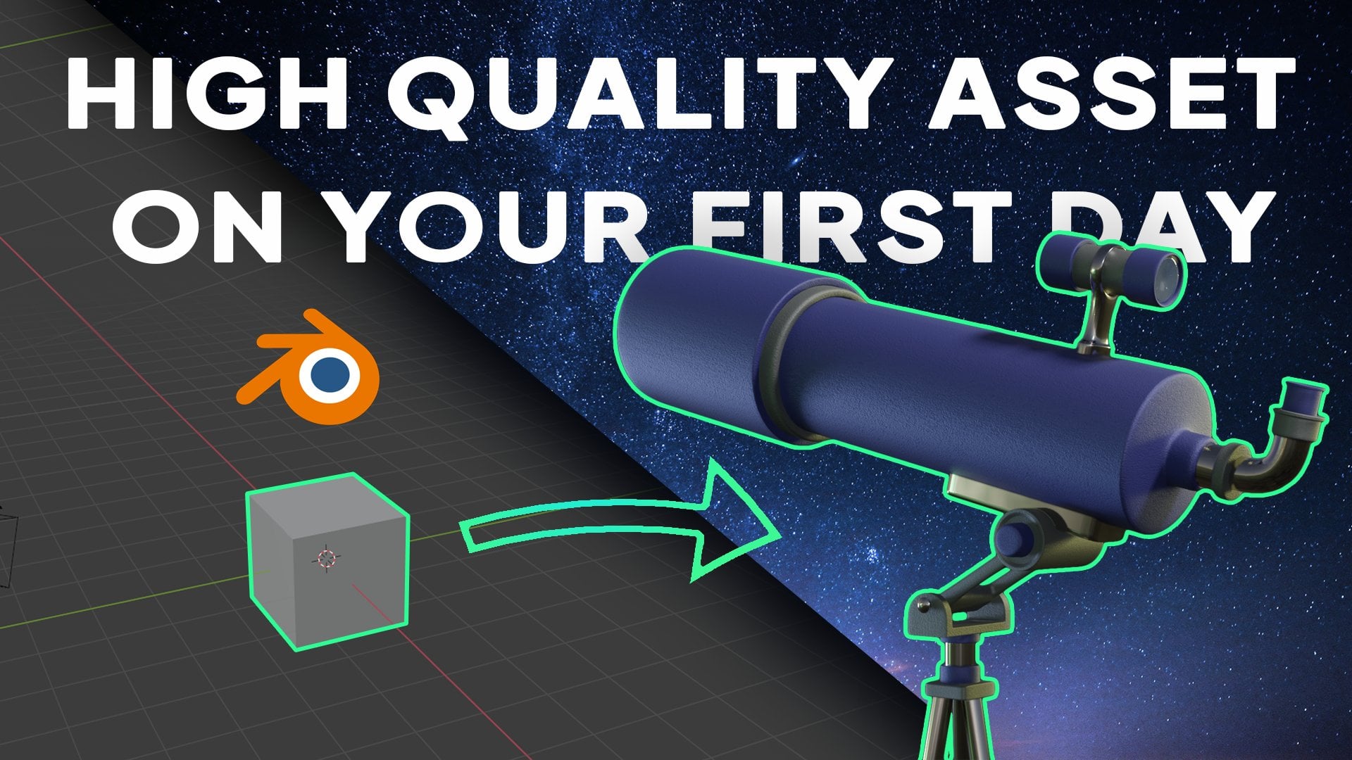
1. Introduction!: Welcome everyone to this class. Today we're going
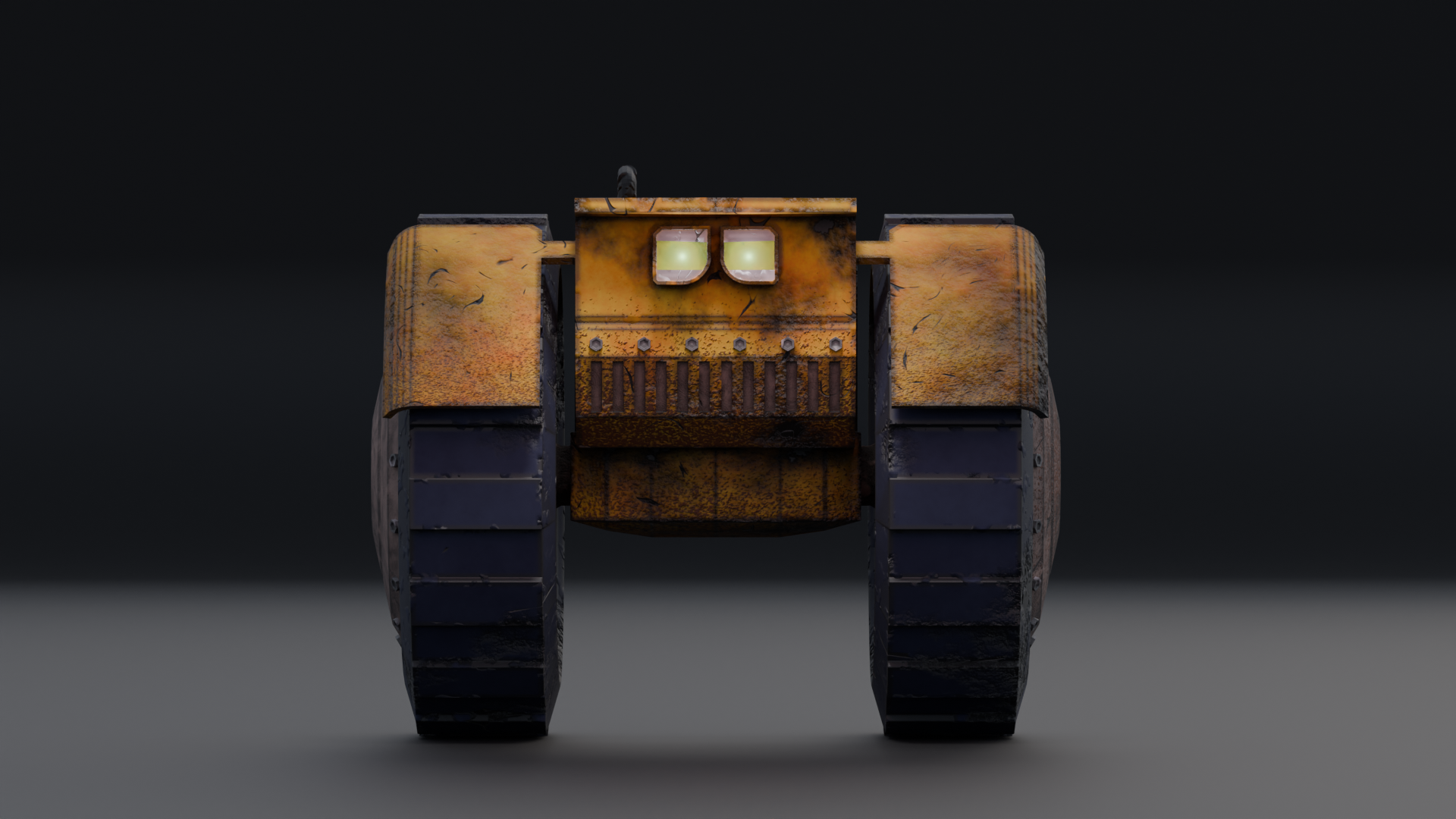
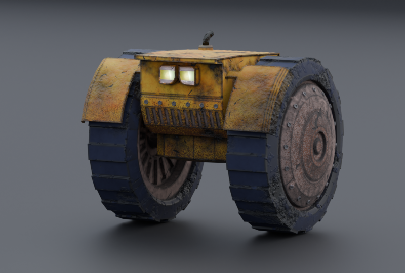
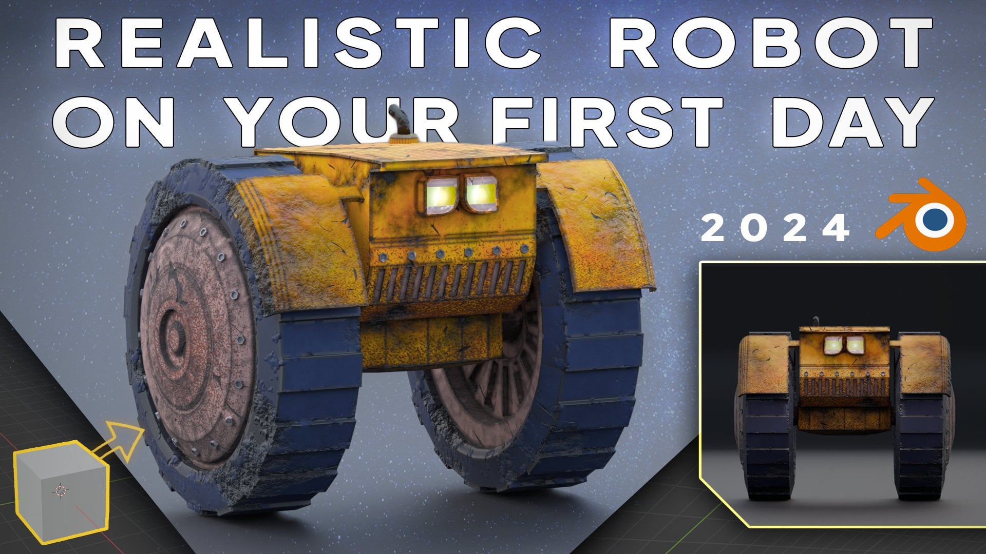
to learn how to create this robot that
you're seeing now on screen. This is supposed to be
a heavy duty robot that is used to explore outer
planets and lost lands. You will be able to follow this tutorial even if it's
your first day in Blender. Because I will guide you
step by step without skipping any information or
taking things for granted. This way you will learn what
every tool and setting does and how to go from an empty world to a
fully rendered scene. You will always
have on screen at all times the keys
that I'm using, the mouse clicks, and
all the shortcuts, so you don't get
lost. At any point, we will start from scratch. And using all the tools
that Blender offers, we will work our
way up to having a very realistic model of a robot and creating
amazing renders of it. After this tutorial,
you will be very comfortable using this
software and you will be able to recreate
models on your own and obtain
remarkable results. We will go over modeling
applying modifiers, a wide range of tips
and tricks that will make your modeling
life much easier. Creation of very
realistic materials with nodes, lighting and rendering. As well as covering some
essential strategies that will make your models
stand out from the rest. To fix some common issues that may happen while
you are modeling. All of this and more will
be covered in detail and is the result of hundreds of hours of learning and using Blender. All very carefully
prepared here in this class to offer you the most efficient
way of modeling and to prepare you for
future modeling projects without wasting any more
time. Let's dive into.
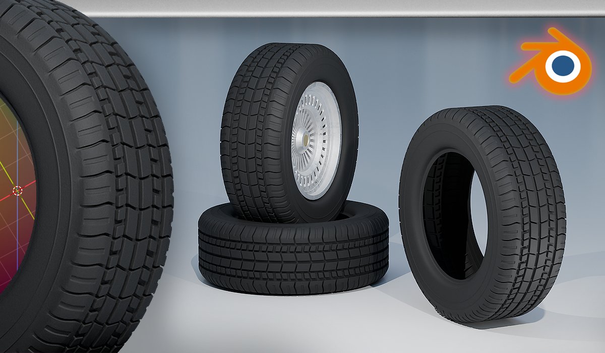
2. Modeling: Wheels: Here we are with the initial set up from Blender is what shows up when we first create a
general file before modeling. I will just tell you that here below, down on the left side, you have the keys
that I'm pressing, even from the mouse or the
keystrokes that I press. So if I press a letter A, you will see that
it shows up here. This will be very
convenient for you, so you can keep an eye here
on the bottom and see if you don't understand
something that I say or you want to
follow along better. You can just check what
keys I'm using here. We can already start modeling. We don't know much to
begin with because I will be explaining step by
step everything that I do it. And I feel like to learn
it much better that you also model with
me so we can do it together and we will get to the model that we have
seen in the intro. Definitely, just be free to take your time and experiment
while we are doing it. You can post the videos. That's very convenient. Also, in order to begin our
scene, it's very simple. We will start with the wheel, the wheels of the roper. And basically what
we have here is not going to be useful as of
now. We're going to delete. In order to delete, we
can select everything by just clicking and then
pressing the key, Delete. If we press control
that we go back. Also you can press the letter A to select everything
and press Delete. Or you can go up here to the Collection and just
click the first one, Shift, click the last one. Everything will be selected. You can press Delete again
and it will be deleted. What I'm going to do
as well is to hide this panel here on the bottom.
This is the play line. We are not going to
animate anything. So we can just hide this
because it's always here. When we open blender, it's not really necessary and
it takes up space. So in order to collapse this
panel, it's very simple. We can just go down
in the corner, in any of the corners, we will go here, down on the right corner. And you will see that the
cursor changes to this cross. When this happens, you can
just click hold and drag down, and this happens and
this panel disappears. Which is nice because we have
more room now to work with. Now we need to start modeling the wheels as you may expect. We need to add a
mesh or an object here that will be the
base of our wheel. The wheels don't come created, so we have to basically
do everything on our own, but we can try to find
the best starting point. As you remember, we had a
default cube here with the cube is not really resemblance
to a wheel at all. We have to find something
that's more suitable. When we are here in
the basic layout, make sure that you
are in object mode. Here you can see that
we are in object mode. You can press the keys shift
A or you can go here to add, and it will show the same thing, but we will press
shift A, it's quicker. In here you will see that we
have a menu to add a mesh. I will tell you already that the one that we're looking
for is the cylinder. And the cylinder is found in
the first tab in the mesh. And we can add a cylinder. There are other meshes
that are available. But for now, we're
just going to add a cylinder which really
resembles the wheel. Once we add the cylinder, we have the add cylinder options here on the bottom
that if you click, you can tune a little
bit the settings of it, like decreasing the vertices. The more vertices there are, the closer it will look
to an actual circle. If we look it from
the top, however, we don't want to
increase it a lot, otherwise it will be
too hard to manipulate. We're going to leave it at
the 32, which is the default. We're going to type 32 or just leave it as
default and press Enter. Now when we click away
from the cylinder, we will lose these options. Now, they are not
accessible anymore. We cannot modify the
vertices of the cylinder. If you want to add another cylinder with a
different set of vertices, you just have to delete
this one shift a cylinder and you have to make sure that you
are happy with these options at
the very beginning. But the most important
one are the vertices, the position and all
of these other radius can be tweaked up afterwards.
That's no problem. We're going to leave
the vertices at 32, and now we have this
cylinder here. This is nice. We will rotate it and place it, let's say on this
horizontal plane, the X, Y plane. If we were to imagine
this cylinder rotating, it would be nice
that it was rotating along the X and Y
axis, like the wheels. We will rotate this cylinder. And basically we could actually create the
wheels like this, but for convenience, we
are going to think about the X and Y axis as
the ground plane. To do this, we just
have to rotate it along the Y axis, 90 degrees. This is very simple. We
just click the cylinder. We press the letter R, then the latter Y, and then the number
is 9.0 for 90. And you can see that
we have rotated the cylinder along the
y axis for 90 degrees. Now this looks a little
bit more like Wheel. Now what we're going
to do is to scale it a little bit
along the X axis. This red axis here, it will be thinner then x
and drag down a little bit. We're going to start by
something like this. We can modify this later
so it's no problem. But I want this
robot to be quite robust and like heavy
duty in this case, I want to add thicker wheels. But something like this,
I feel like it's okay. We're going to go quite detailed here for the wheels because they will be quite big in comparison to the
rest of the model. And right now we can
just go to edit them. And to do this we're just
going to go to Added mode. So we can click the wheel, make sure that it's selected, go here and click Added Mode. Or you can just press the Ap
key, which is much quicker. We will be using this a lot, so be comfortable with this key. Now we can edit here
everything in particular every single vertices that we
had and every single phase, we can switch from vert
to edge to face here, with this panel to
represent number one. Or click this tab here, we will select vertices. If we click the number two
or the edge select here, we will select vertices. We click three or the
face select here, we will select the entire pass. This will be also
very convenient. We are going to stay in the face select and we're going
to click this face. This face here will be the
outer part of the wheel. Let's say where the rims go. And this one will be
the interior part, so the axis of the wheel will be here connecting
to the other wheel. Let's say actually we're
going to start with this one, the interior part of the wheel. So to do this, we're
going to press the number three
in our keyboard. But this one will put us on the exterior part of the wheel. It doesn't really matter,
but you could build the rim here and then we
could rotate the wheel. It's fine, but it's
much easier to press control three
on the numpad, we will go to the opposite peel. This is the inside
part of the wheel. With this face selected,
we're going to press letter I and this will
inside the faces. This is very convenient
in cylinders. So if we press, we
can scale it down. If we hold down shift, we will be able to move slowly. So this is fairly nice as well. I will hold down sheep and go down a little bit.
Something like this. And now I can click left click. And we have made this
face here, very nice. This ring that we've
created will be actually, let's say the steel,
the tire itself. The rubber part of the tire. Now I'm going to click again to insert maybe something
like this if we rotate. Now if I press the
letter E and go inwards, we can create an extrusion, but we'll make like a hole
in this part of the wheel. We press the letter E, I will hold down shift, you can see what we are making. I will go something
like this for now. If you're wondering
why I created this ring outside with
the smaller inset, this will be basically
like transition from the rubber part of the wheel to the metal
part of the wheel. In order to do
something with it, we are going to go to edge mode. So we're going to
press the number two. And I'm going to hold down old and click on one of these
edges of this inset, and it will, this entire edge. What I'm going to do
is I'm going to move it towards the x axis. Then x, you can see it
creates this shape. I think it looks better. Now, I'm going to press number three again and
go to this phase. I'm going to press for Inst. Something bigger like this. Nice. But before also if you have created an inset and you
don't like the size of it. If you don't like the size of an inset that
you have created, but you have already
selected something else and you cannot
basically get rid of it. You can press letter
and it will scale it down or up in the same axis. It will be very easy to change. If you want to completely
get rid of it, you can click this face, press letter X, and you
have to dissolve the edges. We start again, this is very nice to know
something like this. I'm going to extrude again. Maybe I went too much in with the extrusion,
so I will press G, then X with this
selected and pull it out, something like this. Now I'm going to
show you a trick. We're going to do
one small inset. Now another big inset. This will be for some
radial metal parts that pick out from the wheels
are very common in wheels. I don't know the
exact word for it, but you will see we can do this, insert like this,
something like that. We will go to control three. To see this belt, I'm going to press again,
something like this. What I'm going to do before doing this trick that I've said, I will extrude this inwards, holding down shift here because this will
be the final part. Will then x a little bit
out, something like this. You can see that starts
to look a little bit, much more like a wheel. I'm going to do the last one. Where the axis of the
wheel will be placed. I'm going to do something
like this and now I'm going to extrude
it on the X axis. As you can see, we have this
sort of wheel actually. Before extruding this, I will press control for
you to see better. What I'm going to do here. If you have created this
and you want to remove it, you can just do it the same way. X and the all faces. And you will be in the
same place as before. You can go x these
all faces again, and you can go
backwards if you don't have the control history. Anyways, what I will show
you here is a nice trick which consists in selecting all of these ring of faces here. Like this. I want to
select every other phase. I would like to
have it like this. We can select one face and hold down shift and
click other faces. That this will take a long
time to select all the faces. Well, actually it
doesn't take that long. But I think it's better to know this trick that I will show you. Select all of them,
and we're going to place Spacebar to
open the search menu. But see that now, when
I pressed Spacebar, the animation starts to play. If you remember that
tab that we had before about the play line here, the button Spacebar
makes it start and stop. We don't want this, actually. We can change that by going
to the icon of Blender here. And we click the splash screen. You will see that the
Spacebar is set to play. We will click and select Search, And we can save the settings. We click outside here, we will go back to the model. And now when we press Spacebar, this search menu comes up. This is extremely nice to have it here on the Spacebar
because there are a lot of menu that are hard to find by just pressing Spacebar
and writing the name here. You can find the tools quickly. You can simply select all
these rings and go here to select and click
Check the Select. You will see where it
gets or controls that. And we can press Space Bar
and just type Checker Select. I usually do it like this. Now with this selected, you can see that we have
every other phase selected. This works everywhere else. We will press Alt and click
on one of the edges here. We'll select all of this space. And the last option that we clicked will be
the first one here. So it's easier to find, we
don't even have to type. You click here and we can
select all of these faces. But anyways, we will go
here selecting these faces. And I'm going to extrude
them inward a little bit, not too much, but
something like this. I feel that it looks very nice. I'm going to extrude
this, as I said before, something like this. For now, I feel like this is already a good
starting point for the wheel. What I'm going to do is to start by the other
side right now. In this case I'm going to
start by another inset. To create the inset
again we can just pres eye to create
this inset here. We will do something
clever which is going first to the
side El by pressing the number three on our
numpad if we want to match the size of this first Bl that we have created here. Because as I said, this should be like the rubber
part of the wheel. So it makes sense that in
both sides it's the same. We can go to side heel
and press shift or press this icon here to
activate the wireframe mode. In the wire frame wheel, we can see through the
faces of the object. And this is very nice, it's
like the x ray vision. We can press now the letter
and create this sort of inset to match the first one that we have created
on the other side. If we press shift that again, you can see that we have created
successfully this inset. We will go again to the side
view shift that I will do, the same one for the second
inset that we have created. Nice. Since it doesn't really have to be
that precise here, it's okay to do it this way. If we wanted to be
extremely precise, we could add a mirror to this
specific part of the wheel. And then it would be
exactly perfectly symmetrical in sight from
one side to the other side. But this is perfectly nice and it will be
completely unnoticeable. We will use mirror modifiers
after in this tutorial, so you will learn how
to use them as well. But here I'm going
to do the same. I will press
something like this. I will press I, and now you can feel free to
experiment as much as you want. I will press to modify a little bit shape
something like this. I will extrude this
outward a little bit, something like this. Then I will do it again. Maybe something like that. I could strew it, but I
will do it another one. In this one liger, what I will actually do
is I will move all of these insted faces that
I've created before. I will press both, Select all of this ring and
now just holding shift, I will click this
one and then X. Yeah, something like
this. With this maybe I will pull it as well. So in X, for this one
I will press three. I will go to the side. Again, Maybe one
last detail here. I again, something like this. And I will extrude
one last time. I will scale it down
with the letter. That's it for the moment. As you can see, we have created this shape, is a
very nice wheel. Now that I remember, we have to do this here in this edge
of selecting this ring. Then then X, moving a little bit inside it adds
a nice detail. Now to finish the wheel, I want to do something to
add some texture to it, basically so that it's not
super flat like it's now. But before also I
want to show you this tree because as
you can see it now, when we turn around the wheel, we cannot really see the shade if we even go here on the front, there is really not
shading here going on, and it's hard to see where
we have made this insects. To fix this, we can go here to this shading options by
pressing this arrow here. We will turn on the cavity and the depths field also
here on the cavity type, we're going to show
it on both sides. We're going to show it
on both directions. And you can see that now we get a much cleaner look of
how the wheel looks. And even if we go
to this side whel, or if we press
control that sideb, we can totally see where we have made the cuts.
This is very nice. We're going to do
what I've said. We're going to select this ring, we're going to use
checker de select. Now actually before doing this, I will select this
entire ring and I will scale it a little
bit on the X axis. This will make the
external part of this wheel a little bit
thinner than this part here. This is nice. I
like how it looks at some of curvature
in a little bit. Now, with this selected, we're going to check this. Select, I'm going to
extrude it outward. But as you can see when we
press, look what we get. This extrusion only
on the z axis. We don't want this, we
want to extrude it so that every single phase is extruding
outwards from its normal. In order to do this, basically, so that every phase
is getting extruded perpendicular to
where it's standing. This, we can extrude using a
special kind of extrusion, which we can do it
by pressing old old E. And we will
select the extrude, pass along normals, and you
can see what we're getting. Now this is basically extruding along the
normals of this phase. The normal is the
perpendicular vector that's coming out of the phase. And we will do
something like this. As you can see, we have created this nice texture on the wheel. If for any reason you want to modify this extrusion
that we have created, you want to make it
taller or shorter. We can try to select
it also face by face, but it will take a long time. And the checker de select, you will see it
doesn't work the same way because you
select this ring. And we go to select,
check, er, dis select. We will not select the
faces that selected before. And that's because
we have created extra faces and it's actually
doing what it has to do. It selects one phase, it selects the one
that's next to it and then select the other. But here in this
case, it's dielecting the extruded faces on the sides of this extrusion
that we have created. And that's not what we want. If we do checker
disselect again, you will see that it doesn't do anything because these faces
are not connected anymore. As you can see, we
get this error. However, when we
check er de select here actually depends on
what phase you select first. But when you do
checker di select, you will see that we
have these options here actually on the bottom. What we want actually, is to select one of
these phases and then select this phase, this phase. To do this, if you take a look, we are selecting this phase, we want to skip this one, this one, this one, and then select this one. We're selecting one,
skipping three, and selecting the other one. Considering that we are going, let's say clockwise direction, if we select this entire ring, we go to check, select. We can now tweak this pattern. We want to select one phase. Yes, we want to
dielect three phases. As you can see, we
get this result. We can play a little bit with the offset if it's not working, but sometimes I have
the feeling that it doesn't work too properly. Because for instance, here, it selects perfectly
the edge faces. But when we add the offset, it starts selecting,
nice, what we want. However, here, it somehow
Mrs. this face, basically, if you select the whole ring, but making sure that the
active phase is this. The active face is the one
that appears wide here. When you select the
ring like this, make sure that this white
face is here on the top. You can change this
by clicking Shift, Reselecting a face here, by making sure that we have this active face here
on the top, select. It works for me with
these parameters. Three phases di
selected one selected and one offset of negative one. But it depends on what
phase you select. But with this selected finally, we can basically
scale it down or up. But as we did with the
extrusion, if we press, it will not work
properly because, yeah, right now it's
extruding every phase, but it's also extruding
on the X axis. Will press control
and press old. This is more convenient
to do it like this, even though you could
use the scale and constrain the X axis
by pressing shift X. But still we don't get the
same result as you can see. Because the faces are
getting larger as we go further away
from the axis. If you press old, you will see that they
stay the same shape. That's why we want to do old. You can do it if you want old, but make sure to not
extrude it again, even if you do old and
extrude along the normals. Because you're
creating an extra look here of geometry that we
don't need this one here. By pressing old, we
are not creating this extra look for the moment. I will leave it
something like this. I feel like this looks like a very robust and
heavy duty wheel if you wanted to
make it thicker. Let's say we can select the wheel in object
mode by pressing Tab, going back to object mode
and pressing then X. You will see that it
makes it thicker, but it also makes this
part thicker actually. In this case it's
quite proportional, so it doesn't really matter. But more convenient way
to extrude this would be do not affect this part of
the rim that we have created. Because as I said, if you press an X, if you do it very exaggerated, you will see that this part
gets also very extruded. Actually, that's
a very nice shape that you can add
later to the robot. To do this properly and modify
the width of the wheel, you can just go to edit mode. And we will basically move only the vertices from one side. Basically press the number
one to go to vertex mode. And we will shift that
to go to wire frame. Now we will go to
the top El with number seven on our Numpet. We will box select this
side of the wheel, let's say the rim, all
of these vertices. If you don't have box select, you can press the
letter or click here, hold and click and
choose Select Box. If you press W, it will switch between the different
selection of options. With all of this selected, we can press the letter X. You can press that even
with this selected, it will remain the
selection as you can see. If we press G, then X, we can just move
it without losing the proportions here
on the rim at least. But for me, I think
that this is okay. And I will leave it
like this for now. Later we will add a mirror
and copy to the other side. So we will have two identical
wheels, one on each side. This will be very
convenient also and very nice for the car. It will save so much effort, we don't have to
create two wheels. We will add a mirror
modifier for this. And we will start creating the connection between
these two axes. Because in order to, let's say, properly move the robot, if it was existing in real life, both of the wheels
shouldn't be connected. Otherwise, they would always
turn in the same direction. But in order to turn a robot or something that
only has two wheels, the wheels have to
be able to turn in different directions or
in different speeds. So in order to do this, we will add a separation
or a box between this axis here and
the other axis from the wheel that
we're going to copy with the mirror modifier. And this will make it
look more realistic. So make sure to save your progress by pressing
File and save us. And save it wherever you want, and we will continue.
3. Modeling: Transmission: Okay, then we can continue
with the modeling here. In this case, what
we're going to start doing is by placing
a mirror modifiers, we can establish what's the distance between
the two wheels, because the main body will be
in between the two wheels, something like here
in the middle. This makes the robot
look much more compact and in my way of seeing it,
it looks sophisticated. And like it's a more
solid body of a robot. It's not so vulnerable
if we put the body of the robot where the main
components are protected, the strong wheels. Let's
start by doing this. In order to create
the mirror modifier, we're going to first mirror
it along the x axis. But before, let's separate
the wheel a little bit because it will mirror it with respect to this
center point here. What the mirror modifier
will do is that it will copy this wheel
that we have created. All of it on the other
side of the x axis. Right now we are in
the exact center of the x axis. Let's say a zero. If we hide the wheel by clicking it in object mode
and present letter H, we can see that this point
here is zero in the X axis. Basically, the mirror
modifier will copy from the positive axis to the negative axis, or
the other way around. First we want to put the wheel
in one side of the X axis. Let's say that the entire wheel is on the right of
this green line, or to the left of
this green line. To do this is pretty simple. We can press old H
or go up here in the cylinder view and we
can enable the view again. Or if I press old H, it will unhide all the items
or objects that are hidden. But first let's actually
rename this wheel. We're going to
double click here on the cylinder and we're
going to type wheel wheels, actually, because it
will be both wheels, the same object once we
place the mirror modifier. So as I said, what we will do is we're
going to move it on the x axis and place it here on the right
side for instance. But see what happens to
this orange point here, which is the origin
point of the object. And the mirroring will be with respect to
this origin point. If we move the object, this wheel, in the object mode, then X see that this origin point will be also moving with
the wheel itself, because this origin point stays in the origin of the geometry. In the origin of this wheel, we go to the side view by pressing number
three and our Nampt, we can see that
this orange point is exactly in the center
point of the wheel. However, if we place
the mirror modifier, now it would make
sense because it would actually mirror with
respect to this point. So it would basically create an overlapping
copy of the wheel. We want to keep the
origin point here in the center because it will
make things so much easier. We usually will always
mirror with respect to the origin of the
world, let's say 00. But as I said, this
point has been direct also with
the wheel itself. And that's because
we have moved it in object mode if we
press control that. But now I will show you
a way to do it if you actually want to move specifically the origin point
without moving the wheel. But first I will
show you this way by moving the object
in added mode. So if we press control that, now we go in edit mode and the selection
from before remains. But we are going to
select everything by clicking the
letter a or we can shift that and select the
entire wheel with box select. What wireframe allows us is
to select through vertices. Because if we select
the wheel like this without wireframe mode, we have selected everything
that's on our view. But if we turn around, we can see that none of this
is selected or the inside. However, if we turn
wireframe and we select now we can disable wire frame shifts that you can see that
absolutely everything, every vertex is selected
by selecting everything. And now we move it
along the x axis. It will be the same
movement as we did before. But take a look at the
origin point here, then x. As you can see, it remains here. This is very convenient because otherwise we have to
move the origin point, which is actually simple,
but it's quicker like this. But I will show it basically moving it in object mode then x. We have moved the
origin point here, but we want it to be here. While making sure that
we are in object mode, we're going to adhere to object with the wheel
selected of course. And we're going to click and go Set Origin And put the origin
to the three decursor, y to the three decursor, because the three decursor
is here in the middle. By clicking here,
you will see that it will move the point
to the three decursor. Which is the middle, therefore,
that's what we want. But let's say that your origin point is somewhere different. Because you can move
it accidentally by just pressing shift
and right click. You can see that we can
move the three dicursor by pressing shift
and right click. This is something
that you want to take into account before moving the origin point of this
object to the three decursor. As we want to move the origin point to the
three decursor, we want first the three
decursor to be in the origin and the
000 coordinate. This is very simple to do. We can press shift S. We
will get these options, and you can see this one here, cursor to the world origin. If we click, we will
move this cursor here. Now that the Thredcursor
is in the world origin, we're going to go to object
with the wheel selected, set origin and origin
to Thredcursor. You can see that we're in
the same place that we were when we moved
it with a mode. But the problem here is
that if you move the wheel again on the x axis
or any other axis, the x, the origin
point is moved. Again, we'd have to do the same set origin
origin to predecursor. But it's much easier to do it on edit mode because
you can just move it while keeping always the origin point
at the same place. Right now that we have it here, we're going to apply
a mirror modifier with the wheel selected. We're going to go here to the right side of
the screen and go down and look for this modifier staff range
With the object selected, we're going to click
it at Modifier. And you can type here or you can go to Generate and click Mirror. So if you go and click here, you will see that it
has done something. I'm not sure if you can see it. Do you remember that
we have actually made the dents here in
the wheel right now? All of them look extruded, and that's because it has
mirrored along the wrong axis. However, what it
is doing is wrong, even though we are
mirroring along the X axis, which
is what we want. You can see the
axis is selected. Why is it actually not
mirroring across the X axis? Well, this is actually
because the axis are flipped. If we disable this, you can
see where it's happening. If we do it with the Y axis, it will not work either. But if we do the z axis,
check what happens. Oh, we have the wheel
mirrored, which is very nice, but why is it mirroring across
the z axis and not X axis? This is because we have
rotated at the beginning. If you remember, we have rotated this wheel because
it was in principle, it was a cylinder and
we have rotated it. Right now, the object
still keeps this rotation. And for this object, this red
axis here that we consider the x axis for this object
is actually the z axis. I'm going to actually
disable this for a second. And we're going to do
something which is more convenient in order
to apply modifiers. We're going to actually apply the rotation of this object, meaning that we will reset all the rotation that
we have applied it, but it will still
keep the same shape. Nothing will happen. We
will just reset the values. If we actually pick
the object and go here or plus the letter n, we will open this menu. We can go to Iten, and you
can go to the Rotation, and check that we have actually rotated 90 degrees
along the Y axis. This is what we have done at the beginning of the
tutorial with this. If we set this back to zero,
we will see what happens. This is not what we
want, but right now, the object is not rotated
in any direction. It will behave as we expected. For instance, if I
go the next now, mirror along the X axis, it does as expected. It mirrors along the X axis. But the problem now is that
the rotation is wrong. We have to apply the rotation. If we press control and
to apply the rotation, we can just go to object mode. With the object selected, you can press Control A and
apply and click rotation. Or you can go to object up here, click Apply and
apply the rotation. And check these values here. What happens when we apply the rotation control a rotation? They all go back to zero, but the object stays the same. So we have basically reset
the values for the object. Right now, it is like
if it has appeared in the world like this in the blender scene
with this rotation, so it understands that
the x axis is this one. Right now, we can enable
the mirror again in the x axis and everything
works perfectly. Right now we have the
very nice wheels. They are perfectly in line. They are exactly mirrored
where we want them to be. What I'm going to
do first is I'm going to connect this axis. The good thing
about the mirror is that they can interact
with each other. So we can just actually extrude
this and make them one, basically convert them
into one piece in a way, even though the
mirror will be always available for us to be
enabled or disabled. What we're going to do
is I'm going to add first a little bit
of shape here. I will select this phase, Going to select
clicking this phase, The next, I'm going
to move it and see what happens
to the other side. Whatever we do, it's copied. So this is very
comfortable for us. I'm going to move this bit and I'm going to make an inset. But see what happens here. I'm doing the inset and
look what we are getting. The scale of this
inset is wrong. Instead of getting a perfect
circle with the inset, we got this oval shape
as you can expect. This is because the
scaling of the inset is acting different
depending on what axis. You can see that
this horizontal part is the Y axis, the green line. It's scaling more on the Y
axis than in the Z axis. Therefore, it's an oval shape. Basically, it's longer
vertically than horizontally. We will press control and
this has a very easy fix. We will go back to
object mode right now. If you look at the object mode again on the properties here, you will see that the zet
has a different scale. That's why it was
scaling less efficiently in the Zet scale
than in the Y scale. When we were doing the Inst, if you press control A, we can do the same that
we did with the rotation. But for the scale, if you click, all the
values will be reset. And now we can go again, insetter I and
check what happens. It does everything symmetrically and natally evenly
for all the axis. I'm going to insert like this, I'm going to pull it
a little bit out, so she is an X,
something like this. Maybe I will scale
it up a little bit. I'm going to extrude it, but before connecting the axis, you can see that you draw. You can see what happens, see that these are overlapping. As you can see, this axis is getting on the other
side of the mirror. Because the mirror,
you can imagine it as an invisible line here on
the z axis and Y axis. It's like a wall here. We don't want the faces of one side of the mirror
crossing the other part. We just want them
that they merge here in the middle,
and that's it. In order to do this, we have
to turn on the clipping. You can see that if you
hover over this property, it says that it
prevents the vertices from going through the
other side of the mirror. Now with the clipping on, you can press it to extrude. When you get to the middle, you will see that it
doesn't let this phase here that we are extruding to
continue to the other side. Check that it stops and we
cannot go like there's a wall. But this is perfect
because it will basically connect
these two phases. But before this,
I'm going to delete this phase because we don't need a phase
here in the middle. Because when we press
the next right here, we don't need to
press extrude again. We don't need to
create more geometry when these two
will be connected. This phase that is selected makes no center
it in the middle. It's just an extra phase,
it's not necessary. So we're going to do some best practice and
delete these extra faces. We don't need that.
We're going to press X and simply delete faces. Right now we will select
this loop by going to Edge, select Holt, and
clicking on this ring. And we're going to
press X connected. Now you can see that we have this beautiful wheel
axis connected together. Now that I look at it,
I think I will pull this thicker axis a little
bit more towards the center. There's a little
bit more variation to do. This is very simple. We have to pull these two
rings towards the X axis, towards the center
of the x axis. Clicking one of
them with A and now shift and Alt and
selecting the other one. Now then X. You can see that
we're getting this. I'm not going to do
it too much because here will be the
body of the robot. But actually I think
that I will like to scale this axis a
little bit down. I will select all of this ring, and I'm going to scale it down. But I'm not going to scale
it down along the X axis, because I want to keep this
inclination here the same. I'm going to scale it
along the Y and Z axis, but not on the X axis. To do this, I'm going to press, and to exclude the X axis, I can just press shift and X. And you can see that we are only scaling along these
two axis here, but not to something like this. Yes, now I will maybe move this a little bit
backwards a little bit. X, just something that
you feel like looks good. Maybe I scale it down
too much as shift x. I will maybe scale this
down a little bit. As well as shift x
one little bit more. Yeah, something like this.
Looks pretty nice to me. I'm going to save
control right now. You can see that we have
this very nice wheel base. If you like the
separation, it's good. If you want them to
be closer together, maybe I will bring it slide. It's very easy. We just
have to move all of these spaces towards
the x axis to do this. We have done it before ship that we're going to
select all of these. Shift that again to
see what we are doing. And then X and we are
moving both ways. Something like this. For the
moment it will be like this. We can always move this later. Right now, we can add the
next piece which will be this connection
transmission line, or I'm not sure the
exact words in English, but will be like a box
that will basically, in a way, join both axis. But let's say that it
will theoretically allow both axis to turn in different directions
if it was necessary. Because as I said, if we try to rotate this wheel
in one direction, this one will follow
because they are connected. But if we create a
sort of separation, let's say that we can enable both wheels to turn in
different directions. You can go as
technical as you want, but I feel like it's
very nice to do it. And also more
importantly than this, it will serve as the base to build the main
body of the robot. Because we will otherwise not be able to actually put
a square piece here. Would make no sense to
connect a moving piece, like the wheels
to a static piece like the body of the robot. To do this, we're going to
have to add another object. Make sure that you owe to
object mode and press shift A. And let's add the cube. But I will actually
show you a thing that happens if you add the
object in edit mode. So we are now in the added
mode of the wheels shift take. We can actually add the cube, but you can probably
notice that we don't have as many options as we have in object mode like
this. There are many more. That's a great
indicator that you are adding the object
in the added mode, which is usually not
what you want to do. But if you mistakenly
add a cube in edit mode, you will see that when you
go back to object mode, this is an entire object. We don't want this
because this cube is like stuck between the wheels and you cannot select the cube alone, it belongs to the object. Now if you go to edit mode, let's say that you click
away from the cube. It's very hard to actually
select the cube and delete it because it's life in the
model and it interacts. So if you press shifts that
you will see that it's here in the middle, in
this case the cube. It's quite simple to remove. You could just select the faces like this one by one and delete. But there's a much
quicker way to prevent this and to
delete this much quicker, just select one phase of the
cube and press the letter L, and it will select
all the linked faces. If you shifts that, you will see that there's
only the cube selected. You can press X and delete
the vertices and we are back with the object
deleted. And that's perfect. Shift A, we'll go to
object mode and ate, we'll go to the front
view by pressing one. And let's scale it so
it fits in the middle. Something like that.
Maybe a little bit less. Well, this will be
actually the box. Maybe it can be a
little bit smaller, but we can scale it a little bit more afterwards, so it's fine. Okay, we're going
to scale it now in the axis something like this. If we go to the top
view with seven, I think that this
is a decent shape. Maybe I will scale it a little
bit on the y axis, S, Y, maybe a little bit more in
the X, something like that. I'm going to just make sure that it covers nicely the axis. So basically selecting this, I'm going to make an
interesting shape. I guess put a bit
less on their axis. Okay, what I'm going
to do is actually, let's apply a mirror
modifier here, because it will be
symmetrical for short. And probably we will just mirror half of it and the
rest will be mirrored. If we want to mirror this cube, we can actually do as before, the X in added mode. And then clip with
clipping on X, this part to the other
side with the mirror. But there's a better way because right now we
have the origin where we want and the cube is placed
actually where we want. We can actually do
something clever which is cutting
the cube in half, and we will basically mirror the other half
in the same place. The result will be
exactly the same cube, but we will just
modify half of it and the other half will
follow to do this. How can we cut the qube in half? We can just go to
edit mode as we are. We can select this top face
for instance, or any face. We will press control R, and you can see that there's this yellow loop
that goes around. So you can see here, if you press Escape, it will go away. We want to place this, which right now is exactly perfectly in the
center of the cube. This is a perfect
division of the cube. We can place it by
clicking left click. But when we click left click, you will see that now we
have the option to move it, but we want to leave
it in the center. To leave it on the center, just press right click and
it's perfectly centered right. Now if you go to the
top view, for instance, you press control that you
go to the vertex select. We will select
these two vertices, not two but four vertices. But if you select just
these two from the top, we will select the
entire face here. You can see or you can just press ship that with the cube. This go to select and
select this face here. You're going to press X
and delete this vertices. You can see that we have
just half cube here. It's empty. Okay, but we're
going to mirror it right now. You know how it works. Click the cube in object mode. Add. And we're going to
type here mirror click. And we're going to turn
on clipping and Perfect, that's the cube,
the same as before. But what happens right
now that we cannot click this house because we can
only work with this one. Whatever we do here,
we press here, then X or something, it will basically react the
same way on the other side. That's much more
comfortable for us, We just have to model here. I'm going to press to
hide this menu here. If you're wondering
where is the positive x, you can see it
here in this menu. See that where the x
is inside the circle, it means it is positive, and the one here
is the negative x. Right now we have the
editing objects here. You can see where we can edit because the
wheel is the same, The wheel that we can edit. This one here, this one you
can say, we cannot select it. We're editing the objects in the positive x and we're
copying them to the negative x. But we can go back
to the cube here. We're going to do
certain things actually. Now that we have learned
how to use the loops, we can add some of them to
make interesting shapes. What I want to do is
going to the top and I want to add triangle
shape here in a way, like a trapezoid here in front. And also in the
back. It will look like pointing in a
way, but not too much. We could actually
pull this edge here by selecting the edge G then Y. You could do something like
this. It doesn't look bad, but I think it
looks very simple. So we're going to pass
control that and we're going to add a few
control loops. Control R, and I'm going
to place one over here, also one over here. I'm going to go
to the top wheel. I'm going to place one here. Actually, before
placing one here, I want to place one on
each side of the axis, but they should be
equally spaced. In order to do this,
I can press control R. I can rotate the
wheel of the mouse, and you can see if
I scroll the wheel, we are adding more
and more loops. I just want to like this,
but as you can see, they are not really
separated enough to actually fit the axis
through the middle of them. But it's not a problem we
can move them so they are separated the exact same way with respect to the
center of the axis. If you click here, you will see that we
have this loop perfect. And to separate them right now, with both of them selected, we can just press S Y, and you can see that
we are moving them, both of them exactly the same. We go to the top view Y, we can adjust them nicely. They are exactly the
same separation, one to the other. We can see that the axis is perfectly in the
middle of these two. You could do it by just adding
one loop and moving it, and then adding another one and moving it almost the same, but they are not exactly the same distance from this edge. I think it's better to do it
as we did. Let me redo this. I will, first I will add this look here
that we have added. And these two click S, Y. I'm going to top
something like this. Looks fairly nice to me. I think that this will be useful to create some
interesting shapes. What I'm going to do is I'm going to select this face here, and I'm going to
press G, then Y. As you can see, we're
pulling it a little bit to the front like before, but I like this more now. It looks more solid to me. Maybe if you want a little
bit more of a spike, I'm going to add
another control, another loop, maybe
place it here. Going to select this
edge right now. The Y. Yeah, I like it. I think that it looks way
too flat right now. So we're going to
add something else, but we're going
to do this below. Because here it
doesn't matter because the body of the robot
will be on top of here. We'll try to make a shape here that it will
accommodate nightly. The body, it will be
just flat here on top. We're going to go to the bottom. What I'm going to use and
add another loop here. As you can see, if
we go to the top, when we press the
control R for the loop, you see that it follows
the shape actually of the edges that
are next to it, which is quite nice. In this case, what I'm
going to do is that I'm going to place this
something like this, and I'm going to go to
the bottom of this. I'm going to select these faces, let's say these
four faces for now. I'm going to move
them along the axis. Then as you can see, a little bit more
as you can see. If we go to the front view, we are adding this part that
comes out which looks nice. I think it's quite common
also in cars and engines. They have this coming out part which protects it a little
bit from the bottom. Maybe you can even drop this
one a little bit more, Et. Yeah, we have created a nice
shape here on the bottom. I like how it looks. Now for the back, we could
do something similar. But here I want to actually make a little bit
longer in the back. And I will want to
also extrude it. If we go to the top
bill a little bit more, Maybe I'm going to press
control to add a look here. Maybe I can move it. To move it, you can double
tap the letter G with the loop selected again. And it will follow in the same
line as it is right. Now. What I'm going to
do is I'm going to select these three faces. But before maybe excluding them, I will move this one
back a little bit. Then this edge, which will create spike,
I like how it looks. You know what we can do also. We can pull the three
edges by shift, clicking them, we can pull
them a little bit inwards, then Y, something like this. We are this inclined line. I like it now with
the repass selected. I'm going to exclude them
along the z axis then. Or actually, no need to press
that. Something like this. Yeah, I think it looks good. Maybe a little bit
more. See that? I'm not pressing
again to Stroud, which in fact is the same. But we are creating this extra loop here
which we don't need. Then we can just move it without creating an
extra geometry part here. If we go to the front view, you can see how it looks. Maybe it's a little bit
too. Think actually I think that the axis is still
a little bit too thick. I'm going to go and
hide this object. If I click this objects H, I'm just going to
see the wheels. I will select these faces here, all select this loop shift, this one, scale them, except from the Act by
pressing shift X. Yeah, something like this is probably
even a little bit better, maybe this one a
little bit more. Okay, I like it better. Now we can hold H
to reveal this one. Again, front view, I'm going to select and actually scale
all of it in object mode. Doesn't matter along the act, then x, something like that. For now, maybe a little bit tiny bit less as
the next actually, before finishing, I
like how it looks. I'm going to tell
you something that we can do which is
adding a able to it. Because for instance,
let's say that. You can say that this
edge here is sharp. You could select it by clicking the number two edge,
both of these edges. And now you press control. You can add this edge here, which makes it look nice. And I think that I will do it. The bevel actually works
the same way as the insert. In a way, if the scale
is not well applied, it will not behave
correctly as we just have scaled the
x axis a little bit. We have to apply the
scale because if we go to the larger and you will see that the scale
is a little bit off. And that's because actually
we have modified it a lot in the beginning when
we were reshaping it to fit it in
between the wheels. Control A in object mode
control A, apply the scale. Right now, the Beb
will work fine. Then we could do
something like this. You could go to top bill. Yes, I like it also if you pass control that you can add the babble and
before applying it, you can rotate the
wheeler will in your mouth and it will
create a shape like this. But I like when it's
just one makes it look more aggressive in
a way and more simple. But actually a robot like this wouldn't be so complex
in shape like this. Before completing this, what we would like to do is
fit in this area, the main body of the robot
that we will do it next. But I'm going to show
you a trick which is adding a general Beble
to all the piece. A Beble is another modifier. You can find it
here by going into the Beble with the
object selected. You can click Beble and you can add this Bebble modifier
and see what it does. It makes everything more smooth, but right now the
Bble is too high, it makes it look weird. In a way to reduce this, we can go to the
amount and by holding down shift with your
mouse left click. You can drag holding
shift and drag it down. Don't go high at all, just slight, very slight
touch. Something like this. It's 0.04 in my case. You can actually see
the difference of it by clicking this screen here. If you look at it and I'm
going to click it off and on, you can see the
difference that it makes. It doesn't have to be so high, but it really makes
a difference to Y. It makes the edges more smooth and the light is reflected
better like this. What I'm going to do is go here also to the bl properties. And I'm going to go down to geometry here where
the meter outer. I'm going to press it to R. Even though the difference
here is hard to see, Maybe we cannot really see because we are not
really bubbling that much. But it will make smoother
transitions in the bubble. Good thing to do. I
really like how we look. Now what I've seen is that here, I'm not sure if you can see
it through your screen, maybe not, but in
this face here, there's a little bit of
a line going through. This is because the shading
is a little bit off here. It doesn't matter that much. There are several
ways to fix it. And that's because
of the geometry of this space is
acting a little bit. We, we can try to
either move this vertex up the now it has disappeared. Basically it was
because as you can see, this face is in a
very weird position. You can see that if I click it, all of its four vertices are in very different positions,
in different heights. By moving this vertex here up, I'm in stabilizing the pace a little bit and relieving
the stress of this phase. Because if you imagine it
as a real piece of metal, it will be very stressed
the way it was right now, like this, it's less stretch,
it basically disappears. We'll do it a tiny bit more. There's a smoother transition and that's perfectly
fine right now. Maybe we'll actually pull
this one up a little bit. Keep gone. This is very nice
for the moment. We are going to press
control to save, and we will continue
with the next part, the main body of the robot.
4. Modeling: Main Body: All right, so we can continue
with the model here. Right now we are going to do
the main body part first. Let's rename this part that
we have created before. Right now it's named cube, but we can just double click and maybe something more convenient
like transmission, maybe. Good. Now we will add a cube. Make sure to be in object mode. Shift a mesh cube. We're going to go to
the front view by pressing number
one on the dumped. We're going to move this V and make sure that
it fits between the wheels. Then X, I will make
it a little bit less thicker than this
transmission thing, so that I can fit inside
something like this. Then let's, that's too long. So Y, I want that it sticks out a
little bit from the front. But here I want it to be behind this transmission
that we built, the Y, something like that. For now, I want it to be
around the same highest wheel, probably I will scale it down along the axis a little bit. I'm going to move it
to maybe like this. Actually, right now I feel like the wheels maybe a
little bit too thick. I'm going to modify this very
quick, clicking the wheel, shift that top view, selecting these edges here. These vertices going
to go to front view and X. Yeah,
something like this. Now that I've scaled
them down a little bit, I will increase a little
bit more the size of the axis in order to
just see the wheels. We could hide these two objects, but what we can do is by
selecting the wheels, press the slash on our keyboard, so we will isolate
these wheels and we will only see them like this, the slag in the Numpad. Right now, if we
press Slade again, we can just focus on the wheels. I want to scale this down a
little bit because I want to also reduce a little bit the
height of the transmission. I felt like it looked
too thick when looking the model from
the front like this, seeing that this is a
little bit too long. So I want to change it. We can just select this
shift and all by selecting this and scale shift X,
something like that. And I will move this
also a little bit. This one x and
something like this. Also, Maybe this one. Okay? Something like that.
I'm going to go to front, I'm going to press the Sl again. As you can see now
I'm going to scale this little bit down maybe more. I will go back into edit mode and I will
slide these three phases. I'm going to move
them up again, so, and if you press number one in our Numpad,
you will go to the front. If you press control one,
you will go to the back. I will press, and to make
it a little bit higher, I don't want it to cover it
something like this for now. We can always come
back later to change. Anything else if we want to. Now, if we go to the front, I will also scale it a little
bit more on the X axis so there's not so much room in between the wheels and
this transmission. The X also, this one X skirt up on the axis,
something like this. Looks fine to me. It's just making sure that the proportions look nice and it's just something that
makes sense to the eyes. And now we can start
modeling a little bit. This part, what I would like to add for a short is
like a hood here. Like something that sticks out here from the top,
just on the face here. So it's like a cover like you would see in a cat or in a hat. You have this sort of cover to protect the sun from
getting into your eyes. And I would like to add
something similar here to protect the sensors or the cameras that will
be in the front. And I think that right
now it looks very square. So I want to add
some devel here. I'm going to isolate this part. I'm going to select
it and press Slash. And what we want to do first is something like an inclined
roof a little bit, but not all the roof because
we could do something like that on this edge and we will make
something like this. But first actually
let's mirror it. We're going to go to edit mode. Shift that vertex, select. With number one,
we're going to select the four vertices of this
phase in the negative axis, negative x axis,
delete vertices. But before of course, we need
to add a control loop here. Control R, click right click to leave it in the middle and we will delete these four vertices. Now we're going to click it, we're going to go back to
solid view. Achieve that. Add modifier mirror and
it's already on the x axis. Good. We're going to
turn and slipping. We have it, you can see nothing has changed but we have
the mirrored object. I'm going to add first a
loop around here, maybe. We can just have this
part of the roof of this phase going a
little bit down then. Not too much, but as you can see we have this part which is straight and this
goes a little bit down. Think it at a little
bit of variation, maybe a little bit
more so like this edge that maybe we will add some lines here to make
it have some texture. Also, I think it could look
good is to add a babble here, something like this,
with two segments. Looks good actually.
Or maybe just one. We're going to add two for now. Make sure that the
scale is applied, the babbles work fine. Let's go in object
mode control A. Apply the scale just in case we're going
to do this again. Yes, I think this
shape looks good. As I said, I wanted to add
this wood thing in the front. This will be very simple to add. We can just select this
phase control R. We're going to bring this loop
up, something like this. As you can see, this
loop doesn't go around the object now because we
have modified this phase. Now this phase doesn't have just four vertices
like the others. And we have created
one of the enleons, which is like a polygon
with more than four faces. Then the loops don't
go across these faces. We're going to
extrude this, then Y, or just alone, it
will work as well, maybe not that much then Y. If we go to the
front, maybe it's a little bit too thin actually, I'm just going to
move this edge here, down then that as you can see, we create this
interesting shape Also, I will probably move this one towards the front a little bit, or this one a little bit
backwards is the same. But I want this to,
this edge here, to be more forward
than this one. We create like a pointy
shape by clicking this one. Moving it along the y axis, you can see that we are
getting this shape, and I think it looks good. Maybe I will make this
a little bit secret, and also this one. Maybe I will pull the pace a
little bit along the y axis, a little bit more than
Y, something like this. For now, what I
think it could look good now that I look
it from the site, is to add basically an inset. If I select these three
phases and press I, we're going to add a small
inset and then extrude it. But be very careful
when you insert here. Because this phase
is very small, we cannot really inst, we
focus here on this face. And press, we will see
that we have this room. But then when you go too much these edges that are
generating with the inset, they will start overlapping. It will create a
very random think. Check how many issues we are
dealing with because all of these edges and new faces are
being overlapped together. You never want this to happen. So make sure that when you insert these three
faces together, you don't over inst by generating these
overlapping edges here. So we're going to do small
inst, something like this. And we're going to
extrude it inward, so we're going to pull
inside something like this. I think it adds a good
interesting detail to it. Yes. What we're going to add
as well is what I said, the lines here on the top. To do this we're going to go
to top with number seven. We can select this phase,
or any phase on the top, and press control R. And
let's acquire a few cuts. Maybe you can see the
number on the bottom right, on the corner there
on the left corner. But either way, when you click, you will be able to change
maybe like this. There are 13. If I click and let's
say press left click to leave it on the
center, you can see. And now we have this
number and we can still increase and check the numbers. So maybe let's check
12 looks quite loud, so I will just click away. And we have the 12 loops. With all of these loops created, I'm going to show you
a trick and we're going to select
every other edge. And we could do something like this and do checker disselect, but it wouldn't work because
all of these edges are different and we cannot really specify that we want
the checker dis, select to just work,
let's say on the x axis, by selecting only
some of the edges. So I'm going to just
select maybe this edge. Let's avoid the ones for now. I think it can look
better without them. I'm going to select the. I'm going to show you a trick. If you do G, then that you
can see what we're getting. And as you can see, I
think it looks very nice. Maybe that's a
little bit too much. I don't want it to be
that noticeable for and pull it up a little bit. I think this looks very nice. You can see we have this texture that it's quite
common for roofs. If you wanted to avoid this
to appear in the front here, we can just select
this edge here. Not all the loop. You can see this will select
all the loop. We can just select the starting
point and the last point, clicking this control
and clicking this one. And just will select
this line is connecting edges and zero and it
will flatten this. Maybe this looks
good, but I think this transition is to grow. I will just press
control exactly if this, I think this adds a
very nice texture, is a quite interesting trick. We're going to do
something similar here on the front because
it will go to front. It looks good to
me, but maybe it looks a little bit too simple. What I'm going to want to do
is add in this phase here. Now that we have all
these loops created, we can benefit from them and I'm going to add like a grill. In order to do this,
we're going to select, let's say this phase, this phase, this
phase, this phase. And we can exclude
them inside E. This will extrude them
nicely along its normals. If it doesn't work
properly for you, you can just press Alt and
extrude faces along normal. You make sure that they are
exuding along its normal. And not just like this in the axis or something
weird like this. Maybe you can find something
that looks good as well. But all normals, we're going
to go inside a little bit. Holding down shift, you can modify a little bit, how
much do you want it, but what I think it doesn't look good here is the fact that they are actually that
close to the edges. I think that we can leave some
room here so that it's not creating these extrusions
so close to the edge. So we can actually
change this very simply. And also we have a problem here, which is the fact that one of them is larger than
one in the middle. Because even though
we're living just a face between each insertion
here towards the inside. But here we have this issue
that this face is mirrored. We have this problem
that this is double the size and
these other grills. But it's fine. We're going to
press control that we will change this very simply. We're going to go back here to create this margin
here on the top and bottom. We're going to add
two control loop. Control R the wheel. Let's put two. We're going
to select one of them all. And click this one, so you can see close
here behind as well. And G, double tap
and you can move it, holding down shift slowly,
something like this. You can do the same
with this one.gg. Something like this. Now we can do the same as you can see. We still have to
fix this thing in the middle but the side. And now it looks much
better because we have this margin things
very convenient. But to fix this in the middle, we just can do something
which is basically moving these faces a
little bit towards the inside before
actually making the ex. We can do something
very simple like X. It should be no problem here. If we go to front, we'll extrude it and there will be a little
bit more room here. Something like this will
select these faces again, and as you can see, this looks very nice. Honestly, to me, we have left the perfect room
here in the middle, so that it looks the same. Actually, you should leave half of the width of the
rectangule here in here. So when it's mirrored, it's
the same size as this one. This is very nice.
Finally, let's add another detail here. Because what I want
to add in here, around this part here, let's say here where
I'm selecting, I want to add and with a
mirror to the other side. I want to add like two cameras, which will represent
the eyes of the robot. But then also so that this part in the bottom
is not that empty. We could add also
more details like some other sensors
or the things, but for the moment I'm going to add like a dent that goes all across something like
this that we have done on the top to
this is very simple. Let's add control. We're going to move it something like this. We're going to go to the front. I'm going to add
another one. Control R. Yes. And now I'm going
to place one in between control without moving it
so it's perfectly centered. And left click? Right click. If you have moved it so that
it stays on the center, as you can see, it creates a little bit of
an inclined shape here. It doesn't really matter, but if you want it to be
completely straight, you can select one
of them as zero. And you can do the same
for the others as 00. Now with this one selected just here control and this edge, we can pull it inside
Y, something like that. As you can see, if
we look it from the front now it
looks very nice. This looks very robust here. What we can do finally to
add just the final touch, is at the pebble modifier, like we have done before with
the transmission at here, the modifier type pebble. Of course, here we
will not be able to increase the bubble too
much because we have then edges here and the geometry faces are very thin as well as these
faces here inside. If you try to increase too much the size of the
level, it will not work. There's like a limit because it prevents geometry
from overlapping. As you can see, if I hide this lebble by clicking
this screen here, I try to, for instance, create a bebble here on
this edge control B. You can see that
if we go too much, the bebble stops making sense and it just goes
in one direction. When we add the bevel modifier, it prevents this from happening. As you can see, there's like no room until
here. It works fine. But once it hits this
edge here, this one, it stops because it
doesn't have any phase, any geometry to move. We will just turn it on, but we will be very
slight with it. Maybe that's even too much. We don't really want
to notice the bevel, we just want it to
be very subtle. Something like this. As
we have done before. We will go here to the geometry. And you can see the
meter outer is sharp. And if you pay attention here, check what happens when
we turn it to arch. You can see this part here. I think it looks better, but
for you it looks better. And sharp we can leave it here. But arch makes the transition a little bit
smoother. That's it. Maybe actually now
that I see when we have moved this edge
towards the inside, this edge here, you can see that now it's harder to click this edge because
we have doubled. You can always turn it off if you need to
change something, but once we move this line
here towards the inside, we have also made this
space a little bit smaller. I'm going to maybe move this one also a little
bit towards the outside. The Y. Yeah, I have
seen this looks good. Feel free to add it. Or not interesting shape or
maybe it looks good if it's just flat like this
for the moment, I will add it because it's just an extra details
not that noticeable. If you go to the
three side view, let's make sure that it's
similar size as this edge here. I like it and that's good. Going to turn the able on
again, Control to save. And let's press slash
to hide this object. Everything looks fine.
I like how it looks. Maybe I will scale it a
little bit on the axis, will move it down
a little bit more. Or maybe what I can do is I can move this bottom face down. Because here I don't
want this to be so close to this edge with having
this object selected. I'm going to click this
clicking control here. I'm going to pull it a
little bit out. So then Y. Yes, even a little
bit more than y. As I said, I want to make
this phase go lower. I'm going to isolate it again. I'm going to go to
the bottom view. To go to the bottom view, you can remember
that you have to go to top view which is seven, but then you want the
opposite control seven. We will select all
these faces from the bottom except this is
not the bottom already. Control seven. So we're going to drag and select
these faces here. This one shift and old. Let's remove this role. I'm going to perceive
that I'm going to bring it back by pressing slash so we
can see what we're doing. Control one and I'm going to move this really down to. And. Yeah, front. I think
I like how it looks. I'm going to just
do one last scaling with these two selected
in object mode. I'm going to select this
one shift click this one. We're scaling both of them on the x axis as the X,
something like this. I will once again, but I will make the wheels a
little bit thinner to deal with shift that activated wire frame front to shift that again. X, yeah. Okay. I think that's good. And the proportions right
now are good because otherwise but it
depends on your liking. But the wheels like this look very thick
and way too heavy. Something like this looks more manoeuvrable if you want
to change something, if you want to make the rims to stick out a little bit more, you can always do
this by selecting, maybe this pulling it out x. But it really depends right now, that's on you for the moment. I think this looks good to me. We're going to add
some more details. Of course, we are not done. The details is what really
makes the difference. But right now, we really
have a nice object here. Now actually that I see it, when we have moved
these faces down, we have forgotten to actually move the inset
that we have created. If we isolate this object
and we go to side view, we have made this inset even
it's very easy to change. We're going to just
select this edge here. With select this one
here is one as well, these two edges and
this one as well. We're going to hide
the babble just to see better side view. And only this one, we will have to move it towards the left and Y perfect. So you can see now we
have fixed it Controls to save slash to see what we are doing with
everything together. You like how it looks. Maybe one last small change. I will pull this pace a
little bit more backwards. All of these faces on the back. I'm going to isolate
this one again. Right now. I will select
all of these faces with face select activator also. I will select this
inner face here to move this inset as well, the Y. Without this face selected, we will make this
inset thicker then y. You can see we got
this weird effect. So make sure that you are
also moving this inset face. I'm going to, again, Y going to top view a little bit more,
something like this. I think it looks good.
Control and perfect. Now we can bring this bebo back on and we're going
to add the details. It's one of the most
important parts and one of my favorite ones is to basically spend some time
creating small details. Now that we have all the
base that's created, this can take some time, but it really depends to you how many details do
you want to add? What I want to add for
sure is in the front view, I'm going to add here like
a line of screws here. Also here on the wheels. I will add, as I said, the cameras that represent the eyes and we will see
what else we can do. But for now, you can feel free to add anything
else that you want. If you want, you can add like a connection here and add
like small trunk here or something like
a carriage or like a wagon that can carry
some of the stuff. For the moment, we're just going to leave it like
this and we will start with the modeling
of the details.
5. Modeling: Eyes/Sensors: Let's start by adding the
details of the robot. We're going to start by adding the ice here, let's
say the camera. That will be the sensor to keep an eye on what's
in front of the robot. To do this, we want
to make some ice. Let's say we're going
to call them that. They look serious and
focused on what's in front like this very round ice. We will try to go with something more pointy, more linear, more square like we have these shapes which are very
straight in the robot, I think it will look good. Also, I will maybe scale this up a little bit more
in the axis as that. I'm going to move it a
little bit that now. Okay, Yes. Object mode. Of course, this time we're not going to
add a cube or a cylinder, we're going to add a circle. This is done by shift A. And we're going to go
down to circle here, which will be basically
a flat circle like this. There's nothing else,
just a line of points. You can see of vertices
connected in a circle way. This is nice and I'm going
to show you why we do this. But first, let's rotate it
along the x axis 90 degrees, and we will put it perfally, let's say then y. We're going to place
it here on front. Even though I said that
I wanted to create some ice that are not
circular like this. I will start by this
because I want to make at least some curvy shape
in some part of the, if I will show you
right now, very soon. So we're going to
go to front view and we're going to
scale it down so it has a similar shape of what
a camera would look like. And right now we
are in added mode, we are still leaving the point of origin of the object right
there in the world origin. We'll probably have to
change it right now because we will definitely
apply a mirror here, but it doesn't matter for now. I'm going to place the camera more or less here
where it should be, I suppose more
close to the robot. What I'm going to do
is I will show you this trick which is,
let's zoom in here. I want to first isolate this so you can actually see it
better by pressing slash. I want to keep this curve here. And the rest, I want
to make it square. In order to do this, we
want to just keep this. And we want to flatten the edges and make them straight line
parallel to the axis. And the same we want this
part on the top to be horizontal and this
also to be vertical. To do this, we will
select these vertices here by pressing X and
believe the vertices we are left with the highest
point in the circle and also the left point that's
more towards the left. With these two, we can
just connect them. We want to connect
them by making a 90 degree angle here.
This is very simple. We will first extrude this
point along the x axis. Then we want to extrude this down and connect
it to that one. But first, we want to
make sure that this point here is exactly on
top of this one. To do this, we will use
this tool here of snapping. We turn this on by
clicking on top. And we drop down the menu here. And make sure that we are
snapping into a vertex. Right now, when we
press letter G, you will see that it
snaps into vertices. But we want to keep
it where it is, so we will snap, but making sure that we
remain on the X axis. I have pressed then X right now. I will hover on top
of this and you will see that it has been
moved along the X axis, just enough to be placed exactly on top of
the press control. You will see it was here
before and after the snapping. It is here. You can see
really how it moves. You can pass control shift
and to redo the control, you basically undo the action
with control and you can redo it with control
shifts that anyways, we want to right now,
connect these two. To do this, it's very simple. You just select them
and then we press the letter to fill. We fill this gap
here with an edge. This edge has been created, there's another way of doing it. If I delete this edge here, we go to vertex, we can extrude
it downwards on the axis. We can try to basically
merge these two vertices. And the snapping here
is very convenient, because we can
just move it along the axis and put it on
top of this vertex, and this will look perfect. However, we have
done a mistake here, which basically means that here there are two existing vertices, exactly one on top of another,
and we don't want this. In order to fix this, we
have to turn on automerge, which will merge the vertices. And if we place one
on top of another, it will just convert
to just one vertex. In order to activate
this automerge option, we have to be sure
to be added mode. We go to this tool panel, here we go to Options, and we turn on automerge. Now we've press G, then Z. Bring it on top of this vertex. You can see that if I press, we can move it and there's just one vertex
on the other way. If I turn off otomerge, I press then that
I connect it here. You will see that if I click theoretically, I'm
clicking a vertex. But it already
looks weird because here it doesn't look like
any vertex is selected. If I press now, you can see that I'm moving just one
of the vertices. It can be either this
one or this one. This is not what we want. There's another way of
activating this Automage option. In edit mode, you
can go here and you can see that we have this option here
which is the same. You can see that
when we activate it, it turns automage on. We can click it if you
are in object mode, it doesn't appear in
added mode to merge. You should really
always keep this option on them and connect
them like this, or as I said, you can just remove these
two vertices and it's even quicker to choose like both of them and press to fill. This way you don't even have to merge any of the vertices. We are going to do the same. Actually, here, very simple. We delete this
vertices X vertices. We have to delete
this one as well. Now we have two vertices here. We cannot press here because it will just
connect them like this. We have to extrude this one, then X, We can actually
use snapping already. We put our mat on
top of this one. It's exactly under.
When we press, we have this perfectly
vertical line. We could keep the ice like this, but I think that still looks
better the other way around. Then x connected here, we have this shape. We will add some levels
here on the edges, so it doesn't look
like that point. Now we can get rid
of this vertex here and this one you can click the vertex control X and it will dissolve the selection
of this vertex. Or you can just click the
vertex X and dissolve vertices. We are getting rid
of it very simply. Right now we have
this shape here. However, this shape
is completely empty. It's just a two D shape
with vertex only on edges. So it has no, let's
say surface on it. We can just press A to select everything of the
vertices or you can just drag. Now if you remember what we used to connect these two
vertices, for instance, you can press the letter, but for everything, and
it will fill a phase. And as you can see, by press F, we have this phase right
now, which is very nice. What we're going to do now is we're going to
select this phase, with this phase selected. We're going to press
the letter to extrude. We're going to move it art
outwards something like this. As you can see right now,
it looks transparent because I have this
mode x ray on. I somehow clicked
all at some point. So I'm going to turn this off. This is a mode similar to
the shift that we have, but it allows you
to see through, but also while keeping a little bit of an idea
of how the object looks. But we're going to turn it off. As you can see, we
have created this, we can now add some levels here. But I'm going to actually first mirror it to
the other side. Let's press the slash key. And you can see this is
a little bit how it will look in order to
mirror this object. The origin point is already placed nicely in
the world origin. We don't need really
to change it, but if you need to change it and your origin
point is not here, let's say that it's in
the geometry like this. It's fine. There's
nothing to worry. You can just remember
to place first the three de cursor while in object mode on the word origin. Shift as cursor to word origin. And then you select this object, set origin and origin
to three decursor. It goes back there, nice. We can go now to the mirror. Click Mirror Modifier. Perfect. We can go to frontie
and see how it looks. Remember that if you want
to move the ice right now, you cannot just press G. Let's make sure to
turn off the snapping. Right now, you cannot just press because you can see
that it moved them both. But they don't keep
the center here. So you have to go to edit mode. Select everything with
lighter a and now then X, and it moves them
while still keeping the mirror working with
respect to the X axis. What I'm going to do
first is make sure that I like the spacing between
them and the five. I think I will put them
a little bit closer. Something like this. I
think it looks nice. We will be able
to move it later. Let's actually add some level
here on this edge for sure. Something like this. I'm
going to press control. The scaling is nice, but we will just apply
the scale just in case control a in object mode. Apply scale control,
not too much. Something like this. Yes, I will actually make
another one here, maybe a little bit just
to add some variation. Just a bubble like this. Maybe here on top, I
will not even able it because we will even add
the bubble modifier, which will add a very
slight able here. This way we keep
some variation here. In this eyes, I will right now make an inset.
I will go here. You can see that right
now when we are rotating, it's hard to actually
see how the object is. Because we are rotating
and it goes very far away. We would like to
rotate maybe just with respect around this
object, this ice. But that's because whenever we rotate in lender and we move, we are doing it with respect
to the three decursor. This point here of three
decursor, it looks like this. In order to basically
move around better, you can just press the slash. It will be much more comfortable
to work around with. What I want to do is
add an inset here. In this phase, I will
select this phase, I will add something like this. Let's extrude it inward. If we go back to
the general view, we can see that we
have this object. I will bring them a
little bit more insight. If you go to the side view, I will press G, then Y, and maybe
something like this. Now what I want to add is
actually like some lids here. Like the humanized, we have some lids that close and open. I want to also have
them for the robot because if we have like
the sensor of the camera, usually the cameras have this protection because
let's say that this robot was exploding somewhere
and it was in very rough conditions like a sandstorm or
something like this. It would want to protect
this critical part and very important part
of the cameras to basically be able to
perform and move around. It would have protection
that would close and basically act like the
leads of the human eyes. And I will add
this and this will be a new procedure
that we haven't done. So pay attention to this because it's a little
bit more tricky. But we're going to
use a new technique, which is very nice
that you'll learn. So we're going to select this, we're going to go to edit mode, and we're going to
select this space that we have created
with the inset. And what we're going to do with this space is that
we're going to duplicate are we're going to create an object
based on this space. Because we want to basically create the lids which
will be a part of this. They will have this
shape in a way they will be like open in
a rectangular way. Let's say we have a rectangular
opening a little bit, we can personalize it, but the outer shape
will be like this. We could try to add up and try to modify the
exact same model, but this will be much quicker. So pay attention. We just have this phase selected,
only this phase. We're going to duplicate
it by pressing Shift D. When I press Shift
D, we have it like this. If we press right click, it will go back and be placed exactly where it was before. We will have two faces, one on top of the other, Shift D and right click. Be careful. And now
we have two phases, one on top of each other. And as I said before, we don't really want
this with the vertices. We never want geometry overlapping one on
top of each other. So we have to separate it, we want to convert it
into another object. And remember that we have
this phase selected. If for any reason you dis
select this phase, it's okay, you can still select it back, but make sure that you
keep into account. And if you don't
want to do this, just press X and
delete this phase. Now we just have one phase, because otherwise you
will forget the phase, in a way, you will
forget it here. Then you lose track whether you have this face here or not, and you have two faces,
and then there's problems with the shading
and the materials. Right now, if I don't even know if I have
one or two faces, I can just press X.
Delete the faces. And yeah, indeed there
was just one phase. If I want, I can just fill
it back with selecting this ring with old and click
and press it's the same again. Let's start shift
D and right click. Now we have two phases. And we're going to press P to separate and we're going
to separate by selection. We will separate the selection
that we have right now. Click Selection. As you can see, now we have another circle here. If you remember, the object that we have created was a circle. Now we have a copy
of that circle. Right now you can
select it's final because these are two
different objects we have separated that
phase that we have duplicated and we have
converted into another object. This is very nice
because if you hide this main ice with the H key, you will see that
we have this phase that we have duplicated here, old H. Even if you isolate
and only see this ice here. You will see that
if I go here and I press X and delete this phase, while we actually see
the one from before. Because we have gone into the isolation mode with
two objects selected. Right now we have two objects. If we just select the main Ice, and now we go here and you read this phase just to see
you don't have to do it, but we only have one phase. Even though we have duplicated, we have made sure that
this extra phase is another object I can isolate just for this phase if I want. If I click this
phase, only isolate. We have only this back
to where we were. This is two phases. We can press G one and why. And see that indeed we
have these two phases, like some glasses.
Why did we do this? Well, this will basically
be the lids of our drawbot. But we will first
have to make like an opening here so
that it can see. Because this would be
the lids fully closed. When we add like an opening, it will look much better
like some lids to this. We're going to first extrude
this new phase that we have created because and we right now just
have a two phase. And in real life, nothing like this exists. Everything has some
sort of volume. And it works again better to
actually put the materials in making sure that we have this new phase
selected like this. Usually sometimes a little bit hard because they are one
on top of each other, so it might be hard to select. If you press Add It, now you are selecting
the wrong phase. You want to make sure that you
have the new one selected. And with that selected, we're
going to go to Edit mode. If you are not
comfortable enough, you just make sure that
you are in Slash and that you see this
newly created phase. We're going to exclude them a little bit, something like this. We can go back to this view. What we will do now is
we're going to move it a little bit
along the y axis. Because right now, this
interface of this object, let's say it's hard
to see right now, but if I just isolate
these two objects, the inside phase, let's go
to the x ray view here. The space from the inside
is exactly on top, is the one that we
have duplicated. So it's exactly on top of this space of the
main object here. You can see it
better. We want to basically move this a
little bit outwards, so there's a little bit
of a separation between the lids and the actual
glass of the camera, which would be then y. You can see we want
to place it inside, but not that's
touching right now. If we go to side view,
we perceive that, you can see that we have some separation between
this line here, which is the pace that
we have duplicated at the very beginning where the glass of the
camera would be, for instance, the Lit. Let's say the closest part is not touching as it was before, which was something like this. We have the lit, let's say
in the middle of this inset we have created right now. We can go to this view and to create this sort of hole here, we could basically go
with some edge loop. We could select this lead, select this phase control R. We could add some loops here. But as you can see, the
loop don't really work because we have so much
extra vertices here. We have actually a
much better way, which is non destructive, which means that we
don't really need to add geometry and we will still
make this hole here. To do this, it's very simple. We will add a cube, which will serve as a cutter, let's say mesh a cube. Wherever this cube is, we will use it to
remove material and to remove basically another object. Whatever falls inside of this cube from another
object will be removed. Let's say right now
you can see a deletes. If we just isolate
these two objects, see that we have the lids here. We will use this cube
that we have selected to remove the intersection. What's inside of
this cube will be removed from the lids in a way. If we were to remove the parts that are overlapping with this cube from the lids, we would be only
left remaining with the parts that are sticking out. This part from the bottom here, and this part from the top. If we just make
it a bit smaller, we don't really
need that, then X. And then Y. We will place it here. We will make it, it thinner.
Something like this. Then X, make sure that it's
bigger though than the Lit, doesn't have to be huge, but a little bit bigger. Otherwise, we will have some problems, something like this. Right now, this doesn't
make any sense, but you will see pay
attention to what we are doing now because we are
using another new modifier. So make sure that you are in
object mode and you can go here to the modifiers and
you will select the Lets, make sure you have the lit,
selected add modifier. And we're going to add a
bullion modifier bullion here, B O L. And you can just go to Generate otherwise and click Heal Bullion
we want to use. The difference is already
selected by default. I think with the selected we can go to the pipe select
here, the eye dropper. We will select the cube
that we have just created. You will see that right now
the selection has changed. As you can see, look at
the selected orange frame. When we enable this, check that it changes
what I said before, the upper and lower part, the thing here is that we have
this object still visible. If we hide it with the letter H, look what we have remaining.
This is very nice. This is exactly what we want. Check that if we
move this object, then said, we'll cut
different things. If I hide it, check
what's going on. I will show you a trick that
if you have this object, maybe you don't see, you just see the
bounds of the object. It could be if you
want to change it, you go here to the
object date of the cube and we're going to go down to
the Viewport display. You can see that it is being displayed right
now as a texture, so basically the entire
cube in a solid way. But we can select
this to bounds. I happen to remember
that usually by default disappears whenever
you add to bullion. But I think it's
because I was used to doing it with an addon
which makes it simpler, which you can just select two objects and press a
shortcut in the keyboard, which will basically
create the cut, apply the bullion, and make this object being
displayed as bound. This addon can be
activated here in the preferences go addons. And you can look for Bull Tool and you can see that this add, you can enable it by clicking here. Right now it's enabled. We don't really have
to close Blender or anything, but if, let's say I go back to Texture view and you
don't have to do it, but if I remove this bullion, we will be left as
we were before. Now I set this object right now I have this object selected. The one that I want to use to cut and then the
one that I want to, actually, I click it
afterwards with the shift. Now I can press control minus and see that we
have applied the bullion, the difference bullion
with respect to this cube. And it has applied
this viewpoint bounds option which basically makes it much more maneuverable. So you can see that now this
is the frame of the cube, the cube being in wireframe
mode but not the rest. If we go to Iro frame, this cube remains in Iro
frame but not the rest. This is very convenient
because check what happens if I press the letter G
and that, for instance, we're basically
having this eraser in a way like see through
wherever we leave this cube. If we isolate this again, everything, check what we have. We have lids that
actually work and you can actually scale that axis and you can open them and
close them like this. This is very nice and this has been done thanks to the bullion, you can hide this cutter because its purpose
is basically that, to act as a tool to remove
from another object. And you don't really want to
always see this box here, so you can just
spread the letter H. But before we're going to
modify it a little bit, because I will
show you something that will make this look a
little bit more interesting. But before we're going
to actually rename this, because I've been
saying the circles, which is probably
not very convenient. So this is the ice,
I will call it ice. Then I will choose the lids. I will name the lids, of course. Then I will name this as
the cutter underscore lids. This will be the cutter that basically is used
to open the lids. Nice, Then I will basically
hide it like this. We don't really need to see it. You can see that it has been automatically removed
from the render. This camera is not turned on. Usually, this is done also with this adom that
I've mentioned, the but if you don't have a and you have done it first
way that I've mentioned, it's completely
fine, it's the same. But make sure that the camera is turned off like this if
you don't want to see it because otherwise
it will show in the renders as the whole
object like texture like this. We really have to remove
it from the renders. I like to leave it in bounds because it really it's
comfortable to see. But also wire is convenient. Not in this case because a cube has the same
wire and bounds. But usually wire is quite beneficial for objects
that are not exactly cube. What I said that I was going to do is I'm going to
add something to this cube that we have used
as a cutter very quickly. We're going to go back to
the texture view of cube. We're going to add
a look at here in the middle control R,
something like this. Now I'm going to grab
these two faces, actually just this edge here. These upper edges
shift and click. And I'm going to
go to front here. And I want to move them
a little bit along the z axis above Lanzett. You can see that
like this right now. If I put it back to the bounds, you will say we have created
this hungry little bit lit. If I move the cube little
bit down, I hide it. Again, you can see we
have created this. I think it looks good like this. Maybe it's a little
bit too much. I will increase it. I don't want it to
make it look so angry, but I think it looks not bad. It looks like it has
more expression, but I will not do it that much. I will also do it a
little bit like this, it's not so flat. Then maybe move it up a little
bit, very, very slightly. Now, if I hide it again, he see that we have this nice
object here, this nice ice. Maybe what I will do is I will actually open it a
little bit more. I can click this and I
will just scale it along the axis entirely that
something like this. Hide it for the moment.
We'll keep it like this. Maybe I will pull the little, little bit closer then y, make sure that they are not overlapping but
something like this. Maybe I will make
this inset here, this outer face, then
y a little bit closer, doesn't have to be that deep. And also the let
doesn't have to be that thick, as you can see. Now when we try to edit, delete, of course
it's an entire phase, the entire object
of the let because the object itself in added
mode is not being modified. It's the same, but when
we go to object mode, the bullion is
making its effect. Otherwise, in added mode, you can always
tweak this without actually seeing what's here. If you would only
want to see this, you would have to apply the
modifier so you can see. And you don't have
to do this, but if I press control A on
top of this bullion, it will apply the modifier. We have to go in
object mode first, control A, this
modifier is applied. Right now we have
this separation, but we don't really
want this now because usually applying these bullion
is destructive way and you lose this shape and
it's very hard to go back to it unless you are very sure you don't
really apply them. I'm going to move this then Y, make it a little bit thinner and tap object mode to
C. That's very good. I like how it looks. Maybe what I will do is
one last change here. I will spell it a little bit less and I will move it down. Hide this. And I
will go to the Lit, both the Lit and the selected. I'm going to go
to tap Edit mode. I will select
everything well with the letter A and then X, because right now the Lit is a different object
than the itself. We have to move them
both along the x axis if we want to separate them or
make them closer together. Right now, I think
it looks very good. We're going to add the
ble here in the ice. Let's go add modifier and Able, we're going to add just
a very slight ble. Very little here. 0.02 is even too much. I will just type 0.001
something like this. I think it looks good. Let's change the
geometry here to that. We don't really need to
add babble in the lids. I like how it looks. The eyes maybe put them a
little bit more inside, but it really depends
on you and Y. See that? I forgot to select the lids Y. It doesn't matter if I move
them along the Y axis. I don't have to do it
in the added mode, because if I move them
along the Y axis, the origin point will be
still placed in X equal zero. It doesn't really
have any effect. As long as the origin
point is at x equal zero, it doesn't matter
at what point in the y axis the green
axis is located. We just want to keep it
at x equals to zero. The mirror is done with respect to the x equals
zero which is here on the origin control
x for the ice. We're going to leave
them like this for now. We can then proceed with
the next decoration, for the next detail that we
want to add to this robot.
6. Modeling: Bolts & Details: What we're going to add now is some details on the wheels
and also the bolts here. We're actually going to start
by adding the bolts here, but also I have thought
that it would be nice to add one of
these lines like this, but in the wheels it will make this flat surface of the rims a little bit
more interesting. I think this will
be done the same way as we have done
this dent here. We select the wheels. We're going to
select, for instance, this face, and we're going
to add one of these. Edge looks something like this. We're going to press double tap, slide it a little bit across, something like this one.
Something like this. Here depends on you how
thick you want this to be. I will move them, this a
little bit closer together, two times, two times. Now, with this one selected, then x inside or outside, maybe it still looks
good as well, right? But for the moment I
will do it inside. Not too much, but it
adds this extra detail. I think it looks pretty nice. We're going to add
now the bolts here. I'm going to actually make
sure that you say constantly, we're going to add
hexagonal bolts because I think they look
quite interesting as details. I will also want to add
volts here on the wheels. I think that it
makes sense to add them in the wheels
to hold the rims, but we're going to
start here this way. You will also learn a new
trick which is very nice and very convenient to
use in these models. To create an hexagon, you would think that we
have the shape here, maybe an exxagon, but there's no way to add
an hexagon anywhere. This is because it would
make no sense to have a mesh for each kind of
geometry that we can create. Like there should have
to be an hexagon and then all the eptigon
and octagon. So it would be a very long list. In order to do this, we're
going to add a cylinder. You will see that, in
fact, a cylinder at some point is also a hexagon. If I add a cylinder, you can see we have
these properties here. These properties can only
be accessed when we add it, at the moment that we add it, if you click away or if
you move it with the G, you have lost the properties and now it's impossible
to modify it. You have to delete and
add a new one cylinder. And we're going to go to
the top wheel number seven. We're going to basically
reduce the vertices to six, basically when we put it
to three it's a triangle. It's like a prism. But the
three faces with four, this is essentially a cube, but it's a cylinder. In fact, we have to
increase it until six. I think this is a very general shape
for a bolt or a screw. So we can now click away and we will move it real bit on the axis so we can see
what we are doing. So we will just
isolate it and we will make it shorter like this and much smaller on
the axis x and y scale. Except the axis, because
if we scale it down, we will make it very thin as
well scale and shift that to only affect the X and Y
axis, something like this. We can now bring it back. It's still huge. We will first rotate
it R, then X 90. Good. We will go to the side, El Y, place it somewhere
around here, front view. And we will make it smaller so that it fits in this space. I'm going to move it
along the syaxis, even smaller,
something like this, maybe now I'm going to place
it in one of the sides, then x, maybe here. Now what we will
do is we will add some new modifier which will
copy towards this area. But before let's add some
detail to this hexagon, it will be very simple, but I want to basically select this face on the top at an
inset, something like this. Always, before doing
this sort of operations, I recommend that you fly the
scale and you do it inside, and then you can
extrude it inwards. Something like this. Then
why a little bit more. Make sure that when you
extrude a phase like this, you don't go too deep. Because then it
will overlap here. And there's the faces here, you can see that
are overlapping. They are outside and inside
here, which makes no sense. If you go here to this top and you move to
face orientation, you will see that the faces
are wrongly oriented. You always want to
see only blue faces. The red faces, theoretically
are inside faces. When we render, they will be rendered different
if they are inside. So make sure that if
you press this key, even that's interesting
to see that we have this, we'll have to actually change. This is very important
as you can see. I will show you this brief. I press control set
here on the hexagon. Okay, let's actually do this
extrusion very quickly. Okay, nice. Let's go
back to show you this. If we turn this off, so you select this
drop down menu, remove the phase orientation. When we go to the front deal, you can see that it
looks completely fine. It doesn't really look like there's anything
wrong and it's fine. But usually sometimes you can see that there's
some shading mistakes. And you may not be
able to really see the shade being cast it in this object because
it's an inside phase. If we go back here, you will see that
everything is nice. Usually by default, everything will be nice unless you made some weird overlapping
geometry or mistakes. But this is very easy to fix. We can just select this
object, go to Edit mode, and we're going to select all
the faces and press Shift, and it will recalculate
the normals. Now everything is blue, now everything is nice. We can just deactivate
this, and that's perfect. It's always a nice Abby to at
some point in your project, especially towards the end
where you want to render, make sure that you check
this because it will basically prevent some errors. And when you're rendering,
it's something that it's quite hard to notice
at the beginning. Why is the reason of it? But here is the clear reason is that as you can see
now that I click the ice, we don't have the
clipping on here. We don't really
need to have it on. But you can turn it on just
in case if you wanted to connect something
like a bridge here, like some glasses or something, you would need to
turn the clipping on. Either way, we can go back
to what we were doing. We have this boat here, we will place it
so it makes sense. So we're going to go to
the bottom view, actually. So cultural seven, we will press and Y and place
it something like this. We're going to make it longer
so it's easier to place the Y this space and
we have made it really longer and we're just
going to place it inside. It doesn't really
have to stick out a lot, but something like this, make sure again that
the inside phase of the extrusion is outside. And it's not this phase
that's further away. You can see that now this
phase is still below behind, let's say, of this both. But if we pull it inside a Y, we will see that this
phase is the one showing we are actually
not seeing the extrusion, we have made the Y
something like this. It's up to you to choose
how much we want to extrude them and how much
we want the shape to be. I will actually make this
a little bit smaller, Scale them down like this, puases something like this. To copy this bolt
along this face here, we're going to add
another modifier which is called array. So we're going to
click the object, make sure that we
are in object mode. Let's actually rename it first. We're going to type
bolt like this. We're going to actually, which is named Cube. We're going to
rename it as well, which is the body easier
to understand like this. Okay, with the boat selected, we're going to add an array or we're going to
go to generate. And the first one is the ray. And as you can see directly, what it happens is that
it copies it to the side. We're going to go to front
view and as you can see it has copied it one
unit to the positive x. But this is the positive x here that goes towards
this direction. As you can see with
this arrow here, we want to actually make the rate towards the
other direction, because we want to
move it towards the negative x. This is very simple. You can just drag
the factoral x down. You can basically increase the number of copies like this. By increasing the count, you will see that they
will create more copies. And by modifying the offsite, you can decide how many you put. I'm not going to add too
many, maybe just six. I'm just going to make sure
that they go all the way. Something like this
I think looks fine, making sure that
more or less they are spaced evenly
from the sides. I think that something
like this is very nice centered and it's good. Maybe I will put them a
little bit more outside. And Y, this in a way is
like a mirror modifier. Whatever you do to this
instance, you can see this. You cannot click
this other volts, but if you exclude
this, for instance, all the other volts will react. This is nice and that's perfect. Very simple modifier, very nice. In this way we can just have very nice detl in the
front face of the body. Now we're going to do the same. We're going to apply
and create these volts, but now around the circle. And you will see this a little bit more complicated procedure, but it will add a very nice detail here on
the wheels and make sure that you pay attention
to it because it's not the same kind of array. And we have to add
another extra object. So we have already
created the boat. We don't really need
to create a new one. What we want to do is we
want to reuse this bolt. Not this array but this
boat chief to duplicate. I'm going to move it
just axis for a second. So you can see we
can basically remove the array of this newly created
object by pressing the x. Here, the array is gone. This volt is another object
with this volt selected. We're going to try to place it somewhere that
makes more sense. Not here in floating
but here on the wheel, then x, but we don't really
have to place it perfectly. I will show you a way
to actually snap it in the wheel, X, z. What we're going to
do first is basically rotate it so that it makes
sense how it's placed. Because right now it's
facing the other direction. We want to rotate it along the z axis 90 degrees
in this case. But maybe in your case, it will actually be
maybe 270 degrees, or it depends on how you
actually created the model. If you started from
the other side, maybe you have to rotate it. Yeah, 270 degrees
or -90 degrees. But you basically want it to be basically pointing
like the rims. Let's say the part that you screw should be facing outside. Now what we could do actually if we could actually just move it along the X axis and place
it something like this. As you can see, this could be already a good place
for the vault, but I don't want to
put it like this. I wanted to make it so that it's perpendicular
to this face here. You could do this by simply
rotating it along the y axis, something like this,
which looks much better. But I will show you a trick
on how to actually do it. So what you can do is you can go here to the
snapping that we have used before and we will
basically snap it on the face. And make sure that
we are aligning the rotation to the
target right now. When we actually move it with the G and we place it
on top of the face, it will align this
object that we have to the face that
we are putting it on. When I place and I move it,
you can see what happens. It's aligning it perfectly and it follows the
shape of the wheel. It depends sometimes on where you actually
put your mouse, because sometimes we will
snap it on the other side, on the other side of the face, so you want it to be outside. But you can see that it snaps perfectly in every face here. However, you can see that the object doesn't
rotate in a way, so the volt is always
in the same rotation, let's say, let's say that here. You can see that if I go to
the side view, it looks good. But you can see that it's
kind of rotated wrong. Like it's a little bit tough. You would probably want it
to be like this, right? It's like parallel. Something like this looks
better than this, doesn't it? Because this space on the
bottom is parallel to this, and it makes sense
in this position. But if we have it like this, you don't really
have to rotate it. We have another way
to actually align this rotation to this phase. Let's actually move it
maybe in this phase here. Let's place it here,
because it's the closest to the vertical line. I think it's always
better to work like this. You could actually put it
in between these lines, but I will place it here and
I will show you the story. We're going to select this phase where we want to
align the rotation. And I'm going to go here
where it says global. And we're going to
drop this menu. And we're going to create
a new orientation. If I press the plus sign here, we're going to create a new
orientation which will be called phase because it's copying the rotation
of this phase. We have now here it says phase. Basically, we have
the information of this phase in this orientation. We can use our benefit because we can select
this object here, We can align this object
to the phase orientation, even if I actually place it
somewhere different like this for you to see with
the object selected. If I go to object and we can use transform here and align
to transform orientation, or you can use spaceware and type Align to
transform orientation. You will see that it's
placed exactly how was intended to be placed in this phase and the
rotation is also perfect. In this case, you can see that it makes sense the object
to be placed like this, in this case right now. Due to the orientation
and how it was said, this pace is not
parallel to this one. But these faces on the side of the volt are parallel to
these two faces on the side. So it makes sense
how we go right now. See that if we are
in object mode, we have still this phase
orientation selected. And we have to always
remember to change, because right now the axes are actually meant to be the ones
representing this phase. When I select, for
instance, any other object, or I can add another one, shift a cube, if you press. And now check what happens, like what is wrong. Like the axis is not here, We press then x, see that it's going in the
wrong direction, or in. And why look at this?
Why is this happening? Well, this is because we have
this orientation selected. Therefore, we have the
wrong axis selected. We are not used to
working with these axis, but sometimes it's convenient if you actually want to
keep the orientation on, but move it along
the typical axis, you can just press
and another time. Whereas if you just
press one time, the X, we will move it along
the one that we have selected in the
orientation here. Now since the
snapping is still on, you can see that it still
snaps it to the faces. We will turn off
snapping and then we will place the default
orientation to global. We can delete this cube, it was just for the example, but make sure that you change it because otherwise
it makes no sense. Sometimes however, this
will be convenient again here to actually place
this both relevate inside. Because if we press
without the snapping, if we press and we will
see that we bring it down, it's hard to actually
move it inside, because we could do it with the X is right now
very convenient, but theoretically the
right way to do this. And this works right
now because it's aligned this phase
with the x axis. But you want to go to phase and actually move it
along the z axis, which is the normal of
this phase that we used for the transformation here,
the orientation present. Now then you can
see that this axis, the first one that we do
with the first tab of the z, is the normal of this phase. We can actually
move it comfortably and put it inside of this
phase by just typing the. Now we can just go back to transforming to the
global transformation. The last thing that we're going
to do is that we're going to place it perfectly in
the center of this phase. So make sure to save, because for the last time, this is the second
time that I'm doing this part of the bolt here. Because the last
time I did this, it crashed somehow when I
activated one of these options. Hopefully right now
it will not crash, but I will save it just in case. Okay, it actually has
crashed again for me. And I have noticed why
maybe just my problem or maybe it's a problem
of this version. But make sure that
whenever we start aligning this object to
the center of this phase, we will use vertex snapping. So dropping down this menu
and choosing vertex select, make sure that you turn off align rotation to target
we were using before. I'm not sure, again, if this is a problem with my
computer, maybe. But if you try to align
this object like this to a vertex and now use
the letter A that it's the one that
we're going to use to line in four vertices. I think it crashes.
At least it has crashed for me two
consecutive times. Make sure that you have this
off and it has to be off. Don't do it with this on, because otherwise we will lose the rotation that we have done now with the global and
phase orientations. If we press, make sure
that this is off. With vertex select on
and the snapping is on. We will be able to press and we're going to select
these four vertices. And we're going to put it here nice when we have this here. In order to leave this vertex, let's say reminded in the memory of where to align
it, we have to presla, as you can see this, as you can see now
this vertex is selected with a
circle around it. Now when we put it in
the other vertex here, we can also precla A. As you can see, somehow it's a little bit confusing
if you move the mouse, but if you keep it here on top, you can see it has placed this object right in the
middle of these two vertices. If we do the same here, we take this one and we press A. It will be placed
in the middle of the three vertices in
this triangle shape. Now if we press A on the last
one, it places like this. But as you can see, if we now click here. It's not really centered, even though we have placed it in the center of
these four vertices. It's not properly
centered because when we are actually aligning it
with the four vertices, snapping it into the
center of four vertices, it's actually doing it to the closest one that
we have selected, but we want to actually
place it in the center. Do this again. G are A here on this vertex
A again and again here. As you can see when you are finished clicking the vertices don't click again here on top of this vertex,
but somewhere else. Otherwise it will
put preference in this vertex and it will move it and shift
it to that vertex. But if I click here, you can see that
now the object is perfectly placed in the
center of this phase. And the rotation is
perfectly fine because we have aligned it with
this phase orientation. If you want right now, you can pull it
outside more or less. If you want to pull it outside, select this phase
transformation orientation and G and Set. You can do this if you want. You can actually modify
this space as well, so G and it keeps
the orientation, so g, z will make it a
little bit deeper here. And we're going to go back
to global, that's perfect. We have, if we go
to the side view, a bolt placed perfectly in
the center of this phase. And that's very
nice because right now we'll do a circular array. To do this circular array, pay attention because it's also a little bit
of a hard process. It's not the most
intuitive things, sometimes the same as this
face orientation thing, that it's a little bit tricky and it's not
the most simple thing. It's a very nice thing that
you can understand and know. And make sure that if you need to rewatch it
more than once, then just feel free to go
back in the video for this. I will also ask you to pay
some attention because there will be also some
math involved to it. If you want to
actually it perfectly, I will show you something. You can just look
at it right now. If I had an modifier, you can see that we will
do the same as before. However, it is basically
placing it in the wrong place. This is because the object has a certain rotation
applied to it. But there's no really a way to actually put the object
where we want it to be, even if we managed to put it somewhere that makes
sense, like this. If we increase the count, it just always is
in one direction, like straight line, definitely we cannot use
the relative offset. We're going to drop
this back to one. We can just remove
the this for now. Right now you can
just follow along again because we have to
use another kind of array. It's the same array modifier, but we have to use it
in a different way. Basically, when
we add the array, we want to use the
object offset. Which basically means that we have to turn off the
relative offset, which comes by default. We will need to use
this object offset. We'll need a target object
with this eye dropper, or we can select
it here like this. But this object will
be the one which determines how the
array behaves. What we're going to do actually, is turn off snapping, because we will need
to add another object and we want to keep
it in the origin, making sure that we
are in object mode. We can press Shift A And
we're going to add something that's completely new and that you will not use regularly, but it's an empty object. We're going to add the one with arrows here, empty arrows. And check that what we have
added if we isolated it, just some axis here, the axis. And it's pointing where? It has to pointing yes. But this is actually an object that shows up here as empty. And we will use this object to categorize how our
array is behaving. Essentially, what we want
to do is an array that copies this object and
rotates it at the same time, while always keeping
the same distance from the center of the wheel. Essentially, what we want to rotate is the object
along this point here, let's say the center point. And basically always rotating
a certain amount of angle, like not just rotating it, let's say 11 degrees
or ten or five. You want to actually make sure that it's placed in the
center of every phase. I will show you how to do this. Basically, we need this object, empty object, the empty arrows to be the reference
for the array. If we now basically
select this volt here, and we target this drop
to the empty arrows, we can see that you can
select the eye dropper and click the object
empty like this. Or you can just
click here and it easier lovely to
click the empty. Right Now, if we rotate this
or we move it with the G, you will see that
something happens. Right now, nothing
happens because the count is set to one or two. Actually, we should
see something. But look what's happening.
Look down there. The array is being placed. Completely weird. So you can see when
we move this object, it's actually controlling
how array is working. If you rotate it, it does
all kinds of weird things. We need to actually fix this. But this is good to see that array is working
properly and that this array, this empty object is
controlling the array. We're going to
press control that. We're going to leave
it back on default. If we go back to the bolt here
and making sure that this is finally we will press the letter N. I
will turn on the keys, sorry for having them off
for the last section, but if we go with
the letter N here, we want to go to the item and making sure that
this is all to zero and the scale is set
to one because this otherwise will affect the
rotation or the effect, final result of the array. In order to do an
array properly, we want to actually put
this origin of the object in the same origin of the world where the
arrows are located. This is very simple. We
have done it a few times. As you can see there's
even inside here, there's a part of the modifier. You can see if I isolated, there's a random
copy of this object. As you can see, it's
behaving wrong. That's because the origin
is not placed here in the center of where
the three dicursor and the empty arrows are. You can set the object origin
to the three decursor. We can actually just
hide this for now. And with the objects
selected this, go to objects set
origin origin to three. The cursor right now, if I enable it again, you can see that something
different has changed. And maybe it looks a little bit more decent but still wrong. Of course, this is
actually weird because it shouldn't happen because there must be a problem
with the empty. And as you can see, the
empty will be modified. So if I go back to the empty, and basically what we
need to do right now is the last step which is to apply the changes
that we have done, the modifications
to this object. If I press control A and
apply all transforms, right now you don't see anymore
the five counts here of the five copies of the array because they are
all one on top of the other. Right now it's where
the empty takes place. And if we rotate the
empty along the x axis, see what happens. R and x. Look, now, this makes sense, right? This is what we want. However, let's do one last thing so that it makes more sense. We're going to go
to the three bills. The side view, by the way. I will repeat this process
after doing this already. So that you can actually
see it more quickly and in a more direct way
without so many explanations. If you prefer right now we
can press to hide this, we will do some mats to actually know how much rotation
do we have to apply in order to place the next bolt here
exactly in this phase, because for instance, you
can decide how many you put. But I will put a bolt
in every other phase. Not here the next one
will be, but here. And not here, but here. To know this, it's quite simple. First of all, you can either go here and select this loop, this ring of faces
where the volt will be selected and we want to know
how many faces there are. We already know because we have added a default cylinder
to create this, which comes with 32
pass by default. Therefore, if we want to place a volt in
every other phase, we just need 16 faces. Another more clever way to
do it to make sure if you don't know with how many faces you have created your cylinder, you can select this ring
and you can go up here. Here is where we use the
phase orientation thing. But you can turn
on the statistics, you can see that we have
32 phases selected, which is indeed what I said
at the default cylinder. If you want to know
actually how many of phases do you want
to put the bolt on, You can use the typical
checkers select, and you can see that 16 phases is the one that
are selected is the number of bolts that we will
want to have and basically the number here in the count that we
will need to put. What I'm going to do is I'm
going to drop it to two. Just to add 1 volt extra
just to see something. And it's very important
this step because it will basically create the entire array angle
that we need to choose. So we will turn off
the statistics right now with this volt selected
and count set to two. With the object of set
set to this empty, we will rotate the empty along the axis that we want
to rotate the bolt. The volt will be copied in the array rotating with
respect to this point, the origin point
along the x axis. You can see if I
select this and rotate it along the x axis,
check what happens. Look, it's perfect right now. If I, for instance,
increase the count, you can see what's happening, which is exactly what we want. However, we wanted 16 because we wanted
one in every phase. But you can see what happens. It's placing 16, but we need to separate
them a little bit more. We could rotate it
so that it fits, but as you can see, even though it feels
like it's centered, it's very hard to
actually pull it nicely. As you can see,
this rotation error that's basically not placing it perfectly here on the center
is accumulating even here. In the last copy, it looks
like it's off in the center. We want to know the exact
angle that we have to rotate this bolt so that it
ends here in the center, perfectly of this space. That's why I said that you
can set the count to two. As you can see,
you can either do it with mass, it's very simple. We have this circle here that say we are basically
doing an entire rotation. An entire rotation
is 360 degrees. We want to have 16 instances
of this evenly spaced. We just have to use
a calculator and do 360/16 which yields
22.5 degrees. You can use this with
the calculator of Windows or any sort
of calculator, even in your phone, divide 360 by the number of balls
that you want to have. In this case, it's 22.5 degrees. But I will show you
maybe another way. Not as good, but
it will probably serve for this demonstration, which is basically going here. If you press the letter and to see the rotation
of the empty. If I rotate it along
the x axis R, then x, I will try to place
it as close as possible to the
center of this phase. As you can see it probably
something like this. And check that the angle that
we have rotated the empty, it's almost 22.5 which
is what it should be. If I actually type 22.5 or
-22.5 It's the same, honestly. It will be in the
other direction. You can see that now it's
placed perfectly in the middle. We will leave this value here, and right now we just have
to increase this count. 216. Boom, We have
exactly 16 copies. Perfectly rotated,
exactly evenly separated, each of them being
centered in its face, while keeping the rotation
and orientation of each face. Right now, this empty, it remains like this.
You cannot delete it. If you modify this empty, let's say that you
press, you will completely ruin this array. But at the same time, you can see that something
happen and it looks cool. Sometimes if you
scale it or if you rotate it all things can happen. Let's press control and
basically leave it like this. This empty is like
one of these cutters. You can hide it by
pressing letter H, and we don't really
need to see it anymore. It's just like this. It helps for the array, but that's it. We will press control
S to save for sure. I will actually repeat
a little bit quick, the process of doing this. I actually encourage
you to to repeat this process because I
know that it can be hard. Let's delete this empty. We're going to
delete this array. We are left with this. If you remember, we
had the object origin here on the geometry. Okay, what we have
to do let's say first is control a and
apply Al transforms. This will actually
by default bring the object origin
towards the center, say the origin, but just in case origin to three decursor, which in fact the
three decursor has to be in the world origin. Shift cursor to world origin. And then with the
objects selected, we apply all the transforms. And if you have
applied them and for any reason the origin is
not in the world origin, you just move it to
the world origin by using origin to
three dicursor here. Okay, that's perfect. Now we just add mt arrows. We can rename this
to circular array. We go to this object, we add an array modifier. We remove the relative upset. We just go to the object
offset eye dropper. We can select this
circular array. We already know
that it's working. It's very easy an x, but to know the exact rotation, we want to place the same
amount of pass like this. Checker select here, we
go to statistics here, we can go here and see
that it's 16 phases, so we want 16 volts. But for this example,
for instance, let's say that I want it
to be just eight phases, I want 8 volts. In this case, we know that
we want just eight phases, and therefore we have to
basically divide 360 by eight. I have a calculator
here on my phone. 360/8 is 45, which makes sense. Is twice the same amount
as 22.5 which makes sense twice the amount of
22.5 Because we wanted 16, then it was 22.5
But if we eight, which is half of the 16, we have to separate, double
the amount, 45 degrees. In this case you go here, rotate it along the x axis, the empty by 45 degrees and you increase
the count to eight. You can just scroll
up eight perfectly. We have eight bolts. However, if you
increase it even more, you will not notice
any difference because it's actually placing them one on top of the other already. You can see if you go
to eight, this is nice. The ninth copy will
be placed here, inside of this one. It's not necessary
to have it and it's a lot of extra geometries. Just type the number of copies. That is the exact one. If I type 16, now it will look the
same because right now we have 16 copies on every
copy of this, there are two. If I split this by separated by rotating
this 22.5 degrees, we will see that places the
bolts as they were before, perfectly in the center of
each face, and there are 16. The last thing that
we want to do here is to copy this bolt
on the other side. This is very simple. We can just apply
a mirror modifier, our friend, the mirror
modifier mirror. We don't have to
really change anything because the origin
point is already set to the world origin copied
along the x axis mirror. Good. And you have the very nicely detailed
bolts in the wheels. I hope that you learned
this is a very nice trick. It's a little bit complex. As I said, it can be a little
bit tricky to understand. Just remember to
hide this array, you really need to see it. And also that the angle
doesn't really matter. If it's positive or negative, it could be -22.5 It
just indicates that the orientation or what
direction the array starts. But it would work if you only
wanted to put maybe three. If you want to put only three, let's say by
pressing three here, if you want them to be. Not here, but towards
the other direction. You just go to the circular
array here, empty, make sure that you have the
selected and just type minus and it will do it on
the other direction. But in this case, it doesn't really matter because we want to make a full rotation
selecting the ray, bringing this back
to 16 and perfect. If you want, you can add also a bevel modifier
here for instance, but it has to be very low. Let's drop it a lot. Actually will be very hard to do it and we have to
type it manually. As you can see, it looks
a little bit weird. So we will put the
geometry to art here. I think it looks good like this. Actually, we didn't
even bubble the wheels. We can do it, this
is already babbled. Yes, we will put the
bubble here also. Even though it seems like
it looks better like this, I recommend to not go
crazy with the bubble. It's a typical mistake to just go with a very
strong bubble. But honestly, it doesn't have
to be as strong to be good. Maybe that's even
already too much, 0.003 Yes, that helps ease out a little
bit, the sharp edges. This looks good. Maybe this
one as well needs the array. We can copy this array here. We can select this
object, and this one, if we press control L, we'll have this option
of copying modifiers. But now that I think
of it, it will not work because we have
different modifiers. Here we have an extra ray and an extra mirror,
and some babbles. That the babble is the
only one that we want. Actually, we cannot really
copy one able like this. We don't have the option
to copy modifier. We'll just quickly remember this 0.01 value or press
control C to copy. There are some addons here
in preferences that you can use to actually
copy just one modifier. And it makes it very simple, but in this case we're just
going to type above here control or 0.001 geometry arch, and we have the exact
same level here. Very simple, very quick control
S to save necessary here. After this heart part
of the tutorial, we will continue actually
by adding something extra, some sort of protection
here for the wheels. I think it can look good because if you look it from the front, for me it looks like
it's missing something. We will add some
shoulders in a way to protect the wheels from
any impact or something. And this is something
common in machinery like this because the wheels of this robot are very important, it cannot get them damaged. So we will add these
protections and I think that we will
definitely add like escape, like a tube here that will come out a little
bit curved way. I think it can
look very nice and we will see if we
get any other idea. And this will be our next detail that we add to our model.
7. Modeling: Exhaust & Final touches: Okay, so we can continue with the modeling
of the details. What I want to do is to
add this scape tube here, but also before this I want
to actually go to frontal. I want to scale the
ice a little bit more. I think they look quite small
with respect to the rest. Actually, making them a
little bit bigger will feel this face here
a little bit more. It will not look so empty. It's very easy. We can just select the ice and
scale in them up, but we have to also
select the leads because they are a
part of the ice. In order to actually do
this in a more simple way, we can parent the leads
to the ice itself. Basically, parenting means
that whatever we scale in the ice will actually be
also scaled in the leads. I will show you a very
quick example here. You don't have to
do it, but I will preceift at a cube and place it, let's say here I will preceift a cylinder and I will
move it along the x axis, a little bit like this. Let's say we have
these two objects. There are two different objects
like the ice and the lit. But what we can do is we can
get this smaller object like the cylinder and clicking it shift and then clicking
the bigger object. I can press control
and I will set the parent two object while keeping the
transformations right. Now, check what
happens if I move the cube and also see
that there's this line, this tal line that has appeared
between the two objects. Now I have the cube selected
and I will move it along the exact sis and see
that the other object, the one who's
parented to the cube, is following. This is very nice. We can actually just modify whatever we want individually
in the cylinder, but whenever we move the cube, it will follow and if we
scale it will also follow. This is very convenient for operations like the
bullion that we did before. I will delete these objects if you want to remove
the parenting, we slightly cylinder and press all P and
clear the parent. Now it's as before, if we move the cube, the
cylinder will not be affected. We will essentially do this
with what we have done here. Actually, we cannot forget about the cutter
because the cutter is actually an object here
who is making an impact here. If we scale everything up, we also want to keep
this proportion. The parenting has to
be also applied in this object for the cutter
of the opening of the lids. What we will do first is we're going to get this cutter object, we're going to press
shift and click the lids. We're going to parent these two, control, parent and
object, keep transform. We will do now the lids and we will parent them to
the frame of the ice. Control P object keep transformed this way we have the ice as you can
see here in this panel, we have lost in a way
where the objects are, the lids and the cutter because they are right
now inside of the ice. You can see we have
the lids here and the cutter and the
frame of the ice, let's say the parent
of these two objects, whatever you do to the ice, the other two will follow. This is very convenient. As
you can see by just pressing, we are also moving the leads. If you want to move the leads, you can move them and the child
of the leads will follow. Okay. So basically you have the youngest child
which is the cutter, the middle child, let's say, which are the leads and the parent which is
the main object, the last one that we have
parented everything, Everything will follow
the parent and it's this key that's going on
and it's like a chain. Right now, we can just
scale very comfortably the ice without having to worry about the
other two objects. With that being said,
we can hide again, this object here, the hatcher, and we can scale it up. As we said that we would be careful right now because
when we scale it up, it will scale it up with respect to the
origin point here. So it will also make it move
far away from the object. As you can see, that's
not much of a problem. We will just scale it up as
we want something like this. And now I will put them
back inside, so G, then Y, something
like this looks good. If you want to move
them closer together, the parenting will not
work the same way. Because if you go to
added mode, for instance, and select all the faces of
this object in added mode, the parenting will not
affect the same way. As you can see, we are not
actually moving the lids. To do this, we have
to select the lids, shift clip, and select
this object as well. We can also the
cutter if you want, but in this case, it
doesn't really matter. We will select everything
with the letter A, with these two objects, selected the lids, and I. In added mode, we will not see the effect of the
opening of the bullion, then X, that's it. What I will also do quickly is I will make it a
little bit thinner. I will scale these two objects a little bit less
around the x axis, but not the volts. Because if we scale this
volts along the X axis, we will lose a little
bit its proportions. As you can see, they don't
look symmetrical anymore. I will have to readjust
a little bit quickly the array distance
as the x here. I will bring the
wheels closer as well. And I will also fix
this a little quickly. Actually, we can just move this along the x
axis a little bit. Here, I will go to the
properties of the array, and I will decrease the factor a little bit to
something like this. Let's go to the wheels quickly. I will insulate them. I will shift that to
View in edit mode. I will select all of this, I can go back to this
mode and then x from. Okay, that looks good. I forgot to select actually, in this case we cannot move
them with and x because and X will basically affect where
the origin point is placed. That we can just
go to edit mode. Select everything with a G
and X and put them back in. Maybe I will put it a little
bit more inside and X, okay, I think that
the proportions, now the robot look a little bit better. Looks more compact. We're going to start by adding this new scape tube. I
will put it down here. Yes, it will be a new object
that we haven't used before, but we're going to use
a simple cylinder. So be sure that you're
in object mode. Scale it down. You can
put it whatever you want. Maybe I will put
it in the center. Depends on how it looks. Scale it down a little
bit more top view and place it
somewhere like this. Just remember that when you are in top view, for instance, when you place like this, you will never move
it along the z axis. This is convenient this way
if you go to side view, you will never move
it along the X axis, despite of how much
you move the mouse, the object will not get
closer to the camera. Let's say to where we are
looking at for the moment. I will put it here that I will make something like
an interesting shape to feed up inside. Basically, maybe I will
select this control, we will apply the
scale as always, before doing the
babbles control B. Maybe not too much,
something like that. Then I will select this, I will make an insert. I will extrude it down, something like this, and I
will make another insert. This one I will pull it out with just to make
something different. I will make another one. I will press and here is where the main top of the
escapes will be. I like it now we have
to add like the tube. This is a new object. As I said, this new
object is a curve. We can do it as we have been
adding the other objects. Shift a and we can not a mesh because
we cannot find it here. But we have to go down here to curve and let's add
a bezier curve. You will see that it looks
very curious shape because actually we cannot see it
because it's inside it has appeared in the
three decursorf. You actually click the Besier
curve here and isolate it. Also, making sure that
you have your mouse on top of this frame
here of the screen, not here on this tab, you will see that this
is the Bezier curve. If you actually place G nze, you can take it outside from the world origin and you
can see that it's here. If you actually want to delete it and place it directly here, you can click this object shift and move the cursor to
this selected object, which will place
the three decursor where the origin
of this object is. Now you can press shift
A at the Baser curve, and it will be placed right
here in the three decursor. For now, we're going
to do this way. Also remember that when
we rotate the camera, we are rotating with respect
to the three decursor. Which is quite comfortable here because we will
work in this area. You can see that
this is the curve. It is indeed a curve. If you go to edit mode, it will look quite
different than what we are used to because what we see, we have the two points we
have in each 0.2 handles. What we want to basically
do is make the shape of, let's say like the shape
of the letter L in a way, but with the curve in it, like maybe more like letter J. We want to do is by the use of the handles and
these two points, we will probably actually
need to add another point. But you can see
that to this curve will actually just isolate it. We'll go to top view. Let's say we have
this curve right now. This is flat, it's to
the curve right now. If you try to create, as I said, something which looks like a letter L in a way or
something like this. You have to move the points
but also the handles. These handles control
the curvature of the curve that is being formed by connecting the two points. Check that if I
grab this handle, we can move it like we move
other things with letter G. You can see depending
on how we move it, we will shape the curve. If you are familiar with maybe some video editing
software or some other software, the curves are quite typical
because they really let you control the shape and
the slope of a property. For instance, you can control the speed of a video
with this curve, and this would represent
to speed up the video. If we stand here,
you can speed up. And this is used also in some more advanced
animating techniques here in blender with
the key frames. But we're not going
to do this now. What you need to basically
understand is that these handles are able
to modify the curvature. So if we want to make this
curve here less soft, we can just move this point, for instance, closer
to the other one, then X, then x. We will see that this
curve is now steeper, but we can also modify
it with the handles. And then x, for instance. You can see that now we have
a more compact shape here. We are going to move this
one as well, so ten x, but also see that the
handles are very long here, which means that we are putting a lot of
stress in the curve. If we put the handles
closer to the point, it will ease out a little bit. Check what happens
to this curve here. If I press in the handle
and move it closer, can see it makes it smoother. So you want the handles a little bit proportional to
the size of the curve. You don't want a handle super
long because then you will get shapes look a little
bit too stretched, but it really depends
on what you want. And see that when we click this handle, we have this line, which are the two
handles which is not really perpendicular to
let's say the x axis. If we wanted to connect the curve like this
into a flat surface, we would want to have
the normal, let's say, of the x axis being parallel to the line form by
the two handles. And to basically
make it parallel to the normal of the X axis, or parallel to the Y
axis, it's the same. We can just select both axis
and we can press X and zero. Good. Now when we
actually add some shape, a tube circular
around this curve, this end part of
the curve will be completely flat on the
ground, which is nice. So we can connect it
directly to the surface. Here we have the
same, this is nice. We can just move
this a little bit. It will make no impact to
move this point though, but just to be comfortable, we can move it a
little bit closer. We will make the same
here as here, Y zero. This is already
flat, that's good. I'm going to move
this one a little bit lower because
as you can see, this curve is not really
exactly horizontal here, it sticks out a little bit because this
handle is too long. As you can see, if I pull it on the y axis a little bit more, you can see how we're
getting this shape. I wanted to go
lower a little bit. The y, something like
this. Looks fine. I will bring this a little bit closer, probably even more. Right now what I want
to do is that I will basically rotate
the entire objects. So going to object
mode and rotating it along the x axis are x 90. Maybe I will rotate it
along the z axis as well are 90 degrees. I will put it here in the center of the tube
going into the top, then Y and we can basically
put it here from the center, we will go to the side
view will be easier, then Y, something like this. We will adjust later if we need. As you can see, this
would be the tube, but right now we
cannot see anything. It's just like a very thin line. We'll go to side b again. I will make some small
corrections here. We'll make this shorter. I will first make this
handle shorter as well. Now I will pull this back, y, a little bit too high. I will leave it like this. I think it looks
nice. Like this one can pull it a little bit down. Maybe something like
this looks nice. I will show you now how to actually be able to
see something here. Let's go to object mode. Let's the curve, we're going to go down here to the
data of the curve. And you can see that we
have the properties here of the Bezier curve
that we have added. We're going to go down
where there's geometry, as you can see, we
have certain options. We're going to add bl to it. B is not exactly the Ble
that we were used to it. By applying the modifier of the bl in this object like this, this ble will actually seek this line that we have created and check what
happens when we increase it. We have this empty cube, let's say, which
looks very nice. Honestly, going
from the distance, you can see that it's like
the exhaust tube right now. I think it looks quite tall. I will just either bring it
down, it doesn't matter. Or you can still access the properties of
the curve by going to, let's say side view and
controlling these two points. And this curve will react. I can still move this however I want and do something
that makes sense. You can also select one
vertex and rotate it, so it will move both handles for the moment. I will leave it like this.
I like how it looks. This is a very good way to add like a curve to your object. If you want, you can
even make it thicker. And then you can just scale this object a little bit more
if you want for the moment. I think this looks good. Maybe I will make it a
little bit less tall. Again, I will bring
it down a little bit. I will go to sib and just correct the fact that
it's overlapping. So I will move this
point up and I will make sure that
the handles are not that long as well. Here we have this curve here. Maybe there's also a
little bit too much here. Yes. And something like
this. I think it looks good. We will add something
else, of course, to it. Right now when you go around it, you can see it's empty. I think it's good that it
looks empty because heat, it should be empty
so that the smoke generated in the
engine can come out. However, right now
it's way too thin. As I said, it has no volume. It's just the surface. We will add some volume to it. To do, we have to go
to the modifiers. We will add a new
modifier which will basically make things
thicker in a way. We click Add Modifier, we can go to Generate Here, and we can go to Solidify. And as you can see, we're getting this thickening
of the edges. So it's like we are adding volume and you can
change the thickness. Of course, going to match
will make very weird results, but as you can see,
we are getting a nice thickness to the walls. However, it looks a little
bit weird right now because the shedding is not working properly
here on the end. So we're going to
actually remove the solidified for a moment.
We will add it again. Remember that this
is just curved, so if you go back to edit mode, you cannot click
any of these walls. You are just dealing
with two points. And this can be a little
bit confusing because you cannot really extrude
anything from this. Even if you solidified, you have no control of
what these faces are. It's not like when we click the walls that if
you go to edit mode, you can basically change
things of all of these faces. What we want to do basically, is that if you remember
when we added this object, we added this object
from the top of the curves and we would like
to convert it to a mesh. Because meshes are
these objects where we can access and
click every phase. To do this, we're going to
delete this one for a second and just select this and convert it to a mesh.
This is very simple. With the object selected
in object mode, right click and convert to mesh. And check that there's nothing different initially
but when you want to addit mode that we have
actually generated all of these phases and right now we have lost let's say
the two pivot point, the two control points that
we had to move the curve. If we now want to
move the curve, it will be much harder because you would
have to do it with the letter G. And cycling
these pass individually. Only do this when you are
happy with how it looks. Of course you can actually wait until the very end
to actually apply the mesh because
right now when we apply the solidified modifier, It will still look the same. But what we will do now is
that we're going to press right click in object mode
and click Shade Smooth. We'll turn on auto smooth here. As you can see, what we're
getting is a much better vote. The shading here
depends a little bit on the angle
that's applied here. You can see that if you
tweak it a little bit, some of the lines will disappear and some of them will appear. Because it depends on the
angle being formed between the two faces that
it will actually cast like a smooth
surface or not. Check that when you increase it, all these faces are included
in the auto smooth. It ends up looking like
a very smooth surface. But here, it doesn't really apply it on this
edge here because it's actually a 90 degree angle with respect to this face here. If you actually go to the
Autosooth properties, if you want to change them. If you can go to the
date of the curve, this measure right now, and you can go to the normals, and you have this
angle here to tweak. If you increase it a lot, you will see that basically we get the same as we
were getting before. If you turn it low, I think that it can actually look good Sometimes here it's
just like flat, rendering it shade flat here. But if you increase it
a little bit above 30, we start to get some lines
here which may look good at 30 or 2099. You can see that you start getting some
interesting results. However, it's very sensible. But I like how it looks. Right now it's
exactly 30 degrees, but maybe it's 30.1 in
around it. I don't know. You can experiment and it depends on the curbatorya
you have applied to it. But I like how it looks. I like this better than being it completely
smooth somehow. I think these lines here add
like a nice touch to it. And we're going to add something else here
with the bullion. Actually, just to add some
extra detail to the tube, what I want to add is
basically add two holes here, or even 41 on each side to help the exhaust
air escape better. And we're going to do this
very quickly with the bullion. I'm going to add a
cylinder in object mode. Rotate it along the y axis, 90 degrees, scale it smaller. I'm going to actually scale
it on the X axis a little bit more than the, scale it along the X
axis so that it for sure covers the entire
length of the tube. I'm going to scale it down. It's way too thick and
something like this looks nice. I will go to sideview. I
will put it around here. Let's say something
like this looks nice. And if you remember
how to do the bullion, we're going to go
to this object. You can use the Bull
tool that we have enabled before in the references
to apply the bullion. We can use the Bull tool
that we have added before. Remember that we have gone to Edit Preferences type Bull tool and here in the
atoms stab somehow. It's off for me right now, I will turn it on again. Right now I can
select this object shift, click the object. After that we want to
remove from control minus you can see that we
have applied the bullion. No problem works perfectly. We would hide the cater now. And you can see that
by using the Bulto, the object is displayed
with the bounds already. But I will show
you the other way, just in case you cannot
install the Bulto Adm. We will select the main object that we want
to remove something from. We will add a bullion modifier. Modifiers. All we'll
select Difference. We'll use the eye dropper to select the cylinder
that we have added. Right now the
bullion is created, however, the cylinder
is still visible. We can basically
press H to hide it, or we can press control of that. And with this object
selected as I like, you can go to the
object properties viewport display and you can
display it as the bounds. But all of this is done
automatically by the Bull tool. So as you can see,
it looks good. Maybe we'll have
some shading issues. As you can see, because we
have added this new geometry, it shouldn't really matter
because we will never actually see what's
inside of this tube. You can see that. I'm not sure if it's visible in the video. There's this line which is due to this new geometry
being added. What we can do actually, is make sure that we
select the frame, let's say the bounds of this
object that we have added. And we will right click and
actually shade it's moot. The inner walls
will look better. Shake that by shading it's moot. We are getting rid of it in order to fix this issue
here with the shading. And to remove this
shading issue, maybe you will not have it. It depends really on the size of your object that you have
added and other factors. See that right now we
have something different, but that's usually because of the bullion that
we have applied. And we can change it
very quickly by going to the main object
where the bullion is applied and we can go to
the properties of it. So if we go down to the bullion, we can see that
there's the solver. We can choose the fast one, and as you can see, it completely disappears.
Check the difference. It looks much better like this. Now we will hide this cutter, and actually we will
parent it just in case we need to move
this object later. Because as I said, if you move this object
now we will see that the bullion is staying here in the same spot,
this bullion cutter. And we don't want this, we
want to move them together. Clicking this one shift
control object transform and now moving this object, the tube will also carry with
itself the bullion cutter. So this is very convenient. As you can see, the
point appears up here. But we can just basically object set origin and
origin to geometry. And it will place the origin point here in
the center of the geometry. Let's hide this
bullion by pressing H, and we have now this tube. You can add more holes if you want by adding more cylinders. Right now that I check,
I can even still see some shading issues
here on the other side. We can actually try
to fix it if you want in another quick way, which is by adding a little bit more geometry in these edges. To do this, we will basically add the Bevel modifier here. We're going to type
bevel and make sure that the beble is placed
after the pullion. We will go to the
properties here, let's go to arch here
in the meter outer. And let's go to the shading and we will harden the normals. And as you can see, this makes quite an improvement if
we turn it on and off. And some of these shading issues are quite unavoidable
unless you actually start applying
these modifiers and modifying the geometry
by yourself one by one. Like correcting the position of the vertices and making
sure that there are no overlapping faces or any geometry which is
very close to each other, which makes the
shading issues appear. But as you can see, seeing
it from the distance, we will not be taking a
render inside this tube. So it should be okay like this. And this looks pretty
solid right now. And I will move
the three dicursor to the world origin again. Right now the model
looks pretty good. There's something that
you can do now that you have learned how
to use the curves, is that they are very useful to simulate and
represent cables. So if you want to
kind of connect some parts and just
to add some cables, maybe going here below or
connecting the components here, maybe adding it in the side of the eye and
bringing it down here. It could be very simple
to just basically add one of these
curves as your curve. And you can basically put it around here. If you
want to do this. You can do it by just pressing
Shift in object mode. And I will show
you quickly how to add more points to the curve. We have this curve as before. If you go to the top view, we will try to actually
make this very quickly, the 90, to start in a
more favorable position. We're going to go here,
let's scale it down. I will try to make
a curve that will go from the side of the
ice towards the back. Then what I want
to do is I want to move this point so that it
reaches this part of the eye. But see if I do this first, I will move the curve
along the exact slow, that most of it is already here. Because I wanted to go between the wheel and this face here. I cannot really just
move this point, because it will
actually bring all of this part of the curve
towards the inside. If I press G, then X. If I just select this
point and click then X. So you can see it's
unavoidable to do this. We can actually play
with the handles and we can still fix it. However, I think we
will benefit from having more points here
to play around with. So to do this, we will simply select this point and
this other point. With these two points selected, we will add an extra point in the middle by going to
here segments and clicking subdivide and check
that now we have another point which will basically act like
an anchor point. So when we move this
one with the letter G, ten X, this one
will remain there. It prevents some movement
that we don't want to happen. I will go to the top bill. I will right now, turn
on the x ray mode. Here we can see a little
bit what we are doing. The side of the Y is here. I will move a little
bit, these handles. We'll do this quickly
because I'm not sure if I will actually leave
this cable here. But I just want to show you
a little bit how it works. I will make it go
around and just. Something around here. And I will add
maybe another point between this one and this one. Tweaking both of them segments subdivide because I want
to make a rotation here, maybe to connect it to the face. It goes inside
something like this. As you can see it like a cable. What I'm going to do
now is I will turn off the x ray and I will add
some ble to the curve. To the curve properties. B will increase it not
too much as you can see. Very simple like that, we
have added like a cable. You can also mirror the cables. If you wanted, you
could for instance, select this object, go to
the mirror and press mirror. You can move the origin
to the three dicursor of this object set origin origin, the three coursor which is
right now in the world origin. And you can see that very
quickly if you do the same here and you add this origin in the
three dicursor as well. Right now we apply the
rotation of this object. You can see that we can
add two scape tubes. If you want to do this, that
actually doesn't look bad, but for the moment I will delete it by just deleting
these mirrors. Okay? You could do the
same here with the cable. Just set the origin point
to the wall origin. And you can do
something like this. Right now, it doesn't look
that much like a cable because I think it
looks way too stiff. You should add some
gravity effect. Let's say you could select
these two vertices subdivided, maybe going to the front El. We'll put this one inside the X. With this one we can drop
it a little bit down. It adds this weight to the cable and now we have to just make sure to play a little
bit with the handles, the X that it makes a
little bit of sense. This should be a
little bit down, maybe as well on this one too. As you can see, you have
an interesting table here. It depends on you. If you want it or
not, you can play a little bit more
around with it. It just matter whether
you like it or not, for me, I don't think
I will leave it. But you can place
it somewhere else. Maybe just maybe
connecting here. And rotating it, you can
connect things like this, for instance, this one
doesn't look bad here. An interesting addition,
It's up to you whether you use it or not and whether
you add more details. You can duplicate this by just pressing shift D. Maybe
you can add this one here, just next to it, then X and add some variation by
modifying this a little bit. As you can see, you
have two cables here which looks very nice. I will not leave
them here just for the idea and the
concept of the robot, which represents that it's very robust and it
has to actually be exploring somewhere for a very long time having these
cables exposed like this, considering that they
maybe would be quite important for the
functioning of the robot. It's quite dangerous
because they are very exposed to any sort of danger. And if they get damaged, then the robot may be put,
stop working properly. But maybe you could add
them here on the top and connect them to an
antenna, for instance. So for the moment I
will not delete them, but I will hide them
selecting both of them. Hide them with the letter H. And I will actually remove
them from the renders, making sure that
I remove it from the renders by totaling
off these cameras. I will rename them to
cable one, cable two. I will also rename these two parts because we're starting to have
quite a bit of objects. We will type this as scape tube, Scape tube here, and let's
say scape base for instance. Now we have all the
objects named correctly, which is very helpful
when you're editing. I also see that
the circle array, like the arrows that we
have added for these boats, is not disabled from
the rendering to disable it just in case even
though it's an empty object. And the last thing that
we're going to add is a protection for the wheels. As I said, it will be very
simple and very quick. Let's do it by basically
adding a cylinder which will cover this part here, not too much side el
shift A in object mode, mesh and cylinder, rotating it along the
Yx is 90 degrees, you consider it has the exact
same shape as the wheels. We're going to scale
it up a little bit. What we're going to do first is basically remove most of it. We're going to go to the top el, we're going to isolate
it now vertex mode we're going to go to edit
mode and vertex mode. Shift that, We're
going to remove half of it because we will
for sure mirror it, X delete the vertices. We can go to again, shift
that to see the phase. Now we have just
this phase here. We don't need that much. We will go to sideview and we're going to go
again to edit mode. And we're going to
isolate it again mode, I'm going to delete, let's
say all the bottom of it. Delete is vertices which will
in fact delete the phase. And I'm going to delete
all of this as well. We only have 90 degrees, so we can go back,
isolate this again. I think that this will
be actually too much. I went to remove these two
vertices of the edges, so X vertices maybe. Actually that's even too much. I will read these two
because what I will do now, I will select these four edges. I'm going to extrude
them along the axis X. As you can see, you get the idea of what
I'm trying to do, this protection for the wheel. What I want to do is
I want to move it a little bit closer to the wheels. To do this, I can just select it and move it along the axis, or y axis in this case. For instance, see what
happens when we do this, is that it's closer to this part of the wheel than
to this part of the wheel. This is because this is not a proper way of actually
moving this object. In order to get it closer, we should actually
scale it down. See that when we are
scaling it down, we're actually
getting it closer. And also at the same
distance to the wheel. So this is very convenient if
this doesn't work for you, as you can see, it moves
it a little bit as well. But if this doesn't
work for you, make sure that you can put the pivot point to
the three dicursor, which is in the world origin. And do it the same way, but we're going to leave
it in individual origins. And I'm going to move it
a little bit on the Acts. You can see that
this is very flat. We can do what we have
done here with this tube. We're going to apply
the solidify. Modifier. Solidify, not apply it,
just leave it here. We can increase a little bit the thickness and you
can play a little bit with the offset if you want
it to be below or above. You can see the offset, We are actually moving where the thickness
is being added. In this case, I will just
leave it here on the top. Something like this Looks good, but what I'm going to do is add something to add
more detail to it. Basically, when we
go back to add mode, we will not see the
solidified modifier, which is quite nice as well. What I will do now is
add a little bit of a curve here to
protect this part. This side, what we can do is, thanks that we have added
the solidified modifier, it's very easy to add geometry. I'm going to hide
it for a second. I'm going to go to Add mode, and I'm going to select
also this edge here, and I will actually
extrude it, then X. I'm going to go to side view
and I'm going to press old. Not just because we
will scale it down, you consider it's not scaling with respect
to the normals. Old will actually create
this nice shape here. We'll put it
something like this. What I want to do is that with this selected
I will add a level. And we will add que level
with not just one segment, but we will add maybe
four or five like this. As you can see, we
have added this curve here which looks good right now. We can turn the
solidify back on. And we have added this nice protection here to the wheels. If you want to change something, you can turn this
off a little bit. I will make this a
little bit less long, G, X, maybe something like this, in order to connect
it to the main body. What I will do will
be very simple, since we have the solidify. When I will extrude
one of the edges here, it will actually be thicker, then it will basically act like a breaching part To connect
this shoulders to this, you're going to go again to the added mode of this object. And you could
extrude this H here, then X, bring it solar
inside of the robot. When you turn this back on, you already have it
connected like this, which looks quite nice already. Maybe it's a little
bit too much to think, but since the origin point of this object is already
in the center, we will actually make
sure that it's moved. In the world origin object. Set origin origin to three
decursor check that. What we can do is we
can go to side view and we can rotate it
along the x axis. And we have this nice
possibility to actually rotate it while still being around the
wheel at all times. You can choose where
you place it than X, maybe something more like this. But I think that this edge
here, maybe it's too thick. This one that we have extruded, I will actually reduce
the size of it. I will disable the solidify and I will isolate
it for a second. I will delete this Y, X, deleting the vertices. Maybe I'll just want to reduce
the size to half of it. I will add just loop here, leave like this, and then x. We can turn this back on. And you can see that
right now we have this connection here which looks a little bit more thinner, which I think it looks
better right now I will show you also another trick that we will mirror this. You know how mirrors work. We have the origin poin
8. Materials: Creating Nodes: Okay, people. So let's continue
by adding the material. But actually I will show
you one last thing, especially because I've been looking here at the wheels
and they look good. But I think that we could
benefit a little bit from smoothing out some
of the faces here. Because even though I feel
like it's good that we have some sharp edges
here, we would want also, maybe this ring here, this ring here, to be actually, maybe smooth so we don't see
as many little lines here, but it depends on
what you prefer. I will show you a trick
on how to actually smooth the shading
on specific areas. In order to do this, we can actually do what we
were doing before. Like you can write click and shade to smooth,
for instance. And you will see that what we
get is not necessarily bad. I like how it looks like this. It's quite an improvement. However, here in that same or the end that
we have created, it looks very weird. We can actually play
a little bit with the angle, and by decreasing it, you can see that we can
actually get, again, some of these edges which like this pretty much
stops the issue. Like we could just leave the wheel like this and
it looks very nice. You can see if we shade flat, we pretty much get a
very big difference. Check the difference here by just switching from
one to another. However, I will
show you one trick, because in some cases, it's just impossible to specify one angle
that will actually fulfill our requirements in what we want to be a
sharp edge and whatnot. I will show you this trick
of actually specifying which edges we want to keep sharp and which edges
not to keep sharp. This is very simple to actually. We can go to a mode like this. We will go to select, we will click
Select Sharp Edges. In this case, we were
in phase select. We will actually do it
again by having the edge select on select and
select sharp edges. You will see that we
have right now selected automatically the
edges which are sharp. If we right now go to here
edge and click mark sharp, we will see that we paint
them blue right now. Apply the auto smooth
shade of smooth. Even if we increase the angle, these edges that are blue, they will remain always sharp. However, the problem is here, because I would
like to keep maybe this ring here to be sharp. And also especially these
that we have created here. And this one as well. This is very simple, just
as we have done before. You can do this, select
this ring and you can click either
edge mark sharp, or you can just
select one of them and press control
and Mark Sharp. And we're going to do
this again here and here, and maybe here, Mark Sharp. And as you can see,
if you click one of these sharp edges, you
can press control. Click Sharp and it will
basically remove it. But in this case,
I want this one. Well, Mark Sharp right now, see the difference that's on the wheel before it
was much more pointy. And right now we have smoothed
out some of these lines, which I think it
looks pretty good. And you can try other,
maybe this one. You wouldn't want
it to be sharp. Let's see how it looks
without it clear, sharp and it looks a
little bit smoother. Maybe I will leave it
like this for now. Maybe here on the other side, I don't think that we really
need to change anything. All the sharp edges have
been marked quite nicely. What we can do, maybe
you can say there's some also small
shading issue here. We can add another ring here
to support a little bit. You can see that we get rid of all of these shading issues. That's because there's maybe
not enough geometry here. And this is such a big case in comparison to maybe some of the others which
are quite small. And the way that it is
positioned here in an area which there will be a lot of geometry added because
of the babble. And supporting these
conflict areas by adding some extra
geometry close to it. It will help a little
bit and tweeze how the shading propagating along
the surface of the wheel. We can actually
do the same here. Shade auto, smooth. Maybe here, it looks already quite nice. But maybe we can mark sharp. Let's see one of these edges. Let's go to edit mode. We will disable the solidify
modifier here, maybe. Let's try what
happens if we mark this sharp and we mark it sharp. Make sure that you press
mark sharp and not mark. If we turn on the this again, you can see what we get. It's one. Whether you prefer
it or not, maybe I will not. Put it here because I think it looks quite
nice. Like this. Maybe going here
in the properties, we can modify something. We can try playing a little bit with the angle and
see what you get. You can see that if we
leave it here like a 12, we get only these three edges. Sharp four edges. I mean, sorry, it looks good for the moment. I will
leave it like this. We will see how it
looks in the render and we can change it
later for the rest. I don't think that we really need to change anything else, only these spaces,
because it's a wheel. Then we expect it to be more round and less pointy
with some sharp edges, but it depends again
on how do you like it. And it's so easy to change
because right now you can just right click and shade flat and we're back to where
we were before. But like this, it looks a little bit more refined, more polished. So now that we have this done, you can do it also if you have
added some extra details. But we will continue
with the materials. And to do this we have to go
to one of these other tabs. We have been all the
time in the layout tap, but now we will switch
to the shading tab. We can just click here. This will be the layout that
you will most likely see. We don't need this
side panel here, Most likely we can just go here in the corner
of this view here. Click and drag towards the left, and we can just get rid of it. Also, this panel on the lower left is not
necessary either. For now. We will add it
if we need it later, but we can collapse it as well. So what we definitely need is this one
here on the bottom, and we can help rebate
ourselves with the view. However, you will notice
that the robot has changed. It doesn't look gray
as it did before, and we're seeing some
interesting things like these spheres here, but you don't really
have to worry about it. This is the part where
we kind of paint our model Here when we
were in the modeling tab, you can see that here, the colors are good for
modeling because we can see the shadows being
reflected quite nicely. But here we are just seeing
the object flat white. There's some lightning as you
can see coming from there. Which is cast from, usually it comes by default here because we have switched to the viewport shading,
not the solid mode. We can click this drop down menu and you can see that here, it's the scenario that's
casting light in our scene. If you don't have it
selected by default, we have a few to choose from, so you can change a little
bit your lightning, but we will change
it afterwards. And we will leave
it open. Because if you don't have any
sort of lightning, it will look very dark. If you hide, it just looks
like the silhouette. You cannot really see
anything. There's no light. So we'll leave this one on and you can play a little
bit with the strength, but it's probably not necessary. It will be quite
good by default. So we're going to
leave this back to one here in this panel below, we have the ability to create the material and to actually start changing a little bit of color and the surface
of our objects. But if for any reason you
don't see this panel and it's like this, it
doesn't matter. We can bring it up by putting our mouse
here in the corner. Instead of collapsing, we
can just bring this up, which will open a new window. But we have to change the
tab because we are seeing the basic D viewport
as you can see. You can go here and choose the shader editor and we're
back to where we were before. What we want to do
here is to start creating a material
which will paint, as I said, the surface
of the object. We're going to select
the body for now because it's the main part
and the biggest one. We will create the main
material of this robot here. Of course, we will
then actually be able to focus on
more specific parts. Because when we
apply a material, it will apply to
the entire object if you wanted to.
And let me go here. If you wanted to apply here, maybe in this part of the grill, let's say you wanted to
actually change another color. Or maybe these faces that we
have created with the inset, or let's say something else. You wanted to keep it
a different color. We can change this later, but for the moment we will
keep it everything the same. Then after we'll add some more, let's say refined details inside these smaller areas or smaller details that
you want to add. Back to shading, you will see that right now with
this object selected, there's no material in it. If you go here to the material, you will see that
it has no material. You can click new
here or new here. It's the same thing we'll
click right now here, New In the shader editor, you will see that the
new material is added. As you can see, the principal
BSDF is added is usually the default material that comes when we add a new
material to an object. This is the material in
its most simple form. You can change the base color as you expect and
it will basically change the color of our model
of our object, let's say. In older versions, it used to look a little
bit different, but essentially
we have all these main properties
like the metallic, which specifies a little bit as the name says,
how metallic it is. If we keep it very metallic, you will see that the
reflection of the light is quite different
than non metallic. And the roughness will
tell how reflective it is. Bringing the roughness to zero is quite something commonly used in metals because it really creates a very
nice reflection. And even just like this, maybe the color is not
the most suitable, but it already
looks very decent. However, this looks super
new and super perfect. And let's say that in this
case I will press the control to leave it as
default like this. We just a new material maybe. But in this case I want to add something much more worn out. Let's say this right
now really depends on your style and what you want
to go with your material. You can be free to,
let's say, experiment. If it's your first time
in London and you have never experimented with
nodes. These are the nodes. As you can see, it's basically
different properties that can be connected with these
nodes between each other. And these are just two that represent the
output in the surface, as you can see here
of the object. But this can get very big and
there are plenty of nodes, so we will experiment
with quite a bit of them. But I will tell that
it's really up to you whether you want to keep your
robot something more new, let's say out of the factory. Which is maybe more easy
because as you have seen, just decreasing
roughness and increasing the metallic already
looks quite good on this. But I want to go with something much more complex in a way which will make it look like the robot has been outside
exploring for decades. And my approach is
something very worn out, like the colors fading out, some scratches and some
dirtiness in the surface. Like if the robot had been through everything in
the planet, let's say, and had been outside in the elements dealing with everything a little
bit rusty as well. I think it fits very nicely with the idea of this
very robust robot, which is intended to be left somewhere and be
exploring for ages. So that will be my approach, and here it's basically
your creativity. What stops you? You can just decide
what's your idea, but, but I think that this
will be nice if you follow along because
we will use a lot of notes and it's useful
for you to get used to it. However, the creation of
materials and the nodes is something completely new and it has to sort of be studied. If you want to actually
learn how to create nodes, if you have no
experience with it, it's quite hard to actually get to learn this on your own. Maybe if you come from another
software that has three, the modeling and nodes, you can maybe be familiar
with a lot of these nodes. They will be probably
named differently, but they will share a
lot of the properties. But if you have never
done notes in your life, then it's a
completely new thing. It's like this tap here could be like another software,
not just blender. It could actually be
a software on its own because it
basically extends to a very large scale of
different and new things that some of them are
quite complex to understand and you shouldn't
be scared of this. This is actually a
thing that should be encouraging for you
to actually discover how much is hidden there and how many possibilities you
have to create materials. This is very good because
Blender offers this as a very customizable
opportunity to create any high
quality materials that look super realistic. And that's kind of what
we're going to do. But as I said, this is not something that you can just say, I want to create this material which will be let's
say with dirt in it and just with some scratches without
even knowing how to start. Because you will see that
it's quite confusing a little bit in the beginning
and just learning this. Need a long tutorial of hours and hours to
actually go through everything and understand how these nodes interact with each other and how
do they behave. What I will also tell you
is that if your goal and your idea approach for this robot is something very specific that you
really want to do, you could look online for materials on how to
actually achieve this look. So imagine that you have
created something in the robot, like a window maybe, and
it's made out of glass. Then you could look
for something like a glass material online and how to actually constructed
with the nodes. It's probably something that it requires a few nodes and
you will see that later. When we add different
kind of materials, you can basically create
materials for everything. And you could add
this material here, then a glass somewhere else, then the rubber for the
wheel somewhere else. And these sort of things. You are free to basically
choose what materials, what colors, everything
that you do. But in this case,
what I'm going to do and follow you along with it, is a material that I found. A few years ago and it's like a collaboration of a
few different people. I think it is quite
common material actually. Like most commonly used worn
out materials used always the same style and the same procedural effects here to actually
achieve the same thing. Because for a worn out material, you want to start with
basically a color, then maybe fade it
out to another color to merge the fact that
it's a little bit dirty. Then you can add some noise
and some ruggedness to it. So you can basically use some of the nodes that
we will see to create some scratches and to create
some scars and basically to make more worn out than just a perfect
solid surface here. And we will also
create some sort of texture so it's not as
flat as it is right now. We will add some small bumps
which will make the surface look more carved in in some areas and out
in some other areas, which I think it's very good. You have seen already
in the beginning how the end result looks. So you will basically know what I'm talking
about right now. But as I said, this is not something that
I credit to myself, is the material that I have
found out a few years ago. And I'm used to creating it
because I usually apply it to most of the models
that I do that have to have this worn outlook. And in this case, we are just going to
create it with you. So I will go slowly so
that you can follow along and you can
customize it as you want. It's just that I will
use certain colors, maybe you can use
different ones. And if you want to
skip certain things, you can also do it. But the good thing about
these materials is that once you have
created them once, then you can copy them and apply it to different
projects that you will have. So basically, it's good to spend some time creating a
decent material and making everything a little bit
organized so that later you can just take it and apply it to any project that you want. So with that being
said, we can start with the creation
of our material. Here, the main material. The first thing that
I'm going to tell you is to go to Edit here. Very good to go up here
and go to Preference. We will install another Adm, which is called Node Angular. I have it on as you see here. Make sure to click it, just stick in this box. And it will help us quite a bit in this creation
of the nodes. In order to start
with the material, we'll basically use a little bit like we are adding the objects, the shortcut shift A, to a different nodes. We will start by
adding a mixed node, a mixed color shift A. And you can type
here mixed color, and you can see that
we have this node. What we will do is
first add a few nodes, and then we will connect them. And then we will see a little
bit how the output looks. And with this mixed node,
we will be able to add more than one color to actually create a little
bit of variation. And to control this variation, we will add a color
ramp like this. This variation will be
actually created with the noise texture we are basically generating noise
with the color ramp, we will choose how much of this noise we want to
let through in the mix. We will choose the color of these two generated
textures from the noise, because just from
the color ramp, we will see it looks
black and white. And here we can choose what these black and white
colors represent. So we can basically
here take two colors. I will show you here a trick with the node Angular add on, which is clicking
the noise texture. And we're going
to press Control, which will add two
extra nodes to it, which are the texture,
coordinate and mapping. Which we will probably add to every chain of
nodes that we do. Because it's very useful to
control the scale rotation, location and choose
the randomness of the texture that
we are adding. If sometimes you add a random texture like
the noise texture, you may find that there's some noise in an area that
you specifically on light, so you can move a little
bit the location of it. So this can be very helpful. And also here in the
texture coordinate, I will show you something in
the end because sometimes this material is applied when we are adding some textures, they have some similar
issue like we had when we were not applying the
scale with the bevels, that it sometimes affects one direction more
than the other. So we will be able to change a little bit with this
object eye dropper here. But for the moment we will go back to the mixed stator
that we have added. And let's go here just focusing on the vein body
to see what we are doing. What we will do is first we will connect
these nodes together. This is simple
because we have to connect the factor here, Let's say this point here, the factor to where it belongs to the other factor
of the color ramp. These nodes are linear, so they go from left to right, and we're connecting
them one to the other. We can connect the color
here to the factor. And to see what we are doing, we will click the mixed node. And we will press the
letter which will basically connect this node to the output of the
material in the surface. So it will replace basically
this green connection here, so that we can see what we are doing only with these nodes. Because if we connect
this one to the output, all of these four will also be connected because they are
affecting the mixed node. And if we press the letter, oh, this is from the node, rangular shortcuts that it
will connect this one to here. If you don't have the node
angular in this case, you would have to
disconnect one of them and actually
connect this one. To disconnect, you
can just click this and just leave
it like this outside. But we want to
connect it like this. Right now, it looks like nothing because we have not
changed anything. The first thing that we're
going to do is that we're going to choose two colors, which will be fairly similar. But let's say I would like to go something like
yellow for my robot. You can play a little bit
with the colors here. And this bar on the side, which will make it brighter or darker. Something like this. And maybe this, something
like this, looks good to me. You can be free to choose
whatever color you want. But you can see that
right now with just this, we're adding this already
texture of colors. You can make it more crazy to see the effect
of it if you want, but for the moment, we
will stay like this. You can see that
here on the top. As I was saying before, this texture here
looks stretched. At least it does to me, it will probably be the same for
you if you scale the model. Why? Let's say you can see that the texture
looks very stretched. We can change, we will
change this soon. But already like this, we can perfectly see
what we are doing. So now we have the
color ramp here, which by dragging these values, you can see that
we are basically increasing one of the
colors or the other. If we basically make
all the ramp black, we'll basically
prioritize the color A and leave out all the B. The more black that there
is here in this line, the less of the
color will be or the more of color A that
there will show up. You regulate a little
bit here by moving this. If you want it to be
more orange and yellow, just some stains of yellow. You can basically play
a little bit with this. I will keep it even, but it really doesn't matter
the values that you choose, because you can change
this whenever you want. In your case, you can
also do the same. But you can see that something like this looks quite good. You can see that if you bring these two very close
to each other, you will create a
very sharp jump from one color to another. But for the moment,
I will keep it maybe like this,
something more smooth. Now we can go to
the next texture. You don't really
have to change much of it because it's
essentially noise. You can play a little bit with the scale and you will
see what we are getting. It depends if you want
it very big or not. There are several parameters. I like to increase the
detail a little bit, so it looks a little
bit more refined. The noise and the roughness is, as you can see, what it's doing which is
creating this more noisy, let's say grainy texture. Maybe it's hard to see for you in the screen of the video, but you are probably seeing
better in your screen. The lack narity is quite good. Also sometimes for the noise, but increasing it
too much makes it look very artificial.
You can see that. If you increase it a lot, well, we start losing the actual
shape of the noise. So I will leave it just like this at default
or just three. And the same for distortion. Actually here it
looks very weird. Kind of looks like wood here. I'm not sure, maybe this is
something that you want, but I don't really
signal it's necessary, so I will just leave it out for the moment we
have this texture. Don't worry if you want this
to be more metallic or not. Let's say more
reflective to the light, because we will
change this later. But for the moment,
we are just seeing the effect of this
mix of colors. Which is nice again
here for the mapping. As I said, you can play a little bit and randomize
it a little bit more. Maybe we'll have to use
it in some other areas. I think that here as noise
is something super random, it doesn't really make
that much difference. But as it comes very
simple by pressing control to add these two combination
nodes in the node, Angular addon, we
can just use it, but what we will
definitely add is what I said to fix this
stretch texture. To fix this is very simple. We have to change
this connection here. We'll not plague degenerated, which comes by default
to the vector. But rather we will connect the object to the vector
by just plugging this. It already makes it look much. Even as you can see right now, the pattern and the texture
is looking much better. So we don't really even need
to add any object here, but in the case that it still looks quite
stretched to you, we have this option to add an object which will
serve as a reference for these nodes to know how it's
the size of our object. Basically, this is done by
usually adding in object mode. You go to empty and
you are like a cube. And you make the cube the
same size as the main body. We will scale it down in the
axis that you could feed, basically the body
inside this cube. We will scale it
down in the X axis. Just leave some room. It doesn't have to
be perfect at all. Just something like this
will do as the next as Y. As you can see, I've created this box around the
model right now. If I go back to the
material by clicking this main body and I select
with this eye dropper, I select this empty object, you will see that the texture
is also quite homogeneous. It's burning nice
because we have actually specified in a way, how has to be the
texture of the noise, the scaling and the
stretching of the noise is based on the size
of this object. As I see, we don't really
need it in this case, but sometimes you will
probably need it. You can try to see what looks
better with or without. For the moment, we
will just leave it here because we will add more node chains
to add more stuff in our material for the moment. I will leave it here. If
we end up not using it, we can just hide
it or delete it, But it doesn't hurt
to have it here. And I can make spoiler for you that this material
will be quite long. We prefer to add some
sort of organization, which will be basically
by adding frames. And a frame is
basically a box around a certain amount of nodes
that we can name it. So we have everything
separated like in folders. So let's press shift
A and type frame. And as you can see, we
have this box here. If we place it here
and then select all the nodes that we
want to put inside, press letter and click
inside the frame. We'll put all of them inside
of this newly created frame. We will place it
somewhere around here. For the moment, we can move a little bit, this principle BSDF. We will go back to it later, but this is our, let's say coloring and
random Noise coloring node. We can here in the node
properties rename it. If you don't see this panel, you have to press letter
when selecting the frame. And you can add a label here. And I will name it color, Let's say capital letters so that you can see it
better like this. And I will also change the
color to, let's say orange. So we can actually tell that this note is what is making
this a little bit orange. Let's say we can
increase the label size a little bit here so that
you can see it thing, it looks good right now. This block here is basically
what paints a little bit the most general look of
our surface, of the object. And what we can add now
is a layer of maybe like dirtiness because as it is
so close to the wheels, we would expect that maybe
the bottom part would be quite dirty from
any splashes of mud that could have appeared in
the rolling of the wheels on top of a wet surface or any sort of dirt
that could get stuck. We want to kind add an
extra layer on top of this material that will create a little bit of a
effect here on the bottom, like a gradient that makes the bottom of the robot
a little bit dirty. We're going to add
this. You will see that the procedure of creating
materials is quite similar. Usually at the start like colorram and Mix
are quite common. And also these two ones, because they are quite
general and very useful. We're going to
start with our new, let's say block of nodes. We're going to make this
a little bit bigger. And as I said, we want to
add it just in the bottom, but not just in a flat line. We will add a gradient
that says that, okay, we just want it here more, and it starts disappearing
as soon as we go up. So we're going to start by
adding, let's say a gradient. Just shift a ingradient texture, we're going to place it here. And this gradient,
similar as before, we want the same
effect of being able to control a little bit what is being
affected and whatnot. Color Ram directly like this. And we can connect the
color here to the factor. What we will do now
is we want to see the effect of this chain of
note that we are building. Now we can disconnect
this one here, or just selecting this color arm and pressing the letter O. And right now you can see the effect of a
basic color ramp. This is what it's doing. In a way, you can
already tell that this is creating a separation
between two colors. This is thanks to this gradient. But we want to actually rotate
it because right now we would be able to apply one color here and one color
on the other side. And we want to
rotate it so we have the one color more on the
bottom and one on the top, which in fact, we can
translate to painting just the bottom and not the
top with this layer of dirt. In order to actually is
out this very sharp line, we will also need to
add some noise to it and make it fade
out as we did before. We will add noise, texture and color ramp on the side like
exactly as before. Like this. You can see you can even copy the
nodes if you want, but clicking here, control and we have the same
set up of four nodes. This is very common set up for adding noise somewhere
factored here. We're going to
connect the object here to the vector and
we have the four nodes. Will move them a little bit. Actually it's the same as
before. Now that I noticed. Yeah, because we will add
a mixed color here and we'll switch it to add and we can connect the color
here in the first color, in the color below, We will
actually create something to rotate the gradient because it's wrongly placed, basically, as I said before, in order to rotate and move
things around, we can place this
and press control, which will add actually
three nodes here. But we will actually
delete the image texture, we don't need it now. And just keep these two
and connect the vector here to the B color
as you can see. Now if we rearrange
a little bit, this, we will start tweaking
a little bit of properties. But check what happens when I play around with the x value. For instance, right now if we modify these values,
we will see that it, right now if we
modify these values, they should change a little bit the color or the way that it's distributed the black and white. However, we have to still connect this one
to the gradient. Because we are visualizing
this one as you can see, we have lost the gradient.
We are not seeing it. This is because the
gradient is probably acting a little bit far away
from where the object is. Maybe we can try to find it by just rotating
it a little bit, or just by scaling
it in the x axis. You can see that we have found, let's say this threshold here, this range of values is
where it starts to happen. What it will happen here is that the black color
here on the top will remain the same color
as it came out of here, like yellow and orange. But what's white will
be replaced with, let's say, more brown color. In this case, this is too much. I will basically play a little bit with the
noise scale and texture, make it much smaller. The stains or spots
of white color, I want them to make
them much less big. They are more like particles. We can increase the scale,
maybe something like this. For now now it's
good that we have the color ramp here
because we can actually modify a little
bit how it affects. As you can see right now, it starts to look very
good because we have this, let's say, texture of dirt that only is represented here below and not that
much on the bottom. But this has been very easy for me just
by moving a little bit. The scale here on the x axis, usually the scale is very
noticeable, its effect. But you may have to also play
a little bit around with the rotation and try to
find the best alignment, or even the location. But here I think it
looks quite good. But that if I change the
position of the x here, I'm actually reducing it. So maybe I can find a good trade off it
in what looks better. So back to the noise texture. Maybe I will increase
a little bit the detail and the roughness. And as you can see,
I don't want this to be very noticeable though. But like small detail, maybe something like this
starts to look good to me. Just studying maybe
some distortion and playing a little bit
around with these values, this is essentially creating the most random texture
that you can find. And this looks good. Maybe I
will increase a little bit more the value of the x here that we have it a
little bit higher. The rotation also may help. In some cases we
can move it up or down here with maybe rotation. Sometimes it's not the
most intuitive depending. While your object is oriented. But to make sure
that the scale is quite good will connect
the object to the vector. Actually, here you
can see that we lost the rotation and that is
because the object is rotated. We could do control a and
apply all the transforms, but in this case we
will definitely have to rotate the gradient because it's being generated in the wrong direction
as you can see, rotating it along the way axis, you can see that we are
getting its rotation. We want to keep the
white part down, so it should be
basically -90 degrees. Let's just change a little
bit the position again. Actually check that we
are just putting it here, actually it's not goodly
rotated because we have also rotated in the
axis as you can see. Just affecting the front but
also it's a lot on the top. That is because of the rotation
here. It's not necessary. I'm going to leave it at
zero and move it down more. Something like
this. Should work. Yes. Good. Now let's say
we're back to where we were just changing a little bit the values to see
what you like more or not. I maybe don't want it
to be so noticeable, so I will decrease the scale of the axis and also pull
it a little bit down. Something like this maybe lead for the moment something like that I
think looks quite good. We can go here, back to the color Ram and
tweak a little bit more if you want it to make
it less or more evident. Let's say something like this. What we will do with
this is that we will combine it right now
with this color that we have created before we have this effect of the dirt
and effect of the color. I'm going to add another
frame, shift a frame. Let's place it here. I
will select all of them. Place it inside. We'll
move it down here. And let's rename it so we have some clue about what it is. Let's say, we could
say dust or dirt. I mean, something like this. Let's change the color. The dirt, I think I will put
it something like brown. I will maybe put it like this. Let's increase the label. We can see better,
something like this. Now what we want is to combine these two because right now we are just seeing this which is actually white, black and white. We don't really actually see
the end resolved with this. We want to combine
these two outputs, let's say, and see what is the combination
of these two outputs. What we will do is
like we did here, we can use to mix the output of two
other nodes mixed color. We can leave it here to mix. And what we will do is
that we will connect this result to the first color. For this note, maybe your temptation is to
connect to the color, but in this case it would make no sense because this
is providing no, really color information to
the surface of the robot. It's just deciding that the white areas should be one color and the black
should be another color. But we don't really care about
the color black and white. We don't want these two colors. We want another color which will be based on the black
and white values. We will plug this color
actually, to the factor, which the factor by itself is what controls the
amount of a and B. But just for an example, I will connect it to the
B, basically, right now,
9. Materials: Completing the Robot: So right now that we
have this material, what we will do is I'm
going to hide this object. We didn't really use it, so I can just click it
and press H to hide it. Okay, that's completely fine. And what we can do now is basically start applying it
somewhere else if we need it. In this case, I will put it here for a short,
the same material. I will just click the
shoulders, let's say. And I'm going to go here
and click the material, basically, this is
the only material that we have. But
we will rename it. I'm going to rename
it to damaged paint, so we can remember the
materials by the name. This way we have a reference
of the material that we are using by the name of it is
very nice in this case. I like how it looks right now. The only thing that
happens when we apply the same material is that if we modify any properties here, it will be also
affecting the main body. If you want to avoid actually
modifying this main body, even though you want to still
keep the same material, you can actually create like
a copy of the material. And you will modify just
some of the properties here, but not in the main body. Because check that if I
go here, for instance, and I modify the damage here, you will see what
happens even though I have the shoulders
here selected. If I change the scale, it also affects the main
body soil press control. That what I will do
is I will create the copy of this material here. Right now, even though they
are the same material, we can press the number two here which will create a copy. As you can see, it will basically add 001
here after the name. If you select this drop menu, you can see that now we have two materials, the damage paint, which is the one applied
here to the main body, and the damage paint 001, which is the one that we
have just duplicated. In this case, I will
just change the name something like this so
we know that it's for the shoulder thing right now. If I change some
of the parameters, it only affects this part. This can be quite useful if we want to target
specific property. Maybe I don't like that there's such a big amount
of damage here. What I will do is I
will move a little bit, the x position here. Maybe I will decrease
to the scale. I will leave it
something like this. And maybe I will
increase a little bit. The scratches, I will leave
it something like this. And there's also something
that if you look properly, you can see that this space here on the bottom and this
space on the top, they are not continuously getting this texture
of some of these, let's say grain or dirtiness
here added to the surface. And this is because the babble applied
to these two faces, it's probably not
getting caught by this level information here because of the angle of these
two faces is probably to, we can try to maybe change
a little bit this value. Maybe what you can do is
smooth this a little bit out. You can decrease, maybe this
fracture as you can see, we have reduced it already. It looks a little
bit cleaner now, but we will compensate maybe by increasing more
of this damage here. Something like that. It
looks good to me and maybe just move it around,
something like this. I like how it looks. Also remember that we have a gradient applied
here on the bottom, which is here on the dirt. Maybe you want to rotate. It depends on where you
want these particles to be. Maybe I will rotate it
so it's diagonal here. It's affecting also this edge, outer edge, but also a
little bit on the bottom. Also just a reminder that the
materials are not mirrored. As you can see,
this part here is not the same as this
one on the other side. This makes total sense because otherwise it would look very bad if the material
was mirrored. Just take into account
that if you may be here on this side tide to rotate
the gradient, let's say. You can see that it shows
up here the dirt but not on the other side because it's
not mirrored in that case, if you wanted to add
particular radient on one side and another
in the other side, you would basically need to have these two as
independent objects. You could have one
material here, damage paint shoulders
one or the shoulder. And damage paint shoulders
two or left and right. You could actually have a
different gradient orientation for this one and that one. Or you can just try to find something which works for both, which is basically keeping it horizontal and then you maybe can increase the position
on the set axis. In this case
something like that. Because it's remembering the
one that we have used here. But this part is lower so we have to maybe
rise a little bit this part of the gradient so that it reaches
higher here, let's say. And we can just play
a little bit taken with the values for the moment, I will
leave it like this. What I will do is that if
you pay attention here, I don't really like how this
is being connected here, because it looks like
a very sharp line. We can fix this very quickly by actually adding some edge here. This way it will
detect this edge in the edge degrading here. And therefore, it will
add some direct material, let's say it will
expose the metal, this part of our model. And then the transition
will be much better. If I isolate this object, then I can still go
in edit mode here. I will select this edge here. I will go back to the main view and I will move it along
the x axis like this. It's probably very
hard for you to see. I will go actually to modeling. Okay, As you can see we're
moving this edge, then X. What I'm going to do is I
will go to the front wheel, then X around here. Maybe what I will do is that I will extrude it along
the x axis again. And I'm going to scale
it something like this. And I'm going to try to place it very close to the edge here. Shift that, I will move it to
the next that it is inside, but very close to the edge
so that we can better see the effect of the
babble here degrading. If we go back to shading now you can see that it looks like it's
attached a little bit better. We have some extra
dust here added, which is very good as you can see here as
well. It looks nice. Very similarly, we're
going to do the same here. I'm going to actually
maybe change the color, Select this bottom
piece, the transmission. And I will just, let's say the damage print
from the body. I will press the number
two to create a copy. And actually looks pretty
nice to me already, but maybe I will
just try to change, let's say the dirt again
a little bit like this. I will increase the damage, something like that
for the damage. And you could change the
color of the paint if you wanted or the color
of the metal, let's say you go here
to the base color and you can see that you can actually choose something else, maybe for the paint or the dirt. You can make the dirt
a little bit darker if you want like this. And we can change the colors you want is to make it
green, for instance. You can do it all red. What I will do is
that I will make these colors a
little bit darker, Both of them, okay, like this, because it's the
bottom part of the vehicle. Maybe it's usually even dirtier due to it being
closer to the ground. I will rename this to
Damage pain transmission. Good for the wheels. We have an issue right now, which is that whether if we
apply a material or not, we actually cannot just
apply a single material. Because if we just do
this, for instance, you can see that
it makes no sense that all of the wheels are the same color because they
are different materials. In reality, what I
will do is I will press control that
I'm going to go to modeling for a second so it will be easier to maneuver
and to see what we are doing. What I want to do now is I want to actually select the parts. Select the faces of the wheel that I want
from a specific material, and just apply a material
only to those selected faces. To this, I'm going to isolate
the wheels like this. Let's see, which parts
do we want to be from one of the
materials for sure. What I want to have as a
different color are the rims. And the rims
theoretically start here, let's say here, and then it's all those spaces to
select these ribs. We will do something clever, which is selecting
maybe this space, and we will start
pressing control plus, which will extend the selection until we get here to the
beginning of the tire itself. Control plus. And it will
start selecting the faces. Like this. We have
these faces selected. What we want to do is apply
a material to these faces. We can go to the material
tab here on the side. With this selected,
what we're going to do is select this one material. Go to the brows, and
let's add, for instance, the damage paint for a second, even though it will be applied to every part of the wheels. If we go to the shading view, all the wheels will have the
same material. Don't worry. Because if right now we go, for instance on this side, let's say we will actually
first make a duplicate of this because this
is the one re using it from the paint
of the main body. We cannot click the number two here because
we are added mode. If we go back to object
mode, click here. We have created a new, basically copy of this material. We will go quickly to shading. And we are going to modify this just as a different
color to see it better, let's say like this for now, but we will change it later. This will be the
color of the rims, but not from the tires. We want to create another
material for the tires. To do this, we go back to modeling and we will
select the tires. Let's out click
this loop of job, and let's press control
plants one more time. You can see here we
have selected an extra one, Old and Shift. And let's select this
place here like this. We will click the plus to add another material and
we will do the same. Let's copy this red material that we have just created
before, object mode. Click the number here
to duplicate it. And we're going to see in
shading that right now, if we select this newly created material
and change the color, we have to first press assign to assign it to these faces. And you can see that we have two different materials
on the wheels right now. We are just doing this to understand a little
bit what we are doing, but we will have, of course, to change it a little
bit the colors, but right now you can see
that we isolate the wheels. We have two different
materials on the wheels. What we're going to do now
is that we're going to basically change most of these. Let's actually rename
this one to tire. You can check the other one here and rename it to rim like this. If you drop down the list, you can see that we
have already created a few copies of this
material already. If we go to the rims, maybe I will just
start with the dirt. By rotating the gradient, we can see that we
are applying it, let's say in a vertical
way like this. And not just on the bottom. Because this is circular, the wheel is
constantly rotating. The dirt will be, let's say, evenly on all the surface, not just on the bottom. In some other parts like the same here
applies on the tires, It makes no sense that
only the bottom part of the tire is dirty. What we can do as well is maybe change the color to something a little
bit different. Maybe for now I will
keep them like this. The rims, at least the color, let's say maybe I can change
also the one from the metal. You can see that we can get
cool effects like this. Right now, it seems very rusty, but it's way too shiny. So we can increase the
roughness a little bit, but I think that's a
little bit too much. Maybe I will just
drop it a little bit. I will play a little bit
with the noise here of the damage for the moment. Maybe I will leave it like this. Let's quickly change the tires because they are
looking very bad. Like this, we can just
select the tire up here, or if you don't want
to click up here, you can just change
it here on the slot. But see that if we are
playing with the rims, with the color and you drop down the material here
and choose the tire, it doesn't mean that
we are changing towards the rims or
towards the tire. If we click the tire here, it actually changes the
material in the slot. One which is the slot which
has the faces of the rims. So we actually need
to change it in the slot to go to the tire. So let's actually change this to something which
makes more sense. We will add this dark color
for the color of the dirt. We can do the same, We can
try to rotate the gradient. We could actually
bother doing it on both sides by
separating the wheel, which would basically be done by applying the mirror modifier and simply selecting half
of it in added mode, and clicking and
separating by selection. I will show you quickly how
to do it if you want to, you can basically have the
wheel selected like this. We go to the modifiers, we will just apply
the mirror right now. If we go to edit mode, we can see that we
have the wheels, all of them are modifiable. We have applied mirrors, so whatever we edit on one side will not copy
on the other side. To do simple, what we can do to separate them is
select this edge here. And let's do control B, something like this to
create a small gap. And we will delete these pass
as you can see right now, if we click anything
here and press letter L, we will select all
the linked faces, or you can just do it with Shift that and copy all of the site. But this is much easier because there's a gap
between the geometry. When you press L, these
two are not connected. You can basically have the wheel separated
from the other. You can press letter and
separate by selection. Right now, we have two objects which are different
to one another. Like this, we have the
wheels and the wheel, one to which you can apply also different materials
like the tire material, you could share it,
but one from the rims. If you want to specify a
different gradient here, because you need to have it rotated on the other side here. You can basically
do this by copying the gradient material here on this side and making
a duplicate for it, and simply rotating the
orientation of the gradient. But for this case, for the sake of this tutorial, I'll show you how to
do it and you can do it if you want
better results. But it's also important to
note that for the render, we will probably take a
picture in this angle. We will not ever
see in a picture both dreams unless you
go here on the front. In this case, it's
probably a good idea to do it if you want to take
a picture from the front. But if you make a picture like
this or render like this, you don't really need
to see both gradient. It really depends
on what effort, on how much effort
you want to put. Now that I see, I will go
to slot one for a second. I will make this a little bit darker, something like that. And let's go back to slot two. I will do what I said
for the gradient. If I rotate it and I can move it a little
bit, the position here, the X position, you can see that I can basically place the
gradient just wherever I want. If you want to put
it first here, slightly on the, let's
say edge of the wheels, it doesn't look back. But in this case, I actually like how it looks
without the gradient. Maybe I will just simply not put anything here on the
gradient to remove it. It's very simple. You
could use the factor here. You can unplug it and
reduce the factor to zero. Or you can keep it
plugged just in case you want to
add it again later. You basically have to
use this as a factor. You can see that the
factor is connected to this color ramp which
controls the factor itself. If you bring it
everything to black, we will make it disappear. First, we need to delete this white playhead so you can click it and
click the minus sign. Right now everything is black. We basically have no
gradient like this. I think it looks quite nice. I don't think that we really
need to change much from it. I like this texture which looks like one of these
very heavy duty tires. And this material
itself from the tires, I think that it could be
applied in the bolts. Let's try how it looks. Maybe it's a little bit too
dark, so I will click it, make a copy, and write bolts. I will make it lighter in color. Something like this. Looks good. We can apply
the same material here, the one from the volts. I'm not sure if I'm convinced
yet with the rings, but let me go here
again to the rings. I think it's because
of this brown, rusty texture that
I wanted to add. Maybe if I make it more gray. Yeah, I think this looks
better. Something like that. We're going to
reduce some of this. For the scape, maybe. Let's on the same
one from the volts. Here. I will apply the
same one as the main body. Maybe this looks
good for the lets. Maybe we can use the one
from the bolt as well. Looks good for the
lens here of the ice. What we can do is we can actually merge
these two objects, the ice with the, the main body. This way we will create
also a nice union between the material and it will also automatically
link the materials. But it will look
better than if we just apply the damage
paint like this, which doesn't look bad. But check that if I
press control that and by having the Bull tool add, we can click this one Shift
click and press control. You can see that
now it looks much better what we can do as
well if we have done this. If you don't have the Bull tool, you remember you can
just select this object. We are not adding
a different one. We're using union to
merge these two objects. If we put the babble underneath, it will even look better, even though it might
not be as noticeable. If we go to modeling right
now and go to object mode, you can see that we have
added this able that goes around this union which
makes it look much better. And right now we really
have a very solid loop. You could actually, if
you wanted to apply different material here on the inside of the
lenses, you can do it. But if you really want to create something unique here in the eyes, I will
show you a tree. Let's go back to modeling. What we're going to
do is an object mode. We're going to add
just let's say, a glass panel, a glass lens between the lids and
the space of the eyes. What I'm going to do is
I'm going to move this a little bit the
Y axis so there's a little bit of room
and I'm going to make a very seen copy of this phase. Going here to edit mode, you can see that
right now we don't see any more the eyes. We cannot click them
because we have united them here with the union, which in fact makes
it invisible in edit mode unless we
apply the modifier here. If you press control right now, we can access these phases. But what I'll do, just in case that we want
to change it later, I will delete it for a second. And as you can see, we don't see them because they are hidden in the view board display
is set to bounce, but we want it to be textured. What I'll do is I will
click this phase shift, if you remember, right
click to leave it at the same place
separate by selection. And right now we can go
back to object mode. Click this one control and place the babble
below this union. Good. So right now we
have this extra panel here and I'm going
to move it just a tiny bit along the y axis
so it's not overlapping. And I'm going to extrude
it in added mode, just also very tiny bit on the y axis, something like this. And we're going to add a
glass material to this one. This is very simple
material to add. We can go to Shading, We will click here,
New Material. We're going to go
here on the site with the material tab selected. And we're going to click here on the surface and
click glass BSBF. However, we cannot really see it because it's disabled
from the render. As you can see, it's not showing because the
camera is turned off. If we turn it on again, we cannot see it still. Even if you choose
another material and apply it to this thing
that we have created, it's still not visible. This is because there's another option that we
may have to change. Maybe you see it, but if
you don't see it here, we can just change
it by going in the data here of the object
and we go down to visibility. We have to turn on the camera. Right now, we can see it. Even if I choose another one, like the tire, you can see
that it has this effect. We are seeing it,
not like before. You can play a little bit
here with the roughness. Looks very beautiful. What I will add
here is modeling. And I will apply a
different material on these faces of the grill. Because I remember
saying this very simple, selecting them, adding
a new material. This material will be the one, let's say from the tires. I think it will look
like it quite nicely. Click a sign back to shading. We have added this very nicely, or maybe you can change
it to something else like the volts or even the
one from the rims. Yeah, I feel like this one
looks a little bit better. This is looking very
nice right now. We still have to make a render and set up the camera and
maybe set up some lights, but for the moment,
this is how it looks. You can feel free
to experiment with other materials and to
actually add more parts to it, but this is very
solid basically. There's also here on the roof, I like how it looks now that I noticed some weird issues
here with the shading. In order to fix this,
it's quite simple. We could just go here
to shade or too smooth. Basically it gets rid of them, but it also loses the lines that I think that they look
quite good here on the top. In order to fix this
shade smooth thing, as you can see, it's
way too smooth. We will do the same
procedure as we did before. Shade flat, we
will go to object, we will go here and
select sharp edges. But making sure
that we are here in edge select select
sharp edges like this. We will press control
and mark sharp. We will also add for
sure these two nice. This will make it much better. We will select that.
Let's see how we look. If we press control sharp, let to render built
here you can see we basically have fixed the issue which looks very nice right now. Right now what you have
to do is to make sure to save control as important. And basically what we will do right now is the last
step of this tutorial, which is basically creating the cameras and making
the final render. I will show you
some tips and pigs, which will be very useful to get a very solid look and very nice export that you
can share with anyone. Let's dive right into it.
10. Rendering: Lights, Cameras & Action!: Okay, people. So now we
can start the rendering. What we will do first is the most important part
probably is to add a camera. By creating a camera, we will basically
choose the frame of the image that we want
to see and the angle, let's say that we want to create a camera that's
looking like this, in this direction
that we're looking. Now we can go as we are usually doing here
in object mode, and we can press shift A
and add a camera here. As you can see, we have added
a camera if you look here, but we cannot really see
it right now because it has been created in
the three cursor. If you insulate the camera by clicking it
here on the slide, you will see that it's
being placed here. However, we really
don't want it here. We want it to be looking
somewhere more interesting. Because if we press the
number zero in our num pet, we will see what the camera is. Right now, I press zero and I
cannot see anything because the camera is actually
inside of the model. This is not what we want. With the camera selected, you can press the
letter N and go to bill and lock camera to
bill this option here. This way when you press the
number zero on your amphet, you will see that this
frame, this box here, is what we will see if it has this dashed line surrounding it. In color red. It means that the camera is
locked to the view. You can see that
if you disable it, this line is not red. Basically, when we lock
the camera to view, it means that when we start
moving the camera right now, the view, it was a mount. You can see like
this. Right now, we have moved the
camera to this view, the current view that we
are seeing right now. If I unlock it, it remains
in the same place. You will see that the
camera has been moved here, which is very convenient. Another way of changing the
position of the camera is going to any view that you
want, for instance, here. Or you can rotate it,
whatever you want. Let's say that I want
to place it here. Then what I can do is click the camera that we have just
created and go to view, a line view and an
active camera to view. And you will see that it gets
placed right where we were. This can be quite
useful as well. If you lock the
camera to view again, you can just make some small adjustments by
zooming out a little bit. You can choose what
angle and what zoom, let's say what is the composition of your model of your render that we will do? If you have the camera
selected like this, you can also go to
this panel here of the data of the camera and you can change a little
bit the focal length. If you know a little bit
how photography works, this is quite useful sometimes. I wouldn't really
change anything else. Maybe the depth of sell is sometimes useful if you
have a very big object, but we will probably
not need it. But we can play a little
bit with the focal length, which will add some compression. Sometimes it's quite useful and you can be farther away and increase a little
bit the focal length and it gets a nice effect. It's not the same
effect that you had by just zooming or
getting closer. We got this effect
of being far away. And maybe something like this looks like a good
rendered to begin with. So I will leave it here, the camera, and as you can
see, it's quite far away. Whenever you want to actually
see how the render looks, just go back to the number zero in your Numpet and you
will see it like this. What I'm going to do
is that in this case this background doesn't look bad because it's very neutral. We have the clouds here,
but everything looks very smooth and white,
which is quite good. But I will actually remove
this as we did before. You can go to render,
you can go to film and clear, transparent. So right now it definitely
looks much worse. But what we will do is to add a plane below our model because first it will reflect some light and will
cast some shadows, which is very essential. We will mostly always
want to add like a surface below your model which makes everything look
much better together. So we will start by basically pressing shift A
and going to mesh. And we will add just a plane, we will go to the
front view and we will place it under the wheels, let it will basically
be the floor. Place it just very close to the wheels but
make sure that it's not overlapping something like
this and you can scale it. We have enough room that we
shouldn't see how it ends. Basically, here when
I go to the camera, I don't want to see the end. I don't want to see that
there's this more gap. I can either scale a lot or you can also extrude
this edge of the end, like regulator stud
along the axis. You will get a similar result. However, make sure that if
you extrude it like this, you can add a Ble because otherwise you will
have a sharp shadow here, control at the beble and
add a lot of segments. By scrawling the wheel,
something like that. I just added to it with 30
segments should be okay. And we will shade it smooth
so that the light is going smooth and even the vertices and edges are less noticeable. As you can see we
have some shadow under this object
which is play nice. And also the lining will be reflected better
in our model. That's why we always want
to have some surface. If we look at it like
this, it looks nice. You may want to
change the color of the plane, and it's very simple. You can go to shading and you can select
the plane itself. You could add any
of these materials. It's up to you what
you want to add. This one doesn't look bad. It can look like a surface,
interesting surface. You may want to actually add one of these materials
that we have created and play a little bit with
the settings to create like a dystopian looking surface. It may actually not look bad. If you even change the color, maybe you can get something
which will look quite decent, or you can simply delete and
click at a new material. And maybe you can just change
the color to something more simple like this if you want to basically keep it more simple. And it will focus the
eyes more on the model rather than on the background and it's less
distracting like this. We will start by this, but maybe we can experiment
with some other backgrounds. But for the moment like this, you can see that it starts
to look so realistic. Maybe color like
this is quite dark. But I like it and you can play a little bit with the value
here of the metallic and the roughness mainly see that when we drop
the roughness we get this very
reflective material. I don't think it looks good when it's too reflective
because again, it distracts a lot of the
attention from the main model. But of course it's up to you, but I don't really like is this curvature
here of the light. I will scale this
plane more or I will simply move it
along the Y axis. Scale it along the X axis, will go back to the camera. We'll scale it even more on the Y axis, something like this. But I will actually
bring it a little bit back to have some slight
shallow in the end. Actually, I can rotate
it along the axis, it matches a bit the angle
that we have with the robot. You can experiment
with different colors, but usually keeping it
white or dark gray. It's quite nice for
something like this. I like it, in this
case it's good because it makes quite some
contrast to our model. What we can do now as well is to change the rotation of our HDR. If you go to the world, you can see we have this
mapping added to it. And by rotating it
along the zeraxis, we can get some
difference in the light, which will also generate
different shadows. You can just try
to see what looks better by dragging the rotation, you can see that shadows are being cast in
a different way. As you can see now the
lighting is coming more here towards the back of
the robot and the top. Now it looks quite good
as well like this. This is also quite
good because it adds some light here on the
bottom of the wheels, which reveals this part of
the inside of the wheels, which is quite good and also keeps this wheel very well lit, which has a lot of
texture and casts some very nice detail here
on the damage of the wheels. While it also keeps this
lining good here on this area. And this lower part
is quite dark, which makes sense
because it's below the main body which is
blocking some of the light. So for the moment, I
will keep this rotation. You can play also a little
bit with the strength. If you feel like the light
is not coming strong enough, you can always increase a
little bit the strength here, maybe something like that. What we can do now is to
add some lights as well. Right now, it looks already
quite decent, honestly. But I will show you how to
add light so we can add like an extra dimension to
our composition shift A. And we have the option
to add lights here. We can choose between point, sun, spot, and area. These names are quite representative of how
this light source is. The sun will be a
very big light. I will add one just to show you it has appeared
inside of the model. Again, we cannot really fit. We will move it just as
any other object, the z. Right now you can see we have this light on top of our object, but we don't see any difference. We may have to
increase the strength if you don't see still
any differences. Because you may have to
go here to this shading, drop the menu, and make sure that the scene lights are on. And as you can see now, we can see the effect of the lights. Check that the sun,
if you go here, you can check the effect by
showing it or not showing it Here you can see
that it's adding a very big light which affects
the entire scene mainly. And you can see that when
you drag the strength at. It stops at ten. But that doesn't mean that
ten is the maximum. You then have to
type by yourself, Let's say 50 if you want, but you can always
drop the value down. Of course, this is too much. But maybe you can
create a sunlight to make the whole composition
a little bit brighter. And you can play also with the rotation by
clicking the light. If I rotate it, let's
say along the X axis, you can see that I can focus
on some areas of the robot. If I want light coming
from the front, I can rotate it so that this arrow is facing
the model like this. The sunlight as it's coming, let's say from a
very general source, moving the position
doesn't really matter. A press the X, it will not make any difference then Y,
not any difference. It only basically
affects the rotation. Again, you can play
a little bit with the buttons here to see if
you actually like it or not. Of course, you can change
the color as well. If you want to set a
little bit like a mood. You can use the color as maybe going blue will make it
look a little bit colder, going red will make it
look warmer as you want. But always be careful when
you add these lights, especially the sunlight, because if you increase it too much, even though it makes
it look quite good, we also lose a lot of the shadows that are
being cast like this. So it's kind of a trade off. But if you click the light here, you can actually change the type or you can add
also another light. But if you go to area, it's kind of similar to the sun, but in this case
it's just coming more from a smaller
area that you can set. The size of this rectangle
here and the power as well. It's more controlled,
which is quite better in this case. This one. I will leave it on because
it helps illuminate the left shoulder here or its right shoulder of the robot. If you can see on is now
of it looks much flat. I will add it, It
creates some variation. But the name remains a sun because it's the first
light that we have added. And we have just
changed the type, but the first name stays. I will just change it to light. I like how it looks right now. I may try to add
something cool, maybe. Let's see if it works. And
needs to add another light, which will be a point light. Since we have created the ice
of the robot out of glass, this panel here is
made out of glass. Maybe we can try to
illuminate this area only. This is why the point light is a very precise light just focusing in a
very small region. I will try to place it
right in front here and maybe just even inside
of this glass panel. And you can see
that maybe we get a cool effect to place it. Just make sure that it's
selected and you can move it with and Z like this. And going to the side view, we will try to place
it right here. Let's say something
right in front. We're going to go to front view. You can see that we will have probably to create two for now. I will focus here
on this right I. As you can see, we have
basically illuminated this area. If you move it a little
bit too far on the y axis, you will see that you start to illuminate the entire phase. Maybe that's not what we want. I will just bring it as close
as possible to the lids. Once we start seeing
that it disappears. Now the light is off. I will bring it a
little bit out, just when I can see like this. As you can see, I have basically illuminated the
eyes of the robot. If I go back to the camera, think that we get a very
interesting effect. You can now play a little bit with this point light and
you can change the strength. You might want to play a
little bit with the radius. Actually it looks
quite cold like this, but it's too strong. But I like the effect that it
casts here on the shoulder, like light that
it's used to scan. Things that I will
really crisp a lot. At the end, I will leave
it something like this, not too strong radius zero. I will go to Front view
and I will press Shift D, and I will move it only
across the x axis. And do the same for the other. You can try changing the color, which may look a
little bit good, but for now I will
leave it like this. As you can see, I
think that it adds quite an interesting touch right now after we
have added this slide. Maybe you could even add. A spot light. And we will go to side view and we'll
place it here in front of the eyes and rotate it along the x axis,
something like this. As you can see by
the shape of it, it looks like a flashlight. If we go back to the camera view and we'll move it a little bit, maybe just here of the eye. And you can see that if
I increase the power, you can see that these
eyes right now seem that they are basically
illuminating the floor. This looks very cool, honestly. You can rotate it a little bit or you can use one of these spot lights
and you can rotate it and put it on top of
the robot like this. By increasing a lot of
student as the name says, you can make the robot
in the spot light. But for the moment
I will remove it. It's up to you to be
creative with the lines. When you are happy with your lining set up
and your composition, you can go here to
render and let's see, a little bit of the property. Most of them are already good. By default, we can
turn on the denoising, which may help a little bit here in the render to reduce
a little bit the noise, but sometimes it
doesn't look too good. I recommend you to try with both the noising and also
without the noising. Also here on the render, you can see that the
max sample is set to 4,096 This is
probably quite high, we don't need that much and it will take
forever like this. For now, I will just
drop it to 1024. From here, we don't really
need to change much more. We can go maybe here to the performance and change
the tiling a little bit, because that might be
so big as well, so 512. But it really depends
on your computer. My computer is not that
powerful in this case. It helps to reduce these parameters and the end
result will be the same. But it just takes
maybe a little bit longer and does it in
a more optimal way. Also, what you can do
is go to the output here and you can change
also the resolution. The resolution is this frame here that you are
seeing at all times. You can basically change a
little bit how you want it, but for now I will leave it
on this default resolution, which is the typical
horizontal resolution. But you can scale
it to four k if you want to have it in a wallpaper
or something like this, but it will also
take much longer. When you're happy with
these parameters, make sure that you are
cycles and GPU compute, you can now press F 12
to start the render. Okay. A quick side note here, it's me from the
future and during the next minute of
the screen recording. My screen didn't
capture the render tab, the one that shows up
when you press F 12. Therefore I have
recreated now what I was saying live when I
was recording the class. And basically what
you are seeing now on screen for
the next minute contains the same
gestures that I was doing when I was
recording it live. It's just that I have done
this after the class, so some of the things
that I have modified, maybe a little bit
different suggests a little color difference
or some lining differences. If it looks a little bit different for you,
it's just that. But after I go back to the modeling view after this 1 minute of the
render talk here, just consider that if
something looks a little bit different for this picture that's being shown
in the screen, it's just what you will
be able to achieve. But maybe there have been
some extra modifications that will happen in the following
minutes of the class. You can now press F 12
to start the render. You can see that
this square here is one tile that is being rendered, the one that we have
set to 512 relitut. You can see that here is our frame and it's
rendering tile by tile. If you set a tile
which is too big, it will render the
entire image at once. But in cases like this, it's good to have some smaller tiles. Because here in areas like this, which is just background, it really renders very quickly. It can go through this tile quick and then
spend more time in these tiles where there's more data to process
and more lining. If you set the light
bounces very high, it takes much longer to basically work with all
of these light bounces. If you go too crazy, then it may take even
hours to make a render. For now, you can
see that we have been up here 1 minute already, but it's going well. The result is looking very nice. Honestly, much better
than I expected. Check what happens here
on the scape tube, there's the cylinder
crossing here. We have forgotten to disable
it from the renders. I'm going to do this right now because it's looking a
little bit weird like this. But what I really
like are the tires. I think that this texture
looks very awesome. Even though you
may want to invert the material bump so that it's actually
carving inside the wheel. Because I think
that right now it's actually being added the damage. Or maybe actually I think that it's a very
nice addition to add this background check that by having these shadows
here on the bottom, it's just looking very clean. What may be a good
idea is probably to remove most of the
damage from the delete, because otherwise as we
have added this light, it makes it look a
little bit weird. Because it's reflecting here, this damage, casting
shadows there. It looks a little bit weird. Maybe I think that I will change the color
of the scape tube. It looks way too gray and
here it's very simple color. And also for sure,
remove the cylinder. First of all, if you
go, for instance, to modeling and in
the solid view, it will be quicker to
basically move around. As you can see here, we don't see the cylinder that
was used to make the hole. And the cylinder that we have used to carve this hole here is we can check it on the
bullion cylinder 001. You can see the name
here on the value. It's not here. Check it. You will not see a cylinder 001 because as it's part
of this bullion, it has been placed
here inside the cube. And you can see that it's here. And the camera
here is turned on, and it means that it
appears on the renders. Let's click it. Turn it off, so it will
not show in the renders. This empty will
disable even though by default it shouldn't
be shown as an empty. Right now we have
solved this issue. I will go back to the shading. I will create a new
material from this, and I will rename it
damaged pain escape. And I will make it darker here. I'm just playing a
little bit here with some of the values to find
something that looks good. Let's do the same here quickly. For the let, what I will do is I will remove
this bigger damage. To do this, I can just make this white header disappear
and it will be all black. There's no color
ramp, basically. If you want to add it again, you can just press the
plus sign here and you can see that it has added one
header which is also black. It doesn't really matter, we cannot see any difference
here in color. But you have to go here color
and bring it up to white. Right now, you can start
playing with the values again, but I will delete it.
We have it like this. There's just a scar like this, which I think it looks
quite epic right now. Just an interesting look
that it has scar right here. Going through the eye.
We can press F 12 again. Render finished again. I think that now
it looks perfect. I will definitely
save this image. Save another angle that could look good is the
one from the front. You press number one
and you go view. But before you have
to select the camera and align active camera
to view, as you can see, since we have some
poking length adjusted, it will be a little
bit different, but we can select the
camera rest letter and align the
camera to the bill. And we will place it a little
bit toward the center. And I'm going to them
out a little bit. Something like that. I think
it looks pretty solid. Maybe I will move this
plane a little bit away, the Y, maybe
something like this. Maybe I will move this light
here that it's on the top, rotated to the little bit. We'll unlock this list in case, as you can see from
this angle we can see repeat a very small gap
here below the wheels. So I will move this bit
right now, it looks good. Maybe just a tiny bit more. Okay, now it's perfect. You can start playing a
lot with these angles. You can even add spotlight. I will try to see how it looks. Something like that. Maybe what I will try is to go
to the world here. Down here, I will
try to decrease, maybe the strength to
something like that. And I will increase the power
of the spot light here. You have to be creative. That's the fun part of it. Maybe I will place it here, will pro tate it on the x axis. Maybe I will change the color of this one sport, fun like this. Then I will go to sideview. I will put it a bit more towards the front, something like that. Maybe you can change the material here as
well if you want. Let's try to see
how this one looks. Since we have been creating
quite a few lights, this is starting
to become a mess. What we're going to
do is we're going to select all the lights, the two. We also have the point light
here, control and click. We have these lights
also the camera why we're going to strike these things that are
used for the render. While we are here,
we're going to press M and click New
Collection to move these objects to a
new collection which will be rendering repress. Okay? And you can see that now we have this new collection here which contains
the rendering things. If you want to disable
one of the lights for the render because you don't want it for this
particular picture, let's say what you can do is, apart from hiding it here
so that you don't see it, you need to also disable it from the renders
with the camera. Otherwise, even if it's off, you will see it in the render. So it has to be disabled
in the render here. I will reduce the cone. Maybe I would rest a bit
more of the power here. 12 again. There we go. There's this new
amazing render here. I really like this one. Definitely. I'm going
to save it, image, save us, I will name
it here, render two. With these two
renders right now, you know how to actually
set up the camera, set up the light, and set up a different
composition that makes the extremely nice results out of the model that
we have created. This is a very important part
of the modeling process. And having a nice output and a nice render of your model is what basically set
the difference. Otherwise, having
the model here, if we go back to the modeling, this is what we had before, which already looked pretty nice when we were looking at it. But right now there's no
way that we can go back to just this view after having seen how it looks
in the shading. It's just a completely
new different level. And yes, it takes quite a
bit to set up the materials, to set up the cameras,
to set up the lights. But why would you keep
just a picture like this when you could
have a nice render? It's basically incomplete if
you don't add the materials. And it really makes yourself proud to see the nice
renders of your model and see that it looks
something so professional that you have done in just a
few hours in blender, which is very powerful tool. And even though it may look a little bit harder at
the beginning to learn, you can create something like this and much more right now. Because you have learned a lot. And it's impressive how much
you can learn very quickly. So I really encourage you
to find more angles and try some different
lightning techniques, some different compositions. And maybe you can
experiment a little bit more with the
materials if you want. You can create now new models. And it would really mean a lot to me if you could share them here or you could share them
with me as well as you want. But it's very nice to see that someone is actually
learning from this because it takes some time
to create these courses and actually it just makes me so happy to see other
people taking them. So feel free to share your robots and post
them wherever you want. It has been a pleasure for
me to teach this class. Hopefully, it has
been very useful for you and I hope
that this is one of your steps towards being a
very good treaty modular. Thanks again, and I will
see you in the next one.
 Auripher ∞, Creator