Transcripts
1. Intro Blender Geometry Nodes for Beginners – Procedural Bridge Generator: Hey, there. I'm Vadim
from Fred Tutor. Welcome to Blender
Geometer notes for beginners procedural
bridge generator. In this course, you will
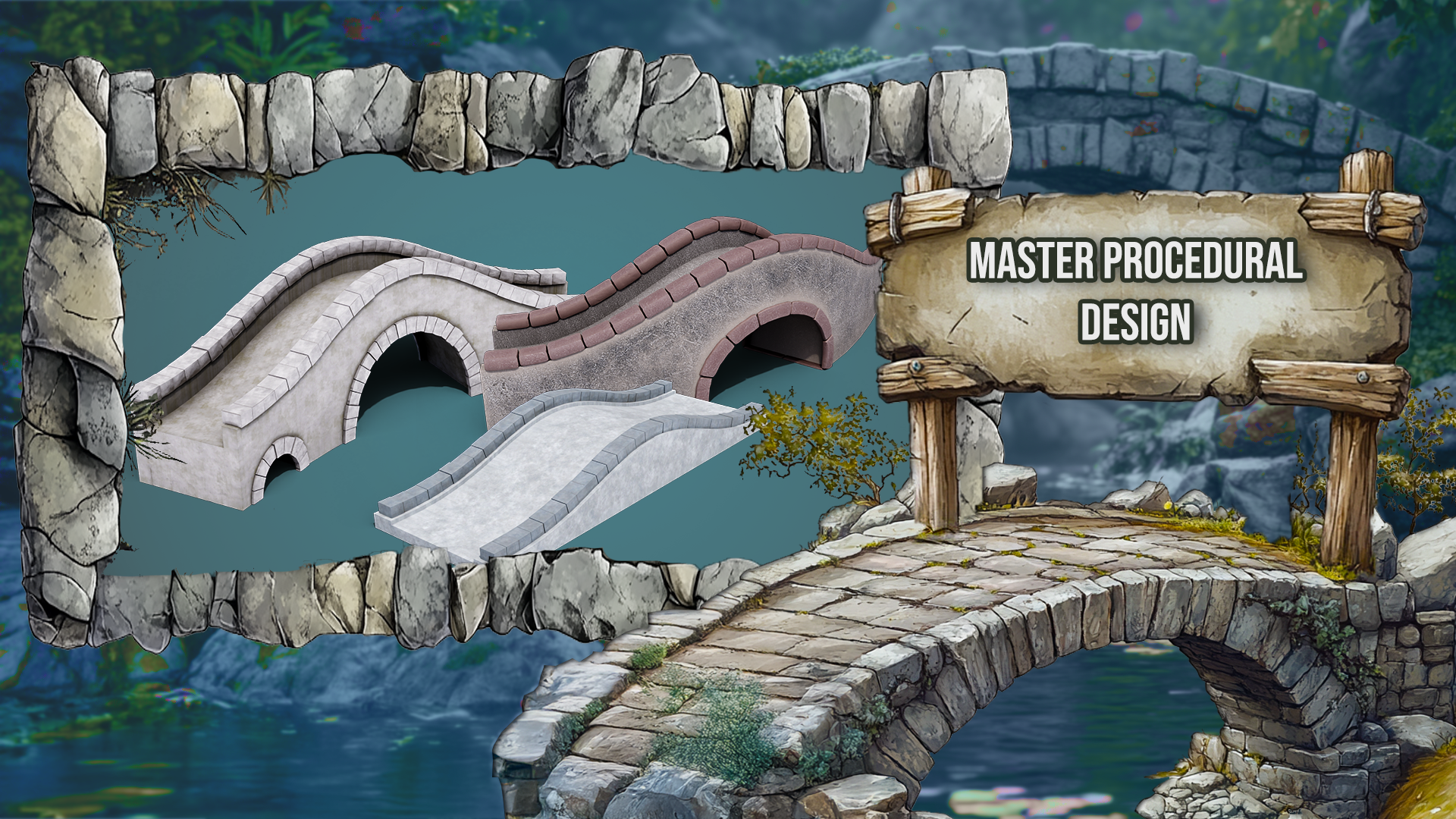
learn how to design and create custom
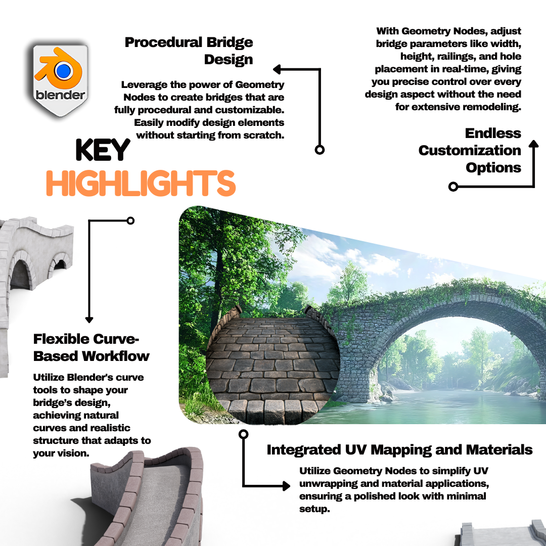
procedural bridges that can be simply adjusted and shaped to your preference using Blenders powerful Geometer nodes system. Whether you are new to
Blenders Geometri nodes or already have some experience, this course will
guide you through the process of building
bridges from scratch. We will break down the steps to make it easy and enjoyable, focusing on how to draw
out bridge profiles, adjust parameters
for custom shapes, and control various
design elements to create stunning
dynamic results. We will start by
covering the essentials, how geometry nodes
work, and how we can use the curve tools to create
procedural structures. Right from the start, you'll get familiar with drawing out bridge profiles and adding key inputs for
things like height, width, and railing controls. By the end of this section, you'll be well equipped to shape your bridges exactly
how you want them. This course, you
will learn how to add intricate details
to your bridges from sweeping curves to displacement effects for
realistic, more dynamic shapes. We will also cover how to
introduce customizable elements like holes within the bridge for added realism
or stylization. These features are essential to creating bridges
that not only look great but are functional in a variety of freed environments. Once we've covered the basics, we will dive into more
advanced features like UV and wrapping, adding materials,
and even generating stone paths to enhance the
overall look of your bridge. You will learn how to
align stones to curves and customize their appearance to match the unique
style of your scene. We've designed this
course to be efficient, ensuring you can create professional quality
bridges without the hassle. With easy to use inputs
and prebuilt nodes, you will save time while
retaining full creative control. These techniques will help
you streamline your workflow, leaving you more room to focus on the artistic
side of your scene. By the end of this course, you will have the
skills to create custom procedural bridges that are both functional
and beautiful. Whether you're working on a stylized game or
realistic freed scenes, the tools and techniques
you'll gain here will elevate your designs.
Don't miss out. Join our course today and
unlock the potential of blanched geometry rods to transform your creative
ideas into reality. Let's get started
on building bridges that bring your freed
worlds together.
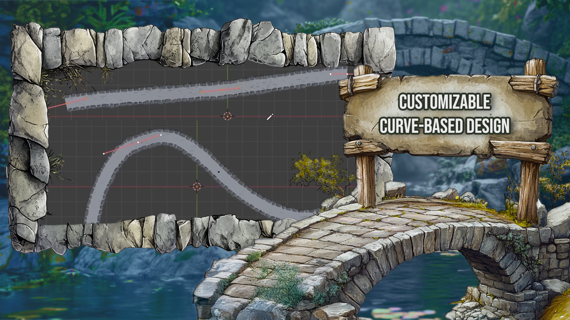
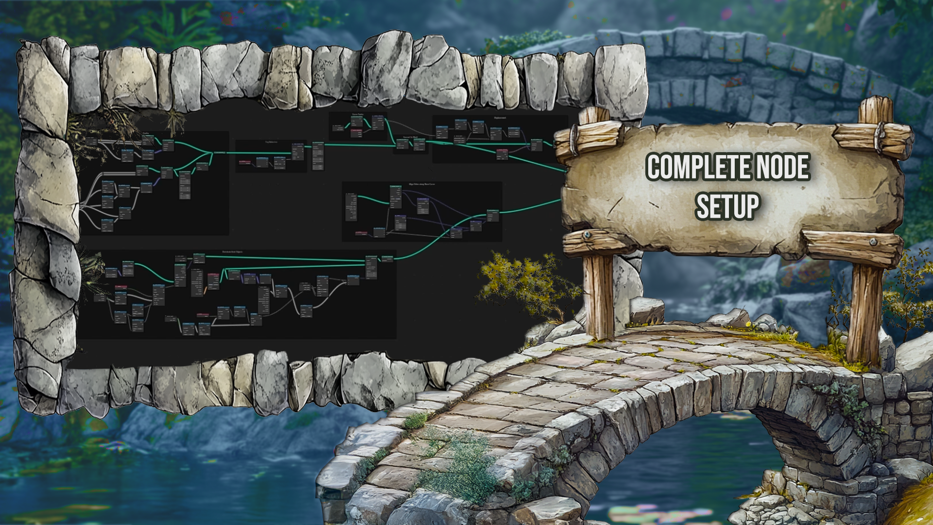
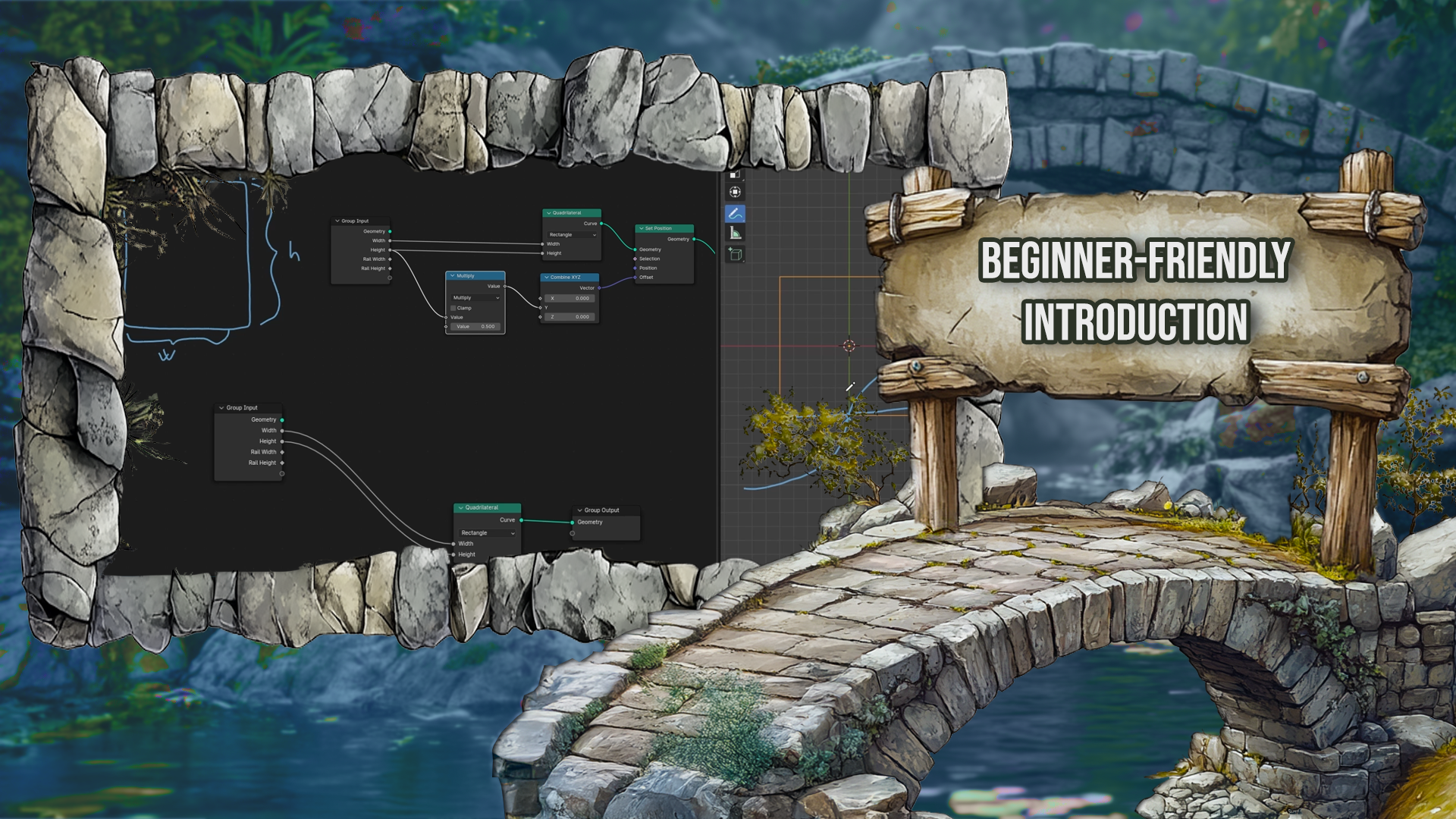
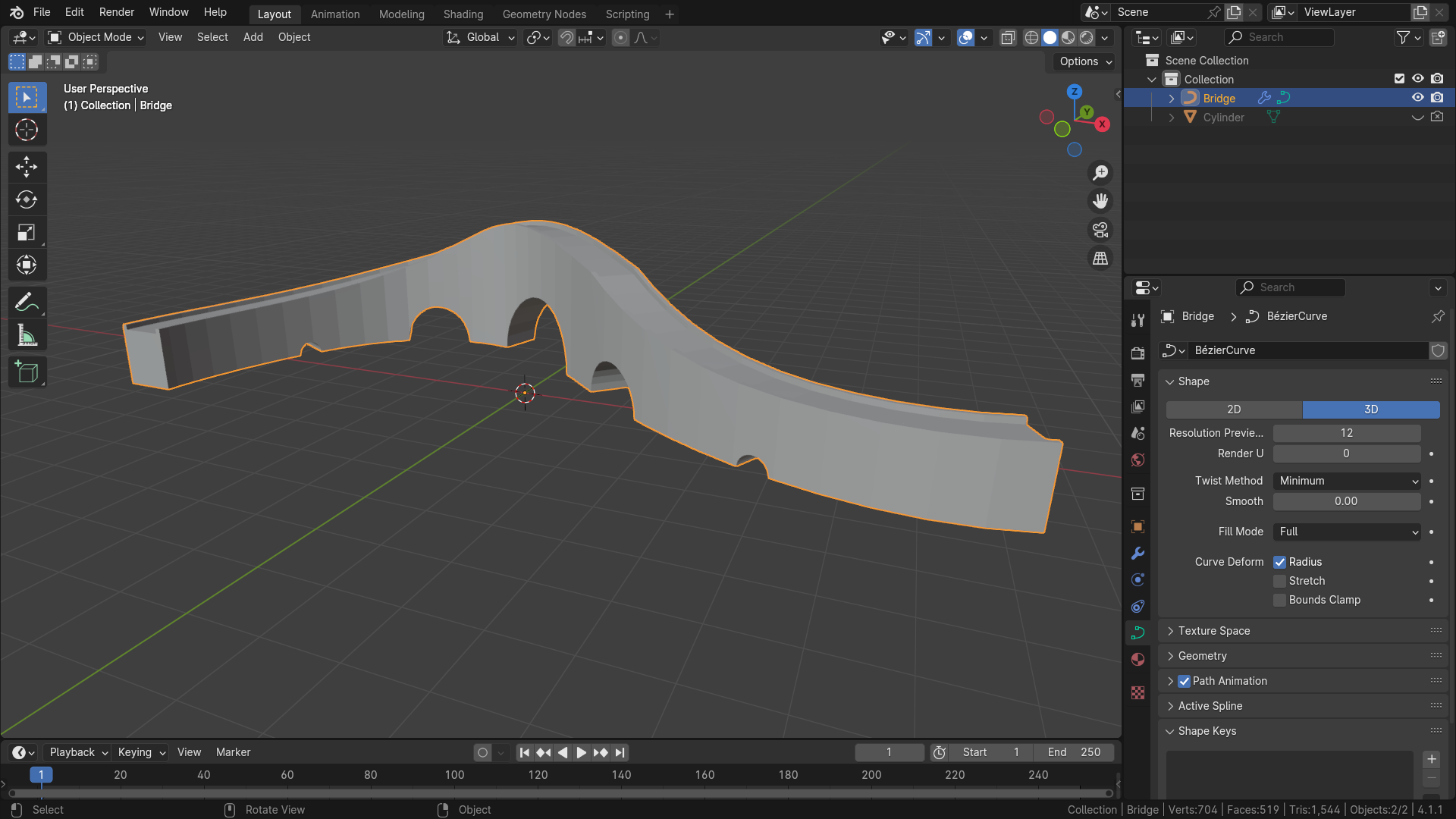
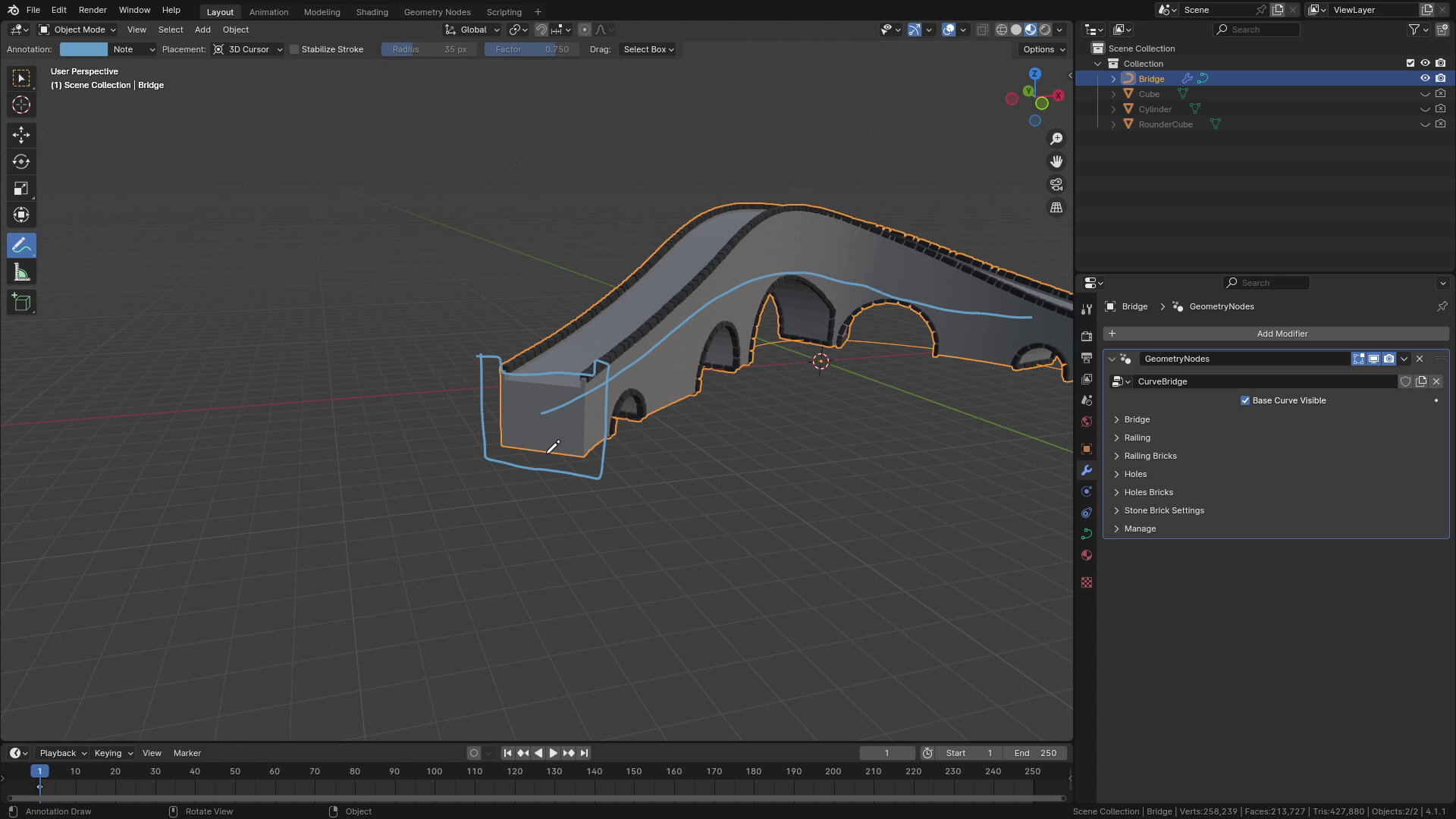
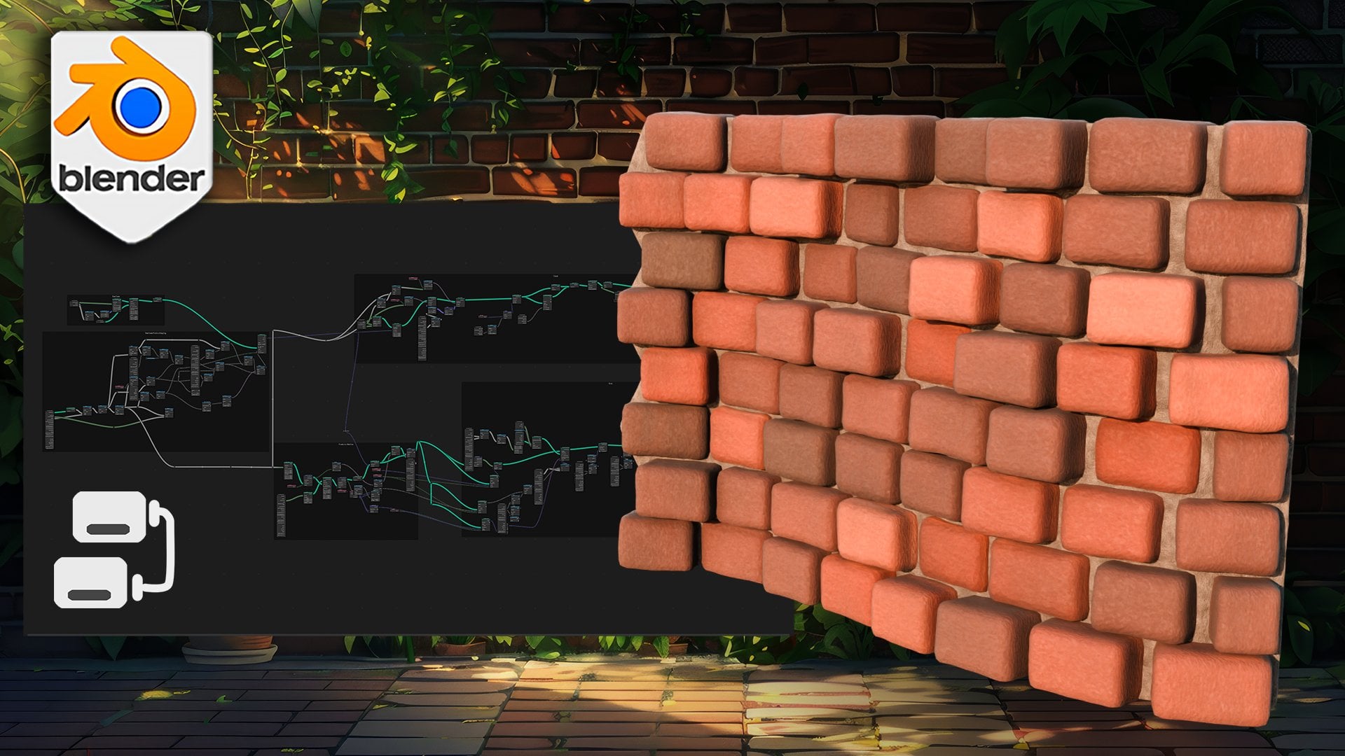
2. Introduction to Curve Bridge: Hello, and welcome
to the introduction to Blenders Procedural
Bridge course. In this lesson, we
will go through individual steps of
creating the setup, how our setup will
look at the end of this course and what
features will it contain? Our setup is based on curve. So if I go to Edit mode, you can see that there is simple BZR curve on which it's based. If I move, for
example, this point, you can see that
the curve changed its shape depending on
the shape of the curve. Let's go through the
all parameters which this setup will have at
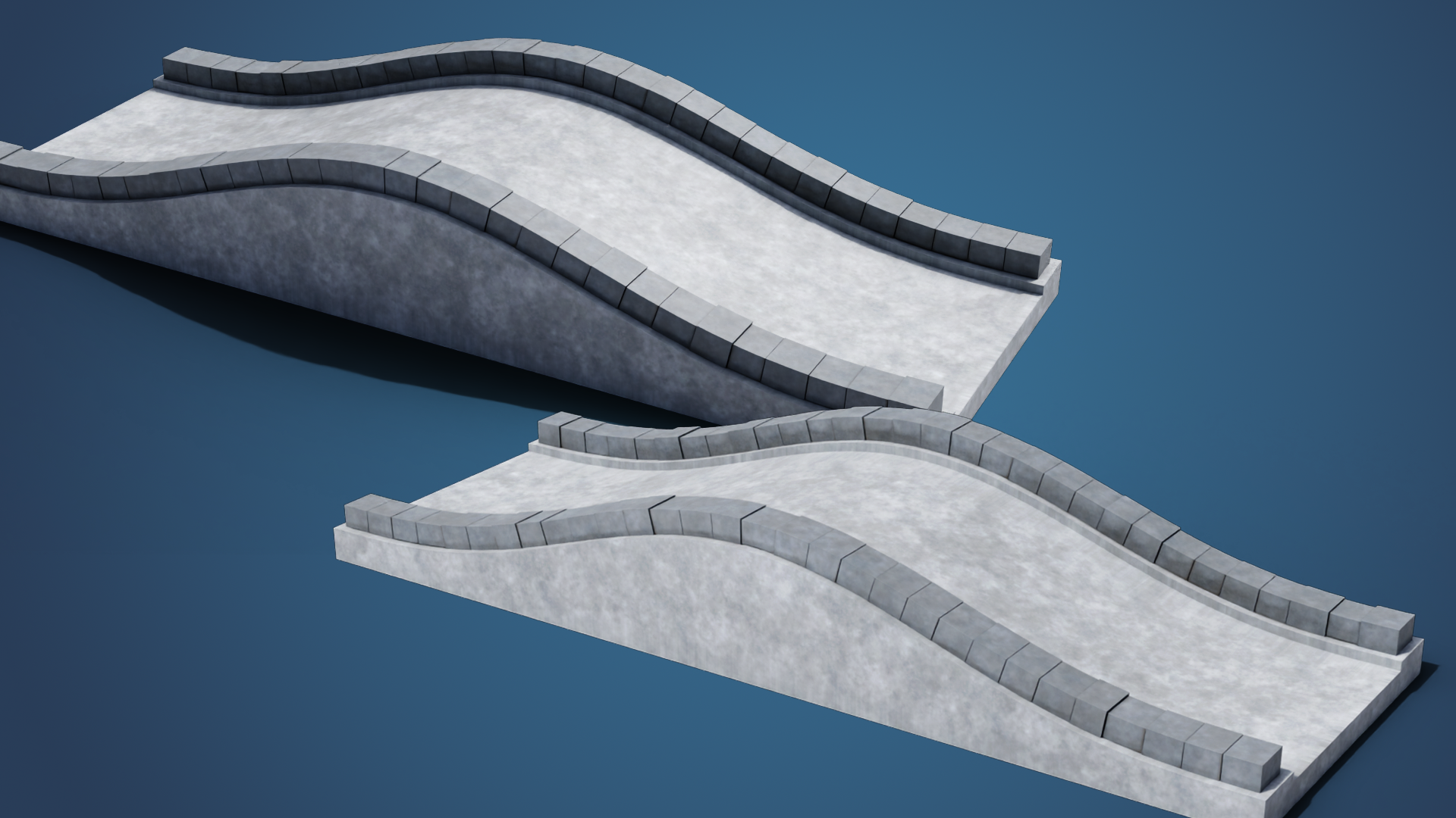
the end of this course. So first, there are overall
settings of the bridge. You can set its material width, height, and some other stuff. The most important here is
the width and the height. So if I, for example,
change width to five, you can see that the width of the bridge changes to the
five and we can also set, for example, height to two, which elevates the whole bridge. Then there is this
railing section, which in our setup
means these parts here. So you can set their
width and height, also enable and disable them. So for example, if
I set width to 0.5, they change their width
to 0.5 and, for example, height to one, you can see
that it's changing altogether. Next, our setup will also
contain some bricks. So those are the
black bricks here, which you can see along the railings and also
around the holes. You can set all of these
parameters of them. I won't go individually
through them right now, but you can set
their dimensions, gaps, rounding, and so on. The bridge can also
have some holes, so you can enable
them or disable them. And you can also pick which
object you would like to use for creating holes
inside our bridge. Next, there are settings for
bricks around the holes. So those are
basically the same as the settings for the
bricks along the rails. And the last thing which is here are settings for the
bricks themselves. So you can set their
subdivision bevel and some displacement
settings here. Now let's go through
some basic ideas which we will use
throughout this course. So the basic shape
of this bridge is actually created just
with simple profile, which is profile
with this shape, and then it's sweep
along the base curve. So that's how we create
this basic shape, and then we displace it
a little bit so we get this nice rounded shape which
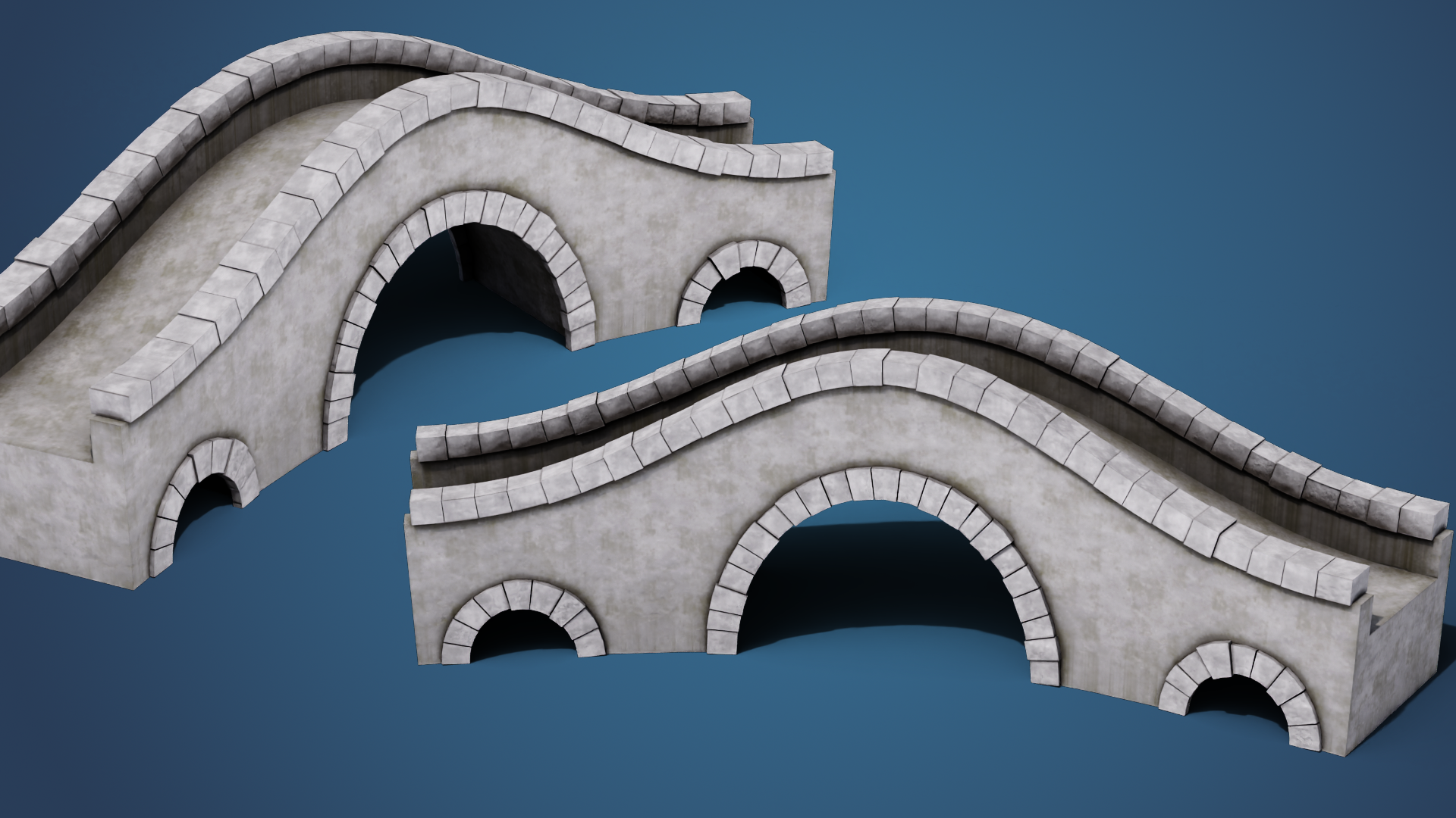
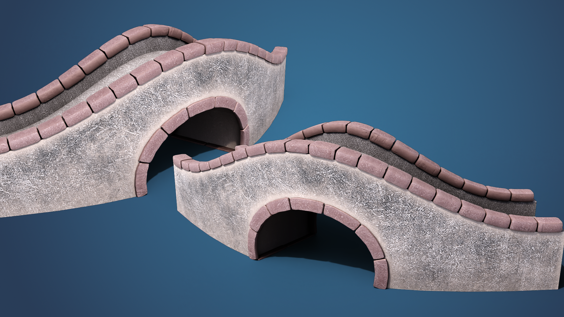
is elevated in the middle. The next thing which is here are the holes inside the bridge. Those are just basically
five cylinders. In this case, five
cylinders distributed along the base curve and then
subtracted from the bridge mesh. The last part here
are the bricks, which will have separate
lessons for them, and we will basically
create a procedural way to generate these bricks along
any curve you give to them, and then we will just give the setup these curves along the railings and also
curves around the holes, and that will generate these
nice bricks on our bridge.
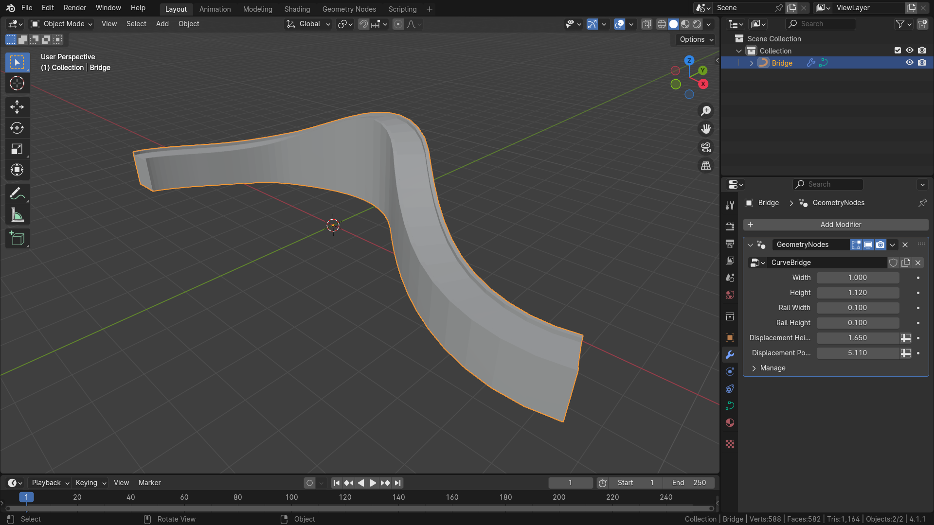
3. Designing the Bridge Profile: Hi. Welcome back to Blenders
procedural Bridge course, in which we will create
a profile shape of our bridge and add parameters
for overall control. So here I have a
fresh blender scene, and first thing I'll do is
I'll delete everything, so I'll hit A for selecting everything in
our scene and X to delete. And I'll create my curve object on which I'll be
building my setup. So Shift A curve and
I'll select Bezier. I'll rename it here to bridge. And I'll also create a
better shape for our bridge. So I'll go to Edit mode with
tab, delete all vertices, and I'll select this
draw option here and draw a basic shape from the
top, so something like this. And now we can start
working on our bridge. I'll go to Geometry
nodes Tap and create a new geometry node modifier
by hitting this new button, and I'll rename it
to curve bridge. So first thing on which we'll be working on is the
profile of our bridge. Our profile will be
basically three rectangles, one for the base mesh and two small rectangles for the railing,
something like this. And that's what we
will create now. So first, I'll add some
perimeters to our group input. We will want to control height
of this main rectangle, which we can call just height, width of this rectangle
will be width, and dimensions of these little
rectangles which are for the railings can be something like rail width and rail height. So we can hit to bring up
this menu on the right side. And I'll add new perimeter
here with the plus button, sit input, and the first
one will be width. We can set minimum of it to zero and leave
maximum to infinity. We can duplicate it for the
height and just name it. And we will also create two more perimeters for
railwath and rail height. So I'll again duplicate
height and rename it to Railwth and duplicate it one more time and call
it rail height. Can also set some
default values for them. So for the width, we can set default to one, same value for height. And for railing, we can set
something like 0.1 and 0.1. Now when our
parameters are ready, we can also set them
actually to our setup. So if we go to modifier
tap ander over our input, we can hit backspace to set or reset this value to
default value like this. And then we can go back
to geometry notes. To create a simple rectangle, we can add a new quadrillT
shift A and type this name. And for the basic rectangle, we want width of it to be our width and height to
be with sorry, height. And now, if we hold out
shift and left click, make sure you have node
angular addon installed, you can see that we have this simple rectangle we want to make sure that pivot of our rectangles is down here, down here because that's
a place where we want actually the curve to
be because we will be sweeping this profile
along the curve, which will be
something like this. And if the pivot point would be in the middle
of this rectangle, it would be sweeping along the curve like this,
and that's not what we want. So we need to move
this rectangle so that this base edge is
here at this level. So to do that, we can
add set position node, which will change position of our rectangle and we will want to change the Y value. So for that, we can add
a combined XYZ node. And now if we plug
height to our Y, you can see that it chumps
on the y axis by the height, but we only want half of it, so we can multiply
this height by 0.5 by adding
multiply meth node. That's default to 0.5. And then if we plug the
result into combine XYZ, we have it nicely aligned to
the pivot point of the mesh. Now, if I go to my
basic view and change dimensions of my
rectangle or my bridge, you can see that it always
stays here at the pivot point. Now, let's add our remaining
rectangles somewhere here. So for that, we will
create a simple rectangle. We can duplicate this node with Shift D and just input
different values for it. So for this one, we will be using the rail
width and rail height. And if I view it with
old shift left click, you can see that
we have only this little rectangle down here. Now we need to position
it so it's somewhere here at our original rectangle. So for that, we will also
at set position note. And our rectangle
was somewhere here. So first thing which we need to do is we need to move it on the X axis so it's
somewhere here. And we get this value by using the width of this rectangle that will move our rectangle here
and then move it back to the left by half of
our rail rectangle. So first, let's add combine XYZ. Plug it to offset, and we'll
be changing the X axis. So first, let's take width
of our large rectangle and multiply it by 0.5
and plug it into X axis. If we view it, you
can see that it's in the bottom right corner
of our large rectangle. So we need to move it
back by half of it. So let's subtract half of our
railwidth from this value. So I'll subtract
and also multiply rail width by 0.5 and
plug it into subtract. And now those two rectangles
should be aligned on X axis. So you can see that if
I switch between them, they are both aligned
on the x axis, and now we need to
figure out the Y axis. On the Y axis, it will
be pretty similar. We need to move it by the
height of the large rectangle. So I'll just make
this a little nicer. Will take height of our
rectangle and plug it into Y. That will move our
small rectangle. If I actually join
them together, you can see that it's
almost at the right spot, but we need to move it by the half of the small rectangle. So let's also add rail height multiplied by 0.5 and add it to
the original height. And now, if I plug
this into Y axis, you can see that those
rectangles are nicely. So to actually sum it up, we started with little rectangle here and move it on the X axis by width of the large rectangle minus width of small
rectangle divided by two. And on the Y axis, we
took the height of the large rectangle and added half of the height
of little rectangle. So those are the
calculations which we needed to position
our small rectangle to this nice position. And now we might do this
for the opposite one, but much simpler approach
is using the transform node and scaling this rectangle
on X axis by minus one. If I add transform rode or transform geometry and add
it to my joint geometry, you can see that if
I change value of X, it starts getting to the middle. So if it's zero, it's actually
here on the xx is on zero. But if I extend it
to negative one, you will see that it's
nicely aligned to the opposite corner of
this large rectangle. So now let's look how our
setup works right now. We can change the height
of our bridge, its width, and also dimensions of railings, and you can see that
it's nicely changing together without any problems.
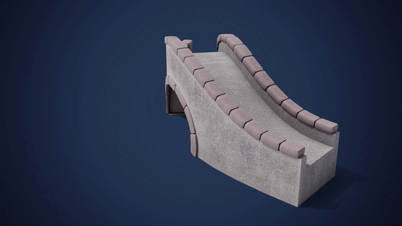
4. Shaping the Bridge Curve: Hi. Welcome back to Blenders
Procedural Bridge course. In this lesson, we will create a basic shape of our bridge from the profile shape which
we made in previous lesson. We will also add displacement so the bridge will have
more interesting shape. So currently our profile
looks something like this. And now let's actually
sweep it along our Base curve to get
the basic bridge mesh. So here we have the setup which we created in previous lesson. We can actually make it more nicer with framing
all of these notes. So we can select all of them, hit Control J and F two
to rename this frame. We can call it, for
example, profile. And now let's create the
base mesh of our bridge. Through that we can add
curve to mesh node, which will create
mesh from our curve. And this node has two inputs. First one is the curve along which we want to
sweep the other curve, and the profile curve is the one which will be
sweeped along the curve. So the profile curve will be this fin which we
made in previous lesson, and the base curve will be curve which we get
from the group input or basically this curve which
is created by the user. So let's take group input and geometry from this
and plug it into curve. And now, if we take a look at the result of this
curve to mesh node, you can see we have
something which looks almost like the
thing which we created. But first, it looks
like it's flipped. So that's first thing
which we need to fix. And also, it has shades
move by default, so we will disable this feature. So first one, let's disable the shades moving so we
can add set shades smooth, add it after the
curve to mesh node, and we can disable
this checkbook, which will disable
shades moving, and now we can see that we can nicely see
geometry of our mesh, and let's also flip it. So I'll add transform geometry, and we'll just need to scale it. I think it's Yaxis so it's
in the right direction, and we will set scale
on YXs two minus one. Now you can see that we have very basic shape of
our curve bridge, and we can also check
this fill caps so we get geometry at the
end of the bridge. And now if I, for example, change the curve or just move
the points somewhere else, you can see that the mesh is responding to these changes
and it's working nicely. You can also see that if I
move this point upwards, this bridge gets rotated
and that might be an issue. So we can fix this by setting normals of our
curve to the Z axis. To do that, we can add
set curve normal node, which will add or it will
change normals of our curve. The reason why we need to
change this is because the rotation of
these sweeped curves depends on the normals. So currently, the normals probably look
something like this, and we want them to look
something like this, so they point upwards
to the Z axis. So that's exactly what we can do with the set curve normal. So I'll plug it before the curve mesh and after the input
geometry and set it to ZA. And now you can see
that our issue is fixed and our bridge is
not rotated anymore. I'll change position
of our point back to the ground plane, but you can see that
it doesn't have any problems with points which aren't on one plane. Now the next thing which
you would like to control is actually elevate the
middle of the bridge, so it looks something like this. First thing we will
need to do is actually figure out which parts of the bridge we would
like to displace. So if we look at the
profile of our bridge, we want these two
bottom vertices to stay at their current position, and we want to move all
of these vertices on ZXs. So to differentiate
between them, we can create a selection
which will select only these top points and
exclude these bottom points. We can do it before
creating our mesh. So let's create a
new attribute which will tell us if those are the points which we
want to move or not. So let's add Stern attribute. And we will call
this attribute top. For example, its datatype would be bullying because it's
just either true or false. And we will figure
out now the value. Input geometry will
be our profile, and we will plug output of it back to transform and how to differentiate between
these points, we can, for example, use
position and we can see that position on Y excess
of these points is zero, and for these points, it's something larger than zero. So we can differentiate
between them with this. We can add position node, separate it to only get the Y value and we can say that if it's
greater than zero, it will be our top, so we can plug the
result into value. And if it's zero, that means that it's not
greater than zero, and it will be false for
the bottom vertices. We can view this value by using Control
Shift to at viewer, and I can also Control
Shift left click our value, and you can see that those are white and those at
the bottom are black, which means that the top
value for this is zero, and to value for this is one. So those are the
values which will be stored here in
the name attribute, and we can use it after creating our Base mesh for
displacing the top parts. To displace them, we can
add set position node. And for the
selection, we can use our attribute which we
created previously. We will select it here and plug the attribute
into selection. And now if I move
the value on Zaxs, you can see that only top
parts of the bridge are moved and the bottom
stay at their position. We don't only want to move these points
by constant value, but we want the
value change from zero to some height
and back to zero. We can achieve this shape
by using, for example, sine or cosine or
some other functions, but we will stick to sine. And what it means that
we want some value which will go through zero to Pi, where if we take the sine, it looks something like this. And here is zero, here it's Pi, and we will use this curve to create this
kind of shape of our bridge. To create this value
between zero and Pi, we can use perimeter of our base curve to
figure this out. We can't use a spin
perimeter here without capturing it before creating the mesh because at this point, we are not working with
the curve anymore, but we are working
with the mesh. To get the spline perimeter, we can capture it here before converting
our curve to mesh. So I'll at capture attribute, and we'll be capturing a
factor from spline perimeter. So if you add spine perimeter node and plug factor
to the value, and now we can again use
viewer, so control shift. And we will select mesh from curve to mesh and attribute from the
scripture attribute, you can see that here at zero, and here it's currently one. But if we multiply it by Pi, we will get zero to Pi. So let's do that first. We will at multiply, and
you can type Pi here, which puts a Pi value. And now if we view this value, you can see that it's
from zero to white, but it's white somewhere here. So that means those are some larger values than
one, which are the Pi. So now let's actually
create a function from it. We can use sign. Through this. And if we now plug this value to the Z
circuit of this offset, so we will use combine XYZ and plug result of this
sine to the Z axis, you can see that
it's going from zero to some offset in the middle
and then back to zero. We can increase this
displacement by multiplying this
sin by some value. So let's at multiply between
sine and combine XYZ. And if we multiply
it by some value, you can see that
it's getting higher And also to make this
a little sharper, we can use power here, which by default, sine
looks something like this. But if we use sine squared, it will look more
something like this. So if I add power here
between sine and multiply, you can see that if I
increase the power, it stays at the
zero for a little longer and then quickly elevates to the
one in the middle. So this is more controls
which we can use. And I would actually create some parameters which will
control all of these values. So what we will want to
control is this power, which is the shape of it, and then the multiply, which is the displacement
on those Z xs. So I'll hit end to bring up this menu and create a new input called displacement height and one more attribute which will be called displacement power. We can set some default
values for them. So displacement height can be default to two, for example, and minimum to zero, and displacement power can be default to one and
minimum also to zero. And our last thing which
we need to do is to plug these inputs to these nodes. So I'll plug
displacement height to this multiply and displacement
power to the power. Now, if I reset these values to their defaults and maybe
increase the power a little bit, you can see that we can control overall shape of our bridge. One last thing we can
also do is to clean up those notes a little bit. So I'll first group four of
these four nodes and call it top selection because we are selecting top
vertices in this part. Here is the transform node which fixes the flipped profile. We can call this
part displacement. So also Control J and F
to rename this frame. And these nodes in the middle, we can call this
curve factor because we are capturing original
factor of our base curve, and these two nodes are converting our base curve
and profile to the mesh.
5. Creating Holes and Custom Shapes: Hello, and welcome
to the next lesson of procedural bridge cars. In this lesson, we will add an option to create hose inside our bridge and add
some more controls to be able to control
all kinds of perimeters. But first, let's
actually think about how we will add
hose to our bridge and how we will generate the booling objects which we
will use inside our setup. So let's say we'll want
to add three hose, which will have circular shape, so we'll want to add
something like this. Or we might want to make the middle one a little larger because of the shape
of our bridge. So maybe something like this. Because of that, we
will want to be able to control scales of our objects. So we'll be using two values. There will be value for scale of center objects,
which in this case, can be something like two, and then value for
objects on the sides. So for example, if you would have two more holes
here and here, those can be something like 0.5. So there will be two values. We can call them center
scale and sit scale, and scales of objects between those values
will be mapped. So for example, this one
will have scale of one, but this one will be calculated, so user wouldn't need
to input this value. If the side scale
would be, for example, one and center scale also one, the scale of this middle
object will also remain one. Now let's think
about how we will distribute our cylinders
or in our case, cylinders along our curve. Let's take a look from the top and let's stick to the idea
of just three cylinders. So the middle one would
be somewhere like this, and the smaller ones would
be something like this. This is just look from the top. From the side, there
would be there would be circular shapes. And this comes with few issues. So for example, if this curve would have some sharper turning, so let's rearrange this
curve a little bit. I'll add one more point and
add something like this. So let's say this bridge would have shape
something like this, and then the middle would
be here at the top. Then the setup would generate our center cylinder somewhere here and the side
cylinders somewhere here. And you can see
that in the sides, this should be pretty okay. But in the middle,
this would create some not so nice holes. So you can see that there would be hole
something like this, probably, and that
wouldn't be pretty nice. So we need to think about way to make this a little better. And what we want to achieve is basically something like this. So the hose it would look something like
this from this side, and from the other side,
it would be a bit larger. The approach we'll be
using will be very similar to curve modifier
in modifier step. So if you go to
deform and curve, this modifier will
basically take your objects and deform
it along some curves. And what we'll do is we
will basically create a basic distribution of these cylinders
along straight line. So we'll create straight line with same length
as our base curve. Then we will distribute
our cylinders along this curve or line, and then we will
take this object and deform it along our base
mesh or our base curve. With this, we will achieve exactly this behavior
of our whole objects, and we should get some pretty nice holes inside our bridge. One more thing we would like
to be able to control is how close the hose will be to the
center of our base curve. So let's say we would
like hose something like this where this is the
center of our base curve, and we want one large hole in the middle and
then two smaller at the sides and no more
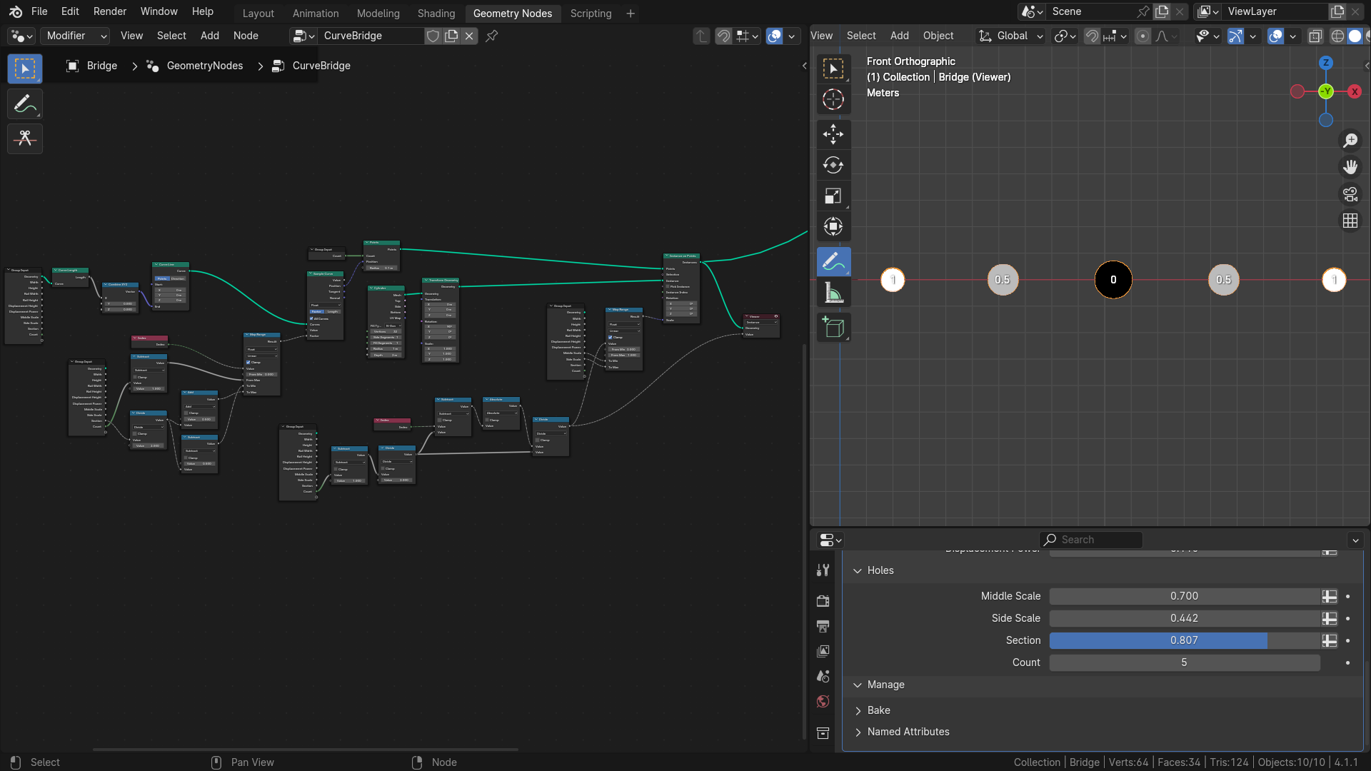
holes here at the sides. So we'll add perimeter, which will control basically
width of this hole section. With which we will be able to control the behavior
of our holes. If this perimeter
will be set to one, the hose will be distributed
along hole curve. And if it would be,
for example, 0.5, it might look
something like this, where it's just center. You know, you can split the
pace curve into quarters. So let's say, here
is the middle one, here's 0.5, here
is zero and one. And if our value would be 0.5, it will be from here to here. All right, so let's get started with a very basic distribution along straight line with same
length of our base curve. So let's go to our
geometric not step, and we will add a new panel
here with this plus button, select panel, and we
will call it holes. In this panel, there will be
all parameters which will be controlling our holes
inside our bridge. So let's add some parameters. We will be controlling our middle scale and side
scale. So let's add those. Middle scale, default
can be set to one, and minimum is zero. Now we can duplicate
this perimeter and call it stscale which
will be controlling scale of our objects at
the ends, basically. And we can set defaults
to one as well. Then there will be
how large portion will be occupied by these holes. So we can call this something like section scale
or just section. Subtype will be factor
because this will be 0-1, and we can set default
to one, let's say. And now let's go back to our Geometri nodes modifier
and reset these values to their default values with backspace and go back
to geometri nodes. For now, we'll be just using
some basic cylinder objects, and then we will replace it with custom objects from our user. First thing which I talked
about was the base curve. So let's create a curve line. And I'll zoom in a little bit. Our start can be at zero, zero, and N will be on X axis, it will be length
of our base curve and Y and Z will be zero. So let's add combine XYZ, and we will plug length of our
base curve to the X value. The length of our base curve can be obtained with curve length, so we'll use our base curve
at a curve length node. And this will give us total
length of our base curve. I will plug it into X. Now, if I output this,
you can see that there is just a simple curve line and the length
looks pretty okay. It's same as the base curve. You can also check it here. If you **** over output
of the curve length node, you can see that it's
something crowd 20, so that should be fine. Now the way we will distribute our objects
along this curve will be that we will
distribute some points on this curve and then instance our objects on these points. So let's add points node, which will generate some points, and we can also
set their position with this position socket. For that, we need actually
count of our objects. So let's add a new
input, call it count, and we can set default to three and also type two integer because
this is always integer. And also minimum
can be set to zero. Let's also reset this value. And the count of
the objects will be count from our group input. So let's add a group input and connect this count value
to number of points. And now you can see that if I output this and
hower over output, you can see that there are three points in the point cloud. Now let's figure out the
positions of our points. For this, we will be sampling
this straight curve and using the position
of some factors on this curve to control
positions of these points. So if I add simple curve and plug our base curve or our
straight curve to this node, this curve will tell us at which position is the
point on this curve, which has factor
which we input here. So basically, we'll be
controlling this factor, and this will output
position on this curve, and we'll control the position of
our points with this one. We can also check all curves because there's only one curve And now if I change the factor, you can see that when it's zero, it's at the start of
our straight curve, and when it's one, it's at the
end of our straight curve. For calculating the
factor of each point, we'll be using their index. So let's add index node. And we will be mapping
our index from zero to maximum index to
some factors 0-1. So let's add a map wrench node, which will remap
our index from zero to count minus one because that's the maximum
index of our points. So let's add count,
subtract one, And if we leave it like this, this will remap our
points to factor 021. If I plug the result to factor, you will see that we
have our three points distributed along
our straight line. And if I increase the
count of the points, you can see that they
are nicely distributing. But that's not actually all
what we want to control. We also want to include
the section value, which will control the
range of these points. When the section is one, we
want this range to be 0-1. But when it's, for example, 0.5, we want this to be 025-075. So we can achieve
these values with some simple math so when
our section is 0.5, our min will be 025
and max will be 075. And I'll also write if it's one, you want this to
be zero and one. So we will need some basic
math to calculate this, and how we can do this is we can basically take the
center of our curve, which is 0.5 and then subtract or add
half of this section. If we add section
divided by two, this will give us our maximum. And if we subtract this
instead of adding, this should give us our minimum. So let's use our values. When the section is one, this
will be 0.5 and 0.5 plus 0.5 is one and 0.5 -0.5 is zero. So this part is okay,
and let's try this one. When the section is 0.5, this will be 025. So the maximum will be
075 and minimum 025. So that's looking pretty good. And let's implement
this simple expression and use it for our
main max values. So we'll be using our section, and let's divide it by two. And now I will add two
I'll add two meth nodes, which one will be at, and the second one
will be subtract. And once we will be adding
half of our section, that's going to be our maximum, and the second time will be subtracting, and
that's our minimum. Now, if I check this
inside our layout, you can see that as I
change the section to zero, all the points go to the middle. And if I set it to 0.5, you can see that they are
nicely distributed like this. I can also increase the count, and this should remain
in the same section. So that's working pretty nicely. So this looks pretty good, and now we can move on to instancing our whole
objects on these points. I'll set this back to
three and Section 20.5. And let's go to our
geometry notes. So here in this section, we
are distributing our points, and now let's instance
objects on these points. So we will at
instance on points. Our points will be the
points we distributed. And the instances will
be for now cylinders. Later, we will replace
it with custom object. You can see that our cylinders aren't really
positioned correctly. So I'll just add
a transform node, which will tweak
this a little bit, and we will just rotate it
around X axis by 90 degrees, and now they are
correctly rotated. Because if you imagine
there is the bridge, this is the orientation of the hose we would like to have. Now we also need to figure out the scaling of our cylinders. So let's work on that. We'll be controlling the
scale input of our instances, and we need to figure out another equation or expression which will
calculate our scale. So I'll add two
more cylinders in here and maybe increase
the section a little bit. And now, if we look
from the side, we want these side
cylinders to have side scale and this cylinder
to have middle scale, and those will need
to be calculated. So the way we can do this
is we can basically map distance of each cylinder
from the middle to one. So the middle one will
have distance zero. The side ones would
be distance one, and cylinders between
them will be calculated. So this one will have 0.5. This one also 0.5, and
this one will be one. And then we can
just map this value between middle scale
and side scale. We will be again using
indexes of our instances. So let's add index note. And let's say this
one has index zero. This one is one, two,
three, and four. So what we would like to
get is something like zero, 0.5 and one as here above. And so the first thing we
can do is we can actually create or calculate distance of our index from
the middle one. So for that, we
should get here zero. There will be one, two, and here also one and two. We can do this by subtracting the middle value from each of these and then
using absolute value. So let's subtract value, and the value we'll be
subtracting will be number of cylinders -1/2
because with the minus one, we will get the four and divided by two will
give us the two. So we'll again bring
up the group input. We'll count and subtract one. And now we will be
divided by two. And this should give
us a nicer value. We can also view this. So if I use Viewer, and I'll enable
attributes text here. You'll see that we have I'll try to say this two instances. Yeah, perfect. Now you can see that
this one has minus two. This one has one,
zero, one and two. Perfect. So now we can just use the absolute
value of these. So let's add absolute value and plug it into
viewers to view it. Now you can see that we
have exactly these values. Now we just need to divide this by the highest
value of this. So this is two, and that also
should be our middle value. So let's divide it
by this value here, which should be two for now. And if we divide this
and plug it into viewer, you will see that
we have zero here, 0.5 here and one here. If I add some more points, I will just quickly add a
property step modifiers, and I'll just
increase the count. You can see that the values
are nicely changing. If I increase it
to seven or six, those values are still
looking pretty good, and we will be using these values for
remapping our scale. So let's add a map range node, and we will be
mapping this value 0-1 to middle scale
to side scale. So let's add group input, and those two values are right because the
middle one has zero, side one has one,
and now we can just plug we can map zero to middle scale
and one to side scale. And this should give us
the appropriate scale. And if we tweak
this a little bit, you can see that if I
increase the side scale, the cylinders at the site
are getting smaller. I can also increase these
and we can also play around with the middle scale
and it's all working nicely. If we increase this and
values a little bit, you can see that our scaling
is working perfectly, and now we can move on to aligning these cylinders
along the base curve.
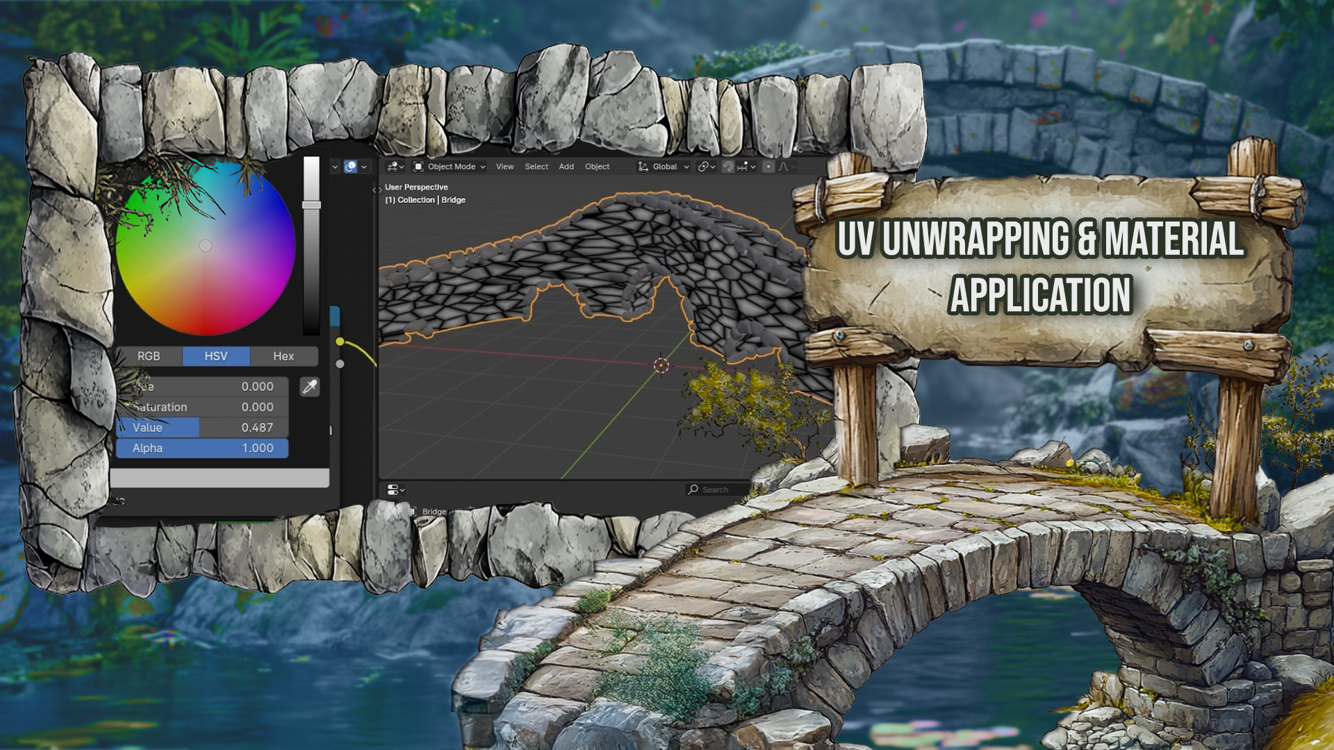
6. UV Unwrapping the Curve Bridge: Hello, and welcome
to the next lesson of procedural bridge cars. In previous lesson,
we distributed our holes objects along a straight curve,
and in this lesson, we will try to align these along the base
curve and then use Bolling modifier to subtract these objects from
our base mesh. So the technique
we'll be using is actually very similar
to the curve modifier, which I talked about
in previous lesson, and we will basically redo this modifier but inside
the geometric node. So for this, we will need some
objects we need to deform, which are in our case,
the cylinders here, and we will also need a curve along which we will
deform these objects, and that one will
be our base curve. So we have this curve
and the cylinders, and we want to deform the
cylinders along this curve. This technique is very useful, and we will also use it in the next lessons where we'll
be working on the brakes. First, before actually
doing the setup, we will also realize
our instances from our curve holes
or bridge holes. So now we can work with
their points individually. For aligning these
objects along the curve, we'll use a simple curve node, which will be reading some
stuff about the base curve. We can check all curves
because it's only one curve, and also we'll be
using length instead of factor because we'll be working with positions of
these points on their X axis, which will basically tell us on which length we want
to read those values. So for this, we can add a position and we
will separate XYZ. For now, we will only use the X value which we will
plug into the length. This will result in that, for example, this
point in the middle, we'll take a look
at this curve in the middle and read its
position tangent and normal. And it will set
position of this point to corresponding point
along this curve. So we will be also using
a set position node, which will be deforming
our base mesh. So let's plug our instances or our realized instances
to the set position. And now if we plug position
of this point to position of our base mesh or
our whole smash, you can see that this creates
this not so nice mesh, but it's actually
working correctly because if I said this to five, you can see there are something
like five of these parts, and each of these is
one of our cylinder. So this is basic
position of our points, and now we need to offset
those from these so that if the point,
for example, here, was on the Y axis let's say one, we want to take a
vector on this curve, pointing outwards and scale it by one and add
it to the position. This will result in recreating the whole
object along this curve. So along this curve, we
will need two more vectors. One is the one which
I talked about. It will be perpendicular
to this curve and also aligned
with the XY plane. So it will be flat, and the second one will
be one pointing upwards. The way this will work is we
will always take position, this will give us
point on our curve. Y position, this will give us distance in this direction from the position or from the
curve and also Z value, which will give us distance from our base curve on the Z
axis or in this direction. So to obtain this Z direction, we can basically set it to Z axis because we always
want this to point upwards. So for this, we can
just use vector scale. So let's add vector
Math, set it to scale. And we will scale vector
pointing upwards with length one by the Z axis or Z position of our cylinder and
plug it into offset. If we do this, you
can see that we have those outlines which are basically the cylinders
squeezed in this direction. And now we just need to add the deforming to this axis or
to direction of our Y axis. To get the Y axis, we can just use our tangent, which is vector which
always points in the direction of the curve
and use that product. So if we use tangent T
and create Oh sorry, cross product, cross
product with Z, this will give us a vector which is perpendicular
to both Z and T, and that means that's
the Y direction. So let's calculate the Y. It will be cross product
with the tangent, so I'll at cross product
between tangent and 001. And now we can just
scale this value by the Y. Y position of hour point, and we will add
it to our offset, so I'll add those two vectors together and plug
it into offset. If I output this,
you can see that our cylinders are
nicely aligned, and this should give us pretty
good holes in our bridge. You can see that they are
not perfectly straight because the curve here
was something like this, and this created
those nice alignments of our holes along
the base curve. The last thing which is
missing is just subtracting these cylinders from
our bridge mesh. So I'll put this here. And here we have
our bridge mesh, and here are our hose. And we can just add a
booling or mesh booling. This will be set to difference. I'll just put this closer. And we will be subtracting
from this mesh, and we will subtract
these cylinders. And now you can see that
it's not actually working, even though it should
work if we check the bridge from the top, it
looks something like this. And if we check the holes, those look pretty okay. So it should create the
holes inside the bridge, but there's probably one issue
which we didn't fix yet, and that's the pas orientation. If you enable this
and view the bridge, you can see that the face
orientation of these faces is wrong because the color which we should be
seeing is the blue, but most of the bridge
has just red value, which means that the normals or the faces are pointing inside
the mesh and not outside, which should be that's
how it should be done. And same thing for
the cylinders, if we go into the
cylinder somehow, you can see that inside is blue, so the normals are
pointing this direction, and those should be
pointing outwards. So we all need to fix those two issues and then
it should work nicely. So for the cylinders,
it should be pretty simple because the Z axis is definitely okay
because that's what we put here in the
scale by default. But the problem might
be with the Y direction because those cylinders
had some orientation, and we might have displaced
it in different direction. We can flip this direction by just changing this 001
to 00 negative one, and now you can see that they have blue face orientation,
and that's fine. If we now view the mesh booling, you can see that it's
actually working. But I think we should also fix the pace orientation
of our bridge mesh. So let's try and do that. So you can see the whole
thing here has Runk norms, except one of the railings. So we can flip most of these
by just flipping faces. And you can see that fixes most of these
except this one railing. That's because this railing
was created by default, and then this one was just
scaled this by minus one. And the way we can fix this
is just reversing curve of this profile because
let's say this was going in some kind of this direction, and then this one went
in wrong direction. And if we reverse this
to the same direction, it should create better faces. So if we go to our
profile, which is here, you can see that this
is our default railing, and this one is just scaled on the X x is by negative one. And if we just reverse curve and plug this instead instead
of the one before, this should give
us a nice profile, which has also write normals. Now, if you go too mesh bullying,
this is working nicely. Except this part where the cylinders are just too narrow to create actual
holes inside our mesh. And there are several
ways to fix this. The easiest way is
probably just to increase the depth
of our cylinders, which makes them longer, and
now this is working nicely. But we might fix this
in a more elegant way. Here where we are
scaling our instances, we are scaling them
on all of the axis. And the thing we can do is just scale them on if we take a look, we can just scale them on this direction and
this direction. And this direction, which
is the dimension which controls or it needs to be at least the
width of the bridge. We can control this
by some calculations. So first, let's just
control these two Xs. We can probably add combine XYZ. So let's add combine XYZ, and we just need to
scale them on X and Z. So let's plug this value into X and Z value and set Y to one. This will result that
all of the cylinders have same length
in this direction. Make the cylinders
correctly wide, we can calculate this Y scale by taking the dimensions
of these objects on Y Xs and then looking at the width of the bridge and then multiplying
this by something. So let's say that the
bridge has width of one and our cylinder or our whole object has width of let's say, 0.75. If we divide this one by 0.75, we will get something
like Y 1.333. And then if we scale this cylinder by this
value on Y axis, which is 1.33 by times 075, we should get the width of one, which is width of our bridge. We might also
increase this value, so it overlaps or
extends a little bit, so we make sure that it
actually creates the hole and the faces aren't perfectly
lining with the bridge, which might get us
into some issues. So let's do this calculation. First, we need to get dimensions of our whole objects on Y axis. We can do this by creating a bounding
box of this geometry, which if we take a
look what it does, we have the cylinder here and
we take the bounding box. It just creates the bounding
box around this object. We can get the dimensions of this by subtracting
max from men. Maximum value is probably
this point and minimal sorry, is down here at the bottom, and we can just subtract these which gives us
dimensions of each axis, and then we just need dimension on Y axis so we
can separate this. And here I have my calculation. So we need to divide width of our bridge by width
of our object. With of our bridge, we can
take this from group input. That's this width, and let's at the divide and divide
it by this Y value. This will give us
scaling on Y axis. Now if we plug this into Y, we should get
something like this. And if we take a
look at the bridge, you can see that it should
theoretically work nicely, and you can also see it works. If I take a look from the top, you can see that here are the cylinders and
here is the bridge. If I change the dimensions
on Y axis of the cylinder, this shouldn't do thing
because the scaling is recalculated to
do the right amount, and it's working nicely. But if you take a
look at the holes, you can see that there
are some artifacts, and that's because A, the cylinders might not
have geometry here, so they are straight like this and the bridge
still has some curving. So that caused this thing here. And we can just fix this by multiplying the scale
value by something like 1.1 to make sure
that it doesn't happen. So let's multiply it by 1.1, plug it into axis. You can see that still it still doesn't
really work nicely, so we can set it to 1.5, and we can make
sure with this that it always creates nice holes. Now let's take a look at our setup and how
it actually works. We can set the count of our
objects with this value. So let's set it
to three for now. We can play around
with the section, which controls how
close those are. So I'll set it to
five, for example, set the section to
something like this, and I can also change
the middle scale. You can see that
it's again a little bit like glitching here, but I'll also talk
about this later. And if we set side scale
to something smaller, you can see that you get
these pretty nice holes. The problem which we are
getting here is that basically, if you look from the
top from the cylinders, you can see there is this
large portion of this. And the problem here is that this cylinder has only
this just flat face here. But what we would need
is that would have some geometry like this so it can actually
bend along the curve. That's why it's better to use some more complex shapes or just objects
with more geometry. We can, for example, try
this when using cube. So let's add cube here. And if I plug this into
instead of this cylinder, so I'll just put this here and
plug cube inside this one. You can see that
we have now cubes or cubic holes in here. And if I increase
the middle scale, we should, you can see that we are getting the
same problems here. But if I increase the vertices number to
something like ten, this is fixed because now
the cubes can be also bend. We can also check it
here from the top. You can see they
are nicely bend. But if this value was at two, those were just straight and didn't really align
with the base curve. So when using some Hole objects, make sure that they
have enough geometry to actually bend
nicely like this. So let's actually
add a perimeter for users to use their
custom whole objects. For this, we will
hit to bring up this menu and add a new input. We can call it le object and
we will set type to object. And now instead of
using the cylinder, we'll be using
this whole object. So let's delete the
cylinder and bring up. First, we'll need a group input. Whole object, we'll plug
it into object info, which will give us
the actual geometry, and now we can use this
geometry instead of cylinder. Now we don't see anything. I'll actually output the
final output of the setup. So now there's
just plain bridge. But if I create some kind of whole object, we can
use the cylinder. I'll rotate it on
Xxs by 90 degrees. And now we need to replace these faces with some
higher geometry faces. And if you select these
vertices with Alt, sorry, these edges with Alt and left click and now hit F free
to bring up this menu, search for Grit fill, and this will fill
this cylinder nicely. We will also do this for
the other side. Like this. And now we should have a
pretty nice hole object which we can use
inside our setup. So I'll just leave
it by cylinder. I'll hide this and
rig up our bridge. Now in a whole object, I
can select my cylinder. You can see that right away, we have cylindric holes, and we don't get any
issues here because the cylinder has nice geometry and it's all working nicely.
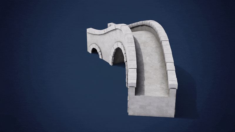
7. Introduction to Stone Path: Hello, and welcome back to Blenders Procedural
Bridge course. In this lesson, I'll explain
how we will add stones to railing of our bridge and how this setup will
actually work. So currently our bridge
looks something like this, and the stones will be located here around the railings or basically on top
of the railings. So if we take a look at them, you can see that their shape is something like
this, let's say, and the stones will
basically generate stone bricks along these curves
on top of these railings. So at the end, when the stone breaks
will be finished, we'll just use some kind
of these curves and assign the stone break set up to them or geometer node group to them, and it will generate
some breaks which will look something like this, let's say, this will be all
the way around the curves. It will be also on
the other side, and we will also edit
around the holes. So basically
somewhere like this, and there will be
stone bricks as well. There will be quite
a few perimeters which we'll be able to control. So let's say, for example, that there will be
curve like this, and now we need to create
stone breaks along this curve. So we will have some
parameters for stone breaks. We will have their dimensions, so we'll have length,
width, and height. And we will need first to create some basic cubes
along this curve, and then we will also apply
some kind of displacement. If you would place the cubes
right away to this curve, we might get similar
issues which we got when creating
holes to our bridge. So if the curve would
have a shape like this, for example, and we would just place cubes along this curve, it might end up looking
something like this where the cubes would
overlap in some areas, and that's something
we don't really want. So for this setup, we'll use a very
similar approach to which we used for the holes. So first, we will actually generate these bricks
along straight curves, and then we will align
them to our pace curves, which was our input. So for that, let's say we will have this
curve, and first, we will create straight curve, which is just same
length as this one. Then we will
distribute some cubes or some bricks along this curve. Like this, and then we will align these objects
along this curve. There's also one more problem which I would like
to talk about, and that's when we
will actually want to place these stone breaks
along not only one curve, but along multiple curves. So this is also one thing
we'll be implementing, and we'll implement it in
that way that let's say we'll have curve like
this and curve like this, and this will be input
to our node group. So the thing we will
do is we will look at all of these curves and create as many curves as there are. So here are two, so
we'll create two curves, and this curve will have same
length as the first curve, and this curve will have same
length as the second curve. Then we will distribute breaks along these straight curves. And then for each of them, we will align them to
their original curve. So this is for the holes
or the stone breaks around the holes because
we don't actually know or we might know
it, but also not. So we'll make it as
procedural as possible, and it will work really
nicely because we won't need to actually care about how many curves we input
to the node group, and it will just work with
anything we input to that. Let's talk about a little
bit how we will actually distribute stone breaks
along straight curve. So let's say we have
straight curve, and we want the
stone breaks to have a different or a little
bit randomized dimensions. So let's say we would
like something like this, that this one is shorter,
this one is longer. This one is something
in between, longer again, maybe
too shorter like this. And this is actually a
pretty interesting problem because if we want just
bricks with same size, we can just take a
curve, resample it. So resample it to some number of points and then just instance cube
on each of these points. This is the simplest approach, but we want actually
to randomize them. If you would want
to randomize these, we would need to
shift these points by some randomized
amount and then just figure out how
large the cubes or the instance cubes must be to not intersect
with each other. But this might get
really complicated. So the solution
we will use is we will create the straight
curve and resample. Then we will actually
displace the points randomly. So let's say this
point will be here. This point will be here. And they will have randomized
distances between them. And then we want instance
cubes on the points, but we will use edges to
instance cube on them. For the edges, we
can actually get their length and
their center point, which is enough or information to generate cubes on these. So basically, we'll
have some kind of curve like this and we
will create cube with same length as this edge and place it in the same
position as the edge, and we will do this
for each of the edges. That will result in
something like this. And then we can also use some randomized dimensions
to make these wider. And that's not a big deal because this won't cause any collisions
with other breaks, so this should be pretty simple. As the last thing, we will also apply some kind of displacement, so those won't be straight, but might be some
displaced or something, and we will also UV and
wrap these and apply some kind of material to them to make it look more realistic.
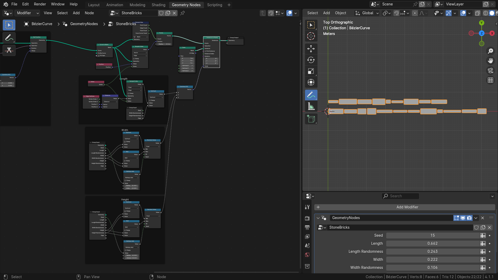
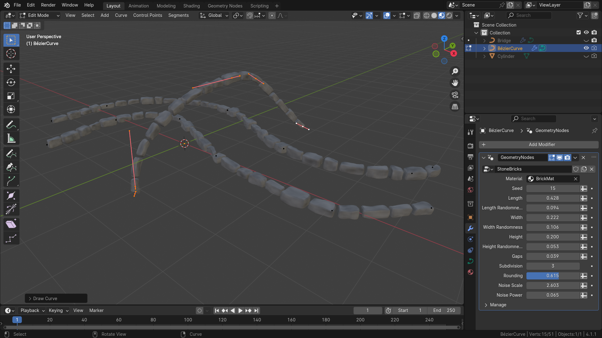
8. Generating Stones on Paths: Hello, and welcome back to
BlandarsPcedural bridge cars. In this lesson, we will actually create the base for
our stone bricks, so we'll create straight curves on which we'll distribute
the stone bricks, and in the next lesson, we will align them to the input curves. We won't be using
our bridge setup for now because we will be building this
stone brick setup as a separate node group, and then we will import
it to our bridge setup and just use the
existing node group. So for now, we can hide the
bridge with this eye icon, and we will add a new object, which will be curve.
I'll select Bezier. And I'll also draw out some testing curves on which we will be
testing our setup, so we can just do something
like this, I guess. And on these curves,
we will be building up our stone break setup
and testing it as well. So we can go to Modifier stop
and create a new modifier. I'll select Geometri nodes here, hit new and call
it stone breaks. And now we can go to
Geometrines workspace and start working on these. So here is our basic
geometern setup, and the first thing
we need to do is we need to create as many curves
as there are in the input. So if you **** over this input, you can see that there are two splines constructed
from nine points, and we need to create
as many curves as there are in the input. So for this one, we
can first create as many points as there
are curves and then instance a simple
curves on them. So let's add points node. And the count, we can
figure out the number of splines by adding
a domain size node, which will tell us exactly
how many curves there are. We just need to switch
this from mesh to curve, and this will give
us the spine count which we plug into the points. Now, if I output the points, you can see that there
are just two points. And yeah, you can
also check it here. And now we'll instance basic
curve on these points. So the points on which we will be instancing
are these points, and the instance
will be curve line. Now you can see that
there are two instances, and the next thing
is that we need to set length of these lines
to length of each curve. We can do this by various ways, but the simplest
in my opinion is set length of this curve line to one and then just scale it on appropriate axis to the
length of our curve. So if we set this start or we can
leave this start on zero, zero, zero, and I'll set to 100. So it's actually just on X axis. And then if you scale
this on X axis, you can see that it
scales both curves on X axis to this length which
we input to the X value. So we can actually separate
these by ding combine XYZ, and then just set this to
one on all of these values. And if we change this X value, you can see that it changes
length of the curves. The problem now is that each curve has a
different length, but that should be pretty fine for us because
those inputs, you can see those square, which means that we can input a different value
for each instance. So to figure out
length of each curve, we can use sample index. We'll be sampling
our input geometry. We also want to
work with spline, so we'll switch this to spline. And the value which we want
to sample is spline length. These notes give
us the length of this spline and also how
many points it contains, but that's not actually
useful for us. We just need the length,
so we'll plug length to the value and then
the value to the X. Now you can see that it changed
to some kind of length, and that depends on this index. If I switch this, you can
see that it's shorter, and if I switch this back
to zero, it's longer. That's because there
are two lines. I think this one
has index zero and this 11 because if
we set this to zero, it's longer, and if we set
it to one, it's shorter. To input the right index, we just need to use
index of our instance, so we can just add index, which should give
us in this context, index of our splines. And now we still
see just one curve, but there should be
two different curves. And we can also check this by just translating these
instances a little bit. So let's add translate instance. And we will just translate them on depending on their index, we can scale this
index with vector. Like this. And if
I set this to one, like this into translation, you can see that it separates, or it basically
moves the curve with Index one by some value, so we can just see that there
are two different curves. If I add a new curve like this, you can see that
it added a third curve and it's working nicely. So the next thing we
will do is we will add a few parameters
to our node group, and we'll start
working on the brakes. So we can hit end to
bring up this site menu, and we will add a few
parameters for the bricks, first, we will add
some dimensions, so it will have length,
width, and height. So let's add length. Default can be set to
0.5 and minimum to zero, and I'll duplicate this two
times to at width and height. I'll also set the
default width to 0.2 and height to also 0.2, and I'll reset these in the modifier so we actually have these
default values applied. We also want some randomness. So let's add randomness
just for length, and then we will add this for the width and height as well. So I'll duplicate
this one more time and rename it to
length randomness. And the default can
be set to zero, minimum to zero as well. So now when we have
some basic inputs, we can start working
on the bridge. We can also frame
this section and call it curve or base
curve generation. And after creating these curves, we need to realize these
instances so we can work with individual points of the curves and not only the instances. First thing we'll do
is we will resample these curves to the length. So let's add resample curve, and we will switch
this type to length, so we will actually just set
the length of segment we want and not only number
of points we want, and the length will be length
of from our group input. So you can edit like this. And now if we hover over this, you can see there is 30 points. If I increase the length, we should have less points. We can see there are only seven because the breaks
will be longer, and that means we
need less points. Now we'll be displacing
these points a little bit. So for that, we'll be
using set position. And we will be displacing
these only on the X axis. So you can see that if
I change the X value, it changes location
of all the points. The thing we want
to displace are only the points which
are inside the curves. So for this, we can use this selection to
actually select only points which we
want to displace. And for selecting endpoints, there is the thing called
endpoint selection. And if we set length
to something higher, and maybe we can also view the points so we actually
see some kind of points. So we can add curve to points node and make sure to set this to evaluate it so it doesn't
change the points. And if we also convert these points to vertices,
we can actually see them. So if I change the X
value onset position, you can see that now it's
displacing only the selection, but we actually want to
displace the other points. So we can just negate this selection by adding a node from the
Bollin math node, which will invert this, and now we will be displacing only the
points inside the curve. The values by which
we want to displace these points are controlled
by the length randomness. So if you imagine
there are few points, let's say like this, and we will be displacing this point. We only want this to
displace it to somewhere here as a maximum because if
this would go any further, this could intersect with other points and it
wouldn't work well. So we just need to limit the range to length divided by two to minus
length divided by two, because if you mentioned
this part is length, and this is just half of these. So the maximum length randomness is actually length
divided by two. The length randomness
will tell us how wide this range is in which we
can randomize the offset. And if it's longer than
length divided by two, we will just clamp it and not
allow it to go any further. So let's first figure out the actual range of our randomness. So I'll bring up group input, and we need to clamp this value so we can
add clamp value. We clamp this between zero
and length divided by two. So we'll divide length by two. Like this and plug the result
of division to the maximum. Now the length randomness says the current maximum range in which we want
randomize the position, and now we can randomize or
create randomized value. Let's add random. The minimum
will be minus this value. So let's multiply
this by negative one. And the maximum
will be this value. So let's plug it to maximum. And now we can just use
this value to create a vector with this
value on X axis. So let's at combine XYZ. Plug this two X, and this
vector we plug it into offset. Now you can see that
all of the points are in their original position. That's because the length
randomness is set to zero. But if we increase
this, you can see that the points are displacing or
they are feeling displaced. You can also add a
little bit more points, and you can see that we are controlling the
displacement of these points. That means that our points are ready or basically our curves, and now we can start
creating the bricks on them to create the final shape. So I'll remove these points because we'll be now
working with the curves. And now the thing we need to
do is for each of the edges. So let's say it looks
something like this. For each of these edges, we will create a point here and at 00 with
the points node, then set its position to
position of appropriate edge, and then instance
a cube on these. So let's first
generate the points. I'll add a new points node. And to work with edges, we actually need to convert
these curves to mesh. So let's add curve to mesh. Now you can see
that this mesh has 16 vertices and 14 edges. Because there are 14 edges, we need to create 14 points. And to get this number, we can
again use the domain size, the same thing as we used
for counting our curves. Now we will leave
this on mesh and use this edge count and
plug it into points. This created 14 points, and now we just need to set
position of each point to the corresponding edge
of the original mesh. So we can use this
position socket to control their position. And to get position of edge or center of
edge of this mesh, we can just add sample index. We'll be sampling
edges, so we need edge. We want position,
so that's a vector. The value will be the position, and the index will be
index of our point, so we can just add index node. And because we are working with the points in this context, it will use index of each point, and we can just plug this
and you can see that we have the points nicely distributed
inside the curve. Now, on each point, we
will instance a cube. And now because each cube will
have different dimension, we can use, again, similar approach as we
used for the curves. So we will instance a cube with all lengths or all
sides set to one, and then we can use scale to individually change
dimensions of these breaks. So let's add instance on points. The instance will be cube, and the cube can just
have one by one by 1 meter size and vertices
can be two for now. Now you can see that we
have plenty of cubes here, which are intersecting,
but that's not actually a problem right now because we'll
be scaling these. I I separate this vector by combine XYZ and
set these to one, you can see that if I change the X value, it
changes the length. Y value is width, and Z value is height. So for now, I'll just leave width and height to
some small value, something like 0.2, and
we'll focus on the X value. The X value will be basically the length of the edge on which we are
instancing our cube. So to get the
length of the edge, we can again use sample index. So I'll duplicate this
with Control Shift D. And now instead of vector, we want to get
length of the edge, so we'll switch this to float
and disconnect this socit. And instead of this, we need to somehow get the
length of the edge. For this, we can use
edge vertices node, which will give us
positions because each edge has two vertices from
which it exists. And we can take those vertices and measure distance
between them, which will basically give
us length of this edge. So let's add a distance node. We want distance between
position one and position two, which are the positions
of the vertices. And this value will give
us the length of the edge, and the sampled value
can be plugged to X. Now, if we switch
to node frame view, you can see that those cubes are perfectly aligned and they
are not intersecting, which is exactly what we
wanted, and it looks perfect. We'll also be adding
some kind of gaps. So let's add a new
input and call it gaps. Default value can be set to
zero and minimum to zero. And for the gaps,
we just need to subtract the gap
value from the wave, and that should be
working nicely. So let's add a subtract
and subtract gap from this value and plug this into X. Now if we increase
the gap value, you can see that
we are controlling gaps between these breaks. So now you can see that
we can control the gaps. We can also control
the length randomness. You can see it's working nicely. And also the length
can be controlled. And it's overall looking
pretty good, in my opinion. And we can start adding
the different perimeters. So for the Y and Z, we will use our
width and height, but we will also at
randomness for them. So I'll duplicate this
length randomness twice. The first one will
be width randomness. The second one will
be height randomness, and I'll place these after they are corresponding
parameters. And now we can use very
similar approach as we used. But for now, let's say we
want to control the width. So we have some value width, and then we have the randomness, which gives us the range
of our randomized value. And to generate
this random value, we need to minimum and maximum, which we can just get width
minus its randomness, which will be this minimum, and width plus randomness
will be the maximum. So let's add those. I'll
add a new group input. We will generate the
minimum and maximum. I'll add and subtract nodes, and to each I'll plug
the width randomness. Let me actually swap these
and I'll add random value. Minimum will be the subtraction and maximum will
be the addition, and we can plug this
into the Y axis. Now if we increase the
with randomize randomness, you can see that the bricks
are now randomly white, which is looking pretty
good, in my opinion. We can also switch s so you can control
different patterns here, and now we'll also do the
same thing for the height. So for this, we can just
select these nodes, hit Shift D to duplicate it, and now we will just reconnect these instead of with
use height values, also maybe different
set for now, and we will plug this into the Z coordinate of
the resulting vector. Now you can see that
also the height can be controlled randomly, and those are looking
better and better. Because we are using a
lot of randomness here, we want to be able
to control this. So we'll add a seat perimeter, which will be integer. We can call it seat. And we can plug this into all
of these random nodes. But before that, we'll
do some a little bit of math because
now you can see that It's actually
generating values in similar ranges because if
you see there's long brick, it's thin, and if
it's short brick, it's white, in some cases. Currently, those
are not same seeds. If those were same seeds, you can actually
see this better. So those longer are thinner
and the shorter are wider. That's because it's using the same seed and it's
in similar ranges. And to break this, we can just input a different seed for
each of these random values, and then it will be
truly randomized. So we have free
randomized node here. So for each weekend, I like to do I like to use
multiply at node, which will first multiply
the seat by something. So, let's say, like
20 and then at 12. And this will just
do some random value from the seat or random. It's precalculated,
but it should be different for all of
the random values. And I'll plug this result
to seat and I'll do this for two remaining
random values as well. So here, I'll again use seat. I'll use different value here. So it's 32 and subject 23, plug it into seat
and same thing here. I'll use 42 and at
48, I don't know. It's pretty random, and we can plug this
into seat as well. Now you can see that some of the longer breaks are wider
and some of them thinner, and it's truly randomized. And we can use this seat to
change the randomization. Let's frame these
notes a little bit. So I'll put this aside. And in this part, we
displaced the points. So let's call it
point displacement. And then we can maybe
frame these individually. So this is height.
This is width. And these notes are
here for the length. So let's plug it into length. Or, sorry, let's just group this with Control J
and call it length. And we can just leave
these like this. I think it looks pretty good. All right, so now we have
our bricks and we can also test it if I add a
new curve here like this, you can see that it added
a new straight curve and generated random
breaks along this. And now we also want to add
some kind of displacement, also maybe a little
bit of more geometry, and also do some
basic UVs for this. And that's what we will
do in the next lesson.
9. Aligning Stones to Bridge Curves: Hi, welcome back to Blenders
procedural bridge course. In this lesson, we will
finish these stone bricks, so we'll add some
displacement to them, a little bit of more geometry
to make it more realistic, some basic UV and wrapping, and then we will finally align
this to the base curves. So first, let's work with
the shape of these bricks. Currently, those are just
basic bricks or just cubes, and we need to add some more
geometry and displacing. So after this
instance on points, which we made in
previous lesson, let's add a realized
instance node. Now we can work with
individual cubes or points. And for the more geometry, we'll be using the
subdivision surface, which we go here, and you
can see straight away that it created a little bit
more rounded shapes. And if we increase the level, it's even more rounded. How rounded this we can control this with
the edge crease, which is basically
something like rounding, and we will add some input
perimeters for these. So let's add a new input
which will be subdivision. The default will be one. Minimum will be zero, and maximum will be 32, let's say, and we will
plug this into the level. Like this. And the edge crease can see if I increase
the subdivisions here. You can see that the edge crease is
something like rounding, but it's inverted
because if it's zero, it's all rounded,
and if it's one, it's all straight edges. So we'll just add a
new rounding input, and we will invert it so it corresponds with the
edge crease value. So called this
rounding, we will set sub type two factor because
this will be limited 0-1. And if we would
plug this rounding into edge crease straight away, you can see that if
a rounding is zero, it's all rounded, and when
it's one, it's all straight. So we just need
to invert this so we can subdivide, sorry, subtract subtract this
from one like this, and we can plug this subtracted
value to the edge crease. Now, if rounding is
one, it's all rounded, and if it's zero, you can see that it's straight. If I increase the subdivisions, you can see that those are
pretty high density meshes, maybe four or three
is reasonable, and you can play around
with these values. Now, let's add some
more displacement. So for this, we'll be
using set position node, and we'll be using
this offset value, which will offset these in
some randomized direction. We might use random
value for this, but we want this to
be more continuous, and that's why we will add a new noise texture and
we will use this one. If we plug the color, which is basically
also vector to offset, this will get pretty messy, and that's because the
color gives us random value 0-1 on three axis. But what we want is we want something between
negative one and one, and then we'll scale it down. So for remapping,
we'll use map wrench. Currently, this color gives us values between zero to ones, and we want this to be
between negative one and one. And after mapping this value, we will scale it down
to some better numbers. Now if I plug it into
offset and scale this down, you will see that if
the scaling value is something pretty small, it's looking more interesting than just the straight breaks. To control the noise, you
can also change the scale. So if it's zero, the displacement
will be more smoother. If I increase this, you can see those
are more smoother. And as I increase the
scale, it gets more harsh. So those will be two
values which you'll be controlling from
the node group. So let's add a new socket, call it noise scale. And the second one
will be noise power. Default value for noise scale
can be something like free, and for the power, it can
be something like 0.1. So I'll reset these and we'll plug these
into our nose here. So the noise scale will be controlling scale of the noise, and the noise power will
control the scale value, which controls how much power we give to the noise to
displace the original mesh. Now you can see that
we can nicely control these from the group input. And the last thing for this is adding some kind of
UV and wrapping. The great thing here is that we used the cube which
already has a UV map. So we just need to store this somewhere and then
use it in the shader. For storing these, we can
use store named attribute. We'll stored for each faced corner because
that's better than just using points when
creating UE maps. Type is vector, and
we'll name it UVM. Like this. Make sure
it looks like this, or you can name it
something else, but you need to remember this and then just plug this
UV map into the value. For the using UV map, we
might add a new input, which will be for the material. So let's add new input, switch type two material
and collet material. And here at the end, we can use set material node
and set this material from group input to the
stone bricks like this. And now this should be
relatively ready to go. Let's actually test a
simple material with these, so I'll add a new
material here and call it Bickmt for brick material. And here in modifiers tab, I'll set this brick
met to my bricks. You can see that
now they are white. And if I go to shading workspace and change this principle
BSDF to something different, you can see that we can
change color of our bricks. We can also use our
UI map by adding attribute node and setting name to the same name which
we used for the UI maps. Now, if I view this, you
can see that they have a nice UV maps like this. And for this, we
can, for example, plug this into some kind
of texture so I can use Vernoi texture And then just plug the color
into color ramp and maybe do some different
shades like this. Or maybe we can use
a different texture, a simple noise
texture, plug, again, UVs to the vector, factor
to the color ramp, and now we can change
this like this. You can also see that all of the bricks now have same noise. That's because they
all have same UV map. To make this a little
bit of randomized, we can add a new attribute, which will generate
a random value for each of these bricks. So if we go back
to geometry notes and here we are
creating a UV map, and after creating
the instances, we can store a value
for each instance, so I'll add a new
store named attribute. We want to store it for
instances, and it will be float. We can call it a random, for example, and for
generating this value, we can use random value,
which will be 0-1. Set can be seed from
our group input, and we'll plug this
value into this value. Now in shading workspace, you can duplicate
this attribute, rename it to random. And if you view this,
you can see that each of the bricks have a little bit
of different shade of gray. And we can use this
value, for example, if we switch this free
to 40 and you view this you can see that we can change basically
seat of this noise. And if you use this
random value as the seat, each of the bricks should
now have different noise, and they are looking
pretty good. We can plug this base color to principle BSDF and we might get a little
bit more roughness. And yeah, we have some
pretty nice bricks, which we can also control
from the modifier step. We can set their length, randomness of the length, and all kinds of
parameters here. So yeah, now we have
some pretty nice bricks. And the last step is to align them to the
input curves because now we want to be able to align
these bricks along the base curve so
we can actually use this for our bridge. And currently, the stone breaks
are along straight curve, and now we'll use, again, very similar approach
as we used for aligning whole objects when creating holes
inside our bridge. So for this, we'll need our original curves
which we can get from group input and the
objects we want to align. We'll be again using
simple curve node, but now it will be a little bit different because we don't
have only one curve, but we have quite a few curves or we actually don't know
how many curves we have. So we'll be using this
curve index input. To figure out the curve index, we'll need to store this data
somewhere before creating all this stuff and then reuse it here for using the
appropriate index. So the problem here
is that first, we have some basic
straight curves where we want to
capture the index, and then we want this index to propagate here at the end
and then use it here. The problem here is that
we are creating a bunch of new geometries in here because first we have the
straight curves, then we create
points inside them, and then we instance
cubes on them. So we first need to send the index of our pase curves to the points and then from
the points to the cubes. So first, for this, we can capture this
is the place where we are creating
points on the edges. So we will add a
capture attribute node, and we will want
to capture index, which is integer of the splines, and I'll plug index as a value. And we want to transform
it here to the points. So here we will store named
attribute after the points. So we'll store the
value for each point, and it will be integer
for the point. And we can call it, for example, for example, I as a index. And to get this value
from here to here, I'm not sure if this
will work straightaway because you can see that
if I view it with quber, all of these are zero. I can also add attribute text and you can see that
they are all zeros. So to get this value
right, we can use the simple index and we can plug this captured value
to the value of this one, which we also need
to set to integer. And now if we plug this value into the Sternmed attribute, we should have write
data inside our points. We can check this by adding
a named perimeter here. We'll set it to I and
then bring up the viewer. And now you can see
that the first curve all the points have
zeros in here. The second curve has all ones. If I add a new curve there's
one with two in here, and that's exactly what we want. And now because we are then instancing cubes
on these points, this attribute will translate to the instanced points or
instanced cubes in this case, and we should be able to access this original index
here where we need it. So if I bring up
named attribute, set this to I and
add a new viewer, you can see that there
are many numbers because it's for each point, but you can see that all
of these have zeros and the second have ones,
which is perfect. So we'll be using this e
value for the curve index. We'll switch this factor to
length because we are using the length as our exposition, right, because we want this These tone breaks to be at the start of the curve and
these to be at the end, so we'll use their positions on X value on X axis
as a length here. So let's add a position, separate XYZ and use X
value for the length. And we'll be now using the position and
tangent and normal. So let's add a set
position note. And for now, we can just set
position to the position. And if we switch to wire frame, you will see that there are
these chunks of meshes here. If I increase the gaps,
you can see it better. There are actually
the breaks are all on the original curves, but they are squeezed
together and they are just simple
lines, basically. But there are much more points in here than just a simple line. Now we need to displace
the other axes of this. So the Y axis will
be our tangent, for example, because it shouldn't really
matter what this is. So let's add a scale vector. The Y position will be our scaling factor and we
will be scaling sorry, the normal of this because the normal is pointing
somewhere here, and we'll put this into offset. Now you can see
that they are flat, but we have their basic shapes, and then the third axis, we'll use cross product
with tangent and normal because tangent is
pointing in this direction, normal is here, and the third
which we actually need is cross product of
this because that will give us vector which is perpendicular
to both of these. So let's create a cross
product between tangent and normal and scale this value by the Z coordinate
of our original mesh. And we will combine
these two scale into one vector by
adding them together. And if we put them into offset, you can see that we have nicely aligned stones along
our original curves. So you can see that it's
all nicely working. And if I actually add
a new curve like this, it will generate some
points along this one. I can see some issues here, and that's because at the start, you can see that
this is a little offset it from this one. And that's because for better controlling
how it's working, we displaced our meshes here. And because their Y
value is now larger, it's a little bit of offset
from the original meshes, so we can just mute this. And if I output it again, it should be perfectly
aligned with the curves. Sorry, I will draw a
few of these curves, and you can see that it's nicely working without any problems.
10. Adding Stone Paths to Bridge: Hello, and welcome back to Blenders Procedural
Bridge course. In this lesson, we
will finally create stone bricks for
our bridge by using the node group which
we created called Stone bricks and re using
this inside our bridge setup. So for now, we can hide our
testing object which we used for the stone bricks and
bring up back our bridge. And now if we go to geometry nodes workspace
and you hit Shift A, you can go to groups,
and here you can see your stone brick node group. If we bring this up, you
can see that we have exactly the same inputs as we had in the modifier step before. But now we can
reuse this here and create some nice stone
bricks around the railings. So that will be our first
thing we'll be working on. And then we will also try
to add stone breaks around these holes to finish
this nice bridge. So the only things
we actually need to get is creating curves along the railings and then
just plugging them into our stone breaks setup and same thing for the stone
breaks around the holes. Before that, we might also group these notes a little bit because we know actually
what they are doing. This part is doing basic distribution of
the whole objects. So I'll call it
distribute whole objects, and this part above it is aligning them along
the original curve. So let's call it align
holes along base curve. And now we can work
on the stone bricks. For creating curves
along our railings, we'll use a simple trick, and the trick works in that
way adhere in a profile. We will add two points here at the position where we want the
railings curves to be, which are these positions. We will add just a
simple points here, and then we will after
creating the whole bridge, we will separate these and
create stone bricks on them. So we'll add a new points. And to show you how word works, I'll just add a
new simple point. I'll convert it to curves, so I'll add points
to curves node, and I'll plug it into
this joint geometry. Now, if we view this
curve after displacement, which is what we wanted, you can see that now when
I put the point here, or now you can actually
use viewpoint. If I put it, you can
see that it's here. I'll put it somewhere
here, for example. And if I view the
sweep geometry, you can see that there's
this curve on top, which we can control
with our point. So if I move this, you can see that
it's moving nicely. So we'll just need to create these two points
and then separate them from the base geometry and use them for
the stone bricks. We'll need to calculate
positions of these points, and those should
be similar which we used for our
railings profiles. So for this one at the top left, it will be something like, Oh, let's actually do this one, and then we will use
same technique which we just scale it on the
X xs by minus one, which will generate point here. So we'll create this
point where the position, I'll just at combined XYZ. On the Y axis, it
should be pretty simple because it will be this
height plus this height, so it's rail height plus height. So I'll add group input and some or at rail height
with the original height, plug it into Y axis. And now the X axis will be width of the bridge minus
half of the rail with. So let's add an addition
where it will be subtracted. We will subtract from the width, and the value which
we'll be subtracting is rail width divided by two, so you can multiply this by 0.5 and plug this
into the X axis. Wait, I checked the point, and it's over there, which
means on the x axis, it should be only, it should be width divided by
two, and then subtracting. So we can also
multiply this by 0.5. And now, if we view this, you can see it should be
in the right spot here. Now we can just use transform
geometry and scale this on X axis by negative
one and join it with the original. So
something like this. But you can see that if we do it before the points to curves, it actually connects
these points to curve, and we don't actually want this. We want this to be separated. So let's do this after
points to curve no. So it will look
something like this. And now we have
these points here, which should create our profile, which
we are looking for. Let's check it here
after displacement. And yeah, now you
can see there are these curves here and here. If I, for example, change this a little bit. Yeah, you can see that the
second curve is moving, so that's looking pretty fine. And now we just need to
separate these from our mesh. We can do this by assigning
some kind of attribute for them and then just checking if it actually exists
for each point. So let's add store
named attribute. We can set it to
bullying, for example, and get it too true, we'll call it rail curve. And now if we go after
the displacement and add a named attribute with the same name and
view if it exists, it looks like it's true
for all the points. So we will also need to
set this value to falls. Maybe if we view the attribute. Yeah, if we use
just the attribute, you can see that here
something is true. Yeah, it's true here, so we can use it for this. And we can just use
separate geometry. We'll be separating
points and selecting only the points where
this attribute is true. Now if we view the selection, you can see that we have
these perfect curves, which we'll just plug
into our stone breaks. So to sum it up, we
created two points, stored some kind of value to be able to
separate them later. And then we used
separate geometry and use this attribute
to separate these. Now we have these nice curves. Currently, those are meshes, so we'll need to convert
these back to curves. So let's add a mesh
to curve node. Now those are curves. And Yeah. The last part for this is
just adding the stone breaks. So let's add a stone break and plug this curve
into the geometry. And now, if we view this, you can see that we have some
kind of stones here. We'll just play around with
these values a little bit. So maybe something like this. The problem here is that
you can see those are rotated in some kind
of wrong direction, and we can just fix this by setting normal
of these curves. So let's set curve
normal, sorry, set curve normal
and set this to ZA, which should reset the
normals two point upwards. And now those are
nicely aligned. We can also use
our brick material and maybe at some kind
of length randomness. Also increase the length, and you can play around
with these how you like it. If we combine this with
our resulting mesh, you will see that those
are looking pretty good. I might make them shorter. Something like this,
the length randomness can be something like 0.1. And now you can see that we
have pretty nice stones here, which work really great
with the railings. We also want to be
able to control all of these parameters from the
outside of the node group, but we will add this at
the end when we have also working the stone breaks
around the holes. All right, so if we take a look at the part where we
are creating the holes, you can see that this
mesh booling node also gives us these
intersecting edges. That's something we
might be able to use. So let's actually try to separate these edges
from the original mesh. I'll add separate separate
geometry like this, the geometry will be
the mesh we can use, and the interdistint edges
will be for the selection. And now, if we view this, you can see that if we use
the separate geometry, it gives us also some
edges which we don't want. But if you switch this to edge, it actually creates exactly
what we are looking for. So those are the outlines along which we want to
create our stone breaks. So let's convert these meshes to curves. With mesh to curve. And then we can just
duplicate the stone breaks for now and use this. If you view this, you
can see that we have pretty nice stone breaks
here along the holes, and I think it's
pretty good and we can use this to finish
our whole bridge. So if we also combine this with the joint geometry and
plug this into res, you can see that the holes are nicely arranged with
the stones around it, and we can change all
their parameters here. So now the last part is adding all these parameters
to our group input, and we can also make this
a little simpler by using only 1 stone bricks setup and plugging all of
these curves to it. So for this, I'll just delete the stone bricks
for the railings, and I'll combine these
two curves together. So let's add the joint geometry. And we'll plug these
railing curves and these whole curves together. So let's combine them
with join geometry, and we'll plug this result of Jen geometry to stone bricks. Now if we view this, you
can see that we have nice stone bricks.
Along all of these. And we can just combine it with the mesh which we get from the mesh boolin here
to the gene geometry. And yeah, now we have
the finished bridge. So the last things
is we will add some inputs for these and also overall material
of the whole bridge. So it's not like
this white or it has some kind of gray
or stone texture. So now we will add all of these parameters to
our group input. So I'll add a new panel
and call it stone breaks. Now if I bring up group input, we can use this empty socket
to create a new group input, actually, and it will be
added here at the top. If we do this for each
of these, it's, I think, still better than creating all
of the perimeters by hand. So I'll do this for
all of these inputs. And now I will move all of these perimeters to
my stone brick panel. All right. Now when we are done, you can see that we can control these perimeters from
the group input. And we might also add a shade
smoothing for the breaks. So let's add let's go to stone breaks by selecting the node group and hitting Tab, which will move us
to the node group. And I'll add one more input, which will be shade smooth. And I'll add set shades smooth, depending on the value
which we get here. Also, the type will
be set to Bolin. And I'll just plug shade smooth from the group input
to the shade smooth value. Now if I hit tap again, I'll go back to my
original node group. And if I turn this off, you can see that this will
look a little better. And yeah, I think it's
looking pretty nice. Let's also add this shades
move to my group input. So I'll add one more input and move this to my
stone brick panel. You can always hide unused
sockets using Control H, so it will look a little better than having this long
group input here. So now let's also add
material for our bridge. So I'll add a new input,
call it material. And we will also assign this material to
our original mesh. So let's add a set material here and use this first
material to our material. And now we can create a very
simple material for it. So let's add a new material, call it bridge met. I'll set it for now
to something gray and assign it to my setup. And if you go to
shading workspace, we can actually set
some different values for this or create some
better textures with noise. So we can, for example, use verni texture and use distance. And now we can plug the color
ramp into the distance. Maybe scale down or
scale up this texture, and let's actually switch
to distance to edge. This will give us a
little nicer values. And by combining it combining it with, for
example, distance, we can use this For example, for using normal, so
let's add a pump note. We'll plug this value to the height and the
normal to normal, and we can use this maybe
switch this back this one, you can see that we have these interesting
displacements which looks like stone texture or stones, and we can play around with these One last thing I would add is also shades
moving of our bridge. So let's go to geometric notes. Let's add a new input and
call it shade smooth. Switch type to Bolin. And we can do this by
setting the material. We can also use Angle
smooth or smooth bi angle. And now this ignore sharpness will control our shades moving. So let's let's connect shades
move to this and enable it. Now it looks a little better. And yeah, I think our
bridge is finished. And now we can play around
with all of the perimeters. You can, for example, just change the shape. I can delete all of these. And if I want just
straight bridge, I can do something like this. Thanks so much for
following along with this Blender Geometri
nodes Bridge course. I hope you've picked
up some valuable tips for creating with
Geometri notes. Don't forget to leave a review. It really helps us
understand what went well and where
we can improve. And if you enjoy this course, be sure to check out
our other lessons. We have one that
teaches you to create a fully animated procedurally
generated stylized fire and another for crafting a
brick wall from scratch. See you in the next course
and happy creating.
 3D Tudor, Bestselling Blender Author & 3D Educator