Transcripts
1. Blender Geometry Nodes for Beginners Course Introduction final nologo: Hey, there. I'm Bladen
from Free D Trier. Welcome to Blender
Geometrals for Beginners. Fully scatter. Get ready to dive into world where your
free D scenes can be transformed into lush
vibrant environments with just a few clicks. Whether it's grass
swing in the wind or flowers blooming
across a field, this course will show
you how to bring your free D worlds to life
using Blenders geometrals. Better if you are a beginner looking to learn the roades or an experienced user wanting
to expand your skill set. This course is crafted for you. We'll simplify the world
of geomagion nodes, making it easy and
enjoyable for you to create stanning folage effects across
your free D landscapes. We kick things off by
diving into the basics, how nodes function and how
you can harness their power. You will quickly get the hang of the node based workflow,
and before you know it, you'll be scattering
grass and foliage across your scenes with
confidence and precision. While practicality
might not be our goal, creating believable and engaging environments certainly is. In this course, you
will learn how to at those subtle variations that bring your stylized
scenes to life. Imagine the rich, immersive
worlds found in games, such as word for graph
or elder scrolls online, where every blade of grass and every flower bal has character. With our ready to use assets, you'll be equipped to
graph environments that are not just
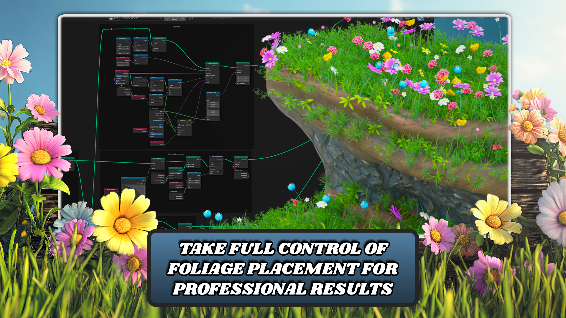
visually striking, but also full of personality. Once you master the basics, we'll take things further by daving into more
advanced techniques. You will learn to precisely
control foliage placement, whether that means adjusting for der and slope or
strategically placing flowers and i spots to create natural
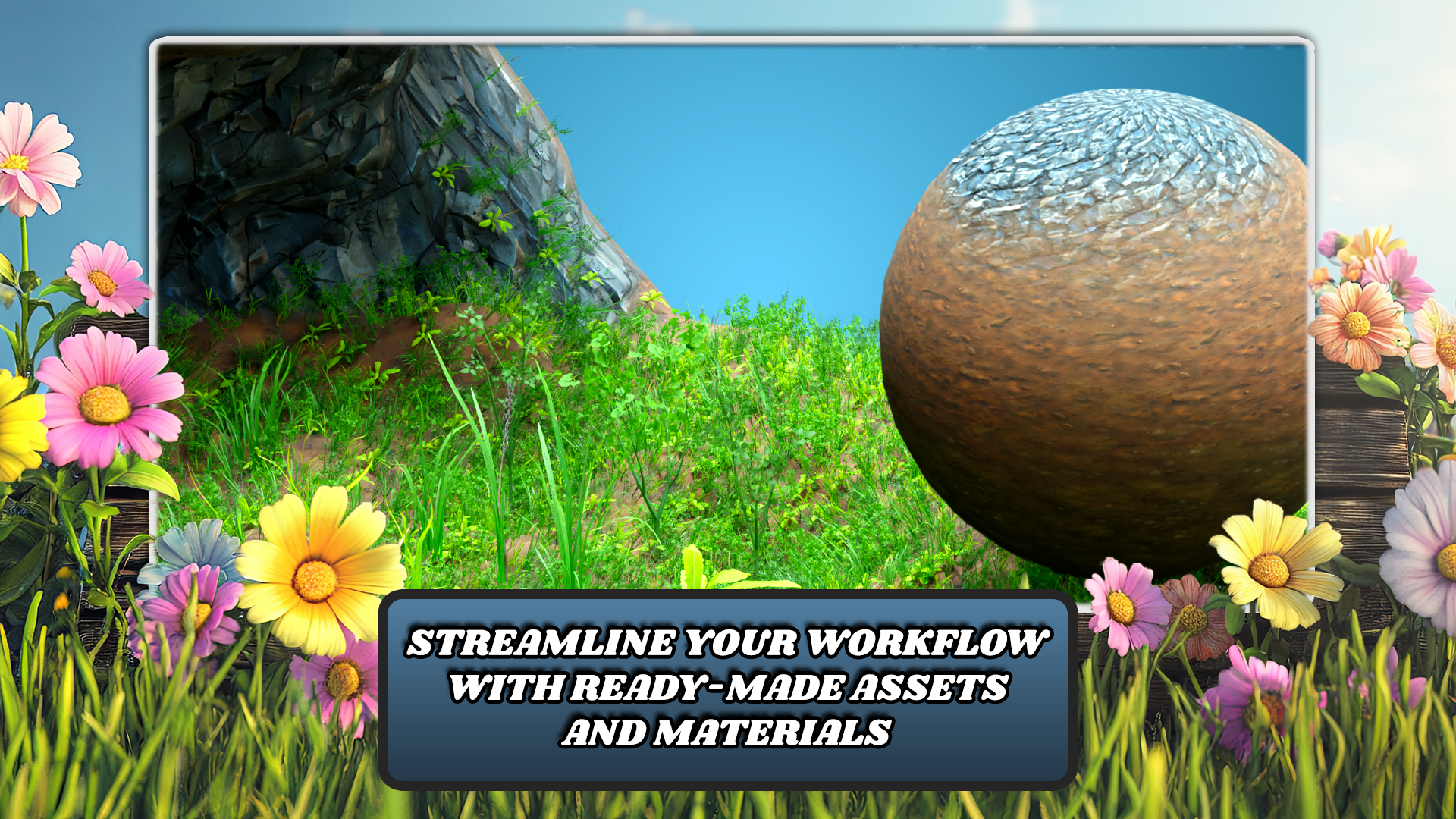
pliable environments. Efficiency is crucial,
which is why we packed this course with assets
that streamline war flow. From premade materials
to optimized s groups, you'll be able to
create professional quality scenes
quickly and easily, leaving more time for you
to unleash your creativity. When you finish this course, you'll be equipped
to create sunning vibrant landscapes that
captivate and inspire. What are you
designing worlds with a stylized aesthetic like
those in legend of Zelda? Or any other vibrant
virtual world. The skills you gain here will allow you to create environments that are both magical and
immersive. So don't wait. Enroll in the course today, and let's transform
your free D worlds with the power of
planes geometerals. Don't just dream about
mastering Planter. Take the lead and
make it reality. This course is your key to unlocking the full potential
of your creativity. Let's turn your passion into
truly amazing free D art.
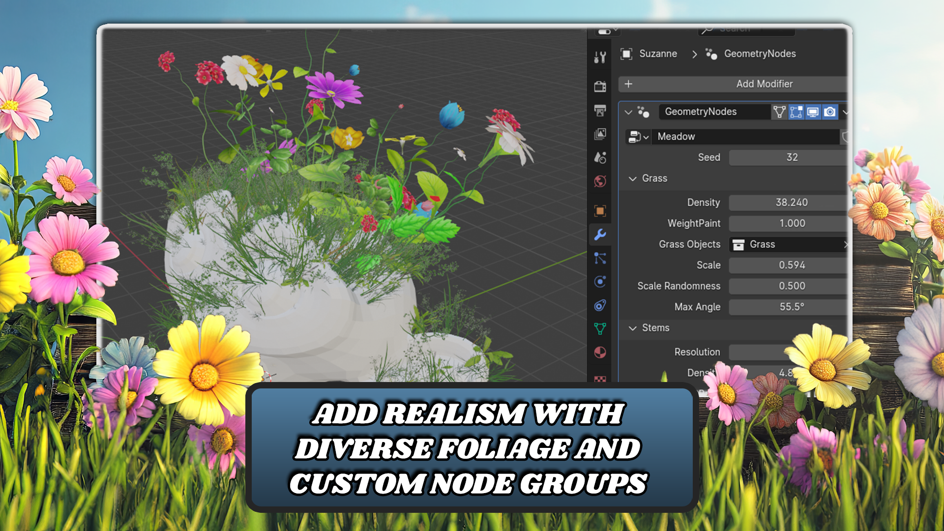
2. Introduction to Geometry Nodes: The next. Hi. In this lesson, you will learn the basics of
using geometernal modifiers. You will learn how to create a new geometeral modifier
and at a two object. Then how you can reuse this modifier and use
it on multiple objects. You will also learn how
to deal with user inputs, how to group these inputs and manage them inside the No three. At the end, I'll show
you some tips and tricks to speed
up your workflow. Here we have a fresh Bandersm. Now let's say we want to create a very simple geometernal setup, which will just change
location of our object. For this example, we can
just use default cube. Let's select it. Let's
go to modifier stop. And to a geometernal modifier, just add it just like you
would add any other modifiers. We just add modifier, and you can use this
search menu here and search for geometers.
Now to create a new one. We just hit this new button, and this will create a
new Geometernal setup, which is called geometers.
You can rename it. Let's name it location changer. Now our Geeteral setup is ready. To modify this setup, you need to go to
emerals work space, so I have one here, but you might not have
gemerals in your tab here. You can just click
this plus button and there is general
and Geometerals. Your work space might
look a little different, but you can tweak it as you like just like any other
work space in lender. Currently, our setup only
has these two nodes, which is group input
and group output, and you can see
that input geometry is connected directly
to group output. If I disconnect this, you can see that our
cube disappears. If I connect it
back, you can see that our cube appears again. Between these two nodes. You can do as many
operations as you need. You can add new geometry,
you can modify it, change locations or
rotations of all objects, and there are plenty of options you can do
with geometry nodes. One of the simplest things you can do is just
change the location. Let's actually see
how we can do this. To change location of object. There is a node called
transform geometry. You can find it in here in ad, geometry operations and
transform geometry. But it can be really
intimidating, trying to find the note
you are looking for. I recommend just using shift A, which will bring up this menu. Now you can start typing. You can just type transform, and this will bring our
transform geometry, you can hit enter, and we have the same node as we get
from this menu up here. Now you can just drag this
note onto this connection. Now, if we change, for example, translation, you can see that
the cube changes location. You can even change
rotation and scale, but for now, we will
only stick to location. To reset these values, you can hower over these
sockets and hit pack space, which will reset them to
their default values, but you can see that scale
has defaults to one, so you can just change
it to all ones, and rotation should be
fine with all zeros. Now we want to control
the translation from outside of the
geometer note setup. What we need is we need to control this vector
by this group input. The simplest way
to do it is just drag from this empty
socket to the translation, which will add a new
input to our group input. Now if we go back to
our original layout, you can see that we
have a new parameter here called translation, which has three
parameters for each axis, and you can see that
if I change this, it will change
location of our e. S. Also the default
values work here as well. If I hit space, it defaults to our value
which we had there before. Now let's go a little bit
deeper into the group inputs to manage all
the group inputs. You can hit n, which will bring
up this menu here. Here you can see that
we have two inputs. One is our geometry, which is our cube, and the second one is
this translation. If I click translation, you
can see that type is vector, and the default value
is 0.70 and zero. You can also set minimum
and maximum values, and also some other things which we will talk about later. To add a new input, you can just hit this plus icon. You can select if it's
input output or panel. For now, we will just use input. Let's call this rotation. We will set type
to vector as well. You can see that
here in group input, a new input appeared
in srotation, and we can plug it
into the rotation. Now if we go back to
our origin layout, you can see that we can also control our
rotation from here. You can see that
in this modifier, we don't have any units, and here in translation,
we have meters. To change that, you can
change this subtype, which in year in translation, it's translation, but there are other
things like direction, velocity, acceleration,
and so on. For the rotation, We
will use oil or angles. Now you can see that
we have angles here, which is much more
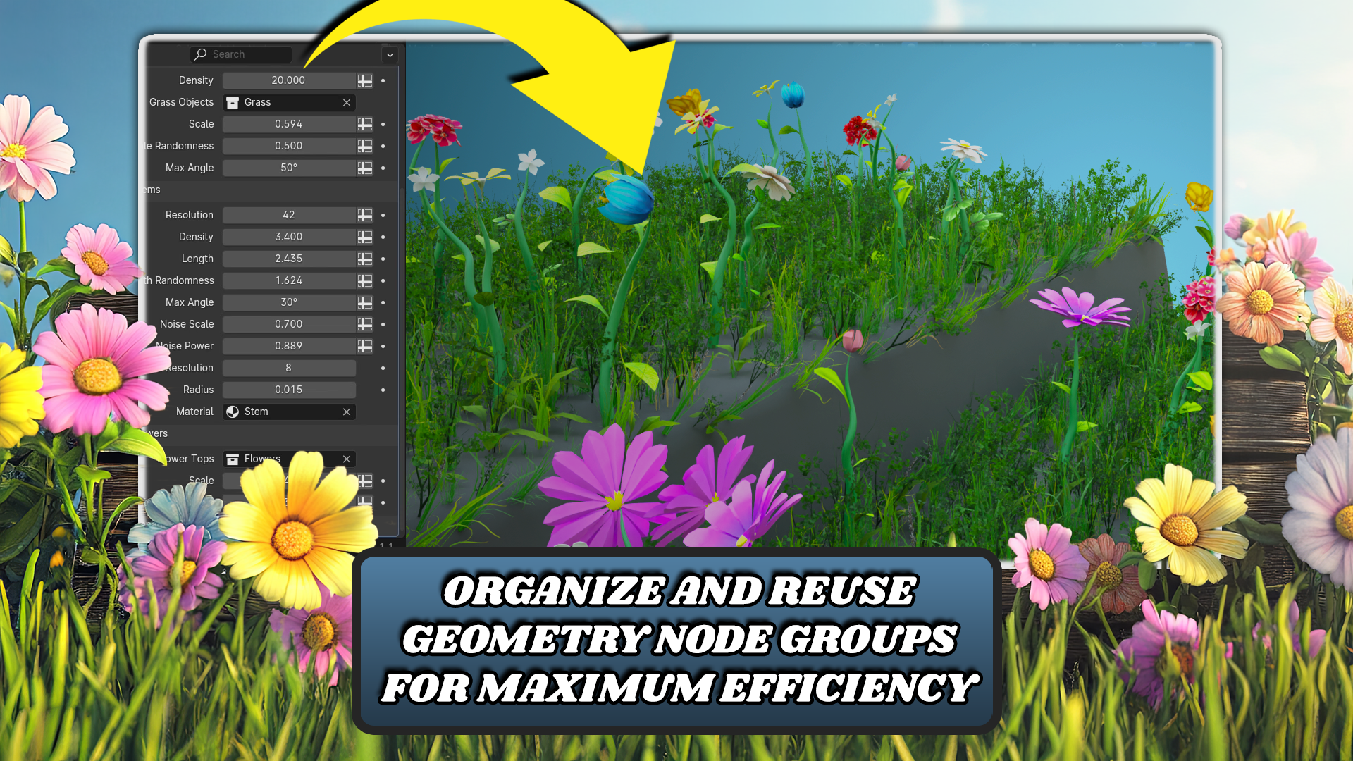
user friendly. Now imagine that your setup has more than just
these two inputs, but for example,
20, and you want to urge them to be
more user friendly. For that, we have panels. To add panel, you can just
hit plus and select panel. This will add a new
panel for us and we can call it for example,
transformation. And we can drag inputs into this panel just
by click and drag. I'll just drag translation
into this panel and also rotation after
translation circuit. You can see that I can
collapse this panel. Also here in our layout, I can make this a little shorter or just
hide these inputs. If you have a larger setup, this is a very good
practice to group similar inputs together to
make it more user friendly. Now let's actually try to apply this geometer modifier
to other objects. We will add a new object
simply with shift A, and for now, I'll use
Monkey, for example. And to add same geometer object, and to add the same
geom modifier, you can again add modifier
and select geometer nodes. But now instead of clicking, you can here select
our location changer. Now you can see that I can control this monkey the same way as I can control the cube. Those are the very basics of dealing with
geometernal setups. Now let's look into some tips and tricks to
speed up your work flow. There's a very nice
ad on for blender, which is called node wangular. You can install it by
going to edit preferences, ads, and now you can
search for node wang. I have enabled here. And all you need to do is just
to enable this checkbook. This ad on contains
many shortcuts and also new features for
node setups like this. Now I'll go through some
very basic shortcuts which you can use
throughout your journey. For example, if you hold
shift and right click, you can it dross this line. If you drag over the connection, it will add this little dot.
This is called rear out. With these rear outs, you can
make your connections much clearer and more visible. Now, if you have
some connections which you actually
don't want here, you can use Control
and right click, which will add or which
is basically a cut tool. If you cut connection, it will delete it. That's also very useful. If you have more geometries, which you want to join. If I would have two
geometries like this, I can join them with
joint geometry. Note. You can see that
this dot isn't just dot, it's val, which means it
can have multiple inputs. We can drag both of these
outputs to this one input. Now if we drag this here, nothing really happens
here in our scene. But if I translate this, you can see that we
have two cubes here. This is a thing you do
very often in enteral. To do this, you can actually
just hold control shift, right click your first node and then drag to the other node. If you release the moth button, you can see that it generates
this join geometry node, and we have the same
results as before. One last thing which
I already mentioned, but it's really simple
and if you'll really speed up your workflow is just adding your
nodes with shift A, and then just typing a name of note which
you are looking for. This is the workflow which I'll be using
for the whole curse. So, I really recommend
using this one. So, those are all tips and
tricks from me for now, and I hope you will
enjoy the course.
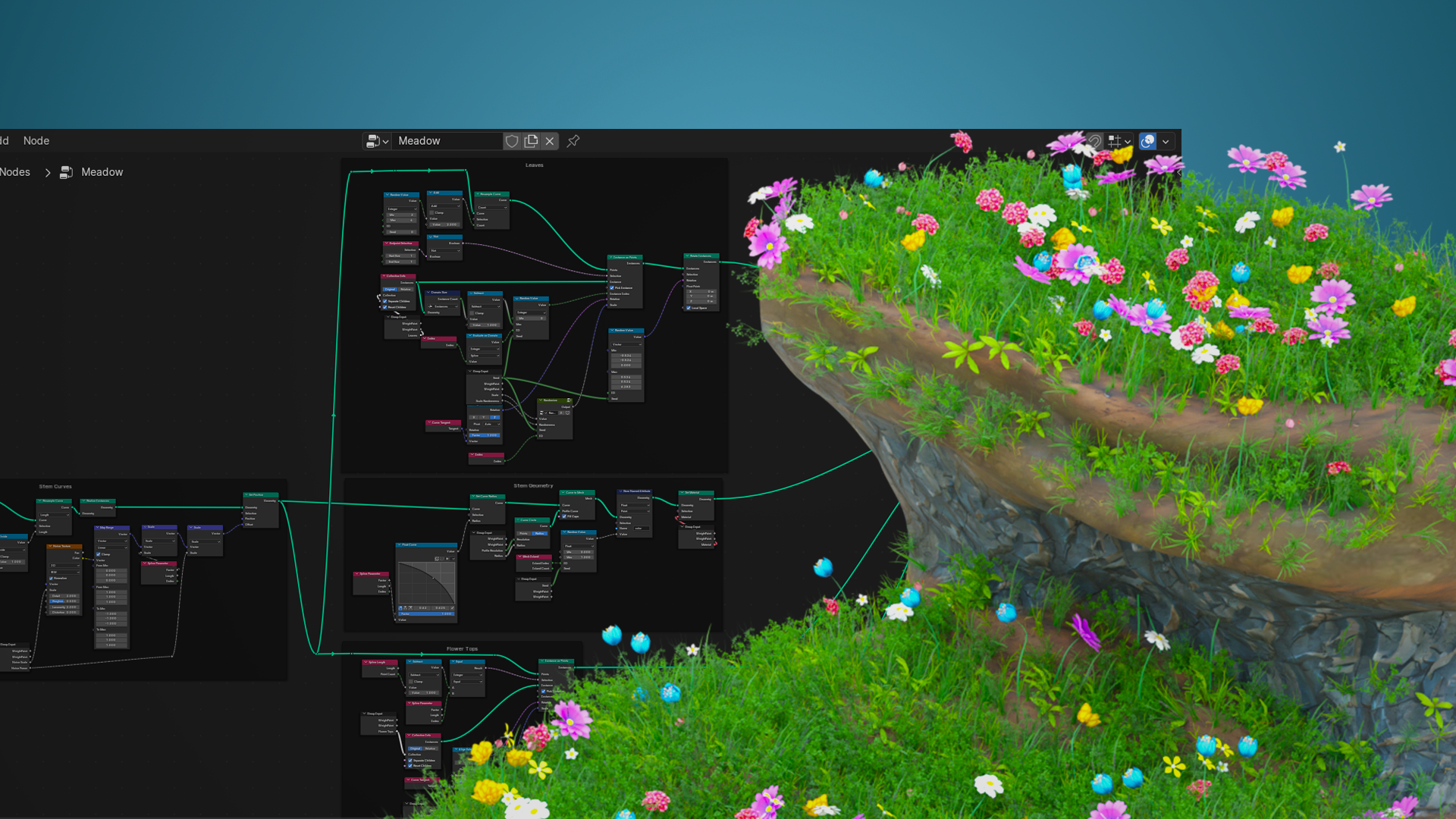
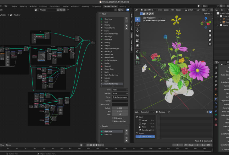
3. Grass Creation Point Distribution and Instancing: Hello, and welcome back to Blender Geometrts for
Beginners Folg Skater course. In this lesson, we will start working on Geometral
setup itself. The first thing we'll be working on is the grass
part of the setup. We'll start by a very
basic point distribution on the surface of our base mesh, and then we will use a bunch of grass objects to
replace these points. Here we have a fresh blender
scene, and as you can see, there's only a default cube, but I also have here some assets which we'll
be using for our setup. Here I have collection assets
with grass collection, leaves collection, and
flowers collection, and you will be able
to download this file, including all of these
assets so you can work with me and you don't have to worry
about any of these assets. This lesson, we'll be only using this grass collection so
we can hide leaves and flowers and we'll only use these objects to
create our grass part. First, let's actually create a pace mesh on which we'll
be testing our setup. I'll first delete everything
in our scene with A to select everything in
our scene and x to delete. Now I'll add monkey,
for example, subdivide it with control one, and position it so it
looks a little better. When I'm done with
positioning my monkey, I'll hit Control A, and
I'll apply all transforms. Now we can create our
geometric modifier. We'll go to modifier Stop. We can apply our subdivision, and we will add a new modifier, which will be geometries. We'll click new, and we can
re this set up to Mato. Now when our setup is ready, we can go to
geometries work space. First thing we need to do
is we need to actually distribute some points
on surface of our manky, and then we will use
our grass objects and replace those points
with these objects. For distributing
points on surface, there is actually a node called distribute
points on faces, which takes an
existing mesh and it generates randomly points
on faces of the mesh. If I hit shift A and search for distribute
points on faces, and it enter, you can see
that there's input for mesh, and it outputs a bunch of points. Let's
actually try this. I'll input my monkey to this distribute points on
faces and output these points. Now you can see that we still can somehow see the
shape of the monkey, but the base mesh disappeared, and now we have just a bunch of points on the surface
of our monkey. We can actually join join these points with
our original mesh. Now we can see both
of these objects. We can see the monkey and also the points on the surfaces. This node has a bunch
of more inputs. First, there is this drop down where you can select
random or Pason disc. If this is selected to random, it will just really randomly distribute
points on these faces. But if you select pasoon disc, you can see that there are
more inputs than before. There is this distance men, which if we increase it
to something like 0.2, you can see that we
have less points here, and I I increase it even more, there are even less points. What this value does is that it generates points in that
way that the distance between each two points
isn't less than this value. If we set this 20.4, we know that distance between these two points should
be more than 0.4. This is great for
some applications, but for now, we can stick
to the random type. Then there is selection
with which you can select which faces you would like to
distribute points on. There's also density, which basically controls the
density of the points. We'll be using this input. There's also at which is the sat for random number
generator inside this node. In our setup, we want to actually control both
of these inputs. We'll add these to
our group input. For that, we will hit
M and go to group tap. Because we are working on grass, we can create a new panel called grass and put everything
inside this panel. You can click plus panel
and rename it to grass. Now, we'll be putting
all parameters which are controlling
the grass to this panel. First, we will control density. Let's add input. This will automatically
create float input, which is what we want, and
we'll call it density. We can set a default value to ten and minimum value to zero. You can see that
here in group input, our density appear
in group input, and we can connect it
directly to this node. You can see that all of
the points disappeared, but that's because
if you look here, the density is set to zero, so we can hit back
space to reset it and our points are back. Now we will also want
to control the sat, but we want to have one parameter which will control seats of all random
number generators. Let's actually add
this seat input before the grass panel. I'll click this geometry
and add new input. Type will be in teacher, and we can collect sat. Now we can collect the
sat to seat of this node. Now, if I change the seat, you can see that points are distributed in a different
way than the other seat. I can also control density. Now when our points
are distributed. All we need to do is we need to replace these points
with our grass objects. For that, we need to somehow bring up collection
of our grass objects, and then for each point, we will choose one of these grass objects randomly and put it instead of the point. First, let's actually create
a new input in our panel. In this input, you will select your collection of
the grass objects. New input, type will be collection and we can
call it grass objects, and the default
collection can be grass. You need to keep in mind
that you always need to set these values here in
the modifier step. I'll select my grass
collection here. Now we can bring
up this collection with collection infra node. Collection infra
node, basically takes this white input and outputs basically all objects which are in this collection. We can hit shift A
and collection info. Or there's a little
quicker way to do this. You can how over this
white circle here. Click and drag like you want
to add a new connection, but release it in the air. And now you have a search menu and you can search
for collection info, and this will automatically
add a collection info and connect this socket to
the collection input, which is even quicker than adding this node
and connecting it. Now, if we view
output of this node, you can see that we have
all grass objects here. But what we actually want
is we want these objects to be in the zero of
the world origin. Let's actually separate these
children and reset those. Now you can see
that we have all of the grass objects here at 00. For the replacing the
points by these objects, we can actually use node
called instance on points, which if we look for, There
are two geometry inputs. There is first input for points, and then there is instance. Basically what it does, it takes a bunch of points and replaces each point
with this instance. Cool thing is that if you
input a bunch of instances here and check this
pick instance, it will randomly pick random
instance and use that one. Let's actually connect our
points to this node and also the instances and
check this big instance. Now, if we look at the
output of this node, you can see that we
have a lot of grass, but it actually looks like
this shape of our monkey, which looks like
it's in great way. If we go to our previous view, we can try decreasing
our density and you can see that it looks
actually pretty nice. The only problem I currently
see is that all of the grass objects are
aligned to the axis, just like our objects here. But what we want is if
I view this thing here, Basically, if we
have grass here, we want to point it
in this direction. If there is grass, let's say here on this point, we want it to point
in this direction. If it's even here, we want to point in this direction like from
the monkey actually. How we can actually do this? For this, there is
this rotation input, with which we can control
rotation of each instance. If I change this value here, you can see that the
objects are rotating. You can also see that
this distribute points on faces gives us more
than just the points, but it also gives us a normal, which is a vector
pointing outwards from the mesh for each point. There's also this rotation data, which should give us right
rotation data for the grass. If we try to connect
it to rotation, you can now see that
the grass objects are nicely aligned to the
mesh of the monkey. Let's actually join this
with our base mesh. I will delete this
connection and put this one. And you can see
that our monkey has growing grass on it,
which is pretty nice. This was really simple
way to do this, but I will also show you a little more
complex way of doing this because you might
learn something new. If there wouldn't be the rotation value
and only the normal, we can still use nodes to calculate
rotation for each cross. For that, there is the
align oiler to vector. Which has three inputs here. We don't need to
mess around with the vector now and we
will just keep it on one. But here we have a rotation
and vector inputs. Rotation can be vector, basically is a value of
rotation you currently have, and you want to
somehow tweak it. How we want to tweak
it is that you want to align one of these xs
to this input vector. Let's say our rotation is zero, so we don't need
to input anything, and we want to align z axis because you
can see that Here, the grass objects are
pointing upwards, which is z axis, and we want to
align those arrows to a normal of the point, which is for like this
one is this here. If it creates a grass, it has pointing z axis upwards, and we want to rotate it, so it's pointing this way. We will use this normal and plug it into
this input vector. Select our Z axis. Now if we use this rotation, we should get the same results as we get with this rotation. You can see that they
are slightly different, but it should only be
rotation around the z axis, there shouldn't be
a big difference. You can choose which
way you want to use. Probably the rotation
is just simpler, but, this is also
the way to do this. For now, I'll be using
this align aller vector because I'm used to it. I'll also clean up
this a little bit, so I'll add out
here and just make this connection clearer
and move this closer. Now, our grass is
looking pretty good. The only thing is that I think the grass is
a little bit big. The objects might be
a little smaller, but there is no way to actually control it in our setup.
We need to add that. For that, we can
control the scale here, which is scale of our
instance objects, and if I change this, we can see that I can control basically size of
my grass objects. What I actually want to do
is I want to be able to set scale of these objects and also randomize this
scale a little bit. For this, we'll create a simple node which
we'll reuse later, and it's called randomized node.
4. Randomizing Grass Instance Scale: Te. Welcome back to blender geometric nodes for
beginners Fool skater Cs. In this las ending,
you will learn how to create a randomized note, which we'll use on many
places of this cores. This example, we'll be
using randomized note to create random scale for
each of these nine cubes. Here I have a very
simple setup which just creates grid and on
each point of the grid, it will instance a cube. Here you can see
that we can control scale of these cubes, but for each cube, you want a random
scale in some range. First, let's actually
add a rear route. Okay. Just a simple reroute. Now hit Control G to
create node group. If you hit tab, you
will get out of this note group and
this node group, we will be reusing
throughout our course. We can rename this to randomize and hit tab
to go back into it. If I hit n, you can see that
we have output and input, which is currents set to color. What we will be outputting
is actually a float. Let's select float here. First, let's
actually get through how this setup will work. What we basically need
is we need to create a range between some two values and then generate
a random value in this range and output
it in this group input. There are many ways how
to select this range. What I like to do
is I like to set a middle of this range
and then the width of it. The middle input will
be called value. And the range can be called,
for example, randomness. Let's say for example, that
for our value input is 0.5. And randomness is 0.2. That means that we'll be generating random
value between 0.3, which is value minus
randomness and 0.7, which is value plus randomness. We'll pick a value
from this range and output it from
our non group. Let's add these two inputs
to our group input. You can hit n, and
First input will be called value and its
type will be flowed. And the second input will
be called randomness, and it will also be flowed. For generating random value, we will be using
random value node, which has two inputs,
minimum and maximum. We can control these
two values, as I said, The minimum is value minus so we'll use
subtract randomness. And put this into minimum and maximum will be value
plus randomness. I can show you a
nice trick how to speed up actually this workflow. You can see that we
have a math node, and we'll be also
adding a math node, but we just addition
instead of subtraction. We can just use control
shift D to duplicate this node with these inputs
and move it down here. We don't want to
subtra but at these, we will change subtract to at and we can connect output
of this addition to maximum. Now when our random
value is generated, we can just output it
to the group input. Now if I hit tab, you can see that I am outside of the node group and I am in
my starting node set up, and I can connect this
output to the scale. Currently, the scale is zero. We can't see anything,
but if I increase this, you can see that we can
control scale of these cubes, and if I sit randomness, you can see that
scales of cubes are changing and they have
very different sizes. The problem is that we actually can change the sat of this. Let's add seed input to
this randomized node group. We can just drag this
empty socket to the sat, which will add our sat control, and now we can control
it from outside. Also sometimes the thing which
can happen is that all of the objects will have same
value t rated with this setup, and to differentiate
between these objects, we can also use this ID socket, which basically takes
some identifier for each object and it basically
works like another st, but for each object separately. In this setup, each
cube has different IDs, this is working correctly, but sometimes it doesn't
have to work nicely. To make sure we
can control this, we will also plug ID
into the group input. Now you can actually see that
our cubes have same size, which means that ID
for each cube is same. To differentiate, we
can, for example, plug a index here, which is index of each cube, and now it's working
correctly again. Now we have this
nice randomized, which has just like two
parameters we need to control, so we can just plug these parameters
into our group input if we have a larger setup, and it's very simple to create randomized
values in some range.
5. Controlling Grass Placement with Max Angle: Hi, I welcome back to Blender Geometri nodes for
Beginners Folig Scaler cars. In previous lessons, we made a very basic
point distribution with instancing and also
created a randomized node, which we will now use for scaling our grass
objects random. Next, we will add a
parameter to our setup, which will control the
maximum steepness of the mesh on which
grass generates. If the mesh is steeper
than our value, the grass won't generate
at these places anymore. First thing we will do
is we will actually use our randomized node to scale these graphs
objects randomly. If you made this set up
in a different file, it's not a really big problem. You can just go to file append find your file
with randomized node. And now go to Node stree
and select your randomize. Now, if you go to
geometric node work space, you can now search for
randomize and you should have your node group here. Let's actually use
our randomized node. I'll use shift A and
search for andomize, and bring in my
randomized note group. There are a few parameters. At first, we can
connect output to our scale of instances, and now we will be
controlling these values. You can see that
if f change value, it changes the scale of the grass objects and
the f change randomness. You can see that some
of the objects are getting smaller and some of
them are getting larger. I can maybe decrease
the density, so we can see it better. Those are the two inputs
which we want to be able to use or control from
outside Onal group, Let's actually hit n
to bring up this menu, and we will add two parameters. First one will be scale, and the second one will
be scale randomness. We can also set default values. For scale, default can be one, and scale randomness
can be zero. Now all we need to do
is we need to connect these group inputs to this
randomized node group. I'll bring up new group input. And connect my scale to scale
randomness to randomness. Also we can forget to connect our s to st of our randomize no. Also we will use this ID circuit to which we will connect
index index value. This will cause that
for each instance, there's a unique index, each instance will have a
different random value. Now, if we reset those values and set a scale randomness to
something like 0.5, you can see that
the grass objects are randomly scaled around one. The next thing we'll be
working on is adding a maximum angle on which
grass de generates. Basically how we will control this generation is that here we distribute
points on faces, we are generating a bunch of points on top of the our monkey, and we will delete some of them, which we don't actually want to use for our grass objects. For that, we will add a delete node between
these two connections. Shift A and search
for delete geometry, and we can put it
over this connection. Now you can see that all
of our points are deleted, but we will control it
with this selection socket and we will only delete some of the points which we
don't want to use. The idea behind this
effect is that we have some surface and we
have points on it. Let's say, these
xs are my points, and each of these points
have its own normal, which is this socket right here. I'll draw something like normal. Let's say Let's say these
vectors are my normals. What I want to do is I don't want here these
points, for example, because this surface
is too steep, so the grass might
not grow here. I want to delete these
points, but not these. How can you actually do this? For this, we will just use this normal value
and compare it with With arrow pointing upwards, which is basically the z axis. If we put, let's say this normal side by
side with z axis, there's a way to calculate angle between
these two vectors. We can say that if this vector
is larger than some value, we will delete these points. There are many ways
how to calculate this angle Alpha
between two vectors, but I'll use the simplest
pan in my opinion. The equation says that
cosine of our angle Alpha is the product of these two vectors divided by
multiplication of lengths. Basically, it's
something like this. Let's say our z x vector
is A and our normal is B. It's going to be the product of these vectors divided
by length of A, multiply by length of B. Because this is cosine of Alpha, we need to do cosccine
of this part. It's basically coscsine of the product divided
by their lengths. Now all we need to do
is we need to recreate this expression inside
blender using geometerals. To make this node tree cleaner, we will actually create
a new node group, which will calculate angle
between two vectors. We can use the same approach as we did when creating
randomized node. We can add a new readout
and hit Control G, and this will create
our new node group. We can hit n to change
our inputs and outputs. Our output will be flow value, and subtype can be angle because it will be angle
between these two vectors, and there will be two inputs,
which will be vectors, so we can rename this two
A and type will be vector. Now we can just duplicate
this and rename it two B. That's looking. Now let's
just do this expression. First, we will do a dot
product of these two vectors. I can create connection from
A and then search for dot, which will bring up that product and I can connect vector B. Now we need multiplication
of lengths of these vectors. I can use the same technique, but instead of dot
I write length, and Iuplicate this
and connect B to it. Now we'll just multiply
these two values. And divide the product
by this multiplication. I'll add divide and connect
this multiplication. You can see that
I'm basically going from inside of the
expression to outside. First, I made this
part and this part. Then I did the whole division, and now I'm going to
do this whole part. I'll just do arc cosine, so I can again create a new correction and
write arc cosine. And this will be output
of my group output, so I can connect this value to output and delete this out. That's looking pretty
good and now we can test our node group. You can hit tab to go outside of this node group and we can
rename this to angle between, for example, now we will
use this node to find out if each point is on steeper surface
than we actually want. I'll create a little
bit of space here. Now we'll be calculating
angle between vector zero, 01 and normal of each point,
which is this socket. Now, if this is greater, so I'll add greater if this is greater than some
value, I will delete it. Let's say I'll put
here Pi over four, which is 45 degrees. If it's steeper than 45 degrees, the result will be one and
it will delete the point. Now you can see that
when I plug this into the geometry into
the geometry node, you can see that
only grass on top of the monkey remained here and grass from the
sides was deleted. If I increase this angle, you can see that the grass
starts growing on the sides. If it's larger than
Pi, basically, these points here
down there should have the angle around Pi, which is 180 degrees. If it's larger than one Pi, it should grow everywhere. This is the value we want to be able to control from outside. Again, we will create
a new group input. I'll create a new input and
we can call it Mx angle. Type will be flowed and
subtype will be angle. We can set default to
something like Pi over four, which look pretty good, and minimum can be zero
and maximum can be Pi. I think I can also
delete this expression, so we don't need this anymore. Now if we go to our layout. I also forget to actually connect my group input to
this straighter than node. Make this quickly,
you can actually just create connection from this
B or basically to this B. Now if you write a name
of your group input, which is in my case Mx angle, you can connect this group
input straight to this node, and you can see that it created a group input with just
one of these outputs. Now let's increase my max angle. You can see that the grass
slowly starts growing on top of the monkey and it goes
to the sides slowly. Now where we have our next
angle feature ready for use. Last thing we will do
in this lesson is that we will combine all of these nodes into one
node group because we'll be reusing this little
setup for the flowers, and we want to be able to set different parameters to
our flowers and our grass. That's why we'll be using two instances of
this node group, which we will now create. I'll move this up
because we won't be grouping these parts
to our node group. Also great practice when
creating a node group and using group input is to always use just one
of these group inputs. Because if I would group
these nodes like this, I will just box select them
with my mouse and hit Control G. You can see that Now if
I go outside node group, some of the inputs. For example, the sat
is duplicated here, and that's not what we
want, so I'll undo this. What we need now is to use just one group input and
then group this setup. For this, I think I'll
just use this group input, I'll connect Mx angle
instead of this max angle. Then we will connect this scale instead of this scale and skill
randomness as well. The last thing which
is here is this sat. I will connect this
sat to this one. Now you can see that
this group input doesn't have any used perimeters,
so we can delete it. Now great way to make the note or cleaner is to
use reroutes to make it. You can use shift right click drag over
these connections, and then just move them so they are not
touching anything else. I'll use a bunch of these re
roads to make this nicer. Now I think this part
looks pretty nice, so I can select all
of these nodes, including the re roads
and hit Control G, which will create this
relatively nice note group. If I go outside of the
None group with tab, you can see that there's just one group input connected to the sn group
and it's looking nice. Now we can move these node here. Last thing is that
we will rename this node group and we can
use it and we can call it, for example, my
distribute points, or you can name it
wherever you like. Also, you can see that some of these inputs
aren't named correctly, so we will fix this quickly. You can see that density
collection is okay, but there are four inputs now. We can remember that
it's scale handomness, sat and max angle,
we'll just reams. I'll also move up, it's the first perimeter. Now I think it's looking great.
6. Creating Stems Curves and Placement on Mesh: Hey, there. Welcome back to Blender Geometrodes for
beginners Folly scatter course. In this lesson, we will start working on the flowers objects, which will be scattered
on top of the grass. For this part, we will use a very similar approach as we
used for the grass objects. But instead of using
existing objects, we will create our own curves, and then instance tops of the flowers and their
leaves on these curves. In previous lesson, we created this distribute
points node group, which we can now reuse
for generating our stems. How this will work is that
we will basically generate again a bunch of points on
the surface of our object. Then we will replace each
point with a curve line, which will be randomly scaled. It will look
something like this. Then we will
resemble this curve, so it has more
geometry to work with. Use noise to displace
these points. It will be a little
bit more natural. Then we will place
flower objects on top of these and also some
leaves along the curves. First thing we need
to do is we need to generate a bunch of curve
lines on top of the monkey. For this, we can use
our distribute points. You can use shift D
to duplicate this. Now we need to create
a bunch of new group inputs to control this setup. You can hit n to
bring up this menu. For this part, we will
create a new panel, which will be called flowers. Some of the inputs
will be the same, so we can duplicate
this group input and we'll be generating flowers on the same mesh as we are
generating our grass, the geometry will be the same. We might be able to use the
same seed for this one, but this can lead to generating flowers on the
same spots as the grass, which is something we
don't actually want. We need to somehow
tweak the seed, so it's not the same
as our original seed. For that, I like to
use multiply at node, which basically
multiplies this value and adds a random value to it. You can for example, multiply it by 42 and add 42. The only value where
this can be same is zero because zero times
anything is still zero. But when we add 42, it will result in 42, this should give us a nice sat, which will be different
than our original sat. We can connect value to the sat. Now we will be creating a
new group inputs because density of our flowers might be different from
density of our grass. Let's add a new input. We will call it density type is flowed and we can
set default two, for example, maybe
five will be great. You can see that there is a
new density in a group input. It can be a little bit confusing because now there are
two density inputs. But if you look at
our group input, you can see the first
density belongs to grass and second density
belongs to flowers. We will use this second density. For now, we'll remain collection empty and we will do that later. Then there is scale scale
randomness and nex angle. Instead of scale, we can call these inputs length
and length randomness. I'll add two of those
new barometers, length can be by default one, minimum zero, and
length randomness can be default to
something like 0.2. And we can again
connect these inputs to scale and scale randomness. The last one is Mx angle. For this, we can just duplicate this value and move it
to our flowers panel. Now I'll just reconnect this
max angle to this mix angle. Now if we output this node, it doesn't generate anything because our collection is empty. The problem is that
this node group needs a collection from which it will pick a random object and
use it as an instance. But we don't have
any collection, so we need to go around
this a little bit. I'll go into this
node group with tab. And we will change
this a little bit. Instead of collection, it will
use instances or objects, and for the grass object, we will move this
collection info outside of this node group. I'll remove this collection info with out and left
post patent drug, and now collect the collection
straight into instances. You can see that this gets read, but that's because this
is type of collection, and this needs a object. We will hit n and change type of this collection to
object or geometries. And also rename
it two instances. Now Ile hit tap to get outside of this node group
and you can see that this connection is now
red because there is collection and it
needs instances. So let collection info. Connect this collection
to this socket and now output of this collection
info back to my node group. Now if I output this, you can see that
it's at bit weird, and that's because we didn't separate and sit our children, and, you can keep
this on original. Now it's working as before. H Now when our node group
needs only instances, this is something we are able to create inside geometry nodes. An object which we will be instancing will be basically
just a curve line, so let's add curve line. Now if I look at
this curve line, it just creates this little
line which has length of one. But that's fine
for now and we can plug this curve straight
into instances. Now if we output this, we still can't see anything. That's because our parameters here aren't set to
anything reasonable. Also, you can see that here is a little error in
this node group. That's because when
this is picked, it needs actually a
bunch of instances and when this is
working correctly. One way would be to connect the pick instances
to group input, but we should be
able to make a bunch of instances from
this one curve line with geometry two instances. If we connect this curve
two geometer instances and now this two instances, this is basically a collection containing only one object. It thinks that it's collection, but it's actually just
one curve object. But you can see that now
it's working nicely and we can continue working
on the setup.
7. Generating Flower Stems Using Curves: Welcome back. Let's
continue with blender geometries for
beginners, fully scale course. I will also beat the
values a little bit, so you can see that we can
control the length and the randomness and also again Mx angle on
which it's generated. I think I will bring density down a bit to
something like one. We have just a few flowers. Now let's continue
with the stems. The next thing I
said we will need to do is we need to
resemble these curves, which will basically add
more geometry to them. Currently, each curve is constructed only
from two points, and we want to make a
shape something like this, which needs a lot more
points to make it smooth. For this thing, there
is a node called resemble node. Resemble curve. Which has few inputs. One of them is curve input to which we will
connect our curves. Then there is selection. We don't need to
worry about that now, and then there is count, which is basically to how many points you want
to resemble this curve. Let's say if I would plug this curve into this
node with count five, it will create a curve with five points evenly
distributed along the curve. There are also other
options like length, which sets a distance
between points on the curve. If this is 20.1, and
the curve, for example, 1 meter long, it will create a ten points which are
evenly distributed. Imagine this is ten points, and distance between each
two points is 0.1 meters. This is great way if you don't know how long the
curve is and you want same resolution on
different length of curves. This is great to use. We'll be also using this length option because flowers have different lengths, and we want them to
have same resolution. Let's use this option. To check from how many points
our curves are constructed. You can, for example, go to
we can add a spreadsheet. I'll bring a new window and change its type
to spreadsheet. You can see those
are just instances. But if we realize instances, you can see that
currently are feints constructed from 154 points. If I increase the line, you can see that number of
control points is decreased. What this realized
instances note basically does is that after using
instance on points, which is used here
in this note group, each instance is treated like a single object and we can't
access its points basically. But if we realize
these instances, the whole group of the
instances is changed to one large object
with many points, and we can control its
individual points. That's why we can actually see number of
control points here. Now we want to be able to control resolution
of these curves, so we can set how smooth
they basically are. We'll be controlling
this length input. It's a little bit hard for users to understand
these values. I like to create a little calculations to
make it more user friendly. For controlling this length, we will add a new parameter, which will be called resolution. Is type will be integer. I'll move it up here
and default can be something like ten and
minimum 22, for example. What I like to do is we can plug this directly
into the length because resolution normally
works that if it's lower v, let's make this line. Let's say this is resolution. When it's low, basically
there should be a less points then when
it's something higher. But if you would put it
straight to the length, you can see that if
I set it to 0.07, there are 210 points, and if I put it to 0.2, there are only 84
points or something. Basically there's less points, so it's lower resolution
when I increase the length. We need to invert this What I like to do is I
like to take divide. Let's add Mth node and
set this two division, and we will divide one
by our resolution. If the resolution is one, output of this will be one, if the resolution is ten, output will be 0.1. If we increase the resolution, the distances between points on the curves will
get smaller and we will get more points
and more geometry. I'll set this resolution to ten, and now we should be able to control resolution of our stems. We still can't actually
see the resolution. Now I'll finally move to
the part where you will be able to see how the resolution
is actually working. Now we will be basically
displacing our points, so it has more natural shape. For that, we will
be two main nodes. One of them is set position, which has this geometry input, which is the geometry
we want to dip. Then there is this There are
basically two vector inputs. The first is position, which where you can input
exact position, you want to put each 0.2, and there's also offset, which will just move the
points from current position. That's also the socket
we'll be using. Let's connect our curves
to this germaput. Now if I output
this set position. You can see that if
I change the offset, it will move the curves. Together because each
curve has same input. But when displacing them, each point will have a
slightly different value this offset and it will
create a nice natural shape. To add this nice noise, we will add a noise texture, which will give us
these random values which are basically continuous, it will create nice shapes. This noise texture has
this color output, which is basically a
vector with values 0-1. Basically, output of
this noise texture will give us random color, which if we take two vector space is
basically random vector in this cube because each
axis can be only 021. It's 021 on x, 021 on y, and 0212 set. Basically it will pick a
random point inside this cube. Currently, when we
have straight curves, we want to displace
those points to all of the directions and not only
basically this one direction, we want to be able to displace
them in all directions. What we need to do is we
need to tweak this value. The random value which
we will get from cube, from the noise texture, will basically also include
all of these values. It will go into
all directions and displace them nicely
in different shapes. To tweak this color output, we can use map range, which will basically
remap values of this color circuit
to something different. Currently, we have values 0-1, so these vectors
are set correctly. At minimum it's all zeros
and at maximum, it's ones, and we want to remap it to
negative ones, two ones, which will basically
transform our small cube to larger cube with all directions with
also negative values. Now if we plug this
vector to our offset, also, I will unhide my monkey. You can see by disconnect
and connect this, you can see that our
lines are displaced. At this point, they are
a little bit jacked, but we will tweak this
to make it nicer. First thing we can do is we can decrease scale of the noise, which will make it smoother. Now you can see that they
are nicely displaced. If it's something like 0.6, And we should be also able to control power of this
noise or displacement. We can scale this vector by some value and change its power. I'll at scale and
connect it to offset. Now when it's one,
it's still same, but we can increase
it by increasing the scale value or decrease
it by making it smaller. Now you can see that there
will be a little bit problem. I I Also display my monkey
and not my grass for now. If I scaled noise, you can see that stems can fly away from their original
position because of the noise. For example, this stem
started here on the nose, but if I increase
the noise power, it will fly somewhere else where it's not
something we want. To fix these issues. We'll be also scaling or multiplying this
noise by some number, and what we actually
want is we want to have noise here at the
roots have zero power, and here at the top, it
can have 100% power, which should result in that the roots remain
in the same positions, and then it will gradually make larger displacements
along the curves. To make this possible, we
need to somehow find out which points on the curves are here at the roots and
which are here at the top. For that, we have a nice
node which will tell us almost this thing and
it's called splan parameter. This plane parameter, we can
visualize this with viewer. You can see that this
factor basically gives us zero here at the start
and one at the end. There's also length, which
gives us very similar values. But instead of for which is 0-1, this will give us length
from the start of the curve. If this curve would
be, for example, 2 meters long, here at
the end, it would be two. In the half, it will be
one and at the start, it will be still zero. There's also index, which
will give us index of point on one given spine. But for now, we'll
be using defector. What we can basically
do is we can just plug this factor
straight into the scale, which will result in
that here at the bottom, the scale for the
noise will be zero, and here at the top,
it will be one. We can try that. And
you can see that our stems are displaced a
little bit more nicely. But now we lost the ability to control
power of the noise. But we can fix it very simply
by adding another scale. You can duplicate
this one and then just connected after
the first one. Now if I change the scale, you can see that roots of the stems are remaining
at the same position, but the rest is
displaced pretty nicely. Now we have a very
nice foundation for the shape of the stems, but we should add some
parameters to make the user able to actually
control these values. The simplest way to control this setup is to actually
expose this scale value, which will control noise power, and also scale of
the noise texture, which will control how
smooth the displacement is. We can hit n to
bring up our menu, and we will add two new inputs. One of them will be noise scale, and we can default to
something like 0.4, and the other one
will be noise power, which can be default to one. Now we can bring up our
group input and connect noise scale to this scale and noise power to
this scale node. I'll also make
this little nicer. As you can see, our group inputs are getting longer and longer. There is a nice shortcut
if you hit control H, you can hide unused sockets. There will only remain our
sockets which we are using, and you can also undo
it by again hitting control H. Now if
we go to our setup, and reset these, you
can see that we can control power of minise
and also its scale. If it's something
closer to zero, the displacement will
be much smoother. I fit something like 0.7, you can see that displacement
is pretty smooth. If I increase it to
something larger, you can see that
it's very jacked. But we can actually fix this with increasing of resolution. You can see that
if I increase it, there are more and more points. But in my opinion, it's better
to keep noise scale lower. Now maybe even lower
to something like 0.7, and now it's looking
pretty nice in my opinion. We can also tweak our
length randomness. Some of the flowers are much smaller and some of
them are taller. Maybe something like
this looks nice. Now we have a nice
foundation for our stems.
8. Mesh Conversion and Material Setup for Stems: Hello, and welcome back to Blender Geometri notes for
beginners Folig Skater Course. In this lesson, we will create an actual geometry from curves, which we made in
previous lesson, and also create a
simple material, which will have a different
shade of green for each stem. To generate mesh
from our curves, there is a very simple node, which is called curve mesh. And this node has two inputs and one checkbox and one output. The first input is
this curve input, which will be our curves. Then there is profile
curve, which is curve, which is basically sweep
along our base curve. If, for example, if the
curve would be a line, and profile would be circle. This node will generate
something like this. It will sweep the
circle along the curve. And we will have some
curved cylinder. As a profile, we'll be
using curve circle, so we can add that we
shift a and searching for curve circle and
curve will be our curves. Let's plug it in. And if I connect output of this
node to group output, you can see that it generated
bunch of weird cylinders. Currently, all of
them are very thick because radius of the
curve circle is 1 meter, so we can decrease it and now
it's looking much better. Also, we can see that if
we check this fill caps, it will fill these endpoints of our curves and
make them solid mesh. This looks pretty nice, but a better thing would be if the stems would be thicker at the start
and thinner at the end. The first thing you
might want to do is to use something like
sprain parameter, this factor and connect
it right to the radius. At the start, it would be zero, and at the end, it will be one, and we will just remap it. But if you try it, there will be this
spread connection, and that's because
this radius is constant and we can change
it for different points. Luckily, there is the
other way how to do this, and that's using curve radius. To change curve radius. There is a node called
set curve radius. Here we input our curve
and set its radius. Here you can see that there is a square socket and no circle, which means that we can actually change it for different points. Let's connect it to our setup. Now the radius is very small. I'll set it to one for now. Now if I connect
my spine parameter to this radius socket, you can see that our stems are thin at the
start and thick at the end. We want this the other way. There are few ways how
to do this, but for now, I will choose float curve
because we didn't use this and you will get more control
over using other ways. Let's add float curve. This f curve has two inputs. First one is factor,
we'll keep this on one, and the second one is value. Value is number which we
want to basically remap. We'll connect our
factor to value. Now if we plug output of
this node two radius, this should remain the same
because here it's constant. But if we change
this a little bit, you can see that they are more thin and then it's quickly
going to thicker radius. Or if we do this, you
can see that it's thin and it's
thicker much quicker or you can basically control
the shape of the radius. One thing we can also do is
to swap these control points. If I put this to
one and this 20, you can see that now the stem is thick at the start
and thin at the end, and we can also play around with this
third control point, and you can add as many
control points as you want. Now our stems have radius
or much better shape, and we can also control radius
with this radius socket. And the other parameter which curve circle has
is this resolution. If I go to wire frame mode, you can see that this has
a pretty big resolution, which is basically
from how many points the curve circle is constructed,
and if I decrease it, you can see that it's more
low p. For the stems, because those are
usually very thin, we can keep this
on lower number, something like eight or even three might be possible because if you look
from further distance, you can see much difference. Those are the two parameters which we would like to control, Let's hit n, and we will
add it to our group input. First thing I'll add
is profile resolution, which will be integer. Default can be set to eight, minimum to three, and maximum
can be this big number. The second one is profile radius or we can just
keep it on radius, and default can be 0.05, for example, and
minimum will be zero. Now we just need to connect these two new inputs
to the crave circle. Let's do that. And we can also hide une
circds with control H. Now our stems disappeared, but that's because we
didn't set any values here, so let's reset these two defold, and you can see that
we have nice stems. Now, if we connect
this to our monkey, you can see that this is
still a little bit thick. I'll set it 2.0 15, let's say. We can also increase density, and I think this is
looking pretty nice. The next thing we'll be
working on is adding material to these stems
because currently they don't have any
material and they are just this white default material,
so we will change that. First, let's actually add
group input to this material, so we'll add a new input
and set type two material, and we can just
call it material. And we want to set
material of these stems. We will add a set material node, which will basically just assign this material to this mesh. We'll connect it and connect
it to our joint geometry. As a material, we will pick our material from group input. We can duplicate this
group input and just connect this material to
this material socket. Now if we go back to our layout, we can create a new material. You can go to this
material tab and hit new, and we can call it, for example, stem and set base
color to just some green. Now if we sucked our monkey
and set our material to stem, You can see that our
monkey is also green. That's because I made this material on the monkey
and that's default material, which is it assigned
to monkey mesh. I'll also create a separate
material for monkey, which can be just this white
material and assign it. Now you can see that
we can actually control color of our stems. But one thing we
would like to add is that each stem would have a slightly different
shade of green. There are a bunch of
ways to make this, and the approach where we
will be using is we will first create a random color
inside geometry nodes, store it inside the mesh, and then use it in shader. So for storing some
values inside the mesh, those are basically
called attributes. For storing attributes, there is store named attribute note, which will do exactly
what we are looking for. This node has few inputs. One of them is geometry on which we want to store some data. We will connect this
geometry input and output. Then there is
selection. We'll be storing this to all points, so we don't have to use this. Then the name,
which is basically name of the variable
or attribute. So we can call it color, and then there is the value. The approach I'll be using is I'll store random value 0-1, and then use it in the shader. To create a random value, we can use random value node. By default, it's 0-1, so that's what we want, and we can plug this value
into this value. Now, if we go to Shader, so we can go to
our stem material. We can use this color attribute. To add this attribute,
you can add attribute node, which
looks like this. Here you need to input
name of your attribute. We named it color,
let's add it to color. Now if we output this
factor to the surface, you will see that the stems have different shades
of black and white. That's because here,
in the geometers, we stored this random
value for each point, which means that each point
has a different random value, and that's because the
stems looks like this. The problem is that we want
for each stem only one color, so we can fix this by
using this ID circuit. To differentiate between stems, there is a value which
is from Mesha islands. We can add this mesh island
and this gives us two values. One of them is island index, and one of them is island count. This island is basically
a piece of mesh, which isn't connected
to anything else. Because these stems are
basically like islands, each of them has
different index. If we connect this index to ID, you can see that each stem has now a different
shade of gray, and we can use this further
for changing the color. We can also connect the
st to our group input. Let's also add group input and connect sat to
this random value. Now we can go to
Shader and change the color depending
on this value. Let's go to shading workspace, and to blend between two colors, there are again, many
ways to do this. But what I like to do, I
like to use color ramp, which is basically
the color ramp where you input a value 0-1, and it will interpoate
between these colors. If I leave this on
zero and output this, All of the stems are black, but if I change factor to one, you can see that they are white. Instead of using this manually, we can plug our color
attribute to this factor. Now you can see that they
are again white or black. But the nice feature is that we can actually
change these colors, so we can use one
shade of green, and then a different
shade of green. You can see that now
it's interplating between these two green colors. If we look closely, each of them has slightly
different shade of green. Also to make this a little
better with shading, we can use this principle BSDF, plug our color to base color, and then output this
BSDF to surface. I think this is
looking pretty nice, and we can also control
the seed, for example, which also changes the
generation of our flowers, and you can see that they
have nice shades of green.
9. Spawning Flower Petals on Top of Stems: Welcome back to
Blender Geometri nodes for beginners Folkter cars. And this lesson, we will add
flower tops to the stems, which we finished
in previous lesson. Before we start, I
would like to clean up this note tree and organize it a little bit because
it's always better to keep your nose
trees organized. So if you want to change something in the
note tree in the future, it's much easier to
orient in your nose tree. So we're going to
organize it with frames because that makes a
notary pretty readable. First thing I will frame
is this part here, where if I o, this is
our grass objects. So To frame this, you can select all of these
nodes with left most button, and then just hit Control J, which will create a frame
around these nodes. We can also rename this frame. You can hit F two and name it, for example, grass objects
or maybe just grass. Also, you can side there
is this redo which outputs our input geometry, and that's on grass so
I'll just delete this and put this before
the joint geometry. After we finish this.
Then in this part, we are creating our stem curves. I'll move this a little
bit to the side, and again, hit Control J
and call this stem curves. In this part, we are creating
a mesh from our stems. Again, I'll frame this and
call this stem geometry. Now we can combine these parts together with
this joint geometry. I'll connect grass to this joint geometry and now
we have everything together. Last part which is
missing is our base math. I'll add group input and connect our geometry
to this joint geometry. Now there is the monkey as well. I'll also tweak
the grass ale bit, so it's a little smaller and
I can increase the density. Now when my setup is tweaked, I can start working
on the flowers. In this lesson, we will finally use the rest of our assets, which are the leaves here
and also the flower tops. As I previously
said, for each stem, we'll pick one of
these flower tops and put them here at the top and also pick one of the leaf types and distribute them
along the curve. Let's go to our setup. As you can see, we have
many group inputs now and if we would add more
inputs to our flowers panel, I think it would get pretty
crowded and hard to use. I think it would be better
to have separate panel for our stems and then
separate panel for our flower tops and leaves. Let's rename this from
flowers to stems. And we can start with
the flower tops. We will add a new panel
and call it flowers. Because we'll be
using our assets, we need a collection input. I'll add a new input
to this panel, set type to collection, and name this two flower tops. Here in my modifier stub, I will set my collection
to flower tops. There are actually many
ways to distribute these flower tops on
tops of our curves. But I'll do the simplest one. We'll be using the stem curves. Let's use these for
now and we'll be instancing at the end
points of these curves. For this, we can use
instance on points. Let's add instance
on points node, and our points will
be our curves. If we output this, we
won't see anything because we didn't put
anything in our instance. But now just for
testing purposes, we can just use, for
example, small cube. At cube and set size 2.1. Now you can see that
there are cubes. There's a cube on each
point of the curve. You can see that they
have large resolutions, so there are many cubes. Because we only want two
instance objects at the end, we'll use this selection to
select only these end points. To select only end
points of our curves. We can for each curve get
a number of points and then only select
point with index, which corresponds to the
maximum index on this curve. To get number of
points for each curve, you can get it from
this line length, where it also tells
us point cout, which is just from
how many points the curve is constructed and because we are
indexing from zero, for example, let's say this
curve would have five points, which means there is
point with index zero, one, two, three, and four. And we need to select this four. We will take this point count
and subtract one and we'll only select points where index is equal to this
point count minus one. Let's do that. We will subtract one from
this point count. And to select only
indexes with this index, we will bring up our index
node and compare it. We need to find out where
those values are equal. We can add compare node
and set type two equal. We can also set type two integer because
those are integers. And if those are equal, this will be one, and it will
only select our end points. As you can see, this only
results in one cube, and that's because we
are using this index. If we t this selection, now we have a bunch of points, and if we use this index, for example, it starts on
this line, these indexes are, let's say 0-10, then it
continues on this plane, it's 11 to 20, and so on. What we need is we need
index on only the one curve. We need only indexes
here and here, we need at the start
of each curve, the index will be
zero, and at the end, it will be something
like ten or something. For that, we need to use different index
instead of this index, and the index we need to use
is from spine parameter. Which tells us index of point on given curve and not
in the whole mesh. If we switch this index to the EQ and set
this to selection, we can now see that we only have cubes at the end
points of our curves. Now we can swap these
cubes for our flowers. Let's do that. We can
bring up our group input. And we will use
these flower tops. We'll again use collection info, which will give
us the instances, and we need to separate
those and reset children. And you can see that now they
are in the world origin. We can plug these instances
into this instance on points, and also we'll pick
instance because we only want one randomly selected
from this collection. Now if I output it, you can see that each curve
has its own flower top. If we combine this
with our stems. We will plug this to this
joint geometry as well. You can see that each
flower has its own end. But one problem, which I can see is that they
are not aligned with the stems because for this one we would like it
to be like this. It would be aligned
to the direction of the stem. Let's add that. For this, we can get a
tangent of this end point, which is basically a direction
on which it's pointing, so we can use curve tangent, and we'll be aligning Z axis of the flower
top to the tangent. We'll be align oiler vector. And we want to align z
axis to the tangent. We'll plug tangent
to this vector, and no rotation to rotation. Now you can see that
the orientation of the flowers is correct, and they are in straight
lines with the stems. One more thing we
would like to control is a scale of these flowers. We'll be using the same
technique as we are using inside this distribution point where we use our
randomized node. We can use it here as well. Let's add randomize
and as a seed, we can use seed from
our group input. ID can be our index. Now we'll be controlling
these two values and its randomness
from the group input. Let's add those to our panel. I at scale by default can
be one and minimum zero, and then scale randomness, which will be by default
zero and minimum also zero. Now we can just plug
these two inputs to this randomize node group. Now our randomize is ready and we can connect
this to our scale. Now all of them, it
looks a little weird. Let's reset these
two their defaults, and you can see that I
can change the scale of these and also the randomness. We can also increase density of our flowers and set
the leng randomness. And you can see that
it looks really nice. The last thing which
is missing are only the leaves of our flowers.
10. Placing Leaves Along Flower Stems: Hi, welcome back to Blender geometries for
Beginners Fool skater Cars. In this lesson, we will finish our flowers by distributing leaf objects on our stems and
adding controls for them. Before creating our leaves, we can also frame this setup, so we know what it's
actually doing. I'll again hit Control
and two flower tops. And move it here. Now we can start
working on the leaves. How the leaves will
work is that now, again, we'll be working
with the curves. Let's say we want to have
four leaves, for example, we want to distribute
them on the c, like this. We need to pick these points and then instance
the leaves on them. There are many ways again, how to pick these four points. But in my opinion, the
simplest thing is to resemple the curve
to needed count. Let's say we want four leaves, and we want them
distributed like this, and here is the flower crop. And we don't want anything here. What we can do is
we can resemble the curve in this
case to six points, which also includes the flower
top and the empty point, we will only instance these s leaves on these four points which are in the middle
of the whole curve. We'll basically
exclude first and the last point from
this instancing. First thing we will
do, we will again be using these curves,
so we can take those. First thing we will do
is we will resemble them to some number of points. This number can be randomized. Let's say we want
something 2-6 leaves. We will need to
generate this number, and then we will add two because those are the
end points and then resemble the curve
to this number. Let's first generate
random value. It will be integer, and let's say menu will be
two and maximum six. Then we will add two at two and resemple the
curve to this number. If we visualize this,
you can see that those curves have
just a few points. For example, this one has here, here, here and here. Aerated two at two and
then resemble 24 points. Now we need to instance the
leaves on these points. Again, we will be using
instance on points. And our points, we
will use these curves. For the instances, I'll again use just a small
cube for testing, and then we will plug our
leaves to this socket. Now if we visualize this, you can see that this curve
has a bit more points. But you can see that there
are just few points. You can maybe decrease
this a little two to four. Now as you can see, the cubes are instance
on all points, and we need to exclude
first and the last point. I'll use a different
approach than before. You will learn something new. For this one, we can use
end point selection, which is a node which gives
us exactly what it says. It selects the end points. If we plug this straight
to the selection, you can see that it only instanced cubes on the
first and last point. And what we need
is exact opposite. We can just negate this, so we can use nut, which will turn one to
zero and zero to one. If we plug this two selection, you can see that only points in the
middle of the curve are selected and
cubes are on time. Now we can use leaves
in of our cubes. First, we will add a new
panel for our leaves, and add a collection
input for them. I'll also set the input
to write collection here. Now we can delete this cube
and bring up our collection. I'll add a group input, use collection info to get
all instances of our leaves. I will separate and
reset children. We can visualize this
and you can see that we have leaves here in word origin, and we can plug
these instances into this instance and also
check this big instance. Now you can see that there
are a bunch of leaves. It's a little hard
to see, but we might combine this with our curves so we can see which leaves
belong to which curve. I'll just add joint geometry. For example, you can
see that this curve has those are three different
types of leaf leaves, which doesn't really make sense. What we need is we need to pick a random leaf for each
curve and just use that one. For that, we can
generate a random value. And then just plug it
into this instance index. We'll be generating a random
value using random value, and we need to pick a random
index of this instance. We can switches to
integer and we know that it's going to
be random number between zero and number
of our leaves minus one. First approach we can use is just see how many leaves
we have in our collection, which is like seven, but that wouldn't be really practical. If you add some leaves, we would need to
change this value. Instead of that, we can actually use a node called domain size, which gives us number of
any type you actually need. If you set this two mesh, you can get how many points
edges or faces there are, but we need instances, we will set this two
instances and it also can give us instance count. We can use this one and
subtract one because we are always in
indexing from zero, and this will give
us a random index. For our instances. Now we can plug this random
value to instance index. You can see that it's still
not working and that's because it's generating
random point for each point, and we need to set this ID. So it generates the same
value for one curve, and we should be able to
use island index again. Let's use mesh Island and plug
this island index into ID. As you can see it
doesn't really work. We will need to use a
different approach. Instead of this,
we can use index of our curves for the ID. The problem is if we plug
index here straight to the ID, It doesn't really work, as
you can see in this curve, and that's because it's giving
us index of each point. We need to actually index
of curve instead of points. To change this, we can
use evaluate on domain, which means that it gives us index of part which
we select here. Instead of point,
we want spline, and now this socket gives
us index of each spline. Now, finally, it's
working correctly. You can see that each curve
has only one type of leaf, and that's exactly
what we wanted. We can also plug our sat from our group input to this
random value. Let's do that. We also need to set a
randomized scale to these leaves and
also rotate them randomly around the curve, so they are not pointing
a hole in one direction. Let's first fix the rotation. First, we will need to
align these leaves to the direction of stem and then
rotate them around z axis. We'll align them the same
way as we did before. We'll use curve tangent
and align oil vector. We'll be aligning z axes and
we want to align to tangent, we'll plug tangent to vector and now
rotation to rotation. Now the leaves are
correctly aligned, and to rotate them
around z axes. There are a few ways to do this, but I'll use rotate instances after instancing on points because this node
gives us instances, with this rotate instances, we can use this local space, which if the leaf like this. If we rotate this somehow, it still has the
original local space, which is this down here. If we rotate this
now around z axis, you can see that it's basically rotating around the state. We can just randomize
this value. We will only be
using the z axis, but we can also rotate the
other axes a little bit. Let's add random value. And instead of float, we will be generating random vector. Let's switch this to vector, and we can the z, xs will be 0-2 Pi, and the x and y can
be something like from minus Pi over
62 Pi over six. Which is something
like 30 degrees. Now we can pug this value
into rotation and you can see that leaves are
now randomly rotated. We can also again use the seed. I will use the seed
from random value and plug it into this as well. Last thing we will be
controlling the scale. Again, we will add
a new two inputs, scale and scale randomness. Se default scale to one
and penuum to zero, and create also randomness, which will have deft zero, and penum also zero. Now we can just plug these
two values which appear here to randomize node group. We'll add another
randomized node group, plug it into these sockets, also ST, and for the ID, we can use index
just like before, and the output will be scale. Now if we reset these values, you can see that we can
control the scale of our leaves and also randomness. Now we can finally combine
all of these parts together. I'll plug these instances
to this joint geometry. And output all of this. Now
you can see that we have nice flowers here with leaves on their stems and is
looking really nice. We can also frame this part. I'll select all of these
nodes, hit control, to leaves, and I'll
move it up here. We can also use three outs
to make this a nicer.
11. Controlling Flower Density with Weight Painting: Welcome back to
Blender Geometris for Beginners Fully
Scatter course. In this lesson, we will finish our fully scatter
setup by adding weight paint support for
scattering our objects. First thing we need
to actually do is to add a weight paint to our object on which we
are using our scatter setup. So we need to go to this panel, and we will add a
new vertex group. I can call it, for example, WP as a weight paint, and now we need to go from
object mode to weight paint. We will have our vertex group
here selected at the top, and now we can paint
over our object. As you can see, I
can't see anything, and that's because I have my
geometrial modifier applied, and if I hide it with this icon, you can see that I
can now see where I'm painting with my weight paint. I'll paint something
here at the top and maybe I'll just set strength to 0.5 and paint it
here at the front. And I think we are
good to go for now. I'll switch back
to my object mode and enable my game to set up. When using weight paint, it's actually pretty
simple to do this. We'll just add a
new float input. Instead of using one
of these constants, you can actually just select
this input attribute, and here we can select
our weight paint. We won't be doing
this in our density, but we will add a
new float input for each grass and stems and then use our weight paint
to control the density. Let's go to our goeral
setup and first, we will work on our grass part. I'll go here to the grass, and you can see that
we are controlling density with just
this density input. What we'll do is we will
add a new parameter, which we will then
multiply by density and plug it into the density
of my distribute points. Let's add a new input and
call it weight paint. We'll just multiply
these two sockets together. Let's add multiply. And connect output of this
multiplication to the density. Now you can see that there
is no grass and that's because the weight
paint is by defol zero, and if I increase it to one, you can see that the
grass appears again. If we now switch
this input type to input attribute with
this little button here and select
our weight paint, you can now see that
our grass is only at the parts where we
draw our weight paint, and if I go to
weight paint mode, I can actually draw
more grass here. The problem is that
the distribution is also controlled
by this x angle. If we actually sit
it to 180 degrees, it's not controlled anymore
because if this is on 180 degrees, it's
distributed everywhere, and now we can actually draw our grass with left
most button like this. You can also delete
it b by holding control and left
Most button drug as you would draw something. As you can see, it's pretty simple to eight
weight paint support, and now we will also
add weight paint for our stems or flowers basically. For that, we can use a different weight paint or we can use the same weight paint. I will create a
new weight paint. Let's go to Data and
create new t group, and alk it WP underscore
flowers, for example. And I'll do the same thing. I'll go to geometerls,
add a new input. But instead of in grass panel, I'll add it in Stems panel. I'll call it weight paint. Now I'll go here
where I generate my stem curves and multiply
density by this weight paint. Now you can see that again, my flowers disappeared
and that's because the weight paint
is by default zero. Also one thing, if you don't
want to use weight paint, you can just select this
one and set it to one and it will work just
like before so you can control it with Mx angle. And do it like this. Now for the stems, I'll switch weight paint to
weight paint flowers, which now doesn't have any
data, but we can add it. You can see that if I
draw something here, and I can increase density. It will look a little better. Also the max angle is where it's actually
also controlling, so I can set it to 180 degrees. Now if I draw here, we can see that it made this flower on the
nose of the monkey. Let's say I only
want to generate this on top a little bit. I'll add it here. Now we can also control
the density at these parts and I'll say I want a little bit of them here at the bottom. And I think it's
looking pretty nice. I can go back to object mode, and maybe increase
density of my grass. Yeah. This is all for now for
the fully scattered setup. But we'll be adding
one more thing, which is weight paint material with which you can paint on your object and finalize your scene with beautiful
material on top of your object.
12. Special Materials for Terrain and Texture Painting: Welcome back. Let's
continue with blender Geometri roles for beginners, fully scaled course. In this lesson, we
will look into how to use the setup on
a different mesh, and you will also get a
free special material which will make your
scenes even better. First of all, let's create a new mesh on which we
will test our setup, so I'll hide my monkey and add a new plane and create
some kind of terrain. Here I have my new t
rain and we can add our set up by
clicking at modifier, selecting Geomet nodes,
and here in Dropdown, we can select our Mato. Now you can see that a few of the things are missing here. First, we will set collection of our flower
tops to our collection, which is flowers, and also leaves are our
leaves collection. Now you can also see that the weight paint inputs
are set to zero, so we need to reset these 21, and we might fix these default
values in our ema setup. Let's get into mage noes, and I'll just quickly
fix these inputs. Now you can see that our
set up blocks a little. I say that because scales are
set to some higher values. Let's set these to
some smaller values. Something like this,
and also material of our stems isn't
here, I'll apply it. That's our stem material, and you can see that our
meto looks pretty good. We can also test our
weight paint controls, I'll add a new weight
paint by going to weight paint mode and we can add a new vertex group
here and n it, for example, weight paint. Now if I d here,
I can see it now, but if I hide the modifier, you can see the weight paint. Now if I use this wave
paint instead of one here. I'll just click this
icon and switch this to wave paint and same
thing for the staans. Now you can see that I can draw my meto on top of my mesh. Now let's look into the material which you'll get for
free with this course. To add this material
to your scene, you simply go to the file, which you'll get
with this course by clicking the file and
then selecting your file. Then you need to go to a material folder and
select your ground mat, which is our material. Now we can apply this
material to this mesh. Let's click our mesh, and
I'll go to Material tab, and here I'll select
my ground Mt. You can see that from
the start the ground has this kind of stone texture, but you can actually change
this by using great paint. If you switch from object
mode to vertex paint, you can actually paint three
different materials on this mesh by using red green and blue
colors here at the top. If I draw with red color, you can see that I
have this d ground which can be used
here on the sides. If I select green color, there's this default
ground material which you can use
under your grass. For that, it's
better to increase the density of the grass, so I'll increase it
to fury, for example. The third part, which is here is by using this blue color, and that's our stone texture, which you can use, for
example, like this. Of course, you can mix
between these three textures by using different
shades of these colors. For example, if I
choose this purple, which is between red and blue, it will be something my
stone texture and ground. You can play around with
these free textures, and it's always better to do
this menu because it will always look a little
better than using just some noise or
randomized textures. If I, for example, switch
this plane to sphere, I'll grease it a
little bit in scale, and I'll also set a vein paint, I'll draw some
flowers here on top. Now if I go to my vertex paint, I can actually paint
again, my texture, so I'll switch to blue, which is my stone and I
can draw it down here. Now, I'll switch to
darker shade of dirt, which is red and I can paint
it here in the middle. Also it's great to play
around with the strength. You can do a transitions
between those textures. I'll set strength to 0.5, and now I can paint over the
stones and nice transitions. We are at the end
of this course and now you should have a
solid understanding of Blenders geo materials and
how to use them to create dynamic foliage setups from scattering grass
to adding reals, the flower tops and leaves. We now know how to control
vari foliage appears, introduce natural
variations, and enhance your scenes using the provided assets
and materials. Armed with these skills, you'll be ready to create
vibrant lifelike environments that bring your free
D projects to life. Umbra from Free Der and I want to thank you for joining
the Fog scatter course. We hope you enjoyed
the journey and found it both educational
and inspiring.
 3D Tudor, The 3D Tutor