Transcripts
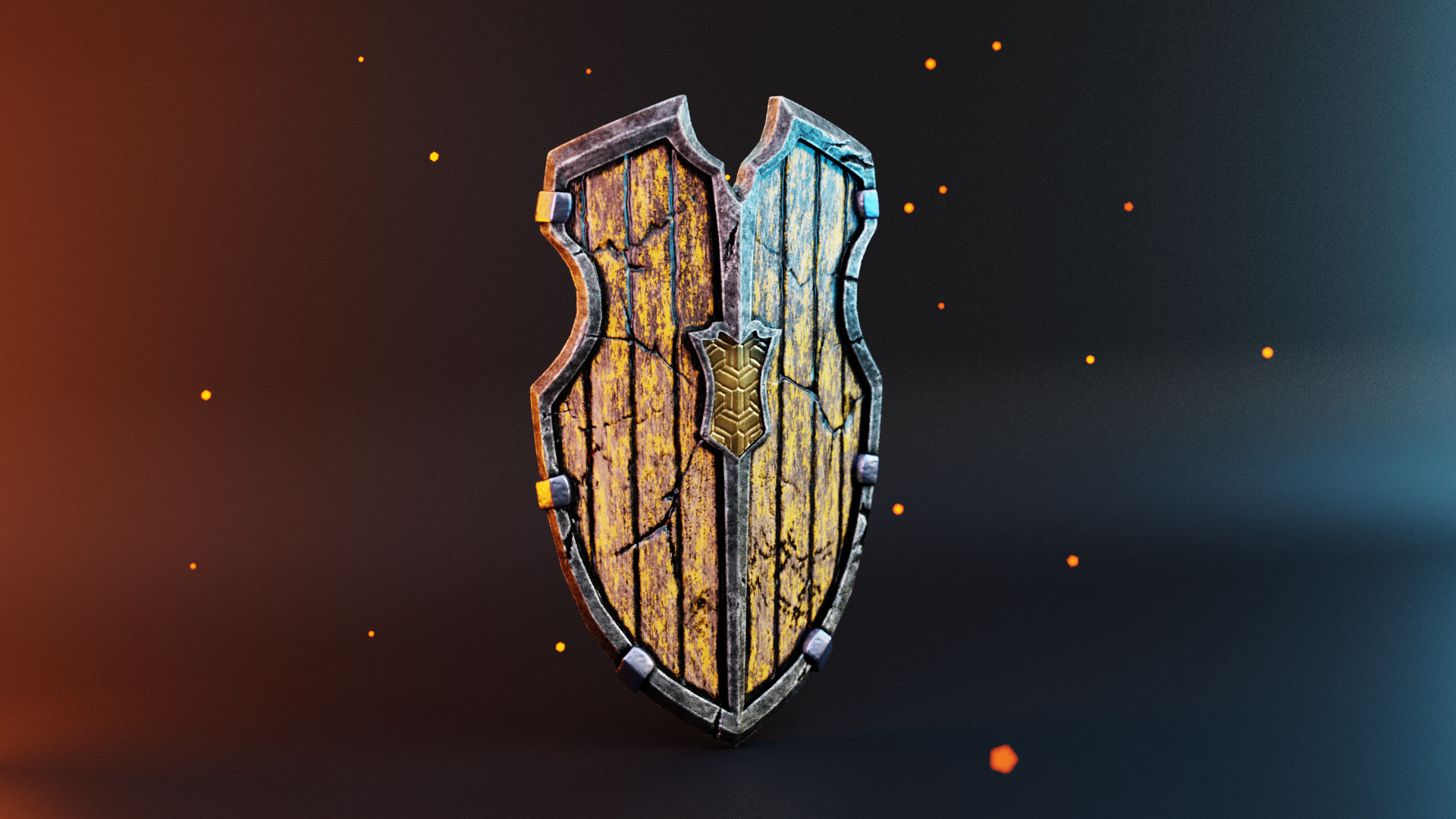
1. Introduction: Low poly 3D assets are great for games and real-time
applications. I am Hashanah well-done. Join me in this class
where we create a stylized low poly shield
from scratch using Blender, we will start with modeling, where we learn the
correct approach to 3D modeling for such objects. We then go to sculpting, where we use
displacement maps and alpha brushes to add cracks
and damaged due dates. We will then bake these
details onto mesh maps, such as normal ambient
occlusion and curvature map, followed by a full PBR
texturing session. Finally, we will extract
renders of our shield and also make a 3 16th turntable
animation to showcase our model. I'm excited to
share my knowledge, tips and best practices for low poly asset
creation in Blender, giant know, and I hope
to see you in the class.
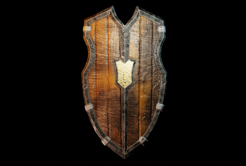
2. Importing The Reference Image: Hey, before we get
inside the modelling, I wish, I want you to understand
the concept in detail. Let's go ahead inside
our exercise files. And instead of which we
have a concept image. I'll open that. And here you can
see the concept. And first of all, analyze what you see here. So this is basically a shield. Shield can be treated
as a planar surface. We can basically
start with a plane and then the form,
the shields form. Here you can see the
details of the shield. So try to imagine a plane. We first create a
plane and then we add more loops in the plane. Then we can basically ship out those loops by pushing
and pulling the vertices. Didn't we match shields
shape like that. Here you can see how
we have a curve. So we need to be
adding loops this way. So there'll be 123
or four loops here. And we can basically pull
them in to get the scope. And same way for
this curve as well. We can add loops for the same plane and
we can pull that in. Thus we get plane in shape
of this shields cut out. It's like, it's like a
paper cutout, right? So it's a plane which
is basically going to have this shape
of this shield. Once we achieve that shape, the outline of this shield, we can then add
the details. Here. You can see inside that we have one more loop which
follows the outline. This is basically like an
inset of this planar surface. Then we'll create that inset and we'll continue that instead. And create this mid
shape like this. This is the approach
that we are going to do. I'll repeat that we are going
to make a plane and we're just going to follow the
outlines of this shield. And then we'll go inside the detailing by adding an inset, which means we're
adding more loops, then we'll extrude
this wall over here. The reason why we're
extruding this is because this is the metallic part, while this part
will be our wood. That's why we are creating
a lip on our outer edge, which will be Metric. Alright, So with
this understanding, let's go ahead and start
modelling this off. I'll close this and
I'll open Blender. And as always, I like to use some kind of
real-world scale. Because using the RightScale
will give you a lot of good results in terms of lighting and in
terms of modifiers. Because modifiers always
work according to the scale. That's why I always
advise to keep some kind of scale accurate so you
get the right ourselves. Let's get started. First, I'll import
this reference image. Go to my front view. I'll open a file browser. I'll click on this concept
and drag and drop. And there we go. We've got this concept here. I'll press Alt G. This snaps right to
the ground there. If you want to see what
skills that I use is I will get inside
scene properties. And here you can
see I'm working on a metric scale and I have
get the unit scale to 0.01. Here. I'm using centimeters
to model this. I want this to be approximately
17 centimeters tall. So how do we check this as we'll add another plane
of 17 centimeters, then we can just match
this to that plane. So I'll add a plane.
Let's rotate that. This plane, as you can see, it has the dimensions
of two centimeters. We need 70 rights. So on our y-axis,
I'll just press, just click on a y-axis
there and press enter 70, my numpad, and this is
the size of our shield. I'll select the shield
and scale that up. I match this Blaine. It may not be accurate, can be rough dimension. So we have got that. Now. I'll get rid of the spleen. I'll push this reference
image a little above. So I'll use my move
tool and select this image and put this on the ground somewhere there
so that touches the ground. Alright, right, so let's
go ahead and rename this. Say this is meaningful
reference image and get inside our object data properties,
properties manner. Check the opacity and get
this opacity down to 0.5. This is because so that
we can see something that is behind this image
and we can see the model. Or I just would
like to work with a little demo reference image so that it doesn't
obstruct our view. With that said, let's
go ahead and lock this reference so we
accidentally do not move this. Select our reference,
and get inside here, and click on the
filters on outliner. And make sure you select
the selectable filter. And let's go ahead
and take this off. The cost of debt. We no longer will be able
to select our blink. Great. Let's begin
modelling now.
3. Getting Started With Modelling: For that, again, as I said, I'll be using a plane. So make sure your 3D cursor
is in center of the world. If not, you can always
press Shift and see. Your cursor always falls to the origin or the
center of the world. Let's create a plane. Now. I will say shift a and get
inside Mesh and add a plane. We have a plane. Rotate this on my x-axis. Now I'll get inside edit
mode by pressing Tab. I'll select all by pressing
a and scale this up. Move this plane here. I'm basically going to make this plane the size of shielded. So it basically needs to
cover up entire shield. Then we can go ahead and add the loops to detail this out. This plane now covers
almost entirely. And scale this up a little
on my x-axis like that here. Okay? So as you can see, this is symmetric form, which means we can always
use the mirror modifier in conditions like this
to make this symmetric, to make the model symmetric, I'll add one loop right in the middle by
pressing Control R, and that adds up a loop. Then we have a loop that
runs right in the center. Now, I can go ahead and
delete 1.5 of our model. So I'll select
these vertices and press X on my keyboard and click vertices to get
rid of that half. And now we only have
half of our model. To make a meter. Let's get inside our
mirror modifier and say Add Modifier and
get inside middle. And make sure you turn
the clipping on here. This will always
ensures that you don't have double point in the center. So I always turn the
clipping and merging on. We have got the
middle setup now, all we need to do
is just work on 1.5 and get the outline read. The other half
automatically follows it. So now it's all
about adding loops by pressing Control
R and then using the Move tool to just
move the vertices and edges so that we get our
outline looking right. Okay, so I'll start
adding loops. I'll be using Control R as
a shortcut to add loops. So I'll press Control
and add a loop there. A best step while adding loops, this you need to
know where you want the new resolution or new
loops for the geometry. You don't need to add loops
where it's not necessarily, always add loops where
the absolutely required. A good way to find
very unique loops is when you add a
loop on the edges, you will always need to
add loops on the corners. So when I move this till here, you can see the outline. We have a straight outline, but we need more loops or more vertices in order
to get this shape. That says that we'll need
to add loop over here. Now, we need to add loops here so that you have the
ship getting insane. So now you have a curve there. This is how you need to
analyze where you need loops. So wherever there is
a change of shape or change of curvature
or you have a corner, make sure you have loops there. But adding loops here is
absolutely unnecessary because there is a no change
of shape in the outline. There is no point adding
multiple loops here. You will just be increasing
your resolution without need. And thus you will also
be increasing polygon. So avoid adding loops
where you don't need. Now let's go ahead
and shape out. We just drag these
points in here. Here you can see we have
a different curvature. We have a smoother
curvature here. So we'll add loop here
and one loop over there. Let's drag these
vertices inside. We have better looking
curve that matches, that matches our shape. So I'll continue to add
loops on the bottom half. And so I'll add one day like this inside,
something like that. So I'll add one mole this out. As you can see, the mode
loops where we are, we are able to shape
out our shape. But be careful if you add a lot more than
what is required, it is very difficult to
shape your mesh user. You should always be in
the sweet spot where you need exactly the loops
that you require. Not more, not less light. So let's add one
loop over there, and let's push this out. Suppose this is this, it protects out and same here. You can see how the geometry is traveling here and we'll be
needing a loop over there. So instead of adding a loop, I have one extra
point over here, which I'm going to position it right in the
center, somewhere there. We have got some
shape that's going on here and we have
roughly matched outline. And let's continue to
match it on the top. So I'll be adding a
loop one over here, and I'll drag this still there. You can see how this
edge flows here. All right, So I'll
catch the topmost. I'll catch the top
vertex and push this up. And this can, this vertex can
go to the bottom like that. And we have got that, we ship and of course we'll be
adding more points here. These points, and it'll
load something like that. Now you can see the edge flow. What I feel here, this edge can be flown a
little more optimally. What I mean here is we have one free vertex that's,
that's right here. So we can connect this vertex to this edge and make a
nice U-shape here. So let's do that. I'll press K on my keyboard
and connected till there. Again, press K and connect this inside our
middle, like that. Now I can get rid
of this edge here, so I'll select that and press X and say this on edges and that gets RID and we're back
to GW art-based topology. Don't worry about this detail here because we'll be making an inset which will give us
the details necessary. Here. I'm not going to match this
with this code over there. You can see that we have got
really spaced out geometry, so we can add one
more loop in here. I'll add one there. And this runs nicely and we get a little more evenly
spaced out topology. So I'll add something like that.
4. Adding Metal Details To The Shield: The next thing what we can do is start shipping out
the inner detail, which is this here. So I'll pull these points and start shaping out
this street in there. And I'll just move all
these points so that we have good flow in
topology, that's it. That out. And pull this vertex inside. Something like that. Use this vertex to
make the corner. Something like that. Now let us go ahead and
add some more loops here. I'll add a loop here
by pressing Control R. Here you can see we
have an edge that flows to this point and this vertex and it
flows down like this. So I need some
resolution here, right? So instead of this
edge going this way, I have used my knife
and cut off a new edge that we have one more vertex
to aid in our modelling. So I'll just pull
this in like that. Now we need to make a corner here and we need
more details there. I'll go ahead and use
my knife again, escape. And from this point I'm just
going to make cuts to lead. And I'll just move this out. Alright. I'll just move these edges, this edge, I lose, move this loop little below. Because as I said, we're going to make an inset, so we're not worried
about the inside line. We have got somewhat
outline which we want. Let's continue shaping. I'll select the top one. Looks almost fine. Now let's go ahead
and shift the bottom. And as I said, we'll
be making an inset. And here you can see that these edges are following
after that point, which will be an
issue when we insert, select these points,
are these vertices, and I'll move them up. Like that. You can
see the distance between these two edges. You can continue the
similar distance here. Select this, pull
this up, let me know. There we go. So we have got that
and now I think it's a good time that we
can make an inset. So I'll select all and press I on my keyboard to insert this. We can make an
inset that roughly matches are inside curve. So once we have the inset,
I'm pressing the G, or you can use the Move
Gizmo and place it roughly where you'd like it
to something around there. Yeah. We'll have
to make changes to this so that we
have the details. Let's again go inside our
vertex mode and from the top we make the shape of
the inset, right? So these points
are looking fine. I'll use my lasso. But we can move this and
place it somewhere there. This can be moved out. This vertex. I'm basically selecting the vertices and I'm creating the
shape in a design. Match this vertex up. This vertex which will
be on wooden part. This scan goes something like that. Now let's go ahead and
match the inner they then I'll select this vertex and push this out. Go out. Further, go out. Something that you can see that we don't have, we don't have an edge here. For that, Let's use
a knife tool and connect these two vertices. And let's end up, and we have got a
new point over that. And we can move this. Do we have a shape there? And the same way we have
a curve here as well. So we'll need another cut there. So I'll use the knife and
I will make a cut here. This also gets us
the quart need here. This two limb. All right, We have
got the detail here. So when I use the
Face Selection, you can see the detail that
we need is exactly there. We have got our outline now we can go ahead
to our next step. Now, before we do that, I just wanted to give
this some thickness. So we have some 3D object or
3D geometry to work with. I'll select all and
go ahead and extrude this on my y-axis so we have some thickness to
somewhere around it. Now, we can go ahead and give our metallic part
and extrusion outside, which will have to
select this loop. Along with this, we need to select the inner detail as well. So I'll select these. Make sure I just
have the front face selected and not
anything at the back. Now, I'll make another
extrusion on my y-axis, so I will put us be and
why extrude it somewhere?
5. Defining The Center Panel: You can see that
the next retail, but what we need
to add is the edge that runs in between
these phases. Let's add one more loop.
Right in the middle. We have a loop. I added on
the wrong side and undo. It's added on the front. We have a loop that runs across, so we don't need the
loop to continue here. Instead, we need the loop to be joining this half of our model. How do we do that is
we need to cut points. I'll go ahead and use
my knife tool and make a cut here to there. And match this point. These points we have
regard that runs well. As you can see, we can add
one mode detail here or we can add one more loop
here so that we have the curve looking
more, looking better. So I'll add another loop here. By pressing Control Up. Made a loop. This curve needs to be
matched properly like that. Yes, we have got
this also becomes, this phase also
becomes a quote here. That is fine. Since
we have joined the mid line till here, we don't need this edges
that is running till here. I'll go ahead and get rid of it. Select the edge
due to the bottom. And press X and say this all edges so that we
can get rid of it. And now we will need
to connect this with the center so that this doesn't
run without any issues. So go ahead and use my knife
tool to connect the LED. And I will select
this vertex and that vertex and press M and merge. At last. We have a merging point there. All right, now it's
fairly simple. We just need to select
our limited edges and simply move this out in the
y-axis to get our shape. All right, so now we need
to work on the part. So I will use my face
selection and select all these phases and
press I to insert them. And this time I'll do a
border and set by pressing B. This gets a borderland set. And we can insert it like
that and match these. Again, I will select
the interfaces. And this time I'm
going to extrude it. So we get a dip and say, I'm going to press E on my keyboard to
extrude it and say, we have something like that. This, I do not want
the shape to continue. This planes to be flat. With all those faces selected. You'll need to press S to scale on your keyboard
and press white, which is the axis. And just enter 0 on your numpad. That will scale at Blaine
in the y-axis to 0, which will make it flat. Alright, so we
have a flat obtain there. I'll do that again. I will select the
required phases, but as S and Y and enter 0 on number to get this
flatter surface.
6. Making The Edges Sharp: We have got the base form ready. Now, let us go ahead
and give this some smoothing and let's
see how this looks. I get to my modifiers and add modifiers and say
subdivision surface. And here you can see
that this looks well, but we don't have these
sharp edges or corners. The way we add that is by using bevel modifier and
an edge bubble rate. So let us add another
modifier and say bevel, and put this modifier
about subdivision surface. So we have a bevel there. Now let's change the
limit method to wait. Now it's just a matter of, I'll isolate this, select
my model and press Slash. To isolate this, we need to mark the edges
that we need shot. I'm going to get
inside-out edge mode and select the edges
which I wanted to mark shot these edges. For a moment, I'll
just switch off our subdivisions so we
know what we're selecting. So let's select
this and delete it. I'm just going to
sharpen these edges. Let's try one. Before we mark everything. I'll select the
entire loop there. An entire loop at the back. Because all these edges
needs to be sharpen. This press Control E. Or you
can go and say an edge and say edge beveled weight and put the value
all over to one. We have bubbles only
on our map areas. And now let's turn on the subdivisions to
see how they look. We need this edge to be shot. Here. You can see the
sharp edges like that, so that's looking fine. So let's go ahead and do
this for all the edges that needs to be sharpened.
Just subdivisions. And I will continue
marking beveled weights. Here. When using Edge bevel rates, always make sure that you get the factor all the way to one. And keeping the factor
that any value that is between 01 will not give
you a better less than. So it's always like
a Boolean operation. You have one or 0. Mark these. The middle segment needs to be sharp as well. Middle edge. Let's
check our concept once. You can see how the sharp edges runs and you can find
the sharp bends here and there and that meets the edge over here.
Let's do that. And these edges as well. Let's try subdivisions now. You can see that these also
needs to be sharpened. Select switch off subdivisions. That similarly on the bottom, on the insights. So you can see I'm
just switching off subdivisions each
time I'm going to mark and the edge
beveled rates so that I'm very sure
which edge I'm using. And you can do the same as well. This curve here which we do not want to wait. Here you can see a curve
which we do not want. Again, it's made
mark right here. We get a sharp probe over there. This needs to continue
all the way to the back. Select this. All right, Now let's change our shader to check
how that looks. Shinier. There you can
see another curve. So H alone one,
mark. This as well. Needs to continue. Yeah, cool.
7. Adding Details To The Back Part: Let's go ahead and make the
backside and it'll better. I'll go ahead and turn
off the subdivisions. On the backside since
it's a metallic part, this is going to
have a thickness and the same board is going to
be on the back as well. We need to differentiate
that wood and metal. So similarly, we have a
thickness on the front. The same way the back
is also going to be thicker wherever
the metallic part is, which means we'll be using
our extrusion to do that. I'll go ahead and clean up
some edges on the back. Here. I want to
continue till here, till this point, not like the one we have
done on the front. So I will just go ahead
and merge these m At last. We've got that munched. Metal on the back will
run across like this instead of having the bed because we don't have a
mid segment on the back. Push these and continue
shaping their own. This can be merged here. At last, selecting the loops all
the way down there. And let's press E
to extrude this. Oops, forgot one. Extrude this out a little bit. There. Let's make the edges
sharp here as well. This loops that we shot. Same way I found the front. I'm just selecting
the ones I want. The sharp edges control
E, edge pebble rate. These needs to continue.
Similarly there. Whichever I just
had a sharp on the front needs to be sharp
on the back as well. All right, let's turn on our
subdivisions. It looks neat. We have successfully made the outline and
we have extruded, and we're almost going to
be finished with modelling. So I wish to check
out the concepts. So I'll move this
concept with this. Select our reference and
move this to the same. Check how that looks. Here. I feel we have a lot
more curves that's going on. So I don't want to have
this loop over here. Select that, that loop which
we created essentially. I'll press X on my keyboard
and say dissolved. I'm okay with this club. That's going right over here. If you see, we can
see that there is some detail which
can be brought in. And I'll make this
edge shot. Again. Use my move tool. Just pull that up a little bit. We have those lines continuing. Our concept. Release down. Make this edge shot as well. This out just a little bit. So we have a little
more definition and character to our
shield over there. Now let's change the
sharpness a little bit of a bevel up the segments. Right now, increase this to 0.3. Something like that.
8. Creating Bend Using Simple Deform Modifier: Now we have got the shape ready. Now let's go ahead and bend this shields so that it
looks like a shield. For this, we'll be
using performance. The simple deform modifier. Get switched off our reference. We don't need that anymore. Make sure you have the
3D cursor in the center. I'll press Shift C, and
I'll add one empty, empty. And let's add arrows. Make sure it's visible
by increasing the size. Something like that. Now, select our object here, and let's call this a shield. Let us add a modifier which
is called as simple deform. This deformed, we need
this to be a bend. So I'll select the bend. Now, we'll choose the
origin, has an empty. Put this on Z, and that will basically
deform or chill and give us the
band that we need. Increases a little bit. We have got the
band working right? So, which is great. So we just model
this from a plane. If we wanted to model this bend, then it would've been
really difficult issue. And you can see that we don't
have much deformations on the mesh and it looks appears very clean on the
highlights and reflections, which is a really
good thing because we use the simple
deform modifier. If we go ahead and
manually do this, then we will definitely be
having some surface issues and will need to be resolving it by pushing and pulling
vertices endlessly. There'll be have a surface
that has this kind of quality. You can see how these reflections
appear on the surface. And it's really good to see. We've got a clean mesh
with goods surfaces.
9. Modelling The Clamps: Since it's a modifier, we can go ahead and switch this off and on whenever we mourn. I'll switch this off. And now I feel I can add a little more details to our
mesh at this point of time. Little more detail in terms of, let's add some clamps to
this model so that it appears much more
realistic and good. To do this, I'll go ahead
and enter edit mode. And I'll select
these loops here. And I'm just going to press
Shift D to duplicate this. And I'm going to press P on my keyboard to
separate this selection. This is become a
separate object. Now I'm just going to
make an extrusion. I'm just going to make an
extrusion of the vertices. Have a clamp like structure. Alright. Now I'll select on and just scale this up
and move this inside. Scale this up. This is going to be a
clamp which we need. We have got the clamps
structure here, bringing these outermost
faces a little more unsafe. So we can see the clamp. You can see that we've got
some shading issues here. Now what we need to check normals if we have
issues like this. Let's get inside
viewport overlays and turn on face orientation. And you can see that entire
mesh has flipped normal. We can select all and press Alt and on our keyboard and say recalculate outside. This gives us the right
normal switch we need. Here you can see that some edges have a
different normals, which is why we had that
shading issue earlier. See something like this. We'll need to recalculate
normals for this. Select all hold N and
say calculate moments. And this gives us
the right normals. We need. Switch off the face
orientation and skip this a little inside this In. Make sure that you make it touch our mesh as
much as possible. Make it touch our shield. Okay, great. Now let us add solidify to this so
we have some thickness, so I get rid of. So I'll add the solidifying
and select this clamp and get to add modifier
and say solidify. Put this solidify above subdivision surface and
give it some thickness. I'm giving the
thickness in the minus because we want this glance
to be extruding out, not the other way inside. So I will say minus 0.5. We have a clamp over there. Select these and drag this up. So that becomes a clap. Yeah. I increase the thickness
just a little bit to 0 minus 0.7. Let us go ahead and duplicate
this clamp everywhere. We need. Just press shift D and
put one on the top. This just a little up. Rotate that. Duplicate
this one more time. And planes one on the bottom. Alexa, we have placed
the glands as well. Now let's go ahead and
switch on the symbol, the form future on this
simple form for the gland. Now since we have
extracted this clamp from our mesh itself or
from our shield itself. It has copied all
the modifiers to it, which made it really simple to just turn on the simple deform and we have got the clamp
that's following our mesh. Now let's take this in
our shinier matte gap. And yeah, there we go. It looks right.
10. Modelling The Handles: Now let's make the handles at the backside so that someone
can make use of this. She'd go to the backside. Now I'll make a plane. Rotate this on the
x for the state. So this will be our handle. To use the sheep. I'll just extrude
from this point. And extrude, I'm just
making a shape of a C. So this will act as a handle and just push this till
it gets to the back and push this back. Something like that.
And let's reduce its thickness. Scale this up. Continue to shape the handle and we need this to be larger. Let's give this some smoothing. By adding a subdivisions and right-click and
hit Shade smooth. Let's give this some thickness
by using a solidify. Due to some thickness like that. That looks fine. Let's make
the handle a little bit. And once we are satisfied, we can just go ahead and
duplicate this. Two here. Just wrote it to match
the plains of our shield. You can be creative and you can rotate this as
well a little bit. Let's add loops here
and pull this out. Let's go ahead and
rename this as handled. Alright, so we have
got the handle and now I feel we have done
with the modelling. And the next phase would
be to UV unwrap this. And then we can
forward to tension.
11. UV Unwrapping The Model: Let's go ahead and
mark seams for our shields so that we
can use them to unwrap. Switch off simple default. We need seams in. Materials like the
wooden part will be a separate island theme as the bag and the metal
will be a separate. So it's that simple. Let's go ahead and
start marking them. Get inside you were editing. Start selecting the
edges for themes. Maxine here, and define the mid part II and say Maxine. We don't want this
clear theme there. All right. We're marked themes for this word and fame
way in the bottom, same as the backside as well. So select the edges. Let's go ahead and
switch off subdivisions so we can see what's happening. Better, less maximum in terms of islands. And I press L to select
and use the UEs. Seems. You can see this is
an entire seam here. This will be our wooden part, same way on the backend sweat. This would be our part, so that's the thickness. And then we have one metal here. Since we have marked the themes, now we don't need
the middle anymore. We can start applying some modifiers at
this point of time. So I'll go ahead and switch on subdivision and our bevel again. And simple the form as well. You can go ahead and push this simple deform above
the subdivision surface. And you can push it
one more time so that this sits right
next to the middle. This is not affected
our machine anyway, I'll go ahead and apply
the mirror first. Apply. Simple deform
can be applied. Now we have a mock seams with the mirror modifier
here automatically, the seams continue on
the other side as well. Now let's select all
and plus you and say unwrap to get a clean and
wrap of what we have. So this is what we get. I'd like to turn this this side. Somewhere there. I will select this
one and rotate it. One AT Summit, like that can be scaled down. Now, we need this part to be a separate one because
we are planning to add some pattern in here. I'll go ahead and select
only the mid part. I select these faces, the front field,
and go to unwrap. Get this out. Select only the middle
portion and I'll scale the stone in our stone. Place it somewhere. Or we can go ahead
and scale that down. Because the size of this
roughly is stood here. So let's maintain the theme
and I'll place it somewhere. Within that. We have got our shield,
which is UV unwrap. Now let's go ahead and add
a checker texture to see how this looks. Add one mode. So I'll make a new
window here, new report. And let us say we need something
called a shader editor, and let's give it
a new material. Let's call an image here, Shift a and search
for image structure. New. Set this to you in grid. And 1024 is fine. Say, okay, connect
this to the principal. Let's check the
material preview. You can see how
architecture is unwrapped. And you can see some
stretches happening here. Especially on the regions here. You can see how it actually stretched here and it
will just not good. But this is not happening
because of the geometry. It's entirely because
of our bevel modifier. What we've got, we can make the segments a
little more three. When I up the segments to three, that issue goes off and we
are having good-looking UAE. I will put it to three. But you can see
that on the edges, they're not very good. Texturing is happening here. So let's go ahead and
bump this up two, One more time to fall. And now you can see how these
stretches disappear here. And put this again. So 34. You can see how that
accommodates for the stretches. And now we have got clean
and sharp but looking lines. Let's go ahead and
select the other bots. Model. You and unwrap. All the other parts,
get unwrapped as well. I'm just pushed it somewhere where it doesn't
interfere with our model. You can always check
that by selecting all and entering edit
mode at the same time. Just catch the middle portion and place it somewhere
else so it doesn't interfere with our other objects such as the clamp
and other things. There we go. We have successfully and wrap our shield there and the pictures are
looking fairly good. Now we are ready to go into
the next step where we are. We can sculpt this out
and the sculpting mode and see how we can use
alphas and other stuff here.
12. Assigning The Vertex Groups: All right, so the US
look fine and we've got a nice checkerboard
texture here. Now let us go ahead
and apply modifiers. And let's get started
with a sculptor. I'll go ahead and get
to my solid view. Now we're just going to
apply the modifiers. We won't be needing
the a pebble anymore. I'll just go ahead
and apply our bevel. Then I'll take off the
subdivision surface. Similarly, I will select our lamps over here and
apply middle bevel, solidify takeoff
the subdivisions, and apply for the form. Alright, so we have got
low poly version here. Apply modifiers here as well. So I'll take that off. Now we have got all the
objects in our scene now, we'll go ahead and join
them to make them one. So I'll select the clamps, I select a shield, I just select the
handles and Control J. The order is important, so I'll select the
clamps, I undo, select the handle, and then I will select the shield
and press Control J. So all of them come and join with the sheets
together as one partner. Alright, so now let's
get rid of ui here. Here you can see how
they have come up here. For our, for our
handles are here. And then now UVs
for lamps are here. Check one more time how
they look in the checker. And they look well, I didn't find any issues here. Now, we can go ahead and give it a multi-resolution
modifier for sculpting. Select and get into add modifier and add
a multi-resolution. For this weekend, subdivide
this all the way up. Now. There are two methods now. One is that you can directly
grab your stylus and your tablet and you can start giving details like
whichever way you want, the wood grains and everything
can be manually sculpted. And there is also one
other way where what we can do is we can
use textures and give some displacement
maps using the displacement modifier big that inside our
multi-resolution. And then we can use a
hand sculpting or using alphas to give some details
like cracks or crevices, etc, and some damage,
stuff like that. I'm not going to get inside manually sculpting everything in at this point because it is a time-consuming process and
it is having the artistic, it takes its own time to do it. What we'll do is we'll
go ahead and use a misplaced modifier
and give it some maps. I've also included
some maps here. And really what I want here is that the wooden region here, the middle portion will have vertical wood
planks like this. So there'll be blanks
going like this. And then there'll
be a greeny kind of a metal which is the outside. And the clamps can have a similar language
of the metadata. Let's go ahead and use
the displaced modifier. You need to split your, especially where you have multiple materials
into one object. In those cases, we'll be using vertex groups to split them
and give only displacement. That particular vertex group. They wouldn't part will
be a vertex group. Let's start giving vertex
groups according to our ones. I'll select the wooden part, whatever is wood needs
to be selected here. So these three panelists needs
to be selected together. There'll be first,
so that'll get inside Object Data Properties. And then under vertex group, I'll click Add Vertex group
and call this as board. And say Assign. We have got the vertex group is saying to check it
if it worked or not, and say de-select, to de-select that and
select that again, this vertex group gets elected. That's why we see only the wooden part
getting selected grid. Let's do the same for
the metal as well. I'll select the metallic
portions. To select it. I'm just pressing L. While I'm inside. When I press L, it
selects the link. The link where I'm going to use urease sin to select
only that part of it. Since seams and our materials are very linked wherever
there is a material split, there is also a
there's also a seam in this case which is
lay this worked well. This is another place
where you want the metal. So I'm selecting
that by pressing N, and now I'll create a
new group and I'll call this metal and say Assign. And we have a saying that. Then finally the
middle portion and select that and give
it a new vertex group. And I'll call this center
part and say assign, de-select, Select
to confirm that you have assigned
the right group. Select the metal, select.
13. Adding The Wooden Plank Details: Cool, so we have got the right vertex group
assigned to each. Now let's go ahead and give it a displacement map
to see what it does. Now, I want to have
this resolution or the mesh resolution to five so that we get a
better displacement. Now this may be a
little slow on, little slower PCs,
but that's okay. You can wait. I've got
my resolution to five. Then let us add a
misplaced modifier. I get into add modifier
and say displace. And really having a
displacement map, no. Alright, we have it. And now here you can see I
click on new displacement. And I'll call this S first. Then my coordinates
needs to be set in UV. Then my direction
is to be normal. And my vertex group
can be chosen as good. Alright, so we have selected
our vertex group there. Now let us go ahead and
give it a detection. I will say in our
texture properties, I'll go ahead and open. And inside of Maps, then you can see
something called stripes. I had open image. And yes, we have got
stripes opened here. You can see those
links like this. But the issue here, what we are experiencing
is we have our UVs in, we have two different
orientations in LUV, different one is
facing this side and the backside is
going the other way. That's just see these two. This is the front panel and
this is the back button. You can see that
the back panel has a different orientation
than different dependent. Now, assume that these
stripes run across like this. Then the front panel will
have the stripes running vertically and the
back panel will have stripes running
the other way, which is exactly what
we are undergoing. Now. As you can see, the front panel and
background are different, which shouldn't be the case. You have two options here. One way is to change this UV map and make sure that these
two are aligned properly. There is one more option
where what we will do is we'll add another
UV map for this. So I will show you
the second option. We'd go ahead and
create another UV map. I'll get inside object
data properties. Uv maps. I will call another map that
has greater than other map. And make sure you pick this one. Select this one. And now you can
see that this ui, which is UV map zeros 01, will have been selected. Yeah, exactly. I call this as UV map. Standard stem means
for temporary because this is not the UV
map which you'd be using. This is just for the
displacement map and then we'll bake it
and get rid of this map. That's why I'm calling this. Once we have got that, we can go ahead and
adjust the USEF. You remap them. Make sure that these two are facing
the right orientation. Just move these off for now. Select these and
rotate this 90 degrees and put this roughly over there. You can get this back. I mean, I can move this here. Bring these guys
somewhere over there. We have got the
temporary map ready. As soon as I get out
of the edit mode, you can see stripes coming
down in the right orientation. Now, even here, you can go
ahead and adjust it more. If you want more stripes, you can see the map here. The stripe map looks
this is automatic. Yeah, so this is what is
the map that we've given? This way will be positioning
of our stripes here. So if you want to
have most stripes, you just need to scale
this up like that. So you will be having
more divisions in your stripes like that
and something like that. So we are having alone
123456788 stripes. So I reduce the
size a little bit. And let's place it somewhere. Where our middle portion lice in the black spot of stripes, the black lines and the middle of this line
corresponds to that. Greece. Over this way, we can avoid
ugly-looking divisions in the middle of our shield. Let's put it like that. Now let's see how this looks. Get out of edit more. And yeah, that
looks pretty neat. I'm happy to wait, as you can see, since we have
matched the midline in the middle of our shield, we have guard that
midline coming like that. Alright, nice and neat. Set the UV map to them. Once we are happy
with this weekend, go ahead and see applying. This will be built into the fifth level of the
multi-resolution modifier. You can go ahead and change the values of strength
to see how that looks, but I'm pretty happy with
how it has come out. So I'll go ahead and apply the displacement and apply this. And this has been
applied and now this has been baked
into our mesh.
14. Adding The Metallic Surface Details: Similar way, let us go ahead
and apply a displacement for a metal to again add
modifier and get inside. It displays. Got this. Click on what it says. But we are going to change
the wooden texture here. Something like open and
mental underscore bump in our exercise files
and other maps. I'll select the middle
underscore bump and open image. This is getting us
really fine bumps. Let's go ahead and adjust it. Here under the
coordinates at this view. You can set the UV map as
UML vertex group as method. And now you can see that the displacement has only
come to the metallic part, which is why we give different
vertex group two each. So let's go ahead and reduce this number to 0.1
as the strength. You can see that there
are really fine bumps. I'll let you point to
that looks like metal, so I'll go ahead with that. And you can copy the same in here as well by just adding these into
your vertex groups. So I'll just press
L in my edit mode to select all these clamps. And I'll get inside object
data properties and assign this methyl group
to all the clamps, and get out of edit mode. You can see that this texture has come up on our clamps S1. This is depending
entirely on the scale of us that can be adjusted
in our attempt map. That's just the way
we adjusted our wood. But now I feel happy
with what has come. So I leave it as it is. We have got the
metal and this would
15. Adding The Wooden Surface Details: Now let's go ahead and give some other bump for the
wooden green as well. Let's select this again
and get inside modifiers. And this time I'll go ahead and apply the displays here as well. So I'll press, I'll open
this and say Apply. And this will again bake the displacement
inside multifidus. Level five. Again,
a displacement. Open this word. Again, us get inside the texture and call
another texture here. And this time I'll call 035. So let's open image
here as well. We need to set the
coordinates to UE, and then we need to
change the vertex group. Remapped will be remap
and it's called temp. And then our vertex group
will be set to wood. Right? So we had getting the
grains of the wood here. Exactly. But this is a little
too much for our detail. So I'll go with 0 to put the
detail back a little bit. You can see that how our greens are getting affected.
By this way. Let's go ahead and 0.3 maybe. All right, so I'm
okay with three. Now you can go ahead and turn on the cavity if
you wanted to see the details on our
viewport shading to see how this has come out. This is pretty much good. Let us go ahead and
switch this off again. I'll go ahead and apply this. Displace applied. This is also applied
to Martina's. Finally, let us go ahead
and do the center part.
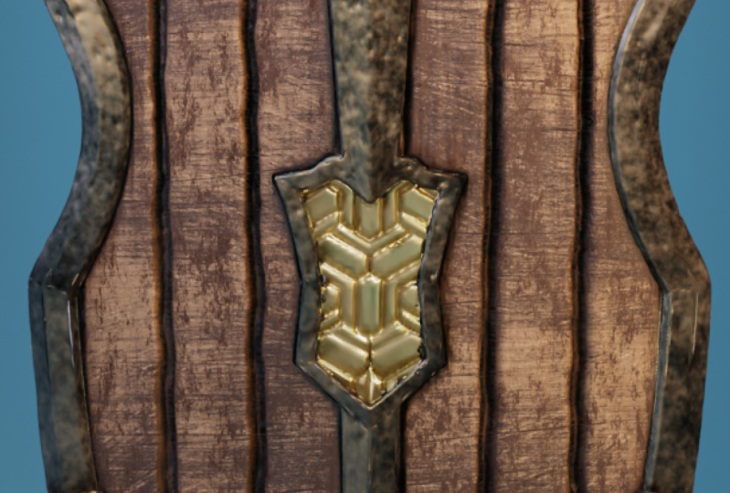
16. Adding Patterns On The Center Panel: For the center
part, I have added one more map so you
can access that. You just need to open image and there's something
called as front we did. You can open that. This is different detail.
For this to work. We can make use of
the temporary UV map. And please this front
view we exactly on that. You can see that this is a map which has black and Greece. This would really work to get us the displacement
or that we need. Again, add another displays. We've got a disgrace. And this time I'll say the
vertex group center part. So this only appears
on a center. Then I will set this
to image and say, Would we have got would
only on this end apart. Now this needs to be changed. So I will get inside
our texture properties. And here I will
call a new texture. This time, I'll call
the front D-Day. We have got different
detail here. So the issue here is that the UEs are not
aligned to here. Let's go ahead and do that. Select the edit mode
and select only here, only the middle portion. By pressing L, we have
got the UE selected. And you can see how the UE side and make sure that
you are in the UAE. And Matt temp, the reason why we did this is
because as you can see, you are basically mixing. You resort to, you
are adjusting gear, the VCR in terms when
you unwrap the UVs. Not only in this case,
take some other case. For example, when
you unwrap a URI, you will set up the layout
according to your wish. But after you come to the scoping phase where
we add displacement, that setup can change which we don't want
because you spent a lot of time in adjusting your UVs to get the best
layout that you wanted. Here that those layout will
no longer makes sense. As you can see here, that we are the one who
plays the map here, but it doesn't make
any sense now. In order to change the US
only for displacement, we added one other UV map, which is the UV map
underscore temp. In this way, you
can adjust the map according to your wish
at any point of time. Let's push this up. Please. Scale this up. It seems fine. Tab out of edit mode. You can see something like this has come and you can change
the coordinates to UE. Since the UV map S MP. We have got the
detail here as well. And I like to increase
the strength to five. It will be like two. Seems fine for me. I keep it to two. And now let's go ahead
and apply this displays. Again. Apply. This displacement
is also now baked inside the Mandela
solution modifier. Now we no longer need
a temporary we mapped so and go ahead and change this back to UV map
and select that. This can be turned off. It's no longer required. Now you are again back to
your existing UV layout. You can check it here. This was the way it was earlier. Let's go ahead and save that. At this point of time, you can
go ahead and experiment or stats carping and start
giving your own details. But you saw how it was
really easy to add displacement map and give the primary details before
even touching sculpting. Now after this weekend, go ahead and refine our
model using sculpting.
17. Adding Cracks And Damage Details: Okay, So we have
got the textures on displacement
and it looks nice. The next step we can do is
to add some imperfections, some damage, some scratches
are dense on our shield. Now at this point, you can go ahead and
do this manually. You can get creative
and sculpt by hands. Or if you have alphas it then you are welcome
to use your own Alphas. But it will not be doing much
on here because the purpose is just to demonstrate
alphas on this 3D model. Let's go ahead and call alphas. I'll get inside our scalping. So we have our object there, get inside our brushes. And I have selected the drop
brush and make sure you're in the direction of subtract
because these alphas, what I'm going to give will be covering inside the surface because the dense or the cracks or cuts
should be coming inside. That's why we are keeping
this negative value. Then in the detection of the
brush, soap on detection. And I'll say New. And get inside the texture
properties and say open. And let us get inside
Exercise Files and alpha. Then you can see that
alpha underscore three. So I'll open that right now. Scale this up so you
can see the size of the alpha here. Like that. Let us get inside our mapping. Sin one is one that's fine. Get inside our brush
properties again into mapping. It should be in view
plane instead of dialing. That's why even when whatever we see will be projected
on the mesh. So when I click the problem
here is this looks good, but it also appears on the back. I'll undo and get
inside our brush. Check on front phases only. This will avoid anything
going to the back. Again. Scale this up.
Autocratic there. That's it. Do I give it some more rotation and rotate
it? Autocratic somewhere. Like that. Scale that down. Support one on the
edge. Like that. Notice the strength, the
higher you have that, the deeper you will
have the Alpha. As I said, you are free to use
your own Alpha to do this, I'm just adding some random bins and damages here
using the same alpha. Yeah, something like that. Now let's change it. And open. This time I will be
using the Alpha-1. Let's continue
adding some damage. Some smaller damages. Rotate Alpha in our brush, something like that. So we have added some damage. Let's call another Alpha, which is the Alpha-2, which just like damages. So I scale it down and
add it on the metal part. One can go and make damages all day long as
much as he likes it. For the purpose of this class, we stop at an early phase is you can go ahead and experiment with
the origin alphas. You can give the
damage your way. You can do it by hand
sculpting or by alphas. Put it like that.
Small images here. I'm just adding
some damage details using malloc for keeping
the strength low. So it's not very perceivable, but it's still there. This gives us a nice surface. When light shines on it. Yeah, that's great. So now let us again
load one alpha, which is the Alpha-1. Because I need some cracks
somewhere over here. Yeah. That's about it. Then let's go ahead
and scale this down. Push this up a little bit, and just add some damages
on the metal partner. That looks good. Some over here. Just gives it some kind of
character to our sheet. Just placing random damages. All right, enough of this, let's take our script brush
and let's get our Alpha of note texture here.
18. Sculpting Imperfections: Scale this up a little bit. This starts scraping of
the sum of the edges. Can be scraped off like that. Just add some more
drama to chill. Some scrape on the top
edge to some over here. You can be very random
and doing this. Or even have a story to say
you can do that as well. It's up to you.
You can basically see that how easy it
is to create something like this in using displacement
maps, multi-resolution. Some alphas. Quickly get us the
results that we want. This stone not concerned
much about the back portion, but if you want, you can add
the details on the backend. Let's just continue
doing this clip. The edges. Square root of this edge. We have added some damage and we have views
these great brush to scrape some of the edges
and give it some dented look. Alright, so let's stop here. If you want, you can go
ahead and do it more. But for the purpose
of this class, let's end it here and
let's get to the, let's get to the next step
where we talked about baking this and we extract Maps, mesh maps like the
occlusion and normal maps, and also curvature
map so that we can use them all to bake
a low poly mesh.
19. Baking The Normal Map: Okay, so now let's go ahead and big this details
into a normal map. We're going to pick
the mesh maps. This is going to
really help us to do a low poly texturing
and even for entering. So let's go ahead and do that. Get out of sculpting
by grading and do the shading. We are
in the shading. Let me go ahead and take
this off. Right here. What we can do is really
create a new picture. Shift a search image. First, real big the normal map. I'll create an image
structure and say new. For normal maps.
Let's go ahead and keep the resolution to 2048. Okay. Let me change
this to UV editor. Let's get inside. You can see that we have
got some patterns here, but this looks
really, really small. So this might be an issue. So we'll just select this UV and scale this up
a little bit so that we have good amount of space
for the big picture here. Get out, say Come here. Here, I will call
this as normal. Let's call this
as normal map and put the color space
as non-color. Let's add a normal map input here and connect the color inside our color
and normal to none. Got the normal map ready. We can go ahead and select the object and select
the normal map and get inside your and keep
the multifidus to one. We have one
elementaries and we can go inside our render
properties and make sure you set
this to cycles and CPU and come under big. I would say it's combined. I check the big
from multilayers. We enable the Mandela's
Baker and it says normal. Now we are good, too big. Finally, just make
sure you select here and keep the map open
right over here. So we're good to go and select the big type enormous and
the margin is set to 16. And please put this to faith. Maybe I'll put this to ten
pixels and click on big. Yes, we have got an
enormous neatly big. You can see how that has
come up. It's looking good. We can go ahead
and save this map, an image, and save S. Let's put this into our maps
and call this S normal man. Save this image. And that's great. We've got enormous. Let's
check how this has come. Get inside material preview. You can see all
those details have neatly come up in
the normal map. This black to see
how this has come. Nice and neat. We've got the normal
map now let's go ahead and leave
the other months.
20. Baking The Ambient Occlusion Map: Since we are baking the others, I'll take off the
normal for now. Select that and get
inside multifidus. And put this back
to five. Again. We have got the
high-resolution mesh and let's add another
image texture. This will be odd
ambient occlusion map. Say New. And say, Okay, we've got the map loaded, make sure you select that. And we can bring in a node
called the occlusion. I'm just going to search for it. And there we go. Now let's go to
the render view to see how they render view, we'll definitely take
some time to load, since this is a higher
resolution mesh, which is okay. I connect V. I'm using Control and Shift. Clicking this will just hold
Control Shift template. Make sure that you have
the add-on called us know, triangular enabled
in order to do this kind of work
in the node editor, I didn't see you
can simply connect the cable and check
how this looks. This is the arrow that has come. If you wanted to
adjust the hill, you can go ahead and
put the distance. I will increase the distance. We have a little more occlusion
and I'll add color lamp. Here. Let's just change the RAM. You can see how nicely picks
up the crevices on our mesh. Wherever there needs
to be shadows, we are getting a nice
dark shadow around it, so I'll increase the distance small for them,
somewhere around ten. Maybe 20. Yeah. We are also getting details around
the clumps, which is nice. We can reduce the
blacks if wanted. So I'll put it
somewhere like that. Otherwise it's
getting really dark. I leave it there and we have got the ambient occlusion going on. This data can be
baked into a map, which is the aroma. So how do we do it? We add shader called S
and emission shader. Plugging the emission
and plug this in here. I know that there are other ways that you can bake the map, but I find this has much more control than
to do what we need. So I've plugged in
the emission shader to this office and we have got the plugged it into the emission shadows
with this grid. Now let us go ahead and
do a render properties. Make sure you are in a
cycle cylinder engine. And under the Render properties, you can see the max
sample sector 49 to six, which is a lot for baking. I will just set the
max samples to five. And then what I'm going to do is get to this render
properties and a check-off, the big Chrome idealist
and the bait type, I will set this to MIT. Right now it's ready to be big. And here I'll call a map. Let's say big. Treat for it to bake. Yes. Right here we can see the
ambient occlusion of our mesh. Let's go ahead and
save this image C of S. Let's call this as a
map. Save this image. That's it. So now we
can get rid of this.
21. Baking The Curvature Map: Now let us create
our curvature map. So the way we do it is by, is by adding first
new image structure. Put an image texture
and say New these 22048 and call
this as curvature. We've got a curvature map
changes to non-color data. Keep this aside now call
this coverage here. For this to work, we
need to shade us here. One is the bevel and
one is the geometry. So let's call the
geometry first. Let's call a bevel. Let's make math, which
is a vector math, which is going to, which
is going to create a dot-product of the geometry
and the beveled shader. Let's connect the normal vector and the bevel normal
to the vector. And seeing this
as a dot product. Now, you can connect
this directly. We can make sure that you're on the cycles and get
inside render. This is what we get. Now for us to adjust. We can go ahead and
increase the radius to 0.2. We are getting something
here and let's add a color ramp that we can control some mode
using these sliders. Right? Inverting them and
it seemed to work. Just move this closer. You can see that we
are able to pick up the details,
Something like that. This has picked up most of the details of the
corners and the edge. Let's make this value, the black value to gray.
Something like this. We have got curvature map pretty that shows all our edges. We can maybe a little more
increase the radius to 0.3. I liked this value of 0.4. 0.4 works. I'll keep 0.4. And this is my college and math. Now, this data can be baked into math just the way we did
the ambient occlusion. I'm going to add an emission, this inside the emission and
connect this to the surface. Let's go ahead and pick this. So I'll hit the maximum
samples to fav. Get inside the big. Make sure that you have got
the curvature map selected. If it should be in CPU
and get to be big and set the big type
to emit. Say big. Select this. So we have got the curvature
map for an object. Let's save this and put it inside the maps and
call this as curvature map. With this, we have all
the basic mesh maps necessary to get inside
and start texturing. In the next lesson,
let's go ahead and make little
low poly of this, and then let's start
texturing that.
22. Assigning Materials: Since we have got
all our mesh maps ready, we are victim all. And now let's go
ahead and get inside texturing the shading
workspace here, we have the shaded view. If you recall, this
is the map which we created earlier
when we were doing and dropping to
check the squares and stretching and
all that stuff. So I'll go ahead and remove
that I no longer needed that. We have got a mesh here. I'll go ahead and put this
Mandela's back to one. We are now left
with low poly mesh. We'll go ahead and get
started actually in here. First, let's split
the materials for the shield in our
material editor. What we have to do is we need
to split some materials. First is the ion or
the metal part here, and then we have
the wooden part, and we have the
clamps over here. And finally we have some
handles over there. So we need to split materials
for these individually, which we can do this, select the machine and
let's get to the edit mode. To get inside my edit mode now, I can select individual parts on this shield because we
have split them in UVs, even though we have join
some other meshes to this still there UVs are nicely
disconnected and separated, which means we can now also
separately select them. Get inside your head,
inside the edit mode. And best L, hovering
over something. When I press L, when I hover, or any object here. You can see that object
gets linked because here you can see that it
is linked by seems. We do not want to
select by seems. I wish to select by the ui's because the seams two
or three in this case, because we have applied
the bevel modifier. Modifier when applied
what it does, it basically splits your edges, are beveled edges and applies
that number of registrants. So once we just
had one edge now, but now we are
having 12345 inches, which is why I'll seems
will not work in this case. So I'll just press L and
use my ui's to select. What this is doing is open up the UV editor here you
can take a better look. And if you see here that
when I select this as well, you can see that that you
will get separately selected. So this will be our
wooden part in the front. Similar way I'll select
the backside would also, when I press L here, this selects everything together
because this is just as one island which is
get over there. Great. Now let's give this
a separate material. What we can do is, first of all, I'll rename my material, which is material
zeros 01, metal. Nice. Then let's create
one more material here by adding the plus icon. And I'll say New. And I'll call this as simply hit assigned here that assigns this particular material
to the selected polygons. Over here, we have
assigned would do three Islands
according to the UN. So all these has got the the
wood material applied to it. And then let's select
the metal parts. I will select this. Select this declines. I'll go to my wireframe to make sure I've
selected everything. Even on this. Yeah. I'll now just click the
metal and hit assign. All these objects, get
metal material as saying. Now let's go ahead and
split one last material, which is T for an endpart. I'll go to the front
view and I only select this particular
portion because I wish to give this make this
as a separate material. I'll go ahead and put
one more material here, add a material slot
and click New, and call this as front. Front a metal. And I had to
go ahead and click Assign. Now we have assigned
some materials here. Let's go inside material preview by pressing Z and clicking
on material preview, you can see that
everything looks white because we haven't
given any properties, do any of the three materials. So let's go ahead and
give some properties so that we can differentiate
them from each other. So first I'm just going
to select the metal part. And I will select
the base color and put it too dark. And
I put it to black. You can see only the metallic
parts are getting in black. This handles. You can go ahead and
give your own material if you prefer leather
or something else. That also will loop will
select only the handles. And let's make a new material, new and call this as handled
and assign them here. So now they're
separate material. Now let us select
would give this as different color to see if
this has come out right? Yeah, that has come out right. And we can select the front metal here and
seeing this color something. Yeah. So now you can see that all the different parts have
gotten a different color, which means using
these properties, we can go ahead and start assigning textures
to these materials.
23. Texturing Metal With Procedural Techniques : Okay, now let's go
ahead and start giving a picture for that metal. Select the metal here. We have the properties
for this year. It's just a principled
shader as of now. First of all, we increase the metallic value to
one since it is a metal. And then we will
have to give some, some character to the
metallic material. So when you just increase the color or you
just put the color to white, it just has one
metallic material and this is not that cool, So we need to give
some character to it. We can do that by adding some procedural textures
that are into Blender. Blender. If you do
not know blender it comes or blender ships with
a lot of residual textures. So first we'll go ahead and add a nice texture to give this method some characteristics
to the color. Okay, so now let's add a
noise and go and Shift E, search and call as
call a noise texture. This is a nice
texture right here. And the next node which we
will call is a mixed RGB. So again, Shift a
to add mix RGB. And really put a mixed RGB here. And then connect the
factor and the factor, and then Control Shift and click the mix to
connect this directly. This is the node
triangular Anna. So when I connect this, you can see how the
texture looks yet. No, we do not see
anything because the two colors or C. So go ahead and change any one of the
color to have some kind of organic looking pattern or organic texture in metal areas, you can see this wherever
black comes and whether whites are because of
the noise texture, this values are being
driven by the nice texture. So whenever we change
the values here, we get to change the texture that appears
on the metal patterns. So for example, I'll
change the scale. You can see how
that affects here. And right off now, this is using the
generated coordinates because noise map or noise
texture did not know. He said 3D texture. So it's automatically getting
Mac or its map based on mathematical
representations are this is a completely
procedural texture. So we'll go ahead and give
it some UV coordinates to have a better look at mapping. We can take this year
and then I add a texture coordinate connect the ui's
inside the vector of mapping. You can see that this
has slightly improved. And we can see the quality of the texture is much better
than it was before. Let's increase the roughness
or something like that. Let's see how that looks. We are connecting this and we'll connect the color
inside the base color. Takes a little while to update. Yeah, we can see that now the metal has a
little more character. It was before. You can go ahead and dramatize this effect by adding color. I'm adding a color ramp. What it does is it actually manipulates the values of
your whites and blacks. It increases in
contrast and it gives, sometimes it adds to
the drama of her. Look. I'll add a color ramp here. I'll go ahead and
search for color ramp. And let's put the
color ramp between the nice texture
and the mixed RGB. Now, just changing the values. You can see how this
affects our picture. I'm just playing with
the value still I feel it looks right. We can go ahead and
increase the scale. Metal looks a little more
grainy than it is right now. It looks better. Reduce the
color just a little bit. You can try inverting
this values too. If you want.
Something like that.
24. Refining The Metal Texture: Okay, so now let us
go ahead and add the curvature map which
we have baked to this. What this does is it
just going to add, or it's going to
enhance the details on our corners and
sharper edges here. So let's quickly call
our curvature map, which we have baked and kept. So this is right here. I'll call this and
put this inside here. This will be our curvature map. And I've seen this
too, non-color data. I put this on top. Now I'm just going to add
another mixed RGB here. I will search for mix RGB. Let's connect the
color inside the fact. Alright, so we have connected the color inside the factor, and now let us connect this color inside
one of the input. And let's see how this
looks. Right off the bat. You can see we had adding some details
and you can see that the edges are much more
visible than it was before. This is the color that
control only the edges. So whatever details here, this is the detail which
we had put before. So whatever color you give here is going to
be the edge color. You can put your own
color for the edges. Right now I'm going
to give some kind of white to the edge color. Now let us connect this inside the base color and
see how that looks. Yes, you can see that
it's a good result at the edges are looking much more vibrant than they
are more visible. Then they went before. Connect this to show
you the difference. So this is what we had before where the edges
were not one-off. When we give the curvature map, we're getting some edges
as it needs to be. All right, that's looking
good. But what I've noticed is once I add the curvature map, we are having an overall brightened the mental
than it was before. How do we control it?
This is happening because of the curvature map
being in a gray color. So you can see the curvature
map here, how that looks. If you see that some parts are white and some of the
parts that are green. If you have a blacker shade, then we can ask blender
to mask that black off, keeping only the white areas. But since we have a grid, what this is doing is
it's giving the color of white wherever they're
complete whites. And it's giving the color of darker because
there are Greece then which means we need a black and white or
darker garbage HMM. But here we have grades here, so we need to make
this darker so that we can eliminate this color
spilling over other areas. So we only need
this color to be on the edges and not
on the other areas. So how do we do that is, if you see that if we increase
the contrast for this map, we're going to have
darker blacks, darker grades, and
bright lights. And that's what we want to know. So we just put a contrast node in-between the curvature
map under mixed RGB. So I'm just going to add a
contrast, such for contrast. We have a brightness
contrast node and this will get in here. I'll simply bump
up the contrast. So let's see how that looks. This was 0. Before. You can see when I
dial this value up, you can see that the darker
colors begin to reappear. So anything above one is
a little bit distorted. So I'll put the
value to somewhere around five or something, where now you can see
the darker mental as well as the curvature map. So I connect this to show you. Now, connect this. You can see the difference. Now there is not
much difference, only the curvature map has
been added to this grid. You can see here how you
can make adjustments to your maps on the
flow in blender, which is a really great feature. And tanks to bright
contrast such nodes which enhance the image and manipulate
some values of an image, we are able to control some
maps, right from blender, which is good if I now connect this to
see how that looks. You can see how we're getting some kind of a metallic
look over there. Nice. Now let's go ahead and give it some
roughness value. Now I want to keep this
nice texture assets and give the similar details to the roughness
channel as well. We can go ahead and
directly connect this insider factor
to our roughness. You can see that we have
changed some roughness values. Now if you want to see
that much more clearly, I would ask you to
again add a color ramp. Let's search for a color ramp. Let's put it in between the noise texture
and the roughness. And when you change the
values here you can see the dramatic difference
of what's happening. Yeah. You can adjust the ramp to have the exact
values that you need. Now I'm going to put this
back and I'm happy with the initial results
which we got. If you want, don't want
that much of a roughness, you can always change the
white values a little darker. Now according to Blender, when you connect roughness map, anything that is white
will be rough and anything that's black
will be completely shiny. So with that in mind, we can go ahead and reduce
the white values so that it becomes much more shiny. It, yeah, we can see
some shine there. Too much. Increase that. Just a, alright, so
now we will go ahead and add a normal map
which we had big. So that will give the details which we gave for the mountain. I'll go ahead and
call the normal map. This was baked from our
multi-resolution modifier. Go and put this to non-color. I'll add a normal map. Connect the color inside
color and normal to normal. Now we're getting
those details which we sculpted back and up. Now I can see that this
looks a little more shinier. So let's go ahead
and reduce those. Put those white
values backup here, that's off now I
feel this is fine. Let us go ahead and start
texturing the wood.
25. Texturing Wood Using PBR Maps: Select the word here. Inside of which you can see would underscore Thirty-five,
zero thirty five. Now this is a map which I
downloaded from ambient CG, which is CC 0 license map. So I would ask you to go ahead and support them because they're making really good maps. I'll go ahead and open would underscore 35 and I
will connect this here. This is our base color. You can see that this looks
on a different direction, so we need to rotate
this 90 degrees. So let's go ahead and change the values of
how this is mapping. I will connect
texture coordinate, connect the UE to the vector. Let's add a mapping. Just enter 90. That's turned up
so we can go ahead and change the scale to two. Um, we get smaller
kind of green step. Leave that back to one. Let's go ahead and connect our normal map to get a
better understanding. We even here, Let's go back and let's take
our normal map. Put it here, this is the
same normal switch be big. I would call a normal map. Connect the color. Put
the normal inside. Nominal. Yes. Let's bring in a
roughness to this. So what Zillow 35, I'll call the roughness. Put it here and I had connect
the same vector inside this vector and put this
roughness inside out. And often as you can see that our wood has a
nice roughness map to it. It's looking good and we can go ahead and change
some parameters. And right now this
roughness is set to sRGB. Let's put this to non-color. That reduces some
shine on outward. But we can always go
ahead and put a color, change some values to bring back the shiny just a
little bit late. So I go ahead and add a hue saturation value that I can see in some
values of this image. So I'll reduce the value.
I want a little darker. So I'll go with 0.8. Yeah, that makes
a little darker. So it was like this
before and now 0.8 makes it just a tad darker. So just to add to the effect,
you can do one thing. It's like once we had
added a temporary UV map, now you can go ahead and
call that temporary UML. Change your scale, rotate
your direction if you wanted. That's fine. It's up
to you completely. And then you can switch
off that tempo map. And you can always
call a UV map here. Calling a UV map. From here, you can call
them up whatever you need. If you're using a temporary map, then you can connect
this to here. So that's how that works, but I do not want that right
now and go ahead and delete.
26. Refining The Wood Texture: Now let's add some
more color to our would like some kind
of a pain detail. I'll go ahead and
search for a mixed RGB and put the color one of the channel. It's
connected here. You can see how that looks. Now. So let's add some
more details to our crevices by using our
ambient occlusion map. Let's call our
ambient occlusion. From maps. We can see we have got ambient
occlusion able map here. I'll go ahead and
bring that inside. Can be sRGB if you're using directly or I'm going
to use non-color. And let's call a mixed RGB. I will connect the color to our factor and hue saturation
value to one of the colors. And let's see how that looks. Right off. You can
see we're having white colors in the crevices
because of the map. This is being driven by the map. Here. This map is
basically acting as a mask to give us some
colors to our mask. So I will connect this and change this white
color to black. You can see how that's
adding a little more detail. Connect this to base color. Let's see how that looks. Yeah, once we added those, you can see how that
has given some details. Okay, So we have got
the wood texture running and we have got
some ambient occlusion. Now let us go ahead and
give this some more detail. Let's push these principled away so we have some
more space to work with. Let's again add a mixed RGB. After this, I will
connect to that. So you can see that
I'm just using mixed RGB and I'm using
them like layers, and I'm just adding details
on one top of the other. Making our texture getting
a little more complex and having a little more detail
by adding more layers. So let's add a mass
grave texture here. Shift such wear mask, grip. Use the height into our factor. Immediately. You
can see that we're getting some textures here, so I'll reduce the dimension
0 and increase the detail. You can see some details or not. This will be yellow, darker yellow color,
something like that. It looks nice, but we
can go ahead and change this by adding a ramp colorRamp
in-between the height, in-between the values from
the Musqueam and mixed RGB. I'm just going to
change the values. Just bring the white down. So this will reduce the
opacity of color on our wood. That seems nice for now. I think we have come
to an end of our wood. Now let's go ahead and UT
texture for our front panel.
27. Texturing The Center Panel: Selective friends, metal, seem, let's bring the normal map in. Fake. Connect a normal. Gonna do this in here,
normal to normal. And put the value
of metallic to one. Let's add mix RGB. Let's add a nice my
password. Nice texture. Connect this to the factor. This to see how that looks. And I'll add a
texture coordinate. The ui's inside the vector. Let's increase the scale. We're not seeing
anything because both the colors are
the same color. I'll go ahead and put one
of the color to black. Increase the scale. You can see that there
is some detail going on. Alright, let's
connect this inside our base color to
see how that looks. We are having some details
on other bumped it. And now we can give a
different color for the metal, which is in the middle. I'll change the color of
this to little golden. Something like that.
Little brighter. Let's sing the
roughness of this. We can give the same noise
map inside our roughness. Yeah, that looks good. I would like to tweak
some of the metal. Finally, I'll select
the middle and give this some tweak,
which is this color. To make this a little
darker, a little documented. Let's go ahead and make the
material for the handle.
28. Texturing The Handles: For this, I'm just
going to add mix RGB, disconnected in our base
color and add a nice texture. Connect the factor here and change this to
a kind of a letter, kind of a leather color. Make it dark like that and make it darker. Texture coordinate. The UEs and a ramp and change the values,
increase the scale. Something like that.
Switch the details up and give it some roughness,
something like that. And since it's a back part, I'm not giving much details
here, but if you wish, you can go ahead and make better details for this
strap on the handle. So I'll play something like that and reduce the
color a little bit. Connect the nice
texture, roughness, and add a separate
color ramp to this. Here you can see that this does not yet touched on model fully, which is the biggest reason
for doing the modelling, baking, and texturing
everything in one software. It is because you can
directly go ahead and edit your model
at any point of time. Instead of having multiple
packages to your work. Select our strap here. Hold this as my last point. Period key and changes
to active element. This is rotate this
to make that touch. That looks fine. And I'll just adjust
my color just a bit. Something like that. We have come to an end of our texturing session
and resell how easy it is to add details
using pre-existing PBR max. So as we did here, we just call the diffuse
and roughness maps. And then we added
our own details on top using
procedural textures. Using procedural textures,
you can do a lot more. If you are very
much interested in learning more on
procedural texturing, I would advise you to
check out my course, which is organic procedural
texturing in Blender. For that shows a lot more
on procedural texturing. We have since we have
done the textures. Now let us go ahead and light this up and see how that looks.
29. Creating A Render: Alright, so we have modeled
it and we have textured it. And let's go ahead and
light this thing up. So let's see how
that looks for this. I'm going to go inside
my layout. There we go. This is what we
have got. Go inside material preview here
to see how that looks. And I'm going to use
EV to light this. I'll get inside render properties and change this
to you, random or TEV. And I'll go to Render. And here you can
see that nothing is visible because we
do not have lights. I get inside the
world properties and put the strength
of the world to 0. And we have no
lights on our scene. So I'll create a new collection
and call this as lights. Let's add the first
light to our scene. So Shift a and get inside
light, color, point light. You can go to the
properties of the point light by going inside the
object data properties. And here I want to
bring up the intensity of this light to
about ten watts. Regard 10-watt there. And then I'll just
move this away. Put it somewhere there, and
let's increase the radius of this around 20 centimeters. You can see how that light
is affecting our geometry. You can go ahead and seeing
the color of the light. Put this a little warmer tone, somewhat orangeish,
something like that. Let us go ahead and
increase this power to 15. I'm just going to duplicate this slide and put
it on that side. Let's change this color to some somewhere around
blue. Cooler color. We add different kind of lights and different
colors of lights is because we wanted to give some contrast in
the light color. One is warmer and colder will give
you a good contrast to shoot something like this. So I'll go ahead and duplicate this one more time
and put this on the back. Somewhere like that. Which this up this backlight is giving us a nicer limb and it's lighting up
the details here. Feel free to use some
other color which we want. And you can go ahead
and feel creative and change our experiment
with color options here. Bluer shade. Let's reduce the size. Good ten, and let's
increase the power to 30. Bring that closer. Something like that. Now let's change some settings in the EB. Let's get seen. And let's done on the screen space reflections
and ambient occlusion. You can also check on the blue. What this does is it gives a bloom on your metallic areas, like what you see here can be
adjusted by the threshold. Something like that. Let's increase the
color of this late. Let's put this to match mode. Oranges, whew already issue. Let's add one in the front. Somewhere there. Change this color and
reduce the radius. Change the color of this slight. Increase the
saturation just a bit. This to 25. Let's put a
transparent in our film. Let's add some lights on
the backwards as well. I'll duplicate this and
put it on the back. Bring that down. Just used set of point lights to have a
quick lighting like this. You can use an HDR if
you are using cycles. But I just wanted to add some point lights
here to show you some lighting techniques
here and you can see how the surface
looks in this slide. And even though metal here, you can go ahead and
experiment your own lane set up to arrive at
better results here. I'll put one more here. We have an isolate on the limbs. The Scholar just increasing the intensity because
it looks at it. And make sure that you have got your color management to
filmic and very high contrast. Immediately you can see the contrast that this
slides at reducing, reduce some kind of
an intensity image. As you can see, lighting is a very iterative process and
you have to work on your own to set your own moon and you need to experiment
with light year. As of now, we can stop here and let's go ahead and
take a render. I'll add a camera. Let's scale this camera up. Getting inside the
camera by pressing control and 0 and my numpad. Using my view lock
camera to view, I can go ahead and position
my camera the way I want. And let's turn off the overlays. We don't see anything, but just start
something like that. And just split my viewport
into to where I have one as light LET view and
one has my shaded view, and then go ahead and turn
the viewport or less back on. Now, I just want to
add some view here, so I'll add one more late. Just bump up the intensity. You can see how that's
producing a highlight there. You can add rim lights like
that so I can get inside. View, camera view. Add a room somewhere over here. Reduce the intensity. 30. Get inside camera view. You can see a nice rim
going on in there. Keep the steroid.
Just suggesting some positions of my later life. I'm happy with the way it looks. Reduce this to ten. I can see some details here. Yes, No. Let's just go ahead and take a quick render of this. Let's say render the image. You can see that how
that has done them. You can go ahead and save
this image to where you want.
30. Creating A Turntable Animation: Now let's create a quick table so that we can showcase
this to someone. So I will create another camera. I shift a and C camera. I'm going to put this
their scale that up. Getting inside this
camera by pressing control and 0 exclusion that we face the front view. Like that. We have an empty already here. Now this is the empty
which we used to bend our shield in
our performance. Now we are going to use the
same empty to parents who are cameras so that we can
rotate around our object. I'll select my camera and then
my MD and press Control P, an object that parents
to our object. Now whenever I rotate this, the camera rotates
around an object. So we can go ahead and
make the turntable. Once you've got the
empty, select the MD, make sure you're on the
first keyframe and press N to show up our
transform properties. Here. Select on item. Just press I on the z-axis. So this sets keyframe
on the rotation. Then you can change
this timeline to go to frame 250 and
change the values on the Z. Wish to go this way? Yeah. This enter minus 60. Yeah. Now you can see
how our object rotates. We have got our turntable. Now we can go ahead and
render this as an animation by getting inside our output properties,
I'll select the output. You can see where
this output here. You can go ahead and change
that exercise files. And here you can
save this animation. You can render this
out as a PNG sequence, or you can go ahead and render
this as a video directly. So I have set as FFmpeg video. And under encoding I'm going
to set this as MPEG-4. And we're going to set the
video codec to medium quality. I'll put this as high-quality
and encoding speed is good. And we can go ahead and say
render, render animation. This will give us a
quick turntable video. Alright, so we have
got the turntable recorded and I've
exported as an MP4. If he open, you can see
how we have got our table.
31. Creating A Low Poly Model: Okay, so we have completed
the texturing of our model. Now let's see a little bit on the high poly or locally
version of our model. So I'll go ahead and get inside the layout and I'll go
ahead and join areas. I no longer need that. Let's turn this back on and switch off our lights
and get inside. Material premium. This is the multi-resolution
meshes we have just added a normal maps and AO maps to give out
low poly model, higher poly look, which is fine. You can go ahead
and use this model as it is now to see the polygon, I would ask you to
turn on the report overlays and under that you can see something I'll
ask statistics. I'll turn that on and you
can see an object here. Now I'll go to Edit
Mode and select all to see how many
phases I haven't got. So I've got 400704
phases as of now. If I switch off
mandela solution now, depending on your requirement and this total poly
count might change. This can be your it
completely depends on your LOD level of detail. If you're going to have
a close-up shot of this mesh or this shield itself, then you would actually going
to bump up your resolution. You can turn this
on and make this as one so far close-up
shots and on. But if this asset
is something that only appears from a
far away distance, then you can go ahead
and turn this off. Depending on your
level of details. I'll go ahead and put
our material preview. And here you can't
really say that this is a low poly mesh
from this distance. But when he says, zoom in and still it looks
pretty much better. Still you can see
some jaggedness, but it is okay. If you want, you can go home
and turn on this Martinez. And you would also one
other way or do you can do is go ahead and duplicate this mission put to the side. And let's go ahead and put
this multi-resolution off. So we are back at
the low poly mesh. And I'll add a subdivision
surface and put this as one. We have got one
subdivisions here and I go ahead and
apply the subdivisions. Now we have got a significant
amount of geometry, which is having 18
thousand faces, which is a lot and it's
gonna be really used. So I'll go ahead and add
decimate modifier to this. Put a decimate here and let's check the
material preview now, you can see that we have
got it in collapse, but these techniques work differently for each mesh
and you need to really experiment to find
which one works best for your model and what
gives the best results. Right off now, let's
keep this to collapse. And we can see an
option called as triangulate and the ratio, I'm going to enter
a number of 0.4. This has basically
decimated my mesh, and this has got a
count of 10 thousand. I can go ahead and put
this even below 0.2. You can see some
shading artifacts here, but do not worry. That's why we have
the normal maps. When using the normal maps, all the shading artifacts
generally go away. Here. This is a phase count
of 7,500 phases. Now you can go ahead and apply this and this has got a
really nice smooth occurs. But at 7 thousand phrases, you can go ahead and put this value even more
to see how that looks. But generally having
a drastic values might not give you good
textures here you can see that the texture is getting this started and that generally affects your quality
of the model. It all comes to the performance. What you can expect for this
model, whether you are, whether you are showing it from a distance or whether
you are showing it up-close and which
application you are using it. Are you using this
model in a smartphone which needs tremendously
less a polygon? Are you doing this in a console, which means you can go and bump up the polygon a
little bit more and how much detail it is or how important is this in
addition to your story? So depending on that, you can always use
the decimate modifier and go to the poly count, which you generally required. You can simply go
ahead and take off the multi-resolution
and use it as it is. Or you can go ahead and put
the multi-layer solution to one and use the
model as it does. So I hope this video clarifying some information
on the polygon.
32. Conclusion: I hope you have enjoyed and learned something
new from this class. Good class is about
discussions and interactions. Go ahead and use the
discussions panel to tell me what you
thought about the class. And I request you to
give me a feedback on your thoughts on this glass and do share what do
you have created? I would love to go through
them and give my feedbacks. Thank you for
watching this class. Keep learning and cheese.
 Harshavardhan Saravanan, Co-founder | CGI Artist | Author