Transcripts
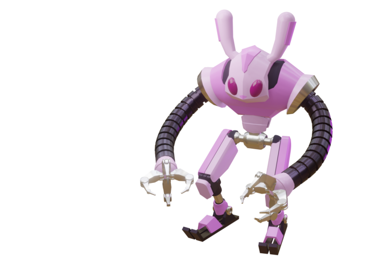
1. Introduction: assalam alaikum. My name is redeem Attack in I am an entrepreneur and also on academy lecturer in computer graphics disciplines. If you want to learn three d from zero, meaning no prior experience needed at all, then you've come to the right place. This course will teach you the fundamentals off really skills using blender 2.8 or above. The curriculum in this course is carefully designed so that students can learn gradually from the easiest lesson to the more advanced lessons seamlessly. After completing this course, you should be able to model a robot like this at material story, create lights and then rendering using the E V rendering engine. You are going to learn so many things in this course they are just too many to cover in this short introduction video. But just for a quick summary, the course is divided into four parts in the first part will cover the essentials, such as understanding how blenders you I works different techniques off Vieux port navigation, learn basic object operations, then basic transformation, different types, off interaction modes and how to do basic mesh editing in the second part will focus on look development techniques will cover in depth each of you poor shedding modes available in blender. Learn about different rendering engines. Learn how to create and use materials. Basic CD concepts such as color models, bit Depp and color codes. Learn how to create and control the camera object. Learn about the surface, smooth shading and how to control it and how to use screen space reflection inside. Evie in 1/3 part, will focus on three D modeling skills. We will cover advanced transformation techniques, then learn about the people point and how to control it. Learn different selection techniques learnt about inset, extrude and bevel. Then we will cover knife and bisect tools. Learn how to add loop cuts. How toe which hosts using different methods, learned the basics off modifiers and how to use the mirror modifier. Learn to come on three D Modeling mistakes and how to avoid them. Understanding normal direction and how to create money for geometry, learn point to point modelling techniques and so much more. There are many hands on projects in this course, such as creating this custom monkey head model, using just the basic mesh editing techniques and then at materials to it. learn to modernise kindergarten chair, create racist like this using different approaches. Create Roman column like this one. Create a toy train model by leveraging the snapping feature in Lender, then model a coffee table like this one. Finally, in a four part off this course, we will do the final hands on Project, which is making this robot. We are going to make use off most off the things that we've learned previously, but also learn new things along the way. Sort IHS how to sketch in three D, You seem to point to point modelling techniques combined with the skin modifier. Then we'll cover the basics off the grease spent so so we can grow sketches directly inside Bender. Then we will cover special movement operations such as fatten and shrinking and also sliding versus or ages. We will also be covering the basics off look off objects in lender and how to use it to create the snake like arm off the robot. Finally, we will cover how to create global illumination in Evie. Using the radiance volume initial law, you'll be able to create robots like this or any three D models at this level of complexity . If you follow the course step by step in order. So doing now and take your first step into the world off. Pretty using blender Hef unlearning wa Sallam alaykum.
2. New courses availability: Before you start learning
from these courses, I need to inform you
that I have released a new version of
this course series that uses Blender Version four. If you are already using
Blender Version four, you should take those
courses instead of this one. After you have taken the essential courses for the version of blender
you are using, you can go back to these
older courses just to challenge yourself to
try out the projects. Now, you may be wondering if I do not recommend
this course, why is it still round? Why not just unpublish it? Well, there are two reasons. First, Skillshare is
unique learning platform. You see, unlike other
platforms where authors can freely publish and
unpublish their courses, Skillshare does not
allow you to do that. There is no unpublished button
on the author's dashboard. So authors can only publish, but unpublishing is entirely
in Skillshare's power. If the course like
student engagement, which is a sign of
poor course quality, Skillshare will
review the course and then automatically
unpublish it. The second reason is that
many students have actually asked me not to remove the
course. And why is that? Because these students have old or slow computers that cannot run newer
versions of Blender, so they have to use older versions of blender
for their daily work. So these are the reasons why we still have the old
versions of the courses. I am sure you understand
the situation.
3. UI introduction: in this lesson video. We're going toe. Familiarize ourselves with blenders, user interface blenders. U Y is unique compared to other software you have seen before. Unlike other software, the you I consists off multiple areas that can be tiled s. You wish. But before we get into the nitty gritty, let's talk about what the default has to offer. When we first long to vendor, we will see these splash screen. You can close these splash screen simply by clicking outside the splash screen window. No, if you use blender in a public computer such as in classroom or library, you may have different you I layouts from what I have here. If that is the case, you may need to go to the file menu up here, defaults and then click on these load factory settings. This will set everything toe the defaults. This is important. So we have the same starting point and avoid confusion along the way. Okay, up here we have the menu bar. We have file menu in here where we can save an open file. Then we have the edit menu where we can undo and redo. But most importantly, it is where we can access the preferences down here. We also have render menu where we can render image an animation. We have window menu where we can Togo blender toe full screen or to create a new blender window. This is helpful. For example, if you have multi monitors set up okay, after the main use, we can see we have so many types in here. These tabs are used to store workspaces. What workspace means in Lender is you. I layout precept by default lender. Already provide suffer a work spaces such as lee out modeling, sculpting, UV editing and so on. Now human orders. Did I have some off the works by steps, clip or hidden like this? This is because Are you standard 7 20 p HD resolution to record the video? I don't use full HD or 10 80 p resolution because I know that a lot of my students like to watch the lessons in small sized mobile devices. A full SD resolution video will make the mouse cursor and the U I buttons look too small in those devices anyway, if you use Brender in small sized resolution, you may also experience this y clipping now, Don't worry. Toe access the hidden new I simply hover your mouse over the area and then just rotate the mouse scroll wheel. This method also works with other clipped or hit a new high in lender. If you have full HD or larger screen resolution, you really don't need to do this. Okay, let's get back to discussing the workspaces. To switch between these workspaces quickly. We can use keyboard shortcuts to switch to the next work space. We can hold control and then pitch down to go back to the previous work space. We can hold control and then press which up? Okay, Later, we will learn how toe create, customize ed and remove our own workspace. For now, let's use the default workspace, which is layout in here. Okay. At the right side, we have seen pulled on lease and also the fuel earlier pulled on lease. We'll discuss both off this when the time come. The middle area we see in here is the three D few Port Editor. This is where we can see out pretty objects from different angle at the bottom. We have the timeline editor where we can play and pass animation, said the starting and the ending frame etcetera. This timeline editor will be very important later when we are doing animation and the right side, we have two editors. The top one is the outline, er, any terror where all objects in our scene are listed in its editor, we can slack object. We can also hide and show objects by clicking on this ice. Impose less, but not least is the property editor. This is where we set perimeters, whether be global parameters that affect everything or contextual parameters which will affect only the selector for the active object. Okay, when working inside vendor sometime, we want to escape from the U I complexity and focus only on one editor. We can maximize on editor to take up the entire blender window by holding control and then press space bar. But you must remember this shortcut works in conjunction with your mouse cursor position. So, for example, if you're most cursor is over, this pretty few Port Editor Pressing Control Space bar will make their three d few poor editor maximized press control space bar again. We returned the editor to its original area or size notice. If I have are my mouse cursor on its outline er area pressing control and space. Barkey will make that outline er every terror toe fill up the entire window control space bar again to minimize it. So important lesson that I want to explain first here is that all blenders, shortcuts work based on where you're Musker, sir is located. Okay, I repeat again, as this is very, very important. All blenders, shortcuts work on the editor where your mouse cursor currently positioned. So just remember that when you try to execute a certain shortcut, you need to place your mouse cursor in the correct editor that you want to target. Otherwise, the shortcuts one work or it will work. But in another way, meaning it may produce different results, which you are not expecting at all. We will learn a lot of shortcuts in this course, as in my experience. As far as I know, blender is the most short cup oriented software in the world. You may feel a bit discourage. Stolen blender. At first I feel that way to the first time I learned blender. But trust me after knowing how blender works, you will want all software toe work, like blender. So just bear with me now and keep moving forward.
4. Editor and Area: in this video, we're going toe kaffir about editor an area If they look at our default You I lay out we actually have something like this. Each off this color box is called area and in each off these areas, we can define the editors. So essentially we always need an editor to feels up area. Okay, let's discuss about the editor first and then later the area. There are many editors in render. Each is used for a specific task. Now each editor must always have on element called header. It is a horizontal strip with buttons and our menus by default. Most headers are located at the top like this out liner editor in here, for example. So this whole area is an editor called the Outline er and this bar. At the top of it is the out liners. Header the Properties editor, which is this area also has the header placed on top. Now, sometimes the header looks transparent. Like this large three d few port editor we see at the center. This whole area is the editor and this row off buttons is It's header. This editor don't here is called the Timeline and it has the header on top also. Now, if you don't like the header to be placed on top, we can switch its location to the bottom. We can do that by right clicking on the header bar and then just flip the bottom. Now the header is placed at the bottom to place it back to the top. We can right click again on the header bar and then just flip top if you mistakenly right, leak and then click this show header option in here. The header will be hidden to bring it back. You need to click this small character button in here. It is very small in sub toe, but you should be able to see it in your own monitor. Okay for the TV few port header because it is transparent. You need to write three on any off the buttons in there to see headers off menu. Then you can access the header Functions such as flipping it to bottom are flipping it back to top. Now you might be wondering, why are we talking about header so much? Because in a header, there is a special pulled on lease where we can switch the editor toe another type off editor that we want to show on that current area. For example, we want to change this treaty. Few port editor in tow, a youth. The editor. We can do that by clicking on this left most button and noticed that blender provide so many different editors. Click on this UV editor in here, for example. Now, as we can see the center area previously occupied by the three D few Port, any terror is now occupied by new UV editor. If we click again in here and into Out liner, for example, we have something similar with this area to change this back to the three D few port editor . Just click again in a header pull down lease and then just three d few port now out of three D. Few port is back, just like before. So, as you can see in our default you, I lay out. We have all of these editors and on each off these editors, we have headers that we can use for different things. But most importantly, we use them to switch the editor into different types off editor that we want to use. Let's talk about resizing the areas each off. These areas are recyclable. To resize them simply hover our mouths over a border which exists between areas until you see the aero cursor and then just click drag the mouse to resize it. We can do this both on the vertical borders and also on the horizontal borders. Okay, besides switching the editor every sizing it, we can create our own custom layout by splitting and joining areas to split an area for us . We need to move our mouse cursor on the corner off our editor. When we see our mouse cursor change into a plus Imbo there is where we know that we are at the editors corner. If we drag it down like this, we will get a new area by splitting the previous area horizontally. We can then change this editor toe image editor, for example, or to any editor that you like. If we direct the corner to the left instead, the area now spread vertically. OK, Now you need to be very careful in where you place your most cursor. If you just slightly move it to the right crossing the border and then dragged down like this. You split the outline er instead, not the three d few port. Okay, so just watch where your mouse cursor is positioned. Next. Let's discuss how we can join areas to join areas. There are two rules you need to remember. First is on area can only be a rectangular shape. And second to join, you need to drag outside. Not inside. Let's see what the first rule means. If we have something like these, we can do in these two areas together because the resulting area will be a rectangle. Right. But we cannot join this area in this area directly. Why? Well, if you think about it, if this one and this one are joined together, the resulting area will be on our shipped area. And that is just impossible to do in lender. If you want to join this whole areas back to just one area, just like before then what you should do is doing this to areas together first and then later during the resulting area with the area below it. Okay, the second rule off joining area is dragged outside. Not inside. Let me split up the area again. So we have something to work with and changed the right area. Toe UV editor, for example. Okay, now we want we join these two areas to make it easier. Just imagine that these are two different countries Country A and Country B. If you want to join these two countries, you need to determine which country should conquer which country. If, for example, country a invade country, be then country B will not exist anymore. All of this region will be country a right to do that, we need to send armies off country A to country B. So we need to direct the corner off the left editor. We just this one, not this one, and then drag it to the right or direct outside. Not this way, because this way is dragging inside, which will create another split. So hope this corner and drag outside to the right like this. You will see a dark overly with bright Aargh before releasing the mounts. You can actually direct this to the left or right if you need to change your mind. Essentially, the area that has the dark overly will be gone. If we released the mounts at the right area we can see now this whole area become one area using the previous left area as the editor at this stage, if we want to join this area with this area, we can do that now because it will produce a rectangular area, simply direct this corner to this area and then release. Okay, I teach blender for quite some time now in the university in also on offline workshops. And very often my students have problem when spreading in doing areas. Mostly, this problems happen due to mistakenly taking the wrong corner to drag and also some thyme toe, a wrong direction. So they end up with so many needless areas in there. You, I lay out. If you experience this problems, don't worry, because there is another easier method off doing splitting and joining areas, and that will be by using the right mouse button. Now you might be wondering why not? We just learned this easier method and forget the direct corner method then well, easy. It's not always faster Dragging editors Corner is still my favorite method as it is much faster to perform. But using the right click method proves to be less prone to error. This is important, especially for those who are very new to blender. Let's see how we can do this right click method, and later you can decide yourself which method you want to use. For example, we want to split this pretty few port editor. The first question is, Which way do you want this area to split vertically or horizontally? If you want to split it vertically, then you need to move your mouse on the horizontal border off this editor until we see the Aero cursor, then right click and then just split area notice. We get this brief, you line off where the split will happen. We can move these right or left. We can also split the other area off the border. If you want to buy moving the preview line to the area. If you want to confirm, simply left click and we have our split area. If you want to split horizontally, it it's mostly the same process. But you should right click on a vertical border instead. Then, just like before to split area. We will see a preview line again, but now it is horizontal. We can move this to the other side if you want. Oh, and then just left click to confirm OK now tojoin areas, for example. We want tojoin this one with this one simply rightly on the border that separates them and then choose join area. Now, as we can see, we have this a dark between overlay just like before. However, your mouth to the area you want to remove and then left click to confirm we now have a larger area from joining the previous two areas.
5. UI Size and Workspaces: in this lesson video we're going to discuss about how to change the you I size and then how to manage you. I layouts using workspaces blenders default you y size. It's actually easy enough to read and to work with if you have a standard sized monitor. But in some cases, you may need to make the U I size bigger. For example, if you are working on a very dense picks up for each monitor, this happens so some off my students to fix this issue. Blender actually comes with two features that can resize your you. I elements easily. First is the display resolution, skill setting toe access it. We can go to the edit menu and into his Preferences interface tab. You will find the display section, and in here you will see resolution scale slider by default. It is said one If he dragged this value left or right notice. How do you I become bigger or smaller so this slider will affect all off the you I elements in lender globally before render version 2.8 final release. After you make any changes up here, you need to click on this pull down menu. Then you should click this safe preferences button in here. Otherwise, off the settings you have made will get reset back to the default when you close and restart blender. Okay, but since Blender 2.8 final release, you really don't need to click the safe preferences manually again, because there is a new option in here called auto Safe Preferences. If this option is on, which is the default, every time you make changes in the preference window, the settings will be safe automatically another way off. Changing the U I elements. Size is by using shortcuts. But I must warn you guys that this method is not supported uniformly across different editors. Also, the changes happen locally and temporarily to see how we can do this. First, we need to place our mouse cursor over the area that we want to Reese Ice, for example. I want to resize this Properties editor. So however, our mouths on top off the Properties editor and impress the plus key on a number head to make the U I bigger and minus key on the Phnom Penh toe make it smaller. As you can see, the changes happen on Lee on the properties editor and not affecting the rest off the u I. If you want to reset the size back to its the fault, you can press the home key in keyboard. Now, if you try to do this on the outline er editor, it will produce a different result. If we hover our mouths in here and impress the plus numbered button, we actually just expanding objects. Hierarchy pressing minus numbered button will collapse them. If you use this method on a three D few port editor, this will zoom in and out the few instead. But three D few Port has two additional U I panels. The left one you see in here is called the Toolbar, and another one at the right side is called The Sidebar. We cannot see it now because by default it is hidden. If you look closely at this area, you can see a small, corrupt button. If you click on it, it will open the three D few ports Sidebar panel. Now, if we have for the mouse cursor on the sidebar and impressed the plus sign button in the Phnom Penh, it will make the U I elements in the sidebar. Bigger. If you press the minus ember, it will make them smaller. If you breast home, the size will get reset. We can also do this on the toolbar plus to make it bigger minus to make it smaller and home to reset it. Now, if you do this on the timeline, it will zoom in and out instead. Okay, So to recap, the less method behaves locally and it works non uniformly across different you a region. Some may skill the you I some may not. We have talked about workspaces briefly before, but we haven't explored them more in depth, such as how to create our own custom work space. If you want to create your own workspace preset first you can click this plus button up here and then choose duplicate Curren. Or you can pick any off the rocks. Pay step, right click and into duplicated. By doing this, we will have a new workspace tab. If you want to delete a workspace, you can right click on the one you want to remove. And then just the lit in here to rename a workspace, simply double click on the name off it and then type a new name. For example, We d okay, now, I don't really need this layout, so let me just remove it from the earlier lesson. We know that these workspaces up here under the fault workspaces exists in lender now. What if he accidentally removed them? For example? I can right click on the animation work space in here and into the lead. If this ever happened to you, don't panic. Because all of this default workspaces can be called again easily to do that trick again on the plus button and into general category. In here we can see the animation work space in here if you click on it. The animation workspace is no back. Something that you need to be aware, though, when using workspace presets, is that if you create a custom workspace precept, that workspace will only be available in your blender file. Meaning if you save the file and then later re opening, the workspace will still be there. But if you open another file or start a new file that custom works based that you have created before will not be available. If you want to make your custom preset always be available. Whenever you start a new file in render, then you need to say if you're currently in negotiation as the default starting file. To do that, you can go to the file menu defaults, then choose save startup file in here. Okay, Now, I'm not going to do that, because in the scores, I want to make use the defaults as much as I can. By doing this, I hope the course will be easier to follow. Since we all have the same user interface, lay out.
6. Mouse viewport navigation: in this video, we are going to learn how to navigate the three d few port. If you are doing anything that is related to three D such as three D modeling, texture, ring, animation, etcetera then treaty. Few port will be the editor where you do most off your work in Lander. That is why it is the first editor we need to cover before anything else. OK, when we start blender the first time you will have these three objects available inside your scene, we're going to remove these three objects and then create a monkey had object instead. Why? Because we need something in the few port that has percents off direction, toe practice, the navigation to select all off the objects in the scene. Desprez s a letter key. After that To delete them, we can press X letter key and in just delete in here. Now our scene is empty. Next, let's click on this at menu button to smash, then to us Monkey in here. I know we haven't talked about object creation yet, but just bear with me for now, okay To rotate around the treaty, few poor. We can press and hold the middle most button and then just drag around. Now you must remember that we are not actually rotating our object in here. The object in our sin is unchanged. We simply wrote it around on how we see the object. Now. Some off, you might ask. Hey, I don't have a middle button in my mouth. How can I wrote it? My few port then Well, if you use standard mouse with a scroll Leo, you actually have a middle. Most button. Simply click down on the scroll Leo, and that will be a middle most button click. But if you have some kind off fancy touch mouse like the April magic mounts, unfortunately they don't have middle button. So you need to work around this limitation by using additional keyboard shortcuts or use different methods off navigation, which were going toe cover in later lessons. But anyway, if you are planning to learn blender or any three D software in general, you better infest on a good mouse with middle button as blender and also other three D software that I know off such a studious Max Maya, etcetera. They all use Middle mouse button extensively for a few port navigation. Yes, you can use other methods for navigation, but using mouse is by far the fastest way to never get the few poor. So this should be your priority before the other methods. Okay, next to zoom in and out the few port you can use the mouse scroll wheel, scroll up to zoom in and scroll down to zoom out. Now, when zooming with the scroll wheel, we get these stepped motion. If you don't want this step, effect meaning you want to zoom in and out smoothly. Then you can use the other method, and that will be holding the control key and then hold the middle most button and wreck the mouse up and down. As we can see, the zooming motion is now smooth and not stepped as before. The next navigation control that we want to cover is to pen or to drag around the treaty. Few port. We can pan around a few ports by holding the shift key and then press the middle most button and just move the mouse around. Two. Penned a few parts. Okay, guys. So that is how we can never get the treaty. Few port using the mouse. I strongly suggest that you memorize in practice this navigation technique before moving on , as this is very, very important when working with three D in blender.
7. Alternative navigation methods: in this lesson video. We're going to discuss how we can never get the treaty few part using the you I buttons and then using only the keyboard shortcuts, although using amounts is the fastest way and my preferred method off navigating the treaty . Few part. But you may experience situations where you cannot use a three button mouse. Perhaps you need to work mobile, but your mouth is broken or you accidentally left your mouths at home so you are forced to use your laptop strike bed. For example. Let's discuss how to never get using the you I button first and then later using the keyboard shortcuts since Blender for version 2.8, we have you I elements in the treaty few port that we can use for mitigation. Let's start with few port rotation to rotate around a few port. We can move our mouse cursor at this area that has colorful small circles and then just dreck around as we can see. As we dragged around, the mouse cursor becomes hidden and a few port. We wrote it along our mouse movement when we released the mouse. Our mouse cursor is back at the exact location. We start dragging before okay. To zoom in and out the few port we can hover our mouths on top off this magnifying dress, Aiken, and then drag it up and down, drink up to some closer and write down to zoom further away. The less navigation you I told that we can use is spending. We can do this using the next button that looks like a hand symbol. Click dreck on it, and as we can see, we can penned a few port around. Okay, so we have all that we need to navigate the three D few parts. But what about these two buttons? Well, this one is useful to switch the few toe camera few mode we will discuss about this more in depth in later section when we discuss rendering this left most button is useful to switch the treaty. Few port from perspective mode, toe oughta graphic mode back and forth in perspective mode. We just the default. We have a vanishing points. We can see that this grid lines will converge or inter cross into a single point if we switch the few toe oughta graphic mode. All off this greed lines are perfectly parallel to one another. This feeling system is also known as isometric off course. This is not realistic, but we often needed for a certain type off work. Next, we can also use the keyboard only to never get the treaty. Few port. But I wouldn't recommend this method at all, as it is very limited in term. Off the control goodies, we can use the keys number 246 and eight in a numb bed. Number two and eight can be used to rotate the few port vertically like these. This is number two, and this is number eight. And for number four and six, you might already guess it. Number four is for rotating the few port to the left, and number six is for rotating the few port to the right to zoom in and out. The few poor we can use the plus and the minus symbols in a nom pad and finally to pen around a few parts. We can hold control and then press number four and number six. In a number. This will penned a few port horizontally. If we hold the control key and impress number two or number eight in the number had the few port will pen vertically. So it is how you do few port navigation using only the keyboard.
8. Axis viewpoints: in this lesson video, we're going to discuss about access a few points. So what is exactly access a few points? Well, excess few points are special viewing presets where we can see our scene straight from a certain access. But before we start learning how to switch out of you to access a few points, there is something important that we need to discuss first, and that will be orientation convention. When working in three D, It is strongly recommended that you first understand the convention off the orientation relative to the access. This is because different really software or game engines may have different orientation. Convention, for example, what is considered to be up direction in three DS max is different than the up direction in Unity Game engine In Treaty S Max, the up direction is a Z axis. While in unity, the up direction is why access, if you are working with multiple truly saw for this can be a bit daunting. But there is at least one thing that is common in uniform, across all pretty saw for in the world, and that is the colors off the excess, no matter what really software you are using Z axis is always blue. Why? Access is always green. An X axis is always read. Okay, for now let's focus on Lee on the orientation convention inside Lender in render the up direction is Z positive access and the down direction is Z negative access. Okay. The front direction is why Negative axis and the back direction is the Y positive access Leslie, The right direction is the X positive access and the left direction is the Xnegative axis. Now you always need to remember this convention all the time when working inside vendor especially the front direction which is why negative access You should always create object facing negative y axis when modelling You will understand later why this is important If you ever forget this convention, just create a monkey had object The monkey had object or also known as Suzanne will face the front direction correctly by default. So this way is front. We can see this green line in here. This is the Y axis We can sit letter Why in here is also green and aligned with this green line? The one that has letter Why is the positive direction so this way, it's positive and this way is negative. Okay, this red line is the X axis wandered Has Letter X is the positive direction which is this way and one that doesn't have platter X means the negative direction which is this way and for the access. I think it is very obvious. Now positive Z axis is up, which is this way, and negative Z axis is down, which is this way. Okay. When modelling or placing objects in our truly seen, we often need to see objects straight from front or side or top view. We can do this using several methods. Most method you I method and keyboard method. Let's see how we can do this using the you I method first to see object from the top view, we can click on this small zeal, a turkey. If we do this correctly, we can see the world top cartographic in here. It means we actually seeing the treaty. Few port from top and a few is set toe Arte graphic mode. Mostly if you want to see objects from the access if you point you wanted to be in Orta graphic If for some reason you still want to see in perspective mode. We can press this perspective toggle button just as we discussed earlier. Now, while in access few point like this, you can zoom in and out, and you can also penned a few part but notice. If you try to rotate the few, it will go back to custom view and perspective mode. You can see the words user perspective again, like before the user attacks in here means that it is in user preference viewing angle to see from the side view. We can either click on the X positive in here for the xnegative in here to see from the front. We can click on the Y negative in here and to see from the back. We can click on the Y positive in here. I'm sure you get the idea now. Next is accessing access few points using only the keyboard shortcuts. To do this, we need to rely on the number again. First is number one key in a number of bed. This number one button will change our view. Port toe from view Orta graphic. Next is number three, which we'll change our viewing angle to cite a view, Orta graphic unless but not least is number seven, which we will change our view. Port toe top view. Orta graphic. Okay, you might be wondering by now why in the world blender to use those numbers for switching the view. I mean, why number one and three and seven to answer this question? Let's take a look at this graphic first. Remember, when we are in high school, we learned how to draw simple technical drawing on paper, for example. Let's say we want to draw a car. Usually we need to start with the front view. Then we take our ruler and create these guidelines so we can draw the top area precisely like these. Then we create horizontal lines like these to guide us to draw the car from the side view. Okay, so this is the front view. This is the top view, and this is the side view. Now, if you just remember this image, just put this image in your head. You will remember the number 13 and seven shortcuts. Because if we map this to our Nam pit layout, we can see that they have similar positions. Number seven, key position is at the left top corner, just like this. Stop. Few growing number one is for the front view located at the left bottom corner. Dislike this image off our cars from view. And the less one is number three located at the right bottom part off the lump ed. Exactly like the position off our cars side few drawing. Okay, So again, just remember this layout in your head and you should remember the short cuts Much easier. Now, you might be wondering, Can we always see three access views using keyboard shortcuts? What about the back few, but on few and left view. Well, there are two methods to access them First is by holding the control key. So, for example, if we want to see the bottom view because bottom is the opposite rooftop view, we can hold control and then press the number of seven key. Now we have button view to see from the left of you hold control and then impressed number three key. And finally, to see the back few hold control and unimpressed. Number one key. Okay, so those are the first method. The second method is by using the number nine key. This key is actually used to flip the view. So, for example, if we want to see the bottom view, we can press seven firsts which essentially turned the view toe top view and then followed by nine. We are now seeing the bottom view to see from the left of you We can press three and then followed by nine to see the back few. We can press one and then followed by nine. Okay. And the less keyboard shortcut I want to mention here is number five pressing number five in a Phnom Penh. We'll talk about a few port within perspective and oughta Graphic mode. So basically, it is the same as clicking on this small button up here. This is photographic, and this is perspective. Okay, so that is how you use the keyboard shortcuts, toe access, access a few points. The less method we are going to discuss is using the mouse toe access the access viewpoints . If we have a use of a view like this and we want to see this monkey had object from right view, which is this way first, hold the R key and then drag using the middle most button to the left like you normally do view port tradition. As you can see, the View port will step to the nearest access viewpoint and automatically so it toe oughta graphic mode. At this stage, if we hold out again and then drag with the middle most button to the right, we get the front access viewpoint. If we hold out and dragged down like this, we get the top view. I'm sure you get the idea now something that you need to be aware, though, when using the most method is that you need to hold the out first and then drag with the middle mouse button. If you do this the other way around, I mean, if you first direct your middle mouse button and then while dragging you hold the out key, you will also get an Axis viewpoint snapping. But we don't photographic mode or it is still in perspective mode. Mostly, this is not what we want, so just make sure you hold the out key first before dragging with the middle most button. So we get the Orta graphic few automatically
9. Basic object selection: in this lesson video. We're going to discuss how to do basic object selection in lender and a very important concept in render called the active Object. If you used blender prior to version 2.8, you might already accustomed to use the right mouse button just like objects. Since Blender 2.8, the default most input to select objects has changed to left click. Some people may like the exchanges and some people may not. In this course, we are going to stick with the default to make everything easy for all of us. Okay, So to select objects for smack Scher, the stool up here, which is the select mode, is active. We will discuss the rest off these two modes in later lessons. To select this life object, for example, we can left click on it. We can tell that the object is selected by this orange highlight color. This object is actually a camera object. We can click on it also to select it. Notice when we slacken object The previous selected object will be be selected automatically. Okay, so clicking will get you one object selection Now what if we want to select multiple objects in blender. There are many ways to do this. One simple method that we can do is by performing a click drag like this. Every objects that are inside the rectangular bounding box will get selected when we released the mouse. If you need more position, you can use the shift modifier key. For example, we can select this life object again, then press and hold the shift key. Then click on this camera object notice. We just select the object, but the previous selected object is still selected. We can shift click again on this cube object. So now we have a total off three objects selected to clear or to dislike all objects. We can simply left, leak or click direct on any empty area in the view port. But if you prefer shortcut, you can press out a to dislike all. If you forget the shortcut, you can go to the select menu in a three D few port header and then select none in here. Yes, you can see the shortcut is out. A. We can also see that there is a shortcut to select all, and also there is control. I shortcut toe select invert. So let's try these shortcuts now. Press A to select all objects in the scene out a toe on select all. And if we click to select this cube object and impressed control, I now the selection get inverted. Everything is now selected except the cube object. Okay. Another way to clear the selection is by pressing a twice quickly. So again, to dislike all objects in a sin, you can either use out a or you can tap a better key twice quickly When selecting multiple objects. Using the shift key method, you may notice that the less selected object always have different highlight color. It is brighter or more yellowish, while the others are still orange, not only in the view port, but you can also see the colors in the outline. Ever. This one is bright, yellowish orange, while the others are a darker orange. This yellow color indicates that this object is now the active object. Okay, so what is actually active object? We'll just assume that the active object is the current main object or the focus object, because there can only be one active objects in the scene. This active object concept is a very important later when we discuss more advanced topics such as advanced transformation, joining objects, rigging, etcetera. For now, we just need to know that this yellow highlighted selection is the active object. Okay, besides the color, another way to tell which object is the active object is by checking the properties editor from the step and below, the perimeters are all showing the active object which is currently the camera object. You can also tell which object is the active object from the status bar. Don't. Here you can see the world camera. Don't. Here. This is actually the name off the active object. Now, if you don't see the status bar down here, it may have been turned off accidentally. Toe. Turn it back on. You can go to the window menu up here and then make sure this show status bar option is on no notice if we hold chief and click again on another sector object. The active object title is now given to this object. But notice if we hold chief and click again on the active object, that object will get the selected. It is still the active object but not selected anymore. So, yes, you can have an object active but not selected. But most off the time on active object is a selected object. So again, generally speaking, clicking and she's clicking on an object will make that object the active object. But if you shift click on the active object, that object will get the selective even know it is. They are technically the active object.
10. 3D cursor: in this lesson video. We are going to discuss one unique feature in Brender, which is called the Precursor. So what is exactly a treaty? Coarser? Well, if you look closely at the center off the treaty world in Blender, there is a small circle that looks like a sniper scope target. This is the tree dicker, sir. It is basically a pointer in three D space that can be used for a lot of things in lender when you sage off three D cursor is for defining the location off newly created objects. So that is why we need to discuss the three D cards or first, before we can discuss creating objects in lender by default. The treaty cursor is located at the centre off the World. If you want to move it around, there are at least four ways to do this. Using the mouse and keyboard modifier key. Using the treaty cars are too mode using the snap command and finally using the site barter . Let's list us each off this methods one by one for us, we can hold shift and then right click on any location that we want. The precursor will jump to that location lender will detect really surfaces when doing this . So if we hold chief and right click on top off this cube, for example, the three d cursor will be moved to the surface off this cube. The second method to move the three D cursor is by using the three D cursor to mood, which is this button in here. In this two mode, we can simply left click to any location. We like to move the precursor to that location. This method will also retake object surfaces. The third method is by using the snap command. With this method, we can easily line a treaty cursor with any object in a scene. To do this for us, we need to select an object. For example, this like object. Let me activity the select mode first so we can select objects like before. Select this like object by left clicking on it and impress Schiff s toe. Open the snap by menu to score, Sir. Too active in here. We can see now the treaty cursor moved to the light object location. If you forget the shortcut, you can access the snap command via the object. Manu in the TV few port header and then to snap in here, then cursor toe active. The less method off controlling the treaty cursor location is by using the three D View port sidebar panel. We have discussed briefly about the sidebar panel. Besides clicking the small carrot button in here to open the sidebar, we can press end in the keyboard, or we can go to a few menu up here and choose Togo. Sidebar in here in the sidebar panel in the view tab noticed. Don't. Here you will find a precursor section. If you don't see perimeters like these this make sure the carrot symbol or this small triangle Aiken in here is looking down, which means the panel section is expanded. If you click this whole barter, the carrot will be pointing to the right, which means the section is collapsed. Okay, In here we can see the location off. The traffickers are in three co ordinate the X value, the Y value and a Z value. If you want to move the treaty cursor toe a specific coordinate, we can directly type in the values by clicking on any off the sliders and then input the number. Or you can also move the mouse cursor on any off this input fields and then drag left or right like this. Now, this method off input is common inside blender, meaning you will find a lot off this input fields in lender. Most off the time we wondered through the cursor Toby, located at the centre off the world. You will understand, Leader, why we want to do this to reset the precursor location. We can do this in several ways. First, we can use the keyboard shortcut, Chief. See, this method is also useful to reset the view port to the center off the world. So if you have the view port looking on other area or direction pressing shift see not only will center the treaty cursor, but also will center the view port to view the center off the three D world. If you forget the shortcut, you can use the snap command method. We just by going to the object menu, snap and then choose cursor to world origin or by using the snap command also, but via by many a shortcut. And that will be Schiff s and into score, sir. Toward origin. OK. Finally, the less method to reset the treaty cursor is by going to the sidebar panel and in the treaty cursor section, rightly on any off these values and into preset all to default values. This will make all of it according IT access set to zero that's making the treaty cursor positioned back to the center off the three d world.
11. Creating and Deleting objects: in this lesson video. We're going to discuss how to create into the lit objects to create a new object for us. We need to specify where the object will be created. By positioning the treaty cursor, for example, we can hope Schiff and then right click in here next toe at an object we can press shift a notice. There are so many options off object types that we can create in Lender. If you want to create a three D object, then you need to go to the mesh option. And then it's like any off this objects in here. Let's big monkey. For now, you might be wondering, OK, cube, sphere cylinder makes sense. But why Monkey head? Well, this monkey head, which is called Suzanne, is the mascot off blender. We can say its name in your liner in here as we can see that her name is Susan. Having Suzanne as a geometric that we can create off the shelf is a very useful, for example, for a quick testing, lighting or material. Basically, we can use Suzanne every time we need a more complex object than this regular primitive objects. Okay, If you forget the shortcut. Or, if you prefer to use menu, you can use the edit menu in here. But first, let's shift right click on this location so the new object will not overlap with the existing monkey object. Now we can go to add menu to smash, and let's create a new office for your object. So that is how you create new object in blender. I'm pretty sure you get the idea by now. Display around with this for a while. You can experiment with different type off my subjects that blender provides. When our sin is starting to get crowded. It is a good time for us to learn how to delete objects, total it an object simply selected first, then press X platter key in the keyboard and then just delete in here. If you want to delete object right away without blender confirming your action, you can delete also using the delete key in the keyboard. But this method only exists for PC and Lennox users. For those of you who you smack, you need to stick with the ex letter key shortcut because, as most off you probably already known the delete key in my computer's is actually a backspace button in PC, so blender will pick that as a backspace. Also, if you want to delete multiple objects at once, simply select those objects first and then press X and then choose delete when we create a primitive objects such as cube, cylinder sphere, etcetera. We might want to change certain aspect off that object, like the radius or the DEP, or how much segments exists on certain sides. Another three D software, usually after primitive objects, are created. They still hold those parameters so we can always go back and change the parameters. Him lender, however, there is not the case. Brender doesn't have any construction history. What we can do exchange the parameters exactly right after the object is created. So, for example, let's create a cylinder press shift, see first to center the precursor. Then she if a toe open the object floating panel MASH and selling better notice right after we create a Syrian better. We have option down here in the bottom part off the treaty. Few port. We can click on this character button or this whole bar, actually to expand the panel notice. In here we have first assist perimeter. This determines how much sites that cylinder has. Then we have radius to change the circle or size off the cylinder, and then we have depth, which basically controls the height off the cylinder. We also have some other stuffs down here, another way toe open. This creation parameter spinal is by using a keyboard shortcut, which is F nine. But notice when we press F nine blender actually opens up a different panel that is floating and positioned at our mouse cursor location. We can move the spend all around by clicking and dragging the upper part area. However, we can just move our most cursor to any location we like and then pressed F nine again to close the panel. Simply move the Mosque Ursula way and it will close automatically. And although this one and this one are two separate panels, the parameters inside these two panels are exactly the same, which is contextual depending on the less command we performed in lender. Okay, What I really want to point out right now is that these parameters exists only after you created the object. If after this you do something else, such as moving the object or create another object or many other things in render These parameters will be gone forever. For example, I will shift right click in here to move the treaty cursor Schiff A at a monkey had object . We know get size to control the monkey head object if we select the cylinder object again. The parameters that we saw before such as virtuous is in radius and dep. They are not there anymore. Okay, you might be thinking that this behavior is one off the floors or these advantages in using render. I can assure you that this is never been a case. I have used a lot of three D software before, and personally, I like how blender works. If you have been doing three d modeling before in order to the software, you know exactly that 99% off your time when modeling will be tweaking. Verjus is moving ages, extruding faces and many other modeling tasks. We don't spend too much time tweaking primitive objects perimeters, Therefore, for three D modelers, the way blender works is exactly as we expected. As it is more straightforward. We'll be covering more in depth about remodeling later in this course, and you will understand more about this issue as we go along
12. Viewport settings: in this lesson video we are going to discuss suffer a few port settings to make sure we have the best experience. We're navigating the treaty. Few Port. The first thing we are going to discuss is the navigation settings in the preference editor . So let's open the edit menu preferences and opened a navigation category in here. You want to make sure all of these three options are on and also this one option. Zoom to most position. Quick explanation about the settings For us, it's the orbit around selection. When this option is turned on, the few port center off rotation will be at the location off our selected object. This is helpful so that the few port will not go astray and always have our selected object in frame. Second is the older perspective. By default it is on. This is the reason why when we switch from user to any excess, a few points such a stop or right or front view, the few port automatically changed toe oughta graphic vice versa. If we go back from access few points to use their a few, it will automatically change toe perspective. Is the Auto dep basically if this is on blender, will detect the depth off the object surfaces beneath the most coarser and use that for reference. Okay, you might be asking reference to what the answer is the next option, which is zoom to most position. When this option is enabled, the most pointer position becomes the focus point off, zooming instead off the few port center. Now with the auto DEP option turned on a blender will be smart enough to sense the three D surface under our most pointer so that the zooming process become more precise. The next setting we want to look at is the few poor quality. If you already have in the preference of editor open like this, just go to the few poor category. In here you will see quality section. I am setting all of these values to know or none, and finally, I said this edit mode, smooth wires toe off. Also, all off the settings determine how much entirely acing effects will be applied in the few port. If you don't know what anti alias ing is, essentially, it is a rendering technique to make Jega pixels look smoother by adding extra, semi transparent pixels around objects, border or lines. This will make the few port looks better of easily, but at the course off performance. If you have fast, high end GPU and you want to enjoy extra smoothness in the few port, you may want to live. These settings toe the default for me because mostly I don't actually need anti Elia Sing in the few port and also because I have my screen recording running in the background. I prefer toe. Have maximum performance out off blender. There is why I turn off all off these settings if we place our most cursor inside the treaty. Few port and impress end toe open the sidebar we can see in a few section. We have this parameters. Focal length clip, start and clip n. These default values are already good, so for more situation, you don't really need to change them. But you may need to change them later in the future, so let's discuss each off this parameters one by one the focal length value. Determine how wide the fueling angle off our few poor. It works just like how a camera lens works in the real world. That is why it is measured in lands. Millimeter value. If you are not familiar with photography, don't worry. Basically the higher risk focal length value, the narrower, the fueling anger that's killing off the perspective effect the lower this value, the wider the feeling angle. So we get to see more objects in frame. But the perspective distortion will become stronger again. For most cases. This default value, which is 50 millimeter already fine. Next is the clip start in the clip and values. These values are very useful when we have a very complex scene, and we want to reduce few, put workloads and maintain workable performance. Essentially, the scraping values will avoid the few poor to display anything that are further away from the clip and values and anything that are closer than the cliff start value. To see these values in action. If we use a very low value in a clip end like 20 meter, for example, we can see everything beyond this distance will be invisible, even agreed, becomes invisible. If we drag the slider even smaller, we start to see the cube get cut off. We can see the same thing happen if we increase the clip start value in here, The front cube area will get cut off. I'm pretty sure you get the idea to reset this to the default value. Simply right. Click on it and just reset to default value.
13. Framing and custom shortcut: in this lesson video we're going to discuss about framing and how to create custom shortcut in lender framing is a way off, making our few port to focus on certain objects. When working with large sin filled with multiple objects, we often need to zoom in directly to a select the object. Or perhaps we need to see everything in the scene quickly. In this scene, I already have several objects to practice framing. The first method off framing is to see all objects in the scene. We can do this using the home key in the keyboard. So if we have our few port zoomed in like this pressing home key, well framed a few port so that all objects in the scene are visible. The next framing method is to focus on a selected object. To do this, we can use the darky on a number head. But of course, this method will require us to select an object first. So just click on this cube, for example, and then press the darky on a number head toe frame it. As we can see, the few port will automatically move and zoom so that the selected object we have currently is in frame press home again to see the overall objects in the scene. If you ever forget the shortcuts, you can go to the view menu up here in a three d few port header, we can see the frame selected. Shortcut is dot and the frame all shortcut is home. Okay, guys, I really need to stress out that these framing methods are very, very important. Why? Well, if you are working on a complex in, you will often zoom out the few port way back and sometimes zoom in very, very close to see the small details using the scroll wheel. Now, this condition will often bring problems. Sometimes our a few port just get stuck because we zoom in or out. So far, this problem is not specific to blender all three D software that I know half this problem also, if you ever experience where your few port one zoom or it does zoom but very, very slow, you need to reframe your few poor, either by pressing the home key to frame all objects, or you can select an object. You want to focus first and then hit the number dot key because these framing matters will reset the zoom value off our few poor. So after framing, we can zoom in and out again, like we normally do now, because this dopey shortcut is very, very important. If you use laptop or you use a computer that doesn't have any Phnom Penh in its keyboard, you may want to create a custom short cut for it. Off course. You don't have to do this if you have a full keyword with Dump ed, but you can still watch dress off this lesson to learn how to create your own custom shortcut For the shortcut. You can replace the dorky in the NAM paired with the dorky in the latter pad. This is entirely up to you, but personally, I prefer to use the Q letter key for the custom shortcut because off two reasons. First, the letter Q key is near our left hand position, making it more convenient to reach. And we will need to use framing a lot, especially in modeling session. Second, the Q letter KIIS originally used for a quick faith free, which is a feature I rarely use to create a custom shortcut, go to the edit menu and into his preferences. You will see key map category in here. All blender keyboard shortcuts are listed in here. The left column shows the name off the command, and the right column shows the key combination. You can try finding a short cut manually by digging through all of these leases. But to make this easier, just click on the search bar up here and then type fuel selected blender will filter beliefs so it only display commence that have fuel selected words in its names. What we are aiming here is the three D few port shortcut, which is the section notice. We have this number dot key in here to replace this with the Qula turkey. Your split on it until the world's press. A key show up, then impressed the Qula turkey. And that's it. You just created a custom shortcut in Lender. We can tell that a short cut is not a default shortcut by the zero button. If you click on this aero button, it will referred back to Phnom Penh doc again. If you mistakenly click on one off this ex buttons, the shortcut will get removed. Don't worry, just click this restore button up here to get it back, but this will also reset our custom shortcut. So click again in here and then press Pula, turkey. Close the preferences window and let's there's our custom shortcut. Select this object, for example, and then press. Q. The shortcut works as we expected. Okay, guys, from this lesson forward, when I say frame to a select the object, it means pressing the daqian, a Phnom Penh or a Q custom shortcut, or any key that you choose for the custom shortcut.
14. Hiding and Local view: in this lesson video, we're going to discuss about how to hide and show objects in the scene. Then we are also going to discuss about the local view. First, let's discuss how we can hide and show objects in lender when you are working on a complex scene, it will be very hard if you want to focus your war on Lee on a specific object, because the object might have been coffered or offer left with other objects. So that is why it is important to be able to hide and show objects in the scene. In lender, we can hide and show objects using different methods. For us, it's using the outline, er, second, using the keyboard shortcuts and finally using the menu. There are actually more methods on how to manage objects visibility in lender, such as using collection and our sin. But for now we will focus only on hiding and showing objects and also how to use the local view. Okay, so to show and hide objects using the outline, er simply look at the object in your liner and just click on the ice symbol at the right side to hide that object For example, if I click on the ice symbol off the cube object, that cube object will be hidden. You can see the eye symbol is closed. Okay, so show it back. Just click again on the ice. Imbo. Now the object is shown again, and the ice imbo is open again. The next method off showing and hiding objects in lender is through the keyboard shortcuts . For example, if we have this cube selected to hide the cube object, we can press H in the keyboard noticed by pressing age. The selected object, which is the cube, will be hidden. We can see the ice ember in the old liner is close to also so show hidden objects in the scene. We can press out H now we can see the cube again. Bless keyboard shortcut we are going to discuss is Schiff H. Basically it will hide everything except the selected objects. So, for example, if we have this cube object, selected pressing shift H will make the light and the camera objects become hidden, but the cube object still visible to show off them. We can breast out H again Now if you ever forget the shortcuts we can use the less method, which is using the menu toe access, the height and show commands. We can go to the object menu in a treaty fuel port header and then just show hide sub menu . In here, you can see all off the commands we have used before. Listed here, show hidden objects, hide selected objects and finally hide and selected objects. Now let's talk about the local view feature in lender when working with complex scenes. Sometimes we want to focus on certain object and just want to hide the rest. You won't be thinking OK, so this is like hiding objects. Well, yes, but it is a bit different if you used other treaty software before this mode is often called isolation moder. Essentially, in this mortar, you only see the object you want to work on and make the rest off the objects hidden in lender. However, this isolation mode is called the local view mode toe access it. First, we need to select an object, then press the forward slash key in the number pad for the Ford Slash key in the letter pad area. By doing this, the few port will resume in tow. The selected object and we can see up here in the view port. There is a packs that say's local now notice when we wrote it, the view port around. We don't see any other objects except this cube object, although in the old liner we can see that all off the objects are actually not hidden. After you are finished working with this object, you can go back to the global view mode by pressing the forward slash kill gin in a keyboard. Now the local tax is gone and we can see all off the objects again, just like before.
15. Basic transformation: the term transformation in computer graphic is everything that has to do with position, rotation and scale. So basically, in this lesson, we're going toe cover on how to move objects, how to rotate objects and, lastly, how to scale objects in vendor. We can transform objects using EVERLYS three methods for us by using the manipulator second by using shortcuts and third, by typing in the values In this lesson, we're going to focus on Lee on how to transform objects using the manipulator. First, let's discuss on how to move objects to move objects. You need to activate the move tool, which is this button in here. If we have the move tool active and we have an object selected, we will see these three arrows at the center off the object, this colorful arrows. It's what is called the manipulator. The Blue Arrow indicates the Z axis direction. The green one is the Y axis, and the red one is the X axis. Let's say we want to move this object along the X axis. To do that, however, our mouse cursor over dread aero, then click and wrecked like these as we can see the object will move along the X axis. If you want to move it along the Z axis, we can click and wreck over the blue arrow and the same thing with the green arrow. If we click and drag on it, the object will move along. Boy access. So it is very important to place your mouse cursor correctly over these access arrows to get the correct result. Now, besides a rose, if you look closely, you can actually see squares at the manipulator. These squares are playing constraints, meaning you can use this to limit the movement toe to access at the same time. For example, if we move arm Oscar sir on this blue square and then click drag, we are moving the object freely, but only on the why and the X axis directions. The object won't be able to move under the axis direction. The same concept applies to the other plane constraints. If it directly green square, the object can move on Lee on the X and Z direction. The Y axis is locked, and if he direct red, square the object and moved only on the Y and A Z directions because the X axis is locked. Okay. Now, how about rotation to rotate objects? You've seen the manipulator. We need to activate the rotate mode by clicking this button. Here, we can see the manipulator is different instead off a rose. Now we have circles, but the same concept still applies. Hover over the blue circle and then click and drag to rotate the object around, using the Z axis as the rotational access. Use the red circle to wrote it using the X axis and use the green one to rotate, using the way access now beside the X Y and Z access. We can also rotate using the current viewing access. To do that, we need to click and drag this white colored circle. We can see the object well wrote it, using our eyes or our viewing direction as the rotational axis. Sometimes we also want to rotate on, object freely without any access constrains. We can do that by moving our most cursor inside the manipulator area, but not touching any off the circles and just drag it around like this. We can see the object rotates freely. We don't any excess constrains. Okay, So that is how you wrote it with the money. Pure leader Next is scaling to scale. We can click on this button. We can tell that we are in scale to mode by these colorful boxes. This is the scale manipulator. Click director. Read books to scale the object only on the X axis. Use the green one to scale the object on the Y axis and the blue one to skill object in the Z axis. Now, most often when you scale a complete model, you really don't want to stretch or squash it. You want todo uniforms scaling, meaning the X and Y and Z axis scale together at the same time. You can do that by hovering the mouse inside the manipulator, but not touching any off this colored access and just dragged further or closer. As we can see, the scaling happens uniformly in all directions. Next in scale mood. We can also see plain constraints dislike in a move mode. Basically, the concept is similar to the move mode. If we direct the Blue Square, the scale will happen in X and Y direction, but not in the direction. If we direct the Green Square, the scale will happen in X NZ direction, but not in why direction and finally, as you may already guess it. If we direct Red Square, the scale will happen in why NZ direction, but not in the X direction. Okay, until now, you already understand what these three buttons do. This is for movement. This one is for rotation and this one is for spelling in lender. There is also another mode where we can access all off the transformation modes at the same time. To do that, we can click this button. You can see that the manipulator is different. It shows movement scale in rotation altogether at the same time so we can move the object using the arrows we can scale using the boxes and we can rotate using the circles.
16. Interaction modes: in this lesson video. We're going to discuss about the interaction modes in Lender when working with the treaty. Few port in lender by default were working in on interaction mode, called the Object Mode. In Object Motor, we can strike objects and do some transformation. Another object based manipulation. Now Object mode is actually one off the many interaction modes available in lender to see or to access other interaction modes. We can click on this pulled on lease that has the world object mood as we can see in here, we have edit mood, Scott Mood Overtake Spain Mood Wait Pain, Mood and Test European moder. We will discuss all of them in time in show law for a quick explanation about what each off this most do edit mode is where we do the three D modelling process. In this mood, we can access the sub objects or the elements that make up the three D object were discussed more in depth about edit mood later in this video. Next is the sculpt Moder. Scott Mood is used for three D modeling, also, but it uses a very different approach. Scott Mode mimics how Riel sculptor works with play. Okay, next is overtaxed Spain Moder. In this mood, we can paint colors to our three d model. It is called work. Explain because the color information that we pain will be saved on each off the Vertex off our three D model if you don't know what Vertex is, Vertex is basically a point in three D space. We will discuss more in depth about Vertex later in the next lesson. Next is the weight pain mode. This mode is used for editing the influence off bones toe the skin object. Now you might be wondering, What is bone and what is skin object? Well in the world off computer graphics We need at least two types off objects when doing pretty organic character animation. The bone objects that can be any mater. But we will not be visible by default when rendered and the skin object that will be driven by the bones, which will actually get rendered. Basically, if you do three D organic character animation after you have created the treaty model or the skin off the character, you don't need to create the bone structure or also known as the arm archer in lender. Then after that, you need to go to the way pain mood to control the relation between the bones and the skin model. Okay, the last one is texture pain. This is the mode where we can paint on through the object using brushes just like how we do it in Crete A or Photoshopped. The big difference between the smooth versus the vertex pain mood is their texture. Pain mood will safe the texture that we pain in roster image formats such as PNG or J pic etcetera. For now, let's focus on the edit mood as this is the mood we need to use in three D modelling process. As I mentioned earlier, Edit mode is the mode where we can add it. The elements often object toe access, the edit mode force. You need to have an active object, So let's like this cube object. Just, for example, there are three matters that we can use to access the edit mode, using the interaction pulled on lease, using keyboard shortcut and finally using the modeling workspace. Let's look at each off these methods. One by one, force is by clicking on this interaction would pulled on lease and choose edit mode. We can tell we are in the edit mood because we can select vert Asus or this points in this cube object. Also, we can see at the left side the modelling tools are no visible and accessible. To go back to object mode, we can click in here again and chose object moder. Okay, The second method is using the keyboard shortcut with the stab. So press tab toe go to edit mode and to go back to object mode, we can impress them again. The last method off accessing the edit mode is by going to the modeling work space up here . Remember that the shortcut for switching the workspace is controlled. Pitch up and control pitcher down. As you can see in modeling workspace, the default interaction mode is edit mode. To go back to the layout workspace, you can either clicking here or a press controlled beach up. Okay, Now, before moving on, you must first understand that there are many types off objects in lender. If you go to edit mode while you have a mesh object selected, you will get mesh editing tools available for you. But if you go to edit mood with a cursed object or affects object selected, for example, that will be a different story in edit mode. Each object type will have a different set off editing tools. Some object types don't even have any edit mode feature available for them. For example, if you select this camera object, you can see it only has object mode of elbow in this pool. Don't list. And if it's like a light object, it also does not provide edit mode in the spooled on lease. Okay, so just be sure you select the right object before going into the edit. Motive. When you are inside the edit mode, you can only select the elements off the current active object so you will be able to select this light object for this camera object. Because they are both objects, you need to be in object mode to select them. Also, if we have multiple mesh objects in a sin such as this month, he had object and the cylinder object. We cannot select them or select their elements. If you want to edit the mesh elements inside, the monkey had object, for example, you need to go back to the object mode. You can use the tab keyboard shortcut for this and then select the monkey had object. Then press step again to go to the edit mode. We are now inside the edit mode off this monkey head object so we can edit this monkey had object. But you won't be able to select this cube object. Now you might be wondering what if I want to edit multiple objects at the same time? Is that possible? Since blender 2.8 yes, it is possible, but it is still emitted. Let me show you what I mean. If we go back to the object mode and instead off selecting one object, I select remesch objects like this notice if I pressed Steptoe, go to edit mode, we can actually access the elements off all of these three objects, which is kind of cool because you couldn't do this before version 2.8. But it still has some limitations. You can perform modeling features on each off these objects, but you won't be able to perform modeling features that potentially combined these objects . For example, we cannot create a mesh structure from here to here or from here to here, basically each object. It's like their own little private islands. We can, however, combined this mesh together force, but that will be for another lesson.
17. Mesh sub objects: in this lesson video. We're going to discuss about different types off mesh sub objects in render and how to select an edit. Um, if we have a mesh object selected, for example, a cube like this and impress step to go to the edit mode, we can see up here we have three weapons in a treaty. Few port header. These buttons determine what type off much sub object you want to work on. This is overtax mode. This is a gym or and this one is face moder. If the Vertex mode is active, then you can only select vert assists belonged to the current active object. If you don't know what Vertex is, it is basically a point in three D space in plural form, it is called overdoses. So again, overtax is singular form, and virtuous is is the plural form. Our cube here, for example, has a total off. Eight further sees we have 12344 theses at the top and who have 5678 at the bottom. Next is the age mode. In H Mordor, we can always like ages. Ages are basically lines connecting the vert assists in this cube, for example, we have 123 for ages, at the top and at the side. We have additional for ages. Now if you want to see it through the solid surface. One way to do this in Lender is by clicking this show X ray button up here or by pressing out ze for short cut. This way we can count all off the ages. So we have 5678 ages than at the bottom 9 10 11 12 Total ages in this cube. Finally, the less button is for the face moder basically the term face in lender Issa Rae gin or a piece off surface formed by looping closed ages. For example. This stop face can exists because we have one toe, three for ages in here, forming loop. And so this cube has a total off six faces 12345 and six. If you used other three suffer before you may already be accustomed to the term polygon. Well, face and polygon are basically the same thing. OK, so again, if you want to select vert Asus, then you need to go to the Vertex Mordor. If you want to select ages, then you need to go to the H moder. And finally, if you want to select faces, then you need to go to the face mode. Now you might be wondering why in the world blamed or force us to select only one type off my sub object. Why not just let us like everything at the same time? Well, I have two answers for this. First, the modeling features in Lender are tied to a certain self object type, so focusing only on certain sub object type can actually help us to avoid error or confusion. The second answer. You can actually select multiple types off sub objects, although I wouldn't recommend it. But if you really need to do that, simply hold Schiff and then click on the buttons that are not active now because all off the subject modes are active, we can also like faces, ages and overdoses without restriction. But again, I prefer toe only have one type off subject active at a time Now, if you think going back and forth between these three buttons, it's not that convenient. Don't worry, because we can use keyboard shortcuts to switch between them The short cuts are number one number two and number three Kiss at the left side, off the keyboard above the letter. Q and W Remember, these are not the number keys in the NAM pad. OK, so Number one is for activating the Vertex mode. Number two is for activating the H moder and number three is for activating the face mode. I found this method to be the most effective way to switch between subjects. Moder. The next thing I want to discuss is counting the sub objects. If we look at the status bar, don't hear blender actually displayed the numbers off over theses ages and faces in here. There are two values for each off the subject types. The left one is the number for the selected elements, and the right one is the number for the total existing elements. So, for example, if we have for over two assists selected like these noticed don't here in avert Asus section, we can see four slash eight, meaning there are forever theses currently selected out off total eight vert asses. This information is important for people who work in a game industry, especially when they are targeting mobile devices because most often they need to keep the resource is below a certain budget. For example, they need to model something, but the model can only has 1000 polygons or below. So select some objects. Basically, the techniques are similar to how we select objects in the object murder. So click ones to select a single vertex. If we hold Schiff and click again, we can select multiple overdoses if we want to do box Radiance Aleck, make sure we have these selectable active and just click and drag like this to re select. We can press out a or tapping the A letter key twice quickly or simply by clicking or clicking and dragging on empty space. Okay, the last thing that I want to cover in this video is selecting hidden elements. If we turn off the X ray mode by pressing off Z again or by clicking on this button again, if we create a selection box like this and then release, it looks like we have selected everything but notice if we wrote it The View port, the Vertex does not actually get selected. What is that? Well, because in lender, when working in the edit mode, you need to see it to be able to select it. That is, if you're using the drag selection methods. The work around for this is to make the object not looking solid anymore, so we can see through the virtuous is that are hidden behind the surfaces. To do this, we can use the extra A shortcut again like before, which is out Z or by clicking on this button. Or you can also enter the wire frame mode by pressing Z and then click on this wire frame by menu item. In here, we will discuss about this display modes more in depth later. Know that we can see the hidden Vertex. If we do click and wreck again like this to select all off them, they are all become selected to go back to the solid few mode. We can press a Z again and then two solid here
18. Basic mesh editing: in this lesson video. We're going to cover the basics off much editing in Lender. First, let's discuss on how we can do basic transformation inside the edit mode. In edit mode, we can do transformation on some objects, just like how we do transformation at object level. For example, we can click direct like this to select these virtuous is then to move. This virtuous is we can activate the move toe and then used the move manipulator to reposition this vortices To rotate, we can use the rotator to and to scale. We can use the scale tool. The same principle applies to age, subject mode and face subject moder. So just for a quick example, we can go to the H sub object mode, use the selection tool and then select these ages in here we can activate the rotate Oh, and rotate this ages. If we go to the face mode and select this face, for example, and then activate the scale motor, we can scale this face like this. So again, basically, we can do transformation inside the edit mode, just like how we do it in the object mood. Okay, A lot of times when we are modeling, we need to tweak vert ASUs or others of object types quickly. What I mean about Weiqing is selecting and moving some objects repeatedly and quickly. For example, let's say I want to make the mouth off. This monkey had model to smile in conventional way. We can stay in the move tool and then select overtax by clicking on it. Then use the manipulator to move the vertex, then click again to select and then move it again and so on, just repeating the process. As you can see, this method is just too slow. There is a better way to tweaks of objects and that is by using the select and move mood toe access it. If you click and hold on the select tool, you can see that this rectal is actually consists off Four different tools the selectable select box, select circle and select lasso. So all this time we actually have been using this select box in here. What we are interested now is the stool, the select tool or what? I like to call it the slack and move tool because that is what actually this still do. We can even see the A rose in the Eiken, showing that you can move things around with the stool, so select the tool. Then, to tweak overtax, you simply need to click and drag like this so instead off creaking and then clicking and dragging like before we can tweak vert assists with a single click. Drag it. It's much easier and faster this way. The next thing I want to cover is creating new object inside the edit mode. If you are in the object mode pressing shift A and then create a match object, for example, a you face fear that object will become an independent object. We can see it has its own name in the outline er, but notice. If we are in the edit mode, that's move literally cursor to this location first, and then press shift A to create a new object. We can see that the pope a panel looks a bit different. We cannot create objects except the mesh type. If we just this surrender, for example, the new cylinder will become part off the current object, so there is no new object list of in your liner if we go back out to the object moder and try to move this object. The monkey head and the cylinder move together because they are actually part off the same object. Okay, so that is the difference in creating new objects between the object mode and the edit mode . The less modeling feature we're going to discuss in this lesson is Sima tries feature is the name implies it ISS used to create symmetrical mash. For example. We have a cylinder in here. If you want to have the same cylinder at this side, we need to select this whole Verte sees to do this easily. We can just hover the mouse on any off these verses and then press L in the keyboard. This will select the host off objects belong toe on independent structure because there is no face or H that connects the cylinder with the head mash. The cylinder is considered to be an independent structure, although both off the measures belonged to the same object. That is why pressing the shortcut works now toe access. The Seema tries command. We can go to Domash menu up here and then to see Matt Reis. As you can see, Blender created a duplicate off the selected mash at the other side. Now, if you look at the creation panel, don't here we can still change the mirror direction If we select negative why? To positive why the duplicate result will be creative in here. If we select positive Z two negative z, the duplicate will be created. Don't here If we select positive X two negative X then we have nothing. Why? Because at positive X side which is here, we have nothing. Therefore, we are mirroring on empty area. So let's change this back to negative X two Positive x. Okay, so that is how you can mirror measures using SIMA tries command.
19. Monkey head challenge: in this video, I'm going to give you a challenge and also suffer all tips that can help you finish the challenge. Basically, the challenge is this. You need to create this monkey head model by using all of the things that you have learned from the previous lessons. Essentially, you need to create a monkey head model for us and then Monday fight it. You need to make the mouth smile more at a squared, wart like nose at eyeglasses and finally, at ahead on top off the head. Now, although you can just jump to the next lesson to see the answer, I strongly recommend you to try this challenge for by yourself before watching the next lesson. This will be a very good exercise in terms off something problems by making the most off the techniques we already know, because as professionals in the treaty industry, this is exactly what you will face. Every day you'll be presented with a problem, and to solve the problem, you have to know how to combine various techniques and skills. Did you have mastered in the correct way? I will give you some hints on how to create this monkey had object for the head. You will need to create a cone for the eyeglasses. You need cylinders for a nose. The nose is actually made off sphere. And finally for the mouth. You just need to tweak the vert assists just like how we do it in a previous lesson before I end this video, there is one technique that I want to explain, which will be very beneficial when you need to work on the Monkey Head project later from the previous lesson, we already know that a three d object can have suffer independent structures inside it. These independent structures inside a single object are called linked elements. We briefly covered in the less lesson that we can quickly select this linked elements using the l shortcut. So, for example, if we want to select the head mash here simply move our most cursor to any off the overdoses in help geometry. Now we do this because we currently in overtax moder. If you are in the face mood, for example, then you need to have the most cursor on top off any off the faces in the head geometry. Okay, then press l letter key in a keyboard. You don't need to click or rightly, anything with the mouse. Just hover the mouse cursor on one off the vert ASUs and press L letter key. Okay, Now the thing is, with this method, it is always in ad selection motor meaning if you have all your mouse, another link element and press l again, the pre of your selection will stay selected. So you will have more and more selection off linked elements. This way, you can press out a to clear all off the selection like you normally would. Now what if we want to reduce the selection instead? For example, I want to select the eyeglasses on Lee but mistakenly selected the head. Also. Basically, I want to take out the head from the selection. To do this, you can use the Schiff l shortcut. So however, the most cursor toe one off the vert ASUs in the have geometry called Schiff and then press l letter key. Now the head mash is not selected anymore. Another method off selecting linked elements is by using the control l method. To do these first, you need to select, overtax or suffer over Texas or any measure element types, depending on what mood you are in. Then hold control and impress l. We can see we get the same result as before. If you ever forget the shortcut, you can go to the select menu up here. Just select linked, then linked. We can see the shortcut is control L in here. Now you might be wondering, Why do we have to methods for selecting linked elements? Well, in my experience, both methods are very helpful for different scenarios. If I don't have any selection yet hovering the mouse, impressing L, it's much faster. But in other cases, if I already have a selection, perhaps after a certain modeling function that I performed previously, pressing control l is much faster. Okay, guys, I think we have covered everything that you need to know to successfully finish the challenge again. I strongly suggest that you try this monkey had challenge yourself before moving on to the next lesson to see the answer
20. Monkey head project: in this lesson video. We are going to create the monkey head model that we have discussed as a challenge project in a previous video. Before we start force, I want to make the three d view port larger. We can do this by removing the timeline area. So right, click in a border here to doing area and move our mouse cursor down like this not up but down to the timeline area and then click. So now we have more space for working with our three d model. Next. We don't need all of these objects. So press a so so, like all off them press X and into the lead. Next, we need to make sure that the treaty cursor is at the semper off the world. If it is not, then you can press chief see to center it next we need to create the monkey had model for us chief a mash and into us Monkey. Then we want to make this monkey had model bigger. So activate the scale tool and just drag like this to make it bigger. Now I want to show you how we can scale the object Exactly three times off the previous size. To do that, we need to access the less operation perimeter Spano. We can see we have three separate input fields for each off the access instead off clicking and typing each off them. One by one. We can just direct like this, just like all off them. Then type three, then hit. Enter as we can see now, all off the scale values are set to three. I think this is big enough for our project. Let's move this up a bit, so it doesnt overlap with the floor grid. Let's start by eating the nose first. We're going to do this inside the edit Mordor. So press tab to go to the edit mode for the nose will use a simple UV sphere, press chief, a dangerous UV sphere. Next, we need to move the sphere to the front because by default this fear is already selected. We can just activate the move tool and just move this to the front like this, Then move it up. And I think I need to make this a bit smaller and move this back a little. Now if we want to make the nose more like squid work knows we can scale it at the axis on Lee and let's rotated in X axis. I think we already have a nice squid would like no snow. Next. Let's add the head press shift a and then to Scone. Let's still this corn a bit, using the X axis and scale it up. And let's move it so it is perfectly placed on top off the monkey head. I think we need to scale this up again and just do a final tweak for the position. Okay, I think the head is perfect now. Next, we need to add the eyeglasses, press shift a and into cylinder to turn the cylinder into a lens. We can simply scale this down in the Z axis direction. Then we need to rotate it so that it faces the front direction. Basically, we need to rotate it 90 degree angle in the X axis. Now there are actually many ways to do this. For now. Let's use what we have already learned. Force used to rotate Oh, and rotate the cylinder in the X axis like this. Then, to make the previous rotation precisely at a 90 degree angle, we can open the bottom panel and change this angle value here toe 90 and then press enter. So there is one way to do it. Next. Use the move toe to place the cylinder at the front, off the left eye. Our left side there is I think this is too big. Let's scale it down and move this a bit to the right. Okay. I think we already have a nice looking lands at the left side. We cannot duplicate the lines to the right by going to the MASH menu and then to see Mike Rice. And now we have a symmetrical eyeglass us on a monkey head. The last thing we need to do is to tweak the vert assists off the mouth. So it has a bigger smile that's closely spinal, so it doesn't get in the way. And let's activate the select and move tool. And just week, the vert assists until you are satisfied with the ship off it. Now, I know this method will not produce a symmetrical geometry. That is totally fine. We're going toe cover. How to create symmetrical model in an exception off this course. Serious. Inshallah. So there you have it. Our monkey had model challenge finished
21. Viewport shading modes : Wireframe: in this lesson video. We're going to discuss about few port shedding modes in a TV few Poor editor. You can find a few port shedding more buttons at the right top area. You can see there are four circular icons up here. This is the wire frame mode. This is the salad mode look, development or material preview mode and finally, the rendered moder. If you click on the left one or the wire frame mode, the objects in the View port will be displayed as wire frames. Wire frame simply means that blender will not display any faces or surfaces on the three D models. We can only see the ages off them. No, if I click on the 2nd 1 this is the solid mode, which is the default mode. When we first opened vendor, there is why now that read Amado's look solid, just like before, Okay. Besides the buttons up here, we can also access different few port shedding modes via a short cut, which is the Z locker key. This will opens up the view port shedding by menu. We already discussed this briefly before, but now I just want to explain that we can actually use two different methods to access by menus in lender. The first method is by pressing and then releasing the Z letter key, and then you have over your mouse and then click OK. The other method is to hold the Z Letter key, not releasing it. And while holding the zeal a turkey, we can hover the most cursor on top off any off this options. Now you don't even need to be on top off the bottles. You can just move the mouse slightly to the direction you want to target and then released . Zeal a turkey. The second method is actually much faster to perform, but it does require a bit off practice. OK to play around with the settings notice at the far right, you will see this carrot button or a triangle like button. This weapon works contextually based on what shading mode you are in. So, for example, if you have the wire frame mode active and then click on this carrot button, all you can see here are the options related to the wire frame mode. Only all the other options will be hidden. If I have the salad mode active and then click on his carrot button again. Then all you can see in here are the options related to the salad shedding mode. I'm sure you get the idea here now, before we continue. I need to explain that. Call off this view. Port shading option Onley affect how objects displayed in a three D view port. They will not affect the final rendering. So if I said this the wire frame mode again, for example than openly shading option panel again and changed any settings don't hear. This does not mean that when I render the scene, the final result will be like this wire frame view in here. No, how three d objects look when rendered will be controlled by their materials, not the view port shedding option. We will cover about materials later. For now again, you just need to know that these settings only affect how you see objects in the view port and will not affect the final rendering result. Okay, let's go back to the wire frame mood again and open up the shading option panel. The color option will determine the color off the wire frame if it is set to single It means it will use one color for all through the objects in the scene. Currently, it is set to black. Now, you might be wondering what if I want to change the color off the wire frame in this single color mode? Well, this will be a more advanced topic about you Itim editing in render, but just to keep things simple, This color is not determined for object basis, but it is determined by the team color. So to change it, you need to go to the edit menu preferences and into him. You will see a three D view section and then you will see this wire color option here If you click on it to change the color, bring this value up so we can see the colors and click on this area to choose any color you like. You can see the color off the wire frames change. No, I actually don't need to change this color, so I just press the reset button up here. Okay. The next color option is object color. This is where we can specify the wire frame colors for object basis, for example, we want to make this object toe have a red wire frame color. To do that, we need to click on it so it becomes the active object. Then in the Properties editor, find the object tab. It has this square like Aiken, at least in my blender version I am using. Then finder of you. Put this place section. You will see a color option in here, click on it and change this to red color. For example, if we click on empty space to dislike everything, we can see the wire frame color. It's no red. Okay, The next color option is random, which essentially will give each object a unique random color. Now this option can be very helpful when you only need to see the objects more clearly, we don't having to tweak each objects color one by one. Next is the background color options. The team option. We'll use the color defined by the U I team, so if you want to change it, you need to change the team color just like how we did before. When we change the wire frame single color. Next is the world option. Basically, this will use the settings from the world properties if you want to change it, you need to go to the properties, Eddie Terror, Find a world property step, which has a group like Aiken. In here you will see two different settings. This surface setting we are determined the world color in the final rendering. This is not what we need. What we need is the other color setting, which is located in the View port display section. This car setting will only affect the view port display. If we change the color to blue, for example, we can see the background change because we set it to use the world setting. Okay. To reset the color, you can just right click on it and then to reset to default value. The less option is the view port option. This is basically just like the road option, but we can change the color directly up here. We don't having toe go back and forth to the properties editor. OK, next is the X ray option. Turning this on will make the hidden ages visible and turning this off will make them hidden again. Basically, it is the same as turning on or off the X ray. Togo button up here. But don't. Here we have more control over adjusting the feasibility level off the hidden ages. The more we drag this to the right, the less obvious the lines are. And if you drag this all the way to the left, the hidden lines we look solid again. The outline option will add additional lines at the border or at the objects silhouette. These works best if you set the color contrast to the background color. So this is with the outline and this is without Okay, guys. So that is the first of you port shedding mode, which is where? Frame mode. In the next lesson, we will cover the rest off the modes.
22. Vviewport shading modes : Solid: in this lesson video, we are going to continue discussing about view poor shedding modes. This time we will focus on a solid mode force. Is the lighting settings in here We have Studio, which is the default lighting mode, then madcap and finally flat. Let's discuss the flat mode first because this is the less complicated of all essentially flat mode. We will remove any shading from the three resurfaces in the view port. So we get to cities. Flat colors, silhouettes off pretty objects. The white color you see on the objects are not controlled by lighting settings, but by the color settings below it. So if it just random in here, we can see the objects better in a flat lighting mode. OK, the next lighting setting is the madcap moder. The name madcap is an abbreviation, which is stands for material capture. It is actually just a to the image that looks like a sphere that you see here. So, yes, you can create your own madcap preset, easily using graphics software. In previous versions, we can simply use J pic or a PNG files Esmat caps. But since blender 2.8, it requires on the X are file format, and since version 2.81 blender support multi layers E X are format. Essentially, with this format, we can now separate the diffuse, and a speculator colors off the madcap, but we're not going toe cover. How to create a custom made cap in this lesson in madcap mode, we can just the MCA presets by clicking on this fear image Here. As we can see, Blender already provides many different mad caps that we can use out off the box. We have this brown one or is Z brush style right? Madcap, which many artists is prefer to use when doing sculpting. And then we have a normal map like Mad Cap, which can be useful for checking surface integrity. Feel free to try each off this mad caps and see which one you like best. If you want to flip the madcap color, you can do so by clicking on this aero button in here. Now the way madcap works, it's like this. The sphere like to the image off the madcap will be used by blender to determine what color to put on a three D model based on their surface normal direction. So basically, the faces that are facing this way, for example, will be map to the sculler in here. Faces that are facing this direction will have color taken from this area, and faces that are directly oriented to our viewing angle will be colored using the center color in here. I'm pretty sure you get the idea here now because Matt CAPPs already provide color information. If you have the color set a random blender actually over laced the random color with the midcaps color, which is nice. We can see if we set the color to single here. All of the objects colors now look uniform. Okay. Now, if you want to add more MCA presets, perhaps you already created one or already downloaded from the Web. You can add those mad caps to blender by going toe the preference window from the edit menu or simply hit this button in here. As you can see, it actually opens up the preference US window and then in the mid caps section, click install in here Tuesday image file you want to use and then click this install custom button. Don't hear Curly. I don't really want to install any new madcap, so I just hit. Cancel here. Although madcap looks complex, it is actually cheap. What I mean about Chip is that it doesn't really require a lot of processing power from your system. This is because madcap doesn't really calculate lighting it, just faking it. Now this is different from the studio lighting option in here. The studio option actually ed and calculate lights in the view port. So, yes, it is more expensive compared to madcap. But although it uses light sources, you cannot really see them in the view port because they are just spiritual light sources. If you have a studio active, we can select the preset by clicking on a sphere image. In here, we can see blender already provide us with sufferers studio lighting presets. You can try each off them to see which one you like best. Now, by default, the studio lighting mode will use our viewing angle as the reference, meaning the light sources will actually move along with us as we rotate the view port. If you want to make the light sources study or reference the three D world. Instead, we can click on this button here. Now, if we rotate the view port, we can see the areas that previously cannot be seen. In this mode, we can wrote it the whole light sources by clicking and dragging this rotations lighter in here. Okay, Now you might be wondering, what if I want to create my own custom studio lighting precept? Can I do that? Yes, you can. First, you need to click this setting weapon, which will open up the preferences window in a studio lights section, click on this editor and then click on this edit studio light button. This will synchronize your life editing with the treaty Vieux Port to have a better preview off it. Brender provides a maximum off four light sources for studio lighting murder. But you can turn off any off this lights if you don't really need for light sources to save performance. Each like can be customized as much as you like. You can control the base color by adjusting the diffuse color. You can control the highlight color by adjusting the speculator color. You can control how smooth or how sharp the highlight areas using the smooth value, and finally, you can control the direction off the light simply by dragging the sphere in here. The less option is the immune color. This color determines the darkest color possible Present in the view port by default, It is said to black if we direct the value up, the overall darkest color will go up. Does making the treaty objects in the view port brighter? You can even add color to this Ambien value if you want. Oh, okay. Now, if you like the setting and you want to keep it as a precept, you can click this safe studio like button in here and name the precept with any name you like. I'll name mine. We D OK, let's turn off the edit studio light mode. So the treaty Vieux Port does not sink again with the studio lighting editor? Yes, you can see we know half a new custom studio lighting preset listed up here. And if we close the preference US window, we can also find a new precept in a shading option panel in here. If you want to remove a custom studio lighting precept, just click the setting button again. Just the precept you want to remove and then click this minus button. Okay, The next settings we are going to discuss is the color settings. For now, I need to skip this texture mode in here and is vertex more in here? Also, you will understand about these moods later in shallow when we discuss texture and worth. Explain Ting, we already know about random which basically adding unique random cover to each off the objects single in here we make all of the objects in a sin to have a uniform color. We can specify the color by using the color picker here. You can select any color that you like and this real show on the three D objects in the view port. Next is the object color. In this mode, blender will use the objects color property which can be controlled from the Properties Editor. We actually already discussed this before when we cover the wire frame mode. So, for example, if we want to change these objects color, you need to select it. First, open the properties any better, click on this object property step open the view port display section and change this color down here. With this method, you can really customize and control each off. The objects display color independently from one to the other. The less off the color settings is the material motor. Now this might get a bit complex. I know we haven't discussed about material yet, so I want to make this as simple as possible. You see, materials in lender can display two different types off colors, the one that actually gets rendered and one that serves on Lee for a view port display. When you are in solid mode and you have the material option said as the color moder, the only color matter is the display color off the material, not the actual color in the materials. Shader, let me show you what I mean. If I click on the original cube and go to the material tab in the properties, any terror, it is the one that has a sphere like I can not this one because this is dual properties. But this one Okay, notice. The original cube already has a material notice. At the top area, there is a color value that has the world based color. This is the real color that will affect the rendering result, but will not affect the color in the view port. If we are in a solid mode, what you really want to change is all the way down here in the View Port display section. This is the color you need to change. You can see how it affect the color in the view port. Okay, next is the background color settings. Basically, they are the same with what we have discussed in a wire frame model, so we can safely escape this one. Let's discuss the options we have down here. Back face culling means hiding the faces that are pointing backward. Now you might be wondering what in the world pointing backward means you see in computer graphics each face or each polygon has a single direction called the normal direction. By default, the normal direction is perpendicular toe one off its side. Either this way or this way. Yes, we can bend a normal direction, but that will be for a more at once. Discussion. The site that is facing the normal direction is called the front face side, while the one facing the opposite direction is called the back Face Side. Knowing where the polygons normal direction is important because in many game engines, if not all off them by default, the bank faces will not be rendered to save performance. You can see this clearly on plane objects if we have the back face culling option turned on . And then we wrote it. The view port like this. The plane becomes invisible if we are looking at it from the bottom direction. Another example is if we added the cylinder by removing the top phase of it when we see the model from the inside or the interior, it seems that the cylinder doesn't have any polygons at its side. It actually has. Blender just doesn't render them. If we turn this back face culling option off again. Now we can see the side faces, even if we are looking at it from the inside again. This feature is very important for game developers to check their three D models integrity before they are exported. Toe game Indians. OK, we have discussed about X ray already so we can skip this one. The shadow option will at Shea does to the three D objects. We can set the opacity off the shadow by dragging this slider left or Right now, you might be thinking that this shadow option correlates with the studio lighting option we have on top, but it's not. It is actually a different independent system. You can click on this setting button and use these parameters to control the shadow. Next is the cavity option. This option can help us to spot which off the surface areas are concave and which off them are convicts in screen mode. Blender will add bright lines on Regis and dark lines on valleys or crevices. We can control the strength off the bright lines for the regis using the slider, and we can control the string off the dark lines for the valley's using the slider. Okay, if we said the cavity mode to world now we get Indian occlusion effect. In theory, ambient occlusion are soft shadows that you can find in corners, crevices and objects intersections, basically with the small order. Instead, off lines, we get soft shadows on valley areas. Now, if you want to see both the Indian occlusion effects and the cavity lines at the same time , we can just turn on this both moat in here. Now we can see the soft shadows and the lines together. Okay for the depth of field option. We need to skip this for now because we haven't discussed about camera settings yet. Next is the outline option. This is exactly like we have discussed before in a wire frame mode. The last one is the speculum lighting option. This option will turn off or on off the speculator effects from the studio light sources. But if you are in the madcap mode, this option will not work unless the Metka precept that you currently use already supports speculative separation, meaning the madcap uses multi layers xar format that separates the speculator color from the diffuse color, which I don't have in the blender version I'm currently using.
23. Viewport shading modes : LookDev: in this lesson video. We are going to continue discussing about the View port shedding moods. This time we will focus on the look deaf mode or also known as the Material Review Mood. You can access this mode by clicking on this button up here. The name look Death is actually on abbreviation from the words look development. It is a view port shady mood designed specifically for tweaking materials As you can get an instant preview off your material settings in the view port. If you use the wire frame mode or the salad mood, you will not be able to see the changes you make on the material because, as we discussed earlier, these two modes don't use the materials to display to the objects surfaces in a view port. If you click on a shading option, you can see that it has suffered all settings that you can tweak. The most obvious one will be this sphere. If you click on it, you can just reach environment lighting you want to use in the view port. These environments fears are actually panoramic. Image files stored in the X are format. If you open the blender installation folder, you will see a sub folder named Data Files. Inside It, you will see Studio Lights folder and then inside it again. There is a folder called World In Here. We can See the actual EXE are files used for the environment lighting. Besides, E X R Blender also supports HDR file format. You can try opening one off this files using Creator, for example, this one studio doughty X R. Yes, you can see this is a panoramic image stored in the xar file format. What I mean about panoramic is basically you can wrap the image on a sphere and it will look good. Now you might be wondering, Why not just use J Pick or PNG Y Use xar well. X R is basically a high range image format. Similar toe actually are format or cameras. Row file formats, unlike ordinary eight beats, J pick or PNG file formats that we commonly see in the Web, he xar file format able to contain wider range off lighting information so it is better at preserving the real world lighting condition. That is why X r, and actually our files are commonly used in computer graphics s light sources. Now, if you want to add your own image as a look deaf environment precept, you can click this dear Aiken button here and then in the look there section, you can click this install button. Just just your e X, are or actually are file that you want to use. I have one here Don't loaded from str i heaven dot com, which is in HDR file format. Then click this install custom studio like button here. Now the image file is available as a one off the environment, like precept in the look deaf mode. If you need to remove it, you can go back to the preference of spinal, select the image and then click this minus button here. Okay, next, you can rotate the image. Using this rotation slider, you can control the lighting intensity using this strength slider and don't. Here you can change the view port background to better represent the colors in the image file. The next option we want to discuss is this scene world option. If this is on, then lender will not use the images in the look deaf presets in immoral. Instead, it will use the parameters in the world properties. So if you have this option active to change the view port lighting, you need to go to the properties. Any terror, An open dual property. Step here. Yes. You can see when I make changes here. It reflects immediately on the view port. Okay, the less setting is the scene like option. If this is on, blender will calculate the lighting from the light objects present in a scene in the defaults in. We already have this light object. That is why turning on the scene light option. Here we will brighten up the cube object a bit in this area. Turning this off again will make blender ignore the light objects in the scene.
24. The rendering engines: in this lesson video. We are going to discuss about the rendering engines available in Blender and also about the Render the View Port Shady Moder. First, let's start with the basic terms, so we all have the same starting point. The term rendering in three D computer graphics is basically a calculation process done by computer to output on image from the working three D data. If you render multiple images, then this images can be combined into a video. So technically, the process off rendering on animation is the same as rendering a single image. You just need to do multiple image rendering to render on animation. The rendering process off. A single image can take hours or even days, depending on the complexity off the treaty data. But it can also happen in just a split off a second. This is where the term real time rendering comes into play. Basically, real time rendering is the rendering process that can happen so fast multiple times in one second. These kind off rendering speed is needed for interactive applications such as video games or a VR etcetera. The next term is the rendering engine. Essentially rendering engine is a piece off program responsible for performing the rendering task by default. Blender comes with three nearly friend ring engines to walk system. We can go to the Properties editor and an open the Render property spend all which is least there that has a camera like I can. If you click here, you can see the three rendering engines available in Brender, evey workbench and cycles. If you installed 1/3 party rendering engine, you will see more options here. A quick explanation about each off this rendering engines first is the workbench. This rendering engine is actually what we have seen so far when we are in a wire frame, few mode and in a solid fume order. Workbench is a real time rendering engine that mainly focuses on providing users toe effectively in three D View port so it is not designed to produce pretty pictures. It it's more geared towards speed. Next is cycles. Rendering engine, in contrast to the work wage rendering engine cycles is we look for out putting high quality photo realistic results. It is a rendering engine comparable to any modern renderers such as to be Ray Corona Obtain Arnold, etcetera, psychos can do all off these things because it simulates how light behaves in the real world. But it does so with the costs off. The rendering time cycles is the slowest rendering engine compared Toa Evie or workbench. Finally, every rendering engine evey is the new kid on the block. Since Brenda version 2.8 released, Evie is standing in the middle between the workbench and the cycles, rendering engines. I mean, in terms off picture quality. Evey is way better than workbench, but it is still below cycles and in terms off rendering speed. Evey is actually designed as a real time rendering engine, so it is way faster than cycles. But it is Theo slower than the workbench engine. Evie uses a lot of modern graphics technologies to cut corners. Comparable toe does that you can find in popular game engines. Start s unity or unreal game engines, etcetera in render. There are two types off rendering process, final rendering and preview rendering. Now these are just my own terms for differentiating the two. What I mean about preview rendering is basically seeing your rendering result directly in the view port. You can do this by activating the rendered report Shedding mode. We just this button up here. In this mode, you can get instant visual feedback and still be able to rotate the view port freely and also able to slack and manipulate objects in the scene. But in this mood, you cannot say if the rendering result toe on image. The other type off rendering is the final rendering. This rendering type is not performed in a three D view poor, so you cannot interact with the objects in the scene directly. But you can safe the final result toe on image, so that later you can use that image in under a graphic software. The less difference between the two is camera in preview rendering mode. You don't really need any camera object. But in the final rendering Mordor having a camera object is a mass you cannot perform any final rendering. We don't any camera object. We will discuss more about the final rendering process in a later lesson. For now, let's focus on a preview rendering just to recap what we have learned so far about Vieux Port shedding modes. This is the wire frame order, and this is the solid fume order. These two modes actually used the walk wage engine regardless off what rendering engine you used in a properties editor. OK, next is the look deaf mode or the material preview mortar. This more actually uses the evey rendering engine. So again, regardless off what rendering engine you choose in the properties Editor, the look deaf mood always uses every rendering engine. Okay, the last one is the rendered the View port shedding mode. This is the mode where we do preview rendering. It is the only mode where the rendering engine option in the properties editor really matters. So if you have this rendered shedding more active, changing the rendering engine from Evie, so cycles, for example, or to work Bench, for example really makes a big difference in what you see in the view port and this difference us also show in a shading option if we have the workbench active. For example, when you open the shading option panel, you will not see any settings that you can tweak in here. But if we change these two cycles, we get a post button in here and several settings in a shading option panel. We're not going to discuss about cycles now because later we will have a dedicated section about it in shallow. For now, let's change the rendering engine back to evey In TV. The rendered shedding option will display the same settings we have seen in the look death mode, so I'm pretty sure you already familiar with the settings.
25. Introduction to material: in this lesson video, we're going to discuss about material and some general concepts about shader and texture. Also in three D computer graphics, there are several terms related to how three D objects look when being rendered material. Shader and texture. As a general guideline, the term material is a collection off data, or parameters which determine how to the object. Look, next is Shader. Shader is actually a program or a piece off courts. It is a set off rules and logic to control how object we look against different condition so essentially to create a shader, you actually need to write some codes. The good news is there are many visual tools that we can use to create Shader as the replacement off writing the actual Cordes. This can greatly help artists, us or non programmers to create custom shares, and the last one is texture. Texture is basically an image that we place on the surface off three D models. OK, so that is the basics. Again, material is a set off parameters. Shader, Issa program and textures are basically images. Now, the way these three things work together, it's like this A material is the hub for shade, er's and textures and three D objects. So in order for a treaty object to use shader and texture, it needs a material inside a material we can define the shader that we want to use and also the textures in a single material. We can have multiple she aiders and also multiple textures. But at minimum, a material needs at least one shader, for it works. It is impossible to have a material without any shader, but in terms off texture, texture is actually not Thomas. I mean, you can have a material. We don't any text shudder. Okay, In practice, pretty artists street materials like materials in the real world so we can create a material called would, for example, and assigned that material to any object that we want to make. It looks like wood such as wooden tables, wooden doors wouldn't regis etcetera. Then we can create another material called robber. For example, we can apply the robber material toe three D objects such as car tyres, earphone, bods, certain furniture, components, etcetera. We can create material for gold, chrome wall, fabric, glass, water, etcetera. Basically, for every type off material we see in the reward. We should have a material in it really seen to represent it. Let's discuss how we can apply a material toe, a three D object inside blender. But before we do that, go to the properties, every terror, and open the render property step in here. Just make sure that you set the rendering engine here toe TV. So we all have the same parameters to walk with. Okay, now, if we select the existing cube, then go to the Properties editor notice we have this step Aiken, that looks like a sphere. This is the Material Properties panel where we can access all off the parameters related to material. Noticed that our default cube object already has a material applied to it. And the material has a name material. As we can see here, we can rename the material by either clicking here or by double clicking in here. Let's change this toe. Let's say a plastic dot white just for example. Okay, now, if I create a new object, let's say a monkey had object. You can see that the material is empty, so essentially when you create new mesh objects in lender, they will not have any materials applied to them. Now, I want you to look closely at the top area off the material panel. This lease is the material index. You can think off it as a set off sorts or growers where we can put material each off the slots can have one material assigned to it. Tow it a slot. You can click on this place button clicking again. We'll give you more slots. If you want to remove a slot for us, you need to select the slot and then hit the minus button in here. Currently, these slots are empty. There are no materials on them. To add a material, you need to select the slot first and then click this new button in here. Now we can see a new material in the slot. We can see these parameters. Don't here because we have this lot selected. If we select this empty slot, the nothing is shown down here. So basically, what you see down here depends on which slot use like up here. If the stock doesn't have any material, then there is nothing to see. Don't Here. Okay. We are going to discuss more about multiple materials later. For now, let's remove all of these slots so we have an empty material index. When you don't have any material slot like this, clicking the new material button down here will actually cost two things to happen. First, blender will create a new material slot up here for us automatically. And second Blender will feel that material sort with a new material. OK, let's rename the material toe metal dot red, for example. Now, if you wonder which part off this material are called Schrader's Well, this default material uses a surface shader called principle Be SDF. This shader was originally developed by what this name to achieve physically correct rendering results. But at the same time, giving the is off use toe three D artists is if you click here, you can see that blender actually comes with many different shade. Er's. Previously we need to mix and match these different shade er's to achieve a certain result . But since Bender adopts the principle, be SDF shader as the default Shader pretty artists us now almost never need to touch the other shade er's anymore. This is because almost all of the materials you can find in the real world can be recreated using only the principal. Be SDF shader. Well, you don't need to use Adarsh aiders for a special cases commonly for creating things that do not actually exist in the real world. So if you want to become a visual effects artists, you will need to learn an experiment with different shade er's available in blender. But if you are doing only architectural projects or basically things that exist in the real world, then using the principle be SDF shader is really more than enough. Okay, now what about game? Artis is well, this will be more complex topic to discuss because game engines used their own materials or she aiders by default.
26. Picking colors: in this lesson video we are going to discuss about how Toby colors in lender and how to change the color picker style. If you click on any off the color boxes inside vendor, you can see that it has this unique color picker. We can divide the color picker into two sections. The upper area is where we pick color of easily. And the lower area is where we can pick a color based on numerical values. For now, make sure you have HSV active in here. The right strip Here is where we defined the value off the color or the brightness You can see when I drag this up and down the V value Don't hear changes. We stands for a value. The circle is where we do find a hue in the situation. The more you go to the center, the less saturated the color will be And the more you go to the outer area, the stronger the color saturation will be. You can City s value down here changes as stands for situation. If you wrote it the color selector like this, you can see the H value down here changes. H is for Hugh. It is basically the color wheel. Okay, now what is this? A value here? Well, a stands for offer. It is basically the opacity for the transparency level off the color, but you should understand that not everything affected by the offer value. For example, in a material panel changing the offer value off the base color will not make the object becomes transparent. The base color parameter in here only cares about the color information, and we'll ignore the offer value. Now if they look at the lower area. We have three options here. RGB, HSV and Hex, which is a short form off Texel Decimal. RGB and HSV are the color models supported by blender, while Hexi decimal here, it's not an actual color model. It is essentially a compact version off RGB values. If you want to learn more about color models and Hexi decimal values, they nice throw me suggests that you watch the next two lessons. After this lesson. I want this lesson Toby as practical as possible. In RGB mode, you can tweak the color by controlling the strength off the basic color components, which are red, green and blue but picking color Using RGB sliders like this is very hard. There is why you almost never see. An artist uses RGB ciders toe big color from scratch, but for a slight adjustment, you may need it occasionally. For example, if you need to add a bit off red to the color or green or reducing the blue color component , for example, in most cases you want tohave the H as the sliders active again. H is for you as ISS for Situation and V is for value or the brightness off the color. The last one is the Hexi decimal motor. In this mood, you can see the color in the Hexi decimal format. The 1st 2 digits is actually defined red color. The 2nd 2 digits is for the green color and less two digits. ISS for the blue color. Because Hexi decimal color values are compact and standardized, you can easily copy paste color values from lender to other applications back and forth. After you select a color toe finish up, you don't really need to press any button. Simply move the mouse cursor away from this color picker panel, and I said you might be tempted to press the escape key After picking a color, I must warn you that you Children do that because if you press the escape key, then all off the color preferences that you have made. We'll get discovered so again, after picking a color, simply move your most away from the panel unless you change your mind so you need to revert back to the previous color. If this is the case, then you should press the escape key. Sometimes it is just too bothersome. Toe. Get the hex of decimal color codes from other applications. For example, if you have an image that contains the color, you want to use it. It's much easier to just pick the color directly from the image you can notice in vendor using this eyedropper button in here that exists in the color picker panel. After picking this button, you can hover the mouse to any location in lender and then click toe Pick the color. Now, in order for you to pick a color from an image, that image must be important force to Brender. I know we haven't discussed about image editor or texture ring, but for a quick color picking, you can simply open the file browser you have in your system and just direct the image to blender. If you released the image on the three D view port blender will place the image based on our current viewing angle. You can zoom in or out and wrecked the view port toe. Find a color you need. Then open the color picker again. Click on the eyedropper button and click on the image. Then it is done. After finished, you can just delete the image. Object. Okay, if you use for a shop before you might already be more familiar with a square color picker type instead. Off the blenders. Default. Circular color picker Alhamdulillah Brender provides this type off color picker also toe. Turn it on. You need to go to the edit menu, then preferences in the interface tab. You'll see the editors section in here. You can see the color picker type option select square as a V H from the pooed on lease and then disclosed the preferences window. Now, if you open the color picker again, notice No blender. Used a photo shop like square color picker. We can select the hue in this bottom strip, then You can specify the situation off the color by clicking and dragging in a square area , left or right, and then specify the value or the brightness off color up and down. Okay. From now on, I'll be using this square color picker instead off the default one, because personally, it just feels more comfortable. But feel free to use the default or other type off color pickers available in blender. You can easily copy paste colors between Brender and other applications using Hexi decimal color codes. But if you only need to copy paste colors between color boxes inside vendor, this is actually even way easier. For example, I want to copy the base color where you here to the subsurface color value down here. To do this, simply hover your mouse cursor on top off the base color box. Don't click. Just hover the mouse over it, then press control. See the color information now actually already recorder in a clipboard. Next, just hover the mouse to the subsurface color box. Remember, you don't need to create anything, then press control V. And there you have it copying and pasting collars inside vendor
27. Color models: in this lesson video. We're going toe cover color models. Now. I must warn you that this lesson and the next one are theoretical lessons and not related directly to blender. So if you want to skip ahead, you can do so. We don't any problem. But if you watch the lesson, you may get some additional insight about how color works in the real world and in computer graphics. It will be beneficial if you need to work with any graphics applications. In general, color is one off the most important aspects off, creating beautiful art and design. There are so many colors and color variations exist in the world. For centuries, we as humans have tried so hard to uncover the secrets behind colors. Why is this so important for us? Because by knowing how colors actually work, we can later capture them. Store in digitized, Um, but he produced them or display them precisely. We need to simplify the covers toe their basic components, which are called the key colors. Using the combination off this key colors, we can reproduce any color that we want. This is what we call the color model, so basically color models are methods off describing colors, using a combination off key colors or using a set off parameters. There are two types off color models. Light based color models and pigment based color model. Light based color models use lights as the color producer. All devices that produce light use this color motto. For example, computer monitors, smartphone screens, televisions, projectors, etcetera. There are two light based color models we are going to discuss in this lesson video. They are RGB an HSV. Okay, next is the big hman based color model. Unlike the light based color model, the Pickman based color motto uses things are pains to produce color. Everything that is. Sprinter uses this color model. The most common pigment based color model is C. M Y T. Let's discuss the light based color models first and then later. The pigment color model RGB s I mentioned before is the cover model for lights. RGB stands for red, green and blue. By using these three key colors, we can produce any colors that we like. If all off the colors red, green and blue all turned on to its maximum strength, the output color will be white. And if none off the RGB colors are turned on, then the output color will be black. So basically in the RGB color model, black means off or no lights at all. If only the red and green colors turned on, then the output color will be yellow. If the green and blue are turned on and the red is off, then the output color will be sigh in. If the red and blue colors are turned on while the green color is turned off, then the output color will be like purple color. If the strength off each general is uniform, then the output color will be grayscale colors. Other colors can be produced by controlling the strength off each channel. Okay, so there is the RGB color model now, although RGB is the true color model off lights using RGB to pick a color, it's a very unimpressive If we need to select a certain color, we need to do a lot of guessing and trial and error process. There is why another light based color model was introduced, called HSV H S V, which stands for Hugh Situation and Value is the derivative color model from the RGB color model. It is a light based color model also. But unlike RGB, which divides the color in tow three men key colors. HSV uses color characteristics instead. Do you find the color output? The 1st 1 is Hugh. This hue strip will display the color wheel. It is called the color wheel. Because it is a rotational value from 0 to 3 60 degrees, we can see that the red color in here is actually the same with the red color. In here, The situation value controls how much color present as opposed to gray scale colors. If we set this to the maximum value, the color will be at the strongest situation. And if we set this to zero, there will be no color at all or basically makes everything in a grey scale spectrum changing this situation. Slider is the same as dragging the color pointer up here left and right. Okay. The V slider here is for value in other software. Sometimes it is called B, which stands for brightness or l for level. So basically the terms H S B and H S V and each s l are all the same thing. The brightness value controls. How much light is being emitted from the color changing this value or brightness? Slider is the same as dragging the color pointer up here, up and down. If we set this all the way to zero, we will have black color because in the light color model, as I mentioned earlier, black means dark or no lights at all. If we set this old way up, the color will be at its brightest. The third color model is the C M Y que color motto. Unlike the two color models we have discussed earlier. C M y que Issa Pigment based color model. If you own a color printer, most likely you already familiar with C M y que. Because the ink cartridges off the color printer are based only scholar model a long time ago, we used to think that the key colors off pigment or pains are red, blue and yellow because a lot of colors can be produced by mixing these three colors, some arc scores even still teach this concept until now. Although you can achieve a lot of color variations with red, blue and yellow pains, you cannot produce all off them. Scientists has already discovered that pigments key colors are more likely to be C M Y key . See for science color M for magenta color. Why for yellow color and K Well, okay, actually stands for key color. But because most off lucky colors are considered as black color in the printing industry, we can safely assume that K is for black. We need black color because cyan, magenta and yellow colors, when mixed together, can only achieve brownish mud color. They can never achieve black color without a dedicated black king. Now you might be wondering. Are there any other pigment based color models besides the M y Que? Actually there are, But mostly they are not commonly used color models, and they are proprietary is to certain printer companies. Some printer manufacturers release color printers that use more than for color components. They have unique color models but are still based on the same y que color model. For example, a six Colors X, a chrome printer, uses C M y que things, plus a dedicated orange and green things. Another type off six color sprinter uses the dark light method, meaning besides the same YKK things, it's lighter shade off, sigh in and a lighter shade off magenta. There are also digital printers that use eight or more based color things in this course. Because we are focusing on three D computer graphics were not going to use the same work a color model. As we all know, pretty graphics are always displayed on screens, which all use light based color model. You can generate real objects from your pretty data using three D printers or come machines . But these three D printing process has nothing to do with the same work. A color model. Yes, you can render toe on image and then print that image using C M Y que printers. But commonly you duties through photographic software. This is the reason were in Lender You on fine seem like a color picker like the one you can find in photo shop or adobe illustrator
28. Hexadecimal color code: When working with colors, you will often see people share colors using this hex a decimal courts, especially if you're doing Web design. Most likely, you already used these Hexi decimal courts to define colors in HTML or CS Escort's. If you open lenders color picker, you can see the hex step in here where we can input color or copy and paste the color in Hexi decimal code format, usually in other graphics software. Hexi Decimal Color code preceded with a hash mark or a sharp symbol like this. In his video, we're going to discuss the underlying structure off these Hexi decimal color codes so later you can use them confidently and be able to change the color just by tweaking the numbers. Quick explanation. First, These Hexi decimal codes can be divided into three groups, each with double digits, so the 1st 2 digits are actually for red color. The 2nd 2 digits are for green color and Leslie the 3rd 2 digits are for the blue color value. Okay, you might be wondering by now how come we have these numbers and letters all mixed up like this instead of RGB eight bits for channel images it channel will have a digits, and in each digit we can have a value off zero or one. Now, if we divide these eight beats into left wing and right wing, we can have four digits at the left and four digits at the right. Because we have four probable spaces and each with two possible values, we can calculate the maximum number off variations we can have and that will be to power by four equals toe 16 variations each. Okay, so it win can have a value between 1 to 16. But if you start from zero, then we get 0 to 15 values. The idea here is how can we write each off this wing with only one digit? Not for regents like this. As when we are using wineries or not using two digits like this as when we are using decimal. The answer is by writing the value in Hexi Decimal. So what is actually Hexi decimal? Well, we all know about decimal, right? We count from 1 to 3 up until nine. Then after we reached 10 we actually doing a look here we are back to zero than 11 12 13 etcetera basically using decimal for each 10 value. We are looping the counting order. This behavior exists mostly because we as humans have 10 fingers. No, just imagine here for a second. Let's say you encounter on alien race that has 16 fingers instead off 10. How do you think the real code numbers using the decimal system? Not likely. Big chance. They will use a Hexi decimal system. Hexi Decimal System. Look, the counting order. Not when it reaches demon off then but when it reaches 16. Now, if we were over the system, we can use only one digit to refer the value off each off this wing. But wait. We still have a problem here. We don't have the number symbols greater than nine. How can we symbolise numbers like 10 11 12 until 15 in Hexi Decimal than well, we can. Hecate. We can use letters instead. So as decimal ghost like this one toe three for until we reach nine. After that we have 10 11 and so on. In Hexi Decimal, we have 123 Up until nine. We still have the same symbols here. But when we reached 10 we use letter a then B for 11 and so on until F 4 15 when we reached 16 then we have 10. So then in Hexi, decimal value is equal to the amount off 16 in decimal values. Okay, so by using the system at one digit space, we can have a minimum value off zero, which is equal to the amount off. Zero also in decimal and the maximum value off half, which is equal to the amount off, 15 in decimal. So now, with only six digits, we can define any RGB colors that we like. Sometimes You will also encounter prodigious color value or also known as Web safe colors. Please don't be confused with these courts as basically they are double values. So, for example, if we have 37 a like this, the real value for this is actually 3377 a double three double Stephan and double A now Web safe color. Its legacy off the old days standard when computers still have limited colors and also limit of Ben with Nowadays, they really not important at all. Suffer hints when working with Hexi decimal values, when all of the values zero either six digits like 000000 or just 000 Using Web safe color format Both off, these numbers mean black, as in RGB color model. No light means black if we have all off the values, said toe F, such as F f f r f f f f f f. This means the color is white. Why is the strongest color? Yes, all of the RGB channels are set to its maximum values. Next. We also can tell if the color is gray scale, and that is when each number off R G and B values are identical. So, for example, 12 12 12 like this or for E four e four e or C C. C. All of these are grayscale color values.
29. Basic material properties: in this lesson video, we're going to discuss about the basic material settings that we can find in the principal , the SDF Shader. There are four material properties that were going toe cover in this lesson. First is the metallic value. Second is the base color value. Third is the roughness and Leslie the transmission value to get you start quickly. I already prepared a blender file named Basic Material Properties start dot blend. If you open the file, you will see one monkey had object with a sub deficient surface modifier applied to it. You don't need to worry about this right now because in this lesson we only focus on the material settings. Okay, I also set the view port shedding mode to look death, as you can see up here. Now, if you select the monkey head model and then open the Material Properties panel, you can see that the object doesn't have any material applied to it. So let's create a new one by clicking on this new button here, the first parameter we're going to discuss its this one called metallic. As the name implies, these value determines whether the material is metallic or not. in the reward, we can characterize materials in tow, Toby Categories metal an insulator. Examples off metal material are iron, gold, copper, chrome, still etcetera. Metals are all good electrical conductors. On the other hand, insulators are also known as the electric materials are materials who are bed in transferring electricity materials such as wood, fabric, glass, rubber, plastic, etcetera. Basically, anything that is not metal is considered to be the electrics to see the metallic effect better. First, let's turn down the roughness value here, all the way to zero. Okay, so the physically correct way to set up the metallic value is to set it to zero. If the material is the electrics or set it all the way to one if it is a metal material in the real world, there is no value in between zero in one. Yes, there is no such thing as half metal. Half die electric materials. Now the question is why in the road we have slider in here and not an on off check box. Why blender? Let us set the metallic value between zero and one. Well, this is because not all three D projects aimed for a physically correct or photo realistic rendering. Some projects prefer toe have more stylized look. So it all depends on you as the treaty artists again. If you are aiming for a photo realistic rendering, then you should stick with using either zero or one for the metallic value. But if you're aiming for a more stylistic look, you can just any value in here between zero and one, and you can even exaggerate the value Toby higher than one. To do this, you need to click on a slider and in tight in the number manually. For example, 10 or even 100. This will make the material super metallic off course. You will never see material like this in the real world, but this can be used to create interesting visual effects. Let's change the metallic value back to zero. The next parameter is the base color value here. Basically, it is used to define the color off the material. For example, we can change this material to read or two blue etcetera. This is a very basic stuff, but there is one thing I need to mention about. This base color is that it will serve as a different purpose depending on the metallic value. If you said the material SDH electric, this base color value will be used as the based surface color or also known as albedo. But if you said the material s metal than the base color is not actually used as albedo, but rather for 10th in the reflection color you see in the real world, it is simply impossible to see the base color off metal materials due to its reflectivity. Simply put, all metal materials don't have any based colors. What we see as yellow in gold, for example, is actually a color deflection off its surroundings. So again, metal materials have the ability to colorize or to attend the reflection. And in order to do that, using the principle shader, it's by using the base color value here. The next important value we need to discuss is roughness. In theory, roughness value controls the amount off microscopic hills and valleys off the surface. High roughness value will make light rays hitting the surface toe bonds off in random directions, while low roughness value means that the surface is smoother. Therefore, the light race will bounce off in more predictable manner. Essentially If we said the roughness of value to zero, we will see clear reflections and sharp highlights on the surface. And as we increased the roughness value, we will get more blood reflection or less highlights on the surface. If we set the roughness all the way to one, we will have appear diffuse material. The less material property we want to discuss in this lesson is transmission. Basically, this property determines how much light can pass through the material. So with this property, we can simulate defective materials such as glass, crystal, emerald water, ice oil, etcetera. Let's see how we can do this. But first, make sure the base color is said to pure white and the roughness value is set to zero. And now let's increase the transmission value here. Although it one we can see now the material looks like a glass or crystal. Okay. Now, while the material has a transmission value like this, you really don't want to turn the metallic option on in here. Why? Well, this is because all transmission materials are dialect tricks. There are no metal material who happens to be a trance missive material at the same time, so again. If you use transmission, will you don't hear. You should always avoid turning on the metallic value up here. That is, if you are aiming for a physically correct result. Okay, Next, we can control both the color and also the transparency off the material using the base color value. To do that less click on the base color so we can access the color picker. If you have your material in trance missive mode when picking a color, it is better to use the H as we color model. This is because each off this HSV values controls a different aspect off the material. First, the value order the perimeter in here in trance missive mode. Setting this value up, we'll make the material more transparent and setting it down will make it more opaque and also darker. Next is the S or the saturation value. This situation value will affect the tinting strength. But we need to increase divvy value again to see the effect. Okay, so zero will make it clear like pure water. And if he dragged the value up, we can see we get more color tenting on the material. Now this object looks like a ruby. The last one is the H or the few value which basically controls the tinting color. For example. We can make it green like this. So now it looks more like an emerald.
30. Material assignment: in this lesson video we're going to discuss about how to assign materials in lender. If you want to follow along right way, you can download the fire are provided for this lesson. Imagine the scenario. If in a single scene you have multiple objects made off gold, will it be a waste off time if you have to select each off these objects and then create the same exact gold material again and again? This is the reason why in lender and also in other three D applications, materials entreaty models are structured as separate entities. Materials are not the sub ordinate off three D models in face for so three D models are not the subordinate off materials. We can freely link one material to many treaty objects and ling many materials to a single treaty Object force. We will cover how to assign one material to multiple objects and then after that, we will learn how to assign multiple materials, toe a single object. Let's create a gold material for his sphere, object, select the sphere and then open the material property sternal. Create a new material and then change the metallic value toe one. Because as we all know gold is a metal material. Then change the base color here, toe a yellow color. Next, let's reduce the roughness here. Toe 0.1. Now we have a nice looking gold material. Less rename this material to metal, not gold. Okay, next, let's say you want to make this sphere Toby Gold. Also instead off recreating the material from scratch. You can just use the same gold material that you have just created to do that, select the object first. Then open the material property. Spend all now instead off clicking the new button. Here you can click on this small button on the left side. Notice blender. Release all of the existing materials in a scene. Just the metal of the goat material No s. We can see we have two objects. You seem the same material. Notice if it with this gold material. Let's say by changing the base color from yellow to blue, for example, Not only this sphere object change, but also this sphere object. So this is something you need to keep in mind. If you share material across multiple objects changing the material, we'll change the look off every object linked to that material. Let's change these gold material back to yellow. By pressing control Z, we can put multiple materials inside one object by creating multiple material sorts and then assigning faces to those material slots in the air it murder. Let's see how we can do this on this cube object. So select the cube object and an open material property. Spend all Creek the plus button up here three times to create three new material slots. Next, just the top material slot and create a new material by clicking on the new button. Here. Let's change the base color toe a dark gray color, almost black. Then change the roughness of value toe 0.8 and rename this material toe rubber dot black. Next, let's click on the second slot and then create a new material. Change the base color to red and then changed the roughness. Value toe 0.2. Rename the material toe plastic not read for the less material slot. We can use the existing growth material for this. So instead off clicking the new button, we can click in here and then just the matter that go material from the list Now we have three material slots. Each contains different material, but notice how the cube object looks. Only the black rubber material is used by the cube object. It is like the second and 1/3 Material slots have no effect whatsoever to the object. What is that? Well, this is because in order for you to use the material slots other than the four slot you, Tito signed them first to the objects faces in the edit mode. So move the mouse cursor, toe the three D view port and then press tab toe. Go to the edit mode. As you can see in the edit mode, we have additional options here that were not available before. When we are in the object, Moder next, go to the face mode by pressing three on the keyboard and then select this police up here. Next, select the second slot. Now click on this assign button here, as you can see now, the upper face off the Cube uses the material in the second slot. We can do this again for this face, for example. Select the third slot and then he'd be assigned button here. Okay, One thing I need to stress out here is that this face assignments are tied to the material slots and not to the material itself. So, for example, this upper face it's not actually tied to direct plastic material, but it is tied to the second material slot. If we click this X button here, the material is removed from the slot, but we still have dueling between the faces and the material slot. If we click here in change the material. So the gold material, for example, the upper face now uses the gulf material just like this side face here, which is assigned to the third material slot.
31. Introduction to camera: in this lesson video we're going to discuss about the basics of how to work with camera objects. Yes, I mentioned earlier. You need a camera object if you want to perform final rendering in vendor. OK, so what is exactly a camera object? Well, just like in the real world, the camera object in blender is used to direct the view. So blender knows what would display when doing the final rendering. You can also any meat the camera object to add more dynamics to urination. If we create a new default seen in lender, we actually already have a camera object which is this pyramid like object with a triangle head on top of it. There are three methods that we can use to switch the three D View port. From the use of you toe the camera view back and forth. The first method is by pressing zero on the Phnom Penh. Yes, you can see we are now viewing the scene from the camera object to go back to the use of U mode. You can press zero again on the nam bed. Okay, now well, you are inside the camera view mode. You can see a dark area surrounding a rectangular frame. When you do final rendering only the area inside this frame, we'll get rendered anything outside the frame or in the dark. Areas will be ignored, while in this view you can pen or resume the view port. But you cannot rotate the view port because it will bring you back to the use of you. So I repeat, you can hold Schiff and wrecked the middle mouse button depend of you put around. You can also use the most Chloe O, or is the control plus middle most button to zoom in and out off the view. But if you try to rotate the view but wagging the middle most button, then this will bring you back to the user of you mode. OK, the second method to access the camera view mood is by clicking on this button here now, before in Vendor 2.8, this button was located around here stacked horizontally, but since version 2.81 they move the button to this location in vertical order. This button works like a toggle button, meaning if you click again on it, the View port will revert back to the previous you serve you mode. The last method is by using the menu walks us the camera view mode. You can go to the View menu in a three D View port header, then just cameras and into active camera in here. Or you can also go to the viewpoints of menu here and into his camera in here. Yes, I know this is redundant. We have two commands in the menu that do exactly the same thing. But this is what I have in my current version off blender, and this might be subject to change in the future. Release in Brender, we can have multiple cameras in one scene to create a new camera, simply hit Schiff A and enters camera in here. A new camera will be created in the three D cursor location, and it will be oriented to our current viewing angle. We can see it is pointing that way. If you want to reset the orientation off a camera object or any object in lender, actually you can do so by pressing out are, or if you forget the shortcut, you can go to the object menu, then clear and then choose rotation in here. Notice In theory, set the orientation. The camera will face straight down along the Z axis like this, and a triangle hat will face towards the positive for access. Now, you might be wondering what is the function off this triangle ship? Well, this triangles function is to indicate the local up direction off camera object. So this is the up direction. When we view the scene, you sing this camera. Okay? Now, if you press zero again, notice that we are viewing the scene from the first camera, not from the second camera that we have just created. Why is that? Well, this is because the first camera is still the active camera. You can have so many cameras in the scene, but there can only be one active camera. We can tell which one is the active camera of easily. By looking at the color off the triangle head, the active camera will have a solid color triangle like this one, while the known active cameras half the triangle hollow or only showing the lines like this one in the old liner, we can tell which one is the active camera. By looking at this I can in here. The one with bright background is the active camera. Okay, now what if we want to make this camera as the active camera? Well, we can do this in three different ways. First, by using the keyboard shortcut. But first we need to make sure that the camera is selected and then press control zero. The camera now is the active camera, and the view port also changed. So the camera view automatically, we can see that in the old liner. The I can now has brighter background color. And also, if he wrote it the view port. We can see this camera now have a solid triangle hat on top of it. The second method is by going to the view menu, then cameras and into said, active object s camera in here. And the less method is by going toe the outline er and this click on this wall camera, I can the next technique we are going to discuss in this lesson it's lining the active camera toe. The current user view. Let's say we are in the use of you murder. And after rotating the view and adjusting the zoom, we happen to like the view angle, and we want to use that view for the final rendering. Remember, Final Rendering needs a camera, and right now we are viewing the scene in the use of you mode, not in a camera view model. So essentially we want to make the active camera to reposition and align itself to our current. You serve you to do that, we can hold control out and then press zero. Or, if you forget the shortcut, you can go to the view menu, then a line view and then just this command line active camera to view. As you can see Now, the active camera has changed, and it is now viewing the scene just like how we see the scene before in the use of you modem. If we have a camera object selected in a properties editor, we can see a camera tab. Here we can see a bunch off perimeters that we can tweak. For now, we will cover only the most important ones at the top area. We can set the camera mode, Toby perspective, photographic or panoramic. We have discussed about perspective and oughta graphic before, but just for a quick reminder perspective will have vanishing points. Dislike how we see three D objects in the real world while Autograph E or also known as isometric, we'll display the treaty scene. We don't any vanishing points. This is useful if you want to create I. So metric Game Artworks or Aikens etcetera Panoramic Option in Here will create a 3 60 degree Render that it's useful for creating Skyway grounds for game engines, for example, or for creating high, dynamic range images. Currently, in my version, off blender panoramic mode is not supported by evey rendering engine. You need to use cycles for these, but we're not going to cover panoramic rendering. In this lesson, let's focus on the perspective mode as mostly this is, the more you will be using when doing the final rendering. The next parameter, which I believe the most important one is the focal length in here. By default, it uses millimeter May German unit equivalent to the real world camera lances for those off you not familiar with cameras focal length value. Essentially, this perimeter controls the with off the camera view angle, the smaller the focal length value, the wider the view that's making the perspective distortion very strong. The larger the focal length value, the narrower the viewing angle. Oh, that's making the perspective distortion less noticeable. If you don't like to use cameras focal length value and just want to control the viewing angle directly using a degree value, you can do so by using this field of view perimeter again. The function is similar to the focal length of value, which essentially controls do with off the camera view, but it uses angle degrees instead off lens milimeter value. The shift value here is useful for a shifting the camera view from its original position. The X value will shift the camera horizontally, and while value will shift the camera vertically, this is mostly useful for creating camera vertical shift effect, which is usually needed for architectural rendering. But this will be an advance topic, so we will have to skip it for now. Next is the clipping values. These values are useful to hide objects that are too close or too far away from the camera . Essentially, the camera will only render objects that are located between the start and the end values. Notice if we drag this start value up. At a certain point, some parts off the cube will be clipped out from the rendering. Usually, I just set this stock value very low, like 0.1 Okay.
32. Camera framing and image resolution: in this lesson video we're going to discuss on how to set up the camera frame. Intention the resolution for the final rendering. If you want to follow along, you can just use this file. I provided for this lesson in here I have a monkey had model with a wrapped metallic material. Before we do final rendering, the first thing we need to do is to set up the camera. As you may notice, we don't have any cameras yet in our scene. So let's create a camera object by pressing shift A and then to scam Arra here. Then, while in the use of U mode, you can try to find the best viewing angle for the final rendering by rotating and zooming the view port. I think I like this angle. Next, you need to make sure to zoom back a little to give more room for the camera frame, then press control are zero. To line the camera, object to our current viewing angle. Okay, Next, we need to specify the size off the rendering output. To do these, you can open the properties, any terror and gently on the up a tab here which has the sprinter like I can. The Resolution X value here determines the with off the image and the resolution. While value here determines the height off the image, you can set these values to any number you like. But you need to remember that the larger the image size, the longer it will take to render it OK. No notice if you change one off these values, the camera view frame changes also to reflect the new size ratio. Wanting that you need to understand is that changing these values will not change the focal length auto field of view off the camera. To show you what I mean, Let me reset these values to the default, which is a full HD resolution. Okay, now let's say you have the set up. Imagine you have some objects out of frame and you want to make this objects visible in a camera view. If you try to increase the X value here, I noticed the with off the frame or how white the camera does not change at all. Instead, the friends height that actually getting shorter. Why is that? Well, this is because you are changing the wrong perimeter. If you want to change the field of view, then you need to go to the camera tab and change the focal length of value here. Just as we discussed in a previous lesson, you do not change the image resolution. If what you need is a wider view, Changing the image resolution will affect two things. First, it will affect the frame size ratio or, in other words, the rectangular shape off the frame. And second, it will affect the image size off the rendering result, which essentially defined human off pixels needed to be rendered after we have the initial camera view and the resolution set up correctly, sometimes you still want to make slight adjustments to the camera. There are two methods to do this first is by using the transformation shortcut method, and second, by using the low camera to view mood, let's discuss each off them one by one. The first method is by using the transformation shortcuts. In this lesson, we will cover only two off these shortcuts just enough for you to adjust the camera. If you want to learn more about object transformation using shortcuts, you can check the lesson about advanced transformation okay to do a transformation. The first thing that you need to do is to make sure that the camera object is actually selected. If, for example, you have to monkey had object selected like this, doing any transformation will change. The monkey had model instead and not the camera to select the camera object. Well, in this camera view mode, you need to click on this frame. You can see the frame now has this orange color. This means that the camera object isno selected. Yes, you can also click the camera in the outline er, but I believe you already know how to do this. Okay, for us to penned a camera, we can press G and then move the mouse around. If you want to confirm the new position, you can left click on the mouse, but if you want to cancel, you can right click instead. The second keyboard shortcut is pressing G and then followed by Z and M Z again. So press G and then double Z and then move the mouse up and down. This will activate the movement mode. You seem the locals the access as the constrain in terms off the camera movement. By doing this, you can make the camera move forward and record. This is like camera dolly in cinematography term. Now you might be wondering, Can I just use the most scroll wheel to zoom in and out? Well, the scroll will can all ism in and out the view port, but it will not change the camera view frame when you do rendering it doesn't matter if you zoom out like this for you, zoom in very close like this. What you will get is what is inside this frame. Okay. However, you can use the view port navigation method to control the camera using a special mode called low camera to view mood. In this mode, any view port navigation method you performed will affect the camera objects, position and rotation. For this to work, you don't need to have a camera object selected so you can select the monkey had object or any other objects that you have in sin and this method were still work. So to activate this mood, you can go to the sidebar panel off the view port. You can do this quickly by pressing end on a keyboard and then go to the view tab. In the view section, you will find the view lock subsection, and in here you can see the low camera to view checkbooks. If you click it and then try to navigate the view port. Everything you do will actually affect the camera object transformation so you can use the middle most button to rotate scroll wheel to zoom in and out and shift middle mouse button to pen. After you are satisfied with the result, you can click again on the checkbooks to turn off the mode.
33. Rendering basics: in this lesson video we're going to discuss on how to do basic final rendering in lender. If you want to follow long, you can use the file I provided for this lesson. Here. We have to say Monkey had model from the previous lesson, and we already have the camera and the image resolution set up before we hit the Render button. We should do Orender preview first, and we can do this. But you seem to render view Mordor in this mode with the camera view active, we can have a very accurate preview off how the final rendering will look like, but notice how dark the scene is. If you compare this against the look deaf moder where everything is lit properly. Well, the difference is in the look deaf mode. We get decent lighting from the environment precept that lender provides. This makes sense because the look deaf mode is designed for users to quickly preview and just the materials without requiring them to create any light sources in the scene. If you turn on the scene, would lighting option here? Now we get the relighting condition, like when we do the final rendering, basically in the final rendering the environment lighting that we have in the look deaf mode does not exist. And because we don't have any light sources, the sin looks very dark. I know we haven't discussed about lighting yet, so for now we can just borrow the xar file used in the look Death in Vermont lighting and you step for our final rendering. So how can we do that? Well, in the final rendering, we can control the environment using the world setting here notice if I increase the way grown color value, for example, the scene becomes brighter, but it looks so tao. This is because there is nothing to reflect on the objects surfaces except this solid color . We can use d xar file toe overwrite this color value. To do that, we can click on this small circle here and interest in warm and texture. Now, suddenly the scene looks thing or bright purple. Don't worry. This is just a way for blender toe. Warn us that we just use on environment texture, but we haven't assigned any image for it to select the image. We can click on this open button here for now, I will use the one provided by blender, but you can use your own HDR or xar file if you want to. Currently, I am opening the folder where are installed Bender. Find a sub folder name data files and then opened the studio Lights folder and then world. Let's just this forest, the xar file and then click the open image button. Don't here? Yes, you can see we know half a nice environment lighting and also deflections on the model surface, just like what we have in the look death murder. But notice the background now is filled with the forest background image from the XAR file . If, for example, you want to render the monkey had model and later in photo shop, you want to use your own background. Then you need to remove this background and replace it with transparency. Otherwise, you need to crop. The monkey had model manually, which is a necessary, tedious labor. So to make the big round becomes transparent, you need to go to the render property, spend all and find a film section noticed. There is a transparent checkbooks here, just click on it and now you can see the background disappeared and replaced by this checker pattern. This checker pattern is just an indication that this area will be transparent in the final rendering result. Okay, To do the final rendering, we can use the F 12 key for the shortcut. Or if you forget the shortcut, you can goto the render menu up here. And NGOs render image here because we are using Evie and seem that we have is not complicated at all. The rendering finished instantly. After the rendering process is done, blender will automatically open up the image editor as a floating window. And inside it, we can see the resulting image to self this image toe a file. You need to click on the image menu here. Don't just safe s lenders file browser will show up here. We can specify the folder location off where we want to say if the image don't Here we can name the image and at the right side we can access the setting for the image format. You can click on this gear button to show or hide the setting panel. If you want to self the image along with its transparency, then you need to save it s PNG rgb a. A quick explanation about this option. B w here stands for black and white or, in other words, grayscale mood. RGB here means red, green and blue or, in other words, it supports color while rgb a here means color also, but with additional Alpha Channel to save the transparency information. Now, you need to be aware that not all image format supports transparency. For example, if you just j peg here, you can see J pic format only supports gray scale and color images. It does not support RGB a. So that is something you need to keep in mind. Let's change this back toe PNG. If you want to know more about image format and beat their per channel, then I suggest you to watch the next lesson after these. Okay, Next, you can then click the safe s image button here and it is done. You can no close this window if you need to access the render result again and you haven't made any changes from the last rendering. You don't really need to press F 12 again. You can just open the image Editor by clicking on the editor selector at the upper corner off the header bar. Or you can also access the rendering work space up here If you want to, we can see the rendering result again here in the image menu, where we can say off the image. The last feature I want to mention in this lesson is the view port screenshot or officially named Vieux Port Render image. Remember when I mentioned earlier that you cannot output on image from render previews? Well, you can, actually, but with some caveats, you can save what you see visually in the wire frame, mod salad mode, look deaf mode and the rendered more toe on image. But this feature works more like a screen capture functionality instead, off real image rendering. If you are like me, I mean doing a lot of tutorials for blender. This feature can be quite useful to capture what is being displayed in the view port. So to do this, you can be in any view port mode. For example, I just the solid mode here, then opened the View menu up here and then click on this view Port Vendor Image Command. As you can see, blender just generated on image from the view port display. We can still see the access lines and the floor Great. Just as we see them in a view port, you can self the image just like how we discussed before. Now you might be wondering, Can I hide these access lines in the floor? Great. Well, of course you can, although personally, I prefer Desprez ng F 12 to do the final rendering instead because in the final rendering, you won't see any off this view port over lease. But if you still want to export the view poor display toe on image without any off the over Lee's, then you can click on this overlays option button, then turn off the floor and the access has needed. Essentially, if you don't see it in the view port, then you won't say it in a view port. Render image result. So if I do another view port render the overlays now are gone. Okay, again, This feature may not be for everyone, but it can be helpful if you are writing books or block process about vendor
34. Bit per channel: in this lesson video. We're going toe cover about bit per channel and some basic information about high range images. If you open standard raster images such as PNG or JPEG in any graphic applications, for example, for a shop gimp or critter and then you zoomed in close enough, you will start to see the reality that these images are actually just agreed off. Small squares, which are called pixels. Each piece, so stores at least three pieces off information How much the strength is for the red color , How much is for the green color and finally, how much is for the blue color. Different levels off red, green and blue color components determine the color output off the pixel. These three types off information for each existing pixels are called channels. Basically, channel is just a block off data inside a pixel toe. Hold the color components, so we have Red Channel, Green Channel and Blue Channel. Now, besides red, green and blue channels, we can also have Alpha Channel in our image. Essentially, Alpha Channel is an additional channel, which is used for controlling the transparency off each off the pixel. You must be aware, though that not all image file formats support all for Geno Biagi. Steve NTD File formats are some off the examples their support off a geno. So by using this file formats, you can have transparency because again, it speaks us in that file can have four channels total three channels for a color or the RGB values and one channel for the transparency or the Alpha Channel. Okay, Now we're going to discuss the nitty gritty off image for formats, and that will be the number off bits in each channel. If you render something in lender and try to save render results on image, you can see this color depth option eight or 16. These numbers we find the amount off beat Porteno. Now you need to know that all standard images only use eight beat per channel. This is the setting for common images you see in the web or images you see on screen devices such as thievy. More bio phones, tablets, etcetera. OK, so what is exactly before channel value means this number means that it channel in the image will have eight bits memory slot. So we have eight slots for red, eight slots for green and eight slots for Blue. And if we have on offer channel, then we have another eight slots for it. Okay, Now, computers actually only know binary numbers, which are zero in one. So these eight sorts will be filled in with a bunch off zero and one numbers, for example. It can be something like this. Now, these are just random digit numbers just to give you an example. Okay, What we can count with the set up is that if we have a probable space and two probable values which are zero and one, how much are the total configurations that we can get from it? Well, that will be to power by eight equals 256 variations. So with eight bits per channel, each channel can have 1 to 256 probable values. But if we start from zero instead off one, we can have 0 to 255 values for each channel. No. In lender, the RGB channels are all represented by 0 to 1 scale values. But behind seen each off these values, it's actually 0 to 255. You can tell this because another graphic software sort excreta, for example, each off the channels red, green and blue can only have a maximum value off 255. Also, if we have an Alfa Channel, the level of transparency can exist from zero s the lows value, which means fully transparent to 255 which means fully opaque. Okay, so for standard RGB file, each pixel will have eight plus eight plus eight bits equals to the total off 24 bits. But if you have an hour for channel in the image, each pixel will have an additional eight bits information. So the total will be 32 bits now, although this seems not important at the moment. But trust me by knowing this will help you understand file settings better in other graphic applications. Because some graphic application has unique ways off showing image parameters, sort as they ask you whether to save as 24 bits or 32 bits or safe to RGB bliss Alfa. It's a draw. By now, you already understand that 24 bits image file equals to the standard RGB file with no transparency and 32 bits image file equals toe a standard RGB file, but with all for transparency. Okay, so now we know that standard images have eight beats per channel. But what about other wits per channel value, such as 16 or 32 bits per channel? Well, these types off images are mostly used to store more lighting information from the real world. You see in the real world, lightness or brightness can range from zero toe, theoretically on infinite value. Zero means a pitch black dark situation where there are no lights at all. In this condition, we are caught on court. Blind as we cannot see anything, an infinite brightness value. It's just a theory. As for us living on planet Earth, the brightest thing we can see is the sun. There is no men made light able to defeat the sun's brightness. Okay, now, if any took after this lightness information into an image because our standard image only has eight beats for channel, it may only capture a small portion off the real world lighting condition. We can, however, compress it like this. This kind of technique is known as stone mapping. It is a very important technique because off our display devices, such as computer monitors, TV smartphone screens, etcetera, even the LCD screen at the back off our digital cameras. Mostly, they all have a standard color space called S RGB, which is stands for standard RGB s RGB only supports eight beats per channel. By the time I record this video. There are already some monitors that can display high range images, but they are still very expensive and so rarely used by common people. Now tone mapping is good only for displaying images in display devices. But if you want to re use the image as a light source in a truly seen, for example, or for further tweaking in post processing eight beats per channel, images are too limiting. There is not much off the actual ICT information that can be put in the image. That is why high range image formats were created to solve this problem. Sufferer examples off high range images are actually are openly X are high range PNG files , camera roll files, etcetera essentially these file formats able to store more than eight beats per channel. Now again, mostly, this file formats are useless if we only want to see them directly with our standard screen or display devices, because mostly our display devices can only support eight beats per channel. Therefore, they won't be able to show the true form off high range images. So again to recap. High range images are mostly not useful for common people, but they are very useful for graphic professionals. For example, they can be used a slight sources inside three D software or inside game engines. Also, they are useful in photography and in video editing as they can provide more flexibility when you need to tweak the exposure.
35. Surface smoothing: in this lesson video we're going to discuss about surface moving by default. When you create a three D object in lender, the object will have a fracture heading mode. If you create a new you face fear, for example, this is what you will get. You can see all of the individual faces Clearly another example is cylinder. You can also see the individual faces at the site off the cylinder. Now, when do intraday modeling this flat shading is perfect because we can see the geometric clearly. But when you need to render it mostly you want the shading to look smooth. In lender, we can switch between flat and smooth shading for object basis. To do that first you need to select the object for example this sphere, then right click and then choose Shared smooth in here Notice the sphere now looks smooth. If you want to turn it back two from shedding mode, you can right click again and then just shade flat. Here. Another method is by going to the object menu up here you can see the shed smooth and a shared threat options in here also. Okay, now switching between these two modes will not alter the geometry at all. The geometry is exactly the same. Blender only changes how shadows are being calculated and rendered throughout the surface off the object. Okay, smoothing a sphere. It's nice, but what about other objects, such as cylinder, For example, If it's like this cylinder and then just the smooth shading mode, the cylinder looks awfully wrong. The site should look smooth, but this ages, which is the border between the sites area and the cap area, should not be smooth at all. To fix this issue, you can notice either automatically or manually. Let's see how to fix this, using the automatic way and then later using the menu. Always. The automatic way to fix the smoking behaviour is by using the auto smooth perimeter. To do this first, you need to make sure the object is selected. Then go to the Properties editor and then open the object data panel, which is this step here with a triangle like Aiken. In here, you will find normals section, and inside it you can see the auto smooth option turn disruption on, and right away we can see the cylinder looks so much better What this out or smooth option does is applying automatic smoking on adjacent faces if the anger between those faces is below this anger value. Otherwise, the front shading will be used instead because the face at the cylinder cab forms a 90 degree angle with the faces at the side. And, of course, 90 degrees is higher than this 30 degree threshold we have in here. There is why the ages at this corner used from shedding instead off smooth shading. If we direct this angle threshold down, we will get all from shedding eventually. And if we direct this value up until passing the 90 degree threshold, we will get this ugly over a smooth surface. Again, let's change this back toe 30 degree, which is the default. Now, something you need to keep in mind is that these autos would check box, and also this angle threshold value will only work. If you said the objects shedding type to smooth. If you set it toe flat mood, then the object. We always display sharp ages, no matter what. Okay, so just make sure you set the shading style to smooth first before using this auto smooth option the manual way to control surface moting is by using the age sharpness properties. Although this method is not as easy as the auto smooth option, it gives you precise control on which ages you want to make them sharp and which ages You want to make them smooth. To do this, you need to be in the edit mode and then activate the H mode. For example, let's say you want to make these ages to be sharp force. Select these three ages, right click and in just Mark Shop here. If we click on empty space to dislike all we can see, that vendor adds this sign color to indicate sharp ages. We can see the effect better if we pressed EB toe. Go back to the object mode because in the object mood, the shop signed color overlays are hidden. We can see this ages now look sharp because blender does not smooth out the shedding transition in this area. If we go back to the edit mode, we can see the science color overlays again on this ages. Personally, I prefer toe have these colors turned on so I can easily spot which ages in this model are mark as sharp. But if you need to hide this color overlays in the edit mode, you can go to the view port over lace panel up here and in Turn off this sharp option here . Okay, Next. If you want to clear out the shop property from the ages, you need to select the ages first and then right click and in just clear shop in here. Another method off manually. Controlling the smooth shading is by applying it at the face level, for example. Let's see, we want to make the monkey model smooth except the eyebrows. First, select the monkey model and then change the shedding mode to smooth press Steptoe, go to the edit mode and then go to the face mood. Select the faces you want to edit. In my case, I want Walter the polygons at the eyebrows area. Okay, next right. Click and interest shared flat in here. Now, if you go to the object mood, you can see that the eyebrows area is now has a flat shading while the other faces are smooth. Yes, this method does not offer the process control like the previous age sharpness method you can only do either flat or a smooth per face level, but sometimes for simple objects, you can get the job done more quickly using this method.
36. Screen space effects: in this lesson video. We're going toe cover screen space effects in the E V rendering engine. Basically, we will learn how to activate reflection and refraction features when using E V. This lesson. It's not on in their pleasant about Evie, because there will be a whole section dedicated toe evey rendering engine in this course serious. Okay, if you want to follow along, just don't look. The file. I provide it for this lesson in this file. I have created two spheres and a hidden box object. I already assigned a green metal material to this right sphere and a yellow diffuse material to this left sphere. Let's start with the definitions. So what is exactly screen space reflection and stream space refraction. First, let's talk about reflection and refraction. Reflection is when we see light bouncing off off a surface. When you see an object with a reflective surface such as Crume or a mere etcetera, you can see the surrounding environment on the objects. Serifis because the lights coming from the environment reflector on the objects surface into your eyes. Refraction, on the other hand, is when we see lights pressing through a trance missive. Material such as quarter glass crystal etcetera when passing through an object light will Ben and distorted the amount off Bending and distortion depends on the materials characteristic, which is known as I O. R or index off reflection. Okay, now, in a fully ray trace renderers such as cycles, this reflection and refraction effects are on by default. However, in real time renderers such as E V, they are not undone by default. This is because calculating reflection and refraction are expensive ive the use of several methods to fake reflection and refraction, and one off them is by using the screen space technique. What screen space means is actually calculating the reflection and refraction Onley on objects or surfaces that are a visible in the camera view directly. Anything that is not visible directly, such as objects located behind the camera view or surfaces that are blocked by other objects, will be ignored from the reflection and refreshing calculations. Okay, so how can we use this skin space reflection and refraction? Then, in this example, we can see that this sphere, although it has a glasses surface, it only reflects the image from the environment texture. It doesn't reflect other objects around it. We cannot see any yellow sphere on the surface. Currently, we are in the look deaf mode and as I mentioned earlier, look, death mode actually uses the evey rendering engine. So to tweak the settings we need to go to the V rendering property. Spend all here. You will find screen space, reflections, checkbooks and section Click on it. Yes, you can see we know half the yellow sphere reflection on a green sphere surface. But there is something odd about this reflection. The reflection looks nice from this angle, but if he wrote it to decide part off the yellow sphere is not feasible. This is because the backside off the yellow sphere is not being rendered to see if performance. Therefore, it is excluded from the reflection also. So again, this is the K via off screen space reflection. It only cares about surfaces that are feasible directly and ignored the rest. Okay, now let's unhurried the box. This box already has a trance missive material, so in theory, we should be able to see past through it. But this is what we get by default. We can see the environment through the object, but we cannot see the green and yellow spheres to turn on the screen. Space Refraction Feature Unit to deal with two different settings. The global setting and the local setting. The global setting is in the rendering property. Spend all in a screen space reflections section. You can see a reflection. Checkbooks click to turn it on. Now TV will calculate reflection globally, but we also need to turn on the reflection option locally, which exists but a material basis. So go to the material property. Spinal don't. Here in the Settings section, you can see the screen space diffraction option turned on. Now we can see the green sphere and the yellow sphere through the box object.
37. Monkey head material challenge: in this video, I'm going to give you a challenge. You need to take the monkey head model from the earlier project and give it some materials . These are the rules for the challenge. First, you need to create at least five different materials on this monkey head model. You can add more if you want to. For these five materials to off them have Toby metal materials and then one off them has to be a transmission of material. Next, you can put the materials on any faces that you like. For the color. You can freely choose any color you like. For the materials. Just be creative with the colors and the materials placement. After that, you need to create a camera and then render the scene with Evie. Then you need to see if the rendah results as an image. You can submit the image as is, or if you know how to use creator or for a shop, etcetera. You can add your own background using this graphic software. Okay, although you can jump to the next lesson to see how it is done, I strongly suggest that you try this challenge first by yourself before watching the next lesson. This would be a very good exercise for you to strengthen the knowledge you have learned so far in this section.
38. Monkey head material project: in this lesson video. We're going to add materials to the monkey head model, as we discussed in a previous challenge video. After that, we will create a camera and then rendering using every rendering engine. Let's start by fixing the surface, smoothing off the model because currently the model looks facing due to the flat shading mode, so select the object and then right click and enters shared smooth Here. Now the model is over smoother. For example, this ages should be sharp and this age is also let's fix this, using the auto smooth method we can see. The model looks a bit better now as we have this ages and this age is sharp. But these areas in the head have too many sharp ages. Let's try increasing the auto smooth threshold. Value 18 45 degrees should do it. You can spend more time refining the smoothing group using the H sharpness method, but for now, I consider this good enough for the purpose off our project. Next, let's add some materials, go to the material property, spend all and make sure we are in the look deaf mode so we can preview the material in the View port notice when an object doesn't have any material yet. Lender will actually use this white material. Let's click the new material button. And first we want to create the material for the main had surface because this material covers the majority off the surface in a motto. Now, before we rename the material notice, the U area is too narrow, so let's recites it a bit, so we have more room to work. Okay, rename this material toe monkey dot head changed the base color to dark brown color. You can see that currently the material is too glassy. Well, at least for a monkey head toe fix. This just increased the roughness value until all the way to one. This will remove follow for the speculators from the surface. Next, let's focus on the ice. For this. Let's create a new material sort and then create a new material. Rename the material toe ice look white for the color. I think the current color is already cracked for the roughness. We want the ice Toby glassy. So let's turn down this roughness value toe run 0.2. Now, if you need to preview the material But you don't have the material in the scene or in a view port yet we can use the material preview section up here. We can see the speculator here, but I think we need more off it. Let's riff ice the roughness value to about 0.1. And okay, I think it looks better now. We can close the preview section for now because it takes a lot of space in the UAE now, So sign the material to the eye faces press tab to go to the edit mode and press three to go to the face mode. Next to select this eyes, we can hover over one off the faces in the eye area and impress l and press elegant on the left side. Now we have this size selected. As you can see, we need to work on the ice. But this eyeglasses are blocking the view. We can hide all un selected faces by pressing Schiff H. In case you forget, you can access this command from the mash menu up here. They look for the show heights of menu item. You can see the height and selected command here. Okay, Now, because we already have the ice faces selected. We can click reassign button here. Now we have the ice with the correct material. Next for the black ice, we need to select the center faces. Here. You can select the faces manually or you can do this faster by going to the Vertex mode. Select the center Vertex called Schiff and then select these Vertex. Then you can hold control and press the plus imbo in a number it several times this will grow the selection. If you want pushing the selection, you can hold control and then press minor symbol in a numb bed. After we have the correct face A selector Through the use off Vertex selection and grow method, we can continue creating the material, create a new slot and a new material Rename the material toe. I don't black changed the base color to black. Introduced the roughness toe 0.1 just like the setting we have for the white I material. Then hit the sign button here. Okay, Next, we want one height all off the polygons. To do that, we can press out h again. If you forget the shortcut, you can go to the mash menu, then show hide and then click on this. Reveal hidden command. Okay, let's focus on the mouth Aereo Press tree to go to the face mode. And just like all off these faces inside the mouth, make sure none off them left behind and just the same route in here. Create an empty slot, then a new material. Rename the material toe monkey dot mouth, change the color toe dark red and then said the roughness value toe around 0.8. Let's have a look at the material preview. Yeah, I think this looks OK. Let's click the assign button. Now we have fall off the materials for the main monkey had model. Next, let's add the material for the head. Create an empty slot, then new material. Let's name this one metal dot green because this is a metal we need. Toe makes out the metallic value here. Toe one changed the base color toe green for the roughness. I think I want to go with 0.3 this time. Let's see this in the preview. It looks very dark, but let's just assigned this first to the have faces. We can fix it later if we need to hover over this area. Press l then hit a sign here. I think this material turned out to be nice. Next, let's add a red metal material for the nose. Now, This time I want to show you a different method off creating material instead, off clicking the new material button. We can just duplicate this green metal material and then turn it into a red metal material . First, let me make some more room for our material index here, create a new slot, then instead off creaking this new button. Let's pick the existing method of green material first. Then we can duplicate this material by clicking on this button here. Now, currently, we have two different green metal materials, this one and this one. The new material is independent from the original material and fights for So we want to have a red color for this new one. So let's rename this toe metal that red. And then, of course, we need to change the base color to red. I think slightly towards spaying or purple will be better. Okay, I think this looks nice. Select the nose faces and then hit the sign button. Okay, The less material that we want to create is the eyeglasses create the new slot and a new material renaming toe eyeglass us for the base color. Just leave it as is. We don't want to have any roughness, so make this all the way to zero. And finally, we need to set the transmission value odor. Wait one. Let's preview the material first. I think it looks good. Next, select the faces and then assigned a new material. Okay. Now, currently, the eyeglasses material only reflecting the environment, texture, but not the surrounding surfaces. Just as we discussed before, we need to turn on the screen space, reflection and refraction. So open the render property, spend all we can see. We have Evie active here. Then turn on the screen space reflections here and also the refraction option here. Next, Go back to the material panel. Make sure we do have free eyeglasses material selected up here. Scroll down until we see the settings section and in turn on the screen. Space diffraction checkbooks. Here. As you can see, the eyeglasses now reflecting the objects behind it after we have the materials Next, we need to create a camera and then render the scene toe on image to create a camera object simply right, click and into his camera here, a new camera just created at the treaty cursor location. Next, let's find a good view angle so we can align the camera, object to the view port and to line the camera, press control out and zero on the NAM bed. The camera view is now active, but you can see that parts off the object are out off frame. To fix this, we can use the low camera to view method. So press end, then interview section turn on this low camera to view mode. With this mood on, we can penned a camera around using the shift middle mouse button or zoom in or out using the scroll wheel. Try to make the object fully in frame. Just take your time to find the best angle After finished. We need to deactivate the law camera to view mode just to be safe, then press and to hide the sidebar. Okay, finally, we can move on to the rendering process for the output size. We are going to use the default full HD resolution so we actually don't need to change anything here. The only thing that we need to do now is to prepare the light source. If we go to the rendered view mode, we can see the scene is quite dark. This is because, as we discussed earlier, we need actual light sources when rendering we can use d xar file that lender used in look deaf mood for the light source. So go to the Worldpanel overwrite the color prime Attar here with an environment texture Click the open button Here opened the folder where you installed Bender. Opened the date off US folder Studio lights and then world. Okay, Now, if you want to see the Tom nails off this exe are files. You can do so by clicking here and into stomp nails. This way we can preview the files of Israeli Just as before. I will use this forest, Dottie xar file. But feel free to use any file that you like. Okay, Now our sin is sleep. But I still think this is too dark. We can fix this by adjusting the strength of value here. If increase this value, the sin will be brighter. Just find a value that you like next we want to make the big ground becomes transparent. Go to the render panel. Let's close this for down. Don't. Here you can find a film section and inside it you can turn on this transparent option. Then, to render the scene Desprez s F 12 the image editor, we will show up with the rendering result to self the result Click on the image menu here, then safe s give the image name monkey underscored Render underscore 001 and then make sure we use PNG format with all for transparency. Basically it is already too default. So we don't need to change anything. Click the save button and we are done.
39. Transformation shortcuts: in this lesson video. We're going to discuss how to do transformation using keyboard shortcuts to move an object you can use G for the shortcut. Let's see how we can do this. First. Make sure the object that we want to move is selected, then press G on the keyboard. Notice. The object is now moving, following the most movement to confirm the new position. You can left click, but if you change your mind any to cancer, the movement you can right click. So again, press G to move the object and then left click to confirm or right click to cancel. Now moving an object with a G shortcut. We let you move it within the view port plain, meaning it will move based on your view. Port angle direction. Now what if we want to move on object along the X or Y or Z axis? Well, we can do that simply by tapping the letter off the access that we want to use. For example, make sure the object is selected, then press G toe. Activate the grab or the move mode, then, while in this grabbing mode, press and release X letter key in the keyboard notice. We have a red line indicating we are constraining the movement to the X access. If you press why now the movement constrained toda y access. We can see the Green Line is no active. Pressing Z will constrain the object movement to see access. And just like before, we can left click to confirm or right click toe cancer. The movement Next ISS rotation to rotate an object. We can use the our letter key for a short cut. We can see the rotation mode by default. Uses our viewing angle as the rotational access. At this stage, we can then left click to confirm or right click. If you want to cancel the rotation just like the move operation, we can also constrained rotational access to X or Y or Z. Using the letter keys, for example, we want to rotate this monkey head using the Z axis. To do this first press are toe. Activate the rotation moder Notice it rotates perpendicular to our viewing angle. Now if you press z the object, No wrote, it's using the Z axis. If you press X, it will use the X axis. And if you press why it will used y Xs next is scaling to scale an object using shortcut, we can use the s letter key. Basically, the same concept applies here. We can constrain the scaling only to a certain access. You seen the letter key shortcut. So, for example, make sure the object is selected then press s to activate the scale mode. Right now, the scaling happens uniformly on all access, so the object does not stretch or squash in a certain direction. If we press Z now, the scaling happens only in the Z axis direction. Pressing X will make it happen only only X access and impressing. Why we'll constrain the scaling to do I access. After this, you can left click to confirm or right click to cancel. Sometimes you need to move on object not in just the x axis or why access on Lee, but both in X and y access. This is what we call playing constrain. As basically we are not them straining to a single access but to a plane defined by to access at the same time. If you have to move tool active, we can do this easily by dragging these small squares. This feature is important for a lot of situations. For example, just imagine that this is a furniture object and we want to move this freely to a different location, but still on the same floor. We don't want it to fly up or to sing inside the floor to use the plane. Constrain using the shortcut, you need to hold Schiff and then press the letter key off the access that you want to deactivate. For example, we want to move this object along the X Y plane. Essentially, we want toady activity. Does he access? So press g to activate the move mode, then press shift Z because now does the axis is deactivated. The only to access remain is the X and y access. As we can see, we can move the object around freely on the X and y access, but it won't move up or down along the Z axis for the other plane constrained access. The same concept applies, for example, toe constraint to the X Z plane. You need to press shift, why, or if you want to constrain toe the Y Z plane, you can press shift X now. Besides movement. You can also use the plane constrain for scaling for rotation. However, it it's useless because a plane cannot be used as a rotational access. For example, let's say we want to stretch This monkey had object along the X and Y access at the same time press s to activate the scale tool and then she if z no, As you can see, the object stretches along the X Y plane on Lee while the stale owners the axis remains unchanged.
40. Transformation orientation: in this lesson video. We're going to cover global versus local transformation orientation by default. Blender uses the global space reference to move, rotate and scale objects basically, in a global space, the access is always pointing up X access, always pointing this way and why access? Always pointing that way all static or based on a three D world orientation. Now what if we want to move an object forward? But the objects orientation is not straight. For example, this monkey, if I press, are then Z then wrote it this a bit like so. Then let's activate the Mostow so we can see the move manipulator at this condition. It is difficult to move the object that way along the direction where it is currently facing. We cannot use dough. I access because the global why direction is straight this way. Not this way. This might seem like a trivial thing, but just imagine if you have to enemy a space ship or a boat, for example, or perhaps you just need to model an object that is not facing straight to any off the global access. Before we move the object first, let's discuss about the local space. Every three D object in Lender has its own local space. This monkey object, for example, has local space. Also, it has a minus y axis pointing towards this direction. Toe. Activate the local space. We need to go to the head or area and click this pooed on lease. We can see that vendor actually provide us with different types off axis references or officially called transformation orientation. Let's speak local here. Noticed. Now the manipulator access are aligned with the objects orientation. The Y axis is not pointing this way anymore. Instead, it is pointing this way. So at this stage we can easily move the monkey forward. But reading do I handle off the manipulator? Let's switch this back to the global mode for now and use the selectable. We can use the local access constrain with the shortcut. For example, we want to move this monkey object along its local y axis again, just like before. To do that first press G to activate the move mode, then you need to press the why Letter key twice the first y key pressed will only constrain it to the global. Why access the second time you pressed the while a turkey will activate the local. Why access Constrain Notice? It has the green color access, but the orientation off the access is different from the global way access. Now we can move the object along its local Why access? Okay, now what if we want to cancel the constrain and go back to the free dragging mode? Well, we need to press why again the third time. As you can see, we are now not bone to any access anymore. Another method to clear the axis constraints is by pressing the seal a turkey, and this see shortcut works with any transformation modes and with any excess constrain smooth. So if I press g to move their impress Z to activate the CXS constrain pressing C, we'll need get the constraints. So we are back in a free move. Mordor to recap After a pressing G to activate the grab for the movie mode pressing, why once will constrain the movement to the global? Why access pressing? Why again the second time will active it local Why access? And finally, if we press why again the constrain will be off This way we can move the object freely again. You can also press the sea letter key at any stage toe. Clear the constrains for rotation and scale. Basically, the concept and the method are the same. So I will leave this to you to try them yourselves.
41. Resetting transformation: in this lesson video. We're going toe cover different methods off resetting the transformation values. Sometimes we need to reset the transformation often object to its default values. If, for example, I move this monkey and then lose some non uniforms, scale on it and then also at some rotation, this monkey object now has a lot off transformation happening on it. Position, rotation and skill to see the transformation values off a selected object, we can press end toe open the View port sidebar panel. We can see the position, according It's Here. These are the rotational angles in degree, and these are the skill values. We can also access these values through the properties editor. On the right side, click on this subject property. Spend all you can see the location, rotation and scale values just like what we have in a sidebar panel. So Tory said the transformation. You can do this in several ways for us, using the shortcuts, then second using the menu third by tapping in the values next, using the right click method and finally using the backspace method, let's discuss each off this methods one by one, first is using the shortcuts to reset the position we can press R g. We can see the co ordinates off. The monkey model is no at 000 or at the center off the world To reset the rotation, we can use our our Now we can see each off the axis angles are all at zero degrees and the monkey is now facing straight at the world negative. Why access again next to reset the scale we can press out s as you can see, the default skill values are not zero but one. So again, to recap off G to reset the position out our to reset the orientation and finally R s to reset the skill. Now, if you forget the shortcuts, you can always use the second method. And that is by using the menu to do this, go to the object menu here, then just clear sub menu. Here we can see all off the commands and shortcuts for resetting the transformation. Let me undo this again. So we have our transformed monkey back. Okay, Sometimes we need to reset only one or tow transformation access and not all off them. For example, you want to more fun object down to the ground plane, but you don't want it to move to the center off the world. If you know exactly which transformation and which access you want to reset, you can just type in the value in the sidebar or in the properties editor here. If you want to move this object to the ground plane, then quick policy axis, location and then type zero. Remember, the default value for location and rotation is zero and the default value for scale. This one. Okay, if you want to reset two or three values at the same time, for example, the X and Y values here we can click and drag like this. Then, at this stage, you can type in any value you want. But if you want to reset it, then you need to type zero and then enter another example. Let's say you want to reset the Objects scale. You can click and wrecked like this to select all off the access input fields, then press one, then enter. Now, this method off in putting values can be used with any other input fields in lender, so this is not limited to just the transformation values. Let me under these several times again. The next method is by right clicking on input fields we can rightly, on a single input field here and two preset single toe the fourth value. This will reset on lee the value that we rightly toe the default. We can also right click and just this one Recep all to default values. This will reset off the values in input fields belong to the same group. So for example, if you right click here in one off the scale, values and interests reset all to the fort values This will reset off the X y and Z scale values at the same time. Let me undo this again. The less method off resetting the values is by using the backspace method. To do this first, you need tohave her your mouse cursor on top off the input field. You want to reset now we don't clicking anything with the mouse distress. The backspace key on the keyboard noticed the value we reset back to its default. So again just hover the mouse, then press the backspace key. This method also works for other input fields in lender. So this is not limited to just resetting transformation values
42. Pivot point: when doing transformation blender use a reference point called the People Appoint. But to really understand how to use the pivot point for us, we need to discuss about the origin. So what is exactly origin? To make things simple, basically, origin is the semper, often object blender used the origin as the reference point for calculating coordinates. If you select an object, you will see an orange dot in the center of it. This is the origin. If we select another object, you will see the origin here also indicated by an orange dog. Now, if we activate the move tool, for example, the manipulator position will be located at the origin by default Notice. If it's like this cube, then go to the edit mode and then cycle off the vert Asus and then move them like so we actually just moved the versus away from the objects origin. We can see that this orange dot now located outside off the geometry volume. If we press tab toe, go back to the object mode, we can see the move Manipulator is located outside off the cube. Now, of course, most after we don't want to have something like this. I'm just trying to explain that the origin is actually not part off an image. Elements origin is basically just a point off difference in pretty space. We are going to discuss about the origin more in depth later in the future. Section off discourse Serious For now, we just need to know that each object has a center point called Origin. Okay, now let's move on to discussing about the pivot point. As I mentioned earlier, people point history for unspoiled used when doing transformation. Let's see how this pivot point works in lender to access the pivot point options. We can click on this pooed on lease in here. Or you can also use the doughty below the latter key toe access. The people point by men you remember not the dot key in the Phnom Penh, but the dot key at the left below the l letter key. OK, now, if we only have one object selected, most off these people pouring options will be ignored except this option to dicker sir. So if we select active element median point, ineffectual origin and bounding walks center, none off them really matter and lender will use the origin off the object as the pivot point. Instead, if we hold Schiff and then right click on the spot to reposition the treaty cursor, then to stay precursor as the pivot point mood from the pulled on lease notice the position off the manipulator is now located at the three D cursor, not at the objects origin anymore. If we rotate, the rotation will use the precursor as the center off the rotation. If we scale the object, the scaling. We also use the treaty cursor as the scaling center. So again, if we only have one object selected, the only option matters in a pivot point lease. Is this treaty cursor option? Okay, now, if we have multiple objects selected, this is where we start to see the benefit off people point. Let's discuss the pivot point options one by one. The first option is called the Active Element. We have talked about the concept off active object in lender before. If we have multiple objects selected, the active object will have to bright the scholar off, all almost like yellow color. If we have the active elements set as the pivot point, then this object, which is the active object, its origin will be used as the center off the transformation. So if he wrote it, all of them by going to the rotate tool and right this blue circle, for example, as we can see, the rotation will happen circling around this active object. If we hold shift and then click on this one. This object now is the active object indicated by its bright, yellowish color. If we wrote it again, like so the whole selection now rotating around this object instead. Next, let's discuss the individual origins option. This option, when activated, will create multiple pivot points on each off the objects origin to show you the difference . For example, if we select the Bounding Walks center as the pivot point and do a rotation, we'll get something like this. Now, if we select individual origins as the pivot point when we wrote it, we will get this result. Each object rotates independently. If we used the scale tool and do scaling, each object will scale using their own origin as the center point. OK, the last two types off the Bitcoin are the boning book center in the median point, both off them are almost identical. What makes them different is that bounding box will create on imaginary box surrounding the object, then use their imaginary bounding box toe, calculate the center location and use that as the pivot point. Median point, on the other hand, will calculate the center location off every object in a selection and an average them to find the center location. Median point is the default option for People point mode in object level mode. Both boning walks, center and median point are almost identical, but in edit mode they are very different in edit mode. The median point option will use the density off the geometry to determine the location off the pivot point, while the bounding box center option will not. So, for example, in here I already have a cube. If we go inside the edit mode, we can see that the right side has dancer overdoses than the left side. Now, if we select all off the vert Asus and just bounding box center for the pivot point noticed the location off. The manipulator is always at the centre off the cube, regardless off the first assist concentration. But if it's like the median point we can see the pivot point is no shifted to the right of it again. This is because the density off the mash is now taking into account.
43. Transformation value input: in this lesson video we're going to discuss on how to precisely transform objects by in putting the values. But before we do that, let's discuss about the measurement unit First, if you open the properties editor and then open the same property spinal, which is this step here in the units section, you can see the vendor by default uses the metric system for the measurement unit. If you live in the U. S, you might want to switch to the imperial system here. For our course. We will stick with the default, which is the metric system. Knowing the measurement unit is important because blender will use that unit system for a value input and for displaying the transformation values. We can transform an object using a value input with two methods for void less operation parameters. And second, by using the keyboard shortcuts, let's discuss each off this methods one by one for us is the less operation parameters. If you move or rotate or scale an object using the tools here or using the shortcut method , for example, I can select this object and then press G and then move it like this, then left leg to confirm the new location, you will see a small collapse panel show up here with this panel, you can reverse the less operation right after it is executed. Toe access this panel. You can also press F nine. If you prefer a floating panel near your most cursor location here, we can see some values in the X Y and Z excess. Now you need to understand that these values are not co ordinates. I repeat, these are not co ordinates that you see in the sidebar or in the properties panel. These values are the amount off movement in X, y and Z directions that happened during the less operation. If you have over one off lease input fields and then press backspace, it will zero call off them and essentially make the object back to its original position. If you click on the X value and then type one, then enter, we can see the object moved one meter toe the positive X direction now because blender understands the measurement unit. If you type 150 c m for example, then hit Enter the object moved 1.5 meters. So, yes, besides the number you can type into May German unit Sort s millimeter. This emitter centimeter kilometer, etcetera. Essentially you can use every units exists in the metric system. But if you type in the value in meter, you don't really need toe type M behind the number, because meter is already the default you need. If you are using the imperial system. Blender also understands inches fate, miles, etcetera. Now you might be wondering, Can I use Each is inside the metric system. The answer is yes, you can. This is what's so great about vendor. Even if you have the metric system active, you can input in imperial units. Blender will convert that value crackly. For example, If I type 100 then type double quote, we get the correct result in meter now. Double court is just one way off expressing the inch unit. You can also type inch than enter, or you can do this just by typing in. So, for example, 100 then in then enter. So as you can see, blender is quite smart for accepting different types off formats and units. Something that you need to remember is that this panel only shows up once right after you execute the operation. If you do something else after that, then the perimeters will be gone forever replaced by the parameters off the new operation. So, for example, if I scared this object, we can see the scale values we did before in here. And you can still Orefice it if you want. Oh, but if you do something else, like rotating the object now the perimeters here are about the rotation and not about the previous scale anymore. Even if you just click on empty space like this to de select the object, the panel and the perimeters are going forever. The next method off transforming objects using value input is by using the keyboard shortcut. Let's say we want to move this subject up for three meters to Rudy's of I a shortcut force press G to go to the move mood, then press Z to constrain it to the Z axis. Then type three, then he enter or space bar. We can see the cube just move upward for three meters. So essentially, if we have the metric units system active every time you type in a value, that value will be considered as meter Now what if we want to move the object for 10 centimeter then well, we can type 0.1 to do that. For example, we want to move this cube tu minus X axis direction for 10 centimeter to do that first press G, then X then type minus 0.1, then hit. Enter. Now sometimes when typing values like this we make mistakes. Perhaps we forget toe type into minor symbol. Or perhaps we type too many zero. If this ever happens to you, don't worry. You can always Orefice It s you go as long as you haven't press the enter key. So for example let's say you want to move this object minus to meet us in the Z axis direction. So you press g then Z and then you mistakenly type 20 You forget the minor symbol and also you have more zero than you need notice at the top left area blender actually displaced the value that you type. If you press backspace, you can see the value now is back toe two meters. If you press five for example then you get 25 meters pressing zero now will get you 250 meters. Now pressing backspace once will get you 25 meters again. And if you press backspace now you will get two meters again. Basically, this is like typing in value insight an input field. Except you don't see the text or sir Now, to fix the minor simmer, you can actually press Do minus key any time you like. It doesn't have to be before typing the number. So at this stage pressing the minus key will get U minus two meters. But if you press minus again, then this will get you a positive value off two meters again. So that is how you use the shortcut to input transformation value. You can do this also to rotation and scale transformation. The concept is basically the same. But just to give you an example, let's say we want to scale. This monkey had model twice the size off the current size. We can do that by selecting the object, then press s and then press to then enter another example. Let's say we want to rotate the monkey model so it is facing up straight. To do this, we can rotate it in X access by 90 degrees, so press are then X and then type 90 noticed 90 degrees Actually make the monkey head facing down straight. This is not what we won. So in this condition, simply hit the minus key on the keyboard. The rotation no happens in reverse. Do minus KIIS like a total button so you can press it again to reverse the rotation after dead, just press enter or space bar.
44. Objects dimension: in this lesson video. We are going to discuss how to set on objects dimension in lender and then how to apply the transformation When modelling an object, we often need to set the objects size toe a certain value in vendor. We can do this easily using the Dimension Input Fields, which is located in the View port Sidebar panel so you can press end to show it if it is currently hidden noticed below the transformation values, we can see the dimensions section. Currently the cube object has two meters with to meet her step and two meters height indicated by this X, Y and Z values. To change the size, we can type the new size directly in this input fields. For example, we want to set the with off the cube. Toby five meters. To do that, just change the X value here. Toe five, then hit. Enter the cubes. Dimension now has changed. We know half a cube or ever a box that has five meters. With using this method, we can easily set any object toe have any dimension we want. But there is something that you need to be aware off when you change the dimension. Brender actually scales the object so it fits to the target size value that we input. Notice up here. The scale X value off the object is not at its default anymore. It is now 2.5. Well, the scale values at Y and Z are still at the defaults, which it's one. When doing precision modeling or creating rig for intonation, you always want your objects scale Toby at the default values. This requirement applies to every three D software that I know off, not just blender. Why? Well, it's kind of a long story, but basically you will get troubles later when doing certain operations in lender. If you're objects, scale is not at the default or even stretch non uniformly tow. Avoid these problems. You need to apply the scale value off the object. Now applying transformation is different than resetting transformation in terms off scaling . Presenting the transformation will change the scale values back toe one. But this will affect the dimension off the object also, so this object, for example, will be two meter with again. On the other hand, applying transformation will change the scale values back to the defaults but it will retain the objects dimension. So, for example, we can apply the scale transformation off this object by pressing control a notice. We have the option here for the type off transformation that we want to apply juice skill here. Now notice the scale values up here has been reverted back to the defaults, which is one but the dimension that we have before is maintained. If you forget the shortcut, you can go to the object menu up here and then just apply then to scale here now, although you can apply any transformation such as position in rotation also. But most often, what you will need is supplying the scale, especially after changing the dimension. So a tip from me here is after changing the objects, dimension always applied the scale. I repeat, after changing the dimension value, always applied a scale. Okay, If you follow these steps consistently, you will avoid many problems later down the road
45. Selection tools: in this lesson video. We're going to discuss more in depth about different selection features in lender, such as the selection tools in their modes and also using the interactive selection method . If you click and then hold on the select tool, you can see there are four different selection tools that we can use previously. We have covered the tweak tool, and we also have covered the default select box tool briefly. But let's go over them again, one by one first is the tweak tool. Previously in Lender version 2.8 this tool WAAS called the selectable. But since Bender 2.81 the name has changed toe quick toe, which fighting is better suited toe hold to works. These two lets you move, and Rick objects quickly in a single operation. Next is the Select Books tool. This is actually the default select mode. When we first opened, render essentially with the stool, we can create a selection by drawing a rectangle in the view port. Next is the select Circle tool in other three D application. These type off selection method is often called the selecting tool. With this tool, we can click and drag like we are painting on the canvass. The most cursor will change into a circle, and every object get touched by the circle will be selected. Now you need to be aware that in object mode, when doing circle selection like these, an object will get selected Onley if its origin touch by the circle. If you only touch the geometry, it will not get selected. Okay, If you want to recites the brush or the circle size, you can go up here and type or direct the value left or right. If you need to make it back to the default value, we can use the hover and backspace method. Now this bar here is actually called the two Settings. If you right click and just this check box, the bar will be hidden. To show it again. You can go to the View menu and then just so settings. Another way to access the two settings parameter is by going to the sidebar panel in a tooth. Up here, we can see the same parameters that we have up here. The less selection tool is the select lasso tool. This is like the less off selection tools you see in two D graphics software. Essentially, you draw a selection region freely by clicking and dragging the mouse and dislike the select circle tool. You also need to include the origin off the object to get that objects like that. If you only touch the geometry, the object will not get selected. To activate the selection tool of I a shortcut, you can press shift space bar and then press and hope on the stop tool, then directo any off the selection tools listed here and then release the mouse. But the shortcut method is just too slow, as there are too many steps involved. Another shortcut method that we can use toe active it and two psychos between these selection tools is the double you shortcut Notice if I have this move too active. If I press w immediately, the less selection too active will be active again. Pressing W again. We'll select the next selection tool. If you press w again several times, it will cycle back to the tool we have before. Besides, in the object mode, these selection tools are also available in the edit mode. Let's like this fear and then go to the edit mode we can use to select books to to select vert ASUs like this, for example, are if we go to the face mode and used to select circle tool, we can pain on the object surface to create a selection like this. Or we can use the select lasso tool to create a free form region to select mesh elements. If we have the selection tools active, that is other than the tweet tool. For example, if you select the select circle tool here, we can see here there are different selection tool moods by default, it is said toe new selection at the left, meaning Every time we draw a selection, it always clear the previous one and create a new selection. Now, if we set this to add mood or extend mode here when we drew a selection, it will not remove the previous one. Instead, it will just keep adding more selection. If we used to subtract mode, then every time we dro the objects or subjects that are touched by the selection circle will be the selected. Now, if we use the Select books tool or the select lasso tool, we have two additional selection modes. First is the invert mode. Essentially invert will at the selection, but within any area off a left with the previous selection will get the selected. The less one is intersect mode. This is the reverse off the invert moder. If we have a selection and then create another selection that overlaps the previous one, everything will get the selected except for the overlapping area, if it is to bother some for you to go back and forth to the top area and prefer to use shortcuts instead, you can hope shift to add selection called control to subtract selection and hope both shift and control together to intersect selection. So, using this method, you can be in any mood. I'm here. It doesn't really matter. For example, you can just set the mood at the default new mood here, then to add more selection, hold Schiff and then wreck like so we can see more and more faces get selected. If we press in whole control, then we are reducing the selection, and if we hold shift and control together now, we are in the intersection selection mode. Besides using the selection tools in blender, you can use a faster way to do this different types off selection. That is why I prefer to use this method instead. The office Your documents stated that this method is called the interactive selection mode . We can use be shortcut to access the books selection mode and see shortcut to access the circle selection mode. But name aside, this method is actually what we have been using in Lender for so long before a version 2.8 . What makes this method faster is because you have shorter keyboard shortcuts, and also you can be in any tool to use this method. I mean, you can be in a scale who wrote it. Our move tool, etcetera, toe access this method so this can prevent you from having to move your mouse back and forth between the tools to show you what I mean. Let's activate the move toe here, and as you can see, I am inside the edit mode and in the face selection moder. So to access the books selection, you can press be you will see these vertical and horizontal lines in the view port. If you direct like this, you create a rectangular selection region. Basically, it works like the select books tool we previously used, but notice we are still in the move toe when doing it in terms off using the modifier key. When you press be into a rectangular selection like this, it always performs in the ed selection mode, so you always adding more and more selection. If you want to subtract the selection, you can hold the shift modifier key, so press B, then hold the shift. Then Drake, like this or another way to do this, is by using the middle most button. So press be. Then instead, off clicking and dragging with the left mouse button, you can click drag with the middle most button. Next is the circle selection toe. Access it you can press see on the keyboard, just like the books selection before. By default, the circle selection will perform in the ed selection mode, so it will keep adding more selection to subtract the selection. You can hold, shift and rig with your left most button, or you can also click direct using the middle mouse button instead. What's so cool about the circle selection method compared to the select circle tool we discussed before is that we can use the mouse crow Leo to change the brush size to exit the circle selection mode. We can either press escape or enter or simply right click. Next is using the lasso selection tool toe. Access it by default. There is no letter Kia signed for this feature. What you need to do is to hold the control key and then drag using the right most button, as with before by default. It works in the ed selection mode, so it will keep adding more and more selection. To subtract the selection, you need to hold control and shift together, then direct with the right most button. Okay, now, I must warn you, though, about this method. If you mistakenly right click release instead off clicking and dragging with the right mouse button. Notice what happened. Blender will extra the currently selected faces, so control and wreck with the right mouse button is used for less or selection. But control and right click release is for extruding very subtle input difference but produced totally different results. So again, this is something you need to be aware off and keep in mind in the scores after this lesson forward, I will use this interactive selection method more often than the selection tools because it is just faster to perform.
46. Loop and Ring selection: in this video, we're going to discuss how to create the loop enduring selection. In a previous video, we learned how to create selections using lasso box and circle methods. Those matters are available both in the object mode and in the edit mode. What we are going to cover in his video only works in the edit mode. They will not be available in the object. Moder. Let's create a UV sphere press s to scale, then type three to make it three times bigger control A and apply the scale. Let me bring this up a bit so it doesn't penetrate the ground floor and then go to the edit mode. Make sure we are any age mode for now. To create loops selection, you need to press out and then click on on age. For example, this age notice all off the age is connected to this age will get selected in terms off three D modeling. These connective ages are usually called the H loop or simply the loop. So again, to select an H loop, we can hold out and then click on an age to create the selection. Next is serving selection now ring selection is almost like the loop selection, but instead selecting connected serial ages. Bring selection will select parallel ages to create a ring selection. We can press and hold the all key and control key together and then click on on age. As we can see, the ages that gets selected are this way. Instead, off this way again, putting selection will pick parallel ages and a loop selection will pick cereal ages. One thing that you need to remember when doing loop or in selection is that they can only work. If the polygons are, the faces are all quarts. What what means is that each off this faces has four sites or ages around them. If you have a face that is a triangle or has five sites or more when you do loop or a ring selection, the selection will stop at that location. So, yes, in CG, the ideal to the model is the one that has all off. Its face is formed by for ages or also known as quote polygons. Sometimes we want to select multiple oop or ring. We can do this easily with the help off the shift key modifier, for example, Let's break this age loop, press and hold out, then click on this age. Now we want to select this H loop also above it. We can hold out than Schiff, then click on his age, so we now have two H loops selected. If we want to select another H loop, just do the same process as before called out. Then she if then click on his age, for example, we know half three loops selected. We can also use the shift key modifier for adding more ring selection. To show you how it is done, press out a first to dislike everything next whole control and out and click to select this H ring. To add more wagering selection, we can hold Schiff and Control and all key together and then click on this age and another one like this. The shift key method can also be used to reduce the selection so it actually works like a Togo function. For example, let's press out again to remove all off the selection, then hold out and click here to select the H loop, then press shift and all and click to select this age loop. And this age loop. OK, now notice when I hope the Schiff and Ault and click on be selected each loop, they will get distracted. If you click again, they will get selected again. It also works with during selection, but I'm sure you get the idea here. Until now, you might be wondering this loop and bring Selection only works in H Mood. What about Vertex in face mode? Well, loop and ring also work in a vertex and face more, but they behave a bit different. Let's see how it is done in a vertex mode first. So go to the Vertex mode by pressing one on the keyboard. If you hold out and then click on this age, you will get this loop selection. But in a form off Vertex selection. Now you must remember, although we are in a Vertex mode and of course, we can only select vert assists in Vertex mode. But to select a loop, we need to click on age, not on the Vertex very important to remember. So, for example, I want to select this loop up here, hope out and click on his age, not on the Vertex, because if you try to select on the Vertex blender will determine the closest age off where you click, so you might accidentally select this age. Instead, you can also do a ring selection in a vertex mode, using the control and out and click method. The same rule applies here. You need to click on the age, not the Vertex. Okay, now, what about the face mode? Well, in face more basically, the concept is the same. It just that in the face mood there is no such thing as loop and ring selection as they are both the same thing for faces. Let me show you what I mean. If you go to the face mode, put out and click on his age, we get this face looks selection again, just like before. You need to click on the age, not on the face center. So, for example, we want to select a face loop this way vertically called the R Key. Move your mouse over this age, then click to select the whole face loop. Now, if you use during selection method and that is by holding control and all key together and then click on his age, for example, you will get the same result as using only the R key. So again, to recap in the face more, there is no difference between holding out versus holding control anarchy to do a selection . They both produced the same result. Okay, so just use only the AKI in the face mode for convenient.
47. Inset, Extrude & Bevel: in this lesson video. We're going to discuss about three basic modeling features inside Vendor. But before we do that, there are two things that you need to understand in terms off. Three D modeling force toe access The modeling features you need to be in edit mode, not the object mode. Second, you need to remember that each off the modeling features are tied to a certain type off. Michelle men. What I mean by this is that a treaty modeling feature that exists in the face mode, for example, may not exist if you are currently in the H mode or over packs mode and vice versa. So this is something you need to be aware off. Okay, first, let's discuss about insect Insect only works in the face. Moder. Okay, so let's select this monkey had model here, go to edit mode by pressing tab, and then make sure we are in a face Moder not age or Vertex Mordor. Then Justine said, tool in here. Well, the stool is active if weekly and release on a face blender will select that face. But if you click and direct in the view port, it doesn't have to be right on top off the face. You can click and drag even on empty space like this Notice. When you do that, you are doing the insect operation. As you can see, essentially, insect will create new faces by shrinking the selected face. After doing insect, you can still change the less insect operation details by going to the spinal down here or by pressing F nine. There are many things we can control in here, but for now, let's just focus on this sickness value here. As you can see, we can precisely control how take the insect operation is by using the slider or, if you need more position, you can click on it and type in a value that you like. Now, if I click on this face called Schiff and click again on several other faces like this and to a click dreck again, we can see that we can actually perform insect on a group off creases. Okay, next is the extra operation, which you can access via the stool here now, although we can use extra in Vertex age or face murder the way extra behaves is different for each off the mesh element types. For now, we will be focusing only on face extra operation, not Vertex extrusion or age extrusion. So just make sure we are in the face mode now to extradite or face. First, we can select a face by clicking on it. Then you can click direct on this place Aiken to extract that face. We can drag this inward or outward, depending on your need, so basically extra will create new faces by pushing or pulling the selected face from the initial surface. Notice that when we direct this plus sign again, a new extrusion will be created and the direction off it is always facing the normal direction. Now, if you don't know what normal direction means. Basically, the term normal direction in computer graphics is the direction perpendicular to the face plane. We can click to select a face, then hold Schiff and click again on several more to select multiple faces. This way, we can extrude suffer faces at once, now two extra. We can also do click and drag anywhere on the view port, but this method will produce a freeform exclusions, meaning the direction we're just follow where our mouse cursor is going. It does not follow the normal direction anymore. And as with insects, after doing extrude, we can press F nine or access this panel. Don't here to control the less extra operation? The less modelling technique we're going to cover in this lesson video is level. There are actually two types off Devil's Vertex Bevel and H bevel. In this video, we're going to focus on Lee only h bevel. So let's like the H moder whoever on age we can activate the bevel tool, which is this button here now on. The same principle applies. We can click to select an age or hold shift and then click again to select multiple ages. Taub. Ever these ages, we can click direct anywhere in the view port. So basically, bevel operation will add new faces by splitting the selected age for ages. If we open the less operation panel down here, we can see there are many parameters that we can tweak. We can control the with the amount off segments, and we can also play around with the profile value. Setting this value down towards zero will make the beveled area becomes process or concave
48. Knife and Bisect tool: in this lesson video we will cover to modeling features in Lender. For us, it's the knife toe, and second is the Bisek tool again as before. Because these are treaty modeling features, you need to be in the edit mode to be able to use them. I already created a UV sphere here and already in the edit mode. The knife toe is used to create freeform ages that were snapped to any elements we wish it can snapped over Texas existing ages at random point on any faces or even on empty spaces. There are two ways that we can use. The knife feature in Lender Force is by using the knife toe and second, by using the shortcut. Personally, I prefer to use the shortcut method because it is faster and you can perform it. We don't having to activate any tool back and forth. So let's discuss how to do this. Using the shortcut first to access the knife mode, we can press que in the keyboard, notice our mouse cursor change toe a knife symbol, and we have this small green square. Whenever we move our most cursor on top off Umesh this green square indicates that blender already finds a surface for the knife toe. If we have over on age, we will get these age. Highlighting indicates that we are snapping toe the age. If we have her over over picks, the Green Square will have a red border. This indicates that the knife toe will cut precisely from or to the Vertex. If I click on this age, then on this age we can see that the knife toe will keep cutting. Continuing from the previous cut location, we can cut at over pics like this or at faces like this. If you want to confirm the cut, you can press enter or space bar. But if you want to cancel, you can right click with your mouse or by pressing the escape key. The second method off accessing deny feature is by using the knife tool, which is this button here in the toolbar. When you have the knife tool active, you are not automatically in the knife Operation murder. You need to click on any off the sub objects here, or you can even click on the empty areas like this to start the knife operation notice I can create a zigzagging cut like this by clicking on the empty areas and then continue cutting by snapping toe any off the sub objects in the MASH model, which is kind of cool. Let me go back to the default Select Works tool. The knife operation also has the ability to snap to the center off the ages, and we can create, suffer or cuts in a single process. Let's see how we can do this, Press K. And then, if you want to cut at the center off this age, we can hold the control key. Notice our green square cursor. We'll snap perfectly to the center location off the age, Click to create the cut control and click in here and in here and so on. Okay, now, sometimes we need to finish a cut until this point. But we don't want to confirm and exit the knife mode yet. We want to create another cut in this area, for example, we can do that by pressing the E rep for key on the keyboard. Yes, you can see I can start a new cut. We don't leaving the knife mode. You might be wondering by now. How do I know about this. A shortcut when in a knife cutting mode. Well, you can actually read them down here at this info bar. You can see here that E is for creating a new cut. You can also see other stuff in here related to the knife operation mode. So if you ever forget this additional shortcuts, just look at this bottom area. And this basic concept also applies to all other operations in lender, not just for the knife mood. Okay, Another example off a new knife technique that we can try just by looking at the information bar is this see shortcut, which will make our knife becomes constrained, vertical or horizontal or diagonal direction based on our viewing angle. So I think this is more suitable for front side top or any other access viewpoints and not very useful in the user perspective view mode. Also, while in the knife mode we have this the option don't hear this will make the knife toe cut through the surface, making the hidden mash elements at the backside get cut up. Also, this the option will make the knife. Dole works more like the bicycle tool which we are going to discuss after this. Basically, if you used a tool in lender, just try to see the options down here, and you may end up finding cool features that you never thought possible before. Next is the Bisek tool. Have you ever imagined having lightsaber that can cut through anything that you one well, this is exactly what I think about the Bisek feature. Bisek will cut anything based on our viewing angle, and then we can decide which part of it we want to keep and which part off it we want to remove. Unlike the knife toe by default, Bisect doesn't have any shortcut assigned to it. So to use it you need to go to the toolbar and then press and hold on the knife toe. We can see the Bisek tool here and before you can use the Bisek tool, you actually need to select the faces, or at least the age is that you want to buy sec. If you press out A to dislike everything and try to buy sick by clicking and dragging on the view, port render will display another message like this. Selective ages or face is required basically it will only cut the selected much elements and we'll ignore dress. But let's say we want to cut the whole object so we need to press a just like all off them and then click and hold and Indrek like these. Then release. As we can see, blender just got the object based on our viewing angle. After bisecting an object, we can adjust the parameters using the less cooperation panel down here or by pressing F nine for the shortcut. Or you can also use the bicycle this more if you want to do it visually. The basic principle off by six is the first you put the initial co ordinate, which is where you first click your mouse. Then when you direct, the mouse render creates a plane where the cut will be performed. Imagine that the plane is like a giant infinite knife. So you sing. This gets Mom. We can move the initial according it by dragging the small plane here, we can see the plane point, according it changes as we move the square geese moon. Next, we can move the initial according it forward and backward locally based on a cutting plane , normal direction using this aero here. And finally you can use the circle gizmo to rotate the play normal. We have talk about normal before essentially the term normal is a direction perpendicular to a certain plane. So again, basically this plane gets more and this aero gizmo are used for adjusting the co ordinate while the circle gizmo is used to adjust the orientation of it. Next are these options don't hear these three options are what make bisect different from the knife tool. If you turn on the clear outer option, the parts that are on the same side as the aero will be removed, while the clear winner option will do the opposite. So you really don't want tohave both off? These options turned on at the same time as this will remove all off the geometry. Next is the feel option. Here. This feel option will create faces patching the hole produced by the bicycle operation Leslie the access pressure value. This value determines whether the cutting line will snap to the nearest overt assists or not. If you set this all the way to one, you mostly will get what faces or at least triangles as the result, but off course at the expense off losing the perfect straight cut line. Now there is one thing that you need to be aware off about the feel option here. This option will only works if the original MASH doesn't have any hole in the area where the cut happens, let me give you another example. To make this more clear, Let's go to the object mode and let this sphere then create a monkey had object for a step to go to the edit mode. Press tree. To use the face mode, activate the Bisek tool. Let's say we want to split the monkey hair exactly half at the center for us. Remember, you need to select all of the faces that you want to buy sick. Then just click direct like this. Next, we want to put the initial according it at the center. The easiest way to do this is by hovering the mouse on top off the coordinate values and then press backspace. This will zero up everything. Next. We need Torrey in the cutting plane so that it aligned with y Z plane, meaning the plane should be perpendicular to the X axis Basically, you need to put one in the X value here and zero on both y and Z values. So click here, type one press steptoe, go to the next input fields, type zero than tab, then type zero again, then enter. Now the Bisek cutting plane is perfectly straight based on the X axis. Next, if it turn on the clear outer here, we can see half off the monkey head. If you turn on the field option here, we get something like this. Now, if it wrecked the aero gizmo to the left as soon as it touches the I whole area, the field stops working. But when we pressed the whole area, the feel option works again. As expected, the same thing happens if we direct this all the way to the right side. We can see the feeling Stop working when we are in the whole area. And Leslie, if he makes out the access threshold option here and read the arrow again, Left or right, we can see the car area dumps around. S Brender tries to snap the cutting line to the nearest existing verte sis
49. Loop-cut and connecting vertices: in this lesson video. We're going toe cover different methods off reading ages into a MASH force. We will cover the loop, cut in slight methods and then, after that, learn how to connect vert assists using the F N G Shortcuts method to use the loop cut and slight feature in lender. You can do this in two different ways. First, by using the shortcut and second by using the loop cut tool, let's discuss how to use the shortcut first and then later using the tool. The shortcut for Luke cut and slight operation is control. Are the loop Cut and slide, as the name implies are like two operations in a single command. It will first create a new loop cut and then, after it is confirmed, move onto the next process, which is age sliding process. Let's see how we can do this. Press control are then move the mouse cursor over on age. Vendor will create this preview off where the loop cut will happen Now. In this condition, you can scroll the mouse up and down to do you find the amount off ages for the loop cut. If you want to cancel now you can right click, but if you want to proceed to love, cut the ages, you can confirm it by left clicking after left clicking. The look of process is finished, but we're not done yet. Yes, we are now inside the age sliding process. In this process, we can move our mouths to tweak the position off the newly created rube Cut ages. If you want to confirm the sliding, you can left click again. But if you don't want to slight the ages, you can press cry click to cancel the sliding. So this is something you need to keep in mind. The first left click or right click will be for confirming or cancelling the loop cut process and the second left leg or right click well before confirming or cancelling the sliding process. After performing the loop, cut and slide, you can still access the parameters using the less operation panel provided you haven't done anything else Afterward, you can set the number off cuts here. Smoothness will make the loop cut Baulch like this or stretched in like this. If we said it tonegative value and we can find a sliding factor in here to adjust the H sliding process before the second method off. Accessing the loop cut and slide feature is by using the tool here. The way the tool works is a bit different from the shortcut mode for us up here. You can specify the number off Luke cuts. For example, let's make it three, then hover the mouse over an age where you want to add the loop cut blender will display a highlight toe. Preview the loop cut operation. Then we can click to create the loop cut. Or we can also click directo slight. The loop cuts, then release. As with the shortcut method, you can tweak the parameters here in the operator panel if you need to revise them next, let's discuss this option here to understand what these options do more clearly, I already prepare a cube here. Notice at the top area. We have one. Vertex slightly moved towards this direction. Now, if you do look cut by pressing control, are and then click to confirm the loop, cut and then right click to cancel the sliding you considered by default. The loop cut cooperation always places the vert assist at the center off the ages essentially just flow at the center. Now, by turning on the even option here, the new loop cut will not flow at the center anymore. Instead, it flows, copying the flow off the adjacent loop. Cut and clicking on this flipped option will make the flow copying the other adjacent look cut. So this flip option will do nothing if we have the even option turned off. Next is the claim option. If you have this turned off, you can input the factor of value here, Toby greater than one or smaller than negative one, which basically makes the loop cuts able to slide beyond its adjacent loop cuts. Normally, you always want to have this option turned on. The last one is the correct You V's option. You also want to have this option turned on all the time. I know we haven't discussed you fee anything yet at this lesson, but this for a quick explanation. UV map is afraid to d representation off a three D surface. It is created to accommodate to the texture placement on a treaty model. If your model already has a UV map and then you need to do loop, cut on it. This option will prevent the U female from restarting as it will find the best way to fit the new loop cut into the existing UV map. The less method off aiding ages that we want to discuss in this lesson is the Connect Worth X Path. The shortcut for this is Jay, and you can only do this correctly in a Vertex model. So go to the Vertex Mordor and select this one. And in this one, for example, then press J notice we have a new age connecting these two overdoses. We can also select multiple overdoses like these blender. Well, remember the order off the selection. So when we hit J again, New Ages will be created following the order off the selection. We can even do something harder if I select these Vertex and in its vortex, which is a bit far away from the 1st 1 and then hit J again, Brender can connect these verjus is by cutting through the ages. Now you may have seen people on the Internet using the F shortcut to create ages between vert assists. I must warn you guys that these two shortcuts are totally different If you right click, we can see that the F shortcut is for creating new ages or faces, while the J shortcut is for connecting vert assists to show you the difference. If I select this Vertex at the top off the head and then this Vertex at the eyebrow. If I pressed Jay, this is what I get. The new agents will confirm to the existing topology. Now let me under this first. If I press f instead, look what happened. I think we can see this better in wire frame odor. So press shift Z we can see. The New Age was created directly from these Vertex Tory's Vertex, completely ignoring the topology. The problem occurs when someone tries to connect to nearby Fort assists, for example, this one and this one in this condition. You should really use the G shortcut, not the F shortcut. If you use F instead, it seems that nothing is wrong. But this topology is actually bad. Notice. If I go to the face mode and try to select this face, this is still a single face. So this age is actually floating above this face and not part off this face and you cannot fix this problem. Using the merch over Texas command, you have to select and remove the ages manually, so to save you from hours off frustration later, here's the rule. In using these two commands, use J to connect vert ASUs on existing geometry and use F only to connect vert ASUs, where there is no geometry exists yet. If you follow this simple rule, you should be able to avoid unnecessary, time consuming problems in the future.
50. Delete and Dissolve: in this lesson video. We're going toe cover different methods off, deleting much elements when inside the edit mode. Before we get into the details, there is something that I need to explain for us. One off the beginner's mistakes when trying to delete an object from a sin is dilating them inside the edit mode. This is a huge mistake. You need to differentiate between letting in the object mode and letting in the edit murder . Currently, I have this cube selected and inside the edit murder. Let's say, after doing some modeling, I decided to trash the model. So I press A to select all and impress X and into first assists. Here it seems that nothing is wrong. But if you look at the outline, er, the cube object still exists. So basically what I just did it's only leading the geometry or domash. But the container of it, which is the cube object, still exists in this condition. If you go back out to the object Mordor, it will be very hard for you to select the cube anymore, since it doesn't have any visual representation in the view port. However, you can still selected via the outline er and then related. But it is always better to avoid this situation from the beginning. So just remember to go back to the object mode and then let the object from there. If you want to delete the whole object, okay, in the object murder. When you press X to do it an object, you will only get one question to confirm whether you want to delete it or not. In the edit mode, however, pressing X will prompt you with so many options, we have ordinary delete operations such as Vertex age or face delete. Or we can also use this off. Options are limited this off or these two options don't hear. So which one should we choose? A quick, easy beginners rule is this. If you are in a Vertex mode, when you delete unit to choose vert, assist from the delete panel. If you are in the H mode, then you need to choose ages. And finally, if you are in the face mode unit to choose faces. So, for example, if we are in a Vertex mode after selecting over pecks or suffer over Texas like this and then hit eggs, you should just vert Asus here noticed Neuvirth assists that we have selected before are no removed now. Undulating much elements with the ordinary delete operations will create a hole in the geometry. Sometimes this is not what we want. This is where the SOF operations come in handy. This off will remove certain elements but well maintained integrity off the geometry. Basically, the SOF will not create a hole as the lead us. For example, let's pick this over texts press X, and choose this off Vertex, as we expected. The Vertex is gone, but the geometry is preserved. We can do this with ages and faces also. For example, let's like this age Press X, then the soft ages for a new face. Let's go to the face murder and select these three faces. Press eggs and induce lease off faces. I am sure you get the idea here. If you want to use the shortcut, you can use control X two days off any selected elements instantly. So, for example, let's go to the H mood called out and clicking here to select on a cello. Now press control X, and you can see the H loop is dissolved. The main idea off limited. The soft is dissolving elements automatically based on the angle threshold limit that this off is very useful for a cleaning up geometry. For example, I already have a cube with so many worth assists in ages on each side off it. But you notice that these vert Asus really doesn't do anything. I mean, it doesn't contribute to the overall shape off the geometry. This kind of condition is a perfect example for making use off delimited the SOF. Let's like all of the elements you can be in Vertex or age or face selection mode to use limit at the soft. It doesn't really matter. Then Press X just limited the soft in here. Now we have this clean cube with only much elements that matters to the form off the geometry. If they look at the operator panel, we have the maximum anger threshold here. Any mesh elements exists that from an angle under this degree, value will baby soft together to see this more clearly. Let's let this scoop object and create a new UV sphere object. Go to the edit mode and select all of the elements. Press X and just limit of the SOF notice. When I increase the mix tango value, the higher the threshold, the more faces considered as Fred. So more elements get the soft together, the old boundaries option here. It's used to automatically this off courtesies that only have two ages connect a twit. So, for example, this one and this one both off this versus only have two ages connected to it. There is why they are removed or the soft. The next option is the delimit type. Essentially, this option will prevent faces from joining. When they don't share certain properties by default, it is set to normal, which, basically, just using the angle threshold up here. We don't any additional emitter. We can use material seem sharp and UV to limit the lease off operation. Now, we haven't discussed UV Oracene yet, but we already discussed material an age sharp feature. So let's try using the sharp limiter option here. Just click on an empty space and then control Z several times until we have the original you fi sphere. Now go to the H more out click on this age, then she off our click on this age right leak and interests Mark Sharp. This will mark the to selected H loops. Toby Sharp, press a to select all then press X and in just limited this off. Don't forget to turn on the shop delimit option here so we can see the difference. Yes, we increase the maximum angle value. We can see blender. We always try to respect the age loops that are mark as sharp. The next delete feature is the H collapse. Basically, this will march off the ages that are selected into a single vertex. For example, if I select this age, then press X and then h collapse the previous age will become a single vertex. Now, if we have multiple ages like these selected, applying h collapse will make each off them turned into a vertex. Now, if we have a ring selection like this applying the H collapse operation, we'll create a new H eloped in the sand. Better if you need to use this feature a lot, you can use the shortcut which is about em and into his collapse from the merch pop up menu . The less delete operation is the H Lube Command. This will remove in a cello and then patch the surrounding faces more or less. It produces similar results. With this off ages command up here. The only difference is that if you use the H Loop Command after the operation is performed , blender will select all off. The face is surrounding the previous ages. For example, if he used the soft ages command, we can see the resulting faces are not selected. But let me under this if we use the H Look command instead, we have the same geometry result, but the faces are selected. This can be useful if later you want to extrude or do other modeling operations on these faces.
51. Patching holes: in this lesson video. We're going to discuss different methods off patching holes in vendor. In here I have a monkey head model. If I select these two faces at the top Press X and then just faces after doing some modeling or deleting some off the mesh elements in your model, you might end up with the whole likeness in your geometry to patch a hole like this. We can use the F shortcut, but first we need to select the vert ASUs or the ages around the hole that we want to feel to select the vert assists. Around the whole, we can notice using the slack Luke method. We can do this either in a Vertex mode or in the H mode. Just move your mouse cursor on top off any off the ages at the whole border called the R Key, and then click now the ages for the vert assists around the whole get selected. Then we can press F toe fill out the whole with a new face. Let me undo this. If you forget the shortcut, you can also access it via Dover Packs menu. You can see the new H or face from Vert ASUs Command with F as the shortcut. Or you can also access it via right click pop up menu, provided you have some ages or avert ASUs selector. If you have none selected, then when you right click, you will not see the option. Okay, now, if we feel a non quote whole, using the F shortcut blender will use a large non court polygon to patch the hole. So most often after you do this, you need to fix the topology by adding some ages to fix the quad issue. It's a mentioned earlier. The most ideal topology is toe have all off the face is in your model as squat type polygons. We can use the knife toe toe. Fix this so we can press K and then create an age here. Or we can also use the J shortcut to do that. Select this or attacks first, Then this one also then press J. Another method off filling the hole is by using the grade field command. Great feel will automatically create quite faces when filling the hole. This way, we don't need to fix the topology afterward, but because it is based on court structure. Great field can only work on quote pipe holes to show you how it works. Let's take a look at the backside off this monkey had model notice these four faces half court structure. If we do leave them. We have acquired based whole goto the H mood or over a text mode, Then hold out and click on one off the ages at the whole border. Toe access the great feel command. We can go to the face menu, then Great Phil. We can see it doesn't have any default. Hockey's assigned to it. Click it and whole is now auto filled with a nice, great off court faces. Now, if we have a non quart based hole, this great feel method won't work. For example, we can see this face in the back off the monkeys. Here is a triangle, not a quart face. If it's like this for faces and then late to create a whole, then go to H more, Select the border and try to fill it with the great feel. Command blender will throw us this error message. We can fix this face by using the knife store and off this vertex down a bit this way. We have acquired based hole we can see if we try to greet filled the whole again. Now it works. So again, make sure you have 1/4 based hole in order to use the grid feel feature. Another method off feeling hole is by using the out F shortcut. Personally, I almost never used this method as it produces triangle based polygons. So, for example, let me just under these several times here, we already have a non quite whole. If you press out f, we can see the patch. Apology are triangulated like these. If you forget the shortcut, you can access it via right click pop up menu and then feel here or by going to the face menu, then feel.
52. Subdividing and Duplicating mesh 002: in this lesson video. We're going to cover three things. First is how to subdivide Amash. Second is a tip on how to transfer selection between selection moods and Leslie about duplicating mesh elements. I know it seems that these three topics do not relate to each other, but we need to cover this first, so we have the required foundation for further lessons. Let's bring this cube up of it, then go to the edit mode. If you want to add more faces based on acquired agreed toe on object or too much elements, we can use the subdivide command. For example, if we select this single face right click and into subdivide here, the previous face now becomes four faces. If we right click and then subdivide again now we have 16 faces. Essentially, the subdivide command will add more faces by dividing each off the selected faces into four faces. You can also perform subdivide on ages, for example, If I select this age, then right click and then subdivide, we can change the number off cuts here Toe three, for example. Now, if we go to the Vertex Motor, we can see you have three new Vertex is here. Let me under these several times. If you want to subdivide the whole object, then you need to select all of the faces, right? Click and then subdivide. You can change the number off cuts here to any number you like. You can slight toe get higher value quickly, but the maximum number for a single subdivide operation is 10. If you need more, you can do multiple sublet fight operations. Now let's discuss about transferring selection in lender If you have to overdoses selector like this, then press to Togo to the H mode or by clicking on the H. Aiken up here, we can see that vendor converts the Vertex selection automatically to age selection. But if you press tree or go to the face selection mode using this button, you can see the selection is gone. This is because overdoses or on age selection cannot represent a face If we go back to over packs mode and then select for overdoses like this instead, if we go to the H mood, we have four ages selective, and if we go to the face mood, we have one face selected. Now here is a question What if we want to select these four faces by only selecting this single vertex in the center? Can we do that? Yes, we can. To do that, we use the control modifier key when switching between selection motor. So select this vertex and then hold control and then click on the face button up here, you can see this. Four faces are no selected. Now the courting about this selection technique is that it is reversible. So if you hold control and click the Vertex button again, we have our single Vertex selection back. Another way to do this is by holding the control key and impressed. Number 12 and three Control two is for age selection. Control Tree is for face selection In render. You can duplicate objects using several methods, but the most basic way to duplicate objects is by using shift the shortcut. Currently, I am in the object mortar. If you select an object and impress chef de, the object will get duplicated and you automatically in a grab for the move murder. In this condition, you can move for the object to any location you want and then left click to confirm the new location or you can right click if you want to cancel the movement. Now, if you right click, you are only canceling the movement, not the duplication process. So currently the cube object is already duplicated, and it is now located at the same exact location with the original object we can see if you press G and move it like this, we actually have two cubes here. Let's let this one and let's like this one and do another object duplication Press shift d . Now, because we are in the movie mode, we can use all off the move. More features such as pressing X, for example, toe constrained the movement to the X access. You can type in the value off how far it will move away. For example, type three, then left, click or enter or space bar to confirm if we are in the edit mode, we can also perform duplication on much elements. We can duplicate vert, ASUs ages or faces that cities in the face mode. First, if it's like a face and then chef de and then move like this, we have this new face floating in here. Now if we are in the H mortar, selecting a single age and then shift D. We get an age floating like these, but if it's like ages that form a face, for example, this for ages here, when we duplicate them, it will also duplicate the face in overtax mode. The same principle applies if it's like a single for pecs and in duplicate we get overtax floating like this. But if it's like toe adjacent verte cysts that form on age and then duplicate, we have to over Texas and the H that connects them. If it's like for overdoses that from a face, when we duplicate, we get a face also, finally, we can also constrain the movement after the duplication process, just like how we duplicate objects in the object mode. For example, I want O copy this face and move it to meters that way alone the negative. Why access so select the face shifty then too constrained to the y axis we can press. Why, then press miners type two and then enter
53. Bridge: in this lesson video. We're going to cover the bridge commands. Basically, the beach commands will create polygons to connect face groups or ages or holes. Let's see how this works in our scene I already created to subdivided cubes. If it's like these were backs here and in this vortex here, hold control, then press tree. We have four faces in here, selected and for faces in here selected. Also Taub Rich at least to face groups we can right click and choose breach faces. Here we can see new faces created to connect the previously selected faces. If you press shift Z toe, go to the wire frame model. We can see the previous faces are now gone, so the surface is continues. Ordway shift Z again to go back to the solid few mode. By using bridge, we can create a tunnel in our mash model. For example, if I select these two faces here and is to face is also right, click and then bridge. We have a tunnel. Another example. If it's like these over packs up here and then it's worth pecs. Don't here called Control and unimpressed. Three. Right click and bridge. We have something like this. Now, if you want to do the bridge operation, you need to make sure that the amount off ages in the first and in the second face group are the same. If they are not at the same number, the resulting breach will not be all quite faces. You will have triangles in some off the areas. For example. On this side, I only select one face while at this site I select two faces. When I do the bridge command, we can see the resulting faces are triangulated. So this is something you need to be aware off. Besides faces, you can also breach H loops and holes. For example, if I select this ages and in this age is also and in rightly and Tuesday's reach h loops, we have breached creases like this for the whole example. Let's go to the face mode, select this face and this face, then press X and in just faces here. If you have host to bridge them, you need to be in the H mood called out and click on one off the ages at the whole border. Then hold Schiff out and click on this H water also then right click and enters Breach H loops. So again, rich command works on faces, ages and also holes. Let me reload the file so we have a fresh start just like before. I have four faced a selected at this side and for face. A selector at this site also lets bridge them again after performing to bridge Command. If he opened the operator panel, we can see we have a lot of options here. The number off cuts value here will add more age groups into the bridge Result. If you have enough number off, cuts the value you can play around with the profile factor here to make it fatter or Tina, the curve shape can be controlled by these profile ship options. We can use the twist option here to twist the bridge faces. Here. You can also use negative values if you want to rotate it in the other direction, you can see we can create different types off interesting shapes just by playing around with these values. The next more advance of values are this interpolation option and this smoothness value. Let me change these values back to the defaults and Let's have 20 cuts for our breach. Okay? Now, if we have the interpolation option, said to Lanier, the smoothness of value here will do nothing. But if he changed these to blend path dragging, the smoothness of value here will control the loop cuts distribution on the bridge, whether they are closer to the source faces or compressed in the middle area. Now, if it's like blamed surface, we get something like this. Let's direct the smoothness value here to almost zero. What blend surface does is that it tries to continue the existing surface normal around the selector faces because the surface is facing this way. It is why the bridge faces curve like this. It is interesting to see that this center H loops sink into the breach, creating a concave surface. Next are the merch and emerge factor parameters. The merch factor here only works if you have dimmers, checkbooks turned on. Basically, the March option will not create a bridge, but instead it will merge. The vert assists off the selected faces. Do merch Factor determines whether Demort takes place in the first face group location or at the center or at the second face group location. The less option we're going to discuss is this. Connect loops option. But to really understand this option, we need to create a different type off bridge. And that is the multiple oops, breach to see how do multiple apps breach works? We need sufferer h loves. Let's create a circle object and change the vert ASUs of value toe only 16. Essentially, circle object is just a bunch off vert ASUs and ages connecting them, creating around loop without any faces. Go to the edit mood and press tree in the NAM paid to see our circle object in Orta Graphic from the side view press R and then type 90. What we want to create now is some kind off motorbike X else place the surgical here Schiff need to duplicate and right click to cancel the movement. Move the new circle manually with the move togs move shifty again and right click press s to scale it. Move it slightly to the right, shifty and impress. Why? And then move it here shifty again and then move it here. Then press are then wrote at this a bit like soul. Next, select the surgical at the back chef de again and right Click Press as to scale it down and move it slightly to the left, shifty again. Move it here, scale it up and rotate this a bit and so on. I just speed up the video for now. Okay, We know half suffering age loops in a form off circle shapes. What we want to do now is to bridge all off this H lobes to create the motorbike ex house. To do that, press a to select all off them right click and NGOs breach h loops. Here we can see we just created a motorbike exhaust from a bunch off circus. So from this example, we know now that bridge works also on multiple targets. With this method, you can create a different variety off models such as you can model a human digestion system from the throat, intestine, stomach all the way until the heinous. And remember, you are not bound to just using circular shapes. You can breach circle two rectangular H loops in face for so or any shit you like. Just make sure they have the same amount off ages. Finally, in the operator panel, the option we haven't discussed yet is this. Connect Loops option By default, it is set to open loop. If we change this toe close loop, we can see Blender. We'll try to breach the first endless Age loops, which is not really helpful for our excess model. And the less option is look pairs. Now this option only works. If you have uneven number off H. Lupe's basically it will breach only the odd toe the vin number off H loops. And it was give bridging the even though the R H loops.
54. Joining and Separating objects: in this restaurant video, we're going toe cover. How to join in separate objects. If you have two objects or more and you want to edit them together, you need to join them first. Now, since Brender 2.8, you can enter the edit mode while having multiple objects selected. So, for example, if I have these two cubes selected and then enter the edit mode by pressing tab, you can perform anything operations in both off this objects. You can extract this face, for example, or you can also extract these face. But because both off these measures actually belong to different objects, you cannot perform modeling operations that connect this measures. If, for example, I select this Vertex than these were packs and impress F to create an age blender won't do anything. Or if I select this face and in this face and then right click and just breach faces here blender, we'll just throw this error message. So again, this is something you need to understand. If you want to fully edit the measures and perform all off the three D modeling features that blender can offer, you need to join these objects first. Let's go back to the object mode tojoin objects for us. You need to be in the object mode. Then you need to select two or more mesh objects in sin. Next, This is something to keep in mind. Before joining the objects, you need to make sure that the main object is the active object. The one that has a brighter color which is this cube is the active object. And when you join these two objects together, this cube will become part off this object. So if they look at the outline er, this is the active object because the I can hear is brighter. When we joined this to the mash data here will be transferred to the smash later and the container over it, which is cube 001 will be erased from the scene tojoin the objects, make sure the most cursor is in the view port area and then press control J. If you forget the shortcut, you can also right click and then just join here. Or you can go to the object menu up here and then just join here. Now we don't see the cube 001 object anymore in the old liner. If we press tab to go to the edit mode, we cannot perform breach faces as we expected after learning tojoin objects. It just makes sense now that we learn how to separate them. To do that first, you need to make sure that you are in the edit mode. Then you need to select the sub objects you want to separate. For example, if I select this face here, then press control number plus to grow the selection. Then, to make these selected faces become an independent object, you can press letter P key on the keyboard your C three options. The first option will separate the selected subjects. The second method will automatically separate the MASH based on their interior assignment, and the less option. We automatically separate the mesh also. But based on loose parts, we will see more about this option later for now, because we want to separate the selected faces, then we need to select the first option. Now, as we can see, we cannot select this part anymore because this area has become a new object called Cube 001 If you forget the short cut, you can also use the right click method. You can see the separate command down here with all of the options. Or you can also go to the mash menu up here and interests separate here. Okay, One less technique I want to discuss in this lesson. Video is splitting measures. If we are in the air, it mood and we have some faces selected like this. For example, if you right click, we can see besides separate. There is also a Knop shin here called Split and a shortcut for it is why now splitting is different than separating essentially splitting. We'll just create blue spark in your model. But the resulting part is still inside the same object. It will not create a new object. So, for example, if we want to split this face, just press why. And the result is when we try to move this face, we can see it will not affect the surrounding structure because this 44 theses are not attached anymore to discover Texas or, in other words, they become new independent overdoses. Now, if you select this face, they impress. Why then this face and impress why again, we now have multiple loose parts in this condition. If we press P and into by loose parts, then go back to the object mode, we can see each off. The previous loose parts has become independent objects.
55. Modifier basics: in this lesson video, we will cover about modifier. So what is exactly modifier? Well, you can think off modifier as a function or a plug in that can be attached to an object. To add a modifier to an object force, you need to select the object, then go to the Properties editor, open the modifier panel, which looks like a range symbol. Currently, there is nothing on this panel as we haven't had any money. Fire to this object. Click this at money fire button. This will open up the least off modifiers that we can add to our selected object. In this lesson, we're going to focus on a basic concept off the modifiers, so we will cover only several off them. I'm hoping that after this lesson, you will have a good understanding off how the modifier works so you can explore Address off the modifiers exists in lender by yourself. Let's add a wire frame money fire here. Notice that adding a wire frame modifier will alter the monkey objects geometry every age in the monkey head, now changed to a cylindrical form. If they look at the other monkey head notice, there appear Ian's has not changed at all. Only this one change. And if you select this one, we don't see any parameters off the wire frame, money, fire like the parameters we see in this object. So basically, the first thing we need to know about modifiers is that they are unique. I mean, they only exists on the object where we at the modifiers onto. The second thing you need to know about modifier is that they are known destructive. So you can select any object that has a modifier and then change the values here, for example, we can change the thickness of it any time we need to. If you don't like the modify error, you can always hide it. Using this monitor button up here, this monitor button will Togo the modifier visibility on or off in a view port? But this will not change the visibility off it. When we do the final rendering toe, turn it off from showing up in the final rendering. You need to click this camera button next. If you want to remove the money fire completely from the Koran object, you can do that easily simply by clicking this X button at right And now the money fire is gone and our object back to its original form. The next modifier characteristic we are going to learn is that modifiers are stackable. We can stake modifiers on top off each other and also change their stacking order as we like. For example, I had a subdivision surface modifier here the subdivision money, fire. Well, multiply the number off polygons our faces with the power off four does making our object looks smoother. We have two types off subdivision values here Vieux Port and render the view port value is used for a view port smoothing and render value is used for the final rendering By default , the render value is set to two meaning. When we render the object, blender will smooth out the object by multiplying the face amount by four to the power off . Two equals 16 times off the original face number. For now, I will just turned the viewpoint value toe to also, as we can see, we know half a lot more faces in our treaty model. Now let's at the wire Free money fire again. Let me turn this on. We'll discuss about this button in a moment Notice we have a dancer wire frame from the previous example. This is because we at the wire frame money fire after the subdivision Modify error. So basically, the wire frame modifier is working based on, um organs of geometry produced by the subdivision surface. Modify error Now what s I switch the modifier order. We can click this up button to move this wild free money Fire to the top As Brender will process modifiers from top to bottom. It will process the wire frame modifier first. So we have something like this. If we hide the subdivision modifier, then the subdivision modifier will be calculated after the wire frame. Modify error. So in conclusion, modifiers can be stacked on top off each other and we can also arrange their stacking order . Just be aware that changing the modifiers sticking order will produce a different final result. The next thing we need to know about modifiers is that they can be applied. What I mean by this is that we can convert the actual geometry toe the result off the modifier. You might be wondering by now he's in the object currently already change. Well, the answer is yes and no reasonably. Yes, if you render the object. This is what we get as the result. But no in terms off mesh creditability. Because, for example, if you want to select these overdoses or faces, you cannot. They are bound to the modify error. If we go to the edit mode by pressing tab notice, we can see this semi transparent geometry. This is the original measures that we can actually add it. The salad one is the result off the modifiers. Sometimes when we added an object, we want to turn off the modify error. We can do that by clicking this button here. So this way we are not distracted by too many details that we cannot select directly. If we go back to the object mode, the result off the money fires will be visible again. Now, toe, apply a modifier. We need to be in the object mode. If you try to do this inside the edit mode, render will give you a warning message. So again, make sure you are in the object, moder and then hit this apply button on the money fire. You want to apply? Okay, Now, here is something you need to remember. When you want to apply a stack off modifiers like this, you need to apply them in sequence, top to bottom, not random, not bottom to top. If you don't do this in the correct order, the final result will be like having the modifier steak not in the correct order also. So apply this one first at the top. Notice that the applied money fire will be gone from the steak. Next is this one okay, After applying the money fires, if we go to the edit mode by pressing tab notice now we can add it this much elements directly. But you also need to realize that applying a modifier means that your original mash will be gone forever replaced by this new much data.
56. Mirror modifier: in this lesson video. We're going to discuss the mirror modifier, which we can use to make an object become symmetrical. This is important as a lot of pretty models that we want to create our symmetrical, such as cars, characters for each other, etcetera to make an object symmetrical. We can actually use two different methods for us is by using the Sima Tries mesh operation and second, by using the mirror modifier. Previously, we already learned how to use The seamer tries much cooperation. So now the only method we haven't discussed yet is the mirror. Modify your mirror modifier, as the name implies, will create a mirror version off the object. For example, here we have a monkey head model To add a mirror modifier, make sure the object is selected, then go to the modifier panel in a properties every terror at money, fire and induce mirror. Here at a glance, it seems that nothing has happened to the object. This is because the original object is already symmetrical. But if we go to the edit mode and move, fall off the mesh elements around. As we can see, we actually have two measures here. The 1st 1 is the original mash that we can add it. And the 2nd 1 is the mash generated by the mirror modifier. By default, the origin off the object is used as the center or s the mirror plane location in the modifier panel. We can see that the mirror modifier comes with several options. The X Y Z axis. Check boxes here at the left. Determine the direction off where the mirror will happen. By default, blender will use the X axis. So the direction off the reflection is this way. If it just why this is what happens if we moved to match around. We can see the mirror happens on your access. If it just Z, it will be like this. Okay, we can turn on multiple access at the same time if you want to, so we can get this kind of result. I am sure you get the idea here now, most off the time we don't want this measures toe overlaps like this. So the idea workflow when using the mirror modifier is you need to cut the object half exactly at the origins location and then delete the faces or the vert ASUs at the site we want to ignore in a previous version. You have to do this manually. But since Brander 2.8 now, you can use this Bisek options to remove the half part automatically, just like the mirror access you can turn on or off bisect for each off the excess. I think to make this more clear, let's just focus on a Z axis. For now, turn off the other check boxes and just used is the access for now. If we go back out to the object motor, we can see two mouths, one at the top and one at the bottom. If you turn on the Z Bisek checkbooks, the mouths are now gone. So by sick it's like cutting the model with a knife and just remove the other half There is penetrating the mirror plane. Now what if we actually want to see the mouth and not the ice? Well, this what these flip options do. If we click on this Z flip checkbooks, we are mirroring the bottom to top instead off the top to bottom. Let me turn off these Z options and just use the X axis and ex Bisek here, the mirror object. Here we let you ignore the origin and use another object as the mirror plane. For example, If you press shift A and then create an empty object, I prefer these arrows type as it displaced the access. If you don't know what empty object is, basically it is just a dummy object that will not get rendered when we do the final rendering as it does not contain any miss data. But because empty objects do have transformation data like the location, rotation and scale, we can use anti objects for overriding or controlling transformation value, such as the case with this mirror modifier. To select this empty object, we can click here blender, release all off the objects in the scene that can be used to override the mirror plane location. We can select the empty object here, or you can also use this. I drop or I can here and then click on the empty object toe. Pick it after it is assigned. We can see the name off the empty object here. If we move the empty object around, we can see we are moving the mirror plane off the mirror modifier. If you don't need the empty object anymore to release it, you can click this X button here. The Vertex group option here will mirror the Vertex group assignment that you already made in the model. Now, we haven't discussed about Vertex group yet, so we need to escape this for now. Next is the clipping option. The clipping option is probably the most helpful feature when it comes to the modelling process. Basically, it will constrain the position off the vert ASUs in our object so they won't bypass or cross the mirror plane to show you what I mean. Go to the Vertex mode and Justice Vertex and then movies toe about this position crossing the mirror plane we can see with the clipping option turned off, we can freely move some objects across the mirror plane. Let me under this first. Now let's turn on the clipping option notice with the clipping option turned on. If we try to move this vertex to the left side again, it cannot bypass the clipping plane no matter how hard we try. And this is nice. So we can easily and precisely place vert assis on the mirror plane without worries, the march option here will merge the adjacent vert assists at the mirror plane. Mostly you always want to turn disruption on. Otherwise, if you turn it off when you apply the modifier, you will have double vert ASUs along the center area where the mirror happens. The March limit values here only works if we have too much option up here turned on. Essentially, this value determines how close the vert ASUs should be for the merch operation toe work. The less one is the textures options. Basically, this options allow you to flip the UV map when you perform Mirroring. That is, if the object already has a UV map. Now, if you don't know what you female yet, don't worry. We will have a dedicated section about texture ring, and you feel mapping in this score. Serious? For now, we just have to skip this part. We will revisit this again when we discuss you fi mapping
57. Project : Kindergarten chair: in this project, we're going to model a simple kindergarten chair like this one for us. We won't be needing the slam and its camera for now. We can select them by pressing control I, which basically involves the selection. Then press X and then just delete. Now, in this project, we're going tomahto. You seeing a real measurement unit currently the size off This cube is pretty large for a kindergarten chair. If he selected and impress end to open the sidebar panel, we can see the size of it is two meters by two meters by two meters. We want to set the with Toby only 35 centimeter for the length. I want tohave 35 centimeter also and for the height off the seater, it should be partitioned leader. So let's input the dimension for the with 35 centimeter in the X input field press tab. Then for the length it should be 35 centimeter also then enter. We will fix the height later. Now, before we continue, remember that every time we change the dimension, we should always apply the scale afterward. This is so the scale values are back to the default which is one so press control a and enters scale. Here we can see the scale values are now back to the default. Next, let's go to the edit mode. Then select the upper face and change this. Recording it off it to 30 centimeter for grownups. 30 centimeter seater Height is probably too low. But for small kids, this is just about right. Next, we want to make the seater thickness. Toby, about four centimeter. Select the bottom face and then input the Z coordinate value here toe 26 centimeter. Or you can just type in 0.26 and then enter. So now we have something like this. You may notice that the great here is too big. It is said to one meter by default. If we want to set the Great to 10 centimeter, we can go to the overlays option panel up here and then change this grip scale Value toe 0.1. Now this great size is 10 centimeter by 10 centimeter. Next, if we go to the view tab in the sidebar, the view port clip start here is too big for working on small objects. Currently, it is set toe tense and the leader with this value, If wisdom toe close closer than 10 centimeter, the view port will start clipping for working with smaller objects. We need to make this clipping value smaller, less just enter 0.1 or one centimeter. This way, we can zoom closer to see the detail often object. So, to recap, there are two steps that you need to take when working with small sized objects. Force you need to change the great size. And second, you need to make the view port. Start clipping value toe a very low number. Now, before we move on s a mentioned earlier. It is important that your object should always be facing the negative or direction when doing modeling. This is because this direction is the default from direction. And so the positive for direction which is aligned this way Letter with a green circle here is that way to the back direction off the object. Okay, Next, we need to add suffer cuts this way and this way. So press control our scrotum mouse until we have three loop cuts left leg and then right click. Then we need to do it again for the side. Also control our scroll left leak and then right click. Next we want to mirror the subject so we only need to work on the right side and the left side will follow automatically. So go to the modifier panel at modifier and then mirror. Make sure we have the X axis and the Bisek X active also, and we also want this creeping option on. Let's start adding the legs. Go to the face mode, select this face and in this face also. Then press I toe insect them open the operator panel and that's just input the value for this gap. I think 1.5 centimeter will be enough. Then impress E to extract them. Now we want the spaces, Toby at the ground. So press and And make sure we are in the item tab unless just input zero on a Z coordinate . Next, we want to add the back rest spark off the chair. That's like this face here, press I to inset use the same values as before, which is 1.5 centimeter or 0.15 meter. Then we want to extract this for 10 centimeter. So press e then type 0.1, then enter. Next we need to add another extrude for a 20 centimetre press e type 0.2 and then enter then Leslie for the top part, we want to wait another two centimeter extension. So press again. Type 0.2 then hit. Enter Next. We want to create the Bakr s. We need to extract this face for two centimeter again. Press e 0.2 and then enter then extra The spark. I'm just using my mouse. Now. Next we want to extra this until the mirror plane because currently we have the clipping option turned on. If the extra police face all the way, it won't cross the mirror plane. This is nice, but after we confirm if we press shift Z to go to the wire frame mode, we can see we have this interior face. Now this is a bad thing. We will discuss why this is bad. Later, for now, just make sure you delayed the face this way. When later we apply the modifier, we will have a clinician terrier. Okay, now we can already see the basic shape off our chair model. Next, we want to make some adjustments to the model to make it looks more comfortable. And also, I think we need to make the back rest a bit taller. So press tree in the Nam pair Togo to the side view. Let's side the sidebar panel goto the Vertex mode. Next, we need to select the whole vert assists in a back rest area. If you try to do this in a side view motor, we can only select. The virtuous is that we can see in render. You can only selects up objects that you can see anything that is not visible directly will be ignored to give you an example. If I hold control and then click direct with the right most button, it seems that everything is selected but noticed. If you rotate the view, these verses are actually not selected, so how can we select them? Is really well, we need to see the vert assists to be able to select them. To do that, we can either activate the X ray mode by pressing out Z or by entering the wire frame mode here or just using the shift is the short cut. Now, if we do not delay so selection like this, we have all of the backside over. Theses selected also. But let me select the upper part only and just move this up a bit. I think it looks better this way. Now select the whole back rest area. What we want with this vert assists is to rotate them. But using this point here as the rotational access location, we can notice with the help off the treaty cursor. So a zoom in a bit, hold Schiff and then right click on the spot next, when rotating or doing any transformation in general, Brender will use the people point to set this treaty cursor as the pivot point. We can go up here and change these toe precursor. We can see the transform manipulator position. Now it's at this treaty cursor location. If we press our to rotate, the rotation will use that location as the rotational access left Lee to confirm, make sure we change the people point back to the default, which is median point. Next, we want to select these vert assists. Press out the for us. But it's like everything then lost or select this and then just move them to the back side like this. Let's do this also for the front legs. Just a tiny bit. So now we have something like this. Next we want to add some stretchers in this area and also up here in this area. I don't think we need any for this back area because we already have some rail at the top. So let's go back to the side view now. We want to cut this legs straight horizontally. We can use the Bisek tool for the knife toe for the scenario. Let's just use the knife toe for now. Let me close the spinal first. So press K Tau, activate the knife tool, click and release at this spot now. Well, we move the mouse like this press see toe, constrain it to the horizontal direction and then also press Z to make the knife toe cuts everything including the faces at the backside, then left Click. Now remember how the knife tool works? We are still cutting the object now to confirm we need to press space bar or enter next. We want to cut this area also so go back to the side view just like before Press K, then see to constrain and then z toe cut through everything Left, click and in Space Barn. Next, go to the H mood. We already have this h looks director called Schiff and out and click on this age loop and then this H loop also then press control be toe Bevo the H lobes. Beveling, An age Philip will result in the age Lopo spread apart like this. Okay, Now go to the face mode and select this face here then this face and also this face up here . Next press, I toe insect the faces. Let's input fighting five millimeter will be fine. So let's type 0.5 and an entire er next. Let's select the two faces on the side, right click and into a breach faces. So we get something like this for the top face. We cannot breach this because we actually don't have anything at the left side. For this, we can press e to extrude until touching the mirror plane and then left. Click. Remember, we need to remove this interior face here, suppress X and in juice faces the three D modelling process is finished. We just need some refinement on the corners. That's center out the precursor by pressing she F. C. The next thing we need to do is to make the corners less sharp, because in the real world we hardly find sharp corners like this. Well, unless the objects are intentionally made sharp, like knives or Swartz, for example, essentially one off the key ingredients to make an object looks more realistic is to make the corners of it blunt. In vendor, we can notice easily by using the Web or modify error. Now the bever modifier by default, will bevel all off the ages in the model. We can see this in wire frame mode, or you can also display the wire frames while in salad mode by going to the overlays options up here and then turn on this wire frame check box. Here. We can see that all off the ages. Arbet vote. We don't want this. We need the bever toe only take place at the sharp corners. For this, we can go to the limit method options and into angle here. With this mode, only the ages that form an angle above this angle value, we'll be beveled next we want to. With off the bevel Toby only two millimeter. We can type in here to M M and then enter less turn off the wire frame display again. The last step is to add the material if we go to the material panel because we are modeling from the Default Cube we already provided with the material here. Let's rename this material toe would dot plane just, for example, and I think I need to make this your area a bit bigger. Change the color to a bright brown color and let's activate the material Preview view. Port Morgan produced the roughness Value Toe 0.3. If you want to render the scene, then you need a light source. Just as we discussed earlier, we can put on each year I image as the environment light source. Here I have a folder where I put different each year I files. I don't know that all off these files from each year I haven't dot com. Let's pick this one. Or perhaps this one lets you see how it looks. Don't forget to use the render the view Mordor. I think the color is too yellowish. Let me change this back to a more neutral color. Okay? I think I go with this one. Next Goto the render setting spinal and we want to use this Indian occlusion person Initially a O or immune occlusion will add subtitles Shadows on corners or crevices So just turned this on. Now we can see the sofa shadows appear on the model. Next let's turn on the screen space reflection. So we get this nice self reflection on the surface then we don't want to see the background when we render it later. So go to the film section here and then check. These can spare an option here. We finally have a nice set up that we can render But I will skip the rendering part as you should already know how to do that by now.
58. 3D modeling common problems: in this lesson video we're going to discuss. The common problems usually happen in a three d modelling process. I've been teaching three D for more than 17 years now when a record this video and throughout those years have seen the same problems appear again and again in my students works. So I decided to create this lesson to explain these common problems and how to fix them. There are a total off five common problems I want to discuss. Three off them will be discussed in this lesson in the other two problems will be discussed in the next two lessons because they require a more in depth explanation. The first common problem is the bever modifier not working as expected, to give you the examples. Here I have three cubes at a glance. They look identical if ice like this one and add a bevel modifier. I can slight this with the value all the way until the cube looks like double pyramids or also known as an octahedron. Now, if it's like this one and try to do the same, sliding the with value only works to a certain extent. After that certain value the bever modifier seems to stop working. The last cube here is even worse. If you add a bevel modifier on it, it just doesn't do anything. So what is actually going on here? Well, something that you need to understand about the bevel modifier is that by default it will not add a bevel with more than the smallest age gap you have in your model. If we look at the first cube and go to the edit mode, let's turn off this edit mode preview button. The ages in this model are clean. There are no ages touching each other or positions to close. Now, if we look at the next model less turn off this preview button. Also, we can see we have this age and this age close to each other, creating this very small gap. This is the reason why the bevel modifier cannot go any further. Because if you push it beyond the size off this gap, the geometry will break as the ages will overlap. Now, you might be wondering what if I want to make the ages overlap? Can we do that? Well, yes, we can, although I wouldn't recommend it in a bevel modifier. You can see this option. Clamp overlap. This is the option responsible for detecting overlapping ages and then limit the wit to avoid that overlaps. If you go to the object mode and then turn off this clamp off lap option if we have a large value as the with larger than existing each gap in the model, we can get something like this most off the time. You don't want this to happen to your model, so I always have this option turned on. And I rather fixed the motto such as dissolving the unwanted age loops or slide them away to remove the small gaps. This will make sure we have a good geometry in our model. No. What about the less cube? Then? If you look at this cube in the edit mode, it seems nothing is rahm. But if you select this top face and then press g to move it, we can see that this object has on offer lapping much problem. This seems strange, but believe me, this problem happens a lot to my students. Let me turn these off. Also, the most common cost why this is happening is that you select your face and then press he to extrude. But then in the middle, off the process you change your mind and cancel it by pressing the right Most button it looks like you just cancer the extra operation. But in reality you only can solve the face movement. The extrusion already performed. So to fix this issue, if you want to cancel the extrusion after you right Plato Cancer, the movement You also need to press control Z, this will undo the extrusion Now what if we already have too many off this double mashes and the under command does not apply anymore? Well, you can use much by distance operation to do that first Select all off the vert assist you want to merch You can just press a to select all and then press out m This will open up too much overt assist sub menu tools by distance here this command will merge over Texas If the distance between them it's less than its value here. As we can see now, the Bever money fire works as we expected. The second problem is the double mesh elements, as we discussed previously. One off the reasons why this can happen is because we do extra, but then we can sleep with right click. Besides, that, many other things can cost this double makes problems, for example, trying to duplicate much elements. But then cancel it if I select this face and impress Chef de to duplicate, and I try to move this duplicated face to another location. But then I changed my mind and right click to cancel what actually happened here. I just can sort the movement, not the duplication you can see if I select this face and try to move it. We have double faces in this location to fix this issue. It is basically the same as before. You need to press control Z if you want to cancel the duplication, or you can use the murder of Earth assists by distance method, which is about em for the shortcut. If you forget the shortcut, you can open overtax menu up here too smart over the cysts, then by distance, or another way to do this is by going to the match menu up here. Don't just clean up and then march by distance. The next common problem is using the F shortcut on existing topology. If you have existing topology, then you should use the J short cut instead to connect versus not the f shortcut. We have to discuss this more in depth before. So please check the previous lesson about connecting vert assists. If you forget about this topic. The last two common problems in three D modeling our flip normals and on many for geometry . Now, because these two topics are too deep to be discussed briefly in a single lesson, we will discuss each off them in separate lessons.
59. Normal direction: in this lesson video. We're going to discuss normal direction, why it is important and how to fix mesh problems related to normal direction. We already discussed briefly about normal direction before. Basically, the normal direction is the direction. Put a particular toe one off the sides belonged to offer explain Let's create a plane object and movies to the side and up a bit so it doesnt overlap with the ground floor. This plane object, which consists only off a single face element, has a normal direction, which is up towards the Z axis. This cube, however, consists off six faces each off these faces has its own normal direction. This face, for example, it's normal direction is up towards the Z axis just like the face on the plane object. But this face normal direction is this way towards the X axis. This face normal direction is this way towards the negative or access you get the idea now or face can be considered to have two sides. The side that exists lined with the normal direction is called the front face side. This is the default side that we want to see the other side, which is the opposite off the normal direction is called the back face side. This is the side you don't want to see for the plane object, This is the front face. And if you rotated, this is the back face. If we want to see the back faces in its cube, however, you cannot see them by default because they are all facing inside the cube. You can go to the edit mode, select this face at the top and then related. Now you can see the back faces off this cube object. Currently, it is hard to tell which are the front faces and which are the back faces to help us to see them better. Blender provides a special of you put overlays feature called the face orientation. You can access it via this view port of lease option and NGOs face orientation here. What this overly featured us is basically colorized off the front faces with blue color and the big faces with red color. We can see that the bottom part off this plane object has a red color and the inner part off the stoop object has red color. Also. Normally you always want tohave everything that is feasible to the camera toe. Have a blue color. Okay, let me turn off this face orientation option For now, you might be wondering why is it knowing this normal direction is important? Well, there are at least three answers for these First. If you are planning to export your tree model to give engines, you should know that most game engines use breakfast calling by default. We already discussed about breakfast calling before, but just to refresh your memory back face culling is basically a rendering method to optimize performance by not rendering the back faces so all of the big faces will be invisible, as if there were no faces at all. We can see the effect by going to the salad mood of you put options here and then turn on this back face culling. We can see the big faces now become invisible again. You need to remember that all treaty game engines have back face culling on by default. So you always want to check whether your model has back face culling problem or not in blender before exporting it to the external game engines. The second reason why, knowing the normal direction is important because later we're going to learn about the normal map. Essentially normal map is a special texture that uses RGB colors to bend a normal direction off a surface, giving an illusion off complex depth or bumpiness on their surface. That that reason why knowing normal direction is important is because there are modifiers in lender that rely on the normal direction. Information. If the normal directions in your model flipped randomly or incorrectly, then this modifiers will output unexpected wrong results. We'll see an example off this issue later in the next project. A video. For now, let's focus on how to fix normal problems that may occur in our geometry. When importing through the objects from other people or from other applications, or doing some complex point to point modeling, you may occasionally encounter objects that have flipped normals in some parts of it. In lender, we can fix this issue using the manual method or by using the automatic method. Let me turn on the face orientation option again, so flip certain faces normal direction manually. You need to be in the face mode, then you need to select the face you want to flip and then press out and this will open up the normals sub menu. We can see there are so many things we can do with the normal direction to flip it. We can select this flip command here we can see now this face normal is flipped. It is now facing inside. If you forget the shortcut, you can always open diminish menu up here and then goto normals. We can see the normals sub menu here. If you find an object that has some off, the faces flipped and some are not. There is an easier way or an automatic method to fix this kind of issue. First you need to be in the face mode, then press a to select all and then press Schiff. And by doing this, blender will calculate each off the faces and then set the normal directions. Toby facing outside the opposite method off. This is by pressing she off control End with this blender will calculate each off the faces like before, but then said the normal directions Toby facing inside. This is useful for doing an interior scene or for creating a game level that happens inside a room or a dungeon, for example. If you forget each off these shortcuts, you can also press, enforce. And you can see chief in here for recalculate outside and shift control and here for re calculate inside.
60. Manifold geometry: in this lesson video we're going to discuss about many fall versus known, many for geometry. So what is a many fold object? Well, there are several terms related to many fall actually stand that many four and salad. Many fault. You can check about the differences online, but for our lesson. Just to make things simple, we will assume that this many for types are the same. So in short, how many for to the object is a three D object that can exist in the real world Or they can be unfolded in Toto di planes. We don't any normal facing problem by now. You should already know that three D models in render or in any three D digital content creation software are actually hollow. They are not solid. They are like paper craft glued together. But when doing modeling, we need to imagine that they are solid objects. Basically, the surfaces off our three D model need to be watertight. No holes, and there should be no face intersection. Also, there should be no age is or vert Asus floating around without faces attached to them. If you have a known many for through the object and then try to export and print it with a three D printer. It will produce another message. As the structure is just impossible to exist in the real world, let's say several examples off what we're talking about. We have this cube now. This cube is many fold. It can exist in the real world. Now, if we go to the face mode, select this face and impress X and in just faces we have a whole Now in our geometry, our object now characterize s known many fall We have exposed flat zero thickness surfaces here, which is impossible to exist in the real world. Even papers in the real world have some thickness. Well, this open faces have a complete zero thickness. This kind off non many for we'll get you on error when you try to three d print the object . The next non manifold is face intersection. If I select this age and impress e to extrude, we know have three faces intersecting on a single age. This kind off geometry is a very, very bad. This is not acceptable at all, whether for pretty printing or for any other usage. Basically, an age must always have a maximum off two faces attached to it, so you should always avoid this kind off. Non many folks at all costs us. In my experience, this kind off non many fault happens a lot when importing models from a sketch up. Because in sketch of when you create lines that loop, it will create a polygon or face automatically on that loop, resulting in ages with more than two faces. Intersection. So this is something you need to be aware off. Well important. Three D models from sketch Up the next Non many fault is floating ages. Invert Asus, for example. If we go to the overtax mode, then select this Vertex hold control and right click here, then here and so on. We can actually create a structure off ages and vert assists. We don't any faces at all. It is possible to do this in lender, and this feature is also quite useful in the modelling process. But you should never export a three D model like this again. Don't get me wrong here. You may used floating ages and vert assists, but only in the development face. Not for the final product. We're going toe cover. How to utilize 40 ages. Invert Asus for modeling in the next project Lesson. The last known many folks we're going to discuss is a single Vertex that holds two or more non linked geometrical structures. For example, let me create a new cube here. Go to the edit mode. Skill this on the access control arm scroll until we have three loop cuts, Click and then right click. Now if is like the middle H loop, press eggs and into H collapse will get something like these one. Vertex holding too much structures. This kind off geometry is a very bad, and you must avoid something like this in your tree model. Not all treaty models that we create this for three D printing purpose. Most often, we need them for still image rendering animation or exporting them to external game engines such as unity or on Really, for example, for the scenarios. There is no problem at all. If you have these two types off known, many fold and they are flat faces and offer lapping geometry. So, for example, if I create a plane object like this, then create another object. Let's say a you face fear, which is intersecting the plane object. This flat plain object doesn't have any volume, so it is actually known many fold, and this were object intersecting the plane object like this, which is actually known. Many fall also, but this objects are completely acceptable in animation or in game development, so you don't need to fix anything at all. Sometimes we need to work as a team and it to import other people's three D models. Unfortunately, the treaty models that we import are not always perfect, and finding on many for problems in a treaty object manually can be trouble. Some Alhamdulillah lender has the method to select all known, many for over theses provided the objects we want to check are joined as one object here. I have an example through the motto, which was important from sketch up. I also add some non many for problems in this model on purpose just for the day. Most sake to check for non many for vert assists. First, you need to be in the arid mode and in vortex selection moder. Press out a to de select all of the major elements, then go to the select menu. Just select all by trade and then just known many faults. Yes, you can see own on many fold. Vert assists are selected automatically. From here, you can use different modeling methods that we have discussed earlier to fix the model manually.
61. Point to point modeling basics: in this lesson video. We are going to learn the basics off going to point modeling. So what is exactly point to point modeling? Well, this is actually not a common term in computer graphics. This is just my own term off naming a modelling technique that mainly uses birth assists in ages, first to create shapes and then use debt shapes to generate pretty measures using different methods such as extrude, spin breach, etcetera. The downside off going toe point modeling is that the resulting measures tend to have normal problems. This is not a big deal. You just need to remember to perform recalculate normal every time you finish generating a three D mesh from point to point modelling techniques. Now, because we are going to work a lot with only ages and vert, Asus and that therefore color off over Texas in ages are black. We need a brighter background color to be able to see them clearly in the view port. So go to the View port option panel here and change this way grown color mode, toe Vieux port so we can use a custom color. Make it brighter at around zero point cellphone off the level of value, and I want to make this a bit bluish. You really don't want to set the background color, Toby Pure white. Because select advert Asus will have pure white color. Also. Now, if you don't want to change the background color and it is totally fine, I need to do this so you guys can see the lesson better. The first thing we need to do is to have an object in the scene as the container for the vert Asus and ages that we want to create. There are three scenarios for this force. If you already working on an object and then you want to add more mash using point to point modeling in the scenario, you don't need to create a new object. Just stay in the edit mode off that object and start modeling. The second scenario is that you need a blank mesh object. What? I mean, a blank mesh object is a three D object, but we don't an image data inside it. For this, you can just create an image object, for example, a cube and then go to the edit mode and just read everything from inside the addict Moder. The third scenario is you need to start with a single Vertex at the center off the world and or at the origin location. For these, you can create the plane object, go to the edit mood and impress X and in choose age collapse. This will create a single vertex at the center So you can start working from this vortex. No, because you only have a single vertex. You need to make sure that you are in overtax mode the first time you edited because if you are in the face mode or in the H mode, you only able to see anything. Another way to start going toe point modeling in a case off scenario two and three is to use the extra objects at on. This Adan is an official blender at on, so you don't need to doughnut it manually from elsewhere to turn it on, simply open the preference of spinal go to the add on tab search extra. Here we can see there are two Eddins that are named extra objects. This one is the much object type and this one is for the cursed object type. What we need now is the much object type. So click on the text books to turn it on and just close the preferences window here. Now if we go back to our view port and impress he A in measures of menu below the monkey option, you can see additional mesh objects that are not here before we can create around cube different types, off totals, objects. We have gears and you can even create three days Max style. Keep what object here. What we want to focus on now is this single Vertex menu here. Under this menu, there is a single Vertex option which basically will create a new mission. Object with a single vertex inside it and this option object origin Onley. This will create a blank mesh object. For now, let's select these at single Vertex option. Here we know half an object with a single vertex in the treaty cursor location. What's so unique about this at single Vertex Command is that it automatically turns on the edit mode, which is nice. Now let's discuss the basic techniques off going to point muddling press one in a number had to go to the front view. Remember, we know half One Vertex selector We can see down here in the status bar words one off one It means currently we have one selected Vertex out off one photo Vertex If we hold control and then right click here then here and so on. We are extruding over tax directly to where we right click the mouse. Basically extruding overtax means we are creating a new vertex with an age connected to it . If you press out a to dislike all then hold control and right click here, for example, blender will create the new Vertex floating alone. So again, if you already have Overpeck selection control and rightly will extruded. But if you don't have any selection, it would just create overtax alone on the location where you right click your mouse. Now, if we select multiple overdoses that are not connected directly to each other like this, for example, control and in right click we'll get multiple vert assists extruded But if we have adjacent Virtuous is selected, for example like this this well actually select the h connecting the vert Asus also because off this, if we hold control and in rightly Brender will extra the ages and so it starts creating some faces. You can also do this any H selection mode. For example, if you select this age called control and then right click here and then hair and so on. Blender will create this ribbon structure and you can see how it slightly corrects the rotation off the previous age to create a smooth ribbon. Kerf using the simple method, you can create roads quickly, or perhaps a path for a snake and ladder type off game, for example. Another method off excluding vortices or ages is by using the E shortcut. So yes, he shortcut can be used for excluding all mish element types faces, ages and vert assists. The biggest benefit off using the shortcut is that we can create straight ages. For example, if it's like this Vertex here, then press e, we can see the Vertex is extruded, and we are now in a move mode at the stage. If we want to create a horizontal line, we can press X on a keyboard. The movement is now constrained to the X axis. We can then left Leak to confirm if you press again and now we want to constrain toe the vertical direction because we are in front of you. The vertical direction is Z, so we need to press the zeal a turkey. Now the movement is constrained to the Z axis. Then we can left leg to confirm now because using the shortcut is actually an operation. We can always riff ice the distance or the location of where the operator panel here. When using the shortcut, you can also type in the value on the fly without using the operator panel nor using the mouse. For example, we want to extract these ver pecs to the left. For two meters. We can press E, then press X and then minus two, then enter. If you want to extract this up for 50 centimeters, press E, then Z, then type 0.5, then enter. Now, if you don't like typing on the keyboard too much and prefer to use the mouse, you can actually constraint to any access on the fly using the middle most button. For example, If I press again now, we are in a free movement mode in his condition. Instead of typing the excess letter key, you can press and hold the middle most button When holding the middle most button, you can choose to either constrain two X access or two z axis after you just the access released the middle most button and just continue placing the new Vertex, then left late to confirm. You can also deactivate the constrain by using the same middle mouse button method to show you what I mean. If you press again and then hold the middle mouse button just the X axis, for example, and then released the middle most button, we are now constrained to the X axis. Now, at this stage, if you want to release the excess constrain, simply click release on the middle mouse button again. Now we are back in the free movement mode again. Using the shortcut is great, but there is a cave here, just like how we extra faces if you press E and then try to move these new Vertex around. But then you change your mind and cancel it by right clicking. You actually only cancer, the movement, not the extrusion. So currently we have double vert Asus here. We can see this if you press G and then move the mouse around So just remember to press control Z after right clicking. So we also cancel the extrusion. Next we're going to cover suffer more techniques for refining the shape off our ages and vert assists. The 1st 1 is subdivide if you have h like this and you want to add more overt assists on this age, for example, you want to add Revert assists along this age force, you need to select the age. You can do this in the H mode like this. Or you can also do this in overtax mode by selecting this Vertex here and is very packs here. Okay, now, right click and then choose subdivide in your praetor panel. Just type three in the number off cuts input field. Now we have training over Texas on this age. The next technique is connecting versus we actually have discussed this already, but I need to explain this again just as a reminder. If you want to create an age between these Vertex and his Vertex, we need to select both off these versus first and then press f A new age will be created connecting the vert Asus again. This is something you should already know by now The last technique I want to cover in his video is Vertex Bevel. Let's say you have a corner Vertex like this and you want to convert this into around corner to Rudy's You can use the bevel operation but the bever operation we are going to use it's not the H bevel operation we have covered before. Instead this is over packs bevel operation So if h bevel operation used control be short cut Vertex Bevel operation Use she if control be shortcut There is an additional shift modifier key here. So again make sure the Vertex is selected Then hold shift control and then press B in his condition We can offer the mouse closer or further to define the bevel Depp and we can scroll Tomas will to define the number off Neuvirth Asus Creator. And if you left click to confirm a so is we can still defies the perimeters in your praetor panel here. Okay, guys. So those are the basic techniques Off going toe point modeling in an Except for lessons, we will cover the matters that we can use to convert the shapes that we have created in a point to point modeling into pretty measures
62. Spin and Screw modifier: in this lesson video. We're going to cover the speed modeling operation and a screw modifier. With these two methods, we can convert the shapes that we have created using the point to point modelling techniques before in tow. A three d mesh do it is to work. It's like this. First you need to create a profile and then spin or the screw modifier. We rotate this profile and turn it into a treaty mesh like this one. For example. Imagine how Patraeus made in the real world. Basically, you put a lump off play on a rotating table, and because the table rotates, you only need to focus on one side to be able to shape the whole poetry. Let's create the base ship force. For now, we're going to create a simple ways for us. We need a container so press shift a create a single vertex object, then go to the front view Port Press, E X and in type 0.1. This will extract the Vertex for 10 centimeter. You can try to zoom in or frame the view port. If you cannot see anything next, cold control and then right click here, then here and so on until we get something like this. OK, select this vertex here and impress shift control. Be to do overtaxed bevel scrotum as well, until we have around seven. Put invert assists. Next, select this vertex and revel it also feel free to create different shapes if you want to. I think I want to use the tweak toe and just moved his vertex a bit like this. Okay, Before we used to spin operation let's go back to the object mode and then press shift d then X, and just move It is to the right a bit. We will use this one later for the screw modifier press h to hide the object. For now, select the subject again and impressed. Able to go to the edit mode to use the spin operation There are several things that you need to prepare First you need to make sure that the virtuous is you want to spin are selected Second, you need to avoid seeing your object from the front view or any access Vieux port because human accidentally use that access as the rotational access. So just throated the view to go back to the use of perspective, you poor just to play safe. The hurting you need to prepare is the three D cursor location. Because the Spain operation will use the treaty cursor location as the center off its location, you need to make sure that it is located at the centre after you have the street ings prepared. Then you can start using the spin operation by clicking on the stool. Here, the tool will display the spin Bismol. Click and drag on one off this plus sign and do not let go. What reading like this. We can see the treaty mesh takes into form. If you want to snap the rotation by five degrees in Cremin, you can hold the control key. This way we can easily wrote it old way and snapped 03 60 degrees to create a full circle. If you made a mistake, don't worry. Just opened less operator panel here and change the parameters that you need to Orefice. If, for example, you mistakenly stop at the wrong angle degree, you can type 3 60 here to have a full circle up here. You can define how many steps you want to have for the spin, the more steps you have, the smoother the result. But at the course, off more polygons Creative arts at this 1 to 36 Now this out or march option here is important as this will merge the vert assists in the area where to start and the end mitt. But unfortunately at the current blend reversion that I'm using this option one Murch, the vert assist don't here at the center area. So we need to fix this center area later manually. Next. As I mentioned before, point to point modeling will usually cost flip normals problem. You can see this clearly if you turn on the face or intention overlay. And this flip normals option here will not solve the problem as it only flips the normals back and forth To fix the normal problems. We can use the recalculate normal operation. But before bed notice Currently we are still in a spin to motor that's activate the select to mode here. Or you can press w on the keyboard just to be safe as we don't want to accidentally spend a mash again. Now, before we fix the normal, I think it is best that we fix the double Verte sys problem force. If he wrote it the object and select this Vertex and impressed G to move it. We can see in this location we actually have multiple of Earth. ASUs, Let's under the movement toe fix this double vert ASUs problem. Simply press a to select all they impress out M and interest by distance. Now, there should be no more double vert assists in the model Max. To fix the normal issue, press a again to select all and impress chief. And if President Schiff n makes the outer officious red instead of blue, then you need to use the opposite shortcut, which is shift control end. Just make sure that dread color is inside and the blue color is outside. Okay, If you want to three d print this model, then you need to give the model of thickness. One way to do this is by using the solidify command. So, like, all off the face is by pressing a then in the face menu up here, find a solidify faces command. We can control the thickness by the operator panel down here. If you want a value to go up and down slower. You can do so by holding the shift modifier key when sliding the value we can see. If we have negative number, you will get flipped normal. You can use this value and fix the normal again. But I will use positive value now, so I don't need to fix the normals after this. And there you go. This model is now many fall so you can print it using three D printers. That's turn off the face orientation overly changed the shading to smooth and open the data tape here and turn on the auto smooth option. Next, we can create a revolving treaty. Mash using the screw modifier instead off the spin mash operation. The benefit off Having a modifier, as we discussed earlier, is that it is known destructive. So, unlike the spin operation by using the screw modifier, you can always change things around Later. Let's hide this one and none hide the other one that we duplicated before, make sure this object is selected and then go to the modifier panel at modifier and then choose screw here, right way we get this treaty ways here. The screw modifier by default will add smooth shading to the object. So all we need to do now is going to the data panel normals and turn on. The others would option here. This way, you can have more control on where the smoothing will happen. You see this angle threshold value Now, at this stage, if you want to see the wire frame, you cannot just press step toe, go to the edit mode because in the edit mode you only have police in shape. We can turn off this edit mode review here to see the original much better. The circular mash is generated by the modifier. There is why it is not accessible in the added murder. If we go back to the object mode and we want to see the wire frame here, what we can do is to 80 with wire frame view, port overlay. We can access it by clicking here and in turn this wire frame check box on. Now we can see the wire frame off the mash generated by the modifier. First of all, I always have this much vert assist option on, So this way there should be no double vert assists in a model next we want to add more steps. Basically, this is like the steps in Spain operation. The more you have, the smoother the mash will be at the expense off. More polygon counts. Let's put 36 also but notice There are actually two different steps values here. The upper one is the steps of value that will be used in the view port. Well, the render steps value don't here is used when we do the final rendering most off the time you on this values to be the same Or in certain scenario, you even wonder Vieux Port steps of value to be lower than the render steps of value. For now, let's just make it the same toe copy paste the value simply hover the mouse on top off this one. Then we don't clicking or anything. This breast control see then hovered the mouse to the render steps input field here and impressed Control V we know have similar steps of values. Okay, now what about the enormous problem? Because we created the base shape. You seem the point to point modelling techniques. If you turn on the face or intuition overly, we can see that the normals are not correct or uniform to fix this issue, we can just turn on this calculate order option here. Now the outer faces become all blue. If somehow they all turned into red, then you need to click this flip option here. The screw modifier is not only good for a revolving or rotating mash, but it also able to produce spiral mesh. That is why it is named screw and not spend modifier. To do this, you need to use the screw input field here. We can see it adds value to the existing revolving mash. And if you want to repeat the geometry again and again, you can simply increase the operations of value here as much as you needed for now, less change these values back to the defaults by hovering on them and then pressed backspace. If, for example, you want to three d print this object, then you need to add thickness to this object also. Previously we use the solidify operation. Now we are going to do that also, but using the solidify modifier so at modifier, then select solidify here and just change the thickness of value here as needed. Let me turn off the face orientation overly again and on height, the original object that we created. Before you see the spin operation, As we can see, we have similar results. But this one has more advantage over this one as we created it using Marie fires.
63. Project Roman column: in this lesson video. We are going to create this Roman column using the techniques we already discussed before, which are point to point modelling techniques and also the spin operation. First, let's set up the scene and then also the y. We don't need all off these objects, so let's just greet them all next. We want to create the column using Real Measurement Unit The column height will be only three meters. So having the default, one great union s one meter is too large for our need. We want to use stents and the meter for the great size. To do that, goto the overly option here and change these scale value toe 0.1 next, as we discussed earlier tow, avoid Vieux port clipping when working on small scale objects. You always want to set the view port creep, start no value to a small number, so press and and go to the view tab. Change these toe 0.1 Next, we will be editing floating vert Asus and ages. So let's change the background color toe a brighter color. Also, I want to make this a bit bluish. This way we can see distracted verjus is easier for a solid view. Mordor. I want to use madcap and turn on the cavity option. Don't here and then choose world here so we can see some Indian occlusion effect on Amado. Now we can start modeling the middle part off the column or also known as the Shaft. We can start by creating a cylinder because we changed the group scale of value before toe 0.1 Blender now creates new objects 10 times smaller by default. Press dot on the NAM paid to frame the object for the chef We want to create 16 keeps a like tournaments each off these ornaments will take up to face us. So the total over Texas that we need our 16 multi flight by two equals 32. Basically, this default value is already correct, so we don't need to change anything for the radius. We want a total diamond er off the column Toby 40 centimetre. So the radius should be 20 centimetre. Next is for the dep or the height. We will take care off this later so we can just leave this value as is for now. Press Steptoe, go to the edit mode noticed this green y axis line Here. We want to slack this two faces at the front, go to the face mode and select this tool. Press control I to invert the selection and impress X and remove all off the selective faces. Next we want to insect these two faces together press a to select all then press I to inset them roughly about the size. Next, we want to make around apology. To do this, we simply need to Beverly's Vertex and later use the mirror modifier toe copy it to the left and to the bottom area. So again we only need to focus on his Vertex. Now select this Vertex No, we need to do Vertex Bever not h bevel forage bevel We use control Be while for Vertex Bevel We use shift control be move it further and scrotum Mouse. So we get for over Texas at the bevel area and make the left bever touching the existing Vertex Next we need to fix that apology So most off, the faces are quartz. We can do this using many different techniques For now, let's use the knife toe by pressing K cut from this age then this Vertex and in this age press e to start a new cut cut on this Vertex than on the stage press again. Now if you wonder why I do this again basically I want to make all off the faces become quartz. The less one is from this Vertex So this age up here next to fix this mess it apology quickly we can go to the face mode are a to de select all then press see toe activate the circle selection murder It's like all of these faces Now if we have multiple faces like this, pressing f will actually merge them all into a single and gun face. Let's select these two faces, then impress F Also, if we go to the overtax mode, we can see this Vertex here this selected impressed Control X two days off it next select this vortex here and is Vertex. We want to connect these two overdoses, Remember we need to use J shortcut for these because we already have an existing topology. Now we have something like this. It looks nice, but notice if it's like this Vertex and try to move it, we actually have double overdoses here. So press a then our M and interest by distance. Or you can simply press be right are key. We can see the B letter here has an underscore below it. We know half a clean model. We don't any double over Texas. Next to copy dissed apology to do F and bottom, we can use the mirror modifier goto the object mode. If any object mode you want to see the wire frame in the view port, you can go up here and activate the wire frame option here opened a modifier panel at modifier and into smear here. Make sure the X axis and ex Bisek options turned on also the Axis NZ Bisek. So now we have something like this. Hit the apply button and then go back to the edit mode. Next we want to select all off the face is inside the capsule shape. You can go to the face mood and select the manually, but I want to show you on alternative method. Now select this Vertex here, then whole control and select this Vertex we dis method blender. We'll find a short respect between the two over Texas and instruct the overdoses along that path. Okay, After we have something like this, we can hold control and impressed three on the keyboard to convert the selection to face election mode, Then impress E to extrude. Try not to extra to face too far. I think I just push it too far. Press G. Why? And let me bring this to the front of it. Okay, Now we have a single mijo that we can spin around to spin it. We need to select them all. Activate the spin tool and just drag this little and release in your praetor panel. Make sure the anger is set toe 3 60 degrees. We haven't discussed this before. The spin operation actually has two different modes in the default mode which we have used before. Each off the selected vert assists will be extruded out en rotated around the second more which we're going to use is this Use duplicates option here with this option, the vert Asus will not be extraordinary, but Reiber duplicated or repeated over and over again along the circular path. We know that we have 16 steps. So in the 16 in here, the only problem now is that the first and the less copy become double they know exist together in the same location. Toe fix this easily. Desprez s a then all M and impress Be Leslie. Just to be safe, press shift and to recalculate the normals. Next, we want to make this chef even prettier. Go back to the object mode. Turn off the wire frame overlay, right, click and use the smart shedding mode. Go to the data tab, normals, and then turn on the autos with option. Here, the surface smoothing looks better now. But if you want to make the capsule border even smoother, we can use the bevel modifier. So at modifier and just bevel here. We don't want all off the ages in the model bevel. We only want to shop ages that get bever. So change the limit method to angle here. Let's create the base in the capital parts off our column. Now when we matter the base, we need to see this chef part off the column just for reference. Basically, we only want to see the bounding box off the model and not all off the ages and vert assists because this will be just too confusing to see. For these, we can go to the object panel and don't hear interview put display. We can change this display as option from texture toe bones. What this actually means before blender is allowed to display the object in the view port up until the texture version of it. Now we only allow blender to display it as a bounding box To create the base. We can start from a single Vertex object. So press shift a single vertex at single Vertex notice we are now still in the spin to Mordor. Select the move to hear press one in a number to go to the front view for the base. I wanted to have a diamond er off 60 centimeters. So just move this Vertex to run 40 centimeters away from the origin Press E and N Z and then move it like so rusty again and move it here and so on. You can create your own style for the profile if you want to. Okay, I think are stealing to tweak some off this vert Asus around. Next. Let's select this one. Press shift. Control be toe Beverly. And then let's wherever this one. Also. Okay, I think the profile is done to spin it. We need to select them all, use the spin tool and rotate this a bit. Input 3 60 here and for the steps. I think 36 is good enough to get a smoke result. Remember, we created the profile using the point to point modelling technique, So expect to get Fred normals. We can see some off them are blue, but most off them are red. Press a and then shift, and now we have Notre Part blue and inner part red. Let's turn off the normal overly Max took up the holes in the base object. Go to the H mode, called out and click on one off the ages at the whole border. Then press F do the same thing with the bottom part are click and impress F. Go back to the object mode, change the shading type to smooth and then turn on the auto smooth option. I think this line should not be sharp. Let's increase the angle threshold until we have all off the round surfaces. Smooth out. Next we went toe copy and mirror this base to the top. Yes, you can create a different style for the capital part. But the process will be similar to how we created the base. I'm just being lazy Here, let me turn on the move tool to duplicate press shift D and impress Z and then move this up to mirror or to flip the subject vertically. We can go to the object menu up here, then choose Mirror and NZ Global here. Or as you can see, the short cut is control em. So let me show you how to use the shortcut press control em and then press Z and then left late to confirm. Okay? No, because the origin off this object is exactly at the top of it. If we want to create a column with exactly three meters in height, we can just input this object z co ordinate toe three meters. So press n we should be in the item tab here in the location Z include field type in three in an antenna. So now we have the bass part in the capital part off the column finished. All we need to do now is to fix the chef, select a chef object Let's bring back the default display mode for this object, which is textured movies up. We can see this better from the front view. Move it until the bottom part, slightly overlapping the base. Then shift Z Deb one All a and impressed. Be and select only the upper part. Activate the move mode and just bring these vert Asus up until the top are slightly overlapping the capital part. Okay, finally, we are done pressed ebb, and then shift Z. We can see we have a nice looking architectural column. With a real world scale, You can combine this objects into a single object if you want. Oh, I believe you already know how to do that by now.
64. Vertex snapping: in this video, we're going to discuss basic snapping techniques to turn on snapping. You can press this button up here that looks like a magnet. I can. This is on, and this is off. If you prefer shortcut, you can press shift tab Toto go. The snapping on or off the button on the right side will open the panel, where we can access the options for the snapping feature. In vendor, we can snap two different things. Here. We can choose whether we want to snap based on in Cremin snapped overtax age face at CETRA . You can also turn on more than one off this options. If you hold Schiff and then click on any off the options, it will Togo them on or off. You can also hold Schiff and just click drag like this. If you want to below it, you can see the options for the current snapping. Modern deception will change depending on what snapping modes that are currently active up here. In this lesson, we will focus on Leone over packs snapping as this is probably the most often used snapping mode when doing pretty modeling. But attacks snapping simply means that we are targeting over text to snap toe. If you have liver packs snapping active here, you can see in a snap with options. Don't hear closest center median and active now to be able to see the difference between these. Snap with options, especially this last three options. We need to have multiple objects. Select that otherwise they will produce a similar outcome. So here I have a total off for cubes. If we want to do snapping, we need to select the objects that we want to move or snap. So I select these three cubes here. The left Cuba will be our target object. Let's activate the move tool here so we can see the people point location. Make sure the snapping mode is on. For now. Make sure this option aligned rotation tow target is off. We'll discuss more about this later. Let's activate the closest option here. Courses means that blender will determine which point from the selected objects closest to the target Vertex and used that reference to move the object. When we press G and move our mouse cursor to this Vertex location, we can see brander use this point to snap to the Vertex under our Moscow. Certain next is the center option. The center option will basically use the current People Point or the Transformation Center as the reference to moving the object to the target. So this option actually depends on a pivot point settings we have up here. If we set this to a bounding box, for example, we can see the transform this more move slightly. If you press G and then move our most cursor on this ver pecks at the Left Cube, the selected cubes will be moved, though lined up a 4.2. The Vertex location here next is the median option. The median option will use the center off the selection as the reference point. It doesn't really care about the people point. But if you have a pivot point here, said Toe median like this, then both the centre option and the median option are now basically the same. So if you press G and then move it again like before, we'll get something like this. Finally, the active option. This option will use the active object or reactive element if you are in the edit mode as the reference to snap to the target we can see now The active object is this one. If we press g and then try to move the most cursor to discover packs again the selection move based on the location off this active object. Okay, so that is the difference between each off the snap with options. But before we move on, there is something I need to explain about the closer setting here. You see, if you are in the object mode, this closer setting will work on the boning walks off the selected object not on the actual closest birth. ASUs here I have a monkey had object If I move it like so the server pecks on the mouth should be the closest Vertex put is very packs hair in a cube. Right? But if you press g and move the most cursor onto this Vertex, the monkey head snaps like this it doesn't use or detective Earth assists in the monkey model again. This is because in the object mood, the bounding box will be used instead. If you want to see the bounding box often object, you can go to the object panel here in a view port display section. You can turn on this bounce option here. So this invisible bounding box this will actually be used in a snapping calculation when we have the closest option active. However, if you are inside the edit mode, this will be a different story. Render well, actually calculate the closest vert ASUs between the selective mash and the target Vertex. So if I hold Schiff and select this cube here and then press control J, we just combined the objects. So now the monkey mash is inside the cube object. If we press step to go to the edit mood, press one to go to over packs mode, then out a to de select all If we have over one off, the Vertex is here and impress l to select all linked elements. Don't press G to move. We can see the closest vertex we have in a selection. Precisely snap to the vertex in a cubes corner, which is nice. We will use this Vertex closest snapping method a lot later in the next project. No less discussed this option blind rotation to target. If we have this option turned on, the objects will not only change their location but they were also rotate tow line to the normal direction off the target vortex. Now, if you do this on the cubes because the normal directions off the vert assists at the corners are dagano, it's kind of hard to tell the difference. To see this more clearly, I already prepared a large sphere. Object here for the target and also a cone object that we can move around. Make sure this land rotation tow target is on for the snap with option because we only have one object selected. It doesn't really matter which off this tree active, but let's just use center for now, press G and move the most cursor to any off divert assists in the sphere. You can see that Brender new text Dover packs normal direction and automatically aligned the orientation off the corn object. This is useful for placing details on three D surfaces such as screws, nails, rocks, mushrooms, etcetera. But for placing objects on surfaces, you generally want to activate the face snapping mode here and not the Vertex mode. The last thing I want to discuss in this lesson video is how to use the snapping mode temporarily for this. You can use the control of modifier key when moving the objects. But this control key method actually works by any getting are flipping the current snapping mode. So before you use it, you need to actually turn off the snapping mode first. Otherwise pressing control. Well, actually, the activated. So when moving this object, for example, if you hold control, we can see the snapping mode becomes active. We can see the object snaps. If we release the control key, the snapping will turn off again. This feature is very handy because when modelling, we don't always need the snapping feature. So instead of going back and forth to the snap button up here or a pressing shift tab, just hold control. When moving objects or much elements toe temporarily activate the snapping mode.
65. Using reference image: in this lesson video. We are going to discuss how to place images as big grown or reference in the Treaty of You Port afternoon when doing modeling or any other tasks in render you need to bring in on image or a picture toe the View port to be used as reference. Since Blender 2.8. It's much easier to do this because we can use a new type off empty object called the Image Object. This object can provide almost everything that we need in terms off having image reference in a three D view port. This video will be divided into three sections. Force. We'll discuss suffer methods off creating image objects. Second, we will dive in to discuss each off the features provided by the image objects and finally entered section. We will discuss how to ed image backgrounds toe the camera view. We need to discuss this separately because for camera objects, the method is different as we don't use the image object to create an image object in lender you can notice in two different ways. Force is by dragging an image onto the three D view port, for example. I can open the file browser like this. Pick on image and then just drag it like so to the blender. Three D View Port. When you release the mouse blender automatically creates this image object from the image file. The image object will be positioned and oriented based on our viewing and go. So if you on the image to be aligned to the right view, for example, make sure that you are viewing the right view port first before dragging in the image. The second method off creating an image object is by using the object command. You can go to the ATM menu up here or simply by pressing shift A. There are actually three locations in the object menu where you can create an image object . You can see the image category here in its sub menu, we can find two options reference and were grown both off. This options will actually create the same image object type. The only difference is the settings that they will have when created. But don't worry. These settings are not set in stone. You can always change the settings later so you can convert preference type toe background type Orefice versa. Big grown to reference later. We don't any problem If you click reference here, for example, blender will ask you to select the image file you want to use just like any image you have on your computer and then press load reference image button here. Just like before we have an image object aligned to the current view. Let me hide this for now. The third place where you can create an image object is inside the empty category here and NGOs image Don't. Here, let's click this. As you can see, dress method is a bit different because blender didn't ask for any image. It only creates this rectangle, which is actually an empty image object again. All of these different methods we discussed here will basically create the same image object type. If we select this empty image object and then open the properties, any terror you can see now the data property spend all shows this empty object. I can. So yes, the image object is actually just a subset off the empty objects in the display s menu. You can actually convert it Two other types off empty objects sort s playing access or a rose etcetera. But if you said this to image, you will be able to access this perimeters and also picked the image you want to use using the section. Just click open here and then browse for the image. Now we can see the image in the view port. Also notice how the data panel I can has changed to this image. I can. Besides a single image, you can also bring in a sequence off images or movie files, etcetera. This can be quite useful for doing rotoscoping, for example, now, because the image object is just an object, you can do transformation on it, such as moving it around or rotated or Scalea. But I wouldn't recommend you to scale it as that can be stored. The image ratio and also will break the measurement or the size value off the object. What you should do instead is using this size parameter here. If you change the size toe five meters, for example, the five meters value is actually used to define the longer spark off the image source. Either bid with or the height, so whichever is the longest will have five meters value. What's so great about image objects is the handles. We don't typing the size of value manually. You can change the size of easily by dragging any off the four corners. Or you can also direct the border lines like this. As you may already notice, it always respects the original image size ratio you never have to worry about accidentally stretched or squashed D Mich. Which is another great feature off the image object. But there is a small caveat here. After you direct the corners or the borders, sometimes you need to click on the image object toe force the size of value here to be updated. I don't think this is a bug. You just needs time to update the value. Now, one thing you need to be aware off when reading these corners is that you may offset the image far from its original location. You see this orange dot here, this is the origin off the image object To move the whole image relative to its origin, you can use these offset values X to move it horizontally and why the move it vertically. If you want the origin Toby at the Santa Error, you can just hover your mouse on top off this input fields and impress big space in lender pressing backspace. We reset any input fields toe the default values in the case off our image offset values. The defaults ar minus 0.5, not zero. If you input zero, this will actually put the origin at the bottom left corner, not at the center. Next, we can control the transparency off the image object by first activating this use offer option here and then just change this transparency of value. Here I find this transparency feature very helpful to make the image less distracting when doing modeling. Now we're going to discuss the core parameters off the image object. The depth of value is for controlling the depth. Sorting to see these options in action, let's create a cube, put it below or behind the image, and in duplicate it and put the new one in front off the image object. Okay, Now, if we are looking at the image from this angle, the default option here we make the image looks like any ordinary to the object in lender. It will block what is behind it, and the blocks by what is in front of it. But if you set this to front the image object now always render up after the other to the objects, so it is always in front off the other objects. If we set this to back, the opposite will happen. It always rendered before the other to the objects, so it looks like it is behind the other objects. Again, this option will not change the image object position. It only affects the depth sorting or the order off how it is rendered in the view port. The next setting is the side setting. Both here means you will be able to see the image from the front side of it and also from the back side of it. If he said this two front, we can always see the image from the front side. If you try to view the object from the backside, it will look invisible. The last one is back, which basically the opposite. Often the front option. It is now invisible from the phone side, but visible from the backside. Next is the display photographic here, if this is off and you have the view port in the photographic moder, the image object will become invisible. So this way you can only see it when in the perspective mode. Next is the display perspective. This is the reverse off the previous option. If you have this off, then you can only see the image. When in Orta graphic mode in perspective mode deem it will be invisible, the less option here is the display only Axis aligned. If you have this option turned on, you can always see the image if you are in the access viewpoints. What access viewpoints mean our straight view points such as front top left, right, etcetera. If you are in the use of you, mood demisch will become invisible. This is useful if you have multiple image references. For example, one image for the front view, one for the side view and another one for a top view. Placing image objects to be used in access views. It's relatively easy because they are just objects. You can just rotate them for 90 degrees Toby perpendicular to any access 31. For example, if I want this image object, Toby only viewable in the front view. Dis press are who wrote it and in X and N type 90 then enter and just turn on this Nespoli only access aligned option. Now the image only visible when we are in front of you. Poor. If he wrote it, water view angle, it becomes invisible. Okay, but what if you want to place the image in a camera view? How can we do that? Well, for the scenario, camera objects actually have their own background image, so it doesn't use the image object. We have just discussed toe access it. First, you need to select a camera object and then in a camera data tab, Don't. Here you can find a bigger on images section To add an image background. You need to click this at image button here, click open and just just deem it you want to use for now our pick an image that has a portrait ratio on purpose. This is so we can discuss how to adjust the image ratio. Later. We can see the settings are a bit different from the image object. To see the background image and hold the settings affected, you need to be in a camera view mode. So press zero on a number head this offer value here is used for controlling the transparency off the image. The setting is for controlling the DEP sorting, which basically has the same concept with the image object upsetting. Now this frame method here does not exist in image object. In a camera object, you can have the image stretch toe the camera view ratio off course. If your image doesn't have the same image ratio with the render output, some stretching will occurs if you set this toe. Faith deem it will always be displayed fully in the camera view without any cropping, so you may see some off. The areas become blang not covered by the image. The less one is crop. Basically, this will cover the entire camera view by lowing blender toe crop. The image if needed. The offset options is basically the same with the image object. The only difference is that it uses zero as the default numbers for centering the image and the four setting stone here should be self explanatory. This is for rotating the image. This one is for scaling the image. This is for flipping the image horizontally and this one for flipping vertically. If he wrote it, the view to go back to the use of perspective view. We can see the background image. It's not visible anymore because it's the only visible when we have the camera view active .
66. Project : Toy train | Part 1: in this project video, we are going to model this wooden toy train. I know tomato seems very simple. The idea off this project, it's not to create a complex shape but to practice Vertex snapping when doing three d modeling. Also, we're going to learn how to model from an image reference. So I really recommend you to do this project as there are a lot of things that you can learn from it. First, we only need the cube So press control I X and then delete now because our reference image is facing to the right. We need to be in the left Vieux port when importing. It s a very grown image just for convenience, so we don't need to rotate it again afterward. Press control three to go to the left view port. Then she if a just image and in Baghran pick the toy train image that I provided for this lesson. Click this button. Now we have the image loaded as an image object. When modelling, I actually prefer to use the right view port then the left of you port. Why? Because later, when we use the mirror modifier, it is defaulted to mirror the positive X to the negative X and also pressing number three toe access drive you port is easier than pressing control number three Essentially, I want to model on the side. So to set this up, this breast number three to go to the right view port We can see our image object is invisible from the side. We can easily fix this by going toe the image data tab and we can see that the site is now set to front. Change this to back Now we can say it from the right view port. Next. We want to make this box here, Toby lined with the cube object. We can notice in several ways While this image object is still selected. Press G and move it here. Then, to change the size, we can use the size parameter here. Or you can also use the handles as we discussed in the earlier lesson. You can move it again if you need to. I think we have about the right size. Now we can see the length here is almost the same. Now we can start modeling the cabin window. Let's select the cube object. Go to the edit mode. Select the space and also the other face on the left side. We want to do Insect. Now we're looking at the reference so press tree again And let's make the object transparent. To do that, we can press out Z toe, activate the X ray model, then press I and then move the mouse until we get roughly the same size with the hole in a reference image. Next, we want to breach these two faces. So right, leak. Just reach places. Press out Z again. Turn off the X ray model. We can see we just created a tunnel. Now we don't need this upper area as we're going to replace it with a cylinder. So hold out and then click on this age, we just created a face loop selection, then press X and then just faces here Next we want to pull these age and in this age down so they aligned with this age. For this we need Vertex or h snapping. We'll be using the control key so we don't need to activate the snap button. But we still need to set the snapping option correctly, so make sure it is set to overtax and the snap with option Seto closest Now we can go to the H mode by pressing to and then select this age and also this age and then press G to move then Z then move the mouse cursor to discover packs Location ho control. We can see how it snaps. They left click to confirm So now we have something like this. Next we want to create a cylinder for the roof. So press shift A Remember, we are still in the edit mode so the new cylinder mash will be part off this object. Okay, Now we need to rotate the cylinder 90 degrees using the y axis. So press are then why? Nn type 90. Don't press enter. Let's move this up a bit. Press G and NZ. Next, we want to cut the cylinder in half. We can do this in many different ways, but I want to use the knife toll for these Press three to go to the right view. I think it is better to cities in Vertex mode press key and move the cursor until we get this Vertex highlighted click. And while moving the mouse like this press see to make the cutting line constraint horizontally, then press Z So we are cutting through everything in front of us, including the big faces. Then click here and impress space Barter. Now we have something like this. Next we want to split these areas using this line. We can do this using the age split method. I don't think we have discussed this before, but it is very simple. First, make sure you are in the h mode. Select the ages. You want to split, we can hold out and click here. So we have a nature loop selected around the object. Then go to the H menu and in just a split here Now the cylinder mash already split into two parts toe prophecies. If you are in the face mood and impress l here we can see the selection can only go halfway . This part is not selected. We can move the top part without affecting the lower part. Now we actually need the upper part. So select the lower part you see in the l. A. Shortcut again and and elated. Okay, let's stretch the bottom hole here. Press two to go to the H mode. How? And click on this age, then press f toe. Fill it with the face. Next, select the whole roof part by pressing control. L next. Breast three. We want to scale the cylinder so it roughly follows Dove shaped in the image reference. Move this down a bit. Let's focus on the with for now. Basically, we want to scale on the y access. So, press s, then Why? Until it reaches this point here Next, let's focus on the height. Press out Z toe, activate the X ray Morgan, then move this down a bit. I think the height is about right. Maybe just scale it down slightly in the Z axis. Okay, Next, we want to move the roof in the Z axis and snap it to this Vertex here. So just hold control and move our mouse cursor toe the vertex. Next. We want this part and this part march into one piece just like the toy train. In the reference to do this, we can press control, are and create for cuts. Don't hear press Ozzy so we can see this better. What we want to do now is to move freeze age so it snaps to discover packs here. Besides using the G shortcut, you can also use the move toe here just to show you that this tool can also work with snapping. So move it like this. Then hold control and move the most cursor to this Vertex. Then select this one and just do the same thing. Then we need to do this for the other two ages on the right side. So select this one, move it and hold control. So it snaps to this Vertex and the less one is this age here Now, if we activate the face mode, we can see we still have faces in these areas. We can select them if you are confused. These faces actually belonged to the cylinder mash. Okay, let me undo this. So distress X and interest faces. No, the interior faces are gone, but the vert assists are still not connected. We can see this in a vertex mode. They are still separate. Vert assists too much them. We can press a just like all. Then press out M and interest by distance. Now we have marched over the seas next to reduce the end going effect in this area here. Let's connect this to avert ASUs and impress J and his two overdoses Also press G sometimes bevel modifier fail if you have large end gun that adjacent with sharp corners just to be safe. So the right part is finished for the left part. We can live this for the mirror. Modify error Next, Let's create the base frame part cross shift A and use cube more for the stone. We want to snap this cube toe This Vertex the technique is basically the same so I don't really need to explain everything again. Next we want to scale this sideway so press s and in X and make it about the size. Let's fix the height. Now imagine this line goes all the way to this back area. I think the height is already good. Let's focus on this line instead. If we draw a line from here to the back part, we should have a loop cut at this point. So press control, our left click and in slight this up until right the world here left leaked to confirm Next go to the face mode select this face at the front and impress e to extruded movies. Face until right about this position. Next, we want to create the big wheel, Schiff A. And in just cylinder for the Wheel. I think 32 overdoses are too much. So let's be force the value toe. I think 24 is just enough. Next we want to rotate the mesh cylinder this way, using the y axis. So press are why and in 90 movies to the side. And then we want to move this back and snap to this vertex here, move this down and then select these face and then move it to the left. Next, we want to take here off the size to select all of the faces in this wheel. If we already have some off them selected, we can just press control. L go to the right view to see this better. Let's press Chief Z to go to the wire frame mode. We can see that the wheel size is a bit bigger than this box up here. We need to steal this Well, what? We want to constrain the scaling toe only Z and why access or in other words, on the explain. So press s then Schiff X, and just make it about the size. We can see that the wheel is slightly backward compared to the box. So let's nobody's slightly okay. So far, we have something like this. Just my personal taste. I think it will be better if we make this wheel ticker. Yeah, I think it looks better now. Next, we want to create the too small wheels. Press control l then shifty to duplicate press Z and just movies up a bit. For now. Goto the right view. That's no freeze to the site first, so we can compare it with reference image press s and then chief ex. Okay, Now we need to move this to the right again. 100 of these vert assists become the courses movies on a Z axis and hold control so we can snap it to this Vertex movies to the left until it matches the reference then shifty to duplicate Didn't press why and move the new one to the next wheel location. So now we have something like this. Okay, guys, I'm afraid that the video will become too long. So let's wrap up the lesson for now. And we will continue the toy train modeling project in the next video
67. Project : Toy train | Part 2: in this project video. We're going to continue modeling this wooden toy train. The last thing we have to the model where the wheels on the right side Let's at the mirror modifier so we can see the wheels on the left side also go to the object mode, then at modifier and into smear here. Now we can see the wheels in the left area. Don't forget to turn on the Bisek option here so we don't get double verjus is next. We want to fix the smoothing group, right? Click and choose Shared smooth. Go to the mesh data panel normals and in turn on the auto smooth option here, I think therefore 30 degrees angle already looks good, so we don't need to change anything. Next. I want to use a madcap material. So go to the View port option and to Smith kept here. And I think I go with this brown one turn on the cavity option and said it toe world. So we get some immune occlusion shadows in our model. I don't need the regis for now and for the valley. Let's bump this up a little toe 1.5 this way we have darker Indian occlusion shadows. With the set up, we will be able to see and read the geometry better. Next, we want to create the boiler, go to the edit mode, press shift a and into cylinder here for the cylinder because it is quite large. I want tohave 32 overdoses at the side, so open the operator piano and riff ice. This virtuous is value toe 32. Next, we need to rotate these using the X axis so press are than X and in 90 then enter. Move this to the front. Now if they look at the image reference, let me collapse. Display no and also hide our toy train object. We can see the Diamond er off the boiler. Tang is about the size off the initial box, then below. As it gets smaller, it gets cut off. We can see it is not a full circle. Okay, let's unhurried our object again Movies until it snaps Tory's Vertex. We can see the boiler border already matched the initial box. Let's move this down until it penetrates the bottom frame about this deep. Okay, let's drag needs to the front and then hold control and snap it to this Vertex. Currently, we have this faces offer left with each other. This is about 13. So let's move this back of it. Next. We want to create the front lamp. For this, we can move the treaty cursor force to his face center location. Press shift s to scarcer to select it. Here, we can see the treaty. Cursor is now at the face location. So if we create a new you face fear it will be creative at that location. It looks kind of cool, but we'll stick with the reference image. We need to rotate this object. Oh, sorry. That's reduced. Divert ASUs first because this will be a relatively small object. Let's make it 16 vert assists. Then let's wrote it. This sphere press are X and in 90 then enter Let's cities from the side view she fz to go to the wire frame mod Skelly until about the size. I think this should be a bit squashed. So let's scale these underway access and move it to the front about this father. Okay. Next we want to create the front bottom pilot. She's a and use cube here less movies to the front and let's close. This panel used to move togs more and then hold control and snap it to this vertex here. Go to the H mode and select this age. Move it along the X axis and then snap it to rece vertex Here. Next, we want to resolve this age for this. You can just press control X next. We want this face, Toby slightly higher than the bottom part off this. Well, we can snap it first, then move this up a little. Next, we need to make this age aligned to the far side off the wheel, we can see in the reference image The shadow here is aligned with this wheel here. So the side age is actually a tilting to make the H down here aligned to the wheel, go to the H mood and select this age here and move it and snap it to the vertex at the wheel. Then select this age here we can see the thickness off. This pilot mash is about half the weight off the wheel. So let's bring this toe about this location. Next, we want to create the chimney press shift a and two cylinder. Because this chimney is relatively smaller than the wheel, let's use fewer site for the seas. I think 16 is good enough. Let's cities from the side view press shift Z to go to the wire frame mod. Move it to about this location. Scale it down so it is about the size off the chimney. In the image reference movies down, go to the Vertex mode out a den in press B. To activate the box selection mode, select the upper overdoses and then move it until here. Then press he to extrude. Move it to about this location has to scale it down. Notice how the surface is a bit curved. Let's add a loop cut by using control. Are and then scurried up a bit. I think the chimney already looks good. That's copy to mesh for the whistle Press control L to select the whole chimney. Mash shifty and move it here. Scale it down until do it off it. It's roughly the same. Let's not least down a bit now. Off course, the reference image has some perspective distortion, so we need to just approximate the actual position off the chimney and whistle measures. I think this should be closer to the roof, out A and an L and movies back too much and move this down a bit. Okay, We can spend more time tweaking the position here and there. But let's just continue for now if he said the object to smooth. But then after that, we had more measures into the object. The new measures will not get smooth out automatically. We can sit is better in the object mode. Notice how the chimney and the we saw our friend shaded. So you need to redo the shed. Smooth command, right click and just shared smooth. No, they look smooth, but we actually won the ages here, Toby Sharp, not smooth. And this is kind of tricky because if you go to the data panel and play around with the auto smooth angle threshold, there is no value that can solve this problem. Due to the number off faces and angles near those ages. Let's change these back to 30 degrees. So instead of relying on this global threshold value, we're going to use the more custom H crease method. Make sure we are in the H mode called out and click on one off these ages. Then shave out and click this h also. So now we have to h loops selected next to shove them right click and into mark Sharp Here Now we can see the ages look sharp. The modelling process is finished. The less final step is to add a bevel modifier to get rid off all the shop ages in the model. So go to the modifier panel at modifier and into spell. Oh, by default all off, the ages will be beveled. We only want to have us toe happen on sharp corner ages. So in the limit methods section like angle here. But now the bevel one show up. I did some research before off the record. Turns out that we need to create an age here. So let's do that. Select this Vertex and his vortex Then press Gene, we need to do this also for the side. Select this one and this one then press J. Now we can see the bever modifier start kicking in. But this bever with is too large. Let's input 0.1 I'm I think this is too small. Let's try 0.15 Okay, I think I like this one. So Alhamdulillah, we are done now
68. Origin and Local coordinate: in this lesson video. We're going to discuss two things. The local coordinate and the origin. Let's discuss the local co ordinate first in the object mood. If you select an object, you can see it's coordinates in the object property spendable and also in the sidebar. If you move the object, we can see how recording it changes. Blender uses the origin as the point off reference to calculate the co ordinate. You can see this orange dot at the center off the object. This is the origin. So again, what you see here as the co ordinate is basically the location off the objects origin. Now, if we go to the edit mode, we are no measuring the mesh elements coordinates and not the object as a whole. You can see in the sidebar we have two types off coordinates local and global. So what is the difference between local and global coordinates? Well, the difference is global, according it uses the center off the world as the reference to calculate according it, while local according it uses the objects origin as the reference to calculate. According it, If it's like this upper face, for example, we can see that the Z local coordinate iss one Niedere because the distance from this face to the origin is one leader. But if he used the global according it, we get these numbers because now we are calculating the face. Coordinate using the center off the world as the reference point do a blender calculates multiple mesh elements is by finding the median point off all the selective much elements. That is why you can see Door median here. So, for example, if I select only this vertex up here and we have recording it, Mood said to local, we get one meter in a Z coordinate value. But if we hold chief and then select, this Vertex does, according at the value now shows zero. This is because Blender calculates Dominion Point off the to avert Asus, which happens to be perfectly aligned to the origin in easy access. We have briefly discussed origin before. Basically, the origin can be considered as the center off the object. Blender uses origins to define objects, co ordinates, but the most important role off origin. It's not just their origin. ISS used as the default people point when doing a transformation for example, if I scared this cube in X axis and then scale it also on the y axis, we just created a door. Now, if we go to the object mood used to rotate oh, and try to rotate it, it uses the origin as the center off the rotation. If this is a door, we are not expecting it to rotate like this. Well, yes, there are special doors with hinges at the center off them, but most common doors have hinges at the side. To make this door to walk properly, you need to move the origin to the side. So you understand now how important it is to be able to edit the origin position within an object to aided the origin blender provides suffer always to do. This force is by using the set origin commands. Second is by using the three D cursor help third, by moving the mash instead and for which is new to blender. 2.81 is by using the affect only origins option in a tour settings. Let's see each off this methods one by one. To use the set origin commands, you need to be in the object mode. If you are in the edit mode, you won't find the object menu up here. So again, make sure you are in the object mode. Goto the object menu up here and to accept origin. You can see here we have some options to manipulate the origin. Most off this options are for centering the origin except this one, which uses the three d cor Acerra to see what these options do. I already prepared suffer or cubes here. As you can see, each off this cubes has origin positioned outside the mesh area. If I select this one and then go to the object menu said origin and into storage in tow geometry, we know half the origin center at the object. Let me undo this. Now if I just geometry toe origin. The origin is now also at the centre off the Cube. But the difference is Domash moved towards the origin instead off the origin moved towards the mash. Next, let's like this cube here. Now this cube is a bit different. If we go to the edit mode, you can see that I add a lot of details on the right side of it. If we go back to the object mode and in just origin toe geometry. This is what happens. The origin will move towards the right area instead off the center. So what I want to point out here is that either the origin to geometry or geometry to origin will use each off the mesh Elements locations to calculate the center location for the origin. In other words, the density off the vert assist matters. Let me on notice again. Now what if the only one toe calculate based on the surface or the volume this regarding the mesh elements density? Well, you can do so by using these two matters off origin to center off mess. If I click this, we can see the origin is now at the center off the cube. This regarding the mesh density? If we open the object menu again, we can see that there are two types off origin to center off mess, command, surface based and volume based. Most off the time. These two options will produce the same result, provided you have a nice money fall object. If you have a known many fourth object and or flip normals problem, the second method, which is the volume based method will produce incorrect results. The second method off manipulating the origin is through the use off three d. Coursera. The way this works is basically we move the three D cursor force and then we move the origin to align toe the treaty coarser. Let's go back to this cube here. If I hope she if and then right click on the spot, the treaty cursor will move to this location. Now, if we go to the object menu again and then click this origin toe precursor the origin just moved to that location. Another scenario is moving the origin to the center off a face. If you press step to go to the edit mood, then select this face. For example, hold Schiff and Impress S. This will open up the snap by menu, just cursor to select the we can see the treaty cursor is now placed precisely at the center off the face. Now to move the origin toe the precursor location. Remember, we cannot do that inside the edit mode. So press steptoe, go back to the object mode. Goto the object menu, set origin and just origin toe precursor. Now the origin is exactly at the centre. Off this face, the that matter is by moving the mash instead. To do this, you need to be India Edit mode. Let's go back to our door. Example, If we move an object in the object mode, the origin will follow. But if we go inside the edit mode, select all of the mesh elements and then move them like so we can see the origin stays. So let me under this press one in a number to go to the front view. If we want to move the origin toe the left side, we can move the mash to the right side instead. Like so Now if we go back to the object mode and use the rotate Oh, rotate this door object. It rotates as expected because now it uses its side as the change location at the stage. Some off, you might be wondering Hey, we d How come the origin is used as the pivot point? Well, the pivot point option up here he said toe median, not the individual origin. Well, this options only matter if you have multiple objects selected, if you only have one object selector. Pull off this options except the traffickers or option will use the origin as the pivot point. The fourth method off manipulating the origin is by using the affect only origin mode. This is a new Fisher introduced in Lender 2.81 By using this mode when you do, transformation such as moving, rotating and scaling, all of these will only affect the origin and not the object itself. Now, to activate the smooth, there are several ways that you can do this. First you can open this option. Spend all up here and inactivate this origins option here, where in this mood your CD X Y Z access coming out from the origin. You can also open the sidebar panel in a tool. Tip your city options and in transform sections. Inside this, you will see the same settings we saw before, or you can also open toe setting step in a properties editor. You can see the same settings here. The less method is by using the shortcut, which is controlled dot not the door on the lump it but the dog or the period symbol on the left side near the L a turkey so press controlled ought to activate the effect origin, Onley, mode and press controlled up again to the activated. After we are in the effect only origin moder, we can use G shortcut or use the move to here to move the origin to any location that we like. We can also use the snapping feature while transforming the origin. For example, let's turn on the Vertex snapping mode. We can move the origin along the Z axis and then hold control to snap to this Vertex or just used to G shortcut to freely move the origin and then hold control to snap it to this Vertex. We can also snapped the origin toe, other much element types, for example faces. We can turn on the face snapping mode here, press G and then hold control. And most of the most cursor on this face opposition the origin toe this face
69. Coffee table challenge: in this video, I'm going to give you a challenge. You need to moderate stuffy table, you seeing all off the things that we have learned before. The specification off the table is this. The with off the table is 120 centimetre. The depth of it is 70 centimeter. The height of it is 40 centimetre. The thickness off the table top part is seven centimeter and with off the metal legs is also seven centimeter, while the thickness off the metal leg is one centimeter. For the stable, you should position the origin Toby exactly at the bottom center off the object. It's always, although you can jump to the next lesson to see how it is done. I strongly suggest that you try this challenge first by yourself before watching the next lesson. This will be a very good exercise for you to strengthen the knowledge you have learned so far in this section.
70. Coffee table project: in this lesson video. We're going to model this coffee table force. We only need the cube object. Suppress control I and then just delete them. And just like before, because we will be working with a relatively small object. Let's change the great size 10 centimeters by changing this value here toe 0.1. Then press end toe open the sidebar panel in the view tab, Change this clip. Start value toe 0.1 Next, we want to change the dimension off the cube object for the with or re X dimension. It should be 120 centimeters. So just type in 1.2, then press tab for the DEP. It should be 70 centimeters pressed eb finally for the hype type in 0.4 or 40 centimeters And as always, after changing the dimension, you should apply the scale so control a and choose scale Here Now we have all of the scale values back toe one, but with the correct dimension Next, you may noticed that the origin off the object is at the center. We want it to be at the bottom. This way it will be easier to calculate the height and also when later we need to place the object on the floor. So to do this we need to use overtax, snapping mortar. Activate the move tool then on the options spend all up here in the effect only section to its origin here. Due to this, when we move an object, the object will not move. Only the origin off it will move Now we want to move this origin down and snap to this Vertex. So move it down along the Z axis and then hold control and move the mouse cursor to this Vertex before we continue modeling. Don't forget to turn off the effect only origin option. Although this option only works in the object mode and not in the edit mode. But it is always better turn this off when we don't need it. Just to be safe now because we have the origin positions at the bottom, we can place our object at the floor precisely by entering zero in a recording It our object is not penetrating the ground floor anymore. Next let's create the tabletop, but I stab to go to the edit mode. Goto face mood and select the bottom face here. Now we want to move this up so that from the top face it is seven centimeters away. For this, we can let vendor do the math for us. We know the top face is 40 centimeters in height, so type 40 centimeters, then minus then Stephan, then enter. So now we have 33 centimeters Hype for the bottom face. I know we can just type in the value, but this Imagine working on a larger scene with larger numbers. Having blender to do the math for us can really speed up our workflow. Okay, so we have seven centimeters thickness for the tabletop. Basically, the tabletop is done for the legs. We can go to the H mode and select this age and then extruded on a Z axis. Oh, yes. I don't think I have explained this before. The age in Vertex exclusions are different from the face extrusion if you are excluding or face because off face has a normal direction. If you press e to extrude blender, we'll use the normal direction to constrain the extrusion automatically. So you don't really need to press any letter key Toto access constrain But if you do this on a judge, let me under this first. If you have an eight selector and then press e, the exclusion will not have any default direction. You can go anywhere by moving the mouse, so if you want it to go down vertically, you need to press Z. Now it moves straight as it uses Z axis as the constraint. Next we need to place this on the floor. So just input zero owners according it next to make our life easier, that is so we can select these vert Asus. We don't accidentally selecting the vert assists at the table top. We can separate the face as a new object. So Goto, face mood and select this face press B and two selection here. Now, if you go to the object mood, we have two objects this one and this one. Select this one and press step toe. Go to the edit mode. Press one in a numb paired toe Go to the front view Goto Vertex selection mode plus a to select all. Then press she have control Be to Dover packs Bevel, drag this out and scroll the mouse until we have about five segments in a bevel area. Now we want a beveled up here, Toby. Exactly five centimeters. Goto the operator panel and Inuit input field type in five centimeters and then enter next . We want to extra. Only only age is not the face, so we can go to the face selection mode. Select the face Press X and Tuesday's option only faces. This will remove only the face notice if they go to overtax mode. We can still see the vert assists in the ages, so Oh, and we want to exclude them along the y axis. So press e No, it is in the free mode, as you can see here press why to constrain it. So I access. And at this stage you can type in the extrusion value on the fly. So type 0.7 and an entire ER we can see we just input the seven centimeters for the extrusion length on the Y axis. Next, we want to mirror it that way. On the y. Access goto the object mood at modifier and to smear here again, we want to mirror underway access, not the x axis. Turn on the Bisek also, and under flip option here. Now we have two legs. Next, let's turn on the clipping option as we're going to create the part that bridges the two legs go to edit mode Control are in this area left leg and then right click to cancel the sliding press control Be toe bevel the age we want this to be seven centimeters in with. So what we need to do now is to input half off seven centimeters in the with input field, so type in 0.0 35 and we only need one segment now. So now we have something like this. Next let me collapse this for now, go to the H mode, select this age and then press E because we are extraordinary on age, we need to press why So we get a straight result and because the mirror modifier now uses treating, we can easily snapped this to the center. After it is done, we can add thickness to it using the solid If I modifier let may collapse this mirror modifier and let's at the solidify modifier for the thickness. We want this to be one centimeter. Currently it is already set toe one centimeter by default, so we don't need to change anything. The last money fire we want to add is the bevel modifier. Just angle here and for the with. We only need one millimeter. You can type in one millimeter or type in 0.1 so we have these small devils on the legs. Next. We also want to add a bevel modifier on the tabletop Object now for the tabletop using angle or none here is actually the same as we want all off the ages to get beveled for the were let's use five millimeters. Mm, I think this is too big. Let's try at three millimeters. Okay, I think three millimeters is good. Next. If we want to combine the tabletop and the legs into a single object, we need to apply the modifiers first. So apply this weather modifier for the likes object. We need to apply the modifier from top to bottom, so applied a mirror, then the solidify and finally, the bevel modifier. Hold, shift and select the tabletop object. Then press control J. To combine the objects, we can rename the object by double clicking on it in the old liner. Let's name it. Coffee table. The last thing that we need to fix is the smoking Group. We can still see these faces. The polygons on the legs. So right. Click and choose. Shared, smooth. And, as always, we can turn on the auto. Smooth option in the data panel. Okay, I guess we are done now.
71. Straightening tilted objects: in this lesson video. I'm going to discuss how we can straighten total objects easily using the origin feature. I will explain the techniques gradually from the easiest example scenario toe hard, this one. But before that force, I will explain the basics. If you have a knob decked like this, monkey had object. For example, No matter how you rotate the object, you can easily reset the objects rotation back to its original orientation. Why? Because the original information about the objects orientation is still there. If you go to the transformation or intuition option up here and select local here, we can see the objects origin still hold the information off where the original X Y and Z axis relative to itself. So in this local mood, we can easily move the monkey head forward by dragging. Why access or move it sideways or move it up and down relative to its own orientation. If the objects origin still correctly aligned to the geometry like this, it is very easy to reset the orientation. You can simply hold out and impress are or if you forget the shortcut, you can also go to the object menu, then to us clear, then just rotation. Here we can see the object is back to its original orientation. Now, if he wrote it, this object again toe a random orientation. Currently, the origins orientation is still correctly aligned with the geometry. But if we apply the orientation by pressing control a an interest rotation here now, the local or the origins orientation is not aligned anymore with the geometry. Instead, we just re oriented it toe follow the current world orientation. If we wrote it this object around, we can see that the origins access are just not right. And if we try to reset it using the all our command, it will go back to the orientation off where we apply the rotation before. So how can we fix this going off the author object? Well, this is what the video is all about. Straightening tilted objects. The war flow off straightening tilted objects using origin manipulation is basically divided into two steps for fixed dizzy access. Then second, fix the Z rotation and that's it. Although it looks simple, the details off each step may differ depending on the type off object you are working on. I'm going to go over these step by step by showing you how to straight and different objects from the easiest one. Toe her bus one here. I already have suffered or filtered objects. Let's go with the easiest one. Which is a cube first, Mack. Sure. The snap mode here is set toe face. And this is super important. Make sure planned rotation to target Option Eastern known. The whole technique we are discussing relies on this option. Okay, Now we don't need to turn on the snap button here. Yes, we are going to use the control key shortcut to activate the snapping mode. Next, goto the tool option Spinal here. Antos origin. With this option, if we do any transformation, only the origin will get affected. The geometry. We'll stay still. The shortcut for this option is controlled out. Next, we need to find the face that should be pointing up to the Z axis. Because this is a cube. We can pick any face that we like. Press G. Now we are moving the origin freely. Move the mouse cursor on his face and then hold control to activate the snapping mode. Then left click to confirm we can see how the origins is. The access is no perfectly perpendicular to this face, so we successfully passed the first step. Press up our to reset the rotation. The cube now stands straight vertically. The next step is to face the Z rotation. For this, you need to find a face there is straight vertically and facing to the front side off the object again. Because this is a cube, you can pick any off the side faces. Here, let's pick this one. For example, Press G to move the origin them off the most cursor on this face, then hope the control key to snap the origin toe this face the left lead to confirm next in a sidebar panel or any object property spendable in the rotation of the axis of value type in zero here, then enter. Now we can see the cube geometry becomes perfectly straighten, but we're not finished yet. You need to apply the transformation, so if anything happens, you can simply reset it back. To apply the transformation, you can press control a and choose rotation. If you forget the shortcut, you can go to the object menu up here and then just apply here and then rotation. We can see the orientation is correct, but the origin location is not centered To center the origin, you can go to the object menu again, said Origin. And in just origin toe geometry here. Now we are done. Next. Let's fix this ceiling better. Essentially, the process is almost similar to fixing the cube. Press G, then control. To snap to this face out are G again and control to Steptoe. Any off this site faces, then input zero in the rotation Z axis center, be origin, then apply the rotation. It looks like we are done, but we are not yet. You see, the original cylinder has the vert Asus aligned at the Y Axis line, so we need to rotate this a bit. We know that the default cylinder has 32 overdoses. If we want to rotate half off the amount off the side faces, we can multiply 32 by two, which is 64 a new step number to divide 360 degrees so we can type here. 3 60 Divide, simmer, then 64 then enter. Now we have vert Asus at the center or at the Y Axis line. Just apply the rotation again, and we are done next. We're going to use more advanced techniques because we are now dealing with objects that don't have any straight vertical face like this corn object or object that doesn't have any face pointing out to the Z axis like this monkey head model. Let's tackle the corn object first. Look on Object only has a face that it's pointing down, not up. We can still use this face, but then later we need to rotate it 180 degrees. So press g and then hold control and snap the origin. So this face press out our to reset the transformation. The corn is now rotator upside down in the X or Y rotation axis, type in 180 then enter, then applied the rotation by pressing control A and just rotation. Next, we need to find a face that is vertically straight and facing the front direction. Currently, look on. Object doesn't have that kind of face off the side faces are tilted, therefore we cannot use them. So how can we solve this problem then? Well, we can just create the face. We can delete it later after we are done. So go to the edit mood and go to the H mode. So, like any off the bottom ages here, press e to extrude then press Z, you need to constrain the extrusion toe the Z axis. Otherwise it will not create a perfectly straight vertical face. After we have something like this, go back to the object mode Press G called control and snap the origin to the new face. Input zero In a Z rotation access go to the edit mode. Believe this face. Go back to the object mood, center out the origin and then apply the rotation. And just like how we did this with the cylinder, If you want to be super prolific type in 3 60 divide symbol 64 then enter Then do another apply rotation. Now we are done. Finally, the monkey had object. Now this is the hardest model that we can fix. Why? Well even know. The cone object doesn't have any face pointing up. It still has a face pointing straight down. The monkey had model, on the other hand, doesn't have that kind off face. None facing up nor facing down. Also, it doesn't have any face that is vertically straight facing to the front direction because there is no reference in the object itself that can indicates its original orientation. We can only fix this model so far, but we won't be able to get 100% accurate to the original orientation. They're just impossible to do. Yes, we can create another monkey head model and compare death side by side. But that is not the point off this tutorial. Just imagine that this monkey had object is a custom model that you cannot just create simply by pressing shift A. Okay, so the way we can approach this is by looking at the Centre Ages. Instead, let's turn on the wire frame off place so we can see the ages better. Try to find the center ages that are almost aligned to the originals. The access less big, the stage at the mouth here Now, because we're going to snap toe on age, make sure the snap mode is set to age, press G and then move the most cursor toe this age here and then hold control, then left Leak press out our next we need to create a face just like how we did it with the cone object. It should be straight vertically and facing the front direction relative to the object. So go to the edit mode. Select this age and his age here. We don't want to break the original geometry solids. Duplicate this first shift D and impress Z and then move it down a bit. Then press e to extrude, then press Z toe. Make it straight vertically. Select the center age dim press control X So these off it we know half the face that we need. Go back to object mood. Remember, we're going to snap toe a face now, So change the snap mode back to face press G and then whole control on this face to snap to it. Then input zero in his the rotation. We know half a straight and monkey head mash. Apply the rotation by pressing control a and interest tradition. Go back inside the edit mode and just remove grease floating face. Goto the object mode and go to the object menu. Set origin and just origin to geometry to center the origin. But as you can see the monkey had is facing backwards. We can easily fix this by typing 180 in his. The rotation applied rotation again and we are done.
72. What we're going to create: in this section, we are going to do a project which is creating this construction robot will start from modeling and then adding the materials and finally rendering it using the E V rendering engine. We are going to make use off most off the things that we've learned previously. But there are also many new things that you can learn from this project, which we haven't discussed yet in the previous lessons. Some off them are learning how to sketch entreaty, using the point to point modelling techniques combined with the skin modifier. Then we'll cover the basics off the grease pencil just enough so we can draw sketches directly inside vendor. Then we will cover special movement operations such as fatten and sharing in also sliding vert assists or ages. We will also be covering the basics off the cough objects in lender and use it to create the snake like arm off Robert. Finally, we will cover how to create global illumination in evey, using the radiance volume and how to bake it. In this project, the three D model will be creating. It's a medium to low polygon objects suitable for real time applications such as games or of ER, but it is also good enough as the foundation if later you need to add more details through the use off stopping or subdivision methods.
73. Volume sketching: in this video, we are going to do sketching. Unlike sketching on paper or in two D graphics applications, we are going to sketch directly in three D. We can do this using the point of point modelling techniques and also a modifier called skin. The idea behind this process is to get a sense off volume and opposed for our final model. Think off. It s like creating a silhouette before doing the hor illustration. So let's get started. We don't need all off these, but we do need the cube so press control I and and lead later, we will be working with ages and vert assists a lot and also the height off. Our robot is only three meters, so let's prepare the scene in the U I first. To fit our current projects need changed the great scale toe 0.1. Then change the view port clip start value toe 0.1 Next change The solid lighting, mood toe madcap and a big round here to about 0.3 of a early level. Turn on the cavity option said it to the world Mordor and we don't need the Regis highlights. We've done this many times before so I believe you already know why we are doing this next . We are going to use this cube as the reference for the height off the robot. Later we're going to delete it. Let's change dizzy dimension toe three meters. We don't actually need to apply the scale for this box As we are not going to model anything out off it. What we need is to move this origin so it is located at the bottom used the most bull and activate the effect origin Onley mode and make sure the snap mode is set to overtax. Now we can move the origin down, hold control and snap it to re spot on Vertex. Don't forget to turn off the effect Origin only mode. For this we can just press control dot to move the box to the ground plane. We can type in zero in its Z coordinate again. We're not going to model from the subject. We only need this for the high preference. So in the object property. Spano, scroll down until you see the View Port display section in the display s option to bounce here next to protect the object from any accidental changes. We can look all off its information components. To do that, simply click dreck like this from top to bottom. Now this subject is unyielding, meaning you cannot move, rotate or scale it. We will delete this books later, after we finished building our robot volume sketch to stop building the volume sketch, we need a starting vortex. So let's create a single Vertex object. Schiff, a mash single Vertex at single Vertex. These were packs will be the pelvis, so let's move this up to about the center off the total height, because the total height is three meters. We can set the height off this pelvis toe 1.5 meters, but I want it to be a bit lower, so let's input 1.3 meters. Next, we want to create a connection to the Thai press e to extrude, then press X to constrain it to the X axis. Next, the tie to the cough. For this, let's press three in a numb pit to see from the right view, press again and move it toe about this position. Breasseale gin to create the cough. Then he again and Murphy's down. This should be at the ground. So let's input zero in the Z coordinate from here. We want to extend it to the front. So press e and why and move it like so. Then select this ankle Vertex again. Press e why? And move it back. Now we have the structure for the right leg, our right side. That is but the left side off the robot now to create the left leg, we can use the mirror modifier. So let's at the mirror modifier. Turn on Bisek here just to be safe. Let's turn on the clipping option Also. Now we have toe symmetrical legs. I think the legs are positioned toe forward. Let's like all off them and then bring them back a bit. So the faith are exactly at the centre. I think we need to make the knee a bit longer and the foot down a bit. If we want to add overtax here, we can select this vortex and its Vertex right click and then subdivide. Then we can move it toe about this location. Next, let's create the upper torso. Select the pelvis. Vertex goto the right view, press e and move it here, then he again and move it to about here. And let's do that again for the head area. Next we want to at the skin modifier. Essentially, the skin modifier will add a volume to our stick figure here. Less collapsed, the mirror modifier first at modifier and interest skin here. Now we have some volume. Currently, everything looks to walkie and tow uniform, but don't worry. We'll fix that soon to be able to see through the mashed so we can edit our over Texas. We can turn on the X ray mode by pressing on Z, or you can click this button if you forget the shortcut. Now let's say we want to reduce the volume in the perfect area. We can select the Vertex and to control the volume size we need to press control. A. As we can see by moving the most further or closer, we control the size off the volume. Another example. Let's select the spine Vertex here, control a and just adjust the volume. Select the hippo Vertex and control a again and make this one smaller. Also next, select this Vertex hold control and then click this Vertex to select the short Elspeth Press Control A. We can see that we can control the volume off multiple vert assists at once. I will speed up the video. Now, as there is no new technique to discuss most off the things that I do here are just moving vert ASUs extruding, subdividing and controlling the volume off the skin using the control a short cut. Now, at this stage, I tried to extra the chest vertex toe create the Classico. But blender would let me do that. This is because we still have the clipping option in the mirror modifier turned on. So if you need to extract anything from the center line, you need to make sure to turn off the clipping option First leader. You can turn it on again afterward. Now, if you press e and in X, we can create the classical age without any problem, control A and make it smaller. I'll speed up the video again for now. Now, at this stage, I want to make the elbow curved as later we want to create a snake like arm for the robot. We can use the Vertex Bevel operation for this so press shift control be moved further and scrawled. A mouse will toe add some segments as needed. Okay, let's press out Z to turn off the X ray mode. We can see our robot volume sketch is almost finished. This can really help us to shape and visualize the look off the final robot. We still can make this even better. Just my personal taste. I think the arm is too small and the head is too big. So let's fix them. I'm speeding up the video again now, after we have one clo we want to create the other two, but you seem to spin tool for us. We need to put the precursor to this location. Remember, spin operation. We'll use the precursor as the center off the rotation. So after you select the Vertex Press chief s and into cursor to select that, select the clover theses. Activate the spin tool. Now we don't want to spend toe happen all easy access. Instead, we wanted to rotate on. Why access to change the rotational access? We can go up here and then click. Why, then, just direct one off the handles and do a small direct like this. We can see by default. It uses extrusion moder. What we need now is the duplicate mode. We only want to have three copies, and we wanted to have a full circle. Okay, now we actually have for close to off them are off slapping each other, and the other two are still not connected to the main hand. We can easily fix this by merging the vert ASUs. So press a, then I'll em Antos by distance. Let's activate the move tool press artsy. Basically, we are done. But again, the idea off this process is to experiment with the volumes and posters before we start working on the real model. So feel free to tweet things around until you are really satisfied with how it looks. So this is the final result. Now we can safely delete the initial reference books. In the next video will be adding more detail, sketching using the grease pencil off each other
74. Grease pencil details sketching: in this lesson video. We're going to continue sketching our robot, But unlike before, we will be sketching in two D using the grease pencil feature in lender there are two types off grease Pencil. First is the notation type, which is this toe you see here. And second, it's the object type which will show up in the old liner if you create one in this lesson, we will be using the grease Spencer object type. Why? Because it allows us to use modifiers. One particular modifier that we are going to use is the mirror Modify error. This way we can sketch only on the right side and the left side will be generated automatically. Orefice first, sir, You cannot have this feature If you use the U notation type force, make sure the treaty cursor is at the center off the world by pressing shift, See go to the front view, then press shift A and into grease. Pencil didn't use playing here. We can see we know half a new grease pencil object because it is an object. We can add a mirror modifier to it. Make sure it is set toe X, which is the default. Now if we have a grease pencil object selected if he opened the interaction modes food on lease, we can see a unique interaction mode here called Grow. This is the mood where we can actually draw on the grease pencil object. We can see all off this drawing tools no available for us. You can row in free form line kerf etcetera are just used the dro tool up here and use the default pencil brush preset. Now, if it grows some brush strokes like this, we can see the strokes becomes symmetrical automatically. But the color is gray, which almost identical with the med cap and the background color. We want to color to stand out more to create a new color inside the grease. Spencer, we need to create a new material. So open the material panel, create the new material, change the color to a light blue color, something that we can see clearly in the View port. We can rename the material toe blue dot light. We actually only need this one color for sketching, but in case you do need more colors, you can just add more slots and create new materials. Let's say you need a red color. Rename this toe red. Now, when you dro, you are using the red color to change the color. You can pick the color in a material panel, but picking it from up here is easier as the property. Spano might be used for displaying other things like modifier or data, etcetera. Now I'm switching from the mouse to my drawing tablet, so from now on you may see the most closer jump to random location because blender will read my pen. Pressure to determine the strength and the radius off the brush. I need to increase the strength of value here. Toe one and double the radius here toe 50 pixels. Now, if you don't own a drawing tablet, you can also do this with your mouse. But it is just way easier to draw using a drawing tablet, then using a mouse next when doing sketching. We don't want the strokes to appear behind the objects or follow therefore object depth sorting. We want them to be always in front. To do that, we can go to the object panel in a view port display section. You can find the in front option if you have this turned on now, if you throw some brush strokes again yes, you can see they are always be rendered as if they are in front off the other objects. After we've done all of those set ups, we can now start sketching. I will be using only the light blue color the upper torso off the robot is basically made off large cylinder. If you make a mistake, just used the racer tool here to erase the brush strokes again. This is a sketching face, so it is okay to make mistakes. In fact, the more mistakes and more corrections you make in the sketching face can avoid you from making large mistakes later in a three d modelling process. From now on, the process will be mostly repetitive. So I'm speeding up the video now. - Until this point, I decided that the front sketch is already good enough to create the sketch for the side view. You can just use the same grease pencil object, but I prefer to use another grease pencil object so that later I can easily hide and unhurried each off them independently. So let's hide the first grease pencil object we can see we are back to the object mode automatically. Schiff A And in just grease pencil, then Blang tow. Avoid confusion. Leader. Let's just rename these objects. Oh, named this one gp do outside. They named the previous one toe gp dot front. Make sure the site object is selected. Go to the right view. Now if we activate the drone mode, we don't see the colors we have before. This is because just like the three D objects materials you need to assign the colors first toe this Chris pencil object. I'm not going to use the red color, but in case you need the color, you can add it like you at materials. Next. Don't forget to activate the infra option. So our sketch we always appear in front off the other objects. After we set the grease pencil object correctly, we can start sketching the side view off the robot. I'm speeding up the video again now, as there is nothing new to explain. - Okay , guys, we are done now until the stage we have the front sketch which is this grease pencil object . Then we have the side sketch which is this object and finally, the volume or the post sketch, which is this object. Now, before moving on to the actual three D modelling process, I will tweak these sketch objects here and they're off the record. It will be too boring for you to watch s. I won't be using any new techniques in the process.
75. Special movement operations: in this lesson video. We're going to discuss three special movement operations inside the edit mode. First is age sliding. Second is Vertex striding, and third is moving along the normal direction or also known as sharing and fatten operation. We need to discuss these three techniques because we're going to use them in the upcoming lessons. First, let's discuss age sliding A lot of times when doing modeling, we need to move on age or ages along the existing surface. This is what age sliding is all about. In this example, I have a tilted cylinder and a cube both off. These measures are already joined together as a single object. If we go to the edit mode, we have suffering age loops at the center, off the cylinder mash. Now let's say you want to move this H low so it is closer to the top area. We cannot use the existing access constraints. You can keep trying, but you will never get a perfect result. Even if you change this to the local orientation because the mash is already tilted, there is no access constrain that can help us at the moment. In this scenario, the H sliding method is the best option that we have. Essentially, it will slide ages on existing surface or topology toe access age sliding. First, make sure the age or ages are selected. Goto the H menu and then choose age slide. Amy. You can simply right click and into a slight here. In this mood, we can slide the whole age loop along the surface easily. Now, besides using the H menu or the right click method, there is actually a hidden shortcut. 48 slight operation, and that is by pressing G twice. So press G and N g again we can see we are sliding this ages. OK, Another way to do it sliding is to use the H sliding tool, which is this tool here. If we have the tool active, we need to have the age or age is selected. Then we can click and drag anywhere in the view port to slightly age. Personally, I prefer to use the double G shortcut and just have the tool Mood said to move or the selection tool in certain scenarios on age or ages can have multiple services or face is connected to it. For example, this age at this cube mash. If you want to slight this age, you can either side it this way along this face or slide it this way along. This face blender is smart enough to retake our most cursor and decide which surface we actually want to align. So if we press G twice, you can see if I move the most cursor to this direction. Blender will snap the age toe the top surface, but if I move the mouse this way, the H will snap to the side face another sliding feature that, almost similar to the age sliding operation, is the Overpeck subsiding operation. Essentially, Vertex sliding operation will slide over tax along the existing ages connected to it. To do this, you need to be in a Vertex extraction motor. Let's say you want to slight these voter Becks, make sure the Vertex is selected. Then you can right click into slide. Verjus is here. We can see how it automatically snaps to the age courses to the most cursor location. Because there are three age is connected to the Vertex, you can pick which off these ages you want to snap to. For Overpeck sliding there are two shortcuts that you can use first is Schiff V. You can see the shortcut when you right click or by going to the Vertex menu up here. And second is by pressing the G letter key twice, just like how we use the H striding just like the H striding operation. Vertex Sliding also has a dedicated tool. If you hold impress the verb backsliding tool, you will see the ver pecs sliding tool here to use the stool. First, we need tohave over packs selected. Then we can click and drag anywhere in the view port. So slight Vertex The most movement will determine on which age you want to slight the Vertex. The technique we're going to discuss is the move along the normal direction or officially named as sharing and fatten operation. Let's say we select this face at the cylinder and we want to move the face this way along its normal direction. To do this, we can press out s and this more for the mouse up and down we can see how the face movement is constrained by its normal direction. If you forget the shortcut, you can open the mesh menu up here. Transform and into sharing. Fatten! Here we can see the short cut is out s let me under these. If it's like this face loop, impress out s we can get something like this. Now, at this point, you might be thinking that this operation is similar to the ordinary scale operation. My answer is, in certain scenarios such as this one, they both might produce the same result. But the way they work is actually very different. For example, if I select this stop face and then press out s, we can see the face can extend or retract following its normal direction. But if we press s to do the ordinary scaling, this is what happens. It becomes bigger or smaller instead off moving to face in a certain direction. So from this example, I hope you understand the difference. Now, if you prefer to use the two mood, you can access ushering fatten tool, which is this toe here. The workflow is basically the same with the other tools for us. You need to select the mash elements, Then just click and drag the mouse up and down on the view port dragged down to shrink DMB and rack up so fat and, um
76. The upper torso: in this lesson video. We will start modeling the upper torso off our construction robot. Let's side all off our references except the front sketch. Next, we want to reduce the opacity off this from sketch so it doesn't get in the way when we are modeling. To do that, we can open the grease pencil data panel. Here we can see the active layer where our sketch exists. Reduce the opacity value toe 0.5. Next, the upper torso is more or less like a big cylinder. So let's start modeling it from a cylinder. Schiff A and in just cylinder for the number off overdoses on the side. I think we only need 20 verte sees. Go to the front view press G, then Z and move this to the center off the upper torso location. Now don't rotate it yet. We want to maintain the origins default rotation, go to the edit mode first, then press our Then why then type 90 and then end are press s to skill and make it to roughly about the size. Later, we will use the mirror modifier a lot For now. Let's make this face to be at the center or at the origin location. To do this while the face a selected open the sidebar panel and type in zero in the X input field. Then we want to remove the face so that later or model doesn't have any interior face. Next, select these face here. Now imagine there is a line here. We want to create that line so more for the face to this location. Press are to rotated and move it. So it is lined with the reference sketch. Proceed to extrude until the next line press are to rotate, dress as to scale and just move it around as needed. Until we like the result extra it again and scary. Don't obey it. Next, we want to create a whole for the robot arm Press between said, Um I think this is to small scale these up a bit. Okay, Next, let's extra this inward and then scale it down a bit. I think this area is already looking good. Next let's create the left side. Go to the object mode and a mirror modifier. Turn on Bisek X just to be safe. Then apply the modifier. So now we have a symmetrical model. Now let's start working on the based apology for the head area, go to the edit mood and then go to the age selection mode, called out and select this center ages move it down a bit so it is roughly aligned to the shoulder area. It doesn't have to be perfect, so we don't need to use snapping for these. Next let's Breschi toe, activate the knife tool while in this mode press Z toe cut through Domash, including the break faces. Click here then this age here and finally this age press space bar to confirm. Let's create the best apology for the bottom area also Presti and NZ and then click here until this face up here. Now press see, so we can create a perfectly horizontal cut until this center age. Then press space bar. Let's add an apply a mirror modifier again. So we have a symmetrical mash. Now we have something like this for the backside. I actually want to make it a bit higher. Let me hide the sketch object first. Just my personal taste. I think the cut should be up here for the backside. Use the knife tool again and just cut from this Vertex Tory's age here. Then select these ages. Press control. Xto this off them. We will mirror this later. For now, let's fix that apology at the front side. Let's create an age from here to here press key and then click this vortex. Then this vortex. Next we want to create the bottom hole as the base for the lower torso. To do that, we can select this age here called Control and then click this age here to select the shorter Speth. Then hold control and press tree to convert the H selection into a face Selection press I go inside it next we want to move each off the faces inward along the normal direction. To do that, we can press our s adjusted. So we have something like this. Then press e to extrude, then Z move it up like so we can press shift Z toe goto wire frame mode and I think we need to make this even higher Chief Z again to go back to the solid mood. Next we want to focus on extruding tohave area. But before we can do that, remember that this side doesn't have the age like the other side. So go to the object mode at a mirror modifier. Don't forget to turn on the bicycle option and then apply the modifier. Go back to the edit mode. Now we have symmetrical topology. We want to select the faces inside the top base area. We can go to the age selection mode select this age could control and then click this age until this age. Next, Code Control and press three to convert the selection toe a face selection. So now we have this face is selected. Go to the front view on height, the front sketch object. We want to insect this far based on the reference sketch. So press I go inside about this far press off s toe fat in the face is until they are a stick as the reference I think this is to take. I want the upper area ticker, Then decide areas so rest out s again to shutting down the faces back a bit. Turn on the reference and move this up until it matches the reference. Okay, I think this looks better than before. Just my personal taste. Next we want to create the I. We can create a cylinder right inside the edit mode off the torso object. So press shift a two cylinder here for the vert assists amount. Blender will use the last setting we have, which is 20. I think 20 is a good number also for the I. So let's just move this up. Press our than X and then type 90. Then enter. Go to the front view, Turn on the front sketch object again. Move this up. She if z Diogo tow wire frame order movies and Scalise until it roughly matches the reference Schiff Z again, Move this forward a bit. Let's side the reference for no, this measure will have a yellow color leader select the front face and inside it just a tiny be it. Then extruded this area will have a dark color leader Press I to inset Chris E to extruded inward, then press e to extrude it again. But outward damn press s to scale it down. Now, To make this area more around, we can use the H level operation so press control be and move it further and screw up to add more segments for a curved surface Okay. I think we already have a nice UMA tree for the upper torso. The last thing we need to do now is to control the smooth shading. So right, click and choose. Shared smooth, then open dimension Data panel normals auto smooth. For this object, we will rely more on age sharpness. This way we have more control over the smoothing group. So for the angle, threshold just increased this to high number like 50 degrees. Then go to the edit mode or Sorry, let's at a mirror modifier force so we can preview the H sharp effects on both sides. Turn on the bicycle option. It's always Then go to the edit mode and go to the H mode called out and then click here. Then Schiff out and click here then here and here also. Why click and just mark sharp next, These H loop should be sharp also. And then this ages at the base off the head Mark, Please s shop also then the upper ages mark them as sharp. Next, let's focus on the ages at the bottom hole called out and click here then Schiff all and click here, right? Leak and Mark shop and just to be safe. Let's let the ages at the border off this inner area and make them sharp also, although I doubt anyone will see them. Finally, the eye area, essentially just like all off the age loops that are supposed to be sharp and mark them as sharp. Go back to the object murder. I think we already have a nice model with a nice smoking group. Let's apply demeanor, modifier, and we are done.
77. The Lower Torso: in this lesson video. We will continue modeling our robot. Now we will focus on the lower torso. But before that previously, I forgot to name the upper torso object. So let's rename this toe. Also don't operator and hide the side reference object. We can see it is still toe opaque. Let's make it more sub toe. Select the object opened Agree spent so data panel reduce the opacity toe 0.5 just like how we set the front reference object. OK, go to the right view. We can see our upper torso is not quite aligned. We decide reference So let's move this forward Next We want to rotate the upper torso so it's easy Access is aligned to the location off the pelvis To see the local Is the access better? We can turn on the local transform orientation. Then press are to rotate. We can see the sea access is still not aligned yet Let's keep rotating this until roughly at this angle and that snuff this back of it. It is okay to have the I now facing down because our robot is indeed slightly been forward . So now we have something like this now let's start by making the pelvis for is it is better to create a separate object, so make sure you are in the object more now. Schiff A and then just cylinder now for the pelvis area. We don't actually need the same number off overdoses as the upper torso, so let's change it to 12. I think this is enough. Go to the front view and let's hide the side reference and on hide the front one. Move this up on the leaders at the center, off the bell vis area. Next, as before, we don't want to rotate this in the object mode. We want the origin Toby aligned to the world as much as we can. So go to the edit mode. We can rotate it in this mood instead. So press are then why type 90 then enter next. Let's scale these up under. It roughly follows the reference sketch. Now we need to move this up a bit, but if you notice in the edit mode, it will shift the origin so it is not at the center anymore. So for this, go back to the object mode and move this up a bit you might be wondering by now. Why should we care about this origin so much? Well, this is because if you later need to any made this robot, you have to regain using a parent child relationship. The origins will be used as the joint locations, so having to really care about the origins locations and its orientation from the start can help you avoid headaches later down the road. Okay, so let's go back to the edit mode again before we do extrusion in rotation that's copied the cylinder first by pressing shift d denim press X So it moves to the right, constrained by the X axis, Scale it down to about the size off the reference press s than X and make it longer. And this movie is to the left a bid. Next, go to the face mood and select this side face extra this and then scaled this down a bit, rotated and just reposition dislike. So I think the rotation is too much. Okay, Next press I to inset extra this inward and scared is down just a little. Next, we want to add a loop cut to create the base for the spine at the upper part, so press control are and slide it toe about this position. Then select these H up here and also this age move the two ages to the side to make that apology symmetrical. Go back to the object mode and at a mirror Ramadi fire, Turn on the Bisek option and then apply the modifier. Now, if we go back to the edit mode, we can see we already have symmetrical topology. Before we extract any faces. Let's turn off the front reference and turn on the side reference. Goto the object mode. Let's feud is from the side. We can see the pelvis location. It's way too forward. Let's smoke police back toe about this location. Go back to the edit mode again. Now we want to select the upper faces. Let's hide the side reference for now. Select this age could control and in this age next could control and unimpressed. Three. Now we have this face is selected press e to extrude. Next we want to fight on this curve surface. One way to do this, it's just to scale it down to zero on a Z axis. So press s then Z and impress zero. Then enter. Let's bring this up and then steadied up just a little. Let's extra again and scurried up again. I think we need to scale it up again, but only on the X axis. About the size we can adjust this spine part again later. But for now, I want to wrote at this so it goes into the upper torso to rotate this. We should do this in the object murder so press are than X and then just adjusted. Like so. I think we need to rotate this again just a tiny bit. Let's go to the edit mode again. Press shift Z to goto wire frame odor. I think we need to scale these on the X axis and just move this up again. Okay, It looks good. Now. Next, we want to add some plates on the abdomen area. For this, we can go to the side view, then shift Z. Let's do some point to point modeling now, but before that, let's move this forward a little toe, give more room for the plates out A to dislike. All go to the Vertex mode. Basically, we are going to create the plates like this Hold control and then right click here, then here and then here and finally here. So that's one plate that's create another one out a two to select, all called control again. And then rightly here and then here, here and here, next for the backside. The process will be similar, So I'm speeding up the video for now. Next, we want to select all off these vortices. So, however, over this one press l then move the most here press l and so on press shift z Togo to solid mode. We want to exclude this age is to the right. So press e then x and then just move it like this. Go to the front of you. Now we want to make these ages, Toby slanted. We can just rotate them and then let's skill them down a bit. Then move it like so press e than X Press s to scale it down again. The spine mesh already penetrates the upper torso hole, so let's adjust the position again. Go back to solid Morgan. We now have something like this. Next, I'm going to do a serious off small adjustments to the plates smash. I'm spitting up the video as there is nothing new to discuss. - Okay , now we need to check the normals because we created these ages using the point of point modelling technique. We can see that these are blue, but this faces are red. Go to the face. More press l And then l again press shift and to recalculate the normals. Now the normals are correct. Let's turn off the face. Orientation over lace. Select All off. The face is off the plates again. We want to separate these from the lower torso. Object so we can apply somebody fires without draining the lower torso. Object crispy into selection. Go to the object mode. We can see there are no separate objects. Select the plates Object. We will add a mirror modifier later. But for now, let's control the age sharpness. Go to the edit mode out and click here then Schiff, all and click here. Then here. And then here. Right click and in just mark shop. Um, I think this H loop should move backward a little. Okay. Looking good. Now let's go back to the object mode at a mirror modifier. Turn on the bicycle option. Then, at a solid E five modifier, we can tweak the thickness of value here. I think two centimeters is a good number. Next, we can apply all off the modifiers from top to bottom. Let's join this back to the main lower torso object. So hold shift and click this during press control Jay to join them. Next. We want to create some kind off around join in this area for basis instead of creating a new cylinder. We are going to copy it from the spark for a stab and go to the face more. Select these face here she did to duplicate move it to this location Press s toe Make it bigger. Next, let's insect this extra this inward and then inside it again extra bits outward. And let's make this a bit smaller. Go to the H more, hold out and click this age Press e than X. Move it like so press control l to select all and movies on the X axis towards the spine. I think we need more depth out click again and just make this longer control l and mostly stores the spine area again. Next. Let's defined yet sharpness for this process. I believe you already know the drill by now. So I'm spitting up the video. Okay, Now for the left side, let's at a mirror modifier sewn on by sick and then apply it. Now we have symmetrical geometry. Turn on the smooth shading and also the auto smooth option increased this toe 50 degrees as we are mostly relying on the h sharpness. Attribute the model looks good, but we're not done yet. We want to create a blood join in this area. We can create a sphere for basis. But first we need to move the precursor to this location. So go to the edit mode, face mode and slackness face Schiff s and in just cursor to select that. Now the precursor is precisely in this location. Go back to the object mode, Chief A and into a cylinder. Ah, sorry. My bed. Let me under this. It should be a You face fear here now for the UFA sphere because this is a relatively small object. Let's reduce the segments of value to 12 breast ebb, then 12 also for drinks. Next, let's control the size and the X axis location. Move it to this location and Scalito about this size, let's apply the scale for now. Next, we want to rotate this sphere but we do this inside the edit mode. We want to rotate this using the y axis. So press are then why? And then type 90 then enter. Go back to object mode. Let me hide the front sketch object. Before we joined this object to do lower torso object we need to create a duplicate off this fear. We are going to use the duplicate that sphere as the join and also asked the origin reference for the tie object so shifty and then rightly to cancel the movement and just hide it for now. We'll use it later When we start modeling the leg select this fear. Make it smooth. Okay, hold chef and click on the lower torso Object Then control Jay to join them toe, create the left Join. We can just add a mirror modifier. Turn on Bisek and then apply. I think we are done now we have a nice looking lower torso for our robot. Oh yes. Let's not forget to name our object This time we can name this total, so don't lower And we're done now
78. Introduction to curve: in this lesson video. We are going to discuss the basics off kerf. So what is exactly kerf to make things simple? A Kerf is a special type off object in Lender that consists off points and lines connecting those points. If you use Adobe Illustrator, Our Escape before you actually already used curves in other graphic software, they often called Explain Our Path. But unlike to the applications, because blender is a treaty application, each point inside a curve has three Xs coordinate. Essentially, they can occupy three D space you might be wondering by now. So what makes curves different from the ordinary? Mesh overdoses in ages? Well, first, in a cough object, the lines connecting the points don't need Toby a straight line. They can bend and twist through the use off mathematical definition. Second, the curves lines half direction, so they are perfect for creating follow in emissions or anything that requires a path In lender, there are three types off curves. Polly, busier and nerves. Let's look at each off this types one by one. The 1st 1 ISP Ali, the public off type mimics hot Amish vert. Assists in ages behave so essentially the lines connecting the points wouldn't be ableto ben. They are always straight or linear. The second type is busier now. This is the most common cough type that exists in almost all photographic software. Essentially, the points inside the basic off type have handles. These handles are what actually control the curvature off the line. The third type is nerves. NOS is actually a no abbreviation off non uniformed relational be spine, essentially internals type curve. We have two subjects. The curve itself and the control points. We cannot directly manipulate the curve, like how we edit the busier kerf. What we can do is manipulating the control points the way this control points positioned well defined the shape off the kerf. If you press shift a and then kerf and into a circle here and impressed Steptoe, go to the edit mode, we can tell that this cough object it's a beige type because the points have handles. Now, if we want to convert this into a police type curve, for example, we can write, leak and then just said, explain, type and then just Polly here, or you can also go to the kerf menu up here, sets plying type and then just Polly Yes, you can see Nepali type Curve doesn't have any handles and therefore the lines are this linear like this. If you right click and convert this back toe Obey Zia type. We have no handles back, but they are not oriented Like the original circle we saw before. If you right click again sets plying type and then just nerves Here we get this result. These are the control points and this is the curve. We can tweak the position off the control points to shape the curve. Until now, you might be wondering why is the curve in lender has legs like these? Kind off remind us off center peed. Well, remember I mentioned before that curve has a direction. Well, these are not legs. These are actually arrowheads. They are showing us that the direction off the curve is this way. In render this direction is also known as the normal direction off a curve. So, yes, the term normal is used not only on much faces, but also on curves lines, although they are actually different things. If you are be stopped by these arrowheads because they look like center pit legs. You can control them by going to the overlays option. Spinal. Don't here in a cough edit mode section in the normal slider, you can change the size off, look off normals or just totally hide them by clicking on this checkbooks here. Now, if you have a nerves cough like this, you cannot convert it directly. Toe Obey zee. Occur off. If you try to do that, blender will just throw on error message. However, you can convert it first toe a party type curve, then, after that, converted to obey Zia Type one off. The most important features in modeling inside Brender is the ability to convert a mash toe a curve and vice versa. A curve toe mash. This is important because there are specific features only available for a cough object type, and there are specific features only available for the mesh object type. Having the ability to convert between the two opens up a lot of possibilities in three D modeling. Let's see an example off this process. Let's do it all off this objects. Go to the front view and create a single vertex object. Move this Vertex to this location. Let's see, we want to create a way feline. It will be very hard to root is directly using mesh object. But we can do this easily using a cough object. So while in a much editing mode, ho control and right click here, then here and so on until we have roughly something like this. Next, go to the object mode to convert this mash toe a curve. Remember, we need to be in the object more to do this, not in the edit mode. Goto the object main. You don't just convert toe, then to scarf here. The object is now a kerf. We can see the object I can in the data I can are showing the cough symbol if you convert a mash toe a curve by default. The result is a poly type curve, so if you need a nerves curve, for example, you need to go inside the edit mode by pressing time, Right, Bleek said Splain type and interest nerves. Here we can see the previous mesh elements now become the control points, and we now have a curve here at the center. We can direct these control points around to shape the curve but notice how the scarf doesn't really end at the first and the less control points. If you want to make the Gulf's ends to make the control points, we can go to the cuff data panel. In the active explain section, you can find an option here called and plain. You turn deception on. Now you can see the curve ends at the control points. Just adjust the curve, using the control points as needed. After you are done, you can go back to the object mode. Goto the object menu, convert toe, then to smash here. No, we have a mesh object again. We can go to the edit mode so, like all and then press E. Then why? And then drag it like soul. After this, you can continue by adding solidify money, fire and then fix the smoothing group and so on. But the main idea off this lesson is that you can really make use off looking for operation from a mash toe, a curve back and forth to create complex surfaces
79. The arm: in this lesson video. We will continue modeling our robot. Now we will focus on the arm. We are going to create the arm using a cylinder and on herbs Kerf. Now, from this point forward, I won't be explaining too much detail on most commonly used keyboard shortcuts. I assume you already know them as you heard me explaining those short cuts dozens off times before. First, we need to move the precursor to the center off the whole, at the shoulder. So select the opera torso, goto it node, and select this face Schiff s and interest cursor to selected. Go back to the object mode and create a cylinder for this cylinder. We don't need 32 overdoses. Let's change these 2 12 instead. Now we need to rotate this 90 degrees on the y axis. Previously, I always voted inside the edit mode to prevent changing the origins. Therefore, orientation. I'm going to show you another way, which is basically using the apply transformation operation. So press are why and then type 90. Then we need to apply the rotation by pressing control a antis rotation. The end result is the same with you rotating the mash inside the edit mode. Next scale the subject. So it is about the size off the whole. I think this is too big. Let me slow this down a bit now because we did scaling on the object. Let's apply the scale Also next, we want to create a repeatable measure. Unit forward robots snake like arm. Select this face and move it like so inside it and then extruded. Now, before we accept wire frame mod later, we will need to create a cursed object to reform the arm ash. To be able to do that perfectly, the origin off the curve has to be at the same location estimates, origin, location. Because we moved the mash before that. Really, cursor is not aligned anymore with the mesh origin. So we need to press shift as again and interest cursor to selective. Now the treaty cursor is aligned perfectly with the mesh origin. This way, when later we create the curve and reform the arm, we wouldn't have any alignment problems. Let's go back to object mode and at the or a modifier. Oh, sorry. I forgot to fix the smoking group. Right click shared smooth, then turn on the auto smooth option and make these 50 degrees just like the rest off the objects in the scene. This is actually enough as the corners from 90 degrees angle. But let's assign the age shop attributes to the corner ages just to be safe. Select all of these H loops. What leak and then mark shop. Okay, looks good. Next, we want to repeat this mash over and over again. We can do this by using a modifier called Array, so at modifier and enters away here. If we input 12 here, for example, will get 12 copies off the original mesh. Now, by default, the Ori modifier uses a relative offset off one, meaning the mash will be repeated exactly for one off its length. The starting for the seas will meet the Enver theses perfectly. I actually wanted toe overlap a little. To do that, we can reduce the X priority of offset value here to around 0.8. So until now, we have something like this. Next we need to create a curve to deform the arm. We can notice in many different ways, but I like to work with point to point modelling techniques first and later, converted toe unnerves curve. We already have the treaty cursor in place, so press shift A and create a single Vertex object. Now we have over tax here and automatically went to the edit mode. Make sure we are in a Vertex moat. Now. Go to the front view, Turn on the front reference called Control and then right click here. Now I think I want to make this a bit further from the initial plan. Let's just see what happens. So control and right click here that's serious. From the side view, Hide the front reference and un hide the side reference movies ever picks here and his voter Becks to about this location. Next, we convey ever these ver packs to create more ages, so shift control B and make it like so. Next we need to convert this mesh network into a curve. The reason for this is because later we will use the modifier called kerf to deform the mash, which only works with curved objects. So go to object mode in the object menu, select convert toe and then choose curve here. The object now is a cuff type object, but it is a poly type curve. If we want the curve object to be ableto ben smoothly, we need either a busy a type or a nups type. I prefer done herbs curve as it has less complexity. Then the busy a type so converted we need to go to the edit mode in a cough menu. Fine sets, plying type and interest nerves here. Now we have a nervous curve. The problem with the default nerves setting is that the resulting curve is floating at the center like this. Of course, we don't want the arm to float in the air like this. We wanted to exist from the start to the end off the control points locations. We can fix this by going to the cuff later. Property. Spend all in the active spine section. Turn on the end point, you option. Now we have the resulting curve from end to end. Let's tweak the control points first, so we have a nicer post for the Army formation. Okay, let's get back to the object mode next to make the arm object follows the curve. We need to add a curve modifier on the arm object, so select the arm object hope on the modifier panel. After the or a modifier, we add the curve modifier. Next, we need to tell the money fire that we want to use this curve object. To do this, we can use the I drop or two here, or just use the least here because we only have one cough object in the scene. We can only see one listed here selected, and we can see the arm now. Ben's following the cough object. Let's remember cough object so it will be easier when later we need to select it from the outline. Er, name this arm the curve photo mesh object. Let's just rename this to arm next toe. Have an arm also on the left side. We can use the mirror modifier, so we are adding the mirror modifier after the curve modifier by default, the mirror modifier uses the origin as the mirror plane location. This is not what we want. We want to use the center off the world as the meter plane. To do this, we can create an empty object at the center off the world, or we can just speak the mirror plane reference from any existing object that already has the origin located at the center off the world. Currently, we already have two objects located at the centre, the upper torso and the lower torso. Let's speak the upper torso by going to the list here and to store so the operator and now we have two arms that are symmetrical.
80. The hand: in this lesson video. We will continue modeling or robot. Now we will focus on the hand and the clothes for the hand. We will start with a sphere, so she's a in just you fi sphere For this fear. We want to have 20 for the segments and 20 for the rings, more for the sphere so it is aligned with the arm position. Next, we need to rotate this index access for 90 degrees. We would just do this in the object mode for fixing the position and the scale of it. Let's look at the volume sketch object for the position. Let's move this forward for the scale. Let's make this bigger toe about the size. Now we can hide the volume sketch object again. Next. Let's focus on making the hand from the sphere, but I think we can make this a little bit bigger. Before we added this object because we did scaling and rotation in the object mode. Let's apply the scale for us and then apply the rotation. Next, go to the edit mode. We want to make this area tickle her. We can do that by pressing control, are and add Luke cut here near this existing H loop. Next, select this vertex at the Blackpool, then press control plus symbol on the NAM pad to grow the selection. Until we get to the location off the new H loop. Goto face more. Press out s to fatten the faces. Next. We want to flat on the faces from this area and then extruded we don't need to do a split in this h loop. We can just use the F shortcut. Let me just show you go to the edit mode. We already have the selection. Press control minus symbol, pushing the selection after we have a selection like these press f notice what just happened? Blender just replaced those selected much elements with large handgun face. Next extra. This until about this far. Go back to object mode. Move this backward. I think we need to see the volume sketch reference again. Move it to about this position for the back face. I think we need to move this forward a bit and make it bigger so the arm mash can fit in. After you are done, you can select these age groups and applied the machine shop attribute to them for the front area. We want to frighten these out Also So select this were tax and then control plus symbol to grow the selection. Then press f go to the h more select this h also and then Mark Sharp changed the smoking time and in turn on the autos with option also as usual. Next, we want to create the clothes for us. We need to change the cursor location, toe the center off the hand so she s cursor to select it. Then create a cube object. Move it and Skelly So it is positioned at the base off the top. Clo, go to the edit mode and select the top face. Rotate this a bit so it is facing the next finger segment. Then we are going to do a serious off point to point modeling. But on a face so no control and then right click here then here and finally here Scale this down. Select this h Liu and make it slightly bigger. Just the position so that from the side view we have a small size H loop at the base toe a bigger size at the center, off the finger. Then at each off the joints. We want to add H bevel, so select the H loops. Basically, we want to create on illusion that they are separated. Parts control be toe, bevel them, make it two segments each, like so then select the center H loops Press R s to sharing them next, although in a side view this bottom part is smaller, I think it should be wider in the X direction. So scare be sunny X axis and also the bottom part. We can select these vert ASUs, then scale them on the X axis. Also, this will make the crow looks sturdy. Error. Next, we need to create their own joints or the hinges. Let's hide the volume sketch object. Create a cylinder. Make the site vert. Assists. 10. Rotated 90 degrees on the Y axis. Just the position in the scale. Also, basically, we want to make it small but still cover the bottom area in the top area. Let's apply the rotation scary to the site of being go to edit mode. Career to H loops. Make this a bit wider by scaling them on the X axis. Next, select this to H Loops. We want to sharing them inward. So we need Tobe able them first. Make sure we have on h loop at the center that we can shrink. Then select those center ages R s to sharing them. Next select this h loops And in March sharp let's at some details on a side face extruded and then scale it down. I think this is enough for the last part. We can just use the mirror modifier. Now the left part is fixed. We can then set the shading to smooth turn on the auto smooth and said this toe 50 degrees I'm spitting up the video now as basically I just duplicate the hinge and do Skilling and repositioning things that you should already know by now. Next we want to spend duplicate this CLO measures to do that for us we can join them to domain an object. Okay, Now go to the edit mode Press a twice to dislike all Move the mouse here, impress l then here l also until we have all off the clo measures Selected activity Spin tool. Make sure it is said to the y axis. Drag this handle. Make sure we used the duplicate mood, said the steps to three and we want to have a full circle. Now we have three close well, four, actually, as the first and the last one are at the exact same location. To fix this, let me change this first to the selection tool just to be safe. I don't want to spend handles Toby floating around in the view port Select all off the vert ASUs, press out m cantos by distance. Now there shouldn't be any more double over theses. Next to make the left hand, we can just add Amirahmadi fire then used the upper torso object as the middle plane. Now we have two symmetrical hands The close look good, but I think the base hand is too small just my personal taste. So let's fix this real quick Go to edit mode this like all and then press l then asked to scale it up, Then select this face and make it smaller. The hands looked great now, but the arm I think it will be better if it bends towards this direction just a tiny bit. So select the arm cough, object press step toe, Go to the edit mode select this Vertex and just movies to this location. I'm speeding up the video now as mostly I'm just adjusting some vert ASUs location. At this stage. You can see that we need more arm piece here. So go back to object mode and select the are much object. Open the or a modifier and increased your a count to 13. Okay, guys, basically, we are done now. I don't see anything that needs more tweaking for the last step. Let's rename our an object toe hen. Next we will create the type are off the robot.
81. The thigh: in this lesson video. We will continue modeling our robot Now we will focus on modeling the Thai part off Robot. This is what we have so far. Let's hide the arm and hand first so they don't get in the way. Then unheard This fear object that we have duplicated before. When we model the lower torso object, we will use this object as the origin reference. Select this age. Now we want to split this age. So go to the H menu. Don't use age split here now Goto face mode Press l here, then deleted next to a thickness to this object. We can add a solid if I modify error, but before that, let's face the age sharpness. Select this H loop, then mark shop, Go to the object mood rightly and share smooth, Then turn on the auto smooth and changed the angle toe 50 degrees. Then let's add the salad e five modifier. By default, the 75 modifier will add the thickness inward to make it goes outward. We need to use a negative value. So type minus two centimeter, then enter. Okay. I think this is good enough. Let's apply the modifier now for the tie object base, we will use a cube, but before that, let's move the precursor to the join location. Next, create a cube object. Then we need to rotate the cube so it aligns with reference and hide the side reference. Rotate this cube. I think we need the longer walks so easily Align it to the reference. So go to the edit mode. Select this face at the bottom. Activate the move toe now because we wrote that the object in the object mode and we are no in the local mode, we have easy access, still perfectly oriented or aligned toe domash. Move the face long enough so we can use it to line the object to the reference notice. If we have this in global mode, there is no access that we can use. After we have something like this, we can go back to object mode and try to rotate it again. I think we just need suffer a small degrees laugh. Let's try negative 60.8. Okay, just memorize this number as we will use it again. Leader. Let's try moving the face again until the end off the tie in the reference. Yeah, I think we have the objects rotation value just about. Right. So, like this upper face and move it like so then this face and finally this face. Next we want to create these truncated area. So, like this age Sorry. I mean his age here, Beverly. So, like this age here and movies along the local is the axes. Next, select these two ages, then control be and just about 3 to 4 segments on a bevel area. Then select these two ages at the top. Control be again and make it like so next. We want to make it wider on the X axis. Let's turn off the side reference and turn on the phone reference. Select this side face and just drag this along the X axis. Later, we will add more. Take nous using extrude and insect here for the left face. We want to expose the bullet join. So let's drag this to about this location. Hide the front reference. Now we want to focus on modeling only on the right side and have the left side follows. We can add a mirror modifier for these, but we need to move the origin to the center. Off the object first. This is the function off risks. We're here with this. We can always line the origin back to this location. So to center the origin go back to the object mode. Object menu, sec origin, origin, toe geometry. Now that we have the origin of the center, we can add a mirror modifier. Make sure the Bisek option is active. Go back to edit mode. So, like this face extort this just a little than insects movies to the right, I think we need more. Instead it again and movies again. We want to create a curved surface at the site off the tie. Next. We want to continue this Vertex here by creating ages to the direction So control are and create an age loop up here, slide it to this location, select this Vertex. And then this one also then hit J to connect them to reduce the end goal effect on this side. Let's like this very picks and this one Then press Jay and we need to do this also on this side. And so on our speed up the video for now. Now let's apply to meter modifier. Next, we want to create the bottom hole to expose Danny, join, select this age, call control and then select this age Press controlled three to select the faces press X and just creases Next we need to create the whole also for the upper part For this let's go to the right view Goto, wire frame, mood, Breschi and NZ and just cut it to this point here. Space bar to confirm. Okay, Now we want to split apart this age to add some detail exposing the inner part off the tie just a tiny bit. So select this h A loop here, Beverly, we only need one segment for this bevel. Make it very small, then left click to confirm. Then well, we have a new faces selected. Delete them Next we can start creating the whole for the top our press k and hold control. So it snaps to the center off the age click here been hover toe this area, hold control also and then click then space ball to confirm the cut. So now we have something like these. Let's do this also on the other side. Breschi control click then control click again here, then Space bar. Next hope. Shift out and click on this age. Then speak this ages. Now we can select this faces separately from the main model. Just delete them. Okay, Next let's define the shop ages select this h then this H loop. Mark them as sharp. Go back to the object Mood said it to smooth and turn on the auto smooth option and set this angle value to 50 degrees as usual. So now we have something like this. Let's add some thickness to the motto using the solidify modifier. I think I want to go with presenting meters for now. Next we want to create a hinge. Join for the knee. For this we need to move the precursor to this location to make it exactly at the centre off the Thai base model. We can select this vertex here and in this world packs on the other side. Because we have this to overdoses Select that the median point will be exactly at the centre off them. So this way, when we press shift s and just cursor to selected, we can see now that really cursor is at that location. Make sure we are in the object mode and then create a new cylinder. Changed the number off versus toe. 16 rotated 90 degrees on the y axis. Apply the rotation Skelley on the X axis, but still give a bit off room for later exclusion. Applied the skill. Now go to the edit mode. Add to look cuts here, go to H mode and select the to look cuts. Then bevel them. Make sure it has two segments each select the center H lobes press up as to shooting them. Mark, these s sharp. Also these ages. For the left part, we will use a mirror modifier later, extra police face and scale it down. Instead it and instead it again the second time movies face inward. Get back to the object mood shed smooth and turn on the auto. Smooth option said it to 50 degrees at a meter modifier turned on by sick and then apply it . Next. We want to create the inner part off the tie for this. I think it is better to straighten the tie 1st 0 sorry. Almost forget we haven't lined the knee joint to decide reference. So go to the side view on hide the side reference. And this movie is joined to this location here. Next, we need to join this. So this. Make sure we don't have any money. Fires active when joining them. So applied to solidify modifier, select on each object called shift, and then select the main tie object control Jay to join them. Next. We need to move for the origin back to the bullet. Join location. Because right now, if you rotated, it will do like this. There are actually several ways to use this object as the pivot point. We'll just use the same technique we've done before. Select this bullet, join chief s and select cursor to selected. After that, we can select this object again and said its origin to align to the treaty cursor location . Press out our to reset rotation. We can see it is known straight vertically. Schiff A and create a cube. Go to the edit mode and no fitness to the center. Off the main tie object. Select the bottom vert Asus and move them down. Select all and scale it up on the x axis. Then scale it up also on the Y axis. I think this stop overdoses need to be a bit higher. Goto object mood and she have select the bullet. Join object press forward slash on a number to go to the local view. This will isolate the view so we only see these two objects and hide rest. Select this inner tie object and at two loop cuts select this please here and then extruded . Let's like this to face is also and Skelly on the Y axis so that the bullet join is covered . Select these two ages and level them just like so. I think we need to scale this even more so it covers the bullet join. Let's mark these HD loops as sharp. Next, select this bottom face and extorted down. Press forward slash again to go back to the global view For the bottom part, we want it to look like it is connected to the center hinge. We can scale this face down and that's movies face a little bit to the right. So, like this age and move it forward, select these ages and then move them up. I think we are done within report. Let's fix the small thing now. One less touch. I think it will be better if he dragged his face up a little. Okay, we cannot join this object to the main tie object. Just double check if we have any money for years active that we need to apply first look safe. So, like the inner part called Chief and then the main part control J. Then let's join this object to the bullet, join object again. Before we do that, just check whether it has a modifier active, then joined them. For now, it is actually doesn't matter which one is the active object, as they both have the same origin location control Jay to join. And that's still this tie object again by rotating it on the X axis for negative 60.8 degrees. Next, let's at a meter modifier. So we have the left eye for the mirror object. Let's speak the upper torso, we know have toe symmetrical ties for the robot, so we are done modeling. Now let's see what we have so far with the arm and the hen just to check whether we still need to tweak things around. I think I'm happy with the results so far. Let's rename the object to tie, and we are done in the next video. We'll continue with modeling the cough object
82. The calf: in this lesson video. We will continue modeling our robot. We will focus on modeling the cough Now, this is what we have so far. Just like before. Let's hide the arm and the hen so they don't get in the way. We need to move the precursor so it is located at the centre off the knee hinge. To do this, we need to select the Thai object and go to edit Moon. We can see we have a lot of faces selected. Now what we need is toast like only this face and the face on the other side. This is so we have the median point at the center off the hinge Chief s and then cursor to selective. Go back to the object mode. Now we want to create a cylinder as the core part off. Look off object. So she if a and then two cylinder for a cough poll, we don't need a lot of earth. ASUs less changed the vert ASUs Value toe 16. Let's close this. Go to the area mood and let's make this cylinder longer. Go back to object mode. We want to align the cylinder with the side reference about this angle. Let's see the actual number off this angle. I think we can just around this value toe 50 degrees. Just remember this value so that later if you need to add more measures onto this cough object, we know how much we should rotate them. The cylinder will be this part off the reference sketch, so go to the edit mode so, like all and move it to fit the reference. Let's make this smaller. Next, we want to add more details to the upper part in the lower part. Let's start with lower part. Select this face, move it up until about this location, then extorted Scalea, then extruded again until around this location, extra it again and then make it smaller for the upper part of the process is basically similar, So I'm speeding up the video. Now. I'm selecting the H loops and mark them as sharp changed the shading more to smooth and in turn on the auto smooth option as usual. So now we have something like this for his area. We want to connect the name change with the cough ball by creating a cube as the base object. So Chief a and into Scoob toe till the object. We can just put 50 degrees in here. Sorry. Not the why but the x axis. Go to edit mode and move this down. Maybe we should hide this reference for now. Movies down so it doesn't penetrate the change. Next, Skelly on the x axis, select the lower face and drag it down to about this location. Move this one forward. Control our and slighted to this location Goto face mood and extruded toe Cover the car full. Next we wanted Toby Curve. So go to H mode and select this age. Then this age control be toe bevel them make the bevel toe have 3 to 4 segments. Next we want to connect this object with the hinge by creating some kind off breach in here and in here. For this, we can start by editing tool cuts. Okay, we'll add a mirror modifier later. So for now we can focus only on the right side. So, like this face extruded Scalia on the X axis movies of it scale it again. And in Skelly on the Y axis. I think this is too high. Next we need to apply the sharpness a tribute to the corner ages head and apply a mirror modifier Then set the shading mood to smooth. The process is basically the same as before so I'm speeding up the video now. Okay, we know half something like these. Next we want to add a new pad to protect the knee area. For this, we can just copy the existing faces on this object. Select these two faces Shifty. Then why extract them? Like so? Perhaps ticker control L as X Select the upper faces and move them up until it covers the lower part. Offered any join and then movies faces down. Currently, the knee pad is floating, so it doesn't make sense. Let's connect it to the upper cough object. Create a loop cut here, Beverly. So, like these two faces in set them and then extrude next to make it looks more interesting. We can select this age. Sorry. We should be in the h mode, select this age and then this age. Then level them. I'm just reading the h shop attribute now, so I'm speeding up the video again. So this is what we have so far. I think this age loops should go down a bit. Just my personal taste. Okay, Looks better now. Next, we can join these two objects together to create the cough object. On the left side s usual. We can add a mirror modifier. And then you said the upper torso as the mirror reference, we can click here and then just or so the upper from the lease. Finally, we can rename the object toe cough. In the next video, we'll create robots, food.
83. The foot: in this lesson video. We will continue modeling or robot. Now we will focus on modeling the food. If we go to the side view and in turn on the side reference, we can see that we need to create this prone. Join at the ankle instead off recreating it from scratch. We're going toe, copy it from the knee. So select the Thai object and then go to the edit mode. Press a twice Toby Select All hovered the mouse on the knee mash and impress L. Schiff D and then Z We just duplicated the mash, but it is still inside the Thai object. So press speed to separate it and to select up here. If we go to the object mode, we can see that this object is now independent from this object. Next, let's move the origin to the center first so we can easily move the object around and let's reset or applied rotation. It doesn't really matter. For this model. We can see the object already has a mirror. Modifier will make use off this later. For now, let's go to the side view and move This joined to the ankle location. If we rotate the view. Notice how the joints detail discovered by this shock breaker part. We need to expose the details to the side force. Let's change the existing mirror modifier so it uses the origin Estimate er plane, click this X button. And don't forget to turn on the Bisek option. Go to edit mode and shift Z. We want to move this detail to the laugh, activate the Vertex mode and select these overdoses here and move them to the left. Like so. I think we need to make the site area ticker. Select the center face press control plus suffer all times. Sorry. Too much. Then move these faces. Like, so. Looks good. We can apply the mirror modifier now. Next, we need to create the food soul. Let's move literally cursor to the ankle joint location. Schiff s cursor to select that. Then create a plane object. Schiff, A mash plane. Scale these on the X axis until about the size off the ankle. Join next. We want to move this down to the ground plane. To do this, we can simply input zero in the Z X escorting it. Scalia on one axis for now. I think it is better to apply the scale first. Then go to the edit mode, select this front age, move it forward, then e to extrude and move it here. Then select this age at the back. Move it to about this location. Okay, Next we want to split the soul we want to make It looks like a skateboard Control are to add a loop cut, then control be to Beverly about the size. Then they let the faces next to a thickness. So this object, we can use the solidified modifier for the thickness value. I think four centimeters is enough. We need to use a negative value because a positive value will add the thickness inward against the normal direction. Next, we shall turn on this even thickness option here because if this is off the corner, areas like this will be thinner than four centimeters. Applied the modifier. So this is what we have so far. Next, we want to create the front and kosher. For this, we can start from extorting the existing age on this object. Go to the edit mode, select this age press e, then z select the face and then press p n Choose selection to separate it from the sole object, Go back to the object mode, select this new object and then go inside the edit mode. Select this age. Move it to this location and then this age here, move it, toe dislocation. Next, select these Vertex. Move it here, then this Vertex movinto disposition here to create the geometry on the other side, we can add a mirror modifier, Turn on Bisek and also the clipping option. Here, go to the edit mode. Select this upper age moving east towards the center, press e to extrude and then press x toe. Constrain it to the X axis. Because we have the creeping option on, we can place the age perfectly at the center to a thickness to the space. We can add a solidify modifier after the mirror modifier. As before, make sure the even thickness option is on. And for the thickness, I think two centimeters is good enough. Next, let's apply the modifiers. We need to do this from top to bottom. So applied the mirror modifier 1st 0 sorry. My bed. I am still in the edit mode. We need Toby in the object mode to apply. Modifiers apply and then apply again. Next we can doing all off these objects to the ankle object. This is because this object has the perfect origin location. This is important if you later need to rig an any meat robot, so select all off them and make sure the ankle is the less objects like the press control Jay to join them next. To create the left food, we can add a mirror, modify error, then pick the upper torso as the mirror plane object. So now we have two symmetrical field. Next, we want to create the part that connects the soul and the ankle join. Currently, the mirror modifier uses the upper torso as the mirror plane. Let's remove this So now it is back on using the origin, and because it is mirroring itself, make sure to buy Set option is on. Otherwise we'll get double overdoses problems later. Now we can focus only on the side. The other side will be taken care off by the mirror modifier. Go to the edit mode. Busy like all control are toe loop cut. We can see that because this an H loop is stilted the age group here becomes stilted. Also, to make this threat against the Y axis, we can press s. Then why then type zero at another loop, cut and slide it toe about this location. Then control are again along this direction like so So like this face extruded toe about this high I think it is better to hide the side reference for now. Scale the stone, then Skelly Onley on the Y axis and more furnace. So it is just below the wrong join. Then we can extract this face. Make the face higher, but push this one inward so it doesn't show up penetrating the join. Yes, you can see the other side is already created by the mirror modifier. Go back to object mode and apply the mirror modifier. But I think it looks so skinny. It will be better if we pull this back a bit. So go back to the edit mode, Select this age and pull this back a little. And this h also just push this forward. Yeah, I think this is way better than before. Next applied the modifier. And then at another meter modifier used the upper torso s. Demeter object. Now we have two symmetrical feet. Next we want to create the enclosure for the ankle. Now, this is my mistake. This base is actually not part off the food, but it is part off the cough. But we are creating it in a foot modeling session. No problem. We are going to use the existing faces in a cough object as the starting point, select the cough object, go to edit mode and I'll click on his age. Then, on this age, to select the to face slopes, shifty to duplicate and right click to cancer. The movement press out s toe fat. And this up about the size for a speedy and just selection here to separate it into a new object. If we go to the object mode, we cannot select this as an independent object. Go to the edit mode in the H mode. I'll click this age, then control three to convert it into a face selection. Press control plus two times. So we have for this selection. Delete this faces. Select this H Hello and move it along. The locals, the axes. I think this is positioned to forward. Let's know if this back a bit. Select all and move it to about this position. Select this bottom H loop again. We want to scale and rotate this a job. So it is flat rotated like so. Next we need to change the transform orientation Moto Global. This way we can easily scale or frightened measures using the global access. So press s Z and in zero, then enter Move it here skillet on the y axis. Basically, I want to make the bottom part bigger. But this age here creates a tilted line lined to the cough object. Okay, start to look good. I think we need to steal this out on the X axis. Next we need to slightly Stover Texas up along the ages. So select them and then press G twice to slight them up. Next. I want to extrude these overdoses here. This is like all press be toe book select this versus than E then Z then Scully down. So it fits the centre space and just adjust it as needed. Go to the object mode. I think I want to reverse the cough object just a tiny bit. Select these two faces here used the local transformation mood again and just move this up . I don't know. I just think it looks better this way. Then select these faces and move this up also. Okay, Next, we want to join this object to domain cough object. But before that noticed this object doesn't have any tick nous. So let's remove this mirror. Modify your first, then at a solid E five modifier, set two centimeters for the thickness and make sure you turn on the even thickness of value . Here. Let's check whether it needs some fixing applied the modifier. Then she if and click on the main cough object, then press control Jay to join them. Let's unhurt the arm and hand to see the Overlook off the robot. At the current stage, I think the model is good. Finally, we know have a full robot model, but we can still adjust the post to make it look more interesting when render. But let's do that in the next video
84. Fixing the pose: in this lesson video. We will fix the posts off the robot, so it looks more interesting when we render it. This is what we have so far. We are going to change a lot of things in this robot force. We will fix the arm. Then we will make the leg straighter and then make the torso Toby less bending forward less . But not least, we will make the legs open a bit to make them look more natural. So let's focus on the arm and the hand force. If we look at the robot from the side view, we can see that the hen looks to massive at the front side. Making the robot looks like going to fall forward. Basically, I want to make the hand move backward a bit. Try to make the end off the hand. Toby roughly aligned with the bottom part off the I like. So now because we move these backward. We also need to fix the arms curvature because the arm scarf object is located inside the arm. Smash. Let's select it from the outline er instead, then press Steptoe, go to the edit mode. Click this Vertex to select it then hold control and click on this one. So we have three verjus is selected and just move this backward so that the end off the arm met just the hen location. But I step again to go back to the object mode. Now we have something like this. Next we want to fix the posts off the leg, which basically the tie, the cough and a foot orientations. We can see how they are to crouching to handle this issue. We're going to learn a new concept called cinematic, but also known as the parent child hierarchy. This is the foundation off rigging and character animation. We're not going into the details on this topic yet just to give you an idea off what this cinematic concept can do and then use it now to fix the leg post notice in the default condition. We don't any kin o Matic applied. If it's like this cough object and then move it, the food will not follow. In this case, we actually want the food to follow the cough. Also, if we move the Thai object, we want the cough and food to follow a swell. To do this, we need to make the food object a child off the cuff object and then a cough object. A child off the Thai object To create a cinematic or ah, child parent relationship in Lander force, you need to select the child object and in hold Schiff and select the parent object. Okay, so the parent object should be the active object, then press control P. This will opens up the set parent to menu, then select object here. Know that the cough object is the parent often foot object. If it's like only the cough and move it like this, the foot will follow automatically. Next, hold shift and click on a tie object. We want to make the Thai object as the parent off the cuff object. So press control p again and to subject, know that this object is the parent off this object and this object is the parent off this object. If we move the Thai object all off, its descendants will follow, including when we rotated or Skelly Essentially, with the set up, we can now easily post the leg. Goto the side view. Let's rotate these 10 degrees Press are type in minus Stan then enter, then select the cough object press are type in 10 then enter because now dialects are penetrating the grown plane. Let's move everything up a bit forced. Let's change our transformation Orientation mode global so we can constrain to global is the excess easily press a to select all and then move all off them on a global C axis direction. So we have for the food roughly on the ground floor. Next, we want to make the spine or the lower torso a bit straighter. What? We don't want the upper torso to rotate. I kind of like how it is still currently and how the arms are oriented, just like before. We don't any kin o Matic. If you rotate this like so the upper part will not follow. So we need to assign the parent child relationship first in order to post them easily. Basically, we need to select all off the arm and hand objects, then parent them to the upper torso, then apparently upper torso to the lower torso. Let's like a variety out liner. Click here, then hold control and then click here and then click on the hen item. So we know half three objects selected. Next, hold Schiff and then click on the upper torso. So now this is the active object. Then control P and to subject now. The upper torso object is the parent off the arms and a head objects next. Parenti upper torso to the lower torso. Okay. Now we can select the lower torso only and impress our to rotate type in minus 10. Sorry. Press minus. Again toe. Get a positive value, then enter. Now we have a straighter spine. But we also rotated the upper torso. We want to rotate this back forward in 10 degrees. So press R and then type in minus 10. Now we have something like this. I think this is better than the previous pose. The last thing we are going to do is to open the legs a little, so they don't look too stiff. With the current Lex parent child hierarchy, we should be able to do this easily. Just like the tie object. We want to rotate this 10 degrees on the global is the x ius So press are then Z type 10 then enter. Now the robot has a nicer looking post. Feel free to create your own robots pose using the techniques I show you in this lesson video. In the next lesson video, we'll move on to ending the materials.
85. Adding the materials: in this lesson video. We'll continue our robot project. This is what we have from the previous lesson. Before we had any materials. Let's organize our objects in the outline. Er, currently we have everything inside a single collection. We want all of the reference objects which are the front decide and the volume sketch objects all grouped into a separate collection. To do that, we can click this button up here. This will create a new collection. We can rename the new collection to Raff, which stands for reference. Then circle off the reference objects and read them all to the new ref collection. No, that all off them are inside a single collection we can hide an unheard it all off them via the collection at the stage, you might be wondering where are the arms and legs? Objects in the outline? Other? Well, they exist but hidden. The reason why they are hidden is because we parent them toe the tie and lower torso objects. Notice you thickly the current button to expand the object. We can see the cough object is inside the Thai object and the foot object this inside look off object so that is the reason why they are not visible in the main level. Okay, now, because all off these objects are part off the robot. Let's just rename the collection to Robot. Let's drag this so we have more room for the material parameters. Next to work with materials, we should be using the material preview mode, not the solid mode. Previously, when we created the materials, we pick the colors directly in Bender. We don't any reference in this lesson. I'm going to show you a different approach to select colors, which is basically using provided color reference. Just imagine that your client or your art director already has a preferred color scheme, so you don't need to come up with a new color. They are expecting you to just follow the reference. To do these first, go to the front view, open the File Explorer or the file browser that you have in your system and opened the folder where the color scheme image is located. I already provided this image for you to download, but feel free to use or create your own if you want to. I created these using creator off the record. That is why I still have the origin. No doubt. Craft file here. Currently, when I record the video blender does not support do native create a file, so we need to use dopey and diversion off the image. You strike and drop the image into blender like so less precise, this reference image toe two meters only, and just move it here. Let's start creating some materials. I am using the selection to now just to be safe. Let's start with the upper torso object. Select the object upon the material panel and click new here. Let's start with the most dominant color in the upper torso, which is yellow now. The yellow material that I have in mind is painted metal, basically a fully painted metal. It's not metal anymore, but rather odd electric material. So let's name this material pain the gloss dot yellow next for the base color. We want to pick the color from this reference image. To do that, just click on the color, Then activate the eyedropper tool here and click on the color in a reference image. So there is how you pick a color from an image reference. Next we want this material, Toby glassy. To do that, just reduce the roughness value toe 0.2. Next, click the plus button to create a new slot. We want to create another pain close material, but use orange for a base color for these instead off, creating it from scratch. Let's duplicate it from the yellow material so well this law is selected. Active it the yellow material, then duplicate the material by clicking on this button here. Now we have a new material. This one is independent from this one. Let's rename this toe pain, not gloss, not orange. Then pick the base color, usually eyedropper tool to pick the orange color from the reference. Next, we want to assign the orange material to this area here and also the inner area inside the hole. To do this, we can go to the local mood and go to read it more. Select this face here, then go to the select menu, Select Lincoln and in Link a Plate faces, we can increase the sharpness special here so that the neighboring faces gets elected. Also, press control, plus several times until we have these faces selected. Make sure we have for the Orange material selector. Then click the assign button here, called out and click here, then shift all and click here. Then Schiff and click these two faces, picked your inch material and then hit a sign. Let's look at the back side. Select this four faces just the orange material and then hit a sign. Now we have something like this. Next, we want to create a black metal material for the faces at the outer I. First, let's get out from the local mode. Create a new slot and a new material. Rename the new material toe metal dot black for a base color. We will simple the color from the reference image again, which is this dark gray color here. This material should be metal. So said the metallic value toe one for the roughness. This material should be more towards glassy, so let's changed the roughness of value Toe 0.3. Let's assigned the material to the eye faces. Make sure we are in the face mode, the select all and then out and click on this age control plus toe grow the selection, then assigned the black metal material. Now we have something like this. Next for the glass. We want to use this dark blue color. Create a new slot, new material. Rename it toe glass dot blue for the base color. Pick the color from the reference We want this to be super glossy. So said Roughness. Value all the way to zero. Next, select the two faces at the center off the I, then grow the selection assigned the blue glass material. Okay, the less material we need to create for the upper torso is the crow material. We are going to put this on the right and the left shoulders just like before. Create a new slot. New material. Rename the material toe metal but chrome use the color from the reference, as the materials based color change the material to metal. But in putting one on a metallic value for the roughness, it should be glossier than the black matter, which has 0.3 roughness value. So let's input 0.2. Next. To apply the material, go to the edit mode. Select this face here called Chief in also this face here control, plus several times until we have for the shoulder areas selected just the metal Crow material slot and then hit a sign. Press control minus several times until we have for the inner face the selector, then apply the black matter material. So now we have something like this. Next, we don't need this reference image anymore. You can delete it if you want to, or we can drag and drop the reference image to the ref collection. Let me make the outline or bigger for now and just wreck this item. Toe the ref collection. Next, we want to add materials to the arm and hand objects. Select the arms mesh object. From this point forward, we won't be creating any new materials. We will just be reusing the existing materials that we have created before. So click on the materialists and choose metal dot black for the hand. Let's start with the crow material. Go to the edit mood, select this face loop, grow the selection until this point, create a new material slot, use the yellow pain material and then assigned material. Let's push this up again so we have more room for the material. The rest one is this center face. Create a new slot, just the black metal material and in a sign for dress off Drobot parts. The process is pretty much similar. I'm speeding up the video now as we're not going to create any new materials. And there is no new technique we can discuss also. - Okay , guys, we are donating to materials and this is what we have so far.
86. Lighting and Rendering: in this lesson video. We're going to add light sources to our robot scene and then render it. This is what we have so far after the modelling process and adding the materials toe previewed lighting in our scene, we should be in rendered view mode, but before there any light sources into our sin, we need to make sure that all off our reference objects, which are miss objects, do not show up when we do the final rendering. To do this easily, we can deactivate the rendering checkbooks off the collection by default. The rendering check boxes are not visible. To show them. We can click this button up here and in turn, this option that looks like a camera on. We can see that by default. The ref collection has surrendered. Option turned on just like this. Turn it off and now the whole ref collection will not be visible in the final rendering. Next, let's focus on the environment light. We can see that the environment life is too dull. This is because if we go to the world property spinal, it only uses this salad gray color as the light source we want to use a next year I file for the environment Light. We've discussed this many times before, so you should already be familiar with the process. Click This small button used the environment texture node. It looks being now because we haven't assigned nes year. I file click the open button. I have a special folder where I put all off the HDR I files, but I don't loaded from last year. I haven't dot com Let's pick this one because I kind of like the trees here, which gives a nice variation off speculators on the reflections. If you want to use the same s year I file that I use here, you can download it from last year. I haven't outcome. The file name is Bethnal Green Entrance. Okay, Now we have a nice environment light, but we actually don't need to see the background. So go to the render property, spend all in a film section, turn on the transparent option here. Next, we want to have supper shadows on crevices or on surface intersections. For these, we can turn on the Ambien occlusion option here. Next, turn on the screen space reflection. Then we can use the bloom effects here to add glowing visual effects automatically on light emitting materials are on reflections were strong. Lights appear. Next we want to add to lights. First is the key light and second East back light. But as Schiff A and into slight and into this area here, Basically, area light is a type off light source in Lander that emits lights from a defined area, not from a single point. It can be from a square rectangle circle, etcetera. Let's rename the light object toe like the key just to make things more organized in your liner. For the light settings, let's change the color to a bright yellow color for the power. Let's scram is upto 100 watts for the size. Let's make it two meters. As you can see, the light is currently facing down. Let's rotate these on the X Axis press are than X and N type 90 then enter Go to the front view G and NZ and in movies up like so, go to the top view and move the light toe about this location, rotated and try to make it facing the robot. Next, we want to add a backlight at the side. We can just duplicate the existing key light so shifty and move it to about this location. Then rotate this so it is roughly facing robot for the back light. We don't want to have the same yellow color. Let's speak a bluish color. Next, we want to make the slight not square, but more like a strip off vertical life. To do this, we need to change the shape from square to rectangle. Due to this, we can no set the X and Y values separately for the X. Let's input one meter and for the why let's make it two meters. Feel free to experiment with the light settings for me. I consider this good enough so I'll move on with this one. Next to be ableto final, render this robot. We need a camera Schiff A. And into his camera here. Then try to find the best view Port anger for the final rendering. I think I like this one. Maybe zoom out a veto. I want to show this area and also the like curve. Clearly after you like the view press control out zero to line the camera to the current view, we can see some clipping occurs in camera view to move the camera back a little. We can press G, then Z twice to activate the locals the access constrain, then move this back so that the whole robot is in frame. You can press G opened a camera. Next, we want to achieve more realism by adding global illumination or indirect lighting to the scene, as we discussed before. Evie Issa. Real time renderers. Unlike cycles, which is a full pack tracer in TV indirect lighting that's not available out of the box, we need to break it first or for better terms. We need to calculate it and safe it in a memory before we do any rendering. If you used game engines like Unity on Riel or Goudeau before, you should already be familiar with this process. Okay, so to do this press shift a like probe and into US Iranians volume. Next, we need to make this a radiance. A volume object to cover the entire robot goto front view, move the sub and then Scully until the inner box covers the whole robot. The clothes are still partly outside the inner box. We can scale this only only X access to fix it. If you are wondering what this radiance volume does actually well, the most important part off the subject is this little dots here or also known as probes when later we do the baking each off, this probes will store the lighting information based on the surrounding surfaces and their colors. Essentially, the more dots we have, the more precise the result will be but at the cost off, longer making time. Currently we have four by four by four probes inside the volume that's increasing his value but not too much. We can click direct like so and then type in eight, then enter. Now we have eight by eight by eight props inside the radiance volume object. Next to actually make use off this probes, we need to bake the indirect lighting. To do this, we need to go to the rendering panel, open the indirect lighting section and then click this button. Bake in direct writing. Now blender is calculating the indirect lighting information and store them to each off the light probes. We can see the baking progress. Don't hear, depending on how fast your computer is and how many life probes need to be calculated. This can take a while and we are done. It looks good. So let's just do the final rendering press f 12 and it is done. The courting about TV is that because we already baked the global illumination before it will perform the rendering almost instantly to safe the image just as we discussed before we can go to the image menu, then safe s. You can name this to any name you like. I'll name mine with the lesson code. So later you can find a file easier. Make sure you have the default setting, which is BND format with RGB a more this way You can store the transparency information and use the image for later compositing in any to the traffic application way easier. And yeah, I think we are done. Oh, sorry. I forgot to rename the back like object. Let's rename this toe like that back and alhamdulillah, we are no done
 Widhi Muttaqien, CG expert & entrepreneur