Transcripts
1. Class Introduction - Getting Started: It is a building information
modelling software that is used to create a diligent 3D models
of buildings and production of construction
documentation, drawings, and architectural
presentations is not only used for a particular
design and documentation, but also for seamless
collaboration and coordination
amongst architecture, engineering, and
construction disciplines. Welcome to Autodesk Revit actor between 19 beginner's guide. My name is Andy Murray, me and I'll be your instructor. This course is meant for beginner users with a background in architecture, engineering
and construction. And other card users wanting
to transition to read it. In this beginner's guide, you will learn the following. Setting up our project. Between 19 start screen, user interface and navigating
around the software. Setting building levels for a single story
residential project. Drawing walls, adding those windows and
interior components, modeling flows,
sealants and roofs, and customizing the
presentation styles for building elevations,
the floor plan. And finally, creating a colorful Lydians for room
labeling and annotation. So if you're new to it and would like to acquire
these skills, enroll to this course and
let's meet in the next lesson.
2. Revit User Interface + Start Screen: In this video, I'll be showing
you how I model buildings, rather our model, my
projects in Revit. So if you're ready,
let's get started. When you open Revit
version 2019. This is the screen that
you're going to see. The very first screen before
you get to open any project. We'll start working
on any project. At the top here we
have some tubs that we'll get to discuss when we
start creating our project. But I would like
us to take a look at these thumbnail images
that we are seeing here. So that at the top here we
have projects and beat them. The images are showing the recent projects
that had been opened. At the bottom of this title. Projects, you have
options for opening Revit project file and options for creating a Revit project file,
which is a new one. And options for
creating a new tablet. In this case, is you are able to create a construction template and Architectural Template, specular templates under
mechanical template. Below that, we have
families and families like the individual
components that form part of building model. So these are the things
that we bring together as a assemblies and components
to form the project. Now, in this case, here we have room tag, a sample architecture family
that had been opened. A sample structure
family, this case, these are trust that
had been opened and a sample systems family that been recently opened
in Revit Families. Here, you have
options for creating, opening our average family
that is an existing one, and for creating a
custom component to use in your project as a new rabbit family
and an option for creating a new conceptual
massing model. To the right side, you have the various resources
that will be very useful for you as you
work in, in Revit. So you have options for what
other links to getting to know what are the new
features in the offline. Videos on what's new? We have essential skills videos, you have additional videos
is maybe tutorials, link to the Autodesk App Store, and a link to the
Revit community. We use a place where you
can ask questions and share information about rabbit
with their peers. Gloria, you have them deal for a video tutorial
that is the getting started video is
going to show you how you can get started
working in Revit. So we are done with
that explanation. I want to ask to
create a new project. And in this case, we'll go to where we have the
list of projects. Below. Here you have
an option for new, click on New, and
you click on New, you're going to get this
popup or dialogue at D, The asking you for
parameters that it is going to use to create
a new project for you. So this one requires you
to select a template file. If you click on this drop-down
options for selecting None of construction template
and Architectural Template, structural template and
a mechanical templates. If you are interested
in creating I'm mechanical projects wherever
you are working on them, on something to do with the mechanical
engineering project, you're going to have
mechanical template in place. If you are working on our
structural engineering project, you're going to select
structural template. You're working on an, on
an architectural projects, like our case here,
you're going to have an architectural templates open. If you are a contractor, you are preparing a
construction drawings. Going to have our construction
template in place. In our case, we'll click
on a particular template. And then below here, you want to make
sure that you have selected create a new project. Because we are interested
in creating a new project, not a project template. When you're done with
that, you click Okay, and it is going to start
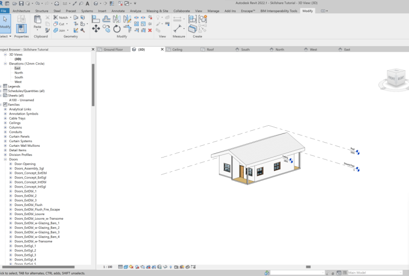
creating a new project for you. So our new project is already created and we have a
blank whitespace here, which is going to
be a workspace. So these four arrows that
you can see here, they are, our elevation markers
will be talking about elevations later
in the tutorial. So this is where you
do all your modelling, all your drawings, all you are. Annotations and everything
to do with the project. To the left side of that above via you have properties
which is going to be displaying the properties of the various design items
that will be selecting. In this case, we are
on the floor plan. And you can see here properties
that are active here. Properties for the floor plan
staff to do with the scale, display model and
visibility and all those. Below that, we have
this project browser, which shows us the
structure of a project. In this case, we have our project structured
in terms of floor plans. We have ceiling plans, we have building
elevations of Lydians, shed use Sheets,
families and groups. That's it. So we go
to the top. Yeah. You're going to see
frequently used operations such as options for
opening a project, saving our project, synchronizing
and modifying settings. We have the undo
and redo commands. We have print, measure, and all these ones
that you can look at on your own time and
see what these icons mean. The bottom we have the various
tabs that we are going to be looking at and we'll be using most of these
in our project. So in this case,
the very first one here is an architectural tab. And this is one. This one is going to allow us to create the various architectural
elements for a project, starting with walls, doors,
windows, and components. That is, the various design
elements, for example. And the components we love stuff like mechanical elements, Centauri, where furniture
for the building, etc. You have columns. We have roof, ceiling and floor. That system cut
and run my aliens. We have circulations
style regulation items to do with the railing
ramps and stairs. You have more items, model text, but a
line and group. We have room and area, openings, data and workplace. The next we have
the Structure tab, which is going to give us access to the structure,
connection, foundation, reinforcement and
the model groups allowing us to put
in place beams, structural walls,
columns, flows, trusses, brace and beam systems, connections for all those
isolated foundations, like foundations
for the columns, all and slab reinforcements
and all those. We have our tab that deals
with the everything to do with this steel
structural systems. And we go here to systems, which here we have a group
dealing with heating, ventilation, and
air conditioning. So everything to do with
ducts that took place holders at Domino's fabrication parts
or those mechanical items, piping and plumping
thing's true with pipes, electrical stuff, and all those. So this is where we have the services
engineers coming in. We have the Insert tab, which deals with them giving
us options to link and import data from
external libraries and from external files. We have a tab, annotate tab, which gives us options for
putting in place dimensions, details, texts, tags, color
fields, and same pose. Then we analyze tab for
doing the analysis. Here we have things like
analytical modelling commands. We have analytical
modelling tools we have to do with space and zones, reports and use you can extract
changes from your model. It is for checking systems
and energy optimization. We have amassing and site tab. You have a collaborate
tab, View tab, which is going to
allow you to switch between the various views. We have a managed tab for
managing your data and linking with other
apps such as DynamoDB, dynamodb layer, that is
for visual programming. Add-ins for linking it with
that departed blanking at the party plugins
that are going to help us in modelling
our project. And the last tab here we
have is the Modify tab, which is going to allow you
to do modification to any of the design elements that we'll
be creating our projects. For example, you have options
for cutting geometry, for joining, for demolishing, for moving form, aligning,
offset, copy, rotate. Just basic modification commands that you will find in
any design software. So as that band, I just want you to
pause this video, take a look at the
various tabs that we looked at for right
from architecture to modify tab and get to familiarize yourself with the various tools
that are there. And from there we can now start
creating, building model.
3. Getting Started with Modelling + Documenting: This section forms the
bulk of our course. We'll be looking at the
various architectural tools that we'll use to
modeller project. These include the
revenue, grids, walls, those Windows,
components, rooms, floors, ceiling and roof,
annotations and Lydians. So let's get started
in the next lesson.
4. Revit Grids: Well, I want us to begin by
setting the building levels, rather putting the
building levels in place. So in our case, we are modelling a simple project which is only going to the
ground floor and a roof. So in our case, we are going to like three levels in place. We love our level for
the ground floor, which is going to be at 0. Elevation height,
will have a level for the saline because one to
ceiling plans in place. And we will also
have a level for the roof which is going to
be at an elevation of like, let's say seal to
store a height of 3 thousand millimeters,
that's three meters. And from there we can now
start creating the project. So I would suggest we go
to the Project Browser. So under project browser, click on one of
these elevations. And that is going to open up the levels that I
was talking about. Now I want the very
first level to be renamed to ground floor level. I'm going to click
here. Double-click. That is going to allow
me to rename it. And then I'll select that
and write ground floor. So our ground floor
is going to be at 0. Click on Okay. I'll grant flow is
going to be at 0. And then from where we
have the ground floor, the next flow is going
to be our ceiling level, which I suggest we
love that at 2800. Mm. We'll click on this and
rename it to ceiling level. So that is going to
be a saline level. Click outside and
click on Yes to rename the corresponding
VCE ground ceiling. And the next is going to be
on our roof, roof level. Back to Architecture tab. And here we have the level from where we
have the ceiling level. This one is going
to be like let's say to get rid those
and we'll have 200. Yeah, yeah. So good to architecture. Ligand level from IO. Yeah. 200. She'd be having 200. Like that. Then you can just move
it to this point. Here. Click to place it. Like that. You can be able now to
click on that point. Then you can elongate it
up to where we have that. Then of course this is
now our roof level. And as to rename
it to roof level. And click on Yes. To have that renamed. Luca, the project browser, you're going to see an update in terms
of the flood plans. So we have our ceiling level. You have a ground floor
level of level and A-site whose are the ones
that are being created? Elevations, building elevation
remained the same year, east, north, south,
and west elevation. So we're done with them
with building levels. So these ones are going
to appear both in our 3D and all the
corresponding elevation views. So if you look at the North, you have the same sound as the same and west
elevation as the same. Because we're not use
we're not using this one's just close them and
go back to the, the ground floor one to look at what we
have in the 3D view. You go up here and
we have the 3D view. Click can use this flywheel
to rotate or beat like that. And you can see you have the building
levels set in place. So go back to the floor
plan v Glick to exit, lip gloss, the 3D window. And then we want to
start by putting in place a construction grid. So under the Architecture
tab at the end, eoyo grid. If you click on Grid
and a properties, you're going to have
the properties for this grid shown if you
click on Edit Type. This is going to bring you to this point where
you are now able to customize the properties of these grid element that
we have put in place. So you can see the family. Here is a system family, which is a grid. And the type, you click on the drop-down
here you're going to see the type or do we have 6.5
m, m bubbles selected? So you have options
for 6.5 MM bubble gas, custom gap, and 6.5 main
bubble gap options. So I want to use the ones
that are already selected. Down here we have
type parameters. So you have a
parameter and a value. You have graphics here, which we are looking at. So here is the simple. We have an EM grid Ed so-called. You're going to see that when
we placed the grids control for like segment weight
and Karla segment pattern. And an unplanned simple viz. So we are good with that. So just click okay, then we'll create first grid. Here. It is going to
be a vertical one. We have like four
grids from named a, B, C, and D. We the
specific spacings. So here I'm going to start
with the very first one, which is going to be
our first grid element. Let's say click away from that. You see this is a great
one and I want this to be. So double-click and type a. That is a very fast grid. And what I'm going
to do is get back to Architecture tab
again. Wait grid. And then I want to create
a grid with an offset from this at 2400 men. And this is going to be myGrid, be selected, Select, modify. The next entity. That is agreed, be placed it there. I want to create
another vertical grid which is going to be agreed. See that one is to find the
domain from great decreed be. So click on this. An offset of 1200 MM near you or grid see in place. You can be able to
select it to modify. Then then you clip, click on that up to where
we have the other ones. So you're moving it
up to that point. And then we'll adjust these
from these end up to there. It is naps. So we have our grid. See in place. I also want to create
angry D 3,600 MM room. We are, we have grid. See. So here it's going
to go up to 3,600. Enter a grade. D is going to be created. And then click to place it. And that's, that's
a vertical grids. We have our vertical
grids in place. So just before we
continue with that, Let's try to set the units. So I have, we have
our command U N, which is going to open the project units
and predict units. I want to select my discipline
to be seeing an IG piping, electrical, HVAC,
structural common. I'm not seeing
architectural discipline. So let's say I have common, their land is going
to be measured in millimeters by area is going to be in square millimeters,
in square meters. My volume is going to
be in cubic meters, which is, I'm okay with that. Love my uncles in degrees, slopes, in degrees currency. Currency is going to be what? Rounding in two decimal
places you need simple is not indicated. In Kenya. I would like to use
Kenya shillings, but it's not here. So I think with
none will be okay. Click on Okay. Mass
density is going to be kilograms per cubic
meter, which is okay. And there's more simple or digit grouping will look like
what we have here. This sittings, okay,
for my project. They actually represent
the units that I use for my actual projects. So click on okay, we have that set. We can get back to
working on our, on our grid lines. So before we continue
on to confirm whether the spacing that we have here
is in the right spacing. I'll go to Annotate
and dimensions. Here. I have aligned dimension. If I click on that, I'll be able to put some
dimensions in place. So I can be able now to
reference from that point. I know that whatever I put in place here is that
it's the correct being. So those are now the
construction grids for the vertical ones. We have like other
horizontal ones, and they run from number
one to number ten. So we want to get back
to the Architecture tab, activate the grid,
and then start creating our
horizontal grid lines. So let's say we have our
first grid here and modify this so that we have this
starting at number one. Then the next from
there is based at 1500. So just click water rather move your cursor up to
that point until it snaps. Then you're going to be able
to type the spacing as 15. And you next, you have the
other one the same as 15. And you can place
the next one there. Grid number four is spaced at 11 Android from number three. So here, 1100 from number three. And you place it there. You have grid number
five spaced at 2000s. We limit us from
number for steel, click, bless it there. You gotta be able to use the
Escape key so that you can, that gives you an
option of moving away from the grid that we've
placed and we cannot be able to walk on the next one. So a great number six is based
at 1400 from number four. So we're 1400 like that. And by seven, easy also for
demanded from 614 Android. Enter from six. Escape. Number 80. The 1900 from that one. Like that. Number nine is 1100 from this. So the same process
texts some time there, but I'm doing this because this is supposed to be a
beginner, beginner tutorial. And I want you to grasp
it every concert. And they get to do
everything step-by-step without having to
look for shortcuts. Last grid here is based at 600
m from from the other one. So we have our grid
system in place. But if you look at these ones, they are, they are
very elongated. They want to be able to reduce that up to
a certain point. There. That will be okay. Yes. Yes. And then we can also use an audit align the
dimension to get to confirm whether
these are insulin to allow grids as paste at the correct spacing that I want us to use
for the project. So click to place it. First one is 1511
to build on that. So that is the spacing. That is this big thing
that we have that we'll be able to maybe share
this project file. A look for a way of sharing these project files
so that you can use, you can download it
and follow along with the while you're working
on your own project.
5. Revit Walls: So as we go on with our project, I'm just noting out, just pointing out that because you're seeing me use
this reconstruction grids, that does not mean that this is the only the only procedure that you have to follow when
you're working in Revit. But for me, I find that this construct and grids
make it make it easy for me to be able to place the load bearing walls for my model. Because what I'm
planning to do is to have at the intersection
of these grades, we love my load bearing, let's say columns and running
through these grades, we love my load-bearing walls. So that's just a process that I have developed for myself, which works conveniently for me. And I'm hoping that as
we continue working on this project and as you continue
practicing on your own, you are going to develop
your own ways of conveniently working on
your own project in Revit. So as we go on, that should be about that
shouldn't be the case. That we should be aware that
I'm showing you my process. Not to say that this is
the only way that you can follow or other, this is the only procedure
that you can use to come up with a building
modelling revit. I've just noticed that we are not saved
our project and we might need to save our project so that in
case anything happens, we are not going to lose our data and the process
that we have gone through. So I'll go to file up here. And we have an option of Save. And it's going to open
these File Explorer. I'm going to locate my desktop. I have files, files,
Revit project files, and I want to call these between 19 tutorial was going to be the product name is a
race between 19 tutorial, that is the project name. Then we have the files of type is going to
be a project file, which is going to have
our VT file extension. You have other note,
RT file extension, which is for template file, this case a Revit project file. So it's going to be RV
TIF file extension. Then we click on sale. And you're going to see the name of that
project is going to appear at the top here where
we have Autodesk Revit 2019. Right now we are
ready to enlighten tutorial floor
plan, ground floor. And that is because we
have opened the plan. We have opened the project
and we are working on the ground floor Plan. So that's it with that. And to start putting
in place they walls. And I will start with the
external load bearing walls. So under the Architecture
tab here, click on wall. And when that is activated
in the properties panel. This is the properties panel. We have. These options are
other properties. Right now you have a base wall, generic 200 MM selected. If you click on this drop-down. Going to have these
types of walls, we have a generic
Andrea and 50 m, m mass on real-world
generic 200 memoir. We have generic name field. These are the various predefined in the wall
profiles that we can use. And if you want to
create our own, we can just select
one of these and then make some adjustments. This case I want
to select Generic, then click on Edit Type. We're just going to take
me to where we have a type properties for this
system family, basic worldly. And the other types
are available on click on this
drop-down arrow here, which is going to show all
these types that we have here. In this case, let's say you
went to an exterior wall. Just have the generic
that we are like that. But in this case, okay, In this case under type parameters, we
have the structure. And stuff like function
of this world, we have some parameters for graphics materials and
finishes, analytical data. You have identity data. We yeah. So under structure,
if you click on Edit, you're going to see
the assembly in place. This gives us the sample
height of the wall. And the material
compositions here, where we have the exterior
side and the interior side. Here we have the cobe
boundaries in place. You will have to now place your materials
in these layers here. And when you're done,
you have options for accepting the customizations
that you will have done. So in this case, let's say
we're not changing anything. We'll come back to that later in the project. Click on Okay. Then click on, Okay, yeah, get back to our project and then start placing our worlds because that will
already selected. But before we do that, we have in terms of i2, i2, which is we should be
connected, I think. Because as, as we
have the case here, so the base constrained of this wall is our
ground floor, right? But the top constraint
is not indicated. To change this top
constraint to, let's say the roof level. What that means is Let's get to like an
elevation viewpoint here. And I'll show you
what that means. So all we are saying is this
world that we are creating. Top constraint is
going to be here, which is, we've seen roof level. So that is the top part
where that is linked. And then the bottom constraint is going to be our ground level, is going to be running
from ground to roof level and the height will
be 3,003 millimeters. If you get back to that, you have selected ground
floor as the base constraint. And the top constraint
is up to the roof level. So that is in order. One runs from grid C1. C1 is this up to here, then moves all the
way up to nine. So nine is here. Back to C9. Then moving all the
way back to where we started. Like that. Again, we have an extension from this point
up to that point. The same hole. And we never worn by
running from C eight, d8 up to B2. C8 is here. Up to there. D2 is here. Then this runs back
to that point. Our external worlds. And do I have The small-world
extending by one? They want to have
another here extending by one and read it. If you want to modify anything. Yes, click on this and
move it towards that side. We live like they lived 200. That will be part of what
I'm going to use as a buyer. The same with this. I'm
going to click on it. Will it outwards to 200. Also pull this one
outwards to snap, but at some point,
at that point. And those are now going
to be our external walls. The next step after that is
going to be to put in place or modelling place the
interior walls of our project. And they're going to be a little bit different from
external worlds because one to have different
parameters for this world. And one of these, one of these major differences
is going to be in terms of the thicknesses of these words. So our external worlds
were of two mm thickness. And I want the internal walls
to be 150 millimeter thick. So in this case, under
the Architecture tab, if I click on wall, I want to be able
to come back here. And Properties click
on the drop-down their leg and be able to
look for a world that is of the same thickness that I want to use
the leg here we have generic 150 MMA
millimeter thick myosin tool. I can click on that. This wall is based on strain
is at the ground floor. Top constraint is up to, let's see, the roof level. So that is well set. Start putting in place
the internal walls. And there's one that runs
from great degree here. From year to year, running all the
way up to grid D7. Then moving back to that
one in is from grid. Yes. We have grid five grid
six partitions there. So green 56 is this partition. So make sure it's
at the center here. Plays that. And we have
another world like that. The one that runs from these great day six
runs from EC2, C6. So click on modifying, select this and drag
up to this point. It is going to intersect
with that one. Click away to place it. Then we have a separation for this room in a grid for
that moves up to from from, from, from grid D4, intersection of D4 to the
intersection of before. And that point is here. So you have the wall, again
selected architectural. And from here to here, that is a click away. Escape. Love that wall placed, as you can see, these walls allowing us to create the various rooms that are going to start using.
6. Doors and Windows: The next step in this
project is to create the dose that will allow us to access the various
rooms in the building. Steel that is available
under the Architecture tab. On the Architecture tab, you have double click
on that to activate. Though. Then you can choose to load the
families are about, okay, you can choose
to load the families. If you have Revit family, which is either an external installed in
an external library, or you can use
these ones that are available readily in
your installation. And we have single
flashed dose of various thicknesses,
the various sizes. In this case, I can still use this one that
is available here. So all I have to do is come to a wall and I want
to place a dog. Well, I need to do is come, bring the cursor to that wall. Then let's say I want this
door to open to the inside. Use the Tab key on the keyboard. So that is going to give
me write like that. To flip it like that. Then I click to place it. That is my first door, which is giving me access
from this point is going to be my entrance
inside the building. Then they're going to
have a door, open, bedroom door that
opens this room. Here. You have another
one like that. So I'm using Tab key
on the keyboard to flip the door to
have access to this. From which point? From this point, going to
open like this to our door, opening to the inside like that. Click to place it. Then click away. As
one opening from this. Like that. You click to place it. Then we'll need to
also have a door here. Going to be our kitchen. Then we will need a door opening to the
corridor to give us access from these two rooms too. These are the side
of the building. But in this case, I want this to be an empty door opening. So I'm going to select it. Click on Load Family. And that is going
to be to take me to the external libraries
that I have. I'm going to do is click
on it and delete it. Then go back to
architecture. Components. Click on Load Family and
allowed family, love. Let's say we use libraries UK. Then we have those here. Look for the internal door that is going to match the options that I want
to use for that one, I want us to have an
empty door opening. So in this case we are
going to go back to the Architecture
tab, select door. Then you will have a single
flush door selected here. So click on edit,
type and properties. Then I want us to
duplicate this dose so that we can further edit it. So here we are. You have the type properties. Click on Duplicate. Then you're going to
name these as empty, 915 by, by two into one. That T4 click on, Okay.
And that is done. I want you to click
on Load Family here, which takes you to the
external library that we have. And these external library is where I'm going to
locate this though. So I'm going to use this one, m double opening, click on Okay. Open. Then we're
going to click Okay. So this is the one
that we have here. I'm going to place
it at this point. Click to place it there. Take your tab,
click on modifying. Click to select that dough. In the properties panel here, click on Edit Type and
you have the rough width. You can change to 200. Apply. Click Okay. You'll see that
reflected in the plan. So we have access
to all the rooms that we wanted to have. The next point or the next step will be to
put in place windows. These are also accessible
under the Architecture tab. Under the Architecture
tab, click on Window. Then we have the M fixed
window appearing here. If you click on Edit type
options for loading families. And they want to go
back to libraries. And we have US metric. We have, sorry,
back to libraries. Let's use UK windows here. So see which one we
are going to select. So let's select that. All bus, windows, SDL, all Buzz, click on open. But I want us to change
dimensions here. So the height is
going to be 1200 MM. The wind is going to
be for Android M. Like that. Click on Okay. Then I'll replace one of
these DOS Windows here. Lead to place another one in. Another window. Here is also here. We don't have a window. So it's at this point window. This room as a window. The window here, because
we have another one here. Window at this point. So those ones have
the same size. These tools, small
rooms here that we use one of the windows in place. So all you are
supposed to do is go back to the Architecture
tab. Now Windows. You will click and
select this fixed one, like this one. Then inserted here. And here. You can still go
back to modify that, select it each type. Then, um, in terms of
when you can have 600, in terms of steel, you can have the same 600. And click on Okay, that is going to
update as necessary. So those are the windows. We've put the windows in place. I want us to have the various fungi and other
components for our project.
7. Interior Components: I'll go to the
Architecture tab again. And then here we'll
click on component. And when component is clicked. So he ended up properties. You see we have a desk selected. So if you click on Edit Type, going to have families, you have this desk, parking space tree and all that. But that is not
what I want to use. So I'll click on Edit Type, will bring me to type
properties here. Then I click on load, which will allow me to the external libraries that are saved the ear that you get. So load table, which
is under Francia, want to load the beds
which is under function. So click on beds. You have these types. Which one is best suited for? Our, our, our project will be fungi in bed
one. Click on Open. There. Then here when it loads, you have a twin bed selected. Click on okay. One does to place this bed, 11 of those beds in this room. So it is like that and
you want to rotate it, rotate it to the desired
location for all you do is hit the Tab key
on your keyboard. Like that. You're going
to have it rotate. So I can place one bed there. I can place another one here. This room. So those are going
to be a bedrooms. So we'll have one there and the last one will
be at this point, you said the beds
for those rooms. So we're going to have
this as a bedroom. This has a bedroom, and these other
one as a bedroom. So let's say this is going
to be an entrance point. Yeah. So when we enter the building, very fast, room ear is going
to be our sitting room. And we want to have some table. And to suffer. And Architecture tab components, a layer, click on
Place or component. So edit type, and
then click on Load. Going to take me back to
the external libraries. And fungi we have tables. So I can be able to
choose from a list of these tables that
are provided here. So in my case, one to use coffee table, I want to use rectangular
dining table. Let's say that, that one click
on Okay, click Okay here, and then you can place it at
the center of this position. So I want to rotate by Tab key, by the Space key on my keyboard, and that is going to
be rotated as well. Then conveniently, I can place
this table, their escape. Go back to component
and each type load. And I want to have
instead of a table, now that we have a table of unplug some sofas
so I could go to sitting and select
software from here. Let's, let's use
these ligand open when that is
selected. Click Okay. And to place it here like that. Then click back to load family. And they want to
have a bigger sofa. Let's say this one. Let's
say we use this sofa, click on open to load
it to the project. Then we're going
to place it here. So I want to space bar
and rotate like that. Then we can move to place these At that point
regarding escaped. That is, if I start regiment
of fungi in that room, which is going to
be our living room. As we move to the
inside of that room, here is going to be
the dining space. And we can load some components
for the dining space because I only want to have
a table and some chairs. So back to that
picture tab here. Go back to modify. Should be the Insert tab. Yes. To the inside Insert tab. Here you have options
for loading family. So click on Load Family. Drop-down button here.
Back to furniture. You have beds, some, some, some tables, Click on tables. And I want to see if we have some dining table with chairs. Let's keep on scrolling. So this is a conference and this is a dining
table with chairs, is one is rectangular shape, this one is around. Then we can use the round
one, click on Open. Then it's going to allow
us to place it here. Take the tab component, then we can place
it at this point. So click to place it, then escape so that that
one will have been saved. Then we can still control S, continue saving our
project as we work on it. In this part, we
are, we have these, these two small rooms here. These ones are going
to be a wash rooms. And I can go to the components here and
load some families. Then this is going to take
us to go to Mechanical M, E P and a general
components lumping folder. Double-click on the
plebeian folder and then you will have
to Carol items here. So here you have fixed
just digest bathtub, drains, drinking fountains, showers, sinks, stops,
toilet cubicles, you rhinos and water closets. So here we are. Not interested
in a toilet cubicle. I'm interested in in water
closets. As you can see. I want to have a wall
like this one or these. I would choose these fixture, WC system. Click on Open. Then I want to place
one at this point here. Then the other one. It's meant to be placed
at that other room. Ocean basins somewhere. Here. If I go to Components, click on Load Family. And wash basins are going to be found here under fixtures. And then we have
So under things. You have a small basin. You have lots of these options
that you can choose from. And in this case, I think
the one that is more interesting is sink,
bathroom sink. And let's say this one. Yeah, Let's use
bathroom sink one. Click on Okay. And I
want to place it here. I love one here. Then the rest the other
side of the room be placed there like that escape. But if you look at that
arrangement of the doors opening to that point and
that is not looking so well. I think we need to edit these
dose by yeah, like that. So just click on the door
there when it is selected. You're going to use the
space bar on your keyboard. Like that. Ylab that rotated
to the other side. So at least it is now going to give us some
space for us to be able to access those
plumbing fixtures that we have put there. So that's our building. Now, looks like we have the necessary
components in place. The last the very last one here is going to be kitchen sink. This is going to be our kitchen. I think we can go to components. Again, Load Family and sinks. Let's say let's try and
look for for kitchen sink. So we have this double sink. Click on that selected, then want to place
it here. That point. So we have things in place, that is our kitchen
sink in place. Alternatively, we can choose
to have that thing around. Then we go to an audit, then go on to use a
line tool to create some reason there is
going to be for sure. Let's see from here, from that 0.600, move like that, then from this point, skip on this point. Up to date we have 600 skip. We can connect these two. Then when that is done, I can choose to delete this. Then select this and modify
it back to that position. So in essence, if you
look at the kitchen area, we have designated where
we are going to have our work top and then we have a kitchen
sink at that point. So that's how to do the interior furniture using the components and
their families.
8. Rooms: We have been consistently
modelling everything in 2D. And I've not appreciated how these project now looks in
a three-dimensional way. And I want us to go to the top. Here we have the View tab, and then we activate the
3D view so that we can see our project look like in
3D is turned on these. A look at our project. We're going to use
this scroll wheel and that it allows me to obit through the project
and see what we've created, we've modelled in place. So basically that's
what we have. The various rooms, the
walls, the components, as you can see them
from that point, and continue
modeling or project. So you see it is a building information modelling software
the same as African. And what this means
is that when you are modelling anything in one view, you're going to have data
views updating automatically. So as we were modelling into
DEI in the floor plan view, we add the 3D getting
updated and we have other 2D views such as
as as this elevations. If you click on the elevations. Going to see that
we have we have some updates to
these elevations. As you can see, that is the north elevation
as those look it looks like the South elevations. These ones I've just
updated automatically. So when we create in 2D, the project is also getting
updated in 3D views. So with that, I'm just going to gloss elevations because that is not what I am working on. We go the next screen. We can live 3D open. Let's go to the next step here. In our project. The one to
look at the Architecture tab. Here. I want to put some
rooms apparatus where we have this big open space
here that is being shared by our dining area
and the seating area. I want to use this
room separator here, click on room separator. And I'll draw from this
wall going to escape. So we have separated
these two rooms. One to put some room
boundaries where we have this like that. And then we have another
boundary at that point. That when we come back
to putting the rooms, the room tags, we love the space is
already created for us. We love another boundary there
than other room separator. So that's, that's that's it
with the rooms separate us. Go back to activate your tab. You have the rooms which
says Create a room, Bowden bimodal elements
such as workflows, feelings, and separation lines. So these days,
trying to show you how you are going to
place those rooms. So what we do is legal
nudge to activate the room. Then I want to tag those
elements as I placed them. Start with this. When you bring it there, you see that it is taking
the shape of that room. You are pleased with that. Yet click to place it. Then we'll come to this room. The same with that. Click to place it. Number two. Bumps here. These alone. Then we have this bedroom. This small passage here. Also want to designate
that as a room. At the far end. Here. You have the kitchen yet. This is going to be okay. Jenny had designated
that as a room. The inside you have this as our kitchen is going to
be room number eight. Don't worry, we're
going to rename everything so that
they look well. You have this as our dining
room or room tag there. Come back to the living room. Please tag. Then we have the
entrance area here. Please attack. When you're done, just click away and you have
those rooms in place. So what I want to
do is select this, go to edit type. And ELA, it's where
we have the graphics. Let me zoom so that you can
see the type properties. Well, we have these type
parameters down here. You have graphics
for the project, for the room tag. And in this case, you have
showroom number as ticked. So I want to and take that, then click on Okay, you're going to see
that update in our 2D. So what I want to do is now come back and rename this one. So this is our kitchen,
the ad quality, and then tried to move
towards the center like that. This is our kitchen. So type teach in there. Try to move it a little bit
towards the center like that. And this is our dining room. So I'm going to double-click type dining, dining like that. Then go on to move this a
little bit away from the sea, from the table so
that it is visible. This is going to
be a living room. So I can just type
living and then move it a little
bit away from yeah, from that so we can
have an avid there. So these are the room
is our entrance. Let's call it. Then we move it to the center. And we have this as our
bedroom number one. Click and type bedroom 01. And I want to drag it
to the center here. Bedroom 01. This one
to be a washroom. So I type WC and drag it
to the center. Again. Like that. The same
with this other one. You'll also drag it to
the correct position. Then this is going to be
a passage me type path. That's a passage. That point. Bank is a place to which other rooms we
have this as bedroom. Bedroom number two. The last one here is
our bedroom number 303. Plates. Move it a little
bit away from the band. And you have it.
You up the rooms. Like if you are to
take a look at that. You know, you have
a bedroom here. We have the kitchen.
The kitchen. We have our bedroom, a passage. You have a dining room. We have the washroom areas. We have the living
room, bedroom, and that's basically that's basically the the various
rooms that we have in. So as we proceed, I want to do some
customizations to both the internal
and external walls. And what I'm going to
do is select this wall. When the Properties
panel is active at click on living room to take me
to the type properties. Here. You can see we are
editing to the main field, do all the type parameters in the construction
and structure, and click on Edit. And then where we
have these assembly. I want to have these wall
as concrete or stone. Let's try and see if
we can find stone. We can have concrete,
cast-in-place, concrete, precast brick, concrete,
lightweight concrete. Let's have concrete masonry
units as the core there. And then towards
the exterior side. And to insert this and then move it up to the exterior side. This is going to be
a finish to finish. And this finished here. It should be plaster. So type here plaster to
know whether we have plus, let's say we use
nibs or wallboard. And this. As our 15 m m thickness. Then you insert another one
here and move it down to the inside where we
are going to have a finished the same as the Alone. Lu, you have plasma.
We have Render. We have plus theta plus the
board are going to be 15 m, m. So here the central 170, like this is going
to be the structure of our wall assembly. When I'm done, going
to click on, okay. Then I come back to where
we have the graphics. Here we have our
cos fill pattern. Now one to have this
as a solid fill, solid field like that, then this is going to
be a darker shade. Then if I click on Okay, you're going to see that
get applied to our project. Select that, go to edit
type and properties. And then we learn this
where we have costs. That is in terms of graphics
costs, scale, fill pattern. This is a diagonal
edge here and I want to put a solid fill, click on Okay, and
click on Okay. And you see that
also update in 2D so that these are
more contrast if you look at where our walls placed and other design
elements in the building. So awesome. Look
at the elements, the variables in terms of color. They are going through the plan and then making neat and tidy. So one of these things
you can do because the main purpose of these grid
lines was to enable us to, to position the worlds in place. And we've already used them. If you don't want to keep them, you can select them
and delete them. But in my case, I want to keep them for
dimensioning purposes. And that will select
these ones and tried to change to a color that is faint or more less
pronounced Karla. If I click on that, it is going to activate
a grid properties here. Then I go click on Edit type, where we ended segment Karla. Here. I can click on that and
look for one of these, let's say these gray like that. Then we segment button, button, you type these, this is controlling, this
is controlling them. The type of line that
you are going to show we're going to see in 2D. So I think it's green line EI is okay because we've changed
this Kyla going to have some effect on how these grids leukemia
it in on our plan. So as you can see now, they are not start
more pronounced. So we can be able to see our plan and components
in the plan. We better. The same with these
dimension line here. I'll click on edit that. And one of the things
I want to do with dimensions is changed the font. Change the font.
That is one thing. And the other one is
change the color. So you can scroll
down and the type of parameters here in Karla, we want to have some blue, some blue shade in place. Let's say we have that. Then. In terms of font, text, font, Arial in place, I want to change that to
a favorite poem for 400, but I use, so we have
inter that in place. Click Okay, Let's have a
look at the dimensions. So some, some beta of customizations and I
think that looks okay. So we are ready to go to the
next phase of the project, which is modelling
in place the slab, the ceiling, and the roof.
9. Floor, Ceiling + Roof: So the ground slab for this structure is going
to be an architectural flaw. And that is accessed and
the Architecture tab. If you click on the
Architecture tab, yeah, underflow, there's this
drop-down arrow here. And that allows you to
create four times of flows. We have flow architectural one. You have a floor
structurally flawed by face and flow by slab edge. In this case, we want to
create an octet rule of law. I'll click on floor
architectural. And what that does
is it's going to activate these modified tab, which allows us to
create a flow boundary. And I want us to create these
flow boundary using a line. So click on this line
that gets active and you have the external
outline of this building. That is where we
are going to have the boundary for this flow. So just follow along with the external
outline of the building. And we are going to create
the flow boundary like this. Make sure you pick all
the necessary points. Well, until you
get back to where you started and the boundary
is going to get complete. So when that boundary
is put in place, before we accept that
fluid to be formed, we need to go to the
Properties panel. Here. You can see we have
our generic flow of 100 millimeter selected. If you click on the drop-down, you'll have other types, such as 60 millimetre concrete with metal
deck we would waste. So I think these are not the
ones that I want to use. But in this case
you can click on edit type ER where you have
this generic fund flow. Click on duplicate
so that maybe you can create one fifty, one fifty millimetre
concrete flow. So click Okay. Then under structure, the
center here is one fifty. One fifty. Then we can insert these finished
at the top here, which we can say, let's, we're going to use wood
to the team and say, OK, OK, fluorine of like five MM. Going to be there. The bottom, we don't have anything. So this lab total length, let's say to put your concrete concrete material,
cast-in-place concrete. The total the total thickness of this flow is going to be
50 plus 25 millimeter, that is going to be 175 of them. So if I click on
Okay and click Okay. You'll see here under the
Properties final hour and 50 MM concrete floor has been
selected for our project. Now because we are done, we are putting in place
to the parameters. But you can do is, well, we have this, the top here, at the top here where we have this red X for canceling
the editing mode. And we have a green tick. Yeah, for finishing
editing mode, I want you to click on
finish editing mode. And you will see flow
has been created. If you click away, that's going to get lost. So for us to be able to
appreciate how this looks, we can go back to
the 3D window here and try to go a bit obit. We'll see from the bottom
of this of this building, we have a flow in place. We can change out
this model looks by changing the details
and the visual style, which in this case I'm
going to have shaded model. That few take a closer look at the project is going to be
how it looks now in 3D. So you are able now to
see the various colors. And everything like that
is the exterior part, the anterior part
of our building. So that is our model in 3D. So the lab, rather the
flow is now in place. Let's go back to the
ground flow again. And in this case, we want to create the ceiling
on the Project Browser. The floor plans here we
have the ceiling level, click on the silicon level. And this is going
to be activated. This is how the ceiling
level looks, looks like. And we want to be able to modelling place as
salient for every room. Because what happens is that silliness is not going to be
cutting through the walls. It's going to be
constrained inside the boundaries that
we have created here. So still that one
is also accessible and that the Architecture
tab and the OEF ceiling. So if you click on that, you have the cylinder
selected in place. And what we want to do is to do to sketch the
outline of the feeling. So these were being told here creates a ceiling based on selected was or
sketched lines. So we open a zillion plan
to sketch a ceiling. And you can sketch
our ceiling by picking walls using
the sketching tool. So using the automatic
sealing tune, you sketch as specified, distance above the level
in which it resides. In the ceiling
includes a grid and the grid is centered
in the room. So this is basically Autodesk
trying to explain to us how to come up with
using these Sketch mode. So I can select Sketch there. And it's going to allow
me to be able to create a salient boundary
the same way we did with them with the flow. And one thing I want you to note is here and sealing properties. We have level selected as ghrelin level because we are we are putting this
under the ceiling level. We are decreed Vaseline level. We have offset it as 2601
to change this to 0. Because I want this to appear just right at the level
that we have created. And then this is a
compound ceiling or 600 Beethoven Android the grid. You tried to look
at the structure. You find that we have a ceiling tile that
struck you at the top. I'm not interested in
changing that as that now. But if you click on Okay, you can be able to sketch the boundary lines for the
ceilings in each room. And I decided to
start with this room, which in this case, that is where we are going
to have our ceiling. Like that. I'll come back to
this room here. Sketch the ceiling boundary. The same way I have done
with the first room. Gasoline is going to get to to go to the inside part
of the building, constrained by the
world boundaries. Follow along and make sure that you are doing it correctly. So when it goes into our ceiling spanning all that full distance. And the last point where
we have the passage here, we're also going
to have a ceiling. And I will sketch the
outline like that. Once you have the very
acetylene boundaries created, all you have to do for
you to be to place that silly now is to click on finish editing mode and you
have your ceiling in place. We can go to the 3D view here, tried to look at how
this looks in it. In a three-dimensional view. And you can see we have our
ceiling in place. Has okay. Let's go back to
ground floor again. And in this case,
because we've created a floor or ceiling in place, I want us now to to create the roof so that we have,
are modelled complete. So in this case, roof is going to be an
architectural roof. Because if we have a structural
engineer in our project, is going to come up with
the structural components of the root structure
and everything. So in this case we are
going to creep to modeller, roof accessible
Lambda architecture. And then roof. We have options for year, we have the roof. We have options for creating
roof by food footprint. We have options for
creating roof by extrusion. We have proved by
fast growth, so fit. These are components we have refreshing and the roof gutter. My case, I want to create
roof by footprints. So I'm going to click
on roof by footprint. It's going to ask me, you have created the roof on
the lowest level of new like to move it to ground
flow, move it to. Which tied to the roof
level and click on Yes. We also get the
modified boundary line for creating or other. We get the Modify tab activated. And in this case we can be
able to create a boundary line for for our roof. And I'm going to use a line here and start creating
the boundaries. So this one is going
to move up to there. This is going to move here. The same. We then let's have these moving to I think we should
get right there. That point. Then I want it to move back to where we started. That's going to
close it that way. And if you look at the line, that means we have not
given you have not created any roof over
n for this project. So all I want to do is maybe offset these lines
towards the outside. Bye. Like six hundred, six hundred demand that we be able to also set
these by by the same 600. I also want to set this to add this side by 200. Yes. And also affect this
this side by 600. I've typed here. So in that case, we have a roof over n. And if you just want
to place that roof, then click on finish
editing mode. Then you love the roof in place. So let's go to breed the window. See how that looks. That is our roof node, the very best of what
we intended to create. But in this case, we want to have a
gable end here. Now gable end to the other side. While this, this, this side, this side and the opposite side. And the ones that are
supposed to be at an angle. So in this case I can just
click on that roof and then I want to edit footprint. Then this footprint is going
to take me back to here. So click on this. And what that does is it defines roof slope
and the properties. And click that so that the roof slope is not
being defined by that. Then also come back to the
other side and then pick that. Then we can come back here, select that and select
this other end. And then we'll have changed like the pitch to be 22.5 degrees, sorry, 22.5 degrees like that. Then when we're
done with editing, we can finish edit mode. And you will see now our
roof gets updated like that. Then we are when let's
say first, it's saving. Let's try to orbit. Like at the, at the front here. You have the roof like that. But there is an
issue here because these walls and these
are the words here, are not connected to the roof. So how do I connect them
to the roof to make sure that you're not having
a space in-between. All you do is click
to select them. And then up here you
have an option of an auction and the modifier
walls written here Attach Top base or are
detached from base. So all I want to do is
click on Attach top, base, the one that is done, I can click on the roof
and then you'll see that will move up and attach itself. That will be the case
with this wall like that. And the same with that attached
to the base of that roof. Tried to beat around
and select that. Attach it to the
base of that roof. Select this one. I teach to the base of this roof and select this
budget to the base of this roof and obit to
the back of the house. We have the same case
here with these walls. So all you do is we'll
repeat the same procedure. Selecting these world, attaching to the
base of this roof. So you have the wall
selected, click on, Attach Up to base, and that moves up. You have this same operation. And these are the one
in applied the same. But I should put
that in this case. You try to obit you are our walls moving up well
connected to the roof. Then if you look at
these windows here, think they need to move up by, say we could add these as 200. It's now 1500, like that. Then I have these as 1500 so
that it moves up the same. In the other words, that is our 3D model. We've done the floor, you've done the ceiling, we've done the roof. And in the next phase of the
development of the project. When does to look at some
bits of annotations really, in terms of putting
tags or other tagging the windows and the doors and putting dimensions in place. So just to appreciate the level of detail that we
have reached for a project, you can see the 3D model
that we've created. We can be able to appreciate
the ceiling plan, that we can be able to appreciate the floor
plan that we have created and all these editings
that we have been doing. I've been getting
synchronized to other views such as the building
elevations that we have. Because if you click
on the east elevation, you'll see now that we have
an elevation in place. And I can choose not to show this by selecting one of
those grids, right-clicking. And then you can see
elements in view. Let's say we select all of them. Because I want the
elevation to be cleaner. Right-click. Say, I didn't view
those elements in V. So this is our East elevation. I also want to now because
all we are looking at from television point is
the roof level and the ceiling and the
ground floor level you have on east elevation, we have another elevation
in place possible getting updated automatically
as we work on 2D and 3D. We have the south elevation. The same television was
all getting updated. As we proceed with
working on the rest of the 2D and 3D project.
10. Annotations: We continue with the
customizations of division views. And in this case, I have the
west elevation open here. And all I want to do is select
these grid lines, control. Then click on each of them
individually. Like that. When I selected right-click, I want you to hide this in view. You click on hide elements. Will they get lost? And we are filling view or rather ceiling level
line because we're not showing the feeling
in the elevation point. I want to hide it
also, I didn't view. Then we have our
innovation looking a bit cleaner like that. That's how our west elevation, when you're done with that,
you can just close it. Do the same with the south
elevation, eye level line. Select the grid lines. I added them in this way. Innovation looking like that. You can do the same with the north elevation.
I didn't view. Same thing with the grid hide so that you have no
television looking like that. Go to the east elevation. We had already customized. It looks well. Then tried to close it. You can gloss possible
the ceiling view, whatever the ceiling level
you have already in place. Let's go back to
floor plan here. One does too. And that's to put some tags. And in this case we are going to doors and windows
so that we can be able now to identify
these linked quantity shin doula for
us to be able to know. This is the window type and this is the number
of new windows. This is the datatype, this
is the number of dose. So we this active. Let us go to the annotate tab and the annotate tab where
we have the tags. Here. I want to select these one tag. Click in the current view. And then we have
yeah, door tags. And then we have a
window tag here. These are the ones
that I want to use it that orientation is
going to be horizontal. And we click on Apply and
click OK. And when we do that, we're going to see
where we have a window. We have this tag with tagline teen showing
these type of a window. These tags does ten. Once at this point. Then we have which ones? These are the, these
are the windows. Then we have tags for the
dose that is in place. The next thing I want to
do is they mentioned, no good the annotate
tab like that. I will select the very
first dimension type, which is aligned dimension. And I want to reference while faces so that I can be
able to select each, each opening or each element to be dimension individually. So in this case,
dimension line in place. For the grid. I want to do the openings. So I'll take pick that point. Pick that one. So it should be from here. Yes. Then pick this
and that clicking, and that turns blue. You click to pick the point. Then the external one here, you will move this
dimension up to that point. I want to click on modify. I want to move this upwards. So I learned, drag
them up to that point. Then I'll come back to
my aligned dimensions. Pick wall thicknesses like that. That will be my other dimension. As you can see. I'm done with that point and
move to these other phase. Do the same. Select the openings. Select all the openings
that is going to be fast dimension line
with the openings. Dimension line is
going to be widths, thicknesses of the worlds. That dimension line
is going to be these grids that
we've put in place. Like that. We have dimensions
on both sides. You need to have
dimensions here. Awesome. I'm going to pick
openings first. Openings first. Up to this point. That is going to be our
first dimension line, is going to pick
weaknesses of the walls. We have the wall
thickness is taken care of that, in that. So every worldly is
going to be dimension. And then we pick the last point and place
this dimension line here. Click to place it. So we have our
dimensions like that. Last point. The last slide is here. To pick that. Pick this opening. Go ahead and pick
these are the opening. Then pick the last point here, which is going to form
first dimension line. Placed that point and the circle will be thicknesses
of these words here. So big, big every wall. You can see up to
the last one ear. And we place this dimension
line at that point. Click away. The last one is
going to be these grids. So I'm going to pick all of them and place this
dimension line. At that point. If you look at our
plan, let me save it. We have the door tags, window tags, and the
dimensions in place. So that's how to
do the dimensions. I'm hoping at the end
of this be able to create rabbit to upload
these project files online. So that will be
able to download. I'm going to leave a link in the description of this
video for you to follow. So don't worry about that.
11. Presentation: Color Fill Legend: So as we wind up our tutorial, I want to show you
a quick way of representing these rooms in
a nice presentation format. What I am calling or other word rabid called a colorful lenient. I want to up the various rooms. Instead of having
these names in place, we can have just colors. And then we have our color
lenient at some point here so that we can be able to reference
from the color Lydian. I get to know what type
of a room that Let's get back to the
Architecture tab. Yeah. And then the Architecture tab, you're going to see
go to annotate. So let's go to the annotate tab. At the end here you are going
to see Karla field ligand. So if you click, if you
put your mouse over this, you're going to see
some descriptions that are given here. So colorful, lenient
places alleviate Navi to indicate the meaning of colors for rooms or areas. So you open up a
floor plan view or a section to place
a colorful lenient. If you've not yet assigned
a color scheme to the View, you'll be prompted
to select one to create or modify the color
scheme, the scheme tool. This is basically giving
you information on how you are going to
create this color lenient. So all I want to do
is click on that. And when I click, you see here it's telling me no color
scheme assigned to v. So what you're going to
do is place it there. And it's going to prompt you to choose the space
type and color scheme. So yeah, and that's base type. I want to use the rooms. And the color scheme here. I want to name yes, yes, name. Then click on. Okay. So it's calculating and put a room lenient in place
with the various colors. As you can see, we try
to move it a little bit. This point. So if you go back to
a floor plan view, you see we have the various rooms with
the different colors. That is what I wanted to ask. When you're done with that, maybe we can write to delete
a room tags like that. So delete the tag. Rooms are still going to exist. But we love the tags. Deleting that instead of
having these texts in there, you're going to
have room ligand. So our floor plan
now looks like this. We have our own ligand.
Wish this color points two bedroom, one. You can be able to
see the koala is this one bedroom to this girl? Bedroom three, these Karla
and all these other ones. Let's say you want to edit
anything in the room, Legion, all you do is legal needs
as we've done right now. The top here you
have ended scheme, which is going to open the
various color schemes for us. In terms of these, I
want to have the WC in a completely different color. Let's say we have
black, black, black. Let's have this click, Okay, in terms of the
field, cross hatch. This one, which looks like that. If I click on Apply
and click Okay. You'll see these as updated. Here we have the WC areas. The same with what we have to also change
for the kitchen. The kitchen onto Nicholas blue. That blue. Okay. And then instead
of a solid field, Let's have a watch
and apply that click. Okay, we'll see the
same, get updated here. So that's how to create a room lenient color scheme for presentation
of your drawing. With that, I think
we've managed to create our other two modeller
building in Revit. If I can just take you back
to what we've created. These projects, browser EOS, which shows us various
floor plans that we have. We have a ceiling level plan, we have our ground floor level
and site selling plants, 3D views, elevations, radians. She does and all those. And just to appreciate
what we have in this is our floor plan laid out
with everything in place. This is the 3D view
of the project. You can be able to make more
customizations to this. But for the purposes of
explaining this concept to grasp this is a
beginner tutorial for the purposes of explaining
these concepts. This is what we've
created as our 3D model. The various elevations
already in place. And our East elevation
or not elevation. The elevation and
the west elevation. We've come to the end. But tutorial. Thank you for watching
and I hope to see you in the next videos like this. Please subscribe
and your friends. Thank you and see you
in the next video.
12. Final Thoughts + Thank You Note: Congratulations for
making it this far. Also. Thank you for choosing
to enroll to my cos. How has it been like to get
your feedback on the course? Please leave a review
as it will help other students
like you in making a decision on whether to
enroll to the course. Thank you and all the best.
 Nzangi Muimi, Quantity Surveyor + Educator