Transcripts
1. Class Intro: I'll cut 25 is the latest
version released by graphy sort at the time
of making this video. These are premier BIM software that is building information
modelling software that allows you to create intelligent building models with construction information
linked to eat. If you're looking
into understanding 2D and 3D modelling and
documentation in aggregate, this course is for you. Hello, and welcome
to this course. My name is Zach, and this is occurred during
the five basics, creating an architectural
floor plan. I'll be your instructor. This course targets the
following categories of people. Ambani, the architecture, engineering and
construction students with basic academic skills
and the one to learn the process of developing
a floor plan in aggregate. Number two is begin to add card users who are proficient
in other CAD software. And one to master aggregate
2D and 3D drafting, modeling and documenting skills. Course is broken down into step-by-step tutorials
at a slow pace, making it easy to follow along as you work on a real project. By the end of the course, you should be able
to do the following. One is create that project to develop a comprehensive
architectural floor plan. And by three, annotate and
document your project. And before publish
your drawings to a multi-page PDF file
or a BIM x hyper modal. So if you are
interested in getting and on the practical skills, enroll to this course and let's
meet in the next section.
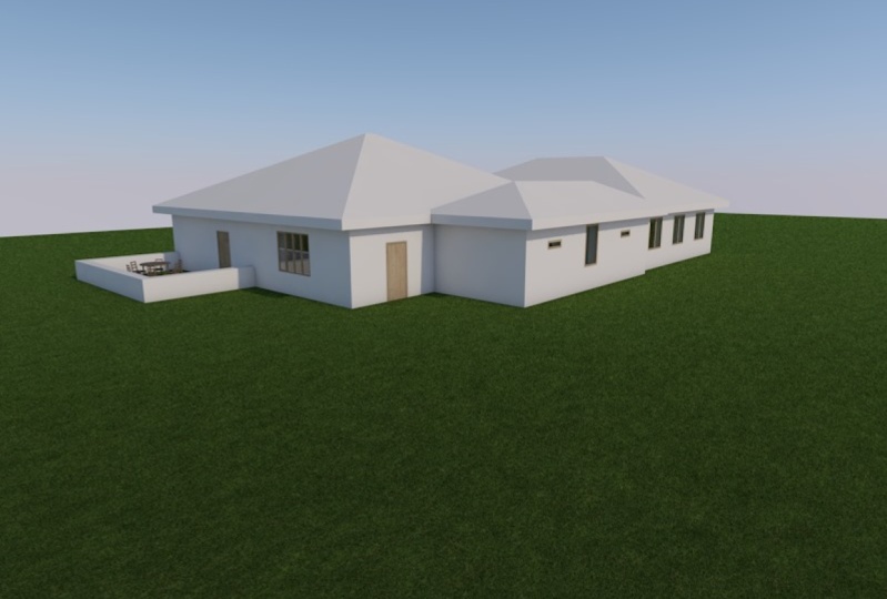
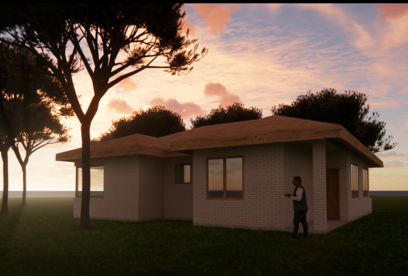
2. Class Project: This is a practice-based
cost that involves the development of an
architectural floor plan for a section of a three-bedroom apartment block will have a reference path in the downloadable
resources section and step-by-step tutorials
that will help you work alongside the instructor
to create the model. Your course project
assignment is to develop a simple architectural
floor plan for a three-bedroom
apartment block. We will do so using accurate to N5 software to demonstrate you've learned the
skills taught in the course right from
the very first lesson, we'll create a new project
and follow along with the instructor as you build
an add more details to eat. At the end, you'll
be required to share this project to get feedback
from your instructor.
3. Intro to Modelling and Drafting: In this section, we will be doing more of
modelling and drafting. We'll get started by creating a new project and making
sure that they work in. The work environment is set and important details such
as the Project Location, Settings, Site, and client
details are put in place. Then we will proceed to
stories, settings, and units. The bulk of the rest of
the tutorials will be the actual process of placing
our construction grid, modelling the world's less
than windows and doors, arranging the interior
frontier and components, bottling the roof in place and dimensioning that being said, let's get started
in the next lesson.
4. Creating a New Project: In this lesson, we
are discussing how to create a new project
in Attica 25. So I have my occurred when
five open on the screen, you can see the advert
when five-star screen, which is basically a collection of the various buttons
that we have here. The first one at the
top left here is new, which indicates options for
creating a new project. The next one after that
is the browse option for browsing and existing
solo project. And the bad one here, which is teamwork for
opening a teamwork project. At the center of the screen, we have thumbnails for the most recent projects that we had opened using aggregate. At the bottom left here we have a link that says quit aggregate. If we click on these, they are going to quit. Or above, you're going
to close the program. Let's say you are an
existing project like this. At the bottom right, you will see this button here written fopen selected,
which gets active. And this is going to allow us to open the project that has
been highlighted here. So without further ado, we can begin our project, or rather we can begin our exercise by
clicking on New Year. And we're going to get this, welcome, not click on it. And that is going to start
creating a new project for us. So when you do that, going to get this dialogue, you're going to get this
dialogue box that asks the various options
that allows us to customize our one
to create a project. So it's saying create
a new project from. And this very first
option here gives us options for selecting
the templates that we want our
product to be based on. If you click on this
drop-down arrow, you're going to get
here with the RT card. We have occurred when
five template to TP L. We are also given an option for browsing
for any template that we might be having
saved in a computer. So below that, we have what environmental profile and the work environment profile, we have the various
options that we have. So if you click on the
drop-down arrow here, you're going to get options
for selecting Ada of these one of the last used profiles
are the default profile, deal with that, you can
also be able to select from these six premade profiles that come with the standard
Attica, the installation. So for our project
and asked to go with default profile like
that and click on New. So it's going to start
creating a new project for us. As you can see at God
is opening a project. So depending on how
fast your computer is, a cat is going to take some time to generate a new
project for you. And when that is done, you are going to be greeted
by this screen that displays a blank
whitespace at the center, which is going to be
our working space, where we are going to
populate that space with the various design elements that we will have
incorporated for our project. At the top, here, we have
the various menu options that will help us in terms
of project creation. At the right side we have the project browser
and the project map, and the various navigation
options that we'll be exploring as we
create our project. At the left side. Two, on the left side, we have the various design
elements displayed there. We have viewpoint options and
documenting tools for use. And the various
documenting tools that are given in this list. So now that we have
created our new project, we wanted us to proceed to saving these projects
so that as we make the various changes that
we will be making will be saving these to a
specific project file. So undoes to go to File here. Then under File, let's
choose Save As option. And save as option
is going to open this dialogue which helps us locate the specific folder in the file explorer where we are going to
save this project. So I'll click on this
drop-down arrow. Now be able to select the
folder that I want to square, the folder where
I want my product to be saved to a file name. I choose to call this HDRI
three-bedroom apartment, that is the project name. So under Save As type, if you click on this drop-down, you are going to get
the various projects or other file types. The various file types
that are supported by aggregate doing five hours
is an alkyne solo project. So we'll click on solo project, which is going to
save this file with a dot PLN extension. So we have oxygens here. And under options. Let's have this button for
compressed file checked. Click on, Okay, then click Save. Let's look at gut is telling me three-bedroom apartment
or PLN already exits. So do you want to replace it? I'll say no. And then
I'll rename this file to that skill share. Then click Save. And now project now
is going to be saved.
5. Project Location Settings, Site and Client Details: With the story settings, the settings for
the working units and dimension in units in place. Now we will proceed to project location settings and putting in place at the site details
and the client details. So that is our class
bool and options. So we'll go to Options here. Then under options we
have project preferences. And the project
preferences we have this option says
location settings. So you'll click on that. And it's going to
open this dialog box. So it's going to open
this dialogue box, which contains the
three settings that need to be customized. So the very first one is
our project location. The second set of settings
is under survey point. And the data set of
settings is under project. Not. Let's begin with Project
Location Settings. Here. We have the project name which is supposed to
be displayed here. So to be able to edit that, we have this edit button. So click on it. And
when you click on that, we have this popup that shows here with the
various projects in for that we need
to put in place. So under project details, you have the project name. So all you need to do is click
on these three dots here. Click on it. That will open and allow you
to type the project name. Project name will have
proposed rate bedroom, residential,
apartment like that. And click on Okay. When you do that,
the project name is now going to be shown there. So you have things like project
description, project id, project called Project Number, project status, the keywords, notes, and any other
custom information that you want to include
about the project. Let's move down to Site Details. Details is going to
ask for the site name. Click on these three dots there to be able to
type in the site name. Then you have decided is krypton site ID
sides, full address. You have site gross
perimeter, gross area, and other custom information that you might want to
include about the site. In terms of building Details. Options for putting in
place the building them. Options for putting a
building description, the building ID, and any other custom
information that you want to include about the building. We have contact details which gave details for the company that is working on the project. And in terms of the
contact full name, you can be able
to click on this. And you have options for typing your name in terms of the
prefix, alright, yeah. That type my given name
and the middle name. Then the family name name, or you have a family
name appearing fast, or giving them appearing fast. So you have those two
options that you can choose. I choose given in Fast. Click on Okay, and
that name is going to show under contact full name. You have contact
ID, contact role. What is your role
in this project? Let's say you are, maybe
the architect, are, you are all in this is
being manager role, whatever the role that you have. So make sure you type it in the description. Click on Okay. And it's going to be showing
here under Contact role, you have the contact department. The same thing as what we had
done to the contract role. So you click on that and type the name of the
department there. You can be able also to indicate the full name
for the CAD technician, the name of the Contact Company, which in this case I
am going to include the my my company name. That click on Okay, what is the contacts
company code here? Contact full address. The full address is
in terms of postal. You have a physical address. Let's say you specify the
office postal address. I have that as my
postal address. This is my city. Nairobi. Nairobi there. What is the zip code is row 01, and then my country is Kenya. So we boost details in place. I click on Okay, and
they're going to show here under Contact Full Andres, we have also the contact email. The same thing. Type
the type, the email. Click on. Okay. And that will be put in place. Contact phone number and
contact Fox contact web, and any other custom
information that you want to include there. In terms of client details, we have options for putting in place the glands full name. So we'll click on this, click on this button. Then you love options for
putting in place the name of the client, the
client's contacts, the client's company, full
address, their email, their phone number, fax, and any other custom information that you might want to include. After typing in all that
project information. We'll click on, Okay, you love the information
saved in your project. So we'll go to
site full address. So click on edit here and
you are able to specify, let's say the site is
alone, Mombasa road. Whereas Mombasa rod is in Kenya, in a city called Nairobi. Then let's say this is the postal box and
this is the zip code. So click Okay. When you type, you finish
typing that and saving. It will start appearing here
and insightful address. Below site full Andres, we have the latitude, the longitude, the time zone, and the altitude
above sea level for our project that is based on
the location on the site. So this is going to be defined. The latitude and
longitude are going to be defined by the location
of the project. In terms of that, instead of typing
need to manually. I'll click on deed on
this globe icon here, which will give me a list of the various cities that
have been predefined. So my project is in obesity or look for Nairobi
in that list. Then when I get to Nairobi, click on that to select it, and then click on okay. And you are able to see that the latitude and
the longitude as a change has been effected as that time zone should be the
same as change to Nairobi. So attitude, the height
above sea level, I am not sure about that. I can be able to check for that information
in Google Maps. You see this option
here which says show in Google
Maps where we have a point and project not do
anything to survey point. I don't have any surveying lands away information
to put in place. In terms of project node. This is, is, this, this allows you to
define the sun path, which is going to affect how
we are building is going to cast shadows to the ground. So you'd be able to select
whatever to change the sun powered by defining
the project node using this icon here like that. Then if you click on Okay, all those settings that
we have put in place, I've now been implemented. Rather they'd been saved in the project to make sure that
everything has been saved. As usual, we go to file, go to File, then we
have the save option. So click on that. And your project is
going to be saved.
6. Storey Settings, Working and Dimensioning Units: Now that we have created
and saved our new project, the next thing would be to start doing some settings
as we prepare to. The next thing would
be to start doing some settings as we prepare to put more details to our project. In this video, we'll
look at stories, settings, and how to set working units and
dimension in units. So let's go to a project map and add the ground
floor activated. At the bottom right, we have these settings here below the properties,
we have Settings. Click on these settings, which is going to open
the story settings. Here, we are able to either insert new stories or
delete existing stories. And we are also able to change the various dimensions
such as height. The next story, which
as at now is set as three meters from ground
floor to the next story, which is the first flow. I'm going to give this story specific names like I
loved the first one here. The first is Graham's law. So the next is going
to be my first flow and that there's going
to be my second floor. When you are done, you
have below the stories, you have these options for Ada inserting a new story above. So if you click on this, see we have inserted
a new story above. Story number two, if you
click on insert below, will have inserted
a new thread below this one that I'd been selected. So let's say you want to
delete an existing story. What are we going to do? We'll just click to select, then choose this option lead story like
that, select that, delete like that, and
then we click on Okay to make sure that those things have now been saved
to the project. After doing the story settings
I want us to go to View. Then under View will act, activate the construction
period display for that. What space is going
to look like that? The various grids. Then from there we look at just amazing customizing
the working unit and the dimensioning units, which is accessible
and the options. Then we go to
Project paraphrases. And the very first option here
will be our working unit. So if you click on that, love that dialog box opening. And I want us to set the
various units for the length, the area, the volumes, angles, and the layout units. So the length will have units in dark measured
in terms of millimeters, two to the 0 decimal
places in terms of areas, will have areas measured in square meters to
two decimal places. And then the volume is
going to be measured in cubic meters to two
decimal places. Angles will be given
in decimal degrees. You have options for either
degrees, minutes or seconds. You can give. You can measure angles in terms of
radians or maybe the specifics of air as you need that is going to be
provided by us aware. So in terms of this project, I love the angle units
measured in decimal degrees to 0 decimal places and the layout units as millimeters
to 0 decimal places. Then when I'm done with that, I'll click on Okay
to make sure that those savings settings
have been saved. Then still under Options,
the preferences, I will click on dimension
so that then be able to set my preferred then dimensioning
units for the project. So here under dimensions, we have currently this set as meters to three decimal places
with the extra accuracy, with extra accuracy,
this disabled. So we want to select this
option for plane a millimeter, which is going to change the linear dimension units to millimeters to 0 decimal places. And that is what we want
to have for the project. So when that is done, just click on here and we love
the settings implemented. So let's go to them to document, documenting tools and select this dimension so that
we can be able to set, so that we can be
able to do that. We're gonna be able to
customize so that we can make some
customizations here. So I click on the Settings dialogue for
the dimensioning tool. And this is going to open the
dimension default settings. Under default settings
for the dimensions, we have options for
the dimension type, which is, in this case, we are having a linear
methods selected. And we have this as
the marker type. The various types that
we can choose from. These are the types
that are available, so you are free to
check on any of these. And then a witness
line I will have the line selected scaffold for the witness
line for the pants. Yeah. This I'm going
to set to 48 and then these for the pen
sets for the witness line. I'm going to set that
to pin eight full. You are done with
dimension type. You can close that and
move to text style. I want to have the font, Fonts type as DME sons selected. And the pen type
will be pen for the, for the dimensions text and the font size will
be two millimeters. So that set a start. And America and the
witness line options, we have options for changing
or other for customizing the size of the marker and
the size of the witness line, which is indicated here
as custom wetlands. Custom witness line length
fed as three millimeters. We have pointer options, which is basically options for the line type
and the pen sets. And the type is arrowheads and the pen
sets for the arrowhead. So we have dimension
details which allows you to either display the height of the openings in your floor plan, the floor plan
dimensions and options for dimensioning
the various phases of the walls and the slabs. So with that, the very last options
are for the properties, which we'll leave it as default. And our innovation for the
properties settings will have the default settings
for that when you are done with the
default selection settings. So I'll click on Okay, and those settings will
be saved for our projects or for us to make sure that
the settings that we have, the settings that we have put in place have been saved
in the project. We'll go to File and
Save the project. We go to File. Under File we have
this option, Save. So click on sale
and the settings are going to be saved
in the project.
7. Structural Construction Grid System: After having the
product location, settings, the client details, and the details in place, we are now ready to start drafting the floor
plan for our house. So we'll start we'll start
with the construction greed, or rather the structural grid. And the grid is a
documenting tool that is accessible and a
document documenting tools. So here we have
the grid elements, so click on it to select it. When the grid element
tool is selected, we'll go to the settings dialogue for the
grid elements tool, which is going to display
the default settings. And we'll be able to customize how these grids
appear on floor plan, on section or elevation views. The naming rules that
will be followed when we start putting those
grids in place. The size, the size, and the shape of the gas, the text, the text style, and the 3D view settings. So we'll start with first, the floor plan view, which I love the solid line
here changed to dashed long. And I love the grid
showing on all stories. But for the pen sets, I want to take this
from Penn number four to Penn number one or four. Like that, will have
these buttons checked for displaying the marker
at the start of the grid element and at the
end of the grid element. So that is it for floor
plan will go to section. We have the same
settings or other the same customizations
for this section and elevation as we add
for the floor plan, will change this line to
dashed long as earlier. Then the pen set to pin
number one or four. Like that. For the naming rules, these names to be
generated automatically. So if you start with a, will have this as
the naming style a, B, C, D, E, F as that. If we have one here, Again, this naming
style to 12345. This is mine right
now that is there. This tile dynamic style that we have for the naming rules. So that's it. For the Mac gas, we have options for changing
the size of the market. So right now the circle has
a radius of ten millimeters. So under change that
to 6.5 millimeters. Marker. Pen is a
pen number seven, the text pane is pin number one. I am okay with that. And the markers
shape as so-called. We have this arrow here, which if you click on it, it's going to give you
the various shapes that you can adopt
for, for the marker. So you have a circle,
we have our square, we have a pentagon, we have an extra gone. That's done. Background field is off. Click on text style. And you're able to
change the font type, which I'm going to adopt
DLM science for my project. The pen, the text pen is going to be paying
number-one asset. And then the font size is
going to be 2.4 millimeters. That's for me, the settings. So let's, let's go to 3D view
options and other 3D view. You have options for displaying these construction
grid in the 3D window. So if you want to be displayed, you love this button
checked like that. And the various grid
line settings for either the mark texts and how you want the
grid line to show. For me. I don't want to display the grids in the 3D window. So I'll uncheck this and
proceed to clicking on OK. The settings for
the customizations for the grid element will
be saved in the project. So Control S is going
to save the projects. The project as at now. Then we'll begin now
putting their various, rather the grids in place. I'll click here. Like that. Pull the mass towards
the direction where I want this grid line
to extend two. And then when I'm satisfied that the grid line Aztec and
the length that I want. I'll click on that
to specify the end, then drag it into
position. Here. I want to have
similar to this one, to have eight more
grid lines in place. So what I'm going to do is
while this is selected, shift and then click on it
to select it, right-click. And under Move, you have this option dragging
multiple copies. So what I'll do is click
on drug multiple copies. And we will see my cursor. There are displayed as an
arrow with the two plus signs. If I click on this grid line, be able to move as
many copies as I want to add any direction
that I specify. So I want to have
seven more copies of these vertical grid
lines, 1234567. Then when I'm done,
click on Escape, Escape, and they will
be placed there. So that's for the
vertical grids. Let's look at the horizontal
grid, grid lines. So I'll do the same thing as I had done with the vertical ones. I'll specify the start by
clicking on 1 like that. Moving the mouse and the gas
are towards the direction where I want these green
line to extend two. And when I'm
satisfied that it has reached the exact
length that I want. For the grid line. I'll click to specify
the end point, and that will have placed
my very fast read line. I'll select this right-click and then choose to
drag multiple copies. And I want it more copies
of this horizontal grid. So the same with what I did
with the vertical ones. Well, I have 1234567 and the last one here. Click on escape like that. Then you will have the
horizontal and the vertical and the
horizontal grids in place. But if you look at, let's say an example as with
the vertical ones, all of them are named. Juan them to have different
names so that I can use them to make reference to their various locations
in their floor plan. So what I'll do is select that, change that to be well, be selecting each unchanging. And then d, f, g, h. The same with same with the
horizontal grids, or change their names. So I love these as number one. This has to follow the same procedure and change all the names.
So this is 45. And finally, the last
one here is greed nine. So those are my, my horizontal
and vertical grid lines. So I want to customize now the spacings are
other way distance between these grid lines. I'll go to document. I'll go to document here. Then under documenting tools, I'll choose to have the dimension tool
selected and activated. Then I'll pick the
various grids. They mentioned them so
that I can be able to know the distance between each. So when I have made sure that
I have picked or the lines, double-click and then click once to place the
dimension line. I'll do the same to
the horizontal grids. So pick all the grids, the horizontal ones like that. Then double-click and
click once to place them. So I want to change and to set spacing between
a and b as 1200. So let's say I select
all these grids. Now I laugh. Right-click move, drug. So I'll drag all this by. If this is true of the
alanine supposed to be 1106, that becomes 12th. The next one, the spacing
should be there should be 600. So we have to indeed
396 minus 600, which gives us 1796. So I'll drag this
control D drug based by 1796, like that. Then between C and D
should be 4 thousand. Which means I will have to extend these by
some measurements, so allow for those
and minus 2510, which gives me for T9. So Control D. And
move these to ask them to ask the right by 149. That's set in place. D and E spacing between that is 7570150 gives me 1951. Means we are going
to move these ones. Bye. 1951. Like that. Spacing between E and F is 1450. So we have 53 minus within 50, giving us 140 brain. So I'll move these to
add e by 1403 units. Spacing between F and d is 2400. So to achieve that
means I love to move G to F by 415 units. And then the spacing between
G and edge should be 1600. So that 385 minus 1600, that gives me 1785. So I'm supposed to move
edge to G by 1785 units. So those, those are now the spacing that I'm supposed
to have for the project. That is for the vertical grids. So let's move to the
horizontal grids and try and customize that. I'll select. I will select this. Select these various
vertical or horizontal grids that We have here by holding down the Shift key on the keyboard and
then clicking to select. So we started by customizing the spacing between
grid one and group two, which is supposed to be 1200. Right now we have 159159
minus 1200 is 391. So we're going to move
these to answer number one by 391 units will
achieve 200 there. Between 23, we have
that one Android, that 100 minus 1785, that gives us 1315. So we're going to move
three away from to buy a teen 15 that we have. So we're going to move
grid green wave from two by the teen 12 units so that we have two
unknowns there. Between 34 should be 600. Right now we have 1636, which means we'll
move this by 1010. That is six. That gives us six hundred
four hundred five is 2 four hundred, four hundred minus 1750. That gives us 650. So we'll move five away
from four by 650 units. Laughter into four there. Let's go to spacing
between 56, which is 1400. That means we'll move
this by how many units? 1400, that's 5401400 there, between 6767 that in Android. So 2352 minus t in
Android gives us 1052. So we'll drag seven to add six by 1052 will have the spacing they achieved
for that in Android. The very last one here is three. We have spacing
between 56 as 1467, as 1267 as 12, which means we allow this move. Should be 12. Love that, moving up by Android. And then 2848848 minus 1300. That gives you 1548. So moved by 1548, giving us, but in 141213 like that, the very last one is 89, and the spacing there is 1500. So you have that
default to N3 minus, minus 1500, giving us 1923. So Control D, move
that up by 1923. So that's what you are
supposed to have in your, in your grid, grids. So if you look at them, we need to readjust these sizes. So I want to stretch
this up to bear, stretch all of these
grids so that they get to appear in a
good presentation. Now present a ball man. Now presentable way. Stretch their mass like that. They're straight up to that. You have all that
stretched this side, green to move anything. You're going to have
that left us that. So let's select the
vertical ones and readjust. I illustrate these up to
that point and stretch all these other grid lines to move to the same size,
rather the same length. So an abdomen. With stretching the grid lines. I'll select this dimension
lines and delete them. Control D this up a bit. So basically that's,
that's the grid lines. That is the grid system that
we are trying to create. Then from there we'll
now start putting in place the external and internal
walls for the project.
8. Adding External and Internal Walls: With the construction
grid in place, we are now ready to start drawing the external
and internal walls. And I'll start this by
activating the wall tool, which is found and design. So let's go to Design. Here. Under design, we have the
various articular tools, and I'll choose two. I'll click on the wall
tool to activate it. Then I'll open the wall
settings dialogue, which will display this dialogue that asked the world
default settings. And in terms of geometry
and positioning, I want this world structure
to be basic wall structure. And that allows me to have customizations for
the wall thickness, which I want to specify
as 200 millimeters. That is the wall thickness
dams of top link. These these wall I
want to set as not linked to any any
top floor there. Then I will have
the settings for the floor plan and the
section left as default, and including model, structure
or analytical parameters. Here I will set the
structure or function of the world as load bearing, which is going to
allow me to perform a structure or analytics
on the building. Then under that classification
and properties, these properties that
we need to define, but basically for these
basic floor plan, change, anything under
classification and properties. So I'll just click on Okay, we have the wall tool activated and ready to start
drawing our worlds. So I'll start with the grid F. So there's our running
through Grid f from, from from horizontal grid
one to horizontal grid nine. So I'll zoom to F here and
click on this intersection. That is going to
be shown as start. For my wall to be at the center. Basically, the grids are located at the
center of the walls. So I want to change here a reference line location
here to be at the center. So that when I draw my wall, the grid is going
to be at the center of the world like that. So I'll hold the Shift button. There are other the
Shift key like that, then the row that wall
up to that point. So that is my first world. That is grid f from number
one to number nine. Then the next wall is
going to be running from a grid f yeah, horizontally up to
where we have a, we have now the world running from grid number one up
to grid number four. Then from there, the intersection
of grid number four up to where we have the
intersection of E For like that. From there. We will put in place these
wall that runs along Grid be another word from that is a long. That's a long. These grid line nine, the horizontal, the
horizontal one. The world runs up to that point. Then from there we
have greed six, that is from nine to six
vertically, like that. Moves them up to this point. Then we have a wall here. Notes that is grid D from D9 point to D7. Like that. Then these connect
to close that gap. From here, which is
E, this intersection. The world runs up to where
we have E for that point. We have other worlds. From where we, from where
we have these wall is a distance of These
terms of move. And drag a copy of this. How many units should be that? The 600, I hope. Let's confirm with the
dimension line 34. So I'll move this up to there. Becomes that D6. Let's see what this is. Well, that's okay.
So that is where we have the next world. So is forming a room there. So we have those in place. There, one other one
running along grid. So let's go back to the wall tool runs from
this intersection to here. And then from that intersection
where we have grid three. So I should run up to here. Then move inside
intersection of G and three. Then move like that up
to where we have grid. Then we love doing
here like that. That forms our room. At that point. From grid, intersection of
grid is 88 is here. That runs up to here. And this goes that way, then connects at that point. So we have those internal
and external walls that we have placed there. Basically, the various
roles that we have. What I want to do is select all the walls by Control
a on my keyboard. Then go to the settings
dialogue for the world. The geometry and positioning. I'll concentrate on floor plan. Concentrate on floor plan
and section settings. So here we have cut surfaces. So under cut surfaces, so you have this option for
override cut field pens. So right now it's set as non onto click on this
arrow and set it as both. You said it has both activated. Now the pen, pen tool for Cut Fill Foreground pen and
the Cut Fill background pen. So all of these, I want to
set them as one and click. Okay. You will see, you will see that we have now these new arching that has
been achieved for our walls. And if I look at it, if I look at the world that way, I think the, they look better
in terms of presentation. So that's internal and external
worlds for our project. Let's meet in the next video.
9. Room Tags using the Text Tool: In this video, in this video, I want us to define, I want us to define
the various rooms by allocating them what
I'm calling room tags, that is texts that
is identifying the various functions
that each of the spaces that we have
created here will be put into the very
first part here, which I'll show you by using this line tool is
defined there like that. For this part is going to
form the entry to a building. Or we'll do a room tags by
using simple text tool, which is accessible
under documenting tools. So I'll go to document
documenting tools and I'll look for the text
tool that is selected. Then click on the Settings
dialogue for the text tool, you have the text
default settings opening as Pat and
the text style. I want to change the font
type to DM sons we with 2.4. Let's RBS does have two
millimeters as the font size. That's okay. We have dance-like
textblock formatting, always readable, selected as
that paper size as a start. So that's basically all I want to set for the default
settings for the Text Tool. So click on Okay, and then zoom to this point, then double-click and type, type in cups entry. So this is going to form
the entry to our building. We love that place there. So that's our entry. When you enter the building, you'll have this big room air, this space will form a lounge. Then we'll have the lounge combined together with a dining. The external part
will be a veranda. So we are for veranda, the room and they're
sent to the entrance. Here will be our kitchen
or kitchen type. From the kitchen,
you have this room. There will be the bathroom is shared between
these two bedrooms. So here we love bedroom, it may call this bedroom one. And these are the room
will be my bedroom. 0 to like that. From there, we have
a master bedroom, which will be this space
at the bottom here. So we love master
bedroom as that. Then this room close to the
master bedroom is going to be the bathroom for
their master status that these are the room tags, which we've just used a text tool to identify
the various rooms.
10. Doors and Windows: We their worlds and the
room tags in place. Now it's time for us to specify. Now it's time for us to
start putting in place the articular fenestrations
in terms of windows and doors that we have for our plan. And I will start with
the entrance part, will lead to have
those in place, which is exist, exist under
design a particular tools. Before that, I wanted to put
a column here at this point. So I'll go to Design and go to Design Tools and
activate the column. Then I'll click on this to
place the column keyboard. Click to select it. And size are other
cross section. I'll specify to the
column cross section eight and wind as
200 millimeters. And click Okay.
You see my column adjusted to fit in position. Then let's get back to Columns Settings again. And section. We have touched surfaces. I'll choose override
Cut, Fill pens. Both the card and the card filled background
pen is the last one. Is I'm going to look in terms of 2D present.
We'll click Okay. You're going to see the
column appears that. So that's it for the
entrance parts column. Let's go to design
a particular tools. A lead is the node tool
selected. Click on the tool. And here you have options for for searching for any of the types of dose that you want to
have for your project. But if you look at this
folder structure here, you have an embedded library
and I linked library, which contains subfolders for the various door types that we might need to use
for our projects. So in terms of these yellows, we also have preview and
positioning settings, which options for customizing the width and the
height of the building. Each to those settings, which allow us to select
a custom door leaf, adores, floor plan
and section settings. They mentioned Marcus. Classification
properties and oil does. So without changing anything. What I'll do is click on Okay. Then go ahead and
place the various dose that we have in the plan. We have an e at the
entrance point. You bring the cursor until
this sun icon points to the outside because this is
where we are coming from. The sun is pointing to. The icon should be pointing
to the outside like that. And then move your mouse to specify what direction
you want the window, the door to open towards. Then click once to place it. I love adore their lab. Another door opening to
the outside like that. From there. We have our though at
the kitchen area here. So that point, it's opening
to that inside like that. We have the bathroom here as a door opening to the
inside like that. We have a door to the master bedroom that's put in place and form
the master bedroom. We have a dog giving us access
to the bathroom like that. So here you love to dose. Then we have access
to the bedroom two from these points that door. Then from these points
two bedroom, one. We also have that door. If you look at it, we
have those in place. That's all that we have. We have another door opening to the outside from the
kitchen at these points. So that opens towards
that like that. So that's what you should
have in your plan. So the next parties putting
in place the windows. So we'll go to design
and architectural tools will activate the window tool settings dialogue
for the window. Window default settings
looks pretty much similar to what we add in
the door default settings. We're not going to
change anything as at these class, this video. But in the next, in the next and the next lecture,
we are going to have. We're going to explore the various premium
positioning settings, basic Windows Settings,
and floor plan and section dimension markers and
all those for the window. So I'll just have
the window tool, the way to use like that. Selected activated. And then I'll place the various windows
that we need to add. So I start with the
lounge dining area. You have two here, so we have one there
and another one here. Towards the veranda. We have one here. From the kitchen. We
have one lead point. From this bedroom.
We have one awesome. Then these bedroom as to one, at that point, another
one towards that oil. This bedroom as one, master bedroom as two. So two year. One. Another one in this one. This bedroom as two. So you have to like that. So that's all the windows
and the doors that we have for the project. So as at now, plan should look like what you
are seeing on that screen. Before we go to the next point, I want to make some changes to these worlds
that we have here. So let me activate the selection arrow selection
tool and select this wall. And this wall. Use these TuneCore split. Split at that point and
select this other one. Go to the wall selection
settings under Geometry and positioning
around this age to be 900. Like that. So you'll see we have
that effected as that. So that's it for this video.
11. Doors and Windows Advanced Settings and Customizations [ArchiCAD 25 Basics]: In this video, we'll look at advanced settings
and customizations for windows and doors. So this is for us to
be able to customize the appearance of
these fenestrations. So if you take a look
at the 3D window, you're going to see
our model in 3D. And this is how the doors
and the windows loop. So we want to change
these appearance. And that is effected by
doing some custom settings. Go to Design the
particular tools. I'll activate the DOE tool, then Control a on my keyboard
to select all doors, open. The settings dialogue
for the door. And each age two doors, door 25, this is the
one that is selected. And we want to make some
customizations to this dough. Under preview and positioning, the wind is 900
millimeters, which is okay. And I8 as 2.1 meters,
that's 2100 millimeters. Two-story height as
100 millimeters, revealed to all surface As, as 0. So that's okay. And each dose settings, we have those
settings and opening, which gives us access to the various customizations
that we can make. Terms of nominal
sizes and tolerance. Though settings and
opening in terms of things like frame and
leave, natural ventilation, door leaf type, opening
type and Angola opening, fixtures and fittings and floor
plans section appearance. As at now, I want us to
look at the door leaf. So if I click on this where
they've indicated no greed, if I click on this
arrow like that, That's going to give
me all these options. Rather these various
types of leaves that I can choose for my
project, of our project. Let's say we prefer
to have style that T4 as the door leaf opening type is an asset and the frame
as a CBO, simple rebates. And that handle,
EIT is indicated as nan and asked to click on
that and then set number. Let's say ten. Let's use animals and
all six for the wall, for, for, for the dose. Floor plan and section settings in terms of
floor plan, display, simple and outline
and cut surfaces, I want to leave all these
settings as they are. Then I'll click on, Okay, you will see those
changes have been affected. So let's take a look in the
3D and see how the windows, the doors appear like. So in terms of 3D, You see that? So now looks like. So let's get back to
the ground floor. And now, right now we want
to estimate the windows. Start with Windows
in the bedrooms, let's say master bedroom. This one. This other tool. Select them, go to the settings, dialogue, and window types here. To choose triple window, we decide transforms
to interface. So this one, this one, I'll click to select
it, then I'll change. Let's say you have
the Windows 2, thousand itis 15, Android. Let, let's change these
H2 that in Android, we're supposed to be
having that tinge. That is the height
plus Cl two story, I should add up to one. Which means here we are
800. Specific to story. And the reveal to call should
be yeah, I'm sitting 50. Limit us like that. So with that, let's click on. Okay, Let's move to the 3D window and take a look at that window that
we're customizing. So it's taking the shape
that we want it to take. Bark to Settings, dialogue for the window and the window
settings and opening a one, the main Search to be fixed. Glass on top is fixed. Top one, top, top transform slash one is
fixed and two is fixed glass. That's okay. So that's frame with fresh
options and as such options, click on this and
choose EHV grid. We have main sites with, let's say vertically
three, like that. Let's say three vertically too. That's for the main sites transform and decide
once I start, click on okay,
prevent redeem in 3D. That's how they're
window looks like, which is better parents, you can still select it while
you are in the 3D window, open the settings
dialogue for that. And you can choose to have
the window sill in place. Click on this, Activate. We do board, pick two hour
window board in place, selected as that
casing to the outside. Then click Okay, and you will see the changes getting
effected in the 3D window. So that's it for, for those windows will repeat the same process with windows
in these other areas. So like we have for the kitchen. Select this. This one says fixed glass, put in place a seal
and a window board. Check to have the
window board and check for outside casing
and click. Okay. So that's the window that we
have in the kitchen area. Let's customize the last two here in the
lounge dining area. Repeat the same. So for that, we
said fixed glass. Fixed glass. Click on that arrow. Options HV grid
of that as three. Then under seal,
choose to our seal. Select that, go to Window board, click on leaderboard, then
check to our outside casing. And these ones are going to
reflect on the plan as part. So you will repeat the same
procedure with that window. So like that and 2000s. So with that, I hope now
you understand how to make more advanced customizations to the windows and the
doors in aggregate. So let's meet in the next video where I show you how to put in place the various fungi and sanitary appliances for hours.
12. Furniture Layout using the Object Tool: In this video, I'll
be showing you how to develop fungi layout
for our plan. That is to put in place
the various fungi and sanitary a plan this
that we'll need for use in the various rooms. I'll start with the lounge
and the dining area. And yeah, we'll need to have some table and
chairs for the lounge. That table and just for, for the dining room that is
accessible by to design. So we'll go to Design Tools. Then under tools I will activate the object tool by
clicking on it. Then click on the Settings dialogue for the
object to object. Here we have such entry or this search bar it tells us occurred is waiting for such
entry for the sitting room. I want to look for some
fun jelly out for that. So let's say fungi,
such for furniture. It's funny like that. I'll get these
chairs, bed layouts. I'll get layout. Again, these dining room table rectangle dining table rounds. Let's say we use this
then in timber round for for the click to
place that there. Get back to the
twins dialogue and continue looking for the sofa, which is the sofa layout
to addFive, select that, and then click to place
on your keyboard. Click to select Control
E for rotation. L1 to rotate these
on that plane by 90 degrees Control D and drag
it to position like that. So that's where we live. Is the meaning of ours
is going to move a bit towards that
side of the dining. Dining on to select the texts. The texts beach
towards that side. So if you look at the
plan we have already, we have now demos or adjust for the lounge
tables and chairs, table and chair for
the dining room. Let's move to the kitchen area. In the kitchen area. Yeah, we will want
to have walked up. And they'll designate
that by you. Align tool. So the document or commanding tools I
liked with the line tool, search these pen
tool number one. Then the width of this work to be supposed
to be 600 millimeter. It's going to
extend up to there. I'm going to move this
window down one by. Let's see why I'm Andrea. Like that extends up to here. We have another one beginning. So we treat those lines and
train these lines as well. And we'll have, let's say shift, move or copy up to there, then draw a line that way. And so that's the layout of
the work top in the kitchen. This storage space? Yeah. So designate
these using a line. We have our cup
board at this point. Yeah, we have general worked
up for that work top, you're going to have, what do we sync. So such forcing. Say we love that thing. So K, double, double
kitchen sink. Place this. Where
would you place that? Let's say we have seen there. And then four cockpits. Such cook in cockpits,
list them here. So it will be cooking
from that point. We have this its positioning
them accurately. Let that we have cockpits there. Move them a bit
to the left side. Then. Control E like that. Then rotate this thing that
way and place it here. So that's where we have the sink in your
washing utensils. You are looking to
outside like that. So we are done with the kitchen. Let's move to
bedroom number one. For bedroom number
one, all we need, this is a bed. So back to Settings dialogue for the object tool
and fudge for bed. Going to get, let's say
fungi under the bed layouts. These 125. Okay. So that is going to
be part of bedroom one, bedroom two, and
the master bedroom. I placed them there. Let these two control M is for Mira Mira them to ask
those areas like that. Control D, allowing me to move that bed towards the oil. So select that bed. Right-click. Choose to drag. Drag these to that point. So we have beds for master bedroom and
bedroom number two. Then I'll also have to move
this towards that point. Let's say control,
right-click, move, choose, Rotate,
right-click, move, juice. Then you rotate it like that. Control D four, drag. Drag it into position here. So that's our bedroom, one
bedroom, two bedroom drain. Let's put in place some
built-in wardrobes. Fell designate that we just
go back to the oil tool, draw, 600 millimeters like that. Then they'll run a level
600 millimeters like that. Yeah, that side by 600. Then select them. Go to the settings dialogue. Thickness to 100. That is under Geometry and positioning and the
Flow Plan settings. And let's look at cut surfaces. We have override cut
field pens fed as none. Click on this arrow
and set us both. And then change the Cut Fill Foreground pen
for that to be pen one. And background paint
B1. Click on Okay. And you'll see those adjustments
appear on your plan. To have. Choose a line. From this. One meter. Meter is too much.
Let's add 600. So that means I'll drag
this one up to here. And then I'll choose
to have a line here to show that is
where I have my wardrobe. As simple as that because we
are doing 2D 2D drawings. So in that is in place, can choose to copy this control, let's say right-click
move, drag a copy. So drag a copy here. And then right-click,
select to activate tool. Then type ear, built
in, Rob wardrobe. And the band to let's say 1.4. And drag the text in position. We have a built-in
wardrobe for bedroom two. Let's solve the same for these fixed Andrea.
Let's have seats. But this one going to be
moved up to that point. This line. Then we love our land
from ear to ear. But I still think
that's a small space. We can adjust it too much. That was too much three
and that is okay. So train that. That's why you're going to have your other word rooms
for the master bedroom. So let's copy these texts. Right-click, move a
copy from ear to ear. So we are wardrobes in place
for those two bedrooms. Will do the same
two bedroom one. I love that line. So this part is where we
have a built-in wardrobes. So that's done. Okay. We're done with the fungi or other objects for for
the three bedrooms. Let's look at the bathrooms. In the bathroom will lead the WC back to Design Tools and object in the object
settings dialogue. Let's search for Lucy. Toilets. Click on that to select. So please one here,
another one here. Then let's search for shower. Shower. I love shout Caribbean to MD5. Selected place one here. Another one in this bathroom. Go back to the settings dialogue for the object to
land search for. So I wonder watershed basin. So basically we have which
one base encounter like that. And I want it to have
the basin settings. Wanted to have number of basins. Us one. Okay. With one there and another one. So now it's time to customize. So we love this shower
selected right-click, move and will do sweet rotation. We'll do this mirror
and see how it looks. Then we'll do Control M
mirror again like that. Then Control D, place it here. The window a bit
too and be saved. Then select this right-click. Then we love mirror,
a mirror there. Then Control D to drag and
drag it into position. And we laughed movie
to B2 and these eight. So we have shower and
we have WC there. And select that and drag. So right-click, choose
more blood to position. Now, into re-scale,
it meets that. Change up to bear. Then boutique, the
world like that. So for the bedroom we have that. We have our Chad Basin, we have a shower, you have a WC. So that bedroom is going
to be very last part, which is going to be the other. But here, we'll do
the same thing. Select these control to drag, then click your mouse
to place it there. Then click and reduce the
size of this. Like that. Drag it to location. Same thing with this one. Control E for rotate, specify the rotation line
and rotate it by 90 degrees. Control D for drug, so that you drag it
to position it there. Select the shower, right-click. Move Mira, Mira, this. Do the same. Mira, Mira H2, like that, then Control D and place it that point so that we have
we have the ocean basin, we have the shower, and we have the WC less. So that's us done in terms of fungi layout,
the objects tool. So if you look at our plan, now it is more presentable. Let me deactivate the
construction grid display so that you can see what we are. Also select these grids. And these ones. They part of the
structural grid layer. So what do I do Control? L is going to open the layers. Then I'll toggle this off to a bad Eden been implemented. That control structure of greed. Yeah, then z, what we have done in the
interior fungi layer. So let's an idea like that. All we need to do is
Control L and look for, look for the greed. Greed. Yeah, I did get to see our plan as it
now appears like that. So we have fungi in place. The next video,
I'll show you how to dimension the floor plan. Before we export this to a PDF and an image
file for sharing.
13. Placing and Editing the Roof: In this lesson and asked
to begin by modelling the roof or other placing the roof or
putting the roof in place. That will begin by going to
design up here in this menu. And our design, I'll
choose or take Euro tools. Then we have the roof. So click on the Roof tool. And when that is activated, you have these settings dialog, click on the Settings dialogue, and that is going to open
the roof default settings. In this case, we have six panels that we should look at in terms of the roof
default settings. The very last one here, which is a classification
and properties, is controlling ID categories or innovation filters,
dinner or ratings. Roof classification. Generally this is
constructing data or other environmental life cycle, environmental environmental
class stored NID. You look at things like
production descriptions, structural analysis data, IFC property is
data, and the likes. In this category of
classifications, only one to change where you have this regard the
classifications. So make sure AT set to two roof. In this case is a gabled roof. Click on juice. Then under Geometry
and positioning, this is where we
are going to have most of the customizations. In this case, I want to
choose the first structure, which is a basic one. And that thickness as
it's 300 days, okay? This layer here is going to be timber roof of options that you can choose from this
that are given here. With that as timber roof lawyer, I want the pitch to be 2.5 degrees and the
vertical inch or other, set these vertical edge for
the roof us this given here. Then it will open their
mouth plain, geometric. And CEO, we avoid pitch having reflected there, went down here, and that is over n as eight under the undoes to reduce
that to 600 millimeters. And the floor plan and display. These ones are going to be left as they are not
going to change. Anything in the model. Model. Contrast the surfaces,
as you can see here, we have the top surface, the surface and the
bottom surface. So if I choose to
activate these, so these surface materials are going to be the
ones showing in 3D. So let's just click on. Okay, then I'll take you back to the floor plan and we are going to draw the
outline of this roof. And then after that,
I want us to look at the 3D view and see,
oh, that looks like. So I'll zoom to this
corner and click. I'll do the same to all corners. So that is where now the
roof line is going to be. I'll make sure that it
becomes a complete loop. So at the end of it, that line goes back to where we started. And you'll notice after clicking on this to
complete the roof, the roof outline is going
to be placed on the plan, as you can see right now. And so with that in place, can go to the DV by f
three on our keyboard. That is, that is how the roof
looks like from the top. Let's try to do some OB rotation
and see from the sides. So that is our roof as
we customized stat. But you notice if you are looking at our
structure from below, you have the function, the components being
visible because we don't have a
floor slab in place. So what I'm going to do, we're going to get back to the ground floor and then click away to unselect the roof. Go back to here under
design and peculiar tools, I'm going to activate
the slab tool then using the very same method that I've used to draw the
outline of the roof. I'm also going to draw the
outline of the flows lab. But before that, let's
click on the Settings dialogue for this lab and audiometry and
positioning here. Let's add the slab. Let's select these
type of a structure. And then the thickness
of the slab to be Andrew and 50
millimeters here. Below that we have a
floor plan and section. I'm not going to
change anything. Even the models, structural, analytical parameters and
classification properties are going to remain us. Given. Then I'll click on Okay, so that I only wanted to change the
thickness of the slab. So now we can now go over to our sketching the outline of
this lab on our floor plan. I am currently doing. I'll get peak or the corners to make sure that this lab is
covering everything. Like that. Very last point we see that
is the outline of our slab. You get back to 3D. Look at the bottom now
that one has been closed. But there is something
that is also missing because this case, our house looks like
it is floating, floating in the air. So what can we do it for? Now? These models to look, to look realistic, going to get back the
ground floor again. And then design. I used to have the mesh tool. Click on the Settings
dialogue for the mesh tool, which takes us to this page. By geometry and positioning, we have this mesh idea to check. To save that as
2500 millimeters. The top surface only with
the scattering solid body selected and the layer
is building material. Ea is a generic environment. The floor plan and secure
settings will remain unchanged. But for the surfaces, I'm going to activate
both the bottom and let's cut surface. Then when I'm done, notice
here we have the layer as the fate landscape terrain. When you're done, click on OK. So Now I want us to zoom like that and draw
just from anywhere. Draw that outline.
Douglass that. Then when you click on place, that mesh boon to form now, some ads with the terrain. So if you want to
see how that looks, always, get back to the 3D view. Just wait for that
load and the eighties. But still, I don't want
to see these grid lines. So what do I do to
the grid lines? I'll get back to the
floor plan view. The first thing I want to, I don't want to be
seeing these layer that we have added here
of sight and terrain. Landscape and
terrain. And to put, to switch it off in two
different plan view. But for it to be
active in the 3D view. So Control L. Going to open my
layers or the mode of is I have the site
landscape, terrain selected. If you look at where we are, we have this icon that
looks like an eye. You can toggle that on and off. What I want to do is toggle
it off. Click. Okay. And that layer is gone in 2D. But in 3D is going to be seen. Because if I just
switch like this, still going to see the
site and terrain layer, rather the site and
Landscape layer in 3D. To 2D. And the document. I'll select Grid element. When it is activated. I'll use Control a
on the keyboard, which is going to select all
the grid lines that we have. Then I'll open the
settings dialogue for the grids and 3D view. And check display in 3D view. I'm Jack. Then click on Okay, wait for that to say. Go back to 3D view. And you're going to notice that the grid lines and now off, so that is the building now is going to look like
in terms of the 3D. You right-click. You have
these trendy styles. And the 3D styles you have basic vectorial views
of our simple shading. Your technical drawing,
detailed shading, your input shading,
see Bush painting with the shadows, wet model. What model is shadows
and wireframe? Let's click on Wireframe. And that's how wireframe
view look like. It's not our desirable. And in this case, I
just wanted to show you that what we change
are other switch between various views and in terms of how you
want to visualize. You model. In terms of if you can
have a white model only going to have
simple shading, we then shadows technical
drawing like that. That is the technical
drawing view. We can have simple
shading Victorian views. They must add. This case, I prefer to
simple shading with shadows as that 3D
view for our project. I wanted to show you how
to put the roof in place. And we're already
done with that. So let's and meet
in the next lesson.
14. Placing Dimensions: In this lesson, we are going
to look at dimensioning. And I will start by going back to the floor
plan review here. So this is a floor plan. As you can see, there
are no dimensions that are put in place. The first thing to do
is to check whether we have set then dimension
in units correctly. And this is done by
accessing the options here. So under Options,
Project preferences, then we working
units. Working units. Here we have the length, the area, the volume,
ankle, the layout, and the number of units set as we are discussed in
the previous lecture. So let's go back to Options and we look
at dimensions here. So click on dimensions. So the project preferences,
the dimensions here. Because I'm working using
the international version. I've set these two
plane millimeter. So that's what I
wanted to check. Make sure yours is
in plane millimeter. If you are working in meters, you can set that to plan meet, or any other units, as you might prefer, down and linear dimensions. Here the unit is millimeters. Asset can see we
have other options, but I'm sitting in
millimeters and the Desmos, we have 0 decimal places
and extra accuracy set of n witness lines
scalability as scaled. So when that is done, just click on Okay, then let's go to document and then document and
a documenting tools. We choose these type of
dimension selected here. So click on dimension. When that is clicked. Let's go back to the settings
dialogue for the dimension. Click on the Settings dialogue, going to open the dimension
default settings. And under dimension type, we have, we have settings for the
dimension and type here. So the first one
is linear methods, second one is cumulative needed baseline method and
elevation dimension. In this case, it
goes, I'm setting linear measurements
around to set the type as linear method
do not enable any of these, or we have sure dimension, text only and static dimension. So these will be left on ticked
and Mark, mark MCA type. You have these types of markers. Just look for the one
that is most interesting, the most preferred
for you, and set up. Then you'll also customize extensions for the line witness. And this is how the line
witness looks like. So in my case, I have this custom ICT selected. There. You have these
texts or other Mac pen for Ben types for the marker and pen types
for the witness line. Then we'll move
down to text style. And in terms of
textile or undoes to set the font type as DME sons, that's my favorite DMZ. Once we have down here
the dimension text pin, set, the pin number 46 and the font size
as two millimeter. And these other options, as you can see on the screen, we have down here, mark and the witness
line options. This marker size is
1.25 millimeters. The dynamic witness
line gap is disabled. Then we have custom witness
line length three meters. So if we have pointer, because we're not using
the pointer, the pointer. So you're not going to change anything here because you're
not using the pointer. And then the dimension
of details here, we have options for displaying the height of openings as well. This isn't the case where we
have dimensioning openings. And what I would want
to have that set and dict as determined by width
in terms of the skin size. So here is set as automatically dimension
walls and we'll be using the outer faces of this building elements
for the dimensioning. I think that he said, Well, the properties, we
have reinnervation. So this is set as default. And when you're done with that down here you have
the layer as general. This is a general
dimensioning general layer. Let's just leave it as
that and click Okay. Then we'll get back to
our floor plan again. And I want to
explain a few things before we start dimensioning. There is an order in which we display dimensions
on the floor plan. In terms of that order, the very first dimension
line usually indicates the sizes of openings that
we have in our building. And the second dimension line is going to show the
thickness of the walls. That that dimension line
is going to show Ada, the overall size
of that elevation. Or in a case where we have, like our case here, where we have grid lines, that dimension line
is going to show. Pacing. But the distances between
these grid lines, then we will have
our fourth one, which is going to show now the overall dimension
for that side. So let's get started. And the way you place this dimension is
that we just zoom. We're doing it manually. I prefer doing it manually. You're going to zoom to that side and then click
on the very first to pick. And I mentioned, and then
we'll also click on that. So all the points that
you want to pick, you just click to pick
them and make sure you are picking
the opening sizes. In that case, I'll pick up
to this external point here, then move the cursor
pencil like Kazaa. Decide where I want to
place mine dimension. Just double-click. You love the witness
line shown us that the gas is going to
change to an AMA like trigger. And then when you are satisfied, that is where you want to place your first dimension line. You just click and you'll see your dimension
line get placed. This case you are seeing an
example of this dimension. Here. You have 2 thousand
and then you have 1500. So in this case, you
dimensioning window. We are being, given these two, being shown these
two sizes here. So in this case we have a and B. It is a 2 thousand,
which is the wind, and B is the size and the
height of that window. So that is what
we're being shown. Let's get back to
dimensioning again. So I want to place our
second dimension line. This case we are
picking, we said what? You are picking the
thicknesses of the world's. Start by picking this. Just move the cursor
where you have the wall. And then if it returns two blue means you are
now ready to select that. You just click Dimension,
dimension points picked. Then we just repeat the same
method as we have done. Double-click. And then move that cost
up to where you want to place the dimension line
and then click to place it. So let's do the same. That line we had said. You're going to pick the
spacing between the grid lines. Then we'll place this year. And then the very final one was going to be
overall dimension. So we're picking the
extreme farthest end of that building in the
other extreme farthest end. And we'll place the
dimension line there. So in this case, I think we just click the node, move that. So that is a final one.
Let me select them. Control D on my
keyboard and drag to the inside so that I can
have some spacing left for. Yeah, so this is
displaying well, so the same process
that we have done on this side is the same process
that we are going to do. These are the elevation side. So I'm just going
to do it as fast. Pick these points. And these are the points. Then the final one
is going to be these extreme fat
for this point here, because it's going to be
shown in our elevation. Now place that line here. I'll pick the thicknesses of the world's start
speak the last one. Place that dimension line there. Then this other one
is picking the phases are other spacing
between the grid lines. I'll place the
dimension line there. Then I'll pick this
point, starting point. And if I list pointing
that elevation side, that will be my overall lane, supposed to be my
overall dimensions. So let's go back, pick this, zoom back, and pick
these other ones. And then place it here. And save. And we'll do the same to this
other side of the building. So let's start by picking
the phases of the openings. That will be our first. They measure length. So pick piece and that piece. And then pick the
last point here. Then click to place. The dimension line. Will proceed to pick the thicknesses
of the walls. Place the dimension
line that side. Then we'll pick spacings
between these grid lines. I'm doing it manually
because I want to capture the details that I think are
necessary for the project. So please start here. Then we'll pick the extreme end of that building to that side. And then the other extreme end, we'll have an overall
dimension placed there. Fasta. Again, I'll go
to this other side. Let's start by picking sizes
of the openings again. Make sure you pick
or the openings. Then the last point is this. Follow along. As I placed the dimensions. In this case I'm picking
by that dimension line, which is a spacings between
the grid lines are placing the dimension line and
going back and picking now the two sides, rather the two extreme sides of that elevation to have my overall dimension
in place as that. As fast as that, we've now put our
external dimensions. And maybe in a case
where you want to know the sizes of the
buildings internally, we can use sizes of the
rooms and internally, you can use the grid lines because we've dimensions
the grid lines. Or in some other cases, if you want to put dimensions to the inside
faces of the building, you can do that is the normal process that
I have taught you. So in this case, let's say I want to dimension from there. Let's say you want
to pick the size of that would be interior dimension is also would be helpful for someone who is
reading your plan. And let's try. Let's look at our first
dimension line here, which shows the sizes
of the openings. But in this case, if you look at a dimension like this one, we have 864, we have another
one has 5235 millimeters. And I want them to
be whole numbers. Let's say if I tried
to change these 2900, that would mean I
am supposed to add a spacing of Lake 100 minus 64. That gives me six millimeters. So what I'm going to do
is select this window, Right-click move drug, then I'll drag it
towards this side. By, that is six millimeters. That case, I see this
one has adjusted, so we have a whole number. Is we able to measure that? Well, maybe I can try to adjust this dimension to 6 thousand. So let's add this dimension
at yesterday as 52005200. Click on Okay. And it shows us that
as well. The same. We can adjust it to Android. Mm. When you are done,
just click Okay, you have that dimension set. Before you finalize
this section, make sure you look at all the dimensions
that you've placed. Make sure that you have all numbers in terms of make sure that
your dimensions are in all numbers because we don't want to have
a case where we have 723 millimeters
because when you own site, you're building diesel site, IT team will be
problematic to try and measure two into
2023 millimeters. Accuracy was in terms of meters. You're going to
have this as 0.723. I want these to be
0.70.75 or link. You can just select this
a window and try to move it towards this side by three. Now, you love these are
adjusted as a whole number. Then we'll look for
any other place where we need to adjust so
that side is done. Okay, These other side, we have all numbers. It's more to this other
side and try to inspect. Some are just mean that we
can do here thing visas 1501. So let's select
this right-click. Try to move it towards this
side by 0.5 millimeters. And I'll see this one
now adjusting as well. So if you're done with that, that is going to
be our dimension, is going to be our dimension
architectural floor plan. So try to save the
file and let's meet in the next section
where I teach now to develop two or rather to
be teaching you how to generate elevations
and edit them and generate and edit sections. And put that together in a custom layouts and
publish your drawings.
15. Intro to Documentation: These documentation section
involves pulling data from a 3D model to generate
the different building views. Thus, automatically creating the various elevations
and sections. Will then edit these to enhance their
graphic appearances. Bless them on custom layouts and proceed to publish
your drawings to a multi-page PDF file
or a BIM x hyper modal.
16. Generating and Editing Building Elevations: In this lesson, we are
going to discuss how to regenerate and edit building
elevations using advocate. For these, for the
purposes of this course, we're only going
to show you how to edit just one elevation
for the building, for this product
that we created. And then using the skills that we are going to learn
in this lesson, you are going to edit the other three elevations to suit your presentation
requirements. So if you look at your building, you have this indications
here like you have an east elevation with
that line and an arrow pointing to the other side. You have I know the
elevation and arrow pointing to the building and
you are a waste elevation. And that's how the elevation. So these ones are usually, usually when you
create a new project. We love this.
Elevation viewpoints already pre-built in the project because when you are
creating a new project, you are choosing something
called a template. A template for use
with your product. In the case where you
find that you do not have this elevation viewpoints
already created for you. You're going to create that
by going here and viewpoint. Then you have the
very first one. The first one here is a selection tool and the second one is
an elevation to it. So when you click on
the elevation tool, that getting active and
the same way we were editing the settings dialogue
for all other items or all. I've got design and
documenting a tools. You're going to access
the setting dialogue for the elevation tool. And it's going to open the
elevation default settings. And with that, you
believe you can edit or other customize
the general settings here. Modal appearances, the
MCA, MCA text style. You have Maxime Poland text, story levels, story levels, texts, story level simples, and you have agreed tools. In this case, we just click on, Okay, with this
elevation tool selected. What I want to show you
is that if you don't have the west elevations and the different
elevations viewpoints that IR you can create one. So let's say you want to create an elevation
viewpoint from here. All you do is make sure you
elevation tool is selected. And then click move
evaluation line up to here. So this is from this
point to this point, this is going to be
the viewpoint range. So we are going to view as details from this
point to this point. And how do you
want to view them? So if you click on
that, we love thee, I will show you that, well, you love this icon
here, as you can see it. And there's an arrow
that moves both sides. So if you place the eye icon on the side of the arrow
pointing to this side, meaning that we are viewing from where you have
this black line. We're viewing the older building elements
towards that side. So if you move it
to the other side, you see the arrow changes
and points downwards. In this case, we want to view on the arrow to
point to the buildings. So I'll click an
easier one elevation that has been created
and placed them. So that's how to create
custom elevation viewpoints. And if you wanted to edit this, you would just click, select it, right-click, and then choose Open with
current view settings. And that would open this. You need to start editing
the leg just close that. We have many elevation. So we have the east elevation, the elevation, the
north elevation. We have the integration. So double-click to
open the elevation. Delegation. Be showing you, yeah, this is the west elevation. So gloss, go back
to 2D floor plans. And let's say I want to
edit the north elevation. So what I'll do is select what other holding down the
Shift key on your keyboard. You click on that to
select that elevation. Then right-click options for liberation
selection settings. You can click on that and
it's going to open now. Elevation selection settings. But in our case, I want to
open the elevation itself, so I'll right-click
and open Tuesday that option here or bandwidth
current view settings. We will click Open with
current view settings, going to open this
elevation to the screen. So this side, you can
see the story levels. We have customized them. And you are also seeing some grid lines grid lines that were part of the floor plan. I also reflecting
in the elevations. We have some dimensions here. But most importantly,
this is now the elevation as default,
as occupied creativity, as it is generated
by default when you, when you are using it, as it is generated by default. When you create a new
elevation viewpoint, there is some element
that is missing. If you look at the
bottom here, rather let, let me take you to the
3D view so you are able to see the 3D view looks. The 3D view. You have the building itself sitting on a mass of some soil. So we have some topography. We have this mesh
that is missing. So if I go back to the
node elevation and the control L on my
keyboard, I'm using Windows. I am not using Mac. And Windows Control L, if you're using Mac, reactions may be different. So let's look for a layer that
has been eaten like that. And we are looking
for the terrain one. So you, this site and
landscape terrain. So you see the icon
is not active, so click on it to activate it. We have now the layer
visible if you click Okay. And wait for our
elevation to load, you see we have
this now in place. And that's that's, that's okay. I wanted that to be there. As you continue
editing your project, make sure to always save it. Then I want to do some editing. I don't want to see these
elements on my innovation. Right-click and select that. Click. This, click on
elevation and fittings. Innovation selection
settings is going to open. We are interested
in the grid tool. Here you as, as, as displayed on the screen. You see we have chosen to show the grid elements
in our elevation. So if I untick this and
click on Okay to save, then wait for the
project to load the notice our elevations or other grid lines are gone and it looks way more
Nita with that look. The other thing I'm going to
do is change the appearance of this component here. I'll use documenting tools. I'll use a fill. So
click on that field. And up here we have
the field category. Me show you the field category. So I want you to click on
this arrow and choose. Change this from market
field to a drafting field. Go back to this point. And we're going to draw
on top of this niche like that and select this
field type I want to use. Click. Then you see now at
the bottom of that, we have that pattern that
shows that looks nice. And select everything. Try to move it upwards, really touches that point. And do the same with
the exact mention, the mesh will be doubled. So we have that in place. The next thing we're
going to do is to change the appearance of everything. So again, right-click selection settings, that
elevation settings. And in this case, we start up, up there. We have the general settings where we can change
the reference ID. We can also change the
elevation name and customize the source
markers and references. To that. I don't do I don't want to
change this because already occurred as the template. We are using these settings in order before we turn back to model appearance and
modeller appearance on to book about these MCA. Mca is the one we are the thin
on the ground floor plan. If you remember, these
oh, these look like Maybe in case we want
to change the color, size and anything, we can
then make a few changes here. You click on Uniform, you're going to see
these also change. We have Micah text style. In this case, I like to use DM sounds like you have
these textiles, number one, and the font size as three markers, simple and text. In this case, you can
change the styles. You have all these options
that are given here. So depending on
which one you think would be the best to
look for you. Yes. Change that for you. The presentation purposes. Story levels. To show story levels is
dictators display only. Want to change that
to display an output. Because when we are
moving these drawings to the layout for publishing on two of these lines showing change,
the line, dashed. We love the story pen line as, as, as given it a five year. Then this, make sure
this is ticked. This is ticked, and
this is also taped. And here you have
uniform Martha, change that to Ben number one. Let's go to story
levels, text style. The first thing to
change its font, type, font, text pen. Let's have it as six, and the font size
as two millimeters. Story Levels, levels,
simple and texts. We love these just
as they've shown it. And then click on, Okay. Notice there has not
been so much changes. But these are the customizations that we are trying
to put in place. As you can see, initially, this was not like that. T has changed your
baseline as double-dotted. Like that. That looks that looks well. So you can choose
to go back again. And this time, we're
going to focus on what their appearance,
model appearance. Open. My vision for how these
elements are going to appear. We have customizations for our and cut elements
are going to appear. Scroll down we are the
characteristics and shadows. So let's change something. Under, undercut
elements, we have uniform and then I want
to have that as uniform. So if you click on this box to pick or to select or to activate
uniform and cut pens. To God when lane. Change that to pin number one. Transparency. He's got roughly for
ground. This one. We can experiment and
see how that looks. But first I want to
turn off transparency, distance elements, then come back to
where we have the Sun. I want to show
shadows like that. Then we can go down here. Click on Okay. Love that. I think the feed elements
is not desirable in this case because we are seeing this building looking like
it's too far from us. So I can get back again. We feed distance
elements, diktat, level elevation now coming back and looking so
nice as you can see, yeah, this is what we
wanted to achieve. If you look at the
windows, look realistic. We have some shadows in place because when
you have shadows, it starts to look nice. What else can we change? Let's try to see. We
have service Cavafy. Let's see if that is
going to affect anything. Look nice. So go
back up to vet that. Did this. I say, okay. So here I want to
introduce some background. And I'm going to use the field. So we will go back to document, documenting tools and
let's select the field. Like your field category. Here is a drafting board. Then you can draw from
this edge like that. The top essay somewhere,
somewhere there. Let's make sure
this is the edge, set, edge weight back. But if you look at our building, elevation is eaten by the field. But because we have
the fill selected, we can right-click and
under Display Options, choose Send to Back. Display Options choose Send
to Back. So click on that. Low elevation is being seen. Now visible again. Let me try to
select these lines. Think this. Yeah, I think
it's okay. It's okay. Is that what the intention
is to have this field? As? The intention is to have this field as a
grantee interface. We use electric field type. Here. You can see the data types, which can also be accessed when you open the settings
dialogue for the field. And you have this pattern. This case I want to
have a linear gradient. Then click on Okay, but look the other
way with the data, but to be on top and the lighter part to
be at the bottom. Click to select Zoom, you have this and
click on this side. Then select this
option of morphine. And I stopped. Select this option
will move fill handle. Then let's move
it to that point. And you notice you notice
we have flipped that, but still it doesn't look that way or other doesn't
look so presentable. We can try to adjust
by moving these up. They're trying to
locate these lines. So in that case, we are just changing the
distribution of the colors that form these scholar grantee. And so in that case, we can try to add a few things
to put these into context. One of these things
would be a dimension. So I click on dimension and then choose these
elevation Melbourne. I can add there. Then if you are looking
at your elevation, you want to know the size
of the baby brother. You want this to be interactive. This case we can add
some other elements. Let's say we have some
trees or the background, or we have a human being interacting with it with
elevation in this case, will be able now to get the real scale of
all of the items. Let's go to Design Tools. Activate object tool. In this case, go to the settings
dialogue for the object. To search for. Tried to such an essay standing, like we have this
standing man options. We have a woman we're going to select this one could
do a custom settings. Here. We have a preview, but we also
have custom settings here. Real type is set
as linear slope. I want to change that to
front view. Front view. We're going to see this person from the elevation side as tab. Click. Okay, then let's
place this buzzword here and select Control plus b. Then we are going
to move this up. Select that, delete. So in that case you have
someone standing there. So in that case we can
be able now to get the scale of more than. I will also place
another one ear. Tried to make some adjustments. Should be standing
on top of the slab. But because I want
that person to be shown in the background or
juice to display these, send backwards or Send to Back. Display, bring forward. Then let's say display. Send backward. Bending backward. It's up there as the
buck. Yeah, like that. In that case now we can
tell them elevation. Let's just add the one
item in the objects. So let's search for some three. Choose that. And pine. Looking for one
that we can change the appearance to look like. Let's see. If we add that. Yes. Okay, let's add the
deciduous tree 25. In preview. You're going to see
this from the top. To go to settings, we can change a few
things here and a 2D representation
representation. You have the view
type set as top view. Let's zoom to that point. So you have this
set as top view. But I want us to
change these two. Side view, symbolic side
view, symbolic side. And then we'll go
ahead and place that. Somewhere. Like that. Maybe go back and change
these type of a tree. Let's say I want this
to look like at what? These would look better. Click Okay. Yeah. You can drag it
up to that point. Then. Display, send backward. Or they can choose to
display central bank. So send that to back. The same thing with three. Try to move it down a
little bit that point. And then change the
display to send to back. Then select your field, right-click display,
Send to Back. Now your trees appear
now at the front. So that is elaboration. But you look at them
or that elevation, you have some tree that is
ever grid and evergreen. And we have another one here
that does not have leaves. Doesn't look realistic because there would be maybe realistic. But I would consider
making some changes. So that in case of
instead of that, I can have like this tree here and change these to
symbolic side view. Then we'll have the Trias, let's say these one, John five. Click Okay. Changes like that. So just a few
customizations here and there maybe depending on
what you want to achieve. Because in this case I'm just showing you
how you can play around with by
introducing objects to just bring your
revision to scale. So with that, I hope you
are now able to develop innovations to generate and edit elevations
you seeing at gut. If you go back to the
2D view of a building, the one that we have customized
is the north elevation. So we have the west elevation. You can do the same to
the west elevation. You can also do the same
to the south elevation. And you can also make
the same editings to the east elevation
so that in this case, The elevations well edited
and ready for precipitation. So go ahead, experiment
as much as you can, make, as much changes as
possible to come up with various were other
multiple iterations of all you want do
elevations to look like. Then when you're
satisfied with this, how you can move to
the next lesson. And let's see how to generate and edit
buildings sections.
17. Generating and Editing Building Sections: In the previous lesson, we had seen how to generate and edit a building elevation. In this video, we are
going to discuss how to generate and edit a
building sexual in article. So the difference
is an elevation. You are viewing the
building from the outside. Or maybe from that would be. If you're viewing the
building from the outside, we're going to call that
external elevation. And if you're viewing
the building from some common point
inside the building, love what we call the
interior elevations in place. But in this case, we are
talking we are talking about a building a
building section. Section. As with
any other sexual, whether for building or just any item section means that you are cutting
through something. So in the case with a building, we're going to cut through some parts of this building,
through the walls, through the rooms and everything so that we
can see some details that we're not able to see if this section
is not generated. And in this case, we'll
do that by having, in our case by, by selecting, we'll do that by treating section viewpoint. In this case, we'll
go to viewpoint and the very first
selection tool. Click on that to select it. We love that selected. Then let's, let's choose a desirable place where we can place these
sexual viewpoint. I want to cut
through this entry. They teach in the bud and
the bedroom to select this, Let's say this
point role at that. Let's zoom to the outside. Let's say I want these
to be up to that point. Then we'll have the arrow
pointing to the right, click to place it. Then I want us to extend, extend this point here, or just click on that. Then select stretch. Stretch it to the
outside like this. We have our liberation
point in place. So if you come to this side, the project map,
or under Sections, you start seeing this as
one building section. So you can choose
to either open it from this side by
double-clicking. Then you love elevation, openness that or we can
choose to go back to the, to the floor plan V. Select the elevation
line, right-click. And we have this option here. That option open with
current view settings. You click on that. I'm going to open the elevation
for you. Just close. Let's navigate to
the project map and affections and identify
as 01 buildings section. Double-click to open it. Then. I elevation open. The same settings
that we were doing we were putting in
place for our section for elevation will be
almost the same as what we are going to do
with this section. The first thing would
be to activate. Earlier in the lesson,
please activate the terrain layer as
that click, Okay. So you have the
terrain layer showing. Then I'll right-click outside the drawing itself
or right-click. Go to section settings
and agreed to take. So that if you save that, you're not going
to have the grids. And these are the dimensions
you see is cleaner that way. Let's get back. Again. We have a level
of simple and texts. We're not going to
change anything. Let's go to story level, text style to DLM science that is going to
be deformed pipe. The rest are K. And that's totally levels of
these story level line here. Display and output. Because I want these
to show when we put this drawing in the layout
and change this line to triple dashed down and
MCA size of the uniform pen. And add these spin
number one clause that marker simple and settings. These settings in place. Martha text style,
change the font. I have texts pen as
46 and the size, the font size as
three millimeter. Done. This marker. I don't want
to change any of these. I'm okay with how these shows on the plan and on this section. But in case this is the
line that is shown, the facial line type. This is the pen that
section line type. And below and shows on plan. Then we have these markers. I show you these ads on
both sides as we add on our blend type, which specifies the color
that is seen on the plants. So if we change,
this is going to change all that is
viewed on the plan. So again, depending on how you want your floor
plan to look like, you can go ahead and
change this one. Click Okay, we'll
get back again. That's how that looks. Maybe a few beings. Again. This section
settings. This time. In this case, we forecast on model appearance for
the anchor element, the one to have a
uniform pen and change that said that
pain has been number one. That put transparency off. Then under here 1 12th
shadows on that set. Click Okay, and watch the changes that
happen. In this case. Now you see we are getting to a more realistic innovation and getting to a more
realistic section. And I want to change
some bits here below. So this part one to have a fill. So I'll go to document, documenting Tools and
select the field, really a drafting field and
the drafting field category. So this is checked as drafting field room to grow from here. Select that and change it up appearance because
that is the ground. Then we have some items
that need some adjustments. Like if you look
at these wardrobe, it's floating so we can
drag it down that point. And we do the same
to even these WC. What does he stand here
for? The washroom. Drag it down. Make
sure these as shown. Then you have the bed that and drag it to touch the floor. If you want to do some
customizations to this window, you can n and its appearance. You just select it, go to the settings dialogue
for that window. I think this is what we
are having, window 25, but we can make some
changes to these and it should be fresh options. Let's have these grid. Before we move, we need
to end up preview. We have nominal
sizes and tolerance. We have shipped
Windows Settings, window settings and
opening. Click on that. That as fixed size.
That would work well. And then we're going
to have that update. Shape looks better than
what we add initially. For these costly
the washroom part, you can add some high-level
window, which is top. And then under preview
and positioning, we can fill two-story as 1500. And the real size
of this 600 by 600. That is millimeter. Click Okay. And you'll see that update. Because still drug it up so that it matches this here. So that is our section. Before we get done, we can add a few beings here. There may be in
terms of dimensions. You can add these
structural member that given we're going to specify the height of maybe the windows
from the ground. We love that. Big. That is, okay. Maybe you can even give
some details for this job, but that window select
these dimensions. But in this case
I want to reduce the font size up the
S Nita, like that. Then we can add some texts. We add these as our kitchen. So let's just
annotate the rooms. Kitchen. There. Maybe we can change, then drag multiple copies. So pragmatic, multiple copies. Copy of that here and
another copy here. Let us get washroom. I love these. Wc. Same. We have the shower then
straight to have that bedroom. Bedroom like that. In terms of this section. Because we wanted to view
how this now looks like. Some realistic views. And we'll deal with the
fraction looking like that. But if you want to
go ahead and add more levels to this and
add maybe you want to tag, these, are going to
tag this window. What I've done is that
decrementing tools. Here. You have this
label, that label. So if I want to, before
I tagged in, me, just go to the default
settings for that. Change a few things. Here. We have the texts, the type, and preview. I would like to have
that, yes, auto texts. But these should be the font that we have
been consistently using. Then we have like two
millimeter font size. One, the pointer to be that. Then the text and everything. Click on. Okay. So that now I can
tag this window, this window in the roof itself. Just a few things to show you
how you can add some notes. I'll say this is Steel
Case main window. I'm going to place this. Say change something. That point. These angles
should be like that. Select these three. Go back to the default settings. Choose that. Click. Okay. Then let's have these. So we are giving
specifications for the roof. Timber truss roof. Again, this is just
an example of how you're going to put
these tags in place. We live with different
descriptions that will suit your project. Let's extend these. Extended upwards so that
we can call this WC. We still case men, still case main window. Move it up to that point. But in terms of the system, think this should
be a straight one so that it looks nice. But if we don't get some
place to show it on the top, move it to this side here. So the land use, the system and the tag is there. Just like that. Depending on the details that you want
to show on this section, you're going to go ahead
and use maybe the texts to auto text annotation level or whatever you're going to be able to use to put some tags to the, to the, to the, to the various
elements on your section. And then we'll see
how that looks. Just adding more,
just a way of adding more information so that whatever is going to be
interpreting our drawings, we love some references. Let's say in this case, if I wanted to select
this roof, go to Design. And then we have designed the extras are other
we have roof extras. We have the trust maker. And then I'll go
to roof with that. Sale settings. Like the rafters, beams. We have bylines, we
have three mass, we have the edges. So you can go
through these ones, the cross-sections of
sizes of the rafters, or you want them to be aligned the distances between
no more off-task. The minimal distance
between dropped us. If you want to add that extra
wrapped as well, big gaps. If you want to do
it the most land. Such, such things. You can also look at this
where we have the beams. We also have bylines. Change a few settings
if necessary. Then click Okay. Let's
see that update in 2D. In 2D, we're going
to have that in 3D. They're not able to see that because it is hidden
in the building. But in terms of
this section here, we should be able now to see
the rafters that are being introduced now appearing in
our in our section as that, if you're done with
those customizations, just click or Control S on
your keyboard or use File. Save to save your project. And let's meet in
the next lesson.
18. Creating Custom Layouts, Title Block + Placing Drawings on Layouts: Developed architectural
floor plan. You have the doors, the windows, the interior Francia, or other kind of
building components. In class, we have room labels, the grids, the
dimensions in place. So that's a complete floor plan. We have a building section
that we have customized as simple buildings section
as you can see on the screen, you have a building
elevation also that we are customized and edited. And the 3D views
for the building, also well taken care of. So in this lesson, now to show you how to
create custom layouts, we custom title block
so that we can now put these drawings on these
ALL ready for publishing. To begin with. We'll
be focusing more on this side of the project, where we have the project map, view map, the alert book,
the publisher sets. Below. It goes the
project map gives us, gives us the structure of the project terms of the
various stories that we have. The sections, elevations,
interior elevations, the worksheets, the details, the 3D documents and 3D views. And below, we have
shared this project indices list and the
other lesser information. So that is what we find
in the project map. That is what we've been using to navigate between
stories and stories to move from ground to fast flow from one
section to another, from one elevation to
another elevation. This case, let's go
to the next part. We are, we have the Vmax, which now is now the
generated the views. So we have like the floor
plans with ceiling plans, with structure of
plants according to the various filters that
this puts in place. So you have like this as our stock erode
plan for the ground. That's what I
wanted to show you. These elevations, the 3D
views and the indices. Let's go to the layout book. And you can see the layout
book as the sheet index, the various flow
plans, elevations. And we have some
master layout here. So you have an air
for master layout. We have an ED ray must allow air to master layout and
of A1 master layout. So let me just double-click
on one of the master layout. This is the f or must allow. You're going to see
we have this noise, the **** the drawing sheet
out is going to look. We have the frame in place, this white space where we are
going to place our plans. And we have down here
the title block, same with every
landscape layout. We have the title block with these details and less space
for placing our drawings. We have E2 landscape
with the same view, the same look as A3, but a bigger size. This one, I already did
some customizations. You can see we have the logo changing here. And
do you have A1? Also with the same details? We have the graph is of logo, we have company
details and all those. So this just delete these
layers that are there. So select that delete, delete layout, and
then delete this. So that we love the sheet index, which I really don't want to, because I don't see
it being unnecessary one maybe I can ingest. But let's up the sheet index. So the sheet index in place, I think Dom's off the ground. The ground floor
plans delete delete, the layouts, lead even this
first one on elevations. Then we are done.
Now. I want us to create our layouts just for the drawings that
we want to publish. So in this case we
are going to use, Let's use E2 landscape. And this is the master layout. We are going to edit the title block in
the master layout. And then we'll use this as we create now a new layouts for the floor plans
and elevations. And we should also have
another one for the sections. But if you if you
zoom to this corner, you're going to see
this title block with some revision on
Eastern company title. We have the project title here. You have the drawing title
in Auto Text Format. During Stata, modified, checked by drawing scale layer
tidy and revisions. In this case, here you
have a logo, company logo. But this one is
one that I had put let's open entry landscape
and see how that looks. In this case, if
you're going to see the graph is of log, right? These are changed it, I just select a date, went to the settings
dialogue for that. And where you have
this logo here. I clicked on Open. And this was going to open
a folder on my computer. Then I checked,
click on my logo, uploaded it there. Okay. Then he appears on the screen. So you have your own logo. You can use it. So back
to our A2 landscape. We can change a few
things here if we wanted. So under revision history
to just remain as it is company title of the logo, maybe you can change what
appears under the company name. So right-click,
Select and activate. And then from there we are now able to access this information. So I'll delete this. Let's say I give it
just a postal address. Postal address. Say this is in
general post office. And we have this in Nairobi,
Kenya. Click outside. And these two at the
same time that we have, we can change a few things. Spacing can add some spacing is that is that these
company titled changed. Then we have the project title. So I can delete this. And let's say we have
that as our project, proposed residential project. Move these downwards. We can copy this Control and drag and copy this point. Then change these
to Project Titan. So this is a project
title which is now the proposed residential
project. Drawing them. Here. We're not going to change this because we
have an outdoor texts on the word auto text
does is it's going to pick exactly what we
place on the layout. So he replaced our floor
plan and growing them. Here is going to update to floor plan this year
with the drawing status. We have an outer texts
which is going to update to update
the drawing status. When we are placing
drawings on that layout. When you move down where
you have modified by yeah, once you to change these to UNM. So like in my case, I'll put my name and checked by. If you have another person
checking your drawings. So I have their name, their debts, we can
introduce an outer text. So select there,
then you have this, Insert a photo texts. If you click on that,
you can search for debt. Let's use the date short format and do the same with the
bottom one, xij for debt. And add. Click. You can click away, but we need to have
some changes here. Right click, select and activate these moves downwards like that. That is, the debt
drawings clearly is going to be changing
when we place a drawing. So it's going to reflect the
exact scale of that drawing. The same with the layout
ID and the revision ID. So we love those
left just like that. So this is our master layout. It too much master left. So when we are
creating new master, new layouts will associate
them with this must allele. What they must allow does, is that the information that we have put here is going to be replicated in all
other layers that we create based on
these master layer. And if we wanted, if you wanted to create new
master layout or new layouts, we could use one of these. So this allows us to
create a new layout. This option allows us to
create a new master layout. And this allows us
to create a subset. And there's, this
other one is going to allow us to update
drawings in our layout. And here we can delete else. Let's see what we
have. Here. You have a subset called the floor plans. I want to create an
architectural floor plan here. So right-click and
select New Layout. Create new layout will
open that pop up. And you'll be asked to input
the name of that layout, I'll call it
architectural floor plan. Floor plan is associated
with the landscape, which is the master layout
that we have just customized. Then I want to I lead
for the drawings. Just arrange the
drawings manually. So click on Create. And when that is created, at me show you, you have that. But you notice it is
showing in it red color. Red is the information
that we have picked from. One we have picked from
the master layout. So we're not going to be
adding this information again. But you notice we have
somewhere where we have the drawing scale is not showing the status
of the drawing name. But all these are
going to be reflecting when we add in now
our floor plan. Let's go ahead and elevations. And elevations, or right-click
and say Create new layer. And I'll call this, I hope we had edited
node elevation. Let me call it node elevation. Base it on the landscape
and muster layout, and click on Create. So in that case now we also have another elevation in place. I want to create a new subset, right-click and say
Create new subset. The subset will be my sections. Like a sub folder that is
going to have the sections. We have it there, but we just delete. Shouldn't be up on top. So click new subset,
call it sections. And these sections right-click and create a new layer and call it building Section S 01. Base it on the head to
landscape and select Create. So now we have a custom
made title block in place. We have layouts. The next thing we're
going to do is please drawings of these layers. Let's see how to do that. Let's open. Like in this case, we have selected are building
section layout. We have this section here. All I'm going to do is
zoom up to that point, right-click and then
select this option. Save and please view on layout. And then I'll place
this drawing there. You can see to update, that is our section
is placed there. If you look at this link, the layout size is bigger
and they are sexually small. So we can make some changes. Right-click on it, go
to Layout settings, maybe change this to A3
landscape and CEO that appears. Then every landscape is smaller. And now we can move a drawing somewhere
at the center there. And that now appears. But you notice the
customizations that we had made in the other parts of
it to landscape lost. So maybe you can choose to
get back to A2 landscape. Of these are dissenter. Click on the Settings, dialogue there,
which is going to open during selection settings. And we'll say Me want
and identification. That's okay. And go to
size and appearance. Let's magnify these to fit, to lay out like that and then see how that
looks. Looks bigger. So maybe change
the scale to yeah, I think that that is okay. That would be okay for me. All I need to do is to move it a little bit to the left side. Then we can go back
and add some friends. That case. Then we
have our title and the texts when the
incidence drawing title is at the bottom. Like that, Click on Okay. We have the title showing there. And I can adjust this
frame towards the inside, like that by clicking
and dragging. So it fits, it fits well. So that is now our section which has been put
on, let's see. Now the title block looks. We have company title, project title, buildings section as updated to building
section here. And we have the dates
and the scale has shown. That is set Control S to save. Let's open the elaboration
and this layout book. Hello stat section. Let's go to the project
map and we are, we have the elevations. Double-click to open it
there, the north elevation. And then right-click choose Save and place view or layout. Or you can have Alt, F7. Let's Alt, and they've seven. Allows us to place these
on this layout like that. Select the drawing, open the settings dialogue
for that drawing selection. Sittings for
identification, phase size. I'm going to have these as
fetal layout so that it, it just won't fit on
this best at which is provided terms of the
size of that page frame. I put a printable friend. Then I love the title font. Font, but a pen as one. And change the text pen. I will change the
title text style to a font that is
preferable to me, rather, my favorite font. I'll go to the drawing title
and check if that is okay. And I click on Okay. You see that? Yes thing is that.
So let's try to move that frame inwards. A select again, move it
to a sum that point. Then I can drag that it does not obstruct
the title block. Again, if you look
at the title block, you see the drawing name as updated and the
scale as updated. So that is our drawing. Television. Again, we'll go to
Layout book a book, click on a floor plan layout. Let's lost this elevation. The project map has
good to ground floor. These are ground flow control L because I want us
to add some less. So I did this and the
d shell roof click. Okay. So these ones are gone. You can now right-click, Save on layout and
place this on layout. Then we'll go ahead add some printable border,
size and appearance. Let's have this as
a 100 and a frame. Click On to add
printable border. She's a solid line
that I told here. Change this color to
paint type number one, the font here to
your favorite font. And click on Okay, then adjust these manually, like that. Just this. And also we have this one that we have the
ground floor appearing there, but I don't want to have this growth love,
this title here. So we go back to the settings, dialogue and the identification. Choose costume. Then I type, then click Okay. You'll see that change. And the same changes should be reflected in the title block. So that's how to customize
a title block and put your drawings in
a custom layout. So as we have seen, the floor plan layout, we have the elevation
on a layout as that. We have the building
section on a layout. So if you had created
their deliberations, roof plan, all
those other things are drawings that I needed. You can go ahead and follow the same process and
place them on layouts. And then we meet
in the next lesson where I'm going to show
you how to publish these now to either
a PDF file or a BIM x hyper modal file.
19. Publishing Your Drawings: In the previous lesson, we had seen how to glaze or
how to create custom layouts, the title block, and place
our drawings on those levels. We placed these
buildings session on a layout that our
customer is done elevation, placed it on a layout, and we're done the same
to this floor plan. Now for this for this lesson
and asked to proceed at now, publish these drawings to a format that we can share
with external parties. That is, people are not
using that article. But mostly we will do PDFs. So someone who is using
BMX model viewer, we can send these to be a mixed model so
they can be able to access it on a mobile
phone using the BMX up. Let's go. Here. We have the
project juicer. I'm going to zoom the
project Jews are here. They want to link to
click on Show organizer. What this does is it
opens at this point. We have room up here. But otherwise this
is not a rumor that the layout book here, and we have the publisher
sets on this other side. So what we are trying to do now prepare these for printing. This case. Visual Project. The sheet index there. Take care of your floor plan. I'll see them update
on the background, the north elevation
as the updating them. And we have the
buildings section. What is here? Tried to maybe delete this. That is the layouts. Now orange too. You pick these, drop it here. And if you open, now going to see now
the structure of our file system that
we had created. So we have, we have this
sheet index as that. We have this sub, sub folder that
shows that vector of Lapland, these elevations. And we have this other
one with the section. Or my interests is in
terms of now publishing. As you can see, you have very many options
that you can choose. Not so many, but you have
the WAF file format, your file format.
We have our DWG. You have a BGN,
BMP, GIF or JPEG, PNG, IWF, the windows and the metafile and your Windows metafile,
then you have a PDF. Let's publish a PDF file and
see how that looks like. A document options. You can choose
whether you want to these you have colored
or black and white. My, in my case, I want to have a colored one. I'll show you how to do all
these other colored one. This is, these are the PDF
options you can reach us. An avid has an aldehyde. You're going to export those
layers at atleast to PDF, security options in the ear
and resolution options. We can go ahead and
customize those properties. These are the
properties that we see. The properties change. When you're done, you're going
to click on this button. Publish and we are
publishing an entire that. And then click Publish. Then you get some warning. Please define an
undressed stroke path for the publication. You can do that in the publisher said
properties dialog box. So what we'll do is click on
Publish asset properties. Then it's going to
open the dialogue. Here. You want to publish
by saving files. This case you have options
for printing saving files, bloating and uploading
BMX hyper modal, let's say save files. And the first option
here, Greta single file. We're going to create for us just one file with
all those drawings. This is the file name. So proposed residential,
apartment one nails. Or you can even customize this. Let's go live. Like that, doing five basic layouts. This is the path. The path is where you want
to store these drawings. I'll click on Browse. And it's going to give me options of storing
them on the bank loaned or on the
local file system interested in using
the local file system. So click on local file system. Either going to open
my desktop and I will choose to have this stored
in some folder here. This PC local disk
files of projects. You dummy. Yeah, let's
add them stored here. Click on okay, and you
love the fall apart. Showing that information set. Is going to be just a
single selection as part. So here you have options. You can choose. If you want to add this as a PDF or E1 is a BMX IPO model. This case, let's have a PDF. Click on that instead. So we can go back again
and click on Publish. And you're going to
see the progress of the publications here. So your files are getting saved. Then after, at the end of it, you'll be notified that
your files are being saved. So I'll click on Close. Let's go to storage where
we have these files. So this is the one
that has been saved. If you click to open it, you're going to notice it
is just a single page, single file, it has
multiple pages. So this is the sheet index. And the next page
is our floor plan. You can see how nice it looks. The other one is is our
elevation as we had saved it. And the other one
is the section. That is how these
are going to appear. I'll be sharing these files in the downloadable
resources section for you to access them. So close that. And also close this. Let's get back to our article. And in this case, we add saved the
first one PDF file. Let's see if we can have some format document options
that was a colored one, just to have a black and white. For all these ones. The plan or grayscale,
black and white. And that's settings here. Let's see if you click on
publish to create a Nana. Another, another file
that is black and white can access that. Black and white that
has been treated. Sharing that awesome. Let's see. Buck publishing properties. Here. We go file. Let's say we have a
single project file, customized these
to save as a PDF. Let's save this now as
a BMX hyper modelling. See credits. Display your name,
your company name, or logo, preferably equal. Okay. Go ahead and publish. So let's publish, gloating
now BI next package. You can see the progress. These ones are
going to be saved. When everything is saved, I'm going to show you the file. Then I'll be also
sharing that file. Downloadable resources section. Let's go back, click
on close that, go back to local storage. And this is the
file. You can see. This is the file that is out to publish your
drawings to either a PDF. Next IPO model, this case a PDF. You can open it on any
device that is not using advocate as long as
you have a PDF viewer. And then they BMX hyper modal, you can open it using the viewer on the beam portal or even an app you
can install on your, on your mobile phone. You're able to also
open fudge files. So thank you for following along and we've come to the
end of this section.
20. Final Thoughts + Thank You Note: Congratulations, you have made it to the
last video of this course, and that is amazing. He has been more than
20 video lessons with step-by-step
instructions on how to create your first
architectural model in aggregate with five, I hope you are going
to continue practicing the skills you've learned in this course by creating
more projects. As you finalize, please
consider leaving a review as it helps other students
like you to make a decision on whether to
enroll to the course. Thank you, and I wish
you all the best. Gs.
 Nzangi Muimi, Quantity Surveyor + Educator