Transcripts
1. Course Introduction: Hi, everyone. My name is Chris and welcome to the
Autodesk Fusion 360, year 2025 Complete
Beginner's Guide. A bit of background to myself. I'm an automotive engineer with over 15 years of
experience in design, and I've been specializing in military automotive
applications since 2018. During my career, I've
been working with different CAD programs
and have found Fusion 360 to be the perfect choice
for those wanting to learn three D mechanical design and especially for prototyping or
three D printing projects. This beginner friendly course is designed to guide you step by step in three D mechanical
design with Autodesk Fusion. By the end of this course,
you will have the skills to use Autodesk Fusion
for personal projects, three D printing applications, academic work, and professional
engineering tasks. This course is divided
into ten sections. Each one is organized in
a logical order to build your skills and modeling techniques in this
powerful CAD software. As we progress, you
will learn how to navigate fusions, user
friendly interfaces, create complex sketches
and components, build three D assembly models, and produce detailed two
D engineering drawings to industry standards. This course also features assignments and
practice exercises. These will enable you to apply the skills and
techniques that you will learn to generate complex level cad parts and assemblies. So whether you're an
aspiring engineer, a professional working
in the industry or a hobbyist exploring
three D printing, this course is designed for you. So, let's dive into the world of three D
mechanical design. This course consists of
ten sections which are structured in an order that provides a progressive
learning experience, enabling you to enhance
your understanding of three D mechanical design
in fusion software. By the end of this
course, you'll have the skills and
knowledge necessary to create a wide range of parts and assemblies at an
intermediate level. So let's explore each
of these ten sections. In the first section
of this course, I will detail the contents of each section, which
is this lecture now, and then I will walk you
through step by step how to download fusion via
the Autodesk website, and we'll take a look at the various licensing
requirements and also the available options for acquiring a free license. Once you have fusion
downloaded and installed, we'll move on to
the second section, setting up your workspace. Here, we will study
fusions user interface and the design environment. We will also cover how to
create and navigate projects. And as a part of this process, we will create a
dedicated project for this course
and its contents. We'll then learn how we can
change the settings within fusion to switch between
metric and imperial units, I millimeters and inches. And finally, in this section, we'll learn how to
adjust the grid settings and change the
environment background. Now that we have our
workspace setup, we'll move on to
the third section and begin two D sketching. This is a fundamental topic when learning three
D design infusion. And here we'll learn about
the fundamental sketch tools, including the line tools, rectangle tools, hex tools, slot tools, circle tools, arc tools, and many more. Following this, we will explore the sketch modification
tools that allow for precise adjustments
within our sketches. Then move on to
patterning sketches. We'll learn how we can
implement linear patterns, circular patterns, and
sketch mirroring techniques. Now we'll also give you
a detailed overview of sketch constraints
and how they can be used to accurately define geometry based on
specific requirements. We will then cover
dimensions and controls before moving on to
three assignments. Now, these are designed to
give you the opportunity to apply the tools and techniques
covered in this section. These assignments will test your knowledge of sketching
for mechanical design. And should you have any
questions during these, please don't hesitate
to send me a message. Section four is where we
will begin three D modeling. We'll start off with
the extrude tool and learn how to add and remove material based on the profiles created from our two D sketches. We'll then take a look at the
revolve modeling tool and understand its application based on part geometry and features. Then we'll study the sweep tool and identify when and where to use it effectively based on the parts
design requirements. We'll then learn how to add engraved or embossed
texts such as logos, brands, part numbers
or similar features. Moving on, we'll study shell and whole features and how to
apply threaded features, including both male
and female threads. We'll then study how we can
assign materials to parts and customize their appearance for a more realistic representation. And of course, we'll study
the rendering environment built into fusion as well. You will then be provided with three D modeling assignments. Each assignment involves
creating a three D model based on defined dimensions
at the start of each lecture. These exercises are designed
to test your ability to apply the tools
and techniques learned in this section. Now I'll also
demonstrate a technique for modeling each one
of these exercises. If you have any questions
during these assignments, please do send me a message. In Section five, we
focus on creating assemblies by combining
individual three D model parts. We'll start with
modeling each component of a pulley assembly, and I will guide you step by
step through the process of designing these parts with
predefined dimensions. Once the individual
parts are modeled, we will then place and learn
how to position each part. After the parts are placed, we will study how to use the
joint command and assign the various types of rigid and revolute joints to build
the complete assembly. Todos fusion is provided with
a complete content library. So we'll take a look
at the vast collection of premade standardized parts and learn how we can
insert them into our assemblies to
streamline our workflow. Then we'll learn how to create cross sectional views
to visualize and analyze parts that may otherwise be difficult to see
within an assembly. Also, we'll learn
how to toggle and adjust the visibility
and transparency of individual parts or
subassemblies to improve clarity and focus
during assembly design. We'll then explore how we can pattern parts within
assembly files, focusing on both linear
and circular pans. Finally, we'll cover how to
edit existing assemblies, including modifying joints,
repositioning parts, and making necessary adjustments to achieve the desired results. Section six is a project
where we will create a generic design of workbench,
as we can see here. We'll use various
sketch techniques to incorporate the dog holes on the worktop and offset rigid joints to position
the braces and aprons. All the dimensions are pre calculated and we'll go step by step in creating each component and building the
entire assembly. Section seven is another
project focused on modeling and creating an STL file of a
three D printed phone stand. If you are using a
multicolor three D printer, I have included a
technique to generate separate bodies and faces to assign the correct
filament colors. Otherwise, this can
be printed using a single filament
printer in one piece. We'll also model in
a generic smartphone which can be three D printed. This is more for sketching
and modeling practice, but I feel it's a
good exercise to expand upon your sketching
and modeling skills. In Section eight, we'll be creating two de
engineering drawings. We will begin by learning
how to create drawing files, linked to parts or assemblies, and how we can customize them, such as adding new sheets and defining title block attributes. I've also included lectra
specifically on creating your own title block
where you will be able to create your own
tailored to your company, your clients, or your
academic requirements. Using the Pulley
assembly modeled in a three D modeling section, we will insert a base view, project additional
views from it, and also create section views. The process will also cover
how to switch between first and third angle projections
within two D drawings. For each view, whether
base or projected, we will learn how to adjust
the associated styles, add labels, and include
essential information. Following this, we will
learn how to insert dimensions and modify
drawing preferences. Once the dimensions are added, I will demonstrate how to apply linear and
angular tolerances. For assembly sheets,
we will also cover how to add a
pas list and use identification balloons
to correlate parts within the pars list and
any related details. And finally, I've included a complete example of generating a two D drawing for the Pulley
assembly modeled earlier. In Section nine, it will explore
some additional content, not necessarily required
for previous assignments, but useful for understanding some further capabilities
within fusion. We'll start with an
example of modeling springs and spirals
using the coil command, and after that, we'll take
a look at loft modeling, which allows us to create
complex geometries and faces. And next, we'll learn how to
split bodies within apart. And finally, I'll provide a 30 minute overview
of auto Des fusion. I created this for
American students in 2024, and I feel that it's a good sort of getting started summary. In Section ten, this includes plenty of practice
modeling exercises, and it's a good summary
of all the tools and techniques learned
within this course. All the dimensions for each
exercise are provided, so feel free to have a go at
modeling these yourselves, and I will also be providing
a complete demonstration on how we can model each one of
these parts or assemblies. Overall, this course provides a clear and logical overview and structure for learning auto sfusion for
professional purposes. Upon completion, you will
reach an intermediate level. You will be capable of
sketching, modeling, assembling, and creating two D
engineering drawings to professional standards. If you have any questions, please feel free to contact me, and I wish you all the best in your future endeavors
in CAD design. So I look forward to seeing
you in the course. Thank you.
2. Downloading Autodesk Fusion: In this lecture, we'll learn
how to download Fusion 360. So for this, we'll be working
on the Autodesk website, and we will take a look at
options for free licenses, Fusion limited,
educational licenses, free 30 day trials
offered by Autodesk, and also the subscription
plans available. So to do this from your desktop, if you open up your browser, but today I'm working in Chrome, in the search bar, if
we enter Autodesk, and then click Search, you should then see the
very first option. It's autodesk.com. But this is the American site. It should be exactly the same, either in Europe or
elsewhere in the world. Once the link has opened, we want to come up
to the very top where we've got products, pick the drop down
there, and then immediately Autodesk will be
promoting their packages. So a package for CAD design here, including
various softwares, package for architecture,
instruction, media entertainment
and so forth. You'll also see on
the right, got to start a trial, download
your software, what you need to be
already in possession of a license for and
various other options. But for now, we ought to come down to view all products and take a look in depth
at the options available for autodesk fusion. So let's click once the page
opens, if you scroll down, you'll see all the various
Autodesk softwares starting off with AutoCad, AutoCad Lite, Fusion, which
we'll be focusing on today. They've got packages
in here as well. Autodesk inventor, RDS
Max, and so forth. But as I say, today,
we're going to be focusing on autodction, and immediately
they're trying to promote their
subscription plans. We're not so much
interested in that for now. Let's take a look
at all the options. Let's select Fusion, LetclickO. And now we're starting to see more of the available
options to us. So immediately at
the start here, we have the option to
download a free trial, and then down here
again, they're promoting their
subscription options. Let's go on download a free
trial, Left Click ones. And then within the free trials, there are three options. Now, number one is a
free 30 day trial, and that's the full package for all features and
all functionality. And I would recommend
downloading this package if you are
investigating fusion, if your company is
interested in fusion, or you're thinking about
pursuing cad design with fusion. The next option we've got
is what I call fusion LT, Fusion Light fusion Limited. This is really for hobbyists. So this is a free license, okay, free access to fusion. However, it does have
limited functionality. It is more intended
for hobbyist users. I've never used the
limited version of fusion, and I wouldn't really recommend it because we don't
want to be running into any limitations when
we need to use perhaps certain tools or features or methodologies when
we're working in CAD. Then the last option
available here, and this is another
free license type, this is for educational use. So if you are a
registered student at an educational institution, you can have free
access to a full, complete license
for full features, full functionalities
for students, and also educators as well. So if you are teaching
engineering or such or you're teaching at
an educational institution, you can unlock
educational access here. I do believe you need to provide some sort of documentation or proof that you are a registered personnel
at such an institute, and then once approved,
you will have access to the full license. So in terms of downloading fusion and acquiring an
appropriate license, it depends on where
you stand currently. I would always recommend
starting the free trial, whereas if you're a
student or an educator, jump straight into an
education license, or if you are working for a
business and you're intending to use CAT software for the purposes of
business development, it will be worth looking
into a subscription plan. And if we come down to
the three plans here, I would definitely recommend
the one year annual license. So right now it is a
discount of $476 per year, which equates to
about $40 per month. So depending on
your circumstances, you can select the appropriate, either a license or you
can select the free trial. So if we select, start
a free 30 day trial. So from here, you can
enter your email address, register an account, and
then once that's complete, you can come up to products, come across to download your software, and
then from there, you need to sign in, and
you'll be able to download Fusion 360 under that
appropriate license. Okay, I hope that
all makes sense. Any issues, please
send me a message. Aside from that, I will see
you in the next lecture.
3. Workspace Introduction: In this section, we'll learn
how to set up our workspace. We'll start by studying
Fusion's three D environment, its various tabs and
toolbar locations, and how we can
create new projects. I recommend creating
a new project specifically for this course, and we'll keep all of
our example models and assignments in a single location
that's easy to navigate. In addition, we'll
learn how we can switch between metric and Imperial
measurement units, I E millimeters and
inches and also adjust the modeling
environment settings such as the grid and
the background colors. So let's set up our workspace.
4. User Interface: In this lecture, we
will open fusion and review the key components
of the user interface, including the three D
environment, display tools, browser, tabs and tools, and last but not
least the ViewCube. So once we've opened up
fusion, as we can see here, straight away, we are presented with the modeling environment. So in the very center, we
have the three D environment, and this is where we
will be sketching, re modeling, and
creating our assemblies. It is the main focus
of modeling in fusion. At the bottom, we have a
panel of display tools and viewing tools such
as pan, orbit, Zoom, et cetera, and we'll be
covering each one of these and their keyboard or mouse shortcuts throughout
this course. The left hand side,
we have the browser. Now, this organizes all of our design elements,
such as parts, document settings, and the
default axis and planes, and we'll be sure to be using these throughout
the course also. At the top are the tabs. So the two main that we
will be using within this course are called
solid and sketch, which are essentially
three D modeling and two D sketching
respectively. And under each tab
is a series of tools relating to
that tab title. And on the right hand side,
just up in the corner, we have the view cube, and this is a really useful
tool that helps us to orbit and orientate parts or assembly for better
viewing angles, and we'll be for sure using that a lot throughout
this course, also. So that is a quick overview of the key elements of
the user interface. Throughout this
course, we will be learning more about each one and how they are utilized to allow us to design and
create as we need. The more that we use fusion, the more that we will become
more fluent in the software. Now let's move on to
the next lecture and create our very
own first project.
5. Create Your First Project: In this lecture, we will
create our first project. And I would always
recommend creating a new project for different projects that
you're working on, as this will keep each
related part file together alongside any related assemblies
and drawing files. So this will give you the
quick and easy access to everything in one area. So to create our new project, we're going to
come up to the top left where we have the
nine squares here, which is our data panel,
Left Quick that once. And you'll see on my
screen here that I've got a number of projects that
I've already created. So I've got my automotive, my fusion course project, general applications, military
personnel, et cetera. All of these projects are
stored within the Cloud, and that's one unique thing
about fusion compared to traditional CAD programs is that every file you work
on is cloud based, whereas programs like Autodesk
Inventor or Solid Works would keep files either locally or stored within
some sort of vault. I really like that about fusion, especially if you're
working globally or you want to share files
around the world. It's really fantastic for that. It's also quite safe and secure. You've got that
backup there online. So to create our new
project, let's come up here. Let's select new project. And then you can name
this how you like. So for me, I call it
Fusion Course Project. So I've obviously
already created this, and I've got all my
content within there. So feel free to call that Fusion course project
or how you like. And then once it's created, if you double click
on that project, it should be completely
empty with inside. And as you work your way
through this course, you can add each of the
files and assemblies, examples, exercises
that we work on. A few options we have here when it comes
to the interface, so we can open on the web. So if we select this, it's
essentially exactly the same, but on the web, and there are a few more options available on there as well. It's very rare that I use that. But if you prefer to navigate
through your files online, then you can open
on the web here. And you've also got the
COG app here as well, which enables you to sort. So last updated name, also view differently as well. So it was a grid or a list. I typically view as list
and I sort by name, but feel free to adjust
those how you like. And that is how we
create a project, and I would advise you
to zap all the files within this course within
that single project, and we'll be referencing
them throughout this course. Thanks for watching, and I'll see you in the next lecture.
6. 2026 Updates Design Files: Hi, everyone, Chris, here. I hope that you're enjoying
the course so far. I created and published this course at the
beginning of 2025. And since then, there have
been a number of updates that Autodesk have introduced
for fusion software. One of those updates I
undercover in this lecture. It's a very small change, and it has almost no impact for the remainder
of this course, but it's still relevant,
and I think that it's something we should
discuss. Let's take a look. Starting from Fusion's
2026 updates, when we open fusion, we can see this window up here, which asks us what do
you want to design. And here we must select the appropriate design file based on what we are creating. Most important and commonly used design files
are the first three, part design, assembly
design, and hybrid design. So in this lecture,
I will explain what these three are and
when we should use them. Let's start with part design. This design type is used for
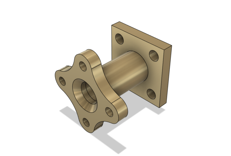
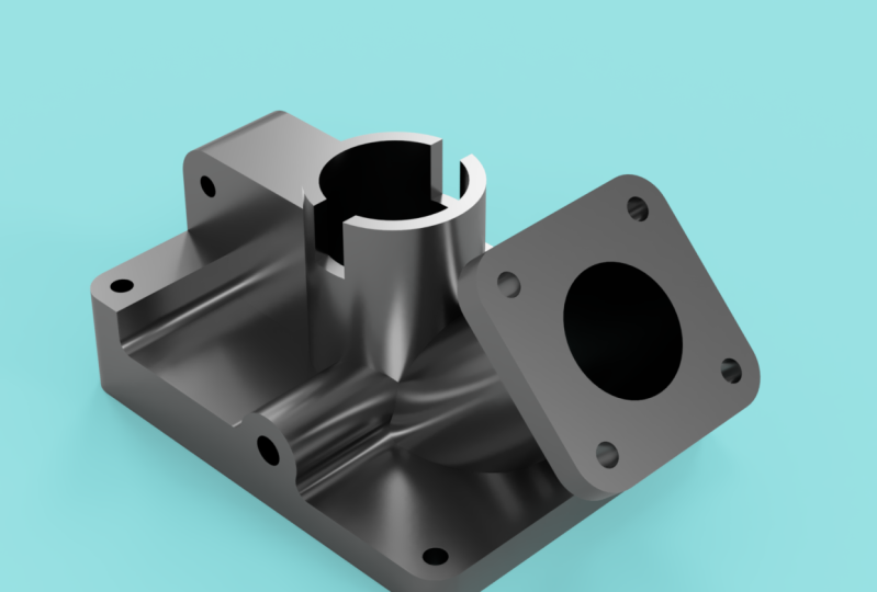
designing individual parts. For example, we would
use a part design to model this base plate or
this bracket or this bolt. For assembly design, this
design type is used when we combine parts together
to form an assembly. For example, we
can insert all of the above part designs and position them accordingly
to form an assembly, like we can see here where
we have the base plate, the bracket, and in this case, I've added two bolts. Then we have hybrid design. Now, this is the original
fusion file type. So before 2026, this was the
only file type available. In hybrid design, you can model individual parts
and form assemblies all within the same file. So at this point,
you might be asking, can we use hybrid designs
for every part and assembly? And the answer is yes, you can. It gives us most flexibility and control for
efficient modeling. However, for intermediate
or advanced users, it can give some
limitations when it comes to editing individual
parts or salssembies. I won't go into too much detail at this
point on the course. For the remainder
of this course, I will be using the
fusion default file type, which is hybrid design
for every lecture. So what should you use? My recommendations are if you are new to fusion CAD modeling, then choose hybrid design for every lecture
throughout this course. This gives you the
most flexibility when designing parts and
assemblies and as the design type
that I have used in this entire course for every part and assembly
that I will create. However, if you are coming from a solid works inventor
or other CAD background, I recommend choosing
part design for individual parts and assembly
design for assembly files. Now, this is the
traditional bottom up approach that's used for complex assemblies and
project management. So if you're coming
from a solid works or inventor background, it will be a lot easier
for you to transition to fusion if you are already
accustomed with this workflow. Now, if we go back to
the design type box, you'll notice there
are other design files such as drawing. Now, this is intended for
two D engineering drawings. This course features an
entire section on drawings, which is Section eight, so I'll explain this
design file there. And next, we have
electronics design and the electronics library. Now, these are very bespoke
design modeling environments for circuit board and
component design. We'll put those aside for
now as we're primarily focused on two D and three
D mechanical design. Once you have selected
either hybrid part or assembly as the design, just double check the options
on the right hand side. Make sure to select standard
as the default file type. And for the unit system, I will be using millimeters
and grams for every lecture, but feel free to
change as you prefer. I hope that makes sense, but
if you have any questions, please don't hesitate
to comment either on this video or you can
send me a direct message. In later sections
on this course, I will revisit these
design file types, and you will
understand more about CAT model structuring
and workflow. So I'll see you in the
next lecture. Thank you.
7. Design Files Switching Between them: In this lecture, I will
show you how the user interface changes when we
are using part design, assembly design,
and hybrid design. I'll then show you how to tell which design type
we are using and how we can switch between the file types if we've
selected the wrong one. So let's open up fusion, and for example, let's
go with a hybrid design. Make sure our unit system
here and when to use Metric, in this case, millimeters
and grams to create new. So from here, if we come over to the left hand side,
you'll see here, we've got the browser, and then under the
document settings, it identifies here
hybrid design. Now, let's say that perhaps in the future, you
want to change that. So we click on the Convert icon there, and then over here, we have this toolbox
that pops up, and under design type, it states hybrid, we
can change that. So we could jump into
part, for example. Now, before I demonstrate this, I just want us to take a look at the tool
bar at the top here. So in all of my lectures
in this course, I'm using the hybrid design, so the tool bar will
look the same as this. But watch how this changes. Let's select Let's go on
assembly and click Convert. Now, the tool bar here
looks very different, and these tools are all
related to forming assemblies. If we then change
that, let's go on to part design, click Convert. You'll see here that
all the tools are in relation to designing
individual parts. So it's just one thing
to keep in mind and to appreciate when you're
selecting the design type. But for me, I'm going to stay on the hybrid as I've
done in this course, click Convert and
use this tool bar, which features all of
the tools required for individual part design and
for assembly design as well. Okay, I hope that's all clear, and I'll see you in
the next lecture.
8. Setting Units, Grid Settings & Environment: In this lecture, we will learn how to switch between units. So I mean metric and imperial, commonly millimeters and inches. So we will learn
how to do this in our individual designs and also how to switch units
for permanent use. So by this, I mean in
the user settings. So once we've opened up
a new design like here, we can tell what
units we're working in by coming over
to the browser. And under the browser,
we've got one folder here, which is document settings. If we hit the drop
down next to that, it'll then detail to us what units that we're
currently working in. So currently I'm
working in millimeters. And if we want to change
this, we can just simply left click on
change active units, and our tour boox pops up. We can select here centimeters, meters, inches, out foot. So I'm going to stay in
millimeters for the time being. So this is how we change units
for an individual design. I'll only be applicable for this design here and
not for any others. But if we want to make
a permanent change, all future designs to be in
a specific type of units, we can come up to the top right under where
our profile icon is, if we left click on that
and then hit preferences, they have many tools pop up here that you should be studying on the
general settings here, so you can change to the
language and so forth. We won't go through
all of these, but we will be covering quite a few throughout this course. But in terms of units, we
come down to the bottom, and we have the default units. So under here if we
come under design, which is what we're going to be working on in this course. And here we have
the option to set the default units
for new designs. And again, I've got
these in millimeters, but you can switch between
these as you like. For example, if I change to inches and select apply, okay. Then start a new design by just selecting the new
design button up here. So we're in our new design now, and if we come over to
the document settings, hit the drop down. You'll then see that
we're working in inches. Okay? So I'm going to switch
that back to millimeters, come on the default
units design, that back and mill apply, okay? Close down that design,
start a new one, and just make sure that's in millimeters as
begin to see here. So those are the two methods
for switching units. Let's now take a look
at our environment, and you see here that
we have this grid. Now, many students have asked me previously how they
can turn off the grid. The grid is there as
a reference point, and it's good to help with
three D visualization. I understand that it can
be quite distracting. So in terms of turning this off when we are in design mode, we come down to our
display tools down here where we have
grids and snaps. Just hit the drop down there, and we've got this option here to turn off the layout grid. And then we can continue design in just a plain
environment, like so. Another option we have here
as well is grid settings. So if I turn the grid back on, then go to grid settings, we've got a toolbox pop up here, we've got the option
here to have the grid as being adaptive or fixed. For me, personally, if
you keep the grid on, I would recommend
keeping it adaptive. So what this does is
it adapts according to how far you zooming
out or zooming. It depends on the scale
on which you're modeling. If you're modeling
something very large, it will adapt accordingly. Otherwise, if we
have it as fixed, we can actually fix the
major grid spacing. So in this case, if I
change that to 500 mil, you can then see the
grid has changed to 500 mil spacing and the
minus subdivisions. If I change that to let's say two, I'm going
to press Okay. I'll then need to
zoom out so that we can see the scale
of the grid now. So we have 250 mil going on half a meter and
in the other direction. Recommend for me
personally, grid settings, I usually keep the grid on, and I recommend keeping it
on adaptive, pressing okay. And then, regardless of
the scale we're modeling, the grid will adapt accordingly as we can see that
I'm zooming in now. Just a reference, by
the way, I'm using the mouse wheel to
zoom in and zoom out. The way you see me
panning around, I'm using the middle
mouse button. We'll cover all those details in a later lecture alongside
a few keyboard shortcuts. Now let's take a look
at the environment and some of the
display settings. So if we come down to the
panel at the bottom and then under display settings,
hit the drop down there. And first, let's take
a look at environment. So right now, I'm
in photo booth. You see it's a white background. I'll give an example here. Let's select gray room. And there we're working
in a gray background. Let's try one more. It's
going to tranquility blue. We've got that nice
blue background there. I typically work in photo booth, but it's completely up to you. What your preference? I like to have the white background
for me personally. Also the display settings, we've got some visual styles. So to better demonstrate this, I'm actually going to
open an existing part. So this is a fastener that
I've drawn previously. Going to use this
as an example to show you about the
visual styles. So the default is shaded
with visible edges, okay? So we can see the edges there
are highlighted in black. We've got options here to
change the visual style. So you may want to just have it shaded with hidden edges, okay? So shaded part, and then we
can see the hidden edges. Another option there
is just shaded, so that's where the edges
are not so visible. We've also got the
option for wire frame, and also wireframe with hidden edges and with
visible edges, okay? Like, so the visual
style that I prefer to model in is shaded with
visible edges only. So I think that's sort
of visually the most easy to read parts
and assemblies in. And the last setting I want
to show you whilst we've got this part open
are the view ports. So if we hit the drop down here and go on multiple viewports, we can then see we've
got our sort of ISO view at the top right here, and we've got our front view, top view, and side view. And this can be really useful
if we're communicating with clients or working with
other team members, other engineers, other
students, et cetera. So another option there in which we can work with our parts. And even within each
viewport, we can edit them. So, for example, if I jump over to we're now looking
at the top view, okay, I can move this around and make any edits or show any visuals,
likewise, for the others. If we want to leave
the viewports, we just hit the drop down again, and then just go on single view. Then we're back to our original
part in a single view. Okay, I hope that all makes
sense in this lecture. And again, if you
have any questions, please send me a message. Aside from that, I will see
you in the next lecture.
9. Sketching Intro: In this section, we will learn all the fundamental
elements of sketching. Sketching is essential
to three D modeling, and Fusion provides many
sketch tools that enable us to construct high quality sketches to then later three D model. We'll start by understanding all of these sketch
creation tools, their location on the toolbars and their keyboard shortcuts. We'll then study the
sketch modification tools, pattern tools, and very
importantly, sketch constraints. The end of this
section, there are three sketching assignments for you to test your knowledge and capability to sketch infusion. All the tools required to model these sketches are taught
within the following lectures. So I look forward to seeing how you get on with
these assignments. Each lecture in this section
is presented step by step, and I will walk you
through how we can use these sketch tools
for common practices. I'll be giving a range of examples throughout
the lectures, which I recommend
you follow along with me and take the opportunity to practice these tools and familiarize yourself with
what they are used for. In the following
sections of this course, I'll be regularly
using the tools covered in this section,
and so will you. Regarding the design file types, which one should you use? Again, if you're new to fusion, I recommend within
this section for every lecture to
use hybrid design. So that's the same as me. I'm going to be using
millimeters and grams. And then for those
of you who have worked previously
with Solid Works or inventor and want to follow the same workflow as
in those CAD programs, I would recommend going for the part design selecting standard, and then you're
according units here. So let's start sketching.
10. Sketching Planes, Lines & Dimensions: In this lecture, we will
create our first sketch, and we're going to be
using the line tool. We'll start by understanding which default plane we should start our
sketch on and then we'll create a basic sketch
using the line tool and apply both linear and angular
dimensions to fully constrain it. And then finally, we'll finish the sketch by saving it
within our project folder. So now we've got Fusion Open. Let's come up to the
top where our tabs are, come under solid, and the very first option there
is to create a sketch. Left click that
once, and now we're presented with 32
dimensional planes, which we need to choose one
of them to do our sketch on. So this one here
is the X Z plane. This one here is the Y Z plane, and this one here
is the XY plane. A lot of students have
asked me previously, which plane should
I do my sketch on? Now, there's not necessarily a right or wrong answer here. It depends on the
orientation of the part. Example, if I'm modeling
this part here, let's say it's some sort
of bracket base plate, in this orientation, I would
model it on the XY plane. So when I apply this
to my assembly, it will automatically be in
the correct orientation. Whereas if I were to
model the same part, but in this orientation, I would be modeling
that on the X z plane. And likewise, if I were to model the same part in
this orientation, I would model that
on the Y Z plane. We'll learn more about
default planes as we progress throughout this
course and create more parts, and you'll become more
familiar and accustomed to choosing the more
appropriate plane to draw on. But for the purposes
of this lecture, we're going to start
with the XY plane. So let's left click
on that once, and now you'll see we're looking perpendicularly to that two
dimensional environment. And if we look up to the
top where our tabs are, have a new tab there,
which is sketch. And underneath this tab, we have many tools in relation
to sketching. For example, we have
the creation tools, modification tools, automate, which
relates to fusion, applying automatic
dimensions and constraints. We've then got the constraints, configure inspection tools, ability to insert
parts or images, various selection tools, and the option to
finish the sketch. So within this section
of the course, we'll be covering all of the
core tools available here, including many that are in
the drop downs as well. So we're not just limited
to what's available here. We've also got additional
tools here which perhaps might not
be as regular used. Let's start off with
a line tool then. We'll come under
our creation tools, and you'll see the first option
there is line next to it, two point rectangle,
then to diameter circle, spline tool, mirror and dimension or various
other tools in there. So the line tool is
the very first one. It's the most
commonly used tool, the shortcut for that
is L on the keyboard. So if I come over
to the workspace and I hit L on the keyboard, you can then see the line
tool is selected and I'm now using the line
tool in this environment. At the very center here
where the two axis cross. So that's the X and the Y axis. This is called the origin, and that is 0.000 on the X, Y, and Z axis, and it's typically where
we start sketching. I'm going to start my line
sketch from the origin. I'm going to left click once, and I'm going to
drag out my line. Immediately here, we can see we have two parameters
which we can control. Number one is a dimension and
the other one is an angle. So we can choose either
to add in a dimension at an angle or we can just left click anywhere
in the environment. So if I just left click here, for example, we have now
this blue line in place. I'm going to hit Escape on
the keyboard, on this line, I'm going to hit Delete,
and then I'm going to hit L on the keyboard
and redo that. Let's start from the origin, come across, and now
let's input a dimension. Let's go for 50 millimeters. I'm going to type in
50 on the keyboard. And then if we move
the mouse around, you'll see that that
dimension is locked in place. So we have a line that's
50 mill in length, that linear dimension there, that is the angle
that we still need to input and control exactly where
this line is going to be. So that angle is in
relation to the X axis, and how we control that is by hitting tab on the keyboard, and now you can see
it's highlighted, and we can insert an
angular dimension there. So in this case, I'm going
to type in 45 degrees. Then I'm going to hit
Enter on the keyboard. Now we have this fixed line
in place 50 mil in length, 45 degrees from the X axis. Now notice as well that
the color is black, and the two endpoints are
black circles as well. So what that color
indicates is that this entity is now
fully constrained. It's not possible to
change its angle or dimension. It cannot be moved. Now we can change
these if we want simply by double
clicking. So 50. If I change that to, let's say 75 and the angle double click, let's say 30, they can
change it like so. We can then press Control Z
on the keyboard if we want to go and now we're back to our 50 mill linear and
45 degree angle line. Let's continue sketching then. I go to hit L on
the keyboard again, go back to the line tool. I'm going to bring the
mouse over and snap on to the end of our line here
with that blue box up here. I'm going to drag to
the right hand side, and you'll see we're
snapping to the grid. If you want to turn
off grid snaps, come down to the grid and snaps, then you can turn
off snap to grid. But for me, I'm going to keep that on throughout
this course. I'm going to come across, and I'm just going to drop the line. Let's just say somewhere here, bring this line down
again, left click once. Across here. Left click. And now I want to finish
off my sketch and generate a closed
profile so to do this. I'm just going to simply left click once at the origin again. And now you can see we've
got this shaded blue area, which is our closed profile. I notice that we're
still in the line tool. There are different ways
to exit the line tool. We can hit exit on the keyboard or we can right click
and press Okay, and now we've left
the line tool, we're free to use
any other tools. So now we've created
a basic sketch. If we then look at the
color of these lines, we can see this one is
black. This one is black. The other two lines
here are both blue, and that indicates
that they can move. Okay? So we can
move this line like on the X axis and this
one on the y axis. We want to constrain
those in place. But to do that, we want
to apply dimensions. Let's come over and do our
create tools again and let's select sketch dimension or
shortcut D on the keyboard. So if I hit D, and then going
to select this line here, click once, bring
that dimension out. Left click again. I'll
apply a dimension there. Four, 50 millimeters, press enter. See
where we are there. So this line has
now turned black, and it's not possible to move. I hold down the left mouse
button. Can't move that line. This one is still
moving on the X axis. There's control here would
be the length of this line. So I'm going to hit D
on the keyboard again. I'm going to put
an in dimension on this line, bring that down, add a dimension there of 80
millimeters press enter. Okay, I'm going to press exit and leave the dimension tool. And now we have a fully
constrained sketch. Okay. All our lines, all the endpoints
are black in color. We have our closed profile
there. That's looking good. One more thing I want
to show you, as well, I let's go for the shortcut
L on the keyboard, I'm just going to start
anywhere in the environment. Left click once, and I can
continue drawing like so. Left click again. And then I'm going to left click one
more time, let's say here. Let's say that I want to
end the sketch there. Mag, I don't want to
generate closed profile. Options we have here is to
press exit on the keyboard, right click, select Okay. Or another option is to just left click once on
this green tick here, we're telling fusion that we
want to finish the sketch. And now we're no longer drawing
lines from the endpoint here to escape on the keyboard and we've
completed that sketch there. If we ever want to
remove any entities, quite simply, we can left click, press delete on the keyboard. We can also select them as well. If we hold down the
left mouse button and drag across a line, we need to make sure
that the entire line is encapsulated
within the square. We can then hit Delete
on the keyboard. And then another option as well, if we left click and
drag up like this, notice that it's a
different colored square. So this one here is kind of
orange with a purple border. One here is yellow
with a dash border. What this means is
that any entity that comes into contact with
this area will be selected. If I let go now, you'll see
we've selected that line. But if I do the same thing and drag across like
this and let go, I've not selected it. It's a really useful tool when
we're working with fusion. Just drag across like this. Maybe I have selected it, hit the lead on the keyboard, and now we're left just
with our sketch there. So now we've completed
our first sketch. Let's go ahead and save that. We come up to the top left. We're going to hit
Save. Now we've got the option to
give it a name. So, in this case, I'll
just say first sketch, and then location,
we just want to make sure the correct
project is selected. So our fusion course
project, save. And let's go into our
nine squares up here. Then you'll see our first
sketch has just appeared here. I've also got the bracket in there that I threw into
this lecture earlier. But yeah, you should just
have the first sketch on its own in that project. Okay, so that's the
basics of the line tool and adding dimensions and
having fully constrained parts. We're going to move on
in the next couple of lectures and go through the remainder of
the creation tools, then we'll do modifications, constraints, and so on. So I'll see you in
the next lecture.
11. Sketching Rectangle Tools: In this lecture, we will
learn how and where to use the three types
of rectangle tools. So these are the two
point rectangle, three point rectangle, and
the center point rectangle. So to demonstrate this, I
will work in a new design. But if you want to work from the previous file where
we did the line tool, if you've got that
open, great, if it's not open, no worries. Come up to the show data panel. Make sure you go to home and then select
the according project. In this case, Fusion
course project. And you should have the file that we called
first sketch there, right click and select open. But for me, I'm going to work in a new design for this one. So let's come up
through the top left. Again, under solid.
Let's hit Create sketch. And for this, we could
choose any plane, but I'm going to go with
the XY plane in this case. And let's go up through
our Create tools, and then you can
see there we've got the two point rectangle, which is the shortcut
R on the keyboard. Now, if we hit the drop down, and then we come
under rectangle here, you see there are
three options here. The two point rectangle,
which is the standard. That's the most commonly
used type of rectangle, the three point
rectangle, which I very rarely use, only
in some instances. And then we've got
the center rectangle. And that's a fairly
commonly used tool as well. So we've got the shortcut
R on the keyboard. And then if we look on
the right hand side, we've got the sketch
palette, so I'm just going to bring
that to center now. In terms of feature options, we can actually pre select which type of rectangle we want, 2.3 point or center. So just by hitting
R on the keyboard, we can then just quickly choose
there as opposed to going to create rectangle and then choosing the
appropriate one there. So put the palette
over there for now. So again, I'm going to
start from the origin. Going to pan across by holding down the middle mouse button. And I'm going to start at zero, 00. That's the origin. I'm going to bring
the mouse out. And as we can see here, we're forming a rectangle. And again, just
like the line tool, we've got parameter options,
which we can input. For this particular case, I'm going to put
in 80 millimeters, and let's do that by 40
and height press Enter, and there we have our
complete profile there, a rectangle that features all black lines, that's
fully constrained. Notice these symbols
that will pop up here. Now, these indicate constraints, which we'll be covering
in a later lecture, but just to give you
a bit of a heads up, this symbol here represents
a horizontal constraint. Now, this symbol is
tied to this line. So this line is
indefinitely horizontal, so we cannot change the angle,
cannot make it vertical, or that is horizontal and likewise, the
same with this one. So that's one of the
powerful features behind using the two
point rectangle tool. Likewise, for the
vertical lines, you'll see this symbol here, same symbol, but just in
a different orientation. So it being vertical here indicates a vertical
constraint on this line, and the same is also apparent
on this line as well. It's a fantastic tool, and it's much quicker
than drawing out a rectangle with the
line tool and then perhaps having to add
individual dimensions and constraints on top of that. So it's a quick way to
show rectangular geometry. I go to pan across now, and I want to demonstrate
the next rectangle tool. Let's go for the three point. So I'm going to press
R on the keyboard, then under my sketch palette, I'm just going to click
three point rectangle, throw that back over there. I only click once. So not
the origin this time. We're just going to go
sammer on the Xaxis. So it's called three point
because we do three clicks? We identify three locations
for this rectangle to form. So we got the starting point,
which I've clicked already. Now I need to do one
more left click, which I'm just going to do
anywhere. Let's say here. I need to do one more click now. And if I draw the mouse out, I then need to
define the height. So in the first two clicks, I defined the angle
and also the length, and then in the third
click, I define the height. I'm just going to put that
in its 50 mil for now. Again, I very rarely use
the three point rectangle. It's only in certain cases, but you may find yourself using this more and
more regularly, depending on the geometries that you're regularly drawing. Now notice again here that this rectangle is
completely blue. All edges and all the
corners are all blue. That means we can
move it anywhere. So if I hold down the left
mouse button at this point, for example, I can move it. And also, we don't have a
dimension on this line. I got to go ahead and add
that press D on the keyboard, select this line, put a
length in there of 110. Then if I try that again, so the dimensions are
fixed, but in this case, I'm able to move that around, and that will be so until we anchor down one of these
corner points here. So that's the three
point rectangle. Now I'm going to press R on
the keyboard one last time, and we're going to take a
look at the center rectangle. This is quite a commonly used rectangle where we only need to identify two points
to define the rectangle. So the very first
being the center. In this case, I'll just
select on the x axis there. And my second point then will define both the length
and the height. So I've got control of
that corner point there, or I can input dimensions. So in this case, let's go
over 150 p. Let's go 80. Then I can also control
the position of this rectangle using the
center of the rectangle. I can hold down the
left mouse button, and I can move that around to say, wherever it
would need to be. And we see here
as well that it's also input a number
of constraints. So this type of constraint here is called the
parallel constraint. So this is parallel
to this line here. And likewise, with these
two vertical lines, then down here, we've
got one more constraint which is perpendicular. So we've got that 90
degree angle there. I like to use the centerpoint rectangle whenever I'm mirroring entities because I've got the center point of it
identified already, so I can do any mirror lines down the center or
across the horizontal, we'll be doing that
in a later lecture. But those are the
three rectangle tools. Again, the most common is
the two point rectangle, it sits right up here, and it's the first selection when we hit R on the keyboard. Next most popular would be
the centerpoint rectangle, and then the third only
for special cases, we see the three
point rectangle. So we'll be using rectangles
in the later examples, and I will see you
in the next lecture.
12. Sketching Circle Tools: In this lecture, we will
learn about the functions of the five types of circle tours and I'll
demonstrate each one of these. So these are the center
diameter circle. We've then got the two point
circle, three point circle, and then we've got
the two tangent and the three tangent
circle, as well. So I've opened up fusion. I've started a new part,
and as you can see here, I've input some
geometries already. That's going to help
me to demonstrate the functions behind each
of these circle tools. So let's come up to
our creation tools, to the drop down the circle. We see that the shortcut
for the center domed circle is C. So let's go ahead
and hit C on the keyboard. Now, just like the
rectangle tool, our toolbox pops up and offers us the different
variations of circle tool. I'm going to put that
toll aside for now. Let's go ahead and use the
center diameter circle. So this is the most commonly
used type of circle. So to demonstrate this, I use the square that
I've drawn in here. And the very first
click that we define is the center point
of that circle. And as we bring the mouse out, we can start to see the
circumference form. We have the option at this
point to enter a diameter into the parameters box or we can
snap onto existing geometry. For example, I've drawn
this square in place. I could snap on to the midpoint
of this horizontal line, or I could even snap on to the corner point of the
square if I left click there. So if I left click there, we've then got our circle in position. The next tool we're
going to take a look at is the two point circle. So if we come over to our box and select the two point circle, just zoom out pan over a bit, the two point circle,
the very first point we define is a place on the
circumference of the circle. If I left click at the end
point of this line here, that's one position
of my circumference, and then you'll see the next
click wherever that may be. Will be the other circumference. So that will define
the diameter. So in this case, I could snap
onto existing geometries, or I could just
input a diameter. In this case, I'm just
going to snap on to the midpoint of this line here, or left click there, and there
we have two point circle. So the next we have the
three point circle. So principles exactly the
same as the two point, except on this occasion,
we're actually identifying three points
on the circumference. To demonstrate this, if
I select, let's say, the endpoint of
this line here as one position or
my circumference, another point as the
endpoint of this line, and then I just need to
define one more point, which will be the last
point of my circle, identifying those
three points there, and I'll choose the midpoint
of this horizontal line, and there we have
our complete circle. The next tool to demonstrate is the two point tangent circle. So very straightforward to use. This is just where
we need to identify two points to which our circle
will be tangential too. So to demonstrate this, I'm just going to
use this V here. I'm just going to
select these two lines. I'll select the first line, so the circle must be
tangential to this line. I'm going to select
the second line here, as we can see our
circles formed. And we now have the option
to move the circle. However, wherever we move it, we are constrained by the tangential constraints to the two lines that we
identified previously. Here, we can identify
a radius or we can just click wherever
it needs to be. For example, I
just let go there. And now we see that we have these tangential
constraint symbols pop up, identifying that this circle
is tangential to this line, the circle is tangential
to this line here. And that leads me on
to the last tool, so I hit C on the
keyboard once again, and then we'll move on to
the three tangent circle. So same principles
as the two point, except here, we just
identify three points. So I'm going to identify
the three entities here. F one, two, and my third entity is
going to be this one here. And we've got this
preview coming into play, and we can see the
position of the circle. So I'll select
that entity there. And again, we've got these three tangential
symbols pop up here, identifying the
according constraints. So that's a quick overview
of the five circle tools. The main ones that we
use when modeling are the center diameter circle and definitely the two
tangential circle, as well. We rarely use the others, but they do come into play, depending on what
geometry we're working on. I hope that all makes sense. And if you have any
questions, please send me a message, but
aside from that, I'll see you in the
next lecture and we'll do some more of
the creation tools.
13. Sketching Arc Tools: In this lecture,
we'll learn about the three different types of arc tools and how or
when to use them. So the three tools are
the three point arc, the center point arc,
and the tangent arc. I've started a new design
in fusion, and as you see, I've already input
some sketches, and I'm going to
use these to aid me in demonstrating how
these tools work. So first of all,
let's come up to the top. We're in sketch mode. Let's come under Create. Come under Ark. There we have the three tools
available to us there. Now notice there
is not a shortcut for any of the arc tools. If you want to add a shortcut, you can do so by
left clicking on the three dots here and then going change
keyboard shortcut. Then you can put any
shortcut that you want in here and
then press, Okay. The first tool we'll start
with is the three point arc. If I select this, and again, we've got our sketch palette which is docked on the right, and there we have
the center point, the three point and the tangent. I'm going to put that back
over to the right hand side. Let's start with this
three point arc then. So here we need to
define three points. The first is the starting point. We'll go left click once here, and then we need to place
the end point of the arc. Okay? So we've got our
endpoint in place. And then when we
move the mouse now, we'll then see the arc
beginning to form. Typically here we
would snap onto an existing geometry or perhaps an ideal
location on the grid. We bring the arc in like this. We can see that the arc becomes tangential to the two lines, the horizontal and the vertical. So it essentially forms a fillt. But in this case, I'm just going to
explode that slightly. I'll bring it up to
this point here, and there we have
our three point arc. So three points, the start, the end, and then the
final sapping position. Let's now take a look at
the center point arc. I'm going to come
over to the palette and select the center point arc. This is very
straightforward to use. So the very first click that we do is the location of
the center of this arc. We're putting in
the center point, which in this case, I'm
going to use this sketch. I'm going to select the
center of my cross there. And then the second click identifies the
beginning of the arc. Let's say I want my arc to start in this position here,
left click once, and then you'll see that as
we move the mouse around, the radius is fixed as per the distance which
we have defined here. And as we bring the arc around, we can then either snap on or put in an
appropriate angle. So I'm going to
snap on too, yep. There we go. And there's
a three point center. Ah, let's do that one more time, then, let's select the center. Bring that out slightly
for a snap out. Here. Then we can
draw that around. And yeah, perhaps we can end it in roughly the same
location, like so. And that's how we use the
center point arc tool. And the last arc tool I want to demonstrate is the tangent arc. Now, this is really
useful for when we want that tangential constraint
at the start of the arc. I I demonstrate this by
starting our arc here, so we're coming off of a curve, we start our arc here. And as we move the mouse, we can see that wherever we bring that endpoint of the arc, it will always be tangential at the starting point
with this arc here. Let's say my ending point
is here, Snap on there, got our arc in place,
and we see that it's input a tangential
constraint there. We've got a tangential
joint between this arc and the one
that we created. Now, one thing to keep
in mind here with the tangent arc is
that it will only be tangent with the
initial geometry and not with the final geometry. So as we see here, this joint
here is not tangential, let's say, with
this vertical line here or the horizontal line. So just something
that we need to understand when we're
using the tangential arc. And I want to show you
one quick tip as well, which is actually
under the line tool. So let's say, for
example, I draw a line, I'm just going to snap
onto the grid, go 40 mil. And now I'm still on
the line tool, right? But from here, I can
actually draw an arc. By coming to the endpoint
of this first line here and holding down
the left mouse button. And with the left mouse
button held down, if I draw out what
should be a line, it actually becomes an arc. That's a really handy tool
for when we're doing a lot of sketching and we're in need of tangential arcs coming
off of existing entities. We can just quite
simply hold down the left mouse button and
continue to draw arcs like so. Okay, so those are
the three arc tools very straightforward to use. The most commonly used
one is a three point arc, but equally the
center point arc and the tangential arc are
quite commonly used, depending on what geometries
that you're working with. It will be for sure using these tools throughout the
remainder of this course. And I'll see you in
the next lecture.
14. Sketching Slots: In this lecture,
we'll learn about the various types of slot
tools and how we can use them. So there are five variations
of the slot tool. These are the center to center
slot, the overall slot, the center point slot,
three point arc slot, and the center point arc slot. So let's take a look
at each one of these. So if we come over to fusion, I've opened up a new design. I'm already in sketch
mode to come up to the create up here and
come under the slot. And we'll see here
that we've got the five slot tools available. Now, just like the arc tools, there are no pre installed
shortcuts to these slot tools. If you do want to add them, hit the three dots and add a
keyboard shortcut here. So let's start with the
center to center slot. Let me demonstrate this one.
So the very first click defines the center point
of one of the arcs. I'm going to start
that at the origin, and I'm going to come across
say 50 mil in this case, and I'm going to
left click again. And the second click defines the center point
of the other arc. And so if I now
move my mouse out, you're going then see we
need to apply a with. But if I apply a WIC
there, let's say, ten mil, can enter that in a keyboard, or I could click to Snap
on the grid's Enter. We've then got our slot form. So the first click, as I said, that was the center
point of this arc. Second click was the
center point of this arc, and the third click
or input dimension determines the
width of the slot. So a nice and easy tool to use. And in my experience, it is the most commonly
used slot tool. Let's go back onto
these tools then, let's go for the overall slot. To demonstrate this,
let me go below and I'll select this position here being the very first point and this position here
being the second point. Now, if I open this
up now, and again, I'm going to put in ten mil, press Enter, you'll see
the difference here. So the very first click defines the outer quadrant of this arc, and the second point defines the outer quadrant
here of this arc, then our third click
defines the width. Okay? So first one, we're
going center to center. Then we're going
overall, and now we're going to take a look at
the center point slot. The center point slot
tool demonstrate this. I'm going to choose
our first click here. So this is the
center of the slot. I'm going to drag that
out to this point here. So 25 mil from the center to
the center point of one arc. And then if I expand that out, you'll see our slot form. Again, I'll input ten mil enter our first clicks the
very center of the slot. Second click center
point of this arc, and then third click
determines the width. And essentially what's on the right hand side has
mirrored onto the left. So center center point width. Then we've got the
three point arc slot, create, three point arc. Very first click defines where we're going
to start our arc. So let's say here. Second point defines where it's going to end. And the third point, we're
going to add in this arc. Let's go for this position here. And once we've clicked
our third point and we expand our mouse, we can then form a with around the arc that
we've created. Again, let's go for
ten mil press Enter. So this is the arc
here that we drew in. We do 1.2 point and then define the radius and then
moving the mouse out, we've then defined the
width of this slot, or rather I input it as
ten on the keyboard. And then last but not least, we have the center
point arc slot. Select that center
point arc slot. I'm actually going
to reference it from the center point
of this arc here. So if I do my first click here, I then need to define
where my arc will start. So let's go for
this position here, and then going to
draw in my arc. Let's come up to here. And then I need to input my
width, let's say, ten mil. So this is just a variation
of the three point arc slot. Was a three point, we
define 1.2 0.3 point, and the center point arc, we actually determine
the center point of this arc and then the starting
and the finishing point. I'd like to give one example
of where this can be used in some geometry I've
drawn just over here. We'll come to my
tools again, slot. Select the center
point arc slot. I'm going to define
the center point of my arc, in this
case, it is here, and I'm going to define
my first point of the arc being this
geometry here. I'm going to bring the
arc around and snap on to this point
here, expand my slot. I'm going to input a radius, sorry, a slot width of
let's go for ten mil. Press ok. That's an example of where this tool
would be commonly used. It's really snapping on
to existing geometries. Okay, so fairly straightforward
for the Actors. As I say, the most commonly used one is the center
to center slot. But they all come into
use. It all depends on what we're modeling,
what we're working with. Any questions, please
send them to me, but aside from that, I'll
see you in the next lecture.
15. Sketching Polygons: In this lecture,
we'll take a look at the three polygon tools and understand where we
should be using them. So these tools are the
circumscribed polygon, the inscribed polygon,
and the edged polygon. So jumping into fusion, I've opened up a new design, come up to the top,
create a sketch. In this case, it doesn't
matter which plane. I'm going to go
for the XY plane. And if we come under Create, then we've got our
polygon options here, circumscribed,
inscribed, and edge. Let's start off with the
circumscribed polygon. I'm going to model
this over here. So first of all, we need to find the center of our polygon. So that's the very first click. Then as we bring the mouse out, we can see the polygon
begin to form. And there are two parameters
which we control here. Number one is the distance
from the center of the polygon to the midpoint
of one of the edges. I'm going to put in
a distance here. Let's go for 50 millimeters. I'm going to hit tap
on the keyboard, and the other parameter
is the number of edges. So the default is six. I'm going to go, in
this case for eight. Then finally, I can
adjust the mouse to change the angle. I'm
quite happy with that. It's our left click once. And there we have our
complete profile, eight sided polygon, 50 mil from the center to
the midpoint of this edge. Let's do that one more time and take a closer look
at the preview. So we can already
see the preview of the polygon here and we
see this circle inside. And so the polygon is on the exterior of that circle and hence it is circumscribed. In that every edge
of our polygon is tangential to that circle. I'm going to now change and move on to the inscribed polygon. Take a look at this.
Our left click, once again, that's
starting the center point. And then as I bring
the polygon out, we can now see that the
circle is on the outside, and every corner or joining
point of our polygon is then in contact
with the circle and the edges are no
longer tangential. In this case, again, we have
two parameters to define. I'm going to go ahead
again with 50 millimeters. Press tap on the keyboard. I'll also change that to
an eight sided polygon, press enter, and then we can clearly see the difference
between the two. So one is measuring
a distance from the center point to the
midpoint of this edge. One is measuring a distance
from the center point of the polygon to one of the
edges or joining points. That leads us on to the
final of the polygon tools, which is the edge
polygon. Roll over here. So in the edge polygon,
the first click defines the starting point
of one of the edges, and the second point will define the ending
point of that edge. So I'm going to actually
put in a distance here. Let's do it 40 millimeters, and we've also got the
option to control the angle. If we hit tab on the keyboard, I'll put in an angle
of 30 degrees. I'll press Enter, and then we can see a preview of
the polygon appearing. And depending on which side of the line the mouse cursor is, it will determine
where oligon is, whether it's this
side or this side. We're going to also control
here another parameter, which is the number of edges. I'm going to increase
that to eight again. Let's enter on the keyboard, and there we have our
parameters in place there. Now, we can modify
these parameters. Let's put this down to. Let's go for 25 and I'll
change that to 15 degrees. Let's change this 125. We can boost this up
to 75 as an example. And the only parameter
that we cannot later control once the polygon is in place is the number of sides. Once we have defined an eight
sided polygon or six sided, et cetera, that is then fixed. And so if we did want to
change the number of sides, we would have to select the
leap and then start again. And so that is a summary
of the polygons. The most commonly used one is
the circumscribed polygon. But again, situationally, you might be a need to use
either of the other two. And I will see you
in the next lecture.
16. Fillets & Chamfers: In this lecture, we'll
study the Fillet and Shamfa sketch tools in different ways that
we can apply them. So we'll start with
the filet tool, and then we'll move
on to the three different types of Shafer tools, which are the equal
distance Shamfa, the distance and angle Shamfa and the two
distance Shamfa. So jumping into fusion, come under the create sketch, select any plane here. Just going to go ahead with
the ex plane and over here. And to demonstrate
this, I'm going to draw in a two point rectangle. Start at one point
here, and I'll add in a horizontal dimension 150, press tab on the keyboard,
vertical dimension 100. So let's say that
we wanted to add fillets to each
of these corners. We come up to the
top, and actually, we're going to come under
the modified tools. You'll see fillets
available here. We've also got the icon here
that we can choose as well. No shortcut assigned, so feel free to add a
shortcut if you'd like. So let's select fillet. So from here, we need to
either define a corner point. For example, I could
select this corner here, we've got that red
preview in place, identifying where
the fillet will be. Or we can do is actually
select the vertical line here and then this horizontal line to give us that fillet
between the two. So I'm going to go ahead
and do it the quick way, which is just a single click
right in the corner there, and then I've given the
parameter of the fillet, so I need to define
the fillet radius. In this case, it's given
me the default 20. I'm going to go ahead
and add 25 mil, and then press Enter
on the keyboard. And then you'll see going
to hide the constraints. There we see the
dimension there. Move that up here. And
again, we can change that. Double left click.
Let's go for 18 mill. Okay. Let's do the same
principle on this corner, but using a slightly
different method. Select fillet, and
then we select the horizontal and then
select the vertical, then we can input our dimension
there. Let's go to 25. And let's say that
we wanted to add multiple fillets of
the same dimension. You can do that by again, choosing the Fillet tool or
select this corner here. We won't input a
parameter just yet. Let's say we want that to be
ten mil and this one here. Okay, so now we've got
both of those selected. Now we can enter the parameter. So in this case,
let's go for ten mil, let's enter, and you'll see
both of these are ten mil. And this fillet here is controlled by this
dimension here. If I move this dimension, I'll put it there for now. If I then change that
dimension to let's say 25, we'll see that both of these fillets have
increased to 25 milad. I'm gonna put that back.
Let's go for five mil. They go got five mill there, five mill there, 25 and 18. And so it's a very
straightforward tool to use, it's very quick, very effective. It's used often in sketching, although we can also apply filllets within three
dimensional mode as well. So that's after we
extrude a profile. We can apply
filllets after that, or if we're in sketch mode, we can apply them before. There is a slight
difference between the two, and we're going to
cover that when we move on to the three D
modeling section. So that's it for the filllets. Now let me demonstrate
to you SHAMFAs. Again, I'm going to draw
in a two point rectangle, do the same dimensions. Let's go 150 by 100. And from here we
come under modify, and then we've got SHAPAt
three options here. Got some nice
previews that appear. For example, under
equal distance Shanfa, you can see there that
the ShanfA in this case, is 20 by 20. It's a 20 mill vertical,
20 mill horizontal. We've got the
distance and angle, and that's where
we put a distance on either, in this case, the horizontal or we
can do the vertical, and then the angle
would be applied, and that would determine the
distance on the opposite, whether it's the
horizontal or vertical. And then we've got the
two distant Shafer. So this is where we
have essentially a non equal distant chamfer. Let's go ahead and
apply some of these. Let's go for the equal
distance chamfer first. And again, we can just select the corner point or we
can select the two lines. Going to select the
corner point for now. Let's go with a 20 mil
Shafer, press enter, see if we've got 20 mil on the horizontal and
20 on the vertical. We look at these dimensions, got 20 here, and then
we've got FX 20. Now, FX is a function, so it's referring to something. We hover the mouse over there, it's referring to this dimension
here, which is D eight. If we double click here, it just says it's
referring to D eight. So if I go ahead and
change dimension D eight, and I enter there,
let's go for 15. We can then see that we've
changed the horizontal by 15, and then the function has
read off of that dimension. Now they're both 15, and that remains as an equal
distance chamfer. Come over to this corner then. Go ahead and demonstrate the
distance and angle Shaf. Now, one note when
we're using this tool where we want to
define the distance, we need to select
that line first. For example, if we
want to control the distance on the
horizontal here, we choose this line on the vertical, we choose
this line first. But let's go ahead and let's go with the distance
on the horizontal, and then we're going to
chooe a second line, which is the vertical and
start to see the Shaf form. So for the linear distance
here, let's go for 40. Then for the angle, we
can control it with this wheel or we've got
the parameter box there. I'm going to input an
angle for 20 degrees, press Enter, there we
see our parameters. Our dimensions have
appeared there. And again, we can adjust these. So change that to 30,
can change that too. Let's go for 15. That is the distance and
angle ShafA and last, we'll go for the
two distance ShafA. So here we're going
to select two lines or a corner point. Let's go for the corner point. Then first of all, we need to enter in the highlighted arrow. So in this case, the horizontal. Let's go for 50 mil there. And then let's select this arrow here and let's go
for, say, 15 mil. Press Enter. Now we've got those two linear
distances there. Then you can change any
of these dimensions, so you can adjust
them accordingly if you need to do so later. So that is a summary
of the fillet and the hamper tours very
straightforward to use, and we'll definitely be using
these in future lectures. And so I'll see you
in the next lecture.
17. Text Tools: In this lecture,
we'll learn how to add text to art sketches, which can then later be used
to either iboss or engrave. And I've got two examples here. So if we look at the
blue text down here, this is Imboss text
that we see it protrudes out from this
face, ortho scusion. And then the example I've
got up here is an engraving. I've engraved my text
here, AtoEcusion. So let's learn how we can
apply text to art sketches. So under a new design,
come up to the top. I'll let create sketch. You can choose any one
of the default planes. In this case, I'm going
to choose the X z plane. If we come up to the top left
under our creation tools, we then have the tool here text. And if we left
click on that once, you'll see a toolbox pops
up. And we have two options. Number one is text, which
is just a text box, essentially, and the
other is text on a path. And I'll demonstrate
both of these to you. But this is where we have
some predefined geometry, and our text will conform to
the path of that geometry. So let's start with the text or the text box, as I call it. We left click once anywhere
in the environment, bring out our text box. Left click again. We then see we have some sample
text in place already. We've got our toolbox
here where we can control a number of
variables about this text. I'm going to change this
to Autodesk fusion. And then moving down, we've got various fonts that we can
work with. I change this. Let's go for aerial, whether it's bold, italic, then we've got the
option to change. Well, it says height, but
this is essentially the size. So if we change this
to, let's say, 15, you see much larger, go to leave that it's eight
for the time being. And in terms of
character spacing, this determines the spacing between each one of the letters. If I increase that
to go for 20, okay? We can then see
we've got some quite large spacing between
those letters. Leave that as zero
default for now. We've also got the
option to flip as well. Where required, we can
flip on the vertical, like so, or on the
horizontal, like so. And then relating to
the textbox itself, we have various
options for alignment. So we can align that to the left if we want that to
be on the top here, you can adjust
these how you need. It's very straightforward.
We've also got the option here as
well to change the angle. Hold down the left mouse button. We can adjust that
or you can manually input an angle that you
need. Go ahead with zero. So let's look at
text now on a path. But to demonstrate
this, I'm going to draw in a centerpoint arc. I'll start the center
point of my arc here. Let's go and start the arc here, bring that around, like so. Let's come up to the
create tools. Select text. Then in here, we just
want to make sure that we've got text on path selected. And then, first of
all, we need to define the path which
the text needs to be on. I'm going to select
my arc in this case, and then our range of
options pops up again. I type in Autodesk inventor. Okay. And we can make any of the same adjustments that we covered with the text in a box. But here we need
to flip the text. I'm going to flip on the
vertical. That's correct. We've also got the
option as well to input the text on the other side
of our geometry as well. So to do this, we
come under placement, and then we could put, in
this case, above the path. And so we've got the text below the arc or we
can have it above. We've also got the option
here as well to fit to path. So fusion here will take into account the length of this arc, and it will adjust the text spacing so it fits from
one point to the other. And this can be quite
useful when we have a defined area in which we
want our text to cover. So if I hit the checkbox here, we'll then see it spaced out accordingly to cover the
entire of that path. And again, at the bottom, we've got the options for aligning. So we're going align it
to the left of the path, either center or to the right. And so that's it for the text. It's very straightforward,
and we'll be using this more in the three D modeling
section where we will begin to engrave and emboss three D part or see you
in the next lecture.
18. Sketch Modification Tools: So far in this
course, we've covered the fillet and the
various hamper tools. Now, they all come under
the modification tools. And in this lecture,
I want to study the remainder of the
modification tools. These are offset, trim, extend, break, and
scale and move. So let's start off
with the offset tool. Now I've drawn in some existing sketches to help me
demonstrate this. We'll come up to the
top, come under modify, and let's go straight to offset, which is O on the keyboard. Let's press offset. Our toolbox pops up, and here Fusion is asking us to identify what curves
that we want to offset. We've got the option as
well for chain selection, which I'll show on the
square afterwards, and then we've got two sides
flip and match topology. So let's first of
all, select a curve. In this case, I'm going to
choose the circle here. From here, we can either
use the arrows or we can input a
distance to offset. But if I left click, if I hold down the left mouse
button and drag, we can then choose to
offset that how we like, or we can input an
exact distance. But let's say, in this
case, we're going to go for 25 we also have the option
to do a two sided offset. So that's offsetting
exterior and interior. So if I select this, well then see if we're
offsetting the circle, 25 mil exterior and
25 mil interior. If I click Okay, we can then see we have those two
dimensions in place there. So this is our original circle. The outer offset is by 25 mil, so we can change that by
double clicking Gentha 30, and the inner one, we
can change that to, let's say, minus ten. Okay? And there we have our
two created offset circles. I'll show one more example
of that using the flip tool, if I press O on the keyboard, select my curve, and
I input an offset of, let's say, 25,
unchecked two sides. And now we're
offsetting exterior. But if we flip that, it
will then flip to interior, and essentially, it'll just put a minus in between the value. But if we change
that to a positive, it will then go on the exterior. We'll click Okay with it, and then we'll move
over to the square. I'm going to press
O on the keyboard, bring up the offset tool, and here, I need to
select my curves. Now, in terms of selection, we can either have chain
selection turned on or off. Let's turn chain
selection off and select this top
horizontal line here. I can now offset that line, the exterior of the
square or interior. But if I click Chain selection, it will chain select
all of the curves or entities which are in contact with the one that we selected, which is a nice shortcut. I'm going to enter
an offset value there of let's say ten mil. Let's do two sided, as
well and press Okay. And there we have art to offset squares by ten mil
from our original. Let's move on now
to the trim tool. We'll come up to modify.
We've got our trim tool here. That's the shortcut
T on the keyboard, of a press and in trim mode. And the trim tool is
very straightforward. It will essentially
trim an entity where it intersects
with another. So, for example, we can
see a preview here. This purple line will be
trimmed away fusion will recognize where that
line intersects with the circle and
then trim accordingly. If I place the mouse cursor
over this line here, it will trim from
this intersection of the circle to this
intersection of the circle. So let me click this line here. We can see that's been trimmed. This one here, choose this side, and this one down here,
choose this side, and we can even do the same
to the circle as well. So if I hover the mouse over
this part of the circle, it will recognize this
intersection point with this line and this intersection
point with this line. If I select that arc there, we can then remove
that likewise, on the other side, even do the
same up here and so forth. It's a really handy tool
when we're sketching. Next up, let's take a
look at the extent tool. Again, a very
simple tool to use. Come under the
modification tools, and there we have extend. And this will just
extend a curve until it intersects
with another one. So, for example, as I hover
my mouse over this line here, we'll see this red
preview appear, and it will extend this line all up until the
intersection to this circle. If I left click there, that line is then extended like so. Likewise, on this
vertical line here, just hover the mouse over, and it will extend that
line all the way up until contact with
this one, like so. So again, very
straightforward and a very practical tool for
when we're doing sketching. Now let's move on to the
next tool, which is break. So one of the
modification tools, we come down to
break, select that. And break just simply breaks an entity where it is in contact and
conflicts with another. For example, I have a circle here and I've got a line
running through it. If I hover the mouse
over the circle, like so we can see these two red crosses
appear down here. What this will do is
this will break up this circle at those two points. By left click on that circle
and leave the brake tool, press a scape on the keyboard, and then I go to
select the circle. I can no longer select the
entirety of the circle. I can only select this arc. And likewise, if I then select
this side of the circle, I can only select this arc, but it's broken up circle
into two arcs there. But notice that the
line remains intact. If we want to change that,
we can come under break, and then we can just click
on the line like so, press exit on the keyboard, and then when we move the
mouse over this line, you'll see it's
then broken up from this one and this one
is now independent, and so is this one here. That's the principle
behind the break tool. And now we'll move on
to the scale tool. So let's come under the
modification tools, then we'll come down
to sketch scale. This is very
straightforward to use. We have a toolbox pop up in
which point we need to select the entities we want to scale and then the
point of the scale. So in terms of entities,
we can either select individual ones or hold down the left mouse button
and just drag across. In this case, I'm
going to select the polygon and the circle. And then the point at which
we're going to scale from. In this case, I'm going
to choose the very center of the circle there
and the scale, we can then define
the factor here. So let's say, for example, let's scale that by two,
and then press Enter. We've now scaled our components
by a scale factor of two. And then the last of the
modification tools is scale MV. That has a shortcut
of M on the keyboard. So let's select that, and
then our toolbox pops up. And the first thing we have
to do is to select what it is that we either
want to move or copy. So for this example,
I'm going to select the polygon
and the circle, then we can see here that
we have a pivot in place. And if we move that
pivot, let's say, over here, our entire
selection will move with that. We can also choose
to rotate as well. Another option is
the square here. We hold down the
left mouse button. We've got free movement over
everything that's selected. And in terms of the rotation, if you do want to adjust
the position of the pivot, so that was an
automatic position, we can come across to our
toolbar and under set pivot, we select this, and then we define the new
place of the pivot. So in this case, I'm going to select the
center of the circle. And then when we're done with
that, we can click Done, and now we can then move from that pivot or rotate
from that pivot point. If you want to fine tune movement of anything
you've selected, you can use the distances here. For example, if I
enter 25 on the X, 25 on the Y, and the z would just move it
forward and backwards. So we'll leave that at
zero and compress Okay. Press Control Z to stop that, press M to go back into the move tool, re
select everything. And then we've got the
various options to rotate this sketch around all three
of the axes, X Y and Z. At the very bottom, we've got the option to create a copy. If we select that,
and then I go to move this sketch over here
and then let go. That's okay. We can now see that we've copied that sketch and
positioned it over here. Press M on the keyboard back
into the move and copy tool, and now I want to demonstrate the point to point move type. So we need to just
select two points here. One is the original of the
entities that we select, and then one is the target point to which that will move too. So if I now select
all these entities here, polygon and Circle, but the original point, I'm going to click here
as an example, and a target point,
I move over here. I'm going to select this
to be my target point, and we'll see that all
of my selection has moved over according
to our two points, the origin and the target. Press okay? Okay,
a press control Z I want to show you a shortcut
to moving any sketches. So if I drag select across
the polygon and the circle, I hold down the
left mouse button, I then have the free movement of those that I've selected, and it doesn't just have to be the center point of the circle, can also be any point like so. Okay, so that is
the fundamentals of the modification tools. And definitely in
future lectures, when we start three D
modeling and I start doing a number of examples and
you have assignments, you will find these
tools of great use. And so I'll see you
in the next lecture.
19. Sketch Pattern Tools: In this lecture, we will study
the various pattern tools, including the
rectangular patterns, single jewel and symmetric, the circular pattern,
and the mirror tool. So in fusion, I've
done some sketches to help me demonstrate these. Now, first of all, we're
going to start with a rectangular pattern
on a single axis. So right here, I've
got a rectangle with a circle, and let's
say, for example, we want to pattern this circle
alongside this axis here. So let's come under
our creation tools. Let's come under
rectangular pattern. Our toolbox pops up. We need to identify
the object to pattern, in this case, and
choose the circle. Then we have a lot
more tools available. So first of all,
we need to define a direction or directions. So for now, we'll
focus on single axis, so I'm just going
to select one axis. Now here we can choose any
pre existing geometry. For example, I could select this line here if I
wanted to pattern in this direction or
the vertical line here in the vertical direction, and I can choose
construction lines as well. So in this case, I'm going
to select this line here. And then I've got the option to change between the
distribution type. So I've got extent and spacing. I'm going to stick
with extent for now, and I'll show you
spacing a bit later. Moving down to the boxes, we have quantity here, so I'm going to
select I want to have a total of four
of these circles. And in terms of their distance, now this relates
to distribution. So the extent of my
pattern, in this case, I've calculated
it to be 250 mil. And as we can see now, we
have the original circle, the second circle,
third and the fourth. So four circles total, and the extent
distance is 250 mil. That is the distance
from the center point of this circle up to the center
point of this circle here. The next up, we've
got the direction. So I'm just patterning
in one direction here, but we can also
pattern symmetrically, which would lead to more circles appearing on this side,
which we don't want, and I will demonstrate
an example of where symmetric panning
is useful later. And then you'll see
we've got another quantity distance and direction. So these three here only
relate to a second axis. So we've only selected
one direction. So essentially, we don't need those three for this
particular example. I'm quite happy with my four
circles at 250 mil extent. And then if I press Okay, we can then see those
circles now form. And we can edit these anytime by double left clicking
on this symbol here, which is the rectangular
pattern symbol. So if I double left click, you can see our toolbox pops up again and we can make any
according changes from there. Now one useful tool within
this is suppression. So if I tick this box, we can then see that we have these check boxes appear
in the patterned circles. And then if I select
this one here, for example, and let's go
for this one, as well, and presso, we can then see that those instances of our
pattern are now suppressed. I press Control Z on the
keyboard, bring them back. Double Left click
on this symbol, and then we've got our
toolbox available again. Another way to do this as well, so I'm going to hit
Control Z to come up to create rectangular
pattern, select my object. Now, in terms of direction, so we've talked about
selecting individual entities. But in this case, what we can
also do is use the arrows. This is a really useful, handy quick tool
that we can use. So in this case, I'm patterning
a quantity of three, but if I go for four,
and then we can adjust the arrow accordingly
as to where we want them. So if I click Okay
there, looking good. Let's move on now to the
rectangular pattern Jual acts. I'm going to use this sketch
to help me show this. Let's come up to our
creation tools again, go on a rectangular pattern. Again, we're going to
select our object, in this case, this circle, and under direction
or directions, select, and now we're going
to select two directions. Let's go for this horizontal
line and this vertical line. So we're going to pattern
in this direction and also vertically as well. And for this, I'm going
to drag my toolbox down so you can use the scroll bar on the
side if you need. Keep the distribution as extent and go for a quantity of four. Then distance, let's
go for the same 250. So we're patterning like we
did for the single axis. And then under the quantity
distance and direction, this is for the vertical. So let's go for a
quantity of three, and I've already pre calculated
this as a distance of 100 and that's an extent
reference distance. Then we can see we've
panned in both axis. And if we click Okay,
that's looking good. Then again, double click. In this case, yeah, we
want to suppress anyone. Let's say we want to
suppress these two. Let's go for three, press Okay. And then we've removed
those instances, and we can put them back. So again, go in the suppression. We can just left click
to bring them back. That's okay, like
so. And that is the rectangular
pattern for dual axis. Let's now move on to
symmetric patterning. I'm going to use this
sketch up here to help me. Let's say that we want
this circle pattern in both directions horizontally
and vertically. Let's come under
create. Let's choose our rectangular pattern tool and object, select the circle. And under direction,
let's click on this horizontal line
and this vertical line, keep the distribution as extent. And then under quantity,
let's stick with three, and I do a distance here. So this is pre calculated 100, and then I'm going to change
the direction of this. Right now, the distance between this center point and this
centerpoint is 100 mil, and I've got my
three circles there. But if I change the
direction to symmetric, you can then see I've
got my three circles, and they are both
patterned by 100 mil. So center point to center point, 100 mil, and center point
to this center 0.100 mil. I'm going to repeat that for
the other direction as well, which is the vertical,
keep the quantity three, and then I'm going to put
a distance here of 50 mil. And again, I'm going to change that direction to symmetric. So patterning symmetrically
both above and below. Okay. And that's a case where the symmetric pattern
can be very useful. So now we've covered the
rectangular pan tool. Let's now move on to
the circular pan tool. But to demonstrate this, I'm going to use this
sketch down here. Let's say, in this case,
we wanted this circle to be patterned around
this axis here. Come under the create tools, select circular
pattern, very simply, just like the rectangular
tool, we select our object. So I'm going to drag
around this circle here. And then in terms of
the center point, I'm going to select
the center point of this circle here
like this one. And put a quantity there.
Let's go for eight. And then we've got different
options for distribution. So full distribution
is essentially patting around 360 degrees. We could change that to
partial distribution. So in this case, we're
patterning over 180 degrees. We could change that to say two, two, five and so forth. We've then got the option
to symmetric pattern. So if I got a symmetric,
and I'll type in, let's say, 180, and I'll
go for a quantity of five. We can then see that this
is our original circle, and we're patterning
symmetrically. So I've got an additional
two circles on this side, so counterclockwise,
and then clockwise, two circles on this
side over 180 degrees. And again, we can change
that we go to 270, like so or if I
change that to 90, they can all be so
bunched up together like that if I put that back on full, let's go for a
quantity of eight. And again, just to show you the same suppression ability is available by clicking here, and then we can
just left click on any instances that we
don't want to have. Click Okay. And again, if we want to edit any of this, we can double Left click on the circular pattern
tool and then make any changes from there. So I go in my suppression. Take these back and press Okay. And that is the
circular pattern tool, so a very simple tool to use. And the last tool I want to
show you is the mirror tool. So that's the tool just up here. And we can also find that under the creation tools just
above circular pattern here. But to demonstrate
this, I'm going to be using this sketch here. Let's say, in this case, that we had these two circles here, and we wanted to mirror
them over to this side. You see, I've got this construction line
that's in the center, and that's snapped
onto the midpoint of this horizontal line and the midpoint of this
horizontal line. Let's go ahead and use the
mirror tool with our tool mox. We need to select our objects. In this case, I
choose one and two. And then under mirror
line, click Select. And in this case, I'm going to choose the mirror line here, my pre drawn construction line, and we see the two previews
appear on the other side, and if I click Okay, we've then mirrored across
those circles. It's a really
straightforward tool to use a really good for
efficient sketching. That is a summary of
the pattern tools. So we've done the
rectangular patterns, looking at single axis, dual axis, and also symmetric. We've covered the
circular pattern tool, and we've also covered
the mirror tool as well. These tools are really handy
when it comes to sketching and can be used fairly regularly depending on what
we're working with. And we'll be for
sure using these throughout the remainder
of this course. I'll see you in
the next lecture.
20. Dimensions & Constraints: In this lecture, we will study the dimension and the
constraint tools. So constraints are
essentially applied rules to geometries that
cannot be broken. They restrict how
these geometries can move or change
relative to each other. Overall, they help
us to ensure that our sketch maintains certain relationships
when being modified, which allows us to
design with precision while maintaining fully
constrained sketches. So in this lecture, I will
demonstrate applications for both linear and
angular tolerances and then each of the
common constraints. We will be using these
on many occasions when sketching in this course, and particularly during
the examples that I give, the assignments for you, and also the projects that
we work on together. So let's jump into
fusion and start off with the linear and
angular dimensions. So the shortcut for this
is D on the keyboard. And then if we come up here, we've got sketched dimension, or if we hit Create, we've got sketched
dimension just down here. I typically use the
shortcut, D on the keyboard. Now let's take a look
at this line here. So this line is sitting at
an angle from this one, which isn't yet defined. Therefore, it's free to
roam in terms of angle, and if we see there, it's
free to change its length. If we want to constrain this, we can use the dimension tool. So I'm going to select
this line to dimension, and then I've got two
options from here. Number one, I can state
its linear length like so, or I can define a length from the endpoint of the line
just here to the origin. And so how I change between the two is just by
dragging the mouse up. So if I drag the mouse
closer to the line, it will recognize that I want to input a flat linear dimension, whereas if I drag the mouse up, it's then referencing from
the endpoint to the origin. So let's say, for example, I want to input a
dimension of 100 mil, just a linear length
of that line. Let's enter Okay. I've come out the
dimension tool. Now we've applied
a dimension to it, but as we can see the
line is still blue, and that's because
we haven't defined an angle or given this
a constraint yet. So in this case, I'm
going to apply an angle. So an angular
dimension very simply, we click one line,
click another, and then we see the
angular dimension forms. I'm going to drop that there and give that an angle
of 30 degrees. Press Enter on the keyboard. As we can see now, all of the geometries here
are black in color, so they are fully constrained, so nothing can move. I cannot change the
angle of this line or change the length of this line without coming into
the dimension itself. So if I double click, hit 45, or if I double click here, hit 50, that's the only
way we can change it. I hate control Z on the
keyboard to revert back. Another example I'll give is dimensioning between two points. For example, we have the
center point of this circle, going to left click here once and the center point
of this circle. We just here, left click again, and then we can just define
that dimension there. So let's say 100. Now
that's fully constrained. And again, once that
dimension is in place, quite simply double click and
we can alter it as we need. So that's the dimension to very straightforward and
very commonly used. Let's move on now
to constraints. So the first constraint we're
going to be working with is the vertical and
horizontal constraints. So to help me demonstrate
this, I have two lines here. You can see neither of them are either vertical
or horizontal, we can make some changes here. So if we come up to the top
where our constraints are, we can see the shortcut
for this is just here, horizontal vertical, or we
can select the drop down, and it's available for us here. So we'll left click that once. Now we are in the vertical
horizontal constraint. We can then left
click, for example, on this line here, and it will apply that constraint
to this line. And we'll see the
symbol form here. Now, this is the vertical
constraint symbol, which indicates that this line is constrained vertically
like we've just done. And I'm going to do the same
for this line, like so. And I'm going to
exit that tool by right clicking and
then selecting Okay. And we can see now that both of these lines have that
constraint in place there. Now, if we have a line, for example, let's
say, at this angle, and we use the vertical
horizontal constraint, in this instance, this line
here will become horizontal. So if I left click, we then see the
horizontal constraint, and the reason for that
depends on the angle. If the line is closer
to a vertical position, it will be assigned the
vertical constraint, whereas if it's closer to
the horizontal position, it will be assigned the
horizontal constraint. Just move this out the way,
and then I'll show you another example of where the horizontal constraint
can be useful. If I select the vertical
horizontal constraint here and I select
this endpoint here, and then this one,
we'll notice that this endpoint is now
horizontal with this one here. And if we hover our mouse, let me just bring these closer. If we hover our mouse
over this constraint, we'll see that this one is also highlighted and vice versa, and that indicates
that that relationship is in there between
these two points here. They are constrained
horizontally. So this line here is
now fully constrained, and the only movement we have in this line here is
from side to side. We cannot change its angle
because of this constraint, and we cannot move it up and down because of this
constraint here. So the only thing left to
do here is to press D on the keyboard and
give a dimension between these two, let's say 40. Now this line and its
endpoints are in black color, and this sketch here
is fully constrained. Let's move on now to the
coincident constraint. So a coincident
constraint is when two points are made
coincident with each other. For example, let's
have a look at this circle here
and this line here. Let's come up and select
the coincident constraint, which is just here
or on the drop down, the second one and
here as an example, I'm going to select the
center point of this circle, and then I'm going to choose
the midpoint of this line. Now I could choose the
endpoints as well. But for now, I just
go with the midpoint, and we can see here this symbol is the coincident
constraint symbol, identifying that the two
points here are coincident. So we can remove any constraint
that we have applied. For example, if I right
click on this one and I select delete and I try
and move my circle, we can see that that constraint
is no longer in place and to put it back
centerpoint to midpoint. Another example I give
is these two lines here. So when I've drawn
these two lines, notice here that they are
automatically inserted with, in this case, a
horizontal constraint, and in this case, a
vertical constraint. So if I just select
the line to and I begin to draw a
line vertically, we can see in blue there, just below the
mouse, that fusion will automatically apply
that vertical constraint. And likewise, if I apply
horizontal constraint, we can see the
symbol appear there. And that's really helpful when it comes to
quick sketching. So let's select the coincident
constraint once again. And in this case,
I'm going to select this point and this point here. And we'll see that
they are now joined, and if we zoom in, hover
the mouse over the corner, we can see that
constraint there. Let's now take a look at
the tangent constraint. In the center here,
I have a circle and then three lines
surrounding it. Let's say that we
wanted this line to be tangential to the
circle, like so. First of all, I'm going to apply a coincident constraint between the endpoint of this line, and then I'm going to
select the circle here. And then for tangency, just going to select tangent
here or in the dropdown, it's the third one down and select the entire
line and the circle. We'll now see that
tangent constraint has put in place, and
we've got our line there. Press control z. I'll show you a Nullar example
with this line here. So again, tangent constraint, select this line,
select this circle. And now those two have this
tangential relationship. So with this line, it can
still move up and down, and it will always maintain that relationship
with the circle. I'll give one more demonstration
with this line here, so tangent, this
line to this circle. And again, lines can
be at any angle. But for example, this
angle is not lined, so if I move it around, you will see that it will
always follow that tangency. Then if I go ahead and apply a horizontal constraint
to this line here, we can move it side
to side like so, and then if I apply a
coincident constraint between this point
here and the circle, it's now fixed in place. And likewise, I do the same
for the vertical line. Let's go for this
point and the circle. Let's do the 30 mill
length line as well, endpoint to line,
tangency, line, circle. Now we have those three
tangent constraints in place. It's a very simple tool to use. We use this very regularly when we're working with
arcs or circles. Next, let's take a look
at the equal constraint. So I'm going to
demonstrate this on this line here and
this one here. An equal constraint ensures that two geometries are
exactly the same, either in length or it could
be a radius or a diameter. So the equal
constraint is just up here or on the constraints,
fourth one down. I'm going to select
this line here, which is dimensioned at 30 mill and then
select this one here. And now that
relationships in place. If I measure this line, we can see that it's 30 in
length following this one. And now that that
relationship is in place, if I change this
dimension, let's say, change to 50, you'll see that this dimension
will change also. Here we have 50 mil and 50 mil. And likewise, if I do
the same for, let's say, this line and this line, although there's not
a dimension in place, they will still have this
equal constraint here. And if I go ahead and then
apply a dimension here, let's go for 40 mil. I'll see they are both
40 mil in height. I'll demonstrate the
same using some circles. So if I draw a circle out, let's say 40 mil, I draw
another circle out, but don't place the dimension. Choose the equal constraint
and select them in any order. So I select these two here. This one will jump up
to the same diameter, and then we can change
that. I'll say 75. And now we have 275
diameter circles. Next up, we have the
parallel constraint. So put simply, this constraint ensure that two lines are
parallel to one another. It's located just up here, and then the constraints,
it's the fifth one down. So I'll select that tool.
And to demonstrate this, I want to choose this line here, and I want that to have a parallel constraint
with this line here. I I left click
there, we can then see that we've got that parallel constraint
in place there. Where I move this line, it will stay parallel
with this one. And if I change
this one's angle, we can see this angle
will change also as they are kept with that
parallel relationship. I'll demonstrate
that again up here. So up here, we have a
rectangle and a straight line. Going to use the parallel
tool, select the line. And I'm going to use, for
example, this edge here, then we can see that both of those are parallel
to one another, and I cannot change the angle. So if I grab the
endpoint of the line, not possible to
change the angle. Next is the perpendicular
constraint. So if I select the perpendicular
constraint just up here, it's a sixth one
down perpendicular, and I want to have a
perpendicular constraint between this line
and this line here, so that essentially forms a 90 degree angle
between these two. If I left click this line and
then left click this line, we'll see the constraint
similar pier here, and we've got that 90
degree relationship. And likewise, I could
repeat that for these two lines here and
form the same relationship, one, two, and then we see the
similar peer here as well. Another example is if we
press L on the keyboard, so we're in a line
tool, and then we snap on to this line here.
So I'll left click once. If I draw a line
vertically upwards, like so, and then
left click again, come out of that line tool, we can see at the bottom
here that fusion has automatically input the
perpendicular constraint. It's recognized
that this is coming off perpendicularly
from this line. So again, it's quite useful
for efficient sketching. Next, we have the fix
unfix Constraint. So right now, within this
sketch that I've drawn here, it is almost fully defined. There is only one piece of
movement that this can do, so I hold on to a corner point. I can move this sketch
around, but aside from that, I cannot alter any dimension of either the straight
lines or the arc. Everything here is
either fixed by the dimensions or
by the constraints. So if I want to
prevent this movement, we use the fix constraint. If I select this,
I can then apply that at any point
on this sketch, and it will then be
fully constrained. So every line now is currently blue due to that
freedom of movement. But if I apply a
fixed constraint, let's say this
corner point here, we'll see that every
line now turns black and that this
is fully constrained. So I cannot move this if I try and hold down
the left mouse button. Everything there is
fully constrained as a result of applying
that fixed constraint. If we want to remove
that fixed constraint, we need to right click on it and then come down here
and select unfix. And then doing so, the
sketch is blew again, and I have freedom to move it, where I could apply it in different location
let's say there. So that's a really handy tool, and especially when
perhaps we're not referencing sketches
from the origin. Next is the midpoint constraint. So this is located
by the triangle up here that identifies
the midpoint. So with this constraint,
if I then select, let's say this endpoint here. So this blue line, I want this endpoint to be constrained with the
midpoint of this line, which is roughly around here. So now I've selected
that endpoint. If I just click anywhere
on this straight line, fusion will pick up
where the midpoint is and it will form a
constraint between the two. And we can see that relationship triangle just in place there. Another example I give is
if we want the midpoint of this line here to be constrained to the midpoint
of this line here, we can just select
the two lines. So for example, our left click once here and then
once again here, and we'll see that both
those midpoints are now constrained together as represented by the
triangle there. Another example I'll give is, let's say we have an example
of a circle and a line. If we want the center point of this circle to be in contact with the
midpoint of this line, it's going to select the center. It's going to click anywhere on this line, let's say here, and then we've got that
constraint put in place, we've got our triangle
appearing there. Next, we have the
concentric constraint. So this is very straightforward. This is represented
by the two circles here and it's also just
down here below midpoint. So if I select this,
and we want to have these two circles to be
concentric with one another, I E, their center point
axis is concentric. We can just quite simply left click on both of those circles. And as you'll see
there, we've got the concentric constraint
symbol showing up, and both of these circles
have the same center point. That can also be applicable
on an arc as well. So in this case, an
arc on a circle, if I select the circle
and then select the arc. So this here is the
midpoint of the arc. So essentially, what will happen is the center point
of the circle will be on the center point of the arc or left
click on the arc, and then we can see that
relationship put in place. And if I try and
move these around, we can see they move
together because they have the same center points exactly the same for
the circles as well. Next is the colinear constraint. So let's say, for example, here, I want this line here to
be colinear with this one, so it will be
something like that. We could raise this one
up, something like that. We can come up to
the top when we've got colinear, can select that. And quite simply,
we'll just select the two lines to have
that relationship. We'll see the colinear
constraint symbol just there. And then if I adjust, let's say, the height of this line here, so press D on the keyboard, add a dimension in,
let's go for 50 mil. You will see that
the relationship is maintained between the two. And likewise, if I adjust
that to let's say 80, these two lines will always remain colinear
with one another. Another example, I hit
L on the keyboard, and I start at the midpoint
of this line here. So left click once, I
just bring that across, then I'll press L on
the keyboard again, I draw in another line here. If I want these two
to be collinear, I'll select the constraint. Now, this line here
is perpendicular to this line as indicated
by this constraint here. And it's also this endpoint of the line is snapped on to
the midpoint of this line. Therefore, only this line can move to be colinear
with this one. So if I select these
two, we'll see this one jump down again to the
midpoint of this position, and we're maintaining that colinear relationship
between the two. And last but not least is
the symmetry constraint. So quite simply, this
just ensures that two entities are symmetric
about a symmetry line. So in this case,
this vertical line is going to act as
the symmetry line, and we're going to add
a symmetry constraint between these 2100
mill length lines. So that's located just up here. Click on symmetry. First of all, we need to define the
very first sketch entity. So we'll select this
one. And the second one, we'll select this one, and then our third click defines
the symmetry line. In this case, I'll select
the vertical line. What we'll see as the
angle between the two is then the same
by right click Okay. Now, if I adjust one of these lines, like
the angle, like so, we'll see that based
on its symmetry constraint about this line, that this angle
will move as well. So let me D on the keyboard
and dimension these two. Let's go for 45. We'll see
both these angles are now 45, and if I adjust that,
let's go for 15. Both of these are now 15, and these lines maintain this symmetry
constraint just here. So that is a overview of the dimension and the
constraints tools. Now, the constraint tools I gone through the
most common ones, and we will be using these throughout the remainder
of this course, especially when we move on to
the projects, the examples, and the assignments, and you'll become more and
more familiar with them. It does take some time, and in my experience, the
more that you sketch, the more you become accustomed
to constraints and how useful they are in forming
precision engineered sketches. So I look forward to seeing
you in the next lecture.
21. Construction Lines & Measurements: So far in this
course, we've covered all of the fundamental
sketch tools. So in this lecture,
I will highlight some additional
sketching techniques to support us in
two D sketching. We will take a look
at how to sketch construction lines and how they differ from generic lines. I'll introduce you to
the measurement tool, show you how to switch between dimension diameters and radii, and we'll also take a look
at the sketch palette. So construction lines, you might have seen this in
previous lectures. These are construction
lines here. They are dash lines, and they can be used as
temporary reference lines to help position and align other
entities within a sketch. So essentially, they act
as guidelines that can be deleted once the primary
design elements are placed. So I'll give an example
of how these can be used. Let's come out of the
create tool and a slot. I do a center to center slot. I just throw this in anywhere, give it any dimensions. And then I'm going to
use my mirror tool, select these geometries,
and the mirror line, I can select, let's
say this line here. And so this is a good example of where construction
lines are used. It's used as a reference
line, in this case, to help us project a geometry by using the mirror
pattern that's directly in the center of
the two horizontal lines. So how do we input
construction lines? Let's hit L on the keyboard? To put in construction lines, we need to ensure
that the line type, so under the sketch palette, that this construction icon here is then
highlighted, like so. And then any geometries that I draw will be
construction lines like So also the same likewise
goes if I use other tools. So if I use the
circle creation tool, or if I use the rectangle tool. So it's important when we're finished with our
construction lines to make sure that this
is unchecked, like so. So how does that differ
from generic lines? I'll show you the
key difference here. So when I hover my mouse
over this rectangle here, it's actually split
into four rectangles. So these are four
individual profiles. Whereas when we're using
construction lines, the rectangle itself just
acts as one profile. And this can be
really handy when we later come to
three D modeling. If we're using the
extrusion tool, revolve tool, sweep
tool, loft tool, et cetera, we are required to define profiles in
which to three D model. And in this case, we would have four individual
ones, whereas in this case, if we take out the slots, we just have one
profile available. If you do it by accident, draw any construction lines and you wanted to make that
a generic line. You can left click on it, and then under the sketch palette, we can just uncheck the
construction there, move that back, and there
we have a generic line. And as you see now, we have
these two profiles available. Another really useful
tool we can use when sketching is
the inspection tool. And that's located just
under the toolbar here, so we can just click there or under the drop down,
it's the very first one. It's a shortcut I
on the keyboard. If I hit I on the keyboard, they're going to take
some measurements. So the toolbox pops up. We've got options here to
select faces, edges, vertices. We've got bodies, which
we'll be covering in the three D modeling section
and also components. Under precision, I just
leave that as the default, if you want to measure
in secondary units as well, you can do so. Let's take a look
at that in a bit. For now, I'm going to select
this horizontal line, which is identified
as selection one and then this vertical line,
identified as selection two. Immediately, fusion will show us the angle between
those two lines. If we look at our toolbox, we'll see that selection one, so the horizontal line
has a length of 200 mil, and selection two,
the vertical line is the length of 125. So let's take a look at
secondary units then. Let's say we wanted
to measure in imperial units, so inches. We now have a look
at the length. It's shown in
metric, and then in brackets afterwards,
shown in inches. So 7.874 " is 200 mil. Let's give another
example of that. I'm going to hit on
the keyboard again. We're going to take
a measurement this time from the center point of this circle to the corner
point of this rectangle here. Now, if we look at our toolbox, we can see quite a
bit more data there. So we've got this
results section. So the true distance between the two is 71.589 millimeters. We've got that in
inches as well. And then if we want to see
the distances on the X, Y, and Z axis, we can
select one of these. So, for example, if
I select this one, we can see that on
the Y, we've got 15 mil on the X is 70. And we can switch
between the measurements being aligned to
Section one or two. So, for example,
I've got them as one here or as two there. Those figures that we see on the screen are then input here, so X, Y, and Z. Then we've got some
more data down here. So selection one, which is the center point
of this circle, its position relative
to the origin is 300 mil on the Y zero
and then on the Z 95. So we can see the
two axis up here. We've got the X and
then the Z there. And the same for
selection two, X Y and Z. So referencing, again,
from the origin zero, zero, zero on the XY and Z axis. So that's a very handy tool
for quick measurements. We don't have to
input dimensions. We can just do a
quick check there on either distances or angles. And the last tool or rather technique that I want to
show you in this lecture is how to switch
between diameter and radius when we're
dimensioning off circles. I'm going to hit C
on the keyboard, I draw in a circle there. Let's go for 100 mil. So we've got our 100 mil
diameter circle here. Now, this is currently
displaying as a diameter, but we can change
it to a radius. You simply right click on it
and select toggle radius, and then you'll
see it will become radius measuring 50 mil. A nice quick tip to
finish this lecture, and I hope those
tips are useful, and you'll be seeing me use
these throughout the course. I look forward to seeing
you in the next lecture.
22. Sketch Assignment 1: So far in this course,
we've covered all of the fundamental creation modification and
constraint tools. And so this lecture is your
first sketching assignment. The assignment brief
is to sketch this part using the tools learnt
in this section. Now, there isn't necessarily a single correct methodology
to draw this part. The most important thing is that the end result is consisting of all the dimension geometries and that they are all
fully constrained. But I recommend
pausing the lecture here and attempting
this assignment. For the remainder
of this lecture, I will complete
this sketch using the tools that have been
demonstrated so far. But please pause the video
here and attempt this sketch, and I will see you shortly. Okay, welcome back, and hope you got along
well with the sketch. And now I will model this part myself and talk you through
the tools I will be using. So I will be going through
this quite quickly, but I will be explaining each use of the tools
as I go through them. I've opened up a new design,
count to the top left. It creates sketch. The options are the three default planes. You can choose any one of
these for this two D sketch. So let's go with the XY plane,
then on the sketch grid. I'm going to start
with the outer body. So for this, I use the
two point rectangle, start at the origin,
draw that out. We can see on the
horizontal there, we have a dimension
of 80 millimeters. It tab on the keyboard. We put a vertical dimension of 40 millimeters, enter
on the keyboard. They want to add in
my two center lines. So these are identifying at the center according to the
midpoint of the verticals, and also the centers,
according to the midpoint of the horizontals. I hit the line tool, then
going to hit construction. I'm going to find the midpoint of this line as identified here. Left click once,
drag that down and left click again
onto the midpoint of this horizontal line. Same for the
verticals, midpoint, come to midpoint, left
click, looking good. Then off my construction lines. G to hit C on the keyboard
and start drawing the circle from this center line here
with a diameter of 15 mil. I'm going to press O on
the keyboard for offset. Offset that circle. I use the parameter box
over 2.5. It's okay. G to hit D on the keyboard, dimension from the center
point to the vertical line. And that dimension as per the drawing is 20
mil press enter. And now we can see
those circles are black in color and they
are fully constrained. Now let's go ahead
and add in this slot, one of the create
tools and the slot. As for the dimensions provided, we have a dimension of 15 mil from the center point
of both the arcs. So it's logical, in this case, to use the center to center
slot. I'll select that. Make sure my slots on
this center line here, draw that across,
expand that out. I've got a slot w there
of six mill plus enter. I want to use my dimension
tool and dimension the center point of this
arc to this vertical line. Add that dimension
in 15 mil, enter. Then I'm just going to
add one more dimension from the two center points. Is the 15 mil plus enter. Okay, everything's in
black color looking good, turn off the
constraints for now. Want to add in this arc down here over this
creation tools arc. I'm going to use
the in this case, I'll go for the
center point arc. I know my center point
is defined here. I know the first
point is defined on this vertical line at a
distance of the radius, which is 12.5 mil. Okay. Then click once, make sure it's snapping
onto a vertical line, draw the arc around
and then snap onto the horizontal line
here, our arc in place. We can put this square geometry
with a Shafer in here. But for this, I use the
two point rectangle tool, start from this
corner, drag across, and then put the dimensions, 12 mill on the horizontal, press tab on the keyboard, and got ten mill on
the vertical, Enter. Now Shanfer on this corner here. Come under the
modification tools. It's Shafer. We know the
Shafer is four by four, so it's an equal distance
Shafer. I'll select that tool. I select my corner point here
into four on the keyboard, press Enter looking good. Now we're going to
put in the arc up here so we know the
center point of this arc is the
intersection between the horizontal and the
vertical center line. We coming of the
creation tools and the arc on center point arc. Started here. Drag that across, make sure we're snapping
to that horizontal line. We've got the rad of 12 mil. So we're going to left
click once on that snap, draw that around
and then left click again when we're in contact
with this horizontal line. Now we just need to
add the text on top. Under the creation
tools, let's go on text. In this case, we don't
want the text box, but rather the text on path. Now we need to
identify the path. In this case, it's the arc. In terms of the text,
we've got fusion 2025, might bump that size up a bit, and let's go for 2.5. Then we want to make sure the
alignment is in the center, not that it's offset like so, and that's the
correct orientation, horizontal, not vertical
flip, looking good. It's okay. The last feature
that we need to add now is just the three
mill circles around all four of the
corners to do this. It's C on the keyboard, but in the circle,
three diameter, enter. I'm going to hit D
on the keyboard and dimension the center
point, the vertical line. That's five on the drawing, then center point to the
horizontal is also five. And quite simply, I'm going
to use the mirror tool to mirror this across
to this location, this location, and this one. Mirror line, first
of all, the object, select the circle, mirror line or select this center
line here, press Okay. Let's use the mirror tool again. So I'm going to right click
and select repeat mirror. Under my objects, I want to
select this circle, this one. In terms of mirror line, we want our vertical
center line here. Okay, looking good. Now I'm just going to
tidy up these dimensions. Okay, so that is the
sketch complete. I did go through
that quite quickly, but hope you were able
to follow along, okay. If you were able to
do this yourself, yeah, big, well done. That's fantastic. And
so following this, I look forward to seeing you in the next sketching assignment.
I'll see you there.
23. Sketch Assignment 2: This lecture is your second
sketching assignment. So the assignment
brief is to sketch this part using the tools
learnt in this section. And there are many ways in
which we can complete this, but our only concern is
the final result having all the dimensioned geometries and that they are all
fully constrained. So for the remainder
of this lecture, I will demonstrate how to create this sketch using the
tools learnt so far. So at this point, please pause the video and
attempt this sketch, and I will see you shortly. Okay, welcome back, and I hope you got along
well with the sketch. So now I will model this part myself and talk you through
the tools that I'll be using. So, let's first of all,
come up to create sketch. We can select any plane. In this case, I'll
choose the XY plane. I keep the sketch grid
off for this sketch, and hit L on the keyboard and start with a line
tough from the origin, come up vertical, enter the
dimension there is 60 mill. Enter. I'm going to right click, select repeat line,
start from the origin, and come across on
the horizontal by 84. I'm going to left click, come up by 18. Again, left click, come
across 18, vertical 24. And then we have an angled line. So I'm going to put
this in anywhere for the time being and
then come across 24. I'm going to hit Enter
on the keyboard. I'm just going to tidy
up these sketches quickly and turn off
the constraints. So we know that
this point here and this point are
horizontally constrained, and we have a tangential arc coming from this line across. So let's go on the
horizontal constraint, select the endpoint here
and the endpoint here. Then come up to create an arc. I'm going to go ahead
with the tangent arc. I'm going to start that
from this endpoint here. So we've got our tangency
with this vertical line. I'm going to come across
and finish our arc there. I just need to add
in a dimension, so hit D on the keyboard, and I'm going to
give that a rad. In this case, it's 12 mil. That's looking good.
Everything's black in color, all fully constrained. You need to add the text
in on this line here. It's come under create and text. And again, we want this
to be on text on path, and we'll select our path. Is this line here. Text,
in this case is Fusion 25. We want to make sure that
we've got the fit to path option selected
there so that the text starts at the start of this line and finishes at
the endpoint. That's okay. I'm now going to
add in the polygon here to come under
create polygon. For this, I'm going to
use inscribed polygon because the dimension given eight mill is from
the center point of the polygon to one of the outer points of the
polygon. Left click here. I draw that out eight
mill, press Enter. It's got six sides. And here I know that this point is horizontally constrained
at this point. So I use the
horizontal constraint, this point to this point. Now black in color,
fully constrained. Ahead and have the
circle down here, C on the keyboard, draw
that circle, 12 mill, D on the keyboard
and dimension from the center point to the
horizontal line 12 mill, and then again, center
point to the vertical. Let's go 12 mill as well. We've got the Shafer down here, so the various champa
tools we can use. But we know that this Shafer
has two different distances. So in this case, it's come
under the modification tools. Shafer. We're going
to two distance Shamfa Do this line
here, this line here. So we're going to control
this distance first. That is five mil and then I'm going to
control this distance, which is ten mil, let's enter. That's all looking good, and then just one
more feature to add, which is the rectangle. So let's come under
the creation tools and the rectangle for this, we use a three point
rectangle, draw this in. So it has a length of 16 mill. Okay, I'm just going
to click once, and I'll adjust the angle later. Then we're going to
add the height in, which is eight mill Iso. Now we know that this line
here is parallel to this line. So I'm going to select
the parallel constraint, select this line
here and this one. Then I know also that there is a vertical constraint between
this point and this point. Choose my vertical constraint, this point, this point. And then there's a distance between these two
points as well. So I hit D on the keyboard, this point to this point, come across ten mil, enter, and I'm just going to tidy up these
dimensions quickly. Okay, so all of our entities
are black in color. Everything's fully constrained.
That's looking good. I hope you were able
to follow along, okay. And if you did this yourself, a big well done, that's fantastic. And if you have any
questions, please don't hesitate to contact me, and I look forward to seeing
you in the next assignment.
24. Sketch Assignment 3: This lecture is your third and final sketching assignment. The assignment
brief is to sketch this part using the tools
learned in this section. This may look quite intimidating with all the various arcs, curved slots, and tangencies. But if we break this down,
it's not too difficult, and it makes a good
use of a range of tools for complex geometries. We need to get a
bit creative here and ensure that in
our final result, we have all
dimensioned geometries and that they are all
fully constrained. For the remainder
of this lecture, I'll demonstrate how to sketch this using the tools
learned so far. So please pause
the video here and attempt this sketch, and
I will see you shortly. Okay, welcome back. And I hope you did well
during this sketch. And so now I will model
this part myself, and I'll talk you through
the tools that I'm using. So I'm under a new design,
go to create sketch. Gonna choose the XY plane. Gonna turn the sketch grid off. And I'm going to press C on the keyboard, start
at the origin, and go to draw the circle on the arc on the
right hand side. So the circles got
a diameter of 30. Then the arc has a radius of 30. So to a circle diameter of 60, and later we can trim this to
just leave the arc behind. Going to input another circle. So somewhere over
here, 18 mil diameter, and that's referenced by the 100 mil dimension to the center point
of these circles. So I'm going to hit D on
the keyboard and dimension between these two center
points at 100 mil. We can also see that these
are horizontally constrained. So I'm going to use the
horizontal constraint tool, center point to center point. And now our sketch is in black, fully constrained.
It's looking good. I'm also going to add
in some more circles. So there is an arc down
here with a rad of 15. So I put a circle diameter 30. We've also got an
arc up here of 60, so circle diameter 120. We know that both of these are tangential to this circle here. I'm going to use a tangential
constraint tangent this circle to this one
and this one to this one. Now, let's move over to the left side where we've got this slot. So to model this, we need to input these construction lines. So I hit L on the keyboard, make sure that construction is selected under the line type. I'm going to draw a line
out from here, like so. Do exactly the same from here. This will be our
ten degree line, and then the same up here, which will be our
100 degree line. So let me put these angles in, hit dimension on the keyboard,
select these two lines, our construction lines, add
in the ten degrees there, and then we've got 100 degrees
between these two lines. So now that we've got our
construction lines in place, we can draw this curved slot. They're coming to
create slot tools, which is the center
point arc slot. We know the center
point is here, I'm going to bring
that out by the radius of the slot, which is 60 mil. And then we want to snap onto our ten degree line
and bring that curve. I'll make sure the
construction's turned off. Bring that curve all the way around to our
hundred degree line, and then we're going to
bring that out, it's got a radius of ten the arc, so that'll be a slot
width of 20 mil. We've then got an arc on
the exterior of this. So I want to offset this, press O on the keyboard,
select the slot. I'm going to bring that out by five mil as per the drawing. Good. We know the circles
tangential to this arc, so we can put in a tangency
between these two. And then moving down here, we've got this straight line that's tangent to this arc and
tangent to this circle. Press L on the keyboard, and I'll start somewhere on this arc and finish
somewhere on this circle. Then use the tangency constraint between this line
and this circle and then this line and this
circle and this arc here. So that's looking good. We just need to use the
trim tool now and tidy this up and trim away this
part of the arc, this one, this one, these guys, also this one and this one. I'm going to tidy up
these dimensions here. So where we've got a diameter, I want that to
change to a radius. I'm going to right
click and select Toggle radius and do
the same down here. And so that is our
sketch complete, but we can see that
it's not fully constrained because we still
have a number of blue lines. So there are a few dimensions which we just need to confirm. That is the width
of 20. I'm also going to put in the distance
here, the offset of five. And we just need to put in the dimension as per the drawing between these two center
points, just 15 mil. And then if we look
at this curve here, we don't have the
tangency between these two. So let's input that. And that is the complete sketch. Fully constrained, as per
the drawing. Looking good. And if you were able
to draw it yourselves, fantastic, even if it
wasn't fully constrained. And that concludes
the third assignment. So I will see you in
the next lecture.
25. 3D Modelling Section Intro: In the previous section, we studied the key
elements of sketching, and in this section,
we'll take those tools with us and begin to
form three D models. We'll start by understanding the fundamental three D
modeling tools such as extrude, revolve and sweep
modeling before moving on to three D modification
and construction tools. We'll learn about each
tool's location and their respective keyboard
shortcuts where applicable. We'll also study how to assign materials and add
appearances to parts, and finally, how to create high quality rendered images
of our parts or assemblies. At the end of this
section are a series of three D modeling
assignments for you to test your knowledge and capability to three
D model infusion. All the tools required to model these parts are taught within
the following lectures. So I look forward to seeing how you get on with
these assignments. Just like in the
sketching section, each lecture in the
three D modeling section is presented step by step. And I will walk you through and demonstrate how we can use these three D modeling tools to generate complex
three D geometries. I'll be giving a range of examples throughout
the lectures, which I would
recommend you follow along with me and
take the opportunity to practice these tools and familiarize yourself with
what they are used for. In the following
sections of this course, I will be regularly using the three D modeling
tools covered in this section,
and so will you. Regarding the design file types, if you're new to fusion, let's stay with the hybrid designs. Make sure you choose
the right unit system. So me, I'm going to use
millimeters and grams. And if you're coming
from a CAD background, I recommend for
this section to use part design and make sure
that your type is standard. And then, yeah, you can choose the correct unit system there. So, let's start
three D modeling.
26. 3D Modelling Introduction: In the previous section, we studied the key
elements of sketching, and in this section,
we'll take those tools with us and begin to
form three D models. We'll start by understanding the fundamental three D
modeling tools such as extrude, revolve and sweep
modeling before moving on to three D modification
and construction tools. We'll learn about each
tool's location and their respective keyboard
shortcuts where applicable. We'll also study how to assign materials and add
appearances to parts, and finally, how to create high quality rendered images
of our parts or assemblies. At the end of this
section are a series of three D modeling
assignments for you to test your knowledge and capability to three
D model infusion. All the tools required to model these parts are taught within
the following lectures. So I look forward to seeing how you get on with
these assignments. Just like in the
sketching section, each lecture in the
three D modeling section is presented step by step. And I will walk you through and demonstrate how we can use these three D modeling tools to generate complex
three D geometries. I'll be giving a range of examples throughout
the lectures, which I would
recommend you follow along with me and
take the opportunity to practice these tools and familiarize yourself with
what they are used for. In the following
sections of this course, I'll be regularly using the three D modeling
tools covered in this section,
and so will you. So let's start three D modeling.
27. Extrude & Extrude Cut: In this lecture, we will
study the extrude tool. This tool is one of the key three D modeling
tools in fusion. It allows us to generate three D geometries by either adding material or
by removing it, which we call extrude cut. To demonstrate this, we'll be modeling this part
that we see here. It makes good use of the extrude and the extrude cut tool. So we'll start off by
doing some sketching and then I'll introduce
the various options, controls, and edits we have
when using the extrude tool. So to model this part,
we'll start off with a sketch and an
extrusion of the base. We'll then form the cylindrical feature at the back like this. We'll then create the slot in the top using the
extruded cut tool. We'll then add the
boss around the slot, and then finally,
we'll use extruded cut again to remove
material from the base. This is a good part to
demonstrate for this lecture, as it requires us to use
the extre tool for both adding material and
also removing material. So let's start by
sketching the base. So I have up and up
fusion in a new design. Let's come up to the top
left, create sketch. We're going to do
this on the XY plane. Let's start off with a line
tools, hit L on the keyboard. We'll start at the
origin. And then I'm going to draw
this line out 60. And then from there, we've
got a tangential arc coming down with a radius of 25 on the arc tools,
like tangent arc. Start from this endpoint,
bring that around. But in 25, okay. Then from there, back
into the line tool, come across by 60, and then we have
another arc here. So I'm going to continue to
do that in the line tool. Just go to hold down
the left mouse button and drag that up to
the endpoint here. That's good. So this sketch
is not yet fully defined. We've got the tangency
between this line and this arc and the tangency here between this
arc and this line. We do need another tangency
between these two here. We don't need one at
the origin because the arc snaps on to the origin, and that forms a
coincident constraint. From here now,
there is a through hole on the left hand side, that's a radius of ten. So it's C on the keyboard, from the center, then
a diameter of 20. Then we've got a
center to center slot over here. Let's go create. But in the slot,
center to center, it starts from the
center point of this arc and comes across. I'm just going to put
the slot in there and then dimension
that up afterwards. So center to center,
we have 12 mill, and then the radius of the slot, we have six mill. So that's our first
sketch complete. And we have three profiles here. We have this profile. We have this profile within the circle, and this profile
within the slot. Let's come up to finish
sketch on the top right. Let's go on the home view. So next to the View cube,
just hit the home icon, and let's come over to solid, and we've got the
option to extrude here. So this is the shortcut
E on the keyboard. And our toolbox pops up. In terms of the
type of extrusion, we have the default extrude or the general extrude,
which is most common. And then we also have
thin extrude, as well. So this is very similar
to shelling apart, and we'll be looking
at that later. But for now, we're going
to focus on extrude. In terms of profiles,
we'll need to select one of the
three profiles. So we've got one,
two, and three. We want to select this one here, so I'll left click there. In terms of the starting
point for the extrusion, we want that to be on
the profile plane. So that is the plane in
which we drew the sketch on. Now, there are other
options like offset that we can't offset an
extrusion by a distance. For example, if I select offset, I put my offsets,
let's go for 50 mil, and my extrusion
distance, let's say, ten, we'll see here
that the extrusion does not start on the plane. It's actually offset by 50 mil, and then we've got our
ten mil extrusion. That's not exactly what
we're looking for. But exit that. Let's go
back to profile plane, select that profile again. And then we have another option
here, which is direction. So in this case, we're
just extruding in one direction where we see
the arrow is, like so. But we have got the option
as well for two sides. So this is where we can
control the extrusion in one direction and then
in another, as well. So we've got these
side one and side two. But in this case,
we're just going to go with the one side. There's also symmetric, as well. So symmetric would be
equal distance both sides. We said, let's say, 20 mil be
20 mil in one direction and 20 mil in the other unless we change the measurement
here to the whole length. Which case, it
will be ten mil in one direction and ten
mile in the other. So an overall
extrusion of 20 mil. Let's change the direction
back to one side. We've then got extent type, so distance is where we state a distance
for it to extrude. So we manually input
a figure there. We've got two object, so that's in the case
where we can extrude to another body or a face or perhaps a plane
that we've inserted. And then we've also
got all, as well. So this is where fusion
would recognize all of the bodies within the path of the extrusion and then
extrude up to that point. We'll take a look at that later. Keep it on distance for now. And as per the drawing, we have a extrusion of tent
mill and a zero degree taper. So if I change the taper, let's say to 25 degrees, and then I click
on the front view, we can see there
that it's tapering. So I scroll this way, we see that taper all the way around. And if we want it to taper
in the other direction, we can just put a
minus in front of it, and it will taper like so. We're not so much interested in taps for now. We'll
keep that at zero. And the last option
here is operation. So we've got join, cut, intersect, new
body and component. So we want to leave our
first extrusion as new body. And then for any
further extrusions, we can then investigate
whether they are to join onto an existing body
to cut that body, which we'll be doing
today or to intersect and so forth. So
let's press Okay. Next up, let's do the
circular feature on the left hand side with the through hole and the
slot running through it. So to do this, we
want to sketch on this face here and then
extrude from that face. So to do this, we
can either click on Create sketch and
then select the face, or a shortcut is just to right click and then select
Create sketch. Now we're looking at
that face perpendicular. I'm going to choose the circle tool press C on the keyboard, and I want to snap on to the center point of this
circle here and this arc. If we move the mouse here,
fusion will recognize. We're trying to get
to the center point, and we'll see that blue circle. Let's draw that out,
and we can just bring that to the origin
as that's 50 mil. That's the diameter of this circular extrusion.
We'll click there once. Then nice and simple. We'll come to solid, select extrude. Then we're going to
select our profile here. So we do have two profiles available, but this
is the one we want. Left click on there. In
terms of the toolbox, everything here is to
be left as default, and under distance,
we want to enter in 30 minus ten, which is 20. And now as we look
at the operation, you'll see that fusion will no longer be generating a new body. Instead, it will create a join. So that will join essentially
this body to this one, so we'll just have one body. If I click Okay for now, and then I come over to my
browser on the left hand side, and next to bodies, so
if I hit the drop down, you'll see we just
have one body, and we can choose to
hide that if we want. Now, if I come down
to my timeline, and I right click
on the extrusion and then select edit feature. So I'm going to edit
this extrusion here. Got my toolbox again. If I select new
body and then okay, come over to our bodies folder, and we see we've got
two bodies there. We've got the new body, which
is generated and body one, we can choose to hide either
one of these or show them, it can be really useful
when it comes to doing any presentation work or
demonstrations and such. But for the purposes
of this part, we only need a
join in this case, so I'm going to edit feature, change that to join, press Okay, and then we want to
implement this slot, which is on this face here. So I'm going to
right click on that face, hit Create sketch. Now for this, I'm going
to use the centerpoint rectangle under my
creation tools, rectangle, centerpoint. And again, I want to snap on to the centerpoint of
these two circles here. But now we can see
that blue circle. It's left click
once Snap on there, bring out our center
point rectangle. I want to make sure this comes exterior of the 50 mil circle. We're going to enter
in a length there of let's say 60 millimeters, press tab on the keyboard, and then the width of
this slot is 12 mil. Press Enter by geometry
and place there. Let's come up to solid,
select extrude again. Then we just need to extrude these certain profiles which are this one here and this one here. Now, notice that the default in fusion is to add material. For example, with
this arrow here, fusion is wanting to add
material to this part, but actually, we want to remove material in the other direction. So if we move the mouse down, we'll then see this
red highlighted area indicating that material
is then being removed. And also, if we look
at the toolbox, we can see that the
operation is not a new body. It's not a join, but it's a cutting operation,
essentially removing material. So we want to leave
everything as default. So starting from the
plane we drew on, only going in one direction, and we want this to be
a distance extent type. So in this case, the
slot depth is six mill, so type in minus six. A operation is cut, and that's correct,
and press Okay. There we have our slot in place on the home view.
That's looking good. The next thing we need
to do is add the boss, which encapsulates
the slot just here. So to do that, I want to
sketch on this face here. So again, I'm going to right
click, go create sketch. And here I'm going to
use the offset tool because the entities of
this slot are all present. So if I hit O on the keyboard, or you can go into Modify
and then select offset, we can then select
the slot entities. So from here, I want to offset
in the other direction. So I'm going to hit the flip, and then I'm going to enter
a distance there of minus. So we've got the
ads 11 minus six. So that'll be minus five. That's okay. Then you see
we've got this profile here. That's the one we
want to extrude. I'm just going to hit E
on the keyboard and then hover my mouse over till we
see this profile selected, not this one, this one. And then we're going to
extrude that by a distance of four mel as per the drawing and leave everything
else as defaults, and we do on that to
be a joint operation. So it just remains
within the same body. Click Okay. And there we have the boss
surrounding the slot. And let's add one more
feature to this part so we can practice again with
the extrude cut tool. And for this, we want
to sketch on this face, and they're going to
take off some material giving us a slot on the
underside of this part. So let's right click
create sketch. And for this, I'm going
to use a line tool and draw in a construction line. So under my line type
hit construction, when I come across to I
see the midpoint snap. Left click once, take that down to the midpoint
snap of this horizontal. That's good. And let's turn off construction, put
the palette back. Come under my create
tools rectangle. Let's go with the
center rectangle. And this is why I drew the construction line
in place so that I can hover down and identify the center point of
that construction line, which identifies the
middle of this part, and I can just drag
that out like so. I need to make sure
that my slot width is exterior of both of those. So I'm going to go for 125 mil. And then in terms of the width, let's go for 12 mill again. Just enter on the keyboard. Then let's come up to solid. Let's go on extrude, and let's select the
according profile. So we've got one, two, three. So in this case, we don't
want to add material, so we don't want material
coming out like this. So we're going to go in
the other direction, make sure the operation is cut, and in this case, we're
going for -4 millimeters. Leave everything else
as default, press okay. Then we have the slot on
the underside of this part. And that is our completed part. So it's a good practice
of the Extrude tool for both adding
material and removing. And just before we
finish this lecture, please do remember
to save this part as we will be referencing
it in a future lecture. I hope you're able to
follow along, okay. And again, any issues
with either the sketching or the three D modeling,
please send me a message. But aside from that, I will
see you in the next lecture.
28. The Viewcube: In previous lectures, I've referenced the view
cube a number of times. So let's take a closer
look at what this tool can do and how it can
streamline our workflow. As a quick summary,
the view cube is a three D navigation tool that helps us to orientate
our part or assembly. And so it's mostly used
in three D modeling, but it can also be used in
two D sketching as well. Ultimately, it can
allow us to view our part or assembly from
different viewpoints, I E, the front view, top
view, side view, et cetera. So let's take a look
at how this works. So we've got the view cube
up here on the top left, and to demonstrate
this, I'm going to be using the part that
we drew previously. If we come over
to the View cube, we have the option to select
one of the faces here. For example, as highlighted
the front view. If I click on this, I'm now looking at the part
from the front view. And as we bring our mouse
over the view cube, you'll see we have these
four arrows around the cube. If we click the
arrow on the right, for example, we'll then be
looking at the right view. And then once again,
the back view, left, and back to front view. Likewise, on the top, we can see the top view, and if you go to the bottom,
we see the bottom view. And in the top left here,
we've got the home view. So if we click that, I
use that very commonly. When I'm modeling, it really helps for
efficient modeling. So let me go back on
the front view then. I just wanted to show you
these two arrows up here. So if we select this
arrow here or left click, we'll see that the part rotates 90 degrees in that
orientation, so clockwise. And likewise, if we do the
same with the other arrow, it will go counterclockwise. I go back to the home view. And a few options I want
to show you, as well. So we have a drop down here,
and if we select that, the very first three
options that we have are the types of
view that we're seeing. For example, typically,
when modeling, we work in orthographic. For me, that's preferred. But some people like
to use perspective. So I've selected perspective, and as you can see, the
part looks different. It looks more somewhat three
dimensional and realistic. Can be a really useful tool if we need screenshots of
our models or assemblies, we're showing these
with clients. We're doing them
in presentations. Perspective can
be nice for that. We've also got the option for perspective with ortho faces. So that means that I'm
going to click on that now. That means that we're looking at this part in perspective view. But if we look at a face, let's say the top view, so I'm going to click that
in the ViewCube. We'll now be looking at
that view orthographically. So when we say from
an angle like this, it's perspective,
but then when we look at a face,
it's orthographic. Let me give an example of that. Let's look at the top view. So here is orthographic. But if I change just
to perspective, you'll then see the
difference there, and we see that kind
of element of realism, how we would perceive
it with the human eye. I'll go back to the
home view again. A few more options
we've got here. So we can set current
views as home. So where I click on the home, this is currently the home view. But if we want the home
view to be, let's say, this corner here, so we can select the corners as
well, or the edges. I'll click this corner here. If I want this to
be the home view, I can go to my drop down and I can set current view as home. And then we've got the option of a fixed distance or view. So a fixed distance is
the distance it's at now. So if I zoom out a bit, so then I go to my
options set current view. If I go fixed distance, we will always see the home
view from this distance. But if we go fit to view,
then we go to the home view, this is our new home view, and it will sort of come to
the screen and fill the page. We can also reset the
home view as well. So I I left click Reset home,
then go to the home button. We'll see you now on
the original home view. We can also do the same as well with setting current views. So in terms of front and top, let me click on the front face. So this is currently front face. Let's say we wanted this
face to be the front. I can do is I can set
current view as the front, and then we'll see
on the View cube it's now titled front. We can also reset that
as well so we can reset the front like so,
back to the home view. Going to put
orthographic back on. That's how I typically model and we can also do
the same process as well with the top view. So if for whatever reason,
just for an example, if we wanted this
view to be the top, set current view as top, and then we see that
in the view cube, then all we need to do
is reset the front, and then the entire
view cube will reset to the default and go
back to the home view. So that's an overview
of the view cube. We can also left click anywhere on the cube and orbit like so. So it's a really
useful tool for when a part modeling or working
with assemblies, then you'll be
seeing me use this a lot throughout the
upcoming lectures. Hope that's all clear, and I'll see you in the next lecture.
29. Revolve Modelling: In this lecture,
we'll learn how and when to use the revolve
three D modeling tool. To demonstrate where
this tool is used, I've shown some examples here. So on the left hand side
are models that would typically be modeled
using the extrusion tool, whereas on the right hand side, we would use the revolve tool. So the revolve
tool enables us to rotate a two D profile
about an axis, thus generating
complex geometries such as gears and
rotary components. So in today's lecture, let's
revolve model a rotary part. This is the sketch profile
that we'll be working with, and then once we've
complete that sketch, we'll then proceed
to revolve this around one of the default axis. So jumping into fusion, let's go under Create sketch. And for this, we could choose
any of the default planes, and then we'll select
the according axis for us to revolve that around. In this case, I'm going
to go with the Y Z plane. I'm going to start
with the line tool, hit L on the keyboard, and I'm going to start
above the origin. So if we move the mouse over
the origin and then come up, we can see we've got that
snapping line there available. Left click there once, then
that's come across by 100. And then I want to
dimension this line here from the origin at
a distance of 15 mil. And so once our sketch
is complete up here, we'll then be revolving
around this axis here. Let's continue in the line tool. We'll go from this endpoint, come vertical 40. Come across 60. And then from here, we
want to come down and snap onto the endpoint of
our hundred mil line here. Let's also put in a constraint, so let's do a vertical constraint
between the origin and this point here so that
everything is then fully defined, everything's fully
constrained, and we can see the red padlock
there. That's good. I'm just going to tidy up
these dimensions quickly. Then let's come up to
finish the sketch. Let's go on the home view
and have a look at that. So we see our profile there. That's only one
profile available. Let's come up to
solid, and then we're going to select
the revolve tool. We left click that once. Our toolbox pops up. We need to define the profile. So fusion has
automatically selected this profile for us because
it's the only one available. Under axis, we need to choose
one of the default axis. We've got three here, blue, which is the z, red is the X, and the green is the Y. So in this case,
we want to revolve this profile around the Y
axis, so I'll select that one. Or alternatively,
we can actually select it from the
Who exit that. Alternatively, we
can actually select it under the origin folder here. So we've got the
three axis here, so we could just
click Y, like so. On the home view, I'm going
to turn off the grid. Then under the options,
the main option is the extent type. So typically, that
should be on full, which is a 360
degree revolution. We've also got the option
of partial, as well. But this is where let's
say we can rotate it by an angle of 180 or if we
want to flip the direction, put a minus in front of it, and then we'll just have
that 180 revolution, or we could go, let's say, 270. Another option we
have is to an object, so that's when it comes into contact or interferes
with another object. And in this case,
we don't have that, so we won't be doing that today. Let's go ahead with partial minus 270 in terms of direction, so we're just revolving
in one direction, but we have got the
option to go two sides. So if we go two sides,
we have two angles here, need to be careful
about the minus. So in this case, we're
going minus 270. Let's go minus 135, and let's also go
the other direction, so we can just bring the
wheel around like so. Okay and that's also a negative. So negative 135 in both
directions gives us this. And we've also got the option
for symmetric, as well. So just like extrude, it will revolve in
both directions. So if I type in, let's
just go with 90. Okay, so that's essentially
90 degrees in each direction. I'm going to keep that as
one side. Let's go partial. And let's do minus 270. And in terms of the
operation, yeah, we want this to be
in the new body, the first body in this design. Is it okay? And there we have revolve parts.
So that is the basics. We want to start
off with a sketch. Okay, and then we need axis
to revolve that round. Now, in this case, I used
one of the default axes, but it might be
that you're working away from the default axis. In which case, you
can input your own. So, for example, I can actually draw a line
in, let's say, here. Then if I finish that sketch, I'm going to delete this feature down here in the timeline. So delete that revolve feature, we've still got
our sketch there. We'll come under
solid, hit Revolve, we'll select our profile here. Then under axis,
I'm just going to select the line that
I drew in here, and we can see it's
the same shape, but instead of revolving
around the Y axis here, we've now revolved
around our own line, like Okay, so that's an
overview of the revolve tool. It's used somewhat regularly, but it's good to appreciate
so that when we do come across these
complex geometries, we know that there is
a more suitable tool as opposed to the
extrusion tool, which would be quite tricky and time consuming for
a part like this. And we'll be doing
examples later in the course when we use
the revolve tool as well. And so I'll see you
in the next lecture.
30. Sweep Modelling: In this lecture,
we'll learn how and when to use the sweep
three D modeling tool. On the slide here, we can see three examples of whether
sweep tool will be used. The sweep tool enables us to
create complex geometries by sweeping two D
sketch profiles along a predefined path. This is a great tool if
we are modeling piping or cable conduits or
similar geometries. So in this lecture, I will
demonstrate the principles by modeling an RClip using the
sketch path as defined here. Jump inofusionGt a new design
here. Let's create sketch. And let's do this
on the X zplane. Press L on the keyboard,
start from the origin. We'll go to the left 68 mill. They're going to hit L
on the keyboard again and draw in a tangential arc. So they're going to hold
down the left mouse button and draw that arc around, and I'm going to finish
it roughly around there. Green tick move this
dimension out the way. Press D on the keyboard. Dimension this arc here
that has a rod of 12.5 mil. From here, we've got a
straight line coming down to a series of arcs and then
an endpoint over here. I want to put in the
center points of these arcs and then I can
draw the arcs from there. To do this, I'm going
to come under create. I'm going to enter
a series of points. My first points going
to be roughly here, second is there, third is there. Now, these are the center
points of each of the arcs. So we've got the dimensions
for where they are. Let's go ahead and put those in. First one has a
horizontal distance from the center point of
this arc at 24.5 mil. Second one center point
of this arc is 36.3. And the third one is 53.2. We know these two points are
horizontally constrained. I'll go on the horizontal
vertical constraint. So like those two points, then we'll press D one
more time on the keyboard, and we'll put a dimension
in from here to the origin. So that height dimension
there is 12.5. And then the height dimension to the origin from
this point is 5.6. Now we've got three center
points in of the arc. I'm going to use
the circle tool. I'm going to start a circle
from this point here. Let's got a rod of five
mils, so diameter of ten. Repeat the process for
the other two points. And then what we can do
is we can trim off any of these circles that we don't need later just to leave
us with the arc. Let's go ahead and put
in this straight line then. That's coming down here. I want to make sure
that we're using the tangential
constraint line to arc. We've got that tangency there, same process here,
line to circle. Now it's black in color. That's constrained. We've
got our tangencies in place. Nice. Let's do the same then. So line tool, let's go
to these two circles, and let's also put a line tool to these two circles, as well. Again, tangency constraint, line to circle, line to circle. Same process here. Okay, all
in black color looking good. And you can now start
to see the part of the circle that will
be soon to trim off. We've got one more line, which is the line that just
finishes off this sketch. I'm going to put
that point up here. Going to use the
vertical constraint between this point
and this point, and then I'm going to use
the tangency constraint between the line and the circle. Then want to make
this horizontally constrained with
this point here. Use a horizontal constraint,
center point there. That's looking good. Okay,
everything's black in color. Everything should be fully constrained by the sketches,
yeah, that's right. But the red padlock there,
that's looking good. Let's go ahead now and use the trim tool then
and tidy this up, so we don't need this arc
here, but we do want this one. If we trim, select there,
we're left with our arc. Same process for these two here, and now we have our
complete profile. Going to tidy up these
dimensions a bit. So what are the diameters,
let's right click on them, toggle to radius, all three. And I just tidy these guys up. Okay, so that's one
sketch complete. What we're going to do is we're going to finish sketch there. That was our path. Let's
go back on the home view. And now we're going
to do another sketch, which is going to
be our profile, which is going to begin here. Let's go and create sketch. And in this case, instead of
drawing on the X z plane, we want to be drawing
on the Y Z plane. I'll select the Y
Z plane, zoom in, and now you'll see we're looking at a 90 degree angle to how
we were looking before. And we're going
to start off with a enter diameter circle
from the origin, which if I rotate the model, we'll see is the beginning
of our sketch path. We're going to put
in a diameter there at five mil press Enter. And that's our profile,
and quite simply, we're just going to sweep
that along this path. Let's go and finish sketch. Go up to solid, let's go and
create. Let's go and sweep. In terms of the sweep command, so first of all, we need
to define out profile. So I'm going to
select this one here, Left click once, and the path, select this box, and then we're going to select that
path. So this one here. Now, we need to make sure that we have chain selection on. If I do that again
without chain selection, it will only take one entity. For example, if I
click this line here, it'll only be sweeping down here and not the
entire path itself. They want to make sure
chain selection is on, and it will chain the
entire path together. Left click there. The distance, we want to keep that as one. So the distance defines how much of the path we
actually extrude along. So if we choose a
distance of one, it means the entire
path is followed. However, if we reduce this, so if I say let's say at 0.5, it will only go half of the
way along this profile. And we can also control the distance with
this arrowhead here. I hold down the
left mouse button. I can actually drag
it along the path, and as I'm doing that, you'll see that the distance changes. So this particular
position is 0.786, and if I go all the
way to the end, I will end up just about one. So we can control that by manually dragging the
profile along the path. I'm going to leave that as
one for now the taper wangle. So we could put in a taper
angle there actually 0.5. Okay, we can see
that tapering out, and then if I put minus
in front of that, we'll see that taper down. But for an clip, the
thickness should be constant, in that case, we'll
put zero, zero. For the twist angle, it won't be applicable
for this part here because the profile that we're sweeping along the
path is circular. I'm actually going
to just jump over quickly to another
part that I've done here where the profile
is rectangular, like so. Add in a twist angle there. So if I put in,
let's go 45 degrees, we'll see that where our profile has started in that orientation, by the time it reaches the
end of the sweet path, it will have rotated
by 45 degrees, so twisted by 45. If I change that to 180, it is now in the sort of upside down orientation
at the end. So that is an
example of where we perhaps would use
the twist angle. So let's go back
to the arch wip. Orientation leave
us perpendicular, so that's perpendicular to the path itself. And operation. So just like when we use
other modeling tools, we've got different
options here. We've got to join to, let's say, an existing body, which in
this case, we wouldn't choose. In this case, we would
go with a new body. But we've also got the
option here to cut, as well. So just like inextrude or
the same with revolve, we can cut by following a path. And I want to show
you an example on that on another part
that I've done here. So I've drawn in a
cylindrical block, and then at the top here, I've drawn in a profile, and I've done a
sweep path around the perimeter of this cylinder. So let's go and create.
Let's go and sweep. Then in terms of my profile, I'll select the one that
I've drawn in here. Then in terms of path, we'll select the perimeter, like so. And then we've got the same details so
we can adjust here. So we can include
tapers and such. We can also control
the two arrows here. So, for example, if I do these, we can then manually
define sort of how much that we're actually
cutting away at this. But in this case, I'm
going to stick with a distance of one and one, and then we'll make sure we're
under the cut operation, so we see in red to remove
material. We click Okay. As an example of where the sweep tool can be
used to remove material. If we go back to the arclip. Again, for this one,
we're going to keep as a new body, so
let's click Okay. And there we have
our complete arclip. What we can do is change
the visual style. So if we put shaded
with visible edges, we can then we can see more of the geometry and
intersection points between how we did the sketch. We're going to leave that
as just shaded for now. So it's a really useful tool, and now you understand
the principles behind it. We can assess based on
what we need to model, if we need to use the sweep tool or the revolve tool
or the extrude tool, which is what we've
covered so far. Okay, so I will see you
in the next lecture.
31. Engrave + Emboss: In this lecture, we'll
study the Ibo Engrave tool. This is a three
dimensional tool that we can use to incorporate
text into a part. Examples of where
this can be used is branding or
adding part numbers, and it is especially
useful for when we are designing plastic
injection molds. So here are two examples
we can see on the screen. The text on the very top is
what we call Imboss text, though it's where it
protrudes from a face. And just below that,
the text there is what we call engraved text, which is engraved or
carved into the face. So let's move over to Fusion now and see how
these tools work. So I've pre drawn a cube, as we can see, it's
100 by 100 by 100. The very first thing we need
to do is to add some text. So we need to start
a two D sketch. So let's go for this face here. Let's right click and
select Create sketch. Now we're looking
perpendicular at that face. Let's now come up to create
and we'll select text. So like we did in the
two D sketching section, we have the option here to
either input a text box or we can write text on a
path. So it's up to you. In this case, let's
actually go for a path. I want to draw in an arc
to a three point arc. Just going to use the vertical constraint
tool to position that in the center. There we go. That'll do for now. There we go. That will do for this example. Let's come back into
our text tool then, and let's go for text on Path. I need to define the path, and then let's input our text. So let's go for It fusion 2025. I'm okay with the size of that. I want to make sure that's
in the center of this arc. Let's press Okay. Let's
go on the home view. You can see our two
D sketch in there. Let's now go finish sketch. Let's come over to solid tab
under the creation tools. So the three D tools, let's use the one here called
IBOs. The toolbox pops up. We need to define the profile, so we just hover the
mouse over the text. I'll highlight in blue.
Left click that text. And in terms of the face
we want to emboss from, we're going to select
this face here. Okay, let's take a
look at that preview. It's looking good. So that's
embossing by a height, a depth rather of
two mils so far, so feel free to change that. Let's go for's go
for four, okay? So a bit exaggerated. And then we've got the
option to choose the effect. So whether it's
embossed or infusion, they call it debo, but the
term that we use is engrave. So, for example,
if I select that, we see that red highlight there indicating it's
removing material, and we can see it
being engraved or debossed into that face. For this example,
let's go with Imboss. And then in terms of
alignment, we can offset this. So if I go on the top
view, rotate that. We can use our arrows here
to offset this how we like. We can also change the angle. I'm going to leave everything
there is the default, zero, tab, zero, tab, zero. That's okay. Then
if we rotate that, so we can use the ViewCube,
we can see that looks good. We've got our four mil
inboss text there. Exactly the same process
for engraved or DeBoss. Go right click on this
face, create sketch. Go under our creation
tools, hit text. I'm just going to go this
time for the textbox. Okay, start finish.
Into my text. Let's go fusion 2025. I need to flip that orientation, both vertical, horizontal,
place that in the center. I turn the text on bold. That's Okay, I'm happy
with that position. Let's finish the sketch
there, go on the home view. We've got our text in place. Come under the creation
tools, and again, in Boss In terms of profile, we'll select the text there,
and in terms of face, we'll select this face here. So, in this case,
we just need to debosset's go for minus
two, in this case. Just look at the preview there. Yeah, that's looking good. It's what we wanted
to do. I leave all my alignments
to zero, preso. Looking nice there. So that is how we Ibos or
debos or engrave text, it can be part numbers. It can be brands. It can be any form of
information, like a label. And as I say, for plastic injection molding, this is particularly useful. So a very simple tool
to help us there, and I'll see you in
the next lecture.
32. Adding Planes: In this lecture, we
will learn when and how to use all of the varieties
of construction planes. These planes are temporary
reference planes that are excellent at helping us to model perhaps complex
elements or designs. Just like the default planes, so the X Y, the X
Z, and the Y Z, these construction
planes are used for sketching to then
later three D model, and I'll show you some examples as we
go through each one. So let's jump into
fusion and you'll see here that I've drawn in
four existing bodies. So I'm going to using
these to help me demonstrate a use for each one of these
construction planes. The construction planes are located just at the
top here so that under the solid tap and then
as we come across to the right hand side,
we've got construct. And if we open
this up, we've got our eight planes
located up here. So we're going to go through
each one of these today. Let's take a look
at the offset plane to begin with. So this
is nice and simple. It's left click on this once. We have a toolbox pop up. And then here we need to define
either an existing plane. For example, we've
got the default, the XY, the XE, or the Y z, so just locate it down here or we
can select a face. I can select this
face, this one, any of these faces here. And to demonstrate this, I'm going to choose this face here. We'll then see our
construction plane appear. And we can use the arrow here to either move that up
if we want to sketch some geometry here
or we can move it in the opposite direction and actually go into
existing bodies. So in this case, I'm going
to go into this body, let's say about 25, okay, press Enter, and then we
see the plane appear here. We look on the left hand
side where the browser is, come down to the
bottom, you'll see a new folder has appeared
called construction. And within that, we've got our plane that we've added here. So this one is referred
to as plain nine. And we can right click and
rename that if you like. I'm going to leave it
as plain nine for now. We can turn off the visibility
by clicking the I there, turning it back on like so. So let me give an
example of why we might put a plane inside
an existing body. Let me right click on that, and we're going to create
a sketch on this plane. I go to go for actually, I'm just going to
go for a rectangle, press R on the keyboard. I'm drawing a rectangle here, let's say 50 by 25. Press Enter. Let's finish that
sketch there then, and you'll see that sketch is located on the plane
that we've added. So we see the sketch just there. Let's now go ahead on solid, and I'm going to make
an extrusion there. I'm going to draw the arrow up. Fusion will recognize that
as a cutting operation. So I'll leave that
there for now, and I'll come across
and I input a taper. Let's go 15 degrees. Okay, and we see that tapering extrusion cut moving out there. If I press Okay, we've now got that feature added.
Remove that plane. So that's how we add the
offset plane, nice and simple, select the face,
selectors position, and then we can begin sketching. The next construction plane is a plane at angle. So
the second one down. So if we select this,
we then need to define a line or an edge in which we can generate
this plane from. So, for example,
I'm going to choose this edge here if
I left click once. Hey, I then need
to input an angle. But here, I can
control the wheel. Okay? I can input
the plane like so, or we can input the angle. So I'm going to about
45 degrees plus enter, and now plane's generated, and then we've got
plane ten under our construction folder
appearing just there. Right click on that.
Create a sketch. Let's put some geometry here. I'm going to go with
a circle. Just going to draw that anywhere
for the time being. Let's go 25 mil, go solid, extrude,
rotate that slightly. Then with the
arrowhead, we can move this to add material
in this direction, or we can remove material if we add it in the
other direction, but also we can add material if we choose a joining operation. But in this case, I'm going to go with
the cutting operation, preso then you see we've
input this feature here. Next, we have the tangent plane. So I'm going to demonstrate that using this cylinder here. It's come up to our
construction tools. Let's go to the tangent plane, third one down, and then our toolbox just dictates that
we need to select a face. In this case, I'm going
to select this face, and we will have a plane that's tangential to this face here. Left click once and
our plane appears, and then we can use the wheel to rotate that or we can
enter in an angle. I'm going to control this
by going on minus 315. I think that's the angle I
want. Yeah, that's correct. That's okay. Now to
demonstrate a use for this, I'm going to right
click create sketch. For this, I'm going
to add some text. To create text. I'm going to add it in a
text box, all that out. But fusion 2025 plus okay, happy with the size
and its position. And we see that text
now upon that plane. So it's not wrapped
around that face. It's just sitting
on our plane 11, in this case. Turn
that grid off. Then let's come up to solid, go to our creation tools, and let's emboss that text. I'll select the
text, and the faces, I'm going to select this
circular face. Okay. And then we can see we have
that emboss text there, or it's actually
engraved in this case. I want to switch
that to IbosspsoG that from the home
view, there we go. That's how we wrap
text around in an embossed fashion onto a
cylindrical face like this. A very straightforward
tool to use. It can be very useful when we're referencing construction
planes or any type of geometry from planes that are tangential to
an existing face. And next, we have the midplane. I use this one quite regularly. It's the fourth one down, select midplane, and then we just need to define
two planes here. Okay? So if we want a plane to appear in the center
of this square, I'm going to reference this face here and rotate the model
and select this face here, and then you'll see a mid
plane appears in the center. Okay. And likewise, if I
use the same tool again, the same on the other two faces, we've got that
plane appear there. I'm going to pres Control Z on the keyboard
to remove those, and I want to give
you one more example of how we can use the mid plane. Let's say, for example,
you choose this space. Now, we don't need to choose a face that's
parallel to this one. For example, this one here, we can choose one that's
perpendicular, so this one here, if
I select these two, we'll then see this plane
appear at a 45 degree angle, and we begin doing any
sketching or work on that. So another very
straightforward plane to use, and one that we use
fairly regularly when model the next
construction plane is the plane through two edges. I'm just going to hide
this plane first, so our plane 12, let's
remove that one. Come to construct, select
our plane through two edges. This is very simple, so we
just need to define two edges. In this case, I'm going to
use my two bodies over here. I select this edge here, and then I'm going to
reference this edge here, and you'll see how
plane applies. Likewise, if I do the
same thing, so two edges, let's go for this one,
and this one here, we can create a plane, go
through those two edges asll. But notice a slight
limitation here where if we go through plane through two edges and we
select this plane, we cannot select
this plane as well. And so by means of angles, it's just not possible
because the angle is indefinitely
variable the further down this line that you go. So in this case, the two edges have to be parallel
with one another. So if I hide this plane here,
I'm going to do a sketch. Right click Create sketch. Make sure that we're
looking at that plane. Let's go in this case, let's
just go for a rectangle, a solid, extrude, turn around. And then we're modeling
from this plane here. So we can use the
arrow to push material out or remove material
like so I press okay. We've then got that slot
running through this body here. Let's move on now to the
plane through three points. Let's come under construct
plane through three points. And quite self
explanatory in the title, we just need to select
three points and identify these points within our model and then a
plane will be formed. So we're under the
selector already. I'm going to select, in
this case, this point here. Let's go for this one and
go for this one here. These three points, we should
have a plane that will form that's in contact
with all three of them. I very rarely use the plane
through three points, but it can be used when working on something that's
particularly complex. That's an overview of the
plane through three points. The next construction plane is the plane tangent
to face at point. So I'm going to go ahead
and turn this plane off to demonstrate this.
Let's go under construct. It's like plane tangent
to face at point. In this case, again, I'm
going to use the cylinder. So the face that I
want this plane to be tangent to is this face here, and then I need to
define a point. So this point can be
any existing point, and a plane will form that's
related to that point. For example, if I go
for this point here, we'll see how
construction plane form, and that can be really
useful for when we're working with, like, complex geometries, and we need a plane to be in
an exact location. I do an example there, right click, let's create a sketch. That's a good
example of the plane tangent to face up point, got a tangency and then just
referencing off any point. And the last plane is
the plane along path. So we need a path to
demonstrate this on. I've drawn one in. I think it's sketch nine.
That's correct. So I've got a path here.
It's going to construct. I want to select
plane along path. And then very simply, we just select the path left click once, we'll see our construction
plane appear there. And we can use the
arrow there to manually position this
anywhere along the path. Okay, or we can control this. So when it comes to
proportional distance type, number one would be right at the end of the path and
zeros at the start. But if I go 0.25, that's a quarter of
a way down the path, 4.75 would be three quarters. And as we move this, we can see the distance will
change accordingly. Another option here as
well, it's physical. So this takes into account the actual length of this path. If we put a distance
there of, let's say, 150 mil, it will jump
150 mil into the path. Likewise, let's go for 250. It's okay. That's how we put a construction
plane in on a path. Then it can be used
to sketch profiles, and then we can sweep along that path in either direction. Okay, so that is a summary of the construction
planes within fusion. I hope that all makes
sense, and you can understand where each of
them would come into play. We will be using them throughout
this course, for sure. I look forward to seeing
you in the next lecture.
33. Extrude & Revolve to Objects: Now that we have completed the lecture on
construction planes, let's revisit the Extrude
tool and understand the use behind the extrude to
object, extent type. So let's jump into fusion, and you'll see that I've drawn a few parts here to
demonstrate this. Let's first of all, focus on this bracket and
this plane here. So this is a construction
plane that I've added. I use the offset plane tool and offset it from
this face here. And on that plane, I've
drawn in a circle. We're going to come up to
solid, going to hit Extrude. We're going to
select our profile that we want to
extrude this one here. And then coming down
under the extent type, instead of stating in a fixed
distance, so if I said, let's say 50 or in this case, I -50, we can come under the extent type
and we can go to two object. And then we've got
a new option here to select an object
to extrude two. So I could select this
object here, for example, and fusion will calculate
the distance and bring that material all the
way up to this face here. We've also got the option here to add in an offset as well. So if we wanted to
offset from this face, let's go for, let's
say, 25 mil offset. Okay, well then see where 25
mill offset from that face. We can also add a taper
in there as well. Put the offset back to zero, tab, put in a taper there. Let's go for five degrees. Okay, so then we're extruding
with a taper with zero offset up to this face using
the two object extent type. Other example, as well, so
I've selected this face here. But we can also
select any object. For example, I could
select this object here, and likewise, we
have that extrusion all the way up until
that object there. I'll put that back as
this face for now, press okay hide that
plane or hide the sketch. Let's take a look at
another example, then. So over here, we've got
two cylinders that I've drawn in a sketch on this
face, this circle here. Let's go and extrude,
select that profile. Again, we'll come
to the extent type. Let's go to object,
rotate the model. Now I'm going to
select this face here. Click once, and you'll see we're extruding all the way to
that face, precalculated. No need to specify
any distances. But in a taper there,
let's go for ten degrees. Okay. And so those are examples of the extent
type being object to. So a nice quick and handy tool to use infusion when extruding. Just a quick lecture there and look forward to seeing
you in the next.
34. Fillet & Chamfer: In the two D sketching
section of this course, we covered how to add fillets and chamfers to our
two D sketches. And in this lecture,
we'll learn how to add these features in three
dimensional modeling. Adding these features
in three D is our preferred route to
adding fillets and chamfers because it avoids
any conflicts or losses of dimensions and
constraints in sketching, and they're also easy
to modify later. So today, I'll be demonstrating these tools using
this model here. I will include this part file as a separate download in
the resources section, so feel free to download it and work with this part
if you would like. Let's start with
the radius tool, and there are a number of different things we
can do with this. So both the radius and the Shafer tool are located
under the solid tab, under the modification tools. We've got Fillet and
ShafR available to us. We got the shortcut F on the
keyboard for Fillet as well. So let's start with
the Philip tool, it F on the keyboard. We've got our toolbox pop up. The first thing we need
to do is either to select a face like so or
an individual edge. In this case, I'm going
to choose this edge here, left click once,
and then from here, we can adjust this blue arrow to determine the size of the
radius so that we'll do it manually or we can
use the parameter box here or the one in
the tool box up here. We're going to go with
a rad of four mil in this case, and then presso. So that is the fundamental of the radius tools very
straightforward, and I will give
some more examples where we can do more
things with radii. I'm going to right click
on that feature and delete that F on
the keyboard again. And now I'm going to
select the same edge. But this time, under
the radius type, instead of constant,
I'm going to hit the drop down and we're
going to select variable. In here, notice we
have two arrows. So this one we can adjust, or this one we can
adjust as well. And this will give
us a variable fillet as we see in that preview there. We can control both of these
parameters in the toolbox. So let's say at the start of this fillet, let's
go for one mil. And let's say we finish
with, let's go for six mil. And if we press okay, we've then got that variable
fillet there. So one transitioning nicely into six mil right at
the end of that fillet. We can also apply fillets
to a face as well. But, for example, if I
hit F on the keyboard, and then if we hover the
mouse over this face here, there are eight edges in total
in contact with this face. And so if we select that
face, then move the arrow, we can see there that all of those eight edges are
being radiid. Let's go. Let's go a three mill.
Okay, press Okay. There we see we've
done a shortcut there, so we can select any face and all edges in contact with
that face will be radiid. Give her another example. I'm going to hit this face
here, select that one. Let's go for a ads
go have a two mill. Okay. So just a
nice shortcut there where we can select faces
instead of individual ledges. Example we should take
a look at is corners. So corners are quite unique
when it comes to radicing. Let's hit F on the
keyboard and let's select individual edges here
under a constant radius. Let's go for this edge here,
this one, and this one. We're encapsulating that
corner within that. I'm going to enter in a fillet there or let's go for two mill. Actually, I'll make
that four mill, a bit more obvious to see. Now if we see the corner here, we can see that this nicely blends into the
other three fillets. We've got the option at the
bottom here for corner type. But this is currently
what they call a rolling ball corner, whereas we've got
the option there to do a setback corner. If I select that, see by
the preview that fusion is now adding material into the transition
between each fillet. And so I jump back
to rolling ball. This is the default option, and then setback is another
option we have there as well. I'll leave that as
rolling ball for now. That's the standard. Preso. So we've taken a
look at exterior edges. We've taken a look
at corner points. Now let's look at joining
edges like this one here. To hit F on the keyboard. We're going to select this
joining edge just down here, left click once. Go to
put in a fillet there. Let's go for four mill.
And as we can see here, we're now actually adding
material as opposed to this exterior edge where
we would remove material. Fusion is now adding
material and forming that nice smooth transition between this face here
and this one here. Again, we can change
the radius type, so I could make that a variable. Let's start from two
mill and let's jump up to six and press Okay. And we can do transitions like this using the Philip tool. If we have a part which consists of different size fillets, we can include all of those different filets
within one feature. So if I hit F on the keyboard, that's I'm going to choose
this exterior edge here, I'm going to go for
a constant radius, and let's give that
2 millimeters. We can then click
the plus icon here. Let's add a selection set. I can then choose
this edge here, and you see this one then
appears in my toolbox. We can give this a rod
of, let's say, one mil. I can add another selection set. And let's go for a
face, in this case. Let's go for four Milt, and
then we can press Okay. And there we've got
different size fillets all included within one feature. So we don't have to
have a huge list of fillets within our timeline. We can do all of them
under one feature. We can always right
click on that edit, and then we can select
the according one we want to edit and make
any changes from there. So that's an overview of the fundamentals of
the Philip tool. Now let's move on
to the ShamfaTol. So I don't have a shortcut
assigned to this one. Again, we can do so
about a three dots and add a keyboard shortcut. I'm going to just leave that as selecting under modification. So I'll click on ShamFA and then just like the fillet tool, we need to define either an
edge, a face or a feature. So to demonstrate this, I
use this edge here again, and we can use the
arrow to add in our ShamfA like so or
using the parameter boxes. So in this case, I'm
going to go let's go for two mill So we got a 2
million shamfa there, and this type of chamfer
is an equal distance. So that's 45 by 45. We look at that from
the right view. We can see that's
two millin from the horizontal and two
millin on the vertical. And hence this is
a 45 degree angle, or as fusion calls it an
equal distance chamfer. I'll give another example
there, use the same edge, but in this case, I'm going
to use two distance chamfer. If I zoom in a bit, we can
see we have two arrows. So number one determines
the length in the horizontal and number two determines the length
in the vertical. So we no longer have
that equal Shanfa or that angle of 45 degrees. And instead, we're only
defining two lengths, horizontal and
vertical, and again, we can put these
parameters there. Let's go over two and eight. It's okay. Look at that
from the front view, and there we see we've got
a much sharper angle there. So two millin from the horizontal and eight mill
up from the vertical. Another type of
chamfer we can add is the distance and angle chamfer. I hit plus, and I'm going to
select this same edge here. And here you see
we have an arrow, so we're defining a distance
here, in this case, on the horizontal,
and then we've got a wheel defining the
angle of that chamfer. So again, we can
modify these manually or we can input parameters
here in the boxes. So let's go for a four mill in the horizontal and an angle. Let's go for 60 degrees. Okay. Look at that
from the front view. There we have our four mill
and our 60 degree angle, which will then determine
the length on the vertical. Let's go back to the type of
hamper being equal distance, and I'll just use
this to demonstrate on joining edges,
as we can see here. So if we select this edge, we then see we have this arrow. So if we draw that arrow out, we can then see we're
adding in our shampa. So I'm just going to leave
it as that, press okay. And again, just like
the fillet tool, we're adding material
there and forming, well, in this case, not so much of a smooth transition between
this face and this one. As with the fillet tool, we are forming a
transition of such, in this case, a 45
degree to 45 degree. Okay, so that is an overview of the Fillet and Chamfer tool.
I hope that all makes sense. Any questions,
please let me know. Aside from that, I will see
you in the next lecture.
35. Shell Command: I In this lecture, we'll study the shell command. To demonstrate this tool, I've drawn in some models
that we will work with today. And you can download
these models if you want, from the lecture resources and feel free to
follow along with me. So the shell tool
is located up in the modifications tool,
and it's this one here. So the third one in on the
defaults shell or we're going to hit the drop down and we'll see it's the fourth
one down, shell. And feel free to assign a
shortcut if you'd like. So let's select the shell tool, and we have a toolbox pop up. So nice and simple, here we need to define either
a face or a body. So in this particular case, I'm going to work with this cube, and I'm going to
select this face here. And we can hold down
the left mouse button and we can draw that
into the shape, like so, and you'll see we
have this preview of a shell. I'm going to put
in a figure from that, let's say, five mil. So it's a constant five mil
thickness on all the walls, and that includes the
thickness of the base as well. So we've got some more
options that have popped up now that
we've select the face. These are the shell
type. So for now, we're going to stick
with a sharp shell, and I'll demonstrate
round it later. This is the parameter
where we dictate the thickness of our shell
and then the direction. So we got inside
outside and both. Let's stick with inside for now, and I'll show you the
other two in a bit. Let's click Okay. And you can see we've shelled
out this box. And if I come under
the inspection tours and hit section analysis, I'm going to rotate the model
and select this face here. Just use the arrow to draw
that in on the front view. As we can see now, we've got this five mil thickness on the walls and also
on the base as well. So that's the basics
of the shell command, and that is a single face shell. Now let's take a look at
the multiphase shell. So again, we'll come
out of the shell tool, I'm going to work
with this model here. And in terms of faces, let's
select this face here, then throw in a value of five. That's okay. You'll see there
we've shelled that out. But if we want to
remove this face as well, we can quite
simply do that. So I'm going to go back into the feature, edit the feature. And when we are
identifying the faces, we just want to hold
down Control on the keyboard and then select any other faces
which we want to shell. I've just hit this face here. I'm going to press Okay. And now you'll see that we've
removed those two faces, and we have our remaining
five mil wall thickness. Another example of that. If I come back to the cube, right click on that
feature and go edit. And here, hold down Control. I'm going to select this
face here and also this one. So these three
faces are selected, and if we press okay, we'll see then that we've
removed those walls as well. So we can remove as
many walls as we need. I'll give you another example on this part, right
click on this part, hit Edit feature, hold down Control, select
this face here. That's okay. Now I can see those two faces
have been removed. So far, all of the
shelling we've done has been in the
direction of inside. Let's now take a look at
shelling on the inside. So a toolbox pops up. I'm going to choose
this face here, for example, choose this one. And then the default
direction is inside. So if I type in there,
let's say ten mil, we're shelling the
inside of material, but notice that the
wall thickness, so the thickness
that we've assigned a ten mil is actually going
on the inside direction. And if we change
that to outside, and I put in another ten mil, we'll notice that
the material is now exterior rather
than interior. I go back to inside, okay, the material goes inside,
likewise, outside. Outside. Another option we have in terms of direction
as well as both. So where we have the perimeter
of our three D model, if we select both from there, we can control the material inside and also outside as well. And we can use these parameter
boxes to control that. Let's say we go five inside
and let's say 20 exterior. We've come in five and
where exterior is 20 mil. That's okay. So that's another
useful feature when it comes to shelling the
opportunity to shell in different
directions or in both. And the last feature
I want to show you is the shell type. Let's go on the shell command, and so far we have been working with the
sharp shell type. There's also the option
here for rounded, as well. I'm gonna go sharp for now. And if I select this face, hold down Control,
select this face. Let's put five and five. This is the sharp shell type. But if we select
the rounded shell, you'll see that every
edge coming about from that shell command
is now rounded like so. That's okay. Now, I just do
one common shell feature, which would be for
the vars at the back. To go here with a sharp shell, select one face, and I want that to be inside direction.
Select this one. And let's go go for
two mill thick bars. There we go. And again, if I come under inspect,
go on section analysis. Okay. And then if we
look at our bars, we see we've got that uniform
two mill wall thickness coming about from that
shelling operation. So that's an overview
of the shell command. It's a really unique tool, very useful in certain
circumstances. And I look forward to seeing
you in the next lecture.
36. The Hole Command (Threads, C/Bore, C/Sunk etc.): This lecture, we'll
study the whole command. With this tool, we can
design many kinds of industry standard holes,
including counterbore holes, countersunk holes,
simple threaded holes, et cetera, all conforming to
relative thread standards. In previous lectures, we've
learned to create holes using the extrude command.
I give an example here. If I right click
create sketch circle, just draw in a circle there, solid, extrude. So
like that circle. We've previously learned to make holes by extruding like so. Okay, we have a hole there. So in this lecture,
we're going to explore the whole tool and what
additional options that gives us. I'll right click on that
feature and delete that, and then we'll
come up to create. And if we look here, we
have the whole feature, which is a shortcut
H on the keyboard. So I'll hit H on the keyboard, and then our tour boox pops up. The very first thing we need
to define is the placement. So whether it's a single point, so I a single hole or whether
it's multiple points. So we'll cover that
shortly afterwards. But for now, let's focus
on a single point. So I'll select this, and then
we need to define a face. So in this case,
I'm going to select this face here, left click once. Now, as we can see
by the preview, in the location that I
clicked, a hole has appeared. I'm going to look at
this from the top view. So this is not a fixed position, and we can move this as we want. So with the circle
here, hold down the left mouse button and we can move that to any
position we want. And if we see in
the center there, there is a snapping point, which is the center of, in this case, a two dimensional square
that we're looking at. We can step on there, but let's say that we wanted this in an exact location relative
to these two lines here. What we can do in our toolbox
is use the two references. So the first reference,
let's click Select. I'm going to use this edge
here as my first reference. I'll say 30 mill. And then I've got
the option to add a second reference.
So select that. I'm going to use this
vertical line here, and again, let's go for 30 mil. And then we can position this hole exactly
where we want it. So after we've
placed our hole and we've determined
its exact position, we then come onto
shape settings. So first of all,
we've got extents. So just like when we extrude, we can do a distance, which we set manually. We can do two, like to
an object or a face, or we can do all, so all geometry in the way
of where this hole is. So if I click A for now, you'll see it extends
all the way down, and the preview shows us the hole going all
the way through. We then need to
define the hole type. We've got simple
countable or countersunk. For this example, let's go with counterble then we need
to define the tap type. So it's a simple hole,
there's no thread, but it's a clearance hole, a tapped hole or a taper taped. So let's just keep it simple and go with this simple hole, and then we need to
define the dimensions relating to this
countable simple hole. So in terms of the height, okay? That's our very first parameter. Because we've selected
the extents to be all, that will remain as all. And we can change that
if we go into distance, we can then say, let's
say a 25 mil hole, we'll see the preview
change there. I'm going to leave that at
all for the time being. And then we need to define the
diameter of the counterbe, the height of the counterbar, and then the diameter
of the hole. We can also do this
manually as well. So we have this arrow and these two sets of
arrows as well. So this arrow here
would determine the depth of the counter baall. This would determine
the diameter, and then this one
here determines the diameter of the hole. So we can adjust those manually. But in the case of holes, I would always recommend
to do them using the parameters here and get the exact dimensions
that you're seeking. So as an example, for the
diameter of the counter baall, let's go 50 mil, the
height of it. Let's go 15. And for the diameter
of the hole, let's go for 30 mill. Let's press Okay. There we
have our countable hole. I'll just look at that
from a section analysis. We'll see that a bit better. There we go. That's
our hole there. So we could also do this
using the Extrude tool, but it would be many different
extrusions and sketches. I would take a very long time, and here we've got an accurate, exact countable hole
as per our dimensions. Let's move on to another
example of a hex snap. So we've got our hex
nut here and we need to implement a through
hole that's threaded. Let's hit H on the keyboard. In terms of placement,
we'll go for a single hole. We can also define our
hole type as well. So for a henut we'll go simple,
want that to be tapped. And we want the
extends to be all. So I'm going to left
click on this face. I'm going to look at
that from the top view, rotate that. Zoom in a bit. I want this to be in
the center, right? So as we drag this around, we
see the center point there. Let's snap onto that.
Okay? There's no need to reference to any of the
edges or the joining points. In terms of the dimensions, so we've got the hole
going through all, which relates to the extents. We've got our diameter here, which we cannot edit. And the reason this is is because this is a threaded hole, so a tapped hole, and we need to use the parameters
down here to adjust that. So in terms of thread type, we have many different
related standards. We've got the ACs, dns
and we got IOs down here. So I typically use
isometric profiles. In terms of size, I'm going to leave that as 30 now,
but feel free to adjust. You can't adjust that to 25. But for this
particular size nut, I'm going to go with
30 designations. So that's the pitch thread. So I'm going to leave
the standard there 3.5 class and then direction
of thread, as well. If it's a right hand thread
or a left hand thread, and then the final option
we have here is modeled. So if I rotate the view now, we can see a visual
thread in the preview. I click Okay there, see that
thread is just a visual. So it's just a texture
on top of this surface. It's not a physical thread. Whereas if I right
click on that feature, edit feature, I I
now select modeled, you'll see the
appearance changes. I click Okay. We now have all these additional
faces and geometries, forming a physical
thread within that nut. And that's absolutely fantastic. If you are three D printing. This is what you want to
have a physical thread so that you get that when
you're three D printing. However, if you're designing many parts with many threads, I would recommend where
necessary not to have the modeled selection ticked and just to leave them
as visual threads. And the reason that
is is because if you have many parts with
many physical threads, all those additional
geometries put quite a bit of strain on your
computer's graphics card and processing unit. So where possible,
I would leave it unmodeled and just as a
visual thread like so. If we click Okay, there we have our hex nut with
a visual thread. So far, we've covered
single hole positioning. Now let's take a look at
multi hole positioning. Let's press H on the keyboard. Then under our placement type, let's go on multi holes. Now, here we need to
define sketch points. So we need exact locations for
where these holes will go. We're going to do this on
this block, but currently, I don't have any sketch
points, but cancel on that. I'm going to create a new TD sketch on this face
here. Left click once. Go on the creation tools, and we'll select points. Put in two points. I'm also
going to draw in a line. I'm going to put that
as a construction line, and I'm going to mirror these two points to the other side. We'll start at the midpoint of this vertical over to the
midpoint of this vertical. Press D on the keyboard
for dimension. Dimension this one,
the vertical 20, and then to the
top horizontal 20. Let's use the
horizontal constraint between these two points. Press D on the keyboard again. We'll put in a
distance here of 20, then that's fully constrained. Now I can use the mirror tool. Select these two points here. Then under the mirror line, going to select my
construction line, and we can click
Okay, then we can finish the sketch there,
back to the home view. And let's press H
on the keyboard, back to the whole tool. Let's go on our multi
hole placement. And here we need to
define our sketch points. So I'm just going to
drag around this one, this one, this one,
and the last one. Look at that from the top
view, rotate that again. So that's how we use the
multiple tool placement. We must have these points input in a two
dimensional sketch that we can later identify as the positioning that we
want to have these holes. So an example here, let's
cover a whole type. Let's go on counter
sunks and hole type tab. Let's just do simple. And under the extents, let's
go through all. In terms of dimensions relative to the size of this piece, let's go on 20 as the
diameter of the counter ball, 90 degree counter ball standard. And then the diameter
of the whole. Let's go for 12 mil. Let's have a look
at that preview. It's looking good. Again,
we can adjust any of these parameters with
the two arrowheads here. I click Okay. Now got our multiple holes positioned
just from one feature. And again, like any feature, we can edit them
by right clicking, slacking edit feature, make any according changes
in our toolbox there. In the last example, I
just want to show you that holes can penetrate
existing features. For example, I've
got this cube here with a slot feature
running through it. Let's press H on the keyboard. In terms of placement,
we'll go for a single hole and we'll select this face here in
terms of positioning, snap that onto the center there. Let's choose the extensors
all the whole type is simple, and let's put a thread
on this one, as well. Let's go an isometric profile, and for the size of
this, up 30 press okay. We can see we have our
through hole feature there that is threaded running
through an existing feature. Okay, so that is an overview of the whole tool. I hope
that all makes sense. Any difficulties, please
send me a message. But aside from that, I will
see you in the next lecture.
37. Applying Threads: In this lecture, we'll
visit the Thread tool. It's nice and
simple to use and a great feature when
working in Fusion 360. I've modeled up some parts here that I'll be working with. I'll add them as a
downloadable resource, so you can download these
and use them if you like. Otherwise, feel free to model your own parts and you
can work with them. So on the left hand side,
I've currently got a shaft, which we're going
to add a thread to so that'll become a rod. In the center there, we've
got a generic hex head bolt, and then right at the end
there, we've got a nut. So we're going to work
with two external threads and then an internal
thread on the nut. Let's start first of
all with a shaft, and let's make this
a threaded rod. So the thread tool
is located under the creation tools under solid There's left
click there once, as we scroll down,
we've got thread there. And again, feel free to add
a shortcut if you like. I'm going to select
the thread tool. And then our toolbox pops up and we need to identify here
a face that we want to apply the thread to very simply left click once
identifying this face. We've then got the
option for this to be a modeled thread. So just like the whole tool, we can actually make
this a physical thread. We can see right now this is just a visual thread
that's been applied. But when I click modeled, you'll see then that a
physical thread forms, which adds many faces
and geometries. And this is ideal for
three D printing. So any part where three D printing that requires a thread, we would always go with
the modeled selection on. However, as explained, when we're working
with a whole tool, if we have got a lot of threads within our parts and designs, we need to be a bit
conscious about having them all
modeled because it can be quite demanding
on your graphics card and processing unit. I'm going to leave that
as a model for now, then I'll scroll further down. So we've got full
length, in this case, a threaded rod, I'm going to
leave that as full length. Another thread type, just
like in the whole tool, we've got all the various
standards available here. I'm going to go with
isometric profile. And the size, it's
currently assigned 12 mill, and that's based
off the diameter of what the shaft was. But
we can change this. For example, if I manually
move this arrow like so, it will change the
diameter of the rod. And likewise, if I
change the size here, so currently it's on 14, I bump this up, let's go to 24. We'll see the increase
in diameter there. I'm going to drop
that back down too. Let's go for 12 mile designation,
sort of thread pitch. Leave that 1.75 standard, last, and then the direction. So clockwise or counter
clockwise thread, then we can click Okay, and we're left with a
physical thread there. That's a full length thread. Let's now move on to
this hex spot here. Come in the decoration
tools, go for thread. Going to select this face here. Left click once. I'm going to turn modeled on as
well for this one. But instead of full length, I want there to be a shank and
then followed by a thread. I'll take off full length. I want to offset this, so
I'm going to offset this. So this will be my shank length. Let's Let's go for 25.
Yeah, that's suitable. But in terms of length, I'm just going to
manually adjust that. I'm going to leave that
as a size 12 mill, but again, we can change this. So if we go to 18, you'll see the whole diameter
jumps up in size. I'm going to leave that
as 12 mill for now, leave everything else as
the default. Press Okay. There we have our
hex head bolt with a 25 mil shank followed
by the thread. So those are two examples
of exterior threads, and then on the nut here, we can apply an interior thread. Again, creation
tools, go for thread. The face, we want
this cylindrical face here, left click ones. I go to put this as
modeled as well, ready for three D printing,
full length, of course. And again, yeah, we can change this. So I drop this down to. Let's say seven, the diameter
drastically reduces. Put that up to. Let's
go for 14 mill, leave everything else as
standard, right hand thread. Click Okay. Now we've
got our physical thread. I'll just show you that through the section analysis
by section from here. Like, okay. And then
we can visually see or we can see
much better here, the actual physical thread
form as it weaves around. The same with our
bolt with the shank and then with the nut as well. All of those parts are now
ready for three D printing. And that's it for
the thread tool. It's a very straightforward
tool to use. Really useful especially when it comes to three D printing. And so I will see you
in the next lecture.
38. The Projection Tool: In this lecture, we're going to take a look at projections. This is an incredibly useful
tool when we are designing. Projecting infusion
is the process of taking existing geometry, edges, faces or bodies, and referencing
them into a sketch. So you can build new features based on these
referenced geometry. So the key points here are that projections copies
geometry as references, keeps designs parametric and
avoids manual resketching. So let me give an example of where we could
use projections. And from this, you have a good understanding of what
this is used for. To demonstrate this, I'm
going to create a new sketch. And for this, let's
go on the Y Z plane. And I'm going to
create a rectangle. Let's go to the two point
rectangle, start at the origin. Let's go for a height of 40, press tab on the
keyboard, and a length. Let's go for 100. Let's press E on the
keyboard to extrude. Now fusions automatically
selected this profile here, and let's just drag this out. Let's go for a distance
of 50 millimeters, plus Enter on the keyboard, and there we have
our three D model. Now I'm going to do a new
sketch on this face here. And on this face, I'm going to I'm going to hit
C on the keyboard and drawing a circle here. Let's go for a diameter
of 15 millimeters, press enter. Go to hit. Let's actually go
for a rectangle. Let's go for a center rectangle, start that here and I'm going to give that a
height of 15 millimeters, press tab on the keyboard, and let's go for a width
or of 15 millimeters. Okay, I'm going to
constrain these in place. So I'm going to use the
horizontal constraint. Come over to this line
here, hold down shift, select the midpoint, and then I'll select the center
point of the circle here. Then I'm going to do
exactly the same with the center point of
this square here, and I'll choose this point
as well, right click. Okay. So the circle is now constrained with
this point here. So we just need to
give that a dimension from this line and the
same with the square. We can only move left or right. It's a D on the keyboard, center point of the
circle to this line here. Let's go for 20 mil, Enter. I'm going to repeat that process between the square
and this line. Let's go for 20 mil Enter. Okay, that should all
be fully constrained. Yeah, correct? Okay. And let's
finish that sketch there. Now, let's go for E on
the keyboard, so extrude. I'm going to select
the circle profile and the square profile. Drag these in to
make an extrude cut. And let's go for a cut
of -10 millimeters. Okay, that's looking
good. Let's press Okay. And now we have these
two features in place. Now, let's say, for example, that we want to replicate these two features
on the other side, but instead of extrude cutting, so going into the block, we want to extrude, so as to go away from the block. So this would be a manual
process where we'd have to essentially sketch
on this plane again, the circle and the square, reconstrain them,
re dimension them, and then extrude from there. But projections allows us to project these geometries
onto this face here. So I'm going to
demonstrate that now. Let's go and create sketch, and let's select this face here. I'm just going to
rotate the model. Now, remember that
we're still working on this two dimensional
plane here. So this face, what I'm going to do is I'm going
to hit P on the keyboard. So if I hit P on the keyboard, we have the project
tool come up. And notice that you can find
this just up at the toolbar. So come Create. And we've got down
here, project. Let's go on project here. Okay, so our tool bar pops up. And then we need to
select our geometry. So I'm going to zoom in here and I'm going to select
this circle here, and we'll see a preview of
that on the other side, that red circle we can see. And then as a hover
over to the square, we'll see exactly the same. I'm going to select
the square as well. Now, we do have
some options here, so we can either select specific entities as we've
done in this case, the circle and the
square or bodies. But in this case, we
just want to go for the circle and the square.
And projection link. We're going to
leave this ticked, and I would recommend in
the vast majority of cases leaving this ticked and
you'll see why in a second. Let's click Okay. Now if we come back to where our
sketches on this face, we'll see that we've projected these to the circle
and the square. We've projected those
geometries here. And then from here, we're going
to hit E on the keyboard. Then maybe let's select
these two profiles, and we can extrude them out. Let's go for ten
mil press Enter. So that's an example there
of how the projectol works. An example of where it
can be quite useful. Now, back in the projectol, we kept the projection link.
I'm going to show you why. Let's now go back into the sketch that we
made these two on, which I believe
is this one here, right click and edit. Now, I'm going to change
these dimensions here. So instead of 15 millimeters
on the diameter, let's boost that out and
go for 30 millimeters. On the square, I'm going to
change that to, let's say, 10 millimeters, and I'm going to change the height
to Let's go over 25. Okay. And yeah, we'll
leave it like that. And we're going
to finish sketch. So we can see these two
features have changed according to the
dimensions that we change in the sketch,
okay, as expected. And now let's see what's
happened on the other side. We can see here that because we kept that projection link, we maintain that relationship, and this is a great example of what parametric modeling is. So here we can see
our extrusions now conform to the
change that we've made. And so we've maintained
that relationship by using the projection command. So
I hope that makes sense. And if you have any
questions on projections, please don't hesitate
to send me a message, and I will be using projections
later on in this course, so we'll be sure to
revisit this tool then. So I'll see you in
the next lecture.
39. Assigning Material & Appearances: In this lecture, we'll take
a look at how we can assign materials and appearances
to parts or assemblies. So first of all,
let's differentiate between materials
and appearances. A material assigns
physical properties as well as an appearance, whereas an appearance only
assigns a physical appearance. And so if we are wanting to understand the weight
of a part, for example, we need to apply a material from Fusion's library of
materials to get a realistic representation of the weight based
on the materials associated density
properties and the volume of the part itself. And Fusion will pre
calculate this for us. Another example of
where we would want to apply material were to be if we intended to use
stress analysis simulations, we would want to ensure that the according material
is assigned to stress test those
specific properties under the stress conditions. So let's jump into Fusion
now, and let's come up, first of all, to our profile, and then let's click
on preferences. And under here, if
we scroll down to where material is
and we select this, we can see what the default materials and appearances are. But, for example,
here, we've got the physical material
category is a metal, and then the material, so the default material assigned to any part that
we draw is steel. And in terms of the appearance, we just down here,
we've got steel satin. And you can modify this how you like, so these are the defaults. So if you wanted all your parts to be let's say in copper, we just select copper, press apply, and then go from there. I'm gonna leave those for
steel for the time being. In terms of assigning a
material or appearance, we come up to the
modifications tab, hit the drop down,
and then we got physical material here
and appearance here, which is A on the
keyboard for a shortcut. So let's start with the
physical material first. Our tour boox pops up, and at the top, it says, In this design, and this will be the default material
that Fusion assigns. I hover my mouse over. We'll
see it's a steel there. And then as we come down,
we've got our library. So within the library, we
have a range of materials, and we can select any one of these, let's say, the metals, and we can scroll through, and we've got a huge library of available materials to us, which come with their own
properties and appearances. We've got our aluminums, got some aluminums anodized, brass, copper, gold, iron. We get down to stainless steel and the carbon
steels, et cetera. So let's say, for example,
we wanted to change this material from a
steel to an aluminum. We come under the metals
folder, scroll down. I'm just going to go with
the generic aluminum here. There are different ways
we're going assign this. Number one, we can hold
down the left mouse button and actually drop
it on the part, or we can drop it on the body
itself under our browser. And another way as well
is just to come up in this design and then just drop it on the preexisting material. So if I go ahead and do that, we'll then see that now our
aluminum is in this design, and we'll see that
the appearance of this part is changed
to that of a aluminum. So this aluminum that's
assigned has preset properties. And we can edit those if we right click and
then select Edit. We can straightaway
change the density, also change the name as well, and then we've got
the advanced section. I won't go through
all of these here, but let's take a quick
look at physical. We can change any one
of the, let's say, the thermal properties or
mechanical properties. So if you're working
with a material that's been supplied to you
with its own data sheet, and those properties
aren't quite in line with the
defaults of fusion, you can go ahead and adjust
these as you need if you wanted to progress on to
do any form of simulations. Look like counts all there. So that's how we
assign a material. Quite simply, we select it
and let's go for another one. Let's go for a ceramic,
have a porcelain. I'm going to drag this up,
drop it on the existing one. We see the appearance
has changed, and now we're working
with a porcelain part. I'm just going to change
that back to the default, which is steel, and then we
can move on to appearances. Close the physical materials. Let's come up to
modification now, and then here we
have appearance. At the very top, we
need to select whether we're applying an
appearance to a body, a component or just
an individual face. If I just select face,
then it would just be an appearance assigned
to an individual face. But in this case, I'm going
to go for the bodies. So in this design, we've
got the default appearance, which is a steel satin look. Let's say we wanted this
part to be painted. So let's go for a paint
for a glossy paint. And then let me just
move this over. What we'll see is we've
got these download icons next to some of
these appearances. So this only appears in the
case that we need to update that appearance and have it more local, then
we can apply that. For example, if I go for
the blue, click Download. I'm just going to drag
that up and drop that on my existing appearances
and design, and then we'll see it's
changed to a nice blue color. In this case, enamel glossy
blue. Let's go for green. So same process, drop it above. Let's now go for an
individual face. So let's choose let's go
let's go for the gray. We're going to hold
that down. Then we're going to actually drag
it over the part, and we're just going to
drop it on this face here. Likewise, for the blue,
drop it on this face there. And that's how we can
apply appearances. Another handy tool
within this library is the ability to
search the library. So we've got a lot
of appearances listed under all
these folders here. But if we do a search,
let's just say we go for type of
just having red, for example, come to the
Fusion appearance Library. We've got all these variations of red here available to us. And we can choose to use these. Let's go for a
match drop this in. Okay, something
like that. Okay, so that's a summary of applying
materials and appearances, and I will see you
in the next lecture.
40. Decals & Images: In this lecture,
we'll learn how to add dackls to our part files. And this is very
straightforward, and Fusion makes this
really easy for us. So to demonstrate
this, let's create some parts to put
these decals on. Let's go and create sketch, select the XY plane, its C on the keyboard, start from the origin with diameter of 50 mil, press Enter. I'm going to press
R on the keyboard. I draw in a rectangle. Let's go 50, hit tab
on the keyboard, press 50 again, Enter. Got two profiles there. Let's finish this
sketch. Let's press E on the keyboard for extrude. Let's select this
profile and this one. Then in the parameter box, I'm going to put
in 100 mil enter. Now we've got our two parts. So our cylinder and our block, let's go ahead and put a
decal on both of these. So on the cylinder,
I'll show you about wrapping a
decal to a face. And then on the block,
we'll just go to one face and also
multiple faces as well. So let's come up to the top and our insert, let's
hit the drop down. Then we have decal just here. Left click once. And then Fusion will bring us to
our project folders. And so if you're
storing your decals or images in here, fantastic. I've got mine just down here, fusion logo dot PNG. But otherwise, if
you want to pull a file from your computer, you can select Insert
from my computer, locate the according file, and Fusion will import that. I've chosen my image,
and I select insert, then our tour boox pops up, and very simple, we just
need to define a face. First of all, let's go
for this face here. Left click once, Look at
that from the front view. And we can adjust this
manually so we can move it up and down on the
Y, cross on the z. We can also flip
it horizontally, so we just left click once in the same vertically
as well, like so. We can rotate this to
any angle that we need. We've got the square here,
so that's just a free move. Can move that anywhere
on the X and Y. We've also got the
scales here as well. So the one on the corner
is a uniform scale, and the one here is a
scale in the Y axis. Go put that back as one, and then the other one is
a scale in the X axis, and I'll put that
back as one as well. So let's position this
roughly in the center. We're going to scale
that up slightly. Let's go for this
size, looking good. And then we have all
of those options available to us in the toolbox. So the very first option
available is opacity, so we can use the slider there. If we bring that
down, we'll see there that parts becoming
very much transparent. Bring that up to 100, control the distances,
angles, and scaling. I got my flips here as well. We're going to press Okay there, rotate the part, and we'll see that logo nicely positioned. Let's go ahead and edit this
decal, then right click, select edit feature,
and that's move this up until we breach
onto this face here. I continue to drag up just
for an example there, and then we can see
that the logo has kind of wrapped to this
face and this face. Likewise, we can do that
with other faces as well. So if I drag in this direction, we can see that it wraps around, although it doesn't look
kind of odd if we do that. So I'm going to move that back, keep it on this face here. Press Okay there. Okay, let's do the same full of
cylinder, as well. Commun insert decal. Select my same image insert. Gonna select this face here. Not too keen on that angle. Let's rotate that around. Yeah, so -90 degrees on
the z, reposition that. Go to scale that up
slightly, as well. Okay. Then we can see that that has wrapped
around the cylinder. It's a really nice tool to use in fusion, very straightforward. That is how we insert
decals into our parts. Hope you're able to follow
along, okay. Any questions? Please let me know.
But aside from that, I will see you in
the next lecture.
41. Rendering: In this lecture, we'll
learn how to use the core rendering
features in fusion. Rendering infusion
is a fantastic way to generate high quality images, and I much prefer it over other CAT softwares which tend to overcomplicate
rendering tools. So to demonstrate this, I'll be using the part
that we modeled in the extrusion lecture of
the three D modeling section. So feel free to use this
part if you'd like, or you can experiment with any other parts or assemblies
that you've modeled. So let's jump into fusion. And if we look at the tabs at the top on the
left hand side, you'll see that we're currently working in the
design environment, which has been the
environment we've been working on so far
in this course. Let's hit the drop down, then
it's come down to render. Now we enter the
rendering environment, which looks very different. We can already see
our part there having a different
visual appearance. In terms of the render tools, if we come up to the top
under the tab render, we'll see we've got
the setup tools, the ability to in Canvas render. So that's in this
environment here. We can just render without
then generating JPEGs or PNGs, and then we've got the
final render option here. So today, we're going to be
taking a look at appearances, the scene setup, decals. We'll take a look at
the in Canvas renders and the final render
setup as well. So let's start with the setup then. Let's come
into appearance. And following on
from the materials and appearances
lecture that we did, the appearance toolbar is exactly the same as in
the design environment. But here we can apply
appearances to the bodies, components, or individual faces. Currently in my design, I've got the default steel satin finish, which is associated with
the steel material. I'm going to change that though and come
down to my library. I'm going to choose a metal, and I want to choose a
aluminum in this case. And we're going to go for
aluminum anodized rough blue. We make sure that we've
already got that downloaded, which I have a left click, drag that across, drop
that on the part, and we'll see the change
there. We'll then click Close. Next, in the setup, let's take a look at the scene settings. So there are many options that
we have to play with here. We've got the settings, and then the other tab is the
Environment Library. When it comes to the settings, I suggest that you have a
play around with these and familiarize yourself with each of the values that
we can change. And if you ever want to revert back to the default settings, we've always got
the option here at the bottom to restore defaults. So if we do change
some of these figures, we can't quite remember
what the defaults were, we can just simply click here. So in terms of environment,
we got the brightness. So this is measured in lux. To illustrate what
type of lux values might be relevant to the type of scene that you're generating, I'm showing a table here, which is a generic
guidens table telling us the according lux
values as per the type of scene that we can sort of expect to achieve from there. We've then got the
position as well, so here we can
position the light. So currently got that
on around 75 degrees. We're going to adjust
that like so when we see the shadow moves around. Put that back to 75. Once we're done with position, make sure that we click off it. We're all the background. So here, I've got a single
color gray background. Now, if you want a
solid color background, you can adjust it here.
So we click and edit. We can adjust this
anyhow we want, so we can move the mouse c. So let's say here, we click Opli. We've got a very
harsh red there. I can move over to. Let's
say a blue, go free. Okay, looking nice.
But for this one, I'm going to stick
with the green, something along
the lines of this. We've also got the option
there as well for environment. So if we select the environment, then we come under the
environment library, these are the fusion
built in environments. If we want to use any of these, let's say, field, for example, we can left click
and drag it into the environment and
then drop it like so. If we pan around, we can then
see that we are in a field. But the default is cool light. Okay? And if we come
back to settings, and we change that
to solid color or then revert back to the green
that I selected before. Underground, we're
going to include the plane, which will
give us a shadow. So for example, turn
the shadow on and off. Got the option to flatten ground and also
reflections as well. We we see this reflection
in the ground plane, we can adjust how sharp or kind of blurry or rough that
is with this slide here. So if we go all the
way up, that's the most rough and all the way
down is the most sharp. Leave that as 0.1
as the default. The camera, we've
got the options, so just like we did in
the design environment for orthographic view, like so, and the
perspective being a more kind of realistic
three D appearance. And then there are options for
focal length and exposure, which I'm going to
leave as the defaults, but feel free to have a
playground with those. One thing I will show you
about the focal length, let's go back to the
environment library. And if I throw the field
environment in there, come back to settings, make sure my background is
the field setting. If I adjust the focal length, it will also play an effect
on the background as well. And in this case, we might want to turn off the reflections. Okay, let's cut close. Moving on, we've
got the options in this environment to add decals. So I select that, then
need to choose our decal. So that's in your
fusion projects, you can find your appropriate
project in the image there, or you can insert
from your computer. I'm going to go ahead and
add in my fusion logo, which is under my fusion
course project insert. Let's go for this face here. Okay, that's looking
quite interesting. One option we do have
this environment is to use in Canvas renders. We don't have to perform
a complete render, but we can look
at a IcavasRnder, which is essentially a preview. If I click In Canvas render. And then if we move down
to the bottom right, you'll see here that
we've got options to adjust this slider here. I can adjust it
in any direction. Here is referred to as
a excellent render, which has so many iterations. I will give us an excellent
render, supposedly. We then got the final render, which I believe is 100
iterations, and then infinite. So infinite is when we
would then later pause once we're happy with the number of iterations upon that part. Now, this is being done locally. So your graphics card, your processing unit, is processing each of
these iterations. So depending on your hardware, this will determine how
long the render takes. I've just got this going at excellent quality at the minute. Got this background, the
settings that we set, the settings that we set in the scene setup and this
part here with the logo. And that's looking okay
as an in Canvas render. Just one thing I
would advise here, because it's in Canvas, we can actually rotate this and
continue to work with it. I would suggest that
if you are doing that, to turn off the
in Canvas render. And by doing so, we're
not asking too much RPC, and also it's not
necessary for when we're here adjusting
parts and such. Also, under the
in Canvas render, we've got options to adjust
some of the settings there, and we've also got the option
to capture image as well, and we can save that locally. And then finally, we've
got the option to render. If we select this so there are some presets here and a
mobile web print video, but in this case,
I'm going to go for custom my image size. I'm going to leave
that as a 16 by nine ratio, one megapixel. Leave the exposure as
default in the file format. I typically do as JPEG. But if you do do a PNG, you can make the
background transparent. I'm going to leave that as JPEG. I want to have the
background in there. And under the renderer, we can do this either
in the Autodesk cloud or we can do it
locally, so on RPC. Doing this in the Cloud
is a good option. However, it requires us
to use Cloud credits. And depending on
your license type, you might have limits here. And to be honest, I don't notice any particular difference in render time compared
to running it locally. But again, it would depend on your PC and what you're
doing at the time. So I'm going to go
on a local render, make sure we've got the
advanced settings open, and then under here, we
can adjust this slider. So the number here represents
the number of iterations. So a draft would be 25
standard 50 iterations, final 75, and then excellent
quality would be 100. For a final output render, I would always recommend
either final or excellent. But in this case,
I'm going to go with final and then
let's click Render. When the render begins,
it will appear in the bottom left here in
our rendering gallery. If you hobble the mouse over it, it will tell us some details, like how long it will take the image size, render quality. And once that's complete,
it will then show, and then we can go ahead
and save that image. And then our render is complete. I think that's looking okay,
quite happy with that. And if we come up
to the top here, we've got the
option to download, and then we can
download that locally and make sure we got the
right file type selected. So in this case, we
rendered as a JPEG, so we've got type
JPEG, click Save. And there we have our
final render output. So that's an overview of the rendering capabilities
with infusion. If you are rendering regularly, I strongly suggest that
you have a good study of the parameters that you can adjust in these scene settings. I look forward to seeing the renders you
produce in the future. And I will see you
in the next lecture.
42. Part Properties: This is just a very
quick lecture where I'll show you how we can
review part properties, such as the surface
area of a part, the density of that
assigned material, the total mass of a part. It will also confirm the assigned material
and appearance, and also show us the center of mass location and a few
other properties as well. So I'm going to be working
with this part here. Let's say, for
example, we wanted to understand what the mass was and just double check what the assigned material was and perhaps the density as well. If we come over to
our browser tree, where we have bodies, we have body one, which is
this part here. We're going to right
click on that. We're going to come
down to properties. The left click once,
our toolbox pops up. We have all the
information here. So we've got the total surface
area millimeter squared, the density of this
particular material. And if we look down here,
the physical material assigned is the default
infusion, which is steel. We've got the mass of this part, so it's coming in at one
kilo as these dimensions. The volume of the body,
confirming the appearance, which again is the default
that goes alongside steel, so steel, satin finish. Then we've got the
center of mass and some other properties here. One useful tool
here if you want to communicate this data
with your client or boss, you can copy the clipboard and then paste that
perhaps in an email or a document if you're doing a report
or something like that. So yeah, a very quick tip. Come over to the
browser. We right click on the body,
go to properties. I've got all the
relevant data there. And one quick tip,
you'll see here that all the units I'm working
with here are in metric. If you work in imperial, no
issues, that's okay there. Come across to the
document settings under the browser.
Next to the units. Let's change those
guys to inches. I'm going to right click
on the body again, go on properties,
and then you'll see the units are in
imperial measurements. So I hope that helps, and I'll see you in
the next lecture.
43. How to Cross Section: This is just a quick lecture
on section analysis. It's a tool that you would have seen me use in
previous lectures. We're on to run through it in a bit more detail
in this lecture. So let's say that we
have this part here, I'll include it in the
resources section. So if you want to download
it, feel free to do so. Now, let's use the
section Analysis tool. So it's under our solid tools, and we come across to inspect, we hit the drop down
there, and then we come down to
section analysis. And from here, we
need to determine a plane to start the
section analysis, but also we can choose a face. For example, I could
choose this face here or this one, this
one, and this one. But to demonstrate this, I'm
going to use the X Z plane, which is this one here,
and we can select that from the origin
folder in the browser. We can come down to Zed. So I'm going to left click once. Within my toolbox
there, I just want to quickly flip this so I'll
select the flip icon. And now you can see that we've
cross sectioned this part, and we can see this
additional detail in here. So there's a change of diameter, which we couldn't otherwise
see if we hadn't done the section analysis unless
we looked from the top. So when we've implemented our
section, we can adjust it. So we can offset that from the plane which we
chose, okay, like so. We can also specify
a distance in here. So the distance offset, let's
just go for zero for now. Angle one, so again, we can adjust the angle of that plane. In this case, this is
around the X axis. I'm going to put that at
zero, and then this angle, we can adjust using
the wheel as well, and we can adjust that like so. Again, put that at zero. We've got a section
color here as well. So you can use from component, or you can go custom in which case you can select here
and make any color change. Let's go for a red. Okay, and then we can see where the part has been intersected. It's now red in color. So let's click Okay, now we've done our cross sectional
view. That's looking good. But how do we come out of
that cross sectional view? To do that, we come
over to the browser, and you'll see that we
have a new folder input here, which is analysis. So in this case, it's
called Section two. We can right click and
rename that how we like. We can delete it or edit it. We can also hide, so hiding that section.
So it's just normal. So we can actually
keep that section view there for future. Let's say we do some more edits. We want to see that section again, and we can
just click there. So nice and easy.
Remove it, as I say, just right click select delete, and then the whole
folder disappears, and then we're left
with our original part. Okay, so yeah, I just
wanted to cover that. It's a really useful tool, and I'll see you in
the next lecture.
44. Export STL 3D Model: In this lecture,
I'll show you how to export files in a
dot STL format, which is suitable for
the vast majority of three D printing
slicing software. So I'm going to use this part to demonstrate. There are
two ways to do this. There's a very quick
and simple way, which gives us a very
standard STL file to which we can't edit the mesh. And then there's the
more detailed way to which we can edit that mesh. Let's start with the simple
way. Let's come up to the top left where we've got file.
Click the drop down there. Then we come down to
Export, left click once. Then very simply, we can
just choose a location on PC and save that file and make
sure the type here is STL. But if we want to edit the
mesh and ensure that we get some nice smooth curves like
what we see around here, we can come across
two bodies where we have our body there or if
you have multiple bodies, right click, then come
down to save as mesh. And then another toolbox, we want the preparation type
to be export, the object, which Fusion has
already selected for us, the format, yet, keep that as XTL unit
type millimeters, which pulls in from the
document settings here. Then if we do a
preview of the mesh, come into the top view,
see that a bit better. We can see that there
aren't a great deal of triangles here around
the curvature areas, and this may result in
a low quality print, depending on what
settings you're using in your slicing software. Therefore, if we come
over to our toolbox, hit the refinement settings, then under the refinement, currently we're on
the low setting, so we've got a triangle
count, 744 triangles. Let's bump that up
to Let's go for a high triangle count and
see the difference there. Immediately, we can
see many more of these triangles form and especially around
any complex areas, such as the circular areas, any arcs or the slot. And so by leaving
everything else as a default here, if
we then click Okay, we can then either save that to our projects or we can
save that to our computer, choose a suitable location,
and then click Save. And that is how we export
an STL file in fusion.
45. 3D Modelling Assignment 1: This is your first three
D modeling assignment. It builds on the fundamental
three D modeling creation, modification and
construction tools covered in previous lectures. This part requires us to use various three D
modeling commands and we'll test your
understanding of each one. The dimensions for this part are shown in the three D
technical drawing here. This is displayed in third
angle projection and will help you to visualize and understand
each feature's geometry. Now there are multiple ways in which we can model this part, so there's no single
correct method. The key objective here is to achieve the same final result. But during this lecture,
I will demonstrate a method and selection of
tools to model this part. And so at this point, it
is recommended that you pause the lecture and
attempt modeling this part. And once complete, you
can continue watching this video to see one modeling method that
I will demonstrate. So if you could pause
the video here and have a go at modeling this part
and I'll see you shortly. Okay, welcome back. I hope you got along
well with the part. And so now I will
model this part myself as a demonstration, and I'll talk you through the
tools that I'll be using. If you do have any questions, please feel free to contact me, but aside from that, I'll
begin to model this part. So let's jump into fusion, and let's take a
look at this part. It's built up of
several extrusions. We've got some fillets. We've
got a non equal hamper. We've got some threaded
countersunk holes. We've got some extruded
text in there, and we've also got
a deco as well. So there's quite a lot of
features within this part. Let's start now by
drawing the base. I'm going to press
C on the keyboard, I'm gonna do this
on the XY plane. R on the keyboard, rectangle, start of the origin,
to draw that out. That has a horizontal
length of 96. Press tab on the keyboard, and we've got a
vertical there of 64. Okay, that's looking
good. Let's continue with the line tool then
and we can input this slot feature just here. Go back to the top view. I'm just going to draw this
in anywhere for the time being and then position
that more accurately later. That's got a
dimension of 20 mil, and a left click once there, H down the left mouse button, I'm just going to
drag out an arc, let's say somewhere here, bring that back to the start line. Move that dimension out the way, press D on the keyboard. Let's put in the rad here. But this slot worth 16 mill so that'll be a rad of
eight mil per center. Then we want this point to be aligned with the midpoint
of this line here. For this, I'm going to use
the horizontal constraint, start at the center
point of the arc. All down shift on the keyboard, and then we select the center
point of this line here. Now that's fully constrained. We double check our sketches, see the red padlock there. That's looking
good and ready for us to extrude this profile here. Now, at this point,
we could input fillets on this corner,
this one, and this one. But I much prefer to do
this in three D modeling. It gives us more flexibility and an easier way
to edit, as well. So let's finish
the sketch there. A E on the keyboard extrude. In terms of profile,
we're going to select this one here on the home view, input a distance there. As per the drawing,
it's 16 mill Enter. Nice, let's get these
fillets in here then. Let's come a modification tool. Let's go and fill it.
Select this line, this line, and this line. These are constant fillets at four mil radius,
into four there. Press okay. That's looking nice. And now let's focus on this
wall at the back here. Again, there are different
ways to do this, but I'm going to hit
C on the keyboard. I'm going to do this
on this face here. Press R on the keyboard. We'll start the origin again. We've got a wi there of 16 mil. I'm going to bring that up
and snap onto this line here. It's fully constrained.
Finish that sketch. It's head extrude, let's
extrude that profile, and that comes up by
64 -16. So that's 48. Just enter. We've now got this Shamfa on
this corner here. We want the
modification, on Shampa. We want the type to be
a two distance Shafer, so make sure we're
under two distance. Select this edge here. In
terms of this dimension. I want this one to be 20 mil, press tab on the keyboard, and the vertical is 30 mill. Okay. We've then got this
slot feature in here. So I'm actually going to
draw this on this plane. It's C on the keyboard,
press space here. Press R on the keyboard, let's draw in this rectangle. I'm just going to
draw it roughly here and then position it later. In terms of the width, we've got the same width as
the champs, let's say, 16. I tab on the keyboard. Then we've got a dimension
there ten mil center, and now we just need
to position this. But to do this, I'm going to use the coincident constraint. I'm going to select the
center point of this line, hold down shift on the keyboard. I like the center point
of this line here. Then want to do exactly
the same for this line. Hold down shift. I like
that midpoint there. Good. Let's finish that sketch. E on the keyboard. Going
to select this profile. We're going to enter
a distance of minus because we want to
cut the depth of 2.5. It's okay. Looking good. Let's go ahead now and
add these hole features to this face here.
There are two holes. So within a toll tool, we need to use
points to identify the location of those two holes. So we need to do a
sketch for that. It's C on the keyboard,
select this face here. Come under the creation
tools, select points. Going to throw in two points anywhere for now and dimension these I mentioned the first one from the top horizontal,
we've got ten mil. And then that's align that
with a vertical constraint. So from this point, go down
shift on the keyboard, select the midpoint
of this line. It's now fully constrained. You need to do the same here. So let's continue in the
vertical constraint, select this one and this one, hit D on the keyboard, and then this one from this top horizontal
line is 34 miles enter. That's now fully constrained. Got our red padlock.
Finish the sketch there. Got our two points here. We don't need this
one, but that's okay. Come over to the creation tools. Going to sect the whole command. And in terms of placement,
we don't want a single hall. We want multiple.
But now we need to select the sketch points one, two, Looking quite
interesting in a preview. These hole there
specify a two holes, ten mil diameter of the countersunk and 90
degree countersunk. So I want to make sure that we're under the
countersunk holes. Make sure they're
tapped, fully threaded, and the depth there is 25. The diameter of the counter sunk as per the drawing is ten. There are 90 degrees in there. And in terms of size, we're going for M five by 0.8. So make sure we got five
meal selected here. And under the designation, make sure we got
the thread pitch, 0.8 selected, six H right hand. Okay. Looking good. Let's now rotate the part and
get this other feature in. It's C on the keyboard, go to select this face here. Use the rectangle tool for this. Let's start at
this corner point. Going to bring that out. That has a width of 56 -16, so that's 40 and a
total height of 42 -16. Just a quick tip, by the way, we can actually enter 42 -16, let's enter, and it will
pre calculate that for you. We've now got this arc in here. I'm going to use the
circle tool for that, hit C on the keyboard. Start from the midpoint of
this line here to snap on. That has a diameter of well, it's got a rad of 12. So a diameter of 24
press enter. Okay? And this is the profile
here we want to extrude. Finish that sketch. E on the keyboard, select
this profile. W that to be in a distance, but in this case, we
want it to be minus. That's minus. We got 56 -16. So again, that's 40 press enter. We're back on the home view. That's looking good. Now
we've got some text up here. It's C on the keyboard,
select this face. Go to the creation
tools, select text. In this case, we want
the text on path, and our path is this line here. Select that.En through
our text Fusion 2025. I'm going to leave font aserial. If that is not bald,
height five, okay? Placement above the line. We don't want it
under. We're not too concerned about fit to
path. Let's press Okay. Finish the sketch there. Come
under the creation tools. We'll go on Ibo. We will select that text feature there or
we can select sketch six. In terms of faces, so we want to reference
from this face here, go on the home view,
do them in a bit. We want this to be an Ibo, not a DBs, the depth we want. If we change that 0.5, Enter. Okay. Go to decal on this face. Let's go under
Insert, elect Decal. I'm going to take
this from my project, and I will include this as
a downloadable resource, so feel free to download
this part if you'd like, or you can use any
decal that you have. Select Insert. My face,
select this one here. Go back on the sorry,
the right view. Want to rotate that by 90
degrees, or in this case, sorry 270, reposition that, scale that up slightly. Leave that there.
That looks good. Press okay on the home view. Everything there is
looking nice. We just need to add in this
rib feature here. To rotate the part,
C on the keyboard, this face, L on the keyboard. This endpoint to this endpoint, and then we've got our
profile there in blue. So we turn profile off, white color profile on,
we see the blue color. So a complete profile
there on finished sketch, E on the keyboard,
like that profile. Blue arrow is going
this direction, so that's the positive. You want to go
negative in this case. And we're going negative
12 on the home view. And then we just need to
input the fillets down here. Get on the modification
tools, hit Fillet. I want this to be a constant
fillet on this edge, this one, this guy and this guy. Under the fillet size, the drawing states two mill. Okay. And there we have the completed model.
That's looking nice. The only final touch
we could do is just to change the
color of this text. Recommend we do now. Let's hit A on the keyboard,
change the appearance. In this case, I want to change the appearance of faces only. And I'm going to drag
select across these faces. I don't want to select this
face or this one or this one. So left click on
each one of those. And then I'm just
going to choose. Let's go for a paint
under a glossy paint. I'm going to go for
enamel glossy red. Drop that on Yep, close on the home view. And there we have
the completed part. I think that's
looking quite nice. I hope that you were able
to do that yourselves. If you were fantastic
news, World unto you. And again, if you do
have any questions either about the sketching
or the modeling, the tools that I'm using,
please do send me a message. I'll reply as soon as I can. Aside from that, I will see
you in the next assignment.
46. Modelling Assignment 2: This is your second three
D modeling assignment. But the first thing
to do here is to review the geometry
of the part and determine which is the most suitable three D modeling tool to complete the main body. The dimensions of this part are shown in the three D
technical drawing here. This is displayed in
third angle projection, and it helps you to visualize and understand each
feature's geometry. So during this lecture,
I will demonstrate a method and selection of
tools to model this part. It is recommended to
pause the lecture here and attempt modeling
this part yourself, and then once completed,
you can continue watching the video to see one
modeling method, which I will demonstrate. So if you could pause
the video here and have it go at modeling
this part yourself. Okay, welcome back. I hope you got along well with
modeling this part. And now I will give
a demonstration of one way in which we can
model this part here. So, let's go on
create new sketch, and I'm going to sketch
this on the XZ plane. I'm going to use the
revolve tool for this. We could do this using
the extrusion tool, but it'll be much more
time consuming and easier to edit and sketch
using the revolve tool. So let's start off
with a line tool then, and I'm going to draw
in our revolution line. Make that let's say 100 mil for now. Got a construction line. Good. Move that
dimension out the way, turn off construction line, hit L on the keyboard again. I'm going to roughly
draw in this geometry. I'm not going to dimension
it up for the time being and fine tune
it a bit later. If we come across, we come
up, come back to the right, go up across down, and then we coming in a bit of a recess, we're
going down again. So let's constrain and
dimension this part here. First of all, this line
needs to be vertical, so use the vertical constraint. Apply that. That's now vertical. I need a horizontal constraint between the origin
and this point here. Horizontal constraint,
this point, origin. Now I'm going to
start dimensioning. So let's dimension this
point here from the origin. And as for the drawing,
we can see that we've got a 50 mill inner diameter
below that recess. We need to divide that
by two, but in 25. And then from the outer point here to the center point here, we have a dimension
of 200/2, so 100 mil. We've got a wall height
here of ten mil. Put that in ten mil. We've got a distance from
this line to the origin, and that is 100/2, so 50. Then we can do this
line to the origin, which is 58/2, so 29. And then we need to
assign a length here. So this vertical line
is 50 minus ten, so that's 40, and then the
same for this line here. So this line is 30 mil. Okay, that should be
fully constrained. If we open up our sketches, yet, we see the padlock there fully constrained and
ready to revolve. We can finish the sketch there. We're back on the home view. Come up to the revolve
tool, select that. Fusion has selected
the profile already. It's the only one available. We just need now to
identify the axis. I use the construction
line here. Okay, previews looking good. We've got our recess
in there looking nice. Let's press okay. One thing we could have done
in a sketch is to implement the Shamps
on this edge, this edge, and this edge,
I much prefer to do this in three D modeling mode as
opposed to two D sketching. Let's come up to the modification
tools, go and Shampa. And here we've got all Shamfs
are four mil by 45 degrees, so they are equal
distance shafs. I'm going to select this
edge here, this edge. And this edge going to
input here four mil. Okay. Looking nice. And now the only two
features left are the series of counterbar
holes around this face, and then the series of simple threaded holes around this face. Let's do the
counterblls first then. Hit C on the keyboard,
select this face. And for these countable holes, we've got a total of 12. So we need to input our points in a pitch circle diameter, 12 of those, which will then use the whole tool in three
D modeling tools. So let's start with a circle tool then and
I'm going to input a construction line
going to be a circle, in fact, and that's going to be our pitch circle diameter. So we've got 150 mil there, we know that our 12
circles are distance equally around this PCD
pitch circle diameter. I'm going to move that
dimension slightly. Let's go ahead and
add a point, then. It's coming to
create at a point. I'm going to snap that on, so it's coincident with the PCD. They're going to use
the vertical constraint from the point to the origin. Now that's fully constrained,
can't move anywhere. Now come under create you're
on the circular pattern, and we are going to
circular pattern this point around the center
point, which is the origin. And in terms of instances
for the quantity, we have a total of 12 holes. Okay, preview looks
good. Let's press okay. But this is the center point of all the holes we'll make.
Finish the sketch there. Come over to the hole tool. In terms of placement. So
we've got multi holes. We'll select that. Need to
identify our sketch points. Let's go for these four. Sorry, these five, these five, and these two So we've
selected our 12 holes. These are countable,
so I'm going to select countable and
they are threaded. They've got eight thread. Make sure that is selected. They're fully threaded and
drill point with an angle. We can't go for flat
actually because they're through holes, so it
doesn't matter which one. So depth, yeah, well, that's through so we
could leave it as 25, but we're actually
going to go with the thickness of this plate
here, which is ten mil. Then the counterbll diameter as per the drawing is 14 mill, so leave that as 14, and the depth of the
counterbll is four. And then as we come
down, we need size. So yeah, we size eight M eight, make sure we got eight selected. Make sure the
designation is correct. So 1.25 mil pitch thread. Okay, six H right hand. Okay, let's look at
the preview then. Looking nice. Okay. Select okay. There we have our 12
counterbll holes. One more feature to add then, which is exactly the same
process for this face here. But these are simple
threaded holes. Press C on the keyboard,
select this face. Press C on the
keyboard again for the circle tool,
start at the origin. This has a PCD, pitch circle diameter,
75 mil plus Enter. Going to select that circle
at a construction line. Move that dimension. To
create put in a point, snap that to the PCD, same process, vertical
to the origin. Come on the create circular
pattern, point there. Center point the origin here. In total, here, we've got six
holes as per the drawing. But our six points there. Okay? Finish the sketch. Come on to the whole
tool. Again, we're going to choose
placement multi holes. Choose our points. Let's go for these three and these three. These are simple
holes the whole type. We want simple. They do have
an assigned distance here, which is 25 mil deep, okay? They are tapped. They've got an Might by
a 1.25 mil pitch thread, holds to be fully threaded, and the drill point, in this
case, will go in an angle. Let's put the depth in here,
then. We've got 25 mill. We'll come down to the bottom, make sure we've got
eight mill selected, the correct designations,
a 1.25 mil pitch thread, six H right hand. That will look at the
preview. Looking good. Coming down 25 mil, okay? And there we have
our completed part. That's looking good,
but I just want to do an inspection on that, do a section analysis, and let's do our section
analysis on the plane. Just go to flip that direction. Everything here is looking good. Okay, that's looking fine. Our shamps in there,
counter boors. 25 mil simple threaded holes. Yeah, yeah, that's
looking good to me. Okay, go to select right
there. Back to the home view. I'll turn off that
section analysis. That's one way in which
we can model this part. Again, it could be done
with the extrusion tool, but much more efficient
and easier to control with the revolve tool. I hope you got along well
with that assignment. And again, any questions,
please send me a message. I'll reply as soon as I can. And aside from that, I will see you in the next assignment.
47. Modelling Assignment 3: This is your third three
D modeling assignment. This is a plastic injection
molded housing consisting of quite a few features and a threaded simple
hole in the center. The dimensions for this part are shown in the three D
technical drawing here. They're displayed in third
angle projection to help you visualize and understand
each feature's geometry. During the lecture,
I will demonstrate a method and selection of
tools to model this part. So at this point, it is
recommended to pause the lecture here and attempt
modeling this part yourself. And then once completed,
you can continue watching the video to see one modeling method as I will demonstrate. Okay, welcome back. I hope you got along well
with that part. And so from this
point in, I will demonstrate how I would
typically model this part. So let's hit C on the
keyboard, start a new sketch. We're going to do
this on the XY plane. Start with the
rectangle tool press R on the keyboard, start
with the origin. Going to come across 160. We're going to come across 160 on the height as well. So
that's the footprint there. Let's go ahead and
finish that sketch, then it E on the keyboard. We're going to extrude
that one profile there. And that's a height
of 40 mil plus Enter. And we can see this
is then shelled out. So an option here is
for us to shell out this box and then add in
the remaining features. So the housing wall
thickness is four mill. So let's come up to modify. Let's hit the shell tool. We're going to select
this face here. We want to remove it. And in terms of the
wall thickness, we're going to go four mill. It's okay. Now we've got our shelled box.
It's looking good. Et's now go ahead and start
adding some features to this. So I'm going to hit C on the
keyboard, create sketch. We can do this either
on this face here, in this case, I'm
going to choose this face, either one or two. Let's start off with the
corner feature here. So we've got a hole there
with a diameter of ten, and that's got a wall around it, that's got a radius of 20 mil, and then that leans into
four milradite edges, which goes into the
thickness of the wall. Let's hit C on the keyboard, put it in the circle, give that a diameter of ten. Going
to dimension that. In this case, from
the origin, 14 mil. And again, we're
going to dimension that on the horizontal, I get in 14 mill. I select 14. I've just clicked
that dimension there, so it's referencing D seven. I've got that link
in there. From here, we've got an arc with
a 20 mill radius. I'm going to draw
that in as a circle. We can delete any part of
that circle we don't need. So put in a diameter
there are 40. That's looking good,
and then that's one profile here
for us to extrude. Then in terms of the radii, which are around these
edges here and here, we can add those in later. Let's move to the center then. Hit C on the keyboard. Let's go for a circle. We've got a 30 mill diameter circle there. We've got a hole in the center. We're going to go I'm going
to do this a different way. Instead of using the hole tool, I'm just going to
add in a hole by means of using an extrusion and then add a thread to that later. But if you want to
go for a point, you can do, no problem. I'll put an 18 mill there. Dimension this from
the outer wall. That's a dimension of 80, and then dimension this
from the top horizontal. That's also 80, so
that's centered. Everything's in black. Everything should be
fully constrained. We've got our red padlock there. That's looking good. Let's come over to this feature up here. So there's a wall that protrudes
out with two holes in. Let's go on the line tool. I'll start at the edge here, come across down,
join that back. Put in some dimensions. The thickness here
we've got, actually, we're referencing to reference that dimension from this
line to this outer edge, 34 mill we've got a
height of that of 15 mil. And then from this line here to the outer horizontal edge, we've got 20 mil. Just need to input the
circles at the circle tool, add in the two circles there, make sure they're
constrained horizontally, one, two, is good. I want to make sure there's
a horizontal constraint with the midpoint of this line and the center point
of these two circles. I've selected this
center point here, hold down shift on the keyboard, and then we'll select the
midpoint of this line here. You'll see they will
move accordingly. We just need to dimension those. So this circle here from this outer wall as
per the drawing, 12 mill, and then
this one is 27. Let's put it in a diameter, hit D on the keyboard, but in the diameter, one of
these circles is six mill. Then I'm going to put
a equal constraint, and I'm going to select this
circle and this one here. Now they are both
locked equally. So both six mill both are constrained fully
as they're dimensioned. And that feature there
we can leave as is, and we've got our profile
to extrude there. I'm drawing on the top lane, as we can see, we've
got one profile, two profile, and three profiles ready to extrude
down to this face. And so the last
feature to add is the slightly complex one
down in this corner. I'm going to go ahead
and use the line tool and roughly drawing
this geometry. Come across down, cross and
down. Dimension this up. Line here going to reference
from the outer edge there. So that's 34 mil. Dimension the height
of this 115 mil. Height of this one as
per the drawing 38 mil. Then we've got a
distance from this line here to the outer edge. That is 50 mil. Okay, all black
color looking good. Let's go ahead now and add
the we've got a hole here, so I press C on the keyboard, bring that out diameter six. You can dimension that from
the outer wall 19 mill. And then we've got a dimension
here to this wall here. That is eight mill. Okay,
that's fully constrained now. Then last, kind of hit
R on the keyboard, and I'm going to draw in two point rectangle, dimension that. Width, we've got 30 and
height, we've got 20. And in terms of positioning, we've got this line
here to the outer edge, which is ten mil. And then one more
dimension from down here, which is 12 mill. Looking good? Okay. So all of the
radii, all the fillets. I'll be adding them after
we do our extrusion here. So we're going to make
sure that's fully constrained yet, got
the red padlock. That's looking good.
Finish the sketch there. Jump into solid, E on the keyboard and select
the profiles to extrude. So we're going to choose
this one, this one, this one, and this one. In terms of direction,
we on them going up. We want them going down. But in this case, I'm
actually going to choose the extent type
to be two object, and then my object to select, I'm going to choose this object
here or rather this face. Click once. You can see all the extrusions will
go down to that face. We can do join or a new body. In this case, I'm
going to do join. It's all plastic molded as
one part, but it's okay. A few more features to add here. Let's go ahead and
add this thread. Let's come under Create. Come
under the thread command. We're going to select
this face here. And in our toolbox,
it's already recognized the diameter there is 18
mil. Press that okay. Happy with. And then we just
need to add the fillets. Let's go and modify,
choose the Philip tool. I'm going to select this face, so all of these edges
in contact with this face will be filleted
by, in this case, four mill. There are also a few
more. So this one here, just speed up the video
and go through these. Okay. I think that's
just about everything. We'll click Okay there.
Let's see how that looks. That is looking good, and
that is the completed part. I hope everything
made sense there, and if you were able
to do this yourself, a big well done a good job for recognizing to use
the shell command here. That's a nice shortcut. Any questions? Again,
please send them to me. I'll reply as soon as I can. Aside from that, I will see
you in the next lecture.
48. Creating Assemblies Introduction: In this section, we'll
learn how to form assemblies of multiple
parts with infusion. To start with, we will mold each individual part of a Pulley assembly
and then bring these into a single design
file and form the appropriate joint
types for this assembly. We'll also learn how to
take advantage of the built in Autodesk
contents library, which offers us an array of pre built parts that we can
customize to suit our needs. In addition, we'll learn how to manipulate part
visibility and opacity, how to use pattern tools when working with assemblies,
and much more. Just like in previous sections, each lecture in this section
is presented step by step, and I will walk you through
and demonstrate how we can generate assemblies using
Fusion's joint command. I'll be giving a range of examples throughout
the lectures, which I recommend
you follow along with me and take the opportunity to practice these tools and familiarize yourself with
what they are used for. So, let's start
creating assemblies.
49. Baseplate: So the very first part
of our assembly that we're going to model
together is the base plate. So let's jump into fusion, and I recommend, at this point, hitting save at the top. And then under the location,
let's hit the drop down. Let's come into our
fusion course project. Then I suggest creating
a new folder there and calling that pulley project
or creating assemblies. In this case, I've already
created the folder here, creating assemblies, and I've got all my various
parts in there. So once you've
created a new folder, name this appropriately,
let's call it. Base plate. Fully
assembly, then hit Save. And now let's begin
to model this. This is the drawing of the part, third angle projection, with
all our dimensions there. If you would like to model
this part by yourself, by all means, please do so. And now it will be a
good opportunity to pause the video and have
it go at modeling this. But aside from that, throughout the remainder
of this lecture, I will be showing you how I would typically model this part. So let's begin and come up to
create a new two D sketch. Let's do this on the XY plane. That's the orientation we
want this part to be in, considering the full assembly. But let's select that plane.
Let's hit R on the keyboard, rectangle, start of the
origin, drag that out. We'll do a WI there 100
as per the drawing. Press tap on the keyboard, and we'll do a
height there of 50. Press Enter. Let's go ahead and add these
whole features then. Hit C on the keyboard, begin to draw a circle
anywhere for the time being. That's got a diameter
of eight enter. D on the keyboard, dimension between the circle,
this line here. That's ten in the
drawing and circle to this top horizontal
line there is also ten. And then going to draw
in some mirror lines. So I'm going to start
at the midpoint of this line so we can see
the indicator just there. Make sure that's
construction line first, and then draw that down to snap onto the midpoint
of this line, exactly the same process
starting midpoint on the vertical line to the
midpoint of this vertical line. Ahead and use the mirror tool. I like the geometry to mirror, the mirror line, select
this center line here. Press o. Select the
mirror tool again. Rags like the first circle,
second one, as well. Mirror line, this one here, press o. That's looking good. Now, we could add the radii
on the corners there. So we've got this eight
mill radii on each corner. But I'm going to be
doing that using a three D modeling fillet tool. Again, I much prefer
to do this in three D modeling as
opposed to sketching. Let's go on finish sketch. The E on the keyboard extrude. I'm going to select
this profile here. On the home view. I'm going to extrude that by a distance. As per the drawing is ten mil. Enter looking nice. Go ahead and add these fillets in. Select the filllet tool. Drag select around
this edge here, this one, this one, and this one. Back
to the home view. This is a constant
radius fillet. So no need to make any changes, leave everything as default. The eight mile fillets
there. Press Enter. Okay, that's looking good. Alright, so the last
part we need to do is just to remove material. So I've got some material
being removed here, here, then on the
underside, as well. So the best plane to sketch
on is this plane here. Hit C on the keyboard. Gonna select this face. And then we're going to model
in some rectangles and remove that material. So if we hit R on the keyboard, we'll notice that we can't snap to this corner point here. That's because it's not
actually in this plane. If we look, it's offset from the plane. That's
absolutely fine. What we're going to
do there is project. So let's come under
the creation tools. Let's go now to project, choose project here
or P on the keyboard, and we're just going to
project this point here, also this point here with our two points selected,
our toolbox there, where then going to click
Okay, and now they are projected onto the plane
that we're modeling on. Go back to that face front face. That are on the keyboard then, and we start from
our projected point. We're going to come
across there by 30 mil as per the drawing,
tab on the keyboard. We've got a depth
there of two mil. Press Enter, one rectangle. Let's get the other one
in there. So starting from the other projection point, 30 tab, two, enter, and good. Then rectangle going
to snap on here. Take that across. We've
got 70 -30, that's 40. Depth there is also
two. Press Enter. Now I need to position this. So to do this, I'm going to use the horizontal constraint. Going to hold shift
on the keyboard, snap on to the center
point of this line, hold shift on the keyboard, then snap on to the center point of this line here,
which is here. Enter. Sorry, left click. Okay, that's all
fully constrained. Got the red padlock there.
That's looking good. Finish the sketch. Let's go
on solid, go on extrude. And there are profiles. Let's select these two, these two, and this one here. We want this to be a
cutting operation. Let's go cut, move that
in the correct direction. And these cuts are through all. So in terms of the extent type, we're going to click on here, and then we're
going to select A. It's okay? Let's look at
that from the front view. Yeah, that's looking
nice. Can finish that off by applying
an appearance. A on the keyboard. We want this to be applied
to the whole body, so we'll keep that selected. Right now, we've got
the steel satin finish. Let's change that then. Let's go for quite like
the one of the metals. And this is just an
appearance. This is not we're actually applying
physical properties here. I quite like the aluminum
anodized rough blue. So rag that up, replace
the existing appearance, close that on the
home view again. And there we have
our completed part. So that is the base plate, and now we can move on to
drawing the remainder of the components prior to
building our assembly. So I'll see you in
the next lecture.
50. Bracket Arms: Let's move on now
to the second part, which is the bracket arms. On the screen now, I'm showing the
dimensions of the part. So if you would like to
model this yourself, please feel free to do so. Aside from that, for the
remainder of this lecture, I will model this part myself. So let's jump into fusion, and let's go ahead
and save this file. Make sure we save it
in the same location as the first part we
did the base plate. I'm going to call this
racket arms pulley. Look save. Now let's
begin modeling. But let's start off with
the footprint of this part. Let's go and create sketch. Best plane to choose
here is the XY plane. That's for the
correct orientation. R on the keyboard. We're
drawing a rectangle. Now we've got
dimensions of 50 by 30. Press Enter. Let's go ahead and draw in these
circle features then. Hit C on the keyboard. Is diameter of eight mil, plus D on the keyboard, dimension that from this
line here, it's ten mil. And again, from the horizontal
lower line ten mil. We can go ahead and mirror
that on the other side, plus L on the keyboard. Or a construction line down
to the midpoint of this line. Go to mirror, drag select the circle, mirror
construction line. Okay. Again, we could
put in the radii here, but we're going to
do that in three D modeling mode using
the Fillet tool. Finish the sketch, it E on the keyboard, select
this profile. Let's extrude that by distance, in this case, as per
the drawing eight mill. Now we can go ahead and
input these fillets. Let's select this
edge here, this one, they're constant fillets, they've got a radius
of eight mil. Okay. That's looking good. So there we've got the
footprint of the part. Now let's go ahead and draw in this vertical part
which sits on here. To do that, I'm going to
sketch on this plane here. C on the keyboard, select
this plane. We go four. Let's go for the rectangle tool. The snap onto this line
here. Let's come up. Let's got a width of 20 mill
plus tab on the keyboard. Got a total height
there of 58 mill. That's the rectangle, and then we're going to
hit C on the keyboard. And from the center
point of this line here, we're going to expand
that out so we get that nice arc geometry
at the top there. You can also draw in the
through hole as well. So start that at the same
center point, draw that out. That's got a diameter
of eight mill as well. Now we need to position this. It's just kind of
floating around. Let's go for the
coincident constraint. I'll down shift on the
keyboard, select this midpoint. I'll down shift. And
if we can find it, select that midpoint there. Good. Finish that sketch then, hit E on the keyboard, let's choose the profiles
we want to extrude, which are this one,
this one, and this one. We want them going
in this direction, minus, in this case, no minus eight mill as
per the drawing. Okay. Looking good. Got these fillets to
add on on this edge. And this one here, go
on the Fillet tool, select these two edges. They constant fillet, and
the radius is 15 mil. Press Enter. Okay,
that's looking nice. And now just one
last feature to add, which is the rib down
here to do that, let's go for a
construction plane. Choose a mid plane, house this
face we choose this face. Get our new plane input
there. Press Okay. Let's sketch on this plane then, hit C on the keyboard,
select this plane. I'm going to press
L on the keyboard. I want to snap to
this point here, which I can't do,
so I'm going to press P on the
keyboard, projection. Project this point
here. That's okay. You see our projection
point there. Let's go back on that plane
then. Go under construction. Plane one, create sketch. G that from the right view. Press L for line two, start at the projected
point, draw that up. But then in randomly there. We need to project some more
geometry here so that we can dimension between this
line and this line here. Press P on the keyboard, select these two lines, go
to select this one as well. And this one okay. And now see we have those lines projected onto the
plane we're sketching. Go back to the right plane then. A coincident constraint I point this line to
this line here. Let's hit D on the
keyboard and put in an angle from this line
here to this line here. That angle as per
the drawing is 60. Okay, that's looking good. Go ahead and finish that
sketch then. Go and extrude. Profiles already
selected for us. Now we want to go
in both directions. So under direction,
we'll go two sides, and then we've got a
total width of six. That'll be three inside one and then three inside
two. We press Okay. Have a look at that.
That's looking good. And that's all other
features for this bracket. Let's just wrap this up then
by applying an appearance. So let's it A on the keyboard. Bring that over here.
In terms of appearance, I'm actually going to choose
a paint in this case. I'm gonna chooe a glossy paint. Gonna go for enamel glossy red. Drop that on the existing
appearance, close. There we have our
completed bracket. Okay, so in the next lecture, we'll be modeling the pin, and then finally, we'll be
doing the pulley itself. And so I will see you
in the next lecture.
51. Pin: Let's move on now
to the third part, which is the pin for our pulley. These are the dimensions
for the part here. So if you would like to
model these yourself, please feel free to do so. But aside from that, I will
now model this part myself. So let's jump into fusion, and first of all, let's
save this design. Let's give this a name pin. We want to make sure
that location is under our project folder that we've
been working on so far. Looks save let's go
ahead and model this. So there are different ways
to construct this part. The most efficient way would
be to use the revolve tool. I would just simply
draw a profile, a revolution axis, then
revolve around that axis. So let's go create sketch, and we're going to do this on the Y Z plane as per the
orientation of the assembly. And different ways to
start this sketch, Let's start with the Let's
go for a center point arc. Let's start from the
origin. Let's come out. So we get a radius of
seven there, okay? Make sure that's coming out. Like, so, bring that
around 90 degrees. Going to use the horizontal
constraint on this line here. Make sure that's horizontal. Move that radius out the way. Use the line tool then, start at the end point of our arc, and
we're going to come down. So we've got seven,
and that's four. So that's three.
Okay, down. Click on. Then we're going to
draw out another line, which is 8.5 then from
here, we're coming up. We've got 20 there.
That'll be ten from there. So I'm just going to draw
in this roughly like so. Now let's use the
dimension tool. So from here to the center
point, let's put the drawing. We've got that dimension
available there. 20/2, that's ten. In terms of the width, we've got 12.5 -8.5, so that's four. And then I'm going
to dimension from the origin to this
endpoint here. It's going to be 56/2. Press Enter. And we just want to make this line here collinear with this
one because right now, this one can move up and down. Let's go for a collinear
constraint between these two. Everything there should
be fully constrained. We've got our red padlock, okay. Next, I'm going to
use the line tool. I'm going to draw in a
construction line down. And so the idea here, I'm sure you recognize
already is to mirror this across and then we'll draw
in our line of revolution, and then we'll go and
use the revolt tool. Let's use the mirror
tool. We go to select all of this. Then use
the mirror line. Be the construction line here, press ok. And finally, I just want to use a line, not a construction line. We need to complete
a profile here. I go to start from
the endpoint of this arc and finish at
the endpoint of this arc. And now we'll see
this is shaded blue indicating a profile that's
ready for us to use. Finish the sketch there. Go on solid tours, go on revolve. The fusions
automatically selected, the only profile available. In terms of axis,
you want to select this one here. We a
preview of the part. Want to go the full 360. We're not looking for
270 or minus 270. Let's go 360. And
then let's look Okay. And there we have
our pin. Let's go ahead and assign
an appearance to that. Here you on the keyboard. And for this one,
I'm going to go with enamur glossy black, replace the current appearance, close, and just go
to hit Save on that. Okay. And there we have our pin. If you were able to
model that yourself, yeah, fantastic. Big, well done. But otherwise, I hope
you were able to follow along with how
I modeled this part. And I look forward
to seeing you. In the next lecture,
we'll model the pulley.
52. Pulley Wheel: So that leads us on to our
final part, the Pulley wheel. These are the dimensions
of the part here. But if you would like
to model this yourself, please feel free to do so. Aside from that, I will now have a go at modeling
this part myself. So let's jump into fusion, and first of all,
let's click Save. Let's title this Pulley wheel. And make sure it's in
the correct location under our project
folder, hit Save. Let's start a sketch. And we're going to do this on the same plane that
we drew the pin on. That's the correct orientation. That's the Y Z plane.
Select that one. And from here, the first
thing I'm going to do is put in a
construction line, and this is going to be
our axis of revolution. So just like the pin, we're
going to revolve this part. We're just going to draw
a profile and revolve that around the line I'm
about to draw in now. In that to be a
construction line. I go to put in a
dimension there of 40 mil over that
dimension down there, and the construction lines off. Alright, let's book from the top because that's
quite easy then. So we've got a
rectangle up here, it's got a width of 20
and a thickness of three. Put that in the right position. So I'm going to constrain that
vertically to the origin, and I'm going to put in
a dimension there from the top corner point
to the origin. And as for the drawing,
that's 30 mill. Looking good. Let's continue with the
rectangle tool then. Going to snap on anywhere
on this line now. But in the width here, which is two mill
and the length here, which is 18 minus
three, that's 15. Okay. And now we can only
move it across like this. Let's go ahead, and let's put
in a horizontal constraint. The center point of this line, hold down shift, select that. There we go. And I
want to constrain it horizontally with the
midpoint, sorry, of this line. So everything there should
be fully constrained. I've got a red padlock,
ok? Good so far. Move that dimension out the way. Then from here, let's
use the line tool. I'm going to start from
this corner point. I go to come down here roughly. I'm just going to put in the
rough geometries like so, something like that, and
then we'll tidy those up. So let's go with the
vertical constraint. I go to select this
point to this point. Gonna go ahead and dimension
from this point to here. In the drawing, we're given
that dimension as 24. And then this point is
a top corner point. We're giving that
dimension as 26. Okay, looking good.
I want to put in an equal constraint between
this line and this line here. They are the same height, and we just need to put
in a vertical constraint between the origin
and this point here, and there we have our profile. One more detail to add. That is the arc down here. So to do that, go to
use the circle tool, press C on the keyboard, snap to the midpoint
of that line. I'm going to bring that out by a radius of one, so
diameter of two. It's good. So we've
got one profile here, one here and one here. That's fully constrained. We've got our axis of revolution here. Let's finish the sketch. We over the solid,
hit the revolve tool. Then from here,
select our profiles, so one, two, three. Okay, we just want those three. And the axis, let's select
our construction line here. Let's just have a quick
look at that preview. That's looking good. That's what we're after, okay? Nice. All 360 degrees
direction one side, and operation new body. Okay. Okay, just one
more feature to add, which is the holes
around this face here. Let's press C on the keyboard. We're going to select
this face here to draw those holes on. Start with the circle tool, and let's input the
pitch circle diameter, which we're giving in
the drawing as 41 mil. I'm going to make that
a construction line. Okay, click once. Turn off
the construction line. Now we'll stay in
the circle tool. I'm going to draw in a circle here with a diameter
of three mil. They want to use the
vertical constraint, center point of the
circle to the origin. That's now fully constrained. Now we can go into the create
tools, circular pattern, drag around our circles, and the center point, that
would be the origin quantity. We've got three plus
three. That's six. Okay, that's looking good. Let's finish the sketch there. Come into solid, extrude. Profiles. Let's select these
three, and these three. There needs to be a
cutting operation. So I'm going to move
the arrow across. But in terms of the distance, I'm just going to select all. Now I'll cut only the material in that extrusion's direction. The preview looks good.
Let's press Okay. There we have our
completed pulley wheel. Go ahead and add
an appearance to that. Here on the keyboard. And this one, I'm going
to go I'm gonna go for a paint glossy
enamel glossy green. Brag that over the existing
one, replace that. Then we have our complete part. Yep, I hope that was okay. You were able to
follow along okay. And again, if you do that
yourself, a big well done. And now we're about to move on to assembling these
parts together. So I'll see you in
the next lecture.
53. Placing & Positioning Parts: Okay, so we have modeled each of our individual components, and our final goal is to
create a full assembly here and also input the fasteners from the fusion parts library. So let's go ahead and start
to make our assembly. So to do this, let's
come up to the top. Let's go on a new design. And it's within this new
design that we are going to insert each of the
individual components. We're going to constrain
these using joints infusion, and then our assembly
will be complete. And so the process of forming
an assembly infusion is considerably different from
traditional CAT softwares, such as Autodesk inventor, solid works, Semen Xenx. In these traditional programs, we create a dedicated
assembly file and then draw in the individual part files that we
drew previously, whereas in fusion, we
form an assembly within a design file where each of those components have a link to their associated design files. So with our new design open, let's come up to the top left, and we're going to
hit Show data panel. And then within the data panel, you need to locate
under your projects the And then within
the data panel, you need to locate within your projects the four parts
that we previously drew. So mine are in home
fusion course project. I've got a folder called
creating assemblies, and then under
Assembly tutorial, I've got the past four
parts that we've drawn. So let's start by
inserting one of these. Let's go for the base plate. To do this, we right click, and then we select insert into current design.
Left click one. Another part is brought
into this design, and straightaway, we have
the option to move this. So this is relative to the X Y and Z axis in
this environment. We can move it in
any direction xa. We also have the
ability to rotate it, and we can control all of these parameters with
the toolbox here. We've also got the circle in the center, so
that's a free move, and then we've got three
individual squares here, and they relate to just
moving under two axis. So, for example, this
one here is the X z. This one here is the Y Z, this one here is the XY. Let's go back on
the home view then, and let's rotate this part by 90 degrees in this
direction here. By happy with that
orientation, go to press Okay. Our first part insert. And then if we come
over to our browser, we'll then see that we only have one design in here or one
part, it is the base plate. And we see we've got
this chain symbol here, and this represents a link to the original
file, which is here. And at this point, it
would be a good idea to save this file. So
let's click Save. I'm going to type
this Bully assembly, and that is the
correct location. Make sure the projects
correct. Click Save. And then we should
see that appear in the data panel
here as we see it. It's just popped up there and it's just uploading that data. Let's continue with
our assembly then. Let's inputs and more parts. Let's go for the bracket arms, go to right click insert
into current design. And I'm just going to
roughly position these. So you could accurately
position them, but I want to show you
how to use joints, and so I'm just going to roughly throw them into place, okay? Something like that.
That's good for now. Happy with that position.
Let's press Okay. Let's do exactly the same. We want the other
side. Again, I'm going to use these
arrows down here, move this into
position, move that up. Rotate that 180. Like so. Okay. Let's go ahead and put the
pin in, right click insert. Roughly position
this. Let's go on the right view,
move that arrow up. Okay? That's right. And
the same for the wheel. So right click, insert
into current design. Again, going to go on the
right view for this one. Roughly position this. Okay. Go back to the home view.
And then if we want to readjust any of
these, it's very simple. We just hold down the
left mouse button and we can drag and
move that around. Now, some students have
advised me that they are unable to do so. No
problems at all. We come up to our tools
at the top and we come under these selection
tools, hit the drop down. And you'll see here
there's a checkbox for component drag. And with that turn on, we
can freely drag items. If I have it turned off,
we're unable to freely drag unless we hold down
Alt on the keyboard. I I hold down Alt, I can then
move these parts around, but without Alt held down, I'm unable to move this part. I would always recommend
keeping comona drag on. Personally, it's just easier
for moving things around. Now, there's one item here, which is the base plate
that we are unable to move. So I'm holding down the
left mouse butter now, but I'm unable to
move this part. However, all the others I can. And so this has
formed a relationship with this particular design, and it's what we call
ground to parent. Okay? So if we come up to our browser and then we
go another base plate, we'll see there's this anchor
symbol next to the part, and that indicates that
it's a ground part. So if we right click on this, we've got the option here,
unground from parent. So the parent, in this case, is referring to this
particular design file. So it's referring to the
origin, the X Y and Z. This part is ground to that data and so we
are unable to move it. But we can right click on it, unground it, and then we have the free option to move that. I'm going to keep that
ground for the time being. I like to have the
first part grounded, and that's what we do in
traditional CAD software because then every other part, as we form the constraints or the joints infusion
with this part, it's then all related, and everything is
fixed in position, so we can be ensured that all the relationships that
we want are in place. Just another tip
for moving parts. If we did want to
move ap precisely, we can come over to the browser. Let's say we wanted to
move this part precisely. We can right click
on that part and then select move copy or
Shorku M on the keyboard, and then we've got our
arrows and our wheels. We can adjust that
how we need, like so. We can use the parameters in the box here to control that. Okay, so that's how
we place parts inside a design file and
roughly position them. And then in the next lecture, we'll begin to use
joints where we'll form constraints and relationships between each individual part. So I look forward to
seeing you there.
54. Using Joints in Fusion: So now that we've input each of our parts into this design file, it's now time to give these parts relationships
and complete the assembly. So in traditional CAT softwares, we would use what's
called constraints. So, for example, in Autodesk
inventor or solid works, we would use a series of
constraints to align parts and fully constrain those parts together until we've got
a complete assembly. A fusion works quite differently and uses what's called joints. Joints and fusion are quite a simple method of
joining parts together, and it's actually very
efficient to use. Joints are located under
the assembly category here. We've got the outron
here for joint or it's the shortcut
J on the keyboard. To begin with, I'm going
to remove the data panel, so I'm going to click
the X up there. We no longer need
that. I'm going to press J on the keyboard. And as a demonstration,
the first two parts that I join are this bracket arm
here and our base plate. So this bracket arm
is going to sit somewhere somewhere
on top of there. Going to throw that
there for now. I'll sit J on the keyboard, we've got a tour boox pop up. The process here is
to select a joint on one part and then a
corresponding joint on the other. For example, I'm
going to move to the base of this bracket here, and as we hover the
mouse over the face, we'll start to see all of
these joining points appear. We can select one of these. The one in the very center is the most logical one to
go for in this case. I'm going to select
this joint here. Then if I rotate the part,
come down to the base plate, I hover my mouse
over this part here, the corresponding joint would be right here in the center. So if I left click there once, I'll then see the bracket
arm move to that position, and then we can offset it. Where those two
points are joining, we can then offset it in
this direction or this one, and we can also rotate
the angle as well. And you can control any of these parameters in
these boxes here. And we press Okay. And
that's looking good. And if we look at the
top of our toolbox, we've got position and motion. If we go to motion, we can then select different
types of motion. So rigid is essentially
rigid, nothing moves. They got the option
for revolute. So about that joint
between the two parts, this bracket arm can revolve, so it can revolve around, in this case, the z axis. Also the option for slider and various other
motions as well. But the majority of cases we're
using rigid motion, okay? We will be using revolute
for the pulley itself. We'll get onto that
later. Make sure we got rigid selected,
my position. I'm happy with that joint type, happy with the alignments. Everything there is
good. Press Okay. Now, if we try to
move the bracket arm, so we're unable to do so. Holding down the
left mouse put and cannot move, the same
with the base plate. But the base plate is
grounded to the origin, and then the rigid joint between this bracket arm makes
it unable to move. However, this bracket
arm, we can still move. So let's put a joint in there, press J on the keyboard. I'm going to do this
slightly differently. So instead of selecting
this middle point here, actually going to choose
the center point of this circle and just show you that this is another method. And in fact, there are many different joining
points we could use. But just, for example, going to select this joining point here, and then the corresponding
point would be the center of this hole here. Left click once there, see
those two parts come together. Happy with the
alignment. We don't need to rotate that or
do any offsets. And in terms of motion,
we want that to be rigid, as well. Like so that's good. It's okay. And out this part,
we cannot move as well. Though good. We're
getting there. And now we need to
position our pin. Let's J on the keyboard. Again, a variety of ways
in which we can do this. I'd say that the most
simple way is to select the center point
of this face here. So I've got my mouse
over this face, and then go to move the mouse down I can select the center
point there as we can see. So I'm going to left click once. Then the corresponding
joint point will be over here as I move my mouse
over this whole feature, I got the option to
select this point here. Go left click.
Okay, that's good. Reviews looking good.
Everything there is fine. Click Okay. Come out nicely, again, that cannot move now. There's only one
part left to join, which is our pulley wheel. So we're going to do this
slightly differently. I'm gonna press J on the
keyboard, and this time, instead of using the
simple origin mode, we're going to use the
between two faces. But let's select
that. We're going to come across to
our pulley wheel, and we're going to
select this face here, and then we need to
select a second face. We're going to choose the
face on the other side. And then what we see
is, we have this kind of like plane in
the center there. Now, on that plane,
there will be a series of points
which we can snap onto. So as I move my mouse
more towards the center, we can see at the very center
there is a snapping point. I want to take that snapping point on the left click once. And in terms of
our component two, we're going to do
exactly the same. So between two faces,
and this time, I'm going to refer to the pin, although we could refer
to the bracket arms. But for the pin, I'm going
to choose this face, and then I'm going
to choose this face. And then under my
selection point, as we bring the
mouse to the middle, we'll see this sort of
plane up here where we can select only one point here,
a left click there once. Pulley wheel move into place. By the preview, that is
looking good. Happy with that. But in terms of the motion, I don't want this to
be a rigid motion. I would like to show
the animation and have the ability for
this pulley wheel to rotate about that pin. So under the type, I'm going
to go ahead for revolute. And so about where that joint
face is, we are rotating. So in this case,
around the z axis. Now, we could change that
and rotate around the X, but that's not
exactly what we're after or likewise, for the Y. But yeah, the obvious
one to go for is the Z. We look at that and that's
what we're looking for. We do have motion limits, so we can set a
minimum and a maximum. For example, I'm going
to turn these guys on. We're going to put 180, and then we'll see we've got a 180 degree motion limit there. If we clicked to preview, we'll see it will only travel
180 and then back like so, but cannot do the full 360. That's not what we're after, but in certain circumstances, you may want that. We're
going to turn that off. I don't want there to be any
limits. I want the full 360. Let's play that, make
sure we're doing 360. Okay, looking good.
Let's click Okay. There we have our completed
assembly all fully jointed. And you will notice that
about the positions or the joints are these indicators that there are joints there now. And we can right click on these. We can edit that joint. We can suppress
the joint, animate that joint, and so forth. So we did want to edit that. Let's say that we wanted
to change this one to a rigid joint, come edit joint. Then the motion, we can change. We can change exo, cancel there. And we can also see that if
we come down to our timeline, we've then got the
four joints there. So we should have
three rigid joints, and then the last revolute
joint, which is this one here. And again, we can
edit any from here, so right click and edit joint. If we don't want to be seeing these indicators that
we have joints present, we can come under
the display settings and the object visibility, then we can turn off joints, and then you'll see that
the indicators are gone, and then we can just refer
to them from the timeline or we can turn them
back on, like so. And so that is a overview
of using joints infusion. I think it's a
fantastic tool and an interesting and
simplistic approach to forming constrained
assemblies. I also think that compared
to traditional CAT software, that this is much more
of an efficient process, but it can be slightly
problematic when we're working with large scale
complex assemblies. Now, I would recommend
having a good study of the joint tool and adjusting where needed any
of the parameters, such as the alignments and
the various motion types. If you have any questions regarding joints and assemblies, please do send me a message, and I'll see you in
the next lecture.
55. Contents Library: Okay, so at this
point, we've used joints to assemble each
of our individual parts. Everything's looking
good there. We've got the poliwheel rotating like so with everything
else being rigid. There's just one more
thing to add then, which is the fastness,
which go in the holes here. And I'd like to
show you one of the built in features with infusion, which is to insert fastness. Go back on the home view. W to come up to the tabs at the top, I'm going to go under insert. We're going to select
insert fastener. You can't hit the drop down,
second one down there. Let's go insert fastener. Then from here, our
toolbox pops up. We can do a search for
fastness from there. You can also select
some viewing options. So whether they're
listed or tiles. For me, personally, I prefer tiles, so I'll leave it as that. We can then filter as well so we can filter by a standard. We can also filter
by the unit system. So imperial inches,
metric, mill. For me, I work in metrics, so I'm going to
leave it as metric. And under here, yeah, we're
looking for fasteners. And in this particular case, we're looking for, let's
start off with some bolts. And we've got various
options here, so the countersunk flanged hex. Let's go for instead of
going for a flanged hex, we're just going to go for
a hex, and then I want to insert washers as well
and show you that option. So I'm under the
hex head fasteners. Got options for self tapping
sheet metal shoulder. Then we've got various options
or hex head bolts here. I'm going to go
with the very first one just as an example. And then we have quite a lot of parameters that we can adjust. Now, what's great about fusion and what I
really like about this feature is that where
we move the mouse point, fusion will do its best to pre calculate what the size
of the fasten will be. For example, if I
bring my mouse over, let's say, this hole here, okay? So that orientation is not
what we're looking for, but if we move the
mouse slightly, it will then recognize what will be the
correct orientation. And it will also
put in fastness, like we see on the
other side as well. Which fusion we'll
see as being similar. And we don't have to do
that if we don't want. So under select similar, we can take that off,
and if we come back, it will just do the one here. But in this particular case, I do want to have the same
fastener in this hole as well. So if we can adjust
this down like so, and a left click once, and then we can adjust
the parameters here. The fusions recognize
the whole site, and as assigned this Mate, okay? You can adjust this if
that's not accurate, but in this case,
Mate is good for us. In terms of the nominal length, so fusion now has input 30. Let's go on the front view. Yeah, 30 is okay.
It's a bit long. We can get a nut on
there with these. Let's go for 25 mil.
Happy with that. And the material. We can assign a material here,
stainless, aluminum. Gonna go for steel,
another finish. Let's go for a black finish. And then once we're done
with that, let's click Okay. Then you'll see that
fusion has input the two fasteners there as
per the parameter boxes, and they've applied a
visual thread as well, so not a physical,
and we need to repeat that process for
the other side just here. That's insert fastener. Again, let's go bolts and
screws. Let's go Hex head. I'm gonna pick the first
one again as an example. Of the mouse over, click once, and then I'm going to
adjust that to 25. By for the finish, I'll
put that as black as well. Then presso. And then we have four hex head
bolts put in place. That's nice. It's also had some washers there
as an example, as well. Let's go back on
Insert fastener. And here, let's choose
the washers folder. Do we want a plane, a
spring washer or a square? This is eight bolt. Springwher under that
torque will do very little. So let's go for a plain washer. I'm just going to
choose the first one as an example again. And
it's the same process. So I've got select
similar selected. To hover the mouse over.
Then when I click once, I then hit the green
tick here or press Okay. Fusion will adjust that bolt so that it then sits
onto the fastener, which is a really nice feature. And perhaps at this
point, actually, we might want to revert
that length to 30 mil, as we haven't got much length on there for a nut, which
we'll do in a second. Okay, and fusions
applied washers to all four of those.
That's fantastic. If we want to change any of the parameters
about these fasteners, let's say, for example, we want to change the washers to black. Come down to our timeline. You can just simply
right click on the feature, Edit fastener. Go on the finish. Let's
put that as black. That's okay. We've
adjusted that. That's nice. Let's also
add on another five mill. So let's go for that 30
mill on the fasteners. Okay, so I'll come down
to that feature there. Ed it fastener. But in 30 mill that's going to
do these two over here. That's okay. And repeat the process for this
feature as well, which is these two bolts here. G 30 mil, okay? And there we go. That's how we make
use of this brilliant feature bit winter fusion. In my experience, a lot of the calculations
that fusion does in order to auto adjust
the size and length of fastness is actually really
good and quite accurate, but at times we do
need to implement some manual adjustment to get exactly what
we're looking for. Okay. Any questions about that?
Please send me a message. And I would recommend
having a play around with the insert fastener toolbox. Plenty to choose from lots
of different variations, according standards, et cetera. And overall, yeah, really
useful and efficient tool. Saves us a lot of
time when it comes to generating and assigning
fastness as well. So I'll see you in
the next lecture.
56. Cross Section Views: In the three D modeling section, we took a look at
section analysis. In this lecture, I just
want to show you that the same feature is also available to us when
we're making assemblies. So to do this, we come
under the inspect, we'll hit the drop down there. We'll come down to
section analysis, and then just like in
the modeling section, we need to select
a plane or a face. So we could go to this
face, for example, or we could go with the default
plane here or this face. Going to select this
face in this case. We've got some parameters
we can adjust, but we can also adjust
them manually as well. I bring this into let's
just say halfway, and we just wanted to check the clearances and
check the mating parts. Everything there
looks good. And it's quite interesting to
see if we look at the front view that
we can see here the profile that we drew in order to revolve
the pulley wheel. And also the same can
be applied as well for the pin here if we saw
split down and half there. That's the profile
we sketched out. Now we see it being
three D modeled. From a section analysis,
I'm happy with that. I'm happy with the
joints that we applied. That's looking good. Go
back to the home view. And again, to leave
the section view, come under to our browser and under the new
folder analysis, you can hit the drop down. I've already got a
section in there, but the one we just
applied is Section two, and we can hide it like so or we can hide all of the
analysis like that. If we want to edit
the section view, we can just simply
right click on it under the Analysis folder. We can select Edit, and
then we can adjust any of the angles and so and also
move it as well, like that. Exactly the same as
three D modeling. And yet, let's hide
that section view then. So just a quick tip
for this lecture. I hope that helps, and I'll
see you in the next lecture.
57. Visibility & Transparency: Another useful tip as well when we're working
with assemblies is to control the visibility of a part and also the
opacity as well. The visibility is very
straightforward to control. Let's take this assembly
here as an example, and let's say that we
wanted to show this without the fasteners or without the hex head bolts and
without the washers, as well. But very simply, we come
over to the browser, and when we've got our folder
here called fasteners, next up, we've got the eye icon. And if we select that, we'll then see that those
are then hidden, though this essentially
is the show hide option. If we only wanted to show
or hide individual ones, we can hit the drop down there. And let's say we wanted
to turn these guys off, maybe the two washers as well. Locate that one. There we go. So yeah, we just
control everything in terms of visibility
by shot and hide. And likewise, let's say we
wanted to hide the base plate, could locate that we
could hide that part, like so, or one of the
bracket arms as well. And that's how we
control the visibility of individual parts. Turn those back on. Another way to do this as well is to
right click on a part. So let's say the
Pulley wheel here. We right click come
down to Show Hide, select that, and
then hide that part. And then to turn the
visibility back on, we come over to our browser where we've got
the pulley wheel, hit the drop down
there, hit the bodies, and then we turn the visibility
of that body back on. But for me, I would
recommend by using the show and hide
icons in the browser. It's more easier to
control and turn back on the visibility as
opposed to right click and then selecting
Show slash Hide. We may also want to change
the opacity of a part. So, for example, if we take, let's say, the Pulewheel here, we didn't want this
to be 100% opaque and we just wanted it to
be partially transparent, we can control the
element of opacity. So let's locate that
part in our browser. It's come down. We've
got pulley wheel here. I'm just going to
select the pencil icon next to that part so
that is edit in place. Left click that once. And now the environment has changed. Although we're still in
the design environment, we aren't specifically
editing only this part here. So if we come across again to the browser where
we have our bodies, so in this case,
we just have one revolved body here. We
can right click on that. We can come down to
opacity control. Let's say we want to set that to 50% and then right
click on the part, select finish edit in place, and now we're back to
the full assembly, and you'll see
that our Pulewheel has that transparency there. If you want to change that
just the same process, select the pencil icon. Come down to the
body, right click. I'm under opacity control. Put that back to 100. Okay, right click,
finish Edit in place. Now we're back to
100% opaque part. So that can be really useful if we're doing presentations
or reports, and want to highlight
certain parts. We can make the others partially
transparent like that. Okay, another useful tip, and I'll see you in
the next lecture.
58. Pattern Assemblies: In this lecture,
we'll talk about patterning and assembly. So just like when
we're two D sketching or when we are three D modeling, we do have the ability to pattern complete
assemblies, as well. I'm going to give an
example of that here. Let's say we wanted to pattern
our entire assembly there. We'll come up to
the creation tools, hit the dropdown, then
we'll come down to pattern. And in this case,
I'm going to go for a rectangular pattern. Sing left click that once. Then with the
toolbox popping up, make sure we have rectangular
patterns selected. Then in terms of object type, I want to make
sure, in this case, that we're selecting components
as we can now select each one of our
individual components, including the fastness. We don't want to
be selecting faces or features or bodies. Just want to select the
components we've input. So when it comes to objects, we need to select
these components. The easiest way to do
this is just to click drag around our
assembly, like so. And then you'll see
in the browser that each one of our
components are selected. And if we open up the
fasteners folder, we can see that each one of the fasteners are
selected as well. And so we can choose to
deselect one of these. We hold down Control,
left click once, or then see that bracket
arm is no longer selected. But for this pattern, I want to make sure
this is selected, hold down Control and select. Once we've identified
everything to be patterned, they come to the axis,
let's select that. In this case, I'm going
to choose the Y axis, which is this one here,
back on the home view. We've got our toolbox pop up, and I'm going to control this manually with this arrow here. I'm just going to drag this out. Currently, fusion
has input a default, I have a quantity of
three, but in this case, I'm going to go for four on the distribution to be
extent and under distance, let's say, 500 mil Again, we can control that manually
with the arrow there. I'm happy with that. Click Okay. There we have pan, our
complete assembly. We have four in total.
It's looking nice. A little army of pulleys there. And then if we come
across to the browser, we'll then see that these additional components
have been added, and it's also the same for
the fasteners as well. So suddenly our browser tree
has become very populated. That's how we can
pattern assemblies. I just wanted to show
you that to make you aware that you can pattern
complete assemblies, as well as three D models in
any sketch entities as well. So just another quick tip there, and I'm sure that will
be of great use to you, and I will see you
in the next lecture.
59. Editing Existing Assemblies: In this lecture,
we'll take a look at different ways that we
can edit our assemblies. So the first and
foremost way to edit an existing assembly is
refer to the timeline, just at the bottom
left down here. Again, we can scroll this
arrow back and forth to kind of go back in time and see where we
were at that point. And as we scroll through, we'll then see the
complete assembly form. We can make an edit to any
one of these items here. So, for example, this joint here was from the bracket
arm to the base plate. We can make a change there by
right clicking and editing. Likewise, we can do exactly
the same for anything here. So in terms of the fasteners,
we can right click, edit the fasteners there, we can edit their joints and so forth. Can also edit joints as
well from the browser. So if we come up here
under our joints, all of these joints here are associated with our first
assembly that we did here, and then those are
then patterned across. If we want to make an edit to an existing part
with in assembly, there are different ways in which we can do this infusion, but I recommend following
the structure behind traditional CAT softwares as that keeps things
very easy to control, and it ensures that we're not
prone to making mistakes. So to do this, I'm going
to give an example here. Let's say that we want
to edit the base plate. So we've got the same part here, which is all linked to
the same base plate file. So let's find that in
the browser, then, we've got the first
base plate here, but the second one
here and so forth. And we can make this change. And we can make one
change to any one of these and they'll be reflected
in that linked file. So for example, I'm going to
choose this base plate here, which is this component here, and we're going
to right click on that and then select Open. Once a part file opens,
let's make our change. So I'm just going to go
for a simple change. I'm going to increase
the thickness of this. So that's our
extrusion right here. I'm going to right click on
that, select Edit feature, and I'm going to
bump that up to, let's say, 25 mil o. That gives us a much more
beefy base plate there. Following that, we
want to hit Save. We click Okay. And then let's come up to our
Pulley assembly file. And what we'll see
here is we'll see a warning message appear
in the bottom right here saying that one of our references or one of our
components is out of date, and we need to update that. So it's referring to
the change that we just made regarding
the base plate. So let's come up to
the top left and where we've got the
update icon here. We left click that once, and then fusion will
process that change and then refer to the
latest saved file, which in this case, is the
linked base plate file here. And as we can see, that
change is then reflected to all of our patterned
base plates here. Another way which we
can edit files as well is to select Edit in place. But I would recommend
avoiding to do this because if
we edit in place, it will edit in reference to this particular design here as opposed to the
original linked file. And so, yeah, any changes we want to make always right click. Let's go open, make
the change, hit Save. And then in our assembly file, click the update icon, and then we'll see that
change reflected there. And that will also be
reflected as well in the original linked part file.
I hope that makes sense. And again, any questions over editing parts or assemblies, please do give me a message. Aside from that, I'll see
you in the next lecture.
60. Project 1 Introduction: In this section, we'll start
our very own first project, a workbench that features
a lower shelf and a 96 millimeter pattern of
dog holes on the top base. This workbench was actually
a custom design project for a client of ours in
the UK back in 2022, and I think that it's a good
exercise for those who are learning fusion in order to
practice two D sketching, three D modeling, and
forming assemblies. So the sketching and modeling, they're fairly straightforward, but the positioning of each part according to the design needs to be done accurately by adjusting certain parameters in
the joint command, which does require
certain considerations. But overall, I think
it's a fun ject and realistic for any
woodworker to build. In terms of joinery, there are many techniques available
to construct this part, I pocket holes, angle brackets, or just wood screws, et cetera. We're not so much interested
in the joinery techniques, but rather the focus is on
modeling and construction. And I hope you
enjoy this project, and please send me a message if you have any questions
or comments. So let's model and
build our workbench.
61. Table Top & Shelf: In the first lecture
of this project, we'll model the tabletop
and also the lower shelf. But let's start
with the tabletop. Come under a new design, and I'm just going to
show here the dimensions. And if you would like
to draw this yourself, please feel free to do so. But continuing on, I
will model this part. But first of all, I'm
going to click Save. I'm going go down
and title this. Make sure the
location is correct. So it's in our project
folder, and then under here, I've actually created
a new folder, which is Project one workbench. You can go on the drop
down and you can add any new folders you want
to your current projects. We click Save. Then I'm
going to start sketching. So let's hit C on the keyboard. Let's go on the XY plane. Let's hit R on the
keyboard, rectangle, start of the origin,
and we'll drag that out 1.8 meters in length. So 1,800 mil plus
tab on the keyboard, and then 750 mil on the
height, plus Enter. Double click the middle
mouse button there. Okay, that's looking good.
Now, as for the dog holes, we can pattern these in here, and then we can only
extrude one profile, but that will give us all
of the features we need. So let's say C on the keyboard. We're drawing a
circle, and each one of these holes has a
diameter of 20 mil. Let's position our first one, press D on the keyboard and dimension from the center
point to the vertical. That's a dimension of 180. And then from the center
point to the top horizontal, we've got a dimension
there of 13, five. Then from here,
let's go create and we're going to select
rectangular pattern. In terms of our
objects, we're going to drag select
around the circle. And then in terms of directions, we're going to take this
direction and this one. Under distribution, we
want to be under spacing. We want to have suppression
turned on as we will be suppressing a number of the holes. I'll
show you why later. In terms of quantity,
and this is coming across the
first direction, we want to have a total of 16. Press tab on the keyboard, and then we're going
to put 96 mill. That's a spacing
between each one. And then for the
other direction, we're going to go for
a quantity of six, press tab on the keyboard, and we want these to
be a square pattern. So let's put 96 in again. That's looking good.
Now, there are a few of these that
we need to suppress, which is the fifth row
in from both sides. And the reason for that
is in this area here, this is where one of the braces sit beneath this tabletop, so we don't want to have
any conflict there. Let's go ahead and select these
checkboxes here to remove them and exactly the same
process on the other side. One, two, three, four, going for five, one, two, Okay. Once that's done,
let's click Okay. It's looking good so far. Let's finish this sketch.
Let's extrude on the keyboard. And then select
this profile here. And then in terms of distance, let's go for 20 mil, let's enter. That
is looking nice. We just need to add. We just need to add a good appearance. So let's go for A on the
keyboard appearance. And then in the library,
so the material that I went for is a
wood in brackets solid, and I went for an unfinished, in this case, I went for
three D pine unfinished. I'm just going to drag that up, drop it down on the
existing appearance, click Close, go
on the home view. And there we have the
tabletop. That's looking nice. And next up, we just need
to model the lower shelf. So let's go on new
design at the top, let's go ahead and
save this part. So I'm going to title this. And again, make sure that's
in the correct location. Look safe. These are the
dimensions of the lower shelf. So if you would like to
model this yourself, please feel free to do so. But otherwise, I will continue
to model this myself. By nice, easy sketch this one, hit C on the keyboard. And again, we're going
to go for the XY plane. Use the rectangle tool, start of the origin,
drag this out. Got a length there
of 1.7 meters, 1,700 mil, and a height of 650. And then within that we need the cutoffs for where
the legs will sit. So to do this, I'm going to go for a rectangle tool again. I go to start at
this corner point. Back that out, 75 tab
on the keyboard, 75. Do the same process down here, origin, 75 tab, 75. And just to mix things up a bit, I'm going to put in
a construction line, so select construction
in this palette there. Start at the midpoint
of this line. Make sure it's 90 degrees, finish at the midpoint
of this line. I'm going to choose the
mirror tool, the mirror, and I want to mirror
these two lines and also these the mirror line, select that construction line. Let's click Okay.
Review is looking good. I like that. Let's
go on finish sketch. It's said E on the keyboard. We only want to extrude
this profile here. There are quite a
few profiles we can choose from. We just
want this one here. In terms of distance, we
have another 20 mile there. That's okay. Yeah,
that's looking nice. Write it A on the keyboard. Let's go ahead in our materials, and let's apply the same one. So three D pine unfinished. Drop that on the
existing appearance, click Close back
to the home view. And there we have the lower
shelf, nice and easy. Okay, so that concludes
for this lecture, and I'll see you in
the next one where we'll continue to
model this workbench.
62. Legs: Next up in our assembly, we need to model the
table legs here. So let's go on a new design. And these are the dimensions
of the table leg, so feel free to
draw this yourself. I'm going to go ahead
and click Save. Make sure it's the
right location. Then click Save. Nice
straightforward. Let's go and create sketch. Let's do this on the XY, R on the keyboard rectangle, start at the origin, 75 tab 75. A, finish the sketch there, hit E on the keyboard. Our oniPfile has
been automatically selected by fusion
in distance here, 850 press ok back
to the home view. Hit A on the keyboard. We're going to apply the
same appearance here, three D pine unfinished look. And there we have
the workbench legs. Very straightforward, but a fundamental part
of our workbench. I'll see you in
the next lecture.
63. Frame Aprons: So far, we've modeled
the tabletop, the lower shelf,
and also the legs. And in this lecture, we will
model all of the aprons, which are these parts here. So let's go in a new design, and let's start with
the long apron first. So there are four of these
in our final assembly. These are the dimensions here, so feel free to
model this yourself. Let's set C on the keyboard. We're going to draw
this on the Y Z plane, press R on the keyboard,
start at the origin. We're going to type in 25, so 1 ", press tab, 75 mil. So that's three
inch, press enter. That's then press extrude. And we're going to extrude
this by distance as per the drawing of 1550 preso. Home view, going to
hit A on the keyboard, and let's apply the same
appearance three D pine, close. Save that part. We'll call that apron long. Look, save. Now let's do these short aprons.
So new design. These are the dimensions here, so feel free to model
these yourself. Let's C on the keyboard,
and in this case, we're going to go
for the X z plane. R on the keyboard rectangle, start at the origin, 25 by 75, E on the keyboard
extrude, distance here, 500, Enter, go on the
home view appearance. We'll apply the same
appearance, drop that in, press close, and we'll save that and call it short aprons. Okay, nice and easy. And
then in the final electrons, we'll model the braces before we complete the entire assembly.
So I'll see you there.
64. Braces: The final parts
to be modeled are the braces for our workbench. Which are these parts here. So, let's go on a new design. These are the dimensions
of these support braces, so feel free to model this
yourself, if you'd like. But I'll put them
in a corner now, and then I can model this part. The first of all, we'll start
with these support braces. Let's hit C on the keyboard. We're going to draw
these on the E z plane, hit R on the keyboard rectangle,
start from the origin, 75 tab 75, E on the keyboard, extrude that distance 580, enter, on the home
view, appearance. Again, let's apply
a three D pine unfinished close.
Let's save that part. We're going to call
that support brace. Save. And then we'll
start a new design. And here we'll model
the shelf brace. Same process, C on the
keyboard, same plane, rectangle tool, origin, 75
by 75, E on the keyboard. I'm gonna extrude that by 500, enter home view looking good. Press appearance, apply
three pine, unfinished. And we're going to save
that part as well. Gonna call that shelf
brace. Look, save. Okay, and that's all
the parts modeled now, we're ready to
form the assembly. So I'll see you in the
next lecture for that.
65. Workbench Assembly: So now we have modeled all of
the parts of our workbench. We can now go on to forming
the complete assembly. So if you select the nine
dots just in the left corner, you'll see the data panel, and then within that,
you should have every part that we've
previously drawn. So let's start off
with the legs, then, and we'll use this as a
reference to add in all of the other parts.
Let's right click here. Select insert into
current design. We've got our leg appear there, and that's landed at the
origin. We'll click Okay. We're happy with that.
And the first thing we're going to do is go
to our creation tools, come under pattern tools, and we're going to
rectangular pattern this leg. So in terms of the object type, we want to make sure we
have components selected. Okay? And then in
terms of objects, we can either select
the part here or we can select the
part in the browser. So our left click
once on the part. Then in terms of axis, we want to be going down the X axis and also
down the Y axis. Let me bring out
the X axis then. Okay? So fusion is using a
default of three as a pattern. Let's change that to
two. Then the distance that we're patterning
by is 1625 mil. Okay, and then we'll
move on to the Y. And again, let's
change that to two. And then distance there is 57
5 millimeters. Press Okay. You'll notice here that
all of the parts that we've patterned, we cannot move. And that is because they are patterned from the
original part, which is this one here, and that is grounded to this file. So all of these four are
now fixed, which is great. And we can move on
now and add in. Let's go for the apron. Let's
go for the short apron. Right click on that,
insert the current design. That's in the
correct orientation and almost in the
right position. Just roughly position
that. Click Okay. And then we're going to
use the joint command. So we need to select a point. That's first of all,
choose the apron. I'm going to choose
this face here. We see our available
points we can select. I'm going to go with
the top corner here. Left click once. Then
if we rotate the part, then we match that to the corresponding point
on this face, which is this point
here, left click again. It's looking nice, and we're
going to bring that in. We want that to have an offset
actually minus ten mil, in this case, minus
ten. Press Enter. There we have our short apron. Let's go ahead and
add a long apron, right click on that,
insert current design. See, that's in the
correct orientation? That's good. Let's
bring that up, okay. Press J on the keyboard again. And in this case, we're
going to select this face. So mouse over this face, and then bring up to select
this point. Left click once. And then its corresponding
point would be on this face. And this point here, left click. And again, we're going to offset that by ten mil, press Okay. Looking good. Let's
add in the other one. Right click Insert. Bring that across
slightly ups, okay. Is J on the keyboard. Let's go for this point here, and its corresponding one
would be this point here. We're just going to draw
that in ten mil like soap. Then let's add the last
short apron insert. Bring that across.
J on the keyboard. And we're going to
reference this point here to this point here, again, offset that ten mil. It's okay. There we go. So our frame is forming. Let's also add in the braces. So these are these
support braces insert into current design. Similar process here. But in this case, we're
going to press J, and we're going to reference
from this face here, which means we want to select
this corner point here, so mouse on this face,
select this point. Corresponding point would
be this face point here. And then we're going
to offset that by distance of 400 mil. Okay. Repeat the process
again for the other side. All that across, then up. Okay. Okay on the keyboard. Select this point here. Corresponding point
this one here. And we're gonna
pull that across. That's -400 offset. Press Okay. There we go. Looking
good. And at this point, we can add the tabletop. So let's right
click on that part. Insert current
design. Now, let's push this up, like so, okay. In terms of reference point
here, let's use joint, and let's use this corner here and we'll match
that to this point here. And now we want to offset this by 50 mil in this direction, offset 50 and also 50
mil in this direction. Yeah, 50 and 50's press Okay. Have a look at that
from the bottom view. That's looking nice.
And I'm just going to use the inspection tool here. So the measurement tool,
hit I on the keyboard. Select this face,
select this face. Should see there 50 mil. That's good. We clear those, select this face.
And this one here. Yeah, 50 mil.
Perfect. Okay, yeah, we know that's in
the right position. And now we can go ahead
and do the shelf. So just before I
do that, I want to turn off the joints
and to do that, display settings,
object visibility and just turn off the
joint visibility there. That's looking better already. So for the shelf, let's put in our braces between the legs. So right click insert
current design. I'm just going to
click Okay there. And I'm going to choose
in terms of a joint, let's choose this face here. And we're going to choose this
joint, this point, sorry. And then that corresponds with this point here,
left click once. And I'm going to offset
that. In this case, it's 150 mil. That's okay. Same process on the other
side, insert current design. Draw that across. Okay,
Let's J on the keyboard. Let's select this point here and make a corresponding
joint with this point here. And let's offset Let's
offset that as well. 150, enter. Okay,
that's looking nice. Let's also get the aprons in there for the shelf, as well. The Rilk insert current
design. Then process again. Move that roughly's
J on the keyboard. Let's go from this point here. Do this point here.
Offset that by ten mil. And then in this axis, we want to offset that
offset that by 150 enter. Do the same on the other
side, right click insert. Okay, just go to put that into position roughly with a mouse, J on the keyboard, this face, this point, this
face, this point. Ten mil offset this direction,
and then this direction. We want an offset of 150, Enter. Go on the home view. Okay, coming together,
let's also get the support braces
in there as well. So right click Insert. Okay, roughly position that. Let's press J on
the keyboard then, and we're going to go we're going to go this
face, this corner. The corresponding
point there is here. We're going to
offset that by 400. Okay. Nice. And one more.
Repeat that process. -400 Enter. And now we're ready to
add in the lower shelf. So let's get our lower shelf. Right click Insert. Okay, go to bring
that up. Press okay. And then in terms
of a joint here, we've got many options to
select, but in this case, I'm gonna owe this face and
this face and this point. And that corresponds with
this face and this joint, except it's going to
be offset by ten mil, like so, press okay. There, see that?
It's a nice fit. Same with this corner. Let's
check the other two as well. Yep. Okay, yeah, that
is our workbench. So it is quite a repetitive process when it comes to joints. In terms of efficiency,
it's about understanding, which points to select and their corresponding points and then forming the appropriate
joints from there. Just one thing I
want to point out is if I go and edit one
of these joints, I just want to highlight
that on the motion type of every joint we just made
was rigid as it should be. Like we wouldn't want
to, let's say, check, uh choose the
revolute motion type, for example, or perhaps
let's go for a pin slot. Okay, we definitely don't want our workbench
to be doing that. So yeah, all joints here
are rigid in this case, as they should be
for a workbench. Let's press Okay.
And as you can see, the reason that we
removed the dog holes down this
column here and also down this column
was just to avoid any conflict with the
lower braces here. The client was yet more
than satisfied with that. Okay, so that is the
project for the workbench. Hope you guys get along well
with that. Any questions? Please do send me a message. But aside from that, I'll
see you in the next project.
66. Project 2 Introduction: In this section, we'll model a phone stand and a generic
design of smartphone. And both of these parts are suitable for three D printing. We'll start by sketching and
three D modeling each part. We'll then form an
assembly and learn how to export each file
individually as an STL, considering the mesh
refinement settings, and then you will have
the ability to import that file into your
slicing software for three D printing. So both the phone
stand and the phone itself are interesting
to sketch and model, as they make use of
multi body components and a large variety of
sketch and modeling tools. So let's start designing
for three D printing.
67. Modelling the Phone Stand: Let's start by modeling the
three D printed phone stand. Although this part looks fairly simple to either
extrude or sweep, we need to be conscious of the assignment of
different appearances, I E, the gray and the
green appearances. To enable these features, we need to create two
individual bodies that we can each
assign appearance to. So if we look at the browser, we can see under
our bodies folder, I have two bodies
here, one that I've titled outer body gray
and out of body green. So if I hide the green, we'll
see the single body there. Okay? And then if we hide that, switch those guys around, we'll see the other body there. And this makes for
an interesting two D sketch where we will take advantage of the offset tool to give us two
separate profiles. And we can then later project these sketches and form
two different extrusions, therefore, giving us the
two separate bodies. So I've included these
sketch dimensions here, if you would like to
model this yourself, and from here on in, I will have a go at this sketch and model. So let's begin. Let's
go on a new design. So to model this, the
technique I would recommend here would be to model the inner profile line and
then by simply offsetting that in both directions so
that we get the two profiles, and then we can extrude both
of those as separate bodies. So let's go on Create sketch, and we're going to do
this on the X z plane. And we're going to start to
the origin to start with. We're going to do an arc, to do a three point arc,
start to the origin. I'm going to bring
this roughly down here and just raw
in a rough arc, which we can later
dimension and constrain. Let's then press L
on the keyboard, and we're going to
come across here by the dimension 66
mil. Let's enter. Going to stay on the line tool, hold down the left
mouse button until we draw out a tangential
arc like so. Then we're going to come
across by 42 mil, again, stay on the line
tool and draw out another tangential
arc roughly like so, and then we're going to
draw up this line here, which is about 60 degrees. Going to tidy up
these dimensions. And first of all,
I'm going to apply a tangential constraint. As we can see here, we need
a tangential constraint between this arc and this line, and also the same between
this arc and this line. And likewise, it's this
arc and this line here. Let's now go ahead and
press D on the keyboard, let's dimension this arc here. So we've got a rad
there of 6.5 mil, okay. Let's dimension this arc here. Let's got a rad of seven mil. And this arc here also
has a rad of seven mil. We're going to apply a
length to this line here of 60 mil And then we're just going to
revisit the arc down here. So this is still mobile,
like we can see here. What we want to do is have a horizontal constraint between the origin and this point here. Let's choose the horizontal
vertical constraint, select the origin, and this is the center point of our
arc here, or select that. Now we'll see the majority
of our sketches in black. The only thing we
need to define here is the angle of this line here. So let's hit D on the keyboard. I'll select this line
and this line here. And this has a dimension of
60 degrees. Press Enter. And now we should be fully constrained.
Everything's in black. And if we go into
our sketches folder, we'll see the red padlock there indicating everything is
now fully constrained. That's fantastic. And now we need to create the two
profiles to us to extrude, both of the individual bodies. And for this, we're going
to use the offset tool. I'm going to refer to the entities that we've
already drawn. So we don't want these to
be creating any profiles, and so I'm going to drag
select around those, and then we'll identify them as construction lines, like so. I'm also going to turn off all of these dimensions as well. It's getting a bit
hectic on the screen. So in our palette, turn off the dimensions much
easier to see. I'll also turn off the
constraints for now as well. So let's go ahead and use
the offset tool then. Hit O on the keyboard. And
then in terms of our curves, we need to select
our curve here, and we want to make sure we've got chain selection turned on. We want to make
sure also we've got two sides turned on as well. So if we select
this entity here, we'll see it with change
select, left click once. We've got the offset
then in both directions, and the distance we want to
go for is 2 millimeters. Want to leave everything else
as the default. Click Okay. Then we want to
repeat that process. So I'll press O on the keyboard, select our construction
line again, keep everything else
as the defaults. Make sure chain
selection is turned on, two sides is turned on as well. And then in terms
of the distance, we're going to go for
naught 0.75 press Okay. And then from here, we need
to complete the profiles. So here we need to close up these gaps and the same
on the top, as well. Let's start with
this one down here. We're going to press L on the
keyboard, use a line tool. We start from this point, hard down the left mouse button, draw out a tangential arc, we'll finish that
at this point here, and the same process, bringing
this one around here. I'm happy with those
tangential arcs just turn my constraints on. Make this one
tangential, as well. This line to this point, and this arc to this arc. That's looking
good. Now, there's still a bit of movement here. That's because we can move this arc up and down, and
the same with this one. So we just want to make sure
these center points are matching to the endpoint of this construction line
or to the origin. So let's go on the
coincident constraint, and we'll select the center
point of this arc here. Select. Then we'll select
our place of origin there, do exactly the same process. So the center point
of the large arc, bring that to the
origin, as well. Black in color, fully
constrained, looking good. Let's now take a
look at the top. Same process, on the keyboard, hog down the left
mouse button and draw around that
tangential arc like so. And the same process here. Looking good. I want to get that tangential constraint
between these two. Select that constraint.
Straight line to the arc. It's looking nice. There's
still some movement here. We can see we've got
two arcs coming out. So let's repeat the process
again, coincident constraint. This time we're going
to go center point of the small arc to the endpoint
of our construction line, centerpoint of the large arc, endpoint of our
construction line. Right click. Okay. And then if we take a look at our sketch, we've got the red padlock there. That's fully constrained.
That's good. And if we look, we've
got our two profiles. So this profile
here, the outer one, that's our gray colored body, and then the inner
one here would be our green colored body. So that's now ready to extrude. Let's finish the sketch there. Let's go on our three
D tools, hit Extrude. Let's go with the
outer one first. I'm going to take a look
from this corner here, and I'm going to right
click on the ViewCube and set the current view
as home fit to view. So this is now our home view. And we're going
to extend this by a total of 18 millimeters. That's okay. Then if we
look at our folder here, we've got body one. Okay. And if we look, we've then got this gap in
the center there, which is where our
second body will be. So to do this, we're going
to create a new sketch. We're going to do this on the
same plane, so the plane. And in this case,
we're going to project this existing body
onto this plane, and then we can
extrude from there. So hit P on the keyboard. In terms of geometry,
we want to make sure that we're not
specifying an entity. We'd have to select a lot
of entities for that, but instead we're
selecting a body. And in this case, I'm just
going to choose this body here or we can choose body
one from the browser. Click Okay. Now you
can see in purple, all of the sketch entities about that body
are now projected. Let's finish the sketch there. E on the keyboard extrude. You need to select a profile. In this case, we want
the inner profile. Just zoom out a
bit and make sure that's going in the correct
direction yet, like so. We only want that
going 80 millimeters. And we want to make
sure that under our operation that we're
going with new body. So this will give us
the both bodies we can apply each appearance to. So once that's
selected, press Okay, now we could see we've got this joint between
the two there. And if we look in our bodies
folder, got body one, the exterior, and body
two is the interior. Okay, so there we go. There
we have our phone stand. Now let's apply our appearances. So hit A on the keyboard, and we're going to come
down to our appearances. We're gonna come under
the paint options, and we're going to go with the
powder coat smooth folder. And then under that,
for me, personally, I've gone with the
powder Coat dark ray, but feel free to
select any of these. And we want to apply
these to one body only. Going to select that appearance, and I'm just going
to drop that on body one in the browser,
glow of that. You can see the
color change there. I got a nice smooth powder
coat gray in this case. And then for body two, I want to go for one
that's called LED green. Hold down left mouse
button on this one, and drag that over to body two. Then we can see that appearance up here. We can close that. Just have a look at that
from the front view. Everything's looking good there. All the geometry is correct. I just wanted to add at
this point that if you are using a multi color
three D printer, the splicing software
would need to distinguish between the
green and the gray bodies. So in order to do this,
I would recommend having a protruded face coming
from this profile here. So if we hit E on the keyboard and we then select that profile, we can draw that out by,
let's say, our 0.25. Okay. And instead of
the operation join, we're going to go
for a new body Okay, and do the same for
the other side, then hit A on the keyboard and assign this appearance
to those new bodies. Click close, and then we can even add a fillet
to that, as well. Let's chain this edge here. Let's go for the fillet 0.25, give us a nice round over there. And there we have
that face protruding. So again, depending on
your slicing software, you may need to identify these faces here as the ones to apply the green filament to. Yeah, that's looking
nice. Okay. And there we have our phone stand. I hope you were able to
follow along okay there. And again, any questions,
please do send them to me. I'll reply as soon as I can. And I look forward to seeing
you in the next lecture, where we'll model a
380 printed phone. So I'll see you there.
68. Modelling the SmartPhone: So now we have completed
the phone stand. Let's go ahead and three D
model the generic smartphone. Just a quick
disclaimer, by the way. If you are intending to
three D put in this, it will not fully
function as a smartphone, but just as a model as a bit of a gimmick for maybe a desktop
present, it can be done. Okay, so let's go ahead
and let's hide the stand, and this is what we're going
to be focusing on today. So all the features
here we'll add, including the decors
if you like, as well. So let's go on to a new design. Now let's start with
a create sketch. And we're going to start the
sketch on the X z plane. That's the most suited
plane to do this sketch on, and then we'll
extruded from there. So we'll select
that plane there, hit R on the keyboard. We're going to start
at the origin. We're going to give
this a width of 78 mil, press tap on the keyboard, I give that a height
of 160. Press Enter. Go on to the home view. Okay, there's our
footprint there. Let's add some
fillets to this then. I'm going to do this
in sketch mode. Start, select fillet,
select this corner point here, this one, as well. And also the remaining two here. Going to give that a dimension of that's got a
radius of 15 mil. Plus enter. Looking good. Let's finish this sketch.
Let's go extrude. Let's extrude that
body by eight mil. And then just around off these sharp edges that we've got around both
sides of the phone. Let's use the Fillet tool again. Make sure that we've got
tangent chain selected, okay? We're going to select this
chain here and also this one, we're going to give
that radius of two mil. Okay, press enter. And next up, we will model the screen face. So this is going to be
the front of our phone. So let's right
click on this face. Go and create sketch. We're going to offset all of the entities surrounding the
phone on this face here. So let's select the offset tool. Make sure we've got chain
selection turned on. We don't need two sides. We're only going to
offset in one side, so we'll turn that
off, and let's go ahead and select this
chain of entities here. I want to be chaining
inside to a negative value. And we're going to
go for in this case, it's a negative
three. Press Enter. And then if we come
up to the top, we're going to make
some allowance for the speaker and also
the proximity sensors. Let's L on the keyboard. We're going to start anywhere snapping on to this line here. Going to come down, go to
come across and then back up, go to position this
centrally in a second. Let's press D on
the keyboard then, select this line,
and they're going to select the endpoint
of this arc here. We'll put in a dimension
there of ten mil. And we're going to repeat that process for this line here. So the end of this
arc in this case, and also ten mil. And then we can select let's
go this line to this one. We can put in a dimension there. That's three mill, and then we're going to apply
some fillets here. So we'll select the fillet tool, and we're going to take
between these two lines. Give that a fillet of 0.5. We also want to do the
same on the other side. Gonna put that line back in then from this point
to this point, select our fillet tool. We're going to go
this corner here. And again, we're going to
choose 0.5 for us enter, then we'll also give some
fillets to these corners here. Let's go back on the
fillet tool then. Select this corner point
here and this corner point. Then we'll give radius
two mill there. Looking good. Notice over
here, these lines are blue. Okay, they're not
fully constrained, so we've got some
movement going on here. So this line here, we want to use the
horizontal constrain, ay that to this line, and then we have all black
color fully constrained. And we can confirm that with the sketch to having
the red padlock. And that's our sketch down. We've got one profile
here we want to extrude. Let's go on finish sketch we'll press E on the
keyboard extrude. We're going to select
this profile here. Then in our toolbox,
we're going to enter a dimension of 0.25 mil, and we want to join that to the existing
body. Press Okay. Then we can revisit
this face here, we can add in our speaker and
also the proximity sensors. So I'm going to right click on this face, select Create sketch. Knock down there. Let's
come back up to the top. Press L on the keyboard, and I'm going to draw
in a construction line. So just a reference line from
this point to this point. And then from here, we can
use the centerpoint slot from the midpoint of this
construction line to give us our speaker grill. So we go on create slot. Choose a center point slot, come across till we snap
onto the midpoint there. Gonna draw that across. That's got a distance
of five mil. G to make sure that that
is horizontal, like so. I'm gonna turn off
construction line as well. And then that has a
diameter we want to give. So we got diameter three,
enter three. Okay. And then we just need to
add in these sensors. So press C on the keyboard. We want to snap to
this line here, it can be anywhere
for the time being. L span those out, give
them a diameter, 1.5, repeat the process
for the other side, C on the keyboard, 1.5, enter. Press D on the
keyboard dimension. We're going to dimension
from this center point here to the center point
of this arc of a slot. Put that dimension there,
we'll give that five mill and then same process for the other side to
this center point. Five mil. Then we go
fully constrained. And then we're going to extrude cut these three profiles here. So let's finish the sketch
to E on the keyboard. And we'll select this profile, this one, and this one here. Then we go for a
cutting operation. So we're extruding by minus, and in this case, it's 0.25. That's okay. And there
we have the slot there. It's going to
represent our speaker and the two holes there, which will represent the
sensors, proximity sensors. Okay, that's looking
good. Next, we need to add the volume buttons. So these are going to
go on this face here. So I'm going to
right click on this face, and create sketch. And I want to draw in a slot. In this case, I'm going to go with another center point slot. Start that just anywhere
for the time being, and I will position
that shortly after. So that's got a overall
length of ten mil, so we're going to go
with five between the center point of the slot and the center
point of the first arc. Then that's click once. Let's
draw out that slot there. That's got a diameter of 2.4. Press Enter. Now we just
need to position this. So I'm going to press D
on the keyboard and from the center point of this arc to this line here or this point, we're going to go with 25 mil. And then I just want to
do a vertical constraint between the center
point of this line. So I'm going to hold down shift, select that center point, and then I'm going to
select the center point of our slot. Okay, that's good. That's all in black, apart
from this blue line here. So we just need to put
in that dimension there, select this line.
That's ten mil. Just enter so that's
for the volume up, and now we need the volume down, which is the same button, same geometries, so I'm
just going to pattern that. L on the keyboard to
snap onto this line, and I'm going to make that
a construction line. Okay? We don't want any
profiles coming from it. It's just a reference line. We're going to
dimension this from the center point of
this arc at two mil. Okay, so the center point
of the volume up to the center point of the
volume down will be four mil. Let's go ahead and
use the mirror tool. Go to drag select around
our volume up button. And in terms of the mirror line, we'll select our
construction line there. Press ok. Looking good. Everything's in black
color, fully constrained. We've got the red padlock.
Let's finish that sketch. And let's go ahead and solid. Let's hit E on the keyboard, and we'll select our
profile for volume up and the profile
for volume down. Now we'll extrude those by
a distance of 1 millimeter. Okay, press ok. Looking right. Let's go ahead and get rid of these sort of sharp edges where this join is and also the sharp edges on the
outside as well. Let's use the fillet command. And we're going to
do two fillets here. Make sure we got
tangent chain on. We're going to select
this chain and this one. I'm going to give
the fillet a 0.4, and then we're
going to hit plus, give another fillet, which will be this chain and this chain, the two outs, and they're going to have a
fillet of 0.1 mil. Press Okay. That's looking good. So we've got our
two volume buttons, but we do need a power
button on the other side. So let's start a
new two D sketch on this face right
click Create sketch. And what we're going to
do here, we're going to take a bit of a shortcut. We're actually going to project this geometry onto
the other side, and then we can
extrude from there. So let's hit P on the
keyboard and project. And in this case, we want to
project specified entities. The entities we want to select
are this one, this arc. This one here and
also the lower rc. So we selected all
those entities there. Let's press Okay,
see what happens. Hopefully, on the other side, yeah, that's what
we want to see. Our power button is based off exactly the same geometries and sketch profile as
the volume button, so that's ready to extrude. So we can finish the
sketch, E on the keyboard. We're going to
select this profile here. And we're going
to extrude that. Let's go for one mil or so, press Okay, and again, we'll apply some
fillets to that. To fill it. Chain this 10.4. G click Plus and chain
this one as 0.1. It's okay. There we have our power button and now volume up volume down, looking nice. Next, we can go ahead and
add the charging port, which is on the
bottom face here. So right click there once. Let's go and create sketch. And we're going to
draw in a slot. It's come under our
creation tools. Got a slot. Let's do
a center point slot. Just going to draw this in
actually away from this face, and then we can
dimension it afterwards. So in terms of the
length or center point of the slot to the center
point of the first arc, it's going to be four
mill. Left click once. And then the width of the slot, in this case, is 2.8 mill. That's okay. And then we can use constraints to
put this in the right place. Just going to add in a dimension that eight mill in
there. Let's enter. Okay, now we can
move that around. We want it somewhere
in the center. So let's use the
vertical constraint. Let's snap on to the
midpoint of this line. So again, hold down and
shift on the keyboard, select the midpoint
of that line, and then select the
center point of our slot here. Okay, that's good. And now it's constrained too at the midpoint of
this line vertically. Now we want to do
the same practice, but horizontally with the
midpoint of this line. It's a horizontal constraint, hold down shift,
select that point, centerpoint of the slot. All black in color,
fully constrained. And that's ready to be extruded. So let's finish the sketch. Yeah. Rotate that slightly. E on the keyboard, then, select that profile. And we're
going to extrude this. So it's going to be an
extrude cutting operation. So we're going to put minus in. Then we're going to add
minus five operations cut. That's correct. Preview looks good. Press Okay. Then we have our charging port. Another feature that we
need to add to this face here is the speakers and
also the microphone. So I'll right click here,
go and create a sketch. And to do this, we're going
to pattern across a number of circles and then mirror
them onto the other side. So I'm going to hit
L on the keyboard. I'm going to put this in
as a construction line. It's just for reference. I go to start at the
midpoint of this line, bring that across to the
midpoint of this line. And I'm going to hit
C on the keyboard, I'm going to snap on
to this line here, bring that out, although we don't want a construction line. We actually want
this as a profile, so take construction off. Give it a diameter of one mil, enter and let's hit D
on the keyboard and dimension from the center point here to the center
point of this arc. Give that a dimension
of five mile, and then we're going
to rectangular pattern this in this direction. So that's come under
creation tools, doing our rectangular
pattern tool, in terms of objects,
Tracks select the circle. In terms of direction
or directions, we only want one direction. We're going to choose
the construction line. Just bring this across. That's the direction we
want to be going in. In terms of quantity,
we want a total of six and distribution,
we want spacing. So that's the spacing
between each one. We want that spacing to be minus two -2 millimeters.
That's okay. Looking good. And now let's mirror those onto
the other side. So I'm going to put in
another construction line, press L on the keyboard. Mark that as construction. Going to go from the
midpoint of this line, bring that down,
midpoint of this line. Then we're going to
use the mirror tool, and we're going to
select these holes here as our objects. Then in terms of mirror line, we'll select this
center line here. It's okay. Now we've got one, two, three,
four, five, six. We've got our 12 profiles there. Okay, let's go back
on the home view. Let's finish that sketch, then.
That's fully constrained. Let's hit E on the keyboard in terms of profiles to extrude. Select these guys, drag select, and the same for
these guys, as well. Want this to be a
cutting operation. So on the distance, go to minus. Then we want -2 millimeters. Are preview looks good. Pre okay. Then we have
our speakers microphone. The next feature to add is
the cameras on the back. Okay, so I'm going to do these in the top left corner here. Right click this
face, create sketch. Let's go ahead and draw in a rectangle two point rectangle
to hit R on the keyboard. Just go to draw in
rough rectangle there, give that dimensions width 25, hit tab on the keyboard, height 30, press Enter. I want to give some
radii to these guys. Just going to do that
in sketch. So fill it. Hose this corner, this one, and these guys gonna give those a rod of five
mil, press Enter. Just go to move these dimensions
out, tidy that up a bit. And now let's position this
a bit more accurately. So let's it D on the keyboard,
let's do a dimension. Let's go from this point
to this point here. That dimension, let's
go for five mil. Then let's go from the same point to the same point again. But in this case, we'll
go a height dimension. So that will also be five mil, and then that's
fully constrained. That's ready to be extruded, so we can finish
the sketch there, it E on the keyboard. Can select this profile here, and we'll extrude that by
a distance of 2.5 mil. So we'll look at
that from the side. Yeah, okay, that's
looking all right. It's okay. Let's go ahead and get rid of
these sharp edges here. So again, let's chose
the fillet command. Choose this chain here. We're going to give that
a fillet of not 0.4. And then click the plus icon. We'll go for this chain here. Let's also give
that fillet of 0.4. Press Okay. It's looking nice. Now we just need to input some extrusions for the cameras
and also the flashlight. I'll be this face here.
Let's right quick. Create sketch. Oop,
come back to that, press C on the keyboard. Let's enter in some
of these circles then I'm going to
enter one camera. Let's go for two and three. And we'll do a flash
somewhere up there. So I want the three cameras
to be equal in size, go use the equal constraint. So select these two. And I'm
going to select these two. And then I'll give this
one here a diameter, and that will make them all
have the same diameter. So in this case, let's go for ten mil and let's position
our first camera. Let's go D on the keyboard. We'll select center point here. Let's go to this line. Let's go for seven mil.
And then center point here to this line. Let's also go for seven mil. Then this circle here
is fully constrained. I'm going to put in a
vertical constraint then between these two cameras. So centerpoint to centerpoint. Then I just need to add in a dimension from this point here, and we're going
to go let's go to the same line or
this point here. So this is going to
be 15 plus seven, so that's 22. Let's enter. It's now fully constrained. Then as for this one here, let's dimension
that to this one. And let's go for 7.5. Let's also go from
the center point here to this reference point, and we'll do that at 13. We also want the flashlight to be vertically constrained
with this center point. So I'll set the
vertical constraint, center point to center point, and then just one more
dimension to add. We'll hit in dimension, then more dimension this one. Let's go to this
center point here. We'll give that
dimension of 2.5. And also we need to give
that a diameter as well. So select that one. Let's go for a diameter of four mil can
be the smaller flashlight. That's now fully constrained, so we can finish that sketch. Then hit E on the keyboard,
select our profiles, one, two, three, also
the flashlight four. And we want these
to extrude cut. In this case, so
let's go four minus. Let's go 0.25, press Enter. And on here, we'll just
put in the decals for the cameras and also
the flashlight as well. Now we're on to the appearances. First of all, I want to give
an appearance to this body and also a separate appearance
to this extrusion here. Now, this extrusion, we actually did as a joining operation. So if we look at
our folder here, we've only got one
body available to us. But if we select this and we
come down to our timeline, we can see highlighted
here is this feature? Let's right click on this.
Let's go into Edit feature. And then under the operation, let's select that, and
we'll go on new body. And if we click Okay, you can then see we've got
these two bodies here. So there's one and two. Now help us when we're
applying our appearances. Let's apply I'm going to go
for a powder coat blue for the body and then a powder
coat red for this body here. So I hit A on the keyboard, and under my appearances, I'm going to come under paint, and then I'm going to
choose powder Coat smooth. I'm gonna go powder Coat blue. So let's drag that across, and let's drop that on
this body here, okay? We'll notice that body two
is still the default color. And for that, I'm going
to apply powder coat red. Drop that on that body.
Close. Okay, looking good. And let's go ahead
and add some decals. So the decos that I be using, these are just generic images
that I got from Google, you're more than
welcome to use these, and I will include them
in the resource folder, so feel free to download
them if you'd like. Unfortunately, they won't
appear in your three D print, but just for visuals when three D modeling, they
can be quite nice. So let's go on Insert,
and let's go deco. And then I've input
the three decels I'm using into the
project folder. So I've got these
available here. But if you have these
images on your computer, feel free to insert
from your computer. So first of all, I'm going
to go with what I've called screen saver
two, click Insert. We need to select the face. So I'm going to select
this face here. Let's go on the
front view and let's adjust this. So
let's scale that up. We definitely don't want
that to be chaining across faces. That
looks very strange. Take off the chain,
and there we see it's just on the one face there. Let's click Okay. I'm
quite happy with that. I'm going to leave that as this, but feel free to
play around if you. Then on the back, same process. We chose Decal, going to
go for the camera lens, press insert, select this face. I don't want to be
chaining this one either, so I'm just going
to explode that. I'm just going to
roughly position that, something like that. Okay. Repeat that process
for the other two. I'll just speed up
the video here. And then I'll just add the
last decal for the flashlight. I'll speed up the video again.
Okay, that's looking nice. And then there's one more
I'll add to this space here, which will be the fusion logo. Okay, so I think that'll do. I won't spend too
much time on that. Yeah, I hope you were able
to follow along okay. And now we're ready
to move on to our assembly, if it's
something you want to do. But if you're three D
printing, by all means, you can follow on to the next lecture or
the next next lecture, which is when we'll export
these as SDL files. So I'll see you in
the next lecture.
69. Assembly of the Phone & Stand: Okay, so this would
just be a quick lecture on the assembly
of the two parts. It's not necessary
for three D printing, of course, but yeah, if you'd like to have
the assembly available, we can work on that
in this lecture. So let's come up to the top. Let's go on plus go
on a new design. And we're going to click
on the nine squares at the top to open
up our data panel, and then within there, you should have the two parts
that you've modeled already. So yeah, depending on
where you save them, if you could find that location. For me, I've got phone
modeling tutorial and phone stand tutorial. I'm going to go ahead and put
in the phone stand first. So we're going to ground
this to the parent file. So in this design,
let's right click, select Insert into
current design. In terms of orientation,
I'd like to rotate that by 90
degrees, like so. Let's press Okay. Looking good. Let's go ahead now
and add in the phone. Right click on the phone,
insert into current design. Okay. I'm just going to
drag that away. Press Okay. And now we can use
the joint command to position this in the
center of the stand, and then we can
adjust it manually. Sit J on the keyboard, and let's hover over this face. And in terms of the
most logical joint, let's go for the
one in the center. And then if we rotate,
look at this face, we'll match that with
this center point here. It's looking okay
from the right side, so we need to bring
it up on the stand. So use the arrow in this case, we're just going to draw that
up until it's in contact. Just about so there. I'm
going to click Okay. Have a look at that.
That's looking nice. Yeah, that's looking good.
I'm quite happy with that. So as per that joint, the phone is centralized on
the phone stand. That is our complete assembly. Nice that we've got the
logo in the back there. Just go to hide the object
visibility under joints. I'm also going to change
the visual style. Let's go and shaded. And let's go on the camera,
go on perspective look. I think that's
looking quite nice. Let's look at that
from the right view. Yeah, that's looking good. Okay. There we go. That's our complete assembly. And so in the next
lecture, we'll move on to exporting these
as an STL file. And then if you'd
like to three D print these, that's
entirely up to you. Okay, so a nice
and easy lecture, and I'll see you
in the next one.
70. Export STL File: Now we can take a look at converting these components into STOs ready to bring into our slicing software
for three D printing. So first of all, let's
start with the phone stand. We're going to come
over to the browser and where we've got our
two components there, we'll go with the phone
stand, right click on that. Then we're going to
come down to where it says, Save as mesh. Left click once. And our toolbox pops up I want to make
sure this is under export. In terms of object, make sure only that
component is selected. Under the format, we want STL. That's the generic import
file for slicing software. Unit type, this
will draw out from the document settings,
millimeters. Then under structure,
we just want one file. Let's also have a look
at the preview as well. So this will show
us the STL format, in the case of triangles. And in this particular as per the refinement
settings here, there are about thousand
almost 4,700 triangles. If we go on the
refinement settings, let's just have a
quick look at these. So we see that the triangles and the complexities are all
around the curvatures. And this is currently set
at a refinement of medium. Okay? So if we bump
that up to high, we'll see that our
triangle count increases to almost 12,000, and you'll see there's
much smaller triangles all around these
complex areas here. But judging by this,
on a medium setting, and based on the
radius of these arcs, these curves, this
should come up absolutely perfect on
a three D printer. Wouldn't necessarily need
to move to high refinement. But if you are looking
for that better quality, might be worth
jumping into high, and it would also
depend on the type of settings that you're
using in your slicing software as well. But overall, that's
looking nice as an STL. I'm quite happy with
that as a mesh preview. We click Okay. We
can then save that. So I'm going to save that
in my project file here, call that mesh STL file in my
project file in the Cloud. I'm going to make sure
that that's ticks. Don't need to save
to my computer and then just click Save. And from there, you can access that file and import that into your slicing software and then over to you for
three D printing. Thanks for watching and I'll
see you in the next lecture.
71. Engineering Drawings Introduction: In this section, we will
learn how to create two D engineering drawings
manually in fusion. Fusion does have an automatic
drawing creation option, but it's still in
development and rarely outputs a drawing format that's
considered professional. So first, we'll
learn how to create a TD technical drawing from a design of a part or assembly, and then we'll study the
drawing environment and take a closer look at how we can create custom to D
drawing templates. Following that, we'll
learn about drawing preferences, how
to modify these, and how we can add dimensions, tolerances, parts list,
and balloon identifiers. And finally, I will do a
full tutorial on completing a TD engineering drawing of the Pulley assembly that we modeled in the assembly section. So let's start creating
TD technical drawings.
72. Create a 2D Technical Drawing: In this lecture, we'll
learn how to create a two D drawing using the
default fusion template. And I'll also run you through the interface for the two
D drawing environment. So to begin with, let's open
up any one of our parts. So for this demonstration,
I'll use this design here, which we did together from
the three D modeling section. So if we want to create a
technical drawing of this part, we can come up to the
environment options, which are just the top left, and now we're currently in
the design environment. Let's hit the drop down. And if we bring the
mouse down to drawing, we've got two options there. We're going to
select from design. So we want our drawing from the design environment.
Left click there once. And within this toolbox here, we have a series of
options which we need to select prior
to clicking Okay. So the very first two are
automatic and manual. Now, in this case, we're
going to go for manual. Fusion has recently introduced the ability to create
automatic drawings. However, unless the
part is really simple, I would not recommend
choosing this option. I think it's a nice feature. However, it's just not practical at this stage in
its development. Feel free to experiment with automatic drawing
creation, if you like. So that's where
fusion will generate an entire drawing for you. But for this lecture and for me, probably about 98% of the time, so I always go with manual as it gives us full control
of the drawing. So in terms of sheet count
one, that's realistic. We only need one
sheet for this part, and we can also add sheets later in the drawing
environment. In terms of contents, so
this is just one body here. Okay? It's not an assembly. And so for this
case, we can just go full assembly or we can go select and then just
highlight the body, which we want to display
in our two D drawing. When it comes to assemblies, if you have got parts
hidden and you only want to choose visible parts to be
in your assembly drawing, you can choose Alexo or you can individually
select them like we just did. So we can go select
or full assembly and leave that as full assembly. In terms of destination,
so drawing, yeah, we're going to create
a new drawing. We don't have an existing one. And in terms of the template, we're going to go in this
case, by from scratch. But if I hit the drop down here, you'll see that I've
got one option. This is a custom
title block that I designed specifically
for this course, and we'll be covering that in
a later lecture so you will then have the ability to design your own custom title blocks. For out, let's go
with from scratch. Standard, okay, choose your
recording standard there. I typically work
in ISO standards. And again, with units, I
typically work in mill, but feel free to change. In terms of sheet
size, I'm going to go with A three. You can
adjust as you need. And then we've got the
width and the height there of this sheet in terms
of its orientation. So, in this case,
we're going to go for landscape, you can
adjust like so. So let's go for landscape.
And then let's press Okay. And welcome to the two
D drawing environment. So very first of all,
we can see as we move our mouse around,
we have our part there. And in this particular
orientation is the front view. And Fusion is asking us what location we want
our front view to be in, and then we can project views
from there and so forth. But for now, I'm
actually going to click Cansel on our toolbox, as I just want to run you
through the interface and show you the various tools that we have available to us. So let's start in the
bottom left corner. Down here, we have our sheets. So we just have the one
sheet available to us now, but if we do want to add more, we can just simply click
the plus icon there. We can also right click on sheets as well if you
want to delete them, rename them, duplicate them. And we can also export
to PDF as well. And in doing so, we
can either export individual sheets or all of the sheets within
this drawing. On the left hand side,
we have our browser, which is quite a
bit different from the browser in the
design environment. So first of all, let's have
a look at document settings. Here, we can adjust our fonts, so we just select
their change font. We've got the text height
group, so size of the text. That could be dimensions,
and it could also be any notes or any text that we
add to the drawing as well. Dimension units, so we can adjust between mill
and inches there, linewidth group, and
also the revision scope. Now what we can do
if we come under the font aerial and
click change font, actually, all of
those adjustments are available to us here. So for example, if you want
to change the font, yeah, we can go under, let's
just say area or black. Under the text height group, we can change that
to, let's say large. Under the dimensions, so
we'll go under units. We've got our units
available to us there. So if I just change
these as an example, press Okay, we'll then see that those changes
are now reflected here. And likewise, we can do the same for the angwidth group as well. Moving further
down, we have sheet one here, which we
haven't renamed. We can rename that.
So right click. Let's rename example sheet. Let's enter, and you'll see the name change will
be reflected up there, and then any other sheets that we add will be
listed here as well. Now in terms of the settings, hit the drop down there, and
we have two objects here. The first is the
title block, ok? So we can hide that visibility like so, recommend
keeping it on. And we can edit this as well. So, for example, bring
our toolbox across here, we can change the size and
also change the orientation. And we can do that for
any further sheets as. And then down here we
have our title block, which is referring to this
title block down here. Now, this is the default
fusion title block, which I don't like
personally myself, and I will be showing you
in this section how to create your own
customized title block. We'll be doing that
together later. But we've also got the option
to hide that, as well. We can also change that
here as well if we do have other title
blocks available to us. We'll take a look at that later. And along the tool
bar at the top, if we start at the
left hand side, and along the top,
we have a series of tours available to us. If we start on the
left hand side, we have our creation tools here, so these all relate
to views, okay? So we'll run through those
throughout this section, we've also got the
option as well. If we want to add any sketches, we can create sketches
similar to what we do in the design environment just with limited sketch
tools available. Next, we've got
the modified tour so rotate move and delete. Got some geometry tools, so this is where we would
identify center lines, center marks, mark patterns, edge extension, and so forth. And under here, we
have our dimensions. So the majority of
dimensions we do we can do just with the
general dimension tool, but it might be on
occasion that we're looking for a specific
type of dimension, in which case, we run through the list and select
the according one. Next, we've got the text tools. So here we can add
in some generic text or a note or a leader note. We'll run through
those in this section. Then we've got symbols here. So if we identifying, say, surface finish, we've got our welding symbols
and so forth. Got the option to insert images, very rare to do so, but
it's there if we need it, and then we've got tables here. And this is where
in this section, we'll be looking at parts
lists and balloons, as well. And then the last is
the ability to export. So we can export as
PDF, for example, very similar to
right clicking on the sheets and then
exporting there. So that is the interface for the two D technical
drawing environment. And in the next few lectures, we'll start to understand
more about individual sheets, and we'll also start adding
base views, projecting views. We'll be working
with an assembly, and we'll learn all
the fundamentals behind two D technical drawing. So I'll see you in
the next lecture.
73. Customizing the Title Block: In this lecture, we
will learn how to create our own title
block infusion. Fusion supplies us with
a default title block, as we can see here. However, this is very
generic and may not include all of the part or assembly information
that we need. So this sample here is a title block that
I made in fusion. And in this lecture, I'll walk you through step
by step how we can utilize the various tools that fusion offers to create
our own title block. Now, some engineers
would recommend creating a two D
drawing template in another software such
as Autodesk inventor or AutoCAD and then
importing into fusion. But fusion has the necessary built in features
to enable us to do this already. So let's begin. Let's jump into fusion, and we'll come up to the top
left where we have file, hit the drop down
there, and we'll select new drawing template.
Left click once. You should see a toolbox pop up. And in terms of template, we
want to select from scratch. You can then select your
recording standard. So for me, going to
work in ISO units. I've got imperial and metric. I'm going to stick in metric, then sheet size. I'm
going to go for A three. Got our dimensions there,
and in terms of orientation, I'll stay with landscape. Let's click Okay. And now we are in an environment
to create a new template. So around the side here
we have our border, and then just down here
we have our title block, which is what we're going
to be focusing on today. So let's say we want to
add a new title block. We'll come over to the browser, hit the dropdown next to sheet settings and where we have
our title block here. So if I hide that, then show it, we can right click
on it and we can go new title block. Left
click that once. And then with the toolbox
here, there are three sources. We can create a title block from existing from scratch
or from a drawing file. So we want to go from scratch. We're going to do
this all infusion, and let's give this a name. Let's go for sample block. Okay. And now we are in a new environment
where we are going to be sketching
out the title block. So if we look at our
tours at the top, we've got some very generic
and basic sketch tours. We have our
constraints available, modification tools,
inspection tools. We've also got the
ability to insert decals, as well, which is what
we'll be doing today. So I'm going to sketch out the title block that I showed at the beginning
of this lecture. Going to be referring
to this. You're more than welcome to copy it
and use it as it is, or if you're free
to design your own. So let's go ahead
and use the tools and me up this title block. So I'm going to
sketch this out in the center of this environment. And then once that's
done, once it's complete, I'm going to move it all down
to the bottom right corner, which is where I prefer
to have title blocks. But you can move it around
the page wherever you like. So let's hit R on
the keyboard then. We're drawing a rectangle. And notice here
that sketching is a little bit different to
when we're in design mode, and we cannot enter
the parameters, let's say, the vertical, or
the horizontal dimensions. When drawing out the rectangle, we can only do it with
the dimension tool. So I'm going to roughly
draw up that rectangle. I notice from my
constraints that we have a parallel constraint
between these two lines, we have a parallel constraint
between these two lines, but a perpendicular
constraint here. I want to make sure that this
line here is horizontal, so it doesn't sort of shift
and go at a funny angle. So left click there once. And for now, I'm also
going to constrain. I'm going to use a
fixed constraint on the bottom left corner to prevent that from
moving anywhere. So now that's fully constrained. We can go ahead and use
the dimension tool. I hit D on the keyboard. And first of all, let's
dimension the width, which in this case, as per the drawing is 180 millimeters. Then we're going to go ahead
and dimension the height, which is 60 millimeters. Let's enter. Then from here, we need to use the line tool, so I'm going to hit L
on the keyboard. I'm I'm going to draw
in a straight line. So I'm going to snap
to this line here, but notice when I come down, fusion will not apply a automatic vertical
constraint to this line, so we don't know that
it's exactly 90 degrees, and it also gives it the
ability to move as well. So I'm actually going to
put an angle like so, and then I'm going to use
the vertical constraint and apply it to this line, and now it's fixed vertical, and I'm going to give
that a dimension as well. So this line to
this one here has a dimension of 16
millimeters this enter. And then I'll use the line tool again and we can
start, let's say, let's snap onto this line
here and come across again, and go at a bit of
a funny angle here. Use the horizontal constraint, constrain this
line horizontally. Then I'm going to press
D on the keyboard, then reference this line to this one and give that a total
height of 40 millimeters. Enter. That's looking good. And now I'm just going
to go ahead and input all of the other lines as
per this current design, so I'll speed up the video for Okay, that's looking
nice. I just want to take a quick look at a preview of this to make
sure everything looks good. So let's go on the
finished title block. Name you can see, yeah,
that's looking fine. Got all my lines in there. All
the spacing looks correct. Now let's continue editing it. So let's come under our
sample block here so you'll see the name that we've given
it has now appeared here. So right click Edit title block. And then from here,
we're going to enter some text to identify each one of these fields here before
we input the smart text. So to do this, we can come
under our creation tools. We've got text here,
shortcut T on the keyboard, or we've got the
text option up here. So I'm going to hit T on the
keyboard, left click once, and I'm just going to
draw in a textbox, and I'm going to enter Title. Our parameters box,
we can edit the font, the size, the color,
and so forth. We can also add symbols
where we need to as well. I click Close. I'm just going to repeat that process to identify the remainder
of the field, so I'll speed up
the video for that. Okay, that's looking nice.
And next we're going to add the smart text or infusion,
it's called attributes. An attribute is a property that relates to either a
part or an assembly. So, for example, when
we add a part in here, if we add smart text
here, which is, let's say, the title,
it will refer to the title of that part
as it has been named. So whatever part or assembly
we put in this file, it will pick up on that and
always insert that text here. So it's really useful to have and saves us a lot
of time in terms of editing the title block on every single drawing
that we're doing. So to do this, we come up
to our creation tools, and then we have attribute here of what's called
the shortcut up there. Click that and then I'm going to enter the attribute
under the title, and that is going to be,
in this case, Title one. Again, we can change the
fonts like so, click Close. Repeat that process,
so I'm going to right click and select
repeat attribute. So a bit of a shortcut there. Right click, and in
our shortcuts wheel, we can repeat our last command. In terms of material,
it the drop down, select material there, close. I'm just going to
repeat this for all of the other fields as well
that require attributes. I'll do that quickly now
and speed up the video. I'm also going to add
in some text here. This template will always be
used for metric drawings. So I'm going to hit
T on the keyboard and input a box there, put in millimeters
in position there. Okay, and after we
save this title book, we'll then create a new drawing and we'll see the Smart text, all the attributes
working for us there. So here it will define the sheet we're on the first sheet of, let's say, five or
the second sheet, et cetera, part number. That's relating to the model, and we'll learn how to adjust
part numbers for models. Material. Yeah,
we've got the title, who it was drawn by and the
date that it was drawn, and then referring
here to the scale. Okay, so I'm just going to
finish title block there and make sure everything's looking
good. It looks fine to me. Yeah, okay. Let's right
click on that again, select Edit title block, and just two more images
that I want to add here. So in terms of projection, we could actually
sketch in the geometry for either first or third angle, but I'm going to
choose to use an image that I just got from Google, and I'm also going to add
in a decal over here and maybe add in some text here as well, about the tolerances. So to do decals,
let's come up to insert and more select image. This will bring us to our
Fusion library in the Cloud. So I'm going to try and find the fusion logo,
which is good here. So all you can insert
from your computer. Select my image
and press Insert. And then you'll
see that it's very much oversized, but that's okay. We're just left click once. We do have a toolbox
here where we can adjust its position
and also the scale. But I would recommend
doing this manually. It's a lot easier.
Click Okay there. Hold the mouse over the image. Then as we come to the outside of its border, we
can select that. We can then scale it down
with the corner points there. We can also position it. Oh, not that one. Control Z. Take the border. We can
also position that. Yeah, like, something like that. That's looking good
as our first decal, and I'll add another
one for projection. A note here, when we
created this template, we assigned the ISO standard, which utilizes first
angle projection. And you'll see here that I'm
using a third angle decal. But it's just to demonstrate
the insertion of a decal. However, there is a
lecture in this section specifically on first and
third angle projections, and I'll show you how we can
alternate between the two. Again, this one's
very much oversized. I'm just going to
click Okay, move to the border, left click once, scale that right down, and position it
somewhere about there. Looking good. Let's just have
a quick preview of that. Finish the title block. Yeah, that's looking good. Okay. Could make that a bit
bigger. And our fusion logo. Yeah, that's okay. Right
click Edit Title Block. And just one more thing I want
to add in some more text. So I'm going to add
in a textbox here. And I'm going to
drop this text down. Let's go 2.5. See
how that comes out. Type in tolerances. For linear, Let's
go up 0.2 mill. Let's say some
steelwork and angular. Let's go for 1.5. And I'm going to
add a symbol here. So I'm going to drop
down on the symbols, add the degree
symbol, quite close. Position that roughly, like so. Okay, almost there, we
just need to position this in the correct
location on this sheet. So I constrained so I applied a fixed constraint
to this corner here, which we now need to remove. So if you hole the
mouse over here, we'll then see the
lock constraint show up here or the
fixed constraint. Right click on that, select
the leak constraint. And now under the
modification tools, I'm going to select move. In terms of my selection, I'm going to drag select
around everything to move. Then we want to
make sure that we transform point to
point turned on. So we're just going to select
this corner point here. And in my case, I'm
going to snap this down to this corner point
down here, like so. But feel free to move
that wherever you like. And then when we
click Okay, we'll see that everything
has now moved over, and we can go on
Finish Title Block. And there we have our
custom made title block. The next thing we need
to do is save it, and then we'll put
it to the test. So first thing we need
to do, let's click Save. Then we can name
this appropriately. So we say sample, I'm going to put
sample title block. And then we just want
to make sure that the location is correct. So I'm going to put this in my engineering drawings
folder under my project, but feel free to
position that wherever you like, click Save. And now let's put this
template to the test. Let's come onto a new design. And I'm just going to
do a basic sketch here. Let's go on the XY plane. I'm drawing a circle. Let's go 100 mil hit E on the keyboard
and extrude that by, let's say, 25 mil. We've got a nice disk there,
okay? Go to save that file. Then we'll come up to design, come down to drawing, and
then we'll go from design. And then in terms of
our template here, let's go to our drop down. And you'll see we've got so here I've got the
sample title block, and this is a separate
one that I made, but this is the one
that I just saved. So I'll select
sample title block. Click this one. Then make sure we're under manual,
and then click Okay. I'm just going to left
click anywhere for now, so I'm just going to
input the front view or the base view of this part. Click Okay. Then I
focus is down here. So as you can see,
the Smart text. So where it was here, so
Title one has picked up the name of this particular
part, which I call test. Okay, it's material. So it's using the default
material steel, part number, and so forth. It's got today's date.
It's got myname there, the scale, and also the sheet. So let's say we want to change some of these
attributes, then. Let's go ahead and change the material on the part number. Let's come into this part.
We modify going to change. Let's go physical material. And I'm going to make
this. Let's go for a wood. Let's just go for a cherry. Close. And I want to
change the part number. So I had to do this, come
across to the browser, right click on the component, and then come down to
properties, left click. And then here we've
got the option to change the part number. So I'll call this
wooden disk one, two, wooden disk one, two, three, four. Okay, click Close. Then we're going
to save that Okay. If we come back to the drawing, we're being told you,
there's a warning. So changes have been made referencing this component here. So come up to the top left
and select this button here. So update those references. It's one of the fantastic
things about fusion. A lot of it is automated. You can see here the material
has changed to Cherry and the part number has changed as we named it there, WD 1234. And if we want to change
the title of the part, we can come up to
our data panel. Locate that part, right click, rename, call that
wooden disks enter. Exit the data panel, click Update again,
and then you'll see we've got the title
change to wooden disk. So yeah, all automated. A part or assembly that we bring in to this
particular template, the Smart texts or the
attributes will pick up the according attributes
and display that data here. That's a really fantastic tool instead of having to
manually edit everything. I hope that all makes sense.
And again, any questions, please don't hesitate
to contact me, aside from that, I'll see
you in the next tutorial.
74. Base Views, Projected, Section & Detailed Views: In this lecture, we
will learn how to create base views,
projected views, section views, and
detailed views in our two D technical drawings. So to demonstrate this,
I'm going to work with the assembly that we made in the three D modeling section. So if you would like
to do the same, you're more than
welcome to do so, or you can use your own
part if you'd like. So let's take this assembly and make a two D drawing out of it. Let's come up to our
Environments tab, click on the dropdown, come down to drawing,
and we're going to select drawing from design. So from this design environment
here, left click once. And then in our toolbox, let's definitely go a manual drawing. In terms of reference,
I don't want to select the full
assembly in this case. I want to give an example here where we exclude the fasteners. So let's go for select, and I'm just going to
use the browser and select the base plate
here for the bracket, second bracket,
the rotary wheel, and also the pin as well. So in this case, I haven't
got the fasteners selected. And if we hit the drop
down next to them, you'll see they're
unselected there. You can also see in
the preview there. In terms of drawing, we're
going to create a new, so we don't currently have a drawing specific
for this assembly. So we're starting from scratch. And in terms of the template, let's also go from
scratch, as well, but feel free to use any
existing title blocks that you've made from
the previous lecture. Let's stick with from scratch. The standard, I go for ISO, mill, A three sheet
size, and landscape. Let's click Okay. And then as soon as we come into
the drawing environment, you'll have toolbox
pop up and we'll have a preview of the base view. So we can control that
by this toolbox here. So the orientation
of the base view now is the front view,
which is very typical, but you can change these
around if you need, so you can look at
different sides, top and bottom, et cetera. We're going to stay
with front for now. In terms of style, we've got the option for
visible edges only. We can show hidden edges. We can do shaded and
then shaded with hidden. But for the front view, it's
very typical to go with visible edges
unless you're doing something detailed
where you need to show hidden edges as well. But for this, let's stick
with visible edges. For the scale, so
judging by the preview, it's very small here. Let's bump that scale up. Let's go for Let's go for 1.5. So one to 1.5 scale. I'm okay with that. Gonna
be doing quite a few views, so I will need the space
around it to work with. Terms of edge visibility, I want to demonstrate
this by actually dropping this view
just over here. So I'm going to left click once, and I'm going to select Okay. From here, let's zoom in a bit and double
click on this view. And then here we've got the options to make
any adjustments. And we can do that for
any views when we're in the two D drawing environment.
So double left click. Then under the tangent edges, I want to demonstrate
the full length. So right now we've got
tangent edges off. If I turn them into full length, we can then see any of
these tangential edges. So if you recall
as per the model, this is where a flat face
will be joining a fillet, like so and that's
represented by this line. And also, we've got
the fillet down here. So showing this line here,
we can turn them off. I recommend for this part
that we turn them on full length as it better communicates about this part
and the different bases. And for interference
edges and thread edges, these are not applicable
for our model, so we can leave them
turned off for now. And then we've got the automatic center marks and center lines. So there are no holes
showing in this face here, so no need to turn
any of these on. In terms of center lines, we could turn on the
round extrudes, and then we'll see that
the revolve parts. So in this case, the pin and the pulley wheel will have a center line running
through them. Click close there. Double
click the middle mouse button. And there we have our base view. And we can move
this around if we like. We hover over the view. Hold on the left mouse button. We can position
that where we want. For me, I'm going to
position that here. What's going to
turn off the title block for this lecture. I need the space to work with. So turn that off. Close the sheet settings. Everything there
is looking good. Okay, so we've got our
base view in place. Now let's go ahead and add some projected views and get some more detail
in this drawing. So if we come up
to the top left, we have our creation tools. We're going to
select the For me, it's the second one in
the second one down, so shork P on the keyboard. That's the projected view. So if we select that, then we need to select our parent view, which in this case,
is the base view. So if we pull the mouse out to the right hand side,
we'll have a right view, a nice Io view there, top view, left view,
and bottom view. Go with a side view, Let's
also go with an IO view. And let's go for a top view. I think that will
be enough views to detail this assembly. Then once we're
finished, we can select the green tick here or right
click and select Okay. Let's move this Io view, then. Let's move that over
to the corner here. And let's change the
visual appearance. So let's double
left click on this. And under the style, we're
going to click Shade. And in terms of the scale, I might bump this up a bit. So it's following the
parent file one to 1.5. Let's bump this up too.
Let's go one for one. Close. We got a nice
ESO view there. I like to do the EO
views in a shaded style. I feel that it better
communicates about the part and makes it more
easier to understand. Okay, and likewise, we
can move the side view, but we will see here that we
cannot move it up and down, and it is locked to
the parent view, so identifying that it
is, yeah, from the right. And likewise with
the top as well, we cannot move it side to
side, only up and down. Let's come onto the top view and you see we've got our
extrusion holes here. Let's double left click on this. And under the center marks, these are defined as round cuts. So under center marks,
let's select round cuts. I'll see you have the
center marks there. That's good. Let's also do
the same for the side view. But on the round cuts, plus closes looking nice. That's how we do projected
views, nice and easy. And next we're going to take
a look at a section view. So a section view is where a part is essentially
cut in half, and then we look at
it from the cut. So I'm going to demonstrate
this on the base view. So first of all, we need
to select our parent view, left click once and identify the start and
finish of our cut. So I'm going to zoom in, and
I'm going to try and snap to this line here and
draw that up slightly, click once there,
bring that down, make sure we're going vertical,
and then click again. Take the tick. And here
we have our section view, which I'm going to
put to the side here. I'm going to leave all of
the parameters as default. I'm happy with that. Press Okay. I'm going to move
this up slightly. So here is our section view, and that's labeled AA. And as we see, by the cut
line, we've got AA there, and the direction of the
arrows indicate that we're looking at this
view from this direction. So we're looking towards the
right, if that makes sense. I'm going to drop this
down to the other side. We can move that around. And it also indicates the
style as well. We can modify this if we like, so we can double click
and adjust accordingly. And perhaps also, we want to have some center
marks on the holes here. Okay, that's looking good. And wherever the cross section will intersect a solid body, we'll have this nice
hatching appear there. So we know this
hatching is coming from the pulley wheel and this hatching here is coming
from this material here. Okay, so we've done
the base view. We've done our projected views, and we've also done
a section view. Next, let's take a look
at a detailed view. So this is located up here, so the fourth one in
or creation tools. It is this one here.
I'll select that. The detailed view is literally
just an exploded view of a particular area where we might want to
indicate more detail. So for this assembly, I wouldn't say it's
really necessary, but zoom in on the base view or select
that as the parent view. Then we need to identify the
center of our detail view. So if I choose this
point here and expand out that circle,
so we go for this. Left click once again.
I'm happy with that. We can then see our detail view, which we're going
to drop down here. On that scale to bump up a bit. Let's go for one to 0.5.
Let's put that in here. That's okay. You can
see that's labeled or identified as section B with the according scale there. And just here, we might be
wanting to communicate about the assembly in terms of the distances
between the bodies, let's say, the pulley
wheel and the pin and how that mounts with
the bracket as well. One thing to note in
this lecture is that your views might look
slightly different to mine. And that will be
because they're being projected in a different angle, and it's something that I'll cover in the next lecture where we'll take a look at first
and third angle projection. So I look forward to
seeing you there.
75. Switch Between 1st and 3rd angle Projections: In this lecture,
we'll learn how to switch between
projection methods, first and third
angle projections. When working with the
IO drawing standard, the default is first angle, and for ASM is third angle. But fusion allows us to
override these should we need. To differentiate
between the two, we can refer to
this diagram here. It's a slightly tricky
concept to explain, but there are some brilliant
videos on YouTube that you can refer to to get a
better understanding of it. So if we look at this image
here on the left hand side, we have first angle projection. So we can see that
the front view is the same front view as in
third angle projection. Only the projections differ. So, for example, the top view appears beneath the front view, and the side view
appears to the left, whereas it's the opposite
for third angle projection. So that's a very simplistic
way of trying to explain it. But by all means,
please refer to the YouTube videos for
a better explanation. So let's learn how to switch between the
two infusion then. So I've drawn up a
basic part here, and I want to check if
I now start a drawing, what projection angle
is going to be used. So to do this, we come up
to our profile at the top, we're going to left
click on this, and then we're going to
go under preferences. Left click there. And then we have many, many
tabs and options here. I'm going to close a
few of these down. We want to come under General, and we are interested in the drawing section
under General. And at the top of drawing, we'll see the standard. So in this case, I've
got IO selected. And in terms of the projectiing
angle, it's first angle. Now, we can't
override these, okay, by ticking this box, and
then we can adjust like so. But I'm going to leave that
as the default for now. Click Apply, Okay. Going to go into design
drawing. Let's go from design. Make sure this says IO, okay, create new from scratch. Okay? If I place the base view, click Okay, hit P on the
keyboard and project. I'm going to project
my base view. If I come down, we'll
then see the top view. I come to the side. We'll see that side view
and this view here. So this is first
angle projection in accordance with what our
preferences are currently. So to change this,
we'll need to exit this. Okay? Don't save. Come back into our preferences. We're going to override this, and we're going to stake this as third angle, apply, okay. Going to repeat the same
process, drawing from design. Make sure it's an ISO, okay. Put in the front view, P on the keyboard, and
then give a top view, side view, and the ISO view. We can see now that we're working in third
angle projection. So we can control
this from coming into our preferences
and overriding if we're working on ISO or we can conform with the ISO or ASM, depending if we want to work in first angle or third
angle projections. So just a quick tip there.
I'm sure that will help, and I'll see you in
the next lecture.
76. View Styles, Labels, Leaders: In this lecture, we
will take a look at views styles, labels, and leaders, and how
they can be used to support us in the creation of
two Di technical drawings. So to demonstrate this, I've drawn up quite a
simple part here. I've just got a block
with a taper extrusion, and in the center there, we have a countersunk tapped hole. So let's move over to
the drawing of this. I've input a front
view, a top view, and also an Io view, and this is in third
angle projection. We've briefly covered
the view styles already, but I just want to visit
them in a bit more detail and see where they're more
practical to be used. So, for example, if we take
a look at the front view, if I double click on this,
we have our styles here. So right now this is the
visible edges style. So we just see the visible
edges according to the orthographic
perception of this view. We select visible
with hidden edges, we'll see now that we're
showing the hidden edges in dashed lines relating
to the countersunk hole. And that can be really useful for indicating
perhaps, in this case, the depth of the countersunk regardless that we would later dimension that within the
details of this feature here. But in this particular drawing, this could just be that
extra bit of help for communicating the full
depth or in this case, a through countersunk hole.
Double click on that again. And the next style
we have is shaded. So that's as we see up
here in the Io view. That's the shaded appearance. And this to
demonstrate actually, I'll do it on this view here to demonstrate the shaded
with hidden edges. It's very rare to
see this, in fact, but doing this on
the front view, we then see it shaded with
the hidden edges there. And if we do that
on the Io view, it will then see
the hidden edges, so forming the remainder
of the block and also the details as well
of the countersunk hole. So I'm going to revert
this back to shaded only. And I'm going to turn this one I'm going to keep on
visible with hidden edges. I think it adds some
extra value to show that detail and so those
are the view styles. And we can use these as we like to better communicate about features that are hidden in any details that we
need to get across. Next, let's move on to leaders. So here we're going to be
looking at the text tools. So we've got generic text, shortcut T. We've got notes, leader notes, whole and
thread notes, and bend notes. So let's start with text. We can hit T on the keyboard, perhaps we might want to label this view here.
So drawing a box. I'm going to increase
the font size there. Let's go for 4.5, and I'm going to
type in front view, centralize there, and
then we can move that around just holding
down the left mouse button and dragging. I'm going to repeat that
for the other two views. And it's quite common to use the text tool for notes as well. For example, if I make
some text down here, add in some notes, let's say, tolerances, XY z, no sharp
edges or burs, et cetera. And the next tool available
to us is the note. So N on the keyboard, we can select onto any edge and identify some details there. So perhaps we might want to, let's say, click onto this edge there and identify the taper. So let's say taper, I
think it's 15 degrees. Let's put the degrees
simple there, press close. Give me an example of where
we would use the note. Another common use
for the note as well. So if we select that,
we can then click, let's say this feature here,
so the countersunk details. Instead of manually
writing this out, we can just click on one of its edges and then
click our leader there, and fusion will
automatically pick up on the details of that feature
and then add them in like so. So we've got our 18
mildiameter countersunk, 90 degree countersunk, and
the tapped hole is 12. We've got our pitch thread,
six H class, 21 depth. And if we want to edit this, can double left click and
make any edits from there. And next, we have
the leader note. So an example how the
leader note difference from the general note is that it won't pick up on any features. So if I repeat the same process for this countersunk hole, we can just write empty
text in there and it will not pick up on
any features there. I very rarely use
that. We've also got the hole and thread note, and this is only
really useful for where we have some really
complicated geometry, a lot of entities and a
lot of lines to select. And in this particular case, notice that we cannot select
any other edge or line here. We can only select existing holes or
threads, nothing else. I cannot select any
of these edges, but I can select these here. So yeah, likewise,
we repeat the same. But in most cases, I would just do that with the note tool. And the same is also applicable for the bend note as well. So if we click this because we have no bends in this part, notice that we cannot select any of the existing lines here. So there's a quick overview
of the notes and leaders. The most commonly
used one is the note, unless we're working
with something really complex
where we might want to use the hole and thread
note or the bend note. And I'll see you in
the next lecture.
77. Adding Dimensions & Editing Drawing Preferences: In this lecture,
we'll take a look at the various dimensions and how we can change our
drawing preferences. So to demonstrate this, I'm going to be using
this bracket here. And if you'd like
to draw the same, then please refer
to these dimensions here, and you can model that up. I think that's quite a good
exercise at this point. And if we take a look at this
part, it's fairly generic. We've just got one extrusion. We've got four threaded holes, and we've got the simple hole in the center with no thread, and then we have these two
bosses on the outside. So let's create a
two D drawing of this and apply some
dimensions to it. So before we create a
drawing, let's check, first of all, what
our preferences are when it comes to drawings. Let's come up to our
account at the top. I'm going to select
preferences Left Quick once. Then in here, we
want to come under general and then if I just hide all these to come
down to drawing here, make sure that's
selected, and we want to check that
everything here is correct. So this is all good, and
under the projection angle, I'm going to go, in this
case, from third angle. So make sure you've got
this tick box checked. They will let you overwrite
the default ISO standards. Under linear precision,
we can state there how many decimal
places we want to show. And we can also adjust
this independently for dimensions when we're in the two D drawing
environment, which I'll show you in a bit. Also, in terms of the point, so I typically use
a decimal point, you can change to
comma, as well. I'm going to stay for decimal
for now. Just click Okay. And now we can come over
to the environments tab, hit the drop down, go
on drawing from design. Then in our toolbox here, make sure we're under manual, to create a drawing
from scratch. Going to go with
the IO millimeters, A three sheet size, and landscape
orientation. Click Okay. Let's go ahead and
add a base view. So this is quite small
for this sheet size. I'm gonna bump up the scale. Let's go for one to 1.5. Input the base view. Click Okay. G to hit P on the keyboard. So project, select
this view here, put it in a top view, go
to put it in a side view, and I'll put in a
icer view as well. Hit the green tick, move this over here,
double click on this. Put that in shaded, close. And on the top view, I want to show the center marks
for all of these holes. Double left click under
center marks, select hole. Then you'll see there
that the four holes. I've used the hole feature, so they'll have center marks. And then also I want to include
the round cuts as well, which is just the simple hole
in the center. Click close. For the base view
and the side view, I want to keep the
hidden edges on. I think that's quite
valuable detail to show, considering it shows that
the holes here are through. We don't have to label that
either in a leader or a note. So in terms of dimensions, if we come up to
the top, we have the dimensions tab just here. We hit the drop down
there, and we'll see there are many different
dimensions available. However, in 95% of cases, we only need to use the
general dimension tool, which is D, and that
enables us to use the vast majority of
different dimensions here, and we can change between them. But in some cases, we might want to use some specific
dimensions here, such as the arc
length dimension. So mostly, we're going to be
using the dimension tool, and Fusion also has a auto
dimension tool built in. So if I select this, let's
see how it comes out. As this part is fairly
simple, fusion, in this case, has done quite a good job
of dimensioning this part, although it's very hectic. And definitely
when we're working with more complex parts, if we're using auto dimension, it can look really
messy on our sheet. But in this case, we're not going to go
with auto dimension, but that feature is available
if you want to use it. Let's jump in and apply
some dimensions then. Let's hit D on the keyboard,
so general dimension. And I'm going to apply a
dimension for the total length of this part from this
corner here to this corner. So very simple, just
left click once on the corner and left click
once on this corner. Fusion will identify
the distance according to the pot we drew. Then we just quite simply left click once to input
that dimension. Let's do the same for
the extrusion height. So this point here to this
point, put in the ten. Let's do the same as well from the total length from this
corner to this corner. So that is essentially the
distance from this face to the corresponding
opposite face over here. So at this corner point, this
corner point, click here. And as we see in this dimension, there is one decimal place. So we've got the 0.5, whereas we don't have that
reflected over here. And that's because
these dimensions don't have any decimal places, and so fusion will automatically pick up on that for us,
which is quite handy. In this case, if we did want to remove the 0.5, I don't
see why we would, but we can do that by double
clicking on the dimension, and then we can make
any changes here. So, for example, under
linear dimension, if I put that to
zero decimal places, we'll see now it's just 141 in this case, so
it's rounded up. But I'm going to put
that back to well, the default is two
decimal places, but in this case,
we only need 0.1. So I'm going to go
with the default, press close, and then
we have the dimension. Let's move over to the top view. So this is where most
of our dimensions will be to D on the keyboard and have a
look at this radius here. So what's great about the
dimension tool we'll pick up this is a radius and
therefore give it a radius. And so we don't need to then go into the dimension tool and select and specifically
select the radius dimension. We can just use the
general dimension tool, and fusion will pick up on that. We can left click once place that
dimension where we want. Let's take a look at this
circle in the center. So if I hit D on the keyboard, fusion will recognize it's a
circle and apply a diameter. However, in the case that we
did want to apply a radius, it wouldn't be possible to
do so in the dimension tool. So instance like this
where we might want to specifically select
radius dimension, and then any item
we select such as this here will be displayed
then as a radius. I'm going to use
the dimension tool, put in a diameter there. It's 25 mil. And then we can add the other dimensions to confirm the position of this. Let's go from the
center point then. Let's go to this point here,
add in this dimension. Again, from the center point, let's go to this point here. And you'll see here that the dimension tool is giving
us an aligned dimension. And what's great
about this tool is that as we move
the mouse around, fusion will adjust the
dimension accordingly, so we can put in this dimension
here or this dimension, and we can move the
mouse around like so. So I'm going to go with the
dimension that we're after. In this case, 90,
drop that in there. Let's also do a distance
from this line here, so select that
line to this line, draw that across,
and then you'll see we've got the one
decimal point there. We can go back and edit
these dimensions as well. So let's say this one is 90, we've got no decimal places, right? We can double
click on that. And then under the
linear precision, we're showing two
decimal places, there's no trailing
zero selected. So if we select trailing
zeros, perhaps close, we can then show
those trailing zeros specifically for this dimension. And we would only use that
if you wanted to highlight some fundamental
information that was perhaps a unclear otherwise. Now if we move on
to dimensioning up these threaded holes here, let's use the dimension tool, zoom in on one of these. As we bring the mouse
over this arc here, we'll see it's
giving us a radius, and we've got a diameter
on the inside there. But that's not the
detail that we want to get across about
these threaded holes. So in this case, we wouldn't use the dimension tool and
we would use a note. So we'll come back
up to, in this case, we're going to use text.
We're going to select note. We're going to click on to
this hole here, drag that out. Left click once. That's
o on the toolbar. Now you see we've got
these four holes here, all ten by 1.5 thread class six H. So I'm going to go ahead now and add the rest of the
dimensions for the part, very straightforward process, and I'll speed up
the video for this. And we can also add
in angles, as well. So, for example, where this
boss sits off this line here, we can use the dimension tool by selecting this line
and this line, and then you'll see it'll give us that angle to add there. We can drop that in.
Or alternatively, we could come under
the dimension, and we could add a
angular dimension, which will only
pick up on angles. So if I select these two lines here, we've got
that angle there. So that's an overview
of the dimension tool. It's nice and simple to use. Again, for very simple parts, we might want to
use auto dimension, but as I say, 95% of cases, we end up using the
dimension tool. And only if we had a lot of entities and perhaps
complexity on our part, we might want to specifically identify the type of dimension
that we want to give. And so I'll see you in
the next lecture where we take a look at
adding tolerances.
78. Adding Tolerances: In this lecture, we'll
learn how to add tolerances to our dimensions. So in two D technical drawings, it's very common to see
general tolerance stated. So I'm going to go
ahead and add in a general tolerance guideline, and I do that in
the title block. So here we have our
general tolerances, which are applicable to every dimension within this drawing. So our linear has a
tolerance of plus or minus not 0.2 and our
angular plus or -1.5. But let's say, for example, that we had a
dimension which was critical and differed from
the general tolerances. We can state that specifically along with the dimension here. So, we're going to choose
this one in this case. So this dimension is from this face here to the
face on the other side. Let's go ahead and
double click on that. And then in our toolbox,
if we scroll down, then we'll get to
the bottom where we have tolerances, select that. In fusion, we're offered
three different options, symmetrical deviation and limit. Symmetrical is a simple
plus or minus value. So in this case,
the tolerance let's say a tolerance of 15 there
differs from the general. So we've allowed here
for a tolerance on this linear dimension of
plus or minus, no 0.15. So in this case, the upper
tolerance would be 140.65, and the lower would be 140.35. That would change
that to deviation, and this is where the
upper and lowers differ. So let's say the upper was, let's say we're allowed for 0.3, but the lower we would
only allow down to 0.15. So in this case, we would have 140.8 as
the upper tolerance, and then the lower
would be 140.35. And the last option
we have is limit, and this is where we just
state the upper tolerance, so 140.8, and the lower is 140.35 as per the limits
that we've input here. So that's how we add
tolerances to our drawings. Nice and simple and really
helpful for when we need to deviate from
the general tolerance, and I'll see you in
the next lecture.
79. Parts Lists & Ballons: In this lecture, we will
learn how to add a parts list and also balloons to our
two D technical drawings. So to demonstrate
this, I'm going to use this assembly here from the
creating assembly section, so feel free to do the same. And let's create a drawing. So come over to
our environments, and we'll select
drawing from design. I'll leave everything as default here, make sure that's manual. Coming of ISO, size 83 and a landscape orientation.
Let's click Okay. Then as always, we need
to enter in a base view. I don't particularly want to use the front view for
this viewpoint. I want to use Near isometric. I'm quite happy with
that, but we need to bump up the scale.
Let's change that. Let's go for 0.75. Yeah, that's a good size. Okay, so left click once there. I'm also going to
change the style as well to shade it. Click Okay. And there we have
our full assembly. And now let's go ahead
and add a parts list. So to do this, we'll
come up to the tools at the top and where we have
the section called tables. We can hit the
dropdown. We've got the general table,
custom parts list. Got the option to add balloons and various other
tables in here as well. But to keep this simple, we're just going
to select table. Then our toolbox pops up, and in terms of the type, we hit the drop down there,
we can choose one of these. We're going to go for
parts lists in this case. I leave the structure
as first level. We can title that
differently if you want, but I generally leave
it as a parts list. Then left click anywhere
in the environment. That will give us our table, and simultaneous to that, fusion will automatically
add balloons, identifying each
one of the parts, although these are
very messy right now, so we'll definitely
tidy those up. And if we look at the table,
as fusion has input it, the information is kind of
very cluttered and together. It's quite bunched up. So we definitely want to make
some edits to this. There are two ways we
can edit these tables. So if we hover the mouse over the parts list and
then left click once, we have the option
to adjust any of the columns and also
to reposition it, as well, and notice that it will snap into corners like so. And another way to edit
this is to hover over and double left click until
we have our toolbox here. And here we can change the title structure
table direction. So currently it's down.
If I change it to up, have the titles at the bottom, and then item one, two,
three, four, five, six, leave that as down
typically how I work. I'm also going to add
the description in. We can adjust the position
of any one of these. For example, if we wanted the description to be
before the parts number, we just select
that and then move that above the parts
number like so. But for me, I'm going
to leave that after the part number, click Close. So I'm just going
to drag that over here and let's look at
the information we have. So in terms of item one,
two, three, four, five, six, these item numbers here correspond with the
balloon numbers. So item number one, have
our part number here. That's the Pulley base plate
and carbon steel material. Then we have that
item number one here pointing to the base plate. We've got the quantity. So yeah, we've only
got one base plate. Atom number two is
the bracket arm, so two of those, one wheel, one pin, and four fasteners, the hex head bolts, and four
of the washers as well. Then the part numbers here. So we did cover this
in a previous lecture, but I'll just show you quickly
how to add a part number. Let's take the base
plate, for example, if we want to add or
change the part number, come across, right
click, go on properties. And then here we can
adjust the part number. We can also change the
description as well. We're going to leave
that as it is for now. That's all good. Let's go back to our drawing. And then finally, we
have the material. So again, to change this, if I jump back into the base plate, go and modify, come down
to physical material. And then as we see here, I have carbon steel assigned
to this base plate. So all of that information relating to each
other parts will be brought from their
part files and input into this table here. So now I will adjust
some of the wicks of these columns and we'll position
it in this corner here. So I'll left click once
track this column out. Also same for this one slightly, make these ones slightly bigger. Track this one out,
as well. There we go. Okay, quite happy with that. So I'm going to left
click on it once, select the corner point. I'm going to track that over until I snap into
the corner there. That's our parts list complete. And now let's focus
on our assembly here. I'm going to track
this over here. In terms of the balloons, so if we left click
on one of these, we can track this, like so. I'm gonna put four,
five, and six over here. I'm going to tidy all these up. Let's take a look at
number one first. This is our base plate.
Move this one over here. So again, just left
click and dragging. And in terms of the arrowhead,
again, same process, left click and drag, we need to make sure that it snaps
on to the right part. So we don't want to
snap onto this part, in which case, it will
become number two. Snap that back to part number one base plate.
That's correct. Part number two, let's
leave that as the bracket. Then the wheel, bring
that down slightly. Okay. But number four, we've got our pin, okay, bit of an awkward
one to snap to. Let's try and move this arrow. Let's go to this edge
here. That's good. Then five, we've got
the hex head bolt. Let's bring this down somewhere here for now, and then six. Let's drag this one across to the washer to make sure that actually snaps on to the
washer and not to the bolt. Okay, there we go. So
that's how we add the parts list also to
add the balloons, make any necessary
adjustments or modifications, and I'll see you in
the next lecture.
80. Example 2D Technical Drawing: In this lecture,
I will use all of the tools learnt in
previous lectures to create an entire two D
technical drawing from this Pulley assembly
that we drew in the creating assemblies section. So this is a five page document,
and on the first page, we have our assembly
model here with the parts list and the corresponding balloons
labeled here. On the second page, we have the base plate all
dimensioned up, and we've also got a
tolerance there as the width of this base plate differs
from the general tolerance. On the third page, we
have the bracket arms, so two of these in total
within the assembly. On the fourth page, we have
the pulley wheel itself. We've also got a
cross sectional view, which is titled AA. So that's referring to the
base view here, section AA. And on the fifth page,
we have the pin, nice and simple
drawing for us there. So let's go through step by step and create this
entire drawing. First of all, let's open
up the assembly itself. And then from here, let's come
over to the environments. We'll had the drop down,
go down to drawing, and we'll select from design. In our toolbox here, I want to make sure
we're under manual. Keep the contents
as full assembly. We will include the
fasteners, as well. Drawing, create new
template from scratch. Gonna do an IO
drawing, in this case, Units millimeters
sheet size A three, and I'm going to do
this in the landscape orientation for each page. Click Okay. Et's start by
inputting a base view. So on our first sheet, we'll
have the full assembly. So for this, I want
to use a isoew. So I'm going to change
the orientation here. I do this NI isometric. I think that's the correct view. Yeah, that's the correct view. Just need to bump up that scale. Let's put that. Let's try 1.75. I think that's a good
size for this sheet. I'm also going to change the
style to shade it, as well. Okay, I'm going to place
that there. That's okay. That's looking nice. Now
let's add a parts list. Come to tables, and I'm
just going to hit table. And in terms of type, make
sure parts list selected, leave everything else as
default. Drop that in there. I to do some edits to this one. Let's double click on
this, and we're going to insert the description.
That's in the right location. I change the font
of this come into document settings
under our font. Let's change this too. Let's go for aerial. It's
okay. It's looking better. Move this over here slightly. I'm just going to
change the size of these columns, so
I left click once. I pull out the material. Then let's drop that
into the corner. So I'm going to choose
the arrow point here, snap on to the corner. That's looking good. Let's
hit T on the keyboard. Let's title this view. Let's good for ISerview, center there, press closes,
trp positions okay. And now let's adjust
these balloons. In order to align
these balloons. So vertically, we pull out
this one, for example. If we then pull out the two and bring that
near to the one, it will snap to the one. And then if we bring
that up, we can see we've got that
alignment there. I'm going to do the same process for balloon number
three, as well. Okay? Something like that.
They're nicely aligned. Let's do this same for
the other side and tidy this That's looking good,
quite happy with that. Let's put in the
general tolerances. So in terms of the title block, I'll be using the generic one associated with
the ITO standard. But when creating the drawing, feel free to use your own. So I'm going to come over
to the sheet settings, hit the drop down, right
click on the title block. Then I'm going to select
Edit Title Block. Let's click Okay. Let's T on the keyboard
instead of textbox like so. Okay, so linear tornce
plus or -0.2 mil, and angular tolerance,
pussle -1.5 degrees. Let's finish the
title block there. And we can later apply that to all of the other
sheets as well. Double click the
mirror mouse button. And let's go ahead and
create the remaining sheets. So we've got five in total, so we're going to add four,
one, two, three, four. And let's come back
to the second sheet, which is our base plate so you can right click on
these and rename them. I rename this base
plate example. I'll do the same for
the others as well. Assembly. Let's come
under the base view then. So up here, let's
click Base view. We want this to be
the front view. We're going to bump
up that scale. Let's go 0.75, left click
once there, press Okay. We only want to be
showing the base plate. So let's come over
to our browser where we have the pulley
wheel assembly here. We want the base
plate to be showing. But the bracket,
I'm going to select that hold down Shift
and select the pin. I'll select all of them.
Right click, suppress those. Same process for the
fasteners as well. Left click, one of those,
hold down shift left click the last one,
right click, suppress. Now we're just left
with the base plate. Pee on the keyboard,
do a projection. Let's project this
view, do a top view. Let's go for a side view
and ISO view as well. Io let's make that shaded. And for the front view, I feel that it would
add value just to clarify that these holes
here are through holes. So for this, let's show the
hidden dimensions. St close. Now this side view
relates to the base view, but I don't want to show
the hidden dimensions there. They don't
add much value. So I just go visible edges only, rest close. That's looking good. I'm going to title
these views up. And now let's start
adding some dimensions. Let's hit D on the keyboard. Let's do the side view first. So this will go the
overall height. Let's go this point here to this point here,
but our ten mil. Let's come over to the
side view and start defining these depths
of the cutouts. Select this point
here and this one, place that in there too. I'm just going to
reposition that. So left click once, hold
down on this pointer, drop that there, move
the base view slightly. Let's D on the keyboard again, then from this height to
this height to define this depression and going
to bring this out there. Right click. Okay, that's good. Double click mirror
mouse button. On this view here, we want to identify center
marks for our holes, double click on them,
under center marks, select hole, click Close. Let's press D on the keyboard, then give this a height. So this point here
to this point, and this one has a
tolerance that differs from the general tolerance, so
we'll do that in a second. Also still in the
dimension tool. Let's give the overall
width of this. So this point to this point. We're going to
bring this up here. And then we'll add a few other horizontal dimensions as well. Again, refer to this point. Let's go to the center
point of this hole here, like so, bring that up there. Let's move the mouse, ten. Again, this point here to the point of this
base, bring that up. Let's go 30 and this point here to the
point of this boss. Bring that up 70, bring
that 100 up as well. Bring that top view
down slightly. Let's also add the
other details. So in terms of this hole,
press D on the keyboard. We're going to center
point to the top vertical, put in that dimension there ten. We also need to identify
these holes here. Now, we don't want
to apply a dimension here, but rather a note. So hit escape on the keyboard, press N on the keyboard, and then select the
hole here and bring that leader out left
click once. Press okay. We've got identification here, so four holes, diameter eight
through, simple, no thread. And then let's give this
fillet a radius, as well. So we hit D on the keyboard,
select the radius. Fusion will pick up that we
want to define a radius here, just judging by a
fillet. Looking good. Let's double click the
mirror mouse button. And then we have our general
tolerances down here in our title block like we
added from the first sheet. And now we just need to add in the tolerance specific for the width, in this case, 50 mil. Let's double click on that.
Let's select tolerance. And we're going to
go with a symmetric tolerance of plus or minus. I think it's 150.15,
quite close. Got that tolerance
display there. That's and there we have the
sheet for the base plate and feel free again to adjust the title block if you're
using the default IO one. Before we continue, let's
make sure that we hit Save and just double
check the location. So that's in my project file
while creating assemblies, which is the location of
the pulley wheel itself. Let's click Save. Now let's
move on to the bracket arms, so we'll select that sheet. Again, let's go with base view. And for the front
view, I'd like this to be either from the
right or the left. Let's go with the
right. Bump that scale up as well, 0.75. Actually, no, let's
drop that down to 0.1. Drop that in there. That's okay. Let's suppress the
parts we don't need. So we want to keep the front
bracket, which is this one, but select the others
right click. Suppress. And that's the same for
the fasteners as well. So left click once,
hold down Shift, left click, right
click, suppress. And then let's
project some views. Pee on the keyboard,
select this view. Let's do a top view. Let's do a side view and an
ISO view as well. Might actually change
that scale again. So I see how it looks 1.75. I think that's okay.
Let's go with that. This in a corner. Let's go for a shaded appearance
on that. Click close. Let's also show the hidden
lines on this drawing. Show the through holes. Then, likewise, we
can see them on the side view and also for
the hole at the top, as well. 's double click this view. Let's have our center marks turned on for the
whole features. And the same process for
the top view, as well. Turn the center marks on, close. That's good. I'm gonna
title up these views. Okay, let's start on the front you then, hit D on the keyboard. Let's first of all, dimension
up this radius here, 15. I'm going to bring
that dimension out slightly left l once, draw that out so hit
D on the keyboard. Let's go for the WIC then. Let's go from this point
here to this point. Got our 20 in there. Let's
also go for the radii here. Ten. I'm going to bring
that out slightly. And then as this
as a hole feature, let's hit N on the keyboard, put in a note for
this hole here, bring out the leader right
click, diameter eight. And it's a through,
in this case, or eight mil, which is the
thickness of this body here. Let's move over
to the side view. Let's hit D on the keyboard
and define the depth. Let's go from this
point to this one. Drop that dimension in there, and then a few
vertical dimensions. I want to dimension
this side here eight. Also the dimension here to the center point
of this hole here. Let's go 58 and also this point here to the
very top as well, 68. Let's also give the dimension as well for the width of this, eight mill, point to point. Looks good. Then let's
define an angle here. Let's go from this
line to this line. We could define it
on the inside there, but it does conflict onto the model itself
and it's generally advised to keep dimensions
outside of the part. So I'm going to go with a
120 there then we can easily recognize that it's
just a 60 degree remaining to make up the 180, giving us this angle here. Double click the
middle mouse button. Now let's work on the top view. I'm going to adjust the front
and the side view slightly. Okay, give the top
view. So more space. Sit D on the keyboard
then and go for the width, this
point to this point. At 50 mil in there. We've already defined
this thickness here is eight mill, so
that's on the drawing there. We just need to go
from this point to this point here
and define this. So we got our 22 there, and then let's do the holes. So center point. Let's also reference this point, ten mil. And from this point here
to the center point, we should have another ten. Let's give this fillet a
radius, eight mill there, and then for the holes,
we're going to use note, suppress N on the
keyboard, select the hole, bring the leader out, two
holes, both diameter eight, and they're both through
or eight mill thickness, which is what we've
defined down here. That will left click,
the middle mouse button. Then just one more
dimension that we need to add is the thickness of the rib. Move this top view
out of the way. Let's move that over here,
hit D on the keyboard, point to 0.6 mil. Put that identification back. Yeah, somewhere there, double cocking middle mouse button. That's looking good,
quite happy with that. I adjust the base slightly. There we go. That's it, save. And let's move on now
to the fourth page, which is the Pulewheel. It's the same process.
Let's do a base view. And I'm going to flip
the orientation of the base view to take a look
at the left orientation. That's looking good. And
again, let's bump that. Scale up. Try 0.75 again.
That should be okay. Gonna left click on, okay? And then supress those
parts I don't need. Same process. Go
hold down Control. Select the parts we don't
want to show, right click, suppress, and same for
the fastens as well. Hold down, shift, right
click and suppress. Let's now do some projections, hit P on the keyboard,
select the base view. Move up to the top. Let's
get a top view in there. Let's get an IO view
in there as well. Green tick. Let's have the
cross section as well. Come into the section view. First of all, select the base view as being
our parent view. In terms of points,
I want to select the very top quadrant and
the very lower one here. Okay, on a right
click, continue. Let's put that view just
to the side here, okay? I'm just going to move
these arrowheads. I don't like them so much conflicting with
the part itself. So hold down on this
point, they're here. Same process for the lower one. Looking nice. Move that. Let's take this icer
view in the corner. Let's put that on shaded flows. Double click on our
base view as well, let's get these center
marks in on all of these holes here.
Select that hole. Okay. We have our center
marks there. That's good. Let's also put in a center
line to define this hole here. So I'm going to use the
centerline to under geometry. That's like my first edge
here, second edge here. Looks good. Go to
label these views up. Let's T on the keyboard. And for the cross section view, that's already labeled
up as section AA. Now we can go ahead and start
adding some dimensions. Let's do the top
view first, fairly straightforward. D on
the keyboard then. I want to come to the center
point of this arc here, indicating that
groove moving around the pulleys like
this point here. So we know we'll to sketch that and then the overall
height as well. It should be 30. Okay. We'll
do it outer diameter, 60. Then let's radius,
this arc here. So as we select this
using the dimension tool, fusion will be using
the diameter dimension. However, we want to
be using the radius. So as in a case like this,
we'll go to the dimensions, select the radius dimension, and we'll just select
that radius there, put in the radius one, double
click Middle mouse button. Okay. That looks
good. Let's go ahead and define the pitch circle diameter for these holes here. So to do this, come
under geometry. I like the center mark pattern. And we'll select this
circle and this one. Okay, happy with that, leave everything as
default. Press Okay. Actually, let's
double click on that, and let's also add the
center mark as well. This is a through hole
here. Press Okay. And now let's dimension this up. Let's D on the keyboard. Give the PCD a dimension. So 41. And these holes here, let's
hit N on the keyboard. I did these using
the hole command. Let's select that edge there,
bring that leader rout. So six holes in total,
three mile diameter. And they're all
through, as we can see in the cross
sectional view here. It's also the center lines there whilst we're at it, center line. These two. Same
process. These two. And finally, that's
dimension the section view. D on the keyboard? We'll start from the center line
of the through hole. And we're going to use a series
of dimensions working our way Okay, there's
a dimension there. So sent a line through hole, center line for these
holes, as well. In the last two dimensions
will be these guys, 27, it should be 30. Okay, that looks good. There we have our completed pulley. And last but
certainly not least, we have the pin drawing. So let's come down to our fifth
sheet. We'll select that. Let's go ahead and
add a base view. And for the base
view, I'm gonna leave the orientation as front.
Put that scale up. Let's try zero pot 75.
Yeah, that should be fine. Let's click Okay. And again, let's suppress the
parts we don't need. So base plate, the brackets rotary, right, click, suppress. Same process fasteners,
click once, hold down shift. Click again, right,
click, suppress. Just have the pin. Let's
do a side view of that, hit P on the keyboard.
Select the base view. Do a side view. Also go for a projected ISO view, as well. Green tick. Go to bump
that scale up, actually. Let's go for 0.5. That's good. Double click on
this one, make it shaded. All these guys down. Got to label these views up. And now let's add
some dimensions. D on the keyboard.
I'm going to use this point here as
a reference point. Select that point there.
Let's go here first. Do this point to this one. Let's also add the thickness
of this shaft as well, so this point to this point. And as for the
diameter of this body and also the diameter
of the end of the pin. We can do that on the side
view. D on the keyboard then. So this one here
is this body here, so diameter of 20, and this one here is the end
of the pin diameter of 14. And there we have the
technical drawing of the pin. Okay, and lastly, let's
export this as a PDF. So let's come up to the
top where our tours are. Let's go and export
and select Export PDF. In terms of sheets, make sure we have all
sheets selected. Let's open the PDF, as well, and keep the line weights
turned on. It's okay. We could save this either into the Cloud or on the computer. I'm going to save this
locally on my PC, save. And there we have the full PDF. So this is our assembly page. We got our base
plate, side brackets, pulley wheel and the pin.
So as a quick effort. I'm quite happy with that. There are a few
things we could do, maybe to ti this up a bit, but all of the essential
information is there. I hope that lecture was helpful, and I'll see you
in the next one.
81. Additional Content Introduction: In this section,
we'll take a look at some additional
modeling tools. Now, these tools are
not commonly used, but they are great to understand for the occasion when
they are required. These include the coil command, which is commonly used for
modeling springs or spirals, the loft command, which
is Fusion's tool for creating complex geometries
between different profiles. We'll also take a look at a technique for splitting
bodies where required, and have also included
a condensed summary of fusion for
absolute beginners. And this was a lecture
I made in 2024 for new entry level students as
a kind of get started guide. Each tool and technique is
presented step by step. And if you have any questions, please do send me a message, and I'll respond
as soon as I can. I hope you enjoy this section, and I look forward
to seeing you in the next lecture.
So let's begin.
82. Coil Command: In this section, we'll learn
how to use the coil command. This can be used
to make springs or spirals with all sorts
of customization tools. So I've got three examples here. On the left hand side,
we have a spiral, and then we have
three springs here, each one of them with a
different cross section profile. So, let's learn how
to use this tool. Let's jump into a new design. And instead of creating
a two D sketch, we're going to
jump straight into the creation tools and
straightaway, click on Coil. Now within a coil command, we need to select a plane
to do our circle on. This is a special type of circle that the
coil command will reference in order to form a
spiral or spring from that. So let's select let's
go for the XY plane. Let's have a look
at the top view. And now, although
we're still in solid, we're in the coil command, we're actually about to draw a circle. So I'm going to left look at the origin and bring out a circle. I'm going to put
a diameter there. Let's go for 150 mil. Press Enter. Then you'll
see a preview there. In this case, it's a spiral, we have all sorts of parameters
that we can change here. So feel free to have a good
play around with these. I won't run through
every single one. As we can see here, this
type of coil is a spiral. So under the type, we can shift it to revolution and height. So these are the
parameters we'll dictate. We could dictate pitch
as well as revolution, and also height and pitch. But in this case, I'm
just going to stick with the revolution and height and
do a conventional spring. So in the preview
mode, we've got several arrows we
can play with here. This arrow relates to
the cross section, so we can make that
smaller, okay, like so. So we see essentially
we're sweeping that profile around this coil path, or we
can make it larger. We can control that in the
diameter box, as well. Let's go 25 mill. We've also got the
option here to increase. So in this case,
it's the size of the circle, so the diameter. We can make that
much bigger like so or make it smaller.
Let's stick here. Let's go for the 150
that we said originally. We've got the
height option here, so this is the
arrow we see here. So total height will keep the number of revolutions
and just adjust, the height accordingly,
so we can have it quite compressed or like so. Let's go for a height of 400. We can also taper
this, as well, okay? So taper like that, and then taper external as well. I'm going to keep that as
zero for this example. And then for the
profile down here, so the cross sectional profile right now is just a circle. So what we would have
in a typical spring, we can change that to a square. You see this nice square
profile appear there. And two other options we have
is triangular, so external. So in this case, the triangle is kind of pointing outwards as
it were, and then internal. So yeah, pointing inwards. I'm going to go with the
circular section for now. And then in terms
of the position. So this relates
where this section here is in relation
to the path here. So, for example, let's change the section position to outside. We'll see there that
the section profile is on the outside of
that line on center, okay, so and then
inside is like this. Then section size, I'm
going to leave a 25 mil. And then, in this case,
definitely got it for a new body. Let's click Okay, got a home
view. It's looking good. And of course, let's apply an appearance to this. Let's go. I'm gonna go for a
paint, glossy paint, glossy red, click Close. And right now, I've
got the visual style just turned to shaded. Turn visibility on. We'll
see the path there. I'm going to keep that
off for now just shaded. That's how we use
the coil command, nice and simple, and I'll
see you in the next lecture.
83. Loft Command: In this lecture, we'll take
a look at loft modeling. So on the screen here
are five examples of parts that were created
using the loft command. And as you can see, the
geometries are quite complex and not achievable by using either the extrude
or the sweep tool. And this is where the
loft tool can enable us to create these types
of complex models. The loft tool essentially
takes sketches from different sketch planes and calculates a three D
body between them. There's a lot of maths going on behind the scenes to
generate these faces, but we have the option with the loft tool to adjust
certain parameters that will influence
these calculations and create the
geometries that we need. So in this lecture,
we'll take a look at the three key types
of loft modeling, which are profile loft modeling, centerline guide loft modeling, and rail guide loft modeling. So let's start with
profile loft modeling. And to demonstrate
this, we're going to be modeling this part here, which is an interesting
looking vase. Let's go into a new design. Let's first of all,
save this file, save call this profile
loft modeling. Make sure it's in the right
location. That's good. Safe. And to model this vase, we need to do four
individual sketches on four different planes. Therefore, we're going
to use the construction, and we're going to
offset a plane, and we're going to
offset, in this case, from the XY plane. We're going to come up vertical, and that's going to
be a dimension of 75 mil. Let's enter. Let's put another plane then, let's offset from this one here. Let's go another 75 mil, and let's do one more
as well from this one. Let's go up another 75 mil. So we've got our three
added construction planes, and we've got the
default X Y down here. So let's press C on the
keyboard and start a sketch, and that's sketch
on the XY plane. And it C on the keyboard
again for a circle. And we want to start
from the origin. So we just rotate that slightly. I've got the origin there.
I'm going to drag that out. Let's go for a diameter
of 75 mil. Just enter. Okay, that's nice, and let's
finish that sketch there. And now let's create
a new sketch. Hit C on the keyboard, and now we're going to
sketch on this plane here. Okay? So we're sketching here. We've got our origin there. So let's start from there,
bring out a circle, and let's go for 200 mil. Let's Enter. Okay, got our two sketches in there.
Let's finish this sketch. Hit C on the keyboard. Let's go for the third
plane this time. And we're going to start just at the origin there. I'm
going to drag that out. Let's go 80 mil so I
got our three sketches. Finish that sketch.
Se on the keyboard, and we'll do a sketch on
the top plane as well. And instead of a
circle for this one, I'm going to come up to
create going to go in a rectangle and I'm going to
do eight center rectangle. I'm going to start that from
this origin point here. In terms of the
width, let's go 4150, press tab on the keyboard, let's do a height of
100, press Enter. Then we have our four
different sketches there, and you can see how
this will build the volume and the
body of this vase. Let's finish that sketch then. Okay, everything there
is looking good. Now let's come under
the creation tools, and we're going to select loft. So from here, our
toolbox pops up, and we need to identify
profiles in which to loft from. One thing to note here
that's very important is the order in which you
select these profiles. For example, we'd
either want to go from the bottom to the top or
the top to the bottom. We wouldn't want to, say,
start from this one, work our way down, and
then select this one last. As per the calculations
built into fusion, we must
start, let's say, with this one here, and
then in logical order, we'll go through the
rest of the sketches. So this one here, we can start to see that
preview form already. Now let's see how that preview changes when we select
this profile here. Okay, we get that nice arc, nice curve coming in here. Then last but not least, we'll select this profile here. Everything in the
preview is looking good, so we're just doing
profile modeling here, so we're only concerned
about this box. We're not concerned
for the time being about guy types or rails, but we will cover these
in a demonstration after. So we can click Okay there, let's have a look at this.
That's looking good. It's the geometry
that we're after. We can add to this as well.
Let's do a shell command. Going to select
this top face here. And in terms of thickness,
let's go for a two mill. See how that comes
out. That's okay. Yeah, that's looking
nice. We've got our unique looking vase there. So let's see how we can edit
some of these faces, then. We can understand here that by using the extrude
tool or the sweep tool, this would be
impossible to model, whereas with the loft tool, we're able to achieve this
particular type of face here. You're going to turn off
the grid. There we go. So let's come down to our
timeline then and we can see we've got our added three
construction planes. We've got all four
of our sketches. We've got our loft there
and also the shell command. We can edit any one of these. So we can edit these sketches. We can edit the
distance of the plane. We can also edit the
loft tool as well. So let's right click
on the loft tool. Let's go edit
feature. Let's take a closer look at the model. Now, you'll see
on every profile, there are these circles, which essentially guides
the faces of this feature. And we can adjust these. For example, left click,
we can drag these down. We can see here how
this guideline will alter depending on where
we locate this point here. And likewise, if we do that
to this one over here, okay, we can shift it
around like so and start getting some really
funky shapes coming out. Okay, let's see how that
comes out. Press okay. There you can see
our faces there are very I don't know how
to describe that. We're going to skew whiff, and we've got these
sharp bends in here. Okay, so these are points
that we can adjust within the oftalEdit feature to achieve profiles that
we want to achieve. So I'm gonna press Control Z, take that back, put the
shell command back in. So that is the basics behind profile loft modeling,
very straightforward. We just need to
remember to go in logical order from one
profile to the next. Now let's move on
and take a look at center line guide lot modeling. So to do this, let's
go on a new design. And let's press C on the
keyboard, create a sketch. Let's go ahead with the Let's
go for the XY plane again. Let's press C on the keyboard, and we're going to draw a circle out to the right of the origin. Let's go for a
diameter of 50 mil. We're going to use the
horizontal constraint between the origin and the center
point of the circle. They're gonna press
D on the keyboard and dimension these guys up. Let's go for a distance, yeah. Let's give a 100 mil.
Finish that sketch there. That's one sketch we're
going to loft from, and then let's do a
corresponding face to loft two. Hit C on the keyboard
again, and this time, I'll use a default plane, so we won't put in any
construction planes. Let's go with the YZ plane. And for this, let's create
let's go for a polygon. Let's go for circumscribed. Let's draw in a polygon here. Let's go for a ten mil. Constrain that vertically
with the origin, and I'm going to put
a dimension in there. Let's also go for
100 mil as well. I got a bit horizontal constraint on one of
these lines here, and now that's
fully constrained. Let's finish the
sketch there, then. So we have these two profiles
and loft between them. Let's come up to create.
Let's go on loft, select our first profile,
select our second. Okay, that preview is
looking interesting, and we can just
see a direct loft between these two profiles. So it's kind of like a diagonal. Not exactly what we want
to achieve in this case, we want to have a nice
arc coming in like so. And so to do this, we're
going to use a guide, and in this case, we're going
to use a center line guide. So this is something that
we need to sketch in. So let's go back to
the drawing board, press C on the keyboard, and let's do a new sketch
this time on the X z plane. And let's go to create.
Let's put it in an arc. Let's go for a Let's go for a center point arc,
start from the origin. First point here to here. But notice we cannot snap on to the center points of either of these two profiles because
they're not projected. So we're going to press
P on the keyboard, and going to project
to this point and this point, press O. Okay, now they're projected. We should be able to
continue in our sketch. Let's go back to the arc
center point, start from here, snap on to the first point, and then finish the arc
at this point here. Okay, right click. Okay,
let's finish that sketch. And now this arc here will act as arc center line
for our lofting, so it should follow
this guide here. Let's go and create.
Let's go loft. Set our first profile
and our second. Alright, not quite
what we want to have. So here we're going to
put in a guide type, and instead of rail, we're going to start with center line. And here we need to
select our center line. So we're going to
select this one here and see that
big change there. So a nice guide to direct
the loft. It's okay. There's one more thing I want to show you in here as well. So if we right click
and edit this feature, I want to take away profile too. So I'm going to hit the
cross here to remove that. And instead for my
second profile, I'm actually going to select
instead of this profile, I'm actually going
to select this point here. If we press Okay. So we don't have to
go to a profile, we can go to a point. We can see that nice kind of sharp end there
looking very sharp, sort of like a wizard tap. Okay, so very simple. Let's just go right
click Edit feature. And again, we just add in either a center line
or a rail here. But in this particular example, we used a center line. Now that we've
covered the center line guide, loft modeling, let's take a look now at the
rail guide loft modeling. So let's jump into a new design. Let's do an example of this. So let's hit C on the
keyboard, start a sketch. Let's go on the XY plane. And let's hit R on the keyboard. I'm going to use a rectangle
to demonstrate this. Draw a a rectangle.
Going to do 80 tab 60. Okay, and then we're
going to constrain that. Let's go for the coincident
constraint origin, hold down shift, like the
midpoint of this line. That's fully constrained.
Finish that sketch there. That's one of our
profiles that we're left. Let's do another one now, but let's offset that
from the XY plane. Let's offset that by
let's go 4150. It's okay. C on the keyboard. Let's do a new sketch on this plane here. And I'm just going to project
these lines here one, two, three, four. There we go. That's looking good in
the preview. Click Okay. The finish the sketch there, and there we have Art
two sketch profiles. So if we go ahead and
loft between these now, it will just be as easy as doing an extrusion,
nothing interesting. But if we now go
ahead and add in some guides to guide the
loft in its direction, will show us something
quite unique. So let's hit C on the
keyboard and let's do a sketch on let's
go for the Z plane. And in this case, I'm
going to us an arc. Now, let's use an
arc, three point arc. One note about when
we're using rails, they must be to
some extent smooth. If we've got a
really jagged line, fusion will not be
able to carry out the loft as the faces will be too complex and perhaps
conflict with one another. So I want to snap
onto this line, but I need to project it. So I'm going to hit
P on the keyboard, project this point
here, press O. Okay? We've got that point
there. That's nice. Let's go back into the arc
tool then three point arc. Let's do the center point
to this point here. And I'm just going to
bring that out like, so let's put a rad on that. Let's press D on the
keyboard, put it in a rad. Let's go for 90.'s
finished sketch. Now let's go on create and loft. And this line here, instead
of acting as a center line, we can sign this
to act as a rail. So very similar to the
concept of center line. First of all, let's
select our two profiles. Let's go one and two, okay? Very basic extrusion there. And now let's go on the
guy type, select the rail, and let's select our line that
we've done here, the arc. And we'll see now that the
loft kind of conforms to that rail guideline all on the external in the center of this face here. That's okay? And again, we can
edit this. We can right click, edit feature, and we can adjust
these points here, okay, so this will create
some additional faces. We some rather crazy
things, plus Okay. Okay? And then we've got quite a
unique shape coming out there. So that covers the
profile loft modeling, the rail guide type, and also the center
line as well. I hope that was all clear,
and I would recommend having a good play around
with this tool depending on what you're
trying to achieve. And if you have any
comments or questions, please do send them to
me, but aside from that, I'll see you in
the next lecture.
84. Split Bodies: In this lecture, we
will learn how to split a body and also learn
how to split faces. So I've drawn up a
basic part here, and I've also added in
a construction line, which is this one here,
and also a sketch, which is this sketch here. I'll turn off the construction
line visibility for now. Just a note, we don't need to add this on a construction line. I've just done it
for this lecture so we can better see
the splitting line, but we can draw it, let's
say, on this face here. So I've got my
splitting line here, which is a spine, and
we've got our part here. Let's come up to modify and we see we have the
two commands here, split face and body. So we want to split faces, we'll choose this one or
the entire body, this one. Let's have a go with
split face first. And for this one,
I'm going to select. Let's go for this one, this one, going to select my faces. Okay, so I've selected
my five faces. And in terms of the
splitting tool, I'm just going to select
my spine I've drawn here, and we'll see a preview there, Okay what looks like a
plane moving through this. Now will identify visually to us where this will intersect the faces I selected and
create multiple faces. So split those in two.
Let's press okay. As you can see now, of the
faces that I've selected, they are now split into two, according to the
intersection between those faces and the geometry of this spine that I drew here. So I noticed this face is not
split, neither is this one. Whereas this one is here.
Likewise it's here. And also, we've got the detail there like we have in our spine. So I'm going to hit Control Z, and I'm going to show you I'm going to show you
one more example. Coming to modify, in this
case, it's just body. So body to split, we've only got one
body to choose from. And if we come into
our bodies folder, we can select it there or select in the
environment itself, and full of slidding tool's
select the spine, press it o, and then we'll see there that
every face is now split, and we now have two
bodies in our tree. So body one, and in this
case, it's body three. It A on the keyboard,
apply an appearance. Now let's go for green, supply green here, and red here. And we can also assign
different materials to both of these bodies as well. I'm going to go ahead
and hide that sketch. That's looking good. And
that's how we either split individual faces
or split entire bodies. I'll see you in
the next lecture.
85. Condensed Summary of Fusion 360: Welcome to this beginner
friendly tutorial for Autodesk Fusion, or as it was previously
called Fusion 360. In this video, we
will go step by step and model a base
plate, a bracket, some threaded hexkey fasteners, and with them, we will
create an assembly, as we can see here. Overall, this video
will guide you through the user
interface, sketch tools, three D modeling tools, how to create three
D assemblies, and we'll also take a look at materials and customization. So, let's get started. When we open fusion,
straightaway, we are presented with the
modeling environment. In the very center, we have
the three D environment. This is where we
will be sketching, three D modeling, and
creating assemblies. It is the main focus
of modeling infusion. At the bottom, we
have a panel of display tools and viewing tools, such as pan, orbit, Zoom, et cetera, and we'll be covering each one of these and
their shortcuts later. On the left, we
have the browser. This organizes all of our
design elements, such as parts, document settings, and also the default axis
and default planes. At the top are our tabs, the main two of which are
called solid and sketch, and under each tab
is a series of tools associated
with the tab title. On the right hand side in the corner, we have
the view cube. This is used to help
orbit and orientate parts or assemblies for
better viewing angles, and we're using that a lot
throughout this tutorial. First of all, let's start
by creating a new project. I would always
recommend creating a new project as it will keep
each related part together, alongside any related
assemblies and drawing files for
quick and easy access. So let's go to the top
left and let's select Save and let's call this
first part base plate. And then when we come
down to location, let's select the drop down here, and then we'll see
a list of projects. So if you haven't
used fusion before, you'll most likely just
have the admin and the default projects available.
That's absolutely fine. But in this case, let's
go under new project. And then let's call this
let's go for Fusion tutorial. And then if we click Save, we'll now see that a
fusion tutorial project has been created. Let's
click Save again. And now this part in any
future parts that we make, we'll save into the same project so we can access them together. Now we have created our project, Let's start by creating
the base plate. So to do this, we need to create a two dimensional
sketch to which we will then turn into
a three D model. As we can see on the screen now, these are the dimensions
of the base plate. So let's go ahead
and model this part. I will be modeling this part in millimeters, but if
you want to change, you can come up to
the document settings and then just click next
to the Units to change. Got the option there to change
to imperial, if you want. So if you want to jump
into inches, for me, I typically draw in metric, so I'm going to stay
in millimeters. Some people find
that the grid in the background can be
a bit distracting. If that's the case for you,
feel free to turn it off. So if we come down to
tours at the bottom, we hit grid and snaps, we can turn off the
layout grid like so. I'm going to leave that on
as the default, though. Also, if you want to change
the color of the environment, we can come down to
display settings, then we select environment. If you want to go, for
example, a gray background, you can change like so, or, for example, a blue background. But for me, I'll stay
with the default as photoboth have a
white background. So let's begin modeling
this part, then. Let's come up to the
top where our tabs are. Make sure we're under solid. We want to come under
the creation tools, and we want to hit
the very first one, which is create sketch. And then we are presented
with three planes. So this one here
is the Z Y plane. This one here is the X Z, and this one here is the X Y. Need to select one
of these planes to do our two
dimensional sketch on. The more that you use fusion, you'll have a better
understanding of which plane to draw on. But I would always
recommend choosing the plane which orientates
best your part. So in this case, we're
drawing a base plate. So the best plane to draw, this one on is the XY plane. So we're going to left
click once on this plane, and now we're looking
at it perpendicularly, and we're ready to do a two dimensional sketch
on this plane. Let's start with the
footprint of this base plate. So if we come up to the
top under the tabs, you'll see there's
a new tab here, which is sketch, we have
all our sketch tools, creation modify
constraints, and so forth. Let's come under
the creation tools, and let's select the two point rectangle left click here once, and we're going to
start at the origin. So the origin is zero, 00 on the X, Y, and Z planes. So let's left click once here, and it should snap into place. Left click once, and as
we draw the mouse out, we'll see a rectangle
begin to form. Also see that the
horizontal dimension is highlighted. Okay? So if we enter a dimension on the keyboard, it
will become that. So as per the model, let's go for 90 millimeters. And then we're going to
hit tab on the keyboard, and that will bring us to
the vertical dimension. And this is also 90 millimeters. Enter that us enter
on the keyboard. Then you can see we've
got our square there. If you want to pan around, what we can do is to select
the pan tool down here, and then we can left
click and move around. An alternative to that is to hold down the middle
mouse button, and then we can pan like so. So that's a shortcut. If you
want to zoom in and out, we can use the mouse wheel
to zoom in, zoom out. Now let's go ahead and
add in this hamper. So we've got a 45 degree
hamper at 20 mil. So to do this, let's come
under the sketch tab again, and in this case, we're going
to select the line tool. And I'm going to
put the chamfer on this corner here to do this. I'm just going to left click on the vertical at any position, it doesn't matter for
now, and then left click also any position
on the horizontal. And they want to apply
a dimension between this endpoint and the origin at 20 mil and likewise,
for this endpoint. So let's come up to sketch dimension or shortcut
D on the keyboard. Select the endpoint of our line, select the origin
and left click once, I'm going to enter 20 mil on
the keyboard, press Enter. I'm going to do the
exact same process for the endpoint
of this line here. Now if we notice this
line is blue in color, that means it's not
fully constrained. But we need to add this
further dimension, select the origin, enter 20 mil, press Enter, and now we'll
see it's black color, so it's fully constrained.
It's not moving anywhere. It hasn't got the
option to move. Also got this rough
hole feature, which is roughly in the
center of this square. Let's go ahead and
select the circle tool. I'm going to input this circle anywhere
for the time being. The diameter is 35
millimeters, let's enter. I'm going to use
the dimension tool again to dimension
this accordingly, so we'll see that it's
blue in color now. We want that to be black, so it's not going
to move anywhere. Left click wants on the circle. Let's go to the vertical. This dimension is 40 mil. Left click wants on the
circle to the horizontal, left click and then
40 mils enter. Now I see the circles
black in color, and it's positioned
to where we want it to and we've also got some fillets around
this corner here, this corner, and this corner. Let's come up to
the modified tools, and we'll select fillet, and then we'll select
this vertical line and this horizontal line, and you'll see a
preview appear there. We've got an option to enter
in the size of this fillet, which in this case,
is 10 millimeters. Let's enter we'll do the
same for this corner here. So left at the vertical, left put the horizontal and the vertical, ten on the keyboard. Same process, this corner here, horizontal vertical, ten
on the keyboard, enter. And now I see that all of the entities here
are black in color. Everything is fully constrained. Am I ready to finish
the sketch there. So to do this, let's come up to the top right and
select Finish Sketch. Okay. Everything's looking good. Let's go ahead and three D
model this profile here. So let's come up to the
top where our tabs are. Let's come under solid, and we're going to select
this tool here, which is extrude or a
shortcut E on the keyboard. Let's click that, and we've
got a toolbox pop up. Now, first of all,
we need to define what profile we want to extrude. There are three profiles here. There's this one, this
one inside the circle, and then this one that's
encompassed by the ShamfA. The profile we want is obviously this one here, so
I'll select that. Everything else we'll
leave as default, so the extrusion will start
from the profile plane. The direction is just
going in one direction. The extend type has a distance, and we're going to state
that distance here. Now, as per the drawing, that's 10 millimeters into ten. We don't want that
to be tapered, and the operation, we do
want it to be a new body. So let's click Okay. Now let's
come up to the ViewCube, let's click on the home view. Now we can see the three
D model of that part. What we can do come down here. We can select orbit. And then if we left click, we can orbit around
the part like so. Or a shortcut on your keyboard would be to hold down Shift, and then the middle
mouse button, and then we can orbit like so. It's quite a useful shortcut. Way in which we can orbit
is to use the view cube. So if we left click
anywhere and hold down on the view cube,
move the mouse around. We can orbit the part like so. We can also look
at specific faces. So, for example, if I left
click the front face, we're looking at it
from the front view. I can then use these four
arrows to rotate the part. That's rotated by 90. We
can see the left view. Also click on the corner here. We can have a look at
it from an ISO view. We can also reposition what
we refer to as the home. So to do this, we
can right click. We can select the current
view as home bit to view. Then if I just move
that to a random angle, and then we select
the home view, you'll see the home
view has changed to what we set it as. So that is the baseplate
part complete. Let's just finish this
off by giving it a color. Let's come up to modify. Let's click on the dropdown. If we come down, we'll
just assign an appearance. Now you can apply a
material as well. But for the purposes
of this tutorial, we'll just go ahead and
let's go for a red color. I'm just gonna go for a
paint enamel gloss red. I'm going to hold down
left mouse button and drag that appearance across
and let go onto the part. I'm going to close
my appearances. There we have our base plate. Okay, so the base
plate is looking good. Now let's go ahead and
model the bracket. So to do this, let's
come up to the top. Let's come under File, and
we'll click New design. And then we're going to
go straight away and save that I want to call that racket. We want to make sure that its location is
under our project. So fusion tutorial. That's good. Let's click Save. Now let's start to
model this part. So we're going to
do this in stages, and first of all, we're going to start
with the footprint. So again, let's go
ahead up to solid. Let's create a two D sketch, and let's select the XY plane. And then we're going to start
with the rectangle tool. So two point rectangle, again, we'll start
at the origin. We'll bring that out, and the horizontal dimension,
we'll add in 80. We're going to hit
tab on the keyboard, add in 80 on the vertical. Let's Enter. Looking good. Let's get that hampurin. So let's go the line tool. Roughly position that in. Now I'm going to select
the dimension tool, endpoint of the line to
the origin, 20, yes. Other endpoint of
the line to origin. And then 20 press
Enter. That's good. Let's go ahead and
have this hole. So the center point circle, put that anywhere
for the time being, and it has a diameter
of 30 millimeters, and we'll sketch
dimension there. So circle to vertical,
going to be 40, then circle to the
lower horizontal, it's going to be 40 as well. From here, we can
finish the sketch, and we're ready to extrude this. So again, we'll come up
to solid, select extrude, make sure that we select
this profile here, not this one or this one. So let click once. Then
for the distance here, we've got a distance
of 10 millimeters. Leave everything
else as the default. Yet new body is
correct. Press okay? Take a look at
that looking nice. Now the next feature we'll
add is the side walls. That's the wall going along
here and then down here. So to do this, we
want to sketch on this face here. So we'll start. We'll create a sketch, and then we've got the three
default planes there, which we don't want to select, but we can select faces
of our three D body. So let's go ahead and
select this face here. We'll look perpendicular at. Then let's go ahead and use
the two point rectangle tool. We're drawing the wall at the back here to
start in the corner. We're just going
to snap anywhere onto the vertical line there. Then we go ahead
and dimension that. So our dimension between
this line here and this one, and it's got a wall thickness of 10 millimeters,
there's ten, okay. Let's do exactly the same
then for the other wall. So this corner here, bring that up anywhere
for the time being. Let's dimension this
line to this line. Again, wall thickness, 10
millimeters, press Enter. Good. Now, we do have a fillet here and also on the
outside as well. But just to show you another
way of adding fillets, we can do them in three D mode. So I'm going to leave this
two D sketch as it is. I'm going to go ahead,
come up to finish sketch, first of all, then
solid extrude. I want just like three profiles. One, two, three,
and I want these extruded a distance of 40
millimeters as per the drawing. Okay. Now, you see
here under operation, we've now got the option to
join to the existing body, which is what we want
to do in this case. So let's stick with join. Okay, now, this is still
one body here, okay? So these two walls are then
joined to our original body. You got to hold down shift
middle mouse button, just rotate around. Let's go ahead and add in this
fillet on this edge here. So to do this, let's come
under the solid tools. We'll come under modify, we'll select fillet, we'll
select this corner here. Then our toolbox pops up. So we've selected one edge. Need to select the
filllet radius, which in this case,
is 5 millimeters. Okay, leave everything
else as the default, constant radius,
all looking good. Press okay. We've got that fillet up here there.
That's looking nice. We've also got the fillet
on the exterior here. So let's choose the
filllet tool again. We'll select this edge here. This dimension is 15
millimeters as per the drawing. Press Okay. It's
looking nice and we've got that uniform thickness
running along the back wall. We've just got two
features to add here. One is the hole on this wall and the other
on this wall here. So to do this, we
want to sketch on this wall. Let's
create a sketch. Let's select this face here,
okay? Looking perpendicular. Let's select the center
diameter circle. Again, I'll just draw that in anywhere for the time being. That's got a diameter
of 15 mil. Let's enter. A sketch dimension,
circle to the vertical, that is 35 and then circle
to this face here is 20 mil. Okay, the circles in black, fully constrained, looking good. Let's go ahead and
finish that sketch. Now we need to extrude cut, so we need to remove
the material. So again, we'll select
the extrude tool, under here, we'll
select our profile, which in this case,
is this profile here. In a distance, we
see the arrow here. So we can hold down the
left mouse button and we can pull that out to
extrude and add material, or in the other direction, we can remove material. So I'm going to put in a distance there
going to be accurate, put it in a distance
of -10 millimeters, rotate around.
That's looking good. And the operation
you'll see here is automatically selected cut, so we're removing material. It's okay. It's looking nice. Do exactly the same process
for this face here. So create sketch, select
the face, circle diameter, 15 mil sketch from
the horizontal 20, sketch on the vertical 35, finished sketch, solid, extrude. I'll select that profile there. I'm going to actually just
show you how to do this. So if we just go into
operation and click cut and then we go ten mil, make sure we reverse that arrow. Oops, put in that ten mil again, minus ten, press Okay. Then we have our two whole
features. It's looking good. That's all the features of
this bracket, looking nice. Okay. Let's finish that up
by adding an appearance. Let's go to modify appearance. I'm just gonna go for,
let's go for green. Let's go for the
powder coat rough green. Okay, looking nice. And we're just going to close
that back to the home view. Okay, and there we go.
That's looking nice. That is the bracket done. Okay, let's move on
to the faster then. Let's come up to
select a new design. Let's first of all, go
on create sketch, okay? Now, in this case, I'm going
to select the ZX plane. And this is purely
because this will best orientate the part
ready for our assembly. I'm going to select that plane, and you'll see what
I mean when we come to the assembly file. Come up to our creation tours. So we're under the sketch tab. Let's go on the center
diameter circle, start at the origin, drag that out, we'll apply a diameter there
of 15 millimeters. Let's go ahead and extrude that. I'll come under solid,
come under extrude, make sure that
profile is selected. Okay, I'm going to put
in a distance there. In our toolbox, we'll lab
everything as the default, but for the distance,
let's add in 30. And now we need to add
the head of the bolt. So we've got the shank already. Let's come under create sketch. In this case, I'm
going to choose this face here of the shank. Let's go under the center
diameter circle tool again, start at the origin, and bring that out
to a diameter, 25 mil let's come up to solid. Let's extrude that
profile there. Now notice we have two profiles, the one which we've
created there, and there's also an auto generated one coming
from the shank. So we want to select
both of those. We want to extrude those by a distance of five
mil, looking nice. Let's go ahead and
add in a Shampa then to this edge here
and also this one. Come up to modify, select Shamfa going
to select this edge here and this one and our
toolbox for the shampa pops up. So we've got the two
edges identified there. W these to be equal distance. Okay? So in this case, we only need to put in one dimension, which is 2 millimeters. You'll see both of
these are now two. Leave everything else
as default. It's okay. Then we've got
that nice shamp on the head there just at
the base of the shank. Let's now put in the thread on the shank come under create, then come down to thread. The following our toolbox, we need to select a face
to apply the thread to. In this case, we'll
select the shank. The thread type is automatically
an isometric profile, but feel free to adjust
according to your needs. Going to stay under the
default there under size, so it'll automatically recognize the diameter of the shank. In this case, the designation is 15 by a nominal
pitch thread of 1.5. Bass and direction
leaves the same. But if you're doing
a left hand thread, feel free to change.
That's okay. And now we need to
do one more feature, which is the keyway
on this face here. Let's go under create sketch.
We'll select the face. Then we'll come under our
creation sketch tools. We'll select the polygon. In this case, going to use the circumscribed
polygon, select that. We'll start the origin. And as you see as we drag this out, we're then going to
add in a dimension from the origin to the flat. So flat to flat is ten mil. So origin to the flat
will be five mils okay. Looking good, we
just need to remove some material there
that's come the solid, go and extrude, make sure that we select
the right profile. So we want this one here. And let's make sure that's
in the right direction. Okay. So it's a
negative dimension. So in this case, it
will be negative five. Leave everything
else as default, operation, set to
cut. That's okay. We've got our keyway, and
there we have our fastener, and we're now ready
to form our assembly. Let's go ahead and
save that part, then. We'll call this fastener. We'll make sure
that the location is under our project folder, Fusion tutorial. Look save. And now we're ready to
move on to our assembly. Now, let's go ahead and
make this assembly, and this is where
things get interesting. So let's come up to the
top. We'll go to file. We'll go on another new design, immediately, let's save that. And we'll call this. Let's
go for assembly file. And then make sure the location is the project we created. So Fusion Tutorial. Big save. And now we're going to go
back up to the top left, and we're going to
select Show data panel. And within this, we'll
see every part that we've created under our Fusion
Tutorial project. And if you want to see any other projects that
you're working on, just select home, and you'll
have them all listed here. The one we're
focusing on today is Fusion Tutorial double
left click that one. And now you'll see, we've
got our assembly file, base plate, bracket,
and fastness. Let's go ahead and add
in the base plate then. There are two ways to do this. Number one is to right click and select insert
into current design. Or the method I like to
do is just to hold down the left mouse button and drag that anywhere
into the environment. The part will appear, and we've
got our tour boox pop up. We've got some options
to orientate the part. So we can use these wheels
to rotate the part, or we can use these arrows to move them in
linear directions. We've also got the center point of this part which we can
just drag anywhere we want. So I'm just going
to press Control Z and put that on zero
on the XY and Z, and also the angle
zero, as well. I'm quite happy with
that being the position. I'm also going to
rotate the view cube, have a look at the
part from the corner, zoom out a little bit. Now let's go ahead and
add in the bracket so that will sit on top
of our base plate. We're going to hold down
the left mouse button and drag that into
the environment. That's not exactly
where we want it as it's conflicting
with the base plate, so we want to move that
in a linear direction up. So we can move that up on
the Zeraxis by ten mil, and that's where
we want it to be. However, I do want to show you how to use the
joint command. So for this, I'm actually
going to raise it slightly higher and
offset that we use the joint command to constrain and make these a rigid mate. So I'm going to leave
that as 40 mil. That's okay. Now I'm going to go ahead and
add in two fasteners. So let's throw in one.
Roughly position this, so I hold down its center
point, Bing that over here. I'm going to use this wheel to rotate that by 180 degrees. I just offset that
slightly as well. I want to form a joint between this hole
and this fastener. That's okay. Let's draw in another fastener,
drag that over. Okay, use the center point,
roughly position that. Rotate that by 90 I'm just going to move
that in this direction, and we'll form that joint later. That's okay. Now, this
base plate here is fixed. It was the first part we put in. The bracket. We can
move. It's free to roam. It's not constrained
to anything, and the same for the
two fasteners as well. So now we need to go
ahead and add in joints. So to do this, let's
come under assemble. We can select joint, okay, or the shortcut J
on the keyboard. Very straightforward to use. We've got the option to
determine positions and motion. So motion is very typical to go with rigid unless you're doing
moving parts, so feel free to have a
play around with those. But for this
particular assembly, we only want to
have rigid joints. And under position, we need
to snap two points together. Okay? So in this case, let's focus on the bracket
and the base plate. So for the base plate, I want
to select this point here, and I want to make sure
that it's referenced from this face, not
from this face. So for example, this is what
we don't want to choose, and this is what we
do want to choose. So that's left click on there. And just rotate the model, and then I'm going to choose the corresponding joint point for the bracket. So again, from this face here, we want to choose this
point a left click once, you'll see we've got
that mate there. It's not exactly the
orientation that we want. So in this case, I'm
going to use the wheel just to position that
by in this case, -45 degrees. I'm
going to press Okay. Now we cannot move this bracket. It's now got that rigid
joint to the base plate and the base plate is fixed in place. So that's looking good. Now let's do these
two fasteners. So still, these are both
roaming around free. Let's go on assemble and joint. And in this case, I want
to make a joint between the center point of this circle as we see is highlighted there. I'll just select that
circle, rotate around. I come over to this circle here, and we can see its center
point being identified there. So we select that circle. That is the mate that
we want to have. That's looking good. Let's press Okay. And
again, that's a rigid mate. So again, I cannot
move that fastener, cannot move the bracket, cannot move the base plate. The only thing that's still in motion is this last
fastener here. Let's add a joint to that then
do the exact same process. Set the center point
of this circle here, and I want to select the center point of this circle here. That's looking nice. And that's a rigid motion and position. That's all good. Press Okay. And there we have our
complete assembly. Now in the next section,
I want to cover on how we can edit assemblies
and parts as well. So stay tuned for that. Et's now take a quick look at how we
can edit assemblies or parts. So as an example, let's
say that we wanted to increase the diameter of
this hole by 5 millimeters. That hole is a feature as
a part of this bracket, so we need to go into
the bracket to edit it. So in our project folder, we right click on the
bracket, select open. And once that's opened, there
are two ways to do this. But I would recommend
coming down to the bottom here where we've got
the timeline, okay? And what you can do is move the arrowhead kind of back in time. Then we can go back in time and see where
we were at that point. Each symbol here
represents something. This symbol here is a sketch. This is an extrusion, then we can see we've got
the fillets there. Also got another extrusion, and the last extrusion was
the hole that we cut there. This hole here was a
feature as a part of the very first sketch that we did, which is this one here. We can actually turn that
sketch on under the browser where we have our
sketches, it's sketch one. We can actually see
that sketch there. So if we come down to the sketch at the bottom,
right click on it, and if we edit that sketch, we can then make
any changes here. Let's boost this up to
35 mil press Enter. Okay, finish that sketch. Then we can see visually the size of that
hole is increased. Let's also go to measure that. So if we come up to the top, inspect measure so the shortcut there is I on the keyboard. Here, we need to
select some geometry. We'll select this face here. And then under our toolbox, we can see the diameter is increased to 35 mil,
which is correct. We just need to
make sure from here that we save the file. Okay? So I just
click, okay, save. And then if we come back into our assembly, so
right click Okay. Then see that in a browser, we have these exclamation marks
and also at the top here. Now, this indicates that
there has been an update, and we need to activate that update to be
reflected in our assembly. So to do that, we
come up to the top, and we need to update
that child component, which in this case,
is the bracket, and then we can see visually
that our hole is increased. And again, I'm just going
to double check that. Click that geometry, and again, diameter of 35 mil, it's the same diameter
now as the 35 mil, which was what we did
for the base plate. Few edits that we can
do in assemblies. So we see here we've
got these symbols here. They indicate rigid joints. If we come over to our browser, we hit the drop down
next to joints, we can actually turn the
visibility of these off. So now you can no longer see those indications that
there are joints there. We can turn them back on by
selecting the eyes here here. And if we want to edit
them, we can right click and then go to Edit joint. We can see where then
referring to this joint here, and we can make any
cordits that we like. One more example I'll show you, let's say that we
wanted to increase the height of these walls here, and we need to go back into the bracket, right click, okay. Come down to our timeline
and identify that feature. So if we jump back in time, we'll see it's
this feature here, right click, select
Edit the feature, and we can change
that dimension. So from 40, let's boost
that up to 60, press Okay. Then we're going to move
our arrow head back to the end. Again, let's save that. That's okay. Let's right
click on our assembly file. Click Open. And then, again, we're going to hit the
update child component. So it's just going
to follow along that update from the bracket, reflect that in the assembly. There we see now the walls have increased by
20 milli in height, and also the according joints
are still relative as well. And so that is an
overview of fusion or Fusion 360 as it was previously called. I
hope you enjoyed that. It was of educational value. If you have any questions,
please put them in the comment section and I'll
reply as soon as I can. But aside from that,
thank you very much, and I'll see you in
the next tutorial.
86. Practise Exercise Introduction: This section of the course
consists of a series of practice modeling
exercises that will take advantage of all the tours
and techniques covered in the two D sketching and
three D modeling sections. Each exercise is provided with a dimension technical drawing. So feel free to have a girl at creating these
models yourselves. But also, I will
be demonstrating a complete methodology
to model each part. And if you have any questions, please send me a message, and I will respond
as soon as I can. Many of these parts can be
three D printed and have included some cool desktop
three D printed parts, including a smartphone and a
Supermio stationary holder. So you're welcome to
print these if you like. And if you do so,
please send me a photo. Also included are two practice
three D modeling exams. Now, these are based
on the exams that are associated with becoming a certified fusion
instructor and require you to utilize a range of sketch and
modeling tools and techniques and also the ability to read complex
technical drawings. I feel that these exercises are a good summary
to this course, and I hope that you enjoy
them too. So let's begin.
87. Flange & Piping Exercise: In this exercise, we will
model this part here. So it looks fairly complicated. Aside from the base plate,
that's very straightforward. Might be a bit challenging
doing these two pipes here. Flange on the end
should be simple. Let's go under inspect. Let's do a sect analysis, have a look internally, what's going on here,
draw that back. Okay, so we've got some fillets
internally there, okay? So all lamina fluid flow.
Okay, looking nice. Okay, and these
shelled out pipes. I think in a case like this,
it would be best to start from the base plate
and then we'll build up two sweep profiles
for these two pipes here, and then it's quite
simple to add the flange, although the flange is
offset from this face here. So we'll be using quite a lot of construction tools to
help us make this. So let's begin. Let's
jump into a new design. These are the dimensions
of the base plate. So if you'd like to
draw this yourself, please feel free to do so. Aside from that, I'll have
to go at this myself now. So let's sit C on the
keyboard, start a new sketch. Let's go on the XY plane. Set C on the keyboard again, let's start from the right
hand side at the origin, and let's put in the 30 mill
circle here, press C again. Let's put in the PCD. So I'm going to put this
as a construction line. It's got 91 mil diameter. Help us position
those eight holes. Let's add another
circle as well. Turn construction off,
start at the origin, and this will be
the outer circle. So one oh five it's looking
good. Let's see again. I go to snap on
coincident to the PCD and add in one of these
holes mile diameter. I'm going to use the
vertical constraint from the center of that
hole to the origin. That's fully constrained. We're going to create circular pattern,
select the circle. And the point that
we're patterning around is the origin here. Okay? We want to have
eight instances. Okay, equa spaced around 360 plus okay. It's looking good. I just tidy up these
dimensions at. Et's continue on the
left hand side then. So hit C on the keyboard again. I'm going to draw this
anywhere for the time being. So we got the same circle here, 30 mill and we put a PCD
put on construction. PCD, in this case, is 66. Then one more circle. Turn off construction.
This is the outer circle. It's 80. Press you on
the keyboard again. Let's input one of these
holes coincident to the PCD. And this has a
diameter of eight. Again, vertical constraint, center point of this circle to the center point of this one. And then I'm going to
create circular pattern this circle here and that
around the center point here. And again, on this parameter
box we've got here, let's put in eight it's
okay. It's looking good. And now we need to define where this is in relation to this one. So we can see us
for the drawing. We've got a dimension from the center point here
to this center point. That is a aligned
dimension. So 91 mil. Move that dimension
out of the way. Okay, there's still some
movement going on here. But we can see in the drawing that there's
a relationship of 30 degrees between these
two center points here. So I'm going to add in a line. I do a construction line, centerpoint of this circle,
center point of this one. I do one more construction line as well. Center
point of this one. I'm just going to
bring this out here, press D on the keyboard, and then we can input this
30 degree angle 30, okay. And there we are. That's
fully constrained. Let's finish off the profile so we can form our extrusion. Let's go L on the keyboard line tool, turn
off construction. I'm just going to put
in a line in between these two circles
here and then make that line tangential
to this line here, tangential this circle, and
likewise to this circle. Then down here,
we've got this arc. So to do this, I'm
going to hit C on the keyboard. I'm going
to draw a a circle. It's got a rod of eight,
so diameter of 16, and I'm going to make
this one tangential to this circle and
likewise here. And at this point, we
do have the option to trim away the lines
that we don't need. But infusion, I do
find that that removes the fully constrained
feature of this sketch, and so I'd rather just select
the individual profiles. So I'm going to finish
the sketch there. E on the keyboard extrude. Let's select this
profile, this one, this one, like this one in
here, and also this one. Let's have a look at a preview
then that's looking good. Okay. And the extrusion,
in this case, it's ten mil thickness.'s
enter. G on the home view. And there we have our base
plate that's looking good. And then next, let's do one of the sweep profile and paths
of one of these pipes. Let's go for this one here, and then we can form
the flange after that and just tight it up
with the fillets holes, and also this fillet here. So this starts from this
hole here on our base plate. So let's go back to our model. Okay? So we're starting in here. These are the dimensions
of the sweep path. So if you'd like to
model these yourself, feel free to do so. First of all, let's
do the path then. So we want to sketch that on. Let's look at what planes
we've got available to us. Okay, in this case, it
would be the X Z plane. So let's create sketch
hit C on the keyboard, and let's select the
default z plane. Now for this, I want to start at the center point of
this circle here, so I need to project
this geometry. So I'm going to hit
P on the keyboard, select this circle
here, press Okay. Then we've got this
line projected, and we do have a midpoint
in there as well. Let's go on the line to then. Let's go on the front view for this and we see our
projected line, snap onto the midpoint,
as we can see there. I'm just going to roughly draw in the entities here, so
we've got a straight line, hold down left mouse bottom, draw out that tangential arc, and then we're going to come
across a certain distance. Want to put a
tangential constraint between this arc
and this line here. Now we can go ahead
and dimension this up. So as for the drawing,
we've got a dimension of from this line
here to the origin. We've got 60 60? Sorry, 80 mill. Got a ad here. So this radius is 40 mil. We've got a total distance. So from this endpoint
here to the origin, we've got there a distance.
We have one, four, three. Let's enter. Let's
finish the sketch there. Okay, that's our sweet path. Now we just need to
enter the profile. Let's C on the keyboard, and this sketch, we're going to profile from this face here. So I'll select that face. Let's C on the keyboard, from the origin here. We're going to expand
this out by 40 mil. Okay. And here we have our profile and then it'll
follow this path here. Let's finish the sketch.
Let's come up to our tool. Let's go and create and
let's choose the sweep tool. In terms of the
profile, profile here. We're going to select this
one, and in terms of our path, we'll select this line here. Okay, previews looking good, already shelled
out. That's nice. How does the join look down
here. That's looking fine. Okay? And the operation, we
want to make sure this is a join. Okay, that's
looking good. Let's press Okay. And
for the next feature, now that we've swept
our pipe here, let's go ahead and add
in this flange feature. So to do this, first of all, I'm just going to
change the home view. I click on this corner here, right click on the ViewCube and select the current
viewer's home fit to view. Now, if we look at
where this flame sits, it sits off of this face here. Let's inspect that face to face. So I've hit I on the keyboard, at a distance there of four mil. So offset a four mil. Let's do that with a
construction line. Let's goingto construct, offset a plane, select this face here. And we're going to go in this
direction, so the minus. In this case, we
want minus four. Okay. Now let's hit C on the keyboard and let's do a sketch on our new
construction plane. We're now sketching
on our plane. Let's come under Create.
Let's go on rectangle. Start the centerpoint rectangle. I'm hoping that we can snap to the center point of this
circle, but we can't. So let's press P
on the keyboard, and then we're going
to project this circle onto our plane. Let's press Okay. We can see the projection there
and the center point. Let's go back to the left view. Go on create rectangle. Let's do centerpoint rectangle. We'll start from
the center point here, we're going
to bring that out. I'm going to type in 60, press Tab 60, Enter. Looking good. Let's get some
of these holes in as well. That's a C on the keyboard. Snap coincident to this
construction line here. Diameter, eight mill, repeat
the same process down here, eight mill then we can
mirror these lines across. We can mirror these
circles across. Let's go on the vertical
constraint between these two, and that's sort of
distance between them. So D on the keyboard, center point to center point. We put that dimension
in as per the drawing, 44 mil Go ahead and add a
construction line that we can mirror over construction
center point of this line, doing that down, center
point of this line. Select the mirror tool, select these two circles
as our objects. And in terms of mirror line, we'll go with this
construction line plus o. It's looking nice. Let's
finish the sketch there, Let's go back to the home view. P E on the keyboard and we'll
extrude this profile here. So we don't want to
go in this direction, but rather this direction. We don't want this to
be a cutting operation. So let's change the
operation to join. And in this case, we can go
four minus ten mil, plus o. It's looking good.
You're heading out some fillets
to these corners. It's like the fillet command. Choose this edge here, this edge, also this one
and this one as well. As for the model, we're
doing eight mill fillets. Let's enter. Let's go
on the home view again. Okay, that's looking
good, like that. Okay, next feature,
we need to add in this other pipe which
sits around here, which is this one here. Okay, so to do this,
we need to create a sketch plane that we can
model the sweep path on. It's a little bit
tricky in this case, because we can't use any
of the default planes, so we're going to have
to construct a plane. But to do this, we need
some geometries to reference from for that plane
to be in the correct place. But what we can use is the axis of these three circles here. So I'm going to come under
construct and select axis, enter and axis
there, press okay, right click and then select
repeat axis, this one, press Enter, right click, repeat, this one, Enter. Got a three axis there.
These act as edges. So let's come under construct. We're going to a plane
through two edges. Okay? So we can only
select two of these, so we just go one, two. That's okay. I'm just going to make that
plane a bit bigger. Do you want to drag that across. Okay, yet, that is
the correct angle. That's parallel with
this face here. These are the dimensions
of the sweet path. So again, if you want to draw
these, feel free to do so. Let's hit C on the keyboard then and select this plane here. And I want to start at the
center point of this circle. So I'm going to hit
P on the keyboard and project this
circle here, preso. We see what our projection
line at a midpoint in there. From here, let's look
at the left view. Let's hit L on the keyboard, find that midpoint,
which is just there. We're going to
roughly draw this in. So we've got a straight
line coming up, hold down left mouse button, drawing that tangential arc. Let that go around there. Let's use the horizontal
constraint then end point of this arc to the start
point of this arc. Then it's dimension this up. So as per the drawing,
this dimension here of this line is 95. And the route of
this arc is 22.75. That will take us
to the top quadrant of this circle here or at
least a distance away from. That's our path complete. Now let's put in our profile. So I'll finish that sketch. We'll start a new sketch. But this time, we're going
to sketch on this face here. Same process like before. Gonna hit C on the keyboard, start at the center
point of this circle. Take that out 240,
finish that sketch. There we've got our
profile and our path. So let's go create, go
sweep, select this profile. In terms of path,
select this one. Okay, previews looking good. Okay, let's shell down.
That's all correct. Let's go with the joint
operation and press Okay. Then from here, we don't
need these axis anymore. So if we hit the drop down
next to construction, we're going to turn
off their visibility. And the next feature
we're going to add is the continuation of
this shelling feature through this body here. So to do this, I'm
going to create a sketch on this plane here. And what I'm going to do
is I'm going to hit pee on the keyboard and
project this circle here. So that's the profile
I want to extrude cut through this
material. Was press okay? Okay, let's finish
the sketch there. Hit E on the keyboard extrude. We're going to select that
profile we've just created. Going to bring this down a
cutting operation that's nice. Now, in terms of the distance, we need to be a bit careful
here because we don't want that going through
the entire body. So what we're going to do is
we're going to go to object, and then I'm going to
select this face here. And as you'll see
the preview shows, it will only cut
up to this face. Let's press Okay. That's what
we're looking for. Nice. And now we just
need to make that join between this profile
here and this body. So it's a E on the keyboard. That profile is
available to us already. So we're going to
do a continuation. We don't want to
cut, though. I want to go for a join operation. And in terms of the extent type, let's go to object and
select this object here. A preview is looking good, make sure that's a join, okay. It's looking nice. We've got
our connection there, okay? So almost there, we need to tidy this up with a few fillets. So let's select the
fillet command. And let's select the edges
about all of the joins. Let's go this one, this one. Let's go for this one, as well. So this one down here, this one, and also internally. You know, we don't want
any possibility of increased turbulent
fluid flow, okay? We'd like to have
laminar fluid flow. Let's get a radius there. Let's go a four mill. See how that comes
out. Looking nice. Let's also select this
one here as well. It's four mil or so. And let's give it overall radius as well to the base plate. So let's put a fillet on. Make sure we've got
tangent chain turned on. This one here, let's
go for one mill. And let's press Okay and
see how that comes out. Looking nice, okay? Got our fillets in there.
Go back to the home view, and let's do a section
analysis, to double check. Everything is in order. I'll select this face here, and let's just work
our way through. Okay, nice and
smooth joins there. That's looking good.
Continue. Yeah, perfect. There we go. It's okay. Back to a little home view. Then we have our complete part. Let's definitely apply an
appearance to this one then. I said, A on the keyboard. In this case, I'm gonna go for a let's go into the metals. And yeah, let's
go for stainless. Let's go for stainless, seal polished. I'm gonna
drag that up. Drop that here, press close. There we have our completed
part looking really nice. If you were able to
model this yourself, a big, well done. It is quite a challenge. I hope you enjoyed that lecture. Look forward to seeing
you in the next one.
88. Door Hinge Exercise: In this example, we will model a simple door hinge,
as we can see here. And in the assembly,
we're going to assign a joint with limitations. Okay, so this will
be a revolute joint, and it's only limited to these
motions that we see here. If you'd like to
model this yourself, I created a drawing here. So please refer to this,
and you can model up the pin and also the sheet metal part
and then form the assembly. Aside from that, I will continue and have a go at this myself. So let's jump into a new design. And let's hit C on the
keyboard, create sketch. Let's go on the XY plane. Hit R on the keyboard rectangle. We'll start at the
origin. We'll give this a width as per
the drawing 40 mil. Press tab on the keyboard,
height 100, okay. And we're just going to
hit E on the keyboard, and let's extrude this by
the thickness, 1.5 mil. Press Enter. Okay, looking good. Let's get those fillets
in there, then. Let's press F on the
keyboard and just go to drag select to capture that edge there, and also this one here. And that's got a rat
five mil. Press Okay. Next up, let's put in
these countersunk holes. Let's see on the keyboard
and select this face. And we're going to
input some points that's coming out of the
creation tools points. I go to roughly place
these, something like that. And then I'm going to hit
the vertical constraint, apply it between these two, and apply the same vertical
between these two. And then we can go ahead and
start dimensioning this up. So this point from this
vertical line here is 20 mil, and this point from this
vertical is ten mil. This point from this line here, we've got 12 mill. Then we've got 36 from
this point to this point. Then we've got 65 from
this one to this one. And last, we've got 88 from this point to this
line here, 88. Let's finish the
sketch there, then. These are our four points
fully constrained. Let's go on the whole command, and we'll select
these four here. So one, two, three, four, and in terms
of the extents, we want that to
be all hole type. Let's go the counter sunk, and they're simple.
There's no threads. So as for the drawing, we've
got, yeah, four holes, diameter eight on the
counter sunk by 90 degree, and then the through
hole is five mil. Okay? So all these
figures are correct? Let's preso, okay. Looking good. And now let's get the
housing in for the pin. So I'm going to hit
C on the keyboard. Let's do a sketch
on this plane here. And I'm just going to sketch
this in in the environment. So let's go over circle, and let's draw in. So we've got a radius
of five on the outside. So ten, it's circle again. So from the center point, and we've got a
diameter of six there. We've then got a cut out, so I'm going to use
a line tool here. We're going to
draw in two lines, one, two, and that's
usually the dimension tool. We can dimension between those. That's got a distance of 1.5. Then we can also see that from the center point
to this line here, we've got a dimension
of 0.5 mil. And we've also got
a fillet between this line and this
line to do this, going to hit C on the
keyboard, drawing a circle. So it's got a rod of
one, diameter two. Okay, so the fillet will
sit, something like that. Let's use the tangent tool. Let's go circle to circle
and circle to line. I got that nice,
fill it in there. Let's start to
position this then. So you know this line here
is collinear with this one, so we can apply that
as a constraint, go collinear constraint,
this one, to this one, and also let's choose the
coincident constraint, this point to this one. And then all we need
to do is to join up from the origin
to this line here. Make sure that line, we've
got a complete profile there. Let's finish that sketch. Put it E on the
keyboard and select the profiles we need.
So we need this one. We're going to choose this one, this one, and this one as well. Just have a look at a preview
of that we track that out. Yeah, that looks good. Okay, and we've got a distance
there of about 25 mills, so -25 in this direction. Okay, that's looking nice. Now I want to pattern this over, instead of drawing it again. So I'm actually going to
make this a new body. So I'm going to
edit that feature and go to make this instead of a join. Go to get a new body. Press Okay. Make sure in our body's folder,
hit the drop down. We've got our first body and
second one, that's correct. So let's go of the
creation tools. Let's go on pattern,
rectangular pattern, and we're going to
select the body, in this case, this one here, and the axis, we'll choose this line here and
bring this across. We only need a quantity. So only two instances in
terms of the distance. So as per the drawing, we want to go 25 plus
25. Let's do 50. That's okay. There we go. There we have our sheet metal
part. That's looking nice. Make sure we save
that part. So let's call it sheet metal part. Say that in the right
location, save. Okay, let's start
a new design and model up the pin.
Got a new design. It's a great sketch.
And we're going to do this on the XZ plane. Start with C on the keyboard
circle, start at the origin. And for this, we'll do
the inner diameter. So that's six mil. Okay, then hit E
on the keyboard, and we'll extrude that
by a distance of, so 100 up until the head. That's okay. Over here. Let's press E on the keyboard,
sketch on this plane. Hit C again, circle, do the outer diameter
of the head, which is ten mil. It's okay. E on the keyboard extrude. I want to select this
profile and also this one. Distance here is as per
the drawing two mill. Okay, let's go on the home view. That's our pin. Let's
now save that part. And we'll just call this pin. Call it Pin tutorial, save. Now we've drawn up our sheet
metal part and our pin, we have one of these in the
assembly and two of these. Let's go ahead now and
make the assembly. Let's go on a new design. And let's come into our data
panel under our project, if you find the
cording parts here, we've got the sheet metal
part and Pin tutorial, right click Insert
into current design. You're quite happy with that.
Go to leave that there. I go to insert another one. So right click insert. I'm going to slightly
move this one over here, and let's rotate
that 180 as well. Like so. Okay, let's also
get the pin in there, right click insert
into carret design. Yeah, happy with the
orientation of that. Let's leave that there, okay? Let's go ahead now and
add in some joints. So let's put the
pin in place first. Let's go J on the keyboard, and we'll hover over the circle here and we'll see it
selects this joint here. This point here. That's correct. And we want that to
be corresponding with this point here. So left click there once. It's okay. Review looks good. Now we just need to place
this sheet metal part. Let's get J on the
keyboard again. And in this case,
many to choose from. But let's go this point here, and we'll join that
to this join here. Okay, that's nice. Under motion. So we don't want this
to be a rigid joint. We'd rather have it
as a revolute joint. However, that's not exactly the type of revolution
that we want. So in this case, we're
going to input some limits. So this will take some
playing around with, but let's put it in a
minimum and a maximum. And I'm going to
do this manually using the pointers here. Okay? So if we bring
this around like so, let's just see how
that comes out there. Okay, that's looking
pretty good to me. I got 150 on the minimum, 30 on the max. Have a
look at that again. Okay, and feel free to
change those how you like, but I'm going to leave those as they are for the time being. Let's go back to the home view, exit out of the data panel. And let's go ahead and apply
some appearances then. Let's make this look pretty. Let's press A on the keyboard. And for these sheet metal parts, I'm going to come under metal, and I'm going to choose a brass. Let's go for a polished brass. Make sure that we're under bodies at the top and not faces. So polished brass. I'm gonna go for this this
face here and this face here. And then for the pin, I'm
just simply going to go on. Let's go for a paint
glossy and black. Body there. Press close,
back to the home view. And let's just have a look
at that joint one more time. Motion, preview. Yeah, that's looking nice. Okay. And then we'll
finish up there. Just go to tidy up
this by coming under the object visibility,
turning off the joints. There we have our complete part. Yeah, I hope you were able
to follow along okay. And again, if you do
that yourself, big, well done, I'll look forward to seeing you
in the next lecture.
89. Elbow Pipe Bend: In this exercise, we will
model this part here. So we've got a nice
pipe, 90 degree bend, and then two flanges either side with a chamfer and
some mounting holes. If you want to have a
go at this yourself, I've done a drawing here, so feel free to use these
dimensions and have it go. Aside from that, I will
continue and model this myself. So let's go on a new design. And let's hit C on the
keyboard, start a two D sketch. And we're going to start
off, in this case. I go to start off with
one of the flanges. Then we'll do the sweep
profile and path. We'll sweep that 90 degree bend, and then we'll add in the
other flange at the end. So let's do our first
flange on the Y Z plane. Let's go for the creation tools. And let's go on a let's
go on a center rectangle. Let's go from the origin
and draw this out. We're gonna go 360 by 360. Then we're going to input
this through hole there. So E on the keyboard,
star the origin. We'll bring that out by 210 mil. Let's Enter. That's
fully constrained. Let's E on the keyboard. Straightaway. Let's
extrude that. And the distance
there is 50 mil. This is a very big flange. Let's go ahead and
put these fillets in. Let's F on the keyboard. Select this edge,
this one, this one, and this one give that
a radius of 20 mil. Let's enter. Now let's go ahead and add
these holes in here. So these are just
simple through holes. Going to use the
whole tool for these. So let's hit C on the
keyboard, create a new sketch. Let's go on this face here
and let's insert some points, identify the center
of these holes. So four points there. Use a horizontal constrain
between these two. Vertical constrain these ones, and horizontal
constrain these ones and vertical these ones. Now we can go ahead and
put in some dimensions, D on the keyboard, center point of this one to the
top horizontal line. It's 50 mile top horizontal
line to this one here is 310. Then this one to
the vertical line. We've got 50 and this
one to this point here. We've got 310 -50, so that's 260 center. There we are fully constrained. Let's finish that sketch there. Got all our center
point to our holes. Let's go on the
hole command, then, we'll select one,
two, three, four. And as per the drawing,
again, simple holes. In terms of distance,
let's go through all, and we've got a
diameter of yet 40 mil, Okay, all these parameters are
correct, let's press okay. There we have our first flange. That's our very first feature. And now we need to
go ahead and input a profile and path
for this swept bend. So let's go ahead and put
in the profile first, set C on the keyboard,
select this face here. We've already got
this circle here, but we want to add in the
outer diameter of this bend, which in this case, is 290. Okay. We have our profile there. Let's finish that sketch. Now we need to put in our path. Let's see what default
planes we have available. Hit the drop down here, and we want to choose,
in this case, yeah. It's the X Z plane, we'll right click on
that, create sketch. Start with the line tool,
start from the origin. I'm going to come out
horizontally distance off. So it's 150 -50. That's 100. You're going to click there, and then I'm going to hold down the left mouse button and
drag out a tangential curve. To finish somewhere there,
and then bring a line up 100 and press Enter. Let's go ahead and add
a tangential constraint between this arc
here and this line. And then following
that, let's give a dimension to this arc here. That dimension is 405 minus
one, 15. Let's enter. You go, that's looking good, that should be all
fully constrained. Yeah, we've got the red
padlock there, okay? So we've got our path.
Let's finish the sketch. Now let's go on our
creation tours. Go on sweep. We're going to
select this profile here. And under the path, let's
select our path here. Okay, previews looking good.
Okay, let's press Okay. And just one last
feature to add, and that is the exact
same flange as per its dimensions on
this face here. So first of all,
let's add the Shampa and finish off this flash. So let's come to modify Shamfa. We've got a 45 degree Shamfa like this one
here, so equidistance. And this is ten mils per
the drawing. But Okay. And then we have different
options available to us to put this flange on
top of this face here. So what we could
do is essentially repeat all of these sketching and three D modeling operations
on top of this face here, which is very time consuming or a much quicker way to do it, which is what we're
going to do here is to just copy this
feature over here. So if we're going to
copy this, we need to check how many
bodies that we have. We only have the one
body available to us. So let's make this
one a separate body. So let's find our sweep, which is as we can see, it's highlighted in
our timeline here. Let's right click on this,
go and edit feature. Then under the
operation, let's change that instead of join,
so just be one body. Let's go on a new body. Click Okay. Make sure
that's come out right. So body one, in this case, is the flange, and body two
is a sweat profile here. So we are interested in
copying body one and repositioning here. So
let's right click on that. Move Copy. And in our toolbox,
let's drag this over here. Let's go on a free move. And let's just well, we need to make sure that
we create copy here. We don't want to be
moving the original. Just go to move
this up, like so. I'm going to rotate
that by 90 degrees. Okay, and they're going
to press Okay there. Then from here, we're
going to do one more move operation on
this body here. If you look at our
bodies folder, we now have a third body
created one we copied here. Right click on that, move copy. In this case, we're
going to choose point to point as a move type. Want to make sure we
got body selected, and this one's already
selected for us. Needed to create the origin
point and the target point, and we don't want to create
a copy in this case. So it's very similar
to the joint command in that if we
actually highlight, let's say this circle here, we can see the point
highlight in the center. So we select that circle. That points now chosen for us. Then we repeat the
exact same here, and we can see this blue kind of diagonal line showing
the point to point met. So let's left click there
once. And let's click Okay. That preview looks good.
Let's go on the home view. And there we have
our completed parts, so comprise of three bodies, the first flange
there, swept profile, and the third flange up there, which we copied across. Everything there is
looking good. Let's go ahead and apply an appearance
to this, of course. Let's A on the keyboard. And let's go let's
go for a metal, and let's go for a stainless. And I've got to stainle's
polished again. That's quite a nice
one. Que close. And that is our complete part. So we can save the
part from there. And I look forward to seeing
you in the next lecture.
90. Flange Coupling Assembly: In this exercise, we will
model this part here. So this is an
assembly made up of a flange component with a neck corresponding on
the other side as well. And also, if I hid one of them, we'll see inside there right in the center, we have a gasket, and then external
mating these together, we have a series of fasteners, which are brought in from
the fusion content library. So this is an interesting
assembly to make. If you want to have a goat
with this to yourself, I have a drawing here
of the flange and neck so feel free to
take those dimensions, and then have another
drawing here, which is off the gasket. So we've got the OD, PCD, size of the holes, and then
the internal hole, as well. So let's begin to model
this assembly here. Let's start off with
the flange on its neck. Let's go on a new design. And let's hit C on the keyboard, create sketch, and we're
going to sketch this on. Let's go for the exit plane and start the origin
with the circle tool. Draw that out, and
let's go for the OD, which in this case, is 175 mil. And let's go for the
through hole as well. So C on the keyboard, put in the other circle here, which is 64 mil. And then we can hit E on
the keyboard and select our profile. We want
to extrude that. So that's got a width
of 18 mil. It's okay. Now let's get these holes in
position around the flange. Let's C on the keyboard,
select this space here. Let's put it in a
series of points again at one point in there. Let's put C on the keyboard
and put in the PCD, so put circle diameter, make that a construction line. That has a dimension of 140. Want to use the
coincident constraint between this point and the PCD, and then the vertical constraint between this point
here and the origin. Come and create, do
a circular pattern, select the center
point of one hole, and the center of
our circular pattern will be the origin here. Total number of holes.
We've got three, six, eight. Okay, there we go. Finish the sketch. Let's
use the whole tool, press H on the keyboard, and let's select
the multiple holes. And then gonna drag select
these three here, these two. Go for these two, as well. And this one here
at eight in total. In terms of extense,
let's go through all, and the whole type is simple, and there's no tap,
just a simple hole. And the diameter of
this hole as per the drawing is 15
mil. Press Enter. It's looking good. And now
let's get the neck in place. Let's C on the keyboard. We'll select this face here. Again, C, and we'll
start at the origin. We're going to bring
this out by 80. Let's hit E on the
keyboard extrude. That profile is
already there for us. Fantastic. Let's
draw all this out. Previews looking good,
total distance we've got there is 118 -18. Enter. Okay, that's
looking nice. Let's get that champa
in there as well. So let's go modify hamper. Select this edge here. This is an equal champa so it'll
stay equal distance. And in terms of the
dimension there is ten, so ten by ten, press Enter. And let's also right
click in our timeline. Let's go Edit feature. Let's
add in two more hampers, this edge here, and this one. These will both
be equal as well. Let's go for one
mil. Press Okay. Go on the home view.
It's looking good. Okay, let's save that part. Let's call that flange Nick. Lange coupling, save. And now let's go ahead
and create a new design, which in this case,
will be the gasket. Let's it S on the keyboard.
Let's do a sketch. We're going to do this again on the same default plane, Ed, S on the keyboard again,
start from the origin, and we'll do the outer
diameter here, which is 170. Put in the PCD, so make that a construction line
type from the origin. That is 140. Then we've got
the through hole there. So C once again, turn
off construction. And Alan one last circle here, which will be 70 mil. And in terms of the holes, we
could either do these using the whole command using points or we could
do them in sketch. So I'm going to do
these in sketch at C on the keyboard,
draw that out. We've got a diameter of 15 mil. Again, vertical constraint,
center point to the origin, and then create
circular pattern, choose the circle, point of reference will be the center
here and a total of eight. That's okay. Finish
the sketch there. E on the keyboard, let's
extrude this profile here. We've got a thickness
as per the drawing, 1.5 mil let's go ahead
and save our gasket. Call it gasket. We're going to call
it two for me. Save. And now let's go ahead
and create our assembly. So let's go on a new design. Let's come into our data panel. And we have here our flange
eneck in our gasket. Let's go ahead and insert
the flange Neck first, right click insert
into current design. Looking nice, I'm
going to leave that there grounded to the parent. And let's input one more. So right click insert in
current design again. And this one I want to move. Move that up there,
rotate that 180 degrees. Like so just go to leave that floating there
for the time being. Let's put in our gasket,
right click insert. Definitely want to move
this over here, press okay. We can start using
the joint command and making up our assembly. So you need to be a bit
careful about where we select. I want to choose the center
point of this circle here, so left click there once. I want that to join to
the corresponding point, which is the center point
here of this circle. Looking good. I want it
to be a rigid constraint, make sure that those
holes are all aligned. That's looking good, okay. Then last we can put
in this part here. So J on the keyboard. And let's go for the same point. So this circle here. And I want the outer gasket
circle center point, which is this one. It's Okay. Make
sure that's good. Yeah, looking good. We've
got our gasket sandwiched in there. Nice
through holes there. That'll be for the 14 fasteners. Let's go on the home view. Close down the data panel now, and now we can go
on Insert fastn. Okay, so let's start off. Let's get some bolts
in there first. I'm gonna go for
flanged hex bolts. I've got a filter on here for ISO standard and
metric measurements. So in this case,
I'm just going to go out with the default here. Left click on that
once, and make sure select similar
is turned on. Then as we move over here, we should see that they will pattern throughout the
flange. Left click once. Just double check
these parameters here M 14, yet, that's good. We've got 15 mile holes. Nominal length 60. Yeah, we're going to have
a nut on the end of there. There should be enough
thread leftover. Let's stick with 60.
Material is good, finish. Okay. Actually, let's
change the finish. Let's go for black. Let's press Okay. Right, that's
looking nice. I'm just going to hide
these joint symbols. So display settings object visibility, turn off the joints. There we go. They're
looking nice. And now let's repeat the process for some nuts on the other side. It's going to insert fastener. We're gonna go four nuts, and I'm just going to
choose a flanged hex nut. Again, I've got IO and metric, and I'm just going to
use the first one here. Bring this over roughly
put this in position, and hopefully fusion will recognize where we
want that to sit, which is here, and then it will pattern over and select
similar like so. Preview looks good there. Let's click Okay. I'm going
to make these black as well. G to right click on
that. Edit the fastener. Finish black. That's
okay. There we go. There we have our
complete assembly. That's looking really
nice. We've got our Gascon sandwiched in there. We've got our fasteners, and
we've got our flange neck, as well. Looking really nice. If you did that
yourself, Big well done, and I look forward to seeing
you in the next exercise.
91. Paperclip Sweep Exercise: In this exercise, we will model this paper clip as
we can see here. If you'd like to have a go
at modeling this yourself, you can refer to the drawing, which I'm just showing here. So feel free to use
these dimensions, and we've got a profile
down here of 0.4 mil. But aside from
that, I'll continue to model this part myself. So let's go into a new design. Sit C on the keyboard,
create a sketch. And for this, let's start with
the path on the XY plane. Sit L on the keyboard, start of the origin, and we're going to come
up by ten mil. Zoom in a bit. Left
click there once. Hold down the left mouse button
and do a tangential arc. And this has a radius of three, so I'm going to roughly position that, something like that. And then come down, B
15 Left click once. Same process with
the tangential arc. And this one here is 2.5, so roughly put that in position. Then we're going to come
up again by 13 mill. Left click to another tangential arc,
something like that. Then we'll finish off
the line tool there. Then we'll use some
constraints and dimensions and have
this fully constrained. So first of all, let's go on
the horizontal constraint. Let's start with the
origin at this point here. Let's then hit D
on the keyboard. Let's put in the ad for
this arcuate got a radius. We've got between 3.2
and 2.8, so that's 3.0. And this AD down here, we've got 2.7, 2.3, so 2.5, this rat up here,
we've got 2.21 0.8, so 2.0, then that should
be fully constrained. That's how I look
at my sketches yet. We've got the red padlock there, and that is our sketch path. Let's finish that
sketch there then. And now we need to
sketch in the profile. So let's hit C on the
keyboard once again. And for the profile, we'll go on the Zplane and C
on the keyboard. Let's do a circle. And
this is our 0.4 mil. Finish that sketch.
We've got our profile, and we've got our
sweep path here. It's come up to create,
select the sweep tool. And in terms of a profile,
select this one here. And in terms of a path,
let's go for this one here. Make sure that we have
change selection turned on. The other parameters, yet, we want the full
distance of the path. So leave that as one. Don't need a taper or a twist orientation. So yeah, the profile is
perpendicular to the path. So leave that as it
is. And operation. New body, press Okay. We have our paper clip, and of course, let's
apply and appearance. Hit A on the keyboard. And for this, I applied
I went into metal brass, and I went for brass polished. We'll drop this one in the
appearances here, close. And there we have
our paper clip, nice and simple exercise, a really effective way
of using the sweep tool to generate nice paper clip
profile as we see here. I'll see you in
the next exercise.
92. Mug and Coaster 3D Printing Exercise: If you're into three D printing, one of the parts that I see regularly online
that's very common for people who are getting
into three D printing is custom design coasters. So I have a design here. It's very generic, simple
sketch using the extrusion, a few different
sketch techniques. So we've got a revolve there. I'm using splines to create the profile of the fusion logo, and then of course,
you can insert anything that you like in here. We can also model up the
coaster holder as well, which can be three
D printed also. So let's see how this looks
if we put a glass on top. We hide these and let's have
a look with a glass on top. Yeah, that looks
fairly nice, okay? Good sizing generic
coaster there. For this part here,
I've created a drawing. So if you want to model specifically this part,
feel free to do so. As for the fusion logo, we'll learn to use
the spline tool in this example and also
insert the text there. Well, let's begin to
model this part, then. Let's go into a new design. Let's at C on the keyboard, created sketch, and let's
go with the XY plane. That's the one we
want for a coaster. Within the circle tool, let's start at the origin, and we'll bring
out this diameter at 80 mil as per the drawing. And then we'll put
in one arrowhead and more circular pattern that around this circle here. So I'm going to roughly
draw this in place. G to draw a line angle like so, and then roughly like that. Let's use the
perpendicular constraint between these two lines. Let's also use the
equal constraint between these two, as well. And then we can apply a
dimension to one of these lines, which as per the drawing,
it's eight mill. Okay, that's looking
nice. Let's continue. Press L on the
keyboard line tool. Come across here perpendicular
by a distance of two mill. Click on. G to bring this up something like that,
again, over perpendicular. I'm going to join off finish
off this line just here. Let's go on the perpendicular constraint between these guys. And let's put in an
equal constraint between this line and this one, so they'll both become two. And let's use a
vertical constraint between this point
and this point. Okay, I think that's
looking good. Go ahead and apply one
more vertical constraint, this endpoint to the origin. And that's applied
dimension between the origin and this point here. And in the drawing, that's
28 mill and hopefully, that should be
fully constrained. Let's go in our sketches. We've got the red padlock. That's perfect.
We're now ready to circular pattern this
around this circle here. It's going to create
circular pattern. A drag select around
the arrowhead. And for the center
point, let's go with the origin and for quantity, thrown to 16, up to you, whatever shape you're drawing, feel free to insert as you like. Lets go for 16, press Okay. Finish
that sketch there. Okay? I think that's
looking quite nice. And let's E on the
keyboard, then. Let's extrude this.
And in my design, I'm extruding by four mill. So if a three D
printed, that should be fairly strong.
Let's press okay. It's looking nice so far. Let's go ahead and add a
border for our coaster, then. Set C on the keyboard. And for this, we'd want to sketch on the base
of our coaster. Okay. And I'm going to offset
the outer circle here. I go to bring this
out. We're going to offset this by three
mil. That's okay. If we look at that from the top, then simply go to hit
E on the keyboard. I want to do an extrude. It's going to be a
joining operation. I want to go in this
direction here. So that's the negative. Let's go negative five. Let's enter. We should have a one mil offset
between these two faces. Let's hit E on the keyboard
and just double check that. This face, this face. Yeah, we've got the
distance there of one mil offset. That's good. Let's go ahead and apply
some radian into this, then we don't want to
have any sharp edges. Let's apply some fillets, and let's like this face here. And I got to like
this face here. So I got two edges. Let's go for a one mill. That's looking
nice. That's okay. I think that's a good border
to have for our coaster. Let's add the next feature then. So for this, I'm going to do the fusion logo
just at the side, I'm going to extrude cut that. So to do this, I'm actually
going to insert the decal. I'm going to use
the spline tool to model around that part
to generate a profile, and then I can extrude that. So let me find that that's in my three D modeling section,
fusion logo insert. Okay, let's go on the top view. And let's insert it
on this face here. All right. I'm going
to rotate that. May put that around 90 degrees. I'm going to scale that down slightly as well,
something like this. And I'm going to position
that here. Let's go. Okay. And now let's
start a sketch. Let's go S on the keyboard. We're going to select this
face here, rotate that back. And then I'm going to
use the creation tools, but here I'm going to use spine. I'm going to use Control Point
spline. Select this once. And now I'm going to start
at this corner here, and I'm just going to
follow the logo up. I want to try and
follow as best I can the outline of this F. A and I'm going to
finish that there. So I just did that roughly, I didn't spend too much
time, but as you can see, we've got a profile that's
conforming to the fusion logo. Let's finish that sketch then. Let's go on E for Extrude. Let's select this profile here. We don't need the deco
there, so we can hide that. So come into our folder, just turn off the decals. And then let's extrude that
profile in this direction. And then the distance, let's go through all, make sure it's cutting
operation, press okay. How I look at that
from the top view. Yeah, quite happy with that for a rough use of the spine
tool, that's come out, okay? Let's insert one
more. Sketch as well. Let's go see on the keyboard. This face here,
rotate that back. Let's come up to the
creation tools and use text, roughly drawing a border there. I'm just going to put
in insert logo here. Take that down in size. Let's go to three mill. Okay, maybe four mill. And I want to change the font. I'm going to go in this case, for stentil That's okay. I go to reposition that slightly. Let's
finish the sketch. E or extrude again, select our text there,
make sure we're going in the cutting
direction and under distance. Let's select all. That's
okay. There we go. That is a very basic design for a three D printed coaster. Of course, let's apply
an appearance for this. Gonna go for a
generic glossy paint. Gonna go for enamel
glossy green. Drop that there, press close. Back on the home view.
That's looking quite nice. And moving on now that we
have modeled up the coaster, let's go ahead and model
up the coaster holder. So this is a very
simple design with dimensions that are suited
for the design of coaster. We just modeled, but feel free to adapt this how you like. So let's go on a new design, and let's press E
on the keyboard, so circle tool,
and we'll do this sketch on the XY plane,
select this one. Start the origin, and we'll bring this out the
larger diameter. So 96 mil Enter, press E on the keyboard. Let's extrude that by. We've got a thickness
of three mil. C on the keyboard again. And in this case, we want to
sketch on this plane here. Okay? So from the origin, we'll bring that out 90 mill, so this is the inner diameter, and then we can extrude
out these walls here, set E on the keyboard. So like this profile, and
we're going to extrude this one by we've
got 50 minus three, so 47 gives us a total
height of 50 mil. That's nice. Okay.
And then from here, we want to create these
cut out sections here. So we use the extrude
cut tool for that. So let's create a sketch, and let's select this face here. And I'm going to hit
L on the keyboard. Let's do some lines. Let's start coincident
to this outer circle. Just go to draw this
anywhere and make it coincident to
the same circle, put it on the other
side. Same process here. Then we can add some
constraints and tidy this up. Let's go on a
coincident constraint. So like this line
here and the origin. Same process for this
one and this one. I'm going to draw in a center
line in which I can use the symmetry constraint between these two lines to
on the keyboard, choose construction
origin to the top. Make sure that's got the
vertical constrain on. That's nice. Select symmetry,
select my two lines. And we're going to select
our construction line as the symmetry line. Okay,
that's looking good. So still quite a
lot of motion here. Let's get a dimension in
there, D on the keyboard, endpoint of this line, endpoint of this line,
place that there. I put 20 milwas per
the design that I did. To finish that sketch, we should have a profile
here and a profile here. That's perfect. Let's
a E on the keyboard, select those two profiles
that we created. And we're going to be
cut and extruding these. And we're going to go -45. Enter. Now we can apply some
fillets and tidy this up. Sit F on the keyboard, then. Let's apply the larger
fillets, first of all. So we've got this edge here, this one, this one, this one, same on
the other side. Let's go back to the home view, and let's apply Let's
go for five mil. See how that looks. Let's click
Okay there. Looking good. Let's press F on the keyboard again, apply one more fillet. Make sure we got tangent
chain turned on here. Let's select this
edge and this one, and that will chain all
of these edges together. And let's just apply
a small fillet there. Let's go for one mil. Press Enter. That's
looking nice, okay? Let's save that part. We call that holder tutorial, save that. And let's just make
an assembly and make sure that these dimensions work. Let's go on a new design.
Let's go on our data panel. Let's insert the coaster holder. So I call it holder tutorial, insert into current design. Let's go ahead and
put one coaster here, insert into current design. Let's go to position
this somewhere up here, although actually, it
looks like a perfect fit. Okay, let's just
chuck that up here. We can apply a joint there. Let's it J on the keyboard, and then we want to
select the center of this circle here. So at that point
there, we want that corresponding to the center
of this circle here. Okay, that's looking nice. And let's see how
that looks with our glass as well. Right click. So this is a part that I
modeled up separately, but feel free to draw your
own mug or glasses you need. And just kind of check that
in there. Roughly like so. Let's go okay. See
how that looks. That needs to come down a bit.
Yeah, something like that. Yeah, that looks good
to me. Okay, and there we have our coaster
and our coaster holder. Hope you enjoy the exercise. And if you are three D printing, please feel free to
print off this design, and I'll see you in
the next exercise.
93. Mario Stationary Holder 3D Printing Exercise: In this exercise, we will model a desktop stationary holder. So I've input these pens here. This is where you store, pens, pencils, rulers, and such. And it's quite a
cool little piece to go on someone's desktop. This can all be three
D printed, by the way. How you three D
print this would be up to you if that
would be one piece, or most likely you'll be going for individual pieces here. But that's up to you and how you command that in the
splicing software. If you do go ahead and
three D print this, please do send me a picture
I very much like to see, and I hope one day that I will three D print this as well. You want to model
this part yourself, I've done some rough
dimensions here. That should be enough to
enable you to model this. But aside from that, for the
remainder of this lecture, I will continue to
model this myself. So let's go into a new design. Instead of doing
this as an assembly, so drawing all individual parts and then bringing
them together, I'm just going to do
this in one design. So first of all, I'm going
to start with the base. Let's set R on the keyboard
then rectangle tool, and let's do this
on the XY plane. I'm going to start
at the origin. So two point rectangle,
bring that out. The dimensions are 150 width, press tab, and 80 on the height. Let's finish that sketch. E on the keyboard extrude, and let's bring that up
by, let's say ten mil. And let's add some
fillets to that, press F on the keyboard. Going to drag select
one, drag select two, three, and let's get that
fourth one in there as well. Fillet dimension, five
mil, press Enter. It's looking good, we can apply an appearance
to that later. So we'll give that A an
earth like appearance. Moving on, let's do
the grass layer. So that, in this case, is the green layer here. Let's go let's go create sketch and then
select this face here. And to do this, we can
just simply offset the perimeter of this box here. So come in to modify offset, make sure we've got
chain selection turned on and select the edge there. We can bring that out,
but not that big, let's offset that by two mil. Press Enter. Looking good. Let's finish that sketch. Let's hit E on the
keyboard and extrude. And we want to
select two profiles, the one we generated
here and the original one of the
body down there. And we want to
extrude that like so, but let's go for a
distance of five mil. Now, this is going to have
a different appearance to the kind of
earth block below. Therefore, for the operation, I'm going to go new body. I just simply assign a green
appearance to this new body. Come into our bodies folder. Yeah, we've got body one, which will give the earth appearance, and body two will go for the kind of green
grass appearance. Next, let's model in the let's go for the actual
stationary holder itself. So I'm going to hit C on the keyboard circle tool and I'm going to
select this face here. I'm going to put that circle
anywhere for the time being, and I'm going to give a
diameter of 50 mil enter, and then I'm going to
offset that to modify, offset, select that
circle, pull that in. That should be the negative,
yeah, negative distance. Let's go for a wall
thickness of let's go for a four mill for three D
printing that will be strong. Row D on the keyboard and
place this center point. Let's go centerpoint then to
the vertical on the left. And that dimension there
is let's go for 38 mill, and then centerpoint
to the top horizontal. Let's go. So let's go
for halfway. So 42 mil. Let's it E on the keyboard, and let's extrude that profile we made there. Let's
bring that up. And we'll extrude that
by a distance of 80 mil. And operation, we could go for a new body as well as this will be a different green appearance
to the grass layer here. So. We've got our three bodies in our bodies folder there. Let's create the head
of this tube, then. Let's go C on the keyboard, and let's do that
on this face here. And let's snap to the center
point of this circle. Yeah, so it should appear
there. Blue circle. Click there once, so we
snap there, bring that out. Let's go over 60 mill. It looks okay to me. Yeah, let's finish that sketch. And that's at E on the keyboard, and we'll select
this profile here. We want to extrude down, okay? Something like that,
except not too much. So this is a negative,
so negative 15. Press Enter. It's
looking nice, okay? We've got a holder there
for our stationary. And feel free to change any of these
dimensions if you want this diameter to be bigger
or positioned elsewhere. Yeah, please feel free to do so. Let's tidy this up by
applying some fillets, Let's it F on the keyboard. Let's go for one, two. Let's go for three
and four, as well. For a fillet, let's make this quite discrete. Let's
go for one mil. Tidy that up. I'm just going
to turn off the edges. So it just looks
shaded. There we go. Yeah, that's looking
nice. Here, let's put those edges back on, then. Let's do the next feature then, which will be this cube and also the flagpole flag itself. So let's do this
on this face here. We're going to press
R on the keyboard and select this face here. So we're in the rectangle tool, go to draw in a rectangle, and I'm going to enter a
width of 30 and a height 30, as well. So square. D on the keyboard, put this in position, select this line. Let's go to the
right to vertical. But that's 20 mil. And let's put in a constraint
to lock this in place. Let's go for a horizontal
constraint between this point here and snap on to the
endpoint of this arc. This one here. There you go. That's fully constrained. Let's finish that sketch. Put E on the keyboard,
then, select that profile. We're going to
bring this guy up. And let's make this a cube. So let's go for 30, enter, and maybe we could make this a different appearance as well. So if we right click
on that feature, edit. Let's go new body or so. Press Okay. Let's go ahead
and do the flagpole, then. So let's see on the
keyboard circle tool, select this face here. And I'm just want to put
a circle in anywhere, and we can constrain
that in position. Diameter six, Enter. Let's use the
horizontal constraint between the center point here. And hopefully we can
get the midpoint here. Yeah, so as you see
we snap on there, hold down shift on the
keyboard. Click once. That's good. And now
it's constrained, so we cannot move it up and
down, only side to side. So let's get this in the middle. Let's use the
vertical constraint, center point, hover over, hod down shift, snap
onto the center point, fully constrained, looking good. Let's finish that sketch
to E on the keyboard. Let's extrude this profile here. And let's bring that
up by 100 Mill. That's for maturing.
Press Enter. That's our flagpole. But again, I want to right
click edit feature, and make that a
new body as well. Assign its own appearance. And the next up, we
need to add the ball at the top of the flagpole
and also the flag itself. So to do this, we need to
sketch on a plane that's currently not there
in our original, so the default planes. We've got the XY, Xs and the Ys, then not in position we need. So we need to construct a plane, set the drop down
under construction, and let's go on a mid plane, and let's select this point
sorry this face here. And this face here, we see that plane appear as a preview. That's correct. That's okay. I'm going to draw that out so you can see it a bit better. I go to make sure
that is halfway. Yeah, perfect. Let's
go on create sketch, then, and let's select
this plane here. And to do this, let's
do the ball first. So I'm going to
come under Create. Let's do an arc and a three
point arc and hopefully we can snap on to the
endpoints, but we can't. So let's hit P on the
keyboard to project. And what we're going to
do is we're going to project this circle here, okay? So we have that
projection line up here. That's okay. We should have
a midpoint on there as well. Let's go back on the
front view then. And let's come up to create
arc, three point arc. We can see the two points. So this is the start of our arc. This is the end of the arc. Then we can bring that up. As
for a dimension, up to you. I'm going to go for
something like this. And I'm going to go for a L
on the keyboard line tool. I'm going to snap on to
the upper quadrant here, snap on to the midpoint of our projected line,
okay, like so. And then we've got a profile
here, which we can revolve. Let's finish that sketch. Let's go on revolve. We'll
select this profile here. In terms of axis, we'll select this line we drew
here. It's looking good. Definitely going on a
new body here to make this like a yellow
color. It's okay. It's looking nice. Let's
go on the home view again. Yeah, we're getting there, okay. And now let's go ahead
and model in the flag. So it's up to you
how you do this. You could create an
extrude cut like a slot or a slit in the flag pole here, and then you could mount in the three D printed flagpiece. But for the purposes
of this exercise, I'm just going to
draw in the flag, but up to you how you
choose to assemble it. Let's create a sketch. And let's go on the same plane, which is no longer visible. So let's go drop down
next to construction, and let's select plane one. Drawing on the same plane again. I'm going to use the line tool, and I'm going to
select 1.2 0.3 0.4. Okay, that's looking
good. Let's apply a vertical constraint
to this line here. It's also hit D on the keyboard to mention this line
here. Let's go 25. And let's do on the keyboard and from this point to this point, let's do a distance on the axis. Let's go with 34
mil should work. Then we've still got
some movement here. So we just need to
tidy up these angles. Let's go for an equal constraint between this slin and this line. I'll tidy that up nicely. I'm just going to
position this here. But again, if you create a
slot in this flag ball here, and then what you can do is, after that's three D printed, you could just insert it,
yeah, something like that. But again, for this example, I'm just going to
roughly position that here. Let's
finish the sketch. And I said E on the keyboard. Let's extrude this profile. You want to extrude
in both directions. So direction, let's
go symmetric. And let's do a whole length of, let's try two mil.
It's a bit too thick. Let's go 1.5. Actually, let's
knock that down to one. Okay. So just going to one mil. Press Okay there. Okay, I think that's
sufficient as a flag. Now we can go ahead and tidy
this up by applying a decal. So it's come under insert. Can hit the drop
down, select decal. And then you can insert
the Mario flag decal. So I will add this as a
downloadable resource, so I feel for you to download it and you can use
it as you like. So I'm going to select
that. It's under my project folder, press Insert. In terms of face, this one here. I don't want it to
be chain faces, so we just want it
on the one face, and I'm just going to tidy
this up, rotate that 90. Let's go on the front view. And I'm going to scale this
up and position there. Okay. That looks good. Press okay. Yeah,
preview looks fine. I feel free to do the same
on the other face, as well. And next, let's add
in the Piranha plant, which I've got in my design
just sitting down here. So I've drawn this
in another software. It is available as a step file as a downloadable resource, so feel free to
download and use that. And to insert that
into this design, let's come into our data panel. And where you store that
within your project. So here I've got
it called Mario, well, it should
be piranha plant, but Mario flycatcher,
right clerk, insert into current design, just like in an assembly. And there we have
that part there. I'm just going to
check that roughly there for now and rotate that. Go for 90 degrees plus okay. I'm also going to chuck in
a pen in there as well. So I've called this CO Pen, insert into current design. And just go to lift that up. And let's rotate this
slightly as well. Let's go 90 degrees. It's okay. Close
down the data panel. We can just tidy this up. So
we could apply a joint here. Let's go J on the keyboard, and let's select
the center point of this circle here,
left click once. And let's select
this point here, then we can adjust it manually. So I'm just going to roughly
place this into position, something, something like
that. Let's press okay there. And for the pen, I'm not
going to do a joint for this, but I'm going to
come into my browser where we've got the part, right click and then we're
going to select move copy. Then we can just roughly
move that into position. Let's go on the top view. Okay, something like that. So yeah, I've
included both these as downloadable resources, so feel free to download both stephls and you
can insert them. And then the only
thing left to do is to apply some appearances. So let's start off
with the sphere at the top here. Sit
A on the keyboard. And for this, I'm going to
come under paint glossy, and then just going
to apply yellow, enamel glossy yellow and
just bring that over, make sure we got
bodies selected. Okay, select that body there. That's looking good. Let's
also do the flagpole as well, so I'm going to stay and
paint go for the white here. Select that body there.
That's looking good. Let's do the tube here. So for this, I'm going
to type it in LED. Then if we come down,
we've got our LEDs here. I'm going to go for green
in this case, okay. Drop that on that body there. And then for the
grass layer here, let's go ahead and let's
just apply a paint green. But this is too
dark for my liking, so we can change that. Feel free if you
like. Gonna right click on that. I'm
going to select Edit. And then within my options here, I'm going to move the shader slightly more
towards the yellow, something I think something
like that's quite nice. More of a green grass
appearance, press done. And then for the
Earth like color, which will go on the lower block there and also this cube here, let's go let's assign
another color here. So let's add blue up here, and then apply this to the block and also to the
earthy compound below. Let's right click on that and edit. And that's the justice. So more of an earthy kind
of brown color somewhere over here, that over here. Yeah, something like that.
I think that's okay. Feel free to play around with
those as much as you like. And there we have
our complete model. That looks quite nice.
Let's turn off the lines, then. Let's just go shaded. I think that looks really nice. I hope you enjoyed that lecture, and I look forward to
seeing you in the next one.
94. Wall Mounted Hook Exercise: In this exercise, we will
model this wall mounted hook. So for the base plate, the
sheet metal part here, that's very simple,
basic extrusion. We can use the whole tool
for these counter sunks. The sphere on top, very simple. Use the revolve tool. But the
only difficulty is the arm. And for this, we're going
to be using the loft tool. So if you want to have a
modeling this part yourself, I have created a drawing for this with the dimensions here, so feel free to capture this
and have it go yourself. But for the remainder
of this lecture, I'm going to model up this part. So let's go on a new design. Let's all start off with
the base plate then. Let's it R on the
keyboard, rectangle tool. And let's select the Let's
go for the Y Z plane. That's the most
logical for this part. Start of the origin, and let's drag that out.
Wick through the part. We've got 60, tab on the
keyboard, and the height. We've got 20. Let's Enter. Let's go ahead, press
E on the keyboard. Let's extrude this. Let's
come out in this direction. Definitely not by that much. Let's go for three mill. Let's Enter. And let's
it F on the keyboard. Let's put in our fillets
on this edge here, and we also want this edge here. This fillets have
a radius of ten. Okay, looking good. Just
go to turn off the edges, visual style shaded with edges. Now, let's go ahead and
put in some points, and we use the whole command
to put the counter sunks in. So let's create a sketch and we'll do them
on this face here. Let's come to create point. And let's put in
these roughly one, two, three, four,
something like that. Use the horizontal constraint
between these two, and horizontal between
these two, as well. And let's go ahead and
press D on the keyboard. Let's come from the center
point of the first hole to the top horizontal
line. That's five mil. And then we've got
the center point there to this line here, which is 45 mil. And this one here to this one, 15, and this one from
the top here is also 15. Could mirror those across. But in this case, I'm just going to add
the one dimension. So I'm just going
to select instead of entering a value
in the parameter box, I'm just going to select
this dimension here. So if we do change
it, that change will be reflected in the
opposing one as well. Likewise it's going
to do the same for this guy. Select 15. Enter, that's fully constrained. Let's finish that sketch. Use the hole tool and make sure we have multi
hole selected, coming in for one,
two, three, four. Okay, those holes are
particularly big. In terms of distance, we're
definitely going through all. Want to go for a counter sunk and we just want a simple hole. So as for the drawing,
we got four holes. The countersunk is six mill, angle is 90, and the diameter
of the hole is three mill. Let's enter. That's
looking pretty good, okay? Now let's go ahead and
add in the sphere, which will be sitting
somewhere up here. So we don't have a sketch
plane up there currently. We're going to have to
insert one. So to do this, I'm going to select a mid plane between this
face here and this face. Okay, I'm going to
press Okay there, bring this up roughly so
we can see looking good. Let's press Let's have a C
on the keyboard circle tool, and we'll select the
plane that we drew. I'm just going to
drawing the sphere here. So it's got a
diameter at 15 mil. Hit D on the keyboard,
and let's position this. So we know that the center point to this corner point here that's got a dimension of 25 Then
we've got a height of 40, and that's also from
this corner point here. It's 40. Okay,
it's looking nice. Let's go for the line
tool then so we can select a revolution line. Okay? I'm going to put in a
straight line there from the top quadrant, let's
finish that sketch. It's gone the revolve tool, select one of these
profiles here, and under the axis, we'll
select that line we threw in. Okay. So there we've got our sphere and our
wall mounted bracket. We just need to put in this arm. So I'm going to use the
loft command for this. So I need to draw two profiles, one on this face here, and then one somewhere
within the sphere. So let's go let's go
for the line to then, press L on the keyboard, and we'll model on this
face here or sketch. I'm just going to roughly
draw it in a triangle, something like that,
and that should be a complete
profile. That's good. Let's go on the dimension tool then between these
two points here. And that's got a
dimension of 16 mill. And I want these two
angles to be the same. So I'm going to use the equal constraint
between these two lines. That's looking nice. And now we just need to define
where this goes. So let's use the coincident constraint on this point here. Then if we can find
the midpoint line by holding down Shift,
it's just there. That's perfect. That's
fully constrained. Let's finish that sketch. So that's one of
our profiles there. And then we just need to
insert the other profile, which will be in
the center here. So to do this, we
need a plane to draw on in the center
of this sphere. So let's go and construct
and offset a plane. Let's select this face here, we can bring that plane up. That's got a distance
as per the drawing. It's 40 mil. Let's enter. Let's make sure that does intersect where we want it
to go on the front view. Yeah, perfect. Alright, let's get a sketch on this plane then. Let's go and create sketch. Let's select this plane here. I want to project this
sphere onto that plane. Let's hit P on the
keyboard, then. In terms of geometry, we want to make sure
here that we have bodies selected because this is a different body
from this one. We know that from the two
bodies in the body's folder. So make sure we
have body selected, select this body here, presso. Then we should have a
center point there and also the exterior of the
sphere has been projected. That's great. We
can see it there. For the circle tool
then, and let's start at the center of this circle.
And let's bring this out. I'm just going to
go for eight mil, but feel free to adjust
this. How like it. I just chose eight Mil,
and that's going to be my profile in the center there and this one here
for the loft command. Let's go and finish
that sketch then. Let's see if this will work.
Let's go and create Loft. Okay? So we want to
select two profiles here. Let's go one. Let's go
two. Alright, interesting. Okay. So as in the preview, it's not exactly
what we're after. So what we can do is just
come up to our profiles here. I'm going to change the
connected to direction. Okay? And then we can
adjust that, right? So we can do something
funky like this. I bring that out
roughly like so. Let's go direction on the
second profile, as well. Okay? Actually, that's
looking quite good. But again, you can adjust this how we like, so it
can move it around. Gonna go for ten on the
top, then profile one. Got it it's eight of the minute. Okay, so I'm quite happy
with that preview, but right now it's doing a cutting operation, which
is not what we want. So let's change that too.
Let's go for a join. Looking much better. Press okay. I think that's come
out quite nice. Then, of course, let's apply
an appearance to this. So press A on the keyboard. And for this, I chose a brass. So let's go into metal. Going to brass, and I
went with brass polish. So I'm just going
to drop this here. That should be on all the
bodies, as we can see. But clothes there. Looking nice. Let's turn off those edges. Visual star shaded. There we have the complete
part. That's looking good. If you managed to
do that yourself, especially with the loft
command, big, well done, and hope you enjoyed
that exercise, and I look forward to
seeing you in the next one.
95. 3D Modelling Exam 1: In this exercise, we will
model this part here. And this is quite
an interesting part because it takes advantage of a lot of different
sketch techniques and also modeling as well, particularly using
construction planes. If you'd like to model
this part yourself, do have a drawing that's fully dimensioned,
which is here. So feel free to use this,
but aside from that, for the remainder
of this lecture, I'm going to model
this part myself. So where to begin, I would recommend starting off
with the base plate here. That's just a simple extrusion, we could include a number
of these features here, and then we can move on to
the remaining bodies here, and then finally we can finish off with the flange just here. So let's start a new design. And let's press R
on the keyboard. So rectangle tool, we're
going to start on the plane. Let's start from the origin, and we'll give this rectangle. So we're just doing
the base plate here. We've got a Wik has
Poller drawing, 64 mill, press tab
on the keyboard, total height, 15 mil. Then we can use the line tool and add in some of
the other features. So I'm just going to
draw these in roughly. So we're going to
come down, something like that. Come across. We've then got a circle here, so I'm going to hit C.
Gonna give that a diameter. So it's an arc, in
this case, five mil, so diameter ten you can use
a horizontal constraint, not midpoint of the circle, coincident constraint,
endpoint to the circle. Continue with the
line tool then. Let's snap on to the right
quadrant of this circle. Come down, bring that across. And we just want to extend this line here to be in
contact with the circle. So just bring that up slightly. Going to modify, extend,
hover over this line. We see the preview.
That's good to me. Let's finish that there. Press C on the keyboard and put
in the through hole. So concentric with this circle. Let's start at the center point. And that's got a
diameter of four mil. Now we can go ahead and start adding some
more dimensions. So from this line
here to this one, we have a distance
there eight mil. And then from the origin to the center point
of these circles, we have a dimension 36. From this line here
to our origin, the dimension there is nine mil. And last dimension
should be these two, which is five mil. That should be
fully constrained. Let's just check in
our sketches folder. Yet, we've got the red padlock. That's perfect. Another thing we can do here is to
add in the fillets. So we could do those
in three D mode. I'm going to do them
in sketching for now. So I put in a circle here, so
it's got a filllet of two, so rod of four, same for here, four, and the same
down here, four. Let's use the tangential
constraint now. So circle to vertical, circle to horizontal,
circle horizontal, circle circle, and circle. Let's go for the horizontal
and circle circle. That should be all the
profiles that we need. L's finish that sketch
then, E on the keyboard. So like this profile. Let's get our fillet in there as well. Also, this fillet this circle. We want to have this fill
it here and also this one. I think that's all that we need. Let's bring the arrow out. Have a look at
that. Yeah, that's looking good to me, okay? So the depth of this part is
50 mil. Let's press Enter. That's looking nice. Let's go ahead and add the
fillets then on each of the four corner edges. Let's press F on the keyboard, select this edge, this
one, drag select this one. And we need this one as well. So four edges, and these
have a rat four mill. Let's go back to the home view. Now we can start to add
in our through holes. So one in each corner, I suggest that we sketch
them on this face here, and we can mirror
these across to the other side here so we
can extrude cut through all. So let's hit C on
the keyboard, then. I want to make sure that
we select this space here. And we're going to
start our first circle from the center
point of this arc. So if we just drag down, we'll see that blue
circle appear there. So we've got four holes
at three mil each. That's our first one. Let's add in another one, then again, find the center point of
this arc. Okay, three mill. And in this case, we're going to project
this entity here, and this entity
here, that's okay. Let's go on the
circle tall again. Then from the center points three and one more here three. You could mirror those
across if you like. So our four profiles there.
Let's finish the sketch. Let's go on E extrude, and select the first profile, second, the and the fourth. Let's pull the arrow down then. So yeah, we've got
the operation cut. In terms of the extent type, we want to change
that to all presser. Okay. Then we have our
four hole features. That's nice. Okay, so that's all the features
for the base plate. Let's go back to our model then. And now we've just
got this feature, this one, this one,
and the flange. Let's now move on and input this kind of pipe feature here. So to do this, let's
put the sketch. We're going to start at
the top of this feature and then extrude that down
to these bodies here. So to do that, we need
to construct a plane. We need to offset that offset that from the bottom
here, actually. And we can use the
dimension 40 mil. So in this case,
it'll be -40 mil to get to the top of this
circular feature. Press C on the keyboard, and let's select this plane here. And just going to draw these
two circles in anywhere. So outer has a rad of 11. So let's go 22 diameter and C on the keyboard.
Let's do the inner. So inner is nine,
so diameter 18. To position these, we need to refer to some of
the entities here. So I'm going to project
these up to this plane. Select. Let's just go for this entity here
and press Okay. So we see we've now
got that entity there. And let's go on the horizontal constraint center
point of the circles. And let's find the midpoint of this line by holding down Shift. We've got the midpoint there. Let's go back on our top view. It's okay. Now we see
we're constrained there. We just need to position
this on the X axis. So let's dimension, and we'll select this point
here to this line, and we'll just do half
of the total width. So 64/2, enter. It's now fully constrained. Let's finish that sketch, then. We've got our profile there. E on the keyboard,
select that profile. Make sure that we're going down. We don't want a cutting
operation like so. Definitely want that to be Let's go for a joint operation. And in terms of the extent type, let's go to object. Let's select this one here. However, there's a slight
problem in doing this. And if we come
over to our bodies and I hide our existing body, we'll see that
we're getting a lot of conflict of material, which is not exactly
what we want to have. And so under extend, let's go to adjacent faces, and let's see how
that changes there. So we see here the material
of our extrusion will only go down until it contacts
any of these bodies here. So, let's press Okay.
That's looking good. And we've also got
these slot features running through this
cylindrical feature as well. So let's do a new sketch. Let's go on this face here. Let's project this circle here, and we can reference this point. So I'm going to project
this circle here. Okay. We've got that point in
there. It's going to create rectangle to
center rectangle, select that point and bring
out a rectangle there. The width of this slot is five mil plus tab
on the keyboard and the distance or
the height just has to be farther than the
extent of the circle. So just about 35. Let's
finish that sketch. Let's set E on the keyboard,
then, extrude cut. Let's go this profile
and this one. If we bring the arrowhead down, we've got our slot
coming to play. So depth of that slot, we've got 8 millimeters. So in this case,
yeah, minus eight. That's okay. Now we've got our
slot feature looking nice. Now let's work on
another feature. So let's focus on this
one at the back here. So let's the drawing, we're going to follow
the same process. We're going to create a
plane, do a sketch on that extrude down until the extrusion meets
these faces here. So let's go and construct,
offset a plane. Let's offset it from the base of our base plate, and
we'll bring this up. So this starts 29 mill, so -29. We're going to press
let's R on the keyboard, rectangle, make sure we select
this construction plane. I'm just going to roughly draw in a rectangle or
something like that. Press D on the keyboard. Let's give this guy
a dimension here. We've got 14 mill and
I'm also going to put in a coincident constraint between the endpoint of this
line and this line here. I want to make sure this
is in the center as well. So I'm going to move
this one up slightly. Then I'm going to
use a coincident constraint, hold down shift, select the midpoint
and hold down shift, select the midpoint
of this line here. That should be in
the right position. Now, we only want one profile, which is up until this arc here, right now, the whole thing is being selected as a profile. So what we're going
to do, we're going to project and we're going
to select an entity. So this one, okay. And then we've just got
the one profile here. That's exactly what we want. Let's finish that sketch, then. And that's at E on the keyboard, and we'll select this profile here. We're going
to bring this down. So again, not a
cutting operation. Let's go for another
join extent type. Let's go to object. Got to select this face here. I want to make sure that we
select two adjacent faces. Okay? Let me just hide
the existing body. Yeah, that's exactly
what we're after. Let's press Okay. And then we just need to give
this edge here, fill it. So F on the keyboard,
select that edge. And we've got a fillet
there of five mil. And we've also got this through
hole on this face here. So let's go C for circle,
select this face here. And that starts at the
midpoint of this arc. Sorry, the center
point of this arc. We'll bring that down, find the center point there.
Let's bring that out. Got a diameter of three. E on the keyboard,
select that profile. Bring that in this
direction. Extent type. Let's go through all make
sure the operation is cut. Press okay. Here we go. We're getting there,
looking good. Okay. And the last two
features that we need to add are the flange here
and also this pipe. So to do this, we need to
sketch on a plane here. So we're going to make
another construction plane, and we'll go from there, create the flange and the pipe also. So a little bit
tricky to do this. In terms of construction planes, the one I would suggest
to use here would be a plane through two edges, so we can just sketch these in. Let's use the line tool then, and let's do a
sketch on this plane here. Use the line to in. Let's draw down a line, something like that, let's dimension this point
to this point. And that is 15.04. And this point to this one
here, we've got 36.25. We know this line is
at a 45 degree angle. So let's hit another line. Me that construction,
draw this with a horizontal constraint
D on the keyboard. Dimension these
guys. Let's go 45. And we've still got some
movement going on here. So let's apply one
more dimension between this endpoint
here and this endpoint, which we can't select right now, so we're going to
need to project. Let's project an entity, this one here, press Okay. We see we've now got
that point there, dimension between these guys. And the distance there is 14.75. Yeah, that's good. That
lines now fully constrained. Let's finish that sketch. Let's create another
line on this face here. So let's go L on the keyboard
and select this line here, and we could just project
this existing line. So let's hit P on the keyboard and select this
line. Press Okay. Now we've got these
two edges here. We can form that plane. So
let's finish the sketch. Come under construction and
go plane through two edges. We can select these two
edges here, press okay. Then from here, we
can start sketching. So let's model in
our flange first, and then we can do the pipe, which will be extruded down
to these bodies there. We no longer need to
see these sketches, only the construction plane. So let's go into our sketches
folder. We can hide. In this case, it's a sketch
nine and also sketch ten. We're just left with
the construction plane. So let's go on create sketch, and we'll make sure that we select this construction
plane here. We're looking at that
perpendicular. That's correct. G to first of all, draw in the let's go for
the through hole. So this has a
diameter of 16 mill. We can position that
roughly over here. So as for the drawing,
there's not a fixed position, and so it's up to us here
to make an assumption. In which case, I'm
going to assume that it snaps on to this arc here, and that it's vertically
constrained with, let's say, this arc here. So to do that, I need to
project some geometries. Let's hit pee on the keyboard. Going to project, not that one. I just want to project the
single entity down there. And also, let's go for
this one, press Okay. And then if we move our circle over, so it does drag over, use the vertical
constraint between the center point of this arc and the center point
of this circle. Okay, yeah, that's looking good. And then we can
just go ahead and snap on to this line here. So we can use the cointinentra, center point of the
circle onto the arc. Now that's fully constrained in the right position.
That's looking good. Let's go ahead and draw in the remainder of
our flange then. So to do this, let's
go and create. Let's go rectangle,
center rectangle, start at the center
point of the circle. Drag this out. We've
got dimensions 30, tab 30, 30 square. And then we also
got the four holes. They're three mill diameter
each on a PCD of 30, so pitch circle diameter
for a C on the keyboard. Add this in as a
construction line, D it to account as any profile. Let's at 30 diameter
for our PCD. I set C on the
keyboard again, then, and we're just going to snap
on to this location here, the intersection between the PCD and this construction line. Going to turn off
construction here. Add 03 mile circle. Then very simply, we can go create circular pattern,
select that circle. And the center point would be the center point
of these circles. Full distribution, 360 degrees and quantity, we're
going to go for four. It's press okay. It's
looking quite nice. Alright, I think we're almost
there ready to extrude. Let's finish that sketch,
then, E on the keyboard, select our profile or to make sure that we're
extruding in this direction, not in this direction, okay? Because when we put in
our construction plane, it was this face of the flange. And so the distance or thickness rather of the
flange, we've got four mil. Let's also go ahead and
add in our fillets then. Let's press F on the
keyboard, like one edge, two, three, if I can
get that one and four. And the to have a round
of five mil. Press Enter. Looking nice so far.
We just need to add in the last feature, which is the pipe section. So let's create a new sketch, and let's go on this face then. And what I'm going to do here is I'm just going to hide body one, just so that we can see
the flange more clearly. Let's go back a look at that. And let's set on the
keyboard circle, start at the center point here, and we're going to
bring this out. So let's put the drawing. It's got a diameter of 20 mil.'s enter.'s finish
that sketch there. Let's put body one back. And let's sit E on
the keyboard extrude, select this profile here. Make sure we're going in the
right direction. Yeah, okay. We don't want a
cutting operation. Definitely want to join. And under the extent type, let's go to object. Let's select this object here. Then make sure we have
two adjacent faces. Have a look at that. Yeah, that's looking
really nice. A join function as well. Okay. There we go. So that is our complete model. I hope you enjoyed that.
And if you were able to do that yourself,
yeah, big well done. That's good use of multiple
sketch tours techniques and also the use of
construction plans as well. So you need to be
quite methodical when we're modeling
parts like this. Hope you enjoyed that, and I'll see you in the next exercise.
96. 3D Modelling Exam 2: In this exercise, we will
model this part here. And this was sent to me
by a student in America. This was one of their CAT exams when they were studying
at university. If you want to have a go at
drawing this part yourself, feel free to refer to
this drawing here. And for the remainder
of this lecture, I will have a go at
modeling this part myself. So in terms of where to start, we could start, well, we could start at any of these
three bodies, really. I'm going to start with
the most complicated one, though, which is this one here. It requires some unique and slightly complex
sketching techniques. So let's go ahead and
start a new design then. Let's first of all start off with this through hole, then. Let's go see on the keyboard. Let's go for a circle tool, and let's do this on this
plane here, the plane. Let's start at the
origin, and the through hole is diameter of 40 mil. That's okay. And let's do the four mounting
holes on this part. So to get these into
the right position, I'm going to use
the creation tool and I'm going to
have a rectangle. And let's go for a
center rectangle, but I'm going to make
this a construction because we don't want to take
into account its profile. We bring this out
by the distance between these mounting holes, which is a square 80. And then we know that each of the corner points of this
square are these holes. Sit see on the keyboard,
turn construction off. And let's get one
of these holes in. That's got a diameter of four
holes by 16 mile diameter. Let's go ahead and pattern these around to each of
these corners then. Let's go create circular
pattern, select the circle, and we'll choose
the center point as the origin here. Let's
go over a quantity. Let's go four. Okay, and that'll be revolved around 360
degrees. Let's press okay. It's looking good.
Then from here, we can get the walls which
surround these holes here, which have the
same center point. So let's see on the keyboard. It's going to start
here again. Let's start a midpoint, the
center point there. And we'll bring this out
by that's got a rod of 20, so diameter of 40. And let's again, use the
circular pattern tool. Let's get this guy and around
the center point here. Let's go for 4/360. Press okay. That's nice. And
now we just need these arcs sitting in here. So to do this, I'm going
to use the circle tool. I'm going to draw out a circle. And we know that the
radius of this arc is 55, so I'm going to
enter 55 times two, so 110, move this
circle up here. I make that tangential. So tangent constraint
between this circle and this one and this
circle in this one. Then quite simply, we're
going to circular pattern, this circle, center
point, origin, 4/360, press ok.
And there we have our profile including
these profiles here to which we
want to extrude. Let's finish that sketch, then. And that's a E on the keyboard and select the
according profiles. So we definitely want this one. These guys and also
these guys down here. Let's just get a
preview of that, make sure that's
coming out correctly. Yeah, that's what
we're looking for. And the distance as per the drawing is 20 miles
Enter, there we go. We've turned that
fairly complex sketch into a nice three D extrusion. Got the chamfer to do
on this edge here, but we've also got
the chamfer on the edge on the opposing flange, as well, so we can do those
in the same operation later. But let's continue then.
So we've got this. We've got a pipe
joining them together. Let's hit C on the keyboard. Let's do a sketch on this
face, start the origin. And we're going to
bring this out we've got a diameter of 60. Let's set E on the keyboard, and that's extrude that profile. Just draw that out. Yeah,
that's looking good. We've got a distance
there of 100 -20, that's 80, but plus we want the 20 of the opposing
flange, as well. So if we do this 100, it's okay. That's looking good, let's get this other flange
in there, then. So let's go for I want to do a rectangle
on this face here. Let's go and create sketch,
select this face here. In terms of the rectangle tools, in this case, we're gonna
use a three point rectangle. I'm just going to draw this in just roughly,
something like that. And we can use constraints
to position this. So let's go for the
horizontal constraint. Sorry, vertical
constraint between this point and the origin, also this point and the origin. And I want to bring this guy up, and I want that to
be made horizontal. Let's go horizontal, this
point to the origin, and this point to
the origin, as well. It's looking good. We can go
ahead and dimension that. So we got 120, so total
length of this line to 120. It's 120 square.
It's looking nice. And now we can get the four
holes in there as well. So as per the drawing, we're
not given a dimension on the distance or
the offset between the center point of the
circle and the origin here. So we're going to have to
get a little bit creative. Let's set C on the keyboard and put in one of these circles. And we've got A. There's four of these by 20 milli diameter. And we're going to
do the same over here as well, 20 milli diameter. Goa put a vertical constraint between the center point
of this circle and the origin and a horizontal between this one and
the origin, as well. And we've got a distance between the center point
of this circle and the center point of this
circle at 80 mil Okay, that's looking good,
but there's still quite a bit of movement
going on here. We want the distance from the center points to
the origin to be equal. And this is where I'm going to use some construction lines. That's it L on the
keyboard then. Let's turn these
as construction. We'll do the center point of
the circle to the origin, and origin to the center
point of this circle. And then there should still
be that movement there. We want these two lines to
be in the same distance. So we use the equal constraint,
select this center line. Sorry, select this construction
line and this one. And now that should
be fully constrained. Let's just have a
look in sketch. Yeah, we've got the red
padlock fully constrained. It's looking good. Let's go ahead and draw a
mirror line then. Let's start at the
midpoint of this line, and we could just come up
to the origin, actually. Now, let's select
the mirror command, select these two circles
and our mirror line. We use this
construction line here. That's okay. Put our
four holes there. That's good. Let's
finish that sketch. Let's E on the keyboard,
select this profile. And we actually want to
extrude in this direction. So we want that to
be a join operation. Definitely not a cut. And
we're gonna go for a distance of we got 120 -100,
so that's 20. We're gonna go -20. Make sure that's in the right
direction. That's nice. Get these fillets on
these sharp edges, then. Sit F on the keyboard. Gona drag select this guy, this guy. This one. Let's do this one as well. Okay, got four edges selected. And the fillet, in this
case, it's got a rad of 20. Let's enter. Looks nice. Let's get the hampers
in there as well. Let's go modify hamper this
edge, this edge as well. So it's a 45 degree
Shampa equal hamper. And we know the whole is 40 mill and the outer
diameter, this pipe is 60. So that would that'd be ten mil. Ten champa equal, that should
make as per the drawing. If we hit inspect, it should
make this circle 60 correct. And this circle here,
just clear that. This circle here is 40. That's correct. As
per the drawing. That's nice. Let's
go on the home view, then, and of course, let's apply an
appearance to this. I'm going to go for a
copper in this case. So under metal, kind of copper. I'm going to go copper polished. Just drop that in here, close. Then we have the
completed model. That's looking
really nice. If you were able to model it yourself, working from this drawing here
with all these dimensions, I know it's quite hectic.
Yeah, big, well done. That's really good. You
enjoyed that exercise, and thank you very
much for watching.
 Chris Richardson, Design, Prototype, Manufacture