Transcripts
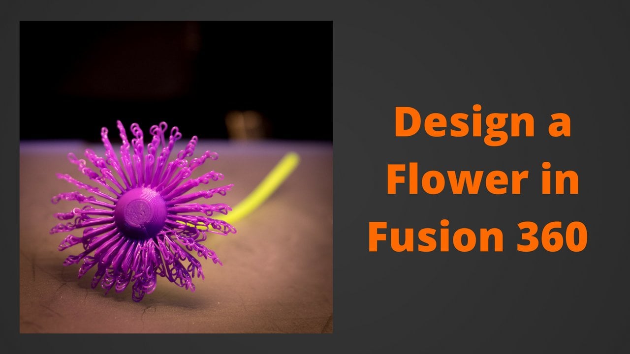
1. Welcome to the class!: Hello and welcome to this fusion 360 mastering the basics course. My name is Jamie and I'm going to be showing you the basics to starting design in Fusion 360. And by the end of this course, you will have learned all about the solid environment and how to render your designs. In this course, I'll be teaching you how to design from scratch using a load of different techniques and learning many skills along the way. Here are just some of the many skills that you'll be learning from this course. I'll be walking you through all of the core and key features of designing solid bodies in Fusion 360, as well as how to create compelling renders if your designs, no matter who you are, wherever you are, an experienced 3D printing hobbyist, or you may just have an interest in 3D design or one to start creating your own designs from scratch for laser cutting, milling or simply just rendering. This course is a great resource for getting you open your feet and creating impressive designs in no time. And we'll finish up with the final project where we'll be designing our very own socket wrench without any further ado. Let's get right into it.
2. Tour of the workspace: Okay, so before we can start modelling, we need to know what's in the Fusion 360 workspace. So if we start from the top of the screen, we can see that we've got the data panel in the top left. And if we open the data panel, we can see all of the recent projects that we've been working on. We have lots of options with these different projects. We can right-click them and we can open, insert into current design. Or we can use one of the menu of options that we've got. If we exit the data panel, we can see that we've got the File menu. And next to that we've got the save, undo and redo buttons. So you can see that we've got Smith the most commonly used functions brighter. The top of the screen. Below that, we've got the toolbar. And the toolbar, I've got lots of different menus which hold all the functions that we'll be using in our designs. We can see that we've got other menus, such as Modify and assemble, as well as construct, inspect, insert, and select. So if we hadn't to the Create menu, we can see that we've got commonly used functions, such as creating components and other manipulation functions such as extrude, revolve, sweep, loft, and others. So below law is the browser does not all there at the moment, but that's not important right now, one thing we can take from the browser right now is learning about the visibility button. The icon for this is like a human eye. And if we press this, we can toggle on and off the visibility of whatever's next to it. So for example, we can show and hide the origin using this button here. So in the middle of the screen we can see that we've got the origin. In the very center. We have white dots indicating where the axes intercept. We have orange squares indicating where two axes form of plane. So this is the exit plane, this is the x y plane, and this is the YZ plane. And we'll get on to that later. Over here we have the view cube. And we can use this to orbit our design. We can do this by clicking and holding the left button on the mouse and dragging it around. And here we are orbiting in a design. We can also click a certain portion of the view cube and fusion will take us to that view. So if I wanted to go to the top view, I can click this. And we can see that I've been taken to the top view of the model here, and I'm looking directly at it. Down here we can see that we've got the design timeline. And this is where Fusion 360 captures all of the manipulations that you do on your project. You can also move between nice to see the design history of your model. And most serious, we get some with designing. So let's jump in and practice some of these tools.
3. Learning to sketch: So the first step to creating a design in Fusion 360 is to create a safe file just in case anything happens to your design while you're working on it. We can press the Save button up in the top-left. Alternatively, we can hold Control S or Command S. If you're on a Mac. We can use this drop-down menu here and create a new project. And we're going to call this tutorial. We're going to save this model into tutorial. And we're going to call it model one. And click Save. Okay, So creating sketches with two-dimensional geometry is a critical step in any CAD program. To do this, we're going to create a new sketch. And to do that, we can either press a shocker here, auger down into the Create menu slightly underneath and press Create Sketch. Fusion will then ask us which plane we'd like to sketch on. And each of these planes are represented by the two axes that they join. For example, this is zx plane, and intuitively it connects the zed and the x-axis together. I'm gonna go ahead and choose the x y plane is this is going to be the base for our design. Please note that the sketch plan you do choose does matter as it dictates the direction that your 3D model sits, as well as the direction that any 3D modifications can be created is not critical, but it's worth considering when you make a design. You'll notice that the view automatically rotates to look directly at the sketch plane, which is very helpful. It's the setting turned on by default. And you can change it into Fusion 360 preferences if you wanted to turn it off. And we can do this by clicking your name or initials in the top right of the screen. I'm pressing preferences. So I'll continue by pressing the line tool or clicking Create within the sketch menu. You'll notice that next to the name of the function is a keyboard shortcut. For example, we can press L on the keyboard, and this will help us create a line much quicker than going through all the menus every time. So we're just gonna make a random shape here. So I'll click once with left button of the mouse, which chooses the initial starting point and the line. The line then follows my cursor as well. Our next click with the left mouse button will be where the final point of the line will sit. And after I've created one line, when I move the cursor and keep on clicking subsequent lines are created. And I'm just going to make a random shape. And once I connect the final line to the starting point, we've got what is called a profile. And this is essentially fusion telling us, okay, we can do something of this. And what we're gonna do with it is we're going to extrude it. But first I'm going to add a center diameter circle from the Create menu. Alternatively, you can see that I could have press C on my keyboard. And I'm just going to add this here with a dimension of 40 millimeters. You don't have to specify the units like I just did. If you go into the document settings on the left of the screen, you can choose the default units. However, if you wanted a dimension in anything over then the default units, you can type in the units in the textbox and the shape will be created accordingly. Another way you can create dimensions in the sketch is by pressing the sketch dimensions burden, open the Create tab. You can then select a line or two points, or two lines which are at an angle to each other or any of the sketch geometry. And you can select dimensions to help constrain that sketch. In this situation, we're just going to give one of our lines a dimension. By pressing the line and clicking again. I'm going to go through a dimension of 50 millimeters. Now we're finished with our sketch. We can click the conveniently named Finish Sketch button and will re-enter the workspace that were in before. And you'll see now that we now have our sketch in the workspace. And this can be found in the browser tree under the sketches top. As I mentioned before, we can press the eye next to sketch one to toggle the visibility of it, but we're going to leave it on for now, is often good practice to rename a sketch right after we've created it. And to do this, we can right-click the name and press rename, or we can just slowly double-click on the name. And this will allow us to put in a new name for it. So I'm just going to slowly double-click. And just for demonstration, I'm going to rename this sketch one to sketch. And this concludes our tour of how to sketch. See you in the next video.
4. Learning to extrude: Okay, So now we're ready to extrude the 2D sketch we created in the last video. And to do this, we go into the Create menu and click Extrude. Alternatively, we can press E on our keyboard and it'll open the extrude menu. We then given a few options, and the first of which is profiles. It's asking us to select the profiles that we'd like to sketch. And I'm going to choose the outside profile. So this weird shape we've got going on here and say we wanted to extrude it by 20 millimeters. We can just type in 20 into the box. Now that's done. We are given a few more options of India extrude many, but we'll get to those later. We can press, Enter on the keyboard or we can press Okay. And this will finish the extrude operation for us. And we can see that we've now transformed our 2D sketch into a 3D solid body. And here we go. This is our first 3D shape. See you in the next video.
5. Learning to navigate the workspace: So now we've got our 3D shape. Let's talk a little bit about navigation. So if I click and hold down my scroll wheel, I can pan within the workspace. It's like I'm grabbing this model and moving it around. You don't really want to be working with a trackpad. It's better to have a three button mouse because that way you have more control over the navigation within the workspace. So if that scroll wheel on my mouse, I can zoom in and out by scrolling up and down. And you can see that I'm doing this right now. If I ever lose the model by zooming out too far, I can double-click the middle mouse button, which is on the scroll wheel, and it'll bring it right back to me. We can also omit the model by holding down either left or right shift on the keyboard and holding down the middle mouse button. If you're using a trackpad, you can hold down the left button on the mouse and drag around this view cube. And we can see that we all get in pivot the model around here. If we ever want to return to the home view, we can press this little house on the top-left at the view cube and it'll bring it straight back to our home view. And if you don't have a mouse with you right now, it's okay because we can look at the bottom of the screen and we've got this menu bar here. You can see that we've gotten orbit button, a Lookup Button, a pan, zoom, and a fit button, and are about to tell you what these do. If I go over to the orbit button, we can see that if I press it, I can orbit just like I could before. If I choose a Lookup Button, I can then select a face and we'll be looking directly at that face. So let's try it on the top face. So we're now looking at the top face, but it's not all in view. So we can click on the pan button and move it back into the workspace. We now going to have a look at the zoom button. So if you press this, we can drag with our left button held down and we can zoom in and out. If you want to maximize your view of our design while fitting everything on the screen, we can go and press the fit button. And you see that now everything is on the screen in our design. We've also got over display settings and Cretan snaps options, including turning off and on layout grid using this toggle button under the Display Options. And this concludes our navigation in Fusion 360 tall.
6. Using construction geometry and fillets: So now we've got this 3D model. We can perform some operations on it to see what else fusion 360 has to offer. I'm going to create a sketch on one of the faces. And to do this, I'm going to press Create Sketch. And I'm going to click on the face I would like to sketch upon. And for now that's going to be this one here. And you can see the view changes. So as I'm looking directly at this face, I want to create a circle in the center of this rectangle because I don't currently know where that is. I can find it by pressing C and dragging my mouse around the rectangle. And I can see this, I can reach the center of the rectangle and it snaps into place here. Another way of finding this is by using construction lines, which I'm about to show you now. So if I press escape, I'm no longer working with a circle and I press L. I'm working with lines. And we can see that the options in the sketch palette on the right change construction lines or a piece of geometry that can be used as reference lines and turn out to the actual design. So if I press X, I can toggle on construction lines. I'm going to draw a line from each corner to the diagonally opposite corner of the rectangle. And we can see that the point where these lines overlap is the center of the rectangle. So I'm going to turn off construction geometry by pressing X and then pressing C to switch to the circle tool. I want to create a center diameter circle about the center of this rectangle. So I'm going to click here. And I'm going to type in 10 as I wanted, 10 millimeter diameter circle. And hit Enter. I'm going to click Finish Sketch. And I want to extrude the circle, but I want to cut into the model. So I'm going to press E for Extrude. Select the circle. And we can see that the default direction for this extrude is outwards and this will be creating a new body. But what I want to do is I want to cut inwards. So I'm going to drag this in and I'm just going to make a cup by 15 millimeters. And we can see that the operation here has changed to cut an oppressor k. And we can see if we orbit that we've now got a circular curves in the side of this 3D model. Construction lines can be really useful. So if we create another sketch on this face here, we can see that they've got over uses. So if we press L for line and x for construction, we can create a line just going down here. And we can make sure that this is perpendicular to the overages in the design by using this constraint here, perpendicular. So we press this and this, and we see that this constraint is now been formed between the two lines. And we've got over constraints here and we can get on to those in due course. I press escape to stop working with lines. I'm going to press X, so I'm no longer working with construction lines. And I'm going to go into the Create menu here. And I'm going to click Polygon, circumscribed polygon. Now I'm just going to click here any point, it doesn't really matter. I'm going to give this a diameter of seven. I'm going to press Tab to go to the next box. And I'm going to say we want a sides press Enter. So the cool thing about construction lines is that we can use them to mirror geometry. So if we go into the Create menu and press mirror, we can see that new box pops up on the right. We can select the objects in the mirror line. So we're going to select this object here. I'm going to select the mirror line, which is going to be this construction line here. And we can see that our object has been married on to the oversight of the construction line. And we're going to press, Okay, I'm going to click Finish Sketch. And we can just extrude this out by 10 millimeters. Another commonly used tool in the fusion workspace is fill it. We can access this by pressing F on the keyboard. Or you can find up here in the Modify menu, we can select the edge that we want to fill it. So we can choose this one, for example. And we can drag the arrow to choose the radius of the fill it. And we're just gonna go with ten for now and press OK. As you can see, this isn't the most beautiful model, but it demonstrates some of the tools that we've got to work with. In the next video, we'll be looking at construction planes.
7. Creating Planes and Lofts: As we know, creating sketches and fusion is a very important feature that design. You can create sketches on faces or Plains about the origin, but we can also create planes. And these will make your life much easier when you're making designs. For example, we can go into the construct menu over here, and we can see that there are lots of different options to create planes. For example, we are going to make an offset plane. We can see that we can choose to create this offset plane on any phase of our model. We can also offset it about the planes at the origin. But we're going to choose this face here. And we're going to create an offset plane by 25 milliliters and press Enter. And if we open ground, we can see that we've created this plane 25 millimeters from this face on our model. We're going to create a sketch on this plane. What we're going to do now is we're going to create a circle about the center of this plane. And we can see that each plane we create has its own origin. And we can see this origin here. So if we create a circle by pressing C, and we can create a circle, and we'll say five millimeter diameter for this one here. And press Enter. And we're going to finish Sketch and orbit. And we can see that this sketch has been created 25 millimeters offset from this face on our model. Another feature we can use with in Fusion 360 is called loft, and this can be found in the Create menu. So if we go into Create and press loft, he asked us for two profiles to choose for this loft. And we're going to choose this one here and this circle here. And we can see there's a loft has now been created between this rectangular face here and this circular face. And if we orbits around, we can see it that connects. If you press OK, we can see that this loft has now been created. And that offset plane is just one of many planes that we've got to choose from within the workspace. For example, if we travel back over to the construct menu, we can see that we've got the offset plane, which we've just used. The plane, it's an angle tangent plane, mid-plane. And we also have for vista, but we're going to choose tangent plane now. We're going to select tangent plane, head over to a circular face, for example, this one here. And we can choose which I'm go. This plane will be created up. If we cancel this and go back to the construct menu and maybe choose plane its angle. We now get the option to choose a line or an edge to create a playlist mango from. So if we choose this one here, we can see what I am good. We'd like to choose our plane. And this is really useful for creating more complex 3D models.
8. Using constraints: The first constraints I'd like to show you is the coincident constraint. The coincident constraint simply joins two points together. I've created a sketch with two lines in a circle. And firstly, I just want to connect the two end points of the lines together. And I'm going to use a coincident constraint to do this. So I'm going to go up into my constraints menu, click coincident, and select two points on the line. So as you can see, after I press escape, the endpoints of each line are connected to each other. So if I move one line, the other line will move with it. Next, I'm going to make the end points of this line coincident with the origin. So our press coincidence, select this point and this point. So you can see that this end point of the line is now coincident with the origin. And we can see if I move this line, all of the points stay fixed together. A shortcut you can use is by holding down Control on Windows or Command on Mac. And you can pre-select the points before you select the constraint. For example, I'm going to hold down command. Select the points of the center of the circle. And the points on the end of this line select coincident. And there we go. We see that the circle is now coincident with the points on the end of the line. The next constraint would like to show you is the co-linear constraint. As we can see here, I've got two rectangles, both of width, 50 millimeters. However, only one of them is constrained in height. The left rectangle is 50 millimeters tall. However, the height of the second rectangle is on fixed. We're going to use a colon and constraint to ensure that the heights are exactly the same. This constraint ensures that two lines are in the same plane. And we can find it here. We're going to select the two lines. And we can see that these two lines and are in the same plane are not co-linear to each other. As Never example, I'm going to press Escape and then R for rectangle. Draw a rectangle over here. And we're going to use a co-linear constraint again and select this line and this line, and this line and this line. And we can see that the lines are selected in pairs. And now colinear. Next I'm going to be showing you how to use a concentric constraint. The concentric constraint takes to round things and makes it a center point, a common constraint. For example, I'm going to make the circle I have here concentric with the radius of this shape. I have here. To do this, I'm going to click the entity that I wanted to be concentric first and then select what I want it to be concentric width. I'm going to use this constraint right here, concentric, select the circle and the radius. And we can see that this circle now shares the center point with this radius. And this radius is just an arc. This I created using this tool here. For another example, I can create an arc just simply like this. And we can see that the center point is where my mouse is right now. If I use C and create a circle, is a concentric constraint. Select the circle and select the arc. We can see that they now share the same center point. The midpoint constraint, find the midpoint of an entity. And it can be used to find the midpoint of a line. For example, if you want to connect the end points of this line here to the midpoint of this line. We can go ahead and select the midpoint constraint. Select this point and this line. And now we can see that this endpoint of this line has now been connected to the midpoint of this line. Suppose we wanted to connect the center point of the circle to the midpoint of this line. We can press a center point and this line, and we can see that the center of the circle is now on the center of this line. If we wanted to practice our constraint skills and make this line vertical, we can hit Escape, select this line, go into constraints, and choose horizontal slash vertical. And we can now see that this line is now vertical. We can do the same three for these lines up here. And I'm going to choose this one. Another constraint there hasn't yet been covered is the perpendicular constraint. We can see this here. And if I press this, I can choose for these two lines to be perpendicular to each other by selecting them. At the moment, all of the sketch objects can currently be moved. And you can see me doing this right now. If I didn't want this to be the case, I can use the fixed constraint. So if I select this now and I fix this circle, you can see that the outline turns green to show that it's fixed. If I hit Escape, we can see that this circle nor this line can be moved. If I ever wanted to remove a constraint, I can press Escape, click on the constraint, and use the backspace or delete key to remove the constraint. Say I wanted this line to now be perpendicular to this line. I can click the perpendicular constraint, click this line and this line. And we can see that this line and this line and now perpendicular. However, if I wanted this point, connect to this point here, I can use a coincident constraint. And I'm going to show you this now. So if I click this point here on the end of the line and this point is in the center of the circle, then are coincident. Following unfamiliar. I can use the cosine constraint to make sure this line and this line are co-linear. And I can use a coincident constraint to connect the points. And this concludes our tour of the sketch constraints.
9. Designing a drinking glass: So in this video, I'm going to be showing you the revolve function. This tool can be used to evolve a sketch profile or planar face around the selected axis. And in this video, we are going to be revolving a simple glass cup. And I'm just going to quickly speed up the process of me creating the sketch for this cup. But feel free to follow my steps if you'd like to create this glass for yourself. So here I'm using the offset function, which can be found in the Modify menu. And I'm just going to create a three millimeter offset. And I'm going to do this inside, which will be minus three millimeters. I'm going to add some fillets to my sketch. These are also found in the Modify menu. Or by pressing f. I'm going to use the extend tool from the modify menu. And I'm just going to extend this line so that it connects the inside and the outside faces of the glass that will be creating. I'm going to pan down and I'm also going to use the extend tool in the bottom corner here. We're going to use the trim tool from the same menu. And this is going to be used to trim off the lines that I don't want to my design anymore. So once we've got the basic shape, we're going to go into the Create menu and click Revolve. We then going to select the profile of the shape we've just created? Fusion does automatically select this. Although it can be changed by clicking profile. And then selecting the profile plane that you would like to evolve. Then we need to go ahead and choose the axis that we'd like to revolve around. I'm going to choose is that axis and this is the blue dotted line about the origin. We can see that our shape is now being revolved around the z-axis. And if we orbit around, we can see that we've got this nice glass shape here. The revolve function does offer some extra tools. You are not required to revolve all 360 degrees. You can choose the amount of degrees that you'd like to revolve by. And you can do this by dragging the blue dot. Or you can type in the text box the exact amount of degrees that you would like to revolve by. Which in this case we're just going to go 360 degrees. You also get options to create a new body, join, curves, intersect, or creates a new component, and we're just going to select, creates a new body. Go ahead and click Okay. And we can see we've got our glass shape here. Just as an extra feature to Fusion 360, we can change the appearance of this glass to actually look like glass. We can press a on the keyboard or go to modify and press Appearance. If we go into the Fusion 360 appearances tab, double-click on the glass folder and select Smooth and glass clear. And if we drag this onto our design, and we can see that we've got a clear glass of parents now applied onto our design, making it look more realistic like an actual glass. And this is just a simple example of what we can do if the Revolve tool.
10. Introduction to rendering: Okay, So in the last video, we created our drinking glass using the revolve function. And in this video, we'll learn how to create a compelling render of a. So if we go into the rendering work-space using this tab at the top of the screen, we can see that we now have a different backdrop, and this is called the environment. But we'll get onto this in a moment. You'll see next to render, the appearance button is first in line. And we've already applied our parents to the glass to make it more realistic. But just as a recap, we can open this menu, navigate to the appearance we'd like to choose and drag it onto the object. We also have extra options surrounding the appearances we'd like to use, which can be found by right-clicking and pressing Edit. Specifically for glass, we can see that we've got options such as the refractive index and we can change those if we so please. Next up in the setup tab is the Scene Settings option, which is where most of the magic happens. When we select this plane appears on the screen with loads of settings. And we're going to go top-down and go through all of these options. So first we have the brightness, which is pretty simple. You can choose the value of the brightness you'd like, either by using the slider and doing it by eye or typing a brightness into the box. And this is measured in looks. Below that, you can click on the position icon, which will allow us to change the position and angle of the light source, which will be used to provide light to this render. To ensure that your render fits the idea of what you think it looked like. Or just to have a quick view of how it's going to turn out. We can do an in canvas render. It won't be perfect, but if we press it now we can see that in the bottom right we have a progress bar showing us how far along are in Canvas renderer is until it reaches what fusion calls excellence or final quality. And now if that isn't enough for you, you can move the slider all the way to infinite and let that render continue until you see fit. Once you're happy with this, you can press the Save icon here and save the vendor to your downloads or your Fusion 360 file directory. The main purpose of an inch canvas render is to ensure that your settings are properly chosen before you decide to go ahead and start a full render. As these can often take a lot more time. Next, we can choose what our background looks like, and we can choose between an existing Fusion background or a solid color. If we choose Solid Color, we can see that there is a color selector underneath. And when we click on that, you can see that we have all sorts of options to choose our color. If we select environment and enter the environment library, we've got a bunch of fusion environments to make your design look more in contexts with different lighting situations and positions. It's also possible to add your own environments. And there's many free examples out there online. If that's something that interests you, you can't use a JPEG or another image file. Bear in mind. It does specifically have to be what is called HDRI file. But there's loads of those floating around on the internet that you can download and apply for your designs for free. If you go back into the Settings tab next up we have a ground plane. We can toggle this on and off these changes, whether or not we have a shadow. Below that, we have the flattened ground function. If you're using an environment, you may find the flattened ground function to be useful, but we're not going to be using this right now. The reflections button is fairly self-explanatory and it will dictate whether or not reflections will be seen on the ground. When the reflections are turned on, you'll see an option for roughness. And the height of the roughness is softer. The shadow will be. If you turn this all the way down, you'll see a sharp reflection of the object above, reflected in the ground plane. Next up, we've got camera options. And if you sell your hobby, you'll definitely know what these mean. Firstly, we can choose between perspective and orthographic views. And we generally find that perspective views are better for renders as they accurately depict what you would see in real life. Below that, we have focal length and exposure options. Focal length is essentially the range between fisheye lenses and telephoto lenses. And this can impact quite heavily on your renders. We're going to leave that as a default value here, but that may be worth reading upon if you're not familiar. The exposure is similar to the brightness and essentially dictates how much light the camera listen to the lens affecting the overall brightness and darkness of the photo. Next, we can choose depth of field options. Once selected, we can select which part of the object we want to be in focus. We can then choose a blur factor. And once again, we can do this numerically or by using the slider. So if we zoom in and select a certain point on the model and sets a blow factor of say, No.5. We would see that we have a depth of field effect applied to our render. With this point being in perfect focus and other parts of the design in the background will be blurred. Lastly, we can change the aspect ratio of the render, choosing from common aspect ratios such as square or 16 by 9. Or we can input our own. And I'm just going to restart a settings to default for now. Once we're happy with all our settings, we can close the scene settings pane. We can then press Render on the very right-hand side. And we'll get more options to complete either a cloud or a local render. You can see that we have different sizes and dimensions of the output photo. And the highest quality default option is found in the print tab. And we can select the 8.4 megapixels, 300 pixels per inch option. We can choose between the cloud or local renderer. And we can choose Standard or final quality for the render quality, please bear in mind that the cloud Renderer will cost Cloud credits. If you choose the local renderer, you can also choose how many iterations of the render you'd like, which is directly proportional to the quality that you receive. I'll send this to the cloud to render at the highest quality. And here are the results. As you can see, the render function really does create realistic results. See you in the next video.
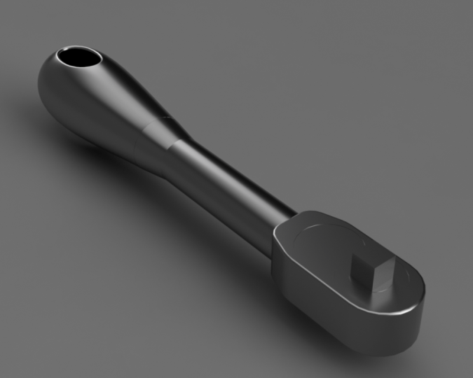
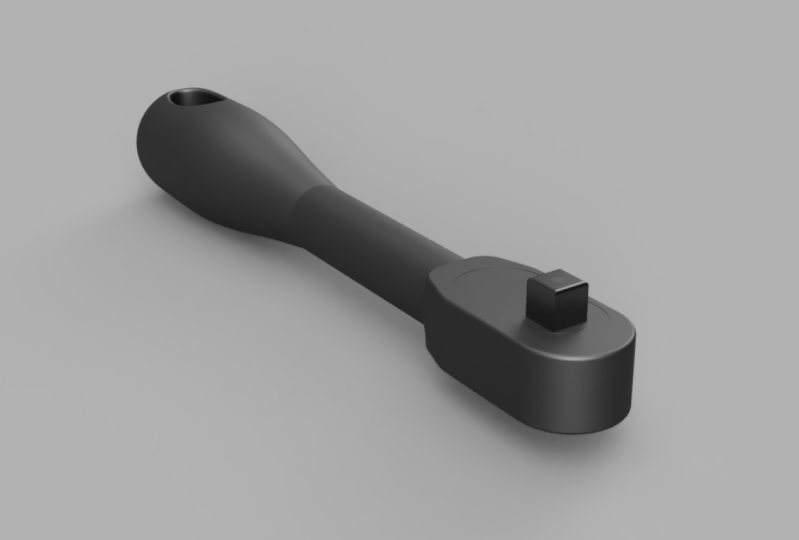
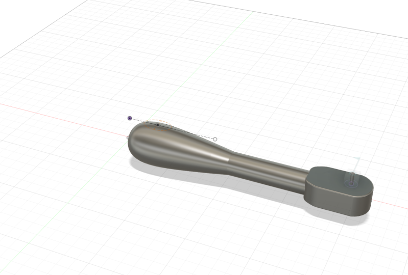
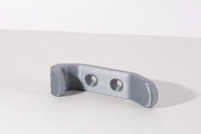
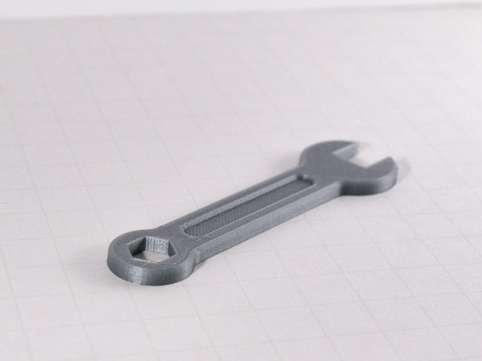
11. Final Project - Designing a socket wrench: Welcome to the last section of tutorial videos for this course. Hopefully by now, you'll have learned development skills needed to complete this final project. We're going to be designing a socket wrench. And if you don't know what one of those looks like, I'll harvest on the screen now. Let's jump into it. So what we're gonna do, we're going to create a blank component for the wrench itself. And I'm simply going to call this component socket wrench. And click. Okay. I'm now going to create a sketch on the x-y work plane. Our first line is going to be along here, and it's going to be 95 millimeters long. We are going to create a construction line so that this doesn't interfere with the rest of our sketch. And I've done not by pressing X on the keyboard after selecting the line. I'm now going to create three lines, starting at this point, going up by 10. And clicking OK, starting at this point and going up by 12.5. And a final line just overhead, which is 18.75 millimeters tall. It doesn't currently matter where they've been placed along the line at the moment. Because we're about to add the dimensions now, using D for the distance tool, I'm going to set this line 30 millimeters from the axis. And the spacing between these lines is going to be 15. And you can see the all of our lines and now block, which means that constraint. I'm now going to draw a line between 10 millimeter line on the 12.5 millimeter line. I'm now going to go into the Create menu and select Fit point spline. And create a spline between this point, this point, and this point. And we're gonna go ahead and click Okay. Okay, so bear in mind, this shape is going to be the handle for our socket wrench. So I'm going to zoom in here. If I press Escape. So I'm no longer working with any tools. I can use these green handles to change the curvature of this spline. For example, if I wanted a steeper gradient, I can just drag this here. And I think I'm going to leave it something like this. It's up to you. How you do this. It's completely up to you. I'm not going to change this construction line back into a solid line by clicking it and selecting x. So now we've got the sketch and we've got a profile. We could extrude this, but because it's a curved shape, we're going to have to use the revolve tool, which we learned in one of the earlier videos. So we're going to finish the sketch, go into the Create menu and select Revolve. And we're going to select all three profiles we've got here. And for the axis, we're just going to choose this line which runs along the x axis. This looks okay to me. So I'm going to press Okay. But if we revolve around, we can see that we've got to sort of pointed shape going on at the end of this. So what we can do is we can right-click on the sketch here and we can press Edit Sketch. And what I'm going to do is I'm just going to change this so we don't get such a pointed shape when we end up doing our evolve. And what I can do is press Finish Sketch, and you'll see that this has been updated in our design. So next we need a handle for a socket wrench. And we're going to use the extrude command. And we're going to be extruding this circular plane right here. So I press a on the keyboard, select this plane, and we're going to extrude by about, say, 65 millimeters. Yeah, that looks okay. And then press Okay. So to create the head of the wrench, we're going to need a new profile to be working on. And I'm just going to move the view cube up here and select the top plane. Uses error to rotate it so it looks better on our screen. And we're going to use the constraint menu. And we're going to create a tangent plane. We're going to place that on the top of this circular handle. That looks about right to me. So we're going to press OK. And we're going to start a sketch on this surface. You can do this by right-clicking the surface and pressing Create Sketch. Alternatively, you can just do it like novel by going up here. So a new thing that we're going to be using now is a project tool. This allows us to constrain our objects on the sketch around. Objects already exist in the workplace. For example, if I move my mouse along the edges here, I wouldn't be able to snap a line or a point to them when I'm making my design. So I'll press P for project. And we're going to select this object here. And then press Okay. So we can see this geometry is now included in our sketch and it's now shown as purple to show us it's been projected. So now we'll be sketching the shape of the head of the socket wrench. I'm going to create a line from the center point and it's going to go out by 60 millimeters. This is going to be a construction line, so I'm going to click it and press X. I'm going to make a number line 30 millimeters long. I'll disappear and type in 30. Going to use the dimension tool to ensure that this line is a dimension of 15 millimeters from near the I'm just going to press Escape and drag this dimension out the way. So it's easier to look up. What I'm now going to do is I'm going to create an three-point arc between this point and this point here. And I'm just going to drag that till it snaps. I'm going to create another line. So pressing L and I'm going to join these two points here. Then finally, I'm just going to connect these two points. I'll now turn off construction on the line that lies in the center. We're now going to use the mirror tool, so we can find this in the create menu and press mirror. We're going to drag from top-left to bottom-right. And we can use this to select the sketch objects that we've been working with. You can see that 14 objects in our selected, but one of these is the mirror line. So we're going to de-select the mirror line just by clicking it. And then we're going to select mirror line. And we're going to use a mirror line height we just said. And we can see that these objects have now been married over the river line. This looks fine to me. So we're going to go ahead and press Okay. One thing I guess we could have done before we made the sketch is just apply a fill it. So we're going to apply Philip between this line and this line. And we're just gonna give that a value of, say, we'll go with 15. So they're going to be a small Philip. And because we did this after the mirror, we just going to do it on the side here by 15. I'm going to click Finish Sketch. I'm now just going to get this in a suitable position. We're now going to use the extrude tool or E on the keyboard. I'm going to extrude this down by 20 millimeters. See it says negative 20 meters is the arrow is pointing up originally. And we're going to select new body so that when we modify the head of this socket wrench, it doesn't affect anything we've done in the past. So the rest of our design would not be affected. And a benefit of this is if I just turned around here, I can select this edge and this edge here. And we're going to press F, fulfill it. We're going to make sure both are selected. And we're going to make a affiliates of 7.5 millimeters. And just repentance, we're going to create a second, fill it on the top and the bottom edges. And this is just going to be a small one millimeter Philip. And this is purely just for parents so that it looks more like the real life tool. And now that we've finished modifying this head, we can use a combined tool. And we can just join the two bodies together. Okay? So if we orbits our body, we can see that we've got some extra leftover faces here. So we're going to press extrude. And we're going to select both of these faces. You might have to orbit around a little bit. We're just going to extrude these alphabets and choose join. And then we can see that the faces have now connected perfectly. So I'm going to press OK. We could also notice that we've got small edges here and we can do the same. But I'm going to show you a more efficient way of doing this. So we select the plane here. I'm going to choose as the extent type to Object. And we're going to select this object here and extrudes exactly to the point where it will meet this object. So if we click join, we can see that that's extruded perfectly. And we can do this on the bottom as well. And click Join. Okay? Okay, So with this term we're going to be creating the face of the top of the socket wrench. Going to start to sketch on this plane here. I'm going to use P to project the geometry that we've already got on click. Okay. So if you follow my lead here, we're going to create a circle of diameter 25. And another one over here, also 25. The distance between the center points of these circles is 20 millimeters using the dimension tool. And the distance between the center of this circle and this point here, or this edge is also going to be 20 millimeters. And we're also going to create a third circle about the center of this circle here. I'm going to make this 15 millimeters in diameter. We're going to finish sketch. And we're going to start an extrude of these three planes right here. And to effectively emboss this pattern onto the head, we're just going to extrude this by 0.1 millimeters. And this will just do a little tiny cuts into the surface of the head. So if you look at the reference image of the socket wrench, which I showed you the beginning of this video. You'll notice that the socket wrench has a revolving part and we're going to make fat now. So we're going to create a sketch on this plane here. And we're going to make a circle at the center of this circle. And you can see it's just snapped on. And this is just going to be three millimeters in diameter. And we're going to extrude this buy-in of 10. So to make the revolving bit, we're going to start another sketch on the top of this peg. And we're going to create a 10 by 10 center rectangle. So to do this, we're going to go into create rectangle and center rectangle. Just going to select the center point here. And we want this to be 10 by 10. And we can switch between these two boxes when we're typing just by pressing tab and press Enter. And there we go. And once this is done, we're going to click Finish Sketch. And we're going to extrude this downwards by 10 millimeters. However, we do want this to be able to evolve. So we're going to have to create a new component for this peg. As later on, when we use joins, we can only create them between components, not bodies. And to make everything a little easier, I'm just going to change the visual style to shaded with visible edges only. As it could be quite hard to understand when there's no lines. So if you go into the browser tree, we can see that we've got this new component. And so it's good practice to rename the components so we know what we're working with. And I'm just going to click that and we're gonna call it revolve. Just so we know what we're working with. So we're going to go into the menu and click as-built joint. As the components have been created in position and don't require moving to create the joint. So I'll select the cube. And we're going to select the rest of the head. And we can see that we've got joint types here on the right. And we've got quite a lot of different joint types. But the one we want right now is a revolute joint. And we can choose our joint origin to be this point here. And we can see by this nice little animation, if you want to replay it, we can press this button here. We can see that this joint has been created exactly as we wanted. And we even gets a visual demonstration of what we're creating. And then we're just gonna go press. Okay. What we're gonna do now is we're going to go back into the socket wrench component and activate that. I'm just going to zoom out and we're going to have a look at our socket wrench. So this looks pretty realistic, but one thing we're definitely missing is a hole in the handle around here. And this can be used for hanging up the socket wrench or tying to a strap or putting it a string or chain inside. So what we're going to do is we're going to construct an offset plane. And we're going to choose this plane here. And we're going to move it up by a bout 20, just so we can see it's above the top of the handle here. And click, Okay. We're going to create a sketch on this plane. And we're just going to create a quick construction line. Going from this point outwards. Use X to make it a construction line. And we're going to use the Ellipse tool, which you can find in the create menu. And we're just going to create the ellipse here is going to be 25 millimeters long. And we're gonna make a 15 millimeters tall. Personally, I'd like to speak a little bit further left. So I'm just going to drag this like so. And I think that looks about right. We're going to finish the sketch. Hits extrude. And we're just going to create a coat's going all the way through. And we can see that we've got a whole now an ellipse shaped hole in the handle, which is what we wanted. And just for aesthetics, I'm going to create a fill it on the top and the bottom edges here. And I'm going to give this a value of one millimeter. And here we have the main body of the wrench.
 Jamie G, 3D Printing mad!