Transcripts
1. 1 Introduction: Hello and welcome This new
cars inertia are going to show you our base embedded
system simulation. This is Ashraf from
educational engineering team. And in this course, I
will introduce to you an online electronic simulator that you can use to
simulate arduino, ESP, and many other popular
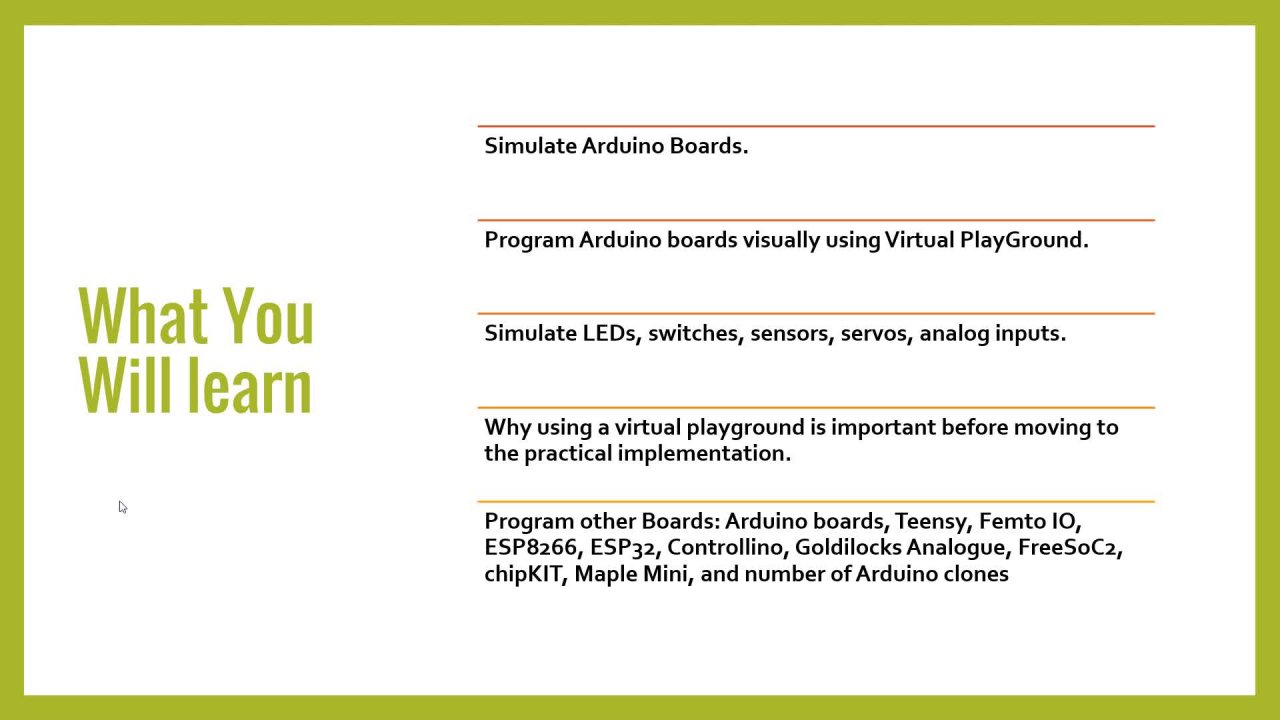
boards, arts and sensors. Now, let's talk about what you
will learn in this course. First, we will explain the user interface and
how to create an account. Then we will start by
simulating Arduino board. After that, we'll move on to
the ESP board simulations. Then we would also simulate
transparent by boards. And we will show
you how to simulate different sensors and
different boards as well. This platform keeps adding
new boards as we speak. And if you looked
over the internet, you will not find any
simulation platform that allows you to simulate ESP or Raspberry
Pi boards for instance. So stay tuned for this course. Now, why we are showing you this and why we are
making a course about it. Well, one of our
students asked us about a way to simulate
transparent by or ESP balls. And we don't, we didn't have any until we stumbled
with this platform. This platform will help
you start right now. You don't have to wait for components or downloading
large software. Your browser has everything
you need to start coding your next Internet of
Thing project in seconds. Mistakes are okay. Using this platform, you cannot destroy the virtual hardware. Trust me, we tried and you don't need to worry about frying your precious components. And unlikely word
or real hardware, you can always undo things. It's also easy to get
help and feedback. We can answer any
of your questions. And they also have a community where you
can ask questions. You can gain confidence
in your code. Separate hardware
and software issues by testing the hardware. Firsthand. There is also the
unlimited hardware. There is no need to buy or
take paths from all projects. You can use as many parts
as you need without worrying about Project
Price and stock. Now, all of these features, combined with the ability
to simulate and Wi-Fi, there is also a virtual
logic analyzer, advanced debugging and GDB. And as the car simulation out of features that will make
your life way much easier. All of this and other things are available in this
platform. Stay tuned. Join us, and you'll gain a lot of knowledge
that will make your life easier before moving to the hardware
testing of your projects. Thanks for watching this lesson. This is Ashraf from
educational engineering team.
2. 2 Simulating Arduino Boards on the Web Trim: Hello and welcome
to this new lesson in which we are going to start by simulating
an Arduino board. Now once you go to the platform, you will see a list of projects
that you can start with. Green or mega ESP 32, Arduino nano pico, and micro
Python on the SP theta2. Now, we will start with the first one which
is Arduino Uno. And to go to this platform, all what you need to do
is to write this word W0 wi.com using your browser. And your browser will do. So. Let's get started by
clicking on the Arduino on. Now here we have the Arduino
Uno board. As you can see. Here, we have our coding area. And as you can see,
we have this pattern where you can toggle between full screen to build the grid, turn it on or off. If you have something to do with spaces
between components, you can zoom in or out, or you can use your keyboard
to zoom in and out. All. You can simply click F
to fit this to the screen. You can also enter
full screen mode or click on Help to get
help regarding anything. Now, we also have
the blast button, which is the add a
new part button. This is a list of parts
that you can add. And for this we
will use the LCD. Now. We have to answer D is
also the 60 by two. And LCD 60 by two I2C. We will use the I2C since it has less wires, only four wires. So click once and drag
it and drop it here. Now, you can zoom in and
out using your mouse, crawl as you can see. And let's connect these. We have VCC, which you
need to connect to. As you can see, it's
already marking the pins to which you can
connect your Vcc two, which is the fivefold. We also have the ground and
the coloring is automatic. Now it's also helping you
by marking the ground pen. Now we have the SDA and SCL. We will connect a CL to A5 and we'll connect SDA to A4. Now as you can see, this, a wire that you can click on
ones to change the color. So you can make it yellow
to make things different. And you can also move
it using these circles. Now you can move it from here, or you can move it from here. Again, you can zoom in and out using the keyboard
or the mouse scroll. You can make it fit
screen by pressing F. And it will fit,
as you can see. Again, ground vcc as the ACL, now as d and the CL, if you don't know I2C,
you should look it up. It's a communication protocol that allows you to transfer data using only two wires,
data wire anticlockwise. Now, to program our code, what you need to do here is
simply add the LCD library. So let's do this here. Hash include liquid, and you can see that we
have autocomplete feature. Now we need the liquid
crystal I2C library. Once done, you need to
set the pins, right? Liquid star underscore. I see. Then LCD, which is the object. And in here, you need
to write 0 x to seven, which is the address
follow-up LCD. And you need to write 24. Now. Now 24 here means 20
column by four rows. Now, the one that we
have here is 16 by two. Now once you are
done with this step, you can move on
to the next step, which is basically
inside the void setup. We need to add the
LCD initialize. So LCD that initialize. After that you need to
turn on the backlight. Lcd backlight. And the last step is
LCD to set cursor so that you can set
the cursor was a sham. So see you are SLR. And we'll set it to 1. First column 0, okay? Now the last step is to print something LCD that print hello. Word, occasional, okay, hello, because we don't
have a lot of space. Now, once done, you can go inside the loop as well and move the cursor to another location. So Street LCDs and make it 81. And we can supply anything. You can type LCD rent. Inside here you can
provide video and team. Now, list this things out. Now once you are
done with the code, if it doesn't have
any syntax errors, you can simply hit
the play button. Now if everything is
working correctly, you should see this on your LCD. Now, you interest
him is not showing. So I want to go back the five
gold on number five here. So stop play again. Now we have drawn here at the
Orange team. Hello world. Now, let's explain, let's
explain again what happened. We connected the LCD
using I2C. And in here. First we added the liquid
crystal I2C library. Then we moved on and created LCD with the I2C address and
the size of the LCD. We initialize the LCD, we turned on the backlight. We set the cursor position
to the beginning, and then we printed hello world and inside
the setup function. After that, inside
the void loop, we move the cursor
to the second line, the fifth column, and we
printed a two inch team. As you can see here.
You can change this. You can print something
else, like LCD. And you can print the middle
is divide it by 1 thousand. Now let's see how this will go. Okay? Now as you can
see, as Arduino's on, it will keep counting the
time and print it here, which is something beautiful. Now, this is the first example using an Arduino
board and an LCD. I didn't want to turn it on and off because everyone
knows how to do that. And this is a simple
example as well. Now you can add
other components. As you can see, you can add RTC, you can adopt GB LED. You can have seven
segments are PIR, motion sensor,
temperature sensor, and any other sensor.
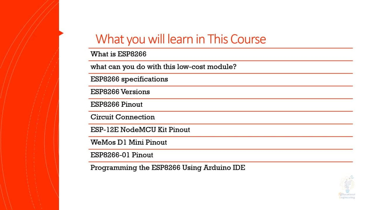
3. 3 Simulating ESP32 Boards on the Web Trim: Welcome to this new
lesson in which we are going to simulate ESP
Thursday toolbar. Now, you need to go
back to the platform. Click on ESP 32. Now let's get going. This is our ESP 32. I prefer to turn the grid on. Now here is the board. We need to connect a
resistor and an LED. So click the plus sign. Had an LED, drag it here. Now we also need that
as this resistor. This is just so that's
what I was talking about. Now if you click here, you can see the description for this
item which is the resistor. Now let's go back to
that previous page. Here we are. Now. Now
to retain the resistor, simply select it and risk are. Now on your keyboard. I had to change the
anguish, sorry. Now, just out on your keyboard so that you can
easily rotate that. Now, let's connect it. First. We need to
connect the ground. Here we have anode and cathode. So once you click
on the cathode, you can simply connect
it to the ground here. Now click ones, change the
color to black of this drug, drug and connect
the other pin to, let's say d two. Now you can change the color
again. Now here's a trick. Once you have connected
that is a store, you need to change the
resistor value to 220. And in order to do this, you need to go to that diagram, the json, and look for the walk. We change the value to 220. And as you can see, as you
are changing the value, the colors are changing as well. So let's change
this to 1 thousand. As you can see. Now, bring it back to 220. And now we have that I value. Go back to the sketch. Again. This is done using
the diagram, the json. And by looking for the
component and the type section, then change the value
and this attribute. That's it. Go back
to the sketch. And now we have the sketch. Now, this will print. Hello. Yes, we talked to
on the serial monitor. What we need to do is
to define the LED. So define LED. And the value will be two, since we are using D2 here. Now, the next step
is going here. Black pen mode, which is
the function that we use to set up in as input and
output and select out the lead, which has been number two,
will be treated as outward. Since this LED is
basically an output, go back to the loop. Now inside that all
we need to turn this layer on and
off. Digitalwrite. Led. And high. Either delay. Off, let's say 500 milliseconds. Then digital light again. Lids, low. Delay, again, 500 milliseconds. Now let's move this.
Won't need it. Once you are done, you have connected
everything correctly. And here we have the lead, that is this torque
and our ESP theta2. You can't run the simulation. As you can see, the built and let this
turning on and off. And the outside lid
that's connected to D2 is also
turning on and off. This is how you can
easily turn and LED on and off using ESP
theta2 on this platform. Now, let's make things a little bit harder
by adding an input. So if the button or
an input button, if the button is
clicked to turn it on, if not, it will turn it off. To do this, we need another pen. So define button. And let's make it bend
for, which is this term. Now, the next step is
setting this as output. So pinMode button
and select output. The button will be the input. Now, after doing this, we need to use a
digital read function. So baton states equal digital. We need to read the
status of that button. Now once we read
the button Status, we will store it inside
the button status integer, and it will either be one or 0. Now, if else, Let's do this. Veteran status equal equal one. We need to turn that in on. Otherwise, we will turn it off. So this is our code
now it's up and ready. Let's review this. We have an LED and a button
connected to pin number two. And for the eyelid is an output, that button is an input. We are reading the button state and storing it inside the
button state variable. Now, vitamin state
equal equal one. Then we will turn it on and
wait for 500 milliseconds. Else, if the buttons
set is equal, 0 means the button's
not pressed, and it will turn that off. Now, in here, we need to
start adding components so you can look for the most part one and
simply place it here. Let's zoom out.
Now this pattern, as you can see, we have 1234. So we have these two pens, one lift and right, and we have two left
and two, right? So this is, we can connect it directly to pin number four. And the other part, we can
connect it directly to, let's say five
volts or 3.3 volts. It's up to you this by connecting this to three
months, three months. Now, let's test things out. Now the button, this button
connection is wrong. You have to connect,
pull up or pull down to check if it
is working or not. Now, this is giving us
and always on-state. So let's fix this. Here. We need to make sure that
button state is initialized, appears and make it
equal 0 out here. Outside of this area. Now we will move from here. Now, in this case, the button is directly
taking five volts, so we need to add a resistor. Here. Rotate it. It is. Now this is a still be
connected to three volts. And it says, and here we
have this button connected. Now. You have to fix
the button connection. Let's delete this. Now. This is connected
to five volts or 3.3 volts through this resistor. And the other pin must
be connected to ground. Now the output will be
taken from button 12, left. So drag it and place it here. Now here we have the resistor
connected to 11, right? And 11 lift is
connected to ground. One to lift is
connected to default. But one input. Now, turn it on. Few clicked once and waited. Now it's sitting on, sometimes it takes some time to, let's say, process that codes because this is
an online platform. But here it is. Now. It's off. Now. It will turn on. And now it will turn off. Now, this is how you can
connect a button and an LED. We tried output and input
with ESP 32 and this example, I hope that everything is clear. Thanks for watching this lesson. If you have any questions
I'm here to help. This is Ashraf.
4. 4 Simulating Raspberry Pi Pico on the Web Trim: Welcome to this new lesson
in which we are going to show you how to simulate
Raspberry Pi beagle. Now pKa is the ball
supported for now. More to come later. Now click on last
failure by Pico. And you will see this. Now. As you can see, this is
the last petabyte vehicle. And you can see the
pens and everything. And the left side here, you can see a symbol
C code that you can use on this raspberry pi
p. Now this is serial. Again. We have cylinder
to print new line. Hello raspberry white people. Now, you can run this in the simulated
environment depend. You will see this, this hello
Last favored by people. As you can see here. Now you can change this text with
anything you want. You can do occasional
engineering team. And you can't run it again. To see that as long as you can see
educational engineering team. Now, this is a C code. It's not a Python code. And you can use all of our C functions inside this
peak or Raspberry Pi B. As you can see, you
can interface with general purpose
input, output pins. And you can communicate
to this ball using the same duration you usually use with
Arduino. For instance. Let's try to turn
this LED on and off. Now let's explain how you can
turn this layer on and off. First step, as usual, is to define a hash, define LED. And it's been about 25. Now in hand. You need to use that pen wound lent out. And in here, you need to
use this to light lids, high and delay. Milliseconds. Digitalwrite again. And ED low. Gla, 500 milliseconds again. Now once you are done,
click Save and click on. As you can see that it
does turning on and off. Now you can connect
an external lead with a 220 ohm resistor. And it will also turn
this LED on and off. Now this is done using C. So you can go back and use the Raspberry Pi
people with micro Python. So let's go back again. You can simply click here
micro Python on pi pico. And you will see here that
we have a Python code. Now, this Python code will allow you to
use Python to turn this on and off all to read any digital estate
of these pens. And you can do this by
running the following code. So let's start with
typing clear font, machine and poor pen. Now and part-time asset that we need to set
that it led equal. And this spring will be five
for number 25, pen dots out. Now, to turn this
LED on and off, you can simply write
led the token. And you can add a
time delay, 0.5. You can leave the
print hello pico, or you can delete it. Now let's test things out and
see if it will work or not. All we need to do
any modifications. Now, let's run. Now
as you can see, we are having our problem. So let's see what's
happening here. Now the issue that happened
is that we did turn it on, but we don't have an infinite loop so that it
is turning on only ones. If you concentrated here, you will see that it
turning on ones then off. To fix this, all that you
need to do is go here, right spline tool and move
these using the Tab button. Now, click Run, and then
it will turn on and off. This is a simple
Python code that we use to tear the built-in LED, which has been 25 on and off using this
simulated platform. I hope that everything
is clear now. Thanks for watching this lesson.
5. 5 Save and Share your Simulated Projects Trim: Welcome to this new
lesson in which I'm going to show you a few more tracks. Now, after creating a cold and a simulation
on this platform, you can save it by clicking
on the Save button. Under good features that
you can click here and make a copy or look this project
or unlisted from the library. You can even download this
project as a zip file. Now once you hit the
Download button, you will get a sketch dot zip
file in which you will see the Arduino sketch and
name of the platform. Now, if you want, you can come to this simulation area and you can simply
take a screenshot. You can zoom in and out. You can disable the grid, make it fit, and
then simply take a screenshot with the
snipping tool on windows. As you can see. That's it. And simply save your screenshot. It's called Snipping
Tool. Sorry, yes. Now click Save As and you can save it and use it,
whatever you want. Now, another good feature is that you can even
share your project. This is the public
link for your project. You can copy it and
you can give it to anyone so that they can have
access to your project. So let's say that I'm
on another browser. And here we are. You can see the design that code and share it with anyone. Now, we can also sign up by clicking on the
top right corner here. And two will give you options
to sign up using Google, GitHub or your email. Now let's go back to
our previous window. Click on the Sign Out. And I prefer to sign
up with Google. Now select the email
that you want to sign up with, then sign-in. And here we are. Now, this is my image, this is my Gmail account. And here we can
see that roadmap, the club, if you
want to participate. They have a discord channel
where you can ask questions. And this is the My
Projects sections. And if you open the
My Projects section, here you can see the projects
that you have created. We have created this project. So you can click on
it and we'll open up. You can do whatever you want. You can rename it or delete it. And here you will see the
projects that you have liked other people's projects. Again. Here, they have a discord channel,
they have a club. And this is the roadmap. This is the feature list. And as you can see,
you get to vote on a feature and they will add it according to the
number of votes, which is a very cool system. So this is a very
promising platform and it's free to use. Thanks for watching this lesson.
 Achraf Mad, Creative Engineer