Transcripts
1. UAV Promo: Hello friends. I'm thanks to the rapid development
of real engine, in recent years, it has become a trend in architectural
visualization. It is up to you to
not miss this trend. Throughout the
course, you will gain access to over 30
hours of knowledge, which is reduced into 3 hours. I have covered all the points I deemed necessary
during the process. I designed this course
to serve as a guide. I turned it into
a place where you can refer back to
whenever you get stuck. By purchasing this course, I will do my best to provide
you with as much support as possible from installization
to material systems, scene creation, camera
settings, cinematic creation, turning the scene into
interactive form, and many other
detailed contents. You will have access to
a wide range of topics. I value your time
so the videos are kept as short and
understandable as possible. If you are ready, I will see
you in the world of unreal.
2. Before Starting: Hello friends. Before
we start our course, there are a few things I
would like to mention. Firstly, take your time. Initially, the dense amount of information within the sections
may seem overwhelming. The logic behind compressing this course wasn't for
you to finish it quickly. It was to allow you
to easily revisit the sections you may have forgotten after
completing the course. Let's say you completed the
course and a year has passed. I don't want you to spend another 30 hours redoing
it like other courses. On the contrary, you
will be able to watch the entire course from start
to finish in just 3 hours, like watching a movie. Additionally, do not rush. You don't have to finish
a section in one setting. You may find yourself posing
the video frequently, and that's perfectly normal. Follow the sections comfortably
and understandingly. Learning may seem
difficult at first, but when you climb
the entire staircase, you will look back and
proud of yourself. Secondly, be unique
throughout the course. I don't want you to
replicate every step I take. I will be explaining
the methods to you, not directly what
you need to do. Remember, Unreal
is an application that provides us flexibility. It is a vast stage
where you can test your artistic
abilities, utilize it. Thirdly, make sure you
understand before moving on. Skipping sections without
fully understanding them may cause you to struggle
extra in later sections. There are some parts I mentioned you might be
able to skip the part, but these parts are there
to make you even better. I recommend following
every minute of the course diligently while
shortening the course. I try to ensure that sentences carries as much
meaning as possible. I encourage you to create your own architectural
visualization projects using the provided techniques, whether you choose to utilize my thread assets or your own. Once you have
completed the renders, feel free to upload the best images to the
Skillshare Project gallery. Additionally, you can
share your animation or watery videos on Youtube and embed the links in
the project gallery. This will allow you to receive constructive feedback from
fellow community members, fostering improvement
in your work. After all, we are a
community here to support each other.
That's all for now. Looking forward to seeing
you in the lessons.
3. Inside Unreal: Hello friends. Welcome
to the first part of our architectural
visualization course. I am Z. In this chapter, we will dive into installization
of Unreal Engine, explore the interface,
and dive into essential settings for
architectural visualization. This section serves as an introduction covering
general settings and is moderately important if you are not new
to the program. I recommend just
reviewing the settings. Shall we dive inside
the unreal then for the installzation
of the engine? Do not install the Epic Games
launcher on your computer. From the Epic Games website, you will need to create
an account on the site, which is a
straightforward process. You can also log in existing
memberships like Google, Apple, Xbox, et cetera. After becoming a member and completing the
installization, you will encounter
a screen like this. As you may know, Epic Games
is a gaming platform. And the part that concerns us is the Unreal Engine
tab on the left. From this point on, the
most relevant sections for us will be the library
and market play steps, access to Tv Motion. A visualization
program similar to aluminum is also
available from here. If you are looking for Q
visualizations in your projects, you can use this on
real based software. Moreover, if you don't have plans to generate income
from your project, the software is completely free. However, my personal opinion
is that software like TV Motion and Luminu may not provide us with
sufficient flexibility. Therefore, we will proceed directly with Unreal
for our purposes. Before starting, after
installing the engine, click on the small arrow
next to the launch option. Click on the option Stab under the target
platform section. If you don't have
any intention of releasing your software
on these platforms, you can fire up
significant space on your computer by unchecking
the boxes under ios, Android, and Linux taps. Let's move on to
the project set up. After installing the engine, click on the launch button. This is a small step for
humanity, but big one for you. Here you will find
various templates. Let's choose the arches
template directly under architecture section and create our project by naming
ultimate arches course. Our entry screen
will look like this. First, let's learn the controls. Holding down the right mouse
button allows you to rotate the camera While holding
down the right mouse button, you can navigate within the
interface using WAS keys. In addition, you can move up
and down with E and Q keys. I recommend using
these controls if you want to adjust your speed
while moving in the interface, you can change the
speed by scrolling the mouse field
forward and backward. You can also manually adjust the speed from the
top right section. First, let's talk about
our content browser. This tap is the library where assets in our
projects are located. And we will organize it. The more organized we keep it, the easier our works
will be in the future. For now, I have color
coded the Arcs, project and blueprints
folder in red, indicating that we will
access these folders later. The outliner window on the
right shows the assets in R C. This can also be considered as the
library of assets in RC. Just like in the
content browser. The more organized we keep it, the easier our work will be. Remember, Unreal
provides flexibility, but if you work in a
disorganized manner, you can get lost
in your own work. When you click on any
asset in the scene, it's editable data will appear. In the details panel below, you can see how adjusting the foc density value changes
the amount of foc in the C. The word partition
and word setting steps are not features I
use extensively for Arqus. In short, as your world grows, the load on your
computer increases. With these tools, we can control when each
area is loaded. There's a small add
tab in the upper left. Under this step, you can quickly add unreal basic
assets to your scene. Let's add a square light source. Since it's daytime, we can
perceive the light much. But when we turn
off the sun light, we can see the added light
along with the other lights. Our goal right now is to
understand the logic of unreal. I am just touching
on these features. In future sections, we will explore the elements
we'll use in detail. Don't worry, click on Quisol
Bridge in the Ad Tap. This tap will be the most important online library we use. After logging into Quiksil
Bridge with your Epic account, all the content will
become downloadable. Bridge contains three assets
created with photogrammetry. You can download and directly add these models to your seen. The nonite quality option
you see here is one of the important features that come with on real engine five. These are high quality thread
models with large sizes. After downloading,
click at on the right to add the file directly
to content browser. You can include the
static machine, you're seen by dragging it. By the way, there's a feature I forgot
to mention earlier. While holding down the
right mouse button, you can zoom in and
out with C and Z keys. Release the right
mouse button to return the camera to
its normal state. Bridge also contains pre
configured materials. We can easily download and
add many of these materials. We are looking for the project for times when we can't
find what we want. We will explore the material
system in future lessons. When you add content to your
project or content browser, a white star will appear
below the added asset. This indicates that the
project has not been saved. If your project crashes and
you exit without saving, these assets won't be there, even if your scene is saved. If the project is not saved, the assets will be missing
when you reopen it. That's because there is no mesh. To place it anymore in
the content browser. It's advisable to save
your project regularly. You can also save the
project as a whole with control shift plus S. Note that control only saves the C. Let's move on to the Project settings
under the edit tap, search for race to
check the boxes. If your graphics card is Nvidia, RTX 2000 series or higher, this technology will be very useful if your graphics
card is not Nvidia. Do not worry on. Real Engine Five also comes with Neman Lightning Technology. Besides the setting, search for virtual texture and set the
check boxes as shown here. This feature is useful when your graphics card memory
is not sufficient. Let's also click on
Plugins under the editor. If you have created the project like I did, you
may not need this. But it's worth mentioning. Make sure movie render Q and
modeling tools are active. It's better to
activate them now. If you activate them later, Shedder compilation
will take longer. Now let's talk about the
post process volume. The boxes you see here are defined as postparcess volumes. Player entering
these volumes will experience the environment
differently based on the volume settings when you enter the
prepared post process box. Here, it adds a stroke effect to three D models,
creating a cartons. Look, let's control our
postpcess volume type. Posporces in a tap and click. You might be wondering
if you have to adjust the size of
this box every time, but that's not the case. If you search for unbound under the Details tab and check
the box that appears, your post process will
affect the entire world. Let's look at the settings
we will use the most. The bolum effect
increases and decreases the comeras glare among
the bolum methods. I think the second one leaves a more realistic and crystallized
effect on the camera. However, instead of using the bolom effect
within the engine, I prefer to edit it. In post production,
programs like Ad Premier Pro or
Davinci resolve after completing the
rendering process. This is because the
Bollom effect sometimes causes flash explosions
during rendering, which is not the desired result. When we manually
adjust this setting, we turn off the automatic
brightness adjustments based on the light reflected
on our camera screen. Since the automatic adjustments mimics the human eye
manually adjusting, it makes the scene
more convincing as if it were shot
with a real camera. I balance the value by
setting it to minus two, thinking the scene looks good. When used at low levels, the setting can
mimic a real camera. This effect occurs due to the different angles at which the main wavelights
of light green, blue, and red hit the camera. When we increase this value, be careful not to raise it too much as it can cause nausea. Our camera settings are generally
brightness adjustments. If you have a
professional camera, you can understand these
features more easily. Since we won't change
these settings. Let's move on for now. Lens flare is an
effect caused by reflection of light
hitting the camera's lens. However, I should mention that it works together
with polume effect. Additionally, you need to importantly desired lens
flare as a texture. I think adding this
effect in post editing with other programs
produce better results. Get. This feature
is a shadow cast on the corners of your
camera in cinematography. It is used to direct the
ever's attention to elements in the center of the
screen Tpto field. Explaining this setting
now won't make much sense because this setting applies to cameras assigned to the scene. Since we are currently
in the view port camera, any changes we make won't take effect under the color grading. You can adjust the
temperature to control the warmth and
coolness of colors. We usually use the
setting to make the distinction between
indoor and outdoor spaces. Cold colors dominate outdoors, while warm colors
differentiate indoor spaces. This way, indoor spaces
can be made more vivid. We see the second section just to the right of the Ad tab. This tool is a time
interval where we will create our
architectural visualization. We will combine the
camera shots we create in this tool
to make a film. I create our sequence under the Arcs project
with the name test. By the way, I believe that
using the content browser on the left side of the screen will make the scene
more efficient. I recommend organizing your
interface like me, of course. First we need to add a
camera under the sequencer. Let's start by adding the
most basic scene, a camera. Click on the camera
icon to add one. When it's added, we will be
seeing through camera view. If you want to exit the view, you basically click on
the icon next to camera. The camera will
be at frame zero. The transform section
is the part that allows us to change the cameras
coordinates in the world. By clicking on the small circle in the middle of the section, we create a key frame to write the cameras position at
that moment in sequencer. Let's strike the
timeline to frame 150. Currently, our video is set to render at 30
frames per second. You can change this
value as you wish, but keep in mind that higher numbers will
increase your render time. Youtube is generally
set at 48 PS. For now, we will stick with 30 FPS to understand how
many seconds your video is, divide the total number of
frames to frames per second. Currently, 150/30 equals a total of 5 seconds for our shot. Now let's create
another key frame, or simply press Enter. Great, we have created
our first animation. Now let's click on the
camera icon next to camera cuts to watch
the entire seconds. Click rewound, press the Spacebar and
our animation is played. We see here we can update our animation in real time
by adding key frames. In addition, if you remember, I asked you to activate the Mob render que
plug in a while ago. Clic three dots, you see here, select, mobnderque
and clicondiconnext. This part will be
your render settings. Every setting we make here directly determines
how the render will be taken and what extension and name the output will have. I usually prefer
the output to be in EXR seconds format
rather than GPA. After rendering, we will
convert this image series into a video with programs like Premier Pro or Deviancy Result. Our entry chapter to
Unreal was like this. If you have any questions, feel free to reach out to
me on the Discord server. I wish you all happy
and helter days.
4. Fundamentals of Material: Hello friends. Welcome
to second chapter of our architectural
visualization course, IMOs. In this lesson, we will start learning the
fundamentals of the material system of Unreal Engine Five.
Let's get to it. As you know, materials are of critical importance in
architectural visualization. To accurately translate
your architectural design into the digital realm, it is essential to represent
building materials in the computer environment
in a way that reflects reality to
the highest degree. I will provide you with all the information about
how materials work. Firstly, let's understand
what is material. Let's think about it
in the real world. Every surface around
us has a material, and these materials reflect
light in a different way. The logic in our real is not
much different from this. Now, as we work, we will create our materials
based on this logic. To start, let's add
the starter content, which I think will be useful in this section to our
content browser. Under the content
browser Clicon Ad feature or content
pack from the Add tab, Choose Starter Content
and Clicon Ad. Now let's create a new level. We can also start creating our directory
structure which will contain most of the elements
of our visualization. In the next stages, Clicon ad select new folder and
rename it UAV course. Since this folder will be the most important folder
in our future work, I'm assigning a bright
green color to this folder. Let's Create levels
and Materials, Folders under this folder. In the levels
folder, right click, select level to
create our new level. Then double click to open it. Since there is no light
source in our scene yet, it will appear dark, You can easily create light sources by
selecting the environment light mixer from the window tab and clicking on the
elements you see here. For now, I want to
use volumetric clot, but you can use it if you want. Let's find a ground
model to work on. These are easily accessible
in the starter content. If you don't want
to add from here. You can also add from the Add button on the right
of the selection mode. Select object here, drag and
drop it into your scene. And move the position
of our treaty object to the word origin from
the details panel below. Let's track and drop a
table into our scene. Our ground came in a
size of 232 meter. It's a bit small for us. Instead of copying and increasing the
ground side by side, we can easily adjust the size
of our ground by scaling it with 100 in the
x and y dimensions. Actually, I will talk about a graphical glitch
that appears early. You see the ugly
shadows on the object. The reason for this is that tracing and Nani system are
not yet fully integrated. The Nene system adjusts
to numbers of surfaces of three D objects according to the space occupy on the screen. Tracing, on the other hand, is a system that works by reflecting light from the
surfaces of three D objects. While nanite system reduces
the number of surfaces, it can distort
keometric surfaces and tracing calculates based on
these distorted surfaces. To provide this for now, we need to either disable the rate tracing
shadow feature of our light source or disable the nanite
feature of that object. When we do one of these, the problem will be solved. I will disable the
retracing shadow feature of our light source to avoid
killing performance. A short note, don't forget to keep the item
level organized. Now let's start by creating a new material in our
Materials folder. Let's name it Mt
Basic and open it. Let's trig and drop our
material window next to our level for a comfortable
working environment. What is color? It's important to understand this
before we start RGBA, red, green, blue, and Pa. In the computer
environment, colors, namely R GBA, are values
assigned to pixels. Each pixel is divided into
a series of channels. All these channels vary 0-1 You can think of
this as a percentage. We determine the
percentage values of colors in that pixel. Zero represents 0% while one represents
100% Additionally, the O value represents
transparency. The closer we bring
this value to one, the lower the opacity is. For example, if you want
to achieve pure red color, we set the R value to one and the other
color values to zero. If we then increase the value
of our green color to one, we can achieve pure yellow. When creating our materials, we will focus on
three main variables, base color, metallic,
and roughness values. The base color defines the
color of our material. The metallic value determines how metallic the
material appears. The roughness value controls how rough the surface
of the material is. Values like metallic and
roughness vary 0-1 For example, let's talk about roughness. The closer its value is to zero, the more the material
reflects light like glass. While as the value
approaches one, the material absorbs light. In addition to this, there are Ms channels and
Normal channels. Mc works similarly
to base color, but emit light to create a channel in the
material blueprint. While holding down the number of channels you want to create, you can left click
on an empty space. For example, let's create a color with three
channels, RGB. While holding down three, we left click to
create our color. Then we connect
it to base color. By right clicking Roughness
and Metallic values, we can assign a variable
which we can change later. We can start visualizing our material by dragging and
dropping onto our table. Currently, due to the
high roughness value, our table appears to have
a smooth surface that looks like it can be
easily broken, doesn't it? If you want to turn our object into a light emitting object, we can connect our base
color to our emissive color. This way, when we turn up
to lights in our scene, we will have a light source that we can perceive more easily. We use such materials
for televisions, computer screens, et cetera. Suppose we weren't
satisfied with the brightness values and
wanted to change them. Let's focus on
that for a moment. We can start by
creating a copy of our Mt basic material
and working on it first, let's change the
color from here on. The roughness and
metallic values won't matter much to us.
We will dilate them. We can adjust the
brightness of our color by multiplying the values
in the RGB channels. But instead of doing
this through RGB, we will use as multiply node. This node has two inputs. The first input takes the color, while the second input is
a single channeled value. The multiply node
simply gives us the result of multiplying
these values together. The higher we raise
the second value, the brighter our
new light will be. We can easily make our
secondary value editable by right clicking on it and
selecting convert to parameter. We can change it
to question mark x to indicate by how much
it will be multiplied, but you can rate something else. When we save and close, you will see that due
to our parameters, normal value being zero, it doesn't emit any light because it's multiplied by zero. To be able to control
this in real time, we right click on the Material and select Create
Material Instance. The parameters we create
from this copy become easily controllable and we
will use this feature a lot. Now that we have
learned the basics, we can start using textures
instead of our base color. Our starter content contains
many stone textures. When we transfer the
stone texture to the material blueprint and
connect it to the base color, you will notice that
there are no details. The reason for this is that our material normal
Map is not connected. The normal map is based
on mimicking de details on our three D models without increasing
the surface count. When we connect the normal map, we will see shadows on the surface even though
it's actually flat, making it look more realistic. And testing your
material on your object. You might experience instances where the bricks are too large. This is because your
three D models us do not intersect with your textures
us as you would like. Let's talk about what U's are. Uv maps refer to the
process of projecting two D images or textures
onto three D objects. Represents the
horizontal direction and represents the
vertical direction. Now since we can't change our objects UE layouts while
applying this texture, we will make adjustments to the repetition frequency
of our texture. To do this, let's create a texture coordinate
node with a right click. We will connect this UE value to a parameter through
a multiply node. Then we will connect
the output from the multiply node to the
UV inputs of our textures. With the set up in the
material instances we create, we can adjust the
repetition amount of the textures by
manipulating our parameter. When we increase this
amount too much, we experience a
decrease in realism. There are various methods
to solve this problem, but for now, I believe knowing
this much is sufficient. As our scenes grow, we know that the load on our
computer increases. This can be a problem, especially for real time
systems like real engine. There are various techniques to stabilize the load
on the system. Let's stalve into one used
in the material system. We can start by creating
a new material. Let's name our material MT Wood. We will filter the word wood in the texture folder of
the starter content. From these textures, we will
use the pine based color and normal map textures to create basic version of
our wood material. There are also some
vividly colored textures in the textures folder. Among these, we will
examine ceramic tile. The reason for textures like
this being colarized in the seemingly random
way is actually because the RGB channels are used
for different purposes. For example, within
a single texture, one channel could contain
metallic information, another roughness, and another
ambient occlusion values. This way, we hit three
targets with one arrow. If you examine these
values individually, we can see that the red channel represents the gaps
between the tiles. The green channel
represents tiles randomly, and the blue channel represents the tiles in an orderly manner. Now let's try to make our joints emit lights
using the red channel. First, let's create our emissive
input as we saw before. If we inspect our red channel, we will see that the gaps
between the joints are black. However, the color
values in the area we want to change should
always be closer to one. Meaning they should be white. We can achieve this by
inverting the note we extract from our red channel
with the one minus command. This way we can turn the
black areas into white. Now by multiplying
the pixel data of this texture with
the color we select, we can change the
color of our joints. Our color will be multiplied
with black and white areas. White areas will
be emitting light, and the black areas
will be normal. If you find the
brightness insufficient, you can create another
multiplier command and make it adaptable with a parameter
to change it alive. Let's also adjust the normal map where the light comes out. Let's take the normal map of our ceramic from
the texture folder. Now if you want to integrate
two normal maps together, we must first set the
bolo channel volues of one of our normal
maps to zero, because when we add
these channels, our values exceed one. To do this, we mask the
red and green channels of our ceramic normal map and integrate a value of zero
as the third channel. For this, we will use
the append command. Now let's add the
obtained new data to our wood normal map with the add command and connect
it to normal input. Now let's apply another effect to our material using
the same texture. Using the tile arrangement in the blue channel of our texture. Let's assign green to black parts and read
to the white parts. To achieve this effect, we need three components. The blue channel of
our ceramic texture, the color we want to paint, and our wood texture. Let's start by multiplying our blue channel with our color. Let's mix this data
we obtained with our wood texture using
the lob command. By setting the alpha value
of our lob command to 0.2 we can increase the mixing ratio towards the direction
of our color. We will apply the same process
to the remaining tiles by inverting our blue channel
with the one minus command. After obtaining the new
green painted texture, let's create another
Lp command to mix the two textures equally and
obtain our painted material. We can display this texture by connecting it to Base color. Our entry to material system of Unreal Engine was like this. Try to practice along the road
to understand the system. This is one of the most
important sections. If you have any questions, feel free to reach out to
me on the Discord server. I wish you all happy
and healthy days.
5. Glass Material: Hello friends. Welcome
to the third part of our ultimate architectural
visualization course, IM O's. In this section we will create our essential smart class
material used in all of our projects to
quickly proceed with our project at the
end of the day and await re entering the
blueprint system. We will manage to
process through material instances with
the parameters we create. Let's start without
wasting any time. You can begin by opening the interior level in
the Arcs project folder, then create a sub folder
named Smart Materials in the Material folder we created
in the UAV course folder. Let's create a new
material blueprint in this folder and
name it Glass Basic. In the previous lesson, we understood the basic logic
of the material system, but that was just the beginning. There are tons of
settings to adapt to different material types
in the material system. Today we will work on translucency settings
for our glass material. Let's start adjusting
the details panel on the left by clicking
on the materials, not the opacity node must be activated for
our glass material, otherwise our material
will not allow light to pass through below
the details panel. Change the blend mode to translucent and the
shading model to ten translucent to activate
our opacity entry. Also under the translucency tab, change the lightning mode
to service further shading. Along with this,
there is an entry in our main material node that is not specified but
necessary named Tin, translucent material
right click in an empty area to add our entry and connect our white
color to the parameter. Next is to create parameters to determine
the color of our glass. While holding down the tree key, we can summon two RGB colors to the blueprint by left
clicking in an empty area. Right click on the
colors to convert them into parameters
and name them, inner color and outer color. You can update these colors as the desired default
colors for your material. For this purpose, I will
update them to black and gray. We will achieve the transition of our colors with
the Larp command. However, we need a texture
to smooth the transition. Instead of looking for
the texture outside, we will use unos
fresnel command, right click, and search for
fresnel to fight the node. Fresnel is a term used to
define how light you see reflects at different
intensities depending on the
angle you look at it. For example, if you stand above a pool and
look directly at it, you won't see much
reflection in the water. However, as you start
moving your head to make the water in the pool
parallel to your eye level, you will notice
increasing reflections. We will control this
setting by connecting a single channel parameter
to the exponent in input. Let's name this parameter
Fresno setting. If we enable the preview feature by right clicking on Fresno, we will have a better
chance to examine it. As we change our parameter, we will observe the decrease
in our white color. I decided that values
0-20 will be suitable. I changed the slider max
value of our parameter to 20. This way when we play with our parameter on the
material instance, our maximum value will be 20, making it easier to control. Now we can connect our Lo
command to base color. We see our color as pitch black, but do not worry, it looks like this because we haven't
made our adjustments yet. We can select the nodes we used to create our
base color and group them by pressing C.
Let's name our group as color. Four parameters we created after selecting them under
the details panel. Change group, name
none to color. This way our parameters
will appear under a group preventing complexity
when making changes. Now it is time to adjust
another simple data. You can directly turn metallic, specular and roughness
data into parameters. By right clicking and
selecting Promo to parameter. You can set default values
for metallic as zero, specular as 0.8 and roughness as 0.05 Let's group
these parameters by selecting them and pressing
C and name it to general. Also don't forget to change the parameters group
under the details panel. Next is the opacity input. We will be using
the fresnel node. Here again, let's continue connecting the love command
to our opacity input. This time, unlike what
we did with base color, we will connect single
channel parameters instead of three channels. Let's change the names
of these two parameters to ineropacity and
other opacity. You can set default values
to inter opacity as 0.5 other opacity as 0.8 Now let's work
on the fresnel node. Again, we will apply the same process as we
did with the base color. You can copy it from
above if you wish. Let's group the nodes we
use for opacity by pressing C. Then let's change the groups of our
parameters to opacity. To keep your
workspace organized, you can create stops in connections by electrical
clicking where you want. This doesn't affect performance, it just helps keep your
space more organized. Now it is time to deal with the normal map and
how we will set it. We will use the normal map
to give shape of our glass. By utilizing the light refracting
property of our glass, we can achieve shaped
glass in ultra quality. I found three normal maps that you can use
in your projects. You can add these
textures by dragging and dropping them into
the content browser. Now we need a parameter to
connect these textures. Right click, find the
texture sample node added to the blueprint, and drag and drop any of them while the texture
sample is selected. We need a parameter to adjust the reputation frequency
of our texture. Let's create it by calling the multiply and text
coordinate nodes and call this parameter
UV coordinate. We will control this with a
single channel parameter. Don't forget to
change texture sample as parameter to now, let's create a parameter to adjust the sharpness
of our normal map. We will create a single
channel parameter and obtain it by multiplying the
red and green channel data. Let's connect the
subtracted connections from the red and green
channels to the multiply node, then connect the normal
strength to the other inputs. Now we will create two channeled color by
using a pent command. Then we combine our blue channel with the two channeled color. We connect this texture
to our normally, but when connected, we will visualize our material
as you can see. Since we haven't yet given our glass the ability
to refract light, only shadows are forming. Now let's move on
to the OR settings. Or stands for Index
of refraction. Every transparent
material refracts light to a certain level. You can easily access
these values on the Internet by
searching for OR values. We will perform these settings
on our main material node, with the material
attributes node selected. Let's find the refraction
tab under the Details panel. You will see that the refraction
method is not set yet. Change the setting to
the index of refraction. Activating the
refraction index option, create a parameter for
this setting as well. We can assign a value
between 1.3 and 1.5 as the default value
for this parameter. Since the refraction
value for glass is 1-2 I prefer to set the
slider max value to two. Finally, let's group
our normal parameters. Also, let's include our OR parameter in
the general group. Now it is time to view the
material in the scene. First, create copies of existing objects
and light sources in our scene by holding down the alt C. There are small adjustments we need to make on the post process volume. To view our material
in maximum quality, select the post process box, Find Lumen under
Details and edit the settings under
Lumen Reflections as shown on the screen. These settings will maximize
the reflection quality. After completing the setting, you can now drag and drop our material onto our
object to weave it. Since we drag our main material, we cannot easily weave
the parameters for this. Let's create a material
instance double click to open it and see what we can achieve by playing
with the parameters. There's a part that I forgot to group, our
opacity parameters. I will quickly add their
groups to my main material. Now, after making sure to drag and drop the
material instance, you can see what you can achieve by adjusting
our parameters. Can you see how well our Fresno settings work
together with our normal map? Unfortunately, this
setting doesn't work when using right tracing
only reflections. I'm sure they will provide a solution for this
in the future. You can get rid of the
shapes in the glass by setting our normal
strength to zero. Or if you want to change
the shape of the glass, you can activate
the normal mapbox and drag and drop other
normal maps here. With this material we created, I don't think we will need additional settings for
glass in the future. Our class about creating custom made class
material was like this. If you have any questions, feel free to reach out to
me on the discourse server. I wish you all happy
and healthy days.
6. Jumpstarting ArchViz: Hello friends. Welcome
to our fourth chapter of architectural
visualization course, IMOs. Today we will be jump starting our arches
animation project. First we will import our primate three D model
to our real engine. Start creating new
level and assign our models materials
on the road. I will be given the tips and tricks while explaining
every move I do. This chapter will be an easy one if we have completed
the previous classes while understanding their logics without wasting any
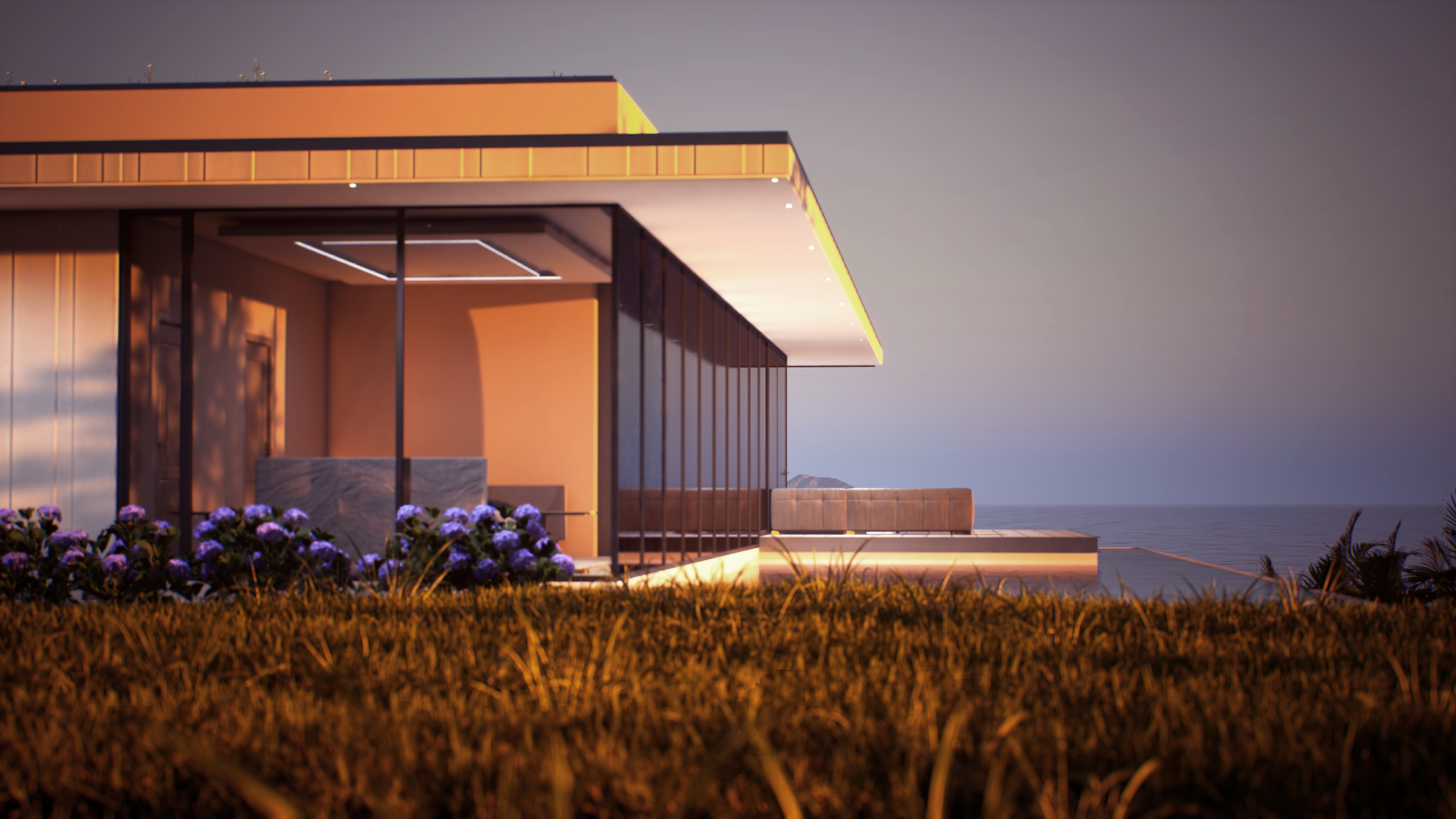
time. Let's begin. I have been modeling this
house for a few weeks. I have taken a huge inspiration from a house named
Slope House from 77 Studio for the main shape of the building which I once
seen in Arc Daley site. I have drawn and re imagined the house
only for discourse. In my version, the house has been designed for
a coastal area. For that we will be assigning brighter colors as materials
for three D modeling. I am using a few three
D software together. My main workflow is
usually in blender. But blender is more
for artistic works. Blender is hard to use when
working with measurements, but it is free to use
software like Unreal. For that reason, it
has huge amounts of plugins which can make
our works easier. For this model, I have used Architt to create basic
shape of the building, then use blender to
detail the model. I have separated
our three D model into six groups which are house, main, bathroom, private
bathroom gates and curtains. Each separation have
different reasons. Bathrooms were separated
because we might disable them for performance
boost in future. Gates will be used to create interactive
blueprints cross area for having a basic collision. When we are adding foliage, our jobs may become easier. And curtains to copy or delay
any of them in the engine. To export from blender, we can use APX or
OBJ extensions. There are other options too, but I believe Px
is the best one. After making all
groups invisible, make the group we want
to export visible. After selecting all
visible objects, we go to file PX file type
In the setting spanel, we change pat mode to copy
and click the box next to it. Tick the selected objects, or you can choose Visible
to then under geometry, change Smoothing to face, and click on Export Px. We do the same for
all of our groups. You can find the
exported files in the course folder I will
be publishing later. Since this is not
a blender course, you do not have to
worry about this part. I'm mentioning this for you to understand the
logic of separating the model into different
parts inside unreal. Let's start by creating
a new level and naming it A R. Let's open
up our new level. Now I want this new level to open every time when I
launch on Real engine. For this, we can go under Edit and select
Project Settings, select Maps and modes. Then change editor. Start up map to our level, which was named AR quiz. Then we create a new
folder under UAV course, and we name it three D meshes. Then we drag and
drop our R house 123.53 D objects into
this new folder. We do not want Unreal
to create the materials for us because we will
not be using them. For that reason, we
change search location to search material
Import methods do not create material untick import textures after
those under advanced, we tick combined
measures like this. The different models
we exported under the same group will be combined
together as 13d object. Then we create new
folder as doors in this folder we can
drag and drop to import our AR house
for gates file. During import
options that untick the combined meshes so we
can add them separately. When we are complete
importing these, we do the same for
curtains as well. Create new folder, then drag and drop the AR House six curtain. Since our importings are done, we can start
adjusting our level. Let's add our environment
lights first under window. We can select
environment light mixer to add them quickly. I click all the settings
except volumetric clouds, now we can drag all imported
models on our scene. Then reset their position
to world origin. Don't forget, you can keep
your outliner organized. It is all up to you to
organize it as you like. You can copy mine if you want, which I recommend you to do. Now let's add our
post process volume to disable the bloom effect. After adding surfer bound under details and
tick the setting, the under Bloom decrease
intends to do zero. This way we won't be having any lens flares
or Bloom effects. After this, we will have lots of material assigning works
to be done as you know. Material assigning is doing the similar processes
over and over again. I have 4.5 hours
of progress video, but I will not be showing
all of it since it doesn't fit for our
courses main purpose. Instead of this, I
will be mentioning some highlights which I believe can be
important for you too. Then you can have your own material
assigning work for your. Let's start by creating a new glass material instance and have its normal
intensity to zero. This way we can have a
clear looking glass. Then I drag this
material to the windows. You can also adjust
refraction value to one. This way our glasses shall
look better on our buildings. For other materials,
we have quixel bridge. Let's open quixel
bridge and login. We have lots of surface
materials we can use here. I recommend you to download medium or high quality textures because if our
scenes gets heavier, we might need better
system requirements from the very start. Have this logic in your mind, you will have lesser
problems in the future. As you can see when you open the downloaded
material instance, it comes with lots of
parameters you can adjust. Here you can check which
parameters changes. What about the main material I mostly use Tiling offset and
albedo tint options here. Tiling changes to
repetition rate and albedo controls changes
to materials color. Basically, we will be creating new materials
for some purposes too. Even though these materials
will be very basic, they will not look
absurd for that. In the materials folder, let's create a new
folder and material, we can name them basic
inside material blueprint. We can create parameters for base color, metallic
roughness inputs. These inputs will
be enough for us to create as many
materials as we need. After that, we can
start creating material instances and change
the parameters as we want. For our purposes, I will be using these
materials for clean surfaces, such as kitchen
furnitures, TV screen, fridge sinks, window
frames, et cetera. Since they are basic, they
will not be heavy at all. Additionally, we will
create a Msim material too. For that, create a new material
again and name it Ems. We created in tutorial we call an RGB color and multiply the values with one
parameter like this. We can adjust the
brightness of our color. By the way, I would like to
mention about glass shadows. For some reason, the shadows
of the glasses are very sharp and act like there is
no opacity on our material. To fix this, we can go to main glass material
and under details, search for red traced shadows. By unticking the box, it will start looking more realistic inside areas
without natural light. I prefer to use
singular light source to lighten up the room. This way, the engine will require lesser time
to calculate light. The project will be smoother. You can add the
desired light source from the Add button as you
can see on the screen. Let's create a Mirror Material. Now we will do the same
thing as basic material. More or less only differences when material attributes
node is selected. Scroll down under the details until you find
forward shading part. Then tick the high
quality reflections and plenary reflections. After this, you can drag your material onto
the mirror objects. Now it is time for creating
curtain materials. It is going to be basic. In fact, you can even use a new glass material
instance and change the roughness value higher for short if you want to
do it separately. Me create a new material named Curtain Change Blend
Mode, Translucent. Take two sided under translucency change
lightning mode to surface forward shading, and create parameters for color, roughness, and opacity entries. If you create a
material instance now you can adjust the look
however you would like. You might experience a
graphical problem like here. As you can see from the
other side of our glass, the curtain is not
visible at all. To fix it, you can click on the post process volume and
search for translucency, change type to ray
tracing and max refraction rays to a higher
value like five here. Now inside bathroom, I have this carpet which I downloaded
from CG Trader for free. It had its own
material textures. Instead of changing
it, I will show you how to bring it
inside Unreal Engine. Let's go to our thread meshes folder and create a new
folder named Imported, then create another
named bathroom. After dragging the
texture to this folder, right click on it and
create new material. Let's change its roughness
value higher than say. Now we can see it. By dragging the material to its object, it looks quite well. Now it is time to assign our
water material to our pool. We will use the water material which we saw in
Arcus template here. I think its parameters
are going to be working pretty well
here in our pool. To find it, you can select
the building folder, then search for water. As you can see here,
there are a few options. We will create a new
material instance from this polish pond material, then drag it into our pool after playing
with the parameters, I believe these settings are working quite well for our pool. The class about jump starting our Arcs animation
project was like this. If you have any questions, feel free to reach out to
me on the discord server. I wish you all happy
and all today.
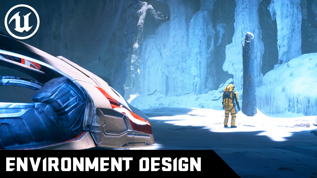
7. Environment Design - P1: Welcome to our fifth chapter of Architectural
Visualization course. I am. In today's lesson, we will start designing
our environment. Torino. We will be learning
landscape and foliage modes. After learning the basics
about these modes, I will be mentioning
the highlights of my working process like we
did in the last chapter. This is going to
be a long chapter, let's not waste any more time. Firstly, I would like to say that you don't need
to apply this part. We will apply all of these
again on our project level. I will briefly go over
the landscape mode. On an empty level, you can access the
landscape mode from the top left corner of the screen or simply
press Shift plus F two. The first screen that appears contains the basic
data of the landscape, including data such as
location, rotation, and scale. There are also section
settings that we can adjust the size
of the landscape. If you have a height map
to create the landscape, you can switch to the
import from file option. By uploading your height
map here you can let Unreal create the landscape based on the data you uploaded. Let's set the landscape
size and click Create. Now we can move on to
the sculpt options. The landscape has
two essential parts, the landscape material
and the sculpted mode. Let's quickly go through
the sculpt mode. In this mode, using a brush, we will essentially perform excavation work
on the landscape. The sculpt option is used to
raise and lower the terrain. If you hold down
the left sheet key, you can perform the
lowering operation. Tool strength determines how quickly your brush
will have an effect. Brush size defines the
size of the brush. Brush fall off sets the softness value
of the brush edges. The arrays option rests the effect you applied
in the painted area. The smooth option smooths the
terrain between elevations. Flatten option makes
the surface flat. The ramp option adds a linear
ramp between elevations. The erosion option simulates
the erosion effect created over time by the
movement of the terrain. The hydro option simulates the effect of water
on the ground. The noise option gives the ground sharp transitions
opposite of smooth option. I don't exactly know about the re top auction as
I have never used it. The visibility option allows us to raise certain areas
of the landscape, but there are settings we need to handle it in the
material system. The blue print option, if you have landscape
blueprints, allows us to quickly
create specific shapes. The mirror auction serves
as a mirror taking the symmetry of regions
from specified plane. The select option
masks a specific area, allowing us to exclude that
area from our working area. The copy option allows
us to take a copy of an area and use the brush to create a copy in another area. Our summary is complete, let's return to our normal
level and get to work. We will start by
creating a landscape. Let's create the material
for our landscape. First, we need to
collect the materials we want for our landscape
from Quixel Bridge. I collected three
materials for this. Sand, gravelly soil
and forest soil. You can see that I colored these collected materials green
under the surface folder. Instead of using
the automatically generated material
instances by quixel, we will create a new material
that includes all three. Let's create our material under the Smart Materials folder
and name it Landscape. First, with Material
Attributes Nodes selected, change the blend mode of
the material to mask. Then transfer the textures of the download materials into
our material blueprint, grouping them into base
color, normal and ARD. The RD textures at the bottom, as mentioned in
earlier chapters, are textures created with the method of saving
space from the Ram. The channels include
ambient occlusion, roughness and
displacement inputs In order now we need a new node, right click and add
landscape layer blend with this node selected, create three layers with
the plot icon on the left. Name these layers.
Sand, dirt and gravel according to your
selected materials. Of course, connect the
base color textures to the layers we created. Then create copies of this
landscape layer blend node for normal maps and
ARD textures as well. The reason we created
two copies for ARD textures is that we will not be using the
displacement feature. As mentioned before,
problems can occur in the shadows created
by nine ray tracing. Let's bypass it for now. Connect the textures to
the copies we created and connect the blend nodes
to the correct places. I'm sure you can find
the right places, but I will not be hiding
my screen just in case. Finally, add the landscape
visibility mask node. This node will contain layer infos for areas we will
mask on the landscape. Our material is complete, we can create the landscape. Now let's switch to
the landscape mode. Assign the prepared material. Set our landscape
size to 63 x 63, and press the Create button. As you can see, the landscape
has a strange material. This is because the layer infos have not been determined yet. For this setting,
go to Paint Tab and click on the Small plus sign
next to the Material Layers. Choose Weight blended layer and say within the
Materials folder. After doing this for all
layers, select these layers. And with your brush, you can make material
changes on the landscape. If you can't see your brush, you can try changing
the translucency option from ray tracing to ruster
on post process volume. Now it is time to use
the sculpt feature. Let's adjust our terrain to overlap with the surroundings
of our building. When our adjustment is done, select the visibility feature. As mentioned, this feature will allow us to create
holes on the landscape. We use this because we want to make the landscape invisible. In the areas where
our building is, we don't see the soil indoors. Once we have completed this, we will need a C. For the C, we need a high quality
water material. We will obtain this
water material from an asset available for free
in Unreal Engine Store. After entering the store, search for rural Australia and add the asset
to our project. Click on Water in the
Rural Australia folder in the content browser. Now we will create a new plane
to generate the material. Add a plane to our scene and scale it by multiplying
the values by 1,000 Place it at the height
where you want your C to be, then drag and drop
our material onto it. This water material is really high quality and being
free makes me very happy. I use it frequently
in my projects. You can adjust the parameters
in the material instance. My settings are currently, as you can see on
the screen now, we will create a road
extending into our terrain. I have prepared a treaty
object for our road. You can obtain this object from the folder I will be
sharing with the course. Create a road folder
inside imported folder and transfer the treaty
objects and textures inside. Right click on Base Color
and select Create Material. Then connect the normal
occlusion and roughness values to material attributes and save. Now open the treaty mesh and drag our material as
default material. Our treaty object we need
for the road is ready. Now let's shape
the road for this. We will need a PP
spline mesh blueprint mentioned in chapter one. Of course before that make sure the area where we will
create our road is flat. You can use the flatten option from landscape sculpt features. The pat doesn't have to be
flat, but if it is not, you may have difficulty attaching this spline
mesh seamlessly. In that case, you can make
changes to the landscape. Now select the BP spline mesh in R C in the details
panel on the right. Add our road object to
the static mesh blank. After setting the
section length to 500, you can freely create our road. You can extend the spline by dragging it while holding
down the Alt key. Using the same technique, you can add the
metal guard rail we obtained from Quicksell
bridge next to our road. These are entirely up to
what you want to add. After all, design will vary
from person to person. Maybe you will do
better than me. This depends entirely on the time and effort you
put on the project. Now let's add an
asphalt material from Megascans to our
road clean object. As I said, you can try
different materials. This is up to you.
This asphalt path will connect our
road to the house. If you have difficulty attaching this blind mesh while
creating the path, you can make changes
to the landscape. Now let's use our static mesh to close the gap between our
road and the entrance. It is time for the foliage mode. Foliage mode is essentially the quick painting and placement of static objects and actors onto the
level using a brush. We can access this mode
from where we reach the landscape or simply by
pressing Shift plus three. We need static measures
as the basic components. We can obtain these objects from the plant section
on quixel bridge. After having the
objects find the drag the objects you want to
use onto foliage section, You can place the
objects on the scene by painting with the brush or by holding the shift
key to paint and clear selected areas
from painted objects. You can change the density of each object by clicking
on them and adjusting the parameters like
brush size and paint density to achieve
the desired scale. You can control the
slope branch where our objects will spawn using
the ground slope settings. Also on slope terrains, you will notice that
our objects are placed perpendicular
to the surface. You can cancel this future by removing the align
to normal option, allowing the plants to
grow opposite to gravity. In summary, the foliage
mode works like this. I'm aware that I went
through it quickly, but you can experience these
modes best by using them. Since their usage is simple, I'm sure you will
grasp them quickly. Now let's go back to
our original scene. As mentioned, we need plants objects for the foliage mode. Let's enter quixel bridge. You can choose any
objects you want from the three D plant section
or even three D objects. I need a grass object that I will use intensively
in our terrain. I believe the grass
clump object under the grass lawn category is
suitable for this purpose. Download the objects and track them onto
the foliage tool. Increase the density
setting and start painting. As you can see, it is
quite simple logic. With this method, we can quickly transfer thousands of
objects to our scene. Honestly, this is one of the most enjoyable parts
of the process for me. While greening your area, make sure that the grass doesn't invade the
inside of the building. An unrealistic image may occur. Now let's create a
small flower garden at the back of our building. I obtain the required object
again from Quicksell Bridge. The box food in the garden plants category
will serve my purpose. Double click on the object
we will use and turn off tracing support
from the details panel. Now we are ready
to use our object. We will be using one of the
blueprints of R's template. Here again, drag BP's pone
mesh along spline blueprint to the level and our box object onto the static me section
for our blueprint. Increase the distance
between instances, option 250 and adjust the
length of our blueprint. Can you see the key point
in placing objects? If this blueprint didn't exist, we would have to manually
place them one by one. After completing the placement, we can place the desired flowers in the inner part as we wish. After applying this
in different ways, in a few places, I
found it sufficient. As you can see, there are
no trees in Quixel bridge. But don't worry, quixel
is not only serving here. Let's go to the
Unreal engine store. Enter Megascan trees in
the search bar and search. Alternatively, you can type trees and activate the
free filter on the right. Quixomgascans trees are
the highest quality trees you can find for Unreal. In addition, they are Avivable
for free in the market. I am adding common hazard and black elder trees
to our project. If you encounter any
problems while adding, you can try closing the
project and add later. You can add the
trees we added to our content browser by
adding and dropping them from the geometry
pivot painter folder or using the foliage tool. It is that simple. If you would like to understand more
about Megascan trees, you may check the
Quicksell video about Megascan trees on Youtube. Now, let's move on to the
last part of this section. We will learn how to
turn the textures we downloaded from Quixel
Bridge into three D shapes. For this, we need a plane model, and our quixel textures start by choosing and downloading the
texture from Quixel bridge. I downloaded
Construction Gravel. Duplicate the plane model
inside Shapes folder. From the starter content, you can name the
new model Rocky. We will work on it by dragging and dropping it onto our seen. First transfer our
material onto the plane, then switch to modeling mode. Go to the mesh tab on the left. Click on Rems and change the target triangle
count to a higher value. I'm setting it to 20,000
but this is up to you. Update our model by
clicking Accept. Then select Displace
from the Deform tab, choose Texture to D
map as a method at the top and drag or ORD map to the displacement
texture section, change the channel to blusince the displacement data of our
texture is in blue channel. The reason we can't
observe any changes is that virtual texture
support is enabled. We can disable this
feature by opening the texture and searching for
a virtual texture on tick. It, then refresh the texture
again by dragging it, Our object is starting
to text shape. You can adjust the
displacement values to capture a suitable elevation. Finally, choose lattice
from the deform tap. When we will be using our
object multiple times, we want them to blend
better with each other. Holding the shift key, select the outermost points, pull them down slightly,
and click accept. Now we have a stone
model that we can use on the edges
of our structure. You can copy and paste it into our level as
much as you like. But don't forget to activate the Anite support for this mesh. That was our environment
design section for today. If you have any questions, feel free to reach out to
me on the discord server. I wish you all happy
and healthy days.
8. Environment Design - P2: Welcome to our sixth chapter of architectural visualization
course, IMOs. In today's lesson, I will be mentioning the highlights of my environment design process. Doing so, you will
get to understand the methods and tricks I am using to create our environment. I will not be designing
the interior of our house, but I will be trying to show you the techniques instead.
Let's get started. We can start from
where we left off, which is adding quixil
tride objects to our scene. We open up quixil breach, We have two locations to find
our desired Tride objects. We can search them
by name or go under collections category
and find what we need. I'm choosing a few of the rock objects to enchance our
exterior environment. Higher quality is good for getting better quality
on close up shots, but here we won't be capturing any close
shots for the rugs. For that, I add them
as medium quality. After adding them
to content browser, we can drag static mes
actor to the seam. Adding Quickl objects are usually comes with Nana
support turned off. To change this, you
may right click on the object and tick
the Nana support. When you drag these objects, sometimes there are these
ugly shadows appear. If you remember, I mentioned this in the previous chapters. It is caused by retracing
being not calculated. Well, now we will learn a different approach
to minimize this issue. Open the treat object by double clicking
under Nani settings. We change fallback target
from auto to relative error. Then change fall back
relative error value to zero and apply the changes.
This should help it. You can always fix this issue
by enabling nanite support. But if you use this asset, let's say about 1,000 times, it will be heavy for
your computer to handle. If you are planning to use
only one of these objects and get the best quality of
it for a close up shot, maybe you can turn it off. Instead of dragging
our object and positioning it every
time in the scene, we can use foliage mode to
add them fast and variously. To do that, let's go to foliage mode and drag
our tread object inside. Turn off all other
assets by selecting them with control A and
unticking any of them. Then tick our desired object and change the parameters as you
would like them to vary. Then select the tool
how you would like to place the object
and place it. Now let's go back
interior of our building. You might have noticed we do
not have any doors inside. It is time we build them. I will be adding a
door mesh inside our course Assets folder
for interior doors. We will be using
this three D object under imported folder. Let's create another
folder and name it Door. Open the Assets folder and drag the three D object
and texture inside. We have to change some
values here due to doors. Export settings are not 100%
compatible with unreal. Change First, offset
rotation value 290 and uniform scale value 22. Please note that
we have to uncheck combined measure selection so our parts can be
imported separately. Drag them into our
scene to check if the scale and rotation
values are right. Once you set it right, we
can create the material by right clicking on the texture and selecting Create material. You can see it by dragging
the material onto our object. You are free to play
with materials values, but I found it suitable. We set the difficult materials by opening the static
mesh actors and assigning the material on our door panel and
sheet for handle. We can use one of
the basic colors we have created
in less chapters, then save them all with
control shift plus. Now of course, we won't
be adding these parts separately every time
inside our scene. Instead we will create a
new static actor blueprint. In future chapters,
we will adjust this blueprint for
playable level two. But for now our intention is to create a
basic arciinematic. Let's create a new blueprint
by right clicking and selecting blueprint and
then selecting the actor. Let's name our blueprint
door actor and open it. We will drag our static measures under default scene root. As you can see, we have only one door handle
to duplicate it. We simply create a
copy by control C and control V. Then select
one of the copies, got the details panel and change its dimension scale
to minus one. This will mirror it
on the other side. After you do this dragular
blueprint to the scene, our door will come
in one component. By changing this blueprint
scale, location, rotation values, you can affect the whole
component easily. Seems like our door is a little bit smaller
than our door opening. Let's place the door and scale it a little bit until it fits. Right now, we use this blueprint to fill all the door openings
in our interior space. It's starting to look okay. But if you try to rotate
to open our hinged door, you will notice that it is
not acting as it should be. This is because
when object values like rotation and
scale are adjusted, programs grab a reference
point to apply the effect. This reference point is called pivot point in Unreal engine. With modeling mode, we are able to edit this pot
point inside Unreal. To edit it, basically direct the object you want to edit inside somewhere
in our scene. In this case, we want our
door open modeling mode. While this object is selected, go to X form and then edit pot. From here we can change our
pot point anywhere we like. After changing it, click on Except and open
the blueprint. Again, you will see that our door sheet location
has been moved. This is because location is actually our pot point location. Let's adjust it to
where we want it to be. After adjusting now, we can make parenting to the handles
without parenting. The handles will stay
in the same place while our door sheet
is being opened. To make handles move
with door sheet, we have to make our sheet
parent of our handles. Parenting is basically when the parent object
values are changed. Parents pivot point is taken to change children
objects as well. To make a parent object, you simply select the
children objects and drag them onto the object you
want to make a parent of. It is that easy
inside our house? Let's add a few
furnitures to fill it. I imported and created the blueprint objects as the
same as door Pulueprint. You can control each
part easily to blend together and come with
a unique furniture set. I also downloaded a white
furniture fabric from Quicksell Bridge and assign its instances to my furnitures. I would like to use
white color to dominate the space because I am such
a Mediterranean person, maybe you will do
a mountain view. If you do create
something like that, please make sure deposit to
me on discourse server two. I'm eager to see what you
can do with the knowledge. Now let's mention about decals. Decals are used for adding
new textures over surfaces. This way we can add
Naf textures over materials without making any changes inside
material blueprints. I usually use these
decals to add sprays, dirt leakages, manholes,
asphalt cracks, et cetera. When you feel the surface
needs more detail, I suggest you to check decals. When I look at the scene, I believe there are some details missing
to fill the scene. I believe we can add
a little port for two boats to obtain the boat. Let's check CG trailer. I found this Yatch model
and downloaded it. I will be also adding
these two course assets. So don't worry, you won't
have to download it again. Now let's return to Unreal. We need a platform
to access our boats. If you are one of my type, you might not want to
model it from scratch. Let's go to Starter Contents
Architecture folder. And find what we need there
by dragging the objects. Let's try to achieve
our desired look. Then add some pillars below and assign this gray stone
material to them. It looks well, but we didn't
import the yatch yet. Let's import our yatch model
inside our imported folder, then drag it into our scene. People won't be just
jumping down over the boat. We can create a staircase in the same way or adjust the
height of our platform. I choose to lower the
platform and scale it a little bit smaller
so it fits better. We need two models of yachtch. Let's duplicate it by
holding out and dragging. Now, these boats needs
to be different colors. You may assign the colors as you like from basic materials, or you may wait for automotive
materials to be imported. The assign them later. I feel something is missing from our port and it is the pat
that would lead to our house. We don't want
people to walk over this grassland every time
they want to go to the port. Let's make a pat. To create it, we can use BP's plane along
mesh blueprint here again, I believe we can create
the path from stones. Grass can grow
between each tile. I believe this will
fit our environment. I have prepared a
new treaty model we can use here
with the blueprint. Import yard pad stone, object to content
browser and assign the same material of the
platform to set our pale. We can set foliage
actor invisible. For now. Adjust the
spline leading to our garden door and drag our
object to see the result. You can change the distance between objects
inside details panel. Something close to
50 looks fitting. When we are finished,
we can make the foliage visible again and erase
the objects in the path. But we are wanting some
grass to grow between them. Right? To do that, we will paint grippon grass
between the tiles by hand. It is the best way to
do it, in my opinion. There can be other ways
like procedural generation, but they are more advanced
tech, to be honest. They are added recently
to the engine. For that reason, I do not consider myself professionally
using them yet. When we are done with it,
it should look like this. It gave our scene
more life, didn't it? When we look at the
distance, it looks endless. But I want some lands or
islands to be seen there. Most of our houses values
comes from the view, not just for discourse. It is a universal thing. Let's add some
islands in distance. We will use some mega
scan rocks here. Let's go back inside the quixel bridge and search
what we can use there. I found this mostly rock face
suitable for this purpose. Download it and add it to our content browser after the
drag it in some distance. The trick here is
we will play with its scale values by scaling it bigger and
duplicating a few of them. To blend each other, we shall have different kinds of lens to fulfill the view. This is the most basic method I used to create distant views. I also use a software called Kaya to create
landscapes which is free or might check on real marketplace to find
redi, static mesh landscapes. Now it is time for cars. I believe this can be the
most frustrating part. I will be making it
easier for you to adapt. I will explain all the way, but you will be responsible for the last part
of this process. Usually I find my cars online on sites like CG Trader or Sketch. A CD Trader has better choices for free,
we will stick with it. Now, you may search
for a car and choose any model you like
after downloading the object. There are some adjustments, needs to be done in other
softwares like Lender. When we import the model, we see that the model
is complicated. We need the models
prepared in nine parts. For real engine, the parts are main shape of the car wheels
and brakes for each wheel. The reason for this is they
will be parented to each other as less as we can have
these objects is better. I had a prepared model
which was OD model R eight. You may import this
inside a new folder. This time we need some quality materials made
for vehicles to acquire it, go to Real Engine Marketplace and search for
Automotive Materials. This is completely free
again and top Quality. Click Add to Project, and under select Version, Select One closest
to your version. Min is 5.1 at the moment. Now it is added to
our content browser. Open each static object
to add default materials. Here you can see the slot
names of each material, Find it inside automatic
materials and assign them. You can change some of
them if you would like to. It is all under your control. You might want to change element 12.13 materials to
clear glass material. That's because stopped car lamps would basically not be working. If you make a animation, we will change it later. After we are done
with materials, let's create a new
blueprint actor. Drag our objects inside. Blueprint set wheel locations
to their right places. Make sure that the wheels
which should be parallel to each other are on the same
value on that dimension. For example, right side
wheels should be on 78 to be in order then bring the
brakes to right places. When we are complete
carrying the objects, we can start parenting
the objects. Parent wheels to the main shape of the car and breaks to wheels. The only problem here is breaks
wheel rotate with wheels. We can change this by un parenting or assigning
each part to a skeleton. These are more
advanced techniques. You might find these
skeletal ricks inside marketplace to purchase
if you are interested. When complete parenting, we can compile and
close the blueprint, Drag our blueprint to our scene. Now we can see our
car in one component. Seems like I have made a little mistake while
putting the garage gates. They are smaller than I thought. I will put our car outside. This is a big car anyways. Now our vehicle is also ready. Before we end this chapter, I would like to mention some of my favorite assets
inside marketplace. The first one is called Ultra Dynamic Sky
from Everett Gunter. This asset comes
with two blueprints. First one allows you to
control the sky like you can change the fog clouds
in a very detailed manner. The second one lets you
control the weather with it. You can make it snow, rain, and even thunderstorm. This blueprint also
affects other assets, like making them wet easily. The second asset is called
Easy Folk by William Foucher. William Foucher is a
content creator for Unreal Engine and always
seeking realism in his works. You may check his
Youtube channel. This blueprint lets you add distant folks very easily to
achieve a cinematic look. The third one is
called Ocean System. For rendered cinematics
from Blue ray Addict. You can use this very high
quality water blueprint to capture seashells in
our ultra cinematic. I am showing you what
I added to our scene using these methods so you can experience them
in one breath. Our environment design
process was like this. If you have any questions, feel free to reach out to
me on the discord server. I will try to answer all the questions as
much as I am alievable. I wish you all happy
and healthy days.
9. CINEMATIC: Hello friends. Welcome
to the new section of our architectural
visualization course, IMOs. Today we will create our architectural
animation together. In this section, I will share all the key points in the
animation process with you. Let's start if you're ready. In the previous environment
design sections, we added many things, but we haven't touched
on visual effects system at all as we start this section. Let's look at the moment
elements that we shouldn't miss in our animations
on real engines. Visual effect system
is called Niagara. You can find the birds and falling leaves effects
in the effects folder within the rural
Australia assets we added to the project earlier. By dragging these
elements into our scene, we will make birds
spawn in various areas. When rendering our animations, these birds will be
primary elements bringing life into our scene. The secondary element will
be adding animation to the grass and flowers we added to our scene through Megascans. To add animation, we will find the folder of that object
in the content browser. When you open the
materials in the folder, you can see enable grass wind
at the bottom, parameters. After activating this option, you'll observe that the objects in the scene start moving. You can find the desired
value by adjusting the parameters after completing
the animation elements. Let's take a final look at the important settings
for rendering. Let's examine the
directional light actor. I recommend keeping the
intensity value 10-12 locks. I aim for softer
transitions of shadows. By increasing the
source angle and source soft angles
values to tube, You can increase the indirect
lightning intensity value in a way that suits
your project. This value represents how much the lumen light system will reflect bright lights in the
environment to other pixels. The higher you raise this value, the more light will be reflected
onto the other surfaces. Now let's move on to
exponential height fog. Here I changed the foc
height fall of volue 2.3 I activated the
volumetric foc feature and increased the
extinction scale value 22, I strongly recommend
enabling volumetric foc. Now on to sky atmosphere. You can achieve significant
changes by adjusting the ray light scattering scale and
scattering scale values. While the usefulness for
architecture is debatable, it can be beneficial
when creating cinematic scenes and our
precious post process volume. This actor shares
great similarities with the camera settings
we will use shortly. The changes we make
here will apply to all the settings
for cameras we add. I want to note that any
adjustments you make in the camera later will
overwrite these settings. First, we had turned
off the Bloom effect. Now let's set the intensity 2.2 in the chromatic
aberration tab. I recommend keeping this value
low under color grading. In the temperature section, let's set the temperature
to 6,000 Calvin. Note that the
approximate value of natural light is 5,600 Kelvin. Selecting a value 5600-6200
should be sufficient for now. We will make color adjustments after the rendering process. In the reflection step, ensure that the
quality value is two. The tracing mode option is set to hit lighting
For reflections, the high quality
translucent option is active and the max reflection
bounces value is three. These values are important for render quality
under translucency. It will be beneficial
for the type mode to be racing under the post
process volume tap. Make sure unbound is active or these settings will
have no significance. All these settings can
vary for your scene. Fiopherty, use different values. Now we can start
creating our animation. To create our cinematic, we need to first
create a sequencer. Click on the moe
icon you see above, and select at level seconds, while selecting the directory
for creating the sequence, you can also provide a name. Now we have two ways
to create our cameras. We can either combine
our cameras into a single sequence or create separate sequencers
for individual shots. Eventually, we will combine these shots in the final
sequence we will create later. This is a method we
are about to apply. Let's start by naming our
first sequence shot one first. Let's summarize the features
we will use in sequencer. The FPS indicator
you see determines what frames per second your
animation will be rendered. Higher numbers result in
smoother image quality. If you want to view
the sequence time line in seconds instead of frames, you can click on FPS and change show time as 2 seconds
in the timeline. Green line on the
left and red line on the right indicates
the start and end. You can adjust to
the display range of the time line by changing the internal numbers
at the bottom. When the magnet icon is active, it allows you to
snap to K movements. We can add our camera from
the camera icon on the left. When the camera is selected, camera settings will appear
in the details panel. From this panel, I choose the super 35 millimeter
camera preset that I have selected
for this project. Instead of controlling
our camera like an actor in the scene, we can directly view
and control the camera. Click on the small
camera icon next to the camera to switch
to the camera view. As you noticed, the camera
presents offer a square view. To change this, we will first select the lens that is
suitable for our shot. Higher millimeter lenses are
designed for closer shots. Once we make the lens selection, let's change the squeeze
factor value below to 1.6 With this change, as our field of view expands, black bars will appear at the top and bottom
of the screen. Now that we are in
the camera view, let's move to the point where
we want the camera to see. Now we will create a keyframe. Keyframes are markers
that determine the state of actors
we use in sequencer. At the moment, the
transform option under our camera actor contains
data such as location, rotation, and scale
of the camera. Now all we need to do
is create a keyframe. We can create a keyframe
next to transform by clicking on the small.in
the middle of the arrows. Afterward, we can drag this keyframe to desired
time on our timeline. Now our camera has instant
position information, but if you want some movement, we need at least two key frames. We can drag our timeline on the last frame and move our
camera slightly upward. However, without creating
this new key frame, it will be meaningless. Let's create the key frame and play the animation
with this spacebar. Our camera is moving,
but there is an issue. The camera is slower at the beginning and end of the animation to
fix this effect. After selecting the transform, we will go to curve
settings to see above. Here, select all key frames, cliconlinear interpolation
from the top. And now our camera
will move linearly. If you want to revert
to previous state, you can click on the auto while the key frames
are selected. My recommendation is to plan each shot longer than
you normally want. For example, I am planning
this shot for 10 seconds, but I updated it to
15 in the process. The length of our
shots will provides flexibility during the editing
phase in the Premier Pro, after right clicking
on camera cuts, we can change the length of the shots to the edit section. However, this is not enough. We also need to
drag our end line. We may not be able to snap
this line to the camera. Therefore, by switching your viewport settings
to cinematic view, as you can see, you can manually update it from the bottom
right of the viewport. As you see, camera control
is straightforward. If you have used programs
like aluminum before, you will get used
to it very quickly. With this method, we can
create most of our shots, but let's dive into more detail. For example, we will shoot
our boats in one C. However, the boats are stationary. To animate the boats, we select them and drag them from the outliner to sequencer. The transform option will automatically appear under them. Now similar to the camera
at different times, we need to create different
poses and add keyframes. In this way, we can mimic the effect of water
waves on our boats. We can also use the
same technique to create animations that
require object movement, such as a door opening. In close ups, the focus point
becomes more important. We can change the
focused instance under focus settings by clicking on the icon next to this value, we can create a keyframe. Also, by making changes in the focus distance
in our shots, we can enhance the
quality of our animation. Finally, let's add
animation to our vehicle. Animating the vehicle with the transform option is a bit more challenging
than you might think. However, don't worry, I have
a special method for you. We will create our
animation without the need to download an animation
rig for our vehicle. What we need is
the comma regrail. You can add the comer grail by searching or adding it
from the cinematic tab. Now extend this rig along the path where
your vehicle will move. Just like this spline
along mesh blueprint. Once we define our path, we will create a
parent by dragging our vehicle blueprint onto the Comer Grail in the outliner. This way when the comer
Grail position changes, our vehicle will move with it. If our vehicle doesn't
align with the rail, update the location
values to zero, it will quickly
settle onto the Re. With camera Grail selected after activating the lock
orientation to rail option, you can visualize your
vehicle moving by dragging the current
position on rail data. However, the wheels of
your vehicle won't turn. Now let's fix that. Make sure you have
dragged both your vehicle and camera grail into sequencer. Then let's create K frames for the camera grails
current position. If done correctly, when
we advance our timeline, we should see our
vehicle moving. Click the plus icon next
to our vehicle blueprint, and add all the
wheels individually. Now we will need to adjust the position
data for each wheel. Colick the plus icon
next to all wheels, and click on Transform. We will change the transform
rotation roll data for all the wheels. Positive values here will make our wheels turn in the
opposite direction. We will find the
correct value to trying as the road extends, the value will increase. Once wheels and speed of our
vehicle are synchronized, you can determine the
value for this shot. The value was set to -3,000 After entering this
value for all wheels, don't forget to convert the key frames through
linear interpol otation. You can easily change this
by selecting the key frames, right clicking, and
selecting linear. This is how we create
our vehicle animation. Now it is time to merge all
the shots. We are prepared. Let's create a new sequencer to combine all the shots
and name it cinematic. This time, instead
of creating a camera click on the track on the
left and select Shot Track. Then using the small
plus icon next to it. We will combine the
shots one by one. After adding all the shots you want to render consecutively. Change the start and end lines. If you don't change
the end line, you might end up with
five second animation. Additionally, the
exclamation mark next to your second FPS indicse that different shots
have different FPS. Select 60 FPS, again, to update the FPS data
for all shots to render. We will use the Movienderq plug in if you created the project
using the archistemplate. This plugin will be
active by default. If you created it differently, you can activate the
plug in by selecting edit plug ins from the top menu and
searching for movienderq. Enable the two plug ins that appear and restart the engine. Now with the cinematic
sequencer open, click on the film icon
to open the render que. Let's open the settings. Here you will find process
that I prepared for you. You can obtain this process from the course files or the
course assets folder. There are two methods
you can apply to bring them into your
individual projects. First, with the project open, select the preset files in the UAV course sequencer folder. Right click, choose
Asset Actions, then select Migrate. After clicking. Okay. Choose your projects content
folder to copy the files. Secondly, you can directly
copy these files and pass them into your desired location inside your projects
content folder. When you want to
change the config in movie render K settings, the process will
automatically appear. Although I prepared the presets, there are some settings
I want you to know. Firstly, antalyzing
special sample count and temporary sample count
are multiplied values. If you set both to 16, a frame will be
calculated 256 times, making the render time huge for architectural
visualization, I think increasing the temporal sample
count is sufficient. This data applies motion
blur effect to our frames. After changing the values, make sure overright
antalyzing is enabled. Warmup frames can
be activated to start frames before
recording renders. Helping to sharpen camera
and light settings, the output tap is one of the
most important settings. Here we determine the directory and resolution for our renders. Do not change the
name and format, or it may complicate things when importing into Premier Pro. Moreover, the other
settings to quickly understand their functions
by reading the explanations. Once you have completed
the settings, you can click on Render Local. The other option will open
a new Unreal engine window, slowing down your computer. When our under is complete, we can move on to Premier Pro. At this stage, you can use different programs
if you prefer, but I will guide you
through my approach. Let's start by creating
a new project. Now I will explain the windows that make
up our main screen. In the top left corner, we have the effects control, where we can adjust
properties like opacity, position, and scale. To its right is the port
where we will view our video. Below that, similar to our
real engine sequencer, we have our timeline. To its left is the
content browser. To the right side window is the panel for color adjustments. Right click in the content
browser and choose Import. Select the first
frame of your render. Check the Ime second
option, and click Open. Since we imported our video
as an email sequence, it comes with a fixed
frame rate of 25 PS. Right click on the video, choose Modify, Interpret
Footage, and Set. Assume this frame rate to
APS value of your render. Now you can drag your
video onto the timeline. Let's import our background
music by dragging it into the content browser
in the timeline. The top section is
dedicated to videos. The bottom section
is for audio files. Drag and drop your music into the bottom section and play it. Both our music and
video starts off noisy, which is the first
thing that bothers me with the music selected. Change the volume value
in the effects controlled to -30 for the first level, and create a key frame. The key frame logic
is similar here. Now let's listen. Great. Now what I want
you to do is separate all your shots using the resertolee while
holding down the old key. You can zoom in an outfit mousel to make this process easier. Once you have made all the cuts, we will create a composition
harmonizing with the music. It is entirely up to your
artistic abilities and I have full confidence in you
when arranging the videos. You can also use upper channels. Videos in the upper channel
have display priority. If your video is too short
to fill the desired space, you can right click
on that section in the timeline and changes
speed or duration. Small changes won't
disrupt the FPS balance. Once we have completed
our composition, let's add some text. I want to place the text
ultimate R quiz course parallel to our building on the balcony in
the first scene. To do it is select
the text tool and determine where you want to
create our text in the scene. After typing the text, enlarge the borders to
make it fully visible. Open the essential graphics
panel on the right to change the font size and
other features of our text. If you don't see this panel, you can activate it
from the window me. Direct the text to where
you want it to appear. Then search for transform in the effects panel and
drag it onto the text. In our timeline, new settings will appear in the
effects control panel. Direct the skew value to
achieve the ideal angle. It's going well, but text remains fixed
as the camera moves. We need to create key frames
for the position and scale. As for the text, After updating the position where
the text fields start, click on the icon
next to the position and scale in the
effect control panel. This will activate the
ability to place key frames. Then go to the last moment
before text disappears, and update the position
and scale values. Key frames will be
created automatically. This way you can add as many
animated text as you want. Now that we have added
text to our composition, Congrats, we have completed
half of the cinematic. Are you feeling intimidated?
Well, don't worry. I said that they emphasize the importance of
the remaining part. Now let's apply color grading, open the lumetri color and
lumetri scope spanels. If you can't see these panels, you can activate them
from the window menu. I want you to right click on the Lumetri scope spanel and open waveform and vector scope. In the Vectorscope values
0-255 are displayed. This indicator helps us understand the amount
of color in our scene. The top part
represents highlights, whites, and the bottom part represents plaques and shadows. Lumetri color has six sections. Let's start with the first one. Before starting this process, you should determine your goal. My goal is to achieve a
dreamy effect from the video, the secret to achieving a
dreamy look lies in increasing the dominance of colors and
amounts of magenta and pink. Let's get started. At the top, there are lookup table presets. However, we won't focus
on precess right now, since loose settings are tailored for different
types of cameras. I think it's more accurate
to make our own adjustments. Use the white balance sector. Plan to click on a point in the video that you
believe is truly white. This shall automatically
adjust the white balance. Temperature and tint are the fundamental values for
adjusting white balance. The settings under tint, our light settings, exposure
opens up all colors. Contrast separates
whites and blacks. Highlights change the
light of bright areas, shadows to the opposite
for dark areas. Whites and blacks adjust brightness of
extreme points like 255.0 Saturation is
the color intensity. If you pull it all
the way to left, you'll get black and white. In the basic correction section, we balance the colors
between these values. Let's move on to the
creative section. The Luke action works like lot. I recommend experimenting
with the section. It's logic is quite simple. Let's skip this and move on to the curse because we
won't be using it. The top point we see in curves determines whites and
low points are shadows. While changing the setting, we can create three points shaping the curve
slightly downwards, sharpens shadows and
highlights hue and saturation. Adjust specific
color saturation, hue versus hue changes
the color versus luma, adjust brightness of the color. I won't go into the
other settings. They are a bit complicated
and even I barely use them. Color wheels applies
the color balance of a different frame to your selected C. You can achieve this by switching
to the comparison view. Hsl Secondary allows us
to select a color more detailed and offers
different variables in addition to color. This is like versus U actually allows you to change
a specific color range, while in curves we could
only change the color. Here, the changes we make, like polar effects, only affect
the selected color range. The net setting applies
a shadow effect on the edges and attracts the
focus to center of our scene. We finished the adjustments
for our first scene. Look at the difference between turning the effects on and off. Amazing, that's why
we do post editing. Now you can copy these
lumetri color settings for other scenes from the
effects control panel. Remember that these settings
will vary for each lighting. Conditions are different
for each shot, you need to make
slight adjustments. Finally, there is one more point to address the balum effect. If you remember, we turned
off the bloom effect in unreal and now it is
time to recreate it. Creating it is straightforward. First, duplicate our
scene on the top layer, Apply Gaussian blur
from the effects panel. When you set polyurinous value to 500, you will see the effect. Change the blend modus screen
and reduce the opacity to 25 to 35% Then however, this setting affects
all of our colors. Additionally, from effects, find Lumache and add it to
the top video layer. It is important that lumache is above Gaussian blur
in effect control. Otherwise, we won't achieve
the desired effect. Now everything is
as it should be. If you want, you can
cover the glare effect at the top and bottom by
adding a new black band. For this, you will need
the rectangle tool. Place the rectangle
and duplicate from essential graphics
to drag it upwards. Holding down control
will make it easier to snap to the
edges of the screen. Your video is ready. Go to the export
section in the top left and get the final
render of your video. We have reached the end of the cinematic creation chapter. Feel free to reach out to me
through the Discord server. If you have any questions, I leave you with
the final video. Wish you happy and healthy days.
10. Walkthrough Level: Hello friends. Welcome
to the eighth chapter of our architectural
visualization course. I am Oz. In this section, we will learn how to make our scene playable, which we said in previous
sections. Let's get started. Instead of working directly on the scene where we
created our cinematic, we will work on a copy
of this scene this way if you want to make changes to our
cinematic later on, we can easily do so. Let's duplicate the
acres level inside the levels folder I am naming
the file walk through. Let's open our level. Now we need a game mode where we can navigate
through our scene. For this, we will use the First Person
shooter template provided by Unreal Engine. Click on Ad, then Content Pack. From there, select First Person Shooter
and add to Content. Now open the First person
blueprints folder. The BP First Person
character you see here is the blueprint for the character we
will be controlling. However, since the blueprints in this folder work together, we will make some changes
to adapt them to our scene. Let's start by dragging the
first person blueprint into our scene with the blueprint
selected in the scene. Search for auto in
the details panel and change the autoposcess. Player and auto receive input
options to player zero. The setting helps the
game find the character. We will be controlling
when the game starts. Now double click on the
blueprint to open it, we don't need the arms. Let's select and delete them. We need to set up the playable level settings
for our project. Go to Edit, Project
Settings, Maps and Modes. Here, change the default
game mode to BP, first person game mode. You can also select our new level for the
editor start up map. This ensures that every
time we open the editor, we encounter this level avoiding accidental changes
to cinematic level. Each object in our scene
has its own collision. You can think of these
collisions as volumes, switch the mode to
player collisions to see how free we are to
move around the scene. If architectural objects
are imported as scene, it means they don't have
a collision set up. These collisions are where the player can step
on inside the level. There is a way to fix this, but it can significantly affect performance in
large scale buildings. Let's open the treaty
model of our building and go to collision tap here. By changing the collision
complexity option to use complex
collision as simple, we can fix the problem. We can apply this to other
models causing the issue. While not the most
performance efficient method, it's the quickest solution. Now let's control our
character in the scene. When comparing the widow of
the door to our character, we can see that our character
has a good appetite. Therefore, let's
reduce the width of the capsule in the
character blueprint. This capsule represents the
volume of our character. Additionally, we can
lower our camera habit. We will disable some sections of the character blueprint
to disable jumping, cut the connection
of the red node in the jumping
section and compile. We will also disable BP, first person projectile PP pickup rifle and PP
weapon component blueprints in the same way these
plugins enable weapon use. Now let's add collision boxes to areas where we don't want
to access while playing. These areas act as
boundaries similar to pools. Select cube from ad shapes and place it in
the desired areas. Although they won't be
visible in the game, their collisions
will remain active. Lastly, select the cubes, search for visible in the details panel
and unchecked box. After these steps, our
scene will be playable. You can also adjust the speed of our character in the
details panel while PP, first person character
is selected. Since we won't be applying any rendering processes anymore, we can bring our scene to its final look with
Pospcess volume, I want our scene to have evening light and
feel warm For this, I enable Bloom and
Glens flare effects in the pospcess volume. You can adjust the
values as you like. Additionally, you can easily change the position of
the sun We control out, since steam rises from the sea to the sky in
the evening times, I slightly increase the atmospheres
scattering scale value. This should be enough for now. Let's move on to adding
interactive elements. Interactive elements are objects in the scene that we
can interact with. These objects will interact
with our character blueprint. However, for our
character blueprint to work with other blueprints, we need to define our
character blueprint. Let's open the blueprint
and search for tax in the details panel Under
the advanced text section, add a tech named player. Now we can identify ourselves as player in newly
created blueprints. Remember the static door
blueprints we placed in our C to avoid adding
doors to scene. Again, we will work
with this blueprint. Create a new blueprint folder, and move the previously
created bulueprintsreow. Let's open the door blueprint. Ensure that the pivot point of our door panel is
aligned with the hinge. If not, you can adjust it
using the modeling tool. Now we need to define when
the interactive blueprint we are creating will be triggered by our character blueprint. For this, let's add a box
collision to the scene, then adjust its dimensions to cover the front
and back of the door. We will make the door usable when our capsule enters the box. To ensure the box
works properly, be careful not to
make the mistake of adding it as a child
to the board, like me. Otherwise, the cube will move at the door causing
it to glitch. Now let's integrate our box into the blueprint coding system with the box selected at
the On component, begin overlap and On component and overlap options
from the lower sections. In the blueprint system, red nodes always mark the beginning of a
command sequence. Therefore, we can't add
inputs to those nodes. When these commands
are triggered, they execute the code
sequence that follows. The blueprint coding system is a simplified version of C
Sharp programming system. If you have basic
knowledge of C Sharp, you can easily understand it. However, I will explain
it as simply as possible. The red codes are like starting a paragraph every
time they trigger it. Each paragraph has
its main topic. We can call it as our goal. Also, our goal could be to rotate the door
panel by 90 degrees. Now let's focus on
the first node we added on, component
begin overlap. As the name suggests, the box collision is a common triggered when interacting
with other collision. Here we want the intersecting
object to be our player. For this, we need an if command. The blueprint version of the if command is the
branch command. I will prefer to
use if instead of branch as I believe it's
more understandable. The if command has two inputs. One end shares the continuum of the command series and the
other checks the condition. Additionally, condition
can have two outputs. One if the condition
value is one true and the other if the condition
value is zero falls. Now let's add the
actor has tag node. We will connect the
overlap component to the target and right
player in the tag section. This way this value
will check whether the other collision
intersecting with our box has the
player tag or not. If it does, the
value will be one. Otherwise it will be zero. We will connect this to the
condition node in the node, thus forming our first sentence. Although it may seem
difficult at first, it's actually quite simple. With a few practices, you will grasp it, trust me. Now let's drag our door sheet component
into the blueprint. After all is the
object, we will rotate. Now we need to control the opening time of the
door in the blueprint. If you directly enter
the change comment, the door will suddenly open. As soon as the
comment is triggered, we don't want to
see that happening. We will control this
with the timeline node. Double click and
open the node from the Track button in the upper left corner
select at flow track, a screen similar to the
second circuit will appear. We will add two new key points to the line by left clicking. When these points are selected, we can adjust the time
and value values above. The first point should be at second zero with
a value of zero, while the second
point should be at second two with a value of 90. You can adjust the values to fit the screen by clicking on the
boxes to the left of time. Although the variables may
seem linearly connected, we will right click on the
points and select Auto. To smooth out the value change. The added variable will appear in the output
values of our node. You can rename it if you wish. Now let's add the set
relative rotation node, which will rotate our door. We will connect the door
sheet to the target and split the variables
to set the z value. By connecting the arrows, we can continue the coding
and test our door in the C. Now, our door will
automatically be triggered every time our
character approaches it. Let's make it start closing automatically when we
move away from it. As with the previous one, we need to confirm
that the object moving away from the
door is our player. We can copy the code from above. For this then,
it's quite simple. We will connect
the code series to the timeline to run in
the opposite direction. This way we learned
that we can use the same code series with
two different triggers. Now, all the hinged doors
in our scene will open. When we approach them, yes, they open, but you may not be
able to pass through them. To fix this, let's
open the mesh of our door frame and change the collision as we
did with the building. If you still can't
pass through the door, it's worth reviewing
the collision of your character blueprint, although we could leave it here. I think telling a little bit
deeper could be beneficial. Let's continue by adding a
text and an interaction button to indicate that we can interact with the door
when we approach it. But first, let's
create a copy of our door blueprint so that our changes don't affect
the old blueprint. We can continue by
creating our text right click in the content browser and add user interface,
rigid blueprint. The tools we need
here, canvas and text. You can drag and drop the tools from the
menu on the left. Let's edit our text to
say press to Interact. To center it on the screen, select the bottom center as the anchor point and change
the positions to zero. We can change the alignment
values to determine how the text will be placed
relative to the anchor point. We can set these values
to 0.5 and five. Finally, we can check
the size to content box. This will automatically expand our text box to the
limits of our text. Now let's return to
our door Blueprint. We will add a new trigger node. This node is one of the most commonly used
nodes in Unreal Engine, the event pig in play. This note will be automatically triggered every time
our level is running. Then add the create widget node and select the text we
created from the class. This node ensures that our text blueprint is
activated in our level, but it remains invisible until
we add it to the screen. If we add it directly
to the screen, it will always be active
when the level is run, instead of being triggered
when we approach the door. To prevent this, we will
make it a parameter. Right click on the return value and select Prometo variable. It will appear under
Components on the left side. We can change its name
from the details panel. Now let's track this node
after the collision. From our player control, we will connect the output
data to the add to port node. To continue the code series, we can apply the same procedure
to the other code series. However, this time we will use the remote from parent node
instead of add to v part. This way our text will disappear when our character
moves away from the door. After compiling and
saving. Let's test it. It works Next, we need to make our door
openable with a key input. For this, we will need
to create new variables. Click on the plus next to
variables on the left, and create a new variable. Variables can be
created in many types. For example, one of them
can hold x, y, z values. One of them may change. 0-11 can be a text. For now, we are interested
in body in type. This type can take two values, 0.10 represents false
and one represents true is the foundation of classical programming
as you will understand. For example, one can be
determined as yes, any, I did the shopping and zero can be determined
as a pure chaos. We will use one of
these new values to check whether the
door is open or not. The other to check whether
the EK is pressible or not, we want the EK to become active when our character
approaches the door. Let's track this value
into our panel and select Set pressible Get node is used to question the value
while set changes it. Let's set this value
to true so that our character can press the key when entering
the box boundaries. Now let's add a red key node and check if the
pressable node is active. We will use the same
technique we used on the player to
apply the command. Then we will create
another connection to check if the door
is open or closed. We will use the other door
open value we created. For this, it's important for the bullion default
value to be zero because the doors will be
closed when the level is run. Then we can connect our code
series to the timeline. Currently, our door will become openable when
we approach it. However, if you
press the key again, it won't close because the
door open data is still zero. Meaning our code will still try to open the door
thinking it's closed. To change this value, we need to add another if comment to the end
of our code series. And check the get door open. If the data is false we will change it to true
with set door open. If it's true we will
change it to false. This way the code series will change the status of our
door every time it's run. Finally, we need to make sure the player key detection
feature is active. For this we need to add
get player controller and enable input nodes at the end of the code series
inside the box. Similarly, when we exit the box, we will connect disable
input instead of enable input after compiling. Saving our door is
fully ready to use. You can apply this blueprint to other hinge door models by
changing the three mesh. We have learned how to
create a hinge door. Now it's time for
a sliding door. For the sliding door, let's create a copy of
our door blueprint. The main change here is that instead of
rotating the door, it will be based on translation. Let's open the blueprint and dilate all three D
measures except the box. Then let's dilate the set
relative rotation node as well. Let's import the three D mess of our sliding door
into the blueprint. By dragging it under
the scene root, we will create three copies of our door to create
our back garden door. Let's adjust the positions
of the doors and our box. Then let's make them parents of each other so that
when we move one, the others will follow
in a coordinated manner. Let's add the first set
relative location node where we deleted the
first panel node. This time we will use set relative location
instead of rotation. We need to change the
data in the timeline. As you know, we set the
data to go 0-90 However, this time we will use the data not in degrees but
as a distance unit. We can examine how much our door will progress in the
blueprint viewport. Using location data, we will use the desired arrival and
starting value on y axis. For our first panel, this value changes from -180 to -20 Let's make the necessary
adjustments in the timeline. If you want, you can also
extend the timeline. I am extending it to 5
seconds because I think it would be strange for
such a large door to open in 2 seconds. Let's split the location
data with split struct pin and connect the output of our created timeline
to the Y input. There is an important
point to note here, which is the value
of our panel on the X axis as we
see in the V part. The value for panel
one is minus three. If you don't enter this value, all our panels can overlap, which is not what we want. Now let's perform the same
procedure for other panels. We don't need to create a new timeline output
for panel two, so we can connect to Y
axis data for panel two. Let's update the X axis data and connect our comment
series to final. Of course, you don't have to create these
buleprints yourself. I will share the blueprints
I have created and you can open and use them
from the project files. That was the chapter in which we adjust our level to be playable. If you have any questions, feel free to reach out to me on the discourse server wishing you a happy and healthy days.
11. User Interface: Hello friends. Welcome
to the ninth part of our architectural
visualization course, IMOs. Today we will learn
how to create a user interface with the UI. We will create, we
will be able to switch between the
levels we prepared, change quality
settings, and display the information we want
to convey on the screen. Let's not waste any more time. Let's get started by
creating a folder named UI. In this folder, we will host our widgets
and the five tools. Then let's copy our votry level and name it our main menu. This level will contain the first menu that will appear
when we run the program. The reason I copied the Voc through level
is that I want to see our scene live in the background while
navigating through the menu. We could have done
this without copying, but for now I want to
keep our work cleaner. Let's open the UI
folder and right click select Igd Blueprint from the user interface tab at the bottom and
name it main Menu. When we open the blueprint, you will see interface
tools on the left side. Instead of discussing
all of these tools, we will focus only on the ones that will
quickly achieve our goal. First, let's start
with the vertical box. Vertical box allows
you to arrange the elements you attach
to it vertically. Alongside this, the
horizontal box tool will arrange the elements
you attach horizontally. Let's add vertical box as
a child to our canvas. Now let's talk about
anchors a bit. Anchor is the name
given to points that allow us to change the
boundaries of our boxes. Drag and drop these points to the desired location where you want the boundaries
of the box to be. Then change all offset
values to zero. To align the dimensions of
our box to these boundaries, we will design our main
menu within this box. The remaining area will be the space where our
background scene will be. Now let's add an image again which will be
apparent to the canvas. Let's adjust the anchor
dimensions of the image, like in our box, and set to offset values to 010. Let's set the image color
to black and decrease the alpha volue to 0.6
With this addition, we have added a transparent
background color to our menu. This will be
insufficient normally, but I will also include the background blur
tool that I always use. Similarly, let's add the
tool under the canvas as a child and adjust the
anchor and offset values. We will change the
background bill with the polar strength value. You can use any value you want. You might wonder why
we added those two separately by repeating
the same process. We are forced to do this
because the image and polar tools do not accept any child elements
underneath them. This is not applicable
for vertical box. Therefore, we will
add our texts, buttons, and many images as
children to the vertical box. Let's drag and drop new vertical
box tools into our box, or on top of it in here. Ahi. To create children
for our current purpose, we need a total of
four child boxes. Let's select all of
them and choose Field from the details panel
With the setting, our boxes will be divided equally within their parent box. You can adjust the widths
of our boxes by changing the value that comes next to
field setting a small tip. When adjusting the setting, if you distribute
the total value of all boxes to equal one, it will be easier to
maintain the ratio. I set this values 20.15 0.2
0.6 and 0.2 Now let's strike the image tool where we
will place our logo onto the top box enabling the field option and aligning the alignment values
to the center. We see that our image
box is blurred. The reason for this is the
background tone and blur we added earlier are
affecting our logo image, just like in Photoshop
player system. Here, we also have layers
that stay on top or bottom. We control the layer order in UI tools with the z order value. When we change this value to minus one for background tools, you will see that the many
items become clearer. Let's go back to our logo and update the
image size to 100. By 100, we haven't imported
our logo to unreal yet. You can get the logo I used from the course
assets file I shared. Of course, you can also place your own or your
client logo here. Let's import the
logo and complete our process by selecting
it from the image tab. Now let's add a text block to the second pox choose fell from the details panel and align the alignment
settings to center. I want to use my own font
instead of unreal font. I will import our font
into the UI folder. Then you will be able to easily change the
font of our text. You can add our texts and
adjust their positions. In this section, I will
prefer to turn off the field option and manually
adjusted text positions. Additionally, I want to separate the text by driving a line. We can use the image
tool for this purpose, let's add the image
tool and move it to a higher place by clicking
on the arrow on top. Then let's align the
alignment settings to center and change the dimensions of
the image to be like a line from the image size. You can balance the
positions by changing the pattern option at the
top of the details panel. Now time to add our
buttons for this menu. I want to have four main
buttons play to run our vol level cinematic to play our cinematic
quality settings. To change our quality settings and exit to close the project, let's start by
dragging the button from the left money
onto the third box. Align the buttons,
alignment settings to the center and activate
the field option. Then let's drag the text
tool onto our button. Let's change the text to play. And return to the
button For the button. We will deal with the normal
Howard and press sections under the style tap. The normal setting represents the normal appearance
of the button. Let's open the color
of the setting and lower the alpha
volue to zero. With this setting,
the background color of the button will be disabled. In this normal appearance, the Howard setting
represents the appearance of the button when we
hover our mouse over it. Here we can lower
the alpha volue of the color to 0.2 This way it will slightly
shine when hovered over the press setting represents how the
bottom will look. When pressed for this setting, we can change our
color to black. And lower the alpha volue to 0.4 This way the
background color, which is white when
pressed, will turn black. Now that we have made our initial settings,
it is time to test. Now let's learn how
to activate our UI. When we play our scene, select open level blueprint from the blueprint option
on the left in V part. The only node we will need
here is event begin Play. You can dilate the others. Add the create, Get node and select main menu from under
the class we are creating. Then right click and add
the add to port node. With this setting, the interface will open when we press play. However, since we are in game mode you may not
be able to access it to switch to UI mode
right click and add the set input
mode to UI only node. Then add get player
controller node to the player controller input. We are in UI mode now but
the mouse isn't visible. To add the mouse, copy the Get player controller
and connect it to the set show
mouse cursor node. You should activate the checkbox here or it won't show up again. When we run our level, we will start to see
the menu interactively. Now we can return to
the interface git to avoid repeating
the same process for our other buttons. Let's copy our play button
three times in here tab. Make sure that the
vertical box is selected when performing
the copying process. After copying, we can
change the texts and fonts. You may have noticed
that our camera goes to the first person blueprint
in the test screen. To prevent this,
let's select the BP, first person character
from our scene. When we play our scene, our camera position
will no longer change. Now let's create a
simple camera shot for our background scene. Since we have covered
the details of this part enough in
the previous section, I won't go deep into it. The only point I
want to mention is that we will slightly
move the camera, since it will be
in sequence, Look, make sure that the starting
and ending positions of the camera are the same. Once we complete this process, let's reopen the level
blueprint as the next step. Let's add Create Level
Sequence Player as a continuum node and select
the sequence we created. When we start the scene, our background will play
the sequence we created. It's time to add
functions to our buttons. While the main menu git is open. You will see two options
at top right Designer, which is the screen we
have been using so far. And Graph, which is the
classical but print interface. Let's switch to graph interface. You can dilate all
the nodes you see. Let's start by selecting the Play button from the
variable step on the left. We will click click from
the details panel below. This will add a node
to the graph that will be triggered when
the button is clicked. After this node is triggered, we want our actor level to open. We will use the open level
by object reference node. After adding the node
and selecting the level, our first function is ready. Let's perform the same
application for other buttons. Since we haven't created
our cinematic level yet. We will leave the
level section blank. We will change it after
we prepare the level. When we click the
Quality button, we want an additional section
of the interface to open. Let's leave this part
blank for now as well. Finally, let's add
the Exit button here. We will use the quick game node. Now we can continue from
the quality settings menu. Let's create a new vertical
box for quality settings. And track its anchor points to the areas that will
limit our box. Then let's zero out the offset values to set
borders to their normal sizes. Now just like we did
in the left menu, we also need to add buller and image tools
to the background. Let's align their
boundaries and offset values with the values
of the vertical box. Make sure that our box and tools have the same boundaries. We don't want any
problems when adding the opening Animation
a small node. It is not necessary to
adjust the boundaries of the image because Buller
can accept one child. You can add the image as
a child to the Buller. Change the z order to
minus one for the biller. We will add our buttons in the same way as
in the left menu. If you want, you can select and copy one of the
buttons on the left, then paste it as a new child. When the newly created
box is selected, we need a total of five
buttons in this menu because Real has a total of five quality settings
that we can change. Now let's open the
animation tab in the bottom left and
talk to tool bar to the layout Cl plus animation tab to create a
new animation sequence. Ten, with quality box selected
Clic plus trap button. Let's do the same
for blur as well. These two tubes are now
ready to prepare animations. You will remember
creating key frames. The small markers next to
the values you want to change are there for us
to create key frames. You will find the
values you want to use for the animation under
the transform option, I think changing only the
scale values will be enough. As you know the values effect
based on the pot point. You can change the pot values to change the reference point. You can achieve the effect you see by changing
the scale x value. That's shorten the
timeline to 1 second. And add key frames to
the beginning and end. It's important to change 0-1 If you leave the
initial value as one, the menu will appear open. Let's do the same for the blur and switch to the graph tap. We will use the
play animation node to play our animation. Our animation will be
hidden under variables. Animation on the left. We will drag it and connect it to the L and animation input. As in the previous section, like we did with the door, we need a volume to check
if the menu is open or not. Let's create it under variables and name it
Quality Box Status. We will add get
quality box status to the graph and separate its status with the
branch command. If the status is true, we will play the
animation in reverse. If it's false we will
play it normally. To play it in reverse, we need to copy
the animation node and change the play
mode to reverse. Let's make the necessary
connections and link the set quality
box status nodes. At the end of the
series we play forward. Let's change the status
value true for the other. Let's change it to false. Now we can test.
It's working fine. It is time to add functionality
to our settings buttons. Let's call the on
clicked trigger for all our quality buttons. What we are going to
do is very simple. We will solve it with a
single console command. Let's add the execute
console command node in the command field type
scalability followed by a space to value you enter
after the space will vary. 1-51 represents the
lowest settings, while five represents
cinematic quality settings. You can also access these
settings via the V part. Clicking on the settings
in the top right corner, we'll bring up engine
scalability settings, where we can adjust
the settings. We can lower the quality from here to navigate
faster while working. However, I prefer to keep
the image quality high because we can see what we will achieve in
the final product. Copy this setting for all
buttons and adjust to value. Our many interface
will be ready. Now we can turn back to
our cinematic button. Let's create a new
empty level To start, let's open our level. Import the cinematic and music from the class
assets folder. The reason we import
the music separately is because real separates the image and sound when
we're playing that. Now what we are going
to basically do is turn the sinematic into a material and display it
through a new Widgit. To convert the cinematic
into a material, right click, Add a media
player from the media tab. Take the box that
appears and click okay. Select the video
from the many below. And when you save it, a new texture will be created
in the same directory. Right click on the texture, Select Create, Material and Red. Now we will create the
Widgit to display it. Similarly, right click
Add Git Blueprint on the user interface. Open Widgit. The tools we
need are canvas and image. After adding the canvas, direct the image onto it
and select the option to cover the entire
screen from the anchors. Then we need to set the
offset values to zero. To fill the screen, select
the newly created material. From the image, you will see
a red warning below Clicon, change material domain
and open the material, connect the RGV data
to the final color. With this, we have opened the video but not played it yet. To play the video,
let's switch to the graph tab and we can delete all nodes
except event construct. We will add a new variable
from the variable stab. This variable should be of type media player
object reference. Let's add our variable to
the graph as a get node and connected to open source
node with an extension. Select our cinematic from
the media source and connected to play Sound
two D. As you might guess, we will use the
cinematic Music here. If you want to close
our cinematic early, we might want to assign
a key for it to. But you may remember we
restricted the input mode for UI. Let's change this by adding the set input mode
to game and UI. Note next, let's also connect to the Get
player controller node. And this series is complete. We can prepare our
button sequence below. Let's right click and
search for escape. And add it connected to the open level by
object reference. Note next we can select R
main menu for the level. The widget is ready, but it won't appear on the
screen when our level starts. We will fix this by editing
the level blueprint. Let's connect the create
widget node to event begin play and select
the widget we created, then connect at the port node. The video won't play because
we missed a tie thing. Let's select this cinematic
media player from the movie variable we
created in the widget graph. This time, I promise it
will be done when play it, our video will be displayed. Now we can go back to
our main main widget and finally complete our
empty cinematic button. We can leave it here,
but just in case you want to return from the
water level to the main menu, I will add one more
escape K binding. First, let's open
our water level than the level blueprint. Connect a set input
game mode node to event pig and play again. Remember to connect to
get player controller. Now let's add the escape
key to the graph and connect it to the open level
by object reference node. Again, choose the
main menu level. And in this section, we learned how to
design a simple, yet professional looking menu. Additionally, we provided
functionality to this menu. Furthermore, we
examined how to play videos imported from
external sources. In real, if you
have any questions, feel free to reach out to
me on the discord server. I will do my best
to answer them. Wishing you all happy
and healthy days.
12. Packaging: Hello friends. Welcome
to the final chapter of our Architectural
Visualization course, IMOs. In this section, we will package our project and it
will be quite short. Let's get started to
package our project. We need to have
Microsoft Visual Studio installed on our computer. Let's search for Visual Studio on Google and go
to the first page. Click on the Free Visual
Studio at the top and download it to start
the installzation process. The option we will
select here will be Universal Windows
Platform Development. Click on it and check
the Windows version you have for SDkey from the
details on the right. Then also select the C Plus
Plus game development option. In the lower section, check the Unreal Engine installer from the details panel
and clickon Install. After the installization
process is complete, we will need to
restart our computer. Once we have restarted, we can open our project. Now let's switch to the Project Settings menu
from the top Edit menu. First I will talk about
the description section. Under this option, we enter data such as the name of
the project version, copyright, et
cetera. Take a look. This part is quite simple. Then let's move on to
the maps and modes menu. Let's change the
editor start up and game default maps
to our main menu. This way our menu will be displayed first when
the game is opened. The packaging menu is currently
the most important menu. If you don't know
what you are doing, I recommend not to
mess with it too much. The only option we will change is the build
configuration. We will change this
option to shipping. This change will greatly assist in compressing
the project. You can save up to about 80% of space in the supported
platforms menu. I disable all platforms
except Windows. If you plan to use
any other platform, check it here, otherwise
it won't work. Then slide the Bart
to Platform menu and determine how the program will run on the
target platforms. Here I decided to change only the game splash
and game icon images. Other settings are
not imported for new. Additionally, there
is a situation we may encounter during the packaging
process if you have changed the folders of
some items while working. This warning may appear
to prevent this, right? Clicon content and select
fix up redirectors. Then we are ready to
package Clicon platforms in the top menu and select Package Projects from
the target platform. Choose a folder where
you want it to be packaged and process. That's it. We will leave the
rest of computer. This process can take hours, depending on the size
of your project. Then you can open your
project and enjoy it. This was the final section of our architectural
visualization course. If you have any questions, feel free to reach out to me. As always, I wish you all
happy and healthy days.
 Oguz DIKKAS, Architect | UE5 Dev