Transcripts
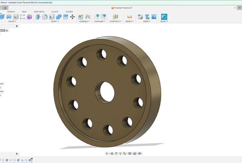
1. 3D CAD Design Designing a flywheel Introduction: Welcome to this product on how to design a flow using Fusion 360. During this class, we will cover various things such as sketching for design, extruding your design, and then patterning certain features as well. So you don't need to sketch every single one. We'll look at mirroring features as well, so that you don't need to draw things twice. And we'll look at adding an appearance to your final design. This is mainly a class for beginners or people who have never used Fusion 360. It's taken slowly step-by-step, so you can follow along and understand why things are done. The end of the class, you'll essentially have a grasp on the tools you've used and you will understand how to use them. Not only that, you'll understand why they used in a certain way, why we selected certain parameters and why this is best, but also other options as well. You know, there's not always one way to do things, but sometimes there are easier ways to do things. So that's what we learned from this project. I hope you enjoy it.
2. 3D CAD Design For Beginners Creating a New Component: In this lesson, we'll look at Sanger components and starting off your project correctly. You can just essentially dive into document and start designing. But really what you want to do is create component from the star and do your designing from their components are good because they essentially allow movement and rotation. And they had their own origin. Whereas bodies do not so highly accomplished folder before the body just there. And you cannot see, right-click and turn a body into a component. And this is all doing things backwards to some degree, far easier, in my opinion, to essentially start off by creating component and no way you're going. And then you can see copy that and edit design more easily. So I mean, a component can be anything. In this example, Floyd will be low. It could be the body of the frame bike. And then you can combine these components and create joints between them, which allow for rotation, movement, so on and so forth. With bodies, you can't do that. So that's why it's important to start off from the beginning and set you document up correctly. So the first thing you want to do is go to the top right here on the new Design tab and just left-click, you'll get an untitled document appear. So we've got this whole document and we can think of this as well. We store all of our components, is an assembly document compared to other software, is there more bottom-up? So you design each individual component and then you bring them all into one document. With this software is more top down, so you have one document and you design all the components within it. And you assemble them and create joints between them. So it's a little bit easier. In my opinion, I may not use both top-down and bottom-up softwares. And this is really nice because everything is in one place. It can get a bit messy if you're not careful. So you need to obviously keep non-linear design tree and nine things appropriately. But if you do that, you won't have any trouble. So if you right click where it says unsaved, you can then click on New Component. And you'll get a pop up. And we need to do is just name this components will left-click twice and we'll rename this flow amorphous. Okay? What you can see happens there is we get a new component creative. It becomes the active component as denoted by the slow black doll here and is empty. There's nothing going on in there at the moment, we've got some origin points that we talked about. We can also activate the whole assembly, which is the document as a whole that will be shown. If that were more components in there, they would all come together, that you'd see them all at once. So if we activate the floor well, I mean, yeah. You can then describe sketch. We can click the credit sketch tap just now. And we can hover over the z-x plane, this red-blue flying. And we can see on the cube up here, it says zed x. So you can just hover over that left-click. And then you can pass the center diameter circle, left-click, and drag out typing a 100 millimeters and press enter. You can then just finish that sketch. So that means you can say in this component, if you haven't done so already, you can open the flow component. We've now got sketch that we've just drawn. A nice contained within that component. So we can then copy this component and make more copies. Or we can create another component. And that could then be joined with our current point. Obviously want to extrude this out first, but he began to get the idea. So what we'll do is we'll delete this. Now. You just go flywheel. So I left-click on my sketch, I just press the delete key. So essentially go off flywheel or empty component. And in the next lesson, we'll start designing that.
3. CAD Desdign For Beginners Creating a Sketch And Extruding: So what you should have done is you should have created a new design and right-click and create a new component mass where we're at so far. So in this lesson, we're going to sketch the profile of our flow will, I'm going to extrude out. So if you remember, we deleted our sketch. If you haven't done so already, you can open up your sketch folder, left-click and the liter, we'll just start with a blank canvas essentially. So go up to create, sketch, left-click, and then honest zx plane, what we looked at last time, just hover over and you say it'll change color, the other two planes will remain orange. And you can just left-click the scream a little bit round. And then we'll get this origin point at the center here from which we can design. So if you hold down the central mouse scroll wheel, you can pan things about. And if you hold Shift and the scroll wheel, you can orbit the screen round. So to get back to a completely front view, we can come up to the View cube and we can hover over the front way until the whole of the front goes blue and just left-click. If we click on sense diameter circle, coming into the origin point and just hover over until you get that blue square around it, until it snaps into place. Left-click, drag out and type in a value of a 100 millimeters and present. If you change the document settings, you can act on the document settings folder, just left-click courses units, and then change the units and press OK. So you've got your 100 millimeter sketches there. If for example, you accidentally left click, if you drew it and you forgot to add the dimension, you accidently press enter or you won't change things around again. You can click on the sketch dimension tool, hover over, left-click, drag out, left-click again, and timestamp 12 you need and you press the Escape key, de-select everything. And if you double-click, you can type in a new value and press enter. So that's fine. We'll press Finish Sketch. And what we'll do is we'll left-click, left-click again and just name this too, 100 millimeter profile and press enter. So within our component, we've got a sketch and we have named it, so it is easier to identify. The next thing to do is come up to the extrude tool. And using this a lot is just a basic feature. Now, you've got a few options here. We can just extrude out or drag the ARRA there and shoot it out in one direction. And that's seen by this direction here. One solid. If you remember the star, we drew on this set x plane, and that is on this side here. And if we extrude in one direction, we are going to have that plane on the left-hand side and the extrusion to the right, you can just extrude, outlaw that. And that's actually defined. But advantage of extruding out symmetrically. Is it a postdoc plane in the middle? As important because it then means we don't need to construct another plane in the future. And it's just less tasks for the designer to do. It speeds things up for you. You don't need to mess around doing any actual work The otherwise wouldn't need to do. So what we'll do is we'll click on distance here, and we'll type in a value of ten millimeters. The operation will automatically default to new body. And we talked about bodies. So we'll have a look at that in just a moment. But you can press OK. And what that'll do is that plane. If we click on new scan, plane, is positioned right in the middle there. As you move around zx plane. I'll just cancel out, press escape. If I go to construct a planning, you need to do this. I'll just show you. We otherwise would have had to click and drag alone composition in this plane where we would have wanted it. Now, I know that's not much work, but when you don't need to do something, for example, drawing a feature 2-3 times is locally just a pattern that feature instead. So it's important to learn where you can obviously save time and how you can currently used features. Okay, so you've got about 100 millimeters profile. And if you look once we extruded that out, we did ten millimeters either side. 40 photos created so we can open that body and its name, body one. What we want to do is just name that flow will not makes it easier to identify if we have multiple components and we want to create a joint between them. When you hover over something you can select to highlight and you can more easily identify things if things are just named body one, body two, body three, it becomes a lot harder to identify and pick what you want. So that's not done. We'll move on to the next lesson.
4. 3D CAD Design For Beginners Creating a Hole: In this lesson, we'll look at creating a hole in our flow. Well, there's multiple ways you can do this. You can use the whole feature at the top here, or you can sketch the circle and extrude out. Most timeout recommend using the whole feature comes a lot of features and parameters that you can set. However, I want to show you how to extrude a circle initially first. And it's because I can then show you the extent feature and a few options around that. So start off, if we go to Create Sketch, we'll be presented with our planes and our origin point. So we're going to sketch on that set x plane again, this plane intersects in the middle here. You can scroll with the scroll wheel so you can more easily select that. Or we can go to the origin folder, open up, and then hover over that z-x plane and just left-click like that. And that will allow us to select and then sketch on that central plane. That plane is in the middle and cuts through flywheel object. Sadness is close up. This body soda, savvy bottleneck sketch here. What we'll do is we start by selecting the line tool. And you can either press X on the keyboard or you can just click construction line IS really up to you. And what we'll do is we'll zoom in. We're scrolling with the mouse scroll wheel and we'll hold it down and pan. Next, if you hover over this origin point, it will snap into place. You can left-click, drag upwards, keeping inverse food analytic off an angle like that. And we'll type in a value of 35%. Uh, so that's 35-millimeter slide and press on the keyboard all these left-click on the construction tool there to deselect it. Next, what we'll do is we'll select the sense diameter, circle and hover over this endpoint should snap into place. You'll get that blue square around it. Left-click and drag out. And taught me the value of ten millimeters present. You can click and drag to move these dimensions around. Okay. So we'll click Finish Sketch. Artist named the sketch, ten millimeter, center and museum aloe vera and our press Shift and the central scroll down to orbit round. So what we'll do is we'll click extrude. Now, initially it just wants to extrude them one direction. So who set the direction to symmetric? Because if you remember, on our original objective is this original extrusion. We're shooting to the left and to the right or the front and towards the bank. Now, when we say distance is now going to extrude to the right and left, just like that, or to the front and the back. And just select the extent. And what we're gonna do is we're going to select all the reason we've done that. And this is important because if I just clicked and dragged out and we just selected distance, the extents we typed in 60 millimeters, which is what this is that we dragged down just here. It means if we change. Original extrusion or profile. We selected it and extruded out to a 100 millimeters. The hole isn't gonna be a 100 millimeters, whether the whole will only be 60 millimeters deep. Whereas if I select, again, all for the extent, it will match whatever the extrusion is of this 100 millimeter per file. So if we extruded this out 200 millimeters, the hole was matched because the extent is actual wherever possible. In my opinion, you should do extend o when creating hole like this, because you won't need to go in and it thinks twice, it will automatically update and regenerate if you just change one feature. So as you can see, it's actually automatically selected our profile here for just deselect man. If you hover over a left-click on the front, you essentially select the whole foil, which is not what we want. We don't want to cut out the outflow goes. So just press X, dislike that. You got a couple of options. You can press shift and scroll on the mouse will, and you can hover your mouse in there and select a law that plus a little bit awkward is low but the next day. So we'll just dislike that. If you do the select things and you want to select again, you accidentally dislodge profile. You can just left-click drag and release, and it will select that sketch for you. They're in orbit around beholden shift and the mouse scroll down and you can see is essentially cutting the object to our thickness we require. So the operation is changed the cap, which is what we wanted. Hamlin just press OK. So I'll then generate our hole. You can see he should have something that looks like that. So obviously, like I said, where possible you do want to use a whole feature. But when creating a hole like this, make sure you select that extent feature or option because it means if we change the thickness of this extrusion, the hole will actually match. So we can actually do that and test that. So if we go down to the timeline and we hover over this first extrusion and we right-click and select Edit Feature. If we change the distance to 20 millimeters and press OK. You can see the thickness of the whole updates as well. So hopefully that gives you a better idea. So we'll get back to that. We'll right-click, left-click on edit feature and change the distance back to ten millimeters and press OK without fed at work here. So it's important to save everything. You can see the document is untitled and it says unsaved here at the top of the documents. If we just press Control S or you can come up and press the Save icon just there. And I'll just name this. As such. You can save in your desired location. I'm in click Cite. And now you can see why will the untitled document gets changed. The flow will video tutorial, and at the top here, the actual document itself gets changed. So this is actually the whole assemblies and could activate that we want to. But we'll get back to activate the flow will be through working on at the moment. Okay, so onto our next lesson.
5. 3D CAD Design For Beginners Creating A Circular Pattern: In this lesson, we'll look at creating a certain pattern to create a copy of this whole we've just drawn. So to do that, we can click on the Create dropdown of software. And we come way down to pattern and we can select circular pattern. Now, we've got a few different options here. It's saying what objects do you select? So at the moment we've got patent type satisfy faces. With a hole, there really is only one internal phase, so we can just select that. And it will highlight how the internal face of the whole just like that. And then we can select access. And you've got a few options here axis, you can either hover over Lisa who then wait till it goes black, just like that. And you can sight labs or axis. And you'll see we can regenerate the preview of three quantities, three instances, and just cancel out earlier. You can also select the axis here, this y-axis is green line. When we hover over, it turns blue. And now obviously be the center axis like that. And we'll just close nexus that will, we can open up the origin point arm. We can select the y-axis, just dial on it. So there's a few different ways you can select it for speed craft. And I just slightly out outside diameter of the circle and I, because this is something isn't gonna be changing. If of course it's an obscure shape, then quite often you probably just want to open up the origin folder and select the axis itself there in case the outside diameter changes. Okay, so you've got the axis selected. We can then adjust the quantity once you go everything selected as well as the object. And you can select the type foo, symmetric angles at EPA folks wanted to build around. It lives a patent. I can click on the drop-down. You see we can also select features. Quite often. I'll recommend where possible, always using the feature selection. Purely because when you come down to the timeline and you select that feature, in this case, we're selecting this just here and it's extrude. Sorry, we need to highlight over object, press select. Men, come down and select the outer that so you can see it's highlighted our whole where possible, or most of the time. This selects all the faces that we need. So we're not just selecting one face. If this had multiple faces, is this hole was way more complicated. It was countable. It will select everything that we need. Just three one-click. You don't need to revolve things around and select multiple faces. So just speeds up things when you're trying to create a certain pattern. Use this again in the next lesson or the lesson after that. And I'll show you, I mean, more clearly. So as I said, where hospital just use the features, toys for the object. We then selected that in the timeline itself axis, there's a few different ways like SAT, you can hover over the y axis there. Or we can just select the outside diameter, in this case, times the quantity. We'll just select them and leave the Compute option on it just so that we only press okay. And that's now patterned. Although circles around for slab, we can press control S to save and just click OK. And now as the circular pattern.
6. 3D CAD Design For Beginners Creating a Recess And Mirroring It: Ok, so you're making good progress. We're well on the way to finish it off this flow will we're going to do now is we're gonna create a and 90 millimeter recess. And then we're going to extrude it and will mirror it to the other solids. You don't need to actually draw it twice. And we'll talk about a few things I mentioned in the last lesson as well. So if we go up to create a sketch and left-click, inflict on the front, just navigate to bring things back round on just orbiting weather. What we'll do is instead of scattered on a plane and we're going to just sketch on a face, move the mouse cursor over the face of our fly wheel, and this is the front. We can see them from on YouTube. Just move the cursor over to the front of the face there and just left like this will bring things around. If I move around, you can see we are sketching on this front face. We're not sketching on a plane, intersects or anything like that. So I'll left click on the front of the VTA block that will come up to sense diameter circle, and hover over the origin point, it should snap into place. You get that blue square around it. Just left-click when it does track outwards. And either when it reaches 90 millimeters, you can just click or you can type in 90 millimeters presenter. And if you need to, you can all see just sketch dimension. If it's incorrect. Ok, let me go. So Finish Sketch. Left click and rename this sketch to 90 millimeter recess. And again, now, if we click on OK, screwed up here, and we hover over the internal diameter, not the external bit like that, but the internal and left click. You can see it'll now have our Profile Selected. We can left-click and drag the mouse on the arrow there. Or you can just type in a negative distance. So we'll type in minus five millimeters. And again, direction we want it to be one solids because we are drawing on one side of our object. So it's only going to be one side. If we change it to symmetric or two-sided, then there'll be a cut into nothing essentially. Okay, so we'll press OK. The operation we can't distance is minus five and the direction is one-sided. So press OK. As you can see, it's crates, the cup or the stove around. But on the other side it remains the same. So next what we want to do is want to mirror what we've just done here over to the other side. So okay, click on Create will come down to mirror. And mirror is asking us what objects do we want to patent? So like I said in the last lesson, we could select this face and then we could hold control. And we could select this face and we can mirror them over to the other side. However, a quick way to do that, I'll just clear that is where possible. I would recommend you click on features under the patent toys. And we can come down to our timeline and hover over that extrude that we did. Left-click and I'll select all the faces that we want to copy it to the quick way of selecting things. No, save you time. Next we click on the mirror plane, so we'll click the Select their scroll out on the scroll wheel to make it more easy to select. If you want to select that z-x plane just by hovering over it like that. If you don't want to do it that way, we can come up to the origin view. And we can just come down and select the z-x plane here. And if you look around, this is the plane intersects down the middle. So you can see from the star, that's why we extruded in one direction on the other. We don't need to get this moment in time, create another plane. We've saved ourselves a little bit of time instead of playing construct, setting it midway along our object. Obviously there will be times when you will have, this will where possible is you can say this is just saved us a bit of time using a bad logical thinking style, the design side, mirror plane, then we will select this set x plane y that it'll highlight. And if we orbit around, you can see actually generates a preview like that. So we know that we've got in the correct position. You can scroll by count and we'll press OK. So let's try that shift and the central mouse scroll wheel button. And that's mirrored over to the side, just what we want, perfect. Press control S to save. And until the next lesson.
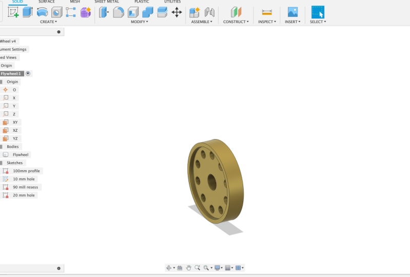
7. 3D CAD Design For Beginners Creating a 20mm Hole: In this lesson, we'll look at creating a 20 millimeter central hall so that this flow will be mounted on a shaft. So make sure you've got the flywheel is the active component. If you haven't already. We can go up to the top here and we can click the Create Sketch button. If you scroll down, you can select a plane on that. It will enlarge, makes it easier to select. So we can select that X, Z plane. If that's very difficult, we can open up the origin folder and we can select the x z plane just there. There we go. Scroll with the mouse wheel to zoom in. Quite often people work at distance. It makes it so much easier if you just scroll in MATLAB, we can press C on our keyboard or we can click the center diameter circle icon at the top there. Hover over the origin point. Left-click, drag out and type in a value of 20 millimeters and then press Enter on the keyboard. We can then come to the top and click Finish Sketch. Hamilton just left-click, left-click again and rename this sketch to 20 millimeter o. Now if you have a look, if you press Control and the center of mass will down, you can pan. And if you just press the central mass will down, you can get around as well. Sorry, press shift in the central mouse wheel down to Open. Now if we look withdrawn on that central plane now you can see intersect in the center. So we're gonna do is we're going to extrude this out. So press extrude the top left. And then it will say select the profile if you haven't selected it or it hasn't automatically selected, you can just left-click drag. And it will select a law that makes sure you've got Profile flipped in selected otherwise nothing will happen. So you want to change the direction to symmetric and we want to set the extent o. This means that if we change the thickness of the flow will, then this hole will match that as well. So we all around, we can see that. So this is obviously where the logical thinking of the star comes into place. We plan from the star to extrude out to both sides. That's why we've done the symmetric Extrusion here. And an extent, oh, so we're making it as easy as possible for ourselves. And then in the future, if we make any changes, we don't need to go changing every single feature they should update just when we make a change to one or two features. So I make sure the operation is cut and press ok. So that is your 20 millimeter Holden in the center there. And manage your flywheel basically complete Larson's do is just add an appearance. So what you can do is you open up the bodies folder and we can right-click and select the parents. You've got options at the top here you can apply an appearance to a body or component, or just the face. So the body or the component can be thought of as the whole component just here. So the appearance will get applauded tool of it. If we select faces, then it might only apply it to this front face here or this outer diameter face here. So it just depends. Walks all look, you're going for it, but we'll select bodies and components at the top here. Scroll down and we'll click metal again. We'll scroll down a bit more and that's just click on coatings. I don't usually left-click and drag across like that. You may need to download it if you haven't done so already. You can have a play around here. If you own an add any coatings, whatever you prefer, just to get a feel for. Locke said you may need to download some so we could do stainless brush, knee along, drag and apply that. And asked to be parents done, seek press close. Control S to save your progress and manage a fly will complete it. I hope you've enjoyed this.
 Harry Oliver, Learn 3D CAD Design