Transcripts
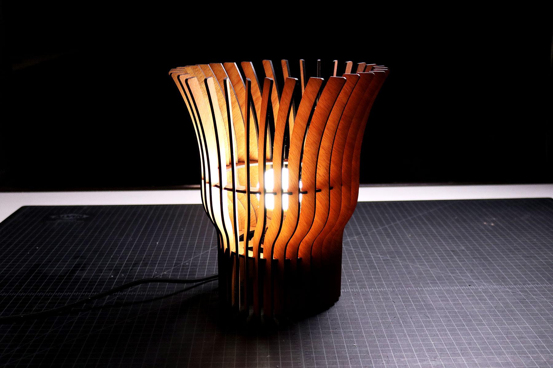
1. Introduction: There are projects like this
custom lamp that looked complex and very difficult for a beginning
craftsperson to make. What most people don't
know is that creating this lamp is a lot
easier than it seems. It's just made up of a handful
of simple components that come together to create
something beautiful and unique. The hardest part of designing a laser cut product like this one is coming
up with the idea of the overall form
that we could break down into elements like
a frame and panels. When you do it correctly, you end up with a product
that will make people stop, stare and wonder
how it was created. Hey, there, I'm
Tim and architect and your instructor for
this design course. I've been designing
custom products and using a laser
cutters since 2010. And I have a YouTube channel
where I share my process of creating unique
physical products and architecture projects. In this course, I'll
walk you through my process of creating a
custom laser cut lamp, beginning with hand sketching
and developing the idea. Then we'll go step-by-step
through the process of designing a product in a
computer aided design software, also known as cat. After that, we'll laser cut all the components and
assemble the final product. By the end of this course, you'll have an understanding
of the fundamentals of designing and creating a custom
lamp with a laser cutter. Let's get started.
2. Hand Sketching a Unique Idea: The first thing that I do
for every project has come up with a very basic
hand sketch of my idea. Before we jump into
hand sketching, I wanted to share something for anyone who might
be afraid of it. Even though I'm an
architect and designer, one of the skills
that I struggled to develop was sketching. I've always thought that my sketches look terrible and that no one would ever
see the beautiful image that I had in my head. I struggled with this
for a long time, but I eventually realized
that sketching is a form of brainstorming by capturing
thoughts onto paper. It's a way of problem-solving
and quickly refining ideas. That's it. No one ever needs to see it. And if the ideas that I sketch for a project don't
lead anywhere, I can just throw it away. With that in mind. Let's catch the idea
for this custom lamp. We'll start with a small
circle representing the light bulb
because we'll have to work around it in
the real-world. This identifies our
first design problems and constraints which we can figure out through sketching. Let me explain. First, we'll need to be able
to install a light bulb, which means we need
to have an opening somewhere for a
hand to fit into, screw it into a lamp days. I'm imagining this project as a table lamp with a light
bulb installed from the top. So we'll provide an
opening large enough for my hand and
light bulb to fit, which is about four
inches minimum. Second, the design
will need to provide a frame to hold the
light bulb in place. We'll be using a light
kit which has a base with a twist cap that secures
the base to a frame. We'll sketch a line to represent this frame that holds the
land-based and light bulb. The next design problem is blocking views of the
bright light bulb. This means we need to
have a shade component around a frame that
we're designing so that it could reflect the
light from the bulb into the space while
hiding it from view. To solve this problem, we'll design panels that
are installed at an angle around the perimeter of the
frame at regular intervals, these panels will be
slightly curved outwards, then they'll flare out
at a slight angle. Now, we need to securely
hold these panels in place. This means we need to provide another frame so that
the panels can attach it to points to keep the product rigid and structurally stable. With the rough sketch complete, we can move on to the next step, which is figuring
out the overall size of the different
components in his lamp. I'll see you in the next lesson.
3. Dimensioning the Hand Sketch: Now that we have our
rough ideas sketched out, it's time to add notes
to keep us organized. First, we'll not
the material and exact thickness that we're
using to build this lamp. I'll be using eighth
inch plywood, which I've measured
with digital calipers and noted in my sketch, will use this thickness to size slots and tabs
throughout the project. Next, we need to come up with the overall size and shape of all the
different components. I'm imagining this lamp
as a circular one, which means that the primary
frames needs to be a circle. One frame will have a cutout at the center where the lamp
phase will be attached and the other will be a
large circular ring to give the panels a
second of attachment. Overall size will be six inches
in width and there'll be notches at an angle around
the perimeter of the frames. The center cutout will be
roughly 1.5 inches wide, which I got from
measuring the lambaste. The last component
that we need to dimension is the width
and height of the panels. For this project, we'll
stick to a width of one inch or less and
a maximum height of eight inches when we're
designing this project and a CAD software will come up
with the final dimensions. Then the reason for this is that design changes as you start to come up with a
finite numbers. I'll show you when we get to
that step of this project. The next dimension that
we need to note are the notches around the
perimeter of the frames. All of the notches on
both of the frames and two panelists will be
a quarter of an inch deep. A width of all of them will match the thickness
of the plywood. With this sketch and
dimension is complete, it's time to move on to the
digital part of this project by designing it in a computer
aided design software, also known as CAD. This is the hardest part of this project, but don't worry, I'll walk you step-by-step
through the process of designing this in a
program called Rhinoceros. I'll see you in the next lesson.
4. Getting Started with Rhinoceros 7 (CAD): Every CAD program functions
in a very similar way. The one that I prefer to use for my product designs
is rhinoceros. But you can find other
programs that costs less and are able to
achieve similar results. Just keep in mind
that in some cases, the cost of a
program does affect the quality and performance
that you get from them. Using rhinoceros as an example, the way that the
user interface of CAD programs are set up
is that you generally have windows or ribbons
around the border with different functions that
you can click and use. Before we get to any commands, Let's make sure we're working
in the correct units. Most of these programs are
automatically set to metric, but if you're in
the USA like me, you'll want to type
units and press Enter. Here, a window will pop
up and we just need to find and switch the
different measurements from metric to imperial. Now let's go over other
important features of CAD software. There are two that
are important for this design project
and future ones. First, let's turn on Ortho Mode, which lets us easily draw shapes and lines at
specific angles. If we right-click on Ortho
and we go to set ortho angle. We can set the angle
to the one that we prefer to use for our project. I generally use 15 degree
increments for my projects and all other justice setting whenever I need to
work at smaller ones. So here I'll type
15 and press Enter. Second, there's the snap
feature which lets us a line, a new point that we're
drawing on a specific part of an existing object or shape
that we already drew. In all cats software, we should be able to
turn on different areas to snap our points
to such as end, near point, middle, center,
perpendicular, and others. That's all we need to know for the user interface and CAD
setup for this project. Now let's go over
some examples of how all these functions
come together. If we wanted to draw a line, we can look for
the line function under window and the left. Click it, go into
our user interface, click somewhere into screen, and start drawing a line. You can see that wherever I
move my mouse cursor or the second automatically snaps
to the 15 degree increments. Now we can either type an exact measurement and
left-click to draw the line, or we can eyeball
it and left-click. I prefer the former because
designing a product and CAD programs is about precision
and exact measurement. Now, let's design
by typing commands, which is my preferred way
of using CAD programs. First, let's type polyline. As I'm typing, you can see
that the command bar has multiple options popping
up and auto-filling. When I'm done typing, I press Enter and I'm ready to draw a series of
connected lines, which is what a polyline is. You can also do this with
other shapes like a circle. Now let me show you an
example of how the objects snapping will work with
the polyline command. I'll start at the midpoint of the line that we first drew. We can see on my mouse cursor is snapping to that center point. If I left-click,
it'll start drawing a polyline at that midpoint. Now I can move my
mouse cursor in any direction and typing the
exact dimension that I want, like one inch and
just left-click. We can continue drawing lines. And so we have a
shape that we want. There are hundreds of
commands in every CAD program that can be used together to
create beautiful designs. Instead of going
through all of them, I'll let you know
what command we're using to design
this custom lamps that you can follow along and the Zionist project
alongside of me. Now let's move on to the
next step where we'll start designing this custom
lamp in Rhinoceros.
5. Designing the Primary Frames: Design this custom lamp project. I'm going to walk you
through my entire process, but I'm also going to make sure that I show you any
of the mistakes that I make along the way just
so you can see how I'm thinking through the
resolution for those problems. So to start this project
and a top view here, I'm going to go over to the side by right-clicking and
holding down so I can pan and going to the right side here off of the grid just so
you can see what I'm doing. The first command I'm
going to use is circle. If I type Circle and I click
anywhere on the screen, I can start drawing a circle. I'm going to zoom
in a little bit. For this circle, we want the base plate of this
project to be six inches, which is what we
originally sketched out. Right now we're
drawing a radius, so I need to type three
inches and press Enter. Once I do that, I now have
a six inch diameter circle. With this, I'm going
to type circle again. And at the bottom I'm
going to make sure that centers is turned on
for the Object Snap. Once that's turned on, I'll hover over the line
of this circle that we just drew and it'll snap
to the center point of it. When I click, I
can start drawing another circle anywhere
that I want within there. So now that it's
drawing the circle, I'm going to type 0.75
because the diameter of the lamp based that
we're going to be using is about 1.5 inches in diameter. It's actually a
little bit larger, so I'm going to make this 0.76. And now we have the beginning of the base plate of this project. The next thing that
I'm going to do is cut out some voids because
I want to make sure that there's enough air is circulating through
to make sure that the entire lamp that we're designing get too
hot on the inside. To do that. I'm going to type line. I'm going to snap it
to the center point. I'm just going to draw a really long line down,
going to select it. Type M for move. Or you can type the
entire word, press Enter, click on the end point, and just move up in
your screen and make sure that your
ortho is turned on. So you're snapping to
an exact 90 vertically. I'm just going to make
sure that this line is overlapping that circle. And now that it is, I'm
going to click on it again and type offset
and press enter. By doing this, I can now offset this line to either
side of that circle. For this project, I
want to make sure that this offset will end up giving me about three-quarters of an inch to both sides of it. So I actually want it to be
three-eighths of an inch because I want the total to
be three-quarters of an inch. To do that, I'll type
three over eight. Go up to this command bar and where it says both
sides, I'll click on that. Now you can see that
it's going to offset that lines of both sides by
three-eighths of an inch. By looking at this, I really don't like how it's aligned to both
sides of the circle. So instead of doing it this way, I'll actually just
go with a quarter of an inch instead of
three-eighths of an inch. So let's see what
that looks like. That's too small. And this is where you can
start messing around with these different settings to see what the better
alternatives look like. Once you have one
that you really like, you can choose to
go with it and just left-click and it'll
end that command. So let's see what
One-half might look like. That looks a lot better to me. Now I'll go back into the screen and left-click and
it'll end neck command. Now we can delete
this center line that we're no longer using. The next thing I want to do is offset both of these circles. I'll start with this outer one. Offset. I'd like this one on the outside to go in
three-quarters of an inch. So I'll type three over four. Press Enter and click. I also want to offset
this center one, just so that we can have a
frame that goes around it. I'm going to type
offset, press Enter, and offset this one outward by three-quarters
of an inch as well. Now, I'm going to select these two lines
that we originally drew. Type mirror. Press Enter, and snap
to the center point. Once we snap to it
and left-click, I'm going to go at a 45-degree left-click again to end it. Now you can start to see the
different shapes that we could potentially
be cutting out in order to get this offset and to create a frame with
some voids in it, I'm going to select
all of these lines. So I trim and press Enter, zoom in and I'm going to just start by cleaning
up the outside. What trim lets you do
is it lets you cut lines that will end at the next line that
you've selected. It's wherever
they're overlapping or touching one another. So here you can see
as I'm trimming, is this trimming it to the
outer edge of the circle. Once that's done,
I'll zoom into here. And what we know is we need
to keep this center circle. So I'm just going to trim
everything else inside. Once I'm done here, I have to start deciding on this frame and what
it will look like. I'd like to frame to come from the outer ring inwards
towards this circle. I like how this is
looking right now. So I'm just going to keep
mimicking this throughout. Now if you start
to imagine this, we have an outer
ring for the frame, comes inwards this circle. In order for this
circle to sit here, we need to have a ring
that's around it as well. Which means we need to
eliminate these lines here. And now, when we laser cut this, what will end up being cut. So let's just end
this command by clicking outside
and pressing Enter. So now when we laser cut this, what we'll get is we'll
get an outer ring here. We'll get an inner ring here. And we'll have the outer ring
connect to that inner ring with this area here,
this area here. So now we have a good
start to the base frame. The next thing that
we need to start designing or all of the
cutouts along the exterior, which is where the
panels would go. We already know that the
mahogany plywood that we're using is 0.135 inches. So if we're going to have a
0.135 inch thick plywood, Let's start by
drawing a rectangle. I'll type polyline, press
Enter, click on the screen. And I want these insets to be about a quarter
of an inch deep. So I'll type one over four. Press Enter. And now I can
put that in any direction. For this, I'll just
draw it straight up. Actually, I'll draw
it straight down. Click, move over to the right. And this is where
we're going to draw the thickness of that cutout. So it's going to be 0.135. Press Enter, left-click, go back up one-quarter of an
inch. Left-click. And I actually don't want to end by closing off
that rectangle. I just want to end it
where it is right now. I'll just press
Enter and that'll complete that polyline command. Now let's select this
shape, type Move. Press Enter. Click on the center point of
that shorter line. Come to the center of the
circle and snap to center. The next thing I want
to do is I want to rotate this because we want the panelists to be
installed at a slight angle. I'm going to click on
that center point. Go straight up. Left-click again. And now you can start rotating this shape in any
direction that you want. For this project,
I'll probably go in at about a 30
degree, which is here. Now I'm going to type move. I'm going to move
this entire shape up to where it intersects with the edge
of that outer circle. You can see I'm just going
to end a little bit short. Tight move again. Click on this endpoint,
move it straight up. And where it's intersecting. I'll left-click. Now when I'm looking at this, I'm trying to decide in my
head whether or not that's enough space for the panel to come in and have
enough support. I think we should
actually move it so that this point is
touching the outer edge. So let's type move again on this end point and
move it straight down. And where it's intersecting, I'll left-click and
enter that command. Now you can see that this
line is a little too short to reach this here. So in order to fix that, we can click on that circle, type, extend, press enter. And then we can click on
the line that's too short. And what it'll do
is it'll extend this line to this one
that we've selected. And with that, we
have the beginning of the insets from the outside. Now when I'm looking at this, part of me is starting to think back to the
other option that was shorter because it will actually cut less out of this frame. And it will make
sure that this frame has a lot of rigidity to it. So I'm actually going
to hold control and undo it all by pressing Z. Going back to this option, I think this small
amount is just enough for us to work with when we
start inserting the panels. This is only here for us to
make sure that the panels are aligned and that they're
going inside of this cutout. So instead of extending, going to select this
cut out here and the circle by holding Shift
Left clicking on a circle. I can trim, pressing Enter. Now I can trim this line, and I can also trim this circle. And now that's looking
a lot better to me. So in this case we're almost there with
this entire design. There are two ways
we can do this, or multiple ways we can do this. Next step, we can select
that rectangle type mirror. We can snap to the center
and just start mirroring this around the entire circle wherever we wanted it to go. But instead of
doing it that way, we can actually select it and it easier way to go on
to left ribbon here. Come down to this array
function, left-click and hold. Go over. And you'll see that there's
one called polar array. If we select that, we can now select
them center point. And left-click here, we can tell it how
many items we want. I'm just going to start at 36 on seaward at where it ends
up in what it looks like. Press Enter. And here we can say that we
want this to go 360 degrees. So I'll just say 360. Press Enter. And you can see that it's
going to copy this around in a circle for that full
length of that circle. And it's going to
give me 36 of them. If I want to try
different quantities, I can come up here
to the command bar where it says Items. Click on that again and
typing 24 and pressing Enter. I can see we only
have 24 copies. We can keep doing this over
and over and over again. For me. And my project. I like this at 36 because I think this
will give us enough of the vertical panels to cover the light bulbs that we're not seeing it from the outside. But they're also
give this project enough wood so that the light is reflecting off of it and making this look really cool from
the outside looking in. So with that in mind,
I'm going to try one other option to see if it can be reduced to
maybe 30 or 32. I'll try 30 and see
what that looks like. 30 starting to look really good. I think 32 might be the number
that I'm going with here. Yes, 32 gives just enough
to get that cover. Now that I like it, I press
Enter and it's created. And the last step here for this frame is just
select everything here. Type trim, press Enter to zoom in and start
trimming the circle. Wherever it's in-between. These cutouts along
the perimeter. If you mess up anywhere
along the way, just hold Control and press
Z will undo that step. Okay, now that we're done
trimming all of them, press Enter and it'll end. And now we can select
everything here. And the last thing I like to do, because you can
see how everything is a separate line now. Because I like to
select everything here, type, Join, and press Enter. Now you can see how that quickly joined all of these
lines together. With that, we have the base
plate of this entire project. The next step is
going to be creating the support frame
that's going to be above this base plate. The support frame is
just in this project to help us add
some more rigidity to this design by
letting the panels attach the two points
instead of just one, which is all of
these points you're seeing on the perimeter
of this base plate. To do that, the easiest way that I've thought of as
the type circle. Snap to the center
of this point, draw it as three
inches radius. Again. Press Enter. Select both of them. Type, copy. Click, and just move across the screen and left-click
again to copy that over. Now we can delete that line
that we drew that circle over the first base plate that
we created and delete it. Now in this version here, the reason why we drew this circle is because
now we want to offset this three-quarters
of an inch inwards and then delete that outer line. And now you can see we quickly created that support
frame above. So this one will actually go above this one when we
start modeling it later. Now let's start designing the
last piece of this project, which is the vertical
panels that'll get installed onto both
of these frames.
6. Designing the Panels Pt.1: Design the panels
for this project. The first thing
I'm going to do is double-click top so that we can enlarge this viewport and have it take up
the entire screen. This will help us
stay focused as we're designing the panel
for this project. The next thing I'm
going to do is draw a reference line at the full height of the
panels so that we don't go past that 0.1 of the
things that I decided to do is actually make the total panel height
longer than eight inches, which is what I originally
had in my sketch. The reason for that
is that we need to hold the light bulb
above a table. If we're using this as
a table lamp and not have the chord underneath
it touching the table. I want to hold that up
about three inches. So ultimately, I decided to make this panel about
12 inches maximum. So now we're going to type a line so we can draw
that reference line, start anywhere on the screen and go straight down type 12. Press Enter. And you can see it's
drawing a 12 inch line. Now we're going to
use this just as a guide to help us
design the panel. Now let's start drawing some of the things that we already know. The first thing I'm going to
do is type line and sort out the endpoint here and go
straight up three inches. This is where the land-based
should be installed, which means that this
panel here will end up getting installed at about
this height right here. That means that the
curve that was in our original panel design has to start
somewhere above here. And the curve that we
had will curve outward, go back to a vertical and then flare out at the top.
So let's do that. I'm going to draw a line
from here that goes up two inches just to help us start figuring out where
things could be placed. I'm going to take this two
inch line that we just drew, type copy, like on
a base point here. And we're going to move
it out about an inch. Press Enter and left-click. Now we have this one-inch
line off to the side. The other thing I want
to do here is move this line up two inches. Now you can see we've got
this two-inch line here, this two-inch line here. What I would like
to do now is have the curves start here
at the base point of that first line that
we drew and come up and curves and connect
to this point right here. I have to do that. I'll draw a line, the
midpoint of this first one. Pull it out one inch. And now I'm going to go to the
ribbon on the left. Let's click and hold
over this curve and go over to the second one
for interpolating points. And now I'm just going
to experiment with a few different options to
see what kind of curve I can get and see how I can achieve what I wanted to
originally in my design. So I'll start this curve at the top of that
three inch line. And I'll see how it looks when I go to this midpoint here
and go to the left. So one of the things
that I don't like is how this line comes up and it curves inward
before it goes out. So I'm going to delete that. And now let's try the
first option here, which is control point curve. Let's see what this looks
like if we snapped that first up to that middle one. Go to this one here at the end
point of that second line. Go up to the midpoint of that. Press Enter. Now you can see this is
starting to look a lot better. It's starting to look just like the sketch that I
originally had. The one thing that I really
wanted to explore as well as if we copy this over and
made it a little bit wider. Let's go over another inch. Press Enter, copy
this line over. And now let's do the same
command at the same point here. And instead, let's
go up to this point. Up here. Go left, click on
this point here, and go up to the very end. Let's see what this looks like. This curve is looking
a lot better to me. It's a bit more dynamic. It's following the shape
that we wanted it to. And it goes out to the left. A lot more to this
curve really comes out. The other thing
we could do if we really wanted to is
you can start moving these control points to
adjust what that looks like. And you can get it to be more
specific to your design. For this project. For me, I really liked
this two-inch offset here. I think it adds a lot more
flair to the project. But this one here
will allow us to go up and flare back out without
using a lot of materials. So I'll actually go
with this first one. I'll delete the second version. And in this one here, I want that dynamic design that we
just had in the previous one. So I'm going to click this point and I'm going to drag it down. I'm going to do the same here, clicking this point,
dragging it straight up. Now you can see how it's
getting more of that curve from the other design that we just deleted where
it will come up, come over, come straight up. And now we're going to
select this curve and trim this bottom portion
of that vertical. And now what we have is
we have a point down here where as the
base of this curve, this will be where
this base plate gets installed and add this part
here, this vertical part. Since it's straight,
we can have this support peace get
installed here. And now we just need to
finish this design by creating that little curved
part up here that flares out. So to do that, I'll come over. Let's try a few options here. If I had it at four
inches, this is at three. This is at 22 is
a little subtle. Three might be good
with how about 2.5? I think it's between
2.53 for this design, just for that end flair
for this project. I'll go with 2.5. It's subtle enough
that it'll be really sleek and it will
really flow well here. So now with that, we just
need to finish this curve, which means we
need another point somewhere that we can snap to. Right now. If we type
distance and press enter, we can actually measure how far this end point is
from that line. More about five inches. I'll copy this down
halfway to 2.5. And now, if we go back to interpellate curve by
left clicking and holding, going to this second option
here to interpolate points. Looking at this end point, midpoint and the
top, this endpoint. You can see how it's
starting to flare out. Now, I want this to be a
little bit more dynamic. But let's see what this
ends up looking like. We pulled this up. I think
it is looking better, but I don't like
the little kink to part over here into shapes. Let's undo that by holding
Control and pressing Z. And let's try it with
the first option here, control point and curve. Let's see what this looks like. If we start at the same point. And instead of going to this center point does midpoint here, let's just go vertically
until we intersect it. And end all the way up
here. And pressing Enter. This is the second line we join. It's very subtle,
very subtle curve. It looks really
nice. It's sleek. Let's see what happens if we
start pulling this point. So I don't like at the
bottom here when it starts to go pass
that vertical line. So let's go straight up instead. Somewhere here. Now this line is
looking a lot better, so I'll delete the first one, which is this one I
have highlighted. Now, keep working with this until I like where it's going. I think this is subtle enough. But I actually like
the original option of using that same line that we just deleted control
point curve. And let's just get
it back to where it was by going vertically here. Looking at this end point, looking again, pressing Enter. And now let's delete all of
these other reference lines. Now this is our
shape right here. I'm going to highlight
all of them like I just did here. Type join. And now we have one
curve for all of this. Now we need to give this
panel some thickness. To do that, I'm going to
type offset the Press Enter. And I want these panels to be three-quarters of an inch thick. And we can decide to go
either inward or outward. For this project, I'll go
outward this way because you can see the curves work
a lot better this way. Click and then we're done.
7. Designing the Panels Pt.2: Now type line, press Enter, connect these bottom lines. Up here. We have
a choice to make. We can either end
this with a line connecting the ends this way or we can have a line
coming straight across. And then we can type
extend, press Enter, click the line we
want to extend to press Enter and click this
line here to extend it. And then use trim. Press enter, highlight everything here,
press enter, trim this. And now we can either go
with this first option here where we ended
with this shape, or we can go with
the option that we just designed where
it's a flat top. Personally, I like the
flat top a lot more, but I don't like
the sharper edge. To clean that up. I'll just go with a simple
circle by typing circle, left, clicking here, and just trying different dimensions until I get a shape that works
really well here. So let's try 18. Let's try 1 eighth of an inch. What about a quarter? I like an eighth of an inch.
Let's see if this works. Click that circle type move. Let's move it from this
midpoint, this corner. And now we can keep
moving this circle around until it's intersecting the shape where we want it to. I'm going to turn off the center snap so that we can just select the circles
by their points. Click on the point of its trade up where it snaps to this line. Type move again. The client is left
point, go left. And you can see that the bottom left of that circle is
starting to overlap here. So I'm going to zoom into it. Try and get it to
slightly overlap there. And now we're slightly overlap. So I'm going to type trim. And I'm going to trim
this line and this line. Press Enter, select
everything here on my screen. Type trim again. Now I'm going to
trim the circle. Press Enter, and now we
have a rounded corners so people don't walk by and
get caught on a sharp edge. And with that, we can select
everything here, type Join. And now the panel
shape is coming. Well, we need to do
is we need to create similar cutouts
that they can inset into all of these around the
perimeter of the circles. So now we're going to draw a
polyline by typing polyline. Clicking somewhere
on the screen. Going one-quarter of
an inch to the left. Going down the thickness of
the plywood that we're using, which is 0.135 inches. Clicking, going back to the
right quarter of an inch. Again, pressing Enter
so we don't have to end the entire shape. Now. We have that little
cut out for this. I'm going to type moved,
going to click on this bottom left edge of that rectangle all
the way down here, and snap it to the end point
of that bottom of the panel. Type move again. And let's move this upward. Three inches. See where we end up. You can see we're actually
starting where the curve is. So we want to move
this down a quarter of an inch or an eighth of an inch rather. So let's type move, move it
back up an eighth of an inch. And now we can move the
outside points all the way in. And now we have this cutout located and this is where this base plate is
going to get installed. The second thing we
want to do is copy this so that it is in this
area here at the midpoint. And personally, I want this
midpoint of this line, the midpoint of the vertical,
which is right here. Again. Click on this
point and pull it in. Let's collect and ended. Now we have these
two points here. This is going to be this frame, and this is going
to be this frame. One of the issues
I can see is that the frames are the
same diameter. What you can see here that
we actually went back. So we need to make one of the other frames one and
a quarter inches deeper. Just so that should
be one inch deeper. Let's see. We just need to make
it one inch deeper so that this frame gets larger. And it will actually attach. Right here. So let's
keep that in mind. Let's delete this
line I just drew. Select everything
here, type trim, click the line between
cut-out that we just made. And the command. Select everything
here, type joined. Now we have the panel
design completed, but now we need to refine this one here, this upper frame. So to do that, we're going to click on this
outer portion, type explode. Hold Control on the keyboard, and left-click and drag
over one of these joints. I'm going to choose
that center middle one. Press Delete to delete
everything that's highlighted. Let's select all of those
lines to type Join. Now, I want you to type circle
to create another circle. And this time we need to turn on center because we
turned it off before. Snap to the center
point of this circle. Now let's pull this out. We need it to be one inch wider, which means that we need
it to be 3.5 inches. And dad, let's just double-check
by typing distance. If we go from this
end point to here, it should be seven. There it is seven inches. So with that done,
let's select this. Cut out here. Tight move on this point, straight up where it
hits the circle ended. And you can see we're
actually a little bit shorter because the
circle is larger. Select this circle type extend like on a line
that's a little bit off. And I will extend it there. Select both shapes, type, trim, Enter, and trim the
line in between them. And now we can go
back in the left, the ribbon to array, go to polar array. Find that center point. Click. We want 32 items, which is already preset so that we can match
all of these here. Press enter, and we want it to be around 360 degrees
so we can type 360, press Enter, and
press Enter again. And now we can delete this. We can trim all of the
lines between them. But before we do that, I just wanted to double-check that these are all
going to line up. So I'm going to copy this outer shape by clicking
it and typing copy, snapping to the center point. Snapping to this center point. Now let's just make sure that if we start at
any line from here, that they're going to line up, you can see the edges
of these all lining up. So it's looking good to me. But the one thing I'm
a little concerned with is that ideally, we'd have this point here aligned with this
corner point here. And that's not happening. Let's see why that's the case. Draw a line straight
up vertically. You can see where a
little bit off here. I think we're actually fine because all of these
should technically align. And so right now, I think we're, I
think we're good, but one of the things we'll
figure out is whether or not this is actually
working when we create a 3D model
of this project. Once delete this
copy that I made, I'm going to select
all of these lines. And before I do anything, I want to offset
this by one inch for the frame or not one inch. But let's see, Let's see
what will work here. If we draw a circle again, the center point at three
points In five inches. Select it and offset that inward by three-quarters
of an inch. So we have that frame thickness
that we originally had. Flick. And now delete this,
delete that one. And if we select everything
here with you now, trim just like we did
with the first circle. And then after this step, we'll be ready to try
creating a 3D model to make sure that everything's actually lining up the
way that we want it to. Now that we're done,
press Enter type of join. And it will pull
everything into one curve. And now we have our two-dimensional design
complete for this project. So let's move into
that next step of creating a 3D model
of this project.
8. 3D Modeling and Refining the Design: One of the things
that I like to do at this point with all of
my projects is created 3D models so that I can
see if all of the pieces that we just designed will
come together as intended. To do that, I'm going to
double-click on top so that I go into all of
these different viewports. I'm going to select
all the pieces in this perspective view
and type extrude. See RV, press Enter. And you'll see it's extruding the shape to any
depth that I want. For this project,
we're using plywood and minus 0.135 inches. I'm going to type that
in and press Enter. So now we have all of the
pieces extruded to that depth. One of the things we
need to do now is rotate this panels
that it's vertical. To do that, I'm going to
go into this right view, zoom all the way out. Zoom into where the
pieces and type rotate. Press Enter. Click
on that piece, go all the way to the right. Click. Go all the way up, click again. And now you can see I just
rotated it vertically. Now I want to make sure
that this point of this cutout is going to align
with this base plate here. So I'm going to
type move the zoom into that cutout,
take a corner of it, zoom into this 3D model of this Facebook and just put
it in any one of these that I think it's close to matching and snap it to the corner point
where it should be. Now I'm going to go
into this top view. Zoom in, hype, rotate. Select that point
that's intersecting. Select the opposite
side of that piece of the panel and
rotate it into place. And now you can see we
have the start of this. So now we just
need to rotate and duplicate this around
the entire circle. To do that, I'll go
back to the top view, go into that polar
array command and the bar on the left
side here, selected. Find that center point. Click. And you can see
everything's already pre-set up in the command bar. 32 items, press enter, 360 degrees, press Enter. And you can see it here before you even
complete the command. And if it looks right,
press Enter again. Now you can see it's
actually going into all of the cutouts that we have. And if we go into a
perspective view, you can see what it looks like. Now we need to just move this
frame into these points. And I still think that there's something wrong with this frame, but we'll find out
in the next step. Now we go into this, the
top view, tight mode. Find the center point, click, find the center point
of this base frame. Like again. Then now we can go into
this perspective view. And you can see we're actually too low to just move it up. Now let's go into this front view here where you can see some
of these cutouts. And let's try and move
this up just enough. I think it's at
about 3.5 inches. Press Enter and click
were very close. Let's go up just a
little bit more. Might be a 16th of an inch.
Down just a little bit. There we go. Now. Just by a little bit. I think I snapped it to a point that was a
little bit off here. Let's undo that. In any event, you can see
here that our frame for the support piece here
is actually too small. It's not going all
the way through. We're actually ended in
short of this piece here. So we need to enlarge this. And we also are at
the wrong angle because the angle of these cutouts are not
matching the angles up here. In this next step
here to resolve this, I'll show you a trick that's
really cool in Rhino. And I don't know if this is
another CAD software is, but if they have
Boolean functions, you'll see how it works
here and maybe you can replicate it and in any other software that
you might be using. So let's delete this piece here. Go back to a top
view, come over here. And this is the frame
that we'd have to update. And what I'll do here is
I'm going to draw a circle, snap it to the
center point here, and pull it out so
that it's a half of an inch wider than
this is right now, I think this was at 3.5. So if I type that in C and
we actually need this to be 3.75 so that it includes
that quarter-inch cutout. Press Enter, come
here and select this and just delete
this shape for now. Type offset. And now we want to offset this inner circle by quarter of an inch as
wells that we still have that perfect
three-quarters of an inch width for
the frame here. We can delete this,
enter one, select. Both of these circles, go into this
multi-perspective view. And then type extrude
and pull this up 0.135. Once we are done. We can select this
circle and move this circle so that
the center point, the center point here. And now what we need to do
is somehow figure out how we can snap this circle exactly to where it needs
to be here to align into the youth that I'll
go into this top view, look for the panel and draw a line so that we know
where we're trying to go. So this is where we need to
move that new piece suit. So the distance from here
to here is 3.558 inches. So let's go into this
right to view move. And I actually think
we're a little bit above that other piece. So we just want to make
sure that we are perfectly aligned with it,
which we are not. So let's move this circle out. Let's catch the center of it. Let's go here, catch the center
point of this shape here. And now I think we're
perfectly overlapped. Now we need to move
this up 3.558 inches. Left-click. And now we're perfectly in this area with
all the cutouts. So now that that's there, Let's go back to
this perspective. You have that circle selected, type, boolean,
difference. Press Enter. And now let's select
all of the panels. And what this is doing
is it's going to cut out these panels from this circular shape wherever
they're intersecting. So select all the panels, press. And up here where it says delete input before we press Enter, just make sure it says no. Usually it says yes. We don't want to
delete the panels. So just make sure it
says no. Press Enter. And now you can see I've cut out all of those
little parts for us. So now we know where it needs to go and what angle at that. Now let's go into a top view. Let's pull this out. Let's move this so that the center is
where it needs to be. Let's move this out. And one of the things
we can actually do, I'll show you this
other step type moving in. Let's pull this away. And now let's type make
to the press Enter. And in this here, let's
make sure that view is a top projection is a view from input objects, hidden lines, all of
these options here. And now hit Enter
and we can hit Okay. Now what that did
was it actually took that shape and made a
two-dimensional version of it. If we move this over here, what I'll do is I'll take type explode just so we can
see how many lines we have. We don't want too
many lines here. One group. Now we can see we have exactly
what we need here. Okay, Let's join all
of this back together. Tight moved, and let's
just double-check one more time. Take
the center point. The center points here, sizes are exactly
where we need them. They're exactly the right size. And now we can undo, hold Control and press Z. We can delete this here that
we use to get this shape. That belief, this 3D model, select all of these lines. Once this top view perspective
type extrude, CRP. Let's pull this up. 1.1350, entered. Select it, and now
let's move this so that we are exactly
where we need it to be. Which would be right here. Now if we go around and just
double-check some spots, you can see this is the frame. By clicking it, you can
see it highlighted. This is the panel. If you hold shift
and click both, you can see where they're connecting. And this is perfect. This is exactly where
we want it to be. And the base is perfectly where
we want it to be as well. So now we know we have the entire project
designed properly. I'm just going to select
all the 3D components by left clicking and holding, dragging over only the 3D parts. Going up to here, holding shift and
just left clicking the last piece of going to
a top view and moving this, that it's off of my
two-dimensional shapes. I'm going to select this one
here that we just created. Move it close to the other one, and just go to the properties. Switch this to by layer. The layer of this
will be layer three, just so that it matches. So now we have all
the components and we know we need 32 of these. And we know that we need one
of each of these frames. So now I'm going to show you
in the next step how I take these two-dimensional
components and lay them out so
that we can laser cut them in our laser cutter.
9. Laser Cut Sheet Setup: To set up these pieces
for laser cutting. The first thing that
I always do is I draw a rectangular boundary
that represents the maximum cutting size
of my laser cutter. I'm using a glow Forge, so mine is about 19 inches
wide by 11 inches tall. So let me start by
typing polyline, coming to a, an area down here, starting a point in saying 19 inches wide by
11 inches tall, 19 inches over to the left, and ending this rectangle. Now that we're done here, the first thing I'll
do is I'll copy all of this down to the side. The reason for that is I
always want to file that has all of these
pieces somewhere in it so I can come back to
it if I ever need to have the original design down here, we might end up moving pieces
around or trimming them, or having them go side-by-side and just trimming
the excess lines. So with that, I'll move this
frame over and put it on as cutting sheet here over it into place through the same
thing with this one here. Now the other thing I
started to notice is that I think there's other the
design of this project. This might actually fit
within this shape here. And it does. And so
what I'm going to do here is I'm going to take this one
here and undo that. And what I'll
actually do is I'll explode these lines out here. And I'll delete all of the
ones in-between the cutouts. Just that we don't have two different lines cutting
two different times. So when I delete this, you'll see what I
mean when I move this shape back on that circle. Right now these lines
that I'm deleting are the same diameter as
this circle here. So they'll just end up
overlapping and cutting twice. And we're done here.
Select everything here. Join again. Move. Go to the center point, snap to the center
point of this circle. Click. And now what this will do
is it'll save up material. It'll save us a lot of material, but it will also make
this project a lot more efficient while
cutting because it'll cut down on the cutting time. It won't cut this shape out twice or just
cut it out once. Now, I really love doing this because
it's all about trying to conserve the amount of material that cutting
for every project, but also speeding it up
and making it faster. Now we can select all of this, move it onto this cutting sheet, make sure it fits
when within it. I'm going to copy this down. We need a second one. Put it down here. And let's move this shape
here and see how it fits. So you can see it's too
long to fit vertically because we're at 12 inches
and this needs to be at 11. So instead, we'll
rotate it, rotate. Let's go at 90 degrees. Now, we can probably
fit this down here. The other thing I want to
do is copy it down here as well and see if this
actually fits side. So if we just copy
this trait down, can we actually get these two shapes to
fit within each other? Nice and snug way just to save some more
material here too. Let's move this up. Let's see what this looks like. I don't want to risk having
these two overlapping. And I don't want this piece here to slightly cut
into the next one. So I'm actually
going to move this back down just a little bit. Something like this. Now we need 32 of these. So this might not give me
the best layout initiates. Let me rotate this. 45 degrees will help. Now, let's rotate
this 30 degrees. And now, what if we went
something like this? Oh, that's pretty close. Okay, Let's go ten degrees. This might help us save
a lot of material here. So with this, now we can select this second
shape I've copied. Now that we know that
this spacing is working, and then copy it from here. And now we can see
there's an issue here because we need these
to a line across the top. That means we need
to move this piece. Draw a line across
here just as a guide. Select the piece
we're trying to move. And let's find a spot
that works for it. I think that works right there. Okay, select the second
piece and now we can go back to copying
it over a few times. Hey, we're so close to
fitting this one here. So let's delete that last one. Let's bring this down
to this sheet here. Move this over to here. Let's continue copying lists. You can see we're actually
going out a little bit. So I wonder if we can optimize
this a little bit more. Let's try one more time. So we took all of these,
they're going to get them. Let's rotate this shape so
that these points here. Let's turn off my
ortho and object snap, and let's just try and eyeball the best way of
putting this on here. I think that works pretty well. And now for your turn off
auto and object, snap again. We can copy this. Let's see if this works. Looks like it
worked pretty well. Let's move this
over just a little bit so that they're
not overlapping. And now let's copy this over. Now we have 34567891011. Here we have three, 4567, we have 711, so that's 18. We're going to need
there's 11 here, 2222 plus seven. So we need two sheets
less typed text, just so we can keep
track of this. So we need two sheets of this. We need one sheet. Now, let's copy this down. And I think we only
need one sheet. Here. If we have this, that's
22 plus seven is 28, then we only need four. So that means that we can
go with those four. Okay? So with this, can
delete these lines. And now we can come here
and just type export. You can export this as whatever file type
you want to use. You can either go
with an SVG file type or you can go with
any of these here. Generally for me, I'll go with the Adobe Illustrator file. I'll go into Adobe Illustrator. And then as you can see, I have a different
project saved here. Once I save this as
an Illustrator file, I open it there and I
just reorganize it on a sheet in Illustrator
and export it as a PDF. So I'll show you that step two, let me just finish
exporting this now. Alright, so here in
Adobe Illustrator, and when I opened a file, the first thing I'll
do is I'll zoom out, go to Document Setup,
Edit, art boards. And for my purposes, I know I have four sheets, so I'll just hold Alt, left-click and drag to
copy and hold Shift so that I can just go either
left or right or up and down. And all the copies, I have
four of these ports. Now. I'll hold Control and press a. It selects everything that
we're not seeing here. Now press 0, and then I'll go with a minus sign on the
keyboard so I can zoom out. You can see all
of the pieces are off to the side
here, which is fine, or pull it over,
drop it in here, put it on the side, and zoom in. And now the first thing that I realized is that I didn't
size these boards. So let me show you
how I would do that. On the very top of the screen. Click on Document
Setup, Edit, Artboard. And let's delete
these three beers. We want to make sure that all
of these are the same size. Hold Control and press
R to turn on the ruler. This is my ruler here. Right-click on any of the
rulers and go to inches. So now everything is in inches. The width type in. I think my plywood is
actually 18.2 inches wide. So I'll just put it at 18
for the height, I'll say 11. And now we can copy this down that we have for those
can come over to here. And now we can start
organizing the sheets. Let me come here. Let me just bump these up to 19. I think I have some wider
sheets of plywood somewhere. If I don't have enough plywood, I can always cut these on
some scrap pieces somewhere. And now we have our name. We have our boards setup, and we just need to move. All of this is that
they're all on the board. Now, this one is set up. All of the pieces are almost on a board where a
little bit off down here. Let's move this up so that we are on the board and you can tell because you can see
this border on the outside. Just make sure you don't
do this and re-size it because if you do anything like this, you'll mess it up. And you can see while I was
doing that actually didn't select all of the pieces here. So what we need to undo
everything we just did there. And now make sure you
select everything here. And then now we can
move everything on. Here is the first part. Now for the second one,
we do the same thing. Everything on here. That's good. These are the
last four pieces we need. We can move them to
this last sheet here. And we need to boards with
this exact same setup here. And with that, we now have our
entire laser sheets setup. And we're ready to start
laser cutting this project. So I'll see you in the next step where
I'll show you all of the materials that I'm using
to make this custom lamp. And I'll walk you
through my process of laser cutting and
assembling this project. I'll see you in that next step.
10. Laser Cutting and Assembling: I gathered my materials
including mahogany plywood, protective paper masking tape, plastic card, utility knife, superglue light fixture
kit and LED light bulb. I apply the paper masking
tape to the plywood to protect it from scorching
and burns from the laser. I placed the plywood into my glow Forge laser
cutter and start the process of cutting
and engraving. While I was laser
cutting this project, I thought of two ways I
could have made this project more efficient with
materials and time. The first is to reduce the height of the
panels so I could fit more onto one sheet of plywood
within my laser cutter. The second is that I could buy a laser cutter with a larger
maximum cutting area. From beginning to end. It took roughly 50 minutes to laser cut every piece
of this table lamp. While I was waiting, I just watched the laser and
action because it gives me a similar feeling to sitting
and staring at a campfire, seeing the laser cutting
something we just designed as precisely as this makes
it seem like magic. When the pieces were cut, I took them out of my glow Forge and placed them
on my work table. I remove the paper
masking tape from the plywood to reveal the
beautiful mahogany plywood. Then I use a lint free cloth and rubbing oil to finish the
surfaces of the plywood. This brings up the
grains of the wood, darkens it and makes it shine while also
protecting the surface. Next, I apply Mexico here superglue to the tabs at the
slots of the perimeters of the frames aligned as lots of one panel with each frame
and push it into place. Repeating this process gets easier as more panels
are installed, instead of applying superglue
only in the next slide, I apply it in a handful of them, bring over the panels
and install each one. They click into
place when they're aligned and properly installed. Once the glue dries, I turned a table lamp upright, bring over the
lamp fixture base, inserted through the center, cut out of the bottom frame, and twist the cap to
lock it into place. To finish up this project, we installed a light
bulb and turn it on. Now, this custom table
lamp is complete. What I love most about
this project is how the repetitive
panels look a little different based on the
angle of the light, the location we're
viewing it from, the shadows that are
cast on its surface. And that is how we laser cut and assemble this custom
laser cut and lab. I'll see you in the final lesson of
this Skillshare course.
11. Conclusion: I hope you enjoyed
this course on designing and making a
custom laser cut lamp. We covered the basics of coming
up with a unique design, refining our design through
sketching, designing, and a CAD program, laser cutting and
assembling this product. These are all difficult
skills to learn. And the biggest advice
that I have is to open your preferred CAD software every day with a product in mind and just
start designing. It takes a lot of
patience, practice, and endless Google or YouTube searches to find your preferred
process of designing. Remember to follow me
here on Skillshare, where I'll be sharing
my design process for more laser cut and
architecture projects. Thanks for taking
this course and have a fun time creating
something unique.
 Tim Ung, Architect | Designer | Maker