Transcripts
1. INTRO: In this video, I'll be showing those that have never
use Grasshopper before in our
intimidated and think that it's a little bit
scary how to use it. I'm going to be going over the super basic scripts and showing you the power of
parametric architecture and how it can be a super powerful
tool for designing and to see all of your options when you're
creating 3D models. Hopefully you find this
useful if you see anything or have any questions that are very critical to this
tutorial, let me know. This is something I
want to build upon and share with other people
and get them started so they can become familiar with the process of parametric
design and architecture.
2. HOW TO GET STARTED: So to start, I want to talk about the fact that
the more knowledge you have instead of bright now in terms of
modelling or drafting, the better you
will be instead of grasshopper in the sense that all of the things
that you see here, like the creating a line, creating a circle, a rectangle. All of these things
are available inside of grasshopper also. But if you don't know how to
use them instead of Rhino, it's a little bit trickier to understand how to get them to function
instead of grasshopper. But that doesn't mean that you can't kind of play around
instead of grasshopper and see and learn new things that then you can
translate into right now. So it kinda goes both ways in the sense that one
thing that you learned in one side kind of helps you
understand the modeling. 3d modeling in general
a little bit better.
3. TRANSLATING RHINO KNOWLEDGE: To start the example
I'm going to use as creating a rectangle
instead of rhino, showing you how to do that
inside of grasshopper. That way you understand
how it works. 11 instead of rhino and then the other one
instead of grasshopper. Let's say you want to create a rectangle here
instead of right now. There are two ways to do that. You can first type in
a command rectangle. You can click on a button. That is the rectangle. So basically any command
or any button that you, it is going to do an operation whether
it's rectangle points, circle, we're going to
this time do a rectangle. So I'll click here
on this button. Now that I've clicked, notice that first thing that we
do is click on the button. That's the first command, is find the button and the
command that you want. Then it's going to ask you, first, a corner of a rectangle. That's going to be the
first operation is where it's going to be located. Now we can either
click somewhere here or type-in here at the top, 0 comma 0. Let's do that here. You could do 0 Enter and it'll do it at the origin
or 0 comma 0, comma 0, which is going
to be the origin point. Because technically we have
here a coordinate system, x, y, and z. And so we're now going
to do other corner lane. So that's going to be the x. Here. We can just say 30. Now it's going to ask width. Now we can plug in the
next command, which is 30. Basically we've created a 30 by 30 rectangle at
the origin point. This is fairly basic, but the output of
what we have from the set of steps that we created was a rectangle
that is the output. Now we can't really
change the size because we've just clicked and gone through
liquor linear process. So we are now going to be aware of
the steps that we took, which is clicked the button. Now set the origin point and then the length
and the width. And we're gonna be
doing that the same thing inside of grasshopper. I'll take this and
I'll use the gumball. If you don't have that
on, click on this. And you'll be able to drag that arrow to move
this to the side. Now we can go into
grasshopper mode. Let me show you how to
create this rectangle. Here instead of grasshopper.
4. PARAMETRIC DESIGN BASICS: To open up grasshopper, go inside of rhino and on the command bar type
in Grasshopper. Or you can go to this button here that launches grasshopper. Once you do that,
you'll see a file and there will be some default
files for you to open. Go ahead and go to
file new documents and you'll see
something like this. Now as you can see, we
basically have a open space, but this is different than what we see instead
of right now, we don't have a coordinate
system inside of grasshopper. All we have is this blank space. But this is going to function
as the logic of this. The buttons and the
icons that you see here, they're going to be
created here. This way. It can be created
parametrically. First thing that we do in
the same way that we did it in here in Rhino is we
want to double-click. And this is the way that you
basically type in a command. In Rhino, when you type in a
command or click a button, the way to do that here is double-clicking on
the blank space. Now we can type in rectangle. I can bring in this
rectangle components. I can go in here
and cycle through the different tabs which
are going to give us different aspects of geometries and different transformations
thinks that we could do. We want to look for
a curve primitive. We want to look for rectangle. In the same way that
inside of rhino, we can look for
icon and click it. Or we can type in the command. You can double-click
type the command or go into the tab of, let's say a curve. So two-dimensional
curve primitive, which means that
it's going to be the basics and a rectangle, which is going to
be this component. Now there are different
ways to view a component. First way to view
it is going to be, I'm going to disable
all of these. And you'll see that the component just
says the name and has one letter or the inputs and
one letter for the output. This is okay. Sometimes
it's necessary. But me and in my opinion, the best way to display it, it's going to be enabling
all of the the icons, fancy wires, and full names. This way you can actually see the icon of what you're doing. And you can actually have a
little bit more information for the input and the output. Now that we have
this component here, notice that we have these little inputs
and these outputs, and that's the same
thing that we have. When we click on an icon here we have inputs which is
going to be the plane. This is the location base plane. That's going to ask us, where do we want to place it? Now, grasshopper, by
default, for the most part, will give you a default plane is the x-y coordinate system, which is the same thing as this coordinate system that
we have instead of Rhino. So the x and y are going to be the same that
are plugged in here. Now we can change that. We can bring in an x, z plane instead of grasshopper
and change the plane. But by default it
will put it here. Now we want to change the size. Now remember that for this
rectangle, we did 3030. So let's do that here. Now to plug in inputs, we can either right-click on that set domain and
change the size, or we can bring in a slider. Now a slider is really important here for
parametric design. And that's because
this will give us a range of numbers
that we can change. So if we have x
and y, we want to, let's say, plugin in the
x 30 and then the y. We also want to plug in 30. So this is where I'll
double-click here. And to basically
bringing a slider, we can just plug in the
number that we want. So let's say 30. It'll give me a Slater of 30. Just notice that when you
double-click the slider, it'll say the
minimum number is 0, the maximum number is 100. It's going to set it at 30. Now what I'm going to do is plug that into both the x and y. Notice that we've basically recreated that rectangle here. Instead of grasshopper. The only thing that is
different is the fact that when you select
this, it turns green. And when you try to go
to our Rhino file and we look in the viewport
and I tried to select this as hard as I can
and I cannot select it. This is because when you created it parametrically
inside of grasshopper, technically not
an object that is completed in the sense
that it can always change. So think of it as clay. Can be molded until
it's baked in. Once you've baked it, it'll actually turn it
into the form that it's supposed to be where it
won't be able to move. This is the same
thing that we do in here instead of grasshopper. Well, let's say I have
a size of 25 rectangle. I can click this middle click
or right-click and bake. Then it's going to ask me which layer do I
want to put it in? I'll just put it in
the default layer. And you'll see that now I can actually click it and move it. And that's what the
power of grasshopper is, is that you can bake iteration. So now I can just move this
around and then bake it, and then move this
around and bake it and just have iterations of different options
just by moving a slider. That gets you started
with how grasshopper works in the sense
that we're going to, I just wanted to show you
our components are brought in how components work
in relation to Rhino. And from here there's a
lot more to be learned in the sense that there's a
lot of different components. There's a lot of different
ways to create numbers. But this is getting your feet
wet and kind of getting, not getting scared and being afraid and intimidated
by parametric design. Because in my
opinion, it's one of the most powerful tools
that anyone can use. So hopefully you
found that useful and I'll see you
on the next video.
5. BASICS CONTINUED: Going further with
this exercise, let me show you the next
and the next thing is, and the other things that
we can do with this, now that we have brought it in, we have giving it
an x and y size. Now let's change the inputs rather than just one
input for the x and y. Let's copy this slider and
create a different white size. So you can take this slider, control C and control
V to create a copy. You can also drag this down here and then tap Alt or Option. If you're on a Mac, in this way you get two sliders. And we can now plug that
into the why and have two different dimensions
for the x and y. You can also change the maximum and
minimum if you want to limit the size to
a specific amount. But now that we've
created the size of this, let's change the
name on the slider so we know what this does. Now that we have
this lighter if 35, we know that the x size. So we can right-click on top
of that and change the name. So we can type in x size. I use caps, but it's just
a personal preference. Go here to y size. The other thing you're
going to see is that when you bring
in components, don't have to use
all of the inputs, but there are some critical
inputs that you need to use for the component
to work correctly. So what I do is for this one, it gives you a plane
world x and y, but we can change that location. So let's say you have
a plain x and y and we want to move it to x 70. This is where it
will create a point. So I'll double-click here
and go to Create point. Where we can go to construct. This way. It's going to create a point, but it's going to ask us
to input the x, y, and z. We know that we want to move this in the x-direction.
This is important. Very important is to be aware
of your coordinate system. So this is positive x, this is positive y. So we want to move it
in the positive x. This is where we'll take
a slider, will it here. So we'll double-click here. I can go to 70 and
plug that into the x. And as you can see, it creates
a point at that location. Now, we can plug in that
point into the plane and see that we've successfully
moved it in the x-direction. Now if I plug in both x and y, you'll see that it will
actually move diagonally, because when you have x and y, it's actually a slope. In the same way
that if you do a Z, it's actually moving it
up in that direction. So this is how you can
change the location of this plane by changing the
inputs of its location. Now, this point,
we move it here. But it says x, y plane. Why don't we change it
to a plane that is x, z. If I double-click
here and bringing a component x z plane will see that this component has one input and one output. And the input is going
to be the origin point, which is a point that
we created up here. Now I create a plane in this plane can be plugged
into this plane output. Now, notice that it
actually creates it. I'm not on the ground or relative to this x and
y coordinate system. Now it's actually created it off of the x and z
coordinate system, which is a component. So every component, we can
now use this component, which is the reference plane, and use that as the input. So just wanted to show
you some of those aspects of basically referencing
multiple lanes and changing the
location of that. So at this point,
what we've done is changed the origin point. We can unplug components, inputs and outputs by bringing this back out and
holding down Control. And you'll see a negative sign, which means that
it will remove it. And now it only has the x and y. We can remove the x. Just have this. Now, in the same way that
we have one input, the x. Let's say we want to take this
and create two rectangles. Well, we can copy
and paste this. And holding down shift, we can add more
inputs to one input, which means that we can
create two rectangles by putting two inputs into the point that then creates
the reference plane. That is then creating the rectangle that we
can change the size of. All of this is tied
together parametrically. Lastly, for this exercise, we can change, of course,
the location here. So this is going to be
the name of location one. This will be location two. Lastly, we have a rectangle. Notice that we have
some outputs here. Now, not only is it
important to be aware of the inputs in the
information that we put in. We also need to be
aware of the outputs and the things that come
out with this component. We have a point that comes out. And this is why we
have two points, because we have two x coordinates plugged
into the sliders. Then that point then
creates that origin plane, where then we have
this rectangle. Now this rectangle will
give us an output, which is the rectangle, which is what we see,
and also a length. When you hover over an output, you'll see information
regarding that output. For this one, it says to
locally defined values, a rectangle giving you the width of one
of the rectangles. And then the second
one giving you the width and the height
of the rectangle. The length is going to give us the length of this rectangle and the length of this rectangle
in sometimes that's important depending on
what you're trying to do. So with that, let's go
to the radius and this, sometimes it'll say radius and you'll be like,
what is it asking? When you hover over the input, it'll say rectangle,
corner, delete radius. What that means since it's
going to round off the edges. Let's go here, double-click. And this is where
you can also plug in a number using a decimal value. So I'll just go here to 3.50. Change this and plug
that into the radius. And notice that when you
do two decimal points, it'll give you a slider
with two decimal points. But when you pick a
number between 010, it'll give you a
minimum and max of 010. And it'll lose that number there when you do it in
larger than ten, it'll actually create a number
between 0100 and so on. With that being said,
let's change this to, this is another way in which we can round off the
edges were further change the output by plugging in a different
input for the radius. Now you can always go to 0
and have a perfect rectangle. But as you can see, it's good
to see how all of this is tied together in how this
works parametrically. And these are what
we're working with, are the basics down to when you were working
in parametric design. We're working down to
the basics and back to understanding the origins
of how things are created. From their understanding
that this is not necessarily a
linear process. Where you go from
beginning to end. You actually can always
change the inputs, therefore not being
linear process more of a spiral coming back
into the process. So thank you very much for
being here for this video, and I'll see you
in the next one.
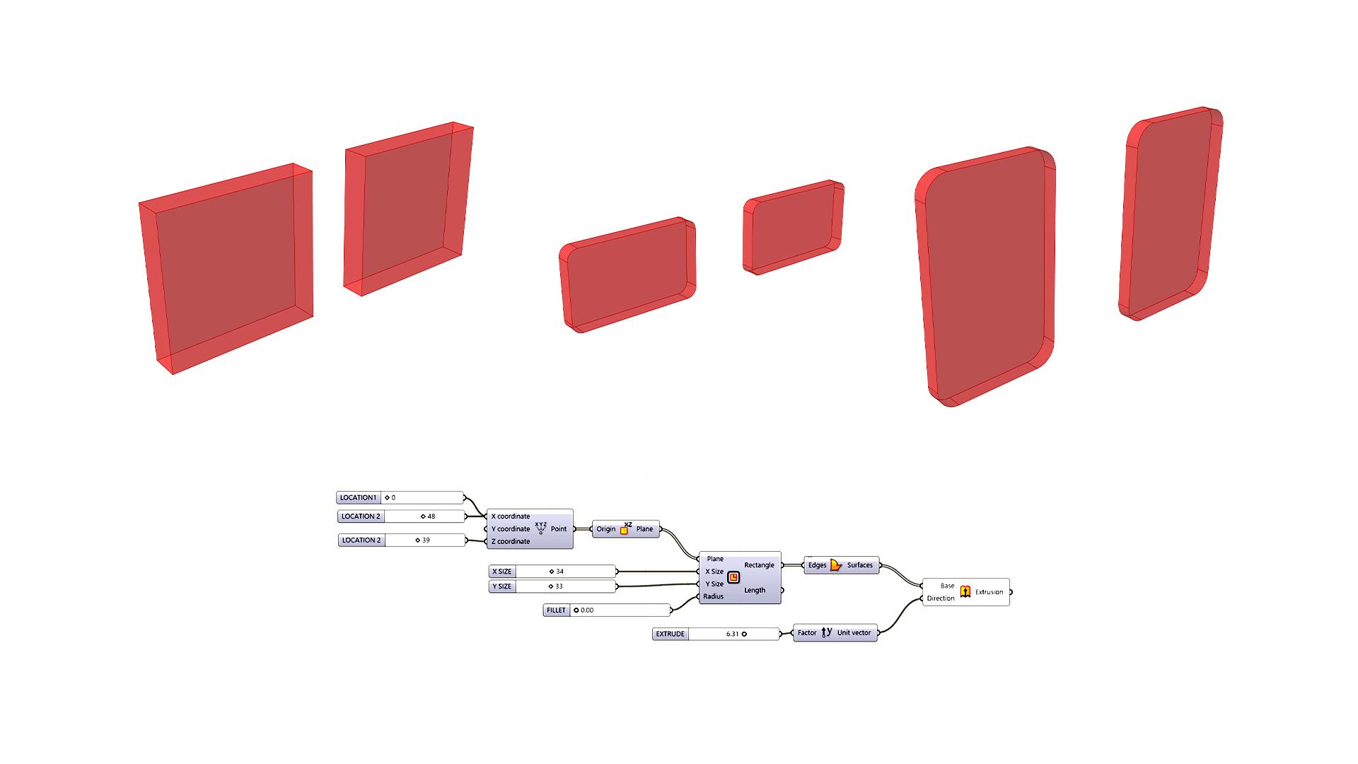
6. BASICS CONCLUSION: Now that we've made it this far, we've created two rectangles
using this algorithm. The next thing we're going to
do is create a surface ear, then extrude it to give it
some three-dimensionality. So to create a surface, the component that
we're going to bring in is called boundary surfaces. I'll double-click here
and go to a component, said, boundary surfaces, which
will create a rectangle. Create a surface along
a closed polyline. This rectangle is going to
be our closed polyline. We can use that and
create a surface. Now, notice that our
previews are always in red. These are things that
can be changed if you go to display and
other settings. But by default you will
see that they are red. And you will also
see things like this kind of checkerboard thing. And that is actually a
reference plane. That is this. And you can right-click and
disabled preview. This way. You don't have to look at those things if
you don't want to, you can only preview the things that are important to you. Right-click, disabled preview or selected on middle
click and do the, the guy with the bandanna over the eyes to hide everything. Or let's see What
was the other way. I think on a Mac it's
not middle-class. It's going to be Spacebar. There's a way to get like this. This is called the
radial options. So you can disable the
preview. So you don't see. Now that we have this surface that was fairly straightforward, just make sure that if it's
going to create a surface, it has to be a planar. That means that it has to be on a two-dimensional surface. It cannot be anywhere
outside of that. There are other ways to
create a surface on that. But with boundary surfaces, it's only gonna do it on a
two-dimensional flat boundary. For, with that being said, let's take this and extrude it. Now when you bring in an
extrusion, so double-click here. Extrude. And we'll extrude this surface. So plug that into the base. And notice that the input
is just a sea surface. So you'd go like, oh,
it doesn't say surface, it's not gonna work
while the base is going to be just geometry input. You can extrude surfaces, you can extrude curves,
things like that. So it's going to
ask for a direction because in the same way that
in here inside of rhino, we type in extrude. It's going to ask what curve
and in which direction, in sometimes it does upsides and you can change
the direction. Well, we need to be aware that these rectangles are actually aligned in the y z plane. We actually want to extrude
these in the y direction. This is where we'll double-click here and bring in a unit y. So I'll just click
on Y and it'll bring in the option to bring in
unit y. Let's bring that in. By default. When you bring in a vector, it's going to, by default
the input is gonna be one. Let's change that by
changing the input. Now I'll change, I'll
take this and copy it. So I'll slide it here. Tap out and change the name
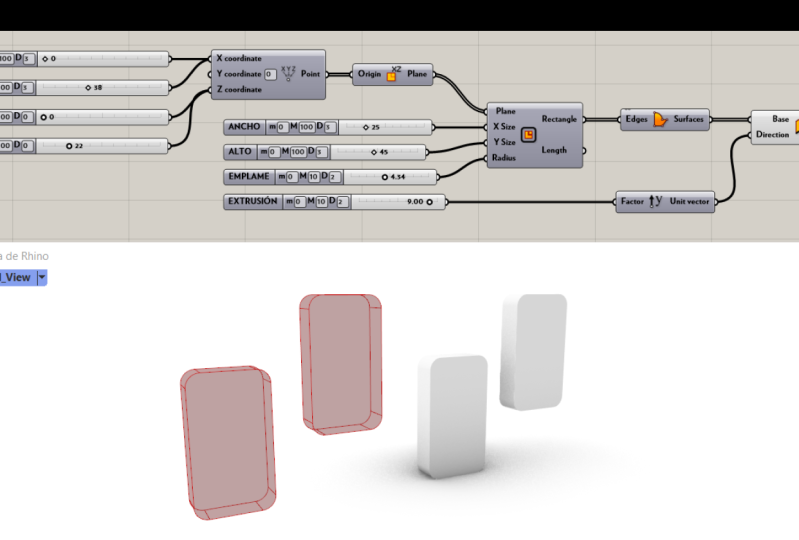
to extrusion, Extrude. Now let's plug this into here. Now it's extruding by 0. Now it's extruding more. Now what's cool is that
you can also let say, do something like this where
you see whatever radius. These are some of
the things that you can tie parametrically, which I feel like the cool thing to have that ability to change things to see
if they look good or not. And so with that, that concludes kinda the
overall Getting Started lesson. If you notice something
that I didn't go over, you got stuck somewhere. I'll please let me know if this is something I want to build on and help new people get started using
parametric design. It's a little bit intimidating
at the beginning, but like I've said before, it is some of the most useful things
to understand Into get used to it if you
were trying to do architecture and things
like that in the future. If you enjoyed that content, be sure to subscribe
for future videos and also check out the website
for more resources. I will have this script available to download
on the site. Just so you can have it
side-by-side just in case you're not able to kinda plug in
everything and get it working.
 DCO Graphicstudio