Transcripts
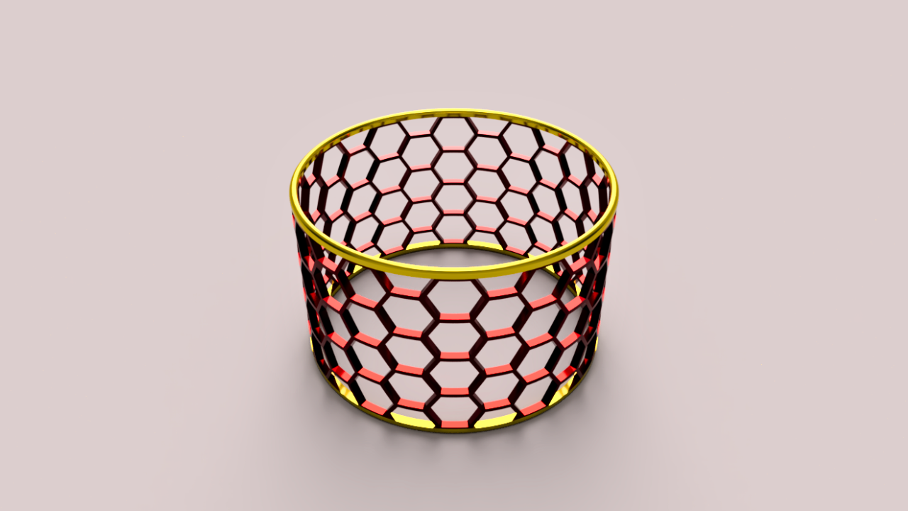
1. Introduction: In this class, you will create a circular honeycomb
pattern in fusion, a clean free D model
that looks great. I'll guide you step by
step and we'll finish with a professional rendering
that you'll upload as your class
project. I'm Martin. I run a YouTube
channel focused on Autodesk Fusion with
thousands of subscribers, and I teach in a way
that's fast paced, clear, and to the point. I have over ten years of experience with
different CAD programs, including teaching at a
leading Swedish University, and Autodesk Fusion is my
favorite tool to work with. By the end, you'll have your own honeycomb model
and the finished rendering. Up next, you'll learn
about your class project.
2. Class Project: Your class project is to create your own circular honeycomb
free D model infusion and present it with
the rendering. Once your design is complete, apply different
appearances to explore how materials and colors change
the look of your model. Then move into the
render workspace to set up lighting and capture
a polished image. When you're done,
export your rendering and upload a picture of
it to share your work. You can post a single
finished image or several variations to
show off your creativity. This is your chance to
practice both modeling and rendering and to showcase your design in a
professional way. In the next lesson, we'll start the project by following
the first rule of fusion.
3. The first Rule of Autodesk Fusion: We'll start by following
Fusion's first rule, create a new component. This keeps the design organized and makes edits easier later. As we go, you'll see keyboard shortcuts pop up
in the bottom left corner, starting with design
and sketch commands. Go ahead and give your
component a clear name. With Activate
checked by default, we're already working inside it. See you in the next
lesson where we'll create the sketch that
drives the three D design.
4. Sketch the honeycomb pattern: Create your sketch on the vertical construction
plane facing you. I'll use the circumscribed
polygon tool. If you're preparing this
for FDM free D printing, consider rotating the
polygon so a point faces upward or use the inscribed
polygon with its point up. Without that orientation, the design is not
practical to free D print. Create guidelines
for the honeycomb sketch and turn them into construction lines so they don't become part
of the final shape. Draw one line
pointing straight up and another at a 30 degree
angle to the right. Fusion makes this easy. It will snap to 30 degrees, which lines up with the midpoint of one of the polygons sides. The length of the
guidelines doesn't matter. You can over sketch them to
speed up your design process. Next, select your polygon
sketch as the object in the rectangular pattern and use your construction lines
to set the directions. For the distribution,
switch the setting to spacing so you can control the distance between
each polygon. Then set the direction
to symmetric to spread the design evenly on both
sides of the origin. Dragging the handles shows
how the settings work, but we want exact values. Each polygon measures
5 millimeters from the center to the top edge, so 10 millimeters in total. Setting the spacing
to 11 millimeters leaves a 1 millimeter gap
between each polygon. The exact quantity
isn't important. Add more polygons
than you'll need, and later we'll just use the
ones that fit our design. Draw a center diameter rectangle to set the boundary for
the polygons will keep. Use regular lines, not
construction lines, so the rectangle becomes
part of the design. Feel free to try
your own dimensions, but make sure the rectangles edges align with the central
points of the polygons. In my case, the height
is 44 millimeters. Keep that in mind because
later in the tutorial, you'll see why it matters. Good job following along. In the next lesson,
we'll sketch the circle that forms the foundation
of the circular design.
5. Building the Circular Base: Proceed with the circular
base by starting a new sketch on the horizontal
construction plane. If objects are stacked
on top of each other, press and hold the
left mouse button. This brings up a small menu where you can pick
the plane you want. Now, draw a circle
right at the origin. I set mine to 75
millimeters in diameter. Your circle doesn't
need to be exact. What matters is that it's wider than the rectangle
from the last step, since we'll only use parts
of it later in the course. Nice work so far. Up next, we'll use surface modeling.
6. Introducing Surface Modeling: I you can spot surface modeling tools
by their orange icons. We'll use the surface
extrude command to create a paper thin surface, no thickness, just a skin. Set the extrusion height to match the rectangle
frame from earlier. 44 millimeters in total spread evenly on both
sides of the sketch plane. In the measurement settings, you can choose to enter either half the length
or the full length. The result is the same,
so go with whatever feels most natural Leave this as a new body and
close the sketch. If you're unsure
about your settings, do a quick check with
the measure tool to confirm the total height. It's fast, reliable, and
handy for quick spot checks. Up next, honeycomb
design on the cylinder.
7. Honeycomb design on the cylinder: The 44 millimeter
rectangle acts as a frame, letting us extrude
the honeycomb pattern straight through the cylinder. Make sure to over extrude so the sketch fully
intersects the circle. Change the operation
to intersect. That way, only the
overlapping parts with the surface remain. Since this surface
is still paper thin, next we'll give it thickness. A
8. Thicken the honeycomb surface: Surface modeling is flexible. One powerful option is turning an infinitely thin surface like this into a solid by
adding thickness. A thickness of 2 millimeters in the suggested direction works well if you're following
my dimensions. To a quick orbit to check the
model from another angle. Next up, we'll add the
missing honeycomb pieces.
9. Add missing honeycomb pieces: Earlier, we cut away part of the cylinder with the
extrude intersect command. Now by applying a
circular pattern around the blue
axis at the center, Fusion automatically fills
in the missing honeycombs. If you need to adjust
a number of copies, just change the value
in the input box. The honeycomb intersections
are fine for this project. But if you were making an
actual physical product, you'd probably
refine them further. For now, let's move on and shape the smooth rings at
the top and bottom. I
10. Sketch for the smooth rings: Creating a new circle
with the same dimensions, but no relation to the
model has drawbacks. It won't update if we change
the honeycomb body later. Instead, we'll project
the underlying geometry onto this sketch plane. Projected geometry shows up in purple and stays
linked to its source. So any changes in the
timeline will carry through. From here, we can
offset the projection and match the thickness
of the honeycomb model. Great job keeping up. Next up, we'll turn this sketch
into a solid body. I
11. Turn the sketch into a solid body: We'll turn this linked geometry into a solid body in
just a few steps. Then thanks to our
symmetrical setup, we can reuse the design on
the other side of the model. Be sure to set the operation to new body so you can manage
this part separately. It also makes it easier to
apply different colors later. The thickness works well
with the rest of the design, but we can take it further. A round filet improves the look, makes the model
more user friendly, and can even add strength. Using a full round filet
keeps it parametric, so it always adjusts to the part's thickness and gives
us a smooth, clean finish. Instead of rebuilding everything and risking extra edits later, we'll use the mirror command. This creates a linked identical part on
the opposite end of the model using the
central construction plane as our mirror plane. Things are really
starting to take shape. Next up, we'll add appearances
using custom color codes.
12. Add appearances with custom colors: I'm searching for
anodized aluminum because it's a great
visual fit for our design. We'll adjust the colors later. You can drag and
drop appearances directly onto the bodies, and we have plenty of those
after the circular pattern. Another option is to select
the bodies in the browser, hold control if you're on PC and apply the
appearance there. Right click the
applied appearance in the menu and choose Edit. Here, you can adjust the
color with RGB values or go further into the
advanced menu to use custom HTML color codes. There are lots of
great sources for color codes from
classic palettes, online to asking AOI tools
for tailored suggestions. The appearance library
offers plenty of materials, and AI suggested that gold pairs nicely with the
red anodized aluminum. We'll apply the gold to
both the top and bottom. If you think about it, we
could have saved a step by applying the appearance
before mirroring the body. Then it would have carried
over automatically. Let's take this chance to apply a custom gold HTML
color code two. I'm excited to see
your renderings with your own color choices
uploaded to the project. To create stunning visuals
in the render workspace, we'll first need to save our project and set
up a rendering. So let's do that in
the next lesson.
13. Save and render your project: You'll see the same objects in the rendering workspace as
in the design workspace. You can toggle visibility
in either workspace, but it's smart to do it in the design workspace
before saving. That way, your model is always ready for rendering
without extra steps. Switch to the Render
workspace from the drop down in the
top left corner. Right click in the Canvas
and open scene settings. Choose any setup you like. For mine, I'll use a Photo Booth environment
with a gray background. You can also add
RGB color codes, which is handy if you want
consistent backgrounds across multiple
renderings for a website. It's simple to adjust how the
light falls on your model. Rotate the environment
by changing its position, then use pan, orbit, and the ViewCube
to frame your model, just like in the
design workspace. The view cube is especially
useful if you want consistent standardized
angles that you can repeat across projects. Open render settings
to set width, height, quality, and whether to render
locally or in the Cloud. Cloud rendering can be
free or use flex tokens, and you'll see an
estimated Qu time right next to the render button. Once it starts, your render will appear in the
gallery within that time. We'll skip ahead a few minutes
to the finished result. As soon as your
rendering is ready in the gallery,
click to open it. Use the arrow to download, then pick your image format and decide if you want a
transparent background. I'll go with PNG since it keeps high quality and
supports transparency. Perfect for using the image on websites or in
design layouts. From here, just choose
where to save your file. Nice work, keeping up. Up next, we'll wrap up
and complete the project.
14. Project completion: Great work, making it this far. You've now created your own circular honeycomb free D model and presented it
with a rendering. Be sure to share your render. You'll learn a lot by
showing your work and seeing how others
approach the same design. I hope this project has
given you new tools for working with Fusion and fresh ideas for
your own modeling. If you enjoyed this class, please consider
leaving a review. It helps others find the course
and supports my teaching. Thanks for joining me,
and I hope to see you in another project
here or on YouTube.
 Martin Lennernäs, Autodesk Fusion Enthusiast | Maker