Transcripts
1. Introduction: Welcome to the world of Autodesk Fusion where your creativity
knows no bounds. Diving into new CAD software
can feel overwhelming, but don't worry you are
in the right place. Autodesk Fusion boosts over 1,400 commands and several
different workspaces, making it a powerful tool that can seem
daunting at first. However, with the
right approach, you can quickly grasp
advanced 3D modeling techniques and start bringing your ideas to life. This course is
designed to help you prioritize and master essential
skills in Autodesk Fusion. By the end, you will have a solid foundation in solid modeling
commands and workflows, ready to tackle many
projects. Hi, I'm Martin. Your guide on this journey. With extensive experience
in the AEC industries, that's architecture,
engineering and construction, I bring real world
experience to the table. The AEC sector is the largest
in the global economy, and it's constantly evolving, making it an exciting
field to be part of. I also teach at top ranked
Swedish University in addition to my
online courses. I mastered more than five
different CAD programs, and Autodesk Fusion is my favorite. Its design and
manufacturing tools are perfect for 3D printing
and sheet metal design. And I'm excited to show
you how to use them. We'll start with the basics. In the first section,
you will get an overview of Autodesk Fusion. Understand its core
design methodologies, and learn to navigate
the user interface. These short lessons will set the stage for the more
detailed instruction to come. In the second section, you will dive into
essential commands that form the backbone
of Autodesk Fusion. Practice makes perfect, and you will quickly see
your skills improve. As you work through
these exercises, the third section
is where tool comes together in a project
based format. You'll use a top down
design methodology to 3D model and assemble
a hexnut and a bolt, Applying what you've learned
in a practical contetext. In the third section
of this course, there are several
projects available. Your assignment is
to upload a photo of any project you worked on
to the project gallery. So enough talking, let's get started. I can't wait to see what you will create in Autodesk Fusion. See you in the next lesson.
2. Introduction to Section one: Welcome to Section one. Here we'll blend essential theoretical concepts
with hands on screen cast tutorials to give you a strong foundation
in Autodesk Fusion. Understanding the core ideas
behind design methodologies, components, the user interface, and customization options will
make navigating Autodesk Fusion a breeze. While this section might not be what you envisioned
when you first signed up. It's a crucial step
that will pay off immensely as you continue
your learning journey. Commit to these lessons now. And future, you will be grateful for the time
and frustration saved. Let's dive in and set the stage for your success in
Autodesk Fusion.
3. About Autodesk Fusion: In this lesson, we
take a fast look at the big picture without
looking into the details. Autodesk Fusion is cloud based, and all your design data is
securely stored in the cloud, so there is no reason to panic, at least not for your
Autodesk Fusion designs, if you accidentally spill
coffee on your computer. You access your data when you're connected
to the Internet, and it's also possible to use some parts of Autodesk Fusion
in offline mode, which you can activate
and learn more about from the top right corner. One huge benefit with Autodesk Fusion is
the possibility to connect your entire product
development process in one single platform. It's a CAD, CAM, CAE, and PCB platform for
collaborative design, problem solving, and
product development. This allows both individuals
and teams to streamline their product development and go faster from idea to manufacturing. There are more details to this, but we're working with big picture in this
section of the course, so let's keep moving forward and see you in the next
lesson. Thank you.
4. Design Methodologies in Autodesk Fusion: In this lesson, we
take a brief look at different design
methodologies and components. Both top down, bottom up and hybrid
design methodology is possible with Autodesk Fusion. Parts can be designed in context with other components
within the same file with a top down methodology as opposed to a bottom
up design approach, which typically has
a lot of files that you extrav together
into an assembly. An ref is an external reference that you bring into your file. Key benefits with top down modeling are the
possibility to perform rapid design iterations and
the possibility to build new components in context with other parts of your design. You work with internal
components when you work with a top down
design methodology. Key benefits with bottom
up design methodology are the possibility to reuse individual components in
different projects and the possibility to manage
each component separately, which is helpful when you work on large and complex designs. You work with external
components when you work with a bottom up
design methodology. You can obviouslywork with
hybrid scenarios and combine both a top down and
bottom up design methodology. Understanding those
different design workflows is essential for your
long term efficiency. It's considered best
practice to create a new component when you
work with Autodesk Fusion. A component is like a
basket with information. You collect features, design
edits, sketches, geometry, and more that belong to the component within
the same component. With this method, you will
thank yourself further down the road when you need to
adjust or edit your design. You win time. We'll get
back to components, assemblies, joints, bodies, et
cetera throughout the course. But now let's continue
with the goal of building the big
picture. Thank you.
5. Autodesk Fusion User Interface: In this lesson, we take a tour of the Autodesk Fusion
user interface. And don't mind the
3D printed computer fan grill project
you see in the middle. The purpose is just to
have something there, so you have something to look
at when we take the tour. The tour will be like going
around window shopping in a new city without entering
any of the stores, museums, restaurants, or
if you're old enough, bars. It can be frustrating, but we are just learning to find our way around
in this lesson. Let's start with the data panel. There is an application bar
in the top of your screen. The first button will show
or hide the data panel. It's hidden by default. You can access your
projects, teams, designs, design data, and collaborate
with others from here. Next, you have the file menu. You create new
designs, new drawings, open save and export
projects, and more from here. The Save button will
allow you to save an untitled design or save a
new version of your design. The icon is a floppy disk. Some people in the
modern workplace have never seen one - too young. Undo and redo will undo
or redo your actions. The X will close your design and the plus sign will
create a new design. Yes, you recognize a lot of standardized functionality
from other computer programs. Extensions are a set of advanced 3D design
and modeling tools. Find out more under
each extension. Job status allows you to
see things like Fusion update status, and online
or offline status. And relevant notifications are shown here if there are any. Help gives you
access to areas like documentation, the
community and support. And finally, you
have your profile where you access your
Autodesk account. You can adjust your Autodesk
preferences, which, for example, can be useful if you migrate from
another program. From another CAD
program, that is. Let's look at the toolbar. First, you have the
workspace picker and different workspaces. What you see in the toolbar depends on the workspace
you currently working. We will spend most
our time but not all our time in the design
workspace in this course. Each workspace is
organized in tabs. The tabs contain groupings of
related tools and commands. You recognize this structure
from many computer programs, including different
CAD software. Some commands will
activate contextual tabs. For example, when I
activate create sketch, a contextual tab
with a tool set of contextual commandos appears to the right on the
regular toolbar. The contextual tab
goes away when you exit the contextual
environment. The browser list objects
in your assembly. You find document settings
and objects such as joints, components, sketches and bodies, some, but not all of them
visible in this design. We'll cover them later. You can control the visibility
of your objects from here. Right click on the browser to
display additional options. You can left click
in the browser or directly on the objects in the canvas when you
want to select them. The ViewCube is a great
aid when you want to look at your design from
different perspectives. Press the home button
to return safely to a preset perspective that
includes your entire design. Right click on the canvas
to access the marking menu, sometimes called the
right click Menu. You can expect to find
frequently used commandos in the wheel and additional
commands in the menu below. You find commands used
to orbit, look, look at, pan, zoom, fit on screen, display settings,
grid and snap settings, and view ports in
the navigation bar. The timeline list commands
performed in your design. Remember what we said
earlier about components. Each component has
its own timeline. Use the buttons to go backwards and forwards in your
design history. You can right click operations in the timeline when you
want to make changes. Make a change and later actions in the timeline
will be affected. Parametric modeling allows you to change the order in which your operations are calculated simply by rearranging the order. This was a quick tour of the Autodesk Fusion
user interface. Don't worry if there is a
lot of new information, and don't be mad at me for
not going more in depth yet. We're building a framework
and a big picture here, and we will go more in depth on different sections
later in the course.
6. Customize your Autodesk Fusion User Experience: In this lesson, we customize your
Autodesk Fusion experience. Some of you will just go with the presets and some of
you will change settings. Let me empower you. Maybe you want to customize Fusion based on your
personal needs, your company standard,
or your industry needs. Customization can be a great
way to increase efficiency. It's a two edged sword,
so don't overdo it. You can easily add your favorite commandos to the toolbar. Just hover over the commando, click on the three dots
and check pin to toolbar. Un-check the box to remove
an item from the toolbox. Press keyboard shortcut S to
reach design shortcuts. You'll reach sketch shortcuts and get access to sketch tools, not design shortcuts and
design tools, if you're in the contextual
sketch environment when you press keyboard shortcut S. Search for commandos
in the search window. You'll also see some easily
accessible commandos above the search
bar in the toolbox. I'll show you two workflows that will add a command
to the toolbox. One way is to search
for the commando and press the Add to shortcuts arrow. Another way is to find
your commando from the toolbar and check
Pin to shortcuts. To remove the command,
search for it, and press the remove button. It's easy for you to change keyboard shortcuts
in Autodesk Fusion. This is a great way to
improve efficiency. Find your item from the toolbar and select change
keyboard shortcut. There are five scenarios
you should know about here. First, if you select
a free shortcut key, then you can go on and just press OK to assign
the shortcut. You can also combine
shortcut keys, for example, hold shift and I to assign
a shortcut like this one. Secondly, if you select a taken shortcut key,
you'll have a conflict. You'll be notified that
the shortcut key will be removed from another commando
if you choose to continue. Thirdly, some shortcut
keys are reserved. There is a link to reserved shortcut keys in the
course resources. A reserved shortcut
key cannot be changed. Number four, just leave the window blank to
remove a shortcut key. And finally, the fifth
and final thing, if you want to reassign your
shortcut key to default, just press the return
to default option. Your saved shortcuts,
which you reach with keyboard shortcut S, are also found via the right click menu, also called the marking menu. You also find other options
such as repeat Commando, which will show the
latest commando you used and other
popular commandos. You can also enter the
contextual sketch environment and continue with your
sketch from here. The right click menu is a
great option that will allow you to work fast without moving your mouse
around too much. Hold Shift and your
middle mouse button to orbit around your design. This is a useful way to inspect your work from
different angles. A small green dot
appears when orbit. This is your orbit center. Right click the
Canvas and select set orbit Center when
you need a custom setup. Likewise, right click and select reset orbit Center if you change your mind and you want to reset
your settings to default. You can change many settings
within your design. For example, you'll
find active units under document settings
via design shortcuts. You can also adjust
your preferences from the application menu in
the top right corner. Here, you will find program specific shortcut
presets which are valuable if you come from another program such as
Inventor or Solid Works. Other common adjustments are orbit settings, default
unit settings, or new designs and automatic
recovery backup intervals.
7. Introduction to Section two - Essential commands in Autodesk Fusion: Starting with a new
software can be daunting, especially with Autodesk
Fusions extensive library of over 1,400 commands. However, just like learning a new language or mastering
a hobby like bike riding, the key to success lies in
building strong fundamentals. In this section, we'll focus on the foundational solid
modeling and sketching concepts in Autodesk Fusion that will set you to the
path to proficiency. Think of this as your introduction
to a powerful toolbox. While it's not
necessary to explore every detail or explore
every command right away, my primary goal is
to help you grasp the big picture and establish
a solid understanding. I encourage you to
open Autodesk Fusion on your computer and follow along as we go
through each topic. Active participation,
listening, and practicing is far more effective
than passive learning. By the end of this section, you'll have a strong
foundation to build upon as you continue your journey
with Autodesk Fusion. So let's dive in and discover the first essential command
of Autodesk Fusion together.
8. How to create a component in Autodesk Fusion: In this lesson, you will
learn about components. The first rule of Autodesk Fusion is
to create a new component. Components are critical for
your Autodesk Fusion success, and you have many
reasons to use them. I like to think about components as containers for information. Within one component, you can save information such as bodies, sketches, construction geometry, decals, and other components. Components are great both for organizing your work and
for reusing designs. Components are necessary
to use when you create assemblies or
work with moving parts. Each component has
its own timeline, origin and coordinate system, and unlike bodies,
components will show up in parts list when you
work with manufacturing. You can copy in
paste components and automatically update
the copied components when you change the original. We'll go on and create a
new component for now, and then we'll get more
reasons to see components in action later when we work
with the first project. Here are six different ways
to create your new component. You can choose new component from the assemble dropdown menu, from the create dropdown menu, by right clicking a body and creating components from bodies, by right clicking the browser, by searching for
new component after activating Autodesk Fusion
design shortcuts with keyboard shortcut S, or by selecting new component from the operational drop down menu
during an active command. A menu appears when you
make your selection. Sheet metal components are
for sheet metal designs. For other cases, a
standard component is fine. An external component,
an xRef, is created in a separate file and referenced into your assembly in
your current design. This is a classic bottom
up design approach and has benefits
when you want to reuse components or collaborate with colleagues on complex designs. An internal component is created within your
current design and is typically used for the
top down design approach where you create your
assembly inside your model. From bodies is used
when you want to create a design from
an existing body. The parent component is the activated component on the hierarchical level
above your new component. This is useful when you create components
within components. Leave activate checked
if you want to activate your component and work within it right away after creating it. This is often the
case, but not always. You can create your
component with the suggested name
and press OK. A good name will make things
easier for you if your design file contains
a lot of information. Your new component appears
on the project browser. The key takeaway from
this lesson is to organize your work
within components. Let's look at the next
essential tool and create a sketch in the
next lesson. Thank you.
9. How to create a sketch in Autodesk Fusion: Well done keeping up. In this lesson, you will be introduced to the
sketch environment. And don't worry if you don't remember everything
after this lesson. We will look more closely at all details later
in the course. Your sketch is the
geometric profile that shapes your three
dimensional geometry. I like to think
about sketches as the underlying assets that drive the shapes of your design. A sketch is more than just a shape that creates
three dimensional geometry. Sketch workflows
provide you with an opportunity to
work proactively with your two dimensional and
three dimensional designs as well as with your
entire assembly. Later in the course, we
will see example of how sketch workflows improve
both efficiency and quality. You can create your sketches
on construction planes, faces or at any point in the
three dimensional space, and you can utilize
existing design assets such as edges from other
geometry when you make sketches. You will recognize
tools you have used in other CAD software such as multiple options for
creating rectangles, circles, arcs,
splines, and more. You have two different sketch
profiles in Autodesk Fusion. An open profile does not
form a closed boundary. We will explore open profiles later in the course
when we extrude thin solid features, when we guide modeling operations such as sweep and when we work
with surface modeling. A closed profile forms
a closed boundary. This closed boundary is
easy to spot in Autodesk Fusion. The area has a
shaded blue color. Closed profiles can be used when you want to extrude
three dimensional shapes or perform Boolean operations
such as cut or join. Sketches can either
be unconstrained, partial constrained
or fully constrained. I like to think about
constraints as rules. More rules equals less
freedom, and just as in life, there are times
when rules are good and there are times when
no rules are good. And the best thing is
probably a balance between rules and different
degrees of freedom. An unconstrained sketch is generally better early
in the design process. During this phase, you want
flexibility and freedom. You will recognize
unconstrained sketches in your project browser when you spot this symbol
next to the sketch, and you can move this geometry around in your design space since the sketch isn't fully locked with dimensions
or constraints. A constrained sketch
has geometry that's locked in place by
dimensions and constraints. A fully constrained
sketch is black. Rules, for example,
dimensions or constraints can be useful when you know your desired details
about your design. You want to avoid
surprises and enjoy predictable results when you
make changes to your design. You should recognize six
types of sketch geometry. Default sketch geometry
is blue with shaded blue color
for closed profiles. Construction geometry
is orange and dashed. I like to think about those
as help lines that don't contribute to the sketch profile that drives the three
dimensional design. Center line geometry is orange, dashed, it shows symmetry. Projection geometry is purple. Those sketch lines are
projected onto the sketch plane from existing two dimensional or three dimensional profiles. Fixed geometry is
green and is a sketch locked in place with the
fix / un-fix constraint. And finally, constrained
geometry is black. This geometry has so
many rules, for example, dimensions and constraints,
so it can't move. You can make both
two dimensional and three dimensional sketches, but you need to activate
3D sketch if you don't want your sketch to be restricted
to the selected plane. I personally recommend two dimensional sketches
most of the time, such as when you intend to utilize features
such as extrude, and three dimensional
sketches when you want to create a path with
options such as sweep. A contextual tab appears when
you create your sketch, and you close this
contextual tab when you click Finish Sketch.
A Pro Tip here; You can skip the Finish Sketch
step and jump right into 3D Modeling
commands by pressing 3D modeling commands
such as Extrude. We'll start from the basic with the sketch line command in the next lesson.
Good job keeping up.
10. How to work with sketch lines in Autodesk Fusion: In this lesson, you will
learn that there is more to sketch line
than just a line. Create a new sketch from the top left corner and choose
any construction plane. You are now inside the
contextual sketch environment. You can activate the line
command from the toolbar. From the create drop down menu, via the keyboard short cut
L and you can see assigned keyboard shortcuts
to the right of the commando in the drop down menu
or by activating sketch shortcuts with
keyboard shortcut S and searching for Line. One box for degrees and
one box for length appear. Use the tab key to
jump between boxes. You can lock to
degrees or the length. In this example, I enter
a value of 45 degrees, and my line is now locked to 45 relative degrees
in any direction. Enter a distance, let's say 100 millimeters and press Enter. You can change the dimension or the angle by pressing them
and entering a new value. Let's create a new line and see how Fusion aids our design. You can snap to the end of the line, to the middle
of the line or why not to the sketch
grid if you have the snap to grid
functionality turned on. Fusion will help you when you want to create
relative geometry. Let's look at one example. Activate the line commando. Nothing happens when you
hover in this space. Let's stay inside
the line commando and hover over the
end of the line. A helpful guideline suddenly appears and you
can create a line. A small symbol automate
appears next to the line. You'll find the same constraint
symbol in the toolbar. This is a perpendicular
constraint, and you can read more
about the commando when you stay with your
mouse above the button. This constraint locks the
line to a 90 degree angle, and you have to
select and delete the constraint if you want
to get rid of this rule. It's possible for you to create arcs when you are within
the line Commando. Click and hold your left mouse
button and create your arc. That's it for this
sketchline introduction. Let's move on and continue
with the next lesson.
11. How to create circles in Autodesk Fusion: In this lesson, you
learn that there's more than one way to create
the perfect circuit. Just like with other
sketch geometry, you create your circles inside the contextual sketch
environment in ascition. The center diameter circle, Kebotcat C is your best choice when you know the size and
location for your circuit. The two point circle is useful
when you want to create the diameter of the circle
by placing two points. The three point circle is
useful when you want to create a circle by placing three
points on the circumference. Two tangent circle creates
a circle tangent to two lines and the
free tangent circle creates a circle
tangent to three lines. I personally find those commands useful when I want to integrate the circle with other
sketch geometry here exemplified
with a trim tool. You can change the circle
type in the sketch palette, and just like we saw earlier, wood rescusion will
help you and provide guiding lines and sometimes
even automatic constraints.
12. How to use sketch Dimensions in Autodesk Fusion: In this lesson, you
will learn about sketch dimensions in the
contextual sketch environment. You can use sketch dimensions to control the size and
position of your geometry. The default shortcut for
sketch dimensions is D. It's easy to add dimensions for different
types of geometry. Just press relevant lines or points in your geometry
and add a value. A dimension can both
be driving and driven. Driving dimensions are the
defect dimension type. Those dimensions
drive your design. For example, when
I make this line 100 millimeters,
the design updates. Your dimension will be driven if the sketch becomes
overconstraint. For example, this
perpendicular constraint indicates that the
angular degree between the lines
will be 19 degrees. Therefore, I can't add a dimension here that
breaks the rule. Your dimension will be driven, flexible and determined
by other dimensions. This dimension is presented
in parenthesis and gradeout. You can reference dimensions. This is useful
when you work with parametric modeling and
can save you a lot of time and increase quality since the probability of
mistakes can decrease. I'll use a circle
in this example, but other types of
geometry are fine as well. Add a dimension to
the first circuit, add another dimension to the second circle and
click the first dimension. FX indicates that this is
a reference dimension. Change the first dimension and the second
dimension follows. You can add formulas
to dimensions. Imagine that you want
this circle to always be 20% larger than the
referenced circle. Select your reference times
1.2 or one comma two. Your formula is okay if
the text turns black. And that's it for
dimensions for now. We'll put it more into practice later in the
course. Thank you.
13. How to sketch Rectangles in Autodesk Fusion: In this lesson, you will
learn about three types of rectangles in the contextual
sketch environment. The two point rectangle
is the default option in the toolbar and has the keyboard shortcut R assigned to it. You can work in four
different orientations once you anchor the first point, and you can also add
dimensions for precision. Pay attention how horizontal slash vertical
constraints are added automatically and prevent
you from changing the shape of the rectangle unless you remove
the constraints. The three point rectangle means more work if
you intend to create a rectangle in the
same directions that the two point
rectangle works, but it provides more
flexibility and more opportunities
when you want to create a rectangle
in other directions. You can also lock the value after you place the first point, which can be helpful depending
on your design intention. The center rectangle creates a symmetrical value from one center point and
one corner point. I often use the center
rectangle when I want to start a sketch from the
center point of the region, and I want default
construction planes centralized in my design. And that's it for rectangles. See you in the next lesson. Thank you.
14. How to Project a Sketch in Autodesk Fusion: This lesson, you will learn
how to project a sketch. Create a sketch and you will find project keyboard shortcut P in the create dropdown menu in the contextual
sketch environment. Project will bring geometry from other parts of your project
onto your sketch plane. You can reference faces, edges, points, or bodies. Let's make a projection on
this construction plane with specified entities
as our selection filter. The highlighted line
shows geometry that will be projected onto
your construction plane. Delete your projected
lines and project again, but with bodies as
your selection filter. We can't select a
sketch this time, but just hoing over any part
of the body is enough to project the boundaries from the top surface onto our
active construction blade. The specified entity
selection filter has a broader application than
a body selection filter, since you can pick
specific parts. You can project with or
without a projection link. You create a
relationship between your original sketch and your projection when you
project with Elling. Those projections are purple. Change the original sketch and your projection
automatically updates. Make sure that your
unchecked projection link if you want to project
an independent sketch that doesn't update
when you make changes to the underlying sketch
used for the projection. Linked projections are blue. You'll probably run into a few scenarios when you
create a projection link, but realize later that your projection link doesn't support your design intention. You don't want automatic updates on your projected sketch. Your linked
projection is purple. Select your sketch,
right click and edit and right click again
on your selection and select Break Link. As you've seen, project is both a time saver
and quality driver. You can reuse and create
accurate sketch geometry, and you can also save a lot of time when you make
changes to your design. Good job following long you in the next
lesson. Thank you. But
15. How to use Sketch Project Intersect in Autodesk Fusion: In this lesson, you
will learn how to project a sketch with
project intersect. Sketch Project intersect has many similarities
with sketch project. The main difference
is that we will pick up intersecting geometry. This cylinder clearly intersects the level of this
construction plane. Enter your contextual
sketch environment and select sketch
Project intersect. Projected geometry will be
added to our sketch plane if our selection intersects
our sketchplane. Your selection filter and projection link
work similarly as the sketch project
commando you watched in an earlier lesson
dedicated to sketch project. Your selection filter must cross your authorized fusion
sketch plane to project, and you can select bodies if that's more
convenient for you. Good job. Let's keep moving forward and see you
in the next lesson. Thank you.
16. How to Extrude in Autodesk Fusion: There is more to extrude than making a freedom
model from a sketch. Activate extrude from the
toolbar or with keyboard shortcut E. You can select
one or multiple profiles, and you can also choose
if you want to extrude a solid body or a
thin extrude with custom wall thickness
and with location set in inside, outside or center. The default setting is to start your extrude commando
from the profile plane, but you can also start with
an offset distance from the profile or from another object such as
a construction plane. This gives you great
flexibility when you design. It is easy to extrude
in multiple directions, both with custom dimensions
and with symmetric settings. Use the measurement settings
to select if you want your symmetric extrude
distance to be valid for the whole length
or for the whole flangth. For example, do you want to
distance 200 millimeters on each side or a total
of 200 millimeters, which equals 100
millimeters on each side. You can set a positive
or negative taper angle depending on your design go. And just like the other
demonstrated options, this works well with the
thin extrude option as well. Let's create a sketch on a face to demonstrate
operation type. First, I'll just
go back and edit our extrude feature and turn
it into a solid model again. When you drag your
sketch upwards, a joint operation is suggested. This new body will be part
of your current body. Change to new body
or new component if you want to create this
as an individual part. Cut is automatically suggested when you go inside your body, and the red area will be
removed in this cut operation. You can cut a specific distance to an object or through
the entire body, including several bodies or components if you have
that in your model. You can also flip directions
to the other direction, which could be useful in some
cases, but not this one. You can also cut
with a taper angle. Cut intersect is an
interesting commando. It creates a new body from your cut selection and
removes the rest of the body. You'll see more from Extrude when you start the
first project, but first, see you in the
next lesson. Thank you.
17. How to create a Hole in Autodesk Fusion: This lesson will teach
you how you can create a hole in a solid
body in autodesction. Actuate hole from the great dropdown menu or with keyboard shortcut H. Your first
choice is placement. The most common thing is
probably to select the face, but you can also select
multiple sketch points. Centralize this hole
right above the center. You can use the point in
the orgo as your reference. Drag the manipulators or enter exact values for
your whole site. You recognize the extent options
from the extrude lesson. Extend A, for example, is a good choice if you
want your whole to extend through the entire thickness,
including future changes. You can choose between simple
counterbore and counter sync hole types and
simple clearance tapped or taper tapped
hole tap types. You'll see an illustrative
image below each choice, including Fred upset options for the tapped hole tap type. You also have fret type,
size, designation direction, and option to select if
you want your fread to be modeled or if you settle with
a visual representation. Modeled is useful in some cases, for example, if you intend
to free print your design. Keep in mind that your file becomes more complex
if you check modeled and every extra detail can eventually slow
down your file. Hence, if you only want a visual representation
in your file, then you don't have
to check modeled. If you need to
change your whole, just use the timeline
and edit your feature. And that's it for now. Good job. See you in the next
lesson. Thank you.
18. How to use Fillet in Autodesk Fusion: Fillet is a great command, especially when you take the end user experience for physical
products into account. Fillet is your command when
you want to round the edges, exterior or interior
of a solid body. You find fillet
in the toolbar in the modified drop down
menu or a Kepo shortcut F. You have three different
fillet types at your disposal. Let's start with filet. We will then look at rule fillet and finally full round fillet. You can work with one or multiple selection
sets when you work with fillt and you can work
with both edges and sides. G one tangent or G two carbaor will give you
different field transitions. The explanation for that is not within the scope
of this video. Select whether you
want a constant or short length radius type. You'll see the
short length marked in the small picture
assigned to the command. Tangency weight
is an easy way to increase or decrease the
scale of your fillet. Change corner type
from rolling bowl to setback if you want to blend the edges into adjacent faces. You'll see a small
demonstration of the feature if you look
closely at the picture. You can think of rule filet as a fillet based on rules
instead on selections. For example, set your
rule to all edges, select your top face, and your fillet command
will be applied to all edges according
to the rule. Likewise, set between faces
features as your rule, select face feature one
and face feature two, and your rule is applied between your selected faces
and features. The full round filet is
useful when you want to add a smooth round
finish to your design. And that's a basic introduction
to the filet commander. See you in the next
lesson and good job.
19. How to use Construction Geometry in Autodesk Fusion: Construction geometry is a
great category of commands. Some examples are
the possibility to sketch where no plane
or face exist and the possibility to combine construction geometry
with other commands such as the cutting tool. You have got construction
planes, construction access, and construction points
at your disposal, and within each category, you find a set of commands. This gives you great
flexibility when you sketch. Let's start with a
simple offset plane. Select the pace and your
extend type to place it. You now have a new
plane to work with. Construction plane at an angle works a little differently. Select a linear edge, axis or sketline and
then select your angle. It's obvious that you can use construction planes
as sketch surfaces, but they are good for
other things as well. Here, I use a
construction plane as splitting tool and divide
my body into two bodies. Sometimes you need a new axis. The Xi axis in the
ridian are, for example, great to combine with
other commands such as the circular paten tools or
when you work with joints. Use construct and axis through two points to set
up a custom axis. A reference point can be a
helpful aid in your work. With point along paths, you use to slick path and either a proportional
or physical distance. Now you know the basics
about construction planes. Keep moving forward and see you in the next
lesson. Thank you.
20. How to Copy and Paste Components in Autodesk Fusion: You can use different
methods when you copy and reuse your components. You can choose to paste
components that are linked to the original and hence updates when your original
component updates. You can also paste
new components when you want to
reuse your component, but want to continue
working on it as an individual
piece of information. Inserting the current designs
allows you to reference, also known as raf short
for external reference, external water dstusion designs within your current assembly. Right click on the component you want to copy on
your browser and then right click on
the component you want to nest your copied
component within. It's common to nest your component within
your top level component, but you can also nest it
within lower level components. Position your pasted component. Pay attention to the
unique designations at the end of the
copied component name. Press Okay to finish. This component is
linked to the original. Use this method when you
want changes made to the original component
to also update the copy. Paste New works similarly, but paste is an unlinked
copy of your component. Pay attention to the file
name when you paste New. The name differs from the paste component workflow
with a linked component. You also have the
option to fire up a new design and paste
your component theory. This independent component won't update when you
update the original, which is useful when
you want to reuse digital assets but continue working with them as originals. Use insert in the current
design when you want to extra a component
from another design. Select your parent component
in your design before you right click your
shoes and design in the data panel and insert it. Edit in place allows you to edit the external component
in your current context. You can also break the link from the original design
and continue to work with your component as an independent piece
of information. You now know the basics about copying and pasting components. See you soon in the
next lesson. Thank you.
21. How to use Joints in Autodesk Fusion: You use joints for different reasons when
you make your assembly. Let's take a closer look. You can create joints between components in your assembly, and your joints define the relative position and
motion between two components. Joints give you the
opportunity to simulate and understand motion in
a digital environment. Just like with other commands, you can interact with joints
either in the browser, in the canvas or
in the timeline. Your selection order matters. Your first component
selection moves or rotates along an axis in the direction of the degrees of freedom arrow relative to the second component
component two. In other words, select whatever
you want to move first, then decide how you want to move it and what the
limitations are. The rigid joint type will lock
your components together. This joint removes all
degrees of freedom. Therefore, the
options look a little different compared to
joints with motion. A common scenario is a
welded or bolted component. You want the components
to stick together. The rigid joint has a
vibrating simulation that, unlike other
simulations, doesn't simulate the movement
since the joint is rigid. The revolute joint lets your component rotate
around your joint rigid. Use one of the three options
under region mode for your first and second component and find your snap points. First selected moves first. Joint motion limits are accessible for
several joint types, and we will demonstrate
them on another joint type. Just as with probably
most computer software, a contextual menu appears when you right click on objects. Here, a small menu appears when you right
click the joint, and you can allow the joint
animation to run when you look at your assembly
from different angles. The slider joint
moves your component without rotation along
your selected axis. This component is 200
millimeters long, and you will soon see why I
show you this measurement. Select slider as
your motion type and select the component
that you want to move first. This is what the movement looks like without
motion limits. Let's set a maximum of 200 millimeters and make sure to activate it
with the shake boox. Your movement is now adjusted. Play around with your settings to get a feeling for this tool. Rest is simply where
your joint rests. The joint counts the
motion limit distance from the joint placement, which in this example is placed at the end
of the green bar. The cylindrical joint rotates
and moves around an axis. Sometimes it's easier to find the desired joint
slap placement if you turn off the visibility
of other obets. You can set motion limits for both your rotation
and your slide, and you can preview
one motion at a time or all motion
limits simultaneously. The limit is counted from
your snap placement, and even if it says 0
millimeters as minimum, it won't affect the moment until we activate
the motion limit. That's it for a
basic introduction of the cylindrical joint. The pin slot joint rotates and slides your component
on two different axes. Finding your snap
point can be tricky. You can make it easier if
you lock onto a plane. Over the face, press and hold control on your PC
and find your spot. Oh As you see, this joint slides along one axis and rotates
around another axis. You recognize the
possibility to preview motion for one or
both motion limits. The inner distance is
100 millimeters here. Switch to the slide joint
motion limits menu. This joint is placed in the
middle of the pin slot. Therefore, we set negative and positive 50 millimeters
as our distance. If the joint was
placed at end, well, then our minimum would be 0 millimeters and our
maximum 100 millimeters. Good job following along. Let's proceed with
our next joint. The planar joint slides your component along
two axis parallel to the plane and rotates your component around
a single axis. You can set up all kinds of movements with all those
sliding motion options. Finally, we have
the ball component. This component rotates
around all three axes. You are recognizing
the similarities from other joint types, but also the differences
for the motion settings. Small flags indicate
the different degrees. It's easier to see
them when you preview degrees outside of the
joint settings environment. And that's it for joints. Now that you have a basic
understanding of them, you just need to practice
them in different situations. Let's summarize this
information intense lesson. You can use the Xi or
CTXs for your joints, but also a custom xs which we demonstrated earlier,
how you can set up. You can edit your joints by right clicking on
them in the browser, in the Canvas or
in the timeline. You can animate your joints
and see them in action. Some people find
joints challenging, and that's perfectly fine. We often good start
with Bong picture, and we will leave the joints here for this lesson. Thank you.
22. Joints vs As-Built Joints in Autodesk Fusion: Main difference between joints and as built joints is that components maintain
their current position when you assemble them
as as built joints. Therefore, you can use this
option when you model with a top down design methodology and your components
are in place, whereas the joint
option is your route when you want to position
components in your assemble. Reassemble roll down
menu and select as built joint keyboard
shortcut Shift plus J. Select your components
and press O. No component will move, so both can be grounded. And that's it for
as built joints. Check the as and on
joints if you want to see the different joint types
in action. Thank you.
23. How to Insert an image in Autodesk Fusion: In this lesson, you learn
how to insert an image. You can add files like PDFs, TIFFs, or JPGs from
your computer. Go to the Insert dropdown
menu and select Canvas. Click Insert from your
computer and find your image. For this tutorial, I'm using
a stock photo of a king. You can access the full project in the courses project section. Insert your image onto a face
or a construction plane. Adjust the settings if needed. You might lower the image
opacity for easier tracing. You can also change the
scale or flip the image. Use the options next
to your image to scale, move, or rotate. Once you're satisfied,
click Okay. The red rectangle is the
border of your picture, and that's how easy it is to insert an image in
autodesk fusion.
24. How to Calibrate an image in Autodesk Fusion: In this lesson,
you'll learn how to size your image exactly
how you want it. Find your image under Canvases
in the project browser. Right click and
select Calibrate. Next, add two points. A data input box will appear
after the second point. Enter the distance
between the points. Your image will resize
once you press Enter. That's how fast
and easy it is to calibrate an image
in Autodesk fusion.
25. How to Revolve a Solid Body in Autodesk Fusion: In this lesson, you learn
how to revolve a solid body. Use the revolve tool to create a solid from a sketch
profile or face. It's perfect when you
trace an image like a vase and want to turn
it into a three D object. In this example, we'll use
it to model a chess king. Find the revolve tool
in the create drop down menu under the solid
modeling environment. Here, I have one sketch profile and it's already selected. Now, I'll choose the
axis for the operation. Once you pick the axis, the model appears instantly. You'll see other options
like extent type, angle, direction, and
operation type. Click Okay. Then inspect your model to make sure it meets
your standards.
26. Surface modeling - An Introduction to Surface modeling: This lesson, you'll explore the differences between surface and solid modeling and why
surface modeling is essential. Surface modeling creates thin outer surfaces
with no thickness. These surfaces can
be used to form watertight volumes
and solid bodies. Why not just create a
solid body from the start? We'll get back to
that, but first, let's examine the tools
for surface modeling. You'll recognize familiar tools like Extrude,
revolve, and sweep. These work in both environments
but behave differently. For instance, in
surface modeling, you can work with
open profiles while solid modeling requires
closed profiles. Surface modeling also
introduces unique capabilities. For example, oft lets you
connect free D sketch entities, unlike the solid environment, which uses closed
to these sketches. Patch creates planR or freed
surfaces within a loop. Ruled generates surfaces at a distance and angle from edges. Offset produces a
new surface body at a specific distance. You'll also find specialized
modification tools like trim, untrim, extend, stitch, stitch and reverse normal tools unavailable in the solid modeling environment. Surface modeling shines
when creating shapes that solid modeling struggles with
or can't achieve easily. Even more powerful, surface and solid modeling can be
combined to craft complex, watertight designs
and solid bodies. Now, let's dive in and
create some basic surfaces.
27. Surface modeling - Extrude in the Surface Modeling Environment: In this lesson, you'll
discover key details about the extrude command in orthodskFusion surface
modeling environment. While extrude is in the same location as in the
solid modeling workspace, the symbols in the surface
environment are orange. When you extrude
a closed profile in the solid modeling workspace, you create a solid object. In contrast, the surface
modeling environment generates an infinitely
thin surface. Surface modeling also
allows you to extrude open profiles such
as lines or splines, something not possible in
the solid environment. Just like in solid modeling, you can sink
multiple extrusions. The contextual menu offers powerful options
like taper angle, enabling precise customization
for your design. Take a look at the
project browser. Notice the new symbols
for the extruded bodies. The number in parenthesis tells us how many phases
each body has. For example, this one says one, meaning it has a single phase, and this one shows four
indicating four phases. These numbers give
a quick overview of the body structure
at a glance. Stay tuned as we
explore more about fusion surface modeling
tools in the next lesson.
28. Surface modeling - How to use Revolve in the Surface Modeling Environment: The revolve tool in the
surface modeling environment works similarly to the
solid modeling environment. However, instead of
selecting a close profile, you pick a line and an axis. Like other surface
modeling tools, the result is an
infinitely thin surface. The contextual toolbar offers familiar options such as
angle and extent type. Surface bodies are easily identified by the
colors of their sides, as shown here, when this line
is revolved 180 degrees. Revolve workflows pair
well with tools like trim. Let's dive into those
combinations in the next lesson.
29. Surface modeling - How to Trim in the Surface Modeling Environment: Trim tool unlocks
powerful options for creating intricate designs. Take this revolved
vase as an example. Start by selecting
the trim tool, then pick the section
you want to remove. The result is a unique
opening at the top, something that
couldn't be achieved with the revolve command alone. The flexibility
doesn't stop there. You can easily adjust
the top opening by editing the sketch. Giving you precise
control over the design. Now, let's look at an extruded profile alongside
a closed profile behind it. Activate the trim
tool and choose the trimming edge followed by
the part you want to trim. The outcome is a
complex shape that would be challenging to
create with other tools. You're making great progress. Later in this course, we'll explore even more
advanced workflows. For now. Let's continue and dive deeper into
surface modeling.
30. Surface modeling - How to create complex geometry with loft in the Surface Modeling Environment: Mustering tools
like oft lets you create complex geometry
with simple input. For this example, there are two planar sketches and
13 dimensional sketch. These can be connected with Loft using several
different workflows. Connecting the
sketches is simple, but creating geometry like this in the solid
modeling environment can be incredibly time consuming or even
impossible in some cases. Another approach is
to loft to points, which can be extremely useful
depending on the project. Guiding rails offer
even more control. In this case, the outer arcs
are used as guiding rails. Without them,
there's a small gap between the lofted
surface and the lines. Adding the rails, adjust the
surface, making it seamless. This technique
allows you to create stunning custom designs that
suit your unique needs. In the next lesson, we'll
continue building on this foundation and explore
more about surface modeling.
31. Surface modeling - How to Sweep in the Surface Modeling Environment: Sweeps are incredibly powerful for creating complex
surfaces quickly. Using the single type sweep, we can wrap a surface around
this body in seconds. There are other options, too, like the Path and guide rail sweep or the Path
and guide surface sweep. Our guiding profile here
has only one phase, but if it had multiple, the guide surface sweep would generate the profile
with several phases. Sweeps excel at producing intricate patterns such as custom threads or helic shapes. By simply adding a twist angle, we can instantly form a helix. Let's move on to more
surface modeling examples in the next
lesson. Great work.
32. Surface modeling - How to Patch in the Surface Modeling Environment: Patch is an excellent tool for creating or fixing geometry. For example, you can create a flat surface by clicking
a closed profile. But what if the geometry is more complex like a
surface with a hole? This often happens when importing models with
missing sections. With patch, you can close
the hole effortlessly and the new surface will follow the original shape.
There's more to explore. Continuity plays a big role
when working with surfaces. G zero, connected continuity. The surfaces meet but aren't
smooth. They simply connect. G one, tangent continuity. The surfaces share
a common tangent, ensuring a smoother transition. G two, curvature continuity. This adds an extra
layer of smoothness by matching curvature, creating
seamless transitions. For a visual demonstration, let's modify this cone. Using patch, G zero
creates a flat top. G one adds a smooth bump. G two delivers an ultra
smooth transition. Next, we'll explore how to turn surfaces into solid bodies.
33. Surface modeling - How to Thicken a Surface in Autodesk Fusion: Turning surfaces
into solid bodies is straightforward
with the thicken tool, but there are key
points to consider. This surface body has six parts as shown in the project browser. You can quickly
select them all at once by clicking in
the project browser. You can thick on one
side or symmetrically. To reverse the direction of
one side of the thickness, add a minus sine before
the input value. Notice how the 90 degree
angle section adjusts when we change the thickness. However, the inner
radius on the right, which is 5 millimeters, disappears if the thickness
exceeds the curvature radius. When you finish the
thicken command, your surface model
is automatically hidden and a new solid body appears in the project browser. There are other ways to
create solid bodies from surfaces that might work
better for certain workflows. See you in the next lesson.
34. Surface modeling - How to Stitch a surface in Autodesk Fusion: In this example,
we're working with the cone that has holes at
both the top and bottom. To close these openings, we'll use the patch tool. However, as shown in
the project browser, the model still consists
of several surface bodies. To verify the
interior of the cone, we can use section
analysis for inspection. Once we've reviewed
this, we'll turn off the section analysis and convert the model
into a solid body. The stitch tool found in the modified drop down menu or the surface modeling tool bar helps us achieve this. Green edges indicate that the edges are within
the selected tolerance. When we stitch together
body one and body two, these bodies disappear from the project browser and
the number series updates. Repeating the stitch operation on the bottom of the cone and connecting the green edges adds another step
to the timeline. At this point, all
surface bodies are replaced by a solid body
in the project browser. Reactivating the
section analysis confirms the transformation
into a solid body. In the next lesson, we'll explore boundary
fill. See you there.
35. Surface modeling - How to use Boundary Fill in Autodesk Fusion: Imagine you have
two sketch lines and the closed spine profile. We'll use boundary fill to create a solid volume
from these boundaries. First, extrude the spine. Keep it simple. Exact size
doesn't matter for now. Next, make a
symmetrical extrusion of the two sketch lines. Over extrude them slightly to keep the workflow
smooth and efficient. Now we have three infinitely thin surfaces enclosing an area. Let's fill this area
with a solid volume. Open the boundary fill tool, select tools and then select a single cell that represents
the enclosed space. A new solid body instantly
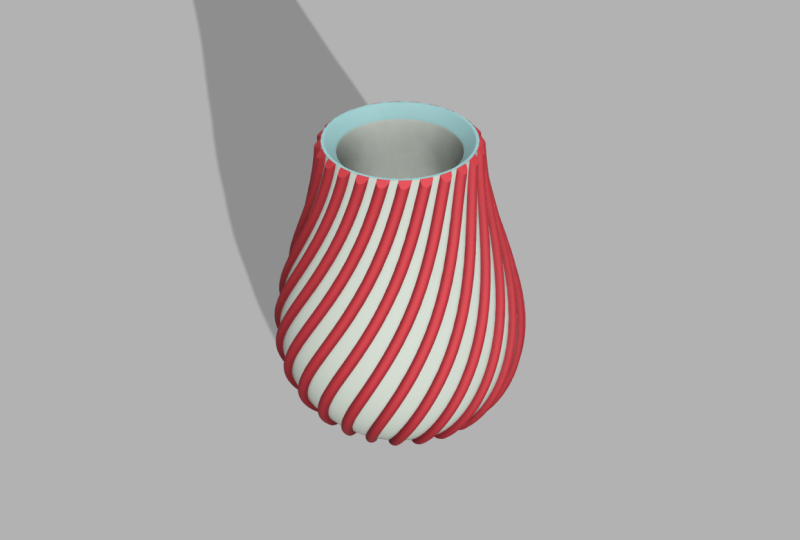
appears in the browser. To finish, use the shell
tool on the solid body. This transforms it into a stylish vase created with
minimal input and effort. Boundary fill has many uses. For example, you could calculate the vase's water capacity
by using it and much more. There's so much more
to discover in fusion. See you in the next lesson.
36. Introduction to Section three - Project Based Tutorials: Welcome to our nuts
and bolts project. Now that you have mastered the basics in
Section one and two, it's time to put that
knowledge into practice. In this hands on project, you'll create a hig
knot and a bolt, applying the fundamental
skills you have acquired. Ready to bring your
learning into life, let's jump right in
and start creating.
37. Autodesk Fusion Hexnut Project: Dive into your project
with a strong start. First and foremost, I recommend saving your
project immediately. This simple habit keeps
your work organized and safeguards against any
unexpected data loss. Now, let's get into
creating your components. For this project, you'll be working with two
essential parts, a hexnut and a bolt. Right click in your
browser to create them. Since this isn't a
sheet metal project, choose the standard type. We'll be using a top
down modeling approach, selecting internal
is the way to go. Naming your components
clearly is crucial. It makes everything
easier to manage. Your top level component
will act as the parent, which is perfect for our setup. Typically, you'd leave the
activate option checked to start working on your
new component immediately. However, since you're creating both components right
from the start, you can leave activate
unchecked for now. This keeps you in
the main component, making it easier to manage
your initial setup. Once you click Okay,
your bolt component will appear in your browser ready for you to start building. This organized approach sets a solid foundation for
the rest of your project. Imagine the small anchor
symbol as a sign that this component is firmly attached to the
parent component, much like a rigid joint. While you won't need to worry
about this for our project, I thought it would be useful to mention in case
you were curious. Every action you
take is recorded in the timeline of
the active component. This handy feature allows you to easily navigate through
your model's history. Just ensure you're working
in the correct component to keep everything organized
and aligned with your plan. We'll start building our
free D model from a sketch. I'm creating a bolt that
will stand upright, so using the horizontal
construction plane is ideal. You have several
polygon options, but I suggest using
the top two since they let you create a polygon
from a central point. Using the origin as your center point is
particularly helpful because it provides a
consistent reference which you'll see in action
later in our project. You can size your
polygon anyway you like, but it's important to understand what the measurement represents. The distance from the center
of the polygon to its side. Notice the blue infill. That means our
sketch is closed and a polygon constraint has
been automatically applied. Change the length
of one side and all sides will
adjust accordingly. Now, here's a time saving tip. Instead of exiting the sketch before making your next move, go straight to the next step. For instance, if
you press the Ike, you'll exit the
sketch environment and jump directly into
the extrude command. For this example, I'll set
the height to 10 millimeters, but feel free to experiment
with different dimensions. We need a closed profile
that starts from the profile plane extending 10 millimeters without
the taper angle. This setup is
perfect for creating a new body within our
active component. You built the foundation
for your first component. Great job. Before
we move forward, it's a good idea
to save your work. This way, you can always return to this
version if needed. When I hit Save, it still
says V one version one. But as soon as we
start the next step, which is sketching, the file
will update to version two. Let's die back into sketching
our bolt component. This time, we'll use the face of the component instead of
a construction plane. This approach lets
us sketch exactly where we want the next
part of our design. For this part of the design, we need to create a circle. It's a good habit to use keyboard shortcuts
to speed things up. By pressing the C key, the circle command
becomes active, which you'll notice by the blue highlight behind the
circle icon in the toolbar. Remember, I asked you to center your polygon
above the origin. This is the second time we're using the central
point over the origin, ensuring that both
our circle and polygon are perfectly positioned
relative to each other. I'll give the circle a
diameter of 20 millimeters, but feel free to experiment
with other dimensions. You can always right click your sketch in the
timeline to edit it later. Any changes you make will update all subsequent actions
in the timeline. To save some time, press the E key to activate
the extrude command. For the extent type, we'll
type a distance since we're not extruding through
or to another object. We'll start at the profile
plane where we made our sketch with the
direction being one sided. The taper angle isn't
relevant for our design here. Lastly, don't forget the
operation drop down menu. Autodesk Fusion suggests a join operation
which works for us since we want everything
we've modeled so far to be included
in the same body. But remember, there will
be times when you'll need other options from this
menu, so keep an eye on it. Your bolt needs a thread which you'll find in the
create drop down menu. The image shows an
internal thread, but this tool works just as
well for external threads. Our entire bolt
will be threaded, but you can easily uncheck
the full length option if you want to set a custom start distance and
thread length. This thread is just a
visual representation. If you want to free
the model the fread, which you might need to do if you're planning to
free the print it, you can check the modeled box. Keep in mind that modeling the thread makes your
design more complex. While this won't be an issue for a small project like ours, it can slow you down
on larger projects. Unless you need a
fully detailed thread for printing or other purposes, you can leave modeled unchecked. Regarding fread type,
size, designation, class and direction,
we'll just note that standardized options
exist for these settings. However, we won't dive deep into those details
for this project. By using the default settings, you'll still get a functional and visually accurate
thread for your bolt. This approach keeps things
straightforward and efficient, allowing you to focus on the overall design
without getting bogged down in complexities that aren't necessary
for this tutorial. Every action you take is
recorded in the timeline below. This timeline is specific
to the bolt component. When you move on to
the hex nut component, a fresh timeline starts capturing your actions
there as well. Now as you begin sketching, it's important to utilize
the bolt component. While we could create
a new polygon, that would be a mistake and
add unnecessary work since we want the hexnut to match
the size of the bolt exactly. Instead, let's make use of your original bolt
sketch which is conveniently located
within the bolt component. To do this, go to the create
Menu and select project. The selection filter
allows you to choose whether you want to project
from the sketch or the body. By using the projection link, you are ensuring that
any changes made to the original sketch or body will automatically update
the projection. This is especially useful if you ever decide to adjust
the bolt size, as the hig Nut will
adjust accordingly. Now, you'll see a polygon
sketch on top of the bolt. The purple color and the projection symbol indicate that this is a
linked projection. Next, activate the
extrude command by pressing E and
create the extrusion. I'll measure the bolt to ensure the hignut matches
perfectly in size. If you get an incorrect
measurement, no worries. Just right click and select
repeat measure to correct it. Obviously need a
hole in our hignot. Instead of just drawing a
circle and cutting it out, we're going to use
the whole command, which you'll find in the
create dropdown menu. It's a good habit to use keyboard shortcuts
whenever you can. I'll go ahead and
activate design shortcuts by pressing S and
searching for hole. Now, while the
quickest way would be to press H for
the whole command, searching is a great
backup if you ever forget the shortcut or
haven't learned it yet. We need to position this hole
correctly and once again, we'll align it with the
central point at the origin. It can be tricky
to spot the origin behind all the other
components, but here's a tip. Press and hold the left mouse
button to reveal a menu, then select O to move
your whole to the origin. For quality assurance,
it's always a good idea to check your
work from different angles. While the whole command might look perfect from the top view, a different perspective could
reveal some issues like accidentally cutting
into parts of the design that you
want to keep intact. We certainly don't want to
cut through our red parts. To fix this, you can
adjust the whole settings. Changing the extent type
to all isn't helpful here because it would drill through the entire
boat component. Instead, I'll set the depth to match the thickness
of the hex nut. In some cases, you might prefer to link the depth
to another object, so it updates automatically, but that's more advanced than we need for this basic tutorial. As for the whole
type, let's go with the threaded hole matching the settings of your
external bolt thread. Everything's looking
good so far, so let's continue
refining the design. In the modified dropdown menu, you'll find a wide range of commands to tweak and
refine your design. As you might expect, the great dropdown
is where you build your components and
the modified menu is where you fine tune them. One useful tool here
is the chamfer tool, which lets you remove
material from your edges. To get started, select the
edges you want to hamfor. If the distance value window gets in your way, no problem. Just press and hold your mouse button until
a small hand appears, allowing you to pan around your workspace and
get a better view. As you select more edges, keep an eye on the bottom
right corner of the canvas. You'll see the number of selected edges
update in real time, so you can be sure you're
working on the right parts. Once you've made
your selections, go ahead and add a distance,
but don't stop there. There's more to the Shafer tool than just setting a distance. For example, you can experiment with the
blend corner type, which I think will give our
hexnut a nice smooth finish. If you prefer a different
look like a sharper edge, try the Shafer or
mitre corner types. The key takeaway isn't to
memorize every corner type, but to stay curious and explore the different options available in various command environments. Once you're happy with
the settings, press Okay. Personally, I think the hegnut is looking even
better than the bolt, so let's apply the
same chamfer to your bolt and keep that
sleek finish consistent. Before you dive into any work, make sure to activate the component you
intend to work with. This is crucial, especially
if you're planning to tackle more complex
projects down the line. We're going to keep reinforcing
the use of shortcuts. Instead of going through the modified drop down
menu this time, I simply right click and
choose repeat chamfer. This saves time and keeps
the workflow smooth. Now, go ahead and
select all your edges. There should be 18 in total, which you'll see confirmed
in the chamfer menu. We're going to stick
with the same settings, a 1 millimeter chamfer with an equal distance type and a blend corner type to give it that smooth,
polished look. You can bring your
components to life by working with either
materials or appearances. Think of appearances as purely cosmetic. They're
all about the look. Materials, on the other hand, not only change
the look but also add physical attributes
like weight and strength. In simpler terms, appearances
handle the color while materials bring
in both the color and the engineering properties. Now, in this project, we're not diving into the
engineering side of things, but let's apply E material just to get familiar
with the process. Mateials are
organized in folders, and all you have to do is drag and drop them
onto your component. You'll notice that
many commands and workflows in fusion are
designed to be intuitive. Even if you haven't
used them before, you can often guess
your way through. Let's switch over to the
Hixnat component and repeat the process with the
physical materials command. I'm going to choose
lik red metal, but you're welcome to explore the fusion material
library and pick whatever color and
material you like best. It's time to bring your
components together. To do that, head over
to the joint command or simply press the
keyboard shortcut J. Whenever command has a shortcut, you'll see it listed right
there in the drop down menu. Before selecting
your components, make sure to choose the
correct joint type. For this project, we
want our hexnut to both slide and rotate
around the vertical axis, making the cylindrical
joint the perfect choice. When you start
selecting components, remember that the first one
you pick will move first, we'll select the hexnut
component first. You can see, I made a
mistake trying to place the joint exactly
centered above the hole. Here's a pro tip
to make it easier. Hover your mouse
over the face while holding down control
if you're on a PC. This trick helps you snap
right to the center with ease. You can use the same method
when snapping to the boat. Now, your hex nut will
reposition itself according to your joint and you'll see the joint
appear in the model. Next, let's talk
about motion limits. You have two options here, rotate and slide. We'll
start with the slide. You can set limits for how
far the hex nut can move. For instance, I'm setting the
maximum slide distance to 50 millimeters and you'll immediately see a
demonstration of that limit. The rest position is where the joint will
naturally settle. Since I set the slide limit to 50 millimeters,
it rests there, but if I had set it
to 25 millimeters, the joint would rest
at 25 millimeters. X Nut moves deep into the model. Let's set the minimum slide
limit to 0 millimeters. This is where we initially
set the joint snap, meaning any positive
value moves above that spot and any
negative value below it. You can preview how
both rotating and sliding limits will look by
selecting those options. It would be more realistic and
frankly more impressive if the joint rotated back once it reached the top. Let's
make that happen. Find your joint in the
browser and model, right click it and
choose edit joint. In the joint motion
limits options, go to the rotate section. Once you activate the limits
and set some degrees, you'll see an illustration of your settings right around
the joint in the model. For this basic tutorial, I'll set the minimum rotation to zero degrees and the
maximum to 180 degrees. Make sure to check all
limits before previewing. Now, the hex nut
rotates 180 degrees, pauses, and then returns
180 degrees backward. It's pretty
mesmerizing to watch, but let's keep moving
forward with our project. When it comes to renderings,
you've got options. You can do them locally
or in the cloud. And some are free while
others might cost you. For this tutorial, we'll keep it simple and create an
Canvas rendering. First, switch your workspace to render in the
top left corner. You'll be rendering exactly
what you see on the screen, so it's a good idea
to hide any elements like joints that you don't want to include in
the final image. You can easily do this in the project browser by
toggling visibility. To get started, right click
and open the scene settings. You'll notice that many of the settings and shortcuts feel familiar if you've used other
computer programs before, like right click
contextual menus and various keyboard shortcuts. Rendering in orthodskFusion
is straightforward. One of the basic settings
you'll need to decide on is whether to use a solid color background
or an environment. Simply drag and drop your preferred environment
into the scene and don't forget to change the
background setting from solid color to
environment to match. Adjusting the
brightness, positioning, and other settings
like shadows and reflections is intuitive
and easy to grasp. If your chosen
environment has lamps, you can easily position
them in relation to your object using
the rotation command under the position settings. There are, of course, more advanced settings
you can explore later, but for now, we're focusing on building
a broad skill set. We'll get into the more
specialized features of autodesk fusion once you've
got the basics down. You can start your render
directly in your fusion canvas using the in Canvas render
feature. It's straightforward. Just press the in Canvas
render play button to begin. As the rendering
process unfolds, you'll see the elapse time and
iteration number appear in the bottom right corner while your image gradually takes
shape on the canvas. If you want to increase
the number of rendering iterations for a sharper result, just drag the little icon that looks like a
cater to the right. When you're happy with
how everything looks, simply press the capture Image button to save
your rendering. Once you're happy
with the settings, validate the first
menu by clicking Okay. If you'd like to
rename your image, now's the time to change the image name and select
your preferred file type. I'm going to save this
project to my local computer. But remember, you also
have the option to save your image directly to
a project in the Cloud. Image turned out fantastic, especially considering this was a free rendering done with standard settings and completed
in just a few minutes. There you have it. You
successfully completed your HxnutPject using a
top down design approach. You probably recognized many of the commands from earlier, but we also introduced some
new ones along the way. I believe the three key
takeaways from this project are. First, stay organized. Think of it as an investment. Taking a little extra time at the beginning to set up
your components properly, name them clearly and switch between them as
needed will save you time and open up
more possibilities as your designs
become more complex. Second, make the most of symmetry and preset
design resources. In this project, we frequently
return to the origin which allowed us to work quickly and maintain high
quality throughout. And third, make smart choices. Instead of manually
sketching out a polygon with lines and angles, we use the polygon command
to speed up the process. If you ever find yourself
needing a particular command, chances are that
others have needed it, too, so it's likely available
within the software. Next time you're unsure
if a command exists, take a moment to search for it. You can activate
design shortcuts with the Ske and see
what's available.
38. Autodesk Fusion Roundbox Project: Massive learnings ahead, let's make a rapid prototype
of a round box. Quick tip, save your
project right away and copy paste the project name
in your internal component. Stunning designs begin
with the sketch command. To create a standing round boox, it makes perfect sense to select one of the vertical
construction planes. Efficiency is key here. Start with the simple
two point rectangle and seamlessly navigate between data input boxes using the tab key to keep your
workflow smooth and swift. To create segments for your
Round box three D model, use the line commands. Don't worry too much about where you place the first line. Just focus on shaping the
different parts of your sketch. When adding constraints, use dimensions to
control the size. The last dimension is based on the others and appears
in parenthesis. As you edit, your
sketch will adjust automatically reflecting the
changes in your dimensions. Save time by moving
straight from the sketch environment to
your solid modeling command, in this case, revolve. When extruding profiles
around the central axis, be sure to select the
correct operation type to keep your second body
separate from the first. Right click to repeat
the revolve command and change the operation
from joint to new body. This approach lets you focus
on each part separately, which will be
incredibly valuable and essential as you
progress in the project. Luck doesn't
determine the success of this project.
You're in control. Use the section analysis
to guide your next step. If you see the wrong side, just flip the direction
and continue. Keep the section
analysis on as you add an external thread
to your round box. To make navigation easier, turn off the visibility
of one of the bodies. Select the outside of the visible body to
add your thread. The default setting only shows
a visual representation, not an actual three D model, which saves memory
usage on your computer. To create a real free D
thread, select modeled. For this rapid prototype, choose a thread that
looks realistic. Remember your choice as you'll use the same settings
for the second body. Repeat the steps for Fred, modeled and designation before turning the visibility of
the first body back on. Let's move on to creating
the body of the round box. You can use the rectangle tool, but feel free to explore
other options as well. Just like with the
first two bodies, the goal is to create a sketch that will revolve around
the central axis. A mix of the rectangle tool offset and the line command
works perfectly for this. When you use the
revolve command, the presets are mostly spot on, but make sure to set
the operation type to join so that this new body merges with the first one since they were part
of the same object. Et's make a few quick
tweaks to your lid. First, trim a bit of the bottom to ensure it fits snugly
with the round box. Then add a bit of height to
the lid and close it up. Draw this sketch right
on top of the lid. A simple circle will do the job. Make sure it covers
the entire lid, even the parts hidden by
your section analysis. Things look great for you, but the corners could
use some softening. The standard fillet settings work well for
smoothing the corners. Just be careful not to select
your thread by mistake, so skip the selection filters when choosing multiple edges. A 1 millimeter fillet looks just right
for this prototype. Turn off the section
analysis and sketches, then move and rotate your lid. Place it on the ground. But instead of guessing
the right position, use the align tool to save time. If you have trouble
selecting surfaces, switch the object setting
from components to bodies. A great appearance will impress your
colleagues or friends. You can choose any
material you like. I'll go with ABS, a popular three D
printing material known for its strength
and durability. If you want, right click
to edit your color choice. Then head to the
Render Workspace to create an image
of your design. Right click on the Fusion Canvas to open the scene settings. Feel free to customize
it as you like, but I recommend using an
environment as your background. You can simply drag and drop one from the
Environment Library. Before closing the
scene settings, make sure to adjust the
position and other details. If you want to see how
the lighting looks, use the ViewCube for
a better perspective. For this tutorial, I suggest
trying the Cloud renderer. Just set your width and
height, then hit render. Your rendering will appear
in the rendering gallery. Just click it, choose your
file type, and download it. I hope you enjoyed this
project as much as I did. See you in the next lesson.
39. Autodesk Fusion Dice Project: I hope you feel lucky today. Let us make a dice together. Let's get started by staying organized and saving
your project right away. You can copy the project name and use it for your
internal component. If you're using a top
down design approach and don't plan to reuse this
dice in other projects, an internal component
is the way to go. In this Autodesk fusion
project for students, your sketch will serve as the foundation for
creating your die. You can begin by selecting
any construction plane, though I recommend using the horizontal
plane for this die, as it aligns well with
the laws of physics. For this project, I suggest using the
center rectangle tool, which will help ensure that your dice is centralized
at the origin. Next, choose the dimensions for your die and
make a note of them, as you'll need to use
the same value for the extrusion distance
to maintain consistency. While we won't be using user
parameters in this tutorial, consider exploring
that option as a bonus to enhance
your design process. To speed up the
process of selecting all edges rather than
selecting them one by one, which can be time consuming
and prone to mistakes, here's a helpful tip. Create a selection filter
specifically for body edges. This will allow you to select
all the edges at once, saving you time and
ensuring none are missed. For softer corners on your dice, you can apply a filllet. Feel free to experiment with the dimensions to achieve
the look you prefer. You don't need to follow
my exact measurements. One interesting filllet
option is the corner type. Personally, I like using the setback corner
type for my dice, but feel free to choose what
works best for your design. Infusion, keep an eye on the timeline located in
the bottom left corner. Every action you take
such as sketching, extruding, and adding
fillets is recorded there. If you need to make changes, simply right click
on any step and select Edit to modify
your previous work. At this point, you can customize the appearance
of your dice. This way, you'll only need to go back and edit
the dots later. While ABS is a strong and durable material
for freed printing, feel free to choose any color or material that suits
your dice project. For creating the
dots on your die, I recommend starting
with a single sketch and reusing it across all six sites. This approach reduces the chance of errors and speeds up
the overall process. Finding the center of your sketch plane
is straightforward. You can size the dots
however you prefer, ensure there's enough
room for all of them. Instead of manually placing
each dot one by one, which can be time consuming, use a rectangular pattern. This will allow for precise
controlled positioning and offer options for
symmetrical placement of the dots in all directions. You may notice that
your die requires 1-6 dots per side,
so why sketch nine? Think of this as a template. You'll never use all nine
dots on any single side, but this setup will streamline the placement of
the correct number of dots as you move forward. Copy your fusion sketch to
the other sides of your die. There are different settings
and workflows to consider, but let's start with a
straightforward approach. First, select your circles, enable to create copy option, and move your sketch
by -50 millimeters, which corresponds to
the depth of the dice. We use a negative value because the movement is in the opposite
direction of the arrow. The second copying workflow will help enhance your skills. Start by selecting your sketch. Keep in mind that
even though you may check the create
copy checkbox, switching to the point to point copy command can uncheck
it automatically. The point to point method allows you to move
elements with precision. Now, consider how to
rotate your sketch. Switching back to the free
move option will enable this, but a new challenge may arise. If you rotate using the
current pivot point, your sketch won't align centrally on the
side of your dice. To fix this, you can
set a new pivot point. Think of it as choosing a new
spot to hold your sketch. Be sure to confirm
this new location. Otherwise, no change
will be noticeable. Once the new pivot is set, you can easily rotate and position your sketch in
the desired location. Observe carefully as you move your sketch to the opposite
side of your dice. Notice that your pivot is based on the first
selection you made. While this works well for
this particular move, this insight will be valuable for future
copying workflows. We're working point to
point again, but this time, begin with the central
circle and make sure your pivot is correctly
positioned from the start. Hold down control as you
select each circle one by one. Don't forget to check the create copy option when activating point to point mode. Now, finish the final side. With more circles on the screen, it might be trickier to
select the right ones. So take extra care not to
pick from the wrong source. Start by creating a single hole to test the settings for depth, fillet radius, and
overall appearance. Make adjustments to these
parameters until you're satisfied before applying
them to all the holes. Choose your extrude depth and fillet radius based
on your preferences. For the color, I'm keeping it simple with a black
and white dice design. This time, instead of applying color to the entire
die like before, switch your settings to faces and color specific
parts of the die. Are you ready to move forward and create the rest of the dots? Simply select them one by one. If you're not satisfied
with the outcome, you can always use the timeline to go back and make adjustments. Personally, I recommend
working on one side at a time. Remember, you'll need to extrude a negative value when extruding in the opposite
direction of the arrow. There's a small arrow
here with an extra dot, but that gives me a chance
to show how to edit using the timeline later.
And that's it. All the dots are created and every extrude action is now
recorded in the timeline. This model is getting
intense infusion toggle the sketch visibility in
the project browser to get a clearer view before selecting the edges
you want to fill. Notice that the arrow points in the direction of your selection. I'm setting my fillet
to 1 millimeter, but feel free to try something different with your
design infusion. This side looks off, find the corresponding
action in the timeline, then select edit feature. Once inside, you can deselect the circle from
your fillet action. We're seeing an error message because a later
fillet action became impossible when the
reference geometry or extruded hole was deleted. It's no big deal.
You can go back, edit the feature and confirm the updated reference
geometry without the hole. Fusion will adjust accordingly. Don't forget to save
your project regularly. Fusion allows you to
open different versions, so it's smart to save not
just at regular intervals, but also when you
hit key milestones. This way, you can always impress your spouse
with your progress. Before adding appearance
to your extruded dots, make sure to switch from bodies
and components to faces. You can apply the appearance
to each dot individually. It may seem a bit manual, but it's surprisingly fast. The view cube is
an excellent tool. It allows you to
paint your model from different angles with a
more organized approach. You no longer need to
view all the edges, so feel free to switch
to a shaded view. It's a good practice to
regularly check your work from different angles as part of your quality
assurance routine. There's an error on the
dice. Can you find it? It's on the side with six dots. Fortunately, it's a simple fix. Head back to your
design workspace and open the appearance menu. Apply colors to
any missing faces, double check the other
sites for consistency, and then return to the
rendering environment. Right click on the Canvas to
access the scene settings. You can keep it simple, rotate the scene to create
a nice shadow, then submit a free
cloud rendering. My rendering appeared in the gallery within
just a few minutes. You can easily toggle between
your renderings there, and there are some additional
settings worth noting. Using the turntable
feature costs flex tokens, but it's a great option
if you need one. Post processing allows for quick and easy edits to your rendering
before downloading, and you can save your image
with multiple options, including a transparent
background. The file name will automatically include a date and timestamp, and here's what my
final image looks like. I really hope you enjoyed
this Autodesk fusion project. Along the way, you explored
various workflows, including sketching techniques, the Fillet tool,
and the timeline. I look forward to seeing you in future projects. Thank you.
40. Autodesk Fusion Chess King Project: This exciting project,
you'll bring a chess king to life by combining
an image and a sketch. Along the way, you'll master a variety of
sketching techniques, learn how to set up construction
planes with precision, experiment with different fillet commands for smooth edges, and carve out intricate details
using the Extrude tool. By the end, you'll
have a strong grasp of essential modeling
techniques and a stunning chess
piece to show for it. As always, let's start by setting ourselves
up for success. Go ahead and save
your project first. In this tutorial,
I'll be creating a new internal component specifically for
this chess piece, so everything stays organized and easy to manage
throughout the project. I'll start by importing my licensed stock photo using
the insert Canvas option. You can follow along
by choosing a photo to trace and inserting
it from your computer. Select a construction
plane where you want your chess
piece to stand upright. If you need better
visibility while sketching, feel free to adjust
the canvas opacity. The other default settings
are fine for this project. While your image may not
be the right size yet, we won't worry about
scaling it now since we don't have
the exact dimensions. Go ahead and click
Okay to proceed. You'll notice a red boundary around the image, but
don't worry about that. It's just the outline
of your canvas. Right click on the Canvas to open the
calibration settings. Once inside, select two
reference points on your canvas and define the
distance between them. In this tutorial, we're
working at a one to one scale, and I'm setting
my chess piece to be 100 millimeters tall. However, feel free to choose any dimension that
suits your project. If you need to reposition
your inserted image, go to the edit Canvas option. To help find a
logical placement, you can enable the origin
in the project browser. While perfectly
centering your image over the origin isn't
crucial for this project, it's a helpful practice to keep your work organized
and predictable. Doing so will make it
easier to insert components into other projects and have them appear in a
logical position. Are plenty of sketch
tools available, including splines,
arcs and lines. We'll experiment with
a few techniques and address potential
challenges along the way. For instance, we can
place a circle here, and it would be helpful to have the same radius on both
sides for symmetry. In several areas of the design, using the same radius
will enhance the look, and we also have
an opportunity to place a circle on
top of the model. Let's begin by using the
center diameter circle tool, which makes it simple to position a circle
directly on the sketch. Some of you may prefer
the two point circle, which lets you define the
circle by selecting two points. Next, we'll revolve the sketch
around the vertical line. If the line ends up too long, you can easily drag
and resize it. A horizontal slash
vertical constraint will keep the line
perfectly vertical. Fusion often applies
this constraint automatically when
you draw the line. Additionally, you don't need to sketch everything from
one side to the other. You can easily connect
lines afterward, which can be helpful if you have repetitive commands to execute. Extend is a great tool when you need to extend one
line to meet another. Let's start working on the
sketch using the line tool. If you press and hold the left mouse button
while drawing a line, you can also create an arc which makes tracing images
quick and enjoyable. While fusion has more
advanced methods for refining curvature, this technique works well
enough for our current project. Now, let's move forward to the next interesting point
in our image tracing. An effective approach for
achieving equal radii on both sides is to begin
with the two point rectangle. We can then use a mirror line to duplicate one
half of the sketch, and the filllet
tool will help us create rounded corners
with equal radii. Fusion automatically applies the same radius to
your next selection. It's common to sketch extra geometry and trim away the parts that
aren't needed. Let's continue using
the line and arc method and jump ahead to another
key moment in our tracing. Here's another chance to use the two point rectangle
alongside the fillletommand. Remember, pressing
the Fkey will close the contextual
sketch environment and open the solid
modeling Fillet tool. In the sketch environment, the filllet tool is
recognized by a thin line. Don't forget to add filllets to connecting lines for a
smoother appearance. Let's jump forward again to
the next notable section. The possible radius you can achieve depends on
the connecting line, and adding a small line
in the right direction can make it easier to
create a longer radius. Let's make another jump
and see where we are. The three point arc is another excellent tool
for image tracing. The curvature constraints that appear automatically ensure that lines are connected to a single point
without overlapping. For the bottom, don't forget to add a line to
close your sketch. If the sketch doesn't turn blue, that indicates it's still open. We need to fix this before moving on to revolve our sketch. We'll also need to smooth out some edges with the filet tool, and if we're lucky, we'll locate the open
part of our sketch. If the open part remains hidden, we'll try a few
different techniques to pinpoint where
the sketch is open. The bottom part of the
sketch turns blue, signaling that the
unconnected segments are located at the top. The white dots highlight
the lines that aren't yet constrained to
the surrounding geometry. While the sketch can still
close around these white dots, if we zoom in, we'll
spot the issue. There's an overlap right here. This is where the
mistake occurred. The blue fill confirms
the sketch is now closed, meaning there's
no need to search for additional
unconnected lines. When we activate the
revolve command, the sketch profile is
automatically selected, and the result appears as
soon as we choose our axis. While the default settings
like angle, direction, and operation type
work for this project, it's a good practice
to familiarize yourself with these options
for future designs. I'm happy with how
the lower parts of the geometry turned out, but take a look at
the top of our king. Do you see what
needs to be fixed? Right now, the crown doesn't
quite resemble a crown, so we're not there with
our chess king just yet. To fix this, you'll need to
create a new sketch plane. From there, sketch a profile
that will help you trim away the excess geometry and
shape the crown properly. Make sure to toggle the visibility of
your initial sketch. We'll use it as a
reference for symmetry. Now, you're sketching on
the new construction plane. Don't worry if the positioning isn't perfect on the first try. You can always use the Autodesk fusion timeline to
edit your sketch, and everything will
automatically update. Any part of the original
sketch can serve as the mirror line since they
all share the same axis. Next, use the shortcut E to jump directly to
the extrude command. For the extent type, choose
all instead of distance. This ensures that future updates to the size of our
king will be included. Our chess piece is starting
to look like a king, but we still need to refine the edges for a polished finish. Use the filllet command
to smooth the edges. Another way to do this would have been to keep
the corners sharp in the sketch and add the fillets after the solid body was made. This would give you more
control over the final shape. Use the copy move command
to set up both kings. Toggle off the visibility of anything you don't
want in the rendering. Press A to open the appearance menu.
Wood gives a nice look. But if you're three D printing, choose a color that matches
the filament you have. Our chess pieces look good. Right click and open
scene settings. I want shadows, so
I'll reposition the rendering environment
for those rim highlights. They're placed differently
than in other environments. If you want, try
Cloud rendering. I'm sticking with an
in Canvas render. You can switch from excellent to final if you
want more detail. While the rendering runs, let's go over three
key takeaways. First, you traced an
image using arcs, lines, rectangles and circles
to create the sketch. There are many ways to do this. Some focus more on
sketch precision, others on adjustments
in solid modeling. Different workflows,
same problem solved. Second, you used
construction planes and the extrude cut command to remove parts of
the king's crown. It was faster than making
a perfect crown from scratch and integrating it
into the revolved profile. Lastly, we made an
internal component, but I think an external
one could be interesting. We could standardize
the king's base and then create custom crowns
for different models. Just a thought. Hope you
enjoyed the project. Happy three D modeling.
41. Autodesk Fusion Phone Stand Project: Come to this project where
you'll master the art of designing and rendering a practical phone
stand with fusion. This project will take you
through essential steps like setting up projects,
precise sketching, surface and solid modeling, applying filllets for
enhanced user experience and optimizing for
free D printing. We'll dive into rendering techniques to bring
your design to life. Start your project by saving it immediately and creating
a new component. I'll opt for an internal
component here, as I'm not planning
to collaborate or reuse this design
in other projects. Access the design shortcuts menu to create your new
internal component, ensure the activated option is checked and then confirm
by clicking Okay. Begin your sketch on
any construction plane. I recommend using a vertical one for easier navigation
with the ViewCube. Start from the central point
of the origin and draft a rough sketch that will serve as the foundation
for your design. All right, let's refine
our sketch dimensions. You can either measure
your own phone or find the dimensions online if you're aiming for a model that fits
your specific device. Note, black lines in
your sketch indicate constraints which
make your sketches more predictable and
easier to manage. I noticed I've entered the wrong dimension
for the foot here, so I'll exit this and
correct the measurement. Escape the current
dimension command and re enter the
correct dimension. Once you've set the lengths, take a moment to check
the angles as well. There's currently a small
gap under the foot, but don't sweat it for now. We'll address details like that in upcoming modeling steps. Once you've completed
your sketch, finalize your sketch
by clicking on the finished sketch
button and rotate your model to view it
from different angles. This helps in catching any unnoticed errors
or misalignments. Remember, the more accurate
your sketch at this stage, the easier the following
modeling steps will be. Now we'll move to
our next command, which is in the
surface modeling tab. While you can find it through
the design shortcuts, let's navigate there directly so you know where to find it. Go to the surface
tab on your toolbar. The extrude command here differs from the one in
the solid modeling tab. This one allows you to
extrude thin lines. Change the direction
to symmetric. This ensures your model remains centralized
above the origin. Input 20 millimeters for the
half length measurement, since this will extrude
20 millimeters on each side, totaling
40 millimeters. Ensure everything looks correct, then click Okay to confirm. This approach will give you a balanced and precise model
of your phones back support. Let's head back to the
solid modeling environment. To add thickness to our design, locate the thicken command in
the create drop down menu. Select the faces you
want to thicken. You can do this either
directly on the canvas or by navigating through the model in the browser for the thickness. Set a symmetric thickness of 1.5 millimeters on both sides. This gives us a total
thickness of 3 millimeters. This thickness is
beneficial because it's sufficient for addition
to the free D printing bed. It results in a sleeker, more elegant model that prints faster compared to
thicker designs. Remember, the choice of
thickness can be a matter of personal preference or
specific project requirements. Once you're satisfied
with your settings, click Okay to apply. Tip, if you're not yet comfortable with terms
like symmetric thickness, it's a good practice
to measure and verify the distances to ensure your model meets
your expectations. Activate filllet
via the toolbar, design shortcuts or with
the keyboard shortcut F. The full round fillet is a great choice
for areas like this. Getting rid of those sharp edges will improve the
user experience. I'll keep the sharp edges at the sides because it
will make it easier to print this model
with larger areas facing the three D printing bed. But I recommend that you switch to the
regular fillt option and remove the remaining sharp
edges excluding the sides. Make a quick quality check from the side angle
before moving on. Appearance can be found in
the modified drop down menu. I'll three D print this in a red mate color and use the
same color for my rendering. A quick three D printing tip before we proceed to the
rendering environment. Print your phone stand lying
on its side like this. It will make things easier. With that said, let's move on and render your phone stand. Set up your rendering through the scene settings accessible
via the right click menu. I personally prefer using an environment as a background for the excellent
lighting it provides. Adjust the lighting to
achieve perfect shadows. Then move to the render
settings where you can customize the width and
height among other options. Let's now jump to the
completion of the render, which you can monitor in the bottom left
corner of a fusion. Our rendering is complete,
so let's review it. You can download it in your
preferred file format with or without a
transparent background to any location
on your computer. Congratulations on
completing this project. You've now mastered
designing, modeling, and rendering a phone
stand using fusion. From setting up projects
to precision sketching, surface and solid modeling, filleting for ergonomics, and optimizing for
three D printing, you've gained a
comprehensive skill set. Plus, you've learned to render your designs
professionally, showcasing your ability to visualize and present your work. Keep creating, keep innovating and see you in the next project.
42. Crafting a modern Hanging Vase in Fusion for 3D Printing: Let's design a sleek, modern hanging vast that's
ready for free D printing. Every great project
begins with good habits, and your free de vase
design is no different. First, let's save
your project with a meaningful name and
upload it to the Cloud. A well organized
workflow starts here, making your project accessible anywhere and easier to
manage as it grows. Next, we'll create a
standard internal component. Components are the backbone
of many workflows in fusion, ensuring better organization and flexibility as your
skills advance. By starting with this step now, you'll set yourself
up for smoother, more professional
designs in the future. The default construction
plane is ready, but let's expand the
workspace by adding two offset planes to create three levels for
your vase design. For my vase, I'll place the first offset plane 100
millimeters above the base. Then I'll add
another offset plane reaching a total height
of 150 millimeters. You can either reference
the base directly or add 50 millimeters from the
construction plane at the top. The reference point you choose shapes the structure
of your design. Let's explore why it matters. Your construction
planes are set. The bottom to middle plane is 100 millimeters and
the top plane is 150 millimeters from the bottom with a 50 millimeter
step above the middle. This setup creates the
framework for your valves. Here's the power of fusion. Ofset planes are flexible. You can adjust them
in the timeline. For example, changing
the first plane 100-125 millimeters
moves the top plane to 175 millimeters while keeping the 50 millimeter step if the top plane were
tied to the bottom, it would stay at 150 millimeters
breaking the balance. Let's start your
vase design with the first sketch on the
original construction plane. This marks the sharp point
at the bottom of the vs. Select the point tool
from the create menu and place it at the origin.
Simple and centered. Next, move to your first
offset plane, the middle one. Right click to quickly enter
the sketch environment, draw a six sided polygon
starting at the origin. Instead of using a 100
millimeter radius, reduce it to 50 millimeters to avoid steep angles that could cause three
D printing issues. A good rule is to
keep angles under 45 degrees depending on
your printer and material. When finishing the sketch, use the S key for the
sketch shortcut menu. It's quicker than
clicking the button. For the third sketch, go to the highest
construction plane and create another six sided
polygon above the origin. Making it about 60% the
size of the middle one, this is your chance
to experiment and refine the size and
proportions of your vase. Let's organize your model and get it ready
for the next steps. Keeping your
sketches labeled and tidy is key to an
efficient workflow. A well organized design helps not only you but anyone
working with you later on. Start by renaming your sketches. Click on each one in the browser and give it a clear,
meaningful name. Use a system that works for you, whether it's descriptive
or project specific. Now, let's shape your
model using the L of tool. Loft is versatile, and there are multiple ways to use it
to achieve your design. Let's experiment a bit
to find the best method. First, I'll select all
profiles in order, but that doesn't give
the shape I want. Instead of forcing it,
I'll hit Escape to exit. Sometimes it's
better to pause and rethink than settle
for a poor result. Let's try again this time selecting one
profile at a time. That works much better
and the base looks great. I'll hit Okay to confirm. To continue, I'll right click
and choose repeat loft. Notice how fusion suggests
a join operation type. This is perfect for creating a single unified solid
body for our design. Your vase is coming together. Before we finish, be sure to give your model
a proper name. Naming your components is a great habit to stay organized, especially for more
complex projects. Saving your project
regularly is like creating a safety net
for your creativity. Every design journey
has its ups and downs, so take a moment to
save your progress. You can even name your
versions and set milestones, making it easy to revisit earlier ideas or
recover from mistakes. Now, let's dive
deeper literally. The Section analysis tool is perfect for looking
inside your model. See the hatch pattern. That
means it's a solid model. To turn this into
a functional vase, we need to hollow
out the inside. Enter the shell tool, your new best friend
for hollowing designs. Start by selecting
the top face of your vase and setting
an inside thickness. For this design, I'm
going with 3 millimeters. This strikes the right balance between using less material, reducing three D printing time, and ensuring a sturdy result. Plus, it gives you a stable
surface for printing. And just like that, your
vase is taking shape. It now has room for soil
and a beautiful flower, but those sharp edges,
they need a little work. Let's make edge selection
quick and painless. Picking edges one by
one can be tedious, especially with many edges. Here's a game changer,
the selection filter. Switch it to body edges, and you've selected all
48 edges instantly. This simple trick saves time and keeps you focused on
designing, not clicking. With your edges selected, it's time to refine them
using the Shafer tool. This feature
flattens your edges, giving your design a
sharp, modern look. Keep an eye on the
chamfer distance. Fusion will alert you if it's too large for
your model's geometry, giving you a helpful nudge
to maintain balance. Now, let's get creative
with corner types. The meter option adds a sharp, angular finish while
the blend type softens things for
a smoother look. For this vase, I'm choosing the chamfer corner type to match the clean geometric style. But don't just follow my choice. Experiment with the options and select what fits
your design best. You've done a great job bringing your ways
to life so far. Now, there's one final step
to make it truly functional, adding a way to hang it. Let's create free holes to hang our vas while exploring
free workflows. These holes aren't
just practical. They'll also show off Fusion's
parametric design power. The first approach
might seem obvious. Sketch three circles manually
and turn them into holes. Simple but tedious
and prone to errors. The second is faster, sketch one circle and
duplicate it with a pattern. However, this can complicate
the model unnecessarily. The recommended
method is better. We'll sketch one
hole, extrude it, and then use the
circular pattern feature for precision and simplicity. Starting with the
sketch, I'll place a center diameter circle on the Chamford part of the vase
sized at 1.65 millimeters. It's perfect for
fretting fishing line, giving the vase a
floating effect. Next, we extrude the hole. The vases geometry
makes this tricky. I usually rely on the
extrude two object feature, but I made a small mistake
by clicking the wrong wall. If I'd click the right one, it would have worked perfectly. No problem, though. Fusion
offers alternatives. Instead, I'll over
extrude the whole ensuring it passes
cleanly through the wall. Here's where Fusion's
parametric features shine. If the holes position is off, you don't need
to start over. Adjust a sketch in the timeline, and fusion updates
everything automatically. It's not about getting it
perfect the first time, it's about staying flexible. Think of your extrude cut as a living part
of your timeline. When earlier features change, it adapts automatically.
Here's how it works. Find the sketch
in your timeline, right click and choose
Edit Sketch feature. With the sketch active,
press for move and copy. Use the YXS arrow to shift the position while keeping
everything else intact. Once you're satisfied, hit Okay to return to the
design workspace. The circular pattern tool
is ideal for creating evenly spaced features like
the holes in our vase. Start by going to
the create menu and selecting circular pattern. Since we're working
with the hole, set the object type to
feature in the drop down, this is essential to make
the tool work as intended. Now, select the hole as your
object and choose your axis. If your sketch is
centered at the origin, you can simply use one of the predefined axes
for perfect alignment. For this vase, we
need three holes, enter three in the
quantity field. Once everything is set, press okay and you'll see three evenly spaced holes
placed around your vase. Go to the Modify menu and select appearance or just press
A for quick access. Fusion lets you apply
appearances to entire bodies, components, or even individual faces for
detailed customization. Browse the appearance library to find the perfect
material or color. Drag it onto your
vase to apply it. If you see a small arrow icon, you'll need to download
the appearance first. Just a quick click. For my vase, I'm using a matte white plastic finish
for a sleek, modern look. Keep in mind, the colors in fusion are for
presentation or renders. They don't affect the
actual free D print color. Here's a pro tip. Right click your applied appearance
and choose Edit. You can adjust the color,
roughness or reflectance, or even input exact RGB values
for precise customization. Before we dive into rendering, save your fusion project and add A Version description
to stay organized. Switch to the Render
Workspace and open scene settings by right
clicking in the workspace. I'll set the background to
an environment setting. Cool lights work
beautifully here. Adjusting light angles and
brightness adds depth, turning a flat image
into realistic visual. Your render captures
the current view. So take a moment to adjust
the perspective using Zoom, orbit, and the view cube. For this tutorial, I'll
create a Cloud render which delivers high quality results,
great for presentations. If you're short on time, in Canvas rendering is
a faster option. Both let you customize settings like aspect ratio
to fit your needs. Rendering times worry, but this one took less
than 2 minutes. And there it is a professional
render ready to showcase. You can even download it in different file
formats and choose options like a
transparent background. Fusion makes it easy to create
visuals that stand out. Great work getting this far. Now, let's prepare your design for export and bring it
into the real world. Go back to the design workspace and open the file
drop down menu. Select Export, but first, save your project if
you haven't already, it's always good practice. In the export dialogue, set the file type to STL, the standard for
free D printing. Choose where to save the
file, then click Export. Remember, exporting
uses the Cloud, so ensure you're
online. That's it. You now have an STL file ready for slicing in your free
D printing software. When setting up
your free D print, flip the vase upside down in the slicer for the best results. I hope you've enjoyed
this tutorial. You've nailed the basics, and we'll pick up the pace in future projects. See
you in the next one.
43. Industrial Design Pen Holder Project: You can use Fusions solid
modeling commands to design a sleek pen holder
that adds style to any desk. In this tutorial, we'll
explore sketching, extrude, fill it, chamfer, and other essential tools. Start strong, save your
project and set up a dedicated component to keep
your workflow organized. One option could be to
start with a simple box, but I recommend using
a center rectangle. This keeps your design
centered on the origin, which will come in handy
later in the workflow. For realistic dimensions,
take inspiration from the measurements of best
selling pen holders online. If needed, you can always
return to the timeline to adjust the sketch or tweak
the extrude height later, offering flexibility as
your design evolves. You can use Fillet in both the sketching and solid
modeling environments. Each option has
its pros and cons, but a good rule of
thumb is to keep sketches simple and
safe operations like fillets for the solid
modeling environment. This approach makes it easier to adjust and refine
your design later. I'm setting the thickness
to 5 millimeters to achieve a robust and durable
feel for the pen holder. This strikes a balance
between quality, free D printing time, cost, material usage, and
environmental considerations. Chamfers are a great way to enhance both the aesthetics
and durability of a product. With a thickness
of 5 millimeters, the chamfR distance
is naturally kept. A smaller chamfer on
the outside paired with similar top and bottom
chamfers creates a clean look. Adding a slightly
larger chamfer on the inside adds depth and
refinement to the design. Being centralized
above the origin makes it easy to locate
the design center line. We'll use this line to create the pattern around
the pen holder, starting just below
the chamfered edge. While you can use
user parameters to ensure the line
updates with the chamfer, that workflow is beyond
the scope of this lesson. Fusion offers many tools
to add or remove geometry. The pipe tool, like others, provides settings to
customize your design. As mentioned earlier,
modifying a solid model in the solid modeling
environment is often easier than making changes in
the sketching environment. Using the pattern
on path tool with a few adjustments is ideal
for distributing the pattern. First, change the object type to features before
making your selection. The pen holder began
as a rectangle with 475 millimeter edges,
totaling 300 millimeters. With the fillet supplied, the perimeter is now shorter. Let's estimate 280
millimeters, not quite right. 285 millimeters
feels a bit long, but 283 millimeters
seems just right. Next, switch the orientation
to pot direction for better corner results
and set the quantity to 45. Now that you're familiar
with the workflow, take your time to refine the distribution and quantity
for the best result. There are many ways to apply an appearance
to this design. If you want the pattern feature
to have a unique color, I recommend coloring it
before creating the pattern. This way, you only need
to color one phase. You can also explore
the color libraries to find the perfect shade. Since it's a snowy day,
as I'm recording this, let's go with snow white
for a clean and crisp blue. Save your project before diving into the
rendering settings. Use a descriptive milestone name to keep track of your progress. Once saved, head to the
workspace picker in the top left corner to switch
to the rendering workspace. Right click the fusion Canvas in the rendering environment
to access scene settings. I'll set the background
to environment and choose sharp highlights
for a clean look. The suggested settings
usually work well, but feel free to fine tune them, including adjusting the camera
angle to your preference. When ready, start
the Cloud renderer with your desired
width and height. You'll see an estimated Q time, and the rendering will appear in the bottom left corner
of the workspace. The estimated queue time for this rendering was
under 20 minutes, but it completed in about seven. Once finished, download
your rendering in your preferred file format with or without a
transparent background, depending on your post
processing plans. If the file name is too long, shorten it to ensure
it saves properly, and that's a rep for the Industrial Design
pen holder project. Here's the rendering
we just created, along with another I made, featuring additional
items in the scene. I hope you found this
tutorial helpful and look forward to seeing you in the
next project. Thank you.
44. Create an eye-catching 3D-printed vase in Fusion!: Build this three D
printed vase and solve a major challenge that came
up during this design. You'll see every keyboard shortcut in the
bottom left corner. This tutorial moves faster than earlier ones because by
now you've made progress. Finish your component,
click Okay, and save your project
with a clear name. Start with a two
point rectangle. I'm using 100 by
100 millimeters, but feel free to experiment
with your own dimensions. The width isn't critical as long as it's wider
than your vase, but the height sets
the vos final height. Place the bottom left corner at the origin for a well
centered design. Stay in the contextual sketch environment
for our next step. Try to minimize the number of fit points blind control points. Three control points are
sufficient to shape this vase. The exact positioning of the control points isn't
important at this stage, since we'll refine the design. I set the top of my vase to 25 millimeters and the
bottom to 30 millimeters, giving the top a 50
millimeter diameter. You should try your
own dimensions to see how they
affect the design. Remember, you can
always adjust it later using the fusion timeline. Press and hold a control
point to move it. Control points snap to
the grid by default, but you can disable this
for more flexibility. Click to activate
green handles for finer adjustments in
multiple directions. We're using the solid
modeling revolve command recognizable by its blue
color to shape the vase. The surface modeling
option is orange. The default revolve
settings are perfect, so we just select the
profile and the axis. A quick check from
the home view in the ViewCube confirms
everything is on track. Turn on the sketch visibility, and let's work on the twisted
shapes around the walls. Instead of offsetting the spine and revolving a new profile, we'll create a
profile directly from the sketch to keep the number
of sketch items minimal. Start by extruding
a line outward. Our goal is a profile that extends 90
degrees from the vas. Since we can't extrude it
directly at a 90 degree angle, we first create an extrusion
and then thicken it. The symmetric two millimeter extrude turned out too large, but I kept it as
part of the project. Troubleshooting design issues is key to the iterative process. We'll identify the
problem and adjust it later in the project
as we refine the design. Once we have a surface,
we can thicken it to define the patterns
thickness around the vase. You saw the curved
pattern around the valves in the image at the
beginning of this project. The part we just created serves as a cutting
tool for that pattern. Soon, we'll create
another profile and use this tool to cut
out the curve design. Use the shell command to hollow out the solid body
into a valves. The ideal thickness depends
on your priorities, balancing material usage,
print time, and quality. Each factor impacts cost and has environmental
considerations. Set up two construction planes, one above and one
below the walls. These planes give you the space to oversketch the
curved pattern, ensuring a cleaner finish
when we cut it out. You can easily access
the latest tool you used via the
right click menu, which speeds up your workflow. There's no precise distance between the planes and the vas, so place them wherever it's most convenient for
navigating your model. Let's start with the sketch on the construction
above the vas. I'll begin at the origin
and over sketch this. The exact length of this
line doesn't matter since we'll cut out the parts we
need and erase the rest. The angle we set here, combined with the sketch line we'll
make under the vase, will determine the overall angle of the curved pattern
wrapping around the valves. Practice makes perfect. Let's finish this
sketch and repeat the workflow with a new
sketch line under the vase. Again, we'll start
at the origin and make this line 100
millimeters long. Just like before, we'll
cut out the section that wraps around the vase and
keep it discarding the rest. A quick quality check with the ViewCube shows that
both lines look great. It's easy to forget when
having this much fun, but remember to save
your project regularly. We're using the surface
modeling loft command recognizable by its orange color since we're lofting
two sketch lines. The solid modeling loft
requires closed profiles. This large thin profile is exactly what we
need at this stage of the design process.
Thicken the surface. This thickness will determine the patterns thickness
wrapping around the vase. I'll keep the
extrusion direction symmetrical and extrude a
total of 2 millimeters, providing enough
material to work with while maintaining
an elegant design. We can see the
curved shape where the lofted surface
meets the vase. Let's turn off the visibility of the sketches and the vase
to get a better view. We'll use the revolve
command around the central axis and set the
operation type to intersect. This keeps everything
that the revolve operation intersects
and removes the rest. Next, turn off the visibility
of the tool used for the revolve intersect operation and turn on the vase visibility. Everything looks good so far, but there's a small issue
we need to address. You would have
encountered this problem if you follow the
exact dimensions and made the revolve
intersect operation with the vase body visible. Let's refine the face's edges. The thickness limits how
large a chamfur we can apply. Zooming in, we see an
issue with the profile. It cuts into the vase. We mentioned this at 2:40. It's an easy fix,
but we'll leave it for now and focus
on the chamfur tool. There's more to learn
here. Applying a chamfer almost seems to fix the issue, but it doesn't.
You'll see why later. Use the right click
menu to access the chamfer command and apply it to the bottom of
the curved section. Again, the maximum chamfer
distance depends on thickness. It's smart to apply
these filets and chamfers now before creating
a pattern around the vase. This keeps the workflow clean and prevents unnecessary
complications. Now, the full round fillet
option is parametric, meaning it updates
with design changes. It also gives the vase
a smooth, rounded look. Adding custom appearances
in fusion is easy. If you need inspiration, you can find matching
color codes online. Start with a base material. Since this vase is
for free D printing, I'll use a matte plastic
finish, common for filament. Apply a color to the vase body, then right click to Edit. I'm using the Advanced option
to enter a ig color code, also known as an
HTML color code. You'll find this
under Edit color along with plenty of other
customization options. Right click and duplicate
your custom appearance setup. Like the full round fillet, applying this before creating
a pattern saves time. Renaming your custom color
helps keep things organized. We'll enter the hig color
code in the same place, but if you have RGB values, you can use those elsewhere. This custom color is for the
pattern around the vase, and since it's an
individual body, we leave the settings to
bodies and components. When creating a third
appearance for the vase, keep in mind it's for
the Camford section. Since it's not a separate body, change the setting to faces. Zooming in makes it
easier to select the right surface before
applying the appearance. When you name appearances, it helps keep your fusion
project organized. You can quickly
identify materials, match colors across designs, or even note the
filament you plan to use for your three
D printed vase. Great job sticking with it. A well structured fusion project makes
everything smoother, and this three D printed vase
is really coming together. It's smart to save
your project before advanced patterns
or timeline edits that require heavy computations. Circular patterns
are easy to use, especially with a central axis. The hidden blue
axis automatically appears when selecting axis
in the contextual menu. The preview updates instantly
as we adjust the quantity. I'm going with 24
for a balanced look. Once we click Okay, a bunch of new bodies appear in
the project browser, a great reminder of the
value of planning ahead and performing some actions on the part we used in the pattern. I'm saving again
because I plan to edit the computations
through the timeline. The pattern looks great, but we can add more twists. Those two lines are used in the loft feature later
in the timeline, and the loft is cut with the
revolve intersect command. The intersected profile is then used in the
circular pattern. This means changing
those two lines lets us test new looks with
minimal data input. Let's address the issue. We mentioned 2 minutes and
40 seconds into the lesson. Zooming in, we still see some red under the
light blue surface. This happens because the shape unintentionally cuts into
the vase when revolved. One fix is to make the
extruded surface very thin but still long enough to
be thickened and extruded. Another solution which shifts to a solid modeling
workflow is to offset the original spine and use the new closed sketch profile
in the revolve command. After adjusting the extruded surface, everything looks great. We can see the new
fin profile in the thickened feature if we
check it in the timeline. Well done completing
the project, you worked in both the solid and surface modeling
environments, mastering revolve, loft, shell, and advanced patterns
while refining sketches and solving
real design challenges. Now it's your turn. Upload a rendering
of your vase to the course project
gallery and show off your unique take
on this design. Thank you and see you
soon in another project.
45. Course completion: Congratulations on completing
the course. Fantastic job. You have successfully
navigated through the fundamentals of solid
modeling in Risk fusion. Your journey into
freedom modeling is just beginning and there is so much more to explore and create. Let's co create the
future of this course. This course is a
collaborative effort and your feedback is essential
for shaping its future. Here are three important
things I'd love you to do. First, stay updated. Keep an eye on the
course description for upcoming updates. As new content is added, you'll continue to expand
your skills and knowledge. Two, share your experience,
leave a review. Your insights will help future
students understand what they can expect and how this
course can benefit them. Three, provide feedback. Share your suggestions for
future course updates. What topics do you want
to dive deeper into? What new features are you
eager to learn about? Thank you for taking
this journey with me. Your dedication and hard
work have paid off, and I'm excited to see the amazing projects you will create with
Autodesk Fusion. Remember, this is
just the beginning. Keep practicing. Stay curious and never stop
learning. Thank you.
 Martin Lennernäs, Autodesk Fusion Enthusiast | Maker