Transcripts
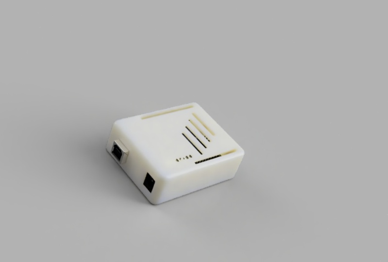
1. 1 Introduction: Hello and welcome to the course in which you will learn how to design a 3D printed enclose our for Arduino boards using Fusion 360 free software. This is astronaut from what you learn in this course is how to download and install free version of 360 or Fusion 360. We will exit plan the user interface. And you will learn how to get your design dimensions and how to create your frame using specific dimensions that are available online. You will use features like extrude, Cham far split and other techniques. You will also be introduced to the time back future to fix mistakes. So if you made a mistake at the first stage in your design process and you did discover this mistake at the last stage, you can easily, with a single mouse click, go back in time to the first step and fix it. Then you don't have to go through everything all over again. You can simply go to the last step after fixing the issue. And this is explained inside our course. This feature will save you hours of hard work and redoing the same design or the SAM steps can also check, you'll design for errors and discover if an error happens once you import a 3D model of the Arduino board that you are creating the case for. I will also teach you how to import and hopefully the model until the Fusion 360 environment and how to place it inside the case that you just created. You will also learn how to create cutouts and chip guts. And you will add all your able to add your own name. And artworks are to the top layer of the case. And the end, you'll be able to create a 3D motion video for your project. Like this one. This is assembled video. As you can see. The upper part is moving away and you can see it's moving away. And the Arduino parts are exploding everywhere. You can't share that type of machine that you want with any other type. That's it. This is everything that we are going to cover in this course. I'm sure you will enjoy this course material. If you have any question, you can't simply ask that you and the board see you inside. This is Ashley.
2. 3 Design the outer frame in 2d: Now let's get started by creating a blank design. And I'm going to start off by creating a sketch that really drives most of my design for this enclosure. So I'll start by making a 2 rectangle. So what you need to do is basically go here, click Create, then create, sketch. And you will get this window. After that. Now, click here on this plan and go to the 2 rectangle, which will create a rectangle using two points for the diagonal corner. Click once, click here, then you can move to any point. And before doing that, let me show you that I mentioned for our algorithm all enclosure. Now as you can see here, we have 53.3 centimeter. And here we have a 101.6 centimeter. And on the other side we have 53.3 centimeter. And here we have 68.6 for Arduino Uno. And these are for Arduino Mega. Since we are making this for Arduino, we will stick to these 53.368.6. So let's meanwhile this choose two points, rectangular ones here. And now you can start writing 53. Boy three. And the other dimension, which is basically this one, you can't simply it, it the dimensions or you can delete it and draw this again. Committee, there's now 53.3. And on the other side we have click the tab button on your keyboard. And Dr. says 68.6. Now we have Furman enclosure for our Arduino. Let us start by modelling the outside shape of ma, Arduino, followed by some holes. And we are going to make these holes using the circle tool, since our diameter circle, and you can simply draw the holes wherever you want. I'm going to make them 2.8. You need to draw four holes. And another one here, 2.8102.8. The last one will be here. These holes will be for the screws. And you can make them larger or smaller depending on what you prefer. Now, let's measure without the distance between the holes and the border is to say convenient. Now let's use the dimension tool. Plague the distance between these two. Let's say 14. And same for this one. The distance from here to here. Let's make it 14. Now. Let's make the distance between this hall and this all 66.1, same for this point. Okay, now let's control the vertical distance. Let's make the distance between this hall and this pole does 2.5. and let's make this sense between this hole and this 50.7. Now, let's make this distance between this whole this area, 7.6. Let's make a sunscreen, this hole and this line, 35.5. Okay, and that's it. Now we have created four holes and you have created the main frame. And the next lesson, we are going to make some adjustment so that we can extrude this shape or this sketch. Thanks for watching this lesson. See you next.
3. 4 Extrude and Split the body in half: Okay, now that we have the holes dimensions, I'm going to be building the enclosure around my Arduino. And I want you to have a little bit of Fourier room. I don't want it to have to fit perfectly within the enclosure, so I'm going to use the offset tool. Now what you need to do is select the offset tool and start by selecting the ones that you want to offset. Then you can't choose the amount of space that you want to move this boulder to. Then you can choose the amount of space that you want to move this board 4s2. And let's make it one, and then click OK. Next, select the four NR lines. And right-click and choose normal construction. That's it. This is how you can apply the offset. Now once you are done, click Finish Sketch, and let's rotate it. You calculate it wherever you want. As you can see here. Now, click extrude. Unless they see everything. Now, choose these four points. And now you have this tons to one or two millimeters. As you can see, the full profile points up. But we also need to select the plane. So again, go to Extrude, choose this, this point, this point, this point, and this point then choose 22 millimeters when into that sets. This is the outer shape, our structure. Now we need to shell out this buggy and do that. Click thou shall out from the Tools menu. And you need to select the body, which is the one that we just created. Then choose 1.6. Hit enter. That's it. Now we have shell out all pudgy. Now we want to split this in half. So I'm going to create our construction plan. So go to the construction and choose midpoints. And let's make it between the upper body and lower body. Let's go back up to the home points so that you can see what's happened. Now, as you can see, I have chosen the upper and the lower body to make our midpoint construction. Now, this is the construction plan, as you can see, it's an orange or yellow. Now, click OK. And we have these two plans and took off him in half box. You need to go here. And from this menu you cancel x split body, unsullied the body about we want to split. Then you can simply select Lapland that's you want to use for splitting. Click OK. And now you have two bodies, the upper, the lower one. As you can see. That's it for this lesson. If you have any questions please ask in the next, we are going to make more adjustment.
4. 5 Create standing points for the case: Hello and welcome. Now that we have created our, let's say outer surface or outer buddy, let's create all x through these four points. So let's hide the construction plan. The buddy, verbal Buddy. Now here we have four points. We need to extrude them. So it's rude. And start by selecting the four points. Now, you cancel lit the x through the amount. You can make it 11, but I will make it 15 millimeters so that we can see there are higher than the lower body. To help stick the lower and upper body together. The next thing that we need to do is add some standoffs here, here, here, and here. And these four coulombs or whatever, you call them. Ok, now, what on these four circles who need to add standoffs? So what we need to do is simply Right-click and we can't ever sketch or we can simply select a sketch tool and select this surface to draw a sketch. Now, you can't simply go. Now to the other four circles. What you need to do is simply select the central diameter circle. Make sure that you select the central Benetton. And from this point you can start throwing your circle. You can zoom in to make sure that you're throwing circuit correctly. And make it four millimeters now or one to the next one. Do the same. Formerly retires, make sure that it's in the sensor. Okay. Now let's move on. And the rows are circled here. Another former Lemaitre. And the last one will be here. Four millimeters. Now finished sketch and go back to the home. And select, extrude, select these four circles. Make sure that you are selecting the circles. Okay? This is the first circle. So this one, this one, this one. And this one was formerly winters. Now let's go back. Now the phis though disappearing problem, you need to select extrude mesh with LTR, selecting these four surfaces. Here, the outside surface, k, Again, the outside circle. It's very since, as you can see. Now this ok. Now here and select for and myself got you in. Select new body. And also join. Then click OK. Now you should see two initial yo this. You should see the standoffs created around each of these points. Now if we did the high the sketch, you can see them. Okay. These are the sand ofs and these are the man standing points for the Barr body. That's it for this lesson. Thanks for watching.
5. 6 Using Time Machine to Fix errors and add filllet: Now to make our case look Pixar and remove these four corners, let's add affiliate. But to do that, at this point, it will be problematic. So we can use this feature which is the timeline. We can go back in time to the point where we extruded the face before filling, before adding affiliate, or before cutting the body to two parts. Now, choose the affiliate tool and select the four corners. Select this one, and select this one. Now what you need to do. Now, let's make a three millimeter click. As you can see now, we have an ice shell around the shape, around the corners. And we can't go back. As you can see. Now we have what we did it, it apply to the last shape which has all components and which has lower aren't up our body. This is how you can use the time feature to go back in time to any point. And it is something that you did wrong, then you can proceed to the future. And this is a very nice feature. Thanks for watching. This is Ashraf.
6. 7 Upper body holes and Chamfering process: Now what we need to do is creating a sketch on the apart buggy. So let's move here to the sketch tool and select this to create a sketch. Now let's hide the body. And this is the sketch that we're all going to create. Now, we need to protect n upper body, as you can see here. Heal me. Ok, this, now, this is the lower body and this is the sketch that we created on the upper body, we need to project and these four circles. So to do this, now to project these four circles, you can simply click on your keyboard, all go to the Create menu. And from there choose projects and simply project from here. This will project these four circles. Okay? Now as you can see, we have a sketch here. These four circles, projector's. Now let's hide that puppy and choose the top menu. Now let's select these. Select these four points. Ok, click OK. Now select these four points. Are projected points. Right click and choose normal construction. Now we will use these four points as reference. So let's zoom in. Now less SAR creating our circles. Click here, select the center and select 2.8. Since we already selected 2.8 for the men points other than with our lower buggy, let's choose 3.2 here so that we can allow some clearance. Now let's draw another circle, and let's make it 5.2. Now, let's move on. We can link this smaller. We can add cell five-point too. We can add five. Now let's move to the second. This one, when it is the same point to the second circuit, needs to be five. So let me turn. Now, let's move on to the next 1.253 or five millimeters. Now, again, let's move on to the last 13125 millimeters. That sets. Now, let's go back. Okay, this is it. This is our sketch. Now let's show the body. Let's go back to the home view. This is the top part of our enclosure. Less latitudes. As you can see. This is the third Barth. Now we need to exclude these. So click Finish Sketch. What we need to do now is simply select extrude and select these four points. Select the outside circle and select 11 or ten millimeters. And now if you did look at it from another angle, as you can see, it will fit perfectly. Now let's hide this unsure. The lower body. We can add shuffling here two 0s in these points and allow them to get the whole easily. To do so. And go to the Modify, select Channel four, and select these four circles. And you can't select 0.4 millimeters. As you can see. Now the holes are shown fold. You can select 0.2 millimeters or whatever you want. It's up to you. And that's it. And let us lesson. We are going to add Arduino Uno to this enclosure, aren't. We'll start cutting things to make our Arduino or more USB ports visible. But that's it for this lesson. Thanks for watching.
7. 8 Importing Arduino UNO 3D Model: Hello and welcome. Now we are going to download Arduino on. The first step that you need to do is go to google.com and right, Arduino Uno for Fusion 360. And the first result is from o to this library. So click on it. And here we have an Arduino Uno. Click open, all download the model. And you can simply download it by clicking once. Now click I have read and agreed to perfuse. As you can see, I'm downloading this library file. Now, go to your fusion and select the library option from here. Click Upload. Usually you'll get this menu and go to libraries, double-click and select upload. You can now select the file that you just downloaded, which is this file. Now select Upload. It will take some time to upload this model to your library. Depending on your internet speed. Once uploaded, you can easily use it with your design. Now you can't get other models or other schematics, 3D designs from their library. As you can see here we have our gallery and also this group sides. It has a lot of elements. As you can see, there are three for you to use modify. And you can even 3D print these models. Okay, now complete, click Close. Let's see if it will work with our design or not. Right? Now, once you have it in your library here, you need to import it. And once you import that, you can choose how you want it to be located. We want to make sure that it's located exactly in a way that will fit and all design. Let's hide or the ok. That's it. As you can see. Now it fits inside our enclosure. Now click enter. And as you can see, this is our Arduino and here is a top view. And as you can see, everything fits perfectly and dislocation. Now let's name these. This is the upper body, but we need to create components from buddies for each of these two values. The first one and the second one. The first one, which is this one, is the lower body. And this one is the upper body. Okay? Now, let's take a quick look here. As you can see. Now once you convert it to our components, you can simply move it around. And let's measure with us than our body is treated as a ground. So right-click and select the round. That's it. Now we have our Arduino and the next lesson we are going to create some cuts for the power supply and for the SP. Thanks for watching this lesson. This is Ashraf.
8. 9 Creating Joints and fixing issues: Now we can create a joint between the upper and the lower part D by simply clicking here, joint, continue. And we can't simply take this, select this point. And then we can select this point and the lower body. And then click OK. That's it. You can even, let's press controls it. And you can select joined. Again. Let's rotate this, select the same point. Let's go back and select the same point here. Now, from this menu, you can control the motion, how it will move. As you can see, our board down to can show you this. As you can see, up or down cylindrical way. And these can be used for motion or other stuff. Now that are the most convenient one is the slider up and down. You can run the animation and you can't control the axis parts. Let's make it rigid nor case. As you can see, it sticks. And then click OK. That's it. Let's hide the apart so that you can see the bold. Now we need to create some cutouts. So click here. Go back here. And those you can see you can either cut out for this and that gets outfalls our power supply right here. But before doing that, we need to make sure that our Arduino is standing on bass standoffs here. So to do that, we need first to hide, let me hide this. We need to hide the lower surface and go down here. We need to use the joint. Select this circle. And once you do that, go and hide the Arduino, show the lower surface, the rotate. This wheel to stand here on this offset. Now after that, what do you need to do is simply click OK. And let's show our Arduino. Or let's make sure that everything is in its place. Okay. To see the top fuel. Now this one is okay, this one's okay. And we have problem with this one. So we will fix this issue. But let's make sure that we won't have issues here. No. No. She's here. And not shields here. Okay. So if you're going back to the home location, you can see that our algorithm now is standing on the top of the standoffs. Now, let's go back and fix the issue that we have here. To fix it, we need to go back in time. Again. Do the sketching area. I think that if we, if we go back here, show the sketch. Okay? Now we have formula or this line. So we need to fix it. And to do so, what we need to do is simply right-click Edit Sketch. And as you can see, we have problem with this space. And if you did check this image, you can see that space between this point and this point to the edge is 14. But if we wanted from the middle here, it's pi one boy, three offsets from faulty in so as 15.3. So let's change this to 15.3 K. We need to make sure that you are choosing the right one. Let me move with the hand tool and share this value, 15.3. Now it has moved to this location, finished sketch, and move to the future. We have problem here. Okay? Now let's go back to the home location. We have this algorithm's hide it. We don't want it. Okay, now let's see the top view. And as you can see, the problem is now fixed. But we need to fix the x standoff extrude, which is basically and other sketching job. And as you can see, if we want back to that top home fuel, this is the sketch. And sketch. We can simply right-click and elite sketch. This is the original sketch. And this is lambda one that we want to add it. What we need to edit is this sketch, the hidden one. So let's hide this one until this one. It is sketch. And let's hide this body. Let's zoom in. And as you can see, this sketch needs to be 3-2 depending on this. So we can either move this one here. Okay? We can't move it. I don't think that this will be a problem. Ok, let's assume N. Now everything is clear. We can go back to our design and see the top view. For the home location. Let's hide the arbor body. Let's see the top view. And as you can see here, we have the xth root option. Since we have two extrudes, Ricardo move one of them and keep that good one by simply clicking and clicking Delete. Now let's move to see fingers. Okay? Now this one is a PA, and this one is OK to. Now let's hide the Arduino. Just to make sure that if we do all still have any problem, we can simply delete the thing that caused the problem that's causing the problem. Now simply select this and click delete, go back and show the Arduino ball. And as you can see, everything fits perfectly. Now we have everything in its place. That's it. This is how to fix that issue. If you did face one.
9. 11 Adding Pins cut out and some art work: Now that we have our bold up under the, we can create cutouts to access pins nor Arduino boards. And to do that, we need to go here. As you can see, this is the Apollo body. We can simply create a sketch on this body. As you can see. Now, what we need to draw on this sketch will depend on our Arduino board. Now, we know, let's hide the upper body. We know that these are the pins. So list project their location by simply selecting the best dot. And this dot, this dot, and this dot. Then we can show babble. Click OK. Here we have the dots. Now select the 2 rectangle and start throwing your rectangle. This is the first one, and this is the second one. Now, click Finish Sketch and choose the x through Tool. Select this one and this one. And let's hide the lower body and the alveolar wall. Let's choose that, extend to object and rotate this. And we need it to cut out frontal three-ish for secant surface and choose cut. Then click OK. Now if we do show the Arduino board and all of the connections where you can see that we have the pins here and here. Now if we did see a top view, this black area is that lends area and this area is that bends area. Now, we can do one more thing to make sure that we have more space. We can go back here to this sketch. And the right-click Edit Sketch. We can't select these two shapes. And choose 0.5. And here we can choose 0.5 as well. Now, once we do that, click Finish Sketch. Now the x through the area can be modified. So we can modify the xth root to include this area. And then click OK. As you can see now we have more space to accelerate the spins. I will zoom in to make you. As you can see, we have 0.5 millimeters around this black area so that you can easily insert your pins. This is one thing that you can't do. A thing that you can do is simply create a shape here. In the upper body, depending on your needs. My case, we can't simply click, Create, Sketch, unselect this upper body. And now what we can do is write a text. So click here and create text. We can simply write educational engineering team. And let's rotate it so that we can. And let's add EDU ANG theme. And as you can see, this is the test that we are going to add. You can show that the height to be five millimeters. And you can show that degree if you want. I'll make it bold so that the cut-out would be and I got shape. And we can add.com. We are making promotion for all company. Then you can choose the font type. If you want to change it. Now click OK. And once you do that, as you can see here, you can even draw some shapes here. We can draw few rectangles. One here. We don't really have to be. These are just some drawings. Just to make our board look nicer. You can draw whatever you want. Now that's it. You can't simply click Finish Sketch. And you can select, extrude, select this text. And this, this, this, this, and this. Then choose the extent to object. Again high, the lower and the Arduino rotates. And select this surface. That's it. Now if you did it rotated, click OK. And as you can see now, you can see your company name and you can add some cutouts so that your ball will look nicer. As you can see. You can add unashamed, you can add a heart rate, monitor shape, or you can import some shapes. You can add an arrow or whatever you want. These are the shapes that I did use. And there are good either the name of all female professional engineering team, you can choose any other thing to add to this. Let's say upper surface. Consider it like an art piece. And Sky is your limit. That's it. If you need to create any other cut out, you can easily do that by simply creating a sketch, then extrude it on that surface. If you have unequal question, you'll ask electron volt. This is our Aldon closer or Arduino case. Thanks for watching. This is us.
10. 12 3D Animation: Now, let's see the last parts of this course, which is that the animation. Now to animate this 3D design and go through this menu and select animation. Now as you can see, this is the animation pan. Now let's delete this. As you can see here, we have all components. This is the upper, lower and our Arduino board. Now, let's start with the upper body. Right-click on it and select manure unexplored, choose where you wanted to move. I wanted to move in this direction. And you can see how to remove using this slider, as you can see. So let's move it away and click OK. Now the next step will be moving our Arduino, which is this one. Now articulate. And let's select Manual explode. And let's see how this will work. As you can see, since this Arduino is an parts, we might have a problem moving it. So let's right-click on this and select Auto exit Lord, all levels. Now, once you do that, it will move in all directions. All of these components. Now once you add autopsy blogs and all directions or of that emboldens side, the ball will move each in a different direction. And if you did move the slider, you can see how these components are moving. And then click this checkmark. And the last tip is moving the base, but I don't prefer that. Once you are done with that motion for each of these components, you can't view or simply publish, love video. Choose one ATP, click OK, and it will be saved to your computer. A few clicked here. Save to my computer than shoes, admin a project, all default project, and choose a name. Then click Save. It will start rendering. As you can see. And I will show you the exported video in less than a minute. You will find it in your downloads folder. Okay, now that video, there's, as you can see, first, our Arduino bald moved as the friction that we did thrill. Tell it to move, which is this direction, as you can see, it's, it's sliding. Then we have all of our Arduino board components. As you can see, the Alex blogging everywhere and all directions. This is the auto explore future that we did apply. And you can add other things to the storyboard and our animation pan here. As you can see, this is the first animation which is basically a box is sliding. And this is the second animation where all components exploded and different directions. And we didn't do anything to the lower part. That's why it did stay and its location. That's it. If you have any questions please ask in the Huangdi aboard. Thanks for watching. This is us.
11. 13 Create a sketch for Arduino Mega: Hello and welcome to this new lesson, inner child going to apply what we have learned throughout the course to create a case for Arduino Mega. Now the first part was creating a case or enclosure for Arduino. And we will follow the same steps for Arduino Mega. The first tip is go and open up to this Fusion 360. As you can see, these are the dimensions. We have 53.3 centimeters here, millimeters, and we have a 101.6 millimeters, about ten centimeters and five centimeters. And we will make it rectangular shaped. Then we would add the six circles and their location and according to these call donations. So Let's get started. Now this is anneal project and the first thing that we need to do is create a sketch. Choose this plan. Now, let's draw a rectangle. And as I already mentioned, we need to these dimensions, 53.3101.6. So 53.3. And this loop is again 531306. As you can see, this is the rectangular shape that we want. Now, the next step is drawing the circles. So let's draw the circles. Let's use this image as a reference. As you can see, these are the locations. Okay? Now, choose a circle form here and start drawing and you need one. Regarding the diameter, you can make it 4.2 or one or three. I'll make it 2.6. Now if you looked here to this image, as you can see here, we have the diameter is 1.3. So double the half is 2.6. And it's the same for all of these. So 216. Let's add another one here. 2.6. Here. Six, here, two, 16, and here. Another one here. Now what I need to mention is that you should print this image so that you can use easily. I will open it up and another screen so that I won't keep moving from one window to another. Now, I have some other screen. And IN0, now the distance between this circle and this line is 14 millimeters. So let's choose the dimension and choose this. And as you can see, I already mentioned that the distance between that tangent or the circle or the edge of the circle and this area is 14. And since we are making the distance between this area and this dot, we must add the 1.3, which is half the diameter. So the total will be 15.3. As you can see. Now, the next step is measure the distance for other items. Let me show you. Now this item. The distance between this item and this line is identical to the above one. So let's do this. Same 15.3. Now. The distance between this line and this circle, 2.5. So select the circuit and this line. And at 2.5 cm for the circle, the distance between this one and this barrier is also 2.5, as you can see here. And if we move to this point, same for this one. Let's make 2.5. Now if we do not face any alarms, we can't fix them later to 15. And same for this 105. And the distance between this point and all of the circle, and this circle is, this shows them, this AS between them is 50.8. Now the distance between this circle, this surface, or this circle, and this circle is 15.2. And as you can see, now, since between this circle and this circle is 27.9. And let's zoom out. Again. The distance between this circle and this circle is 15.8 or 15.8. Okay, now we have all the dots and the original location. What we need to do is extrude this sketch and we will are going to do this and the next lesson. Well, that's it for now. Thanks for watching.
12. 15 Add Arduino Mega 3D Model: Hello and welcome. Now we need to import Arduino omega Fusion 360 3D modelling. So drive this and click ones. Usually the first result will be the result that you are looking for. And this is our Aldi omega. Now, let's download the files. You can sign in with your account. Okay. Now again, let's look for Arduino Mega three, the modern. Select the first result and click download files. You can see the file is downloaded. It's about 15 for me apart. Let's open up the file location. Let's extract it. Here it is. This is the one that we are looking for. Now let's go back to fusion. Select this, show that our panel upload. Select files and select the Edit, a 3D file. It will take some time to upload somewhat six megabytes. So applaud. And it's easier to use a 3D model with the actual dimension to make sure that we don't have any problems with the standoffs. And if we do have a knee problem, we are going to fix this problem as we go with this lesson. And as you know, we have a time machine where we can go back in time without having to edit everything. Okay, so now we need to import this into our area just so lift, drag and drop here. Okay. It's asking us to serve that design fallen porting. So the server design, let's call it algorithm mega 3D case. And the location won't be. Let's make them the admin pleasure, save. Okay, now, as you can see, this is the algorithm omega. We can drag and drop. We have to wait a few seconds. Ok. Now you need to treat it to match. You'll design by 90 degree. And then we need to rotate it like this. Also by 90 degree. Now if we take a look at the top view, we can see that we have some issues and are going to fix them as we go, but that's it. This is the right location. Hit enter. Now, let's zoom in. Okay, as you can see, this point is chosen correctly and we have this point S And the right location to these two points are in the right location. But we might have problem with this point. And maybe with this point. So we need to move it here. Now. As you can see, we do have some issues, but we can't fix them easily. So go back to the home view. We know that at this point and this point have problem. Let's rotate it again. Okay? Now, now to fix these issues, what we need to do is let's hide this. Go back in time to the point where we created the dots. Let's show the sketch. And as you can see here, now, we know that this, these two points needs to be moved in this direction. So that's elites sketch and lets it at these points. Now let's go back to the original design to see what we have list here. Okay, let's zoom in. Okay. Now as you can see here, we have this point about 14. We assume that this point and this point are aligned, they are not. This one is this talent at 14 millimeters from this area, while this one is about 50 and by three. So what we need to do here is change this to 14. And same thing for, I think this one, this thought. Let's go back here. As you can see, these are location differently. They are not the same, at the same, they are not aligned. Sorry. So what we need to do here is move this that way and we need to know exactly the exact amount. Okay? Now, okay, now, to choose this point location, let's move here and select dimension tool. Select the circle. Let's make the distance 96.5 to. Now let's finish the sketch and move to the last point. Now before moving to the last point, we need to make sure that the extrude is done correctly. Your fingers will carry up to this point. Now lets get the Home view. As you can see, we have problem here. We need to go back to this sketch and sketch movie circles. We also need to move this circle. Now finished sketch will go to the Home view. We'll move on. Let's, okay. Now let's get a top view C. Great. Now the problem is solved. We have this and it's right location. And there's one more. Okay, this one's also and the right location. Now, let's go back to the home view. We need to make sure that this argument omega is standing on the standoffs. And to do that, we need to use the join all joined feature. So this is it. Now the first step will be to rotate this body and select the lower circle k. Let me do this again. Select the joint. Now let's go back to the home view, this outlet omega. And then we can select the top area here. Let's show the algorithm omega. Now you can't click OK. And everything is good to all. And as you can see, now the algae omega's standing on the standoffs. Now one thing that you can do to make it easier for you to move things is right-click on the first body and create component by theta come the second body and create convolve. Now, you can easily move this and this. You can also create a joint between the upper and lower bodies, but let's name them. Now this one is the lower body. This one is the upper body. Now we can use the join feature. And we can easily select this point. Then we can select this point. And as you can see, the are placed or each other who can't change the Emotion to whatever we want. Let's go back to the home view, as you can see. But we don't want the lower body to move. So let's cancel this. And the lower body we needed to be ground. So selected ground. Now go back, select join Val about body. And since we are showing the lower body, we need to make sure that we are selecting something from the upper body. Let's select this point. I've Arduino, and select this point as the reference point k again through the joint future. This point from the lower body. And hard the lower body show the upper body. And choose the same point on verbal body. Now once you select the second from the upper body, you can easily see that these upper and lower body moving. And you can choose different motions. While we will stick to the original one which is rigid. K. Select OK. Now that's it. This is the final step in this lesson.
 Achraf Mad, Creative Engineer