Transcripts
1. CAD Design 101 Course Trailer: Hi. Are you interested in creating three-dimensional objects by using CAD software? This course is for you. I am an engineer and I would like to teach you how to design 3D objects in a way that is simple and easy to understand. In this course, we will use a semi-professional CAD software, which you can download for free. The course is specially designed for beginners and Joe's how Cat modelling succeeds from the very basics. In addition to theoretical explanations on the use of the software and the approach to cut design. You will mainly learn how to create 3D objects by means of practical design projects. In this course, you will learn everything you need to know to create three-dimensional components from scratch. Enroll now and get started today.
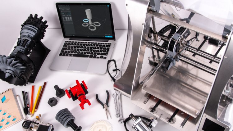
2. Introduction & Motivation: Hello and welcome to cut design 101. Thank you very much for choosing this course. In this course, you will find an introduction to the basics and the operation of cat design, as well as specific and practical design examples to make the learning process as easy and efficient as possible. As you may already know, the abbreviation cat stands for computer aided design. Cad software is used to create or edit three-dimensional object, starting with simple individual parts through complex parts up to into modules that can be ritually assembled. In this beginner's course, you will learn how the environment of a cat program is structured and how to make the best use of the individual features to create a three-dimensional object. You will be able to recreate each design projects step-by-step in one-by-one. Thus gaining an easy introduction to the subject and becoming more familiar with all of the functions of a cat program in the progress. If you're also interested in 3D printing, you can even materialized the objects afterwards by simply printing them. If you're interested, please enroll in my course, 3D printing 101, the ultimate beginner's guide. The cat program used in this course is designed spark mechanical by RS Components. This program offers a clear and simple user interface and is available for free. The structure of the design features is very similar to the professional and very expensive cat programs. But an engineer or technician uses in this daily work. Download the latest version of design spark mechanical 43. Professional CAT software licenses such as from SolidWorks, Catia, Solid Edge or Alto cat and inventor cost one to several thousand dollars and are therefore usually only worthwhile for professional users and freelancers. For this reason, we use the straightforward and free cat program design spark mechanical. The cat environment is where we clear and simple, perfect for finding your way around as a beginner, the software offers all necessary commands to create. Great opt. If you would like to try other programs, you will find other free software for beginners, advanced, and professionals in the following. In some cases, you can only use these programs for simple editing and not for any design itself. As this is the case with some beginner programs. In this course, modelling is explained only by using a design spark mechanical. But since many CAD programs are structured in a very similar way, you will make your way in other CAD programs with ease. Four basic operations and very simple designs. You can try Tinkercad, mesh mixer or 3D slash. As this course progresses, you can try free CAD or SketchUp. And for professional applications, blender and on shape of a good alternative. All popular cats off to work in a very identical way. Let's take a quick look at that now.
3. Design methodology & tips for using the course: To create a 3D model, you must first make a 2D sketch of the desired object. This is done with simple elements such as line, circle, rectangle, and polygon. You can think of making a 2D sketch as drawing in Microsoft Paint. Such a 2D sketch is made on a plane of the three dimensional space and then transformed into a three-dimensional object using an extrusion commands. You will learn exactly how this works in progress of this course. When approaching a 3D objects, there are different methods that vary greatly depending on the designer and the object. But all of them can ultimately lead to the desired result. So there is not only one way, and you're welcome to think about in which other ways the individual objects could be designed. Sometimes a differing approach will get you easier or faster to the goal. Sometimes the opposite is the case. The strains your spatial imagination and is therefore very helpful. The degree of difficulty of the following chapters and objects increases successively. Therefore, it is best to stay in the order given by the course. With each project, you will learn either a new function or a different way of working. But enough words for the beginning. Let's start with the cats are first a few basics and then we'll get into practical application. One more tip on how to use the course. The best and most effective way to learn CAD is to first watch the individual steps carefully. Then stop the video after three or four steps, and try to copy the steps shown without further health. It is best to use this procedure starting with Chapter 3 or alternatively Chapter 5. In the next sections, we will take a look at the interface of the cats of drug design, spark mechanical. And it will learn how to create a 2D sketch, as well as the subsequent transfer the sketch into a 3D object. Let's get started.
4. Settings & software interface: After starting the program, Let's make a few general settings to create the same starting point. Click on File in the upper left corner, and then on design spark options. Switch to the menu items snap and uncheck Grid. This prevents the cursor from following the grid of the 2D sketch environment. It is an advantage to be able to draw as freely as possible. In the menu item units. We check the set of values. We want to use the metric system here and specify a length units in millimeters. In addition, angles should be displayed in degrees and masses in grams. In the menu item advanced, we activate the topmost setting, an able constraint-based sketching in this menu item. But we can also, if desired, change the language of the menu navigation. If necessary, select your desired language setting at language. Then we exit the settings and restart the program first. To apply all setting. After the restart, we start a new design document file, new design. Let's first take a look at the program environment and the menu boss, which are located in the upper end side area. We will first deal with the menu section design. Here you can select different views of the component, as well as the basic functions, pen and spin. Rotating. The drawing environment is also possible with the mouse wheel held down while moving the mouse. Shifting is possible with the Shift key pressed and the mouse will pressed. The zoom function is performed as usual by simply turning the mouse wheel. In the subsequent area mode, it is possible to switch between the 2D sketching mode, the section view, and the 3D mode. The edit area offers, in addition to a simple selection tool, functions such as pool, move, and others. These are relevant when the 3D mode is active. In the intersect area. Bodies or parts can be combined or separated, and the insert area, among other things, planes and axis can be selected or created. In addition, files can be loaded into the design environment, or 3D models can be imported from an online database. In the investigate area, the important functions, measure and dimension, can be found. In the sidebar on the left, a tree structure which lists the individual components of a model, as well as the options of commands are found. The sidebar can also be hidden or rearranged by clicking on the small icon in the upper-right corner of the bar. More details about the functions of this bar will be given later in the practical project. The sketch area, the basic elements for creating a sketch. That means that two-dimensional drawing with which each object begins all located, you will need them in 2D sketching mode. Here you can find elements such as line, circle, arc, rectangle, and others. In addition, edge surroundings can be made and conditions such as the parallelism of two lines or the concentrated city of two circles can be defined in the areas modify and constraints. But more about this later, we already know added containing, pool and move from the design menu bar. So we can skip those in the last section and sketch, you can leave the sketch mode after successful editing and switch to 3D mode. And the next step, we select the menu section display. Here the functions paste and views can be selected again. In addition, the color settings can be changed in the style section, and the display of the model can be changed by selecting graphics. In the window area. A new window can be opened in the following area. Grid settings concerning the sketching grid and the background are to be made. And then the last area display, you can select which elements. For example, the coordinate system should be displayed or not. If you switch to the measure tap, once again, the measuring function represented by a tiny caliper and the possibility to calculate the mass properties of a component can be found. This feature can be very helpful if you want to determine the weight or the center of gravity of a component. In the last menu section, Help resources. You can call up some short guides and tutorials related to the program itself. There is also an interface to the forum and technical support. After that, you will find some sample projects and in the next section, you can update. Finally, in the about section, you can view general information about the program. Don't be afraid of the word T of elements and features. We will get to know the individual elements step-by-step and in detail in this course. Therefore, this brief Introduction should be sufficient for the time being. At the end of this chapter, let's take a closer look at how we can display of objects in different views so that we can start directly with the first sketches in the next chapter. If we switch back to the design section, we can try out the selection of different views. To do this, the 3D mode must first be activated in the motor area. Then in the orange section, we can choose between numerous views, isometric, symmetric, top, bottom, and so on. And now on to the next chapter where we are going to learn one of the most basic concepts of cat sketching in 2D.
5. 2D sketching exercises: 3d component must first be started as a 2D sketch. This is where we define the blueprint of the object. Imagine that you are looking at the top of a simple three-dimensional object. Let's assume you look at the top of a cylinder in a perfect right angle to the axis, what would you see? Correct? Two-dimensional circuit. Nothing else. And starting with this 2D geometry, the cylinder, analogous to all other elements created in the CAT software. In the first step, we have to draw the 2D circle. The three-dimensional shape is obtained by further commands. At the beginning of a sketch, switch to design and click on the pollute set axis of the small coordinate system or on the plane below it. This will select your sketching plane. In this case, it is the plane spanned by the axis x and y. Since we want to look at the top of the final object. First of all, make sure that you are in the sketch mode in the Design tab. Always select this sketch mode to create a 2D sketch. By selecting it, the program jumps to the sketch tab for selecting geometrical elements. Before we make the first 2D sketch uncheck, Show sketch grid in display. Then the grid will be suppressed and you will get the shown display. However, this setting is a matter of taste and does not necessarily have to be made. A rarity of basic drawing elements is available for creating a 2D sketch by selecting a line. For example, geometry can be formed from a liner shaped elements. Let's try this. Just click on any point, for example, on the center of the coordinate system and start drawing by clicking and dragging with your mouse. The drawing should correspond to the cross-section of the desired 3D object. Or in the case of simple objects, to the upper surface or cross-sectional area of the object, also enter the desired dimensions with the help of your keyboard. Besides a line, you can also create a circle and ellipse, curve or a rectangle. Let's try them. In this sketch panel, you will also find a point, various arcs and several other elements. It is best to dry all the elements at least once. Simply pause the course video and start sketching environment of the cat program. It is best to use this approach throughout the course. This is the most effective way to learn. Another tip for the element, a rectangle. When drawing a rectangle, you will notice that the rectangle always starts from corner. However, if you want the rectangle to spend from the center, you can make the worry helps full setting define a rectangle from center in the sidebar properties. This setting option is also available for other elements. To finish the simple 2D sketching exercises, please draw a rectangle which you can then provide with fishes dimensions using dimension. For example, select a width of 35 millimeters and the eighth of 20 millimeters. To do this, click on dimension and then on the desired line. There are two ways leading to the goal. You can draw a rectangle with the correct dimensions by already entering the values using your keyboard while drawing a tip, use the tabulate the key to switch between the individual fields for entering the dimensions. Alternatively, you can first draw a random rectangle and later change the dimensions. You can do this by double-clicking on the dimension, then enter the desired value and confirmed with Enter. You can also dimension the distance between two lines. To do so, just click on the first line and then on the second line, whose distance you want to dimension. Dimension must be active. Now it's your turn. Pause the video and try to draw a rectangle with the given dimensions. You can end the Sketching mode with the green tick in the upper menu bar. In the lower area, you will also find some helpful buttons to exit the sketch mode, like the small green cube. And the program will exit Sketching mode and then automatically switch to 3D mode. You can also use the other buttons to select a new sketching layer or move the grid. To create a three-dimensional object, it is important that the sketched element is completely closed and does not have any gaps. This is indicated by a green background, that first sketched element. It means that the surface has a continuous boundary line without gaps. After selecting 3D mode, rotate the environment by keeping the mouse wheel pressed, moving the mouse, or by using the coordinate system located at the bottom left. Then select pool and click on the area of the rectangle. In the upper left corner, you will see more options for pool, but more about that later. In the next chapter, we will create a three-dimensional object from the 2D sketch. Where he good, you're making good progress. We will get to the first project soon.
6. From a 2D sketch to a 3D object: As announced, we want to create a 3D object from the 2D sketch. For this, we need to use the previously selected pool function. This function represents a so-called extrusion command. In other CAD programs, you will therefore often find terms such as extrusion or linear extrusion or something similar. If you move in the direction of the yellow arrow while selecting pool and holding down the left mouse button. You can create a three-dimensional object from the 2D surface. With the help of the Space bar, you can pause the process and enter our desired dimensions. Then confirm with into. The pool function is a very basic and versatile function. As we will see in the following. Since this three-dimensional object is relatively simple, we want to further modify the object to learn a few basic operations in 3D mode. One possible approach to design is to work in the same way that actual machining, milling or turning, for example, would be done. You first create the raw material, in this case the cube root, and then machine it successively in further steps using cutouts, holes, and other design features to get to the final object. That is why this type of designing is called subtractive. You reduce the initial material through individual processing steps until the desired object is obtained. There are also other approaches, such as the additive variance, in this case, the cat model, or even the real object, as is the case, for example, with 3D printing is built up element by element. However, we will first year with the conventional subtractive approach. And the next steps, we want to make a drilling and a rectangular cut out into our object. To do this, we first need to make a 2D sketch of the geometries for the whole enter cutout. To do so, click on Sketch mode and select the top face of the cuboid. Since we want to drill the hole into the cube root from top to bottom to top face of the cube root, in this case is the face that is parallel to the x, y plane in the set direction. Since the Kuwait has been rotated as shown here. Then select TOP or navigate with the small coordinate system from the bottom. We now want to draw the whole select the option circle for creating the 2D geometry. Then place the circle on the surface with a click and enter a diameter of, for example, four millimeter confirmed with Enter. Next, we define the position of the circular using dimension. Since we are in two-dimensional space, that means sketching on a parallel of the x, y plane. We need an x and our y-dimension to completely define the sketch or the circuit entered the desired dimensions. For example, five millimeter each from the left and upper edge of the cube root. Now the circle for the whole is completely dimension. It has a defined diameter and dimensions in x and y-axis direction to define points. A complete dimensioning and a completely defined sketch is very important for good results. Always pay attention to. We also want to create the geometry for the rectangle cutout in this editing step, since we are already on the correct layer, the surface of the cuboid. To do this, first sketch, a construction line, which is simply a sort of guideline from the center of the top edge to the center of the bottom edge of the rectangle. We need this for easier positioning. Then select the rectangle and place it in the center using dimension. We need half a side length here, which results in a dimension of 2.5 millimeter. The dimensions of the rectangle should be five millimeter each to get a square. Exit the sketch mode or switch to 3D mode and rotate the object with your mouse. Then select pool and click on the surfaces of the two sketched geometries. Move them by holding down the mouse button and dragging in negative and negative set axis direction. That means in the direction of the interior of the cubit. As you can see, that ruling and the cut-out are created. Use the space bar to pause the process and enter the desired dimension. With the pool function, it is also possible to add material instead of removing it, as was already seen during the creation of the qubit. To do this, you only have to move your cursor in the opposite direction. We'll select Add in the sidebar options. Here, you can switch between ADD and cut. You can use the option add whenever designing. Using an additive approach. This is the case whenever you want to add material to an object instead of removing it through virtual machining. Feature also allows you to round edges or create chamfers. For this feature, first select the desired edge or multiple edges. Select multiple edges by holding down the CTRL key. Then move the cursor in the direction of the arrow and use the space bar to specify the desired dimension, that means the radius. Alternatively, just click on the edge again and you can edit the radius. As you can see, pool is very powerful and offers a variety of basic editing options. Conclude this chapter. We will get to know one more function in 3D mode. With Shell, you can easily hollow out an object. To do this, select the function and the bottom surface of the object. That's it. The object is hollow out. The desired wall thickness can be entered using the space bar and keyboard. Pretty simple, isn't it? Now you already know how to create a two-dimensional sketch and generate a 3D object from it. You also know the design environments in two and three-dimensional space. And the most important functions of these. This means that we know all the necessary basics and are now ready to start with the actual design projects. And the following chapter, we'll first design a practical clothing hook, which you can attach to a new offering. Here we go.
7. The design of a simple clothes hook for attaching to a door: This hook has a quite simple geometry for this object, it is recommended to draw the cross section of the model in 2D and then use the pool function to make it three-dimensional. First, we draw the cross-section of the hook. Start by selecting the 2D sketch mode and continue by selecting the set axis or the x, y plane. And then draw the first line as shown. Then at the following lines and dimensions. Complete the cross-section with further lines as follows. Then you can leave that 2D sketching environment and switch to 3D mode. Select pull, and create a three-dimensional body by dragging in the direction of the displayed arrow, enter a dimension of 15 millimeters by using your keyboard. Up to this step, you could of course also use the subtractive design method. Let's try it. To do this, we will draw our rectangle with 33 millimeters and 29 millimeters in the 2D sketch mode. And create a cubit with a thickness of 15 millimeter. Using pool. The program automatically switches to 3D mode. When selecting pool, usually we would click on 2D sketch at this point. Next, we draw the sketches for the cutouts. To do this, we first create a 2D sketch on the top. Alternatively, of course, the bottom surface. First sketch the left half of the cut-out for the hook. And then the write-off off the that you can use to cut out this guest areas. Two approaches for an identical solution. Finally, in 3D mode, we can do some edge rounding. Select all the desired edges using the CTRL key. With pool and selection of rounding in options, pull. The edges can be rounded. For example, use a radius of r equals two millimeters. Then apply these groundings, two other edges as well. Here we can use a radius of one millimeter, for example. Perfect. Then the hook is done and can be saved. Select the desired file type by choosing File and Save As if you want to edit the project later on, it is recommended to save the file as ds mechanical file. If you want to print the object with a 3D printer, you should also select the file format STL of the slicing code. You can print it with a 3D printer. Great. Before we get to the next project, let's take a look at constraints or conditions. You can use these.
8. Theory to project I: Constraints: Sketching environment to create dependencies between any withdrawal geometric elements if you need to. In the following, we will take a closer look at the most important constraints. Let's start with the horizontal and vertical ones. Suppose we tried to draw a rectangle by using lines, but instead, get such a polygon. By selecting the horizontal condition, we will get to perfectly horizontal lines just by clicking on the respective lines. In the same way, we apply the vertical condition to the lateral lines and finally, get a rectangle. Of course, we would have reached our goal more easily if we had used the predefined element for a rectangle right away. But to illustrate these two constraints, we took the laborers way. With concentric to circle structures can be set concentric to each other. To do so, let's draw our large circle and a slightly smaller one. We want to get two concentric circles. That means two circles with congruent axis. We accomplish this by selecting the appropriate constraint. And the two circles. The two constraints, perpendicular and parallel, are relatively self-explanatory. Nevertheless, let's look at a small example with two lines each. For the function perpendicular, we draw the following two lines. By choosing the condition and selecting the lines, we get two lines that are perpendicular to each other. For parallel, we draw two more lines. And by selecting the condition, we get two lines perfectly parallel to each other. But constraints coincident and midpoint usually use whenever you want to connect two points or connect a point of one element with the mid-point of another element. Let's draw a rectangle and two lines. To illustrate this, we want to connect the first line with a corner point of the rectangle and the second line with the center or from one of the lines of the rectangle. By the way, you can also apply multiple constraints. For example, we could also apply the constraint horizontal to this line. Let's have a look at tangent as the name and the small picture already indicate, we can use it to set the line tangent to a circle. For example. Let's try it. First, draw the circle and then align and then apply the condition. Feel free to try the three remaining constraints, fixed, equal radius, and equal distance yourself. As the name is relatively self-explanatory. Fixed, simply fixes an element in the drawing plane and the other to provide equal radius or equal distance between elements. Stop the course and try it. I will provide a solution with two small examples in the following. That's it for this theoretical section at the end of the chapter and the next chapter, we will start the new project. You will learn how to design a simple carabiner. Stay tuned and we'll be worth it. With each chapter. The projects will get a little more complex and exciting. We will start a new project.
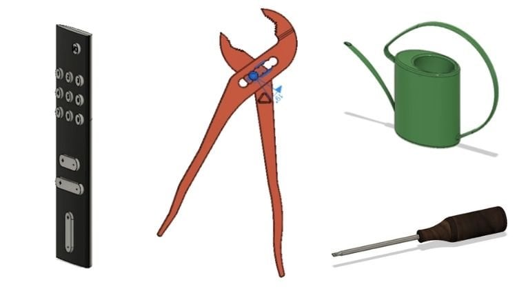
9. Designing a snap hook: We will start a new project for the snap book in 2D sketching mode and select the plane. Let's first consider how the snap hook is structured and how we could design it. If you take a little closer look, you will notice a circular shape in the left and the right area, as well as struts for tangential connections between these circles. Let's try to do it this way. First, simply draw a circle, for example, with a diameter of 50 millimeter, for example, on the x, y plane. Then create another circle with a diameter of 20 millimeter next to the first one. Next, we draw horizontal and vertical guidelines through the centers of the two circles to make it easier to attach dimensions and the tangent line. In the next step, let's connect the intersection points of the vertical guidelines with the circles by two more lines. To get a closed shape, we only need the outer contour. Therefore, we use the trim away to using this tool, remove all superfluous line segments as follows. Now, we could extrude the surface, but then we would have to make a cut out in the following step to get the final snap poke shape. However, now that we are a bit more advanced, we might as well use a faster solution and draw the full cross-section of the snap hook in one step. To do this, at two additional circles with diameters of 35 and 10 millimeter to the inside of the snake hook. And again draw two lines from the intersection points of the circles with the guidelines. Finally, remove all superfluous line segments by using the trim away future. As you can see, this saves one editing step and we can now extrude the shape of this new epoch. To do this, we switch to 3D mode once more and use pull. Select the outer surface of this netbook and enter a value of 10 millimeters. You can remove the surface in the middle of the carabiner by right-clicking on it and selecting delete. Now to create a section for opening the hook, we switch to 2D mode and draw a line at 20 degrees from the intersection of the guideline with the Caribbean to the outer line of the carabiner. The dimension is calculated automatically by specifying the angle and the end points. Then draw a second parallel line with a distance of two millimeter. Of course, we could have also integrated this step into the first sketch, as you may have just noticed. In 3D mode, we can then select the area and drag it towards the snake hook so that this area is cut out and that gap is formed. Finally, we will around a few edges. Awesome. Before we move on to the next design project, let's make another pref, theoretical lesson folder.
10. Theory to project II: Features for editing a 2D sketch: Sketch of the carabiner. We got familiar with trim away from the section modify. There are a few more helpful features in this section. I would like to briefly introduce them to you in the following. For this purpose, I have prepared a few geometric elements. Using a create rounded corner. You can easily and quickly create a rounded corner. Select the first line, enter the desired radius, and then select the second line. The program now creates the desired rounded corner. With the feature create corner, you can create a corner out of two independent line elements simply by selecting the two lines. One or both lines are extended or shortened so that a corner is created. We already had the function trim away, but we can demonstrate it again with these two crossing circles. Simply select the elements you do not need and they are gone. Finally, let's take a look at split curve. We can use this if you want to split an element such as a line at a certain point, select the line and specify a point. You will see that the line will then be split into two lines at that point. If we delete the existing relationship, we can better see where the split point is and move the separator lines. The next.
11. Designing a mounting component: The next design object is a simple fishes mounting component. It can be attached using two bolts and is used, for example, to hold an axis or another turned part. We start by drawing the cross-section of the part in the 2D sketching environment. Feel free to pause the course at this point and try to create the 2D sketch completely on your own. At tip, draw the front side of the object. You can choose dimensions really extruded afterwards with pull. Alternatively, you can proceed with the video and try it after. First, draw a baseline of, for example, 90 millimeter and then to sidelines with 15 millimeter height and 30 millimeter with each. Then we need a pot of 20 millimeter height. And finally, we use the function tan arc to create a semicircle. After selecting the function, click on the two ends of the drawn profile and you will see how the arc is created. Afterwards, you can define the radius of the arc with, for example, r equals 15 millimeter. Then, as usual, use pool to get a 3D object. In the next step, we will create the drilling in the upper part of the component. To do this, switch back to 2D sketch mode and select a suitable view. For example, the front face of the object. Next, draw a circle with a diameter of 15 millimeter and on the starting point of the upper semicircle. Alternatively, you can simply draw the circle and said it concentric to the semicircle using a constraint. You might also notice that you could integrate this step right into the first 2D sketch. Who are you good. When the sketches done the drilling can then be executed by pulling it in 3D mode. For the two mounting holes, switch back to the to the 2D sketch environment and select the view that allows you to look at the component from above. That means preferably the top view. Then draw two guidelines on each of the two surfaces of the component between the centers of the edges of these surfaces. With the help of these guidelines, we can perfectly positioned to circles with diameters of 15 millimeter in the centers of the surfaces without further dimensioning. Alternatively, you can simply dimension from the center of the circles to the sidelines. Then we pulled the sketch surfaces in 3D mode to remove material. Finally, we are on pHs of the two surfaces and finished the part in disarray.
12. Designing a practical smartphone stand: In this chapter, we want to create a smart phone stand. You may have to adapt the dimensions to use on. Let's start with a 50 millimeter long and horizontally aligned line on the y set plane. To do so, we must first select the correct view and then select the button, select new sketch plane. Then we click on the Display view. But why are we drawing on this specific plane? We use the y set plane so that at the end, the views isometric, top, bottom, left, right, and so on, are displayed correctly because we are drawing the cross-section or the side surface of the smartphone holder on this plane. Just look at the part from the side, then you will understand what is meant. We will draw the side surface, which is shown here, so that we can extrude the 3D element. Let's start with a 50 millimeter long end horizontally line. Then we'll add 20 millimeter line at 45 degrees and 23 millimeter line at 35 dB, followed by a three millimeter horizontal line and another 16 millimeter line, which should be parallel to the second line, prone. Continue with a 10 millimeter horizontal line. Now we have to create the support surface for the smartphone. To do this, we draw our 85 millimeter line at 135 degrees, five millimeter horizontal line at the top, and another connecting line to complete the profile. Now the cross-section profile is done and we can switch to 3D mode and create the three-dimensional model using the well-known pool function. We need 15 millimeter. Finally, we are under few edges as follows. Two millimeter at the front bottom, one millimeter, one millimeter at the back button, two millimeter for the rest. That's how easy it is to create a simple smartphone stand. Great job. Please continue with the next chapter.
13. Designing a bowl: In this section, let's take a look at an object that seems a bit more complex to create a poll. How can we start? For example, we could begin by drawing two circles on two different planes and then connecting them. Alternatively, we could design it as it would be machined by turning. But more about that later. First, let's go the more complex way using planes in order to get to know a new feature. For the bottom, we will first use a simple circular geometry. Start in 2D sketch mode and draw a circle with a diameter of 70 millimeter. For the top of the bowl, recreate in 3D mode and additional plane by selecting the plane function, which you can find in the science section and by clicking on the previously created circular area. Now we select the creative plane and move it with, move in the direction of the set access. Enter a value of 18 millimeter. Next, start a 2D sketch on the newly created plane and switch to talk to you. First, select the plane and then draw a circle with a diameter of 150 millimeter in the center of the coordinate system. Make sure you're in 2D sketch mode for this step and that you have selected the correct plane. Then we switch back to 3D mode and select the two circles surfaces holding down the CTRL key. And select the blend or fill and connect surface feature at design and edit. The program uses this feature to create a cone-shaped full area between the two selected faces. Quite convenient, isn't it? By the way, by right-clicking on the selected Plane and choosing Hide. You can, if you want to hide the created layer. With this feature, we got a solid cone for the bowl, however, we need to hollow it. Therefore, select the shell feature and click on the top surface of the created object. Choose a wall thickness of, for example, five millimeter, almost done. Finally, we can make some groundings to improve the design. For example, as follows. Let's, let's use a radius of 2.5 millimeter for the two top edges of the bolt. And the radius of ten millimeter for the edge of the bottom of the boat. Has mentioned at the beginning of the chapter, we can also design the bowl as it would be machined. We would do this as follows. We first draw vertical guideline on the exit plane, which will later serve as an axis of rotation. Now I mentioned that we would cut through the bowl from above. We would get two halves of the bowl. Let's illustrate this to get to know the section view of the program. To do this, create a plane by selecting the plane icon and the set X. Then select section view and the previously created plane. The program will now create a section view for us. We have to draw this cross section on the set plane in order to rotate complete bowl from it later, we use the XY plane because we want to see the front of the cross-section or when drawing it. By the way, we draw without the rounded edges. We simply add them at the end. Let's just try this and then you will surely understand what is meant. For the cross-section, we draw a baseline of 35-millimeter, which is half the width of the bowl at the bottom. Then we draw the wall of the bowl and dimension the top distance as a 75 millimeter, which is half the top bowl with since the wall had five millimeter, we want to use that. Well, you here as well. We are only drawing half of the cross-section profile, since we'll be rotating that half by 360 degrees around the set axis to get the fruit bowl. After we have completed the sketched profile with another line, we can rotate it around the rotation axis by selecting the pool function and by selecting the option revolve in the upper left corner. First select the rotation axis. That means our guideline in the set direction. In the second step, select the drawn surface. For a complete rotation, we need to enter 360 degrees. This way, we get the bowl in a quick way. As less step, you could round the edges again. You can see that there are several possible ways to single, as already mentioned in the beginning, depending on which one you choose, you will be able to design faster and easier. If you design something every now and then, you will develop a sense for the fastest and easiest method after a while. Let's keep going. The next project.
14. Designing a cup with handle: Checked will be a cup. Next, we would like to design a cup including a handle in the following, try to pay attention to the combination of additive and subtractive design methods. Start a new project and create a circle in the 2D sketching environment. The diameter could be 90 millimeter, for example. Then switch to 3D mode and create a cylinder from the sketch using a dimension of 18 millimeter is used here. Then utilize shell to hollow the cup. We choose a wall thickness of five millimeter. In the next step, create a new plane for the handle of the cup on the surface of the upper cup room. Then move this plane 15 millimeter downwards. That means in a negative set axis direction. This is done by selecting the plane and moving it using the blue set axis. But why do we do this? Because the handle should not be on the same level as the edge of the cup, but a little bit lower. Then select 2D sketch and top view to create a vertical line of 20 millimeter on the previously created plain. Complete the profile with two horizontal lines of 40 millimeter and the vertical one so that the rectangle is created. Now you can probably already guess the shape of the handle. In this case, the element is added to the basic cylindrical element, that means the cup. In 3D mode, you can create the handle by pulling it downwards. That means a negative set axis direction. We choose a dimension of 50 millimeter. In the next step, switch back to 2D mode and this time, select the side surface of the handle as the drawing plane. Draw 26 millimeter wide and 36 millimeter high rectangle from a center point and add the dimensions of 20 millimeter and 25 millimeter. Alternatively, you can work with guidelines again. Then you can make the cut out in 3D mode. Finally, we round some edges of the handle and the cup and try to display a few other renderings of the cup. Switch to the section display for the selection of graphics and try out a few renderings. As a final project, we will create an internal threat for a square naught in the following chapter. This threat could even be a 3D printed and is fully functional. For a bolt, the threat creation would work similarity. In this chapter, however, we will draw an internal threat instead of an external threat. By the way, threats can also be created automatically with the help of, with the help of other CAD programs such as Fusion 360 from Autodesk. If you have made it this far, you can be proud of yourself because you have learned all the basics, as well as all important functions and approaches for working on further projects.
15. Designing a square nut: For the threaded square that we create a rectangular part in the 2D sketching environment with a width of 20 millimeter and a height of 20 millimeter. Complete the profile with a circle. Then selected, then select the diameter of 10.2 millimeter. The dimensions for standard parts of mechanical engineering, such as bolts and nuts, can be found in an engineering book. Or even easier by googling. After creating the sketch, switch to 3D mode and pull the area between the circle and square into a 3D object. User dimension of five millimeter. You can delete the circular area. Then. Next, select sanction mode and select the y set plane of the part by clicking on the set axis. We are now in the section view. In this view, create two vertical guidelines as follows, using the 2D sketching mode. The distance between them should be 1.14 millimeter. In the next step, we draw a small triangle. To do this. First, draw a connecting line 30 degrees between the two guidelines. Then another line at 60 degrees in the opposite direction. And finally, vertical line as the last element of the triangle. The dimensions and angles for the particular thread can be obtained from an engineering book or the internet. In our case, we draw an M 12 internal threat. To create the threat, we switch to 3D mode and select a triangular surface. Then we click on pull and use the future revolve, which can be found in the upper left corner. The next step is to activate the option cut in the sidebar had options for the rotation of the threat. Select the set axis, that means the axis of the drilling as our rotation axis. After selecting the x's, we have to activate the function revolt helix. In the left sidebar under options. A small box appears here. As a last step, we entered the values height, pitch, and taper angle, which we also get from an engineering book or online. As a result, you should get such a third. Finally, you can save the project, choose a DS mechanical file to edit the file later on. Alternatively, you can also use the STL format to create a file for a 3D printer using a slicing software. Perfect. Threats are no problem anymore.
16. Conclusion & credits: This brings us to the end of the course, but now it is time for you to think about some new design projects in order to consolidate the methods you have learned and to improve them in this way. Be creative with the project. You have learned all relevant operations in 2D and 3D mode in this course. This enables you to design your own cat files in a quick and easy way. And as mentioned at the beginning of the course, please also take a look at 3D printing. It's tremendously fun and beneficial to materialize your own designs. This way, you have a solution for all sorts of unavoidable but much needed spare parts or anything else. Take a look at my course, 3D printing 101, the ultimate beginner's guide, and enroll today. Thank you very much and have fun with though, designing goodbye.
 Johannes Wild, Engineer (M.Eng. & B.Sc.)