Transcripts
1. 3D Printing Course Trailer: Are you interested in 3D printing? Great. Stay tuned. You have come to the right place. Learn everything you need to know about 3D printing. Easy to understand by using this video tutorial. Learn to print cool objects and realize their own ideas and prototypes. Whether you buy your own 3D printer or use an external 3D printing's provider. The knowledge you will acquire in this workshop is good for both. Find a quick and easy step-by-step instruction to the topic with guidance and experienced engineer and 3D printing expert. From file editing to slicing all the way to the printed objects. Everything you need to know to start with FDM 3D printing is taught in this workshop. In addition to chapters such as basics, materials, troubleshooting, and a lot more, there is a bonus chapter about 3D scanning waiting for you. So what to do next? Enroll in 3D printing 101 now, in order to start into a fascinating world.
2. Getting started! What to expect: Hi there. Welcome
to 3D printing 101. I'm sure you've already heard some fantastic stories
about 3D printing and seen some fascinating photos of 3D printed objects
that have sparked your enthusiasm
for this subject. If not, then let's get in touch with this
ingenious technology. I'm sure that you'll
be amazed what's possible in the world
of 3D printing. What can you expect
from this course? In this course, you will
be guided step-by-step and thus learn how to use
an FDM 3D printer. And it's software by
means of the expertise of an engineer and experienced
3D printing enthusiast. Everything you need to
know to get started in 3D printing is
explained in detail. You will learn how to print objects downloadable for free, and how to materialize your own projects,
ideas, or prototypes. This course is made for all technically
open-minded people who are interested in 3D printing
need for this course. Ideally, you should
buy a 3D printer. But don't worry, you don't have to pay a large amount
of money for it. High-quality 3D printers using the FDM technology are
available for less than $600. If you don't want to buy
your own 3D printer, you will still benefit
from this course. On the one hand,
through knowledge of the most important processes in principles of 3D
printing technology. On the other hand, by means
of the possibility to use a so-called makerspace or an external 3D printing
service provider. A makerspace is a place where several and different
technical devices, such as 3D printers,
laser scanners, or laser cutters are available
to members for free use. These rooms which are
equipped like a workshop, offered the necessary space and the right equipment for the realization of
your own projects. You can easily find out online where the next
makerspace is located. You will also need a
safe place to set up your possible 3D printer
and a few other materials, as well as appropriate
3D printing software. Which materials and software in detail and how it all works. I will explain to you
step-by-step during this course. But first, let's get in
touch with a few examples. Time for some inspiration. For example, you could
print a model of the luck. So junior lamb, the small bouncing lamb
from the intros of a well-known animation studio representing the
letter i of the logo, except for the LED
and the springs. All parts can be printed. The lamp is movable and can
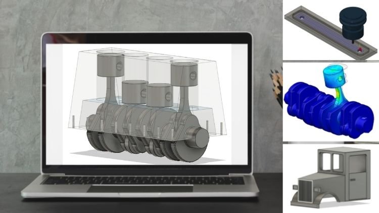
hold the chosen position. Or have you always
wanted to fully understand how
technical systems work? No problem with a
miniature engine model. If you turn the crank shaft, you can clearly understand the movements of the pistons in the cylinders and the
interaction with the crankshaft. 3d printing is perfect for illustrative examples or
interactive teaching aids. A somewhat in conspicuous looking lifting
platform has at all. The special thing
about it is that it is a lifting platform
that has been printed, completely assembled
with full functionality. Yes. You have heard correctly a lifting Jack which
can be printed in one piece and can be used and moved immediately after
the printing process. No further assembly needed. Just imagine the possibilities. 3d printing offers. Many other moving parts, like a ball bearing or
a door latch can be printed in one piece
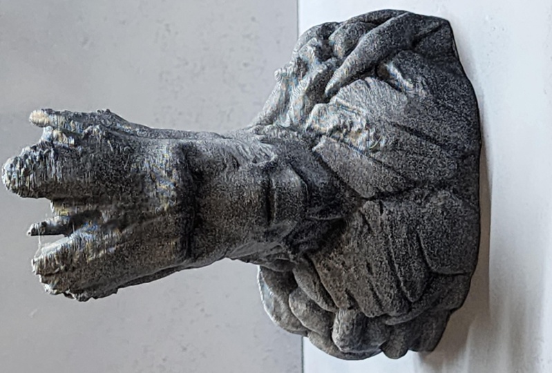
and are fully movable. Afterwards. Let's get to the artists and art
lovers among you. Be it to bring modern art
into your living room or to become artistically
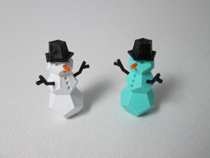
active yourself. No problem with a 3D printer. Besides simple wall sculptures
like a lion or a deer, you can also create more complex structures
like a dog or a horse, using the trendy and
low Polytechnique. Or what do you think
of acute toy plane? Both the wheels and the propeller are
movable when assembled. The threads for the
bolts are printed along with the object. Correct? Even functional threads are
easily made by a 3D printer. Furthermore, you could print a railroad bumper
exactly adjustable to the required dimensions for your railroad models
simply by herself. The bumper is printed using
wood filament, right? Real wood from Birch to pine, willow or cedar,
anything is available. Wood fibers have been added to the actual printing material. The filament to
recreate the look and feel of would probably one of the most important
applications of 3D printing is
rapid prototyping. That means the
rapid production of an invention or idea
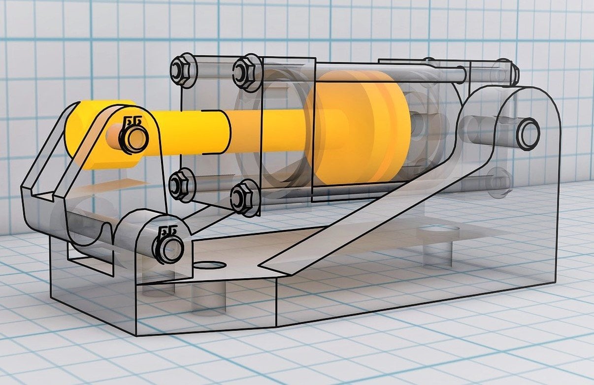
as a prototype. Take a machine
vise, for example. And instead of using
a single drive shaft, the workpiece is clamped more
evenly by to drive shafts. With a 3D printer,
you can quickly, easily and
cost-effectively create prototypes for product
presentations. For inventors or engineers. 3d printing is the ideal tool. But also as an architect, you can realize a lot. Perfect as an eye catcher for your next Halloween party
is a 3D printed skull. And this shows another field of application with
enormous potential. The printing of
prostheses, body parts, or replacement organs by
medical professionals. Just as impressive, is printing a T-Rex skull as ideal
for dinosaur enthusiast. Alternatively, you might just want something more practical, like a designer rack
for your headphones? Or do you prefer a
stylish honeycomb base as a fashionable object
to place on your desk. Be creative. Use this course
to learn all what it takes to 3D print your world. You have surely been able to
pick up some inspiration. Therefore, let's have a short
theoretical introduction to the basics of 3D printing, so that you can start
printing as soon as possible.
3. How does a 3D Printer work? & 3D Printer Components: The mainly presented and discussed 3D printing technology in this workshop is called FDM or FFF. Fdm is the short form of fused deposition modeling. The heart of FDM 3D printer is a nozzle equipped with a heating element, the so-called hot end. This part melts filament the printing material and deposits it layer by layer on the printing bed or the previously printed layer. And in this way, the print object gains height layer by layer. A plastic filament is usually used as a printing material. Pla is perhaps one of the easiest and common materials when it comes to 3D printing. Pla is a plastic that is obtained from regenerative resources. Other plastics, such as abs, are more difficult to print, but have better mechanical properties. The layer thickness is usually chosen in a range between 0.1 millimeters and zero-point four millimeters, whereby the print quality increases with smaller layer thickness. However, the smaller layer thickness, the longer the printing time. To ensure that the printed here as well to the printing bed and does not come loose during printing. Printing bed in the range of approximately 60 degrees Celsius is recommended. Some 3D printing enthusiasts use all kinds of additional equipment, such as adhesive tapes, glue sticks, hairspray, or permanent printing plates to achieve good printing bed adhesion. However, with well-coordinated settings and a calibrated printing bed, it normally works without those kinds of stuff. But there is an insider tip regarding the printing bed. A mirror is used as a printing bed to provide a perfectly flat surface for the print object. The print head can move through all three spatial directions by means of so-called stepper motors. This makes it possible to print almost any shape. In addition to and technology, there are also other 3D printing procedures, such as selective laser sintering and stereo lithography, SLS and SLA for short. These are mainly used in industrial sectors. A laser is used to fuse a plastic powder, liquid resin, or metal powder into solid components. Back to our FDM printer. Now, the filament, which is rolled up in a wire like structure on a school, must of course, first reach the head and nozzle of the printer. This is done by transport via another stepper motor, which grips the filament with a gear wheel and moves it toward or away from the nozzle. Fans attached to the hot end provide temperature control on the one hand, cooling off the liquefied plastic on the other, and thus solidification in the printed form. The printer presented in this course has only one nozzle. So only one color can be used in a printing job unless a mixed color filament is used. However, there are also so-called dual extruders, such as the reality C RX. Dual extruder means the 3D printer is equipped with two nozzles and thus two types of filament or two colors can be processed in one print object.
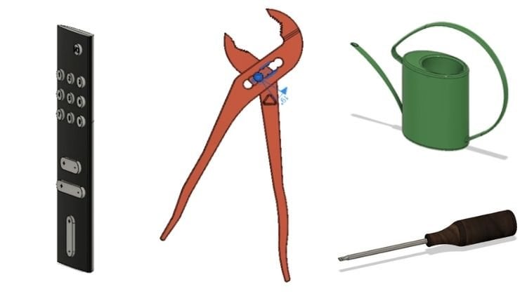
4. 3D printer purchase advice (incl. accessories): Before we start our first printing job, there is some advice on buying FDM printers in the following legal notice, all the following recommendations and interpretations reflects my personal opinions and experiences. I have no business relations with the following 3D printer or filament manufacturers. This also applies to all other products, including 3D printing software presented in this course. As mentioned in the introduction, high-quality 3D printers are available for less than $600. For example, the corporeality CR, It's n. The CR 10 can be ordered directly from China, which works well, but often takes a long time. Fortunately, there are now also cheap and good offers from other warehouses selling on Amazon, eBay, and others. The CR 10 series is highly praised in the 3D printing community. And in my opinion, that is appropriate. The print quality is outstanding and the price is relatively low, depending upon models with approximately 500 to $900. Another advantage is the large building space with the printing bed of 30 by 30 centimeters and our printing height of 40 centimeters. Therefore, this printer is my explicit purchase recommendation. 3d printing is explained in this tutorial by using this printer. However, the basics presented in this course are broadly applicable to all FDM 3D printers. So if you choose a different one, that is not a problem. Meanwhile, there are also other versions of the original CR 10. For instance, the CR TNS and the CR TNS Pro. These offer some useful upgrades like filament sensor to motorized z axes, automatic printing bed leveling, and other helpful modifications. Furthermore, there is a CR 10 version with a printing space of 50 by 50 by 50 centimeters. Other recommended 3D printers are the devices of MakerBot for the so-called replicator, for example, you have to pay about $2200. The MakerBot devices are also designed for hobby and semi-professional use. Besides MakerBot, Ultimaker, 3D printer models are among the pioneers when it comes to 3D printing. And Ultimaker is one of the leading manufacturers in this field. These devices also achieve a very high print surface quality and are therefore listed as a second purchase recommendation from the Netherlands to build their desktop 3D printers series with its small, medium and large models are known starting from approximately $2800. Another noteworthy FDM printer is the Dremel idea builder, priced with approximately $1700. There are numerous further 3D printer manufacturers and models as an orientation to the 3D printers available on the market. However, these recommendations should be sufficient. As a conclusion, it can be said that the CR 10 series, it's newer models like the CR TNS and, or the CR TNS Pro, offers a favorable and good entrance into 3D printing. The Ultimaker as a second recommendation, also offers a very good entry, although a somewhat more expensive one. Now I mentioned in the beginning that if this is still too expensive for you, you don't even have to buy yourself your own 3D printer to realize your ideas. At 3D Hubs.com, for example, you can start a 3D printing job by uploading a 3D model and thus find a suitable 3D printer provider anywhere in the world. Alternatively, there are some other service providers such as Proto Labs, www. Dot proto labs.com, Shapeways, www.Shapeways.com and others. At Proto Labs, for example, you can upload your desired 3D model as an STL file and get a direct price calculation, including design analysis, SLS and SLA methods are also often offered. Or you choose the possibility of using a makerspace. But if you are enthusiastic about buying a 3D printer, the following question arises. What other equipment do you need in addition to the actual printer so that you can get started? On the one hand, a printing material, IE, a filament. I recommend starting with PLA because it's the easiest and safest material to use in this context. I recommend starting with a PLA filament from the award-winning filamented manufacturer son Lu. Alternatively, you can buy PLA plus from the manufacturer t ions as well. The plus stands for further development of PLA through increased mechanical properties combined with equally good preventability. Filaments of Sonu impress with the surface quality of the prince and the low manufacturing tolerance of plus or minus 0.02 millimeters as equality feature, make sure you choose the right filament diameter for your printer. For the CR 10 series, you'll need 1.75 millimeters. However, there are also 3D printers that require a three millimeter filament diameter due to their nozzle size. In addition to filament, you should also get a mirror for the printing bed, a storage medium, memory card for the print files, some cleaning agents for the printing bed, and superglue. Optionally, some model colors if you want to paint that printed parts later on, and other useful tools like some pliers and a spatula to remove the finished parts from the printing platform. The CR 10 comes with a basic set of tools.
5. Setting up a 3D printer (incl. leveling of the printing bed): Now it's time to finally
get to work with your 3D printer and
master the first print. The CRT has to be assembled
first after delivery. Don't worry, it's done very
fast and pretty easily. All parts are already
prefabricated and have been disassembled into three
parts for shipping reasons, only, the best way to proceed is to follow the manufacturer's
video instructions. You can scan the QR code on the printer for the manual
with your smartphone, or view the manual in the YouTube channel of
the manufacturer reality, you may not need to assemble
other printers by yourself. Some printers, however,
are available as assembly kids only and must
be constructed from scratch. After the printer
has been assembled, you have to level
the printing bed to complete its proper function. Newer 3D printer models
already have a sensor for automatic adjustment
of the distance from the nozzle to
the printing bed. But here it also makes
sense to carry out a manual calibration
at the first startup. For the process of
manual calibration, heat up the printing nozzle to the desired printing
temperature, thus, approximately
210 degrees Celsius. And the printing bed to
approximately 60 degrees Celsius manually via the
menu of the 3D printer. Please make sure that
leveling is performed in this warm condition as materials expand by
the influence of heat, then select home position
in the printers menu, prepare, their printer will now move to a defined
home position. In the case of the CR ten, this is the left front
corner of the printing bed. Leveling is performed best with a distance gauge or
feeler gauge of 0.1 mm. If you do not have
such a gauge at hand, you can alternatively
use some paper sheets as well to check the distance between nozzle and printing bed. Place the distance
gauge or the piece of paper between nozzle
and printing bed. The distance gauge or
the paper sheet should just fit between the
nozzle and printing bed. You should be able to hear a scraping noise when
using a paper sheet. Adjust the distance
with the setting wheels of the printing bed
if it is necessary. Perform this procedure in all four corners and then
repeat it one more time. Make sure that if you are
using a piece of paper, the sheet can be hardly moved, then the distance
is exactly right. If the first print
does not adhere, reduce the distance between
nozzle and printing beds. Slightly too large distance
between nozzle and printing bed is one of the most common
beginner's mistakes. However, the nozzle
should not grind on the printing bed either
when moving the print head. If you use a 3D printer
without a sensor, such as the first CRT, this printing bed calibration
should be performed periodically after
every ten to 20 prints. For printers with automatic
distance sensors, such as the CR tennis pro. This calibration is generally
no longer necessary. Before we start our
first printing job. A few safety
instructions follow. To melt the filament, the printing nozzle
has to heat up to approximately 200
degrees Celsius. The printing bed
also heats up to approximately 60
degrees Celsius. Therefore, there is a
high risk of burns, especially when
touching the nozzle. Do not touch moving parts either while the
printer is running. As there is also a
danger of crushing, find a suitable location
for the 3D printer. Ideally, a somewhat
isolated room with a stable workspace
as the printer generates some noise
and vibrations. Also makes sure
that children and pets do not have
access to the printer. It is also a good idea to wait a few minutes
at the start of printing to check whether all operations are being
carried out correctly.
6. First 3D printing job with the CR-10 3D printer: Now all necessary preparations have been made and everything important for the first printing is explained. Traditionally, the CR 10 series starts with a small waving Chinese Lucky cat as a first print. As a filament, you can either use the test filaments supplied with a 3D printer or a separately purchased one. Remove the SD card supplied with the 3D printer from the USB adapter, and insert the SD card into the 3D printer without the adapter. Alternatively, you can connect the printer to a PC using a USB cable. Then switch on the 3D printer and navigate to print of SD card. Then start the file with the cat. If your 3D printer does not come with a suitable printing file, you can skip this chapter first or search for a file online. G-code file is required. Next, the 3D printer will start heating up the nozzle and the printing bed. This process takes about three to five minutes. As soon as the desired temperatures are reached, the printer starts automatically. Check whether the filament and here's evenly to the printing bed. By looking at the printing bed and the nozzle. If not, stop printing and level the printing bed again. When the filament is evenly deposited on the printing bed, you can raise your feet and watch the 3D printer as it works. After approximately two to three hours, the Lucky cat is ready to remove the finished object from the printing platform. It is best to let the heating bed cool down completely.
7. Overview on file formats & slicing software: You have only been able to immediately print the Lucky cat with your 3D printer because of the G code format of the file. By the way, you can see this in the file suffix. Such a G-code file has to be created first. Usually 3D models can be downloaded as STL files. Therefore, we will proceed now to the next chapter in 3D printing. Let's take a look at the necessary software and file formats. By the way, you can download lots of 3D models for free at online platforms. If you want to create your own components, you must use engineering software, but more on that later. The already mentioned G-code file format represents a machine code that provides the necessary movements and other printing information to the printer. This file is created using a so-called slicing program, or slicer for short, slicer, because it divides the geometry of the desired object into layers. The software supplies the printer with unnecessary movements in the spatial directions so that the objects can be printed. As a slicing software. A selection of free and a chargeable software is available as a free software. For example, slicer, which is written with the number 3 instead of an E, is available. Cura Open Source slicing software from the 3D printer manufacturer, Ultimaker can also be downloaded for free. If you want to buy slicing software. Take a look at simplify 3D. This software is priced at about $170. My recommendation however, is Cura. On one hand, the program is free of charge. On the other hand, it is designed by one of the leading 3D printing manufacturers, and it's ideal for beginners. The program works with almost all FDM 3D printers and impresses with It's easy handling. If an object has been constructed with CAD construction software, it can be saved in the so-called STL format. In this format, the geometric information of three-dimensional objects is optimally prepared for 3D printing. You then import the STL files into your slicing software and slice them into a machine code for your printer G-code. There are many online platforms offering STL files. Most of the files are created by members of the 3D printing community and are often available for free, for private, sometimes even for commercial use. One of the biggest platforms is Thingiverse, www dot of Thingiverse.com. This platform offers free files as STL formats. You don't even have to register for it and you can download the files right away. There is, however, one thing to note, though Creative Commons licenses of the files. These licenses can be found on Thingiverse at approximately the left middle page height of an object. With Creative Commons licenses and author and creator of a work can easily grant the public rights to use his or her work. There are different licenses, depending on the license, only printing for private purposes is permitted or sharing and modification of the work is explicitly desired. Or even the commercial use of the work is permitted. All you have to do is take note of a license and makes sure that the downloaded object is only used in the permitted range. In most cases, the creator's name has been mentioned to when the object is used publicly. Depending on the license, you also have to set a link. In the case of a permitted redistribution or representation of the work, you can view the individual licensed meanings on the website of Creative Commons, www.creativecommons.org. Please note that the information in this section about Creative Commons licenses is not binding and cannot constitute legal advice. I will explain to you right away how the creation of a G code works. But first, I want to introduce another software, Autodesk mesh mixer.
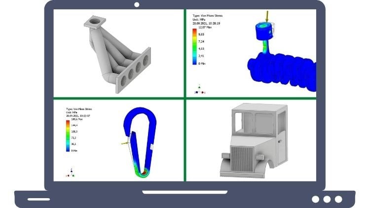
8. Editing of ".stl" files with Autodesk Meshmixer (e.g.: carabiner): This free software tool allows you to edit and position STL files easily. Sometimes STL files are not matched correctly and contain holes or other defects. To obtain a high-quality surface, some files must therefore be repaired beforehand. The process of analysis and repair can be done using mesh mixer. You can download the program free of charge at www.mesh mixer.com. If you want to create your own components or realize new ideas, you have to get into the topic of construction and we'll need construction software. Of course, there are alternatives to the usually more expensive professional programs, such as Solid Works, cavea, solid edge by Siemens or Autodesk Inventor. As a student, you can often get such software for free or discounted as a student license. For all others, a few free programs in the following. The best approach would be to simply try a few different programs to find the right one for your purposes, for beginners and for testing whether designing is the right thing for you. The free program Tinkercad from Autodesk is recommended. Advanced users, on the other hand, should familiarize themselves with Blender or a free CAD, www, free CAD web.org offered by the free CAD community. Since constructing itself is a time-consuming topic and we'd go beyond the scope of this workshop. We will now get back to 3D printing and its software. Let's learn the step-by-step how to proceed with an STL file which you have downloaded, for example, from Thingiverse. As an example, we use a snap hook search for the term carabiner clip in the search function in the upper right corner of Thingiverse and select the first result displayed. Click on the button thing files and download the STL file of the object with one click. You will also be shown the license conditions again, IE, for which purposes you may use this part. First, we went to take a closer look at it in mesh mixer and if necessary, repair or position the part, start the program mesh mixer and simply drag the file into the area of the software window or click Import. Then, first click on the small arrow in the upper right corner to open the printer drop-down menu. Select your 3D printer. If it is not listed, click on it printers preferences, and enter manufacturer and model in the appropriate fields in the next pop-up window. Also add the printer dimensions under printed volume dimensions. For the CR 10, these are a 300 by 300 by 400 millimeters. Then click on Add in the lower area. Now the manufacturer should appear in the printer list. Open the manufacturer menu in the selection tree and click on CRT or select another 3D printer. Now you have the complete installation space of the 3D printer available in mesh mixer. This setting has to be made only once at the beginning. If you click and hold the right mouse button and move the mouse, you can rotate the view. If you click and hold the mouse wheel and move the mouse, you can move the view. If you spin the mouse wheel, you can zoom into and out of the current view as usual, the snap hook is located upright in the printing bed. Printing the object in this orientation would not be very clever. A horizontal position provides better positioning for printing, because in a horizontal position, this part has a much larger contact area and no overhangs that would require a support structure. More about support structure later on. Now, let's first position the print object in the desired way. To do this, click on the button, Edit and then select Transform. Then enter the value 90 at Rotate X. Alternatively, you could also rotate the object by using the colored arrows manually. Then click on except you will then see that the carabiner clip has been rotated 90 degrees around the x-axis, but now it is still floating above the printing bed. To place it on the printing bid, click a line under Edit. The program then specifies the desired position on the printing bed. Simply click Accept, and the Caribbean or clip will be positioned optimally. In this program, we also check the quality of the part to ensure that the surface is free of holes or gaps, which would cause defects in the printed part. To do this, click on Analysis in the toolbar on the left-hand side and select inspector. If there were holes or gaps, colored elements would appear in the area of the defects, then you would simply click on auto repair all and the gaps in the object's mesh would be filled. Our Caribbean or clip, however, does not show any colored markings, so everything seems to be fine. Further advantage of the program mesh mixer is that you can also edit the STL file in other ways. If necessary, you can cut the part in the desired orientation with a command plane, cut and remove unwanted parts of an object. Simply browse a little through the Editing Possibilities of the program. You will find some more useful functions for editing files. However, the presented functions should be sufficient in the beginning. Let's save the modified file by clicking on the button export. Select the file format STL and the desired storage location. Then quit mesh mixer and start a Cura.
9. Introduction to the slicing program "Cura": Creating a ".gcode" (e.g. snap hook): The slicing software. First we have to configure the slicing program to our 3D printer and to make some general settings. When you start the software for the first time, a pop-up window named add printer will appear. If it does not click on Preferences and configure Cura in the upper menu bar. At Printers, select the option add printer. In this window, search for your printer. If you do not have an Ultimaker switch to other, you can then choose your 3D printer out of a long list. With ADD printer. You add the printer and Cura loads the corresponding 3D printer setup. Afterward, select the desired language and currency settings in the general settings, switch to printers again and check the device settings for the 3D printer by clicking on machine's settings, the correct installation space, IE, width, depth, and height is very important. Please refer to your printers operating manual for these dimensions. Under the menu item materials, you can additionally define the filament costs and the weight of a spool. Finally, switched to profiles and import a special printer profile for your 3D printer. For example, from a 3D printing community group. Or leave the default settings of Cura and select a default profile. To make all settings effective, We have to restart Cura first. After the restart, the desired language setting will also be applied. In the next step, you can check if the desired material, PLA, and the desired profile are selected in the menu by clicking on the button custom in a drop-down menu under Print Setup. Then select expert by clicking on the small icon next to the search bar to make a larger selection of setting options visible. In this workshop, we mainly use the custom print setup. I will briefly explain the most important settings in the following. Detailed instructions will follow step-by-step in further chapters. If you open the quality menu item, you can set the desired layer thickness of the entire print object and the first layer. Under the button housing, you can adjust settings for the outer shell of the print, i0 for the walls and lower and upper layers. Under the menu item filling, the fill density of the print object, as well as the desire to Fill pattern are listed. In the next section, you will find all the settings regarding printing material, especially those concerning temperature. We skipped the points movements and cooling and move to the menu Point support structure. All settings for print objects with overhangs can be made here. In the field of printing plate adhesion, you can finally set the desired printing plate adhesion type. All other functions are skipped for the time being. Don't worry if you're a little overwhelmed by the abundance of setting options. In further chapters of this workshop, you will learn in detail how to handle these settings safely. The movements of the view were handled in Cura in the same way as in mesh mixer. A short repetition. If you click and hold the right mouse button and move the mouse, you can rotate the view. If you click and hold the mouse wheel and move the mouse, you can move the view. And if you spin the mouse wheel, you can zoom into or out of the current view. Now we simply drag and drop the previously edited Caribbean or clip STL file into the window area of Cura. And it will be placed on the virtual printing bed into position prior defined in mesh mixer. In addition, if you have selected the Move button in the toolbar on the left side, you can move the part on the printing bed by clicking and holding the left mouse button. You can also use the toolbar to make some basic settings such as scale, rotate, and mirror, or set support structure blocker. Correct. You can also load STL files immediately into the slicing program Cura and to make rotations or scaling without using mesh mixer. Theoretically, you could of course, skip this step. Now to the actual slicing. On the right side at Print Setup, we first adjust the settings individually to the desired object. Since each object has a different geometry and therefore different requirements for slicing, a few settings have to be adjusted almost always if you have not already done so, switch to the custom view. First, we select the layer thickness in the menu item quality. Since the Caribbean or clip is relatively small, we went to achieve a very good surface quality. We select a layer thickness of 0.12 millimeters. Always choose layer thicknesses in 0.04 millimeters steps. For example, as the smallest layer thickness, zero-point 12 millimeters, then zero-point 16, 0.20, et cetera. When using a 0.4 millimeter nozzle. The higher the layer thickness, the coarser the surface, but the faster the print will be finished. Ultimately, it is always a matter of comparing the two criteria of surface quality and printing time. Since the object to be printed is positioned horizontally on the printing bed. We also want to obtain the surface pointing upwards as high-quality as possible. For that reason, we check the Activates smoothing box in the menu item housing. A sub-menu will open. All other settings can be left as they are. Also the skipped sub-items in quality and housing can usually be left at the set values. The smoothing function is only beneficial if the surface of the print facing upwards is a reasonably flat surface. Now you may be able to see why some settings such as these always have to be adapted to the respective print object. Then we said the desire to filling density in the menu item. Filling. 100% filling means that the object will be printed completely solid. This is usually not reasonable due to time and material considerations. With very small or thin parts, it can be quite meaningful. However, normally, filling densities of about 20 percent are sufficient to obtain high-quality components. Sometimes you need a little less, sometimes a little more filling. The higher the filling density, the more compact to the component becomes. In the case of the snap hook, we therefore choose 50% because we want to obtain a strong component that remains resistant under load. Now we could select a filling pattern. By default, you can use the triangle filled pattern, but you should try other ones as well. In a further chapter, we will deal with all of the filling patterns in more detail. All further settings up to the menu item support structure are left alone. The menu items support structure and printing plate adhesion are two vital setting options with this component, however, we do not need a support structure as there are no overhangs with other geometries. On the other hand, support structures for overhangs are required so that the printer has an auxiliary platform on which it can build up to a superior level. This is because the printer is unable to print in the air, but always needs a previous layer on which it can build up the next layer. How and whether support structures are needed will be clearly explained to you later on in the course. But first, we don't have to activate this function yet. With a menu item plate adhesion, we set the function sqrt at the option plate adhesion type. This means that two lines are printed around the print object at a defined distance before actual printing begins. This has the advantage that first material irregularities are compensated at the beginning and thus the actual object can be started cleanly. A few test strips, so to speak. Since the center of gravity of this part is relatively low, it has inadequate contact surface to the printing bed. We do not need any otherwise plate adhesion. The printing plate adhesion type brim, on the other hand, would be set for parts that only have a small contact surface on the printing bed and or a high center of gravity. The brim setting would print a flat first layer surrounding the print object, which increases the contact area towards the printing bed and thus prevents the part from loosening or falling. Warping would also be prevented. Now, all important settings have been adjusted. So we click on the button, prepare in the lower right corner. The software will then perform the slicing and will show us data such as estimated printing time, required material quantity, and costs after completion. Slicing creates the G-code, IE, the machine code for the printer. You can transfer the G code file to the 3D printer after saving it with the STL file to 3D printer can't work with. Experience shows that the printing time is usually a bit longer than the theoretical displayed value. In the upper area, we can finally display different views of the object by using the small dropdown menu. Instead of the standard is solid view. A kind of x-ray view or very helpful for displaying support structures, the layer view. Finally, click on the save to file button. Select the G code format in the pop-up window and save the file. Well done. Now you have learned all the necessary software tools to create a useful and high-quality printed object out of it STL file. Once you have printed the Caribbean or clip and removed it from the printing bed, you will hopefully be curious about what you could print next. In the following chapter, you will learn some more advanced slicing program settings and how to print more complicated geometries and larger objects. Stay tuned. You'll see it will be worth it.
10. Upgrade parts for the 3D printer: Next we're printing some upgrade parts for our 3D printer. If you have purchased a newer model of the CR 10 series or another printer model, you can at least skip printing the parts of this chapter. However, the content of this chapter is interesting nevertheless, because some important explanations about the placement of parts in Cura are given, it makes sense to stabilize the cable of the heating bed of the CR 10 so that it does not break off or come loose after multiple printing jobs. Furthermore, we will print for adjustment wheels for the printing bid. In addition, we print improved mounts for the z axes, which come a little bit loose out of the factory. And as the last part of retainer for larger filament spools. If you'd like to change something else or add more upgrades or modifications to your printer. Just browse thing averse for CR 10 upgrades or CR1 modifications. And you'll quickly find what you're looking for. In my opinion, upgrades presented here are sufficient for beginning. First, we download the STL files from Thingiverse. Search for CR 10, ultimate leveling knob, CR, wire management, CR1, z-axis, lead screw mount, and corporeality CR, spool holder, and download the respective STL files. Thankfully, as with so many other files, members of the 3D printing community have already taken care of the construction of the files and make them available to us for free. What a service after the download.
11. Slicing of the upgrade parts in Cura: We first load the file of the adjusting wheel into Cura. Since I have already checked the files in mesh mixer beforehand, we do not need to use mesh mixer for these. As we need for adjustment wheels. We have to multiply the file first. We can do this by right-clicking on the selected model and then selecting multiply selected model. Alternatively, we could of course, simply drag and drop the file into Cura three more times. If we look at the models, we noticed that there are red markings on the lower side. On the one hand, this visualizes the context to the printing bed. On the other hand, missing contact because of overhangs is shown. The small knobs of the wheels, for example, contain overhangs. From a certain degree. Overhangs must be supported with a so-called support structure. This is printed with the same material but in thinner form and with some distance to the model to avoid support structures and overhangs, saving material and time, as well as achieving a good surface quality. It is therefore best to consider an optimal positioning of the object to be printed in advance. In this case, however, we can not significantly improved the position. And since the overhangs at the edge are only relatively small, we could simply try printing without any support structure. If we rotate the wheel 180 degrees around the red axis and look from below at the area of the wheel hub. We see that this positioning would also contain overhangs. That means that this placement would be much worse than the previous positioning since IT support structure would be required in this area. Therefore, we reverse this step and keep the part in its original position. Next, we arrange our components in some desired sequence and take care of a few individual slicing settings. First, set the layer thickness. Here we choose, for example, 0.2 millimeters, then set the filling, for example, 25 percent. Fillings below ten to 15% are usually not useful as they lead to fragile components and can have a negative influence on the surface quality. We choose the ironing function to obtain a very smooth surface and tried to print without any support structure. Therefore, we do not check this option. Then we can click on Prepare to slice the part and create the G code for the printer. The last step is to save the file, to create space for the next objects, and to delete the previous parts. Right-click on the printing bed and select clean printing plate with the following part, the z-axis mount, we can get deeper into positioning once again. After loading the file, we can see that the object is positioned upside down. If we wanted to print the part in this way, we would have to add a support structure to support the red overhangs of the two shoulders and the holes. Now it makes much more sense to rotate the part around the green coordinate axis by 180 degrees. Because then we only have to support the upper hole and are able to avoid a lot of support structure. If we now rotate the part again by 90 degrees around the red axis, we can ensure that the holes are printed optimally and we can spare further support structures. However, it is usually not possible to completely print without support structures. In the case of more complex parts, we then duplicate the object because we need two pieces for two axes and then load the strain relief for the heating bed cable, including the cover and the spool holder into our printing bed. These are already rotated in the right way. And we can make our settings adjustments after further desired positioning. Since we lead the settings identical to the previous slicing job, we only need to add a support structure. So we check the generate support structure in the menu item support structure. In general, it is recommended to place the support structures at an angle starting at 60 degrees. The printer usually handles overhangs with a smaller angle without any additional support structure on its own. We can leave all other settings as they are. We then click on Prepare. And by selecting the layer view mode, we can first take a look at the support structure in light blue. For this, the option show helper must be checked. On the other hand, we can also see the printing plate adhesion mode skirt. And if we move the slider on the right-hand side in order to scroll through the layers, we can examine the inner filling and the pattern of the filling prior to printing. After printing and installing the upgrade parts, we will focus on the next objects.
12. Example 1: Low-poly dog statue: A low poly dog sculpture is just right for our purposes, to deal even more closely with the topic of the support structure. Download the corresponding STL file. You will find it by using the search term low poly dog. Then drag and drop the file into Cura. When we look at the bottom of the model, we see the red markers on the object that show us the areas with dangerous overhangs to support the head and belly of the dog. We check the generate support structure option. Fdm 3D printers using only one nozzle, such as the CR, are only able to print the support structure in the same material as the actual object. However, to make the structure easy to remove, it is printed thinner than the rest of the object. In addition, a small distances plan between the model and the support structure. Thus, it is usually quite easy to remove the support structure using other printing methods. However, the support structure, it can also be printed from another material. For example, a water soluble material, PVA. This offers the advantage that the support structure can be easily washed away after printing. But back to our dog sculpture, we went to generate the support structure at all endangered areas. So we choose the option everywhere. If you don't want to build up a support structure on parts of the model, but only where the structure touches the printing bed. You would select touch printing bed instead. If for example, there was another element with an overhang positioned on the back of the dog. This element would also have to be supported. In this area, however, the support structure could only be built up from the back of the dog. We placed the support structures again, only in areas larger than 60 degrees. All other settings can generally be left at the set values. With the function supporting roof or supporting floor. A thick material layer between model and support structure, either in the upper or lower area will be modeled. And with the pillar function, individual small overhangs can be supported much better. In general, I have not activated most of these functions. If you don't want support structure to be attached explicitly at certain points, but in the remaining area, so-called support structure blockers could be set on the 3D model. This must be done manually by using the toolbar. Prior to slicing, we should turn our attention to the adhesion of the object to the printing bed first. The contact points, pause of the dog toward the printing bed are relatively small in relation to the object, so that the object it does not detach. During printing, we went to enlarge this contact area. This is done with a setting brim at plate adhesion type. With this function, one layer is printed around the model in connection to the model. This increases the contact area. The width of the element depends on the object and can be freely selected. After a click on Prepare, the selected settings of support structure in printing plate adhesion are displayed. And by using the layer view, it is possible to check the model before we start the printing process. If the option show helper is checked, we can see the support structure in light blue. The brim element is also displayed in light blue in the printing bit area. All dangerous areas are now sufficiently supported. Let's also try the support structure blockers. For example, in the area of the dogs belly. After setting the blockers, slicing the object, and selecting the layer view, the missing support structure can be identified. However, since we want support structure, please undo this process. Finally, we can adjust the settings already discussed, such as layer thickness and desired fill density. And consider whether it makes sense to activate the function ironing or not. In this case, actually not because the dog has a slightly bumpy back and head area. The nozzle could not smooth and very much in these areas. When the dog sculpture has been printed, we have to remove the support structure from their printed object manually. Be careful in order not to damage the printed model. The easiest way to remove this structure is to use a selection of different pliers. Grasp the support structure as wide as possible and in one piece and remove it by bending it sideways and pulling at the same time. Any remaining parts can also be removed with a rasp or spatula.
13. Example 2: Honeycomb vase: Next we went to look at another special feature of Cura, a function that is extremely useful when you want to print a hollow object, such as a vase. For printing vases, Cura offers spiral allies, the outer contours in a menu item, special functions. Download the file from Thingiverse search term curved, a honeycomb vase. The file with the extension spiral vase, STL. When loading the file into Cura, the red markings in the area of the outer shell of the vase attract attention first, this indicates overhangs. In this case, the overhangs are very small, so we tried to print without supporting structures. Furthermore, it is obvious that the file does not actually represent a vase because the object is not hollow. But that doesn't matter because we use this special base function of Cura, this function to hollows out the object later on, entrance forms the outer shell of the model into a single wall. Check the spiralis outer contours box, and slice the model. If we then click on layer view, we can see by using the slider that the object will be printed hello and consists only of a base and a single wall layer. That's precisely what we want it to be. So you can save and print the object. Relatively large objects can be printed with this function in a comparatively short time. One more hint, if you don't want to play synthetic but real flowers in the vase, and thus one to fill the vase with water, you should download one of the other file variance instead, because the previously presented file will not be printed waterproof when using base mode. Other file variants you can print in hollow form with solid walls without using vase mode. Please read the description of the designer at Thingiverse under Thing details. Thanks. Okay. Mr.
14. Example 3: Fill patterns: Next, we went to test several filling patterns and get to know some more special functions of Cura. Therefore, we download a quite simple cube from Thingiverse. You can find it using the search term 20 millimeter test tube. First, we drag the cube into Cura and copy it 12 times. Then we arrange the copies in a preferred order for each of these cubes. We now want to apply a different filling pattern. Therefore, we use the function settings per object. We select this setting fill pattern for each cube and select a different fill pattern, one after the other for each object. All other settings if not selected, apply to all cubes. Then we slice the objects. With a click on the layer view. We display the layers to look inside the cubes. With the slider, we can navigate through the layers and view the fill patterns. It is difficult to say which fill pattern is generally the most useful for which object, because it depends on several parameters. In the case of simple parts which do not fulfill any major functions or are not exposed to stress. A very simple and quick to print filling pattern can be used. The printing time also differs depending on the type of pattern. For components with defined loading directions, it is best to select a filling pattern that is aligned approximately with the loading direction in order to reinforce the structure of the component. In case of doubt, however, a simple triangular pattern can be used as a standard. If the visualization and Cura is not enough, we can of course, print the cubes with the different filling patterns and analyze them for further properties. To print only the filling patterns, we have to remove the outer walls and the upper layers. First. We do this by replacing the set value for number of wall lines and upper layers with zeros at the settings for all components. The fields in Cura will then be marked as this does not normally represent a reasonable settings. After slicing, we can take another virtual look at the result before printing is also best to note at which position, which filling pattern was set, so that you can still keep track of it after printing. Instead, you can also save the Cura project. You can use this procedure for other printing parameters as well. For example, if you want to change the printing profile in order to find an optimal value for a profile setting.
15. Final tips on Slicing: Experiment with the following parameters. If you want to try to reduce printing time or to change surface quality for printing time. Apart from quality, the layer thickness and the printing speed is also relevant. But be careful if you print too fast, you will usually have to accept a loss of quality in addition to the layer thickness as the main parameter responsible for the surface quality, wall thickness, and the number of layers, as well as the smoothing function, are also responsible for surface quality. You can experiment with these settings if you want to make changes here. For saving a modified profile for later use or cataloging. Click on Profile in the drop-down menu and create profile of current settings slash overrides. Meanwhile, you have acquired a solid and advanced knowledge of necessary 3D printing software and can confidently try other objects and especially larger or multipart print models. We will now turn to various filaments and materials in the concluding chapters. There is also an additional chapter on printer maintenance and troubleshooting for fixing poor printing results. Finally, 3D scanning is presented. So be curious.
16. Overview on 3D printing materials: So far we have only printed with PLA or PLA plus, these materials are probably the easiest and safest to use for FDM 3D printing. However, there are many other materials that can be used for printing. For example, abs, PEG and TPE or TPU. The special thing about TPU and TPE is that they are flexible plastics. Of course, this opens up completely new ways. You can print yourself a bathing duck or a flexible cover for your smartphone. Even if flexible plastics, like most materials other than PLA, are more difficult to print with a little experimentation. And patients, it should be quite possible. Abs, one of the most widely used classics is one of the stiffer 3D printing materials. The advantages of this material are the high achievable values for stiffness, toughness, and strength, IE, the mechanical properties. The negative aspect of abs, on the other hand, is the odor generated during printing, which contains toxic substances and should not be inhaled. When printing with ABS, it is therefore essential to ensure adequate ventilation. As a general rule, ventilation should also be provided as a precaution when printing with other materials. Pet g material is a good alternative to ABS and PLA. On one hand, it is as easy to print as PLA. On the other hand, it is usually odorless and very tough. Pet g filaments should be used, especially for components that need to have weather resistant properties. The easiest way is to test all materials on a small scale to familiarize yourself with them. For this purpose, you can often order small test schools, which are already available for five to $10. In addition to standard materials, there are also more exotic material mixtures. For example, wood filament. A filament usually made of a PLA based material to which real wood fibers have been added. It gives the filament a natural and would like character. This can also be detected by the smell during the printing process. The material is ideal for life-like objects. For example, you could print small trees for a model railway, or an architectural model. The difficulty of 3D printing with wood filament is that the print nozzle can be clogged relatively easily by the wind particles. There are also filaments that are mixed with metal powders, for example, silver, aluminum, or copper. And there are also filaments with carbon fibers. Other particles, such as conductive particles, can also be added to filaments. Objects with integrated conductor paths can be printed. The conductive filament of the manufacturer protocol pasta has to be mentioned. You may be able to imagine the dimension and potential of this. Who knows, maybe in the distant future, we will simply print our new smartphone by ourselves at home. The filaments with metal powder additive you could also use for jewelry. Try printing a ring or necklace. It is also advisable to get a smaller or larger selection of different colors, especially for print objects that are composed of several parts. It can make the object look a lot more creative if you print these parts in different colors. One final note, remember that support structure waste, or poor printing objects have to be disposed properly. It is best to contact the manufacturer or your local disposal Association for further information. Nowadays, there are also recycling machines such as protein recycler from 3D tech. This machine can shred and Meltdown 3D printing filament leftovers and rewind it new filament onto an empty school using an integrated recycling process. However, these systems are often not yet profitable enough for users with small amounts of leftover filament.
17. General Maintenance: To enjoy your printer for a long time, it is a good idea to check all bolts for tightness every now and then. After ten to 20 printing operations or if there are discrepancies with adhesion, the printing bed calibration should be redone. If a component of the 3D printer has been damaged, there are usually spare parts or repair services. You can find helpful video instructions on the YouTube channels of some manufacturers for the exchange of parks. From time to time, the nozzle should also be cleaned from filament residues, especially if it is clogged. Heat up the nozzle of the printer manually, removed the filament and clean the nozzle using an acupuncture needle or a similar thin piece of wire. The printing bed can be cleaned best with a microfiber tissue using isopropyl alcohol or conventional part cleaner. If you accidentally damage a print, for instance, when removing it from the printing bed, this is especially annoying for longer-lasting prints. Since this has happened to me from time to time, I prefer to use some glue in such cases, especially with smoothly broken off parts. This small cheating can usually hardly be recognized afterward and is a quite stable option. A good glue is basically any kind of superglue. Another problem is the planning of the remaining amount of a half fused filament spool, is it enough to fully print my part or do I run out of material during printing? This is a tricky guess. Sometimes, if you prefer to be safe, you can weigh the filament on the school. Remember that you have to subtract the weight of the EMT school. The weight of the print object is displayed next to the printing time in Cura. So you can compare whether there is still enough filament on the spool or not. It is better to play in a little more generously. If the filaments should run out during printing, you can also change the filament during printing. However, you will probably see a small flaw in the finished print at this position. Navigate to pause print in the printer menu. Then pull the remaining filament out of the nozzle and change the filament spool. After inserting the new filament, start printing again by selecting the resume print function. The print head starts moving again and completes the rest of the printing job. Some 3D printers are equipped with a filament sensor. This automatically stops printing if the filament runs out during printing.
18. Troubleshooting for poor 3D printing results: Let's get to the actual troubleshooting guide. This chapter shows you some common printing errors and how to fix them. It is intended to help with poor 3D printing results. The whole print or the first layer does not adhere to the printing bed. This problem is relatively essential as the entire printing process will not work if the first layer is missing, you can stop the printing process after the first few minutes right away. The most common cause of this problem is that they're printing bed is not properly leveled, meaning that the nozzle is too far away from the print bed. Carry out the printing bed calibration one more time and reduce the distance from nozzle to printing bed via the adjustment wheels of the bed. Other causes may include excessive printing speed or incorrect temperature settings of the print bed or filament. In most cases, the temperature is too low. If the contact surface is very small, the brim function in Cura may help. An FDM 3D printer usually has no feedback function to tell the software whether there is enough material coming out of the nozzle or not. If not enough material is extruded, but the printer is not informed about that. The error pattern of under extrusion will occur. Holes, gaps, or thin structures, which means that two little filament is processed. A typical cause is often a wrong value for the filament diameter in the slicing software. Over extrusion, on the other hand, is exactly the opposite of under extrusion. This means that too much filament flows out of the printers nozzle. This problem can usually also be traced back to an incorrect value in the filament diameter setting in the slicing software. Stringing, also called oozing, causes the formation of spider like structures around the print object. This is usually caused by residual material being extruded out of the printer is nozzle while the print head is already moving to the next point. In Cura, there are two important settings for solving this problem. The first is the setting activate feed located at the material menu item. Here you can increase the feed distance and feeding speed. On the other hand, the setting activate coasting in the menu item experimental is useful. Layer separation, also known as layer splitting, occurs when the individual print layers cannot connect properly, then crack light conditions occur in the object. One of the reasons for this that the layer thickness is too high. In general, the layer thickness of the print objects should be 20 percent smaller than the diameter of the print nozzle. That means with a 0.4 millimeter printing nozzle, such as the one installed on the CR 10 series. The layer thickness should therefore not exceed 0 32 millimeters. Generally speaking, the smaller layer thicknesses achieve the best results in terms of quality. Another possible cause is that the temperature setting is too low. A suitable melting temperature should be selected for each kind of material individually so that the plastic can melt properly. You can also download a so-called temperature tower from thingiverse.com to find the optimum temperature settings for the respective filament, the G-code of a temperature tower will lower or raise the temperature step-by-step during the printing process. If no filament or only a small amount of filament is being extruded, but all of their functions are working as desired. The nozzle is most likely clogged. There are several ways to solve the problem. On the one hand, remove the filament, heats the nozzle manually, and clean it. On the other hand, you can also replace the nozzle in case of heavy wear or clogging. A new nozzle is available for just a few bucks or supplied as a spare part delivered with a printer. If the whole hot end is affected, it becomes more difficult. Only intensive mechanical cleaning helps if the inner structure of the objects, IE, the filling is printed in very poor quality. This can have several reasons. On the one hand, you can try a different filling pattern. On the other hand, increasing the filling density to more than 20% in a slicing settings is usually helpful if this alone does not lead to the desired result. The problem can also be due to a too fast printing speed. Wave-like structures appear on the outer shell of the printed object. This is probably due to a printing speed that is too high, even if it increases the printing time considerably. In some cases, try a lower value. Other causes are mechanical problems. Tighten all bolts and make sure that the belts of the stepper motors are properly tightened. Sometimes a corner of the print objects may come off the printing bed and to form upwards during printing. This phenomenon is known as warping. The solution is inadequate printing bed temperature, for example, between 50 degrees and 60 degrees Celsius. If you cannot solve this problem in this way. Also tried to select the function brim under plate adhesion type in the slicing settings. If the nozzle moves in areas that have already been printed. This may reduce the number of required filament feeds. This function is called combing. On the other hand, the hot print nozzle can melt the plastic of an already printed layer in this area or extrude some material within the bottom layer of the object and thus leave traces. In Jira, you can activate the function z, jump on retraction in the menu item movements, deactivate the combing mode or set it to the setting value inside filling. If you're printing problem is not listed here, or if you have another more specific problem, you can also search for solutions in other troubleshooting guides on the Internet. There was also the possibility to post a photo of your specific printing problem in a 3D printing help forum or in 3D printing groups of social networks to get individual help and advice.
19. Introduction to 3D scanning: 3D scanners and a simple scanning method: Coming to the end of our workshop, I would like to present the method of 3D scanning the sides. The more expensive 3D scanners on the market, like MakerBot digitizer, which uses two lasers to scan the objects on an automatic turntable or the shining 3D IN scan platform scanner. There are also 3D scanners in the form of handheld devices, like the 3D scanner from XYZ printing or the sense to from 3D Systems. These hand and platform 3D scanners range from 300 to several thousand dollars. A tip. If you own a Microsoft Xbox 360 with so-called Kinect sensor. You can also use suitable software, for example, disconnect free or a disconnect Pro to turn it into a fully functional 3D scanner. But my favorite 3D scanning method is definitely one of the easiest. And those who accept some compromises in scan quality need nothing more than a smartphone and app and a piece of paper for their first 3D scan. This is possible by using the smartphone app clone, spelled QL ONE. You can download this app for free from an App Store that is suitable for your smartphone. The scanning process itself is also free of charge. Costs arise only if a scan process is then saved. For example, as an STL file. For each saved scan, then approximately $1 in costs result of bargain in comparison to the more expensive devices. The scanning process proceeds as follows. You place the objects to be scanned on the grid pattern and then move your smartphone at different heights in a particular movement around the scanning object in order to completely fill the virtual half sphere displayed. Alternatively, you can place the scanned object on a turntable and rotate the object around the camera. In this way, you may achieve an even better scan resolution. When the scan process is finished, you can decide whether you want to save the scan as an STL file or what to discard it.
20. Conclusion of the workshop and credits: This concludes our 3D Printing Workshop, but now it's even more important to get in touch with your 3D printer and materialize many great ideas. Browse through community platforms like Thingiverse or be creative yourself. If you did enjoy the workshop, please recommend the course to your friends and become a part of the growing 3D printing community. And please write a short positive review of the course.
 Johannes Wild, Engineer (M.Eng. & B.Sc.)