Transcripts
1. Intro: Er, welcome back to another awesome Blender
class with me, Ken. Now, in this class, we're going to be talking
about geometry nodes. And to be more specific, we're going to have a practical
session where we will build a Geometry Nodes
propeller system, a reusable parametric system. You can always come and edit in the future to customize for
different applications. And you're also going to
have the skills to set up your own geometry node
setups in the future. You're going to be able to read other people's
geometry nodes setups. You're going to be
able to understand how different nodes function. Now, your project will be
to build your own unique, reusable propeller
or rotor system. You can follow along
exactly and create the propeller we will
design in class or challenge yourself by
adapting the core logic to a completely new
vehicle like a drone or any other mechanism
that uses rotation. The key outcome, by
the end of this class, you won't just have a
finished animation. You will have a fully
valuable asset. You can drop into
your future projects, which will truly level up
your procedural workflow. So does this feel like
something you're excited about? Because it's a superpower? If you're ready,
let's get started.
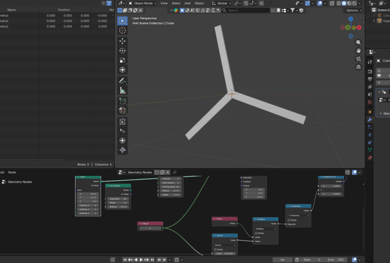
2. Add Blade Attachment Points: On back. Here we
are inside Blender, and as you can see, this
is a brand new project. I'm using Blender 5.0
release candidate. So let's switch directly to the Geometry Nodes
workspace, and here we are. Now, in the previous class, we learned that Geometry
Nodes is actually a modifier so that if
we have a cube here, look at what happens here. Shift A, Cube, a button
appears here immediately. And when I how it, it says, create a new modifier with
a new Geometry node group. So Geometry Nodes is a
modifier, and to add it, I can go to modifiers, add Geometry Nodes, or I can just go here directly and click this and watch
what happens here. If I add that, as you can see, Geometry Nodes modifier has
been added to our cube. And if I come in here, what we have in here is the
group input and group output. The group input provides
us with the geometry or the data of the geometry we added manually to
our three D scene. In this case, our cube. So this group input is providing the geometry of this
cube we've added here. And if we add a node in between, for example, if I hit Shift A, shift A and type
transform geometry, we can use the transform
geometry to translate. That is move, rotate, or scale this geometry that's coming in from
the previous node. What we want to do
in this lesson is to add attachment points
for our blades. So if I come here and
select this node group, we don't want to work
with this geometry here. So I want to delete
this group input. But remember, we're still
working inside the modifier, we added to the cube. So we've not deleted the cube, we're just not supplying the data of this geometry
to the group output. So by deleting the source
of the geometry here, we're just not
showing the geometry, but it still exists. So what we want to do
is say shift A points. As you can see points,
we can add points. Last time we learned that points are what we can use
as attachment points. So if I attach that to the
geometry here and zoom in, we can see our points. We can also increase or
decrease their radius. Now, points are not geometry. They are just given this visual representation to allow us to see where they are. They are not geometry. And because we can see them, we can be able to move them
around and know exactly where we've placed the points
or the attachment points. And I want to use a metaphor
to explain how this node works and also how most
of the other nodes work. So when you look at
this node right here, what it's saying is add
a point, add one point. We've added one point, set the position
to this position, so we've set the
position to zero, zero, zero, and then
set the radius to 0.22 m. We've set the radius. So we can also increase
the radius here. And so now what it does
is it adds the point, then looks at the position, then adds a radius of 0.42. If we add another point, the node adds one point, sets its position to this, and then adds a radius of 0.42. Then it adds another point, sets its position
at 0.000 again, and then 0.42, and
then it stops there. If we add a third
one, it repeats, it adds the first point,
set its position, set its radius,
adds another point, looks at the position,
then the radius. Now we have a problem
because if that's the case, that means all the points have been placed in the
same position. If every time the node reads
the position values to set the value of
the newest point, it finds the same old zero, zero, zero, zero, then it
sets it at the origin. So no matter how
many points we add, they will always
remain in the center, and you will think you
have just one point. Let's go back to let's
say three points. Now, if we move
this in the Y axis, as you can see, we're setting the position to a
different place. So what's happening right
now is we're adding a point, setting its Y position
as 1.1 meters, and then the radius. Adding the second point, setting its Y position as
this hard coded 1.1 meters, and then the radius. The third point the same. If you've ever done any
little bit of coding, you know the difference
between hard coding a value and providing a list of
values that can be read from. So what we want is to be able to read a list of values that can be used by this particular value here to set the
position of each point. Because remember, the
process is add a point, set the current value,
and then the radius. So let me just bring this up. I want to illustrate this. If we can have a list where
we can say, create a point, set the position at one, then set the radius, 1 meter. Create the second point, set the position at two, then set the radius. Create the third point, set its Y position at three. Set its Y position at three
and so on and so forth. If only we had a list like
that that can provide such values to this
particular input field, then this input field
would be able to read from that list from one to
whatever number we want, and it would place a point
at every successive number, one, two, three,
four from that list. And we have such a node. The node is called
the Index node. Let me just undo all this. If we come here and
say Shift A, index. If I connect this
index node directly, it's not going to go in
the direction we want. It's going to go in some funny direction,
diagonal direction. And that's because
if I cut this, we have three axis, X Y and Z. We want to use the index on the X axis alone because we want to move them in
the Y axis alone. Or we can say want
to move them in the X axis or in the Z axis. So what we want to do is
separate these three, and we do that by using a node
called combine vector XYZ. With this combined node, we have access to X or Y, or Z. We can connect it
to anything here. And so the value that
we go out of here is the value we've connected to, let's say, in the X axis. So as you can see here,
we have a point cloud, and this point cloud
has three points. Remember, this is a
point cloud node. So points, we have three points. And those three points, each of them has an index or
a location in memory, index. And so that is this index. So this index node is
pulling this list and making it available to the X axis of the
point cloud node. And so that is the same as providing those values to
this input field right here. So what this Points node is doing right now is it's saying, create the first point, this first point,
set the position based on the current
item in the index list. This is the index list. So the first item here is zero. And so for the first item, we set the position as zero, and that's why it starts
at zero right here. If I switch the top
view with seven, as you can see in the X axis, it starts at zero. Then we go back here
again to the points. It says, create
the second point, and then for its position, look at the next list
item in the index list. So the next item in
the index list is one. So we use one. For the second item
for the second point. So we use the value one to set the position of the second point and then set its radius at 0.42, and that's why it's
the same size as this. The third time, third
point for its position, let's use the third value in this list called
index, which is two. And so one, two, we set it at two and
then the radius. So that's how to distribute
points based on index. And I wanted to drive that home. I know this lesson has
been longer than expected. But I wanted to drive that
home so that from now on, you will never struggle
to understand what's happening when you're creating points or attachment points. Now, to these points, we can add because
you said points are essentially attachment
points to attach things onto, we can attach instances. So let's go ahead and
attach some instances here.
3. Attach Blades: Welcome back. So now it's
time to attach our blades. And remember, in
the previous class, we said points exist to allow
you to attach instances. So we want to attach instances onto the points we added
these three points. So let me just click
here. Shift A. Instance on points. We want to place instances
on each of those points. You will notice the
points have disappeared, and that's because this instance on points needs to be very specific about what shape or geometry we want to place
there as an instance. And so we do that by coming
here to the instance socket. So I'm going to pull
that out and type cube. So now, as you can see, we have three cubes attached to the
points we had right here. So now, let me just make the
instance says slim in the X. So I'm just going to
hold down shift while dragging this to move in small increments,
maybe that size. Then also in the Y, let's make them very
slim, just like that. But now if we switch
the front view, you will notice they are
sinking below the floor. We want to push them upwards. If I switch the front, we
want to push them upwards. The way to do that because we have the cube here before
it becomes an instance, it's still geometry here. We can say set position. The position of the cube as a geometry before it's
instanced onto the points. So we want to set the Z offset
to maybe somewhere there. Notice they're not in the
center on the X axis, and that's because right here, while I was explaining things, I changed the value of Y here. It's supposed to remain at
zero because along the y axis, the green axis, we had
placed it at 1.1 meters. Now it's at zero. So now the three instances are placed on the points or attachment
points we prepared for them. These three will
act as our blades. So let me increase
the vertical height. Remember, we have
the cube itself. This is where we
can set its height. Let's say maybe that size. But then again, now I need
to push it up again in the Z offset, just like that. So that's how to add
instances to points, or that's how to add our blades. But now, as you can tell, this is not what a
propeller looks like. We have three blades, but how do we turn
them into a propeller? That's what we're going
to do in the next lesson.
4. Rotation by Blade Index: This lesson, we
want to see how to rotate these blades
to form a propeller. But before we do that,
I want to select these two nodes and delete them because we don't need them. I added them to explain how this node creates points
and how it positions them. So if I cut that, everything is going to move to the current position right here. So let me delete these two, and let me set these
at zero once again. So we still have three blades. These are three blades, but they're all collapsed into the center of the
world because in the X in the X in the
Y and in the Z axis, the value is zero. So when each point is created, its location is
positioned in the origin, but we still have three blads. Now, if you go down here to
the instance on Points node, you will notice we have this
rotation set of values here. And if we rotate in the Y value, we're rotating all
the blades at once. We want each blade to
have its own rotation. And like I mentioned, if you've ever done any
little bit of coding, you will know that there is a huge difference between how
your code will behave when you hard code a value
versus if you provide a list of values that
your function reads from. If you have a function and
you heard code a value, every iteration of that function will use that same value. So what's happening here
is if we're rotating here, this instance on points node is like a function
that's doing this. It takes the points. It takes the first point because there are three
points coming in. It takes the first point. It places an instance on it. One cube, places
an instance on it, and then it uses this hard coded rotation
value to rotate the instance. And because it's hard coded, when it repeats the same
step for the second point, it takes the second point, places an instance
on it, a cube, and then it picks the same
hard coded value here and rotates the second
instance by that same angle. And the same thing applies
to the third instance. And what you end up
with is instances that are all sharing one
rotation value. If we want to change
that behavior, remember, we already saw how
to solve that right here. We need to use a list
of values so that when we read the first point here and add an instance to it, then come to the rotation value, we're going to have
a specific value. Next time when we come with a second point and add
an instance to it, it should have a
different value. So we need a list of values. And what's a good example of a good list we can
use the index. So let's say index, there we go. And so we cannot connect it directly here to
rotation because it's going to apply to all the three values and that's not what we want.
Let me just show you. It doesn't work like that. So what we want to do is say, we want to access just the Y. So shift A XYZ, combine XYZ, and then
connect it there. Now, that gives us
access to the Y axis. So what's happening now is this instance on
points node is saying, take the first point, add this
cube as an instance to it, attach it as an instance to it. Then use the first list item in this list called index as
the value of the rotation. Then take the second point, place an instance on it, and then use the second
item in this list as the value of the
rotation field of the Y axis and so
on and so forth. Now, if we have a few
instances right here, we will have a short list of indexes or indices
because one, two, three, if we want to go
a full rotation here, we need more points so we can have more indices or indexes. So if I go here to Instances, as you can see, we
have instances. Let me just use the viewer node right here by selecting this, Blender five point oh has this viewer node that
allows you to see what a specific node can see or what a specific
node has processed. So if I hit Control
Shift and left click, now, what this viewer
node can see is what this point node
sees or has processed. And I want us to look at this. So now here we
have seven points, and our index list is now
containing seven items. Index zero up to six. So if we increase
the number here, as you can see, it's growing. So now, if I remove this viewer, and this index node is
now reading from this, it's actually
presenting this list. So if I remove this viewer
node, as you can see, we have now that
number of instances because we have that
number of points. Now, one thing you
need to understand here is that if I cut this, while this number here is in degrees when we're
rotating it is very fine, as you can see, it's in degrees, and that's what we expect. But here, this is not
in degrees because you can't even see that
tiny degree symbol. These are radiance. We need a way to convert
the radiance into degrees. But before we do
that, there's also another problem you
need to notice here. You will notice, even though we have all these blades here, they're not evenly spaced
out. They're just random. If I add more, they just
added to random spaces, but they're not
evenly spaced out. And we have no way
of controlling that. How do we control that? That's a quagmire we need to solve if we're going
to create a reusable, reliable propeller
system that you can use for different
applications. And that's what we're going
to see in the next lesson.
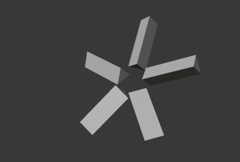
5. Rotation by Number of Blades: Want to solve this problem we experienced in the
previous lesson. Let me just switch
the front view. Our angles here are off. How do we make them equal? Now, let's think of a
circle for a moment. A circle is one full rotation, and one full rotation
is 360 degrees. Let me just spit
that 360 degrees. That's a full circle.
If we want to divide a full circle into
equal portions, maybe let's say we
have a pie chart. We want to divide it
into equal portions. What we do is divide 360 by
that number of portions. So if we want it divided into three equal portions,
we divide it by three. That gives us 120. Degrees. That means each
degree needs to be 120. Each propeller needs to be 120 degrees from the
other propeller. If we have three propellers. If we have six, then
this means, I think, 60. So now, with that in mind, how can we convert this
into geometry nodes? Well, we have math nodes. So first of all,
I'm going to say Shift A, divide, math divide. Yep. So we want to say 360. Divide by what value? We're going to say
three integer. And if I Control
Shift click this, if I say three here, as you can see,
the value is 120. This is the viewer node
just in case you forgot, Control Shift click to see what any node has
processed so far. So the value here is
120 like we saw here. So that's the value
that's going to come out. Let me now remove
this by deleting it. And let me just drag this. In fact, let me just
delete it for a second. I'm going to place
it right there to the side because
you're going to need it. Now, if I connect this
directly, remember, if I connect it to why, there's a problem here.
What's happening? Everything has collapsed
into one angle, and this is because of the same problem we
talked about here, hard coding a value. Remember, now we have this
value of 120 here that's coming from 360 divide
by this value, 120. And we're fitting it
into this Y value here. And that is getting
fed into the rotation. So every time we add a point, we add an instance to it, and then we look for
the rotation value. It's always 120. So all the blades we have, the 26 blades we have
have a rotation of 120. So let me just say three. I want them to be
three. Of course, nothing is going to change. But remember, when we wanted to have each
blade at its own angle, we used a list of values instead of a hard coded value like 120, we were using the
index as our list of values that would separate every blade because
every time we add a blade as an instance, we look at the new value
in the list in this list. So what we need to
do is find a way to combine this list
with this value. And in Blender geometry nodes, we do that by multiplying value. Shift A, another math
node, we have divide. In fact, I can just pick
divide here, Shift D. And then if I put
it to the side, I can say multiply. Now it's a multiply. And instead of 360 by this, it's going to be this by this. Let me just put that there, then say that
multiplied by that. And now, what we
have now are three. Let me switch here to the front. Let me one to switch the front. This value right here, is equal to this
value right here. But the problem is this
value here is in radiance, and this value here
is in degrees. We need a way to provide the
specific degrees we want, maybe 60 degrees or 20 degrees and then have that converted into whatever
radiant value it is. Just before we go too far, I want to drive a point home. I want to help
anyone who is still stuck in understanding how
everything is working. So now we have three
points, and we're saying, with this instance on points, let's take the first
point. We've taken it. Let's add an instance to it. The instance is a cube. Let's say this first one because it's actually
the first one. And then let's look at
the rotation value. So we look at the
rotation value. So we go back to the past and see how did we get
the rotation value. So here, what's
happening is we have 360 divide by whatever
integer we want here, which is the same number as
the number of blades in order to get an equal spacing
between the three of them, and we're going to space
them out like this. But because here we have 120, we're taking 120 multiplied by the first value in the
index list, which is zero. If I click here
again, we have zero. So that's the first value. Let me delete the viewer. We take zero times 120
and supply it here. So why value is zero for the first instance in
terms of rotation. And that's why it's at zero. It's straight upwards. Then the instance on points node again takes
the second point, places an instance on it, a cube, looks at
the rotation value. This time the rotation value is one times 120
because remember, once again, control shift click. Now the next value in the
index list here is one, so one times 120 is 120, so the value is 120. So let me remove
that. But remember, I mentioned that
these are radiance. When this value leaves this
XYZ node into rotation, this leaves here as
radiance, not degrees. So what we want to do is tell Geometry nodes,
Hey, you know what? This value that we're giving you here is in degrees, right? So because we are used to working with degrees
and not radiance, we're giving you degrees,
the degrees we want. But you convert them
into radiance, right? So I can come here and
say Shift A to radiance. If I add this node here, what's happening,
as you can see now, the angles are correct. What's happening
is, as I mentioned, this two radiance is receiving whatever value you give it
and reading it as degrees. If by the time we're here, the value is 120,
we get 120 degrees. I don't know how many
radiance 120 degrees is. So two radiance converts
that into radiance. I don't know what
this is seeing, but it converts that into degrees and gives
it to rotation. All I need to know is that I provided the value I
wanted in degrees. They were converted into radiance before we
provided them to the specific axis we want on
the instance on Points node. And now, I just want to get
rid of all these texts. So let me get the eraser. There we go. And now, you might be wondering now
that we have our propeller, how do we rotate it?
6. Rotate the Propeller: If I drag this aside, remember, now that we have all
the instances, one, two, three instances,
this is one unit now. When it lives here,
it's one unit, and we can transform it. So if I say transform shift A, transform geometry, I can
transform it as a whole, so I can say rotate
in the Y axis. In fact, what I can do is
animate this particular value. So what I can do is
add a group input. Remember the first node that was connected to this
when we added a node group, the group input, Shift
A, input, group input. There we go. I want
to access this field. So I want to say combine XYZ, Shift D. And let me
just drag these two. So I want to connect it
to the rotation there, and now I can access the Y axis. No, not there. I want
to connect it to the second connector link
to create a new socket. So to the Y. And now in the modifier here, if you go to the modifiers under the Geometry node modifier, you've added the Y axis to it. So now, this is where
I can control it from. And now, if I pull
up the timeline, go to one, maybe push
it backwards by one. I can come here and hover
over this and hit I, and that creates a
keyframe right there. Then select this, put
it at the very end. Rotate this maybe
up to that spot, and then hit I while
hovering over it once again. And now you've
created a rotation. So if I hit Spacebar, now we have a propeller. Now, the good thing
about this system and what makes it a reusable, reliable system is I can come here and change
this to anything. I can say Shift A,
let's say cylinder. Cut that and let's use
a cylinder instead. Or I can come here and
say Shift A, UV sphere. Delete that and now
let's say UV sphere. Now, I can also come here. Remember, the angle
here separating the three blades is determined
by this division here, 360 divide by this value, which is also the
number of blades. So what we can do is use the same integer
as the same thing so that it's supplying
these three to the count of blades and
the division number here. Now, if we change this to four, as you can see, it's
multiplying it. We can also reduce the radius of the ball and increase
the number here. And as you can see, we now have a very
interesting pattern. So now they're sharing this. Whenever you increase
this number here, it automatically
applies everywhere. And I think this is a nice
spot to end this class. I hope you learned something if you already
knew Geometry Nodes, but learned something more
than you already knew, I'm glad I played
a role in that. If you were new to
Geometry Nodes, and it finally clicked for you, I'm glad I finally
played a role in.
7. Final Thoughts and Next Steps: Ah, right, so there you have it. You now have a fully
working propeller system. And not only that, you mastered the procedural logic and
rotational principles that make geometry nodes so efficient and now for the most
important step. I'd like to see your
work. Head over to the projects and resources tab right below
this video player and upload your final render. Show us the unique rotor
system you created or how you customized the
core propeller asset we created in class. Uploading your project
is the best way to get feedback and support from
me and the community. Now, before you go, I'd
like to know one thing. Did this class help you? Did you finally
understand Geometry not? If you did, I would
really appreciate it if you could take
just 1 minute of your time and please
consider leaving a review and following
me here on Skillshare. It's the best way for
you to support me and support the creation of
more classes like this one. So drop a review and let me know what you
thought about the class. Now, as I mentioned last time, this is just
the beginning. I have several more
classes in the pipeline, Geometry Nodes classes
to be specific, and I want to help you really understand how
to use this system. So make sure you visit
my profile and click the follow button to be notified every time I publish
a brand new class. Thank you so much for
joining me in this class. Keep experimenting,
keep rendering, and I'll see you in
the next class. Peace.
 Ken Mbesa, Web Designer | 3D Artist