Transcripts
1. Intro: In this class, you're
going to learn Geometry Nodes in a
completely different way, not by memorizing node setups, but by understanding
how the system actually works at a
fundamental level. My name is Ken, and
I'm a web designer, three D artist, and
content creator. I've been using Blender
for about four years now, and I've been constantly
leveling up my skills and sharing everything I learn
through courses like this one. And today, I'm going
to prove to you that Geometry Nodes isn't as
complicated as it looks. It looks daunting at first, but it's actually built on a few core patterns
that repeat everywhere. And once you see those patterns,
everything just clicks. And to make it fun,
we're going to learn through a simple
mental framework, the Spaceship Docking
metaphor will create a mothership install
docking ports on it, dock smaller ships,
deploy the smaller ships, and build armies of sentinels
to ride those ships. And by doing that, you'll
naturally understand points, instances, alignment, and many of the concepts that make
geometry nodes so powerful. We'll be working
in Blender 5.0 O, so you're learning the newest
Geometry node system yet. And by the end of this class, you won't just know
which nodes to use, but you understand
why behind them. You start thinking procedurally, and you'll even be
able to read and understand other people's
Geometry node setups. Now, for your class project, you're going to build your own procedural fleet and an army of sentinels or something
completely your own if you want to put your
creativity to the test. So now, are you ready to finally understand how
Geometry Nodes works? If you are, let's go.
2. Download Blender 5: Welcome back. So now, here we are on the
official website where you can download Blender. This blender.org,
and as you can see, the current version
is Blender 5.0 Beta. Now, if you want
a stable version, you can go ahead
and click Download. And here you will find the
stable version, which is 4.5. Click Download Blender 5.0. Go here. You will find
all architectures, choose whatever
architecture you're using. I am on Windows 11, so I'm going with this. So once you do that, I'll see you in the next
lesson where we will have a quick overview of the
geometry nodes workspace. See you shortly.
3. Geometry Nodes Overview: Welcome back. So now
here we are inside Blender 5.0 O. I hope
you've installed yours, and even if you
haven't, let's go on. Now, I want to add a cube, so Shift A, then cube. And I want to show you what a geometry node is essentially. Now, this is a
geometrical shape. And in Blender, if we want to manipulate this
geometrical shape, we manipulate the
data defining it. The different edges, let me
switch to Edit mode, Edit. These vertices if I
switch to edge mode, these edges and if I
switch to face mode, the faces, if I want to
manipulate these faces, edges and vertices, there
are two ways to do that, at least that I know of destructive methods and
nondestructive methods. If I exit Edit mode for
a second by hitting tab, now we're in object mode, if I want to add bevels to
this cube as an example, I want to make the
corners or edges smooth, the destructive way to
do it is select it, go to Edit Mode. And then switch to edge
mode, select all edges, or I'll just hit A to
select everything, Control B, and add a bevel. Now, that's just
pulling outwards. If I scroll the
mouse wheel upwards, I'll be able to
add more segments to make the bevel smoother. And I can do that as much
as I want right now. But once I finish that, there is no way for me to
increase or decrease the number of segments here to make it
smoother or blocky at will. I have to control Z to undo
that in order to be able to control B and maybe now set
a new number of bevels. That's destructive. It's causing distraction to the underlying geometry
that the cube had. And once we commit the change, there is no way to
edit the changes. There is no way to
edit this bevel. So that's the destructive
way of doing it. If I undo that Control Z, the non destructive
way to add bevels to your geometrical shapes or your geometry is to
go to modifiers, add and then go to
generate bevel. We can edit the
size of the bevel like that and also increase
the number of segments. Just like we did with
the destructive method. But now, if I exit by going to object mode and clicking aside and doing
some other things, we still have our
bevel modifier here, and I can come here and
increase the size of the bevel. I can also increase or
decrease the number of segments to edit the fineness
or smoothness of the bevel. So modifiers allow you to
modify your geometry or your geometrical shapes without taking away your ability to come back and edit the geometry later because you can always
come back here and edit it. Now, with all this
said and done, I want to undo all that just
so we're left with a key, just so we're left with a cube. And now, now that
you know we have modifiers as a way
to edit geometry, Geometry Nodes is
listed under modifiers, which means geometry
nodes is also a modifier, a way to play around with this underlying
geometry that forms the cube and make
the cube deform or move around or scale up and
behave in interesting ways. So that's what Geometry nodes is a modifier that allows us to
do a lot with the geometry. But now Geometry Nodes is a whole entire system that's
very complex, and therefore, this space is not enough to allow us to work
with geometry nodes, the way we're able to work with very simple modifiers
like the bevel modifier. That's why we have
a dedicated space called Geometry Nodes. If we want to work
with geometry nodes, this is where we're
going to work with them. Now, remember, we've added a geometry node here. Let's see. What modifier have we
added a bevel modifier. Let's remove that modifier. Now here, what we have is
the three D view port. We have a spreadsheet showing us the underlying data of this
geometry in tabulated format. What you're seeing
here is represented here by these columns and rows. I'm already preparing a class on how to use this spreadsheet, so we're not going to
touch on it right now, but just know we're going to revisit it later in the future. Are the two viewports we're
going to use in this class. Let me remind you once again, when we want to manipulate the geometry in our
three D viewport, we can do it destructively
or non destructively. And we've concluded that geometry nodes are one
type of a modifier. So let's select our cube, and now let's add
geometry nodes. Now we've added geometry nodes, but there is nothing happening. Why? We've only just added
the geometry node modifier to the cube to enable us to now
do stuff with nodes in here, connect several nodes here
to affect the geometry. Those are called node groups because there are several nodes that you interconnect in
order to affect the geometry. And so here, when
you hove over this, you will create a new
geometry node group, a group of nodes. So if we click this,
notice what happens here. We have a group input
and group output, and the Geometry nodes
group is set up here. I can give it a name. My cube node group. All right. Of course, if you've ever seen any node system
anywhere, you know, now in between these two nodes, we add our other nodes here
and change what we see here. Now, what we're seeing here in the three D view port is the
result of this group output. If we cut the output, we stop seeing anything, but that doesn't
mean the cube is deleted because
as you can see in the time in the outline,
the cube is still there. It's just that the data
is not getting to us. In the group output because it's like disconnecting
a cable, literally. Power isn't getting this. But once it gets
there, the data is able to get to the group
output and tell us, Oh, here's the data
to show the cube. Now, another thing
I should mention is if I delete this node group, a and remove this modifier. We still have our cube. A quick way to add
the modifier and the node group
directly instead of adding the geometry nodes, and then clicking this
plus is to simply select the geometry we want to apply the geometry node to and
then click this plus. That adds a node
group, and of course, it places it inside Geometry Nodes modifier
automatically. So this is just a quick
overview of the geometry nodes, workspace, and the things you need to know as we get started. But more stuff you're
going to learn as we get deeper into
all these other nodes. So I hope now you're ready and excited to get started
because in the next lesson, we're now ready to
build a mothership. Let's see how to
add a mothership using Geometry Nodes down here. I'll see you shortly.
4. Create a Mothership: Now, here we are inside Blender. Now, I want to go straight
to the geometry node setup. And in this lesson, our goal is to see how to add
or create our mothership. And, of course, a mothership is basically one large object. Of course, we don't want to
complicate things right now. We can just use a simple cube. As the shape that
represents our ship. So let's go ahead
and add a cube, Shift A in the
three D view port, Shift A, mesh, cube. And if I add a cube, notice what will
happen down here. So mesh, cube. Now, because we have geometry in our three D view
port and because the geometry is
currently selected, we can add Geometry
Nodes setup to it or Geometry Nodes modifier because nodice here, it's a modifier. So if I click this we've added Geometry Nodes modifier to this cube, specifically
this cube. If I delete the cube, I've deleted it
including its modifiers. Geometry Nodes was the
only modifier it had. So let me just undo that. And now, essentially,
we have our mothership, but we want our mothership to
be longer along the Y axis. So how do you resize any geometry you have
in the three D port? You use a node called
the Transform Geometry. Shift A, let me
just say Transform, and it will be the
first option here. Enter Transform geometry. If I drop it above
that green line cable, it'll turn white and I can just it'll just
automatically attach. Now we have three vectors here. Translation, this is to
move it along the X, Y, and Z axis and do all that. We can rotate it along
the three axis as well and do that. And now what we want is to
scale it along the y axis, so scale it along the y axis. Let me just leave
it right there. Let me just type in three. Now, this cube might
be very simple, but of course, it's for
illustration purposes, and what it represents
is the mother ship, the object onto which many other objects are
going to be attached, the smaller ships or shuttles. And so we add it as a geometry and send
that geometry through a Transform Geometry Node
to allow us to scale it move it around and rotate it within
the three D viewport. So that gives us control. The goal here is not
to be very perfect. The goal is to help you develop that mindset of,
what am I adding? I'm adding an object
onto which I want to attach a cluster of
many smaller things. That's how you should
start thinking about this. And that object should
be able to move around, rotate, and I should be able to scale it.
How do I do that? A good node to do that is
the Transform geometry, which allows you to translate, rotate, and scale the object. In the next lesson,
let's see how to start docking the smaller ships onto the mother ship or whatever you want to
do with this concept. I'll see you shortly.
5. Install Docking Ports: A, welcome back. Now,
in the previous lesson, I concluded by mentioning, we're going to look at how to dock ships onto the mother ship. But before we dock the
ships onto the mother ship, we need docking ports, places for the ships to
attach to on the mother ship. So we need to create attachment points
on the mother ship. If I hit Shift A, the points. You see point, these
points are what I like to think of as docking
ports or attachment points. Now we want to place
several points all over the mothership because those
are our docking ports. So if we go to point, Distribute point on faces because this geometry has faces. Let's select Distribute
points on faces. What we're essentially
saying is, let's place several
docking ports on this mothership on the
geometry that's here. And that's why it's shaped
like our mothership. But now there's a problem
because we've lost all the faces of the
cube. So what happened? Now, this introduces us to another metaphor I like to
use for geometry nodes, which is parallel universes
or parallel timelines. Originally, if I cut this and connect
this directly there, we made a decision here, and this is the future. This is a timeline. If I remove that, instead of that decision of
connecting directly there, I decided, let's first of
all, transform the cube. And then let's put it directly. Let's transform the cube, make it longer in
X in the Y axis, Y axis, and show it. So that's why we
saw this future. Then now we only
have one timeline. Currently, we only have one timeline for
this group input, and this is the only timeline. We introduce these
distribute points on faces. It's still the same timeline, but we're introducing more
decisions as we move along. So we made a decision
here to transform stuff. Then we made a decision
to distribute points on the faces of the geometry
that's right here. But once we have the points, as you can see right here, the node says points,
not geometry, points. So what we see in the
future is the points, the docking ports, and
where we've placed them. If we want to see
the cube as well, we want to combine the
timeline that showed the cube. And this timeline
that's showing where on the cube these
dock in ports are. So we need a way to combine these two so that we show them. But if we try to put
them together there, the group output can
only accept one input. So we have something called
Shift A, Join Geometry. Or if I click away, Shift A, if you go to Geometry,
Join Geometry. So if I add this node,
and place it here. This is still one timeline here, but now we can introduce
this other timeline that had the cube and combine it
with this other timeline. And now we have the cube and the different ports we
want to place on it. But now, remember,
because these are two different timelines
on this timeline, the cube is still the
original size right here, we transformed this timeline to make it longer
along the Y axis. We made it three
units in the Y axis. But right here, the cube
is not transformed. This timeline doesn't know about what you did in
these other parts. It will only get to know
that when it gets here. So what we want to do is select this shift D to duplicate it
and put it in between here. Now because we've just
duplicated this and the value the value was
already three here, it's still three and
because we've put it here, now this expansion has happened to the Y axis
of the underlying cube. Now, in this timeline, the only thing we can see is
we have a geometry, a cube. That cube is expanded in the
Y axis, control, and lik. And on this other
timeline right here, what we're saying is we
have the cube geometry, and then we transform
that geometry. And before we get to distribute
points on its faces, let me just cut that
control, right click. And now, first of all,
let me cut this line as well because I want us to talk about this timeline quickly. So on this timeline, what's happening is we have
the geometry of the cube, and we say we want
to resize the cube. So if I zoom out slightly, the same that's going to produce the same result right here
in these two timeline. So if I hold down
Control Shift and click. We're going to attach a viewer node to this
Transform Geometry Node. And what the viewer
node does is it's a window into what the
current node can see. So what we are seeing right now up here in the three
D view port through the viewer Node is what this transform geometry
has been able to process. So if I control shift
click this one as well. Now what we can see is
the result of this node. So the transform is identical. Now, let me delete
that viewer node. Now, where the change
comes is we make another decision to just go directly to display the
cube, and that's it. That timeline is done.
But now if I cut that, we introduce another
decision here to place to distribute docking ports or points on the faces
of that cube. So what we've done here, if I add a viewer node, Control Shift and click, we are seeing what this
node has processed, exactly where the points
are going to be placed, and it shows the
points placed there. So removing that viewer node, when we connect it here, now that's why we
see only the points. Combining these two
timelines once again is why we are able to now
see the two of them. I know I've done a lot
of repetition there, but I wanted to drive this
home because we're going to do much more of
this going forward. And this is something you're
going to repeat a lot of the time when you're
working with geometry nodes, distributing points on faces. And so I wanted you
to understand about timeline thinking and parallel universes
existing together. And being able to combine
the parallel universes at some point in the future to see what both of them produced. So now, I think this is
the end of this lesson. It's longer than I
expected it to be, but the rest are
not going to be as long as this because
that was one of the most important mindsets I wanted you to have
as we move forward. So in the next lesson, let's dock the fleet onto these docking ports because each docking port
needs a spaceship, a small spaceship.
See you shortly.
6. Dock the Fleet: Now we have our mothership and the docking ports we want to place the smaller ships onto. So it's time to
attach those ships. Remember, the docking
ports are the points. We distributed points on the faces of the mother
ship or of the cube. So we distributed
points on faces Points. Points are ports. Let me hit Shift A. Shift A. If the points
are the docking ports, then the instances
are our ships, the small ships we want to
attach to the docking ports. So points exist to allow you
to attach instances onto. So examples of instances
in another scenario, apart from the
Spaceship scenario is you want to plant
trees on land. You've modeled a piece of
land inside Blender and you want to plant
trees on that land. Each tree will need to be
planted inside a hole. So you distribute
holes on that land, Distribute points on faces, distribute the
holes on that land. And then on inside
each of those holes, you want to plant trees. Each tree is the instance. In our example here, each ship is our instance
and each point is our port. Now, are just more analogies to help you grasp this better. So if I grab these two,
let's say Shift A, if you go to the instances menu, it has many options here that
you will get to use later. But we have this one here
that says Instance on Points, we attach it here. This Instance on Points
Node basically just means place instances on
the points you distributed, but we've not told it what
instance to distribute, what shape should
be distributed. It could be a shoe. It
could be a remote control. It could be a spaceship. What do we want to place there? It could be a cube, it
could be a UVsphere. So that's why we
have this instance Geometry that is
instanced on the points. So we want to say on each point, distribute this
particular geometry. So let's pull that
out and type cube. We're going to generate
a cube natively here. And I'm just going
to click here. Now we have a cube node. And as you can see, it's huge. If I click away
here, they are huge. I'm going to click in
here and drag downwards to select the three
input fields. Then hold down shift to
reduce the size gradually, maybe up to that point. I think I like that size 19. Let me hold down let
me switch it to 0.20. All right. So as you can see, now we're saying
Instance place instances on all the points we distributed on the
faces of the ship. And what should those
instances look like? We tell the instance on points now that we
want them to be cubes. We can delete this with
X and say shift A, maybe U V sphere. If I attach the UV sphere there, now it's going to be UV
spheres like we did before. Let me just reduce the radius, holding down shift to move
in smaller increments. Now we have UV spheres. If I move closer.
So as you can see, we can distribute
different types of things. All right. So that's how to attach ships onto
the mother ship. Let me see what we have
next in our lesson. One thing you will notice here is some of the ships
are overlapping. This cannot happen in
the real physical world. Two ships cannot exist in
the same space in the world. So right here in the
distribute point on faces, that's where we can
make the changes because the problem is where the docking ports
are placed or distributed. Some docking ports, if I go here and control shift click to
bring up the viewer node, Remember, we're viewing
what this node can see, and what it can see are
the points it distributed. And some of the points are together like these,
too. They're together. So we need to change this
from random to poison disc and we need to increase
this distance minimum. And what this does is it tells the Distribute
Points on Faces Node. Let's increase the
minimum personal space of every docking port. Every docking port should
have some personal space. And as we increase the
personal space, of course, that means less docking ports can be accommodated
on the mothership. The more we increase the personal space of
each docking port, the less the mothership
can accommodate. Now, density here means just the number of
docking ports or points. But now the number we wanted
to play around with is this to make sure every docking
port has some personal space. So now, if I now delete that, as you can see, I
don't think we have any overlapping
spaceship anymore. Yep. There we go. So let me just drag that up. Is there anything else? I think we covered just about
everything we wanted, but one more thing I
think I should cover. Remember, I've mentioned we're
using this UV sphere here, but we can also attach
different other shapes. So if I hit Shift A right here
in the three D view port, Shift A, I can add
a mesh and say, let's say icosphere
and it's in here. So G, X to move it in the
X, put it right there. Let me shift A to
add something else, maybe a cylinder, GX, those two for now. Now, with those two,
I'm going to select our original cue once again to bring back our geometry node, and I forgot to click this
to keep this geometry node permanently there
regardless of where I click. Now, because we have these two new items or
these two new objects, the icosphere and the cylinder, one way to add geometry inside the geometry nodes area is
through the native mesh, Shift A, mesh,
primitives, cylinder. Or if we've already generated a cylinder manually
here like we've done here because we
have a cylinder here, we can drag and drop it in here, and it will be brought in
as an object info node, but they're both cylinders. It's just that this one is representing this one
we generated manually. And this one here is
a native cylinder within geometry nodes, but they're both cylinders,
and you can use any. So I want to remove that and attach the geometry
itself right there. And now we have the cylinders. And now you will notice, let me just delete this. You will notice it's too
big and there is no way to resize it like we had with
the native geometry nodes. So here we can add a
transform geometry. So I'll select this shift
D and put it right there. And, of course, we don't want
it to stretch in the three, so one like the rest. And I want to select
the three of them, hold down shift, and
scale downwards. That's another way
to add spaceships. Now, what I wanted to show
before we finish this lesson is notice here that every
ship is facing upwards. Everything is facing
in the same direction. So how do we tell
every ship to face the right direction based on
the face it's attached to? Do that by looking at the Distribute Points
on Faces Node here, it has a rotation filled socket. And we also have a rotation here on the instance on points. We distributed points on faces or we distributed
ports on faces. And when those ports were distributed on
the different faces, they were distributed facing
in the correct directions. But the Instance on
Points Node is not aware of what direction the
ports are facing. So we need to pass
that information to it from the ports that
it's attaching to. We need to tell each instance to rotate in the angle of the
port it's attached to. At this point, the
ports that are distributed already know
how they are facing, what direction they are facing. But here, the instances don't know what direction
the ports are facing. So we make it aware of
that information by connecting the two rotations here. So that's how to do that. So with that, I think this
is a good spot to end this. In the next lesson,
let's see how to lift off because right
now our ships are attached. But what if we want them to lift off from
the mother ship? Or what if we want them to not be sunken deep into the ship? Like, this is not correct. Docked ships don't go deep
into the ship like that. They should be on the
surface. How do we do that? Let's see how to do that in the next lesson.
See you shortly.
7. Fleet Maneuvers: Now it's time to see how to
maneuver our small ships. Now, first of all, I think
we have too many ships. So if we want to reduce
the number of ships, we reduce the density here or
increase the distance mean. Let's say that's the
number of ship we want. So to be able to move them outward from the
attachment space, we can move the ships
themselves, or yeah, let's move the ship outwards. And as you can see, because we already set the
direction right here, it knows exactly what
direction to head in. The ships are now levitating
outside the mother ship. Of course, rotation will also
happen at a local space. So if we rotate them like this, if I zoom in on any of them
and rotate in the Z axis, if we rotate in the Y axis, they're going to rotate
in that direction and X. So the direction we
want is the Z axis. If we want to scale
them outwards, maybe make them longer. Once again, the Z axis. So maybe they are
very long shuttles, and let's move them
outwards. There we go. So that's how to
maneuver your fleet. You can translate them. You can rotate and scale them. In other words, if you have
trees planted inside holes, you can translate your trees. You can rotate
them or scale them inside the holes
they are planted in. This is just one example. So in the next lesson, let's see how to add cargo containers onto the
spaceships, the small ships. Imagine we wanted
each one of them to have some cargo containers. How can we add cargo
containers to them? Let's see how to
do that shortly.
8. Add Cargo Containers: Time to attach some
containers onto the ships that are docked onto the mother ship.
How do we do that? First of all, I want
to do some tidying up of our space right here. I want to select these
nodes, zooming out. Let me just select these
and place them there. Now, remember, to attach these ships
onto the mother ship, we distributed points
onto the mother ship. Now what we want to do is
distribute points onto the smaller ships in order
to attach things onto them. Anytime you want to attach something like a cargo
container onto a surface, it has to attach to a point. So let's distribute some points on the ships, the small ships. And which are the
ships Remember, the cylinder here because
each cylinder is an instance. So we want to select
the cylinders and add or distribute points
or docking ports onto them. So we can duplicate
this shift D, and I'm going to
place it right there, and now it's attached. And the moment
we've attached it, the settings we had here are
also the same settings here. So let me just reduce
this number drastically, maybe to very few containers. Al right now you will notice some docking ports on each ship are too
close to each other, so we can increase the
distance mean like that. Maybe let's just
leave two per ship. And now remember now we're facing the same
problem we had here. Remember the timeline problem. We had this timeline
here that we joined to this other timeline that was
showing the docking ports. And now down here, we also need two timelines, one timeline to show where the cargo containers
are going to show up and one timeline to show
the ship, the small ships. So down here, how do we do that? First of all, before we go far, let's look at this
as a timeline. First of all, let's
know why we need to keep this transform
geometry right here. This transform
geometry right here is if I remove,
let me mute this. Let me select this
and hit to mute it. Now it's as if we only have
this going directly here. So we are creating
cylinders as ships. Each cylinder here
is a spaceship here. And to position the ship and be able to manipulate
and maneuver it, we're using this
transform geometry. And it's attached to the instance because
at the end of the day, everything we're
sending from here, we're sending into this future to define what every
instance should have. So what we're doing is
going back in time, first of all, to
create the containers, attach them in the right place, and then send them to this
transformed geometry because this transformed geometry
is what determines the position and
rotation of the ships. And so everything
we do should come before this transformed
geometry and then go in there. So selecting these two, we've already
defined let me hit. Now we've already
defined exactly where each docking container
is going to be attached. Now, before we attach any cargo containers onto the distributed docking
ports or points, let's first of all,
make sure we send this other timeline that defines the cylinder
into the future. Because remember, if
I attach this here, those are just the ships. But we also need to send the positions of the docking
ports. How do we do that? I know you probably guessed it, but we need a join geometry
like we needed up here. So down here, we come
up with a shift A, join geometry, put
it right here, and then let's send the ships
themselves into the future. Now, we have two timelines
giving us both results, a timeline showing us
the ships and a timeline showing us where the cargo containers are
going to be attached. But now, when we distribute
points on a face, we're distributing them to
attach something onto them. In this case, what
cargo containers. So let's attach them
as instances as usual. They're going to be instances, but now they've disappeared
because we haven't told them what each cargo
container should look like. Remember, we have this
instance here to say the cargo containers
look like a cube. So now, we've attached cube like cargo containers
onto each ship. Now, we can reduce the size if I select these three and hold down ship to reduce like that. And let's do some
arrangement here. I think we're in a good spot. And remember, what
if we want to push out to push these
containers outwards, these cargo containers outwards? The same way we
were able to push our ships outwards and rotate them based on the faces they're attached to because
they were instances. We can do that. Remember,
we used the rotation of the points of the mother
ship to tell the instances, the ships what
direction to face. So we can come here and say, let's use the
rotation information from the attachment points of the cargo containers and send that information to
each cargo container to tell it how to rotate. And now they're rotated. Now, with that, if I come here
and add a trans remember, in order to move the
ships in and out, we were using this
transform geometry, and we were able to do this. The same case down
here attached to the instance is a transform,
then the geometry. So here we also have an instance let's attach a
transform down here. Transform geometry to
transform or move, rotate and scale the
cargo containers. So with this, we can now move
them in and out like that. We can rotate them
in any direction. Let's see that like that. We can also scale them. Let me select the three
or maybe one direction. Push them outward
slightly. And there we go. Let me just return
the rotation to zero. Like that. I love that. So basically what we've done is a dream within a dream if
you've ever watched inception. So we had instances. So these are instances
within instances. So if I drag this and
place it maybe up here, we're trying to get a bit more organized, distribute that. Let's say that you go there. Let's drag all these. Want to get a bit
more organized. In the next lesson, let's see what interesting
thing we can do next. So don't go too far.
9. Extra Tips: Now in this lesson, I want us to look at a few tips and tricks that I'd like
you to be aware of. So, for example, remember
the viewer node. It allows us to see what each node sees at that
particular point in time. Because remember, we're dealing with timelines,
parallel timelines. And so the viewer node allows us to see what
every node has been able to process so far at
that point in that timeline. So this is the future of this. So by this time, what
do we have here. Let me just hold down
Control Shift click. Remember, right here, we had the we were joining
geometry of the Spaceship. And the containers
because in this timeline, we were trying to
add containers. So what we have
here after joining the geometry is a spaceship
and two containers. After transforming the spaceship
and it's two containers, we have now the tiny containers. And if we move on to
the instance on points, now we have all of
them distributed. Once we have the
distributed smaller ships, we join them with
the mother ship. Remember, we sent the
ship into the future. So we have the smaller ships and the mothership attached
together here. So if I control
shift click here, we have all of them here. It's after this point, let me delete that that we can now move the entire mother
ship carrying everything. Shift A, transformed Geometry, and now we can move
it in the Y axis, the green axis with all the smaller ships
docked in their containers. Alright, so I think this is a very good spot
to end this class. I hope you enjoyed everything
you learned so far. In the next lesson, I want
us to work on the army of sentinels that will be
riding these spaceships. Every spaceship needs
sentinels or a space army, and we have to create one. So how do we assemble one inside Geometry nodes using everything
we've learned so far? Let's see how to
do that shortly.
10. Build a Sentinel: Now it's time to build
the sentinels or soldiers who will be
riding our spaceships. Now, this is a
brand new project. I closed the spaceship
Geometry Nodes file. Now this is a brand
new Blender project. So go ahead and open
up a new project. And I'll go straight ahead
and switch to Geometry nodes. And let me just say Shift A to add a cube or
any geometry here. Let me just say plane. Just want to be able to
add a geometry node setup. Now, we're not going to
use this specific geometry of the manually added geometry, which is this geometry input, group input, delete that. But we still have
this. Now, in here, I'll say shift A and under mesh, we're going to primitives. I want to add a UV sphere. Place it there. And if I connect it,
that's a UVsphere. I'm also going to
add Shift A. I'm also going to add a cylinder. And if I connect that, we have a cylinder. So
we have these two. Now, what I want
to do is make them available to our next step, which is assembling them to build a sentinel or a
soldier, one single soldier. And these are the two
components we're going to use. The first thing we want to do is because both of them
must be visible, in order for us to see
both of them together, we have to join them
before this point in time. So join Geometry, join Geometry
like that, that and that. Now we can see both of them. You don't need to do this. If
I add a transform geometry, just to move one of them
slightly, translate in X. As you can see, we have both of them in the center of the world. Now, let me get rid of that. If I want to get rid of
this without disabling without disconnecting the cable while it's selected, control X. Do if I just hit X, it's going to cut the cable. So do Control X. So to begin with, because
we have this setup already, the UVsphere is supposed
to be our head. So let me add a transform
geometry to it. Transform geometry, and I want to push it
upwards in the Z axis. So Z axis zooming in. There we go. Zooming out. Let's say somewhere there. I'm not even going
to resize the head. All right. Next, we want to move. Let's say this is the torso. So this is the cylinder. So first of all, let me
select the UVsphere and hit F two, head. So that's our head. Let me select the
cylinder, hit F two, and I will call it the
torso. Yeah, the torso. And of course, I also
want to push it up, Shift D, and select
put it right there. And now its center has also been pushed up to
the same center as the UV sphere because they
are two by 2 meters anyway. So I want to push this downwards
by reducing the Z axis. And I also want to select the X and Y axis
and not the Z axis. Holding down shift, I'm
going to reduce these two. Oh, wait, that's translation. I want to reduce the scale. Select the X and Y, then hold down shift and reduce the size of the X
and Y and not the Z. Just like that. A slim torso. Let's make it slightly. Let's switch the
front, by the way, with one on the keyboard. All right, we want to
make it slightly longer. So in the Z axis,
holding down shift. No, that's translate
do Z axis here, scale. Move it down in the
Z. There we go. So now we have a
torso and a head. If we want an arm, all we have to do is
create another one here, so Shift D, create another
cylinder, connect it here. And let me pull it to
the side on the X. Now let's rotate it in the Y. Before we rotate it, let's also first of all, scale it down in the
X and Y. All right. I've scaled it down in the
three axes, no problem. Then let me rotate it in the Y, then pull it
rightwards in the X, push it upwards in
the Z. Alright, now that we have that,
if I want a limb here, a leg, all I have to do
is select these two. Shift D. Remember,
all we're doing is sending these limbs
into the future. Alright. This is a
timeline, another timeline. From this perspective, we're
traveling back into time and creating all the
parts we need for the sentinel and then sending
them into the future. And then this is where
they come together to join and become a sentinel. But back here, we are creating every single element
of the sentinel. So drag this and
put it right here. It's still in the same position. So let's zoom in here and
pull it downwards in the Z, and let's scale it up in the
X and Y, holding down shift. And in fact, now let me
increase all of them. Pull it outwards.
Up to that spot. Now, of course, as you
might have guessed, all we have to do for the others is select these two because, of course, this is the Oh, there's also the
torso and the head. So we don't want to
duplicate the torso. We want to duplicate
the arm and leg. So Shift D. Let me just
put them here for now, but I can send this
into the future like that and this one as well. Of course, we need
to translate them. This needs to go this side. In fact, I just need
to reverse this, remove this negative, Enter. And this rotation,
negative, Enter. Same case applies to this. Remove the negative and
put a negative here. Now, I don't like the
small size of the arms. So now, this is the let's see. So that's the right leg. So I'll select this F two. Leg R, leg right. What about this? All right. Arm. R. So this is L. And this should be Is this a leg? Leg L. Yeah, let's see. Yeah. He's facing us. So that's why I'm saying
this is L. But now, what we want to do is increase
the size of the arms, which I don't like right now. No, that's the leg. Selecting these two holding down shift to increase in
small increments. Yeah, I think that's
a better size. So I'll select that, copy that, go to this, select these two, paste, and there we go. So this is the right arm. We can push the
head up slightly. I don't like where it is, or push the torso down slightly. There we go. So now, we've assembled
a single sentinel. Now, this looks a little
bit disorganized, but what we can do is
the legs right there, the arms, the torso. And the head. Then let's move the geometry
join geometry very far. So what we have are you can see there's a lot
of repetition right here. We have transformed Geometry,
Transform geometry. We can organize this better, and I'm going to show you how to organize everything better. But for now, we
have our sentinel. In the next lesson,
let's go ahead and build the army of sentinels because
right now we just have one. I'll see you shortly.
11. Organizing Nodes: You will notice we have
a lot of clutter here, and we can get a little
bit more organized. And we're going to use some brand new nodes introduced in this
version of Blender, Blender 5.0, called bundles. This group of nodes
is very awesome, and let me show
you how it works. So I'll just say Shift
A. I'll type bundle. I'm going to say
combined bundle. I can take data from other nodes and box it in here inside
the combined bundle node, and just keep it there and make it available
anywhere it's needed. And that will allow
us to organize the components from
the transformations. Here's how. Let's start
with a head with the head. If I disconnect that
and drag the head here, I can connect the mesh of
the head to that place, and now it says mesh. Now I can change now, with this combined bundle, what I can do next is bring
this Transform Geometry Node. Node we don't have a head. If I bring this
Transform Geometry Node, it's still connected as
it was and say Shift A bundles, separate bundle. And put that there.
Now, remember we transferred this head data into this combined bundle node. This is like a box, a container for storing whatever
you put in it. We've put this head in here. Now it's aware of all the data, and we've transferred
that data into this separate data bundle,
separate bundle node. And now if we connect that
there, the head comes back. I'll do the same for the torso. Just cut this, connect it there. Now, that says mesh one, and I'll take this
and put it here. And before we go far, let's
first of all, rename this. So with this selected, I'm going to hit N on the
keyboard to bring this up, and I'm going to go into Node. Under Node, we can
rename this to head. And now, as you can see, it
will read head, select this, double click it, and torso. Now, let me hit refresh here
and connect them again. Then let me connect this to
this torso. Refresh that. So now I'm going to drag
these and put them aside. Now, you will notice
automatically, everything is going to start getting organized on
this side and this side, because if I take
this transform, it's supposed to come here and this arm on this other side, cutting that and putting this here and then
dragging it in there. And this is like that.
What do we have here? This is the RM R.
Let's go to arm L. So I'll select that there. Like that. Let me go back
here and refresh this. We're going to
reconnect. Don't worry. They just need to be
refreshed from time to time. Every time you make changes, we can drag these two and arrange them like
that just to save space. Put that there. There we go. So now that we've done this, it seems everything has
been renamed once again. So let me just refresh this and let me just start renaming
them again from the start. This is the head. Second
one is the torso. Third one is the R. So make
sure this is selected. N, Node. The fourth one is the leg R. And leg. Now, let
me connect them. I don't know why we
keep losing them, but there we go. There we go. Finally. All right. So you just want
to make sure you don't have those refresh
icons right here. You just have to know in
what sequence to click them. It's a bit confusing, but I'm going to get
used to it soon. So with that done, at least we have our components of the sentinel separated
from their transformations. Now we can also rename the transformations
themselves, the nodes. Like, for example, we can
select this transform, and because it's for the head, we can F two, so that when we want to
resize or move the head, we know exactly what to change. This is the torso. We have RL. LR leg. All right. Now, let's drag
these two out like that. And for organization,
I'm going to leak. I'm going to hold down Shift, right lik and drag to create
that spot right there. Then hit G. It's still selected. Hit G to drag and
put it right there. I'm going to do the same for
this shift right leak, drag, then G. Control to save it. Let's move on to the
join geometry here. It looks a little bit tangled. All right, let me
just cut everything. Control and cut. And now let's start
from the very top. Put that there. In fact, let me bring it closer
so we can zoom in. I'm going to take this
and put it below that. We want to be organized.
Just like that. And I feel like we can also
create some sort of line. I like organizing my
joints in a straight line. So I'll carry these, place them somewhere there. Just to make them parallel. GX. Now, I'll select
these two GX. No undo that GX. All right. So now I think
we are organized enough, and we're ready to
assemble our army. We're ready for the next step. Our single sentinel is
now created and ready. Let's see how to
assemble the army in the next lesson.
See you shortly.
12. Assemble The Army: Welcome back. So here we are. Our sentinel is ready. I just want to select these two NGX to drag them
to the left like that, just to put that in the center
of those two, like that. Now, going forward,
what we want to do because the sentinel
is assembled already, we want a way to
create standing spots. In previous examples, we
were saying docking ports or holes for planting
trees or attachment spots. Now, for soldiers,
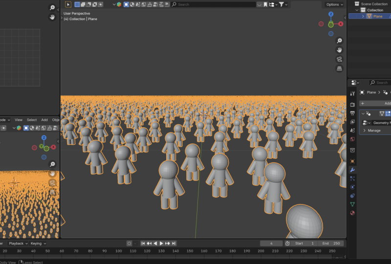
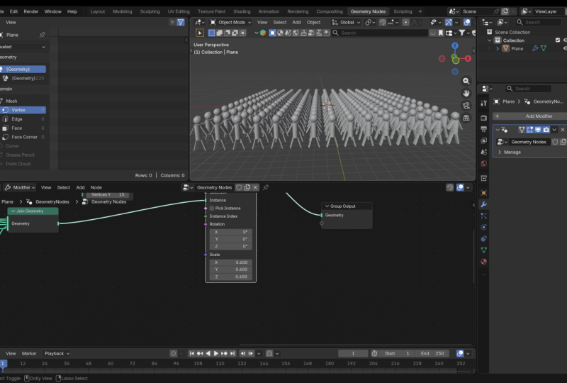
we want to we just want to distribute the places where they're going to stand. And then we're going to instance this soldier onto those points. So we need to instance points on three D space.
How do we do that? One easy way to distribute
soldiers is with a grid. So Shift A, Grid Node. A grid node is like a plane. So if I put it right here,
let me disconnect that. If I put this grid here and
connect it to the output, as you can see, this
is like a plane. If I switch to wireframe
view, as you can see, it is a plane with
four faces right now. If I zoom in, I can increase the size in the X
and Y, like that. And I can also
increase the number of vertices in the X
and Y, like that. Now, every one of
these is a phase, and so we can distribute
points on these faces. If I switch back to solid mode, let's go back in here, Shift A, Distribute
Points on faces. Let's distribute standing spots on that grid, just like that. When we distribute
points on faces, we're doing that in order
to attach what instances. So let's shift A,
Instance on points. Let's place instances on those points that
we've distributed. And what instances do we want to place on these
distributed points? We want to place the soldier, the sentinel that we assembled. So if we say Instance,
there we go. But now they are too big. We can add a transform
geometry right here. Now, if I shift right click, I'll create that junction or corner and drag that
shift right click again, G, and put that there. So we have this soldier, this sentinel we assembled. If I go here to see what our joint geometry can
see, control shift click. We can only see the centinel because up to this
point in time, we only have the
assembled sentinel. We want to make this sentinel
smaller, so Transform, shift A, or we can say, ah, let's say transform and by selecting these three
and holding down shift to moving
small increments, we can make them tiny or
actually the right size. So there we go. We
have our soldiers. Let's you can increase or decrease the
size, as you please. As you can see, right
here, if we zoom in, some of the soldiers
are standing too close to one another. And that's unacceptable. So remember, we will go here to the distribute points on faces and change this
to Poisson disc, and we want to increase the personal space
of each soldier. Now every soldier has
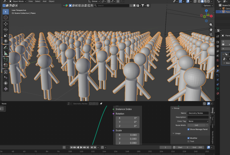
enough personal space. Now one thing you will notice is that our army is scattered. This is not how an army parade
will look, for example. They are typically in straight
lines, almost like a grid. And remember, they are
standing on a grid, this grid. And this grid is
made up of vertices. Now, if I switch
to wireframe view, control shift click the grid. So as you can see
what we have are vertices, edges and faces. Where the lines or edges
intersect, those are vertices. And geometry nodes sees those as points where you
can place instances. So we don't need these
distribute points on faces when we're
dealing with the grid. If I remove this, delete. We have our soldiers. Let me switch back
to solid view. If I select the
distribute point on faces and control X to remove it without
disconnecting the cable, control X, you will notice now all the soldiers are well
organized like a parade. So what's happening is
that the grid allows us to place instances
on every vertex. And that means we
can increase or decrease the number
of instances by regulating the
number of vertices because every vertex
has a sentinel now, another thing I want us to
notice here is we don't really need this
Transform Geometry Node because we were only
using it to scale the sentinel before he
became an instance. But we can also just decide to scale him down
as an instance. So if I come here and
control shift click, what we have is one
single sentinel. But this sentinel is not yet an instance because we've
not yet reached here. So if I delete that
now if I go here, when we reach here,
this is now where we have the sentinel as instances. And we can get rid of this because now we're no
longer using this scale. Notice what happens to the soldiers if I delete
the transform geometry. Now they are huge again, but now we have this scale. We can say, et all sentinels be this
size, holding down shift. Let's view them from
this side. There we go. So that's it. I think this is a good
spot to end this. I just thought I should
share that before we finish.
13. Final Thoughts: And that's it. Believe
it or not, that's it. You've just learned
geometry nodes through a mental framework that
changes everything. You now understand
points, instances, assemblies, transformations, and most importantly,
procedural thinking. You've learned to understand
the system itself, not just which nodes to connect, but how to think procedurally. And now it's your turn. Maybe you've been
following along and doing exactly what we've
been doing in class. You can share that, or
maybe you've assembled a formation of sentinels that looks slightly
different or unique, or maybe you'll apply those concepts doing something
completely different. When you're done, upload
your project to the gallery, and I'll be there to
give you feedback, answer your questions, and
celebrate your work with you. Honestly, seeing what
my students create is my favorite part of
teaching these courses. If this class helped make Geometry Nodes finally
click for you, if this Spaceship metaphor
made things clearer for you, please take a moment
to leave a review. It only takes a minute but
makes a huge difference. Just click the review
tab right below this video player and let me know what you
thought about it. And if you're
interested in this kind of content, this is
just the beginning. I have more Geometry Nodes
classes in the pipeline. So if you're not following me, already make sure you check out my profile and click
that Follow button. Go out and build
something amazing. Keep creating, keep
experimenting, and I'll see you
in the next one. A
 Ken Mbesa, Web Designer | 3D Artist