Transcripts
1. Trailer: You finish the model,
it looks decent, then you hit subdivision surface and everything falls apart. That probably happened to
you more than you can count, and that's the
moment most people get stuck with hard
surface modeling. And the frustrating part
is, you look at the mesh, and it seems fine, but Blender just won't behave
the way you wanted to. You have references,
you follow along. You've heard all the good
talk about topology, and the result still looks off. And even when the model is okay, the moment you add a material, we're shading problems
show up out of nowhere. This course is about
fixing all of that. You will learn how to set up Blender for hard
surface modeling, how to build a clean base mesh that can actually
handle details, and how to carve
cuts, extrusions, and holes without
destroying your geometry. Then materials, metal, glass, screened and finally, how to light and render a
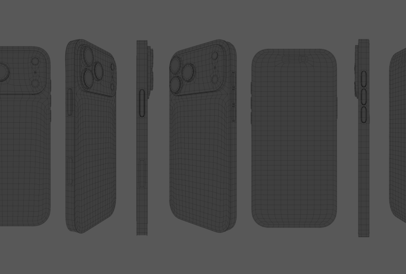
proper product chart. You will learn all of that by modeling your own iPhone 17. By the end, you will have a finished render
in your portfolio, and because it's
an Apple product, it reads as professional
work to anyone who sees it, and it will be a great piece
to add to your portfolio. This course is for beginners
who want one clear, structured way to approach
hard surface modeling, not five different methods
from five different people. If that sounds useful,
I'll see you inside.
2. Setting up Blender: Hi. In this video, you are going to prepare Blender for all the work
you will be doing. You will learn about a
couple of useful add ons that shape with a Blender
and make your life easier. You will also learn how to set up different
photo references and projections to create
precise and accurate models. By the end of this video, you will be ready to start
tackling the modeling work. Hello, and welcome back
inside of my computer. And as I told you,
in this first video, we're going to import all the
different photo references, along with enabling some add ons that we will need
during this course. Things first, make
sure to download all the resources files
that comes with the scores, and the first thing
that you will have is this iPhone 17 Pmax blueprint. This one will be
our main reference when it comes to
modeling the iPhone, since it does contain all
the different dimensions, and it represents accurately all the intricate
details of the iPhone. Next thing, there is this image, which is the exact same
as the previous image, that this one is a real three
D render of the iPhone. And this can also help
us to actually focus on some details and see exactly
how they look in real life. And the last two things
is this Photoshop file. This is the same one as the
iPhone 17 Pro projections. This is just the Photoshop file while I was creating this one. And for the last file, which is the iPhone 17 P references, this is a Pura file, which is a free
software that you can download from the Internet, where you can put all of your different photo
references to reference. Like an infinite
canvas where you can drop all of your images and see them easily instead of switching
between different images. In this one, you will
have the two references, this one, and this one,
and at the same time, there is this image of the different dimensions
of the iPhone, along with the
different colors and this close up on
the camera element. This one will be really
helpful later when trying to model the camera
bump because that's probably the most
complicated part of modeling the iPhone since it does have
a lot of intricate details. So this is all the files that you will need
during this course, and now we can move
on to enabling some add ons that you will
need during the course. So I'm going to open my Blender, and let's click here to create a new file, and right away, I will go to edit
preferences and go to either add ons
or get extensions. Now, I'm not going to lie. I'm still confused between
add ons and get extensions. But as far as I understand,
get extensions, this will pull those
add ons, let's say, from the Internet, from the
Blender extension repository. And for the add ons, these are
the ones that you download and install regularly or
the normal way thing, I'm going to go
to Get extension, and you will notice
here that I have this extension
called Loop tools. So what I'm going to
do is to search for loop tools for whatever
reason, it's not visible here. So let's go to add ons
and look for Loop tool. Yes, we can enable it from here. So either look for it in
G extension or add ons. And actually, you will
notice that a Blender already gives us a
small description, Browse and install and manage extension from remote
and local repository, and add ons manage add ons
installed via extensions. So the add ons will manage the things that we install
through the extensions. Okay. More you
know, first thing, make sure to enable the
loop tools will need it. The other one will be the
famous node wrangler add on. Make sure also to enable it. In case you didn't find it here, make sure to go to extensions, look for node wrangler
and install it. And the last add ons I'm going to enable, and this
is just for me. You shouldn't follow me in
this is the screencast skis, which is just a very
simple add on that will allow you to see my
shortcuts right here, okay? So yeah, go here, save preferences to save these settings that we changed
and close this window. And now we're ready to start importing all the different
photo references. I'm going to hit one
from the number pad to jump to the front projection, and from here, I'm going to
go Shift A, Image, reference. From here, I'm going to select the iPhone 17 Pmax
blueprint at Image empty. And something you will notice is that the size of this cube, if I hit N to open the side bar, the size of this
cube is two meter by 2 meters by 2 meters. This image is way
bigger than that. This means that
this image doesn't represent the real
scale of the iPhone. The first thing that
we need to do is to figure out a way of how to adjust the scale of this image to match the
real scale of the iPhone. In other words, we
need, for example, to make sure that if we
measure this distance, it should exactly be
163.4 millimeters. The best way to go about this
is actually very simple. I'm going to select the cube, and I'm going to
adjust the size of this cube to match exactly
the size of the iPhone, which means in the
X x should be 78. You can type MM for millimeter. For the Y axis, which is
the thickness of the phone, this should be 8.75 millimeters. And for the height of the phone, this should be
163.4 millimeters. So right now, the
dimensions of this cube are perfectly the dimensions
of the iPhone. And all I need to do is to
select my photo reference, hit S for scale, to scale it way way down, and my goal is to fit
this photo reference, the front side of the
iPhone inside this cube. All what I'm going to
do is to hit S to scale it and hit J to move it
so it fits perfectly. Hit S to scale it way way down. In situations like this, I
actually like to switch to the X ray mode so that I will be able to see also
my photo reference, zoom in a little bit, JX to move it on the X axis. We need to scale it
up a little bit more, hit S if you hold shift, something you will notice
is that you will be able to move in
smaller increments. So let's scale it a
little bit up Jx, scale it even more while holding shift to move
in slow increments, Jx. This seems good and JZ to
move it slightly down. Same thing while holding shift. I think we can probably even
scale it add more shift. This seems good and Jx to move it and slide
it on the X axis. This is very nice, and as you can see right now, the reference image
of the front side of the iPhone fits perfectly inside the cube that
we change the scale of it to match the real
scale of the iPhone. And for this image, I'm
going to call it front, and I'm going to move
it to a new collection by going to new collection. I will call this one ref. References and move the
front inside the refs. Something else I always
like to do is to adjust the settings of
the photo reference. If I go here in the
properties menu, first thing you will have
display as it is just an image. And something quick
I want to mention, these are called photo
references or empty objects, which means that
they are just images that are visible in
the three D view port. And the moment you will start rendering, these will be gone. So you don't need to stress
about whether they will be visible in the
final render or not. Next thing is the size. And since we
adjusted the size of this photo reference using
the scale operation S, I like to go Control A
and apply the scale, and as you can see, this
will change the dimensions of the size so that it
will be basically one, and these are by how much we change the size of the
photo reference image. It is 0.32 meters. Next, for the offset in case
you want to move the image, but the most important part
is the depth and side. For the depth, it basically describes whether you want
your photo references to always be in the default where you position them
in the three d space, or you always want them to
be in front of the objects, or you always want them to be
in the back of the object. This can be very useful if
I disable the X ray mode, as you can see right
now, the photo reference is behind the cube. But if I change this to
front, as you can see, whatever I will do,
the photo reference will always be in
front of the objects. I don't like this option that much because it can
mess things up and sometimes the photo
references will start to obscure your view
from certain objects. So most of the time, either
I will leave it at default, which I will do or keep it at. Think these are
both valid options, but in my situation, I'm
going to keep it at default. And the other thing is side. If I jump to the three
D view by rotating, as you can see,
we're able to see the front side and the backside. So this option will allow you to control whether you only
see the front side. So now I can't see what's in the back side or the other way if I only want
to see the backside. Is also very useful
because quite often, especially when we will
duplicate this image to represent the backside of
the phone, it can get very, very confusing because right
now you will be able to see the backside from one view and the backside
of another image, so it can easily
becomes a big mess. That's why I always
like to always keep just the front side
of the image visible. Next thing is show in orthographic and
show in perspective. In short, when you
are navigating like this in the
three D view port, this is called the
perspective view. And the orthographic is
when you jump, for example, to one of the
projections, for example, jumping to the front view by
hitting one from the number. Option will just allow you
to control whether you want to only see your
photo references, for example, if I
uncheck perspective. Now the photo
references will only be visible on the
orthographic view. And this is actually cleaner
because most of the time, when I am in the
perspective mode, I don't want the references to obscure my view, none of that. So I always remove it from the
perspective and keep it in the orthographic view because
as usual, most of the time, whenever I'm trying to do
something very accurate or something that matches perfectly certain
reference I have, I will always find myself switching to the
orthographic view, and that's why I think it
makes more sense to show the photo references only
inside the orthographic Okay. And the last slider,
it is the opacity, which will allow you to control the opacity of the
photo reference. This is a quick run of all the different settings that
you need to adjust and you can adjust them to your taste and how you
want to do your modeling. And since right now we adjusted everything for the
front projection view, we're going to do the same thing for all the different
other projections. So if you remember, hit
one from the number pad, we will jump to the front view. Now if I hit Control one, I will jump to the back
orthographic view, and as you can see from here, I'm going to select
the photo reference, hit chief D to duplicate it. Hit RZ, 180 to rotate it
180 degrees on the Z axis. Hit Enter to confirm. Let's jump again
to the X ray mode, Jx and let's move it just like so until it sits
perfectly inside my cube. And if you hit F two for a name, you can call this back. Let's hit three
from the number pad to jump to the right
orthographic view. And for that, I will select
the front projection, hit chif D to duplicate and R Z 90 degrees to rotate it
on the ZX is 90 degrees. And what is the right
side of the iPhone? It is this one
where we will have the power button and the new camera controller button or whatever it is called. And for whatever reason, I'm
not able to see my cube, so let me just
switch this image to back and JX or actually
JY at this time, JY to move it just like
so, zooming a little bit. Just make sure that it
sits perfectly. Okay. This is good. Hit F two for rename and let's
call this right. Next, we need to
do the same thing, but for the left projection, so three for the right, control three for the left. While you're
selecting your right, shift D to duplicate RZ 180 and JY to move
it just like so. And as usual, make sure
to be as accurate as possible when placing or when sliding the
photo reference. So at least we will reduce
the margin of error. Something like so I
think will be good. F two for rename and call this let now we need to do the
same thing, but from the top. So at seven from the
number pad again to jump to the top view,
and let's select, for example, the 222.
Let's select the left. Shift D for duplicate, R for rotation, Y 90 degrees. And this will be slightly
tricky because we need to know exactly whether the camera will be from this
side or this side. So for this, I'm going to hit one to jump to the front view. And the camera should
be on this side, so it should be on the right. So hit seven, and I will need
to rotate this image again. So hit R Z 180 and JY to move it on the Y axis
and Jx to move it like. Zoom in a little bit, JY. Okay, I think this is
good because seven, that's the location
of the camera. This makes sense, and
hit F two for rename, top, for the bottom,
Control seven. Select the top image, shift due to duplicate, RX 180, and we need
to move this down, so JY, move it down, Jx until it fits perfectly
inside this cube. As you can see, most of what
we did is just positioning the images in different places so that everything
matches perfectly. And I'm going to rename
this last one to bottom. This is how you
can import all of your different photo
references inside of Blender. This is the front, Control
one for the backside, three for the right side, Control three for the
left, seven for the top, and Control seven for the bottom and everything
is set up perfectly. The last thing I'm
going to do is to just go right
here in my view, and right here you will have
this option for selectable, which is just a fancy way to not be able to select
this collection. Even later when I'm working, for example, right here, even if I try to select
the photo reference, I will select it by
mistake because, again, that can get very, very annoying very fast. So this is how I
will set everything up and to close the side bar, it was very annoying. And yeah, the last
thing I'm going to do is to just select this cube, and actually, I'm going to
open the sidebar again. And something you will notice is that the scale is not uniform, and this will cause us a lot
of problems later when it comes to beveling and setting
edges and all of that. So it is always recommended that you should apply the scale. And that's why I'm going
to select this cube, Control A, and apply the scale. And since we're already here, select this cube and call this iPhone body and hit M to move it to
a new collection, new collection, let's call
it iPhone and create. And this is how you
can basically set up your Blender file for all the
work that we will be doing. This might seem or
feel like it is very intense and you need to set up all of these different
projections and all of that. But, believe me,
once you get used to this, you'll be doing it, very fast, and actually it will make your work
very accurate. So this is it for
this video, guys, and I will see you in
the next video where we will start the actual
modeling process. And also, as usual, make
sure to save your five.
3. Modeling the Base Shape: Hi. In this video,
you're going to create the phones base geometry. This is a very important step, and getting it wrong can cause a lot of
headache later on. If you start with
the wrong base, you may end up having
to start from scratch later because you
will be fighting the mesh as you try to carve, extrude, or create
intricate details. That's why it's so important
to get the base right. Hello and welcome back,
everyone inside of Blender. I said, in this video, we are going to create the base model or the base
geometry for the iPhone. The first thing I'm going
to do is to select my cube, hit tap to jump
to the edit mode, and if I hit one to jump to the front projection,
as you can see, the edges of the iPhone
are very smooth, and this can be easily done by beveling these corners cube. To do that, first
of all, we need to select what is called
the edge ring. So I'm going to hit two to switch to the edge
selection mode. And while you're
holding Control, if I double click on this, you will be able to select
the entire edge ring, and that's exactly what we want. Hit one to jump
to the front side and hit Control B to bevel. Let's say something like so, and for the number of segments, I'm going to make it at five by scrolling
the mouse wheel. And overall, I think
this is very decent, and you can click to confirm
everything. Is looking good. Next thing, I'm going to
disable the X ray mode, head three to jump to the
phase selection mode, and a concept that you will always hear people
in the hard surface modeling community
talks about is the idea of having
a good topology. Of course, in case you don't
know what is topology, let's just say it is the
flow of your geometry. So ideally, you don't
want to have a lot of triangles everywhere or you
have a lot of, for example, faces that are formed by multiple points because
those will make your modeling process way hard especially later
when you will start trying to add more details. And that's why the commons
is that try to keep your topology based on
quads as much as possible. And that's a general
practice that we will try to practice as much as
possible during this course. And just as an example,
this phase right now, if I open my statistics, which is right here,
as you will see, this big phase, it is
formed by 24 points. That's what is called an NGO, and the common advice
is to steer away from using gns as
much as possible. That's why we will try to
keep our topology quad based. To do that, I'm going to select the front face and
hit X and then delete this pace
and same thing for the back face X and
then delete it. I'm going to add a couple
of edge loops right here, same thing right here, to have this ring have an even
distribution of edges. So for example, I'm going to hit Control R right
here and let's say, for example, to type 20, probably we'll need to
add a little bit more. So let's something like so, I think this will be even. All what I'm focusing about is the distance between all
the different edges. I want it to be as
even as possible. So I think this is looking good, and we basically added 28 edges. So same thing from the side, Control R, type 28,
and we're good to go. For the top side, let's hit
Control R, add more loops. And I think this
is looking good. So we ended up adding
nine edges right here. So control R type nine
here, and we're good to. Now I have even distribution of a bunch of squares that will help me in the
modeling process. Now what I can do is
to double click on this edge to select
this entire edge loop, hit one to jump to
the front side, and hit E for extrude
and S to be able to extrude it inside
just like so. The extrusion operation doesn't happen on the same rate
between the right and left, and you will need to
adjust that manually. Hit Sx to scale it
only on the x axis. Until more or less it fits
the shape we're looking for. So maybe aX, make it
a little bit smaller, as Z to make it a
little bit down, as X until we have something looking like so,
and this is very good. And now, if you hit Control F, you will have here an
option for grid fill. Choose grid fill, and this way, you will be able to fill this very big face with
a bunch of squares, and this is what we mean
by having a quad topology. I will do the same exact thing on the backside of the phone, but for the backside, I'm
going to hit Control one, and I don't think I'm going
to do the same amount of inner extrusion as much as I did for the front
face, so hit E, has to extrude it
inside a little bit, and SX to scale it a
little bit on the X axis, something like so I
think we'll do the job. Now hit Control F, grid fill, and this will give you
the following thing, which is exactly what we want. If I had tap to
exit the edit mode, this is our current
iPhone model. And later we'll be adding a subdivision surface
and all of that. But for now, I will keep it at this because in
the next video, we will start creating
the camera bump, and those probably will be the hardest part of this course. So yeah, this is
it for this video, and I will see you
in the next one. And as usual, make sure
to save your file.
4. Create the Camera & Battery Cutout: Hi. In this video,
you will learn how to divide your
base mesh into distinct regions to model the camera plate and the battery while maintaining
clean topology. This is an important concept, and you will often face similar
situations where you need to model intricate details
within a larger mesh. Hello, and welcome back
again inside of Blender. And as I said, in this video, we're going to create the camera bump and the
battery cutout, let's say. Will be very simple,
and you will learn some cool
techniques when it comes to carving holes
inside of your meshes. I'm going to hit Control one
to jump to the backside of the phone and hit old Z to
switch to the X ray mode. And in some ways, I need to
create a cutout around here. And this is the first
problem that you will face. Since we're seeing
the entire mesh, something really
frustrating is that if you try to select,
for example, this face, you think or this edge, you think that you
selected this edge, but if you go, you
will see that you selected the front
side of the phone. This can become a
mess very, very fast. So ideally we would love to only be able to see the
backside of the phone. That's why I'm
going to switch to the phase selection mode and select one of
the back faces, for example, this
one right here. And now if I hit Shift
J to select similar, which will allow you to select faces that does have
similar features, I'm going to choose
coplanar which mean faces that are on the same level and they are facing the
same direction, which in our situation will select the entire
backside of the phone. I'm going to hit Control I for invert the selection
and hit H to hide it. And by doing this right now, I will only be able to see
my backside of the phone. So right now, even when
I do my selection, I don't need to stress
about selecting the front side of the phone and all of the MS
that comes with. And now we're ready
to start modeling. Control one to jump
to the backside view, and I'm going to
select this phase, and while you're
holding Control, select this one to select
from here, up until here, control to select until here, control to here,
control to here. And while you're holding shift, you can select the entire
inside of this selection, and then hit X and
then delete the faces. And now we need to create
this rounded rectangle, let's say that contains
all the different cameras. To do that, I'm
going to hit one to jump to the point
selection mode. Let's select this point, Control Sele this point, so I will select
this entire arc, shift D to duplicate it, and hit S to scale it a little
bit down and just make it fit nicely on top of
this rounded rectangle, something like so I
think will be good. And then we need to mirror
it on the other side. To mirror it, I'm going to
hit Shift D to duplicate, S for scale, X for the scaling on the X
axis and minus one. And this will mirror So, now I can hit Jx and
move it somewhere like. And then I can
select this point, shift select this point, hit F to bridge both
of those two points. So now I have one
edge right here. Double click on this one to
select this entire structure. Shift D to tuplicate. I'm going to mirror it
right now on the Z axis. So a Z minus one and
hit Enter and JZ and let's move down to somewhere around here. I
think this will be good. And same thing, select this point and this point and hit F, this point and this point, and hit F. And technically, in a perfect world, right now, we will be able to connect
this edge loop with this one, but there is a slight problem. If I double click on this
one, as you can see, this one is formed by 46 points. Meanwhile, this inner
loop that I just created, it is formed by 32 points. So in some ways, I need to add 14 extra points. This should be really simple. First of all, I'm going to
add one point right here. So this one will be
connected to this one, Control R, and also add
another one right here. So this one will be
connected to this top, I have five points or
actually seven points. So Control R and type seven
to add seven points here, and Control R for this one, we're going to add these
are five vertices, so Control R and Type five. Double click on this one. It is right now
formed by 46 points. Double click on this one,
and it is also 46 points, which means they are equal. So now each point
in my bigger does have an equivalent point
in the smaller loop. To bridge them both together, you can select this loop, shift select this loop. And if you go to the right
mouse button loop tools, you will have bridge,
and for whatever reason, it's not working, and I'm
getting this error message. And I think because I need to be in the edge selection mode. So let's try again, Loop tools, bridge, and I'm getting
the same exact problem. I don't know why this seems
to be some sort of a bug, but let's try the built in
feature inside of Blender, which you can access
by hitting Control E, and you will have another
option bridge edge loops, and it is not working. For some context, there are two ways to bridge edge
loops inside of Blender. The first one is
by going to look towards bridge using
the add ons we enabled in the first video or by hitting Control E and using
the bridge edge loops. And actually, each one uses
a different algorithm. So most of the time, sometimes the Blender built in feature for the bridge edge
loops might work. Meanwhile, the other one
won't, or it's the other way. And sometimes none of them will actually work just
like in my situation. So in those situations,
it's actually very simple. All you need to do is to select, for example, one big face
and hit F to fill it. And when you switch to
the edge selection mode, just select one edge. If you keep hitting F, you will be able to
fill it manually, which is most of
the time very fast, and you can do it
this way manually. And right now, we can start worrying about
creating the care out for the the next thing when it comes to creating the
battery carryout, we need to select this entire
structure on the bottom, and then we need
to delete it the same concept as the camera bump. Let's switch to the
phase selection mode, select this phase,
control to this phase, control until this phase, to this one, to this one, for this time, I
think I'll need to select a little bit
more just like so. Then you can hit Shift and
select the inner part, X, and delete the faces. Let's go back to the
vertice selection mode, select from this point, control up until this point, we will select this arc,
shift digit duplicate, as to scale it a
little bit down, JZ a little bit. I need to mirror it on the
other side, so shift D, SZ minus one, and
JZ to move it up. And all I need to do is to
link both of these two points, so this one and this one by hitting F. Same thing
on the other side, hit F. The last part
of this will be to make sure that the number of
vertices on this inner loop, which is 46 must match
this one, which is 76. Difference is 30. This
will be very easy to fix. We're going to add 15 points
on this sign by typing 15, Control R and type 15 also
on the side and hit Enter. Now this is 76 and
also this one is 76. Shift select also
this inner one. I'm going to go loop tools and bridge and this will give
you the following result. I think this is
looking very decent. Except that I think maybe we can do a better job if
we do it manually. The reason being is
that I don't like how a little bit of the geometry right here is a
little bit stretched. So let's try to do that. Let's set Control Z.
And to fix this issue, I'm actually going to
select these points, hit X, and then delete or only
delete dissolved vertices. So I will only
remove the vertices and I will keep one edge. And same thing on the side,
let's say these ones. By the way, the concept
of what I'm doing is that I want to keep
the arc the way it is, but I'm going to delete
all the points in between, so I will add the
exact number I want. X and then dissolve vertices. Same thing on the side. I think these are the points
that are in between X, dissolve vertices, same
thing on the other side. Select all of these
X dissolve vertices. So this is one,
two, three, four, five, one, two,
three, four, five. Let's so it is the same thing on the bottom, one,
two, three, four, five, six, Okay, one, two, three, four, five, six. On the bottom, we
have six points, but in the top, we
have five points. I don't think this will
cause any problems for now, but just to be sure, I'm going to select this
one, this one, this one, and hit F to fill them.
Same thing on the side. The reason why I'm doing this is that I want to anchor myself. So at least I will always have those good
faces right there, and based on that, I can adjust
the rest of the geometry. Same thing right here. Let's hit F and same thing for this one. Let's hit F. So now I have
two good faces right there. This part right here,
let's do F to fill them F F and F F. Same
thing on the side, select this entire face, switch to the edge
FF and FF again. These are good faces that are evenly distributed,
and that's very good. Let's do the same exact thing,
but from this direction. So select this point,
control up until this point, and these are 18 points. So control R type 18, and these are 18 points. And technically now if I switch back to the
edge selection mode, I will have something looking like so, which is very clean. Let's try the other direction. Up until this point,
these are also 18 points. So control R, type 18 and switch back to the edge
selection mode and hit F. And this is very, very nice. So for this one, we will
have nine vertices. So control R type nine
to add nine vertices. Fill these. Okay. And
for the rest right now, this one will be
matched with this one, so hit F, and this
will be with this one, so hit F. For this one, these F, same thing for these ones, F. For the number
of points here, let's see, we have nine points. And right here, we
already have one. This will be like so, F. So now we should have,
I think, eight points, yes, so control or type eight. And now if I do this, I will have something
looking like so. So technically,
we had to do with the manual way
there was a lot of manual labor you can see, the result is really worth
it because right now we have a really nice even quant
topology right here. And even if you want
to add a loop here, you can do that without
that ugly stretching. And the last thing
I'm going to do is to select this loop
and hit Control F, and you should have an
option for Grid fill. It's not perfectly aligned
for whatever reason, so maybe you can play
a little bit with the span to get something
looking better like 28. And I think this is good
enough for what we want. And I'm going to hit Tab
again to exit the edit mode, and this is how you can create the camera cutout of the iPhone. Just to see everything clearly, I'm going to switch to a MTCAp
and let's say, this one. So yeah, this is
looking very clean, and I can hit the
right most button. Shade auto smooth. So yeah, this is it for this
video for how to create the camera cao and the
battery cartou for later, and I'll see you
in the next video. And as usual, make sure
to save your five.
5. Modeling the Camera Bump: Hi. In this video,
you will learn how to create the camera bump. This can be slightly
tricky because you will first need to extrude the
region for the lenses, then carve separate holes
for the three lenses, the flashlight and
the lighter scanner. You'll learn how to do exactly that while maintaining
clean topology. Hello, and welcome
back again inside of the first thing I'm going to do is to select
the iPhone body. I'm going to jump again to the edit mode by hitting three. I'm going to select this
loop, first of all, by switching to the
edge selection mode and then hitting three
from the number pad. And as you can see,
the cameras needs to be a little bit
extruded right here. There is this plate that is
on the backside of the iPhone that we need first to
create and on that plate, we will put all the
different cameras. I will do E for extrude and hit Y to only extrude
on the Y axis, and let's say something like so, and then I'm going to hit
Control one to jump to the backside view or actually one to jump
to the backside view. Oh, wait. Are we
working in reverse? So Control one. Okay, yes,
everything is working fine. I'm going to extrude
this edge a little bit into the inside to create
this edge right here. Hit E for extrude and as to
extrude based on the scale, and let's say something like so. And as you remember,
whenever you do extrude and then scale, Blender will extrude one
side more than the others, and we need to adjust for that. That's why you can hit S Z
to scale it a little bit on the Z axis until you get
something looking like so. And the next thing
we're going to do is to fill this entire shape
with a grid fill. For the grid fill,
make sure you select your entire loop and make sure that the first or the active selected vertices
is this one right. If it is another one, all
you need to do is just hold Shift and select
this one again, and it will be the
active vertices. This does matter when using
the grid fill because that's the point that
Blender will consider number one when
doing the grid fill. And by doing that, you will get the exact same shape
I'm looking for, and the same one that I
will be using in terms of how all the different
squares are distributed. Go Control F d fill. By default, you will get
something like this, and probably you can
play a little bit with the offset until you
get a better result. Let's try to keep it at zero
and choose simple blending, and I feel like it's a little
bit tilted to the side. That's why I will rotate it
this way, offset by one. And I think this one is
slightly better because we're getting a more even distribution of the different squares. All of these lines sadly are not straight as
we want them to be, but it's not a big deal because this is at the end of the
day is just a flat surface. So the way all of these squares are distributed is
not detrimental. Broadly speaking,
flat surfaces are very forgiving when it
comes either to end goons, as in faces with more
than four points or even surfaces where you don't have a very clean or very well distributed number
of quads, let's say. That's why I'm going to leave it at this and right now jump directly into how we will create all of the
different camera lens. Switch to the X ray
mode by hitting Alt Z, and we will start by creating this first camera right here. Make sure you are in the
vertex selection mode, and let's select
all of these points right here along
with both of these. Hit X and then delete the faces. Or actually, we need to
delete the vertices. Sorry, delete the vertices, and you will get the
following shape. You can probably even select all of these different points, J X and move them
slightly like so. I said, it's not a big deal that you change a little
bit the distribution, all the different quads, because flat surfaces are forgiving
when it comes to the stuff. Next, I'm going to do
the same exact thing, but on the other side, let's select all of these
different vertices, X and then delete the vertices. And we created this camera
cutout for this lens, Jx, Jx. JX. Lastly, we need to do the same exact
thing for these ones. So select these points, X, and then delete the vertices, and this is looking good. Next, let's select we need
to select this inner loop. So from this point and while
you're holding control, control to this point, control to this point, control
to this point. It E for extrude has to extrude on scale so we
can extrude it inside. And the really nice
thing we do have a tool inside the loop tools, which is called circle. So once you click
on this, it will turn selection into a circle. And that way, we will
get the following shape, and all we need to
do is to just adjust it slightly as the camera lands. We will do the same exact
thing on the other side, control to select from
each vertices to another, and then hit E for
extrude a loop tools, circle, J to move
it slightly down, and this is looking very nice. Let's finally do the
same exact thing. But for the other
one, E for extrude, S and loop tools circle, this is big, so S for scale. And let's just make sure it
is the same exact scale. And you can always
rotate it in case you notice that the edges are
not well distributed. And yeah, this is
looking very nice. Next, let's work I think
this is the flashlight, and this should be very
simple also to create. So just select both
of these two points, X, and then delete the vertices. And I might actually
move both of these slightly JX on the X axis, select this loop,
E for extrude S, loop tools, circle, scale
it a little bit down. We will do the same exact thing for is this the microphone? I think it's the microphone. I will delete this vertice, X, delete the vertice. Move both of these by doing JZ to move them slightly
up just like so. Select this loop,
E for extrude S, loop tools circle and scale it down until you get
something like so. And lastly, this is
the layer scanner, I think, select
these two vertices, X, delete the vertices,
select the loop, E for extrude, and
loop tools circle. And just scale it way, way down until you get
something looking like so. Let's zoom out a little bit, and we manage to create all the different
caos that we need, and you will have
something looking like might notice that these faces for whatever reasons are a different
color than these, and this is actually
a problem of normals. A normal is basically to tell Blender where the
face is pointing. Is the face pointing to the
outside or to the inside? And to fix this issue, just hit A to select
the entire mesh and hit Shift N to
recalculate normals, and the problem will be fixed. Let's exit the X ray
mode for a second, and you will have
something looking like so, which is very neat as in
the next couple of videos, we will start
extruding and creating all the different cool stuff that sits in these camera holes. This was a quick one, but it
is important that you take a little bit of time to actually nail the shape of these
different lenses, especially that I know that
it can be very delicate to find the exact mesh flow and how everything should flow, to get something that looks
halfway decent, let's say. This is by far the most
complicated part of this tutorial to actually
create these camera holes. So if you're done with this, I will see you in the next one, and I promise you everything will start to get
easier from here on. And as usual, make sure
to save your file. But
6. Modeling the Lenses & Flashlight: Hi. In this video, you will model all the different components of the cameras, the flashlight, and
the lidar scanner. So hello and welcome
back inside of Blender, and as I said, in this video, we're going to finalize this camera bump by
adding the lenses, the covers, the flashlight, and all the different
components. And before I start
the modeling process, I need to pull my references
just so that we can have a better idea on what exactly we will be
doing in this video. So if I zoom out a
little bit on here, you will notice that the cameras are formed by plenty
of different objects. Honestly, not plenty,
but more like three. First of all, we'll
have these rings, these metal rings, and these are the camera or the lens
containers, let's say. Inside of those, we will have these plastic bits which are the plastic
covering the lens, and we will have a glass
element in the center, and that is the actual lens. And along with all of those, there is also a glass cover that sits on top of all of that. So in total, we need to model four different
things the rings, the outside cover of the lens, the black plastic
inside the lens, and the actual
glass of the lens, this spherical element
right here and right here. And for the rest of the
stuff, the flashlight, and I think this is the adar scanner or
something like that. These are simple because
they are plain color, and they don't have
a lot of details, so those will be easy. By far, the most interesting
bit during this video will be how we should approach modeling the different lenses. And now I want to talk a little bit about an important concept, which is how you should model or how you should separate your objects when you are modeling. Something you will
notice so far is that we only have one object did all of our modeling work just using in a single
mesh, let's say. This is just one object. The whole mesh is connected to each other and all of that. So we just used one
object for everything. But so far this makes sense
because in some ways, all of these different
elements will share more or less
the same material, and even in real life, they are almost the same object because they are too
connected to each other. Meanwhile, for the rest
of these elements, they some ways separated, they are different objects. Of course, you can
continue modeling in the same mesh by adding objects inside the edit
mode and all of that. But that later will also get tedious because you
need to start selecting different parts of
the mesh to assign a different material to
them and all of that. And also, that's not
how real life works because whenever you will
have two different materials, in some ways, you need to treat them as
different objects. This brings me to a
very nice logic or rule you can apply whenever you're doing hard
surface modeling. Whenever you find
yourself trying to model something that is formed
by different components, it makes a lot of sense
that you separate all of those different objects or components to different objects. Sometimes this might not
be the best practice, and I think the more you
do hard surface modeling, the more you will start to have a good intuition
for when you should model things in the
same object and when you should split them
into different objects. By far, the rule I
found the most useful. If they are different materials, probably you can split them to different objects and
think of real life. If these two are separated
in real life, then yeah, you can probably also separate them into different objects. And right now, the first
thing that I will start modeling is the camera rings. I'm talking about these ones around the camera
lenses, let's say. To do that, I'm going
to select this edge, shift, select this edge, shift, select this edge. Let's hit three to
jump to the side view, and I'm going to hit
E to extrude and hit Y to only
extrude on the Y ax. These are the different
camera rings. Now, as you can notice right
here in the photo reference, we need to extrude this
a little bit inside. Let's hit E and then S to
extrude them inside and you will notice that it looks a little bit weird
because right now, Blender is trying
to extrude all of these to a center point
which is around here. That's not what we want. We want to way to tell
Blender that, hey, Blender, extrude each circle
separately. Is very simple. I'm going to hit Control Z until I'm back to here and
make sure to change the transform pivot point from medium point to
individual origins. Now if I hit Control
one to jump to the backside view and hit E to extrude and then
as you can see, I will be able to extrude
each circle separately. Let's say something like
so will do the job, and then I'm going to
extrude them inside, so hit E to extrude, Y to extrude them inside,
something like so. This is not something very precise because all
of this will be later covered with the rest of the camera elements like the lens and the spherical
stuff and all of that. Don't worry about this. But
the most important thing, make sure to not extrude it too much that it start
clipping the camera. And actually, I might do
it a little bit more, so JY, to move it slightly
more, something like so, so I will have
enough room inside this selection later to create all the different
components I need. Once that is done,
all you need to do is to just hit F
to fill that face. Hit to exit the edit mode, and you will have
something looking like so, which is exactly what we want. The next thing we're
going to model is different elements that
form the actual lens. To model that, I'm going
to start by modeling the black plastic
parts that will converge to a spherical object
which is the actual lens. And this is where also we will start to create
different objects. So in Blender, let's go
back to the edit mode. I'm going to hit three to switch to the phase
selection mode. Let's select this loop and also select this loop and
also select this loop. So we will select all of them altogether and then hit
P and choose selection. Exit the edit mode. Let's select the next object and hit Tab to jump
to the edit mode. And now we are ready to start creating all of
those different elements. To do that, I'm going to open my photo reference and
put it here and you can click this spin so it will always stay on top just like so. Then we can start our modeling process
for the first lens. From what I see, first of all, we need to go slightly in and then it will
go a little bit flat and then there's a little bit more of extrusion
around here, and we will have a
sphere that will act as the actual glass of the lens. I'm going to select this loop, but first switch to the
edge selection mode, select this loop,
and then hit E, as to extrude inside,
something like so. And then I'm going
to J Y to move it slightly inward. Just
like the following. And then hit E as to extrude it yet again
to something like so. Maybe even more, so you can
hit S to scale it even more, and then you can hit E S to extrude it inside to
something like so. And for this, I'm going to
hit JY and move it inside, just like the following. This more or less
resemble this shape. So I think this is good enough, and then we need to add the
actual camera lens or glass. That's why we're going
to add a sphere. But right now, if you go
Shift A and add a sphere, it will be added in the center
of the scene somewhere. I already know where.
We want it to be added in this exact spot. You can hit Shift S and choose the option
cursor to select it, which will move the three
D cursor right here. So now when we will
add some objects, they will be added right here
so that we wouldn't need to go hunt for those objects
in the three D environment. Let's go Shift A, and
let's add UVsphere. You might notice that
nothing will happen, and that's mainly because
the sphere so insanely huge. So let's zoom back a little
bit to somewhere around here. Let's start bringing
the radius way way down, and by the way, I'm holding Shift
and scaling things so that I can move
in small increments. And actually, in my situation, this is not even enough because we're working on a
very tiny scale. For the segments, I'm going to lower this to something like 16. I don't need that much geometry. 16 16 will be more than enough, and then I'm going to hit Rx to rotate it on the x
axis 90 degrees, so it will be pointing
in this direction. And this is not big enough, so I'm going to hit S and
scale it way, way up. Even if it is clipping a
little bit the actual mesh, that's not a big problem. And then I'm going
to hit S and Y, to scale it on the Y axis, to squash it a little
bit just like so. And this is looking good. If I hit tap to
exit the edit mode, this is how everything
is looking right now. Right now we will need to
do the same exact thing, but for the rest of the
different elements. I will go slightly
quicker since I think you already get the gist of it of how we should
go about this. Hit Tab to jump
to the edit mode. Let's select this
loop and same thing, I'm going to hit E as
to extrude inside, something like so and JY to
move it slightly inward. This is very similar
to this one and then hit E as to extrude
it just like so. This is a wider lens. That's why I think this sphere
will be slightly bigger. Then you will notice
that I think there is a small extrusion
somewhere around here. That's why while I'm
selecting this loop, I'm going to hit E and Y to extrude it slightly
inside the Y axis. Then hit ES to
extrude it inside, just like and JY to move it like this and maybe E Y to
extrude slightly inward, just like, and maybe S to scale. This is looking good
and now we need to create the actual
camera lens, the glass. Instead of going and
adding a new sphere, you can select any part
of the sphere and hit L to select all the linked
geometry to what you selected. In our situation, it
is just the sphere, hit Shift D to duplicate it, and hit Z to move it only on the Z axis until
somewhere around here, and then you can hit
S to scale a way up, you can also hit
Control one to jump to the backside view so that
you can have a better, more precise view
on what's going on. Something like
this will be good. Let's orbit a little bit. Yeah, I think this
is good enough. Let's do the same exact thing, but for the last lens, and this is by far
the widest one, select the sloop,
E for extrude S, JY, to move it inward. Let's do ES to extrude
inside, something like so. There is also a small edge here that is an extrusion inside. So while you're
selecting this one, E Y to extrude it inside, and maybe you can also hit
ES to scale it slightly inward and JY to move it inside. And this will give you
the following shape. And yes, this is the
widest lens, in some ways, it looks similar, and I might actually hit S to scale
it a little bit down. Select this part of the geometry that belongs to the sphere, hit L to select it. Let's hit also control one to
jump to the backside view, shift it to duplicate
and let's move it here. So let's zoom in a little
bit and hit S to scale it up until it looks
something like so. We need to scale it even more until it looks
something like so. Maybe you can even GY to
move it inside or actually SY to scale it on the Y axis and Y to move
it outward a little bit. And this is looking neat. Okay, so this is how I will go about creating all the
different camera lenses, and now we will need
to move on to creating the actual cover that will sit on top of the
lens to protect it. And for that one, we
will also need to create it as its own
separate object. So to do that, I'm going
to jump back to my mesh. I'm going to select
this loop Shift, double click on
this loop to also select it, and lastly, this one. I'm going to hit Shift D
to duplicate all of these, and then hit P to separate the selection, separate
the selection. So now it is its own mesh, and if I just minimize this, you will have this
new iPhone body. Let's hit tab to exit
the edit mode and make sure you are in the edit
mode of the new object. Hit tab to jump
to the edit mode, hit A to select everything, and hit F to create a new face. And all you need to do is make sure also you're still in
the individual origins. Just hit E to extrude on the
Z axis, something like so. Oh, wait, something
weird is happening. So let's select all of these
faces and hit E to extrude. Ah, okay. Mm hmm. There is a problem
happening, as you can see. If I extrude these inside, this is not extruded, and it is the same way on
the other direction. This is because of normals. If I hit Tab to exit the
edit mode, as you can see, even the color of this one it is not the same as this one. Normals are just where
the faces are pointing. So all you need to do is while you're selecting
the entire mesh, just say shift end
to recalculate the normals and choose whether
they're inside or outside. Both of these, I'm
going to hit Shift N, and let's say they are inside, and yeah, we're good to go. Next, hit Tab, hit A to
select everything again and hit E to extrude on the Z
axis, something like so. This is the actual
thickness of the glass, so it shouldn't be very thick. Something like so
will do the job. Yeah, this is how we'll go about modeling those different
camera lenses. And now we'll move on
to the easier part, which is the flashlight
and all of those. As you can see, this is a very
similar shape to the lens. We need to create a similar
extrusion inward and then we'll also add a sphere to act as the actual flashlight. So let's go about that.
Let's jump around here. Let's hit Tab to jump to
the edit mode yet again, hit two to switch back to the edge selection
mode, select this one. Or actually, you know
what? The way of how I'm thinking about
this is the following. So for this one, this
is just plain color. We can always later in
the shader editor tell Blender to just use a
different color for this part. So does it need to be
a separate object? I don't think so. That's why
I'm just going to select it. And just because I see
some light around here, I think it is extruded
inside a little bit. That's why while I'm
selecting the loop, I'm going to hit E to extrude
it and make sure to hit Y to extrude it slightly in
the Y axis just like so, and then hit F to
fill that face. So that will be
the adar scanner. For this bad boy right here, the antenna, first of all, I feel like it is
slightly too big, so I'm going to
hit S to scale it a little bit down until it
looks something like so. And all you need to
do is to just hit E and Y to extrude it inside. And for that phase, JY maybe move it even more inside and hit F
to fill that phase. Now, lastly, we come
to the flashlight, and I think since it
is very similar in terms of geometry to
the camera lenses, I think it needs to
be part of that mesh, just to keep everything
organized and do not drown in plenty of
different objects later. So here's how I'll
go about this. I'm going to select
this loop by the way, I'm still working
in the iPhone body. This is the main object, and then I'm going to hit E for extrude and Y to extrude
it on the Y axis, something like so, and
hit F to fill that face. The next thing, I need
to figure out a way to merge this part by
selecting these faces. I need to make them also part of the actual camera lenses. This will be very simple,
all you need to do, make sure to select the inner
faces of the flashlight. Hit hit D to duplicate it, hit P to separate it to a new object by
choosing selection. You will have a new
object created. It is this iPhone body 003. Let's set tap to
exit the edit mode. So this one is the flashlight.
Okay, where is it? Sorry. So the iPhone Boto
003 are the camera lenses, and the iPhone boto 001
is the actual flashlight. So just select both of these
by hitting Control and hit Control G to merge
them together, G for join. Now if I hit Tab, as you
will be able to see, these are part of the
same mesh right now. So all we need to do is to
just model the flashlight. This should be very simple. I'm going to jump to the
edge selection mode, hit E for extrude and S, something like and JY
to move it inward. This will do the job. Then I'm going to select one
of these spheres. Let's select the smallest one, hit L to select the
entire link geometry, hit chifD to duplicate it, and let's hit the right
most button to cancel any sort of movement
and hit Control one to jump to the backside
view and JX to move it only on the X
axis, something like so. Let's do J and move it here, maybe even as to
scale it a little bit down until we get
something looking like so. By the way, you will notice some clipping starting to happen. You can always fix that by
hitting to open the side bar. And you should have, okay, inside of
view, clip Start. Make sure this is set to 0.001. Hit to close the side
bar again and JY to move it just like so. JY. This is looking
good. Now, we need to create the cover,
and as you know, the cover should be part
of the iPhone body 002, because this is the
object containing all the glass covers
of the cameras. So to do that, let's
select this loop, Shift D to duplicate it, hit B to separate
it to a new object, just like so, hit tap
to exit the edit mode. And I think for whatever reason, it seems like I've
hit the cover. So it is the iPhone body 002, and for this this is the
cover for the flashlight. This is the edge
we just separated. So just select both of them and Control G to join
them, hit tab again. Now they are part
of the same mesh. Select this loop,
hit F to fill it, and then also you can
hit E for extrude. Just extrude it just
slightly, like so. This will do the job. And yeah, this is how we'll go about this. Let's rename our
different objects. These are glass covers, and for these ones,
these are the lenses. Now, once this is done, make sure to save your file, and I will see you
in the next one.
7. Modeling the Buttons: Hi. In this video, you will learn how to model the buttons. Just like the camera
and battery carrot, this video will also
focus on dividing the base mesh into distinct regions to model
the different buttons. Okay, so welcome again
inside of Blender. I pulled my references
here just so that we can have a better idea on
what we'll be creating. All in all, we'll need to
create five different buttons. We have, I think this
is the action button, the volume buttons,
the power button, and the camera controller. I think this one right
here is the Sim card slot. But I think for the ones that
are being sold in the US, they don't have this slot. That's why we'll skip this part, and we'll only
limit the scope of this video to the different
buttons that actually exist. And now we can start modeling. But before I do that, something very important I
want to mention. If I select this iPhone
body and hit Tab, let me also hit ALTH
to unhide the rest of the geometry because we hit
it earlier, if you remember. What you will notice
is whole iPhone body is still very low ply. We have a very limited number
of vertices and quads. But if I pull my references
here, as you will see, the iPhone is very, very smooth and these
buttons are very smooth. So how can we go about this about creating a
very smooth shapes? Meanwhile, our geometry
is very low poly. That will be by using a
subdivision surface modifier. And that's why I will jump to the modifiers tab at modifier. You can look for
subdivision surface, and let's add this modifier. Let's increase the
level View port two, a tap to exit the edit mode,
and it will look like. This will definitely
look horrible right now because when you're using the subdivision
surface modifier, you will naturally
need to add supporting edge loops so that
everything will look smooth, but also the things that needs to be sharp, it
should look sharp. Later in the course, we will
have a dedicated video for adjusting and sharpening all the different
angles of this model. But for now, I
just want to apply the subdivision surface
modifier so that we at least can start to see
a very smooth shape, and we can adjust the shape of the buttons based on the
subdivision surface modifier. Let me just flip
my phone and I'm going to hit one to jump
to the front from here, we will have the power
button, and from here, we will have the action
button and the volume button. I will start with the left side. Let's set tap to jump
again to the edit mode. I'm going to hit Control
R to add some loops and scroll the mouse wheel
to only add two loops, and let's put them in here. And if I hit S Y to scale them on the Y axis,
nothing will happen. Because I need to change this from individual origin
to medium point, and now if I hit SY, I'll be able to push both of those two loop cuts
away from each other. And that's exactly what I want. Let's say something like
so we'll do the job. Let's switch to the
phase selection mode. And now I need to
select the faces where the different buttons
will sit to do that. Let's hit one to jump again
to the front projection. So the first button
will be around here. Intentionally making
the selection slightly bigger because later I'm going to do some
inset operation and that will make the
whole button smaller. So it is better to go slightly bigger because we will
go smaller later. Hit I for inset. And let's say something
like so, and for the value, I'm going to make it 0.0 005. Let's also copy this value because we will apply it
for the rest of the faces. For the next button, it
should be these three. Let's do the same
exact thing. Do inset. Let's space the value here, Control V, and we
are good to go. And the last button
will be this one. I for inset, and let's
space the value here. And we are good to go.
Next, let's select these faces just
like the following. I'm going to extrude
them inside by doing E for extrude
and extrude it inside. Since we have the
subdivision modifier on, this will cause everything
to look very smooth. I'm just going to disable
it for a second in the viewport so that we can see the low poly
version of this model. Next, I'm going to inset again. Let's do I for inset. This time, the value
should be way way smaller, and we need to extrude
them to the outside. So at E for extrude and
extrude them to the outside. Let's enable the
subdivision modifier again, and you will have
something looking oh. Don't worry about them looking very smooth and blobby
because we'll fix that later. Next thing for the other
side of the phone, we will have the power button and the camera
controller button. So let's create those right now. Let's go on this
side, and actually, I will do the same
exact thing by hitting one to jump to the
front projection view, and the buttons will sit around here from this phase
to this phase. So I'm going to spin, let's say these four phases. I hope I did this
selection the right way. No, I need to shift it. So deselect this one
and select this one. I will need to also make the selection for the
camera controller. Sadly, if I hit one,
the camera controller is not visible from here, but I will need to adjust it accordingly based on this view. I will sit around here. Let's select this phase, one, two, three, four,
hit I for inset, paste the same value, but we will have
a different value of extrusion for this one, since this one is
an actual button. Meanwhile, for the
camera controller, it is just a small extrusion
the inside of the phone. Let's start first with
the Power button, select all of these faces. E for extrude to the inside, aside the references and disable the
subdivision modifier. JX to push it slightly
inward, even more. I for inset, hit one
again, E for extrude, until it sits around
here, this will be good. For the camera controller, all you need to do is to
extrude it to the inside. So E for extrude, let's
push it slightly inward. We'll do the job, let's enable the subdivision
modifier again. And yeah, this is
looking very neat. This is it, everyone for how to model the different
buttons of the iPhone, and I'll see you
in the next one. And as usual, make sure
to save your file.
8. Modeling the Charging Port & Speakers: Hi, this video will model the charging port
and the speakers. This video continues
the logic of creating regions within
regions in your mesh. You will learn how to carve out spaces for the
charging port, which has a pill shape
and for the speakers, which are just
cylindrical holes. And we are back in Blender. The different components
will be modeling. We will start with the charging. Then we will move to
the different speakers. But here's something
that I have noticed. If I hit Control seven to
jump to the bottom view, you will notice that in the original blueprint, we have one, two, three, four, five, six, six different
holes for the speakers. Meanwhile, in my references, we have one, two,
three, four, five. But since I downloaded these different images from
the Apple official website, I will use the number right
here, which is five holes. Something else I have noticed. Which is that this reference
is in some ways flipped. So we should either rotate the model or rotate
the reference. And the choice that makes the most sense is to
rotate the reference, which is the bottom reference. Let's rotate it on the
Z axis, I think 270. So this should give us
the following result, and we need to bring this here. Let's move it along the Y axis, just like so, zooming
a little bit. And by the way, I'm holding shift while moving
the reference. For the location on the ax, let's put it and we are
ready to start modeling. Let me collapse the
references collection. I'm going to hide
the glass cover, and I'm also going
to hide the lenses. And same as usual
because I will be working in the bottom
half of this phone. When I hit, for
example, Control seven, I might by accident, select. As you can see,
this is a big mess. That's why I need to hide all the geometry that
I don't want to see. O to jump to the front view. Let's switch to the vertex
selection mode by hitting one. Let's select the parts
we want to hide. Let's say all of this
and hit H for hide. So we're only left with the
bottom half of this phone. And now we can start
creating the charging. Hit again Control seven to
jump back to the bottom view. All you need to do is to
select these two faces. Hit I for insert, and I'm going to
make it the size of the inner part of the charging
port, something like so. Let's exit the edit mode. And by the way, when
you hit the period key, you will be able to focus
on what's selected. This is a very useful shortcut. Let's do E for extrude and extrude it
inside, just like so. If I hit tab, Alt Z to
cancel the X ray mode, you will have something
looking like so. This will do the job. And then I'm going to hit
Control seven again. Let's hit Control R to
add edge loop here. And in the references, you
will notice that there is a small edge around here that
we also need to recreate. So while you are in the
phase selection mode, let's select this loop by hitting Alt and
clicking on the loop, we can hit E for extrude
and extrude it outward. And also, let's sit
Control seven again and Alt Z to select
the interfaces, which are these ones right here. I'm going to do I
for inset again, S Y to scale them on the Y axis. I'm going to create the
actual charging piece that is in the
inside of the phone, and then you can hit E for extrude and extrude it outward. Just like so, make sure it
is not going to the outside, maybe JZ to move
it just like so. This will do the job for now and later we can adjust
things accordingly. And now we can move to
creating the different holes. Control seven again, a tap
to enter the edit mode, l Z for the X ray mode. Let's select this face, and
let's select this face. I for inset, right most
button, loop tools, circle, scale them a little bit down, but you will notice that
the scale operation is happening based
on the center. Let's change this to individual
origin as for scale. And now if you do X and
then delete the faces, you will be able to have
the following thing, which is exactly want. You might be wondering, Hey, we only have four points
here or four edges, so we're supposed
to get a square. Why are we getting a circle? That's because of the
subdivision surface modifier. Next, we need to also create the rest of the
holes which are one, two, three, four, five. As we said, we will
use only five points. So let's say tab again. This might be a little bit
tricky since we need to add a little bit more edge
loops here so that we will have an individual pace for
each one of those holes. To do that, select edges
just like the following. And if you do subdivide, you will have the
following result. We will do the same
exact thing on the other side, subdivide. And now if you
select five faces, let's select also five faces on the other side and
you do I for inset, make sure to check
individual so that each face will be
inserted individually. Click right most button, circle. They are very big, so
let's scale them down by hitting S and then X and
then delete the faces. And you will have
something looking like so, which is exactly what we want. Of course, later we will fill those holes with some
different materials. We might actually restore
the faces that we deleted, but we'll keep that
for the shading part. This is how you go about
creating the different holes for the speakers and the
charge report in the iPhone. As usual, make sure
to save your file, and I will see you
in the next one.
9. Modeling the Dynamic Island: Hi. This might be the shortest
video in the course because we're only going to create the Dynamic Island on
top of the screen. This will be very simple
and straightforward. Welcome again inside of Blender, and modeling the Dynamic Island is not that
complicated, actually. To do that, let's jump
to the edit mode. And since we hit all
the other geometry, except the bottom of
the phone previously, you will need to hit Alt
H to unhide everything, and let's zoom in a little
bit this area right here. The usual, we only want to see the front
side of the phone, so we don't select
anything by mistake. In this situation, I'm going to shift J for the select similar, which will allow
you to select faces that does share
similar properties. In my situation, I
will choose coplanar, which will select the faces
that are on the same level, Control I to invert the
selection and hit H to hide it. And this way, you will only have the front side of the
phone visible along with some geometry
that belongs to the buttons, but that's okay. We need only to
focus around here. One to jump to the
front side and old Z to switch to
the X ray mode. And let's think
about how we will go about modeling this camera. I delete all of these
vertices right here, X, and then delete the vertices. So I will have this whole. I will add half a circle here and another
half a circle here, and I will merge
everything accordingly. For the half circle that
will sit around here, it will be linked to one, two, three, four, five, six points. But before I add the circle, let's alt and click on
this loop shifts and cursor to select
it so that when I add the circle, it will
be added right here. Shift A, and let's add a circle. And if you remember, I said we have six points right here, and that's why I'm
going to type 12. So double six is. For the radius, I will
just do it manually so hit S to scale it until we
get something like so, R X and rotate it on the
X axis by 90 degrees. Let's make it a
little bit smaller, and let's make sure that it
fits perfectly just like so. We need to delete
half of the points. So let's select
these are just five. So at another point, X and
then delete the vertices. Let's select this
entire geometry by lt and clicking
on it to select the loop and R to rotate it a little bit until you get
something that looks like so. We need to mirror this
on the other side, so shift D and we most button
to candle cell Eddy move. X to scale on the X axis by a scale of minus one and JX
to move it on the X axis, let's make it sit right here. Select this point, this point, and let's hit F to join them. Select this point and this
point and hit F to join them. We have one, two,
three, one, two, three, so control R three points here, Control R, points here. And now, if I select all
of these different points, for example, hit F
to fill that face, switch to the edge selection
mode, select this edge, and hit FFFF until you
fill the full geometry, and you will have
something looking like so. Next, let's hit Alt and click
on this Loop to select it. Control F for fill
and choose grid fill, and this will fill it
with a bunch of squares. Right now to turn this into
a circle for the camera. That should also
be really simple. I'm going to select from this point control
up until this point, ax minus or actually X for
scale on the X axis by zero, and this will
straighten that edge and hit Enter and JX to move it or slide it slightly on the X axis until it
looks something like. Let's switch to the
phase selection mode by selecting all of
these different faces. Once we have all
of them selected, let's hit I for Inset and rightmost button
Loop tools circle, which will give you
the following result. Let's just hit to scale
it a little bit down, maybe JX to move it just like, make it slightly y. And yeah, that's tab again
to exit the edit mode, and this is looking really neat. Make sure also to hit Alt h hide everything and disable
the Xray mode. This is looking very clean. If I hit Tab again, this is
our camera or Dynamic Island. This is it for this video.
Make sure to save your file, and I will see you
in the next one.
10. Beveling the IPhone: Hi, this video will take
your model from looking like this to looking like this by beveling different
edges of the phone. This is the part where
the iPhone takes its final shape and everything starts to
look sharp and clean. Beveling the edges
is the easy part. The tricky part
is deciding which edges to bevel and which
ones to keep smooth. In this video, you will learn the best way to approach it. We'll come back
inside of Blender, and as I said, in this video, we're going to bevel
all the different edges of our iPhone model. Everything right now is
looking very smooth. Beveling will fix all
of these issues and will make this iPhone looks
like an actual iPhone. Beveling the edges, there are in some ways some automated
ways of how to go about it. Maybe you can consider
adding a modifier, generate bevel and let's
switch this to width, maybe increase the
segments to two. But in my experience, this doesn't tend to do a very good job with
these sort of models, not because it is bad, but because we need some custom beveling on different
places and all of that. This is already giving us something decent
and a good base. But, for example,
when it comes to these buttons, they
are all messed up. Same thing with the
cameras and all of that. That's why we will go the manual way when it comes to beveling
all the different edges. You can use this
bevel modifier as a rough way to in some ways, assess what are the values you should be using or in general, how the final model
can look like. Let's delete this
bevel modifier. I'm going to hit Tab, as usual, to jump to the edit mode, and I can't see the
rest of my model, so lth to unhide everything. Select the loop by hitting Alt, and actually, we're still in
the phase selection mode. So let's switch to the
edge selection mode, Alt and select the loop shift and lt and select
also this loop. These are the loops that
are on the outside. Hit Control B for bevel, scroll the mouse wheel to
get two different segments. And for the width or the offset, you can read it from
this one right here. Let's make it 0.02 or three zeros will give us
a result looking like this. And I still think it's looking
a little bit too smooth. So Control Z to cancel
this operation. Control B to bevel again. And for the value,
let's put it 0.001. This is definitely sharper
and looking better. Deb began to jump
to the edit mode. There is a hidden
edge around here, if you remember, but because of the subdivision modifier,
I can't see it. So hit Al Z to switch
to the X ray mode, Alt and click on this loop and Al Z to cancel
the X ray mode, or you can enable it or
disable it from here. Once I have this edge selected, Control B for Bevel. Let's make it like this
and for the value, zero point ooh oh one, this will give you
the following result, and this is looking very clean. Same thing for this
loop right here, Alt click on it, Control B, zero point oh oh oh one. For the cameras, I'm going
to hide the cover glass. Also, let's hide the lenses. For these ones, we need to bevel these three
different edges, the one that is
here, here and here. And it seems like, okay, there's also okay, this one
and this edge right here, they are not bridged. So just to fix this issue, I want to bridge this edge
loop and this edge loop. So this empty space will be filled because it doesn't
make a lot of sense to bevel things that are not a
continuous mesh, let's say. Let's disable the subdivision
surface for a second. Is how everything is looking. I assume the size of this one of this circle right here,
Alt and click on it. The size of this one is the
exact same as this one. Alt and select also this one
by hitting Shift F three, and let's look for
bridge edge loops. And you will have
something looking like so. This is technically better, but just to be sure,
let's enable, again, the subdivision surface
modifier and enable also the cover glass and see how everything will
look and the lenses. I think it will look
good, especially once we bevel everything. That's why for now, I'm going
to hide the glass covers and the lenses just so
I can focus on this. Hit tab again to jump
to the edit mode and Alt Z to switch
to the X ray mode. We need to select
this loop, I think. No, it's this one right here. The one that is on the
outside of the lens. Z. All shift and
click on this one. All shift, and
click on this one, ls to enable the X ray mode, Shift Alt and also
select this one. We want to select all the
edges that needs to be sharp. Lz to disable the X ray mode. Control B for bevel, move the mouse
wheel a little bit. And for the value, it
should be 0.0 001. This is good, and it
will look just like so. This is looking very neat. If we enable the glass
cover and the lenses, Yeah, this is looking very nice. So we need to do this for
the rest of the lenses. I will do that very quick so this doesn't get very boring. Select this loop by hitting Alt, Shift Alt and also
select the loop, go to edge, bridge edge loops. And now we need to select
all the different loops. Alt Z, Alt, select
this loop, Shift Alt, select this loop,
shift l this loop, shift Alt this loop. This is looking neat, Al Z, Control B for Bevo and
make this 0.0 001. Let's do this time, tab, Al select the loop, select the loop, edge
bridge edge loops, AZ for the X ray mode, l to select the loop, shift, l to select this one, this one, and this
one and this one. Als to disable the X ray mode, Control B for bevel, and as usual, make it 0.0 001. And hit tab to mode. And yeah, this is how you can go about beveling all
the different lenses. And for the flashlight and the ladar scanner
and all of those things, this also can be very simple Z to switch to the X ray mode, Al to select the loop,
shift, l to select the loop. And since we're already here, let's do the same thing
for the microphone. Shift Alt select
this one, Shift Alt. Inner one and the same thing
for the lidar scanner. Shift se like this one, Shift Alt, or actually, I'm going to deselect the tR scanner because I
want to do it by itself. Since it is very small, I don't know whether
the value of 0.0 001 will work for it or not. For these ones, Control B for bevel, move the mouse wheel, 0.0 oh oh one, and make sure the
segments are two, and we are good to go. Something like so is very nice. For this one, select this loop. Control B. Let's make it
zero point oh oh oh one. And old Z for the X ray mode.
And yeah, it's working. For this one, I'm
only going to bevel the outside ring and leave the rest looking
slightly smooth. Now we can move on to
beveling the buttons. Let's start with the right side of the phone or the left side, depending on how you look at it, a tap to jump again
to the edit mode. And how should we go about beveling all of these
different edges? We need to keep the rounded
shape of the button, but we need the edge
button to look sharp. Let's hit Alt Z to switch
to the X ray mode. First of all, we need to select this loop by hitting
Alt and clicking on it, shift and also select this loop. And same thing for
the outer part, Shift and Alt to select, not this one, but this one, this one right here, and
shift Alt to select this one. Okay, the outer loop, I think you'll need
to do it manually. This is not that hard,
but it will take a bit. So this one, this this one. Once you have all
of these selected, just like the following, let's hit Aldi to disable
the X ray mode. Control B for Bevel and the
usual value 0.0 oh oh one, and you will have
something looking like so. Let's move to the
other side where we have actually
multiple buttons, three, and let's do
the same exact thing. Aldi to switch to
the X ray mode. And this can be a little bit tricky to select
everything correctly. So let's focus a
little bit here. So Alt, select this loop, not this one, Alt,
select this one, Shift Alt to select this one, Shift Alt to select this one, and Shift Alt to
select this one. Control B, 0.0 001, tap to exit the edit mode. Yes, and this is looking clean. Do the same exact thing
for the other two, shift to select this one, shift to select this one, shift all to select this one, and shift all to
select this one. And since we're here, we can do the same exact thing
for the lower one, shift all to select this one, shift lt for this one, shift Alt for this
one and this one. Now, control B to bevel. 0.0 oh oh one, tap to exit the edit mode. And this is looking very nice. I won't forget about
the camera controller, this one right here. And for this one,
I'm only going to select this loop and
only bevel this one. So Control B two bevel, the usual 0.0 oh oh one, and this is looking better. The reason I'm not going
to also bevel the inside of this one because it is
supposed to be touch sensitive, so I think looking
smooth is better, and that's why I will
keep it like that. The last part will be to
finalize the camera lenses. So first of all, I will
start with the lenses. They will look like
this. You might notice some clipping starting to happen because when we bridge all the
different edge loops, this can cause things to
get a little bit wonky. But as a first step
to fix this problem, I'm going to add another
generate subdivision surface. Increase maybe the levels
to two or let's now, this is definitely
looking slightly better, but the usual problem, we need to select everything. First of all, make sure
it is shaded smooth. Let's shade flat
and see how it will look or shade auto smooth. Yeah, this is looking better, and we need to bevel
a couple of edges, so we keep the lens
look in some way. So select this by Alt
and clicking on it, Alt and also select this one. Shift Alt and select this one, Control B to pvl them. This one doesn't need
to be very sharp, so let's try three edges or just two or three and
make them 0.00 oh five. So this will give you
the following look. Later we'll add the glass
material to the inner elements. So I think we're good to go. And the last part will
be the glass covers. These also need to be beveled, and we need to add the
subdivision surface modifier so they fit perfectly. So add modifier, generate
subdivision surface. I'm going to hit
the slash key to isolate them and hit Tab
to jump to the edit mode. And we need to select this loop, shift all the loop, shift all the loop,
shift all the loop, shift all this one, this one, and I will bevel this by itself because things
can get wonky. Control B to bevel and make sure there
are only two edges. And for the value 0.0
001, this is too much. Let's try zero, another
zero and make it three. This is looking better. And for this one, tab, shift all to select this
loop and this loop, Control B for bevel, and make it very tiny. And hit the slash key again
to exit the focused mode. They will look like this. What if we increase the edges, the value of the subdivision. There is a small gap right here, so I will do J Y to move
them on the Y axis, just a tad so they
will cover the lenses. Just like the following. Now comes the last part of
beveling this iPhone model, which is the charging port and the speakers that
are in the bottom. Let's hit Control seven to
jump to the bottom view, and this is how
everything is looking. This will not be
that hard, actually, because we don't have a lot of edges right here
to worry about. But yeah, let's do it anyway. So Alta select the loop, Al Z, and also we might need to
select this one right here. So Shift Alt and
select the loop. Shift A to select this loop and shift all to
select this loop. So we have all of these
different edges selected. Let's do Control B for Bvl. Same value as the usual
0.00 01. This is too much. Let's add another zero
and change this to three. Hit tab, and it will look like. We might also need
to bevel this one. By the way, when it
comes to beveling, you can also add
supporting edge loops. So you can hit Control R, for example, and do this. But in my situation,
I think I'm going to bevel it the
classic way by hitting Alt and selecting all of these loops or all
of these edges, Control B for bevel, 0.0 oh oh three. So it will look like so.
To make this sharper, let's select this loop, Control B to bevel and make it zero point oh oh oh oh three. Yes, this is better. And for the bottom
one, Control B, zero point oh oh oh oh three. So it's the same value, and this is looking clean. Now, for all of these
different holes that are the speakers, as usual, I don't want them to
be empty spaces like this because that might ruin the beveling and all of that. So I'm going to extrude
them slightly inward. First of all, I need to
select them by hitting Alt, shift all this one,
shift all this one, this one, this one this one, same thing on the other side. Shift all this one. Next,
let's hit E for extrude, extrude them by hitting Z on
the Z axis slightly inward, and you can go to face and fill. Technically, we should
have them selected. And now we need to also
select again the outer loop. Shift, select this one. This one, this one, this one, and this one. Do the same thing on the other
side, shift all this one. This one, this one. Now you can hit
Control B for bevel. Should be a very small value, 0.00 oh one or maybe three. And HIT TAB again to
exit the edit mode, and you will have something
looking like the following. And we can later if we need some extra
details right here, like a mesh or something. So it looks like
the actual speaker. We can do that later. I think
this is it for beveling. I think we managed
to bevel everything. And as you can see, our iPhone
model is looking sharp. So the usual, make sure
to save your file, and I'll see you
in the next one.
 Yassine Larayedh, VFX Artist