Transcripts
1. Main Intro: Hello. In this course, we will focus on the basics of inventor. And instead of just looking at different toads were partially modeled in ancient. And at the same time, we will look at as many tools as possible. This way, you will see and use tools in action. And hopefully this will help you to understand the logic of inventory easier. With this approach.
2. Overview Intro: Hi. Before we start creating drawings or models in a renter, we will look at the homepage of inventor, how to set up our default template. We will look at the file types inventory is using how to start a new file, how to open a file, an inventor, how to select the correct project file you would like to work on. And whole inventory is organized.
3. Home Page: Let's have a look at the inventor homepage. We have three main tired. You have the new tile, the projectile, and the reason document type. Whenever you start Inventor, it will always show you this homepage. You can turn it off if you want, but usually you'd leave it open. So have a look at the new type, the new tile. You can click on one of these buttons which would start a new part file on that new assembly for you. You can see we have like four different times for different buttons here. You can choose. You can start part file and sampling the drawing or presentation. You will get into this a bit later. What each one is four. Now when you click on the small arrow on the bottom right, it will jump over to the advanced templates. And then here you can see which templates inventory is using and whichever what's you have available. For example, we have the English which is the impurity or templates. We have metro templates. There's one volt design templates. And whenever you do change this on your templates, it saves a backup in the old Templates folder. And underneath we see the default template. These are templates inventory is using when you click on one of these buttons here. If you would like to change the default templates, right now, I have them set to millimeters. By default, there is set to interests. So if you would like to change it, you can click on this gear icon on the top right. Or when you go back to the basic tab, you have the gear icon on this bar for the Advance tab. Once you click on it, it will open up a new window, the configured T4 templates folder or window. Or you can define if this one is the interests or if you would like to have it in millimeters and whatever unit you would like to use. Let's change this 12 millimeters and to ANSI-C. And once you have a changed, you click OK and inventory will give you a warning that it will replace the default templates. So once you click on overwrite, inventor will override these templates here with the whatever selection you have. And then every time you click on one of these buttons here to start, for example, a new part five. It uses the template for the millimeters, in this case from metric. Now on the right side, we have the project and hear invented shows you what projects you are connected to right now. By default, you have the default project and the inventor electrical project. In some cases it does not install the electrical project. And some cases it does. So basically in here it will show you what projects you will have access to. And if you would like to change, the project, would like to work on the electrical project, for example, you would select the electrical project. If you would like to work on the default, you click on the checkbox for default. We will have a look into how to create your own project a bit later and go deeper into this one. And on the bottom you have another tile for a recent documents. And here you will see all the documents you previously opened or worked on. And on the left side you have some options so you can filter out what you would like to see if you want to see all files or only a sampling IS drawings. And you can sort it by date and so on. So you have some options to filter and sort what you can see in the recent documents. On the top right, you can you have three options. You can flip it around to half the recent documents on the top or on the bottom. On the Maximize recent. That would maximize the risk documents. Once you click on it, it maximizes to the recent documents at the top, the new time, a new tile on the bottom left and the projectile on the bone right. And in case you just want to go back, click on reset and assert reset it back to the default.
4. File Types: Inventory is using four different file types. We have the part file, which is using the IPAT extension. This is basically where you would create your sketches, your exclusions, and where you would design a part. Then we have the assembly, which is using the extension IAM and assembly. This is where you would put together your parts and create an assembly. And then we have the drawing file. This one is using the extension DW, G and I DW. There are 22 versions at depends on the company. You work on. Some companies which use inventor for quite some time. They usually use ID W. This is in what inventors started with. But at some point they introduced DW G, which is basically the same. We have the same options and you can do the same thing as in the ID W, just with the benefit that you can open this file in order cat. So new companies or companies which are starting now to use inventor, they usually go with the DW G. And the DW G. The drawing file is basically where you would create your drawing. And then we'll have the presentation file, which is using the extension IPN. And in the presentation file, this is where you would create your animation or Presentation Views for your parts or you're assembling.
5. New, Open, and Projects: Okay, let's have a look at how to create a new file. How to open up a file, or hot change to project. There are multiple ways on creating a new file. The first one is by click on the new tile and selecting one of these five types. If you click on the part file type, it would start a new part file and you could start modelling. So you can select one of these buttons here to start a new file. And you go to the advanced tire, you have the option to pick which template, which exact templates you would like to use for the new file. Now the option is to start a new file is we go on to the ribbon, you click on the drop-down for new. You can click on new, or when it says New here you can just click on new. Edge will open up new window where you can select a template. The one you would like to use. You can select which folder you would like to go into like the impurity or you would click the USDA metric. So you have the same templates at on the Advanced title. So you can't define whichever template you would like to use in here. Now after another option to gets to this window is when you go on to file. Because two new you can either click on here and this will use the new, the default templates. Or you click on New and blow up this window again where you can define which template you would like to use. To open up a project. You would click on open. You can click OK. My here, or you go on file and click Open. And this will go to the workspace for this specific project. So right now, it's not really set up. Once we get to setting up the project, you will go and explain you further about the open process to open an existing file. But basically TO pup and new file, you'd either click here or file and open. It's open up a file. And for a project to change the project you work on, you can either select the Project in here, get we're usually list all the projects you have access to. You would select the project to activate it. Or you can click here on projects. This will show you the projects you have. And if you double-click on it and then it will activate this project. Let's move to some backup default. Cross this one. Another way would be on the File tab, go and manage, and click on projects. On top here of inventor. This one is called the Quick Access Toolbar. And here you have the same options. You can start a new file, click the drop-down des. We'll use the default templates. You can open up a new file. And if you would like to have the projects in here as well, you can click the dropdown, you can add once you click on products. Now you have to project on here as well. It's sometimes helps, especially when you work on a file and you would like to start a new file, you would not see this. The homepage. You would simply click on the top, I draw on the template or just anew to pick template. Or you would click on OK map to open up a file, an existing file for a project. If you have a file open, Let's say we work on the default project, we start a new file. As long as you haven't a file open, you can't change the project. You would have to close our fights to change the project.
6. Organization and Location: When you work in inventor, It is very important to stay organized. And that's why we have these project files. For each project, you would create a new project file. Depends on the company broken. If you're working in a bigger company and you have a database attached to, you would usually have one main project. And it will be odd setup and this product. If you work individually or in a small company, then you would create the new part that file for each project. So in here, for an inventor, It is very important to have these projects properly set up and that you use these projects correctly.
7. Overview End: K, We looked at the homepage of inventory. We looked at the different file types inventory is using. We configured our default templates. And next we have to set up our project file before we can get started to working in inventor.
8. Creating a new project: Okay, let's have a look at how to create a new project. By default, we have the default and inventory electrical project. And when we go on to a ribbon and click on projects, there will be a new window showing up for projects. And then here we can see the projects you have access to. Now. Create a new project. You would click on New button on the bottom. And shear we can define if it's a single user project or evolved product. Devoid product would be more for build companies. And this would be already set up for you. For smaller companies and for home USE would use single user project. So we leave this one activated. Go on. Next year you have to define the name and the location. So I save my project into my documents and my training project. And for the name, I would call it training product. So once you have the name and the location filled-in, just click on Finish and inventory will create the project for you. Now we can see we have the new product activated. And when we go to the folder of my project, you can see we have one file folder for old versions. In case I do changes to my project, it will keep a backup. And this is my project file.
9. Sketch Basics Intro: Next, we will look into the sketch basics. But before we start a new sketch, you look at the part fight in how to start a new sketch. And then we will create a few sketches. You will go over a few sketch tooth. And later on we will use these sketches that we create for our models.
10. Looking at a part file: Inside the part file, you would see on the top the ribbon which shows you all the tools you have available to create a model. It might be a bit overwhelmed to see all the tools. In this course, we will only focus on the basic tools so that you can get started and get used to creating something in inventor and the future once you get used to it. And depending in which field you were work in, then this kind of determines which tools you actually need and which ones you don't need. There are so many tools and you will never be able to know all the tools in inventor. On the top we have the tabs, which gives you extra tools like the sketch tab. This gives you tools to create a sketch annotate, so amputations, and so on. The left side we have the model browser. And said the model browser. You can see the part you work on. Underneath we have the representation, which is an advanced tool which you will use more in the future. You don't have to worry about this one in the basic course. And then we have their origin folder, which carries the planes an axis and the centre point for this model. She would like to see the plane. You can right-click on it and showed visibility. And then you can actually see the plane. In case you close the model browser by mistake or for some reason, you can click on the plus and select model browser. Or you can go on to the View tab and user interface and activate the modern browser again. And then it will come back.
11. Sketch (Pin): Let's create our first sketch, an inventor. And the inventor click on part file to start new park. Now in the top left corner, click on 2D sketch to now inventory will show you the planes, what you have available to create the sketch on. When he goes to your mobile browser and explained the origin folder. You will see these are the planes from your origin folder. So these are the main planes from this, this model right now from this file. In the top right corner, we have our view cube in here you can coordinate and which site you would like to create your sketch. And our case, you would like to create the sketch on the right side, three, Click on right. And now when you hover over this plane, it will highlight. And when you look at the model browser or in the bottom left corner, it will tell you what plane it is. So just click on the plane and inventory will jump into the sketch mode. In the top left corner on the tabs, you can see that we are now in the sketch tab. And here you have all the tools you need to create the sketch. When you look at the model browser, you will notice that it's kind of grayed out except your sketch. It just means that you are right now in this sketch. Later on you will have more features. And it really, it's easier to identify in which feature or which sketch you're in right now. Now when you go back and look at the sketch, we can see we have our central lines and we have a yellow dot in the center. This is our center point from our sketch. Let's create a circle in our sketch and offset another circuit to the insight. Let's use the circle tool on your ribbon. When you go to any tool and leave your mouse. Then it will show you kind of a short explanation about the specific tool. Let's click on circle and move to the center of our sketch. You will notice that it will snap to the center point and turn green. That's moved to the center point. Once it snaps, we click and move our mouse to the outside. Now you have the option to type in a size, whatever size you would like to have. Or it can simply place and add the dimension. If you type it in, it will automatically add a dimension to it. Let's type at 22. And here we have to object to type in Imperial or metric. Because we use a metric template, we don't have to type into millimeters. It will automatically detected this is millimeters. If you would like to type it into inches, you can simply add the inch symbol. And it will create 22 inch circle. That's removed to assemble and just have the 22 and hit enter. Now we can see that the inventor automatically added to the dimension for the 22 millimeters. Let's hit escape. Have to keep in mind when you select a tool and you draw something and use the tool, it will stay in sight the mode. So you have to always hit escape to get out of the tool. Now, when you go onto the modify, to modify and click on Offset. To offset the circuit to the insight. Click on the circle and move to the inside. And this time we would like to move it by freeware. So we simply type in three and hit enter. Now we will see on the bottom inventor added the dimension of three millimeters. Let's sit escape to jump out of the feature of the tool and finish the sketch. Before we can save the file, we have to make sure we click on Finish Sketch. Otherwise, inventory will not allow us to save. Click on Finish Sketch, and click on the save icon and top-left corner on file, and save. And save this part as pin. And click Save.
12. Sketch (Connecting Rod): Let's create a new park File and New Sketch and set our part. But this time we will use a few more tools and inventory. A click on part file to start a new part. And there are different ways to create a 2D sketch. You can either go to your plane, once you hover over, it will show you the plane. This time we would like to create the sketch on the front side. So that means the x, y plane. So you can right-click on the plane and start a new sketch. Another option is if you plane as visible, you can hover over two plane. Click on the plane and start a new sketch. Now inside the sketch, we will create an arc. We will project the geometry of our axis and used to offset the Philip feature. Now let's start with the project geometry. When you look at the Create Group and you will see the projectory geometry to, let's click on projectory arbitrary. And once you hover over your access, we need to ax axis. It will show up in your sketch. Once you click on it, it will project the geometry of your ax axis into your sketch. This is quite a handful feature when you would like to have some lines from your model inside your sketch as the reference. So now you projected our X axis into our sketch. It escape to get out of the project, projectory out two and use the Arc tool to create an Arab. Click on the drop-down and select this center point arc. Moves to the center your sketch. Once it snaps to the center point, you click and move it to the left. Type in 17.5 for your arc and hit enter. Now, next thing is you have to enter the degree of how far it should create the arc. Move to the right until it says a 180. And you will notice it snaps to the horizontal line. So you click here. And now we created an arc. Now we create a line from the center point to the right. So you simply go on top left corner and click on the Line tool. Now you move again to the centerpoint. Select the center point and move it to the right. This time we type in a 155 and hit enter. Now we create another arc at this endpoint to endpoint of the line we trust created. So we go back to the drop-down and select the center point arc. So we move to the end point and it will snap to the end point. Now we move to the left again and type in 35 and hit enter. Now we move to the right side. Wants it says a 180. We click here. And now we created the second arc. Let's offset the horizontal line what we just created down by 11. When we go back to the Offset tool, click on offset, will hover over the horizontal line once it highlight screen, click on it and move down. That we will ask for the dimension, how far we would like to move down with typing 11 million and hit enter. Now we have some lines which are crossing. Now we can use the trim tool to trim off this lines. It's gone to under Modify and click on trim. Now once you hover over these lines, you will see it kind of shows a gray hidden line which indicates what it will trim off. Let's turn these two sites off. And the same on the right side. Trim it off. So hit escape. Next, we would like to add affiliate in on the right side only on, in this corner here. So we go on to the fill tool now to ask for the radius for the Philip type and 25. And now you go and select the line you created the offset. And once you hover over the arc recreated, it will give you a preview of the filleted with wants to create. So once you click on the arc, it will create the fill it for you. So we click on X to cancel this one. In case you typed in the wrong dimension is you always have the option to double-click on dimension and change the size. Let's say you want to change the size to tourney type attorney hit Enter and that will change the size for you. Let's undo this one. Next. You would like to mirror this one over to the other side. Going to the mirror tool under pattern, click on mirror. Now you have to select all the lines, arcs, what you would like to mirror. So I select all the slides, the oracle to fill it. Next you click on mirror line. And then you select the horizontal line or the axis, what you projected. And once you click on Apply, it will create a mirror for you. Let's click Done. Let's finish the sketch and save the file as connection ROT. Type in connecting rod and see.
13. Constrains: Let's have a look at constraints. I'm in my sketch from my connection rod. And when you're in this sketch mode, you will see on the top room your constraints. These are odd constraints you have available inside your sketch. When you right-click inside your sketch, you can click on, Show all constraints or hit F8 on your keyboard. And this will show all the constraints you have applied in your sketch. And he created lined in inventor or a circuit. And vector will automatically creates these constraints for you. For example, when I go on to live feature, and they start here once I moved to the right, you can see right above the decree tax box, you will see the constraint invented wants to apply it. And I move my mouse upwards. You will see that now it wants to apply a vertical constraint. So every time you create a line, a circle, arc or whatsoever, it would automatically apply constraints for you. Now when you hover over one of these constraints, for example, on this parallel, it will show us which two lines are connected to each other. If there is a constraint which is blocking you from doing the change, you can always right-click on the constraint and click on delete, gets rid of the constraint. Let's undo this one. When you look at the dimension constraints. And we delete this one, for example, we'll notice that this line change from black to purpose. Now, this line has some degree of freedom. It can move up and down and only look at the bottom right corner. You can see this one dimension needed. When you right-click inside your head escape first and right-click inside your sketch, you have this feature show all degrees of freedom. What this does is it shows you which line and which circle, which point is allowed to do what? In this case, it tells us that this line is a lot to move up and down, cause theorists that dimension missing. Now once we add this dimension back in sectors central line, the outset line, once you place it and at 11 mil. Now we can see that all the degree of freedom is gone, but this line can't move anymore. Now when you right-click, you can turn off your constraints again. Height all constraints. Or if hit F9 on a keyboard.
14. Exercise: Now we have an exercise for you. Try to create two part fights, 1-4 cylinder and one for a crack. And then you try to create these two sketches. What I have here for you inside your part five.
15. Tips-Tricks: Let's have a look at some tips and tricks you can use in inventor when you create a sketch. Let's start with the line tool. And you're familiar with the polyline and autocrat human inventory half, something similar. When you draw a line and all the cats, you have the option to use single line or polyline to single line is you just draw a line and then this line would be by itself. And then you would create another line which is there would be no connection. And inventor. These are usually always part designs or they act like polylines. Basically you draw a line and the next time he draw his connects to, connect it to the first-line created. Now, if you'd like to have an arc, then you would simply move to the end point of the line. Once it turns gray, you would click at the end point and drag your mouse up or down to create an arc. Straight drawn arc up and you can see it would snap or you have your 90 degree. And when you let it go, you have now OK. At the end of the line and then it can continue drawing the line. Now, when you add dimensions to these set of lines, starts from the bottom here we have the bond line. We have 85 millimeters. So once you place the dimensional, you can still type in. You want to have this on 8080 and hit enter. So to change the line to 80 millimeters. So as you can keep going and please dimension and type in whatever you would like to have. So you don't have to draw a precise, you can still change the dimensions or the size later on. But if you draw the line and type in AD and hit Enter, it will automatically add the dimension right from the beginning so you don't have to add it later on. And the same for the Engle and so on. Now, when we look at this dimension for the ED, if we would like to have another dimension, which is the same as what? This dimensionless lets say we will change this one to 100. But we would like to have this AD to follow whatever this dimension is doing. So when you click on, double-click on this dimension, you will see this dimension is called T2. That's the name for this specific dimension. And we double-click on the ED. This one is called the 0. So if you would call this one d2 and hit enter, now this one is following whatever this one is. So if you double-click on this one again and type in 80 and hit enter. So you can see that this one is always following what this dimension is doing. Now when you go up here on the top, you have this a small icon perameters. So when you click on the parameters, you can see all your dimensions you pleased in here. So here we have the d 0 and here we have d2. And then here it tells us this one is 80 and this one is D2. So basically this one is following the D2. So if we go back and to this one sheet, this dimension, and we type in 100, hit enter. So we can see or sketch changes automatically. Now, when you look at this here, when we changed it, we can change the dimensions. You can type in different sizes, we can type and other parameters so that it follows. But you can also type in the formula. In here. It's kind of a calculator built in. Let's see, we have 100 minus 20 plus five. Once we hit enter, this will act like a calculator and calculate what is the dimension. And then we can see in here it is 85. And in here as well you can see what the final result is. It's ED50. So you can always use this one as a calculator as well. And the same, and we close this one and you go back to this one, we can see the same thing in here. So if you would type something and here it will calculate the whatever you need. So you don't really have to have always the exact answer. If you have the calculate something, you can type it in here as well. Inventory will calculate for you. Now, when we look at the name of the dimension is create a new line. And when I start here and a credit line with 50 hit enter. So now when I go on this dimension, this one is called the free. If I would like to have a different name for this specific dimension, I can type in length, for example, equals 50 and hit enter. Now we're going to double-click on this one again. Now we can see not name for this is length. Now when you go back to the parameters, you can see it renamed our parameter or dimension two length. So you can change the name of Ali parameter. You don't have to do it for all the parameters or dimensions, what you have. But you would rename Lake for when you have a length and a width or height, then it's sometimes very helpful to rename so that it's easier to find and then you can use, use it and formulas and so on.
16. Solution (Cylinder): Let's have a look at the sketch for the cylinder. I started new part file and I use the 2D sketch tool to create new sketch. So I go to my right side and start new sketch on the y set pin. And we look at the sketch, we can see that it is symmetrical, so we only have to focus on the one side. And then we can use the mirror tool to mirror it to the other side. So for the mere tools, you will need a central line. In this case, we can protect the geometry of our Y axis, which we can use leader for production or for the mirror. So I select the y-axis, now are projected to y axis into my sketch. And I selected the axis or the projection. Right-click on it and mark it as a construction line. Now it can start drawing for all created my sketch. So I start with the circle on the bottom in the center. And this one should be 3030 and hit Enter. Now I go to the line tool, use the line tool to create the remaining lines. So he started a center point again, moving to the right. And for this 3.145123, hit enter. Now I move upwards by 18.28 and hit enter. And now I don't know the distance, but I know the angle. So I hit Tab to jump in to the English so I can type in how much degree I would like to have. So I have no one 3d5 hit Tab again. That goes back to my dimension. Now, the problem is or no. Inventory will lock it to the Angular, can't move it's, and we're also, it stays at 105. But my problem is that I don't know how long it should be. So just place it anywhere. But I know how far it should go to the left is 9.752 and hit enter. Next, we need an arc going upwards to left. Now we looked before at the sketches how to create an arc. Now when we go back to the end of the line and click here, and we move to the left, then it will create an arc, but this would be to the wrong direction. So it depends on which direction you go first, snow and you go back to the end. And I go upwards, upwards first and then to the left. Then you can see it creates this arc and the correct direction. So that depends on if you go left first and then up, or if you go up first and then to the left. So I move to the left and once you see this hidden line, which means that it's 90 degree, so we just let it go there and hit Escape. So that we have our arc, our line. Now we can add dimension to this arc, which is 15 and hit enter. So now we have these dimensions. And now I can use my constraints, the coincident constraints. I select this one, go to the center point, and then I select the axis, what we projected. And then it will snap to this axis. Now we can see we have half our sketched on. So to finish this off, we go to the trim tool. We trim off this portion and the line. Now in the trim tool, instead of selecting all these lines, there isn't easy ways. You can just click summer and then you drag along and it will start to trim off. Now in here we have a prompt that this line does not cross the circuit. So you would have to draw another line from the center all the way up. And then we can mark this one as a construction, I swear. So now I go back to the trim tool. So it clicks Summer And then I just go through and it will trim often it drag it along. Now it trimmed off bond line here and everything from the circle, what we don't need. Now you notice that it changed the color to procreate. That means it's not constraint anymore. So when you move it, it can move up and down. So we add another constrain, go back to incident constraints, select the line and then the center point. Now it's all constraints are these lines are constrained. There are still two dimensions missing. And we can right-click and go and show all degree of freedom. So now we can see we have a freedom of this line here. So we don't need this line in more street. Only needed is to use the trim tool, so we can delete this one. And then we have a problem here with this arc and this arc down here. And it's probably so that it can still move to the left, so it can still extend. So we go back to the coincident constraint. Click the endpoint and the axis now to snap back so it will not cross the line 4x. Once you haven't extended and you use the trim tool and trim it off, then it will add the constraint as well. So now we can see it's fully constraint. Now we can use the mirror tool. So you make a selection. And then it asks for a mirror line. So we click a mirror line and select the axis, what we projected. Once you're done, click on apply. And then you can see it's all moved to the other side is all mirrored. And the mirrored side is connected to the right side. That means if we would change the dimension of the 18 to 25, it would change on the left side as well. So it's, it added mirror constraints to all these points here we can see that there's a mirror constraint. Now we have one more circle left. So I go back to the circuit tool, go to the center point of my existing oracle, half circle and selected centerpoint, moved outwards and type in 24 and hit enter. Now you see we have sketched on it is fully constrained. And now we can finish the sketch and save the file as cylinder.
17. Solution (Crank): Let's have a look at the sketch for the crank. I started again in new part file and use the 2D sketch tool. And this time I create a sketch on the top, so I adjust my UQ so that they can sit top. And this is the exit plane. So I select my plane and use the line tool to start my first portion of the sketch. So we have two portions it sir, portion which is right through the center of the sketch, and then we have a portion which is further left. So if we'll focus first on the one portion which is on the right side. So I start at my center point. So I go right to the eye center where it snaps and click here. So I'm No, no, my dimension to the right is 3333. Hit enter. Now this one goes in an angered, so I hit Tab and one 3d5 for the angle and tap again. So and now here I don't know the distance, so I'll just place it somewhere and then I can add some constraints later on. So I moved to the right again, which is 13. And now it goes up by 62, left by 20, and down by 50. So now I just moved to left. And once it snaps to decentralize, click here and down to the bottom. And I can either click here to close my or I can right-click and say close. And this will last line down. So I hit escape to get out of the line tool. And now I add another dimension, which is from the top here down to this line here, which is 30. And hit enter. Now I have this portion done. Now I can move to the left portion. And now when we look at this in the bottom right corner, we can see it's fully constraint. So you go to the left and start the line tool again. Now it go down to my horizontal line and start my sketch here. In case you're off, let's draw this one lipid higher upward down here. And then we add a constraint to snapper to our center. So I start here on the bottom, moving to the left, 1.57147 over the up by 15 to the right, 60 and up three to the right by 40, then up again, bye 12. And then to the right. I just moved to the right. Once it's snaps, you can see the dotted line. So it snaps to the end point of the other line. So I just click here and move down or right-click and close. Now I did a small mistake here. I did a horizontal line instead of going upwards. Or just delete this line here. And this one here, and go back into my line tool. And instead of clicking on line, I can just click on L on my keyboard. So go back here and move it up by three to the right 40. And now I just have to snap this and point to this and point. So you can either drag it and snapshots here or we can use this tool, the constraint constant and constraint set, this endpoint and this endpoint here, and it should snap to this endpoint. Now, this portion of the sketch is not really a constraint to the sketch on right side. And we can use the Collinger constraint. And we select the horizontal line on the bottom. And then we move to the right sketch and click on the horizontal line aswell, and then it will snap to the same horizontal line. Now we just need the offset from this line to the center point, which is 550. And hit enter. Now and we look at the sketch, it's fully constraint. And we have all the dimensions we need. To click on, Finish Sketch and sift the sketch as the crack.
18. Sketch Basics End: Okay, we looked at the sketch mode and inventor, we created some interesting sketches. We used different sketch towards in the sketch mode. And I hope now you feel more comfortable and using the sketch mode or creating a sketch, an inventory.
19. Create/Modify Into: Let's move on to creating and modifying parts. We will use the sketches we have done so far and create extra parts by using multiple tools like extrude, revolve, mirror. In-between, we will create a few more sketches. And once we have our parts created, we'll move on to the assembly environment.
20. Extrude: Let's have a look at the Extrude two. So far we have created four different files with sketches inside. We can use to extrude tool underpin cylinder and the correctional For the crank. We come back to this one later and used to report tool and this one. Let's open up the pin First. You can click on the pin and Near East documents, or you can click on open and select your PIN file. To open this up. You'll notice that we are in the works now our workspace. And the workspace is the training project folder we have set up at the beginning. So every time you are in a different folder and click your workspace for always jump to the training project folder. So always make sure you save your files inside this location. You can create subfolders and saved the files and subfolders as well, but never receive outside your training project folder. So I selected pin file and click on OK. Now in the file on the top left, you have the excludes tool. Select the extrude, and a window will pop up. So in here we have the option to create a solid file. Or when we click on the solid icon here, say, then it can change it to a surface. But we would like to exclude a solitary click again to change it to a solid. Now, asked for a profile what you would like to extrude. Gone my sketch and select the surface in between my two circuits. Now to start automatically fill and from the plane for the where it starts from. And then you can adjust the direction. We can change the direction and flip it around. We can make it symmetrical or asymmetrical to have a specific distance at one side and another distance to the other side. We leave this one as default for now. And we changed the distance to 69. And you can click on apply and then cancel once it's done. So now we have created an extrusion. Now we can save this file, close it, and move on to the next one. Now you go to the connection rot, open the connection rod. We can go back to extrude. And one thing we have to keep mind, see now we have this slide in between. We have our axis, what you projected or another line which is crossing our profile, what we would like to extrude. We have the OK to go into the sketch. And that's why we always select these lines which we don't need and mark them as a construction line. Now and we finished sketch and go back to extrude. Now we can see it as all one area, one region. This one, we would like to use the symmetric and extrude this one by 11 millimeters. So notice Henri extrude in both directions. So click on OK. Now we can see if this one Azuela and close. Let's go to the cylinder and click on open selective cylinder. And open. Now for the cylinder, it go again to the extrude tool. Select the area you would like to extrude and type in 40 distance. This time we moved it, flip the direction around and type in for distance. 640. And click OK. One more thing. What is very helpful when you create sketches after you extruded something? Let's create new sketch on our XY plane. Now when we create a sketch, we can't really see the line. We withdraw. If you would like to have a sketch inside a solid. So once you start to sketch feature can hit F7 on a keyboard and it will slice to objects so that you can see the sketchier creating. Or we can right-click and select slice graphics. Once I click on it, it will come back. So this is very helpful when you have Or I didn't extrusion and you need another sketch somewhere inside. You simply click or right click Slice two graphics to see your sketch. Now we have created this extrusion as well, so you can save the file and close this one.
21. Revolve: Next we can look at the revised to click again and open and open up my crank and click OK. Now, besides the extrude tool, we have revived. So we select the revolve tune. And then here we have the same feature. You can click on it and changed to a surface and back to a solid. And then it will ask for a profile what you would like to revolve. So I select my two profiles. And then for the axis, we know that this is our center axis. I can select this line here, or I can go into my origin folder and select, in this case it would be my x axis. I select the X axis. And here we can define and which direction it should go. Share. It does not really matter because we want to go all the way around. So we leave it at 360 so that it goes all the way around. And once you have it all setup, we click on apply and it's done. Now what you have to keep mind everytime you create new feature, it will show all the features you create at the left side. Now we created the revoice and now our sketch disappeared. And we click on the plus. Then we can see that our sketches now part of the revolve. So it will, once you use the sketch for a feature, it we're go underneath the feature you just created. If you need the sketch for another feature, you can always right-click on the sketch and share the sketch, and then it becomes available for the other futures. So I undo on this one. And another thing to keep in mind is that once you create a revolve, you can always right-click on the revolve or any other features and click on Edit Feature. And intended, the window will pop up again. And then you can do some adjustments in case you think, okay, that should be a 180. It just changed the two-dimensional click on apply. And the same for the parameters. When you click on your parameters. You will see in here we change it to a 180, is here, can change it back to 360. So all the parameters will go in here. And you can always change it into your parameters window. And you can always go back to the future and attitude feature in case you typed in the wrong dimension or you did mistake. You can always go back and fix it up later on as well. Click on save and close this file.
22. Exercise (Piston): Now I have another exercise for you. We'll create new part file and call it piston. And it will create a sketch inside your fire. He would use the extrude tool to extrude your sketch. And then it will create another sketch inside your extrusion. And then he will use the revived too to revive a hole inside your piston.
23. Solution (Piston): Okay, let's have a look at the piston. So it started me part file and start a new sketch on my part file. And this time I will created on my top view. So I click on the exit plane. So the first sketch is very simple. I just create a circle, the center of my sketch with 45 millimeters. And click Finish Sketch. Now used to extrude tool to extrude my sketch down by 57 millimeters and hit enter. Okay, so once I have my extrusion, I can go back to my 2D sketch. And I explained my urgent folder. And I hover over the pins to find out which is the correct plane I would like to use. And my case it's the x y plane. So I select my x-y plane. And now I come back to the problem, what we looked at before, that I can't see my sketch. So inside this extrusion, so I click F7 and now my sketch comes visible. So I start with projecting the geometry of my axis, my Y axis, which I will use to revolve my sketch around scape and now select my axis and market as a construction line. Now it can start with my sketch. So I, as I will revolve it around. So I only have to create a sketch on the right side. So I used the line feature and start at the bottom here. So once I hover over, you can see that this line will highlight, which is the bone of my my extrusion. So click on this line and move upwards. So I know I have ten millimeters up. And this one went to the wrong direction to liters from again. And you can see because I selected upon blinded automatically projected the slide into my sketch. So it try again to move it up to ten mill. And now it goes to the left by five and upwards. So I don't really know how far it should go up. So you just place it and move it to the left. Once I touch the the axis, what I projected. And then I draw another line down to the bottom so that I close it. Now I add a few more dimensions. I know the dimension from the top-down is eight millimeters and eat. And from the left to the first line. So I can click this and point of my projection. Or we can project the outside line as well. And so we mark this ones as production construction lines so that we don't have any issues, issues of these lines later on. Now I add my dimension on this side, which is three millimeters. Now I have two more have rectangles up here. So I can use the Rectangle tool. So I start once it snaps to the line, starts here to create the first rectangle. And then I create another one. So once it's snaps, so men it snaps to the other box. So it just place it. And then I can add a dimension how deep they should go. And this is one millimeters. And you can see this line will follow because it's now constrained to this line as well. Then I add narrow dimension from the top-down, my first slide, ten millimeters. Now from this line to this one here, we have to. Then to the next rectangle, we have free millimeter gap. And from here to here, we have two millimeters again. And you come across something like this. Usually you would like to have destined mentioned following whatever this dimension is doing. So you can simply click on this dimension and it will automatically fill in whatever the name of this dimension is. And once you click on apply it automatically it detaches or attaches it to this dimension. So if I would change this one to four millimeters, doesn't really change as well. And move back to two millimeters. And now when I finished sketch, it will highlight my sketch. So it's now inside the extrusion. So now when I go and use to revolve two might be a bit tricky to pick the correct areas what I would like to revolve. But when we go back into the sketch and hit F7, and then we just click on the 3D model tab and select the revolve tool. Stays cut-off, it stays sliced so I can select my area. So now I just noticed that I didn't close my sketch on the bottom. So I go back. I am still my sketch. So I created a line front. Draw another line starting from here to this end point. And now I have my area closed. If you have a bit more complicated part and you would like to figure out the face and you would like to, instead of clicking on top of front, it doesn't always work to have it on the few Q, you can always use this tool here. So once you look at, click on it, and then you select the face you would like to look at and that it will orientate it for you. So, but in a sketch, it usually is a bit easier at automatically usually goes to the front. So now I have my areas closed. So I used to revolve tool. So I use this area, S1 and S1. Now at this time, I would like to make a cut. I don't want to add it to this extra and I would like to cut it out. So in my revolve tool or window, I can under output, I change it to cut. And then it will ask for the axis. So I can either select the axis, what I projected, or I can go through my access and merchant folder and select access. And it will give me a preview of what it is trying to do. And this looks good to me. We needed 360 all the way around. So I click on, okay, and now we have the whole cutout of this extrusion. So I save this file as Western.
24. Work Features: Let's have a look at Work features and our part fire in our origin folder. These are our main route features from or part file. You have three different planes, three different axis and our center point. Now when we go in to urban, we have a group for work futures where we can create our custom points, axis and planes. Let's start with two points. When I go to the dropdown and I have multiple options to create a point. For example, I can create a point by selecting two lines. So select this option and I select one line and lab line. Wherever these two lines cross each other, it will create the point. And same for the other options. Once you select one, it will create a point according to the selection you chose. But when we go to the main point feature, you can basically create different type of soft points. Basically all these points can be created with the basic feature. Sometimes you want to choose a specific one so that you don't have the other options. Sometimes most of the time you just use the point feature. And you would edit, click on an endpoint or an corner. Or you would select the line and another line or a face and so on. So then you have way more options. So it really depends on the situation. So the same for your axis when we go to the dropdown. He have multiple options to create an axis, for example, through two points. So once I select this one and I select 1 and another point over here, it will create an access Audrey through, through these two points. And same as under point, we have the mean access tool, which allows you to create different access. Not only the specific one you chose, you can basically have more options of this one. And she can create any axis you like, would like to have the main tool. And the same for Europe plates. You have different options to create a Brooke Point work plane, for example, a free point. Then it can choose three different points to create a plane. Or you can simply use the mean plain tool and pick three points or pick a plane, and so on to create a new custom plane.
25. Plane-Sketch-Extrude: Let's create a custom plane from a face. And then we create a sketch on top of this new custom plane and then extrude the sketch down to this face. So we can use the offset from plain tool or two basic plane. So if you use the offset from plane, you select the face and type in a 130 to treat the plane. Or if you would like to use the custom plane, you click on the face and drag it up. And then you can type a 130, then hit enter. Now we can create a tub of this plane and new sketch. So first, we start by projecting the geometry of the fees belong into our sketch. So I select the phase and this will projected geometry of all four lines. Then I select the slides and market as a construction line. Now we can use the slot tool when he go and direct Angular and keep go down centered center. So you select a slot center to center and create a slot inside. So the problem is, if you create a sketch here, it would tries to snap to align in the background. So if we create a slot down here, then we can constrain it and moved upwards later. Then we don't have the problem that it constraints or slots to one of these slides. So I start to slow down here. Click on the left side, moves to the right by 475 and hit enter. Now I move it up and type and a 134, the diameter or the worst. So once we have our slot, we can add the constraint, constraint, the top line to the top line from R phase. Then we add the dimension from the center line or the center point to our right line and type in 82.510 entry is now we have a slot inside our sketch, which is fully constraint. Now we need six points along the center line. So we can start using the point tool and are written. And we start the first on left side. Once it snaps to the center point of the circle here. The click here to create the first part. And we can see we have 1 created. And now we can use the rectangular pattern tool to create the remaining five points. So once I click on the rectangular pattern, head will ask for the geometry you would like to treat a patent from. So I select the point. Then it asks for the direction in which direction it should go. Say click on direction and select a central line. In case it points into the wrong direction, he can flip the direction route into whichever direction you need to. Now for the points, for the count, we type in six. So we need six points. And for the distance, we don't really know distance right now. So we can type n, we'd know. We're the first is, and the last point is, which is for 753 typing for 75 divided by five spaces. And once you hover over, it gives you the dimension which just 95. So if you want, you can type in 95 and here, or you can leave the formula and here, usually you have the simple formulas. I like to change it to 95 so that I have a clean number in here. Now we know the offset and click OK. Now you have all six points created and we have our sketch creed. So once you have the sketch done, we'll click on Finish Sketch and used the extrude tool. And inventory automatically detect the area. Now for the distance or direction, we go to the bottom right. We have a tool which says two. Here we can define two which face we want to extrude to. Now when we go to the phase, we started offsetting o plane. We select the face and then inventory will setup the direction it will put in the distance and fill in the face to where it should Extrude. Two, once you have the face selected, click on OK. And now we have to Extrusion created.
26. Exercise (Piston) 2: Try to create a tangent plane on the outside surface of the cylinder parallel to the XY plane. Then you can create a sketch on top of the new plane you create. And then use the sketch to create a Cut Extrusion to cut out a small piece from the cylinder.
27. Solution (Piston) 2: Let's start by creating a plate first. So we can either use the tensioned to surface and parallel to plane feature or tune or domain plane tool. They work both exactly the same. But let's use the, this one here. This one will create exactly what we need. Then in our modern browser, we can select the XY plane. And once we hover over this surface, it will give us a preview of the plane. Once we select the surface, it will create a plane for us. And we can click on the plane and start a 2D sketch. And on our sketch we can project the geometry of the piston, the left line, the BOD, and the right side. And then we mark it as a construction line. Now we can use the Rectangle tool to create a rectangle on the left side and on the right side. So I start on the left side to make sure it snaps to the line. And I go to the bond right? And type in for the width, for the height 24 and hit enter. So I do the same on the right side and move it in, make sure it does not snap to narrow line in the background. Otherwise it will project this line and constrain it. So you'd have to go and delete the line later on. So here are two, the same, 724 and hit enter. Now we can use to constrain the collinear constraint to make the top horizontal lines exactly on the same level. Then I add another dimension from the bottom to the bottom of the bonds that line what we projected and type in 13 and hit Enter. And we can see the Sun moves up as well. Now we have our sketch which is fully constraint. Click on Finish Sketch, and use our Extrude tool. And extrude tool. We select these two surfaces we would like to extrude. And then we go down to output market as cut. And you will see it jumps to the other side and tries to cut into the piston. Now we have to market as through all this way. It will always cut through the entire piston. If we change the size, it will always then cut all the way through. So we haven't marked as cut through all. Now we can click on okay, and to cut through the piston.
28. Mirror: Let's have a look at the mirror tool. We need the same extrusion, what we created on the one side, on the other side, sweat. And your Ruben under the pattern, click on Miro. Then it will ask you for feature. You can Miro a feature or you can mirror the entire solid. But we only need the feature, we only need the top portion. See when I go on to the terrorist solid that will select the entire solid, but we already have to the main portion done. So we don't really want to mirror the main portion. One, a mirror the feature. So you can either click the feature in your model or you can go on your mobile browser and pick which feature you will select a mirror. So it's easier sometimes just a selected on the model. So I select the feature. Then for the plane, it will ask you to select a plane if it's off the center. But because we have our plane or our model centered too in the model, we can use one of the main planes. So you can hover over and find out, try and find out which plane we would like the US or it can go into your model browser and hover over these planes. Because here it gives you a preview. So we need the x y plane, so we can pick the plane in here. And it will market in here, swell. And then it will give you a preview where it wants to put the mirror to extrusion. So once we have this artist setup, we click on OK and it will create the mirror to the site. So now we have a cylinder like this one.
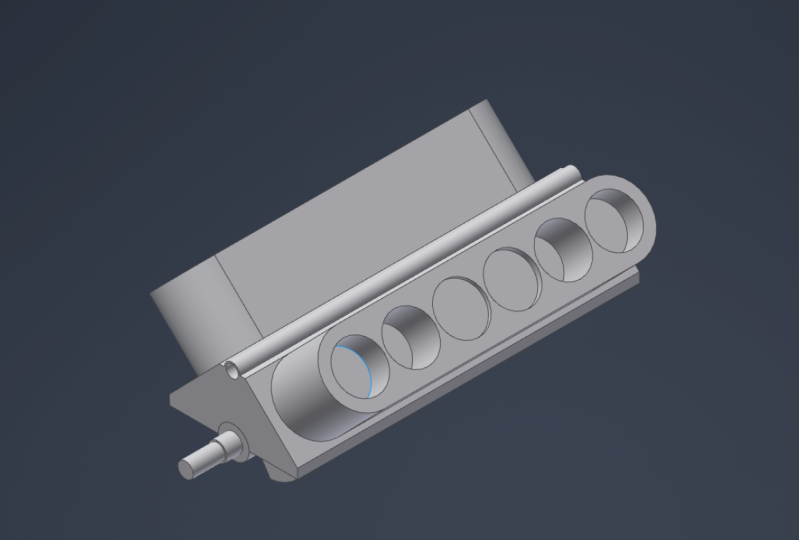
29. Shell: Let's create a shell in our main body of the cylinder. And the problem is we already have the extrusion and the mirror to the other side, but we only need to solve for the main body. And inventory becomes more important, how you model and how you structure your model. And we go into the modern browser, we already have the extrusion and mirror future. Now at the bottom we have n of part. So we can grab this one and move it up above the extrusion. And this will act like the extrusion and the mirror did not have me it. So now we can use the shelf feature. We selected asks for removed the faces we would like to remove. So we select the bottom, the inset it, radius or the circular and then the other phase. And now we type in for the thickness ten millimeters. Once we have the thickness, the faces selected, and make sure you have it to the insight. Click on OK. And now we have our shell created just for the main body. Now when we go to the model browser again, you can grab the end of part, move down or we right-click on it and say, move. And apart to the end. This will move to the end, and then it will bring back our extrusions.
30. Hole 1: Next we have to create some holds for an hour cylinder for the pistons. Now, we have two problems. First, you already created the sketch and we would like to use the same sketch for the holds so that we don't have to create a new sketch. And next one is that once you create the holes on the one side, we don't want to use. And another mirror of future to mirror it. Mirror this holds to the other side. So we can simply use the existing sketch, what we created before for this extrusion. And then we use the mirror feature for mirroring over this holds as well. So for the sketch, you just expand the extrusion, right-click on the sketch and share the Sketch. Sketch becomes available for our whole feature. We've already placed these six points in our sketch before, so we can use these points for the holes. Next problem is for the mirror. So we do the same thing what we did before. We move to the end of part above the mirror. And now we can, now we can use this sketch to create a holds and then we mirror over this portion, this exclusion to the other side. Now, we use the whole feature. And it automatically detects these points, what we created in our sketch. So you don't have to create these circuits in your sketch, which to find these holes, what you need, you just have to place some points. Now we'll leave it as a simple hole. We don't need the seat. We just want to create a hole all the way through. And for the size retype and 90. Now it will give me a preview of the hole. I can rotate to the bond to make sure it goes all the way through. Once we have it set up, click on OK. Now we can turn off the visibility of the sketch and move the on-off part down. Now when you go to the other side, these holds are not existing in the area. Now when you go and right click on the feature, the mirror feature and added feature before we only selected the extrusion. But now we have to click on Features and select a holds, a swell, and then click on OK. Now when we go to the site, you have to hold on both sides.
31. Hole 2: Let's have a look at creating some hosts without an existing sketch. And we use the whole 2D and would like to have a hole on this side. And on the other side. We start on this side first. So if you don't have a sketch credit yet, it will ask for a position for the whole, so you just place it somewhere on this phase here. So it will give you a preview of the hole. We change the size to 22. Now this hole should be centered to this circle here. So once you hover over, it gives you this kind of small icon for this surface. So you select the edge and then you see it will jump to the center point of the circle here. So you can place this hole on this side. And then you do the same thing on the other side. You just paste a hole. And then you select the ACh for the big circle and then the center of it for you. So you don't have to really go in and create a sketch. You simply use the whole feature network treated for you. So for this site, we need 38 and click on OK. Now when we expand the whole feature, we can see in red created two sketches for us. Without us creating the sketches first and then uses the whole future. It is automatically done.
32. Review the Piston: Let's review or piston. It created an extrusion, cut, revolve, and Cut Extrusion. Now when we go to the sketch from our first extrusion, we create the first exclusion with a 45 millimeter diameter. And the cylinder we added 90 millimeters hold. That means we have to increase the size for or a piston. There are two different options to change the size for this. The diameter. We can either go into the sketch and change it to 90, or we use the parameters and change our perimeter, which is the change this one to 90 and hit enter. Once we change the size for the first extrusion, the cut revolve and Cut Extrusion should follow the first extra at the beginning when we created the revolve or the extrusion, you projected lines. Now when you go back into the sketch for the revolve, for example, and hit have sudden so that we can see the sketch. You can see that the outside line, which we projected is following whatever size we have for the fruit exclusion. So if you have it all connected correctly, if you have all the correct constraints and she projected geometry, it should be all updated automatically so that you don't have to go through all the revolving, the extrude to fix up your sketches.
33. Exercise (Piston) 3: For this exercise, tried to create a hole on the flat side of the piston all the way through the piston. And then create a new sketch on the flat surface again. And tried to extruded from both sides of the piston to the inside by 15 millimeters to add some material on the inside of the piston.
34. Solution (Piston) 3: Okay, let's start by adding a hole through the piston. So he used a whole tool and place it on the right side on the flat surface. Now for the time eater, I know it's 22 and from the top down it should be 12 millimeters. Now the problem is that we can't project the geometry of our axis so that we can center it two on the surface. Now when we click on the sketch nor properties, it will jump into the sketch mode. Now when I click on the right side view, now I have the option to project the tree geometry. So I click on projectory geometry, hover over my axis to find out which one I need. And in this case it's the y-axis. Now I project the geometry off my axis. Now I can select my axis and my horizontal line and Margaret as a construction line. And I add a constraint, the coincident constraint, to constrain my whole to the access or they just protected. And now I know I have it centered on my face. So now, once you have it all constraint and ready, we click on the whole future to go back into the properties. And we make sure we have the correct setting so that it goes all the way through. We have the correct diameter and everything looks good. So I click on OK. And now we added the hole through the piston. Next week, creat a sketch on the flat surface so that you can add some material. Third, hit F7 to slice my view. And I start by projecting a few lines. So I need the top horizontal. I need circling the whole what we created before. And I need r axis going through the center. So I can mark the axis and the horizontal line as construction lines. But we still need to hold costs. You only want to extrude the surface around, but not a whole. And now I create a box around this for the material would like to add. So it start at the top, it snaps to the top line. I go down. Just please, it's summer. Make sure you have the vertical constraint attached. And then once it snaps to that point, I start here and move it all the way to the other side. Wants it wants to snap to the horizontal line, let it go. And then I create another line all the way to the top. Wanted snaps to the horizontal line. And it's perfectly worker. I place it here. And then I close the top here to here. And it added a small liner. Delete this one. Now I can start adding some constraints to place it in the correct location. So I can use the concentric constraint. And I use the incense circle first and then the outset circular. And then it will place it exactly around the inset surplus. Alright, at a few more dimensions. In this case, I only need dimension on this circle here, which is 15. And this would drive the size for the left and the right side. So once I have the sketch ready, I click on Finish Sketch and extrude the surface to the insight. Extruded by 15 millimeters and make sure it is not cutting but joining to the existing surface or the existing solid. Once we have the extrusion ready, click on OK. And now we have added material to the one side, but we have to add the same thing on the other side. One option is to mirror, mirror it over to the other side. Or another option would be to share the sketch for the first exclusion. Then we go back to extrude. We select or surface what you would like to exclude. But this time where it says from, you click here. And now we select the other face on the other side. And now you can see it starts from this phase going to the inside by 15 millimeters. If it points into the wrong direction, just flip the direction to the other side so that it goes to the inside. Now we are 15 millimeters at. Looks good. So you click on OK. And now we add it, the extrusion on both sides. So you can turn off the visibility of our sketch and see if the fight.
35. New Solid: Okay, let's go back to our crank part and finish this part. At the beginning, we create the revival for whatever we have so far. Now we can start a new sketch or new part at the insight here. So you start new sketch on the insight phase of our cylinder here. Click the face, hit F7 so that they can see slightly rotate and projected geometry of this cylinder here. Now I can extrude this phase or the circle. But this time we make sure that we mark it as new solid. This way, it will create a new solid and will not join it to the existing. So you change the distance to 20. Make sure it's a new solid and click on OK. Now when we look in our modern browser, we can see we have two solids to one as the first one we created with the revolt. And the second one is the new solid. And when you expand these solids, you can see how it is solids were created. And now we create a new 2D sketch on the inset phase of our news, news, solid. Hit F7 and start a new sketch. Less time I create a circular at the center point, wants it snaps to the centre. But this time, I don't know the diameter. So make sure you right-click. And in here it will say radius. Makes sure you select radius. If radius selected, it will say diameter, but you want to have the radius. For the radius, we type in 85 and hit enter. Now we need another circle up here on the top. So we go to the wants, it snaps to the line, click here and type in 25 for this one. And that's the radius as well. Now we add the dimension from the central point to the center point. And seemed to 40. We can create a line from the outside to the inside. So you move to the insight and wanted snaps and shows you the tension, the constraint. Then you place it suited to our marquee at attention constraint. This one here. So we do the same on the other side. Go and wants it gives us the tenth constraint, please. It. And then hit escape. Now we have to add another dimension m between. We need the angle to be 35. It enter. But now we still have to make sure it is centered to the centre. So we can add another constraint to the central line. Or we can add another constraint, which would be symmetrical constraint. But we still have to protect the axis, which is the y-axis. And then we select the left side and the right side. And now it will centre these two lines to the axis. I will select the asset market as a construction line. Then we use the trim tool to trim off what we don't need. We don't need this portion, don't need this one, and we don't need the insight. Now we have our sketch down. It's fully constraint. So we go on, Finish Sketch and exploit this face here. By 7.5. You have to make sure it adds it to the extrusion. We created a good show your hidden yellow hidden line around all the parts were added to. You could change it to add it to the other solid. But in this case we want to have it to the solid shear. So you click on OK. And now when we go to the solids and click on solid tool, we can see that this is one solid here. Now we create another sketch on top of this face here. And then we just projected geometry of this outside the small circle is created and create a circle at the center point with a diameter of 3838. And hit Enter. This time I mark Estelle Harvard as a radius. So it should have been Time meter. So simple, just delete this dimension and add another dimension and change this to 38. Hit Enter. And then I go finish sketch and use the extrude tool again to extrude this phase by another 2020. And you can see it adds it to the same solid. So it's all one solid. We click on OK. And this is all on joint 20 millimeters. Ok. Now that's how our solid looks like. Now we need a mirror of what we just created and attached to the same salt. So we can go on to our ribbon. Under pattern, we click on mirror. Now this time, we don't want to mirror a feature. You want as mirror a solid. Click on solid. You select a solid, we would like to Miro. And then we have to select a plane. So we select a plane and select the face of the, the last extrusion. We created. This mixture, we join it. We can create a new solid again, but we would like to join it with the other solitary created. And click on OK. Now we have created a new solid on the inside.
36. Rectangular Pattern: Let's have a look at the pattern tool. We use the rectangular pattern before in our sketch. But this time we have to use it for our solid to create a pattern of the solid here. And our 3D model tab under pattern, select the rectangular pattern tool. And then it will ask for the feature. But you would like to create a pardon, from or a solid. So we changed it to solid. And then we select this solid we would like to create a patent from. So click on the solid. Then for the direction. Because we have access going through our part. So we go into our model browser and hover over these axis. So in this case it's the x-axis. So I select my axis and then be careful. Sometimes likes to jump into the wrong direction. Makes sure you flip the direction. We need six of these solids and we need a spacing of 95. Once you have filled in. On the top right, make sure you select, create new bodies so that it will create new BOD is for each of these solids. Instead of combining them all in one, selecting new bodies, and then click on OK. Now we have six of these solids have, when we go into our modern browser, open up the folder. We have several solids in total.
37. Rotate Bodies 1: Let's have a look at how to rotate the solids. And our 3D tab. Click on modify. This will open up the dropdown and there you have to, to move bodies, the selected tool. And now you have the option to free drag a solid or move along a ray, or you can rotate. In this case, we will need to rotate about line to select the tool. Asks us for body, which body you would like to rotate. So we start with the second one. The first one stays the way it is. The second one. You would like to rotate this one by 240 degrees clockwise. When you look at the right side, I should go clockwise. So we have to solid selected. Note ask for the axis. Now we go back to the model Browser and select in this case, my case, it's the ax axis. So select my axis. And you can see it goes counterclockwise. So you can flip the direction. Now it goes clockwise. And we type in 240. Once we have that type, then we have our axis, we have the body selected. It will give you preview what it, what it wants to do and just took so good. So I click on apply and you can see the solid rotated. Now we can do the same for the other solids. So for the third solid, we rotate by a 120 degree. The fourth we rotate by 60, by 300, and the last one by a 180.
38. Rotate Bodies 2: Let's go over a rotating these other solids in case you had some issues. So go back to modify and use the Move bodies tool. So I select my solid and change it to rotate. Now for this pilot, we wanted to rotate this one by a 120. And I have to select my axis, which is the x-axis. And make sure it goes clockwise when you look at the right side. So now just one goes clockwise. Looks good. So I click on Apply and select my next one. It will always jump back to the move so you'll have to change, but to rotate again, you select your access. Sure, it goes clockwise. And for this one really does run 60. So click on Apply and move on to the next one. Do the same. To rotate. I select my access and type 300. Fluid goes into the right direction. Click on Apply. And the last one, change it to rotate again. This time it's a 180. And I select my axis and flip direction. Click Apply. And now I finished rotating on my solids.
39. Combine: Okay, once you have all these solids rotated, we can combine RZ solids into one big Silent. Again, under the modified group, we go to combine or to ask for the B's silent. So we select the first solid to create it, which is this one. And then it will ask for the two body. Now for the two body, you select all these other solids, what we created. So you can pick the solids and your model space or near mode browser you go through and select alia solids. Once you have them selected mixture you have to join. Once it's set up, click on Apply. And now at joints all these solids into one solid. And now when you go into your model browser, you will only see one solid.
40. Direct Edit: Let's do one small touch-up. And front. We have to move to this face here, further out to the front. There are two options. What she could do. Usually, we could use the revolves to go back into the sketch, update our sketch to move this face up or change the dimension 30, because we have to move out but ten millimeters and this would be all updated. Another option is to, if you have to move phase and there is no other way tend to, you can't really change any dimensions and you have to move the face. There is the tool direct added and your modified group click on direct. And this allows you to move faces. We can change the size, you can scale it, rotate or delete phase. But we have to move this face here on the bigger cylinder out by ten millimeters. In this case, you would select the phase. Then it will show you these three arrows in which direction you would like to move. You grabbed this area here and pull it into the front direction. Now you can type in how far you would like to move to entitlement ten. And then it moves it by ten millimeters to the outside. So you click on Apply. And now you have this face moved to the outside by ten millimeters. We can close this one and safe.
41. Exercise (Direct Edit): Open up your cylinder IPT and tried to use the direct added tool to move these two faces by Twenty-five millimeters to the inside.
42. Solution (Direct Edit): I'm in my cylinder IPT. And a good to my modify and select direct. Now if a select my face, and it doesn't really matter which point you select, it gives you multiple options or just pick one. Then you drag it to the insight and happened 25, and click on the play. Then I go to the other side, select my phase, drag it in and take 25 and click on apply. Once I'm done, I click on X, and now I added the Twenty-five millimeters to speak.
43. Create/Modify End: Now we looked at how to create a pardon inventor, how to use multiple tools to modify the parts. And hopefully it gives you a better overall understanding about a part in inventor. Next year, look at bringing all the parts together in one assembly file.
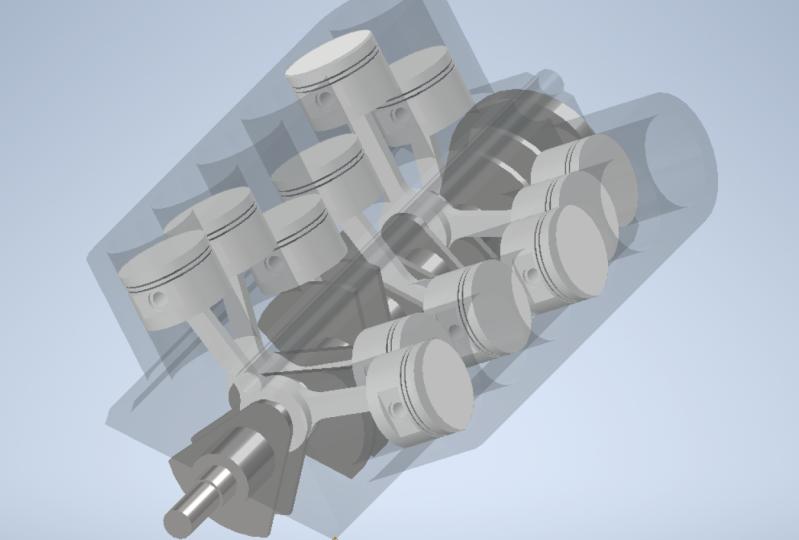
44. Assembly Intro: In this lecture, we will look at the assembly file, take all the parts we have created so far, and place them all in one assembly. At the same time, we will look at the different tools inside the assembly file, which we can use to assemble and modify our parts.
45. Assembly file: Let's have a look at the assembly file and your new title. Click on sampling to start new assembling. Now and here you can see that you have different options than in the part file. And the top left here you can please the files, what you created. You can create new files and terrorists, lots of other fun today. You will learn in the future. And some of the tools you were maybe never even use. So it depends on which area you work in. Then this will kind of define which tools you actually need in here. Now in the top where you have a 3D model cap. What you have to keep in mind that this 3D model tab is not to create solids. It is just to make cutouts in your parts, which you can place in your assembly. So your assembly is not to create solids you're resampling is just to please your parts and create an assembly with the parts you have created.
46. Place Components: I'm in a simplified and let's place our first part into the sampling. So first I start with tuning on my Cyril, my center point. So I right-click and turn on the visibility so that I can see where my center point is. Now, I start to please my cylinder into my assembly. So think of a place, and then it jumps to my workspace. And then I can pick my cylinder. And then I click on, okay. Now first I just place it somewhere into my model. So please it close to my center point. So once you place clicked somewhere, it will place it that it can hit escape to cancel out of this. Now, I would like to move this point here to my center point so that I kind of keep my model centered somehow. You can pick another point. I pick this corner here and move it to my center point. So in order to move it in the top on your ribbon, click on position on the dropdown. And there you have to to grip snap. So you select the tool. And then it will ask you for a corner you have to define or from where you were or what you would like to move, say, go to the corner and it will show me the blue rectangle. And then I select this corner here. Then it will give me some options how I would like to move it. I would like to just move it two way this just from this point to another point. I don't want to rotate or to some funny, I just want to move it. So I click on free drag and then I select my central point. Click on the center point. Now we have to right-click and click continue. And some cases you, if you have multiple points, what you would like to adjust to something, we could keep going on selecting points or something like the center, central line and so on. But I only want to move to 1 and keep it the same rotation. So I right-click again and see, okay. Now when we go and click on the left side and rotate. So you can see it looks all nice and straight. So it's not rotated to looks fine to me. So now what we have to make sure is that this does not move anywhere. So we select the part and right-click on the part and mock market is grounded. Or it can go into your model browser and right on the park and click on grounded. This way, it can move anywhere. You can drag it around, or it will not move by mistake. It it shows you a small pin on the part. Nat means it's grounded and fixed to this location.
47. Relationship (Joint): Again, that's placed the crank next and are the joint constraint to the crank and the cylinder. So to place the crank re going on around them and click on place. It will jump to our workspace. And then we can select the crank selected and click on open. They're just placed at summer on our models in our model space to escape on nii_T1. And now we go on our ribbon and Houston try and constrain to try and get to our cylinder. So it click on joint. Now in here we can leave it on automatic or you have multiple options to select from. In this case, I would prefer because we know we want to have it centered slim tutor and we don't want to have these adoptions makes it sometimes a bit easier. So I select on cylindrical, then a zoom in. Now I go to the third center and I hover over and you can see that it selects this cylinder. And now it wants to snap to the center point. We have three points. We have one in the front, one in the back, and one in the middle. But I need the one in the front. So I move my mouse as far as possible to the front. You might have to rotate a little bit. C. Now it snaps to the front. It's still selects the cylinder, but now it has the font one selected. Now I click here. See now it adds this kind of blue kind of a circulant error on the front. And now I rotate to the bottom and do the same on my cylinder and on the cylinder. And I do the same on the front. See we have three points here as well. And I want to select the front point. So I click here. And it will give us a preview of what it is allowed to do. So it can move back and forth and it can rotate. So when we go here to limit, we can adjust of the anger. Will hire how much it can rotate at linear of the movement back and forth. Let's click on, okay, for now. So now we have placed and have a joint constraint connected here. Now when we grab the crank and move it around, you can see it can move to the front, to the back, and it can rotate. Now, we don't really want this to rotate or to move. We want this to rotate but not move back and forth should be kind of fixed two dislocation here. So we go back in to our model browser and expand the crank. And then here we have this solid cylindrical What we just placed. So you right-click on it and go edit. Now we go to limit. So we changed the angular back to 0 and the linear 20 aswell. Now, we have to set the linear so that it starts from 0 and N by 0. This will fix it in place so that it can't move back and forth. That can only move to 0, to 0. So it will be fixed and dislocation. And then we click on OK. Now let me grab this. It will not move back and forth, but it still rotates. And that's what we need. So once we have habit constraint, we can save it and keep going for me.
48. Edit in place: I just realized that the crank does not really fit into my cylinder because my whole what we created in the cylinder is only a radius of 15 instead of 30. So we would have to go back into the cylinder and update the sketch for a cylinder so that the crank actually fits in there. Now before we go into the cylinder, first I go to view and change my style, visual style to shade it with arches. It makes it easier to see. Now you can see that my cylinder and the atmosphere as a crank it up here. So we can clearly see that it doesn't really fit in there. Now instead of opening the cylinder, we can just double-click on the partners here, or we can right-click on the part and say added. This would jump into this cylinder part file. And we can see in our modern browser, it's all grayed out except the cylinder. That means we are now in the OR part file for the cylinder. But the benefit is that we can still see the crack in the background so that we can still a kind of analyze the interference or what issues we have and update the cylinder part in this case, without going into the part itself during the update and then go back out to the analyzers and jumping back and forth. So you can't see all the parts in the assembly and jump from one part to another. Now when I go to my exclusion, I can see my sketch in here and I can see I used a diameter of 30 instead of the radius 30. So I right-click on my sketch, an Edit Sketch, and change 30 to 60 and hit enter. Finished my sketch. And now it will update. And now any go back, you can click on return or you can double-click on the engine. And this will jump back to the sampling. And now we can see that it lights up. And now my crank actually fits into the cylinder. And that helps us to edit parts in place.
49. Saving in an assembly: One of the things you have to keep in mind when you work in the assembly and you do updates on the perch. And you had SIF rental will show you a window like this one here, and it will show up. And we, cause we changed the cylinder and which changed something on the sampling. And here we can select which one you want to save and which one you don't want to save. So you can simply click on yes. And this will then change to know. Or you can select the file and click nor on the bottom. And to say no which ones you don't want to save. In this case, we want to see if both. But what you have to be careful with this, that if you change a part, let's say we close the cylinder. If you would, OK, this cylinder, he would do some changes on the cylinder. And then he closed the cylinder but you don't want to see if the changes. So you click on No, you don't want to save changes. And then you're in the assembly on, you hit save, it will show up again even though you close the file. So if you do a change on a part and you don't want to save the change. We have to close adventure because it will stay in the memory of inventor, not like other softwares. Once you close the file, the memory of this file that began an inventor, where it will stay in the memory until the close inventor. So always be careful when you click save insight and a sampling cause it will always list odd parts and it always tries to save everything apart. You had open, any closed. So just keep this in mind when you click on safe that you go through and make sure you really want to save these parts. And for the parts you don't want to save, we'll change it to know and then you click on OK. And this case, we want to see if both. So I leave it as Yes and click on okay.
50. Relationship (Constrain) 1: Okay, let's place our piston and constraint into our cylinder. So I go on, place and select my piston and click on open. So I will show you one and then you can go and place all the odd ones. So in my case, I will place one. If you want, you can place 12 and total and then constrain them all into this holds. So I have to want pleased. And now I use the constrain tool to constrain it intuitive Hall. Before we used a joint tool to join the crank to the cylinder. This is because we want to do some animation spit leader so that we can kind of drive it. We will look into this leader in this case, because the piston will be driven by the crank. So we don't need to try and constrain. We just can use the constraint tool to constrain it into the hole. So click on constraint. And we have multiple types like how we can constrain it. In our case, we stay with the meat constraint. And three soon into our piston and select the top cylinder portion. And then it would show it with a highlights the top portion and show a central line going down. And then we can see the small arrow pointing downwards. So you select this cylinder. It's right now we can see the arrow down and then we go to our hole. And in here it will want to hover over. It will highlight the same thing, just in this case now it points upwards. So you select the inside cylinder, the hole, and then it will snap inside the hole. If you have this cylinder pointing in the wrong direction, we can flip the direction to align. See now it flipped to the other way, but it should be this one here. So your flip it into the right direction and click on, okay. And now we have the cylinder or the piston in our cylinder. Now when you grab it, you can move it up or down. And now it's basically placed inside the hole. It's constraint so that it can only move up and down in this axis. Now you can go ahead and place all the other ones inside this hole.
51. Relationship (Constrain) 2: We have our cylinder, and then we have the crank constraint or joined to the cylinder, and we have our pistons. Now the problem is we have to add these pins and the connection rods inside the cylinder. And the cylinder is kind of blocking us. And what you can do is you can select the cylinder, can right-click. And there are two options. You can make it transparent so that you can see inside, but you would still, when he tried to constrain it would not allow you because it's the insight. So you click on it again and turn off the transparency. Or you can right-click on it and tune after visibility, which is appear, just visibility to click on it. And now it's not visible. Now it is not blocking you from seeing this part. So you can easily go and add the pin and the connection wrong. Let's please one pin, please a pin here. And this pin has to be constrained to the piston. So I will replace constraint one pin and then it can go ahead and place are the other pins in to all the pistons. So I click on constraint again, and then I go to my pin and it would show me the same what we had before the cylinder and do a center line going through. So click on it. And then they go to a piston and do the same. I go to the hole and it would show me the same thing. What on tech under pin. So click here and it will snap in. So I still have the freedom to move back and forth, to click on OK. And it still moves back and forth. So it's not really constraint and the insight. So I can add another constraint. You can either click on constraint, we can click C on a keyboard, and this will open up the same window. So this time I add another constraint from the outside face to this face here. And I make it an offset of 3.5 millimeters. And make sure we can see these two errors, the point into the same direction. But right now our constrained with making, made constraint which points into the opposite direction. So he's changed it to a flush and it would snap insight or jump inside. And when you check the other side, so it looks the same. So we have it now constraint inside the piston. We click on OK. And now this one, it can't move. It's kinda fixed inside the piston. So now you can go ahead and please All the other pins and constrain them to Addis pistons.
52. Relationship (Constrain) 3: Okay, once you have the pistons constraints, the pins inside the piston is constraint. Then we can go and add this connection rod. Now we have the same problem as before. Now the pistons are blocking or view. So we can do the same. We can select all the pistons and turn off the visibility. But now we have a ton of stuff in our model browser. And it becomes kind of messy. But we can do is we can right-click and create a new folder and call this folder piston. Now we can grab all this or pistons and drag them and dropped him into the folder. And now it looks, looks bit more clean. We can do the same for the pins. Pin. We select all the prints and move it in site folder. Now, we can right-click on the folder and turn off the visibility. And this will turn off the visibility of all the files inside the, inside the folder. Now it's pretty easy to see what we want, what we have to do. So I please hold connection odd. And this time every place too. And then it can do the add wants the same. So I start with these two and the front. So I use the constraint. And a click the insight of the bigger side and slender on my crank. And it will snap to this point. So I click on apply and do the same for the top. And now I have to make sure we select the correct pin, which applies to these two cylinders, pistons. And then I've started to back one. So I select a, a pin and then it will snap to this one as well. So I click on apply and do the same for the other side. So click on this one and apply it to this click Apply, and then the small hole to the pin. And click OK. Now I have my pin connected to the collection rod, connects rod, so the crank on both sides. Now the other problem is right now it's ten moves to the left and the right. We look at the front, you can see it's not fixed to the centre. So what we can do is we add another constraint from this face. Two. I used a circle and make it a distance of nine millimeters and apply. Now a constraint at this phase from 21 connection rod to the other connection rod and click on apply and cancel. And now all they can do is just rotate around. And by constraining this, you can see now my connection, my crank moves back and forth. So it looks like it lost connection. So we go back to the crank. And in this cylindrical joint what we created, you right-click and add it. So we go back to limits. And it removed the endpoint for summary. So I check it and change this to 0 and click on OK. And now it's fixed into place again. And to make sure it does not change in the future anymore, or that it returned, that we forget about it. Maybe we can add another constraint from the front side to our cylinder. So he turned off to, on the visibility of our cylinder and add the constraint of the front sight to this face here. You make sure it's flush constraint because these both pointing to the same direction and click on OK. And now it will not be able to move back and forth anymore.
53. Clean up: Okay, once you have everything constraints you have to dry and TFR to constraints done. We can turn on to visibility of our parts. So we select all the parts that we have and our modern browser and right-click and click on visibility. Now to turn it off first, then we click on it again and right-click. Then click visibility, it will turn it back on. Now we can see all or parts which we have created and what we have placed in here. Now when we click on the Home view, it rotates to the bottom. Maybe yours is setup, correct? In my case, for some reason it is on the bottom. If you would like to change your home view, click on this corner. I would like to have this as my home views. I right click on the View cube and set my current view as home. And then we can set it by a fixed distance or Fit to View. I'll use this one. Next time I click on home, it will rotate to this view. Then last thing what you have to make sure is you select all the parts, right-click on it and make sure they are not grounded. You only want to have the piston cylinder grounded in this project.
54. Drive: Now we have created all the parts for discourse and we have created an assembly constraint. All the parts are the parts and have it all put together. If you want, you can continue and add more parts for this engine. Before I let you go, I would like to show you one more tool or one more thing. What you can do, which is kind of the height at all, kind of interesting to, to use and to see, especially when you create an, an engine or something which should move. So when we go back to our crank on the cylindrical, What we created at the beginning. So you can right-click on it and select drive. And here we can fill in. It should start from 0 and it should run to 3600. We don't need a POS. We wanted to have it run all the way through. And then you click on play. And then you can see your engine running. So you can rotate around. Then he can see how you engineers running. And that's how you can play around with driving parts. And if you built other parts as well, then he can kind of create an animation and see how it, how it looks like and see if it actually works. What you have created.
55. The End: I hope you enjoyed my course and hopefully I was able to show you the basics of inventor. And venture has lots of functionality and it takes some time to understand the logic of inventor. But if you have a strong knowledge of the basics, it will help you to learn inventive faster.
 Harry Klause, Professional CAD Instructor